JP7255583B2 - Simulation device for plant monitoring system - Google Patents
Simulation device for plant monitoring system Download PDFInfo
- Publication number
- JP7255583B2 JP7255583B2 JP2020504833A JP2020504833A JP7255583B2 JP 7255583 B2 JP7255583 B2 JP 7255583B2 JP 2020504833 A JP2020504833 A JP 2020504833A JP 2020504833 A JP2020504833 A JP 2020504833A JP 7255583 B2 JP7255583 B2 JP 7255583B2
- Authority
- JP
- Japan
- Prior art keywords
- area
- gas cloud
- camera
- unit
- monitoring
- Prior art date
- Legal status (The legal status is an assumption and is not a legal conclusion. Google has not performed a legal analysis and makes no representation as to the accuracy of the status listed.)
- Active
Links
Images


Classifications
-
- G—PHYSICS
- G06—COMPUTING; CALCULATING OR COUNTING
- G06Q—INFORMATION AND COMMUNICATION TECHNOLOGY [ICT] SPECIALLY ADAPTED FOR ADMINISTRATIVE, COMMERCIAL, FINANCIAL, MANAGERIAL OR SUPERVISORY PURPOSES; SYSTEMS OR METHODS SPECIALLY ADAPTED FOR ADMINISTRATIVE, COMMERCIAL, FINANCIAL, MANAGERIAL OR SUPERVISORY PURPOSES, NOT OTHERWISE PROVIDED FOR
- G06Q50/00—Systems or methods specially adapted for specific business sectors, e.g. utilities or tourism
- G06Q50/04—Manufacturing
-
- G—PHYSICS
- G06—COMPUTING; CALCULATING OR COUNTING
- G06T—IMAGE DATA PROCESSING OR GENERATION, IN GENERAL
- G06T19/00—Manipulating 3D models or images for computer graphics
-
- Y—GENERAL TAGGING OF NEW TECHNOLOGICAL DEVELOPMENTS; GENERAL TAGGING OF CROSS-SECTIONAL TECHNOLOGIES SPANNING OVER SEVERAL SECTIONS OF THE IPC; TECHNICAL SUBJECTS COVERED BY FORMER USPC CROSS-REFERENCE ART COLLECTIONS [XRACs] AND DIGESTS
- Y02—TECHNOLOGIES OR APPLICATIONS FOR MITIGATION OR ADAPTATION AGAINST CLIMATE CHANGE
- Y02P—CLIMATE CHANGE MITIGATION TECHNOLOGIES IN THE PRODUCTION OR PROCESSING OF GOODS
- Y02P90/00—Enabling technologies with a potential contribution to greenhouse gas [GHG] emissions mitigation
- Y02P90/30—Computing systems specially adapted for manufacturing
Landscapes
- Engineering & Computer Science (AREA)
- Physics & Mathematics (AREA)
- Business, Economics & Management (AREA)
- Theoretical Computer Science (AREA)
- General Physics & Mathematics (AREA)
- Health & Medical Sciences (AREA)
- Marketing (AREA)
- General Engineering & Computer Science (AREA)
- Manufacturing & Machinery (AREA)
- Computer Hardware Design (AREA)
- Computer Graphics (AREA)
- Economics (AREA)
- General Health & Medical Sciences (AREA)
- Human Resources & Organizations (AREA)
- Software Systems (AREA)
- Primary Health Care (AREA)
- Strategic Management (AREA)
- Tourism & Hospitality (AREA)
- General Business, Economics & Management (AREA)
- Testing And Monitoring For Control Systems (AREA)
- Processing Or Creating Images (AREA)
- Management, Administration, Business Operations System, And Electronic Commerce (AREA)
Description
本発明は、プラント監視システムのシミュレーション装置に関する。 The present invention relates to a simulation device for a plant monitoring system.
例えば、特許文献1には、広域の地図情報と、地図情報に含まれる構造物の情報とを表示することが可能な三次元の表示システムが開示されている。 For example, Patent Literature 1 discloses a three-dimensional display system capable of displaying wide-area map information and structure information included in the map information.
また、特許文献2には、プラント設備を構成する実際の機器を、実際の機器の形状、配置状況に即した三次元の画像として表示することにより、運転員がプラントの状態を容易に把握することができる表示システムが開示されている。 In addition, in Patent Document 2, the actual equipment that constitutes the plant equipment is displayed as a three-dimensional image that matches the shape and arrangement of the actual equipment, so that the operator can easily grasp the state of the plant. A display system is disclosed that can.
ところで、プラント設備などの構造物が設けられる環境の変化は、監視対象に影響を与える場合がある。顧客のニーズに適合する監視情報を提示するためには、構造物が設けられている環境情報を加味した構造物モデルの画像を表示することが好ましい。 By the way, changes in the environment in which structures such as plant equipment are installed may affect objects to be monitored. In order to present monitoring information that meets the customer's needs, it is preferable to display an image of a structure model that takes into account environmental information in which the structure is installed.
しかしながら、上記特許文献1,2に係る表示システムでは、構造物が設けられている環境情報を加味した構造物モデルの画像が表示されないという問題点があった。 However, the display systems according to Patent Literatures 1 and 2 have a problem that the image of the structure model that takes into account the environmental information of the structure is not displayed.
本発明は、顧客のニーズに適合する監視情報を提示することが可能なプラント監視システムのシミュレーション装置を提供することを目的とする。 SUMMARY OF THE INVENTION It is an object of the present invention to provide a plant monitoring system simulation apparatus capable of presenting monitoring information that meets customer needs.
上記の目的を達成するため、本発明におけるプラント監視システムのシミュレーション装置は、
時間の経過に応じて変化する環境を模式的に表示するための表示データを含む環境モデルを生成する環境モデル生成部と、
前記環境に設けられるプラントの構造物を模式的に表示するための表示データを含む構造物モデルを生成する構造物モデル生成部と、
前記環境モデル生成部により生成された前記環境モデルおよび前記構造物モデル生成部により生成された前記構造物モデルを表示する表示部と、を備え、
前記環境モデルは、前記構造物から発生し得るガス雲の検知に影響する誤検知要因モデルを有する。
In order to achieve the above object, the plant monitoring system simulation device of the present invention includes:
an environment model generation unit that generates an environment model including display data for schematically displaying an environment that changes over time;
a structure model generation unit that generates a structure model including display data for schematically displaying a structure of a plant provided in the environment;
a display unit that displays the environment model generated by the environment model generation unit and the structure model generated by the structure model generation unit ;
The environment model includes a false positive factor model that affects the detection of gas clouds that may originate from the structure .
本発明によれば、顧客のニーズに適合する監視情報を提示することができる。 ADVANTAGE OF THE INVENTION According to this invention, the monitoring information which suits a customer's needs can be presented.
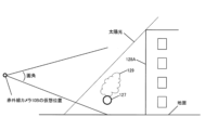
以下、本発明の実施の形態について、図面を参照しながら説明する。図1は、プラントの構造物を模した構造物モデル120の一例を概略的に示す図である。構造物モデル120は、例えば、天然ガスを精製して液化するためのプラントの構造物を模式的に表示するための表示データを有する。構造物モデル120は、例えば、レシーバータンク121、サービスタンク122、モレキュラーシーブ塔123、活性炭塔124、再生ガスヒーター125、および、再生ガス冷却塔126、および、それらを連結する複数の配管127を備えている。なお、複数の配管127を見やすくするために、図1に、配管127を異なる線種(実線、破線)で表す。また、図1に、仮想位置に設けられるカメラ10を示す。
BEST MODE FOR CARRYING OUT THE INVENTION Hereinafter, embodiments of the present invention will be described with reference to the drawings. FIG. 1 is a diagram schematically showing an example of a
図2は、本発明の実施の形態におけるプラント監視システムのシミュレーション装置100の構成を概略的に示す図である。図2に示すように、シミュレーション装置100は、構造物モデル生成部101、環境モデル生成部102、記憶部110、入力部140(本発明の「カメラ位置入力部」に対応)、表示部150、設定演算部160、構造物情報取得部171、および、環境情報取得部172を備えている。設定演算部160は、ガス雲発生エリア設定部161、危険度設定部162、監視エリア作成部163、および、演算部164を備えている。
FIG. 2 is a diagram schematically showing the configuration of a
シミュレーション装置100は、CPU(Central Processing Unit)、ROM(Read Only Memory)、RAM(Random Access Memory)、タッチパネル、ディスプレイ、スピーカーを有し、これらは、バスを介して相互に接続されている。CPUは、プログラムに従って上記各部の制御や各種の演算処理を実行するマイクロプロセッサー等から構成される制御回路である。シミュレーション装置100の上記各部の機能は、それに対応するプログラムをCPUが実行することにより発揮される。ROMは、例えば、不揮発性の半導体メモリーや、大容量の磁気ディスク装置を有しており、3次元データ、コンテンツデータおよび制御処理プログラムが記憶されている。
The
構造物情報取得部171は、プラントの構造物に関する情報(例えば、写真、地図情報)を取得する。
The structure
環境情報取得部172は、現地視察、空撮・人工衛星画像、現場の人からの環境情報を取得する。環境情報は通年の情報である。具体的には、環境情報には、構造物から発生(漏洩)し得るガス雲の検知に影響する環境情報が含まれている。さらに、具体的には、環境情報には、構造物の周辺環境および自然環境が含まれている。周辺環境には、海、道路、線路、周辺の工場、雑木林、山、プラント敷地内の樹木や地面(アスファルト、芝生、土、砂地(砂埃))が含まれている。自然環境には、太陽光(輝度、温度)、気候、気象情報(霧、雨、雪、風)が含まれている。
The environmental
構造物モデル生成部101は、プラントの構造物に関する情報に基づいて構造物モデル120を生成する。構造物モデル生成部101は、写真の情報から撮影に用いたカメラ10(図1に示す可視光カメラ10A、赤外線カメラ10B)のパラメータ(撮影位置、撮影方向)を抽出する。構造物モデル生成部101は、異なる方向から撮影した写真とカメラ10のパラメータとから3次元の構造物モデル120を生成する。記憶部110は、構造物モデル120を記憶する。
The
環境モデル生成部102は、環境情報に基づいて、構造物の環境を模式的に表示するための表示データを含む環境モデル130を生成する。記憶部110は、環境モデル130を記憶する。なお、本実施の形態においては、以下の説明をわかり易くするため、環境モデル130の一例として、太陽光、地面および気候を挙げて説明する。
The environment
環境モデル生成部102は、誤検知要因モデル生成部103を有している。誤検知要因モデル生成部103は、構造物から発生(漏洩)し得るガス雲の検知に影響する誤検知要因モデル131を生成する。記憶部110は、誤検知要因モデル131を記憶する。
The environment
誤検知要因モデル131には、ガス漏洩源(ガス発生部、例えば配管127)の背景の可視画像の輝度が含まれている。具体的には、ガス漏洩源の背景の可視画像の輝度は、太陽光、人工光源、海、建物での太陽反射光、ガスに類似した現象(水蒸気、雲)、砂埃、揺れる木々や芝生がそれぞれガス漏洩源の背景になる可視画像の輝度が含まれる。可視画像ではメタンなどの検知対象のガス雲は見えない。そこで、可視画像は、ガス漏洩源をわかり易くするために赤外画像と重畳して使用される。なお、ガス漏洩源(ガス発生部)の可視画像は、予め定められているガス漏洩源モデルの可視画像である。また、ガス漏洩源の可視画像の輝度は、予め定められている輝度である。 The erroneous detection factor model 131 includes the luminance of the background visible image of the gas leak source (gas generating portion, eg, pipe 127). Specifically, the brightness of the visible image of the background of the gas leak source is affected by sunlight, artificial light sources, the ocean, reflected sunlight on buildings, gas-like phenomena (water vapor, clouds), dust, swaying trees and grass. Each contains the intensity of the visible image background of the gas leak source. Visible images do not show detectable gas clouds such as methane. Therefore, the visible image is superimposed on the infrared image and used to make it easier to identify the gas leak source. Note that the visible image of the gas leakage source (gas generating portion) is a visible image of a predetermined gas leakage source model. Also, the brightness of the visible image of the gas leak source is a predetermined brightness.
本実施の形態では、ガス雲を検知するための赤外線カメラ10Bが設けられていない。なお、以下の説明では、赤外線カメラ10Bが仮想位置に設けられているものと仮定する。図3を参照して赤外線カメラ10Bによるガス雲検知の原理について説明する。ガス雲は背景の温度に応じて放射される赤外線の一部を吸収する。図3に、背景から放射される赤外線量V(Tb)、ガス雲で吸収される赤外線量をαV(Tb)、ガス雲から放射される赤外線量V(Tg)で示す。ここで、V(T)は、絶対温度T(K)における黒体放射輝度である。
In this embodiment, an
ガス雲は、背景から放射される赤外線量V(Tb)と、背景から放射され、ガス雲を透過する赤外線量(1-α)V(Tb)およびガス雲から放射される赤外線量V(Tg)を合算した量との差異に基づいて検知される。したがって、ガス雲検知の範囲は、赤外線量V(Tb)に基づく画像である背景温度画像と、赤外線量((1-α)V(Tb)+V(Tg))に基づく画像であるガス雲あり画像との差異を抽出した画像として定められる。 The gas cloud has the amount of infrared rays radiated from the background V(Tb), the amount of infrared rays radiated from the background and transmitted through the gas cloud (1-α)V(Tb), and the amount of infrared rays radiated from the gas cloud V(Tg ) is detected based on the difference from the total amount. Therefore, the gas cloud detection range includes a background temperature image, which is an image based on the amount of infrared rays V(Tb), and a gas cloud, which is an image based on the amount of infrared rays ((1−α)V(Tb)+V(Tg)). It is defined as an image that extracts the difference from the image.
誤検知要因モデル131には、ガス雲の背景の赤外画像の輝度(熱情報)が含まれている。具体的には、ガス雲の背景の赤外画像の輝度(熱情報)は、太陽光、人工光源、人工熱源が背景になる赤外画像の輝度(熱情報)、風により温度が変化する背景の赤外画像の輝度(熱情報)が含まれる。ガス雲の背景の赤外画像の輝度(熱情報)とガス雲の赤外画像の輝度(熱情報)との差異が予め定められた閾値以下の場合、ガス雲が誤検知される場合がある。なお、ガス雲の赤外画像は、予め定められているガス雲モデルの赤外画像である。また、ガス雲の赤外画像の輝度(熱情報)は、予め定められている輝度(温度)である。 The false positive factor model 131 includes the brightness (thermal information) of the infrared image of the background of the gas cloud. Specifically, the brightness (thermal information) of the infrared image of the background of the gas cloud is the brightness (thermal information) of the infrared image of the background of sunlight, artificial light sources, and artificial heat sources, and the background temperature changes due to the wind. contains the brightness (thermal information) of the infrared image of If the difference between the brightness of the infrared image of the background of the gas cloud (thermal information) and the brightness of the infrared image of the gas cloud (thermal information) is less than a predetermined threshold, the gas cloud may be falsely detected. . Note that the infrared image of the gas cloud is an infrared image of a predetermined gas cloud model. In addition, the brightness (thermal information) of the infrared image of the gas cloud is a predetermined brightness (temperature).
ガス雲発生エリア設定部161は、ガス雲が発生する可能性を有する領域であるガス雲発生可能性エリアを設定する。具体的には、ガス雲発生エリア設定部161は、配管127をガス雲発生可能性エリアとして設定する。ガス雲発生可能性エリアの設定には、入力部140が用いられる。記憶部110は、ガス雲発生可能性エリアを記憶する。以下の説明をわかり易くするため、ガス雲発生可能性エリアの一例として配管127を挙げて説明する。
The gas cloud generation
危険度設定部162は、予め定められた条件に基づいて、ガス雲発生可能性エリア(複数の配管127)におけるガス雲が発生する可能性の高さを示す危険度を設定する。危険度の設定には、入力部140が用いられる。予め定められた条件には、例えば、耐用年数(寿命)、実使用年数、材料(配管127の材料)、使用目的(ガスの種類)、配管127の設置状況(屋外、屋内)、腐食状況、および、劣化状態が含まれる。記憶部110は、危険度を記憶する。
The risk
監視エリア作成部163は、誤検知要因モデル131、ガス雲発生可能性エリア(複数の配管127)および危険度に基づいて、ガス雲を監視する場合の監視設定エリアを作成する。なお、本実施の形態においては、以下の説明をわかり易くするため、危険度設定部162は、ガス雲発生可能性エリア(複数の配管127)を同じ危険度に設定している。なお、危険度設定部162が複数の配管127を互いに異なる危険度に設定している場合、監視エリア作成部163は、危険度が高い配管127に基づいて監視設定エリアを作成する。
The monitoring
次に、誤検知要因モデル131について図4及び図5を参照して説明する。
図4に示す誤検知要因モデル131の一例は、ガス雲の背景に建物の壁面128Aが含まれるものである。図4に、仮想位置に設けられた赤外線カメラ10Bを示す。また、建物の壁面128Aを太陽光が当たらない所として示す。太陽光が当たらない壁面128Aとガス雲との両者の温度がほぼ同じである場合、ガス雲の赤外画像と壁面128Aとの両者の赤外画像の輝度(熱情報)の差異がわずかになる。これにより、ガス雲の検知がし難くなって、ガス雲を誤検知する場合が生じる。監視エリア作成部163は、ガス雲の赤外画像と壁面128Aの赤外画像との両者の輝度(熱情報)の差異が予め定められた閾値以下の場合、壁面128Aが背景となるガス漏洩源としての配管127を誤検知エリア128(図1参照)として監視設定エリアから除外する。Next, the erroneous detection factor model 131 will be described with reference to FIGS. 4 and 5. FIG.
An example of the erroneous detection factor model 131 shown in FIG. 4 includes the
図5に示す誤検知要因モデル131の一例は、ガス雲の背景に樹木128Bが含まれるものである。図5に、仮想位置に設けられた赤外線カメラ10Bを示す。樹木128Bとガス雲との両者の温度がほぼ同じである場合、ガス雲の赤外画像と樹木128Bとの両者の赤外画像の輝度(熱情報)の差異がわずかであると、ガス雲の検知がし難い。なお、ガス雲の検知には、ガス雲の領域を移動体領域として背景領域から抽出する方法が用いられる(例えば、フレーム差分法)。当該方法においては、背景である樹木128Bが風などにより揺れる場合、ガス雲の領域を抽出し難いため、ガス雲の検知がさらに難しくなる。したがって、ガス雲の背景に樹木128Bが含まれる場合、ガス雲を誤検知する可能性が高い。これにより、監視エリア作成部163は、樹木128Bが背景となるガス漏洩源としての配管127を誤検知エリア128(図1参照)として監視設定エリアから除外する。
An example of the false positive factor model 131 shown in FIG. 5 includes
演算部164は、誤検知要因モデル131に基づいて、カメラ10から見える監視設定エリアである有効監視エリアにおけるガス雲の背景の表示データの変化を計算する。ここで、誤検知要因モデル131は、時間の経過に応じて変化する環境情報(太陽の位置、地面、気候)である。また、ガス漏洩源の背景の表示データの変化は、ガス漏洩源の背景になる可視画像の変化である。また、ガス雲の背景の表示データの変化は、ガス雲の背景になる赤外画像の変化である。
Based on the erroneous detection factor model 131, the
カメラ10(可視光カメラ10A、赤外線カメラ10B)の設置場所、設置台数、機種(固定型、パンチルト型)、パンチルト型カメラにおける動作スケジュール、および、監視方向等は、操作者が入力部140を用いることにより入力される。
The operator uses the
図6は、図1における左側のカメラ10から見える有効監視エリアにおけるガス雲の背景の画像を示す図である。図7は、図1における右側のカメラ10から見える有効監視エリアにおけるガス雲の背景の画像を示す図である。
FIG. 6 shows an image of the gas cloud background in the active surveillance area as seen from the
表示部150は、設置位置に設けられたカメラ10から見える有効監視エリアにおけるガス漏洩源の背景の画像(可視画像)、ガス雲の背景の画像(赤外画像)の変化を表示する(図6および図7参照)。また、表示部150は、有効監視エリアにおけるガス雲発生可能性エリア(配管127)に、ガス漏洩源の画像(予め定められているガス漏洩源モデルの可視画像)、ガス雲の画像129(予め定められているガス雲モデルの赤外画像)を表示する。また、表示部150は、図6および図7に示すように、誤検知エリア128を表示する。誤検知エリア128を表示することにより、カメラ10以外の監視機器を設置する必要性について検討する意義があることを顧客に提示することができる。
The
次に、シミュレーション装置100における環境モデル130等の処理について図8を参照して説明する。図8は、シミュレーション装置100における環境モデル130等の処理を示すフローチャートである。なお、本処理には、構造物モデル120および環境モデル130の生成の処理が含まれているが、構造物モデル120および環境モデル130が記憶部110に予め記憶されていれば、構造物モデル120等の生成の処理は含まれなくてもよい。
Next, processing of the
ステップS100において、構造物モデル生成部101は、プラントの構造物に関する情報に基づいて構造物モデル120を生成する。記憶部110は、構造物モデル120を記憶する。
In step S100, the structure
ステップS110において、環境モデル生成部102は、構造物の環境情報に基づいて環境モデル130を生成する。記憶部110は、環境モデル130を記憶する。
In step S110, the
ステップS120において、誤検知要因モデル生成部103は、ガス雲の検知に影響する誤検知要因モデル131を生成する。記憶部110は、誤検知要因モデル131を記憶する。
In step S120, the erroneous detection factor
ステップS130において、ガス雲発生エリア設定部161は、入力部140を用いて、ガス雲発生可能性エリア(複数の配管127)を設定する。記憶部110は、ガス雲発生可能性エリアを記憶する。
In step S<b>130 , the gas cloud generation
ステップS140において、操作者は、入力部140を用いて、ガス雲が発生する危険度を設定する。
In step S<b>140 , the operator uses the
ステップS150において、監視エリア作成部163は、誤検知要因モデル131、ガス雲発生可能性エリアおよび危険度に基づいて監視設定エリアを作成する。
In step S150, the monitoring
ステップS160において、操作者は、入力部140を用いて、カメラ10(可視光カメラ10A、赤外線カメラ10B)の設置位置を入力する。
In step S160, the operator uses the
ステップS170において、表示部150は、設置位置に設けられたカメラ10から見える有効監視エリアを表示する。このとき、表示部150は、ガス雲発生可能性エリアにガス雲を表示する。
In step S170, the
上記実施の形態におけるシミュレーション装置100によれば、時間の経過に応じて変化する環境を模式的に表示するための表示データを含む環境モデル130を記憶し、環境に設けられるプラントの構造物を模式的に表示するための表示データを含む構造物モデル120を記憶する記憶部110と、環境モデル130および構造物モデル120を表示する表示部150とを備える。これにより、構造物が設けられている環境情報を加味した構造物モデル120が表示されるため、顧客のニーズに適合する監視情報を提示することができる。
According to the
また、ガス雲が発生する可能性を有する領域であるガス雲発生可能性エリア(配管127)を設定するガス雲発生エリア設定部161と、構造物から発生し得るガス雲の検知に影響する誤検知要因モデル131およびガス雲発生可能性エリアに基づいて監視設定エリアを作成する監視エリア作成部163とを備える。これにより、誤検知するようなエリアをあえて監視の対象から除くことで、監視の有効性を高めることが可能となる。
In addition, a gas cloud generation
また、監視エリア作成部163は、危険度に基づいて監視設定エリアを作成する。これにより、危険度の高いエリアを優先的に監視することができるため、監視の有効性をさらに高めることが可能となる。
Also, the monitoring
また、カメラ10の設置位置を入力する入力部140を備え、表示部150は、設置位置に設けられたカメラ10から見える有効監視エリアを表示する。有効監視エリアには、ガス雲発生可能性エリア(配管127)、誤検知エリア128、ガス雲の画像129が含まれる。これにより、カメラ10でガス雲がどのように見えるかについて検討することが可能となる。また、ガス雲の検知における周辺環境等による影響の有無についても検討することが可能となる。
Further, an
次に、変形例におけるシミュレーション装置100Aについて説明する。なお、変形例の説明においては、上記実施の形態におけるシミュレーション装置100と異なる構成について主に説明し、同じ構成についてはその説明を省略する。
Next, a
上記実施の形態におけるシミュレーション装置100は、カメラ10(可視光カメラ10A、赤外線カメラ10B)の設置位置を、操作者が入力部140を用いて定めたが、変形例におけるシミュレーション装置100Aは、自動的に定める。
In
図9は、シミュレーション装置100Aの一部を概略的に示す図である。図9に示すように、シミュレーション装置100Aにおける設定演算部160Aは、カメラ位置設定部165、位置候補抽出部166および有効位置算出部167を備えている。
FIG. 9 is a diagram schematically showing part of the
カメラ位置設定部165は、予め定められた条件に基づいて、カメラ10の設置位置を設定する。具体的には、予め定められた条件は、配管127に沿って相互に所定の間隔(例えば1m)をあけて、カメラ10の設置位置が設けられることである。
The camera
位置候補抽出部166は、設置位置に設けられたカメラ10から見える有効監視エリアおよび死角エリアに基づいて、カメラ10の設置位置からカメラ10の設置位置候補を抽出する。ここで、死角エリアとは、カメラ10から見えないエリアであって、カメラ10の光軸方向手前側(図1に示す紙面下側)にある構造物モデル120が邪魔をして、光軸方向奥側(図1に示す紙面上側)のガス雲を検知できないエリアをいう。具体的には、位置候補抽出部166は、死角エリアを除いた有効監視エリアの広さの順に設置位置候補を抽出する。
The position
有効位置算出部167は、設置位置候補のうちから費用対効果が高くなるようなかつ、監視設定エリアのカバー率が高くなるような有効位置を算出する。表示部150は、有効位置に設けられたカメラ10(可視光カメラ10A、赤外線カメラ10B)から見える有効監視エリアを表示する。ここで、費用対効果とは、カメラ10の設置コストに対する有効監視エリアの広さをいう。また、監視設定エリアのカバー率とは、予定される全部の監視設定エリア(例えば、配管127の長さ)に対する、設置位置候補に設けられたカメラ10から見える有効監視エリアの割合をいう。
The effective
次に、変形例におけるシミュレーション装置100Aにおける環境モデル130等の処理について図10を参照して説明する。図10は、変形例におけるシミュレーション装置100Aにおける環境モデル130等の処理を示すフローチャートである。なお、本処理の説明においては、上記実施の形態と異なる処理について主に説明し、同じ処理についてはその説明を省略する。
Next, processing of the
ステップS200~ステップS250における各処理は、上記実施の形態におけるステップS100~ステップS150と同じである。 Each process in step S200 to step S250 is the same as step S100 to step S150 in the above embodiment.
ステップS260において、カメラ位置設定部165は、カメラ10の設置位置を設定する。
In step S<b>260 , the camera
ステップS270において、位置候補抽出部166は、監視設定エリアおよび死角エリアに基づいて、カメラ10の設置位置候補を抽出する。
In step S270, the position
ステップS280において、有効位置算出部167は、費用対効果および監視設定エリアのカバー率に基づいて有効位置を算出する。
In step S280, the effective
ステップS290において、表示部150は、有効位置に設けられたカメラ10から見える有効監視エリアを表示する。
In step S290, the
変形例におけるシミュレーション装置100Aによれば、カメラ10の設置位置を設定するカメラ位置設定部165と、設置位置に設けられたカメラ10から見える有効監視エリア、および、カメラ10から見てガス雲が検知できない死角エリアに基づいて、カメラ10の設置位置からカメラ10の設置位置候補を抽出する位置候補抽出部166と、設置位置候補のうちから高い費用対効果を有する有効位置などを算出する有効位置算出部167とを備えている。これにより、カメラ10の最適な設置位置を自動的に選定することが可能となる。また、カメラ10の最適な台数、および、カメラ10の設置等に必要なコストを算出することが可能となる。
According to the
上記実施の形態及び変形例においては、監視エリア作成部163は、誤検知要因モデル131、ガス雲発生可能性エリア(配管127)および危険度に基づいて監視設定エリアを作成したが、本発明はこれに限らず、例えば、監視エリア作成部163は、誤検知要因モデル131等に代えて、又は、誤検知要因モデル131等に加えて、ガス雲の温度と背景の温度との差異(検知性)に基づいて、差異の大きさを優先して監視設定エリアを作成してもよい。ガス雲の温度と背景の温度との差異が大きいほどガス雲を誤検知する可能性が低くなるため、ガス雲の検知精度を上げることができる。
In the above-described embodiment and modification, the monitoring
上記実施の形態においては、可視画像と重畳して使用される赤外画像は、例えば、環境情報から取得されるが、本発明はこれに限らない。例えば、可視画像から赤外画像に相当する画像(赤外画像相当)を取得してもよい。 In the above-described embodiment, the infrared image that is superimposed on the visible image and used is acquired from environmental information, for example, but the present invention is not limited to this. For example, an image corresponding to an infrared image (corresponding to an infrared image) may be obtained from a visible image.
以下、可視画像から赤外画像相当を取得する方法の一例について説明する。先ず、可視光カメラから得られるカラー画像をモノクロ画像(輝度情報)に変換する。次に、太陽などの熱源が当たって温度が上がるところの輝度を高く、熱源が当たらずに温度が上がらないところの輝度を低くというように、熱源による温度情報を、輝度情報としてモノクロ画像に付加する。環境モデル130に適した基準温度情報を、輝度情報として、上記付加したモノクロ画像に付加する。次に、このモノクロ画像を現実的な赤外画像に近い画像にするために、モノクロ画像の輝度の分布を示すヒストグラムを調整する。
An example of a method for acquiring an infrared image equivalent from a visible image will be described below. First, a color image obtained from a visible light camera is converted into a monochrome image (luminance information). Next, add the temperature information from the heat source to the monochrome image as luminance information by increasing the luminance where the temperature rises due to exposure to a heat source such as the sun and lowering the luminance where the temperature does not rise due to exposure to the heat source. do. Reference temperature information suitable for the
また、上記実施の形態では、プラント監視システムのシミュレーション装置100を適用するプラントとして、天然ガスを液化するプラントを一例に挙げたが、本発明は、これに限らず、例えば、液化天然ガスを気化するプラントなどのように、ガス漏洩の可能性を有するプラントであればどのようなプラントにも適用することが可能である。
In the above-described embodiment, a plant for liquefying natural gas was taken as an example of a plant to which the
2018年3月8日出願の特願2018-042083の日本出願に含まれる明細書、図面および要約書の開示内容は、すべて本願に援用される。 The disclosure contents of the specification, drawings, and abstract included in the Japanese application of Japanese Patent Application No. 2018-042083 filed on March 8, 2018 are incorporated herein by reference.
その他、上記実施の形態は、何れも本発明の実施するにあたっての具体化の一例を示したものに過ぎず、これらによって本発明の技術的範囲が限定的に解釈されてはならないものである。すなわち、本発明はその要旨、またはその主要な特徴から逸脱することなく、様々な形で実施することができる。 In addition, the above-described embodiments are merely examples of specific implementations of the present invention, and the technical scope of the present invention should not be construed to be limited by these. Thus, the invention may be embodied in various forms without departing from its spirit or essential characteristics.
10 カメラ
10A 可視光カメラ
10B 赤外線カメラ
100、100A シミュレーション装置
101 構造物モデル生成部
102 環境モデル生成部
103 誤検知要因モデル生成部
110 記憶部
120 構造物モデル
121 レシーバータンク
122 サービスタンク
123 モレキュラーシーブ塔
124 活性炭塔
125 再生ガスヒーター
126 再生ガス冷却塔
127 配管
128 誤検知エリア
128A 壁面
128B 樹木
130 環境モデル
131 誤検知要因モデル
140 入力部
150 表示部
160、160A 設定演算部
161 ガス雲発生エリア設定部
162 危険度設定部
163 監視エリア作成部
164 演算部
165 カメラ位置設定部
166 位置候補抽出部
167 有効位置算出部
171 構造物情報取得部
172 環境情報取得部10
Claims (11)
前記環境に設けられるプラントの構造物を模式的に表示するための表示データを含む構造物モデルを生成する構造物モデル生成部と、
前記環境モデル生成部により生成された前記環境モデルおよび前記構造物モデル生成部により生成された前記構造物モデルを表示する表示部と、を備え、
前記環境モデルは、前記構造物から発生し得るガス雲の検知に影響する誤検知要因モデルを有する、
プラント監視システムのシミュレーション装置。 an environment model generation unit that generates an environment model including display data for schematically displaying an environment that changes over time;
a structure model generation unit that generates a structure model including display data for schematically displaying a structure of a plant provided in the environment;
a display unit that displays the environment model generated by the environment model generation unit and the structure model generated by the structure model generation unit ;
wherein the environment model has a false positive factor model that affects detection of gas clouds that may originate from the structure ;
Simulation device for plant monitoring system.
前記誤検知要因モデルおよびガス雲発生可能性エリアに基づいて、前記ガス雲を監視する場合の監視設定エリアを作成する監視エリア作成部と、をさらに備える、
請求項1に記載のプラント監視システムのシミュレーション装置。 a gas cloud generation area setting unit that sets a gas cloud generation possibility area, which is an area in which the gas cloud may occur;
a monitoring area creation unit that creates a monitoring setting area for monitoring the gas cloud based on the false detection factor model and the gas cloud occurrence possibility area;
A simulation device for a plant monitoring system according to claim 1 .
前記監視エリア作成部は、さらに、前記危険度に基づいて前記監視設定エリアを作成する、
請求項2に記載のプラント監視システムのシミュレーション装置。 further comprising a risk level setting unit that sets a risk level indicating a possibility that the gas cloud will occur in the gas cloud generation possibility area;
The monitoring area creation unit further creates the monitoring setting area based on the degree of risk.
A simulation apparatus for a plant monitoring system according to claim 2 .
前記表示部は、前記設置位置に設けられた前記カメラから見える前記監視設定エリアである有効監視エリアを表示する、
請求項2または3に記載のプラント監視システムのシミュレーション装置。 Equipped with a camera position input unit for inputting the installation position of the camera,
The display unit displays an effective monitoring area, which is the monitoring setting area visible from the camera provided at the installation position.
A simulation device for a plant monitoring system according to claim 2 or 3 .
前記設置位置に設けられた前記カメラから見える監視設定エリアである有効監視エリア、および、当該カメラから見て前記ガス雲が検知できない死角エリアに基づいて、前記カメラの設置位置から前記カメラの設置位置候補を抽出する位置候補抽出部と、をさらに備える、
請求項2または3に記載のプラント監視システムのシミュレーション装置。 a camera position setting unit that sets the installation position of the camera based on a predetermined condition;
The installation position of the camera from the installation position of the camera based on an effective monitoring area, which is a monitoring setting area visible from the camera provided at the installation position, and a blind spot area where the gas cloud cannot be detected when viewed from the camera. and a position candidate extraction unit that extracts candidates,
A simulation device for a plant monitoring system according to claim 2 or 3 .
請求項5に記載のプラント監視システムのシミュレーション装置。 an effective position calculation unit for calculating, from among the installation position candidates, an effective position that indicates the size of the effective monitoring area relative to the installation cost of the camera and that provides a high cost-effectiveness;
The simulation device for the plant monitoring system according to claim 5 .
請求項5または6に記載のプラント監視システムのシミュレーション装置。 an effective position calculation unit that calculates an effective position such that the monitoring setting area has a high coverage rate from among the installation position candidates;
A simulation device for a plant monitoring system according to claim 5 or 6 .
請求項6または7に記載のプラント監視システムのシミュレーション装置。 The display unit displays an effective monitoring area, which is the monitoring setting area visible from the camera provided at the effective position.
A simulation device for a plant monitoring system according to claim 6 or 7 .
請求項4から8のいずれか一項に記載のプラント監視システムのシミュレーション装置。 The display unit displays an image of the gas cloud in the gas cloud occurrence possibility area in the effective monitoring area.
A simulation device for a plant monitoring system according to any one of claims 4 to 8 .
前記表示部は、前記有効監視エリアにおける前記ガス雲の背景の表示データの変化を表示する、
請求項4から9のいずれか一項に記載のプラント監視システムのシミュレーション装置。 a calculation unit that calculates a change in display data of the background of the gas cloud in the effective monitoring area based on the false detection factor model;
The display unit displays changes in display data of the background of the gas cloud in the effective monitoring area.
A simulation device for a plant monitoring system according to any one of claims 4 to 9 .
前記赤外画像相当は、可視画像から取得される、
請求項4または8に記載のプラント監視システムのシミュレーション装置。 The image in the effective monitoring area has an infrared image equivalent, which is an image equivalent to an infrared image,
wherein the infrared image equivalent is obtained from a visible image;
A simulation device for a plant monitoring system according to claim 4 or 8 .
Applications Claiming Priority (3)
| Application Number | Priority Date | Filing Date | Title |
|---|---|---|---|
| JP2018042083 | 2018-03-08 | ||
| JP2018042083 | 2018-03-08 | ||
| PCT/JP2019/001451 WO2019171777A1 (en) | 2018-03-08 | 2019-01-18 | Plant monitoring system simulator |
Publications (3)
| Publication Number | Publication Date |
|---|---|
| JPWO2019171777A1 JPWO2019171777A1 (en) | 2021-03-04 |
| JPWO2019171777A5 JPWO2019171777A5 (en) | 2022-01-19 |
| JP7255583B2 true JP7255583B2 (en) | 2023-04-11 |
Family
ID=67845976
Family Applications (1)
| Application Number | Title | Priority Date | Filing Date |
|---|---|---|---|
| JP2020504833A Active JP7255583B2 (en) | 2018-03-08 | 2019-01-18 | Simulation device for plant monitoring system |
Country Status (2)
| Country | Link |
|---|---|
| JP (1) | JP7255583B2 (en) |
| WO (1) | WO2019171777A1 (en) |
Families Citing this family (1)
| Publication number | Priority date | Publication date | Assignee | Title |
|---|---|---|---|---|
| KR102618412B1 (en) * | 2023-06-07 | 2023-12-28 | 주식회사 포커스에이치엔에스 | Platform system and method for providing the digital safety quality assessment information of a space |
Family Cites Families (2)
| Publication number | Priority date | Publication date | Assignee | Title |
|---|---|---|---|---|
| JP3214776B2 (en) * | 1994-04-13 | 2001-10-02 | 株式会社東芝 | Virtual environment display device and method |
| JP2003066825A (en) * | 2001-08-24 | 2003-03-05 | Mitsubishi Heavy Ind Ltd | Virtual reality device |
-
2019
- 2019-01-18 WO PCT/JP2019/001451 patent/WO2019171777A1/en active Application Filing
- 2019-01-18 JP JP2020504833A patent/JP7255583B2/en active Active
Also Published As
| Publication number | Publication date |
|---|---|
| WO2019171777A1 (en) | 2019-09-12 |
| JPWO2019171777A1 (en) | 2021-03-04 |
Similar Documents
| Publication | Publication Date | Title |
|---|---|---|
| Kolláth | Measuring and modelling light pollution at the Zselic Starry Sky Park | |
| US20080133190A1 (en) | method and a system for planning a security array of sensor units | |
| Clements et al. | The FireFlux II experiment: a model-guided field experiment to improve understanding of fire–atmosphere interactions and fire spread | |
| US20230282086A1 (en) | Method and system for determining area of fire and estimating progression of fire | |
| CN108564761B (en) | Forest fire identification method based on wind and cloud meteorological satellite data | |
| CN109448292A (en) | A kind of power grid mountain fire monitoring and pre-alarming method | |
| Bernhardt et al. | High resolution modelling of snow transport in complex terrain using downscaled MM5 wind fields | |
| US20170299686A1 (en) | Detection unit and method for identifying and monitoring clouds in an observed area of the sky | |
| EP1523738A1 (en) | System and method for territory thermal monitoring | |
| CN103400463B (en) | A kind of forest fires localization method based on two dimensional image and device | |
| Stipaničev et al. | Forest fire protection by advanced video detection system-Croatian experiences | |
| CN205354263U (en) | Forest fire detection system based on infrared thermal imagery | |
| CN107025753A (en) | A kind of wide area fire alarm installation analyzed based on multispectral image | |
| JP7255583B2 (en) | Simulation device for plant monitoring system | |
| CN103605987A (en) | Coal field fire area determining method and device | |
| Herbel et al. | Detection of atmospheric urban heat island through direct measurements in Cluj-Napoca city, Romania | |
| CN107424078A (en) | Fiery point data based on satellite remote sensing causes the computational methods of transmission line of electricity flashover | |
| Kolarić et al. | Integrated system for forest fire early detection and management | |
| CN108717526A (en) | Satellite monitoring forest fires hot spot recognition methods based on AVHRR data | |
| Danks et al. | Urban scale simulations of solar reflections in the built environment: methodology & validation | |
| Akiyama | Analysis of light intensity data by the DMSP/OLS satellite image using existing spatial data for monitoring human activity in Japan | |
| Matsui et al. | Evaluation of Arctic broadband surface radiation measurements | |
| CN115400366B (en) | Forest fire re-burning treatment method and system based on remote sensing satellite data | |
| JP2009217399A (en) | Disaster observation system and disaster analysis program | |
| WO2017039431A1 (en) | Method and system for controlling natural fire |
Legal Events
| Date | Code | Title | Description |
|---|---|---|---|
| A521 | Request for written amendment filed |
Free format text: JAPANESE INTERMEDIATE CODE: A523 Effective date: 20220111 |
|
| A621 | Written request for application examination |
Free format text: JAPANESE INTERMEDIATE CODE: A621 Effective date: 20220111 |
|
| TRDD | Decision of grant or rejection written | ||
| A01 | Written decision to grant a patent or to grant a registration (utility model) |
Free format text: JAPANESE INTERMEDIATE CODE: A01 Effective date: 20230228 |
|
| A61 | First payment of annual fees (during grant procedure) |
Free format text: JAPANESE INTERMEDIATE CODE: A61 Effective date: 20230313 |
|
| R150 | Certificate of patent or registration of utility model |
Ref document number: 7255583 Country of ref document: JP Free format text: JAPANESE INTERMEDIATE CODE: R150 |