JP7254635B2 - GEAR DAMAGE PREDICTION DEVICE, GEAR DAMAGE PREDICTION SYSTEM, AND GEAR DAMAGE PREDICTION METHOD - Google Patents
GEAR DAMAGE PREDICTION DEVICE, GEAR DAMAGE PREDICTION SYSTEM, AND GEAR DAMAGE PREDICTION METHOD Download PDFInfo
- Publication number
- JP7254635B2 JP7254635B2 JP2019108468A JP2019108468A JP7254635B2 JP 7254635 B2 JP7254635 B2 JP 7254635B2 JP 2019108468 A JP2019108468 A JP 2019108468A JP 2019108468 A JP2019108468 A JP 2019108468A JP 7254635 B2 JP7254635 B2 JP 7254635B2
- Authority
- JP
- Japan
- Prior art keywords
- gear
- oil
- damage prediction
- oil temperature
- temperature
- Prior art date
- Legal status (The legal status is an assumption and is not a legal conclusion. Google has not performed a legal analysis and makes no representation as to the accuracy of the status listed.)
- Active
Links
- 238000000034 method Methods 0.000 title claims description 17
- 239000003921 oil Substances 0.000 claims description 130
- 239000010687 lubricating oil Substances 0.000 claims description 48
- 230000001186 cumulative effect Effects 0.000 claims description 19
- 238000005461 lubrication Methods 0.000 claims description 3
- 230000001050 lubricating effect Effects 0.000 claims 1
- 238000010586 diagram Methods 0.000 description 9
- 238000012423 maintenance Methods 0.000 description 8
- 239000002699 waste material Substances 0.000 description 6
- 239000000463 material Substances 0.000 description 4
- 239000003638 chemical reducing agent Substances 0.000 description 2
- 238000011156 evaluation Methods 0.000 description 2
- 230000010354 integration Effects 0.000 description 2
- 239000004973 liquid crystal related substance Substances 0.000 description 2
- 238000005259 measurement Methods 0.000 description 2
- 239000002184 metal Substances 0.000 description 2
- 238000012545 processing Methods 0.000 description 2
- 230000007704 transition Effects 0.000 description 2
- 238000011144 upstream manufacturing Methods 0.000 description 2
- 240000007594 Oryza sativa Species 0.000 description 1
- 235000007164 Oryza sativa Nutrition 0.000 description 1
- 230000005540 biological transmission Effects 0.000 description 1
- 238000004891 communication Methods 0.000 description 1
- 230000000694 effects Effects 0.000 description 1
- 238000005516 engineering process Methods 0.000 description 1
- 238000009661 fatigue test Methods 0.000 description 1
- 239000012535 impurity Substances 0.000 description 1
- 238000009434 installation Methods 0.000 description 1
- 238000012986 modification Methods 0.000 description 1
- 230000004048 modification Effects 0.000 description 1
- 238000012544 monitoring process Methods 0.000 description 1
- 235000009566 rice Nutrition 0.000 description 1
- 239000004065 semiconductor Substances 0.000 description 1
- 238000004381 surface treatment Methods 0.000 description 1
- 238000012360 testing method Methods 0.000 description 1
Images


Landscapes
- General Details Of Gearings (AREA)
Description
本発明は、歯面の損傷時期を予測する、歯車損傷予測装置に関する。 TECHNICAL FIELD The present invention relates to a gear damage prediction device that predicts the time of tooth flank damage.
船舶や産業用途で用いられる歯車装置は、機械システムの重要部に利用されることが多い。歯車装置は、歯車対のかみ合いにより、回転動力を伝達する。このとき、歯車対のかみ合い部の接触面(歯面)には、高い接触面圧がかかり、繰り返し応力により疲労損傷に至る。この損傷は、装置の使用状態や材料組成の偏りなどにより、発生時期にはばらつきがある。そこで、歯面の損傷時期を予測することができれば、適切なタイミングでメンテナンスを実施し、システムのダウンタイムを低減できる。 Gear devices used in marine and industrial applications are often used in important parts of mechanical systems. A gear device transmits rotational power through meshing of gear pairs. At this time, high contact surface pressure is applied to the contact surface (tooth surface) of the meshing portion of the gear pair, and repeated stress leads to fatigue damage. The timing of occurrence of this damage varies depending on the conditions of use of the device, imbalance in the material composition, and the like. Therefore, if it is possible to predict when the tooth flank will be damaged, maintenance can be performed at an appropriate time, and system downtime can be reduced.
これに対して、非特許文献1の強度評価法では、金属試験片を用いた疲労試験結果から、「摩擦仕事の累積値を考えると、試験範囲内ですべり率によらず最大約1.6倍のばらつきでマイクロピッチング限界を評価できる」としている。すなわち、接触部の摩擦仕事の累積値により、材料表面の損傷時期を整理できるとしている。
On the other hand, in the strength evaluation method of Non-Patent
一方、特許文献1のブレーキ装置では、「ブレーキケース内には、モータ軸よりも半径方向の外側に、複数の回転側ブレーキ板と複数の非回転側ブレーキ板とを、交互に重なり合う状態で配置する。ブレーキケースの潤滑油流出口側には、該潤滑油流出口側から流出する潤滑油の油温を検出する油温センサを設ける。コントローラは、油温センサにより検出された油温に基づいて、回転側ブレーキ板と非回転側ブレーキ板との摩擦係合部の損傷を、予め設定した所定時間内における油温のピーク値とその所定時間内の油温の積算値とを用いて判定する。」としている。すなわち、給排油の温度を計測することで、ブレーキ板の接触部の損傷を検知するとしている。
On the other hand, in the brake device of
歯車損傷時期はさまざまな条件により変化するため、歯車装置の使用時間のみから損傷時期を予測することは難しい。この条件とは、具体的には、トルクや回転速度といった運転条件、潤滑油温度や給油流量といった潤滑条件、歯車の材質や表面処理方法といった材料条件などである。 Since the timing of gear damage varies depending on various conditions, it is difficult to predict the timing of damage only from the operating time of the gear device. Specifically, these conditions include operating conditions such as torque and rotation speed, lubrication conditions such as lubricating oil temperature and oil supply flow rate, and material conditions such as gear material and surface treatment method.
非特許文献1では、接触部の摩擦エネルギの累積値がある一定の値になったときに、金属片の接触疲労損傷が発生すると述べられている。しかし、この摩擦エネルギは、接触応力や接触幅などから計算されるとしており、それらを実機にて計測することは困難である。
Non-Patent
また、特許文献1のブレーキ装置では、ブレーキの損傷を検知するため、油温の変化を計測しているが、ブレーキ装置は発熱箇所がブレーキに限定される構造であるため、排油口後流に設けた油温センサを用いてもブレーキの損傷を正確に判定できるのに対し、歯車箱内に複数の発熱箇所が存在する歯車装置を監視対象とする場合には、軸受など他の機械要素の摩擦エネルギの混入があるため、特許文献1のように排油口後流に設けた油温センサの配置では、歯面の損傷に関与する摩擦エネルギのみを測定することができないという問題があった。
In addition, in the brake device of
そこで、本発明では、歯面の摩擦エネルギが歯面の損傷に関与するだけでなく、歯車のかみ合い部において油温を上昇させることに着目し、かみ合い部前後の油温の変化を計測し、これに基づいて歯面で発生する累積摩擦エネルギを求め、その推移から損傷時期を精度よく予測できる歯車損傷予測装置を提供することを目的とする。 Therefore, in the present invention, not only is the frictional energy of the tooth flank involved in the damage of the tooth flank, but it also increases the oil temperature at the meshing portion of the gear. It is an object of the present invention to provide a gear damage prediction apparatus capable of determining the accumulated frictional energy generated on the tooth flank based on this and accurately predicting the time of damage from the transition of the accumulated frictional energy.
上記課題を解決するために、代表的な本発明の歯車損傷予測装置の一つは、歯車対を収納した歯車箱と、前記歯車箱に潤滑油を供給する給油ノズルと、前記給油ノズルに供給される潤滑油の給油温度を計測する給油温度センサと、前記給油ノズルに供給される潤滑油の流量を計測する流量センサと、前記歯車対のかみ合い後の潤滑油の排油温度を計測する排油温度センサと、を有する歯車装置の歯面損傷時期を予測する歯車損傷予測装置であって、前記給油温度、前記流量、および、前記排油温度を取得する入力部と、前記入力部が取得した前記排油温度と前記給油温度の差と前記流量から前記歯車対の接触面に生じる摩擦エネルギを計算し、前記摩擦エネルギを積分することで累積摩擦エネルギを計算する積分演算部と、を具備するものとした。 In order to solve the above problems, one representative gear damage prediction device of the present invention includes a gear box containing a gear pair, an oil supply nozzle for supplying lubricating oil to the gear box, and a lubricating oil supply to the oil supply nozzle. an oil supply temperature sensor that measures the supply temperature of the lubricating oil supplied to the gear pair; a flow rate sensor that measures the flow rate of the lubricating oil supplied to the oil supply nozzle; A gear damage prediction device for predicting a tooth surface damage timing of a gear device, comprising: an oil temperature sensor; an integral calculation unit that calculates the frictional energy generated on the contact surface of the gear pair from the difference between the discharged oil temperature and the supplied oil temperature and the flow rate, and calculates cumulative frictional energy by integrating the frictional energy. shall be.
本発明の歯車損傷予測装置によれば、運転条件や潤滑条件により変化する歯車損傷時期を、精度よく予測することができる。
上記した以外の課題、構成及び効果は、以下の実施形態の説明により明らかにされる。
According to the gear damage prediction device of the present invention, it is possible to accurately predict the gear damage timing that changes depending on the operating conditions and lubrication conditions.
Problems, configurations, and effects other than those described above will be clarified by the following description of the embodiments.
以下、本発明の歯車損傷予測装置、歯車損傷予測システム、および、歯車損傷予測方法の実施例を、図面を用いて説明する。 Hereinafter, embodiments of the gear damage prediction device, the gear damage prediction system, and the gear damage prediction method of the present invention will be described with reference to the drawings.
本発明の実施例1の歯車損傷予測装置20と、その監視対象である歯車装置1Aを、図1、図2に沿って説明する。
A gear
図1は、歯車装置1Aの概略構成と、歯車装置1Aで計測され歯車損傷予測装置20に送信される計測値を示す概念図である。ここに示すように、歯車装置1Aは、歯車箱3内に収納した、歯車2aと歯車2bがかみ合いながら回転する装置であり、両歯車のかみ合い部の接触面(歯面)には、給油ノズル8から潤滑油が供給されている。かみ合い部から落下した潤滑油は、油槽4で回収され、その後、ポンプ6により汲み上げられる。汲み上げられた油中の不純物はフィルタ5により除去された後、流量調整バルブ7により流量調整され、給油ノズル8を経由して再度、かみ合い部へと供給される。なお、フィルタ5の設置位置は、ポンプ6の上流でも下流でもよい。
FIG. 1 is a conceptual diagram showing a schematic configuration of the
このとき、両歯車のかみ合いの摩擦エネルギにより、かみ合い部を通過した潤滑油の温度は上昇する。そこで、かみ合い部を潤滑油が通過した際の温度上昇を計測することにより、歯車の歯面で生じた摩擦エネルギを推定することができる。具体的には、給油ノズル8の上流配管内に設置した給油温度センサ9により、歯車かみ合い部へ供給される潤滑油の温度(給油温度T1)を計測し、歯車のかみ合い部直下に設置した排油温度センサ11により、かみ合い後の潤滑油の温度(排油温度T2)を計測する。なお、図1では、かみ合い部直下に油受け12を設け、ここに一時的に蓄えた排油の油温を排油温度センサ11で測定することで、できるだけかみ合い直後の油温を計測できるようにしているが、かみ合い部から油槽4に落下する排油の温度を排油温度センサ11で直接計測してもよい。また、流量センサ10により、かみ合い部に供給されている潤滑油の単位時間当たりの流量qを計測する。これらの計測値は、歯車箱3の外部に設置された歯車損傷予測装置20へと入力される。
At this time, the temperature of lubricating oil that has passed through the meshing portion rises due to the frictional energy generated by the meshing of both gears. Therefore, by measuring the temperature rise when lubricating oil passes through the meshing portion, it is possible to estimate the frictional energy generated on the tooth surface of the gear. Specifically, the
図2は、歯車損傷予測装置20の機能ブロック図である。ここに示すように、歯車損傷予測装置20は、入力部21、記憶部22、積分演算部23、比較部24、報知部25を有する。なお、歯車損傷予測装置20は、実際には、CPU等の演算装置、半導体メモリ等の主記憶装置、ハードディスク等の補助記憶装置、通信装置、液晶モニタなどのハードウェアを備えたパソコン等の計算機である。そして、補助記憶装置に記録されたデータベースを参照しながら、主記憶装置にロードされたプログラムを演算装置が実行することで、後述する各機能を実現するが、以下では、このような計算機分野での周知技術を適宜省略しながら説明する。
FIG. 2 is a functional block diagram of the gear
入力部21は、入力された、給油温度T1、排油温度T2、単位時間当たりの流量qの各計測値を処理するとともに、必要に応じて記憶部22や積分演算部23に出力する。
The
記憶部22には、プログラムや計測値や演算結果、および、損傷が発生する際の累積摩擦エネルギの閾値が格納されている。
The
積分演算部23は、各計測値に基づいて単位時間当たりの摩擦エネルギeを計算し、これを時間積分することで累積摩擦エネルギEを計算する。具体的には、式1にて摩擦エネルギeを計算し、式2にて累積摩擦エネルギEを計算する。
The
![]()
![]()
![]()
![]()
ここで、cは潤滑油の単位体積当たりの熱容量であり、使用中の潤滑油の種類に応じた値を記憶部22から取得する。
Here, c is the heat capacity per unit volume of the lubricating oil, and the value corresponding to the type of lubricating oil in use is obtained from the
比較部24は、計算された累積摩擦エネルギEと、予め定めた閾値E0を比較し、歯車損傷時期を予測する。具体的には、これまでの累積摩擦エネルギEの推移から、線形近似などの公知の手法にて外挿することで、累積摩擦エネルギEが閾値E0に到達する歯面損傷時期LHを推定する。
A
報知部25は、積分演算部23で計算された現時点の累積摩擦エネルギEや、比較部24で推定された歯面損傷時期LHを、歯車装置1Aのオペレータや保守員に報知する。なお、報知部25での報知方法は、液晶モニタや警告ランプなどに、累積摩擦エネルギEや歯面損傷時期LHを表示する方法であっても良いし、オペレータ等が所持する端末にそれらの情報を表示させてもよい。また、累積損傷エネルギEのトレンドを外挿することで、歯面損傷時期を予測してもよいし、または、所定の閾値を超えたら警告を出し、損傷判断を報知してもよい。
The
以上で説明したように、本実施例によれば、給油温度センサ9、排油温度センサ11、流量センサ10の各計測値を用いて、歯車対の歯面の損傷時期を精度よく予測することができる。これにより、歯車装置1Aのメンテナンス時期の適正化や、損傷によるダウンタイムの削減を実現でき、装置稼働率の向上が期待される。
As described above, according to the present embodiment, the timing of damage to the tooth flanks of the gear pair can be accurately predicted using the respective measurement values of the supply
なお、図1では、給油ノズル8から潤滑油を供給する歯車装置1Aを例示したが、実施例1の歯車装置1Aは、潤滑油を直接歯車に拭きかけ、歯車を強制冷却する構造を有するものであれば、他の構造のものであっても良い。
Although FIG. 1 illustrates the
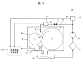
以下、本発明の実施例2の歯車損傷予測装置20と、その監視対象である歯車装置1Bを、図3に沿って説明する。なお、実施例1との共通点は、重複説明を省略する。
A gear
歯車装置のなかには、流量センサ10を搭載しない代わりに、給油ノズル8に向かう配管内の潤滑油の圧力Pを計測する圧力センサ13を搭載したものがある。そこで、本実施例では、潤滑油の流量qを直接計測できない場合であっても、圧力センサ13が計測した圧力Pを用いて潤滑油の流量qを推測し、推測した流量q(以下、「推定流量q1」と称する)を用いて、歯車の損傷時期を予測する。そのため、本実施例の歯車損傷予測装置20では、まず、式3により、推定流量q1を求める。
Some gear devices do not have the
![]()
![]()
ここで、Aは給油ノズル8の形状や表面積に依存する固有値であり、ρは潤滑油の粘度である。粘度ρは、潤滑油の温度に依存するので、給油温度T1と粘度ρの関係を纏めたデータシートにより求めることができる。このデータシートと固有値Aは、事前に記憶部22に格納されている。そして、式3で求めた推定流量q1と、式1、式2を用いることで、実施例1と同様の方法で歯面損傷時期LHを予測できる。
Here, A is an eigenvalue that depends on the shape and surface area of the
以上で説明したように、本実施例によれば、流量センサ10を持たず、圧力センサ13のみを有する歯車装置1Bを監視対象とした場合であっても、歯面損傷時期LHを予測することができる。
As described above, according to the present embodiment, even when the
以下、本発明の実施例3の歯車損傷予測装置20と、その監視対象である歯車装置1Cを、図4と図5に沿って説明する。なお、上述の実施例との共通点は、重複説明を省略する。
A gear
例えば、船舶用歯車減速機などにおいては、前進と後進を行うため、クラッチ操作によりかみ合う歯車対が変化する。また、自動車用トランスミッションにおいても、ギア比の変更時など、かみ合う歯車対が変化する。そこで、以下では、かみ合う歯車対が変化する歯車装置への本発明の適用例を示す。 For example, in a marine gear reducer, the pair of gears that mesh with each other changes depending on the operation of the clutch in order to move forward and backward. Also, in automobile transmissions, meshing gear pairs change when the gear ratio is changed. Therefore, an application example of the present invention to a gear device in which the meshing gear pair changes is shown below.
図4に示す本実施例の歯車装置1Cは、駆動装置(エンジンやモータ等)に接続された入力軸、回転を反対方向にする反転軸、被動装置(プロペラ等)に接続された出力軸、の3つの回転軸を有しており、各々に歯車が取り付けられている。以下では、入力軸に取り付けた歯車を歯車2a、反転軸に取り付けた歯車を歯車2b、出力軸に取り付けた歯車を歯車2cと称する。
A gear device 1C of this embodiment shown in FIG. , and gears are attached to each of them. Hereinafter, the gear attached to the input shaft is referred to as
出力軸を正転させる場合は、入力軸の歯車2aと、出力軸の歯車2cをかみ合わせた歯車対が形成され、出力軸の正転を実現する。一方、出力軸を逆転させる場合は、入力軸の回転は、一度、反転軸へと伝達され、反転軸の歯車2bを駆動する。そして、反転軸の歯車2bと出力軸の歯車2cをかみ合せた歯車対が形成され、出力軸の逆転を実現する。なお、逆転時には、クラッチ操作により、歯車2aから歯車2cへの動力の伝達は行われない。
When the output shaft is to be rotated forward, a gear pair is formed by meshing the
正転時には、給油ノズル8から供給された潤滑油は、歯車2aと歯車2cのかみ合い部から排出される。そこで、その噛み合い部の下流側に設けた油受け12aにおける排油温度T2aを排油温度センサ11aにより計測する。一方、逆転時には、給油ノズル8から供給された潤滑油は、歯車2bと歯車2cのかみ合い部から排出される。そこで、その噛み合い部の下流側に設けた油受け12bにおける排油温度T2bを排油温度センサ11bにより計測する。これらの排油温度は、歯車損傷予測装置20へと入力される。
During forward rotation, the lubricating oil supplied from the
加えて、どの歯車がかみ合っているかを知るためには、運転情報Iが必要である。これは、歯車の回転状態がわかる信号ならよい。例えば、クラッチ操作の信号や別途回転計の信号、当該歯車減速機を搭載する装置に対するオペレータからの運転指示情報などが考えられる。 In addition, driving information I is required to know which gears are in mesh. Any signal that indicates the rotation state of the gear may be used. For example, a clutch operation signal, a separate tachometer signal, and operation instruction information from an operator for a device in which the gear speed reducer is mounted can be considered.
図5は、本実施例の歯車損傷予測装置20での処理手順を示すフローチャートである。まず、処理S1にて、入力された運転情報Iから、出力軸の回転が正転であるか逆転であるかを判断する。正転であれば、処理S2fに進み、逆転であれば、処理S2rに進む。
FIG. 5 is a flow chart showing a processing procedure in the gear
正転の場合、処理S2fでは、入力部21に、給油温度T1、排油温度T2a、流量qが入力される。次に、処理S3fでは、積分演算部23は、累積摩擦エネルギEの積分演算を行う。処理S4fでは、比較部24は、閾値E0と比較し、歯面損傷時期LHを求める。最後に、処理S5fでは、報知部25は、この結果をオペレータ等に報知する。
In the case of forward rotation, in step S2f, the
一方、反転の場合は、処理S2rでは、入力部21に、給油温度T1、排油温度T2b、流量qが入力される。その後、処理S3r~S5rでは、給油温度T1、排油温度T2b、流量qを用いて、正転時の処理S3f~S5fと同様の処理を実行する。
On the other hand, in the case of reversal, in step S2r, the
以上で説明した本実施例の歯車損傷予測方法は、歯車数が3よりも多い場合にも適用できる。その場合、かみ合い歯車ごとに給油、排油温度と給油流量、そしてどの歯車がかみ合っているのかを判断する運転情報が必要となる。言い換えると、複数の歯車が同時にかみ合っている場合、それぞれのかみ合いへ供給される潤滑油の情報を個別に入手する必要がある。 The gear damage prediction method of this embodiment described above can also be applied when the number of gears is more than three. In that case, operation information for judging which gear is engaged is required, as well as oil supply, drain oil temperature and oil flow rate for each meshing gear. In other words, if multiple gears are in mesh at the same time, it is necessary to separately obtain information about the lubricating oil supplied to each mesh.
以上で説明したように、本実施例によれば、かみ合う歯車対が変化する場合であっても、各歯面の損傷時期を予測できる。これにより、クラッチ操作などを有する、より広い歯車製品に適用することができる。 As described above, according to this embodiment, even when the meshing gear pair changes, the damage timing of each tooth flank can be predicted. This makes it applicable to a wider range of gear products, including clutch operations.
以下、本発明の実施例4の歯車損傷予測装置20と、その監視対象である歯車装置1Dを、図6に沿って説明する。なお、上述の実施例との共通点は、重複説明を省略する。
A gear
実施例1~実施例3では、歯車箱3内に排油温度センサ11等を設けた歯車装置1A~1Cを例示したが、歯車箱3の内部に十分なスペースがなく、かみ合い部のそばに排油温度センサを設置できない歯車装置もある。そこで、本実施例では、油槽4内の排油の温度を計測して歯面の損傷時期を予測できるようにした。
In Examples 1 to 3, the
通常、歯車箱3内には、歯車のかみ合い部のみならず、その他の機械要素(例えば、軸受)にも潤滑油が供給されている。実施例1の歯車装置1Aでは、歯車のかみ合い部や軸受に供給された潤滑油は何れも、歯車箱3の下方に設けた油槽4でまとめて回収されるため、油槽4に溜まった排油の温度は、歯車のかみ合いにより発生した摩擦エネルギによる温度上昇と、軸受での回転軸支持により発生した摩擦エネルギによる温度上昇の双方が反映されたものとなる。すなわち、実施例1の構成を前提とすると、油槽4内の排油の温度を用いても、歯面の損傷時期を正確に予測することはできなかった。
In the
そこで、本実施例では、油槽4の流出管と接続した油槽4aと油槽4bを各軸受の直下に設置することで、各軸受から油槽4aまたは油槽4bに落下した潤滑油を、油槽4を経由せずポンプ6で回収できるようにした。
Therefore, in this embodiment, by installing the
この結果、本実施例の歯車装置1Dの油槽4には、歯車のかみ合い部を経由した潤滑油のみが集められるので、油槽4の油温を排油温度センサ11cで計測することで得られた排油温度T2は、歯車のかみ合い部における摩擦エネルギにより昇温したものとなるため、排油温度センサ11cが計測した排油温度T2を用いて、実施例1と同等の方法により、歯面の損傷時期を求める。
As a result, since only the lubricating oil that has passed through the meshing portion of the gear is collected in the oil tank 4 of the
以上で説明したように、本実施例によれば、排油温度センサ11を歯車箱3の内部に設置できない場合でも、歯車装置歯面の損傷時期を予測することができる。
As described above, according to the present embodiment, even if the exhaust
以下、本発明の実施例5の歯車損傷予測システムを、図7に沿って説明する。なお、上述の実施例との共通点は、重複説明を省略する。 A gear damage prediction system according to a fifth embodiment of the present invention will be described below with reference to FIG. It should be noted that duplicate descriptions of the points in common with the above-described embodiment will be omitted.
実施例1では、累積摩擦エネルギEは、歯車損傷予測装置20の記憶部22へと保存される。ここに保存された累積摩擦エネルギEは、歯車装置のメンテナンス時などに、外部のデータ装置と接続されたり、報知部25などを通じて、運転者やメンテナンス者へと伝えられたりする。
In Example 1, the accumulated frictional energy E is stored in the
しかし、例えば交通や輸送用機械の歯車装置に本発明を適用する場合、累積摩擦エネルギEや歯面損傷時期LHを装置ごとに確認することは、稼働装置数の多さから非常に煩雑なものとなる。そこで、本実施例の歯車損傷予測システムでは、複数の歯車装置1Eに設けた歯車損傷予測装置20が求めた累積摩擦エネルギEや歯面損傷時期LHを、インターネット等のネットワーク経由でサーバに収集できるようにした。
However, when the present invention is applied to, for example, a gear device for traffic or transport machinery, checking the cumulative frictional energy E and the tooth surface damage timing LH for each device is extremely complicated due to the large number of operating devices. become a thing. Therefore, in the gear damage prediction system of this embodiment, the accumulated frictional energy E and the tooth surface damage time LH obtained by the gear
図7は、ネットワーク経由で計測情報等を収集できる歯車装置1Eの概念図を示す。
FIG. 7 shows a conceptual diagram of a
ここに示すように、本実施例では、歯車損傷予測装置20にて計算された累積摩擦エネルギEや歯面損傷時期LHを、歯車損傷予測装置20の外部へと発信する。各装置から発信された情報は、サーバ40に蓄積されるので、保守員は監視対象の複数の歯車装置1Eを集中管理することができる。ネットワーク30経由で発信される情報は、給油温度や排油温度、給油量といった計測値でもよく、この場合、歯車損傷予測装置20の内部で行われていた累積摩擦エネルギEの計算が、サーバ40にて行われ、歯面の損傷時期が予測される。
As shown here, in this embodiment, the cumulative frictional energy E and the tooth surface damage timing LH calculated by the gear
以上で説明したように、本実施例によれば、保守員が、より多数の歯車装置1Eの損傷予測が可能となる。また、高頻度な歯車装置の情報を得ることにより、歯車装置の状態を精細に把握し、より適切なメンテナンス時期の提案が可能となる。
As described above, according to this embodiment, maintenance personnel can predict damage to a larger number of
なお、本発明は上記した実施例に限定されるものではなく、様々な変形例が含まれる。例えば、上記した実施例は本発明を分かりやすく説明するために詳細に説明したものであり、必ずしも説明した全ての構成を備えるものに限定されるものではない。また、ある実施例の構成の一部を他の実施例の構成に置き換えることが可能であり、また、ある実施例の構成に他の実施例の構成を加えることも可能である。また、各実施例の構成について、他の構成の追加、削除、置換をすることが可能である。 In addition, the present invention is not limited to the above-described embodiments, and includes various modifications. For example, the above-described embodiments have been described in detail in order to explain the present invention in an easy-to-understand manner, and are not necessarily limited to those having all the described configurations. In addition, it is possible to replace part of the configuration of one embodiment with the configuration of another embodiment, and it is also possible to add the configuration of another embodiment to the configuration of one embodiment. Also, other configurations can be added, deleted, or replaced with respect to the configuration of each embodiment.
1A~1E…歯車装置、
2a~2c…歯車、3…歯車箱、
4、4a、4b…油槽、
5…フィルタ、
6…ポンプ、
7…流量調整バルブ、
8…給油ノズル、
9…給油温度センサ、
10…流量センサ、
11、11a、11b、11c…排油温度センサ、
12、12a、12b…油受け、
13…圧力センサ、
20…歯車損傷予測装置、
30…ネットワーク、
40…サーバ
1A to 1E ... gear device,
2a to 2c... gears, 3... gear boxes,
4, 4a, 4b ... oil tank,
5 Filter,
6 ... pump,
7 ... flow control valve,
8 ... Refueling nozzle,
9 ... refueling temperature sensor,
10... flow rate sensor,
11, 11a, 11b, 11c... Waste oil temperature sensor,
12, 12a, 12b ... oil pan,
13 ... pressure sensor,
20 ... Gear damage prediction device,
30 network,
40 Server
Claims (7)
前記歯車箱に潤滑油を供給する給油ノズルと、
前記給油ノズルに供給される潤滑油の給油温度を計測する給油温度センサと、
前記給油ノズルに供給される潤滑油の流量を計測する流量センサと、
前記歯車対のかみ合い後の潤滑油の排油温度を計測する排油温度センサと、
を有する歯車装置の歯面損傷時期を予測する歯車損傷予測装置であって、
前記給油温度、前記流量、および、前記排油温度を取得する入力部と、
前記入力部が取得した前記排油温度と前記給油温度の差と前記流量から前記歯車対の接触面に生じる摩擦エネルギを計算し、前記摩擦エネルギを積分することで累積摩擦エネルギを計算する積分演算部と、
を具備することを特徴とする歯車損傷予測装置。 a gearbox containing a pair of gears;
an oil supply nozzle that supplies lubricating oil to the gear box;
an oil supply temperature sensor for measuring the oil supply temperature of the lubricating oil supplied to the oil supply nozzle;
a flow sensor for measuring the flow rate of lubricating oil supplied to the oil supply nozzle;
a drain oil temperature sensor for measuring the drain oil temperature of the lubricating oil after meshing of the gear pair;
A gear damage prediction device for predicting the tooth surface damage timing of a gear device having
an input unit that acquires the oil supply temperature, the flow rate, and the drain oil temperature;
Integral operation for calculating the frictional energy generated on the contact surface of the gear pair from the difference between the discharged oil temperature and the supplied oil temperature acquired by the input unit and the flow rate, and calculating the cumulative frictional energy by integrating the frictional energy Department and
A gear damage prediction device comprising:
前記歯車箱に潤滑油を供給する給油ノズルと、
前記給油ノズルに供給される潤滑油の給油温度を計測する給油温度センサと、
前記給油ノズルに供給される潤滑油の圧力を計測する圧力センサと、
前記歯車対のかみ合い後の潤滑油の排油温度を計測する排油温度センサと、
を有する歯車装置の歯面損傷時期を予測する歯車損傷予測装置であって、
前記給油温度、前記圧力、および、前記排油温度を取得する入力部と、
前記入力部が取得した前記圧力に基づいて前記給油ノズルに供給される潤滑油の流量を計算し、前記入力部が取得した前記排油温度と前記給油温度の差と前記流量から前記歯車対の接触面に生じる摩擦エネルギを計算し、前記摩擦エネルギを積分することで累積摩擦エネルギを計算する積分演算部と、
を具備することを特徴とする歯車損傷予測装置。 a gearbox containing a pair of gears;
an oil supply nozzle that supplies lubricating oil to the gear box;
an oil supply temperature sensor for measuring the oil supply temperature of the lubricating oil supplied to the oil supply nozzle;
a pressure sensor that measures the pressure of the lubricating oil supplied to the oil supply nozzle;
a drain oil temperature sensor for measuring the drain oil temperature of the lubricating oil after meshing of the gear pair;
A gear damage prediction device for predicting the tooth surface damage timing of a gear device having
an input unit that acquires the oil supply temperature, the pressure, and the drain oil temperature;
Calculate the flow rate of lubricating oil supplied to the lubrication nozzle based on the pressure acquired by the input unit, and calculate the flow rate of the gear pair from the difference between the drain oil temperature and the oil supply temperature acquired by the input unit and the flow rate an integral calculation unit that calculates the frictional energy generated on the contact surface and integrates the frictional energy to calculate the cumulative frictional energy;
A gear damage prediction device comprising:
前記歯車装置は、
前記歯車箱に第一歯車対と第二歯車対を収納し、
前記第一歯車対のかみ合い後の潤滑油の第一排油温度を計測する第一排油温度センサと、
前記第二歯車対のかみ合い後の潤滑油の第二排油温度を計測する第二排油温度センサと、
を有するものであり、
前記入力部には、さらに、前記第一排油温度、第二排油温度、および、運転情報を取得する入力部と、
前記積分演算部は、前記入力部が取得した前記運転情報に基づいて、かみ合っている歯車対を特定するとともに、前記第一排油温度または前記第二排油温度と前記給油温度の差と前記流量から前記第一歯車対または前記第二歯車対の接触面における摩擦エネルギを計算し、前記摩擦エネルギを積分することで前記第一歯車対または第二歯車対の接触面に生じる累積摩擦エネルギを計算することを特徴とする歯車損傷予測装置。 In the gear damage prediction device according to claim 1 or claim 2,
The gear device is
housing the first gear pair and the second gear pair in the gear box;
a first drain oil temperature sensor that measures the first drain oil temperature of the lubricating oil after the meshing of the first gear pair;
a second drain oil temperature sensor for measuring the second drain oil temperature of the lubricating oil after the meshing of the second gear pair;
and
The input unit further includes an input unit for acquiring the first discharged oil temperature, the second discharged oil temperature, and operation information;
The integral calculation unit identifies the meshed gear pair based on the operation information acquired by the input unit, and determines the difference between the first discharged oil temperature or the second discharged oil temperature and the supply oil temperature Calculating the frictional energy on the contact surface of the first gear pair or the second gear pair from the flow rate, and integrating the frictional energy to obtain the cumulative frictional energy generated on the contact surface of the first gear pair or the second gear pair A gear damage prediction device characterized by calculating.
前記歯車装置には、さらに、
前記歯車対のかみ合い部から落下した潤滑油を回収する第一油槽と、
前記歯車対のかみ合い部以外から落下した潤滑油を回収する第二油槽と、
が設けられており、
前記入力部には、前記排油温度センサが前記第一油槽内の潤滑油から計測した前記排油温度が入力されることを特徴とする歯車損傷予測装置。 In the gear damage prediction device according to claim 1 or claim 2,
The gear device further includes:
a first oil tank for collecting lubricating oil that has fallen from the meshing portion of the gear pair;
a second oil tank for recovering lubricating oil that has fallen from a portion other than the meshing portion of the gear pair;
is provided,
The gear damage prediction device, wherein the input unit receives the exhaust oil temperature measured from the lubricating oil in the first oil tank by the exhaust oil temperature sensor.
さらに、前記摩擦エネルギの増加傾向に基づき、前記累積摩擦エネルギが所定の閾値に到達する歯面損傷時期を推定する比較部を具備することを特徴とする歯車損傷予測装置。 In the gear damage prediction device according to any one of claims 1 to 4,
The gear damage prediction device further comprises a comparison unit for estimating a tooth flank damage timing at which the cumulative friction energy reaches a predetermined threshold based on the increase tendency of the friction energy.
前記歯車損傷予測装置が求めた、累積摩擦エネルギまたは歯面損傷時期を前記サーバへ送信することを特徴とする歯車損傷予測システム。 A gear damage prediction system in which the gear damage prediction device according to claim 5 and a server are connected via a network,
A gear damage prediction system, wherein the accumulated frictional energy or the tooth surface damage timing obtained by the gear damage prediction device is transmitted to the server.
前記歯車箱に潤滑油を供給する給油ノズルと、
を有する歯車装置の歯車損傷時期を予測する歯車損傷予測方法であって
前記給油ノズルに供給される前記潤滑油の給油温度を計測し、
前記給油ノズルに供給される前記潤滑油の流量を計測し、
前記歯車対のかみ合い後の前記潤滑油の排油温度を計測し、
前記給油温度と前記排油温度の差と前記流量から前記歯車対の接触面に生じる摩擦エネルギを計算し、
前記摩擦エネルギを積分することで累積摩擦エネルギを推定し、
前記摩擦エネルギの増加傾向に基づき、前記累積摩擦エネルギが所定の閾値に到達する歯面損傷時期を推定することを特徴とする歯車損傷予測方法。 a gearbox containing a pair of gears;
an oil supply nozzle that supplies lubricating oil to the gear box;
A gear damage prediction method for predicting the gear damage timing of a gear device having
measuring the flow rate of the lubricating oil supplied to the lubricating nozzle;
measuring the drained oil temperature of the lubricating oil after meshing of the gear pair;
calculating the frictional energy generated on the contact surface of the gear pair from the difference between the supplied oil temperature and the discharged oil temperature and the flow rate;
estimating cumulative frictional energy by integrating the frictional energy;
A gear damage prediction method, comprising: estimating a tooth surface damage timing at which the cumulative friction energy reaches a predetermined threshold based on the increase tendency of the friction energy.
Priority Applications (1)
| Application Number | Priority Date | Filing Date | Title |
|---|---|---|---|
| JP2019108468A JP7254635B2 (en) | 2019-06-11 | 2019-06-11 | GEAR DAMAGE PREDICTION DEVICE, GEAR DAMAGE PREDICTION SYSTEM, AND GEAR DAMAGE PREDICTION METHOD |
Applications Claiming Priority (1)
| Application Number | Priority Date | Filing Date | Title |
|---|---|---|---|
| JP2019108468A JP7254635B2 (en) | 2019-06-11 | 2019-06-11 | GEAR DAMAGE PREDICTION DEVICE, GEAR DAMAGE PREDICTION SYSTEM, AND GEAR DAMAGE PREDICTION METHOD |
Publications (2)
| Publication Number | Publication Date |
|---|---|
| JP2020200892A JP2020200892A (en) | 2020-12-17 |
| JP7254635B2 true JP7254635B2 (en) | 2023-04-10 |
Family
ID=73743940
Family Applications (1)
| Application Number | Title | Priority Date | Filing Date |
|---|---|---|---|
| JP2019108468A Active JP7254635B2 (en) | 2019-06-11 | 2019-06-11 | GEAR DAMAGE PREDICTION DEVICE, GEAR DAMAGE PREDICTION SYSTEM, AND GEAR DAMAGE PREDICTION METHOD |
Country Status (1)
| Country | Link |
|---|---|
| JP (1) | JP7254635B2 (en) |
Families Citing this family (2)
| Publication number | Priority date | Publication date | Assignee | Title |
|---|---|---|---|---|
| US12000821B2 (en) * | 2020-06-10 | 2024-06-04 | Bd. of Supervisors of La. St. Univ. & A&MCollege | Fluid monitoring |
| CN119957356B (en) * | 2024-12-26 | 2025-11-25 | 沪东重机(镇江)有限公司 | A diesel engine sliding bearing temperature monitoring and protection device |
Citations (1)
| Publication number | Priority date | Publication date | Assignee | Title |
|---|---|---|---|---|
| JP2018115722A (en) | 2017-01-19 | 2018-07-26 | 株式会社日立ニコトランスミッション | Gear temperature control system and gear temperature control method |
Family Cites Families (1)
| Publication number | Priority date | Publication date | Assignee | Title |
|---|---|---|---|---|
| JPH11337449A (en) * | 1998-05-27 | 1999-12-10 | Hitachi Ltd | Gear device |
-
2019
- 2019-06-11 JP JP2019108468A patent/JP7254635B2/en active Active
Patent Citations (1)
| Publication number | Priority date | Publication date | Assignee | Title |
|---|---|---|---|---|
| JP2018115722A (en) | 2017-01-19 | 2018-07-26 | 株式会社日立ニコトランスミッション | Gear temperature control system and gear temperature control method |
Also Published As
| Publication number | Publication date |
|---|---|
| JP2020200892A (en) | 2020-12-17 |
Similar Documents
| Publication | Publication Date | Title |
|---|---|---|
| US9109748B2 (en) | Machine conditioning monitoring closed loop lubrication system and method | |
| US20210372466A1 (en) | Model-based method and system for monitoring the condition of a sliding bearing, particularly for wind turbines | |
| EP3538764B1 (en) | Pump efficiency of a fluid pump | |
| JP6817446B2 (en) | Close test evaluation module for valve and actuator monitoring systems | |
| EP2959347B1 (en) | A method and an apparatus for predicting the condition of a machine or a component of the machine | |
| JP6812555B2 (en) | Advanced startup counter module for valve and actuator monitoring systems | |
| JP6828167B2 (en) | Guided condition assessment module for valve and actuator monitoring systems | |
| JP7254635B2 (en) | GEAR DAMAGE PREDICTION DEVICE, GEAR DAMAGE PREDICTION SYSTEM, AND GEAR DAMAGE PREDICTION METHOD | |
| CN106575117A (en) | System for diagnosing oil properties in working machine | |
| JPH07294365A (en) | Method and apparatus for display of pump efficiency | |
| JP5011052B2 (en) | Gear device | |
| JP6801112B2 (en) | Solid particle corrosion indicator module for valve and actuator monitoring systems | |
| KR20230072255A (en) | Fault detecting system for vacuum pump | |
| JP5990729B1 (en) | General-purpose deterioration curve creation method and machine life prediction method, and general-purpose deterioration curve creation program and machine life prediction program | |
| WO2018041849A1 (en) | Valve stroke and spindle way counter module for a valve and actuator monitoring system | |
| WO2018041846A1 (en) | Advanced tightness test evaluation module for a valve and actuator monitoring system | |
| CN110083962A (en) | A kind of prediction technique and forecasting system of centrifugal pump main shaft service life | |
| JP2765157B2 (en) | Bearing abnormality monitoring device | |
| WO2023023328A2 (en) | Working fluid system monitoring based on heat exchanger parameters | |
| JP4037854B2 (en) | Construction machine travel drive control device | |
| JP2007248228A (en) | Bearing section monitoring device, grease-supplying apparatus and operation machine | |
| JP2018115722A (en) | Gear temperature control system and gear temperature control method | |
| Drumea et al. | Methods of diagnosing malfunctions in hydraulic actuations | |
| CN109642624A (en) | Monitoring to fluid connector | |
| JP2002168242A (en) | Thrust bearing abnormality detection device and method |
Legal Events
| Date | Code | Title | Description |
|---|---|---|---|
| A621 | Written request for application examination |
Free format text: JAPANESE INTERMEDIATE CODE: A621 Effective date: 20220411 |
|
| TRDD | Decision of grant or rejection written | ||
| A977 | Report on retrieval |
Free format text: JAPANESE INTERMEDIATE CODE: A971007 Effective date: 20230221 |
|
| A01 | Written decision to grant a patent or to grant a registration (utility model) |
Free format text: JAPANESE INTERMEDIATE CODE: A01 Effective date: 20230228 |
|
| A61 | First payment of annual fees (during grant procedure) |
Free format text: JAPANESE INTERMEDIATE CODE: A61 Effective date: 20230329 |
|
| R150 | Certificate of patent or registration of utility model |
Ref document number: 7254635 Country of ref document: JP Free format text: JAPANESE INTERMEDIATE CODE: R150 |