JP7254000B2 - Image delivery device and method, and image delivery system - Google Patents
Image delivery device and method, and image delivery system Download PDFInfo
- Publication number
- JP7254000B2 JP7254000B2 JP2019143261A JP2019143261A JP7254000B2 JP 7254000 B2 JP7254000 B2 JP 7254000B2 JP 2019143261 A JP2019143261 A JP 2019143261A JP 2019143261 A JP2019143261 A JP 2019143261A JP 7254000 B2 JP7254000 B2 JP 7254000B2
- Authority
- JP
- Japan
- Prior art keywords
- vehicle
- image
- information
- time
- target
- Prior art date
- Legal status (The legal status is an assumption and is not a legal conclusion. Google has not performed a legal analysis and makes no representation as to the accuracy of the status listed.)
- Active
Links
Images


Description
本発明は、画像配信装置及び方法並びに画像配信システムに関する。 The present invention relates to an image delivery device and method, and an image delivery system.
ドライブレコーダにより、自車両の外部又は内部の様子を撮影及び記録することができる。また、自車両に設置された複数のカメラの撮影結果に基づき、自車両の周囲の俯瞰画像を生成及び表示する技術もある。これらは何れも、自車両の外部又は内部の様子を撮影し画像化するものであって、自車両そのものを撮影する技術ではない。 The drive recorder can photograph and record the state of the exterior or interior of the own vehicle. There is also a technique for generating and displaying a bird's-eye view image of the surroundings of the own vehicle based on the photographed results of a plurality of cameras installed on the own vehicle. All of these are techniques for photographing and imaging the state of the exterior or interior of the own vehicle, and are not techniques for photographing the own vehicle itself.
車両の所有者は、自車両を自身で運転している際、自車両の外観を確認する機会を持たない。車両の所有者が走行中の自車両の外観を確認するためには、他の人間に自車両を運転してもらい、その時の自車両の様子を外から確認するしか術はない。 Vehicle owners do not have the opportunity to check the appearance of their vehicle when they are driving it themselves. In order for the owner of the vehicle to check the appearance of the own vehicle while it is running, there is no other way but to have another person drive the own vehicle and check the state of the own vehicle at that time from the outside.
一方、走行中の車両を撮影した画像(映像)はローリングショットと呼ばれ、自車両のローリングショットを友人や知人に撮影してもらって鑑賞するといったニーズが自動車愛好家の中で一定数あり、SNS等でも、その様を確認できる。また、趣味性の高いローリングショット収集以外にも、自車両の走行中の外観を確認できたならば、例えば車両の灯火装置(ブレーキランプ等)の故障やトラックの荷崩れのように、走行中の車両の運転手が気付きにくい異常の検知にも役立つ、と考えられる。 On the other hand, an image (video) taken of a moving vehicle is called a rolling shot, and there is a certain number of car enthusiasts who want to have friends and acquaintances take a rolling shot of their own vehicle for viewing. etc., you can check that. Also, in addition to collecting rolling shots, which is a hobby, if you can check the appearance of your vehicle while it is running, you can check the appearance of your vehicle while driving, such as a failure of the vehicle's lighting device (brake lamp, etc.) or a collapse of the truck's cargo. It is thought that it will also be useful for detecting abnormalities that are difficult for the driver of the vehicle to notice.
本発明は、車両の外観を撮影した画像の当該車両への配信を可能とする画像配信装置及び方法並びに画像配信システムを提供することを目的とする。 SUMMARY OF THE INVENTION It is an object of the present invention to provide an image distribution apparatus, method, and image distribution system that enable distribution of an image obtained by photographing the exterior of a vehicle to the vehicle.
本発明に係る画像配信装置は、第1車両及び第2車両に設置された各車載装置と通信を行う処理部であって、前記第2車両の設置カメラの撮影画像である第2車両撮影画像の画像情報を受信可能な通信処理部と、前記通信処理部を用いて、前記第1車両の車載装置から各時刻における前記第1車両の位置情報を取得するとともに前記第2車両の車載装置から各時刻における前記第2車両の位置情報を取得する位置情報取得部と、各時刻における前記第1車両の位置情報及び各時刻における前記第2車両の位置情報に基づき、前記第1車両及び前記第2車両間の相対位置関係が所定の条件を満たす対象時間帯を設定する対象時間帯設定部と、前記対象時間帯における1以上の前記第2車両撮影画像を判定画像として参照し、前記判定画像と予め提供された前記第1車両の外観特徴情報に基づいて前記判定画像内に前記第1車両の画像が含まれているか否かを判定する車両画像判定部と、前記判定画像内に前記第1車両の画像が含まれていると判定されたとき、前記対象時間帯の全部又は一部において前記第2車両の設置カメラにより生成された前記第2車両撮影画像に基づく配信画像の画像情報を、前記通信処理部を用いて前記第1車両の車載装置に送信する画像配信部と、を備えた構成(第1の構成)である。 The image delivery device according to the present invention is a processing unit that communicates with each on-vehicle device installed in a first vehicle and a second vehicle, and is a second vehicle captured image that is a captured image of a camera installed in the second vehicle. and a communication processing unit capable of receiving the image information of, and using the communication processing unit, acquiring position information of the first vehicle at each time from the in-vehicle device of the first vehicle and from the in-vehicle device of the second vehicle a position information acquisition unit that acquires position information of the second vehicle at each time; and based on the position information of the first vehicle at each time and the position information of the second vehicle at each time, the first vehicle and the second vehicle A target time period setting unit for setting a target time period in which a relative positional relationship between two vehicles satisfies a predetermined condition; and a vehicle image determination unit that determines whether or not the image of the first vehicle is included in the determination image based on external appearance feature information of the first vehicle provided in advance; When it is determined that the image of one vehicle is included, the image information of the distributed image based on the second vehicle captured image generated by the camera installed in the second vehicle in all or part of the target time period and an image distribution unit that transmits the image to an in-vehicle device of the first vehicle using the communication processing unit (first configuration).
上記第1の構成に係る画像配信装置において、前記対象時間帯設定部は、各時刻における前記第1車両の位置情報及び各時刻における前記第2車両の位置情報に基づき、前記第1車両及び前記第2車両間の距離が所定値以下となる時間帯を前記対象時間帯として設定する構成(第2の構成)であっても良い。 In the image delivery device according to the first configuration, the target time period setting unit, based on the position information of the first vehicle at each time and the position information of the second vehicle at each time, the first vehicle and the A configuration (second configuration) may be adopted in which a time period in which the distance between the second vehicles is equal to or less than a predetermined value is set as the target time period.
上記第1又は第2の構成に係る画像配信装置において、前記車両画像判定部は、前記対象時間帯において前記第2車両の設置カメラにより生成された時系列上のnA枚の第2車両撮影画像の内、nB枚の第2車両撮影画像を前記判定画像として参照する(nAは2以上の整数であって、nBはnAより小さな1以上の整数)構成(第3の構成)であっても良い。 In the image distribution device according to the first or second configuration, the vehicle image determination unit includes n A images of the second vehicle in the time series generated by the camera installed in the second vehicle in the target time period. Of the images, n B second vehicle captured images are referred to as the judgment images (n A is an integer of 2 or more, and n B is an integer of 1 or more smaller than n A ) configuration (third configuration ) may be
上記第1~第3の構成の何れかに係る画像配信装置において、前記車両画像判定部は、前記判定画像と、前記第1車両の外観特徴情報と、前記判定画像の撮影時刻における前記第1車両及び前記第2車両間の相対位置関係と、基づいて、前記判定画像内に前記第1車両の画像が含まれているか否かを判定する構成(第4の構成)であっても良い。 In the image delivery device according to any one of the first to third configurations, the vehicle image determination unit includes the determination image, the appearance characteristic information of the first vehicle, and the first vehicle at the time when the determination image was captured. A configuration (fourth configuration) may be employed in which it is determined whether or not the image of the first vehicle is included in the determination image based on the relative positional relationship between the vehicle and the second vehicle.
上記第1~第4の構成の何れかに係る画像配信装置において、前記画像配信部は、前記判定画像内に前記第1車両の画像が含まれていると判定されたとき、前記対象時間帯の全部又は一部である切り出し時間帯において前記第2車両の設置カメラにより生成された時系列上の複数の第2車両撮影画像を複数の原画像として参照し、各原画像の撮影時刻における前記第1車両及び前記第2車両間の相対位置関係並びに前記第1車両の外観特徴情報に基づいて、前記原画像ごとに前記原画像の一部に基づく画像であって且つ前記第1車両の画像を含む部分画像を生成する部分画像生成処理を実行し、前記複数の原画像に対して生成した複数の部分画像を時系列上に並べて構成される動画像を前記配信画像として生成する構成(第5の構成)であっても良い。 In the image distribution device according to any one of the first to fourth configurations, the image distribution unit, when it is determined that the image of the first vehicle is included in the determination image, the target time period Referring to a plurality of time-series captured images of the second vehicle generated by the camera installed on the second vehicle in the cut-out time period that is all or part of the above as a plurality of original images, An image based on a part of the original image for each of the original images, based on the relative positional relationship between the first vehicle and the second vehicle and the appearance feature information of the first vehicle, and the image of the first vehicle. and executing a partial image generation process for generating a partial image containing the plurality of original images, and generating a moving image configured by arranging the plurality of partial images generated for the plurality of original images in time series as the distribution image (first 5) may be used.
上記第5の構成に係る画像配信装置において、前記第2車両の設置カメラは全方位カメラであり、前記部分画像生成処理は第1部分画像生成処理及び第2部分画像生成処理を含み、前記第1部分画像生成処理及び前記第2部分画像生成処理は前記原画像ごとに実行され、前記画像配信部は、前記第1部分画像生成処理において、前記原画像の撮影時刻における前記第1車両及び前記第2車両間の相対位置関係に基づいて前記原画像内における前記第1車両の存在画像領域を推定し、推定領域の位置を基準に切り出し画像領域を前記原画像内に設定して前記切り出し画像領域内の画像に対し幾何学的変換を含む所定の第1画像処理を施すことにより第1部分画像を生成し、前記第2部分画像生成処理において、前記第1車両の外観特徴情報に基づき前記第1部分画像内における前記第1車両の画像の位置を特定し、特定した位置に基づき前記切り出し画像領域の位置を補正して補正後の前記切り出し画像領域内の画像に対し幾何学的変換を含む所定の第2画像処理を施すことにより第2部分画像を生成し、前記配信画像は、前記複数の原画像に対して生成した複数の第2部分画像を時系列上に並べて構成される動画像である構成(第6の構成)であっても良い。 In the image delivery device according to the fifth configuration, the camera installed on the second vehicle is an omnidirectional camera, the partial image generation processing includes a first partial image generation processing and a second partial image generation processing, and the The one partial image generation process and the second partial image generation process are executed for each of the original images, and the image distribution unit performs the first partial image generation process on the first vehicle and the estimating an existing image region of the first vehicle in the original image based on the relative positional relationship between the second vehicles, setting a cutout image region in the original image based on the position of the estimated region, and setting the cutout image; A first partial image is generated by performing predetermined first image processing including geometric transformation on an image within the region, and in the second partial image generation processing, based on the appearance feature information of the first vehicle. specifying the position of the first vehicle image in the first partial image, correcting the position of the clipped image area based on the specified position, and geometrically transforming the corrected image in the clipped image area; second partial images are generated by performing predetermined second image processing including A configuration (sixth configuration) that is an image may be used.
本発明に係る画像配信システムは、上記第1~第6の構成の何れかに係る画像配信装置と、第1車両に設置された第1車載装置と、第2車両に設置された第2車載装置と、を備えた画像配信システムであって、前記第1車載装置は、第1車載制御部と、前記第1車両の位置情報を順次生成する第1位置情報生成部と、前記画像配信装置と通信を行う第1通信処理部と、を備え、前記第2車載装置は、第2車載制御部と、前記第2車両の位置情報を順次生成する第2位置情報生成部と、前記画像配信装置と通信を行う第2通信処理部と、を備え、前記第1車載制御部は、順次生成される前記第1車両の位置情報を、前記第1通信処理部を用いて、前記画像配信装置に対して順次送信し、前記第2車載制御部は、順次生成される前記第2車両の位置情報を、前記第2通信処理部を用いて、前記画像配信装置に対して順次送信し、前記第2車両の設置カメラは、前記第2車載装置に接続され又は前記第2車載装置の構成要素に含まれ、所定のフレームレートで前記第2車両撮影画像の画像情報を生成し、前記第2車載制御部は、前記画像配信装置からの送信要求信号に応答し、前記送信要求信号にて指定された時間帯の前記第2車両撮影画像の画像情報を、前記第2通信処理部を用いて前記画像配信装置に送信する、又は、前記第2車両の設置カメラにて順次生成される前記第2車両撮影画像の画像情報を、前記第2通信処理部を用いて所定の送信タイミングで前記画像配信装置に送信する構成(第7の構成)である。 An image delivery system according to the present invention comprises an image delivery device according to any one of the first to sixth configurations, a first vehicle-mounted device installed in a first vehicle, and a second vehicle-mounted device installed in a second vehicle. a device, wherein the first vehicle-mounted device includes a first vehicle-mounted control unit; a first position information generation unit that sequentially generates position information of the first vehicle; and the image distribution device. a first communication processing unit that communicates with the second vehicle-mounted device, the second vehicle-mounted device includes: a second vehicle-mounted control unit; a second location information generation unit that sequentially generates location information of the second vehicle; a second communication processing unit that communicates with a device, wherein the first vehicle-mounted control unit uses the first communication processing unit to transmit position information of the first vehicle that is sequentially generated to the image distribution device; The second vehicle-mounted control unit sequentially transmits the position information of the second vehicle that is sequentially generated to the image distribution device using the second communication processing unit, and the A camera mounted on a second vehicle is connected to the second vehicle-mounted device or included in a component of the second vehicle-mounted device, generates image information of the second vehicle-captured image at a predetermined frame rate, The in-vehicle control unit responds to a transmission request signal from the image distribution device, and uses the second communication processing unit to transmit the image information of the second captured image of the vehicle in the time period specified by the transmission request signal. The image information of the second vehicle captured image that is transmitted to the image distribution device or sequentially generated by the camera installed in the second vehicle is transmitted to the image at a predetermined transmission timing using the second communication processing unit. This is the configuration (seventh configuration) for transmission to the distribution device.
本発明に係る画像配信方法は、第1車両及び第2車両に設置された各車載装置と通信を行う通信処理部を用いて、前記第2車両の設置カメラの撮影画像である第2車両撮影画像の画像情報を受信する通信処理ステップと、前記通信処理部を用いて、前記第1車両の車載装置から各時刻における前記第1車両の位置情報を取得するとともに前記第2車両の車載装置から各時刻における前記第2車両の位置情報を取得する位置情報取得ステップと、各時刻における前記第1車両の位置情報及び各時刻における前記第2車両の位置情報に基づき、前記第1車両及び前記第2車両間の相対位置関係が所定の条件を満たす対象時間帯を設定する対象時間帯設定ステップと、前記対象時間帯における1以上の前記第2車両撮影画像を判定画像として参照し、前記判定画像と予め提供された前記第1車両の外観特徴情報に基づいて前記判定画像内に前記第1車両の画像が含まれているか否かを判定する車両画像判定ステップと、前記判定画像内に前記第1車両の画像が含まれていると判定されたとき、前記対象時間帯の全部又は一部において前記第2車両の設置カメラにより生成された前記第2車両撮影画像に基づく配信画像の画像情報を、前記通信処理部を用いて前記第1車両の車載装置に送信する画像配信ステップと、を備えた構成(第8の構成)である。 An image delivery method according to the present invention uses a communication processing unit that communicates with each on-vehicle device installed in a first vehicle and a second vehicle. a communication processing step of receiving image information of an image; and acquiring position information of the first vehicle at each time from an in-vehicle device of the first vehicle using the communication processing unit and from an in-vehicle device of the second vehicle. a position information acquisition step of acquiring position information of the second vehicle at each time; and based on the position information of the first vehicle at each time and the position information of the second vehicle at each time, the first vehicle and the second vehicle a target time zone setting step of setting a target time zone in which a relative positional relationship between two vehicles satisfies a predetermined condition; a vehicle image determination step of determining whether or not the image of the first vehicle is included in the determination image based on external appearance feature information of the first vehicle provided in advance; When it is determined that the image of one vehicle is included, the image information of the distributed image based on the second vehicle captured image generated by the camera installed in the second vehicle in all or part of the target time period , and an image delivery step of transmitting the image to an in-vehicle device of the first vehicle using the communication processing unit (eighth configuration).
本発明によれば、車両の外観を撮影した画像の当該車両への配信を可能とする画像配信装置及び方法並びに画像配信システムを提供することが可能となる。 According to the present invention, it is possible to provide an image delivery apparatus, method, and image delivery system that enable delivery of an image of the exterior of a vehicle to the vehicle.
以下、本発明の実施形態の例を、図面を参照して具体的に説明する。参照される各図において、同一の部分には同一の符号を付し、同一の部分に関する重複する説明を原則として省略する。尚、本明細書では、記述の簡略化上、情報、信号、物理量又は部材等を参照する記号又は符号を記すことによって、該記号又は符号に対応する情報、信号、物理量又は部材等の名称を省略又は略記することがある。例えば、後述の“610”によって参照される自車両画像配信要求信号は(図9参照)、自車両画像配信要求信号610と表記されることもあるし、要求信号610と略記されることもあり得るが、それらは全て同じものを指す。
Hereinafter, examples of embodiments of the present invention will be specifically described with reference to the drawings. In each figure referred to, the same parts are denoted by the same reference numerals, and redundant descriptions of the same parts are omitted in principle. In this specification, for simplification of description, by describing symbols or codes that refer to information, signals, physical quantities, or members, etc., the names of information, signals, physical quantities, or members, etc. corresponding to the symbols or codes are It may be omitted or abbreviated. For example, the vehicle image distribution request signal referred to by "610" (see FIG. 9) may be referred to as the vehicle image
<<第1実施形態>>
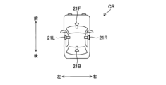
本発明の第1実施形態を説明する。図1に、本発明の第1実施形態に係るドライブレコーダ1の構成を、その周辺装置と共に示す。図2に示す如く、ドライブレコーダ1は車両CRに搭載される。車両CRは路面上を走行可能な車両(自動車等)であれば任意である。車両CRに注目して前後左右を以下のように定義する。車両CRの運転席から車両CRのステアリングホイールに向かう向きを「前方」と定義し、車両CRのステアリングホイールから運転席に向かう向きを「後方」と定義する。前方及び後方間を結ぶ方向は車両CRの直進進行方向に平行であり、車両CRが水平な路面を走行する際、直進進行方向は水平面に対して平行である。車両CRにおいて、運転手は前を向いて運転席に座っているものとし、運転手の左側から右側に向かう向きを「右方向」と定義し、且つ、運転手の右側から左側に向かう向きを「左方向」と定義する。左右方向は、車両CRの直進進行方向及び鉛直線に対して垂直な方向である。また、「上方向」、「下方向」は、夫々、運転手から見た上方向、下方向を指すものとする。
<<First Embodiment>>
A first embodiment of the present invention will be described. FIG. 1 shows the configuration of a
ドライブレコーダ1に対し複数の周辺装置が接続される。ここにおける複数の周辺装置も、ドライブレコーダ1と同様に車両CRに設置される。複数の周辺装置は、カメラ部21、車載センサ部22、GPS処理部23、計時部24及びインターフェース装置30を含む。各周辺装置とドライブレコーダ1との間の情報のやり取りは、車両CR内に形成されたCAN(Controller Area Network)を通じて行われる。
A plurality of peripheral devices are connected to the
カメラ部21は車両CRに設置された1以上のカメラから成る。カメラ部21を構成する各カメラは、自身の撮影範囲(視野)内の風景を所定のフレームレートで順次撮影して、撮影結果を示す撮影画像の画像情報(画像データ)を含むカメラ情報を順次ドライブレコーダ1に送る。尚、カメラ部21はマイクロホンを有していても良く、この場合、車両CRの外部又は内部の音を表す音声情報(音声データ)もカメラ部21にて生成され、生成された音声情報も画像情報に付加された態様でカメラ部21からドライブレコーダ1に送られる。
The
車載センサ部22は、車両CRに設置された複数の車載センサから成り、各車載センサを用いて車両情報を検出及び取得する。車両情報は所定周期で順次取得され、取得された車両情報は順次ドライブレコーダ1に送られる。車両情報は、車両CRの速度を表す車速情報、車両CRに設けられたアクセルペダルの踏み込み量を表すアクセル情報、車両CRに設けられたブレーキペダルの踏み込み量を表すブレーキ情報、及び、車両CRに設けられたステアリングホイールの操舵角を表す操舵角情報などを含む。上記複数の車載センサには加速度センサも含まれ、加速度センサから出力される加速度情報も上記車両情報に含まれる。加速度センサは、互いに直交する3軸又は2軸の夫々の方向において車両CRの加速度を検出し、その検出結果を示す加速度情報を出力する。
The vehicle-mounted
GPS処理部23は、GPS(Global Positioning System)を形成する複数のGPS衛星からの信号を受信することで車両CRの位置(現在地)を検出し、検出位置を示す位置情報を求める。位置情報では、車両CRの位置(現在地)が、地球上における経度及び緯度によって表現される。GPS処理部23は、位置情報を所定周期で順次生成し、生成した位置情報を順次ドライブレコーダ1に送る。
The
計時部24は、現在の日付及び時刻を示す時刻情報を生成してドライブレコーダ1に送る。GPS処理部23の受信信号を用いて時刻情報が生成又は修正されても良い。
The
インターフェース装置30は、ドライブレコーダ1と車両CRの搭乗者(主として運転手)との間のマンマシンインターフェースであり、表示部31、スピーカ32及び操作部33を備える。表示部31は液晶ディスプレイパネル等にて構成される表示装置であり、車載制御部110の制御の下で任意の画像を表示できる。スピーカ32は車載制御部110の制御の下で任意の音を出力できる。操作部33は車両CRの搭乗者(主として運転手)から任意の操作を受け付ける。表示部31及び操作部33によりタッチパネルが構成されていても良い。表示部31、スピーカ32及び操作部33は、車両CRに設置されうるカーナビゲーション装置(不図示)の構成要素であっても良い。
The
[ドライブレコーダの構成及び機能]
ドライブレコーダ1は、車載制御部110、記録媒体120及び通信処理部130を備える。車載制御部110は、CPU(Central Processing Unit)、ROM(Read only memory)及びRAM(Random access memory)等にて構成され、ROMに格納されたプログラムをCPUが実行することで、車載制御部110が実現すべき様々な機能を実現する。記録媒体120は、車載制御部110の制御の下、任意の情報の読み書きが可能な任意の記録媒体である。記録媒体120は、ドライブレコーダ1に対して任意に装着及び脱着が可能な記録媒体であって良く、例えばSDカードに代表されるメモリカードである。通信処理部130は、ドライブレコーダ1とは別の装置との間で無線通信を行うための通信処理ブロックである。
[Configuration and function of drive recorder]
The
車載制御部110は、記録媒体120に対して通常記録制御とイベント記録制御を行うことができる。ここでは例として、記録媒体120の全記録領域に、通常記録制御用の通常記録領域とイベント記録制御用のイベント記録領域とが設けられていることを想定する。
The in-
通常記録制御を説明する。車載制御部110は、車両CRのエンジン始動を契機にして通常記録制御を開始することができ、その後、車両CRのエンジンが停止するまで通常記録制御を継続実行することができる。車両CRのエンジン始動を契機にして通常記録制御を開始した後、車両CRのエンジンが停止したとしても一定時間は通常記録制御を継続実行し、エンジンが一定時間を超えて停止していた場合に限り、通常記録制御を終了するようにしても良い。
Normal recording control will be explained. The in-
通常記録制御では、カメラ部21から順次得られるカメラ情報が時系列に沿って記録媒体120の通常記録領域に順次記録されてゆく。この際、非カメラ情報もカメラ情報に関連付けられた状態で通常記録領域に記録される。即ち、通常記録制御において、或る時刻で取得されたカメラ情報及び非カメラ情報は互いに関連付けられた状態で通常記録領域に記録される。非カメラ情報は車両情報、位置情報及び時刻情報を含む。通常記録制御において通常記録領域に記録されるカメラ情報及び非カメラ情報から成る情報を通常情報と称する。記録媒体120の通常記録領域は一定時間分の通常情報を記録できるだけの記録容量を有し、通常記録制御において、通常記録領域に空き領域が無くなると最も古い時刻に取得された通常情報に対し新たな通常情報を上書きしてゆく。
In the normal recording control, the camera information sequentially obtained from the
通常記録制御がエンジン停止時を除き常時実行されるのに対し、イベント記録制御は、イベントの発生時においてのみ実行される。所定のイベント条件の成立がイベントの発生に相当する。車載制御部110は、カメラ情報又は車両情報に基づいてイベント条件の成否を判定し、イベント条件の成立を契機にイベント記録制御を実行する。例えば、車載制御部110は、上記加速度情報に基づき車両CRに発生した加速度の絶対値をG値として算出し、所定閾値以上のG値が観測されたとき、イベントの1つであるGイベントが発生したと判断する(即ちイベント条件が成立する)。
While normal recording control is always executed except when the engine is stopped, event recording control is executed only when an event occurs. Establishment of a predetermined event condition corresponds to generation of an event. The in-
車載制御部110は、イベント条件が成立すると、イベント条件の成立タイミングから所定時間Δt1だけ前のタイミングを始期とし且つイベント条件の成立タイミングから所定時間Δt2だけ後のタイミングを終期とするイベント保護期間を設定し、イベント保護期間におけるカメラ情報及び非カメラ情報から成る情報をイベント情報として記録媒体120のイベント記録領域に記録する。車載制御部110は、少なくとも所定時間Δt1分のカメラ情報及び非カメラ情報を一時的に保持するバッファメモリを有していて良く、バッファメモリを用いてイベント記録制御を実現して良い。記録媒体120のイベント記録領域は一定時間分のイベント情報を記録できるだけの記録容量を有する。イベント記録制御において、イベント記録領域に対するイベント情報の上書きは禁止されている。従って、イベント記録領域に空き領域が無い状態で、新たにイベントが発生したとき、その新たに発生したイベントについてのイベント情報はイベント記録領域に記録されない。
When the event condition is satisfied, the in-
[カメラ部の構成(全方位カメラ)]
第1実施形態では、カメラ部21に全方位カメラ21Cが備えられているものとする(図3参照)。全方位カメラ21Cは、全方位カメラ21Cの周囲360°の風景を同時に撮影可能なカメラである。このため、車両CRにおいて、全方位カメラ21Cは車両2の最も高い位置、例えば車両CRの屋根の上に設置される。
[Camera configuration (omnidirectional camera)]
In the first embodiment, it is assumed that the
図4(a)は全方位カメラ21Cを用いて周囲の風景500を撮影する場合の模式図である。全方位カメラ21Cは全方位の風景500を撮影する。全方位カメラ21Cを用いて撮影されるべき全方位の風景500とは、車両CRの全方位の風景である。尚、ここにおける全方位とは水平方向における全方位である。故に、全方位カメラ21Cは水平方向において360°の画角を持ち、全方位カメラ21Cにより撮影される全方位の風景500は、車両CRの前方の風景、車両CRの右側の風景、車両CRの左側の風景及び車両CRの後方の風景を含むことになる。全方位カメラ21Cの垂直方向における画角は180°である又は180°未満の所定値であり、少なくとも全方位カメラ21Cの真下は全方位カメラ21Cの撮影範囲外である。このような全方位カメラ21Cは半天球カメラとも称される。但し、全方位カメラ21Cとして全天球カメラを用いても構わない。
FIG. 4(a) is a schematic diagram of the surrounding
全方位カメラ21Cは、曲面ミラー(図4(a)の斜線部に対応)を有して曲面ミラーにより風景500に基づく全方位からの入射光を集光し、曲面ミラー下部の焦点位置に配置された撮像部(CCD又はCMOSイメージセンサ)を用いて、曲面ミラーに映った円環状の風景500を撮影する(即ち画像化する)。この撮影(画像化)により、風景500の円環状の撮影画像が得られる。図4(b)に風景500の撮影により得られる円環状の撮影画像510を示す。全方位カメラ21Cにより生成される円環状の撮影画像510の画像情報はドライブレコーダ1に送られる。
The
車載制御部110は、円環状の撮影画像510に対して幾何学的変換を含む所定の展開画像処理を施すことで、円環状の撮影画像510を展開したパノラマ画像520を生成できて良い(図4(c)参照)。車載制御部110は上記展開画像処理を行う機能を持たない場合もある。パノラマ画像520は、円環状の撮影画像510を所定の仮想平面に投影して得られる平面画像であり、車両CRの前後左右にのみ注目すれば、車両CRの前方の風景の画像と車両CRの右側の風景の画像と車両CRの後方の風景の画像と車両CRの左側の風景の画像とを左右方向に並べて形成される、矩形状の1枚の画像である。円環状の撮影画像510をパノラマ画像520のような矩形状の画像に変換する展開画像処理として、公知の任意の画像処理を用いることができる。
The in-
以下、撮影画像510のような円環状の撮影画像を円環撮影画像と称する。車載制御部110は、通常記録制御又はイベント記録制御において、円環撮影画像をカメラ部21の撮影画像として記録媒体120に記録しても良いし、円環撮影画像に基づくパノラマ画像をカメラ部21の撮影画像として記録媒体120に記録しても良い。以下では、通常記録制御又はイベント記録制御において、円環撮影画像がカメラ部21の撮影画像として記録媒体120に記録されるものとする。尚、任意の画像に関し、画像の記録とは、詳細には、当該画像の内容を表す画像情報(画像データ)の記録を意味する。
Hereinafter, an annular captured image such as the captured
[画像配信システム]
ここまでは車両CRとして1台の車両に注目したが、本実施形態に係る画像配信システムはn台の車両CRの存在を前提としている。nは2以上の任意の整数である。図5に本実施形態に係る画像配信システムSSの全体構成を示す。画像配信システムSSは、サーバ装置2と、n台の車両CRに設置されたn台の車載装置とを備えて構成される。車載装置は、構成要素としてドライブレコーダ1を含み、更にドライブレコーダ1の周辺装置の一部又は全部を含みうる(例えばカメラ部21は車載装置の構成要素に含まれると考えても良い)。
[Image delivery system]
So far, attention has been paid to one vehicle as the vehicle CR, but the image distribution system according to the present embodiment assumes the existence of n vehicles CR. n is an arbitrary integer of 2 or more. FIG. 5 shows the overall configuration of an image delivery system SS according to this embodiment. The image distribution system SS includes a
画像配信システムSSに属するn台の車両CRを互いに区別する場合、n台の車両CRを車両CR[1]~CR[n]にて参照する。また、また、車両CR[i]に搭載されたドライブレコーダ1を特にドライブレコーダ1[i]と称し、車両CR[i]に設置された全方位カメラ21Cを特に全方位カメラ21C[i]と称する。更に、図6に示す如く、車両CR[i]に設置されたカメラ部21、車載センサ部22、GPS処理部23、計時部24、インターフェース装置30、表示部31、スピーカ32、操作部33を、特に夫々符号21[i]、22[i]、23[i]、24[i]、30[i]、31[i]、32[i]、33[i]にて参照する。iは任意の自然数である。
When distinguishing the n vehicles CR belonging to the image distribution system SS, the n vehicles CR are referred to as vehicles CR[1] to CR[n]. Further, the
図7にサーバ装置2の概略構成図を示す。サーバ装置2は、サーバ制御部210、サーバ記録部220及び通信処理部230を備える。
FIG. 7 shows a schematic configuration diagram of the
サーバ制御部210は、位置情報取得部211、近接車両判定部212、対象車両探索部213、切り出し時間帯設定部214及び画像配信部215を備える。サーバ制御部210は、CPU(Central Processing Unit)、ROM(Read only memory)及びRAM(Random access memory)等にて構成され、ROMに格納されたプログラムをCPUが実行することで、位置情報取得部211、近接車両判定部212、対象車両探索部213、切り出し時間帯設定部214及び画像配信部215の機能が実現されて良い。
The
サーバ記録部220はサーバ装置2に設けられた大容量の記録媒体である。通信処理部230は、サーバ装置2とは異なる装置との間で双方向通信を実現するための通信処理ブロックである。画像配信システムSSでは、所定の通信回線を介して各ドライブレコーダ1とサーバ装置2とが無線接続されており、各ドライブレコーダ1の通信処理部130とサーバ装置2の通信処理部230を用い、各ドライブレコーダ1及びサーバ装置2間で所定の通信回線を介した任意の信号及び情報の双方向通信が可能となっている。上記通信回線は、1以上の基地局を経由して形成される通信回線であって良く、移動体通信網を形成する移動体通信回線が例示される。以下の説明では、ドライブレコーダ1及びサーバ装置2間の信号及び情報の通信(送信又は受信)に関して、特に通信処理部130及び230の記述を設けないことがあるが、その通信は、通信処理部130及び230を用いて実現される。
The
画像配信システムSSに属する各車両CRのドライブレコーダ1は、自身に接続されたGPS処理部23からの位置情報及び計時部24からの時刻情報を互いに関連付けて周期的にサーバ装置2に送信し、通信処理部230にて受信されたそれらの情報は、位置情報取得部211に送られる。つまり、位置情報取得部211は、通信処理部230を用いて、各車両CRのドライブレコーダ1から各時刻における各車両CRの位置情報を取得する位置情報取得処理を実行する。図8に示す如く、ドライブレコーダ1[1]及び1[2]に注目した場合、位置情報取得処理において、位置情報取得部211は、通信処理部230を用い、車両CR[1]のドライブレコーダ1[1]から各時刻における車両CR[1]の位置情報を取得すると共に車両CR[2]のドライブレコーダ1[2]から各時刻における車両CR[2]の位置情報を取得する。換言すれば、位置情報取得処理において、位置情報取得部211は、通信処理部230を用い、車両CR[1]のドライブレコーダ1[1]から最新の車両CR[1]の位置情報をリアルタイムで順次取得すると共に車両CR[2]のドライブレコーダ1[2]から最新の車両CR[2]の位置情報をリアルタイムで順次取得する。他の車両CRについても同様である。
The
位置情報取得処理は継続的に実行され、位置情報取得処理により取得された各位置情報は対応する時刻情報に関連付けられた状態でサーバ記録部220に順次記録される。十分に古い位置情報はサーバ記録部220から破棄されることになるが、ここでは、そのような破棄の実行は無視する。サーバ制御部210(特に近接車両判定部212)は、画像配信システムSSに属する車両CR[i]ごとに、位置情報取得処理の継続実行を通じて蓄積された各時刻における車両CR[i]の位置情報から車両CR[i]の移動軌跡(換言すれば走行履歴)を導出できる。車両CR[i]の移動軌跡は、過去の任意の時刻における車両CR[i]の存在位置を特定する。
The position information acquisition process is continuously executed, and each position information acquired by the position information acquisition process is sequentially recorded in the
近接車両判定部212は対象時間帯設定部としての機能を有し且つ対象車両探索部213は車両画像判定部としての機能を有するが、切り出し時間帯設定部214及び画像配信部215を含め、それらの機能の詳細は後述される。
The approaching
第1実施形態は、以下の実施例EX1_1~EX1_7を含む。第1実施形態にて上述した事項は、特に記述無き限り且つ矛盾無き限り、以下の実施例EX1_1~EX1_7に適用され、実施例EX1_1~EX1_7において、第1実施形態にて上述した事項と矛盾する事項については各実施例での記載が優先されて良い。また矛盾無き限り、実施例EX1_1~EX1_7の内、任意の実施例に記載した事項を、他の任意の実施例に適用することもできる(即ち複数の実施例の内の任意の2以上の実施例を組み合わせることも可能である)。 The first embodiment includes the following examples EX1_1 to EX1_7. The matters described above in the first embodiment are applied to the following examples EX1_1 to EX1_7 unless otherwise stated and inconsistent, and contradict the matters described in the first embodiment in examples EX1_1 to EX1_7. Regarding matters, the description in each embodiment may be given priority. In addition, as long as there is no contradiction, the matter described in any one of the examples EX1_1 to EX1_7 can be applied to any other example (that is, any two or more of the plurality of examples can be applied). It is also possible to combine examples).
[実施例EX1_1]
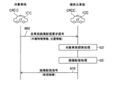
実施例EX1_1を説明する。図9は、実施例EX1_1に係る画像配信システムSSの動作の流れを示す図である。実施例EX1_1にて後述されるように、画像配信システムSSでは、第2車両の設置カメラの撮影画像に基づく配信画像が第1車両の車載装置に提供される。この場合における第1車両を対象車両と称し、第2車両を提供元車両と称する。
[Example EX1_1]
Example EX1_1 will be described. FIG. 9 is a diagram showing the flow of operations of the image distribution system SS according to the embodiment EX1_1. As will be described later in Example EX1_1, in the image delivery system SS, a delivery image based on an image captured by a camera installed in the second vehicle is provided to the in-vehicle device of the first vehicle. The first vehicle in this case is called a target vehicle, and the second vehicle is called a provider vehicle.
実施例EX1_1では車両CR[1]が対象車両として機能し(故に、以下では、車両CR[1]を対象車両CR[1]と称することがある)、対象車両CR[1]の運転手が対象車両CR[1]の外から対象車両CR[1]の外観を撮影した画像の取得を希望しているものとする。この場合、まず対象車両CR[1]の運転手は対象車両CR[1]に設置されたインターフェース装置30[1]に対し上記希望を伝達するための所定の画像配信要求操作を入力する(図6を適宜参照)。典型的には例えば、対象車両CR[1]の運転手が表示部31及び操作部33により構成されるタッチパネルに対し上記希望に対応する所定の画像配信要求操作を入力する。但し、画像配信要求操作の入力の態様は任意であり、音声操作や視線操作等で実現されても良い。
In the embodiment EX1_1, the vehicle CR[1] functions as the target vehicle (therefore, hereinafter, the vehicle CR[1] may be referred to as the target vehicle CR[1]), and the driver of the target vehicle CR[1] is It is assumed that the user desires to acquire an image of the exterior of the target vehicle CR[1] photographed from outside the target vehicle CR[1]. In this case, first, the driver of the target vehicle CR[1] inputs a predetermined image distribution request operation for transmitting the above request to the interface device 30[1] installed in the target vehicle CR[1] (Fig. 6 where appropriate). Typically, for example, the driver of the target vehicle CR[ 1 ] inputs a predetermined image distribution request operation corresponding to the above request to the touch panel configured by the
インターフェース装置30[1]に画像配信要求操作が入力されると、その入力に応答し、車載制御部110[1]は自車両画像配信要求信号610をサーバ装置2に対して送信する。要求信号610は、対象車両CR[1]の外から対象車両CR[1]の外観を撮影した画像をドライブレコーダ1[1]に対して配信することを要求する信号である。尚、任意の画像に関し、画像の配信、送信、受信とは、詳細には、当該画像の内容を表す画像情報(画像データ)の配信、送信、受信を意味する。
When an image distribution request operation is input to interface device 30[1], in-vehicle control unit 110[1] transmits host vehicle image
要求信号610は注目時間帯を表す注目時間帯情報と外観特徴情報を含む。画像配信要求操作において対象車両CR[1]の運転手は注目時間帯を指定することができる。対象車両CR[1]の運転手により注目時間帯が指定されなかった場合には、要求信号610の送信時刻よりも所定時間(例えば1時間や24時間)だけ前の時刻から要求信号610の送信時刻までの時間帯が注目時間帯に設定される。この場合には、要求信号610に注目時間帯情報は含まれず、サーバ装置2側で注目時間帯が設定されていても良い。
The
上記外観特徴情報は、対象車両CR[1]の外観特徴を表す情報であり、ここでは、対象車両CR[1]の車種及び対象車両CR[1]の外装の色を表す情報を含むものとする。上記外観特徴情報は、対象車両CR[1]の外観特徴を表す情報であれば任意であり、対象車両CR[1]の外観の三次元形状データ等を含んでいても良い。 The appearance feature information is information representing the appearance features of the target vehicle CR[1], and includes information representing the vehicle type of the target vehicle CR[1] and the exterior color of the target vehicle CR[1]. The appearance feature information is arbitrary as long as it represents the appearance features of the target vehicle CR[1], and may include three-dimensional shape data of the appearance of the target vehicle CR[1].
サーバ装置2にて要求信号610が受信されると(より詳細にはドライブレコーダ1[1]からの要求信号610が通信処理部230にて受信されると)、近接車両判定部212により近接車両判定処理S1が実行される。
When the
近接車両判定部212は、近接車両判定処理S1において、画像配信システムSSに属する車両CRの内、注目時間帯中に対象車両CR[1]に近接していた車両CRを各車両CRの移動軌跡(換言すれば走行履歴)に基づいて判定し、注目時間帯中に対象車両CR[1]に近接していた車両CRを提供元車両として特定して、対象車両CR[1]と提供元車両CR間との関係において対象時間帯と相対位置関係を導出する。対象時間帯は対象車両CR[1]及び提供元車両CR間の相対位置関係が所定の条件を満たす時間帯である。
In the approaching vehicle determination process S1, the approaching
図10に近接車両判定処理S1のフローチャートを示す。近接車両判定処理S1はステップS11~S13の処理から成る。近接車両判定処理S1では、まずステップS11の処理が実行される。 FIG. 10 shows a flowchart of the approaching vehicle determination process S1. The approaching vehicle determination process S1 consists of steps S11 to S13. In the approaching vehicle determination process S1, the process of step S11 is first executed.
ステップS11において、近接車両判定部212は、対象車両CR[1]の移動軌跡と対象車両CR[1]以外の各車両CRの移動軌跡とに基づき、注目時間帯において対象車両CR[1]に近接した車両CRを検索する。近接車両判定部212は、画像配信システムSSに属する車両CR[i]ごとに、位置情報取得処理の継続実行を通じて蓄積された各時刻における車両CR[i]の位置情報から車両CR[i]の移動軌跡(換言すれば走行履歴)を導出できる。
In step S11, the approaching
ステップS12では、注目時間帯において対象車両CR[1]に近接した車両CRが存在していたかどうかのチェックが行われ、対象車両CR[1]に近接した車両CRが存在していた場合に限りステップS13に進む。近接していたか否かは、車両間の距離が所定距離以下であったか否かにより判定される。注目時間帯の全部又は一部において、対象車両CR[1]と並走した車両CR又は対象車両CR[1]とすれ違った車両CRが、対象車両CR[1]に近接した車両CRとして判定されると期待される。尚、対象車両CR[1]に近接した車両CRが存在しないと判断された場合、サーバ装置2は要求信号610の受信に応答して、所定の配信不可信号を対象車両CR[1]のドライブレコーダ1[1]に送信し、後述の処理S3~S5を行うことなく(図9参照)、要求信号610の受信を契機とした処理を終える。
In step S12, it is checked whether or not there was a vehicle CR adjacent to the target vehicle CR[1] in the time period of interest. Proceed to step S13. Whether or not the vehicles are close to each other is determined by whether or not the distance between the vehicles is equal to or less than a predetermined distance. A vehicle CR that runs parallel to the target vehicle CR[1] or passes the target vehicle CR[1] in all or part of the time period of interest is determined as a vehicle CR that is close to the target vehicle CR[1]. expected to be When it is determined that there is no vehicle CR in the vicinity of the target vehicle CR[1], the
ステップS13において、近接車両判定部212は、注目時間帯において対象車両CR[1]に近接した車両CRを提供元車両CRとして特定し、注目時間帯内において対象車両CR[1]及び提供元車両CR間の距離が所定距離以下となる時間帯を対象時間帯として導出及び設定すると共に対象時間帯内の各時刻における対象車両CR[1]及び提供元車両CR間の相対位置関係を導出する。
In step S13, the approaching
より具体的には例えば以下のようにすれば良い。近接車両判定処理S1において、近接車両判定部212は、対象車両CR[1]以外の車両CR[j]に注目し(jは2以上且つn以下の整数)、注目時間帯内の各時刻における車両CR[1]及びCR[j]の位置情報に基づき、注目時間帯内の各時刻における対象車両CR[1]と車両CR[j]との距離を導出し、導出した距離が所定距離(例えば50m)以下となる時刻が存在するか否かを判定する(ステップS11)。
車両CR[j]について、導出した距離が所定距離以下となる時刻が存在する場合、車両CR[j]は注目時間帯内に対象車両CR[1]に近接した車両CRであると判定されると共に提供元車両として特定及び設定される。車両CR[j]について、導出した距離が所定距離以下となる時刻が存在しない場合、車両CR[j]は注目時間帯内に対象車両CR[1]に近接した車両CRではないと判定されると共に提供元車両として特定されない。
車両CR[j]が提供元車両として特定された場合、近接車両判定部212は、注目時間帯内の各時刻における車両CR[1]及びCR[j]の位置情報に基づき、注目時間帯内において対象車両CR[1]及び提供元車両CR[j]間の距離が所定距離以下となる時間帯を対象時間帯として判定及び設定すると共に対象時間帯内の各時刻における対象車両CR[1]及び提供元車両CR[j]間の相対位置関係を導出する(ステップS13)。対象車両CR[1]及び提供元車両CR[j]間の相対位置関係は、提供元車両CR[j]から見た対象車両CR[1]の存在位置の方位と、対象車両CR[1]及び提供元車両CR[j]間の距離とで、定義される。
More specifically, for example, the following may be done. In the approaching vehicle determination process S1, the approaching
For vehicle CR[j], if there is a time at which the derived distance is equal to or less than a predetermined distance, vehicle CR[j] is determined to be a vehicle CR that is close to target vehicle CR[1] within the time zone of interest. is specified and set as the provider vehicle. If there is no time at which the derived distance is equal to or less than the predetermined distance for the vehicle CR[j], it is determined that the vehicle CR[j] is not a vehicle CR that is close to the target vehicle CR[1] within the time zone of interest. It is not identified as a provider vehicle with
When the vehicle CR[j] is identified as the provider vehicle, the approaching
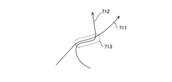
例えば、注目時間帯における対象車両CR[1]の移動軌跡が図11の軌跡711であって且つ注目時間帯における車両CR[j]の移動軌跡が図11の軌跡712であった場合、図11の破線部分713に対応する時間帯が対象時間帯に設定されることになる。
For example, if the movement trajectory of the target vehicle CR[1] in the time period of interest is the
尚、近接車両判定処理S1は、要求信号610の受信を受けてから開始されるものでなくても良い。即ち例えば、近接車両判定部212は、画像配信システムSSに属する任意の車両CRを対象車両とみなした上で、位置情報取得処理の継続実行を通じて蓄積された各時刻における各車両CRの位置情報に基づき、対象車両CRに近接する他の車両CRの有無及び対象車両CRに他の車両CRが近接していた時間帯を常時判定するようにしても良い。この場合、サーバ装置2にて要求信号610が受信されると、既に行われた判定の結果を利用して、提供元車両の特定並びに対象時間帯及び相対位置関係の導出が行われる。
Note that the approaching vehicle determination process S1 does not have to be started after receiving the
また、提供元車両が複数設定された場合には、設定された提供元車両ごとに以下に示す処理が行われて良いが、ここでは、車両CR[2]が提供元車両に設定されたものとし、車両CR[2]に注目して以下に示す処理の内容を説明する。 Further, when a plurality of provider vehicles are set, the following processing may be performed for each of the set provider vehicles. Assuming that the vehicle CR[2] is focused on, the details of the processing shown below will be described.
図9を再度参照し、近接車両判定処理S1において車両CR[2]が提供元車両に設定されると、サーバ装置2(サーバ制御部210)は提供元車両CR[2]のドライブレコーダ1[2]に対し、サンプリング画像送信要求信号620を送信する。この要求信号620は、サンプリング画像の送信を要求する信号であって、対象時間帯を示す対象時間帯情報を含む。
Referring to FIG. 9 again, when the vehicle CR[2] is set as the provider vehicle in the adjacent vehicle determination process S1, the server device 2 (server control unit 210) controls the drive recorder 1[ of the provider vehicle CR[2]. 2], a sampling image
提供元車両CR[2]のドライブレコーダ1[2]にて要求信号620が受信されると、ドライブレコーダ1[2]の車載制御部110[2]により画像サンプリング処理S2が実行される。提供元車両CR[2]では、全方位カメラ21C[2]により車両CR[2]の周囲360°の風景が所定のフレームレートで順次撮影され、撮影結果を示す撮影画像の画像情報(画像データ)が記録媒体120[2]に順次記録される。このため、要求信号620の受信時点において、記録媒体120[2]には全方位カメラ21C[2]による過去の撮影画像が動画像の形式で記録されている。
When the
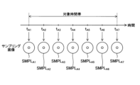
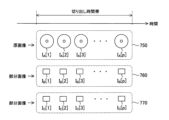
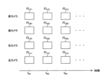
図12に示す如く、動画像は、フレームレートの逆数に相当する所定のフレーム周期の間隔で時系列上に並ぶ複数の静止画像から成り、その静止画像をフレーム画像と称する。また、或る注目時刻での撮影により得られた静止画像を注目時刻のフレーム画像と称する。全方位カメラ21C[2]の撮影で得られる各時刻のフレーム画像は、図4(a)に示したような円環撮影画像である。
As shown in FIG. 12, a moving image consists of a plurality of still images arranged in time series at intervals of a predetermined frame period corresponding to the reciprocal of the frame rate, and the still images are called frame images. A still image obtained by photographing at a certain time of interest is referred to as a frame image of the time of interest. A frame image at each time obtained by photographing by the
画像サンプリング処理S2において、車載制御部110[2]は、動画像の形式で記録媒体120[2]に記録されている撮影画像の中から、対象時間帯に属する1以上の時刻の1以上のフレーム画像をサンプリング画像として抽出する(キャプチャする)。この際、対象時間帯に属するフレーム画像の枚数がnA枚であるならば、そのnA枚のフレーム画像の内、nB枚のフレーム画像をサンプリング画像として抽出すると良い。ここで、nAは2以上の整数であって、且つ、nBはnAよりも小さな1以上の整数である。車載制御部110[2]は、各サンプリング画像の画像情報を含む応答信号630をサーバ装置2に送信する。応答信号630において、各サンプリング画像の画像情報には、各サンプリング画像の撮影時刻を示す撮影時刻情報等の関連情報が付加される。
In the image sampling process S2, the in-vehicle control unit 110[2] extracts one or more images at one or more times belonging to the target time period from the captured images recorded in the recording medium 120[2] in the form of moving images. Extract (capture) the frame image as a sampled image. At this time, if the number of frame images belonging to the target time period is nA , it is preferable to extract nB frame images out of the nA frame images as sampling images. Here, nA is an integer of 2 or more, and nB is an integer of 1 or more that is smaller than nA . The in-vehicle control unit 110 [ 2 ] transmits a
実施例EX1_1では、特にサンプリング画像の枚数(即ち上記のnBの値)が2以上であるものとする。更にここでは、説明の具体化のため、図13に示す如く、対象時間帯が時刻tA1から時刻tA7までの時間帯であるとし、時刻tA1、tA2、tA3、tA4、tA5、tA6及びtA7の夫々がサンプリング画像の抽出時刻に設定されたことを想定する。変数iが任意の整数であるとした場合、時刻tAi+1はtAiよりも後の時刻であり、時刻tA及びtAi+1間の間隔は一定であるとする。故に例えば対象時間帯が、13時00分00秒から13時01分00秒までの1分間分の時間帯である場合、時刻tA1、tA2、tA3、tA4、tA5、tA6、tA7は、夫々、13時00分00秒、13時00分10秒、13時00分20秒、13時00分30秒、13時00分40秒、13時00分50秒、13時01分00秒である。この数値例におけるサンプリング画像の抽出間隔は10秒であるが、サンプリング画像の抽出間隔は様々に変形可能である。但し、サンプリング画像の抽出間隔はフレーム周期(例えば1/30秒)よりも長いものとする。 In Example EX1_1, it is assumed that the number of sampled images (that is, the value of nB above) is 2 or more. Further, here, as shown in FIG. 13, the target time period is assumed to be the time period from time t A1 to time t A7 for concrete explanation, and times t A1 , t A2 , t A3 , t A4 , t Assume that A5 , tA6 and tA7 are each set to the extraction time of the sampled image. Assuming that the variable i is an arbitrary integer, time t Ai+1 is later than t Ai and the interval between times t A and t Ai+1 is constant. Therefore, for example, when the target time zone is a one-minute time zone from 13:00:00 to 13:01:00, times t A1 , t A2 , t A3 , t A4 , t A5 , t A6 , t A7 are respectively 13:00:00, 13:00:10, 13:00:20, 13:00:30, 13:00:40, 13:00:50, 13 It is hour 01:00. Although the sampling image extraction interval in this numerical example is 10 seconds, the sampling image extraction interval can be modified in various ways. However, the sampling image extraction interval is assumed to be longer than the frame cycle (for example, 1/30 second).
車載制御部110[2]は、画像サンプリング処理S2において、時刻tA1、tA2、tA3、tA4、tA5、tA6及びtA7における全方位カメラ21C[2]の撮影画像であるフレーム画像を、夫々、サンプリング画像SMPLA1、SMPLA2、SMPLA3、SMPLA4、SMPLA5、SMPLA6、SMPLA7として抽出する。 In the image sampling process S2 , the in - vehicle control unit 110[2 ] performs frame The images are extracted as sampled images SMPL A1 , SMPL A2 , SMPL A3 , SMPL A4 , SMPL A5 , SMPL A6 , SMPL A7 respectively.
近接車両判定処理S1を経て特定された提供元車両において対象車両が撮影されている可能性がある。但し、近接車両判定処理S1の実行直後の段階では、実際に有効な撮影が提供元車両にてなされているかは不明である。一方で、動画像の画像情報は大容量データであり、全ての動画像の画像情報を近接車両判定処理S1の実行直後の段階でサーバ装置2に送信するのは、サーバ装置2及び通信回線にとって負荷が大きく、無駄になることもある。上述の画像サンプリング処理S2によれば、無駄な情報送信が抑制され、それらの負荷が軽減される。
There is a possibility that the target vehicle is photographed in the provider vehicle specified through the approaching vehicle determination process S1. However, at the stage immediately after execution of the approaching vehicle determination process S1, it is unclear whether effective photography is actually performed in the provider vehicle. On the other hand, the image information of moving images is large-capacity data, and transmitting all the image information of moving images to the
サーバ装置2にて応答信号630が受信されると(より詳細にはドライブレコーダ1[2]からの応答信号630が通信処理部230にて受信されると)、対象車両探索部213により対象車両探索処理S3が実行される(図7、図9参照)。
When the
対象車両探索処理S3において、対象車両探索部213は、サンプリング画像と対象車両CR[1]の外観特徴情報とに基づいて、サンプリング画像内に対象車両CR[1]の画像が含まれているか否かを判定する。サンプリング画像が複数ある場合にはサンプリング画像ごとに対象車両探索処理S3が実行される。対象車両CR[1]の外観特徴情報として要求信号610に含まれる情報を利用できる(図9参照)。
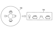
In the target vehicle search process S3, the target
図14を参照し、サンプリング画像SMPLA1~SMPLA7の何れかである1枚のサンプリング画像720に対して実行される対象車両探索処理S3を説明する。提供元車両CR[2]のドライブレコーダ1[2]からサーバ装置2に提供されるサンプリング画像720は、全方位カメラ21C[2]による円環撮影画像である。対象車両探索処理S3では、まずサーバ制御部210に設けられた展開画像処理部(不図示)により、円環撮影画像であるサンプリング画像720に対し幾何学的変換を含む上記展開画像処理が施され、サンプリング画像720を展開したサンプリングパノラマ画像722が生成される。展開画像処理部は対象車両探索部213に設けられると解しても良い。サンプリングパノラマ画像722は円環撮影画像であるサンプリング画像720を所定の仮想平面に投影して得られる矩形状の平面画像である。
With reference to FIG. 14, the target vehicle search process S3 executed for one sampled
対象車両探索部213は、対象車両CR[1]の外観特徴情報に基づく画像認識により、サンプリングパノラマ画像722の全画像領域中に設定された探索領域内において対象車両CR[1]の画像特徴を有する画像を探索する。そして、探索領域内において対象車両CR[1]の画像特徴を有する画像が見つかった場合には、サンプリング画像720内に対象車両CR[1]の画像が含まれていると判定し、探索領域内において対象車両CR[1]の画像特徴を有する画像が見つからなかった場合には、サンプリング画像720内に対象車両CR[1]の画像が含まれていないと判定する。
The target
上記の探索領域はサンプリングパノラマ画像722の全画像領域と一致していても良い。但し、全方位カメラの全撮影画角の中から特定の車両を画像認識で探し当てるのは時間がかかるし、処理負荷が重い。また探索ミスが生じやすくなりうる。
The search area described above may coincide with the entire image area of the sampled
これを考慮し、対象車両探索処理S3において、対象車両探索部213は、サンプリング画像と、対象車両CR[1]の外観特徴情報と、サンプリング画像の撮影時刻における対象車両CR[1]及び提供元車両CR[2]間の相対位置関係と、に基づいて、サンプリング画像内に対象車両CR[1]の画像が含まれているか否かを判定すると良い。つまり、サンプリング画像720について言えば、上述の如くサンプリングパノラマ画像722を生成した後、サンプリングパノラマ画像722の全画像領域中に、サンプリング画像720の撮影時刻における対象車両CR[1]及び提供元車両CR[2]間の相対位置関係に基づく探索領域724を設定し(図15参照)、対象車両CR[1]の外観特徴情報に基づく画像認識により、サンプリングパノラマ画像722中の探索領域724内において対象車両CR[1]の画像特徴を有する画像を探索する。そして、探索領域724内において対象車両CR[1]の画像特徴を有する画像が見つかった場合には、サンプリング画像720内に対象車両CR[1]の画像が含まれていると判定し、探索領域724内において対象車両CR[1]の画像特徴を有する画像が見つからなかった場合には、サンプリング画像720内に対象車両CR[1]の画像が含まれていないと判定すれば良い。
In consideration of this, in the target vehicle search process S3, the target
探索領域724はサンプリングパノラマ画像722の全画像領域よりも小さい。サンプリング画像720の撮影時刻における対象車両CR[1]及び提供元車両CR[2]間の相対位置関係に基づき、サンプリングパノラマ画像722内のどのあたりに対象車両CR[1]の画像が存在しうるかを推定でき、その推定結果に基づき、対象車両CR[1]の画像が存在しうる領域を基準に探索領域724を設定すれば良い。
対象車両CR[1]及び提供元車両CR[2]間の相対位置関係を参照して探索領域を絞り込むことで探索に関わる処理時間及び負荷を軽減することができ、また探索ミスの抑制も期待される。 By narrowing down the search area by referring to the relative positional relationship between the target vehicle CR[1] and the provider vehicle CR[2], it is possible to reduce the processing time and load related to the search, and it is also expected to suppress search errors. be done.
尚、図10のステップ13の段階で、対象時間帯内の各時刻における対象車両CR[1]及び提供元車両CR[j]間の相対位置関係が導出されており、その導出結果を対象車両探索処理S3でも利用可能である。 At the stage of step 13 in FIG. 10, the relative positional relationship between the target vehicle CR[1] and the provider vehicle CR[j] at each time within the target time zone is derived, and the derived result is used as the target vehicle It can also be used in search processing S3.
また、車両CR[2]から見た方位と全方位カメラ21C[2]の撮影画像中の各画素との対応関係を示す撮影パラメータ情報は、サーバ装置2にとって既知であるとし、その撮影パラメータ情報は例えば応答信号630の中に含められていても良い。撮影パラメータ情報により、全方位カメラ21C[2]の撮影画像中の各画素が、車両CR[2]から見て何れの方位に存在する風景を画像化した画素であるのかが特定されるものとする。例えば、図15に示されるサンプリング画像720中の画素730N及び730Sが車両CR[2]から見てそれぞれ北及び南に位置する風景を画像化した画素であるならば、その旨を特定する撮影パラメータ情報がサーバ装置2にとって既知とされる。サンプリング画像720における画素730N、730Sは、夫々、サンプリングパノラマ画像722における画素730N’、730S’に対応する。この場合において、サンプリング画像720の撮影時刻における提供元車両CR[2]から見た対象車両CR[1]の存在位置の方位が北であるならば(北であることが、それらの相対位置関係からわかるならば)、画素730N’を含むが画素730S’を含まない画像領域が探索領域724として設定されることになる。
Further, it is assumed that the imaging parameter information indicating the correspondence relationship between the direction viewed from the vehicle CR[2] and each pixel in the image captured by the
ここでは、矩形状の平面画像であるサンプリングパノラマ画像722上で対象車両CR[1]の画像を探索する方法を説明したが、円環撮影画像であるサンプリング画像720上で対象車両CR[1]の画像を探索するようにしても良い。
Here, the method of searching for the image of the target vehicle CR[1] on the
上述したように、画像サンプリング処理S2においてサンプリング画像SMPLA1~SMPLA7が抽出された場合にあっては(図13参照)、サンプリング画像SMPLA1~SMPLA7の夫々に対し対象車両探索処理S3が実行される。 As described above, when the sampled images SMPL A1 to SMPL A7 are extracted in the image sampling process S2 (see FIG. 13), the target vehicle search process S3 is executed for each of the sampled images SMPL A1 to SMPL A7 . be done.
対象車両探索処理S3の後、切り出し時間帯設定部214は、対象車両探索処理S3の結果に基づいて切り出し時間帯を設定する切り出し時間帯設定処理S4を実行する(図7及び図9参照)。切り出し時間帯設定処理S4では、サンプリング画像SMPLA1~SMPLA7の内、対象車両CR[1]の画像が含まれていると判定されたサンプリング画像の撮影時刻を含む時間帯を切り出し時間帯として設定する。図16(a)に示す如く対象時間帯の全部が切り出し時間帯に設定されることもあるし、図16(b)又は(c)に示す如く対象時間帯の一部が切り出し時間帯に設定されることもある。
After the target vehicle search process S3, the cutout time
例えば、サンプリング画像SMPLA1~SMPLA7の全てにおいて対象車両CR[1]の画像が含まれていると判定された場合には、対象時間帯そのものが切り出し時間帯に設定される。
また例えば、サンプリング画像SMPLA1~SMPLA3の夫々において対象車両CR[1]の画像が含まれていると判定され、且つ、サンプリング画像SMPLA4~SMPLA7には何れも対象車両CR[1]の画像が含まれていないと判定された場合には、時刻tA1から時刻tA3までの時間帯が切り出し時間帯に設定される。
また例えば、サンプリング画像SMPLA1~SMPLA7の内、サンプリング画像SMPLA4においてのみ対象車両CR[1]の画像が含まれていると判定された場合には、時刻tA4を中心とし且つ所定の時間長(例えば10秒)を有する時間帯が切り出し時間帯に設定される。
For example, when it is determined that the image of the target vehicle CR[1] is included in all of the sampled images SMPL A1 to SMPL A7 , the target time period itself is set as the extraction time period.
Further, for example, it is determined that each of the sampling images SMPL A1 to SMPL A3 includes an image of the target vehicle CR[1], and all of the sampling images SMPL A4 to SMPL A7 include an image of the target vehicle CR[1]. When it is determined that the image is not included, the time period from time t A1 to time t A3 is set as the extraction time period.
Further, for example, when it is determined that the image of the target vehicle CR[1] is included only in the sampling image SMPL A4 among the sampling images SMPL A1 to SMPL A7 , the image of the target vehicle CR[ 1 ] A time period with a length (eg, 10 seconds) is set as the cut-out time period.
また例えば、サンプリング画像SMPLA1、SMPLA2、SMPLA5及びSMPLA6の夫々において対象車両CR[1]の画像が含まれていると判定され、且つ、サンプリング画像SMPLA3、SMPLA4及びSMPLA7には何れも対象車両CR[1]の画像が含まれていないと判定された場合には、時刻tA1から時刻tA6までの時間帯が切り出し時間帯に設定されても良いし、時刻tA1から時刻tA2までの時間帯又は時刻tA5から時刻tA6までの時間帯が切り出し時間帯に設定されても良い。 Further, for example, it is determined that the image of the target vehicle CR[1] is included in each of the sampling images SMPL A1 , SMPL A2 , SMPL A5 , and SMPL A6 , and the sampling images SMPL A3 , SMPL A4 , and SMPL A7 include When it is determined that none of the images includes the image of the target vehicle CR[1], the time period from time t A1 to time t A6 may be set as the extraction time period, or from time t A1 . The time period up to time t A2 or the time period from time t A5 to time t A6 may be set as the extraction time period.
仮に、サンプリング画像SMPLA1~SMPLA7の何れにも対象車両CR[1]の画像が含まれていないと判定された場合には、サーバ装置2は所定の配信不可信号を対象車両CR[1]のドライブレコーダ1[1]に送信し、後述の画像配信処理S5を行うことなく、要求信号610の受信を契機とした処理を終える。
If it is determined that the image of the target vehicle CR[1] is not included in any of the sampled images SMPL A1 to SMPL A7 , the
切り出し時間帯の設定後、サーバ制御部210(例えば対象車両探索部213、切り出し時間設定部214又は画像配信部215)は、提供元車両CR[2]のドライブレコーダ1[2]に対し、配信用画像送信要求信号640を送信する。この要求信号640は、後述の配信画像の元となる画像の送信を要求する信号であって、切り出し時間帯を示す切り出し時間帯情報を含む。
After setting the clipping time period, the server control unit 210 (for example, the target
提供元車両CR[2]のドライブレコーダ1[2]にて要求信号640が受信されると、ドライブレコーダ1[2]の車載制御部110[2]は、要求信号640の要求に応える応答信号650をサーバ装置2に送信する。記録媒体120[2]に記録されている全方位カメラ21C[2]による過去の撮影画像の内、切り出し時間帯における撮影画像の画像情報が応答信号650に含められる。例えば、切り出し時間帯が13時00分00秒から13時00分20秒までの計20秒間分の時間帯であるならば、13時00分00秒から13時00分20秒までの20秒間分の全方位カメラ21C[2]の撮影画像の画像情報が応答信号650に含められる。この際、適宜、フレームの間引きが行われても良い。応答信号650において、画像情報には各撮影画像の撮影時刻を示す撮影時刻情報等の関連情報が付加される。
When the
サーバ装置2にて応答信号650が受信されると(より詳細にはドライブレコーダ1[2]からの応答信号650が通信処理部230にて受信されると)、画像配信部215により画像配信処理S5が実行される(図7、図9参照)。
When the
画像配信処理S5において、画像配信部215は、応答信号650に含まれる画像情報に基づく配信画像を生成し、通信処理部230を用いて、配信画像の画像情報を含む画像配信信号660を対象車両CR[1]のドライブレコーダ1[1]に送信する。画像配信信号660を受信したドライブレコーダ1[1]において、車載制御部110[1]は、画像配信信号660に基づき、配信画像の画像情報を記録媒体120[1]に記録することができる他、配信画像を表示部31[1]に表示することもできる。
In the image distribution process S5, the
配信画像の元となる応答信号650に含まれる撮影画像は、記録媒体120[2]に記録されている全方位カメラ21C[2]による過去の撮影画像の内、切り出し時間帯における撮影画像であって動画像形式の撮影画像であるので、図17に示す如く、切り出し時間帯内において時系列上に並ぶ複数のフレーム画像の束から成る。この束により動画像750が形成される。動画像750を構成する各々のフレーム画像は、全方位カメラ21C[2]の撮影により生成された静止画像としての円環撮影画像であり、ここでは、説明の便宜上、動画像750を構成する各々のフレーム画像を原画像と称する。切り出し時間帯において、複数の原画像は全方位カメラ21C[2]のフレーム周期を間隔にして時系列上に並ぶ。更に、ここでは、説明の具体化のため、動画像750を構成する複数の原画像がp枚の原画像から成ると考え、p枚の原画像を互いに区別する必要があるとき、p枚の原画像を原画像IA[1]~IA[p]と称する(pは2以上の整数)。任意の整数iに関し、原画像IA[i+1]は原画像IA[i]よりも後に撮影された画像である。
The captured image included in the
画像配信処理S5は部分画像生成処理を含む(図9参照)。部分画像生成処理では、各原画像の撮影時刻における対象車両CR[1]及び提供元車両CR[2]間の相対位置関係並びに対象車両CR[1]の外観特徴情報に基づいて、原画像ごとに、原画像の一部に基づく画像であって且つ対象車両CR[1]の画像を含む部分画像(後述のIB[i]、IC[i]に対応)を生成する。画像配信部215は、原画像IA[1]~IA[p]に対して生成した部分画像を時系列上に並べて構成される動画像を配信画像として生成することができる(部分画像の詳細については後述)。
The image distribution processing S5 includes partial image generation processing (see FIG. 9). In the partial image generation process, for each original image, based on the relative positional relationship between the target vehicle CR[1] and the provider vehicle CR[2] at the shooting time of each original image and the appearance feature information of the target vehicle CR[1] Then, a partial image (corresponding to I B [i] and I C [i], which will be described later), which is based on a part of the original image and includes the image of the target vehicle CR[1], is generated. The
これにより、対象車両CR[1]の外観を撮影した、対象車両CR[1]の画像を含む配信画像を対象車両CR[1]の運転手に提供することができる。 As a result, it is possible to provide the driver of the target vehicle CR[1] with the delivery image including the image of the target vehicle CR[1], which is a photograph of the appearance of the target vehicle CR[1].
図18を参照して部分画像生成処理を説明する。原画像IA[i]に対して生成されうる部分画像として、部分画像IB[i]と部分画像IC[i]とがある。部分画像生成処理は原画像ごとに実行され、原画像ごとに部分画像が生成されるが、図18を参照して1枚の原画像IA[i]に基づき1枚の部分画像IB[i]及び1枚の部分画像IC[i]を生成する処理を説明する。 The partial image generation processing will be described with reference to FIG. As partial images that can be generated for the original image I A [i], there are a partial image I B [i] and a partial image I C [i]. The partial image generation process is executed for each original image, and a partial image is generated for each original image. Referring to FIG. 18 , one partial image I B [ i] and one partial image I C [i] will be described.
部分画像生成処理は第1部分画像生成処理及び第2部分画像生成処理を含む。部分画像生成処理は原画像ごとに実行されるので、第1部分画像生成処理及び第2部分画像生成処理も原画像ごとに実行される。 The partial image generation processing includes first partial image generation processing and second partial image generation processing. Since the partial image generation processing is executed for each original image, the first partial image generation processing and the second partial image generation processing are also executed for each original image.
第1部分画像生成処理において、画像配信部215は、原画像IA[i]の撮影時刻における対象車両CR[1]及び提供元車両CR[j]間の相対位置関係に基づき、原画像IA[i]内における対象車両CR[1]の存在画像領域(即ち対象車両CR[1]の画像が存在する画像領域)を推定する。ここで推定された画像領域を推定領域810と称する。第1部分画像生成処理において、画像配信部215は、原画像IA[i]における推定領域810の位置を基準に原画像IA[i]内に切り出し画像領域815を設定し、原画像IA[i]における切り出し画像領域815内の画像に対し幾何学的変換を含む所定の第1展開画像処理(第1画像処理)を施すことで部分画像IB[i](第1部分画像)を生成する。展開画像処理の内容は上述した通りである。尚、図10のステップ13の段階で、対象時間帯内の各時刻における対象車両CR[1]及び提供元車両CR[j]間の相対位置関係が導出されており、画像配信部215は、その導出結果を利用可能である。
In the first partial image generation process, the
部分画像IB[i]は、原画像IA[i]の一部である切り出し画像領域815内の画像を所定の仮想平面に投影して得られる矩形状の平面画像である。当該投影を介して生成される部分画像IB[i]が矩形形状を持つように、切り出し画像領域815の形状が設定される。
Partial image I B [i] is a rectangular planar image obtained by projecting an image in clipped
切り出し画像領域815は推定領域810を内包する画像領域である。原画像IA[i]における推定領域810の中心位置812の画像情報が部分画像IB[i]では所定の目標位置812’に現れるように(即ち、原画像IA[i]の中心位置812の画素が第1展開画像処理により部分画像IB[i]の目標位置812’の画素に対応付けられるように)、原画像IA[i]内に切り出し画像領域815が設定される。ここにおける目標位置812’は部分画像IB[i]の中心位置であるとする。但し、目標位置812’は部分画像IB[i]の中心位置からずれていても良い。
A clipped
第1部分画像生成処理における推定に誤差がなければ、部分画像IB[i]において目標位置812’に対象車両CR[1]の画像情報が現れることになる。しかしながら、上記推定での誤差の影響で、部分画像IB[i]において目標位置812’に対象車両CR[1]の画像情報が現れないことも多い。
If there is no error in the estimation in the first partial image generation process, the image information of the target vehicle CR[1] will appear at the target position 812' in the partial image I B [i]. However, due to the error in the estimation, the image information of the target vehicle CR[1] often does not appear at the
そこで、部分画像IB[i]の生成後、第2部分画像生成処理において、画像配信部215は、対象車両CR[1]の外観特徴情報に基づき部分画像IB[i]内にて対象車両CR[1]の画像を探索して部分画像IB[i]内における対象車両CR[1]の画像の位置(中心位置又は重心位置)を特定し、特定した位置と目標位置812’との位置差を導出する。そして、導出した位置差に基づき、原画像IA[i]における切り出し画像領域815の位置を補正する。補正後の切り出し画像領域815を切り出し画像領域815Cにて表す。第2部分画像生成処理において、画像配信部215は、原画像IA[i]における切り出し画像領域815C内の画像に対し幾何学的変換を含む所定の第2展開画像処理(第2画像処理)を施すことで部分画像IC[i](第2部分画像)を生成する。
Therefore, after generating the partial image I B [i], in the second partial image generation process, the
部分画像IC[i]は、原画像IA[i]の一部である切り出し画像領域815C内の画像を所定の仮想平面に投影して得られる矩形状の平面画像である。当該投影を介して生成される部分画像IC[i]が矩形形状を持つように、切り出し画像領域815Cの形状が設定される。
The partial image I C [i] is a rectangular plane image obtained by projecting the image in the clipped
原画像IA[i]内における対象車両CR[1]の画像の中心又は重心位置の画像情報が部分画像IC[i]では所定の目標位置812’に現れるように(即ち、原画像IA[i]内における対象車両CR[1]の画像の中心又は重心位置の画素が第2展開画像処理により部分画像IC[i]の目標位置812’の画素に対応付けられるように)、原画像IA[i]内に切り出し画像領域815Cが設定される(即ち、そのような切り出し画像領域815Cが設定されるように上記補正が実行される)。
Image information of the center or center of gravity position of the image of the target vehicle CR[1] in the original image I A [i] appears at a
画像配信部215は、原画像IA[1]~IA[p]に対して生成した部分画像IC[1]~IC[p]を時系列上に並べて構成される動画像770を配信画像として生成でき(図17参照)、この場合、配信画像としての動画像770の画像情報は通信処理部230を通じ画像配信信号660(図9参照)に含められた形態で対象車両CR[1]のドライブレコーダ1[1]に送信される。
これにより、対象車両CR[1]の画像が適切な位置に配置された、見栄えの良い配信画像を対象車両CR[1]の運転手に提供することができる。 As a result, it is possible to provide the driver of the target vehicle CR[1] with a good-looking distribution image in which the image of the target vehicle CR[1] is arranged at an appropriate position.
或いは、画像配信部215は、原画像IA[1]~IA[p]に対して生成した部分画像IB[1]~IB[p]を時系列上に並べて構成される動画像760を配信画像として生成しても良い(図17参照)。この場合、部分画像IC[i]を生成するための処理の実行は不要であり、配信画像としての動画像760の画像情報は通信処理部230を通じ画像配信信号660(図9参照)に含められた形態で対象車両CR[1]のドライブレコーダ1[1]に送信される。但し、見栄えの良し悪しの観点から言えば、動画像770を配信した方が好ましい。
Alternatively, the
更に或いは、画像配信部215は、原画像IA[1]~IA[p]を時系列上に並べて構成される動画像750を配信画像として生成しても良い(図17参照)。この場合、部分画像IB[i]及びIC[i]を生成するための処理の実行は不要であり、配信画像としての動画像750の画像情報は通信処理部230を通じ画像配信信号660(図9参照)に含められた形態で対象車両CR[1]のドライブレコーダ1[1]に送信される。この場合には、動画像750から動画像760又は770を得るための処理を、ドライブレコーダ1[1]にて、又は図示されないコンピュータ等で行えば良い。
Alternatively, the
尚、ここでは、部分画像IB[i]の生成を経て部分画像IC[i]を生成するようにしているが、原画像IA[i]の撮影時刻における対象車両CR[1]及び提供元車両CR[j]間の相対位置関係と対象車両CR[1]の外観形状情報とに基づき原画像IA[1]上で対象車両CR[1]の画像の存在位置を探索することで、部分画像IB[i]を生成することなく、原画像IA[1]から一気に部分画像IC[i]を生成するようにしても良い。 Here, the partial image I C [i] is generated through the generation of the partial image I B [i] . Searching for the existing position of the image of the target vehicle CR[1] on the original image I A [1] based on the relative positional relationship between the provider vehicles CR[j] and the external shape information of the target vehicle CR[1]. , the partial image I C [i] may be generated at once from the original image I A [1] without generating the partial image I B [i].
上述の如く、本実施例によれば、対象車両CR[1]の外観を撮影した、対象車両CR[1]の画像を含む配信画像を対象車両CR[1]の運転手に提供することができる。
走行中の車両を撮影した画像(映像)はローリングショットと呼ばれ、自車両のローリングショットを友人や知人に撮影してもらって鑑賞するといったニーズが自動車愛好家の中で一定数あり、SNS等でも、その様を確認できる。本実施例によれば、このようなニーズに対応できる。
また、趣味性の高いローリングショット収集以外にも、自車両の走行中の外観を確認できるということは、例えば車両の灯火装置(ブレーキランプ等)の故障やトラックの荷崩れのように、走行中の車両の運転手が気付きにくい異常の検知にも役立ち、運転手への警告通知にも活用可能である。
As described above, according to the present embodiment, it is possible to provide the driver of the target vehicle CR[1] with a delivery image including an image of the target vehicle CR[1], which is an image of the appearance of the target vehicle CR[1]. can.
Images (videos) taken of a moving vehicle are called rolling shots, and there is a certain number of car enthusiasts who want to have friends and acquaintances take rolling shots of their own vehicle for viewing. , can be confirmed. According to this embodiment, such needs can be met.
In addition to collecting rolling shots, which are highly hobbyistic, being able to check the appearance of your own vehicle while it is running can also be useful in situations such as when a vehicle lighting system (brake lamp, etc.) breaks down or when a truck collapses. It is also useful for detecting abnormalities that are difficult for drivers to notice, and can also be used to notify drivers of warnings.
[実施例EX1_2]
実施例EX1_2を説明する。実施例EX1_1では、サンプリング画像の枚数(即ち上記のnBの値)が2以上であると考えたが、サンプリング画像の枚数(即ち上記のnBの値)は1であっても良い。実施例EX1_2では“nB=1”とする。
[Example EX1_2]
Example EX1_2 will be described. In Example EX1_1, the number of sampled images (that is, the value of nB described above) was considered to be two or more, but the number of sampled images (that is, the value of nB described above) may be one. In Example EX1_2, "n B =1".
この場合、車載制御部110[2]は、画像サンプリング処理S2において、対象時間帯内の任意の時刻(例えば、対象時間帯内のちょうど中間の時刻)での全方位カメラ21C[2]の撮影画像(図13の例ではサンプリング画像SMPLA4)を1枚のサンプリング画像として抽出し、抽出した1枚のサンプリング画像の画像情報を含む応答信号630をサーバ装置2に送信すれば良い。実施例EX1_2において、以下では、サンプリング画像SMPLA4の画像情報がサーバ装置2に送信されるものとする。
In this case, in the image sampling process S2, the in-vehicle control unit 110[2] causes the
対象車両探索処理S3はサンプリング画像SMPLA4に対して行われ、サンプリング画像SMPLA4内に対象車両CR[1]の画像が含まれていると判定された場合に限り、上述の切り出し時間帯設定処理S4及び画像配信処理S5(図9参照)が実行される。切り出し時間帯設定処理S4では、サンプリング画像SMPLA4の撮影時刻tA4(図13参照)を中心とし且つ所定の時間長(例えば10秒)を有する時間帯が切り出し時間帯に設定される。切り出し時間帯設定処理S4の後の処理内容は実施例EX1_1と同様である。 The target vehicle search process S3 is performed on the sampled image SMPL A4 , and only when it is determined that the image of the target vehicle CR[1] is included in the sampled image SMPL A4 , the above-described extraction time period setting process is performed. S4 and image distribution processing S5 (see FIG. 9) are executed. In the extraction time zone setting process S4, a time zone having a predetermined length of time (for example, 10 seconds) centered on the photographing time t A4 (see FIG. 13) of the sampling image SMPL A4 is set as the extraction time zone. The contents of processing after the extraction time zone setting processing S4 are the same as those of the embodiment EX1_1.
尚、サンプリング画像SMPLA4内に対象車両CR[1]の画像が含まれていると判定された場合、切り出し時間帯設定処理S4を実行することなく、画像配信処理S5を実行するようにしても良い。この場合、図9の信号640及び650の送受信は不要となり、画像配信処理S5では、1枚の静止画像であるサンプリング画像SMPLA4を図17の原画像IA[1]であるとみなした上で、サンプリング画像SMPLA4としての原画像IA[1]から部分画像IB[1]及びIC[1]を生成すれば良い。そして、サンプリング画像SMPLA4に基づく部分画像IB[1]又はIC[1]を配信画像に設定すればよい。この場合、1枚の静止画像である部分画像IB[1]又はIC[1]の画像情報が配信画像の画像情報として対象車両CR[1]のドライブレコーダ1[1]に送られることになる。或いは、サンプリング画像SMPLA4そのものを配信画像に設定しても良い。この場合、1枚の静止画像であるサンプリング画像SMPLA4の画像情報が配信画像の画像情報として対象車両CR[1]のドライブレコーダ1[1]に送られることになる。
Note that if it is determined that the image of the target vehicle CR[1] is included in the sampled image SMPL A4 , the image distribution process S5 may be executed without executing the extraction time period setting process S4. good. In this case, the transmission/reception of the
[実施例EX1_3]
実施例EX1_3を説明する。各車両CRに搭載されるカメラは全方位カメラ21Cでなくても良い。実施例EX1_3では、図19に示す如く、各車両CRに前カメラ21F、後カメラ21B、右カメラ21R及び左カメラ21Lが設置されていることを想定する。前カメラ21F、後カメラ21B、右カメラ21R及び左カメラ21Lは、図1のカメラ部21の構成要素である。各車両CRにおいて、カメラ21F、21B、21R、21Lは、夫々に、自身の撮影範囲内の風景を所定のフレームレートで順次撮影して、撮影結果を示す撮影画像の画像情報(画像データ)を順次ドライブレコーダ1に送る。各車両CRにおいて、カメラ21F、21B、21R及び21Lの各撮影画像の画像情報は、上述の通常記録制御又はイベント記録制御により、ドライブレコーダ1内の記録媒体120に記録されることになる。
[Example EX1_3]
Example EX1_3 will be described. The camera mounted on each vehicle CR may not be the
図20に示す如く、車両CR[i]に対して設置される前カメラ21F、後カメラ21B、右カメラ21R及び左カメラ21Lを、夫々、符号“21F[i]”、“21B[i]”、“21R[i]”、“21L[i]”にて参照する。前カメラ21F[i]、後カメラ21B[i]、右カメラ21R[i]、左カメラ21L[i]は、夫々、車両CR[i]の前方、後方、右側、左側に撮影範囲を持ち、車両CR[i]の前方、後方、右側、左側の風景を撮影する。
As shown in FIG. 20, the
実施例EX1_3の想定下においても、図9に示したような動作を実現可能である。但し、各車両CRの設置カメラが、全方位カメラ21Cではなく、カメラ21F、21B、21R及び21Lであることに対応して、以下のように変形される(実施例EX1_3で特に述べない事項は実施例EX1_1と同様とされて良い)。尚、実施例EX1_3においても車両CR[2]が提供元車両に設定されるものとする。
Even under the assumption of the embodiment EX1_3, the operation shown in FIG. 9 can be realized. However, the camera installed on each vehicle CR is not the
サーバ装置2は、近接車両判定処理S1を経てサンプリング画像送信要求信号620を車両CR[2]のドライブレコーダ1[2]に送信する際、要求信号620に、対象時間帯情報に加えカメラ方向情報を含める。カメラ方向情報は、対象時間帯内の各時刻における対象車両CR[1]及び提供元車両CR[2]間の相対位置関係に基づく情報であり、対象時間帯内の各時刻における対象車両CR[1]及び提供元車両CR[2]間の相対位置関係そのものを示す情報であっても良い。
When the
要求信号620の受信時点において、記録媒体120[2]には、カメラ21F[2]、21B[2]、21R[2]及び21L[2]による過去の撮影画像が動画像の形式で記録されている。動画像は、フレームレートの逆数に相当する所定のフレーム周期の間隔で時系列上に並ぶ複数の静止画像から成り、その静止画像は上述の如くフレーム画像と称される。図21に示す如く、任意の整数iに関し、時刻tBiでの前カメラ21F[2]の撮影により得られたフレーム画像を符号“FLFi”にて参照し、時刻tBiでの後カメラ21B[2]の撮影により得られたフレーム画像を符号“FLBi”にて参照し、時刻tBiでの右カメラ21R[2]の撮影により得られたフレーム画像を符号“FLRi”にて参照し、時刻tBiでの左カメラ21L[2]の撮影により得られたフレーム画像を符号“FLLi”にて参照する。変数iが任意の整数であるとした場合、時刻tBi+1はtBiよりも後の時刻であり、時刻tBi及びtBi+1間の間隔は一定であるとする。
At the time of receiving the
画像サンプリング処理S2において、車載制御部110[2]は、動画像の形式で記録媒体120[2]に記録されている撮影画像の中から、対象時間帯に属する1以上の時刻の1以上のフレーム画像をサンプリング画像として抽出する(キャプチャする)。この際、カメラ方向情報に基づき、対象時間帯において対象車両CR[1]がカメラ21F[2]、21B[2]、21R[2]及び21L[2]の何れの撮影範囲に含まれていたのかを推定し、対象車両CR[1]を撮影範囲に収めていたと推定されるカメラをサンプリング対象カメラに設定する。そして、サンプリング対象カメラの撮影により得られた撮影画像の中からサンプリング画像を抽出するようにする。
In the image sampling process S2, the in-vehicle control unit 110[2] extracts one or more images at one or more times belonging to the target time period from the captured images recorded in the recording medium 120[2] in the form of moving images. Extract (capture) the frame image as a sampled image. At this time, based on the camera direction information, the target vehicle CR[1] was included in any of the shooting ranges of the
例えば、時刻tB1が対象時間帯に属していて且つ時刻tB1がサンプリング画像の抽出時刻に設定された場合において、カメラ方向情報に基づき時刻tB1において対象車両CR[1]が提供元車両CR[2]の前方に位置していることが分かる場合、時刻tB1でのサンプリング対象カメラは前カメラ21F[2]とされて、サンプリング対象カメラによる時刻tB1での撮影画像(即ちフレーム画像FLF1)が時刻tB1でのサンプリング画像として抽出される。
或いは例えば、時刻tB1が対象時間帯に属していて且つ時刻tB1がサンプリング画像の抽出時刻に設定された場合において、カメラ方向情報に基づき時刻tB1において対象車両CR[1]が提供元車両CR[2]の後方に位置していることが分かる場合、時刻tB1でのサンプリング対象カメラは後カメラ21B[2]とされて、サンプリング対象カメラによる時刻tB1での撮影画像(即ちフレーム画像FLB1)が時刻tB1でのサンプリング画像として抽出される。
For example, when the time t B1 belongs to the target time zone and the time t B1 is set to the extraction time of the sampling image, the target vehicle CR[1] is the providing source vehicle CR at the time t B1 based on the camera direction information. [2], the camera to be sampled at time t B1 is the
Alternatively, for example, when the time t B1 belongs to the target time zone and the time t B1 is set to the extraction time of the sampling image, the target vehicle CR[1] is the providing source vehicle at the time t B1 based on the camera direction information. If it is found to be located behind CR[2], the camera to be sampled at time t B1 is the
対象車両CR[1]及び提供元車両CR[2]間の相対位置関係は対象時間帯内において変化しうるため、複数のサンプリング画像を抽出する場合、複数のサンプリング画像間でサンプリング対象カメラは変化しうる。 Since the relative positional relationship between the target vehicle CR[1] and the provider vehicle CR[2] can change within the target time period, when extracting a plurality of sampled images, the sampling target camera changes between the plurality of sampled images. I can.
例えば、時刻tB1及びtB3が対象時間帯に属していて且つ時刻tB1及びtB3の夫々がサンプリング画像の抽出時刻に設定された場合において、カメラ方向情報に基づき時刻tB1において対象車両CR[1]が提供元車両CR[2]の前方に位置していること及び時刻tB3において対象車両CR[1]が提供元車両CR[2]の右方に位置していることが分かる場合、時刻tB1でのサンプリング対象カメラは前カメラ21F[2]とされて、サンプリング対象カメラによる時刻tB1での撮影画像(即ちフレーム画像FLF1)が時刻tB1でのサンプリング画像として抽出され、且つ、時刻tB3でのサンプリング対象カメラは右カメラ21R[2]とされて、サンプリング対象カメラによる時刻tB3での撮影画像(即ちフレーム画像FLR3)が時刻tB3でのサンプリング画像として抽出される。サンプリング画像の抽出間隔は任意であるが、各カメラのフレーム周期(例えば1/30秒)よりも長いものとする。
For example, when the times t B1 and t B3 belong to the target time zone and the times t B1 and t B3 are set to the sampling image extraction times, the target vehicle CR is detected at the time t B1 based on the camera direction information. [1] is located in front of the provider vehicle CR[2] and the target vehicle CR[1] is located to the right of the provider vehicle CR[2] at time tB3 . , the camera to be sampled at time t B1 is the
以下、実施例EX1_3では、特に記述なき限り、対象時間帯の全体に亘って常に前カメラ21F[2]がサンプリング対象カメラに設定されたとする。
Hereinafter, in Example EX1_3, it is assumed that the
サンプリング画像の画像情報を含む応答信号630がサーバ装置2にて受信されると、対象車両探索部213により対象車両探索処理S3が実行される(図7、図9参照)。対象車両探索処理S3の内容は実施例EX1_1で述べた通りであって良く、対象車両探索部213は、サンプリング画像と対象車両CR[1]の外観特徴情報とに基づいて、サンプリング画像内に対象車両CR[1]の画像が含まれているか否かを判定すれば良い。サンプリング画像が複数ある場合にはサンプリング画像ごとに対象車両探索処理S3が実行される。
When the
切り出し時間帯設定部214は、対象車両探索処理S3の結果に基づいて切り出し時間帯を設定する切り出し時間帯設定処理S4を実行し、その後、切り出し時間帯情報を含む配信用画像送信要求信号640が、サーバ装置2から提供元車両CR[2]のドライブレコーダ1[2]に送信される(図7及び図9参照)。切り出し時間帯設定処理S4及び配信用画像送信要求信号640も実施例EX1_1で述べた通りであって良い。
The cut-out time
提供元車両CR[2]のドライブレコーダ1[2]にて要求信号640が受信されると、ドライブレコーダ1[2]の車載制御部110[2]は、要求信号640の要求に応える応答信号650をサーバ装置2に送信する。記録媒体120[2]に記録されているサンプリング対象カメラ(ここでは前カメラ21F[2]が想定)による過去の撮影画像の内、切り出し時間帯における撮影画像の画像情報が応答信号650に含められる。例えば、切り出し時間帯が13時00分00秒から13時00分20秒までの計20秒間分の時間帯であるならば、13時00分00秒から13時00分20秒までの20秒間分のサンプリング対象カメラ(ここでは前カメラ21F[2]が想定)の撮影画像の画像情報が応答信号650に含められる。この際、適宜、フレームの間引きが行われても良い。応答信号650において、各撮影画像の画像情報には各撮影画像の撮影時刻を示す撮影時刻情報などの関連情報が付加される。
When the
サーバ装置2にて応答信号650が受信されると(より詳細にはドライブレコーダ1[2]からの応答信号650が通信処理部230にて受信されると)、画像配信部215により画像配信処理S5が実行される(図7、図9参照)。
When the
画像配信処理S5において、画像配信部215は、応答信号650に含まれる画像情報に基づく配信画像を生成し、通信処理部230を用いて、配信画像の画像情報を含む画像配信信号660を対象車両CR[1]のドライブレコーダ1[1]に送信する。画像配信信号660を受信したドライブレコーダ1[1]において、車載制御部110[1]は、画像配信信号660に基づき、配信画像の画像情報を記録媒体120[1]に記録することができる他、配信画像を表示部31[1]に表示することもできる。
In the image distribution process S5, the
実施例EX1_3においては、応答信号650に含まれる撮影画像そのものが配信画像とされても良い。即ち例えば、切り出し時間帯が13時00分00秒から13時00分20秒までの計20秒間分の時間帯であるならば、応答信号650に含まれる、13時00分00秒から13時00分20秒までの20秒間分のサンプリング対象カメラ(ここでは前カメラ21F[2]が想定)の撮影画像そのものが配信画像とされても良い。
In Example EX1_3, the captured image itself included in the
或いは、画像配信処理S5において、提供元車両CR[2]から提供を受けた画像に対し、対象車両CR[1]の外観特徴情報に基づく画像処理を実行し、当該画像処理後の画像を配信画像として生成しても良い。即ち例えば、切り出し時間帯が13時00分00秒から13時00分20秒までの計20秒間分の時間帯であるならば、13時00分00秒から13時00分20秒までの20秒間分のサンプリング対象カメラ(ここでは前カメラ21F[2]が想定)の撮影画像に対し、対象車両CR[1]の外観特徴情報に基づく画像処理を実行し、当該画像処理後の画像を20秒間分の配信画像(動画像形式の配信画像)として生成しても良い。この場合例えば、配信画像中の各フレーム画像において、対象車両CR[1]の画像がフレーム画像の中心に位置するような画像処理が実行されると良い。
Alternatively, in the image distribution process S5, image processing based on the appearance feature information of the target vehicle CR[1] is performed on the image provided by the provider vehicle CR[2], and the image after the image processing is distributed. It may be generated as an image. That is, for example, if the extraction time zone is a time zone for a total of 20 seconds from 13:00:00 to 13:00:20, 20 seconds from 13:00:00 to 13:00:20 Image processing based on the appearance feature information of the target vehicle CR[1] is performed on the captured image of the sampling target camera (assumed to be the
常に前カメラ21F[2]がサンプリング対象カメラに設定される状況を想定して、実施例EX1_3に関わる処理S3以降の動作を説明したが、切り出し時間帯の中でサンプリング対象カメラが切り替わる場合にあっては、配信画像中の各フレーム画像内に対象車両CR[1]の画像が含まれるよう、切り出し時間帯内の各時刻における対象車両CR[1]及び提供元車両CR[2]間の相対位置関係に基づき、サーバ装置2及びドライブレコーダ1[2]が動作すれば良い。例えば、切り出し時間帯内の各時刻における対象車両CR[1]及び提供元車両CR[2]間の相対位置関係に基づき、切り出し時間帯の前半区間において対象車両CR[1]が提供元車両CR[2]の前方に位置しており且つ切り出し時間帯の後半区間において対象車両CR[1]が提供元車両CR[2]の右側に位置していることが分かる場合には、上記前半区間中の各時刻での前カメラ21F[2]の撮影により得られたフレーム画像(例えばFLF1を含む)と、上記後半区間中の各時刻での右カメラ21R[2]の撮影により得られたフレーム画像(例えばFLR3を含む)とをドライブレコーダ1[2]からサーバ装置2に送信するようにし、サーバ装置2は、受信したフレーム画像の集まりから配信画像を生成すれば良い。
Assuming that the
また、実施例EX1_1を実施例EX1_2へと変形できるように、実施例EX1_3においてもサンプリング画像の枚数を1とすることができ、対象車両CR[1]の画像を含む1枚のサンプリング画像そのものを配信画像に設定するようにしても良い(この場合、配信画像は静止画像となる)。 Also, in order to transform Example EX1_1 into Example EX1_2, the number of sampled images can be set to 1 in Example EX1_3 as well. You may make it set to a delivery image (in this case, a delivery image becomes a still image).
[実施例EX1_4]
実施例EX1_4を説明する。図9の例では、対象車両CR[1]の外観特徴情報が要求信号610に含められているが、サーバ装置2に対する対象車両CR[1]の外観特徴情報の提供タイミングは、対象車両探索処理S3の実行前であれば任意である。対象車両CR[1]の外観特徴情報は、ドライブレコーダ1[1]以外の装置(不図示)からサーバ装置2に提供されても良い。何れにせよ、対象車両探索処理S3の実行前に、サーバ装置2に対して対象車両CR[1]の外観特徴情報が提供される限り、その外観特徴情報の提供タイミング及び提供方法は任意であって良い。
[Example EX1_4]
Example EX1_4 will be described. In the example of FIG. 9, the
[実施例EX1_5]
実施例EX1_5を説明する。全方位カメラ21Cにより円環状の撮影画像(円環撮影画像)が生成されると上述した。円環撮影画像の中心部は画像情報を持たない中空領域となる。但し、全方位カメラ21Cにより生成される撮影画像において中空領域は不存在であっても良い。この場合、円環撮影画像において中空領域であった部分には、車両CRの真上の風景の画像情報が存在することになる。まとめると、全方位カメラ21Cにより生成される撮影画像は、円形状の撮影画像であって良く、円形状の撮影画像の一形態が円環撮影画像となる。
[Example EX1_5]
Example EX1_5 will be described. As described above, the
[実施例EX1_6]
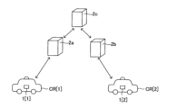
実施例EX1_6を説明する。互いに分離しつつも有線又は無線にて相互接続された複数のサーバ装置にてサーバ装置2が構成されていても良い。これにより、サーバ装置側の処理を分散することができる。例えば、対象車両CR[1]及び提供元車両CR[2]に注目した場合、図22に示す如く、サーバ装置2a、2b及び2cにてサーバ装置2が構成されていても良い。
[Example EX1_6]
Example EX1_6 will be described. The
この場合、対象車両CR[1]及びサーバ装置2a間で任意の信号の双方向通信を行い、且つ、提供元車両CR[2]及びサーバ装置2b間で任意の信号の双方向通信を行い、且つ、サーバ装置2cとサーバ装置2a及び2bとの間で任意の信号の双方向通信を行うことで、サーバ装置2a、2b及び2cの全体で上述のサーバ装置2の機能を実現すれば良い。エッジコンピューティングの観点から、サーバ装置2a、2b及び2cの内、サーバ装置2aは対象車両CR[1]に対して最も近い位置に配置され且つサーバ装置2bは提供元車両CR[2]に対して最も近い位置に配置されていると良い。
In this case, bidirectional communication of arbitrary signals is performed between the target vehicle CR[1] and the
[実施例EX1_7]
実施例EX1_7を説明する。
[Example EX1_7]
Example EX1_7 will be described.
上述の各実施例において、ドライブレコーダ1[i]は(詳細には例えば車載制御部110[i])は、サーバ装置2からの送信要求信号(620又は640)を受信したときに、その送信要求信号にて指定された時間帯(対象時間帯、切り出し時間帯)におけるカメラ(21C[i]、21F[i]、21B[i]、21R[i]、21L[i])の撮影画像の画像情報を、通信処理部130[i]を用いてサーバ装置2に送信している。
In each of the above-described embodiments, when the drive recorder 1[i] (more specifically, for example, the vehicle-mounted control unit 110[i]) receives a transmission request signal (620 or 640) from the
しかしながら、ドライブレコーダ1[i]は(詳細には例えば車載制御部110[i])は、車両CR[i]に設置されたカメラ(21C[i]、21F[i]、21B[i]、21R[i]、21L[i])にて順次生成される撮影画像の画像情報を、送信要求信号の受信の有無に依らず、通信処理部130[i]を用いて所定の送信タイミングでサーバ装置2に送信する自動アップロード方式を採用しても良い。
However, the drive recorder 1[i] (more specifically, the in-vehicle control unit 110[i]) uses cameras (21C[i], 21F[i], 21B[i], 21R[i], 21L[i]) is sent to the server at a predetermined transmission timing using the communication processing unit 130[i] regardless of whether or not a transmission request signal is received. An automatic upload method of transmitting to the
自動アップロード方式における送信は、いわゆるリアルタイム送信であって良い。即ち、車両CR[i]に設置されたカメラが全方位カメラ21C[i]である場合においてリアルタイム送信が行われる場合、全方位カメラ21C[i]にて順次生成される撮影画像の画像情報が、生成と実質的に同時に順次サーバ装置2に送信される(この場合、送信タイミングは実質的に全方位カメラ21C[i]による画像情報の生成タイミングと一致する)。或いは、車両CR[i]に設置されたカメラにて順次生成される撮影画像の画像情報を一定時間分だけ記録媒体120[i]に記録しておいた後、記録媒体120[i]に記録された画像情報を任意の送信タイミングでサーバ装置2に送信するようにしても良い。
The transmission in the automatic upload method may be a so-called real-time transmission. That is, when the camera installed in the vehicle CR[i] is the
自動アップロード方式により図9の信号620、630、640及び650の送受信が不要となり、処理シーケンスが簡略化される。今後の通信網の発達により、自動アップロード方式は、より合理的な方式となりうる。
The automatic upload scheme eliminates the need to send and receive
<<第2実施形態>>
本発明の第2実施形態を説明する。第2実施形態並びに後述の第3及び第4実施形態は第1実施形態を基礎とする実施形態であり、第2~第4実施形態において特に述べない事項に関しては、矛盾の無い限り、第1実施形態の記載が第2~第4実施形態にも適用される。第2実施形態の記載を解釈するにあたり、第1及び第2実施形態間で矛盾する事項については第2実施形態の記載が優先されて良い(後述の第3及び第4実施形態についても同様)。矛盾の無い限り、第1~第4実施形態の内、任意の複数の実施形態を組み合わせても良い。
<<Second Embodiment>>
A second embodiment of the present invention will be described. The second embodiment and third and fourth embodiments to be described later are embodiments based on the first embodiment. The description of the embodiments also applies to the second to fourth embodiments. In interpreting the description of the second embodiment, the description of the second embodiment may be prioritized for items that contradict between the first and second embodiments (the same applies to third and fourth embodiments described later). . As long as there is no contradiction, arbitrary plural embodiments may be combined among the first to fourth embodiments.
第2実施形態は、以下の実施例EX2_1~EX2_4を含む。矛盾なき限り、実施例EX2_1~EX2_4の内、任意の実施例に記載した事項を、他の任意の実施例に適用することもできる(即ち複数の実施例の内の任意の2以上の実施例を組み合わせることも可能である)。 The second embodiment includes the following examples EX2_1 to EX2_4. As long as there is no contradiction, the matter described in any one of Examples EX2_1 to EX2_4 can also be applied to any other example (that is, any two or more examples among a plurality of examples) can also be combined).
[実施例EX2_1]
実施例EX2_1を説明する。対象車両及び提供元車両間の距離が比較的に短く、対象車両及び提供元車両の車載装置間(ここではドライブレコーダ1間)で無線通信が可能な状態においては、提供元車両の設置カメラによる撮影画像の対象車両への配信を、サーバ装置2を介さずに実行するようにしても良い。
[Example EX2_1]
Example EX2_1 will be described. When the distance between the target vehicle and the provider vehicle is relatively short and wireless communication is possible between the in-vehicle devices of the target vehicle and the provider vehicle (here, between the drive recorder 1), the camera installed in the provider vehicle The delivery of the captured image to the target vehicle may be executed without going through the
対象車両及び提供元車両が夫々車両CR[1]及びCR[2]である場合を想定し、これについて説明を加える。対象車両CR[1]に設置されたドライブレコーダ1[1]の車載制御部110[1]と提供元車両CR[2]に設置されたドライブレコーダ1[2]の車載制御部110[2]は、通信処理部130[1]及び130[2]を用いて、ドライブレコーダ1[1]及び1[2]間の無線接続による通信回線の確立を試みる。通信処理部130[1]及び130[2]を用いてドライブレコーダ1[1]及び1[2]間の直接の無線通信が可能となっている状態を、車々間通信可能状態と称する。実施例EX2_1において、以下では、特に記述なき限り車々間通信可能状態が維持されているものとする。また、実施例EX2_1においては各車両CRに全方位カメラ21Cが設置されているものとする。
It is assumed that the target vehicle and the provider vehicle are the vehicles CR[1] and CR[2], respectively, and this will be explained. In-vehicle control unit 110[1] of drive recorder 1[1] installed in target vehicle CR[1] and in-vehicle control unit 110[2] of drive recorder 1[2] installed in provider vehicle CR[2] tries to establish a communication line by wireless connection between the drive recorders 1[1] and 1[2] using the communication processing units 130[1] and 130[2]. A state in which direct wireless communication between the drive recorders 1[1] and 1[2] is possible using the communication processing units 130[1] and 130[2] is referred to as a vehicle-to-vehicle communication enabled state. In the embodiment EX2_1, hereinafter, it is assumed that the vehicle-to-vehicle communication enabled state is maintained unless otherwise specified. Also, in Example EX2_1, an
インターフェース装置30[1]に上述の画像配信要求操作が入力されると、図23に示す如く、車載制御部110[1]は、入力された画像配信要求操作に基づく自車両画像配信要求信860をドライブレコーダ1[2]に送信する。要求信号860は、提供元車両CR[2]に設置されたカメラの撮影画像に基づく画像であって且つ対象車両CR[1]の画像情報を含む画像をドライブレコーダ1[1]に対して配信することを要求する信号である。要求信号860は、対象車両CR[1]の外観特徴を表す情報である上記外観特徴情報と、現在時刻の対象車両CR[1]の位置情報と、を含む。
When the image distribution request operation described above is input to the interface device 30[1], as shown in FIG. to drive recorder 1 [2]. The
ドライブレコーダ1[2]にて要求信号860が受信されると、車載制御部110[2]は、全方位カメラ21C[2]による撮影画像中に対象車両CR[1]の画像が含まれているか否かを判定する対象車両探索処理S3’を実行する。対象車両探索処理S3’の内容は上述の対象車両探索処理S3(図9参照)と同様であるが、対象車両探索処理S3’での判定の対象となる撮影画像は、全方位カメラ21C[2]による現在時刻の撮影画像とされると良い。即ち、対象車両探索処理S3’では、全方位カメラ21C[2]の最新の撮影によって得られる円環撮影画像を図14のサンプリング画像720と捉えて、車載制御部110[2]にて、少なくとも対象車両CR[1]の外観特徴情報に基づき、上述の対象車両探索処理S3と同様の処理を行えば良い(この場合、図7の対象車両探索部213が車載制御部110[2]に内蔵されていると考えても良い)。車載制御部110[2]は、要求信号860に含まれる対象車両CR[1]の位置情報とGPS処理部23[2]から得られる提供元車両CR[2]の最新の位置情報とに基づいて、現在の対象車両CR[1]及び提供元車両CR[2]間の相対位置関係を認識し、その相対位置関係をも利用して対象車両探索処理S3’を行うことができる。
When the drive recorder 1[2] receives the
対象車両探索処理S3’において、全方位カメラ21C[2]による撮影画像(例えば現在時刻の撮影画像)中に対象車両CR[1]の画像が含まれていないと判定された場合、車載制御部110[2]は、所定の配信不可信号を対象車両CR[1]のドライブレコーダ1[1]に送信し、後述の配信画像生成処理S5’を行うことなく、要求信号860の受信を契機とした処理を終える。
In the target vehicle search process S3′, if it is determined that the image of the target vehicle CR[1] is not included in the image captured by the
対象車両探索処理S3’において、全方位カメラ21C[2]による撮影画像(例えば現在時刻の撮影画像)中に対象車両CR[1]の画像が含まれていると判定された場合、車載制御部110[2]は画像配信処理S5’を行う。画像配信処理S5’の内容も上述の画像配信処理S5(図9参照)と同様であって良い。この場合、図17の原画像IA[i]が全方位カメラ21C[2]の最新の撮影によって得られる円環撮影画像であると考えれば良い。
In the target vehicle search process S3′, when it is determined that the image of the target vehicle CR[1] is included in the image captured by the
より具体的に説明する。尚、車々間通信可能状態において、対象車両CR[1]における車載制御部110[1]は、信号860の送信後、最新の対象車両CR[1]の位置情報を逐次ドライブレコーダ1[2]に伝達しているものとする。
More specific description will be given. In the vehicle-to-vehicle communication enabled state, the in-vehicle control unit 110[1] in the target vehicle CR[1] sequentially transmits the latest position information of the target vehicle CR[1] to the drive recorder 1[2] after transmitting the
或る1つのフレーム周期にて全方位カメラ21C[2]にて得られる現在時刻の円環撮影画像が原画像IA[i]であるとすると(図17参照)、画像配信処理S5’に含まれる部分画像生成処理では、現在時刻における対象車両CR[1]及び提供元車両CR[2]間の相対位置関係並びに対象車両CR[1]の外観特徴情報に基づいて、原画像IA[i]の一部に基づく画像であって且つ対象車両CR[1]の画像を含む部分画像IB[i]又はIC[i]を生成する。原画像IA[i]に基づき部分画像IB[i]又はIC[i]を生成する方法は上述した通りである。画像配信処理S5’では部分画像IB[i]又はIC[i]が配信画像として生成されるが、原画像IA[i]が配信画像であっても良い。
Assuming that the original image I A [i] is the current-time ring-shot image obtained by the
車載制御部110[2]は、全方位カメラ21C[2]にて円環撮影画像が得られるたびに、それを原画像IA[i]として取り扱って部分画像IB[i]又はIC[i]を生成できる。
Each time the
車載制御部110[2]は、画像配信処理S5’において、原画像IA[i]、部分画像IB[i]又は部分画像IC[i]の画像情報を、配信画像の画像情報として、リアルタイムに、画像配信信号870に含めた形態で対象車両CR[1]のドライブレコーダ1[1]に送信することができる。
In the image distribution process S5′, the in-vehicle control unit 110 [2] converts the image information of the original image I A [i], the partial image I B [i], or the partial image I C [i] as the image information of the distribution image. , can be transmitted to the drive recorder 1[1] of the target vehicle CR[1] in the form included in the
従って、全方位カメラ21C[2]の撮影により、原画像IA[1]、IA[2]、IA[3]・・・、IA[p]が、この順番で得られたとすると、車載制御部110[2]は、図17に示す動画像750、760又は770を配信画像として生成できる。配信画像としての動画像750、760又は770の画像情報はドライブレコーダ1[2]から画像配信信号870に含められた形態で対象車両CR[1]のドライブレコーダ1[1]に送信される。画像配信信号870を受信したドライブレコーダ1[1]において、車載制御部110[1]は、画像配信信号870に基づき、配信画像の画像情報を記録媒体120[1]に記録することができる他、配信画像を表示部31[1]に表示することもできる。
Therefore, assuming that the original images I A [1], I A [2], I A [ 3], . , the in-vehicle control unit 110[2] can generate a moving
車載制御部110[2]は、例えば、ドライブレコーダ1[1]から所定の配信停止要求信号を受信すると、配信画像の送信を停止する。また、全方位カメラ21C[2]の撮影画像中に対象車両CR[1]の画像が含まれない状態が一定時間以上継続している場合、配信画像の送信を停止するようにしても良い。
For example, when receiving a predetermined distribution stop request signal from the drive recorder 1[1], the in-vehicle control unit 110[2] stops transmission of the distribution image. Further, when the image of the target vehicle CR[1] is not included in the captured image of the
[実施例EX2_2]
実施例EX2_2を説明する。実施例EX2_1では各車両CRに全方位カメラ21Cが設置されていることを想定したが、全方位カメラ21Cの代わりに各車両CRに図19に示したカメラ21F、21B、21R及び21Lが設置されている場合にも、実施例EX2_1に示した方法は実施可能であり、この際には、上述の実施例EX1_3と実施例EX2_1を組み合わせれば良い。
[Example EX2_2]
Example EX2_2 will be described. In the embodiment EX2_1, it is assumed that each vehicle CR is equipped with an
つまり、各車両CRにカメラ21F、21B、21R及び21Lが設置されている場合、車々間通信可能状態において、ドライブレコーダ1[2]にて要求信号860が受信されると、ドライブレコーダ1[2]の車載制御部110[2]は、
現在時刻における対象車両CR[1]及び提供元車両CR[2]間の相対位置関係に基づいて、現在、対象車両CR[1]を撮影できていると推定されるカメラを、カメラ21F[2]、21B[2]、21R[2]及び21L[2]の中から対象カメラとして選択し、
対象車両CR[1]の外観特徴情報に基づいて対象カメラの現在の撮影画像内に対象車両CR[1]の画像が含まれているか否かを判定し、
対象カメラの現在の撮影画像内に対象車両CR[1]の画像が含まれている場合、対象カメラの撮影画像そのもの、又は、対象カメラの撮影画像に所定の画像処理を施して得られる画像を、配信画像としてリアルタイムで対象車両CR[1]のドライブレコーダ1[1]に送信することができる。
That is, when the
Based on the relative positional relationship between the target vehicle CR[1] and the provider vehicle CR[2] at the current time, the
determining whether or not the image of the target vehicle CR[1] is included in the current captured image of the target camera based on the appearance feature information of the target vehicle CR[1];
If the image of the target vehicle CR[1] is included in the current image captured by the target camera, the image itself captured by the target camera or an image obtained by performing predetermined image processing on the image captured by the target camera. , can be transmitted to the drive recorder 1[1] of the target vehicle CR[1] in real time as a distribution image.
[実施例EX2_3]
実施例EX2_3を説明する。実施例EX2_1及びEX2_2において、対象車両CR[1]及び提供元車両CR[2]に設置されたドライブレコーダ1[1]及び1[2]間の通信は、図24に示す如く、他の1台以上の車両CR(例えばCR[3]及びCR[4])に設置された他の1台以上のドライブレコーダ(例えば1[3]及び1[4])を経由して行われるものであっても良い。これによれば、対象車両CR[1]及び提供元車両CR[2]間の距離が大きく、ドライブレコーダ1[1]及び1[2]間での直接通信が不能な状態でも、実施例EX2_1及びEX2_2に示したような配信画像の授受が可能となる。
[Example EX2_3]
Example EX2_3 will be described. In the examples EX2_1 and EX2_2, the communication between the drive recorders 1[1] and 1[2] installed in the target vehicle CR[1] and the provider vehicle CR[2] is performed by another one as shown in FIG. Via one or more other drive recorders (e.g. 1[3] and 1[4]) installed in one or more vehicles CR (e.g. CR[3] and CR[4]) can be According to this, even if the distance between the target vehicle CR[1] and the provider vehicle CR[2] is large and the direct communication between the drive recorders 1[1] and 1[2] is impossible, the embodiment EX2_1 And it becomes possible to send and receive a delivery image as shown in EX2_2.
[実施例EX2_4]
実施例EX2_4を説明する。各車両CRに設定されたナビゲーション装置(不図示)により各車両CRの走行予定ルートが設定されている状況において、車両CR[1]、CR[2]が対象車両、提供元車両となる場合にあっては、以下のようにしても良い。
[Example EX2_4]
Example EX2_4 will be described. In a situation where the planned travel route of each vehicle CR is set by the navigation device (not shown) set in each vehicle CR, when the vehicles CR[1] and CR[2] are the target vehicle and the provider vehicle, If so, you can do the following.
即ち、ドライブレコーダ1[1]及び1[2]の車載制御部110[1]及び110[2]は、夫々、車両CR[1]及びCR[2]の走行予定ルートをサーバ装置2に伝達する。サーバ制御部210は、車両CR[1]及びCR[2]の走行予定ルートに基づいて、ドライブレコーダ1[1]及び1[2]について車々間通信可能状態が実現される時間帯を推測し、推測した時間帯において実施例EX2_1及びEX2_2に示したような配信画像の授受が行われるよう、必要な信号をドライブレコーダ1[1]及び1[2]に送信する。これにより、対象車両CR[1]にて自車両の撮影画像をリアルタイムで取得することができるようになる。
That is, the in-vehicle control units 110[1] and 110[2] of the drive recorders 1[1] and 1[2] respectively transmit the planned travel routes of the vehicles CR[1] and CR[2] to the
<<第3実施形態>>
本発明の第3実施形態を説明する。第1及び第2実施形態に示した技術は、対象車両の外から対象車両の外観を撮影するカメラ(以下、便宜上、提供元カメラJ1と称する)を利用し、提供元カメラJ1の撮影結果に基づく配信画像を対象車両の車載装置に提供する技術であり、第1及び第2実施形態では提供元カメラJ1が車両に設置されているが、提供元カメラJ1は車両に設置されていなくても良い。
<<Third Embodiment>>
A third embodiment of the present invention will be described. The technology shown in the first and second embodiments uses a camera that captures the exterior of the target vehicle from outside the target vehicle (hereinafter referred to as the provider camera J1 for convenience), and the imaging result of the provider camera J1 is used. In the first and second embodiments, the provider camera J1 is installed in the vehicle, but the provider camera J1 is not installed in the vehicle. good.
例えば、提供元カメラJ1は、建造物等の固定物体に設置された定点カメラであっても良い。この場合例えば、提供元車両CR[2]に設けられた車載装置と同等又は類似の構成を有する装置(以下、定点装置と称する)を上記固定物体に対して設置しておき、定点装置に、提供元車両CR[2]に設けられた車載装置の動作(即ち第1又は第2実施形態に示したドライブレコーダ1[2]の動作)を行わせれば良い。但し、上記固定物体の位置情報は不変であるため、定点装置にGPS処理部23は不要であり、定点装置の位置(緯度及び経度)を表す位置情報は一定の位置情報となる。
For example, the provider camera J1 may be a fixed-point camera installed on a fixed object such as a building. In this case, for example, a device (hereinafter referred to as a fixed point device) having the same or similar configuration as the in-vehicle device provided in the provider vehicle CR[2] is installed on the fixed object, and the fixed point device The operation of the in-vehicle device provided in the provider vehicle CR[2] (that is, the operation of the drive recorder 1[2] shown in the first or second embodiment) may be performed. However, since the position information of the fixed object is unchanged, the fixed point device does not need the
<<第4実施形態>>
本発明の第4実施形態を説明する。第1及び第2実施形態に示した技術は、或る対象物の外から対象物の外観を撮影するカメラ(以下、便宜上、提供元カメラJ2と称する)を利用し、提供元カメラJ2の撮影結果に基づく配信画像を提供先装置に提供する技術であり、第1及び第2実施形態では対象物が車両となっているが、対象物は車両以外でも良い。
<<Fourth Embodiment>>
A fourth embodiment of the present invention will be described. The techniques shown in the first and second embodiments use a camera (hereinafter referred to as a provider camera J2 for convenience) that captures the appearance of an object from outside a certain target. This is a technique of providing a distribution image based on the result to a provision destination device. In the first and second embodiments, the target object is a vehicle, but the target object may be other than the vehicle.
対象物は、移動可能な物体であれば任意であり、例えば人間又はペット等の動物であって良い。この場合、対象物は、対象車両CR[1]に設けられた車載装置と同等又は類似の構成を有する装置(以下、対象物装置と称する)を所持する、又は、対象物に対象物装置が取り付けられる。 The target object is any movable object, and may be, for example, a human being or an animal such as a pet. In this case, the target possesses a device (hereinafter referred to as a target device) having an equivalent or similar configuration to the vehicle-mounted device provided in the target vehicle CR[1], or the target device has a target device. It is attached.
提供元カメラJ2は、提供元車両CR[2]に設置されたカメラであっても良いし、建造物等の固定物体に設置された定点カメラであっても良い。提供元カメラJ2が定点カメラである場合、提供元車両CR[2]に設けられた車載装置と同等又は類似の構成を有する定点装置を上記固定物体に対して設置しておき、定点装置に、提供元車両CR[2]に設けられた車載装置の動作(即ち第1又は第2実施形態に示したドライブレコーダ1[2]の動作)を行わせれば良い。但し、上記固定物体の位置情報は不変であるため、定点装置にGPS処理部23は不要であり、定点装置の位置(緯度及び経度)を表す位置情報は一定の位置情報となる。
The provider camera J2 may be a camera installed on the provider vehicle CR[2], or may be a fixed-point camera installed on a fixed object such as a building. When the provider camera J2 is a fixed-point camera, a fixed-point device having the same or similar configuration as the in-vehicle device provided in the provider vehicle CR[2] is installed on the fixed object, and the fixed-point device: The operation of the in-vehicle device provided in the provider vehicle CR[2] (that is, the operation of the drive recorder 1[2] shown in the first or second embodiment) may be performed. However, since the position information of the fixed object is unchanged, the fixed point device does not need the
上記提供先装置は、対象物が所持する又は対象物に取り付けられた対象物装置であっても良いし、それ以外の装置であっても良い。例えば、本実施形態に示す方法を見守りサービスに適用する場合、上記提供先装置は、例えば対象物を見守る側の人物が所持する端末装置(スマートホン等)であって良い。 The provision destination device may be a target device possessed by the target or attached to the target, or may be another device. For example, when the method shown in this embodiment is applied to a watching service, the provision destination device may be, for example, a terminal device (such as a smart phone) possessed by the person watching over the object.
本実施形態の技術は、子供や高齢者等に対する見守りサービスに貢献できる。また、公共のバスやタクシーも車両CRの一種に含めて各車両CRに提供元カメラJ2を設置すれば、対象物の撮影機会も増えると考えられる。対象物をペット等の動物とする場合には、ペット等の行動管理や迷惑防止に活用できる。 The technology of this embodiment can contribute to watching services for children, the elderly, and the like. Also, if public buses and taxis are included as a type of vehicle CR and each vehicle CR is provided with a provider camera J2, opportunities for photographing the target object can be increased. When the target object is an animal such as a pet, it can be used for behavior management and nuisance prevention of the pet.
<<本発明の考察>>
上述の幾つかの実施形態(特に例えば第1実施形態)にて具体化された発明について考察する。
<<Consideration of the present invention>>
Consider the invention embodied in some of the above-described embodiments (particularly, for example, the first embodiment).
本発明の一側面に係る画像配信装置は(図7及び図9参照)、
第1車両(CR[1])及び第2車両(CR[2])に設置された各車載装置と通信を行う処理部であって、前記第2車両の設置カメラの撮影画像(21C[2]、21F[2]、21B[2]、21R[2]又は21L[2])である第2車両撮影画像の画像情報を受信可能な通信処理部(230)と、
前記通信処理部を用いて、前記第1車両の車載装置から各時刻における前記第1車両の位置情報を取得するとともに前記第2車両の車載装置から各時刻における前記第2車両の位置情報を取得する位置情報取得部(211)と、
各時刻における前記第1車両の位置情報及び各時刻における前記第2車両の位置情報に基づき、前記第1車両及び前記第2車両間の相対位置関係が所定の条件を満たす対象時間帯を設定する対象時間帯設定部(212)と、
前記対象時間帯における1以上の前記第2車両撮影画像を判定画像(サンプリング画像)として参照し、前記判定画像と予め提供された前記第1車両の外観特徴情報に基づいて前記判定画像内に前記第1車両の画像が含まれているか否かを判定する車両画像判定部(213)と、
前記判定画像内に前記第1車両の画像が含まれていると判定されたとき、前記対象時間帯の全部又は一部において前記第2車両の設置カメラにより生成された前記第2車両撮影画像に基づく配信画像の画像情報を、前記通信処理部を用いて前記第1車両の車載装置に送信する画像配信部(215)と、を備えている。
An image delivery device according to one aspect of the present invention (see FIGS. 7 and 9)
A processing unit that communicates with each in-vehicle device installed in a first vehicle (CR[1]) and a second vehicle (CR[2]), and is an image captured by a camera installed in the second vehicle (21C[2 ], 21F[2], 21B[2], 21R[2] or 21L[2]);
Using the communication processing unit, the position information of the first vehicle at each time is obtained from the in-vehicle device of the first vehicle, and the position information of the second vehicle at each time is obtained from the in-vehicle device of the second vehicle. a position information acquisition unit (211) to
Based on the positional information of the first vehicle at each time and the positional information of the second vehicle at each time, a target time period in which the relative positional relationship between the first vehicle and the second vehicle satisfies a predetermined condition is set. a target time zone setting unit (212);
One or more of the second vehicle captured images in the target time period are referred to as judgment images (sampling images), and the A vehicle image determination unit (213) that determines whether or not the image of the first vehicle is included;
When it is determined that the image of the first vehicle is included in the determination image, the captured image of the second vehicle generated by the camera installed in the second vehicle in all or part of the target time zone and an image distribution unit (215) for transmitting image information of a distribution image based on the communication processing unit to an in-vehicle device of the first vehicle using the communication processing unit.
これにより、第2車両の設置カメラの撮影結果に基づく、第1車両の画像を含むと期待される配信画像を、第1車両の車載装置に提供することができる(従って例えば、第1車両の運転手に提供することができる)。 As a result, it is possible to provide the distribution image expected to include the image of the first vehicle to the in-vehicle device of the first vehicle (for example, the may be provided to the driver).
上述の幾つかの実施形態ではサーバ装置2が画像配信装置として機能しているが、画像配信装置は、上述の機能を実現できる限り、任意の装置であって良い。
上述のサンプリング画像は判定画像の例である。
Although the
The sampling images described above are examples of determination images.
上述の幾つかの実施形態では、車載装置の例としてドライブレコーダを示した、或いは、ドライブレコーダと周辺装置を併せたものを車載装置として考えた。しかしながら、本発明における車載装置は、ドライブレコーダに分類されない任意の装置であっても良い。例えば、車両の周辺監視システムやナビゲーション装置が本発明に係る車載装置として機能しても良い。
第2車両の設置カメラは、第2車両の車載装置の外部に設けられて第2車両の車載装置に接続されるものであっても良いし、第2車両の車載装置の構成要素に含まれるものであっても良い。
In the above-described several embodiments, the drive recorder is shown as an example of the on-vehicle device, or the combination of the drive recorder and the peripheral device is considered as the on-vehicle device. However, the in-vehicle device in the present invention may be any device that is not classified as a drive recorder. For example, a vehicle surroundings monitoring system or a navigation device may function as an in-vehicle device according to the present invention.
The camera installed in the second vehicle may be provided outside the in-vehicle device of the second vehicle and connected to the in-vehicle device of the second vehicle, or may be included as a component of the in-vehicle device of the second vehicle. It can be anything.
上記の画像配信装置において、前記対象時間帯設定部(212)は、各時刻における前記第1車両の位置情報及び各時刻における前記第2車両の位置情報に基づき、前記第1車両及び前記第2車両間の距離が所定値以下となる時間帯を前記対象時間帯として設定すると良い。 In the above-described image delivery device, the target time period setting unit (212) sets the first vehicle and the second vehicle based on the position information of the first vehicle at each time and the position information of the second vehicle at each time. A time period in which the distance between vehicles is equal to or less than a predetermined value may be set as the target time period.
これにより、第2車両の設置カメラにより第1車両の外観が捉えられている可能性が高い時間帯を対象時間帯に設定することができる。結果、第1車両の画像を含むと期待される配信画像を第1車両の車載装置に提供できる可能性が高まる。 As a result, it is possible to set, as the target time period, the time period in which the exterior of the first vehicle is likely to be captured by the camera installed in the second vehicle. As a result, it is more likely that the delivery image expected to include the image of the first vehicle can be provided to the in-vehicle device of the first vehicle.
本発明の実施形態は、特許請求の範囲に示された技術的思想の範囲内において、適宜、種々の変更が可能である。以上の実施形態は、あくまでも、本発明の実施形態の例であって、本発明ないし各構成要件の用語の意義は、以上の実施形態に記載されたものに制限されるものではない。上述の説明文中に示した具体的な数値は、単なる例示であって、当然の如く、それらを様々な数値に変更することができる。 The embodiments of the present invention can be appropriately modified in various ways within the scope of the technical idea indicated in the scope of claims. The above embodiments are merely examples of the embodiments of the present invention, and the meanings of the terms of the present invention and each constituent element are not limited to those described in the above embodiments. The specific numerical values given in the above description are merely examples and can of course be changed to various numerical values.
1、1[i] ドライブレコーダ
2 サーバ装置
21、21[i] カメラ部
21C、21C[i] 全方位カメラ
21F、21F[i] 前カメラ
21B、21B[i] 後カメラ
21R、21R[i] 右カメラ
21L、21L[i] 左カメラ
210 サーバ制御部
211 位置情報取得部
212 近接車両判定部
213 対象車両探索部
214 切り出し時間帯設定部
215 画像配信部
CR、CR[i] 車両
SS 画像配信システム
1, 1[i]
Claims (10)
前記通信処理部を用いて、前記第1車両の車載装置から各時刻における前記第1車両の位置情報を取得するとともに前記第2車両の車載装置から各時刻における前記第2車両の位置情報を取得する位置情報取得部と、
各時刻における前記第1車両の位置情報及び各時刻における前記第2車両の位置情報に基づき、前記第1車両及び前記第2車両間の相対位置関係が所定の条件を満たす対象時間帯を設定する対象時間帯設定部と、
前記対象時間帯における1以上の前記第2車両撮影画像を判定画像として参照し、前記判定画像と予め提供された前記第1車両の外観特徴情報に基づいて前記判定画像内に前記第1車両の画像が含まれているか否かを判定する車両画像判定部と、
前記判定画像内に前記第1車両の画像が含まれていると判定されたとき、前記対象時間帯の全部又は一部において前記第2車両の設置カメラにより生成された前記第2車両撮影画像に基づく配信画像の画像情報を、前記通信処理部を用いて前記第1車両の車載装置に送信する画像配信部と、を備えた
、画像配信装置。 A processing unit that communicates with each in-vehicle device installed in a first vehicle and a second vehicle, and is a communication process capable of receiving image information of a second vehicle captured image that is a captured image of a camera installed in the second vehicle. Department and
Using the communication processing unit, the position information of the first vehicle at each time is obtained from the in-vehicle device of the first vehicle, and the position information of the second vehicle at each time is obtained from the in-vehicle device of the second vehicle. a location information acquisition unit that
Based on the positional information of the first vehicle at each time and the positional information of the second vehicle at each time, a target time period in which the relative positional relationship between the first vehicle and the second vehicle satisfies a predetermined condition is set. a target time zone setting unit;
One or more of the second vehicle captured images in the target time period are referred to as determination images, and the image of the first vehicle is included in the determination images based on the determination images and external feature information of the first vehicle provided in advance. A vehicle image determination unit that determines whether an image is included;
When it is determined that the image of the first vehicle is included in the determination image, the captured image of the second vehicle generated by the camera installed in the second vehicle in all or part of the target time zone an image distribution unit that transmits image information of a distribution image based on the communication processing unit to an in-vehicle device of the first vehicle using the communication processing unit
, image delivery device.
、請求項1に記載の画像配信装置。 The target time period setting unit sets the distance between the first vehicle and the second vehicle to a predetermined value or less based on the position information of the first vehicle at each time and the position information of the second vehicle at each time. Set the time period as the target time period
, The image distribution device according to claim 1.
、請求項1又は2に記載の画像配信装置。 The vehicle image determination unit selects n B second vehicle captured images out of n A second vehicle captured images in time series generated by the camera installed in the second vehicle in the target time period. Referenced as a judgment image (n A is an integer of 2 or more, and n B is an integer of 1 or more smaller than n A )
3. The image distribution device according to claim 1 or 2.
、請求項1~3の何れかに記載の画像配信装置。 The vehicle image determination unit performs the determination based on the determination image, the appearance feature information of the first vehicle, and the relative positional relationship between the first vehicle and the second vehicle at the time when the determination image was captured. Determining whether an image of the first vehicle is included in the image
4. The image distribution device according to claim 1.
、請求項1~4の何れかに記載の画像配信装置。 When it is determined that the image of the first vehicle is included in the determination image, the image distribution unit is configured to set the camera mounted on the second vehicle in the clipping time period that is all or part of the target time period. A plurality of time-series captured images of the second vehicle generated by is referred to as a plurality of original images, and the relative positional relationship between the first vehicle and the second vehicle at the time of capturing each original image and the first vehicle executing partial image generation processing for generating a partial image based on a part of the original image and including an image of the first vehicle for each of the original images, based on the appearance feature information of the plurality of Generating, as the distribution image, a moving image configured by arranging a plurality of partial images generated for the original image in time series.
The image delivery device according to any one of claims 1 to 4 .
前記部分画像生成処理は第1部分画像生成処理及び第2部分画像生成処理を含み、
前記第1部分画像生成処理及び前記第2部分画像生成処理は前記原画像ごとに実行され、
前記画像配信部は、
前記第1部分画像生成処理において、前記原画像の撮影時刻における前記第1車両及び前記第2車両間の相対位置関係に基づいて前記原画像内における前記第1車両の存在画像領域を推定し、推定領域の位置を基準に切り出し画像領域を前記原画像内に設定して前記切り出し画像領域内の画像に対し幾何学的変換を含む所定の第1画像処理を施すことにより第1部分画像を生成し、
前記第2部分画像生成処理において、前記第1車両の外観特徴情報に基づき前記第1部分画像内における前記第1車両の画像の位置を特定し、特定した位置に基づき前記切り出し画像領域の位置を補正して補正後の前記切り出し画像領域内の画像に対し幾何学的変換を含む所定の第2画像処理を施すことにより第2部分画像を生成し、
前記配信画像は、前記複数の原画像に対して生成した複数の第2部分画像を時系列上に並べて構成される動画像である
、請求項5に記載の画像配信装置。 The camera installed on the second vehicle is an omnidirectional camera,
the partial image generation processing includes a first partial image generation processing and a second partial image generation processing;
the first partial image generation process and the second partial image generation process are executed for each original image,
The image distribution unit
in the first partial image generation process, estimating an existing image area of the first vehicle in the original image based on the relative positional relationship between the first vehicle and the second vehicle at the time when the original image was captured; A first partial image is generated by setting a clipped image area in the original image based on the position of the estimated area and performing predetermined first image processing including geometric transformation on the image in the clipped image area. death,
In the second partial image generation process, the position of the image of the first vehicle in the first partial image is specified based on the appearance feature information of the first vehicle, and the position of the clipped image area is specified based on the specified position. generating a second partial image by performing predetermined second image processing including geometric transformation on the corrected image within the clipped image area after correction;
The distribution image is a moving image configured by arranging a plurality of second partial images generated for the plurality of original images in time series.
6. The image delivery device according to claim 5.
第1車両に設置された第1車載装置と、
第2車両に設置された第2車載装置と、を備えた画像配信システムであって、
前記第1車載装置は、第1車載制御部と、前記第1車両の位置情報を順次生成する第1位置情報生成部と、前記画像配信装置と通信を行う第1通信処理部と、を備え、
前記第2車載装置は、第2車載制御部と、前記第2車両の位置情報を順次生成する第2位置情報生成部と、前記画像配信装置と通信を行う第2通信処理部と、を備え、
前記第1車載制御部は、順次生成される前記第1車両の位置情報を、前記第1通信処理部を用いて、前記画像配信装置に対して順次送信し、
前記第2車載制御部は、順次生成される前記第2車両の位置情報を、前記第2通信処理部を用いて、前記画像配信装置に対して順次送信し、
前記第2車両の設置カメラは、前記第2車載装置に接続され又は前記第2車載装置の構成要素に含まれ、所定のフレームレートで前記第2車両撮影画像の画像情報を生成し、
前記第2車載制御部は、前記画像配信装置からの送信要求信号に応答し、前記送信要求信号にて指定された時間帯の前記第2車両撮影画像の画像情報を、前記第2通信処理部を用いて前記画像配信装置に送信する、又は、
前記第2車両の設置カメラにて順次生成される前記第2車両撮影画像の画像情報を、前記第2通信処理部を用いて所定の送信タイミングで前記画像配信装置に送信する
、画像配信システム。 an image delivery device according to any one of claims 1 to 6;
a first in-vehicle device installed in a first vehicle;
and a second in-vehicle device installed in a second vehicle, wherein
The first in-vehicle device includes a first in-vehicle control unit, a first position information generation unit that sequentially generates position information of the first vehicle, and a first communication processing unit that communicates with the image distribution device. ,
The second in-vehicle device includes a second in-vehicle control unit, a second position information generation unit that sequentially generates position information of the second vehicle, and a second communication processing unit that communicates with the image distribution device. ,
The first in-vehicle control unit sequentially transmits the sequentially generated position information of the first vehicle to the image distribution device using the first communication processing unit,
The second in-vehicle control unit sequentially transmits the sequentially generated position information of the second vehicle to the image distribution device using the second communication processing unit,
a camera installed on the second vehicle, connected to the second vehicle-mounted device or included in a component of the second vehicle-mounted device, generating image information of the second vehicle-captured image at a predetermined frame rate;
The second on-vehicle control unit responds to a transmission request signal from the image distribution device, and transmits the image information of the second captured image of the vehicle in the time period specified by the transmission request signal to the second communication processing unit. or
Image information of the second vehicle captured image sequentially generated by the camera installed in the second vehicle is transmitted to the image distribution device at a predetermined transmission timing using the second communication processing unit.
, image distribution system.
前記通信処理部を用いて、前記第1車両の車載装置から各時刻における前記第1車両の位置情報を取得するとともに前記第2車両の車載装置から各時刻における前記第2車両の位置情報を取得する位置情報取得ステップと、
各時刻における前記第1車両の位置情報及び各時刻における前記第2車両の位置情報に基づき、前記第1車両及び前記第2車両間の相対位置関係が所定の条件を満たす対象時間帯を設定する対象時間帯設定ステップと、
前記対象時間帯における1以上の前記第2車両撮影画像を判定画像として参照し、前記判定画像と予め提供された前記第1車両の外観特徴情報に基づいて前記判定画像内に前記第1車両の画像が含まれているか否かを判定する車両画像判定ステップと、
前記判定画像内に前記第1車両の画像が含まれていると判定されたとき、前記対象時間帯の全部又は一部において前記第2車両の設置カメラにより生成された前記第2車両撮影画像に基づく配信画像の画像情報を、前記通信処理部を用いて前記第1車両の車載装置に送信する画像配信ステップと、を備えた
、画像配信方法。 Communication processing of receiving image information of a second vehicle captured image, which is a captured image of a camera installed in the second vehicle, using a communication processing unit that communicates with each in-vehicle device installed in the first vehicle and the second vehicle. a step;
Using the communication processing unit, the position information of the first vehicle at each time is obtained from the in-vehicle device of the first vehicle, and the position information of the second vehicle at each time is obtained from the in-vehicle device of the second vehicle. a location information acquisition step for
Based on the positional information of the first vehicle at each time and the positional information of the second vehicle at each time, a target time period in which the relative positional relationship between the first vehicle and the second vehicle satisfies a predetermined condition is set. a target time zone setting step;
One or more of the second vehicle captured images in the target time period are referred to as determination images, and the image of the first vehicle is included in the determination images based on the determination images and external feature information of the first vehicle provided in advance. A vehicle image determination step for determining whether an image is included;
When it is determined that the image of the first vehicle is included in the determination image, the captured image of the second vehicle generated by the camera installed in the second vehicle in all or part of the target time zone and an image distribution step of transmitting image information of a distribution image based on the communication processing unit to an in-vehicle device of the first vehicle using the communication processing unit.
, image delivery method.
前記制御部は、 The control unit
前記第1車両の車載装置から各時刻における前記第1車両の位置情報を取得し、前記第2車両の車載装置から各時刻における前記第2車両の位置情報を取得する位置情報取得処理と、 A position information acquisition process of acquiring position information of the first vehicle at each time from the in-vehicle device of the first vehicle and acquiring position information of the second vehicle at each time from the in-vehicle device of the second vehicle;
各時刻における前記第1車両の位置情報及び各時刻における前記第2車両の位置情報に基づき、前記第1車両及び前記第2車両間の相対位置関係が所定の条件を満たす対象時間帯を設定する対象時間帯設定処理と、 Based on the positional information of the first vehicle at each time and the positional information of the second vehicle at each time, a target time period in which the relative positional relationship between the first vehicle and the second vehicle satisfies a predetermined condition is set. Target time zone setting processing;
前記対象時間帯における1以上の前記第2車両撮影画像を判定画像として参照し、前記判定画像と予め提供された前記第1車両の外観特徴情報に基づいて前記判定画像内に前記第1車両の画像が含まれているか否かを判定する車両画像判定処理と、 One or more of the second vehicle captured images in the target time period are referred to as determination images, and the image of the first vehicle is included in the determination images based on the determination images and external feature information of the first vehicle provided in advance. A vehicle image determination process for determining whether an image is included;
前記判定画像内に前記第1車両の画像が含まれていると判定されたとき、前記対象時間帯の全部又は一部を切り出し時間帯として設定する切り出し時間帯設定処理と、 a clipping time zone setting process of setting all or part of the target time zone as a clipping time zone when it is determined that the image of the first vehicle is included in the determination image;
前記切り出し時間帯における前記第2車両撮影画像の画像情報を前記第2車両の車載装置から取得する画像情報取得処理と、を実行する an image information acquisition process of acquiring image information of the captured image of the second vehicle in the clipped time period from an in-vehicle device of the second vehicle;
、画像情報取得装置。, an image information acquisition device.
前記第1車両の車載装置から各時刻における前記第1車両の位置情報を取得するステップと、 a step of acquiring location information of the first vehicle at each time from an in-vehicle device of the first vehicle;
前記第2車両の車載装置から各時刻における前記第2車両の位置情報を取得するステップと、 a step of acquiring location information of the second vehicle at each time from an in-vehicle device of the second vehicle;
各時刻における前記第1車両の位置情報及び各時刻における前記第2車両の位置情報に基づき、前記第1車両及び前記第2車両間の相対位置関係が所定の条件を満たす対象時間帯を設定するステップと、 Based on the positional information of the first vehicle at each time and the positional information of the second vehicle at each time, a target time period in which the relative positional relationship between the first vehicle and the second vehicle satisfies a predetermined condition is set. a step;
前記対象時間帯における1以上の前記第2車両撮影画像を判定画像として参照し、前記判定画像と予め提供された前記第1車両の外観特徴情報に基づいて前記判定画像内に前記第1車両の画像が含まれているか否かを判定するステップと、 One or more of the second vehicle captured images in the target time period are referred to as determination images, and the image of the first vehicle is included in the determination images based on the determination images and external feature information of the first vehicle provided in advance. determining whether an image is included;
前記判定画像内に前記第1車両の画像が含まれていると判定されたとき、前記対象時間帯の全部又は一部を切り出し時間帯として設定するステップと、 setting all or part of the target time period as an extraction time period when it is determined that the image of the first vehicle is included in the determination image;
前記切り出し時間帯における前記第2車両撮影画像の画像情報を前記第2車両の車載装置から取得するステップと、を含む and obtaining image information of the captured image of the second vehicle in the clipped time period from an in-vehicle device of the second vehicle.
、画像情報取得方法。, image information acquisition method.
Priority Applications (1)
| Application Number | Priority Date | Filing Date | Title |
|---|---|---|---|
| JP2019143261A JP7254000B2 (en) | 2019-08-02 | 2019-08-02 | Image delivery device and method, and image delivery system |
Applications Claiming Priority (1)
| Application Number | Priority Date | Filing Date | Title |
|---|---|---|---|
| JP2019143261A JP7254000B2 (en) | 2019-08-02 | 2019-08-02 | Image delivery device and method, and image delivery system |
Publications (3)
| Publication Number | Publication Date |
|---|---|
| JP2021026457A JP2021026457A (en) | 2021-02-22 |
| JP2021026457A5 JP2021026457A5 (en) | 2022-04-13 |
| JP7254000B2 true JP7254000B2 (en) | 2023-04-07 |
Family
ID=74664745
Family Applications (1)
| Application Number | Title | Priority Date | Filing Date |
|---|---|---|---|
| JP2019143261A Active JP7254000B2 (en) | 2019-08-02 | 2019-08-02 | Image delivery device and method, and image delivery system |
Country Status (1)
| Country | Link |
|---|---|
| JP (1) | JP7254000B2 (en) |
Families Citing this family (1)
| Publication number | Priority date | Publication date | Assignee | Title |
|---|---|---|---|---|
| WO2022201244A1 (en) * | 2021-03-22 | 2022-09-29 | 日本電気株式会社 | Boarding assistance system, boarding assistance method, and program recording medium |
Citations (12)
| Publication number | Priority date | Publication date | Assignee | Title |
|---|---|---|---|---|
| JP2003198903A (en) | 2001-12-25 | 2003-07-11 | Mazda Motor Corp | Image pickup method, image pickup system, image pickup control server, and image pickup program |
| JP2003299156A (en) | 2002-04-05 | 2003-10-17 | Matsushita Electric Ind Co Ltd | External image acquisition system and apparatus used therefor |
| JP2008234414A (en) | 2007-03-22 | 2008-10-02 | Equos Research Co Ltd | Database generation device and program |
| JP2011244116A (en) | 2010-05-17 | 2011-12-01 | Panasonic Corp | Panoramic expanded image photography system and method |
| JP2013068426A (en) | 2011-09-20 | 2013-04-18 | Toyota Motor Corp | Information processing system, information processor, and center server |
| JP2013127736A (en) | 2011-12-19 | 2013-06-27 | Denso Corp | Inter-vehicle communication system and on-vehicle device |
| WO2015190473A1 (en) | 2014-06-12 | 2015-12-17 | 本田技研工業株式会社 | Photographic image replacement system, imaging device, and photographic image replacement method |
| JP2017059902A (en) | 2015-09-14 | 2017-03-23 | 株式会社リコー | Information processing device, program, and image processing system |
| JP2018073135A (en) | 2016-10-28 | 2018-05-10 | サクサ株式会社 | Information processing device and program |
| JP2019028986A (en) | 2017-07-27 | 2019-02-21 | パナソニック インテレクチュアル プロパティ コーポレーション オブ アメリカPanasonic Intellectual Property Corporation of America | Information processing method, information processing equipment and information processing program |
| JP2019086895A (en) | 2017-11-02 | 2019-06-06 | トヨタ自動車株式会社 | Drive recorder system, vehicle to be used thereof, information collection device, and method |
| JP2019096972A (en) | 2017-11-20 | 2019-06-20 | トヨタ自動車株式会社 | Information processing device |
-
2019
- 2019-08-02 JP JP2019143261A patent/JP7254000B2/en active Active
Patent Citations (12)
| Publication number | Priority date | Publication date | Assignee | Title |
|---|---|---|---|---|
| JP2003198903A (en) | 2001-12-25 | 2003-07-11 | Mazda Motor Corp | Image pickup method, image pickup system, image pickup control server, and image pickup program |
| JP2003299156A (en) | 2002-04-05 | 2003-10-17 | Matsushita Electric Ind Co Ltd | External image acquisition system and apparatus used therefor |
| JP2008234414A (en) | 2007-03-22 | 2008-10-02 | Equos Research Co Ltd | Database generation device and program |
| JP2011244116A (en) | 2010-05-17 | 2011-12-01 | Panasonic Corp | Panoramic expanded image photography system and method |
| JP2013068426A (en) | 2011-09-20 | 2013-04-18 | Toyota Motor Corp | Information processing system, information processor, and center server |
| JP2013127736A (en) | 2011-12-19 | 2013-06-27 | Denso Corp | Inter-vehicle communication system and on-vehicle device |
| WO2015190473A1 (en) | 2014-06-12 | 2015-12-17 | 本田技研工業株式会社 | Photographic image replacement system, imaging device, and photographic image replacement method |
| JP2017059902A (en) | 2015-09-14 | 2017-03-23 | 株式会社リコー | Information processing device, program, and image processing system |
| JP2018073135A (en) | 2016-10-28 | 2018-05-10 | サクサ株式会社 | Information processing device and program |
| JP2019028986A (en) | 2017-07-27 | 2019-02-21 | パナソニック インテレクチュアル プロパティ コーポレーション オブ アメリカPanasonic Intellectual Property Corporation of America | Information processing method, information processing equipment and information processing program |
| JP2019086895A (en) | 2017-11-02 | 2019-06-06 | トヨタ自動車株式会社 | Drive recorder system, vehicle to be used thereof, information collection device, and method |
| JP2019096972A (en) | 2017-11-20 | 2019-06-20 | トヨタ自動車株式会社 | Information processing device |
Also Published As
| Publication number | Publication date |
|---|---|
| JP2021026457A (en) | 2021-02-22 |
Similar Documents
| Publication | Publication Date | Title |
|---|---|---|
| KR101783982B1 (en) | Integration Control System and Method Using Surveillance Camera for Vehicle | |
| TWI469886B (en) | Cooperative event data record system and method | |
| CN102951089B (en) | Vehicle-mounted navigation and active safety system based on mobile equipment camera | |
| US9531783B2 (en) | Information distribution device | |
| JP7024737B2 (en) | Information processing equipment, information processing methods, programs, and imaging equipment | |
| JP2020087217A (en) | Information providing system, server, onboard device, vehicle, program and information providing method | |
| JP6048246B2 (en) | Inter-vehicle distance measuring device and inter-vehicle distance measuring method | |
| CN108924461B (en) | Video image processing method and device | |
| CN111319560B (en) | Information processing system, program, and information processing method | |
| JP7254000B2 (en) | Image delivery device and method, and image delivery system | |
| CN110741631A (en) | Image providing system for vehicle, server system, and image providing method for vehicle | |
| JP2019087969A (en) | Travel field investigation support device | |
| CN110301133B (en) | Information processing apparatus, information processing method, and computer-readable recording medium | |
| CN111323041A (en) | Information processing system, storage medium, and information processing method | |
| JP6223697B2 (en) | Vehicle imaging device | |
| KR101687656B1 (en) | Method and system for controlling blackbox using mobile | |
| JP7348724B2 (en) | In-vehicle device and display method | |
| EP3565233B1 (en) | Camera, camera processing method, server, server processing method, and information processing device | |
| JP6998237B2 (en) | Server device, image collection method, and image acquisition system | |
| JP2021184547A (en) | Data recording device and method | |
| US20220122345A1 (en) | Information processing device, information processing method, and program | |
| JP2017098865A (en) | Image recording apparatus, image recording method, and program | |
| JP4820334B2 (en) | Roadside machine and traffic information providing system using the same | |
| JP7107629B2 (en) | Server, client, program and method for generating target video | |
| US11303815B2 (en) | Imaging apparatus and imaging method |
Legal Events
| Date | Code | Title | Description |
|---|---|---|---|
| A621 | Written request for application examination |
Free format text: JAPANESE INTERMEDIATE CODE: A621 Effective date: 20220331 |
|
| A521 | Request for written amendment filed |
Free format text: JAPANESE INTERMEDIATE CODE: A523 Effective date: 20220401 |
|
| A977 | Report on retrieval |
Free format text: JAPANESE INTERMEDIATE CODE: A971007 Effective date: 20230222 |
|
| TRDD | Decision of grant or rejection written | ||
| A01 | Written decision to grant a patent or to grant a registration (utility model) |
Free format text: JAPANESE INTERMEDIATE CODE: A01 Effective date: 20230307 |
|
| A61 | First payment of annual fees (during grant procedure) |
Free format text: JAPANESE INTERMEDIATE CODE: A61 Effective date: 20230328 |
|
| R150 | Certificate of patent or registration of utility model |
Ref document number: 7254000 Country of ref document: JP Free format text: JAPANESE INTERMEDIATE CODE: R150 |