JP7253241B2 - automatic chest compression heart massager - Google Patents
automatic chest compression heart massager Download PDFInfo
- Publication number
- JP7253241B2 JP7253241B2 JP2019120390A JP2019120390A JP7253241B2 JP 7253241 B2 JP7253241 B2 JP 7253241B2 JP 2019120390 A JP2019120390 A JP 2019120390A JP 2019120390 A JP2019120390 A JP 2019120390A JP 7253241 B2 JP7253241 B2 JP 7253241B2
- Authority
- JP
- Japan
- Prior art keywords
- back plate
- top surface
- chest compression
- edge
- patient
- Prior art date
- Legal status (The legal status is an assumption and is not a legal conclusion. Google has not performed a legal analysis and makes no representation as to the accuracy of the status listed.)
- Active
Links
- 230000006835 compression Effects 0.000 title claims description 64
- 238000007906 compression Methods 0.000 title claims description 64
- 210000000038 chest Anatomy 0.000 claims description 77
- 239000002184 metal Substances 0.000 claims description 22
- 229910052751 metal Inorganic materials 0.000 claims description 22
- 230000003014 reinforcing effect Effects 0.000 claims description 18
- 230000029058 respiratory gaseous exchange Effects 0.000 claims description 10
- 210000001562 sternum Anatomy 0.000 claims description 9
- 229920003002 synthetic resin Polymers 0.000 claims description 7
- 239000000057 synthetic resin Substances 0.000 claims description 7
- 230000000747 cardiac effect Effects 0.000 claims description 3
- 239000004744 fabric Substances 0.000 description 20
- 238000003780 insertion Methods 0.000 description 15
- 230000037431 insertion Effects 0.000 description 15
- 239000007789 gas Substances 0.000 description 11
- 229920005989 resin Polymers 0.000 description 9
- 239000011347 resin Substances 0.000 description 9
- 238000005452 bending Methods 0.000 description 8
- 239000003365 glass fiber Substances 0.000 description 8
- 238000000034 method Methods 0.000 description 7
- 230000000844 anti-bacterial effect Effects 0.000 description 6
- 229920005668 polycarbonate resin Polymers 0.000 description 5
- 239000004431 polycarbonate resin Substances 0.000 description 5
- 229920000049 Carbon (fiber) Polymers 0.000 description 4
- 239000004917 carbon fiber Substances 0.000 description 4
- 230000003028 elevating effect Effects 0.000 description 4
- 238000003384 imaging method Methods 0.000 description 4
- 230000001965 increasing effect Effects 0.000 description 4
- VNWKTOKETHGBQD-UHFFFAOYSA-N methane Chemical compound C VNWKTOKETHGBQD-UHFFFAOYSA-N 0.000 description 4
- 210000001015 abdomen Anatomy 0.000 description 3
- 238000000576 coating method Methods 0.000 description 3
- 239000003822 epoxy resin Substances 0.000 description 3
- LNEPOXFFQSENCJ-UHFFFAOYSA-N haloperidol Chemical compound C1CC(O)(C=2C=CC(Cl)=CC=2)CCN1CCCC(=O)C1=CC=C(F)C=C1 LNEPOXFFQSENCJ-UHFFFAOYSA-N 0.000 description 3
- 239000005011 phenolic resin Substances 0.000 description 3
- 229920000647 polyepoxide Polymers 0.000 description 3
- 230000002787 reinforcement Effects 0.000 description 3
- 229920001567 vinyl ester resin Polymers 0.000 description 3
- 206010007617 Cardio-respiratory arrest Diseases 0.000 description 2
- 208000010496 Heart Arrest Diseases 0.000 description 2
- 239000003242 anti bacterial agent Substances 0.000 description 2
- 238000002680 cardiopulmonary resuscitation Methods 0.000 description 2
- 239000011248 coating agent Substances 0.000 description 2
- 238000005520 cutting process Methods 0.000 description 2
- 238000006073 displacement reaction Methods 0.000 description 2
- 239000000835 fiber Substances 0.000 description 2
- 238000005304 joining Methods 0.000 description 2
- 238000004898 kneading Methods 0.000 description 2
- 238000000465 moulding Methods 0.000 description 2
- 239000003973 paint Substances 0.000 description 2
- 229920001568 phenolic resin Polymers 0.000 description 2
- MYMOFIZGZYHOMD-UHFFFAOYSA-N Dioxygen Chemical compound O=O MYMOFIZGZYHOMD-UHFFFAOYSA-N 0.000 description 1
- 239000000853 adhesive Substances 0.000 description 1
- 230000001070 adhesive effect Effects 0.000 description 1
- 238000000137 annealing Methods 0.000 description 1
- QVGXLLKOCUKJST-UHFFFAOYSA-N atomic oxygen Chemical compound [O] QVGXLLKOCUKJST-UHFFFAOYSA-N 0.000 description 1
- 230000005540 biological transmission Effects 0.000 description 1
- 238000000071 blow moulding Methods 0.000 description 1
- 238000007664 blowing Methods 0.000 description 1
- 238000004140 cleaning Methods 0.000 description 1
- 238000004891 communication Methods 0.000 description 1
- 238000000748 compression moulding Methods 0.000 description 1
- 239000000470 constituent Substances 0.000 description 1
- 230000000694 effects Effects 0.000 description 1
- 238000001746 injection moulding Methods 0.000 description 1
- 238000004519 manufacturing process Methods 0.000 description 1
- 229910052760 oxygen Inorganic materials 0.000 description 1
- 239000001301 oxygen Substances 0.000 description 1
- 239000007787 solid Substances 0.000 description 1
- 229920005992 thermoplastic resin Polymers 0.000 description 1
- 229920001187 thermosetting polymer Polymers 0.000 description 1
- 238000002627 tracheal intubation Methods 0.000 description 1
- 210000001835 viscera Anatomy 0.000 description 1
- 238000005406 washing Methods 0.000 description 1
Images


Landscapes
- Percussion Or Vibration Massage (AREA)
Description
本開示は、自動式胸骨圧迫心臓マッサージ器に関する。 The present disclosure relates to an automatic chest compression heart massager.
布担架は、階段や狭隘部での患者の搬送が容易であり、救命救急現場で多く使用される。心肺停止患者(CPA:Cardio Pulmonary Arrest)に対し布担架上で自動式胸骨圧迫心臓マッサージ器を用いて救命処置を施す場合がある。本出願人は、自動式胸骨圧迫心臓マッサージ器の圧迫部位に患者の胸部を確実に配置させる、自動式胸骨圧迫心臓マッサージ器を備える布担架を提案している(例えば、特許文献1を参照)。ここで、特許文献1に開示された自動式胸骨圧迫心臓マッサージ器は、患者の胸部上方にまたがって配置されるアーチ部と、アーチ部を支持するバーチカルロッドと、バーチカルロッドを係合する係合部を有し、患者の胸部下面を支持する板である背板とを備えている。背板が合成樹脂からなる場合、患者を布担架上に載置したままX線撮影を行うことができる。
Cloth stretchers are often used in emergency situations because they facilitate the transportation of patients on stairs and in narrow spaces. A cardiopulmonary arrest (CPA) patient may be lifesaving on a cloth stretcher using an automatic chest compression heart massager. The applicant has proposed a cloth stretcher with an automatic chest compression and heart massager that ensures that the patient's chest is positioned at the compression site of the automatic chest compression and heart massager (see, for example, US Pat. . Here, the automatic chest compression heart massager disclosed in
患者を布担架上に載置したままX線撮影を行う際に、撮影されるX線画像が鮮明であることがさらに望まれている。X線画像を鮮明にするには、背板の肉厚をできるだけ薄くする必要があるが、背板の全体の強度及び係合部の強度が下がることが問題となる。また、患者に快適性を与えるよう、背板における患者の背中を支持する箇所を滑らかにする必要がある。 It is further desired that the X-ray image taken is clear when X-rays are taken while the patient is placed on the cloth stretcher. In order to obtain a clear X-ray image, it is necessary to make the thickness of the back plate as thin as possible. Also, the area of the backboard that supports the patient's back should be smooth to provide comfort to the patient.
本開示は、患者の背中からの荷重を受け止める強度を有し、バーチカルロッドが安定して固定できた上で、より鮮明なX線画像が得られる背板を備える自動式胸骨圧迫心臓マッサージ器を提供することを目的とする。 The present disclosure provides an automatic chest compression heart massager that has strength to receive the load from the patient's back, has a vertical rod that can be stably fixed, and has a back plate that enables clearer X-ray images to be obtained. intended to provide
上記目的を達成するために、鋭意検討した結果、背板の底が、底の縁辺部を残して窪ませた凹部を有し、係合部が背板の天面の左右両側の縁辺部に設けられることによって、前記課題を解決できることを見出し、本発明を完成させた。 In order to achieve the above object, as a result of intensive studies, it was found that the bottom of the back plate has a recess that is recessed leaving the edge of the bottom, and the engaging portions are on the left and right edges of the top surface of the back plate. The present inventors have found that the above problems can be solved by providing the above, and have completed the present invention.
本発明に係る自動式胸骨圧迫心臓マッサージ器は、患者の胸部上方を左右方向にまたがって配置されるアーチ部と、該アーチ部の両側をそれぞれ、該アーチ部の上下方向に移動可能に支持するバーチカルロッドと、板状をなし、前記バーチカルロッドを着脱自在に係合させる係合部を有する背板と、前記アーチ部の天面部から下方に突出する、衝撃槌ロッド及び該衝撃槌ロッドに固定された衝撃頭パッドを有する衝撃槌と、該衝撃槌を上下に往復運動させる昇降機構と、該昇降機構を制御する制御部と、を有する自動式胸骨圧迫心臓マッサージ器において、前記背板は合成樹脂製であり、前記背板の底は、底の縁辺部を残して窪ませた凹部を有し、前記係合部は前記背板の天面の左右両側の縁辺部に設けられており、前記背板は、前記凹部の領域にリブを有さず、前記凹部の領域の天板の最小肉厚が該天板の最大肉厚の90~100%であることを特徴とする。前記背板が、前記凹部の領域にリブを有さず、前記凹部の領域の天板の最小肉厚が該天板の最大肉厚の90~100%であることで、凹部を透過したX線に基づいて得られたX線画像には、リブが写り込まず、天板の肉厚差によるX線画像の鮮明度のムラがない。したがって、X線画像をより鮮明にすることができる。 An automatic chest compression and cardiac massager according to the present invention supports an arch portion arranged across the upper chest of a patient in the left-right direction and both sides of the arch portion so as to be movable in the vertical direction of the arch portion. a vertical rod, a plate-shaped back plate having an engaging portion for detachably engaging the vertical rod, an impact hammer rod protruding downward from the top surface of the arch portion, and fixed to the impact hammer rod. An automatic chest compression heart massager comprising: an impact mallet having an impact head pad mounted thereon; an elevating mechanism for reciprocating the impact mallet up and down; and a controller for controlling the elevating mechanism, wherein the back plate is synthetic The back plate is made of resin, and the bottom of the back plate has a recess that is recessed leaving the edge of the bottom, and the engaging portions are provided on both left and right edges of the top surface of the back plate , The back plate has no ribs in the region of the recess, and the minimum thickness of the top plate in the region of the recess is 90 to 100% of the maximum thickness of the top plate. The back plate has no ribs in the region of the recess, and the minimum thickness of the top plate in the region of the recess is 90 to 100% of the maximum thickness of the top plate. In the X-ray image obtained based on the line, the rib is not reflected, and there is no unevenness in definition of the X-ray image due to the thickness difference of the top plate. Therefore, the X-ray image can be made clearer.
本発明に係る自動式胸骨圧迫心臓マッサージ器では、前記背板の底の縁辺部が、リブ、溝及び有底孔の少なくともいずれか一つを有する補強構造となっていることが好ましい。背板の強度を維持しつつ、背板を軽量化することができる。 In the automatic chest compression and heart massager according to the present invention, it is preferable that the edge portion of the bottom of the back plate has a reinforcing structure having at least one of ribs, grooves and bottomed holes. It is possible to reduce the weight of the back plate while maintaining the strength of the back plate.
本発明に係る自動式胸骨圧迫心臓マッサージ器では、前記背板の側面の全周又は一部分が、前記背板の天面から底面に向うにつれて末広がりに傾斜していることが好ましい。患者の背中に背板を挿入する際に引っかかりを少なくすることができる。 In the automatic chest compression and cardiac massager according to the present invention, it is preferable that the entire circumference or a part of the side surface of the back plate is inclined so as to widen from the top surface to the bottom surface of the back plate. It is possible to reduce catching when inserting the backboard into the patient's back.
本発明に係る自動式胸骨圧迫心臓マッサージ器では、前記背板の底の縁辺部うち、少なくとも上下両側の縁辺部の伸延方向に沿って金属部材が固定されていることが好ましい。凹部を透過したX線に基づいて得られたX線画像に金属部材が写り込まない上で、患者の体重によって、背板が底面側にたわむことを抑制することができる。 In the automatic chest compression heart massager according to the present invention, it is preferable that metal members are fixed along the extension direction of at least both upper and lower edges of the edge of the bottom of the back plate. In addition to preventing the metal member from appearing in an X-ray image obtained based on the X-rays transmitted through the recess, it is possible to prevent the back plate from bending toward the bottom side due to the weight of the patient.
本発明に係る自動式胸骨圧迫心臓マッサージ器では、前記背板の天面の前記係合部が設けられた左右両側の縁辺部から傾斜する側面にそれぞれ目印を有し、前記天面を正面視したときに、前記目印は両方とも同時に目視可能であることが好ましい。患者の背中に背板を挿入する際、患者の胸骨の最適な圧迫部分に衝撃槌を正確に当てるための位置合わせを容易にできる。特にバーチカルロッドを差し込んだ後においても位置を確認しやすい。 In the automatic chest compression and heart massager according to the present invention, the side surfaces of the top surface of the back plate that are inclined from the left and right edges where the engaging portions are provided are provided with marks, respectively, and the top surface is viewed from the front. Preferably, both of said indicia are simultaneously visible when done. When inserting the backboard into the patient's back, it is possible to facilitate alignment for accurately applying the impact mallet to the optimal compression part of the patient's sternum. Especially easy to check the position even after inserting the vertical rod.
本発明に係る自動式胸骨圧迫心臓マッサージ器では、前記背板の天面の前記係合部が設けられた左右両側の縁辺部から天面中央側に向う位置に少なくとも一対の目印を有することが好ましい。患者の背中に背板を挿入する際、患者の胸骨の最適な圧迫部分に衝撃槌を正確に当てるための位置合わせを容易にできる。特にバーチカルロッドを差し込む前においても位置を確認しやすい。 In the automatic chest compression heart massager according to the present invention, at least a pair of marks may be provided at positions facing the center of the top surface from the left and right edges of the top surface of the back plate where the engaging portions are provided. preferable. When inserting the backboard into the patient's back, it is possible to facilitate alignment for accurately applying the impact mallet to the optimal compression part of the patient's sternum. Especially easy to check the position even before inserting the vertical rod.
本発明に係る自動式胸骨圧迫心臓マッサージ器では、前記背板は天面と前記凹部における底面とをつなぐ貫通孔を有し、該貫通孔は、細長形状の開口部を有し、かつ、前記天面を正面視したときに、前記開口部の長手方向が前記背板の天面の上側の縁辺又は下側の縁辺の伸延方向に沿っており、前記背板は、前記天面の上側及び下側のうち、少なくともいずれか一方の縁辺から傾斜する側面に、前記側面の傾斜方向に沿って、一対の細長状突起を有し、該一対の細長状突起は、前記開口部の長手方向の長さと同じ間隔を開けて設けられていることが好ましい。貫通孔に背板固定ベルトが通され、一対の細長状突起の間に背板固定ベルトが挟まれることによって、患者の搬送中における布担架と背板とのズレを防止することができる。前記自動式胸骨圧迫心臓マッサージ器は、人工呼吸手段と、前記アーチ部と前記バーチカルロッドと前記背板と前記衝撃槌と前記昇降機構とを有する胸骨圧迫手段と、を備え、前記人工呼吸手段と前記胸骨圧迫手段とが一体型の装置として構成されていることが好ましい。持ち運び性が良く、救命救急の初期において心肺蘇生を迅速に開始することができる。 In the automatic chest compression heart massager according to the present invention, the back plate has a through hole connecting the top surface and the bottom surface of the recess, the through hole has an elongated opening, and When the top surface is viewed from the front, the longitudinal direction of the opening is along the extension direction of the upper edge or the lower edge of the top surface of the back plate, and the back plate extends from the upper side of the top surface and the lower edge of the top surface. A pair of elongated protrusions are provided along the inclination direction of the side surface on the side surface that is inclined from at least one edge of the lower side, and the pair of elongated protrusions extend in the longitudinal direction of the opening. It is preferable that they are provided at intervals equal to the length. By passing the back plate fixing belt through the through-hole and sandwiching the back plate fixing belt between the pair of elongated protrusions, it is possible to prevent the cloth stretcher and the back plate from being displaced while the patient is being transported. The automatic chest compression heart massager includes artificial respiration means, and chest compression means having the arch portion, the vertical rod, the back plate, the impact mallet, and the lifting mechanism, and the artificial respiration means and It is preferable that the chest compression means is configured as an integrated device. It is easy to carry around and can start cardiopulmonary resuscitation quickly in the early stage of critical care.
本開示によれば、患者の背中からの荷重を受け止める強度を有し、バーチカルロッドが安定して固定できた上で、より鮮明なX線画像が得られる背板を備える自動式胸骨圧迫心臓マッサージ器を提供することができる。 According to the present disclosure, automatic chest compression heart massage provided with a back plate that has strength to receive the load from the patient's back, that the vertical rod can be stably fixed, and that a clearer X-ray image can be obtained. equipment can be provided.
以下、本開示の実施形態について、図面を参照しながら詳細に説明する。なお、本開示は、以下に示す実施形態に限定されるものではない。これらの実施の例は例示に過ぎず、本開示は当業者の知識に基づいて種々の変更、改良を施した形態で実施することができる。なお、本明細書及び図面において符号が同じ構成要素は、相互に同一のものを示すものとする。図面における四重線は、構成要素の表面を表す線である。 Hereinafter, embodiments of the present disclosure will be described in detail with reference to the drawings. Note that the present disclosure is not limited to the embodiments shown below. These implementation examples are merely illustrative, and the present disclosure can be implemented in various modified and improved forms based on the knowledge of those skilled in the art. In addition, in this specification and the drawings, constituent elements having the same reference numerals are the same as each other. A quartet in the drawing is a line representing the surface of the component.
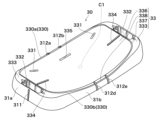
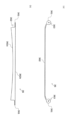
本実施形態に係る自動式胸骨圧迫心臓マッサージ器100は、図1~図4に示すように、患者の胸部上方を左右方向にまたがって配置されるアーチ部10と、アーチ部10の両側をそれぞれ、アーチ部10の上下方向に移動可能に支持するバーチカルロッド20と、板状をなし、バーチカルロッド20を着脱自在に係合させる係合部332を有する背板30と、アーチ部10の天面部11から下方に突出する、衝撃槌ロッド121a及び衝撃槌ロッド121aに固定された衝撃頭パッド121bを有する衝撃槌121と、衝撃槌121を上下に往復運動させる昇降機構122と、昇降機構122を制御する制御部(不図示)と、を有する自動式胸骨圧迫心臓マッサージ器100において、背板30は合成樹脂製であり、背板30の底は、底の縁辺部34(34a,34b,34c,34d)を残して窪ませた凹部35を有し、前記係合部332は背板30の天面33の左右両側の縁辺部333に設けられている。
As shown in FIGS. 1 to 4, an automatic chest
まず、図1を参照して、自動式胸骨圧迫心臓マッサージ器100の構成について説明する。自動式胸骨圧迫心臓マッサージ器100は、人工呼吸手段(不図示)と胸骨圧迫手段120とを備え、人工呼吸手段と胸骨圧迫手段120とが一体型の装置として構成されていることが好ましい。持ち運び性が良く、救命救急の初期において心肺蘇生を迅速に開始することができる。
First, referring to FIG. 1, the configuration of an automatic chest
人工呼吸手段は、患者にガスを吹き込むためのホースと、ホースへガスを供給するためのガス供給系統とを有する。ガスは、例えば、純酸素、酸素富化空気又は空気である。ホースの一方の端部は、例えば、自動式胸骨圧迫心臓マッサージ器100の筐体101に設けられたホース差込口112に連結される。ホースの他方の端部は、例えば、患者に装着するマスク又は気管挿管のチューブに連結される。
The artificial respiration means has a hose for blowing gas into the patient and a gas supply system for supplying gas to the hose. The gas is for example pure oxygen, oxygen-enriched air or air. One end of the hose is connected to, for example, a
胸骨圧迫手段120は、アーチ部10と、バーチカルロッド20と、背板30と、衝撃槌121と、昇降機構122とを備える。
The sternum compression means 120 includes an
(アーチ部)
アーチ部10は、天面部11と、左右側面部12とを有し、患者の胸部上方を左右方向にまたがって配置される。アーチ部10の一部は、筐体101となっていることが好ましい。筐体101には、例えば、人工呼吸手段のガス供給系統、昇降機構122の駆動系統及び制御部が収容される。
(Arch part)
The
(バーチカルロッド)
バーチカルロッド20は、アーチ部の左右方向に一対設けられ、アーチ部の左右側面部12の下端に設けられた固定部13にそれぞれ固定される。バーチカルロッド20は、例えば固定部13のラチェットに係合して、アーチ部10の左右両側をそれぞれ、アーチ部10の上下方向に移動可能に支持する。バーチカルロッド20は、目盛り21が表示されていることが好ましい。アーチ部10を患者にセットした状態で、アーチ部10を患者の胸部に向かって押し下げて行き、頭パッド121bが患者の胸部に接した時点で目盛り21が示す値が、患者の胸厚の値に相当する。この読み取った胸厚を基に、衝撃槌121の圧迫深さを設定することができる。このように、患者の一人ひとりに適した圧迫深さのより細かな調整が可能となる。
(vertical rod)
A pair of
(背板)
背板30は、患者の背中を支持する板状部材である。本実施形態では、制御部はすべてアーチ部10に配置され、背板30は制御部を有さないことが好ましい。X線画像に制御部が写り込まず、X線画像をより鮮明にすることができる。
(Backboard)
The
(衝撃槌)
衝撃槌121は、アーチ部10の天面部11から下方に突出し、天面部11に上下方向に移動可能に支持される。衝撃槌121は、昇降機構122に連結する衝撃槌ロッド121aと、衝撃槌ロッド121aの下端部に取り付けられ、患者の胸部に当てられる衝撃頭パッド121bとを有する。
(Impact mallet)
The
衝撃槌ロッド121a及び衝撃頭パッド121bにおいて、衝撃頭パッド121bは、常にパッド面が患者の胸骨の圧迫ポイントを的確に捉えることができるように、衝撃槌ロッド121aの先端部に衝撃頭パッド121bの角度調整機能を設けることが好ましい。角度調整機能は、例えば、ボールジョイント型構造である。ボールジョイント型構造は、例えば、衝撃槌ロッド121aの先端部に設けられた球状のボール部(不図示)を衝撃頭パッド121bに設けられた収容部(不図示)に摺動・回転自在に嵌め込んだ構造を有する。これによって、衝撃頭パッド121bが患者に対して例えば斜めに当たった場合であっても、衝撃頭パッド121bが首振り又は回転自在であるため、常にパッド面が患者の胸骨と平行になるように衝撃頭パッド121bを当てることができる。その結果、胸骨の骨折を防止できる。
In
(昇降機構)
昇降機構122は、天面部11に対し衝撃槌121を上下に往復運動させる。昇降機構122の駆動方式は、例えばガス駆動方式又は電気駆動方式である。昇降機構122の駆動方式がガス駆動方式であるとき、昇降機構122は、シリンダ123を有する。シリンダ123は、容器状であり、ガス供給口(不図示)及びガス排気口(不図示)とを有する。シリンダ123の内部空間には、ピストン(不図示)と排気時にピストンを押し戻すスプリング(不図示)とが配置される。昇降機構122の駆動方式が電気駆動方式であるとき、衝撃槌121は、例えばモーター駆動によって上下に往復運動する。電気駆動方式は、例えば、内部電池(内部バッテリ)、外部電池(外部バッテリ)、AC100V電源などの外部電源又はこれらの併用である。昇降機構122の駆動方式は、ガス駆動方式と電気駆動方式との混合型駆動方式であってもよい。
(lifting mechanism)
The
(制御部)
制御部は、昇降機構122を制御する。自動式胸骨圧迫心臓マッサージ器100が人工呼吸手段を備えている場合、制御部は、さらに人工呼吸手段のガス供給系統を制御する。制御部は、例えば、プリント基板である。
(control part)
The controller controls the
次に、図2~図13を参照して、背板30についてより詳細に説明する。
Next, the
背板30は、板状をなす。ここで板状とは、長方形、角が丸い長方形、楕円形などの細長形状の輪郭を有する表面及び裏面を備え、表面と裏面との間に厚みを備える形状をいう。表面及び裏面の輪郭を水平面投影したとき、水平面投影された表面の輪郭に囲まれた面積と、水平面投影された裏面の輪郭に囲まれた面積との比は、4:6~6:4であることが好ましい。
The
背板30の外観寸法において、背板30の長手方向(図3におけるD3‐D4方向)の長さは、アーチ部10の左右方向の長さと同程度であり、例えば500~600mmである。バーチカルロッド20が安定して固定されることと、患者の胸部が背板30の真上に位置することを考慮して、背板30の短手方向(図3におけるD1‐D2方向)の長さは、例えば250~320mmである。図2及び図3に示される背板30の天面中央の点C1における高さ(図3における紙面奥‐紙面手前方向の長さ)は、例えば24~33mmである。
Regarding the external dimensions of the
係合部332は、バーチカルロッド20を着脱自在に係合させるための溝又は穴である。係合部332には、例えば、バーチカルロッド20の下端に設けられた突起(不図示)が嵌められる。バーチカルロッド20がアーチ部10を支持することによって、アーチ部10は、患者の胸部上方を左右方向にまたがって配置される。背板30の外観寸法において、係合部332における背板30の高さ(図3における紙面奥‐紙面手前方向の長さ)は、底の縁辺部34の十分な強度を有するように、例えば30~65mmである。
The engaging
背板30は合成樹脂製である。X線を通すことができるため、患者を背板30上に載置したままX線撮影を行うことができる。また、洗浄及び清掃を容易にすることができる。背板30は、全体が射出成形、圧縮成形、ブロー成形などによって一体化した成形品であることが好ましい。天板32と底の縁辺部34(34a,34b,34c,34d)とを一体化することができる。合成樹脂は、硬質の合成樹脂であることが好ましい。硬質の合成樹脂としては、例えば、ポリカーボネート樹脂、ビニルエステル樹脂などの熱可塑性樹脂、又はエポキシ樹脂、フェノール樹脂などの熱硬化性樹脂がある。硬質の合成樹脂は、繊維強化樹脂でもよい。背板30の強度を上げることができる。繊維強化樹脂は、例えば、ガラス繊維強化ポリカーボネート樹脂、ガラス繊維強化ビニルエステル樹脂、ガラス繊維強化エポキシ樹脂、ガラス繊維強化フェノール樹脂、炭素繊維強化ポリカーボネート樹脂、炭素繊維強化フェノール樹脂、炭素繊維強化エポキシ樹脂又は炭素繊維強化ビニルエステル樹脂である。ガラス繊維は、成分元素として、Pb、BaなどのX線を吸収しやすい元素を含有しないことが好ましい。背板30がガラス繊維強化ポリカーボネート樹脂製である場合、ガラス繊維強化ポリカーボネート樹脂におけるガラス繊維の含有率は、求められる強度を考慮して、10~30質量%であることが好ましい。
The
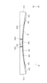
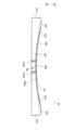
背板30の天面33は、患者を背板30上に載置するときに、患者の背中が接触する側の面である。背板30の天面33は、図2及び図3に示すように、天面の縁辺330に囲まれた領域である。すなわち、天面33は、患者背中接触面336、天面の左右両側の縁辺部333及び中間縁辺部338を有する。天面33は、患者背中接触面336と天面の左右両側の縁辺部333との間、及び患者背中接触面336と中間縁辺部338との間に、連絡部337を有してもよい。本実施形態において、縁辺部333と中間縁辺部338とは、一対の細長状突起312a,312b;312d,312eによって区切られているが、区切られていない場合は一体化されてもよい。天面33は、平滑な面であることが好ましく、より好ましくは、図5に示すような、背板を正面から見て下に凸である平滑な湾曲面である。この平滑な湾曲面であれば、患者の背中の位置のずれをより抑制することができる。本実施形態において、平滑とは、凹凸がない状態、又は患者を背板30に接触させた際に、患者が苦痛に感じない程度の面の凹凸状態をいう。平滑な面は粗面でもよいが、シボ加工面などの、患者が苦痛に感じない程度の凹凸を有する粗面であることが好ましい。患者の背中が天面に接触する際のベタ付き感を軽減し、患者にさらなる快適性を与えることができる。また、背板30の天面33は、抗菌加工品であることが好ましい。背板30を清潔に保つことができる。天面33が抗菌加工品である背板30は、例えば、背板30の天面33に抗菌塗料を塗布することによって得られるか、又は混練によって抗菌剤を配合させた樹脂を成形して得られる。
The
図3に示すように、背板30の天面33の左右両側(図3におけるD3方向側及びD4方向側)の縁辺部333は、それぞれ天面33の左右両側の縁辺から天面33の内側近傍にかけて幅を有する部分である。バーチカルロッド20が安定して固定されることを考慮すると、この幅は、例えば28~45mmである。縁辺部333には、係合部332が設けられる。係合部332のサイズは、開口部が縁辺部333内に収まり、かつ深さが背板30の高さ以内に収まるサイズである。天面33が、背板30を正面から見て下に凸である平滑な湾曲面である場合、左右両側の縁辺部333を残して天面33が湾曲するため、縁辺部333における板厚が確保されたままとなり、係合部332の溝又は穴の深さを維持することができる。したがって、患者の背中の位置のずれをより抑制しつつ、バーチカルロッド20を安定して固定することができる。
As shown in FIG. 3,
背板30の底は、図4に示すように、底の縁辺部34(34a,34b,34c,34d)を残して窪ませた凹部35を有する。縁辺部34を透過したX線に基づいて得られたX線画像の鮮明度は、凹部35を透過したX線に基づいて得られたX線画像の鮮明度よりも低い。しかしながら、患者が背板30上に載置されたとき、縁辺部34は、患者の胸部の中心を通る鉛直線から離れている。したがって、X線画像内の胸部内臓が写った箇所には、縁辺部34による鮮明度低下の影響が顕在化せず、X線画像から医師が得られる情報量の低下が回避される。本実施形態において、底の縁辺部34では、A‐B部の外側において、底の上側の縁辺部34aと、底の下側の縁辺部34bと、底の左側の縁辺部34cと、底の右側の縁辺部34dとが連絡部381を介して連続的に環状に繋がっている。すなわち、背板30の底は、底の縁辺部34と、縁辺部34によって囲まれた凹部35とを有する。
As shown in FIG. 4, the bottom of the
凹部35は、背板30の底において、縁辺部34に囲まれて窪みを有する部分である。背板30の肉厚を薄くするために、天面33ではなく、底に窪みを有することによって、患者に快適性を与える。凹部35は、図4を参照すると、底におけるA‐B部である。凹部35は、図9に示すように、背板30の天面33の左右両側の縁辺部333に挟まれる天板32の下方に設けられる。凹部35のサイズは、背板30の全体の強度及び係合部332の強度が確保可能な限り、できるだけ大きいことが好ましい。X線画像をより広範囲にわたって鮮明にすることができる。凹部35の長手方向(図4におけるD3‐D4方向)の長さは、例えば310~544mmである。凹部35の短手方向(図4におけるD1‐D2方向)の長さは、例えば186~280mmである。凹部35の深さ(図4における紙面奥‐紙面手前方向の長さ)は、例えば中央の点C2において17~29mmであり、凹部35と底の縁辺部34との境界において23~61mmである。
The recessed
天板32は、天面33より上の空間と底の凹部35の空間とを隔てる板である。凹部35の領域における天板32の肉厚はTで表される。肉厚Tは、例えば4~7mmである。
The
本実施形態に係る自動式胸骨圧迫心臓マッサージ器100では、図4、図9及び図10に示すように、背板30は、凹部35の領域にリブを有さず、凹部35の領域の天板32の最小肉厚Tminが天板32の最大肉厚Tmaxの90~100%であることが好ましい。より好ましくは95~100%であり、さらに好ましくは98~100%である。X線画像をより鮮明にすることができる。凹部35の領域を撮影したX線画像には、リブが写り込まず、天板32の肉厚Tが均一又は略均一であるため、肉厚差によるX線画像の鮮明度のムラがない。したがって、X線画像をより鮮明にすることができる。凹部35の領域の天板32の最小肉厚Tminが天板32の最大肉厚Tmaxの100%である場合、凹部35の領域の天板32の肉厚Tが完全に均一である。背板30は、天面33が、背板を正面から見て下に凸の湾曲面であり、凹部35の領域の天板32の肉厚Tが完全に均一であることが好ましい。このとき、凹部35の最深の窪みを有する箇所は、図9に示されるような係合部332の壁と凹部35との接触部分の最上箇所382である。
In the automatic chest
底の縁辺部34は、底の縁辺340から縁辺340の内側近傍にかけて、例えば20~45mmの幅を有する。したがって、背板30は、背板30の輪郭の全周に渡って環状の補強構造38を有することとなる。底の縁辺部34及び凹部35の露出面は、背板30の底面である。背板30の底面は、背板30の肉厚部分を挟んで天面33と反対側に位置する。平らに広げた布担架、床などの平面上に、天面33を上にして背板30を配置するとき、底の縁辺部34は、前記平面と接触する。底の縁辺部34における平面との接触部分は、平坦面であることが好ましい。患者を背板30上に載置するとき、背板30のガタツキを抑制することができる。
The
環状の補強構造38は、背板30の輪郭に沿って欠けなく一周している。欠けを有すると、背板30に荷重がかかったときに背板30がたわむことを抑制できなくなる。環状の補強構造38には、天面33の左右両側の縁辺部333と、係合部332とが設けられる。環状の補強構造38の下側(図4における紙面手前方向側)に設けられる底の縁辺部34の構造は、中実構造でもよく、リブ341、溝342及び有底孔343の少なくともいずれか一つを有する補強構造でもよい。
The annular reinforcing
本実施形態に係る自動式胸骨圧迫心臓マッサージ器100では、図4、図9及び図10に示すように、背板の底の縁辺部34が、リブ341、溝342及び有底孔343の少なくともいずれか一つを有する補強構造となっていることが好ましい。底の縁辺部34の強度を向上しつつ、底の縁辺部34を軽量化することによって、環状の補強構造38の強度を向上しつつ、環状の補強構造38を軽量化することができる。したがって、背板30の強度を向上しつつ、背板30を軽量化することができる。補強構造の形態としては、リブ341を有する補強構造、溝342を有する補強構造、有底孔343を有する補強構造、リブ341と溝342とを有する補強構造、溝342と有底孔とを有する補強構造、有底孔343とリブ341とを有する補強構造又はリブ341と溝342と有底孔343とを有する補強構造がある。
In the automatic chest
リブ341は、係合部332を補強する壁状の部材である。リブ341は、底の左側及び右側の縁辺部34c,34dに設けられる。係合部332にバーチカルロッド20を取り付けるとき、リブ341によって、係合部332の壁が広がることを抑えつつ、背板30を軽量化することができる。リブ341は、リブ同士で接合するか、又は係合部332若しくは連絡部381と共に接合していることが好ましい。リブ341のサイズは、係合部332のサイズによって適宜設定される。係合部332の補強の観点から、図11に示すように、リブ341は、当該リブ341が設けられた側の天面33の縁辺部333に垂直に接合していることが好ましい。
The
溝342は、図4に示すように、底(不図示)と、細長形状の開口部342aとを有する凹みである。細長形状としては、例えば長方形又は角が丸い長方形がある。また、溝342は、例えば、相対する2枚の長壁状リブ38a,38b、間隔を有しつつ長壁状リブ38a,38bの間に挟まれる柱状リブ38cによって形成されているか、又は長壁状リブ38a,38b、柱状リブ38c及び底の内側面345に囲まれることによって形成されている。
The
長壁状リブ38a,38b及び柱状リブ38cは、一体化された部材であり、天板32に接して背板30のたわみを抑制する。したがって背板30の強度を維持しつつ、背板30を軽量化することができる。
The long-
有底孔343は、図4及び図10に示すように、底343bと、非細長形状の開口部343aとを有する凹みである。非細長形状としては、例えば扇形状、三角形状、角が丸い三角形状がある。また、有底孔343は、例えば、長壁状リブ38b、短壁状リブ38d,38e及び底の内側面345に囲まれることによって形成されている。
The bottomed
短壁状リブ38d,38eは、長壁状リブ38a,38b及び柱状リブ38cを支持する。したがって、背板30の強度を維持し、特に天板32に対して横からのたわみ及びねじれを抑制し、背板30を軽量化することができる。
The short-
背板30の側面31は、図2及び図3に示すように、天面33の縁辺330と底の縁辺340との間に挟まれて設けられた面であり、環状帯の外観を呈する。図2に示すように、背板30の側面31は、天面33の左右両側(図3におけるD3方向側及びD4方向側)の縁辺部333から傾斜する側面31aと、天面33の下側(図3におけるD2方向側)の縁辺330bから傾斜する側面31bと、天面33の上側(図3におけるD1方向側)の縁辺330aから傾斜する側面31cとを含む。背板30の側面31は、平滑な面であることが好ましく、より好ましくはシボ加工面などの、患者が苦痛に感じない程度の凹凸を有する粗面である。患者の背中に背板を挿入する際のベタ付き感を軽減することができる。また、背板30の側面31は、抗菌加工品であることが好ましい。背板30を清潔に保つことができる。側面31が抗菌加工品である背板30は、例えば、背板30の側面31に抗菌塗料を塗布することによって得られるか、又は混練によって抗菌剤を配合させた樹脂を成形して得られる。
As shown in FIGS. 2 and 3, the
本実施形態に係る自動式胸骨圧迫心臓マッサージ器100では、図5~図8に示すように、背板30の側面31の全周又は一部分が、背板30の天面33から底面に向うにつれて末広がりに傾斜していることが好ましい。患者の背中に背板を挿入する際に引っかかりを少なくすることができる。側面31の傾斜角は、天面33の左右両側の縁辺部333付近では0°より大きく45°以下であることが好ましく、底の縁辺340付近では45°より大きく85°以下であることが好ましい。側面31の傾斜面は、上に凸の曲面を呈していることが好ましい。また、側面31の傾斜面の肉厚部分を挟んだ反対側には、有底孔343を囲む短壁状リブ38d,38eなどの補強部材が設けられることが好ましい。背板30の強度をより高くすることができる。背板30が、全体が一体化された成形品である場合、製造する際、末広がりの傾斜は、金型から成形品を抜くときの抜き勾配にすることができる。
In the automatic chest
本実施形態に係る自動式胸骨圧迫心臓マッサージ器100では、図2、図3、図7及び図8に示すように、背板30の天面33の係合部332が設けられた左右両側の縁辺部333から傾斜する側面31aにそれぞれ目印311を有し、天面33を正面視したときに、目印311は、両方とも同時に目視可能であることが好ましい。目印311の形態としては、例えば突起、印刷又はラベルがあり、視認性の観点から、突起であることが好ましい。目印311の形状としては、例えば長方形、角が丸い長方形などの細長形状、三角形状又は矢印形状があり、好ましくは細長形状である。患者の背中に背板30を挿入する際、患者の胸骨の最適な圧迫部分に衝撃槌121を正確に当てるための位置合わせを容易にできる。特にバーチカルロッド20を差し込んだ後においても位置を確認しやすい。
As shown in FIGS. 2, 3, 7 and 8, in the automatic chest
本実施形態に係る自動式胸骨圧迫心臓マッサージ器100では、図2、図3及び図10に示すように、背板30の天面33の係合部332が設けられた左右両側の縁辺部333から天面中央側に向う位置に少なくとも一対の目印334を有することが好ましい。目印334の形態としては、例えば突起、溝、塗装又はラベルがある。目印334の形状としては、例えば長方形、角が丸い長方形などの細長形状、三角形状又は矢印形状があり、好ましくは細長形状である。患者の背中に背板30を挿入する際、患者の胸骨の最適な圧迫部分に衝撃槌121を正確に当てるための位置合わせを容易にできる。特にバーチカルロッド20を差し込む前においても位置を確認しやすい。
As shown in FIGS. 2, 3, and 10, in the automatic chest
本実施形態に係る自動式胸骨圧迫心臓マッサージ器100では、図2~図6に示すように、背板30は天面33と凹部35における底面とをつなぐ貫通孔335を有し、貫通孔335は、細長形状の開口部を有し、かつ、天面33を正面視したときに、開口部の長手方向が背板30の天面33の上側の縁辺330a又は下側の縁辺330bの伸延方向(D3‐D4)に沿っており、背板30は、天面33の上側の縁辺330a又は下側の縁辺330bのうち、少なくともいずれか一方の縁辺から傾斜する側面31b,31cに、側面31b,31cの傾斜方向に沿って、一対の細長状突起312a,312b;312d,312eを有し、一対の細長状突起312a,312b;312d,312eは、開口部の長手方向の長さPと同じ間隔Q1,Q2を開けて設けられていることが好ましい。貫通孔335は、背板固定ベルト42を通すための孔であり、一対の細長状突起312a,312b;312d,312eは、間に背板固定ベルト42を挟むための突起である。開口部の細長形状は、例えば角が丸い長方形である。開口部の細長形状の長さと幅との比は、2:7~1:8が好ましい。背板固定ベルトの遊びを最小限に抑制する。一対の細長状突起312a,312b;312d,312eは、患者が苦痛に感じない程度の突起であるならば、天面33側に延長して設けられていてもよく、さらに貫通孔335まで延長してもよい。一対の細長状突起の形態としては、天面33の上側の縁辺330aから傾斜する側面31cに、側面31cの傾斜方向に沿って、一対の細長状突起312a,312bを有する形態、天面33の下側の縁辺330bから傾斜する側面31bに、側面31bの傾斜方向に沿って、一対の細長状突起312d,312eを有する形態、及び天面33の上側の縁辺330aから傾斜する側面31cに、側面31cの傾斜方向に沿って、一対の細長状突起312a,312bを有し、かつ天面33の下側の縁辺330bから傾斜する側面31bに、側面31bの傾斜方向に沿って、一対の細長状突起312d,312eを有する形態がある。
In the automatic chest
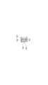
図12は、図4に示される背板を有する自動式胸骨圧迫心臓マッサージ器とは別の実施形態に係る自動式胸骨圧迫心臓マッサージ器が有する背板の底面図である。本実施形態に係る自動式胸骨圧迫心臓マッサージ器100では、図12に示すように、背板30の底の縁辺部34のうち、少なくとも上下両側の縁辺部34a,34bの伸延方向(D3‐D4)に沿って金属部材36が固定されていることが好ましい。金属部材36は、患者の体重によって、背板の高さ方向(図5~図8におけるD5‐D6方向)に、背板30がたわむことを抑制する部材である。金属部材36は、図13に示すように、患者の体重による応力を受ける帯板部362を有することが好ましい。ここで、帯板部362は、底の縁辺部34における帯板部差し込み口344に挿入されることによって、縁辺部34に装着される。したがって、凹部35を通過したX線に基づいて得られたX線画像に金属部材36が写り込まない上で、患者の体重によって、背板30が底面側にたわむことを抑制することができる。帯板部362の形状は、帯板部差し込み口344の形状に適合し、挿入したときに縁辺部34からはみ出さないよう適宜設定される。帯板部362の長手方向に伸びる一側の縁辺の輪郭362bは、段差のない直線であることが好ましい。縁辺の輪郭362bが底の縁辺部の面346上に位置することができる。金属部材36は、図12に示すように、さらに締結部361を有していることが好ましい。締結部361は、例えばねじ孔363などの係合手段を有する。金属部材36が板の形態である場合、締結のしやすさから、締結部361は、金属部材36の両端に設けられることが好ましい。図13に示すように、帯板部362の法線に対して締結部361の法線が90°の角度をなすように傾いた状態である場合、帯板部362及び締結部361は、一枚の板から両端を捻った後焼鈍することによって形成されてもよいが、一本の角材を切削することによって形成されることが好ましい。一本の角材を切削することによって、より高強度の金属部材が得られる。締結部361は、例えば、図12に示されるねじ37をねじ孔363に通して、背板30の底の固定手段受け部(不図示)に到達させて締結することによって固定できる。締結部361は、ねじ37に代えて、又はねじ37と共に接着剤を用いて背板30の底の固定手段受け部に固定されてもよい。
12 is a bottom view of the back plate of an automatic chest compression and heart massager according to another embodiment than the automatic chest compression and heart massager with the back plate shown in FIG. 4. FIG. In the automatic chest
帯板部差し込み口344は、帯板部362を挿入するための溝である。帯板部差し込み口344の深さ方向は、背板の高さ方向であることが好ましい。帯板部362の幅方向が背板の高さ方向に一致して、患者の体重によって背板30がたわむことをより抑制することができる。帯板部差し込み口344は、帯板部362を挿入したときに隙間がないサイズであることが好ましい。帯板部362を緊密に固定することができる。帯板部差し込み口344の底面(不図示)は、図5の正面図及び図6の背面図の紙面手前側から見て天面33の縁辺330に沿うことが好ましい。帯板部362の長手方向に伸びる他側の縁辺の輪郭362aが帯板部差し込み口344の底面の形状に沿うことによって、患者の体重による応力を均等に受けることができる。例えば、天面33が、背板を正面から見て下に凸の湾曲面であり、帯板部差し込み口344が、底の上下両側の縁辺部34a,34bに設けられているとき、帯板部差し込み口344の底面(不図示)は、図6に示すような天面33の上側の縁辺330a、又は図5に示すような天面33の下側の縁辺330bに沿っている。また、金属部材36の帯板部362の形態は、図13(b)に示すように、輪郭362aが弧状である板の形態とすることができる。ここで、輪郭362aは、帯板部差し込み口344の底面に満遍なく接することができる。したがって、輪郭362aは、天面33の上側の縁辺330a又は下側の縁辺330bにおいて、患者の体重による応力を均等に受けることができる。帯板部差し込み口344は、縁辺部34に沿う曲線部分344aを有することが好ましい。帯板部362が帯板部差し込み口344に応じて湾曲することにより、患者の体重による応力に対する強度を向上することができる。
The band plate
金属部材36の配置箇所の形態としては、図12に示すように、背板30の底の縁辺部34のうち、上側及び下側の縁辺部34a,34bの伸延方向(D3‐D4)に沿って金属部材36が配置されている形態、背板30の底の縁辺部34のうち、上側及び下側の縁辺部34a,34bの伸延方向(D3‐D4)並びに左側の縁辺部34cの伸延方向(D1‐D2)に沿って金属部材36が配置されている形態、上側及び下側の縁辺部34a,34bの伸延方向(D3‐D4)並びに右側の縁辺部34dの伸延方向(D1‐D2)に沿って金属部材36が配置されている形態、背板30の底の縁辺部34のうち、上側及び下側の縁辺部34a,34bの伸延方向(D3‐D4)並びに左側及び右側の縁辺部34c,34dの伸延方向(D1‐D2)に沿って金属部材36が配置されている形態がある。
As shown in FIG. 12, the
金属部材36の帯板部362の形態は、金属部材36が配置された背板30の底を正面視したとき、帯板部362の両端同士を接合した環状の枠の形態であってもよい。一つの金属部材36のみによって、底の全ての側の縁辺部34a,34b,34c,34dの伸延方向に沿って配置可能となる。ここで、帯板部差し込み口344は、底の環状の縁辺部34の全周に沿っている。締結部361は、X線を透過しやすくするため、縁辺部34に沿って固定する際に、底の凹部35内に入らないことが好ましい。
The form of the
患者背中接触面336と連絡部337との境界、連絡部337と縁辺部333との境界、連絡部337と中間縁辺部338との境界、縁辺部333と側面31aとの境界、縁辺部333と側面31bとの境界、縁辺部333と側面31cとの境界、中間縁辺部338と側面31bとの境界及び中間縁辺部338と側面31cとの境界は、図2、図3、図5及び図6では角をなしているが、R面をなしていてもよい。これらの境界のうち、一部が角をなし、残りがR面をなしていてもよい。
The boundary between the patient back
本実施形態に係る自動式胸骨圧迫心臓マッサージ器100が布担架40に固定される形態の一例を説明する。図14に示すように、背板付き布担架500は、布担架40と、背板30とを備える。布担架40は、シート部41と、背板固定ベルト42と、肩部固定ベルト43とを備える。シート部41は、患者の載置予定位置に従って、頭部載置予定部411と、胸部載置予定部412と、腹部載置予定部413とを有する。背板固定ベルト42は、胸部載置予定部412の表面から突出する第1の背板固定ベルト片42aと、第1の背板固定ベルト片42aよりも腹部載置予定部413側の表面から突出する第2の背板固定ベルト片42bと、第1の背板固定ベルト片42a及び第2の背板固定ベルト片42bを連結する背板固定ベルト連結手段42cを有する。肩部固定ベルト43は、胸部載置予定部412の表面から突出する脇側ベルト片43aと、脇側ベルト片43aよりも頭部載置予定部411側の表面から突出する肩側ベルト片43bと、脇側ベルト片43a及び肩側ベルト片43bを連結する肩部固定ベルト連結手段43cとを有する。背板30は、胸部載置予定部412に設置されている。
An example of a form in which the automatic chest
背板固定ベルト42は、布担架40を用いるとシート部41と背板30とのズレが生じやすいとき、例えば患者を搬送するときに、図14及び図15に示すように背板30をシート部41に確実に固定させるベルトである。一対の細長状突起312d,312eの間を経由した第1の背板固定ベルト片42aの一端部と、貫通孔335に通された第2の背板固定ベルト片42bの一端部とは、背板固定ベルト連結手段42cを介して連結している。連結する際、背板固定ベルト連結手段42cの位置は、特に限定されない。一対の細長状突起312の間に第2の背板固定ベルト片42bが挟まれることによって、患者の搬送中におけるシート部41と背板30とのズレを防止することができる。第1の背板固定ベルト片42aと、第2の背板固定ベルト片42bとは、それぞれの他端部がシート部41に固定された2本の独立したベルトでもよく、図15のような、縫合などの接合部材45を介してシート部41に固定された1本のベルトでもよい。背板固定ベルト連結手段42cは、例えば、面ファスナーである。
When the
背板30には、図1に示すように、アーチ部10及びバーチカルロッド20が取付けられる。アーチ部10及びバーチカルロッド20の取付けは、予めアーチ部10の固定部13をバーチカルロッド20に固定して、アーチ部10及びバーチカルロッド20を一体化しておいたものを背板30に取付けるか、又は背板30にバーチカルロッド20を係合した後、アーチ部10をバーチカルロッド20に固定してもよい。
The
肩部固定ベルト43は、図14に示すように、患者の腕の付け根部分をシート部41に確実に緊縛固定させるベルトである。肩部固定ベルト43は、左腕用及び右腕用があり、シート部41の長手方向に対して左側及び右側にそれぞれ一つずつ設けられている。脇側ベルト片43aは、シート部41の表面から突出し、患者の脇下から肩前部にわたって掛け回される。肩側ベルト片43bは、シート部41の表面から突出し、患者の肩上部から肩前部にわたって掛け回される。肩部固定ベルト連結手段43cは、例えば、ラチェットバックル、カムバックルなどのバックルである。
As shown in FIG. 14, the
脇側ベルト片43aと肩側ベルト片43bとは、図16に示すように、シート部41の裏面側で繋がった一本のベルトであることが好ましい。このとき、脇側ベルト片43aは、シート部41に形成された脇側ベルト片通し孔46aを経由してシート部41の表面から突出した部分であり、肩側ベルト片43bは、シート部41に形成された肩側ベルト片通し孔46bを経由してシート部41の表面に突出した部分である。脇側ベルト片43a及び肩側ベルト片43bを1本のベルトとすることで、患者の腕の太さにかかわらず、患者を布担架40により強固に固定することができる。
The armpit-
背板30は、図2~図4及び図16に示すように、天面33に脇側ベルト片通し孔331をさらに有し、脇側ベルト片43aだけを背板30を挿通させ、肩側ベルト片43bを背板30に挿通させないことが好ましい。肩部固定ベルト43を締め上げたとき、肩側ベルト片43bの基端部としての肩側ベルト片通し孔46bを背板30側に手繰り寄せることができ、患者の腕の太さにかかわらず、患者を布担架40により強固に固定することができる。患者の胸部を、マッサージ器の胸骨圧迫位置(衝撃槌121の直下)により確実に配置させることができ、処理をより迅速に行って蘇生率の向上が見込まれる。また、布担架40の長手方向における背板30の長さをより短くすることができ、背板30の位置を、マッサージ器の胸骨圧迫位置に合わせてより容易に調整することができる。
As shown in FIGS. 2 to 4 and 16, the
X線撮影では、自動式胸骨圧迫心臓マッサージ器100が装着された患者を布担架40から下ろした後で、患者の胸部をX線撮影することが多い。しかしながら、シート部41、第1の背板固定ベルト片42a、第2の背板固定ベルト片42b及び脇側ベルト片43aは、得られるX線画像に鮮明度低下の影響が顕在化しない程度にX線を透過させる。したがって、患者を布担架40から下ろさなくても患者の胸部をX線撮影できる。
In X-ray imaging, the patient's chest is often X-rayed after the patient with the automatic chest
10 アーチ部
11 天面部
12 左右側面部
13 固定部
20 バーチカルロッド
21 目盛り
30 背板
31 側面
31a 天面の左右両側の縁辺部から傾斜する側面
31b 天面の下側の縁辺から傾斜する側面
31c 天面の上側の縁辺から傾斜する側面
32 天板
33 天面
34a 底の上側の縁辺部
34b 底の下側の縁辺部
34c 底の左側の縁辺部
34d 底の右側の縁辺部
35 凹部
36 金属部材
37 ねじ
38 環状の補強構造
38a,38b 長壁状リブ
38c 柱状リブ
38d,38e 短壁状リブ
40 布担架
41 シート部
42 背板固定ベルト
42a 第1の背板固定ベルト片
42b 第2の背板固定ベルト片
42c 背板固定ベルト連結手段
43 肩部固定ベルト
43a 脇側ベルト片
43b 肩側ベルト片
43c 肩部固定ベルト連結手段
45 接合部材
46a シート部に形成された脇側ベルト片通し孔
46b シート部に形成された肩側ベルト片通し孔
100 自動式胸骨圧迫心臓マッサージ器
101 筐体
112 ホース差込口
120 胸骨圧迫手段
121 衝撃槌
121a 衝撃槌ロッド
121b 衝撃頭パッド
122 昇降機構
123 シリンダ
311 側面の目印
312a,312b,312d,312e 細長状突起
330 天面の縁辺
330a 天面の上側の縁辺
330b 天面の下側の縁辺
331 天面の脇側ベルト片通し孔
332 係合部
333 天面の左右両側の縁辺部
334 天面の目印
335 貫通孔
336 患者背中接触面
337 連絡部
338 中間縁辺部
340 底の縁辺
341 リブ
342 溝
342a 溝の細長形状の開口部
343 有底孔
343a 有底孔の非細長形状の開口部
343b 有底孔の底
344 帯板部差し込み口
344a 帯板部差し込み口の曲線部分
345 底の内側面
346 底の縁辺部の面
361 締結部
362 帯板部
362a 縁辺の輪郭
362b 縁辺の輪郭
363 ねじ孔
381 連絡部
382 係合部の壁と凹部との接触部分の最上箇所
411 頭部載置予定部
412 胸部載置予定部
413 腹部載置予定部
500 背板付き布担架
10 Arch part 11 Top surface part 12 Left and right side parts 13 Fixed part 20 Vertical rod 21 Scale 30 Back plate 31 Side surface 31a Side surface 31b inclined from the left and right edges of the top surface Side surface 31c inclined from the lower edge of the top surface Top Side surface 32 inclined from the upper edge of the surface Top plate 33 Top surface 34a Bottom upper edge 34b Bottom lower edge 34c Bottom left edge 34d Bottom right edge 35 Recess 36 Metal member 37 Screw 38 Annular reinforcing structure 38a, 38b Long-walled rib 38c Column-shaped rib 38d, 38e Short-walled rib 40 Cloth stretcher 41 Seat part 42 Back plate fixing belt 42a First back plate fixing belt piece 42b Second back plate fixing belt Piece 42c Back plate fixing belt connection means 43 Shoulder fixing belt 43a Side belt piece 43b Shoulder side belt piece 43c Shoulder fixing belt connection means 45 Joining member 46a Side belt piece through hole 46b formed in the seat portion In the seat portion Formed shoulder belt one-way hole 100 Automatic chest compression heart massager 101 Housing 112 Hose insertion port 120 Chest compression means 121 Impact hammer 121a Impact hammer rod 121b Impact head pad 122 Elevating mechanism 123 Cylinder 311 Side mark 312a , 312b, 312d, 312e Elongated protrusions 330 Top surface edge 330a Top surface upper edge 330b Top surface lower edge 331 Top surface side belt through hole 332 Engagement portion 333 Left and right sides of the top surface Edge portion 334 Top surface mark 335 Through hole 336 Patient back contact surface 337 Communication portion 338 Intermediate edge portion 340 Bottom edge 341 Rib 342 Groove 342a Elongated opening 343 of groove 343 Bottomed hole 343a Non-elongated shape of bottomed hole Opening 343b Bottom of bottomed hole 344 Band plate insertion port 344a Curved portion 345 of band plate insertion port Inner surface 346 Bottom edge surface 361 Fastening portion 362 Band plate portion 362a Edge outline 362b Edge edge Contour 363 Screw hole 381 Connecting portion 382 Uppermost portion 411 of contact portion between wall of engaging portion and concave portion Planned head placement portion 412 Planned chest placement portion 413 Planned abdomen placement portion 500 Cloth stretcher with backboard
Claims (8)
該アーチ部の両側をそれぞれ、該アーチ部の上下方向に移動可能に支持するバーチカルロッドと、
板状をなし、前記バーチカルロッドを着脱自在に係合させる係合部を有する背板と、
前記アーチ部の天面部から下方に突出する、衝撃槌ロッド及び該衝撃槌ロッドに固定された衝撃頭パッドを有する衝撃槌と、
該衝撃槌を上下に往復運動させる昇降機構と、
該昇降機構を制御する制御部と、を有する自動式胸骨圧迫心臓マッサージ器において、
前記背板は合成樹脂製であり、
前記背板の底は、底の縁辺部を残して窪ませた凹部を有し、
前記係合部は前記背板の天面の左右両側の縁辺部に設けられており、
前記背板は、前記凹部の領域にリブを有さず、前記凹部の領域の天板の最小肉厚が該天板の最大肉厚の90~100%であることを特徴とする自動式胸骨圧迫心臓マッサージ器。 an arch portion arranged across the upper chest of the patient in the left-right direction;
a vertical rod supporting both sides of the arch portion so as to be movable in the vertical direction of the arch portion;
a back plate having a plate shape and having an engaging portion for detachably engaging the vertical rod;
an impact hammer having an impact hammer rod and an impact head pad fixed to the impact hammer rod projecting downward from the top surface of the arch;
a lifting mechanism for reciprocating the impact hammer up and down;
A control unit that controls the lifting mechanism, and an automatic chest compression heart massager comprising:
The back plate is made of synthetic resin,
The bottom of the back plate has a recess that is recessed leaving the edge of the bottom,
The engaging portions are provided on both left and right edges of the top surface of the back plate,
The automatic sternum, wherein the back plate has no ribs in the region of the recess, and the minimum thickness of the top plate in the region of the recess is 90 to 100% of the maximum thickness of the top plate. Compression heart massager.
該貫通孔は、細長形状の開口部を有し、かつ、前記天面を正面視したときに、前記開口部の長手方向が前記背板の天面の上側の縁辺又は下側の縁辺の伸延方向に沿っており、
前記背板は、前記天面の上側及び下側のうち、少なくともいずれか一方の縁辺から傾斜する側面に、前記側面の傾斜方向に沿って、一対の細長状突起を有し、
該一対の細長状突起は、前記開口部の長手方向の長さと同じ間隔を開けて設けられていることを特徴とする請求項1~6のいずれか一つに記載の自動式胸骨圧迫心臓マッサージ器。 The back plate has a through hole connecting the top surface and the bottom surface of the recess,
The through-hole has an elongated opening, and the longitudinal direction of the opening extends from the upper edge or the lower edge of the top surface of the back plate when the top surface is viewed from the front. along the direction of
The back plate has a pair of elongated projections along the direction of inclination of the side surface on the side surface that is inclined from at least one of the upper and lower sides of the top surface,
The automatic chest compression cardiac massager according to any one of claims 1 to 6 , wherein the pair of elongated protrusions are provided with the same interval as the length of the opening in the longitudinal direction. vessel.
前記人工呼吸手段と前記胸骨圧迫手段とが一体型の装置として構成されていることを特徴とする請求項1~7のいずれか一つに記載の自動式胸骨圧迫心臓マッサージ器。 The automatic chest compression heart massager includes artificial respiration means, and chest compression means having the arch portion, the vertical rod, the back plate, the impact mallet, and the lifting mechanism,
The automatic chest compression heart massager according to any one of claims 1 to 7 , wherein said artificial respiration means and said chest compression means are configured as an integrated device.
Priority Applications (1)
| Application Number | Priority Date | Filing Date | Title |
|---|---|---|---|
| JP2019120390A JP7253241B2 (en) | 2019-06-27 | 2019-06-27 | automatic chest compression heart massager |
Applications Claiming Priority (1)
| Application Number | Priority Date | Filing Date | Title |
|---|---|---|---|
| JP2019120390A JP7253241B2 (en) | 2019-06-27 | 2019-06-27 | automatic chest compression heart massager |
Publications (3)
| Publication Number | Publication Date |
|---|---|
| JP2021003538A JP2021003538A (en) | 2021-01-14 |
| JP2021003538A5 JP2021003538A5 (en) | 2022-06-09 |
| JP7253241B2 true JP7253241B2 (en) | 2023-04-06 |
Family
ID=74097385
Family Applications (1)
| Application Number | Title | Priority Date | Filing Date |
|---|---|---|---|
| JP2019120390A Active JP7253241B2 (en) | 2019-06-27 | 2019-06-27 | automatic chest compression heart massager |
Country Status (1)
| Country | Link |
|---|---|
| JP (1) | JP7253241B2 (en) |
Citations (3)
| Publication number | Priority date | Publication date | Assignee | Title |
|---|---|---|---|---|
| JP2015139595A (en) | 2014-01-29 | 2015-08-03 | コ−ケンメディカル株式会社 | Stretcher with automatic chest compression cardiac massage device and stretcher used for the same |
| US20170348190A1 (en) | 2016-06-06 | 2017-12-07 | Jolife Ab | Back plates for mechanical cpr compression |
| JP2018126483A (en) | 2017-02-06 | 2018-08-16 | コ−ケンメディカル株式会社 | Automatic cardiopulmonary resuscitator |
-
2019
- 2019-06-27 JP JP2019120390A patent/JP7253241B2/en active Active
Patent Citations (3)
| Publication number | Priority date | Publication date | Assignee | Title |
|---|---|---|---|---|
| JP2015139595A (en) | 2014-01-29 | 2015-08-03 | コ−ケンメディカル株式会社 | Stretcher with automatic chest compression cardiac massage device and stretcher used for the same |
| US20170348190A1 (en) | 2016-06-06 | 2017-12-07 | Jolife Ab | Back plates for mechanical cpr compression |
| JP2018126483A (en) | 2017-02-06 | 2018-08-16 | コ−ケンメディカル株式会社 | Automatic cardiopulmonary resuscitator |
Also Published As
| Publication number | Publication date |
|---|---|
| JP2021003538A (en) | 2021-01-14 |
Similar Documents
| Publication | Publication Date | Title |
|---|---|---|
| KR101648205B1 (en) | Backboard for an automated cpr system | |
| KR20160025559A (en) | Positioning device and method for use with a patient under anesthesia | |
| CA2412210A1 (en) | Portable cardiopulmonary resuscitation device with precise compression depth and uniformity | |
| US20120305005A1 (en) | Surgical foot support with handles | |
| JP7253241B2 (en) | automatic chest compression heart massager | |
| US10743917B2 (en) | Walking skates system removably coupled to an external ring fixation system | |
| CN108743132A (en) | Simple airway open pillow | |
| EP4000582B1 (en) | Device for cardio-pulmonary resuscitation of a patient | |
| JP7106109B2 (en) | automatic cardiopulmonary resuscitator | |
| JP2000024069A (en) | Automatic heart and lung resuscitator | |
| CN209751076U (en) | Head and neck fixing device for CT simulation room | |
| KR100654883B1 (en) | Ankle exercise equipment | |
| US3889663A (en) | Ambulance cot with cardiopulmonary resuscitation seat and method of administering cardiopulmonary resuscitation | |
| US11497678B2 (en) | System and method for airway management | |
| US20200390629A1 (en) | System and method for airway management | |
| US20200390647A1 (en) | Device for assisting cpr | |
| US4305389A (en) | Rack for a foot-operated anesthetic gas bag | |
| JP4368998B2 (en) | Yoke mounting aid | |
| JP2021003538A5 (en) | ||
| CN213964077U (en) | Medical pillow of sleeping of lying prone | |
| CN217696877U (en) | A head and neck fixation auxiliary device for patients with endotracheal intubation | |
| CN119745580B (en) | A neonatal surgical upper limb fixation frame | |
| CN217066949U (en) | A supine knee bending position pad kit | |
| JP3231340U (en) | Abdominal breathing aid | |
| CN218045665U (en) | Bedridden patient lateral position manager |
Legal Events
| Date | Code | Title | Description |
|---|---|---|---|
| A521 | Request for written amendment filed |
Free format text: JAPANESE INTERMEDIATE CODE: A523 Effective date: 20220601 |
|
| A621 | Written request for application examination |
Free format text: JAPANESE INTERMEDIATE CODE: A621 Effective date: 20220601 |
|
| A131 | Notification of reasons for refusal |
Free format text: JAPANESE INTERMEDIATE CODE: A131 Effective date: 20230207 |
|
| A977 | Report on retrieval |
Free format text: JAPANESE INTERMEDIATE CODE: A971007 Effective date: 20230210 |
|
| A521 | Request for written amendment filed |
Free format text: JAPANESE INTERMEDIATE CODE: A523 Effective date: 20230306 |
|
| TRDD | Decision of grant or rejection written | ||
| A01 | Written decision to grant a patent or to grant a registration (utility model) |
Free format text: JAPANESE INTERMEDIATE CODE: A01 Effective date: 20230314 |
|
| A61 | First payment of annual fees (during grant procedure) |
Free format text: JAPANESE INTERMEDIATE CODE: A61 Effective date: 20230317 |
|
| R150 | Certificate of patent or registration of utility model |
Ref document number: 7253241 Country of ref document: JP Free format text: JAPANESE INTERMEDIATE CODE: R150 |