JP7253190B2 - Coin-roll detection device, coin-roll detection method, and coin-roll storage device - Google Patents
Coin-roll detection device, coin-roll detection method, and coin-roll storage device Download PDFInfo
- Publication number
- JP7253190B2 JP7253190B2 JP2019119825A JP2019119825A JP7253190B2 JP 7253190 B2 JP7253190 B2 JP 7253190B2 JP 2019119825 A JP2019119825 A JP 2019119825A JP 2019119825 A JP2019119825 A JP 2019119825A JP 7253190 B2 JP7253190 B2 JP 7253190B2
- Authority
- JP
- Japan
- Prior art keywords
- coin
- resistance
- magnetic
- roll
- value
- Prior art date
- Legal status (The legal status is an assumption and is not a legal conclusion. Google has not performed a legal analysis and makes no representation as to the accuracy of the status listed.)
- Active
Links
Images


Landscapes
- Geophysics And Detection Of Objects (AREA)
- Investigating Or Analyzing Materials By The Use Of Magnetic Means (AREA)
Description
本発明は、棒金検知装置、棒金検知方法および棒金収納装置に関する。 The present invention relates to a coin-roll detection device, a coin-roll detection method, and a coin-roll storage device.
特許文献1には、複数の集積硬貨(以下、棒金と言う)を棒金収納庫のトレイに載置して収納する棒金収納装置が開示されている。特許文献1に開示された棒金収納装置は、トレイに載置される棒金の近傍に磁気センサが設けられており、この時期センサにより棒金がトレイに載置されたか否かを検知する。 Patent Literature 1 discloses a coin-roll storage device that stores a plurality of accumulated coins (hereinafter referred to as coin-rolls) by placing them on a tray of a coin-roll storage. The coin-roll storage device disclosed in Patent Document 1 is provided with a magnetic sensor in the vicinity of the coin-roll placed on the tray, and the sensor detects whether or not the coin-roll is placed on the tray. .
ところで、特許文献1に開示された棒金収納装置は、当該棒金収納装置における電源部の発熱などにより棒金収納庫の内部の温度が上昇することがある。
棒金を検知するための磁気センサは、棒金収納庫の内部に設けられている。そのため、磁気センサの温度は棒金収納庫の内部の温度変化に応じて変化する。ここで、磁気センサは、磁気コイルを備えているが、磁気コイルのインダクタンスの値は、温度変化に応じて変動する。当該変動が大きい場合、磁気センサによる棒金の検知精度が低下する可能性がある。
By the way, in the coin-roll storage device disclosed in Patent Document 1, the temperature inside the coin-roll storage may rise due to the heat generation of the power supply unit in the coin-roll storage device.
A magnetic sensor for detecting a coin roll is provided inside the coin roll storage. Therefore, the temperature of the magnetic sensor changes according to the temperature change inside the coin-roll storage. Here, the magnetic sensor has a magnetic coil, and the value of the inductance of the magnetic coil fluctuates according to temperature changes. If the variation is large, there is a possibility that the detection accuracy of the coin roll by the magnetic sensor will be lowered.
本発明の目的は、温度変化による棒金の検知精度の低下を防止する棒金検知装置、棒金検知方法および棒金収納装置を提供することにある。 SUMMARY OF THE INVENTION It is an object of the present invention to provide a coin-roll detection device, a coin-roll detection method, and a coin-roll storage device that prevent deterioration in detection accuracy of coin-rolls due to temperature changes.
本発明の第1の態様は、棒金収納庫における棒金の有無を検知する棒金検知装置であって、前記棒金の磁気的性質を検出するための磁気コイルと、前記磁気コイルと同一の配線基板に設けられると共に、前記磁気コイルに接続された抵抗部とを備えた磁気センサと、前記磁気センサの抵抗にかかる値を測定する測定部と、前記抵抗にかかる値に関連付けられた補正値を用いて、前記磁気的性質による出力信号を補正する補正部と、を備え、前記抵抗にかかる値は、前記磁気コイルに直流電流を供給した際の前記磁気コイルの抵抗にかかる値、前記抵抗部に直流電流を供給した際の前記抵抗部の抵抗にかかる値、および前記磁気コイルと前記抵抗部とを組み合わせた回路の抵抗にかかる値の、何れかである、構成とした。
本発明の第2の態様は、棒金収納庫における棒金の有無を検知する棒金検知装置であって、前記棒金の磁気的性質を検出する磁気センサと、前記磁気センサの抵抗にかかる値を測定する測定部と、前記抵抗にかかる値に関連付けられた補正値を用いて、前記磁気的性質による出力信号を補正する補正部と、前記磁気センサに交流電流を供給する交流電流供給部と、前記磁気センサに直流電流を供給する直流電流供給部と、前記交流電流供給部による前記磁気センサへの交流電流の供給と、前記直流電流供給部による前記磁気センサへの直流電流の供給と、を切り替える電流切替部とを備え、前記磁気的性質は、前記電流切替部の切替えにより、前記交流電流供給部からの交流電流が前記磁気センサに供給されている際に検出され、前記抵抗にかかる値は、前記電流切替部の切替えにより、前記直流電流供給部からの直流電流が前記磁気センサに供給されている際に測定される、構成とした。
A first aspect of the present invention is a coin-roll detecting device for detecting the presence or absence of a coin-roll in a coin-roll storage, comprising: a magnetic coil for detecting the magnetic property of the coin-roll; a magnetic sensor provided on a wiring board of and including a resistance unit connected to the magnetic coil ; a measurement unit for measuring a value applied to the resistance of the magnetic sensor; and a correction associated with the value applied to the resistance a correction unit that corrects the output signal due to the magnetic property using a value, wherein the value applied to the resistance is the value applied to the resistance of the magnetic coil when a direct current is supplied to the magnetic coil, the A value applied to the resistance of the resistance portion when a DC current is supplied to the resistance portion, or a value applied to the resistance of a circuit in which the magnetic coil and the resistance portion are combined.
A second aspect of the present invention is a coin-roll detecting device for detecting the presence or absence of a coin-roll in a coin-roll storage, and is related to a magnetic sensor for detecting the magnetic properties of the coin-roll and the resistance of the magnetic sensor. a measuring unit for measuring a value, a correcting unit for correcting the output signal due to the magnetic property using a correction value associated with the value applied to the resistance, and an alternating current supply unit for supplying an alternating current to the magnetic sensor. a DC current supply unit for supplying a DC current to the magnetic sensor; an AC current supply for the magnetic sensor by the AC current supply unit; and a DC current supply for the magnetic sensor by the DC current supply unit. , wherein the magnetic property is detected by switching the current switching unit when an alternating current from the alternating current supply unit is supplied to the magnetic sensor, and the magnetic property is detected by the resistance Such a value is measured when the DC current from the DC current supply unit is supplied to the magnetic sensor by switching the current switching unit.
本発明によれば、棒金収納庫における棒金の有無を検知する棒金検知装置であって、磁気センサの抵抗にかかる値を測定し、抵抗にかかる値に関連付けられた補正値を用いて、磁気センサが検出した棒金の磁気的性質による出力信号を補正するので、温度変化による棒金の検知精度の低下を防止することができる。 According to the present invention, there is provided a coin-roll detecting device for detecting the presence or absence of coin-rolls in a coin-roll storage, which measures a resistance value of a magnetic sensor and uses a correction value associated with the resistance value. Since the output signal based on the magnetic property of the coin roll detected by the magnetic sensor is corrected, it is possible to prevent deterioration in detection accuracy of the coin roll due to temperature changes.
〈棒金収納装置〉
棒金収納装置の一実施形態として図面を参照して以下に説明する。
〈Money roll storage device〉
An embodiment of the coin-roll storage device will be described below with reference to the drawings.
図1に示す本実施形態の棒金収納装置10は、金融機関の店舗の係員側スペースに設置されて係員により取り扱われるものである。棒金収納装置10は、窓口カウンタに近い位置で使用され、主に小束紙幣および棒金を入出庫可能に収納するものである。本実施形態の棒金収納装置10には、キャスタ8が設けられて店舗内フロアを移動可能となっているが、所定の位置に設置して使用されるものであってもよい。
A coin-
棒金収納装置10は、箱型の装置本体11と、この装置本体11に上下方向に複数段(具体的には5段)設けられた収納庫12とを有している。これら収納庫12は、その左右側壁に設けられた図示略のスライドレールを介して装置本体11に対して前後方向に沿って引き出し可能に連結されている。これら収納庫12は、前方に引き出されることで内部にアクセス可能となるように開かれ、後方に押し込まれると内部にアクセス不可となるように閉じられる。前後方向にのみ所定範囲でスライド可能となるように、各収納庫12は装置本体11に連結されている。棒金収納装置10において収納庫12の引き出し方向の手前側の面が使用者側の装置前面となっている。
The coin-
複数段の収納庫12のうち、最も上側のものは、予備収納庫12(A)となっており、結束されていないバラ紙幣、包装されていないバラ硬貨、汚損紙幣や汚損硬貨、金券等を収納する。また、上から2段目および3段目が小束紙幣や大束紙幣を収納する束収納庫12(B)となっており、上から4段目および最下段が棒金を収納する棒金収納庫12(C)となっている。なお、収納庫12の全体の数や、そのうちの束収納庫12(B)および棒金収納庫12(C)の個々の数等は任意に設定可能であり、例えば、予備収納庫12(A)以外の全ての収納庫12を、棒金収納庫12(C)としてもよい。また、上から2段目および3段目の収納庫12を棒金収納庫12(C)とし、上から4段目および最下段を束収納庫12(B)としても良い。
The uppermost one of the
棒金収納装置10は、棒金検知装置100を有している。棒金検知装置100は棒金収納庫12(C)の内部に設けられる。例えば、棒金収納装置10は、棒金収納庫12(C)に該当する4段目および最下段の収納庫12の内部に、それぞれ棒金検知装置100を有している。
The coin-
装置本体11の上部には、操作者によって操作入力がなされるとともに操作者に対して表示を行う操作表示部15が設けられている。操作表示部15は、操作者に対して操作ガイダンス等の情報を表示する表示部17と、操作者のIDカードをスキャンするカードリーダ18と、操作者により操作される操作キーボード19を有している。また、装置本体11には、複数の収納庫12のそれぞれの側方に表示灯23が設けられている。
An
<棒金検知装置>
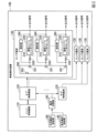
図2に示すように、棒金検知装置100は、メイン制御基板110と、サブ制御基板120と、センサ基板130と、交流電流供給部140と、直流電流供給部145と、電流切替部160を有して構成されている。例えば、直流電流供給部145は、電池などが挙げられる。また、例えば、交流電流供給部140は、直流電流供給部145が供給する直流電流を交流電流に変換するインバーターなどが挙げられる。
<Money roll detection device>
As shown in FIG. 2, the coin-
<メイン制御基板>
メイン制御基板110は、制御部(図示せず)、記憶部(図示せず)及び通信部(図示せず)を備えており、制御部は、記憶部に記憶された制御プログラムを読み込んで実行することで、棒金検知装置100の全体制御を行う。メイン制御基板110は、通信部を介して1又は複数のサブ制御基板120に接続されている。実施の形態では、棒金検知装置100は1個のメイン制御基板110を有している。また、メイン制御基板110は4個のサブ制御基板120に接続されている。
以下の説明では、サブ制御基板120について説明する。
<Main control board>
The
In the following description, the
<サブ制御基板>
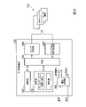
図3に示すように、サブ制御基板120は、制御部210と、記憶部220と、FPGA(Field-Programmable Gate Array)230と、センサ切替部240と、センサ出力信号処理部250と、電圧変換部260と、を備えて構成されている。このサブ制御基板120は、1又は複数のセンサ基板130と接続されており、実施の形態では、サブ制御基板120は24個のセンサ基板130と接続されている。なお、実施の形態では、センサ基板130は、各々10個の磁気センサ310と接続されており、1個のサブ制御基板120は、センサ基板130を介して240個の磁気センサ310と接続されている。
<Sub control board>
As shown in FIG. 3, the
サブ制御基板120の制御部210は、記憶部220に記憶されている制御プログラム(図示せず)を実行することで以下に説明する各機能が実装される。制御部210は、例えばCPU(Central Processing Unit)が挙げられる。制御部210は、磁気センサ310から出力信号を取得し、各々の磁気センサ310からの出力信号を補正した後の値に基づいて棒金の有無を判断する。制御部210は、FPGA230に接続されており、FPGA230に対して所定の論理回路を構築するように指令を与える。制御部210は、棒金検知装置100の補正部の一例である。
The
記憶部220は、ROM(Read Only Memory)、RAM(Random Access Memory)、及びEPROM(Erasable Programmable Read Only Memory)などを含んで構成される記憶装置である。記憶部220には、後述する磁気コイル320の温度と、直流抵抗と、磁気センサ310が出力する出力信号を補正する補正値と、が関連付けられたデータテーブル(図6参照)が記憶されている。
The
FPGA230は、プログラマブルロジックデバイス(Programmable Logic Device:PLD)の一種であり、内部論理回路を定義及び変更できる集積回路(Integrated Circuit:IC)である。FPGA230は、制御部210から与えられた指令に基づいて内部で所定の論理回路を構築する。実施の形態では、FPGA230は、各センサ基板130に設けられた磁気コイル320を駆動するための駆動電流(交流電流)を出力するか否か、駆動電流の出力先となるセンサ基板130を決定するためのセンサ基板切替信号の出力、各センサ基板130に設けられた磁気センサ310を選択するためのセンサ選択信号の出力、各磁気センサで生成された出力信号の取得、取得した出力信号の制御部210への出力、などの機能を発揮するための論理回路を構築する。
The
FPGA230は、電流切替部160(図2参照)から入力された交流電流を所定の周波数及び波形に調整したのち、磁気コイル320を駆動する駆動電流(交流電流)として出力する。FPGA230は、駆動電流と、この駆動電流の出力先となるセンサ基板130決定するためのセンサ基板切替信号と、出力先として決定されたセンサ基板130において、どの磁気センサ310に駆動電流を出力するかを選択するためのセンサ選択信号と、をセンサ切替部240に送信する。
The
また、FPGA230には、後述する電圧変換部260で生成された3.3V電圧(直流電圧)と、電圧変換部260で生成された交流電圧とが供給される。FPGA230は、供給された3.3V電圧から所定の直流電流を生成し、交流電流供給部140から所定の周波数及び波形の交流電流を生成し、これらの直流電流と交流電流とを切り替えてセンサ基板130に供給する。これにより、FPGA230は、交流電流を供給した際の磁気センサ310の出力信号と、直流電流を供給した際に磁気センサ310の抵抗成分と、を取得することができる。
Also, the
センサ切替部240は、FPGA230から送信されたセンサ基板切替信号に基づいて、サブ制御基板120に接続された24個のセンサ基板130のうちの何れかのセンサ基板130を切り替える。その結果、FPGA230から送信された駆動電流又は測定用直流電流は、センサ切替部240により選択された何れかのセンサ基板130に送信される(図2の実線矢印参照)。実施の形態では、センサ切替部240により何れかのセンサ基板130が選択され、FPGA230から送信された駆動電流又は測定用直流電流と、磁気センサ310を選択するためのセンサ選択信号と、が当該選択されたセンサ基板130に送信される。センサ切替部240としては、例えば、スイッチング素子が挙げられる。
The
センサ基板130に送信された駆動電流又は測定用直流電流により選択されたセンサ基板130の磁気センサ310の何れかが駆動され、磁気センサ310の何れかで生成された出力信号がセンサ出力信号処理部250に送信される(図3の破線矢印参照)。
Any of the
センサ出力信号処理部250は、各々の磁気センサ310に接続されており、これらの磁気センサ310からの出力信号を受信する(図3の破線矢印参照)。センサ出力信号処理部250は、磁気センサ310から受信した出力信号である電流値から電圧値への変換、フィルタ処理、及びA/D変換などを行い、デジタル信号をFPGA230に対して出力する。センサ出力信号処理部250は、例えば、電流電圧(I-V)変換回路、ローパスフィルタ回路、A/D変換回路などを含んで構成される。
The sensor
前述した制御部210、FPGA230、センサ切替部240、センサ出力信号処理部250などは、電圧変換部260で変換された電力により駆動される。電圧変換部260は、直流電流供給部145(図2参照)で生成された5Vの電圧を、3.3Vの第1電圧と、±5Vの第2電圧に変換する。3.3Vに変換された第1電圧は、制御部210やFPGA230などの論理回路の駆動に用いられる。±5Vの第2電圧は、絶縁型のDC-DCコンバータ(図示せず)で±12Vに昇圧したのちレギュレータ素子(図示せず)により±5Vに降圧してセンサ基板(検知コイルなど)の駆動に用いられる。±5Vの第2電圧を±12Vに昇圧してから再度±5Vに降圧することで、電源ノイズを抑えてアナログ信号のS/N比(Signal-Noise Ratio)を改善することができる。
The
<センサ基板>
図2に戻って、センサ基板130は、切替用IC350と、1又は複数の磁気センサ310と、各々の磁気センサ310に対応して設けられる測定部340と、を備えている。実施の形態では、1個のセンサ基板130は、10個の磁気センサ310と、これらの磁気センサ310に対応する10個の測定部340と、を備えている。
<Sensor board>
Returning to FIG. 2 , the
切替用IC350は、サブ制御基板120の切替部に接続される入力部(図示せず)と、磁気センサ310に接続される複数の出力部351とを有している。切替用IC350は、サブ制御基板120の切替部から入力されたセンサ選択信号に基づいて、複数の出力部のうちの何れか一つの出力部351を選択し、入力部352と選択した一つの出力部351とを電気的に接続する。これにより、切替用IC350は、サブ制御基板120のセンサ切替部240から入力された駆動電流又は測定用直流電流を磁気センサ310の何れかに送信することができる。このような切替用のICとして、例えば、マルチプレクサ(Multiplexer:MPX)などを用いることができる。
The switching
切替用IC350と各磁気センサ310との間には抵抗部330がそれぞれ接続されている。実施の形態では、抵抗部330は、切替用IC350のスイッチング抵抗であり、切替用IC350の抵抗部330と各磁気センサ310とはそれぞれ直列に接続されている。よって、サブ制御基板120のセンサ切替部240から送信された駆動電流又は測定用直流電流は、抵抗部330を通って磁気センサ310に供給される。
A
磁気センサ310は、螺旋状に複数回巻かれて形成された磁気コイル320をそれぞれ有して構成されている。磁気センサ310は、この磁気コイル320に駆動電流(交流電流)が供給されることで、磁気コイル320の周囲に磁界を発生させる。磁気センサ310では、磁気コイル320から発生した磁界内に棒金が存在する場合と存在しない場合とにより磁界が変化する。磁気センサ310は、この磁界の変化に応じた出力信号を発生させる。例えば、磁気センサ310による出力信号とは、電流、電圧、デジタル信号が挙げられる。
The
センサ基板130では、測定用直流電流を供給した際の抵抗部330の抵抗値と磁気コイル320の抵抗成分とを測定するための測定部340が設けられている。測定部340は、切替用IC350と磁気センサ310との間に直列に設けられた抵抗部330の両端の抵抗値と、磁気コイル320の両端の抵抗の値との少なくとも何れかを測定可能に設けられている。実施の形態では、測定部340は、FPGA230から測定用直流電流である直流電流が磁気コイル320と抵抗とに供給された際の少なくとも何れかの抵抗の値を測定する。例えば、測定部340は、電流値と電圧値を計測して、計測した値を用いて抵抗の値を演算することで抵抗の値を測定する。測定部340は、測定した抵抗値をサブ制御基板120のセンサ出力信号処理部250(図3参照)に送信する。
The
ここで、前述したFPGA230から測定用直流電流を供給した際の抵抗部330と、磁気コイル320の抵抗成分の合成抵抗を直流抵抗と言う。FPGA230から測定用直流電流を供給した際の磁気コイル320の抵抗成分の値、FPGA230から測定用直流電流を供給した際の抵抗部330の値、又は直流抵抗の何れかを磁気センサ310の抵抗成分とも言う。
Here, the combined resistance of the resistance components of the
磁気センサ310から出力された出力信号は、前述したサブ制御基板120のセンサ出力信号処理部250に送信され(図3の破線矢印参照)、センサ出力信号処理部250で所定の処理が行われたのちの出力信号は、FPGA230に送信される。
The output signal output from the
本実施形態の棒金検知装置100は、前述したFPGA230が測定部340で測定した切替用IC350と磁気コイル320との間の直流抵抗の測定結果により補正値を取得して、この補正値を用いて磁気センサ310の出力信号を補正して、各棒金収納庫12(C)における棒金の有無を正確に判断する。
In the coin-
<磁気センサの温度補正方法>
ここで、前述した磁気センサ310では、磁気コイル320の温度変化に応じて当該磁気コイル320のインダクタンスLの値が変動する。その結果、棒金検知装置100では、磁気センサ310から出力される出力信号の値が、磁気コイル320の温度変化の影響を受けて変動する。そのため棒金検知装置100では、磁気センサ310による棒金の検知を正確に行うことができない可能性がある。
<Temperature compensation method for magnetic sensor>
Here, in the
棒金検知装置100では、磁気コイル320の温度変化と磁気コイル320のインダクタンスLの変動との関係、磁気コイル320の温度変化と直流抵抗の値との関係に基づいて、磁気コイル320で発生する出力信号を補正している。
In the coin-
図4は、磁気コイル320の温度と当該磁気コイル320のインダクタンスLの値との関係を説明する図である。図4では、棒金が存在する場合(図4の破線参照)と、棒金が存在しない場合(図4の実線参照)とにおいて、磁気コイル320の温度と当該磁気コイル320のインダクタンスLの値との関係の一例を示している。
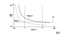
図5は、磁気コイル320の温度と、磁気センサ310の出力信号である電流値との関係を説明する図である。図5では、棒金が存在する場合(図5の破線参照)と、棒金が存在しない場合(図5の実践参照)とにおいて、磁気コイル320の温度と電流値との関係の一例を示している。
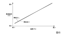
図6は、磁気コイル320の温度と直流抵抗の値との関係を説明する図である。図6では、棒金が存在する場合(図6の破線参照)と、棒金が存在しない場合(図6の実線参照)とにおいて、磁気コイル320の温度と直流抵抗の値との関係の一例を示している。
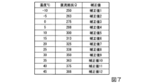
図7は、磁気コイル320の温度と直流抵抗と補正値との関係を示すテーブルの一例を説明する図である。
FIG. 4 is a diagram for explaining the relationship between the temperature of the
FIG. 5 is a diagram for explaining the relationship between the temperature of the
FIG. 6 is a diagram illustrating the relationship between the temperature of the
FIG. 7 is a diagram illustrating an example of a table showing the relationship between the temperature of the
図4に示すように、磁気コイル320の温度と当該磁気コイル320のインダクタンスLとの関係を見ると、磁気コイル320の温度が高くなるに連れて、当該磁気コイル320のインダクタンスLの値も高くなるのが分かる。この磁気コイル320の温度とインダクタンスLの値との関係は、棒金の有り無しに関わらず比例関係にある。磁気コイル320のインダクタンスLの値は、棒金が存在しない場合よりも存在する場合の方が全体的に低い値となる。これは、磁気コイル320から発生した磁界が棒金により遮られるために、磁気コイル320のインダクタンスLは棒金が存在しない場合よりも存在する場合のほうが全体的に低い値となるためである。棒金が存在しない場合の磁気コイル320のインダクタンスLにより規定される線分(図4の上側の線)と、棒金が存在する場合の磁気コイル320のインダクタンスLにより規定される線分(図4の下側の線)とは、ほぼ平行となっている。
As shown in FIG. 4, looking at the relationship between the temperature of the
図6に示すように、磁気コイル320の温度と磁気センサ310の直流抵抗の値との関係を見ると、磁気コイル320の温度が高くなるに連れて、磁気センサ310の直流抵抗の値も高くなるのが分かる。この磁気コイル320の温度と直流抵抗の値との関係は、棒金の有り無しに関わらず比例関係にある。なお、棒金の有無による磁気コイル320に接続される抵抗の値の変化は、棒金の有無によるインダクタンスの変化と比較して十分に小さい。
As shown in FIG. 6, looking at the relationship between the temperature of the
前述したように、磁気コイル320の温度と磁気センサ310の直流抵抗の値とは比例関係にある。そのため、直流抵抗の値とインダクタンスの変化にかんがみた磁気センサ310の補正値を予め求めて置くことで、磁気センサ310の直流抵抗の値から、磁気コイル320の温度変化に応じて変動する磁気センサ310の出力信号の補正値を取得することができる。
よって、磁気センサ310の直流抵抗の値を測定することで磁気コイル320の温度変化に応じて変動する磁気センサ310の出力信号を適切に補正することができる。
As described above, the temperature of the
Therefore, by measuring the value of the DC resistance of the
例えば、図4に示すように、磁気コイル320の温度が温度T1から温度T1よりも高い温度T2(T2>T1)に変化した場合、磁気コイル320の温度の変化(上昇)に応じて当該磁気コイル320のインダクタンスLも高くなる。
For example, as shown in FIG. 4, when the temperature of the
つまり、図5に示すように、温度T1から温度T1よりも高い温度T2(T2>T1)に変化した場合、磁気センサ310からの出力信号である電流は低くなる。これにより、棒金ありの場合であっても、電流の値が棒金なしと判定される電流の閾値X1以下となり、棒金なしと判定されてしまう。
That is, as shown in FIG. 5, when the temperature changes from temperature T1 to temperature T2 (T2>T1) higher than temperature T1, the current, which is the output signal from the
そこで、実施の形態にかかる棒金検知装置100では、磁気センサ310の直流抵抗の値を測定することで、直線抵抗と補正値との関係を定義したテーブル(図7)を参照し、当該直流抵抗の値(磁気コイル320の温度が温度T2)である場合の補正値を取得する。これにより棒金検知装置100では、磁気センサ310の出力信号の補正を適切に行うことができ、棒金の検知を正確に行うことができる。
Therefore, in the coin
例えば、磁気センサ310の磁気コイル320の温度が所定の基準温度30℃であった場合において、棒金検知装置100の長時間使用により45℃まで上昇した場合を一例に説明する。センサ基板130の測定部340による磁気センサ310の直流抵抗の値388が測定される。サブ制御基板120の制御部210は、記憶部220の直流抵抗と補正値との関係を定義したテーブルを参照して補正値12を取得する。制御部210は、補正値12を用いて磁気センサ310の出力信号を補正する。実施の形態では、制御部210は、45℃のときの直流抵抗388から補正値12を減算する演算(388-補正値12)を行い、磁気センサ310の出力信号を補正する。これにより、棒金検知装置100は棒金の検出を正確に行うことができる。
For example, a case where the temperature of the
<棒金検知方法>
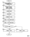
図8は、棒金検知方法の制御のフローチャートである。
<How to detect coin rolls>
FIG. 8 is a flow chart of the control of the coin roll detection method.
ステップS101において、直流電流供給部145は、磁気センサ310に直流電流を供給する。
In step S<b>101 , the DC
ステップS102において、測定部340は、ステップS101において直流電流が供給された磁気センサ310の接続される抵抗部330の抵抗値と磁気コイル320の抵抗成分の値とを測定する。測定部340は、抵抗部330の抵抗値と磁気コイル320の抵抗成分の値との合計値を測定してもよい。
In step S102, the
ステップS103において、サブ制御基板120の制御部210は、ステップS102で取得した抵抗部330の抵抗値と磁気コイル320の抵抗成分の値とを合計する演算を行い、この合計した値を磁気センサ310の直流抵抗の値とする。ステップS102において、測定部340が合計値を測定した場合は、制御部210は、ステップS103における演算を行わなくてもよい。
In step S103, the
ステップS104において、サブ制御基板120の制御部210は、ステップS103で演算した直流抵抗の値から、直流抵抗の値と補正値との関係を定義したテーブルを参照して補正値を取得する。
In step S104, the
ステップS105において、電流切替部160が電流を切り替えて、交流電流供給部140は、磁気センサ310に交流電流を供給する。
In step S<b>105 , the
ステップS106において、サブ制御基板120のセンサ出力信号処理部250は、磁気センサ310に交流電流を通電した際の磁気センサ310から取得した出力信号の処理を行う。具体的には、センサ出力信号処理部250は、磁気センサ310から取得した出力信号を電流値から電圧値への変換を行い、電圧値に変換された出力信号に対してローパスフィルタなどによるフィルタ処理を行い、フィルタ処理後の出力信号をA/D変換などの処理を行う。
In step S106, the sensor output
ステップS107において、サブ制御基板120の制御部210は、ステップS103で取得した補正値に基づいてステップS104で処理した後の出力信号を補正する処理を行う。
In step S107, the
ステップS108において、制御部210は、ステップS105で処理された出力信号に基づいて、棒金の有無を判断する。つまり、制御部210は、補正後の出力信号の値が、棒金の有無を判定する際に用いられる閾値X1以上である場合(ステップS108:YES)は、棒金ありと判断する(ステップS109)。他方、制御部210は、補正後の出力信号の値が、閾値X1以上でない場合(ステップS108:NO)は、棒金なしと判断する(ステップS110)。
In step S108,
前述した棒金検知処理は、所定の時間間隔ごとに繰り返し行われる。 The aforementioned coin-roll detecting process is repeatedly performed at predetermined time intervals.
なお、前述した実施の形態では、棒金検知装置100をいわゆる現金バスの棒金収納庫12に設け、棒金収納庫12に収納された棒金の有無を検知する場合を例示して説明したが、棒金検知装置100を設ける装置は実施の形態に限られない。例えば、棒金検知装置100を、出納機の棒金収納部に設けても良く、釣銭機の棒金収納部に設けても良い。
In the above-described embodiment, the case where the coin-
(1)以上説明したとおり、実施の形態にかかる棒金検知装置は、
収納庫12(棒金収納庫)における棒金の有無を検知する棒金検知装置100であって、
棒金の磁気的性質を検出する磁気センサ310と、
磁気センサ310の抵抗にかかる値を測定する測定部340と、
抵抗にかかる値に関連付けられた補正値を用いて、磁気的性質による出力信号を補正する補正部(制御部210が記憶部に記憶された補正値(図7参照)を用いて、磁気センサ310により検出された棒金の磁気的性質の出力値を補正する構成)と、
を備える構成とした。
(1) As described above, the coin roll detection device according to the embodiment
A coin-
a
a
Using the correction value associated with the resistance value, the correction unit (the
It was configured to include
従来、この種の棒金検知装置では、磁気センサ310の抵抗にかかる値は当該磁気センサ310の温度変化(磁気センサ310の抵抗にかかる値)など応じて変動する。上記のように構成すると、補正部は、磁気センサ310の抵抗にかかる値に関連付けた補正値を用いて、磁気センサ310により検出された棒金の磁気的性質の出力値を補正することができるので、温度変化の影響を受けず、棒金の有無の検出を正確に行うことができる。
Conventionally, in this type of coin-roll detection device, the value of the resistance of the
(2)また、磁気センサ310は、棒金の磁気的性質を検出するための磁気コイル320を備え、
磁気センサ310の抵抗にかかる値は、磁気コイル320の抵抗にかかる値である構成とした。
(2) The
The value of the resistance of the
このように構成すると、
磁気コイル320に直流電流を供給した場合の抵抗にかかる値は、当該磁気コイル320の温度変化に応じて変動する。そのため補正部は、測定部340により実際に測定された磁気コイル320の抵抗にかかる値に関連付けられた補正値を用いて磁気センサ310により検出された棒金の磁気的性質にかかる出力信号を補正することで、収納庫12における棒金の有無の検知を正確に行うことができる。
Configured like this,
The value of the resistance when a direct current is supplied to the
(3)また、磁気センサ310は、棒金の磁気的性質を検出するための磁気コイル320と、
磁気コイル320と同一のセンサ基板130(配線基板)に設けられると共に、磁気コイル320に接続された抵抗部330とを備え、
磁気センサ310の抵抗にかかる値は、磁気コイル320に直流電流を供給した際の磁気コイル320の抵抗にかかる値、抵抗部330に直流電流を供給した際の抵抗部330の抵抗にかかる値、および磁気コイル320と抵抗部330とを組み合わせた回路の抵抗にかかる値の、何れかである構成とした。
(3) In addition, the
It is provided on the same sensor substrate 130 (wiring board) as the
The value of the resistance of the
このように構成すると、磁気コイル320と同一のセンサ基板130に設けられた抵抗部330の温度は、磁気コイル320の温度変化に応じて変動する。よって、補正部は、磁気コイル320の抵抗にかかる値、抵抗部330の抵抗にかかる値、又は磁気コイル320の抵抗にかかる値と抵抗部330の抵抗にかかる値とを組み合わせた回路の抵抗にかかる値の何れか関連付けられた補正値を用いて磁気センサ310の出力信号を補正することで、より正確な温度補正を行うことができ、磁気センサ310による棒金の有無の検知を正確に行うことができる。
With this configuration, the temperature of the
(4)また、磁気センサ310に交流電流を供給する交流電流供給部140と、
磁気センサ310に直流電流を供給する直流電流供給部145と、
交流電流供給部140による磁気センサ310への交流電流の供給と、直流電流供給部145による磁気センサ310への直流電流の供給と、を切り替える電流切替部160とを備え、
棒金の磁気的性質は、電流切替部160の切替えにより、交流電流供給部140からの交流電流が磁気センサ310に供給されている際に検出され、
抵抗にかかる値は、電流切替部160の切替えにより、直流電流供給部145からの直流電流が磁気センサ310に供給されている際に測定される構成とした。
(4) an alternating
a direct
A
The magnetic property of the coin bar is detected when the alternating current from the alternating
The value applied to the resistance is configured to be measured when the DC current from the DC
このように構成すると、
棒金検知装置100では、電流切替部160により、磁気センサ310に供給される電流を交流電流と直流電流とに切替えられる。よって、棒金の磁気的性質にかかる出力信号を補正するための補正値を取得する場合、電流切替部160により磁気センサ310に直流電流を供給してその時の温度に応じた補正値を取得し、棒金の有無を検知する場合、電流切替部160により磁気センサ310に交流電流を供給した際の棒金の磁気的性質にかかる出力信号を補正値により補正することで、棒金の有無を正確に検知することができる。
Configured like this,
In the coin-
(5)収納庫12における棒金の有無を磁気センサ310により検知する棒金検知方法であって、
磁気センサ310の抵抗にかかる値を測定し(ステップS102)、
磁気センサ310の抵抗にかかる値に基づいて棒金の磁気的性質による出力信号を補正し(ステップS107)、
出力信号の補正後の値に基づいて収納庫12(棒金収納庫)における棒金の有無を判断する(ステップS109又はステップS110)方法とした。
(5) A coin roll detection method for detecting the presence or absence of a coin roll in the
Measure the value of the resistance of the magnetic sensor 310 (step S102),
correcting the output signal due to the magnetic property of the metal bar based on the resistance value of the magnetic sensor 310 (step S107);
The presence or absence of a coin roll in the storage 12 (money roll storage) is determined based on the corrected value of the output signal (step S109 or step S110).
従来、この種の棒金検知方法では、磁気センサ310の抵抗にかかる値は当該磁気センサ310の温度変化(磁気センサ310の抵抗にかかる値)など応じて変動する。上記の方法とすると、補正部は、磁気センサ310の抵抗にかかる値に関連付けた補正値を用いて、磁気センサ310により検出された棒金の磁気的性質の出力値を補正することができるので、温度変化の影響を受けず、棒金の有無の検出を正確に行うことができる。
Conventionally, in this type of coin roll detection method, the resistance value of the
(6)棒金を収納する収納庫12(棒金収納庫)と、
上記(1)から(4)の何れか1に記載の棒金検知装置100と、
を備えた棒金収納装置10とした。
(6) a storage box 12 (money roll storage box) for storing a coin roll;
a coin
The coin
このように構成すると、棒金収納装置10の収納庫12に収納されている棒金の検知を確実に行うことができる。
With this configuration, it is possible to reliably detect the coin rolls stored in the
なお、前述した実施の形態では、磁気センサ310の直流抵抗と補正値との関係を定義したテーブルを参照して、実際に測定した直流抵抗から補正値を取得する場合を例示して説明したが、補正値の取得は演算式により行っても良い。
In the above-described embodiment, a case in which a correction value is acquired from an actually measured DC resistance with reference to a table defining the relationship between the DC resistance of the
8 キャスタ
10 棒金収納装置
11 装置本体
12 収納庫
15 操作表示部
17 表示部
18 カードリーダ
19 操作キーボード
23 表示灯
100 棒金検知装置
110 メイン制御基板
120 サブ制御基板
130 センサ基板
140 交流電流供給部
145 直流電流供給部
160 電流切替部
210 制御部
220 記憶部
230 FPGA
240 センサ切替部
250 センサ出力信号処理部
260 電圧変換部
310 磁気センサ
320 磁気コイル
330 抵抗部
340 測定部
350 切替IC
351 出力部
352 入力部
8
240
351
Claims (5)
前記棒金の磁気的性質を検出するための磁気コイルと、
前記磁気コイルと同一の配線基板に設けられると共に、前記磁気コイルに接続された抵抗部と
を備えた磁気センサと、
前記磁気センサの抵抗にかかる値を測定する測定部と、
前記抵抗にかかる値に関連付けられた補正値を用いて、前記磁気的性質による出力信号を補正する補正部と、
を備え、
前記抵抗にかかる値は、前記磁気コイルに直流電流を供給した際の前記磁気コイルの抵抗にかかる値、前記抵抗部に直流電流を供給した際の前記抵抗部の抵抗にかかる値、および前記磁気コイルと前記抵抗部とを組み合わせた回路の抵抗にかかる値の、何れかである
棒金検知装置。 A coin-roll detection device for detecting the presence or absence of a coin-roll in a coin-roll storage,
a magnetic coil for detecting magnetic properties of the metal bar;
A resistance unit provided on the same wiring board as the magnetic coil and connected to the magnetic coil
a magnetic sensor comprising
a measuring unit that measures a value applied to the resistance of the magnetic sensor;
a correction unit that corrects the output signal due to the magnetic property using a correction value associated with the value of the resistance;
with
The value of the resistance includes the value of the resistance of the magnetic coil when a direct current is supplied to the magnetic coil, the value of the resistance of the resistance section when a direct current is supplied to the resistance section, and the magnetic field. Any of the values applied to the resistance of the circuit that combines the coil and the resistor part
Coin detection device.
前記棒金の磁気的性質を検出する磁気センサと、
前記磁気センサの抵抗にかかる値を測定する測定部と、
前記抵抗にかかる値に関連付けられた補正値を用いて、前記磁気的性質による出力信号を補正する補正部と、
前記磁気センサに交流電流を供給する交流電流供給部と、
前記磁気センサに直流電流を供給する直流電流供給部と、
前記交流電流供給部による前記磁気センサへの交流電流の供給と、前記直流電流供給部による前記磁気センサへの直流電流の供給と、を切り替える電流切替部とを備え、
前記磁気的性質は、前記電流切替部の切替えにより、前記交流電流供給部からの交流電流が前記磁気センサに供給されている際に検出され、
前記抵抗にかかる値は、前記電流切替部の切替えにより、前記直流電流供給部からの直流電流が前記磁気センサに供給されている際に測定される
棒金検知装置。 A coin-roll detection device for detecting the presence or absence of a coin-roll in a coin-roll storage,
a magnetic sensor for detecting magnetic properties of the metal bar;
a measuring unit that measures a value applied to the resistance of the magnetic sensor;
a correction unit that corrects the output signal due to the magnetic property using a correction value associated with the value of the resistance;
an alternating current supply unit that supplies an alternating current to the magnetic sensor;
a direct current supply unit that supplies a direct current to the magnetic sensor;
a current switching unit for switching between supply of alternating current to the magnetic sensor by the alternating current supply unit and supply of direct current to the magnetic sensor by the direct current supply unit;
The magnetic property is detected when an alternating current from the alternating current supply unit is supplied to the magnetic sensor by switching the current switching unit,
The value applied to the resistance is measured when the DC current from the DC current supply unit is supplied to the magnetic sensor by switching the current switching unit.
Coin detection device.
請求項1または2に記載の棒金検知装置と、
を備えた棒金収納装置。 a coin-roll storage box for storing coin-rolls;
A coin roll detection device according to claim 1 or 2 ;
A coin roll storage device.
前記棒金の磁気的性質を検出するための磁気コイルと、a magnetic coil for detecting magnetic properties of the metal bar;
前記磁気コイルと同一の配線基板に設けられると共に、前記磁気コイルに接続された抵抗部とA resistance unit provided on the same wiring board as the magnetic coil and connected to the magnetic coil
を備えた磁気センサと、a magnetic sensor comprising
前記磁気センサの抵抗にかかる値を測定する測定部と、a measuring unit that measures a value applied to the resistance of the magnetic sensor;
前記抵抗にかかる値に関連付けられた補正値を用いて、前記磁気的性質による出力信号を補正する補正部と、a correction unit that corrects the output signal due to the magnetic property using a correction value associated with the value of the resistance;
を備える棒金検知装置を用いた棒金検知方法であって、A coin roll detection method using a coin roll detection device comprising
前記抵抗にかかる値を、前記磁気コイルに直流電流を供給した際の前記磁気コイルの抵抗にかかる値、前記抵抗部に直流電流を供給した際の前記抵抗部の抵抗にかかる値、および前記磁気コイルと前記抵抗部とを組み合わせた回路の抵抗にかかる値の、何れかとするThe value of the resistance is the value of the resistance of the magnetic coil when a direct current is supplied to the magnetic coil, the value of the resistance of the resistance section when a direct current is supplied to the resistance section, and the magnetic Any of the values applied to the resistance of the circuit combining the coil and the resistance part
棒金検知方法。Coin detection method.
前記棒金の磁気的性質を検出する磁気センサと、a magnetic sensor for detecting magnetic properties of the metal bar;
前記磁気センサの抵抗にかかる値を測定する測定部と、a measuring unit that measures a value applied to the resistance of the magnetic sensor;
前記抵抗にかかる値に関連付けられた補正値を用いて、前記磁気的性質による出力信号を補正する補正部と、a correction unit that corrects the output signal due to the magnetic property using a correction value associated with the value of the resistance;
前記磁気センサに交流電流を供給する交流電流供給部と、an alternating current supply unit that supplies an alternating current to the magnetic sensor;
前記磁気センサに直流電流を供給する直流電流供給部と、a direct current supply unit that supplies a direct current to the magnetic sensor;
前記交流電流供給部による前記磁気センサへの交流電流の供給と、前記直流電流供給部による前記磁気センサへの直流電流の供給と、を切り替える電流切替部とを備える棒金検知装置を用いた棒金検知方法であって、A bar using a coin-roll detection device comprising a current switching unit for switching between supply of alternating current to the magnetic sensor by the alternating current supply unit and supply of direct current to the magnetic sensor by the direct current supply unit A gold detection method comprising:
前記磁気的性質を、前記電流切替部の切替えにより、前記交流電流供給部からの交流電流が前記磁気センサに供給されている際に検出し、detecting the magnetic property when the alternating current from the alternating current supply unit is supplied to the magnetic sensor by switching the current switching unit;
前記抵抗にかかる値を、前記電流切替部の切替えにより、前記直流電流供給部からの直流電流が前記磁気センサに供給されている際に測定するThe value applied to the resistance is measured when the DC current from the DC current supply unit is supplied to the magnetic sensor by switching the current switching unit.
棒金検知方法。Coin detection method.
Priority Applications (1)
| Application Number | Priority Date | Filing Date | Title |
|---|---|---|---|
| JP2019119825A JP7253190B2 (en) | 2019-06-27 | 2019-06-27 | Coin-roll detection device, coin-roll detection method, and coin-roll storage device |
Applications Claiming Priority (1)
| Application Number | Priority Date | Filing Date | Title |
|---|---|---|---|
| JP2019119825A JP7253190B2 (en) | 2019-06-27 | 2019-06-27 | Coin-roll detection device, coin-roll detection method, and coin-roll storage device |
Publications (2)
| Publication Number | Publication Date |
|---|---|
| JP2021005299A JP2021005299A (en) | 2021-01-14 |
| JP7253190B2 true JP7253190B2 (en) | 2023-04-06 |
Family
ID=74097424
Family Applications (1)
| Application Number | Title | Priority Date | Filing Date |
|---|---|---|---|
| JP2019119825A Active JP7253190B2 (en) | 2019-06-27 | 2019-06-27 | Coin-roll detection device, coin-roll detection method, and coin-roll storage device |
Country Status (1)
| Country | Link |
|---|---|
| JP (1) | JP7253190B2 (en) |
Citations (1)
| Publication number | Priority date | Publication date | Assignee | Title |
|---|---|---|---|---|
| JP2008305033A (en) | 2007-06-06 | 2008-12-18 | Fuji Electric Retail Systems Co Ltd | Coin storage management device |
Family Cites Families (1)
| Publication number | Priority date | Publication date | Assignee | Title |
|---|---|---|---|---|
| JP3363305B2 (en) * | 1996-03-08 | 2003-01-08 | グローリー工業株式会社 | Coin identification device with temperature correction function in coin processing machine |
-
2019
- 2019-06-27 JP JP2019119825A patent/JP7253190B2/en active Active
Patent Citations (1)
| Publication number | Priority date | Publication date | Assignee | Title |
|---|---|---|---|---|
| JP2008305033A (en) | 2007-06-06 | 2008-12-18 | Fuji Electric Retail Systems Co Ltd | Coin storage management device |
Also Published As
| Publication number | Publication date |
|---|---|
| JP2021005299A (en) | 2021-01-14 |
Similar Documents
| Publication | Publication Date | Title |
|---|---|---|
| US8446157B2 (en) | Capacitance meter, method, computer program and computer program product for improved capacitance measurement | |
| US9041392B2 (en) | Current sensor | |
| CN102171543A (en) | Measuring device | |
| CN103189756A (en) | Method of enabling calibration of a current transformer, and associated apparatus | |
| US9747759B2 (en) | Automatic cash register system with motion sequence control | |
| JP7253190B2 (en) | Coin-roll detection device, coin-roll detection method, and coin-roll storage device | |
| KR101488690B1 (en) | Method and current measuring device to measure current by cancelling adjacent current interference | |
| KR102006029B1 (en) | Method and Apparatus for calculation azimuth | |
| WO2017030114A1 (en) | Magnetic sensor for coin identification, coin processing device, and coin identification method | |
| JP2012145466A (en) | Current measurement system and power measurement system | |
| JP2008192079A (en) | Coin roll storage | |
| US8917102B2 (en) | Method, capacitance meter, computer program and computer program product for improved capacitance measurement | |
| KR100997236B1 (en) | Sensor inspection method and apparatus, and financial automation equipment using the same | |
| JP2936752B2 (en) | Coin sorting equipment | |
| JP2021148661A (en) | Measurement device | |
| WO2005038732A1 (en) | Improvements in cash counting | |
| KR101736569B1 (en) | A apparatus for detecting medium and a method for detecting thereof | |
| ITVI20090058A1 (en) | DEVICE AND METHOD FOR DETECTING THE QUANTITY OF COINS IN A TANK | |
| US20020144877A1 (en) | Inductive coin sensor with position correction | |
| JP3642577B2 (en) | Bill discrimination device | |
| JP5009000B2 (en) | Bar storage | |
| JP2003202354A (en) | Energization information measurement device | |
| CN116026510B (en) | Method for calculating output value of tension meter based on proportional value algorithm | |
| JP4350599B2 (en) | Coin identification device | |
| US8800742B2 (en) | Automatic cash register system with variable fixing of accepted denominations |
Legal Events
| Date | Code | Title | Description |
|---|---|---|---|
| A621 | Written request for application examination |
Free format text: JAPANESE INTERMEDIATE CODE: A621 Effective date: 20211021 |
|
| A977 | Report on retrieval |
Free format text: JAPANESE INTERMEDIATE CODE: A971007 Effective date: 20220928 |
|
| A131 | Notification of reasons for refusal |
Free format text: JAPANESE INTERMEDIATE CODE: A131 Effective date: 20221018 |
|
| A521 | Request for written amendment filed |
Free format text: JAPANESE INTERMEDIATE CODE: A523 Effective date: 20221216 |
|
| TRDD | Decision of grant or rejection written | ||
| A01 | Written decision to grant a patent or to grant a registration (utility model) |
Free format text: JAPANESE INTERMEDIATE CODE: A01 Effective date: 20230228 |
|
| A61 | First payment of annual fees (during grant procedure) |
Free format text: JAPANESE INTERMEDIATE CODE: A61 Effective date: 20230316 |
|
| R150 | Certificate of patent or registration of utility model |
Ref document number: 7253190 Country of ref document: JP Free format text: JAPANESE INTERMEDIATE CODE: R150 |
|
| S531 | Written request for registration of change of domicile |
Free format text: JAPANESE INTERMEDIATE CODE: R313531 |
|
| S533 | Written request for registration of change of name |
Free format text: JAPANESE INTERMEDIATE CODE: R313533 |
|
| S111 | Request for change of ownership or part of ownership |
Free format text: JAPANESE INTERMEDIATE CODE: R313115 |
|
| R350 | Written notification of registration of transfer |
Free format text: JAPANESE INTERMEDIATE CODE: R350 |
|
| R250 | Receipt of annual fees |
Free format text: JAPANESE INTERMEDIATE CODE: R250 |