JP7253144B2 - Fixing device and image forming device - Google Patents
Fixing device and image forming device Download PDFInfo
- Publication number
- JP7253144B2 JP7253144B2 JP2019077849A JP2019077849A JP7253144B2 JP 7253144 B2 JP7253144 B2 JP 7253144B2 JP 2019077849 A JP2019077849 A JP 2019077849A JP 2019077849 A JP2019077849 A JP 2019077849A JP 7253144 B2 JP7253144 B2 JP 7253144B2
- Authority
- JP
- Japan
- Prior art keywords
- fixing
- cleaning member
- rotator
- temperature
- roller
- Prior art date
- Legal status (The legal status is an assumption and is not a legal conclusion. Google has not performed a legal analysis and makes no representation as to the accuracy of the status listed.)
- Active
Links
Images


Landscapes
- Fixing For Electrophotography (AREA)
Description
この発明は、複写機、プリンタ、ファクシミリ、又は、それらの複合機等の画像形成装置と、そこに設置される定着装置と、に関するものである。 The present invention relates to image forming apparatuses such as copiers, printers, facsimiles, or multi-function machines thereof, and fixing devices installed therein.
従来から、複写機、プリンタ等の画像形成装置における定着装置において、定着回転体又は加圧回転体の表面に当接するようにクリーニング部材を設置して、その表面をクリーニングする技術が広く知られている(例えば、特許文献1参照。)。
そして、そのようなクリーニング部材を用いた定着装置では、装置が駆動停止した後に、クリーニング部材が定着回転体又は加圧回転体の表面に圧接し続けることで、その圧接部でトナーが固化したり、クリーニング部材が変形したりしないように、駆動停止時にクリーニング部材を定着回転体又は加圧回転体の表面から離間させている。
2. Description of the Related Art Conventionally, in a fixing device in an image forming apparatus such as a copier or a printer, a technique is widely known in which a cleaning member is installed so as to contact the surface of a fixing rotary body or a pressure rotary body to clean the surface. (See
In a fixing device using such a cleaning member, the cleaning member continues to press against the surface of the fixing rotary body or the pressure rotary body after the drive of the device is stopped, causing the toner to solidify at the pressure contact portion. In order to prevent deformation of the cleaning member, the cleaning member is separated from the surface of the fixing rotary member or the pressing rotary member when the drive is stopped.
詳しくは、特許文献1における定着装置において、定着回転体(加熱ローラ)には、加圧回転体(加圧ローラ)が圧接していて、シート(転写材)が搬送されるニップ部(定着ニップ)が形成されている。そして、ニップ部に搬送されたシート上のトナー像が、定着回転体から受ける熱と、ニップ部の圧力と、によって、シート上に定着されることになる。
また、特許文献1において、定着装置には、加圧回転体に対して接離可能に移動するクリーニングローラ(クリーニング部材)が設置されている。そして、クリーニングローラは、加圧ローラ(加圧回転体)に当接して加圧ローラの表面をクリーニングすることになる。
一方、特許文献1における定着装置では、加圧ローラに当接しているクリーニングローラを加圧ローラから離間させるときにも、加圧ローラから離間しているクリーニングローラを加圧ローラに当接させるときにも、その接離動作を加圧ローラが回転している状態でおこなっている。
Specifically, in the fixing device disclosed in
Further, in
On the other hand, in the fixing device disclosed in
従来の定着装置は、回転停止した状態の定着回転体又は加圧回転体の表面にクリーニング部材を当接させたり離間させたりするときに、クリーニング部材の表面に付着したトナーなどの付着物が、定着回転体又は加圧回転体の表面に移動(逆移動)してしまう不具合が生じてしまうことがあった。そして、そのような不具合が生じてしまうと、定着回転体又は加圧回転体の表面が汚れてしまって、定着ニップに搬送されるシートを汚してしまったり、シートに担持された画像の一部が欠損してしまったりしていた。さらに、そのような付着物の逆移動が生じることにより、クリーニング部材の表面に付着した付着物の層が不均一になってしまって、クリーニング部材の回転不良が生じてしまうこともあった。 In the conventional fixing device, when the cleaning member is brought into contact with or separated from the surface of the fixing rotary member or the pressure rotary member in a state where rotation is stopped, the adhered matter such as toner adhered to the surface of the cleaning member is removed. In some cases, the toner moves (reversely moves) to the surface of the fixing rotary member or the pressing rotary member. If such a problem occurs, the surface of the fixing rotator or the pressure rotator may become dirty, and the sheet conveyed to the fixing nip may become dirty, or part of the image carried on the sheet may become dirty. was missing. In addition, the reverse movement of such deposits may cause the layer of deposits adhering to the surface of the cleaning member to become non-uniform, resulting in poor rotation of the cleaning member.
これに対して、特許文献1では、加圧回転体に当接しているクリーニング部材を離間させるときにも、加圧回転体から離間しているクリーニング部材を当接させるときにも、加圧回転体が回転している状態でおこなっているため、そのような不具合が生じにくくなる効果が期待できる。しかし、加圧回転体が回転した状態でクリーニング部材が離間されてしまうと、クリーニング部材が離間された瞬間からクリーニング部材によるクリーニングができない状態になってしまう。同様に、加圧回転体が回転開始されてからクリーニング部材が当接されると、加圧回転体が回転開始されてからクリーニング部材が当接されるまでの間は、クリーニング部材によるクリーニングができない状態になってしまう。
On the other hand, in
この発明は、上述のような課題を解決するためになされたもので、クリーニング部材によるクリーニング性能を良好に維持しつつ、クリーニング部材の表面に付着した付着物が定着回転体又は加圧回転体の表面に逆移動してしまう不具合が軽減される、定着装置、及び、画像形成装置を提供することにある。 SUMMARY OF THE INVENTION The present invention has been made to solve the above-mentioned problems, and the cleaning performance of the cleaning member can be maintained satisfactorily, while the deposits adhering to the surface of the cleaning member can be removed from the fixing rotary member or the pressure rotary member. To provide a fixing device and an image forming device which reduce the problem of reverse movement to the surface.
この発明における定着装置は、トナー像を加熱してシートの表面に定着する定着回転体と、前記定着回転体に圧接することでシートが搬送されるニップ部を形成する加圧回転体と、移動手段の動作によって、前記定着回転体又は前記加圧回転体の表面に当接する当接位置と、当該表面から離れる離間位置と、の間を移動可能に構成されたクリーニング部材と、前記クリーニング部材の温度、又は、前記クリーニング部材が当接する前記定着回転体又は前記加圧回転体の温度、を検知する温度検知手段と、を備え、前記クリーニング部材の前記当接位置から前記離間位置への移動、又は、前記クリーニング部材の前記離間位置から前記当接位置への移動、を前記移動手段によっておこなう場合であって、前記温度検知手段によって検知される温度が所定値以下であるときには、前記クリーニング部材が当接する前記定着回転体又は前記加圧回転体が回転停止している状態で、その移動をおこなうものである。 The fixing device according to the present invention includes a fixing rotator that heats a toner image and fixes it on the surface of a sheet, a pressure rotator that presses against the fixing rotator to form a nip portion where the sheet is conveyed, and a moving a cleaning member configured to be movable between an abutment position where it abuts on the surface of the fixing rotator or the pressure rotator and a spaced position away from the surface by the operation of the cleaning member; temperature detection means for detecting a temperature or a temperature of the fixing rotating body or the pressure rotating body with which the cleaning member abuts, the movement of the cleaning member from the contact position to the separation position; Alternatively, when the movement of the cleaning member from the separated position to the contact position is performed by the moving means, and the temperature detected by the temperature detecting means is equal to or lower than a predetermined value, the cleaning member is moved to the contact position. The movement is performed in a state in which the rotation of the fixing rotary member or the pressing rotary member which abuts is stopped .
本発明によれば、クリーニング部材によるクリーニング性能を良好に維持しつつ、クリーニング部材の表面に付着した付着物が定着回転体又は加圧回転体の表面に逆移動してしまう不具合が軽減される、定着装置、及び、画像形成装置を提供することができる。 According to the present invention, while the cleaning performance of the cleaning member is maintained satisfactorily, it is possible to reduce the inconvenience that the deposits adhering to the surface of the cleaning member reversely move to the surface of the fixing rotary member or the pressure rotary member. A fixing device and an image forming apparatus can be provided.
以下、この発明を実施するための形態について、図面を参照して詳細に説明する。なお、各図中、同一又は相当する部分には同一の符号を付しており、その重複説明は適宜に簡略化ないし省略する。 BEST MODE FOR CARRYING OUT THE INVENTION Hereinafter, embodiments for carrying out the present invention will be described in detail with reference to the drawings. In each figure, the same or corresponding parts are denoted by the same reference numerals, and redundant description thereof will be appropriately simplified or omitted.
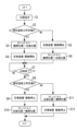
まず、図1にて、画像形成装置1における全体の構成・動作について説明する。
図1において、1は画像形成装置としてのタンデム型カラー複写機、2は入力画像情報に基づいたレーザ光を発する書込み部、3は原稿Dを原稿読込部4に搬送する原稿搬送部、4は原稿Dの画像情報を読み込む原稿読込部、を示す。
また、7は用紙等のシートPが収容される給紙部、9はシートPの搬送タイミングを調整するレジストローラ(タイミングローラ)、11Y、11M、11C、11BKは各色(イエロー、マゼンタ、シアン、ブラック)のトナー像が形成される感光体ドラム、を示す。
First, the overall configuration and operation of the
In FIG. 1, 1 is a tandem type color copier as an image forming apparatus, 2 is a writing unit that emits laser light based on input image information, 3 is a document conveying unit that conveys a document D to a document reading unit 4, and 4 is a document reading unit. A document reading unit for reading image information of a document D is shown.
また、12は各感光体ドラム11Y、11M、11C、11BKの表面を帯電する帯電部、13は各感光体ドラム11Y、11M、11C、11BKの表面に形成される静電潜像を現像する現像部、14は各感光体ドラム11Y、11M、11C、11BKの表面に形成されたトナー像をシートPの表面に重ねて転写する1次転写バイアスローラ、15は各感光体ドラム11Y、11M、11C、11BKの表面に残留した未転写トナーを回収するクリーニング部、を示す。
また、16は中間転写ベルト17を清掃する中間転写ベルトクリーニング部、17は複数色のトナー像が重ねて転写される中間転写ベルト、18は中間転写ベルト17上のカラートナー像をシートP上に転写するための2次転写バイアスローラ、20はシートP上のトナー像(未定着画像)を定着する定着装置、を示す。
A
16 is an intermediate transfer belt cleaning unit for cleaning the
以下、画像形成装置における、通常のカラー画像形成時の動作(印刷動作)について説明する。
まず、原稿Dは、原稿搬送部3の搬送ローラによって、原稿台から搬送されて、原稿読込部4のコンタクトガラス5上に載置される。そして、原稿読込部4で、コンタクトガラス5上に載置された原稿Dの画像情報が光学的に読み取られる。
An operation (printing operation) in normal color image formation in the image forming apparatus will be described below.
First, the document D is conveyed from the document platen by the conveying rollers of the
詳しくは、原稿読込部4は、コンタクトガラス5上の原稿Dの画像に対して、照明ランプから発した光を照射しながら走査させる。そして、原稿Dにて反射した光を、ミラー群及びレンズを介して、カラーセンサに結像する。原稿Dのカラー画像情報は、カラーセンサにてRGB(レッド、グリーン、ブルー)の色分解光ごとに読み取られた後に、電気的な画像信号に変換される。さらに、RGBの色分解画像信号をもとにして画像処理部で色変換処理、色補正処理、空間周波数補正処理等の処理をおこない、イエロー、マゼンタ、シアン、ブラックのカラー画像情報を得る。
Specifically, the document reading unit 4 scans the image of the document D on the
そして、イエロー、マゼンタ、シアン、ブラックの各色の画像情報は、書込み部2に送信される。そして、書込み部2からは、各色の画像情報に基づいたレーザ光(露光光)が、それぞれ、対応する感光体ドラム11Y、11M、11C、11BKの表面に向けて発せられる。
Image information for each color of yellow, magenta, cyan, and black is sent to the
一方、4つの感光体ドラム11Y、11M、11C、11BKは、それぞれ、図1の反時計方向に回転している。そして、まず、感光体ドラム11Y、11M、11C、11BKの表面は、帯電部12との対向部で、一様に帯電される(帯電工程である。)。こうして、感光体ドラム11Y、11M、11C、11BKの表面には、帯電電位が形成される。
その後、帯電された感光体ドラム11Y、11M、11C、11BKの表面は、それぞれのレーザ光の照射位置に達する(露光工程である。)。詳しくは、書込み部2において、4つの光源から画像信号に対応したレーザ光が各色に対応してそれぞれ射出される。各レーザ光は、イエロー、マゼンタ、シアン、ブラックの色成分ごとに別の光路を通過することになる。
On the other hand, the four
After that, the surfaces of the
イエロー成分に対応したレーザ光は、紙面左側から1番目の感光体ドラム11Yの表面に照射される。このとき、イエロー成分のレーザ光は、高速回転するポリゴンミラーにより、感光体ドラム11Yの回転軸方向(主走査方向、幅方向)に走査される。こうして、帯電部12にて帯電された後の感光体ドラム11Y上には、イエロー成分に対応した静電潜像が形成される。
A laser beam corresponding to a yellow component is irradiated onto the surface of the first
同様に、マゼンタ成分に対応したレーザ光は、紙面左から2番目の感光体ドラム11Mの表面に照射されて、マゼンタ成分に対応した静電潜像が形成される。シアン成分のレーザ光は、紙面左から3番目の感光体ドラム11Cの表面に照射されて、シアン成分の静電潜像が形成される。ブラック成分のレーザ光は、紙面左から4番目の感光体ドラム11BKの表面に照射されて、ブラック成分の静電潜像が形成される。
Similarly, the laser beam corresponding to the magenta component is irradiated onto the surface of the
その後、各色の静電潜像が形成された感光体ドラム11Y、11M、11C、11BKの表面は、それぞれ、現像部13との対向位置に達する。そして、各現像部13から感光体ドラム11Y、11M、11C、11BKの表面に各色のトナーが供給されて、感光体ドラム11Y、11M、11C、11BKの表面に形成された潜像が現像される(現像工程である。)。
その後、現像工程後の感光体ドラム11Y、11M、11C、11BKの表面は、それぞれ、中間転写ベルト17との対向部に達する。ここで、それぞれの対向部には、中間転写ベルト17の内周面に当接するように1次転写バイアスローラ14が設置されている。そして、1次転写バイアスローラ14の位置で、中間転写ベルト17上に、感光体ドラム11Y、11M、11C、11BKの表面に形成された各色のトナー像が、順次重ねて転写される(1次転写工程である。)。
After that, the surfaces of the
After that, the surfaces of the
そして、転写工程後の感光体ドラム11Y、11M、11C、11BKの表面は、それぞれ、クリーニング部15との対向位置に達する。そして、クリーニング部15で、感光体ドラム11Y、11M、11C、11BKの表面に残存する未転写トナーが回収される(クリーニング工程である。)。
その後、感光体ドラム11Y、11M、11C、11BKの表面は、除電部を通過して、感光体ドラム11Y、11M、11C、11BKにおける一連の作像プロセスが終了する。
After the transfer process, the surfaces of the
After that, the surfaces of the photoreceptor drums 11Y, 11M, 11C, and 11BK pass through the static elimination unit, and a series of image forming processes on the photoreceptor drums 11Y, 11M, 11C, and 11BK are completed.
他方、感光体ドラム11Y、11M、11C、11BKの表面の各色のトナーが重ねて転写(担持)された中間転写ベルト17は、図1の時計方向に走行して、2次転写バイアスローラ18との対向位置に達する。そして、2次転写バイアスローラ18との対向位置で、シートP上に中間転写ベルト17上に担持されたカラーのトナー像が転写される(2次転写工程である。)。
その後、中間転写ベルト17の表面は、中間転写ベルトクリーニング部16の位置に達する。そして、中間転写ベルト17上に付着した未転写トナーが中間転写ベルトクリーニング部16に回収されて、中間転写ベルト17における一連の転写プロセスが終了する。
On the other hand, the
After that, the surface of the
ここで、中間転写ベルト17と2次転写バイアスローラ18との間(2次転写ニップである。)に搬送されるシートPは、給紙部7からレジストローラ9等を経由して搬送されるものである。
詳しくは、シートPを収納する給紙部7から、給紙ローラ8により給送されたシートPが、搬送経路を通過した後に、レジストローラ9に導かれる。レジストローラ9に達したシートPは、タイミングを合わせて、2次転写ニップに向けて搬送される。
Here, the sheet P conveyed between the
Specifically, the sheet P fed from the
そして、フルカラー画像が転写されたシートPは、搬送ベルトによって定着装置20に導かれる。定着装置20では、定着ローラと加圧ローラとのニップ部(定着ニップ)にて、カラー画像(トナー像)がシートPの表面に定着される(定着工程である。)。
そして、定着工程後のシートPは、排紙ローラによって、装置本体1の外部に出力画像として排出されて、一連の画像形成プロセス(印刷動作)が完了する。
Then, the sheet P onto which the full-color image has been transferred is guided to the fixing
After the fixing process, the sheet P is discharged as an output image to the outside of the apparatus
次に、図2~図7を用いて、画像形成装置本体1に設置される定着装置20の構成・動作について詳述する。
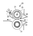
図2に示すように、定着装置20は、定着回転体としての定着ローラ21、加熱手段としてのヒータ25、加圧回転体としての加圧ローラ31、クリーニング部材としてのクリーニングローラ35、温度センサ40、41、45、移動機構38、52(移動手段)、等で構成されている。
Next, the configuration and operation of the fixing
As shown in FIG. 2, the fixing
ここで、定着回転体としての定着ローラ21(定着部材)は、ステンレス鋼などの金属材料からなる中空構造の芯金21a上に、弾性層、離型層が順次積層された多層構造のローラ部材であって、加圧回転体としての加圧ローラ31に圧接してニップ部(定着ニップ)を形成している。
定着ローラ21の弾性層は、フッ素ゴム、シリコーンゴム、発泡性シリコーンゴム等の弾性材料で形成されている。定着ローラ21の離型層は、PFA(4フッ化エチレンバーフルオロアルキルビニルエーテル共重合体樹脂)等で形成されている。定着ローラ21の表層に離型層を設けることにより、トナーT(トナー像)に対する離型性(剥離性)が担保されることになる。定着ローラ21は、駆動モータ51によって図2の時計方向に回転駆動される。
Here, the fixing roller 21 (fixing member) as a fixing rotating body is a roller member having a multi-layer structure in which an elastic layer and a release layer are sequentially laminated on a
The elastic layer of the fixing
中空構造の定着ローラ21(芯金21a)の内部には加熱手段としてのヒータ25(熱源)が固設されている。
ヒータ25(加熱手段)は、ハロゲンヒータであって、その両端部が定着装置20の側板に固定されている。そして、画像形成装置本体1のメインスイッチがオンされた状態で、電源部からヒータ25に電力が供給される。そして、制御部50により出力制御されたヒータ25からの輻射熱によって定着ローラ21が加熱されて、さらに加熱された定着ローラ21の表面からシートP上のトナー像Tに熱が加えられる。
ヒータ25の出力制御は、定着ローラ21表面に非接触で対向する温度センサ40によるローラ表面温度の検知結果に基づいておこなわれる。詳しくは、温度センサ40(サーモパイル)の検知結果に基づいて定められる通電時間だけ、ヒータ25に交流電圧が印加される。このようなヒータ25の出力制御によって、定着ローラ21の温度(定着温度)を所望の温度(目標制御温度)に調整制御することができる。
A heater 25 (heat source) as a heating means is fixed inside the fixing roller 21 (
The heater 25 (heating means) is a halogen heater, and both ends thereof are fixed to side plates of the fixing
The output control of the
また、加圧回転体としての加圧ローラ31(加圧部材)は、主として、芯金32と、芯金32の外周面に接着層を介して形成された弾性層33と、からなる。加圧ローラ31の弾性層33は、発泡性シリコーンゴム、フッ素ゴム、シリコーンゴム等の材料で形成されている。なお、弾性層33の表層にPFA等からなる薄肉の離型層を設けることもできる。
そして、加圧ローラ31は、加圧機構によって定着ローラ21に圧接する。こうして、加圧ローラ31と定着ローラ21との間に、所望のニップ部が形成される。
加圧ローラ31は、定着ローラ21の回転にともない、図2の反時計方向に従動回転する。
Further, the pressure roller 31 (pressure member) as a pressure rotating body mainly consists of a
The
As the fixing
なお、本実施の形態における定着装置20には、加圧ローラ31の表面に付着したトナーや紙粉などの付着物を除去(クリーニング)するクリーニングローラ35(クリーニング部材)や、加圧ローラ31に対してクリーニングローラ35を接離する移動機構38、52(移動手段)や、クリーニングローラ35の温度を検知する温度センサ45(温度検知手段)、なども設置されているが、これらについては後で詳しく説明する。
Note that the fixing
上述のように構成された定着装置20は、次のように動作する。
装置本体1のメインスイッチが投入されると、ヒータ25に交流電圧が印加(給電)される。
そして、印刷指令(プリント要求)が入力されると、駆動モータ51(駆動機構)によって定着ローラ21の時計方向の回転駆動が開始されて、加圧ローラ31の反時計方向の従動回転が開始される。その後、給紙部7からシートPが給送されて、2次転写バイアスローラ18の位置で、中間転写ベルト17上のトナー像がシートP上に未定着画像として担持される。未定着画像T(トナー像)が担持されたシートPは、図2の矢印方向に搬送されて、圧接状態にある定着ローラ21及び加圧ローラ31のニップ部に送入される。そして、定着ローラ21による加熱と、定着ローラ21及び加圧ローラ31の押圧力とによって、シートPの表面にトナー像Tが定着される。そして、定着工程後のシートPは、回転する定着ローラ21及び加圧ローラ31によって、ニップ部から矢印方向に送出される。
The fixing
When the main switch of the apparatus
When a print command (print request) is input, the drive motor 51 (driving mechanism) starts rotating the fixing
以下、本実施の形態における定着装置20(画像形成装置1)において、特徴的な構成・動作について詳しく説明する。
先に図2等を用いて説明したように、定着装置20には、トナー像を加熱してシートPの表面に定着する定着回転体としての定着ローラ21や、定着ローラ21に圧接することでシートPが搬送されるニップ部を形成する加圧回転体としての加圧ローラ31、が設置されている。
そして、本実施の形態における定着装置20には、クリーニング部材としてのクリーニングローラ35や、温度検知手段としての温度センサ45、が設置されている。
Hereinafter, the characteristic configuration and operation of the fixing device 20 (image forming apparatus 1) according to the present embodiment will be described in detail.
As described above with reference to FIG. A
A cleaning
図2、図3を参照して、クリーニング部材としてのクリーニングローラ35は、移動手段としての移動機構38、52の動作によって、加圧ローラ31(加圧回転体)の表面に当接する当接位置(図2の実線で示す位置である。)と、加圧ローラ31の表面から離れる離間位置(図2の破線で示す位置であって、図3に示す位置である。)と、の間を移動可能に構成されている。
Referring to FIGS. 2 and 3, cleaning
詳しくは、本実施の形態において、クリーニングローラ35は、金属材料からなるローラ部材であって、アーム部材38に回転可能に保持されている。クリーニングローラ35は、加圧ローラ31の表面に当接して、加圧ローラ31の表面に付着したトナーや紙粉などの付着物を除去してクリーニングするためのものである。加圧ローラ31の表面がクリーニングされることで、加圧ローラ31自体が直接的にクリーニングされるのはもちろんのこと、定着ローラ21も間接的にクリーニングされて、定着ニップを通過するシートPがトナーや紙粉などで汚れたり画像の一部が欠損したりする不具合が軽減されることになる。
特に、本実施の形態では、クリーニングローラ35は、所定方向に回転している加圧ローラ31に当接した状態のとき加圧ローラ31とともに回転するため、その回転によってクリーニングローラ35の表面を入れ替えながら効率的にクリーニングをおこなうことが可能になる。
Specifically, in this embodiment, the cleaning
In particular, in the present embodiment, the cleaning
ここで、アーム部材38は、支軸38aを中心に図2の両矢印方向に搖動可能に、定着装置20の筐体に保持されている。また、アーム部材38の支軸38aには、正逆双方向回転型のモータ52がギア列を介して接続されている。
そして、制御部50による制御によって、モータ52が正方向に駆動されると、アーム部材38が支軸38aを中心に図2の反時計方向に回動して、図2に示すようにクリーニングローラ35が加圧ローラ31に当接することになる(当接位置に移動することになる)。これに対して、制御部50による制御によって、モータ52が逆方向に駆動されると、アーム部材38が支軸38aを中心に図2の時計方向に回動して、図3に示すようにクリーニングローラ35が加圧ローラ31から離間することになる(離間位置に移動することになる)。
すなわち、モータ52とアーム部材38とが、クリーニングローラ35を移動させる移動手段(移動機構)として機能することになる。
Here, the arm member 38 is held by the housing of the fixing
When the
That is, the
このように移動機構38、52を設けて、クリーニングローラ35を離間可能に構成することで、加圧ローラ31にクリーニングローラ35が常時当接するように構成する場合に比べて、加圧ローラ31とクリーニングローラ35との圧接部でトナーが固化したり、クリーニングローラ35が変形してしまったりする不具合が生じにくくなる。
すなわち、定着装置20が駆動停止した後にも、長時間にわたってクリーニングローラ35が加圧ローラ31に圧接し続けてしまうと、その圧接部に位置するトナーがやがて固化してしまったり、その圧接部でクリーニングローラ35や加圧ローラ31が変形してしまったりすることになる。これに対して、本実施の形態では、クリーニングローラ35を離間可能に構成して、駆動停止時に長時間にわたってクリーニングローラ35が加圧ローラ31に当接し続けないようにしているため、そのような不具合の発生を抑止することができる。
By providing the moving
That is, if the cleaning
また、図2、図3を参照して、温度検知手段としての温度センサ45は、クリーニングローラ35(クリーニング部材)の温度を検知するものである。
詳しくは、図2、図3に示すように、温度センサ45は、サーモパイルや非接触式サーミスタなどの非接触式温度センサであって、その検知面がクリーニングローラ35に対向するようにアーム部材38に保持されている。したがって、温度センサ45は、クリーニングローラ35が加圧ローラ31に対して当接した状態であっても離間した状態であっても、常にクリーニングローラ35に対向して、クリーニングローラ35の温度を検知できる。
2 and 3, a
Specifically, as shown in FIGS. 2 and 3, the
そして、本実施の形態における定着装置20は、クリーニングローラ35(クリーニング部材)の当接位置(図2の位置である。)から離間位置(図3の位置である。)への移動、又は、クリーニングローラ35の離間位置から当接位置への移動、を移動機構38、52(移動手段)によっておこなう場合であって、温度センサ45(温度検知手段)によって検知される温度が所定値Aを超えているときには、加圧ローラ31(クリーニングローラ35が当接する対象である。)が回転している状態で、その移動をおこなうようにしている。
また、クリーニングローラ35の当接位置から離間位置への移動、又は、クリーニングローラ35の離間位置から当接位置への移動、を移動機構38、52(移動手段)によっておこなう場合であって、温度センサ45(温度検知手段)によって検知される温度が所定値A以下であるときには、加圧ローラ31(クリーニングローラ35が当接する対象である。)が回転停止している状態で、その移動をおこなうようにしている。
Then, the fixing
Further, when the movement of the cleaning
以下、定着装置20における離間時の動作について、詳しく説明する。
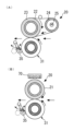
図4(A)は、クリーニングローラ35を当接位置から離間位置に移動するときであって、温度センサ45で検知したクリーニングローラ35の温度(検知温度)が所定値A以下であるときの、加圧ローラ31とクリーニングローラ35との動作を示す図である。
図4(A1)に示すように、制御部50に制御された駆動モータ51によって定着ローラ21とともに加圧ローラ31が回転した状態で、加圧ローラ31に当接しているクリーニングローラ35も図の矢印方向に連れ回りしている。そして、制御部50にてクリーニングローラ35を加圧ローラ31から離間するタイミングであると判断されると、まず、図4(A2)に示すように、クリーニングローラ35が当接したまま加圧ローラ31の回転が停止される(駆動モータ51が駆動停止される)。そして、図4(A3)に示すように、回転停止状態の加圧ローラ31からクリーニングローラ35が離間される。
The operation of the fixing
FIG. 4A shows when the cleaning
As shown in FIG. 4A1, in a state in which the
これに対して、図4(B)は、クリーニングローラ35を当接位置から離間位置に移動するときであって、温度センサ45で検知したクリーニングローラ35の温度が所定値Aを超えるときの、加圧ローラ31とクリーニングローラ35との動作を示す図である。
図4(B1)に示すように、制御部50に制御された駆動モータ51によって定着ローラ21とともに加圧ローラ31が回転した状態で、加圧ローラ31に当接しているクリーニングローラ35も図の矢印方向に連れ回りしている。そして、制御部50にてクリーニングローラ35を加圧ローラ31から離間するタイミングであると判断されると、図4(B2)に示すように、加圧ローラ31が回転したまま(駆動モータ51が駆動したまま)でクリーニングローラ35が離間される。そして、図4(B3)に示すように、クリーニングローラ35が離間された後に、加圧ローラ31の回転が停止される(駆動モータ51が駆動停止される)。
On the other hand, FIG. 4B shows when the cleaning
As shown in FIG. 4B1, in a state in which the
このようにクリーニングローラ35を当接位置から離間位置に移動するときに、クリーニングローラ35の温度に応じて、加圧ローラ31を回転停止した状態で離間動作をおこなったり、加圧ローラ31を回転した状態で離間動作をおこなったり、することにより、クリーニングローラ35によるクリーニング性能を良好に維持しつつ、クリーニングローラ35の表面に付着したトナーなど付着物が加圧ローラ31の表面に逆移動してしまう不具合を軽減することができる。
When the cleaning
詳しくは、図8(A)(図8(A1)~(A3))に示すように、回転停止した状態の加圧ローラ31からクリーニングローラ35を離間させるときに、クリーニングローラ35の表面に付着したトナーなどの付着物Tの一部T´(図8(A2)中、破線で囲んだ圧接部に位置していた付着物T´である。)が、加圧ローラ31の表面に移動(逆移動)してしまう不具合が生じてしまうことがある。そして、本願発明者は、研究を重ねた結果、このような現象が、その離間動作をおこなうときのクリーニングローラ35の温度が所定値A(以下、適宜に「溶け出し温度」と呼ぶ。)に達しているか否かによって、発生したりしなかったりすることを知得した。この現象は、クリーニングローラ35に担持された付着物T(トナー)が、クリーニングローラ35とともに高温(溶け出し温度)に達することで、加圧ローラ31側に溶け出すように移動(オフセット)するものである。
したがって、上述した所定値A(溶け出し温度)は、加圧ローラ31の表面からクリーニングローラ35の表面に移動した付着物(主として、トナーである。)が加圧ローラ31の表面に逆移動する現象が生じない上限温度となる。
そして、そのような現象が生じてしまうと、加圧ローラ31の表面が汚れてしまって、定着ニップに搬送されるシートPを汚してしまったり、シートPに担持された画像の一部が欠損してしまったりしてしまうことになる。さらに、そのような付着物の逆移動が生じることにより、図8(A3)に示すように、クリーニングローラ35の表面に付着した付着物の層が不均一になってしまって、その後にクリーニングローラ35が加圧ローラ31に当接されたときに、クリーニングローラ35の回転不良によるクリーニング不良が生じてしまうことになる。
Specifically, as shown in FIG. 8(A) (FIGS. 8(A1) to (A3)), when the cleaning
Therefore, at the predetermined value A (dissolution temperature) described above, the adhered matter (mainly toner) that has moved from the surface of the
If such a phenomenon occurs, the surface of the
これに対して、本実施の形態では、クリーニングローラ35の温度が所定値A(溶け出し温度)に達していて、付着物T´の逆移動が生じそうなときに、加圧ローラ31を回転させた状態でクリーニングローラ35を離間しているため、クリーニングローラ35に局所的な圧接部が生じることなくクリーニングローラ35が離間されて、そのような不具合の発生が軽減される。
また、本実施の形態では、クリーニングローラ35の温度が所定値A(溶け出し温度)に達しておらず、付着物T´の逆移動が生じにくいときに、加圧ローラ31を回転停止した状態でクリーニングローラ35を離間している。そのため、加圧ローラ31が回転した状態でクリーニングローラ35が離間されることで、クリーニングローラ35が離間された瞬間から加圧ローラ31が回転停止されるまでの間に、クリーニングローラ35による加圧ローラ31のクリーニングができない状態になってしまう不具合を抑止することができる。
すなわち、付着物T´の逆移動が生じやすい高温時のみ、加圧ローラ31を回転させながらクリーニングローラ35を離間して、それ以外のときには、加圧ローラ31を回転停止させた後にクリーニングローラ35を離間してクリーニング性能がフルに発揮されるようにしている。
On the other hand, in the present embodiment, the
In the present embodiment, the
That is, only when the temperature is high enough to cause reverse movement of the adhering matter T', the cleaning
次に、定着装置20における当接時の動作について、詳しく説明する。
図5(A)は、クリーニングローラ35を離間位置から当接位置に移動するときであって、温度センサ45で検知したクリーニングローラ35の温度(検知温度)が所定値A以下であるときの、加圧ローラ31とクリーニングローラ35との動作を示す図である。
図5(A1)に示すように、制御部50に制御された駆動モータ51によって定着ローラ21とともに加圧ローラ31が回転停止した状態で、加圧ローラ31からクリーニングローラ35が離間している。そして、制御部50にてクリーニングローラ35を加圧ローラ31に当接するタイミングであると判断されると、まず、図5(A2)に示すように、加圧ローラ31が回転停止されたまま(駆動モータ51が駆動停止されたまま)、加圧ローラ31にクリーニングローラ35が当接される。そして、図5(A3)に示すように、クリーニングローラ35が当接された後に、加圧ローラ31が回転される(駆動モータ51が駆動される)。
Next, the operation of the fixing
FIG. 5A shows when the cleaning
As shown in FIG.
これに対して、図5(B)は、クリーニングローラ35を離間位置から当接位置に移動するときであって、温度センサ45で検知したクリーニングローラ35の温度が所定値Aを超えるときの、加圧ローラ31とクリーニングローラ35との動作を示す図である。
図5(B1)に示すように、制御部50に制御された駆動モータ51によって定着ローラ21とともに加圧ローラ31が回転停止した状態で、加圧ローラ31からクリーニングローラ35が離間している。そして、制御部50にてクリーニングローラ35を加圧ローラ31に当接するタイミングであると判断されると、まず、図5(B2)に示すように、クリーニングローラ35が離間されたまま、加圧ローラ31が回転される(駆動モータ51が駆動される)。そして、図5(B3)に示すように、回転状態の加圧ローラ31にクリーニングローラ35が当接される。
On the other hand, FIG. 5B shows when the cleaning
As shown in FIG.
このようにクリーニングローラ35を離間位置から当接位置に移動するときに、クリーニングローラ35の温度に応じて、加圧ローラ31を回転停止した状態で当接動作をおこなったり、加圧ローラ31を回転した状態で当接動作をおこなったり、することにより、クリーニングローラ35によるクリーニング性能を良好に維持しつつ、クリーニングローラ35の表面に付着したトナーなど付着物が加圧ローラ31の表面に逆移動してしまう不具合を軽減することができる。
When the cleaning
詳しくは、図8(B)(図8(B1)~(B3))に示すように、回転停止した状態の加圧ローラ31にクリーニングローラ35を当接させるときに、クリーニングローラ35の表面に付着したトナーなどの付着物Tの一部T´(図8(B2)中、破線で囲んだ圧接部に位置することになる付着物T´である。)が、加圧ローラ31の表面に移動(逆移動)してしまう不具合が生じてしまうことがある。そして、本願発明者は、研究を重ねた結果、このような現象が、その当接動作をおこなうときのクリーニングローラ35の温度が所定値A(溶け出し温度)に達しているか否かによって、発生したりしなかったりすることを知得した。この現象は、クリーニングローラ35に担持された付着物T(トナー)が、クリーニングローラ35とともに高温(溶け出し温度)に達することで、加圧ローラ31側に溶け出すように移動(オフセット)するものであって、離間時のメカニズムとほぼ同じである。
そして、そのような現象が生じてしまうと、加圧ローラ31の表面が汚れてしまって、定着ニップに搬送されるシートPを汚してしまったり、シートPに担持された画像の一部が欠損してしまったりしてしまうことになる。さらに、そのような付着物の逆移動が生じることにより、図8(B3)に示すように、クリーニングローラ35の表面に付着した付着物の層が不均一になってしまって、クリーニングローラ35の回転不良によるクリーニング不良が生じてしまうことになる。
Specifically, as shown in FIG. 8(B) (FIGS. 8(B1) to (B3)), when the cleaning
If such a phenomenon occurs, the surface of the
これに対して、本実施の形態では、クリーニングローラ35の温度が所定値A(溶け出し温度)に達していて、付着物T´の逆移動が生じそうなときに、加圧ローラ31を回転させた状態でクリーニングローラ35を当接させているため、クリーニングローラ35に局所的な圧接部が生じることなくクリーニングローラ35が当接されて、そのような不具合の発生が軽減される。
また、本実施の形態では、クリーニングローラ35の温度が所定値A(溶け出し温度)に達しておらず、付着物T´の逆移動が生じにくいときに、加圧ローラ31を回転停止した状態でクリーニングローラ35を当接させている。そのため、加圧ローラ31が回転した状態でクリーニングローラ35が当接されることで、加圧ローラ31が回転開始されてからクリーニングローラ35が当接されるまでの間に、クリーニングローラ35による加圧ローラ31のクリーニングができない状態になってしまう不具合を抑止することができる。
すなわち、付着物T´の逆移動が生じやすい高温時のみ、加圧ローラ31を回転させながらクリーニングローラ35を当接させて、それ以外のときには、加圧ローラ31を回転停止した状態でクリーニングローラ35を当接させてクリーニング性能がフルに発揮されるようにしている。
On the other hand, in the present embodiment, the
In the present embodiment, the
That is, only when the temperature is high, the
ここで、温度センサ45は、定着ニップにおける最大通紙領域M(通紙可能な最大サイズのシートPの幅方向の範囲である。)の領域外で、クリーニングローラ35の温度を検知するように配置されている。
加圧ローラ31(及び、定着ローラ21)は、通紙領域でシートPによって熱が奪われるため、最大通紙領域Mの領域外の温度が最も高くなりやすい。加圧ローラ31から熱を受けるクリーニングローラ35も最大通紙領域Mの領域外の温度が最も高くなりやすいため、その位置の温度を温度センサ45によって検知することで、クリーニングローラ35が「溶け出し温度」に達するタイミングをいち早く把握することが可能になる。
Here, the
Since the heat of the pressure roller 31 (and the fixing roller 21) is taken away by the sheet P in the sheet passing area, the temperature outside the maximum sheet passing area M tends to be the highest. The cleaning
なお、上述した「溶け出し温度」は、使用するトナーや、紙粉の成分などによっても変化するものである。したがって、使用するトナーが異なる機種ごとに上述した所定値Aを最適な値に設定したり、搬送されるシートPに応じて上述した所定値Aを可変したり、することもできる。 It should be noted that the above-mentioned "dissolution temperature" varies depending on the toner used, the components of the paper dust, and the like. Therefore, the above-described predetermined value A can be set to an optimum value for each model using different toner, or the above-described predetermined value A can be varied according to the sheet P to be conveyed.
また、本実施の形態では、クリーニングローラ35の表面温度を直接的に検知する温度センサ45(温度検知手段)の検知温度に基づいて、加圧ローラ31を回転停止した状態でクリーニングローラ35の接離動作をおこなうか、加圧ローラ31を回転した状態でクリーニングローラ35の接離動作をおこなうかを判断した。
これに対して、加圧ローラ31の表面温度の変化とクリーニングローラ35の表面温度の変化との相関が高くて、加圧ローラ31の温度を検知することでクリーニングローラ35の温度を間接的に検知できる場合には、加圧ローラ31の温度を検知する温度センサ41(温度検知手段)の検知温度に基づいて、加圧ローラ31を回転停止した状態でクリーニングローラ35の接離動作をおこなうか、加圧ローラ31を回転した状態でクリーニングローラ35の接離動作をおこなうかを判断することもできる。そのように構成した場合には、温度センサの数を減ずることができるため、装置を低コスト化、小型化することが可能になる。
Further, in the present embodiment, based on the temperature detected by the temperature sensor 45 (temperature detection means) that directly detects the surface temperature of the cleaning
On the other hand, there is a high correlation between changes in the surface temperature of the
ここで、図6を参照して、本実施の形態では、クリーニングローラ35(クリーニング部材)の離間位置から当接位置への移動は、一連の定着工程(印刷動作)が開始される前におこなっている。具体的に、図6(A)、(B)に示すように、温度センサ45の検知温度が所定値Aを超えているか所定値A以下であるかに関わらず、一連の定着工程(印刷動作)がおこなわれるときには、離間状態のクリーニングローラ35が当接状態になっていることになる。すなわち、定着工程前のウォーミングアップ時に、温度センサ45の検知温度に基づいて、加圧ローラ31を回転停止した状態でクリーニングローラ35の当接動作をおこなったり、加圧ローラ31を回転した状態でクリーニングローラ35の当接動作をおこなったりすることになる。
同様に、クリーニングローラ35の当接位置から離間位置への移動は、一連の定着工程(印刷動作)が終了した後におこなっている。具体的に、図6(A)、(B)に示すように、温度センサ45の検知温度が所定値Aを超えているか所定値A以下であるかに関わらず、一連の定着工程(印刷動作)が終了した後には、最終的に、当接状態のクリーニングローラ35が離間状態になっていることになる。すなわち、定着工程後のクールダウン時に、温度センサ45の検知温度に基づいて、加圧ローラ31を回転停止した状態でクリーニングローラ35の離間動作をおこなったり、加圧ローラ31を回転した状態でクリーニングローラ35の離間動作をおこなったりすることになる。
このような制御をおこなうことで、良好な定着工程を維持しつつ、上述した種々の効果が発揮されることになる。
Here, referring to FIG. 6, in the present embodiment, the movement of the cleaning roller 35 (cleaning member) from the separated position to the contact position is performed before a series of fixing steps (printing operation) is started. ing. Specifically, as shown in FIGS. 6A and 6B, a series of fixing processes (printing operation ) is performed, the separated cleaning
Similarly, the movement of the cleaning
By performing such control, various effects described above can be exhibited while maintaining a favorable fixing process.
図7は、ここまで説明したクリーニングローラ35の接離制御を、まとめとして示すフローチャートである。
図7に示すように、まず、ユーザーによって装置の印刷ボタンが押されるなどして、制御部50に印刷指令が入力されると(ステップS1)、温度センサ45の検知温度が所定値A以下であるかが判別される(ステップS2)。
その結果、温度センサ45の検知温度が所定値A以下であるものと判別された場合には、クリーニングローラ35から加圧ローラ31への付着物の逆移動は生じないものとして、定着装置20(加圧ローラ31)が駆動停止した状態のままクリーニングローラ35が離間位置から当接位置に移動される(ステップS3)。そして、クリーニングローラ35が当接位置に移動した後に、定着装置20(加圧ローラ31)の駆動が開始される(ステップS4)。
これに対して、ステップS2で、温度センサ45の検知温度が所定値A以下でないものと判別された場合には、クリーニングローラ35から加圧ローラ31への付着物の逆移動が生じるものとして、まず定着装置20(加圧ローラ31)の駆動が開始される(ステップS5)。そして、定着装置20(加圧ローラ31)が駆動された後に、クリーニングローラ35が離間位置から当接位置に移動される(ステップS6)。
そして、その後、印刷が終了するまで、クリーニングローラ35が加圧ローラ31に当接した状態で一連の印刷が実行されることになる(ステップS7)。
FIG. 7 is a flow chart summarizing the contact/separation control of the cleaning
As shown in FIG. 7, first, when a print command is input to the
As a result, when it is determined that the temperature detected by the
On the other hand, if it is determined in step S2 that the temperature detected by the
After that, a series of printing is executed with the cleaning
そして、印刷が終了した状態が判別されると、再び温度センサ45の検知温度が所定値A以下であるかが判別される(ステップS8)。
その結果、温度センサ45の検知温度が所定値A以下であるものと判別された場合には、クリーニングローラ35から加圧ローラ31への付着物の逆移動は生じないものとして、まず、定着装置20(加圧ローラ31)が駆動停止される(ステップS9)。そして、定着装置20(加圧ローラ31)が駆動停止した状態のまま、クリーニングローラ35が当接位置から離間位置に移動される(ステップS10)。
これに対して、ステップS8で、温度センサ45の検知温度が所定値A以下でないものと判別された場合には、クリーニングローラ35から加圧ローラ31への付着物の逆移動が生じるものとして、定着装置20(加圧ローラ31)が駆動された状態のままクリーニングローラ35が当接位置から離間位置に移動される(ステップS11)。そして、クリーニングローラ35が離間位置に移動した後に、定着装置20(加圧ローラ31)が駆動停止される(ステップS12)。
Then, when it is determined that the printing has ended, it is determined again whether the temperature detected by the
As a result, when it is determined that the temperature detected by the
On the other hand, if it is determined in step S8 that the temperature detected by the
<変形例1>
図9は、変形例1としてのクリーニングローラ35の接離制御の一例を示すタイミングチャートである。
図9に示すように、変形例1では、一連の定着工程(印刷動作)がおこなわれているときにクリーニングローラ35(クリーニング部材)の当接位置(図2に示す位置である。)から離間位置(図3に示す位置である。)への移動がおこなわれた場合には、温度センサ45(温度検知手)によって検知される温度が所定値A以下であっても、その一連の定着工程(印刷動作)がおこなわれている間にクリーニングローラ35の離間位置から当接位置への移動をおこなわない。
すなわち、定着工程中に、クリーニングローラ35の離間動作がおこなわれた場合には、その後のクリーニングローラ35の温度に関わらず、その定着工程が終了するまでクリーニングローラ35の当接動作はおこなわない。そして、一連の定着工程が終了した後も、クリーニングローラ35の離間状態を維持する。
詳しくは、変形例1においても、本実施の形態と同様に、クリーニングローラ35(クリーニング部材)の離間位置から当接位置への移動は、一連の定着工程(印刷動作)が開始される前におこなっている。具体的に、温度センサ45の検知温度が所定値Aを超えているか所定値A以下であるかに関わらず、一連の定着工程(印刷動作)がおこなわれるときには、離間状態のクリーニングローラ35が当接状態になっていることになる。すなわち、定着工程前のウォーミングアップ時に、温度センサ45の検知温度に基づいて、加圧ローラ31を回転停止した状態でクリーニングローラ35の当接動作をおこなったり、加圧ローラ31を回転した状態でクリーニングローラ35の当接動作をおこなったりすることになる。
しかし、クリーニングローラ35の当接位置から離間位置への移動は、本実施の形態とは異なり、一連の定着工程(印刷動作)中にもおこなわれる。具体的に、図9の下方のグラフに示すように、温度センサ45の検知温度が所定値Aに到達した場合には、一連の定着工程がおこなわれている最中であっても、クリーニングローラ35を当接位置から離間位置に移動している。このような制御をおこなうことで、クリーニングローラ35が定着工程中に所定値A(溶け出し温度)を超えてしまうことを防ぎ、良好な定着工程を維持しつつ、本実施の形態のものと同様の種々の効果が発揮されることになる。
図9の下方のグラフに示すように、定着工程(印刷動作)中に離間状態となったクリーニングローラ35は徐々に温度が低下していくが、所定値A以下となった場合でも、その定着工程(印刷動作)中に再び当接状態となることはない。このような制御をおこなうことで、定着工程中にクリーニングローラ35が加圧ローラ31に当接することで生じる画像乱れや、加圧温度の急激な落ち込みにともなう画像品質低下を防ぐことができる。
<
FIG. 9 is a timing chart showing an example of contact/separation control of the cleaning
As shown in FIG. 9, in
That is, when the cleaning
Specifically, in
However, the movement of the cleaning
As shown in the lower graph of FIG. 9, the temperature of the cleaning
<変形例2>
図10は、変形例2としてのクリーニングローラ35の接離制御の一例を示すタイミングチャートである。
図10に示すように、変形例2では、一連の定着工程(印刷動作)がおこなわれているときにシートPのジャム(紙詰まり)が発生した場合には、温度センサ45(温度検知手段)によって検知される温度に関わらず、クリーニングローラ35(クリーニング部材)の当接位置(図2に示す位置である。)から離間位置(図3に示す位置である。)への移動をおこなっている。
詳しくは、一連の定着工程(印刷動作)がおこなわれている最中に、搬送経路中でシートPのジャムが発生した場合に、一様に、クリーニングローラ35の当接位置から離間位置への移動をおこなう。これは、ジャム発生時にクリーニングローラ35が当接状態であると、定着装置20の位置でジャムしたシートPを除去しにくいためである。特に、加圧ローラ31にジャムしたシートPが巻き付いてしまっている場合には、このような制御が有用になる。なお、ジャムの有無は、画像形成装置1における搬送経路中(特に、定着装置20の近傍)に設置されたフォトセンサ(シート検知センサ)によって検知される。
このようにジャムが発生した場合にはクリーニングローラ35の温度に関わらず、クリーニングローラ35の当接位置から離間位置への移動をおこなうことで、ジャムしたシートPを除去するときの作業性が向上する。さらに、ジャムしたシートP(残紙)による温度センサ45の誤検知を防ぐことができる。
<
FIG. 10 is a timing chart showing an example of contact/separation control of the cleaning
As shown in FIG. 10, in Modified Example 2, when a sheet P jam (paper jam) occurs while a series of fixing processes (printing operations) is being performed, the temperature sensor 45 (temperature detection means) The cleaning roller 35 (cleaning member) is moved from the contact position (the position shown in FIG. 2) to the separation position (the position shown in FIG. 3) regardless of the temperature detected by . .
Specifically, when a sheet P jam occurs in the conveying path while a series of fixing processes (printing operations) are being performed, the cleaning
When a jam occurs in this way, by moving the cleaning
<変形例3>
図11は、変形例3としてのクリーニングローラ35の接離制御の一例を示すタイミングチャートである。
図11に示すように、変形例3では、クリーニングローラ35(クリーニング部材)の当接位置(図2に示す位置である。)から離間位置(図3に示す位置である。)への移動速度V2が、クリーニングローラ35の離間位置から当接位置への移動速度V1に比べて速くなるように設定している(V1<V2)。
すなわち、図11に示すように、クリーニングローラ35が当接位置から離間位置に移動するのに要する時間X2は、クリーニングローラ35が離間位置から当接位置に移動するのに要する時間X1に比べて短くなる(X1>X2)。
詳しくは、クリーニングローラ35を接離するモータ52は、回転数可変型のモータであって、クリーニングローラ35の当接動作をおこなうために正方向に駆動するときの回転数が、クリーニングローラ35の離間動作をおこなうために逆方向に駆動するときの回転数に比べて小さくなるように設定されている。
このように構成することにより、加圧ローラ31やクリーニングローラ35の温度が上昇したときに、トナーの溶け出しを回避するためにすばやくクリーニングローラ35を離間することができるため、クリーニングローラ35から加圧ローラ1へのトナーの逆移動を軽減することができる。また、当接動作時には、回転する加圧ローラ31に対して、クリーニングローラ35を比較的遅い移動速度V1でゆっくり当接させることができるため、当接による衝撃やショックを緩和できる。特に、定着工程中にクリーニングローラ35の当接動作がおこなわれる場合には、定着画像に対して振動を与えないので画像乱れが生じにくくなる。また、離間状態のクリーニングローラ35と、加圧ローラ31と、の間には温度差が生じやすいが(前者の方が後者に比べて温度が低くなる。)、当接時にはそのような状態からクリーニングローラ35が加圧ローラ31に移動速度V1で徐々にゆっくりと当接されることになるため、双方の部材31、35の表面温度差が徐々に均一になり、クリーニングローラ35に付着したトナーの温度も急激に低下することもなく、トナーの溶け出しが軽減される。また、加圧ローラ31においては、低温のクリーニングローラ35がゆっくり接触することになるため、加圧ローラ31の表面温度の急激な低下がなく、定着温度低下による定着不良画像の発生も軽減することができる。
<
FIG. 11 is a timing chart showing an example of contact/separation control of the cleaning
As shown in FIG. 11, in
That is, as shown in FIG. 11, the time X2 required for the cleaning
More specifically, the
With this configuration, when the temperature of the
<変形例4>
図12は、変形例4としてのクリーニングローラ35の接離制御の一例を示すタイミングチャートである。
図12(A)に示すように、変形例4では、クリーニングローラ35(クリーニング部材)が当接する加圧ローラ31(加圧回転体)が回転している状態であるときには、クリーニングローラ35の当接位置から離間位置への移動速度V2が、クリーニングローラ35の離間位置から当接位置への移動速度V1に比べて速くなるように設定している(V1<V2)。すなわち、図12(A)に示すように、加圧ローラ31が回転した状態でクリーニングローラ35の当接動作や離間動作をおこなう場合(図4(B)、図5(B)参照)、前記変形例3と同様に、クリーニングローラ35が当接位置から離間位置に移動するのに要する時間X2は、クリーニングローラ35が離間位置から当接位置に移動するのに要する時間X1に比べて短くなる(X1>X2)。これにより、前記変形例3で説明したものと同様の効果を得ることができる。
これに対して、図12(B)に示すように、クリーニングローラ35が当接する加圧ローラ31が回転停止している状態であるときには、クリーニングローラ35の当接位置から離間位置への移動速度V1と、クリーニングローラ35の離間位置から当接位置への移動速度V1と、が略同速度になるように設定している。すなわち、図12(B)に示すように、加圧ローラ31が回転停止した状態でクリーニングローラ35の当接動作や離間動作をおこなう場合(図4(A)、図5(A)参照)、クリーニングローラ35が当接位置から離間位置に移動するのに要する時間X1は、クリーニングローラ35が離間位置から当接位置に移動するのに要する時間X1と略同じになる。
<Modification 4>
FIG. 12 is a timing chart showing an example of contact/separation control of the cleaning
As shown in FIG. 12A, in Modified Example 4, when the pressure roller 31 (pressurizing rotating body) with which the cleaning roller 35 (cleaning member) contacts is rotating, the contact of the cleaning
On the other hand, as shown in FIG. 12B, when the
以下、変形例4において、図12(B)のように制御する理由について説明する。
加圧ローラ31やクリーニングローラ35の温度がそれほど高くなくて、温度センサ45で検知される温度が所定値A(溶け出し温度)以下である場合には、クリーニング機能の効果をできるだけ得るために、加圧ローラ31が停止するまでクリーニングローラ35は当接状態になる。しかし、加圧ローラ31が回転停止した後も、クリーニングローラ35が当接状態で放置冷却されてしまうと、双方の部材31、35の当接部に挟まれたトナーが固着してしまい、次の回転開始時に加圧ローラ31に剥落したトナーが付着して異常画像を発生させてしまう(図8(A)参照)。したがって、加圧ローラ31が回転停止したときに、速やかにクリーニングローラ35の離間動作をおこなうことが好ましい。そのとき、比較的速い移動速度V2でクリーニングローラ35を離間させてしまうと、双方の部材31、35に挟まれた堆積トナーがある程度の粘性を持っているため、加圧ローラ31の表面に剥落して付着しやすくなる。そして、そのような現象が生じてしまうと、次の定着工程時の定着画像に剥落したトナーが付着してしまう。また、クリーニングローラ35の表面の一部が、加圧ローラ31へ剥落したトナーによって、凹状みが形成されてしまうため(図8(A)参照)、クリーニングローラ35の回転不良などが生じやすくなる。
これらのことから、加圧ローラ31が回転停止した状態でおこなうクリーニングローラ35の離間動作は、当接動作時と同様に、比較的遅い移動速度V1でおこなっている。
また、加圧ローラ31が回転停止した状態でおこなうクリーニングローラ35の当接動作は、加圧ローラ31が回転した状態でおこなうクリーニングローラ35の当接動作と同様に、比較的遅い移動速度V1でおこなっている。これにより、双方の部材31、35の当接部で挟まれた堆積トナーの温度が瞬時に高められてしまうようなことがなく、加圧ローラ31にトナーが逆移動(剥落)する不具合が生じにくくなる。また、クリーニングローラ35が加圧ローラ31に当接するときの衝撃や振動が小さくなり、クリーニングローラ35や加圧ローラ31に与えるダメージも小さくなる。
In the following, the reason for controlling as shown in FIG.
When the temperatures of the
For these reasons, the separation operation of the cleaning
The contact operation of the cleaning
<変形例5>
図13は、変形例5としての定着装置20の要部を示す構成図であって、本実施の形態における図2に対応する図である。
図13に示すように、変形例5では、クリーニングローラ35(クリーニング部材)が定着回転体としての定着ローラ21の表面に当接して定着ローラ21の表面をクリーニングするように構成されている。
そして、変形例5でも、本実施の形態のものと同様に、温度センサ45によって検知されるクリーニングローラ35の温度(又は、温度センサ40によって検知される定着ローラ21の温度)が所定値A´を超えているときには、定着ローラ21が回転している状態で、クリーニングローラ35の接離がおこなわれる。また、温度センサ45(又は、温度センサ40)によって検知される温度が所定値A´以下であるときには、定着ローラ21が回転停止している状態で、クリーニングローラ35の接離がおこなわれる。この場合、上述した所定値A´(溶け出し温度)は、定着ローラ21の表面からクリーニングローラ35の表面に移動した付着物(主として、トナーである。)が定着ローラ21の表面に逆移動する現象が生じない上限温度となる。
なお、変形例5では、温度センサ45として、クリーニングローラ35に接触する接触式サーミスタなどの接触式温度センサが用いられている。
このように構成した場合には、クリーニングローラ35によるクリーニング性能を良好に維持しつつ、クリーニングローラ35の表面に付着した付着物が定着ローラ21の表面に逆移動してしまう不具合を軽減することができる。
なお、前記変形例1~4において加圧ローラ31に対して接離するクリーニングローラ35が設置された定着装置20に適用した発明は、本変形例5における定着装置20にも当然に適用することができる。
<
FIG. 13 is a configuration diagram showing a main part of fixing
As shown in FIG. 13, in Modified Example 5, the cleaning roller 35 (cleaning member) is configured to contact the surface of the fixing
Also in Modified Example 5, similarly to the present embodiment, the temperature of the cleaning
In
In the case of such a configuration, it is possible to reduce the inconvenience that the adherents adhering to the surface of the cleaning
The invention applied to the fixing
<変形例6>
図14は、変形例6としての定着装置20を示す構成図であって、本実施の形態における図2に対応する図である。
本実施の形態(及び、変形例1~5)では、熱ヒータ方式のローラ式定着装置20に対して本発明を適用したが、本発明が適用される定着装置20はこのような方式のものに限定されることなく、種々の方式の定着装置に設置することができる。
例えば、図14(A)に示すように、熱ヒータ方式のベルト式定着装置20(定着回転体として定着ベルト22が用いられた定着装置である。)に対しても、本発明を適用することもできる。なお、そのような場合に、定着ベルト22は、定着補助ローラ23、加熱ローラ24、テンションローラなどの複数のローラ部材によって張架・支持されたものとなる。また、定着補助ローラ23は、定着ベルト22を介して加圧ローラ31に圧接してニップ部を形成することになる。さらに、中空構造の加熱ローラ24の内部に、ヒータ25が固設されることになる。
また、図14(B)に示すように、電磁誘導方式(IH方式)のローラ式定着装置20に対しても、本発明を適用することもできる。なお、そのような場合に、定着ローラ21は、芯金部上に、弾性層、励磁コイルが巻装された誘導加熱部70によって電磁誘導加熱される発熱層、離型層などが積層されたものとなる。
また、図示は省略するが、抵抗発熱方式のローラ式定着装置に対しても、本発明を適用することもできる。なお、そのような場合に、定着ローラは、芯金部における中空部に抵抗発熱体が当接するように設置され、芯金部上に弾性層や離型層などが積層されたものとなる。
そして、それらのような場合であっても、本実施の形態(及び、変形例1~5)のものとほぼ同様の効果を得ることができる。
<Modification 6>
FIG. 14 is a configuration diagram showing a fixing
In the present embodiment (and modified examples 1 to 5), the present invention is applied to the heat heater type roller
For example, as shown in FIG. 14A, the present invention can also be applied to a heat heater type belt-type fixing device 20 (a fixing device using a fixing
Further, as shown in FIG. 14B, the present invention can also be applied to an electromagnetic induction type (IH type) roller
Also, although not shown, the present invention can also be applied to a resistance heating roller type fixing device. In such a case, the fixing roller is installed so that the resistance heating element is in contact with the hollow portion of the core metal portion, and an elastic layer, a release layer, and the like are laminated on the core metal portion.
Even in such cases, substantially the same effects as those of the present embodiment (and
以上説明したように、本実施の形態における定着装置20は、クリーニングローラ35(クリーニング部材)の当接位置から離間位置への移動、又は、クリーニングローラ35の離間位置から当接位置への移動、を移動機構38、52(移動手段)によっておこなう場合であって、温度センサ45(温度検知手段)によって検知されるクリーニングローラ35(又は、加圧ローラ31)の温度が所定値Aを超えているときには、クリーニングローラ35が当接する加圧ローラ31(加圧回転体)が回転している状態で、その移動をおこなっている。また、そのようなクリーニングローラ35の移動は、温度センサ45によって検知される温度が所定値A以下であるときには、クリーニングローラ35が当接する加圧ローラ31(加圧回転体)が回転停止している状態で、その移動をおこなっている。
これにより、クリーニングローラ35によるクリーニング性能を良好に維持しつつ、クリーニングローラ35の表面に付着した付着物が加圧ローラ31の表面に逆移動してしまう不具合を軽減することができる。
As described above, the fixing
As a result, the cleaning performance of the cleaning
なお、本実施の形態では、加圧回転体として加圧ローラ31を用いたが、加圧回転体として加圧ベルトを用いることもできる。
また、本実施の形態における定着装置において、離間位置に移動したクリーニングローラ35(クリーニング部材)に当接して、クリーニングローラ35を冷却する冷却部材を設置して、クリーニングローラ35が高温に達しにくくなるようにすることもできる。
そして、それらのような場合にも、本実施の形態のものと同様の効果を得ることができる。
In this embodiment, the
In addition, in the fixing device according to the present embodiment, a cooling member is provided to contact the cleaning roller 35 (cleaning member) moved to the separated position to cool the cleaning
Also in such cases, the same effects as those of the present embodiment can be obtained.
なお、本発明が本実施の形態に限定されず、本発明の技術思想の範囲内において、本実施の形態の中で示唆した以外にも、本実施の形態は適宜変更され得ることは明らかである。また、前記構成部材の数、位置、形状等は本実施の形態に限定されず、本発明を実施する上で好適な数、位置、形状等にすることができる。 It should be noted that the present invention is not limited to the present embodiment, and it is obvious that the present embodiment can be appropriately modified within the scope of the technical idea of the present invention other than suggested in the present embodiment. be. Moreover, the number, position, shape, etc. of the constituent members are not limited to those of the present embodiment, and the number, position, shape, etc. can be set to be suitable for carrying out the present invention.
なお、本願明細書等において、「幅方向」とは、シートの搬送方向に対して直交する方向であるものと定義する。
また、本願明細書等において、「シート」とは、通常の紙(用紙)の他に、コート紙、ラベル紙、OHPシート、フィルムシート等のシート状の記録媒体のすべてを含むものと定義する。
また、本願明細書等において、「一連の定着工程」とは、1枚又は複数枚のシートにトナー像を加熱・定着する定着工程であって、定着装置が途中で駆動停止することなく連続的に駆動され続けながら1枚又は複数枚のシートに対しておこなわれる定着工程であるものと定義する。
In the specification of the present application and the like, the "width direction" is defined as a direction perpendicular to the sheet conveying direction.
In the specification of the present application, the term "sheet" is defined to include all sheet-like recording media such as coated paper, label paper, OHP sheet, and film sheet, in addition to ordinary paper. .
In the specification of the present application, etc., the term "a series of fixing steps" refers to a fixing step of heating and fixing a toner image on one or more sheets, in which the fixing device is continuously operated without stopping midway. is defined as a fusing process performed on one or more sheets while being continuously driven to
1 画像形成装置(画像形成装置本体)、
20 定着装置、
21 定着ローラ(定着回転体)、
25 ヒータ(加熱手段)、
31 加圧ローラ(加圧回転体)、
35 クリーニングローラ(クリーニング部材)、
38 アーム部材(移動手段)、
45 温度センサ(温度検知手段)、
52 モータ(移動手段)、
P シート(記録媒体)。
1 image forming apparatus (image forming apparatus main body),
20 fixing device,
21 fixing roller (fixing rotating body),
25 heater (heating means),
31 pressure roller (pressure rotating body),
35 cleaning roller (cleaning member),
38 arm member (moving means),
45 temperature sensor (temperature detection means),
52 motor (moving means),
P sheet (recording medium).
Claims (11)
前記定着回転体に圧接することでシートが搬送されるニップ部を形成する加圧回転体と、
移動手段の動作によって、前記定着回転体又は前記加圧回転体の表面に当接する当接位置と、当該表面から離れる離間位置と、の間を移動可能に構成されたクリーニング部材と、
前記クリーニング部材の温度、又は、前記クリーニング部材が当接する前記定着回転体又は前記加圧回転体の温度、を検知する温度検知手段と、
を備え、
前記クリーニング部材の前記当接位置から前記離間位置への移動、又は、前記クリーニング部材の前記離間位置から前記当接位置への移動、を前記移動手段によっておこなう場合であって、前記温度検知手段によって検知される温度が所定値以下であるときには、前記クリーニング部材が当接する前記定着回転体又は前記加圧回転体が回転停止している状態で、その移動をおこなうことを特徴とする定着装置。 a fixing rotator that heats the toner image to fix it on the surface of the sheet;
a pressing rotator forming a nip portion where the sheet is conveyed by being pressed against the fixing rotator;
a cleaning member configured to be movable between a contact position where it contacts the surface of the fixing rotator or the pressure rotator and a spaced position where it is separated from the surface by operation of a moving means;
temperature detection means for detecting the temperature of the cleaning member, or the temperature of the fixing rotary member or the pressure rotary member with which the cleaning member contacts;
with
When the movement of the cleaning member from the contact position to the separated position or the movement of the cleaning member from the separated position to the contact position is performed by the moving means, the temperature detecting means A fixing device, wherein when the detected temperature is equal to or lower than a predetermined value, the fixing rotary body or the pressure rotary body with which the cleaning member abuts is moved while the fixing rotary body or the pressure rotary body is not rotating.
前記クリーニング部材の前記当接位置から前記離間位置への移動は、一連の定着工程が終了した後におこなうことを特徴とする請求項1又は請求項2に記載の定着装置。 The movement of the cleaning member from the separated position to the contact position is performed before a series of fixing steps is started,
3. The fixing device according to claim 1, wherein the movement of the cleaning member from the contact position to the separation position is performed after a series of fixing steps are completed.
前記定着回転体に圧接することでシートが搬送されるニップ部を形成する加圧回転体と、
移動手段の動作によって、前記定着回転体又は前記加圧回転体の表面に当接する当接位置と、当該表面から離れる離間位置と、の間を移動可能に構成されたクリーニング部材と、
前記クリーニング部材の温度、又は、前記クリーニング部材が当接する前記定着回転体又は前記加圧回転体の温度、を検知する温度検知手段と、
を備え、
前記クリーニング部材の前記当接位置から前記離間位置への移動、又は、前記クリーニング部材の前記離間位置から前記当接位置への移動、を前記移動手段によっておこなう場合であって、前記温度検知手段によって検知される温度が所定値を超えているときには、前記クリーニング部材が当接する前記定着回転体又は前記加圧回転体が回転している状態で、その移動をおこない、
一連の定着工程がおこなわれているときに前記クリーニング部材の前記当接位置から前記離間位置への移動がおこなわれた場合には、前記温度検知手段によって検知される温度が前記所定値以下であっても、当該一連の定着工程がおこなわれている間に前記クリーニング部材の前記離間位置から前記当接位置への移動をおこなわないことを特徴とする定着装置。 a fixing rotator that heats the toner image to fix it on the surface of the sheet;
a pressing rotator forming a nip portion where the sheet is conveyed by being pressed against the fixing rotator;
a cleaning member configured to be movable between a contact position where it contacts the surface of the fixing rotator or the pressure rotator and a spaced position where it is separated from the surface by operation of a moving means;
temperature detection means for detecting the temperature of the cleaning member, or the temperature of the fixing rotary member or the pressure rotary member with which the cleaning member contacts;
with
When the movement of the cleaning member from the contact position to the separated position or the movement of the cleaning member from the separated position to the contact position is performed by the moving means, the temperature detecting means when the detected temperature exceeds a predetermined value, moving the fixing rotator or the pressure rotator with which the cleaning member abuts while rotating;
When the cleaning member is moved from the contact position to the separation position while a series of fixing steps are being performed, the temperature detected by the temperature detection means is equal to or less than the predetermined value. wherein the cleaning member does not move from the separated position to the contact position while the series of fixing steps is being performed .
前記定着回転体に圧接することでシートが搬送されるニップ部を形成する加圧回転体と、
移動手段の動作によって、前記定着回転体又は前記加圧回転体の表面に当接する当接位置と、当該表面から離れる離間位置と、の間を移動可能に構成されたクリーニング部材と、
前記クリーニング部材の温度、又は、前記クリーニング部材が当接する前記定着回転体又は前記加圧回転体の温度、を検知する温度検知手段と、
を備え、
前記クリーニング部材の前記当接位置から前記離間位置への移動、又は、前記クリーニング部材の前記離間位置から前記当接位置への移動、を前記移動手段によっておこなう場合であって、前記温度検知手段によって検知される温度が所定値を超えているときには、前記クリーニング部材が当接する前記定着回転体又は前記加圧回転体が回転している状態で、その移動をおこない、
一連の定着工程がおこなわれているときにシートのジャムが発生した場合には、前記温度検知手段によって検知される温度に関わらず、前記クリーニング部材の前記当接位置から前記離間位置への移動をおこなうことを特徴とする定着装置。 a fixing rotator that heats the toner image to fix it on the surface of the sheet;
a pressing rotator forming a nip portion where the sheet is conveyed by being pressed against the fixing rotator;
a cleaning member configured to be movable between a contact position where it contacts the surface of the fixing rotator or the pressure rotator and a spaced position where it is separated from the surface by operation of a moving means;
temperature detection means for detecting the temperature of the cleaning member, or the temperature of the fixing rotary member or the pressure rotary member with which the cleaning member contacts;
with
When the movement of the cleaning member from the contact position to the separated position or the movement of the cleaning member from the separated position to the contact position is performed by the moving means, the temperature detecting means when the detected temperature exceeds a predetermined value, moving the fixing rotator or the pressure rotator with which the cleaning member abuts while rotating;
When a sheet jam occurs while a series of fixing processes are being performed, the movement of the cleaning member from the contact position to the separation position is prevented regardless of the temperature detected by the temperature detection means. fixing device.
前記定着回転体に圧接することでシートが搬送されるニップ部を形成する加圧回転体と、
移動手段の動作によって、前記定着回転体又は前記加圧回転体の表面に当接する当接位置と、当該表面から離れる離間位置と、の間を移動可能に構成されたクリーニング部材と、
前記クリーニング部材の温度、又は、前記クリーニング部材が当接する前記定着回転体又は前記加圧回転体の温度、を検知する温度検知手段と、
を備え、
前記クリーニング部材の前記当接位置から前記離間位置への移動、又は、前記クリーニング部材の前記離間位置から前記当接位置への移動、を前記移動手段によっておこなう場合であって、前記温度検知手段によって検知される温度が所定値を超えているときには、前記クリーニング部材が当接する前記定着回転体又は前記加圧回転体が回転している状態で、その移動をおこない、
前記クリーニング部材の前記当接位置から前記離間位置への移動速度が、前記クリーニング部材の前記離間位置から前記当接位置への移動速度に比べて速いことを特徴とする定着装置。 a fixing rotator that heats the toner image to fix it on the surface of the sheet;
a pressing rotator forming a nip portion where the sheet is conveyed by being pressed against the fixing rotator;
a cleaning member configured to be movable between a contact position where it contacts the surface of the fixing rotator or the pressure rotator and a spaced position where it is separated from the surface by operation of a moving means;
temperature detection means for detecting the temperature of the cleaning member, or the temperature of the fixing rotary member or the pressure rotary member with which the cleaning member contacts;
with
When the movement of the cleaning member from the contact position to the separated position or the movement of the cleaning member from the separated position to the contact position is performed by the moving means, the temperature detecting means when the detected temperature exceeds a predetermined value, moving the fixing rotator or the pressure rotator with which the cleaning member abuts while rotating;
A fixing device, wherein a moving speed of the cleaning member from the contact position to the separated position is faster than a moving speed of the cleaning member from the separated position to the contact position.
前記定着回転体に圧接することでシートが搬送されるニップ部を形成する加圧回転体と、
移動手段の動作によって、前記定着回転体又は前記加圧回転体の表面に当接する当接位置と、当該表面から離れる離間位置と、の間を移動可能に構成されたクリーニング部材と、
前記クリーニング部材の温度、又は、前記クリーニング部材が当接する前記定着回転体又は前記加圧回転体の温度、を検知する温度検知手段と、
を備え、
前記クリーニング部材の前記当接位置から前記離間位置への移動、又は、前記クリーニング部材の前記離間位置から前記当接位置への移動、を前記移動手段によっておこなう場合であって、前記温度検知手段によって検知される温度が所定値を超えているときには、前記クリーニング部材が当接する前記定着回転体又は前記加圧回転体が回転している状態で、その移動をおこない、
前記クリーニング部材が当接する前記定着回転体又は前記加圧回転体が回転している状態であるときには、前記クリーニング部材の前記当接位置から前記離間位置への移動速度が、前記クリーニング部材の前記離間位置から前記当接位置への移動速度に比べて速く、
前記クリーニング部材が当接する前記定着回転体又は前記加圧回転体が回転停止している状態であるときには、前記クリーニング部材の前記当接位置から前記離間位置への移動速度と、前記クリーニング部材の前記離間位置から前記当接位置への移動速度と、が略同速度であることを特徴とする定着装置。 a fixing rotator that heats the toner image to fix it on the surface of the sheet;
a pressing rotator forming a nip portion where the sheet is conveyed by being pressed against the fixing rotator;
a cleaning member configured to be movable between a contact position where it contacts the surface of the fixing rotator or the pressure rotator and a spaced position where it is separated from the surface by operation of a moving means;
temperature detection means for detecting the temperature of the cleaning member, or the temperature of the fixing rotary member or the pressure rotary member with which the cleaning member contacts;
with
When the movement of the cleaning member from the contact position to the separated position or the movement of the cleaning member from the separated position to the contact position is performed by the moving means, the temperature detecting means when the detected temperature exceeds a predetermined value, moving the fixing rotator or the pressure rotator with which the cleaning member abuts while rotating;
When the fixing rotator or the pressure rotator with which the cleaning member abuts is rotating, the moving speed of the cleaning member from the contact position to the separation position is equal to the separation position of the cleaning member. faster than the moving speed from the position to the contact position,
When the fixing rotator or the pressure rotator with which the cleaning member abuts is in a state where rotation is stopped, the moving speed of the cleaning member from the contact position to the separation position and the above-mentioned A fixing device, wherein the moving speed from the separated position to the contact position is substantially the same speed.
Priority Applications (1)
| Application Number | Priority Date | Filing Date | Title |
|---|---|---|---|
| US16/676,673 US20200159149A1 (en) | 2018-11-15 | 2019-11-07 | Fixing device and image forming apparatus incorporating same |
Applications Claiming Priority (2)
| Application Number | Priority Date | Filing Date | Title |
|---|---|---|---|
| JP2018214841 | 2018-11-15 | ||
| JP2018214841 | 2018-11-15 |
Publications (2)
| Publication Number | Publication Date |
|---|---|
| JP2020086427A JP2020086427A (en) | 2020-06-04 |
| JP7253144B2 true JP7253144B2 (en) | 2023-04-06 |
Family
ID=70908052
Family Applications (1)
| Application Number | Title | Priority Date | Filing Date |
|---|---|---|---|
| JP2019077849A Active JP7253144B2 (en) | 2018-11-15 | 2019-04-16 | Fixing device and image forming device |
Country Status (1)
| Country | Link |
|---|---|
| JP (1) | JP7253144B2 (en) |
Citations (3)
| Publication number | Priority date | Publication date | Assignee | Title |
|---|---|---|---|---|
| JP2000122459A (en) | 1998-10-15 | 2000-04-28 | Fuji Xerox Co Ltd | Image forming device |
| JP2002207386A (en) | 2001-01-11 | 2002-07-26 | Canon Inc | Image heating device and image forming device |
| JP2016142844A (en) | 2015-01-30 | 2016-08-08 | 株式会社リコー | Fixing device and image forming apparatus |
-
2019
- 2019-04-16 JP JP2019077849A patent/JP7253144B2/en active Active
Patent Citations (3)
| Publication number | Priority date | Publication date | Assignee | Title |
|---|---|---|---|---|
| JP2000122459A (en) | 1998-10-15 | 2000-04-28 | Fuji Xerox Co Ltd | Image forming device |
| JP2002207386A (en) | 2001-01-11 | 2002-07-26 | Canon Inc | Image heating device and image forming device |
| JP2016142844A (en) | 2015-01-30 | 2016-08-08 | 株式会社リコー | Fixing device and image forming apparatus |
Also Published As
| Publication number | Publication date |
|---|---|
| JP2020086427A (en) | 2020-06-04 |
Similar Documents
| Publication | Publication Date | Title |
|---|---|---|
| JP5768507B2 (en) | Fixing apparatus and image forming apparatus | |
| US7317881B2 (en) | Image heating apparatus | |
| JP5173464B2 (en) | Image forming apparatus | |
| US6185388B1 (en) | Image heating apparatus with standby temperature overshooting prevention feature | |
| JP7229461B2 (en) | Fixing device and image forming device | |
| JP2004341177A (en) | Fixing device | |
| JP7161699B2 (en) | Fixing device and image forming device | |
| JP2015087738A (en) | Fixing device and image forming apparatus | |
| US20200159149A1 (en) | Fixing device and image forming apparatus incorporating same | |
| JP7253144B2 (en) | Fixing device and image forming device | |
| CN100424594C (en) | Image forming apparatus with a toner supply device | |
| JP4517864B2 (en) | Image forming apparatus | |
| JP7161698B2 (en) | Fixing device and image forming device | |
| JP7563114B2 (en) | Image forming device | |
| JP6584211B2 (en) | Image forming apparatus | |
| JP2006047410A (en) | Image forming apparatus | |
| JP4262173B2 (en) | Image forming apparatus | |
| JP2011164245A (en) | Fixing device, control method for the same, image forming apparatus including them, and image forming method | |
| JP2012042535A (en) | Fixing device and image forming apparatus | |
| US11644771B2 (en) | Image forming apparatus | |
| JP7761871B2 (en) | Fixing device and image forming apparatus | |
| JP2003233274A (en) | Fixing device and image forming apparatus provided with the fixing device | |
| JP4645262B2 (en) | Fixing apparatus and image forming apparatus using the same | |
| JP6784175B2 (en) | Fixing device and image forming device | |
| JP2024068349A (en) | Fixing device and image forming apparatus |
Legal Events
| Date | Code | Title | Description |
|---|---|---|---|
| A621 | Written request for application examination |
Free format text: JAPANESE INTERMEDIATE CODE: A621 Effective date: 20220207 |
|
| A977 | Report on retrieval |
Free format text: JAPANESE INTERMEDIATE CODE: A971007 Effective date: 20221116 |
|
| A131 | Notification of reasons for refusal |
Free format text: JAPANESE INTERMEDIATE CODE: A131 Effective date: 20221122 |
|
| A521 | Request for written amendment filed |
Free format text: JAPANESE INTERMEDIATE CODE: A523 Effective date: 20230116 |
|
| TRDD | Decision of grant or rejection written | ||
| A01 | Written decision to grant a patent or to grant a registration (utility model) |
Free format text: JAPANESE INTERMEDIATE CODE: A01 Effective date: 20230224 |
|
| A61 | First payment of annual fees (during grant procedure) |
Free format text: JAPANESE INTERMEDIATE CODE: A61 Effective date: 20230309 |
|
| R151 | Written notification of patent or utility model registration |
Ref document number: 7253144 Country of ref document: JP Free format text: JAPANESE INTERMEDIATE CODE: R151 |