JP7251942B2 - SENSOR CALIBRATION SYSTEM, DISPLAY CONTROLLER, PROGRAM, AND SENSOR CALIBRATION METHOD - Google Patents
SENSOR CALIBRATION SYSTEM, DISPLAY CONTROLLER, PROGRAM, AND SENSOR CALIBRATION METHOD Download PDFInfo
- Publication number
- JP7251942B2 JP7251942B2 JP2018195505A JP2018195505A JP7251942B2 JP 7251942 B2 JP7251942 B2 JP 7251942B2 JP 2018195505 A JP2018195505 A JP 2018195505A JP 2018195505 A JP2018195505 A JP 2018195505A JP 7251942 B2 JP7251942 B2 JP 7251942B2
- Authority
- JP
- Japan
- Prior art keywords
- calibration pattern
- luminance
- calibration
- sensor
- region
- Prior art date
- Legal status (The legal status is an assumption and is not a legal conclusion. Google has not performed a legal analysis and makes no representation as to the accuracy of the status listed.)
- Active
Links
- 238000000034 method Methods 0.000 title claims description 11
- PWPJGUXAGUPAHP-UHFFFAOYSA-N lufenuron Chemical compound C1=C(Cl)C(OC(F)(F)C(C(F)(F)F)F)=CC(Cl)=C1NC(=O)NC(=O)C1=C(F)C=CC=C1F PWPJGUXAGUPAHP-UHFFFAOYSA-N 0.000 title 1
- 230000008859 change Effects 0.000 claims description 29
- 238000012545 processing Methods 0.000 claims description 24
- 230000008569 process Effects 0.000 claims description 5
- 238000001514 detection method Methods 0.000 claims 2
- 238000004891 communication Methods 0.000 description 11
- 238000010586 diagram Methods 0.000 description 10
- 230000007423 decrease Effects 0.000 description 5
- 230000002950 deficient Effects 0.000 description 3
- 238000009826 distribution Methods 0.000 description 3
- 238000012986 modification Methods 0.000 description 2
- 230000004048 modification Effects 0.000 description 2
- 230000005540 biological transmission Effects 0.000 description 1
- 239000000470 constituent Substances 0.000 description 1
- 238000005516 engineering process Methods 0.000 description 1
- 239000004973 liquid crystal related substance Substances 0.000 description 1
- 238000013507 mapping Methods 0.000 description 1
- 230000003287 optical effect Effects 0.000 description 1
- 230000002093 peripheral effect Effects 0.000 description 1
- 230000009467 reduction Effects 0.000 description 1
Images


Classifications
-
- H—ELECTRICITY
- H04—ELECTRIC COMMUNICATION TECHNIQUE
- H04N—PICTORIAL COMMUNICATION, e.g. TELEVISION
- H04N25/00—Circuitry of solid-state image sensors [SSIS]; Control thereof
- H04N25/40—Extracting pixel data from image sensors by controlling scanning circuits, e.g. by modifying the number of pixels sampled or to be sampled
- H04N25/42—Extracting pixel data from image sensors by controlling scanning circuits, e.g. by modifying the number of pixels sampled or to be sampled by switching between different modes of operation using different resolutions or aspect ratios, e.g. switching between interlaced and non-interlaced mode
-
- G—PHYSICS
- G01—MEASURING; TESTING
- G01M—TESTING STATIC OR DYNAMIC BALANCE OF MACHINES OR STRUCTURES; TESTING OF STRUCTURES OR APPARATUS, NOT OTHERWISE PROVIDED FOR
- G01M11/00—Testing of optical apparatus; Testing structures by optical methods not otherwise provided for
- G01M11/02—Testing optical properties
- G01M11/0242—Testing optical properties by measuring geometrical properties or aberrations
- G01M11/0257—Testing optical properties by measuring geometrical properties or aberrations by analyzing the image formed by the object to be tested
- G01M11/0264—Testing optical properties by measuring geometrical properties or aberrations by analyzing the image formed by the object to be tested by using targets or reference patterns
-
- G—PHYSICS
- G06—COMPUTING; CALCULATING OR COUNTING
- G06T—IMAGE DATA PROCESSING OR GENERATION, IN GENERAL
- G06T7/00—Image analysis
- G06T7/80—Analysis of captured images to determine intrinsic or extrinsic camera parameters, i.e. camera calibration
-
- H—ELECTRICITY
- H04—ELECTRIC COMMUNICATION TECHNIQUE
- H04N—PICTORIAL COMMUNICATION, e.g. TELEVISION
- H04N17/00—Diagnosis, testing or measuring for television systems or their details
- H04N17/002—Diagnosis, testing or measuring for television systems or their details for television cameras
-
- H—ELECTRICITY
- H04—ELECTRIC COMMUNICATION TECHNIQUE
- H04N—PICTORIAL COMMUNICATION, e.g. TELEVISION
- H04N25/00—Circuitry of solid-state image sensors [SSIS]; Control thereof
- H04N25/47—Image sensors with pixel address output; Event-driven image sensors; Selection of pixels to be read out based on image data
-
- H—ELECTRICITY
- H04—ELECTRIC COMMUNICATION TECHNIQUE
- H04N—PICTORIAL COMMUNICATION, e.g. TELEVISION
- H04N25/00—Circuitry of solid-state image sensors [SSIS]; Control thereof
- H04N25/60—Noise processing, e.g. detecting, correcting, reducing or removing noise
- H04N25/68—Noise processing, e.g. detecting, correcting, reducing or removing noise applied to defects
-
- H—ELECTRICITY
- H04—ELECTRIC COMMUNICATION TECHNIQUE
- H04N—PICTORIAL COMMUNICATION, e.g. TELEVISION
- H04N25/00—Circuitry of solid-state image sensors [SSIS]; Control thereof
- H04N25/70—SSIS architectures; Circuits associated therewith
-
- G—PHYSICS
- G09—EDUCATION; CRYPTOGRAPHY; DISPLAY; ADVERTISING; SEALS
- G09G—ARRANGEMENTS OR CIRCUITS FOR CONTROL OF INDICATING DEVICES USING STATIC MEANS TO PRESENT VARIABLE INFORMATION
- G09G2320/00—Control of display operating conditions
- G09G2320/06—Adjustment of display parameters
- G09G2320/0626—Adjustment of display parameters for control of overall brightness
-
- G—PHYSICS
- G09—EDUCATION; CRYPTOGRAPHY; DISPLAY; ADVERTISING; SEALS
- G09G—ARRANGEMENTS OR CIRCUITS FOR CONTROL OF INDICATING DEVICES USING STATIC MEANS TO PRESENT VARIABLE INFORMATION
- G09G2320/00—Control of display operating conditions
- G09G2320/08—Arrangements within a display terminal for setting, manually or automatically, display parameters of the display terminal
-
- G—PHYSICS
- G09—EDUCATION; CRYPTOGRAPHY; DISPLAY; ADVERTISING; SEALS
- G09G—ARRANGEMENTS OR CIRCUITS FOR CONTROL OF INDICATING DEVICES USING STATIC MEANS TO PRESENT VARIABLE INFORMATION
- G09G2360/00—Aspects of the architecture of display systems
- G09G2360/14—Detecting light within display terminals, e.g. using a single or a plurality of photosensors
- G09G2360/141—Detecting light within display terminals, e.g. using a single or a plurality of photosensors the light conveying information used for selecting or modulating the light emitting or modulating element
- G09G2360/142—Detecting light within display terminals, e.g. using a single or a plurality of photosensors the light conveying information used for selecting or modulating the light emitting or modulating element the light being detected by light detection means within each pixel
-
- G—PHYSICS
- G09—EDUCATION; CRYPTOGRAPHY; DISPLAY; ADVERTISING; SEALS
- G09G—ARRANGEMENTS OR CIRCUITS FOR CONTROL OF INDICATING DEVICES USING STATIC MEANS TO PRESENT VARIABLE INFORMATION
- G09G2360/00—Aspects of the architecture of display systems
- G09G2360/14—Detecting light within display terminals, e.g. using a single or a plurality of photosensors
- G09G2360/144—Detecting light within display terminals, e.g. using a single or a plurality of photosensors the light being ambient light
-
- G—PHYSICS
- G09—EDUCATION; CRYPTOGRAPHY; DISPLAY; ADVERTISING; SEALS
- G09G—ARRANGEMENTS OR CIRCUITS FOR CONTROL OF INDICATING DEVICES USING STATIC MEANS TO PRESENT VARIABLE INFORMATION
- G09G2360/00—Aspects of the architecture of display systems
- G09G2360/16—Calculation or use of calculated indices related to luminance levels in display data
Landscapes
- Engineering & Computer Science (AREA)
- Multimedia (AREA)
- Signal Processing (AREA)
- Physics & Mathematics (AREA)
- General Physics & Mathematics (AREA)
- Biomedical Technology (AREA)
- Theoretical Computer Science (AREA)
- Health & Medical Sciences (AREA)
- Computer Vision & Pattern Recognition (AREA)
- General Health & Medical Sciences (AREA)
- Geometry (AREA)
- Chemical & Material Sciences (AREA)
- Analytical Chemistry (AREA)
- Controls And Circuits For Display Device (AREA)
- Transforming Light Signals Into Electric Signals (AREA)
- Control Of Indicators Other Than Cathode Ray Tubes (AREA)
- Testing, Inspecting, Measuring Of Stereoscopic Televisions And Televisions (AREA)
Description
本発明は、センサの校正システム、表示制御装置、プログラム、およびセンサの校正方法に関する。 The present invention relates to a sensor calibration system, a display control device, a program, and a sensor calibration method.
入射光の強度変化を検出したピクセルが時間非同期的に信号を生成する、イベント駆動型のビジョンセンサが知られている。イベント駆動型のビジョンセンサは、所定の周期ごとに全ピクセルをスキャンするフレーム型ビジョンセンサ、具体的にはCCDやCMOSなどのイメージセンサに比べて、低電力で高速に動作可能である点で有利である。このようなイベント駆動型のビジョンセンサに関する技術は、例えば特許文献1および特許文献2に記載されている。 Event-driven vision sensors are known in which pixels that detect intensity changes in incident light generate signals asynchronously with time. An event-driven vision sensor is advantageous in that it can operate at low power and at high speed compared to a frame-type vision sensor that scans all pixels at predetermined intervals, specifically image sensors such as CCD and CMOS. is. Techniques related to such an event-driven vision sensor are described in Patent Document 1 and Patent Document 2, for example.
しかしながら、イベント駆動型のビジョンセンサについては、上記のような利点は知られているものの、従来のビジョンセンサ、例えばフレーム型ビジョンセンサとは異なる特性を考慮した周辺技術については、まだ十分に提案されているとは言いがたい。 However, although the above advantages of event-driven vision sensors are known, peripheral technologies that consider characteristics different from those of conventional vision sensors, such as frame-type vision sensors, have not yet been sufficiently proposed. It is hard to say that there is.
そこで、本発明は、イベント駆動型のビジョンセンサの校正を効率的に実施することを可能にするセンサの校正システム、表示制御装置、プログラム、およびセンサの校正方法を提供することを目的とする。 SUMMARY OF THE INVENTION Accordingly, it is an object of the present invention to provide a sensor calibration system, a display control device, a program, and a sensor calibration method that enable efficient calibration of an event-driven vision sensor.
本発明のある観点によれば、入射光の強度変化を検出したときにイベント信号を生成するセンサによって構成されるセンサアレイを含むイベント駆動型のビジョンセンサを備えるセンサ装置と、平面領域の輝度をセンサの校正パターンに従って瞬間的に所定の空間解像度で変化させるように構成された表示部を備える表示装置とを含むセンサの校正システムが提供される。 According to one aspect of the invention, there is provided a sensor apparatus comprising an event-driven vision sensor including a sensor array composed of sensors that generate an event signal when a change in intensity of incident light is detected; and a display device comprising a display configured to vary instantaneously at predetermined spatial resolutions according to a sensor calibration pattern.
本発明の別の観点によれば、画像信号に従って平面領域の輝度を瞬間的に所定の空間解像度で変化させるように構成された表示部に、センサの校正パターンに対応する画像信号を出力するように構成された表示制御部を備える表示制御装置が提供される。 According to another aspect of the present invention, an image signal corresponding to a calibration pattern of a sensor is output to a display unit configured to instantaneously change the luminance of a plane area with a predetermined spatial resolution according to the image signal. There is provided a display control device comprising a display control section configured as follows.
本発明のさらに別の観点によれば、画像信号に従って平面領域の輝度を瞬間的に所定の空間解像度で変化させるように構成された表示部に接続される処理回路に、入射光の強度変化を検出したときにイベント信号を生成するセンサの校正パターンに対応する画像信号を出力する処理を実行させるためのプログラムが提供される。 According to still another aspect of the present invention, a processing circuit connected to a display configured to instantaneously change the luminance of a plane area with a predetermined spatial resolution in accordance with an image signal changes the intensity of incident light. A program is provided for executing a process of outputting an image signal corresponding to a sensor calibration pattern that, when detected, produces an event signal.
本発明のさらに別の観点によれば、センサアレイの画角に対応する空間内にある平面領域の輝度を校正パターンに従って瞬間的に所定の空間解像度で変化させるステップと、センサアレイを構成するセンサに、輝度の変化による入射光の強度変化を検出させてイベント信号を生成させるステップとを含むセンサの校正方法が提供される。 According to still another aspect of the present invention, the step of instantaneously changing the luminance of a plane area in a space corresponding to the angle of view of the sensor array with a predetermined spatial resolution in accordance with a calibration pattern; and detecting changes in the intensity of incident light due to changes in luminance to generate an event signal.
上記の構成によれば、表示部への校正用のパターンの表示によって発生する輝度変化を検出させることによって、イベント駆動型のビジョンセンサの校正を効率的に実施することができる。 According to the above configuration, it is possible to efficiently calibrate an event-driven vision sensor by detecting a luminance change caused by displaying a calibration pattern on the display unit.
以下、添付図面を参照しながら、本発明のいくつかの実施形態について詳細に説明する。なお、本明細書および図面において、実質的に同一の機能構成を有する構成要素については、同一の符号を付することにより重複説明を省略する。 Several embodiments of the present invention will be described in detail below with reference to the accompanying drawings. In the present specification and drawings, constituent elements having substantially the same functional configuration are denoted by the same reference numerals, thereby omitting redundant description.
図1は、本発明の一実施形態に係るセンサの校正システムの概略的な構成を示すブロック図である。図1に示されるように、校正システム10は、センサ装置100と、表示装置200とを含む。センサ装置100はイベント駆動型のビジョンセンサ110と制御部120とを含み、表示装置200は表示部210と表示制御部220とを含む。
FIG. 1 is a block diagram showing a schematic configuration of a sensor calibration system according to one embodiment of the present invention. As shown in FIG. 1,
センサ装置100において、ビジョンセンサ110は、画像のピクセルに対応するセンサ111A,111B,…で構成されるセンサアレイ111と、センサアレイ111に接続される処理回路112とを含む。センサ111A,111B,…は、受光素子を含み、入射光の強度変化、より具体的には輝度変化を検出したときにイベント信号を生成する。イベント信号は、例えば、タイムスタンプと、センサの識別情報(例えばピクセルの位置)と、輝度変化の極性(上昇または低下)とを示す情報として処理回路112から出力される。センサアレイ111の画角内で被写体が移動すると、被写体によって反射または散乱される光の強度が変化するため、例えば被写体のエッジに対応するセンサ111A,111B,…が生成するイベント信号によって被写体の移動を時系列で検出することができる。
In the
制御部120は、通信インターフェース121と、処理回路122と、メモリ123とを含む。通信インターフェース121は、ビジョンセンサ110の処理回路112から伝送されたイベント信号を受信して処理回路122に出力する。また、通信インターフェース121は、有線または無線のネットワークを介して表示装置200と通信してもよい。処理回路122は、例えばメモリ123に格納されたプログラムに従って動作し、受信されたイベント信号を処理する。例えば、処理回路122は、イベント信号に基づいて、輝度変化が発生した位置をマッピングした画像を時系列で生成し、メモリ123に一時的または持続的に格納したり、通信インターフェース121を介してさらに別の装置に送信したりする。後述するように、制御部120は、校正パターンに基づいてイベント信号を解析してもよい。
表示装置200において、表示部210は、平面領域の輝度を瞬間的に所定の空間解像度で変化させるように構成された装置、具体的には例えばLCD(Liquid Crystal Display)やOLED(Organic Light-Emitting Diode)ディスプレイ、またはプロジェクタなどである。ここで、本明細書において、「所定の空間解像度で輝度を変化させる」ことは、空間内の領域(例えば平面領域)を所定の数に区分し、区分された領域ごとに輝度を変化させることを意味する。また、「瞬間的に輝度を変化させる」ことは、電子的なスイッチングによって短時間で変化することを意味する。表示部210として例示されるLCDやOLEDディスプレイはバックライトや自発光素子のような電子的な発光体を含み、この場合、輝度を瞬間的に変化させることができる。他の例ではプロジェクタなどを表示部210として用いることも可能である。校正の実行時において、表示部210は、センサアレイ111の画角内にある平面領域の輝度を変化させるように配置される。表示部210が輝度を変化させる平面領域は、例えばディスプレイの表示面に対応する。プロジェクタの場合、輝度が変化させられる平面領域は投影面である。この場合、表示部210を構成するプロジェクタの本体はセンサアレイ111の画角外にあってもよい。後述するように、表示部210は、校正パターンに従って平面領域の輝度を変化させるように構成される。
In the
表示制御部220は、通信インターフェース221と、処理回路222と、メモリ223とを含む。通信インターフェース221は、処理回路222が生成した画像信号を表示部210に出力するように構成される。また、通信インターフェース221は、有線または無線のネットワークを介してセンサ装置100と通信してもよい。処理回路222は、例えばメモリ223に格納されたプログラムに従って動作し、表示部210に表示させる校正パターンに対応する画像信号を生成するように構成される。校正パターンに対応する画像信号は、通信インターフェース221を介して表示部210に出力される。例えば、処理回路222は、校正パターンを示すデータを、メモリ223から読み出したり、通信インターフェース221を介して別の装置から受信したりする。
The
既に述べたように、イベント駆動型のビジョンセンサ110は、フレーム型のビジョンセンサに比べて、低電力で高速に動作可能である点で有利である。これは、センサアレイ111を構成するセンサ111A,111B,…のうち輝度変化を検出したものだけがイベント信号を生成するためである。輝度変化を検出しなかったセンサはイベント信号を生成しないため、処理回路112は輝度変化を検出したセンサのイベント信号だけを高速で処理および伝送することができる。また、輝度変化がない場合には処理および伝送の処理が発生しないため、低電力での動作が可能になる。その一方で、センサアレイ111の画角内に被写体が存在していても、被写体が移動しなければ輝度変化が発生しないため、例えば静止した校正パターンを被写体にしてもビジョンセンサ110の校正を実施することは困難である。
As already mentioned, event-driven
そこで、校正システム10では、表示部210に校正パターンを表示させることによってビジョンセンサ110の校正を実施する。具体的には、例えば、表示部210に表示されている校正パターンを示すデータを表示装置200からセンサ装置100に送信したり、特定の校正パターンのデータを表示する命令をセンサ装置100から表示装置200に送信したりすることによって、センサ装置100の処理回路122が校正パターンに基づいてイベント信号を解析することが可能になる。センサアレイ111を構成するセンサ111A,111B,…は、表示部210による平面領域の輝度の変化に伴う入射光の強度変化を検出してイベント信号を生成するため、校正パターンに基づいてイベント信号を解析することによってビジョンセンサ110の校正を実施できる。例えば、以下で例示するような校正パターンを表示部210に表示させることによって、ビジョンセンサ110の各種の校正を実施することができる。なお、校正パターンに基づくイベント信号の解析は、上記のようにセンサ装置100で実施されてもよいし、表示装置200で実施されてもよいし、あるいは校正パターンを示すデータとイベント信号とが送信されるさらに別の装置で実施されてもよい。
Therefore, in the
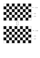
図2は、本実施形態における校正パターンの第1の例を示す図である。図示された例では、表示部210が校正パターン211Aと校正パターン211Bとを切り替えて表示する。つまり、表示部210は、ディスプレイの表示面、またはプロジェクタの投影面に対応する平面領域の輝度を、まず校正パターン211Aに従って変化させ、その後に校正パターン211Bに従って変化させる。これによって、平面領域では、まず校正パターン211Aに従った輝度の空間分布が現れ、それが校正パターン211Bに従った輝度の空間分布に瞬間的に変化する。校正パターン211A,211Bは格子状のパターンに従って配列された高輝度領域212および低輝度領域213を含み、校正パターン211Bにおける高輝度領域212および低輝度領域213は校正パターン211Aに対して反転させられている。なお、他の例では、格子状に限らず任意の空間的パターンに従って高輝度領域212と低輝度領域213が配列されてもよい。
FIG. 2 is a diagram showing a first example of a calibration pattern according to this embodiment. In the illustrated example, the
上述した校正システム10において表示部210によって表示される画像を校正パターン211Aから校正パターン211Bに切り替えると、センサ111A,111B,…のうち校正パターン211Bの高輝度領域212に対応するセンサでは輝度上昇を示すイベント信号が生成され、同様に低輝度領域213に対応するセンサでは輝度低下を示すイベント信号が生成される。それぞれのイベント信号を生成したセンサの位置関係と、校正パターン211A,211Bとを比較することによって、例えばビジョンセンサ110の光学系(図1には示していない)によって生じる像のひずみを検出し、一般的なカメラと同様に定義される内部パラメータ、外部パラメータ、およびひずみ係数などを校正することができる。
In the
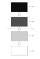
図3は、本実施形態における校正パターンの第2の例を示す図である。図示された例では、表示部210が、校正パターン211C、校正パターン211D、校正パターン211E、および校正パターン211Fを順に切り替えて表示する。つまり、表示部210は、表示部210は、ディスプレイの表示面、またはプロジェクタの投影面に対応する平面領域の輝度を、校正パターン211C~校正パターン211Fに従って順次変化させる。これによって、平面領域では、校正パターン211C~校正パターン211Fのそれぞれに従った輝度の空間分布が、瞬間的に切り替わりつつ順次現れる。校正パターン211C、校正パターン211D、校正パターン211E、および校正パターン211Fは、表示部210の領域全体において輝度が一様で、輝度値は互いに異なっている。輝度値は校正パターン211Cで最も低く、校正パターン211Dでより高く、校正パターン211Eでさらに高く、校正パターン211Fで最も高い。なお、図示された例では輝度値が4段階で切り替えられているが、より多い段階で輝度値が切り替えられてもよい。また、図示された例では輝度値が単調増加するように校正パターンの表示が順に切り替えられるが、逆に輝度値が単調減少するように校正パターンの表示が順に切り替えられてもよい。
FIG. 3 is a diagram showing a second example of the calibration pattern in this embodiment. In the illustrated example, the
上述した校正システム10において表示部210に表示される画像を校正パターンCから校正パターンFまで順次切り替えると、どこかの切り替えの時点で、センサ111A,111B,…のうち表示部210を被写体とするものがイベント信号を生成する。例えば校正パターン211Dが校正パターン211Eに切り替えられたときにイベント信号が生成された場合、センサが輝度変化を検出する閾値thは、校正パターン211Dの輝度値と校正パターン211Eの輝度値との間にある。例えばビジョンセンサ110の製造時に、上記のようにして特定される閾値が設計された範囲内になければセンサ111A,111B,…の調整または交換を実施してもよい。
When the image displayed on the
図4は、本実施形態における校正パターンの第3の例を示す図である。図示された例では、表示部210が、上記で図2を参照して説明した例と同様に校正パターン211Cと校正パターン211Fとを切り替えて表示する。ここで、校正パターン211Cは一様な低輝度領域からなる校正パターンであり、校正パターン211Fは一様な高輝度領域からなる校正パターンである。
FIG. 4 is a diagram showing a third example of the calibration pattern in this embodiment. In the illustrated example, the
上述した校正システム10において表示部210に表示される画像を校正パターン211Cから校正パターン211Fに切り替えると、原理的にはセンサ111A,111B,…のうち表示部210を被写体とするセンサすべてで輝度上昇を示すイベント信号が生成される。従って、この時にイベント信号を生成しなかった、または輝度低下を示すイベント信号を生成したセンサは、欠陥画素(輝点)として特定される。同様に、表示される画像を校正パターン211Fから校正パターン211Cに切り替えると、原理的には表示部210を被写体とするセンサすべてで輝度低下を示すイベント信号が生成される。この時にイベント信号を生成しなかった、または輝度上昇を示すイベント信号を生成したセンサも、欠陥画素(輝点)として特定される。
In the
図5は、本実施形態における校正パターンの第4の例を示す図である。図示された例では、表示部210が、上記で図2を参照して説明した例と同様に校正パターン211Gと校正パターン211Hとを切り替えて表示する。校正パターン211Gは、大部分が低輝度領域213であるが、平面領域の第1の部分、具体的には左上の一部に、輝度反転領域である高輝度領域212Aが配置される。一方、校正パターン211Hも、大部分が低輝度領域213であるが、平面領域の第1の部分とは異なる第2の部分、具体的には右下の一部に、輝度反転領域である高輝度領域212Bが配置される。なお、他の例では、左上および右下に限らず、任意の位置に輝度反転領域が配置されてもよい。また、図示された例とは逆に、校正パターンの大部分が高輝度領域212であり、その一部に輝度反転領域として低輝度領域213が配置されてもよい。
FIG. 5 is a diagram showing a fourth example of the calibration pattern in this embodiment. In the illustrated example, the
上述した校正システム10において表示部210に表示される画像を校正パターン211Gから校正パターン211Hに切り替えると、センサアレイ111のうち平面領域の第1の部分の輝度変化を検出するセンサでは、高輝度領域212Aが低輝度領域213に変化したことによって輝度低下を示すイベント信号が生成される。一方、このとき、センサアレイ111のうち平面領域の第2の部分の輝度変化を検出するセンサでは、低輝度領域213が高輝度領域212Bに変化したことによって輝度上昇を示すイベント信号が生成される。欠陥画素やノイズの影響がある場合を除いて、第1の部分および第2の部分以外の輝度変化を検出するセンサはイベント信号を生成しない。上記のそれぞれのセンサによって生成されるイベント信号のタイムスタンプを比較することによって、センサアレイ111の画角の一部でのみ輝度変化が発生して一部のセンサのみがイベント信号を生成した場合における、センサごとのタイムスタンプのオフセット量を比較することができる。
When the image displayed on the
以上、添付図面を参照しながら本発明のいくつかの実施形態について詳細に説明したが、本発明はかかる例に限定されない。本発明の属する技術の分野における通常の知識を有する者であれば、請求の範囲に記載された技術的思想の範疇内において、各種の変更例または修正例に想到し得ることは明らかであり、これらについても、当然に本発明の技術的範囲に属するものと了解される。 Although several embodiments of the present invention have been described in detail above with reference to the accompanying drawings, the present invention is not limited to such examples. It is clear that a person having ordinary knowledge in the technical field to which the present invention belongs can conceive of various modifications or modifications within the scope of the technical idea described in the claims. It is understood that these also belong to the technical scope of the present invention.
10…校正システム、100…センサ装置、110…ビジョンセンサ、111…センサアレイ、111A,111B…センサ、112…処理回路、120…制御部、121…通信インターフェース、122…処理回路、123…メモリ、200…表示装置、210…表示部、220…表示制御部、221…通信インターフェース、222…処理回路、223…メモリ、211A~211H…校正パターン、212…高輝度領域、213…低輝度領域。
DESCRIPTION OF
Claims (12)
平面領域の輝度を前記センサの校正パターンに従って瞬間的に所定の空間解像度で変化させるように構成された表示部を備える表示装置と
を含み、
前記校正パターンは、第1の校正パターンと第2の校正パターンとを含み、
前記表示部は、前記平面領域の輝度を前記第1の校正パターンに従って変化させた後に、前記平面領域の輝度を前記第2の校正パターンに従って変化させ、
前記第1の校正パターンは、空間的パターンに従って配列された高輝度領域および低輝度領域を含み、
前記第2の校正パターンは、前記第1の校正パターンに対して反転させられた前記高輝度領域と前記低輝度領域とを含み、
前記表示部は、前記第1の校正パターンと前記第2の校正パターンとを切り替えて表示するセンサの校正システム。 a sensor apparatus comprising an event-driven vision sensor including a sensor array composed of sensors that generate an event signal when an intensity change in incident light is detected;
a display device comprising a display unit configured to instantaneously change the luminance of a planar area with a predetermined spatial resolution according to a calibration pattern of the sensor;
The calibration pattern includes a first calibration pattern and a second calibration pattern,
The display unit changes the luminance of the planar region according to the first calibration pattern, and then changes the luminance of the planar region according to the second calibration pattern,
the first calibration pattern includes high intensity areas and low intensity areas arranged according to a spatial pattern;
the second calibration pattern includes the high brightness region and the low brightness region inverted with respect to the first calibration pattern;
The sensor calibration system , wherein the display section switches between and displays the first calibration pattern and the second calibration pattern .
平面領域の輝度を前記センサの校正パターンに従って瞬間的に所定の空間解像度で変化させるように構成された表示部を備える表示装置と a display device comprising a display unit configured to instantaneously change the luminance of a planar area with a predetermined spatial resolution in accordance with a calibration pattern of the sensor;
を含み、 including
前記校正パターンは、第1の校正パターンと第2の校正パターンとを含み、 The calibration pattern includes a first calibration pattern and a second calibration pattern,
前記表示部は、前記平面領域の輝度を前記第1の校正パターンに従って変化させた後に、前記平面領域の輝度を前記第2の校正パターンに従って変化させ、 The display unit changes the luminance of the planar region according to the first calibration pattern, and then changes the luminance of the planar region according to the second calibration pattern,
前記第1の校正パターンは、前記平面領域の第1の部分に輝度反転領域を含み、 the first calibration pattern includes a luminance inversion area in a first portion of the planar area;
前記第2の校正パターンは、前記平面領域の前記第1の部分とは異なる第2の部分に輝度反転領域を含み、 the second calibration pattern includes a luminance inversion area in a second portion different from the first portion of the planar area;
前記第1の校正パターンおよび前記第2の校正パターンの前記輝度反転領域以外の領域は、一様な低輝度領域または高輝度領域であり、 regions other than the luminance inversion region of the first calibration pattern and the second calibration pattern are uniform low luminance regions or high luminance regions;
前記表示部は、前記第1の校正パターンと前記第2の校正パターンとを切り替えて表示するセンサの校正システム。 The sensor calibration system, wherein the display section switches between and displays the first calibration pattern and the second calibration pattern.
前記センサ装置は、前記校正パターンに基づいて前記イベント信号を解析するように構成された制御部をさらに備える、請求項1から請求項3のいずれか1項に記載のセンサの校正システム。 The display device further includes a display control unit configured to output an image signal corresponding to the calibration pattern to the display unit,
The sensor calibration system according to any one of claims 1 to 3 , wherein the sensor device further comprises a controller configured to analyze the event signal based on the calibration pattern.
前記校正パターンは、第1の校正パターンと第2の校正パターンとを含み、
前記表示制御部は、前記平面領域の輝度を前記第1の校正パターンに従って変化させた後に前記平面領域の輝度を前記第2の校正パターンに従って変化させる前記画像信号を前記表示部に出力するように構成され、
前記第1の校正パターンは、空間的パターンに従って配列された高輝度領域および低輝度領域を含み、
前記第2の校正パターンは、前記第1の校正パターンに対して反転させられた前記高輝度領域と前記低輝度領域とを含み、
前記表示制御部は、前記第1の校正パターンと前記第2の校正パターンとを切り替えて表示させる前記画像信号を前記表示部に出力するように構成される表示制御装置。 The display unit configured to instantaneously change the luminance of the planar area with a predetermined spatial resolution according to the image signal, the above-mentioned sensor corresponding to the calibration pattern for generating the event signal when the intensity change of the incident light is detected. A display control unit configured to output an image signal ,
The calibration pattern includes a first calibration pattern and a second calibration pattern,
The display control unit changes the luminance of the planar area according to the first calibration pattern and then outputs to the display unit the image signal that changes the luminance of the planar area according to the second calibration pattern. configured,
the first calibration pattern includes high intensity areas and low intensity areas arranged according to a spatial pattern;
the second calibration pattern includes the high brightness region and the low brightness region inverted with respect to the first calibration pattern;
The display control unit is configured to output to the display unit the image signal for switching and displaying the first calibration pattern and the second calibration pattern.
前記校正パターンは、第1の校正パターンと第2の校正パターンとを含み、 The calibration pattern includes a first calibration pattern and a second calibration pattern,
前記表示制御部は、前記平面領域の輝度を前記第1の校正パターンに従って変化させた後に前記平面領域の輝度を前記第2の校正パターンに従って変化させる前記画像信号を前記表示部に出力するように構成され、 The display control unit changes the luminance of the planar area according to the first calibration pattern and then outputs to the display unit the image signal that changes the luminance of the planar area according to the second calibration pattern. configured,
前記第1の校正パターンは、前記平面領域の第1の部分に輝度反転領域を含み、 the first calibration pattern includes a luminance inversion area in a first portion of the planar area;
前記第2の校正パターンは、前記平面領域の前記第1の部分とは異なる第2の部分に輝度反転領域を含み、 the second calibration pattern includes a luminance inversion area in a second portion different from the first portion of the planar area;
前記第1の校正パターンおよび前記第2の校正パターンの前記輝度反転領域以外の領域は、一様な低輝度領域または高輝度領域であり、 regions other than the luminance inversion region of the first calibration pattern and the second calibration pattern are uniform low luminance regions or high luminance regions;
前記表示制御部は、前記第1の校正パターンと前記第2の校正パターンとを切り替えて表示させる前記画像信号を前記表示部に出力するように構成される表示制御装置。 The display control unit is configured to output to the display unit the image signal for switching and displaying the first calibration pattern and the second calibration pattern.
前記校正パターンは、第1の校正パターンと第2の校正パターンとを含み、
前記処理回路は、前記平面領域の輝度を前記第1の校正パターンに従って変化させた後に前記平面領域の輝度を前記第2の校正パターンに従って変化させる前記画像信号を前記表示部に出力し、
前記第1の校正パターンは、空間的パターンに従って配列された高輝度領域および低輝度領域を含み、
前記第2の校正パターンは、前記第1の校正パターンに対して反転させられた前記高輝度領域と前記低輝度領域とを含み、
前記処理回路は、前記第1の校正パターンと前記第2の校正パターンとを切り替えて表示させるプログラム。 A sensor for generating an event signal upon detection of a change in the intensity of incident light is provided in a processing circuit connected to a display configured to instantaneously change the luminance of a planar region with a predetermined spatial resolution in accordance with an image signal. A program for executing a process of outputting the image signal corresponding to the calibration pattern ,
The calibration pattern includes a first calibration pattern and a second calibration pattern,
The processing circuit changes the luminance of the plane area according to the first calibration pattern and then outputs to the display unit the image signal that changes the luminance of the plane area according to the second calibration pattern,
the first calibration pattern includes high intensity areas and low intensity areas arranged according to a spatial pattern;
the second calibration pattern includes the high brightness region and the low brightness region inverted with respect to the first calibration pattern;
A program for causing the processing circuit to switch between and display the first calibration pattern and the second calibration pattern .
前記校正パターンは、第1の校正パターンと第2の校正パターンとを含み、 The calibration pattern includes a first calibration pattern and a second calibration pattern,
前記処理回路は、前記平面領域の輝度を前記第1の校正パターンに従って変化させた後に前記平面領域の輝度を前記第2の校正パターンに従って変化させる前記画像信号を前記表示部に出力し、 The processing circuit changes the luminance of the plane area according to the first calibration pattern and then outputs to the display unit the image signal that changes the luminance of the plane area according to the second calibration pattern,
前記第1の校正パターンは、前記平面領域の第1の部分に輝度反転領域を含み、 the first calibration pattern includes a luminance inversion area in a first portion of the planar area;
前記第2の校正パターンは、前記平面領域の前記第1の部分とは異なる第2の部分に輝度反転領域を含み、 the second calibration pattern includes a luminance inversion area in a second portion different from the first portion of the planar area;
前記第1の校正パターンおよび前記第2の校正パターンの前記輝度反転領域以外の領域は、一様な低輝度領域または高輝度領域であり、 regions other than the luminance inversion region of the first calibration pattern and the second calibration pattern are uniform low luminance regions or high luminance regions;
前記処理回路は、前記第1の校正パターンと前記第2の校正パターンとを切り替えて表示させるプログラム。 A program for causing the processing circuit to switch between and display the first calibration pattern and the second calibration pattern.
前記センサアレイを構成するセンサに、前記輝度の変化に伴う入射光の強度変化を検出させてイベント信号を生成させるステップと
を含み、
前記校正パターンは、第1の校正パターンと第2の校正パターンとを含み、
前記平面領域の輝度を変化させるステップでは、前記平面領域の輝度を前記第1の校正パターンに従って変化させた後に、前記平面領域の輝度を前記第2の校正パターンに従って変化させ、
前記第1の校正パターンは、空間的パターンに従って配列された高輝度領域および低輝度領域を含み、
前記第2の校正パターンは、前記第1の校正パターンに対して反転させられた前記高輝度領域と前記低輝度領域とを含み、
前記平面領域の輝度を変化させるステップでは、前記第1の校正パターンと前記第2の校正パターンとを切り替えて表示するセンサの校正方法。 momentarily changing the brightness of a planar area within the angle of view of the sensor array according to a calibration pattern with a predetermined spatial resolution;
causing the sensors constituting the sensor array to detect changes in the intensity of incident light that accompany changes in the luminance and generate event signals ;
The calibration pattern includes a first calibration pattern and a second calibration pattern,
In the step of changing the brightness of the plane region, after changing the brightness of the plane region according to the first calibration pattern, the brightness of the plane region is changed according to the second calibration pattern;
the first calibration pattern includes high intensity areas and low intensity areas arranged according to a spatial pattern;
the second calibration pattern includes the high brightness region and the low brightness region inverted with respect to the first calibration pattern;
In the step of changing the brightness of the planar area, the sensor calibration method includes switching between and displaying the first calibration pattern and the second calibration pattern.
前記センサアレイを構成するセンサに、前記輝度の変化に伴う入射光の強度変化を検出させてイベント信号を生成させるステップと a step of causing the sensors constituting the sensor array to detect intensity changes of incident light that accompany changes in the luminance and generate event signals;
を含み、 including
前記校正パターンは、第1の校正パターンと第2の校正パターンとを含み、 The calibration pattern includes a first calibration pattern and a second calibration pattern,
前記平面領域の輝度を変化させるステップでは、前記平面領域の輝度を前記第1の校正パターンに従って変化させた後に、前記平面領域の輝度を前記第2の校正パターンに従って変化させ、 In the step of changing the brightness of the plane region, after changing the brightness of the plane region according to the first calibration pattern, the brightness of the plane region is changed according to the second calibration pattern;
前記第1の校正パターンは、前記平面領域の第1の部分に輝度反転領域を含み、 the first calibration pattern includes a luminance inversion area in a first portion of the planar area;
前記第2の校正パターンは、前記平面領域の前記第1の部分とは異なる第2の部分に輝度反転領域を含み、 the second calibration pattern includes a luminance inversion area in a second portion different from the first portion of the planar area;
前記第1の校正パターンおよび前記第2の校正パターンの前記輝度反転領域以外の領域は、一様な低輝度領域または高輝度領域であり、 regions other than the luminance inversion region of the first calibration pattern and the second calibration pattern are uniform low luminance regions or high luminance regions;
前記平面領域の輝度を変化させるステップでは、前記第1の校正パターンと前記第2の校正パターンとを切り替えて表示するセンサの校正方法。 In the step of changing the brightness of the planar area, the sensor calibration method includes switching between and displaying the first calibration pattern and the second calibration pattern.
Priority Applications (4)
| Application Number | Priority Date | Filing Date | Title |
|---|---|---|---|
| JP2018195505A JP7251942B2 (en) | 2018-10-17 | 2018-10-17 | SENSOR CALIBRATION SYSTEM, DISPLAY CONTROLLER, PROGRAM, AND SENSOR CALIBRATION METHOD |
| PCT/JP2019/039932 WO2020080237A1 (en) | 2018-10-17 | 2019-10-10 | Sensor calibration system, display control device, program, and sensor calibration method |
| US17/283,718 US12033354B2 (en) | 2018-10-17 | 2019-10-10 | Sensor calibration system, display control apparatus, program, and sensor calibration method |
| KR1020217011477A KR102513670B1 (en) | 2018-10-17 | 2019-10-10 | Sensor calibration system, display control device, program, and sensor calibration method |
Applications Claiming Priority (1)
| Application Number | Priority Date | Filing Date | Title |
|---|---|---|---|
| JP2018195505A JP7251942B2 (en) | 2018-10-17 | 2018-10-17 | SENSOR CALIBRATION SYSTEM, DISPLAY CONTROLLER, PROGRAM, AND SENSOR CALIBRATION METHOD |
Publications (3)
| Publication Number | Publication Date |
|---|---|
| JP2020065149A JP2020065149A (en) | 2020-04-23 |
| JP2020065149A5 JP2020065149A5 (en) | 2021-09-30 |
| JP7251942B2 true JP7251942B2 (en) | 2023-04-04 |
Family
ID=70283469
Family Applications (1)
| Application Number | Title | Priority Date | Filing Date |
|---|---|---|---|
| JP2018195505A Active JP7251942B2 (en) | 2018-10-17 | 2018-10-17 | SENSOR CALIBRATION SYSTEM, DISPLAY CONTROLLER, PROGRAM, AND SENSOR CALIBRATION METHOD |
Country Status (4)
| Country | Link |
|---|---|
| US (1) | US12033354B2 (en) |
| JP (1) | JP7251942B2 (en) |
| KR (1) | KR102513670B1 (en) |
| WO (1) | WO2020080237A1 (en) |
Families Citing this family (9)
| Publication number | Priority date | Publication date | Assignee | Title |
|---|---|---|---|---|
| JP2020161987A (en) * | 2019-03-27 | 2020-10-01 | ソニー株式会社 | Imaging system for vehicle |
| CN112532870B (en) * | 2020-11-09 | 2021-11-30 | 福建福瑞康信息技术有限公司 | Multi-terminal adaptive data processing system, method and computer readable storage medium |
| JP2022188987A (en) * | 2021-06-10 | 2022-12-22 | キヤノン株式会社 | Information processing device, information processing method, and program |
| US12111180B2 (en) | 2021-07-01 | 2024-10-08 | Summer Robotics, Inc. | Calibration of sensor position offsets based on rotation and translation vectors for matched trajectories |
| WO2023288067A1 (en) * | 2021-07-15 | 2023-01-19 | Summer Robotics, Inc. | Automatic parameter adjustment for scanning event cameras |
| WO2023009755A1 (en) | 2021-07-29 | 2023-02-02 | Summer Robotics, Inc. | Dynamic calibration of 3d acquisition systems |
| US11808857B2 (en) | 2021-08-27 | 2023-11-07 | Summer Robotics, Inc. | Multi-sensor superresolution scanning and capture system |
| US11785200B1 (en) | 2022-03-14 | 2023-10-10 | Summer Robotics, Inc. | Stage studio for immersive 3-D video capture |
| US11974055B1 (en) | 2022-10-17 | 2024-04-30 | Summer Robotics, Inc. | Perceiving scene features using event sensors and image sensors |
Citations (4)
| Publication number | Priority date | Publication date | Assignee | Title |
|---|---|---|---|---|
| JP2007071618A (en) | 2005-09-06 | 2007-03-22 | Mitsubishi Electric Corp | Image quality inspection system |
| JP2015115962A (en) | 2013-12-11 | 2015-06-22 | アンリツ カンパニー | System and method for measuring brightness response of camera operating in automatic exposure mode |
| US20170155805A1 (en) | 2015-11-26 | 2017-06-01 | Samsung Electronics Co., Ltd. | Method and apparatus for capturing an image of an object by tracking the object |
| JP2018501675A (en) | 2014-09-30 | 2018-01-18 | クアルコム,インコーポレイテッド | Feature calculation in sensor element array |
Family Cites Families (6)
| Publication number | Priority date | Publication date | Assignee | Title |
|---|---|---|---|---|
| JP3705180B2 (en) * | 2001-09-27 | 2005-10-12 | セイコーエプソン株式会社 | Image display system, program, information storage medium, and image processing method |
| US20100201275A1 (en) * | 2009-02-06 | 2010-08-12 | Cok Ronald S | Light sensing in display device |
| KR101880998B1 (en) | 2011-10-14 | 2018-07-24 | 삼성전자주식회사 | Apparatus and Method for motion recognition with event base vision sensor |
| US20160111062A1 (en) * | 2014-10-15 | 2016-04-21 | Intel Corporation | Ambient light-based image adjustment |
| US9489735B1 (en) * | 2015-09-17 | 2016-11-08 | Qualcomm Incorporated | Multiplexed temporal calibration for event-based cameras |
| US20180146149A1 (en) | 2016-11-21 | 2018-05-24 | Samsung Electronics Co., Ltd. | Event-based sensor, user device including the same, and operation method of the same |
-
2018
- 2018-10-17 JP JP2018195505A patent/JP7251942B2/en active Active
-
2019
- 2019-10-10 US US17/283,718 patent/US12033354B2/en active Active
- 2019-10-10 WO PCT/JP2019/039932 patent/WO2020080237A1/en active Application Filing
- 2019-10-10 KR KR1020217011477A patent/KR102513670B1/en active IP Right Grant
Patent Citations (4)
| Publication number | Priority date | Publication date | Assignee | Title |
|---|---|---|---|---|
| JP2007071618A (en) | 2005-09-06 | 2007-03-22 | Mitsubishi Electric Corp | Image quality inspection system |
| JP2015115962A (en) | 2013-12-11 | 2015-06-22 | アンリツ カンパニー | System and method for measuring brightness response of camera operating in automatic exposure mode |
| JP2018501675A (en) | 2014-09-30 | 2018-01-18 | クアルコム,インコーポレイテッド | Feature calculation in sensor element array |
| US20170155805A1 (en) | 2015-11-26 | 2017-06-01 | Samsung Electronics Co., Ltd. | Method and apparatus for capturing an image of an object by tracking the object |
Also Published As
| Publication number | Publication date |
|---|---|
| JP2020065149A (en) | 2020-04-23 |
| US20210327090A1 (en) | 2021-10-21 |
| WO2020080237A1 (en) | 2020-04-23 |
| KR102513670B1 (en) | 2023-03-24 |
| KR20210093233A (en) | 2021-07-27 |
| US12033354B2 (en) | 2024-07-09 |
Similar Documents
| Publication | Publication Date | Title |
|---|---|---|
| JP7251942B2 (en) | SENSOR CALIBRATION SYSTEM, DISPLAY CONTROLLER, PROGRAM, AND SENSOR CALIBRATION METHOD | |
| TWI585436B (en) | Method and apparatus for measuring depth information | |
| KR101033428B1 (en) | Position detection apparatus using area image sensor | |
| JP2020065149A5 (en) | ||
| US20120044093A1 (en) | Combined time-of-flight and image sensor systems | |
| JP2007523394A (en) | Light emitting stylus and user input device using light emitting stylus | |
| US10645302B2 (en) | Image sensing device having adjustable exposure periods and sensing method using the same | |
| KR101465801B1 (en) | Display apparatus | |
| TW202038200A (en) | Method for detecting luminance uniformity of screen, storage medium, and electronic device | |
| JP5975606B2 (en) | Image processing apparatus and control method thereof | |
| TW201633077A (en) | Image processing method capable of detecting noise and related navigation device | |
| TWI695179B (en) | Optical distance measuring sensor | |
| US10628951B2 (en) | Distance measurement system applicable to different reflecting surfaces and computer system | |
| KR102122275B1 (en) | Light distribution characteristic measurement apparatus and light distribution characteristic measurement method | |
| US20150185321A1 (en) | Image Display Device | |
| US9389731B2 (en) | Optical touch system having an image sensing module for generating a two-dimensional image and converting to a one-dimensional feature | |
| JP7207416B2 (en) | Flicker measurement device, flicker measurement method, flicker measurement program | |
| JP2023542645A (en) | System and method for acoustic imaging using cumulative time views | |
| CN114299853B (en) | LED display screen adjusting system, method, equipment and readable storage medium | |
| JP2019008609A (en) | Information processing apparatus, program, and information processing system | |
| JP5248104B2 (en) | Detection sensor with ASIC with CPU | |
| JP2005233922A (en) | Photosensor unit for position tracking, and position estimation method using the same | |
| JP2007035076A (en) | Position detection apparatus using area image sensor | |
| US20180220053A1 (en) | Processing device, processing method, system, and article manufacturing method | |
| JP2022180923A (en) | Display apparatus |
Legal Events
| Date | Code | Title | Description |
|---|---|---|---|
| A521 | Request for written amendment filed |
Free format text: JAPANESE INTERMEDIATE CODE: A523 Effective date: 20210819 |
|
| A621 | Written request for application examination |
Free format text: JAPANESE INTERMEDIATE CODE: A621 Effective date: 20210819 |
|
| A131 | Notification of reasons for refusal |
Free format text: JAPANESE INTERMEDIATE CODE: A131 Effective date: 20220913 |
|
| A521 | Request for written amendment filed |
Free format text: JAPANESE INTERMEDIATE CODE: A523 Effective date: 20221107 |
|
| TRDD | Decision of grant or rejection written | ||
| A01 | Written decision to grant a patent or to grant a registration (utility model) |
Free format text: JAPANESE INTERMEDIATE CODE: A01 Effective date: 20230314 |
|
| A61 | First payment of annual fees (during grant procedure) |
Free format text: JAPANESE INTERMEDIATE CODE: A61 Effective date: 20230323 |
|
| R150 | Certificate of patent or registration of utility model |
Ref document number: 7251942 Country of ref document: JP Free format text: JAPANESE INTERMEDIATE CODE: R150 |