JP7248581B2 - surgical implant system - Google Patents
surgical implant system Download PDFInfo
- Publication number
- JP7248581B2 JP7248581B2 JP2019546279A JP2019546279A JP7248581B2 JP 7248581 B2 JP7248581 B2 JP 7248581B2 JP 2019546279 A JP2019546279 A JP 2019546279A JP 2019546279 A JP2019546279 A JP 2019546279A JP 7248581 B2 JP7248581 B2 JP 7248581B2
- Authority
- JP
- Japan
- Prior art keywords
- surgical implant
- implant
- body portion
- electrodes
- central body
- Prior art date
- Legal status (The legal status is an assumption and is not a legal conclusion. Google has not performed a legal analysis and makes no representation as to the accuracy of the status listed.)
- Active
Links
- 239000007943 implant Substances 0.000 title claims description 263
- 238000004873 anchoring Methods 0.000 claims description 49
- 230000004913 activation Effects 0.000 claims description 47
- 210000005036 nerve Anatomy 0.000 claims description 35
- 239000000463 material Substances 0.000 claims description 33
- 230000003014 reinforcing effect Effects 0.000 claims description 25
- 230000000638 stimulation Effects 0.000 claims description 22
- 230000005684 electric field Effects 0.000 claims description 18
- 238000002513 implantation Methods 0.000 claims description 15
- 238000006073 displacement reaction Methods 0.000 claims description 14
- 210000003205 muscle Anatomy 0.000 claims description 14
- 210000001169 hypoglossal nerve Anatomy 0.000 claims description 12
- 238000000034 method Methods 0.000 claims description 12
- 238000004891 communication Methods 0.000 claims description 11
- 230000004044 response Effects 0.000 claims description 11
- 239000013536 elastomeric material Substances 0.000 claims description 9
- 239000000835 fiber Substances 0.000 claims description 8
- 238000001356 surgical procedure Methods 0.000 claims description 7
- 238000005452 bending Methods 0.000 claims description 3
- 230000001010 compromised effect Effects 0.000 claims description 3
- 230000002787 reinforcement Effects 0.000 claims description 2
- 230000000284 resting effect Effects 0.000 claims description 2
- 230000001681 protective effect Effects 0.000 claims 3
- 230000004007 neuromodulation Effects 0.000 description 10
- 208000001797 obstructive sleep apnea Diseases 0.000 description 8
- 239000004696 Poly ether ether ketone Substances 0.000 description 7
- 230000001537 neural effect Effects 0.000 description 7
- 229920002530 polyetherether ketone Polymers 0.000 description 7
- 229920000106 Liquid crystal polymer Polymers 0.000 description 6
- 239000004977 Liquid-crystal polymers (LCPs) Substances 0.000 description 6
- 239000004642 Polyimide Substances 0.000 description 6
- BASFCYQUMIYNBI-UHFFFAOYSA-N platinum Chemical compound [Pt] BASFCYQUMIYNBI-UHFFFAOYSA-N 0.000 description 6
- 229920001721 polyimide Polymers 0.000 description 6
- 230000003213 activating effect Effects 0.000 description 4
- 229920000249 biocompatible polymer Polymers 0.000 description 4
- 230000008859 change Effects 0.000 description 4
- 230000007246 mechanism Effects 0.000 description 4
- 229920003229 poly(methyl methacrylate) Polymers 0.000 description 4
- 239000004926 polymethyl methacrylate Substances 0.000 description 4
- ZNOCGWVLWPVKAO-UHFFFAOYSA-N trimethoxy(phenyl)silane Chemical compound CO[Si](OC)(OC)C1=CC=CC=C1 ZNOCGWVLWPVKAO-UHFFFAOYSA-N 0.000 description 4
- 229920004738 ULTEM® Polymers 0.000 description 3
- 239000007788 liquid Substances 0.000 description 3
- 230000007383 nerve stimulation Effects 0.000 description 3
- 229910052697 platinum Inorganic materials 0.000 description 3
- 229920001296 polysiloxane Polymers 0.000 description 3
- 239000011253 protective coating Substances 0.000 description 3
- 210000001519 tissue Anatomy 0.000 description 3
- VRBFTYUMFJWSJY-UHFFFAOYSA-N 28804-46-8 Chemical compound ClC1CC(C=C2)=CC=C2C(Cl)CC2=CC=C1C=C2 VRBFTYUMFJWSJY-UHFFFAOYSA-N 0.000 description 2
- 239000004593 Epoxy Substances 0.000 description 2
- 239000000853 adhesive Substances 0.000 description 2
- 230000001070 adhesive effect Effects 0.000 description 2
- 239000000560 biocompatible material Substances 0.000 description 2
- 239000000919 ceramic Substances 0.000 description 2
- 229910010293 ceramic material Inorganic materials 0.000 description 2
- 230000006378 damage Effects 0.000 description 2
- 239000012530 fluid Substances 0.000 description 2
- PCHJSUWPFVWCPO-UHFFFAOYSA-N gold Chemical compound [Au] PCHJSUWPFVWCPO-UHFFFAOYSA-N 0.000 description 2
- 229910052737 gold Inorganic materials 0.000 description 2
- 239000010931 gold Substances 0.000 description 2
- 229910052741 iridium Inorganic materials 0.000 description 2
- GKOZUEZYRPOHIO-UHFFFAOYSA-N iridium atom Chemical compound [Ir] GKOZUEZYRPOHIO-UHFFFAOYSA-N 0.000 description 2
- 229920003223 poly(pyromellitimide-1,4-diphenyl ether) Polymers 0.000 description 2
- 230000009467 reduction Effects 0.000 description 2
- 239000000126 substance Substances 0.000 description 2
- 239000012815 thermoplastic material Substances 0.000 description 2
- RYGMFSIKBFXOCR-UHFFFAOYSA-N Copper Chemical compound [Cu] RYGMFSIKBFXOCR-UHFFFAOYSA-N 0.000 description 1
- 206010011878 Deafness Diseases 0.000 description 1
- BQCADISMDOOEFD-UHFFFAOYSA-N Silver Chemical compound [Ag] BQCADISMDOOEFD-UHFFFAOYSA-N 0.000 description 1
- RTAQQCXQSZGOHL-UHFFFAOYSA-N Titanium Chemical compound [Ti] RTAQQCXQSZGOHL-UHFFFAOYSA-N 0.000 description 1
- 208000027418 Wounds and injury Diseases 0.000 description 1
- 239000000956 alloy Substances 0.000 description 1
- 229910045601 alloy Inorganic materials 0.000 description 1
- 230000004075 alteration Effects 0.000 description 1
- 210000003484 anatomy Anatomy 0.000 description 1
- 210000003403 autonomic nervous system Anatomy 0.000 description 1
- 210000003169 central nervous system Anatomy 0.000 description 1
- 229920001940 conductive polymer Polymers 0.000 description 1
- 239000004020 conductor Substances 0.000 description 1
- 229910052802 copper Inorganic materials 0.000 description 1
- 239000010949 copper Substances 0.000 description 1
- 230000007797 corrosion Effects 0.000 description 1
- 238000005260 corrosion Methods 0.000 description 1
- 210000004207 dermis Anatomy 0.000 description 1
- 230000000694 effects Effects 0.000 description 1
- 239000013013 elastic material Substances 0.000 description 1
- 238000005538 encapsulation Methods 0.000 description 1
- 238000005516 engineering process Methods 0.000 description 1
- 230000005764 inhibitory process Effects 0.000 description 1
- 208000014674 injury Diseases 0.000 description 1
- 230000000670 limiting effect Effects 0.000 description 1
- 230000004048 modification Effects 0.000 description 1
- 238000012986 modification Methods 0.000 description 1
- 230000002232 neuromuscular Effects 0.000 description 1
- 229910000510 noble metal Inorganic materials 0.000 description 1
- 230000036961 partial effect Effects 0.000 description 1
- 230000002093 peripheral effect Effects 0.000 description 1
- 210000001428 peripheral nervous system Anatomy 0.000 description 1
- 230000035699 permeability Effects 0.000 description 1
- 230000000704 physical effect Effects 0.000 description 1
- 229920000642 polymer Polymers 0.000 description 1
- 230000002829 reductive effect Effects 0.000 description 1
- 230000001105 regulatory effect Effects 0.000 description 1
- 229910052709 silver Inorganic materials 0.000 description 1
- 239000004332 silver Substances 0.000 description 1
- 230000004936 stimulating effect Effects 0.000 description 1
- 230000001225 therapeutic effect Effects 0.000 description 1
- 239000010936 titanium Substances 0.000 description 1
- 229910052719 titanium Inorganic materials 0.000 description 1
Images


Classifications
-
- A—HUMAN NECESSITIES
- A61—MEDICAL OR VETERINARY SCIENCE; HYGIENE
- A61N—ELECTROTHERAPY; MAGNETOTHERAPY; RADIATION THERAPY; ULTRASOUND THERAPY
- A61N1/00—Electrotherapy; Circuits therefor
- A61N1/18—Applying electric currents by contact electrodes
- A61N1/32—Applying electric currents by contact electrodes alternating or intermittent currents
- A61N1/36—Applying electric currents by contact electrodes alternating or intermittent currents for stimulation
- A61N1/3601—Applying electric currents by contact electrodes alternating or intermittent currents for stimulation of respiratory organs
-
- A—HUMAN NECESSITIES
- A61—MEDICAL OR VETERINARY SCIENCE; HYGIENE
- A61N—ELECTROTHERAPY; MAGNETOTHERAPY; RADIATION THERAPY; ULTRASOUND THERAPY
- A61N1/00—Electrotherapy; Circuits therefor
- A61N1/02—Details
- A61N1/04—Electrodes
- A61N1/05—Electrodes for implantation or insertion into the body, e.g. heart electrode
- A61N1/0526—Head electrodes
- A61N1/0548—Oral electrodes
-
- A—HUMAN NECESSITIES
- A61—MEDICAL OR VETERINARY SCIENCE; HYGIENE
- A61N—ELECTROTHERAPY; MAGNETOTHERAPY; RADIATION THERAPY; ULTRASOUND THERAPY
- A61N1/00—Electrotherapy; Circuits therefor
- A61N1/18—Applying electric currents by contact electrodes
- A61N1/32—Applying electric currents by contact electrodes alternating or intermittent currents
- A61N1/36—Applying electric currents by contact electrodes alternating or intermittent currents for stimulation
- A61N1/3605—Implantable neurostimulators for stimulating central or peripheral nerve system
- A61N1/3606—Implantable neurostimulators for stimulating central or peripheral nerve system adapted for a particular treatment
- A61N1/3611—Respiration control
Description
(技術分野)
開示される主題は、閉塞性睡眠時無呼吸等の医学的状態に関連する、外科手術用インプラントシステム、デバイス、および方法を対象とする。特に、開示される主題は、神経刺激のためのインプラントと、関連付けられるアクティブ化デバイスおよび方法とを対象とする。
(Technical field)
The disclosed subject matter is directed to surgical implant systems, devices, and methods related to medical conditions such as obstructive sleep apnea. In particular, the disclosed subject matter is directed to implants and associated activation devices and methods for neural stimulation.
(背景)
種々のタイプの神経刺激装置が、当技術分野において公知である。舌下神経の刺激のための神経刺激装置の分野では、以下のものが、いくつかの実施例(その詳細は、参照することによって本明細書に組み込まれる)を提供する。
(background)
Various types of neurostimulators are known in the art. In the field of neurostimulators for stimulation of the hypoglossal nerve, the following provides several examples, the details of which are incorporated herein by reference.
米国第8,577,465号は、可撓性の担体と、可撓性担体上の少なくとも一対の変調電極と、少なくとも一対の変調電極と電気連通する、少なくとも1つの埋込式回路とを含み得る、インプラントユニットを説明する。少なくとも一対の変調電極および少なくとも1つの回路は、少なくとも一対の変調電極から延在する電場が、舌下神経の内側枝の終末線維のうちの1つ以上を変調させ得るように、対象の顎部の下側上の真皮を通した埋込のため、ならびに対象の舌下神経の内側枝の終末線維に近接する場所のために構成されてもよい。 US 8,577,465 includes a flexible carrier, at least one pair of modulating electrodes on the flexible carrier, and at least one implantable circuit in electrical communication with the at least one pair of modulating electrodes. 1 illustrates an implant unit obtained. At least one pair of modulating electrodes and at least one circuit are arranged in the subject's jaw such that an electric field extending from the at least one pair of modulating electrodes may modulate one or more of the terminal fibers of the medial branch of the hypoglossal nerve. It may be configured for implantation through the dermis on the underside of the , as well as for locations adjacent to the terminal fibers of the medial branch of the hypoglossal nerve of interest.
米国第2013085560号は、対象の身体の中への埋込のために構成され、信号を受信するように構成されるアンテナを含み得る、インプラントユニットを説明する。インプラントユニットはまた、変調されるべき少なくとも1つの神経の近傍にある、対象の身体の中に埋設されるように構成される、少なくとも一対の変調電極を含んでもよく、少なくとも一対の変調電極は、アンテナによって受信される信号に応答して、印加される電気信号を受信し、少なくとも一対の変調電極が少なくとも1つの神経に接触しない位置から少なくとも1つの神経を変調させるための、電場を発生させるように構成される。 US2013085560 describes an implant unit configured for implantation into the body of a subject and may include an antenna configured to receive a signal. The implant unit may also include at least one pair of modulating electrodes configured to be implanted in the subject's body proximate to the at least one nerve to be modulated, the at least one pair of modulating electrodes comprising: receiving an applied electrical signal in response to a signal received by the antenna and generating an electric field for modulating the at least one nerve from a position where the at least one pair of modulating electrodes does not contact the at least one nerve; configured to
以下は、外科手技の間、神経刺激装置をアクティブ化するために使用される、アクティブ化ツールのある実施例を提供する。米国第201403189号(その開示は、参照することによって本明細書に組み込まれる)は、インプラントツールと、インプラントアクティブ化装置とを有する、インプラントユニット送達ツールを説明する。インプラントツールは、インプラントユニットが組織に固定される埋込手技の間、インプラントユニットを保定するように構成されてもよい。インプラントアクティブ化装置は、インプラントツールと関連付けられてもよい。加えて、インプラントアクティブ化装置は、埋込手技の間、インプラントユニットに選択的に電力を伝達し、組織へのインプラントユニットの最終固定に先立って、対象の身体内の少なくとも1つの神経の変調を引き起こすように構成されてもよい。 The following provides one example of an activation tool used to activate a neurostimulator during a surgical procedure. US201403189 (the disclosure of which is incorporated herein by reference) describes an implant unit delivery tool having an implant tool and an implant activation device. The implant tool may be configured to retain the implant unit during an implantation procedure in which the implant unit is secured to tissue. An implant activation device may be associated with the implant tool. Additionally, the implant activation device selectively transmits power to the implant unit during the implantation procedure to modulate at least one nerve within the subject's body prior to final fixation of the implant unit to tissue. may be configured to cause
(概略的説明)
開示される主題の一側面では、ある外科手術用インプラントが、開示される。本側面による、外科手術用インプラントは、
上面側と、底面側とを有する、略平面状の中心本体部分と、
少なくとも2つの調節可能な翼部分と、
少なくとも2つの接続部材であって、少なくとも2つの接続部材のうちのそれぞれ1つは、中心本体部分の両側から延在し、少なくとも2つの接続部材のうちのそれぞれ1つは、少なくとも2つの翼部分のうちのそれぞれ1つを、両側において、該中心本体部分に可撓性に接続するために構成される、少なくとも2つの接続部材と
を備える。
(brief description)
In one aspect of the disclosed subject matter, a surgical implant is disclosed. A surgical implant according to this aspect comprises:
a generally planar central body portion having a top side and a bottom side;
at least two adjustable wing portions;
at least two connecting members, each one of the at least two connecting members extending from opposite sides of the central body portion, each one of the at least two connecting members extending from at least two wing portions; at least two connecting members configured to flexibly connect, on opposite sides, a respective one of said central body portions to said central body portion.
以下の実施形態のうちの任意の1つは、単独または組み合わせで、開示される主題の側面のうちの任意の1つに適用されてもよい。
・中心本体は、略平面状である一側面と、少なくとも部分的にアーチ形の表面を有する、反対側とを有してもよい。
・翼は、中心本体部分より可撓性であってもよい。
・翼および中心本体部分は、同一の材料から作製されてもよい。
・翼および中心本体部分は、異なる材料から作製されてもよい。
・可撓性接続は、ヒンジを介し、ヒンジ部分は、その翼が一部である隣接部分より薄い。
・該少なくとも2つの接続部材のうちのそれぞれ1つは、中心本体から少なくとも1つのヒンジ部材を通して延在する。
・該少なくとも2つの接続部材のうちのそれぞれ1つは、中心本体から少なくとも1つのヒンジ部材を通して延在し、該少なくとも2つの翼部分のうちのそれぞれ1つは、中心本体部分と少なくとも2つの翼部分のうちの少なくとも1つとの間に延在する延在部材を通して、少なくとも1つのヒンジにヒンジ式に関節運動される。
・接続部材は、少なくとも1つの方向に変形するように構成される、可撓性要素であってもよい。
・可撓性要素は、中心本体および少なくとも2つの翼部分のそれぞれが、相互から離れるように撓曲するように、その長さに沿って、第1の方向に屈曲移動を可能にする、可撓性アーチの形態であってもよい。
・可撓性アーチをさらに備えてもよく、可撓性アーチは、可撓性アーチの長さに沿って配列される、少なくとも1つの中心区画と、少なくとも2つのヒンジ構造であって、ヒンジ構造のうちのそれぞれ1つは、中心本体と少なくとも1つの中心区画との間、および少なくとも2つの翼部分のうちの一方と中心区画との間に配置され、中心区画の長さに対して横断する方向に配向される、少なくとも2つのヒンジ構造とを備える。
・可撓性アーチは、単一のエラストマ材料から形成されてもよく、ヒンジは、リビングヒンジを備えてもよい。
・可撓性アーチは、複数の区画から形成されてもよく、複数の区画は、リビングヒンジを通して接続されてもよく、複数の区画は、材料を通して接続されてもよく、材料は、区画の厚さ未満の厚さを有してもよい。
・可撓性アーチは、中心本体への接続面積において、最も大きい幅と、翼部分のうちの少なくとも1つとの接続面積において、より狭小な幅とを有する、狭窄幅を有してもよい。
・可撓性アーチは、不均一な厚さおよび/または不均一な幅を有してもよい。
・外科手術用インプラントは、単一のエラストマ材料から形成されてもよい。
・外科手術用インプラントは、少なくとも1つの係留配列を備えてもよい。
・外科手術用インプラントは、少なくとも1つの係留配列を備えてもよく、係留配列は、少なくとも1つの縫合孔の形態であってもよい。
・外科手術用インプラントは、少なくとも1つの係留配列を備えてもよく、係留配列は、少なくとも1つの縫合孔の形態であってもよく、少なくとも1つの縫合孔は、中心本体部分および/または少なくとも2つの翼部分のうちの少なくとも1つ上に提供される。
・係留配列は、縫合孔の形態であってもよく、縫合孔は、内部および/または外部から補強されてもよい。
・補強される係留配列は、埋設される補強要素を備えてもよい。
・補強される係留配列は、埋設される補強要素および/または配列の材料形成部分の補強層を備えてもよい。
・補強係留配列は、メッシュ材料であってもよい。
・係留配列は、インプラントの耐荷重補強要素の一部であってもよい。
・外科手術用インプラントは、少なくとも1つの係留配列を備えてもよく、係留配列は、外科手術用インプラントをインプラント場所に係留し、少なくとも該少なくとも2つの翼部分をそれぞれ別に反対に係留するように構成されてもよい。
・係留配列は、外科手術用インプラントの内部の構成要素の少なくとも一部への損傷を防止するように構成される。
・インプラントユニットは、化学的または機械的であり得る、係留配列を備えてもよく、いくつかの実施例では、係留配列は、接着剤を備えてもよい。別の実施形態では、係留配列は、ステープル、縫合糸、吸収性縫合糸、および身体内のインプラントユニットの少なくとも一部の機械的カプセル化手段を備えてもよい。
・少なくとも2つの翼部分は、少なくとも1つの自由度を有してもよく、主本体に対して種々の角度の配置に可撓性に調節可能であってもよい。
・少なくとも2つの翼部分は、少なくとも1つの自由度を有してもよく、主本体に対して種々の角度配置に可撓性に調節可能であってもよく、角度配置は、0~最大270度であってもよく、ある実施形態によると、角度配置は、-90~最大270度であってもよい。
・少なくとも2つの翼部分は、少なくとも1つの自由度を有してもよく、1つを上回る軸に沿って、いくつかの実施形態では、3つの軸に沿っておよび/またはその周囲において種々の角度配置に可撓性に調節可能であってもよい。
・少なくとも2つの翼部分は、3つを上回る自由度を有し、主本体および/または接続部材に対して種々の角度配置に可撓性に調節可能であってもよい。
・可撓性アーチは、単一のエラストマ材料から形成され、ヒンジは、リビングヒンジを備える。
・少なくともインプラントデバイスの1つの構成において、可撓性アーチは、中心本体の略平面状の表面の上面側を越えて突出してもよい。
・少なくともインプラントデバイスの1つの構成において、可撓性アーチは、中心本体の上面側の平面状の表面を越えてある角度で突出してもよい。
・少なくとも中心本体部分はさらに、中心本体部分に構造的な堅性を提供するように構成される、内部に配置される耐荷重補強構造を具備する。
・少なくとも中心本体部分はさらに、中心本体部分に構造的な堅性を提供するように構成される、内部に配置される耐荷重補強構造を具備し、一実施形態では、補強構造は、要素のシステムであってもよく、別の実施形態では、補強構造は、単一の要素であってもよい。
・耐荷重補強構造は、それに応じた力の消耗下で構造的完全性を保持するように構成される、任意の好適な材料から形成されてもよい。
・耐荷重補強構造は、ポリマー、ポリエーテルエーテルケトン(PEEK)、ULTEM、液晶ポリマー(LCP)、セラミック、または適合性材料の合金または材料の組み合わせのうちの任意の1つから形成されてもよい。
・インプラントは、少なくとも、シリコーン、フェニルトリメトキシシラン(PTMS)、ポリメタクリル酸メチル(PMMA)、パリレンC、ポリイミド、液体ポリイミド、積層ポリイミド、エポキシ、ポリエーテルエーテルケトン(PEEK)、液晶ポリマー(LCP)、KAPTON、またはそれらの組み合わせのうちの少なくとも1つを含む、生体適合性ポリマーの1つの層内に実質的にカプセル化されてもよい。
・インプラントは、少なくとも、生体適合性ポリマーの1つの層内にカプセル化され、その部分を被覆する、1つ以上の付加的な層を含んでもよい。
・インプラントは、少なくとも、生体適合性の材料の1つの層内にカプセル化されてもよく、セラミック材料、ULTEM等の熱可塑性材料、または他の適合性材料を含んでもよい。
・中心本体部分は、信号を受信するように構成される、アンテナを具備してもよく、少なくとも2つの翼部分のうちのそれぞれ1つは、アンテナと電気連通する、少なくとも一対の電極を具備し、電極は、対の電極のうちの少なくとも1つが電場を放出するように構成されるように、アンテナによって受信される信号に応答して、電流を受信するように構成される。
・第1の対の電極および第2の対の電極は、同時に個別の電場を発生させるようにアクティブ化されることができる。
・第1の対の電極および第2の対の電極は、カプセル化材料でそれらの周界において部分的に被覆され、暴露されるそれらの少なくとも一部を有してもよい。
・第1の対の電極および第2の対の電極は、カプセル化材料の中に部分的に埋設され、それにわたって延在する、カプセル化材料の外層を備え、それらの少なくとも一部を環境に暴露されたままにしてもよい。
・外科手術用インプラントは、少なくとも2つの翼部分が、舌下神経の内側枝の終末線維に隣接するオトガイ舌筋の側面に位置付けられるように、対象のオトガイ舌筋の外部表面に共形化するように構成され、電極は、それらから離間されると、内側枝の終末線維を変調させるために十分な電場を発生させる。
・第1の対の電極および第2の対の電極のうちの少なくとも1つは、ワイヤを通して電気回路に接続される。
・第1の対の電極および第2の対の電極のうちの少なくとも1つは、ワイヤを通して電気回路に接続され、回路は、中心本体上に配置され、ワイヤは、個別の接続部材を通して延在するように構成される。
・ワイヤは、接続部材のうちの少なくとも1つが変位されるとき、電気回路と電極との間の連通の完全性が損なわれないように配置されてもよい。
・ワイヤは、コイル状ワイヤであってもよい。
・ワイヤは、波状であってもよい。
Any one of the following embodiments, singly or in combination, may be applied to any one of the aspects of the disclosed subject matter.
• The central body may have one side that is generally planar and an opposite side that has an at least partially arcuate surface.
• The wings may be more flexible than the central body portion.
- The wings and the central body portion may be made from the same material.
- The wings and the central body portion may be made from different materials.
- The flexible connection is through a hinge, the hinge portion being thinner than the adjacent portion of which the wing is a part.
- each one of the at least two connecting members extends from the central body through at least one hinge member;
- each one of the at least two connecting members extends from the central body through at least one hinge member, and each one of the at least two wing portions comprises a central body portion and at least two wings; Hingedly articulated to at least one hinge through an extension member extending between at least one of the portions.
• The connecting member may be a flexible element configured to deform in at least one direction.
- the flexible element permits bending movement along its length in a first direction such that the central body and each of the at least two wing portions flex away from each other; It may be in the form of a flexible arch.
- a flexible arch may further comprise at least one central section and at least two hinge structures arranged along the length of the flexible arch, the hinge structure is disposed between the central body and the at least one central section and between one of the at least two wing portions and the central section and traverses the length of the central section and at least two hinge structures oriented in a direction.
- The flexible arch may be formed from a single elastomeric material and the hinge may comprise a living hinge.
- The flexible arch may be formed from multiple compartments, the multiple compartments may be connected through living hinges, the multiple compartments may be connected through material, and the material may be the thickness of the compartment. may have a thickness of less than
• The flexible arches may have a narrowed width, having a widest width in the area of connection to the central body and a narrower width in the area of connection with at least one of the wing portions.
- The flexible arch may have a non-uniform thickness and/or a non-uniform width.
- The surgical implant may be formed from a single elastomeric material.
• The surgical implant may comprise at least one anchoring arrangement.
- The surgical implant may comprise at least one anchoring arrangement, which may be in the form of at least one suture hole.
- the surgical implant may comprise at least one anchoring arrangement, the anchoring arrangement may be in the form of at least one suture hole, the at least one suture hole extending through the central body portion and/or at least two provided on at least one of the four wing portions.
• The anchoring arrangement may be in the form of suture holes, which may be internally and/or externally reinforced.
• The reinforced mooring arrangement may comprise embedded reinforcing elements.
- A reinforced anchoring arrangement may comprise embedded reinforcing elements and/or a reinforcing layer of the material forming part of the arrangement.
- The reinforcing mooring arrangement may be a mesh material.
• The anchoring arrangement may be part of the load-bearing reinforcing element of the implant.
- the surgical implant may comprise at least one anchoring arrangement, the anchoring arrangement configured to anchor the surgical implant to the implant site and to anchor the at least two wing portions separately and oppositely; may be
- The anchoring arrangement is configured to prevent damage to at least some of the internal components of the surgical implant.
• The implant unit may comprise an anchoring arrangement, which may be chemical or mechanical, and in some examples the anchoring arrangement may comprise an adhesive. In another embodiment, the anchoring arrangement may comprise staples, sutures, absorbable sutures, and mechanical encapsulation means of at least a portion of the implant unit within the body.
- The at least two wing portions may have at least one degree of freedom and may be flexibly adjustable to different angular orientations with respect to the main body.
the at least two wing portions may have at least one degree of freedom and may be flexibly adjustable to various angular orientations with respect to the main body, the angular orientations being from 0 up to 270; degrees, and according to an embodiment, the angular disposition may be from -90 up to 270 degrees.
- The at least two wing portions may have at least one degree of freedom, varying along more than one axis, and in some embodiments along and/or around three axes. It may be flexibly adjustable to angular placement.
- The at least two wing portions may have more than three degrees of freedom and be flexibly adjustable to different angular orientations with respect to the main body and/or the connecting member.
- The flexible arch is formed from a single elastomeric material and the hinge comprises a living hinge.
• In at least one configuration of the implant device, the flexible arch may project beyond the upper side of the substantially planar surface of the central body.
• In at least one configuration of the implant device, the flexible arch may project at an angle beyond the upper planar surface of the central body.
- at least the central body portion further comprises an internally disposed load-bearing reinforcing structure configured to provide structural rigidity to the central body portion;
- at least the central body portion further comprises an internally disposed load-bearing reinforcing structure configured to provide structural rigidity to the central body portion; It may be a system, and in another embodiment the reinforcing structure may be a single element.
- The load-bearing reinforcing structure may be formed from any suitable material configured to retain its structural integrity under corresponding force consumption.
- The load-bearing reinforcing structure may be formed from any one of polymers, polyetheretherketone (PEEK), ULTEM, liquid crystal polymer (LCP), ceramics, or alloys or combinations of materials of compatible materials .
The implant is at least silicone, phenyltrimethoxysilane (PTMS), polymethylmethacrylate (PMMA), parylene C, polyimide, liquid polyimide, laminated polyimide, epoxy, polyetheretherketone (PEEK), liquid crystal polymer (LCP) , KAPTON, or combinations thereof, may be substantially encapsulated within a layer of a biocompatible polymer.
• The implant may comprise at least one or more additional layers encapsulated within one layer of biocompatible polymer and covering that portion.
• The implant may be encapsulated in at least one layer of biocompatible material and may include ceramic material, thermoplastic material such as ULTEM, or other compatible material.
- the central body portion may comprise an antenna configured to receive signals, each one of the at least two wing portions comprising at least a pair of electrodes in electrical communication with the antenna; , the electrodes are configured to receive a current in response to a signal received by the antenna such that at least one of the pair of electrodes is configured to emit an electric field.
• The first pair of electrodes and the second pair of electrodes can be activated simultaneously to generate separate electric fields.
- The first pair of electrodes and the second pair of electrodes may be partially coated at their perimeter with an encapsulating material, having at least a portion thereof exposed.
- the first pair of electrodes and the second pair of electrodes are partially embedded within and extend over an outer layer of encapsulating material to expose at least a portion thereof to the environment; May be left exposed.
- The surgical implant conforms to the external surface of the genioglossus muscle of interest such that at least two wing portions are positioned laterally of the genioglossus muscle adjacent to the terminal fibers of the medial branch of the hypoglossal nerve. The electrodes, when spaced apart from them, generate an electric field sufficient to modulate the terminal fibers of the medial branch.
- At least one of the first pair of electrodes and the second pair of electrodes is connected to an electrical circuit through a wire.
- at least one of the first pair of electrodes and the second pair of electrodes is connected to an electrical circuit through a wire, the circuit being disposed on the central body and the wire extending through a separate connecting member; configured to
• The wires may be arranged such that the integrity of the communication between the electrical circuit and the electrodes is not compromised when at least one of the connecting members is displaced.
- The wire may be a coiled wire.
• The wire may be wavy.
開示される主題の別の側面では、インプラントユニットアクティブ化デバイスが開示され、インプラントユニットアクティブ化デバイスは、主本体を備え、主本体は、インプラントアクティブ化装置と、主本体に対して変位するように構成される、軸方向に変位可能なアダプタとを備え、インプラントアクティブ化装置は、電力源を有し、対象の身体の中へのインプラントユニットの埋込の間、電力源からインプラントユニットに無線でエネルギーを伝達し、対象の身体内の少なくとも1つの神経の刺激を引き起こすように構成され、アダプタの軸方向の変位は、インプラントユニットによって受信されるエネルギーの量の調節を可能にする。 In another aspect of the disclosed subject matter, an implant unit activation device is disclosed, the implant unit activation device comprising a main body, the main body displacing with respect to the implant activation device and the main body. and an axially displaceable adapter, wherein the implant activation device has a power source and wirelessly communicates from the power source to the implant unit during implantation of the implant unit in the body of the subject. Configured to transmit energy and cause stimulation of at least one nerve within the body of a subject, axial displacement of the adapter allows adjustment of the amount of energy received by the implant unit.
エネルギーの量は、インプラントユニットアクティブ化デバイスを通して、直接調節されてもよい。 The amount of energy may be regulated directly through the implant unit activation device.
さらに別の側面では、神経刺激インプラントデバイスを位置付け、それをアクティブ化させる方法であって、
神経刺激デバイスを提供することであって、前記神経刺激デバイスは、
信号を受信するように構成される第1のアンテナを具備する、中心本体部分と、
中心本体部分に動作可能に結合される、少なくとも第1の対の電極および第2の対の電極と
を有し、
中心本体部分は、少なくとも第1の対の電極および第2の対の電極と電気連通し、該少なくとも第1の対の電極および第2の対の電極は、対の電極のうちの少なくとも1つが電場を放出し、対象の身体内の神経を刺激するように構成されるように、第1のアンテナによって受信された電気信号に応答して、電気信号を受信するように構成される、ことと、
インプラントユニットアクティブ化デバイスを提供することであって、本デバイスは、主本体を備え、主本体は、電力源を有するインプラントアクティブ化装置と、信号を第1のアンテナに提供するように構成される第2のアンテナと、インプラントアクティブ化装置と関連付けられる軸方向に変位可能なアダプタ/リトラクタとを備え、インプラントアクティブ化装置は、埋込の間、その中に構成される電力源から神経刺激デバイスに無線でエネルギーを伝達し、対象の身体内の少なくとも1つの神経の刺激を引き起こすように構成され、
少なくとも第1の位置から少なくとも第2の位置へのアダプタ/リトラクタの軸方向の変位は、インプラントユニットによって受信されるエネルギーの程度の調節を可能にする、ことと、
該第1の対の電極を、神経の近位にある推定されるインプラント場所に位置付け、アダプタ/リトラクタに対して主本体を再度位置付けることによって、選択的に第2のアンテナを変位させ、1つ以上の患者信号に基づいて、少なくとも第1の対の電極における刺激閾値を得るために要求される、第1の量の電流および第2の量の電流を送達することによって、少なくとも第1の対の電極ならびに第2の対の電極毎の神経刺激応答の程度を判定することによって、刺激閾値を識別することと、
少なくとも第2の対の電極を推定される場所に位置付け、要求される第2の量の電力を送達し、少なくとも該第2の対の電極による神経刺激の程度を判定することと
を含む方法が、提供される。
In yet another aspect, a method of positioning and activating a neural stimulation implant device comprising:
To provide a neurostimulation device, the neurostimulation device comprising:
a central body portion comprising a first antenna configured to receive a signal;
at least a first pair of electrodes and a second pair of electrodes operably coupled to the central body portion;
The central body portion is in electrical communication with at least a first pair of electrodes and a second pair of electrodes, the at least first pair of electrodes and a second pair of electrodes wherein at least one of the pair of electrodes is configured to receive an electrical signal in response to the electrical signal received by the first antenna configured to emit an electric field and to stimulate nerves within the body of the subject; ,
To provide an implant unit activation device, the device comprising a main body, the main body configured to provide an implant activation device having a power source and a signal to a first antenna. a second antenna and an axially displaceable adapter/retractor associated with an implant activation device, the implant activation device from a power source configured therein to the neurostimulation device during implantation; configured to wirelessly transmit energy to cause stimulation of at least one nerve within a subject's body;
axial displacement of the adapter/retractor from the at least first position to the at least second position allows adjustment of the degree of energy received by the implant unit;
Positioning the first pair of electrodes at a presumed implant site proximal to the nerve and repositioning the main body relative to the adapter/retractor selectively displaces the second antenna, at least a first pair of electrodes by delivering a first amount of current and a second amount of current required to obtain a stimulation threshold at the at least first pair of electrodes based on the patient signal; identifying a stimulation threshold by determining the degree of neural stimulation response for each of the electrodes of the second pair of electrodes;
positioning at least a second pair of electrodes at an estimated location, delivering a required second amount of power, and determining a degree of neural stimulation by at least the second pair of electrodes. , provided.
一実施形態では、インプラントは、閉塞性睡眠時無呼吸の治療のために構成されてもよく、埋込の場所は、舌下神経の近傍であってもよい。本実施形態によると、神経刺激デバイスは、舌下神経の少なくとも1つの内側枝を変調させるように構成されてもよい。 In one embodiment, the implant may be configured for the treatment of obstructive sleep apnea, and the location of implantation may be near the hypoglossal nerve. According to this embodiment, the nerve stimulation device may be configured to modulate at least one medial branch of the hypoglossal nerve.
第2の量は、電力の第1の量より多いまたはそれに等しくてもよい。 The second amount may be greater than or equal to the first amount of power.
第2の量は、電力の第1の量に等しいまたは相対的にそれより少なくてもよい。
本願明細書は、例えば、以下の項目も提供する。
(項目1)
外科手術用インプラントであって、
a.上面側と、底面側とを有する、略平面状の中心本体部分と、
b.少なくとも2つの調節可能な翼部分と、
c.少なくとも2つの接続部材であって、前記少なくとも2つの接続部材のうちのそれぞれ1つは、前記中心本体部分の両側から延在し、前記少なくとも2つの接続部材のうちの前記それぞれ1つは、前記少なくとも2つの翼部分のうちのそれぞれ1つを、両側において、前記中心本体部分に可撓性に接続するために構成されている、少なくとも2つの接続部材と
を備える、外科手術用インプラント。
(項目2)
前記少なくとも2つの接続部材のうちのそれぞれ1つは、前記中心本体から少なくとも1つのヒンジ部材を通して延在する、項目1に記載の外科手術用インプラント。
(項目3)
前記少なくとも2つの接続部材のうちのそれぞれ1つは、前記中心本体から少なくとも1つのヒンジ部材を通して延在し、前記少なくとも2つの翼部分のうちのそれぞれ1つは、前記少なくとも2つの接続部材においてヒンジ式に関節運動される、項目1に記載の外科手術用インプラント。
(項目4)
前記翼は、前記中心本体部分より可撓性である、項目1に記載の外科手術用インプラント。
(項目5)
前記可撓性接続は、ヒンジを介し、前記ヒンジ部分は、前記翼部分の隣接部分より薄い、項目1に記載の外科手術用インプラント。
(項目6)
前記接続部材は、少なくとも1つの方向に変形するように構成された可撓性要素である、項目1に記載の外科手術用インプラント。
(項目7)
前記可撓性要素は、前記中心本体および前記少なくとも2つの翼部分のそれぞれが、相互から離れるように撓曲するように、その長さに沿って、第1の方向に屈曲移動を可能にする、可撓性アーチの形態である、項目1に記載の外科手術用インプラント。
(項目8)
可撓性アーチをさらに備え得、
前記可撓性アーチは、
前記可撓性アーチの長さに沿って配列された少なくとも1つの中心区画と、
少なくとも2つのヒンジ構造であって、前記ヒンジ構造のうちのそれぞれ1つは、前記中心本体と前記少なくとも1つの中心区画との間、および前記少なくとも2つの翼部分のうちの一方と前記中心区画との間に配置され、前記中心区画の長さに対して横断する方向に配向されている、少なくとも2つのヒンジ構造と
を備える、項目1に記載の外科手術用インプラント。
(項目9)
前記可撓性アーチは、単一のエラストマ材料から形成され、前記ヒンジは、リビングヒンジを備える、項目1に記載の外科手術用インプラント。
(項目10)
前記可撓性アーチは、複数の区画から形成され、前記複数の区画は、リビングヒンジを通して接続されている、項目1に記載の外科手術用インプラント。
(項目11)
前記可撓性アーチは、前記中心本体への接続面積において、最も大きい幅と、前記翼部分のうちの少なくとも1つとの前記接続面積において、より狭小な幅とを有する、狭窄幅を有する、項目1に記載の外科手術用インプラント。
(項目12)
前記外科手術用インプラントは、単一のエラストマ材料から形成される、項目1に記載の外科手術用インプラント。
(項目13)
前記外科手術用インプラントは、少なくとも1つの係留配列を備え得る、項目1に記載の外科手術用インプラント。
(項目14)
前記外科手術用インプラントは、少なくとも1つの係留配列を備え得、前記係留配列は、少なくとも1つの縫合孔の形態である、項目1に記載の外科手術用インプラント。
(項目15)
前記外科手術用インプラントは、少なくとも1つの係留配列を備え得、前記係留配列は、少なくとも1つの縫合孔の形態であり、前記少なくとも1つの縫合孔は、前記中心本体部分および/または前記少なくとも2つの翼部分のうちの前記少なくとも1つ上に提供される、項目1に記載の外科手術用インプラント。
(項目16)
前記係留配列は、縫合孔の形態であり、前記縫合孔は、内部および/または外部から補強される、項目1に記載の外科手術用インプラント。
(項目17)
前記補強された係留配列は、埋設された補強要素を備え得る、項目1に記載の外科手術用インプラント。
(項目18)
前記補強される係留配列は、埋設された補強要素および/または前記配列の材料形成部分の補強層を備え得る、項目1に記載の外科手術用インプラント。
(項目19)
補強係留配列は、メッシュ材料である、項目1に記載の外科手術用インプラント。
(項目20)
前記外科手術用インプラントは、少なくとも1つの係留配列を備え得、前記係留配列は、前記外科手術用インプラントを前記インプラント場所に係留し、少なくとも前記少なくとも2つの翼部分をそれぞれ別に反対に係留するように構成されている、項目1に記載の外科手術用インプラント。
(項目21)
前記少なくとも2つの翼部分は、少なくとも1つの自由度を有し、前記主本体に対して種々の角度の配置に可撓性に調節可能である、項目1に記載の外科手術用インプラント。
(項目22)
前記少なくとも2つの翼部分は、少なくとも1つの自由度を有し、前記主本体に対して種々の角度配置に可撓性に調節可能であり、前記角度配置は、約-90~最大270度である、項目1に記載の外科手術用インプラント。
(項目23)
前記少なくとも2つの翼部分は、少なくとも1つの自由度を有し、1つを上回る軸に沿って種々の角度配置に可撓性に調節可能である、項目1に記載の外科手術用インプラント。
(項目24)
前記少なくとも2つの翼部分は、少なくとも1つの自由度を有し、3つの軸に沿っておよび/またはその周囲において種々の角度配置に可撓性に調節可能である、項目1に記載の外科手術用インプラント。
(項目25)
前記少なくとも2つの翼部分は、3つを上回る自由度を有し、前記主本体および/または前記接続部材に対して種々の角度配置に可撓性に調節可能である、項目1に記載の外科手術用インプラント。
(項目26)
前記可撓性アーチは、単一のエラストマ材料から形成され、前記ヒンジは、リビングヒンジを備える、項目1に記載の外科手術用インプラント。
(項目27)
少なくともインプラントデバイスの1つの構成において、前記可撓性アーチは、前記中心本体の略平面状の表面の上面側を越えて突出し得る、項目1に記載の外科手術用インプラント。
(項目28)
少なくとも前記インプラントデバイスの1つの構成において、前記可撓性アーチは、前記中心本体の上面側の前記平面状の表面を越えてある角度で突出し得る、項目1に記載の外科手術用インプラント。
(項目29)
少なくとも前記中心本体部分はさらに、前記中心本体部分に構造的な堅性を提供するように構成されている、内部に配置される耐荷重補強構造を具備する、項目1に記載の外科手術用インプラント。
(項目30)
前記係留配列は、前記インプラントの前記耐荷重補強要素の一部である、項目29に記載の外科手術用インプラント。
(項目31)
前記中心本体部分は、信号を受信するように構成されたアンテナを具備し、前記少なくとも2つの翼部分のうちのそれぞれ1つは、前記アンテナと電気連通する、少なくとも一対の電極を具備し、前記電極は、対の電極のうちの少なくとも1つが電場を放出するように構成されているように、前記アンテナによって受信される前記信号に応答して、電流を受信するように構成される、項目1に記載の外科手術用インプラント。
(項目32)
前記第1の対の電極および前記第2の対の電極は、同時に個別の電場を発生させるようにアクティブ化され得る、項目31に記載の外科手術用インプラント。
(項目33)
前記第1の対の電極および前記第2の対の電極は、カプセル化材料でそれらの周界において部分的に被覆され、暴露されるそれらの少なくとも一部を有する、項目31に記載の外科手術用インプラント。
(項目34)
前記第1の対の電極および前記第2の対の電極は、カプセル化材料の中に部分的に埋設され、それにわたって延在する、カプセル化材料の外層を備え、それらの少なくとも一部を環境に暴露されたままにする、項目31に記載の外科手術用インプラント。
(項目35)
前記外科手術用インプラントは、前記少なくとも2つの翼部分が、舌下神経の内側枝の終末線維に隣接するオトガイ舌筋の側面に位置付けられているように、対象のオトガイ舌筋の外部表面に共形化するように構成され、前記電極は、それらから離間されると、内側枝の前記終末線維を変調させるために十分な電場を発生させる、項目31に記載の外科手術用インプラント。
(項目36)
前記第1の対の電極および前記第2の対の電極のうちの少なくとも1つは、ワイヤを通して電気回路に接続されている、項目31に記載の外科手術用インプラント。
(項目37)
前記第1の対の電極および前記第2の対の電極のうちの少なくとも1つは、ワイヤを通して電気回路に接続され、前記回路は、前記中心本体上に配置され、前記ワイヤは、前記個別の接続部材を通して延在するように構成されている、項目31に記載の外科手術用インプラント。
(項目38)
前記ワイヤは、前記接続部材のうちの少なくとも1つが変位されるとき、前記電気回路と前記電極との間の前記連通の完全性が損なわれないように配置されている、項目1に記載の外科手術用インプラント。
(項目39)
インプラントユニットアクティブ化デバイスであって、前記インプラントユニットアクティブ化デバイスは、主本体を備え、前記主本体は、インプラントアクティブ化装置と、前記主本体に対して変位するように構成された軸方向に変位可能なアダプタとを備え、前記インプラントアクティブ化装置は、電力源を有し、対象の身体の中への前記インプラントユニットの埋込の間、前記電力源からインプラントユニットに無線でエネルギーを伝達し、前記対象の身体内の少なくとも1つの神経の刺激を引き起こすように構成され、前記アダプタの軸方向の変位は、前記インプラントユニットによって受信されるエネルギーの量の調節を可能にする、インプラントユニットアクティブ化デバイス。
(項目40)
神経刺激インプラントデバイスを位置付け、それをアクティブ化させる方法であって、前記方法は、
神経刺激デバイスを提供することであって、前記神経刺激デバイスは、
信号を受信するように構成された第1のアンテナを具備する、中心本体部分と、
中心本体部分に動作可能に結合されている、少なくとも第1の対の電極および第2の対の電極と
を有し、
前記中心本体部分は、少なくとも前記第1の対の電極および前記第2の対の電極と電気連通し、前記少なくとも第1の対の電極および前記第2の対の電極は、対の電極のうちの少なくとも1つが電場を放出し、対象の身体内の神経を刺激するように構成されているように、前記第1のアンテナによって受信された前記信号に応答して、電気信号を受信するように構成されている、ことと、
インプラントユニットアクティブ化デバイスを提供することであって、前記デバイスは、主本体を備え、前記主本体は、電力源を有するインプラントアクティブ化装置と、信号を前記第1のアンテナに提供するように構成された第2のアンテナと、前記インプラントアクティブ化装置と関連付けられた軸方向に変位可能なアダプタとを備え、前記インプラントアクティブ化装置は、埋込の間、電力源から前記神経刺激デバイスに無線でエネルギーを伝達し、前記対象の身体内の少なくとも1つの神経の変調を引き起こすように構成され、
少なくとも第1の位置から少なくとも第2の位置への前記アダプタの軸方向の変位は、前記インプラントユニットによって受信されるエネルギーの前記量の調節を可能にする、ことと、
前記第1の対の電極を、前記神経の近位にある推定されるインプラント場所に位置付け、選択的に第2のアンテナを変位させ、1つ以上の患者信号に基づいて、少なくとも前記第1の対の電極における刺激閾値を得るために要求される、第1の量の電力および第2の量の電力を送達することによって、前記少なくとも第1の対の電極および第2の対の電極毎の神経変調応答の程度を判定することによって、前記刺激閾値を識別することと、
前記少なくとも前記第2の対の電極を推定される場所に位置付け、要求される前記第2の量の電力を送達し、前記少なくとも前記第2の対の電極による神経変調の程度を判定することと
を含む、方法。
The second amount may be equal to or relatively less than the first amount of power.
This specification also provides the following items, for example.
(Item 1)
A surgical implant comprising:
a. a generally planar central body portion having a top side and a bottom side;
b. at least two adjustable wing portions;
c. at least two connecting members, each one of said at least two connecting members extending from opposite sides of said central body portion, said each one of said at least two connecting members extending from said at least two connecting members configured to flexibly connect a respective one of the at least two wing portions on opposite sides to the central body portion;
A surgical implant comprising:
(Item 2)
2. The surgical implant of item 1, wherein each one of the at least two connecting members extends through at least one hinge member from the central body.
(Item 3)
Each one of the at least two connecting members extends from the central body through at least one hinge member, and each one of the at least two wing portions hinges at the at least two connecting members. The surgical implant of item 1, articulated in a manner.
(Item 4)
2. The surgical implant of item 1, wherein the wings are more flexible than the central body portion.
(Item 5)
2. The surgical implant of item 1, wherein the flexible connection is via a hinge, the hinge portion being thinner than adjacent portions of the wing portions.
(Item 6)
2. The surgical implant of item 1, wherein the connecting member is a flexible element configured to deform in at least one direction.
(Item 7)
The flexible element permits bending movement in a first direction along its length such that each of the central body and the at least two wing portions flex away from each other. , in the form of a flexible arch.
(Item 8)
may further comprise a flexible arch;
The flexible arch is
at least one central section arranged along the length of said flexible arch;
at least two hinge structures, each one of said hinge structures between said central body and said at least one central section and between said one of said at least two wing portions and said central section; at least two hinge structures disposed between and oriented in a direction transverse to the length of the central section; and
The surgical implant of item 1, comprising:
(Item 9)
The surgical implant of item 1, wherein the flexible arch is formed from a single elastomeric material and the hinge comprises a living hinge.
(Item 10)
2. The surgical implant of item 1, wherein the flexible arch is formed from a plurality of segments, the plurality of segments connected through living hinges.
(Item 11)
wherein said flexible arches have a narrowed width, having a widest width in the area of connection to said central body and a narrower width in the area of connection with at least one of said wing portions; 2. The surgical implant according to 1.
(Item 12)
2. The surgical implant of item 1, wherein said surgical implant is formed from a single elastomeric material.
(Item 13)
The surgical implant of item 1, wherein the surgical implant may comprise at least one anchoring arrangement.
(Item 14)
The surgical implant of item 1, wherein the surgical implant may comprise at least one anchoring arrangement, the anchoring arrangement being in the form of at least one suture hole.
(Item 15)
The surgical implant may comprise at least one anchoring arrangement, said anchoring arrangement being in the form of at least one suture hole, said at least one suture hole extending through said central body portion and/or said at least two anchoring arrangements. 2. The surgical implant of item 1, provided on said at least one of wing portions.
(Item 16)
A surgical implant according to item 1, wherein said anchoring arrangement is in the form of a suture hole, said suture hole being internally and/or externally reinforced.
(Item 17)
2. The surgical implant of item 1, wherein the reinforced anchoring arrangement may comprise embedded reinforcing elements.
(Item 18)
A surgical implant according to item 1, wherein the reinforced anchoring arrangement may comprise embedded reinforcing elements and/or a reinforcing layer of the material forming part of the arrangement.
(Item 19)
2. The surgical implant of item 1, wherein the reinforcing anchoring arrangement is a mesh material.
(Item 20)
The surgical implant may comprise at least one anchoring arrangement, the anchoring arrangement anchoring the surgical implant to the implant site and anchoring at least the at least two wing portions separately and oppositely. The surgical implant of item 1, wherein the surgical implant is configured.
(Item 21)
The surgical implant of claim 1, wherein the at least two wing portions have at least one degree of freedom and are flexibly adjustable to various angular orientations with respect to the main body.
(Item 22)
The at least two wing portions have at least one degree of freedom and are flexibly adjustable to various angular orientations with respect to the main body, the angular orientations ranging from about -90 up to 270 degrees. The surgical implant of item 1, wherein:
(Item 23)
The surgical implant of item 1, wherein the at least two wing portions have at least one degree of freedom and are flexibly adjustable to different angular orientations along more than one axis.
(Item 24)
The surgical procedure of item 1, wherein said at least two wing portions have at least one degree of freedom and are flexibly adjustable to various angular orientations along and/or about three axes. Implant for.
(Item 25)
The surgical procedure of item 1, wherein said at least two wing portions have more than three degrees of freedom and are flexibly adjustable to various angular orientations with respect to said main body and/or said connecting member. surgical implant.
(Item 26)
The surgical implant of item 1, wherein the flexible arch is formed from a single elastomeric material and the hinge comprises a living hinge.
(Item 27)
The surgical implant of item 1, wherein in at least one configuration of the implant device, the flexible arch may project beyond the upper side of the generally planar surface of the central body.
(Item 28)
The surgical implant of item 1, wherein in at least one configuration of the implant device, the flexible arch may project at an angle beyond the planar surface of the upper side of the central body.
(Item 29)
2. The surgical implant of item 1, wherein at least the central body portion further comprises an internally disposed load-bearing reinforcing structure configured to provide structural rigidity to the central body portion. .
(Item 30)
30. The surgical implant of item 29, wherein the anchoring arrangement is part of the load bearing reinforcing element of the implant.
(Item 31)
said central body portion comprising an antenna configured to receive a signal, each one of said at least two wing portions comprising at least a pair of electrodes in electrical communication with said antenna; Item 1, wherein the electrodes are configured to receive a current in response to said signal received by said antenna such that at least one of a pair of electrodes is configured to emit an electric field. The surgical implant according to .
(Item 32)
32. The surgical implant of item 31, wherein the first pair of electrodes and the second pair of electrodes can be activated simultaneously to generate separate electric fields.
(Item 33)
32. The surgery of item 31, wherein the first pair of electrodes and the second pair of electrodes are partially coated at their periphery with an encapsulating material, having at least a portion thereof exposed. Implant for.
(Item 34)
The first pair of electrodes and the second pair of electrodes are partially embedded within and extend over an outer layer of encapsulating material that is at least partially exposed to the environment. 32. The surgical implant of item 31, which remains exposed to
(Item 35)
The surgical implant co-operates with the external surface of the genioglossus muscle of interest such that the at least two wing portions are positioned laterally of the genioglossus muscle adjacent to the terminal fibers of the medial branch of the hypoglossal nerve. 32. The surgical implant of paragraph 31, wherein the electrodes are configured to shape and, when spaced apart from them, generate an electric field sufficient to modulate the terminal fibers of the medial branch.
(Item 36)
32. The surgical implant of item 31, wherein at least one of the first pair of electrodes and the second pair of electrodes is connected to an electrical circuit through wires.
(Item 37)
At least one of the first pair of electrodes and the second pair of electrodes is connected to an electrical circuit through a wire, the circuit being disposed on the central body, the wire being connected to the individual 32. The surgical implant of item 31, configured to extend through the connecting member.
(Item 38)
The surgical procedure of claim 1, wherein the wires are arranged such that the integrity of the communication between the electrical circuit and the electrode is not compromised when at least one of the connecting members is displaced. surgical implant.
(Item 39)
An implant unit activation device, said implant unit activation device comprising a main body, said main body having an implant activation device and an axial displacement adapted to be displaced relative to said main body. a possible adapter, the implant activation device having a power source and wirelessly transmitting energy from the power source to the implant unit during implantation of the implant unit in a subject's body; An implant unit activation device configured to cause stimulation of at least one nerve within the subject's body, wherein axial displacement of the adapter allows adjustment of the amount of energy received by the implant unit. .
(Item 40)
A method of positioning and activating a neural stimulation implant device, said method comprising:
To provide a neurostimulation device, the neurostimulation device comprising:
a central body portion comprising a first antenna configured to receive a signal;
at least a first pair of electrodes and a second pair of electrodes operably coupled to the central body portion;
has
The central body portion is in electrical communication with at least the first pair of electrodes and the second pair of electrodes, the at least the first pair of electrodes and the second pair of electrodes being one of the pair of electrodes. emits an electric field and is configured to stimulate nerves in a subject's body, receiving an electrical signal in response to the signal received by the first antenna that it consists of
An implant unit activation device is provided, said device comprising a main body, said main body configured to provide an implant activation device having a power source and a signal to said first antenna. and an axially displaceable adapter associated with the implant activation device, the implant activation device wirelessly communicating from a power source to the neurostimulation device during implantation. configured to transmit energy and cause modulation of at least one nerve within the subject's body;
axial displacement of the adapter from at least a first position to at least a second position enables adjustment of the amount of energy received by the implant unit;
positioning the first pair of electrodes at a presumed implant site proximal to the nerve; selectively displacing a second antenna; for each of said at least first pair of electrodes and second pair of electrodes by delivering a first amount of power and a second amount of power required to obtain a stimulation threshold at said pair of electrodes; identifying the stimulation threshold by determining a degree of neuromodulation response;
positioning the at least the second pair of electrodes at an estimated location, delivering the second amount of power required, and determining a degree of neuromodulation by the at least the second pair of electrodes;
A method, including
本明細書に開示される主題をより深く理解するために、かつこれが実践において実行され得る方法を例示するために、ここで、実施形態が、添付図面を参照して、非限定的な実施例のみを用いて説明されるであろう。 For a better understanding of the subject matter disclosed herein, and to illustrate how this may be carried out in practice, embodiments will now be described with reference to the accompanying drawings as non-limiting examples. will be described using only
(実施形態の詳細な説明)
本開示される主題の実施例は、概して、エネルギーの送達を通して神経を変調させるために構成される、外科手術用インプラントに関する。神経変調、すなわち、神経性変調は、中枢、抹消、または自律神経系における、電気的もしくは化学的な活動の阻害(例えば、遮断)、刺激、修正、調整、または治療上の改変を含む。神経変調は、神経にエネルギーを提供し、神経が活性化するまたはそれ自体の電気信号を伝搬するために十分な電圧変化を生じさせることを含み得る、神経刺激の形態を呈してもよい。本明細書に言及されるように、神経の変調は、神経全体の変調および/または神経の一部の変調を含んでもよい。閉塞性睡眠時無呼吸(OSA)を患う患者において、例えば、神経刺激の一次標的応答は、OSAにおける閉塞の原因である、患者の気道を遮断させない位置に舌を移動させるための、舌筋の収縮を含んでもよい。開示される主題の実施例は、OSAに関して議論されるであろうが、開示される主題の特徴は、哺乳類の身体の他の条件に関する神経変調のための外科手術用インプラントに、必要な変更を加えて適用され得ることを理解されたい。本開示される主題は、外科手術用インプラントを対象とし、インプラントは、外部から印加されるか、または対象の身体の中に埋め込まれるかのいずれか一方である電力源を具備するアクティブ化装置ユニットによってアクティブ化され得ることをさらに理解されたい。一実施例では、インプラントのための外部アクティブ化ユニットは、本出願者の他の出願および特許(その開示は、参照することによって本明細書に組み込まれる)に開示されている。
(Detailed description of embodiments)
Embodiments of the disclosed subject matter generally relate to surgical implants configured for modulating nerves through the delivery of energy. Neuromodulation, or neuromodulation, includes inhibition (eg, blockage), stimulation, modification, modulation, or therapeutic alteration of electrical or chemical activity in the central, peripheral, or autonomic nervous system. Neuromodulation may take the form of nerve stimulation, which may involve providing energy to a nerve, causing a voltage change sufficient for the nerve to activate or propagate its own electrical signal. As referred to herein, modulation of a nerve may include modulation of the entire nerve and/or modulation of a portion of the nerve. In patients with obstructive sleep apnea (OSA), for example, the primary target response of neural stimulation is the activation of the tongue muscles to move the tongue into a position that does not block the patient's airway, which is responsible for the obstruction in OSA. May include shrinkage. Although embodiments of the disclosed subject matter will be discussed with respect to OSA, features of the disclosed subject matter can be modified to surgical implants for neuromodulation of other conditions in the mammalian body. It should be understood that it may apply in addition. The presently disclosed subject matter is directed to surgical implants, where the implant is either externally applied or implanted within a subject's body, an activation device unit comprising a power source. It should further be appreciated that it can be activated by In one example, an external activation unit for an implant is disclosed in applicant's other applications and patents, the disclosures of which are incorporated herein by reference.
図1A-1Eおよび図2は、開示される主題による、外科手術用インプラントのある実施例を図示する。インプラントは、患者の身体の中への埋込に好適である任意の材料で形成されてもよい。開示される主題によるインプラントは、生体適合性材料内に少なくとも部分的にカプセル化される。インプラントは、少なくとも、シリコーン、フェニルトリメトキシシラン(PTMS)、ポリメタクリル酸メチル(PMMA)、パリレンC、ポリイミド、液体ポリイミド、積層ポリイミド、エポキシ、ポリエーテルエーテルケトン(PEEK)、液晶ポリマー(LCP)、KAPTON、またはそれらの組み合わせのうちの少なくとも1つを含む、生体適合性ポリマーの少なくとも1つの層内に実質的にカプセル化されてもよい。加えて、インプラントは、少なくとも、生体適合性ポリマーの1つの層内にカプセル化され、その部分を被覆する、1つ以上の付加的な層を含んでもよい。インプラントは、セラミック材料、ULTEM等の熱可塑性材料、または他の適合性材料を含み得ることを理解されたい。 1A-1E and 2 illustrate one example of a surgical implant according to the disclosed subject matter. The implant may be formed of any material suitable for implantation within the patient's body. Implants according to the disclosed subject matter are at least partially encapsulated within a biocompatible material. The implant is made of at least silicone, phenyltrimethoxysilane (PTMS), polymethylmethacrylate (PMMA), parylene C, polyimide, liquid polyimide, laminated polyimide, epoxy, polyetheretherketone (PEEK), liquid crystal polymer (LCP), It may be substantially encapsulated within at least one layer of biocompatible polymer comprising at least one of KAPTON, or combinations thereof. Additionally, the implant may include one or more additional layers encapsulated in at least one layer of biocompatible polymer and covering that portion. It should be appreciated that the implant may comprise ceramic material, thermoplastic material such as ULTEM, or other compatible material.
概して、100と示される外科手術用インプラントは、上面側122と、底面側124とを有する、略平面状の中心本体部分120と、2つの調節可能な翼部分132Aおよび132Bと、接続部材134Aならびに134B(図示される実施例では、各接続部材は、以下においてさらに説明されるであろうように、2つの要素136Aと、136Bとを備える)とを備える。接続部材は、それぞれ、中心本体部分120の両側から延在し、接続部材はそれぞれ、2つの翼部分132Aおよび132Bのうちのそれぞれ1つを、その両側において、該中心本体部分120に可撓性に接続するために構成される。
The surgical implant, generally designated 100, includes a generally planar
本説明は、開示される外科手術用インプラントの構造的特徴を提供するが、開示される主題によると、インプラントはさらに、変調/刺激されるべき神経に直接接触することなく、議論されるであろうように、(例えば、図3に図示されるように)これが神経を変調させることを可能にする場所における対象の中に埋め込まれるとき、神経を刺激するように構成される、電子構成要素を備える。閉塞性睡眠時無呼吸の治療のために神経を刺激するために使用されるとき、インプラントユニット100は、筋肉内に少なくとも部分的に延在し得る舌下神経を神経変調させるように、オトガイ舌筋上に設置されてもよい。一実施例では、外科手術用インプラントの構造、その可撓性、および接続部材ならびに翼部分の自由度に起因して、これは、これらが筋肉組織内に延在するか、または個別の神経枝を網羅する面積にわたって電場を放出することのみが、舌下神経の終末枝等の神経の神経変調を可能にするであろうように分岐するかのいずれか一方であるため、別様にアクセス不可能である、神経枝の神経変調を可能にする。
Although this description provides structural features of the disclosed surgical implants, according to the disclosed subject matter, the implants are also discussed without direct contact with the nerve to be modulated/stimulated. Deaf-wise an electronic component that is configured to stimulate nerves when implanted within a subject in a location that allows it to modulate nerves (e.g., as illustrated in FIG. 3) Prepare. When used to stimulate nerves for the treatment of obstructive sleep apnea,
例えば、インプラントは、(例えば、図1Aおよび2に見られる)アンテナaと、中心本体部分(160、詳細は図示せず)上に搭載されるまたはそれと統合される、関連付けられる電子回路および構成要素とを含んでもよい。アンテナaは、信号および電力を送信ならびに/もしくは受信するように構成され得る、当業者に公知である任意の好適なアンテナを含んでもよい。アンテナは、インプラントの寸法によって適応される、任意の好適なサイズ、形状、および/または構成を含んでもよい。サイズ、形状、および/または構成は、患者の解剖学的構造、インプラントユニットの設置場所、神経を神経変調するために要求されるエネルギーの量等によって判定されてもよい。好適なアンテナは、限定ではないが、長ワイヤアンテナ、パッチアンテナ、螺旋状アンテナ、PCBアンテナ等を含んでもよい。 For example, the implant includes an antenna a (see, for example, FIGS. 1A and 2) and associated electronic circuitry and components mounted on or integrated with a central body portion (160, details not shown). and may include Antenna a may comprise any suitable antenna known to those skilled in the art that may be configured to transmit and/or receive signals and power. The antenna may include any suitable size, shape and/or configuration accommodated by the dimensions of the implant. The size, shape, and/or configuration may be determined by the patient's anatomy, placement of the implant unit, amount of energy required to neuromodulate the nerve, and the like. Suitable antennas may include, but are not limited to, long wire antennas, patch antennas, spiral antennas, PCB antennas, and the like.
インプラントは、加えて、概してeと示される(例えば、図1A、1B、2)、複数の場発生インプラント電極を含んでもよい。電極eは、電極が患者の身体内に電場を発生させるように構成され得る限り、インプラントユニット上に任意の好適な形状および/または配向を含んでもよい。インプラント電極はまた、任意の好適な伝導性材料(例えば、銅、銀、金、白金、イリジウム、白金/イリジウム、白金/金、伝導性ポリマー等)または伝導性(ならびに/もしくは貴金属)材料の組み合わせを含んでもよい。いくつかの実施形態では、例えば、電極は、短線電極、円形電極、および/または円形の対の電極を含んでもよい。図1Bに示されるように、電極eは、接続ワイヤWによって電子構成要素および中心本体上のアンテナに接続される翼部分上に位置してもよい。 The implant may additionally include a plurality of field-generating implant electrodes, generally designated e (eg, FIGS. 1A, 1B, 2). Electrode e may comprise any suitable shape and/or orientation on the implant unit, so long as the electrode can be configured to generate an electric field within the patient's body. The implanted electrode may also be any suitable conductive material (e.g., copper, silver, gold, platinum, iridium, platinum/iridium, platinum/gold, conductive polymers, etc.) or combination of conductive (and/or noble metal) materials. may include In some embodiments, for example, the electrodes may include short line electrodes, circular electrodes, and/or circular pair electrodes. Electrodes e may be located on the wing portions that are connected by connecting wires W to the electronic components and to the antenna on the central body, as shown in FIG. 1B.
しかしながら、電極eは、翼部分の任意の部分上に位置してもよい。接続ワイヤは、接続部材を通して延在するように構成され、その中にカプセル化されるように定寸かつ成形される。ある実施例によると、ワイヤWは、示されるチャネルの中に延在する。さらにある実施形態によると、ワイヤは、示される補強されるチャネルの中に延在してもよい。いくつかの実施例によると、接続部材は、接続ワイヤを定位置に保定するように構成され、さらに、ワイヤおよび中央本体部分ならびに個別の電極上の構成要素へのそれらの個別の接続を破損または損傷させることなく、接続部材の可撓性を促進する、示されるチャネル(図示せず)を具備する。インプラントはさらに、回路構成要素160と、アンテナがエネルギーを受信するように促進し、電極のための本エネルギーを伝送し、神経への電場を放出する、任意の他の要求される構成要素とを含んでもよい。図示される実施例では、インプラントは、電力源を備えていない。図示される実施例におけるインプラントは、外部からアクティブ化される。外部または内部からのいずれか一方のインプラントをアクティブ化させる他の手段もまた、想起され得ることを理解されたい。インプラントユニットは、WiFi、RF、IR、またはBluetooth(登録商標)技術を使用してアクティブ化されることができる。
However, the electrode e may be located on any part of the wing portion. A connecting wire is configured to extend through the connecting member and is sized and shaped to be encapsulated therein. According to one embodiment, the wire W extends into the channel shown. Further, according to certain embodiments, wires may extend into the reinforced channels shown. According to some embodiments, the connecting member is configured to hold the connecting wires in place and further break or break the wires and their respective connections to components on the central body portion and the individual electrodes. With the channels shown (not shown) that facilitate the flexibility of the connecting member without damaging it. The implant further includes
インプラント電極eは、約0.2mm~40mmのあるおよその距離だけ離間されてもよい。他の実施形態では、電極は、約最大12mmの距離だけ離間されてもよい。さらにある実施例によると、距離は、電極の内縁の間で測定される約0.5~7mmであってもよい。アンテナ、電極、回路構成要素、および接続ワイヤを患者の身体内の環境から保護するために、インプラントは、インプラント170をカプセル化する保護コーティングを含んでもよい。いくつかの実施形態では、保護コーティングは、シリコーン等、その屈曲を可能にするような可撓性材料から作製されてもよい。保護コーティングのカプセル化材料はまた、耐湿度透過性であり、腐食に対して保護するものであってもよい。外科手術用インプラントは、実質的にシールされ、流体に対して不浸透性である。本明細書に使用されるような用語「実質的にシールされるインプラント」は、所与の流体流または圧力条件下において十分に低い意図的ではない漏出および浸透率を有する条件を指す。第1の対の電極および第2の対の電極は、カプセル化材料でそれらの周界において部分的に被覆され、それらの少なくとも一部は、暴露されるが、しかしながら、液体が電極の開放窓を囲繞するシールを通して進入または退出しないであろうように、インプラントをシールし得ることを理解されたい。例えば、第1の対の電極および第2の対の電極は、カプセル化材料の中に部分的に埋設され、それにわたって延在し、それらの少なくとも一部を環境に暴露されたままにする、カプセル化材料の外層を備える。
The implant electrodes e may be separated by some approximate distance of about 0.2 mm to 40 mm. In other embodiments, the electrodes may be separated by a distance of about up to 12 mm. Further according to some embodiments, the distance may be about 0.5-7 mm measured between the inner edges of the electrodes. The implant may include a protective coating encapsulating the
図1Aに見られるように、2つの接続部材のうちのそれぞれ1つは、2つの平行に延在するアーチ型の伸長要素136Aおよび136Bによって構成され、それぞれは、接続部材が中心部分と一体的に形成され、それから延在するように、ある角度でかつヒンジ式に中心本体120から延在し、議論されるであろうように、少なくとも1つの自由度を可能にする。そのような接続は、リビングヒンジ、一体型ヒンジ、区画化ヒンジ等であり得るヒンジを通してもよい。アーチ形の伸長区画は、側縁125から延在し、中心本体部分120の上面側122の上方に突出し、図1Cに最も詳細に見られるように、翼部分132Aおよび132Bは、それぞれ、伸長区画の両端部と一体的に形成され、かつそれから延在する。実施例によるこれらの伸長区画は、中心本体部分の中に含有される構成要素から翼部分132Aおよび132B上に配置される個別の電極eまで延在する、接続ワイヤWを収容する。ワイヤは、主本体または電極からの接続解除を伴わない、それらの変形を可能にするであろう構成の中に提供される。例えば、波状、コイル状等のワイヤは、例えば、余分にあってもよい。例示されるインプラント100内にある間、各接続部材は、2つの別個の区画を備え、開示される主題によると、接続部材は、単一の区画であり得ることを理解されたい。別の実施例によると、2つの別個の部材は、アーチ形の伸長区画の間に開口部を残さず連続的に、または区画を相互接続し非連続的層でのいずれか一方で、その間の接続層を用いて接続されてもよい。
As seen in FIG. 1A, each one of the two connecting members is constituted by two parallel extending arcuate
図1Cにさらに見られるように、2つの翼部分のうちのそれぞれ1つは、中心本体部分と2つの翼部分との間に延在する個別の伸長区画(延在部材)と一体的に関節運動される。 As further seen in FIG. 1C, each one of the two wing portions articulates integrally with a separate elongated section (extension member) extending between the central body portion and the two wing portions. be exercised.
接続部材は、少なくとも1つの方向に変形するように構成される、可撓性要素であってもよい。接続部材は、単一の厚さ、または図1Cに例示もしくは最も詳細に見られるように、Hと示される、中心本体との接続面積に最も近接する部分の厚さから、翼部分に最も近接する部分における、hと示される厚さに減少する厚さであることができる。厚さの減少は、(示されるように)緩やかなものである、または代替として、複数の区画で提供されることができる。厚さのそのような減少は、接続部材の可撓性を提供し、接続部材および翼部分の移動の両方への自由度を可能にする。接続部材は、特に、破損または恒久的傷害を被ることなく、屈曲、折曲、もしくは伸展されることに起因する、歪みに耐えるように構成される。本明細書に使用されるような「可撓性」は、弾力性または弾性であるさらなる物性を含む場合とそうではない場合がある。変形は、例えば、予め規定された空間における長さ、厚さ等の変化等、少なくとも1つのパラメータ変化を指し得る。 The connecting member may be a flexible element configured to deform in at least one direction. The connecting member may be of a single thickness, or from the thickness of the portion closest to the connection area with the central body, denoted H, as illustrated or seen in most detail in FIG. The thickness can be reduced to a thickness indicated as h in the portion where the thickness increases. The reduction in thickness can be gradual (as shown) or alternatively provided in multiple sections. Such a reduction in thickness provides flexibility of the connecting member, allowing freedom of movement for both the connecting member and the wing portion. The connecting member is specifically configured to withstand strain due to being flexed, folded or stretched without breaking or sustaining permanent injury. "Flexibility" as used herein may or may not include additional physical properties that are elastic or elastic. Deformation may refer to a change in at least one parameter, for example a change in length, thickness, etc. in a predefined space.
接続部材は、図1Bおよび1Cに最も詳細に図示されるように、2つの翼部分へのいくつかの自由度を可能にする。接続部材は、それらの長さおよび少なくともC、B、ならびにAと示される点(点Cは、中心本体部分への伸長区画の接続における区画を示し、点Bは、伸長部材のアーチの中心の周辺における区画を示し、点Aは、伸長部材を翼部分に一体的に接続する区画を示す)に沿って可撓性を伴って構成される。したがって、図1C、点Bに見られるように、伸長区画は、変形し、アーチを開放させ、0度~最大180度であり得る角度αで翼部分を移動させることを可能にされる。他の実施例では、角度αは、-90(例えば、底面側124に向かう方向に)~270度、または示されるように、約30度に拡張することができる。翼部分は、点Aにおいて、0度~約100度であり得る角度δで枢動することができる。他の実施例では、角度は、-90(例えば、底面側124に向かって)~100度、または図示されるように、最大25度に拡張することができる。角度変位は、点毎に別個に示されているが、変位の組み合わせもまた、可能にされ、翼部分は、接続部材の角度または他の変形と組み合わせて角度付けられ得ることを理解されたい。開示される主題および図示される実施例によると、0度は、位置を変化するための自由度を有する要素の静置位置である。 The connecting member allows several degrees of freedom to the two wing portions, as illustrated in most detail in Figures 1B and 1C. The connecting members have their lengths and at least points labeled C, B, and A (point C denoting the section at the connection of the elongate section to the central body portion and point B at the center of the arch of the elongate member). [0022] FIG. 1 shows a segment at the periphery, with point A representing the segment integrally connecting the elongated member to the wing portion) configured with flexibility. Thus, as seen in FIG. 1C, point B, the extension section is deformed, opening the arch and allowing the wing portion to move at an angle α that can range from 0 degrees up to 180 degrees. In other examples, the angle α can extend from −90 degrees (eg, in a direction toward the bottom side 124) to 270 degrees, or about 30 degrees as shown. The wing portion can pivot at point A through an angle δ that can range from 0 degrees to about 100 degrees. In other examples, the angle can extend from -90 (eg, toward the bottom side 124) to 100 degrees, or up to 25 degrees as shown. Although the angular displacements are shown separately for each point, it should be understood that combinations of displacements are also possible and that the wing portions can be angled in combination with the angles of the connecting members or other deformations. According to the disclosed subject matter and the illustrated examples, 0 degrees is the resting position of an element that has degrees of freedom to change its position.
図1Bにさらに見られるように、翼部分は、矢印X(例えば、水平に)、矢印Z(垂直に)、または矢印Y(角度のある状態で、例えば、翼部分が、相互に向かってもしくはそれから離れるように撓曲し得るように、中心部分の内向きに、またはそこから外向きに)の方向に変位されることができる。多数の寸法に沿ったそのような可撓性は、インプラントの、特に、治療される筋肉にわたるその翼部分の鞍様の位置の中への位置付けを可能にし、対象間で異なり得る筋肉の寸法に共形化する。翼部分の変位はさらに、翼の縁137と中心本体部分を通して延在する水平な平面との間にある角度を提供する、角度βによって定義される。角度βは、約0度~10度であることができ、図示される実施例では、3~7度である。
As can be further seen in FIG. 1B, the wing portions may be aligned with arrow X (e.g., horizontally), arrow Z (vertically), or arrow Y (at an angle, e.g., wing portions pointing toward each other or It can be displaced in a direction (inwardly of the central portion or outwardly therefrom) so that it can flex away from it. Such flexibility along multiple dimensions allows the positioning of the implant, particularly its wing portions, into a saddle-like position over the muscle to be treated, allowing the size of the muscle to vary between subjects. conformal. The displacement of the wing portion is further defined by angle β, which provides the angle between the
すでに議論されたように、外科手術用インプラントは、単一のエラストマ材料から形成されてもよい。インプラントをその示される位置に係留することを可能にするために、インプラントは、係留配列を具備してもよい。開示される実施例では、係留配列は、縫合孔(例えば、152、155)の形態である。インプラントは、弾性材料から作製されるため、縫合孔を補強するために、インプラントは、例えば、舌移動の間のインプラントおよび縫合糸上に作用する力に耐えるように構成される材料から作製される、係留要素を具備してもよい。そのような材料は、例えば、PEEK、セラミック、チタン等であることができる。 As previously discussed, the surgical implant may be formed from a single elastomeric material. The implant may be provided with an anchoring arrangement to allow anchoring of the implant in its indicated position. In the disclosed example, the anchoring arrangement is in the form of suture holes (eg, 152, 155). Because the implant is made of an elastic material, to reinforce the suture hole, the implant is made of a material configured to withstand the forces acting on the implant and sutures during tongue movement, for example. , may comprise an anchoring element. Such materials can be, for example, PEEK, ceramics, titanium, and the like.
図1Bに見られるように、縫合孔152は、翼部分において、所望される場所に提供されることができる。加えて、他の係留要素が、例えば、154として示される図1Dに見られるような、その縁に隣接する、中心本体部分に提供されることができる。インプラントを係留するための他の構成もまた、想起され、例えば、中心本体部分は、4つのそのような孔を備えるが、これらのもののうちのいくつかのみが提供され得る、または全く提供され得ないことを理解されたい。加えて、添付図面内に図示されるように、翼部分上の縫合孔の位置は、例証の目的のためにすぎず、それらの他の形状、構成、および位置もまた、想起される。本明細書に開示されるような、接着剤、ステープル等の他のタイプの係留配列もまた、想起される。 As seen in FIG. 1B, suture holes 152 can be provided at desired locations in the wing portion. Additionally, other anchoring elements can be provided on the central body portion adjacent its edges, such as seen in FIG. 1D indicated as 154, for example. Other configurations for anchoring implants are also envisioned, for example the central body portion comprises four such holes, although only some or none of these may be provided. It should be understood that no Additionally, the locations of the suture holes on the wing portions, as illustrated in the accompanying drawings, are for illustrative purposes only, and other shapes, configurations, and locations thereof are also envisioned. Other types of anchoring arrangements such as adhesives, staples, etc., as disclosed herein are also envisioned.
中心本体部分はさらに、内部に配置され、かつ中心本体部分に構造的堅性を提供するように構成される、耐荷重補強構造158を具備することができる。補強構造は、弾力性であり、力がそれに矢印Eの方向に印加され、中心本体部分の少なくとも一部が、例えば、図1Bに示されるように撓曲することを可能にすると、中心本体部分へのある程度の可撓性を可能にすることができる。図示される実施例における補強構造は、中心本体を通して提供され、例えば、図1Aに見られるように、電子機器160、また、長手方向のリブ158を囲繞するための壁構造156を提供する。補強構造は、異なる構造、例えば、網様構造を形成するような交差状リブ、渦巻き、例えば、相互接続される片等を有し、同一の補強機能およびアンテナならびに電気部品の実質的な暴露を提供してもよいことを理解されたい。
The center body portion may further comprise a load-
インプラントはさらに、少なくともそれらの一部にわたって提供される、外科手術用メッシュ、例えば、ポリマーメッシュを備えてもよい。別の実施例では、外科手術用メッシュは、任意の好適な材料であってもよい。 The implants may further comprise a surgical mesh, such as a polymeric mesh, provided over at least a portion thereof. In another example, the surgical mesh may be of any suitable material.
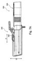
開示される主題の別の側面では、図4-7Cに図示され、概して200と示される、インプラントユニットアクティブ化デバイスが、開示される。本デバイスは、インプラントアクティブ化装置を備える、主本体220と、主本体に対して変位するように構成される、軸方向に変位可能なリトラクタ240とを備える。
In another aspect of the disclosed subject matter, an implant unit activation device, illustrated in FIGS. 4-7C and generally designated 200, is disclosed. The device comprises a
インプラントアクティブ化装置は、アンテナと、電力源と、関連付けられる回路(図示せず)とを備え、対象の身体の中へのインプラントユニットの埋込の間、電力源からインプラントユニット(例えば、外科手術用インプラント100))に無線でエネルギーを伝達し、埋込手技の間、対象の身体内の少なくとも1つの神経の刺激を引き起こすように構成される。リトラクタ240の軸方向の変位は、インプラントユニットによって受信されるエネルギーの程度の調節を可能にする。アクティブ化デバイスは、リトラクタが変位する、またはより具体的には、エネルギーがそれに送達される距離の関数として、インプラントユニットによって受信されるエネルギーの量を制御するように、インプラントから(図7Aに見られる)矢印Pの方向にアクティブ化ユニットを後退させることを可能にする状態で、インプラントユニットにエネルギーを送達するように構成される。代替実施形態として、変位の軸は、例えば、(例えば、図6および7Aに示されるような)軸Qならびに/もしくはRに沿った変位を含んでもよい。
The implant activation device comprises an antenna, a power source, and associated circuitry (not shown) to activate the implant unit from the power source during implantation of the implant unit in the body of the subject (e.g., a surgical procedure). The implant 100)) is configured to wirelessly transmit energy to the implant 100)) to cause stimulation of at least one nerve within the subject's body during the implantation procedure. Axial displacement of the
リトラクタ240は、本実施例では、アクティブ化デバイス主本体の主シャフトSにわたって制御可能に摺動するように構成される、スリーブ様の部材である。スリーブ様の部材は、主本体のシャフトにわたってしっかりと搭載される、中空および軸方向に延在する内部を画定する。後退を促進するために、スリーブ様の部材は、係合機構が、主本体のシャフト上の対応する係合部材225に選択的に係合するように構成されるように、解放レバー245と、係合機構250とを具備する。本実施例では、シャフトは、鋸歯状の表面225を具備し、スリーブの内側は、鋸歯状の表面に係合し、それに対して係止するように構成される突出部によって構成される、係合機構255を具備する。主本体シャフトは、ユーザがスリーブをシャフトに対して係止するために所望される場所を判定することを可能にする標識235を具備してもよい。図4に見られるように、シャフトは、スリーブと整合されるとき、実施例では、図5に見られるように、スリーブの2つの両側に延在するスリーブ内のスリット243内に摺動可能に延在する、突出部229を具備する。アクティブ化デバイスの主本体がインプラントユニットから変位されることを可能にし、本デバイスをインプラントユニットに対して所定の位置に保つ、他の構成もまた、想起されることを理解されたい。スリーブはさらに、ユーザがスリーブを把持しながら、レバー245をアクティブ化し、機構255の係合を解放し、その端部223をスリーブ内の開口部241から距離を空けさせるようにスリーブを通してシャフト本体を後退させることを可能にするための、支持および把持要素247を具備することができる。
図示される実施例に見られるように、デバイス200の縁は、使用の間の視線を可能にするため、および人間工学考慮点のために角度付けられる。図示される実施例では、エネルギーの量または電力レベルは、リトラクタの軸方向の移動によって判定されるが、他の実施例は、スリーブ上のねじと、シャフトから延在し、シャフトの縁をインプラントとの接触点から距離を空けさせるように構成される、部分的要素とを含むことを理解されたい。代替実施例では、エネルギーの量およびレベルは、インプラントデバイスに対するシャフト縁間の距離を調節することなく、本デバイスを通して直接制御されてもよい。
As seen in the illustrated embodiment, the edges of
開示される主題に従って、神経刺激インプラントデバイス(例えば、外科手術用インプラント100)を位置付け、アクティブ化させる、例示的方法が、提供される。開示される主題による、本方法は、
インプラントを提供し、対象の組織、例えば、オトガイ舌筋にわたってそれを位置付けることと、
開示されるようなインプラントユニットアクティブ化デバイスを提供することであって、本デバイスは、主本体を備え、主本体は、電力源を有するインプラントアクティブ化装置と、信号を第1のアンテナに提供するように構成される第2のアンテナと、インプラントアクティブ化装置と関連付けられる軸方向に変位可能なアダプタ/リトラクタとを備え、インプラントアクティブ化装置は、埋込の間、電力源からインプラントに無線でエネルギーを伝達し、対象の身体内の少なくとも1つの神経の変調を引き起こすように構成される、ことと
を含み、
少なくとも第1の位置から少なくとも第2の位置へのアダプタの軸方向の変位(例えば、後退)は、インプラントユニットによって受信されるエネルギーの程度の調節を可能にする。
In accordance with the disclosed subject matter, an exemplary method of positioning and activating a neural stimulation implant device (eg, surgical implant 100) is provided. The method according to the disclosed subject matter comprises:
providing an implant and positioning it over the tissue of interest, e.g., the genioglossus muscle;
To provide an implant unit activation device as disclosed, the device comprising a main body, the main body providing an implant activation device having a power source and a signal to a first antenna. and an axially displaceable adapter/retractor associated with an implant activation device, the implant activation device wirelessly transmitting energy from a power source to the implant during implantation. and configured to cause modulation of at least one nerve within the body of the subject;
Axial displacement (eg, retraction) of the adapter from at least a first position to at least a second position allows adjustment of the degree of energy received by the implant unit.
神経を刺激するために、インプラント、特に、電極を位置付けるための正しい場所を判定するために、次のことは、該第1の対の電極を、神経の近位にある推定されるインプラント場所に位置付け、選択的に第2のアンテナを変位させ、1つ以上の患者信号に基づいて、少なくとも第1の対の電極における刺激閾値を得るために要求される、第1の量の電力および第2の量の電力を送達することによって、少なくとも第1の対の電極ならびに第2の対の電極毎の神経変調応答の程度を判定することによって、刺激閾値を識別することと、
少なくとも第2の対の電極を推定される場所に位置付け、要求される第2の量の電力を送達し、少なくとも該第2の対の電極による神経変調の程度を判定することと
を含み、
刺激閾値は、少なくとも部分的に、少なくとも第1の対の電極および第2の対の電極の各電極の刺激の間、少なくとも1つの神経筋応答に基づく。
To determine the correct location for positioning the implants, and in particular the electrodes, for stimulating the nerve, the next step is to position the first pair of electrodes at the putative implant location proximal to the nerve. a first amount of power and a second amount of power required to position and selectively displace the second antenna to obtain a stimulation threshold at the at least first pair of electrodes based on one or more patient signals; identifying a stimulation threshold by determining a degree of neuromodulation response for each of at least the first pair of electrodes as well as the second pair of electrodes by delivering an amount of power;
positioning at least a second pair of electrodes at an estimated location, delivering a required second amount of power, and determining a degree of neuromodulation by at least the second pair of electrodes;
The stimulation threshold is based, at least in part, on at least one neuromuscular response during stimulation of each electrode of the at least first pair of electrodes and the second pair of electrodes.
一実施形態では、インプラントは、閉塞性睡眠時無呼吸の治療のために構成されてもよく、埋込の場所は、舌下神経の近傍にあってもよい。本実施形態によると、神経刺激デバイスは、舌下神経の少なくとも1つの内側枝を変調させるように構成されてもよい。 In one embodiment, the implant may be configured for the treatment of obstructive sleep apnea and the location of implantation may be near the hypoglossal nerve. According to this embodiment, the nerve stimulation device may be configured to modulate at least one medial branch of the hypoglossal nerve.
第2の量は、電力の第1の量より多いまたはそれに等しくてもよい。 The second amount may be greater than or equal to the first amount of power.
第2の量は、電力の第1の量に等しいまたは相対的にそれより少なくてもよい。 The second amount may be equal to or relatively less than the first amount of power.
Claims (35)
b.少なくとも2つの翼部分であって、前記少なくとも2つの翼部分は、前記中心本体部分に対して移動可能である、少なくとも2つの翼部分と、
c.少なくとも2つの接続部材であって、前記少なくとも2つの接続部材のうちのそれぞれ1つは、前記中心本体部分の前記第1の側縁および前記第2の側縁のうちの一方から延在し、前記少なくとも2つの接続部材のうちの前記それぞれ1つは、可撓性であり、かつ、前記少なくとも2つの翼部分のうちのそれぞれ1つを、前記第1の側縁および前記第2の側縁のうちの前記一方において、前記中心本体部分に接続するために構成されており、前記少なくとも2つの翼部分のうちのそれぞれ1つは、少なくとも一対の電極を具備し、前記少なくとも一対の電極は、前記アンテナと電気連通しており、かつ、電場を神経に放出するように構成されている、少なくとも2つの接続部材と
を備え、
前記翼部分は、前記中心本体部分より可撓性である、外科手術用インプラント。 a. A generally planar center body portion having a first side edge, a second side edge opposite the first side edge, a top side, and a bottom side , the center body portion for carrying a signal. a generally planar central body portion comprising an antenna configured to receive ;
b. at least two wing portions, said at least two wing portions being movable with respect to said central body portion ;
c. at least two connecting members, each one of said at least two connecting members extending from one of said first side edge and said second side edge of said central body portion; The respective one of the at least two connecting members is flexible and extends the respective one of the at least two wing portions along the first side edge and the second side edge. configured for connection to the central body portion , each one of the at least two wing portions comprising at least one pair of electrodes, the at least one pair of electrodes comprising: at least two connection members in electrical communication with the antenna and configured to emit an electric field to the nerve ;
A surgical implant, wherein the wing portions are more flexible than the central body portion.
a.第1の側縁と前記第1の側縁とは反対側の第2の側縁と上面側と底面側とを有する略平面状の中心本体部分であって、前記中心本体部分は、信号を受信するように構成されているアンテナを具備する、略平面状の中心本体部分と、
b.少なくとも2つの翼部分であって、前記少なくとも2つの翼部分は、前記中心本体部分に対して移動可能である、少なくとも2つの翼部分と、
c.少なくとも2つの接続部材であって、前記少なくとも2つの接続部材のうちのそれぞれ1つは、前記中心本体部分の前記第1の側縁および前記第2の側縁のうちの一方から延在し、前記少なくとも2つの接続部材のうちの前記それぞれ1つは、可撓性であり、かつ、前記少なくとも2つの翼部分のうちのそれぞれ1つを、前記第1の側縁および前記第2の側縁のうちの前記一方において、前記中心本体部分に接続するために構成されており、前記少なくとも2つの翼部分のうちのそれぞれ1つは、少なくとも一対の電極を具備し、前記少なくとも一対の電極は、前記アンテナと電気連通しており、かつ、電場を神経に放出するように構成されている、少なくとも2つの接続部材と
を備え、
前記接続部材は、少なくとも1つの方向に変形するように構成されている可撓性要素であり、
前記可撓性要素は、可撓性アーチの形態であり、前記可撓性アーチは、前記可撓性アーチの長さに沿って完全に撓曲可能であり、前記可撓性アーチは、前記中心本体部分および前記少なくとも2つの翼部分のそれぞれが相互から離れるように撓曲するように、第1の方向に屈曲移動を可能にする、外科手術用インプラント。 A surgical implant comprising:
a. A generally planar center body portion having a first side edge, a second side edge opposite the first side edge, a top side, and a bottom side , the center body portion for carrying a signal. a generally planar central body portion comprising an antenna configured to receive ;
b. at least two wing portions, said at least two wing portions being movable with respect to said central body portion ;
c. at least two connecting members, each one of said at least two connecting members extending from one of said first side edge and said second side edge of said central body portion; The respective one of the at least two connecting members is flexible and extends the respective one of the at least two wing portions along the first side edge and the second side edge. configured for connection to the central body portion , each one of the at least two wing portions comprising at least one pair of electrodes, the at least one pair of electrodes comprising: at least two connection members in electrical communication with the antenna and configured to emit an electric field to the nerve ;
the connecting member is a flexible element configured to deform in at least one direction;
Said flexible element is in the form of a flexible arch, said flexible arch being fully bendable along the length of said flexible arch, said flexible arch comprising said A surgical implant capable of bending movement in a first direction such that each of the central body portion and the at least two wing portions flex away from each other.
a.第1の側縁と前記第1の側縁とは反対側の第2の側縁と上面側と底面側とを有する略平面状の中心本体部分であって、前記中心本体部分は、信号を受信するように構成されているアンテナを具備する、略平面状の中心本体部分と、
b.少なくとも2つの翼部分であって、前記少なくとも2つの翼部分は、前記中心本体部分に対して移動可能である、少なくとも2つの翼部分と、
c.少なくとも2つの接続部材であって、前記少なくとも2つの接続部材のうちのそれぞれ1つは、前記中心本体部分の前記第1の側縁および前記第2の側縁のうちの一方から延在し、前記少なくとも2つの接続部材のうちの前記それぞれ1つは、可撓性であり、かつ、前記少なくとも2つの翼部分のうちのそれぞれ1つを、前記第1の側縁および前記第2の側縁のうちの前記一方において、前記中心本体部分に接続するために構成されており、前記少なくとも2つの翼部分のうちのそれぞれ1つは、少なくとも一対の電極を具備し、前記少なくとも一対の電極は、前記アンテナと電気連通しており、かつ、電場を神経に放出するように構成されている、少なくとも2つの接続部材と、
d.可撓性アーチと
を備え、
前記可撓性アーチは、
前記可撓性アーチの中心の周囲に配置されている少なくとも1つの中心区画と、
少なくとも2つのヒンジ構造であって、前記ヒンジ構造のうちのそれぞれ1つは、前記中心本体部分と前記少なくとも1つの中心区画との間、および、前記少なくとも2つの翼部分のうちの一方と前記中心区画との間に配置されており、かつ、前記少なくとも2つの翼部分のうちの前記一方が、前記可撓性アーチの平面内の前記ヒンジ構造のうちの1つのヒンジ点の周りで枢動することを可能にする方向に配向されている、少なくとも2つのヒンジ構造と
を備える、外科手術用インプラント。 A surgical implant comprising:
a. A generally planar center body portion having a first side edge, a second side edge opposite the first side edge, a top side, and a bottom side , the center body portion for carrying a signal. a generally planar central body portion comprising an antenna configured to receive ;
b. at least two wing portions, said at least two wing portions being movable with respect to said central body portion ;
c. at least two connecting members, each one of said at least two connecting members extending from one of said first side edge and said second side edge of said central body portion; The respective one of the at least two connecting members is flexible and extends the respective one of the at least two wing portions along the first side edge and the second side edge. configured for connection to the central body portion , each one of the at least two wing portions comprising at least one pair of electrodes, the at least one pair of electrodes comprising: at least two connecting members in electrical communication with the antenna and configured to emit an electric field to the nerve ;
d. comprising a flexible arch and
The flexible arch is
at least one central section disposed around the center of said flexible arch;
at least two hinge structures, each one of said hinge structures between said central body portion and said at least one central section and between said one of said at least two wing portions and said center and said one of said at least two wing portions pivots about a hinge point of said hinge structure in the plane of said flexible arch. A surgical implant comprising: at least two hinge structures oriented in a direction that allows
Applications Claiming Priority (3)
| Application Number | Priority Date | Filing Date | Title |
|---|---|---|---|
| US201762464917P | 2017-02-28 | 2017-02-28 | |
| US62/464,917 | 2017-02-28 | ||
| PCT/EP2018/054913 WO2018158305A1 (en) | 2017-02-28 | 2018-02-28 | Surgical implant system |
Publications (3)
| Publication Number | Publication Date |
|---|---|
| JP2020508759A JP2020508759A (en) | 2020-03-26 |
| JP2020508759A5 JP2020508759A5 (en) | 2021-04-01 |
| JP7248581B2 true JP7248581B2 (en) | 2023-03-29 |
Family
ID=61837720
Family Applications (1)
| Application Number | Title | Priority Date | Filing Date |
|---|---|---|---|
| JP2019546279A Active JP7248581B2 (en) | 2017-02-28 | 2018-02-28 | surgical implant system |
Country Status (8)
| Country | Link |
|---|---|
| US (1) | US11707623B2 (en) |
| EP (1) | EP3589358A1 (en) |
| JP (1) | JP7248581B2 (en) |
| CN (1) | CN110325243B (en) |
| AU (1) | AU2018227019B2 (en) |
| CA (1) | CA3054180A1 (en) |
| IL (1) | IL268887B2 (en) |
| WO (1) | WO2018158305A1 (en) |
Families Citing this family (2)
| Publication number | Priority date | Publication date | Assignee | Title |
|---|---|---|---|---|
| NL2019598B1 (en) * | 2017-09-21 | 2019-03-28 | Tacx Roerend En Onroerend Goed B V | Bicycle trainer and method of its operation |
| IL268936A (en) * | 2019-08-26 | 2021-03-01 | Nyxoah SA | Method and process for placement and fixation of a surgical implant |
Citations (2)
| Publication number | Priority date | Publication date | Assignee | Title |
|---|---|---|---|---|
| US20110071594A1 (en) | 2009-08-06 | 2011-03-24 | Giancarlo Barolat | Posterior tibial nerve and/or other nerve stimulation system and method |
| JP2015522387A (en) | 2012-07-26 | 2015-08-06 | アディ マシアーチ, | Implanted sleep apnea treatment device including antenna |
Family Cites Families (82)
| Publication number | Priority date | Publication date | Assignee | Title |
|---|---|---|---|---|
| US2125008A (en) | 1935-10-05 | 1938-07-26 | William M Scholl | Medicated pad |
| US4370984A (en) | 1979-04-30 | 1983-02-01 | Ndm Corporation | X-Ray transparent medical electrode |
| USD272943S (en) | 1981-06-22 | 1984-03-06 | Stone Robert D | Electrode for biomedical signals |
| US4856499A (en) | 1988-04-11 | 1989-08-15 | Assist Research Corp. | Erection device |
| US5261400A (en) * | 1992-02-12 | 1993-11-16 | Medtronic, Inc. | Defibrillator employing transvenous and subcutaneous electrodes and method of use |
| USD349958S (en) | 1992-07-24 | 1994-08-23 | Bioject Inc. | Needleless injector |
| US5406945A (en) | 1993-05-24 | 1995-04-18 | Ndm Acquisition Corp. | Biomedical electrode having a secured one-piece conductive terminal |
| US5645586A (en) * | 1994-07-08 | 1997-07-08 | Ventritex, Inc. | Conforming implantable defibrillator |
| USD372787S (en) | 1995-01-31 | 1996-08-13 | Dozier Glenda S | Bandage |
| US5538500A (en) | 1995-02-08 | 1996-07-23 | Peterson; Donald A. | Postoperative wound dressing |
| JP2974959B2 (en) | 1996-03-01 | 1999-11-10 | テクナ電子工業株式会社 | Sleep apnea data recording device |
| US5995874A (en) | 1998-02-09 | 1999-11-30 | Dew Engineering And Development Limited | Transcutaneous energy transfer device |
| US6031746A (en) | 1998-09-04 | 2000-02-29 | General Electric Company | Switching amplifier for generating continuous arbitrary waveforms for magnetic resonance imaging coils |
| USD430674S (en) | 2000-01-07 | 2000-09-05 | 3M Innovative Properties Company | Adhesive bandage |
| GB0011202D0 (en) | 2000-05-09 | 2000-06-28 | Kci Licensing Inc | Abdominal wound dressing |
| US6850803B1 (en) * | 2000-06-16 | 2005-02-01 | Medtronic, Inc. | Implantable medical device with a recharging coil magnetic shield |
| US6549071B1 (en) | 2000-09-12 | 2003-04-15 | Silicon Laboratories, Inc. | Power amplifier circuitry and method using an inductance coupled to power amplifier switching devices |
| US7052483B2 (en) | 2000-12-19 | 2006-05-30 | Animas Corporation | Transcutaneous inserter for low-profile infusion sets |
| US7151914B2 (en) | 2001-08-21 | 2006-12-19 | Medtronic, Inc. | Transmitter system for wireless communication with implanted devices |
| US20040010233A1 (en) | 2002-04-16 | 2004-01-15 | Birger Hjertman | System and a method for modification of a device and a device suitable for modification |
| USD477085S1 (en) | 2002-10-07 | 2003-07-08 | Robert Michael Sanfilippo | Medical electrode with an off-set snaptab |
| US7976519B2 (en) | 2002-12-31 | 2011-07-12 | Kci Licensing, Inc. | Externally-applied patient interface system and method |
| USD516212S1 (en) | 2003-05-13 | 2006-02-28 | Atos Medical Ab | Tracheostoma plaster device |
| US7233137B2 (en) | 2003-09-30 | 2007-06-19 | Sharp Kabushiki Kaisha | Power supply system |
| ATE547069T1 (en) * | 2005-03-21 | 2012-03-15 | Kyphon S Rl | INTERSPINAL IMPLANT WITH EXPANDABLE WING |
| USD655807S1 (en) | 2005-12-09 | 2012-03-13 | Unomedical A/S | Medical device |
| US7610100B2 (en) * | 2005-12-30 | 2009-10-27 | Boston Scientific Neuromodulation Corporation | Methods and systems for treating osteoarthritis |
| USD598539S1 (en) | 2006-10-30 | 2009-08-18 | Sanofi-Aventis Deutschland Gmbh | Medical injector |
| US7772582B2 (en) | 2007-07-11 | 2010-08-10 | International Business Machines Corporation | Four-terminal reconfigurable devices |
| US9452296B2 (en) | 2007-10-16 | 2016-09-27 | Peter Forsell | Method and system for controlling supply of energy to an implantable medical device |
| NZ565234A (en) | 2008-01-18 | 2010-11-26 | Telemetry Res Ltd | Selectable resonant frequency transcutaneous energy transfer system |
| CN103944196B (en) | 2008-03-13 | 2017-09-22 | 捷通国际有限公司 | Induction power supply system with multiple coil primaries |
| US8487480B1 (en) | 2008-09-27 | 2013-07-16 | Witricity Corporation | Wireless energy transfer resonator kit |
| US20120235504A1 (en) | 2008-09-27 | 2012-09-20 | Kesler Morris P | Tunable wireless energy transfer for sensors |
| US9396867B2 (en) | 2008-09-27 | 2016-07-19 | Witricity Corporation | Integrated resonator-shield structures |
| US9515494B2 (en) | 2008-09-27 | 2016-12-06 | Witricity Corporation | Wireless power system including impedance matching network |
| US8862241B2 (en) | 2008-11-21 | 2014-10-14 | Peter Forsell | System for supplying energy to an implantable medical device |
| JP2010252468A (en) | 2009-04-14 | 2010-11-04 | Sony Corp | Power transmission device and method, power receiving device and method, and power transmission system |
| US9044588B2 (en) | 2009-04-16 | 2015-06-02 | Cochlear Limited | Reference electrode apparatus and method for neurostimulation implants |
| WO2011008165A1 (en) | 2009-07-17 | 2011-01-20 | Milux Holding S.A. | An improved medical system comprising implants |
| US10716940B2 (en) * | 2009-10-20 | 2020-07-21 | Nyxoah SA | Implant unit for modulation of small diameter nerves |
| KR101383383B1 (en) | 2009-12-16 | 2014-04-08 | 후지쯔 가부시끼가이샤 | Magnetic resonance power transmitter and magnetic resonance power receiver |
| US8721661B2 (en) * | 2010-04-14 | 2014-05-13 | Medtronic, Inc. | Strain relief apparatus for use with implantable medical lead |
| US20120089081A1 (en) | 2010-10-12 | 2012-04-12 | Wahng Chao Uei | Piezoelectric element driver |
| CA141113S (en) | 2010-12-23 | 2012-01-23 | Profibrix Bv | Dispenser for pharmaceutical powder formulations |
| DE102011005519A1 (en) | 2011-03-14 | 2012-09-20 | Maschinenfabrik Gustav Eirich Gmbh & Co. Kg | Granulating or agglomerating process and tool therefor |
| US9962500B2 (en) | 2011-04-28 | 2018-05-08 | Sanofi-Aventis Deutschland Gmbh | Connection for medical device |
| US8401664B2 (en) | 2011-04-29 | 2013-03-19 | Cyberonics, Inc. | System and method for charging a power cell in an implantable medical device |
| USD735322S1 (en) | 2011-05-11 | 2015-07-28 | Sanofi-Aventis Deutschland Gmbh | Injection device |
| WO2013046049A2 (en) | 2011-09-30 | 2013-04-04 | Adi Mashiach | Devices and methods for delivering energy as a function of condition severity |
| US9818530B2 (en) | 2012-01-17 | 2017-11-14 | Texas Instruments Incorporated | Adaptive wireless power transfer system and method |
| JP2013223409A (en) | 2012-04-19 | 2013-10-28 | Sony Corp | Transmission device, non-contact power transmission system, and signal generating method |
| EP2845290B1 (en) | 2012-05-03 | 2018-08-29 | Powermat Technologies Ltd. | System and method for triggering power transfer across an inductive power coupling and non resonant transmission |
| AU346291S (en) | 2012-05-15 | 2013-01-09 | Smith & Nephew | Medical dressing |
| US10052097B2 (en) * | 2012-07-26 | 2018-08-21 | Nyxoah SA | Implant unit delivery tool |
| US9935498B2 (en) | 2012-09-25 | 2018-04-03 | Cyberonics, Inc. | Communication efficiency with an implantable medical device using a circulator and a backscatter signal |
| US9305700B2 (en) | 2012-10-04 | 2016-04-05 | Linear Technology Corporation | Auto resonant driver for wireless power transmitter sensing required transmit power for optimum efficiency |
| US10238875B2 (en) | 2012-12-19 | 2019-03-26 | Adi Mashiach | Systems and methods for hypertension control |
| US20140339910A1 (en) | 2013-05-15 | 2014-11-20 | Witricity Corporation | Device to device signaling in wireless energy transfer systems |
| WO2015004540A2 (en) * | 2013-06-17 | 2015-01-15 | Adi Mashiach | Dynamic modification of modulation throughout a therapy period |
| USD764657S1 (en) | 2013-07-03 | 2016-08-23 | Unitract Syringe Pty Ltd | Automatic injector |
| US9504839B2 (en) | 2013-07-15 | 2016-11-29 | Boston Scientific Neuromodulation Corporation | Tension clamp side loading lead anchor and methods and systems using the lead anchor |
| USD755980S1 (en) | 2013-08-30 | 2016-05-10 | Mölnlycke Health Care Ab | Wound dressing |
| CN104578439B (en) | 2013-10-21 | 2018-10-09 | 台达电子企业管理(上海)有限公司 | Device for wireless charging link |
| USD715928S1 (en) | 2013-10-28 | 2014-10-21 | Tidi Securement Products, Llc | Catheter anchor pad with release layer |
| US9294057B2 (en) | 2013-12-18 | 2016-03-22 | National Instruments Corporation | Efficient low noise high speed amplifier |
| US9895531B2 (en) | 2014-04-11 | 2018-02-20 | Pacesetter, Inc. | Protective patch for protecting the implant site of a trial neurostimulation lead |
| USD778451S1 (en) | 2014-05-13 | 2017-02-07 | Tdk Corporation | Conductive seal of a biomedical signal recorder |
| US9358384B2 (en) * | 2014-09-05 | 2016-06-07 | Advanced Neuromodulation Systems, Inc. | Implantable lead with flexible paddle electrode array |
| WO2016040695A1 (en) | 2014-09-10 | 2016-03-17 | C.R. Bard, Inc. | Protective dressing for skin-placed medical device |
| USD759828S1 (en) | 2014-09-18 | 2016-06-21 | Steven Riedle | Adhesive bandage |
| USD756513S1 (en) | 2014-11-13 | 2016-05-17 | Biomedical Enterprises, Inc. | Orthopedic implant insertion device |
| USD780311S1 (en) | 2014-11-20 | 2017-02-28 | Biomedical Enterprises, Inc. | Orthopedic implant |
| US20170007442A1 (en) | 2015-07-11 | 2017-01-12 | Thermal Fit, LLC | Intraoral Orthosis Device and Method for Manufacturing |
| USD777329S1 (en) | 2015-10-19 | 2017-01-24 | Nextremity Solutions, Inc. | Bone staple |
| USD773665S1 (en) | 2015-10-27 | 2016-12-06 | Biomedical Enterprises, Inc. | Orthopedic implant |
| USD773666S1 (en) | 2015-10-27 | 2016-12-06 | Biomedical Enterprises, Inc. | Orthopedic implant |
| USD819202S1 (en) | 2016-02-04 | 2018-05-29 | Atos Medical Ab | Heat and moisture exchanger base plate |
| USD790714S1 (en) | 2016-02-12 | 2017-06-27 | Kci Usa, Inc. | Medical dressing support frame with tab |
| USD866769S1 (en) | 2016-09-12 | 2019-11-12 | Nyxoah S.A. | Patch |
| CN106422063A (en) | 2016-11-23 | 2017-02-22 | 刘帆 | Simple method and simple device for stopping snoring by electrical stimulation |
| WO2018136493A1 (en) | 2017-01-17 | 2018-07-26 | Veressa Medical, Inc. | System for identifying a target medical device implant site |
-
2018
- 2018-02-28 WO PCT/EP2018/054913 patent/WO2018158305A1/en unknown
- 2018-02-28 IL IL268887A patent/IL268887B2/en unknown
- 2018-02-28 AU AU2018227019A patent/AU2018227019B2/en active Active
- 2018-02-28 US US16/488,141 patent/US11707623B2/en active Active
- 2018-02-28 EP EP18714702.0A patent/EP3589358A1/en active Pending
- 2018-02-28 CA CA3054180A patent/CA3054180A1/en active Pending
- 2018-02-28 CN CN201880014151.9A patent/CN110325243B/en active Active
- 2018-02-28 JP JP2019546279A patent/JP7248581B2/en active Active
Patent Citations (2)
| Publication number | Priority date | Publication date | Assignee | Title |
|---|---|---|---|---|
| US20110071594A1 (en) | 2009-08-06 | 2011-03-24 | Giancarlo Barolat | Posterior tibial nerve and/or other nerve stimulation system and method |
| JP2015522387A (en) | 2012-07-26 | 2015-08-06 | アディ マシアーチ, | Implanted sleep apnea treatment device including antenna |
Also Published As
| Publication number | Publication date |
|---|---|
| AU2018227019B2 (en) | 2023-07-20 |
| IL268887B2 (en) | 2023-11-01 |
| WO2018158305A9 (en) | 2019-07-18 |
| CA3054180A1 (en) | 2018-09-07 |
| EP3589358A1 (en) | 2020-01-08 |
| IL268887A (en) | 2019-10-31 |
| US20200001082A1 (en) | 2020-01-02 |
| CN110325243B (en) | 2023-12-05 |
| WO2018158305A1 (en) | 2018-09-07 |
| IL268887B1 (en) | 2023-07-01 |
| AU2018227019A1 (en) | 2019-10-17 |
| JP2020508759A (en) | 2020-03-26 |
| US11707623B2 (en) | 2023-07-25 |
| CN110325243A (en) | 2019-10-11 |
Similar Documents
| Publication | Publication Date | Title |
|---|---|---|
| US9610041B2 (en) | Fixation mechanism assembly and method for implantable devices | |
| US9486621B2 (en) | Implanting an electrode array against the spinal cord inside the dura for stimulating the spinal cord and treating pain | |
| US9026227B2 (en) | Anchor sleeve for implantable lead | |
| US20120330355A1 (en) | Multi-durometer reinforced suture sleeve | |
| WO2006049964A1 (en) | Expandable fixation mechanism | |
| US20090248123A1 (en) | Implantable Elongate Member | |
| WO2008017059A1 (en) | Implantable medical lead with proximal retrievable wire | |
| US11559679B2 (en) | Lead implant fixation mechanism | |
| JP7248581B2 (en) | surgical implant system | |
| EP3021935B1 (en) | Multi-electrode lead with backing for mecho/baroreceptor stimulation | |
| US20190001122A1 (en) | Lead for neuromodulation | |
| US9572975B2 (en) | Paddle leads configured for suture fixation | |
| ES2862458T3 (en) | Intrafascicular lead implant | |
| JP2020508759A5 (en) | ||
| US20240116231A1 (en) | Implantable medical devices at least partially formed from a thermoset material | |
| EP4056224A1 (en) | Active implantable medical device for sensing an electric signal of an organ of a human or animal patient |
Legal Events
| Date | Code | Title | Description |
|---|---|---|---|
| A521 | Request for written amendment filed |
Free format text: JAPANESE INTERMEDIATE CODE: A523 Effective date: 20210216 |
|
| A621 | Written request for application examination |
Free format text: JAPANESE INTERMEDIATE CODE: A621 Effective date: 20210216 |
|
| A977 | Report on retrieval |
Free format text: JAPANESE INTERMEDIATE CODE: A971007 Effective date: 20211124 |
|
| A131 | Notification of reasons for refusal |
Free format text: JAPANESE INTERMEDIATE CODE: A131 Effective date: 20211201 |
|
| A601 | Written request for extension of time |
Free format text: JAPANESE INTERMEDIATE CODE: A601 Effective date: 20220228 |
|
| A521 | Request for written amendment filed |
Free format text: JAPANESE INTERMEDIATE CODE: A523 Effective date: 20220502 |
|
| A131 | Notification of reasons for refusal |
Free format text: JAPANESE INTERMEDIATE CODE: A131 Effective date: 20220902 |
|
| A521 | Request for written amendment filed |
Free format text: JAPANESE INTERMEDIATE CODE: A523 Effective date: 20221201 |
|
| TRDD | Decision of grant or rejection written | ||
| A01 | Written decision to grant a patent or to grant a registration (utility model) |
Free format text: JAPANESE INTERMEDIATE CODE: A01 Effective date: 20230307 |
|
| A61 | First payment of annual fees (during grant procedure) |
Free format text: JAPANESE INTERMEDIATE CODE: A61 Effective date: 20230316 |
|
| R150 | Certificate of patent or registration of utility model |
Ref document number: 7248581 Country of ref document: JP Free format text: JAPANESE INTERMEDIATE CODE: R150 |