JP7248323B2 - Systems and methods for applying materials to medical devices - Google Patents
Systems and methods for applying materials to medical devices Download PDFInfo
- Publication number
- JP7248323B2 JP7248323B2 JP2020506709A JP2020506709A JP7248323B2 JP 7248323 B2 JP7248323 B2 JP 7248323B2 JP 2020506709 A JP2020506709 A JP 2020506709A JP 2020506709 A JP2020506709 A JP 2020506709A JP 7248323 B2 JP7248323 B2 JP 7248323B2
- Authority
- JP
- Japan
- Prior art keywords
- elongated
- motor
- tube
- distribution conduit
- orifice
- Prior art date
- Legal status (The legal status is an assumption and is not a legal conclusion. Google has not performed a legal analysis and makes no representation as to the accuracy of the status listed.)
- Active
Links
Images


Classifications
-
- B—PERFORMING OPERATIONS; TRANSPORTING
- B05—SPRAYING OR ATOMISING IN GENERAL; APPLYING FLUENT MATERIALS TO SURFACES, IN GENERAL
- B05D—PROCESSES FOR APPLYING FLUENT MATERIALS TO SURFACES, IN GENERAL
- B05D1/00—Processes for applying liquids or other fluent materials
- B05D1/002—Processes for applying liquids or other fluent materials the substrate being rotated
-
- B—PERFORMING OPERATIONS; TRANSPORTING
- B05—SPRAYING OR ATOMISING IN GENERAL; APPLYING FLUENT MATERIALS TO SURFACES, IN GENERAL
- B05B—SPRAYING APPARATUS; ATOMISING APPARATUS; NOZZLES
- B05B13/00—Machines or plants for applying liquids or other fluent materials to surfaces of objects or other work by spraying, not covered by groups B05B1/00 - B05B11/00
- B05B13/02—Means for supporting work; Arrangement or mounting of spray heads; Adaptation or arrangement of means for feeding work
- B05B13/0207—Means for supporting work; Arrangement or mounting of spray heads; Adaptation or arrangement of means for feeding work the work being an elongated body, e.g. wire or pipe
-
- B—PERFORMING OPERATIONS; TRANSPORTING
- B05—SPRAYING OR ATOMISING IN GENERAL; APPLYING FLUENT MATERIALS TO SURFACES, IN GENERAL
- B05B—SPRAYING APPARATUS; ATOMISING APPARATUS; NOZZLES
- B05B13/00—Machines or plants for applying liquids or other fluent materials to surfaces of objects or other work by spraying, not covered by groups B05B1/00 - B05B11/00
- B05B13/02—Means for supporting work; Arrangement or mounting of spray heads; Adaptation or arrangement of means for feeding work
- B05B13/0221—Means for supporting work; Arrangement or mounting of spray heads; Adaptation or arrangement of means for feeding work characterised by the means for moving or conveying the objects or other work, e.g. conveyor belts
- B05B13/0235—Means for supporting work; Arrangement or mounting of spray heads; Adaptation or arrangement of means for feeding work characterised by the means for moving or conveying the objects or other work, e.g. conveyor belts the movement of the objects being a combination of rotation and linear displacement
-
- B—PERFORMING OPERATIONS; TRANSPORTING
- B05—SPRAYING OR ATOMISING IN GENERAL; APPLYING FLUENT MATERIALS TO SURFACES, IN GENERAL
- B05B—SPRAYING APPARATUS; ATOMISING APPARATUS; NOZZLES
- B05B13/00—Machines or plants for applying liquids or other fluent materials to surfaces of objects or other work by spraying, not covered by groups B05B1/00 - B05B11/00
- B05B13/06—Machines or plants for applying liquids or other fluent materials to surfaces of objects or other work by spraying, not covered by groups B05B1/00 - B05B11/00 specially designed for treating the inside of hollow bodies
- B05B13/0645—Machines or plants for applying liquids or other fluent materials to surfaces of objects or other work by spraying, not covered by groups B05B1/00 - B05B11/00 specially designed for treating the inside of hollow bodies the hollow bodies being rotated during treatment operation
-
- B—PERFORMING OPERATIONS; TRANSPORTING
- B05—SPRAYING OR ATOMISING IN GENERAL; APPLYING FLUENT MATERIALS TO SURFACES, IN GENERAL
- B05C—APPARATUS FOR APPLYING FLUENT MATERIALS TO SURFACES, IN GENERAL
- B05C13/00—Means for manipulating or holding work, e.g. for separate articles
- B05C13/02—Means for manipulating or holding work, e.g. for separate articles for particular articles
- B05C13/025—Means for manipulating or holding work, e.g. for separate articles for particular articles relatively small cylindrical objects, e.g. cans, bottles
-
- B—PERFORMING OPERATIONS; TRANSPORTING
- B05—SPRAYING OR ATOMISING IN GENERAL; APPLYING FLUENT MATERIALS TO SURFACES, IN GENERAL
- B05C—APPARATUS FOR APPLYING FLUENT MATERIALS TO SURFACES, IN GENERAL
- B05C5/00—Apparatus in which liquid or other fluent material is projected, poured or allowed to flow on to the surface of the work
- B05C5/02—Apparatus in which liquid or other fluent material is projected, poured or allowed to flow on to the surface of the work the liquid or other fluent material being discharged through an outlet orifice by pressure, e.g. from an outlet device in contact or almost in contact, with the work
- B05C5/0208—Apparatus in which liquid or other fluent material is projected, poured or allowed to flow on to the surface of the work the liquid or other fluent material being discharged through an outlet orifice by pressure, e.g. from an outlet device in contact or almost in contact, with the work for applying liquid or other fluent material to separate articles
- B05C5/0212—Apparatus in which liquid or other fluent material is projected, poured or allowed to flow on to the surface of the work the liquid or other fluent material being discharged through an outlet orifice by pressure, e.g. from an outlet device in contact or almost in contact, with the work for applying liquid or other fluent material to separate articles only at particular parts of the articles
- B05C5/0216—Apparatus in which liquid or other fluent material is projected, poured or allowed to flow on to the surface of the work the liquid or other fluent material being discharged through an outlet orifice by pressure, e.g. from an outlet device in contact or almost in contact, with the work for applying liquid or other fluent material to separate articles only at particular parts of the articles by relative movement of article and outlet according to a predetermined path
- B05C5/022—Apparatus in which liquid or other fluent material is projected, poured or allowed to flow on to the surface of the work the liquid or other fluent material being discharged through an outlet orifice by pressure, e.g. from an outlet device in contact or almost in contact, with the work for applying liquid or other fluent material to separate articles only at particular parts of the articles by relative movement of article and outlet according to a predetermined path the outlet being fixed during operation
-
- B—PERFORMING OPERATIONS; TRANSPORTING
- B05—SPRAYING OR ATOMISING IN GENERAL; APPLYING FLUENT MATERIALS TO SURFACES, IN GENERAL
- B05C—APPARATUS FOR APPLYING FLUENT MATERIALS TO SURFACES, IN GENERAL
- B05C5/00—Apparatus in which liquid or other fluent material is projected, poured or allowed to flow on to the surface of the work
- B05C5/02—Apparatus in which liquid or other fluent material is projected, poured or allowed to flow on to the surface of the work the liquid or other fluent material being discharged through an outlet orifice by pressure, e.g. from an outlet device in contact or almost in contact, with the work
- B05C5/0241—Apparatus in which liquid or other fluent material is projected, poured or allowed to flow on to the surface of the work the liquid or other fluent material being discharged through an outlet orifice by pressure, e.g. from an outlet device in contact or almost in contact, with the work for applying liquid or other fluent material to elongated work, e.g. wires, cables, tubes
-
- B—PERFORMING OPERATIONS; TRANSPORTING
- B05—SPRAYING OR ATOMISING IN GENERAL; APPLYING FLUENT MATERIALS TO SURFACES, IN GENERAL
- B05C—APPARATUS FOR APPLYING FLUENT MATERIALS TO SURFACES, IN GENERAL
- B05C5/00—Apparatus in which liquid or other fluent material is projected, poured or allowed to flow on to the surface of the work
- B05C5/02—Apparatus in which liquid or other fluent material is projected, poured or allowed to flow on to the surface of the work the liquid or other fluent material being discharged through an outlet orifice by pressure, e.g. from an outlet device in contact or almost in contact, with the work
- B05C5/0254—Coating heads with slot-shaped outlet
-
- B—PERFORMING OPERATIONS; TRANSPORTING
- B05—SPRAYING OR ATOMISING IN GENERAL; APPLYING FLUENT MATERIALS TO SURFACES, IN GENERAL
- B05D—PROCESSES FOR APPLYING FLUENT MATERIALS TO SURFACES, IN GENERAL
- B05D1/00—Processes for applying liquids or other fluent materials
- B05D1/26—Processes for applying liquids or other fluent materials performed by applying the liquid or other fluent material from an outlet device in contact with, or almost in contact with, the surface
-
- B—PERFORMING OPERATIONS; TRANSPORTING
- B05—SPRAYING OR ATOMISING IN GENERAL; APPLYING FLUENT MATERIALS TO SURFACES, IN GENERAL
- B05C—APPARATUS FOR APPLYING FLUENT MATERIALS TO SURFACES, IN GENERAL
- B05C5/00—Apparatus in which liquid or other fluent material is projected, poured or allowed to flow on to the surface of the work
- B05C5/02—Apparatus in which liquid or other fluent material is projected, poured or allowed to flow on to the surface of the work the liquid or other fluent material being discharged through an outlet orifice by pressure, e.g. from an outlet device in contact or almost in contact, with the work
- B05C5/027—Coating heads with several outlets, e.g. aligned transversally to the moving direction of a web to be coated
-
- B—PERFORMING OPERATIONS; TRANSPORTING
- B05—SPRAYING OR ATOMISING IN GENERAL; APPLYING FLUENT MATERIALS TO SURFACES, IN GENERAL
- B05D—PROCESSES FOR APPLYING FLUENT MATERIALS TO SURFACES, IN GENERAL
- B05D2254/00—Tubes
- B05D2254/02—Applying the material on the exterior of the tube
-
- B—PERFORMING OPERATIONS; TRANSPORTING
- B29—WORKING OF PLASTICS; WORKING OF SUBSTANCES IN A PLASTIC STATE IN GENERAL
- B29C—SHAPING OR JOINING OF PLASTICS; SHAPING OF MATERIAL IN A PLASTIC STATE, NOT OTHERWISE PROVIDED FOR; AFTER-TREATMENT OF THE SHAPED PRODUCTS, e.g. REPAIRING
- B29C64/00—Additive manufacturing, i.e. manufacturing of three-dimensional [3D] objects by additive deposition, additive agglomeration or additive layering, e.g. by 3D printing, stereolithography or selective laser sintering
- B29C64/10—Processes of additive manufacturing
- B29C64/106—Processes of additive manufacturing using only liquids or viscous materials, e.g. depositing a continuous bead of viscous material
-
- B—PERFORMING OPERATIONS; TRANSPORTING
- B29—WORKING OF PLASTICS; WORKING OF SUBSTANCES IN A PLASTIC STATE IN GENERAL
- B29C—SHAPING OR JOINING OF PLASTICS; SHAPING OF MATERIAL IN A PLASTIC STATE, NOT OTHERWISE PROVIDED FOR; AFTER-TREATMENT OF THE SHAPED PRODUCTS, e.g. REPAIRING
- B29C64/00—Additive manufacturing, i.e. manufacturing of three-dimensional [3D] objects by additive deposition, additive agglomeration or additive layering, e.g. by 3D printing, stereolithography or selective laser sintering
- B29C64/20—Apparatus for additive manufacturing; Details thereof or accessories therefor
- B29C64/205—Means for applying layers
- B29C64/209—Heads; Nozzles
-
- B—PERFORMING OPERATIONS; TRANSPORTING
- B33—ADDITIVE MANUFACTURING TECHNOLOGY
- B33Y—ADDITIVE MANUFACTURING, i.e. MANUFACTURING OF THREE-DIMENSIONAL [3-D] OBJECTS BY ADDITIVE DEPOSITION, ADDITIVE AGGLOMERATION OR ADDITIVE LAYERING, e.g. BY 3-D PRINTING, STEREOLITHOGRAPHY OR SELECTIVE LASER SINTERING
- B33Y10/00—Processes of additive manufacturing
-
- B—PERFORMING OPERATIONS; TRANSPORTING
- B33—ADDITIVE MANUFACTURING TECHNOLOGY
- B33Y—ADDITIVE MANUFACTURING, i.e. MANUFACTURING OF THREE-DIMENSIONAL [3-D] OBJECTS BY ADDITIVE DEPOSITION, ADDITIVE AGGLOMERATION OR ADDITIVE LAYERING, e.g. BY 3-D PRINTING, STEREOLITHOGRAPHY OR SELECTIVE LASER SINTERING
- B33Y30/00—Apparatus for additive manufacturing; Details thereof or accessories therefor
Description
[0001]本発明の分野は、生体の腔内部で診断または治療処置を実行するためのシステムに関する。 [0001] The field of the invention relates to systems for performing diagnostic or therapeutic procedures within a body cavity.
[0002]可撓性プラスチック材料で作られた医療器具に機能性を付加するため、膨張式カフ、風船、スリーブ、または膜上に導電性フレキシブル電子回路を印刷するプロセスが開発された。いくつかの代表的な実施形態は、気管内チューブ、経鼻胃チューブを含むが、これらに制限されない。非円形である外周を有する管、またはある程度の複雑さを有する特徴部に対して、このプロセスを使用する場合、問題が生じる。 [0002] To add functionality to medical devices made of flexible plastic materials, processes have been developed to print conductive flexible electronic circuits onto inflatable cuffs, balloons, sleeves, or membranes. Some representative embodiments include, but are not limited to, endotracheal tubes, nasogastric tubes. A problem arises when using this process for tubes with perimeters that are non-circular, or features that have some degree of complexity.
[0003]本開示の一実施形態では、材料の所定のパターンを細長い管状基材上に適用するための機構が、第1のモータと、第1のモータによって回転可能であり、長手方向軸線を有する細長い部材を可逆的に把持するように構成され、それによって、第1のモータの回転により、細長い部材をその長手方向軸線を中心として回転させるようになっている、係合部材と、第1の流動性状態を有する流体を分配するように構成された流体ディスペンサであって、流体ディスペンサが、オリフィスを有する遠位端部を有する細長い分配導管を含み、オリフィスが、細長い部材の表面に隣接して配置されるように構成されている、流体ディスペンサと、オリフィスがその相対的な位置を細長い部材の長手方向軸線に沿って変化させるように、細長い部材または細長い分配導管のうちの少なくとも一方を動かすように構成された、第2のモータと、を備え、細長い分配導管の遠位端部が、細長い部材の表面上に付勢を加えるように構成されている。 [0003] In one embodiment of the present disclosure, a mechanism for applying a predetermined pattern of material onto an elongated tubular substrate includes a first motor and a mechanism rotatable by the first motor and having a longitudinal axis of an engagement member configured to reversibly grip an elongated member comprising a first motor, whereby rotation of the first motor causes rotation of the elongated member about its longitudinal axis; A fluid dispenser configured to dispense a fluid having a fluidity state of , the fluid dispenser including an elongated dispensing conduit having a distal end with an orifice, the orifice adjacent a surface of the elongated member. and moving at least one of the elongated member or the elongated distribution conduit such that the orifice varies its relative position along the longitudinal axis of the elongated member. and a second motor configured to apply a bias to the distal end of the elongated distribution conduit onto the surface of the elongated member.
[0004]本開示の別の実施形態では、材料の所定のパターンを細長い管状基材上に適用するための機構が、第1のモータと、第1のモータによって回転可能であり、長手方向軸線を有する細長い部材を可逆的に保持するように構成され、それによって、第1のモータの回転により、細長い部材をその長手方向軸線を中心として回転させるようになっている、係合部材と、第1の流動性状態を有する流体を分配するように構成された流体ディスペンサであって、流体ディスペンサが、オリフィスを有する遠位端部を有する細長い分配導管を含み、オリフィスが、細長い部材の表面に隣接して配置されるように構成されている、流体ディスペンサと、オリフィスがその相対的な位置を細長い部材の長手方向軸線に沿って変化させるように、細長い部材または細長い分配導管のうちの少なくとも一方を動かすように構成された、第2のモータと、係合部材から第1の距離だけ離間し、第1、第2、および第3のローラを含む、可変ベアリングであって、第1、第2、および第3のローラがそれぞれ、細長い部材の一回転にわたって細長い部材の表面に同時に接触するように構成されている、可変ベアリングと、を備える。 [0004] In another embodiment of the present disclosure, a mechanism for applying a predetermined pattern of material onto an elongated tubular substrate includes a first motor, and is rotatable by the first motor and has a longitudinal axis. an engagement member configured to reversibly retain an elongated member having a , such that rotation of the first motor causes rotation of the elongated member about its longitudinal axis; A fluid dispenser configured to dispense a fluid having one fluidity state, the fluid dispenser including an elongated dispensing conduit having a distal end with an orifice, the orifice adjacent a surface of the elongated member. and at least one of the elongated member or the elongated distribution conduit such that the orifices vary their relative positions along the longitudinal axis of the elongated member. A second motor configured to move and a variable bearing spaced a first distance from the engagement member and including first, second and third rollers; , and a third roller each configured to simultaneously contact a surface of the elongated member over one revolution of the elongated member.
[0005]本開示のさらに別の実施形態では、中空または管状構造体を有するおもちゃが、第1の表面と、第1の表面上に配された1つまたは複数のエレクトロルミネセント素子と、1つまたは複数のエレクトロルミネセント素子を動作させるように構成された回路と、を含む。 [0005] In yet another embodiment of the present disclosure, a toy having a hollow or tubular structure is provided with a first surface, one or more electroluminescent elements disposed on the first surface; and circuitry configured to operate the one or more electroluminescent elements.
[0006]本開示のさらに別の実施形態では、防曇アイウェアが、フレームと、フレームに連結された1つまたは複数のレンズと、フレームまたは1つまたは複数のレンズのうちの少なくとも一方の上に保持された1つまたは複数の加熱素子と、を含む。 [0006] In yet another embodiment of the present disclosure, the anti-fog eyewear comprises a frame, one or more lenses coupled to the frame, and a lens on at least one of the frame or the one or more lenses. and one or more heating elements held in the .
[0007]本開示のさらに別の実施形態では、飲用グラスが、内側表面および外側表面を有する容器本体と、内側表面または外側表面のうちの少なくとも一方に保持された1つまたは複数の加熱素子と、を含む。 [0007] In yet another embodiment of the present disclosure, a drinking glass includes a container body having an inner surface and an outer surface, and one or more heating elements retained on at least one of the inner surface or the outer surface. ,including.
[0008]本開示のさらに別の実施形態では、材料の所定のパターンを細長い管状基材上に適用するための方法が、非円形外周を有する細長いチューブの第1の部分を、第1のモータによって回転されるように構成された係合部材に固定し、それによって、細長いチューブを係合部材と同時に回転できるようにするステップと、第1のモータを動作させて細長いチューブを回転させるステップと、第2のモータを動作させて、細長いチューブと分配導管との間の相対変位を細長いチューブの長手方向軸線に沿って変化させるステップと、導電性接着剤を流体ディスペンサから分配導管を通じて放出して、導電性接着剤の所定のパターンを細長いチューブの表面上に形成するステップと、を含み、導電性接着剤の所定のパターンは、非円形外周に沿った表面の少なくとも180°を、長手方向軸線に沿った少なくとも2mmの幅にわたって覆う。 [0008] In yet another embodiment of the present disclosure, a method for applying a predetermined pattern of material onto an elongated tubular substrate comprises applying a first portion of an elongated tube having a non-circular perimeter to a first motor. securing to an engagement member configured to be rotated by a , thereby allowing the elongated tube to rotate simultaneously with the engagement member; and operating a first motor to rotate the elongated tube. , operating the second motor to vary the relative displacement between the elongated tube and the distribution conduit along the longitudinal axis of the elongated tube; and discharging the conductive adhesive from the fluid dispenser through the distribution conduit. and forming a predetermined pattern of conductive adhesive on a surface of the elongated tube, wherein the predetermined pattern of conductive adhesive extends at least 180° of the surface along the non-circular circumference to the longitudinal axis. cover over a width of at least 2 mm along the
[0009]本開示のさらに別の実施形態では、医療器具が、外側円筒形表面、内腔、壁、壁の第1の穴、および壁の第2の穴を有する、ポリマーチューブと、チューブの内腔を少なくとも部分的に通って延びる導体であって、第1の穴を出て第2の穴に入る、導体と、第1の穴と第2の穴との間の部分において導体をチューブの外側円筒形表面に固定する第1の導電性接着剤層と、第1の穴と第2の穴との間の部分において導体および第1の導電性接着剤層を覆う第2の導電性接着剤層と、を含む。 [0009] In yet another embodiment of the present disclosure, a medical device includes a polymer tube having an outer cylindrical surface, a lumen, a wall, a first hole in the wall, and a second hole in the wall; a conductor extending at least partially through the lumen, the conductor exiting the first hole and entering the second hole, and the conductor tubing in a portion between the first hole and the second hole; and a second conductive adhesive layer covering the conductor and the first conductive adhesive layer in a portion between the first and second holes. and an adhesive layer.
[0052]本発明の実施形態は、細長いチューブもしくはシャフト、または成形表面(contoured surfaces)上に適用された材料の所定のパターンを有する医療器具、医療器具の構成要素、または他の非医療器具もしくは構成要素を製造するための機械および方法、ならびにこれらの機械を使用するための方法を含む。 [0052] Embodiments of the present invention provide medical devices, medical device components, or other non-medical devices or devices having predetermined patterns of material applied onto elongated tubes or shafts or contoured surfaces. Including machines and methods for manufacturing components and methods for using these machines.
[0053]いくつかのタイプの医療器具は、ポリマー体、シャフト、管、または風船によって保持された導電性トレースを利用する。少なくともいくつかが粘膜組織に接触する、体腔内部に配列された電極センサを用いた血流の生体インピーダンス法の例は、1998年8月11日に発行され、発明の名称を「APPARATUS AND METHOD OF BIOELECTRICAL IMPEDANCE ANALYSIS OF BLOOD FLOW」とする、米国特許第5,791,349号明細書、1998年7月21日に発行され、発明の名称を「APPARATUS AND METHOD OF BIOELECTRICAL IMPEDANCE ANALYSIS OF BLOOD FLOW」とする米国特許第5,782,774号明細書、2000年8月1日に発行され、発明の名称を「APPARATUS AND METHODS OF BIOELECTRICAL IMPEDANCE ANALYSIS OF BLOOD FLOW」とする、米国特許第6,095,987号明細書、および2001年9月18日に発行され、発明の名称を「APPARATUS AND METHODS OF BIOELECTRICAL IMPEDANCE ANALYSIS OF BLOOD FLOW」とする、米国特許第6,292,689号明細書で見ることができ、これらはすべて、あらゆる目的で参照により全体として本明細書に組み込まれる。 [0053] Some types of medical devices utilize conductive traces held by a polymer body, shaft, tube, or balloon. An example of a bioimpedance method of blood flow using electrode sensors arrayed inside a body cavity, at least some of which contact mucosal tissue, was published Aug. 11, 1998 and entitled "APPARATUS AND METHOD OF. U.S. Pat. No. 5,791,349, issued Jul. 21, 1998, entitled "APPARATUS AND METHOD OF BIOELECTRICAL IMPEDANCE ANALYSIS OF BLOOD FLOW." U.S. Pat. No. 5,782,774, U.S. Pat. No. 6,095,987, issued Aug. 1, 2000, and entitled "APPARATUS AND METHODS OF BIOELECTRICAL IMPEDANCE ANALYSIS OF BLOOD FLOW." and U.S. Pat. No. 6,292,689, issued September 18, 2001 and entitled "APPARATUS AND METHODS OF BIOELECTRICAL IMPEDANCE ANALYSIS OF BLOOD FLOW"; All of which are incorporated herein by reference in their entireties for all purposes.
[0054]センサおよび導電性トレースを有する装置はまた、2016年11月10日に公開され、発明の名称を「SYSTEMS AND METHODS FOR INTERNAL ECG ACQUISITION」とする、国際公開番号WO2016/179563号明細書、および2017年11月2日に出願され、発明の名称を「SYSTEMS AND METHODS FOR INTERNAL ECG ACQUISITION」とする、共有の米国特許出願第15/571,350号明細書に記載するように、電気的タイミング情報を提供するために患者の身体から心電図信号を入手するのに利用され得、これらの特許文献はいずれもあらゆる目的で参照により全体として本明細書に組み込まれる。 [0054] Devices with sensors and conductive traces are also described in International Publication No. WO 2016/179563, entitled "SYSTEMS AND METHODS FOR INTERNAL ECG ACQUISITION," published Nov. 10, 2016; and electrical timing, as described in commonly-owned U.S. Patent Application No. 15/571,350, filed November 2, 2017 and entitled "SYSTEMS AND METHODS FOR INTERNAL ECG ACQUISITION." Both of these patent documents are hereby incorporated by reference in their entirety for all purposes and may be used to obtain electrocardiogram signals from a patient's body to provide information.
[0055]センサ、導電性トレース、または他のパターンを、非円形である外周を有する管上に、または、ある程度の複雑さを有するか、もしくは非平面である特徴部上に、適用する場合に、問題が生じる。図1および図2は、導電性接着剤102を、細長い基材104、またはカテーテルチューブもしくはプローブ本体を含む、医療器具シャフト(管)に適用するように構成された、機械100を示す。機械100は、基部106を備え、基部106は、基部106に固定された静止底部分110を有する長手方向スライド108と、静止底部分110に対してスライド可能である変位可能な上部分112と、を含む。上部分112に取り付けられ、上部分と共に移動可能であるのが、モータ114である。モータ114は、医療器具シャフト104の端部分118に固定可能、かつこれから解放可能となるように構成された、ロック部材116(または係合部材)に回転連結される。ロック部材116は、医療器具シャフト104の周りでユーザによって締められるか、または緩められ(もしくはロックおよびロック解除され)得る、チャックまたはシンチまたは圧縮ロック(トーイボーストシール(Touhy-Borst seal)に類似)を備え得る。あるいは、ロック部材116は、磁石を含み得、医療器具シャフト104の内腔内部に設置された鉄鋼材料(例えば、ステンレス鋼マンドレル)に固定されるように構成され得る。ロック部材116が医療器具シャフト104にロックまたは固定されると、ロック部材116の回転により、医療器具シャフト104の1対1の回転が生じる。よって、モータ114の動作により、医療器具シャフト104は、ロック部材116を介して回転される。1つまたは複数のギヤ117が、モータ114とロック部材116との間に設置され、モータ114の回転に対してロック部材の回転を加速もしくは減速させ、かつ/または回転方向を変化させることができる。よって、ロック部材116および医療器具シャフト104は、モータ114の回転子もしくはシャフトと同じ方向に、またはモータの回転子もしくはシャフトとは反対方向に、回転させられ得る。さらに、ロック部材116および医療器具シャフト104は、モータ114の回転子もしくはシャフトと同じ回転速度、またはモータの回転子もしくはシャフトとは異なる回転速度で(より遅いか、もしくはより速く)回転させられ得る。本明細書における目的は、機械100が、円形外周を有する(すなわち、断面で見た場合)シャフトもしくは管104だけでなく、D字形、長円形、卵形、または楕円形外周を含むがこれらに制限されない、非円形外周を有するシャフトもしくは管104にも適応することである。ロック部材116は、円形または非円形の管104に固定可能(かつこれから解放可能)となるように構成され、それによって、管104にロックされると、モータ114は、ロック部材116を回転させるように動作され得、よって、管104をその長手方向軸線120を中心として回転させる。
[0055] When applying sensors, conductive traces, or other patterns on a tube having a perimeter that is non-circular, or on features that have some degree of complexity or are non-planar, , a problem arises. 1 and 2 show a
[0056]モータ122が、(図1に示すように、管104の長手方向軸線120に平行な)いずれかの長手方向に、底部分110に対して、長手方向スライド108の上部分112を長手方向に移動させるように構成される。コントローラ124が、モータ114、122の動作を制御するように構成され、それによって、管104の回転と長手方向運動との任意の組み合わせが達成され得る。当技術分野で既知のいくつかのコントローラ124、例えば、図6にさらに詳細に示される、米国メリーランド州ブルックビルのSynthetos,LLCが販売する、USBベースのCNC6軸コントローラであるTinyG(商標)、が使用され得る。
[0056] A
[0057]機械100は、シリンジ126を含み、これは、プランジャ/バレルシリンジを含み得るか、または、内圧で作動されるシリンジであってよい。図1から図2のシリンジ126は、加圧注入システム128に対して、これらの間に接続されたガスライン130を介して取り付けられる。加圧注入システム128は、空気、濾過空気、窒素、または二酸化炭素を含む、いくつかのガスを使用し得る。注入中にシリンジ126のバレル132の内部に送達される内圧は、約4ポンド/平方インチ(0.27atm)~約12ポンド/平方インチ(0.82atm)、または約6ポンド/平方インチ(0.41atm)~約8ポンド/平方インチ(0.54atm)であってよいが、利用される圧力は、シリンジ126と共に使用されている中空(皮下)針136の内径および長さ次第であってもよい。シリンジ126のバレル132は、導電性接着剤134を満たされ、シリンジ126/加圧注入システム128は、針136または他のチューブ(金属、プラスチックなど)を通じて、導電性接着剤134を注入するように構成される。図5を見ると、針136は、シリンジ126のバレル132に流体連結された近位ハブ138を含む。針136はまた、オリフィス142を有する遠位部分140を含み、オリフィス142を通じて、注入された導電性接着剤134が加圧時に出る。いくつかの実施形態では、シリンジ126は、(例えば、x、y、およびz軸に沿って)長手方向スライド108の上部分112に対して、相対位置が手動で調節可能であってよい。シリンジ126はまた、例えば、湾曲するか、または略まっすぐでない針136が利用される場合に、回転可能であってよい。他の実施形態では、少なくとも1つのモータ144、例えば、1つ、2つ、3つ、または4つのモータが、シリンジ126の位置および/または角度の向きを自動的に調節するため、さらに具体的には、管104に対して、針136のオリフィス142の位置および向きを調節するために、使用され得る。本明細書でさらに説明するように、管104がモータ114によって回転される間に非円形外周を有する管104の表面146との密接な関係にオリフィス142を維持するための複数の手段が説明される。これらの手段はまた、管104の表面146との密接な関係にオリフィス142を維持するように構成され得る。例えば、管104が先細になる外側横方向寸法または直径を有する場合、これは、管104がモータ122によって長さ方向に変位されるときに管104の隣接部分の直径を変化させる。
[0057] The
[0058]いったんオリフィス142が導電性接着剤134で覆われるかまたはコーティングされる管104の表面146に近接させられると、予めプログラムされた一連の(モータ114を介する)管104の回転および(モータ122を介する)管104の長手方向運動が、(例えば、コントローラ124によって)実行され、加圧注入システム128は、管104の表面146上に適用された導電性接着剤134の特定のパターンを作り出すために(手動で、またはコントローラ124からのコマンドを介して)導電性接着剤134を注入するようコマンドを与えられる。接着剤134のパターン148の適用後の別個の管104は、図1において、基部106の上で長手方向スライド108の隣で支持されて示されている。パターン148は、導電性バンド150a~150c、または長手方向トレーシング152を含み得、これは、はんだまたは他の接合方法を用いて、導電性バンド150a~150cのうちの1つまたは複数を導電体(銅線など)(不図示)に電気的に接続するのに使用され得る。バンド150a~150cおよび長手方向トレーシング152の適用後、長手方向トレーシング152の上に、またバンド150a~150cの一部の上にも、またははんだ接合部の上に、誘電材料を適用するのが望ましい場合がある。誘電材料は、シリンジ126と同様のシリンジ内に配置され、導電性接着剤134と同様に機械100によって適用され得る。二次硬化または固化プロセスも、いったん適用された、導電性接着剤134または誘電材料のいずれかの、液体または流動性形態から、さらに固体または硬化した形態への変化を加速させるか、最適化するか、または単に完了させるために使用され得る。二次動作は、機械100に連結された転換モジュール(不図示)によって実行されるか、または、機械100と共に使用され得る。いくつかの実施形態では、(例えば、上昇した)温度が、加熱器、例えば、温風、赤外線加熱、ハロゲンランプ、放射、架橋を用いて、使用され得る。他の実施形態では、紫外線(UV)硬化が組み込まれ得る。他の実施形態では、化学的接着促進剤が、例えばスプレーによって、適用され得る。管104は、制御された均一な様式で所望の変化または凝固を生じさせるために、温度または放射を適用する間、回転され得る。バンド150a~150cは、センサ、電極、(電気接続のための)接点、および/または加熱素子(例えば、抵抗加熱器)を含む、医療器具に共通のいくつかの異なる素子として機能するように組み込まれ得る。導電性接着剤134または誘電材料はそれぞれ、シリンジ126内に入れられる前に混合されガス抜きされ得(必要な場合)、または、他の実施形態では、それらは、事前混合され、凍らせて保管され、その後、使用前に解凍され得る。コンピュータプログラムが、非一時的なコンピュータ可読媒体において実現され得、これは、1つまたは複数のコンピュータ上で実行された際に、モータ114、122、144のうちの少なくとも1つを動作させる命令を提供する。
[0058] Once the
[0059]医療用シャフトおよび管は、しばしば非円形外周を有する。多内腔押出は、ポリマー管材料の冷却および凝固中の不均一の冷却または不均一の応力により、典型的には、管に丸くない断面を作り出す。多くの医療器具シャフトは、複合構造を有し、丸くない断面を生じる特定の素子を含む(硬化ワイヤ、電線、ガイドワイヤ内腔)。管104の丸さまたは丸みのなさの程度に関わらず、バンド150a~150cまたは他の特徴部、例えば長手方向トレーシング152が、管104の表面146上にスムーズかつ連続して置かれることが望ましいので、丸くない(非円形外周を有する)管104は、回転中に安定するように、機械100内部に保持される。
[0059] Medical shafts and tubes often have non-circular perimeters. Multi-lumen extrusion typically produces non-round cross-sections in the tube due to uneven cooling or uneven stress during cooling and solidification of the polymeric tubing. Many medical device shafts have a composite structure and contain certain elements (stiffening wires, electrical wires, guidewire lumens) that produce non-round cross-sections. Regardless of the degree of roundness or bluntness of
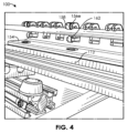
[0060]1つまたは複数の保持部材154は、管104を支えるように、また、針136の遠位部分140およびオリフィス142が、覆われるかまたはコーティングされる管104の表面146の部分にアクセスすることができるように、構成される。図3および図4を見ると、保持部材154は、フィンガ156a~156eを含み、これは、保持部材154と共に、ローラ158、160、162を保持し、これらのローラ158、160、162は、円形外周または非円形外周を有する細長い部材の周りに3つの向かい合う線形接点を維持するように、捕捉ローラvブロックとして役立つよう構成される。ローラ158、160、162は、ロック部材116から、例えば、約1cm~約100cm、または約2cm~約50cm、または約2cm~約25cmの長手方向距離だけ離間している。例えば、図1では、支えられて、非円形外周を有する管104の制御された回転を可能にする、保持部材154aが示され、支えられて、略円形外周を有するマンドレル164の制御された回転を可能にする、保持部材154bが示されている。
[0060] One or
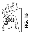
[0061]図8から図10を見ると、保持部材254は、アクセストラフ257a~257gによって分離された、フィンガ256a~256hを備える。保持部材254の長さに延びる長手方向空間259は、管104またはマンドレル164の設置を可能にするように構成される。特に第1のフィンガ256aに注目すると、第1のローラ258は、フィンガ256aの第1の突出部205の穴203を通って、またフィンガ256aの第2の突出部209の穴(不図示)を通って、設置された、第1のピン201を中心として回転可能である。第1のローラ258は、第1の軸211を中心として回転するように構成され、よって、第1の軸211は、保持部材254に対して静止している。第2のローラ260は、フィンガ256aの第3の突出部217の穴215を通って、また、フィンガ256aの第4の突出部219の穴(不図示)を通って、設置された、第2のピン213を中心として回転可能である。第2のローラ260は、第2の軸221を中心として回転するように構成され、よって、第2の軸221も、保持部材254に対して静止している。第1のローラ258および第2のローラ260は、第1の部分223および第2の部分225それぞれに、ローラvブロックを形成する。第3のローラ262は、アーム233の第1の突出部231の第1の穴229およびアーム233の第2の突出部237の第2の穴(不図示)を通ってピン227によって回転保持される。アーム233は、軸239において保持部材254に回転連結される。よって、アーム233は、保持部材254に対して静止している、軸239を中心として円弧241を描いて回転する。アーム233は、(保持部材254の穴を通る)ピン242によって回転保持される。第3のローラ233は、軸243を中心として回転し、軸243は、アーム233に対して静止しているが、保持部材254に対して移動可能である(静止していない)。第1の付勢部材247および第2の付勢部材249は、図9においてらせんばね素子として示されている。付勢部材247、249は、図3の保持部材154のアーム(見えない)の付勢部材147と類似しており、1つまたは複数の弾性バンドを備える。らせんおよび非らせんばねを含む、他のタイプの付勢部材が使用され得る。これらは、板ばね、リビングヒンジ、および弾性限界内で動作するように構成された、介在圧迫材料を含む。図9に戻ると、第1の付勢部材247は、アーム233および保持部材254第1の部分251に連結され、第2の付勢部材249は、アーム233および保持部材254の第2の部分253に連結される。よって、ローラ262は、第1のローラ258および第2のローラ260に近づくか、もしくはこれらから遠ざかることによって調節され、丸くない管もしくはシャフトの横方向寸法の変化に適応することができ、よって、管104の回転中に管104の表面146上のすべての点において回転する3点(線)接触を可能にする。これは、図11から図15でさらに詳細に説明される。
[0061] Looking to Figures 8-10, the
[0062]図11は、第1の内腔272および第2の内腔274のそれぞれが中に延びる、2内腔管270を備えた、図8の保持部材254を示す。図11の保持部材254は、付勢部材247、249がアーム233と保持部材254との間の内部板ばね261で置換されている点で、図8の保持部材254から変更されている。管270は、非円形外周を有し、実質的にD字形である。管270が(例えば、機械100のモータ114によって)回転すると、アーム233は、板ばね261によって加えられる付勢から、開閉し、それによって、ローラ262は、管270の表面263との接触を維持し、ローラ262はまた、管270をローラ258、260それぞれに押し付ける。よって、アーム233の動きにより、ローラ258、260、262は可変ベアリングとして役立つことができる。図12では、第1の内腔272および第2の内腔274は、それぞれ左および右に配置される。図13では、管270は、湾曲した矢印で示す回転方向に60°回転されている。図14では、管270は、この同じ回転方向にさらに30°回転されている。図15では、管270は、この同じ回転方向にさらに60°回転されている。いかなる場合も、ローラ258、260、262はそれぞれ、管270の表面263との接触を維持し、よって、管の向きを安定させ維持する。管270の長手方向軸線265は、管270が、ローラ258、260、262との接触を維持するために必要に応じて上下左右に動くことができるので、必ずしも保持部材254に対して静止したままではないことに留意されたい。分かるように、針136のオリフィス142を管270の表面263の近くに維持する他の手段も本明細書に記載される。
[0062] FIG. 11 shows the
[0063]図7Aは、2内腔の楕円形チューブ280が、湾曲した矢印に対応する回転方向に回転しているところを示す。シリンジ282は、導電性接着剤284を、(皮下管または針を含み得る)管286を通じて、オリフィス288から、注入し、これによって、導電性接着剤284を、チューブ280の表面290上に適用して、特徴部292を作る。管286の遠位部分294は、チューブ280の表面290に対して予荷重力Fで押し下げられ、それによって、チューブ280が図7Bの位置まで回転されると、管286の遠位部分294(よって、オリフィス288)は、(例えば、屈曲により)下がって、チューブ280の表面290と接触したままとなる。遠位部分294は、チューブ280が一回転する間中、またチューブ280が複数回回転する間中、チューブ280の表面290と接触したままとなるように構成される。よって、管286のオリフィス288が非円形外周の360°の回転にわたってチューブ280の表面290の近くにとどまることが確実となる、予荷重力Fが選択され得る。図7Aおよび図7Bでは、予荷重力は、ステンレス鋼などの金属材料であってよいか、または、ポリマー材料、例えばPTFE、ポリエチレン、もしくはポリプロピレンであってよい、管286の片持ち梁の曲げに全面的に基づいて、付勢される。管286の直径、長さ、または壁厚は、所望の予荷重力を達成するために、選択された各異なる材料(係数)で変更され得る。さらに、特定の荷重変位(ひずみ)が、所望の予荷重を達成するように選択され得る。多様な管286が本明細書に記載される実施形態のいずれでも利用され得るが、代表的な管286は、0.0045インチ~0.0095インチ、または約0.005インチ~約0.007インチの内径を有する、304ステンレス鋼の皮下管を含む。
[0063] Figure 7A shows a two-lumen
[0064]図7Cは、代替的な実施形態を示し、予荷重付勢が、管296の片持ち梁の曲げの代わりに、付勢要素によって達成される。シリンジ282は、中空の可撓性ベローズ297を介して管296に流体取り付けされ、これにより、管296とシリンジ282との間の角度変位(角形成)295を可能にする。引っ張りばね298および対向する圧縮ばね299は、管296の遠位部分293(よって、オリフィス291)をチューブ280の表面290に対して付勢する予荷重力Fを提供する。他の実施形態では、引っ張りばね298のみが利用される。他の実施形態では、圧縮ばね299のみが利用される。他の実施形態では、ばね298、299が使用されないが、その代わりに、可撓性ベローズ297が、形状記憶ポリマーから湾曲形状で熱形成され、よって、これを付勢要素にする。いくつかの実施形態では、予荷重付勢は、管286の曲げと、圧縮ばね298、299の変位との組み合わせによって達成され得る。
[0064] FIG. 7C shows an alternative embodiment in which preload biasing is achieved by biasing elements instead of cantilever bending of
[0065]図7Dは、ガスライン301およびディスペンサチューブ302を備えたシリンジ300を示し、ディスペンサチューブ302は、遠位端部306に横方向の切り込み304を有し、標準的な形でディスペンサチューブ302に対して横方向に向けられたオリフィス308を有する。遠位端部306におけるエッジ310は、面取りされる(filleted)か、または別様に平滑化されておらず、よって、管312は、第1の方向314にのみ回転して、導電性接着剤316を適用し、これは、反対方向への回転は、予荷重力Fが適用された場合にエッジ310が管312の表面318に引っかかるおそれがあるためである。いくつかの実施形態では、単一の方向314が、所望のパターンを管312の表面318に適用するのに必要な唯一の回転方向である。しかしながら、図7Eは、閉鎖端部322および側方穴オリフィス324を有するディスペンサチューブ320を備えたシリンジ300を示す。側方穴オリフィス324は、いずれの回転方向326にも管312の表面318に沿ってスライドし得る。図7Fは、オリフィス332を備えた傾斜端部330を有するディスペンサチューブ328を備えたシリンジ300を示す。傾斜端部330は、鈍角にすることによってエッジ334を最小限にし、よって、いずれの回転方向326にも管312の自由な回転を可能にする。図7Gは、まっすぐな近位部分338と、近位部分338に対して角度がある遠位部分340と、を有するディスペンサチューブ336を備えたシリンジ300を示す。まっすぐな近位部分338と角度がある遠位部分340との間の移行は、緩やかな、もしくはつながった曲線であってよいか、または直角に近くてよい(頂点においていくらかの曲率半径を有する)。ディスペンサチューブ336の端部342は、管312の表面318に沿って同じ高さで進み、これにより、端部342およびオリフィス344は、管312がいずれの回転方向326に回転する間も、管312の表面に近接したままとなる。その他のチューブ/針などで見られるように、ディスペンサチューブ336は、その片持ち梁の曲げによって、または追加の付勢要素によって、またはこれら2つの組み合わせによって、付勢を加え得る。ディスペンサチューブ336の曲線形状は、ディスペンサチューブ336のオリフィス344を管312の表面に隣接して最もよく方向付け、かつ所望の付勢を管312に加えるような、角度、半径もしくは曲率および/または長さで構成され得る。
[0065] FIG. 7D shows a
[0066]図7Dから図7Gに示すディスペンサチューブ302、320、328、338は、円形断面を有する内腔を有する円形管で作られている。しかしながら、楕円形、長円形、矩形、正方形、三角形、または他の多角形形状を含む、ディスペンサチューブの他の構成が望ましい場合がある。オリフィスも、円形、楕円形、長円形、矩形、正方形、三角形、または他の多角形形状などの、他の形状を含み得る。図7Hは、楕円形オリフィス352を有する楕円形ディスペンサチューブ350を示す。接着剤適用の増大した幅W1は、それぞれの特定の内腔断面積で達成され得る。幅W1が接着剤で覆われている管の長手方向軸線に沿って方向付けられると、パターンを形成するのに必要とされる管の回転数が少なくなり得る。パターンは、例えば、接着剤により管上に形成された360°のバンドを含み得る。よって、必要な回転数が減少すると、この方法で構成要素を製造する時間および費用を減らすことができる。図7Iは、実質的に矩形のオリフィス356を有する実質的に矩形のディスペンサチューブ354を示す。チューブ354は、いくらか大きなアスペクト比を有することにより、それぞれの特定の内腔断面積で、さらに大きな幅W2が可能となる。図7Jは、マルチチューブアレイ360を備える複合ディスペンサチューブ358を示し、各個別のチューブ362a~362fは、(例えば、ハブを介して)シリンジに流体連結され、端部オリフィス364a~364fを有する。複合ディスペンサチューブ358は、図7Iの矩形のディスペンサチューブ354と同様であるが、単にいくつかの標準的な皮下チューブを一緒に線形アレイで取り付けることによって作られ得る。さらに、各チューブの小さな直径により、曲げの柔軟性が望まれる場合に、その特性を増大させることができる。
[0066] The
[0067]図16から図21は、導電性接着剤102を管104に適用する、使用中の機械100を示す。シリンジの針136のオリフィス142は、コントローラ124(図6)によって、トラフ157a内に、フィンガ156a(図16)に向かって方向付けられ、管104は、モータ114(図1)によって(回転方向111に)回転する。接着剤102は、管104が回転し、モータ122が管104を長手方向に並進運動させて導電性バンド150a(図17)を形成する間、適用される。オリフィス142が管104の表面に沿ってとる相対的経路は、らせん状であってよく、または、長手方向に並べられた一連の同心円を備え得る。らせんを形成するため、モータ114およびモータ122はそれぞれ、一定の速度で動作し得る。一連の同心円を形成するため、モータ114は、モータ122が停止する間に動作し、接着剤102の360°以上の適用を形成することができ、その後、モータ122は、適用された接着剤102の幅よりわずかに短い距離だけ管104を割り出し得る(よって、少なくともいくらか重ねる)。次に、モータ114は、モータ122が再び停止する間に動作し、第1のバンドにわずかに重なる別の360°のバンドを形成し、結果として得られるバンドをより幅広くすることができる。導電性バンド150aは、管104の円形もしくは非円形外周に沿った表面の少なくとも180°、または少なくとも270°、または360°を覆い得る。導電性バンド150aは、管104の長手方向軸線に沿って少なくとも2mm、または少なくとも5mm、または約1mm~約20mm、または約2mm~約10mmの長さを有し得る。コントローラ124はモータ114、122にコマンドを与えることができ、それによって、連続動作では、これらは、らせん運動を生じ、または、コントローラ124は、モータ114、112について、停止および開始コマンドを含んで、一連の同心円を含む運動を生じ得る。図18は、シリンジ126/針136がコントローラ124からのコマンドを介して、1つまたは複数のモータ144(図1)によってトラフ157aから(例えば、上方向に)動かされているところを示す。図19は、管104がコントローラ124からのコマンドを介して、モータ122によって長手方向に(図19における右に)動かされているところを示す。シリンジ126の針136のオリフィス142は、コントローラ124によって、トラフ157c内に、フィンガ156c(図20)に向かって方向付けられ、管104は、モータ114によって(回転方向111に)回転する。接着剤102は、管104が回転し、モータ122が管104を長手方向に並進運動させて別の導電性バンド150c(図21)を形成する間、適用される。
[0067] FIGS. 16-21 show the
[0068]図22は、電気接続部374(図23)が形成されるポリマーチューブ372を備える医療器具370を示す。例えば絶縁カバー373を有する銅線371を備える導体376が、チューブ372の内腔378を通される。2つの穴380、382が、チューブ372の壁369に形成され、導体376は、第1の穴380から出て、第2の穴382に入る。いくつかの実施形態では、導体376は、内腔378を通って延び続け、その中に固定されてもよい(接着により、またはエポキシ結合される)。チューブ372の外側で第1の穴380と第2の穴382との間を延びるセクション384は、その外部電気絶縁材料373を取り除かれる。これは、導体376が2つの穴380、382を通過する前、または後から、セクション384において実行され得る。第1のコーティングまたは被覆プロセスが次に、線388と線390との間のエリア386を覆うために第1の粘度を有する第1の導電性接着剤392を利用して実行される。第1の導電性接着剤392は、手動で、または本明細書中、その実施形態のいずれかに記載される機械100で、適用され得る。この第1のコーティングまたは被覆プロセスに続き、露出したワイヤ371のセクション384が、チューブ372の表面394に対して保持される。適用中に(例えば、未硬化状態で)十分に高い粘度を示す第1の導電性接着剤392が選択されるので、例えば、穴380、382を少なくとも部分的に満たして、より強い接合部を形成することが可能である。例えば、第1の導電性接着剤392を破線の矩形393内部のエリア391にのみ適用することが望ましい場合がある。本明細書中、その実施形態のいずれかに記載される機械100を利用する、図23に示すような第2のコーティングまたは被覆プロセスでは、第2の導電性接着剤396が、第1の導電性接着剤392上に適用されて、線397と線398との間に延びる導電性バンド399を形成する。適用中に第1の導電性接着剤392より低い粘度を有するように、また、第1の導電性接着剤392に十分接着し、良好な電気接触を保証するように、第2の導電性接着剤396が選択され得る。第1の導電性接着剤392は、第2の導電性接着剤396の適用前に完全にセットアップされるか、固化されるか、もしくは硬化され得、または、部分的にのみセットアップされるか、固化されるか、もしくは硬化され得る。よって、第1のコーティングまたは被覆プロセスでは、第1の導電性接着剤392は、「粘着性」または「セットアップ」を提供し、第2のコーティングまたは被覆プロセスでは、第2の導電性接着剤は、電気接続部374を完成させる。よって、電気接続部374は、ワイヤ371と導電性バンド399を導電的に結合する。このプロセスを用いると、電気接続部374は、著しく空隙が無く、よって、電流の流れの信頼性が高レベルである。
[0068] Figure 22 shows a
[0069]機械100(図1から図2)の針136(図5)は、コントローラ124からのコマンドによって動かされ得、または、前述したように、手動で動かされ得る。さらに、1つまたは複数の感知装置が、機械100において利用され、針136の動き、ひいてはオリフィス142の位置を制御し得る。針402を有するシリンジ400が図24に示される。プレート406を有する容量性近接センサ404が、プレート406と針402との間のギャップを感知する。容量性近接センサ404は、針402の、全体的な位置特定(一般的な標的エリア)、または、より細かい正確な配置に利用され得る。
[0069] The needle 136 (Fig. 5) of the machine 100 (Figs. 1-2) may be moved by command from the
[0070]針402を有するシリンジ400が図25に示される。誘導コイル412を有する誘導近接センサ410が、誘導コイル412と針402との間のギャップgを感知する。針402は、金属材料、例えば、ステンレス鋼を含む。誘導近接センサ410は、針402の、全体的な位置特定(一般的な標的エリア)、または、より細かい正確な配置に利用され得る。
[0070] A
[0071]針402を有するシリンジ400が図26に示される。小さな磁石424が針402によって保持される。リードスイッチ422を有する磁気近接センサ420が、リードスイッチ422と針402の磁石424との間のギャップgを感知する。磁気近接センサ420は、針402の、全体的な位置特定(一般的な標的エリア)、または、より細かい正確な配置に利用され得る。
[0071] A
[0072]針402を有するシリンジ400が図27に示される。エミッタ430およびレシーバ432を備えるレーザマイクロメータ431が、スキャンビーム434を、エミッタ430からレシーバ432へと、垂直矢印の方向に通過させる。レーザマイクロメータ431は、針402がいつスキャンビーム434を横切り始めたか、例えば、いつ水平矢印の方向に、ビーム434内へと動いているか、を感知するように、プログラムされ得る。レーザマイクロメータ431は、針402の、全体的な位置特定(一般的な標的エリア)、または、より細かい正確な配置のための近接センサとして利用され得る。図24から図27に記載する実施形態のいずれにおいても、コントローラ124は、針402の特定のギャップgまたは特定の位置が感知されると、針402の動きを停止させるようにプログラムされ得る。所望のギャップgが、例えばユーザインターフェースで、メモリ内に入力され得、それによって、コントローラ124は、選択されたギャップgの値を比較する。
[0072] A
[0073]本明細書で教示される改善点を組み込み得る装置は、標準的な、または修正された気管内チューブ、鼻腔胃(NG)チューブ、ラリンゲアルマスク、胃洗浄チューブ、胃吸引チューブ、胃減圧チューブ、Ewald経口胃チューブ、Lavacutor(登録商標)経口胃チューブ、Edlich経口胃チューブ、サンプチューブ、Salemチューブ、Levinチューブ、胃内容吸引/栄養チューブ、Moss Mark IV鼻腔チューブ、Dobbhoff経鼻空腸栄養および胃減圧チューブ、経鼻腸チューブ、Miller-Abbottチューブ、またはSengstaken-Blakemoreチューブを含む。 [0073] Devices that may incorporate the improvements taught herein include standard or modified endotracheal tubes, nasogastric (NG) tubes, laryngeal masks, gastric lavage tubes, gastric suction tubes, gastric decompression tubes. , Ewald oral gastric tube, Lavacutor® oral gastric tube, Edlich oral gastric tube, sump tube, Salem tube, Levin tube, gastric suction/feeding tube, Moss Mark IV nasogastric tube, Dobbhoff nasojejunal feeding and gastric decompression Including tubes, naso-intestinal tubes, Miller-Abbott tubes, or Sengtaken-Blakemore tubes.
[0074]導電材料の適用を組み込まず、むしろ非導電材料を組み込む、他の実施形態が思い描かれる。いくつかの実施形態は、抵抗加熱を介して身体の一部に温熱療法を送達するための装置を構築するのに使用され得る、高抵抗性材料を含む抵抗性材料を組み込んでよい。いくつかの実施形態は、放射不透過性材料を組み込み得る。抵抗性材料を組み込み得る装置は、(例えば、出血を止めるための)経尿道アブレーション、経子宮滅菌(例えば、卵管)、心電図アブレーション処置、または近接照射療法のための装置を含む。 [0074] Other embodiments are envisioned that do not incorporate the application of conductive materials, but rather incorporate non-conductive materials. Some embodiments may incorporate resistive materials, including highly resistive materials, that can be used to construct devices for delivering hyperthermia to a part of the body via resistive heating. Some embodiments may incorporate radiopaque materials. Devices that may incorporate resistant materials include devices for transurethral ablation (eg, to stop bleeding), transuterine sterilization (eg, fallopian tube), electrocardiographic ablation procedures, or brachytherapy.
[0075]医療器具に加えて、他の製品が、本明細書に開示される非平面状の表面上に材料のパターンを設置するための方法および器具のうちのいくつかまたはすべてを用いて構築され得る。図28は、周辺に延びる縫い目506に沿って第2の材料シート504に固定された第1の材料シート502(または壁)を含む膨張性風船500を示す。第1および第2のシートは、ポリエステル、例えばポリエチレンテレフタレート(PET)を含み得る。第1のシート502および第2のシート504は、ウレタン接着剤のような柔軟な接着剤、または米国オハイオ州ストウのMorgan Adhesives Companyが製造するUglu(登録商標)接着剤ストリップ、もしくはStretchy(商標)風船テープを含む、柔軟なテープストリップを用いて、縫い目506において固定され得る。入口510が、第1のシート502および第2のシート504のそれぞれの底部に位置し、風船500を、空気より軽いガス、例えばヘリウムで満たすように構成される。ひも512が、例えば、入口510において、風船500に固定され得る。ひも512は、例えば結び目511において、入口510を縛るのに用いられ得、または別個のプラグ(不図示)が、入口510の中に入れられて、入口510からガスが流れるのを防ぐことができる。風船500は、膨張した状態で図28に示され、エレクトロルミネセンス性の文字514a~514mが、第1のシート502の表面516上に記載されている。エレクトロルミネセンス性の文字514a~514mは文字として示されているが、他の実施形態では、エレクトロルミネセンス性の文字514a~514mは、他のエレクトロルミネセンス性の文字、デザイン、もしくは絵と置換されるか、またはこれらによって補強され得る。追加のエレクトロルミネセンス性の文字514a~514mが、第2のシート504の表面(不図示)上に記載され得る。トレース520を含む回路518、マルチワイヤケーブル522、およびプリント基板(PCB)524が、(例えば、はんだ付けによって)互いに、またエレクトロルミネセンス性の文字514a~514mに、電気接続される。トレース520(またはトレーシング)およびエレクトロルミネセンス性の文字514a~514mはそれぞれ、本明細書に開示される方法および器具によって第1のシート502(または第2のシート504)に適用され得る。例えば、2つまたはそれ以上のモータを有する機械が利用され、シリンジの管状導管および膨張した風船500を互いに対して動かし、エレクトロルミネセンス性材料を所定のパターンで適用し、かつ/または、導電性接着剤を所定のパターンで適用して、エレクトロルミネセンス性の文字514a~514mおよびトレース520をそれぞれ作ることができる。ケーブル522は、はんだ付けによって、または電気クリップもしくはコネクタによって、(地点Bにおいて)PCB524に、また(地点Aにおいて)トレース520に、接続され得る。PCB524は、1つまたは複数のバッテリーを含み得る、電源526を含む。マイクロプロセッサ525も、PCB524上に支持され、(回路518に電気的に連結された加速度計527によって感知される)動き、または(回路に電気的に連結された容量性もしくは抵抗性タッチセンサ529によって感知される)触れられることに応じて、エレクトロルミネセンス性の文字514a~514mのうちの1つまたは複数を、例えば、特定のパターンまたはタイミングで、光らせるように構成され得る。
[0075] In addition to medical devices, other products are constructed using some or all of the methods and devices for placing patterns of materials on non-planar surfaces disclosed herein. can be FIG. 28 shows an
[0076]エレクトロルミネセンスは、材料が電流の通過に応じて光を発する光学的現象および電気的現象である。電源526は、電圧を供給し、電流を、ケーブル522、トレース520、およびエレクトロルミネセンス性の文字514a~514mに通し、エレクトロルミネセンス性の文字514a~514mが「ハッピーバースデー(HAPPY BIRTHDAY)」などのメッセージ、または絵もしくはデザインを照らす。PCB524は、1つまたは複数のエレクトロルミネセンス性の文字514が異なる時間に照らされるように、1つまたは複数のタイマー回路528を含み得る。例えば、単語「ハッピー(HAPPY)」は、最初に1秒間単独で照らされてよく、次に、単語「ハッピー(HAPPY)」および「バースデー(BIRTHDAY)」の両方が、続いて共に3秒間照らされてよく、その後、0.5秒、単語「ハッピー(HAPPY)」も単語「バースデー(BIRTHDAY)」も照らされない。他の実施形態では、1つまたは複数のタイマー回路528は、各文字が次々に照らされ始めるように構成され得る。例えば、「H」が光り、光ったままとなり、次に、「A」が光り、それによって、「HA」が見えるようになるなどして、ついに「ハッピーバースデー(HAPPY BIRTHDAY)」が照らされる。一般的に、第1の期間中、第1のサブセットのエレクトロルミネセンス性の文字514a~514mが光り、第2のサブセットのエレクトロルミネセンス性の文字514a~514mは光らない。第2の期間中、第2のサブセットのエレクトロルミネセンス性の文字514a~514mのうちの1つまたは複数を含む、第3のサブセットのエレクトロルミネセンス性の文字514a~514mが光る。いくつかの実施形態では、第2の期間中、第1のサブセットのエレクトロルミネセンス性の文字514a~514mのうちの1つまたは複数は消され得る。いくつかの実施形態では、第1のサブセットおよび第2のサブセットはいずれも、風船500の同じ表面516上にある。他の実施形態では、第1のサブセットは第1の表面516上にあり、第2のサブセットは第2の表面上にある。複数の回路518が、いくつかの実施形態では採用されて、より複雑な一連の点滅もしくは点灯オプションを提供し、または回路518のうちの1つが故障した場合にバックアップを提供することができる。
[0076] Electroluminescence is an optical and electrical phenomenon in which a material emits light in response to the passage of an electric current. A
[0077]エレクトロルミネセンス性の文字514を形成するのに利用され得る、エレクトロルミネセンス性材料の例は、黄色がかっているオレンジ色の光を発する、マンガンをドープされた硫化亜鉛、緑色の光を発する、銅をドープされた、粉末硫化亜鉛、青色の光を発する、銀をドープされた粉末硫化亜鉛を含む。他の材料は、ホウ素をドープされた天然のブルーダイヤモンド、リン酸インジウム、ヒ化ガリウム、もしくは窒化ガリウムなど、第3または第5族元素を用いた発光ダイオード(LED)を含む半導体、およびトリス(2,2’-ビピリジン)ルテニウム(II)ヘキサフルオロホスフェートを含む有機半導体を含む。いくつかの実施形態では、エレクトロルミネセンス性の文字514は、超弾性発光コンデンサ(HLEC)を備え得る。 [0077] Examples of electroluminescent materials that may be utilized to form the electroluminescent characters 514 are manganese doped zinc sulfide, which emits yellowish orange light, green light, including copper-doped, powdered zinc sulfide that emits blue light, and silver-doped, powdered zinc sulfide that emits blue light. Other materials include semiconductors, including light-emitting diodes (LEDs) using Group 3 or 5 elements such as natural blue diamond doped with boron, indium phosphate, gallium arsenide, or gallium nitride, and Tris ( 2,2′-bipyridine)ruthenium(II) hexafluorophosphate containing organic semiconductors. In some embodiments, electroluminescent character 514 may comprise a superelastic light emitting capacitor (HLEC).
[0078]図29は、本明細書に開示される方法および器具のうちのいくつかまたはすべてを用いて構築され得る、おもちゃのダーツ530を示す。2つまたはそれ以上のモータを有する機械が利用され、シリンジの管状導管およびおもちゃのダーツ530を互いに対して動かし、エレクトロルミネセンス性材料を所定のパターンで適用し、かつ/または、導電性接着剤を所定のパターンで適用して、1つまたは複数のエレクトロルミネセンス性のデザイン532、534、536およびトレース550をそれぞれ作ることができる。エレクトロルミネセンス性のデザイン532、534、536は、図29に示され、他の実施形態では、文字(例えば、メッセージ)または絵を含み得る。ダーツ530は、3つのフィン540a~540cが固定されかつ半径方向に延びている、本体538と、軟質発泡体ヘッド542と、を含む。ヘッド542は、球状の形状で示されているが、卵形、円錐形、または他の対称もしくは非対称の形状であってよい。本体538、フィン540、およびヘッド542のうちの1つまたは複数は、発泡体、例えば、ポリウレタン発泡体を含み得る。エレクトロルミネセンス性のデザイン532は、フィン540cの1つの表面544に適用されており、さらに、フィン540a~540cのその他の表面に適用され得る。エレクトロルミネセンス性のデザイン534は、フィン540aとフィン540cとの間の表面546において本体538に適用されているが、本体538の他の部分にも適用され得る。エレクトロルミネセンス性のデザイン536は、1つの部分548においてヘッド542に適用されているが、さらに、ヘッド542の他の部分に適用され得る。トレース550は、エレクトロルミネセンス性のデザイン532、534、536間に延び、本明細書に記載するように、導電性接着剤を含み得、誘電材料で完全に、または部分的に覆われ得る。フレックス回路552は、丸まって、本体538のキャビティ554内部に挿入される。フレックス回路552は、1つまたは複数のバッテリー556および1つまたは複数のタイマー回路558を保持し、これらは、図28の風船500のものと同じように機能する。マイクロプロセッサ560も、フレックス回路552上に保持され、ダーツ530のヘッド542が物体と接触すると、エレクトロルミネセンス性のデザイン532、534、536のうちの1つまたは複数を、例えば、特定のパターンまたはタイミングで、生じさせるように構成され得る。フレックス回路552は、ダーツ530のヘッド542が物体にいつ接触したかを判定するための加速度計562を含み得る。マイクロプロセッサ560は、加速度計562によって測定される減速度のレベルおよび向きによって、特定のパターンまたはシーケンスを照らすように構成され得る。容量性または抵抗性タッチセンサ531も、おもちゃのダーツ530の任意の部分に組み込まれ得る。例えば、マイクロプロセッサ560は、タッチセンサ531が触れられると、エレクトロルミネセンス性のデザイン532、534、536のうちの1つ、いくつか、またはすべてを、2、3、4、5、6、7、8、9、10、20、30、60秒またはそれ以上の期間にわたり、点滅させるように構成され得る。あるいは、またはさらに、マイクロプロセッサ560は、おもちゃのダーツ530が投げられたことを示す信号パターンを加速度計562が出力すると、エレクトロルミネセンス性のデザイン532、534、536のうちの1つ、いくつか、またはすべてを、2、3、4、5、6、7、8、9、10、20、30、60秒またはそれ以上の期間にわたり、点滅させるように構成され得る。
[0078] FIG. 29 illustrates a
[0079]防曇アイウェアが開示され、図30の防曇眼鏡600、図31の防曇スキー用ゴーグル602、および図32の防曇水泳用ゴーグル604により表されている。アイウェア600、602、604は、フレーム606、608、610と、フレーム606、608、610によって支持されたレンズ612a、612b、614、616a、616bと、を含む。アイウェアは、本明細書に開示される方法および器具のうちのいくつかもしくはすべてを用いて、フレーム606、608、610に適用される抵抗加熱器トレース618、620、622を含み得、かつ/または、本明細書に開示される方法および器具のうちのいくつかもしくはすべてを用いて、レンズ612a、612b、614、616a、616bに直接適用された抵抗加熱器トレース624、626、628を含み得る。使用中、電流が、先行する実施形態(図28~図29)のPCB524またはフレックス回路552の素子または構成のいずれかを含み得る回路630、632、634によって抵抗加熱器トレース618、620、622、624、626、628を通され、これらはすべて、導電性トレース648、650、652によって接続され得る。2つまたはそれ以上のモータを有する機械が利用されて、シリンジの管状導管および眼鏡またはゴーグル600、602、604を互いに対して動かし、抵抗加熱器トレース618、620、622、624、626、628または導電性トレース648、650、652を適用することができる。回路630、632、634はまた、レンズ612a、612b、614、616a、616bの内部表面に固定された湿度センサ636、638、640に連結することができる。湿度センサは、スイス・シュテファのSensirionが製造したSHTW2を含み得る。回路630、632、634上に保持されたマイクロプロセッサ642、644、646は、抵抗加熱器トレース618、620、622、624、626、628を通る電流の量を制御するように構成され得る。いくつかの実施形態では、マイクロプロセッサ642、644、646は、湿度センサ636、638、640によって測定される湿度に応じて抵抗加熱器トレース618、620、622、624、626、628を通る電流の量を制御するように構成され得る。レンズ612a、612b、614、616a、616bのいずれも、矯正レンズまたは非矯正レンズとなるように構成され得、また、ガラスまたはポリマー材料で構築され得る。レンズ612a、612b、614、616a、616bは、日光から保護するように構築され得、UV防御を含み得、かつ/または偏光であってよい。
[0079] Anti-fog eyewear is disclosed and represented by
[0080]ガラス、プラスチック、またはセラミックを含む容器本体656を有する自動加温飲用グラス654が、図33に示される。回路658が、導電性トレース660を介して、1つまたは複数の抵抗加熱器トレース662、663に電気的に接続される。加熱器トレース662は、実質的に垂直に延びており(または実質的に長手方向)、加熱器トレース663は、実質的に水平に延びている(または実質的に周方向)。加熱器トレース662、663のいずれかは、容器本体656の輪郭に沿うように湾曲され得る。1つまたは複数の抵抗加熱器トレース662、663は、ユーザの手で把持されないであろう容器本体656のエリア664を覆うように構成され得る。1つまたは複数の抵抗加熱器トレース662、663は、熱くなるかまたは著しく暖かい手により生じるユーザの不快感を避けるために、容器本体656の把持エリア666を意図的に欠いていてよい。加熱器トレース662、663はいずれも、本明細書に開示される方法および器具のうちのいくつかまたはすべてを用いて適用され得る。例えば、2つまたはそれ以上のモータを有する機械が利用され、シリンジの管状導管および飲用グラス654を互いに対して動かし、1つまたは複数の抵抗加熱器トレース662、663または導電性トレース660を適用することができる。
[0080] An automatic
[0081]実施形態が図示され説明されてきたが、さまざまな変更が、本明細書に開示される発明の概念の範囲を逸脱せずに、行われ得る。 [0081] While embodiments have been illustrated and described, various changes can be made without departing from the scope of the inventive concepts disclosed herein.
[0082]本明細書に開示される範囲はまた、ありとあらゆる重複、部分範囲、およびそれらの組み合わせを包含する。「まで(up to)」、「少なくとも(at least)」、「より多い(greater than)」、「より少ない(less than)」、「間(between)」などといった言い回しは、列挙される数を含む。本明細書で使用される「およそ」、「約」、および「実質的に」などの用語が先行する数は、列挙された数を含み(例えば、約10%=10%)、依然として所望の機能を実行するか、または、所望の結果を達成する、定められた量に近い量も表す。例えば、用語「およそ」、「約」、および「実質的に」は、定められた量の、10%未満以内、5%未満以内、1%未満以内、0.1%未満以内、および0.01%未満以内の量を指すことができる。 [0082] The ranges disclosed herein also encompass any and all overlaps, subranges, and combinations thereof. Phrases such as "up to," "at least," "greater than," "less than," "between," etc., refer to the numbers listed. include. As used herein, numbers preceded by terms such as “approximately,” “about,” and “substantially” are inclusive of the recited number (e.g., about 10%=10%) and still have the desired It also refers to an approximate amount that performs a function or achieves a desired result. For example, the terms “approximately,” “about,” and “substantially” refer to less than 10%, less than 5%, less than 1%, less than 0.1%, and 0.1% of a stated amount. It can refer to an amount within less than 01%.
Claims (98)
非円形外周を有する細長いチューブの第1の部分を、第1のモータによって回転されるように構成された係合部材に固定し、それによって、前記細長いチューブを前記係合部材と同時に回転できるようにする、ステップと、
前記第1のモータを動作させて前記細長いチューブを回転させるステップと、
第2のモータを動作させて、前記細長いチューブの長手方向軸線に沿って前記細長いチューブと分配導管との間の相対変位を変化させるステップと、
前記分配導管のオリフィスを前記細長いチューブの表面に近接させたままで、導電性接着剤を流体ディスペンサから前記分配導管を通じて前記分配導管の前記オリフィスから放出して、前記導電性接着剤の所定のパターンを前記細長いチューブの表面上に形成するステップであって、前記導電性接着剤の前記所定のパターンは、前記非円形外周に沿った前記表面の少なくとも180°を、前記長手方向軸線に沿った少なくとも2mmの幅にわたって覆う、ステップと、を含む、方法。 A method for applying a predetermined pattern of material onto an elongated tubular substrate, comprising:
A first portion of an elongated tube having a non-circular perimeter is secured to an engagement member configured to be rotated by a first motor, thereby allowing said elongated tube to rotate simultaneously with said engagement member. to, a step and
operating the first motor to rotate the elongated tube;
operating a second motor to vary the relative displacement between the elongated tube and the distribution conduit along the longitudinal axis of the elongated tube;
While the orifice of the distribution conduit remains proximate to the surface of the elongated tube, a conductive adhesive is expelled from the fluid dispenser through the distribution conduit from the orifice of the distribution conduit to form a predetermined pattern of the conductive adhesive. forming on a surface of the elongated tube, the predetermined pattern of the conductive adhesive covering at least 180° of the surface along the non-circular perimeter by at least 2 mm along the longitudinal axis; covering across the width of the method.
第1のモータと、
前記第1のモータによって回転可能であり、長手方向軸線を有する細長い部材を可逆的に把持するように構成され、それによって、前記第1のモータの回転により、前記細長い部材をその長手方向軸線を中心として回転させるようになっている、係合部材と、
第1の流動性状態を有する流体を分配するように構成された流体ディスペンサであって、前記流体ディスペンサが、オリフィスを有する遠位端部を有する細長い分配導管を備え、前記オリフィスが、前記細長い部材の表面に隣接して配置されるように構成されている、流体ディスペンサと、
前記オリフィスがその相対的な位置を前記細長い部材の前記長手方向軸線に沿って変化させるように、前記細長い部材または前記細長い分配導管のうちの少なくとも一方を動かすように構成された、第2のモータと、を備え、
前記細長い分配導管の前記遠位端部が、前記細長い部材の前記表面上に付勢を加えるように構成されており、前記細長い分配導管の前記遠位端部が、前記細長い分配導管の前記遠位端部に近接して位置する第1の旋回点を中心として少なくとも第1の回転円弧を描いて動くように構成されており、前記細長い分配導管が、付勢要素に連結され、それによって、前記細長い分配導管の前記遠位端部が、少なくとも部分的に前記付勢要素を介して前記付勢を加えるように構成されている、機構。 A mechanism for applying a predetermined pattern of material onto an elongated tubular substrate, comprising:
a first motor;
Rotatable by the first motor and configured to reversibly grasp an elongated member having a longitudinal axis, whereby rotation of the first motor causes the elongated member to move along its longitudinal axis. an engagement member adapted to rotate about a center;
A fluid dispenser configured to dispense a fluid having a first fluidity state, said fluid dispenser comprising an elongated dispensing conduit having a distal end with an orifice, said orifice extending into said elongated member. a fluid dispenser configured to be positioned adjacent to a surface of
a second motor configured to move at least one of the elongated member or the elongated distribution conduit such that the orifices change their relative position along the longitudinal axis of the elongated member; and
The distal end of the elongated distribution conduit is configured to apply a bias onto the surface of the elongated member , and the distal end of the elongated distribution conduit is configured to extend the distal end of the elongated distribution conduit. configured to move through at least a first arc of rotation about a first pivot point located proximate the distal end, the elongated distribution conduit being coupled to a biasing element, thereby: A mechanism, wherein the distal end of the elongated distribution conduit is configured to apply the bias at least partially via the biasing element.
長手方向軸線および非円形外周を有する細長いチューブを入手するステップと、
前記細長いチューブの一部を機構の係合部材に固定するステップであって、前記機構が、
第1のモータであって、前記係合部材が、前記第1のモータによって回転可能であり、前記細長いチューブを可逆的に把持するように構成され、それによって、前記第1のモータの回転により、前記細長いチューブをその長手方向軸線を中心として回転させるようになっている、第1のモータと、
第1の流動性状態を有する流体を分配するように構成された流体ディスペンサであって、前記流体ディスペンサが、オリフィスを有する遠位端部を有する細長い分配導管を備え、前記オリフィスが、前記細長いチューブの表面に隣接して配置されるように構成されている、流体ディスペンサと、
前記オリフィスがその相対的な位置を前記細長いチューブの前記長手方向軸線に沿って変化させるように、前記細長いチューブまたは前記細長い分配導管のうちの少なくとも一方を動かすように構成された、第2のモータと、を備え、
前記細長い分配導管の前記遠位端部が、前記細長いチューブの前記表面上に付勢を加えるように構成されている、固定するステップと、
前記機構の前記第1のモータを動作させて前記細長いチューブを回転させるステップと、
前記機構の前記オリフィスが前記細長いチューブの長手方向軸線に沿ってその相対的な位置を変化させるように、前記機構の前記第2のモータを動作させて、前記細長いチューブまたは前記機構の前記細長い分配導管のうちの少なくとも一方を動かすステップと、
導電性接着剤を前記機構の前記流体ディスペンサから放出して、前記導電性接着剤の所定のパターンを前記細長いチューブの表面上に形成するステップと、を含む、方法。 A method for applying a predetermined pattern of material onto an elongated tubular substrate, comprising:
obtaining an elongated tube having a longitudinal axis and a non-circular perimeter;
securing a portion of the elongated tube to an engagement member of a mechanism , the mechanism comprising:
A first motor, wherein the engagement member is rotatable by the first motor and configured to reversibly grip the elongated tube such that rotation of the first motor a first motor adapted to rotate said elongated tube about its longitudinal axis;
A fluid dispenser configured to dispense a fluid having a first fluidity state, said fluid dispenser comprising an elongated dispensing conduit having a distal end with an orifice, said orifice corresponding to said elongated tube. a fluid dispenser configured to be positioned adjacent to a surface of
a second motor configured to move at least one of the elongated tube or the elongated distribution conduit such that the orifices change their relative position along the longitudinal axis of the elongated tube; and
securing, wherein the distal end of the elongated distribution conduit is configured to apply a bias onto the surface of the elongated tube;
operating the first motor of the mechanism to rotate the elongated tube;
Operate the second motor of the mechanism to operate the elongated tube or the elongated dispensing of the mechanism such that the orifice of the mechanism changes its relative position along the longitudinal axis of the elongated tube. moving at least one of the conduits;
discharging a conductive adhesive from the fluid dispenser of the mechanism to form a predetermined pattern of the conductive adhesive on the surface of the elongated tube.
第1のモータと、
前記第1のモータによって回転可能であり、長手方向軸線を有する細長い部材を可逆的に保持するように構成され、それによって、前記第1のモータの回転により、前記細長い部材をその長手方向軸線を中心として回転させるようになっている、係合部材と、
第1の流動性状態を有する流体を分配するように構成された流体ディスペンサであって、前記流体ディスペンサが、オリフィスを有する遠位端部を有する細長い分配導管を備え、前記オリフィスが、前記細長い部材の表面に隣接して配置されるように構成されている、流体ディスペンサと、
前記オリフィスがその相対的な位置を前記細長い部材の前記長手方向軸線に沿って変化させるように、前記細長い部材または前記細長い分配導管のうちの少なくとも一方を動かすように構成された、第2のモータと、
前記係合部材から長手方向に第1の距離だけ離間し、第1、第2、および第3のローラを含む、可変ベアリングであって、前記第1、第2、および第3のローラがそれぞれ、前記細長い部材の一回転にわたって前記細長い部材の前記表面に同時に接触するように構成されている、可変ベアリングと、を備える、機構。 A mechanism for applying a predetermined pattern of material onto an elongated tubular substrate, comprising:
a first motor;
configured to reversibly retain an elongated member rotatable by the first motor and having a longitudinal axis, whereby rotation of the first motor causes the elongated member to rotate along its longitudinal axis; an engagement member adapted to rotate about a center;
A fluid dispenser configured to dispense a fluid having a first fluidity state, said fluid dispenser comprising an elongated dispensing conduit having a distal end with an orifice, said orifice extending into said elongated member. a fluid dispenser configured to be positioned adjacent to a surface of
a second motor configured to move at least one of the elongated member or the elongated distribution conduit such that the orifices change their relative position along the longitudinal axis of the elongated member; and,
A variable bearing longitudinally spaced a first distance from said engagement member and including first, second and third rollers, said first, second and third rollers respectively a variable bearing configured to simultaneously contact the surface of the elongated member over one revolution of the elongated member.
非円形外周を有する細長いチューブを入手するステップと、
前記細長いチューブの一部を、請求項18~20および57~63のいずれか一項に記載の機構の前記係合部材に固定するステップと、
前記機構の前記第1のモータを動作させて前記細長いチューブを回転させるステップと、
前記機構の前記オリフィスが前記細長いチューブの長手方向軸線に沿ってその相対的な位置を変化させるように、前記機構の前記第2のモータを動作させて、前記細長いチューブまたは前記機構の前記細長い分配導管のうちの少なくとも一方を動かすステップと、
導電性接着剤を前記機構の前記流体ディスペンサから放出して、前記導電性接着剤の所定のパターンを前記細長いチューブの表面上に形成するステップと、を含む、方法。 A method for applying a predetermined pattern of material onto an elongated tubular substrate, comprising:
obtaining an elongated tube having a non-circular perimeter;
securing a portion of said elongated tube to said engagement member of a mechanism according to any one of claims 18-20 and 57-63 ;
operating the first motor of the mechanism to rotate the elongated tube;
Operate the second motor of the mechanism to operate the elongated tube or the elongated dispensing of the mechanism such that the orifice of the mechanism changes its relative position along the longitudinal axis of the elongated tube. moving at least one of the conduits;
discharging a conductive adhesive from the fluid dispenser of the mechanism to form a predetermined pattern of the conductive adhesive on the surface of the elongated tube.
Priority Applications (1)
| Application Number | Priority Date | Filing Date | Title |
|---|---|---|---|
| JP2023036335A JP2023071965A (en) | 2017-08-21 | 2023-03-09 | System and method for applying material to medical device |
Applications Claiming Priority (3)
| Application Number | Priority Date | Filing Date | Title |
|---|---|---|---|
| US201762548129P | 2017-08-21 | 2017-08-21 | |
| US62/548,129 | 2017-08-21 | ||
| PCT/US2018/047152 WO2019040393A1 (en) | 2017-08-21 | 2018-08-21 | Systems and methods for applying materials to medical devices |
Related Child Applications (1)
| Application Number | Title | Priority Date | Filing Date |
|---|---|---|---|
| JP2023036335A Division JP2023071965A (en) | 2017-08-21 | 2023-03-09 | System and method for applying material to medical device |
Publications (4)
| Publication Number | Publication Date |
|---|---|
| JP2020531251A JP2020531251A (en) | 2020-11-05 |
| JP2020531251A5 JP2020531251A5 (en) | 2021-09-16 |
| JPWO2019040393A5 JPWO2019040393A5 (en) | 2022-07-26 |
| JP7248323B2 true JP7248323B2 (en) | 2023-03-29 |
Family
ID=65439212
Family Applications (2)
| Application Number | Title | Priority Date | Filing Date |
|---|---|---|---|
| JP2020506709A Active JP7248323B2 (en) | 2017-08-21 | 2018-08-21 | Systems and methods for applying materials to medical devices |
| JP2023036335A Pending JP2023071965A (en) | 2017-08-21 | 2023-03-09 | System and method for applying material to medical device |
Family Applications After (1)
| Application Number | Title | Priority Date | Filing Date |
|---|---|---|---|
| JP2023036335A Pending JP2023071965A (en) | 2017-08-21 | 2023-03-09 | System and method for applying material to medical device |
Country Status (6)
| Country | Link |
|---|---|
| US (2) | US11465171B2 (en) |
| EP (1) | EP3672735A4 (en) |
| JP (2) | JP7248323B2 (en) |
| CN (1) | CN111201090A (en) |
| CA (1) | CA3072055A1 (en) |
| WO (1) | WO2019040393A1 (en) |
Families Citing this family (6)
| Publication number | Priority date | Publication date | Assignee | Title |
|---|---|---|---|---|
| WO2020112816A1 (en) * | 2018-11-29 | 2020-06-04 | Surmodics, Inc. | Apparatus and methods for coating medical devices |
| US11819590B2 (en) | 2019-05-13 | 2023-11-21 | Surmodics, Inc. | Apparatus and methods for coating medical devices |
| CN110143061B (en) * | 2019-07-02 | 2020-07-24 | 敏达环保科技(嘉兴)有限公司 | Special impression device of iron sheet |
| DE102019122918A1 (en) * | 2019-08-27 | 2021-03-04 | Dürr Systems Ag | Applicator for applying a sealing compound to a flange fold |
| CN114178120B (en) * | 2021-12-06 | 2022-12-13 | 北京克莱明科技有限公司 | Automatic roller coating device for intelligent spraying robot |
| CN116453784B (en) * | 2023-04-03 | 2023-11-21 | 国网浙江省电力有限公司杭州供电公司 | Be used for electric power insulator production and processing auxiliary assembly |
Citations (2)
| Publication number | Priority date | Publication date | Assignee | Title |
|---|---|---|---|---|
| WO2015151876A1 (en) | 2014-04-01 | 2015-10-08 | テルモ株式会社 | Balloon coating method |
| US20160310708A1 (en) | 2015-04-23 | 2016-10-27 | Terumo Kabushiki Kaisha | Balloon coating method, balloon rotating method and balloon coating apparatus |
Family Cites Families (49)
| Publication number | Priority date | Publication date | Assignee | Title |
|---|---|---|---|---|
| US4075975A (en) * | 1976-10-06 | 1978-02-28 | Kaiser Steel Corporation | Rotator and coater system for drum shells |
| US4982897A (en) * | 1986-08-15 | 1991-01-08 | Iwata Air Compressor Mfg. Co., Ltd. | Spraying method and apparatus employed therefor |
| DE3818389C1 (en) | 1988-05-30 | 1989-10-12 | Optyl Holding Gmbh & Co Verwaltungs-Kg, 8013 Haar, De | |
| US5363153A (en) | 1991-10-07 | 1994-11-08 | Bailiff Clealen D | Comfort zone heating apparatus for glasses or the like |
| CA2084545C (en) | 1991-12-06 | 1999-11-02 | Nagao Kajiwara | Apparatus for monitoring bronchial electrocardiogram |
| US5319397A (en) | 1992-09-21 | 1994-06-07 | Ryden William D | Defogging eyeglasses |
| JP3456051B2 (en) * | 1995-03-07 | 2003-10-14 | 三菱化学株式会社 | Coating method and device |
| US5791349A (en) | 1996-04-17 | 1998-08-11 | Urohealth, Inc. | Apparatus and method of bioelectrical impedance analysis of blood flow |
| US6292689B1 (en) | 1996-04-17 | 2001-09-18 | Imagyn Medical Technologies California, Inc. | Apparatus and methods of bioelectrical impedance analysis of blood flow |
| US5782774A (en) | 1996-04-17 | 1998-07-21 | Imagyn Medical Technologies California, Inc. | Apparatus and method of bioelectrical impedance analysis of blood flow |
| DE19703482A1 (en) * | 1997-01-31 | 1998-08-06 | Ernst Peter Prof Dr M Strecker | Stent |
| US5947581A (en) | 1997-06-13 | 1999-09-07 | Chemical Light, Inc. | Illuminated balloon having a self-contained light member |
| US6605154B1 (en) * | 2001-05-31 | 2003-08-12 | Advanced Cardiovascular Systems, Inc. | Stent mounting device |
| US7125577B2 (en) * | 2002-09-27 | 2006-10-24 | Surmodics, Inc | Method and apparatus for coating of substrates |
| US7334510B2 (en) * | 2003-07-24 | 2008-02-26 | Hunter Engineering Company | Vehicle brake lathe with variable speed motor |
| US7479157B2 (en) * | 2003-08-07 | 2009-01-20 | Boston Scientific Scimed, Inc. | Stent designs which enable the visibility of the inside of the stent during MRI |
| US7108576B2 (en) | 2004-02-13 | 2006-09-19 | Poof Products, Inc. | Foam projectile exhibiting an illuminating element |
| US20060029720A1 (en) * | 2004-08-03 | 2006-02-09 | Anastasia Panos | Methods and apparatus for injection coating a medical device |
| US7410254B2 (en) | 2005-03-01 | 2008-08-12 | Craig James Goodis | Heated eyewear |
| US7611395B2 (en) | 2005-11-30 | 2009-11-03 | Intercomm S.R.L. | Illuminating balloon inflatable with air |
| US7648234B2 (en) | 2006-04-28 | 2010-01-19 | Kimberly-Clark Worldwide, Inc. | Eyewear with heating elements |
| US7641351B2 (en) | 2006-06-22 | 2010-01-05 | Sourcemaker, Inc. | Lighting balloon apparatus |
| US7743702B2 (en) * | 2006-07-18 | 2010-06-29 | Max Levy Autograph, Inc. | Method for applying electronic circuits to curved surfaces |
| US20080208001A1 (en) * | 2007-02-26 | 2008-08-28 | Ron Hadani | Conforming endoscope |
| WO2008114585A1 (en) | 2007-03-20 | 2008-09-25 | Terumo Kabushiki Kaisha | Coating method and coating device |
| AU2008310656A1 (en) | 2007-10-12 | 2009-04-16 | Conmed Corporation | Apparatus and methods for the measurement of cardiac output |
| US8211489B2 (en) * | 2007-12-19 | 2012-07-03 | Abbott Cardiovascular Systems, Inc. | Methods for applying an application material to an implantable device |
| WO2010024898A2 (en) | 2008-08-29 | 2010-03-04 | Lutonix, Inc. | Methods and apparatuses for coating balloon catheters |
| WO2010108173A2 (en) | 2009-03-20 | 2010-09-23 | Reset Medical, Inc. | Endotracheal tube with sensors |
| US8573148B2 (en) * | 2009-09-04 | 2013-11-05 | Abbott Cardiovascular Systems Inc. | System for coating a stent |
| WO2011040218A1 (en) * | 2009-09-30 | 2011-04-07 | テルモ株式会社 | Stent |
| WO2011041684A2 (en) | 2009-10-02 | 2011-04-07 | Medtronic-Xomed, Inc. | Endotracheal tube apparatus |
| CN201532506U (en) | 2009-10-15 | 2010-07-21 | 赵顺阳 | Electric heating glasses |
| US8460754B2 (en) * | 2009-12-21 | 2013-06-11 | 3M Innovative Properties Company | Needle coating and in-line curing of a coated workpiece |
| CA2786481A1 (en) * | 2010-01-18 | 2011-07-21 | Concept Medical Research Private Limited | Method and system for coating insertable medical devices |
| BR112012021861A2 (en) | 2010-03-04 | 2021-03-16 | Koninklijke Philips Electrnics N. V. | DEVICE AND METHOD OF BUILDING A DEVICE |
| CN101818237B (en) * | 2010-03-30 | 2011-09-21 | 江苏武进不锈钢管厂集团有限公司 | Device for clamping and rotating steel tube |
| US8992519B2 (en) | 2010-11-23 | 2015-03-31 | Boston Scientific Scime, Inc. | Inverted balloon RF ablation catheter and method |
| US9084874B2 (en) | 2011-06-10 | 2015-07-21 | Abbott Laboratories | Method and system to maintain a fixed distance during coating of a medical device |
| US8940358B2 (en) * | 2011-06-10 | 2015-01-27 | Abbott Cardiovascular Systems Inc. | Maintaining a fixed distance by laser or sonar assisted positioning during coating of a medical device |
| US8226228B2 (en) | 2011-08-16 | 2012-07-24 | Totada R Shantha | Cooling and heating eyeglasses |
| KR20150143881A (en) | 2011-09-30 | 2015-12-23 | 코비디엔 엘피 | Energy delivery device and methods of use |
| WO2014060116A1 (en) * | 2012-10-19 | 2014-04-24 | Brunner Phillippe | Medical device comprising a curved needle |
| US20150054221A1 (en) | 2013-08-20 | 2015-02-26 | Verus Sports, Inc. | Illuminated games and related method |
| EP3064247B1 (en) * | 2013-12-21 | 2018-06-27 | Terumo Kabushiki Kaisha | Balloon coating method and balloon coating device |
| CN204183234U (en) * | 2014-09-24 | 2015-03-04 | 杭州世达机械有限公司 | Bracket |
| EP3291729B1 (en) | 2015-05-07 | 2020-05-13 | Ecom Medical, Inc. | Method for fabricating invasive ecg probe |
| US20170066925A1 (en) | 2015-09-03 | 2017-03-09 | Brother International Corporation | Inkjet-printable foil balloon and it's fabrication |
| TWM529593U (en) * | 2016-03-08 | 2016-10-01 | pei-zhen Zheng | Improved pipe cutter structure |
-
2018
- 2018-08-21 CN CN201880054148.XA patent/CN111201090A/en active Pending
- 2018-08-21 WO PCT/US2018/047152 patent/WO2019040393A1/en unknown
- 2018-08-21 US US16/640,338 patent/US11465171B2/en active Active
- 2018-08-21 JP JP2020506709A patent/JP7248323B2/en active Active
- 2018-08-21 EP EP18848012.3A patent/EP3672735A4/en active Pending
- 2018-08-21 CA CA3072055A patent/CA3072055A1/en active Pending
-
2022
- 2022-07-07 US US17/859,497 patent/US11794207B2/en active Active
-
2023
- 2023-03-09 JP JP2023036335A patent/JP2023071965A/en active Pending
Patent Citations (3)
| Publication number | Priority date | Publication date | Assignee | Title |
|---|---|---|---|---|
| WO2015151876A1 (en) | 2014-04-01 | 2015-10-08 | テルモ株式会社 | Balloon coating method |
| US20160310708A1 (en) | 2015-04-23 | 2016-10-27 | Terumo Kabushiki Kaisha | Balloon coating method, balloon rotating method and balloon coating apparatus |
| JP2016202917A (en) | 2015-04-23 | 2016-12-08 | テルモ株式会社 | Balloon coating method, balloon rotating method, and balloon coating device |
Also Published As
| Publication number | Publication date |
|---|---|
| JP2023071965A (en) | 2023-05-23 |
| CA3072055A1 (en) | 2019-02-28 |
| EP3672735A1 (en) | 2020-07-01 |
| EP3672735A4 (en) | 2020-08-05 |
| US11794207B2 (en) | 2023-10-24 |
| US20220339664A1 (en) | 2022-10-27 |
| US11465171B2 (en) | 2022-10-11 |
| US20200353502A1 (en) | 2020-11-12 |
| JP2020531251A (en) | 2020-11-05 |
| WO2019040393A1 (en) | 2019-02-28 |
| CN111201090A (en) | 2020-05-26 |
Similar Documents
| Publication | Publication Date | Title |
|---|---|---|
| JP7248323B2 (en) | Systems and methods for applying materials to medical devices | |
| US9623215B2 (en) | Apparatus and methods for coating medical devices | |
| US9901719B2 (en) | Balloon coating method, balloon rotating method and balloon coating apparatus | |
| CN106456247B (en) | The medical instrument of sympathetic nerve ablation is used for printing assembly | |
| JP5112877B2 (en) | Apparatus and method for improved energy delivery | |
| US6482211B1 (en) | Angulated stent delivery system and method of use | |
| CN102271607A (en) | Low profile electrode assembly | |
| JP2019503229A5 (en) | ||
| EP1767238A1 (en) | Reagent Injection Apparatus and Method of Producing the same | |
| CN103118620A (en) | Low profile electrode assembly | |
| US20130116622A1 (en) | Medical device | |
| EP3038809B1 (en) | Apparatuses and methods for providing radiopaque medical balloons | |
| CN106170245A (en) | Intracavity aperture sensor array device | |
| US10646697B2 (en) | Balloon coating method, balloon rotating method and balloon coating apparatus | |
| US11497548B2 (en) | Bipolar sphincterotome | |
| US10427184B2 (en) | Balloon coating method, balloon rotating method and balloon coating apparatus | |
| US10369334B2 (en) | Balloon coating method and balloon rotating method | |
| US9622890B2 (en) | Catheter for forming biological tissue holding member | |
| CN219167467U (en) | Drug coating expansion saccule | |
| CN116570363B (en) | Radio frequency catheter | |
| US20230126555A1 (en) | Balloon catheter and balloon catheter system | |
| US20200297584A1 (en) | System and Method for External Steering of Nasogastric Tube During Its Placement | |
| JP2021146033A (en) | Balloon catheter | |
| CN107982609A (en) | A kind of medical anesthesia syringe |
Legal Events
| Date | Code | Title | Description |
|---|---|---|---|
| A521 | Request for written amendment filed |
Free format text: JAPANESE INTERMEDIATE CODE: A523 Effective date: 20210806 |
|
| A621 | Written request for application examination |
Free format text: JAPANESE INTERMEDIATE CODE: A621 Effective date: 20210806 |
|
| A521 | Request for written amendment filed |
Free format text: JAPANESE INTERMEDIATE CODE: A523 Effective date: 20220715 |
|
| A977 | Report on retrieval |
Free format text: JAPANESE INTERMEDIATE CODE: A971007 Effective date: 20220816 |
|
| A131 | Notification of reasons for refusal |
Free format text: JAPANESE INTERMEDIATE CODE: A131 Effective date: 20221004 |
|
| A521 | Request for written amendment filed |
Free format text: JAPANESE INTERMEDIATE CODE: A523 Effective date: 20230104 |
|
| TRDD | Decision of grant or rejection written | ||
| A01 | Written decision to grant a patent or to grant a registration (utility model) |
Free format text: JAPANESE INTERMEDIATE CODE: A01 Effective date: 20230207 |
|
| A61 | First payment of annual fees (during grant procedure) |
Free format text: JAPANESE INTERMEDIATE CODE: A61 Effective date: 20230309 |
|
| R150 | Certificate of patent or registration of utility model |
Ref document number: 7248323 Country of ref document: JP Free format text: JAPANESE INTERMEDIATE CODE: R150 |