JP7247461B2 - game machine - Google Patents

game machine Download PDF

Info

Publication number
JP7247461B2
JP7247461B2 JP2018055366A JP2018055366A JP7247461B2 JP 7247461 B2 JP7247461 B2 JP 7247461B2 JP 2018055366 A JP2018055366 A JP 2018055366A JP 2018055366 A JP2018055366 A JP 2018055366A JP 7247461 B2 JP7247461 B2 JP 7247461B2
Authority
JP
Japan
Prior art keywords
plate
unit
view
displacement
state
Prior art date
Legal status (The legal status is an assumption and is not a legal conclusion. Google has not performed a legal analysis and makes no representation as to the accuracy of the status listed.)
Active
Application number
JP2018055366A
Other languages
Japanese (ja)
Other versions
JP2019165908A (en
JP2019165908A5 (en
Inventor
智大 鈴木
成弘 伊藤
拓哉 加納
Current Assignee (The listed assignees may be inaccurate. Google has not performed a legal analysis and makes no representation or warranty as to the accuracy of the list.)
Sanyo Bussan Co Ltd
Original Assignee
Sanyo Bussan Co Ltd
Priority date (The priority date is an assumption and is not a legal conclusion. Google has not performed a legal analysis and makes no representation as to the accuracy of the date listed.)
Filing date
Publication date
Application filed by Sanyo Bussan Co Ltd filed Critical Sanyo Bussan Co Ltd
Priority to JP2018055366A priority Critical patent/JP7247461B2/en
Publication of JP2019165908A publication Critical patent/JP2019165908A/en
Publication of JP2019165908A5 publication Critical patent/JP2019165908A5/ja
Priority to JP2022146105A priority patent/JP2022168270A/en
Application granted granted Critical
Publication of JP7247461B2 publication Critical patent/JP7247461B2/en
Priority to JP2024023071A priority patent/JP2024050953A/en
Active legal-status Critical Current
Anticipated expiration legal-status Critical

Links

Images

Description

本発明は、パチンコ機などの遊技機に関するものである。 The present invention relates to gaming machines such as pachinko machines.

遊技球の重さで回転動作して、遊技球を一側または他側へ振り分ける振分部材を備えた遊技機が知られている(特許文献1)。 A gaming machine is known that has a distribution member that rotates under the weight of a game ball and distributes the game ball to one side or the other (Patent Document 1).

特開2017-148189号公報JP 2017-148189 A

しかしながら、上述した従来の遊技機では、振分部材に改善の余地があるという問題点があった。 However, the conventional game machine described above has a problem that the sorting member has room for improvement.

本発明は、上記例示した問題点を解決するためになされたものであり、振分部材が好適に構成された遊技機を提供することを目的とする。 SUMMARY OF THE INVENTION It is an object of the present invention to solve the problems exemplified above, and to provide a gaming machine in which a sorting member is suitably configured .

この目的を達成するために請求項1記載の遊技機は、正面側の正面部およびその正面部の背面側から張り出す張出部を有し、前記張出部に作用した遊技球の重さで回転動作して、遊技球を一側または他側へ振り分ける振分部材と、前記一側へ振り分けられた遊技球を検出可能な第1検出手段と、前記他側へ振り分けられた遊技球を検出可能な第2検出手段と、を備え、前記振分部材は、所定の態様で流下する遊技球を前記一側へ振り分ける事象における前記振分部材の回転方向と、前記所定の態様で流下する他の遊技球を前記他側へ振り分ける事象における前記振分部材の回転方向とが異なり、前記所定の態様で流下する遊技球を前記一側へ振り分ける事象における前記振分部材の回転速度よりも遊技球を前記一側へ振り分けた直後の状態において前記所定の態様で流下する他の遊技球を前記他側へ振り分ける事象における前記振分部材の回転速度を遅くすることが可能に構成され、前記張出部は、第1張出部と、第2張出部と、第3張出部とを備え、前記第2張出部と前記第3張出部とは、前記振分部材の回転軸の軸方向視において前記第1張出部を基準に対称な形状とされ、前記一側へ振り分けられた遊技球および前記他側へ振り分けられた遊技球、前記振分部材の回転軸の方向と略直交する平面に沿って流下可能される。 In order to achieve this object, the game machine according to claim 1 has a front portion on the front side and an overhanging portion projecting from the back side of the front portion, and the weight of the game ball acting on the overhanging portion is increased. to distribute the game balls to one side or the other side, the first detection means capable of detecting the game balls distributed to the one side, and the game balls distributed to the other side. and a detectable second detection means, wherein the distribution member is configured to distribute the game balls flowing down in a predetermined manner to the one side in the rotation direction of the distribution member and the distribution member to flow down in the predetermined manner. The rotation direction of the distribution member in the event of distributing the other game balls to the other side is different, and the rotation speed of the distribution member in the event of distributing the game balls flowing down in the predetermined manner to the one side is higher than the rotation speed of the distribution member. In the state immediately after the ball is distributed to the one side, the rotation speed of the distribution member can be slowed down in the event of distributing the other game ball flowing down in the predetermined manner to the other side, and the tension The protruding portion includes a first protruding portion, a second protruding portion, and a third protruding portion. When viewed in the axial direction, the game balls distributed to the one side and the game balls distributed to the other side have a symmetrical shape with respect to the first projecting portion, and the game balls distributed to the other side are located on the rotating shaft of the distribution member. It is allowed to flow down along a plane substantially perpendicular to the direction.

請求項1記載の遊技機によれば、振分部材が好適に構成される。 According to the game machine of claim 1, the distribution member is preferably configured .

第1実施形態におけるパチンコ機の正面図である。1 is a front view of a pachinko machine according to a first embodiment; FIG. パチンコ機の遊技盤の正面図である。1 is a front view of a game board of a pachinko machine; FIG. パチンコ機の背面図である。It is a rear view of the pachinko machine. パチンコ機の電気的構成を示すブロック図である。1 is a block diagram showing an electrical configuration of a pachinko machine; FIG. 遊技盤及び動作ユニットの分解正面斜視図である。It is an exploded front perspective view of the game board and the operation unit. 遊技盤及び動作ユニットの分解背面斜視図である。It is an exploded back perspective view of the game board and the operation unit. 遊技盤の分解背面斜視図である。It is an exploded rear perspective view of the game board. 補助装置の分解正面斜視図である。It is an exploded front perspective view of an auxiliary device. 補助装置の分解背面斜視図である。It is an exploded rear perspective view of the auxiliary device. 図2のX-X線における窓部可動ユニットの断面図である。FIG. 3 is a cross-sectional view of the window movable unit taken along line XX of FIG. 2; (a)は、窓部可動ユニットの背面図であり、(b)は、窓部可動ユニットの正面図である。(a) is a rear view of the window movable unit, and (b) is a front view of the window movable unit. (a)は、窓部可動ユニットの背面図であり、(b)は、窓部可動ユニットの正面図である。(a) is a rear view of the window movable unit, and (b) is a front view of the window movable unit. 動作ユニットの分解正面斜視図である。4 is an exploded front perspective view of the operating unit; FIG. 遊技盤、外縁部材及び金属板状部材の分解正面斜視図である。It is an exploded front perspective view of a game board, an outer edge member, and a metal plate-shaped member. 遊技盤、外縁部材及び金属板状部材の分解背面斜視図である。It is an exploded back perspective view of a game board, an outer edge member, and a metal plate-shaped member. 動作ユニットの部分正面図である。FIG. 4 is a partial front view of the operating unit; 動作ユニットの部分正面図である。FIG. 4 is a partial front view of the operating unit; 第1動作ユニットの正面斜視図である。Fig. 3 is a front perspective view of the first operating unit; 第1動作ユニットの正面斜視図である。Fig. 3 is a front perspective view of the first operating unit; 第1動作ユニットの背面斜視図である。Fig. 10 is a rear perspective view of the first operating unit; 第1動作ユニットの背面斜視図である。Fig. 10 is a rear perspective view of the first operating unit; (a)は、第1動作ユニットの分解正面斜視図であり、(b)は、羽状部材と補助部材の歯合状態を示す羽状部材及び補助部材の正面斜視図である。(a) is an exploded front perspective view of the first operation unit, and (b) is a front perspective view of the wing-shaped member and the auxiliary member, showing the meshing state of the wing-shaped member and the auxiliary member. 第1動作ユニットの分解正面斜視図である。4 is an exploded front perspective view of the first motion unit; FIG. 第1動作ユニットの分解背面斜視図である。FIG. 4 is an exploded rear perspective view of the first operation unit; 第1動作ユニットの分解背面斜視図である。FIG. 4 is an exploded rear perspective view of the first operation unit; 第1動作ユニットの上面図である。FIG. 4A is a top view of the first operating unit; 第1動作ユニットの背面図である。Fig. 10 is a rear view of the first operating unit; 第1動作ユニットの背面図である。Fig. 10 is a rear view of the first operating unit; 第1動作ユニットの背面図である。Fig. 10 is a rear view of the first operating unit; 第1動作ユニットの背面図である。Fig. 10 is a rear view of the first operating unit; 第1動作ユニットの正面図である。FIG. 4 is a front view of the first operating unit; 第1動作ユニットの正面図である。FIG. 4 is a front view of the first operating unit; 第1動作ユニットの正面図である。FIG. 4 is a front view of the first operating unit; 第1動作ユニットの正面図である。FIG. 4 is a front view of the first operating unit; 支持板部、羽状部材、補助部材及び固定伝達板の背面図である。FIG. 4 is a rear view of the support plate portion, feather-shaped member, auxiliary member, and fixed transmission plate; 支持板部、羽状部材、補助部材及び固定伝達板の背面図である。FIG. 4 is a rear view of the support plate portion, feather-shaped member, auxiliary member, and fixed transmission plate; 支持板部、羽状部材、補助部材及び固定伝達板の背面図である。FIG. 4 is a rear view of the support plate portion, feather-shaped member, auxiliary member, and fixed transmission plate; 支持板部、羽状部材、補助部材及び固定伝達板の背面図である。FIG. 4 is a rear view of the support plate portion, feather-shaped member, auxiliary member, and fixed transmission plate; (a)から(c)は、第1動作ユニットの変位関係を模式的に図示する模式図である。(a) to (c) are schematic diagrams schematically illustrating the displacement relationship of the first operation unit. 動作ユニットの分解正面斜視図である。4 is an exploded front perspective view of the operating unit; FIG. 第2動作ユニットの正面斜視図である。Fig. 10 is a front perspective view of the second operating unit; 第2動作ユニットの背面斜視図である。FIG. 11 is a rear perspective view of the second operating unit; 第2動作ユニットの分解正面斜視図である。FIG. 11 is an exploded front perspective view of the second operation unit; 第2動作ユニットの分解正面斜視図である。FIG. 11 is an exploded front perspective view of the second operation unit; 第2動作ユニットの分解背面斜視図である。FIG. 11 is an exploded rear perspective view of the second operation unit; 土台部材の分解正面斜視図である。4 is an exploded front perspective view of the base member; FIG. 板状変位部材の上面図である。FIG. 4 is a top view of a plate-shaped displacement member; 中空部材740の正面斜視図である。7 is a front perspective view of hollow member 740. FIG. (a)から(c)は、図47のXLIX-XLIX線における導光部材、板状変位部材及び中空部材の断面図である。48(a) to (c) are cross-sectional views of the light guide member, the plate-like displacement member, and the hollow member taken along line XLIX-XLIX in FIG. 47. FIG. 駆動ユニットの分解正面斜視図である。4 is an exploded front perspective view of the drive unit; FIG. (a)及び(b)は、駆動ユニットの正面図である。(a) and (b) are front views of a drive unit. 第2動作ユニットの正面図である。FIG. 11 is a front view of the second operating unit; 第2動作ユニットの正面図である。FIG. 11 is a front view of the second operating unit; 第2動作ユニットの正面図である。FIG. 11 is a front view of the second operating unit; (a)は、図53のLVa-LVa線における第2動作ユニットの断面図であり、(b)は、図54のLVb-LVb線における第2動作ユニットの断面図である。54. (a) is a cross-sectional view of the second operation unit taken along line LVa-LVa in FIG. 53, and (b) is a cross-sectional view of the second operation unit taken along line LVb-LVb in FIG. (a)及び(b)は、左右の電磁ソレノイドの導通の計時変化と板状変位部材の姿勢変化の一例を示した模式図である。4(a) and 4(b) are schematic diagrams showing an example of change in conduction of left and right electromagnetic solenoids over time and change in posture of a plate-like displacement member. FIG. (a)及び(b)は、左右の電磁ソレノイドの導通の計時変化と板状変位部材の姿勢変化の一例を示した模式図である。4(a) and 4(b) are schematic diagrams showing an example of change in conduction of left and right electromagnetic solenoids over time and change in posture of a plate-like displacement member. FIG. 第2動作ユニットの上面図である。FIG. 11 is a top view of the second operating unit; 図58のLIX-LIX線における第2動作ユニットの部分断面図である。FIG. 59 is a partial cross-sectional view of the second operating unit taken along line LIX-LIX in FIG. 58; 図58のLIX-LIX線における第2動作ユニットの部分断面図である。FIG. 59 is a partial cross-sectional view of the second operating unit taken along line LIX-LIX in FIG. 58; 図58のLIX-LIX線における第2動作ユニットの部分断面図である。FIG. 59 is a partial cross-sectional view of the second operating unit taken along line LIX-LIX in FIG. 58; 図58のLIX-LIX線における第2動作ユニットの部分断面図である。FIG. 59 is a partial cross-sectional view of the second operating unit taken along line LIX-LIX in FIG. 58; 図58のLXIII-LXIII線における第2動作ユニットの部分断面図である。FIG. 59 is a partial cross-sectional view of the second operating unit taken along line LXIII-LXIII of FIG. 58; 図58のLXIII-LXIII線における第2動作ユニットの部分断面図である。FIG. 59 is a partial cross-sectional view of the second operating unit taken along line LXIII-LXIII of FIG. 58; 図58のLXIII-LXIII線における第2動作ユニットの部分断面図である。FIG. 59 is a partial cross-sectional view of the second operating unit taken along line LXIII-LXIII of FIG. 58; 図58のLXIII-LXIII線における第2動作ユニットの部分断面図である。FIG. 59 is a partial cross-sectional view of the second operating unit taken along line LXIII-LXIII of FIG. 58; 大受け部の回転変位を模式的に示す模式図である。FIG. 4 is a schematic diagram schematically showing rotational displacement of a large receiving portion; 図58のLXVIII-LXVIII線における第2動作ユニットの部分断面図である。FIG. 59 is a partial cross-sectional view of the second operating unit taken along line LXVIII-LXVIII of FIG. 58; 図58のLXVIII-LXVIII線における第2動作ユニットの部分断面図である。FIG. 59 is a partial cross-sectional view of the second operating unit taken along line LXVIII-LXVIII of FIG. 58; 図58のLXVIII-LXVIII線における第2動作ユニットの部分断面図である。FIG. 59 is a partial cross-sectional view of the second operating unit taken along line LXVIII-LXVIII of FIG. 58; 図58のLXVIII-LXVIII線における第2動作ユニットの部分断面図である。FIG. 59 is a partial cross-sectional view of the second operating unit taken along line LXVIII-LXVIII of FIG. 58; 図58のLXXII-LXXII線における第2動作ユニットの断面図である。FIG. 59 is a cross-sectional view of the second operating unit taken along line LXXII-LXXII of FIG. 58; (a)及び(b)は、第2実施形態における窓部可動ユニットの背面図である。(a) and (b) are rear views of the window movable unit in the second embodiment. 第3実施形態における第1動作ユニットの正面図である。FIG. 11 is a front view of a first operation unit in the third embodiment; 第1動作ユニットの正面図である。FIG. 4 is a front view of the first operating unit; 第1動作ユニットの正面図である。FIG. 4 is a front view of the first operating unit; 第1動作ユニットの正面図である。FIG. 4 is a front view of the first operating unit; (a)から(c)は、第1動作ユニットの変位関係を模式的に図示する模式図である。(a) to (c) are schematic diagrams schematically illustrating the displacement relationship of the first operation unit. (a)及び(b)は、第4実施形態における第2動作ユニットの駆動ユニットの正面図である。(a) and (b) are front views of a drive unit of a second operation unit in a fourth embodiment. (a)及び(b)は、図53のLVa-LVa線に対応する線における第5実施形態の第2動作ユニットの断面図である。54(a) and 54(b) are cross-sectional views of the second operation unit of the fifth embodiment along the line corresponding to the LVa-LVa line in FIG. 53. FIG. 第6実施形態における遊技盤の正面図である。It is a front view of the game board in the sixth embodiment. ベース板、入賞口ユニットおよび送球ユニットの分解斜視正面図である。4 is an exploded perspective front view of a base plate, a winning opening unit and a ball throwing unit; FIG. (a)は、入賞口ユニットの正面図であり、(b)は、入賞口ユニットの背面図である。(a) is a front view of the winning opening unit, and (b) is a back view of the winning opening unit. (a)は、入賞口ユニットの斜視正面図であり、(b)は、入賞口ユニットの斜視背面図である。(a) is a perspective front view of a winning opening unit, and (b) is a perspective rear view of the winning opening unit. 入賞口ユニットの分解斜視正面図である。It is an exploded perspective front view of the prize winning opening unit. 入賞口ユニットの分解斜視背面図である。It is an exploded perspective rear view of the prize winning opening unit. (a)は、正面ユニットの正面図であり、(b)は、正面ユニットの背面図である。(a) is a front view of the front unit, and (b) is a rear view of the front unit. 正面ユニットの分解斜視正面図である。It is an exploded perspective front view of a front unit. 正面ユニットの分解斜視背面図である。It is an exploded perspective rear view of a front unit. (a)は、変位部材の正面図であり、(b)は、変位部材の側面図であり(c)は、変位部材の斜視正面図である。(a) is a front view of a displacement member, (b) is a side view of the displacement member, and (c) is a perspective front view of the displacement member. 図87(b)の範囲XCIにおける入賞口ユニットおよび変位部材の背面図である。FIG. 87B is a rear view of the winning opening unit and the displacement member in the range XCI of FIG. 87(b). 図87(b)の範囲XCIにおける入賞口ユニットおよび変位部材の背面図である。FIG. 87B is a rear view of the winning opening unit and the displacement member in the range XCI of FIG. 87(b). (a)は、駆動ユニットの側面図であり、(b)は、駆動ユニットの上面図であり、(c)は、駆動ユニットの斜視正面図である。(a) is a side view of the drive unit, (b) is a top view of the drive unit, and (c) is a perspective front view of the drive unit. 駆動ユニットの分解斜視正面図である。It is an exploded perspective front view of a drive unit. 駆動ユニットの分解斜視背面図である。It is an exploded perspective rear view of a drive unit. (a)及び(b)は、図93(b)のXCVI-XCVI線における駆動ユニットの断面図である。93(a) and 93(b) are sectional views of the drive unit taken along line XCVI--XCVI in FIG. 93(b). 図83のXCVII-XCVII線における入賞口ユニットの断面図である。FIG. 84 is a sectional view of the winning opening unit taken along line XCVII-XCVII of FIG. 83; (a)及び(b)は、図97のXCVIII-XCVIII線における入賞口ユニットの断面図である。97(a) and (b) are sectional views of the winning opening unit taken along line XCVIII--XCVIII in FIG. (a)は、特定入賞口ユニットの正面図であり、(b)は、特定入賞口ユニットの背面図であり、(c)は、特定入賞口ユニットの上面図である。(a) is a front view of a specific winning opening unit, (b) is a rear view of the specific winning opening unit, and (c) is a top view of the specific winning opening unit. 特定入賞口ユニットの分解斜視正面図である。It is an exploded perspective front view of a specific prize winning opening unit. 特定入賞口ユニット950の分解斜視背面図である。FIG. 11 is an exploded perspective rear view of a specific winning hole unit 950; (a)及び(b)は、図99(c)のCII-CII線における特定入賞口ユニットの断面図である。99(a) and (b) are cross-sectional views of the specific winning opening unit taken along line CII-CII in FIG. 99(c). (a)及び(b)は、特定入賞口ユニットの斜視正面図である。(a) and (b) are perspective front views of a specific winning slot unit. (a)は、特定入賞口ユニットの正面図であり、(b)は、図104(a)のCIVb-CIVb線における特定入賞口ユニットの断面図である。(a) is a front view of the specific winning opening unit, and (b) is a cross-sectional view of the specific winning opening unit taken along line CIVb-CIVb of FIG. 104(a). (a)は、特定入賞口ユニットおよび駆動ユニットの上面図であり、(b)は、特定入賞口ユニットおよび駆動ユニットの側面図である。(a) is a top view of the specific winning opening unit and the driving unit, and (b) is a side view of the specific winning opening unit and the driving unit. (a)は、図105(a)のCVIa-CVIa線における特定入賞口ユニットおよび駆動ユニットの断面図であり、(b)は、図106(a)のCVIb-CVIb線における特定入賞口ユニットおよび駆動ユニットの断面図である。(a) is a cross-sectional view of the specific winning opening unit and the drive unit along the CVIa-CVIa line in FIG. 4 is a cross-sectional view of the drive unit; FIG. (a)は、送球ユニットの正面図であり、(b)は、送球ユニットの側面図である。(a) is a front view of a ball-throwing unit, and (b) is a side view of the ball-throwing unit. (a)は、送球ユニットの分解斜視正面図であり、(b)は、送球ユニットの分解斜視背面図である。(a) is an exploded perspective front view of the ball throwing unit, and (b) is an exploded perspective rear view of the ball throwing unit. (a)は、振分けユニットの正面図であり、(b)は、振分けユニットの側面図である。(a) is a front view of a sorting unit, and (b) is a side view of the sorting unit. 振分けユニットの分解斜視正面図である。4 is an exploded perspective front view of the sorting unit; FIG. 振分けユニットの分解斜視背面図である。FIG. 4 is an exploded perspective rear view of the sorting unit; (a)は、図109(a)のCXIIa-CXIIa線における振分けユニットの断面図であり、図112(b)は、図112(a)のCXIIb-CXIIbにおける振分けユニットの断面図である。112(a) is a cross-sectional view of the sorting unit along line CXIIa-CXIIa in FIG. 109(a), and FIG. 112(b) is a cross-sectional view of the sorting unit along line CXIIb-CXIIb in FIG. 112(a). (a)及び(b)は、図112(b)の範囲CXIIIにおける振分けユニットの部分拡大断面図である。112(a) and 112(b) are partially enlarged cross-sectional views of the sorting unit in range CXIII of FIG. 112(b). (a)は、通路ユニットの正面図であり、(b)は、通路ユニットの側面図である。(a) is a front view of a passageway unit, and (b) is a side view of the passageway unit. 通路ユニットの分解斜視正面図である。FIG. 4 is an exploded perspective front view of the passageway unit; 通路ユニットの分解斜視背面図である。FIG. 4 is an exploded perspective rear view of the passage unit; (a)は、交換ユニットの正面図であり、(b)は、交換ユニットの背面図である。(a) is a front view of the replaceable unit, and (b) is a rear view of the replaceable unit. (a)は、図117(a)のCXVIIIa-CXVIIIa線における交換ユニットの断面図であり、(b)は、図118(a)のCXVIIIb-CXVIIIb線における交換ユニットの断面図である。117(a) is a sectional view of the replaceable unit taken along line CXVIIIa-CXVIIIa of FIG. 117(a), and (b) is a sectional view of the replaceable unit taken along line CXVIIIb-CXVIIIb of FIG. 118(a). 図81のCXIXa-CXIXa線における遊技盤の断面図である。81. It is a cross-sectional view of the game board along the CXIXa-CXIXa line in FIG. (a)は、図119の範囲CXXaにおける遊技盤の部分拡大断面図であり、(b)は、図120(a)のCXXb-CXXb線における遊技盤の部分拡大断面図である。119(a) is a partially enlarged sectional view of the game board taken along the range CXXa of FIG. 119, and (b) is a partially enlarged sectional view of the game board taken along line CXXb-CXXb of FIG. 120(a). (a)は、図119の範囲CXXaにおける遊技盤の部分拡大断面図であり、(b)は、図120(a)のCXXb-CXXb線における遊技盤の部分拡大断面図である。119(a) is a partially enlarged sectional view of the game board taken along the range CXXa of FIG. 119, and (b) is a partially enlarged sectional view of the game board taken along line CXXb-CXXb of FIG. 120(a). 第7実施形態における正面ユニット及び変位部材の背面図である。It is a rear view of a front unit and a displacement member in a 7th embodiment. (a)及び(b)は、第8実施形態における駆動ユニットおよびの断面図である。(a) and (b) are cross-sectional views of a drive unit and in an eighth embodiment. (a)及び(b)は、第9実施形態における駆動ユニットおよび変位部材の断面図である。(a) and (b) are cross-sectional views of a drive unit and a displacement member in a ninth embodiment. 第10実施形態における背面ベースおよび変位部材の分解斜視背面図である。FIG. 22 is an exploded perspective rear view of a rear base and a displacement member in the tenth embodiment; (a)及び(b)は、正面ユニットおよび変位部材の背面図である。(a) and (b) are rear views of a front unit and a displacement member. 第11実施形態における背面ベースおよび変位部材の分解斜視背面図である。FIG. 21 is an exploded perspective rear view of a rear base and a displacement member in an eleventh embodiment; (a)及び(b)は、正面ユニットおよび変位部材の背面図である。(a) and (b) are rear views of a front unit and a displacement member. (a)は、第12実施形態における正面ユニットの背面図であり、(b)は、図129(a)のCXXIXb-CXXIXb線における入賞口ユニットの断面図である。(a) is a rear view of the front unit in the twelfth embodiment, and (b) is a cross-sectional view of the winning opening unit taken along line CXXIXb-CXXIXb of FIG. 129(a). (a)は、第13実施形態における入賞口ユニットの断面図であり、(b)は、図130(a)のCXXXb-CXXXb線における入賞口ユニットの断面図である。130(a) is a cross-sectional view of the winning opening unit in the thirteenth embodiment, and (b) is a cross-sectional view of the winning opening unit taken along line CXXXb-CXXXb of FIG. 130(a). (a)は、入賞口ユニットの断面図であり、(b)は、図131(a)のCXXXIb-CXXXIb線における入賞口ユニットの断面図である。131(a) is a cross-sectional view of the winning opening unit, and (b) is a cross-sectional view of the winning opening unit taken along line CXXXIb-CXXXIb of FIG. 131(a). (a)は、第14実施形態における駆動ユニットの側面図であり、(b)は、駆動ユニットの上面図であり、(c)は、駆動ユニットの斜視正面図である。(a) is a side view of a drive unit according to a fourteenth embodiment, (b) is a top view of the drive unit, and (c) is a perspective front view of the drive unit. (a)は、遊技盤の断面図であり、図133(b)は、図133(a)のCXXXIIIb-CXXXIIIb線における遊技盤の断面図である。133(a) is a sectional view of the game board, and FIG. 133(b) is a sectional view of the game board along line CXXXIIIb-CXXXIIIb of FIG. 133(a). (a)は、第15実施形態における遊技盤の断面図であり、(b)は、第16実施形態における遊技盤の断面図である。(a) is a cross-sectional view of a game board in a fifteenth embodiment, and (b) is a cross-sectional view of a game board in a sixteenth embodiment. (a)は、第17実施形態における入賞口ユニットを背面視した模式図であり、(b)は、図135(a)のCXXXVb-CXXXVb線における入賞口ユニットの断面模式図である。135(a) is a schematic rear view of the prize winning unit in the seventeenth embodiment, and (b) is a schematic sectional view of the prize winning unit along the line CXXXVb-CXXXVb of FIG. 135(a). (a)は、入賞口ユニットを背面視した模式図であり、図136(b)は、図136(a)のCXXXVIb-CXXXVIb線における入賞口ユニット930の断面模式図である。136(a) is a schematic view of the winning opening unit viewed from the rear, and FIG. 136(b) is a schematic cross-sectional view of the winning opening unit 930 along line CXXXVIb-CXXXVIb of FIG. 136(a). (a)は、入賞口ユニットを背面視した模式図であり、(b)は、図137(a)のCXXXVIIb-CXXXVIIb線における入賞口ユニット930の断面模式図である。137(a) is a schematic diagram of the winning opening unit viewed from the rear, and (b) is a cross-sectional schematic diagram of the winning opening unit 930 taken along line CXXXVIIb-CXXXVIIb of FIG. 137(a). 第18実施形態における遊技盤の分解斜視正面図である。FIG. 20 is an exploded perspective front view of a game board in an eighteenth embodiment; (a)は、入賞口ユニットの正面図であり、(b)は、入賞口ユニットの背面図である。(a) is a front view of the winning opening unit, and (b) is a back view of the winning opening unit. (a)は、入賞口ユニットの斜視正面図であり、(b)は、入賞口ユニットの斜視背面図である。(a) is a perspective front view of a winning opening unit, and (b) is a perspective rear view of the winning opening unit. 入賞口ユニットの分解斜視正面図である。It is an exploded perspective front view of the prize winning opening unit. 入賞口ユニットの分解斜視背面図である。It is an exploded perspective rear view of the prize winning opening unit. (a)は、正面ユニットの正面図であり、(b)は、正面ユニットの背面図であり、(c)は、図143(a)のCXLIIIc-CXLIIIc線における正面ユニットの断面図である。143(a) is a front view of the front unit, (b) is a back view of the front unit, and (c) is a cross-sectional view of the front unit taken along line CXLIIIc-CXLIIIc in FIG. 143(a). (a)は、正面ユニットの斜視正面図であり、(b)は、正面ユニットの斜視背面図である。(a) is a perspective front view of the front unit, and (b) is a perspective rear view of the front unit. 正面ユニットの分解斜視正面図である。It is an exploded perspective front view of a front unit. 正面ユニットの分解斜視背面図である。It is an exploded perspective rear view of a front unit. (a)は、振分けユニットの正面図であり、(b)は、振分けユニットの側面図である。(a) is a front view of a sorting unit, and (b) is a side view of the sorting unit. (a)は、振分けユニットの斜視正面図であり、(b)は、振分けユニットの斜視背面図である。(a) is a perspective front view of a sorting unit, and (b) is a perspective rear view of the sorting unit. 振分けユニットの分解斜視正面図である。4 is an exploded perspective front view of the sorting unit; FIG. 振分けユニットの分解斜視背面図である。FIG. 4 is an exploded perspective rear view of the sorting unit; (a)は、図149の矢印CLIa方向視における第1側面ベースの側面図であり、(b)は、図149の矢印CLIb方向視における第1側面ベースの側面図であり、(c)は、図149の矢印CLIc方向視における第2側面ベースの側面図であり、(d)は、図149の矢印CLId方向視における第2側面ベースの側面図である。149. (a) is a side view of the first side base as viewed in the direction of arrow CLIa in FIG. 149, (b) is a side view of the first side base as viewed in the direction of arrow CLIb in FIG. 149, and (c) is a 149 is a side view of the second side base as viewed in the direction of arrow CLIc in FIG. 149, and (d) is a side view of the second side base as viewed in the direction of arrow CLId in FIG. 図147(a)のCLIIa-CLIIa線における振分けユニットの断面図である。FIG. 147 is a cross-sectional view of the sorting unit taken along line CLIIa-CLIIa of FIG. 147(a); 図152(a)のCLIII-CLIII線における振分けユニットの断面図である。FIG. 152 is a cross-sectional view of the sorting unit taken along line CLIII-CLIII of FIG. 152(a); (a)は、通路ユニットの正面図であり、(b)は、通路ユニットの上面図であり、(c)は、通路ユニットの側面図であり、(d)は、図154(a)のCLIVd-CLIVd線における通路ユニットの断面図である。(a) is a front view of the passageway unit, (b) is a top view of the passageway unit, (c) is a side view of the passageway unit, and (d) is a side view of FIG. 154(a). FIG. 4 is a cross-sectional view of the passageway unit taken along line CLIVd-CLIVd; (a)は、通路ユニットの斜視正面図であり、(b)は、通路ユニットの斜視背面図である。(a) is a perspective front view of a passageway unit, and (b) is a perspective rear view of the passageway unit. 通路ユニットの分解斜視正面図である。FIG. 4 is an exploded perspective front view of the passageway unit; 通路ユニットの分解斜視背面図である。FIG. 4 is an exploded perspective rear view of the passage unit; 図139(a)のCLVIII-CLVIII線における入賞口ユニットの断面図であり、(a)は羽部材の閉鎖状態を示し、(b)は、羽部材の開放状態を示す。FIG. 139(a) is a cross-sectional view of the winning opening unit taken along line CLVIII-CLVIII, (a) showing the closed state of the wing members, and (b) showing the open state of the wing members. (a)は、羽部材の閉鎖状態における図139(a)の範囲CLIXaにおける入賞口ユニットの部分拡大図であり、(b)は、羽部材の閉鎖状態における入賞口ユニットの側面図である。(a) is a partially enlarged view of the prize winning opening unit in range CLIXa of FIG. 139 (a) in the closed state of the feather members, and (b) is a side view of the winning opening unit in the closed state of the feather members. (a)は、羽部材の開放状態における図139(a)の範囲CLIXaにおける入賞口ユニットの部分拡大図であり、(b)は、羽部材の開放状態における入賞口ユニットの側面図である。(a) is a partially enlarged view of the winning opening unit in range CLIXa of FIG. 139(a) with the feather members open, and (b) is a side view of the winning opening unit with the feather members open. 図139(a)のCLXI-CLXI線における入賞口ユニットの断面図であり、(a)は、振分部材が第1位置に配設された状態が図示され、(b)は、振分部材が第2位置に配設された状態が図示される。FIG. 139(a) is a cross-sectional view of the winning opening unit along the CLXI-CLXI line, (a) shows a state in which the distribution member is arranged at the first position, and (b) shows the distribution member is positioned at the second position. (a)は、図161のCLXIIa-CLXIIa線における入賞口ユニットの断面図であり、(b)は、図162(a)のCLXIIb-CLXIIb線における入賞口ユニットの断面図である。162(a) is a cross-sectional view of the winning opening unit taken along line CLXIIa-CLXIIa in FIG. 161, and FIG. 162(b) is a cross-sectional view of the winning opening unit along line CLXIIb-CLXIIb of FIG. 162(a). 第19実施形態における振分けユニットの断面図であり、図109(a)のCXIIa-CXIIa線における断面に対応する。FIG. 109 is a cross-sectional view of the sorting unit in the nineteenth embodiment, corresponding to the cross section taken along the line CXIIa-CXIIa of FIG. 109(a); 第20実施形態における入賞口ユニットの断面図であり、図139(a)のCLXI-CLXI線における断面に対応する。FIG. 139B is a cross-sectional view of the winning opening unit in the twentieth embodiment, corresponding to the cross-section taken along line CLXI-CLXI in FIG. 139(a). 第21実施形態における入賞口ユニットの断面図であり、図139(a)のCLXI-CLXI線における断面に対応する。FIG. 139B is a cross-sectional view of the winning opening unit in the twenty-first embodiment, and corresponds to the cross-section taken along line CLXI-CLXI in FIG. 139(a). 第22実施形態における入賞口ユニットの断面図であり、図139(a)のCLXI-CLXI線における断面に対応する。FIG. 139B is a cross-sectional view of the winning opening unit in the twenty-second embodiment, and corresponds to the cross-section taken along line CLXI-CLXI in FIG. 139(a). 第23実施形態における入賞口ユニットの断面図であり、図139(a)のCLXI-CLXI線における断面に対応し、(a)では、振分部材が第1位置に配設された状態が図示され、(b)では、振分部材が第2位置に配設された状態が図示される。FIG. 139A is a cross-sectional view of the prize-winning unit in the twenty-third embodiment, corresponding to the cross-section taken along line CLXI-CLXI in FIG. and (b) shows a state in which the distribution member is disposed at the second position. 第24実施形態における入賞口ユニットの断面図であり、図139(a)のCLXI-CLXI線における断面に対応し、(a)では、振分部材が第1位置に配設された状態が図示され、(b)では、振分部材が第2位置に配設された状態が図示される。FIG. 139A is a cross-sectional view of the prize-winning unit in the twenty-fourth embodiment, corresponding to the cross-section taken along line CLXI-CLXI in FIG. and (b) shows a state in which the distribution member is disposed at the second position. 第25実施形態における入賞口ユニットの断面図であり、図139(a)のCLXI-CLXI線における断面に対応し、(a)では、振分部材が第1位置に配設された状態が図示され、(b)では、振分部材が第2位置に配設された状態が図示される。FIG. 139A is a cross-sectional view of the prize-winning unit in the twenty-fifth embodiment, corresponding to the cross-section taken along line CLXI-CLXI in FIG. and (b) shows a state in which the distribution member is disposed at the second position. 第26実施形態における入賞口ユニットの断面図であり、図139(a)のCLXI-CLXI線における断面に対応し、(a)では、振分部材が第1位置に配設された状態が図示され、(b)では、振分部材が第2位置に配設された状態が図示される。FIG. 139A is a cross-sectional view of the prize-winning unit in the twenty-sixth embodiment, corresponding to the cross-section taken along line CLXI-CLXI in FIG. and (b) shows a state in which the distribution member is disposed at the second position. 第27実施形態における入賞口ユニットの断面図であり、図139(a)のCLXI-CLXI線における断面に対応し、(a)では、振分部材が第1位置に配設された状態が図示され、(b)では、振分部材が第2位置に配設された状態が図示される。FIG. 139A is a cross-sectional view of the prize-winning unit in the twenty-seventh embodiment, corresponding to the cross-section taken along line CLXI-CLXI in FIG. and (b) shows a state in which the distribution member is disposed at the second position. 第28実施形態における入賞口ユニットの断面図であり、図139(a)のCLXI-CLXI線における断面に対応し、(a)では、振分部材が第1位置に配設された状態が図示され、(b)では、振分部材が第2位置に配設された状態が図示される。FIG. 139A is a cross-sectional view of the prize-winning unit in the twenty-eighth embodiment, corresponding to the cross-section taken along line CLXI-CLXI in FIG. and (b) shows a state in which the distribution member is disposed at the second position. 第29実施形態における入賞口ユニットの断面図であり、図139(a)のCLXI-CLXI線における断面に対応し、(a)では、振分部材が第1位置に配設された状態が図示され、(b)では、振分部材が第2位置に配設された状態が図示される。FIG. 139A is a cross-sectional view of the prize-winning unit in the twenty-ninth embodiment, corresponding to the cross-section taken along line CLXI-CLXI in FIG. and (b) shows a state in which the distribution member is disposed at the second position. (a)は、第30実施形態における入賞口ユニットの上面図であり、(b)は、入賞口ユニットの側面図である。(a) is a top view of the winning opening unit in the thirtieth embodiment, and (b) is a side view of the winning opening unit. 第31実施形態における入賞口ユニットの断面図であり、図139(a)のCLXI-CLXI線における断面に対応する。FIG. 139B is a cross-sectional view of the winning opening unit in the thirty-first embodiment, corresponding to the cross-section taken along line CLXI-CLXI in FIG. 139(a). 第32実施形態における入賞口ユニットの断面図であり、図139(a)のCLXI-CLXI線における断面に対応し、(a)では、振分部材が第1位置に配設された状態が図示され、(b)では、振分部材が第2位置に配設された状態が図示される。FIG. 139A is a cross-sectional view of the winning opening unit in the thirty-second embodiment, corresponding to the cross-section taken along line CLXI-CLXI in FIG. and (b) shows a state in which the distribution member is disposed at the second position. 第33実施形態における入賞口ユニットの断面図であり、図139(a)のCLXI-CLXI線における断面に対応し、(a)では、振分部材が第1位置に配設された状態が図示され、(b)では、振分部材が後述する軸受部の内側において、第1位置に配設された姿勢(角度)を維持した状態で前方側へ変位された状態が図示され、(c)は、振分部材が第2位置に配設された状態が図示される。FIG. 139A is a cross-sectional view of the prize-winning unit in the thirty-third embodiment, corresponding to the cross-section taken along line CLXI-CLXI in FIG. (b) shows a state in which the distribution member is displaced forward while maintaining the posture (angle) disposed at the first position inside the bearing portion described later, and (c) 4 illustrates a state in which the distribution member is arranged at the second position. 第34実施形態における入賞口ユニットの断面図であり、図139(a)のCLXI-CLXI線における断面に対応し、(a)では、振分部材が第1位置に配設された状態が図示され、(b)では、振分部材が第2位置に配設された状態が図示される。FIG. 139A is a cross-sectional view of the prize-winning unit in the thirty-fourth embodiment, corresponding to the cross-section taken along line CLXI-CLXI in FIG. and (b) shows a state in which the distribution member is disposed at the second position. 第35実施形態における入賞口ユニットの断面図であり、図139(a)のCLXI-CLXI線における断面に対応し、(a)では、振分部材が第1位置に配設された状態が図示され、(b)では、振分部材が第2位置に配設された状態が図示される。FIG. 139A is a cross-sectional view of the prize-winning unit in the thirty-fifth embodiment, corresponding to the cross-section taken along line CLXI-CLXI in FIG. and (b) shows a state in which the distribution member is disposed at the second position. 第36実施形態における入賞口ユニットの断面図であり、図139(a)のCLXI-CLXI線における断面に対応し、(a)では、振分部材が第1位置に配設された状態が図示され、(b)では、振分部材が第2位置に配設された状態が図示される。FIG. 139B is a cross-sectional view of the prize-winning unit in the thirty-sixth embodiment, corresponding to the cross-section taken along line CLXI-CLXI in FIG. and (b) shows a state in which the distribution member is disposed at the second position. 第37実施形態における入賞口ユニットの断面図であり、図139(a)のCLXI-CLXI線における断面に対応し、(a)では、振分部材が第1位置に配設された状態が図示され、(b)では、振分部材が第2位置に配設された状態が図示される。FIG. 139A is a cross-sectional view of the prize-winning unit in the thirty-seventh embodiment, corresponding to the cross-section taken along line CLXI-CLXI in FIG. and (b) shows a state in which the distribution member is disposed at the second position. 第38実施形態における入賞口ユニットの断面図であり、図139(a)のCLXI-CLXI線における断面に対応し、(a)では、振分部材が第1位置に配設された状態が図示され、(b)では、振分部材が第2位置に配設された状態が図示される。FIG. 139A is a cross-sectional view of the prize-winning unit in the thirty-eighth embodiment, corresponding to the cross-section taken along line CLXI-CLXI in FIG. and (b) shows a state in which the distribution member is disposed at the second position. 第39実施形態における入賞口ユニットの断面図であり、図139(a)のCLXI-CLXI線における断面に対応し、振分部材が第1位置に配設された状態が図示される。FIG. 139B is a cross-sectional view of the prize-winning unit in the thirty-ninth embodiment, corresponding to the cross-section taken along line CLXI-CLXI of FIG. 第40実施形態における入賞口ユニットの断面図であり、図139(a)のCLXI-CLXI線における断面に対応する。FIG. 139A is a cross-sectional view of the winning opening unit in the 40th embodiment, corresponding to the cross-section taken along line CLXI-CLXI in FIG. 139(a). (a)は、入賞口ユニットの側面図であり、(b)は、入賞口ユニットの背面図である。(a) is a side view of the winning opening unit, and (b) is a rear view of the winning opening unit.

以下、本発明の実施形態について、添付図面を参照して説明する。まず、図1から図44を参照し、第1実施形態として、本発明をパチンコ遊技機(以下、単に「パチンコ機」という)10に適用した場合の一実施形態について説明する。図1は、第1実施形態におけるパチンコ機10の正面図であり、図2はパチンコ機10の遊技盤13の正面図であり、図3はパチンコ機10の背面図である。 BEST MODE FOR CARRYING OUT THE INVENTION Hereinafter, embodiments of the present invention will be described with reference to the accompanying drawings. First, an embodiment in which the present invention is applied to a pachinko game machine (hereinafter simply referred to as "pachinko machine") 10 will be described as a first embodiment with reference to FIGS. 1 to 44. FIG. 1 is a front view of a pachinko machine 10 according to the first embodiment, FIG. 2 is a front view of a game board 13 of the pachinko machine 10, and FIG. 3 is a rear view of the pachinko machine 10. FIG.

図1に示すように、パチンコ機10は、略矩形状に組み合わせた木枠により外殻が形成される外枠11と、その外枠11と略同一の外形形状に形成され外枠11に対して開閉可能に支持された内枠12とを備えている。外枠11には、内枠12を支持するために正面視(図1参照)左側の上下2カ所に金属製のヒンジ18が取り付けられ、そのヒンジ18が設けられた側を開閉の軸として内枠12が正面手前側へ開閉可能に支持されている。 As shown in FIG. 1, the pachinko machine 10 includes an outer frame 11 whose outer shell is formed by a wooden frame combined in a substantially rectangular shape, and an outer frame 11 formed in substantially the same outer shape as the outer frame 11. and an inner frame 12 supported so as to be openable and closable. In order to support the inner frame 12, the outer frame 11 is provided with metal hinges 18 at two upper and lower positions on the left side when viewed from the front (see FIG. 1). A frame 12 is supported toward the front side so that it can be opened and closed.

内枠12には、多数の釘や入賞口63,64等を有する遊技盤13(図2参照)が裏面側から着脱可能に装着される。この遊技盤13の正面を球(遊技球)が流下することにより弾球遊技が行われる。なお、内枠12には、球を遊技盤13の正面領域に発射する球発射ユニット112a(図4参照)やその球発射ユニット112aから発射された球を遊技盤13の正面領域まで誘導する発射レール(図示せず)等が取り付けられている。 A game board 13 (see FIG. 2) having a large number of nails, winning slots 63 and 64, etc. is detachably attached to the inner frame 12 from the back side. Balls (game balls) flow down in front of the game board 13 to play a pinball game. The inner frame 12 includes a ball shooting unit 112a (see FIG. 4) that shoots a ball to the front area of the game board 13, and a shooting unit that guides the ball shot from the ball shooting unit 112a to the front area of the game board 13. A rail (not shown) or the like is attached.

内枠12の正面側には、その正面上側を覆う正面枠14と、その下側を覆う下皿ユニット15とが設けられている。正面枠14及び下皿ユニット15を支持するために正面視(図1参照)左側の上下2カ所に金属製のヒンジ19が取り付けられ、そのヒンジ19が設けられた側を開閉の軸として正面枠14及び下皿ユニット15が正面手前側へ開閉可能に支持されている。なお、内枠12の施錠と正面枠14の施錠とは、シリンダ錠20の鍵穴21に専用の鍵を差し込んで所定の操作を行うことでそれぞれ解除される。 On the front side of the inner frame 12, a front frame 14 covering the front upper side and a lower tray unit 15 covering the lower side are provided. In order to support the front frame 14 and the lower tray unit 15, metal hinges 19 are attached at two upper and lower positions on the left side of the front view (see FIG. 1). 14 and a lower tray unit 15 are supported so as to be openable and closable toward the front side. The locking of the inner frame 12 and the locking of the front frame 14 are unlocked by inserting a dedicated key into the keyhole 21 of the cylinder lock 20 and performing a predetermined operation.

正面枠14は、装飾用の樹脂部品や電気部品等を組み付けたものであり、その略中央部には略楕円形状に開口形成された窓部14cが設けられている。正面枠14の裏面側には2枚の板ガラスを有するガラスユニット16が配設され、そのガラスユニット16を介して遊技盤13の正面がパチンコ機10の正面側に視認可能となっている。 The front frame 14 is assembled with decorative resin parts, electric parts, and the like, and has a window portion 14c having a substantially elliptical opening at its substantially central portion. A glass unit 16 having two sheet glasses is arranged on the back side of the front frame 14, and the front side of the game board 13 can be visually recognized on the front side of the pachinko machine 10 through the glass unit 16.例文帳に追加

正面枠14には、球を貯留する上皿17が正面側へ張り出して上面を開放した略箱状に形成されており、この上皿17に賞球や貸出球などが排出される。上皿17の底面は正面視(図1参照)右側に下降傾斜して形成され、その傾斜により上皿17に投入された球が球発射ユニット112a(図4参照)へと案内される。また、上皿17の上面には、枠ボタン22が設けられている。この枠ボタン22は、例えば、第3図柄表示装置81(図2参照)で表示される演出のステージを変更したり、スーパーリーチの演出内容を変更したりする場合などに、遊技者により操作される。 The front frame 14 has an upper tray 17 for storing balls projected to the front side and formed in a substantially box-like shape with an open upper surface, and the upper tray 17 discharges prize balls, rental balls, and the like. The bottom surface of the upper tray 17 is inclined downward to the right when viewed from the front (see FIG. 1), and the inclination guides the ball thrown into the upper tray 17 to the ball launching unit 112a (see FIG. 4). A frame button 22 is provided on the upper surface of the upper plate 17 . The frame button 22 is operated by the player when, for example, the stage of the effect displayed on the third symbol display device 81 (see FIG. 2) is changed, or the content of the super ready-to-win effect is changed. be.

正面枠14には、その周囲(例えばコーナー部分)に各種ランプ等の発光手段が設けられている。これら発光手段は、大当たり時や所定のリーチ時等における遊技状態の変化に応じて、点灯又は点滅することにより発光態様が変更制御され、遊技中の演出効果を高める役割を果たす。窓部14cの周縁には、LED等の発光手段を内蔵した電飾部29~33が設けられている。パチンコ機10においては、これら電飾部29~33が大当たりランプ等の演出ランプとして機能し、大当たり時やリーチ演出時等には内蔵するLEDの点灯や点滅によって各電飾部29~33が点灯または点滅して、大当たり中である旨、或いは大当たり一歩手前のリーチ中である旨が報知される。また、正面枠14の正面視(図1参照)左上部には、LED等の発光手段が内蔵され賞球の払い出し中とエラー発生時とを表示可能な表示ランプ34が設けられている。 The front frame 14 is provided with light-emitting means such as various lamps around its periphery (for example, corner portions). These light emitting means are controlled to change the light emitting mode by lighting or blinking in response to changes in the game state such as when a big win is made or when a predetermined ready-to-win state is reached, and play a role of enhancing the effect during the game. Illuminated portions 29 to 33 containing light emitting means such as LEDs are provided on the periphery of the window portion 14c. In the pachinko machine 10, these electric decoration parts 29 to 33 function as production lamps such as big win lamps, and the respective electric decoration parts 29 to 33 are lit by lighting or blinking of built-in LEDs at the time of a big win or a ready-to-win production. Alternatively, it flashes to indicate that the jackpot is in progress or that the player is in the process of reaching one step before the jackpot. In addition, an indicator lamp 34 is provided in the upper left part of the front frame 14 when viewed from the front (see FIG. 1).

また、右側の電飾部32下側には、正面枠14の裏面側を視認できるように裏面側より透明樹脂を取り付けて小窓35が形成され、遊技盤13正面の貼着スペースK1(図2参照)に貼付される証紙等がパチンコ機10の正面から視認可能とされている。また、パチンコ機10においては、より煌びやかさを醸し出すために、電飾部29~33の周りの領域にクロムメッキを施したABS樹脂製のメッキ部材36が取り付けられている。 In addition, a small window 35 is formed by attaching a transparent resin from the back side so that the back side of the front frame 14 can be visually recognized on the lower side of the right electrical decoration part 32, and a pasting space K1 (Fig. 2) can be visually recognized from the front of the pachinko machine 10. In addition, in the pachinko machine 10, in order to bring out more splendor, a plated member 36 made of ABS resin, which is plated with chrome, is attached to the area around the electric decorations 29-33.

窓部14cの下方には、貸球操作部40が配設されている。貸球操作部40には、度数表示部41と、球貸しボタン42と、返却ボタン43とが設けられている。パチンコ機10の側方に配置されるカードユニット(球貸しユニット)(図示せず)に紙幣やカード等を投入した状態で貸球操作部40が操作されると、その操作に応じて球の貸出が行われる。具体的には、度数表示部41はカード等の残額情報が表示される領域であり、内蔵されたLEDが点灯して残額情報として残額が数字で表示される。球貸しボタン42は、カード等(記録媒体)に記録された情報に基づいて貸出球を得るために操作されるものであり、カード等に残額が存在する限りにおいて貸出球が上皿17に供給される。返却ボタン43は、カードユニットに挿入されたカード等の返却を求める際に操作される。なお、カードユニットを介さずに球貸し装置等から上皿17に球が直接貸し出されるパチンコ機、いわゆる現金機では貸球操作部40が不要となるが、この場合には、貸球操作部40の設置部分に飾りシール等を付加して部品構成は共通のものとしても良い。カードユニットを用いたパチンコ機と現金機との共通化を図ることができる。 A ball rental operation unit 40 is arranged below the window portion 14c. The ball rental operation unit 40 is provided with a frequency display unit 41 , a ball rental button 42 and a return button 43 . When the ball lending operation unit 40 is operated with banknotes, cards, etc. inserted into a card unit (ball lending unit) (not shown) arranged on the side of the pachinko machine 10, the balls are released according to the operation. Lending is done. Specifically, the frequency display section 41 is an area in which the balance information of the card or the like is displayed, and the built-in LED is turned on to display the remaining amount in numbers as the balance information. The ball lending button 42 is operated to obtain lending balls based on information recorded on a card or the like (recording medium), and lending balls are supplied to the top tray 17 as long as the card or the like has a balance. be done. The return button 43 is operated when requesting the return of the card or the like inserted in the card unit. A pachinko machine in which balls are directly lent to the upper tray 17 from a ball leasing device or the like without going through the card unit, that is, a so-called cash machine, does not require the ball leasing operation unit 40. A decorative seal or the like may be added to the installation portion to make the parts configuration common. It is possible to achieve commonality between a pachinko machine using a card unit and a cash machine.

上皿17の下側に位置する下皿ユニット15には、その左側部に上皿17に貯留しきれなかった球を貯留するための下皿50が上面を開放した略箱状に形成されている。下皿50の右側には、球を遊技盤13の正面へ打ち込むために遊技者によって操作される操作ハンドル51が配設される。 In the lower tray unit 15 positioned below the upper tray 17, a lower tray 50 for storing balls that could not be stored in the upper tray 17 is formed in a substantially box-like shape with an open upper surface. there is On the right side of the lower plate 50, an operation handle 51 is provided which is operated by the player to hit the ball in front of the game board 13. As shown in FIG.

操作ハンドル51の内部には、球発射ユニット112aの駆動を許可するためのタッチセンサ51aと、押下操作している期間中には球の発射を停止する発射停止スイッチ51bと、操作ハンドル51の回動操作量(回動位置)を電気抵抗の変化により検出する可変抵抗器(図示せず)などが内蔵されている。操作ハンドル51が遊技者によって右回りに回動操作されると、タッチセンサ51aがオンされると共に可変抵抗器の抵抗値が回動操作量に対応して変化し、その可変抵抗器の抵抗値に対応した強さ(発射強度)で球が発射され、これにより遊技者の操作に対応した飛び量で遊技盤13の正面へ球が打ち込まれる。また、操作ハンドル51が遊技者により操作されていない状態においては、タッチセンサ51aおよび発射停止スイッチ51bがオフとなっている。 Inside the operating handle 51, there are a touch sensor 51a for permitting the driving of the ball shooting unit 112a, a shooting stop switch 51b for stopping the shooting of the ball during the pressing operation, and a rotation of the operating handle 51. A variable resistor (not shown) for detecting a dynamic operation amount (rotational position) based on a change in electrical resistance is incorporated. When the operating handle 51 is rotated clockwise by the player, the touch sensor 51a is turned on and the resistance value of the variable resistor changes corresponding to the amount of rotation operation. A ball is shot with a strength (shooting intensity) corresponding to , and is hit in front of the game board 13 with a flying distance corresponding to the player's operation. Further, when the operation handle 51 is not operated by the player, the touch sensor 51a and the firing stop switch 51b are turned off.

下皿50の正面下方部には、下皿50に貯留された球を下方へ排出する際に操作するための球抜きレバー52が設けられている。この球抜きレバー52は、常時、右方向に付勢されており、その付勢に抗して左方向へスライドさせることにより、下皿50の底面に形成された底面口が開口して、その底面口から球が自然落下して排出される。この球抜きレバー52の操作は、通常、下皿50の下方に下皿50から排出された球を受け取る箱(一般に「千両箱」と称される)を置いた状態で行われる。下皿50の右方には、上述したように操作ハンドル51が配設され、下皿50の左方には灰皿(図示せず)が取り付けられている。 A ball extraction lever 52 is provided at the lower front portion of the lower tray 50 for operation when discharging the balls stored in the lower tray 50 downward. The ball extracting lever 52 is always biased to the right, and when it is slid to the left against the bias, the bottom opening formed in the bottom of the lower tray 50 is opened. The ball naturally falls from the bottom opening and is discharged. The operation of the ball extracting lever 52 is normally performed with a box (generally called a "senryo box") placed below the lower tray 50 to receive the balls ejected from the lower tray 50 . The operation handle 51 is arranged on the right side of the lower tray 50 as described above, and an ashtray (not shown) is attached to the left side of the lower tray 50 .

図2に示すように、遊技盤13は、正面視略正方形状に切削加工したベース板60に、球案内用の多数の釘(図示せず)や風車(図示せず)の他、レール61,62、一般入賞口63、第1入賞口64、第2入賞口140、可変入賞装置65、スルーゲート67、可変表示装置ユニット80等を組み付けて構成され、その周縁部が内枠12(図1参照)の裏面側に取り付けられる。 As shown in FIG. 2, the game board 13 includes a base plate 60 which is cut into a substantially square shape when viewed from the front. , 62, a general winning port 63, a first winning port 64, a second winning port 140, a variable winning device 65, a through gate 67, a variable display device unit 80, etc. 1) is attached to the back side of the

ベース板60は、木製の板部材から形成される。一般入賞口63、第1入賞口64、第2入賞口140、可変表示装置ユニット80は、ルータ加工によってベース板60に形成された貫通穴に配設され、遊技盤13の正面側からタッピングネジ等により固定されている。なお、ベース板60を光透過性の樹脂材料から構成しても良い。この場合、その正面側からベース板60の背面側に配設された各種構造体を遊技者に視認させることが可能となる。 The base plate 60 is formed from a wooden plate member. The general winning opening 63, the first winning opening 64, the second winning opening 140, and the variable display device unit 80 are arranged in through-holes formed in the base plate 60 by router processing. etc. is fixed. Note that the base plate 60 may be made of a light-transmitting resin material. In this case, it is possible for the player to visually recognize various structures arranged on the back side of the base plate 60 from the front side.

遊技盤13の正面中央部分は、正面枠14の窓部14c(図1参照)を通じて内枠12の正面側から視認することができる。以下に、主に図2を参照して、遊技盤13の構成について説明する。 The front central portion of the game board 13 can be viewed from the front side of the inner frame 12 through the window portion 14c (see FIG. 1) of the front frame 14. As shown in FIG. Mainly referring to FIG. 2, the configuration of the game board 13 will be described below.

遊技盤13の正面には、帯状の金属板を略円弧状に屈曲加工して形成した外レール62が植立され、その外レール62の内側位置には外レール62と同様に帯状の金属板で形成した円弧状の内レール61が植立される。この内レール61と外レール62とにより遊技盤13の正面外周が囲まれ、遊技盤13とガラスユニット16(図1参照)とにより前後が囲まれることにより、遊技盤13の正面には、球の挙動により遊技が行われる遊技領域が形成される。遊技領域は、遊技盤13の正面であって2本のレール61,62とレール間を繋ぐ樹脂製の外縁部材73とにより区画して形成される領域(入賞口等が配設され、発射された球が流下する領域)である。 In front of the game board 13, an outer rail 62 formed by bending a strip-shaped metal plate into a substantially circular arc is planted, and a strip-shaped metal plate is placed inside the outer rail 62 in the same manner as the outer rail 62. An arc-shaped inner rail 61 formed by is erected. The front outer periphery of the game board 13 is surrounded by the inner rail 61 and the outer rail 62, and the front and rear sides are surrounded by the game board 13 and the glass unit 16 (see FIG. 1). A game area is formed in which a game is played by the behavior of . The game area is the front surface of the game board 13 and is defined by two rails 61 and 62 and a resin outer edge member 73 connecting the rails (a winning opening is provided and a shot is fired). area where the ball flows down).

2本のレール61,62は、球発射ユニット112a(図4参照)から発射された球を遊技盤13上部へ案内するために設けられたものである。内レール61の先端部分(図2の左上部)には戻り球防止部材68が取り付けられ、一旦、遊技盤13の上部へ案内された球が再度球案内通路内に戻ってしまうといった事態が防止される。外レール62の先端部(図2の右上部)には、球の最大飛翔部分に対応する位置に返しゴム69が取り付けられ、所定以上の勢いで発射された球は、返しゴム69に当たって、勢いが減衰されつつ中央部側へ跳ね返される。 The two rails 61 and 62 are provided to guide the balls shot from the ball shooting unit 112a (see FIG. 4) to the upper part of the game board 13. As shown in FIG. A return ball prevention member 68 is attached to the tip of the inner rail 61 (upper left part in FIG. 2) to prevent the ball once guided to the upper part of the game board 13 from returning into the ball guide passage again. be done. A return rubber 69 is attached to the tip of the outer rail 62 (upper right in FIG. 2) at a position corresponding to the maximum flying portion of the ball. is attenuated and rebounded toward the center.

遊技領域の正面視左側下部(図2の左側下部)には、発光手段である複数のLED及び7セグメント表示器を備える第1図柄表示装置37A,37Bが配設されている。第1図柄表示装置37A,37Bは、主制御装置110(図4参照)で行われる各制御に応じた表示がなされるものであり、主にパチンコ機10の遊技状態の表示が行われる。本実施形態では、第1図柄表示装置37A,37Bは、球が、第1入賞口64へ入賞したか、第2入賞口140へ入賞したかに応じて使い分けられるように構成されている。具体的には、球が、第1入賞口64へ入賞した場合には、第1図柄表示装置37Aが作動し、一方で、球が、第2入賞口140へ入賞した場合には、第1図柄表示装置37Bが作動するように構成されている。 First pattern display devices 37A and 37B having a plurality of LEDs as light emitting means and a 7-segment display are provided in the lower left part of the game area when viewed from the front (lower left part in FIG. 2). The first symbol display devices 37A and 37B are for displaying according to each control performed by the main control device 110 (see FIG. 4), and mainly display the game state of the pachinko machine 10. FIG. In this embodiment, the first symbol display devices 37A and 37B are configured to be used properly according to whether the ball has won the first prize winning port 64 or the second prize winning port 140.例文帳に追加Specifically, when the ball enters the first winning hole 64, the first symbol display device 37A operates, while when the ball enters the second winning hole 140, the first The pattern display device 37B is configured to operate.

また、第1図柄表示装置37A,37Bは、LEDにより、パチンコ機10が確変中か時短中か通常中であるかを点灯状態により示したり、変動中であるか否かを点灯状態により示したり、停止図柄が確変大当たりに対応した図柄か普通大当たりに対応した図柄か外れ図柄であるかを点灯状態により示したり、保留球数を点灯状態により示すと共に、7セグメント表示装置により、大当たり中のラウンド数やエラー表示を行う。なお、複数のLEDは、それぞれのLEDの発光色(例えば、赤、緑、青)が異なるよう構成され、その発光色の組み合わせにより、少ないLEDでパチンコ機10の各種遊技状態を示唆することができる。 In addition, the first symbol display devices 37A and 37B use LEDs to indicate whether the pachinko machine 10 is in the variable probability, the time saving mode, or the normal state by the lighting state, or indicate whether the pachinko machine 10 is in the changing state by the lighting state. Whether the stop pattern is a pattern corresponding to the probability variable jackpot, a pattern corresponding to the normal jackpot, or a missing pattern is indicated by the lighting state, the number of pending balls is indicated by the lighting state, and a 7-segment display device indicates the round during the jackpot. Display numbers and errors. The plurality of LEDs are configured so that each LED has a different emission color (for example, red, green, and blue), and depending on the combination of the emission colors, it is possible to suggest various game states of the pachinko machine 10 with a small number of LEDs. can.

尚、本パチンコ機10では、第1入賞口64及び第2入賞口140へ入賞があったことを契機として抽選が行われる。パチンコ機10は、その抽選において、大当たりか否かの当否判定(大当たり抽選)を行うと共に、大当たりと判定した場合はその大当たり種別の判定も行う。ここで判定される大当たり種別としては、15R確変大当たり、4R確変大当たり、15R通常大当たりが用意されている。第1図柄表示装置37A,37Bには、変動終了後の停止図柄として抽選の結果が大当たりであるか否かが示されるだけでなく、大当たりである場合はその大当たり種別に応じた図柄が示される。 In addition, in the pachinko machine 10, a lottery is performed when a prize is won in the first prize winning port 64 and the second prize winning port 140.例文帳に追加In the lottery, the pachinko machine 10 determines whether or not it is a big win (big win lottery), and also determines the kind of big win when it is determined as a big win. As the jackpot type determined here, a 15R probability variable jackpot, a 4R probability variable jackpot, and a 15R normal jackpot are prepared. The first pattern display devices 37A and 37B not only indicate whether or not the result of the lottery is a jackpot as a stop pattern after the end of variation, but also indicate a pattern corresponding to the jackpot type when the jackpot is won. .

ここで、「15R確変大当たり」とは、最大ラウンド数が15ラウンドの大当たりの後に高確率状態へ移行する確変大当たりのことであり、「4R確変大当たり」とは、最大ラウンド数が4ラウンドの大当たりの後に高確率状態へ移行する確変大当たりのことである。また、「15R通常大当たり」は、最大ラウンド数が15ラウンドの大当たりの後に、低確率状態へ移行すると共に、所定の変動回数の間(例えば、100変動回数)は時短状態となる大当たりのことである。 Here, the “15R probability variable jackpot” is a probability variable jackpot that shifts to a high probability state after the maximum number of rounds is 15 rounds, and the “4R probability variable jackpot” is a jackpot with a maximum number of rounds of 4 rounds. It is a variable jackpot that shifts to a high probability state after . In addition, "15R normal jackpot" is a jackpot that shifts to a low probability state after a jackpot with a maximum number of rounds of 15 rounds, and a time-saving state during a predetermined number of fluctuations (for example, 100 fluctuations). be.

また、「高確率状態」とは、大当たり終了後に付加価値としてその後の大当たり確率がアップした状態、いわゆる確率変動中(確変中)の時をいい、換言すれば、特別遊技状態へ移行し易い遊技の状態のことである。本実施形態における高確率状態(確変中)は、後述する第2図柄の当たり確率がアップして第2入賞口140へ球が入賞し易い遊技の状態を含む。「低確率状態」とは、確変中でない時をいい、大当たり確率が通常の状態、即ち、確変の時より大当たり確率が低い状態をいう。また、「低確率状態」のうちの時短状態(時短中)とは、大当たり確率が通常の状態であると共に、大当たり確率がそのままで第2図柄の当たり確率のみがアップして第2入賞口140へ球が入賞し易い遊技の状態のことをいう。一方、パチンコ機10が通常中とは、確変中でも時短中でもない遊技の状態(大当たり確率も第2図柄の当たり確率もアップしていない状態)である。 In addition, the "high probability state" refers to a state in which the probability of a subsequent jackpot is increased as an added value after the end of the jackpot, a time during so-called probability fluctuation (probability change), in other words, a game that is easy to shift to a special game state It is the state of The high-probability state (during variable probability) in the present embodiment includes a game state in which the probability of winning a second symbol, which will be described later, is increased and the ball is likely to enter the second winning hole 140 . "Low probability state" refers to a state in which the odds are not variable, and the jackpot probability is normal, that is, a state in which the jackpot probability is lower than when the odds are variable. In addition, the time-saving state (during time-saving) of the "low-probability state" is a state in which the jackpot probability is normal, and the jackpot probability remains as it is, only the winning probability of the second symbol is increased, and the second winning port 140 It refers to the state of the game in which the ball is likely to win a prize. On the other hand, when the pachinko machine 10 is in the normal state, it means that the game is in a state of neither variable probability nor time reduction (state in which neither the jackpot probability nor the second pattern winning probability is increased).

確変中や時短中は、第2図柄の当たり確率がアップするだけではなく、第2入賞口140に付随する羽部材945(電動役物)が開放される時間も変更され、通常中と比して長い時間が設定される。羽部材945が開放された状態(開放状態)にある場合は、その羽部材945が閉鎖された状態(閉鎖状態)にある場合と比して、第2入賞口140へ球が入賞しやすい状態となる。よって、確変中や時短中は、第2入賞口140へ球が入賞し易い状態となり、大当たり抽選が行われる回数を増やすことができる。 During the probability change and the time reduction, not only the probability of winning the second symbol is increased, but also the time when the feather member 945 (electric accessory) attached to the second winning opening 140 is opened is changed, compared to the normal time. is set to a long time. When the feather member 945 is in the open state (open state), the ball is more likely to enter the second winning hole 140 than when the feather member 945 is in the closed state (closed state). becomes. Therefore, during the probability change or the time reduction, the ball is likely to enter the second winning hole 140, and the number of times the big winning lottery is performed can be increased.

なお、確変中や時短中において、第2入賞口140に付随する羽部材945の開放時間を変更するのではなく、または、その開放時間を変更することに加えて、1回の当たりで羽部材945が開放する回数を通常中よりも増やす変更を行うものとしてもよい。また、確変中や時短中において、第2図柄の当たり確率は変更せず、第2入賞口140に付随する羽部材945が開放される時間および1回の当たりで羽部材945が開放する回数の少なくとも一方を変更するものとしてもよい。また、確変中や時短中において、第2入賞口140に付随する羽部材945が開放される時間や、1回の当たりで羽部材945を開放する回数はせず、第2図柄の当たり確率だけを、通常中と比してアップするよう変更するものであってもよい。 In addition, instead of changing the opening time of the feather member 945 associated with the second winning opening 140 during the probability change or the time saving, or in addition to changing the opening time, the feather member A change may be made to increase the number of times the 945 is opened. In addition, during the probability change or during the time saving, the probability of winning the second pattern is not changed, and the time when the feather member 945 associated with the second winning opening 140 is opened and the number of times the feather member 945 is opened per hit. At least one of them may be changed. In addition, during the probability change or the time saving, the time when the feather member 945 attached to the second winning opening 140 is opened, and the number of times the feather member 945 is opened per hit, only the probability of the second pattern may be changed to be higher than normal.

遊技領域には、球が入賞することにより5個から15個の球が賞球として払い出される複数の一般入賞口63が配設されている。また、遊技領域の中央部分には、可変表示装置ユニット80が配設されている。可変表示装置ユニット80には、第1入賞口64及び第2入賞口140への入賞(始動入賞)をトリガとして、第1図柄表示装置37A,37Bにおける変動表示と同期させながら、第3図柄の変動表示を行う液晶ディスプレイ(以下単に「表示装置」と略す)で構成された第3図柄表示装置81と、スルーゲート67の球の通過をトリガとして第2図柄を変動表示するLEDで構成される第2図柄表示装置(図示せず)とが設けられている。また、可変表示装置ユニット80には、第3図柄表示装置81の外周を囲むようにして、センターフレーム86が配設されている。 The game area is provided with a plurality of general winning holes 63 through which 5 to 15 balls are paid out as prize balls when the balls win. A variable display device unit 80 is arranged in the central portion of the game area. In the variable display device unit 80, the winning (starting winning) to the first winning port 64 and the second winning port 140 is used as a trigger, and while synchronizing with the variable display on the first symbol display devices 37A and 37B, the third symbol is displayed. It is composed of a third pattern display device 81 composed of a liquid crystal display (hereinafter simply referred to as a "display device") that performs variable display, and an LED that variably displays the second pattern triggered by the passage of the ball through the through gate 67. A second pattern display device (not shown) is provided. A center frame 86 is arranged in the variable display device unit 80 so as to surround the outer periphery of the third pattern display device 81 .

第3図柄表示装置81は9インチサイズの大型の液晶ディスプレイで構成されるものであり、表示制御装置114(図4参照)によって表示内容が制御されることにより、例えば上、中及び下の3つの図柄列が表示される。各図柄列は複数の図柄(第3図柄)によって構成され、これらの第3図柄が図柄列毎に横スクロールして第3図柄表示装置81の表示画面上にて第3図柄が可変表示されるようになっている。本実施形態の第3図柄表示装置81は、主制御装置110(図4参照)の制御に伴った遊技状態の表示が第1図柄表示装置37A,37Bで行われるのに対して、その第1図柄表示装置37A,37Bの表示に応じた装飾的な表示を行うものである。なお、表示装置に代えて、例えばリール等を用いて第3図柄表示装置81を構成するようにしても良い。 The third pattern display device 81 is composed of a large 9-inch liquid crystal display, and the display contents are controlled by the display control device 114 (see FIG. 4), so that, for example, upper, middle and lower three patterns are displayed. A column of symbols is displayed. Each pattern row is composed of a plurality of patterns (third patterns), and these third patterns are horizontally scrolled for each pattern row to variably display the third pattern on the display screen of the third pattern display device 81.例文帳に追加It's like In the third symbol display device 81 of the present embodiment, the game state is displayed by the first symbol display devices 37A and 37B under the control of the main control device 110 (see FIG. 4). Decorative display according to the display of the pattern display devices 37A and 37B is performed. Incidentally, instead of the display device, for example, the third symbol display device 81 may be configured using a reel or the like.

第2図柄表示装置は、球がスルーゲート67を通過する毎に表示図柄(第2図柄(図示せず))としての「○」の図柄と「×」の図柄とを所定時間交互に点灯させる変動表示を行うものである。パチンコ機10では、球がスルーゲート67を通過したことが検出されると、当たり抽選が行われる。その当たり抽選の結果、当たりであれば、第2図柄表示装置において、第2図柄の変動表示後に「○」の図柄が停止表示される。また、当たり抽選の結果、外れであれば、第2図柄表示装置において、第3図柄の変動表示後に「×」の図柄が停止表示される。 The second pattern display device alternately lights up a symbol "O" and a symbol "X" as a display symbol (second symbol (not shown)) for a predetermined time each time the ball passes through the through gate 67. This is for variable display. In the pachinko machine 10, when it is detected that the ball has passed through the through gate 67, a winning lottery is performed. As a result of the winning lottery, if the winning lottery is won, the second symbol display device stops and displays the symbol "○" after the second symbol is variably displayed. Further, if the result of the winning lottery is a loss, the symbol "x" is stopped and displayed on the second symbol display device after the variable display of the third symbol.

パチンコ機10は、第2図柄表示装置における変動表示が所定図柄(本実施形態においては「○」の図柄)で停止した場合に、第2入賞口140に付随された羽部材945が所定時間だけ作動状態となる(開放される)よう構成されている。 In the pachinko machine 10, when the variable display on the second symbol display device stops at a predetermined symbol (symbol of "○" in this embodiment), the feather member 945 attached to the second prize winning opening 140 is displayed for a predetermined period of time. It is configured to be activated (opened).

第2図柄の変動表示にかかる時間は、遊技状態が通常中の場合よりも、確変中または時短中の方が短くなるように設定される。これにより、確変中および時短中は、第2図柄の変動表示が短い時間で行われるので、当たり抽選を通常中よりも多く行うことができる。よって、当たり抽選において当たりとなる機会が増えるので、第2入賞口140の羽部材945が開放状態となる機会を遊技者に多く与えることができる。よって、確変中および時短中は、第2入賞口140へ球が入賞しやすい状態とすることができる。 The time required for the variable display of the second symbol is set so as to be shorter during the variable probability or during the time reduction than during the normal game state. As a result, the variable display of the second symbol is performed in a short time during the probability change and the time reduction, so that more winning lotteries can be performed than during normal times. Therefore, since the chances of winning in the winning lottery increase, it is possible to give the player more chances to open the feather member 945 of the second winning opening 140 . Therefore, it is possible to create a state in which the ball is likely to enter the second winning hole 140 during the probability variation and the time saving.

なお、確変中または時短中において、当たり確率を高める、1回に当たりに対する羽部材945の開放時間や開放回数を増やすなど、その他の方法によっても、確変中または時短中に第2入賞口140へ球が入賞しやすい状態としている場合は、第2図柄の変動表示にかかる時間を遊技状態にかかわらず一定としてもよい。一方、第2図柄の変動表示にかかる時間を、確変中または時短中において通常中よりも短く設定する場合は、当たり確率を遊技状態にかかわらず一定にしてもよいし、また、1回の当たりに対する羽部材945の開放時間や開放回数を遊技状態にかかわらず一定にしてもよい。 In addition, during the probability change or the time reduction, the ball to the second winning opening 140 during the probability change or the time reduction by other methods such as increasing the probability of winning, increasing the opening time and the number of openings of the feather member 945 for one hit is in a state in which it is easy to win a prize, the time required for the variable display of the second symbol may be set constant regardless of the game state. On the other hand, if the time required for the variable display of the second symbol is set shorter than normal during the variable probability or during the time saving, the winning probability may be constant regardless of the game state, and one winning The opening time and the number of opening times of the feather member 945 may be constant regardless of the game state.

スルーゲート67は、可変表示装置ユニット80の左右の領域において遊技盤13に組み付けられ、遊技盤13に発射された球の一部が通過可能に構成されている。スルーゲート67を球が通過すると、第2図柄の当たり抽選が行われる。当たり抽選の後、第2図柄表示装置にて変動表示を行い、当たり抽選の結果が当たりであれば、変動表示の停止図柄として「○」の図柄を表示し、当たり抽選の結果が外れであれば、変動表示の停止図柄として「×」の図柄を表示する。 The through gate 67 is assembled to the game board 13 in the left and right regions of the variable display device unit 80, and is configured so that a part of the ball shot to the game board 13 can pass through. When the ball passes through the through gate 67, a winning lottery for the second symbol is performed. After the winning lottery, the variable display is performed on the second symbol display device, and if the result of the winning lottery is a win, the symbol "○" is displayed as a stop symbol of the variable display, and if the result of the winning lottery is a loss. For example, an "x" symbol is displayed as a variable display stop symbol.

球のスルーゲート67の通過回数は、合計で最大4回まで保留され、その保留球数が上述した第1図柄表示装置37A,37Bにより表示されると共に第2図柄保留ランプ(図示せず)においても点灯表示される。第2図柄保留ランプは、最大保留数分の4つ設けられ、第3図柄表示装置81の下方に左右対称に配設されている。 The number of times the ball passes through the through gate 67 is suspended up to a total of four times, and the number of suspended balls is displayed by the first symbol display devices 37A and 37B described above, and is displayed on the second symbol suspension lamp (not shown). is also displayed. Four second pattern holding lamps are provided for the maximum number of holdings, and are arranged symmetrically below the third pattern display device 81 .

なお、第2図柄の変動表示は、本実施形態のように、第2図柄表示装置において複数のランプの点灯と非点灯を切り換えることにより行うものの他、第1図柄表示装置37A,37B及び第3図柄表示装置81の一部を使用して行うようにしても良い。同様に、第2図柄保留ランプの点灯を第3図柄表示装置81の一部で行うようにしても良い。また、スルーゲート67の球の通過に対する最大保留球数は4回に限定されるものでなく、3回以下、又は、5回以上の回数(例えば、8回)に設定しても良い。また、スルーゲート67の組み付け数は2つに限定されるものではなく、例えば1つであっても良い。また、スルーゲート67の組み付け位置は可変表示装置ユニット80の左右に限定されるものではなく、例えば、可変表示装置ユニット80の下方でも良い。また、第1図柄表示装置37A,37Bにより保留球数が示されるので、第2図柄保留ランプにより点灯表示を行わないものとしてもよい。 In addition, the variable display of the second pattern is performed by switching lighting and non-lighting of a plurality of lamps in the second pattern display device as in the present embodiment. A part of the pattern display device 81 may be used. Similarly, the lighting of the second symbol reservation lamp may be performed by a part of the third symbol display device 81 . Also, the maximum number of held balls for passage of the ball through the through gate 67 is not limited to 4, and may be set to 3 or less, or 5 or more (for example, 8). Also, the number of through gates 67 to be assembled is not limited to two, and may be, for example, one. Also, the mounting position of the through gate 67 is not limited to the right and left sides of the variable display unit 80, and may be below the variable display unit 80, for example. In addition, since the number of reserved balls is indicated by the first symbol display devices 37A and 37B, the lighting display may not be performed by the second symbol reservation lamp.

可変表示装置ユニット80の下方には、球が入賞し得る第1入賞口64が配設されている。この第1入賞口64へ球が入賞すると遊技盤13の裏面側に設けられる第1入賞口スイッチ(図示せず)がオンとなり、その第1入賞口スイッチのオンに起因して主制御装置110(図4参照)で大当たりの抽選がなされ、その抽選結果に応じた表示が第1図柄表示装置37Aで示される。 Below the variable display device unit 80, a first winning hole 64 through which balls can win is arranged. When a ball enters the first winning hole 64, a first winning hole switch (not shown) provided on the back side of the game board 13 is turned on, and the main controller 110 is caused to turn on the first winning hole switch. (See FIG. 4), a lottery for a big hit is made, and a display corresponding to the lottery result is shown on the first symbol display device 37A.

一方、第1入賞口64の正面視下方には、球が入賞し得る第2入賞口140が配設されている。この第2入賞口140へ球が入賞すると遊技盤13の裏面側に設けられる第2入賞口スイッチ(図示せず)がオンとなり、その第2入賞口スイッチのオンに起因して主制御装置110(図4参照)で大当たりの抽選がなされ、その抽選結果に応じた表示が第1図柄表示装置37Bで示される。 On the other hand, below the first prize winning port 64 in a front view, a second prize winning port 140 through which a ball can win a prize is arranged. When the ball enters the second winning hole 140, a second winning hole switch (not shown) provided on the back side of the game board 13 is turned on, and the main controller 110 is caused to turn on the second winning hole switch. (See FIG. 4), a lottery for a big win is made, and a display corresponding to the lottery result is shown on the first symbol display device 37B.

また、第1入賞口64および第2入賞口140は、それぞれ、球が入賞すると5個の球が賞球として払い出される入賞口の1つにもなっている。なお、本実施形態においては、第1入賞口64へ球が入賞した場合に払い出される賞球数と第2入賞口140へ球が入賞した場合に払い出される賞球数とを同じに構成したが、第1入賞口64へ球が入賞した場合に払い出される賞球数と第2入賞口140へ球が入賞した場合に払い出される賞球数とを異なる数、例えば、第1入賞口64へ球が入賞した場合に払い出される賞球数を3個とし、第2入賞口140へ球が入賞した場合に払い出される賞球数を5個として構成してもよい。 Also, the first prize winning port 64 and the second prize winning port 140 are also one of the prize winning ports from which five balls are paid out as prize balls when the balls win. In this embodiment, the number of prize balls paid out when the balls enter the first prize winning port 64 and the number of prize balls paid out when the balls enter the second prize winning port 140 are configured to be the same. , the number of prize balls paid out when the balls enter the first prize winning port 64 and the number of prize balls paid out when the balls enter the second prize winning port 140 are different numbers, for example, the number of balls to the first prize winning port 64 The number of prize balls to be paid out when the ball wins may be set to three, and the number of prize balls to be paid out when the ball enters the second prize winning port 140 may be set to five.

第2入賞口140には羽部材945が付随されている。この羽部材945は開閉可能に構成されており、通常は羽部材945が閉鎖状態(縮小状態)となって、球が第2入賞口140へ入賞しにくい状態となっている。一方、スルーゲート67への球の通過を契機として行われる第2図柄の変動表示の結果、「○」の図柄が第2図柄表示装置に表示された場合、羽部材945が開放状態(拡大状態)となり、球が第2入賞口140へ入賞しやすい状態となる。 A feather member 945 is attached to the second prize winning port 140 . The feather member 945 is configured to be openable and closable, and normally the feather member 945 is in a closed state (reduced state), making it difficult for the ball to enter the second winning port 140 . On the other hand, as a result of the variable display of the second symbol triggered by the passage of the ball through the through gate 67, when the symbol "○" is displayed on the second symbol display device, the feather member 945 is in the open state (enlarged state). ), so that the ball can easily enter the second winning hole 140 .

上述した通り、確変中および時短中は、通常中と比して第2図柄の当たり確率が高く、また、第2図柄の変動表示にかかる時間も短いので、第2図柄の変動表示において「○」の図柄が表示され易くなって、羽部材945が開放状態(拡大状態)となる回数が増える。更に、確変中および時短中は、羽部材945が開放される時間も、通常中より長くなる。よって、確変中および時短中は、通常時と比して、第2入賞口140へ球が入賞しやすい状態を作ることができる。 As described above, during the variable probability and during the time saving, the probability of hitting the second symbol is higher than during normal, and the time required for the variable display of the second symbol is short, so in the variable display of the second symbol "○ ' is more likely to be displayed, and the number of times the feather member 945 is in the open state (enlarged state) increases. Furthermore, the time during which the feather member 945 is opened is also longer during the variable probability and during the time saving than during normal operation. Therefore, it is possible to create a state in which the ball is more likely to enter the second winning hole 140 during the variable probability and the shorter working hours compared to the normal time.

ここで、第1入賞口64に球が入賞した場合と第2入賞口140へ球が入賞した場合とで、大当たりとなる確率は、低確率状態であっても高確率状態でも同一である。しかしながら、大当たりとなった場合に選定される大当たりの種別として15R確変大当たりとなる確率は、第2入賞口140へ球が入賞した場合のほうが第1入賞口64へ球が入賞した場合よりも高く設定されている。一方、第1入賞口64は、第2入賞口140にあるような羽部材は有しておらず、球が常時入賞可能な状態となっている。 Here, when the ball enters the first prize winning port 64 and when the ball enters the second prize winning port 140, the probability of winning the jackpot is the same in both the low probability state and the high probability state. However, the probability of the 15R probability variable jackpot as the type of jackpot selected in the event of a jackpot is higher when the ball enters the second winning port 140 than when the ball enters the first winning port 64. is set. On the other hand, the first prize winning port 64 does not have a feather member like the second prize winning port 140, and is in a state in which a ball can always win a prize.

よって、通常中においては、第2入賞口140に付随する羽部材が閉鎖状態にある場合が多く、第2入賞口140に入賞しづらいので、羽部材のない第1入賞口64へ向けて、可変表示装置ユニット80の左方を球が通過するように球を発射し(所謂「左打ち」)、第1入賞口64への入賞によって大当たり抽選の機会を多く得て、大当たりとなることを狙った方が、遊技者にとって有利となる。 Therefore, during normal operation, the feather member associated with the second winning opening 140 is often closed, and it is difficult to win the second winning opening 140. A ball is shot so as to pass through the left side of the variable display unit 80 (so-called "left-handed hitting"), and by winning in the first prize-winning port 64, there are many chances for a big winning lottery, and a big win is expected. Aiming is more advantageous for the player.

一方、確変中や時短中は、スルーゲート67に球を通過させることで、第2入賞口140に付随する羽部材945が開放状態となりやすく、第2入賞口140に入賞しやすい状態であるので、第2入賞口140へ向けて、可変表示装置80の右方を球が通過するように球を発射し(所謂「右打ち」)、スルーゲート67を通過させて羽部材を開放状態にすると共に、第2入賞口140への入賞によって15R確変大当たりとなることを狙った方が、遊技者にとって有利となる。 On the other hand, during the probability change or the time reduction, by passing the ball through the through gate 67, the feather member 945 attached to the second winning opening 140 is likely to be in an open state, and the second winning opening 140 is easy to win. , shoots the ball toward the second winning hole 140 so that the ball passes through the right side of the variable display device 80 (so-called "right hitting"), passes through the through gate 67, and opens the feather member. At the same time, it is advantageous for the player to aim for a 15R probability variable jackpot by winning the second prize winning port 140 .

なお、本実施形態におけるパチンコ機10は、遊技盤13の構成が左右対称とされるため、「右打ち」で第1入賞口64を狙うことも、「左打ち」で第2入賞口140を狙うこともできる。そのため、本実施形態のパチンコ機10は、パチンコ機10の遊技状態(確変中であるか、時短中であるか、通常中であるか)に応じて、遊技者に対し、球の発射の仕方を「左打ち」と「右打ち」とに変えさせることを不要にできる。よって、球の打ち方を変化させる煩わしさを解消することができる。 In the pachinko machine 10 according to the present embodiment, since the configuration of the game board 13 is bilaterally symmetrical, it is possible to aim for the first winning hole 64 by "right-handed hitting" or to aim for the second winning hole 140 by "left-handed hitting". You can also aim. Therefore, the pachinko machine 10 of the present embodiment provides the player with information on how to shoot balls according to the game state of the pachinko machine 10 (whether the game is in variable probability, short time, or normal). It is possible to eliminate the need to change the to "left-handed" and "right-handed". Therefore, it is possible to eliminate the annoyance of changing the way the ball is hit.

第1入賞口64の下方には可変入賞装置65(図2参照)が配設されており、その略中央部分に特定入賞口65aが設けられている。パチンコ機10においては、第1入賞口64又は第2入賞口140への入賞に起因して行われた大当たり抽選が大当たりとなると、所定時間(変動時間)が経過した後に、大当たりの停止図柄となるよう第1図柄表示装置37A又は第1図柄表示装置37Bを点灯させると共に、その大当たりに対応した停止図柄を第3図柄表示装置81に表示させて、大当たりの発生が示される。その後、球が入賞し易い特別遊技状態(大当たり)に遊技状態が遷移する。この特別遊技状態として、通常時には閉鎖されている特定入賞口65aが、所定時間(例えば、30秒経過するまで、或いは、球が10個入賞するまで)開放される。 A variable prize winning device 65 (see FIG. 2) is arranged below the first prize winning port 64, and a specific prize winning port 65a is provided substantially in the center thereof. In the pachinko machine 10, when the jackpot lottery performed due to the winning in the first prize winning port 64 or the second prize winning port 140 results in a jackpot, after a predetermined time (fluctuation time) elapses, the jackpot stop symbol is displayed. The first symbol display device 37A or the first symbol display device 37B is turned on so as to cause the first symbol display device 37A or the first symbol display device 37B to be lit, and the third symbol display device 81 is caused to display the stop symbol corresponding to the big win, thereby indicating the occurrence of the big win. After that, the game state transitions to a special game state (jackpot) in which the ball is likely to win. As this special game state, the specific winning opening 65a which is normally closed is opened for a predetermined time (for example, until 30 seconds have passed or until 10 balls have been won).

この特定入賞口65aは、所定時間が経過すると閉鎖され、その閉鎖後、再度、その特定入賞口65aが所定時間開放される。この特定入賞口65aの開閉動作は、最高で例えば15回(15ラウンド)繰り返し可能にされている。この開閉動作が行われている状態が、遊技者にとって有利な特別遊技状態の一形態であり、遊技者には、遊技上の価値(遊技価値)の付与として通常時より多量の賞球の払い出しが行われる。 The specific winning opening 65a is closed after a predetermined period of time has passed, and after the closing, the specific winning opening 65a is opened again for a predetermined period of time. The opening and closing operation of the specific winning opening 65a can be repeated up to 15 times (15 rounds), for example. The state in which this opening and closing operation is performed is one form of a special game state that is advantageous to the player, and the player is given a game value (game value) by paying out a larger amount of prize balls than usual. is done.

なお、上記した形態に特別遊技状態は限定されるものではない。特定入賞口65aとは別に開閉される大開放口を遊技領域に設け、第1図柄表示装置37A,37Bにおいて大当たりに対応したLEDが点灯した場合に、特定入賞口65aが所定時間開放され、その特定入賞口65aの開放中に、球が特定入賞口65a内へ入賞することを契機として特定入賞口65aとは別に設けられた大開放口が所定時間、所定回数開放される遊技状態を特別遊技状態として形成するようにしても良い。また、特定入賞口65aは1つに限るものではなく、1つ若しくは2以上の複数(例えば3つ)を配置しても良く、また配置位置も第1入賞口64の下方右側や、第1入賞口64の下方左側に限らず、例えば、可変表示装置ユニット80の左方でも良い。 Incidentally, the special game state is not limited to the form described above. A large opening that is opened and closed separately from the specific winning opening 65a is provided in the game area, and when the LED corresponding to the big win is lit in the first pattern display devices 37A and 37B, the specific winning opening 65a is opened for a predetermined time, and the A special game is a game state in which a large opening provided separately from the specific winning opening 65a is opened for a predetermined time and a predetermined number of times when a ball enters the specific winning opening 65a while the specific winning opening 65a is open. You may make it form as a state. In addition, the number of the specific winning openings 65a is not limited to one, and one or more than two (for example, three) may be arranged. The left side of the variable display device unit 80 is not limited to the lower left side of the prize winning opening 64, for example.

遊技盤13の下側における右隅部には、証紙や識別ラベル等を貼着するための貼着スペースK1が設けられ、貼着スペースK1に貼られた証紙等は、正面枠14の小窓35(図1参照)を通じて視認することができる。 An affixing space K1 for affixing a certificate stamp, an identification label, or the like is provided at the right corner of the lower side of the game board 13. 35 (see FIG. 1).

遊技盤13には、アウト口71が設けられている。遊技領域を流下する球であって、いずれの入賞口63,64,65a,640にも入賞しなかった球は、アウト口71を通って図示しない球排出路へと案内される。アウト口71は、特定入賞口65aの左右に一対で配設される。 The game board 13 is provided with an out port 71 . Balls that flow down the game area and do not win in any of the winning openings 63, 64, 65a, 640 are guided through an out opening 71 to a ball discharge path (not shown). A pair of out ports 71 are arranged on the left and right sides of the specific winning port 65a.

遊技盤13には、球の落下方向を適宜分散、調整等するために多数の釘が植設されているとともに、風車等の各種部材(役物)とが配設されている。 The game board 13 is provided with a large number of nails for properly dispersing and adjusting the falling direction of the balls, and various members (accessories) such as windmills.

図3に示すように、パチンコ機10の背面側には、制御基板ユニット90,91と、裏パックユニット94とが主に備えられている。制御基板ユニット90は、主基板(主制御装置110)と音声ランプ制御基板(音声ランプ制御装置113)と表示制御基板(表示制御装置114)とが搭載されてユニット化されている。制御基板ユニット91は、払出制御基板(払出制御装置111)と発射制御基板(発射制御装置112)と電源基板(電源装置115)とカードユニット接続基板116とが搭載されてユニット化されている。 As shown in FIG. 3, the back side of the pachinko machine 10 is mainly provided with control board units 90 and 91 and a back pack unit 94 . The control board unit 90 is unitized by mounting a main board (main controller 110), an audio lamp control board (audio lamp control device 113), and a display control board (display control device 114). The control board unit 91 is unitized by mounting a payout control board (payout control device 111), a launch control board (launch control device 112), a power supply board (power supply device 115), and a card unit connection board 116.

裏パックユニット94は、保護カバー部を形成する裏パック92と払出ユニット93とがユニット化されている。また、各制御基板には、各制御を司る1チップマイコンとしてのMPU、各種機器との連絡をとるポート、各種抽選の際に用いられる乱数発生器、時間計数や同期を図る場合などに使用されるクロックパルス発生回路等が、必要に応じて搭載されている。 The back pack unit 94 includes a back pack 92 forming a protective cover and a dispensing unit 93 as a unit. In addition, each control board has an MPU as a 1-chip microcomputer that manages each control, a port that communicates with various devices, a random number generator that is used for various lotteries, and is used for time counting and synchronization. A clock pulse generation circuit or the like is mounted as required.

なお、主制御装置110、音声ランプ制御装置113及び表示制御装置114、払出制御装置111及び発射制御装置112、電源装置115、カードユニット接続基板116は、それぞれ基板ボックス100~104に収納されている。基板ボックス100~104は、ボックスベースと該ボックスベースの開口部を覆うボックスカバーとを備えており、そのボックスベースとボックスカバーとが互いに連結されて、各制御装置や各基板が収納される。 The main control device 110, the sound lamp control device 113, the display control device 114, the payout control device 111, the firing control device 112, the power supply device 115, and the card unit connection board 116 are housed in the board boxes 100 to 104, respectively. . Each of the board boxes 100 to 104 has a box base and a box cover that covers the opening of the box base. The box base and the box cover are connected to each other to accommodate each controller and each board.

また、基板ボックス100(主制御装置110)及び基板ボックス102(払出制御装置111及び発射制御装置112)は、ボックスベースとボックスカバーとを封印ユニット(図示せず)によって開封不能に連結(かしめ構造による連結)している。また、ボックスベースとボックスカバーとの連結部には、ボックスベースとボックスカバーとに亘って封印シール(図示せず)が貼着されている。この封印シールは、脆性な素材で構成されており、基板ボックス100,102を開封するために封印シールを剥がそうとしたり、基板ボックス100,102を無理に開封しようとすると、ボックスベース側とボックスカバー側とに切断される。よって、封印ユニット又は封印シールを確認することで、基板ボックス100,102が開封されたかどうかを知ることができる。 In addition, the board box 100 (main controller 110) and the board box 102 (dispensing control device 111 and firing control device 112) connect the box base and the box cover in an unopenable manner (caulking structure) by a sealing unit (not shown). consolidation). A sealing seal (not shown) is attached to the connecting portion between the box base and the box cover over the box base and the box cover. The sealing seal is made of a brittle material, and if the sealing seal is peeled off in order to open the circuit board boxes 100, 102, or if the circuit board boxes 100, 102 are forcibly opened, the box base and the box cover may be damaged. cut to the side. Therefore, by checking the sealing unit or the sealing seal, it is possible to know whether the substrate boxes 100, 102 have been opened.

払出ユニット93は、裏パックユニット94の最上部に位置して上方に開口したタンク130と、タンク130の下方に連結され下流側に向けて緩やかに傾斜するタンクレール131と、タンクレール131の下流側に縦向きに連結されるケースレール132と、ケースレール132の最下流部に設けられ、払出モータ216(図4参照)の所定の電気的構成により球の払出を行う払出装置133とを備えている。タンク130には、遊技ホールの島設備から供給される球が逐次補給され、払出装置133により必要個数の球の払い出しが適宜行われる。タンクレール131には、当該タンクレール131に振動を付加するためのバイブレータ134が取り付けられている。 The dispensing unit 93 includes a tank 130 located at the top of the back pack unit 94 and open upward, a tank rail 131 connected to the lower side of the tank 130 and gently inclined toward the downstream side, and a tank rail 131 downstream of the tank rail 131. a case rail 132 vertically connected to the side of the case rail 132; ing. The tank 130 is successively replenished with balls supplied from the island facilities of the game hall, and a payout device 133 pays out the required number of balls as appropriate. A vibrator 134 for applying vibration to the tank rail 131 is attached to the tank rail 131 .

また、払出制御装置111には状態復帰スイッチ120が設けられ、発射制御装置112には可変抵抗器の操作つまみ121が設けられ、電源装置115にはRAM消去スイッチ122が設けられている。状態復帰スイッチ120は、例えば、払出モータ216(図4参照)部の球詰まり等、払出エラーの発生時に球詰まりを解消(正常状態への復帰)するために操作される。操作つまみ121は、発射ソレノイドの発射力を調整するために操作される。RAM消去スイッチ122は、パチンコ機10を初期状態に戻したい場合に電源投入時に操作される。 The payout control device 111 is provided with a state return switch 120, the firing control device 112 is provided with a variable resistor control knob 121, and the power supply device 115 is provided with a RAM erasure switch 122. The state recovery switch 120 is operated to eliminate ball clogging (return to normal state) when a dispensing error such as a ball clogging in the dispensing motor 216 (see FIG. 4) occurs. The operating knob 121 is operated to adjust the firing force of the firing solenoid. The RAM erase switch 122 is operated when the power is turned on when the pachinko machine 10 is to be returned to its initial state.

次に、図4を参照して、本パチンコ機10の電気的構成について説明する。図4は、パチンコ機10の電気的構成を示すブロック図である。 Next, the electrical configuration of the pachinko machine 10 will be described with reference to FIG. FIG. 4 is a block diagram showing the electrical configuration of the pachinko machine 10. As shown in FIG.

主制御装置110には、演算装置である1チップマイコンとしてのMPU201が搭載されている。MPU201には、該MPU201により実行される各種の制御プログラムや固定値データを記憶したROM202と、そのROM202内に記憶される制御プログラムの実行に際して各種のデータ等を一時的に記憶するためのメモリであるRAM203と、そのほか、割込回路やタイマ回路、データ送受信回路などの各種回路が内蔵されている。主制御装置110では、MPU201によって、大当たり抽選や第1図柄表示装置37A,37B及び第3図柄表示装置81における表示の設定、第2図柄表示装置における表示結果の抽選といったパチンコ機10の主要な処理を実行する。 The main control unit 110 is equipped with an MPU 201 as a one-chip microcomputer that is an arithmetic unit. The MPU 201 includes a ROM 202 storing various control programs and fixed value data to be executed by the MPU 201, and a memory for temporarily storing various data when executing the control programs stored in the ROM 202. A RAM 203 and other various circuits such as an interrupt circuit, a timer circuit, and a data transmission/reception circuit are incorporated. In the main control unit 110, the MPU 201 performs main processing of the pachinko machine 10, such as the setting of the jackpot lottery, the display settings of the first symbol display devices 37A, 37B and the third symbol display device 81, and the lottery of the display results of the second symbol display device. to run.

なお、払出制御装置111や音声ランプ制御装置113などのサブ制御装置に対して動作を指示するために、主制御装置110から該サブ制御装置へ各種のコマンドがデータ送受信回路によって送信されるが、かかるコマンドは、主制御装置110からサブ制御装置へ一方向にのみ送信される。 In addition, various commands are transmitted from the main controller 110 to the sub-controllers by the data transmission/reception circuit in order to instruct the sub-controllers such as the payout controller 111 and the sound lamp controller 113 to operate. Such commands are sent in only one direction from the main controller 110 to the sub-controllers.

RAM203は、各種エリア、カウンタ、フラグのほか、MPU201の内部レジスタの内容やMPU201により実行される制御プログラムの戻り先番地などが記憶されるスタックエリアと、各種のフラグおよびカウンタ、I/O等の値が記憶される作業エリア(作業領域)とを有している。なお、RAM203は、パチンコ機10の電源の遮断後においても電源装置115からバックアップ電圧が供給されてデータを保持(バックアップ)できる構成となっており、RAM203に記憶されるデータは、すべてバックアップされる。 The RAM 203 stores various areas, counters, flags, contents of internal registers of the MPU 201, return addresses of control programs executed by the MPU 201, etc., and a stack area for storing various flags, counters, I/O, and the like. and a work area (work area) in which values are stored. The RAM 203 is configured to retain (back up) data by being supplied with a backup voltage from the power supply 115 even after the pachinko machine 10 is powered off, and all the data stored in the RAM 203 is backed up. .

停電などの発生により電源が遮断されると、その電源遮断時(停電発生時を含む。以下同様)のスタックポインタや、各レジスタの値がRAM203に記憶される。一方、電源投入時(停電解消による電源投入を含む。以下同様)には、RAM203に記憶される情報に基づいて、パチンコ機10の状態が電源遮断前の状態に復帰される。RAM203への書き込みはメイン処理(図示せず)によって電源遮断時に実行され、RAM203に書き込まれた各値の復帰は電源投入時の立ち上げ処理(図示せず)において実行される。なお、MPU201のNMI端子(ノンマスカブル割込端子)には、停電等の発生による電源遮断時に、停電監視回路252からの停電信号SG1が入力されるように構成されており、その停電信号SG1がMPU201へ入力されると、停電時処理としてのNMI割込処理(図示せず)が即座に実行される。 When power is interrupted due to power failure or the like, the RAM 203 stores the stack pointer and the values of each register at the time of power interruption (including power failure; the same applies hereinafter). On the other hand, when the power is turned on (including when the power is turned on due to the cancellation of the power failure; the same applies hereinafter), the state of the pachinko machine 10 is restored to the state before the power was cut off based on the information stored in the RAM 203 . Writing to the RAM 203 is executed by the main process (not shown) when the power is turned off, and restoration of each value written in the RAM 203 is executed by the start-up process (not shown) when the power is turned on. The NMI terminal (non-maskable interrupt terminal) of the MPU 201 is configured to receive a power failure signal SG1 from the power failure monitoring circuit 252 when power is shut off due to a power failure or the like. , NMI interrupt processing (not shown) is immediately executed as power failure processing.

主制御装置110のMPU201には、アドレスバス及びデータバスで構成されるバスライン204を介して入出力ポート205が接続されている。入出力ポート205には、払出制御装置111、音声ランプ制御装置113、第1図柄表示装置37A,37B、第2図柄表示装置、第2図柄保留ランプ、特定入賞口65aの開閉板の下辺を軸として正面側に開閉駆動するための大開放口ソレノイドや羽部材を駆動するためのソレノイドなどからなるソレノイド209が接続され、MPU201は、入出力ポート205を介してこれらに対し各種コマンドや制御信号を送信する。 An input/output port 205 is connected to the MPU 201 of the main controller 110 via a bus line 204 comprising an address bus and a data bus. The input/output port 205 includes the payout control device 111, the sound lamp control device 113, the first symbol display devices 37A and 37B, the second symbol display device, the second symbol reservation lamp, and the lower side of the opening/closing plate of the specific winning opening 65a. A solenoid 209 consisting of a large opening solenoid for driving opening and closing and a solenoid for driving a wing member is connected to the front side as a front side. Send.

また、入出力ポート205には、図示しないスイッチ群およびスライド位置検出センサSや回転位置検出センサRを含むセンサ群などからなる各種スイッチ208、電源装置115に設けられた後述のRAM消去スイッチ回路253が接続され、MPU201は各種スイッチ208から出力される信号や、RAM消去スイッチ回路253より出力されるRAM消去信号SG2に基づいて各種処理を実行する。 The input/output port 205 also includes various switches 208 including a group of switches (not shown) and a group of sensors including a slide position detection sensor S and a rotation position detection sensor R, and a RAM erasure switch circuit 253 provided in the power supply 115, which will be described later. , and the MPU 201 executes various processes based on the signals output from the various switches 208 and the RAM erasing signal SG2 output from the RAM erasing switch circuit 253 .

払出制御装置111は、払出モータ216を駆動させて賞球や貸出球の払出制御を行うものである。演算装置であるMPU211は、そのMPU211により実行される制御プログラムや固定値データ等を記憶したROM212と、ワークメモリ等として使用されるRAM213とを有している。 The payout control device 111 drives the payout motor 216 to control the payout of prize balls and rental balls. The MPU 211, which is an arithmetic unit, has a ROM 212 storing control programs executed by the MPU 211, fixed value data, and the like, and a RAM 213 used as a work memory and the like.

払出制御装置111のRAM213は、主制御装置110のRAM203と同様に、MPU211の内部レジスタの内容やMPU211により実行される制御プログラムの戻り先番地などが記憶されるスタックエリアと、各種のフラグおよびカウンタ、I/O等の値が記憶される作業エリア(作業領域)とを有している。RAM213は、パチンコ機10の電源の遮断後においても電源装置115からバックアップ電圧が供給されてデータを保持(バックアップ)できる構成となっており、RAM213に記憶されるデータは、すべてバックアップされる。なお、主制御装置110のMPU201と同様、MPU211のNMI端子にも、停電等の発生による電源遮断時に停電監視回路252から停電信号SG1が入力されるように構成されており、その停電信号SG1がMPU211へ入力されると、停電時処理としてのNMI割込処理(図示せず)が即座に実行される。 The RAM 213 of the payout control device 111, like the RAM 203 of the main control device 110, has a stack area for storing the contents of the internal registers of the MPU 211 and the return address of the control program executed by the MPU 211, and various flags and counters. , and a work area (work area) in which values such as I/O are stored. The RAM 213 is configured to retain (back up) data by being supplied with a backup voltage from the power supply 115 even after the pachinko machine 10 is powered off, and all the data stored in the RAM 213 is backed up. As with the MPU 201 of the main controller 110, the NMI terminal of the MPU 211 is also configured to receive a power failure signal SG1 from the power failure monitoring circuit 252 when power is shut off due to a power failure or the like. When input to the MPU 211, NMI interrupt processing (not shown) is immediately executed as power failure processing.

払出制御装置111のMPU211には、アドレスバス及びデータバスで構成されるバスライン214を介して入出力ポート215が接続されている。入出力ポート215には、主制御装置110や払出モータ216、発射制御装置112などがそれぞれ接続されている。また、図示はしないが、払出制御装置111には、払い出された賞球を検出するための賞球検出スイッチが接続されている。なお、該賞球検出スイッチは、払出制御装置111に接続されるが、主制御装置110には接続されていない。 An input/output port 215 is connected to the MPU 211 of the payout control device 111 via a bus line 214 composed of an address bus and a data bus. The input/output port 215 is connected to the main controller 110, the dispensing motor 216, the launch controller 112, and the like. Although not shown, the payout control device 111 is connected with a prize ball detection switch for detecting paid prize balls. The prize ball detection switch is connected to the payout controller 111 but not to the main controller 110 .

発射制御装置112は、主制御装置110により球の発射の指示がなされた場合に、操作ハンドル51の回動操作量に応じた球の打ち出し強さとなるよう球発射ユニット112aを制御するものである。球発射ユニット112aは、図示しない発射ソレノイドおよび電磁石を備えており、その発射ソレノイドおよび電磁石は、所定条件が整っている場合に駆動が許可される。具体的には、遊技者が操作ハンドル51に触れていることをタッチセンサ51aにより検出し、球の発射を停止させるための発射停止スイッチ51bがオフ(操作されていないこと)を条件に、操作ハンドル51の回動操作量(回動位置)に対応して発射ソレノイドが励磁され、操作ハンドル51の操作量に応じた強さで球が発射される。 The shooting control device 112 controls the ball shooting unit 112a so that the shooting strength of the ball corresponds to the amount of rotation of the operation handle 51 when the main controller 110 issues an instruction to shoot the ball. . The ball shooting unit 112a has a shooting solenoid and an electromagnet (not shown), and the firing solenoid and the electromagnet are permitted to be driven when predetermined conditions are met. Specifically, the touch sensor 51a detects that the player is touching the operation handle 51, and the operation is performed on the condition that the shooting stop switch 51b for stopping the shooting of the ball is turned off (not operated). A shooting solenoid is energized corresponding to the amount of rotation operation (rotation position) of the handle 51 , and the ball is shot with strength corresponding to the amount of operation of the operation handle 51 .

音声ランプ制御装置113は、音声出力装置(図示しないスピーカなど)226における音声の出力、ランプ表示装置(電飾部29~33、表示ランプ34など)227における点灯および消灯の出力、変動演出(変動表示)や予告演出といった表示制御装置114で行われる第3図柄表示装置81の表示態様の設定などを制御するものである。演算装置であるMPU221は、そのMPU221により実行される制御プログラムや固定値データ等を記憶したROM222と、ワークメモリ等として使用されるRAM223とを有している。 The audio lamp control device 113 outputs audio from an audio output device (such as a speaker (not shown)) 226, outputs lighting and extinguishing from a lamp display device (electrical parts 29 to 33, an indicator lamp 34, etc.) 227, and changes production (variation It controls the setting of the display mode of the third pattern display device 81 performed by the display control device 114 such as display) and advance notice effects. The MPU 221, which is an arithmetic device, has a ROM 222 storing control programs executed by the MPU 221, fixed value data, and the like, and a RAM 223 used as a work memory and the like.

音声ランプ制御装置113のMPU221には、アドレスバス及びデータバスで構成されるバスライン224を介して入出力ポート225が接続されている。入出力ポート225には、主制御装置110、表示制御装置114、音声出力装置226、ランプ表示装置227、その他装置228、枠ボタン22などがそれぞれ接続されている。その他装置228には駆動モータMT1や、電磁ソレノイドSOL1,SOL2が含まれる。 An input/output port 225 is connected to the MPU 221 of the audio lamp control device 113 via a bus line 224 comprising an address bus and a data bus. The input/output port 225 is connected to the main control device 110, the display control device 114, the audio output device 226, the lamp display device 227, the other device 228, the frame button 22, and the like. Other devices 228 include a drive motor MT1 and electromagnetic solenoids SOL1 and SOL2.

音声ランプ制御装置113は、主制御装置110から受信した各種のコマンド(変動パターンコマンド、停止種別コマンド等)に基づいて、第3図柄表示装置81の表示態様を決定し、決定した表示態様をコマンド(表示用変動パターンコマンド、表示用停止種別コマンド等)によって表示制御装置114へ通知する。また、音声ランプ制御装置113は、枠ボタン22からの入力を監視し、遊技者によって枠ボタン22が操作された場合は、第3図柄表示装置81で表示されるステージを変更したり、スーパーリーチ時の演出内容を変更したりするように、表示制御装置114へ指示する。ステージが変更される場合は、変更後のステージに応じた背面画像を第3図柄表示装置81に表示させるべく、変更後のステージに関する情報を含めた背面画像変更コマンドを表示制御装置114へ送信する。ここで、背面画像とは、第3図柄表示装置81に表示させる主要な画像である第3図柄の背面側に表示される画像のことである。表示制御装置114は、この音声ランプ制御装置113から送信されるコマンドに従って、第3図柄表示装置81に各種の画像を表示する。 Sound lamp control device 113, based on various commands (fluctuation pattern command, stop type command, etc.) received from main control device 110, determines the display mode of third symbol display device 81, and sends the determined display mode to the command The display control device 114 is notified by (display variation pattern command, display stop type command, etc.). In addition, the sound lamp control device 113 monitors the input from the frame button 22, and when the frame button 22 is operated by the player, changes the stage displayed on the third symbol display device 81 or super reach. The display control device 114 is instructed to change the effect contents of the hour. When the stage is changed, a rear image change command including information about the stage after the change is transmitted to the display control device 114 in order to display the rear image corresponding to the stage after the change on the third pattern display device 81. . Here, the back image is an image displayed on the back side of the third design, which is the main image to be displayed on the third design display device 81 . The display control device 114 displays various images on the third pattern display device 81 in accordance with commands transmitted from the sound lamp control device 113 .

また、音声ランプ制御装置113は、表示制御装置114から第3図柄表示装置81の表示内容を表すコマンド(表示コマンド)を受信する。音声ランプ制御装置113では、表示制御装置114から受信した表示コマンドに基づき、第3図柄表示装置81の表示内容に合わせて、その表示内容に対応する音声を音声出力装置226から出力し、また、その表示内容に対応させてランプ表示装置227の点灯および消灯を制御する。 Also, the sound lamp control device 113 receives a command (display command) representing the display content of the third pattern display device 81 from the display control device 114 . In the audio lamp control device 113, based on the display command received from the display control device 114, in accordance with the display content of the third pattern display device 81, output the audio corresponding to the display content from the audio output device 226, Lighting and extinguishing of the lamp display device 227 are controlled in accordance with the display contents.

表示制御装置114は、音声ランプ制御装置113及び第3図柄表示装置81が接続され、音声ランプ制御装置113より受信したコマンドに基づいて、第3図柄表示装置81における第3図柄の変動演出などの表示を制御するものである。また、表示制御装置114は、第3図柄表示装置81の表示内容を通知する表示コマンドを適宜音声ランプ制御装置113へ送信する。音声ランプ制御装置113は、この表示コマンドによって示される表示内容にあわせて音声出力装置226から音声を出力することで、第3図柄表示装置81の表示と音声出力装置226からの音声出力とをあわせることができる。 The display control device 114 is connected to the sound lamp control device 113 and the third pattern display device 81, and based on the command received from the sound lamp control device 113, the third pattern display device 81 changes the third pattern, etc. It controls the display. Further, the display control device 114 appropriately transmits a display command for notifying the display contents of the third pattern display device 81 to the sound lamp control device 113 . The sound lamp control device 113 outputs sound from the sound output device 226 in accordance with the display contents indicated by this display command, so that the display of the third pattern display device 81 and the sound output from the sound output device 226 are matched. be able to.

電源装置115は、パチンコ機10の各部に電源を供給するための電源部251と、停電等による電源遮断を監視する停電監視回路252と、RAM消去スイッチ122(図3参照)が設けられたRAM消去スイッチ回路253とを有している。電源部251は、図示しない電源経路を通じて、各制御装置110~114等に対して各々に必要な動作電圧を供給する装置である。その概要としては、電源部251は、外部より供給される交流24ボルトの電圧を取り込み、各種スイッチ208などの各種スイッチや、ソレノイド209などのソレノイド、モータ等を駆動するための12ボルトの電圧、ロジック用の5ボルトの電圧、RAMバックアップ用のバックアップ電圧などを生成し、これら12ボルトの電圧、5ボルトの電圧及びバックアップ電圧を各制御装置110~114等に対して必要な電圧を供給する。 The power supply device 115 includes a power supply unit 251 for supplying power to each part of the pachinko machine 10, a power failure monitoring circuit 252 for monitoring power interruption due to power failure, etc., and a RAM provided with a RAM erase switch 122 (see FIG. 3). and an erase switch circuit 253 . The power supply unit 251 is a device that supplies necessary operating voltages to the control devices 110 to 114 and the like through a power supply path (not shown). As an overview, the power supply unit 251 takes in a voltage of 24 volts supplied from the outside, various switches such as the various switches 208, solenoids such as the solenoid 209, a voltage of 12 volts for driving a motor, etc. A voltage of 5 volts for logic, a backup voltage for RAM backup, etc. are generated, and these 12 volts, 5 volts and backup voltages are supplied to the controllers 110 to 114 and the like as necessary voltages.

停電監視回路252は、停電等の発生による電源遮断時に、主制御装置110のMPU201及び払出制御装置111のMPU211の各NMI端子へ停電信号SG1を出力するための回路である。停電監視回路252は、電源部251から出力される最大電圧である直流安定24ボルトの電圧を監視し、この電圧が22ボルト未満になった場合に停電(電源断、電源遮断)の発生と判断して、停電信号SG1を主制御装置110及び払出制御装置111へ出力する。停電信号SG1の出力によって、主制御装置110及び払出制御装置111は、停電の発生を認識し、NMI割込処理を実行する。なお、電源部251は、直流安定24ボルトの電圧が22ボルト未満になった後においても、NMI割込処理の実行に充分な時間の間、制御系の駆動電圧である5ボルトの電圧の出力を正常値に維持するように構成されている。よって、主制御装置110及び払出制御装置111は、NMI割込処理(図示せず)を正常に実行し完了することができる。 The power failure monitoring circuit 252 is a circuit for outputting a power failure signal SG1 to each NMI terminal of the MPU 201 of the main control device 110 and the MPU 211 of the payout control device 111 at the time of power failure due to power failure or the like. The power failure monitoring circuit 252 monitors the voltage of stable DC 24 volts, which is the maximum voltage output from the power supply unit 251, and determines that a power failure (power shutdown, power shutdown) has occurred when this voltage is less than 22 volts. Then, a power failure signal SG1 is output to the main controller 110 and the payout controller 111. By the output of the power failure signal SG1, the main controller 110 and the payout controller 111 recognize the occurrence of the power failure and execute NMI interrupt processing. Even after the stable DC voltage of 24 volts becomes less than 22 volts, the power supply unit 251 outputs a voltage of 5 volts, which is the driving voltage of the control system, for a time sufficient to execute the NMI interrupt processing. is configured to maintain a normal value. Therefore, the main control device 110 and the payout control device 111 can normally execute and complete the NMI interrupt process (not shown).

RAM消去スイッチ回路253は、RAM消去スイッチ122(図3参照)が押下された場合に、主制御装置110へ、バックアップデータをクリアさせるためのRAM消去信号SG2を出力するための回路である。主制御装置110は、パチンコ機10の電源投入時に、RAM消去信号SG2を入力した場合に、バックアップデータをクリアすると共に、払出制御装置111においてバックアップデータをクリアさせるための払出初期化コマンドを払出制御装置111に対して送信する。 The RAM erase switch circuit 253 is a circuit for outputting a RAM erase signal SG2 for clearing backup data to the main controller 110 when the RAM erase switch 122 (see FIG. 3) is pressed. When the pachinko machine 10 is powered on, the main controller 110 clears the backup data when the RAM erase signal SG2 is input, and controls the payout initialization command for clearing the backup data in the payout control device 111. Send to device 111 .

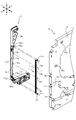
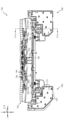
次いで、遊技盤13及び動作ユニット300の構造について説明する。図5は、遊技盤13及び動作ユニット300の分解正面斜視図であり、図6は、遊技盤13及び動作ユニット300の分解背面斜視図である。なお、図5及び図6の説明においては、図2を適宜参照する。また、図6では、第3図柄表示装置81の図示が省略されている。 Next, the structure of the game board 13 and the operation unit 300 will be described. 5 is an exploded front perspective view of the game board 13 and the action unit 300, and FIG. 6 is an exploded rear perspective view of the game board 13 and the action unit 300. FIG. Note that FIG. 2 will be referred to as appropriate in the description of FIGS. 5 and 6 . Further, in FIG. 6, illustration of the third pattern display device 81 is omitted.

遊技盤13は、上述のように、正面視略正方形状に切削加工したベース板60に、球案内用の多数の釘(図示せず)や風車(図示せず)の他、レール61,62、一般入賞口63、第1入賞口64、第2入賞口140、スルーゲート67、可変入賞装置65、可変表示装置ユニット80、左右一対の窓部可動ユニット150、遊技領域から排出された球が流下可能に構成される球流下ユニット290等を組み付けて構成され、その周縁部が内枠12(図1参照)の裏面側に取り付けられる。 As described above, the game board 13 has a base plate 60 cut into a substantially square shape as viewed from the front, and a large number of nails (not shown) for guiding balls, a pinwheel (not shown), and rails 61 and 62. , general winning port 63, first winning port 64, second winning port 140, through gate 67, variable winning device 65, variable display device unit 80, pair of left and right window movable units 150, balls ejected from the game area It is constructed by assembling a spherical flow down unit 290 and the like configured to be able to flow down, and its peripheral portion is attached to the back side of the inner frame 12 (see FIG. 1).

ベース板60は、上述のように、ベニヤ板を重ね合わせた合板から形成されており、その正面側からベース板60の背面側に配設された各種構造体を遊技者に視認させないようにベース板60で遮蔽可能に形成される。 As described above, the base plate 60 is formed of plywood in which plywood is laminated, and the base plate 60 is mounted so as not to allow the player to visually recognize various structures arranged on the back side of the base plate 60 from the front side thereof. Shieldable at 60 .

図6に示すように、ベース板60は、略中央位置において可変表示装置ユニット80を配設可能に穿設される貫通孔の他に、スルーゲート67に接続される電気配線を通すために穿設される複数(本実施形態では2個)の小貫通孔60aと、動作ユニット300の前端部と凹凸嵌合可能に凹設される複数(本実施形態では3個)の嵌合凹部60bと、左右下部において前後方向に穿設される複数(本実施形態では2個)の光透過孔60cとを備える。 As shown in FIG. 6, the base plate 60 has a through hole drilled at a substantially central position so that the variable display device unit 80 can be arranged, and a through hole for passing electrical wiring connected to the through gate 67 . A plurality of (two in this embodiment) small through-holes 60a provided, and a plurality of (three in this embodiment) fitting recesses 60b recessed so as to be fitted to the front end portion of the operation unit 300. , and a plurality of (two in this embodiment) light transmitting holes 60c formed in the front-rear direction in the left and right lower portions.

光透過孔60cは、動作ユニット300側から照射された光が通過可能な位置に形成されており、発光演出の観点から、遊技盤13の演出効果の向上を図っている。このことについて詳しく説明する。 The light transmission hole 60c is formed at a position through which light emitted from the operation unit 300 side can pass, thereby improving the effect of the game board 13 from the viewpoint of light emission effect. This will be explained in detail.

光通過孔60cの正面側には、光透過性の樹脂材料から形成される流下面構成部材91,92が配設されており、その流下面構成部材91,92の外側部94が光通過孔60cを覆設する態様で、流下面構成部材91,92はベース板60に締結固定される。 On the front side of the light passage hole 60c, flow-down surface forming members 91 and 92 formed of a light-transmitting resin material are arranged, and the outer portions 94 of the flow-down surface forming members 91 and 92 are the light passage holes. The downstream surface forming members 91 and 92 are fastened and fixed to the base plate 60 so as to cover the base plate 60c.

左右の流下面構成部材91,92は、右側の流下面構成部材92の正面側に覆設板FBが配設されることを除き、略左右対称形状で構成されるので、左側の流下面構成部材91について詳しく説明し、右側の流下面構成部材92の説明は省略する。 The left and right flow-down surface forming members 91 and 92 are configured in a substantially symmetrical shape except that the covering plate FB is arranged on the front side of the right-side flow-down surface forming member 92, so that the left-side flow-down surface configuration The member 91 will be described in detail, and the description of the right flowing surface forming member 92 will be omitted.

図5に示すように、流下面構成部材91は、ベース板60の正面に沿って配設される板状部が、内レール61と同等の幅の帯状に形成される帯状部93により遊技領域が区画されるように構成されており、帯状部93と、その帯状部93により区画される遊技領域の外側部分(正面視外側部分)である外側部94と、帯状部93により区画される遊技領域の内側部分(正面視内側部分)である内側部95とを備える。 As shown in FIG. 5 , the flow-down surface forming member 91 has a plate-like portion arranged along the front surface of the base plate 60 , which is formed into a band-like portion 93 having a width equal to that of the inner rail 61 . is configured to be partitioned, and the belt-shaped portion 93, the outer portion 94 that is the outer portion (front view outer portion) of the game area partitioned by the belt-shaped portion 93, and the game partitioned by the belt-shaped portion 93 and an inner portion 95 that is the inner portion of the region (the inner portion when viewed from the front).

外側部94は、上述のように、遊技領域の外側なので、球の流下に影響を与え難い部分として構成される。従って、外板部94が変位することに伴う球への影響を考慮する必要が無いので、外側部94の肉厚を薄く設計することができる。 As described above, the outer portion 94 is located outside the playing area, and is configured as a portion that does not easily affect the flow of the ball. Therefore, since there is no need to consider the effect on the ball due to the displacement of the outer plate portion 94, the thickness of the outer portion 94 can be designed to be thin.

また、外側部94を薄く設計した結果、内側部95の肉厚が薄くなったとしても、内側部95の背面側にはベース板60の肉部が配設されるので、ベース板60の剛性を利用して内側部95の前後方向の変位(厚み方向の変形)を抑制することができる。更に、外側部94及び内側部95の肉厚を薄く設計することにより、遊技領域の前後幅を十分に確保することができる。 As a result of designing the outer portion 94 to be thin, even if the thickness of the inner portion 95 is reduced, the thickness of the base plate 60 is disposed on the rear side of the inner portion 95, so the rigidity of the base plate 60 is maintained. can be used to suppress displacement of the inner portion 95 in the front-rear direction (deformation in the thickness direction). Furthermore, by designing the thickness of the outer portion 94 and the inner portion 95 to be thin, it is possible to sufficiently secure the front-to-rear width of the game area.

このように、内側部95に要求される機能を損なわずに、外側部94の肉厚を薄く設計することができ、その結果として、動作ユニット300側から照射され光透過孔60cを通る光を、外側部94を介して遊技者に視認させ易くすることができる。 In this manner, the thickness of the outer portion 94 can be designed to be thin without impairing the functions required of the inner portion 95. As a result, the light emitted from the operation unit 300 and passing through the light transmission hole 60c can be transmitted. , the outer portion 94 can be easily viewed by the player.

本実施形態では、ベース板60が木製の板部材から形成されるので、背面側から照射された光をベース板60の肉厚を介して遊技者に視認させることは困難である。一方で、本実施形態のように光透過孔60c(図6参照)を形成し、その背面側に発光手段を配置することで、ベース板60を木製の板部材で構成しながら、ベース板60を介して視認される明るさを容易に変化させることができる。 In this embodiment, since the base plate 60 is made of a wooden plate member, it is difficult for the player to visually recognize the light emitted from the rear side through the thickness of the base plate 60 . On the other hand, by forming the light transmission hole 60c (see FIG. 6) and arranging the light emitting means on the back side thereof as in the present embodiment, the base plate 60 can be configured with a wooden plate member. The brightness visually recognized through can be easily changed.

例えば、外側部94と、その他の部分とに正面視で連続的に繋がるように視認される装飾模様を形成する場合に、外側部94の背面側に配置される電飾基板777に配設される発光手段778の発光態様を複数種類で変化させ外側部94の明るさを変化させることで、同じ装飾模様であっても、その見え方を複数種類に変化させることができる。 For example, in the case of forming a decorative pattern that is visually recognized as being continuously connected to the outer portion 94 and other portions when viewed from the front, By changing the brightness of the outer portion 94 by changing the light emitting mode of the light emitting means 778 in a plurality of types, it is possible to change the appearance of the same decorative pattern in a plurality of types.

また、例えば、発光手段778の発光態様により視認可能な模様を変化させる装飾部材を外側部94に貼り付けるようにしても良い。この場合、発光手段778の発光態様により遊技盤13の見栄え(イメージ)を大きく変化させることができる。 Further, for example, a decorative member that changes the visible pattern according to the light emitting mode of the light emitting means 778 may be attached to the outer portion 94 . In this case, the appearance (image) of the game board 13 can be greatly changed by the light emission mode of the light emission means 778 .

なお、発光態様により視認可能な模様を変化させる装飾部材の態様は、何ら限定されるものでは無い。例えば、イルミネーションプレートに代表されるような、光を当てる角度により異なる模様を視認可能に設計される部材でも良い。また、例えば、複数色で模様が描かれており、照射される光の色も複数色用意されている前提で、発光色を変えることで視認される模様を変化させるよう設計される部材でも良い。 The mode of the decorative member that changes the visible pattern depending on the light emission mode is not limited at all. For example, it may be a member that is designed so that different patterns can be visually recognized depending on the angle at which light is applied, as typified by an illumination plate. Also, for example, on the premise that a pattern is drawn in multiple colors and multiple colors of light to be irradiated are prepared, a member designed to change the visually recognized pattern by changing the luminescent color may be used. .

内側部95は、上述のように、遊技領域の内側に配設されている。内側部95が変位(変形)すると、遊技領域を流下する球に影響を与える虞があるが、本実施形態では、内側部95の背面側にペース板60の肉部が配置されるように構成されているので(光透過孔60cが正面視で帯状部93に対して外側部94側に収まるように構成されているので)、ベース板60の剛性を利用して、内側部95の変位(変形)を防止することができる。これにより、球の流下を安定させることができる。 The inner part 95 is arranged inside the game area as described above. If the inner portion 95 is displaced (deformed), it may affect the ball flowing down the game area. (because the light transmission hole 60c is configured to be accommodated on the outer side portion 94 side with respect to the strip portion 93 in a front view), the rigidity of the base plate 60 is used to displace the inner portion 95 ( deformation) can be prevented. As a result, the downflow of the ball can be stabilized.

内側部95には一般入賞口63が配設されており、その一般入賞口63はルータ加工によってベース板60に形成された貫通穴に配設され、流下面構成部材91が遊技盤13の正面側からタッピングネジ等により固定されることにより固定されている。 A general prize winning port 63 is arranged in the inner portion 95 , the general prize winning port 63 is arranged in a through hole formed in the base plate 60 by router processing, and the flow-down surface forming member 91 is the front surface of the game board 13 . It is fixed by fixing with a tapping screw or the like from the side.

遊技盤13の正面中央部分は、正面枠14の窓部14c(図1参照)を通じて内枠12の正面側から視認することができる。以下に、主に図2を参照して、遊技盤13の構成について説明する。 The front central portion of the game board 13 can be viewed from the front side of the inner frame 12 through the window portion 14c (see FIG. 1) of the front frame 14. As shown in FIG. Mainly referring to FIG. 2, the configuration of the game board 13 will be described below.

上述のように、可変表示装置ユニット80には、第3図柄表示装置81の外周を囲むようにして、センターフレーム86が配設されており、そのセンターフレーム86の左右上隅部に窓部可動ユニット150が配設されている。 As described above, the variable display device unit 80 is provided with the center frame 86 so as to surround the outer periphery of the third pattern display device 81, and the window portion movable unit 150 is placed at the left and right upper corners of the center frame 86. are arranged.

図7は、遊技盤13の分解背面斜視図である。なお、図7では、遊技盤13の下部の図示が省略され、補助装置160が分解され正面斜視で図示される。 7 is an exploded rear perspective view of the game board 13. FIG. In FIG. 7, illustration of the lower part of the game board 13 is omitted, and the auxiliary device 160 is disassembled and illustrated in perspective from the front.

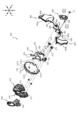
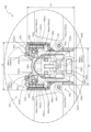
窓部可動ユニット150は、回転変位可能とされ、センターフレーム86の内側の窓部において遊技者が視認可能に構成される変位部材151と、その変位部材151の背面側に配設され、変位部材151を駆動させる駆動力を発生させたり、変位部材151へ向けて光を照射したりする補助装置160とを備える。 The window portion movable unit 150 is rotatably displaceable, and includes a displacement member 151 configured to be visible to the player in the window portion inside the center frame 86, and a displacement member 151 disposed on the back side of the displacement member 151. and an auxiliary device 160 that generates driving force for driving the displacement member 151 and irradiates the displacement member 151 with light.

変位部材151は、前後方向視二股形状に形成され、折れ曲がり部分付近に構成される基端部において軸支される二股部152と、その二股部152の両先端部に配設され背面側が開放される箱状(袋状、コップ状)に形成される先端部153と、二股部152の基端部から径方向へ張り出す張出部154とを備える。 The displacement member 151 is formed in a bifurcated shape when viewed in the front-rear direction, and includes a bifurcated portion 152 that is pivotally supported at a base end configured near the bent portion, and a bifurcated portion 152 that is disposed at both ends of the bifurcated portion 152 and has an open back side. and a protruding portion 154 protruding radially from the base end portion of the bifurcated portion 152 .

先端部153は、底側を正面側へ向けた箱状(袋状、コップ状)に形成され遊技者が視認可能に配設される演出部153aと、その演出部153aの開放部側に締結固定されるリング状部であって、演出部153a側に比較して演出部153aの逆側の方がすぼまる形状とされるリング状部153bとを備える。 The tip part 153 is formed in a box shape (bag shape, cup shape) with the bottom side facing the front side, and is fastened to an effect part 153a arranged so as to be visible to the player, and to the open part side of the effect part 153a. A ring-shaped portion 153b which is a fixed ring-shaped portion and has a shape in which the opposite side of the performance portion 153a narrows compared to the side of the performance portion 153a is provided.

演出部153aは、内側面に光拡散形状(ギザギザ形状)が形成されており、背面側から開放部の内側に照射される光を拡散させることができるので、実際に照射される光は狭い範囲に照射されるものであっても、正面側から演出部153aを視認する遊技者に対して演出部153aの全体が(淡く)光っているように視認させることができる。 The effect part 153a has a light diffusion shape (notched shape) formed on the inner surface, and can diffuse the light irradiated from the back side to the inside of the open part, so that the light actually irradiated is a narrow range. Even if the illumination is directed to the front side, the player viewing the effect portion 153a from the front side can visually recognize the effect portion 153a as a whole as if it were shining (faintly).

張出部154は、センターフレーム86側から突設される一対の爪部86aにより回転方向双方向で変位可能範囲を規定されている。即ち、変位部材151は、爪部86aの配置と、張出部154との関係で規定される角度(360度未満の角度)において回転変位可能に構成される。 The protruding portion 154 defines a displaceable range in both directions in the rotational direction by a pair of claw portions 86a projecting from the center frame 86 side. That is, the displacement member 151 is configured to be rotationally displaceable at an angle (less than 360 degrees) defined by the relationship between the arrangement of the claw portion 86a and the projecting portion 154. As shown in FIG.

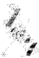
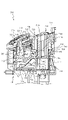
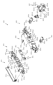
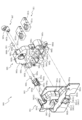
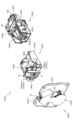
図8は、補助装置160の分解正面斜視図であり、図9は、補助装置160の分解背面斜視図である。補助装置160は、変位部材151(図7参照)と当接可能な位置に配置される当接部材161と、その当接部材161に一端(正面側端)が相対回転不能に連結される金属製(本実施形態では、真鍮製)の伝達軸棒部162と、その伝達軸棒部162の他端(背面側端)に相対回転不能に連結される被駆動部材163と、伝達軸棒部162の両端に径方向から嵌め込まれる公知のEリング164と、伝達軸棒部162を軸支可能に構成され、全体がケース状に構成される支持ケース170と、その支持ケース170の内部に配設される電飾基板180とを備えている。 8 is an exploded front perspective view of the auxiliary device 160, and FIG. 9 is an exploded rear perspective view of the auxiliary device 160. FIG. The auxiliary device 160 includes a contact member 161 arranged at a position capable of contacting the displacement member 151 (see FIG. 7), and a metal member having one end (front side end) connected to the contact member 161 so as not to rotate relative to each other. A transmission shaft rod portion 162 made of brass (in this embodiment, made of brass), a driven member 163 connected to the other end (back side end) of the transmission shaft rod portion 162 so as not to rotate relatively, and a transmission shaft rod portion A well-known E-ring 164 that is radially fitted to both ends of the transmission shaft 162, a support case 170 that is configured to support the transmission shaft portion 162 and has a case shape as a whole, and a support case 170 that is arranged inside the support case 170. It is provided with an electric decoration board 180 provided.

伝達軸棒部162は、中腹部の軸方向(前後方向)視の外形が真円形状である円柱状の部材であって、両側先端において所定の径方向から面状に削られることで、両側先端が断面略D字形状とされている。この両側端部が、当接部材161の被挿通孔161bや、被駆動部材163の被挿通孔163bと嵌合することで、当接部材161、伝達軸棒部162及び被駆動部材163が相対回転不能(一体的)に連結される。 The transmission shaft rod portion 162 is a cylindrical member having a perfect circular external shape when viewed in the axial direction (front-rear direction) of the midsection. The tip has a substantially D-shaped cross section. By fitting the both side end portions into the insertion hole 161b of the contact member 161 and the insertion hole 163b of the driven member 163, the contact member 161, the transmission shaft rod portion 162, and the driven member 163 are connected to each other. Non-rotatably (integrally) connected.

当接部材161は、樹脂材料から形成されており、伝達軸棒部162が挿通される貫通孔であって断面D字形状に構成される被挿通孔161bが穿設される基端部161aと、その基端部161aの外方へ向けて延設され、正面視略コの字状に構成される腕部161cとを備える。 The abutment member 161 is made of a resin material, and has a base end portion 161a in which an insertion hole 161b, which is a through hole through which the transmission shaft rod portion 162 is inserted and has a D-shaped cross section, is formed. , and an arm portion 161c extending outward from the base end portion 161a thereof and configured in a substantially U-shape when viewed from the front.

被駆動部材163は、樹脂材料から形成されており、伝達軸棒部162が挿通される貫通孔であって断面D字形状に構成される被挿通孔163bが穿設される基端部163aと、その基端部161aの外方へ向けて真っすぐに延設され、略平板状に構成される腕部163cとを備える。 The driven member 163 is formed of a resin material, and has a base end portion 163a and a base end portion 163a in which a through hole 163b, which is a through hole through which the transmission shaft rod portion 162 is inserted and has a D-shaped cross section, is bored. , and an arm portion 163c extending straight outward from the base end portion 161a thereof and having a substantially flat plate shape.

被駆動部材163の上面には、金属製(磁性体)の金属板部材MB1が配設される。本実施形態では、金属板部材MB1は、弾性爪163dとの係合により被駆動部材163に固定される。 A metal plate member MB<b>1 made of metal (magnetic material) is arranged on the upper surface of the driven member 163 . In this embodiment, the metal plate member MB1 is fixed to the driven member 163 by engaging with the elastic claws 163d.

詳述すると、腕部163cの径方向両端部において金属板部材MB1の前後スライドを案内するレール部が配設されており、このレール部は、金属板部材MB1を正面側からのみ案内できるように形成されている(正面側のみ十分に開放されている)。レール部に沿って金属板部材MB1をスライドさせる際には弾性爪163dが金属板部材MB1により押し下げられており、そのまま金属板部材MB1をスライドさせると、レール部の背面側壁に金属板部材MB1が当たることでスライドが規制され、当該位置においては金属板部材MB1による弾性爪163dの押し下げは解除されており(金属板部材MB1の側面と対向する位置まで上昇しており)、弾性爪163dが金属板部材MB1の正面側への退避を規制するように係合する。 More specifically, rail portions for guiding the front-to-rear sliding of the metal plate member MB1 are provided at both ends of the arm portion 163c in the radial direction. formed (only the front side is fully open). When the metal plate member MB1 is slid along the rail portion, the elastic claw 163d is pushed down by the metal plate member MB1. At this position, the elastic claw 163d is released from being pushed down by the metal plate member MB1 (the elastic claw 163d is raised to a position facing the side surface of the metal plate member MB1). It engages so as to restrict retraction of the plate member MB1 to the front side.

なお、金属板部材MB1の被駆動部材163への固定方法はこれに限られるものではない。例えば、金属板部材MB1を被駆動部材163に締結固定するものでも良いし、結束バンドでしばりつけても良いし、粘着性のテープ等で貼り付けても良い。 The method of fixing the metal plate member MB1 to the driven member 163 is not limited to this. For example, the metal plate member MB1 may be fastened and fixed to the driven member 163, bound with a binding band, or attached with an adhesive tape or the like.

支持ケース170は、後部材170Bと、その後部材170Bの正面側に配設され伝達軸棒部162が挿通される支持孔174が形成される中部材170Mと、その中部材170Mの正面側に配設され正面側に装飾形状(波模様)が形成される前部材170Fとを備え、これら複数(本実施形態では3個)の板状部材が前後に積層され締結固定されている。 The support case 170 consists of a rear member 170B, a middle member 170M provided on the front side of the rear member 170B and formed with a support hole 174 through which the transmission shaft rod portion 162 is inserted, and a front side of the middle member 170M. A front member 170F having a decorative shape (wavy pattern) formed on the front side is provided, and a plurality of (three in this embodiment) plate-shaped members are stacked in front and behind and fastened and fixed.

電飾基板180は、前部材170Fの形状に合わせて正面視略L字の板形状に形成されており、演出を考慮して設計された位置に配設される複数のLED等から構成される発光手段181と、電気配線が接続される部分として配設されるコネクタ182と、組み付け用に電飾基板180に穿設される複数の貫通孔183とを備える。 The illumination board 180 is formed in a substantially L-shaped plate shape when viewed from the front in accordance with the shape of the front member 170F, and is composed of a plurality of LEDs and the like arranged at positions designed in consideration of presentation. It comprises a light emitting means 181, a connector 182 arranged as a portion to which electrical wiring is connected, and a plurality of through holes 183 drilled in the electrical board 180 for assembly.

発光手段181は、正面視で光透過孔177の内側に配置される強発光手段181aと、光透過孔177の外側に配置される(前部材170Fの板背面と対向配置される)弱発光手段181bとを備える。 The light-emitting means 181 includes a strong light-emitting means 181a arranged inside the light transmission hole 177 in a front view, and a weak light-emitting means arranged outside the light transmission hole 177 (arranged so as to face the rear surface of the front member 170F). 181b.

貫通孔183は、傾斜する方向に沿って長い長円形状で形成されている。これにより、正面視で外形が真円形状で形成される突設円柱部172に対する貫通孔183の組み付けを容易とすることができる。 The through-hole 183 is formed in an elongated oval shape along the direction of inclination. This makes it easy to assemble the through hole 183 to the projecting cylindrical portion 172 which has a perfect circular outer shape when viewed from the front.

即ち、電飾基板180の姿勢が傾斜する一方で(図10参照)、突設円柱部172の突設方向は傾斜していない(前後方向である)ので、同一方向で組み付ける場合に比較して組み付け不良(組み付けられなかったり、緩くなったり)が生じ易くなるが、本実施形態では、貫通孔183が電飾基板180の姿勢が傾斜する方向に沿って長い長円形状で形成されるので、傾斜する方向に沿う貫通孔183の余裕代を大きめにとることができ、突設円柱部172に対する貫通孔183の組み付けを容易とすることができる。 That is, while the electrical board 180 is tilted (see FIG. 10), the projecting direction of the projecting cylindrical portion 172 is not tilted (in the front-rear direction). In this embodiment, the through hole 183 is formed in an elongated oval shape along the direction in which the electrical board 180 is tilted. A large margin for the through-hole 183 along the direction of inclination can be secured, and the through-hole 183 can be easily attached to the projecting cylindrical portion 172 .

電飾基板180は、前部材170Fと中部材170Mとの間に収容されるが、この際、電飾基板180は板正面が斜め下方を向く(法線が正面側下方へ傾斜する)姿勢とされる。このことについて、図10を参照して詳述する。 The electrical board 180 is accommodated between the front member 170F and the middle member 170M. be done. This will be described in detail with reference to FIG.

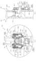
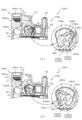
図10は、図2のX-X線における窓部可動ユニット150の断面図である。なお、理解を容易とするために、後部材170Bの図示が省略され、変位部材151の外形が想像線で図示される。なお、X-X線は、上側の突設円柱部172の中心を通るよう配置される。なお、以下の説明では、図8及び図9を適宜参照する。 FIG. 10 is a cross-sectional view of the window movable unit 150 taken along line XX in FIG. In order to facilitate understanding, the illustration of the rear member 170B is omitted, and the outer shape of the displacement member 151 is illustrated by imaginary lines. The line XX is arranged so as to pass through the center of the projecting cylindrical portion 172 on the upper side. 8 and 9 will be referred to as necessary in the following description.

中部材170Mは、その正面側の壁状部の態様が、上側壁状部170MUと、下側壁状部170MDとで異なる。即ち、上側壁状部170MUは、非傾斜(法線が水平方向を向く)の壁状部として構成され、下側壁状部170MDは、傾斜する(法線が正面側下方へ向く)壁状部として構成される。 The middle member 170M has different wall-shaped portions on the front side between the upper wall-shaped portion 170MU and the lower wall-shaped portion 170MD. That is, the upper wall-shaped portion 170MU is configured as a wall-shaped portion that is non-inclined (with its normal directed horizontally), and the lower wall-shaped portion 170MD is configured as a wall-shaped portion that is inclined (with its normal directed downward to the front side). configured as

このように法線の異なる壁状部に対し、電飾基板180は、板背面が下側壁状部170MDに沿う姿勢(法線が正面側下方へ傾斜する姿勢)となるように支持される。即ち、組立状態(図2参照)において、電飾基板180の発光手段181から照射される光の光軸の方向は、正面側下方へ傾斜する。 In this manner, the electrical board 180 is supported so that the back surface of the decorative board 180 is aligned with the lower wall portion 170MD (the normal line is inclined downward toward the front side). That is, in the assembled state (see FIG. 2), the direction of the optical axis of the light emitted from the light emitting means 181 of the electrical board 180 is inclined downward on the front side.

中部材170Mは、正面側へ向けて枠状に突設される突設枠部171と、その突設枠部の内側において正面側へ細径円柱状に突設される複数の突設円柱部172と、左右外側(左側)隅部においてコネクタ182を囲う配置で前後方向に穿設される配線通し孔173とを備える。 The intermediate member 170M includes a projecting frame portion 171 projecting toward the front side in a frame shape, and a plurality of projecting cylindrical portions projecting toward the front side in the form of small-diameter cylinders inside the projecting frame portion. 172, and wire through holes 173 drilled in the front-rear direction so as to surround the connector 182 at the right and left outer (left) corners.

突設枠部171は、前部材170Fの外枠部と前後で当接することで、電飾基板180の周囲に亘って封をする。これにより、電飾基板180が、前部材170Fと中部材170Mとの間から視認されることを回避することができると共に、同様の位置から光漏れが生じることを防止することができる。 The protruding frame portion 171 abuts on the outer frame portion of the front member 170</b>F in the front and rear, thereby sealing the periphery of the electrical board 180 . As a result, the electrical board 180 can be prevented from being seen from between the front member 170F and the middle member 170M, and light leakage from the same position can be prevented.

突設円柱部172は、大径の座部と、その座部から更に突設される小径の挿通部とを備えており、電飾基板180の貫通孔183に挿通部が入るように組み付けることで電飾基板180の板背面が座部に支えられ、電飾基板180の配置を安定させることができる。 The projecting cylindrical portion 172 has a large-diameter seat portion and a small-diameter insertion portion that further protrudes from the seat portion, and is assembled so that the insertion portion enters the through-hole 183 of the electrical board 180. The back surface of the electrical board 180 is supported by the seat portion, and the arrangement of the electrical board 180 can be stabilized.

ここで、下側壁状部170MDに配設される突設円柱部172の座部に比べ、上側壁状部170MUに配設される突設円柱部172の座部が高くなっている。これにより、上述の傾斜姿勢で組み付けられる電飾基板180を安定して支持することができると共に、上側壁状部170MUと電飾基板180との間に空隙を確保することができる。 Here, the seat portion of the projecting cylindrical portion 172 provided on the upper wall portion 170MU is higher than the seat portion of the projecting cylindrical portion 172 provided on the lower wall portion 170MD. As a result, it is possible to stably support the electrical board 180 that is assembled in the above-described inclined posture, and to ensure a space between the upper wall-shaped portion 170MU and the electrical board 180 .

突設円柱部172の座部の突設先端は、電飾基板180の姿勢に合わせた傾斜面(下方へ向かう程に突設長さが短くなるよう構成される傾斜面)として形成されている。これにより、突設円柱部172に、電飾基板180の配置を安定させる機能のみならず、電飾基板180の姿勢を安定させる機能を付与することができる。 The protruding end of the seat portion of the protruding cylindrical portion 172 is formed as an inclined surface (an inclined surface configured so that the protruding length becomes shorter toward the lower side) matching the posture of the electrical board 180 . . Thus, the protruding cylindrical portion 172 can be provided with a function of stabilizing the position of the electrical board 180 as well as the function of stabilizing the arrangement of the electrical board 180 .

配線通し孔173は、電飾基板180のコネクタ182に接続される電気配線を通すための貫通孔である。この電気配線を介して電飾基板180にかけられる負荷により電飾基板180の姿勢維持を図ることができるので、電飾基板180を締結固定することなく、電飾基板180の姿勢を安定的に支持することができる。 The wiring through hole 173 is a through hole for passing the electric wiring connected to the connector 182 of the electrical board 180 . Since the posture of the electrical board 180 can be maintained by the load applied to the electrical board 180 via the electric wiring, the posture of the electrical board 180 can be stably supported without fastening and fixing the electrical board 180. can do.

前部材170Fは、有色(本実施形態では白色)で光透過性の樹脂材料から背側面が下側壁状部170MDと略平行な面となる形状で形成され、前後方向で円形に穿設される複数の光透過孔177と、背面側へ向けて細径円柱状に突設される複数の突設円柱部178と、板背面と外周を形成する枠部との間を連結する左右方向視L字形状のL字形支持部179とを備える。 The front member 170F is made of a colored (white in this embodiment) light-transmitting resin material so that the back surface thereof is substantially parallel to the lower wall-shaped portion 170MD, and is perforated in a circular shape in the front-rear direction. Left-right view L connecting between a plurality of light transmission holes 177, a plurality of projecting cylindrical portions 178 projecting toward the back side in a thin cylindrical shape, and a frame portion forming the back surface and the outer periphery of the plate and an L-shaped support 179 in the shape of a letter.

光透過孔177は、発光手段181を構成するいずれかのLEDを正面視で囲むように形成される。これにより、光透過孔177の背面側に配設される発光手段181と、それ以外の発光手段181とでは、前部材170Fの正面側から視認される態様が変化する。即ち、光透過孔177の内側の方が、それ以外の箇所に比較して強発光しているように視認させることができる。 The light transmitting hole 177 is formed so as to surround any one of the LEDs forming the light emitting means 181 when viewed from the front. As a result, the appearance of the light emitting means 181 disposed on the back side of the light transmission hole 177 and the light emitting means 181 other than the light emitting means 181 when viewed from the front side of the front member 170F changes. That is, the inside of the light transmitting hole 177 can be visually recognized as emitting stronger light than the other portions.

突設円柱部178は、複数が略同等の突設長さで形成されている。これにより、前部材170Fの本体板部と電飾基板180との間隔を電飾基板180の配設範囲全体に亘って一様としつつ、傾斜姿勢の電飾基板180を複数位置で面支持することができるので、発光手段181の配置自由度を維持すると共に発光態様のムラを抑えながら、電飾基板180の支持の安定感を向上することができる。 A plurality of projecting cylindrical portions 178 are formed with substantially the same projecting length. As a result, while the interval between the main body plate portion of the front member 170F and the electrical board 180 is uniform over the entire arrangement range of the electrical board 180, the electrical board 180 in an inclined posture is surface-supported at a plurality of positions. Therefore, it is possible to improve the sense of stability in supporting the electrical board 180 while maintaining the degree of freedom in the arrangement of the light emitting means 181 and suppressing unevenness in the light emission mode.

即ち、電飾基板180は板正面が正面側下方へ向く傾斜姿勢とされるので、その姿勢を維持するためには正面側から下支えすることが好ましいが、一箇所に大面積の支持部を設けて電飾基板180を支持するようにすると、電飾基板180の正面側に配設する発光手段181の配置可能領域が制限され易くなる傾向があった。発光手段181の配置可能領域を優先して支持部の面積を小さくすると、電飾基板180の姿勢が崩れ前部材170Fの本体板部と電飾基板180との間隔が電飾基板180の配設範囲でバラつき易く、発光態様のムラが生じやすくなる虞があった。 That is, since the front surface of the electric board 180 is tilted toward the front side, it is preferable to support it from the front side in order to maintain that position. When the electrical board 180 is supported by the electrical board 180, the area where the light emitting means 181 can be arranged on the front side of the electrical board 180 tends to be limited. If the area of the supporting portion is reduced in favor of the area in which the light emitting means 181 can be arranged, the posture of the electrical board 180 is lost, and the space between the main body plate portion of the front member 170F and the electrical board 180 becomes larger than that of the electrical board 180. There is a possibility that the range tends to fluctuate, resulting in unevenness in the light emission mode.

これに対し、本実施形態では、同様の突設高さで細径の突設円柱部178を複数設け、それらで電飾基板180の板正面を複数点で同時に支持できるように構成していることから、隣接する発光手段181の間に生じる小さな複数の隙間位置に電飾基板180を支持する突設円柱部178を複数配設することができる。これにより、発光手段181の配置自由度を維持すると共に発光態様のムラを抑えながら、電飾基板180の支持の安定感を向上することができる。 On the other hand, in the present embodiment, a plurality of projecting columnar portions 178 having a similar projecting height and a small diameter are provided so that the front surface of the electrical board 180 can be simultaneously supported at a plurality of points. Therefore, a plurality of projecting cylindrical portions 178 for supporting the electrical board 180 can be arranged at a plurality of small gaps between adjacent light emitting means 181 . As a result, it is possible to improve the stability of supporting the electrical board 180 while maintaining the degree of freedom in the arrangement of the light emitting means 181 and suppressing unevenness in the light emission mode.

L字形支持部179は、組立状態において、電飾基板180の上面および正面と対向配置し、電飾基板180の変位を抑制するよう機能する。即ち、電飾基板180が自重で前倒れするのを、電飾基板180の板正面と対向配置するL字形支持部179の下部が下支えして防止している。 The L-shaped support portion 179 faces the upper surface and the front surface of the electrical board 180 in the assembled state, and functions to suppress the displacement of the electrical board 180 . In other words, the lower portion of the L-shaped support portion 179 arranged opposite to the front surface of the decorative electrical board 180 supports and prevents the electrical board 180 from falling forward due to its own weight.

また、電飾基板180の板上面と対向配置するL字形支持部179の後部と電飾基板180とは、通常では隙間を空けて配置されることで、電飾基板180を緩く支持しながら、電飾基板180の上下方向の変位を最小限に抑制することができる。 In addition, the rear portion of the L-shaped support portion 179 facing the plate upper surface of the electrical board 180 and the electrical board 180 are normally arranged with a gap therebetween, so that the electrical board 180 is loosely supported. The vertical displacement of the electrical board 180 can be minimized.

なお、L字形支持部179と同形状の支持部が、中部材170Mの下側壁状部170MDの正面側にも形成されており(左右2位置に形成されており)、電飾基板180の下面および背面と対向配置し、電飾基板180の変位を抑制するよう機能する。即ち、本実施形態では、電飾基板180の上下に配置されるL字形支持部によって、電飾基板180の前後方向および上下方向への変位を抑制可能に構成している。 In addition, support portions having the same shape as the L-shaped support portion 179 are also formed on the front side of the lower wall portion 170MD of the intermediate member 170M (formed at two positions on the left and right). and the rear face, and functions to suppress the displacement of the electrical board 180 . That is, in this embodiment, the L-shaped support portions arranged above and below the electrical board 180 are configured to be capable of suppressing displacement of the electrical board 180 in the front-rear direction and the vertical direction.

このように、本実施形態では、電飾基板180は直接的には締結固定されておらず、前部材170Fと中部材170Mとに前後から挟まれ支持されることで、安定的に支持されている。これは、例えば、中部材170Mと電飾基板180とを締結固定し、単一の剛体として構成すると、中部材170Mに生じる振動の影響を受けて電飾基板180が振動する可能性があるので、それを考慮しての対策である。 Thus, in the present embodiment, the electrical board 180 is not directly fastened and fixed, but is stably supported by being sandwiched between the front member 170F and the middle member 170M from the front and rear. there is This is because, for example, if the middle member 170M and the electric board 180 are fastened and fixed to form a single rigid body, the electric board 180 may vibrate under the influence of the vibration generated in the middle member 170M. , is a countermeasure in consideration of it.

即ち、本実施形態によれば、電飾基板180が中部材170Mにも前部材170Fにも締結固定されていないので、中部材170Mや前部材170Fに振動が生じた場合であっても、それと独立して電飾基板180の配置を維持し易くすることができる。 That is, according to this embodiment, the electrical board 180 is not fastened and fixed to either the middle member 170M or the front member 170F, so even if the middle member 170M or the front member 170F vibrates, it will It is possible to make it easier to independently maintain the arrangement of the electrical board 180 .

ここで、中部材170Mの振動の原因になり易いのは、中部材170Mの背面側に配設される電磁ソレノイドSOL1であると考えられるが、本実施形態では、電磁ソレノイドSOL1は、上側壁状部170MUの正面側に生じる隙間を挟んで電飾基板180の反対側(背面側)に配設される。 Here, it is considered that the electromagnetic solenoid SOL1 disposed on the back side of the intermediate member 170M is likely to cause vibration of the intermediate member 170M. It is arranged on the opposite side (rear side) of the electrical board 180 across a gap generated on the front side of the part 170MU.

この構成により、電磁ソレノイドSOL1の振動は細径の突設円柱部172を介して電飾基板180に伝達されることになるので、振動ソレノイドSOL1の振動を突設円柱部172の変形で緩和することができ、電飾基板180に振動が伝達されることを抑制することができる。従って、振動源としての電磁ソレノイドSOL1から電飾基板180へ直接的に振動が伝達されることを回避することができる。 With this configuration, the vibration of the electromagnetic solenoid SOL1 is transmitted to the electrical board 180 via the small-diameter protruding cylindrical portion 172, so that the deformation of the protruding cylindrical portion 172 mitigates the vibration of the vibration solenoid SOL1. It is possible to suppress the transmission of vibration to the electrical board 180 . Therefore, it is possible to avoid direct transmission of vibration from the electromagnetic solenoid SOL1 as a vibration source to the electrical board 180. FIG.

中部材170Mは、伝達軸棒部162の直径よりも若干長い直径で前後方向に穿設され伝達軸棒部162を回転可能に支持可能に構成される支持孔174と、電磁ソレノイドSOL1の下方に配設される下側規制部175と、電磁ソレノイドSOL1に対して支持孔174の反対側に配設される上側規制部176とを備える。 The middle member 170M has a support hole 174 formed in the front-rear direction with a diameter slightly longer than the diameter of the transmission shaft rod portion 162 and configured to rotatably support the transmission shaft rod portion 162, and below the electromagnetic solenoid SOL1. It has a lower regulating portion 175 arranged and an upper regulating portion 176 arranged on the side opposite to the support hole 174 with respect to the electromagnetic solenoid SOL1.

被駆動部材163は通常、自重で傾倒している(図11(a)参照)が、電磁ソレノイドSOL1に電気が供給されることで磁力(電磁力)が発生し、その磁力(電磁力)により金属板部材MB1が吸着され上昇変位する。即ち、本実施形態では、金属板部材MB1が電磁力で上昇した結果配置される上昇位置と、電磁力が消失し自重で下降した結果配置される下降位置との間で変位することに伴って当接部材161及び被駆動部材163が回転変位する。以下、図11及び図12を参照して、その回転変位について説明する。 The driven member 163 is normally tilted by its own weight (see FIG. 11(a)), but when electricity is supplied to the electromagnetic solenoid SOL1, a magnetic force (electromagnetic force) is generated. The metal plate member MB1 is attracted and displaced upward. That is, in the present embodiment, the metal plate member MB1 is displaced between the raised position where the metal plate member MB1 is raised by the electromagnetic force and the lowered position where the electromagnetic force disappears and the metal plate member MB1 is lowered by its own weight. The contact member 161 and the driven member 163 are rotationally displaced. The rotational displacement will be described below with reference to FIGS. 11 and 12. FIG.

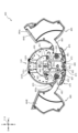
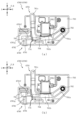
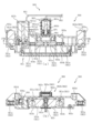
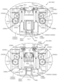
図11(a)は、窓部可動ユニット150の背面図であり、図11(b)は、窓部可動ユニット150の正面図である。また、図12(a)は、窓部可動ユニット150の背面図であり、図12(b)は、窓部可動ユニット150の正面図である。 11(a) is a rear view of the window movable unit 150, and FIG. 11(b) is a front view of the window movable unit 150. FIG. 12(a) is a rear view of the window movable unit 150, and FIG. 12(b) is a front view of the window movable unit 150. FIG.

なお、図11(a)及び図11(b)では、電磁ソレノイドSOL1に電気が供給されておらず被駆動部材163が自重で傾倒している状態(下降位置の状態)が図示され、図12(a)及び図12(b)では、電磁ソレノイドSOL1に電気が供給され発生する電磁力により金属板部材MB1及び被駆動部材163が上昇している状態(上昇位置の状態)が図示される。 11(a) and 11(b) show a state in which electricity is not supplied to the electromagnetic solenoid SOL1 and the driven member 163 is tilted by its own weight (state in the lowered position). 12(a) and 12(b) show a state in which the metal plate member MB1 and the driven member 163 are raised by the electromagnetic force generated by supplying electricity to the electromagnetic solenoid SOL1 (up position state).

また、図11(a)及び図12(a)では、理解を容易とするために、後部材170Bの図示が省略され、図11(b)及び図12(b)では、変位部材151の外形と背面側の開放部の形状が想像線で図示される。 In addition, in FIGS. 11(a) and 12(a), illustration of the rear member 170B is omitted in order to facilitate understanding, and in FIGS. and the shape of the opening on the back side are shown by imaginary lines.

図11(a)及び図12(a)に示すように、被駆動部材163は、下降位置においては下側規制部175の上面に貼り付けられるクッション部175aに当接し下降変位を規制され、上昇位置においては上側規制部176の下面に貼り付けられるクッション部176aに当接し上昇変位を規制される。 As shown in FIGS. 11(a) and 12(a), in the lowered position, the driven member 163 abuts against a cushion portion 175a attached to the upper surface of the lower restricting portion 175, thereby restricting the downward displacement. At the position, it abuts against a cushion portion 176a attached to the lower surface of the upper restricting portion 176 and is restricted from upward displacement.

なお、クッション部175a,176aの材質は何ら限定されるものではない。例えば、ポリプロピレン、ポリスチレン等の汎用プラスチックでも良いし、ポリカーボネート等のエンジニアリングプラスチックでも良いし、メラミン樹脂、ポリウレタン、エポキシ樹脂などの熱硬化性樹脂でも良いし、ゴム性材料でも良い。また、クッション部175a,176aの材質を同じで構成しても良いし、異ならせても良い。 The material of the cushion portions 175a and 176a is not limited at all. For example, general-purpose plastics such as polypropylene and polystyrene may be used, engineering plastics such as polycarbonate may be used, thermosetting resins such as melamine resins, polyurethanes and epoxy resins may be used, and rubber materials may be used. Also, the materials of the cushion portions 175a and 176a may be the same or may be different.

ここで、下側規制部175及び上側規制部176は、伝達軸棒部162を基準とした配置(伝達軸棒部162からの距離)が異なるように構成されているが、それにより生じる効果について説明する。 Here, the lower regulating portion 175 and the upper regulating portion 176 are configured so that their positions (distances from the transmission shaft rod portion 162) with respect to the transmission shaft rod portion 162 are different. explain.

まず、下側規制部175に被駆動部材163を介して与えられる負荷は、主に被駆動部材163の自重により生じる負荷であるので、被駆動部材163の重心を支えることで被駆動部材163を安定して支持することができる。この理由から、下側規制部175は、被駆動部材163の重心位置(腕長さの略中央位置)に配設される。 First, since the load applied to the lower regulating portion 175 via the driven member 163 is mainly caused by the weight of the driven member 163, supporting the center of gravity of the driven member 163 reduces the load on the driven member 163. It can be stably supported. For this reason, the lower restricting portion 175 is arranged at the center of gravity of the driven member 163 (approximately at the center of the arm length).

これに対し、上側規制部176に被駆動部材163を介して与えられる負荷は、主に電磁ソレノイドSOL1で生じる磁力(電磁力)による負荷であるので、上規制部材176の配置を被駆動部材163の重心位置に関連させる利点は少ない。本実施形態では、上規制部材176を被駆動部材163の回転先端に対向配置させることで、被駆動部材163を介して上規制部材176へ伝達される負荷を低減している。 On the other hand, the load applied to the upper restricting portion 176 via the driven member 163 is mainly due to the magnetic force (electromagnetic force) generated by the electromagnetic solenoid SOL1. There are few advantages associated with the position of the center of gravity of the . In this embodiment, the load transmitted to the upper regulation member 176 via the driven member 163 is reduced by arranging the upper regulation member 176 to face the rotating tip of the driven member 163 .

即ち、同じ大きさの力のモーメントが発生している場合、被駆動部材163の回転軸から離れた位置(モーメントに係る腕が長い位置)の方が、被駆動部材163を介して伝達される負荷が小さくなるので、上規制部材176へ伝達される負荷を低減することができる。 That is, when a moment of force of the same magnitude is generated, the position farther from the rotation axis of the driven member 163 (the position where the arm related to the moment is longer) is transmitted through the driven member 163 . Since the load becomes smaller, the load transmitted to the upper regulating member 176 can be reduced.

このように、上規制部材176への負荷伝達は、被駆動部材163の回転先端部において生じることが望ましいので、本実施形態では、クッション部176aの幅寸法(径方向幅)が短くされる(クッション部175aの幅寸法よりも短くされる)。これにより、被駆動部材163の中間部で負荷伝達することを回避し、回転先端での負荷伝達を安定的に生じさせることができる。 In this way, it is desirable that the load transmission to the upper regulating member 176 occurs at the rotating tip portion of the driven member 163. Therefore, in the present embodiment, the width dimension (radial width) of the cushion portion 176a is shortened (cushion shorter than the width dimension of the portion 175a). As a result, it is possible to avoid load transmission at the intermediate portion of the driven member 163 and to stably generate load transmission at the tip of rotation.

また、上昇位置では電磁ソレノイドSOL1による磁力(電磁力)が発生し続けるので、クッション部176aに衝突した後で被駆動部材163が跳ね返ることは考えにくい。 Further, since the magnetic force (electromagnetic force) is continuously generated by the electromagnetic solenoid SOL1 at the raised position, it is difficult to imagine that the driven member 163 bounces back after colliding with the cushion portion 176a.

一方、下側規制部175のクッション部175aの幅寸法(径方向幅)を長く(クッション部176aの幅寸法よりも長く)することで、負荷を受ける面の面積を広くすることができ、被駆動部材163の自重による負荷によりクッション部175aに生じる圧力(応力)を低減することができる。これにより、クッション部175aに衝突した後の被駆動部材163の跳ね返り(バウンド)を抑制することができる。 On the other hand, by increasing the width dimension (radial width) of the cushion portion 175a of the lower regulating portion 175 (longer than the width dimension of the cushion portion 176a), the area of the surface that receives the load can be increased. The pressure (stress) generated in the cushion portion 175a due to the load due to the weight of the drive member 163 can be reduced. As a result, it is possible to suppress the bounce of the driven member 163 after colliding with the cushion portion 175a.

従って、本実施形態によれば、上下両方向の変位時において被駆動部材163を介してクッション部175a,176aに伝達される負荷を低減しながら、被駆動部材163の跳ね返りを抑制することができる。 Therefore, according to the present embodiment, rebounding of the driven member 163 can be suppressed while reducing the load transmitted to the cushion portions 175a and 176a through the driven member 163 during displacement in both the vertical direction.

上側規制部176の下方には、中部材170Mの背面側に湾曲形状で突設される突設部176bが形成される。突設部176bは、被駆動部材163の回動先端部と対向配置され、被駆動部材163が正面側に変位した場合に被駆動部材163との接触を小面積で抑えながら、被駆動部材163の回動を案内する。 Below the upper restricting portion 176, a protruding portion 176b is formed to protrude in a curved shape toward the rear side of the intermediate member 170M. The projecting portion 176b is arranged to face the rotating tip portion of the driven member 163, and when the driven member 163 is displaced to the front side, the projecting portion 176b prevents contact with the driven member 163 with a small area while preventing the driven member 163 from contacting the driven member 163. guides the rotation of

図11(b)及び図12(b)に示すように、正面視で光透過孔177の内側に配置される強発光手段181aの正面側に変位部材151の先端部153が配置される。そのため、強発光手段181aから照射される光は、先端部153を介して遊技者に視認される。 As shown in FIGS. 11(b) and 12(b), the distal end portion 153 of the displacement member 151 is arranged on the front side of the strong light emitting means 181a arranged inside the light transmission hole 177 in front view. Therefore, the light emitted from the strong light-emitting means 181 a is visually recognized by the player through the tip portion 153 .

上述したように、演出部153aの内部形状によって、正面側から演出部153aを視認する遊技者に対して演出部153aの全体が(淡く)光っているように視認させることができるので、強発光手段181aの実際の配置は変化しない一方で変位部材151が変位する状況においても、演出部153aの発光態様の変化を抑制することができる。 As described above, due to the internal shape of the effect section 153a, it is possible for the player viewing the effect section 153a from the front side to visually recognize the entire effect section 153a as if it were shining (faintly). Even in a situation where the displacement member 151 is displaced while the actual arrangement of the means 181a is not changed, it is possible to suppress the change in the lighting mode of the effect section 153a.

換言すれば、演出部153aを介して視認される光が、演出部153aの変位と同期して変位しているように遊技者に視認させることができるので、あたかも演出部153aの内側にLED等の発光手段が配設され、演出部153aの変位と同期して変位しているかのように錯覚させることができる。 In other words, it is possible for the player to visually recognize the light visually recognized through the effect section 153a as if it were displaced in synchronism with the displacement of the effect section 153a. is arranged, and it is possible to make an illusion as if the displacement is synchronized with the displacement of the effect part 153a.

一方で、弱発光手段181bは固定位置で発光しているように見せることができるので、配置固定の電飾基板180を採用しながら、その電飾基板180に配設される弱発光手段181bは固定位置で発光しているように視認させ、同じく電飾基板180に配設される強発光手段181aは変位しながら発光しているように視認させることができる。 On the other hand, the weak light emitting means 181b can appear to emit light at a fixed position. It can be visually recognized as if it is emitting light at a fixed position, and the strong light emitting means 181a that is also arranged on the electrical board 180 can be visually recognized as emitting light while being displaced.

これにより、電飾基板を複数採用して、第1の基板は固定配置で、第2の基板は変位可能に構成することで実現が図られがちな発光演出を、配置固定で単一の電飾基板を利用して実現することができる。その結果、同様の演出効果を奏しながら、電飾基板の枚数を減らすことができる。 As a result, by adopting a plurality of electric decoration boards, the first board is fixed and the second board is displaceable. It can be realized using a decorative substrate. As a result, it is possible to reduce the number of electrical boards while achieving the same presentation effect.

図5に戻って説明する。動作ユニット300は、遊技盤13の背面側に配置され、各種発光手段や、各種動作ユニットが内部に配設されている。 Returning to FIG. 5, description will be made. The operation unit 300 is arranged on the back side of the game board 13, and various light emitting means and various operation units are arranged inside.

図13は、動作ユニット300の分解正面斜視図である。動作ユニット300は、底壁部311と、その底壁部311の外縁から立設される外壁部312とから正面側が開放された箱状に形成される背面ケース310とを備える。 13 is an exploded front perspective view of the operation unit 300. FIG. The operation unit 300 includes a bottom wall portion 311 and an outer wall portion 312 erected from the outer edge of the bottom wall portion 311 and a rear case 310 formed in a box shape whose front side is open.

背面ケース310は、底壁部311の中央に矩形状の開口311aが開口形成されることで、正面視矩形の枠状に形成される。開口311aは、第3図柄表示装置81の表示領域の外形(外縁)に対応した(即ち、第3図柄表示装置81の表示領域を正面視で区切ることが可能な)大きさに形成される。 A rectangular opening 311a is formed in the center of the bottom wall portion 311 of the rear case 310, so that the rear case 310 is formed in a rectangular frame shape when viewed from the front. The opening 311a is formed in a size corresponding to the outer shape (outer edge) of the display area of the third pattern display device 81 (that is, the display area of the third pattern display device 81 can be divided in a front view).

動作ユニット300は、背面ケース310の内部空間に、可動装置が開口311aの上側を含む経路で変位可能に配設される第1動作ユニット400と、開口311aの左右両側に配設され、発光演出等を行う左右演出ユニット600と、開口311aの下側に配設される第2動作ユニット700と、がそれぞれ収容され、これを1ユニットとして構成される。 The operation unit 300 includes a first operation unit 400 disposed in the inner space of the rear case 310 so that the movable device can be displaced along a path including the upper side of the opening 311a, and a first operation unit 400 disposed on both the left and right sides of the opening 311a. A left and right effect unit 600 for performing such operations and a second action unit 700 disposed below the opening 311a are accommodated, respectively, and configured as one unit.

具体的には、第1動作ユニット400は、開口311aの上方位置において、第2動作ユニット700は、開口311aの下方位置において、それぞれ背面ケース310の底壁部311に配設される。なお、図5では、第1動作ユニット400及び第2動作ユニット700が背面ケース310に装着された状態が図示される。 Specifically, the first operation unit 400 and the second operation unit 700 are provided on the bottom wall portion 311 of the rear case 310 above the opening 311a and below the opening 311a, respectively. 5 shows a state in which the first operation unit 400 and the second operation unit 700 are attached to the rear case 310. As shown in FIG.

背面ケース310は、外壁部312の正面側端部に遊技盤13の背面に沿う(例えば、平行に配置される)平面板として延設され、組立状態(図2参照)において遊技盤13を面支持する支持板部313を備える。 The back case 310 extends as a flat plate along the back surface of the game board 13 (for example, arranged in parallel) at the front end of the outer wall 312, and faces the game board 13 in the assembled state (see FIG. 2). A support plate portion 313 for supporting is provided.

支持板部313は、遊技盤13のベース板60に形成される嵌合凹部60bと嵌合可能な形状で正面側へ向けて突設される位置決め凸部313aと、ベース板60に締結される締結ネジを挿通可能に穿設される複数の挿通孔313bとを備える。 The support plate portion 313 is fastened to the base plate 60 with a positioning convex portion 313a projecting toward the front side in a shape that can be fitted into the fitting recess 60b formed in the base plate 60 of the game board 13. and a plurality of insertion holes 313b through which fastening screws can be inserted.

嵌合凹部60b(図6参照)に位置決め凸部313aを嵌合させることによりベース板60に対して背面ケース310を位置決めし、締結ネジを挿通孔313bに挿通し、ベース板60に螺入することにより、遊技盤13と動作ユニット300とを一体的に固定することができるので、遊技盤13及び動作ユニット300の全体としての剛性の向上を図ることができる。 The rear case 310 is positioned with respect to the base plate 60 by fitting the positioning projections 313a into the fitting recesses 60b (see FIG. 6), and the fastening screws are inserted through the insertion holes 313b and screwed into the base plate 60. As a result, the game board 13 and the action unit 300 can be integrally fixed, so that the rigidity of the game board 13 and the action unit 300 as a whole can be improved.

なお、位置決め凸部313aの形状は何ら限定されるものではなく、種々の態様が例示される。例えば、嵌合凹部60bの内形(本実施形態では、円形または長円形)よりも若干小さな外形の凸部でも良いし、組み付け時の作業性を考慮して、嵌合隙間が大きくなるような形状(更に小さな外形)の突部でも良い。また、嵌合凹部60bの内形が矩形状に形成される場合には、それに対応して位置決め凸部313aの形状も矩形状とされることは当然想定される。 In addition, the shape of the positioning protrusion 313a is not limited at all, and various aspects are exemplified. For example, a convex portion having an outer shape slightly smaller than the inner shape (circular or oval in this embodiment) of the fitting recess 60b may be used, or a fitting gap may be increased in consideration of workability during assembly. A shape (smaller outer shape) projection may be used. Further, when the inner shape of the fitting recess 60b is formed in a rectangular shape, it is naturally assumed that the shape of the positioning protrusion 313a is also formed in a rectangular shape correspondingly.

図5及び図13に示すように、本実施形態では、背面ケース310の左側および上側に支持板部313が多く密に配設され、右側および下側では支持板部313の形成が少なくされるが、これは遊技盤13及び動作ユニット300の全体としての剛性の向上と、スペース効率とのバランスを考慮して設計した結果である。 As shown in FIGS. 5 and 13, in this embodiment, a large number of support plate portions 313 are densely arranged on the left side and the upper side of the rear case 310, and less support plate portions 313 are formed on the right side and the lower side. However, this is the result of design considering the balance between the improvement of the rigidity of the game board 13 and the operation unit 300 as a whole and the space efficiency.

即ち、本実施形態のように遊技盤13のベース板60がベニヤ板を重ね合わせた合板から形成されている場合、遊技盤13の背面側に配設される可動部材はベース板60の肉部を通しては視認不能となるので、可動部材を視認可能に配設する演出用の領域として遊技盤13のベース板60に開口形成(側面から凹設形成)できる領域の背面側全体が有効となる。 That is, when the base plate 60 of the game board 13 is made of plywood in which plywood is laminated as in this embodiment, the movable member arranged on the back side of the game board 13 passes through the meat portion of the base plate 60. becomes invisible, the entire back side of the area where an opening can be formed (recessed from the side) in the base plate 60 of the game board 13 is effective as an area for effect where the movable member is arranged so as to be visible.

これに対し、支持板部313を形成する箇所においては、支持板部313の正面視における面積の分だけ背面ケース310の内部空間が内側に侵食されることになるので、その分、可動部材を配設可能な領域が狭まることになる。そのため、支持板部313を省略しても強度的な問題が解消されたまま維持可能であれば、支持板部313を省略することで可動部材の配設範囲が制限されることを回避できるということである。 On the other hand, at the location where the support plate portion 313 is formed, the inner space of the rear case 310 is eroded inwardly by the area of the support plate portion 313 when viewed from the front. This narrows the area where it can be arranged. Therefore, even if the support plate portion 313 is omitted, if the problem of strength can be maintained while being resolved, it is said that by omitting the support plate portion 313, it is possible to avoid the limitation of the arrangement range of the movable member. That is.

本実施形態において背面ケース310の左側および上側に支持板部313が多く配設されているのは、遊技領域等に発射された球を遊技者が視認可能な領域の範囲と関連がある。即ち、発射された球が視認される範囲以外の箇所において、支持板部313を形成するようにしている。 In this embodiment, many support plate portions 313 are arranged on the left side and the upper side of the back case 310 because of the range of the area where the player can visually recognize the balls shot into the game area or the like. That is, the support plate portion 313 is formed at a location other than the range where the shot ball is visually recognized.

より詳しく説明すると、本実施形態において、球発射ユニット112a(図4)から発射された球は、内レール61及び外レール62の間を通り、戻り球防止部材68を通過するようにして遊技領域に導入され、それ以降は遊技領域を流下するように構成される。弾球遊技において、もっとも注目が集まると考えられる箇所は球が通る箇所であり、その他の外方領域(例えば、外レール62や内レール61を挟んで第3図柄表示装置81の反対側の領域)への注目力は低いことが通常である。 More specifically, in this embodiment, a ball shot from the ball shooting unit 112a (FIG. 4) passes between the inner rail 61 and the outer rail 62 and passes through the return ball prevention member 68 to reach the game area. , and after that it is configured to flow down the game area. In a pinball game, the point where the most attention is considered to be the point where the ball passes, and the other outer area (for example, the area on the opposite side of the third pattern display device 81 across the outer rail 62 or the inner rail 61) ) is usually low in attention.

そのため、球が到達し得ない範囲としての、外レール62により形成される左に凸の円弧を基準とした左下部および左上部と、上に凸の円弧を基準とした左上部および右上部とへの遊技者の注目力は低くなると考えられる。 Therefore, the lower left and upper left with reference to the left convex arc formed by the outer rail 62 and the upper left and upper right with reference to the upward convex arc are the ranges that the sphere cannot reach. It is conceivable that the player's attention to .

加えて、本実施形態では、上述の外縁部材73と、外レール62の左下部および左上部における外レール62に対する面が外レール62に沿う形状に形成され遊技盤13の正面側に配設されるブロック状部材74とは、光不透過の樹脂材料から形成されており、遊技盤13がそもそも光を透過し難いベニヤ板から構成されていることに加え、遊技盤13の正面側から外縁部材73やブロック状部材74を介して遊技盤13の背面側を視認することはできないように構成されている。 In addition, in the present embodiment, the surfaces of the outer edge member 73 and the lower left and upper left portions of the outer rail 62 facing the outer rail 62 are formed in a shape along the outer rail 62 and arranged on the front side of the game board 13. The block-shaped member 74 is made of a light-impermeable resin material. The rear side of the game board 13 cannot be visually recognized through the block-shaped member 74. FIG.

本実施形態では、これらの注目力が低くなる箇所や、視認不能な箇所に、優先的に支持板部313を配設している。現に、支持板部313が多く形成される左側部および上側部においても、支持板部313は、外レール62の張出端部としての中央部は避けて、背面ケース310の隅部付近に形成される。 In the present embodiment, the support plate portion 313 is preferentially arranged at the locations where the attention force is low and the locations that are invisible. Actually, even in the left side and the upper side where many support plate portions 313 are formed, the support plate portions 313 are formed near the corners of the rear case 310, avoiding the central portion as the projecting end portion of the outer rail 62. be done.

換言すれば、支持板部313を形成することによりスペースが侵食される箇所を、そもそも視認性の低い(演出能力の低い)箇所から選択することにより、動作ユニット300及び遊技盤13全体の剛性の確保を図るという効果を奏しながら、球に注目する遊技者の視界に入る領域の設計自由度を高く確保することができる。 In other words, the rigidity of the operation unit 300 and the game board 13 as a whole is increased by selecting the portion where the space is eroded by forming the support plate portion 313 from the portion with low visibility (low effect performance). It is possible to ensure a high degree of freedom in designing the area within the field of view of the player who pays attention to the ball while achieving the effect of securing the ball.

この観点において、球発射ユニット112aにより発射された球を外レール62に沿って転動させ遊技領域に導入するというパチンコ機に共通の構成があることから、球が流下しない範囲を左下部、左上部および右上部に容易に配設することができる。 From this point of view, since the pachinko machine has a common configuration in which the ball fired by the ball firing unit 112a rolls along the outer rail 62 and is introduced into the game area, the range where the ball does not flow down is the lower left and the upper left. can be easily arranged in the upper and upper right corners.

右側の外壁部312の略下半部には、背面側へ向けて切り欠かれる(切欠き形成される)切り欠き部312aを備える。この切り欠き部312aは、正面視で遊技盤13の帯状部93(図5参照)よりも下方において切り欠かれており、組立状態(図2参照)において、遊技盤13との間に隙間を形成する。 Approximately the lower half of the outer wall 312 on the right side is provided with a notch 312a that is notched (formed as a notch) toward the rear side. The notch portion 312a is cut below the band-shaped portion 93 (see FIG. 5) of the game board 13 in a front view, and a gap is formed between the game board 13 and the game board 13 in the assembled state (see FIG. 2). Form.

このように切り欠き部312aが形成されることにより、以下のような効果を奏することができる。例えば、切り欠き部312aにより形成される隙間を、可変入賞装置65に連結される電気配線が背面ケース310の外方へ通過する配線通しとして機能させることができる。これにより、配線を上下へ引き回す場合に比較して、電気配線が他の構成部分と干渉する可能性を低くすることができる。 By forming the notch portion 312a in this manner, the following effects can be obtained. For example, the gap formed by the notch portion 312 a can function as a wire passage through which the electric wire connected to the variable winning device 65 passes outward from the rear case 310 . As a result, the possibility of the electrical wiring interfering with other components can be reduced compared to the case where the wiring is routed vertically.

また、切り欠き部312aにより形成される隙間を、可変入賞装置65に必要となる構成の配置スペースとして利用することができる。なお、可変入賞装置65に必要となる構成としては、例えば、駆動力を発生させるソレノイドや、球を流す流路や、発光演出に伴う基板や、球を検出する検出センサや、その他構造物等が例示される。 In addition, the gap formed by the notch portion 312a can be used as an arrangement space for the configuration required for the variable winning device 65. FIG. The configuration required for the variable prize winning device 65 includes, for example, a solenoid that generates a driving force, a flow path through which the ball flows, a substrate that accompanies the lighting effect, a detection sensor that detects the ball, and other structures. are exemplified.

また、切欠き部312aの近傍にLED等の発光手段を配置することで、その発光手段から照射される光を、輪郭のぼやけた光として遊技者に視認させ易くすることができる。換言すると、背面ケース310の全周が遊技盤13と連結されている場合(遊技盤13の背面側から照射される光の境界が背面ケース310の形状に沿って形成される場合)に比較して、遊技盤13を通して視認される光の境界を曖昧にすることができる。これにより、遊技盤13を通して視認される光の境界が背面ケース310の形状に依存することを避けることができ、発光演出の自由度を向上することができる。 Further, by arranging a light emitting means such as an LED near the notch 312a, the light emitted from the light emitting means can be easily recognized by the player as light with a blurred outline. In other words, compared to the case where the entire circumference of the back case 310 is connected to the game board 13 (the boundary of the light emitted from the back side of the game board 13 is formed along the shape of the back case 310). , the boundary of the light visually recognized through the game board 13 can be obscured. As a result, it is possible to avoid the boundary of the light visually recognized through the game board 13 from depending on the shape of the rear case 310, and to improve the degree of freedom of the light emission effect.

更に、LED等の発光手段に接続される電気配線を、遊技盤13の背面に沿って動作ユニット300の外部へ出すように配設する場合に比較して、切り欠き部312aを通して電気配線を動作ユニット300の外部へ出す本実施形態のような構成の方が、電気配線がLEDから発光される光を遮る可能性を低くすることができる。 Furthermore, compared to the case where the electric wiring connected to the light emitting means such as LEDs is arranged along the back surface of the game board 13 so as to extend outside the operation unit 300, the electric wiring can be operated through the notch 312a. The configuration of this embodiment, in which the light is led out of the unit 300, can reduce the possibility that the electric wiring blocks the light emitted from the LED.

即ち、電気配線をLEDの正面側にまわすことなく動作ユニット300の外部に出すことができるように構成することで、電気配線がLEDから発光される光を遮る可能性を排除することができる。従って、LED等の発光手段から発光される光による演出の設計自由度を向上することができる。 In other words, the possibility of the electric wiring blocking the light emitted from the LED can be eliminated by constructing the electric wiring so that it can be put out of the operation unit 300 without being routed to the front side of the LED. Therefore, it is possible to improve the degree of freedom in the design of the performance by the light emitted from the light emitting means such as the LED.

なお、切り欠き部312aの形成長さ(上下方向長さ)は何ら限定されるものではない。例えば、上下の支持板部313の間の全領域(上下幅)に亘って切り欠き部312aが形成されるようにしても良い。 In addition, the formation length (vertical direction length) of the notch part 312a is not limited at all. For example, the notch portion 312a may be formed over the entire area (vertical width) between the upper and lower support plate portions 313 .

上述したように、本実施形態では、背面ケース310の右側部において遊技盤13との締結固定が省略されるので、遊技盤13の右側部における剛性を考えるにあたり、動作ユニット300の剛性に頼ることはできない。 As described above, in the present embodiment, the right side of the back case 310 is not fastened to the game board 13. Therefore, when considering the rigidity of the right side of the game board 13, it is necessary to rely on the rigidity of the operation unit 300. can't.

この対策として、本実施形態では、遊技盤13の右端部に対応する位置において外縁部73に金属製の金属板状部材75が配設される。以下、金属板状部材75について説明する。 As a countermeasure against this, in this embodiment, a metal plate-like member 75 made of metal is arranged on the outer edge portion 73 at a position corresponding to the right end portion of the game board 13 . The metal plate member 75 will be described below.

図14は、遊技盤13、外縁部材73及び金属板状部材75の分解正面斜視図であり、図15は、遊技盤13、外縁部材73及び金属板状部材75の分解背面斜視図である。なお、図14及び図15では、理解を容易とするために、遊技盤13が単体で図示され、遊技盤13に配設される他の部材の図示が省略される。 14 is an exploded front perspective view of the game board 13, the outer edge member 73 and the metal plate member 75, and FIG. 15 is an exploded rear perspective view of the game board 13, the outer edge member 73 and the metal plate member 75. FIG. 14 and 15, in order to facilitate understanding, the game board 13 is illustrated alone, and illustration of other members arranged on the game board 13 is omitted.

外縁部材73は、樹脂材料から形成され、上側部を構成し内側面が円弧形状とされる円弧壁部73aと、その円弧壁部73aの下端部から下方へ向けて薄壁状に延設される縦壁部73bと、その縦壁部73bの下端部から左方へ向けて下降傾斜する上面を有して形成される傾斜壁部73cと、を備える。このように、外縁部材73を、上下方向のほぼ全域を覆う単一の部材で構成することで、外縁部材73が上下に分かれる複数の部材から形成される場合に比較して、外縁部材73の遊技盤13への組み付け工数を少なくすることができる。 The outer edge member 73 is formed of a resin material, and includes an arcuate wall portion 73a forming an upper portion and having an arcuate inner surface, and a thin wall extending downward from a lower end portion of the arcuate wall portion 73a. and an inclined wall portion 73c having an upper surface inclined downward from the lower end of the vertical wall portion 73b toward the left. In this way, by configuring the outer edge member 73 with a single member that covers substantially the entire area in the vertical direction, the outer edge member 73 can be formed more easily than when the outer edge member 73 is formed from a plurality of vertically divided members. The man-hours for assembling to the game board 13 can be reduced.

縦壁部73bは、右面部に沿って背面側へ板状に突設される複数の板状突設部73b1と、右面部の正面側縁部から上下方向視コ字状に折曲形成される複数の折曲部73b2と、円弧壁部73a及び傾斜壁部73cとの継ぎ目部分において背面側へ円柱状に突設される円柱突設部73b3と、その円柱突設部73b3に併設され締結ネジを螺入可能に形成される締結部73b4と、を備える。 The vertical wall portion 73b has a plurality of plate-like projecting portions 73b1 projecting toward the back side along the right surface portion, and is formed by bending the front edge portion of the right surface portion into a U-shape when viewed in the up-down direction. A cylindrical projecting portion 73b3 projecting in a columnar shape toward the back side at a joint portion between a plurality of bent portions 73b2 that extend from the arc wall portion 73a and the inclined wall portion 73c, and the cylindrical projecting portion 73b3 is provided side by side for fastening. and a fastening portion 73b4 into which a screw can be screwed.

折曲部73b2は、板状突設部73b1の配設間隔の中間位置に配置される。これにより、後述する金属板状部材75との関係において、金属板状部材75に形成される継ぎ目貫通部75cの形成個数の抑制を図りながら、縦壁部73bに対する金属板状部材75の保持力を向上させることができる。 The bent portion 73b2 is arranged at an intermediate position between the plate-like projecting portions 73b1. As a result, in relation to the metal plate-like member 75, which will be described later, the holding force of the metal plate-like member 75 with respect to the vertical wall portion 73b is achieved while suppressing the number of seam penetration portions 75c formed in the metal plate-like member 75. can be improved.

換言すれば、3箇所の板状突設部73b1のみで金属板状部材75の湾曲に抵抗する場合に比較して、板状突設部73b1と、折り曲げ部73b2とで金属板状部材75の湾曲に対する抵抗力を生じさせることができるので、一箇所に発生する負荷を低減することができる。加えて、板状突設部73b1及び折り曲げ部73b2が等間隔で配設されることで、金属板状部材75の湾曲発生時に生じる負荷を均等に割り当てることができるので、いずれか一か所に過大な負荷が生じることを防止することができる。 In other words, compared to the case where only the three plate-like protrusions 73b1 resist bending of the metal plate-like member 75, the plate-like protrusions 73b1 and the bent portions 73b2 allow the metal plate-like member 75 to be bent. Since resistance to bending can be generated, the load generated at one location can be reduced. In addition, since the plate-like projecting portions 73b1 and the bent portions 73b2 are arranged at regular intervals, the load generated when the metal plate-like member 75 is bent can be evenly distributed. It is possible to prevent excessive load from occurring.

金属板状部材75は、短手方向が複数回折り返される一方、長手方向には折り目無く形成される本体板部75aと、その本体板部75aの背面側縁において左方へ折曲形成される折曲部75bと、本体板部75a及び折曲部75bとの継ぎ目部分に前後方向へ貫通形成される複数の継ぎ目貫通部75cと、折曲部75bの上下端部において前後方向に貫通形成される貫通孔75dと、その貫通孔75dの形成された板部に併設され正面側へ段付けされた板部に締結ネジが挿通可能に穿設される挿通孔75eと、を備える。 The metal plate-like member 75 has a body plate portion 75a that is folded back a plurality of times in the lateral direction and is formed without creases in the longitudinal direction, and the back side edge of the body plate portion 75a is bent leftward. A plurality of joint penetrating portions 75c penetrating in the front-rear direction at the joint portion between the bent portion 75b and the main body plate portion 75a and the bent portion 75b, and a plurality of joint penetrating portions 75c penetrating in the longitudinal direction at the upper and lower ends of the bent portion 75b. and an insertion hole 75e through which a fastening screw can be inserted through a plate portion formed side by side with the plate portion formed with the through hole 75d and stepped toward the front side.

金属板状部材75は、本体板部75aの折り目の付き方に加えて、折曲部75bが上下方向に亘って形成されることから長尺方向の湾曲に特に強い抵抗を発生させる。そのため、長尺方向で湾曲し易い縦壁部73bと一体的に配設することで、縦壁部73bを効率的に補強することができる。 The metal plate-like member 75 generates a particularly strong resistance to bending in the longitudinal direction because the bent portion 75b is formed in the vertical direction in addition to the way in which the body plate portion 75a is folded. Therefore, it is possible to efficiently reinforce the vertical wall portion 73b by arranging it integrally with the vertical wall portion 73b, which tends to bend in the longitudinal direction.

継ぎ目貫通部75cは、縦壁部73bの板状突設部73b1を挿通可能な大きさで形成される。本実施形態では、継ぎ目貫通部75cに板状突設部73b1を挿通させることで、縦壁部73bと金属板状部材75を一体化することができるように形成される。 The joint penetrating portion 75c is formed to have a size that allows the plate-like projecting portion 73b1 of the vertical wall portion 73b to be inserted therethrough. In this embodiment, the vertical wall portion 73b and the metal plate-like member 75 are formed so as to be integrated by inserting the plate-like projecting portion 73b1 into the joint penetrating portion 75c.

金属板状部材75を縦壁部73bに一体化するように組み付けると、本体板部75aの正面側縁は折曲部73b2と縦壁部73bの外側面との間に挟まれ、円柱突設部73b3が貫通孔75dに挿通される。このように、金属板状部材75と縦壁部73bとは、上下方向に亘り複数箇所で互いに位置決めされる。この状態で、挿通孔75eに挿通した締結ネジを締結部73b4に螺入することで、外縁部材73と金属板状部材75とを締結固定することができる。 When the metal plate-like member 75 is assembled integrally with the vertical wall portion 73b, the front side edge of the main body plate portion 75a is sandwiched between the bent portion 73b2 and the outer surface of the vertical wall portion 73b, forming a cylindrical projection. The portion 73b3 is inserted through the through hole 75d. In this manner, the metal plate member 75 and the vertical wall portion 73b are positioned relative to each other at a plurality of locations in the vertical direction. In this state, the outer edge member 73 and the metal plate member 75 can be fastened and fixed by screwing the fastening screw inserted through the insertion hole 75e into the fastening portion 73b4.

上記構成から、金属板状部材75は縦壁部73bの上下に亘って配設されるので、縦壁部73bの全体を補強することができる。ここで、縦壁部73bの板状突設部73b1及び円柱突設部73b3は、金属板状部材75を突き抜け、背面側まで延びており、その先端部は遊技盤13に係合する。以下、金属板状部材75と遊技盤13との係合について説明する。 Since the metal plate-like member 75 is arranged over the vertical wall portion 73b from the above configuration, the vertical wall portion 73b can be entirely reinforced. Here, the plate-like projecting portion 73b1 and the columnar projecting portion 73b3 of the vertical wall portion 73b penetrate the metal plate-like member 75 and extend to the rear side, and the tip thereof engages with the game board 13 . The engagement between the metal plate member 75 and the game board 13 will be described below.

遊技盤13は、正面の右側縁に板状突設部73b1を受け入れ可能に凹設される複数の凹設部13eと、その凹設部13eの上側および下側において円柱突設部73b3を受け入れ可能な窪みとして凹設形成される複数の位置決め孔13fと、を備える。 The game board 13 has a plurality of recessed portions 13e that are recessed to receive the plate-shaped projecting portions 73b1 on the right edge of the front surface, and the columnar projecting portions 73b3 are received on the upper and lower sides of the recessed portions 13e. and a plurality of positioning holes 13f recessed as possible recesses.

外縁部材73及び金属板状部材75が一体化した状態で遊技盤13に組み付けられると、板状突設部73b1が凹設部13eに、円状突設部73b3が位置決め孔13fに、それぞれ受け入れられ、位置決めされる。即ち、板状突設部73b1及び円状突設部73b3は、金属板状部材75との位置決めだけでなく、遊技盤13との位置決めにも兼用される。これにより、位置決め個数の低減を図ることができる。 When the outer edge member 73 and the metal plate-like member 75 are assembled to the game board 13 in an integrated state, the plate-like projecting portion 73b1 is received in the concave portion 13e, and the circular projecting portion 73b3 is received in the positioning hole 13f. and positioned. That is, the plate-like protruding portion 73b1 and the circular protruding portion 73b3 are used not only for positioning with the metal plate-like member 75 but also for positioning with the game board 13 . As a result, it is possible to reduce the number of pieces to be positioned.

本実施形態では、上述のように、金属板状部材75が縦壁部73bの湾曲を抑制するように組み付けられるので、縦壁部73bに単体で十分な剛性を付与する必要が無く、縦壁部73bを、単体では容易に左右方向へ湾曲する程に薄く形成することができる。 In this embodiment, as described above, the metal plate member 75 is assembled so as to suppress the bending of the vertical wall portion 73b. The portion 73b can be formed so thin as to be easily curved in the left-right direction by itself.

更に、金属板部材75の剛性により遊技盤13の変形を抑制できる(剛性を向上することができる)ので、遊技盤13と背面ケース310との間に隙間が生じていても、遊技盤13の形状を維持することができる。 Furthermore, the rigidity of the metal plate member 75 can suppress deformation of the game board 13 (improve the rigidity). It can maintain its shape.

図5及び図13に戻って説明する。動作ユニット300の第3図柄表示装置81の上側には、第1動作ユニット400が配設されている。第1動作ユニット400は、図5及び図13に示す状態から、第3図柄表示装置81の正面側の位置まで変位可能な発光演出装置LA1を備えており、第3図柄表示装置81の表示と同期して変位するよう制御したり、遊技者が操作可能な枠ボタン22の操作と同期して変位するよう制御したりすることで、遊技者を視覚的に楽しませる装置である。以下において、第1動作ユニット400の詳細について説明する。 Returning to FIG. 5 and FIG. 13, description will be made. A first operation unit 400 is arranged above the third pattern display device 81 of the operation unit 300 . The first operation unit 400 includes a light emitting effect device LA1 that can be displaced from the state shown in FIGS. It is a device that visually entertains the player by controlling displacement in synchronism or controlling displacement in synchronism with the operation of the frame button 22 operable by the player. The details of the first operating unit 400 are described below.

図16及び図17は、動作ユニット300の部分正面図である。図16では、第1動作ユニット400の各構成部材が第3図柄表示装置81の上側へ退避する退避状態が図示され、図17では、第1動作ユニット400の各構成部材が退避状態よりも第3図柄表示装置81側へ張り出す(下降する)張出状態が図示される。 16 and 17 are partial front views of the operation unit 300. FIG. FIG. 16 illustrates a retracted state in which each component of the first operation unit 400 retracts to the upper side of the third pattern display device 81, and FIG. The projected state projected (descended) toward the 3-symbol display device 81 side is illustrated.

図16及び図17に示すように、背面ケース310の内部形状は左右対称には作られていない。特に、上側壁(天井面)については、払出ユニット93のタンク130の形状(図3参照)との関係により、正面視右側の方が、正面視左側に比較して下がっている。即ち、タンク130が動作ユニット300の上部右側に配設されるところ、その配設領域を確保するために、背面ケース310の上側壁が、左側に比較して右側の方が下がった位置に配設されている(壁模式線ULに沿って配設されている)。 As shown in FIGS. 16 and 17, the internal shape of the rear case 310 is not symmetrical. In particular, regarding the upper wall (ceiling surface), the right side in front view is lower than the left side in front view due to the relationship with the shape of the tank 130 of the dispensing unit 93 (see FIG. 3). That is, when the tank 130 is arranged on the upper right side of the operation unit 300, the upper side wall of the rear case 310 is arranged at a lower position on the right side than on the left side in order to secure the arrangement area. (arranged along the wall schematic line UL).

このように、背面ケース310の内側において、右側に比較して左側の方が大きな領域を確保し易い(天井高さに余裕がある)ことから、本実施形態では、駆動モータMT1や、コイルスプリングSP1などの演出の見栄えに直接は影響しない(遊技者に視認させることを目的としない)補助的装置を左側に配設するようにしている。 As described above, in the inside of the back case 310, it is easier to secure a larger area on the left side than on the right side (there is more room in the ceiling height). Auxiliary devices such as SP1 that do not directly affect the appearance of the performance (not intended to be visually recognized by the player) are arranged on the left side.

これにより、背面ケース310の上壁の左右非対称形状により生じる窪み(隙間部分)を有効利用して駆動モータMT1やコイルスプリングSP1を配設でき、第1動作ユニット400の下縁を左右対称形状としながら最大限上側に寄せることができるので、第3図柄表示装置81の表示の視認領域の上下寸法を大きく確保し易くすることができる。 As a result, the drive motor MT1 and the coil spring SP1 can be arranged by effectively utilizing the depression (gap portion) generated by the left-right asymmetric shape of the upper wall of the rear case 310, and the lower edge of the first operation unit 400 can be left-right symmetrical. However, since it can be shifted to the upper side as much as possible, it is possible to easily secure a large vertical dimension of the visual recognition area of the display of the third pattern display device 81 .

また、本実施形態では、背面ケース310の上壁の左右非対称形状に合わせて、第1動作ユニット400の羽状部材460(図16参照)の形状のうち、第1動作ユニット400の退避状態で背面ケース310の上壁に対向配置する側の形状を設計している。即ち、左側の羽状部材460を、右側の羽状部材460に比較して背面ケース310の上壁側に張り出す形状で設計している。 Further, in this embodiment, in accordance with the left-right asymmetrical shape of the upper wall of the rear case 310, the shape of the wing-shaped member 460 (see FIG. 16) of the first operation unit 400 is adjusted to the retracted state of the first operation unit 400. The shape of the side facing the upper wall of the rear case 310 is designed. That is, the wing-like member 460 on the left side is designed to protrude toward the upper wall side of the rear case 310 compared to the wing-like member 460 on the right side.

なお、羽状部材460は、第1動作ユニット400の退避状態から張出状態へ状態が変わることで合体し、一体的に視認されるよう構成され、この状態において左右対称形状となるよう設計されるので、左右の羽状部材460が非対称形状で構成されていることを遊技者に気づかれ難くすることができる。 It should be noted that the feather members 460 are united when the state of the first operation unit 400 changes from the retracted state to the extended state, and are configured so as to be visually recognized integrally, and are designed to have a bilaterally symmetrical shape in this state. Therefore, it is possible to make it difficult for the player to notice that the left and right feather members 460 are configured in an asymmetrical shape.

本実施形態では、第1動作ユニット400の退避状態において、羽状部材460の非対称形状部分(合体する際に当接する上側辺)が遊技盤13に隠されるので(図2参照)、左右の羽状部材460が非対称形状で構成されていることを遊技者に気づかれ難くすることができる。 In this embodiment, when the first operation unit 400 is in the retracted state, the asymmetrically shaped portion of the wing-shaped member 460 (the upper side that abuts when combined) is hidden by the game board 13 (see FIG. 2). It is possible to make it difficult for the player to notice that the shape member 460 is configured in an asymmetrical shape.

図18及び図19は、第1動作ユニット400の正面斜視図であり、図20及び図21は、第1動作ユニット400の背面斜視図である。図18及び図20では、第1動作ユニット400の退避状態が図示され、図19及び図21では、第1動作ユニット400の張出状態が図示される。 18 and 19 are front perspective views of the first operation unit 400, and FIGS. 20 and 21 are rear perspective views of the first operation unit 400. FIG. 18 and 20 show the retracted state of the first operation unit 400, and FIGS. 19 and 21 show the extended state of the first operation unit 400. As shown in FIGS.

第1動作ユニット400は、駆動モータMT1が回転駆動されることにより、間に介在する複数のギアを介してアーム部材414が回転移動し、その回転移動と同期して昇降板430が昇降する。 In the first operation unit 400, the arm member 414 rotates via a plurality of intervening gears when the drive motor MT1 is rotationally driven, and the elevating plate 430 ascends and descends in synchronization with the rotational movement.

昇降板430は、略左右中央位置に配設され、上下に伸縮可能に構成される金属製の金属レール405と、アーム部材414の左右反対側に配設される補助アーム部材444とに支持される。 The elevating plate 430 is arranged substantially in the left-right center position, and is supported by a metal rail 405 configured to be vertically extendable and an auxiliary arm member 444 arranged on the left-right opposite side of the arm member 414 . be.

昇降板430には、補助アーム部材444の姿勢変化と同期して上下方向に相対変位する相対変位部材442が配設されており、この相対変位部材442の変位と同期して、左右対称に回転変位する複数の羽状部材460が変位する。 The elevating plate 430 is provided with a relative displacement member 442 that is relatively displaced in the vertical direction in synchronization with the posture change of the auxiliary arm member 444, and rotates symmetrically in synchronization with the displacement of the relative displacement member 442. A plurality of displaceable feather members 460 are displaced.

従って、第1動作ユニット400の構成部材は、駆動モータMT1の駆動に伴い、昇降と、回転とが組み合わされた変位態様で退避状態と張出状態との間で変位する。これにより、単一の駆動モータMT1を利用するだけにも関わらず、複数方向で構成部材を変位させることができるので、演出効果を向上させることができる。 Accordingly, the constituent members of the first operation unit 400 are displaced between the retracted state and the extended state in a displacement manner in which the drive motor MT1 is driven, in which the upward/downward movement and the rotation are combined. As a result, the structural members can be displaced in a plurality of directions even though only the single drive motor MT1 is used, so the performance effect can be improved.

図20に示すように、第1動作ユニット400の退避状態において、補助アーム部材444の円弧上ギア部444bの上端位置部が、昇降板430の上縁部よりも上方へ張り出すように構成される。第1動作ユニット400の退避状態において、昇降板430の上縁部は遊技盤13のベース板60により遮蔽され(図2参照)、視認され難いことから、昇降板430の上縁部から円弧状ギア部444bが張り出していることを遊技者に気付かれ難くすることができる。 As shown in FIG. 20, when the first operation unit 400 is in the retracted state, the upper end portion of the arcuate upper gear portion 444b of the auxiliary arm member 444 is configured to protrude above the upper edge portion of the lift plate 430. As shown in FIG. be. In the retracted state of the first operation unit 400, the upper edge of the elevator plate 430 is shielded by the base plate 60 of the game board 13 (see FIG. 2) and is difficult to see. It is possible to make it difficult for the player to notice that the gear portion 444b is protruding.

一方で、第1動作ユニット400の退避状態から張出状態へ向けて昇降板430を下降変位させることに連動して補助アーム部材444は回転するので、退避状態において昇降板430の上縁部よりも上方へ張り出していた円弧状ギア部444bは(図27参照)、昇降板430の下降変位に伴い下方へ変位し、昇降板430の上縁よりも下方に隠される(図28参照)。 On the other hand, since the auxiliary arm member 444 rotates in conjunction with the downward displacement of the elevator plate 430 from the retracted state of the first operation unit 400 toward the extended state, the upper edge of the elevator plate 430 in the retracted state can move downward. The arcuate gear portion 444b, which has been projecting upward (see FIG. 27), is displaced downward as the elevator plate 430 is displaced downward, and is hidden below the upper edge of the elevator plate 430 (see FIG. 28).

このように、配置上ベース板60に遮蔽される箇所において補助アーム部材444の円弧状ギア部444bの昇降板430からの張り出し(はみ出し)を許容し、昇降板430がベース板60に遮蔽されない位置に変位するまでに張り出し分を昇降板430の背面側に隠すように補助アーム部材444を変位させるように構成することで、常に昇降板430の背面側に補助アーム部材444を隠すように構成する場合に比較して補助アーム部材444及び昇降板430の設計自由度を向上することができる。 In this manner, the arc-shaped gear portion 444b of the auxiliary arm member 444 is allowed to protrude from the elevating plate 430 at the position shielded by the base plate 60 in terms of arrangement, and the elevating plate 430 is not shielded by the base plate 60. By displacing the auxiliary arm member 444 so as to hide the overhang on the back side of the elevating plate 430 until it is displaced to , the auxiliary arm member 444 is always hidden on the back side of the elevating plate 430. The degree of freedom in designing the auxiliary arm member 444 and the lifting plate 430 can be improved as compared with the case.

例えば、昇降板430の上縁部をより下側に配置することができるので、昇降板430の上縁部と背面ケース310の上部の外壁部312との干渉を避け易くすることができる(図16参照)。 For example, since the upper edge of the elevator plate 430 can be positioned further down, interference between the upper edge of the elevator plate 430 and the upper outer wall portion 312 of the rear case 310 can be easily avoided (Fig. 16).

また、補助アーム部材444を回転変位する構成とすることで、第3図柄表示装置81側にラックギア状の部分(直線に沿って形成されるギア歯を有する部分)が張り出したまま維持される状況を回避しながら、昇降板430の第3図柄表示装置81側への張り出し長さを十分に確保することができる。 In addition, by configuring the auxiliary arm member 444 to be rotationally displaced, the rack gear-shaped portion (the portion having gear teeth formed along a straight line) is maintained to protrude toward the third pattern display device 81 side. While avoiding the above, it is possible to secure a sufficient length of protrusion of the lifting plate 430 toward the third pattern display device 81 side.

即ち、固定のラックギア状の部分を本体板部401の昇降板430側に形成し、回転ギア441と歯合するように構成しても、昇降板430の上下変位に伴い昇降板430に対して相対変位部材442を上下変位させることはできるが、この場合、固定のラックギア状の部分を昇降板430が配置される位置に沿って常に配設させておく必要がある。そのため、本実施形態の昇降板430のように昇降板430の大部分が本体板部401の下縁から下方に張り出す構成を流用すると、固定のラックギア状の部分を本体板部401の下縁から第3図柄表示装置81側へ張り出して形成する必要があった。 That is, even if a fixed rack-gear-shaped portion is formed on the side of the lifting plate 430 of the main body plate portion 401 so as to mesh with the rotary gear 441, the lifting plate 430 is vertically displaced, and the vertical displacement of the lifting plate 430 does not affect the lifting plate 430. Although the relative displacement member 442 can be vertically displaced, in this case, it is necessary to always arrange a fixed rack gear-shaped portion along the position where the elevating plate 430 is arranged. Therefore, if most of the elevating plate 430 projects downward from the lower edge of the main body plate portion 401 as in the elevating plate 430 of the present embodiment, the fixed rack gear-shaped portion can be used as the lower edge of the main body plate portion 401 . Therefore, it is necessary to project from the third pattern display device 81 side.

そのため、第3図柄表示装置81が固定のラックギア状の部分に遮蔽されることにより第3図柄表示装置81の視認性が悪くなる不具合や、第1動作ユニット400の退避状態において昇降板430でラックギア状の部分を隠す目的から昇降板430の設計自由度が低くなる不具合等が生じる虞がある。 Therefore, the visibility of the third pattern display device 81 is deteriorated because the third pattern display device 81 is shielded by the fixed rack gear-shaped portion. Since the purpose is to hide the curved portion, there is a possibility that the degree of freedom in designing the lift plate 430 is lowered.

これに対し、本実施形態によれば、固定のラックギア状の部分の代わりに、可変の補助アーム部材444を採用しているので、昇降板430の変位に合わせて、その背面側に(隠すように)補助アーム部材444を配置させることができる。従って、第3図柄表示装置81側にラックギア状の部分が張り出したまま維持される状況を回避しながら、昇降板430の第3図柄表示装置81側への張り出し長さ(変位量)を十分に確保することができる。 On the other hand, according to this embodiment, instead of the fixed rack gear-shaped portion, the variable auxiliary arm member 444 is adopted, so that it can be hidden on the back side (to be hidden) according to the displacement of the lifting plate 430. 2) an auxiliary arm member 444 may be positioned. Therefore, while avoiding a situation in which the rack-gear-shaped portion is maintained overhanging toward the third symbol display device 81, the extension length (displacement amount) of the elevating plate 430 toward the third symbol display device 81 is sufficiently increased. can be secured.

図22(a)及び図23は、第1動作ユニット400の分解正面斜視図であり、図22(b)は、羽状部材460と補助部材470の歯合状態を示す羽状部材460及び補助部材470の正面斜視図であり、図24及び図25は、第1動作ユニット400の分解背面斜視図である。 FIGS. 22(a) and 23 are exploded front perspective views of the first operation unit 400, and FIG. 22(b) shows a wing member 460 and an auxiliary member 470 which are engaged with each other. 24 and 25 are exploded rear perspective views of the first operating unit 400. FIG.

図22(a)、図23、図24及び図25に示すように、第1動作ユニット400は、樹脂材料から左右に長尺の板状に形成され、背面ケース310(図16参照)の底壁部311に締結固定される本体板部401と、その本体板部401に回転可能に軸支される複数部材から構成される伝達ユニット410と、その伝達ユニット410のアーム部材414の先端に連結される連結板部421を含み同一平面上に配置される複数の板状部から構成される背面配置板420と、その背面配置板420の正面側に配置され、背面配置板420が締結固定される昇降板430と、その昇降板430と背面配置板420の収容板部425との間に支持される同期動作ユニット440とを備える(図23及び図25参照)。 As shown in FIGS. 22(a), 23, 24 and 25, the first operation unit 400 is made of a resin material and formed into a plate shape elongated in the left and right direction. A main body plate portion 401 fastened and fixed to the wall portion 311, a transmission unit 410 composed of a plurality of members rotatably and pivotally supported on the main body plate portion 401, and a tip end of an arm member 414 of the transmission unit 410 is connected. A rear plate 420 is arranged on the front side of the rear plate 420, and the rear plate 420 is fastened and fixed. and a synchronous operation unit 440 supported between the elevating plate 430 and the housing plate portion 425 of the rear plate 420 (see FIGS. 23 and 25).

加えて、第1動作ユニット400は、昇降板430に締結固定される板状の支持板部450と、その支持板部450に回転可能に支持され、同期動作ユニット440の正面側に締結固定される固定伝達板490の変位により与えられる負荷で回転変位する左右一組の羽状部材460と、その羽状部材460と同期回転する補助部材470とを備える(図22(a)、図22(b)及び図24参照)。 In addition, the first operation unit 400 is rotatably supported by a plate-shaped support plate portion 450 that is fastened and fixed to the elevating plate 430 and is fastened and fixed to the front side of the synchronous operation unit 440 . A pair of left and right wing-shaped members 460 that are rotationally displaced by a load applied by the displacement of a fixed transmission plate 490, and an auxiliary member 470 that rotates synchronously with the wing-shaped members 460 (Fig. 22(a), Fig. 22( b) and see FIG. 24).

本体板部401は、伝達ギア412を軸支する軸支柱部402と、その右下部に配置され終端ギア413を支持する終端支持部403と、アーム部材414を支持する柱状部であるアーム支持部404と、左右中央部に配設され正面側部が上下変位可能となるように背面側部が固定される金属レール405と、その金属レール405よりも右側において左右長尺の開口として穿設される長孔部406と、光透過性の樹脂材料から板状に形成され長孔部406が形成される領域に背面側から蓋をする蓋部407と、状態を検出するための検出センサSC1とを備える。 The main body plate portion 401 includes a shaft support portion 402 that supports a transmission gear 412, a terminal support portion 403 that is disposed at the lower right portion and supports a terminal gear 413, and an arm support portion that is a columnar portion that supports an arm member 414. 404, a metal rail 405 disposed in the center of the left and right and fixed on the rear side so that the front side can be vertically displaced, and a long left and right opening is drilled on the right side of the metal rail 405. a long hole portion 406 formed from a light-transmitting resin material in a plate shape and covering the area where the long hole portion 406 is formed from the back side; and a detection sensor SC1 for detecting the state. Prepare.

終端支持部403は、軸支柱部402と同形状で形成される軸支柱部403aと、その軸支柱部403aを中心とする円に沿って突設される円環状突部403bと、その円環状突部403bと軸支柱部403aとの間の位置において扇状に正面側に突設されるストッパ部403cとを備える。ストッパ部403cは、一般的な圧縮成形により構成されるものであり、突設部の反対側は凹設部として形成される。 The end support portion 403 includes a shaft support portion 403a formed in the same shape as the shaft support portion 402, an annular projection 403b projecting along a circle centered on the shaft support portion 403a, and an annular protrusion 403b. A stopper portion 403c projecting in a fan shape toward the front side is provided at a position between the projecting portion 403b and the shaft support portion 403a. The stopper portion 403c is formed by general compression molding, and the opposite side of the projecting portion is formed as a recessed portion.

蓋部407は、長孔部406が形成される領域を閉塞する。本実施形態では、後述するように、本体板部401に貫通形成される配線通し孔401aを本体板部401の正面側から通り長孔部406の背面側に到達した電気配線DH1が、長孔部406を通して正面側へ案内される。そのため、蓋部407が無く、背面側が開放された状況では、電気配線DH1が背面側へ張り出し、組立作業に伴い背面ケース310の底壁部311(図13参照)と本体板部401との間で挟み込まれる虞がある。これに対し、本実施形態では、電気配線DH1が配置される領域が蓋部407により仕切られるので、電気配線DH1が底壁部311と本体板部401との間で挟み込まれることを防止することができる。 The lid portion 407 closes the area where the long hole portion 406 is formed. In the present embodiment, as will be described later, the electrical wiring DH1 passing through the wiring through hole 401a formed through the main body plate portion 401 from the front side of the main body plate portion 401 and reaching the rear side of the long hole portion 406 is connected to the long hole. It is guided to the front side through the portion 406 . Therefore, in a situation where the back side is open without the lid 407, the electrical wiring DH1 protrudes toward the back side, and during the assembly work, the space between the bottom wall portion 311 (see FIG. 13) of the back case 310 and the main body plate portion 401 is removed. There is a risk of being caught in the In contrast, in the present embodiment, the area where the electric wiring DH1 is arranged is partitioned by the lid portion 407, so that the electric wiring DH1 is prevented from being sandwiched between the bottom wall portion 311 and the main body plate portion 401. can be done.

これにより、電気配線DH1の配置を確認することなく第1動作ユニット400を背面ケース310に組み付けることができるので、組立作業の効率化を図ることができる。 As a result, the first operation unit 400 can be assembled to the rear case 310 without checking the arrangement of the electric wiring DH1, so that the efficiency of the assembly work can be improved.

伝達ユニット410は、駆動モータMT1の回転軸に相対回転不能に連結される駆動ギア411と、その駆動ギア411に歯合され軸支柱部402に回転可能に軸支される伝達ギア412と、その伝達ギア412に歯合され軸支柱部403aに回転可能に軸支される終端ギア413と、その終端ギア413の回転に伴い姿勢変化可能にアーム支持部404に軸支されるアーム部材414とを備える。 The transmission unit 410 includes a drive gear 411 that is non-rotatably connected to the rotating shaft of the drive motor MT1; A terminating gear 413 meshed with a transmission gear 412 and rotatably supported on a shaft support portion 403a, and an arm member 414 pivotally supported on an arm supporting portion 404 so as to change its posture as the terminating gear 413 rotates. Prepare.

終端ギア413は、円環状突部403bの外径よりも若干長い内径の円環状に背面側へ突設される円環状突部413aと、その円環状突部413aの内側面との間に隙間を空けてストッパ部403cと同様に扇状に突設される被ストッパ部413bと、軸支柱部403aから離れた偏心位置で正面側へ円柱状に張り出す円柱張出部413cと、ギア部の正面側にフランジ状に形成されるフランジ部から外径方向へ扇状に延設される被検出部413dとを備える。 The terminating gear 413 has a gap between an annular protrusion 413a having an inner diameter slightly longer than the outer diameter of the annular protrusion 403b and protruding toward the rear side of the annular protrusion 413a and the inner surface of the annular protrusion 413a. A stopper-receiving portion 413b projecting in the same fan shape as the stopper portion 403c with a space therebetween; A detected portion 413d extending in a fan shape in the outer diameter direction from a flange portion formed in a flange shape on the side.

円環状突部413aは、軸側の側面が円環状突部403bと対向するように配設され、円環状突部403bを被ストッパ部413bとの間に挟む。即ち、円環状突部403bが、終端ギア413の回転を案内する案内レールとしての役割を果たしている。 The circular ring-shaped protrusion 413a is disposed so that the side surface on the shaft side faces the ring-shaped protrusion 403b, and sandwiches the circular ring-shaped protrusion 403b with the stopped portion 413b. That is, the annular protrusion 403b serves as a guide rail that guides the rotation of the terminal gear 413. As shown in FIG.

被ストッパ部413bは、一般的な圧縮成形により構成されるものであり、突設部の反対側は凹設部として形成される。被ストッパ部413bは、その回転方向でストッパ部403cと干渉する。即ち、本実施形態では、終端ギア413の回転角度は、ストッパ部403c及び被ストッパ部413bの周方向の寸法分だけ制限されることになる。即ち、終端ギア413は、360度未満の回転角度で回転変位する。 The stopper-receiving portion 413b is formed by general compression molding, and the opposite side of the projecting portion is formed as a recessed portion. The stopped portion 413b interferes with the stopper portion 403c in its rotational direction. That is, in this embodiment, the rotation angle of the terminal gear 413 is limited by the circumferential dimension of the stopper portion 403c and the stopper-receiving portion 413b. That is, the terminal gear 413 is rotationally displaced by a rotation angle of less than 360 degrees.

なお、ストッパ部403c及び被ストッパ部413bの形状を設計する場合は、終端ギア413に必要な回転角度を算出し、その余りの角度(終端ギア413の回転角度を360度から差し引いた角度)を二等分した角度でストッパ部403c及び被ストッパ部413bの形状をそれぞれ設計すればいい。これにより、ストッパ部403c及び被ストッパ部413bのいずれか一方が強度的に弱くなることを避けることができるので、第1動作ユニット400の耐用年数を延ばすことができる。 When designing the shapes of the stopper portion 403c and the stopper-receiving portion 413b, the rotation angle required for the terminal gear 413 is calculated, and the remaining angle (the angle obtained by subtracting the rotation angle of the terminal gear 413 from 360 degrees) is The shapes of the stopper portion 403c and the stopper-receiving portion 413b may be designed with an angle that bisects them. As a result, weakening of the strength of either the stopper portion 403c or the stopped portion 413b can be avoided, so that the useful life of the first operation unit 400 can be extended.

円柱張出部413cは、真鍮製の金属棒であり、樹脂製の終端ギア413に嵌合固定される。張出先端部には、摩擦低減用のリング形状のカラーC1と、公知のEリングE1とが配置されており、アーム部材414が脱落不能に円柱張出部413cに連結支持される。 The cylindrical projecting portion 413c is a metal rod made of brass, and is fitted and fixed to the terminal gear 413 made of resin. A friction-reducing ring-shaped collar C1 and a well-known E-ring E1 are arranged at the protruding distal end portion, and the arm member 414 is connected and supported to the cylindrical protruding portion 413c so as not to fall off.

被検出部413dは、検出センサSC1の検出隙間を通過可能な厚みで形成されており、被検出部413dが検出センサSC1に検出されることにより、音声ランプ制御装置113のMPU221は第1動作ユニット400が退避状態であると判定することができる。 The portion to be detected 413d is formed with a thickness that allows it to pass through the detection gap of the detection sensor SC1. 400 can be determined to be in a retracted state.

アーム部材414は、アーム支持部404に回転可能に軸支される環状部414aと、その環状部414aの正面側部から径方向へ板状に延設される板状部414bと、その板状部414bに対して背面側へ平行移動して配置され板状部414bの延設端部と連結される中間板部414cと、その中間板部414cに長孔形状に穿設される長孔部414dと、中間板部414cに対して背面側へ平行移動して配置され中間板部414cの延設端部と連結される先端板部414eと、その先端板部414eの延設先端から正面側へ円柱状に張り出す円柱張出部414fとを備える。 The arm member 414 includes an annular portion 414a rotatably supported by the arm support portion 404, a plate-like portion 414b extending radially from the front side portion of the annular portion 414a, and a plate-like portion 414b. An intermediate plate portion 414c arranged parallel to the rear side of the portion 414b and connected to the extended end portion of the plate-like portion 414b, and an elongated hole portion bored in the intermediate plate portion 414c. 414d, a front end plate portion 414e arranged parallel to the rear side with respect to the intermediate plate portion 414c and connected to the extended end portion of the intermediate plate portion 414c, and a front end from the extended end of the end plate portion 414e. A columnar projecting portion 414f projecting in a columnar shape is provided.

長孔部414dは、終端ギア413の円柱張出部413cが挿通可能な大きさで形成され、この長孔部414dを介して駆動モータMT1の駆動力が伝達される。 The elongated hole portion 414d is formed to have a size that allows the cylindrical projecting portion 413c of the terminal gear 413 to pass through, and the driving force of the drive motor MT1 is transmitted through the elongated hole portion 414d.

円柱張出部414fは、真鍮製の金属棒であり、樹脂製の先端板部414eに嵌合固定される。円柱張出部414fの張出先端部には、摩擦低減用のリング形状のカラーC1と、公知のEリングE1とが配置されており、背面配置板420の連結板部421が脱落不能に円柱張出部414fに連結支持される。 The cylindrical projecting portion 414f is a metal rod made of brass, and is fitted and fixed to the tip plate portion 414e made of resin. A ring-shaped collar C1 for reducing friction and a well-known E-ring E1 are arranged at the projecting tip of the columnar projecting portion 414f so that the connecting plate portion 421 of the rear plate 420 cannot fall off. It is connected and supported by the projecting portion 414f.

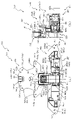
図26は、第1動作ユニット400の上面図である。図26では、第1動作ユニット400の第2中間位置が図示されており、理解を容易とするために、コイルスプリングSP1、コイルスプリングSP1が案内される定滑車、駆動モータMT1及びその駆動モータMT1が締結固定されるベース板の図示が省略される。 26 is a top view of the first operating unit 400. FIG. In FIG. 26 a second intermediate position of the first operating unit 400 is shown, and for ease of understanding the coil spring SP1, the fixed pulley in which the coil spring SP1 is guided, the drive motor MT1 and its drive motor MT1. Illustration of the base plate to which is fastened and fixed is omitted.

図26によれば、本実施形態では、アーム部材414の形状を、アーム部材414の正面側の領域を大きく確保することができるように設計している。即ち、アーム部材414を前後に屈曲した形状で形成することで、他の部材との干渉を機能的に避けることができる。以下、このことについて説明する。 According to FIG. 26, in this embodiment, the shape of the arm member 414 is designed so that a large area on the front side of the arm member 414 can be secured. That is, by forming the arm member 414 in a shape bent back and forth, it is possible to functionally avoid interference with other members. This will be explained below.

板状部414bは、検出センサSC1との干渉を避けるために、検出センサSC1よりも正面側に配置される。即ち、板状部414bの前後位置の制限は検出センサSC1との関係によるものなので、検出センサSC1と関係しない箇所(検出センサSC1を基準として回転軸(アーム支持部404)の反対側の箇所)では、前後位置を任意で設計することができる。 The plate-like portion 414b is arranged closer to the front side than the detection sensor SC1 in order to avoid interference with the detection sensor SC1. That is, since the restriction on the front and back position of the plate-like portion 414b is based on the relationship with the detection sensor SC1, the location not related to the detection sensor SC1 (the location on the opposite side of the rotation shaft (arm support portion 404) with respect to the detection sensor SC1). The front and back position can be designed arbitrarily.

本実施形態では、検出センサSC1を基準として回転軸(アーム支持部404)の反対側の箇所に配設される中間板部414cが、板状部414bに比較して背面側に配置される。これにより、終端ギア413の板前面とアーム部材414との前後間隔を狭めることができ、円柱張出部413cの根元側でアーム部材414への負荷伝達を生じさせることができるので、負荷伝達時に円柱張出部413cが変形することより負荷の伝達効率が低下することを回避することができる。 In this embodiment, the intermediate plate portion 414c, which is arranged on the opposite side of the rotation shaft (arm support portion 404) with respect to the detection sensor SC1, is arranged on the back side compared to the plate-like portion 414b. As a result, the front-to-rear distance between the plate front surface of the terminal gear 413 and the arm member 414 can be narrowed, and the load can be transmitted to the arm member 414 at the root side of the cylindrical projection 413c. It is possible to avoid a decrease in load transmission efficiency due to deformation of the columnar projecting portion 413c.

更に、中間板部414cの前後位置の終端ギア413との関係によるものなので、終端ギア413と関係しない箇所(終端ギア413を基準として回転軸(アーム支持部404)の反対側の箇所)では、前後位置を任意で設計することができる。 Furthermore, since it depends on the relationship with the terminating gear 413 at the front and rear positions of the intermediate plate portion 414c, at a location not related to the terminating gear 413 (a location on the opposite side of the rotation shaft (arm support portion 404) with respect to the terminating gear 413), The front and rear positions can be designed arbitrarily.

本実施形態では、終端ギア413を基準として回転軸(アーム支持部404)の反対側の箇所に配設される先端板部414eが、中間板部414cに比較して背面側に配置される。これにより、先端板部414eの正面側のスペースを大きく確保することができるので、先端板部414eの正面側であって昇降板430の背面側である位置に配設される背面配置板420及び同期動作ユニット440等の構成部材の前後寸法を確保し易くすることができる。 In this embodiment, the tip plate portion 414e arranged on the opposite side of the rotating shaft (arm support portion 404) with respect to the terminal gear 413 is arranged on the back side compared to the intermediate plate portion 414c. As a result, it is possible to secure a large space on the front side of the tip plate portion 414e. It is possible to make it easier to ensure the front-to-rear dimensions of the constituent members such as the synchronous operation unit 440 .

このように、本実施形態では、アーム部材414の形状を他の部材との干渉を回避可能な形状とすることを目的として設定しているが、他にも構造的な効果がある。例えば、アーム部材414を段階的に屈曲形成することで、アーム部材414に生じる負荷が局所的(一点)に集中することを回避することができ(応力集中を緩和することができ)、アーム部材414の耐久性を向上させることができる。 Thus, in this embodiment, the shape of the arm member 414 is set so as to avoid interference with other members, but there are other structural effects. For example, by bending the arm member 414 in stages, the load generated on the arm member 414 can be avoided from being concentrated locally (at one point) (stress concentration can be relieved), and the arm member 414 durability can be improved.

更に、他の部材との干渉を回避するために必要最小限の隙間を構成することで、その隙間を確保する他の部材に対してアーム部材414の反対側にまとまった隙間を構成することができるので、その隙間を利用して電気配線(電気配線DH1とは異なる電気配線)を這わせたり、追加の演出部材(電飾基板等)を配設したりすることができる。 Furthermore, by forming the minimum necessary gap to avoid interference with other members, it is possible to form a large gap on the opposite side of the arm member 414 to the other member that secures the gap. Therefore, the gap can be used to lay an electric wiring (an electric wiring different from the electric wiring DH1), or to arrange an additional production member (electrical decoration board, etc.).

また、図26によれば、本実施形態では、本体板部401側から発光演出装置LA1まで到達するように配設される電気配線DH1が、意図せず羽状部材460に挟み込まれたり、回転ギア441や相対変位部材442のギア歯部分に噛み込まれたりすることを防止可能に構成されている。以下、このことについて説明する。なお、この説明において、図25を適宜参照する。 Further, according to FIG. 26, in the present embodiment, the electric wiring DH1 arranged to reach the light emitting effect device LA1 from the main body plate portion 401 side is unintentionally caught in the feather-shaped member 460 or rotated. It is configured such that it can be prevented from being bitten by the gear teeth of the gear 441 and the relative displacement member 442 . This will be explained below. In this description, FIG. 25 will be referred to as appropriate.

電気配線DH1は、まず本体板部401側から長孔部406を通り補助アーム部材444に案内される。この時、電気配線DH1は、端部側板448の貫通孔448aに挿通されることで延設部444cの内側へ通される。 The electric wiring DH1 is first guided from the main body plate portion 401 side through the elongated hole portion 406 to the auxiliary arm member 444 . At this time, the electrical wiring DH1 is inserted through the through-hole 448a of the end side plate 448 to pass inside the extended portion 444c.

延設部444cの内側において、電気配線DH1は、抜け止め部444c1に脱落を防止されつつ基端側部444aまで案内される。その後、電気配線DH1は、基端側部444aから収容板部425の背面側へ案内され、収容板部425の背面側へ突設される枠部と閉塞板428とで仕切られるL字の領域を通り貫通孔427に到達する。 Inside the extended portion 444c, the electrical wiring DH1 is guided to the proximal side portion 444a while being prevented from falling off by the retaining portion 444c1. After that, the electric wiring DH1 is guided from the base end side portion 444a to the rear side of the housing plate portion 425, and is an L-shaped region partitioned by the frame portion protruding toward the rear side of the housing plate portion 425 and the closing plate 428. to reach the through hole 427 .

収容板部425の背面側へ突設される枠部には、挿通孔425aを中心として略半周に亘って突設が省略される省略部425bを備える。省略部425bにより、電気配線DH1が閉塞板428の正面側へ案内される角度を180度で設けることができる。これにより、補助アーム部材444の回転時に挿通孔425a付近で電気配線DH1が折れ曲がる可能性を低くすることができる。 The frame portion protruding toward the rear side of the housing plate portion 425 is provided with an omission portion 425b in which the protruding portion is omitted over approximately half the circumference around the insertion hole 425a. The omitted portion 425b allows the electric wiring DH1 to be guided to the front side of the blocking plate 428 at an angle of 180 degrees. As a result, it is possible to reduce the possibility that the electrical wiring DH1 is bent near the insertion hole 425a when the auxiliary arm member 444 rotates.

電気配線DH1は、貫通孔427を正面側へ通されることで、その貫通孔427と前後で重なる位置に形成される筒状部433を通り昇降板430の正面側へ案内され、支持板部450の締結部451に結束バンド等で仮留めされつつ、発光演出装置LA1の電飾基板に配設されるコネクタに接続される。 The electric wiring DH1 is passed through the through-hole 427 to the front side, and is guided to the front side of the lifting plate 430 through the cylindrical portion 433 formed at a position overlapping the through-hole 427 in the front and rear direction. It is temporarily fastened to the fastening portion 451 of 450 with a binding band or the like, and is connected to a connector arranged on the illumination board of the light emission effect device LA1.

このように、電気配線DH1は、その経路の大部分で構成部材(補助アーム部材444や背面配置板420)の内側に配設されているので、従来のパチンコ機のように電気配線が経路の大部分で露見される(露出している)場合に比較して、電気配線DH1が他の可動部材と衝突して負荷を受ける可能性を低くすることができる。 In this way, most of the electrical wiring DH1 is disposed inside the constituent members (the auxiliary arm member 444 and the rear panel 420), so that the electrical wiring DH1 is routed like a conventional pachinko machine. It is possible to reduce the possibility that the electrical wiring DH1 will collide with other movable members and receive a load compared to the case where most of the electrical wiring DH1 is exposed (exposed).

また、本実施形態では、電気配線DH1の案内経路と、スライド変位する相対変位部材442とを分断している。即ち、電気配線DH1に屈曲や湾曲等の変形を生じさせ得るのは、補助アーム部材444の回転変位(回転軸のスライド変位を伴う回転変位)に限定される。 Further, in the present embodiment, the guide path of the electrical wiring DH1 is separated from the relative displacement member 442 that slides. That is, it is limited to rotational displacement of the auxiliary arm member 444 (rotational displacement accompanied by sliding displacement of the rotation shaft) that can cause deformation such as bending or curving in the electric wiring DH1.

これにより、昇降板430の上下変位の変位速度と、相対変位部材442の変位速度とが大きく異なるように構成される場合でも、電気配線DH1の変形と相対変位部材442の変位速度との関係を断つことにより、電気配線DH1に与えられる負荷が大きくなることを回避することができる。 As a result, even when the displacement speed of the vertical displacement of the elevator plate 430 and the displacement speed of the relative displacement member 442 differ greatly, the relationship between the deformation of the electric wiring DH1 and the displacement speed of the relative displacement member 442 can be adjusted. By disconnecting the electrical wiring DH1, it is possible to avoid an increase in the load applied to the electrical wiring DH1.

図22(a)、図23、図24及び図25に戻って説明する。背面配置板420は、アーム部材414の円柱張出部414fに連結され昇降板430に締結固定される板状の連結板部421と、その連結板部421の右側に配設され昇降板430に締結固定されると共に金属レール405の正面側部材が締結固定される収容板部425と、その収容板部425に締結固定され、収容板部425の背面側部を部分的に閉塞するL字板形状の閉塞板428とを備える。 Returning to FIG. 22(a), FIG. 23, FIG. 24 and FIG. 25, description will be made. The rear plate 420 includes a plate-like connecting plate portion 421 that is connected to the cylindrical projecting portion 414f of the arm member 414 and fastened and fixed to the lifting plate 430, and is disposed on the right side of the connecting plate portion 421 and attached to the lifting plate 430. An accommodation plate portion 425 to which the front side member of the metal rail 405 is fastened and fixed, and an L-shaped plate that is fastened and fixed to the accommodation plate portion 425 and partially closes the rear side portion of the accommodation plate portion 425. and a shaped closure plate 428 .

連結板部421は、本体板部に左右方向に長い長孔形状で穿設され円柱張出部414fを挿通可能に形成される挿通長孔422と、その挿通長孔422の下方において正面側および上側が開放される箱状に形成される支持箱部423とを備える。 The connecting plate portion 421 has an elongated insertion hole 422 formed in the main body plate portion in a laterally elongated shape so that the cylindrical projecting portion 414f can be inserted therethrough. A support box portion 423 formed in a box shape with an open top is provided.

支持箱部423が挿通長孔422を基準として下方へ長く形成されていることで、支持箱部423を用いて収容板部425の剛性を補強することができる。即ち、支持箱部423は、支持壁部426と左右に対向配置されており、支持壁部426が左方へ大きく撓み変形し支持箱部423と当接した場合には、その変形を支持箱部423の剛性で抑制することができる。 Since the support box portion 423 is elongated downward with respect to the long insertion hole 422 , the support box portion 423 can be used to reinforce the rigidity of the housing plate portion 425 . That is, the support box portion 423 is arranged to face the support wall portion 426 on the left and right sides. It can be suppressed by the rigidity of the portion 423 .

収容板部425は、本体板部の左縁部に、上下方向に沿う直線状の板状に正面側へ突設される支持壁部426と、閉塞板428の正面側で穿設される貫通孔427とを備える。 The housing plate portion 425 includes a support wall portion 426 protruding toward the front side in a linear plate shape extending in the vertical direction from the left edge portion of the main body plate portion, and a through hole formed at the front side of the blocking plate 428 . and a hole 427 .

本実施形態では、貫通孔427に電気配線DH1が挿入される。即ち、貫通孔427は、電気配線DH1の端部に配設されるコネクタを挿通可能な内径で形成される。 In this embodiment, the electrical wiring DH1 is inserted into the through hole 427. As shown in FIG. That is, the through-hole 427 is formed with an inner diameter that allows the insertion of the connector arranged at the end of the electrical wiring DH1.

閉塞板428は、収容板部425の背面側に枠状に突設される枠部に板正面が当接するように形成され、収容板部425と閉塞板428との間で領域を仕切るように構成される。本実施形態では、収容板部425の枠部の内側(閉塞板428の正面側)においてのみ電気配線DH1が配置されるように構成されている。従って、電気配線DH1が金属レール405側(枠部よりも左側)に進入することを防止することができる。 The blocking plate 428 is formed so that the front surface of the plate abuts against a frame portion that protrudes like a frame on the back side of the housing plate portion 425 , and partitions the region between the housing plate portion 425 and the blocking plate 428 . Configured. In this embodiment, the electric wiring DH1 is arranged only inside the frame of the housing plate 425 (on the front side of the closing plate 428). Therefore, it is possible to prevent the electric wiring DH1 from entering the metal rail 405 side (left side of the frame portion).

省略部425bよりも貫通孔427側の位置において背面側にコ字状に張り出す部分である仮留部425cが、背面視で視認可能となるように閉塞板428に異形孔428aが貫通形成される。 A deformed hole 428a is formed through the blocking plate 428 so that the temporary retaining portion 425c, which is a portion protruding in a U-shape toward the rear side at a position closer to the through hole 427 than the omission portion 425b, can be visually recognized from the rear. be.

異形孔428aは、仮留部425cの横幅よりも若干長い左右幅の横長形状部と、結束バンドを通すことができる領域を確保するために横長形状部と交差して設けられる縦長形状部とから形成される。 The deformed hole 428a is composed of a horizontally elongated portion having a lateral width slightly longer than the width of the temporary fastening portion 425c and a vertically elongated portion provided to intersect the horizontally elongated portion to secure an area through which the binding band can be passed. It is formed.

仮留部425cは、結束バンドの留め部としての役割を持つ。結束バンドで電気配線DH1を仮留めすることで、電気配線DH1の配置を安定させることができる。この場合、結束バンドを締め付けることで、補助アーム部材444から閉塞板428側へ案内される電気配線DH1の経路を閉塞板428側に寄せることができるので、収容板部425の挿通孔425aを中心とした半円形状板部のエッジ部分と電気配線DH1との間に隙間を設けることができる(図25、図26参照)。これにより、電気配線DH1が収容板部425のエッジ部分と擦れることを回避することができるので、電気配線DH1の耐用年数を延ばすことができる。 The temporary fastening portion 425c serves as a fastening portion for the binding band. By temporarily fixing the electric wiring DH1 with the binding band, the arrangement of the electric wiring DH1 can be stabilized. In this case, by tightening the binding band, the path of the electrical wiring DH1 guided from the auxiliary arm member 444 to the blocking plate 428 side can be shifted to the blocking plate 428 side, so that the insertion hole 425a of the housing plate portion 425 is centered. A gap can be provided between the edge portion of the semicircular plate portion and the electric wiring DH1 (see FIGS. 25 and 26). As a result, it is possible to prevent the electrical wiring DH1 from rubbing against the edge portion of the housing plate portion 425, so that the service life of the electrical wiring DH1 can be extended.

また、本実施形態によれば、省略部425b間に案内される電気配線DH1(図26参照)を仮留めする結束バンドを閉塞板428の異形孔428aから露出させることができるので、結束バンドの交換や組み付けを、閉塞板428を取り外すことなく行うことができる。 Further, according to the present embodiment, the binding band for temporarily fixing the electrical wiring DH1 (see FIG. 26) guided between the omitted portions 425b can be exposed from the deformed hole 428a of the closing plate 428. Replacement and assembly can be performed without removing the closure plate 428 .

これにより、電気配線DH1の仮留め位置を収容板部425と閉塞板428との間の位置という、第1動作ユニット400の構成部材に対する電気配線DH1の位置が固定される箇所(即ち、電気配線DH1の一端が接続される発光演出装置LA1から電気配線DH1の経路を伝っていく場合に、昇降板430に対して電気配線DH1を変位させる初めての部分である補助アーム部材444の基端側部444aまでの経路と重なる箇所)で電気配線DH1を仮留めしながら、結束バンドの取り替えは閉塞板428を取り外さずに行うことができる。従って、電気配線DH1の耐用年数の向上を図ることができると共に、電気配線DH1に係る結束バンドのメンテナンス性の向上を図ることができる。 As a result, the temporary fixing position of the electric wire DH1 is a position between the housing plate portion 425 and the closing plate 428, which is a position where the position of the electric wire DH1 is fixed with respect to the constituent members of the first operation unit 400 (that is, the electric wire is fixed). The base end side portion of the auxiliary arm member 444, which is the first portion to displace the electric wiring DH1 with respect to the lifting plate 430 when the electric wiring DH1 is routed from the light emitting effect device LA1 to which one end of the DH1 is connected. 444a), the binding band can be replaced without removing the closing plate 428 while the electric wiring DH1 is temporarily fixed. Therefore, it is possible to improve the service life of the electrical wiring DH1, and to improve the maintainability of the binding band related to the electrical wiring DH1.

本実施形態では、電気配線DH1が閉塞板428の正面側を閉塞板428の形状に沿って這わされるところ、閉塞板428が背面視L字形状とされているので、電気配線DH1は、閉塞板428の正面側で前後方向と直交する第1平面に沿って湾曲する一方で、貫通孔427付近で左右方向と直交する第2平面(第1平面と直交する平面)に沿って湾曲することになる。これにより、電気配線DH1を閉塞板428及び収容板425に保持する保持力を向上することができ、電気配線DH1の位置を安定させることができる。 In this embodiment, the electrical wiring DH1 is laid along the front side of the blocking plate 428 along the shape of the blocking plate 428, and the blocking plate 428 is L-shaped when viewed from the rear. The front side of the plate 428 is curved along a first plane perpendicular to the front-rear direction, while the vicinity of the through hole 427 is curved along a second plane perpendicular to the left-right direction (a plane perpendicular to the first plane). become. As a result, the holding force for holding the electrical wiring DH1 on the closing plate 428 and the housing plate 425 can be improved, and the position of the electrical wiring DH1 can be stabilized.

昇降板430は、背面配置板420の締結固定に係る複数の部分から構成される締結部431と、同期動作ユニット440の支持に係る複数の部分から構成される支持部432と、電気配線DH1を挿通可能に形成される筒状部433と、支持板部450の締結固定に係る複数の部分から構成される締結部434と、部材同士の干渉を避けるために本体板部に形成される複数の対処部435と、板正面に略左右対称形状の模様が施される装飾部436とを備える。 The elevating plate 430 includes a fastening portion 431 composed of a plurality of portions for fastening and fixing the rear panel 420, a support portion 432 composed of a plurality of portions for supporting the synchronous operation unit 440, and the electrical wiring DH1. A cylindrical portion 433 formed to be able to be inserted, a fastening portion 434 configured from a plurality of portions related to fastening and fixing of the support plate portion 450, and a plurality of fastening portions formed on the main body plate portion to avoid interference between members. It has a handling part 435 and a decorative part 436 having a substantially symmetrical pattern on the front surface of the plate.

締結部431は、少なくとも、昇降板430の下端部に配置され相対変位部材442(スライドラック)の上下変位を支持する一対の瓢箪状突部431aを備えている。瓢箪状突部431aは、相対変位部材442を支持する部分でありながら、その先端部から雌ネジ形状が形成されており、収容板部425を昇降板430に締結固定する締結ネジが螺入される。即ち、背面配置板420の締結固定に係る部分と、同期動作ユニット440の支持に係る部分とに兼用されている。 The fastening portion 431 includes at least a pair of gourd-shaped protrusions 431a arranged at the lower end of the lifting plate 430 and supporting the vertical displacement of the relative displacement member 442 (slide rack). The gourd-shaped projection 431a is a portion that supports the relative displacement member 442, and has a female screw shape formed from the tip thereof, into which a fastening screw for fastening and fixing the housing plate portion 425 to the elevating plate 430 is screwed. be. That is, it is used both as a portion related to the fastening and fixing of the rear plate 420 and a portion related to the support of the synchronous operation unit 440 .

筒状部433は、同期動作ユニット440の構成部材間の隙間を通して背面側へ延設され、その背面側端部が収容板部425の板前面に当接し、その当接状態で貫通孔427と筒状部433の内部とが連続的に繋がる。この連続的に繋がる部分を通して電気配線DH1が前後に挿通される。 The tubular portion 433 extends to the rear side through the gap between the constituent members of the synchronous operation unit 440 , and the rear side end portion of the cylindrical portion 433 contacts the front surface of the housing plate portion 425 . The inside of the tubular portion 433 is continuously connected. The electric wiring DH1 is inserted back and forth through this continuously connected portion.

対処部435としては、例えば、固定伝達板490と相対変位部材442との連結部分(本実施形態では、上下に並んで配設される嵩上げ締結部)との干渉を避けるために本体板部の下縁から上方へ向けて切り欠かれる切り欠き部435aや、補助アーム部材444の円弧状ギア部444bの軸上方を保護するように壁状に形成される壁部に凹設され円弧状ギア部444bとの干渉を避けるように形成される凹設部435b等が例示される。 As the countermeasure portion 435, for example, in order to avoid interference with the connecting portion (in this embodiment, raised fastening portions arranged vertically) between the fixed transmission plate 490 and the relative displacement member 442, the main body plate portion A cutout portion 435a cut out from the lower edge toward the top, and an arcuate gear portion recessed in a wall portion formed in a wall shape so as to protect the axially upward portion of the arcuate gear portion 444b of the auxiliary arm member 444. A concave portion 435b or the like formed to avoid interference with 444b is exemplified.

装飾部436は、羽状部材460の背面側に配置され、羽状部材460の変位に伴い羽状部材460と連携して一連の模様を視認させることができるように構成されるが、詳細は後述する。 The decorative portion 436 is arranged on the back side of the wing-shaped member 460, and is configured to cooperate with the wing-shaped member 460 as the wing-shaped member 460 is displaced so that a series of patterns can be visually recognized. will be described later.

同期動作ユニット440は、互いに歯合する一対の回転ギア441と、その回転ギア441の一方と歯合し上下方向に変位可能に形成される相対変位部材442と、その相対変位部材442に長孔状に穿設される一対の長孔443と、回転ギア441の他方と歯合する回転ギア歯を有する補助アーム部材444と、補助アーム部材444の回転先端部に背面側から締結固定される端部側板448とを備える。 The synchronous operation unit 440 includes a pair of rotating gears 441 that mesh with each other, a relative displacement member 442 that meshes with one of the rotation gears 441 and is displaceable in the vertical direction, and a long hole in the relative displacement member 442 . an auxiliary arm member 444 having a pair of elongated holes 443 formed in a shape, an auxiliary arm member 444 having a rotating gear tooth that meshes with the other of the rotating gear 441, and an end fastened and fixed to the rotation tip of the auxiliary arm member 444 from the rear side. and a side plate 448 .

長孔443には、瓢箪状突部431aが挿通される。瓢箪形状の長手方向と、長孔443の長尺方向とが略平行に配置されることで、相対変位部材442の姿勢の安定化を図ることができる。 A gourd-shaped protrusion 431 a is inserted through the long hole 443 . By arranging the longitudinal direction of the gourd shape and the longitudinal direction of the long hole 443 substantially parallel, the posture of the relative displacement member 442 can be stabilized.

加えて、瓢箪状突部431aが長円状に形成される場合に比較して、長孔443と接触する面積を小さくすることができるので、瓢箪状突設部431aと相対変位部材442との間で生じる摩擦抵抗を低減することができる。 In addition, compared to the case where the gourd-shaped protrusion 431a is formed in an elliptical shape, the area in contact with the elongated hole 443 can be reduced, so that the gourd-shaped protrusion 431a and the relative displacement member 442 can be separated from each other. It is possible to reduce the frictional resistance generated between them.

補助アーム部材444は、支持部432の大径突部432aに軸支されるリング状の基端側部444aと、その基端側部444aのリング形状と同心円状にギア歯が形成される円弧ギア部444bと、基端側部444aからリング形状の径方向に延設される延設部444cと、その延設部444cの延設先端部に配設される略半筒状に形成される部分であって筒内側の開放部が延設部444cの開放部と連続的に繋がるよう構成される筒状部材444dとを備える。 The auxiliary arm member 444 has a ring-shaped proximal side portion 444a pivotally supported by the large-diameter projection 432a of the support portion 432, and an arcuate gear tooth formed concentrically with the ring shape of the proximal side portion 444a. A gear portion 444b, a ring-shaped extension portion 444c extending in the radial direction from the base end side portion 444a, and a substantially semi-cylindrical shape disposed at the extension distal end portion of the extension portion 444c. A cylindrical member 444d which is a portion and is configured such that an open portion inside the cylinder is continuously connected to an open portion of the extension portion 444c.

基端側部444aは、大径突部432aに挿通された状態で、その大径突部432aの先端に形成される雌ネジ部に螺入される締結ネジが挿通される挿通孔425aを有する収容板部425に背面側への移動を規制される。即ち、基端側部444aは、昇降板430及び収容板部425に前後から対向する態様で脱落不能に軸支される。 The base end side portion 444a has an insertion hole 425a through which a fastening screw is inserted into a female threaded portion formed at the distal end of the large-diameter projection 432a while being inserted into the large-diameter projection 432a. The housing plate portion 425 restricts the movement to the rear side. That is, the base end side portion 444a is pivotally supported so as to oppose the elevating plate 430 and the housing plate portion 425 from the front and rear so as not to fall off.

延設部444cは、背面側が開放された箱状に形成されており、背面側部において短手方向一側から他側へ向けて延設され、他側との間で電気配線DH1の短手方向寸法(幅寸法)よりも若干長い隙間を有して形成される抜け止め部444c1を備える。この抜け止め部444c1は、延設部444cの短手方向他側との間に電気配線DH1を通され延設部444cの内側に配設される電気配線DH1の、その後の脱落を防止する役割を持つ。 The extending portion 444c is formed in a box shape with an open rear side, and extends from one side in the transverse direction to the other side in the rear side portion, and connects the short side of the electrical wiring DH1 to the other side. A retaining portion 444c1 formed with a gap slightly longer than the directional dimension (width dimension) is provided. The retaining portion 444c1 serves to prevent the electrical wire DH1, which is disposed inside the extending portion 444c and is passed between the other side of the extending portion 444c in the short direction, from falling off thereafter. have.

なお、抜け止め部444c1の態様はこれに限られるものではない。例えば、延設部444cと抜け止め部444c1との間の隙間が電気配線DH1の短手方向寸法(幅寸法)よりも短く構成されても良い。この場合には、延設部444cと抜け止め部444c1との間の隙間に電気配線DH1を組み付ける(入れ込む)際に抜け止め部444c1を撓ませて隙間を拡げる必要が生じるが、組み付け後の電気配線DH1の脱落防止効果を向上することができる。 Note that the form of the retainer portion 444c1 is not limited to this. For example, the gap between the extension portion 444c and the retainer portion 444c1 may be configured to be shorter than the lateral dimension (width dimension) of the electrical wiring DH1. In this case, when assembling (inserting) the electrical wiring DH1 into the gap between the extension portion 444c and the retaining portion 444c1, it is necessary to bend the retaining portion 444c1 to widen the gap. It is possible to improve the effect of preventing the electrical wiring DH1 from coming off.

電気配線DH1が延設部444cの内側に配設される限りにおいて、第1動作ユニット400の昇降変位における電気配線DH1の伸縮を最低限に抑えることができるが、詳細については、図27から図30を参照して後述する。 As long as the electrical wiring DH1 is arranged inside the extended portion 444c, it is possible to minimize the expansion and contraction of the electrical wiring DH1 when the first motion unit 400 is vertically displaced. 30 as described below.

筒状部材444dは、その外径が長孔部406の短手方向寸法よりも若干短く設計されており、長孔部406に挿通されることで、長孔部406の長手方向(左右方向)に沿った補助アーム部材444のスライド移動と、補助アーム部材444の回転移動とを可能にする。 The tubular member 444d is designed such that its outer diameter is slightly shorter than the lateral dimension of the long hole portion 406, and when it is inserted through the long hole portion 406, the cylindrical member 444d extends in the longitudinal direction (horizontal direction) of the long hole portion 406. , and rotational movement of the auxiliary arm member 444.

端部側板448には、電気配線DH1を挿通可能な貫通孔448aが穿設されており、貫通孔448aに挿通された電気配線DH1は、長孔部406に挿通されている筒状部444dの内側を通り、延設部444cの内側を通り、基端側部444aの背面側に案内され、閉塞板428と収容板部425との間に入り込む。そして、貫通孔427及び筒状部433を通り正面側へ案内される。 The end side plate 448 is provided with a through hole 448a through which the electrical wiring DH1 can be inserted. It passes through the inner side, passes through the inner side of the extended portion 444 c , is guided to the rear side of the base end side portion 444 a , and enters between the blocking plate 428 and the accommodation plate portion 425 . Then, it is guided to the front side through the through hole 427 and the cylindrical portion 433 .

このように電気配線DH1が通される関係上、貫通孔448aの内形は電気配線DH1の端部に連結されるコネクタの外形よりも大きく形成される。換言すれば、貫通孔448aはコネクタを挿通可能な大きさで形成される。 Since the electrical wiring DH1 is passed through, the inner shape of the through hole 448a is formed larger than the outer shape of the connector connected to the end of the electrical wiring DH1. In other words, the through hole 448a is sized to allow the connector to pass therethrough.

貫通孔448aは、端部側板448の中心部のみでは無く、径外部に偏心した領域を含む異形形状で形成されており、特に、延設部444c側に大きく開口形成されている。従って、補助アーム部材444の姿勢に関わらず、電気配線DH1を延設部444c側に寄せることができるので、補助アーム部材444の姿勢変化に伴って電気配線DH1の補助アーム部材444に対する配置が大きく変わる(暴れる)ことを回避することができる。 The through-hole 448a is formed in an irregular shape including not only the central portion of the end side plate 448 but also an eccentric area on the radial outer side. Therefore, regardless of the posture of the auxiliary arm member 444, the electric wiring DH1 can be brought closer to the extended portion 444c side, so that the arrangement of the electric wiring DH1 with respect to the auxiliary arm member 444 becomes larger as the posture of the auxiliary arm member 444 changes. You can avoid changing (ramping).

加えて、貫通孔448aは、端部側板448の外径側部において延設部444c側を基準に背面視反時計回りに延長されている。この延長分により、第1動作ユニット400の退避状態における貫通孔448aの開口範囲を右側に拡大することができるので、電気配線DH1に要求される左右方向変位幅を抑えることができる。 In addition, the through hole 448a extends counterclockwise in a rear view from the outer diameter side portion of the end side plate 448 with the extension portion 444c side as a reference. Due to this extension, the opening range of the through-hole 448a in the retracted state of the first operation unit 400 can be expanded to the right, so that the horizontal displacement width required for the electric wiring DH1 can be suppressed.

この場合、昇降板430が昇降変位する際に端部側板448が左右に変位する本実施形態の構成であっても、貫通孔448aの向きが変わることで、端部側板448の左右方向変位を緩和するように機能させることができる。従って、端部側板448の変位幅に比較して電気配線DH1に要求される変位幅を短くすることができるので、電気配線DH1の変位を考慮して設定される配線の余分長さを短くすることができると共に、端部側板448から電気配線DH1に与えられる負荷を低減することができる。 In this case, even in the configuration of the present embodiment in which the end side plates 448 are displaced laterally when the elevating plate 430 is vertically displaced, the lateral displacement of the end side plates 448 can be suppressed by changing the direction of the through holes 448a. It can act as a mitigator. Therefore, since the displacement width required for the electrical wiring DH1 can be made shorter than the displacement width of the end side plate 448, the excess wiring length set in consideration of the displacement of the electrical wiring DH1 can be shortened. In addition, the load applied from the end side plate 448 to the electric wiring DH1 can be reduced.

相対変位部材442の正面側には固定伝達板490が締結固定される。即ち、昇降板430と相対変位部材442とが相対変位するのと同様に、昇降板430に締結固定される支持板部450と相対変位部材442に締結固定される固定伝達板490とは相対変位する。 A fixed transmission plate 490 is fastened and fixed to the front side of the relative displacement member 442 . That is, in the same way that the lift plate 430 and the relative displacement member 442 are relatively displaced, the support plate portion 450 fastened and fixed to the lift plate 430 and the fixed transmission plate 490 fastened and fixed to the relative displacement member 442 are relatively displaced. do.

支持板部450は、円板状に形成され背面側に発光基板が配設される発光演出装置LA1が正面側に締結固定される板状部材であって、昇降板430に挿通される締結ネジが螺入される複数の締結部451と、羽状部材460の筒状部461に内嵌され、昇降板430に挿通される締結ネジが螺入される左右一対の締結軸支兼用部452と、その締結軸支兼用部452の下側において左右一対で穿設される貫通孔453と、発光演出装置LA1の上部突片LA1bを引っ掛けて支持する支持部454とを備える。 The support plate portion 450 is a plate-like member to which the light emitting effect device LA1, which is formed in a disk shape and has a light emitting substrate disposed on the back side, is fastened and fixed to the front side, and is a fastening screw inserted through the elevating plate 430. a plurality of fastening portions 451 into which are screwed, and a pair of left and right fastening and shaft supporting portions 452 that are fitted inside the cylindrical portion 461 of the vane member 460 and into which fastening screws that are inserted through the elevating plate 430 are screwed. , a pair of right and left through-holes 453 drilled on the lower side of the fastening and shaft support portion 452, and a support portion 454 for hooking and supporting the upper projecting piece LA1b of the light emitting effect device LA1.

発光演出装置LA1は、下部には支持板部450に挿通される締結ネジが螺入される一対の締結部LA1aを備え、上部には支持部454に差し込み可能に突設される一対の突片LA1bを備える。このように、発光演出装置LA1の下部は締結固定で支持しつつ、上部は係合で支持することで、十分な支持強度を確保しながら、電飾基板の上部背面側に締結ネジの影が生じることを回避することができる。 The light emitting device LA1 has a pair of fastening portions LA1a at its lower portion into which fastening screws to be inserted through the support plate portion 450 are screwed, and a pair of projecting pieces protruding to be inserted into the support portion 454 at its upper portion. LA1b is provided. In this way, while the lower part of the lighting effect device LA1 is supported by fastening and the upper part is supported by engagement, the shadow of the fastening screw is left on the upper back side of the electrical board while ensuring sufficient support strength. can be avoided from occurring.

発光演出装置LA1の正面には、遊技者に視認可能に構成され立体的または平面的な装飾模様が施される。この装飾模様は、羽状部材460や補助部材470に隠されずに視認される状況において、羽状部材460や補助部材470と一体的な装飾として視認させることができるように構成される(図34参照)。 A three-dimensional or two-dimensional decorative pattern is applied to the front of the light-emitting effect device LA1 so as to be visible to the player. This decorative pattern is configured to be visible as an integral decoration with the wing-shaped member 460 and the auxiliary member 470 when it is visible without being hidden by the wing-shaped member 460 and the auxiliary member 470 (Fig. 34). reference).

なお、本実施形態では、羽状部材460や補助部材470の形状が貝(例えば、ほたて貝)を模した形状とされており、その間に配置される発光演出装置LA1の形状は真珠のように視認可能な正面視略円形状から形成される。即ち、発光演出部材LA1、羽状部材460及び補助部材470を一体的に視認させることで、「開いた貝の内側に配置される真珠」という一連の概念を想起させる外観を構成することができる。 In this embodiment, the feather-like member 460 and the auxiliary member 470 are shaped like shellfish (for example, scallop shells), and the light emitting device LA1 arranged between them is shaped like a pearl. It is formed in a substantially circular shape that can be visually recognized from the front. That is, by making the light emitting member LA1, the feather member 460, and the auxiliary member 470 integrally visible, it is possible to construct an appearance that reminds one of a series of concepts of "a pearl placed inside an open shell". .

羽状部材460は、締結軸支兼用部452に支持される複数の部材から構成され、締結軸支兼用部452に回転可能に軸支される筒状部461と、その筒状部461を中心とする円弧状に形成され互いに歯合される円弧状ギア462と、筒状部461から円弧状ギア462の反対側へ板状に延設される延設部463と、その延設部463の延設端側に形成され板正面部に鍍金が塗布されることで光を強度に反射可能に構成される形成部464L,464Rと、円弧状ギア462よりも小径の円弧に沿って円弧状ギア462よりも正面側に形成される下流ギア465と、円弧状ギア462の背面側を覆うフランジ状に形成されるフランジ部466と、そのフランジ部466が外形方向へ延設された延設端部から背面側へ円柱状に張り出す円柱張出部467とを備える。 The feather-like member 460 is composed of a plurality of members supported by the fastening/shaft-supporting part 452 , and has a cylindrical part 461 rotatably supported on the fastening/shaft-supporting part 452 , and a cylindrical part 461 . an arc-shaped gear 462 formed in an arc shape and meshing with each other, an extension portion 463 extending in a plate shape from the cylindrical portion 461 to the opposite side of the arc-shaped gear 462, and the extension portion 463 Forming portions 464L and 464R, which are formed on the extended end side and are plated on the front surface of the plate so as to be able to reflect light strongly, and an arc-shaped gear along an arc having a diameter smaller than that of the arc-shaped gear 462. A downstream gear 465 formed on the front side of the gear 462, a flange portion 466 formed in a flange shape covering the rear side of the circular gear 462, and an extended end portion where the flange portion 466 extends in the outer shape direction. and a columnar projecting portion 467 projecting in a columnar shape from the rear surface side.

円弧状ギア462は、一対の筒状部461の中間位置で歯合する径同一の円弧に形成されるギア歯として形成される。即ち、円弧状ギア462の歯合により回転する複数(左右)の羽状部材460の回転角度は同一(対称)となる。 The arcuate gear 462 is formed as gear teeth formed in an arc having the same diameter and meshing with each other at an intermediate position of the pair of cylindrical portions 461 . That is, the rotation angles of the plurality of (left and right) feather members 460 rotated by the engagement of the circular arc gears 462 are the same (symmetrical).

延設部463は、右側においてのみ凹設形成される凹設部463aを備える。凹設部463aは、筒状部433を通り昇降板430の正面側へ案内される電気配線との干渉を避け易くするための形状部であるが、詳細は後述する。 The extended portion 463 has a recessed portion 463a that is recessed only on the right side. The recessed portion 463a is a shaped portion that facilitates avoiding interference with the electric wiring that passes through the cylindrical portion 433 and is guided to the front side of the lift plate 430, the details of which will be described later.

形成部464L,464Rは、第1動作ユニット400の張出状態において合体し、一連の略半円形状(略半楕円形状)の装飾体として構成される(図17参照)一方で、第1動作ユニット400の退避状態においては、左右に分かれて配置され、且つ、その大きさは左右非対称とされる(図16参照)。 Forming parts 464L and 464R are united in the overhanging state of first action unit 400, and configured as a series of substantially semicircular (substantially semielliptical) ornaments (see FIG. 17). In the retracted state of the unit 400, they are arranged separately on the left and right, and their sizes are left and right asymmetrical (see FIG. 16).

詳述すれば、下部側は左右対称に形成される一方、合体時に当接する上部側の形状において、左側の形成部464Lの方が、右側の形成部464Rに比較して回転方向に張り出して形成されることで、大きく形成される。換言すれば、第1動作ユニット400の張出状態において、形成部464L,464Rの当接面S1が右側寄りに配置される(図17参照)。 More specifically, while the lower part is formed symmetrically, the left forming part 464L protrudes in the rotational direction compared to the right forming part 464R in terms of the shape of the upper part, which abuts when combined. By being done, it will be greatly formed. In other words, in the extended state of the first operation unit 400, the contact surfaces S1 of the forming portions 464L and 464R are arranged on the right side (see FIG. 17).

羽状部材464L,464Rの上端部であって、互いに対向配置される部分の形状は、筒状部461からの距離で異なる。即ち、筒状部461に近い側(回転軸に近い側、内径側)は、羽状部材464L,464Rが最接近した場合に正面視で互いに重なることができるよう、羽状部材464L,464Rの回転軸方向に位置ずれして配置される干渉部464aを設けた形状とされる。 The shape of the upper end portions of the vane members 464L and 464R, which are arranged to face each other, differs depending on the distance from the cylindrical portion 461. As shown in FIG. That is, on the side closer to the tubular portion 461 (the side closer to the rotation shaft, the inner diameter side), the blade members 464L and 464R are arranged so that they overlap each other in a front view when they are closest to each other. It has a shape provided with an interference portion 464a that is displaced in the rotation axis direction.

本実施形態では、筒状部461に近い側は、羽状部材464L,464Rが最接近した場合に一連の模様として視認される装飾模様が形成される部分に相当する。上述の干渉部464aによって、羽状部材464L,464Rが最接近した場合に羽状部材464L,464Rの当接面S1に切れ目が生じることの防止を図ることができるので、装飾模様を遊技者に違和感なく視認させることができる。 In this embodiment, the side closer to the tubular portion 461 corresponds to a portion where a decorative pattern that is visible as a series of patterns is formed when the feather members 464L and 464R are closest to each other. The above-described interference portion 464a can prevent the contact surfaces S1 of the wing-like members 464L and 464R from being cut off when the wing-like members 464L and 464R are closest to each other, so that the decorative pattern can be displayed to the player. It can be visually recognized without discomfort.

一方、筒状部461から遠い側(回転軸から遠い側、外径側)では、羽状部材464L,464Rの回転を当接により停止させることができるよう、羽状部材464L,464Rの回転軸方向で合致する位置に当接面が配置される形状とされる。 On the other hand, on the side far from the tubular portion 461 (the side far from the rotation shaft, the outer diameter side), the rotation shafts of the vane members 464L and 464R are arranged so that the rotation of the vane members 464L and 464R can be stopped by contact. The shape is such that the contact surface is arranged at a position that matches the direction.

羽状部材464L,464Rの停止時の負荷が当接により生じる部分を、力のモーメントの計算における腕長さが最長となる最外径部に設けることで、当接により羽状部材464L,464Rに生じる負荷を最小限に抑えることができる。 By providing the portion where the load on the wing-shaped members 464L and 464R when stopped is caused by the contact at the outermost diameter portion where the arm length in the calculation of the moment of force is the longest, the wing-shaped members 464L and 464R can minimize the load on the

このように、羽状部材464L,464Rの形状を筒状部461からの距離で変化させることにより、羽状部材464L,464Rが最接近した際に形成される一連の装飾模様を遊技者に違和感なく視認させることができると共に、羽状部材464L,464Rの最接近時に羽状部材464L,464Rに生じ得る負荷を最小限に抑えることができる。 In this way, by changing the shape of the wing-like members 464L and 464R according to the distance from the tubular portion 461, the series of decorative patterns formed when the wing-like members 464L and 464R are closest to each other makes the player feel uncomfortable. In addition, it is possible to minimize the load that may be generated on the wing members 464L and 464R when the wing members 464L and 464R are closest to each other.

フランジ部466は、円弧状ギア462の前後方向の位置ずれを抑制することと、円弧状ギア462と固定伝達板490との間を仕切ることとに兼用される。これにより、円弧状ギア462の歯合状態の適正化を図ると共に、円弧状ギア462が固定伝達板490に当接して引っかかり、過大な抵抗が生じることを防止することができる。 The flange portion 466 is used both for suppressing the positional deviation of the arc-shaped gear 462 in the front-rear direction and for separating the arc-shaped gear 462 and the fixed transmission plate 490 . As a result, the meshing state of the arc-shaped gear 462 can be optimized, and it is possible to prevent the arc-shaped gear 462 from coming into contact with and being caught by the fixed transmission plate 490 and causing excessive resistance.

円柱張出部467は、固定伝達板490の長孔部491に挿通され、張出先端部には摩擦低減用のリング形状のカラーC1が挿通される。加えて、張出先端部には、雌ネジが形成され、カラーC1に挿通されると共にカラーC1の内径よりも大きな傘部を有する締結ネジが螺入される。これにより、固定伝達板490が円柱張出部467に脱落不能に連結される。 The columnar projecting portion 467 is inserted through the elongated hole portion 491 of the fixed transmission plate 490, and a ring-shaped collar C1 for reducing friction is inserted through the projecting tip portion. In addition, a female screw is formed on the protruding distal end portion, and a fastening screw that is inserted through the collar C1 and has a head portion larger than the inner diameter of the collar C1 is screwed. As a result, the fixed transmission plate 490 is connected to the cylindrical projecting portion 467 so as not to fall off.

補助部材470は、回転可能に支持される左右一対の板状部材から構成され、有底筒状に形成される被支持部471と、貫通孔453に通され被支持部471に挿通され回転不能に嵌合される金属製の挿通金属棒472と、その挿通金属棒472の端部に回転不能に嵌合され挿通金属棒472を中心とする円弧上に形成されるギア歯を有するギア部473とを備える。 The auxiliary member 470 is composed of a pair of left and right plate-like members that are rotatably supported, and includes a supported portion 471 formed in a cylindrical shape with a bottom, and a through hole 453 that is inserted through the supported portion 471 so as to be non-rotatable. and a gear portion 473 having gear teeth formed on an arc centered on the metal insertion rod 472 and non-rotatably fitted to the end of the metal insertion rod 472. and

挿通金属棒472の正面側部には、径方向に雌ネジが形成されており、被支持部471の対応する位置には雌ネジに螺入される締結ネジの螺入部を挿通可能な貫通孔が形成される。挿通金属棒472を被支持部471に挿通した後で、貫通孔を通して雌ネジに締結ネジを螺入することで、挿通金属棒472が被支持部471から脱落することを防止することができる。 A female screw is formed in the front side portion of the insertion metal rod 472 in a radial direction, and a through hole through which a screw portion of a fastening screw to be screwed into the female screw can be inserted at a corresponding position of the supported portion 471. is formed. After inserting the insertion metal rod 472 through the supported portion 471 , the insertion metal rod 472 can be prevented from falling off from the supported portion 471 by screwing a fastening screw into the female thread through the through hole.

ギア部473は、挿通金属棒472が貫通孔453に支持されることに伴い、貫通孔453を中心に回転可能に軸支される。ギア部473は、下流ギア465と歯合している(図22(b)参照)ので、羽状部材460の回転角度と同期して回転する。 As the insertion metal rod 472 is supported by the through hole 453 , the gear portion 473 is rotatably supported around the through hole 453 . Since the gear portion 473 meshes with the downstream gear 465 (see FIG. 22(b)), it rotates in synchronization with the rotation angle of the vane member 460 .

固定伝達板490は、相対変位部材442の正面側に締結固定される板状部と、その板状部に湾曲する長孔として穿設される長孔部491と、板状部の下端部に回転不能に支持される金属製の棒状部材であって正面側へ張り出す金属棒492と、その金属棒492の張出先端部に回転不能に固定される装飾部493とを備える。 The fixed transmission plate 490 includes a plate-like portion fastened and fixed to the front side of the relative displacement member 442, a long hole portion 491 formed as a curved long hole in the plate-like portion, and a lower end portion of the plate-like portion. It comprises a metal bar 492 which is a non-rotatably supported metal bar-like member and protrudes toward the front side, and a decorative portion 493 which is non-rotatably fixed to the protruding tip of the metal bar 492 .

長孔部491は、上下方向に沿って形成される上下方向部491aと、上下方向部491aよりも左右方向に曲げられて形成される湾曲変化部491bとを備える。このように、長孔部491を区画分けすることで、固定伝達板490の上下方向変位と、それに伴う羽状部材460の回転変位とを完全同期させるのではなく、同期態様にずれを設けることができるが、詳細については後述する。 The elongated hole portion 491 includes a vertical portion 491a formed along the vertical direction, and a curved change portion 491b formed by bending the vertical portion 491a in the horizontal direction. By partitioning the long hole portion 491 in this way, the vertical displacement of the fixed transmission plate 490 and the accompanying rotational displacement of the feather-like member 460 are not completely synchronized, but a deviation is provided in the synchronous mode. The details are described later.

金属棒492と装飾部493との連結固定は、上述の挿通金属棒472と被支持部471との連結態様と同様である。これにより、金属棒492が装飾部493から脱落することを防止することができる。 The connection and fixation between the metal rod 492 and the decorative portion 493 is the same as the manner of connection between the insertion metal rod 472 and the supported portion 471 described above. Thereby, it is possible to prevent the metal rod 492 from falling off from the decorative portion 493 .

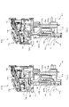
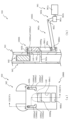
次いで、第1動作ユニット400の動作態様について説明する。図27、図28、図29及び図30は、第1動作ユニット400の背面図である。図27から図30では、駆動モータMT1の回転に伴い各構成部材が変位する様子が図示されており、図27では、第1動作ユニット400の退避状態が、図28では、壁模式線UL(図16参照)の上下ずれ寸法よりも若干長い距離だけ昇降板430が退避状態から下降した第1動作ユニット400の第1中間状態が、図29では、補助アーム部材444の長手方向が左右方向を向く第1動作ユニット400の第2中間状態が、図30では、第1動作ユニット400の張出状態が、それぞれ図示される。 Next, the operation mode of the first operation unit 400 will be described. 27, 28, 29 and 30 are rear views of the first operating unit 400. FIG. FIGS. 27 to 30 illustrate how each constituent member is displaced as the drive motor MT1 rotates. FIG. 27 shows the retracted state of the first operation unit 400, and FIG. 16), the first intermediate state of the first operation unit 400 in which the lift plate 430 is lowered from the retracted state by a distance slightly longer than the vertical deviation dimension in FIG. The second intermediate state of the facing first operating unit 400 and in FIG. 30 the extended state of the first operating unit 400 are respectively illustrated.

図27に示すように、第1動作ユニット400の退避状態では、被検出部413dが検出センサSC1の検出隙間に入り込むことで、終端ギア413の姿勢が判定される。本実施形態では、検出センサSC1により検出される状態は退避状態のみであり、その他の状態(第1中間状態、第2中間状態、張出状態)は、退避状態から予め設定された変位量だけ変位した後の状態であって、検出センサSC1により検出されるものではない。 As shown in FIG. 27, in the retracted state of the first operation unit 400, the position of the terminal gear 413 is determined by the detected portion 413d entering the detection gap of the detection sensor SC1. In this embodiment, the state detected by the detection sensor SC1 is only the retracted state, and the other states (first intermediate state, second intermediate state, extended state) are displaced by a preset amount from the retracted state. This is a state after displacement, and is not detected by the detection sensor SC1.

図27に示すように、第1動作ユニット400の退避状態では、終端ギア413の回転軸と円柱張出部413cとを結ぶ直線と、アーム部材414の長孔部414dの長尺方向(アーム部材414の回転の径方向)とが直交する。これにより、アーム部材414から終端ギア413へ与えられる負荷が終端ギア413の回転軸を通る直線方向に沿って生じることになるので、駆動モータMT1の動力を遮断した状態であってもアーム部材414の姿勢を維持することができる(死点の利用)。 As shown in FIG. 27, in the retracted state of the first operation unit 400, the straight line connecting the rotation shaft of the terminal gear 413 and the cylindrical projecting portion 413c and the longitudinal direction of the long hole portion 414d of the arm member 414 (arm member 414). 414) are orthogonal to each other. As a result, the load applied from the arm member 414 to the terminating gear 413 is generated along the linear direction passing through the rotation axis of the terminating gear 413. Therefore, even when the power of the drive motor MT1 is cut off, the arm member 414 is loaded. posture can be maintained (use of dead point).

アーム部材414の先端板部414eは、アーム部材414の回転軸を中心として終端ギア413の円板部に外接する円弧MXSの外方に配設される。これにより、アーム部材414の回転変位の最中に、先端板部414eと終端ギア413とが干渉することを避けることができる。 A tip plate portion 414e of the arm member 414 is arranged outside an arc MXS that circumscribes the disk portion of the terminal gear 413 with the rotation axis of the arm member 414 as the center. Thereby, it is possible to avoid interference between the tip plate portion 414 e and the terminal gear 413 during the rotational displacement of the arm member 414 .

補助アーム部材444は、昇降板430の右側部が下降することを妨げるように機能する。補助アーム部材444は長孔部406をスライド移動可能に支持されているものの、それは無抵抗のものではなく、筒状部444d(図25参照)と長孔部406との間に生じる接触摩擦により動作抵抗が生じる。即ち、この動作抵抗の作用で、昇降部430の右側部を補助アーム部材444により支持することができる。 The auxiliary arm member 444 functions to prevent the right side of the lift plate 430 from descending. Although the auxiliary arm member 444 is slidably supported in the elongated hole portion 406, it is not without resistance, and contact friction between the tubular portion 444d (see FIG. 25) and the elongated hole portion 406 causes the sliding movement. Motion resistance occurs. That is, the right side portion of the lifting section 430 can be supported by the auxiliary arm member 444 due to the action of this movement resistance.

図28に示すように、アーム部材414が回転変位することで昇降板430が下降変位し、それに伴い変位する補助アーム部材444と歯合する回転ギア441の回転に伴い、相対変位部材442が昇降板430の変位量を超える変位量で下降変位する。 As shown in FIG. 28, the arm member 414 is rotationally displaced so that the elevating plate 430 is displaced downward. It is displaced downward by a displacement amount exceeding the displacement amount of the plate 430 .

複雑な形状をしているものの、補助アーム部材444から相対変位部材442への駆動力の伝達はギアの歯合によるものなので、相対変位部材442の昇降板430に対する変位量と、補助アーム部材444の回転角度とは一対一で対応する。 Although it has a complicated shape, the transmission of the driving force from the auxiliary arm member 444 to the relative displacement member 442 is due to the meshing of the gears. corresponds to the rotation angle of .

図28に示すように、上述のようにアーム部材414、補助アーム部材444、昇降板430及び相対変位部材442が変位している一方で、羽状部材460は退避状態における姿勢と同一の姿勢を維持する。 As shown in FIG. 28, while the arm member 414, the auxiliary arm member 444, the elevating plate 430 and the relative displacement member 442 are displaced as described above, the feather member 460 assumes the same posture as in the retracted state. maintain.

即ち、本実施形態によれば、第1動作ユニット400の退避状態から昇降板430が下降を開始するタイミングと、羽状部材460が回転を開始するタイミングとに時間ずれが生じる。この時間ずれの発生原因については、後述する。 That is, according to this embodiment, there is a time lag between the timing at which the elevator plate 430 starts to descend from the retracted state of the first operation unit 400 and the timing at which the feather member 460 starts to rotate. The cause of this time lag will be described later.

なお、本実施形態では、羽状部材460が回転を開始するまでの間に昇降板430が壁模式線UL(図16参照)の上下寸法分下降することになるので、羽状部材460が回転変位する際に背面ケース310の上壁部に衝突する不具合の発生を防止し易くすることができる。 In the present embodiment, the lift plate 430 is lowered by the vertical dimension of the wall schematic line UL (see FIG. 16) before the wing-like member 460 starts rotating. It is possible to easily prevent the occurrence of the problem of colliding with the upper wall portion of the rear case 310 when displacing.

別の言い方をすれば、壁模式線ULの上下寸法分下降した後で羽状部材460が回転変位する変位態様は、背面ケース310の上壁部が左右で高さにずれが無いように形成される場合に昇降板430の下降と同時に羽状部材460を回転させる変位態様(従来型の変位態様)と同じ条件である。従って、従来型の変位態様の動作条件(ギア比や、変位量等のパラメーター)を流用して、本実施形態の第1動作ユニット400の動作を実現することができる。これにより、設計に要するコストを低減することができる。 In other words, the displacement mode in which the feather-shaped member 460 rotates after it descends by the vertical dimension of the wall schematic line UL is formed so that the upper wall portion of the rear case 310 does not have a height difference between the left and right sides. This is the same condition as the displacement mode (conventional displacement mode) in which the vane member 460 is rotated simultaneously with the descent of the lift plate 430 in the case where the lift plate 430 is lowered. Therefore, it is possible to realize the operation of the first operation unit 400 of the present embodiment by using the operating conditions (parameters such as gear ratio and displacement amount) of the conventional displacement mode. Thereby, the cost required for design can be reduced.

図27に示すように、退避状態では昇降板430の背面側に隠されていたアーム部材414が、図28に示すように、昇降板430が下降することに伴い昇降板430の上側に張り出すように変位する。 As shown in FIG. 27, the arm member 414 hidden behind the lift plate 430 in the retracted state protrudes above the lift plate 430 as the lift plate 430 descends, as shown in FIG. is displaced as follows.

これに対し、本実施形態では、アーム部材414を隠すように羽状部材460が昇降板430に対して変位可能に構成される(図29参照)。即ち、羽状部材460が、表面側に形成される装飾模様を遊技者に視認させて遊技を盛り上げる演出を実行する演出手段としてのみでは無く、駆動伝達のためのアーム部材414を昇降板430と共同で隠す遮蔽手段としても機能する。 On the other hand, in this embodiment, the feather member 460 is configured to be displaceable with respect to the lift plate 430 so as to hide the arm member 414 (see FIG. 29). In other words, the feather-like member 460 not only serves as an effect means for making the player visually recognize the ornamental pattern formed on the surface side and executes an effect to liven up the game. It also functions as a co-hidden shield.

特に、本実施形態では、駆動力伝達の機能を有するアーム部材414が配設される側の羽状部材460の形成部464Lの方が、逆側の羽状部材460の形成部464Rに比較して大きな形状とされるので、アーム部材414を遊技者の視界から隠しやすくすることができる。 In particular, in the present embodiment, the forming portion 464L of the wing-like member 460 on the side where the arm member 414 having the function of transmitting the driving force is arranged is compared to the forming portion 464R of the wing-like member 460 on the opposite side. Since the arm member 414 has a large shape, the arm member 414 can be easily hidden from the player's field of view.

なお、これと同様に、形成部464Rが、補助アーム部材444を隠すように構成される(図30参照)。本実施形態では、その構成から、第2中間状態においてアーム部材414は昇降板430の上側に張り出している一方で、補助アーム部材444は依然として昇降板430の背面側に隠されている。即ち、アーム部材414が昇降板430の上側に張り出した後で、補助アーム部材444が昇降板430の上側に張り出すよう構成される(図30参照)。 Similarly, the forming portion 464R is configured to hide the auxiliary arm member 444 (see FIG. 30). In this embodiment, due to its configuration, in the second intermediate state, the arm member 414 protrudes above the elevator plate 430 while the auxiliary arm member 444 is still hidden behind the elevator plate 430 . That is, after the arm member 414 protrudes above the lift plate 430, the auxiliary arm member 444 protrudes above the lift plate 430 (see FIG. 30).

従って、形成部464Lよりも小さな形状とされる(同時点における昇降板430の上側への張り出し量が形成部464Lよりも小さい)形成部464Rを利用する場合であっても、問題なく補助アーム部材444を遊技者の視界から隠すことができる。 Therefore, even if the forming portion 464R, which has a shape smaller than that of the forming portion 464L (the amount of upward protrusion of the lifting plate 430 at the same point in time is smaller than that of the forming portion 464L), there is no problem in using the auxiliary arm member. 444 can be hidden from the player's view.

図29に示すように、円柱張出部414fがアーム部材414の回転軸から左方へ最も離れた状態を若干過ぎた位置で、補助アーム部材444が、長尺方向が左右方向を向く姿勢となる。円柱張出部414fがアーム部材414の回転軸から左方へ最も離れた状態では、アーム部材414から昇降板430へ与えられる右向きの負荷が大きくなり易いが、これに対向して、同じタイミングで補助アーム部材444が昇降板430へ左向きの負荷を与える場合、昇降板430の変位抵抗が大きくなってしまう。 As shown in FIG. 29, the auxiliary arm member 444 is in a posture in which the longitudinal direction faces the left-right direction at a position slightly past the state where the columnar projecting portion 414f is leftmost away from the rotation axis of the arm member 414. Become. When the columnar overhang 414f is farthest to the left from the rotation axis of the arm member 414, the rightward load applied from the arm member 414 to the lift plate 430 tends to increase. When the auxiliary arm member 444 applies a leftward load to the lift plate 430, the displacement resistance of the lift plate 430 increases.

これに対し、本実施形態では、円柱張出部414fがアーム部材414の回転軸から左方へ最も離れた状態を若干過ぎた位置で補助アーム部材444の姿勢を倒し、筒状部444d(図25参照)を長孔部406の右端に配置することで、補助アーム部材444を介して昇降板430へ左向きの負荷を与えられるように構成することで、昇降板430の昇降変位の変位抵抗を抑制しながら、昇降板430に与えられる左右方向の負荷で昇降板430が左右方向に変位することを抑制することができる。 On the other hand, in the present embodiment, the position of the auxiliary arm member 444 is tilted at a position where the columnar overhanging portion 414f is slightly past the leftmost state from the rotation axis of the arm member 414, and the cylindrical portion 444d (Fig. 25) is arranged at the right end of the elongated hole 406 to apply a leftward load to the lift plate 430 through the auxiliary arm member 444, thereby reducing the displacement resistance of the lift plate 430 up and down. While suppressing this, it is possible to suppress the lateral displacement of the elevator plate 430 due to the load applied to the elevator plate 430 in the horizontal direction.

なお、図29に示す状態では、終端ギア413の円柱張出部413cが円弧MXSの外側に配置されているが、先端板部414eが既に円柱張出部413cの下方に行き過ぎていることから、先端板部414eと終端ギア413との干渉を避けることができる。 In the state shown in FIG. 29, the columnar overhanging portion 413c of the terminal gear 413 is arranged outside the arc MXS. Interference between the tip plate portion 414e and the terminal gear 413 can be avoided.

即ち、円弧MXSは、あくまで目安の位置として規定されるものであり、終端ギア413とアーム部材414との設計は、実際に終端ギア413及びアーム部材414を連動させた場合に干渉が生じるか否かを動的に検討して行われる。 That is, the arc MXS is defined as a reference position only, and the design of the terminating gear 413 and the arm member 414 depends on whether or not interference occurs when the terminating gear 413 and the arm member 414 are actually interlocked. This is done by dynamically considering whether

図30に示すように、第1動作ユニット400の張出状態では、終端ギア413の被ストッパ部413bが本体板部401のストッパ部403cと当接する位置を終点として終端ギア413が回転する。なお、制御としては、被ストッパ部413bがストッパ部403cと当接する位置よりも若干手前の位置で終端ギア413が止まるように駆動モータMT1を駆動するようにしている。これにより、被ストッパ部413b及びストッパ部403cが早期に破損することを回避しながら、終端ギア413が過回転することを構造的に防止することができる。 As shown in FIG. 30 , in the extended state of the first operation unit 400 , the terminating gear 413 rotates around a position where the stopped portion 413 b of the terminating gear 413 contacts the stopper portion 403 c of the main body plate portion 401 as an end point. As for the control, the drive motor MT1 is driven so that the terminal gear 413 stops at a position slightly before the position where the stopped portion 413b contacts the stopper portion 403c. As a result, it is possible to structurally prevent the terminal gear 413 from over-rotating while avoiding early breakage of the stopper-receiving portion 413b and the stopper portion 403c.

図30に示すように、第1動作ユニット400の張出状態では、終端ギア413の回転軸と円柱張出部413cとを結ぶ直線と、アーム部材414の長孔部414dの長尺方向(アーム部材414の回転の径方向)とが直交する。これにより、アーム部材414から終端ギア413へ与えられる負荷が終端ギア413の回転軸を通る直線方向に沿って生じることになるので、駆動モータMT1の動力を遮断した状態であってもアーム部材414の姿勢を維持することができる(死点の利用)。 As shown in FIG. 30, in the overhanging state of the first operation unit 400, the straight line connecting the rotation shaft of the terminal gear 413 and the cylindrical overhanging portion 413c and the longitudinal direction of the elongated hole portion 414d of the arm member 414 (arm). (radial direction of rotation of member 414) are orthogonal to each other. As a result, the load applied from the arm member 414 to the terminating gear 413 is generated along the linear direction passing through the rotation axis of the terminating gear 413. Therefore, even when the power of the drive motor MT1 is cut off, the arm member 414 is loaded. posture can be maintained (use of dead point).

なお、姿勢の維持は、アーム部材414の回転方向に沿う両方向に生じる。即ち、重力方向の変位に限らず、第1動作ユニット400の張出状態から退避状態側へ上昇変位することも防止することができる。 The posture is maintained in both directions along the rotation direction of arm member 414 . That is, it is possible to prevent not only the displacement in the direction of gravity, but also the upward displacement of the first operation unit 400 from the extended state to the retracted state.

これにより、張出状態に到達した後で、アーム部材414に連結される昇降板430が跳ね返り上昇変位することを防止することができるので、駆動力の伝達経路としての昇降板430の下流側の部材(同期動作ユニット440、羽状部材460、補助部材470等)が変位することを防止できる。従って、羽状部材460の当接状態を維持し易くすることができる。 As a result, it is possible to prevent the lifting plate 430 connected to the arm member 414 from rebounding upwardly after reaching the extended state. Displacement of the members (synchronous operation unit 440, feather member 460, auxiliary member 470, etc.) can be prevented. Therefore, the contact state of the feather member 460 can be easily maintained.

補助アーム部材444は、昇降板430の右側部が上昇することを妨げるように機能する。補助アーム部材444は長孔部406をスライド移動可能に支持されているものの、それは無抵抗のものではなく、筒状部444d(図25参照)と長孔部406との間に生じる接触摩擦により動作抵抗が生じる。即ち、この動作抵抗の作用で、昇降部430の右側部を補助アーム部材444により支持することができる。 The auxiliary arm member 444 functions to prevent the right side of the lift plate 430 from rising. Although the auxiliary arm member 444 is slidably supported in the elongated hole portion 406, it is not without resistance, and contact friction between the tubular portion 444d (see FIG. 25) and the elongated hole portion 406 causes the sliding movement. Motion resistance occurs. That is, the right side portion of the lifting section 430 can be supported by the auxiliary arm member 444 due to the action of this movement resistance.

加えて、補助アーム部材444は、昇降板430を吊り下げ支持している。これにより、駆動モータMT1による駆動力や、コイルスプリングSP1による付勢力が左右一側(左側)のみに生じる構成でありながら、金属レール405の左右で昇降板430の姿勢が不安定になることを避けることができる。 In addition, the auxiliary arm member 444 suspends and supports the lift plate 430 . As a result, although the driving force of the drive motor MT1 and the urging force of the coil spring SP1 are generated only on one side (left side), it is possible to prevent the attitude of the lifting plate 430 from becoming unstable on the left and right sides of the metal rail 405. can be avoided.

ここで、上述のように、電気配線DH1が延設部444cの内側に配設される限りにおいて、第1動作ユニット400の昇降板430の昇降変位における電気配線DH1の伸縮を最低限に抑えることができることについて説明する。 Here, as described above, as long as the electric wiring DH1 is arranged inside the extension portion 444c, expansion and contraction of the electric wiring DH1 during the vertical displacement of the elevating plate 430 of the first operation unit 400 should be minimized. Explain what you can do.

電気配線DH1の経路を発光演出装置LA1側から辿った場合、補助アーム部材444に到達するまでは昇降板430に固定の経路とされており、補助アーム部材444で初めて経路が可変となる。一方で、電気配線DH1が内部に配設される延設部444cは、昇降板430が上下変位する間も形状が固定されるので、電気配線DH1に伸縮変位が生じる可能性を低くすることができる。 When the path of the electric wiring DH1 is traced from the side of the lighting effect device LA1, the path is fixed to the lift plate 430 until reaching the auxiliary arm member 444, and the path becomes variable only at the auxiliary arm member 444. - 特許庁On the other hand, the extension portion 444c in which the electric wiring DH1 is disposed is fixed in shape even while the elevating plate 430 is vertically displaced, so that the electric wiring DH1 is less likely to expand or contract. can.

貫通孔448aから背面側に抜け出た位置においては、電気配線DH1に端部側板448の左右方向変位に伴う左右方向変位が生じることになる。このように、電気配線DH1に伸縮が生じる可能性がある変位は端部側板448の変位によるものに限定されるので、本実施形態では、端部側板448の左右方向変位を測定し、必要分の余分長さを算出し、その余分長さを電気配線DH1の固定位置から端部側板448までの経路における電気配線DH1に追加した上で(電気配線DH1が弛んだ状態で)、電気配線DH1を本体板部401に固定している。 At the position where the electrical wiring DH1 is pulled out from the through hole 448a to the rear side, the lateral displacement accompanying the lateral displacement of the end side plate 448 is caused in the electric wiring DH1. In this way, the displacement that may cause expansion and contraction of the electrical wiring DH1 is limited to the displacement of the end side plate 448. Therefore, in the present embodiment, the lateral displacement of the end side plate 448 is measured, and the required amount is measured. After adding the extra length to the electrical wiring DH1 in the route from the fixed position of the electrical wiring DH1 to the end side plate 448 (with the electrical wiring DH1 loosened), the electrical wiring DH1 are fixed to the body plate portion 401 .

換言すれば、昇降板430の上下変位に伴い電気配線DH1に伸縮が生じる可能性が生じる箇所を端部側板448付近に限定することができ、加えて、伸縮を生じさせる変位量を昇降板430の上下変位量の半分以下に抑えることができる。 In other words, it is possible to limit the portion near the end side plate 448 where there is a possibility that the electric wiring DH1 may expand or contract due to the vertical displacement of the lifting plate 430. can be suppressed to less than half of the vertical displacement of

更に、上述のように、端部側板448の貫通孔448aの形状により、端部側板448の変位幅に比較して、電気配線DH1の変位幅を低減することができるので、電気配線DH1の余分長さを短くすることができる。 Furthermore, as described above, the shape of the through hole 448a of the end side plate 448 can reduce the displacement width of the electrical wiring DH1 compared to the displacement width of the end side plate 448, so that the excess of the electrical wiring DH1 can be reduced. length can be shortened.

図31、図32、図33及び図34は、第1動作ユニット400の正面図である。図31から図34では、駆動モータMT1の回転に伴い各構成部材が変位する様子が図示されており、図31では、第1動作ユニット400の退避状態が、図32では、第1動作ユニット400の第1中間状態が、図33では、第1動作ユニット400の第2中間状態が、図34では、第1動作ユニット400の張出状態が、それぞれ図示される。 31, 32, 33 and 34 are front views of the first operating unit 400. FIG. FIGS. 31 to 34 illustrate how each component is displaced as the drive motor MT1 rotates. FIG. 31 shows the retracted state of the first operation unit 400. 33 shows the second intermediate state of the first operating unit 400, and FIG. 34 shows the extended state of the first operating unit 400. As shown in FIG.

図31に示すように、羽状部材460の下縁部は左右対称に形成される。そのため、第1動作ユニット400の退避状態において、第3図柄表示装置81を視認する視界に入り込む第1動作ユニット400は、左右対称形状の可動部材として遊技者に視認させることができる。 As shown in FIG. 31, the lower edge of the feather member 460 is formed symmetrically. Therefore, in the retracted state of the first action unit 400, the first action unit 400 entering the field of view of the third pattern display device 81 can be visually recognized by the player as a symmetrical movable member.

図32に示すように、昇降板430が若干下降変位する際には、羽状部材460の姿勢が維持される。そのため、図32に示す状態においてもなお、第3図柄表示装置81を視認する視界に入り込む第1動作ユニット400を、左右対称形状の可動部材として遊技者に視認させることができる。 As shown in FIG. 32, when the elevating plate 430 is slightly displaced downward, the attitude of the feather member 460 is maintained. Therefore, even in the state shown in FIG. 32, it is possible for the player to visually recognize the first action unit 400, which enters the field of view of the third symbol display device 81, as a symmetrical movable member.

図32に示す第1中間状態では、図31に示す退避状態に比較して、羽状部材460の姿勢は変化しない一方、昇降板430の下降に伴い羽状部材460及び補助部材470が同じだけ下降変位し、その下降変位量を超える変位量で装飾部493が下降変位する。 In the first intermediate state shown in FIG. 32, compared to the retracted state shown in FIG. The decorative portion 493 is displaced downward by a displacement amount exceeding the downward displacement amount.

従って、第1動作ユニット400を退避状態から第1中間状態へ変化させる場合に、昇降板430を視認する遊技者に対して、単独の昇降板430が上下変位する様子のみならず、その昇降板430の上下変位量と異なる上下変位量で変位する装飾部493が上下変位する様子を視認させることができるので、演出効果を向上させることができる。 Therefore, when the first operation unit 400 is changed from the retracted state to the first intermediate state, not only the vertical displacement of the single elevator plate 430 but also the vertical displacement of the elevator plate 430 is observed by the player who visually recognizes the elevator plate 430. Since the vertical displacement of the decorative portion 493, which is displaced by a vertical displacement amount different from that of 430, can be visually recognized, the production effect can be improved.

図33に示すように、第2中間状態では、第1中間状態に比較して昇降板430の変位量と装飾部493の変位量との差が増大し、加えて羽状部材460及び補助部材470が姿勢変化する。 As shown in FIG. 33, in the second intermediate state, the difference between the amount of displacement of the lifting plate 430 and the amount of displacement of the decorative portion 493 increases compared to the first intermediate state. 470 changes its posture.

図34では、羽状部材460が対向位置で当接し合う状態が図示される。羽状部材460は、左右一対の部材が合体することであたかも単一の略半円形状(半楕円形状)の装飾部材であるかのように視認されるところ、その当接面S1は、金属レール405が配設される左右中央位置から右側へずれた位置に形成されている。 FIG. 34 illustrates a state in which the feather members 460 abut against each other at opposing positions. The feather-shaped member 460 is visually recognized as if it were a single substantially semicircular (semi-elliptical) decorative member by combining a pair of left and right members. It is formed at a position deviated to the right from the lateral center position where the rail 405 is arranged.

本実施形態では、予め形成部464Lの上縁側を、形成部464Rの上縁側に比較して形成部464R側に余分に構成することにより、張出状態における当接面S1が左右中央からずれるように構成している。 In the present embodiment, the upper edge side of the forming portion 464L is formed in advance on the side of the forming portion 464R more than the upper edge side of the forming portion 464R, so that the contact surface S1 in the overhanging state is displaced from the left-right center. It consists of

形成部464L,464Rの上縁部は、第1動作ユニット400の退避状態では、遊技盤13のベース板60に遮蔽される位置に配設されることから(図2参照)、形成部464L,464Rを左右非対称の形状で構成していることを遊技者に気付かれ難くすることができる。これにより、形成部464L,464Rの形状が左右非対称であることによる違和感を遊技者に与えることを避けることができる。 Since the upper edge portions of the forming portions 464L and 464R are arranged at positions shielded by the base plate 60 of the game board 13 in the retracted state of the first operation unit 400 (see FIG. 2), the forming portions 464L and 464R It is possible to make it difficult for the player to notice that the 464R is configured in a left-right asymmetrical shape. As a result, it is possible to prevent the player from feeling uncomfortable due to the asymmetrical shapes of the forming portions 464L and 464R.

また、当接面S1が金属レール405と正面視でずれているので、万が一に、羽状部材460が当接時の衝撃で跳ね返り再び隙間が生じた場合であっても、その隙間からレール部材405が視認されることを回避することができ、あくまで本体板部401の板正面に形成される装飾形状が視認されるようにすることができる。 In addition, since the contact surface S1 is displaced from the metal rail 405 in a front view, even if the feather member 460 rebounds due to the impact at the time of contact and creates a gap again, the rail member can be removed from the gap. 405 can be avoided from being visually recognized, and the decorative shape formed on the plate front surface of the main body plate portion 401 can be visually recognized.

これにより、無機的な金属レール405(換言すれば、可動役物の変位を実現するために必要不可欠な部材であって装飾を目的としていない部材)が、隙間から視認される場合に比較して、演出効果の低下を抑制することができる。 As a result, the inorganic metal rail 405 (in other words, a member that is indispensable for realizing the displacement of the movable accessory and is not intended for decoration) is compared to the case where it is visually recognized through the gap. , it is possible to suppress the deterioration of the production effect.

また、左右で当接離反する一対の可動部材の切れ目として一般的に遊技者が想定する左右中央位置からずれた位置に当接面S1が配置されている。即ち、遊技者が、隙間が生じるであろうと予想しながら視認する箇所(左右中央位置)には隙間を生じさせず、その箇所からずれた位置に隙間発生の可能性がある当接面S1を配置することで、隙間が発生したとしてもその隙間を目立ち難くすることができる。 In addition, the contact surface S1 is arranged at a position shifted from the left-right center position, which is generally assumed by a player as a gap between a pair of movable members that contact and separate on the left and right sides. In other words, a contact surface S1 is provided at a position deviated from the position (left-right central position) visually recognized by the player while anticipating that a gap will be formed. By arranging, even if a gap occurs, the gap can be made inconspicuous.

図31から図34に示すように、装飾部436の視認性が羽状部材460の配置によって変化する。即ち、第1動作ユニット400の退避状態(図31参照)から第2中間状態(図33参照)では、装飾部436の外形部が羽状部材460に遮蔽されており、その全貌を遊技者が把握し難い構成となっている。 As shown in FIGS. 31 to 34, the visibility of the decorative portion 436 changes depending on the arrangement of the feather members 460. As shown in FIG. That is, from the retracted state (see FIG. 31) to the second intermediate state (see FIG. 33) of the first action unit 400, the external shape of the decoration part 436 is shielded by the feather member 460, and the player can see the whole picture. The structure is difficult to comprehend.

一方、第1動作ユニット400の張出状態(図34参照)では、羽状部材460の下側に配置される装飾部436の外形部が視認可能とされ、その外形部は、羽状部材460の外形と正面視で連なるように形成されている。 On the other hand, in the extended state of the first operation unit 400 (see FIG. 34), the external shape of the decorative portion 436 arranged below the wing-shaped member 460 is visible, and the external shape of the decorative portion 436 is the same as that of the wing-shaped member 460. It is formed so as to be continuous with the outer shape of when viewed from the front.

即ち、一対の羽状部材460が第1動作ユニット400の張出状態で視認させる一連の装飾形状(本実施形態では「貝」の形状)が、下縁部から下方へ更に延長されるように装飾部436が形成されている。従って、一対の羽状部材460を合体させることで構成される一連の装飾形状(図38参照)よりも大きな一連の装飾形状を構成することができ、遊技者に視認させることができる。 That is, the series of decorative shapes (“shellfish” shapes in this embodiment) visible when the pair of feather members 460 are in the protruding state of the first operation unit 400 are further extended downward from the lower edge. A decorative portion 436 is formed. Therefore, a series of ornamental shapes larger than the series of ornamental shapes (see FIG. 38) formed by combining the pair of feather members 460 can be constructed and can be visually recognized by the player.

このように、本実施形態では、羽状部材460の変位により一連の装飾形状を構成するまでの変位の過程が一通りではない。即ち、第1の変位の過程として、一連の装飾形状の一構成としての一対の羽状部材460は、互いに近接する態様で変位し合体することで一連の装飾形状を構成する過程が挙げられる。 As described above, in the present embodiment, the displacement process of forming a series of ornamental shapes by displacing the feather member 460 is not uniform. That is, the first displacement process includes a process of forming a series of decorative shapes by displacing and merging the pair of feather members 460 as one component of the series of decorative shapes in a manner to approach each other.

一方、第2の変位の過程として、一連の装飾形状の一構成としての羽状部材460と装飾部436とは、第1動作ユニット400の退避状態において正面視で前後に重なっており、張出状態へ近づくにつれて、その重なり代が小さくなる方向(羽状部材460が装飾部436から離れる方向)へ羽状部材460が変位することで一連の装飾形状を構成する過程が挙げられる。 On the other hand, in the process of the second displacement, the wing-like member 460 and the decorative portion 436, which constitute one configuration of the series of decorative shapes, overlap front and rear in the retracted state of the first operation unit 400, and are projected. A process of forming a series of ornamental shapes by displacing the feather members 460 in the direction in which the overlapping margin becomes smaller (the direction in which the feather members 460 move away from the decorative portion 436) as the state approaches.

これらの異なる過程により、羽状部材460の変位自体は近接変位という単純な変位態様としながら、羽状部材460の変位方向に沿った両端縁部において形状を繋げることができ、一連の装飾形状を構成することができる。従って、個別に変位する羽状部材460の形状を小さく抑制しつつも、その大きさに比較して、第1動作ユニット400の張出状態において合体して構成される一連の装飾形状を大きく構成することができる。 Through these different processes, while the displacement of the wing-shaped member 460 itself is a simple displacement mode of proximity displacement, the shape can be connected at both end edges along the displacement direction of the wing-shaped member 460, and a series of ornamental shapes can be formed. Can be configured. Therefore, while suppressing the shape of the individually displaced feather members 460 to be small, the series of ornamental shapes formed by combining in the overhanging state of the first operation unit 400 is configured to be large compared to the size. can do.

図35、図36、図37及び図38は、支持板部450、羽状部材460、補助部材470及び固定伝達板490の背面図である。図35から図38では、駆動モータMT1の回転に伴い各構成部材が変位する様子が図示されており、図35では、第1動作ユニット400の退避状態が、図36では、第1動作ユニット400の第1中間状態が、図37では、第1動作ユニット400の第2中間状態が、図38では、第1動作ユニット400の張出状態が、それぞれ図示される。 35, 36, 37 and 38 are rear views of the support plate portion 450, the feather member 460, the auxiliary member 470 and the fixed transmission plate 490. FIG. FIGS. 35 to 38 illustrate how each component is displaced as the driving motor MT1 rotates. FIG. 37 shows the second intermediate state of the first operating unit 400, and FIG. 38 shows the extended state of the first operating unit 400. As shown in FIG.

図35に示すように、発光演出装置LA1の背面側には、円弧形状に沿って分散配置される複数の貫通孔LA1cが形成されており、この貫通孔LA1cを通して、光が背面側へ漏れ出るように構成している。第1動作ユニット400の張出状態では、貫通孔LA1cの背面側を覆うように羽状部材460が配置されるので、貫通孔LA1cから漏れ出た光を羽状部材460の形成部464L,464Rで正面側へ反射させることができる。 As shown in FIG. 35, a plurality of through holes LA1c distributed along an arc shape are formed on the rear side of the light emitting effect device LA1, and light leaks out to the rear side through the through holes LA1c. It is configured as follows. In the overhanging state of the first operation unit 400, the wing-like member 460 is arranged so as to cover the back side of the through hole LA1c. can be reflected to the front side.

図35から図38を参照し、羽状部材460の回転変位について説明する。羽状部材460の回転変位は、円柱張出部467と固定伝達板490の長孔部491との関係により生じるので、この部分について特に詳しく説明する。 Rotational displacement of feather member 460 will be described with reference to FIGS. 35 to 38 . Rotational displacement of feather-like member 460 is caused by the relationship between cylindrical projecting portion 467 and elongated hole portion 491 of fixed transmission plate 490, so this portion will be described in particular detail.

図35に図示される退避状態から、図36に図示される第1中間状態までは、円柱張出部467が挿通される長孔部491の上下方向部491aの開放される方向(上下方向)と、固定伝達板490の変位方向とが同じであるので、円柱張出部467に与えられる負荷で羽状部材460が回転変位することを防止することができる。 From the retracted state illustrated in FIG. 35 to the first intermediate state illustrated in FIG. , and the displacement direction of the fixed transmission plate 490 is the same, it is possible to prevent the vane member 460 from being rotationally displaced by the load applied to the cylindrical projecting portion 467 .

なお、本実施形態では羽状部材460を退避状態側へ付勢する個別の部材を用意しているわけでは無いが、形成部464L,464Rの形状から重心が回転軸よりも左右外方に配置されており、自重により退避状態の姿勢で維持されている。 In this embodiment, there is no separate member for urging the feather member 460 toward the retracted state, but due to the shape of the forming portions 464L and 464R, the center of gravity is arranged laterally outward from the rotation axis. It is maintained in a retracted posture by its own weight.

図37に示す第2中間状態では、円柱張出部467が湾曲変化部491bに進入することで、円柱張出部467へ左右方向の負荷が生じ、羽状部材460が回転変位を開始する。駆動力の伝達経路の観点から説明すると、駆動モータMT1の駆動力は、固定伝達板490から円柱張出部467を介して左側の羽状部材460へ伝達され、次いで右側の羽状部材460へ伝達される。即ち、右側の羽状部材460に比較して、左側の羽状部材460の方が駆動力の伝達経路において上流側である。 In the second intermediate state shown in FIG. 37, columnar overhanging portion 467 enters curvature changing portion 491b, so that a lateral load is applied to columnar overhanging portion 467, and vane member 460 starts rotational displacement. From the viewpoint of the transmission path of the driving force, the driving force of the drive motor MT1 is transmitted from the fixed transmission plate 490 to the left wing-like member 460 via the cylindrical protrusion 467, and then to the right wing-like member 460. transmitted. That is, compared to the right wing-shaped member 460, the left wing-shaped member 460 is on the upstream side in the driving force transmission path.

本実施形態では、駆動力の伝達経路において上流側とされる左側の羽状部材460の形成部464Lの方が、形成部464Rに比較して若干大きく形成されている(重く形成されている)ことから、駆動力の伝達経路における下流側へ向けて、順次、可動部材が軽くなるように並べることができる。これにより、駆動力の良好な伝達を図ることができると共に、各構成部材が終端位置まで変位した後に跳ね返り変位することを抑制することができる。 In this embodiment, the forming portion 464L of the left feather member 460, which is upstream in the driving force transmission path, is formed slightly larger (heavier) than the forming portion 464R. Therefore, the movable members can be arranged so as to become lighter toward the downstream side in the driving force transmission path. As a result, it is possible to achieve good transmission of the driving force, and it is possible to suppress the rebound displacement of each component after it has been displaced to the end position.

電気配線DH1の案内経路としての筒状部433を形成部464R側に配置していることの理由の一つも、形成部464L,464Rの重量の違いである。詳述すると、形成部464L,464R同士は、円弧状ギア462の歯合と、形成部464L,464Rの対向面の当接とで変位後の位置が決まるところ、円弧状ギア462の噛み合わせの誤差や、羽状部材460の回転角度を規定する長孔部491の経年的な変形等により、形成部464L,464Rの変位後の位置が若干変化することはあり得る。 One of the reasons why the tubular portion 433 as a guide path for the electric wiring DH1 is arranged on the forming portion 464R side is also the difference in weight between the forming portions 464L and 464R. More specifically, the positions of the forming portions 464L and 464R after displacement are determined by the meshing of the arcuate gear 462 and the contact of the facing surfaces of the forming portions 464L and 464R. It is possible that the post-displacement positions of the forming portions 464L and 464R may slightly change due to errors, deformation over time of the elongated hole portion 491 that defines the rotation angle of the vane member 460, and the like.

この場合、変位後の位置の変化は、形成部464L,464Rの重量バランスに寄るところが大きい。即ち、形成部464Lが形成部464Rに乗るように、形成部464Lが押し下げられる可能性が高い。 In this case, the change in position after the displacement largely depends on the weight balance of the forming portions 464L and 464R. That is, there is a high possibility that the forming portion 464L is pushed down so that the forming portion 464L rides on the forming portion 464R.

これを考慮して、本実施形態では、電気配線DH1が通る筒状部433の下側に羽状部材460の延設部463が配設される。加えて、筒状部433と延設部463との重なりが少なくなるように凹設部463aが設けられている。これにより、形成部464Lに意図せず押し下げられる変位が生じた場合であっても、電気配線DH1と形成部464Lとが干渉する可能性を低くすることができる。 In consideration of this, in the present embodiment, the extended portion 463 of the feather member 460 is arranged below the cylindrical portion 433 through which the electric wiring DH1 passes. In addition, a concave portion 463a is provided so that the overlap between the cylindrical portion 433 and the extension portion 463 is reduced. Accordingly, even if the formation portion 464L is unintentionally pushed down and displaced, the possibility of interference between the electric wiring DH1 and the formation portion 464L can be reduced.

また、形成部464Lに変位が生じやすい側が想定できているので、背面視で筒状部433と凹設部463とが部分的に干渉する位置で設計することができる(図38参照)。これにより、設計自由度を向上することができる。 In addition, since the forming portion 464L can be assumed to be easily displaced, it can be designed at a position where the tubular portion 433 and the recessed portion 463 partially interfere with each other when viewed from the rear (see FIG. 38). Thereby, the degree of freedom in design can be improved.

本実施形態では、凹設部463aの形成範囲は、筒状部433の下側部を特に開放できる範囲に設定される。これにより、筒状部433の内部において自重で垂れ易い電気配線DH1と延設部463との接触を回避しながら、左右一対の延設部463の形状の違いを最小限に抑えることができる。 In this embodiment, the formation range of the recessed portion 463a is set to a range in which the lower portion of the cylindrical portion 433 can be particularly opened. As a result, it is possible to minimize the difference in shape between the pair of left and right extension portions 463 while avoiding contact between the extension portions 463 and the electrical wiring DH1 that tends to sag under its own weight inside the cylindrical portion 433 .

即ち、凹設部463が形成部464側に近づきすぎるのを避けることができ、これにより、第1動作ユニット400の退避状態や第1中間状態において、凹設部463aを補助部材470の背面側に配置することができ、凹設部463aを補助部材470で部分的に隠すように構成することができる(図31参照)。 That is, it is possible to prevent the recessed portion 463 from coming too close to the forming portion 464 side, so that the recessed portion 463a is positioned toward the rear side of the auxiliary member 470 in the retracted state or the first intermediate state of the first operation unit 400. , and the concave portion 463a can be partially hidden by the auxiliary member 470 (see FIG. 31).

これにより、第1動作ユニット400の退避状態から張出状態までのどの状態においても、凹設部463aを補助部材470で部分的に隠すように構成することができる。従って、左右一対の羽状部材460の延設部463及び形成部464L,464Rの下縁部を左右対称に視認させ易くすることができるので、対称に変位する部材が非対称に構成されることによる違和感を遊技者に与えることを回避することができる。 Thereby, the concave portion 463a can be partially hidden by the auxiliary member 470 in any state from the retracted state to the extended state of the first operation unit 400. FIG. Therefore, the extending portions 463 and the lower edges of the forming portions 464L and 464R of the pair of left and right feather-shaped members 460 can be easily visually recognized symmetrically. It is possible to avoid giving the player a sense of discomfort.

固定伝達板490から円柱張出部467への駆動力の伝達は、固定伝達板490が羽状部材460の筒状部461から下方へ離れるように変位することで生じる。駆動力の伝達に伴い円柱張出部467が固定伝達板490につられて筒状部461を中心として回転変位するが、固定伝達板490が等速変位すると仮定した場合に円柱張出部467は等速では変位しないよう構成されている(角速度が変化するように構成される)。 Transmission of driving force from fixed transmission plate 490 to columnar projecting portion 467 occurs when fixed transmission plate 490 is displaced downward away from tubular portion 461 of vane member 460 . As the driving force is transmitted, the cylindrical projecting portion 467 is pulled by the fixed transmission plate 490 and is rotationally displaced around the cylindrical portion 461. Assuming that the fixed transmitting plate 490 is displaced at a constant speed, the cylindrical projecting portion 467 is It is configured so as not to be displaced at a constant velocity (configured so that the angular velocity changes).

詳述すると、円柱張出部467の初期位置が筒状部461の左右付近に設定されているので(図35参照)、湾曲変化部491bが水平方向(左右方向)に延びる長孔だと仮定する場合、円柱張出部467が下方へ変位する程、上下方向の変位幅に対する円柱張出部467の回転変位の角度が大きくなる。従って、固定伝達板490が等速変位する場合には、円柱張出部467の回転変位の速度(角速度)が漸増することになる。 More specifically, since the initial position of the cylindrical projecting portion 467 is set near the left and right of the cylindrical portion 461 (see FIG. 35), it is assumed that the curvature changing portion 491b is an elongated hole extending in the horizontal direction (lateral direction). In this case, as the columnar projecting portion 467 is displaced downward, the angle of rotational displacement of the columnar projecting portion 467 with respect to the displacement width in the vertical direction increases. Therefore, when the stationary transmission plate 490 is displaced at a constant speed, the rotational displacement speed (angular speed) of the cylindrical projecting portion 467 gradually increases.

従って、一対の羽状部材460が変位中に減速するような構成に比較して、高速で変位し、合体するという迫力のある演出を構成することができる。 Therefore, compared to a configuration in which the pair of feather-like members 460 decelerate during displacement, it is possible to construct a powerful effect of displacing and merging at high speed.

一方で、円柱張出部467の角速度の漸増は、一対の羽状部材460が近接して合体する直前における羽状部材460の高速化につながることになるが、高速化が行き過ぎると、合体の際の衝撃で一対の羽状部材460が大きく跳ね返る可能性があり、一対の羽状部材460を合体させて一連の装飾模様を視認させるという本実施形態の演出効果が下がる虞がある。 On the other hand, the gradual increase in the angular velocity of the cylindrical projection 467 leads to the speedup of the pair of wing members 460 just before they approach and merge. There is a possibility that the pair of wing-shaped members 460 may rebound greatly due to the impact at the time, and there is a possibility that the production effect of the present embodiment, in which the pair of wing-shaped members 460 are united to make a series of decorative patterns visually recognizable, may be reduced.

これに対し、本実施形態では、湾曲変化部491bを、水平方向(左右方向)に対して円柱張出部467を備える羽状部材460(左側の羽状部材460)の回転軸側へ向けて上昇傾斜する方向に延びる長孔として形成している。これにより、円柱張出部467の回転変位の速度(角速度)の増加を抑制することができる。 On the other hand, in the present embodiment, the curvature changing portion 491b is directed toward the rotation shaft side of the wing-shaped member 460 (the left-hand wing-shaped member 460) having the cylindrical projecting portion 467 in the horizontal direction (left-right direction). It is formed as an elongated hole extending in an upwardly inclined direction. As a result, an increase in rotational displacement velocity (angular velocity) of the columnar projecting portion 467 can be suppressed.

その抑制の程度は、円柱張出部467が配置される箇所における水平方向(左右方向)と平行な長孔に対する湾曲変化部491bの上方への変位量(以下、「上方修正量」とも称する)に対応している。 The degree of suppression is the amount of upward displacement (hereinafter also referred to as "upward correction amount") of the curvature changing portion 491b with respect to the elongated hole parallel to the horizontal direction (left-right direction) at the location where the cylindrical projecting portion 467 is arranged. corresponds to

本実施形態のように、湾曲変化部491bを回転軸側へ向けて上昇傾斜する方向に延びる長孔として構成する場合、円柱張出部467が下方へ変位するほど(一対の羽状部材460が合体する状態へ近づくほど)、上記の上方修正量が大きくなる。そのため、円柱張出部467の回転変位の速度(角速度)の増加を抑制する程度(減少幅)を、円柱張出部467の配置が下側へ変化するほど漸増させることができる。 As in the present embodiment, when the curvature changing portion 491b is configured as an elongated hole extending in a direction that inclines upward toward the rotation shaft side, the lower the cylindrical projecting portion 467 is displaced (the pair of feather members 460 The closer to the coalescing state, the larger the upward correction amount. Therefore, the extent to which an increase in the rotational displacement speed (angular velocity) of cylindrical projection 467 is suppressed (decrease width) can be gradually increased as the arrangement of cylindrical projection 467 changes downward.

従って、同じ摩擦状態を維持するようなブレーキ構造に例示される構成に比較して、程よく速度増加を抑制することができる。なお、羽状部材460の実際の変位速度については後述する。 Therefore, it is possible to moderately suppress the increase in speed compared to a structure exemplified by a brake structure that maintains the same frictional state. Note that the actual displacement speed of the feather-shaped member 460 will be described later.

図39(a)から図39(c)は、第1動作ユニット400の変位関係を模式的に図示する模式図である。図39(a)から図39(c)では、終端ギア413の回転角度が横軸に示され、図39(a)では、昇降板430の下方への変位量が縦軸に、図39(b)では、補助アーム部材444の回転量(角度変化)が縦軸に、図39(c)では、羽状部材460の回転量(角度変化)が縦軸に、それぞれ図示される。 FIGS. 39(a) to 39(c) are schematic diagrams schematically illustrating the displacement relationship of the first motion unit 400. FIG. 39(a) to 39(c), the rotation angle of the terminal gear 413 is shown on the horizontal axis, and in FIG. In b), the amount of rotation (change in angle) of the auxiliary arm member 444 is shown on the vertical axis, and in FIG. 39(c), the amount of rotation (change in angle) of the feather member 460 is shown on the vertical axis.

ここで、駆動モータMT1を等速回転させる場合を想定する。この場合、終端ギア413が等速回転する一方で、アーム部材414の回転移動は等速回転とはならず、昇降板430の昇降変位も等速変位とはならない。 Here, it is assumed that the drive motor MT1 is rotated at a constant speed. In this case, while the terminal gear 413 rotates at a constant speed, the rotational movement of the arm member 414 does not become a constant speed rotation, and the up-and-down displacement of the elevating plate 430 does not become a constant speed displacement either.

即ち、駆動モータMT1の制御態様(例えば、等速回転)と、昇降板430の制御態様(非等速変位)との間にずれが生じることになり、駆動力の伝達経路における昇降板430の下流側の変位態様は、このずれの影響を受ける。従って、駆動モータMT1を等速回転させたとしても、伝達経路における下流側に配置される構成部材を等速変位させることが困難であった。 That is, a deviation occurs between the control mode (for example, uniform rotation) of the drive motor MT1 and the control mode (non-uniform displacement) of the lift plate 430, and the lift plate 430 in the driving force transmission path is The displacement mode on the downstream side is affected by this shift. Therefore, even if the drive motor MT1 is rotated at a constant speed, it is difficult to displace the components arranged downstream in the transmission path at a constant speed.

例えば、本体板部401に固定のラックギア状の部分を形成し、そのラックギア状の部分が同期動作ユニット440の回転ギア441と歯合するように構成したとしても、相対変位部材442の昇降変位は昇降板430の昇降変位態様に依存するので、等速変位とはならない。 For example, even if a fixed rack-gear-shaped portion is formed on the body plate portion 401 and the rack-gear-shaped portion engages with the rotating gear 441 of the synchronous operation unit 440, the vertical displacement of the relative displacement member 442 is Since it depends on the up-and-down displacement mode of the elevating plate 430, uniform velocity displacement is not achieved.

これに対し、本実施形態では、相対変位部材442の昇降変位が固定のラックギア状の部分に規定される構成ではなく、アーム部材414の回動変位が昇降板430の昇降変位(上下方向変位)に変換されるのと同様に補助アーム部材444の回動変位が相対変位部材442の昇降変位(上下方向変位)に変換される構成を採用している。 In contrast, in the present embodiment, the vertical displacement of the relative displacement member 442 is not defined by the fixed rack gear-shaped portion, but the rotational displacement of the arm member 414 is the vertical displacement (vertical displacement) of the elevator plate 430 . , the rotational displacement of the auxiliary arm member 444 is converted into vertical displacement (vertical displacement) of the relative displacement member 442 .

即ち、終端ギア413の回転変位から、アーム部材414の円柱張出部414fの上下変位に伴う昇降板430の昇降変位に変換するための所定の規則(例えば、図39(a)の横軸の数値を縦軸の数値に変換する変換式)を、昇降板430の上下変位に伴う補助アーム部材444の筒状部444dの昇降変位から回転ギア441の回転変位に変換するために逆転して適用することで、変位態様のずれを部分的に相殺し、終端ギア413の変位態様と回転ギア441の変位態様とを近似させることができる。 That is, a predetermined rule for converting the rotational displacement of the terminal gear 413 into the vertical displacement of the elevator plate 430 accompanying the vertical displacement of the cylindrical projecting portion 414f of the arm member 414 (for example, the horizontal axis of FIG. 39A). conversion formula for converting a numerical value to a numerical value on the vertical axis) is reversed to convert vertical displacement of the cylindrical portion 444d of the auxiliary arm member 444 accompanying vertical displacement of the elevator plate 430 into rotational displacement of the rotary gear 441. By doing so, it is possible to partially offset the deviation of the displacement mode, and approximate the displacement mode of the terminal gear 413 and the displacement mode of the rotary gear 441 .

換言すれば、昇降板430の上下方向変位は、終端ギア413の回転角度が90度、140度付近から終端ギア413の変位態様とのずれが生じ始める(図39(a)参照)一方で、補助アーム部材444の回転角度は、終端ギア413の回転角度が30度から170度付近に亘り終端ギア413の変位態様とのずれが抑制される(図39(b)参照)。 In other words, the vertical displacement of the lifting plate 430 begins to deviate from the displacement mode of the terminal gear 413 when the rotation angle of the terminal gear 413 is around 90 degrees and 140 degrees (see FIG. 39(a)). As for the rotation angle of the auxiliary arm member 444, deviation from the displacement mode of the terminal gear 413 is suppressed so that the rotation angle of the terminal gear 413 ranges from 30 degrees to about 170 degrees (see FIG. 39(b)).

これにより、例えば、駆動モータMT1及び終端ギア413を等速回転することに伴い、補助アーム部材444を大部分で等速回転させることができるので(図39(b)参照)、相対変位部材442を昇降板430に対して略等速で上下変位させることができる。 As a result, for example, as the driving motor MT1 and the terminating gear 413 rotate at a constant speed, most of the auxiliary arm member 444 can be rotated at a constant speed (see FIG. 39(b)). can be vertically displaced with respect to the lifting plate 430 at substantially constant speed.

これにより、駆動モータMT1の速度制御を、相対変位部材442の変位態様と結び付け易くすることができるので、遊技者に視認させる駆動演出として第1動作ユニット400に実行させたい変位態様から逆算的に駆動モータMT1の速度を設定し易くすることができる。 As a result, the speed control of the drive motor MT1 can be easily associated with the displacement mode of the relative displacement member 442. Therefore, the displacement mode desired to be executed by the first operation unit 400 as a driving performance to be visually recognized by the player can be calculated backwards from the displacement mode. It is possible to make it easier to set the speed of the drive motor MT1.

また、本実施形態の構成によれば、駆動力の伝達経路における駆動装置側でのみ有利な効果が生じる構成が、伝達経路の先端側に及ぼす影響を低減することができる。ここで、昇降板430を基準として駆動モータMT1側を伝達経路の駆動装置側とし、その逆側を伝達経路の先端側として説明する。 Further, according to the configuration of the present embodiment, it is possible to reduce the influence exerted on the distal end side of the transmission path by the configuration that produces an advantageous effect only on the drive device side in the transmission path of the driving force. Here, with the elevator plate 430 as a reference, the drive motor MT1 side is defined as the drive device side of the transmission path, and the opposite side is defined as the front end side of the transmission path.

伝達経路の駆動装置側では、第1動作ユニット400の退避状態または張出状態において終端ギア413の回転角度に対するアーム部材414の回動角度が抑えられることは、アーム部材414の始動や停止を迅速に行うという観点からは好ましいが、伝達経路の先端側では、退避状態または張出状態に到達する直前におけるアーム部材414の速度が極端に小さくなることから、変位が緩慢になり易いという点で問題があった。 On the driving device side of the transmission path, the suppression of the rotation angle of the arm member 414 with respect to the rotation angle of the terminal gear 413 in the retracted state or the extended state of the first operation unit 400 makes it possible to quickly start and stop the arm member 414. However, on the distal end side of the transmission path, the speed of the arm member 414 is extremely low just before reaching the retracted state or the extended state, so the displacement tends to be slow. was there.

この観点からいうと、伝達経路の先端側の変位態様をアーム部材414の減速の影響を受けないように構成するためには、駆動モータMT1の動作速度をアーム部材414が変位終端に到達する前に変化させたり、アーム部材414の減速が生じる前(退避状態または張出状態に到達するよりも十分に前)にアーム部材414を停止するように制御したりすることで対処することはできる。 From this point of view, in order to configure the displacement mode of the distal end side of the transmission path so as not to be affected by the deceleration of the arm member 414, the operating speed of the drive motor MT1 must be set to or by controlling the arm member 414 to stop before deceleration of the arm member 414 occurs (sufficiently before reaching the retracted state or the extended state).

しかし、前者によれば、複雑な制御を必要とするし、後者によれば、伝達経路の先端側の変位に用いることができるアーム部材414の回転角度が小さくなり変位態様の幅が狭まるという問題点があった。 However, according to the former, complicated control is required, and according to the latter, the rotation angle of the arm member 414 that can be used to displace the distal end of the transmission path becomes small, narrowing the width of the displacement mode. there was a point

これに対し、本実施形態によれば、伝達経路の先端側の変位態様を駆動モータMT1及び終端ギア413の変位態様に近似させることができるので、退避状態または張出状態に到達する直前において同期動作ユニット440の相対変位部材442が減速する程度を小さくし易くすることができる。従って、アーム部材414の回転角度を最大限に利用しながら、伝達経路の先端側に配設される相対変位部材442(及び、その下流側に配設される羽状部材460や補助部材470)の変位が緩慢になることを回避することができる。 On the other hand, according to the present embodiment, the displacement mode of the distal end side of the transmission path can be approximated to the displacement mode of the drive motor MT1 and the terminal gear 413, so that the synchronization is performed immediately before reaching the retracted state or the extended state. The extent to which the relative displacement member 442 of the operation unit 440 decelerates can be made easier to reduce. Therefore, while maximizing the rotation angle of the arm member 414, the relative displacement member 442 arranged on the distal end side of the transmission path (and the feather-like member 460 and the auxiliary member 470 arranged downstream thereof) can be adjusted. slow displacement can be avoided.

遊技者に視認されるのは、羽状部材460及び補助部材470の変位である。図39(c)に示すように、終端ギア413を等速回転させる場合の羽状部材460及び補助部材470の回転角速度は、停止直前までは増加傾向(等速以上)とされ、停止直前で、上述した長孔部491の湾曲変化部491bの形状に対応して減速する。 What the player visually recognizes is the displacement of the feather-shaped member 460 and the auxiliary member 470 . As shown in FIG. 39(c), the rotational angular velocities of the vane-shaped member 460 and the auxiliary member 470 when the terminal gear 413 is rotated at a constant speed tend to increase (at least at a constant speed) until immediately before the stop. , decelerates according to the shape of the curved portion 491b of the long hole portion 491 described above.

これにより、昇降板430の変位態様に依存して羽状部材460及び補助部材470の変位態様が決まる場合に比較して、羽状部材460及び補助部材470の変位の緩急を激しくすることができるので、迫力のある変位を実現でき、演出効果を向上することができる。 As a result, compared to the case where the displacement mode of the wing-shaped member 460 and the auxiliary member 470 is determined depending on the displacement mode of the lifting plate 430, the speed of the displacement of the wing-shaped member 460 and the auxiliary member 470 can be increased. Therefore, powerful displacement can be realized, and the performance effect can be improved.

一方で、羽状部材460及び補助部材470の回転角速度が増加傾向のまま停止させる(羽状部材460同士を合体させる)のではなく、直前に減速させる区間を設けることで、羽状部材460が合体した後に跳ね返り変位することを抑制することができる。 On the other hand, instead of stopping the rotational angular velocities of the wing-shaped member 460 and the auxiliary member 470 while they are increasing (the wing-shaped members 460 are united), a section is provided immediately before the wing-shaped member 460 is decelerated so that the wing-shaped member 460 Rebound displacement after uniting can be suppressed.

このように、本実施形態によれば、駆動モータMT1の駆動力により連なって変位する昇降板430の変位態様と、その下流側で変位する同期動作ユニット440の相対変位部材442、固定伝達板490、羽状部材460及び補助部材470の変位態様とを異ならせることができる。 Thus, according to the present embodiment, the displacement mode of the lifting plate 430 continuously displaced by the driving force of the drive motor MT1, and the relative displacement member 442 and the fixed transmission plate 490 of the synchronous operation unit 440 displaced on the downstream side thereof. , the displacement modes of the feather-shaped member 460 and the auxiliary member 470 can be different.

特に、駆動力の伝達経路に沿って下流に向かう間に、一度変化した変位態様を、再び元に戻る側に変化させることができる。これにより、複数部材が同期して変位する構成において、独特な変位態様を構成することができる。 In particular, while going downstream along the transmission path of the driving force, the once-changed displacement mode can be changed back to the original state. As a result, a unique displacement mode can be configured in a configuration in which a plurality of members are synchronously displaced.

駆動モータMT1の制御態様として退避状態から張出状態まで変位する場合について説明したが、必ずしもこれに限られるものでは無い。例えば、途中位置で反転するように制御しても良い。即ち、例えば、第1動作ユニット400が退避状態と第1中間状態とで往復変位(繰り返し往復変位)するように駆動モータMT1の回転方向を反転制御しても良い。 Although the case of shifting from the retracted state to the extended state has been described as a control mode of the drive motor MT1, it is not necessarily limited to this. For example, it may be controlled to reverse at an intermediate position. That is, for example, the rotation direction of the drive motor MT1 may be reversely controlled so that the first operation unit 400 undergoes reciprocating displacement (repeated reciprocating displacement) between the retracted state and the first intermediate state.

この場合、昇降板430が下降を開始してから、羽状部材460及び補助部材470が回転開始する前に昇降板430を上昇させて退避状態まで復帰させることになるので、遊技者に視認させる第1動作ユニット400の変位を上下方向変位に限定し、回転変位を排除することができる。 In this case, after the elevator plate 430 starts to descend, the elevator plate 430 is raised and returned to the retracted state before the feather member 460 and the auxiliary member 470 start rotating. The displacement of the first motion unit 400 can be limited to vertical displacement and the rotational displacement can be excluded.

なお、第1中間状態までの変位であっても、昇降板430に対して固定伝達板490及び装飾部493は上下方向に相対変位するので、第1動作ユニット400の見栄えに変化を生じさせ易くすることができる。 Note that even when the displacement is up to the first intermediate state, the stationary transmission plate 490 and the decorative portion 493 are relatively displaced in the vertical direction with respect to the lifting plate 430, so the appearance of the first operation unit 400 is likely to change. can do.

図40は、動作ユニット300の分解正面斜視図である。図40では、動作ユニット300から遊技盤13が取り外され正面側に配置された状態が図示され、動作ユニット300及び遊技盤13の上部の図示が省略されている。また、図40では、第3図柄表示装置81の下縁に沿って配設され、無色の光透過性の樹脂から形成される透明カバー部材790の外形が想像線で図示され、その下方の構成が視認可能に図示される。 40 is an exploded front perspective view of the operation unit 300. FIG. FIG. 40 shows a state in which the game board 13 is removed from the operation unit 300 and arranged on the front side, and the upper parts of the operation unit 300 and the game board 13 are omitted. In FIG. 40, the outer shape of a transparent cover member 790 arranged along the lower edge of the third pattern display device 81 and formed of a colorless, light-transmitting resin is illustrated by imaginary lines. is visibly illustrated.

遊技盤13と動作ユニット300とが締結固定され、遊技に使用される場合には、センターフレーム86(図2参照)に区画される窓部を通して第3図柄表示装置81の表示領域の下方正面側に導光部材714及び第2動作ユニット700の上面が視認可能に配置される。また、電飾基板777により正面側へ出射された光は光透過孔60cを通過するのでベース板60の正面側から視認可能とされる。 The game board 13 and the operation unit 300 are fastened and fixed, and when used for a game, the lower front side of the display area of the third pattern display device 81 is displayed through the window portion defined by the center frame 86 (see FIG. 2). , the upper surfaces of the light guide member 714 and the second operation unit 700 are arranged so as to be visible. In addition, the light emitted to the front side by the electrical board 777 passes through the light transmission hole 60c, so that it can be visually recognized from the front side of the base plate 60. FIG.

図41は、第2動作ユニット700の正面斜視図であり、図42は、第2動作ユニット700の背面斜視図である。図41及び図42に示すように、第2動作ユニット700は、複数(本実施形態では8個)が左右方向に並んで配設される導光部材714と、左右に配設される電飾基板777とを備えている。 41 is a front perspective view of the second operation unit 700, and FIG. 42 is a rear perspective view of the second operation unit 700. FIG. As shown in FIGS. 41 and 42, the second operation unit 700 includes a plurality of (eight in this embodiment) light guide members 714 arranged side by side in the left and right direction, and illumination light guide members 714 arranged in the left and right directions. A substrate 777 is provided.

導光部材714のそれぞれは、下方から照射される照射光を導光可能に構成されており、その照射光を上端部から透過させる。電飾基板777は、正面側へ光を照射可能に構成されるLED等の発光手段778を備えている。このように、第2動作ユニット700は、導光部材714を介して上側へ光を出射し、電飾基板777により正面側へ光を出射することができる。 Each of the light guide members 714 is configured to be capable of guiding irradiation light emitted from below, and transmits the irradiation light from the upper end. The decorative board 777 includes a light emitting means 778 such as an LED capable of emitting light to the front side. In this way, the second operation unit 700 can emit light upward through the light guide member 714 and emit light toward the front side through the electrical board 777 .

図43及び図44は、第2動作ユニット700の分解正面斜視図であり、図45は、第2動作ユニット700の分解背面斜視図である。図43では、上から見下げる方向視で図示され、図44及び図45では、下から見上げる方向視で図示される。また、図45では、突設押さえ部724が拡大して図示される。 43 and 44 are exploded front perspective views of the second operation unit 700, and FIG. 45 is an exploded rear perspective view of the second operation unit 700. FIG. FIG. 43 shows a downward view from above, and FIGS. 44 and 45 show an upward view from below. In addition, in FIG. 45, the projecting pressing portion 724 is shown enlarged.

図43、図44及び図45に示すように、第2動作ユニット700は、背面ケース310(図40参照)の底壁部311に締結固定される土台部材701と、その土台部材701の上方から被せられ土台部材701に締結固定されるカバー部材720と、そのカバー部材720と土台部材701とに挟まれ回転変位可能(回転角度約6度で回転変位可能)に軸支される板状変位部材730と、その板状変位部材730の上面に置かれる中空の部材であって、少なくとも上下変位可能に構成される複数(本実施形態では8個)の中空部材740と、その中空部材740よりも正面側において板状変位部材730の上面に置かれ少なくとも上下変位可能に構成される複数(本実施形態では3個)の可変装飾部材750と、土台部材701の左右下側に配設されるそれぞれが、上下方向に沿う直線に対して略線対称な構成を有し板状変位部材730に負荷を付与可能に構成される一対の駆動ユニット760と、透明カバー部材790(図40参照)とを備える。 As shown in FIGS. 43, 44, and 45, the second operation unit 700 includes a base member 701 fastened and fixed to the bottom wall portion 311 of the rear case 310 (see FIG. 40), and a base member 701 which is mounted from above. A cover member 720 that is put on and fastened to the base member 701, and a plate-shaped displacement member that is sandwiched between the cover member 720 and the base member 701 and pivotally supported so as to be rotatably displaceable (rotatably displaceable at a rotation angle of about 6 degrees). 730, a plurality of (eight in this embodiment) hollow members 740, which are hollow members placed on the upper surface of the plate-shaped displacement member 730 and configured to be at least vertically displaceable, and the hollow members 740. A plurality of (three in this embodiment) variable decoration members 750 placed on the upper surface of the plate-shaped displacement member 730 on the front side and configured to be at least vertically displaceable, and arranged on the left and right lower sides of the base member 701, respectively. However, a pair of drive units 760, which are substantially symmetrical with respect to a straight line extending in the vertical direction and are configured to apply a load to the plate-shaped displacement member 730, and a transparent cover member 790 (see FIG. 40). Prepare.

透明カバー部材790は、第2動作ユニット700のカバー部材720の上面および正面を覆う形状の無色透明の樹脂部材であり、カバー部材720に埃や微粒子が到達するのを未然に防いだり、第1動作ユニット400のいずれかの構成部材が誤動作を生じた場合であっても第1動作ユニット400とカバー部材720及び導光部材714とが衝突することを防止したりするように作用する。 The transparent cover member 790 is a colorless and transparent resin member shaped to cover the upper surface and the front surface of the cover member 720 of the second operation unit 700. The transparent cover member 790 prevents dust and fine particles from reaching the cover member 720, It acts to prevent the first operation unit 400 from colliding with the cover member 720 and the light guide member 714 even if any component of the operation unit 400 malfunctions.

透明カバー790の上面は背面側へ向けて下降傾斜していることから、導光部材714の上端部から真上に出射された光の一部を背面側へ屈折させることができる。これにより、第3図柄表示装置81に導光部材714から出射される光が映り込み易くすることができるので、遊技者が第3図柄表示装置81に注目している場合であっても、導光部材714の点灯状態の変化(明暗の変化や光の振動、中空部材740の変位に基づくものを含む)に気づかせ易くすることができる。 Since the upper surface of the transparent cover 790 is inclined downward toward the back side, part of the light emitted directly upward from the upper end of the light guide member 714 can be refracted toward the back side. As a result, the light emitted from the light guide member 714 can be easily reflected in the third symbol display device 81. Changes in the lighting state of the optical member 714 (including changes in brightness, vibration of light, and displacement of the hollow member 740) can be easily noticed.

なお、図43、図44及び図45では、透明カバー部材790の図示が省略される。まず、第2動作ユニット700の骨格を形成する土台部材701について、図46を参照して説明する。 43, 44 and 45, illustration of the transparent cover member 790 is omitted. First, the base member 701 that forms the skeleton of the second motion unit 700 will be described with reference to FIG.

図46は、土台部材701の分解正面斜視図である。図46に示すように、土台部材701は、十分な強度を持つように形成される板状部材702と、その板状部材702の上面に対向して締結固定される電飾基板705と、その電飾基板705の板上面に対向配置され板状部材702に締結固定される仕切り部材708と、その仕切り部材708の上に被される部材であって、樹脂から薄膜状に形成される薄膜カバー部材712と、その薄膜カバー部材712の上に当接する状態で載置される複数(本実施形態では、8個)の導光部材714と、その導光部材714の上側から被せられる板状部材であって、導光部材714の上昇および水平方向への変位を規制する変位規制部材716とを備える。 46 is an exploded front perspective view of the base member 701. FIG. As shown in FIG. 46, the base member 701 includes a plate-like member 702 formed to have sufficient strength, an electrical board 705 fastened and fixed facing the upper surface of the plate-like member 702, and the A partition member 708 that is arranged opposite to the upper surface of the decorative board 705 and fastened and fixed to the plate-like member 702, and a thin film cover that is a member that covers the partition member 708 and is formed in the form of a thin film from resin. A member 712, a plurality of (eight in this embodiment) light guide members 714 placed in contact with the thin film cover member 712, and a plate member covering the light guide members 714 from above. and a displacement restricting member 716 that restricts the upward movement and horizontal displacement of the light guide member 714 .

板状部材702は、カバー部材720の鉤状部721cに係合可能に形成される係合部702aと、板状部材702の左右側部に一対で形成され板状変位部材730の被軸支部731を軸支可能に凹設形成される受入凹部702bと、前側縁から上方に突設され板状変位部材730の回転を規制可能に形成される規制突部702cと、締結ネジが螺入可能に形成される複数の締結部703aと、その締結部703aを超えて上方へ向けて柱状に突設され突設先端部に締結ネジを螺入可能に形成される複数の柱状突設部703bと、上下方向に穿設される複数の貫通孔704とを備える。 The plate-like member 702 includes an engaging portion 702a formed so as to be able to engage with the hook-like portion 721c of the cover member 720, and a pair of supported portions of the plate-like displacement member 730 formed on the left and right sides of the plate-like member 702. Receiving recess 702b formed so as to be capable of axially supporting 731; Control projection 702c projecting upward from the front side edge and formed so as to be able to control the rotation of plate-shaped displacement member 730; a plurality of fastening portions 703a formed on the upper surface of the fixing portion 703a; and a plurality of columnar protrusions 703b formed in a columnar shape so as to protrude upward beyond the fastening portions 703a so that a fastening screw can be screwed into the tip of the protrusion. , and a plurality of through holes 704 drilled in the vertical direction.

複数の締結部703aは、電飾基板705に挿通される締結ネジが締結固定されるものであって、左右中央および左右両端の三か所に形成され、特に左右両端の締結部703aには、位置決め用の突設ピンが併設される。 A plurality of fastening portions 703a are used to fasten and fix fastening screws inserted through the electrical board 705, and are formed at three locations, the left-right center and the left-right ends. A protruding pin for positioning is also provided.

位置決め用の突設ピンに対応して電飾基板705に穿設される貫通孔に突設ピンが挿通されるように電飾基板705を配置することで、電飾基板705に締結ネジを挿通する用に穿設される貫通孔と締結部703aとが連続的に繋がるので、そこに締結ネジを通し螺入することで、電飾基板705を板状部材702に締結固定することができる。 By arranging the electrical board 705 so that the projecting pins are inserted into the through holes drilled in the electrical board 705 corresponding to the projecting pins for positioning, the fastening screws can be inserted into the electrical board 705. Since the through-holes drilled for connecting are continuously connected to the fastening portion 703a, the electrical board 705 can be fastened and fixed to the plate-like member 702 by inserting and screwing fastening screws therethrough.

柱状突設部703bは、変位規制部材716、薄膜カバー部材712、仕切り部材708の順に挿通される締結ネジが螺入される部分であって、基端側が台状に傾斜形成されている。これにより、電飾基板705を適切な位置に配置し易くすることができる。 The columnar projecting portion 703b is a portion into which a fastening screw that is inserted in the order of the displacement regulating member 716, the thin film cover member 712, and the partition member 708 is screwed, and the base end side is formed to be inclined in a trapezoidal shape. This makes it easier to arrange the electrical board 705 at an appropriate position.

貫通孔704は、電飾基板705の下面に配設されるコネクタ(図示せず)や、そのコネクタに接続される電気配線を通すことができる大きさで穿設されるものである。従って、本実施形態では、電飾基板705に接続される電気配線は電飾基板705の下面側に配設されることになり、電飾基板705の上方に張り出してくることは無い。これにより、電飾基板705の板上面全体をLED等の発光手段706の配設可能領域として活用することができる。 The through-hole 704 is sized to allow the passage of a connector (not shown) disposed on the lower surface of the electrical board 705 and electrical wiring connected to the connector. Therefore, in this embodiment, the electrical wiring connected to the electrical board 705 is arranged on the lower surface side of the electrical board 705 and does not protrude above the electrical board 705 . As a result, the entire upper surface of the electrical board 705 can be utilized as a region where the light emitting means 706 such as LEDs can be arranged.

電飾基板705は、LED等から構成される複数の発光手段706と、土台部材701の組立状態(図43参照)において柱状突設部703bと若干の隙間が空くように開放形成される開放部707とを備える。 The illumination board 705 has a plurality of light emitting means 706 composed of LEDs, etc., and an open portion formed so that there is a slight gap between the columnar projecting portion 703b and the base member 701 in the assembled state (see FIG. 43). 707.

発光手段706は、左右方向を向く直線に沿って並べられる複数(本実施形態では、8個)の個別発光手段706aと、その個別発光手段706aとは異なる位置に配設される複数の全体発光手段706bとを備える。 The light emitting means 706 includes a plurality of (eight in this embodiment) individual light emitting means 706a arranged along a straight line facing the horizontal direction, and a plurality of general light emitting means arranged at positions different from the individual light emitting means 706a. and means 706b.

開放部707は、柱状突設部703bと対応する位置に形成されており、柱状突設部703bの突設終端位置は電飾基板705が組立状態において配置される位置よりも上方とされる。そのため、電飾基板705を組立状態において配置される位置まで下降変位させると、開放部707は柱状突設部703bに沿って進むことになる。 The open portion 707 is formed at a position corresponding to the columnar projecting portion 703b, and the projecting end position of the columnar projecting portion 703b is higher than the position where the electrical board 705 is arranged in the assembled state. Therefore, when the electrical board 705 is lowered to the position where it is arranged in the assembled state, the open portion 707 advances along the columnar projecting portion 703b.

本実施形態では、柱状突設部703bの基端側部が上方へ向かうほどすぼまる上面視円形状かつ正面視台形状に形成されているので、柱状突設部703bの基端側部の側面が上下方向に対して傾斜する。電飾基板705を下降変位させる際に、組立状態において配置される位置に対して前後方向に大きく位置ずれしている場合には、柱状突設部703bの基端側部の側面の傾斜に沿って電飾基板705の位置ずれを修正することができるので、電飾基板705を目的の位置に配置し易くすることができる。 In the present embodiment, the base end portion of the columnar projecting portion 703b is formed in a circular shape in top view and a trapezoidal shape in a front view that tapers upward, so that the base end portion of the columnar projecting portion 703b is tapered upward. The side surface is inclined with respect to the vertical direction. When the electrical board 705 is displaced downward, if the position is greatly displaced in the front-rear direction from the position where it is arranged in the assembled state, it is moved along the slope of the side surface of the base end side portion of the columnar projecting portion 703b. Since the positional deviation of the electrical board 705 can be corrected by using the control panel, the electrical board 705 can be easily arranged at the desired position.

仕切り部材708は、光を透過し難い有色(本実施形態では、黒色)の硬質樹脂材料から形成され、個別発光手段706aと対応する位置に穿設される複数の透光孔709と、柱状突設部703bの先端部を挿通可能な内径で穿設される複数の通し孔710aと、変位規制部材716に挿通される締結ネジを螺入可能に形成される複数の締結部710bと、その締結部710bに対して前後方向にずれた位置に変位規制部材716の下面から突設される突設ピン716bを受け入れ可能に凹設(又は穿設)される複数の受入部710cとを備える。 The partition member 708 is made of a colored (black in this embodiment) hard resin material that does not easily transmit light, and includes a plurality of light transmitting holes 709 provided at positions corresponding to the individual light emitting means 706a, and a columnar projection. A plurality of through holes 710a drilled with an inner diameter that allows the tip portion of the setting portion 703b to pass through, a plurality of fastening portions 710b formed so that a fastening screw inserted through the displacement regulating member 716 can be screwed, and the fastening portion 710b. A plurality of receiving portions 710c are recessed (or bored) so as to receive projecting pins 716b projecting from the lower surface of the displacement restricting member 716 at positions shifted in the front-rear direction with respect to the portion 710b.

透光孔709は、前後に長尺のクリスタル形状(略楕円形状、略亀甲形状)断面で形成されており、その長尺方向が左右中央からの位置に対応して異なる方向を向く。即ち、中央寄りの透光孔709ほど長尺方向と前後方向とのずれが小さくされ(本実施形態では、一致され)、左右端へ寄るほど、長尺方向が前側へ向けて左右中央寄りに傾斜する方向とされる。 The light-transmitting hole 709 is formed with an elongated crystal-shaped (substantially elliptical, substantially tortoiseshell-shaped) cross section in the front and rear, and the longitudinal direction thereof faces different directions depending on the position from the left-right center. That is, the longer the light-transmitting hole 709 is closer to the center, the smaller the deviation between the longitudinal direction and the front-rear direction is (in this embodiment, they are aligned), and the closer to the left and right ends, the longer the longitudinal direction is toward the front side and toward the center of the left and right direction. Inclining direction.

即ち、透光孔709の長尺方向は、正面側へ向け左右中央寄りに傾斜する方向に設定されており、その傾斜の角度が、左右端寄りになるほど大きくなるように設計される。本実施形態では、傾斜角度の増分が一定(約5度)となるように構成される。 That is, the longitudinal direction of the light-transmitting hole 709 is set in a direction inclined toward the left-right center toward the front side, and the inclination angle is designed to increase toward the left-right end. In this embodiment, the increment of the tilt angle is configured to be constant (approximately 5 degrees).

薄膜カバー部材712は、剛性の低い薄膜状の無色透明の樹脂部材であって、中央部が盛り上がるように形成され、下面側が開放されており、上底部の左右端部において上下に穿設される一対の大貫通孔712aと、その外貫通孔712aよりも左右方向内側において上下に穿設される複数の中貫通孔712bと、その中貫通孔712bに対して前後方向に位置ずれして上下に穿設される複数の小貫通孔712cとを備える。 The thin-film cover member 712 is a thin-film colorless and transparent resin member with low rigidity, formed so as to swell in the central portion, open on the bottom side, and vertically perforated at the left and right ends of the upper bottom portion. A pair of large through-holes 712a, a plurality of middle through-holes 712b drilled vertically inside the outer through-holes 712a in the left-right direction, and vertically displaced from the middle through-holes 712b in the front-rear direction. A plurality of small through holes 712c are provided.

大貫通孔712aは、変位規制部材716の下面から挿通孔716aの周囲を囲む環状に突設される突設部716e(図72参照)の直径よりも長い直径で形成されている。変位規制部材716の下面から突設される突設部716eは、薄膜カバー部材712の厚みを超える突設長さで突設されるので、大貫通孔712aの縁部分に組み付け時の負荷(締結負荷)が生じることを回避することができる。 The large through-hole 712a is formed with a diameter longer than the diameter of an annular projecting portion 716e (see FIG. 72) projecting from the lower surface of the displacement restricting member 716 to surround the insertion hole 716a. The protruding portion 716e that protrudes from the lower surface of the displacement regulating member 716 protrudes with a protruding length that exceeds the thickness of the thin film cover member 712, so that the edge portion of the large through hole 712a receives a load (fastening force) during assembly. load) can be avoided.

中貫通孔712bは、正面側中央位置において柱状突設部703bに対応する位置に一つが配設され、その他が締結部710bに対応する位置に配設される。 One of the intermediate through holes 712b is provided at a position corresponding to the columnar projecting portion 703b at the central position on the front side, and the other is provided at a position corresponding to the fastening portion 710b.

小貫通孔712cは、締結部710bに対応する位置に配設される中貫通孔712bに対して前後方向に位置ずれして配設されており、変位規制部材716の下面から突設され仕切り部材708の受入部710cに受け入れられる突設ピン716bを挿通可能な大きさで形成される。 The small through-hole 712c is displaced in the front-rear direction with respect to the middle through-hole 712b arranged at the position corresponding to the fastening portion 710b. The projection pin 716b received in the receiving portion 710c of 708 can be inserted through.

従って、仕切り部材708に薄膜カバー部材712を被せ、その上から変位規制部材716を乗せた後で各所に締結ネジを螺入することで各部材が締結固定されるところ、仕切り部材716の下面から突設される突設ピン716bが小貫通孔712c及び受入部710cに挿通されるので、締結ネジを螺入する前の状態において仕切り部材708に対する薄膜カバー部材712及び変位規制部材716の位置合わせを容易に(同時に)行うことができ、その後で締結ネジを螺入する作業の効率を向上させることができる。 Therefore, the partition member 708 is covered with the thin film cover member 712, and the displacement regulating member 716 is placed thereon. Since the projecting pin 716b is inserted through the small through hole 712c and the receiving portion 710c, the thin film cover member 712 and the displacement regulating member 716 are aligned with the partition member 708 before the fastening screw is screwed in. This can be done easily (at the same time), and the efficiency of the operation of screwing in the fastening screw can be improved thereafter.

導光部材714は、無色で光透過性の樹脂材料から上部に底を有する有底筒状に形成され、上面視外形が前後に長尺のクリスタル形状(略楕円形状、略亀甲形状)に形成される本体部714aと、その下縁から左右および前方に張り出す張出縁部714bと、本体部714aの上端部において正面側へ向かうほど下方へ下降傾斜する傾斜面部714cとを備える。 The light guide member 714 is made of a colorless, light-transmitting resin material and formed into a bottomed cylinder having a bottom at the top. a main body portion 714a, a protruding edge portion 714b that protrudes leftward, rightward and forward from the lower edge of the main body portion 714a;

本体部714aの上部外面にはシボ加工が形成されているので、単一の個別発光手段706aから出射され導光部材714の内部を進行し上端部に到達した光を遊技者に視認させる際に、点発光では無く、面で発光しているように視認させることができる。 Since texturing is formed on the upper outer surface of the main body portion 714a, when the light emitted from the single individual light emitting means 706a travels through the light guide member 714 and reaches the upper end portion, the player can see the light. , it can be visually recognized as if the light is emitted from a surface instead of being a point light emission.

一方、本体部714aには、上部外面以外の部分(中間部等)には、シボ加工は形成されておらず、平滑面が形成される。これにより、導光部材714の内部を進行する途中の光が本体部714aの内壁面に入射した場合に乱反射が生じることを防止することができ、光を平滑面で全反射させて本体部714aの上端部へ向かわせ易くすることができるので、本体部714aの途中位置における光のエネルギーロスを低減することができる。 On the other hand, in the body portion 714a, texturing is not formed in portions other than the upper outer surface (intermediate portion, etc.), and a smooth surface is formed. As a result, it is possible to prevent irregular reflection from occurring when the light traveling inside the light guide member 714 is incident on the inner wall surface of the main body 714a. can be easily directed toward the upper end portion of the main body portion 714a, the energy loss of the light at the intermediate position of the main body portion 714a can be reduced.

各導光部材714の本体部714aの上面視長尺方向は、上述した透光孔709の長尺方向の設定に倣う。即ち、中央寄りの導光部材714ほど長尺方向と前後方向とのずれが小さくされ(本実施形態では、一致され)、左右端へ寄るほど、長尺方向が前側へ向けて左右中央寄りに傾斜する方向とされる。 The lengthwise direction of the main body portion 714a of each light guide member 714 in top view conforms to the setting of the lengthwise direction of the light transmission hole 709 described above. That is, the longer the light guide member 714 is closer to the center, the smaller the deviation between the longitudinal direction and the front-back direction is (in this embodiment, they are matched), and the closer to the left and right ends, the longer the longitudinal direction is toward the front side and closer to the center of the left and right direction. Inclining direction.

即ち、導光部材714の長尺方向は、正面側へ向け左右中央寄りに傾斜する方向に設定されており、その傾斜の角度が、左右端寄りになるほど大きくなるように設計される。本実施形態では、傾斜角度の増分が一定(約5度)となるように構成される。 That is, the longitudinal direction of the light guide member 714 is set in a direction inclined toward the center of the left and right toward the front side, and the angle of inclination is designed to increase toward the left and right ends. In this embodiment, the increment of the tilt angle is configured to be constant (approximately 5 degrees).

このように構成することで、導光部材714の上面視における長尺方向の手前側端部(光を遊技者側へ照射する部分として遊技者に近い側の部分)が、長尺方向の中央位置に比較して遊技者側(正面側左右中央)を向くようにすることができる。即ち、導光部材714から遊技者側へ照射される光が遊技者へ向けて集まっているように遊技者に感じさせることができる。 With this configuration, the front end portion of the light guide member 714 in the longitudinal direction in top view (the portion closer to the player as a portion for irradiating light to the player side) is positioned at the center in the longitudinal direction. Compared to the position, it can be made to face the player side (front side left and right center). That is, it is possible to make the player feel as if the light emitted from the light guide member 714 toward the player side is concentrated toward the player.

張出縁部714bは、上下厚み一定で形成され、導光部材714の位置および姿勢を安定化させるための部分として機能し、傾斜面部714cは、導光部材714の下方から入射した光を正面側寄りに出射させるように機能するが、詳細は後述する。 The projecting edge portion 714b is formed with a uniform thickness in the vertical direction and functions as a portion for stabilizing the position and posture of the light guide member 714. It functions to emit light to the side, the details of which will be described later.

変位規制部材716は、光を透過し難い有色(本実施形態では、黒色)の硬質樹脂材料から形成され、締結ネジを挿通可能に穿設される複数の挿通孔716aと、下面から突設される複数の突設ピン716bと、導光部材714に対応する位置に上下に貫通する筒状に形成される複数の受入筒部716cと、その受入筒部716cの下縁部の内形を拡大するように段付きで凹設され導光部材714の張出縁部714bを受入可能な形状で構成される複数の凹設部716dとを備える。 The displacement regulating member 716 is made of a colored (black in this embodiment) hard resin material that does not easily transmit light. a plurality of projecting pins 716b, a plurality of receiving cylinders 716c formed in a cylindrical shape penetrating vertically at positions corresponding to the light guide members 714, and an enlarged inner shape of the lower edge of the receiving cylinders 716c. A plurality of recessed portions 716 d are recessed with steps so as to form a shape capable of receiving the overhanging edge portion 714 b of the light guide member 714 .

受入筒部716cは、内形が上面視で透光孔709の内形と略同等の形状とされており、内側に導光部材714が挿通される。また、凹設部716dの凹設深さは、導光部材714の張出縁部714bの厚み寸法と同等とされていることから、第2動作ユニット700の組立状態(図40参照)において、薄膜カバー部材712の上面と変位規制部材716の下面(凹設部716dの下面)とで張出縁部714bを挟み込むように安定的に面で支持することができる。 The receiving cylindrical portion 716c has an inner shape that is approximately the same as the inner shape of the light transmitting hole 709 when viewed from above, and the light guide member 714 is inserted inside. Further, since the recess depth of the recessed portion 716d is equivalent to the thickness dimension of the overhanging edge portion 714b of the light guide member 714, in the assembled state of the second operation unit 700 (see FIG. 40), The upper surface of the thin film cover member 712 and the lower surface of the displacement regulating member 716 (the lower surface of the concave portion 716d) can stably support the overhanging edge portion 714b so as to sandwich it.

張出縁部714bは、左右および正面側に張り出し形成され、背面側への形成は省略される。これに対応して、変位規制部材716の凹設部716dも、左右および正面側に凹設され、背面側への凹設は省略される。これにより、導光部材714が前後逆向きで組み付けられることを防止することができる。 The protruding edge portions 714b are formed to protrude on the left, right, and front side, and the formation on the rear side is omitted. Correspondingly, recessed portions 716d of the displacement restricting member 716 are also recessed on the left, right, and front sides, and recesses on the back side are omitted. Accordingly, it is possible to prevent the light guide member 714 from being assembled with the front and rear reversed.

即ち、導光部材714を前後逆向きで配置し、変位規制部材716を組み付けようとしても、凹設部716dと張出縁部714bの配置がずれているため、凹設部716dに張出縁部714bを入れ込むことができず、張出縁部714bが変位規制部材716の下面から張り出すことになる。張出縁部714bの厚み寸法分の隙間が薄膜カバー部材712と変位規制部材716との間に生じさせ、締結固定することを困難とすることで、組立作業者(又は組立用の自動機)に導光部材714が前後逆向きであることを気付かせることができる。 That is, even if the light guide member 714 is arranged in the front-rear direction and the displacement regulating member 716 is assembled, the arrangement of the recessed portion 716d and the overhanging edge portion 714b is misaligned. The portion 714b cannot be inserted, and the protruding edge portion 714b protrudes from the lower surface of the displacement regulating member 716. As shown in FIG. A gap corresponding to the thickness of the overhanging edge portion 714b is created between the thin film cover member 712 and the displacement regulating member 716, making it difficult to fasten and fix. can be made to notice that the light guide member 714 is facing backwards and forwards.

土台部材701の組立状態(図43参照)では、凹設部716dと薄膜カバー部材712との間に張出縁部714bが上下方向で挟まれ、これにより導光部材714の位置および姿勢が安定的に固定される。 In the assembled state of the base member 701 (see FIG. 43), the projecting edge portion 714b is vertically sandwiched between the recessed portion 716d and the thin film cover member 712, thereby stabilizing the position and posture of the light guide member 714. fixed.

土台部材701の組み付け手順について説明する。まず、電飾基板705を柱状突設部703bに通して締結位置に配置し、板状部材702に締結固定する。次に、電飾基板705の上方に、仕切り部材708、薄膜カバー部材712、導光部材714、変位規制部材716の順に各構成部材を配置する。 A procedure for assembling the base member 701 will be described. First, the electrical board 705 is passed through the columnar projecting portion 703b, placed at the fastening position, and fastened and fixed to the plate member 702. As shown in FIG. Next, above the electrical board 705 , the partition member 708 , the thin film cover member 712 , the light guide member 714 and the displacement regulating member 716 are arranged in this order.

その際、仕切り部材708の通し孔710aに柱状突設部703bの先端を通すことで仕切り部材708が板状部材702に位置決めされ、受入部710c及び小貫通孔712cに突設ピン716bを通すことで、変位規制部材716及び薄膜カバー部材712が仕切り部材708に位置決めされる。また、本体部714aを受入筒部716cに通すことで、導光部材714が変位規制部材716に位置決めされる。このように、各構成部材同士は、締結ネジを螺入する前から相対的に位置決めされるので、締結ネジを螺入する作業の効率化を図ることができる。 At this time, the partition member 708 is positioned on the plate member 702 by passing the tip of the columnar projecting portion 703b through the through hole 710a of the partition member 708, and the projecting pin 716b is passed through the receiving portion 710c and the small through hole 712c. , the displacement regulating member 716 and the thin film cover member 712 are positioned on the partition member 708 . Further, the light guide member 714 is positioned by the displacement restricting member 716 by passing the main body portion 714a through the receiving cylinder portion 716c. In this way, since the components are positioned relative to each other before the fastening screws are screwed in, the work of screwing in the fastening screws can be made more efficient.

最後に、挿通孔716aに締結ネジを挿通し、締結部710b及び柱状突設部703bに螺入することで、各構成部材を締結固定することができる。本実施形態によれば、電飾基板705の上方に配置される各構成部材を適切な位置に置いたあと、複数の締結ネジをまとめて螺入することができるので、作業工程を単純化することができる。加えて、締結ネジの螺入工程の自動化(ネジ回し用の自動機の利用)を図ることができる。 Finally, by inserting a fastening screw through the insertion hole 716a and screwing it into the fastening portion 710b and the columnar projecting portion 703b, each component can be fastened and fixed. According to this embodiment, a plurality of fastening screws can be collectively screwed in after placing the constituent members arranged above the electrical board 705 in appropriate positions, thereby simplifying the work process. be able to. In addition, it is possible to automate the step of screwing in the fastening screw (using an automatic screwdriver).

本実施形態では、挿通孔716aに挿通した締結ネジを柱状突設部703bに螺入する段階で仕切り部材708が抜き取り不能となるが、挿通孔716aに挿通した締結ネジを締結部710bに螺入することで、仕切り部材708を変位規制部材716側に接近させることができる。 In this embodiment, the partition member 708 cannot be pulled out when the fastening screw inserted through the insertion hole 716a is screwed into the columnar projecting portion 703b. By doing so, the partition member 708 can be brought closer to the displacement regulating member 716 side.

これにより、導光部材714を薄膜カバー部材712に乗せるという構成ながら、実質的には、仕切り部材708に導光部材714が乗るという構成と同一視でき、仕切り部材708の剛性で導光部材714を下支えすることで、導光部材714の支持の安定化を図ることができる。 As a result, while the light guide member 714 is placed on the thin film cover member 712, it can be regarded as substantially the same as the configuration in which the light guide member 714 is placed on the partition member 708. By supporting the light guide member 714, the support of the light guide member 714 can be stabilized.

加えて、薄膜カバー部材712を挟んで、変位規制部材716と仕切り部材708との上下離間寸法を低減することができるので、変位規制部材716と仕切り部材708との間からの光漏れの防止を図ることができる。 In addition, the thin film cover member 712 can be sandwiched between the displacement regulating member 716 and the partition member 708, so that the vertical separation dimension between the displacement regulating member 716 and the partition member 708 can be reduced. can be planned.

図43、図44及び図45に戻って説明する。カバー部材720は、有色(本実施形態では、青色)光透過性の樹脂材料から形成され、土台部材701に締結固定される部材であって、下面視周縁部に配設され土台部材701との結合に利用される複数の結合部721と、土台部材701の導光部材714の位置に対応して導光部材714よりも大きな形状で穿設される複数の後側貫通孔722と、その後側貫通孔722の正面側において左右一対で1セットの貫通孔として複数箇所(本実施形態では3箇所)に穿設される複数の前側貫通孔723と、後側貫通孔722の背面側左右外側部や正面側左右内側部から下方に突設される複数の突設押さえ部724とを備える。 Returning to FIGS. 43, 44 and 45, description will be made. The cover member 720 is a member that is formed of a colored (blue in this embodiment) light-transmitting resin material, is fastened and fixed to the base member 701 , and is disposed on the peripheral portion of the base member 701 when viewed from the bottom. A plurality of coupling portions 721 used for coupling, a plurality of rear side through holes 722 drilled in a shape larger than the light guide member 714 corresponding to the position of the light guide member 714 of the base member 701, and the rear side A plurality of front through-holes 723 are drilled at a plurality of locations (three locations in this embodiment) as a pair of left and right through-holes on the front side of the through-holes 722, and left and right outer portions on the rear side of the rear through-holes 722. and a plurality of projecting pressing portions 724 projecting downward from the left and right inner portions of the front side.

結合部721は、上方から締結ネジが挿通可能に穿設される複数の挿通孔721aと、土台部材701に下方から挿通される締結ネジが螺入される複数の締結部721bと、左右外方背面部に鉤状に形成され土台部材701に係合される複数の鉤状部721cとを備える。 The coupling portion 721 includes a plurality of insertion holes 721a through which fastening screws can be inserted from above, a plurality of fastening portions 721b into which fastening screws are inserted through the base member 701 from below, and a plurality of fastening portions 721b. A plurality of hook-shaped portions 721 c formed in a hook-like shape on the rear surface and engaged with the base member 701 are provided.

後側貫通孔722は、中央寄りの4箇所と、左右寄りの4箇所とで、下縁部の上下位置が異なる。本実施形態では、中央寄りの方が高く形成されている。これは、カバー部材720の上面形状の設計に伴うものである。即ち、カバー部材720の上面形状に立体感を持たせるために中央寄りの部分が盛り上がって見えるように上方へ湾曲形成されていることに伴って、後側貫通孔722の下縁部の上下位置が調整されている。 The rear through-holes 722 are located at four locations near the center and at four locations near the left and right, and the vertical positions of the lower edge portions are different. In this embodiment, the central portion is formed higher. This is due to the design of the top surface shape of the cover member 720 . That is, in order to give the upper surface shape of the cover member 720 a three-dimensional effect, the portion near the center is curved upward so that it appears to swell. is adjusted.

突設押さえ部724は、後側貫通孔722の下縁部の上下位置の違いを部分的に相殺するように突設長さが調整されている。即ち、中央寄りに配設される突設押さえ部724の方が突設長さを長くすることにより、中空部材740の上下変位幅を左右で同等に調整している。なお、正面側の突設押さえ部724及び背面側の突設押さえ部724は、共に、中空部材740の突設柱状部743と上下方向視で重なる位置に配設されるので、中空部材740の姿勢が崩れたとしても、中空部材740の突設柱状部743が板状変位部材730の小受け部735から脱落することを防止することができる。 The projecting holding portion 724 has a projecting length that is adjusted so as to partially offset the difference in the vertical position of the lower edge of the rear through hole 722 . In other words, the vertical displacement width of the hollow member 740 is equally adjusted on the left and right sides by increasing the length of the projecting pressing portion 724 arranged near the center. In addition, since both the projecting holding portion 724 on the front side and the projecting holding portion 724 on the rear side are arranged at a position overlapping the projecting columnar portion 743 of the hollow member 740 in a vertical view, the hollow member 740 is Even if the posture is lost, the projecting columnar portion 743 of the hollow member 740 can be prevented from falling off from the small receiving portion 735 of the plate-like displacement member 730 .

本実施形態では、正面側の突設押さえ部724の下端部の上下位置に比較して、背面側の突設押さえ部724の下端部の上下位置の方が下方に配置される。これにより、中空部材740が突設押さえ部724に当接した場合であっても、中空部材740の姿勢を後傾姿勢に寄せることができる。これにより、正面側から見下げる方向視で中空部材740を見る遊技者に対して、中空部材740の筒状本体部741の正面側の形状や模様を見せ易くすることができる。 In this embodiment, the vertical position of the lower end portion of the projecting pressing portion 724 on the rear side is arranged lower than the vertical position of the lower end portion of the projecting pressing portion 724 on the front side. As a result, even when the hollow member 740 comes into contact with the projecting pressing portion 724, the posture of the hollow member 740 can be shifted to the backward tilting posture. As a result, the shape and pattern on the front side of the cylindrical main body portion 741 of the hollow member 740 can be easily seen by the player looking down at the hollow member 740 from the front side.

板状変位部材730は、無色で光透過性の樹脂材料から形成され、板状部材702の左右側部に一対で形成される受入凹部702bと、カバー部材720の下面とに回転可能に軸支持される部材であって、左右両端から同軸上に円形断面で突設される一対の被軸支部731と、複数箇所において上下方向に穿設される光透過孔732と、被軸支部731よりも正面側へ板状に延設され下方からの押し上げ負荷を受ける一対の被負荷部733と、土台部材701の導光部材714を挿通可能な大きさで上下方向に穿設される複数の導光挿通孔734と、その導光挿通孔734の対角線上に一対で配設され上面視リング形状に突設される複数の小受け部735と、上面視でカバー部材720の前側貫通孔723の中央位置に配置され上面視リング形状に突設される複数の大受け部736とを備える。 The plate-like displacement member 730 is made of a colorless, light-transmitting resin material, and is rotatably supported by a pair of receiving recesses 702 b formed on the left and right sides of the plate-like member 702 and the lower surface of the cover member 720 . A pair of shaft-supporting portions 731 coaxially protruding from both left and right ends with a circular cross section, light transmission holes 732 drilled in the vertical direction at a plurality of locations, and a shaft-supporting portion 731. A pair of load-bearing portions 733 extending in a plate shape toward the front side and receiving a push-up load from below, and a plurality of light guides drilled in the vertical direction with a size that allows the light guide member 714 of the base member 701 to be inserted. An insertion hole 734, a plurality of small receiving portions 735 arranged in pairs on a diagonal line of the light guide insertion hole 734 and projecting in a ring shape when viewed from the top, and the center of the front side through hole 723 of the cover member 720 when viewed from the top. It is provided with a plurality of large receiving portions 736 that are arranged in positions and protrude in a ring shape when viewed from above.

図47は、板状変位部材730の上面図である。被負荷部733は、被軸支部731の中心を通る回転軸よりも正面側に配設されており、左右それぞれに、別々の駆動ユニット760が対応し、下方から負荷が与えられる。 47 is a top view of the plate-shaped displacement member 730. FIG. The loaded portion 733 is arranged on the front side of the rotating shaft passing through the center of the supported portion 731, and left and right are respectively associated with separate drive units 760, and a load is applied from below.

板状変位部材730は、被負荷部733に与えられる負荷の態様の違い(例えば、片側のみに負荷が与えられているのか、又は両側に負荷が与えられているのかや、短い時間間隔の負荷が与えられているのか、又は持続的な負荷が与えられているのか等)により、異なる態様で被軸支部731を中心として回転変位するが、詳細は後述する。 The plate-shaped displacement member 730 is controlled by the difference in the mode of the load applied to the loaded portion 733 (for example, whether the load is applied to only one side or both sides, or whether the load is applied at short time intervals). Depending on whether a load is applied or whether a sustained load is applied, etc.), the rotational displacement about the pivotally supported portion 731 is performed in different manners, the details of which will be described later.

図47に示すように、導光挿通孔734の形状は、上述の透光孔709の形状に倣って形成される。即ち、導光挿通孔734は、前後に長尺のクリスタル形状(略楕円形状、略亀甲形状)で穿設されており、その長尺方向が左右中央からの位置に対応して異なる方向を向く。 As shown in FIG. 47, the shape of the light guide insertion hole 734 is formed following the shape of the light transmitting hole 709 described above. That is, the light guide insertion hole 734 is bored in the front and rear in a long crystal shape (substantially elliptical shape, substantially hexagonal shape), and the longitudinal direction thereof faces different directions depending on the position from the left-right center. .

即ち、中央寄りの導光挿通孔734ほど長尺方向と前後方向とのずれが小さくされ(本実施形態では、一致され)、左右端へ寄るほど、長尺方向が前側へ向けて左右中央寄りに傾斜する方向とされる。 That is, the longer the light guide insertion hole 734 is closer to the center, the smaller the deviation between the longitudinal direction and the front-rear direction is (in this embodiment, they are matched), and the closer to the left and right ends, the longer the longitudinal direction is toward the front side and closer to the center of the left and right. direction of inclination.

即ち、導光挿通孔734の長尺方向は、正面側へ向け左右中央寄りに傾斜する方向に設定されており、その傾斜の角度が、左右端寄りになるほど大きくなるように設計される。本実施形態では、傾斜角度の増分が一定(約5度)となるように構成される。 That is, the longitudinal direction of the light guide insertion hole 734 is set in a direction inclined toward the center of the left and right toward the front side, and the angle of inclination is designed to increase toward the left and right ends. In this embodiment, the increment of the tilt angle is configured to be constant (approximately 5 degrees).

小受け部735は、がたつきを許容して中空部材740を支持する部分であって、板状変位部材730の左右方向中心位置を通る中心線CL1に対して左右対称に配置され、導光挿通孔734の長尺方向に対する関係(一対の小受け部735の間隔や、一対の小受け部735を結ぶ直線と導光挿通孔734の長尺方向とがなす角度)が維持される。 The small receiving portion 735 is a portion that supports the hollow member 740 while allowing rattling. The relationship of the insertion hole 734 with respect to the longitudinal direction (the interval between the pair of small receiving portions 735 and the angle between the straight line connecting the pair of small receiving portions 735 and the longitudinal direction of the light guide insertion hole 734) is maintained.

これにより、中心線CL1の一側に配置される複数の中空部材740を同一形状としながら(他側に配置される中空部材740とは左右対称形状としながら)、第2動作ユニット700の組立状態(図40参照)における中空部材740の姿勢を異ならせることができる。 As a result, the plurality of hollow members 740 arranged on one side of the center line CL1 have the same shape (while the hollow members 740 arranged on the other side have a bilaterally symmetrical shape), while the second operation unit 700 is assembled. (see FIG. 40), the posture of the hollow member 740 can be varied.

即ち、導光挿通孔734の形状と同様に、中央寄りの中空部材740ほど長尺方向と前後方向とのずれが小さくされ、左右端へ寄るほど、長尺方向が前側へ向けて左右中央寄りに傾斜する方向とされる。 That is, similar to the shape of the light guide insertion hole 734, the more central the hollow member 740 is, the smaller the displacement between the longitudinal direction and the front-rear direction is. direction of inclination.

即ち、中空部材740の長尺方向は、正面側へ向け左右中央寄りに傾斜する方向に設定されており、その傾斜の角度が、左右端寄りになるほど大きくなるように設計される。本実施形態では、傾斜角度の増分が一定(約5度)となるように構成される。 That is, the longitudinal direction of the hollow member 740 is set in a direction inclined toward the left-right center toward the front side, and the inclination angle is designed to increase toward the left-right ends. In this embodiment, the increment of the tilt angle is configured to be constant (approximately 5 degrees).

一対の小受け部735は、基準O1に対して正面側に配置され断面円形状の有底筒状に形成される前小受け部735aと、基準O1に対して背面側に配置され断面円形状の有底筒状に形成される後小受け部735bとを備える。 The pair of small receiving portions 735 includes a front small receiving portion 735a which is arranged on the front side with respect to the reference O1 and is formed in a cylindrical shape with a circular cross section and a bottom, and a front small receiving portion 735a which is arranged on the rear side with respect to the reference O1 and has a circular cross section. and a rear small receiving portion 735b formed in a cylindrical shape with a bottom.

本実施形態では、前小受け部735aの内筒の直径に比較して、後小受け部735bの内筒の直径の方が長くなるよう設計される。具体的には、中空部材740の突設柱状部743の断面の直径が3[mm]で設計され、前小受け部735aの内筒の直径は4.8[mm]で設計され、後小受け部735bの内筒の直径は5.0[mm]で設計される。 In this embodiment, the diameter of the inner cylinder of the rear small receiving portion 735b is designed to be longer than the diameter of the inner cylinder of the front small receiving portion 735a. Specifically, the diameter of the cross section of the projecting columnar portion 743 of the hollow member 740 is designed to be 3 mm, the diameter of the inner cylinder of the front small receiving portion 735a is designed to be 4.8 mm, and the diameter of the inner cylinder of the front small receiving portion 735a is designed to be 4.8 mm. The diameter of the inner cylinder of the receiving portion 735b is designed to be 5.0 [mm].

即ち、小受け部735と突設柱状部743との対向方向で生じる隙間寸法は、前小受け部735aと突設柱状部743との隙間寸法の方が、後小受け部735bと突設柱状部743との隙間寸法に比較して小さくなる。 That is, the gap dimension between the small receiving portion 735 and the projecting columnar portion 743 in the facing direction is larger than that between the front small receiving portion 735a and the projecting columnar portion 743. It becomes smaller than the dimension of the gap with the portion 743 .

これにより、がたつきを許容して支持される中空部材740の変位態様に秩序を持たせることができる。即ち、本実施形態では、前小受け部735aを軸とした回転変位の方が、後小受け部735bを軸とした回転変位に比較して生じ易くすることができる。 As a result, the hollow member 740, which is supported while allowing rattling, can be displaced in an orderly manner. That is, in the present embodiment, rotational displacement about the front small receiving portion 735a can be made easier than rotational displacement about the rear small receiving portion 735b.

換言すれば、前小受け部735a付近においては中空部材740の配置を維持し易い一方で、後小受け部735b付近においては中空部材740の配置にずれが生じやすいように構成することができるので、後述する板状変位部材730の回転変位に伴う中空部材740の変位の方向を、背面側へ向けて左右外側へ広がる方向に整えることができる。 In other words, it is possible to easily maintain the arrangement of the hollow members 740 in the vicinity of the front small receiving portion 735a, while allowing the arrangement of the hollow members 740 to easily deviate in the vicinity of the rear small receiving portion 735b. In addition, the direction of displacement of the hollow member 740 accompanying the rotational displacement of the plate-like displacement member 730, which will be described later, can be arranged in the direction of expanding left and right outward toward the back side.

大受け部736は、がたつきを許容して可変装飾部材750を支持する部分であって、中心線CL1上に配置される大受け部736に比較して、左右両側に配置される大受け部736の方が、被軸支部731の中心を通る回転軸からの間隔が長くされ、上下位置も異なるように形成されるが、詳細は後述する。 The large receiving portion 736 is a portion that supports the variable decorative member 750 while allowing rattling. The portion 736 has a longer distance from the rotation axis passing through the center of the supported portion 731 and is formed in a different vertical position, the details of which will be described later.

図43、図44及び図45に戻って説明する。中空部材740は、左側に並べて配設される4個の同一形状部材と、右側に並べて配設される4個の同一形状部材とが、左右対称形状で構成されるので、右側に配設される中空部材740について詳細に説明し、左側に配設される中空部材740については説明を省略する。 Returning to FIGS. 43, 44 and 45, description will be made. The hollow member 740 is arranged on the right side because the four identically shaped members arranged side by side on the left side and the four identically shaped members arranged side by side on the right side are configured in a symmetrical shape. The hollow member 740 located on the left side will be described in detail, and the description of the hollow member 740 disposed on the left side will be omitted.

図48は、中空部材740の正面斜視図である。図48に示すように中空部材740は、導光部材714の前後左右を囲むように配設されることで導光部材714の前後左右から漏れ出る光が遊技者に視認されない(難い)よう遮蔽し、光を視認し易い導光部材714の上先端部に遊技者の視線を集められるよう構成される部材であって、前後に長尺のクリスタル形状(略楕円形状、略亀甲形状)で外枠が設計され上下に開放された筒状に形成される筒状本体部741と、その筒状本体部741の下縁部から前後左右方向に平板状に延設される平板延設部742と、その平板延設部742の板下面から下方に柱状に突設される一対の突設柱状部743とを備える。 48 is a front perspective view of hollow member 740. FIG. As shown in FIG. 48, the hollow member 740 is arranged so as to surround the front, rear, left, and right of the light guide member 714, thereby shielding the light leaking from the front, rear, left, and right of the light guide member 714 so that the player does not (difficultly) see the light. The upper end of the light guide member 714, where the light can be easily seen, is a member configured to attract the player's line of sight. A cylindrical main body portion 741 which is designed with a frame and is formed in a cylindrical shape which is open vertically, and a flat plate extending portion 742 which extends in the front, rear, left, and right directions from the lower edge of the cylindrical main body portion 741 in the form of a flat plate. , and a pair of protruding columnar portions 743 protruding downward from the plate lower surface of the flat plate extending portion 742 .

筒状本体部741の上面視の外形は、カバー部材720の後側貫通孔722の上面視内形よりも若干小さく形成される一方で、平板延設部742の上面視の外形は、カバー部材720の後側貫通孔722の上面視内形よりも大きくなるように形成される。即ち、第2動作ユニット700の組立状態において(図40参照)、中空部材740は、後側貫通孔722に挿通された状態で、上下変位可能とされつつ、カバー部材720の上方へ引き抜かれることは規制される。 The outer shape of the cylindrical body portion 741 when viewed from the top is slightly smaller than the inner shape of the rear through-hole 722 of the cover member 720 when viewed from the top, while the outer shape of the flat plate extending portion 742 when viewed from the top is the same as the outer shape of the cover member 720 when viewed from the top. It is formed so as to be larger than the inner shape of the rear side through hole 722 of 720 when viewed from above. That is, in the assembled state of the second operation unit 700 (see FIG. 40), the hollow member 740 can be vertically displaced while being inserted into the rear through-hole 722, and can be pulled upward from the cover member 720. is regulated.

筒状本体部741の上縁部は、正面側へ向かう程下げられている。これにより、導光部材714の上端部に到達した光を正面側上方へ集中的に放射することができる。一方で、背面側上方へ向かう光は、大部分が筒状本体部741に遮られることになる。従って、導光部材714の上端部に到達した光を遊技者の目に良好に届けることができると共に、導光部材714の上端部に到達した光が第3図柄表示装置81に多量に移り込んでしまうことで表示の視認性が悪くなることを防止することができる。 The upper edge of the tubular main body 741 is lowered toward the front side. As a result, the light reaching the upper end of the light guide member 714 can be intensively radiated upward on the front side. On the other hand, most of the light directed upward on the back side is blocked by the cylindrical body portion 741 . Therefore, the light that has reached the upper end of the light guide member 714 can be well delivered to the eyes of the player, and a large amount of light that has reached the upper end of the light guide member 714 is transferred to the third pattern display device 81. It is possible to prevent the visibility of the display from being deteriorated by putting it away.

平板延設部742は、突設押さえ部724(図45参照)に上昇変位を規制される部分としても機能する。即ち、突設押さえ部724は、背面側の突設柱状部743と対応する位置に形成され、中空部材740が上昇変位することを規制する。このように、突設押さえ部724と突設柱状部743とが対応する位置に形成されることにより、中空部材740が姿勢変化する場合であっても、突設柱状部743が板状変位部材730の小受け部735から抜け出ることを防止することができるので、中空部材740を安定して支持することができる。 The flat plate extending portion 742 also functions as a portion whose upward displacement is restricted by the projecting pressing portion 724 (see FIG. 45). That is, the projecting pressing portion 724 is formed at a position corresponding to the projecting columnar portion 743 on the back side, and restricts the upward displacement of the hollow member 740 . In this manner, the projecting pressing portion 724 and the projecting columnar portion 743 are formed at corresponding positions, so that even when the hollow member 740 changes its posture, the projecting columnar portion 743 is a plate-like displacement member. Since it is possible to prevent the hollow member 730 from slipping out of the small receiving portion 735, the hollow member 740 can be stably supported.

突設柱状部743は、突設先端が半球状に形成され、板状変位部材730(図43参照)の小受け部735の配置間隔に合わせて配設され、第2動作ユニット700の組立状態において(図40参照)、小受け部735に受け入れられる。 The protruding columnar portion 743 has a hemispherical protruding tip, and is arranged in accordance with the arrangement interval of the small receiving portions 735 of the plate-shaped displacement member 730 (see FIG. 43). (see FIG. 40), it is received in the small receiving portion 735 .

一対の突設柱状部743と、筒状本体部741とは、回転対称では無いように構成されるこれにより、前後逆に組み付けた場合に導光部材714との位置関係を変化させることができ、誤取付防止を図ることができる。なお、左右4個ずつ配設される中空部材740は、左右対称形状から形成されていることから、左右中心位置よりも左側に組み付けられる中空部材740が右側に組み付けられることを防止することができる(誤取付防止を図ることができる)。 The pair of protruding columnar portions 743 and the cylindrical main body portion 741 are configured so as not to be rotationally symmetrical, so that the positional relationship with the light guide member 714 can be changed when assembled in the reversed front-to-rear direction. , erroneous attachment can be prevented. In addition, since the hollow members 740 arranged four on each side are formed in a bilaterally symmetrical shape, it is possible to prevent the hollow members 740 assembled on the left side of the center position of the left and right from being assembled on the right side. (It is possible to prevent erroneous attachment).

ここで、小受け部735は、板状変位部材730の変位態様と同じく左右方向を向く回転軸中心に回転変位する一方で、突設柱状部743は中空部材740に許容される上下変位で主に変位することになるところ、突設柱状部743の突設先端が半球状に形成されていることから抵抗少なく中空部材740を変位させることができる。ここで、板状変位部材730の回転変位に伴う中空部材740の変位態様について説明する。 Here, while the small receiving portion 735 is rotationally displaced about the rotational axis pointing in the horizontal direction in the same manner as the displacement mode of the plate-shaped displacement member 730 , the projecting columnar portion 743 is mainly displaced vertically by the hollow member 740 . However, since the projecting tip of the projecting columnar portion 743 is formed in a hemispherical shape, the hollow member 740 can be displaced with little resistance. Here, the displacement mode of the hollow member 740 accompanying the rotational displacement of the plate-shaped displacement member 730 will be described.

図49(a)、図49(b)及び図49(c)は、図47のXLIX-XLIX線における導光部材714、板状変位部材730及び中空部材740の断面図である。図49(a)では、板状変位部材730の下終端姿勢(初期姿勢)が図示され、図49(b)では、板状変位部材730の水平姿勢が図示され、図49(c)では、板状変位部材730の上終端姿勢が図示される。なお、水平姿勢は、下終端姿勢から板状変位部材730が基準O1を中心に約2.1度だけ回転(起き上がり変位)した姿勢に対応し、上終端姿勢は、水平姿勢から板状変位部材730が基準O1を中心に約4度だけ回転(起き上がり変位)した姿勢に対応する。 49(a), 49(b), and 49(c) are cross-sectional views of the light guide member 714, plate-like displacement member 730, and hollow member 740 taken along line XLIX-XLIX in FIG. 49(a) shows the lower end posture (initial posture) of the plate-shaped displacement member 730, FIG. 49(b) shows the horizontal posture of the plate-shaped displacement member 730, and FIG. The upper end posture of the plate-shaped displacement member 730 is illustrated. The horizontal posture corresponds to a posture in which the plate-like displacement member 730 is rotated (raising displacement) by about 2.1 degrees around the reference O1 from the lower end posture, and the upper end posture corresponds to the plate-like displacement member 730 from the horizontal posture. 730 corresponds to a posture rotated by about 4 degrees (rising displacement) about the reference O1.

図49(a)に示すように、駆動ユニット760が作動していない場合には、水平姿勢よりも板状変位部材730が約2.1度だけ前傾した姿勢(下終端姿勢(初期姿勢))で板状変位部材730は安定的に支持される。本実施形態では、前小受け部735aよりも後小受け部735bを深底に凹設することで、板状変位部材730の下終端姿勢(初期姿勢)における前小受け部735aの支持位置(底部)と後小受け部735bの支持位置(底部)の上下方向のずれを抑えている。 As shown in FIG. 49(a), when the drive unit 760 is not operating, the plate-shaped displacement member 730 is tilted forward by about 2.1 degrees from the horizontal position (lower terminal position (initial position)). ), the plate-shaped displacement member 730 is stably supported. In this embodiment, by recessing the rear small receiving portion 735b deeper than the front small receiving portion 735a, the support position ( bottom) and the support position (bottom) of the rear small receiving portion 735b.

これにより、下終端姿勢(初期姿勢)の板状変位部材730に支持される中空部材740の姿勢が前傾姿勢となることを防止することができる。また、前小受け部735a及び後小受け部735bの支持位置(底部)の面が板状変位部材730の傾斜と同様に正面側へ向かう程下降傾斜するよう構成されることで、中空部材740が背面側へ変位した場合であっても、支持位置(底部)の傾斜を利用して中空部材740を滑らせることで中空部材740を正面側に戻すことができる。 Accordingly, it is possible to prevent the posture of the hollow member 740 supported by the plate-shaped displacement member 730 in the lower terminal posture (initial posture) from being tilted forward. In addition, the surfaces of the support positions (bottom portions) of the front small receiving portion 735a and the rear small receiving portion 735b are inclined downward toward the front side in the same manner as the inclination of the plate-shaped displacement member 730, so that the hollow member 740 Even if the hollow member 740 is displaced to the back side, the hollow member 740 can be returned to the front side by sliding the hollow member 740 using the inclination of the support position (bottom).

従って、例えば、正面枠14を開閉する際に生じる負荷により中空部材740が位置ずれした場合であっても、駆動ユニット760の作動前から、中空部材740の位置を正面寄りの位置(初期位置)に安定的に維持することができる。 Therefore, for example, even if the hollow member 740 is displaced due to the load generated when the front frame 14 is opened and closed, the position of the hollow member 740 is shifted to the front position (initial position) before the drive unit 760 operates. can be stably maintained at

図49(b)に示すように、板状変位部材730の水平姿勢では、中空部材740の突設柱状部743は、前後共に、小受け部735との隙間を十分に確保可能とされている。従って、例えば、水平姿勢付近の姿勢で板状変位部材730が小振動する場合には、突設柱状部743の小受け部735の内側における振動の態様が、前後の突設柱状部743で大きな差が無く、中空部材740は前後左右に無秩序に変位し易い。 As shown in FIG. 49(b), in the horizontal posture of the plate-shaped displacement member 730, the protruding columnar portion 743 of the hollow member 740 can sufficiently secure a gap with the small receiving portion 735 in both the front and rear directions. . Therefore, for example, when the plate-shaped displacement member 730 vibrates slightly in a posture near the horizontal posture, the vibration mode inside the small receiving portion 735 of the protruding columnar portion 743 is large in the front and rear protruding columnar portions 743 . There is no difference, and the hollow member 740 tends to displace chaotically in the front, rear, left, and right directions.

図49(c)に示すように、板状変位部材730が上終端姿勢まで変位する過程において、中空部材740の前側の突設柱状部743は前小受け部735aと当接し、背面側へ押進される。 As shown in FIG. 49(c), in the process of displacing the plate-shaped displacement member 730 to the upper end position, the front protruding columnar portion 743 of the hollow member 740 abuts against the front small receiving portion 735a and is pushed to the rear side. advanced.

従って、例えば、上終端姿勢を基準として(上終端姿勢付近で)板状変位部材730が小振動する場合には、前小受け部735aに支持される突設柱状部743を軸として中空部材740が回転変位し易い。即ち、小振動の基準となる板状変位部材730の姿勢に対応して、中空部材740に生じ易い変位態様を変化可能に構成される。 Therefore, for example, when the plate-shaped displacement member 730 vibrates slightly with the upper end posture as a reference (near the upper end posture), the hollow member 740 is rotated around the protruding columnar portion 743 supported by the front small receiving portion 735a. is prone to rotational displacement. That is, it is configured to be able to change the displacement mode that is likely to occur in the hollow member 740 in accordance with the posture of the plate-like displacement member 730 that serves as a reference for small vibrations.

中空部材740には、筒状本体部741の内側に導光部材714が挿通され、一対の突設柱状部743が板状変位部材730の小受け部735に受け入れられることで支持される。そのため、中空部材740の変位は小受け部735の変位に対応するので、まず、小受け部735の変位態様について説明する。 The light guide member 714 is inserted through the hollow member 740 inside the cylindrical body portion 741 , and the pair of projecting columnar portions 743 are received by the small receiving portions 735 of the plate-shaped displacement member 730 to be supported. Therefore, since the displacement of the hollow member 740 corresponds to the displacement of the small receiving portion 735, the displacement mode of the small receiving portion 735 will be described first.

小受け部735は、板状変位部材730の一部なので、板状変位部材730の変位に追従して変位する。板状変位部材730は、被軸支部731同士を結ぶ直線(左右方向を向く直線)である基準O1を中心に回転変位するので、小受け部735は、基準O1方向(左右方向)には変位せず、基準O1と直交する平面上で変位することになる。これに伴い、導光部材714の左右に配置される一対の小受け部735を結ぶ直線の中心線CL1に対する傾斜の度合いが変化することになる。そのため、中空部材740についても、中心線CL1に対する傾斜の度合いの変化が促されることになる。 Since the small receiving portion 735 is a part of the plate-shaped displacement member 730 , it is displaced following the displacement of the plate-shaped displacement member 730 . Since the plate-shaped displacement member 730 is rotationally displaced around the reference O1, which is a straight line connecting the supported portions 731 (a straight line facing in the horizontal direction), the small receiving portion 735 is displaced in the direction of the reference O1 (horizontal direction). Instead, it is displaced on a plane perpendicular to the reference O1. Accordingly, the degree of inclination of the straight line connecting the pair of small receiving portions 735 arranged on the left and right sides of the light guide member 714 with respect to the center line CL1 changes. Therefore, the degree of inclination of the hollow member 740 with respect to the center line CL1 is encouraged to change.

一対の小受け部735に支持される中空部材740には、上述の傾斜の度合いの変化に伴い、基準O1に直交する平面上の変位だけでなく、前後左右方向(水平方向)での変位や姿勢変化が許容される。 The hollow member 740 supported by the pair of small receiving portions 735 is not only displaced on a plane perpendicular to the reference O1 but also displaced in the front-rear and left-right directions (horizontal direction) and Posture changes are allowed.

板状変位部材730の小受け部735の配置が中心線CL1を基準として左右対称とされることから、上述の傾斜の度合いの変化も中心線CL1に対して左右対称とされるので、中空部材740の前後左右方向(水平方向)での変位または姿勢変化を左右対称に生じさせることができる。 Since the arrangement of the small receiving portions 735 of the plate-shaped displacement member 730 is symmetrical with respect to the center line CL1, the change in the degree of inclination is also symmetrical with respect to the center line CL1. 740 can be symmetrically symmetrically displaced or changed in the front-rear and left-right directions (horizontal direction).

また、中心線CL1に対する傾斜の度合いの変化は、変化前の状態における一対の小受け部735の配置に対応するので、中心線CL1に近い側(中央側)の一対の小受け部735の傾斜の度合いの変化と、中心線CL1から遠い側(左右外側)の一対の小受け部735の傾斜の度合いの変化とは異なる。本実施形態では、中心線CL1に対して平行な方向の変位が維持されることから、変化前の状態において中心線CL1に対する傾斜角度が大きい左右外側の一対の小受け部735の傾斜の変化度合いの方が、中央側の一対の小受け部735の傾斜の変化度合いに比較して大きくなる(図47参照)。これにより、板状変位部材730が一定の態様で変位する場合の中空部材740の姿勢変化量を、中心線CL1に近い側か遠い側かで変化させることができる。 Also, since the change in the degree of inclination with respect to the center line CL1 corresponds to the arrangement of the pair of small receiving portions 735 in the state before the change, the inclination of the pair of small receiving portions 735 closer to the center line CL1 (center side) is different from the change in the degree of inclination of the pair of small receiving portions 735 on the far side (left and right outer sides) from the center line CL1. In this embodiment, since the displacement in the direction parallel to the center line CL1 is maintained, the degree of change in the inclination of the pair of left and right outer small receiving portions 735 having a large inclination angle with respect to the center line CL1 in the state before the change. is greater than the degree of change in inclination of the pair of small receiving portions 735 on the central side (see FIG. 47). As a result, the amount of change in the posture of the hollow member 740 when the plate-shaped displacement member 730 is displaced in a constant manner can be changed between the closer side and the farther side from the center line CL1.

変位発生時における中空部材740と導光部材714との関係について説明する。中空部材740の変位時の抵抗を抑制するために、中空部材740の内側面と導光部材714の外側面との間に隙間が生じる寸法関係で、小受け部735の配置、中空部材740の形状および導光部材714の形状が設計される。 The relationship between the hollow member 740 and the light guide member 714 when displacement occurs will be described. In order to suppress the resistance when the hollow member 740 is displaced, the small receiving portion 735 is arranged and the hollow member 740 is arranged with a dimensional relationship that creates a gap between the inner surface of the hollow member 740 and the outer surface of the light guide member 714 . The shape and shape of the light guide member 714 are designed.

ここで、設計上の隙間は、上面視における導光部材714の長尺方向と、長尺方向に対して直交する方向とで異なっている。即ち、長尺方向の隙間の方が、長尺方向に対して直交する方向の隙間に対して大きい。 Here, the design gap differs between the longitudinal direction of the light guide member 714 in top view and the direction orthogonal to the longitudinal direction. That is, the gap in the longitudinal direction is larger than the gap in the direction orthogonal to the longitudinal direction.

従って、導光部材714の上面視における長尺方向の中心線CL1に対する傾斜角度が大きくなるほど(左右外側に配設されるものほど)、中空部材740の内側面と導光部材714の外側面との間の前後方向の隙間が狭まることになる。 Therefore, the larger the angle of inclination of the light guide member 714 with respect to the center line CL1 in the longitudinal direction when viewed from the top (the more the light guide member 714 is arranged on the left and right outer side), the more the inner surface of the hollow member 740 and the outer surface of the light guide member 714 become closer to each other. The gap in the front-rear direction between is narrowed.

そのため、板状変位部材730の回転変位に伴い中空部材740が前後方向に同じだけ変位するとなると、左右外側に配設される中空部材740が導光部材714に押し付けられ、擦れが生じたり、大きな負荷がかかり易くなったりして破損する可能性がある。一方で、その対策として、予め中空部材740の内側面と導光部材714の外側面との間の前後方向の隙間を大きめに設定すると、導光部材714と中空部材740とが離れすぎてしまうので、導光部材714の先端部以外を中空部材740により遮蔽し導光部材714の先端部に遊技者の視線を集めるという効果が薄れてしまう。 Therefore, if the hollow members 740 are displaced in the front-rear direction by the same amount due to the rotational displacement of the plate-shaped displacement member 730, the hollow members 740 arranged on the left and right outer sides are pressed against the light guide member 714, causing rubbing or a large amount of friction. There is a possibility that the load will be applied easily and it will be damaged. On the other hand, as a countermeasure, if the gap in the front-rear direction between the inner surface of the hollow member 740 and the outer surface of the light guide member 714 is set large in advance, the light guide member 714 and the hollow member 740 are too far apart. Therefore, the effect of shielding the light guide member 714 except for the tip portion by the hollow member 740 and focusing the player's line of sight on the tip portion of the light guide member 714 is weakened.

これに対し、本実施形態では、左右外側に配設される中空部材740の前後方向の変位量を、左右中央側に配設される中空部材740の前後方向の変位量に比較して小さくするように構成されている。 In contrast, in the present embodiment, the amount of longitudinal displacement of the hollow members 740 arranged on the left and right outer sides is made smaller than the amount of longitudinal displacement of the hollow members 740 arranged on the left and right central sides. is configured as

即ち、本実施形態では、基準O1に対して平行な同一平面上に複数の小受け部735が配置される構成において、左右外側に配設される小受け部735の方が、左右中央側に配設される小受け部735に比較して、前側の小受け部735と基準O1との前後方向間隔が短くなるように配設されている。 That is, in the present embodiment, in the configuration in which a plurality of small receiving portions 735 are arranged on the same plane parallel to the reference O1, the small receiving portions 735 arranged on the left and right outer sides are arranged on the left and right central sides. The front small receiving portion 735 and the reference O1 are arranged so that the distance in the front-rear direction is shorter than that of the small receiving portion 735 that is arranged.

これにより、板状変位部材730の回転変位に伴い前側の小受け部735が後方変位することにより、押進されて後方へ変位する中空部材740の前後変位量が、左右中央側に配設される部材に比較して、左右外側に配設される部材の方が若干小さくなるように幾何学的に規定することができる。 As a result, the small receiving portion 735 on the front side is displaced rearward as the plate-like displacement member 730 is rotationally displaced. It can be geometrically defined so that the members disposed on the left and right outer sides are slightly smaller than the members on the left and right sides.

板状変位部材730の初期姿勢において、小受け部735と中空部材740の突設柱状部743との間の隙間は、前後左右で略均等に構成され、且つ、中空部材740が水平方向に平行移動しても導光部材714と中空部材740との間の隙間を埋めない程度に設けられている。 In the initial posture of the plate-shaped displacement member 730, the gaps between the small receiving portions 735 and the protruding columnar portions 743 of the hollow member 740 are substantially uniform in the front, rear, left, and right directions, and the hollow member 740 is parallel to the horizontal direction. It is provided to such an extent that it does not fill the gap between the light guide member 714 and the hollow member 740 even when moved.

従って、板状変位部材730が初期姿勢とされている状態(電磁ソレノイドSOL2の非励磁状態)において、遊技者がパチンコ機10を叩いたり、揺らそうとしたりして、パチンコ機10に外力が加えられた場合に中空部材740が変位したとしても、その変位が導光部材714と中空部材740との間の隙間寸法未満に抑えられる。従って、導光部材714と中空部材740との間で伝達される負荷を低減することができる。 Therefore, in the state where the plate-shaped displacement member 730 is in the initial posture (non-excited state of the electromagnetic solenoid SOL2), the player hits or tries to shake the pachinko machine 10, and an external force is applied to the pachinko machine 10. Even if the hollow member 740 is displaced when the light guide member 714 and the hollow member 740 are displaced, the displacement is suppressed to be less than the dimension of the gap between the light guide member 714 and the hollow member 740 . Therefore, the load transmitted between the light guide member 714 and the hollow member 740 can be reduced.

板状変位部材730の回転変位に伴い、導光挿通孔734の左右に配置される一対の小受け部735の間の距離が、上面視で変化することから、小受け部735の中心と中空部材740の突設柱状部743の中心とが一致したまま中空部材740が前後方向に変位する可能性は低い。 As the plate-shaped displacement member 730 rotates, the distance between the pair of small receiving portions 735 arranged on the left and right sides of the light guide insertion hole 734 changes when viewed from above. It is unlikely that the hollow member 740 will be displaced in the front-rear direction while the center of the projecting columnar portion 743 of the member 740 remains aligned.

少なくとも、小受け部735と突設柱状部743との間の隙間において小受け部735に対する突設柱状部743の配置が変化するので、この変化に伴い中空部材740の左右方向への変位や姿勢変化が生じ得る。 At least, the arrangement of the protruding columnar portion 743 with respect to the small receiving portion 735 changes in the gap between the small receiving portion 735 and the protruding columnar portion 743, and this change causes the lateral displacement and posture of the hollow member 740. Changes can occur.

中空部材740を押進する態様について説明する。図49に示すように、板状変位部材730の回転変位中に、前小受け部735a(前後方向変位が大きい側の小受け部735)の内側面の正面側部が突設柱状部743の前側面と当接開始し、背面側へ押進される。 A mode of pushing the hollow member 740 will be described. As shown in FIG. 49 , during the rotational displacement of the plate-shaped displacement member 730 , the front side portion of the inner surface of the front small receiving portion 735 a (the small receiving portion 735 on the side with the larger longitudinal displacement) It starts contacting the front side surface and is pushed to the back side.

この時、上述した寸法関係から、後小受け部735bの内側面前部と突設柱状部743の前面部との間に隙間が維持される。従って、前小受け部735aに支持される突設柱状部743を軸とする回転方向のがたつきが許容されることになる。このがたつきを利用した変位により、上面視における小受け部735同士の間隔が変化したことに対応することができるよう構成されている。 At this time, a gap is maintained between the inner surface front portion of the rear small receiving portion 735b and the front surface portion of the projecting columnar portion 743 due to the above-described dimensional relationship. Therefore, rattling in the direction of rotation about the protruding columnar portion 743 supported by the front small receiving portion 735a is allowed. It is configured to be able to cope with a change in the interval between the small receiving portions 735 when viewed from above due to the displacement using this backlash.

このように、小受け部735が中空部材740を背面側へ変位させるよう構成され、且つ、前側の突設柱状部743を軸とした回転変位が許容されるだけのがたつきを後小受け部735bと突設柱状部743との間に設けるよう構成されている。従って、電磁ソレノイドSOL2を駆動源とした板状変位部材730の回転変位に基づく中空部材740の変位中に、中空部材740と導光部材714とが衝突した場合でも、中空部材740と導光部材714との間で生じる負荷を小さく抑えることができるので、中空部材740または導光部材714が割れたり、欠けたりすることを防止することができる。 In this way, the small receiving portion 735 is configured to displace the hollow member 740 toward the back side, and the rear small receiving portion 735 is configured to allow a rotational displacement about the projecting columnar portion 743 on the front side. It is configured to be provided between the portion 735 b and the protruding columnar portion 743 . Therefore, even if the hollow member 740 collides with the light guide member 714 during the displacement of the hollow member 740 based on the rotational displacement of the plate-shaped displacement member 730 driven by the electromagnetic solenoid SOL2, the hollow member 740 and the light guide member 714, the load generated between them can be kept small, so cracking or chipping of the hollow member 740 or the light guide member 714 can be prevented.

図43、図44及び図45に戻って説明する。可変装飾部材750は、カバー部材720と板状変位部材730との間に支持される二股支持部材751と、その二股支持部材751に締結固定されカバー部材720の上側に配設される装飾部材756とを備える。 Returning to FIGS. 43, 44 and 45, description will be made. The variable decorative member 750 includes a bifurcated support member 751 supported between the cover member 720 and the plate-like displacement member 730, and a decorative member 756 fastened and fixed to the bifurcated support member 751 and arranged above the cover member 720. and

二股支持部材751は、左右長尺の板状に形成される板状本体部の中心部下面から下方へ向けて柱状に突設される柱状突設部752と、板状本体部の左右両端部から上方へ向けて筒状に突設される一対の筒状突設部753(長さ違い)と、板状本体部の中心部から背面側へ板状に延設される板状延設部754とを備える。 The bifurcated support member 751 includes a columnar projecting portion 752 projecting downward from the lower surface of the central portion of a plate-like main body formed in a left-right long plate shape, and left and right end portions of the plate-like main body. A pair of cylindrical projecting portions 753 (different lengths) projected upward from the plate-like projecting portion 753, and a plate-like extending portion extending from the center of the plate-like main body to the back side in a plate-like shape 754.

柱状突設部752の突設先端は半球状に形成されており、板状変位部材730の大受け部736に受け入れられる。二股支持部材751の筒状突設部753は前側貫通孔723に挿通可能に形成され、前側貫通孔723により二股支持部材751の上下方向変位が許容される一方、大受け部736は被軸支部731の中心を通る軸を中心に回転変位する。従って、互いに変位の方向が異なるが、柱状突設部752の突設先端が半球状に形成されていることにより、板状変位部材730の変位に伴い抵抗少なく可変装飾部材750を変位させることができる。 The projecting tip of the columnar projecting part 752 is formed in a hemispherical shape and is received in the large receiving part 736 of the plate-like displacement member 730 . The cylindrical projecting portion 753 of the bifurcated support member 751 is formed so as to be able to be inserted into the front through-hole 723. The front through-hole 723 allows the vertical displacement of the bifurcated support member 751, while the large receiving portion 736 is a shaft supported portion. It is rotationally displaced around an axis passing through the center of 731 . Therefore, although the directions of displacement are different from each other, since the protruding tip of the columnar protruding portion 752 is formed in a hemispherical shape, the variable decorative member 750 can be displaced with less resistance as the plate-like displacement member 730 is displaced. can.

板状延設部754は、可変装飾部材750の重心位置を柱状突設部752の中心よりも背面側に配置するよう作用する。即ち、可変装飾部材750が自重で安定する姿勢を、後傾姿勢とすることができる。これにより、板状変位部材730が初期姿勢とされる場合の柱状突設部752と板状変位部材730との当接位置を、可変装飾部材750が傾斜せずに直立する場合に比較して正面側に寄せることができるので、板状変位部材730の姿勢変化開始時点付近における可変装飾部材750の変位量を大きくすることができる。 The plate-like extending portion 754 acts to position the center of gravity of the variable decorative member 750 on the rear side of the center of the column-like projecting portion 752 . In other words, the posture in which the variable decorative member 750 is stabilized by its own weight can be set to the backward leaning posture. As a result, when the plate-shaped displacement member 730 assumes the initial posture, the contact position between the column-shaped projecting portion 752 and the plate-shaped displacement member 730 is compared with the case where the variable decorative member 750 stands upright without tilting. Since the plate-shaped displacement member 730 can be moved toward the front side, the amount of displacement of the variable decorative member 750 can be increased near the start of the attitude change of the plate-shaped displacement member 730 .

装飾部材756は、筒状突設部753に対応して下方へ突設される一対の突設脚部757を備え、突設脚部757の先端には雌ネジが形成される。突設脚部757は、筒状突設部753の内側に挿通される。 The decorative member 756 has a pair of protruding leg portions 757 protruding downward corresponding to the tubular protruding portion 753 , and female threads are formed at the tips of the protruding leg portions 757 . The protruding leg portion 757 is inserted inside the cylindrical protruding portion 753 .

二股支持部材751の板状本体部には、筒状突設部753の中心位置に沿って締結ネジを挿通可能な挿通孔が形成される。その挿通孔に締結ネジを挿通して、その締結ネジを突設脚部757の先端の雌ネジに螺入することにより、二股支持部材751と装飾部材757とが締結固定される。 The plate-like body portion of the bifurcated support member 751 is formed with an insertion hole through which a fastening screw can be inserted along the center position of the cylindrical projecting portion 753 . The bifurcated support member 751 and the decorative member 757 are fastened and fixed by inserting a fastening screw through the insertion hole and screwing the fastening screw into the female screw at the tip of the projecting leg portion 757 .

第2動作ユニット700の組立工程について説明する。まず、カバー部材720に可変装飾部材750を組み付ける。即ち、二股支持部材751の筒状突設部753をカバー部材720の前側貫通孔723に下側から通し、装飾部材756の突設脚部757を筒状突設部753に挿通し、突設脚部757の先端の雌ネジに締結ネジを螺入する。 An assembly process of the second operation unit 700 will be described. First, the variable decorative member 750 is attached to the cover member 720 . That is, the cylindrical projecting portion 753 of the bifurcated support member 751 is passed through the front through-hole 723 of the cover member 720 from below, and the projecting leg portion 757 of the decorative member 756 is inserted through the cylindrical projecting portion 753 to form the projecting portion. A fastening screw is screwed into the female screw at the tip of the leg portion 757 .

次に、土台部材701に、板状変位部材730、中空部材740、カバー部材720を順番に乗せ、土台部材701にカバー部材720を締結固定する。なお、カバー部材720を土台部材701に組み付ける際には、鉤状部721cを板状部材702の背面側に形成される係合部702aに係合した状態で上から挿通孔721aに締結ネジを挿通しカバー部材720と土台部材701とを締結固定した後で、上下を逆さまにして締結部721bに締結ネジを螺入する。 Next, the plate-shaped displacement member 730, the hollow member 740, and the cover member 720 are put on the base member 701 in this order, and the cover member 720 is fastened and fixed to the base member 701. FIG. When the cover member 720 is assembled to the base member 701, the hook-shaped portion 721c is engaged with the engaging portion 702a formed on the back side of the plate-shaped member 702, and the fastening screw is inserted into the insertion hole 721a from above. After the insertion cover member 720 and the base member 701 are fastened and fixed, they are turned upside down and a fastening screw is screwed into the fastening portion 721b.

これにより、土台部材701とカバー部材720との間に複数の部材を非固定で配置する構成であり、且つ、下面から複数箇所に締結ネジを螺入するという構成ながら、組立途中で各構成部材が土台部材701とカバー部材720との間から脱落することを防止することができる。 As a result, a plurality of members are arranged in a non-fixed manner between the base member 701 and the cover member 720, and the fastening screws are screwed into a plurality of locations from the bottom surface. can be prevented from falling out from between the base member 701 and the cover member 720 .

最後に、駆動ユニット760を土台部材701の下方に配置し、下方から締結ネジを螺入して締結固定する。第2動作ユニット700の組立状態では(図40参照)、下方から螺入される締結ネジの進行方向と背面ケース310の外壁部312とが干渉するので、背面ケース310に第2動作ユニット700を収容した状態で締結ネジを抜き取ることは困難とされる。従って、動作ユニット300の正面側が不正に開放された場合に、駆動ユニット760を独立して背面ケース310から取り出すことを防止することができる。 Finally, the drive unit 760 is arranged below the base member 701, and a fastening screw is screwed in from below to fasten and fix. In the assembled state of the second operation unit 700 (see FIG. 40), the traveling direction of the fastening screw screwed in from below interferes with the outer wall portion 312 of the rear case 310 . It is considered difficult to pull out the fastening screw in the housed state. Therefore, it is possible to prevent the drive unit 760 from being independently removed from the rear case 310 when the front side of the operation unit 300 is illegally opened.

また、駆動ユニット760の背面側には、背面ケース310の底壁部311に挿通される締結ネジが締結固定される締結部766が形成される。従って、駆動ユニット760が組み付いていない状態で第2動作ユニット700が背面ケース310に組み付けられた場合には、底壁部311に締結ネジを挿通して第2動作ユニット700の締結固定を行う段階で締結ネジを締結できない箇所が生じるので、駆動ユニット760が不足していることを作業者に気付かせることができる。これにより、駆動ユニット760の組み付け忘れを抑制することができる。 In addition, a fastening portion 766 to which a fastening screw inserted through the bottom wall portion 311 of the rear case 310 is fastened and fixed is formed on the rear side of the driving unit 760 . Therefore, when the second operation unit 700 is assembled to the rear case 310 without the drive unit 760 being assembled, the fastening screw is inserted through the bottom wall portion 311 to fasten and fix the second operation unit 700 . Since there are places where the fastening screws cannot be fastened in stages, it is possible to make the operator aware of the lack of the drive unit 760 . As a result, forgetting to assemble the drive unit 760 can be suppressed.

図50は、駆動ユニット760の分解正面斜視図である。図50では、正面視右側に配設される駆動ユニット760が図示される。駆動ユニット760は、若干外観が異なるが、構成要素は左右対称とされるので、右側の駆動ユニット760について詳細に説明し、左側の駆動ユニット760の説明を省略する。 50 is an exploded front perspective view of drive unit 760. FIG. FIG. 50 illustrates the drive unit 760 arranged on the right side in front view. Although the drive unit 760 has a slightly different appearance, the components are bilaterally symmetrical, so the right drive unit 760 will be described in detail, and the left drive unit 760 will be omitted.

駆動ユニット760は、板状変位部材730に負荷を付与可能に構成される負荷部材761と、その負荷部材761の基端側を回転可能に支持する金属製(本実施形態では、真鍮製)の円柱形状に形成される軸棒部762と、その軸棒部762が固定され全体がケース状に構成される支持ケース763と、その支持ケース763の内側に配設される電磁ソレノイドSOL2と、支持ケース763の正面側に配設され支持ケース763に締結固定される前蓋部材770と、その前蓋部材770の正面側に締結固定される電飾基板777とを備えている。 The drive unit 760 includes a load member 761 configured to apply a load to the plate-shaped displacement member 730, and a metal (brass in this embodiment) rotatably supporting the base end of the load member 761. A shaft portion 762 formed in a cylindrical shape, a support case 763 in which the shaft portion 762 is fixed and configured in a case shape as a whole, an electromagnetic solenoid SOL2 disposed inside the support case 763, and a support A front lid member 770 is arranged on the front side of the case 763 and fastened and fixed to the support case 763 , and an electric board 777 is fastened and fixed to the front side of the front lid member 770 .

負荷部材761は、樹脂材料から形成されており、軸棒部762が挿通される貫通孔が形成される基端部761aと、その基端部761aの外方へ向けて延設され、略くの字状に屈曲形成される棒状延設部761bと、その棒状延設部761bの延設先端から上方へ向けて正面側へ屈曲する棒状に形成される縦棒状延設部761cと、棒状延設部761bの延設先端から棒状延設部761bの延設方向に沿って張り出す張出部761dと、その張出部761dと棒状延設部761bとの境界部において軸棒部762を中心とする円弧形状に形成され前蓋部材770の湾曲突設部774と対向配置される対向湾曲部761eとを備える。 The load member 761 is made of a resin material, has a base end portion 761a formed with a through hole through which the shaft rod portion 762 is inserted, and extends outward from the base end portion 761a. A rod-shaped extension portion 761b that is bent into a V shape, a vertical rod-shaped extension portion 761c that is formed in a rod shape that bends upward from the extension tip of the rod-shaped extension portion 761b toward the front side, and a rod-shaped extension portion 761b. A protruding portion 761d that protrudes from the extending tip of the setting portion 761b along the extending direction of the rod-shaped extending portion 761b, and a boundary portion between the protruding portion 761d and the rod-shaped extending portion 761b, centering on the axial rod portion 762. A facing curved portion 761e is provided so as to face the curved protruding portion 774 of the front cover member 770, which is formed in an arc shape.

棒状延設部761bの上面には、金属製(磁性体)の金属板部材MB2が配設される。本実施形態では、金属板部材MB2は、上述の金属板部材MB1と同様に、弾性爪との係合により棒状延設部761bに固定される。 A metal plate member MB2 made of metal (magnetic material) is arranged on the upper surface of the rod-shaped extension portion 761b. In the present embodiment, the metal plate member MB2 is fixed to the rod-shaped extension portion 761b by engagement with the elastic claws, similarly to the metal plate member MB1 described above.

詳述すると、棒状延設部761bの長手方向両側に金属板部材MB2の前後スライドを案内するレール部が配設されており、このレール部は、金属板部材MB2を背面側からのみ案内できるように形成されている(背面側のみ十分に開放されている)。レール部に沿って金属板部材MB2をスライドさせる際には弾性爪が金属板部材MB2により押し下げられており、そのまま金属板部材MB2をスライドさせると、レール部の正面側壁に金属板部材MB2が当たることでスライドが規制され、当該位置においては金属板部材MB2による弾性爪の押し下げは解除されており(金属板部材MB1の側面と対向する位置まで上昇しており)、弾性爪が金属板部材MB2の背面側への退避を規制するように係合する。 More specifically, rail portions for guiding the forward and backward sliding of the metal plate member MB2 are provided on both sides in the longitudinal direction of the bar-shaped extension portion 761b. (only the rear side is sufficiently open). When the metal plate member MB2 is slid along the rail portion, the elastic claw is pushed down by the metal plate member MB2, and when the metal plate member MB2 is slid as it is, the metal plate member MB2 hits the front side wall of the rail portion. At this position, the metal plate member MB2 does not push down the elastic claws (the elastic claws are raised to a position facing the side surface of the metal plate member MB1), and the elastic claws are pressed against the metal plate member MB2. engaged so as to restrict retraction to the back side.

なお、金属板部材MB2の棒状延設部761bへの固定方法はこれに限られるものではない。例えば、金属板部材MB2を棒状延設部761bに締結固定するものでも良いし、結束バンドでしばりつけても良いし、粘着性のテープ等で貼り付けても良い。 Note that the method of fixing the metal plate member MB2 to the bar-shaped extension portion 761b is not limited to this. For example, the metal plate member MB2 may be fastened and fixed to the bar-shaped extension portion 761b, may be tied with a binding band, or may be attached with an adhesive tape or the like.

前蓋部材770は、正面側へ向けて枠状に突設される突設枠部771と、その突設枠部771の内側において正面側へ細径円柱状に突設される複数の突設円柱部772と、下縁部において電飾基板777に接続される電気配線または電気配線の端部に連結されるコネクタを通すことができるように凹設される配線通し凹部773と、板背面から軸棒部762を中心とする円弧形状に沿って湾曲板状に突設される湾曲突設部774とを備える。 The front lid member 770 includes a projecting frame portion 771 projecting toward the front side in the shape of a frame, and a plurality of projecting portions projecting toward the front side in the form of small diameter cylinders inside the projecting frame portion 771 . A cylindrical part 772, a wiring through recess 773 recessed so that an electrical wiring connected to the electrical board 777 or a connector connected to the end of the electrical wiring can be passed at the lower edge, and from the back surface of the board. A curved protruding portion 774 protruding in a curved plate shape along an arc shape centering on the axial rod portion 762 is provided.

突設枠部771は、電飾基板777の周囲と対向配置するように形成されており、電飾基板777に上下左右方向から負荷が与えられることを防止する部分である。 The projecting frame portion 771 is formed so as to face the periphery of the electrical board 777, and is a portion that prevents a load from being applied to the electrical board 777 from the vertical and horizontal directions.

突設円柱部772は、正面視瓢箪状の座部と、その座部から更に突設される小径の挿通部とを備えており、電飾基板777の貫通孔779に挿通部が入るように組み付けることで電飾基板777の板背面が座部に支えられ、電飾基板777の配置を安定させることができる。座部には、締結ネジを螺入可能な雌ネジ部が挿通部に併設され、この雌ネジ部に螺入される締結ネジにより電飾基板777が前蓋部材770に締結固定される。 The protruding cylindrical portion 772 has a gourd-shaped seat when viewed from the front and a small-diameter insertion portion which further protrudes from the seat. By assembling, the back surface of the electrical board 777 is supported by the seat portion, and the arrangement of the electrical board 777 can be stabilized. A female threaded portion into which a fastening screw can be screwed is provided along with the insertion portion of the seat portion, and the electrical board 777 is fastened and fixed to the front lid member 770 by fastening screws that are screwed into the female threaded portion.

電飾基板777は、演出を考慮して設計された位置に配設される複数のLED等から構成される発光手段778と、組み付け用に電飾基板777に穿設される複数の貫通孔779とを備える。 The decorative board 777 includes light emitting means 778 composed of a plurality of LEDs or the like arranged at positions designed in consideration of presentation, and a plurality of through holes 779 drilled in the decorative board 777 for assembly. and

貫通孔779は、円形の貫通孔が、突設円柱部772の挿通部と雌ネジ部とに対応する一対が一組として複数箇所(本実施形態では、2箇所)に形成される。 The through-holes 779 are formed at a plurality of locations (two locations in this embodiment) as a pair of circular through-holes corresponding to the insertion portion of the projecting cylindrical portion 772 and the female screw portion.

本実施形態では、電飾基板777が前蓋部材770に直接的に締結固定される。即ち、電磁ソレノイドSOL2の正面側に近接配置される前蓋部材770と電飾基板777とが単一の剛体のように構成されている場合に対応する。そのため、電磁ソレノイドSOL2の励磁により生じる振動により電飾基板777を振動し易くさせることができ、電磁ソレノイドSOL2の励磁により生じる振動により、発光手段778から照射される光の光軸を振動させるように構成することができる。 In this embodiment, the electrical board 777 is directly fastened and fixed to the front lid member 770 . That is, it corresponds to the case where the front cover member 770 and the electrical decoration substrate 777, which are arranged close to the front side of the electromagnetic solenoid SOL2, are configured like a single rigid body. Therefore, the vibration caused by the excitation of the electromagnetic solenoid SOL2 can easily vibrate the electrical board 777, and the vibration caused by the excitation of the electromagnetic solenoid SOL2 causes the optical axis of the light emitted from the light emitting means 778 to vibrate. Can be configured.

なお、本実施形態では、電磁ソレノイドSOL2により変位する負荷部材761と、前蓋部材770の板背面部との間に湾曲突設部774が配設されている。即ち、振動源側としての負荷部材761と、前蓋部材770とが少なくとも湾曲突設部774の幅寸法分だけ離れるので、振動が過度に伝達されることを防止することができる。 In this embodiment, a curved projecting portion 774 is provided between the load member 761 that is displaced by the electromagnetic solenoid SOL2 and the plate back surface portion of the front lid member 770. As shown in FIG. That is, since the load member 761 on the vibration source side and the front lid member 770 are separated by at least the width dimension of the curved projecting portion 774, excessive transmission of vibration can be prevented.

なお、湾曲突設部774の幅寸法は任意に設定可能とされる。そのため、発光手段778から照射される光の光軸を振動させたいか、振動させずに維持したいかにより湾曲突設部774の幅寸法の設定を変化させることができる。前者であれば、幅寸法を短くすれば良いし、後者であれば、幅寸法を長くすれば良い。 Note that the width dimension of the curved projecting portion 774 can be set arbitrarily. Therefore, the setting of the width dimension of the curved protruding portion 774 can be changed depending on whether it is desired to vibrate the optical axis of the light emitted from the light emitting means 778 or to maintain it without vibrating. In the former case, the width dimension should be shortened, and in the latter case, the width dimension should be lengthened.

支持ケース763は、電磁ソレノイドSOL2の下方に配設される下側規制部764と、電磁ソレノイドSOL2に対して軸棒部762の反対側に配設される上側規制部765と、背面ケース310の底壁部311(図6参照)に挿通される締結ネジが螺入される締結部766(図45参照)とを備える。 The support case 763 includes a lower regulating portion 764 arranged below the electromagnetic solenoid SOL2, an upper regulating portion 765 arranged on the side opposite to the shaft portion 762 with respect to the electromagnetic solenoid SOL2, and the rear case 310. A fastening portion 766 (see FIG. 45) into which a fastening screw inserted through the bottom wall portion 311 (see FIG. 6) is screwed.

負荷部材761は通常、自重で傾倒している(図51(a)参照)が、電磁ソレノイドSOL2に電気が供給されることで磁力(電磁力)が発生し、その磁力(電磁力)により金属板部材MB2が吸着され上昇変位する。 The load member 761 is normally tilted by its own weight (see FIG. 51(a)), but when electricity is supplied to the electromagnetic solenoid SOL2, a magnetic force (electromagnetic force) is generated, and the magnetic force (electromagnetic force) pushes the metal. The plate member MB2 is attracted and displaced upward.

即ち、本実施形態では、金属板部材MB2が電磁力で上昇した結果配置される上昇位置と、電磁力が消失し自重で下降した結果配置される下降位置との間で変位することに伴って、負荷部材761からの負荷を受ける板状変位部材730(図43参照)が被軸支部731を中心とする回転方向に変位する。以下、図51を参照して、その回転変位について説明する。 That is, in the present embodiment, the metal plate member MB2 is displaced between the raised position where the metal plate member MB2 is raised by the electromagnetic force and the lowered position where the electromagnetic force disappears and the metal plate member MB2 is lowered by its own weight. , the plate-shaped displacement member 730 (see FIG. 43) that receives the load from the load member 761 is displaced in the direction of rotation about the supported portion 731 . The rotational displacement will be described below with reference to FIG.

図51(a)及び図51(b)は、駆動ユニット760の正面図である。なお、図51(a)及び図51(b)では、湾曲突設部774を除き前蓋部材770及び電飾基板777の図示が省略されており、湾曲突設部774は外形が想像線で図示される。 51(a) and 51(b) are front views of the drive unit 760. FIG. 51(a) and 51(b), illustration of the front cover member 770 and the electrical board 777 is omitted except for the curved projecting portion 774, and the outline of the curved projecting portion 774 is shown by an imaginary line. illustrated.

また、図51(a)では、電磁ソレノイドSOL2に電流が流されておらず負荷部材761が自重で下降位置に配置された状態が図示され、図51(b)では、電磁ソレノイドSOL2に電流が流され発生する電磁力により金属板部材MB2が吸着され負荷部材761が上昇位置に配置された状態が図示される。 FIG. 51(a) shows a state in which no current is applied to the electromagnetic solenoid SOL2 and the load member 761 is placed in the lowered position by its own weight, and FIG. A state is illustrated in which the metal plate member MB2 is attracted by the electromagnetic force generated by the flow, and the load member 761 is arranged at the raised position.

図51(a)及び図51(b)に示すように、負荷部材761は、下降位置においては下側規制部764に当接し下降変位を規制され、上昇位置においては上側規制部765に当接し上昇変位を規制される。 As shown in FIGS. 51(a) and 51(b), the load member 761 abuts against the lower restricting portion 764 at the lowered position and is restricted from downward displacement, and contacts the upper restricting portion 765 at the raised position. Upward displacement is regulated.

ここで、下側規制部764及び上側規制部765は、軸棒部762を基準とした配置(軸棒部762からの距離)が異なるように構成されているが、それにより生じる効果について説明する。 Here, the lower regulating portion 764 and the upper regulating portion 765 are configured so that their arrangement (distance from the axial rod portion 762) with respect to the axial rod portion 762 is different, and the effect produced thereby will be described. .

まず、下側規制部764に負荷部材761を介して与えられる負荷は、主に負荷部材761の自重により生じる負荷であるので、負荷部材761の重心を支えることで負荷部材761を安定して支持することができる。この理由から、下側規制部764は、負荷部材761の重心位置に配設される。 First, since the load applied to the lower regulating portion 764 via the load member 761 is mainly caused by the weight of the load member 761, the load member 761 can be stably supported by supporting the center of gravity of the load member 761. can do. For this reason, the lower restricting portion 764 is arranged at the center of gravity of the load member 761 .

上述の、窓部可動ユニット150の説明においては、被駆動部材163が真っすぐな棒状に形成されていることから重心位置が部材の略中央位置となるとしたが、負荷部材761は、棒状延設部761bの延設先端側から縦棒状延設部761cと張出部761dとが二股で延びるので、重心位置は棒状延設部761bの略中央位置よりも延設先端側に配置されることになる。 In the above description of the window movable unit 150, since the driven member 163 is formed in the shape of a straight rod, the center of gravity is positioned substantially at the center of the member. Since the vertical rod-shaped extension portion 761c and the overhanging portion 761d are bifurcated from the extension tip side of the rod-shaped extension portion 761b, the position of the center of gravity is arranged on the extension tip side rather than the approximate center position of the rod-shaped extension portion 761b. .

このことを考慮して、本実施形態では、下側規制部764が、負荷部材761の重心位置と対応する位置として、棒状延設部761bの略中央位置よりも延設先端側に配置される。 In consideration of this, in the present embodiment, the lower restricting portion 764 is arranged on the extension distal end side of the substantially central position of the bar-shaped extension portion 761b as a position corresponding to the center of gravity of the load member 761. .

これに対し、上側規制部765に負荷部材761を介して与えられる負荷は、主に電磁ソレノイドSOL2で生じる磁力(電磁力)による負荷であるので、上側規制部765の配置を負荷部材761の重心位置に関連させる利点は少ない。本実施形態では、上側規制部765を負荷部材761の回転先端に対向配置させることで、負荷部材761を介して上側規制部765へ伝達される負荷を低減している。 On the other hand, the load applied to the upper regulation portion 765 via the load member 761 is mainly due to the magnetic force (electromagnetic force) generated by the electromagnetic solenoid SOL2. The advantages associated with location are small. In this embodiment, the load transmitted to the upper regulation portion 765 via the load member 761 is reduced by arranging the upper regulation portion 765 to face the rotating tip of the load member 761 .

即ち、同じ大きさの力のモーメントが発生している場合、負荷部材761の回転軸から離れた位置(モーメントに係る腕が長い位置)の方が、負荷部材761を介して伝達される負荷が小さくなるので、上側規制部765へ伝達される負荷を低減することができる。 That is, when a moment of force of the same magnitude is generated, the load transmitted via the load member 761 is greater at a position farther from the rotation axis of the load member 761 (a position where the arm related to the moment is longer). Since it becomes smaller, the load transmitted to the upper restricting portion 765 can be reduced.

このように、上規制部材765への負荷伝達は、負荷部材761の回転先端部において生じることが望ましいので、本実施形態では、棒状延設部761bの延設先端から、張出部761dが更に軸棒部762を中心とする円の外径側へ張り出し、その張出部761dが上規制部材765と当接するように構成されている。これにより、負荷部材761の中間部で負荷伝達することを回避し、回転先端側での負荷伝達を安定的に生じさせることができる。 In this way, it is desirable that the load is transmitted to the upper regulating member 765 at the rotating distal end portion of the load member 761. Therefore, in the present embodiment, the overhanging portion 761d extends further from the extending distal end portion of the bar-shaped extending portion 761b. It projects to the outer diameter side of a circle centering on the axial rod portion 762 , and the projecting portion 761 d is configured to abut on the upper regulating member 765 . As a result, it is possible to prevent the load from being transmitted at the intermediate portion of the load member 761 and to stably transmit the load at the rotating tip side.

本実施形態では、電磁ソレノイドSOL2は、負荷部材761を押進する構成では無く、吸着力により引き上げる構成とされる。即ち、電磁ソレノイドSOL2に配設されている鉄心に生じる磁力が金属板部材MB2を引き付けることで負荷部材761を引き上げるように構成される。 In the present embodiment, the electromagnetic solenoid SOL2 is configured not to push the load member 761, but to pull it up by the attraction force. That is, the load member 761 is pulled up by the magnetic force generated in the iron core disposed in the electromagnetic solenoid SOL2 attracting the metal plate member MB2.

この構成によれば、電磁力で移動する部材で負荷部材761を押進する構成に比較して、負荷部材761に与えられる負荷により負荷部材761が変位した場合であっても過負荷(局所的な負荷)が生じにくいので、電磁ソレノイドSOL2の構成が損傷を受けることを回避し易くすることができる。これにより、本実施形態のように、負荷部材761が変動する負荷を受けるような構成であっても、電磁ソレノイドSOL2の耐用年数を延ばすことができる。 According to this configuration, even if the load member 761 is displaced by the load applied to the load member 761, the load member 761 is overloaded (locally Since an excessive load) is unlikely to occur, it is possible to easily avoid damage to the structure of the electromagnetic solenoid SOL2. As a result, even if the load member 761 is configured to receive a varying load as in the present embodiment, the service life of the electromagnetic solenoid SOL2 can be extended.

図51(b)に示すように、負荷部材761は、電磁ソレノイドSOL2から吸着力を受ける状態(上昇位置)で金属板部材MB2の上面が面接触(電磁ソレノイドSOL2の金属ケースの下縁に所定平面上の複数点で接触)する一方で、金属板部材MB2と電磁ソレノイドSOL2の本体部(コイルを内蔵している部分)との間には隙間を設けるよう構成され、上述の面接触する面と平行な面上で上側規制部765と張出部761dとが面で当接するように構成される。 As shown in FIG. 51(b), the load member 761 is in surface contact with the upper surface of the metal plate member MB2 (at the lower edge of the metal case of the electromagnetic solenoid SOL2) in a state (at the elevated position) that the load member 761 receives the attraction force from the electromagnetic solenoid SOL2. contact at a plurality of points on a plane), while a gap is provided between the metal plate member MB2 and the body portion (the portion containing the coil) of the electromagnetic solenoid SOL2. The upper restricting portion 765 and the protruding portion 761d are configured to contact each other on a plane parallel to .

これにより、負荷部材761が電磁ソレノイドSOL2の本体に衝突することを回避することで電磁ソレノイドSOL2に過負荷が与えられることを回避しながら、電磁力により生じる負荷を、電磁ソレノイドSOL2の金属ケースの下縁部や上側規制部765の下面(当接面)で分散させて受け止めることができる。局所的に大きな負荷が生じることを回避することができる。 This prevents the load member 761 from colliding with the main body of the electromagnetic solenoid SOL2, thereby avoiding overloading the electromagnetic solenoid SOL2. The lower edge portion and the lower surface (abutting surface) of the upper restricting portion 765 can be dispersedly received. It is possible to avoid the occurrence of a large local load.

なお、負荷部材761の上昇位置において、電磁ソレノイドSOL2の本体部と金属板部材MB2との間だけでなく、電磁ソレノイドSOL2の金属ケースの下縁部と金属板部材MB2との間にも隙間を設けるよう構成し、負荷部材761からの負荷を上側規制部765のみで受け止めるように構成しても良い。この場合、負荷部材761と電磁ソレノイドSOL2との間の物理的な負荷伝達を遮断することができるので、電磁ソレノイドSOL2の耐久性を向上することができる。 At the lifted position of the load member 761, a gap is provided not only between the main body of the electromagnetic solenoid SOL2 and the metal plate member MB2, but also between the lower edge of the metal case of the electromagnetic solenoid SOL2 and the metal plate member MB2. The load from the load member 761 may be received only by the upper restricting portion 765 . In this case, physical load transmission between the load member 761 and the electromagnetic solenoid SOL2 can be blocked, so the durability of the electromagnetic solenoid SOL2 can be improved.

この場合において、負荷部材761の内、張出部761dに負荷が集中し易いので、張出部761dが優先的に破損(破断)することになるが、張出部761dが破損(破断)した場合であっても、金属板部材MB2が電磁ソレノイドSOL2の金属ケースの下縁に所定平面上の複数点で当接するよう構成されているので、一点に負荷が集中することを回避することができる。 In this case, the load tends to be concentrated on the projecting portion 761d of the load member 761, so the projecting portion 761d is preferentially damaged (broken). Even in such a case, the metal plate member MB2 is configured to contact the lower edge of the metal case of the electromagnetic solenoid SOL2 at a plurality of points on a predetermined plane, so it is possible to avoid concentration of the load on one point. .

更に、この場合において、張出部761dが破損(破断)すると、金属板部材MB2が金属ケースの下縁に複数点で当接するので、この当接を検出可能に検出センサが別途構成されることにより、張出部761dの破損(破断)を容易に判定することができる。 Furthermore, in this case, if the projecting portion 761d is damaged (broken), the metal plate member MB2 contacts the lower edge of the metal case at a plurality of points. Therefore, it is possible to easily determine whether the projecting portion 761d is damaged (broken).

また、上昇位置では電磁ソレノイドSOL2による磁力(電磁力)が発生し続けるので、上側規制部765に衝突した後で負荷部材761が跳ね返ることは考えにくい。そのため、上側規制部765に伝達される負荷を低減させる効率のみを考えて上側規制部765の配置や姿勢を設計することができる(軸棒部762の中心を通る直線と上側規制部765の幅方向に沿う直線との角度を小さく設計することができる)。 Further, since the magnetic force (electromagnetic force) continues to be generated by the electromagnetic solenoid SOL2 at the raised position, it is difficult to imagine that the load member 761 bounces back after colliding with the upper restricting portion 765 . Therefore, the arrangement and posture of the upper regulation portion 765 can be designed considering only the efficiency of reducing the load transmitted to the upper regulation portion 765. can be designed to have a small angle with a straight line along the direction).

一方、下側規制部764は、その幅方向に沿う直線が、下側規制部764を通り且つ軸棒部762の中心を通る直線rL1に対して傾斜しているので、下側規制部764の幅方向に沿う直線と直線rL1とが平行または同一直線上である場合に比較して、反発力の生じる方向を分散させることができる(力の分解)。これにより、下側規制部764に衝突した後の負荷部材761の跳ね返り(バウンド)を抑制することができる。 On the other hand, the straight line along the width direction of the lower restricting portion 764 is inclined with respect to the straight line rL1 passing through the lower restricting portion 764 and passing through the center of the axial rod portion 762 . Compared to the case where the straight line along the width direction and the straight line rL1 are parallel or on the same straight line, the directions in which the repulsive force is generated can be dispersed (force resolution). As a result, rebounding of the load member 761 after colliding with the lower restricting portion 764 can be suppressed.

且つ、下側規制部764は、幅寸法(径方向に沿う幅)が長めに形成されていることから、負荷を受ける面の面積を広く確保することができ、負荷部材761の自重による負荷により下側規制部764に生じる圧力(応力)を低減することができる。 In addition, since the width dimension (the width along the radial direction) of the lower restricting portion 764 is formed to be long, it is possible to secure a large area of the surface that receives the load. The pressure (stress) generated in the lower regulation portion 764 can be reduced.

従って、本実施形態によれば、上下両方向の変位時において負荷部材761を介して下側規制部764及び上側規制部765に伝達される負荷を低減しながら、負荷部材761の跳ね返り(バウンド)を抑制することができる。 Therefore, according to the present embodiment, the rebound of the load member 761 can be reduced while reducing the load transmitted to the lower regulating portion 764 and the upper regulating portion 765 through the load member 761 when the load member 761 is displaced in both vertical directions. can be suppressed.

なお、上側規制部765及び下側規制部764の材質は何ら限定されるものではない。例えば、ポリプロピレン、ポリスチレン等の汎用プラスチックでも良いし、ポリカーボネート等のエンジニアリングプラスチックでも良いし、メラミン樹脂、ポリウレタン、エポキシ樹脂などの熱硬化性樹脂でも良いし、ゴム性材料でも良い。また、上側規制部765及び下側規制部764の材質を同じで構成しても良いし、異ならせても良い。 In addition, the material of the upper regulation part 765 and the lower regulation part 764 is not limited at all. For example, general-purpose plastics such as polypropylene and polystyrene may be used, engineering plastics such as polycarbonate may be used, thermosetting resins such as melamine resins, polyurethanes and epoxy resins may be used, and rubber materials may be used. Also, the upper restricting portion 765 and the lower restricting portion 764 may be made of the same material or may be made of different materials.

例えば、上昇位置において負荷部材761が板状変位部材730から受け得る負荷により、負荷部材761に生じる可能性がある前後方向への位置ずれを抑制する機能を上側規制部765に付与する場合は、上側規制部765の素材として、減衰性のみではなく、摩擦抵抗に優れた材料や構造を採用するようにしても良い。 For example, when the upper restricting portion 765 is provided with the function of suppressing the positional displacement in the front-rear direction that may occur in the load member 761 due to the load that the load member 761 may receive from the plate-shaped displacement member 730 in the raised position, As the material of the upper restricting portion 765, a material or structure having excellent frictional resistance as well as damping properties may be employed.

この場合、板状変位部材730から負荷部材761に与えられる負荷により負荷部材761が前後方向(軸方向)に変位することを、特に張出部761dと上側規制部765とが当接する状態に限り防止し易くすることができる。 In this case, the displacement of the load member 761 in the longitudinal direction (axial direction) due to the load applied from the plate-shaped displacement member 730 to the load member 761 is limited to the state in which the projecting portion 761d and the upper restricting portion 765 are in contact with each other. can be easily prevented.

負荷部材761が変位する際には、対向湾曲部761eが湾曲突設部774の背面側を変位する。対向湾曲部761e及び湾曲突設部774は共に軸棒部762を中心とする円弧形状とされるので、負荷部材761が正面側に位置ずれし対向湾曲部761e及び湾曲突設部774が当接した状態で負荷部材761が回転変位したとしても、対向湾曲部761e及び湾曲突設部774が回転方向に沿って摺動するに留まるので、回転変位の抵抗を低減することができる。 When the load member 761 is displaced, the opposing curved portion 761e displaces the rear side of the curved projecting portion 774. As shown in FIG. Since both the opposing curved portion 761e and the curved projecting portion 774 are arc-shaped with the axial rod portion 762 as the center, the load member 761 is displaced toward the front side, and the opposing curved portion 761e and the curved projecting portion 774 come into contact with each other. Even if the load member 761 is rotationally displaced in this state, the opposing curved portion 761e and the curved protruding portion 774 only slide along the rotational direction, so resistance to rotational displacement can be reduced.

また、対向湾曲部761eを負荷部材761の下端部に形成することで、その上方に十分なスペースを確保することができる。本実施形態では、この確保したスペースに縦棒状延設部761cが配設されている。 Further, by forming the opposing curved portion 761e at the lower end portion of the load member 761, a sufficient space can be secured above it. In this embodiment, the vertical rod-shaped extension 761c is arranged in this secured space.

縦棒状延設部761cは、対向湾曲部761eの上方に延びているが、湾曲形成される対向湾曲部761eとは異なり、正面視で真っすぐに延設される。即ち、負荷部材761が上昇位置に配置された状態で、正面視で上下方向に延びる棒状に形成される。 The vertical bar-shaped extension portion 761c extends upward from the opposing curved portion 761e, but unlike the curved opposing curved portion 761e, it extends straight when viewed from the front. That is, in a state where the load member 761 is arranged at the raised position, it is formed in a rod shape extending vertically in a front view.

これにより、板状変位部材730から受ける負荷により負荷部材761が左右に撓み変形することを抑制できるので、本実施形態のように、負荷部材761の先端が左右に若干位置ずれしながら上昇変位する構成であっても、板状変位部材730を安定的に押し上げることができる。なお、板状変位部材730から受ける負荷および支持態様については後述する。 As a result, it is possible to prevent the load member 761 from laterally bending and deforming due to the load received from the plate-shaped displacement member 730, so that the distal end of the load member 761 is slightly displaced laterally and displaced upward as in the present embodiment. Even with this configuration, the plate-shaped displacement member 730 can be stably pushed up. The load received from the plate-shaped displacement member 730 and the manner of support will be described later.

なお、縦棒状延設部761cは、正面視では上下方向に真っすぐ延びる棒状に形成されているが、側面視では下端部よりも上端部の方が正面側に配置されるように途中位置(軸棒部762の左方位置)で屈曲(鈍角で屈曲)形成されている。 The vertical rod-shaped extension portion 761c is formed in a rod shape that extends straight in the vertical direction when viewed from the front. It is bent (bent at an obtuse angle) at the left position of the rod portion 762).

これにより、軸棒部762付近よりも下側において負荷部材761が占める領域を背面側に寄せることができ、その正面側に配設される部材の配設領域を確保することができる。即ち、電飾基板777の配設位置を背面側に寄せることができるので、遊技盤13(図40参照)と電飾基板777との間隔を離すことで、発光手段778から照射され流下面構成部材91,92越しに視認される光を広がりのある光として視認させ易くすることができる。換言すれば、LEDの外形程度の大きさで視認される点発光ではなく、光軸を中心とした円状に光が到達し面状に光る面発光で視認させ易くすることができる。 As a result, the area occupied by the load member 761 on the lower side than the vicinity of the axial rod portion 762 can be moved toward the back side, and the area for arranging the members arranged on the front side can be secured. That is, since the arrangement position of the electrical decoration board 777 can be shifted to the back side, by separating the game board 13 (see FIG. 40) and the electrical decoration board 777, the light emitted from the light emitting means 778 flows downward. The light seen through the members 91 and 92 can be easily seen as light with a spread. In other words, it is possible to make it easier to see by surface emission in which the light reaches in a circular shape centering on the optical axis and shines in a planar shape, instead of point emission that is visually recognized as large as the outer shape of the LED.

更に、板状変位部材730から受ける負荷により負荷部材761が前後に撓み変形し易くすることができるので、単一の負荷部材761により板状変位部材730を支持する場合に局所的に過負荷が生じたとしても、負荷部材761が撓み変形することで負荷を逃がすことができる。これにより、負荷部材761の耐久性を向上することができる。 Furthermore, since the load member 761 can be easily deformed back and forth by the load received from the plate-shaped displacement member 730, local overload is not caused when the plate-shaped displacement member 730 is supported by a single load member 761. Even if it occurs, the load can be relieved by bending deformation of the load member 761 . Thereby, the durability of the load member 761 can be improved.

従って、本実施形態によれば、負荷部材761の撓み易さを前後左右で異ならせることで、板状変位部材730の押し上げの安定性と、負荷部材761の耐久性の向上とを図ることができるという効果を奏することができる。 Therefore, according to the present embodiment, by varying the easiness of bending of the load member 761 in the front, rear, left, and right directions, it is possible to improve the stability of pushing up the plate-shaped displacement member 730 and the durability of the load member 761 . It is possible to achieve the effect of being able to

負荷部材761は、上昇位置に配置された状態において、電磁ソレノイドSOL2により生じる上向きの電磁力と、負荷部材761の左右両端において軸棒部762及び上側規制部765との間で生じる下向きの負荷とにより安定的に支持される。 When the load member 761 is located at the raised position, an upward electromagnetic force generated by the electromagnetic solenoid SOL2 and a downward load generated between the shaft rod portion 762 and the upper restricting portion 765 at both left and right ends of the load member 761. It is supported stably by

そのため、後述するように、負荷部材761に板状変位部材730から負荷が与えられる場合においても、基端部761aから張出部761dまでは安定的に支持されることは変わらないので、負荷により撓みが生じる範囲を縦棒状延設部761cに限定することができる。 Therefore, as will be described later, even when a load is applied to the load member 761 from the plate-shaped displacement member 730, the base end portion 761a to the projecting portion 761d are still stably supported. The range in which bending occurs can be limited to the vertical rod-shaped extension portion 761c.

これにより、板状変位部材730から与えられる負荷により負荷部材761が全体的に前後方向に変位し、支持ケース763や前蓋部材770と当接することを回避することができる。換言すれば、負荷部材761が他の部材と擦れることで部材に損傷を与えたり、負荷部材761を駆動させるための駆動力が余分に必要となったりすることを防止することができる。 As a result, the load member 761 is entirely displaced in the front-rear direction due to the load applied from the plate-shaped displacement member 730 , and contact with the support case 763 and the front lid member 770 can be avoided. In other words, it is possible to prevent the load member 761 from being damaged by rubbing against other members and from requiring extra driving force for driving the load member 761 .

<第2動作ユニット700の作用>
第2動作ユニット700の動作態様について説明する。第2動作ユニット700では、左右に配設される駆動ユニット760の駆動態様に対応して板状変位部材730の変位が異なるので、それに伴い板状変位部材730の上に支持される中空部材740と可変装飾部材750の変位も異なるよう構成される。以下では、まず板状変位部材730の変位態様について説明し、次いで可変装飾部材750及び中空部材740の変位態様について説明する。
<Action of Second Operation Unit 700>
An operation mode of the second operation unit 700 will be described. In the second operation unit 700, the displacement of the plate-shaped displacement member 730 differs according to the driving mode of the drive units 760 arranged on the left and right sides. and the displacement of the variable decoration member 750 are also configured to be different. In the following, first, the displacement mode of the plate-shaped displacement member 730 will be described, and then the displacement modes of the variable decorative member 750 and the hollow member 740 will be described.

図52、図53及び図54は、第2動作ユニット700の正面図である。図52では、左右の駆動ユニット760の負荷部材761が両方とも下降位置に配置された状態が図示され、図53では、左側の駆動ユニット760の負荷部材761のみ下降位置に配置され、右側の駆動ユニット760の負荷部材761は下降位置から上昇位置へ向けて上昇変位した状態が図示され、図54では、左右の駆動ユニット760の負荷部材761が両方とも上昇位置に配置された状態が図示される。 52, 53 and 54 are front views of the second operating unit 700. FIG. 52 shows a state in which both the load members 761 of the left and right drive units 760 are placed in the lowered position, and in FIG. 53 only the load members 761 of the left drive unit 760 are placed in the lowered position and the right drive unit A state in which the load member 761 of the unit 760 is displaced upward from the lowered position toward the raised position is illustrated, and FIG. 54 illustrates a state in which the load members 761 of the left and right drive units 760 are both arranged in the raised position. .

図52に示す状態は、左右の駆動ユニット760の電磁ソレノイドSOL2(図50参照)に電流が流れていない状態(非励磁状態)に対応している。この状態では、板状変位部材730の被負荷部733と負荷部材761とは接触しておらず、板状変位部材730の姿勢は土台部材701との当接により維持される下終端姿勢(初期姿勢)とされる。 The state shown in FIG. 52 corresponds to a state (non-excited state) in which no current flows through the electromagnetic solenoids SOL2 (see FIG. 50) of the left and right drive units 760 . In this state, the loaded portion 733 of the plate-shaped displacement member 730 and the load member 761 are not in contact with each other, and the posture of the plate-shaped displacement member 730 is maintained by contact with the base member 701 (initial lower end posture). Posture).

図53に示す状態は、片側(右側)の駆動ユニット760の電磁ソレノイドSOL2(図50参照)に電流が流れるよう制御されている状態(片側励磁状態)に対応している。この状態では、右側の負荷部材761に、板状変位部材730の被負荷部733が押し上げられることで、板状変位部材730が起き上がり方向に姿勢変化され、途中姿勢となっている。なお、本実施形態では、途中姿勢において、板状変位部材730が水平姿勢から約1.3度回転変位している。 The state shown in FIG. 53 corresponds to a state (single-side excitation state) in which current is controlled to flow through the electromagnetic solenoid SOL2 (see FIG. 50) of the drive unit 760 on one side (right side). In this state, the loaded portion 733 of the plate-shaped displacement member 730 is pushed up by the load member 761 on the right side, so that the plate-shaped displacement member 730 changes its posture in the rising direction and assumes a halfway posture. In the present embodiment, the plate-shaped displacement member 730 is rotated about 1.3 degrees from the horizontal position in the halfway position.

図53に示す状態では、板状変位部材730及びその上に乗っている中空部材740や可変装飾部材750の自重による負荷が右側の負荷部材761に集中する。本実施形態では、負荷部材761が細径棒状に形成され、且つ、前後方向に屈曲形成されるており、短手方向(前後方向)に撓み易く構成され、板状変位部材730及びその上に乗っている中空部材740や可変装飾部材750の自重によって撓み変形可能な程度の強度(剛性)で形成される。 In the state shown in FIG. 53, the load due to the weight of the plate-shaped displacement member 730 and the hollow member 740 and variable decorative member 750 placed thereon concentrates on the load member 761 on the right side. In this embodiment, the load member 761 is formed in the shape of a thin rod and bent in the front-rear direction so as to be easily bent in the lateral direction (the front-rear direction). It is formed with strength (rigidity) to the extent that it can be flexed and deformed by the weight of the hollow member 740 and the variable decorative member 750 on which it rides.

本実施形態では、板状変位部材730及びその上に乗っている中空部材740や可変装飾部材750の自重による負荷が、負荷部材761との当接位置において前後方向成分を含む方向にかけられることから(図55参照)、負荷部材761が撓み変形し易いように構成されており、この撓み変形によって負荷を逃がすことができる。即ち、図53に示す状態は、負荷部材761が撓み変形している状態に対応する。 In this embodiment, the load due to the weight of the plate-shaped displacement member 730 and the hollow member 740 and variable decorative member 750 placed thereon is applied in a direction including a longitudinal component at the contact position with the load member 761. (See FIG. 55), the load member 761 is configured to be easily flexurally deformed, and the load can be relieved by this flexural deformation. That is, the state shown in FIG. 53 corresponds to a state in which the load member 761 is flexurally deformed.

なお、図53に示す状態と、以下で説明する図54に示す状態における板状変位部材730の起き上がり方向の姿勢の違いは、負荷部材761の撓みの度合いによるものとして説明することができる。即ち、負荷部材761の弾性係数を適宜設定することにより、板状変位部材730の姿勢の違いを設計することができる。なお、負荷部材761の弾性係数は左右で同等に設計しても良いし、異ならせても良い。 53 and the state shown in FIG. 54, which will be described below, in the rising direction of the plate-like displacement member 730 can be explained as being due to the degree of bending of the load member 761. FIG. That is, by appropriately setting the elastic modulus of the load member 761, it is possible to design different postures of the plate-shaped displacement member 730. FIG. Note that the left and right load members 761 may be designed to have the same elastic modulus, or may be designed to have different elastic moduli.

また、本実施形態では、左右の駆動ユニット760の負荷部材761の形状が左右対称とされるので、図53に示す状態と左右逆の状態として、左側の駆動ユニット760の電磁ソレノイドSOL2(図50参照)に電流が流され、右側の駆動ユニット760の電磁ソレノイドSOL2に電流が流されないようにしても、板状変位部材730の姿勢は図53に示す姿勢と同等となる。従って、以下においては、図53に示す状態を片側励磁状態と称し、電磁ソレノイドSOL2の励磁の関係が左右対称となる状態についての説明を省略する。 Further, in this embodiment, since the load members 761 of the left and right drive units 760 are bilaterally symmetrical, the state shown in FIG. ), and the electromagnetic solenoid SOL2 of the drive unit 760 on the right side is not energized, the posture of the plate-like displacement member 730 is equivalent to that shown in FIG. Therefore, hereinafter, the state shown in FIG. 53 will be referred to as a one-sided excitation state, and description of the state in which the excitation relationship of the electromagnetic solenoid SOL2 is bilaterally symmetrical will be omitted.

図54に示す状態では、板状変位部材730が左右の駆動ユニット760の両方に支持される。そのため、板状変位部材730を介して負荷部材761にかけられる自重の負荷が半分に減ることになるので、負荷部材761の撓み変位を小さくすることができる。 In the state shown in FIG. 54, the plate-shaped displacement member 730 is supported by both the left and right drive units 760 . Therefore, the load of its own weight applied to the load member 761 via the plate-shaped displacement member 730 is reduced by half, so that the deflection displacement of the load member 761 can be reduced.

即ち、図54に示す状態では、図53に示す状態に比較して、左側の負荷部材761が上昇位置に配置されていることに加え、板状変位部材730を介して与えられる負荷による負荷部材761の撓みの程度が約半分であることが異なる。 That is, in the state shown in FIG. 54, in addition to the fact that the left load member 761 is arranged in the raised position as compared with the state shown in FIG. The difference is that the degree of flexure of 761 is about half.

図55(a)は、図53のLVa-LVa線における第2動作ユニット700の断面図であり、図55(b)は、図54のLVb-LVb線における第2動作ユニット700の断面図である。 55(a) is a cross-sectional view of the second operation unit 700 along line LVa-LVa in FIG. 53, and FIG. 55(b) is a cross-sectional view of second operation unit 700 along line LVb-LVb in FIG. be.

図55(b)に示すように、左右一対の電磁ソレノイドSOL2が励磁状態とされる場合は、板状変位部材730を介して負荷部材761にかけられる負荷が二分割されていることから、負荷部材761の撓み変形が少ない状態(撓み変形が約半分の状態)で板状変位部材730を起き上がり変位させることができる。 As shown in FIG. 55(b), when the pair of left and right electromagnetic solenoids SOL2 are energized, the load applied to the load member 761 via the plate-like displacement member 730 is divided into two. The plate-shaped displacement member 730 can be raised and displaced in a state in which the bending deformation of 761 is small (a state in which the bending deformation is about half).

一方で、図55(a)に示すように、左右一対の電磁ソレノイドSOL2の片側が励磁状態とされる場合は、板状変位部材730を介して負荷部材761にかけられる負荷が片側の負荷部材761に集中する。この負荷により負荷部材761に生じる撓み変形が大きくなるので、負荷部材761の回転角度が同じであっても、撓み変形の分だけ板状変位部材730の起き上がり変位量が抑えられる。 On the other hand, as shown in FIG. 55(a), when one side of the pair of left and right electromagnetic solenoids SOL2 is energized, the load applied to the load member 761 via the plate-shaped displacement member 730 is applied to the load member 761 on one side. concentrate on This load increases the bending deformation that occurs in the load member 761, so even if the rotation angle of the load member 761 is the same, the rising displacement amount of the plate-like displacement member 730 is suppressed by the bending deformation.

本実施形態では、板状変位部材730が基準O1を中心として回転変位するよう構成されている。板状変位部材730が規制突部702cに下支えされる状態(初期姿勢、図55(a)に想像線で図示)では、板状変位部材730の被負荷部733の当接面(下面)から延びる法線が背面方向下側へ延びる状態で駆動ユニット760の負荷部材761に当接する。 In this embodiment, the plate-like displacement member 730 is configured to rotate about the reference O1. In a state in which the plate-like displacement member 730 is supported by the restricting projection 702c (initial posture, shown in phantom lines in FIG. 55(a)), the contact surface (lower surface) of the load receiving portion 733 of the plate-like displacement member 730 The extending normal contacts the load member 761 of the drive unit 760 while extending downward in the rear direction.

即ち、被負荷部733を介して板状変位部材730から負荷部材761へ与えられる負荷が、縦棒状延設部761cの延びる方向に沿って生じるので、負荷部材761に生じる撓み変形が小さく抑えられる。そのため、この状態では、負荷部材761を介して伝達される駆動力が、主に板状変位部材730の起き上がり変位に使用される。 That is, since the load applied from the plate-like displacement member 730 to the load member 761 via the load-bearing portion 733 is generated along the direction in which the vertical rod-like extension portion 761c extends, the bending deformation of the load member 761 is suppressed to a small level. . Therefore, in this state, the driving force transmitted through the load member 761 is mainly used for raising the plate-like displacement member 730 .

一方、途中姿勢では(図55(a)参照)、基準O1よりも正面方向下側において、板状変位部材730の被負荷部733の当接面(下面)から延びる法線が正面方向下側へ延びる状態で駆動ユニット760の負荷部材761に当接する。 On the other hand, in the halfway posture (see FIG. 55(a)), the normal extending from the contact surface (lower surface) of the load receiving portion 733 of the plate-shaped displacement member 730 is below the reference O1 in the front direction. abuts on the load member 761 of the drive unit 760 while extending downward.

即ち、負荷部材761の変位が大きくなることから負荷部材761の撓み変形量が大きくなり易い途中姿勢(図55(a)参照)付近において、被負荷部733の下面を介して負荷部材761へ向けて与えられる負荷が、正面方向成分および下方向成分を備える。本実施形態では、負荷部材761が正面へ向かう程上昇傾斜する方向に延びる棒状に形成されていることから、正面方向成分および下方向成分を備える負荷は、負荷部材761を撓み変形させる負荷として作用する。そのため、この状態では、負荷部材761を介して伝達される駆動力が、板状変位部材730の起き上がり変位だけでなく、負荷部材761の撓み変形に使用される(負荷部材761の撓み変形に使用される割合が徐々に増加する)。 That is, in the vicinity of the halfway posture (see FIG. 55(a)) where the amount of flexural deformation of the load member 761 tends to increase due to the large displacement of the load member 761, the The load applied by the y has a frontal component and a downward component. In the present embodiment, since the load member 761 is formed in a rod shape extending in a direction that inclines upward toward the front, the load having the front component and the downward component acts as a load that flexurally deforms the load member 761 . do. Therefore, in this state, the driving force transmitted through the load member 761 is used not only for the upward displacement of the plate-shaped displacement member 730 but also for the bending deformation of the load member 761 (the driving force used for the bending deformation of the load member 761). gradually increase in the proportion of

このように、本実施形態によれば、板状変位部材730の姿勢変化に伴って、負荷部材761に与えられる負荷による負荷部材761の撓み変形のし易さが変化する。即ち、負荷部材761から被負荷部733に負荷が与えられ始める姿勢(下終端姿勢(初期姿勢))においては負荷部材761に撓み変形が生じにくい方向の後側負荷が生じ、水平姿勢からは、後側負荷の方向よりも負荷部材761に撓み変形が生じ易い方向の負荷(下方への負荷や、前側への負荷)が生じる。 Thus, according to the present embodiment, the easiness of bending deformation of the load member 761 due to the load applied to the load member 761 changes as the posture of the plate-shaped displacement member 730 changes. That is, in the posture (lower end posture (initial posture)) in which the load member 761 starts to apply a load to the loaded portion 733, a rear load is generated in the direction in which the load member 761 is less likely to be flexurally deformed. A load (downward load or forward load) is generated in a direction in which bending deformation is more likely to occur in the load member 761 than in the direction of the rear load.

これにより、駆動ユニット760の配置、負荷部材761の変位幅および電磁ソレノイドSOL2の発生力が同じ場合であっても、負荷部材761の形状(特に、縦棒状延設部761cの形状)や被負荷部733の設計次第で、負荷部材761に撓みが生じ易くなるタイミング(板状変位部材730の姿勢)や、撓み変形量を調整することができるので、駆動ユニット760を駆動した場合の第2動作ユニット700の動作態様を異なるように設計することができる。 As a result, even when the arrangement of the drive unit 760, the displacement width of the load member 761, and the force generated by the electromagnetic solenoid SOL2 are the same, the shape of the load member 761 (in particular, the shape of the vertical bar-shaped extension portion 761c) and the load Depending on the design of the portion 733, it is possible to adjust the timing at which the load member 761 is likely to flex (posture of the plate-shaped displacement member 730) and the amount of flexural deformation. The manner of operation of unit 700 can be designed differently.

本実施形態では、縦棒状延設部761cが正面側へ張り出しながら上方へ延設される形状とされるので、早い段階から縦棒状延設部761cに撓み変形を生じさせることができる。即ち、板状変位部材730が水平姿勢とされ鉛直下向きの負荷が負荷部材761に与えられる場合であっても、その負荷により縦棒状延設部761cを撓み変形(前傾方向への変形)させることができる。換言すれば、板状変位部材730が水平姿勢に到達する前段階から、板状変位部材730を介して伝達される自重の負荷を、負荷部材761の撓み変形に使用し始めることができる。 In this embodiment, the vertical rod-shaped extension 761c is shaped to extend upward while projecting toward the front side, so that the vertical rod-shaped extension 761c can be flexurally deformed from an early stage. That is, even when the plate-shaped displacement member 730 is in a horizontal position and a vertically downward load is applied to the load member 761, the vertical rod-shaped extension 761c is flexurally deformed (deformed in the forward tilting direction) by the load. be able to. In other words, before the plate-shaped displacement member 730 reaches the horizontal posture, the load of its own weight transmitted via the plate-shaped displacement member 730 can be used for bending deformation of the load member 761 .

このように、負荷部材761を介して板状変位部材730へ伝達される駆動力の使い道を、板状変位部材730の変位と、負荷部材761の変形とでバランスさせるよう構成することで、負荷部材761に変位過多や、変位不足が生じたとしても、板状変位部材730の姿勢に生じる変動を小さくすることができる。 In this manner, the use of the driving force transmitted to the plate-shaped displacement member 730 via the load member 761 is balanced between the displacement of the plate-shaped displacement member 730 and the deformation of the load member 761, thereby reducing the load. Even if the member 761 is over-displaced or under-displaced, the change in the posture of the plate-shaped displacement member 730 can be reduced.

例えば、負荷部材761がほとんど撓み変形しない場合には、負荷部材761の変位量の違いや負荷部材761の上端部の高さの違いは、板状変位部材730の姿勢変化に直接的に影響するため、負荷部材761の変位量や負荷部材761の上端部の高さにズレが生じないように精密に設計しないと、板状変位部材730の姿勢変化を安定させることができなかった。この場合、部材の製造段階においても、組立段階においても、高精度が求められることになので、製造コストが嵩むことになる。 For example, when the load member 761 hardly bends and deforms, the difference in the amount of displacement of the load member 761 and the difference in the height of the upper end of the load member 761 directly affect the change in the posture of the plate-shaped displacement member 730. Therefore, the change in the posture of the plate-shaped displacement member 730 cannot be stabilized unless the displacement amount of the load member 761 and the height of the upper end portion of the load member 761 are not precisely designed. In this case, high precision is required both in the manufacturing stage of the member and in the assembling stage, so the manufacturing cost increases.

一方、負荷部材761が撓み変形する場合、負荷部材761の変位量の違いや負荷部材761の上端部の高さの違いが多少生じたとしても、負荷部材761の撓み変形で相殺するように設計しておくことで、板状変位部材730の姿勢変化を安定させることができる。そのため、板状変位部材730の姿勢変化を安定させるために求められる製造段階、組立段階の精度を低く抑えることができるので、製造コストを抑えることができる。 On the other hand, when the load member 761 is flexurally deformed, even if there is some difference in the amount of displacement of the load member 761 and the difference in the height of the upper end of the load member 761, it is designed to be offset by the flexural deformation of the load member 761. By doing so, the change in posture of the plate-shaped displacement member 730 can be stabilized. Therefore, the precision required in the manufacturing and assembly stages for stabilizing the change in the posture of the plate-shaped displacement member 730 can be kept low, so the manufacturing cost can be kept low.

これは、負荷部材761単体のみの話では無く、左右の負荷部材761を組み合わせた変位についても、同様のことがいえる。即ち、本実施形態のように、左右の駆動ユニット760の負荷部材761が左右対称の形状から構成される場合において、左右の駆動ユニット760で負荷部材761の変位量や負荷部材761の上端部の高さに多少の違いがあったとしても、その違い分を負荷部材761の撓み変形に使用させることができる。 This applies not only to the load member 761 alone, but also to the combined displacement of the left and right load members 761 . That is, when the load members 761 of the left and right drive units 760 are configured to have a symmetrical shape as in the present embodiment, the displacement amount of the load members 761 and the upper end portions of the load members 761 of the left and right drive units 760 Even if there is some difference in height, the difference can be used for bending deformation of the load member 761 .

これにより、左右の駆動ユニット760のどちらが駆動されることで生じている片側励磁状態なのかに関わらず、片側励磁状態における板状変位部材730の姿勢を途中姿勢で安定させることができる。 As a result, regardless of which of the left and right drive units 760 is driven to cause the one-sided excitation state, the posture of the plate-like displacement member 730 in the one-sided excitation state can be stabilized halfway.

また、被負荷部733を介して負荷部材761に与えられる負荷により負荷部材761に生じる撓みの方向を、正面側に限定することができる。この方向は、棒状延設部761bに対して、縦棒状延設部761cに設定される前後方向の位置ずれの方向と一致する。これにより、負荷部材761に撓み変形を生じさせる負荷が棒状延設部761bから遠ざかる方向を向くように構成できる。 Further, the direction of deflection of the load member 761 caused by the load applied to the load member 761 via the load receiving portion 733 can be limited to the front side. This direction coincides with the direction of positional deviation in the longitudinal direction set for the vertical rod-shaped extension portion 761c with respect to the rod-shaped extension portion 761b. As a result, the load that causes bending deformation of the load member 761 can be directed away from the rod-like extension portion 761b.

従って、被負荷部733から負荷部材761へ向けて与えられる負荷の大部分を負荷部材761の撓み変形で吸収することができ、被負荷部733から与えられる負荷により棒状延設部761bが受ける影響を小さくすることができる。換言すれば、負荷部材761に与えられる影響を縦棒状延設部761c付近に抑えることができる。 Therefore, most of the load applied from the loaded portion 733 toward the load member 761 can be absorbed by the flexural deformation of the load member 761, and the rod-shaped extended portion 761b is affected by the load applied from the loaded portion 733. can be made smaller. In other words, the influence exerted on the load member 761 can be suppressed in the vicinity of the vertical bar-shaped extension portion 761c.

即ち、負荷部材761の他の当接部(例えば、基端部761aと軸棒部762、金属板部材MB2と電磁ソレノイドSOL2、湾曲突設部774と対向湾曲部761e等)に生じる擦れや変形を抑制することができる。これにより、負荷部材761の撓み変形の態様を予想し易くすることができるので、負荷部材761が撓み変形することを前提とした負荷部材761の構造および板状変位部材730の変位態様の設計を容易とすることができる。 That is, the friction and deformation occurring at other contact portions of the load member 761 (for example, the base end portion 761a and the shaft portion 762, the metal plate member MB2 and the electromagnetic solenoid SOL2, the curved projecting portion 774 and the opposing curved portion 761e, etc.) can be suppressed. As a result, it is possible to easily predict the mode of bending deformation of the load member 761. Therefore, it is possible to design the structure of the load member 761 and the mode of displacement of the plate-shaped displacement member 730 on the premise that the load member 761 is bent and deformed. can be made easier.

加えて、負荷部材761に生じる撓みの方向を正面側に限定することができる(同一の箇所が、状況次第で正面側に撓んだり、背面側に撓んだりすることを回避することができる)ので、板状変位部材730の被負荷部733の位置と負荷部材761の撓み量とを一対一で関係づけることができ、且つ、前後両側に撓み得る場合に比較して負荷部材761の耐久性を向上することができる。 In addition, the direction in which the load member 761 is flexed can be limited to the front side (the same location can be prevented from flexing to the front side or flexing to the back side depending on the situation). ), the position of the load receiving portion 733 of the plate-shaped displacement member 730 and the deflection amount of the load member 761 can be correlated one-to-one, and the durability of the load member 761 can be increased compared to the case where the load member 761 can be deflected in both the front and rear directions. can improve sexuality.

図55(a)及び図55(b)では、縦棒状延設部761cの変形の程度により板状変位部材730の姿勢が変化しているものであり、負荷部材761は共に上昇位置とされている(図51(b)参照)。 55(a) and 55(b), the posture of the plate-shaped displacement member 730 changes depending on the degree of deformation of the vertical rod-shaped extension 761c, and the load members 761 are both raised. (See FIG. 51(b)).

そのため、上述したように、縦棒状延設部761cの撓み変形の影響で負荷部材761に与えられる負荷による負荷部材761の前後方向変位を、張出部761dと上側規制部765との間で生じる摩擦により抑制することができる。 Therefore, as described above, the longitudinal displacement of the load member 761 due to the load applied to the load member 761 due to the bending deformation of the vertical bar-shaped extension portion 761c is caused between the projecting portion 761d and the upper restricting portion 765. It can be suppressed by friction.

従って、縦棒状延設部761cの撓みと解除とが繰り返し生じるように制御する場合であっても(例えば、一方の電磁ソレノイドSOL2を励磁状態のまま維持し、他方の電磁ソレノイドSOL2を励磁状態と非励磁状態とで繰り返し切り替える制御態様)、負荷部材761が全体的に前後方向に変位することを抑制することができる。 Therefore, even when the vertical rod-shaped extension portion 761c is controlled to repeatedly bend and release (for example, one electromagnetic solenoid SOL2 is maintained in an excited state and the other electromagnetic solenoid SOL2 is kept in an excited state). The control mode of repeatedly switching between the non-excited state and the non-excited state) can suppress the load member 761 from being displaced in the front-rear direction as a whole.

これは、本実施形態のように、負荷部材761を軸棒部762のみでは無く、軸棒部762と上側規制部765とで支持する構成により良好に実現可能となるものである。更に詳しく言えば、負荷部材761を下降位置と上昇位置との間に配置する状態で板状変位部材730からの負荷を受ける態様ではなく、負荷部材761を上昇位置に固定した状態で板状変位部材730からの負荷を受ける態様だからこそ良好に実現可能となるものである。 This can be satisfactorily realized by a structure in which the load member 761 is supported not only by the shaft rod portion 762 but also by the shaft rod portion 762 and the upper restricting portion 765 as in the present embodiment. More specifically, instead of receiving the load from the plate-like displacement member 730 while the load member 761 is arranged between the lowered position and the raised position, the plate-like displacement is performed while the load member 761 is fixed at the raised position. It is precisely because the load is received from the member 730 that it can be realized satisfactorily.

即ち、負荷部材761を軸棒部762のみで支持する場合、板状変位部材730からの負荷の前後方向成分に対し、基端部761a及び棒状延設部761bという軸棒部762側の部分を含め抵抗することになるが、板状変位部材730からの負荷により棒状延設部761bがねじれたり、前後方向に位置ずれしたりすると、金属板部材MB2と電磁ソレノイドSOL2との間に隙間が生じる可能性がある。 That is, when the load member 761 is supported only by the axial rod portion 762, the base end portion 761a and the rod-shaped extended portion 761b, which are located on the axial rod portion 762 side, are prevented from the front-rear component of the load from the plate-shaped displacement member 730. If the rod-shaped extension 761b is twisted or displaced in the front-rear direction due to the load from the plate-shaped displacement member 730, a gap is generated between the metal plate member MB2 and the electromagnetic solenoid SOL2. there is a possibility.

金属板部材MB2と電磁ソレノイドSOL2との隙間が電磁力を有効に発生させる距離を超えると、電磁力が急激に弱まり、負荷部材761を上昇位置で維持することが困難となる。対策として、棒状延設部761bの剛性を高くしたり、軸棒部762と負荷部材761との抵抗を増加させたりすることで対策することもできるが、前者の場合、負荷部材761が重くなり電磁ソレノイドSOL2の大型化を招き、後者の場合、負荷部材761を回転させるための駆動力が過大に必要となり電磁ソレノイドSOL2の大型化を招くことになるので、好ましくない。 When the gap between the metal plate member MB2 and the electromagnetic solenoid SOL2 exceeds the distance at which the electromagnetic force is effectively generated, the electromagnetic force rapidly weakens, making it difficult to maintain the load member 761 at the raised position. As a countermeasure, it is possible to increase the rigidity of the rod-shaped extension portion 761b or increase the resistance between the axial rod portion 762 and the load member 761. However, in the former case, the load member 761 becomes heavy. In the latter case, an excessive driving force is required to rotate the load member 761, resulting in an increase in the size of the electromagnetic solenoid SOL2, which is not preferable.

これに対し、本実施形態では、縦棒状延設部761cの撓み発生時において、負荷部材761を軸棒部762のみでは無く、軸棒部762と上側規制部765という左右両端位置で安定的に支持している。これにより、左右片側で支持する場合に比較して棒状延設部761bのねじり変形を抑制することができることに加え、上側規制部765との間で生じる摩擦抵抗により負荷部材761の軸方向変位を抑制することができる。 On the other hand, in the present embodiment, when the vertical rod-shaped extension portion 761c is bent, the load member 761 is stably attached not only to the shaft rod portion 762 but also to the left and right end positions of the shaft rod portion 762 and the upper restricting portion 765. Support. This makes it possible to suppress the torsional deformation of the rod-shaped extension portion 761b compared to the case where it is supported on one of the left and right sides. can be suppressed.

従って、電磁ソレノイドSOL2の大型化を招くことなく、縦棒状延設部761cの撓みと解除とが繰り返し生じるように制御する場合に、負荷部材761が全体的に前後方向に変位することを抑制することができる。 Therefore, when performing control so that bending and releasing of the vertical rod-shaped extension portion 761c occur repeatedly, the entire load member 761 is suppressed from being displaced in the front-rear direction without increasing the size of the electromagnetic solenoid SOL2. be able to.

なお、本実施形態では、金属板部材MB2の支持態様から、金属板部材MB2が棒状延設部761bの補強材として機能している(図51参照)。即ち、金属板部材MB2の剛性により棒状延設部761bのねじり変形を防止することができる。 In addition, in the present embodiment, the metal plate member MB2 functions as a reinforcing material for the bar-shaped extended portion 761b because of the support mode of the metal plate member MB2 (see FIG. 51). That is, the rigidity of the metal plate member MB2 can prevent torsional deformation of the bar-shaped extension portion 761b.

図54に戻って説明する。図54に示す状態は、左右の駆動ユニット760の電磁ソレノイドSOL2(図50参照)に電流が流れている状態(励磁状態)に対応している。この状態では、左右両側の負荷部材761に板状変位部材730の左右両側の被負荷部733が押し上げられることで、板状変位部材730が起き上がり方向に姿勢変化され、上終端姿勢となっている。なお、本実施形態では、上終端姿勢において、板状変位部材730が途中姿勢から約2.7度(下終端姿勢から約6.1度、水平姿勢から約4度)回転変位している。 Returning to FIG. 54, description will be made. The state shown in FIG. 54 corresponds to the state (excited state) in which the electromagnetic solenoid SOL2 (see FIG. 50) of the left and right drive units 760 is energized. In this state, the loaded portions 733 on the left and right sides of the plate-shaped displacement member 730 are pushed up by the load members 761 on both the left and right sides, so that the plate-shaped displacement member 730 changes its posture in the rising direction and assumes the upper end posture. . In this embodiment, in the upper terminal position, the plate-shaped displacement member 730 is rotationally displaced by about 2.7 degrees from the middle position (about 6.1 degrees from the lower terminal position, and about 4 degrees from the horizontal position).

図54に示す状態では、図53に示す状態に比較して、板状変位部材730及びその上に乗っている中空部材740や可変装飾部材750の自重による負荷が左右両側の負荷部材761に分割されることで、負荷部材761に生じる撓みが緩和されている。 In the state shown in FIG. 54, compared to the state shown in FIG. 53, the load due to the weight of the plate-shaped displacement member 730 and the hollow member 740 and variable decorative member 750 placed thereon is divided between the left and right load members 761. As a result, the bending of the load member 761 is alleviated.

なお、図54では、便宜的に、左右の負荷部材761の撓みが判別できないほど小さいものとして図示される。即ち、図52で図示される負荷部材761の形状と同じ形状で図示される。 In FIG. 54, for the sake of convenience, the bending of the left and right load members 761 is illustrated as being so small that it cannot be determined. That is, it is illustrated in the same shape as the load member 761 illustrated in FIG.

図52から図54に示すように、本実施形態では、左右の電磁ソレノイドSOL2(図50参照)への導通状態を切り替えることにより、板状変位部材730の姿勢を複数通り(少なくとも、3通り)で切り替えることができる。 As shown in FIGS. 52 to 54, in this embodiment, by switching the state of conduction to the left and right electromagnetic solenoids SOL2 (see FIG. 50), the plate-shaped displacement member 730 can be set in a plurality of (at least three) orientations. can be switched with

なお、図53から図54に板状変位部材730の姿勢を切り替えるためには、右側の駆動ユニット760の電磁ソレノイドSOL2(図50参照)の励磁を維持したまま、左側の駆動ユニット760の電磁ソレノイドSOL2を励磁させれば良いので、容易に、姿勢の切り替えを滑らかにすることができる。 53 to 54, the electromagnetic solenoid SOL2 (see FIG. 50) of the right drive unit 760 is kept energized, and the electromagnetic solenoid of the left drive unit 760 is turned on. Since it suffices to excite SOL2, the posture can be easily switched smoothly.

図56(a)、図56(b)、図57(a)及び図57(b)は、左右の電磁ソレノイドSOL2の導通の計時変化と板状変位部材730の姿勢変化の一例を示した模式図である。図56(a)、図56(b)、図57(a)及び図57(b)では、上段のタイミングチャートが左側の電磁ソレノイドSOL2の導通状態を示し、中段のタイミングチャートが右側の電磁ソレノイドSOL2の導通状態を示し、下段のタイミングチャートが板状変位部材730の姿勢を示している。 FIGS. 56(a), 56(b), 57(a) and 57(b) are schematic diagrams showing an example of changes over time in conduction of the left and right electromagnetic solenoids SOL2 and changes in the attitude of the plate-shaped displacement member 730. It is a diagram. In FIGS. 56(a), 56(b), 57(a) and 57(b), the upper timing chart shows the conductive state of the left electromagnetic solenoid SOL2, and the middle timing chart shows the right electromagnetic solenoid. The lower timing chart shows the posture of the plate-shaped displacement member 730. FIG.

なお、構成上、電磁ソレノイドSOL2に電気を導通させるタイミングと同時に板状変位部材730が変位するものではない(若干の時間差が生じる)が、図56及び図57では、理解を容易とする目的から便宜的に、電磁ソレノイドSOL2の導通と同時に板状変位部材730が変位しているように図示する。 Due to the configuration, the plate-shaped displacement member 730 is not displaced at the same time as the timing of energizing the electromagnetic solenoid SOL2 (there is a slight time difference). For the sake of convenience, the plate-shaped displacement member 730 is illustrated as being displaced simultaneously with the conduction of the electromagnetic solenoid SOL2.

図56(a)に示す電磁ソレノイドSOL2の導通態様は、図52で示す状態と図53に示す状態とが交互に切り替えられる態様と同じである。図56(b)に示す電磁ソレノイドSOL2の導通態様は、図53で示す状態と図54に示す状態とが交互に切り替えられる態様と同じである。図57(a)に示す電磁ソレノイドSOL2の導通態様は、図52で示す状態と図54に示す状態とが交互に切り替えられる態様と同じである。 The conduction mode of the electromagnetic solenoid SOL2 shown in FIG. 56(a) is the same as the mode in which the state shown in FIG. 52 and the state shown in FIG. 53 are alternately switched. The conduction mode of the electromagnetic solenoid SOL2 shown in FIG. 56(b) is the same as the mode in which the state shown in FIG. 53 and the state shown in FIG. 54 are alternately switched. The conduction mode of the electromagnetic solenoid SOL2 shown in FIG. 57(a) is the same as the mode in which the state shown in FIG. 52 and the state shown in FIG. 54 are alternately switched.

図57(b)に示す電磁ソレノイドSOL2の導通態様は、図52で示す状態と図53に示す状態とが交互に切り替えられる態様と、図52で示す状態と図54に示す状態とが交互に切り替えられる態様とが繰り返される態様と同じである。 The conductive state of the electromagnetic solenoid SOL2 shown in FIG. 57(b) is alternately switched between the state shown in FIG. 52 and the state shown in FIG. 53, and alternately between the state shown in FIG. The switched mode is the same as the repeated mode.

このように、図52から図54で上述した状態の切り替えのパターンは一通りでは無く、左右の電磁ソレノイドSOL2の導通態様の組み合わせを異ならせることにより、複数通りで生じる。 In this way, the pattern of switching the states described above with reference to FIGS. 52 to 54 is not just one, but is generated in a plurality of ways by different combinations of the conduction modes of the left and right electromagnetic solenoids SOL2.

従って、板状変位部材730の姿勢の切り替えのパターンが複数通りで生じることになるので、板状変位部材730の上に乗る中空部材740や、可変装飾部材750(図43参照)の変位のパターンを複数通りで構成することができるが、詳細は後述する。 Therefore, since there are a plurality of patterns for switching the orientation of the plate-like displacement member 730, the displacement patterns of the hollow member 740 on top of the plate-like displacement member 730 and the variable decorative member 750 (see FIG. 43) can be configured in a plurality of ways, the details of which will be described later.

なお、図56(a)、図56(b)、図57(a)及び図57(b)では、便宜的に、電磁ソレノイドSOL2の短時間の導通長さ及び導通間隔を一定で図示したが、これは一例に過ぎない。例えば、短時間の導通間隔をバラバラに設定しても良いし、徐々に長くなったり、徐々に短くなったりするように構成しても良く、任意に設定可能である。 Incidentally, in FIGS. 56(a), 56(b), 57(a) and 57(b), for the sake of convenience, the short-time conduction length and conduction interval of the electromagnetic solenoid SOL2 are shown constant. , this is just an example. For example, short-time conduction intervals may be set randomly, or may be configured to gradually lengthen or gradually shorten, and can be set arbitrarily.

また、電磁ソレノイドSOL2の短時間の導通長さを短くすることで、板状変位部材730の姿勢変化を瞬間的(パルス的)に発生させることができる一方で、導通長さを長くすることで、十分な長さで姿勢変化を維持することができる。更に、電磁ソレノイドSOL2の導通間隔を短くすることで、板状変位部材730が振動しているように板状変位部材730を姿勢変化させることができる。 Further, by shortening the short-time conduction length of the electromagnetic solenoid SOL2, it is possible to instantaneously (pulse-like) change the posture of the plate-shaped displacement member 730. On the other hand, by increasing the conduction length, , can maintain posture changes for a sufficient length of time. Further, by shortening the conduction interval of the electromagnetic solenoid SOL2, the posture of the plate-shaped displacement member 730 can be changed as if the plate-shaped displacement member 730 were vibrating.

図58は、第2動作ユニット700の上面図である。図58に示すように、第2動作ユニット700は上面視において略左右対称形状で形成されている。以下においては、対称軸から右側の部分について詳細に説明し、左側の部分の説明を省略する。 58 is a top view of the second operating unit 700. FIG. As shown in FIG. 58, the second motion unit 700 is formed in a substantially symmetrical shape when viewed from above. In the following, the portion on the right side of the axis of symmetry will be described in detail, and the description of the portion on the left side will be omitted.

図59、図60、図61及び図62は、図58のLIX-LIX線における第2動作ユニット700の部分断面図である。図59、図60、図61及び図62では、第2動作ユニット700の変位が時系列で図示されており、図59では、板状変位部材730が下終端姿勢(初期姿勢)とされた状態が図示され、図60では、板状変位部材730が水平姿勢とされた状態が図示され、図61では、板状変位部材730が途中位置とされた状態が図示され、図62では、板状変位部材730が上終端姿勢とされた状態が図示される。 59, 60, 61 and 62 are partial cross-sectional views of the second operating unit 700 taken along line LIX-LIX in FIG. 59, 60, 61 and 62 show the displacement of the second motion unit 700 in chronological order. In FIG. 59, the plate-like displacement member 730 is in the lower end posture (initial posture). 60 shows a state in which the plate-shaped displacement member 730 is in a horizontal posture, FIG. 61 shows a state in which the plate-shaped displacement member 730 is in an intermediate position, and FIG. A state in which the displacement member 730 is in the upper end posture is illustrated.

図59から図62では、板状変位部材730の回転変位の回転軸として、一対の被軸支部731(図43参照)の中心を結ぶ直線が基準O1として図示される。基準O1については、以降の図面について同様の意味で図示される。図59から図62では、左右中央の可変装飾部材750の左右方向中心における断面が図示される。 In FIGS. 59 to 62, a straight line connecting the centers of a pair of supported portions 731 (see FIG. 43) is illustrated as a reference O1 as a rotation axis for rotational displacement of the plate-shaped displacement member 730. FIG. The reference O1 is illustrated with the same meaning in subsequent drawings. FIGS. 59 to 62 show cross sections at the center in the left-right direction of the center variable decorative member 750 in the left-right direction.

左右中央の可変装飾部材750は、前側貫通孔723(図43参照)に上下方向の変位を許容されており、前後左右の変位は前側貫通孔723と筒状突設部753との間の隙間分が許容され、板状変位部材730の大受け部736に下支えされており、板状変位部材730の姿勢変化により大受け部736が変位することに伴って変位する。 The variable decorative member 750 at the center of the left-right direction is allowed to be displaced in the vertical direction by the front through-hole 723 (see FIG. 43). It is supported by the large receiving portion 736 of the plate-like displacement member 730, and is displaced as the large receiving portion 736 is displaced due to the change in posture of the plate-like displacement member 730.

以下において、板状変位部材730の姿勢変化に伴う(左右方向中央の)可変装飾部材750の変位について説明する。なお、理解を容易にするために、可変装飾部材750の重力方向の姿勢変化を省略して図示する。 In the following, the displacement of the variable decoration member 750 (at the center in the left-right direction) accompanying the change in posture of the plate-shaped displacement member 730 will be described. For ease of understanding, the change in attitude of the variable decorative member 750 in the gravitational direction is omitted from the illustration.

図59、図60及び図61の状態変化では、大受け部736の前側面は、可変装飾部材750の柱状突設部752の側面と当接する位置までは変位していない(後退していない)。即ち、可変装飾部材750の変位は上下方向の変位に限定されている。 59, 60 and 61, the front side surface of the large receiving portion 736 has not been displaced (not retracted) to the position where it contacts the side surface of the columnar projecting portion 752 of the variable decorative member 750. . That is, displacement of the variable decorative member 750 is limited to vertical displacement.

一方、図61と図62との状態変化では、大受け部736の前側面が可変装飾部材750の柱状突設部752の前側面と当接する位置まで変位し(後退し)、前後方向の負荷伝達が生じる。即ち、可変装飾部材750が上下方向だけでなく、前後方向にも変位する。 61 and 62, the front side surface of the large receiving portion 736 is displaced (retracted) to a position where it abuts against the front side surface of the columnar projecting portion 752 of the variable decorative member 750, and the load in the longitudinal direction is changed. Transmission occurs. That is, the variable decorative member 750 is displaced not only in the vertical direction but also in the front-rear direction.

従って、板状変位部材730の姿勢変化に伴う(左右方向中央の)可変装飾部材750の変位は、主に上下方向で生じる第1段階(板状変位部材730の初期姿勢からの姿勢変化が小さい段階、図59、図60、図61参照)と、上下方向と前後方向との組み合わせによる方向で生じる第2段階(板状変位部材730の初期姿勢からの姿勢変化が大きい段階、図61、図62参照)とから構成される。これにより、(左右方向中央の)可変装飾部材750の変位態様のバリエーションを増やすことができる。 Therefore, the displacement of the variable decorative member 750 (at the center in the left-right direction) accompanying the change in the posture of the plate-shaped displacement member 730 is mainly in the vertical direction in the first stage (posture change from the initial posture of the plate-shaped displacement member 730 is small). 59, 60, and 61), and the second stage (the stage in which the plate-shaped displacement member 730 has a large change in posture from the initial posture, FIG. 61, FIG. 62). As a result, it is possible to increase variations in the displacement mode of the variable decorative member 750 (at the center in the left-right direction).

ここで、図61に示す状態が片側励磁状態に対応し、図62に示す状態が励磁状態に対応するので、電磁ソレノイドSOL2の駆動態様を切り替えることで、(左右方向中央の)可変装飾部材750の変位態様を複数のバリエーションで切り替えることができる。 Here, the state shown in FIG. 61 corresponds to the one-sided excitation state, and the state shown in FIG. 62 corresponds to the excitation state. can be switched in a plurality of variations.

図62に示すように、二股支持部材751の板状本体部の上面と、前側貫通孔723を構成する筒状部の下端とには隙間が維持される。従って、カバー部材720と板状変位部材730とが上下から可変装飾部材750を挟み込む関係になっていないので、負荷の発生が抑制され、可変装飾部材750の姿勢を不安定な状態で維持することができる。 As shown in FIG. 62 , a gap is maintained between the upper surface of the plate-like main body of the bifurcated support member 751 and the lower end of the cylindrical portion forming the front through-hole 723 . Therefore, since the cover member 720 and the plate-shaped displacement member 730 do not sandwich the variable decorative member 750 from above and below, the generation of load is suppressed, and the posture of the variable decorative member 750 is maintained in an unstable state. can be done.

図63、図64、図65及び図66は、図58のLXIII-LXIII線における第2動作ユニット700の部分断面図である。図63、図64、図65及び図66では、第2動作ユニット700の変位が時系列で図示されており、図63では、板状変位部材730が下終端姿勢(初期姿勢)とされた状態が図示され、図64では、板状変位部材730が水平姿勢とされた状態が図示され、図65では、板状変位部材730が途中位置とされた状態が図示され、図66では、板状変位部材730が上終端姿勢とされた状態が図示される。図63から図66では、右側の可変装飾部材750の左右方向中心における断面が図示される。 63, 64, 65 and 66 are partial cross-sectional views of the second operating unit 700 along line LXIII-LXIII of FIG. 63, 64, 65, and 66 show the displacement of the second motion unit 700 in chronological order, and in FIG. 63, the plate-shaped displacement member 730 is in the lower terminal posture (initial posture). 64 shows a state in which the plate-like displacement member 730 is in a horizontal posture, FIG. 65 shows a state in which the plate-like displacement member 730 is in an intermediate position, and FIG. A state in which the displacement member 730 is in the upper end posture is illustrated. 63 to 66 show cross sections of the right variable decorative member 750 at the center in the horizontal direction.

左右両側の可変装飾部材750は、前側貫通孔723(図43参照)に上下方向の変位を許容されており、前後左右の変位は前側貫通孔723と筒状突設部753との間の隙間分が許容され、板状変位部材730の大受け部736に下支えされており、板状変位部材730の姿勢変化により大受け部736が変位することに伴って変位する。 The variable decorative members 750 on both the left and right sides are allowed to be displaced in the vertical direction by the front through hole 723 (see FIG. 43). It is supported by the large receiving portion 736 of the plate-like displacement member 730, and is displaced as the large receiving portion 736 is displaced due to the change in posture of the plate-like displacement member 730.

左右両側の大受け部736は、左右中央の大受け部736aに比較して、上下方向で基準O1に近く、前後方向で基準O1から離れた位置に配設されている。 The large receiving portions 736 on both left and right sides are arranged at positions closer to the reference O1 in the vertical direction and farther from the reference O1 in the front-rear direction than the large receiving portion 736a in the center of the left and right.

以下において、板状変位部材730の姿勢変化に伴う(左右両側の)可変装飾部材750の変位について説明する。なお、理解を容易にするために、可変装飾部材750の重力方向の姿勢変化が省略して図示される。 In the following, the displacement of the variable decorative members 750 (on both the left and right sides) accompanying the change in posture of the plate-shaped displacement member 730 will be described. For ease of understanding, the change in attitude of the variable decorative member 750 in the direction of gravity is omitted from illustration.

図63、図64及び図65の状態変化では、大受け部736の前側面は、可変装飾部材750の柱状突設部752の側面と当接する位置までは変位していない(後退していない)。即ち、可変装飾部材750の変位は上下方向の変位に限定されている。 63, 64, and 65, the front side surface of the large receiving portion 736 has not been displaced (not retracted) to the position where it contacts the side surface of the columnar projecting portion 752 of the variable decorative member 750. . That is, displacement of the variable decorative member 750 is limited to vertical displacement.

一方、図65と図66との状態変化では、大受け部736の前側面が可変装飾部材750の柱状突設部752の前側面と当接する程度まで変位しているが(後退しているが)、それ以上に押進するような関係になく、前後方向の負荷伝達は抑えられている。 65 and 66, the front side surface of the large receiving portion 736 is displaced to the extent that it contacts the front side surface of the columnar projecting portion 752 of the variable decorative member 750 (although it is retracted). ).

即ち、可変装飾部材750に大受け部736から与えられる負荷は主に上下方向の負荷だけで構成されており、変位の上下方向成分のみを比較した場合には、左右方向中央の可変装飾部材750の変位量に比較して、左右方向両側の可変装飾部材750の変位量の方が大きくなるように構成される。 That is, the load applied to the variable decorative member 750 from the large receiving portion 736 is mainly composed only of the load in the vertical direction. The amount of displacement of the variable decorative members 750 on both sides in the left-right direction is larger than the amount of displacement of .

このように、板状変位部材730の姿勢変化に伴う(左右方向中央の)可変装飾部材750の変位が段階ごとにその方向が異なるように構成されているのに対して、左右方向両側の可変装飾部材750の変位は、主に上下方向で生じる。これにより、板状変位部材730の姿勢変化の程度によって、左右方向中央の可変装飾部材750と、左右方向両側の可変装飾部材750の変位態様を異ならせることができる。 In this way, the direction of the displacement of the variable decoration member 750 (at the center in the left-right direction) accompanying the change in the posture of the plate-shaped displacement member 730 is different for each stage. Displacement of the decorative member 750 occurs mainly in the vertical direction. As a result, depending on the degree of change in the posture of the plate-like displacement member 730, the displacement modes of the variable decorative member 750 in the center in the horizontal direction and the variable decorative members 750 on both sides in the horizontal direction can be made different.

上述したように、左右方向両側の可変装飾部材750の上下方向変位が大きく確保されるので、図66に示すように、左右方向中央の可変装飾部材750に注目していた時には生じていた二股支持部材751の板状本体部の上面と前側貫通孔723を構成する筒状部の下端との隙間が消失し、そのままの前後位置では二股支持部材751の板状本体部が前側貫通孔723を構成する筒状部に食い込む寸法関係となっている。 As described above, a large vertical displacement of the variable decorative members 750 on both sides in the horizontal direction is ensured, so that, as shown in FIG. The gap between the upper surface of the plate-like main body of the member 751 and the lower end of the cylindrical portion forming the front through-hole 723 disappears, and the plate-like main body of the bifurcated support member 751 forms the front through-hole 723 in the front-rear position. It has a dimensional relationship that it bites into the cylindrical portion that

図66では、二股支持部材751の板状本体部が変形しないという前提で、前側貫通孔723を構成する筒状部の下端に当接し二股支持部材751が背面側へ平行移動した後の状態が図示されている。 In FIG. 66, on the premise that the plate-shaped body portion of the bifurcated support member 751 is not deformed, the state after the bifurcated support member 751 abuts against the lower end of the cylindrical portion forming the front through-hole 723 and moves parallel to the back side is shown. Illustrated.

従って、カバー部材720と板状変位部材730とが上下から可変装飾部材750を挟み込む関係となるので、可変装飾部材750に対して、カバー部材720及び板状変位部材730から上下圧縮方向の負荷が与えられる。これにより、可変装飾部材750の姿勢の保持力が大きくなり、可変装飾部材750の姿勢を安定化させることができる。 Accordingly, since the cover member 720 and the plate-shaped displacement member 730 sandwich the variable decorative member 750 from above and below, the variable decoration member 750 is subjected to a load in the vertical compression direction from the cover member 720 and the plate-shaped displacement member 730. Given. As a result, the posture holding force of the variable decorative member 750 is increased, and the posture of the variable decorative member 750 can be stabilized.

従って、左右両側の駆動ユニット760が励磁状態とされ板状変位部材730が上終端姿勢となった状態において、左右中央の可変装飾部材750は不安定な状態で支持される(図62参照)一方で、左右両側の可変装飾部材750は安定に支持される。そのため、板状変位部材730が上終端姿勢とされた後における複数の可変装飾部材750の様子を異ならせることができる。 Therefore, in the state where the drive units 760 on both the left and right sides are energized and the plate-like displacement member 730 assumes the upper end position, the variable decorative member 750 at the center of the left and right is supported in an unstable state (see FIG. 62). , the left and right variable decorative members 750 are stably supported. Therefore, it is possible to make the states of the plurality of variable decorative members 750 different after the plate-shaped displacement member 730 is in the upper end posture.

即ち、左右中央の可変装飾部材750は、板状変位部材730の姿勢変化の名残として僅かな変位を許容するように構成される(緩く支持される)一方で、左右両側の可変装飾部材750は、変位を抑えるように構成される(固く支持される)ことにより、遊技者の注目力を左右中央の可変装飾部材750に引き付けることができる。 That is, the variable decorative member 750 in the center of the left and right is configured (loosely supported) to allow slight displacement as a remnant of the posture change of the plate-shaped displacement member 730, while the variable decorative members 750 on both the left and right sides , the player's attention can be attracted to the variable decoration member 750 in the center of the left and right by being configured (hardly supported) to suppress displacement.

上述したように、板状変位部材730の姿勢変化に伴う上下方向の変位は、左右中央の可変装飾部材750に比較して左右両側の可変装飾部材750の方が大きいので、上下方向の変位としては左右両側の可変装飾部材750に遊技者の注目力が集まり易い一方で、板状変位部材730を上終端姿勢で維持する場合には、左右中央の可変装飾部材750に遊技者の注目力を集めやすくすることができる。 As described above, the displacement in the vertical direction due to the change in the posture of the plate-shaped displacement member 730 is greater for the variable decorative members 750 on both the left and right sides than for the variable decorative member 750 at the center of the left and right. While the player's attention is likely to be focused on the variable decoration members 750 on both the left and right sides, when the plate-shaped displacement member 730 is maintained in the upper terminal posture, the player's attention is drawn to the variable decoration member 750 at the center of the left and right. It can be made easier to collect.

従って、駆動ユニット760の駆動状態を、板状変位部材730を上終端姿勢に到達させなかったり、上終端姿勢では保持しない(停止しない)ように姿勢変化を繰り返したりするように設定する場合には左右両側の可変装飾部材750に遊技者の視線を集め易くすることができ、板状変位部材730を上終端姿勢で若干保持する態様で設定する場合には左右中央の可変装飾部材750に遊技者の視線を集め易くすることができる。 Therefore, when the driving state of the drive unit 760 is set such that the plate-shaped displacement member 730 does not reach the upper terminal posture or the posture is repeatedly changed so as not to be held (stopped) in the upper terminal posture. The variable decorative members 750 on both the left and right sides can easily attract the player's line of sight, and when the plate-shaped displacement member 730 is set in a mode in which the plate-shaped displacement member 730 is slightly held in the upper end posture, the variable decorative member 750 in the center of the left and right can be used by the player. It is possible to make it easier to collect the line of sight of

これにより、複数の導光部材714の内、特に遊技者に注目させたい特定の導光部材714がある場合に、その導光部材714付近の可変装飾部材750に遊技者の視線を集め易い態様で駆動ユニット760が駆動するように制御することで(導光部材714の発光態様と駆動ユニット760の駆動態様とを関連させて制御することで)、遊技者の視線を特定の導光部材714に集めることができる。 As a result, when there is a specific light guide member 714 that the player wants to focus on among the plurality of light guide members 714, the player's line of sight is easily drawn to the variable decorative member 750 near the light guide member 714. By controlling the drive unit 760 to drive in (by controlling the light emission mode of the light guide member 714 and the drive mode of the drive unit 760 in association with each other), the player's line of sight is directed to the specific light guide member 714 can be collected in

図67は、大受け部736の回転変位を模式的に示す模式図である。図67では、基準O1の方向視が図示され、板状変位部材730の水平姿勢および上終端姿勢における中央大受け部736a及び左右外側の左右大受け部736bの配置が図示されている。 FIG. 67 is a schematic diagram schematically showing the rotational displacement of the large receiving portion 736. As shown in FIG. FIG. 67 shows a direction view of the reference O1, and shows the arrangement of the central large receiving portion 736a and the left and right outer large receiving portions 736b in the horizontal posture and the upper end posture of the plate-shaped displacement member 730. FIG.

中央大受け部736aは、基準O1の正面側上方に配置されているので、板状変位部材730が回転変位する僅かな角度(約4度)において、上下方向変位に比較して前後方向変位が大きくなる。 Since the central large receiving portion 736a is arranged above the reference O1 on the front side, at a slight angle (approximately 4 degrees) at which the plate-like displacement member 730 is rotationally displaced, the longitudinal displacement is greater than the vertical displacement. growing.

左右大受け部736bは、中央大受け部736aに比較して基準O1から離れているので、板状変位部材730の回転変位に伴う変位自体は中央大受け部736aよりも大きい。一方で、左右大受け部736bは、基準O1の真正面に配置されているので(水平ライン上に配置されているので)、板状変位部材730が回転変位する僅かな角度(約4度)において、前後方向変位に比較して上下方向変位が大きくなる。 Since the left and right large receiving portions 736b are farther from the reference O1 than the central large receiving portion 736a, the displacement itself due to the rotational displacement of the plate-shaped displacement member 730 is larger than that of the central large receiving portion 736a. On the other hand, since the left and right large receiving portions 736b are arranged directly in front of the reference O1 (because they are arranged on a horizontal line), the plate-shaped displacement member 730 is rotated at a slight angle (about 4 degrees). , the vertical displacement is greater than the longitudinal displacement.

このように、本実施形態によれば、板状変位部材730を基準O1中心に回転変位させることで、中央大受け部736aの変位態様と、左右大受け部736bの変位態様とを異ならせることができる。そのため、大受け部736に変位可能に支持される可変装飾部材750の変位態様を、左右中央に配置される部材と左右外側に配置される部材とで異ならせることができる。 As described above, according to the present embodiment, by rotationally displacing the plate-like displacement member 730 about the reference O1, the displacement mode of the central large receiving portion 736a and the displacement mode of the left and right large receiving portions 736b can be made different. can be done. Therefore, the displacement mode of the variable decorative member 750 displaceably supported by the large receiving portion 736 can be made different between the member arranged in the left-right center and the member arranged on the left-right outer side.

図68、図69、図70及び図71は、図58のLXVIII-LXVIII線における第2動作ユニット700の部分断面図である。図68、図69、図70及び図71では、第2動作ユニット700の変位が時系列で図示されており、図68では、板状変位部材730が下終端姿勢(初期姿勢)とされた状態が図示され、図69では、板状変位部材730が水平姿勢とされた状態が図示され、図70では、板状変位部材730が途中位置とされた状態が図示され、図71では、板状変位部材730が上終端姿勢とされた状態が図示される。 68, 69, 70 and 71 are partial cross-sectional views of the second operating unit 700 along line LXVIII-LXVIII of FIG. 68, 69, 70 and 71 show the displacement of the second motion unit 700 in chronological order. In FIG. 68, the plate-like displacement member 730 is in the lower end posture (initial posture). 69 shows a state in which the plate-shaped displacement member 730 is in a horizontal posture, FIG. 70 shows a state in which the plate-shaped displacement member 730 is in an intermediate position, and FIG. A state in which the displacement member 730 is in the upper end posture is illustrated.

図68から図71では、導光部材714の左右方向中心における断面が図示される。上述したように、板状変位部材730の途中姿勢(図70参照)までは前小受け部735aの内側面前部と突設柱状部743の正面側部との当接が生じず、中空部材740の変位は主に上下方向変位となる。 68 to 71 show cross sections at the center of the light guide member 714 in the left-right direction. As described above, the inner surface front portion of the front small receiving portion 735a does not come into contact with the front side portion of the protruding columnar portion 743 until the plate-shaped displacement member 730 is in the halfway position (see FIG. 70). The displacement of is mainly vertical displacement.

一方で、板状変位部材730の途中姿勢から上終端姿勢までの間に前小受け部735aの内側面前部と突設柱状部743の正面側部とが当接し、当接後において中空部材740が板状変位部材730の変位に伴い背面側へ押進される。このように、板状変位部材730の変位に伴い押進されることで生じる中空部材740の上下方向変位と、水平方向変位との開始タイミングに時間差を設けることができる。 On the other hand, the inner side surface front portion of the front small receiving portion 735a and the front side portion of the protruding columnar portion 743 abut between the midway position and the upper end position of the plate-shaped displacement member 730, and after the abutment, the hollow member 740 is pushed to the rear side as the plate-like displacement member 730 is displaced. In this way, it is possible to provide a time difference between the start timings of the vertical displacement and the horizontal displacement of the hollow member 740 caused by being pushed along with the displacement of the plate-shaped displacement member 730 .

図68及び図71に示すように、板状変位部材730の変位に伴い、導光部材714の上端部を通して屈折する光の幅が変化することによる作用について説明する。 As shown in FIGS. 68 and 71, the effect of changing the width of the light refracted through the upper end portion of the light guide member 714 as the plate-shaped displacement member 730 is displaced will be described.

板状変位部材730が下終端姿勢(初期姿勢)とされる場合において導光部材714から遊技者側へ放射される光の幅は幅LH1aであるのに対して、板状変位部材730が上終端姿勢とされる場合において導光部材714から遊技者側へ放射される光の幅は幅LH1bに変化する(LH1a>LH1b)。 When the plate-shaped displacement member 730 is in the lower terminal posture (initial posture), the width of the light emitted from the light guide member 714 toward the player side is LH1a, whereas the plate-shaped displacement member 730 is in the upper position. The width of the light emitted from the light guide member 714 toward the player changes to the width LH1b (LH1a>LH1b) in the case of the terminal position.

一方で、板状変位部材730の変位が生じても、導光部材714から第3図柄表示装置81側(背面側)へ放射される光の幅は幅LH2で維持される。そのため、板状変位部材730の姿勢変化に伴い、導光部材714から遊技者側へ放射される光の量と、背面側へ放射される光の量のバランスを変化させることができる。 On the other hand, even if the plate-shaped displacement member 730 is displaced, the width of the light emitted from the light guide member 714 to the third pattern display device 81 side (back side) is maintained at the width LH2. Therefore, it is possible to change the balance between the amount of light emitted from the light guide member 714 toward the player side and the amount of light emitted toward the back side as the posture of the plate-shaped displacement member 730 changes.

即ち、駆動ユニット760を駆動させ、板状変位部材730を上終端姿勢へ変化させることで、板状変位部材730が下終端姿勢(初期姿勢)とされる場合に比較して遊技者に向けられる光が弱くなることから、導光部材714を直視し易く(見やすく)できると共に、同様の比較で第3図柄表示装置81に向けられる光が強くなることから、導光部材714から放射される光が第3図柄表示装置81に移り込み易くすることができる。これにより、遊技者が第3図柄表示装置81に注目している場合に、その視線を導光部材714へ引き寄せることができる。 That is, by driving the drive unit 760 and changing the plate-shaped displacement member 730 to the upper end posture, the plate-shaped displacement member 730 is directed toward the player compared to the case where the plate-shaped displacement member 730 is in the lower end posture (initial posture). Since the light becomes weaker, the light guide member 714 can be seen directly (easier to see). can be easily transferred to the third pattern display device 81 . As a result, when the player pays attention to the third pattern display device 81 , the line of sight can be drawn to the light guide member 714 .

図72は、図58のLXXII-LXXII線における第2動作ユニット700の断面図である。仕切り部材708と電飾基板705との間には、上述のように隙間が構成されるが、本実施形態では、図72に示すように、発光手段706から照射された光がこの隙間を通じて漏れることを抑制するように構成している。 72 is a cross-sectional view of the second operating unit 700 taken along line LXXII-LXXII of FIG. 58. FIG. A gap is formed between the partition member 708 and the electrical board 705 as described above. In this embodiment, as shown in FIG. It is configured to suppress

即ち、本実施形態では、仕切り部材708と電飾基板705との間に若干の隙間があり、その隙間の寸法が電飾基板705の発光手段706を構成するLEDの出射面(上端面)の高さ寸法よりも短いので、特に個別発光手段706aから照射された光をほとんど漏れなく導光部材714側へ向けることができる(図72拡大図参照)。 That is, in the present embodiment, there is a slight gap between the partition member 708 and the electrical board 705, and the dimension of the gap is the size of the emission surface (upper end surface) of the LED constituting the light emitting means 706 of the electrical board 705. Since it is shorter than the height dimension, the light emitted from the individual light emitting means 706a can be directed toward the light guide member 714 without any leakage (see enlarged view in FIG. 72).

また、各個別発光手段706aから照射された光は、それぞれ別々の導光部材714に向けて照射されるが、他の導光部材714(一の個別発光手段706aに着目した場合に、その真上に配置された導光部材714以外の導光部材714)に向かうことを防止するように構成されている。即ち、導光部材714同士は基端側が変位規制部材716により分断されているため、導光部材714の内部を通り光が他の導光部材714へ向かうことを防止することができる(図72拡大図参照)。 In addition, the light emitted from each individual light emitting means 706a is emitted toward a separate light guide member 714, but when focusing on another light guide member 714 (one individual light emitting means 706a) It is configured to prevent it from going toward the light guide members 714 other than the light guide members 714 arranged above. That is, since the base ends of the light guide members 714 are separated from each other by the displacement regulating member 716, it is possible to prevent the light from passing through the inside of the light guide member 714 and going to another light guide member 714 (FIG. 72). (See enlarged view).

また、薄膜カバー部材712を介して導光部材714同士が間接的に繋がるよう構成されているが、薄膜カバー部材712が個別発光手段706aの光軸方向(上下方向)に沿って薄肉に構成されているので、個別発光手段706aから照射された光が他の導光部材714に到達することを防止することができる。 The light guide members 714 are indirectly connected to each other through the thin film cover member 712, but the thin film cover member 712 is thin along the optical axis direction (vertical direction) of the individual light emitting means 706a. Therefore, it is possible to prevent the light emitted from the individual light emitting means 706 a from reaching the other light guide member 714 .

従って、各個別発光手段706aから照射される光の色や強度をそれぞれ異ならせるような演出を行う場合に、光が他の導光部材714に到達し、他の導光部材714の見え方に影響を与えることを回避することができる。換言すれば、意図しない導光部材714が発光したり、別々の個別発光手段706aから照射された光が混ざり合った状態で導光部材714を介して視認されたりすることを防止することができる。 Therefore, when an effect is performed in which the color and intensity of the light emitted from each individual light emitting means 706a are made different, the light reaches the other light guide member 714, and the appearance of the other light guide member 714 changes. influence can be avoided. In other words, it is possible to prevent the light guide member 714 from unintentionally emitting light, and the light emitted from the separate individual light emitting means 706a to be mixed and viewed through the light guide member 714. .

なお、個別発光手段706aから照射された光が電飾基板705と仕切り部材708との隙間から漏れ出した場合には、その光を全体発光手段706bの光と混ざり合わせて遊技者に視認させることができる。 In addition, when the light emitted from the individual light emitting means 706a leaks out from the gap between the decorative board 705 and the partition member 708, the light is mixed with the light of the overall light emitting means 706b to be visually recognized by the player. can be done.

上述したように、第2動作ユニット700は、板状変位部材730の左右下方にそれぞれ配設される駆動ユニット760の駆動態様(図56、図57参照)を異ならせることで、異なる態様で変位する。 As described above, the second operation unit 700 can be displaced in different manners by varying the driving manners (see FIGS. 56 and 57) of the drive units 760 arranged below the plate-like displacement member 730, respectively. do.

例えば、板状変位部材730を繰り返し変位させる場合、第1の変位態様として、一方の駆動ユニット760を繰り返し作動させることで、板状変位部材730を下終端姿勢と途中姿勢との間で往復変位させることができる。また、第2の変位態様として、一方の駆動ユニット760を励磁状態で維持した上で、他方の駆動ユニット760を繰り返し作動させることで、板状変位部材730を途中姿勢と上終端姿勢との間で往復変位させることができる。 For example, when the plate-shaped displacement member 730 is repeatedly displaced, as a first displacement mode, by repeatedly operating one drive unit 760, the plate-shaped displacement member 730 is reciprocally displaced between the lower end posture and the intermediate posture. can be made Further, as a second displacement mode, one drive unit 760 is maintained in an excited state, and the other drive unit 760 is repeatedly operated to move the plate-shaped displacement member 730 between the middle position and the upper end position. can be reciprocated by

また、例えば、板状変位部材730を下終端姿勢(初期姿勢)とは異なる姿勢で停止させる場合、第1の停止態様として、一方の駆動ユニット760を励磁状態で維持することで、板状変位部材730を途中姿勢で停止させることができる。また、第2の停止態様として、一方の駆動ユニット760を励磁状態で維持した上で、他方の駆動ユニット760を励磁状態で維持することにより、板状変位部材730を上終端姿勢で停止させることができる。 Further, for example, when the plate-shaped displacement member 730 is stopped in a posture different from the lower end posture (initial posture), as a first stop mode, one drive unit 760 is maintained in an excited state, thereby causing the plate-shaped displacement. The member 730 can be stopped halfway. As a second stopping mode, one drive unit 760 is maintained in an excited state, and the other drive unit 760 is maintained in an excited state, thereby stopping the plate-like displacement member 730 in the upper end posture. can be done.

特に、本実施形態では、左右の駆動ユニット760に構造的な違いを設けることでは無く、一方の駆動ユニット760のみが励磁状態とされる場合に負荷部材761に板状変位部材730から与えられる負荷により負荷部材761に生じる撓みの影響で板状変位部材730の姿勢を調整している(図55(a)参照)。 In particular, in the present embodiment, the load applied to the load member 761 from the plate-shaped displacement member 730 when only one of the drive units 760 is in an excited state is applied without providing a structural difference between the left and right drive units 760 . The posture of the plate-like displacement member 730 is adjusted by the influence of the deflection of the load member 761 caused by the above (see FIG. 55(a)).

そのため、上述の第1の変位態様(停止態様)または第2の変位態様(停止態様)における、一方の駆動ユニット760、他方の駆動ユニット760は、左右いずれかの駆動ユニット760として固定されるものでは無く、状況次第で入れ替えることができる。 Therefore, one drive unit 760 and the other drive unit 760 in the first displacement mode (stop mode) or the second displacement mode (stop mode) are fixed as either the left or right drive unit 760. No, it can be replaced depending on the situation.

従って、一方の駆動ユニット760、他方の駆動ユニット760を、左右いずれかの駆動ユニット760として固定する場合と異なり、励磁状態で維持する側の駆動ユニット760や、繰り返し作動する側の駆動ユニット760を動作回数に応じて交互に切り替えたり、期間ごとに切り替えたりすることで、左右一対の駆動ユニット760の構成材料の疲労の程度を合わせる(調整する)ことができる。これにより、左右の駆動ユニット760の取り替え時期を合わせることができるので、結果的に第2動作ユニット700の耐用年数を長く維持することができる。 Therefore, unlike the case where one drive unit 760 and the other drive unit 760 are fixed as either the left or right drive unit 760, the drive unit 760 on the side that is maintained in the excited state and the drive unit 760 on the side that repeatedly operates are fixed. By alternately switching according to the number of times of operation or by switching for each period, the degree of fatigue of the constituent materials of the pair of left and right drive units 760 can be matched (adjusted). As a result, the right and left drive units 760 can be replaced at the same time, and as a result, the useful life of the second operation unit 700 can be maintained long.

なお、負荷部材761に生じる撓みの程度は一例に過ぎず、任意に設定できるものであり、撓みの大小に寄らず、撓みが生じてさえいればいい。即ち、駆動ユニット760の片方を駆動制御するか、両方ともを駆動制御するかの違いをわずかでも生じさせることができる構成であれば足りる。 It should be noted that the degree of bending of the load member 761 is merely an example, and can be set arbitrarily. In other words, it is sufficient to have a configuration that can make even a slight difference between driving and controlling one of the driving units 760 and driving and controlling both of them.

第2動作ユニット700は、センターフレーム86により区画される窓部を通して、遊技者目線で第3図柄表示装置81と第1入賞口64との間の位置に視認可能に配置される(図2参照)。第2動作ユニット700の制御態様は任意に設定されるものであるが、例えば、第1入賞口64、第2入賞口140及び特定入賞口65aへの遊技球の入球と、駆動ユニット760の制御態様や電飾基板705の発光手段706の点灯状態の制御態様とを対応づけるように制御しても良い。 The second operation unit 700 is arranged so as to be visually recognizable between the third symbol display device 81 and the first prize winning opening 64 from the player's line of sight through the window portion partitioned by the center frame 86 (see FIG. 2). ). Although the control mode of the second operation unit 700 is set arbitrarily, for example, the entry of game balls into the first winning port 64, the second winning port 140 and the specific winning port 65a, and the driving unit 760 The control mode and the control mode of the lighting state of the light emitting means 706 of the electrical decoration board 705 may be controlled so as to correspond to each other.

例えば、点灯状態の制御態様との対応付けとしては、第1入賞口64に遊技球が複数入球し、変動を保留している保留個数に合わせて左側に配置される個別発光手段706aを点灯させるように制御し、第2入賞口140に遊技球が複数入球し、変動を保留している保留個数に合わせて右側に配置される個別発光手段706aを点灯させるように制御しても良い。 For example, as a correspondence with the control mode of the lighting state, a plurality of game balls enter the first winning hole 64, and the individual light emitting means 706a arranged on the left side is lit according to the number of pending changes. A plurality of game balls enter the second winning hole 140, and control may be performed to light the individual light emitting means 706a arranged on the right side according to the number of reserved balls that are reserved for variation. .

この場合、導光部材714の発光態様を確認することで、遊技者が保留球数を把握可能に構成することができる。その上で、遊技球の入球と駆動ユニット760の制御態様とを対応づけることにより、遊技者の視線を導光部材第2動作ユニット700に集めることができる。 In this case, by confirming the light emission mode of the light guide member 714, it is possible for the player to grasp the number of reserved balls. In addition, by associating the entry of the game ball with the control mode of the drive unit 760, the player's line of sight can be focused on the light guide member second operation unit 700. FIG.

例えば、第1入賞口64に遊技球が入球した場合に、上述した第1の変位態様で駆動ユニット760を駆動制御する一方で、第1入賞口64への入球よりも遊技者にとって有利な場合が多い第2入賞口140に遊技球が入球した場合に、上述した第2の変位態様で駆動ユニット760を駆動制御することで、第2動作ユニット700の変位態様の違いから、遊技球が第1入賞口64に入球したか、第2入賞口140に入球したかを遊技者に容易に把握させることができる。 For example, when a game ball enters the first winning hole 64, the drive unit 760 is driven and controlled in the above-described first displacement mode, and is more advantageous to the player than entering the first winning hole 64. When a game ball enters the second winning hole 140, which is often the case, the drive unit 760 is driven and controlled in the above-described second displacement mode. The player can easily grasp whether the ball has entered the first winning hole 64 or the second winning hole 140.例文帳に追加

また、遊技球の入球と駆動ユニット760の制御態様とを対応づける別の例として、保留球数の上限値との関係で駆動ユニット760を駆動制御しても良い。即ち、例えば、第1入賞口64の保留球数が上限値の時に第1入賞口64に遊技球が入球した場合、賞球は得られるが、変動の機会を得られない分、遊技者に不利となるので、第1入賞口64の保留球数が上限に近い場合には、それを遊技者に報知することが望ましい。 As another example of associating the game ball entry with the control mode of the drive unit 760, the drive unit 760 may be driven and controlled in relation to the upper limit value of the number of held balls. That is, for example, when game balls enter the first winning port 64 when the number of reserved balls in the first winning port 64 is the upper limit value, the player can obtain prize balls, but cannot obtain the opportunity for variation. Therefore, when the number of balls held in the first winning hole 64 is close to the upper limit, it is desirable to inform the player of it.

本実施形態の構成によれば、駆動ユニット760を駆動制御することで第2動作ユニット700の中空部材740や可変装飾部材750を変位させることができ、第2動作ユニット700の見栄えを変化させることができるので、遊技者の注目を集めることができる。そのため、第1入賞口64の保留球数が上限に近い(または上限値である)場合に駆動ユニット760を駆動制御することで、遊技者に保留球数が上限に近い(または上限値である)ことを容易に気づかせることができる。 According to the configuration of this embodiment, by driving and controlling the drive unit 760, the hollow member 740 and the variable decorative member 750 of the second motion unit 700 can be displaced, and the appearance of the second motion unit 700 can be changed. can attract the player's attention. Therefore, by driving and controlling the drive unit 760 when the number of reserved balls in the first winning hole 64 is close to the upper limit (or is the upper limit), the player can tell that the number of reserved balls is close to the upper limit (or is the upper limit). ) can be easily noticed.

また、遊技球の入球と駆動ユニット760の制御態様や電飾基板705の発光手段706の点灯状態の制御態様とを対応づける別の例として、特定入賞口65aへの遊技球の入球と対応づけても良い。 Further, as another example of associating the entry of a game ball with the control mode of the drive unit 760 and the control mode of the lighting state of the light emitting means 706 of the illumination board 705, the entry of the game ball into the specific winning hole 65a and the It may be associated.

この場合において、例えば、特定入賞口65aに遊技球が入球したことに対応づけても良いし、特定入賞口65aの開放時に入球が期待される個数(大当たりラウンドあたりの最大カウント数)を超える球数の遊技球が特定入賞口65aに入球した(所謂、オーバー入賞をした)ことに対応づけても良い。 In this case, for example, it may be associated with the entry of game balls into the specific winning opening 65a, or the number of balls expected to enter when the specific winning opening 65a is opened (maximum count number per jackpot round). It may be associated with the fact that game balls exceeding the number of balls enter the specific winning hole 65a (so-called over winning).

これにより、第2動作ユニット700の状態を視認させることで、特定入賞口65aに遊技球が入球したことや、特定入賞口65aに想定を超えた球数の遊技球が入球したことを遊技者に把握させることができる。 As a result, by visually recognizing the state of the second operation unit 700, it is possible to detect that a game ball has entered the specific winning hole 65a or that an unexpected number of game balls have entered the specific winning hole 65a. Players can be made to understand.

図73を参照して、第2実施形態について説明する。第1実施形態では、電磁ソレノイドSOL1の吸着力が上下方向に作用する場合について説明したが、第2実施形態の窓部可動ユニット2150の電磁ソレノイドSOL1は、吸着力が左右方向に作用するよう構成される。なお、上述した各実施形態と同一の部分には同一の符号を付して、その説明は省略する。 A second embodiment will be described with reference to FIG. In the first embodiment, the case where the attraction force of the electromagnetic solenoid SOL1 acts in the vertical direction has been described, but the electromagnetic solenoid SOL1 of the window movable unit 2150 of the second embodiment is configured so that the attraction force acts in the horizontal direction. be done. In addition, the same code|symbol is attached|subjected to the same part as each embodiment mentioned above, and the description is abbreviate|omitted.

図73(a)及び図73(b)は、第2実施形態における窓部可動ユニット2150の背面図である。図73(a)では、電磁ソレノイドSOL1に通電され電磁力が発生した状態が図示され、図73(b)では、通電が解除され電磁力が消えた状態が図示される。 73(a) and 73(b) are rear views of the window movable unit 2150 in the second embodiment. FIG. 73(a) shows a state in which the electromagnetic solenoid SOL1 is energized and an electromagnetic force is generated, and FIG. 73(b) shows a state in which the energization is canceled and the electromagnetic force disappears.

窓部可動ユニット2150は、補助装置160と同軸で支持され被駆動部材163と回転方向で当接可能に配設される当接部材2190と、その当接部材2190を付勢する付勢バネSP21とを備える。 The window movable unit 2150 includes a contact member 2190 supported coaxially with the auxiliary device 160 and disposed so as to be able to contact the driven member 163 in the rotational direction, and a biasing spring SP21 that biases the contact member 2190. and

被駆動部材163の腕部163cの上端部には、重心位置調整のための錘部W21が形成されており、電磁ソレノイドSOL1の非励磁状態において、被駆動部材163が自重で回転変位するよう構成されている(図73(b)参照)。 A weight portion W21 for adjusting the position of the center of gravity is formed at the upper end portion of the arm portion 163c of the driven member 163 so that the driven member 163 is rotationally displaced by its own weight when the electromagnetic solenoid SOL1 is in a non-excited state. (See FIG. 73(b)).

当接部材2190は、被駆動部材163と当接可能に配設されるクッション部175aと、そのクッション部175aを支持する回動部材2191とを備える。 The abutment member 2190 includes a cushion portion 175a disposed so as to be abuttable with the driven member 163, and a rotating member 2191 that supports the cushion portion 175a.

回動部材2191は、付勢バネSP21と対向配置されており、付勢バネSP21の付勢力が回動部材2191を電磁ソレノイドSOL1側へ押し返す方向に生じている。 The rotating member 2191 is arranged to face the biasing spring SP21, and the biasing force of the biasing spring SP21 is generated in the direction of pushing back the rotating member 2191 toward the electromagnetic solenoid SOL1.

被駆動部材163及び回動部材2191の変位態様について説明する。電磁ソレノイドSOL1の励磁状態では、被駆動部材163は、電磁ソレノイドSOL1に電磁力で引き付けられた状態で維持される。 A displacement mode of the driven member 163 and the rotating member 2191 will be described. In the energized state of the electromagnetic solenoid SOL1, the driven member 163 is maintained in a state of being attracted by the electromagnetic force to the electromagnetic solenoid SOL1.

一方、電磁ソレノイドSOL1の非励磁状態では、被駆動部材163は自重で回転変位し、図73(b)に示す状態を経由して、付勢バネSP21の付勢力に対抗して回動部材2191を回転変位させる。即ち、図73(b)に示す状態までは被駆動部材163が単体で変位し、図73(b)に示す状態からは被駆動部材163と回動部材2191とが一体的に変位する。即ち、被駆動部材163の変位速度を、図73(b)の状態を境に変化させることができる。 On the other hand, when the electromagnetic solenoid SOL1 is in the non-excited state, the driven member 163 is rotationally displaced by its own weight, passes through the state shown in FIG. is rotationally displaced. That is, until the state shown in FIG. 73(b), the driven member 163 is displaced alone, and from the state shown in FIG. 73(b), the driven member 163 and the rotating member 2191 are displaced together. That is, the displacement speed of the driven member 163 can be changed with the state of FIG. 73(b) as a boundary.

また、本実施形態では、図73(b)の状態の後は、変動する付勢力により被駆動部材163を振動変位させることができる。これにより、被駆動部材163の変位のバリエーションを増やすことができる。 Further, in this embodiment, after the state of FIG. 73(b), the driven member 163 can be vibrated and displaced by the varying biasing force. As a result, variations in the displacement of the driven member 163 can be increased.

図74から図78を参照して、第3実施形態について説明する。第1実施形態では、アーム部材414の回転変位に連動して昇降板430が上下変位する場合について説明したが、第3実施形態の第1動作ユニット3400は、昇降板430が等速で上下変位するよう駆動力を伝達する伝達手段3410(例えば、不図示のラックアンドピニオンによる伝達機構)を備えている。なお、上述した各実施形態と同一の部分には同一の符号を付して、その説明は省略する。 A third embodiment will be described with reference to FIGS. 74 to 78. FIG. In the first embodiment, the case where the lift plate 430 is vertically displaced in conjunction with the rotational displacement of the arm member 414 has been described. A transmission means 3410 (for example, a rack-and-pinion transmission mechanism (not shown)) for transmitting driving force is provided. In addition, the same code|symbol is attached|subjected to the same part as each embodiment mentioned above, and the description is abbreviate|omitted.

図74から図77は、第3実施形態における第1動作ユニット3400の正面図である。図74から図77では、昇降板430が下降変位する様子が時系列で図示される。 74 to 77 are front views of the first operating unit 3400 in the third embodiment. 74 to 77 show how the lift plate 430 is displaced downward in chronological order.

図78(a)から図78(c)は、第1動作ユニット3400の変位関係を模式的に図示する模式図である。図78(a)から図78(c)では、終端ギア413の回転角度が横軸に示され、図78(a)では、昇降板430の下方への変位量が縦軸に、図78(b)では、補助アーム部材444の回転量(角度変化)が縦軸に、図78(c)では、昇降板430を基準とした相対変位部材442の変位量が縦軸に、それぞれ図示される。 FIGS. 78(a) to 78(c) are schematic diagrams schematically illustrating the displacement relationship of the first motion unit 3400. FIG. 78(a) to 78(c), the rotation angle of the terminal gear 413 is shown on the horizontal axis, and in FIG. In b), the amount of rotation (change in angle) of the auxiliary arm member 444 is shown on the vertical axis, and in FIG. 78(c), the amount of displacement of the relative displacement member 442 with respect to the lift plate 430 is shown on the vertical axis. .

第1動作ユニット3400は、本体板部401にL字形状(長辺同士が直交する長方形を一体化した形状)の長孔部3406が貫通形成される。長孔部3406は、補助アーム部材444の筒状部444dが上下左右方向に変位可能な大きさで開口形成される。 In the first operation unit 3400 , an L-shaped (a shape obtained by integrating a rectangle whose long sides are perpendicular to each other) elongated hole 3406 is formed through the main body plate 401 . The long hole portion 3406 is formed to have a size that allows the cylindrical portion 444d of the auxiliary arm member 444 to be displaced in the vertical and horizontal directions.

図74では、筒状部444dが長孔部3406の上下方向に長尺の開口部の上端位置に配置されており、図75までの変位で、その上下方向に長尺の開口部を下降変位する。即ち、図74から図75までの変位において、筒状部444dの左右位置は変化していないため、補助アーム部材444に回転は生じない。 In FIG. 74, the cylindrical portion 444d is arranged at the upper end position of the vertically elongated opening of the long hole portion 3406, and the vertically elongated opening is displaced downward by the displacement up to FIG. do. 74 to 75, the lateral position of the cylindrical portion 444d does not change, so the auxiliary arm member 444 does not rotate.

一方で、図75から図77では、昇降板430の下降変位に連動して、補助アーム部材444が回転変位する。即ち、本実施形態によれば、昇降板430の上下方向変位に伴い補助アーム部材444が回転変位する区間と、昇降板430が上下方向変位しても補助アーム部材444の姿勢が維持される区間とを構成することができる。 On the other hand, in FIGS. 75 to 77, the auxiliary arm member 444 rotates in conjunction with the downward displacement of the lift plate 430 . That is, according to the present embodiment, there is a section in which the auxiliary arm member 444 is rotationally displaced as the elevating plate 430 is displaced in the vertical direction, and a section in which the posture of the auxiliary arm member 444 is maintained even if the elevating plate 430 is displaced in the vertical direction. and can be configured.

昇降板430が上下方向変位しても補助アーム部材444の姿勢が維持される区間を構成することにより、補助アーム部材444を基準として駆動力伝達の下流側への駆動力の伝達を遮断することができるが、この役割は、第1実施形態において説明した固定伝達板490の上下方向部491aと同様である(図35参照)。本実施形態によれば、固定伝達板490から上下方向部491aを省略することができるので、固定伝達板490の上下方向寸法を小さくすることができる(固定伝達板490の設計自由度を向上することができる)。 By forming a section in which the posture of the auxiliary arm member 444 is maintained even if the lift plate 430 is displaced in the vertical direction, transmission of the driving force to the downstream side of the driving force transmission is cut off with the auxiliary arm member 444 as a reference. This role is the same as that of the vertical portion 491a of the fixed transmission plate 490 described in the first embodiment (see FIG. 35). According to this embodiment, since the vertical portion 491a can be omitted from the fixed transmission plate 490, the vertical dimension of the fixed transmission plate 490 can be reduced (improving the degree of freedom in designing the fixed transmission plate 490). be able to).

従って、昇降板430と羽状部材460との動作開始タイミングをずらすことができるという効果を維持しながら、固定伝達板490の設計自由度を向上することができる。 Therefore, the degree of freedom in designing the fixed transmission plate 490 can be improved while maintaining the effect of being able to shift the operation start timings of the lift plate 430 and the vane-shaped member 460 .

本実施形態では、伝達手段3410により、昇降板430を等速直線運動で上下変位させることが容易となっているところ(図78(a)参照)、この場合、第1実施形態で上述した同期動作ユニット440の構成をそのまま流用すると、補助アーム部材444の回転変位の速度が変位途中で大きく変化する。 In this embodiment, the transmission means 3410 makes it easy to vertically displace the lifting plate 430 by uniform linear motion (see FIG. 78(a)). If the configuration of the operation unit 440 is used as it is, the rotational displacement speed of the auxiliary arm member 444 changes greatly during the displacement.

詳述すると、第1動作ユニット3400の退避状態付近や張出状態付近での回転変位の角速度に比較して、第1動作ユニット4300の第2中間状態付近での回転変位の角速度が低速になる(基端側部444aの変位量に対する角度変化量が小さくなる)。 Specifically, the angular velocity of rotational displacement near the second intermediate state of first operation unit 4300 is lower than the angular velocity of rotational displacement near the retracted state or the extended state of first operation unit 3400 . (The amount of change in angle relative to the amount of displacement of the base end portion 444a becomes smaller).

そのため、相対変位部材442を昇降板430に対して概略等速変位させることができなくなる。これに対し、本実施形態では、左下の回転ギア441の代替品として、円弧状ギア部444dとギア比が等しいギアを備え、右上の回転ギア441と歯合し、相対変位部材442と連結される延設部を備えるアーム付き回転ギア3441が配設される。これにより、補助アーム部材444の角速度の変化を部分的に相殺し、昇降板430と相対変位部材442との変位態様の違いを解消することができる。 Therefore, it becomes impossible to displace the relative displacement member 442 with respect to the lift plate 430 at a substantially constant speed. On the other hand, in the present embodiment, a gear having the same gear ratio as the arc-shaped gear portion 444 d is provided as a substitute for the lower left rotary gear 441 , meshes with the upper right rotary gear 441 , and is connected to the relative displacement member 442 . An armed rotating gear 3441 having an extending portion is provided. Thereby, the change in the angular velocity of the auxiliary arm member 444 can be partially offset, and the difference in the displacement modes between the lift plate 430 and the relative displacement member 442 can be eliminated.

即ち、基端側部444aの上下方向変位量に対する角度変化量に対応(比例)して相対変位部材442を上下変位させる第1実施形態の構成では無く、基端側部444aの上下方向変位量に対する角度変化量を、再度、アーム付き回転ギア3441のアーム先端部の上下変位量に変換し、そのアーム先端部の上下変位量に対応して相対変位部材442を上下変位させるよう構成することで、昇降板430と相対変位部材442との変位態様の違いを部分的に解消(相殺)することができる。 That is, the vertical displacement amount of the proximal side portion 444a is different from the configuration of the first embodiment in which the relative displacement member 442 is vertically displaced in correspondence with (proportional to) the angle change amount with respect to the vertical displacement amount of the proximal side portion 444a. By converting the amount of change in angle with respect to , the difference in displacement mode between the lift plate 430 and the relative displacement member 442 can be partially eliminated (cancelled).

従って、昇降板430に対する相対変位部材442の変位態様を、昇降板430の変位態様に寄せることができる。 Therefore, the displacement mode of the relative displacement member 442 with respect to the lift plate 430 can be brought closer to the displacement mode of the lift plate 430 .

本実施形態において、電気配線DH1がアーム付き回転ギア3441の回転軸を通り、相対変位部材442に案内されるよう構成しても良い。即ち、電気配線DH1の経路を、補助アーム部材444、昇降板430、アーム付き回転ギア3441及び相対変位部材442の順で連続的に形成することで、第1動作ユニット3400の変位に伴う電気配線DH1の経路長が大きく変動することを回避することができる。 In this embodiment, the electrical wiring DH1 may pass through the rotating shaft of the rotary gear 3441 with arm and be guided by the relative displacement member 442 . That is, by continuously forming the path of the electric wiring DH1 in the order of the auxiliary arm member 444, the lifting plate 430, the rotary gear with arm 3441, and the relative displacement member 442, the electric wiring associated with the displacement of the first operation unit 3400 is formed. Large variations in the path length of DH1 can be avoided.

この場合、電気配線DH1を装飾部493に容易に接続することができるので、装飾部493に電飾基板を配設して、LED等の発光手段で発光演出を実行することを容易とすることができる。 In this case, since the electric wiring DH1 can be easily connected to the decorative portion 493, it is possible to arrange the electric decoration board in the decorative portion 493 and facilitate the execution of the light emission effect by the light emitting means such as the LED. can be done.

図79を参照して、第4実施形態について説明する。第1実施形態では、第2動作ユニット700の状態を検出するための検出センサが配置されていない場合について説明したが、第4実施形態の第2動作ユニット4700は、駆動ユニット4760の状態を検出するための検出装置4780を備えている。なお、上述した各実施形態と同一の部分には同一の符号を付して、その説明は省略する。 A fourth embodiment will be described with reference to FIG. In the first embodiment, a case was described in which the detection sensor for detecting the state of the second operation unit 700 was not arranged, but the second operation unit 4700 of the fourth embodiment detects the state of the drive unit 4760 A detection device 4780 is provided for detecting. In addition, the same code|symbol is attached|subjected to the same part as each embodiment mentioned above, and the description is abbreviate|omitted.

図79(a)及び図79(b)は、第4実施形態における第2動作ユニット4700の駆動ユニット4760の正面図である。なお、図79(a)及び図79(b)では、湾曲突設部774を除き前蓋部材770及び電飾基板777の図示が省略されており、湾曲突設部774は外形が想像線で図示される。 79(a) and 79(b) are front views of the drive unit 4760 of the second operation unit 4700 in the fourth embodiment. 79(a) and 79(b), illustration of the front cover member 770 and the electrical board 777 is omitted except for the curved projecting portion 774, and the outline of the curved projecting portion 774 is represented by an imaginary line. illustrated.

また、図79(a)では、電磁ソレノイドSOL2に電流が流されておらず負荷部材4761が自重で下降位置に配置された状態が図示され、図79(b)では、電磁ソレノイドSOL2に電流が流され発生する電磁力により金属板部材MB2が吸着され負荷部材4761が上昇位置に配置された状態が図示される。 FIG. 79(a) shows a state in which no current is applied to the electromagnetic solenoid SOL2 and the load member 4761 is placed in the lowered position by its own weight, and FIG. A state is illustrated in which the metal plate member MB2 is attracted by the electromagnetic force generated by the flow, and the load member 4761 is arranged at the raised position.

図79(a)及び図79(b)に示すように、負荷部材4761は、下降位置においては下側規制部764に当接し下降変位を規制され、上昇位置においては上側規制部765に当接し上昇変位を規制される。 As shown in FIGS. 79(a) and 79(b), the load member 4761 abuts against the lower restricting portion 764 at the lowered position and is restricted from downward displacement, and contacts the upper restricting portion 765 at the raised position. Upward displacement is regulated.

負荷部材4761は、第1実施形態で説明した負荷部材761との比較として、張出部761dが、厚肉張出部4761f及び薄肉張出部4761gに変更されていることを除いて、その他の構成は同一である。 The load member 4761 is different from the load member 761 described in the first embodiment except that the projecting portion 761d is changed to a thick projecting portion 4761f and a thin projecting portion 4761g. The configurations are identical.

厚肉張出部4761fは、棒状延設部761bの延設先端から棒状延設部761bと同等の肉厚(前後幅)で棒状延設部761bの延設方向に沿って張り出す部分であり、負荷部材4761が上昇位置に配置される過程で上側規制部765に当接し、負荷を受ける止める部分に対応する。 The thick overhanging portion 4761f is a portion that overhangs along the extending direction of the rod-like extending portion 761b from the extending tip of the rod-like extending portion 761b with the same thickness (front-rear width) as that of the rod-like extending portion 761b. , correspond to a stopping portion that abuts against the upper restricting portion 765 and receives the load in the process of the load member 4761 being arranged at the raised position.

薄肉張出部4761gは、厚肉張出部4761fの張り出し先端から厚肉張出部4761fよりも薄肉(前後幅が短い)の板状で棒状延設部761bの延設方向に沿って張り出す部分である。薄肉張出部4761gの上下面(張出方向に平行な上下の面)と厚肉張出部4761fの上下面(張出方向に平行な上下の面)とが面一に形成されている。 The thin overhanging portion 4761g has a plate shape thinner than the thick overhanging portion 4761f (shorter front-rear width) than the thick overhanging portion 4761f and overhangs along the extending direction of the rod-like extending portion 761b. part. The upper and lower surfaces of the thin projecting portion 4761g (upper and lower surfaces parallel to the projecting direction) and the upper and lower surfaces of the thick projecting portion 4761f (upper and lower surfaces parallel to the projecting direction) are formed flush with each other.

薄肉張出部4761gは、負荷部材4761が上昇位置に配置される過程で厚肉張出部4761fと同様に上側規制部765に当接するよう構成されているところ、厚肉張出部4761fに比較して細いので、電磁ソレノイドSOL2を繰り返し励磁することによる疲労の蓄積により、厚肉張出部4761fに比較して優先的に破損する。 The thin overhanging portion 4761g is configured to abut against the upper restricting portion 765 in the same manner as the thick overhanging portion 4761f when the load member 4761 is positioned at the raised position. Since it is thin, it is damaged more preferentially than the thick projecting portion 4761f due to accumulated fatigue due to repeated excitation of the electromagnetic solenoid SOL2.

なお、この観点からすれば、薄肉張出部4761gの上下面(張出方向に平行な上下の面)と厚肉張出部4761fの上下面(張出方向に平行な上下の面)とが面一に形成されている必要はなく、少なくとも上面が面一であれば足り、下面の位置については任意に設定可能である。例えば、薄肉張出部4761gの上下幅を厚肉張出部4761fの上下幅に比較して短くすることで、薄肉張出部4761gが破損するまでの電磁ソレノイドSOL2の繰り返し励磁回数を減らすことで薄肉張出部4761gが破損するまでの期間を調整することができる。 From this point of view, the upper and lower surfaces of the thin overhanging portion 4761g (upper and lower surfaces parallel to the overhanging direction) and the upper and lower surfaces of the thick overhanging portion 4761f (upper and lower surfaces parallel to the overhanging direction) It does not have to be flush, and at least the top surface is flush, and the position of the bottom surface can be set arbitrarily. For example, by making the vertical width of the thin overhanging portion 4761g shorter than the vertical width of the thick overhanging portion 4761f, the number of times of repeated excitation of the electromagnetic solenoid SOL2 until the thin overhanging portion 4761g is damaged can be reduced. It is possible to adjust the period until the thin overhanging portion 4761g is damaged.

駆動ユニット4760は、検出装置4780を備えている。検出装置4780は、支持ケース763の下部に固定されるプリント基板4781と、そのプリント基板4781に配設され検出溝に薄肉張出部4761gを抜き差し可能に配設される検出センサ4782とを備える。 Drive unit 4760 comprises detection device 4780 . The detection device 4780 includes a printed circuit board 4781 fixed to the lower portion of the support case 763, and a detection sensor 4782 which is arranged on the printed circuit board 4781 and arranged so that the thin protrusion 4761g can be inserted into and removed from the detection groove.

検出センサ4782は、フォトカプラ方式の検出装置であって、負荷部材4761の下降位置では薄肉張出部4761gが検出光を遮り(図79(a)参照)、負荷部材4761の上昇位置では薄肉張出部4761gが検出光を遮らないように上方に配置される(図79(b)参照)。 The detection sensor 4782 is a photocoupler-type detection device, in which a thin protrusion 4761g blocks detection light when the load member 4761 is lowered (see FIG. 79(a)), and is thin when the load member 4761 is raised. The exit portion 4761g is arranged above so as not to block the detection light (see FIG. 79(b)).

検出センサ4782の機能について説明する。通常、検出センサ4782の検出結果と、負荷部材4761の位置とが対応するので、検出センサ4782の検出結果により負荷部材4761が適切に動作しているかの確認をすることができる。この確認をMPU221(図4参照)に行わせ、誤動作であると判定した場合に警報を発生させたり、表示装置にエラー表示をしたりすることで、第2動作ユニット4700の誤動作を遊技者やホール店員に気付かせ易くすることができる。 The function of detection sensor 4782 will be described. Since the detection result of the detection sensor 4782 and the position of the load member 4761 usually correspond to each other, it is possible to confirm whether the load member 4761 is operating appropriately based on the detection result of the detection sensor 4782 . This confirmation is performed by the MPU 221 (see FIG. 4), and if it is determined to be a malfunction, an alarm is generated, or an error is displayed on the display device, so that the malfunction of the second operation unit 4700 can be detected by the player or the player. It is possible to make it easier for the hall clerk to notice.

加えて、薄肉張出部4761gが破損(破断)して落下した場合には、薄肉張出部4761gと負荷部材4761とが同期動作しなくなるので、負荷部材4761の位置変化と検出センサ4782の検出結果とが対応しなくなる。負荷部材4761の位置変化と検出センサ4782の検出結果とが対応しなくなった場合に、MPU221(図4参照)に警報を発生させたり、表示装置にエラー表示をしたりすることで、薄肉張出部4761gが破損(破断)したことを遊技者やホール店員に気付かせ易くすることができる。 In addition, if the thin overhanging portion 4761g is damaged (broken) and falls, the thin overhanging portion 4761g and the load member 4761 do not operate synchronously. results do not correspond. When the change in the position of the load member 4761 and the detection result of the detection sensor 4782 do not correspond to each other, the MPU 221 (see FIG. 4) issues an alarm or displays an error on the display device. It is possible to make it easier for the player or the hall clerk to notice that the portion 4761g has been damaged (broken).

このように、本実施形態によれば、検出センサ4782を、負荷部材4761の位置を検出する位置検出手段と、負荷部材4761の破損(破断)を検出する破損検出手段とで兼用することができる。 Thus, according to the present embodiment, the detection sensor 4782 can be used both as position detection means for detecting the position of the load member 4761 and as damage detection means for detecting damage (fracture) of the load member 4761. .

なお、本実施形態によれば、薄肉張出部4761gが破損した場合であっても、厚肉張出部4761fが上側規制部765と当接することにより負荷部材4761を上昇位置で停止させることができるので、薄肉張出部4761gが破損する前と同様の対応で負荷部材4761を変位させることができる。従って、薄肉張出部4761gが破損したとしても、直ちに遊技を中止させメンテナンス状態とする必要があるものでは無く、暫くは遊技を継続可能であるので、遊技者に不測の不利益を与えることを回避することができる。 According to this embodiment, even if the thin overhanging portion 4761g is damaged, the thick overhanging portion 4761f abuts against the upper restricting portion 765 so that the load member 4761 can be stopped at the raised position. Therefore, the load member 4761 can be displaced in the same manner as before the thin overhanging portion 4761g is damaged. Therefore, even if the thin overhanging portion 4761g is damaged, it is not necessary to stop the game immediately and put it in the maintenance state, and the game can be continued for a while, so that the player can avoid unexpected disadvantages. can be avoided.

このように、上側規制部765と当接する部分の内、優先的に破損(破断)する部分を設け、その破損(破断)を検出センサ4782で検出することにより、厚肉張出部4761fが破損(破断)するほどに疲労が蓄積する前に負荷部材を取り替えることができる。 In this way, a portion that is preferentially damaged (broken) among the portions that contact the upper restricting portion 765 is provided, and the detection sensor 4782 detects the breakage (breakage), so that the thick projecting portion 4761f is broken. The load member can be replaced before fatigue accumulates to the point of (fracture).

図80を参照して、第5実施形態について説明する。第1実施形態では、縦棒状延設部761c自体の剛性との関係で撓み変形する場合について説明したが、第5実施形態の第2動作ユニット5700は、縦棒状延設部761cに負荷を与え撓み変形を調整する撓み調整装置5780を備えている。なお、上述した各実施形態と同一の部分には同一の符号を付して、その説明は省略する。 A fifth embodiment will be described with reference to FIG. In the first embodiment, the case where the vertical rod-shaped extension 761c is flexurally deformed due to the rigidity of the vertical rod-shaped extension 761c itself is described. A deflection adjustment device 5780 is provided to adjust deflection deformation. In addition, the same code|symbol is attached|subjected to the same part as each embodiment mentioned above, and the description is abbreviate|omitted.

図80(a)及び図80(b)は、図53のLVa-LVa線に対応する線における第5実施形態の第2動作ユニット5700の断面図である。撓み調整装置5780は、金属製のコイルが内蔵された箱状の基礎部材5781と、その基礎部材5781に上下方向に進退可能に支持される鉄棒であって、基礎部材5781の上側に張り出して配置される調整部材5782とを備える。 80(a) and 80(b) are cross-sectional views of the second operation unit 5700 of the fifth embodiment along the line corresponding to line LVa-LVa in FIG. The deflection adjustment device 5780 is a box-shaped base member 5781 in which a metal coil is built, and an iron bar supported by the base member 5781 so as to be able to advance and retreat in the vertical direction, and is arranged to protrude above the base member 5781. and an adjustment member 5782 that is

図80(b)に示すように、左右一対の電磁ソレノイドSOL2が片側励磁状態であっても、撓み調整装置5780が駆動されることで負荷部材761の撓み変形が少ない状態(撓み変形が約半分の状態)に状態変化する。換言すれば、第1実施形態において左右一対の電磁ソレノイドSOL2を(双方とも)励磁状態とすることで板状変位部材730を上終端姿勢に変化させる構成の代わりとして、撓み調整装置5780を採用している。 As shown in FIG. 80(b), even when the pair of left and right electromagnetic solenoids SOL2 are in a one-side excited state, the deflection adjustment device 5780 is driven to reduce the bending deformation of the load member 761 (the bending deformation is about half). state). In other words, the deflection adjustment device 5780 is employed instead of the configuration in which the plate-shaped displacement member 730 is changed to the upper end posture by energizing the pair of left and right electromagnetic solenoids SOL2 (both of them) in the first embodiment. ing.

即ち、電磁ソレノイドSOL2を片側励磁状態としたままで(図80(a)参照)、撓み調整装置5780の基礎部材5781に内蔵される金属製のコイル(図示せず)が調整部材5782の周囲を巻くように配置されている状況で金属製のコイルに通電し電磁石を構成し、調整部材5782を上側に駆動することで、縦棒状延設部761cの撓みを戻す(回復させる)方向の負荷を縦棒状延設部761cに付与することができる(図80(b)参照)。 That is, while the electromagnetic solenoid SOL2 is kept in a one-side excited state (see FIG. 80(a)), a metal coil (not shown) incorporated in the base member 5781 of the deflection adjustment device 5780 is rotated around the adjustment member 5782. By energizing the metal coil in the winding arrangement to form an electromagnet and driving the adjustment member 5782 upward, the load in the direction of restoring (restoring) the bending of the vertical bar-shaped extension 761c is released. It can be applied to the vertical rod-shaped extension 761c (see FIG. 80(b)).

このように、本実施形態によれば、板状変位部材730の左右いずれか片側の電磁ソレノイドSOL2と、その電磁ソレノイドSOL2側に配設される調整装置5780とを協調駆動させることで、板状変位部材730を下終端姿勢(初期姿勢)、途中姿勢および上終端姿勢で姿勢維持させることが可能となる。 As described above, according to the present embodiment, the electromagnetic solenoid SOL2 on either the left or right side of the plate-shaped displacement member 730 and the adjustment device 5780 arranged on the electromagnetic solenoid SOL2 side are cooperatively driven to achieve the plate-shaped displacement member. It is possible to maintain the displacement member 730 in the lower end posture (initial posture), the middle posture, and the upper end posture.

これにより、電磁ソレノイドSOL2を左右一対で配設する必要がある場合に比較して、駆動手段の配置を固めることができる。例えば、駆動手段の各装置に接続される電気配線の配置を固めることができるので、配線を通す経路として必要な領域が各所(例えば、左右)に分散することを回避することができる。 As a result, the arrangement of the drive means can be made more compact than when a pair of left and right electromagnetic solenoids SOL2 need to be arranged. For example, since the arrangement of the electrical wiring connected to each device of the driving means can be fixed, it is possible to avoid distributing the areas required for the paths through which the wiring passes to various places (for example, left and right).

次いで、図81から図121を参照して、第6実施形態における遊技盤13について説明する。第6実施形態では、第1入賞口64、第2入賞口140及び特定入賞口65aが1のユニットとして構成される入賞口ユニット930に形成される。上述した各実施形態と同一の部分には同一の符号を付して、その説明は省略する。 Next, the game board 13 in the sixth embodiment will be described with reference to FIGS. 81 to 121. FIG. In the sixth embodiment, the first winning opening 64, the second winning opening 140 and the specific winning opening 65a are formed in a winning opening unit 930 configured as one unit. The same reference numerals are assigned to the same parts as those of the above-described embodiments, and the description thereof will be omitted.

また、以下では、第1実施形態と同様に、図1に示すパチンコ機10の上下方向を重力方向として、図1に示すパチンコ機1の左右方後方を左右方向として、図1に示すパチンコ機10の紙面手前側を正面側(又は前方)として、図1に示すパチンコ機10の紙面奥側を背面側(又は後方)として説明する。 In the following description, as in the first embodiment, the vertical direction of the pachinko machine 10 shown in FIG. 10 will be described as the front side (or front), and the back side of the pachinko machine 10 shown in FIG. 1 will be described as the rear side (or rear).

初めに、図81及び図82を参照して、第6実施形態における遊技盤13のベース板に配設される入賞口ユニット930及び送球ユニット970について説明する。図81は、第6実施形態における遊技盤13の正面図である。図82は、遊技盤13の分解斜視正面図である。なお、図82では、ベース板60に配設される入賞口ユニット930及び送球ユニット970以外のユニット(例えば、センターフレーム86(図81参照)など)の図示が省略される。 First, referring to FIGS. 81 and 82, the prize winning unit 930 and the ball throwing unit 970 arranged on the base plate of the game board 13 in the sixth embodiment will be described. FIG. 81 is a front view of the game board 13 in the sixth embodiment. 82 is an exploded perspective front view of the game board 13. FIG. Note that in FIG. 82, illustration of units (for example, the center frame 86 (see FIG. 81), etc.) other than the winning hole unit 930 and the ball throwing unit 970 disposed on the base plate 60 is omitted.

図82に示すように、ベース板60には、センターフレーム86(図81参照)が取り付けられる中央開口の重力方向下側(図82下側)にベース板60の厚み方向に貫通する貫通孔60aがルータ加工によって形成される。 As shown in FIG. 82, the base plate 60 has a through hole 60a penetrating in the thickness direction of the base plate 60 below the central opening in the direction of gravity (lower side in FIG. 82) to which the center frame 86 (see FIG. 81) is attached. is formed by router processing.

貫通孔60aは、後述する正面ユニット940の正面視における外形よりも若干小さく形成され、内側に正面ユニット940に配設される駆動ユニット960及び特定入賞口ユニット950が挿入される。 The through-hole 60a is formed slightly smaller than the outer shape of the front unit 940 described later when viewed from the front, and the drive unit 960 and the specific winning opening unit 950 provided in the front unit 940 are inserted inside the through-hole 60a.

ベース板60には、遊技領域(正面)側から入賞口ユニット930が配設され、遊技領域と反対(背面)側から送球ユニット970が配設され、それぞれタッピングネジ等により締結固定される。なお、入賞口ユニット930及び送球ユニット970の詳細な構成については後述する。 On the base plate 60, a prize winning unit 930 is arranged from the game area (front) side, and a ball throwing unit 970 is arranged from the opposite side (rear side) to the game area, which are fastened and fixed by tapping screws or the like. The detailed configurations of the winning hole unit 930 and the ball throwing unit 970 will be described later.

次いで、図83から図86を参照して入賞口ユニット930の全体構成について説明する。図83(a)は、入賞口ユニット930の正面図であり、図83(b)は、入賞口ユニット930の背面図である。図84(a)は、入賞口ユニット930の斜視正面図であり、図84(b)は、入賞口ユニット930の斜視背面図である。図85は、入賞口ユニット930の分解斜視正面図であり、図86は、入賞口ユニット930の分解斜視背面図である。 Next, with reference to FIGS. 83 to 86, the overall configuration of the prize winning port unit 930 will be described. 83(a) is a front view of the prize winning unit 930, and FIG. 83(b) is a rear view of the prize winning unit 930. FIG. 84(a) is a perspective front view of the prize winning unit 930, and FIG. 84(b) is a perspective rear view of the prize winning unit 930. FIG. 85 is an exploded perspective front view of the winning opening unit 930, and FIG. 86 is an exploded perspective rear view of the winning opening unit 930. FIG.

図83から図86に示すように、入賞口ユニット930は、正面ユニット940と、その正面ユニット940の背面(図83(b)紙面手前)側に配設される特定入賞口ユニット950と、その特定入賞口ユニット950の背面(図83(b)紙面手前))側に配設される駆動ユニット960と、その駆動ユニット960及び正面ユニット940との間に配設される変位部材966とを主に備えて形成される。 As shown in FIGS. 83 to 86, the prize winning unit 930 includes a front unit 940, a specific winning unit 950 disposed on the back side of the front unit 940 (FIG. Mainly a drive unit 960 arranged on the back side of the specific winning opening unit 950 (Fig. formed in preparation for

正面ユニット940は、上述したように正面視における外形がベース板60の貫通孔60aよりも大きく形成される。従って、ベース板60に入賞口ユニット930(正面ユニット940)を配設することで、貫通孔60aの開口を塞ぐことができる。これにより、遊技盤13の遊技領域を流下する遊技球が、後述する正面ユニット940に形成される遊技球の通過経路(第1入賞口64、第2入賞口140及び特定入賞口65a)以外の空間から貫通孔60aを通過することを抑制できる。 As described above, the front unit 940 has an outer shape larger than the through hole 60a of the base plate 60 when viewed from the front. Therefore, by arranging the winning opening unit 930 (front unit 940) on the base plate 60, the opening of the through hole 60a can be closed. As a result, the game ball flowing down the game area of the game board 13 can pass through paths other than the game ball passing path (first winning port 64, second winning port 140 and specific winning port 65a) formed in the front unit 940 described later. It is possible to suppress the space from passing through the through hole 60a.

特定入賞口ユニット950は、正面ユニット940に形成される特定入賞口65aの内側に一部が挿入されており、特定入賞口65aを介して遊技球を特定入賞口ユニット950の内側に送球可能とされる。なお、特定入賞口ユニット950についての詳しい説明は後述する。 Part of the specific winning opening unit 950 is inserted inside the specific winning opening 65a formed in the front unit 940, and the game ball can be thrown to the inside of the specific winning opening unit 950 through the specific winning opening 65a. be done. A detailed description of the specific winning hole unit 950 will be given later.

駆動ユニット960は、特定入賞口ユニット950の背面側に配設されると共に、変位部材966を介してその一部(伝達部材965の挿入部965e)が正面ユニットに配設される羽部材945に連結される。これにより、駆動ユニット960の伝達部材965を動作させて羽部材945を回転変位させることができる。なお、羽部材945の動作についての詳しい説明は後述する。 The drive unit 960 is arranged on the back side of the specific winning hole unit 950, and a part thereof (insertion part 965e of the transmission member 965) is attached to the feather member 945 arranged in the front unit via the displacement member 966. concatenated. As a result, the transmission member 965 of the drive unit 960 can be operated to rotationally displace the feather member 945 . A detailed description of the operation of the feather member 945 will be given later.

次いで、図87から図89を参照して、正面ユニット940の詳細な説明をする。図87(a)は、正面ユニット940の正面図であり、図87(b)は、正面ユニット940の背面図である。図88は、正面ユニット940の分解斜視正面図であり、図89は、正面ユニット940の分解斜視背面図である。なお、図87(a)及び図87(b)では、羽部材945の外形が鎖線で図示される。 Next, a detailed description of the front unit 940 will be given with reference to FIGS. 87 to 89. FIG. 87(a) is a front view of the front unit 940, and FIG. 87(b) is a back view of the front unit 940. FIG. 88 is an exploded perspective front view of the front unit 940, and FIG. 89 is an exploded perspective rear view of the front unit 940. FIG. In addition, in FIG.87(a) and FIG.87(b), the outer shape of the feather member 945 is illustrated with the chain line.

図87から図89に示すように、正面ユニット940は、ベース板60に締結される背面ベース941と、その背面ベース941に遊技球の直径よりも大きい距離を隔てて配設される正面ベース943と、背面ベース941及び正面ベース943の対向間に回転可能な状態で配設される2個(一対)の羽部材945とを主に備えて形成される。 As shown in FIGS. 87 to 89, the front unit 940 includes a rear base 941 fastened to the base plate 60, and a front base 943 disposed on the rear base 941 at a distance larger than the diameter of the game ball. and two (a pair of) feather members 945 rotatably disposed between the rear base 941 and the front base 943 facing each other.

背面ベース941は、正面視における外形が上下反対向きの略T字状に形成されると共に、所定の板厚を備える板状体から形成される。また、背面ベース941は、無色透明の樹脂材料から形成されており、入賞口ユニット930(正面ユニット940)がベース板60に配設された状態において、背面ベース941を介してベース板60の貫通孔60aの内部を視認できる。 The back base 941 is formed of a plate-like body having a predetermined plate thickness and having an upside-down substantially T-shaped outer shape when viewed from the front. The rear base 941 is made of a colorless and transparent resin material. The inside of the hole 60a can be visually recognized.

背面ベース941は、遊技球の流下側(重力方向下側(図87(b)下側))に切り欠き形成される第1アウト口71と、その第1アウト口71の上方(図87(b)上方)に位置し水平方向に長い矩形状に貫通形成される特定入賞口65aと、その特定入賞口65aの上方に貫通形成される第2入賞口140と、第1アウト口71と反対側の縁部に切り欠き形成される第1入賞口64とを主に備える。 The rear base 941 includes a first out port 71 cut out on the downstream side of the game ball (lower side in the direction of gravity (lower side in FIG. 87(b))) and an upper side of the first out port 71 (see FIG. 87 ( b) a specific prize winning port 65a positioned above) and penetrating in a horizontally elongated rectangular shape; It is mainly provided with a first prize winning port 64 formed by notching in the side edge.

また、背面ベース941は、外縁部に板厚方向に貫通する貫通孔941aを複数個備える。貫通孔941aは、正面側(図87(a)紙面手前側)から背面側(図87(b)紙面手前側)に向かって縮径する第1貫通孔941a1と、背面側から正面側に向かって縮径する第2貫通孔941a2とから形成される。 Further, the rear base 941 has a plurality of through holes 941a penetrating in the plate thickness direction in the outer edge portion. The through-hole 941a includes a first through-hole 941a1 whose diameter is reduced from the front side (the front side of the paper surface in FIG. 87(a)) to the rear side (the front side of the paper surface of FIG. 87(b)), and a second through hole 941a2 whose diameter is reduced as the diameter increases.

第1貫通孔941a1は、背面ベース941(入賞口ユニット930)をベース板60に締結固定するためのタッピングネジを挿通する孔であり、内径がタッピングネジの螺入部分の外径よりも大きく設定される。また、第1貫通孔941a1は、上述したように、正面側から背面側に向かって縮径して形成されるので、タッピングネジの頭部を正面側の拡径部分に収容することができる。従って、タッピングネジの頭部が遊技領域に突出することを抑制できる。さらに、第1貫通孔941a1の近傍には、背面ベース941の背面から円柱状に突出する位置決め突起942aが形成される。 The first through-hole 941a1 is a hole through which a tapping screw is inserted to fasten and fix the back base 941 (winning unit 930) to the base plate 60. The inner diameter of the first through-hole 941a1 is set larger than the outer diameter of the threaded portion of the tapping screw. be done. Also, as described above, the first through hole 941a1 is formed so as to decrease in diameter from the front side to the back side, so that the head of the tapping screw can be accommodated in the enlarged diameter portion on the front side. Therefore, it is possible to prevent the head of the tapping screw from protruding into the game area. Furthermore, a positioning protrusion 942a that protrudes in a columnar shape from the rear surface of the rear base 941 is formed in the vicinity of the first through hole 941a1.

位置決め突起942aは、ベース板60の貫通孔60aの周囲に形成される位置決め孔60b(図82参照)に対応する位置に形成されると共に、位置決め孔60bの内径と略同一の外径に形成される。これにより、背面ベース941(入賞口ユニット930)をベース板60に対して位置決めして配設できる。 The positioning protrusion 942a is formed at a position corresponding to the positioning hole 60b (see FIG. 82) formed around the through hole 60a of the base plate 60, and has an outer diameter substantially equal to the inner diameter of the positioning hole 60b. be. As a result, the rear base 941 (the prize winning unit 930) can be positioned and arranged with respect to the base plate 60. FIG.

第2貫通孔941a2は、背面ベース941と正面ベース943とを締結するためのネジを背面ベース941側から挿通する孔であり、内径がネジの螺入部分の外径よりも大きく設定される。即ち、正面ベース943は、背面ベース941の背面側からネジで締結される。この場合、正面ベース943の背面ベース941からの取り外しの作業は、入賞口ユニット930をベース板60から取り外した状態とする必要がある。従って、遊技者が不正をして遊技盤13の前面側(遊技領域側)から正面ベース943のみを取り外すことを抑制できる。 The second through-hole 941a2 is a hole through which a screw for fastening the rear base 941 and the front base 943 is inserted from the rear base 941 side, and the inner diameter is set larger than the outer diameter of the threaded portion of the screw. That is, the front base 943 is fastened with screws from the rear side of the rear base 941 . In this case, the operation of removing the front base 943 from the rear base 941 requires that the prize winning unit 930 is removed from the base plate 60 . Therefore, it is possible to prevent the player from illegally removing only the front base 943 from the front side (game area side) of the game board 13 .

また、第2貫通孔941a2は、上述したように、背面側から正面側に向かって縮径して形成されるので、ネジの頭部を背面側の拡径部分に収容することができる。従って、背面ベース941の背面側にネジの頭部が突出することを抑制できる。その結果、背面ベース941の背面側に後述する特定入賞口ユニット950を配設する場合に、ネジの頭が特定入賞口ユニット950に当接することを抑制できる。 Further, as described above, the second through hole 941a2 is formed so as to decrease in diameter from the back side to the front side, so that the head of the screw can be accommodated in the enlarged diameter portion on the back side. Therefore, it is possible to prevent the head of the screw from protruding to the rear side of the rear base 941 . As a result, when the specific winning hole unit 950 described later is arranged on the back side of the back base 941, the head of the screw can be prevented from coming into contact with the specific winning hole unit 950. FIG.

背面べース941は、重力方向下側(図87(b)下側)端部の外形が、遊技盤13の内レール61(図81参照)の内縁に沿って形成される。第1アウト口71は、切欠き底部の縁部(重力方向上側の縁部)が内レール61の内縁と遊技球の直径以上離間する寸法に形成される。これにより、遊技盤13(ベース板60)の前面に形成される遊技領域を流下する遊技球のうち第1入賞口64、第2入賞口140、特定入賞口65a及び一般入賞口63()のいずれにも流入しなかった遊技球を、第1アウト口71を介して遊技盤13の背面側(遊技領域の反対側(図87(b)紙面手前側))に送球できる。 The rear base 941 has a lower (lower in FIG. 87(b)) end in the gravitational force direction formed along the inner edge of the inner rail 61 (see FIG. 81) of the game board 13 . The first out port 71 is formed so that the edge of the notch bottom (the edge on the upper side in the direction of gravity) is separated from the inner edge of the inner rail 61 by at least the diameter of the game ball. As a result, of the game balls flowing down the game area formed on the front surface of the game board 13 (base plate 60), the first winning opening 64, the second winning opening 140, the specific winning opening 65a, and the general winning opening 63 () A game ball that has not flowed into any of them can be thrown to the back side of the game board 13 (opposite side of the game area (FIG. 87(b) front side of the paper surface)) through the first out port 71 .

第1入賞口64は、第1アウト口71と反対側の重力方向上側(図87(b)上側)の端部を半円形状に切り欠いて形成される。また、第1入賞口64は、その内縁の寸法が遊技球の直径よりも大きい寸法に形成される。これにより、後述する第1受部941gの内部に流入する遊技球を第1入賞口64を介して背面側(遊技領域の反対側(図87(b)紙面手前側)に送球できる。 The first winning hole 64 is formed by cutting out a semicircular end portion of the upper side in the gravity direction (upper side in FIG. 87(b)) opposite to the first out hole 71 . In addition, the first winning hole 64 is formed so that the size of its inner edge is larger than the diameter of the game ball. As a result, a game ball flowing into the first receiving portion 941g, which will be described later, can be thrown to the back side (opposite side of the game area (Fig. 87(b) front side of the paper surface)) through the first winning port 64.

第1入賞口64の縁部には、遊技領域側(図87(a)紙面手前側)に突出すると共にカップ状に形成される第1受部941gと、遊技領域と反対側(図87(b)紙面手前側)に断面U字状に突出する第1送球部942gとが形成される。 At the edge of the first winning port 64, a first receiving portion 941g protruding toward the game area (the front side of the paper in FIG. 87(a)) and formed in a cup shape, and the side opposite to the game area (FIG. 87 ( b) A first ball feeding portion 942g that protrudes in a U-shaped cross section is formed on the front side of the paper surface).

第1受部941gは、内側に1球分の遊技球を受け入れ可能な大きさに形成される。これにより、第1受部941g(第1入賞口64)の重力方向上側から遊技領域を流下する遊技球を第1受部941gの内側に流入させることができる。 The first receiving portion 941g is formed to have a size capable of receiving one game ball inside. Thereby, the game ball flowing down the game area from the gravity direction upper side of the first receiving portion 941g (first winning port 64) can be caused to flow into the inside of the first receiving portion 941g.

また、第1受部941gは、底面が背面側(遊技領域の反対側(図87(b)紙面手前側))に下降傾斜して形成される。これにより、第1受部941gに流入した遊技球を第1入賞口64を下介して背面側(第1送球部942g側)に送球できる。 In addition, the bottom surface of the first receiving portion 941g is inclined downward toward the back side (opposite side of the game area (the front side of the paper in FIG. 87(b))). As a result, the game ball that has flowed into the first receiving portion 941g can be thrown to the rear side (first ball-throwing portion 942g side) through the first winning port 64 below.

さらに、第1受部941gは、ベース板60の短手方向(図87左右方向)両端の上端部から、第2入賞口側(重力方向下側(図87(a)下側))に向かってベース板60の短手方向外側に傾斜して立設される案内部941g1を備える。案内部941g1は、所定の厚みを備える板状体に形成されると共に、遊技領域と反対側(背面側)の側面が、背面ベース941の前面側に連結される。これにより、第1受部941gの剛性を高めることができ、流下領域を流下する遊技球が第1受部941gに衝突して、第1受部941gが破損することを抑制できる。 Further, the first receiving portion 941g extends from the upper ends of both ends of the base plate 60 in the lateral direction (horizontal direction in FIG. 87) toward the second prize winning opening side (lower side in the direction of gravity (lower side in FIG. 87(a))). A guide portion 941g1 is provided so as to be inclined outwardly in the lateral direction of the base plate 60. As shown in FIG. The guide part 941 g 1 is formed in a plate-like body having a predetermined thickness, and the side surface opposite to the game area (back side) is connected to the front side of the back base 941 . As a result, the rigidity of the first receiving portion 941g can be increased, and it is possible to suppress damage to the first receiving portion 941g due to collision of the game ball flowing down the flow region with the first receiving portion 941g.

また、背面ベース941に第1入賞口64、第2入賞口140及び特定入賞口65を一体に形成すると、遊技領域を流下する遊技球に変化を与える遊技釘の配置が足りなくなるため、遊技球の流下方向を変化させ難くなる。従って、遊技者の興趣が損なわれる恐れがあるところ、案内部941g1に遊技球を衝突させることで、遊技球の流下方向に変化を与えることができ、遊技者の興趣が損なわれることを抑制できる。 Further, if the first winning port 64, the second winning port 140, and the specific winning port 65 are integrally formed on the rear base 941, the arrangement of the game nails that change the game balls flowing down the game area becomes insufficient. It becomes difficult to change the flow direction of Therefore, even though there is a risk that the interest of the player will be spoiled, by causing the game ball to collide with the guide portion 941g1, the flow direction of the game ball can be changed, and the loss of interest of the player can be suppressed. .

さらに、案内部941g1は、第2入賞口140側に向かってベース板60の短手方向外側(図87(a)左右方向両側)に傾斜して形成されるので、案内部941g1に衝突した遊技球を背面ベース941の水平方向外側に案内できる。これにより、ベース板60に配設される遊技釘(図示しない)に再度衝突させることができ、遊技球の流下方向に変化を与えやすくできる。従って遊技者の興趣が損なわれることを抑制できる。 Furthermore, since the guide portion 941g1 is inclined outward in the lateral direction of the base plate 60 (both sides in the left-right direction in FIG. 87(a)) toward the second winning hole 140, the game that collides with the guide portion 941g1. The sphere can be guided horizontally outward of the rear base 941 . As a result, the game ball can collide again with the game nail (not shown) arranged on the base plate 60, and the game ball can be easily changed in the flowing direction. Therefore, it is possible to prevent the player's interest from being spoiled.

第1送球部942gは、重力方向上側が開放するU字に形成されており、その内縁の対向間の距離寸法が遊技球の直径よりも大きく形成される。また、第1送球部942gは、底面が背面側(遊技領域と反対側(図87(b)紙面手前側))に向かって下降傾斜して形成されると共に、突出先端側が、後述する送球ユニット970の流入口982dの縁部に当接される。これにより、第1受部941gの内側から第1入賞口64を介して第1送球部942gに送球される遊技球を背面側に転動させて、送球ユニット970に送球することができる。 The first ball feeding portion 942g is formed in a U shape that is open on the upper side in the direction of gravity, and the distance dimension between opposing inner edges thereof is formed larger than the diameter of the game ball. The first ball-throwing portion 942g has a bottom surface that slopes downward toward the back side (the side opposite to the game area (the front side of the paper surface in FIG. 87(b))), and the protruding tip side is formed by a ball-throwing unit, which will be described later. The edge of the inlet 982d of 970 is abutted. As a result, the game ball thrown to the first ball throwing portion 942g from the inside of the first receiving portion 941g through the first winning port 64 can be rolled to the back side and thrown to the ball throwing unit 970.

第1送球部942gは、突出先端の上方端部が、側面視矩形状に切り欠かれる第1凹欠部942g1を備える。第1凹欠部942g1は、後述する送球ユニット970の第2突起982d1が載置される切欠きであり、第2突起982d1の側面視形状と略同一の大きさに凹欠される。なお、第1送球部942g及び送球ユニット970の配置についての詳しい説明は後述する。 The first ball feeding portion 942g has a first recessed cutout portion 942g1 cut out in a rectangular shape in a side view at the upper end portion of the projecting tip. The first recessed portion 942g1 is a recessed portion on which a second protrusion 982d1 of the ball feeding unit 970, which will be described later, is placed, and is recessed to have approximately the same size as the side view shape of the second protrusion 982d1. A detailed description of the arrangement of the first ball-throwing portion 942g and the ball-throwing unit 970 will be given later.

第2入賞口140は、正面視において上方が湾曲した略D字状に貫通形成されると共に、内縁が遊技球の外径よりも大きく形成される。これにより、後述する羽部材945の対向間に送球される遊技球を第2入賞口140を介して背面側(遊技領域の反対側(図87(b)紙面手前側))に送球できる。 The second prize winning opening 140 is penetratingly formed in a substantially D shape with an upwardly curved shape when viewed from the front, and has an inner edge larger than the outer diameter of the game ball. As a result, a game ball thrown between opposing feather members 945, which will be described later, can be thrown to the back side (opposite side of the game area (FIG. 87(b) front side of the paper surface)) through the second winning hole 140.

第2入賞口140には、その縁部に、正面側(遊技領域側(図87(a)紙面手前側))に突出する正面側壁部941bと、背面側(遊技領域と反対側(図87(b)紙面手前側))に突出する第2送球部942cとが形成される。 The second winning port 140 has a front side wall portion 941b protruding to the front side (game area side (Fig. 87(a) front side of the paper surface)) and a back side (opposite side to the game area (Fig. 87 (b) A second ball feeding portion 942c protruding toward the front side of the paper)) is formed.

正面側壁部941bは、ベース板60の短手方向における第2入賞口の両側縁部に沿って形成される。正面側壁部941bは、その突出先端面が後述する正面ベース943の送球ガイド部943dと当接する大きさに設定される。 The front side wall portion 941b is formed along both side edges of the second winning opening in the short direction of the base plate 60 . The front side wall portion 941b is sized so that its projecting tip end surface abuts a ball-feeding guide portion 943d of the front base 943, which will be described later.

第2送球部942cは、第2入賞口140の下側縁部の両端のそれぞれに背面視略L字に屈曲して形成される。第2送球部942cは、重力方向(図87(b)上下方向)における寸法が遊技球の半径よりも大きく設定される。これにより、後述する正面ベース943の転動部943aを転動する遊技球が転動部943aの上面から落下することを抑制できる。 The second ball feeding portion 942c is formed at each of both ends of the lower edge portion of the second prize winning opening 140 so as to be bent in a substantially L shape when viewed from the rear. The dimension of the second ball feeding portion 942c in the direction of gravity (vertical direction in FIG. 87(b)) is set larger than the radius of the game ball. As a result, it is possible to prevent game balls rolling on the rolling portion 943a of the front base 943, which will be described later, from falling from the upper surface of the rolling portion 943a.

一対の第2送球部942cは、ベース板60の短手方向(図87(b)左右方向)における対向間の距離寸法が後述する正面ベース943の転動部943aのベース板60の短手方向(図87(b)左右方向)における長さ寸法と略同一に設定され、内側に転動部943aが配設される。また、第2送球部942cは、突出先端部の重力方向他側(重力方向上側(図87(b)上側))に第2凹欠部942c1が切り欠き形成される。第2凹欠部942c1は、内側に後述する通路ユニットの突起981b1が載置される部分であり、その詳しい説明は後述する。 The pair of second ball feeding portions 942c are arranged so that the distance between them in the lateral direction of the base plate 60 (horizontal direction in FIG. 87(b)) is equal to the lateral direction of the base plate 60 of the rolling portion 943a of the front base 943, which will be described later. (Fig. 87(b) left-right direction) is set to be substantially the same length dimension, and the rolling part 943a is provided inside. In addition, the second ball feeding portion 942c is formed with a second recessed portion 942c1 cut out on the other side in the direction of gravity (the upper side in the direction of gravity (the upper side in FIG. 87(b))) of the projecting tip portion. The second recessed portion 942c1 is a portion in which a projection 981b1 of a passage unit, which will be described later, is placed, and detailed description thereof will be given later.

背面ベース941は、第2入賞口140の近傍の重力方向他側(第1入賞口64側(図87(b)上側))に、背面ベース941の遊技領域側から遊技領域と反対側に向かって円形状に2箇所に凹設される第1軸孔941dと、その第1軸孔941dの軸を中心に湾曲して背面ベース941に貫通形成される2箇所の第1開口941eと、その2箇所の第1開口941eの対向方向外側に位置し背面側に突設される第1ガイド壁942bと、第1入賞口64及び第2入賞口140との間に突設される突出部941cとを備えて形成される。 The back base 941 moves from the game area side of the back base 941 toward the opposite side of the game area to the other side of the gravity direction (first winning opening 64 side (upper side in FIG. 87(b)) in the vicinity of the second winning opening 140. A first shaft hole 941d is recessed at two places in a circular shape, and two first openings 941e are formed through the rear base 941 by bending about the axis of the first shaft hole 941d. A projecting portion 941c projecting between the first guide wall 942b located outside the two first openings 941e in the facing direction and projecting on the back side, and the first winning opening 64 and the second winning opening 140. and

第1軸孔941dは、後述する羽部材945を軸支する軸部材945aを支持可能とされ、軸部材945aの外径と略同一の内径に形成される。これにより、軸部材945aの一端を第1軸孔941dに挿入して支持できる。 The first shaft hole 941d can support a shaft member 945a that pivotally supports a blade member 945, which will be described later, and has an inner diameter substantially equal to the outer diameter of the shaft member 945a. Thereby, one end of the shaft member 945a can be inserted into the first shaft hole 941d and supported.

第1開口941eは、第1軸孔941dの中心を軸とする円弧状に開口される。また、第1開口941eは、羽部材945の突起945bを挿通可能とされ、羽部材945の回転軸(挿通孔945c)の径方向における突起945bの最大幅寸法よりも大きく設定される。これにより、羽部材945が回転した際に突起945bが第1開口941eの内面に当接することを抑制できる。 The first opening 941e has an arcuate shape centered on the center of the first shaft hole 941d. Further, the first opening 941e allows the projection 945b of the feather member 945 to pass through, and is set larger than the maximum width dimension of the projection 945b in the radial direction of the rotating shaft (insertion hole 945c) of the feather member 945. Thereby, when the feather member 945 rotates, it is possible to prevent the projection 945b from contacting the inner surface of the first opening 941e.

突出部941cは、正面視における外形が二等辺の三角形状に形成され、二等辺の連結部の角部が後述する羽部材945の対向間の中央位置と略同一の平面上に位置される。また、突出部941cの不等辺は、羽部材945の対向方向と平行に延設して形成されており、その長さ寸法が、閉鎖状態における羽部材945の対向間寸法よりも若干大きく設定される。さらに、突出部941cは、閉鎖状態の羽部材945との最短の離間距離が遊技球の直径よりも小さくされる位置に形成される。これにより、羽部材945が閉鎖状態とされる場合に、遊技球が第2入賞口140(一対の羽部材945の対向間)に送球されることを抑制できる。なお、羽部材945の閉鎖状態についての詳しい説明は後述する。 The projecting portion 941c has an isosceles triangular outer shape when viewed from the front, and the corners of the isosceles connecting portion are positioned on substantially the same plane as the central position between the opposing feather members 945 described later. In addition, the uneven sides of the projecting portion 941c are formed to extend parallel to the facing direction of the feather members 945, and the length dimension thereof is set slightly larger than the dimension between the facing feather members 945 in the closed state. be. Furthermore, the projecting portion 941c is formed at a position where the shortest separation distance from the feather member 945 in the closed state is smaller than the diameter of the game ball. Thereby, when the feather members 945 are closed, it is possible to suppress the game ball from being thrown to the second winning opening 140 (between the pair of feather members 945 facing each other). A detailed description of the closed state of the feather member 945 will be given later.

一対の第1ガイド壁942bは、後述する変位部材966が変位される際に、変位部材966の変位を案内する壁であり、一対の第1ガイド壁942bの対向間における距離寸法が、変位部材966の短手方向の距離寸法よりも若干大きく設定される。 The pair of first guide walls 942b are walls that guide the displacement of the displacement member 966 when the displacement member 966 is displaced. It is set slightly larger than the distance dimension in the short side direction of 966.

また、一対の第1ガイド壁942bは、背面視略L字に形成され、屈曲部分が互いに近づく方向に延設される。これにより、変位部材966の突出部966aを第1ガイド壁942bの屈曲部分に当接させて、変位部材966の変位距離を規制できる。 In addition, the pair of first guide walls 942b are formed in a substantially L-shape when viewed from the rear, and are extended in a direction in which bent portions approach each other. As a result, the displacement distance of the displacement member 966 can be regulated by bringing the projecting portion 966a of the displacement member 966 into contact with the bent portion of the first guide wall 942b.

特定入賞口65aは、一対の羽部材945の対向方向(図87(b)左右方向)に長い矩形状に開口形成されており、その開口の内側に後述する特定入賞口ユニット950の板部材951を挿入することができる。これにより、遊技領域を流下する遊技球を特定入賞口65aを介して特定入賞口ユニット950の内部に送球できる。 The specific winning opening 65a has a long rectangular opening in the facing direction of the pair of feather members 945 (horizontal direction in FIG. 87(b)). can be inserted. Thereby, the game ball flowing down the game area can be thrown into the specific winning opening unit 950 through the specific winning opening 65a.

また、背面ベース941は、特定入賞口65aの周囲を取り囲むと共に背面側(遊技領域と反対側)に立設される立設部942fと、特定入賞口65aの長手方向両端部に背面側から凹設される凹部941hとを備える。 In addition, the rear base 941 includes an upright portion 942f that surrounds the specific winning opening 65a and is erected on the back side (opposite side to the game area), and recessed portions at both ends in the longitudinal direction of the specific winning opening 65a from the back side. and a recess 941h provided.

立設部942fは、その内縁の形状が後述する特定入賞口ユニット950の正面視形状と略同一に設定される。これにより、立設部942fの内側に特定入賞口ユニット950を位置決めして配設し易くできる。 The standing portion 942f has an inner edge shape that is substantially the same as a front view shape of a specific winning opening unit 950, which will be described later. This makes it easier to position and dispose the specific winning hole unit 950 inside the standing portion 942f.

凹部941hは、特定入賞口ユニット950が背面ベース941に配設された状態において、特定入賞口ユニット950の板部材951の回転軸となる棒部材952が挿入される壁部953dと対応する位置に形成される。これにより、棒部材952が板部材951から抜け出る方向に変位した場合に、棒部材952の端面を凹部941hの内縁に当接させて、棒部材952が板部材951から抜け出ることを抑制できる。 The concave portion 941h is located at a position corresponding to the wall portion 953d into which the rod member 952 serving as the rotating shaft of the plate member 951 of the specific winning opening unit 950 is inserted when the specific winning opening unit 950 is arranged on the rear base 941. It is formed. As a result, when the rod member 952 is displaced in the direction in which it escapes from the plate member 951, the end surface of the rod member 952 is brought into contact with the inner edge of the recess 941h, thereby preventing the rod member 952 from slipping out of the plate member 951.

さらに、正面ベース942は、立設部942fと第2送球部942cとの対向間に膨出する膨出部942hと、立設部942fの外周面から第1ガイド壁942b側(図87(b)上側)に突出する第2ガイド壁942dとを備える。 Further, the front base 942 includes a bulging portion 942h that bulges out between the opposing standing portion 942f and the second ball feeding portion 942c, and a first guide wall 942b side from the outer peripheral surface of the standing portion 942f (Fig. 87(b)). ) and a second guide wall 942d projecting upward).

膨出部942hは、背面ベース941の背面側に膨出すると共に、立設部942fと第2送球部942cとに連結される。これにより、後述する変位部材966(図90参照)を背面ベース941の背面側(図87(b)紙面手前側)に配設した場合に、変位部材966と背面ベース941の背面との間に所定の隙間を形成できる。その結果、変位部材966が変位する場合に、変位部材966の摩擦(摺動)抵抗を抑えることができる。 The bulging portion 942h bulges toward the rear side of the rear base 941 and is connected to the standing portion 942f and the second ball feeding portion 942c. As a result, when a displacement member 966 (see FIG. 90), which will be described later, is arranged on the rear side of the rear base 941 (the front side of the paper surface in FIG. A predetermined gap can be formed. As a result, when the displacement member 966 is displaced, the friction (sliding) resistance of the displacement member 966 can be suppressed.

第2ガイド壁942dは、変位部材966の下端部分の変位を案内する壁面であり、一対の第2ガイド壁942dの対向間の距離寸法が変位部材966の短手方向の距離寸法よりも若干大きく設定される。従って、変位部材966を一対の第2ガイド壁942dの対向間に配設した場合に、変位部材966の下端部分の変位部材966の短手方向への変位距離を規制できる。 The second guide wall 942d is a wall surface that guides the displacement of the lower end portion of the displacement member 966, and the distance dimension between the pair of opposing second guide walls 942d is slightly larger than the distance dimension in the lateral direction of the displacement member 966. set. Therefore, when the displacement member 966 is disposed between the pair of second guide walls 942d facing each other, the displacement distance of the lower end portion of the displacement member 966 in the lateral direction can be regulated.

背面ベース941は、特定入賞口65aの長手方向(図87(b)左右方向)両端の重力方向他側(重力方向上側)の縁部に重力方向一側(重力方向下側)に向かって半円状に切り欠いて形成される第2アウト口941fを備える。第2アウト口941fは、正面ベース943に形成される第3受部944aに流入した遊技球をベース板60の背面側(遊技領域と反対側)に送球するための切り欠きであり、遊技球の直径よりも大きい形状に形成される。 The rear base 941 is provided at the edges of the specific winning port 65a in the longitudinal direction (horizontal direction in FIG. 87(b)) on the other side in the direction of gravity (upper side in the direction of gravity). A second out port 941f is formed by cutting out a circular shape. The second out port 941f is a notch for throwing the game ball that has flowed into the third receiving portion 944a formed in the front base 943 to the back side of the base plate 60 (opposite side to the game area). formed to a shape larger than the diameter of the

また、第2アウト口941fの縁部には、背面視略U字状に形成され背面側に突出する第3送球部942eが形成される。これにより、第2アウト口941fの内側を介して背面側に送球した遊技球を第3送球部942eの内側に送球できる。 A third ball-feeding portion 942e, which is formed in a substantially U-shape when viewed from the rear and protrudes toward the rear, is formed at the edge of the second outlet 941f. As a result, the game ball thrown to the rear side through the inside of the second out port 941f can be thrown to the inside of the third ball throwing portion 942e.

第3送球部942eは、背面視U字の湾曲部分(下側部分)が背面側に突出するに従って重力方向下側に傾斜して形成されており、第2アウト口941fから送球された遊技球を背面側に転動させることができる。なお、第3送球部942eの内面を転動する遊技球についての詳しい説明は後述する。 The third ball-throwing portion 942e is formed so as to be inclined downward in the direction of gravity as the curved portion (lower portion) of the U-shape when viewed from the rear protrudes toward the rear side, and the game ball thrown from the second out port 941f is formed. can be rolled to the rear side. A detailed description of the game ball that rolls on the inner surface of the third ball feeding portion 942e will be given later.

正面ベース943は、正面視における外形が背面ベースよりも小さい上下反対の略T字状に形成される。また、正面ベース943は、無色透明な板状体から形成される。これにより、正面ベース943と背面ベース941との対向間を流下する遊技球を遊技者に視認させることができる。 The front base 943 is formed in an upside down substantially T-shape that is smaller than the rear base when viewed from the front. Also, the front base 943 is formed of a colorless and transparent plate-like body. As a result, the game ball flowing down between the front base 943 and the rear base 941 facing each other can be visually recognized by the player.

正面ベース943は、上述した背面ベース941の第2入賞口140及び第2アウト口941fのそれぞれに対応する位置に突設される第2受部943c及び第3受部944aとを主に備えて形成される。 The front base 943 mainly includes a second receiving portion 943c and a third receiving portion 944a protruding from positions corresponding to the second winning opening 140 and the second out opening 941f of the rear base 941 described above. It is formed.

第2受部943cは、背面視略U字に形成され、正面視において内側に背面ベース941の第2入賞口140が配置される。また、第2受部943cの開放側(U字の開放側)には、後述する一対の羽部材945が配設される。さらに、第2受部943cの背面ベース941側への突出距離は、遊技球の直径よりも大きく設定される。よって、背面ベース941及び正面ベース943の対向間に遊技球を送球することができると共に、遊技球が後述する一対の羽部材945の対向間の外側から第2入賞口140に流入することを抑制できる。 The second receiving portion 943c is formed in a substantially U shape when viewed from the rear, and the second prize winning opening 140 of the rear base 941 is arranged inside when viewed from the front. A pair of feather members 945, which will be described later, are arranged on the open side (the open side of the U-shape) of the second receiving portion 943c. Furthermore, the projecting distance of the second receiving portion 943c toward the rear base 941 is set larger than the diameter of the game ball. Therefore, it is possible to throw a game ball between the rear base 941 and the front base 943, and suppress the game ball from flowing into the second winning port 140 from the outside between the pair of feather members 945, which will be described later. can.

また、第2受部943cは、その内縁から内側に突設される送球ガイド部943dと、背面ベース941側(図87(b)紙面手前側)から、円形状に凹設される第1凹部943caと、湾曲部分の内側から背面ベース側に突設される転動部943aとを備える。 The second receiving portion 943c includes a ball-feeding guide portion 943d that protrudes inward from the inner edge thereof, and a first concave portion that is circularly recessed from the rear base 941 side (the front side of the paper in FIG. 87(b)). 943ca, and a rolling part 943a projecting from the inside of the curved portion toward the rear base.

送球ガイド部943dは、一対の羽部材945の重力方向下側(図87(b)下側)に一対形成される。また、一対の送球ガイド部943dは、背面ベース941の正面側壁部941bと対応する位置にそれぞれ形成されており、背面ベース941と正面ベース943とが組み合わされると、その端面同士が当接される。これにより、一対の羽部材945の対向間に流入した遊技球を送球ガイド部943dの対向間に送球できる。 A pair of ball-feeding guide portions 943d are formed on the lower side of the pair of feather members 945 in the gravity direction (lower side in FIG. 87(b)). Also, the pair of ball-feeding guide portions 943d are formed at positions corresponding to the front side wall portions 941b of the rear base 941, respectively, and when the rear base 941 and the front base 943 are combined, the end surfaces thereof come into contact with each other. . As a result, the game ball that has flowed into the space between the pair of feather members 945 facing each other can be thrown between the facing ball guide portions 943d.

転動部943aは、一対の送球ガイド部943dの対向間の重力方向一側(重力方向下側)に形成されると共に、重力方向上側の端面943a1が背面ベース941側に向かって下降傾斜して形成される。また、上述したように、転動部943aは、背面ベース941と正面ベース943とが締結された(組み合わされた)状態において、凹部941jの内側に配置されると共に、先端が背面ベース941の背面側(図87(b)紙面手前側)に突出される。 The rolling portion 943a is formed on one side in the gravitational direction (lower side in the gravitational direction) between the pair of ball-feeding guide portions 943d, and the upper end surface 943a1 in the gravitational direction slopes downward toward the rear base 941 side. It is formed. In addition, as described above, the rolling part 943a is arranged inside the recess 941j in a state in which the rear base 941 and the front base 943 are fastened (combined), and the tip thereof extends from the rear surface of the rear base 941. side (FIG. 87(b) on the front side of the paper surface).

これにより、一対の送球ガイド部943dの対向間に送球された遊技球を転動部の端面943a1に送球できると共に、その遊技球を端面943a1の上部を転動させて、背面ベース941の背面側に送球できる。 As a result, the game ball thrown between the pair of ball-throwing guide portions 943d opposed to each other can be thrown to the end surface 943a1 of the rolling portion, and the game ball is rolled on the upper portion of the end surface 943a1 to move the game ball to the rear side of the rear base 941. can throw to

また、正面ベース943は、第2受部943cの開口側(重力方向上側)に、背面ベース941の第1軸孔941dと対向する位置に円環状に突設される円環突起943bを備える。円環突起943bは、その内縁の第2軸孔943b1を備え、その第2軸孔943b1の内側に後述する羽部材945を軸支する軸部材945aの他端を挿入できる。上述したように、軸部材945aは、一端が背面ベース941の第1軸孔941dに挿入される。よって、背面ベース941と正面ベース943との対向間に軸部材945aを挟持して支持できる。 Further, the front base 943 has an annular projection 943b projecting annularly at a position facing the first shaft hole 941d of the rear base 941 on the opening side (upper side in the direction of gravity) of the second receiving portion 943c. The annular protrusion 943b has a second shaft hole 943b1 on its inner edge, and the other end of a shaft member 945a that pivotally supports a feather member 945 described later can be inserted inside the second shaft hole 943b1. As described above, one end of the shaft member 945 a is inserted into the first shaft hole 941 d of the rear base 941 . Therefore, the shaft member 945a can be sandwiched and supported between the rear base 941 and the front base 943 facing each other.

第3受部944aは、背面視略U字形成されており、その内側に背面ベース941の第2アウト口941fが配置される。これにより、遊技盤13の遊技領域を流下する遊技球を第3受部944aの内側に流入させることができると共に、第3受部944aに流入した遊技球を第2アウト口941fを介して背面側(遊技領域と反対側)に送球することができる。 The third receiving portion 944a is substantially U-shaped when viewed from the rear, and the second outlet 941f of the rear base 941 is arranged inside the third receiving portion 944a. As a result, the game balls flowing down the game area of the game board 13 can be made to flow into the inside of the third receiving portion 944a, and the game balls flowing into the third receiving portion 944a can be transferred to the rear surface through the second out port 941f. You can throw the ball to the side (the side opposite to the play area).

また、第2受部943c及び第3受部944aには、第1凹部943ca及び第2凹部944a1が、背面ベース941側(図87(b)紙面手前側)から円形状に凹設される。第1凹部943ca及び第2凹部944a1は、上述した第2貫通孔941a2に挿入されたネジが螺合される被締結部であり、背面ベース941の第2貫通孔941a2の軸と同軸上に形成される。これにより、背面ベース941と正面ベース943とを締結できる。 A first concave portion 943ca and a second concave portion 944a1 are formed in a circular shape from the rear base 941 side (the front side of the paper in FIG. 87(b)) in the second receiving portion 943c and the third receiving portion 944a. The first recessed portion 943ca and the second recessed portion 944a1 are portions to be fastened to which the screw inserted into the second through hole 941a2 described above is screwed, and are formed coaxially with the axis of the second through hole 941a2 of the rear base 941. be done. Thereby, the rear base 941 and the front base 943 can be fastened.

羽部材945は、正面視において、背面ベース941に形成される第2入賞口140を間に挟んで一対配設される。羽部材945は、有色の半透明材料から形成されており、正面ベース943を介して遊技者から視認可能とされる。 A pair of feather members 945 are arranged with the second prize winning opening 140 formed in the rear base 941 interposed therebetween when viewed from the front. The feather member 945 is made of a colored translucent material, and is visible to the player through the front base 943 .

羽部材945は、正面視略三角形状に形成されると共に、背面ベース941と正面ベース943との対向間よりも小さい厚みに形成される。羽部材945は、厚み方向(背面ベース941側から正面ベース943側)に貫通形成される挿通孔945cと、背面ベース941側の面(背面)から突出する突起945bとを主に備える。 The feather member 945 is formed in a substantially triangular shape when viewed from the front, and is formed to have a thickness smaller than the space between the rear base 941 and the front base 943 facing each other. The feather member 945 mainly includes an insertion hole 945c penetrating in the thickness direction (from the rear base 941 side to the front base 943 side) and a projection 945b protruding from the rear base 941 side surface (back surface).

挿通孔945cは、背面ベース941と正面ベース943との対向間に支持される軸部材945aの外径よりも大きい内径に形成される。よって、背面ベース941と正面ベース943とを締結(組立)する際に、挿通孔945cに軸部材945aを挿通させることで、羽部材945を回転可能な状態で背面ベース941と正面ベース943との対向間に配設できる。これにより、羽部材945は、対向する側面が重力方向に平行な状態の閉鎖状態と、その側面の一側を対向方向外側に変位させた開放状態とで変位可能とされる。 The insertion hole 945c is formed with an inner diameter larger than the outer diameter of the shaft member 945a supported between the rear base 941 and the front base 943 facing each other. Therefore, when the rear base 941 and the front base 943 are fastened (assembled), the shaft member 945a is inserted into the insertion hole 945c so that the rear base 941 and the front base 943 can be connected to each other while the feather member 945 is rotatable. It can be arranged between opposing sides. As a result, the feather member 945 can be displaced between a closed state in which the opposing side surfaces are parallel to the direction of gravity, and an open state in which one side of the side surface is displaced outward in the opposing direction.

突起945bは、後述する変位部材966と連結され、駆動ユニット960の駆動を羽部材945に伝達する伝達部分であり、その先端が背面ベース941の第1開口941eを介して変位部材966が配設される背面ベース941の背面側(遊技領域と反対側)に突出する寸法に設定される。なお、突起945bと変位部材966との連結状態についての詳しい説明は後述する。 The protrusion 945b is connected to a displacement member 966, which will be described later, and is a transmission portion that transmits the drive of the drive unit 960 to the blade member 945. It is set to a dimension that protrudes to the back side of the back base 941 (the side opposite to the game area). A detailed description of the connection state between the projection 945b and the displacement member 966 will be given later.

次いで、図90を参照して、変位部材966についての詳細な説明をする。図90(a)は、変位部材966の正面図であり、図90(b)は、変位部材966の側面図であり、図90(c)は、変位部材966の斜視正面図である。 A detailed description of displacement member 966 will now be provided with reference to FIG. 90(a) is a front view of the displacement member 966, FIG. 90(b) is a side view of the displacement member 966, and FIG. 90(c) is a perspective front view of the displacement member 966. FIG.

変位部材966は、正面視縦長矩形の板状体から形成されると共に、正面視略中央位置に第2開口966cが板厚方向(図90(b)左右方向)に貫通形成される。第2開口966cは、正面視における内縁の形状が上述した背面ベース941の第2入賞口140の内縁の形状よりも大きく形成されると共に、内側に第2入賞口140が配置される。これにより、第2入賞口140を介して遊技領域と反対側に送球される遊技球が変位部材966の内縁に衝突することを抑制できる。 The displacement member 966 is formed of a vertically long rectangular plate-like body when viewed from the front, and has a second opening 966c penetrating therethrough in the plate thickness direction (horizontal direction in FIG. 90(b)) substantially at the center position when viewed from the front. The second opening 966c has an inner edge shape larger than the inner edge shape of the second winning opening 140 of the rear base 941 described above when viewed from the front, and the second winning opening 140 is arranged inside. As a result, it is possible to prevent the game ball thrown to the side opposite to the game area through the second winning hole 140 from colliding with the inner edge of the displacement member 966 .

変位部材966は、長手方向(図90(a)上下方向)一端側(図90(a)上側)から短手方向(図90(a)左右方向)に突出する突出部966aと、長手方向他端側(図90(b)下側)から背面側(背面ベース941側(図85参照))に膨出する膨出部966bとを備える。 The displacement member 966 has a protrusion 966a that protrudes in the longitudinal direction (vertical direction in FIG. 90(a)) from one end (upper side in FIG. 90(a)) in the lateral direction (horizontal direction in FIG. 90(a)). A bulging portion 966b that bulges from the end side (lower side in FIG. 90(b)) toward the back side (back base 941 side (see FIG. 85)) is provided.

突出部966aは、変位部材966の板厚方向に貫通して形成される摺動溝966a2と、変位部材966の短手方向両外側に位置すると共に長手方向に延設される当接部966a1とを備える。 The protruding portion 966a includes a sliding groove 966a2 formed through the displacement member 966 in the plate thickness direction, and contact portions 966a1 positioned on both lateral sides of the displacement member 966 and extending in the longitudinal direction. Prepare.

摺動溝966a2は、内側に上述した羽部材945の突起945bが挿入される長孔であり、変位部材966の短手方向に長い長穴に形成される。また、摺動溝966a2は、幅寸法が羽部材945の回転軸(挿通孔945c)の径方向における突起945bの幅寸法よりも大きく設定される。これにより、羽部材945が回転した際に、突起945bが摺動溝966a2の幅方向に対向する両内面に当接して、羽部材945の動作が規制されることを抑制できる。 The sliding groove 966a2 is an elongated hole into which the protrusion 945b of the blade member 945 described above is inserted, and is formed in an elongated hole elongated in the lateral direction of the displacement member 966. As shown in FIG. Further, the width dimension of the sliding groove 966a2 is set larger than the width dimension of the projection 945b in the radial direction of the rotating shaft (insertion hole 945c) of the blade member 945. As shown in FIG. As a result, when the feather member 945 rotates, it is possible to prevent the protrusion 945b from coming into contact with both inner surfaces of the slide groove 966a2 facing each other in the width direction, and restricting the movement of the feather member 945.

当接部966a1は、正面側(正面ベース943側(図85参照))と背面側(背面ベース941側)にそれぞれ膨出して形成される。これにより、変位部材966と正面ベース943及び後述する駆動ユニット960とが当接する面積を小さくできる。その結果、変位部材966が駆動する場合の抵抗を小さくできる。 The contact portion 966a1 is formed to bulge on the front side (the side of the front base 943 (see FIG. 85)) and the side of the rear side (the side of the rear base 941). As a result, the contact area between the displacement member 966, the front base 943, and the later-described drive unit 960 can be reduced. As a result, resistance when the displacement member 966 is driven can be reduced.

膨出部966bは、背面側(背面ベース941側)に膨出して形成されると共に、背面視における内側部分に横長矩形の連結孔966b1が形成される。連結孔966b1は、後述する駆動ユニット960の伝達部材965の先端(挿入部965e)が挿入される開口であり、内縁の形状が、伝達部材965の先端の外形よりも大きく設定される。なお、連結孔966b1と伝達部材965との連結状態の詳しい説明は後述する。 The bulging portion 966b is formed to bulge toward the back side (back base 941 side), and a laterally long rectangular connecting hole 966b1 is formed in the inner portion in the rear view. The connecting hole 966b1 is an opening into which the tip (insertion portion 965e) of the transmission member 965 of the drive unit 960, which will be described later, is inserted. A detailed description of the connection state between the connection hole 966b1 and the transmission member 965 will be given later.

連結孔966b1は、変位部材966の短手方向に長い矩形状に形成され、重力方向他側(重力方向上側(図90(a)上側))の内周面の一側被当接部966b2と、重力方向一側(重力方向下側(図90(a)下側))の内周面の他側被当接部966b3とを備える。 The connecting hole 966b1 is formed in a rectangular shape elongated in the lateral direction of the displacement member 966, and is connected to a one-side abutted portion 966b2 on the inner peripheral surface on the other side in the gravitational direction (upper side in the gravitational direction (upper side in FIG. 90(a))). , and the other side abutted portion 966b3 on the inner peripheral surface on one side in the direction of gravity (lower side in the direction of gravity (lower side in FIG. 90(a))).

一側被当接部966b2は、後述する伝達部材965の挿入部965eの膨出部965e1が当接する面である。変位部材966は、一側被当接部966b2に、膨出部965e1が当接されてスライド変位されることで、羽部材945を開放状態(図92参照)に変位させることができる。 The one-side abutted portion 966b2 is a surface with which a bulging portion 965e1 of an insertion portion 965e of the transmission member 965, which will be described later, abuts. The displacing member 966 can displace the feather member 945 to the open state (see FIG. 92) by being slidably displaced when the bulging portion 965e1 is brought into contact with the one-side abutted portion 966b2.

他側被当接部966b3は、後述する伝達部材965の挿入部965eの膨出部965e1と反対側の側面が当接する面である。変位部材966は、他側被当接部966b3に、膨出部965e1と反対側の側面が当接されてスライド変位されることで、羽部材945を閉鎖状態(図91参照)に変位させることができる。 The other-side contacted portion 966b3 is a surface with which a side surface opposite to a bulging portion 965e1 of an insertion portion 965e of a transmission member 965, which will be described later, contacts. The displacement member 966 is slid when the side surface opposite to the bulging portion 965e1 is brought into contact with the other abutted portion 966b3, thereby displacing the feather member 945 to the closed state (see FIG. 91). can be done.

次いで、図91及び図92を参照して、変位部材966と羽部材945との連結状態について詳しく説明する。図91及び図92は、図87(b)の範囲XCIにおける入賞口ユニット930及び変位部材966の背面図である。なお、図91及び図92では、羽部材945の外形が鎖線で図示される。また、図91では、羽部材945の閉鎖状態が図示され、図92では、羽部材945の開放状態が図示される。 Next, with reference to FIGS. 91 and 92, the connection state between the displacement member 966 and the feather member 945 will be described in detail. 91 and 92 are rear views of the winning opening unit 930 and the displacement member 966 in the range XCI of FIG. 87(b). 91 and 92, the outer shape of the feather member 945 is illustrated with a dashed line. 91 illustrates the closed state of the wing members 945, and FIG. 92 illustrates the open state of the wing members 945. As shown in FIG.

図91及び図92に示すように、羽部材945の突起945bは、背面視において略三角形状に形成されており、閉鎖状態における一対の羽部材945の対向する面と平行に形成される第1面945b1と、その第1面945b1に連なると共に重力方向一側(特定入賞口65a側)に位置する第3面945b3と、第1面945b1及び第3面945b3と連なる第2面945b2とを主に備える。 As shown in FIGS. 91 and 92, the protrusion 945b of the blade member 945 is formed in a substantially triangular shape when viewed from the rear, and is formed parallel to the facing surfaces of the pair of blade members 945 in the closed state. A surface 945b1, a third surface 945b3 connected to the first surface 945b1 and located on one side in the direction of gravity (the side of the specific winning opening 65a), and a second surface 945b2 connected to the first surface 945b1 and the third surface 945b3. Prepare for.

摺動溝966a2は、重力方向一側(連結孔966b1側)に位置し突起945bと当接して羽部材945を開放状態に変位させる下側内面966a4と、その下側内面966a4と対向すると共に突起945bと当接して羽部材945を閉鎖状態に変位させる上側内面966a3と、変位部材966の短手方向(図91左右方向)外側から下側内面966a4側に向かって変位部材966の短手方向内側に傾斜する傾斜面966a5とを備える。 The sliding groove 966a2 has a lower inner surface 966a4 located on one side in the direction of gravity (connection hole 966b1 side) and in contact with the protrusion 945b to displace the blade member 945 to the open state. An upper inner surface 966a3 that contacts the blade member 945b and displaces the feather member 945 to the closed state, and an inner side of the displacement member 966 in the transverse direction (horizontal direction in FIG. 91) from the outer side of the displacement member 966 toward the lower inner surface 966a4. and an inclined surface 966a5 that inclines to .

なお、変位部材966は、後述する伝達部材965により、背面ベース941に対して長手方向(図91上下方向)に変位可能に配設される。羽部材945は、変位部材966が特定入賞口65a側(図91下側)に変位されると閉鎖状態とされ、変位部材966が第2入賞口140側(図91上側)に変位されると開放状態とされる。 Note that the displacement member 966 is disposed so as to be displaceable in the longitudinal direction (vertical direction in FIG. 91) with respect to the rear base 941 by a transmission member 965 which will be described later. The feather member 945 is closed when the displacement member 966 is displaced toward the specific winning opening 65a (lower side in FIG. 91), and when the displacement member 966 is displaced toward the second winning opening 140 (upper side in FIG. 91). It is in an open state.

次いで、変位部材966の摺動溝966a2と羽部材945の突起945bとの連結について説明する。上述したように、羽部材945の突起945bは、変位部材の摺動溝966a2の内側に配置される。 Next, the connection between the sliding groove 966a2 of the displacement member 966 and the protrusion 945b of the feather member 945 will be described. As described above, the protrusion 945b of the feather member 945 is arranged inside the sliding groove 966a2 of the displacement member.

図91に示すように、羽部材945は、閉鎖状態とされると突起945bが摺動溝966a2の傾斜面966a5側(変位部材966の短手方向外側)に配置される。この状態から、変位部材966が第2入賞口140側(重力方向他側(図91上側))に変位されると、変位部材966の下側内面966a4が、突起945bの第3面945b3と当接して突起945bが変位される。これにより、羽部材945を回転変位させることができる。 As shown in FIG. 91, when the feather member 945 is closed, the protrusion 945b is arranged on the inclined surface 966a5 side of the sliding groove 966a2 (outside the displacement member 966 in the transverse direction). From this state, when the displacement member 966 is displaced to the second prize winning opening 140 side (the other side in the gravity direction (upper side in FIG. 91)), the lower inner surface 966a4 of the displacement member 966 comes into contact with the third surface 945b3 of the projection 945b. The protrusion 945b is displaced in contact with it. Thereby, the feather member 945 can be rotationally displaced.

ここで、遊技球が入球可能に形成される入球口と、その入球口を挟んだ位置に回転可能に軸支され入球口を開放または閉鎖する一対の羽部材と、それら一対の羽部材を回転させるための駆動力を発生させる駆動手段と、その駆動手段の駆動力を一対の羽部材に伝達する伝達機構とを備えた遊技機が知られている。伝達機構は、駆動手段の駆動力により回転させる回転部材を備え、その回転部材の一端側が、一対の羽部材の背面から突設される突設部に連結される。詳細には、回転部材の一端側には、上下に所定の間隔を隔てて対向する対向部が形成され、その対向部の対向間に羽部材の突設部が挿通される。よって、回転部材が回転されると、その回転部材の対向部によって羽部材の突設部が押し上げられる又は押し下げられることで、羽部材が開放または閉鎖される。 Here, a ball entrance into which a game ball can enter, a pair of feather members rotatably supported at positions across the ball entrance for opening or closing the ball entrance, and a pair of feather members for opening or closing the ball entrance 2. Description of the Related Art A game machine is known that includes driving means for generating a driving force for rotating wing members and a transmission mechanism for transmitting the driving force of the driving means to a pair of wing members. The transmission mechanism includes a rotating member that is rotated by the driving force of the driving means, and one end of the rotating member is connected to a projecting portion projecting from the rear surface of the pair of feather members. Specifically, on one end side of the rotating member, opposed portions are formed which face each other at a predetermined interval in the vertical direction, and the projecting portion of the feather member is inserted between the opposed portions. Therefore, when the rotary member is rotated, the facing portion of the rotary member pushes up or pushes down the projecting portion of the wing member, thereby opening or closing the wing member.

しかしながら、従来の遊技機では、対向部と、突設部との間の隙間を大きく設定する必要があるため、羽部材の開閉動作が安定しないという問題があった。即ち、羽部材の開閉動作のために、回転部材が回転される際には、対向部の姿勢が突設部に対して傾斜されるところ、対向部の対向間隔が突設部の外形と同等であると、対向部の対向間に突設部が干渉して、回転部材が回転できなくなる。そのため、突設部が干渉しない大きさに対向部の対向間隔を設定する必要があり、その分、対向部と突設部との間の隙間が大きくなる。その結果、羽部材のがたつきが生じやすいため、羽部材の開閉動作が安定しない。 However, in the conventional game machine, since it is necessary to set a large gap between the opposing portion and the projecting portion, there is a problem that the opening and closing operation of the wing member is unstable. That is, when the rotary member is rotated for the opening and closing operation of the wing member, the posture of the facing portion is inclined with respect to the protruding portion, but the facing distance between the facing portions is equivalent to the outer shape of the protruding portion. Then, the projecting portion interferes between the opposed portions, and the rotary member cannot be rotated. Therefore, it is necessary to set the facing distance between the facing parts to a size that does not interfere with the projecting part, and the gap between the facing part and the projecting part is increased accordingly. As a result, the wing members are likely to rattle, and the opening and closing operations of the wing members are not stable.

これに対し、本実施形態によれば、伝達機構は、駆動手段(駆動ユニット960)の駆動力により回転される伝達部材965と、その伝達部材965の回転に伴ってスライド変位される変位部材966とを備え、一対の羽部材945から突起945bが突設されると共に、その突起945bが摺動可能に挿通される摺動溝966a2が変位部材966に凹設されるので、摺動溝966a2の溝幅を抑制することができる。即ち、変位部材966の変位がスライド変位であり、摺動溝966a2の姿勢が突起945bに対して傾斜しないので、従来品のように回転する際の突設部との干渉を避ける必要がない。よって、摺動溝966a2の溝幅を突起945bの大きさに近似させることができ、溝幅を抑制できるので、摺動溝966a2と突起945bとの間の隙間を小さくできる。その結果、羽部材945のがたつきを抑制でき、羽部材945の開閉動作を安定させることができる。 また、変位部材966の変位の方向が、一対の羽部材945の回転軸に略直交する方向であるので、変位部材966を羽部材945に対して略平行に配設することができる。その結果、羽部材945及び変位部材966の配設に必要なスペースを抑制でき、その分、他の部材を配設するスペースを確保できる。即ち、変位部材966が変位した場合に、変位部材966が一対の羽部材945の回転軸方向に変位しないので、一対の羽部材945の回転軸方向における変位部材の配設に必要なスペースを抑制できる。その結果、他の部材を配設するスペースを確保できる。 On the other hand, according to the present embodiment, the transmission mechanism includes a transmission member 965 rotated by the driving force of the drive means (driving unit 960) and a displacement member 966 slidably displaced as the transmission member 965 rotates. A projection 945b is projected from a pair of feather members 945, and a sliding groove 966a2 into which the projection 945b is slidably inserted is recessed in the displacement member 966, so that the sliding groove 966a2 The groove width can be suppressed. That is, the displacement of the displacement member 966 is sliding displacement, and the attitude of the sliding groove 966a2 is not inclined with respect to the projection 945b, so there is no need to avoid interference with the projecting portion during rotation unlike the conventional product. Therefore, the groove width of the sliding groove 966a2 can be approximated to the size of the protrusion 945b, and the groove width can be suppressed, so that the gap between the sliding groove 966a2 and the protrusion 945b can be reduced. As a result, rattling of the feather member 945 can be suppressed, and the opening and closing operation of the feather member 945 can be stabilized. Further, since the direction of displacement of the displacement member 966 is a direction substantially orthogonal to the rotation shafts of the pair of feather members 945 , the displacement member 966 can be arranged substantially parallel to the feather members 945 . As a result, the space required for arranging the feather member 945 and the displacement member 966 can be reduced, and the space for arranging other members can be secured accordingly. That is, when the displacement member 966 is displaced, the displacement member 966 is not displaced in the rotation axis direction of the pair of feather members 945, so the space required for disposing the displacement member in the rotation axis direction of the pair of feather members 945 is suppressed. can. As a result, a space for arranging other members can be secured.

ここで、一対の羽部材に回転部材が直接連結される従来品に対し、本発明では、羽部材945と伝達部材965との間に変位部材966が介在されるため、変位部材966を重力方向上側(重力方向他側)へスライド変位させる方向への動作時には、変位部材966の重さが加算される分、慣性力が大きくなり、駆動手段(後述するソレノイド610)に必要な駆動力が嵩む。よって、停止状態にある羽部材945の駆動を開始して、開放状態または閉鎖状態に変位させる際の初期動作をスムーズに行うことが困難となる。 Here, in contrast to the conventional product in which the rotating member is directly connected to the pair of blade members, in the present invention, the displacement member 966 is interposed between the blade member 945 and the transmission member 965. At the time of operation in the direction of sliding displacement upward (the other side in the gravity direction), the weight of the displacement member 966 is added, and the inertial force increases, and the driving force required for the driving means (solenoid 610 described later) increases. . Therefore, it is difficult to smoothly perform the initial operation when starting to drive the blade member 945 in the stopped state and displacing it to the open state or the closed state.

これに対し、本実施形態では、一対の羽部材945が閉鎖状態とされる場合において、突起945bは、羽部材945の回転軸(挿通孔945c)の重力方向下側(重力方向一側)に位置される。即ち、変位部材966が重力方向上側(重力方向他側)へ向けてスライド変位を開始する際の突起945bの位置が、羽部材945の回転軸の重力方向に沿った下方に設定される。これにより、摺動溝966a2の内壁押し上げられる突起945bの変位成分を、水平方向(図91左右方向)に大きくし、重力方向(図91下方向)に小さくできる。よって、変位部材966の重さが加算させる本発明においても、停止状態(閉鎖状態)にある羽部材945の駆動を開始して、開放または閉鎖させる際の初期動作をスムーズに行うことができる。 On the other hand, in the present embodiment, when the pair of feather members 945 are closed, the projection 945b is positioned downward in the direction of gravity (one side in the direction of gravity) of the rotating shaft (insertion hole 945c) of the blade member 945. be located. That is, the position of the protrusion 945b when the displacement member 966 starts to slide upward in the direction of gravity (the other side in the direction of gravity) is set below the rotational axis of the feather member 945 along the direction of gravity. As a result, the displacement component of the projection 945b pushed up by the inner wall of the slide groove 966a2 can be increased in the horizontal direction (horizontal direction in FIG. 91) and decreased in the gravitational direction (downward direction in FIG. 91). Therefore, even in the present invention in which the weight of the displacement member 966 is added, the initial operation when starting to drive the blade member 945 in the stopped state (closed state) to open or close can be performed smoothly.

また、羽部材945の重心は、回転軸(挿通孔945c)を挟んで突起945bの反対側に設定される。これにより、羽部材945が閉鎖状態から開放状態に変位される際には、羽部材945の自重を利用して羽部材945を開放状態に変位させることができる。即ち、変位部材966が重力方向上側(重力方向一側)へ向けてスライド変位を開始すると、羽部材945が開放される方向へ回転されるので、羽部材945をその重さ(自重)により回転させることができる。よって、変位部材966の重さが加算される本発明においても、停止状態(閉鎖状態)にある羽部材945の駆動を開始して、開放させる際の初期動作をスムーズに行うことができる。 Further, the center of gravity of the feather member 945 is set on the opposite side of the projection 945b across the rotation shaft (insertion hole 945c). As a result, when the feather member 945 is displaced from the closed state to the open state, the feather member 945 can be displaced to the open state using its own weight. That is, when the displacement member 966 starts to slide upward in the direction of gravity (one side in the direction of gravity), the blade member 945 is rotated in the direction in which it is opened, so the blade member 945 is rotated by its weight (self weight). can be made Therefore, even in the present invention in which the weight of the displacement member 966 is added, it is possible to smoothly perform the initial operation when starting to drive the blade member 945 in the stopped state (closed state) and opening it.

さらに、上述した傾斜面966a5は、羽部材945の回転軸(挿通孔945c)の重力方向一側(重力方向下側(図91下側))に形成される。これにより、突起945bの位置が、羽部材945の回転軸の重力方向に沿った下方に設定される場合であっても、傾斜面966a5の傾斜方向に沿って突起945bを案内して、変位部材966の重力方向他側(重力方向上側)へ向けたスライド変位をスムーズに開始させることができる。 Furthermore, the inclined surface 966a5 described above is formed on one side in the direction of gravity (lower side in the direction of gravity (lower side in FIG. 91)) of the rotating shaft (insertion hole 945c) of the feather member 945 . As a result, even when the position of the projection 945b is set downward along the direction of gravity of the rotating shaft of the feather member 945, the projection 945b can be guided along the direction of inclination of the inclined surface 966a5, thereby displacing the displacement member. 966 can be smoothly started to slide toward the other side in the direction of gravity (upper side in the direction of gravity).

また、摺動溝966a2の内壁に傾斜面966a5が形成されることで、その分、摺動溝966a2の内壁と突起945bとの間の隙間を小さくできるだけでなく、かかる傾斜面966a5への突起945bの当接により、突起945bの重力方向への変位に加え、水平方向への変位も規制することができる。よって、閉鎖状態とされる場合の羽部材945のがたつきを抑制しやすくできる。即ち、遊技球の流下に伴う振動の影響を受けた場合でも、羽部材945を開放姿勢または閉鎖姿勢に維持しやすくできる。 In addition, by forming the inclined surface 966a5 on the inner wall of the sliding groove 966a2, not only can the gap between the inner wall of the sliding groove 966a2 and the projection 945b be reduced accordingly, but also the projection 945b to the inclined surface 966a5 , the horizontal displacement of the protrusion 945b can be restricted in addition to the displacement thereof in the direction of gravity. Therefore, rattling of the feather member 945 in the closed state can be easily suppressed. That is, even when affected by vibration accompanying the falling game ball, the feather member 945 can be easily maintained in the open posture or the closed posture.

図92に示すように、羽部材945が開放状態から閉鎖状態に変位される場合には、変位部材966が、第2入賞口140側から特定入賞口65a側(重力方向一側(図92下側))に変位される。これにより、変位部材966の上側内面966a3が、突起945bの第1面945b1と当接して突起945bが変位される。これにより、羽部材945を回転変位させることができる。 As shown in FIG. 92, when the feather member 945 is displaced from the open state to the closed state, the displacement member 966 moves from the second winning opening 140 side to the specific winning opening 65a side (one side in the gravity direction (lower side in FIG. 92). side)). As a result, the upper inner surface 966a3 of the displacement member 966 comes into contact with the first surface 945b1 of the protrusion 945b, thereby displacing the protrusion 945b. Thereby, the feather member 945 can be rotationally displaced.

また、変位部材966の第2入賞口140側から特定入賞口65a側の変位方向は、重力方向(図92下方向)に設定される。これにより、羽部材945を閉鎖する場合に、変位部材966の自重を利用して羽部材945を変位させることができる。その結果、羽部材945を開放状態から閉鎖状態に変位させやすくできる。 Further, the displacement direction of the displacement member 966 from the side of the second winning opening 140 to the side of the specific winning opening 65a is set in the direction of gravity (downward in FIG. 92). Thereby, when the feather member 945 is closed, the feather member 945 can be displaced using the weight of the displacement member 966 . As a result, the feather member 945 can be easily displaced from the open state to the closed state.

次いで、図93から図95を参照して、駆動ユニット960について詳細な説明をする。図93(a)は、駆動ユニット960の側面図であり、図93(b)は、駆動ユニット960の上面図であり、図93(c)は、駆動ユニット960の斜視正面図である。図94は、駆動ユニット960の分解斜視正面図であり、図95は、駆動ユニット960の分解斜視背面図である。 A detailed description of the drive unit 960 will now be provided with reference to FIGS. 93 to 95 . 93(a) is a side view of the drive unit 960, FIG. 93(b) is a top view of the drive unit 960, and FIG. 93(c) is a perspective front view of the drive unit 960. FIG. 94 is an exploded perspective front view of drive unit 960, and FIG. 95 is an exploded perspective rear view of drive unit 960. FIG.

図93から図95に示すように、駆動ユニット960は、箱形状に形成され対向して配設される第1収容部962及び第2収容部963と、第1収容部962及び第2収容部963の間の空間に配設されるソレノイド610と、そのソレノイド610に連結される連結部材964と、第1収容部962及び第2収容部963に軸支されると共に連結部材964に連結される伝達部材965とを主に備えて形成される。 As shown in FIGS. 93 to 95, the drive unit 960 includes a first housing portion 962 and a second housing portion 963 which are formed in a box shape and arranged to face each other, and a first housing portion 962 and a second housing portion. A solenoid 610 disposed in a space between 963, a connecting member 964 connected to the solenoid 610, and pivotally supported by the first housing portion 962 and the second housing portion 963 and connected to the connecting member 964. A transmission member 965 is mainly provided.

第1収容部962は、無色透明の樹脂材料から形成され、ソレノイド610の一側(図93(a)上側)を覆う覆設部962aと、その覆設部962aから背面ベース941側(図85参照)に突出するガイド部962bとを備える。 The first accommodating portion 962 is formed of a colorless and transparent resin material, and includes a covering portion 962a that covers one side of the solenoid 610 (the upper side in FIG. ), and a guide portion 962b protruding toward the center.

覆設部962aは、ソレノイド610側(図93(a)下側)及びガイド部962b側が開放される略箱形状に形成される。また、覆設部962aは、対向する壁面の一部を切り欠いて形成される被係合部962cと、対向する壁面の外側に対向する方向に突出する締結部962dとを備える。 The covering portion 962a is formed in a substantially box shape with the solenoid 610 side (lower side in FIG. 93(a)) and the guide portion 962b side being open. In addition, the covering portion 962a includes an engaged portion 962c formed by cutting out a part of the opposing wall surface, and a fastening portion 962d projecting outward from the opposing wall surface in the facing direction.

被係合部962cは、後述する第2収容部963の係合部963cを係合させる切欠きであり、側面視において係合部963cの外形よりも大きい形状に切り欠き形成される。これにより、第1収容部962及び第2収容部963を締結する前に、被係合部962cに係合部963cを係合させることができるので、第1収容部962及び第2収容部963との締結の作業性を向上できる。 The engaged portion 962c is a notch that engages with an engaging portion 963c of a second housing portion 963, which will be described later. As a result, the engaging portion 963c can be engaged with the engaged portion 962c before the first accommodating portion 962 and the second accommodating portion 963 are fastened. It is possible to improve the workability of fastening with.

締結部962dは、駆動ユニット960が組み立てられた状態において、第2収容部963の締結孔963b1と対向する位置に形成されており、第2収容部963側(図93(a)下側)に向かって貫通する貫通孔962daを備える。 The fastening portion 962d is formed at a position facing the fastening hole 963b1 of the second housing portion 963 in the assembled state of the drive unit 960, and extends toward the second housing portion 963 side (lower side in FIG. 93(a)). It has a through hole 962da penetrating therethrough.

貫通孔962daは、第2収容部963の締結孔963b1に螺合されるネジ(図示しない)を挿通する孔であり、締結孔963b1と同軸上に形成されると共に、締結孔963b1よりも大きい内径に形成される。これにより、第1収容部962と第2収容部963とを締結固定できる。 The through hole 962da is a hole through which a screw (not shown) to be screwed into the fastening hole 963b1 of the second housing portion 963 is inserted. formed in Thereby, the first accommodating portion 962 and the second accommodating portion 963 can be fastened and fixed.

ガイド部962bは、覆設部962aの対向する壁面に連なって側面視略L字状に形成される一対の腕部962eと、その一対の腕部962eに連結されると共に、正面視門型に形成される壁部962fと、その壁部962fから覆設部962aと反対側(背面ベース941側(図85参照))に突設される突設部962gとを備えて形成される。 The guide portion 962b is connected to a pair of arm portions 962e formed in a substantially L-shape when viewed from the side and connected to the opposing wall surfaces of the covering portion 962a. A wall portion 962f is formed, and a protruding portion 962g protrudes from the wall portion 962f on the side opposite to the covering portion 962a (back base 941 side (see FIG. 85)).

腕部962eは、覆設部962aの対向する壁面のそれぞれから背面ベース941側(図85参照)に突出すると共に突出先端側を重力方向他側(ソレノイド610側と反対側)に屈曲する側面視略L字に形成される。また、一対の腕部962eは、対向間の寸法が後述する振分けユニット980の側壁部981b(図109(a)参照)の水平方向両端部の距離寸法と略同一に設定され、対向間に側壁部981bが挿入される。 The arm portions 962e protrude toward the rear base 941 (see FIG. 85) from the opposing wall surfaces of the covering portion 962a, and the protruding tip sides thereof are bent toward the other side in the direction of gravity (the side opposite to the solenoid 610 side) in a side view. It is formed in a substantially L shape. In addition, the pair of arm portions 962e are set so that the distance between the opposing sides is substantially the same as the distance between the horizontal ends of the side wall portions 981b (see FIG. 109(a)) of the sorting unit 980, which will be described later. Part 981b is inserted.

壁部962fは、上述した腕部962eの先端側(屈曲側)の側面をそれぞれ連結して形成され、その正面視における形状が、上述した変位部材966の正面視形状よりも大きく形成される。また、壁部962fは、対向方向(図93(b)上下方向)における外側の距離寸法L3(図93(b)参照)が、上述した背面ベース941の一対の第1ガイド壁942bの対向方向における外側の距離寸法L4(図91参照)と略同一に設定される(L3=L4)。さらに、壁部962fは、重力方向(図93(a)上下方向)における距離寸法L5(図93(a)参照)が、背面ベース941の第1ガイド壁942bの上端面から立設部942fの外面までの距離寸法L6(図91参照)と略同一に設定される(L5=L6)。これにより、壁部962f及び背面ベース941との対向間に変位部材966を配設できると共に、変位部材966を第1ガイド壁942bの対向間に収容できる。さらに、壁部962fと背面ベース941との対向間に配設される変位部材966の摺動溝966a2を、その対向間に配置することができる。 The wall portion 962f is formed by connecting the side surfaces of the arm portions 962e on the distal end side (bent side), and has a shape larger than that of the displacement member 966 when viewed from the front. In addition, the wall portion 962f has an outer distance dimension L3 (see FIG. 93(b)) in the facing direction (vertical direction in FIG. 93(b)) in the facing direction of the pair of first guide walls 942b of the rear base 941 described above. is set to be substantially the same as the outer distance dimension L4 (see FIG. 91) in (L3=L4). Further, the wall portion 962f is such that the distance dimension L5 (see FIG. 93(a)) in the gravitational direction (vertical direction in FIG. 93(a)) extends from the upper end surface of the first guide wall 942b of the rear base 941 to the standing portion 942f. It is set to be substantially the same as the distance dimension L6 (see FIG. 91) to the outer surface (L5=L6). Thereby, the displacement member 966 can be disposed between the wall portion 962f and the rear base 941, and the displacement member 966 can be accommodated between the first guide walls 942b. Furthermore, the sliding groove 966a2 of the displacement member 966 disposed between the wall portion 962f and the rear base 941 can be arranged between the opposing sides.

突設部962gは、壁部962fの一対の腕部962eの対向方向(図93(b)上下方向)外側から腕部962eと反対側に突出して形成され、その突出寸法が、背面ベース941の第1ガイド壁942bの突出寸法と略同一に設定される。また、突設部962gの対向方向(図93(b)上下方向)における内側寸法L7は、背面ベース941の一対の第2ガイド壁942dの対向方向における外側寸法L8(図91参照)よりも若干大きく設定される。さらに、突設部962gは、重力方向の寸法が、第1ガイド壁942b及び立設部942fの対向間の寸法と略同一に設定さる。 The protruding portion 962g is formed to protrude from the outside of the wall portion 962f in the opposing direction (vertical direction in FIG. 93(b)) to the side opposite to the arm portion 962e. It is set substantially the same as the projection dimension of the first guide wall 942b. In addition, the inner dimension L7 of the protruding portion 962g in the facing direction (vertical direction in FIG. 93(b)) is slightly larger than the outer dimension L8 (see FIG. 91) of the pair of second guide walls 942d of the rear base 941 in the facing direction. set large. Furthermore, the projecting portion 962g has a dimension in the direction of gravity set substantially equal to the dimension between the first guide wall 942b and the standing portion 942f.

これにより、組み立て状態における駆動ユニット960を背面ベース941(正面ユニット940)に配設する際には、突設部962gの対向間に第2ガイド壁942dを挿入すると共に、第1ガイド壁942b及び立設部942fの対向間に突設部962gを挿入することで、駆動ユニット960を背面ベース941に対して位置決めして配設できる。 Accordingly, when the drive unit 960 in the assembled state is arranged on the rear base 941 (the front unit 940), the second guide wall 942d is inserted between the opposed projecting portions 962g, and the first guide wall 942b and the first guide wall 942b The drive unit 960 can be positioned and disposed with respect to the rear base 941 by inserting the protruding portion 962g between the opposing standing portions 942f.

第2収容部963は、無色透明の樹脂材料から形成され、ソレノイド610の他側(図93(a)下側)を覆う箱状体に形成される。第2収容部963は、上面視において後述するソレノイド610の駆動方向(図93(b)左右方向)に長い矩形状に形成される。また、第2収容部963は、長手方向に延設される両壁部の複数箇所に凹設される凹設部963eと、その複数箇所の凹設部963eの間から第1収容部962側に突出する係合部963cと、長手方向に延設される両壁部から短手方向に突出する突出部963bと、短手方向に延設される一方側(背面ベース941側(図85参照)の壁部に凹設される軸受部963dとを備えて形成される。 The second housing portion 963 is made of a colorless and transparent resin material, and is formed into a box-like body that covers the other side of the solenoid 610 (lower side in FIG. 93(a)). The second housing portion 963 is formed in a rectangular shape elongated in the driving direction of the solenoid 610 (horizontal direction in FIG. 93(b)) when viewed from above. In addition, the second housing portion 963 includes recessed portions 963e that are recessed at a plurality of locations on both wall portions that extend in the longitudinal direction, and the recessed portions 963e that extend from between the plurality of recessed portions 963e to the first housing portion 962 side. an engaging portion 963c protruding in the longitudinal direction, a protruding portion 963b protruding in the lateral direction from both wall portions extending in the longitudinal direction, and one side extending in the lateral direction (the rear base 941 side (see FIG. 85). ) and a bearing portion 963d recessed in the wall portion of .

突出部963bは、第2収容部963の短手方向外側に半円弧状に突出して形成され、第1収容部962の貫通孔962daと同軸の締結孔963b1を備える。これにより、第1収容部962の貫通孔962da側からネジを挿通したネジを締結孔963b1に螺合して、第1収容部962と第2収容部963とを締結固定できる。 The projecting portion 963b is formed to protrude outward in the lateral direction of the second accommodating portion 963 in a semicircular shape, and includes a fastening hole 963b1 coaxial with the through hole 962da of the first accommodating portion 962 . As a result, the first accommodation portion 962 and the second accommodation portion 963 can be fastened and fixed by screwing a screw inserted from the through hole 962da side of the first accommodation portion 962 into the fastening hole 963b1.

凹設部963eは、第1収容部962と第2収容部963との対向間に形成される空間に空気を循環させる開口である。凹設部963eを介して空気を循環させることで、第1収容部962と第2収容部963との対向間に配設されるソレノイド610を冷却できる。 The recessed portion 963e is an opening for circulating air in the space formed between the first housing portion 962 and the second housing portion 963 facing each other. By circulating air through the recessed portion 963e, the solenoid 610 disposed between the first housing portion 962 and the second housing portion 963 can be cooled.

係合部963cは、複数個並設される凹設部963eの間から第1収容部962側に突出され、その先端が第2収容部963の短手方向内側に屈曲する鉤状に形成される。また、上述したように係合部963cは、第1収容部962の被係合部962cと対応する位置に形成されており、第1収容部962と第2収容部963とが組み合わされると、係合部963cが被係合部962cの内側に配設されると共に、係合部963cの屈曲部分が第1収容部962の一側端面に係合される。 The engaging portion 963c protrudes toward the first housing portion 962 from between a plurality of recessed portions 963e arranged side by side, and has a hook-shaped tip that is bent inward in the width direction of the second housing portion 963. be. Further, as described above, the engaging portion 963c is formed at a position corresponding to the engaged portion 962c of the first accommodating portion 962, and when the first accommodating portion 962 and the second accommodating portion 963 are combined, The engaging portion 963c is arranged inside the engaged portion 962c, and the bent portion of the engaging portion 963c is engaged with one side end surface of the first accommodating portion 962. As shown in FIG.

また、係合部963cは、凹設部963eの間に形成されるので、係合部963cの基端から先端までの距離を長くできる。従って、係合部963cを第1収容部962に配設する場合に、係合部963cを撓ませ易くでき、係合部963cを第1収容部962に係合させやすくできる。 Moreover, since the engaging portion 963c is formed between the recessed portions 963e, the distance from the proximal end to the distal end of the engaging portion 963c can be increased. Therefore, when the engaging portion 963c is arranged in the first accommodating portion 962, the engaging portion 963c can be easily bent, and the engaging portion 963c can be easily engaged with the first accommodating portion 962. FIG.

軸受部963dは、後述する伝達部材965の回転軸965cを収容する凹みであり、回転軸965cの外形よりも大きい形状に凹設される。また、軸受部963dの第1収容部962側の端面は、第1収容部962の重力方向一側の側面に覆設されており、第1収容部962と第2収容部963とが組み合わされた状態では、軸受部963dに収容された回転軸965cが軸受部963dの外側に外れることを抑制できる。 The bearing portion 963d is a recess that accommodates a rotating shaft 965c of a transmission member 965, which will be described later, and is recessed in a shape larger than the outer shape of the rotating shaft 965c. The end surface of the bearing portion 963d on the side of the first accommodation portion 962 is covered with the side surface of the first accommodation portion 962 on one side in the direction of gravity, and the first accommodation portion 962 and the second accommodation portion 963 are combined. In this state, it is possible to prevent the rotating shaft 965c accommodated in the bearing portion 963d from coming off to the outside of the bearing portion 963d.

ソレノイド610は、直方体に形成される本体部961aと、その本体部961aの内側に挿入されると共に本体部961aに対して変位可能な軸部961bと、その軸部961bの本体部961aと反対側の端部に配設される円環部961cと、円環部961cと本体部961aとの間に配設されるコイルばねSP1とを備える。 The solenoid 610 includes a main body portion 961a formed in a rectangular parallelepiped shape, a shaft portion 961b inserted into the main body portion 961a and displaceable with respect to the main body portion 961a, and a side of the shaft portion 961b opposite to the main body portion 961a. and a coil spring SP1 disposed between the annular portion 961c and the body portion 961a.

本体部961aは、電力が付与(供給)されることで、磁性を発生させるコイル部分であり、その磁性により本体部961aに挿入される軸部961bを内側に引き寄せて挿入できる。 The body portion 961a is a coil portion that generates magnetism when electric power is applied (supplied), and the magnetism allows the shaft portion 961b to be inserted into the body portion 961a to be pulled inward and inserted.

軸部961bは、磁性を有する金属材料から形成されると共に、円柱状に形成される。軸部961bは、軸方向が背面ベース941側に向かう方向に配置されると共に、背面ベース941側の一部が本体部961aから突出した状態で配置される。 The shaft portion 961b is made of a magnetic metal material and has a cylindrical shape. The shaft portion 961b is arranged in a direction in which the axial direction faces the rear base 941 side, and is arranged in a state where a portion on the rear base 941 side protrudes from the main body portion 961a.

円環部961cは、本体部961aから突出した軸部961bの端部に配置される。円環部961cには、後述する連結部材964が連結される。これにより、軸部961bが、本体部961aに対して変位されると、その変位が円環部961cから連結部材964に伝達され連結部材964を変位させることができる。 The annular portion 961c is arranged at the end of the shaft portion 961b protruding from the body portion 961a. A connecting member 964, which will be described later, is connected to the annular portion 961c. Accordingly, when the shaft portion 961b is displaced with respect to the main body portion 961a, the displacement is transmitted from the annular portion 961c to the connecting member 964, and the connecting member 964 can be displaced.

コイルばねSP1は、螺旋状に複数回巻いたバネ部材である。コイルばねSP1は、軸部961bの周囲に配設されると共に、円環部961cと本体部961aとの対向間に少し圧縮された状態で配設される。これにより、円環部961cを本体部961aから離間する方向に付勢できる。従って、本体部961aに電力が付与(供給)されていない状態では、円環部961cを本体部961aから離間させた状態に維持できる。また、本体部961aに電力が付与(供給)された後、電力の付与(供給)が遮断された際には、円環部961cを本体部961aから素早く離間させることができる。 The coil spring SP1 is a spring member that is spirally wound multiple times. The coil spring SP1 is arranged around the shaft portion 961b and is arranged in a slightly compressed state between the annular ring portion 961c and the main body portion 961a. As a result, the annular portion 961c can be biased in a direction away from the body portion 961a. Therefore, when power is not applied (supplied) to the main body portion 961a, the annular portion 961c can be kept separated from the main body portion 961a. In addition, when the application (supply) of electric power is interrupted after the application (supply) of power to the body portion 961a, the ring portion 961c can be quickly separated from the body portion 961a.

連結部材964は、無色透明の樹脂材料から形成される。連結部材964は、ソレノイド610の円環部961cの軸と直交する平面と平行な板状体に形成されるベース部964aと、そのベース部964aの重力方向他側から背面ベース941側(図85参照)側に屈曲する立設部964bとを備えて形成される。 The connecting member 964 is made of a colorless and transparent resin material. The connection member 964 includes a base portion 964a formed in a plate-like body parallel to a plane perpendicular to the axis of the annular portion 961c of the solenoid 610, and a rear base 941 side (FIG. 85) from the other side of the base portion 964a in the gravitational direction. (see reference), and an upright portion 964b that bends to the side.

ベース部964aは、ソレノイド610の円環部961cと連結される部分であり、重力方向一側(図93(b)紙面奥側)の端面から円環部961cの直径よりも大きい寸法で凹設される第1凹設部964cと、その第1凹設部964cのソレノイド610側に位置し軸部961bの直径よりも大きい寸法で凹設される第2凹設部964dとを備える。 The base portion 964a is a portion connected to the annular portion 961c of the solenoid 610, and is recessed from the end face on one side in the direction of gravity (back side of the paper surface of FIG. 93(b)) with a dimension larger than the diameter of the annular portion 961c. and a second recessed portion 964d located on the solenoid 610 side of the first recessed portion 964c and recessed with a dimension larger than the diameter of the shaft portion 961b.

第1凹設部964cは、ソレノイド610の円環部961cを挿入する溝であり、断面視において重力方向一側が開放する略U字状に形成される。また、第1凹設部964cは、その溝幅が円環部961cの板厚よりも大きく設定れる。これにより、第1凹設部964cに円環部961cを挿入できる。 The first recessed portion 964c is a groove into which the annular portion 961c of the solenoid 610 is inserted, and is formed in a substantially U shape with one open side in the direction of gravity when viewed in cross section. Further, the groove width of the first concave portion 964c is set larger than the plate thickness of the annular portion 961c. Thereby, the annular portion 961c can be inserted into the first concave portion 964c.

第2凹設部964dは、上述したように円環部961cを第1凹設部964cの内側に配設した場合に、軸部961bとベース部964aとが干渉することを抑制する切欠きであり、背面視において下側が開放する略U字状に形成されると共に、第1凹設部964c側からソレノイド610側に開口して形成される。 The second recessed portion 964d is a notch that suppresses interference between the shaft portion 961b and the base portion 964a when the annular portion 961c is disposed inside the first recessed portion 964c as described above. It is formed in a substantially U shape with its lower side opened when viewed from the rear, and is formed so as to open from the side of the first concave portion 964c to the side of the solenoid 610 .

立設部964bは、重力方向に貫通する挿通孔964eを備え、その挿通孔964eの内部に後述する伝達部材965の突出部965dが挿入される。これにより、連結部材964がソレノイド610の変位により動作されると、挿通孔964eの内縁に突出部965dが当接して伝達部材965が変位される。なお、伝達部材965の変位についての詳しい説明は後述する。 The upright portion 964b has an insertion hole 964e penetrating in the gravitational direction, and a projecting portion 965d of the transmission member 965, which will be described later, is inserted into the insertion hole 964e. Accordingly, when the connecting member 964 is operated by the displacement of the solenoid 610, the protrusion 965d comes into contact with the inner edge of the insertion hole 964e and the transmission member 965 is displaced. A detailed description of the displacement of the transmission member 965 will be given later.

伝達部材965は、側面視において屈曲して形成され、ソレノイド610の軸部961bの変位方向に延設される先端部965aと、その先端部965aと連なると共に連結部材964側に延設される回転部965bとから形成される。 The transmission member 965 is formed to be bent when viewed from the side, and includes a distal end portion 965a extending in the displacement direction of the shaft portion 961b of the solenoid 610, and a rotating shaft portion 965a connected to the distal end portion 965a and extending toward the connecting member 964 side. 965b.

回転部965bは、第2収容部963の短手方向(図93(b)上下方向)における幅寸法が、第2収容部963に一対形成される軸受部963dの対向間の寸法よりも小さく形成される。また、回転部965bは、964側の端部に第2収容部963の短手方向(図93(b)上下方向)両側に円柱状に突出する回転軸965cと、その回転軸965cの径方向であって重力方向一端側に突出する突出部965dとを備える。 The rotating portion 965b is formed such that the width dimension in the lateral direction of the second accommodating portion 963 (vertical direction in FIG. 93(b)) is smaller than the dimension between the opposing bearing portions 963d formed in the second accommodating portion 963. be done. In addition, the rotating portion 965b has a rotating shaft 965c that protrudes in a columnar shape on both sides of the second housing portion 963 in the lateral direction (vertical direction in FIG. 93(b)) at the end on the 964 side, and and a protrusion 965d that protrudes toward one end in the direction of gravity.

回転軸965cは、上述したように、軸受部963dの溝幅よりも小さい外径に形成される。また、一対の回転軸965cは、突出先端同士の離間距離が、第2収容部963に一対形成される軸受部963dの対向間の距離寸法よりも大きく設定される。これにより、一対の回転軸965cを軸受部963dの内側に挿入して配設できる。従って、回転軸965cを軸受部963dに挿入すると共に第2収容部963と第1収容部962とを締結することで、伝達部材965を回転軸965cを軸に回転可能な状態で支持できる。 The rotating shaft 965c is formed with an outer diameter smaller than the groove width of the bearing portion 963d, as described above. In addition, the pair of rotating shafts 965 c is set such that the distance between the protruding tips thereof is larger than the distance dimension between the pair of facing bearing portions 963 d formed in the second housing portion 963 . Thereby, the pair of rotating shafts 965c can be inserted and disposed inside the bearing portion 963d. Therefore, by inserting the rotating shaft 965c into the bearing portion 963d and fastening the second accommodating portion 963 and the first accommodating portion 962, the transmission member 965 can be supported in a rotatable state about the rotating shaft 965c.

突出部965dは、上述したように、連結部材964の挿通孔964eに挿入される突起であり、上面視においてその外形が挿通孔964eの内縁形状よりも小さく設定される。また、突出部965dは、ソレノイド610の軸部961bが変位される(本体部961aに電力が付与(供給)される)前の状態において、ソレノイド610の軸部961bの変位方向の幅寸法が、挿通孔964eの幅寸法よりも十分に大きく設定される(本実施形態では、挿通孔964eの幅寸法が突出部965dの幅寸法の2倍に設定される)。これにより、伝達部材965が、回転軸965cを軸に回転変位された場合に、軸部961bの変位方向両端面の突出部965dと挿通孔964eとが当接して伝達部材965の回転が規制されることを抑制できる。 As described above, the projecting portion 965d is a projection inserted into the insertion hole 964e of the connecting member 964, and its outer shape is set smaller than the inner edge shape of the insertion hole 964e when viewed from above. In addition, in the state before the shaft portion 961b of the solenoid 610 is displaced (power is applied (supplied) to the main body portion 961a), the width dimension of the protrusion portion 965d in the displacement direction of the shaft portion 961b of the solenoid 610 is It is set sufficiently larger than the width dimension of the insertion hole 964e (in this embodiment, the width dimension of the insertion hole 964e is set to be twice the width dimension of the protrusion 965d). As a result, when the transmission member 965 is rotationally displaced about the rotation shaft 965c, the projections 965d on both end surfaces of the shaft portion 961b in the displacement direction abut against the insertion holes 964e, thereby restricting the rotation of the transmission member 965. can be suppressed.

先端部965aは、ソレノイド610から離間するに従って回転軸965cの軸方向における幅寸法が小さく形成される。また、先端部965aは、その先端に上述した変位部材966の連結孔966b1に挿入される挿入部965eと、回転部965bとの連結側から重力方向一側に突設される立設部965fとを備えて形成される。 The tip portion 965a is formed so that the width dimension in the axial direction of the rotating shaft 965c decreases as the distance from the solenoid 610 increases. The distal end portion 965a has an insertion portion 965e that is inserted into the connecting hole 966b1 of the displacement member 966, and an upright portion 965f that protrudes from the connection side of the rotating portion 965b in the direction of gravity. formed with

挿入部965eは、正面視における外形が変位部材966の連結孔966b1の内縁形状よりも小さく形成されており、連結孔966b1の内側に挿通して配設される。これにより、伝達部材965が回転変位されると、挿入部965eと連結孔966b1とが当接して変位部材966が変位される。なお、伝達部材965と変位部材966との変位についての詳しい説明は後述する。 The insertion portion 965e has an outer shape smaller than the inner edge shape of the connecting hole 966b1 of the displacement member 966 when viewed from the front, and is inserted through the inner side of the connecting hole 966b1. As a result, when the transmission member 965 is rotationally displaced, the insertion portion 965e and the connecting hole 966b1 come into contact with each other and the displacement member 966 is displaced. A detailed description of the displacement of the transmission member 965 and the displacement member 966 will be given later.

次いで、図96を参照して、駆動ユニット960の変位動作について説明する。図96(a)及び図96(b)は、図93(b)のXCVI-XCVI線における駆動ユニット960の断面図である。なお、図96(a)では、ソレノイド610の動作前の状態が図示され、図96(b)では、ソレノイド610の動作後の状態が図示される。また、図96(a)及び図96(b)では、伝達部材965の回転軸965cの外形が鎖線で図示される。 Next, referring to FIG. 96, the displacement operation of drive unit 960 will be described. 96(a) and 96(b) are cross-sectional views of the drive unit 960 along line XCVI--XCVI in FIG. 93(b). 96(a) shows the state before the solenoid 610 operates, and FIG. 96(b) shows the state after the solenoid 610 operates. 96(a) and 96(b), the outer shape of the rotating shaft 965c of the transmission member 965 is illustrated with a chain line.

図96(a)に示すように、ソレノイド610の本体部961aに電力が付与(供給)されていない状態では、本体部961aと円環部961cとの間に配設されるコイルばねSP1の付勢力により円環部961cが本体部961aから離間する状態とされる。これにより、円環部961cに連結される連結部材964が本体部961aから離間する方向(図96(a)左側)に押し出された状態とされる。 As shown in FIG. 96(a), when power is not applied (supplied) to the body portion 961a of the solenoid 610, the coil spring SP1 disposed between the body portion 961a and the annular portion 961c is attached. The annular portion 961c is separated from the body portion 961a by force. As a result, the connecting member 964 connected to the annular portion 961c is pushed out in the direction (left side in FIG. 96(a)) away from the body portion 961a.

連結部材964が本体部961aから離間する方向に押し出されると、伝達部材965の突出部965dのソレノイド610側(図96(a)右側)の面と、連結部材964の挿通孔964eのソレノイド610側の内面とが当接した状態とされる。これにより、伝達部材965の先端部965aが回転軸965cを軸に重力方向一側(図96(a)下側)に押し下げられた状態とされる。また、伝達部材965の先端部965aの重力方向一側への変位は、当接部965gが第2収容部963と当接して規制される。 When the connecting member 964 is pushed away from the body portion 961a, the projection 965d of the transmission member 965 faces the solenoid 610 (right side in FIG. 96(a)) and the insertion hole 964e of the connecting member 964 faces the solenoid 610. is in contact with the inner surface of the As a result, the distal end portion 965a of the transmission member 965 is pushed down to one side in the direction of gravity (lower side in FIG. 96(a)) about the rotating shaft 965c. Displacement of the distal end portion 965a of the transmission member 965 to one side in the direction of gravity is restricted by the contact portion 965g coming into contact with the second accommodating portion 963 .

図96(b)に示すように、ソレノイド610の本体部961aに電力が付与(供給)された状態では、本体部961aに発生する磁力により、軸部961bが本体部961aの内部に引き込まれ円環部961cと本体部961aとが(本体部961aに電力が付与(供給)されていない状態よりも)近接される。これにより、円環部961cに連結される連結部材964が本体部961aに近接する方向(図96(a)右側)に変位された状態とされる。 As shown in FIG. 96(b), when power is applied (supplied) to the body portion 961a of the solenoid 610, the shaft portion 961b is drawn into the body portion 961a by the magnetic force generated in the body portion 961a. The ring portion 961c and the main body portion 961a are brought closer (compared to a state in which power is not applied (supplied) to the main body portion 961a). As a result, the connecting member 964 connected to the annular portion 961c is displaced in the direction (right side in FIG. 96(a)) approaching the body portion 961a.

連結部材964が本体部961aに近接する方向に変位されると、伝達部材965の突出部965dのソレノイド610と反対側(図96(b)左側)の面と、連結部材964の挿通孔964eのソレノイド610側と反対側(図96(b)左側)の内面とが当接した状態とされる。これにより、伝達部材965の先端部965aが回転軸965cを軸に重力方向他側(図96(b)上側)に押し上げられた状態とされる。また、伝達部材965の先端部965aの重力方向他側への変位は、伝達部材965の先端部965aと回転部965bとの連結部分が第1収容部962と当接して規制される。 When the connecting member 964 is displaced toward the body portion 961a, the surface of the projecting portion 965d of the transmission member 965 opposite to the solenoid 610 (the left side in FIG. 96(b)) and the insertion hole 964e of the connecting member 964 are aligned. The solenoid 610 side and the inner surface on the opposite side (the left side in FIG. 96(b)) are in contact with each other. As a result, the distal end portion 965a of the transmission member 965 is pushed up to the other side in the gravity direction (the upper side in FIG. 96B) about the rotating shaft 965c. Displacement of the distal end portion 965 a of the transmission member 965 to the other side in the direction of gravity is restricted by the connecting portion between the distal end portion 965 a of the transmission member 965 and the rotating portion 965 b coming into contact with the first accommodating portion 962 .

従って、伝達部材965の先端部965aが重力方向他側または重力方向一側のどちらか一方に変位されることで、伝達部材965を第1収容部962または第2収容部963のどちらか一方に当接させることができる。これにより、遊技者の不正行為を抑制することができる。 Therefore, by displacing the tip portion 965a of the transmission member 965 to either the other side in the direction of gravity or the one side in the direction of gravity, the transmission member 965 is moved to either the first accommodation portion 962 or the second accommodation portion 963. can be abutted. As a result, it is possible to suppress cheating by the player.

例えば、遊技者が、遊技者側(遊技領域側)からソレノイド610に伝達部材965及び第1収容部962又は第2収容部963の隙間にピアノ線等を挿通した場合に、そのピアノ線の太さの分、伝達部材965の変位距離を少なくすることができる。従って、伝達部材965により変位される羽部材945の変位動作に異常が出るため、店舗の運営者にその不正を発見させやすくできる。 For example, when a player inserts a piano wire or the like from the player side (game area side) into the gap between the transmission member 965 and the first housing portion 962 or the second housing portion 963 to the solenoid 610, the thickness of the piano wire is increased. Accordingly, the displacement distance of the transmission member 965 can be reduced. Therefore, since an abnormality occurs in the displacement operation of the feather member 945 displaced by the transmission member 965, it is possible for the store operator to easily discover the fraud.

また、上述したように、伝達部材965は、回転軸965cから延設されると共に変位部材966に連結される先端部965a及び回転部965bと、回転軸965cから延設されると共にソレノイド610に連結される突出部965dとを備え、先端部965a及び回転部965bが、回転軸965cの軸方向視において略くの字状に屈曲して形成されるので、変位部材966の変位量を確保しつつ、ソレノイド610と変位部材966の間の距離を抑制できる。 Further, as described above, the transmission member 965 includes a distal end portion 965a and a rotating portion 965b extending from the rotating shaft 965c and connected to the displacement member 966, and a rotating portion 965a extending from the rotating shaft 965c and connected to the solenoid 610. The distal end portion 965a and the rotating portion 965b are bent in a substantially dogleg shape when viewed in the axial direction of the rotating shaft 965c. , the distance between the solenoid 610 and the displacement member 966 can be suppressed.

即ち、先端部965aと回転部965bとを回転軸965cの軸方向視において直線状に形成し、且つ、先端部965aと回転部965bとの長さ寸法距離を、本実施形態の先端部965aと回転部965bとを合わせた距離と略同等に設定した場合には、変位部材966のスライド変位量を本実施形態と同等にできるが、ソレノイド610と変位部材966との間の距離が嵩み、全体が大型化する。 That is, the distal end portion 965a and the rotating portion 965b are formed linearly when viewed in the axial direction of the rotating shaft 965c, and the length dimension distance between the distal end portion 965a and the rotating portion 965b is the same as that of the distal end portion 965a of the present embodiment. If it is set to be approximately equal to the distance including the rotating portion 965b, the sliding displacement amount of the displacement member 966 can be made equivalent to that of the present embodiment, but the distance between the solenoid 610 and the displacement member 966 increases, The whole becomes large.

一方、先端部965aと回転部965bとを回転軸965cの軸方向視において直線状に形成、且つ、先端部965aと回転部965bとの長さ寸法距離を、本実施形態の挿入部965eから回転軸965cまでの距離寸法と略同一に設定した(先端部965aと回転部965bとの距離を短くした)場合には、ソレノイド610と変位部材966との間の距離を本実施形態と同等とできるが、変位部材966の変位量が小さくなる。 On the other hand, the distal end portion 965a and the rotating portion 965b are formed linearly when viewed in the axial direction of the rotating shaft 965c, and the length dimension distance between the distal end portion 965a and the rotating portion 965b is rotated from the insertion portion 965e of the present embodiment. When the distance dimension to the shaft 965c is set to be substantially the same (the distance between the distal end portion 965a and the rotating portion 965b is shortened), the distance between the solenoid 610 and the displacement member 966 can be made equivalent to that of the present embodiment. However, the displacement amount of the displacement member 966 becomes small.

これに対し、本実施形態によれば、先端部965aと回転部965bとが、回転軸965cの軸方向視において略くの字状に屈曲して形成されることで、変位部材966のスライド変位量を確保しつつ、ソレノイド610と変位部材966との間の距離を抑制できる。 また、突出部965dは、変位部材966と反対側となる先端部965a及び回転部965bの背面側(図96(a)右側)に形成される。これにより、先端部965a及び回転部965bを屈曲させることで生じたスペースを有効に活用して、伝達部材965を小型化できる。即ち、正面ユニット940の転動部943a(後述する送球ユニット970)及び特定入賞口ユニット950の通路部材955との間のスペースに伝達部材965を効率的に配設して、全体としての小型化を図ることができる。 In contrast, according to the present embodiment, the distal end portion 965a and the rotating portion 965b are bent in a substantially V-shape when viewed in the axial direction of the rotating shaft 965c, so that the displacement member 966 slides. The distance between the solenoid 610 and the displacement member 966 can be suppressed while securing the amount. Also, the projecting portion 965d is formed on the rear side (the right side in FIG. 96(a)) of the distal end portion 965a and the rotating portion 965b opposite to the displacement member 966. As shown in FIG. As a result, the transmission member 965 can be miniaturized by effectively utilizing the space created by bending the distal end portion 965a and the rotating portion 965b. That is, the transmission member 965 is efficiently disposed in the space between the rolling portion 943a (ball throwing unit 970 described later) of the front unit 940 and the passage member 955 of the specific prize winning port unit 950, thereby reducing the overall size. can be achieved.

次いで、図97及び図98を参照して、駆動ユニット960と変位部材966との連結について詳しく説明する。図97は、図83のXCVII-XCVII線における入賞口ユニット930の断面図である。図98(a)及び図98(b)は、図97のXCVIII-XCVIII線における入賞口ユニット930の断面図である。なお、図98(a)では、ソレノイド610の動作前の状態が図示され、図98(b)では、ソレノイド610の動作後の状態が図示される。 Next, with reference to FIGS. 97 and 98, the connection between drive unit 960 and displacement member 966 will be described in detail. FIG. 97 is a cross-sectional view of the winning opening unit 930 taken along line XCVII--XCVII in FIG. 98(a) and 98(b) are cross-sectional views of the winning opening unit 930 taken along line XCVIII-XCVIII in FIG. 98(a) shows the state before the solenoid 610 operates, and FIG. 98(b) shows the state after the solenoid 610 operates.

図97及び図98に示すように、駆動ユニット960と正面ユニット940とが組み上げられた状態では、伝達部材965の先端部965aが変位部材966の連結孔966b1に挿入される。 As shown in FIGS. 97 and 98, when the drive unit 960 and the front unit 940 are assembled, the tip 965a of the transmission member 965 is inserted into the connecting hole 966b1 of the displacement member 966. As shown in FIGS.

従って、上述したように、駆動ユニット960のソレノイド610が駆動されて、伝達部材965の先端部965aが重力方向他側(図98(a)上方)に変位されると、図98(a)及び図98(b)に示すように、挿入部965eの膨出部965e1と変位部材966の連結孔966b1の一側被当接部966b2とが当接して変位部材966が重力方向他側にスライド変位される。 Therefore, as described above, when the solenoid 610 of the drive unit 960 is driven and the distal end portion 965a of the transmission member 965 is displaced to the other side in the gravitational direction (upward in FIG. 98(a)), FIGS. As shown in FIG. 98(b), the bulging portion 965e1 of the insertion portion 965e and the contacted portion 966b2 on one side of the connecting hole 966b1 of the displacement member 966 come into contact with each other, and the displacement member 966 is slid to the other side in the gravity direction. be done.

上述したように、変位部材966が重力方向他側(第2入賞口140側)にスライド変位されると、羽部材945の突起945bが変位されて、羽部材945が開放状態とされる。即ち、ソレノイド610の本体部961aに電力を付与することで、羽部材945が開放状態とされる。 As described above, when the displacement member 966 is slid to the other side in the gravitational direction (the side of the second winning opening 140), the projection 945b of the feather member 945 is displaced and the feather member 945 is opened. That is, by applying electric power to the body portion 961a of the solenoid 610, the feather member 945 is brought into an open state.

一方、ソレノイド610の本体部961aへの電力の付与(供給)が遮断されると、上述したようにソレノイド610に配設したコイルばねSP1の付勢力により伝達部材965の先端部965aが重力方向一側(図98(a)下側)に変位される。これにより、図98(a)に示すように、膨出部965e1の反対面と変位部材966の連結孔966b1の他側被当接部966b3とが当接して変位部材966が重力方向一側にスライド変位される。 On the other hand, when the application (supply) of electric power to the body portion 961a of the solenoid 610 is cut off, the tip portion 965a of the transmission member 965 is aligned in the direction of gravity due to the biasing force of the coil spring SP1 disposed in the solenoid 610 as described above. side (lower side in FIG. 98(a)). As a result, as shown in FIG. 98(a), the opposite surface of the bulging portion 965e1 contacts the contact portion 966b3 on the other side of the connecting hole 966b1 of the displacement member 966, causing the displacement member 966 to move to one side in the direction of gravity. Slide is displaced.

上述したように、変位部材966が重力方向一側(特定入賞口65a側)にスライド変位されると、羽部材945の突起945bが変位されて、羽部材945が閉鎖状態とされる。即ち、ソレノイド610の本体部961aへの電力の付与(供給)を遮断することで、羽部材945が閉鎖状態とされる。 As described above, when the displacement member 966 is slid to one side in the gravitational direction (the side of the specific winning opening 65a), the protrusion 945b of the feather member 945 is displaced, and the feather member 945 is closed. That is, by cutting off the application (supply) of electric power to the main body portion 961a of the solenoid 610, the feather member 945 is brought into the closed state.

この場合、本体部961aへの電力の付与(供給)を遮断した状態で、羽部材945を閉鎖状態とできるので、本体部961aの配線が断線した場合や遊技者の不正行為により本体部961aの配線が切断された場合に、羽部材945が開放状態となり第2入賞口140に遊技球が流入しやすい状態とされることを抑制できる。 In this case, since the blade member 945 can be in the closed state while the application (supply) of power to the body portion 961a is cut off, the body portion 961a can be closed due to disconnection of the wiring of the body portion 961a or due to fraud by the player. When the wiring is cut, it is possible to prevent the feather member 945 from being in the open state and the game ball from easily flowing into the second winning hole 140 .

また、伝達部材965の回転変位は、変位部材966の短手方向略中間位置に形成される連結孔966b1により変位部材966に伝達される。これにより、一対の羽部材945と伝達部材965との間での変位部材の姿勢変化を許容しやすくできる。よって、伝達部材の回転に伴い、変位部材966をスムーズにスライド変位させることができる。その結果、羽部材945を確実に開放または閉鎖させることができる。 Further, the rotational displacement of the transmission member 965 is transmitted to the displacement member 966 through a connecting hole 966b1 formed at a substantially intermediate position of the displacement member 966 in the lateral direction. Thereby, it is possible to easily allow the posture change of the displacement member between the pair of feather members 945 and the transmission member 965 . Therefore, the displacement member 966 can be smoothly slid with the rotation of the transmission member. As a result, the feather member 945 can be reliably opened or closed.

即ち、伝達部材965の回転に伴って、変位部材966をスライド変位させ、一対の羽部材945を開放または閉鎖させる動作中に、一対の羽部材945の内の一方のみに遊技球からの負荷が作用されると、変位部材966の姿勢が変化されるところ、変位部材966が、一対の羽部材945に対して2カ所で連結されると共に、伝達部材965に対しても2カ所で連結されていると、一対の羽部材945と伝達部材965との間での変位部材966の姿勢の変化が許容され難く、変位部材966をスライド変位させる(即ち、伝達部材965を回転させる)際の抵抗が発生して、羽部材の開放または閉鎖が阻害される。これに対し、本発明によれば、変位部材966が、一対の羽部材945に対して2カ所で連結されると共に、伝達部材965に対して1カ所で連結されているので、一対の羽部材945のうちの一方のみに遊技球からの負荷が作用されても、一対の羽部材945と伝達部材965との間での変位部材966の姿勢変化を許容しやすくできる。 That is, when the transmission member 965 rotates, the displacement member 966 is slid and displaced to open or close the pair of feather members 945. Only one of the pair of feather members 945 receives the load from the game ball. When acted on, the posture of the displacement member 966 is changed, and the displacement member 966 is connected to the pair of feather members 945 at two points, and is also connected to the transmission member 965 at two points. In this case, it is difficult to allow a change in the posture of the displacement member 966 between the pair of feather members 945 and the transmission member 965, and the resistance when the displacement member 966 is slidably displaced (that is, the transmission member 965 is rotated) is occurs and obstructs the opening or closing of the wing members. In contrast, according to the present invention, the displacement member 966 is connected to the pair of blade members 945 at two points and is connected to the transmission member 965 at one point. Even if the load from the game ball acts on only one of the 945, it is possible to easily allow the posture change of the displacement member 966 between the pair of feather members 945 and the transmission member 965.

さらに、挿入部965eの一側被当接部966b2及び他側被当接部966b3との当接面の幅寸法D1(図98(a)参照)は、突起945bの最大外形寸法D2(図98(a)参照)の3倍よりも小さく設定される。これにより、一対の羽部材945と伝達部材965との間での変位部材966の姿勢変化を許容しやすくできる。即ち、挿入部965eの幅寸法D1が大きく設定されると、一対の羽部材945と伝達部材965との間での変位部材966の姿勢変化をした場合に、挿入部965eと連結孔966b1との当接しやすくなり、変位部材966の姿勢変化が規制されるところ、かかる挿入部965eの幅寸法D1を、突起945bの最大外形寸法D2の3倍よりも小さく設定することで、変位部材966の姿勢変化が規制されることを抑制できる。その結果、一対の羽部材945と伝達部材965との間での変位部材966の姿勢変化を許容しやすくできる。 Furthermore, the width dimension D1 (see FIG. 98(a)) of the abutment surface between the one side abutted portion 966b2 and the other side abutted portion 966b3 of the insertion portion 965e is equal to the maximum external dimension D2 (FIG. 98A) of the projection 945b. (a)) is set smaller than three times. This makes it easier to allow the change in posture of the displacement member 966 between the pair of feather members 945 and the transmission member 965 . That is, when the width dimension D1 of the insertion portion 965e is set large, when the posture of the displacement member 966 is changed between the pair of feather members 945 and the transmission member 965, the insertion portion 965e and the connecting hole 966b1 are displaced. The position of the displacement member 966 is restricted by setting the width dimension D1 of the insertion portion 965e to be smaller than three times the maximum outer dimension D2 of the protrusion 945b. Controlling change can be suppressed. As a result, the posture change of the displacement member 966 between the pair of feather members 945 and the transmission member 965 can be easily allowed.

なお、挿入部965eの幅寸法D1は、突起945bの最大外形寸法D2の2倍よりも小さく設定されることが好ましい。これによれば、変位部材966の姿勢が変化した場合に、挿入部965eと連結孔966b1とが当接することを抑制しやすくできる。その結果、一対の羽部材945と伝達部材965との間での変位部材966の姿勢変化を許容しやすくできる。 Note that the width dimension D1 of the insertion portion 965e is preferably set smaller than twice the maximum outer dimension D2 of the projection 945b. According to this, when the posture of the displacement member 966 changes, it is possible to easily suppress the contact between the insertion portion 965e and the connecting hole 966b1. As a result, the posture change of the displacement member 966 between the pair of feather members 945 and the transmission member 965 can be easily allowed.

次いで、図99から図101を参照して特定入賞口ユニット950について説明する。図99(a)は、特定入賞口ユニット950の正面図であり、図99(b)は、特定入賞口ユニット950の背面図であり、図99(c)は、特定入賞口ユニット950の上面図である。図100は、特定入賞口ユニット950の分解斜視正面図であり、図101は、特定入賞口ユニット950の分解斜視背面図である。 Next, the specific winning slot unit 950 will be described with reference to FIGS. 99 to 101. FIG. 99(a) is a front view of the specific winning slot unit 950, FIG. 99(b) is a rear view of the specific winning slot unit 950, and FIG. 99(c) is a top view of the specific winning slot unit 950. It is a diagram. 100 is an exploded perspective front view of the specific winning hole unit 950, and FIG. 101 is an exploded perspective rear view of the specific winning hole unit 950. FIG.

図99から図101に示すように、特定入賞口ユニット950は、遊技者側(図99紙面手前側)が開放する箱状体に形成される入球部材953と、その入球部材953の開放部分を覆う状態に配設される板部材951と、入球部材953を挟んで板部材951の反対側に配設される通路部材955と、板部材951を動作させる駆動ユニット957とを備えて形成される。 As shown in FIGS. 99 to 101, the specific winning hole unit 950 includes a ball entry member 953 formed in a box-like body that opens toward the player side (the front side of the paper surface of FIG. 99), and the opening of the ball entry member 953. A plate member 951 arranged to cover a portion, a passage member 955 arranged on the opposite side of the plate member 951 with the ball-entering member 953 interposed therebetween, and a drive unit 957 for operating the plate member 951. It is formed.

板部材951は、有色半透明の樹脂材料から形成され、板部材951を介して入球部材953側を流下する遊技球を遊技者に視認させることができる。板部材951は、正面視横長矩形の板状体に形成される本体部951aと、その本体部951aの長手方向両外側に円筒状に凹設される軸孔951bと、本体部951aの長手方向の一方の端部から入球部材953側に突出する突起951cと、本体部951aの長手方向の他方の端部から入球部材953側に突出する係合部951dとを備えて形成される。 The plate member 951 is made of a colored translucent resin material, and allows the player to visually recognize the game ball flowing down the side of the entering ball member 953 via the plate member 951 . The plate member 951 includes a main body portion 951a formed in a horizontally long rectangular plate-like body when viewed from the front; and an engaging portion 951d protruding toward the ball-entering member 953 from the other end in the longitudinal direction of the body portion 951a.

本体部951aは、正面視において後述する入球部材953の開放側を覆設する大きさに形成されると共に、上述した正面ユニット940の特定入賞口65aの内縁形状よりも若干小さい形状とされる。 The main body portion 951a is formed in a size that covers the open side of the ball entry member 953, which will be described later, when viewed from the front, and has a shape that is slightly smaller than the inner edge shape of the specific winning opening 65a of the front unit 940 described above. .

軸孔951bは、本体部951aの重力方向一側(重力方向下側)に形成されると共に、長手方向の両端のそれぞれが同軸上に設定される。また、軸孔951bは、後述する棒部材952の外径よりも若干大きい内径に形成され、内側に棒部材952を挿入可能とされる。よって、棒部材952を軸孔951bに挿入した状態で入球部材953に支持させることで、板部材951を入球部材953に対して軸支できる。 The shaft hole 951b is formed on one side of the main body 951a in the direction of gravity (lower side in the direction of gravity), and both ends in the longitudinal direction are coaxially set. Further, the shaft hole 951b is formed with an inner diameter slightly larger than the outer diameter of the rod member 952, which will be described later, so that the rod member 952 can be inserted inside. Therefore, the plate member 951 can be pivotally supported with respect to the ball-entering member 953 by supporting the ball-entering member 953 while the rod member 952 is inserted into the shaft hole 951b.

突起951cは、本体部951aの長手方向の一方側に突出して形成される。これにより、板部材951が後述する駆動ユニット957の駆動により軸孔951bを軸に回転変位され、板部材951の重力方向他側が遊技領域側に傾斜する状態とされた場合に、本体部951aに流下した遊技球が本体部951aの長手方向の一方側からから落下することを抑制できる。 The protrusion 951c is formed to protrude from one side in the longitudinal direction of the body portion 951a. As a result, when the plate member 951 is rotationally displaced about the shaft hole 951b by the driving of the drive unit 957, which will be described later, and the other side of the plate member 951 in the direction of gravity is inclined toward the game area, the main body portion 951a It is possible to prevent the falling game ball from falling from one side in the longitudinal direction of the body portion 951a.

係合部951dは、突出先端に部分的に凹設される凹設部951d1を備える。凹設部951d1は、その内側に後述する伝達部材958の先端部958cが連結され、駆動ユニット957の動作が伝達される。また、係合部951dは、板部材951が軸孔951bを軸に回転変位された場合に、その一部が流下領域側に突出することで、本体部951aに流下した遊技球が本体部951aの長手方向の他方側から落下することを抑制できる。 The engaging portion 951d has a recessed portion 951d1 that is partially recessed at the projecting tip. A distal end portion 958c of a transmission member 958, which will be described later, is connected to the inside of the concave portion 951d1, and the operation of the drive unit 957 is transmitted. In addition, when the plate member 951 is rotationally displaced about the shaft hole 951b, the engaging portion 951d partially protrudes toward the flow-down area side, so that the game ball that has flowed down to the main body portion 951a can be suppressed from falling from the other side in the longitudinal direction.

入球部材953は、無色透明の樹脂材料から形成される。入球部材953は、正面視横長矩形の箱形状に形成される本体部953aと、その本体部953aの開放側と反対側の面に立設される立設壁953bと、本体部953aの開放側と反対側の面に突設される係合部953fと、本体部953aの開放側と反対側の面に円環形状に突設される円環突起953cと、本体部953aの開放側の縁部の長手方向両外側から板部材951側に突設される壁部953dと、本体部953aの長手方向の他方側に通路部材955側から板部材951側に貫通する挿通孔953eと、本体部953aの長手方向両端側から突設される突設部953gと、本体部953aの開放側縁部から板部材951側に突出する突起953hと、本体部953aの底面に貫通形成される2箇所の流入口953jとを備えて形成される。 The ball entry member 953 is made of a colorless and transparent resin material. The ball-entering member 953 includes a main body portion 953a formed in a box shape that is oblong in the front view, a standing wall 953b erected on the surface opposite to the open side of the main body portion 953a, and an opening of the main body portion 953a. an engaging portion 953f projecting from the surface opposite to the main body portion 953a; A wall portion 953d projecting from both longitudinal direction outer sides of the edge portion toward the plate member 951 side, an insertion hole 953e penetrating from the passage member 955 side to the plate member 951 side on the other side of the main body portion 953a in the longitudinal direction, and the main body Projecting portions 953g projecting from both ends in the longitudinal direction of the portion 953a, projections 953h projecting from the open-side edge portion of the main body portion 953a toward the plate member 951, and two portions penetrating the bottom surface of the main body portion 953a. , and an inflow port 953j.

本体部953aは、箱形状の内側部分に遊技球を挿通可能な大きさに形成され、板部材951側に開口する開口953a1と、その開口953a1から流入される遊技球を転動させる転動面953a2とを備えて形成される。また、本体部953aの正面視における外形形状は、上述した正面ユニット940の立設部942fの内縁形状よりも若干小さく形成される。これにより、本体部953a(入球部材953)を立設部942fの内側に挿入して正面ユニット940と締結固定できる。なお、本体部953aの内側形状についての詳しい説明は後述する。 The body portion 953a is formed in a box-shaped inner portion with a size that allows game balls to pass through, and has an opening 953a1 that opens toward the plate member 951 and a rolling surface that rolls the game balls flowing in from the opening 953a1. 953a2. Further, the outer shape of the main body portion 953a in a front view is formed slightly smaller than the inner edge shape of the standing portion 942f of the front unit 940 described above. As a result, the main body portion 953a (ball entry member 953) can be inserted inside the standing portion 942f and fastened and fixed to the front unit 940. As shown in FIG. A detailed description of the inner shape of the main body portion 953a will be given later.

また、本体部953aの長手方向寸法は、上述した一対の羽部材945の対向方向外側の離間距離よりも大きく設定される。これにより、遊技領域を流下する遊技球が一対の羽部材945の外周面に衝突した場合であっても、遊技球を特定入賞口65aを介して本体部953aに流入させることができる。 In addition, the longitudinal dimension of the main body portion 953a is set larger than the spaced distance of the pair of feather members 945 on the outside in the opposing direction. Thereby, even when the game ball flowing down the game area collides with the outer peripheral surface of the pair of feather members 945, the game ball can be made to flow into the main body portion 953a through the specific winning hole 65a.

開口953a1は、内縁の形状が遊技球の直径よりも大きく形成されており、板部材951が開放状態とされる場合に、遊技球を開口953a1を介して本体部953aの内側に流入させることができる。 The shape of the inner edge of the opening 953a1 is formed to be larger than the diameter of the game ball, and when the plate member 951 is in the open state, the game ball can flow into the main body portion 953a through the opening 953a1. can.

転動面953a2は、本体部953aの重力方向下側の内縁であり、上面視において矩形状に形成される。また、背面側(通路部材955側)から正面側(板部材951側)の方向(短手方向)における寸法が遊技球の直径よりも大きく形成される。よって、開口953a1から本体部953aの内側に送球される遊技球を、転動面953a2で転動させることができる。 The rolling surface 953a2 is the inner edge of the main body 953a on the lower side in the direction of gravity, and is formed in a rectangular shape when viewed from above. In addition, the dimension in the direction (transverse direction) from the back side (passage member 955 side) to the front side (plate member 951 side) is formed larger than the diameter of the game ball. Therefore, the game ball thrown from the opening 953a1 to the inner side of the main body portion 953a can be rolled on the rolling surface 953a2.

立設壁953bは、本体部953aの開放側と反対側に配設される検出装置SE1を保持する壁であり、背面視略横長矩形に形成される検出装置SE1の3方向の外周面を囲う大きさに形成される。 The standing wall 953b is a wall that holds the detection device SE1 arranged on the side opposite to the open side of the main body portion 953a, and surrounds the three-direction outer peripheral surfaces of the detection device SE1 that is formed in a substantially horizontally long rectangular shape when viewed from the rear. formed to size.

係合部953fは、立設壁953bにより囲われた3方向以外の検出装置SE1の外周面に沿って形成される。これにより、検出装置SE1を立設壁953b及び係合部953fにより囲われた部分の内側に配設できる。また、係合部953fは、基端側から検出装置SE1の厚み分の距離を隔てた先端部分が立設壁953b側に屈曲される。よって、検出装置SE1と係合部953fとが係合して、本体部953aに配設した検出装置SE1が脱落することを抑制できる。 The engaging portion 953f is formed along the outer peripheral surface of the detection device SE1 except for the three directions surrounded by the standing wall 953b. As a result, the detection device SE1 can be arranged inside the portion surrounded by the standing wall 953b and the engaging portion 953f. In addition, the engaging portion 953f is bent toward the erected wall 953b at a tip portion separated from the base end by a distance corresponding to the thickness of the detection device SE1. Therefore, it is possible to prevent the detecting device SE1 and the engaging portion 953f from coming off due to the engagement of the detecting device SE1 and the engaging portion 953f.

なお、検出装置SE1は、遊技球の通過を検知する装置であり、その厚み方向に遊技球よりも若干大きい内径の検出孔SE1aが貫通形成される。検出孔SE1aは、背面視横長矩形の状態で配設される検出装置SE1の長手方向のどちらか一方または他方に偏って形成されており、検出孔SE1aが形成されていない長手方向のどちらか他方または一方に検出装置SE1を制御する検出基板SE1bが配設される。また、検出孔SE1aは、後述する流入口953jと対応する位置に配置されており、流入口953jに流入する遊技球を通過させることができる。 The detection device SE1 is a device for detecting passage of a game ball, and a detection hole SE1a having an inner diameter slightly larger than that of the game ball is formed through the detection device SE1 in its thickness direction. The detection hole SE1a is formed in either one or the other of the longitudinal directions of the detection device SE1, which is arranged in a horizontally long rectangular state when viewed from the rear. Alternatively, a detection substrate SE1b for controlling the detection device SE1 is disposed on one side. Further, the detection hole SE1a is arranged at a position corresponding to an inflow port 953j, which will be described later, and allows game balls flowing into the inflow port 953j to pass therethrough.

円環突起953cは、本体部953aの開放側と反対側に円環状に複数箇所から突出して形成され、その内縁部分に通路部材955と入球部材953と締結固定するネジが螺合される。 The annular protrusion 953c is formed to protrude from a plurality of annular portions on the side opposite to the open side of the main body portion 953a, and a screw for fastening and fixing the passage member 955 and the entrance member 953 is screwed to the inner edge portion of the annular protrusion 953c.

壁部953dは、本体部953aの長手方向両外側に一対形成されており、その対向間における距離寸法が、板部材951の長手方向寸法よりも短く形成される。これにより、一対の壁部953dの対向間に板部材951を配設できる。 A pair of wall portions 953d are formed on both sides in the longitudinal direction of the main body portion 953a, and the distance dimension between the opposing walls is formed shorter than the longitudinal dimension of the plate member 951 . Thereby, the plate member 951 can be disposed between the pair of wall portions 953d facing each other.

また、壁部953dには、本体部953aの長手方向(図99(a)左右方向)に円形状に貫通する軸孔953d1が形成される。軸孔953d1は、板部材951の軸孔951bの内径と略同一の大きさに形成される。よって、一対の壁部953dの対向間に板部材951を配置した後に、板部材951の長手方向両外側から、棒部材952を軸孔953d1及び軸孔951bに挿入することで、板部材951を入球部材953に軸支できる。 The wall portion 953d is formed with a circular shaft hole 953d1 penetrating in the longitudinal direction of the main body portion 953a (horizontal direction in FIG. 99(a)). The shaft hole 953 d 1 is formed to have substantially the same size as the inner diameter of the shaft hole 951 b of the plate member 951 . Therefore, after disposing the plate member 951 between the pair of wall portions 953d facing each other, the plate member 951 can be moved by inserting the rod members 952 into the shaft holes 953d1 and 951b from both sides in the longitudinal direction of the plate member 951. It can be pivotally supported on the ball entry member 953 .

さらに、壁部953dは、上述した正面ユニット940の背面ベース941に形成される凹部941hの凹設距離よりも小さい突出寸法に形成される。従って、正面ユニット940及び特定入賞口ユニット950を組み合わせた状態とすることで、凹部941hの内側に壁部953dを収容できる。これにより、軸孔953d1及び軸孔951bに挿入した棒部材952が抜け出ることを抑制できる。 Furthermore, the wall portion 953d is formed to have a projection dimension smaller than the recess distance of the recess 941h formed in the rear base 941 of the front unit 940 described above. Therefore, by combining the front unit 940 and the specific winning hole unit 950, the wall portion 953d can be accommodated inside the concave portion 941h. This can prevent the rod member 952 inserted into the shaft hole 953d1 and the shaft hole 951b from coming out.

挿通孔953eは、後述する通路部材955に配設される伝達部材965の一部を板部材951側に挿通させる孔であり、通路部材955に配設される伝達部材965と対応する位置に形成される。 The insertion hole 953e is a hole through which a part of the transmission member 965 arranged in the passage member 955 described later is inserted toward the plate member 951, and is formed at a position corresponding to the transmission member 965 arranged in the passage member 955. be done.

突設部953gは、正面ユニット940の連結突起942jの軸上に突出形成される。また、正面ユニット940と特定入賞口ユニット950とが組み合わされた状態において、連結突起942jの内円942j1と突設部953gに貫通形成される挿通孔953g1とが同軸上に配置されると共に、突設部953gと連結突起942jとが当接される。これにより、特定入賞口ユニット950側から挿通孔953g1に挿通したねじを、内円942j1に螺合することで、特定入賞口ユニット950と正面ユニット940とを締結固定できる。 The projecting portion 953g is formed to project on the axis of the connecting projection 942j of the front unit 940. As shown in FIG. In addition, in a state in which the front unit 940 and the specific winning slot unit 950 are combined, the inner circle 942j1 of the connecting projection 942j and the insertion hole 953g1 penetrating the projecting portion 953g are arranged coaxially, The provided portion 953g and the connecting projection 942j are brought into contact with each other. As a result, the specific winning opening unit 950 and the front unit 940 can be fastened and fixed by screwing the screw inserted through the insertion hole 953g1 from the specific winning opening unit 950 side into the inner circle 942j1.

突起953hは、板部材951側に突出して形成される。これにより、後述する駆動ユニット957により板部材951が変位される際に、板部材951と本体部953aの縁部との間に遊技球が挟まり難くできる。 The protrusion 953h is formed to protrude toward the plate member 951 side. As a result, when the plate member 951 is displaced by a drive unit 957, which will be described later, a game ball is less likely to be caught between the plate member 951 and the edge of the body portion 953a.

また、突起953hは、板部材951の突起951c及び係合部951dの板部材951の長手方向(図99(a)左右方向)において略同一の位置に形成される。これにより、突起953hの突出側に遊技球を転動し難くできる。その結果、板部材951が変位される際に、板部材951と突起951cとの間に遊技球が挟まり難くできる。 Also, the projection 953h is formed at substantially the same position in the longitudinal direction of the projection 951c of the plate member 951 and the engagement portion 951d of the plate member 951 (horizontal direction in FIG. 99(a)). This makes it difficult for the game ball to roll on the projecting side of the projection 953h. As a result, when the plate member 951 is displaced, the game ball is less likely to be caught between the plate member 951 and the protrusion 951c.

流入口953jは、板部材951側から通路部材955側に、遊技球の直径よりも大きい内縁形状に開口して形成される。流入口953jは、本体部953aの内側に流入した遊技球を通路部材955に送球する孔であり、本体部953aの長手方向に一対形成される。 The inflow port 953j is formed by opening from the plate member 951 side to the passage member 955 side in an inner edge shape larger than the diameter of the game ball. The inflow port 953j is a hole through which a game ball that has flowed into the inside of the main body portion 953a is fed to the passage member 955, and a pair of the inflow ports 953j are formed in the longitudinal direction of the main body portion 953a.

ここで、遊技球が入球可能に形成される入球口とその入球口を開閉する開閉部材と、入球口に入球された遊技球の通路を形成する通路部材とを備えた遊技機が知られている。入球口は、複数の遊技球が同時に入球可能な大きさに形成され、入球口に入球された遊技球は、転動面を転動することで通路部材に集められ、通路部材へ一球ずつ流入される。しかしながら、上述した従来の遊技機では、入球口を大型化すると、その分入球口の端部から通路部材までの遊技球の転動距離(転動面の長さ)が長くなる。そのため、通路部材へ到着するまでに時間を要し、開閉部材により入球口を閉鎖するまでに別の遊技球が入球口から入球されることで、オーバー入賞が生じ易いという問題があった。 Here, a game comprising a ball entrance into which a game ball can enter, an opening/closing member for opening and closing the ball entrance, and a passage member forming a passage for the game ball entered into the ball entrance machine is known. The ball entrance is formed in a size that allows a plurality of game balls to enter at the same time, and the game balls entered into the ball entrance are collected in the passage member by rolling on the rolling surface, and are collected in the passage member. one ball at a time. However, in the above-described conventional game machine, if the ball entrance is enlarged, the rolling distance (length of the rolling surface) of the game ball from the end of the ball entrance to the passage member is correspondingly increased. Therefore, it takes time to reach the passage member, and another game ball is entered from the ball entrance before the opening and closing member closes the ball entrance, which tends to cause over-winning. rice field.

これに対して、本実施形態では、流入口953jが、所定の間隔を隔てて一対(2箇所に)形成されるので、本体部953aの開口953a1を大型化した場合でも、流入口953jまでの遊技球の転動距離(転動面の長さ)の長さを短くできる。よって、その分、流入口953jへ到達するまでの時間を短くして、流入口953jへ短時間で流入させることができる。その結果、板部材951により開口953a1を閉鎖するまでの間に別の遊技球が入球されることを抑制して、オーバー入賞を抑制できる。 On the other hand, in the present embodiment, the inlets 953j are formed in a pair (at two locations) at a predetermined interval. The rolling distance (length of rolling surface) of the game ball can be shortened. Therefore, the time required to reach the inlet 953j can be shortened, and the liquid can flow into the inlet 953j in a short period of time. As a result, it is possible to suppress the entry of another game ball until the opening 953a1 is closed by the plate member 951, thereby suppressing over-winning.

さらに、入球部材953への遊技球の流入を検出する検出装置SE1は、流入口953jと後述する通路部材955の凹設部955aとの連結部分に配設される。これにより、本体部953aの開口953a1に入球した遊技球をより短時間で検知できる。よって、板部材951により開口953a1を閉鎖するまでの間に別の遊技球が入球されることを抑制でき、オーバー入賞を抑制できる。 Further, the detection device SE1 for detecting the inflow of game balls into the entering ball member 953 is arranged at a connecting portion between the inflow port 953j and the concave portion 955a of the passage member 955, which will be described later. As a result, the game ball entering the opening 953a1 of the body portion 953a can be detected in a shorter time. Therefore, it is possible to suppress another game ball from being entered before the opening 953a1 is closed by the plate member 951, thereby suppressing over-winning.

また、流入口953jは、正面ユニット940及び特定入賞口ユニット950が締結された状態において、閉鎖状態の一対の羽部材945と重力方向に重ならない位置に形成される。即ち、一対の流入口953jの間に閉鎖状態の一対の羽部材945が配置される。 In addition, the inlet 953j is formed at a position that does not overlap the pair of feather members 945 in the closed state in the direction of gravity when the front unit 940 and the specific prize winning unit 950 are fastened. That is, a pair of feather members 945 in a closed state are arranged between a pair of inlets 953j.

ここで、上述したように、特定入賞口ユニット950は、第2入賞口140(一対の羽部材945)の重力方向下側に配設される。また、一対の羽部材945は、遊技領域に配設されるので、遊技領域を流下する遊技球が一対の羽部材945の重力方向下側に流下し難い。従って、特定入賞口ユニット950の入球部材953に流入する遊技球の流入位置に偏りが生じる。本実施形態では、上述したように、流入口953jが閉鎖状態の一対の羽部材945と重力方向に重ならない位置に形成されるので、入球部材953に流入する遊技球の流入が多い位置に流入口953jを近づけることができる。これにより、入球部材953に流入する遊技球を短時間で流入口953jに流入させることができる。その結果、入球部材953への遊技球のオーバー入賞を抑制できる。 Here, as described above, the specific winning opening unit 950 is disposed below the second winning opening 140 (the pair of feather members 945) in the gravity direction. In addition, since the pair of feather members 945 are disposed in the game area, the game ball flowing down the game area is less likely to flow downward in the gravity direction of the pair of feather members 945 . Therefore, the inflow position of the game ball flowing into the ball entry member 953 of the specific winning port unit 950 is biased. In this embodiment, as described above, the inflow port 953j is formed at a position that does not overlap with the pair of feather members 945 in the closed state in the direction of gravity, so that the inflow port 953j is located at a position where a large amount of game balls flow into the ball entry member 953. The inflow port 953j can be brought closer. Thereby, the game ball flowing into the ball entering member 953 can be made to flow into the inflow port 953j in a short time. As a result, over-winning of game balls to the entering ball member 953 can be suppressed.

通路部材955は、無色透明な樹脂材料から形成され、その正面視における外形が、上述した入球部材953の正面視における外形と略同一の形状に形成される。また、通路部材955は、各検出装置SE1の検出孔SE1aと対向する位置に凹設される一対の凹設部955aと、長手方向の他方側に位置し駆動ユニット957側から入球部材953側に貫通形成される第2開口955bと、長手方向両端に駆動ユニット957側から入球部材953側に貫通形成される一対の第3開口955cと、その第3開口955cの重力方向他側に凹設される転動部955dと、一対の凹設部955aの間に位置し駆動ユニット957側から凹設される第2凹設部955fとを備えて形成される。 The passage member 955 is made of a colorless and transparent resin material, and has an outer shape when viewed from the front that is substantially the same as the outer shape of the above-described ball-entering member 953 when viewed from the front. Further, the passage member 955 includes a pair of recessed portions 955a recessed at positions facing the detection holes SE1a of the respective detection devices SE1, and a pair of recessed portions 955a located on the other side in the longitudinal direction and extending from the drive unit 957 side to the ball entry member 953 side. a pair of third openings 955c penetrating from the driving unit 957 side to the ball entering member 953 side at both ends in the longitudinal direction; and a second recessed portion 955f located between a pair of recessed portions 955a and recessed from the drive unit 957 side.

凹設部955aは、検出孔SE1aを挿通する遊技球を案内する通路であり、通路部材955の長手方向の凹設寸法および駆動ユニット957側の凹設寸法が、遊技球の直径よりも大きく設定される。 The recessed portion 955a is a passage for guiding the game ball inserted through the detection hole SE1a, and the recessed dimension in the longitudinal direction of the passage member 955 and the recessed dimension on the drive unit 957 side are set larger than the diameter of the game ball. be done.

第2開口955bは、後述する駆動ユニット957の連結部材957c及び伝達部材958が配設される空間である。また、第2開口955bの内周面には、通路部材955の長手方向に円柱状に突出する軸部955b1(図102(a)参照)が形成される。軸部955b1は、伝達部材958の軸孔958bの内径よりも小さい外径に形成されており、軸孔958bに軸部955b1を挿通することで、伝達部材958を軸支できる。 The second opening 955b is a space in which a connecting member 957c and a transmission member 958 of the drive unit 957, which will be described later, are arranged. A shaft portion 955b1 (see FIG. 102(a)) projecting in the longitudinal direction of the passage member 955 in a cylindrical shape is formed on the inner peripheral surface of the second opening 955b. The shaft portion 955b1 has an outer diameter smaller than the inner diameter of the shaft hole 958b of the transmission member 958, and the transmission member 958 can be supported by inserting the shaft portion 955b1 through the shaft hole 958b.

第3開口955cは、内部に検出孔SE1aの挿通方向が重力方向と平行に配置された検出装置SE2を配設する空間であり、正面視における検出装置SE2の外形形状と略同一に設定される。これにより、第3開口955cの内側に検出装置SE2を配設できる。また、検出装置SE2は、第3開口955cの内部に配設された状態において、検出孔SE1が入球部材953側に突出される。 The third opening 955c is a space for arranging the detection device SE2 in which the direction of insertion of the detection hole SE1a is parallel to the direction of gravity, and is set to have substantially the same external shape as the detection device SE2 when viewed from the front. . Accordingly, the detection device SE2 can be arranged inside the third opening 955c. In addition, the detection hole SE1 of the detection device SE2 protrudes toward the ball entry member 953 when the detection device SE2 is arranged inside the third opening 955c.

また、第3開口955cの縁部には、係合部955eが駆動ユニット957側に突出する。係合部955eは、その突出先端が第3開口955cの内側に屈曲される。第3開口955cに検出装置SE2が配設されると、係合部955eの屈曲部分が検出装置SE2の検出基板SE1b側に係合される。これにより、第3開口955cの内側に挿入された検出装置SE2が駆動ユニット957側に抜け出ることを抑制できる。 An engaging portion 955e protrudes toward the drive unit 957 from the edge of the third opening 955c. The engaging portion 955e has its projecting tip bent inside the third opening 955c. When the detection device SE2 is arranged in the third opening 955c, the bent portion of the engaging portion 955e is engaged with the detection substrate SE1b side of the detection device SE2. As a result, it is possible to prevent the detection device SE2 inserted inside the third opening 955c from slipping out to the drive unit 957 side.

転動部955dは、円弧状に湾曲して形成される。また、転動部955dは、正面ユニット940及び特定入賞口ユニット950とが組み合わされた状態において、板部材951側の端部が、正面ユニット940の第3送球部942eに連結される。これにより、正面ユニット940の第2アウト口941fに流入する遊技球を特定入賞口ユニット950の転動部955dに送球できる。 The rolling part 955d is curved in an arc shape. Further, the rolling portion 955d is connected to the third ball feeding portion 942e of the front unit 940 at its end on the side of the plate member 951 when the front unit 940 and the specific winning hole unit 950 are combined. Thereby, the game ball flowing into the second out port 941f of the front unit 940 can be thrown to the rolling portion 955d of the specific winning port unit 950 .

また、転動部955dの他端側は、第3開口955cに配設される検出装置SE2の検出孔SE1aの重力方向他側に位置される。これにより、転動部955dを転動する遊技球をその他端側から落下させて検出装置SE2の検出孔SE1aに挿通させることができる。これにより、第2アウト口941fに流入した遊技球の球数を検出装置SE2より計測できる。 The other end side of the rolling portion 955d is positioned on the other side in the gravitational direction of the detection hole SE1a of the detection device SE2 arranged in the third opening 955c. As a result, the game ball rolling on the rolling portion 955d can be dropped from the other end side and inserted into the detection hole SE1a of the detection device SE2. As a result, the number of game balls that have flowed into the second out port 941f can be measured by the detection device SE2.

第2凹設部955fは、上述したように遊技球の通路となる一対の凹設部955aの間に形成される。第2凹設部955fは、上述した駆動ユニット960が配設される窪みであり、通路部材955の長手方向(図99(c)左右方向)における距離寸法が、上述した駆動ユニット960の第2収容部963の短手方向(図93(b)上下方向)の距離寸法よりも大きく設定される。 The second recessed portion 955f is formed between a pair of recessed portions 955a that serve as passages for game balls as described above. The second recessed portion 955f is a recess in which the drive unit 960 described above is arranged, and the distance dimension in the longitudinal direction of the passage member 955 (horizontal direction in FIG. It is set to be larger than the distance dimension in the lateral direction of the accommodation portion 963 (vertical direction in FIG. 93(b)).

第2凹設部955fには、通路部材955の長手方向中間位置に貫通形成される挿通孔955hと、駆動ユニット957側に突出する突起955gとが形成される。挿通孔955hは、入球部材953及び通路部材955を締結するネジを挿通する孔であり、ネジの先端の外径よりも大きい内径に形成される。 The second recessed portion 955f is formed with an insertion hole 955h penetrating through the passage member 955 at a longitudinally intermediate position and a projection 955g projecting toward the drive unit 957 side. The insertion hole 955h is a hole for inserting a screw that fastens the ball insertion member 953 and the passage member 955, and is formed with an inner diameter larger than the outer diameter of the tip of the screw.

突起955gは、円柱状に形成されると共に、中心に締結孔955g1が円形に凹設される。締結孔955g1は、駆動ユニット960と通路部材955(特定入賞口ユニット950)とを締結するネジを螺合させる孔であり、駆動ユニット960の第2収容部963に形成される長孔963fと対向する位置に形成される。これにより、駆動ユニット960と通路部材955(特定入賞口ユニット950)とを締結固定できる。 The protrusion 955g is formed in a columnar shape, and has a circular fastening hole 955g1 recessed in the center thereof. The fastening hole 955g1 is a hole into which a screw for fastening the drive unit 960 and the passage member 955 (the specific prize winning port unit 950) is screwed, and faces the long hole 963f formed in the second housing portion 963 of the drive unit 960. It is formed at the position where Thereby, the driving unit 960 and the passage member 955 (the specific winning opening unit 950) can be fastened and fixed.

駆動ユニット957は、ソレノイド957aと、そのソレノイド957aを覆うケース部材957bと、ソレノイド957aの変位部分に配設される連結部材957cとを備えて形成される。 The drive unit 957 is formed including a solenoid 957a, a case member 957b covering the solenoid 957a, and a connecting member 957c arranged at a displacement portion of the solenoid 957a.

ソレノイド957aは、直方体に形成される本体部957a1と、その本体部957a1の内側に挿入されると共に本体部957a1に対して変位可能な軸部957a2と、その軸部957a2の本体部957a1と反対側の端部に配設される円環部957a3と、円環部957a3と本体部957a1との間に配設されるコイルばねSP2とを備える。 The solenoid 957a includes a body portion 957a1 formed in a rectangular parallelepiped shape, a shaft portion 957a2 inserted into the body portion 957a1 and displaceable with respect to the body portion 957a1, and a side of the shaft portion 957a2 opposite to the body portion 957a1. and a coil spring SP2 disposed between the annular portion 957a3 and the body portion 957a1.

本体部957a1は、電力が付与(供給)されることで、磁性を発生させるコイル部分であり、その磁性により本体部957a1に挿入される軸部957a2を本体部957a1の内側に引き寄せて挿入可能とされる。 The body portion 957a1 is a coil portion that generates magnetism when electric power is applied (supplied), and the magnetism allows the shaft portion 957a2 to be inserted into the body portion 957a1 to be drawn toward the inside of the body portion 957a1 and inserted. be done.

軸部957a2は、磁性を有する金属材料から形成されると共に、円柱状に形成される。軸部957a2は、軸方向が通路部材955に向かう方向に配置されると共に、背面ベース941側の一部が本体部957a1から突出した状態で配置される。 The shaft portion 957a2 is made of a magnetic metal material and has a cylindrical shape. The shaft portion 957a2 is arranged with its axial direction directed toward the passage member 955, and is arranged such that a portion on the rear base 941 side protrudes from the main body portion 957a1.

円環部957a3は、本体部957a1から突出した軸部957a2の端部に配置される。円環部957a3には、後述する連結部材957cが連結される。これにより、軸部957a2が、本体部957a1に対して変位されると、その変位が円環部957a3から連結部材957cに伝達され連結部材957cを変位させることができる。 The annular portion 957a3 is arranged at the end of the shaft portion 957a2 protruding from the body portion 957a1. A connecting member 957c, which will be described later, is connected to the annular portion 957a3. Accordingly, when the shaft portion 957a2 is displaced with respect to the main body portion 957a1, the displacement is transmitted from the annular portion 957a3 to the connecting member 957c, thereby displacing the connecting member 957c.

コイルばねSP2は、螺旋状に複数回巻いたバネ部材である。コイルばねSP2は、軸部957a2の周囲に配設されると共に、円環部957a3と本体部957a1との対向間に少し圧縮された状態で配設される。これにより、円環部957a3を本体部957a1から離間する方向に付勢できる。従って、本体部957a1に電力が付与(供給)されていない状態では、円環部957a3を本体部957a1から離間させた状態に維持できる。また、本体部957a1に電力が付与(供給)された後、電力の付与(供給)が遮断された際には、円環部957a3を本体部957a1から素早く離間させることができる。 The coil spring SP2 is a spring member that is spirally wound multiple times. The coil spring SP2 is arranged around the shaft portion 957a2 and is arranged in a slightly compressed state between the opposing annular portion 957a3 and the body portion 957a1. As a result, the annular portion 957a3 can be biased in a direction away from the body portion 957a1. Therefore, when power is not applied (supplied) to the main body portion 957a1, the annular portion 957a3 can be kept separated from the main body portion 957a1. In addition, when the application (supply) of electric power is interrupted after the application (supply) of power to the main body portion 957a1, the annular portion 957a3 can be quickly separated from the main body portion 957a1.

ケース部材957bは、ソレノイド957aの本体部957a1を覆設する箱状体に形成され、軸部957a2が挿入される側の一面が開放される。また、ケース部材957bは、軸部957a2の軸方向に貫通する挿通孔957b1と、開放側と反対側に貫通形成される開口957b2とを備えて形成される。 The case member 957b is formed in a box-like body that covers the body portion 957a1 of the solenoid 957a, and one surface on the side into which the shaft portion 957a2 is inserted is open. Further, the case member 957b is formed with an insertion hole 957b1 passing through the shaft portion 957a2 in the axial direction, and an opening 957b2 penetratingly formed on the side opposite to the open side.

挿通孔957b1は、通路部材955とケース部材957b(駆動ユニット957)とを締結するネジを挿通するネジ穴であり、ネジの先端部の外形よりも大きく形成される。また、挿通孔957b1を挿通されたネジは、通路部材955に螺合される。 The insertion hole 957b1 is a screw hole for inserting a screw that fastens the passage member 955 and the case member 957b (drive unit 957), and is formed larger than the external shape of the tip of the screw. A screw inserted through the insertion hole 957 b 1 is screwed into the passage member 955 .

開口957b2は、軸部957a2の反対側に形成される。これにより、本体部957a1に配線HS1(図105参照)を開口957b2を介して連結できる。 The opening 957b2 is formed on the opposite side of the shaft portion 957a2. Thereby, the wiring HS1 (see FIG. 105) can be connected to the body portion 957a1 through the opening 957b2.

連結部材957cは、無色透明の樹脂材料から形成される。連結部材957cは、ソレノイド957aの円環部957a3の軸と直交する平面と平行な板状体に形成される。連結部材957cは、重力方向一側(図99(b)下側)の端面から円環部957a3の直径よりも大きい寸法で凹設される第1凹設部957c1と、その第1凹設部957c1のソレノイド957a側に位置し軸部957a2の直径よりも大きい寸法に凹設される第2凹設部957c2と、入球部材953側に突出する係合部957c3とを備える。 The connecting member 957c is made of a colorless and transparent resin material. The connecting member 957c is formed in a plate-like body parallel to a plane orthogonal to the axis of the annular portion 957a3 of the solenoid 957a. The connecting member 957c has a first recessed portion 957c1 recessed from the end face on one side in the gravity direction (lower side in FIG. 99(b)) with a dimension larger than the diameter of the annular portion 957a3, and the first recessed portion. A second recessed portion 957c2 located on the solenoid 957a side of the 957c1 and recessed to a dimension larger than the diameter of the shaft portion 957a2, and an engaging portion 957c3 protruding toward the entering ball member 953 side.

第1凹設部957c1は、ソレノイド957aの円環部957a3を挿入する溝であり、断面視において重力方向一側が開放する略U字状に形成される。また、第1凹設部957c1は、その溝幅が、円環部957a3の板厚よりも大きく設定される。これにより、第1凹設部957c1に円環部957a3を挿入できる。 The first recessed portion 957c1 is a groove into which the annular portion 957a3 of the solenoid 957a is inserted, and is formed in a substantially U shape with one open side in the direction of gravity when viewed in cross section. Further, the groove width of the first recessed portion 957c1 is set to be larger than the plate thickness of the annular portion 957a3. As a result, the annular portion 957a3 can be inserted into the first recessed portion 957c1.

第2凹設部957c2は、上述したように円環部957a3を第1凹設部957c1の内側に配設した場合に、軸部957a2と連結部材957cとが干渉することを抑制する切欠きであり、背面視において重力方向一側が開放する略U字状に形成されると共に、第1凹設部957c1側からソレノイド957a側に開口して形成される。 The second recessed portion 957c2 is a notch that suppresses interference between the shaft portion 957a2 and the connecting member 957c when the annular portion 957a3 is disposed inside the first recessed portion 957c1 as described above. It is formed in a substantially U shape that is open on one side in the direction of gravity when viewed from the rear, and is formed so as to open from the side of the first concave portion 957c1 to the side of the solenoid 957a.

係合部957c3は、側面視略L字に屈曲して形成される。係合部957c3は、屈曲部分の内側に後述する伝達部材958の連結部958aが配設される。これにより、連結部材957cが、ソレノイド957aの変位により動作されると、係合部957c3の内縁に連結部958aが当接して伝達部材958が変位される。なお、伝達部材958の変位についての詳しい説明は後述する。 The engaging portion 957c3 is bent in a substantially L shape when viewed from the side. A connecting portion 958a of a transmission member 958, which will be described later, is provided inside the bent portion of the engaging portion 957c3. Accordingly, when the connecting member 957c is operated by the displacement of the solenoid 957a, the connecting portion 958a contacts the inner edge of the engaging portion 957c3 and the transmission member 958 is displaced. A detailed description of the displacement of the transmission member 958 will be given later.

伝達部材958は、側面視略三角形の板状体に形成される。伝達部材958は、板厚方向に円形状に貫通する軸孔958bと、連結部材957c側の端部から板厚方向に円柱状に突出する連結部958aと、板部材951側に突出する先端部958cとを備えて形成される。 The transmission member 958 is formed in a substantially triangular plate-like body when viewed from the side. The transmission member 958 has a circular shaft hole 958b penetrating in the plate thickness direction, a connecting portion 958a cylindrically protruding in the plate thickness direction from the end on the connecting member 957c side, and a tip portion protruding toward the plate member 951 side. 958c.

軸孔958bは、上述したように、軸部955b1(図102(a)参照)が挿入される貫通孔である。また、軸孔958bは、その内径が軸部955b1の外径よりも若干大きく形成される。これにより、伝達部材958が通路部材955に回転可能な状態で軸支される。 The shaft hole 958b is a through hole into which the shaft portion 955b1 (see FIG. 102(a)) is inserted, as described above. Further, the shaft hole 958b is formed such that its inner diameter is slightly larger than the outer diameter of the shaft portion 955b1. As a result, the transmission member 958 is rotatably supported by the passage member 955 .

連結部958aは、上述したように、係合部957c3の屈曲部分の内側に配設される。これにより、連結部材957cが、ソレノイド957aの変位により動作されると、係合部957c3の内縁に連結部958aが当接して伝達部材958が軸孔958bを軸に回転変位される。 The connecting portion 958a is arranged inside the bent portion of the engaging portion 957c3, as described above. Accordingly, when the connecting member 957c is operated by displacement of the solenoid 957a, the connecting portion 958a contacts the inner edge of the engaging portion 957c3, and the transmission member 958 is rotationally displaced about the shaft hole 958b.

先端部958cは、板部材951の凹設部951d1に挿入して配設される。従って、ソレノイド957aが動作されて、伝達部材958が軸孔958bの軸を中心に回転された場合に、先端部958cが変位することで、係合部951d押し上げることができる。これにより、板部材951を回転させることができる。 The distal end portion 958c is inserted into the concave portion 951d1 of the plate member 951 and arranged. Therefore, when the solenoid 957a is operated and the transmission member 958 is rotated about the axis of the shaft hole 958b, the distal end portion 958c is displaced to push up the engaging portion 951d. Thereby, the plate member 951 can be rotated.

次いで、図102及び図103を参照して、板部材951の変位について説明する。図102(a)及び図102(b)は、図99(c)のCII-CII線における特定入賞口ユニット950の断面図である。図103(a)及び図103(b)は、特定入賞口ユニット950の斜視正面図である。 Next, displacement of the plate member 951 will be described with reference to FIGS. 102 and 103. FIG. Figures 102(a) and 102(b) are sectional views of the specific winning port unit 950 along line CII-CII in Figure 99(c). FIGS. 103(a) and 103(b) are perspective front views of the specific winning slot unit 950. FIG.

なお、図102(a)及び図103(a)では、板部材951の閉鎖状態が図示され、図103(a)及び図103(b)では、板部材951の開放状態が図示される。また、板部材951の閉鎖状態とは、本体部951aが入球部材953の本体部953aの開口部分を覆う状態であり、板部材951の開放状態は、本体部951aが入球部材953の本体部953aの開口から離間した状態である。 102(a) and 103(a) show the closed state of the plate member 951, and FIGS. 103(a) and 103(b) show the open state of the plate member 951. As shown in FIG. The closed state of the plate member 951 means that the body portion 951a covers the opening of the body portion 953a of the ball-entering member 953. The open state of the plate member 951 means that the body portion 951a covers the body of the ball-entering member 953. It is in a state separated from the opening of the portion 953a.

図102(a)及び図103(a)に示すように、ソレノイド957aの本体部957a1への電力の付与(供給)が遮断された状態では、コイルばねSP2の付勢力により軸部957a2が板部材951側(図102(a)左側)に突出した状態とされる。これにより、軸部957a2(円環部957a3)に配設される連結部材957cも同様に、本体部957a1側から離間する板部材951側に配置される。 As shown in FIGS. 102(a) and 103(a), when power is not applied (supplied) to the body portion 957a1 of the solenoid 957a, the biasing force of the coil spring SP2 causes the shaft portion 957a2 to become a plate member. It protrudes toward 951 (left side in FIG. 102(a)). Accordingly, the connecting member 957c arranged on the shaft portion 957a2 (annular portion 957a3) is similarly arranged on the plate member 951 side away from the body portion 957a1 side.

この場合、上述したように、伝達部材958の連結部958a(図101参照)は、連結部材957cの係合部957c3の内側に配置されるので、連結部958aが板部材951側に押し出される。これにより、伝達部材958の先端部958cには、軸孔958bを中心に重力方向一側(図102(a)下側)に回転する方向に力が伝達される。 In this case, as described above, the connecting portion 958a (see FIG. 101) of the transmission member 958 is arranged inside the engaging portion 957c3 of the connecting member 957c, so the connecting portion 958a is pushed out toward the plate member 951 side. As a result, force is transmitted to the distal end portion 958c of the transmission member 958 in the direction of rotation in the gravity direction one side (lower side in FIG. 102(a)) about the shaft hole 958b.

先端部958cが重力方向一側に押し下げられると、先端部958cと凹設部951d1とが当接して、板部材951の本体部951aが入球部材953の本体部953aの開口953a1側に近づく方向に回転される。これにより、板部材951を閉鎖状態に維持することができる。 When the tip portion 958c is pushed down to one side in the direction of gravity, the tip portion 958c and the concave portion 951d1 come into contact with each other, and the body portion 951a of the plate member 951 approaches the opening 953a1 side of the body portion 953a of the entering ball member 953. is rotated to Thereby, the plate member 951 can be maintained in the closed state.

また、板部材951が閉鎖状態とされる場合には、連結部材957cの板部材951側の面と、伝達部材958のソレノイド957a側の面とが、当接した状態とされる。これにより、遊技者が不正操作をして板部材951側を無理に開放状態とする場合には、連結部材957cの板部材951側の面を、伝達部材958のソレノイド957a側の面で押し出すことができるので、連結部958a又は係合部957c3に不正操作の力がかかることを抑制できる。その結果、連結部958a又は係合部957c3が破損することを抑制できる。 When the plate member 951 is closed, the surface of the connecting member 957c on the side of the plate member 951 and the surface of the transmission member 958 on the side of the solenoid 957a are brought into contact with each other. As a result, when the player makes an illegal operation and forcibly opens the plate member 951 side, the surface of the connecting member 957c on the side of the plate member 951 is pushed out by the surface of the transmission member 958 on the side of the solenoid 957a. Therefore, it is possible to suppress the application of force to the connecting portion 958a or the engaging portion 957c3 due to improper operation. As a result, damage to the connecting portion 958a or the engaging portion 957c3 can be suppressed.

図102(b)及び図103(b)に示すように、ソレノイド957aの本体部957a1に電力が付与(供給)された状態では、軸部957a2が本体部957a1の内側に引き込まれ(吸着され)た状態とされる。これにより、軸部957a2(円環部957a3)に配設される連結部材957cも同様に、本体部957a1側に配置される。 As shown in FIGS. 102(b) and 103(b), when power is applied (supplied) to the body portion 957a1 of the solenoid 957a, the shaft portion 957a2 is drawn (adsorbed) inside the body portion 957a1. state. Accordingly, the connecting member 957c arranged on the shaft portion 957a2 (annular portion 957a3) is similarly arranged on the main body portion 957a1 side.

この場合、上述したように、伝達部材958の連結部958a(図101参照)は、連結部材957cの係合部957c3の内側に配置されるので、連結部材957cの変位に伴って本体部958a1側(図102(b)右側)に変位される。これにより、伝達部材965には、先端部958cを軸孔958bを中心に重力方向他側(図102(b)上側)に回転する方向の力が伝達される。 In this case, as described above, the connecting portion 958a (see FIG. 101) of the transmission member 958 is arranged inside the engaging portion 957c3 of the connecting member 957c. (right side of FIG. 102(b)). As a result, a force is transmitted to the transmission member 965 in a direction to rotate the distal end portion 958c about the shaft hole 958b toward the other side in the gravitational direction (the upper side in FIG. 102(b)).

先端部958cが、重力方向他側に押し上げられると、先端部958cと凹設部951d1とが当接して、板部材951の本体部951aが、入球部材953の本体部953aの開口側から離間する方向に回転される。これにより、板部材951を開放状態にできる。 When the tip portion 958c is pushed up to the other side in the direction of gravity, the tip portion 958c and the concave portion 951d1 come into contact with each other, and the main body portion 951a of the plate member 951 is separated from the opening side of the main body portion 953a of the ball-entering member 953. is rotated in the direction Thereby, the plate member 951 can be opened.

また、板部材951が閉鎖状態から開放状態に変位される場合には、板部材951の自重を利用して板部材951を開放方向に変位させることができるので、連結部958a又は係合部957c3に力がかかることを抑制できる。その結果、連結部958a又は係合部957c3が破損することを抑制できる。 Further, when the plate member 951 is displaced from the closed state to the open state, the weight of the plate member 951 can be used to displace the plate member 951 in the opening direction. It is possible to suppress the force applied to the As a result, damage to the connecting portion 958a or the engaging portion 957c3 can be suppressed.

次いで、図104を参照して、入球部材953の本体部953aの内側部分について説明する。図104(a)は、特定入賞口ユニット950の正面図であり、図104(b)は、図104(a)のCIVb-CIVb線における特定入賞口ユニット950の断面図である。なお、図104(a)では、板部材951が取り外された状態が図示され、図104(b)では、板部材951が取り付けられた状態が図示される。また、図104(a)及び図104(b)では、板部材951の閉鎖状態が図示される。 Next, referring to FIG. 104, the inner portion of the main body portion 953a of the ball entry member 953 will be described. FIG. 104(a) is a front view of the specific winning opening unit 950, and FIG. 104(b) is a sectional view of the specific winning opening unit 950 along line CIVb-CIVb of FIG. 104(a). Note that FIG. 104(a) shows a state in which the plate member 951 is removed, and FIG. 104(b) shows a state in which the plate member 951 is attached. 104(a) and 104(b) illustrate the closed state of the plate member 951. FIG.

図104に示すように、本体部953aの内側には、本体部953aの長手方向(図104(a)左右方向)中間位置から外側に向かって重力方向一側に傾斜する傾斜面954aと、その傾斜面954aの端部に凹設される凹部954bと、傾斜面954a及び凹部954bの連結部分に突設される突設部954cと、長手方向の両端の各面および通路部材955側の面に連なって立設される立設壁954dとを備えて形成される。 As shown in FIG. 104, inside the main body portion 953a, there is an inclined surface 954a that inclines to one side in the gravitational direction outward from an intermediate position in the longitudinal direction of the main body portion 953a (horizontal direction in FIG. 104(a)). A recessed portion 954b recessed at the end of the inclined surface 954a, a projecting portion 954c projecting from the connecting portion of the inclined surface 954a and the recessed portion 954b, both surfaces in the longitudinal direction and a surface on the side of the passage member 955. 954d of standing installation walls set up in a row are formed.

傾斜面954aは、一対の流入口953jの対向間に流入する遊技球を流入口953j側に転動させる遊技球の転動面であり、流入口953j側に向かって下降傾斜して形成される。これにより、流入口953jの対向間に流入する遊技球を流入口953jへ流入口に転動させることができる。 The inclined surface 954a is a rolling surface of a game ball that rolls a game ball flowing between a pair of inflow ports 953j to the inflow port 953j side, and is formed to be inclined downward toward the inflow port 953j side. . As a result, the game ball that flows into the space facing the inflow port 953j can roll to the inflow port 953j.

凹部954bは、流入口953jの前方(図104(b)下方)に位置し、重力方向一側(重力方向下側)に向かって凹設される。また、凹部954bは、凹設先端面が流入口953jに向かって下降傾斜して形成されており、本体部953aの転動面953a2を転動する遊技球を受け入れて流入口953j(通路部材955の凹設部955a)に案内することができる。よって、本体部953aの開口953a1から入球した遊技球を通路部材955の凹設部955aへ短時間で流入させることができ、その結果、板部材951により開口953a1を閉鎖するまでの間に別の遊技球が入球されることを抑制して、オーバー入賞を抑制できる。 The recess 954b is located in front of the inlet 953j (lower in FIG. 104(b)) and is recessed toward one side in the direction of gravity (downward in the direction of gravity). In addition, the concave portion 954b is formed such that the concave tip surface is inclined downward toward the inlet 953j, and receives the game ball rolling on the rolling surface 953a2 of the main body portion 953a. can be guided to the recessed portion 955a). Therefore, the game ball entered from the opening 953a1 of the main body portion 953a can be made to flow into the recessed portion 955a of the passage member 955 in a short period of time. of game balls can be suppressed to suppress over-winning.

また、凹部954bは、転動面953a2の長手方向に略直交する方向(図104(b)上下方向)に直線状に延設される。これにより、転動面953a2をその転動面953a2の長手方向(図104(b)左右方向)に転動する遊技球を凹部954bに受け入れやすくできると共に、受け入れた遊技球を通路部材955へ短時間で案内する(流入させる)ことができる。その結果、板部材951により開口953a1を閉鎖するまでの間に別の遊技球が入球されることを抑制して、オーバー入賞を抑制できる。 Further, the recessed portion 954b extends linearly in a direction substantially perpendicular to the longitudinal direction of the rolling surface 953a2 (vertical direction in FIG. 104(b)). As a result, the game ball rolling on the rolling surface 953a2 in the longitudinal direction of the rolling surface 953a2 (horizontal direction in FIG. It can be guided (flowed) by time. As a result, it is possible to suppress the entry of another game ball until the opening 953a1 is closed by the plate member 951, thereby suppressing over-winning.

さらに、凹部954bは、転動面953a2の長手方向における幅寸法L9(図104(b)参照)が遊技球の直径と略同一に設定される。これにより、凹部954bに複数の遊技球が受け入れられる場合に、それら各遊技球を整列させた状態で通路部材955へ速やかに流入させることができる。その結果、板部材951により開口953a1を閉鎖するまでの間に別の遊技球が入球されることを抑制して、オーバー入賞を抑制できる。 Furthermore, the concave portion 954b is set such that the width dimension L9 (see FIG. 104(b)) in the longitudinal direction of the rolling surface 953a2 is substantially the same as the diameter of the game ball. Thereby, when a plurality of game balls are received in the concave portion 954b, the game balls can be quickly flowed into the passage member 955 in an aligned state. As a result, it is possible to suppress the entry of another game ball until the opening 953a1 is closed by the plate member 951, thereby suppressing over-winning.

また、凹部954bは、通路部材955側から開口953a1側(板部材951側)に向かって転動面953a2の長手方向における幅寸法が小さくされる。これにより、転動面953a2をその転動面953a2の長手方向に転動する遊技球が凹部954bに受け入れられた場合に、遊技球を通路部材955側に流れやすくできる。その結果、板部材951により開口953a1を閉鎖するまでの間に別の遊技球が入球されることを抑制して、オーバー入賞を抑制できる。 In addition, the width dimension of the concave portion 954b in the longitudinal direction of the rolling surface 953a2 is reduced from the passage member 955 side toward the opening 953a1 side (the plate member 951 side). Thereby, when a game ball rolling on the rolling surface 953a2 in the longitudinal direction of the rolling surface 953a2 is received in the concave portion 954b, the game ball can easily flow to the passage member 955 side. As a result, it is possible to suppress the entry of another game ball until the opening 953a1 is closed by the plate member 951, thereby suppressing over-winning.

第2傾斜面954eは、上述した傾斜面954aに対して転動面953a2の長手方向に凹部954bを挟んで反対側に形成されると共に、流入口953j(通路部材955)に向かって下降傾斜して形成される。これにより、第2傾斜面954e側に入球した遊技球を、第2傾斜面954eの下降傾斜を利用して、流入口953jの手前に転動させ、通路部材955へ向けて速やかに転動させることができる。その結果、板部材951により開口953a1を閉鎖するまでの間に別の遊技球が入球されることを抑制して、オーバー入賞を抑制できる。 The second inclined surface 954e is formed on the opposite side of the inclined surface 954a in the longitudinal direction of the rolling contact surface 953a2 with the concave portion 954b therebetween, and is inclined downward toward the inlet 953j (passage member 955). formed by As a result, the game ball entered on the side of the second inclined surface 954e rolls in front of the inlet 953j using the downward inclination of the second inclined surface 954e, and rolls quickly toward the passage member 955. can be made As a result, it is possible to suppress the entry of another game ball until the opening 953a1 is closed by the plate member 951, thereby suppressing over-winning.

立設壁954dは、第2傾斜面954eと所定の距離離間する位置に形成されると共に、第2傾斜面954eに流入する遊技球の転動方向を流入口953j(通路部材955)側に第2案内面954d1を備える。 The standing wall 954d is formed at a position spaced apart from the second inclined surface 954e by a predetermined distance, and directs the rolling direction of the game ball flowing into the second inclined surface 954e to the inflow port 953j (passage member 955) side. It has two guide surfaces 954d1.

第2案内面954d1は、開口953a1側の端面であり、転動面953a2の長手方向において、凹部954b側に向かって開口953a1側から流入口953j側に傾いて形成される。即ち、第2案内面954d1は、開口953a1から通路部材955へ向けて傾斜し転動面953a2を転動する遊技球に当接可能に形成されると共に、転動面953a2の長手方向端部と通路部材955との間に配設される。これにより、開口953a1の長手方向端部から本体部953aに流入する遊技球を、通路部材955へ向けて速やかに転動させることができる。その結果、板部材951により、開口953a1を閉鎖するまでの間に別の遊技球が入球されることを抑制して、オーバー入賞を抑制できる。 The second guide surface 954d1 is an end surface on the side of the opening 953a1, and is formed to be inclined from the side of the opening 953a1 toward the side of the inlet 953j toward the side of the recess 954b in the longitudinal direction of the rolling surface 953a2. That is, the second guide surface 954d1 is inclined from the opening 953a1 toward the passage member 955 and is formed so as to contact the game ball rolling on the rolling surface 953a2. It is disposed between the passage member 955 and the passage member 955 . As a result, the game ball flowing into the body portion 953a from the longitudinal end portion of the opening 953a1 can be quickly rolled toward the passage member 955. As shown in FIG. As a result, by the plate member 951, it is possible to suppress the entry of another game ball until the opening 953a1 is closed, thereby suppressing over-winning.

突設部954cは、傾斜面954aの転動面953a2の長手方向両端部に形成されると共に、重力方向他側(重力方向上側)に向かって突設される。これにより、傾斜面954aを転動面953a2の長手方向(図104(b)左右方向)外側に転動する遊技球の転動速度を凹部954b(通路部材955)の手前で減速させることができる。即ち、凹部954bまでは、遊技球の転動速度を速くしつつ、凹部954bの手前(直前)で遊技球の転動を減速させて、遊技球が傾斜面954aから凹部954bを通過して第2傾斜面954eまで転動することを抑制できる。よって、その分、遊技球を通路部材955へ短時間で流入させることができる。その結果、板部材951により、開口953a1を閉鎖するまでの間に別の遊技球が入球されることを抑制して、オーバー入賞を抑制できる。 The protruding portions 954c are formed at both ends in the longitudinal direction of the rolling surface 953a2 of the inclined surface 954a and protrude toward the other side in the gravitational direction (upper side in the gravitational direction). As a result, the rolling speed of the game ball rolling on the inclined surface 954a outward in the longitudinal direction (horizontal direction in FIG. 104(b)) of the rolling surface 953a2 can be reduced before the recess 954b (passage member 955). . That is, while increasing the rolling speed of the game ball up to the recess 954b, the rolling of the game ball is decelerated in front of the recess 954b (immediately before), and the game ball passes through the recess 954b from the inclined surface 954a. Rolling up to the second inclined surface 954e can be suppressed. Therefore, the game ball can flow into the passage member 955 in a short period of time. As a result, by the plate member 951, it is possible to suppress the entry of another game ball until the opening 953a1 is closed, thereby suppressing over-winning.

また、突設部954cは、上面視略三角形に形成され、1面が開口953a1と反対側の面に連結されると共に、残りの2面の内の1面が凹部954b側の側縁部954c3が凹部954bの側面に連結して形成され、残りの1面の案内面954c1が遊技球の傾斜面954aの遊技球の転動方向(転動面953a2の長手方向外側方向)に向かって開口953a1側に傾斜して形成される。これにより、傾斜面954aを転動面953a2の長手方向に転動する遊技球の転動面953a2の長手方向における転動速度を凹部954b(通路部材955)の手前で減速させることができる。 The projecting portion 954c is formed in a substantially triangular shape when viewed from above, and one surface is connected to the surface opposite to the opening 953a1, and one of the remaining two surfaces is connected to the side edge portion 954c3 on the side of the recess 954b. is connected to the side surface of the recessed portion 954b, and the remaining one guide surface 954c1 is an opening 953a1 toward the rolling direction of the game ball of the inclined surface 954a of the game ball (the longitudinal direction outer direction of the rolling surface 953a2) It is formed sloping to the side. Thereby, the rolling speed in the longitudinal direction of the rolling surface 953a2 of the game ball rolling on the inclined surface 954a in the longitudinal direction of the rolling surface 953a2 can be reduced before the recess 954b (passage member 955).

即ち、凹部954bまでは、遊技球の転動面953a2の長手方向における転動速度を速くしつつ、凹部954bの手前(直前)で遊技球の転動面953a2の長手方向における転動を減速させて、遊技球が傾斜面954aから凹部954bを通過して第2傾斜面954eまで転動することを抑制できる。よって、その分、遊技球を通路部材955へ短時間で流入させることができる。その結果、板部材951により、開口953a1を閉鎖するまでの間に別の遊技球が入球されることを抑制して、オーバー入賞を抑制できる。 That is, up to the recess 954b, the rolling speed of the game ball in the longitudinal direction of the rolling surface 953a2 is increased, and the rolling in the longitudinal direction of the game ball is decelerated before (just before) the recess 954b. Therefore, it is possible to prevent the game ball from rolling from the inclined surface 954a to the second inclined surface 954e through the concave portion 954b. Therefore, the game ball can flow into the passage member 955 in a short period of time. As a result, by the plate member 951, it is possible to suppress the entry of another game ball until the opening 953a1 is closed, thereby suppressing over-winning.

また、上述したように、板部材951の回転軸は、本体部953aの開口953a1の短手方向における両端部の間に形成されるので、板部材951が開放された状態とされる場合に、板部材951の端部が転動面953a2よりも重力方向一端(重力方向上)側に位置できる。これにより、板部材951が開放状態とされた場合に、本体部951aの内側に流入した遊技球が、本体部951aの開口953a1側から飛び出ることを抑制できる。 Further, as described above, the rotation axis of the plate member 951 is formed between both ends in the width direction of the opening 953a1 of the main body portion 953a. An end portion of the plate member 951 can be located on the one end (upper side in the direction of gravity) of the rolling surface 953a2. As a result, when the plate member 951 is in the open state, it is possible to prevent the game ball that has flowed into the main body portion 951a from jumping out from the opening 953a1 side of the main body portion 951a.

さらに、案内面954c1により開口953a1側に案内された遊技球を、板部材951に当接させることができるので、傾斜面954aを転動面953a2の長手方向に転動する遊技球の転動速度を凹部954b(通路部材955)の手前で減速させることができる。即ち、凹部954bまでは、遊技球の転動速度を速くしつつ、凹部954bの手前(直前)で遊技球の転動を減速させて、遊技球が傾斜面954aから凹部954bを通過して第2傾斜面954eまで転動することを抑制できる。よって、その分、遊技球を通路部材955へ短時間で流入させることができる。その結果、板部材951により、開口953a1を閉鎖するまでの間に別の遊技球が入球されることを抑制して、オーバー入賞を抑制できる。 Furthermore, since the game ball guided to the opening 953a1 side by the guide surface 954c1 can be brought into contact with the plate member 951, the rolling speed of the game ball rolling on the inclined surface 954a in the longitudinal direction of the rolling surface 953a2 is reduced. can be decelerated before the recess 954b (passage member 955). That is, while increasing the rolling speed of the game ball up to the recess 954b, the rolling of the game ball is decelerated in front of the recess 954b (immediately before), and the game ball passes through the recess 954b from the inclined surface 954a. Rolling up to the second inclined surface 954e can be suppressed. Therefore, the game ball can flow into the passage member 955 in a short period of time. As a result, by the plate member 951, it is possible to suppress the entry of another game ball until the opening 953a1 is closed, thereby suppressing over-winning.

また、案内面954c1は、側縁部954c3と流入口953jとの連結部分から傾斜面954aとの連結部分の側辺部954c2に向かう下降傾斜形状に形成される。これにより、傾斜面954aを転動面953a2の長手方向に転動する遊技球が開口953a1から飛び出ることを抑制しつつ、その遊技球を流入口953j(通路部材955)へ短時間で流入させることができる。 Further, the guide surface 954c1 is formed in a downwardly inclined shape from the connection portion between the side edge portion 954c3 and the inlet 953j toward the side portion 954c2 of the connection portion with the inclined surface 954a. Thereby, while suppressing the game ball rolling on the inclined surface 954a in the longitudinal direction of the rolling surface 953a2 from jumping out from the opening 953a1, the game ball is allowed to flow into the inlet 953j (passage member 955) in a short time. can be done.

即ち、傾斜面954aを通路部材955へ向けて転動面953a2の長手方向に沿って転動される遊技球のうち、転動速度が比較的低い(遅い)遊技球に対しては、開口933a1から外部へ飛び出る恐れが低いので、案内面954c1に当接させて、開口953a1側へ案内することで、傾斜面954aから凹部954bを通過して第2傾斜面954eまで転動することを抑制して、その分、通路部材955へ短時間で流入させることができる。一方、転動速度が比較的高い(速い)遊技球に対しては、案内面954c1を乗り越えさせて、第2傾斜面954e側に形成さえる立設壁954dまで案内することができる。よって、案内面954c1の乗り越えと、立設壁954dへの衝突とにより遊技球の運動エネルギーを消費させ、確実に減速させることができる。よって、傾斜面954aを転動面953a2の長手方向に転動する遊技球を、開口953a1から飛び出ることを抑制しつつ、流入口953j(通路部材955)へ早く流入させることができる。これらの結果、板部材951により、開口953a1を閉鎖するまでの間に別の遊技球が入球されることを抑制して、オーバー入賞を抑制できる。 That is, of the game balls that roll along the longitudinal direction of the rolling surface 953a2 with the inclined surface 954a facing the passage member 955, the game ball with a relatively low (slow) rolling speed has an opening 933a1. Since there is little risk of it jumping out of the hole, it is brought into contact with the guide surface 954c1 and guided to the opening 953a1 side, thereby suppressing rolling from the inclined surface 954a to the second inclined surface 954e through the recessed portion 954b. Therefore, it can be made to flow into the passage member 955 in a short time. On the other hand, a game ball with a relatively high (fast) rolling speed can be guided over the guide surface 954c1 to the standing wall 954d formed on the side of the second inclined surface 954e. Therefore, the kinetic energy of the game ball is consumed by riding over the guide surface 954c1 and colliding with the erected wall 954d, and the speed can be reliably decelerated. Therefore, the game ball rolling on the inclined surface 954a in the longitudinal direction of the rolling surface 953a2 can be quickly made to flow into the inlet 953j (passage member 955) while preventing it from jumping out of the opening 953a1. As a result, by the plate member 951, it is possible to suppress the entry of another game ball until the opening 953a1 is closed, thereby suppressing over-winning.

また、突設部954cは、立設壁954dと対向側の端面の側縁部954c3が、転動面953a2の長手方向に略直交する方向に延設される。立設壁954dは、突設部954cと対向側の端面の第2側縁部954d2が転動面953a2の長手方向に略直交する方向に延設される。側縁部954c3は、転動面953a2の長手方向に略直交する方向における長さ寸法L30(図104(b)参照)が、第2側縁部954d2の転動面953a2の長手方向に略直交する方向における長さ寸法L31よりも小さく設定される。これにより、案内面954c1を乗り越えた遊技球を立設壁954dの第2側縁部954d2に当接させて、確実に減速させることができると共に、通路部材955の近傍に位置させやすくできる。よって、遊技球を通路部材へ早く流入させることができる。その結果、板部材951により、開口953a1を閉鎖するまでの間に別の遊技球が入球されることを抑制して、オーバー入賞を抑制できる。 A side edge portion 954c3 of the projecting portion 954c on the end surface opposite to the standing wall 954d extends in a direction substantially perpendicular to the longitudinal direction of the rolling surface 953a2. The standing wall 954d has a second side edge portion 954d2 on the end surface opposite to the projecting portion 954c extending in a direction substantially perpendicular to the longitudinal direction of the rolling surface 953a2. The side edge portion 954c3 has a length dimension L30 (see FIG. 104(b)) in a direction substantially orthogonal to the longitudinal direction of the rolling surface 953a2, which is substantially orthogonal to the longitudinal direction of the rolling surface 953a2 of the second side edge portion 954d2. It is set smaller than the length dimension L31 in the direction to As a result, the game ball that has climbed over the guide surface 954c1 can be brought into contact with the second side edge 954d2 of the erected wall 954d, and can be reliably decelerated and easily positioned in the vicinity of the passage member 955. Therefore, the game ball can be made to flow into the passage member quickly. As a result, by the plate member 951, it is possible to suppress the entry of another game ball until the opening 953a1 is closed, thereby suppressing over-winning.

さらに、立設壁954dは、その厚み方向における中間位置と第2傾斜面954eとの離間距離L32(図104(a)参照)が、遊技球の半径と略同一に設定される。これにより、案内面954c1を乗り越えた遊技球を立設壁954dの第2側縁部954d2に当接させて、確実に減速させることができる。よって、遊技球を通路部材へ早く流入させることができる。その結果、板部材951により、開口953a1を閉鎖するまでの間に別の遊技球が入球されることを抑制して、オーバー入賞を抑制できる。 Furthermore, the standing wall 954d is set such that the distance L32 (see FIG. 104(a)) between the intermediate position in the thickness direction and the second inclined surface 954e is substantially the same as the radius of the game ball. As a result, the game ball that has climbed over the guide surface 954c1 can be brought into contact with the second side edge portion 954d2 of the standing wall 954d, and can be reliably decelerated. Therefore, the game ball can be made to flow into the passage member quickly. As a result, by the plate member 951, it is possible to suppress the entry of another game ball until the opening 953a1 is closed, thereby suppressing over-winning.

立設壁954dの第2案内面954d1の傾斜方向の延長線上に突設部954cが位置されており、第2案内面954d1により凹部954b(通路部材955)へ向けて案内された遊技球の転動速度が比較的高い(低い)場合であっても、かかる遊技球を突設部954cに当接させて、減速させることができる。よって、遊技球を通路部材955へ短時間で流入させることができる。その結果、板部材951により、開口953a1を閉鎖するまでの間に別の遊技球が入球されることを抑制して、オーバー入賞を抑制できる。 A protruding portion 954c is positioned on the extension of the inclination direction of the second guide surface 954d1 of the standing wall 954d, and the game ball guided toward the concave portion 954b (passage member 955) by the second guide surface 954d1 rolls. Even if the moving speed is relatively high (low), the game ball can be brought into contact with the protruding portion 954c and decelerated. Therefore, the game ball can be made to flow into the passage member 955 in a short period of time. As a result, by the plate member 951, it is possible to suppress the entry of another game ball until the opening 953a1 is closed, thereby suppressing over-winning.

突設部954cは、凹部954bの凹設面から突出先端までの距離寸法L33(図104(a)参照)が、遊技球の半径よりも大きく設定される。また、上述したように、突設部954cは、凹部954bの側面に連なって形成されるので、立設壁954dの第2案内面954d1により通路部材955に向けて案内された遊技球を転動速度が比較的高い(速い)場合にも、かかる遊技球を突設部954cに当接しやすくできる。よって、かかる遊技球を減速させることができ、通路部材955に短時間で流入させることができる。その結果、板部材951により、開口953a1を閉鎖するまでの間に別の遊技球が入球されることを抑制して、オーバー入賞を抑制できる。 The projecting portion 954c is set such that the distance dimension L33 (see FIG. 104(a)) from the recessed surface of the recessed portion 954b to the projecting tip is set larger than the radius of the game ball. In addition, as described above, the protruding portion 954c is formed continuously with the side surface of the recessed portion 954b, so that the game ball guided toward the passage member 955 by the second guide surface 954d1 of the standing wall 954d rolls. Even when the speed is relatively high (fast), the game ball can easily come into contact with the projecting portion 954c. Therefore, such a game ball can be decelerated, and can be made to flow into the passage member 955 in a short period of time. As a result, by the plate member 951, it is possible to suppress the entry of another game ball until the opening 953a1 is closed, thereby suppressing over-winning.

次いで、図105及び図106を参照して、特定入賞口ユニット950及び駆動ユニット960の組み立て状態について説明する。図105(a)は、特定入賞口ユニット950及び駆動ユニット960の上面図であり、図105(b)は、特定入賞口ユニット950及び駆動ユニット960の側面図である。図106(a)は、図105(a)のCVIa-CVIa線における特定入賞口ユニット950及び駆動ユニット960の断面図であり、図106(b)は、図106(a)のCVIb-CVIb線における特定入賞口ユニット950及び駆動ユニット960の断面図である。 Next, with reference to FIGS. 105 and 106, the assembled state of the specific winning hole unit 950 and the drive unit 960 will be described. 105(a) is a top view of the specific winning opening unit 950 and the driving unit 960, and FIG. 105(b) is a side view of the specific winning opening unit 950 and the driving unit 960. FIG. FIG. 106(a) is a cross-sectional view of the specific winning opening unit 950 and the drive unit 960 along line CVIa-CVIa in FIG. 105(a), and FIG. 106(b) is line CVIb-CVIb in FIG. 106(a). is a cross-sectional view of the specific winning opening unit 950 and the drive unit 960 in FIG.

なお、図105(a)及び図105(b)では、板部材951を動作するソレノイド957aに連結される配線HS1及び一対の羽部材(図83(a)参照)を動作するソレノイド610に連結される配線HS2の一部が図示された状態とされる。また、図106(b)では、特定入賞口65aに流入した遊技球の数を検出する検出装置SE1に連結される配線HS3の一部が図示された状態とされる。 105(a) and 105(b), the wiring HS1 connected to the solenoid 957a that operates the plate member 951 and the solenoid 610 that operates the pair of blade members (see FIG. 83(a)) are connected. A part of the wiring HS2 is shown. Also, in FIG. 106(b), part of the wiring HS3 connected to the detection device SE1 for detecting the number of game balls that have flowed into the specific winning hole 65a is shown.

図105及び図106に示すように、入賞口ユニット930の羽部材945(図83(a)参照)を駆動する駆動ユニット960は、正面視において、特定入賞口ユニット950とその一部が重なる位置に形成される。これより、第2入賞口140(一対の羽部材945)の遊技領域と反対側(背面側)に空間を形成することができる。 As shown in FIGS. 105 and 106, the driving unit 960 for driving the feather members 945 (see FIG. 83(a)) of the winning opening unit 930 is located at a position where it partially overlaps the specific winning opening unit 950 when viewed from the front. formed in Thus, a space can be formed on the opposite side (back side) of the second winning hole 140 (pair of feather members 945) from the game area.

ここで、従来より、第2入賞口140と、その第2入賞口140を開放または閉鎖する一対の羽部材945と、その一対の羽部材945を駆動する第1駆動手段と、特定入賞口65aと、その特定入賞口65aを開放または閉鎖する板部材951と、その板部材951を駆動する第2駆動手段とを備えた遊技機が知られている。しかしながら、上述した従来の遊技機では、第1駆動手段および第2駆動手段が、それぞれ一対の羽部材945と、板部材951の背面側に配設されるため、これら一対の羽部材945及び板部材951の背面側に他の部材や装置を配設し難く、スペースを有効に活用することが困難であるという問題点があった。 Here, conventionally, the second winning opening 140, the pair of feather members 945 for opening or closing the second winning opening 140, the first driving means for driving the pair of feather members 945, and the specific winning opening 65a , a game machine comprising a plate member 951 for opening or closing the specific prize winning port 65a, and a second driving means for driving the plate member 951 is known. However, in the above-described conventional game machine, the first driving means and the second driving means are arranged on the back side of the pair of feather members 945 and the plate member 951, respectively. There was a problem that it was difficult to dispose other members and devices on the back side of the member 951, and it was difficult to effectively utilize the space.

これに対し、本実施形態では、一対の羽部材945を駆動する駆動ユニット960が、板部材951の背面側に配設されるので、一対の羽部材945の背面側にスペースを形成することができる(図97参照)。即ち、一対の羽部材を駆動する駆動ユニット960及び板部材951を駆動する駆動ユニット957を板部材951(特定入賞口65a)の背面側に集約することで、他の部材や装置を配設するためのスペースを一対の羽部材945(第2入賞口140)の背面に確保でき、その分、スペースを有効に活用することができる。 On the other hand, in this embodiment, since the drive unit 960 for driving the pair of feather members 945 is arranged on the back side of the plate member 951, it is possible to form a space on the back side of the pair of feather members 945. Yes (see Figure 97). That is, the drive unit 960 for driving the pair of feather members and the drive unit 957 for driving the plate member 951 are concentrated on the back side of the plate member 951 (the specific winning opening 65a), thereby arranging other members and devices. A space for this can be secured on the back surface of the pair of feather members 945 (second winning opening 140), and the space can be effectively utilized accordingly.

また、ベース板60(図82参照)に形成される(センターフレーム86が配設される)中央開口の近傍に配設される羽部材945の動作手段(駆動ユニット960)を、中央開口から遠方に配設される板部材951(特定入賞口ユニット950)の背面側に配設することで、中央開口(センターフレーム86)の内側を介して遊技者に視認させる動作ユニットの可動体をベース板60の背面側(遊技領域と反対側)に退避させて遊技者から視認し難くできる。 Further, the operation means (drive unit 960) of the blade member 945 arranged near the central opening (where the center frame 86 is arranged) formed in the base plate 60 (see FIG. 82) is moved away from the central opening. By arranging it on the back side of the plate member 951 (specific winning port unit 950) arranged on the base plate, the movable body of the operation unit that is visible to the player through the inside of the central opening (center frame 86) It can be made difficult to be visually recognized by the player by retreating to the back side of 60 (opposite side to the game area).

即ち、動作ユニットの可動体は、通常(退避)時にベース板60の背面側に配設され、遊技者から視認し難くされると共に、可動(張出)時にベース板60の中央開口(センターフレーム86)の内側に張り出すことで遊技者から視認されやすくされるところ、中央開口の近傍に配設される羽部材945の動作手段(駆動ユニット960)を、中央開口から遠方に位置する特定入賞口ユニット950と水平方向に重なる位置に配設することで、退避時に可動体を中央開口から離れた位置に配置しやすくできる。従って、通常(退避)時における動作ユニットの可動体を遊技者から視認し難くできる。その結果、可動体を動作させて張出状態とした場合に、遊技者に興趣を与え易くできる。 That is, the movable body of the action unit is arranged on the back side of the base plate 60 when it is normally (retracted) so that it is difficult for the player to visually recognize it, and when it is movable (extends) it is located in the central opening (center frame 86) of the base plate 60. ), the operating means (driving unit 960) of the feather member 945 disposed near the central opening is positioned at a specific winning opening located far from the central opening. By arranging it at a position overlapping the unit 950 in the horizontal direction, the movable body can be easily arranged at a position away from the central opening when retracted. Therefore, it is possible to make it difficult for the player to visually recognize the movable body of the action unit during normal (retraction). As a result, when the movable body is moved to the protruding state, it is possible to easily give interest to the player.

また、板部材951は、正面視における投影面積が一対の羽部材945の投影面積よりも大きく設定される。よって、特定入賞口65a(板部材951)の背面におけるデッドスペースを有効に活用できる。即ち、2の変位部材(板部材951及び一対の羽部材945)を備える遊技盤13において、正面視における投影面積の大きい側(板部材951側)の背面にそれぞれの駆動手段(駆動ユニット957及び駆動ユニット960)が配設されるので、それぞれの駆動手段を1の変位部材(板部材951)の背面に配設しやすくできると共に、その他の変位部材(一対の羽部材945)の背面側にスペースを形成できる。 Further, the plate member 951 is set to have a projected area larger than that of the pair of feather members 945 when viewed from the front. Therefore, the dead space behind the specific winning opening 65a (plate member 951) can be effectively utilized. That is, in the game board 13 provided with two displacement members (the plate member 951 and the pair of feather members 945), respective drive means (the drive unit 957 and the Since the drive unit 960) is arranged, each drive means can be easily arranged on the back surface of one displacement member (plate member 951), and the other displacement member (pair of feather members 945) can be easily arranged on the back surface side. Space can be formed.

さらに、板部材951は、正面視における投影面積が、一対の羽部材945を駆動する駆動ユニット960及び板部材951を駆動する駆動ユニット957の正面視における投影面積よりも大きく形成されるので、特定入賞口65a(板部材951)の背面におけるデッドスペースを有効に活用できる。 Furthermore, the plate member 951 has a projected area larger than that of the driving unit 960 that drives the pair of blade members 945 and the driving unit 957 that drives the plate member 951 . The dead space behind the winning opening 65a (plate member 951) can be effectively utilized.

また、図105(a)に示すように、一対の羽部材945を駆動する駆動ユニット960及び板部材951を駆動する駆動ユニット957は、板部材951の長手方向(図105(a)左右方向)に沿って並設される。よって、特定入賞口65a(板部材951)の背面におけるデッドスペースを有効に活用できる。 Further, as shown in FIG. 105(a), the drive unit 960 that drives the pair of feather members 945 and the drive unit 957 that drives the plate member 951 are arranged in the longitudinal direction of the plate member 951 (horizontal direction in FIG. 105(a)). are arranged side by side. Therefore, the dead space behind the specific winning opening 65a (plate member 951) can be effectively utilized.

この場合、上述したように、板部材951(特定入賞口ユニット950)は、ベース板60(図81参照)の中央開口から一対の羽部材945よりも離間した位置に配設されると共に、その離間方向に対して長手方向が直交して配設される。これにより、一対の羽部材945の背面側のスペースを確保しやすくできる。その結果、一対の羽部材945の背面側のスペースを有効に活用することができる。 In this case, as described above, the plate member 951 (specific prize winning unit 950) is disposed at a position spaced apart from the central opening of the base plate 60 (see FIG. 81) than the pair of feather members 945, The longitudinal direction is orthogonal to the separating direction. Thereby, the space on the back side of the pair of feather members 945 can be easily secured. As a result, the space on the back side of the pair of feather members 945 can be effectively utilized.

上述したように、転動部943aは、正面ユニット940の正面ベース943に形成され、転動部943aは背面ベース941の第2入賞口140を介して配設され、駆動ユニット960は、背面ベース941に連結されるので、正面ベース943に背面ベース941を締結固定する作用と同時に、正面ベース943に駆動ユニット960を保持させる(配設する)ことができる。これにより、ベース板60(遊技盤13)に正面ユニット940及び送球ユニット970を取り付ける際に、駆動ユニット960を取り付け忘れることを抑制できる。 As described above, the rolling portion 943a is formed on the front base 943 of the front unit 940, the rolling portion 943a is disposed through the second winning opening 140 of the rear base 941, and the drive unit 960 is formed on the rear base. Since it is connected to 941 , the drive unit 960 can be held (arranged) on the front base 943 at the same time as the operation of fastening and fixing the rear base 941 to the front base 943 . Thus, it is possible to prevent forgetting to attach the drive unit 960 when attaching the front unit 940 and the ball throwing unit 970 to the base plate 60 (game board 13).

駆動ユニット957のソレノイド957a及び駆動ユニット960のソレノイド610は、特定入賞口ユニット950の板部材951側と反対側(背面側)の端部の位置が略同一の位置に設定されると共に、駆動ユニット957のソレノイド957a及び駆動ユニット960のソレノイド610に連結される配線HS1及び配線HS2が、特定入賞口ユニット950の板部材951側と反対側(背面側)の端部から連結される。これにより、ソレノイド957a及びソレノイド610の配線をまとめ易くできる。その結果、遊技盤13の遊技領域と反対側(背面側)で配線がばらけることを抑制でき、配線HS1及びHS2が他の装置や役物に干渉することを抑制できる。 The solenoid 957a of the drive unit 957 and the solenoid 610 of the drive unit 960 are set at substantially the same position on the side opposite to the plate member 951 side (rear side) of the specific winning hole unit 950, and the drive unit Wiring HS1 and wiring HS2 connected to the solenoid 957a of 957 and the solenoid 610 of the drive unit 960 are connected from the end of the specific winning port unit 950 opposite to the plate member 951 side (back side). As a result, wiring of the solenoid 957a and the solenoid 610 can be easily organized. As a result, it is possible to prevent the wires from coming apart on the opposite side (rear side) of the game board 13 from the game area, and to prevent the wires HS1 and HS2 from interfering with other devices and accessories.

即ち、羽部材945を駆動する駆動ユニット960のソレノイド610及び板部材951を駆動する駆動ユニット957のソレノイド957aは、軸部961b及び軸部957a2の軸方向が同一の方向に向けた姿勢で配設されると共に、本体部961a及び軸部957a2の軸部961b及び957a2と反対側に配線HS1及び配線HS2が連結される(引き出される)。これにより、駆動ユニット960の配線HS1と駆動ユニット957の配線HS2とをまとめやすくできる。 That is, the solenoid 610 of the drive unit 960 that drives the blade member 945 and the solenoid 957a of the drive unit 957 that drives the plate member 951 are arranged in a posture in which the axial directions of the shaft portions 961b and 957a2 are oriented in the same direction. At the same time, the wiring HS1 and the wiring HS2 are connected (pulled out) to the opposite side of the main body portion 961a and the shaft portion 957a2 from the shaft portions 961b and 957a2. Accordingly, the wiring HS1 of the driving unit 960 and the wiring HS2 of the driving unit 957 can be easily put together.

一対の羽部材945を駆動する駆動ユニット960及び板部材951を駆動する駆動ユニット957は、重力方向における両側面が略面一となる位置に配設される。これにより、駆動ユニット957及び駆動ユニット960を区画して、駆動ユニット957及び駆動ユニット960を配設した領域に電磁場が流れることを制限する区画部材(図示しない)の形状を簡易化できる。 The drive unit 960 that drives the pair of feather members 945 and the drive unit 957 that drives the plate member 951 are arranged at positions where both side surfaces in the direction of gravity are substantially flush. This makes it possible to simplify the shape of a partitioning member (not shown) that partitions the drive unit 957 and the drive unit 960 and restricts the electromagnetic field from flowing in the area where the drive unit 957 and the drive unit 960 are arranged.

即ち、駆動ユニット960の本体部961a及び駆動ユニット957の本体部957a1の側面が異なる大きさに形成される、又は、駆動ユニット960の本体部961a及び駆動ユニット957の本体部957a1の重力方向における両側面が重力方向に異なる位置に配置される場合には、駆動ユニット960の本体部961aと駆動ユニット957の本体部957a1との重力方向における両側面が段差を形成するため、その段差に合わせて区画部材を形成する必要が生じ、かかる区画部材の形状が複雑となる。 That is, the sides of the main body portion 961a of the driving unit 960 and the main body portion 957a1 of the driving unit 957 are formed to have different sizes, or the main body portion 961a of the driving unit 960 and the main body portion 957a1 of the driving unit 957 are formed on both sides in the direction of gravity. If the surfaces are arranged at different positions in the gravitational direction, both side surfaces in the gravitational direction of the main body portion 961a of the drive unit 960 and the main body portion 957a1 of the drive unit 957 form a step. It becomes necessary to form a member, and the shape of such a partition member becomes complicated.

これに対し、本実施形態では、本体部961aと本体部957a1との重力方向における両側面どうしが略面一となる位置に駆動ユニット960及び駆動ユニット957が配設され、外面どうしが段差を形成しないので、区画部材を平板形状とすることができる。その結果、区画部材の形状を簡易化できる。 On the other hand, in the present embodiment, the drive unit 960 and the drive unit 957 are arranged at a position where both side surfaces of the main body portion 961a and the main body portion 957a1 in the gravitational direction are substantially flush with each other, and a step is formed between the outer surfaces. Therefore, the partition member can be made flat. As a result, the shape of the partition member can be simplified.

なお、区画部材とは、駆動ユニット960及び駆動ユニット957の配設領域と他の領域とを区画して、それら両領域の間を電磁波が流れることを制限するための導電体の障壁であり、金属製の板材から形成される。 The partitioning member is a conductive barrier for partitioning the arrangement area of the drive unit 960 and the drive unit 957 from other areas and restricting the flow of electromagnetic waves between these areas. It is formed from a metal plate.

また、伝達部材965は、特定入賞口ユニット950の通路部材955及び正面ユニット940の転動部943aとの対向間に配設され(図97参照)、その先端(挿入部965e)に伝達部材965の回転に伴ってスライド変位して一対の羽部材945を開閉させる変位部材966が配設されるので、一対の羽部材945の開閉を回転部材のみで行う従来品と比較して、第2入賞口140の背面側であって、転動部943aの両側(側方)にスペースを確保できる。また、従来品のように回転部材との干渉を避けるために、第2入賞口140から流入する遊技球の送球経路を特定入賞口ユニット950側に屈曲させる必要がないので、その分、第2入賞口140を特定入賞口65aへ近接させることができる。 In addition, the transmission member 965 is disposed between the passage member 955 of the specific winning port unit 950 and the rolling portion 943a of the front unit 940 (see FIG. 97), and the transmission member 965 Since the displacement member 966 for opening and closing the pair of blade members 945 by sliding displacement with the rotation of is arranged, compared with the conventional product in which the pair of blade members 945 are opened and closed only by rotating members, the second prize A space can be secured on both sides (sides) of the rolling part 943a on the back side of the port 140. - 特許庁In addition, in order to avoid interference with the rotating member as in the conventional product, there is no need to bend the ball throwing path of the game ball flowing in from the second winning opening 140 toward the specific winning opening unit 950 side. The winning opening 140 can be brought close to the specific winning opening 65a.

さらに、駆動ユニット960は、図106(a)及び図106(b)に示すように、正面視において、特定入賞口ユニット950に一対に配置される検出装置SE2の検出基板SE1bと重なる位置に配設される。即ち、検出装置SE2は、板部材951と駆動ユニット960との間に配設される。これにより、例えば、板部材951を開放させて特定入賞口65aから駆動ユニット960に不正を加える場合、検出装置SE1の検出基板SE1bにより、駆動ユニット960を隠すことができるため、かかる不正行為を行いにくくすることができる。 Further, as shown in FIGS. 106(a) and 106(b), the drive unit 960 is arranged at a position overlapping with the detection board SE1b of the detection device SE2 arranged in a pair in the specific winning opening unit 950 in a front view. is set. That is, the detection device SE2 is arranged between the plate member 951 and the drive unit 960. As shown in FIG. As a result, for example, when the plate member 951 is opened and the drive unit 960 is tampered with through the specific winning opening 65a, the drive unit 960 can be hidden by the detection board SE1b of the detection device SE1, so that such tampering can be performed. can be made difficult.

ここで、上述したように、羽部材945を駆動する駆動手段(駆動ユニット960)が、特定入賞口ユニット950の背面側に配設される場合に、パチンコ機10の隙間からピアノ線等を挿入して遊技機を不正に操作することを目的として、入球部材953に遊技領域側からドリル等で駆動ユニット960まで貫通する穴が形成されると、その不正を店員が発見することが困難とされる恐れがあった。 Here, as described above, when the driving means (driving unit 960) for driving the feather member 945 is arranged on the back side of the specific winning hole unit 950, a piano wire or the like is inserted from the gap of the pachinko machine 10. If a hole penetrating from the game area side to the drive unit 960 is formed in the ball entry member 953 with a drill or the like for the purpose of illegally operating the gaming machine by doing so, it is difficult for the clerk to discover the illegality. there was a risk of being

即ち、入球部材953の遊技領域(遊技者)側には、板部材951が配設されるため、板部材951に入球部材953が隠れてしまい、入球部材953にされる不正を店員が発見することが困難とされる。 That is, since the plate member 951 is arranged on the game area (player) side of the ball entering member 953, the ball entering member 953 is hidden by the plate member 951, and the fraudulent use of the ball entering member 953 is prevented by the clerk. is difficult to find.

これに対し、本実施形態では、特定入賞口65aから第1駆動手段までの、経路を確保するために、例えばドリルなどによる工具が使用されて孔あけ加工などが行われた場合には、検出装置SE1の検出基板SE1bを破壊させることができるので、かかる検出装置SE1の状態を監視することで、不正行為を発見することができる。上述したように、本実施形態では、板部材951を開放して特定入賞口65aから駆動ユニット960に不正が加えられた場合でも、板部材951を閉鎖することで、駆動ユニット960が板部材951に遮蔽され、不正が加えられた箇所を視認不能となるため、検出装置SE1の状態の監視により不正行為を発見できることが特に有効となる。 On the other hand, in the present embodiment, in order to secure the path from the specific winning opening 65a to the first driving means, for example, when a tool such as a drill is used to perform drilling or the like, detection is performed. Since the detection board SE1b of the device SE1 can be destroyed, by monitoring the state of the detection device SE1, it is possible to detect fraudulent activity. As described above, in the present embodiment, even if the plate member 951 is opened and the drive unit 960 is tampered with through the specific winning opening 65a, the drive unit 960 can be prevented from opening the plate member 951 by closing the plate member 951. It is particularly effective to detect fraud by monitoring the state of the detection device SE1, because the area where the fraud has been committed is invisible.

また、検出装置SE1は、他の遊技球を検知する検出装置(例えば、検出装置SE2や検出装置SE3)と同一の流用品(既製品)であるため、その外形の大きさに自由度が確保できない。そのため、検出装置SE1の対向間に隙間が形成される。そのため、その隙間を狙って遊技者がドリル等で入球部材953に穴あけ加工をした場合に、遊技者の不正行為を店員に報知できなくなる恐れがあった。 In addition, since the detecting device SE1 is the same diversion product (ready-made product) as the detecting devices for detecting other game balls (for example, the detecting device SE2 and the detecting device SE3), the degree of freedom in the size of the outer shape is ensured. Can not. Therefore, a gap is formed between the facing detection devices SE1. Therefore, if the player drills the ball-entering member 953 with a drill or the like aiming at the gap, there is a possibility that the clerk cannot be notified of the player's cheating.

これに対し、本実施形態では、一対の検出装置SE1の対向側に配線HS3が連結される。これにより、一対の検出装置SE1の対向間に形成される隙間に配線HS3を配設することができる。従って、遊技者が一対の検出装置SE1の対向間の隙間を狙ってドリル等を貫通させた場合に、ドリルにより配線HS3を断線させることができる。これにより、パチンコ機10に検出不良を認識させることができるので、パチンコ機10がエラーを報知することで店員に不正を発見させやすくできる。 On the other hand, in this embodiment, the wiring HS3 is connected to the opposing sides of the pair of detection devices SE1. Thereby, the wiring HS3 can be arranged in the gap formed between the pair of detection devices SE1 facing each other. Therefore, when the player penetrates the gap between the pair of detection devices SE1 with a drill or the like, the wiring HS3 can be broken by the drill. As a result, the pachinko machine 10 can be made to recognize the detection failure, so that the pachinko machine 10 can make it easier for the clerk to discover the fraud by informing the error.

即ち、配線は比較的損傷を生じやすい。そのため、特定入賞口65aから駆動ユニットまでの経路を確保するために、例えば、ドリルなどによる工具が使用されて穴あけ可能などが行われる場合には、その不正行為に伴って配線HS3を損傷(断線)させやすくできる。或いは、配線HS3を損傷(断線)させずに不正行為を行うことが困難と認識させ、不正行為を抑止しやすくできる。 That is, the wiring is relatively susceptible to damage. Therefore, in order to secure a path from the specific prize winning opening 65a to the drive unit, for example, if a tool such as a drill is used to make a hole, the wiring HS3 may be damaged (disconnected) due to the fraudulent act. ). Alternatively, it is possible to recognize that it is difficult to commit fraud without damaging (disconnecting) the wiring HS3, thereby making it easier to deter fraudulent activity.

また、一対の検出装置SE1の対向間には、入球部材953と通路部材955とを締結するねじを螺合させる円環突起953cが形成される。これにより、板部材951を開放させて、入球部材953の開放側(E10(a)下側)から駆動ユニット960に不正を加える場合、円環突起953cに螺合されるねじにより、駆動ユニット960を隠すことができるため、かかる不正行為をより行いにくくすることができる。即ち、上述したように駆動ユニット960の正面の前面を一対の検出装置SE1により遮蔽することは困難であり、一対の検出装置SE1の対向間には、隙間が形成されやすいため、かかる隙間をねじの締結位置とすることで、駆動ユニット960の正面における遮蔽されない領域をねじにより補うことができるので、不正行為をより行い難くできる。 An annular protrusion 953c into which a screw for fastening the ball entry member 953 and the passage member 955 is screwed is formed between the pair of detecting devices SE1. As a result, when the plate member 951 is opened and the drive unit 960 is tampered with from the open side of the ball entry member 953 (the lower side of E10(a)), the screw screwed into the annular projection 953c allows the drive unit to be tampered with. 960 can be hidden, making such fraud more difficult. That is, as described above, it is difficult to shield the front surface of the drive unit 960 with the pair of detection devices SE1, and a gap is likely to be formed between the pair of detection devices SE1. , the unshielded area in front of the drive unit 960 can be compensated for by the screws, making fraud more difficult.

さらに、図106(b)に示すように配線HS3は、入球部材953の円環突起953cの周囲に巻かれて配置される。これにより、配線HS3を、一対の検出装置SE1の対向間に形成される隙間のより広い範囲にわたって引きまわす(位置させる)ことができる。即ち、駆動ユニット960の正面のより広い範囲を配線HS3により遮蔽できる。よって、例えば、板部材951を開放させて、入球部材953の開放側から駆動ユニット960に不正を加える場合に、かかる不正行為をより行い難くすることができる。或いは、配線HS3を損傷(断線)させずに不正行為を行うことが困難と認識させやすくでき、不正行為を抑止しやすくできる。 Furthermore, as shown in FIG. 106(b), the wiring HS3 is wound around the annular projection 953c of the entering ball member 953. As shown in FIG. Thereby, the wiring HS3 can be routed (positioned) over a wider range of the gap formed between the pair of detection devices SE1 facing each other. That is, a wider area in front of the drive unit 960 can be shielded by the wiring HS3. Therefore, for example, when the plate member 951 is opened and the drive unit 960 is tampered with from the open side of the ball-entering member 953, such tampering can be made more difficult. Alternatively, it is possible to easily recognize that it is difficult to commit fraudulent acts without damaging (disconnecting) the wiring HS3, and it is possible to easily deter fraudulent acts.

従って、遊技者が一対の検出装置SE1の対向間の隙間を狙ってドリル等を貫通させた場合に、ドリルにより配線HS3を断線させる易くできる。これにより、パチンコ機10に検出不良を認識させることができるので、パチンコ機10がエラーを報知することで店員に不正を発見させやすくできる。 Therefore, when the player penetrates the gap between the pair of detection devices SE1 with a drill or the like, the wire HS3 can be easily broken by the drill. As a result, the pachinko machine 10 can be made to recognize the detection failure, so that the pachinko machine 10 can make it easier for the clerk to discover the fraud by informing the error.

さらに、配線HS3は、円環突起953cに巻かれて配置される。これにより、検出装置SE1と配線HSとの連結部分にせん断方向の力が作用し難くできる。即ち、配線HS3が円環突起953cの周囲に巻かれず、特定入賞口ユニット950の外方に排出される場合には、配線HS3が特定入賞口ユニット950に排出方向に引っ張られることにより、検出装置SE1と配線HSとの連結部分にせん断方向の力が作用する。検出装置SE1と配線HS3との連結部分は、挿入式のコネクタにより形成されるので、せん断方向の力により切断され易い。 Further, the wiring HS3 is wound around the annular protrusion 953c. As a result, force in the shearing direction is less likely to act on the connecting portion between the detection device SE1 and the wiring HS. That is, when the wiring HS3 is not wound around the annular protrusion 953c and is discharged outside the specific winning opening unit 950, the wiring HS3 is pulled by the specific winning opening unit 950 in the discharging direction, thereby detecting the wiring HS3. A shearing force acts on the connecting portion between the device SE1 and the wiring HS. Since the connecting portion between the detection device SE1 and the wiring HS3 is formed by an insertion type connector, it is easily cut by force in the shearing direction.

これに対し、本実施形態では、配線HS3が円環突起953cに巻かれて配置されるので、配線HS3が特定入賞口ユニット950の排出方向に引っ張られた場合に、検出装置SE1との連結部分に作用する力の方向を配線HS3が連結される方向に作用させることができる。その結果、配線HS3が、検出装置SE1との連結部分で切断されることを抑制できる。 On the other hand, in the present embodiment, the wire HS3 is wound around the annular protrusion 953c, so that when the wire HS3 is pulled in the discharge direction of the specific winning hole unit 950, the connecting portion with the detection device SE1 can act in the direction in which the wiring HS3 is connected. As a result, it is possible to prevent the wiring HS3 from being cut at the connecting portion with the detection device SE1.

また、一対の検出装置SE1の対向間に形成される円環突起953cは、検出装置SE1の配線HS3の排出側と反対側の端部に偏る位置に形成される。よって、一対の検出装置SE1の配線HS3が、ねじの螺合位置(円環突起953c)と反対側へ引き出されるので、かかる配線HS3を駆動ユニット960の正面のより広い範囲にわたって引き回す(位置させる)ことができる。即ち、駆動ユニット960の正面のより広い範囲をねじと配線とにより、遮蔽できる。よって、例えば、板部材951を開放させて特定入賞口65aから駆動ユニット960に不正を加える場合に、かかる不正行為をより行い難くすることができる。 Also, the annular projection 953c formed between the pair of detection devices SE1 facing each other is formed at a position biased toward the end of the wire HS3 of the detection device SE1 on the side opposite to the discharge side. Therefore, since the wiring HS3 of the pair of detection devices SE1 is pulled out to the opposite side of the screw engagement position (annular projection 953c), the wiring HS3 is routed (positioned) over a wider range in front of the drive unit 960. be able to. That is, a wider area of the front surface of the drive unit 960 can be shielded by screws and wiring. Therefore, for example, when the plate member 951 is opened and the drive unit 960 is tampered with through the specific winning opening 65a, such tampering can be made more difficult.

次いで、図107及び図108を参照して、送球ユニット970の全体構成について説明する。図107(a)は、送球ユニット970の正面図であり、図107(b)は、送球ユニット970の側面図である。図108(a)は、送球ユニット970の分解斜視正面図であり、図108(b)は、送球ユニット970の分解斜視背面図である。 Next, the overall configuration of the ball throwing unit 970 will be described with reference to FIGS. 107 and 108. FIG. 107(a) is a front view of the ball throwing unit 970, and FIG. 107(b) is a side view of the ball throwing unit 970. FIG. 108(a) is an exploded perspective front view of the ball throwing unit 970, and FIG. 108(b) is an exploded perspective rear view of the ball throwing unit 970. FIG.

図107及び図108に示すように、送球ユニット970は、遊技者側(遊技領域側)に配設され内部に遊技球を挿通可能な空間を備える振分けユニット980と、その振分けユニット980の遊技領域と反対側に配設される通路ユニット990とを備えて形成される。 As shown in FIGS. 107 and 108, the ball throwing unit 970 includes a distribution unit 980 provided on the player side (game area side) and having a space in which game balls can be inserted, and a game area of the distribution unit 980. and a passage unit 990 arranged on the opposite side.

振分けユニット980は、上述した入賞口ユニット930の第1入賞口64及び第2入賞口140と連なる開口(流入口982d及び側壁部981b)を備えており、その開口(流入口982d及び側壁部981b)から第1入賞口64及び第2入賞口140の介して遊技領域と反対側に送球される遊技球を内部に受け入れることができる。なお、振分けユニット980についての詳しい説明は後述する。 The sorting unit 980 includes openings (inflow port 982d and side wall portion 981b) connected to the first winning port 64 and the second winning port 140 of the winning port unit 930 described above. ) through the first winning port 64 and the second winning port 140 to the opposite side of the game area. A detailed description of the sorting unit 980 will be given later.

通路ユニット990は、振分けユニット980の重力方向他端側(重力方向下側)に配設される。通路ユニット990は、振分けユニット980との対向面に複数の開口(第1挿通孔991a~第2挿通孔991dを備えており、振分けユニット980の内部を送球される遊技球をその開口から受け入れることができる。なお、通路ユニット990についての詳しい説明は後述する。 The passage unit 990 is disposed on the other end side of the sorting unit 980 in the gravitational direction (lower side in the gravitational direction). The passage unit 990 has a plurality of openings (first insertion hole 991a to second insertion hole 991d) on the surface facing the distribution unit 980, and the game balls thrown inside the distribution unit 980 are received through the openings. A detailed description of the passage unit 990 will be given later.

次いで、図109から図112を参照して、振分けユニット980の構成について詳細な説明をする。図109(a)は、振分けユニット980の正面図であり、図109(b)は、振分けユニット980の側面図である。図110は、振分けユニット980の分解斜視正面図であり、図111は、振分けユニット980の分解斜視背面図である。図112(a)は、図109(a)のCXIIa-CXIIa線における振分けユニット980の断面図であり、図112(b)は、図112(a)のCXIIb-CXIIbにおける振分けユニット980の断面図である。 Next, with reference to FIGS. 109 to 112, the configuration of distribution unit 980 will be described in detail. 109(a) is a front view of the sorting unit 980, and FIG. 109(b) is a side view of the sorting unit 980. FIG. 110 is an exploded perspective front view of the sorting unit 980, and FIG. 111 is an exploded perspective rear view of the sorting unit 980. FIG. 112(a) is a cross-sectional view of the sorting unit 980 along line CXIIa-CXIIa in FIG. 109(a), and FIG. 112(b) is a cross-sectional view of the sorting unit 980 along line CXIIb-CXIIb in FIG. 112(a). is.

図109から図112に示すように、振分けユニット980は、背面ベース985と、その背面ベース985の遊技者側に配設される正面ベース981と、その正面ベース981と背面ベースとの間に回転可能な状態で配設される振分け部983と、背面ベース985の背面側に振分け部983と対応する位置に配設されるカバー部材987とを主に備えて形成される。 As shown in FIGS. 109 to 112, the sorting unit 980 rotates between a rear base 985, a front base 981 arranged on the player side of the rear base 985, and the front base 981 and the rear base. It mainly includes a distribution part 983 arranged in a possible state, and a cover member 987 arranged at a position corresponding to the distribution part 983 on the rear side of the rear base 985 .

背面ベース985は、有色半透明(本実施形態では、青色)の樹脂材料から形成され、板状体に形成されるベース部985aと、そのベース部985aの厚み方向に貫通する複数の開口(開口985b~985g)と、その複数の開口の重力方向他側(重力方向上側)に凹設される凹部985hと、その凹部985hの反対面から突出する収容部986b及び突設部986eとを主に備えて形成される。 The rear base 985 is made of a colored translucent (blue in this embodiment) resin material, and includes a plate-shaped base portion 985a and a plurality of openings (openings) passing through the base portion 985a in the thickness direction. 985b to 985g), a recessed portion 985h recessed on the other side of the plurality of openings in the direction of gravity (upper side in the direction of gravity), and a housing portion 986b and a projecting portion 986e projecting from the opposite surface of the recessed portion 985h. formed with.

ベース部985aは、正面視縦長矩形に形成され、その外縁部に円形状に貫通する複数の締結孔986c及び986dと、正面ベース981側と反対側に重力方向一側に向かって傾斜する傾斜面986aとを備えて形成される。締結孔986cは、後述する正面ベース981を挿通したネジを螺合する孔である。これにより、正面ベース981及び背面ベース985を締結固定することができる。また、締結孔986dは、後述する通路ユニット990を挿通するネジを螺合する孔である。これにより、背面ベース985(振分けユニット980)及び通路ユニット990を締結固定することができる。 The base portion 985a is formed in a vertically elongated rectangular shape when viewed from the front, and has a plurality of fastening holes 986c and 986d circularly penetrating the outer edge thereof, and an inclined surface inclined toward one side in the direction of gravity opposite to the front base 981 side. 986a. The fastening hole 986c is a hole into which a screw inserted through the front base 981, which will be described later, is screwed. Thereby, the front base 981 and the rear base 985 can be fastened and fixed. Further, the fastening hole 986d is a hole into which a screw for inserting a passage unit 990, which will be described later, is screwed. Thereby, the rear base 985 (distribution unit 980) and the passage unit 990 can be fastened and fixed.

傾斜面986aは、後述する開口985b~985fの重力方向他側の一部と重なる位置に形成される。また、傾斜面986aは、正面ベース981及び背面ベース985が組み合わされた状態において、正面ベース981の傾斜部982bと対向する位置に形成される。これにより、重力方向に流下する遊技球の流下方向を開口985b~985f側に案内することができる。その結果、遊技球を開口985b~985fに流入させやすくできる。 The inclined surface 986a is formed at a position overlapping part of the openings 985b to 985f, which will be described later, on the other side in the gravitational direction. Also, the inclined surface 986a is formed at a position facing the inclined portion 982b of the front base 981 when the front base 981 and the rear base 985 are combined. As a result, it is possible to guide the downward direction of the game balls flowing down in the direction of gravity to the side of the openings 985b to 985f. As a result, the game balls can be easily made to flow into the openings 985b to 985f.

凹部985hは、正面ベース981と反対側(図109(b)紙面手前側)に向かって凹設されると共に、ベース部985aの短手方向(図109(b)左右方向)略中央位置に形成される。また、凹部985hは、内側に後述する振分け部983の一部を収容可能な大きさに形成されると共に、底面に円環状に突出する軸受部985jを備える。軸受部985jは、振分け部983を軸支する軸部材988aの一端が挿入される孔であり、軸部材988aの外径よりも大きい内径に形成される。 The recessed portion 985h is recessed toward the side opposite to the front base 981 (the front side of the paper surface in FIG. 109(b)) and is formed substantially in the center of the base portion 985a in the lateral direction (horizontal direction in FIG. 109(b)). be done. Further, the recessed portion 985h is formed to have a size capable of accommodating a part of the distributing portion 983, which will be described later, inside, and has a bearing portion 985j projecting annularly from the bottom surface. The bearing portion 985j is a hole into which one end of the shaft member 988a that supports the distribution portion 983 is inserted, and is formed with an inner diameter larger than the outer diameter of the shaft member 988a.

開口985b及び開口985cは、それぞれベース部985aの短手方向両端部に形成されるとともに、内縁の寸法が遊技球の直径よりも大きく設定される。また、開口985b及び開口985cは、重力方向一側(重力方向下側)の内面が正面ベース981側と反対側に向かうにつれて下降傾斜して形成される。これにより、正面ベース981側から流入する遊技球を正面ベース981側と反対側に転動させることができる。 The openings 985b and 985c are formed at both ends of the base portion 985a in the short direction, and the inner edge dimension is set larger than the diameter of the game ball. In addition, the openings 985b and 985c are formed such that the inner surface on one side in the direction of gravity (lower side in the direction of gravity) slopes downward toward the side opposite to the front base 981 side. Thereby, the game ball flowing in from the front base 981 side can be rolled to the side opposite to the front base 981 side.

開口985dは、ベース部985aの短手方向(図109(b)左右方向)略中央位置に形成され、重力方向(図109(b)上下方向)における位置が開口985b及び開口985cと略同一の位置に設定される。また、開口985dは、開口985b及び開口985cと同様に、重力方向一側(重力方向下側)の内面が正面ベース981側と反対側に向かうにつれて下降傾斜して形成される。これにより、正面ベース981側から流入する遊技球を正面ベース981側と反対側に転動させることができる。 The opening 985d is formed substantially in the center of the base portion 985a in the lateral direction (horizontal direction in FIG. 109(b)), and is positioned substantially at the same position in the gravitational direction (vertical direction in FIG. 109(b)) as the openings 985b and 985c. position. Similarly to the openings 985b and 985c, the opening 985d is formed so that the inner surface on one side in the direction of gravity (lower side in the direction of gravity) slopes downward toward the side opposite to the front base 981 side. Thereby, the game ball flowing in from the front base 981 side can be rolled to the side opposite to the front base 981 side.

開口985eは、開口985b及び開口985dの間に形成され、開口985fは、開口985c及び開口985dの間に形成される。また、開口985e,985fは、正面ベース981側に開口する空間の流入通路985e1,985f1と、正面ベース981側と反対側に開口する空間の排出通路985e3,985f3と、重力方向に延設され流入通路985e1,985f1及び排出通路985e3,985f3を連通する中間通路985e2,985f2と,を主に備えて形成される。 An opening 985e is formed between the openings 985b and 985d, and an opening 985f is formed between the openings 985c and 985d. In addition, the openings 985e and 985f are formed into space inflow passages 985e1 and 985f1 that open on the front base 981 side, and space discharge passages 985e3 and 985f3 that open on the side opposite to the front base 981 side. Intermediate passages 985e2 and 985f2 communicating with the passages 985e1 and 985f1 and the discharge passages 985e3 and 985f3 are mainly formed.

流入通路985e1,985f1は、後述する正面ベース981と背面ベース985との対向間に形成される第1通路TR1及び第2通路TR2に連結されると共に、遊技球が通過可能な大きさに形成される。これにより、第1通路TR1及び第2通路を流下する遊技球を流入通路985e1,985f1に流入させることができる。 The inflow passages 985e1 and 985f1 are connected to a first passage TR1 and a second passage TR2 formed between a front base 981 and a rear base 985, which will be described later, and are sized to allow passage of game balls. be. Thereby, the game balls flowing down the first passage TR1 and the second passage can be made to flow into the inflow passages 985e1 and 985f1.

中間通路985e2,985f2は、重力方向に延設して形成され、重力方向他側(重力方向上側)が流入通路985e1,985f1に連通されると共に、遊技球が通過可能な大きさに形成される。これにより、流入通路985e1,985f1を通過する遊技球を中間通路985e2,985f2に流入させることができる。 The intermediate passages 985e2 and 985f2 are formed to extend in the direction of gravity, and the other side in the direction of gravity (the upper side in the direction of gravity) communicates with the inflow passages 985e1 and 985f1, and are formed to have a size through which game balls can pass. . Thereby, game balls passing through the inflow passages 985e1 and 985f1 can be caused to flow into the intermediate passages 985e2 and 985f2.

また、中間通路985e2,985f2には、遊技球の送球方向(重力方向)と略直交する方向に凹設される凹設部985f4が形成される。凹設部985f4は、その内側に後述する検出装置SE3を配設するための切り欠きであり、背面視において検出装置SE3の外形と略同一に設定される。これにより、検出装置SE3をベース部985aの背面側(正面ベース981と反対側)から挿入して配設することができる。 Further, the intermediate passages 985e2 and 985f2 are formed with recessed portions 985f4 that are recessed in a direction substantially orthogonal to the throwing direction of the game ball (gravitational direction). The recessed portion 985f4 is a notch for arranging a detection device SE3, which will be described later, inside the recessed portion 985f4, and is set to have substantially the same external shape as the detection device SE3 when viewed from the rear. As a result, the detection device SE3 can be installed by inserting it from the rear side of the base portion 985a (the side opposite to the front base 981).

また、検出装置SE3は、検出孔SE1aの軸方向が中間通路985e2,985f2の延設方向に平行に設定されると共に、検出孔SE1aの内部空間と中間通路985e2,985f2の空間とが略一致する位置に配置される。これにより、遊技球が中間通路985e2,985f2の重力方向他側(重力方向上側)から重力方向一側(重力方向下側)に流下する場合に、検出装置SE3の検出孔SE1aを通過させることができる。これにより、第1通路TR1及び第2通路TR2を通過する遊技球を検出することができる。 Further, in the detection device SE3, the axial direction of the detection hole SE1a is set parallel to the extension direction of the intermediate passages 985e2 and 985f2, and the internal space of the detection hole SE1a and the space of the intermediate passages 985e2 and 985f2 substantially coincide. placed in position. As a result, when the game ball flows down from the other side (upper side in the direction of gravity) of the intermediate passages 985e2 and 985f2 to the one side (lower side in the direction of gravity), it can pass through the detection hole SE1a of the detection device SE3. can. Thereby, game balls passing through the first path TR1 and the second path TR2 can be detected.

また、検出装置SE3は、検出孔SE1aの軸方向が重力方向と平行に形成されるので、遊技球を検出孔SE1aに送球する際に、遊技球の自重を利用しやすくできる。その結果、遊技球が中間通路985e2,985f2及び検出孔SE1aとの連結部分に引っ掛ることを抑制できる。なお、検出装置SE3の詳細な構成は、上述した検出装置SE1と同一であるので、その詳しい説明は省略する。 In addition, since the detecting device SE3 is formed such that the axial direction of the detection hole SE1a is parallel to the direction of gravity, the dead weight of the game ball can be easily used when throwing the game ball to the detection hole SE1a. As a result, it is possible to prevent the game ball from being caught in the connecting portion between the intermediate passages 985e2 and 985f2 and the detection hole SE1a. Since the detailed configuration of the detection device SE3 is the same as that of the detection device SE1 described above, detailed description thereof will be omitted.

凹設部985e4,985f4は、流入通路985e1,985f1及び排出通路985e3,985f3の空間と連なって形成される。即ち、中間通路985e2,985f2は、検出装置SE3を利用して形成される。これにより、中間通路985e2,985f2の重力方向の長さ寸法が大きくなることを抑制できる。その結果、背面ベース985が重力方向に大型化することを抑制できる。 The recessed portions 985e4 and 985f4 are formed so as to be continuous with the spaces of the inflow passages 985e1 and 985f1 and the discharge passages 985e3 and 985f3. That is, the intermediate passages 985e2 and 985f2 are formed using the detection device SE3. As a result, it is possible to prevent the length dimension of the intermediate passages 985e2 and 985f2 from increasing in the gravitational direction. As a result, it is possible to suppress the rear base 985 from increasing in size in the direction of gravity.

排出通路985e3,985f3は、中間通路985e2,985f2の重力方向一側(重力方向下側)に連結されると共に、遊技球が通過可能な大きさに形成される。また、排出通路985e3,985f3は、振分けユニット980及び通路ユニット990が組み合わされた状態において、後述する通路ユニット990の第3挿通孔991c及び第4挿通孔991dに連結される。これにより、中間通路985e2,985f2を通過する遊技球を、排出通路985e3,985f3に流入させることができると共に、その空間を通過させて通路ユニット990に送球できる。 The discharge passages 985e3 and 985f3 are connected to one side of the intermediate passages 985e2 and 985f2 in the gravitational direction (lower side in the gravitational direction) and are formed to have a size through which game balls can pass. Further, the discharge passages 985e3 and 985f3 are connected to a third insertion hole 991c and a fourth insertion hole 991d of the passage unit 990, which will be described later, when the distribution unit 980 and the passage unit 990 are combined. As a result, game balls passing through the intermediate passages 985e2 and 985f2 can flow into the discharge passages 985e3 and 985f3 and can be passed through the space to be thrown to the passage unit 990.

開口985gは、開口985dの重力方向一側(重力方向下側)に形成される。また、開口985gは、開口985dと同様に、重力方向一側(重力方向下側)の内面が正面ベース981側と反対側に向かうにつてれて下降傾斜して形成される。これにより、正面ベース981側から流入する遊技球を正面ベース981と反対側に転動させることができる。 The opening 985g is formed on one side of the opening 985d in the gravitational direction (lower side in the gravitational direction). Similarly to the opening 985d, the opening 985g is formed such that the inner surface on one side in the direction of gravity (lower side in the direction of gravity) slopes downward toward the side opposite to the front base 981 side. As a result, the game ball flowing in from the front base 981 side can roll to the side opposite to the front base 981 .

流入通路985e1,985f1は、後述する正面ベース981と背面ベース985との対向間に形成される第1通路TR1及び第2通路TR2に連結されると共に、遊技球が通過可能な大きさに形成される。これにより、第1通路TR1及び第2通路TR2を流下する遊技球を流入通路985e1,985f1に流入させることができる。 The inflow passages 985e1 and 985f1 are connected to a first passage TR1 and a second passage TR2 formed between a front base 981 and a rear base 985, which will be described later, and are sized to allow passage of game balls. be. Thereby, the game balls flowing down the first passage TR1 and the second passage TR2 can be made to flow into the inflow passages 985e1 and 985f1.

収容部986bは、一対の半円環体から形成される。また、収容部986bは、後述する磁性体988bを内側に収容する部分であり、その内径が、円柱体に形成される磁性体988bの外径と略同一に設定される。また、収容部986bの突設寸法は、磁性体988bの軸方向寸法よりも大きく設定される。これにより、収容部986bの内側に磁性体988bを収容できる。また、収容部986bは、一対の半円環体から形成されるので、磁性体988bの外径が製造の誤差により微小に大きく形成された場合でも、一対の半円環体を弾性変形させて磁性体988bを配設できる。 The housing portion 986b is formed from a pair of semi-annular rings. Further, the accommodation portion 986b is a portion that accommodates a magnetic body 988b, which will be described later, inside, and its inner diameter is set to be substantially the same as the outer diameter of the magnetic body 988b that is formed in the cylindrical body. In addition, the projection dimension of the accommodation portion 986b is set larger than the axial dimension of the magnetic body 988b. Thereby, the magnetic body 988b can be accommodated inside the accommodating portion 986b. In addition, since the accommodating portion 986b is formed of a pair of semi-annular bodies, even if the outer diameter of the magnetic body 988b is slightly increased due to a manufacturing error, the pair of semi-annular bodies can be elastically deformed. A magnetic body 988b can be provided.

突設部986eは、上述した軸受部985jとベース部985aを挟んで反対側の位置から円柱状に突設される。また、突設部986eは、その軸に円形状に凹設される締結孔を備える。締結孔は、後述するカバー部材987を挿通するネジの先端を螺合させる孔であり、カバー部材987を当接させた状態でネジを螺合することで、カバー部材987を背面ベース985に締結固定できる。 The protruding portion 986e protrudes in a cylindrical shape from a position on the opposite side of the bearing portion 985j and the base portion 985a. In addition, the projecting portion 986e has a fastening hole recessed in a circular shape in its axis. The fastening hole is a hole into which the tip of a screw that passes through the cover member 987 described later is screwed. By screwing the screw while the cover member 987 is in contact, the cover member 987 is fastened to the rear base 985. can be fixed.

磁性体988bは、磁石から形成されており、収容部986bに配設されることで、ベース部985aを介して正面ベース981側に磁界を発生させることができる。これにより、後述する振分け部983に配設される磁性体988cを反発させて振分け部983を変位させやすくできる。 The magnetic body 988b is formed of a magnet, and can generate a magnetic field toward the front base 981 via the base portion 985a by being disposed in the housing portion 986b. As a result, a magnetic body 988c disposed in the distributing portion 983, which will be described later, is repelled, and the distributing portion 983 can be easily displaced.

正面ベース981は、有色半透明(本実施形態では、青色)の樹脂材料から形成される。また、正面ベース981は、正面視において背面ベース985よりも大きい略矩形状に形成されると共に、ベース板981aとそのベース板981aから遊技者側(背面ベース986と反対側)に膨出する膨出部982とを主に備えて形成される。 The front base 981 is made of a colored translucent (blue in this embodiment) resin material. In addition, the front base 981 is formed in a substantially rectangular shape larger than the rear base 985 when viewed from the front, and includes a base plate 981a and a bulge bulging from the base plate 981a toward the player (opposite side to the rear base 986). It is mainly formed with an exit portion 982 .

ベース板981aは、正面視略矩形状の板部材に形成され、その外周縁部に板厚方向に貫通する複数の挿通孔981gと、背面ベース985側に向けて突設される第1ガイド壁981f及び第2ガイド壁981dと、その第1ガイド壁981f及び第2ガイド壁981dの近傍に貫通する第2挿通孔981eと、膨出部982の重力方向一側(重力方向下側)に板厚方向に貫通する貫通孔981cとを主に備えて形成される。 The base plate 981a is formed as a plate member having a substantially rectangular shape when viewed from the front. 981f and a second guide wall 981d, a second insertion hole 981e penetrating near the first guide wall 981f and the second guide wall 981d, and a plate It mainly includes a through hole 981c penetrating in the thickness direction.

挿通孔981gは、組み立て状態の送球ユニット970をベース板60(図82参照)に締結するネジ(図示しない)を挿通する孔であり、ネジの先端部分の外径よりも大きい内径に設定される。 The insertion hole 981g is a hole for inserting a screw (not shown) that fastens the ball feeding unit 970 in the assembled state to the base plate 60 (see FIG. 82). .

第1ガイド壁981fは、半円の円環形状に形成されると共に、後述する膨出部982を間に挟む状態で短手方向に一対形成される。また、第1ガイド壁981fは、半円の開放部分をベース板981aの短手方向略中央側に向けて形成される。 The first guide walls 981f are formed in a semicircular annular shape, and are formed in a pair in the lateral direction with a bulging portion 982 (to be described later) sandwiched therebetween. In addition, the first guide wall 981f is formed with a semicircular open portion facing substantially the center in the width direction of the base plate 981a.

第2ガイド壁981dは、円環形状に形成されると共に、ベース板981aの短手方向に2箇所形成される。また、第2ガイド壁981dは、後述する膨出部982の重力方向下側に形成されると共に、2箇所の間に貫通孔981cが形成される。 The second guide wall 981d is formed in an annular shape and is formed at two locations in the lateral direction of the base plate 981a. Further, the second guide wall 981d is formed below the bulging portion 982, which will be described later, in the gravitational direction, and a through hole 981c is formed between the two portions.

第1ガイド壁981f及び第2ガイド壁981dは、その内縁形状が上述した背面ベース985の締結孔986cの周囲の外形形状と略同一に形成される。これにより、正面ベース981及び背面ベース985を組み合わせた場合に、第1ガイド壁981f及び第2ガイド壁981dの内側に締結孔986cの周囲の壁部を挿入でき、第1ガイド壁981f及び第2ガイド壁981dを位置決めすることができる。 The first guide wall 981f and the second guide wall 981d are formed so that the inner edge shape thereof is substantially the same as the outer shape around the fastening hole 986c of the rear base 985 described above. As a result, when the front base 981 and the rear base 985 are combined, the walls around the fastening holes 986c can be inserted inside the first guide wall 981f and the second guide wall 981d. A guide wall 981d can be positioned.

第2挿通孔981eは、第1ガイド壁981fの半円の中心および第2ガイド壁981dの中心に形成される。第2挿通孔981eは、正面ベース981及び背面ベース985が組み立られた状態において、締結孔986cと同軸上に形成されており、正面ベース981側からネジを挿通して締結孔986dに螺合させることで、正面ベース981と背面ベース985とを締結できる。 The second insertion hole 981e is formed at the center of the semicircle of the first guide wall 981f and the center of the second guide wall 981d. The second insertion hole 981e is formed coaxially with the fastening hole 986c when the front base 981 and the rear base 985 are assembled. Thus, the front base 981 and the rear base 985 can be fastened.

貫通孔981cは、一辺が遊技球の直径よりも大きい正方形に貫通形成される。また、貫通孔981cは、その縁部に沿って背面ベース985側と反対側(図109(a)紙面手前側)に立設される側壁部981bを備えて形成される。また、貫通孔981cは、上述した入賞口ユニット930の第2入賞口140に連通する部分であり、入賞口ユニット930及び送球ユニット970がベース板60に装着された状態において、第2入賞口140に流入した遊技球の転動方向と重なる位置に形成される。 The through hole 981c is formed in a square having one side larger than the diameter of the game ball. Also, the through hole 981c is formed with a side wall portion 981b erected along the edge portion on the side opposite to the rear base 985 side (the front side of the paper in FIG. 109(a)). Also, the through hole 981c is a portion that communicates with the second winning opening 140 of the winning opening unit 930 described above. It is formed at a position overlapping the rolling direction of the game ball that has flowed into.

側壁部981bは、入賞口ユニット930及び送球ユニット970がベース板60に装着された状態において、立設先端面が入賞口ユニット930の第2送球部942cと当接する寸法に形成される。また、側壁部981bは、重力方向他端側(重力方向下側)の内面の転動面981c1が、転動部943aの端面943a1よりも重力方向他端側に位置されると共に、背面ベース985側に向かって下降傾斜して形成される。 The side wall portion 981b is sized so that the upright front end surface contacts the second ball throwing portion 942c of the winning hole unit 930 when the winning hole unit 930 and the ball throwing unit 970 are attached to the base plate 60 . In addition, the side wall portion 981b has a rolling surface 981c1 on the other end side (lower side in the gravity direction) of the inner surface in the gravity direction, which is located closer to the other end side in the gravity direction than the end surface 943a1 of the rolling portion 943a. It is formed with a downward slope toward the side.

さらに、側壁部981bは、立設先端面から突設される突起981b1を備える。突起981b1は、転動面981c1から重力方向へ遊技球の半径分離間した位置に形成される。これにより、転動部943aの端面943a1から貫通孔981cの転動面981c1に遊技球が送球される場合に、遊技球が転動部943aと貫通孔981cとの間に挟まりにくくできる。なお、転動部943aの端面943a1から貫通孔981cの転動面981c1に遊技球が送球される場合についての詳しい説明は後述する。 Further, the side wall portion 981b has a projection 981b1 projecting from the upright tip surface. The protrusion 981b1 is formed at a position radially separated from the game ball in the gravity direction from the rolling surface 981c1. As a result, when a game ball is thrown from the end surface 943a1 of the rolling portion 943a to the rolling surface 981c1 of the through hole 981c, the game ball is less likely to be caught between the rolling portion 943a and the through hole 981c. A detailed description of the case where the game ball is thrown from the end surface 943a1 of the rolling portion 943a to the rolling surface 981c1 of the through hole 981c will be given later.

膨出部982は、ベース板981aから膨出するドーム状に形成されると共に、その内側に遊技球を挿通可能な大きさに設定され、その内側に流入口982dから流入される遊技球が通過する送球通路TR0と、その送球通路TR0から分岐する第1通路TR1及び第2通路TR2とを備えて形成される。膨出部982は、正面視縦長矩形に形成されると共に、重力方向上端部を切り欠いて形成される流入口982dと、正面視略中間位置に背面ベース985側に向かって屈曲して立設する立設壁982aと、重力方向他側の複数箇所に凹設される凹部982e~982jとを主に備えて形成される。 The bulging portion 982 is formed in a dome shape that bulges from the base plate 981a, and is set to a size that allows game balls to pass through the inside thereof, and the game balls flowing in from the inflow port 982d pass through the inside thereof. and a first passage TR1 and a second passage TR2 branching from the ball throwing passage TR0. The bulging portion 982 is formed in a vertically elongated rectangular shape when viewed from the front, and is bent and erected toward the back base 985 at a position approximately in the middle of an inlet 982d formed by cutting the upper end in the direction of gravity. and concave portions 982e to 982j provided at a plurality of locations on the other side in the direction of gravity.

流入口982dは、正面視略U字状に切り欠き形成される。また、流入口982dは、入賞口ユニット930及び送球ユニット970がベース板60に装着された状態において、内縁部分が、入賞口ユニット930の第1入賞口64に流入した遊技球の転動方向と重なる位置に形成される。 The inflow port 982d is cut out in a substantially U-shape when viewed from the front. In addition, the inlet 982d has an inner edge portion aligned with the rolling direction of the game ball that has flowed into the first winning port 64 of the winning port unit 930 when the winning port unit 930 and the ball throwing unit 970 are attached to the base plate 60. formed at overlapping positions.

また、流入口982dは、重力方向他側(重力方向上側)の縁部に背面ベース985側と反対側に突出する第2突起982d1を備える。第2突起982d1は、上述した入賞口ユニット930の第1凹欠部942g1の内縁形状に形成されており、入賞口ユニット930及び送球ユニット970がベース板60に配設された場合に、第1凹欠部942g1の内縁に第2突起982d1が当接される。 In addition, the inlet 982d has a second protrusion 982d1 that protrudes in the opposite direction to the rear base 985 at the edge on the other side in the direction of gravity (upper side in the direction of gravity). The second protrusion 982d1 is formed in the shape of the inner edge of the first recessed portion 942g1 of the winning hole unit 930 described above. The second protrusion 982d1 abuts against the inner edge of the recessed portion 942g1.

また、第2突起982d1から流入口982dの重力方向一側(重力方向下側)の端面までの距離寸法L34(図109(a)参照)は、第1凹欠部942g1の内縁から第1送球部942gの重力方向一側の内縁までの距離寸法L35(図87(b)参照)までの距離寸法よりも大きく設定される。これにより、第1入賞口64を介して第1送球部942gに送球された遊技球が、流入口982dに流入する際に、流入口982d(膨出部982)と第1送球部942gとの間に挟まりにくくできる。 Also, the distance dimension L34 (see FIG. 109(a)) from the second protrusion 982d1 to the end surface of the inlet 982d on one side in the direction of gravity (lower side in the direction of gravity) is It is set larger than the distance L35 (see FIG. 87(b)) to the inner edge of the portion 942g on one side in the direction of gravity. As a result, when the game ball thrown to the first ball-throwing portion 942g through the first winning port 64 flows into the inflow port 982d, the inflow port 982d (bulging portion 982) and the first ball-throwing portion 942g It is difficult to get caught between them.

立設壁982aは、正面視において膨出部982の外縁形状と所定の間隔を隔てる矩形状に形成される。また、立設壁982aは、流入口982dの重力方向下側に形成されると共に、重力方向上側に立設方向視三角形状に形成される当接部982a1を備えて形成される。 The standing wall 982a is formed in a rectangular shape separated from the outer edge shape of the bulging portion 982 by a predetermined distance when viewed from the front. The standing wall 982a is formed on the lower side of the inlet 982d in the gravitational direction and includes a contact portion 982a1 formed in a triangular shape when viewed in the standing direction on the upper side in the gravitational direction.

立設壁982aは、膨出部982の外周部分の内縁と水平方向における離間距離L36(図112(b)参照)が、遊技球の直径よりも大きく設定されており、その対向間に遊技球が通過可能な空間の第1通路TR1及び第2通路TR2が形成される。 The standing wall 982a is set so that the inner edge of the outer peripheral portion of the bulging portion 982 and the horizontal distance L36 (see FIG. 112(b)) are set larger than the diameter of the game ball. A first passage TR1 and a second passage TR2 are formed which are spaces through which the .

第1通路TR1及び第2通路TR2は、後述する振分け部983の下流側に形成されており、振分け部983を通過する遊技球がどちらかに送球される。振分け部983は、流入口982dに流入する遊技球を、第1通路TR1及び第2通路TR2に交互に送球可能に設定される。これにより、第1入賞口64に流入する遊技球の送球が単調になることを抑制できる。その結果、遊技者の興趣が損なわれることを抑制できる。 The first path TR1 and the second path TR2 are formed on the downstream side of a sorting section 983, which will be described later, and a game ball passing through the sorting section 983 is thrown to one of them. The sorting unit 983 is set to alternately throw game balls flowing into the inflow port 982d to the first passage TR1 and the second passage TR2. As a result, it is possible to prevent the throwing of game balls flowing into the first winning hole 64 from becoming monotonous. As a result, it is possible to prevent the player from losing interest.

立設壁982aの重力方向他側(重力方向上側)には、膨出部982の内側面から背面ベース985側に円環状に突出する軸受部982cが形成される。軸受部982cは、後述する振分け部983を軸支する軸部材988aの他端側を支持する部分であり、内径が軸部材988aの外径と略同一に設定される。よって、軸部材988aを軸受部982cに挿入することで、軸部材988aの他端側を支持できる。 A bearing portion 982c that annularly protrudes from the inner surface of the bulging portion 982 toward the rear base 985 is formed on the other side (upper side in the gravity direction) of the standing wall 982a. The bearing portion 982c is a portion that supports the other end side of a shaft member 988a that pivotally supports the distributing portion 983, which will be described later, and has an inner diameter set substantially equal to the outer diameter of the shaft member 988a. Therefore, by inserting the shaft member 988a into the bearing portion 982c, the other end side of the shaft member 988a can be supported.

また、上述したように、軸部材988aの一端側は、背面ベース985の軸受部985jに挿入されるので、正面ベース981及び背面ベース985を組み合わせる際に、軸部材988aの一端を軸受部985jに挿入すると共に、軸部材988aの他端側を軸受部982cに挿入することで、軸部材988aを正面ベース981及び背面ベース985の間に支持できる。 Further, as described above, one end of the shaft member 988a is inserted into the bearing portion 985j of the rear base 985. Therefore, when combining the front base 981 and the rear base 985, one end of the shaft member 988a is inserted into the bearing portion 985j. The shaft member 988a can be supported between the front base 981 and the rear base 985 by inserting the shaft member 988a and inserting the other end side of the shaft member 988a into the bearing portion 982c.

当接部982a1は、後述する振分け部983の回転軌跡上に形成されており、振分け部983の作用部983aが当接することで、振分け部983の回転変位量が規制される。なお、当接部982a1と振分け部983との当接状態についての詳しい説明は後述する。 The abutment portion 982a1 is formed on the rotation locus of the distributing portion 983, which will be described later, and the amount of rotational displacement of the distributing portion 983 is regulated by the action portion 983a of the distributing portion 983 coming into contact with the contact portion 982a1. A detailed description of the contact state between the contact portion 982a1 and the distribution portion 983 will be given later.

凹部982e及び凹部982fは、膨出部982の重力方向一側(重力方向下側)の内側面から第1通路TR1及び第2通路TR2の延設方向と略直交する方向に凹設される。また、凹部982e及び凹部982fの内側には、第1通路TR1又は第2通路TR2と連通する空間の第1分岐通路BK1又は第2分岐通路BK2が形成される。 The recessed portion 982e and the recessed portion 982f are recessed in a direction substantially orthogonal to the extending direction of the first passage TR1 and the second passage TR2 from the inner surface of the bulging portion 982 on one side in the gravitational direction (lower side in the gravitational direction). A first branch passage BK1 or a second branch passage BK2, which is a space communicating with the first passage TR1 or the second passage TR2, is formed inside the recess 982e and the recess 982f.

第1分岐通路BK1は、正面ベース981及び背面ベース985が組み合わされた状態において背面ベース985の開口985bと連通される。従って、第1分岐通路BK1は、第1通路TR1を流下する遊技球を受け入れ可能に形成されると共に、その受け入れた遊技球を背面ベース985の開口985bに流入可能とされる。 The first branch passage BK1 communicates with the opening 985b of the rear base 985 when the front base 981 and the rear base 985 are combined. Therefore, the first branch path BK1 is formed to be able to receive game balls flowing down the first path TR1, and allows the received game balls to flow into the opening 985b of the rear base 985.

第2分岐通路BK2は、正面ベース981及び背面ベース985が組み合わされた状態において背面ベース985の開口985cと連通される。従って、第2分岐通路BK2は、第2通路TR2を流下する遊技球を受け入れ可能に形成されると共に、その受け入れた遊技球を背面ベース985の開口985cに流入可能とされる。 The second branch passage BK2 communicates with the opening 985c of the rear base 985 when the front base 981 and the rear base 985 are combined. Therefore, the second branch path BK2 is formed to be able to receive game balls flowing down the second path TR2, and allows the received game balls to flow into the opening 985c of the rear base 985.

凹部982h及び凹部982jは、膨出部982の重力方向一側(重力方向下側)の内側面から第1通路TR1及び第2通路TR2の延設方向に凹設される。即ち、第1通路TR1及び第2通路TR2は、凹部982h及び凹部982jの分、重力方向一側に延設される。 The recessed portion 982h and the recessed portion 982j are recessed from the inner surface of the bulging portion 982 on one side in the gravitational direction (lower side in the gravitational direction) in the extending direction of the first passage TR1 and the second passage TR2. That is, the first passage TR1 and the second passage TR2 extend to one side in the gravity direction by the amount of the recess 982h and the recess 982j.

第1通路TR1は、正面ベース981及び背面ベース985が組み合わされた状態において背面ベース985の開口985eと連通される。従って、第1通路TR1は、流入口982dに流入した遊技球が流入されると共に、その流入された遊技球を背面ベース985の開口985eに流入可能とされる。 The first passage TR1 communicates with the opening 985e of the rear base 985 when the front base 981 and the rear base 985 are combined. Therefore, the first passage TR1 allows the game balls that have flowed into the inflow port 982d to flow into the opening 985e of the rear base 985. As shown in FIG.

第2通路TR2は、正面ベース981及び背面ベース985が組み合わされた状態において背面ベース985の開口985fと連通される。従って、第1通路TR1は、流入口982dに流入した遊技球が流入されると共に、その流入された遊技球を背面ベース985の開口985eに流入可能とされる。 The second passage TR2 communicates with the opening 985f of the rear base 985 when the front base 981 and the rear base 985 are combined. Therefore, the first passage TR1 allows the game balls that have flowed into the inflow port 982d to flow into the opening 985e of the rear base 985. As shown in FIG.

凹部982gは、凹部982h及び凹部982jの間に形成されると共に、凹設方向が第1通路TR1及び第2通路TR2の延設方向と平行に設定される。また、凹部982gの内側には、第1通路TR1及び第2通路TR2と連通する空間の第3分岐通路BK3が形成される。よって、第1通路TR1及び第2通路TR2に連通する第3分岐通路BK3が、第1通路TR1及び第2通路TR2との間に形成されるので、振分けユニット980の小型化を図ることができる。 The recessed portion 982g is formed between the recessed portion 982h and the recessed portion 982j, and the recessed direction is set parallel to the extending direction of the first passage TR1 and the second passage TR2. A third branch passage BK3, which is a space communicating with the first passage TR1 and the second passage TR2, is formed inside the recess 982g. Therefore, since the third branch passage BK3 communicating with the first passage TR1 and the second passage TR2 is formed between the first passage TR1 and the second passage TR2, the size reduction of the sorting unit 980 can be achieved. .

第3分岐通路BK3は、正面ベース981及び背面ベース985が組み合わされた状態において背面ベース985の開口985dと連通される。従って、第3分岐通路は、第1通路又は第2通路を流下する遊技球を受け入れ可能に形成されると共に、その受け入れた遊技球を背面ベース985の開口985dに流入可能とされる。 The third branch passage BK3 communicates with the opening 985d of the rear base 985 when the front base 981 and the rear base 985 are combined. Therefore, the third branch passage is formed so as to be able to receive game balls flowing down the first passage or the second passage, and allows the received game balls to flow into the opening 985 d of the rear base 985 .

傾斜部982bは、膨出部982の重力方向一側(重力方向下側)に形成されると共に、重力方向一側に向かって背面ベース985側に傾斜して延設される。また、傾斜部982bは、正面ベース981及び背面ベース985を組み合わせた状態において、開口985bから開口985fと対向する位置に形成される。これにより、第1通路TR1、第2通路TR2、第1分岐通路BK1、第2分岐通路BK2及び第3分岐通路BK3を流下する遊技球を傾斜部982bに当接させることで、流下する遊技球を開口985b~985f側に案内して開口985b~985fに流入させ易くできる。 The inclined portion 982b is formed on one side of the bulging portion 982 in the direction of gravity (lower side in the direction of gravity) and extends toward the one side in the direction of gravity while being inclined toward the rear base 985 side. Also, the inclined portion 982b is formed at a position facing the opening 985f from the opening 985b in a state in which the front base 981 and the rear base 985 are combined. As a result, the game ball flowing down the first path TR1, the second path TR2, the first branch path BK1, the second branch path BK2 and the third branch path BK3 is brought into contact with the inclined portion 982b, thereby causing the game ball to flow down. can be guided to the side of the openings 985b to 985f to facilitate the flow into the openings 985b to 985f.

案内部982h1,982j1及び案内部982j1は、凹部982h及び凹部982jと傾斜部982bとに連結されると共に、立設先端面が背面ベース985側(図109(b)紙面手前側)に向かって下降傾斜される。これにより、第1通路TR1及び第2通路TR2を流下する遊技球を、案内部982h1,982j1及び案内部982j1の立設先端面に当接させて、開口985e及び開口985f側に案内して、開口985e及び開口985fに流入しやすくできる。 The guide portions 982h1 and 982j1 and the guide portion 982j1 are connected to the recessed portions 982h and 982j and the inclined portion 982b, and the standing tip surfaces thereof descend toward the rear base 985 side (the front side of the paper surface in FIG. 109(b)). tilted. As a result, the game balls flowing down the first path TR1 and the second path TR2 are brought into contact with the guide portions 982h1, 982j1, and the standing tip surfaces of the guide portions 982j1, and are guided toward the openings 985e and 985f, It is possible to make it easier to flow into the openings 985e and 985f.

また、案内部982h1,982j1は、傾斜部982bと連結して形成される。これにより、第1通路TR1及び第2通路TR2を流下する遊技球を傾斜部982bに当接させて背面ベース985側に案内しつつ案内部982h1,982j1に衝突させることで、遊技球を開口985e及び開口985fに流入させすくできる。さらに、傾斜部982bの傾斜の分、案内部982h1,982j1の立設距離を小さくすることができるので、案内部982h1,982j1の剛性を高めて耐久性の向上を図ることができる。 Further, the guide portions 982h1 and 982j1 are formed in connection with the inclined portion 982b. As a result, the game ball flowing down the first path TR1 and the second path TR2 is brought into contact with the inclined portion 982b and guided toward the rear base 985, and collides with the guide portions 982h1 and 982j1, thereby causing the game ball to collide with the opening 985e. and the opening 985f. Furthermore, since the standing distance of the guide portions 982h1 and 982j1 can be reduced by the inclination of the inclined portion 982b, the rigidity of the guide portions 982h1 and 982j1 can be increased to improve durability.

ここで、上述したように、振分けユニット980(送球ユニット970)は、遊技者側に配設される正面ユニット940(入賞口ユニット930)を介して遊技者から視認可能とされる。そのため、正面ユニット940を介す分、第1通路TR1及び第2通路TR2を流下する遊技球は、遊技者側から視認し難くなる。さらに、開口985e及び開口985fの正面側に案内部982h1,982j1が立設されると、その案内部982h1,982j1の厚みの分、第1通路TR1及び第2通路TR2を流下する遊技球が遊技者から視認し難くなるという問題点があった。 Here, as described above, the sorting unit 980 (ball throwing unit 970) is made visible to the player through the front unit 940 (winning unit 930) arranged on the player side. Therefore, the game balls flowing down the first path TR1 and the second path TR2 are difficult to be visually recognized from the player's side because they pass through the front unit 940 . Further, when the guide portions 982h1 and 982j1 are erected on the front side of the opening 985e and the opening 985f, the thickness of the guide portions 982h1 and 982j1 causes game balls flowing down the first passage TR1 and the second passage TR2 to play. There is a problem that it becomes difficult for a person to visually recognize.

これに対し、本実施形態では、案内部982h1,982j1は、傾斜部982bと連結して形成されるので、傾斜部982bの立設寸法を小さくできる。従って、開口985e及び開口985fに送球される遊技球(第1通路TR1及び第2通路TR2を流下する遊技球)を、正面ユニット940を介した状態であっても視認させやすくすることができる。即ち、本実施形態では、傾斜部982bが、遊技球の流下方向へ向かうに従って背面ベース985側に位置するように傾斜されることで、剛性の確保と遊技球の案内とを可能としつつ、案内部982h1,982j1の前後方向の厚みを薄くすることができるので、遊技球の視認性を確保できる。 On the other hand, in the present embodiment, the guiding portions 982h1 and 982j1 are formed so as to be connected to the inclined portion 982b, so that the standing dimension of the inclined portion 982b can be reduced. Therefore, it is possible to make the game balls thrown to the openings 985e and 985f (the game balls flowing down the first passage TR1 and the second passage TR2) easier to see even when the front unit 940 is interposed. That is, in the present embodiment, the inclined portion 982b is inclined so as to be positioned closer to the back base 985 as the game ball flows down, thereby ensuring rigidity and guiding the game ball. Since the thickness in the front-rear direction of the portions 982h1 and 982j1 can be reduced, the visibility of the game ball can be ensured.

振分け部983は、正面ベース981及び背面ベース985の対向間の寸法よりも若干小さい厚みに設定されると共に、正面視略T字状に形成される。また、振分け部983は、T字状の一辺側の作用部983aと、その作用部983aの延設方向略中央位置から突出する中間板983bと、作用部983a及び中間板983bの連結部分に貫通される貫通孔983cと、その貫通孔983cの軸を中心に円形状に膨出する当接部983dと、作用部983a及び中間板983bの背面ベース985側に連結して形成される壁部983eとを主に備えて形成される。 The distribution part 983 is set to have a thickness slightly smaller than the dimension between the front base 981 and the rear base 985 facing each other, and is formed in a substantially T shape when viewed from the front. In addition, the sorting portion 983 penetrates through an acting portion 983a on one side of the T-shape, an intermediate plate 983b projecting from approximately the center position of the extending direction of the acting portion 983a, and a connection portion between the acting portion 983a and the intermediate plate 983b. a contact portion 983d that bulges out in a circular shape about the axis of the through hole 983c; and are formed mainly.

貫通孔983cは、正面ベース981及び背面ベース985の対向間に支持される軸部材988aが挿入される孔であり、軸部材988aの外径よりも若干大きく形成される。これにより、正面ベース981及び背面ベース985を組み上げる場合に、軸部材988aを振分け部983の貫通孔983cに挿入した状態とすることで、振分け部983が回転可能な状態で正面ベース981及び背面ベース985の対向間に配設される。 The through hole 983c is a hole into which a shaft member 988a supported between the front base 981 and the rear base 985 is inserted, and is formed to have a slightly larger outer diameter than the shaft member 988a. As a result, when the front base 981 and the rear base 985 are assembled, by inserting the shaft member 988a into the through hole 983c of the distribution section 983, the front base 981 and the rear base 985 can be assembled while the distribution section 983 is rotatable. 985.

中間板983bは、貫通孔983cの径方向外側に向かって延設して形成されると共に、振分け部983の変位が一方または他方に回転して規制された状態において、その先端から中間板983bの内側までの離間距離L37(図112(b)参照)が遊技球の直径よりも小さい寸法とされる。これにより、遊技球の送球が第1通路TR1又は第2通路TR2の一方または他方のどちらかに規制される。また、中間板983bは、振分け部983が貫通孔983cを中心に回転されることで、第1通路TR1の一方に遊技球の送球を規制した状態から第2通路TR2の他方に遊技球の送球を規制した状態に切り換えられる。 The intermediate plate 983b extends outward in the radial direction of the through-hole 983c, and in a state in which the displacement of the distributing portion 983 is regulated by rotating in one direction or the other, the intermediate plate 983b extends from the distal end of the intermediate plate 983b. The spaced distance L37 (see FIG. 112(b)) to the inside is set to a dimension smaller than the diameter of the game ball. As a result, the throwing of the game ball is restricted to one or the other of the first passage TR1 and the second passage TR2. Further, the intermediate plate 983b rotates the distributing portion 983 about the through hole 983c, thereby restricting the throwing of game balls to one side of the first passage TR1 to the other side of the second passage TR2. can be switched to a regulated state.

作用部983aは、正面視において中間板983bの延設方向と略直交する方向に延設して形成される。また、作用部983aは、当接部983dとの連結位置が、中間板983bの当接部983dとの連結位置よりも重力方向他端側(重力方向下側)に設定される。これにより、流入口982dを介して振分け部983に送球される遊技球は、作用部983a側に荷重をかけた状態とされる。その結果、振分け部983は、貫通孔983cを中心に回転変位される。 The acting portion 983a is formed to extend in a direction substantially orthogonal to the extending direction of the intermediate plate 983b when viewed from the front. In addition, the connecting position of the action portion 983a with the contact portion 983d is set to the other end side (lower side in the direction of gravity) of the connecting position of the intermediate plate 983b with the contact portion 983d. As a result, the game ball sent to the distribution section 983 through the inflow port 982d is put in a state where the load is applied to the action section 983a. As a result, the distribution part 983 is rotationally displaced around the through hole 983c.

壁部983eは、作用部983a及び中間板983bに連結されると共に、貫通孔983cの軸方向視において略半円状の板状に形成される。壁部983eは、貫通孔983cの軸と直交する方向において作用部983a及び中間板983bよりも外側に突出して形成されると共に、厚み寸法が上述した背面ベース985の凹部985hの凹設寸法よりも小さく設定される。よって、背面ベース985及び正面ベース981の対向間に振分け部983を配設した状態において、凹部985hの内部に壁部983eを配置できる。これにより、流入口982dから振分けユニット980の内部に送球される遊技球が、凹部985hの内部に引っ掛ることで、その遊技球の流下が阻害されることを抑制できる。 The wall portion 983e is connected to the action portion 983a and the intermediate plate 983b, and is formed in a substantially semicircular plate shape when viewed in the axial direction of the through hole 983c. The wall portion 983e is formed so as to protrude outward from the action portion 983a and the intermediate plate 983b in a direction perpendicular to the axis of the through hole 983c, and has a thickness larger than that of the concave portion 985h of the rear base 985 described above. set small. Therefore, in a state where the distribution part 983 is arranged between the rear base 985 and the front base 981 facing each other, the wall part 983e can be arranged inside the recess 985h. As a result, it is possible to prevent the game ball thrown into the sorting unit 980 from the inflow port 982d from being caught in the concave portion 985h, thereby preventing the game ball from flowing down.

また、壁部983eは、中間板983bの背面側であって、貫通孔983cから径方向外側端部に、中間板983b側に向かって凹設される収容部983e1を備える。収容部983e1は、円柱状体に形成される磁性体988cを内側に収容する部分であり、磁性体988cの外径と略同一の内径の円形に凹設される。また、収容部983e1は、背面ベース985側から正面ベース981側に向かって凹設されており、磁性体988cが背面ベース985側から内部に収容される。 In addition, the wall portion 983e includes a housing portion 983e1 recessed toward the intermediate plate 983b on the rear side of the intermediate plate 983b and at the radially outer end portion from the through hole 983c. The accommodation portion 983e1 is a portion that accommodates the magnetic body 988c formed in a columnar body inside, and is recessed in a circular shape with an inner diameter that is approximately the same as the outer diameter of the magnetic body 988c. Further, the accommodating portion 983e1 is recessed from the rear base 985 side toward the front base 981 side, and the magnetic body 988c is accommodated inside from the rear base 985 side.

磁性体988cは、磁石から形成されており、背面ベース985に配設される磁性体988bと反発する状態で配設される。これにより、振分け部983は、磁性体988cが背面ベース985に配設される磁性体988bから磁力が作用されて、貫通孔983cを軸に回転して作用部983aの延設方向を一方または他方に傾いた状態にできる。 The magnetic body 988c is made of a magnet and arranged in a state of repulsion with the magnetic body 988b arranged on the rear base 985 . As a result, the distributing portion 983 receives a magnetic force from the magnetic body 988b arranged on the rear base 985, rotates about the through hole 983c, and rotates the extending direction of the acting portion 983a to one side or the other side. can be tilted to

また、磁性体988cと磁性体988bとが反発される状態に配設されると共に、収容部983e1が正面側に向かって凹設されるので、収容部983e1に挿入する磁性体988cが収容部983e1から抜け出ることを抑制できる。即ち、収容部983e1に挿入される磁性体988cを係止する部分を必要としないので、振分け部983の構造を簡易にできると共に、振分け部983への磁性体988cの配設を簡易にできる。 Further, since the magnetic body 988c and the magnetic body 988b are disposed in a repulsive state and the housing portion 983e1 is recessed toward the front side, the magnetic body 988c inserted into the housing portion 983e1 can be prevented from escaping from That is, since a portion for locking the magnetic body 988c inserted into the housing portion 983e1 is not required, the structure of the distributing portion 983 can be simplified, and the arrangement of the magnetic body 988c to the distributing portion 983 can be simplified.

なお、磁性体988b及び磁性体988cの磁力は、遊技球の荷重よりも小さい磁着力に設定される。これにより、振分けユニット980の内側を送球される遊技球が磁性体988b及び磁性体988cに磁着して、振分けユニット980の内側に停滞することを抑制できる。 The magnetic forces of the magnetic bodies 988b and 988c are set to magnetic attraction forces smaller than the load of the game ball. As a result, it is possible to prevent game balls thrown inside the distribution unit 980 from being magnetically attached to the magnetic bodies 988b and 988c and stagnating inside the distribution unit 980 .

カバー部材987は、上面視縦長矩形に形成されると共に、背面ベース985の凹部985hの正面ベース981側と反対側に配設される。また、カバー部材987は、正面視円形状に重力方向に並んで凹設される2つの第1凹部987a及び第2凹部987bを備えて形成される。 The cover member 987 is formed in a vertically long rectangular shape when viewed from above, and is arranged on the opposite side of the recess 985h of the rear base 985 from the front base 981 side. In addition, the cover member 987 is formed with two first recessed portions 987a and a second recessed portion 987b that are recessed in the direction of gravity in a circular shape when viewed from the front.

第1凹部987aは、内側に上述した背面ベース985の収容部986bを収容する部分であり、収容部986bの外径と略同一の内径に設定される。よって、上述したように収容部986bの内部に磁性体988bを収容した状態で、第1凹部987aに収容部986bの先端を収容することで、収容部986bの内側に収容した磁性体988bが収容部986bから抜け出ることを抑制できる。 The first recessed portion 987a is a portion that accommodates the accommodation portion 986b of the rear base 985 described above inside, and is set to have an inner diameter that is approximately the same as the outer diameter of the accommodation portion 986b. Therefore, by accommodating the tip of the accommodation portion 986b in the first concave portion 987a while the magnetic body 988b is accommodated inside the accommodation portion 986b as described above, the magnetic substance 988b accommodated inside the accommodation portion 986b can be accommodated. It is possible to prevent it from slipping out of the portion 986b.

第2凹部987bは、その凹設底面に背面ベース985に締結固定するための貫通孔987b1を備える。また、第2凹部987bは、凹設部分の内形が、上述した背面ベース985の突設部986eの外径と略同一の内径に形成される。これにより、カバー部材987は、背面ベース985の突設部986eに第2凹部987bを収容して位置決め配置できると共に、位置決めした状態で貫通孔987b1を介してネジを突設部986eの締結孔に締結できる。 The second recess 987b has a through hole 987b1 for fastening and fixing to the rear base 985 on the bottom of the recess. Further, the inner shape of the recessed portion of the second recessed portion 987b is formed to have substantially the same inner diameter as the outer diameter of the projecting portion 986e of the rear base 985 described above. As a result, the cover member 987 can be positioned by accommodating the second recessed portion 987b in the projecting portion 986e of the rear base 985, and in the positioned state, the screw can be inserted into the fastening hole of the projecting portion 986e through the through hole 987b1. can be concluded.

次いで、図113を参照して、流入口982dから遊技球が振分けユニット980に流入した場合の振り分け部983の動作について説明する。図113(a)及び図113(b)は、図112(b)の範囲CXIIIにおける振分けユニット980の部分拡大断面図である。なお、以下では、振分け部983の作用部983aが第1通路TR1の一方へ遊技球の送球を規制する状態から、第2通路TR2の他方への遊技球の送球を規制する状態へ変位される場合のみを説明し、第2通路TR2の他方への遊技球の送球を規制する状態から、第1通路TR1の一方への遊技球の送球を規制する場合の説明は省略する。 Next, referring to FIG. 113, the operation of the sorting section 983 when game balls flow into the sorting unit 980 from the inflow port 982d will be described. 113(a) and 113(b) are partial enlarged cross-sectional views of the sorting unit 980 in the range CXIII of FIG. 112(b). In the following description, the acting portion 983a of the distribution portion 983 is displaced from the state of restricting the throwing of the game ball to one side of the first path TR1 to the state of restricting the throwing of the game ball to the other side of the second path TR2. Only the case will be described, and the description of the case of restricting the throwing of a game ball to one side of the first path TR1 from the state of restricting the throwing of a game ball to the other side of the second path TR2 will be omitted.

図113(a)及び図113(b)に示すように、振分け部983に遊技球が送球される前(作用部983aに遊技球が当接する前)では、上述したように、振分け983に配設される磁性体988cが磁性体988b(図110参照)と反発することで、貫通孔983cから径方向外側の中間板983bが、第2通路TR2側へ傾いた状態とされる。なお、第2通路TR2側の作用部983aが正面ベース981の当接部982a1に当接することで、その回転量が規制される(図113(a)参照)。 As shown in FIGS. 113(a) and 113(b), before the game ball is thrown to the distribution portion 983 (before the game ball comes into contact with the action portion 983a), as described above, it is distributed to the distribution portion 983. The provided magnetic body 988c repels the magnetic body 988b (see FIG. 110), so that the intermediate plate 983b radially outward from the through hole 983c is inclined toward the second passage TR2. The amount of rotation is regulated by contacting the contact portion 982a1 of the front base 981 with the action portion 983a on the second passage TR2 side (see FIG. 113(a)).

この状態で遊技球が振分け部983に送球されると、遊技球は、中間板983b及び第1通路TR1側の作用部983aとの間に送球される。上述したように、作用部983aは、当接部983dとの連結位置が、中間板983bの当接部983dとの連結位置よりも重力方向他端側(重力方向下側)に設定されるので、遊技球の荷重を第1通路TR1側の作用部983aに作用させることができる。 When the game ball is thrown to the sorting section 983 in this state, the game ball is thrown between the intermediate plate 983b and the action section 983a on the side of the first passage TR1. As described above, the connecting position of the action portion 983a with the contact portion 983d is set to the other end side (lower side in the direction of gravity) of the connecting position of the intermediate plate 983b with the contact portion 983d. , the load of the game ball can be applied to the acting portion 983a on the side of the first passage TR1.

これにより、振分け部983は、図113(b)に示すように、貫通孔983cを軸に回転変位され、貫通孔983cから径方向外側の中間板983bが、第1通路TR1側へ傾いた状態とされる。なお、第1通路TR1側の作用部983aが正面ベース981の当接部982a1に当接することで、その回転量が規制される。また、この場合、磁性体988cの反発方向が、貫通孔983cから径方向外側の中間板983bを第2通路TR2側へ作用する状態から第1通路TR1側へ作用する状態に切り換えられる。 As a result, as shown in FIG. 113(b), the sorting portion 983 is rotationally displaced about the through hole 983c, and the intermediate plate 983b radially outward from the through hole 983c is inclined toward the first passage TR1. It is said that The amount of rotation is regulated by the action portion 983a on the side of the first passage TR1 coming into contact with the contact portion 982a1 of the front base 981. As shown in FIG. Also, in this case, the repelling direction of the magnetic body 988c is switched from a state in which the intermediate plate 983b on the radially outer side of the through hole 983c acts toward the second passage TR2 to a state in which it acts toward the first passage TR1.

従って、振分け部983は、遊技球の荷重および磁性体988cの反発力を利用して、貫通孔983cを軸に回転変位させることができる。また、磁性体988cの反発力の方向が切り替わるので、振分け部983が回転した状態を維持させることができる。従って、振分け部983は、遊技球が送球される都度、中間板983bの傾き方向を変位させて、遊技球を第1通路TR1及び第2通路TR2に一球ずつ送球できる。 Therefore, the distribution part 983 can be rotationally displaced around the through hole 983c using the load of the game ball and the repulsive force of the magnetic body 988c. Moreover, since the direction of the repulsive force of the magnetic body 988c is switched, the rotating state of the distribution part 983 can be maintained. Therefore, each time a game ball is thrown, the sorting section 983 displaces the inclination direction of the intermediate plate 983b to throw the game ball one by one to the first passage TR1 and the second passage TR2.

次いで、図114から図116を参照して、通路ユニット990の構成について説明する。図114(a)は、通路ユニット990の正面図であり、図114(b)は、通路ユニット990の側面図である。図115は、通路ユニット990の分解斜視正面図であり、図116は、通路ユニット990の分解斜視背面図である。 Next, the configuration of the passage unit 990 will be described with reference to FIGS. 114 to 116. FIG. 114(a) is a front view of the passage unit 990, and FIG. 114(b) is a side view of the passage unit 990. FIG. 115 is an exploded perspective front view of the passageway unit 990, and FIG. 116 is an exploded perspective rear view of the passageway unit 990. FIG.

図114から図116に示すように、通路ユニット990は、振分けユニット980側が開口する複数の開口を備える第1通路部材991と、その第1通路部材991に配設される第1通路部材991を通過する遊技球を送球する第2通路部材992と、第2通路部材992に配設され第2通路部材992を通過した遊技球を送球する第3通路部材993と、第2通路部材992及び第3通路部材993の間に配設される検出装置SE4とを主に備えて形成される。 As shown in FIGS. 114 to 116, the passage unit 990 includes a first passage member 991 having a plurality of openings opened on the sorting unit 980 side, and a first passage member 991 arranged in the first passage member 991. A second passage member 992 that throws a game ball that passes through, a third passage member 993 that is disposed in the second passage member 992 and throws a game ball that has passed through the second passage member 992, Detecting device SE4 arranged between three passage members 993 is mainly provided.

第1通路部材991は、正面視横長矩形に形成されると共に第2通路部材992側に所定の幅を備えて形成される。また、第1通路部材991は、振分けユニット980側の重力方向他側(重力方向上側)に貫通形成される第1挿通孔991aと、その第1挿通孔991aの重力方向一側(重力方向下側)に貫通形成される第2挿通孔991bと、その第2挿通孔991bの水平方向両隣に形成される貫通形成される第3挿通孔991c及び第4挿通孔991dと、正面視における外側周囲に円形状に複数個貫通形成される貫通孔991fとを主に備えて形成される。 The first passage member 991 is formed in a horizontally long rectangular shape when viewed from the front, and is formed with a predetermined width on the second passage member 992 side. In addition, the first passage member 991 includes a first insertion hole 991a formed through the sorting unit 980 on the other side in the direction of gravity (upper side in the direction of gravity), and one side of the first insertion hole 991a in the direction of gravity (lower side in the direction of gravity). side), a third through hole 991c and a fourth through hole 991d formed on both sides of the second through hole 991b in the horizontal direction, and an outer periphery in a front view. A plurality of circular through-holes 991f are formed through the through-holes 991f.

第1挿通孔991aは、正面視において一辺が遊技球の直径よりも大きい正方形に形成される。また、第1挿通孔991aは、振分けユニット980及び通路ユニット990を組み合わせた状態において、振分けユニット980の開口985dと内部空間が連なる位置に形成される。これにより、振分けユニット980の内部を流下して開口985dを通過する遊技球を第1挿通孔991aに受け入れることができる。 The first insertion hole 991a is formed in a square having one side larger than the diameter of the game ball when viewed from the front. In addition, the first insertion hole 991a is formed at a position where the opening 985d of the distribution unit 980 and the internal space are connected when the distribution unit 980 and the passage unit 990 are combined. Thereby, the game ball flowing down inside the distribution unit 980 and passing through the opening 985d can be received in the first insertion hole 991a.

また、第1挿通孔991aは、重力方向一側(重力方向下側)の内面が第2通路部材992側に向かって下降傾斜して形成される。これにより、第1挿通孔991aに送球される遊技球を第2通路部材992側に転動させることができる。 The first insertion hole 991a is formed such that the inner surface on one side in the direction of gravity (lower side in the direction of gravity) is inclined downward toward the second passage member 992 side. Thereby, the game ball sent to the first insertion hole 991a can be rolled toward the second passage member 992 side.

さらに、第1挿通孔991aには、第2通路部材992を挿通するネジを螺合する締結孔991g1を備える円環状の円環突起991gが外周部分に連結して形成される。これにより、第1通路部材991及び第2通路部材992を締結固定することができる。 Furthermore, an annular protrusion 991g having a fastening hole 991g1 into which a screw for inserting the second passage member 992 is screwed is formed in the first insertion hole 991a so as to be connected to the outer peripheral portion. Thereby, the first passage member 991 and the second passage member 992 can be fastened and fixed.

第2挿通孔991bは、正面視において縦長矩形に形成され、短手方向の幅寸法が遊技球の直径よりも大きく設定される。また、第2挿通孔991bは、振分けユニット980及び通路ユニット990が組み合わされた状態において、振分けユニット980の開口985gと内部空間が連なる位置に形成される。これにより、振分けユニット980の内部を流下して開口985gを通過する遊技球を第2挿通孔991bに受け入れることができる。 The second insertion hole 991b is formed in a vertically long rectangular shape when viewed from the front, and the width dimension in the lateral direction is set larger than the diameter of the game ball. In addition, the second insertion hole 991b is formed at a position where the opening 985g of the distribution unit 980 and the internal space are connected when the distribution unit 980 and the passage unit 990 are combined. Thereby, the game ball flowing down the inside of the distribution unit 980 and passing through the opening 985g can be received in the second insertion hole 991b.

また、第2挿通孔991bは、重力方向一側(重力方向下側)の内面が第2通路部材992側に向かって下降傾斜して形成される。これにより、第2挿通孔991bに送球される遊技球を第2通路部材992側に転動させることができる。 In addition, the second insertion hole 991b is formed such that the inner surface on one side in the direction of gravity (lower side in the direction of gravity) is inclined downward toward the second passage member 992 side. Thereby, the game ball sent to the second insertion hole 991b can be rolled toward the second passage member 992 side.

第3挿通孔991cは、正面視において縦長矩形に形成され、短手方向の幅寸法が遊技球の直径よりも大きく設定される。また、第3挿通孔991cは、振分けユニット980及び通路ユニット990が組み合わされた状態において、振分けユニット980の開口985bの内部空間が連なる位置に形成される。これにより、振分けユニット980の内部(第1通路TR1)を流下して開口985eを通過する遊技球を第3挿通孔991cに受け入れることができる。 The third insertion hole 991c is formed in a vertically long rectangle when viewed from the front, and the width dimension in the lateral direction is set larger than the diameter of the game ball. Further, the third insertion hole 991c is formed at a position where the internal space of the opening 985b of the distribution unit 980 continues when the distribution unit 980 and the passage unit 990 are combined. Thereby, the game ball flowing down the inside (first passage TR1) of the distribution unit 980 and passing through the opening 985e can be received in the third insertion hole 991c.

また、第3挿通孔991cは、重力方向他側(重力方向上側)に水平方向両側に凹設される凹設部991c1を備える。凹設部991c1は、振分けユニット980に配設される検出装置SE3の検出基板SE1bを内部に収容する部分であり、検出装置SE3の外形と略同一の寸法に形成される。これにより、検出装置SE3の検出基板SE1b側を凹設部991c1により保護することができると共に、検出装置SE3が振分けユニット980及び通路ユニット990を組み合わせた状態で外部から不正に操作されることを抑制できる。 Further, the third insertion hole 991c is provided with recessed portions 991c1 recessed on both sides in the horizontal direction on the other side in the direction of gravity (upper side in the direction of gravity). The recessed portion 991c1 is a portion that accommodates the detection substrate SE1b of the detection device SE3 arranged in the sorting unit 980, and is formed to have approximately the same dimensions as the outer shape of the detection device SE3. As a result, the detection substrate SE1b side of the detection device SE3 can be protected by the recessed portion 991c1, and the detection device SE3 can be prevented from being illegally operated from the outside while the sorting unit 980 and the passage unit 990 are combined. can.

さらに、振分けユニット980と通路ユニット990とを組み合わせる場合に、振分けユニット980に配設する検出装置SE3の検出基板SE1bを通路ユニット990の凹設部991c1の内部に受け入れることができるので、振分けユニット980と通路ユニット990との位置決めとすることができる。これにより、検出装置SE3の一部が外部に張り出すことを抑制して、送球ユニット970の全体としての小型化を図ることができる。 Furthermore, when the distribution unit 980 and the passage unit 990 are combined, the detection board SE1b of the detection device SE3 arranged in the distribution unit 980 can be received inside the concave portion 991c1 of the passage unit 990. and the passage unit 990 can be positioned. As a result, it is possible to prevent a part of the detection device SE3 from protruding outside, and to reduce the size of the ball throwing unit 970 as a whole.

第3挿通孔991cは、第2通路部材992側の内縁に第2挿通孔991b側から突出する突設部991c2を備えると共に、重力方向一側(重力方向下側)の内面が水平方向に隣り合う第2挿通孔991bから離間する方向に下降傾斜して形成される。これにより、第3挿通孔991cに流入した遊技球を突設部991c2に衝突させると共に、第2挿通孔991bから離間する方向(図114(a)左方向)に転動させることができる。 The third insertion hole 991c has a projecting portion 991c2 projecting from the second insertion hole 991b side on the inner edge on the second passage member 992 side, and the inner surface on one side in the direction of gravity (lower side in the direction of gravity) is horizontally adjacent. It is inclined downward in a direction away from the matching second insertion hole 991b. As a result, the game ball that has flowed into the third insertion hole 991c can collide with the projecting portion 991c2 and roll in the direction away from the second insertion hole 991b (leftward in FIG. 114(a)).

第4挿通孔991dは、正面視において縦長矩形に形成され、短手方向の幅寸法が遊技球の直径よりも大きく設定される。また、第4挿通孔991dは、振分けユニット980及び通路ユニット990が組み合わされた状態において、振分けユニット980の開口985bの内部空間が連なる位置に形成される。これにより、振分けユニット980の内部(第2通路TR2)を流下して開口985fを通過する遊技球を第4挿通孔991dに受け入れることができる。 The fourth insertion hole 991d is formed in a vertically long rectangle when viewed from the front, and the width dimension in the lateral direction is set larger than the diameter of the game ball. Further, the fourth insertion hole 991d is formed at a position where the internal space of the opening 985b of the distribution unit 980 continues when the distribution unit 980 and the passage unit 990 are combined. Thereby, the game ball flowing down the inside (second passage TR2) of the distribution unit 980 and passing through the opening 985f can be received in the fourth insertion hole 991d.

また、第4挿通孔991dは、重力方向他側(重力方向上側)に水平方向両側に凹設される凹設部991d1を備える。凹設部991d1は、振分けユニット980に配設される検出装置SE3の検出基板SE1bを内部に収容する部分であり、検出装置SE3の外形と略同一の寸法に形成される。これにより、検出装置SE3の検出基板SE1b側を凹設部991d1により保護することができると共に、検出装置SE3が振分けユニット980及び通路ユニット990を組み合わせた状態で外部から不正に操作されることを抑制できる。 Further, the fourth insertion hole 991d is provided with recessed portions 991d1 recessed on both sides in the horizontal direction on the other side in the direction of gravity (upper side in the direction of gravity). The recessed portion 991d1 is a portion that accommodates the detection board SE1b of the detection device SE3 arranged in the sorting unit 980, and is formed to have approximately the same dimensions as the outer shape of the detection device SE3. As a result, the detection substrate SE1b side of the detection device SE3 can be protected by the recessed portion 991d1, and the detection device SE3 can be prevented from being illegally operated from the outside while the sorting unit 980 and the passage unit 990 are combined. can.

さらに、第4挿通孔991dは、第2通路部材992側の内縁に第2挿通孔991b側から突出する突設部991c2を備えると共に、重力方向一側(重力方向下側)の内面が水平方向に隣り合う第2挿通孔991bから離間する方向に下降傾斜して形成される。これにより、第4挿通孔991dに流入した遊技球を突設部991d2に衝突させると共に、第2挿通孔991bから離間する方向(図114(a)右方向)に転動させることができる。 Further, the fourth insertion hole 991d has a projecting portion 991c2 projecting from the second insertion hole 991b side on the inner edge on the second passage member 992 side, and the inner surface on one side in the direction of gravity (lower side in the direction of gravity) is horizontal. is inclined downward in a direction away from the adjacent second insertion hole 991b. As a result, the game ball that has flowed into the fourth insertion hole 991d can collide with the protruding portion 991d2 and roll away from the second insertion hole 991b (rightward in FIG. 114(a)).

第2通路部材992は、正面視において上下反対の略T字状の板状に形成されると共に、重力方向他側(重力方向上側)に貫通する第5挿通孔922と、その第5挿通孔922の重力方向一側(重力方向下側)に貫通する第6挿通孔992cと、第5挿通孔922の内周縁に立設される立設壁992aとを主に備えて形成される。 The second passage member 992 is formed in a substantially T-shaped plate shape that is upside down when viewed from the front, and has a fifth insertion hole 922 penetrating to the other side in the direction of gravity (upper side in the direction of gravity) and the fifth insertion hole. It mainly includes a sixth insertion hole 992c penetrating to one side (lower side in the gravity direction) of 922 in the gravitational direction, and a standing wall 992a erected on the inner peripheral edge of the fifth insertion hole 922 .

第5挿通孔922は、正面視において縦長矩形に形成され、短手方向の幅寸法が遊技球の直径よりも大きく設定される。また、第5挿通孔991eは、第1通路部材991及び第2通路部材992が組み合わされた状態において、第1通路部材991の第1挿通孔991aの内部空間が連なる位置に形成される。これにより、第1通路部材991の第1挿通孔991aを通過する遊技球を第5挿通孔922に受け入れることができる。 The fifth insertion hole 922 is formed in a vertically long rectangle when viewed from the front, and the width dimension in the lateral direction is set larger than the diameter of the game ball. In addition, the fifth insertion hole 991e is formed at a position where the internal space of the first insertion hole 991a of the first passage member 991 continues when the first passage member 991 and the second passage member 992 are combined. Thereby, the game ball passing through the first insertion hole 991 a of the first passage member 991 can be received in the fifth insertion hole 922 .

立設壁992aは、第5挿通孔922の縁部全域から第3通路部材993側に向かって立設される。また、立設壁992aは、重力方向一側(重力方向下側)の内面が第3通路部材993側に向かって下降傾斜して形成される。これにより、第5挿通孔922に送球された遊技球を第3通路部材993側(図114(b)右側)に転動させることができる。 The erected wall 992a is erected from the entire edge portion of the fifth insertion hole 922 toward the third passage member 993 side. The standing wall 992a is formed such that the inner surface on one side in the direction of gravity (lower side in the direction of gravity) is inclined downward toward the third passage member 993 side. As a result, the game ball sent to the fifth insertion hole 922 can roll toward the third passage member 993 (the right side in FIG. 114(b)).

立設壁992aの外周面には、水平方向に突出する係合部992dと、第1通路部材991側の端部から水平方向に突出する突設壁992eとを備えて形成される。係合部992dは、水平方向に突出すると共に、その先端が第3通路部材993側に屈曲するL字状に形成される。係合部992dは、立設壁992aとの対向間に後述する検出装置SE4及び振分けユニット980に配設される検出装置SE3の配線が挿入される。これにより、検出装置SE3及び検出装置SE4の配線を係止することができるので、検出装置SE3及び検出装置SE4が振分けユニット980及び通路ユニット990から抜け出ることを抑制できる。 An engaging portion 992d that protrudes horizontally and a protruding wall 992e that protrudes horizontally from the end on the first passage member 991 side are formed on the outer peripheral surface of the standing wall 992a. The engaging portion 992d is formed in an L shape that protrudes in the horizontal direction and whose tip is bent toward the third passage member 993 side. In the engagement portion 992d, wirings of the detection device SE4 and the detection device SE3 arranged in the sorting unit 980 are inserted between the engagement portion 992d and the standing wall 992a. As a result, the wires of the detection device SE3 and the detection device SE4 can be locked, so that the detection device SE3 and the detection device SE4 can be prevented from slipping out of the sorting unit 980 and the passage unit 990 .

突設壁992eは、立設壁992aの水平方向両側に正面視半円状に突出して形成され、その半円の軸に貫通する貫通孔992e1を備える。また、突設壁992eは、第1通路部材991及び第2通路部材992が組み合わされた状態において、第1通路部材991の円環突起991gと対向する位置に形成されると共に、貫通孔992e1が締結孔991g1と同軸上に位置される。これにより、第2通路部材992側から貫通孔992e1にネジを挿通すると共に、そのネジを締結孔991g1に螺合することで、第1通路部材991及び第2通路部材992を締結固定できる。 The protruding wall 992e is formed to protrude in a semicircular shape in a front view from both sides of the standing wall 992a in the horizontal direction, and has a through hole 992e1 passing through the axis of the semicircle. Further, the projecting wall 992e is formed at a position facing the annular projection 991g of the first passage member 991 when the first passage member 991 and the second passage member 992 are combined, and the through hole 992e1 It is positioned coaxially with the fastening hole 991g1. Accordingly, by inserting a screw through the through hole 992e1 from the second passage member 992 side and screwing the screw into the fastening hole 991g1, the first passage member 991 and the second passage member 992 can be fastened and fixed.

第6挿通孔992cは、正面視において一辺が遊技球の直径よりも大きい正方形に形成される。また、第6挿通孔992cは、第1通路部材991及び第2通路部材992を組み合わせた状態において、その内部空間が第1通路部材991の第2挿通孔991bの内部空間と連なる位置に形成される。これにより、第1通路部材991の第2挿通孔991bを通過する遊技球を第6挿通孔992cに受け入れることができる。 The sixth insertion hole 992c is formed in a square having one side larger than the diameter of the game ball when viewed from the front. Further, the sixth insertion hole 992c is formed at a position where the internal space thereof communicates with the internal space of the second insertion hole 991b of the first passage member 991 when the first passage member 991 and the second passage member 992 are combined. be. Thereby, the game ball passing through the second insertion hole 991b of the first passage member 991 can be received in the sixth insertion hole 992c.

また、第6挿通孔992cの周囲には、第3通路部材993側に向かって立設されるガイド壁992c1が形成される。ガイド壁992c1は、第6挿通孔992cの重力方向一側(重力方向下側)に立設される第1壁部992c2と、その第1壁部992c2の延設方向の端部と連なると共に重力方向に延設される第2壁部992c3とから形成される。 A guide wall 992c1 standing toward the third passage member 993 is formed around the sixth insertion hole 992c. The guide wall 992c1 is connected to a first wall portion 992c2 erected on one side of the sixth insertion hole 992c in the direction of gravity (lower side in the direction of gravity) and an end portion of the first wall portion 992c2 in the extending direction. and a second wall portion 992c3 extending in the direction.

第1壁部992c2及び第2壁部992c3は、検出装置SE4を配設する位置決めとなる壁面であり、第3通路部材993に形成される立設壁993e及び係合部993dとの対向間における寸法が検出装置SE4の対向における寸法と略同一に設定される。 The first wall portion 992c2 and the second wall portion 992c3 are wall surfaces for positioning the detection device SE4. The dimensions are set to be substantially the same as the dimensions on the opposite side of the detection device SE4.

また、検出装置SE4は、検出孔SE1aの内部空間が第6挿通孔992cの内部空間と連なる位置に配置される。これにより、第6挿通孔992cを通過する遊技球は、検出孔SE1aを通過して検出装置SE4に検出されると共に、第3通路部材993側に送球される。 Further, the detection device SE4 is arranged at a position where the internal space of the detection hole SE1a is connected to the internal space of the sixth insertion hole 992c. As a result, the game ball passing through the sixth insertion hole 992c passes through the detection hole SE1a, is detected by the detection device SE4, and is sent to the third passage member 993 side.

また、第2通路部材992は、第6挿通孔992cから水平方向(図114(a)左右方向)に離間した位置に、第3通路部材993側に突設される円環突起992fを備える。円環突起992fは、その軸に円形状の孔の締結孔992f1を備える。締結孔992f1は、第3通路部材993を挿通したネジを螺合する孔であり、これにより、第2通路部材992及び第3通路部材993を締結固定できる。 The second passage member 992 also has an annular projection 992f projecting toward the third passage member 993 at a position spaced apart from the sixth insertion hole 992c in the horizontal direction (horizontal direction in FIG. 114(a)). The annular protrusion 992f has a circular fastening hole 992f1 on its axis. The fastening hole 992f1 is a hole into which a screw inserted through the third passage member 993 is screwed, whereby the second passage member 992 and the third passage member 993 can be fastened and fixed.

第1挿通孔991aは、正面視において一辺が遊技球の直径よりも大きい正方形に形成される。また、第1挿通孔991aは、振分けユニット980及び通路ユニット990を組み合わせた状態において、振分けユニット980の開口985dと内部空間が連なる位置に形成される。これにより、振分けユニット980の内部を流下して開口985dを通過する遊技球を第1挿通孔991aに受け入れることができる。 The first insertion hole 991a is formed in a square having one side larger than the diameter of the game ball when viewed from the front. In addition, the first insertion hole 991a is formed at a position where the opening 985d of the distribution unit 980 and the internal space are connected when the distribution unit 980 and the passage unit 990 are combined. Thereby, the game ball flowing down inside the distribution unit 980 and passing through the opening 985d can be received in the first insertion hole 991a.

また、第1挿通孔991aは、重力方向一側(重力方向下側)の内面が第2通路部材992側に向かって下降傾斜して形成される。これにより、第1挿通孔991aに送球される遊技球を第2通路部材992側に転動させることができる。 The first insertion hole 991a is formed such that the inner surface on one side in the direction of gravity (lower side in the direction of gravity) is inclined downward toward the second passage member 992 side. Thereby, the game ball sent to the first insertion hole 991a can be rolled toward the second passage member 992 side.

さらに、第1挿通孔991aには、第2通路部材992を挿通するネジを螺合する締結孔991g1を備える円環状の円環突起991gが外周部分に連結して形成される。これにより、第1通路部材991及び第2通路部材992を締結固定することができる。 Furthermore, an annular protrusion 991g having a fastening hole 991g1 into which a screw for inserting the second passage member 992 is screwed is formed in the first insertion hole 991a so as to be connected to the outer peripheral portion. Thereby, the first passage member 991 and the second passage member 992 can be fastened and fixed.

第2挿通孔991bは、正面視において縦長矩形に形成され、短手方向の幅寸法が遊技球の直径よりも大きく設定される。また、第2挿通孔991bは、振分けユニット980及び通路ユニット990が組み合わされた状態において、振分けユニット980の開口985gと内部空間が連なる位置に形成される。これにより、振分けユニット980の内部を流下して開口985gを通過する遊技球を第2挿通孔991bに受け入れることができる。 The second insertion hole 991b is formed in a vertically long rectangular shape when viewed from the front, and the width dimension in the lateral direction is set larger than the diameter of the game ball. In addition, the second insertion hole 991b is formed at a position where the opening 985g of the distribution unit 980 and the internal space are connected when the distribution unit 980 and the passage unit 990 are combined. Thereby, the game ball flowing down the inside of the distribution unit 980 and passing through the opening 985g can be received in the second insertion hole 991b.

また、第2挿通孔991bは、重力方向一側(重力方向下側)の内面が第2通路部材992側に向かって下降傾斜して形成される。これにより、第2挿通孔991bに送球される遊技球を第2通路部材992側に転動させることができる。 In addition, the second insertion hole 991b is formed such that the inner surface on one side in the direction of gravity (lower side in the direction of gravity) is inclined downward toward the second passage member 992 side. Thereby, the game ball sent to the second insertion hole 991b can be rolled toward the second passage member 992 side.

第3通路部材993は、正面視横長矩形の板状に形成される。第3通路部材993は、長手方向略中間位置に貫通形成される第7挿通孔993aと、その第7挿通孔993aの縁部から立設される案内壁993bと、重力方向他側の縁部から第2通路部材992側に立設される立設壁993eと、長手方向に突出する係合部993dと、第2通路部材992側の側面に凹設される凹部993cとを主に備えて形成される。 The third passage member 993 is formed in the shape of a horizontally long rectangular plate when viewed from the front. The third passage member 993 includes a seventh insertion hole 993a penetrating substantially in the middle position in the longitudinal direction, a guide wall 993b erected from the edge of the seventh insertion hole 993a, and an edge on the other side in the direction of gravity. Mainly comprising an upright wall 993e erected from the second passage member 992 side, an engaging portion 993d projecting in the longitudinal direction, and a recessed portion 993c recessed in the side surface of the second passage member 992 side. It is formed.

第7挿通孔993aは、正面視において一辺が遊技球の直径よりも多きい正方形に形成される。また、第7挿通孔993aは、第2通路部材992及び第3通路部材993を組み合わせた状態において、第2通路部材992に配設される検出装置SE4の内部空間と連なる位置に形成される。これにより、第2通路部材992の第7挿通孔993a及び検出装置SE4の検出孔SE1aを通過した遊技球を第7挿通孔993aに受け入れることができる。 The seventh insertion hole 993a is formed in a square having one side larger than the diameter of the game ball when viewed from the front. Also, the seventh insertion hole 993a is formed at a position that communicates with the internal space of the detection device SE4 disposed in the second passage member 992 when the second passage member 992 and the third passage member 993 are combined. Thereby, the game ball passing through the seventh insertion hole 993a of the second passage member 992 and the detection hole SE1a of the detection device SE4 can be received in the seventh insertion hole 993a.

案内壁993bは、第7挿通孔993aの重力方向他側(重力方向上側)を除く3方向の縁部から第2通路部材992側と反対側に向かって立設される。また、案内壁993bは、重力方向一側(重力方向下側)の内面が第2通路部材992側に向かって上方傾斜(第2通路部材992側と反対側に向かって下降傾斜)して形成される。これにより、第7挿通孔992gに送球された遊技球を第2通路部材992側と反対側(図114(b)右側)に転動させることができる。 The guide wall 993b is erected from the edges of the seventh insertion hole 993a in three directions except for the gravity direction other side (gravitational direction upper side) toward the side opposite to the second passage member 992 side. In addition, the guide wall 993b is formed such that the inner surface on one side in the direction of gravity (lower side in the direction of gravity) is inclined upward toward the second passage member 992 (inclined downward toward the side opposite to the second passage member 992). be done. As a result, the game ball sent to the seventh insertion hole 992g can roll to the side opposite to the second passage member 992 (the right side in FIG. 114(b)).

また、第3通路部材993は、図114(b)に示すように、第2通路部材992の立設壁992aの重力方向一側(図114(b)下側)に配設される。上述したように、第3通路部材993は、重力方向他側(図114(b)上側)が開放されるので、その分、第3通路部材993を立設壁992aに近づけて配設できる。その結果、上述した振分けユニット980の開口985dと開口985gとを近づけることができ、振分けユニット980及び通路ユニット990の重力方向における外形を小型化することができる。 Also, as shown in FIG. 114(b), the third passage member 993 is disposed on one side of the standing wall 992a of the second passage member 992 in the gravitational direction (lower side in FIG. 114(b)). As described above, the third passage member 993 is open on the other side in the direction of gravity (the upper side in FIG. 114(b)), so that the third passage member 993 can be arranged closer to the standing wall 992a. As a result, the opening 985d and the opening 985g of the sorting unit 980 can be brought close to each other, and the sizes of the sorting unit 980 and the passage unit 990 in the direction of gravity can be reduced.

立設壁993eは、第2通路部材992及び第3通路部材993が組み合わされた状態において、第2通路部材992の第1壁部992c2との対向間の距離寸法が、検出装置SE4の検出孔SE1aの軸と直交する方向における短手側の距離寸法と略同一に設定される。これにより、検出装置SE4の重力方向における位置決めをすることができる。 When the second passage member 992 and the third passage member 993 are combined, the upright wall 993e has a distance dimension between the opposing first wall portion 992c2 of the second passage member 992 and the detection hole of the detection device SE4. It is set to be substantially the same as the short side distance dimension in the direction perpendicular to the axis of the SE1a. Accordingly, the detection device SE4 can be positioned in the gravitational direction.

また、遊技球が送球される上流側(第2通路部材992側)に、検出装置SE4の重力方向下側の位置決めをする第1壁部992c2が形成される。これにより、第6挿通孔992cを通過する遊技球を検出装置SE4の検出孔SE1aに挿通させやすくできる。 In addition, a first wall portion 992c2 for positioning the lower side of the detection device SE4 in the direction of gravity is formed on the upstream side (the side of the second passage member 992) where game balls are thrown. As a result, the game ball passing through the sixth insertion hole 992c can be easily inserted into the detection hole SE1a of the detection device SE4.

即ち、検出孔SE1aは、遊技者の不正を防止する目的で、遊技球の直径よりも若干大きい寸法に形成されるため、遊技球の転動面の高さの微小な位置ずれにより、その内部に遊技球が挿通できなくなるところ、本実施形態では、遊技球が送球される上流側(第2通路部材992側)に、検出装置SE4の重力方向下側の位置決めをする第1壁部992c2が形成されるので、第6挿通孔992cと検出孔SE1aと転動面の高さが位置ずれすることを抑制できる。その結果、第6挿通孔992cを挿通する遊技球を検出孔SE1aに挿通させやすくできる。 That is, the detection hole SE1a is formed to have a dimension slightly larger than the diameter of the game ball for the purpose of preventing fraud by the player. In this embodiment, the first wall portion 992c2 for positioning the lower side of the detection device SE4 in the direction of gravity is located on the upstream side (second passage member 992 side) where the game ball is thrown. Since it is formed, it is possible to suppress positional deviation of the height of the sixth insertion hole 992c, the detection hole SE1a, and the rolling surface. As a result, it is possible to easily insert the game ball that is inserted through the sixth insertion hole 992c through the detection hole SE1a.

係合部993dは、第3通路部材993の長手方向に突出して形成されると共に、その突出先端に第2通路部材992側に屈曲する屈曲部993d1を備える。屈曲部993d1は、第2通路部材992及び第3通路部材993が組み合わされた状態において、第2通路部材992の第2壁部992c3との対向間の距離寸法が、検出装置SE4の検出孔SE1aの軸と直交する方向における長手側の距離寸法と略同一に設定される。これにより、検出装置SE4の水平方向における位置決めをすることができる。 The engaging portion 993d is formed to protrude in the longitudinal direction of the third passage member 993, and has a bent portion 993d1 bent toward the second passage member 992 at the projecting tip. In the state where the second passage member 992 and the third passage member 993 are combined, the bent portion 993d1 has a distance dimension between the facing second wall portion 992c3 of the second passage member 992 and the detection hole SE1a of the detection device SE4. It is set to be substantially the same as the distance dimension on the long side in the direction orthogonal to the axis of . This makes it possible to position the detection device SE4 in the horizontal direction.

凹部993cは、第2通路部材992と第3通路部材993とが組み合わされた状態において、第2通路部材992の円環突起992fと対向する位置に形成されると共に、円環突起992fの外径よりも大きい内縁形状に形成される。また、凹部993cは、その凹設底面に円環突起992fの締結孔992f1と同軸上に貫通形成される貫通孔993c1を備える。これにより、凹部993cに第2通路部材992の円環突起992fを挿入すると共に、ネジを第3通路部材993側から貫通孔993c1を挿通させて締結孔992f1に螺合させることで、第2通路部材992及び第3通路部材993を締結固定できる。 The recessed portion 993c is formed at a position facing the annular projection 992f of the second passage member 992 when the second passage member 992 and the third passage member 993 are combined, and has an outer diameter of the annular projection 992f. It is formed with an inner edge shape that is larger than the Further, the recessed portion 993c has a through hole 993c1 which is formed through the bottom surface of the recessed portion coaxially with the fastening hole 992f1 of the annular projection 992f. As a result, the annular protrusion 992f of the second passage member 992 is inserted into the concave portion 993c, and a screw is inserted through the through hole 993c1 from the third passage member 993 side and screwed into the fastening hole 992f1, whereby the second passage is closed. The member 992 and the third passage member 993 can be fastened and fixed.

以上のように構成される送球ユニット970によれば、送球ユニット970が、第1入賞口64及び第2入賞口140と異なるユニットから形成されると共に、第1入賞口64及び第2入賞口140を備える正面ユニット940の背面側(遊技領域と反対側)に配設されるので、送球ユニット970(振分けユニット980)を交換して別のユニットを配設することで、遊技領域を流下する遊技球の流下に影響することなく、別の遊技形態とできる。 According to the ball-throwing unit 970 configured as described above, the ball-throwing unit 970 is formed from a unit different from the first prize-winning port 64 and the second prize-winning port 140, and the first prize-winning port 64 and the second prize-winning port 140 Since it is arranged on the back side of the front unit 940 (opposite side of the game area), by replacing the ball throwing unit 970 (distribution unit 980) and arranging another unit, Another game form is possible without affecting the flow of the ball.

図117及び図118を参照して、振分けユニット980の別のユニット(交換ユニット1980)について説明する。図117(a)は、交換ユニット1980の正面図であり、図117(b)は、交換ユニット1980の背面図である。図118(a)は、図117(a)のCXVIIIa-CXVIIIa線における交換ユニット1980の断面図であり、図118(b)は、図118(a)のCXVIIIb-CXVIIIb線における交換ユニット1980の断面図である。なお、上述した振分けユニット980と同一の部分には同一の符号を付してその説明は省略する。 Another unit (replacement unit 1980) of the sorting unit 980 will be described with reference to FIGS. 117 and 118. FIG. 117(a) is a front view of the replaceable unit 1980, and FIG. 117(b) is a rear view of the replaceable unit 1980. FIG. 118(a) is a cross-sectional view of the replacement unit 1980 along line CXVIIIa-CXVIIIa in FIG. 117(a), and FIG. 118(b) is a cross-section of replacement unit 1980 along line CXVIIIb-CXVIIIb in FIG. 118(a). It is a diagram. The same parts as those of the distribution unit 980 described above are denoted by the same reference numerals, and the description thereof will be omitted.

図117及び図118に示すように、交換ユニット1980は、遊技領域側に配設される正面ベース1981と、その正面ベース1981の遊技領域側と反対側に配設される背面ベース1985とを主に備えて形成される。 As shown in FIGS. 117 and 118, the replacement unit 1980 mainly includes a front base 1981 arranged on the game area side and a rear base 1985 arranged on the opposite side of the front base 1981 to the game area side. formed in preparation for

正面ベース1981は、有色半透明の樹脂材料から形成される。また、正面ベース1981は、正面視おける外形が振分けユニット980の正面ベース981と略同一に形成される。正面ベース1981は、ベース板981aと、そのベース板981aから遊技者側(背面ベース1985と反対側)に膨出する膨出部1982とを主に備えて形成される。 The front base 1981 is formed from a colored translucent resin material. Also, the front base 1981 is formed to have substantially the same external shape as the front base 981 of the sorting unit 980 when viewed from the front. The front base 1981 mainly includes a base plate 981a and a bulging portion 1982 that bulges from the base plate 981a toward the player (the side opposite to the rear base 1985).

また、正面ベース1981は、その色が振分けユニット980の正面ベース981の色と異なる色(本実施形態では、黄色)の材料から形成される。これにより、遊技盤13に振分けユニット980が配設されているのか、交換ユニット1980が配設されているのかを遊技者に認識させやすくできる。 Also, the front base 1981 is made of a material whose color is different from the color of the front base 981 of the distribution unit 980 (yellow in this embodiment). As a result, the player can easily recognize whether the game board 13 is provided with the sorting unit 980 or the replacement unit 1980 .

即ち、振分けユニット980を配設した仕様の遊技盤13(パチンコ機10)と、交換ユニット1980を配設した仕様の遊技盤13(パチンコ機10)とが、同一の店舗に導入された場合に、後述するようにどちらの仕様も遊技領域(遊技盤13の前面)の形状が同一のため、遊技者がどちらの仕様か判断し難くなるところ、振分けユニット980と交換ユニット1980との配色を異なるものとすることで、遊技者にどちらの仕様の遊技盤13(パチンコ機10)であるのかを認識させやすくできる。 In other words, when the game board 13 (pachinko machine 10) with specifications on which the sorting unit 980 is arranged and the game board 13 (pachinko machine 10) with specifications on which the exchange unit 1980 is arranged are introduced into the same store. As will be described later, both specifications have the same shape of the game area (the front surface of the game board 13). By doing so, the player can easily recognize which specification the game board 13 (pachinko machine 10) has.

ベース板1981aは、正面視における外形が振分けユニット980のベース板981aの外形と略同一に設定される。よって、振分けユニット980から交換ユニット1980に交換(仕様が変更)された場合に、ベース板60の貫通孔60aの形状を変更することなく、正面ベース1981(交換ユニット1980)をベース板60に配設できる。従って、振分けユニット980と交換ユニット1980との交換による仕様変更に伴って、ベース板60の形状を変更する必要がなくなり、製造コストの削減をすることができる。 The base plate 1981a is set to have substantially the same outer shape as the base plate 981a of the sorting unit 980 when viewed from the front. Therefore, when the sorting unit 980 is replaced with the replacement unit 1980 (the specification is changed), the front base 1981 (the replacement unit 1980) is arranged on the base plate 60 without changing the shape of the through hole 60a of the base plate 60. can be set. Therefore, it is not necessary to change the shape of the base plate 60 in accordance with the specification change due to the replacement of the distribution unit 980 and the replacement unit 1980, and the manufacturing cost can be reduced.

膨出部1982は、ベース板1981aから膨出するドーム状に形成されると共に、その内側に遊技球を挿通可能な大きさに設定される。膨出部1982は、正面視縦長矩形に形成されると共に、重力方向上端部を切り欠いて形成される流入口982dを備えて形成される。 The bulging portion 1982 is formed in a dome shape that bulges from the base plate 1981a, and is set to a size such that a game ball can be inserted therein. The bulging portion 1982 is formed in a vertically long rectangular shape when viewed from the front, and is formed with an inlet 982d formed by notching the upper end portion in the direction of gravity.

膨出部1982の水平方向における幅寸法は、一球の遊技球のみが通過可能な大きさに設定されており、流入口982dから流入した遊技球をその内側を通過させて流下させることができる。また、膨出部1982の重力方向一側(重力方向下側)の内面が、背面ベース1985に形成される開口985dの重力方向一側の内面と略同一の重力方向位置に設定される。これにより、流入口982dから交換ユニット1980に流入した遊技球を、流入口982dに流入する順で開口985dに送球することができる。 The width dimension in the horizontal direction of the bulging portion 1982 is set to a size that allows only one game ball to pass through, and the game ball that has flowed in from the inflow port 982d can pass through the inner side and flow down. . In addition, the inner surface of the bulging portion 1982 on one side in the direction of gravity (lower side in the direction of gravity) is set at substantially the same position in the direction of gravity as the inner surface of the opening 985d formed in the rear base 1985 on the one side in the direction of gravity. As a result, game balls that have flowed into the exchange unit 1980 from the inlet 982d can be thrown to the opening 985d in the order in which they flow into the inlet 982d.

背面ベース1985は、正面視における外形が振分けユニット980の背面ベース985の外形と略同一に設定されると共に、膨出部1982の内部空間に連通される開口985dと貫通孔981cの内部空間に連通する開口985gとを備えて形成される。 The rear base 1985 has an external shape that is substantially the same as the external shape of the rear base 985 of the sorting unit 980 when viewed from the front, and communicates with the internal space of the opening 985d communicating with the internal space of the bulging portion 1982 and the through hole 981c. opening 985g.

以上のように構成される交換ユニット1980によれば、上述したように、ベース板1981aの正面視における外形が、振分けユニット980のベース板981aと略同一であるので、振分けユニット980から交換ユニット1980への交換(仕様の変更)を簡易に行うことができる。 According to the replacement unit 1980 configured as described above, the outer shape of the base plate 1981a when viewed from the front is substantially the same as the base plate 981a of the distribution unit 980, as described above. exchange (change of specifications) can be easily performed.

ここで、遊技球が入球可能に形成される入球口およびその入球口に連結される通路を備えた入球ユニットと、その入球ユニットが配設される遊技盤とを備えた遊技機が知られている。かかる遊技機によれば、入球ユニットを別の入球ユニット(例えば、通路の本数が異なるもの)に取り換えることで、遊技盤を流用(兼用)しつつ、遊技機の仕様を変更することができる。しかしながら、上述した遊技機では、入球ユニットが遊技盤の前面に配設されるので、例えば、通路の最大本数に応じたスペースを予め遊技盤の前面に確保しておく必要があった。そのため、通路の本数が少ない入球ユニットを用いる場合には、遊技盤の前面側のスペースに無駄が生じるという問題点があった。 Here, a game comprising a ball-entering unit provided with a ball-entering opening formed so that a game ball can enter and a passage connected to the ball-entering opening, and a game board on which the ball-entering unit is arranged machine is known. According to such a gaming machine, by replacing the ball-entering unit with another ball-entering unit (for example, one having a different number of passages), it is possible to change the specifications of the gaming machine while diverting (combining) the game board. can. However, in the gaming machine described above, since the ball-entering unit is arranged in front of the game board, it is necessary to secure a space corresponding to the maximum number of passages in advance in front of the game board. Therefore, when using a ball-entering unit with a small number of passages, there is a problem that the space on the front side of the game board is wasted.

これに対し、本実施形態によれば、振分けユニット980(入球ユニット)は、流入口982d及びその流入口982dに連結される第1通路TR1及び第2通路TR2を有すると共に、遊技盤13の前面側に配設される入賞口ユニット930と、その入賞口ユニット930の背面側にベース板60の貫通孔60aを介して配設されると共に、第1通路TR1及び第2通路TR2に連結される通路ユニット990を備えるので、遊技盤13の前面には入賞口ユニット930の大きさに対応するスペースを確保すれば足り、通路の最大本数に応じたスペースを遊技盤の前面に確保しておく必要がない。よって、振分けユニット980を交換ユニット1980に取り換えることで、遊技盤13(ベース板60及び正面ユニット940)を流用(兼用)しつつ、遊技盤13の仕様を変更する際に、遊技盤13の前面のスペースを有効に活用できる。 On the other hand, according to the present embodiment, the sorting unit 980 (entering ball unit) has an inflow port 982d and a first passage TR1 and a second passage TR2 connected to the inflow port 982d. A prize winning port unit 930 arranged on the front side, and a prize winning port unit 930 disposed on the back side of the prize winning port unit 930 via the through hole 60a of the base plate 60 and connected to the first passage TR1 and the second passage TR2. Since the passage unit 990 is provided, it is sufficient to secure a space corresponding to the size of the prize-winning unit 930 on the front surface of the game board 13, and a space corresponding to the maximum number of passages is secured on the front surface of the game board. No need. Therefore, by replacing the sorting unit 980 with the replacement unit 1980, the game board 13 (the base plate 60 and the front unit 940) can be diverted (commonly used), and when the specifications of the game board 13 are changed, the front surface of the game board 13 can be changed. space can be used effectively.

また、上述したように正面ユニット940は、上述したように無色透明(光透過性材料)の樹脂材料から形成され、振分けユニット980又は交換ユニット1980が、入賞口ユニットよりも小さな外形に形成されると共に、正面視において正面ユニット940に重なる位置に配設されるので、正面ユニット940を通して振分けユニット980を遊技者に視認させることができ、遊技の興趣を高めることができる。また、振分けユニット980又は交換ユニット1980を遊技者に視認可能とするために、ベース板60を光透過性材料から形成することが必須とされず、例えば、ベース板60をベニヤ板から形成することや、ベース板60にシールを張り付ける。或いは、ベース板60を塗装することも許容されるので、設計の自由度を高めることができる。 Also, as described above, the front unit 940 is made of a colorless and transparent (light-transmitting material) resin material, and the sorting unit 980 or the replacement unit 1980 is formed to have a smaller outer shape than the prize winning unit. In addition, since it is arranged at a position overlapping the front unit 940 when viewed from the front, the sorting unit 980 can be visually recognized by the player through the front unit 940, and the interest in the game can be enhanced. Further, in order to make the sorting unit 980 or the exchange unit 1980 visible to the player, it is not essential to form the base plate 60 from a light transmissive material. , affixing a seal to the base plate 60. Alternatively, since the base plate 60 can be painted, the degree of freedom in design can be increased.

さらに、振分けユニット980又は交換ユニット1980は、有色半透明(光透過性材料)の樹脂材料から形成されるので、正面ユニット940と通して振分けユニット980又は交換ユニット1980の内部(通路)を流下する遊技球を遊技者に視認させることができ、遊技の興趣を高めることができる。 Further, since the sorting unit 980 or the replacement unit 1980 is made of a colored translucent (light-transmitting) resin material, it flows down the inside (path) of the sorting unit 980 or the replacement unit 1980 through the front unit 940 . A game ball can be visually recognized by a player, and the amusement of the game can be enhanced.

また、正面ユニット940が、無色透明(光透過性材料)の樹脂材料から形成され、振分けユニット980又は交換ユニット1980は、有色半透明(光透過性材料)の樹脂材料から形成されるので、正面ユニット940を通して振分けユニット980又は交換ユニット1980との前後方向(重なり方向)の位置関係を遊技者に把握させやすくできる。即ち、遊技球が前後方向に位置を変化させて流下される態様を遊技者に視認させやすくできるので、遊技の興趣を高めることができる。 In addition, since the front unit 940 is made of a colorless and transparent (light-transmitting) resin material, and the sorting unit 980 or the exchange unit 1980 is made of a colored and semi-transparent (light-transmitting) resin material, Through the unit 940, the player can easily grasp the positional relationship in the front-rear direction (overlapping direction) with the sorting unit 980 or the replacement unit 1980. FIG. In other words, it is possible to make it easier for the player to visually recognize the manner in which the game ball flows down while changing its position in the front-rear direction, so that the amusement of the game can be enhanced.

また、振分けユニット980の遊技球の通路は、流入口982dに連通される送球通路TR0と、その送球通路TR0から分岐される第1通路TR1及び第2通路TR2とを備えて形成される。また、振分けユニット980には、第1通路TR1及び第2通路TR2を通過する遊技球を検出する検出装置SE3が配設される。従って、遊技球の通過経路が多い振分けユニット980から少ない交換ユニット1980に変更して異なる仕様の遊技機を製造する場合に、検出装置SE3の配設数を作業者が間違えることを抑制できる。 The game ball passage of the sorting unit 980 is formed with a ball throwing passage TR0 communicating with the inflow port 982d, and a first passage TR1 and a second passage TR2 branched from the ball throwing passage TR0. Further, the sorting unit 980 is provided with a detection device SE3 for detecting game balls passing through the first passage TR1 and the second passage TR2. Therefore, when a game machine with different specifications is manufactured by changing from the sorting unit 980 with many passage paths of game balls to the replacement unit 1980 with few passing paths, it is possible to prevent the worker from making a mistake in the number of detectors SE3 to be provided.

即ち、振分けユニット980又は交換ユニット1980の下流側に配設される通路ユニット990に検出装置SE3を配設する構造では、振分けユニット980の通路の分だけ検出装置SE3を配設できるところ、流下通路が2本形成される振分けユニット980から流下通路が1本の交換ユニット1980に変更する場合に、1の検出センサを通路ユニット990に配設すれば足りるのに、振分けユニット980の流下通路の本数分だけ検出装置SE3を配設してしまう可能性がある。これに対し、送球通路TR0から分岐される通路に検出装置SE3を配設する構造であれば、振分けユニット980を交換ユニット1980に変更する際に、そのユニットに応じた数の検出装置SE3を配設することになるため、その配設数を作業者が間違えることを抑制できる。 That is, in the structure in which the detection device SE3 is arranged in the passage unit 990 arranged on the downstream side of the distribution unit 980 or the exchange unit 1980, the detection device SE3 can be arranged as much as the passage of the distribution unit 980, but the downflow passage When changing from a distribution unit 980 in which two flow passages are formed to a replacement unit 1980 with one flow passage, it is sufficient to dispose one detection sensor in the passage unit 990, but the number of flow passages in the distribution unit 980 There is a possibility that the number of detection devices SE3 will be increased. On the other hand, if the structure is such that the detection devices SE3 are arranged in a passage branched from the ball-throwing passage TR0, when the sorting unit 980 is changed to the replacement unit 1980, the number of the detection devices SE3 corresponding to the unit is arranged. Therefore, it is possible to prevent the operator from making a mistake in the number of the arrangement.

一方、第2入賞口140への遊技球の流入を検出する検出装置SE4は、上述したように、通路ユニット990に配設される。よって、振分けユニット980及び交換ユニット1980に配設される検出装置を分散させることができ、その分、通路の配置の自由度を高めることができる。 On the other hand, the detection device SE4 for detecting the inflow of game balls into the second winning hole 140 is arranged in the passage unit 990 as described above. Therefore, the detection devices provided in the sorting unit 980 and the replacement unit 1980 can be dispersed, and the degree of freedom in arranging the passages can be increased accordingly.

また、交換ユニット1980には、振分けユニット980と同一の位置に第2入賞口140から流入される遊技球を送球する側壁部981bが形成される。従って、振分けユニット980と同様に、交換ユニット1980を正面ユニット940(入賞口ユニット930)に配設する際に、側壁部981bを利用して交換ユニット1980の位置決めをすることができる。即ち、交換ユニット1980の形態に関わらず、転動部943aと側壁部981bとの連結される位置は同一であるので、転動部943aに対して側壁部981bを位置決めすることで、交換ユニット1980であっても、正面ユニット940に対して位置決めを行うことができる。 Further, the exchange unit 1980 is formed with a side wall portion 981b for throwing the game balls that flow in from the second winning port 140 at the same position as the sorting unit 980 . Therefore, similarly to the sorting unit 980, when the replacement unit 1980 is arranged in the front unit 940 (the prize winning unit 930), the replacement unit 1980 can be positioned using the side wall portion 981b. That is, regardless of the form of the replacement unit 1980, the position where the rolling portion 943a and the side wall portion 981b are connected is the same. However, positioning can be performed with respect to the front unit 940 .

さらに、正面ユニット940に対する交換ユニット1980の位置決めは、振分けユニット980と同様に、転動部943aと側壁部981bとの連結部分に位置ずれ(段差)が生じることを抑制することが目的となるところ、その対象となる部分を位置決めすることができるので、他の部分を位置決めする場合と比較して、位置ずれ(段差)の発生を効果的に抑制できる。その結果、遊技球をスムーズに流下させることができる。 Furthermore, the positioning of the replacement unit 1980 with respect to the front unit 940 is, like the distribution unit 980, aimed at suppressing the occurrence of a positional deviation (step) in the connecting portion between the rolling part 943a and the side wall part 981b. , the target portion can be positioned, so the occurrence of positional deviation (step) can be effectively suppressed as compared with the case of positioning other portions. As a result, the game ball can flow down smoothly.

次いで、図119を参照して、入賞口ユニット930及び送球ユニット970の配置について説明する。図119は、図81のCXIXa-CXIXa線における遊技盤13の断面図である。 Next, with reference to FIG. 119, the arrangement of the winning hole unit 930 and the ball throwing unit 970 will be described. 119 is a cross-sectional view of the game board 13 taken along line CXIXa--CXIXa in FIG.

図119に示すように、正面ユニット940及び送球ユニット970の各通路の連結は、前後方向(図119左右方向)に当接した状態とされると共に、送球ユニット970に形成される凸部が、正面ユニット940に形成される突部に挿入される。 As shown in FIG. 119, the passages of the front unit 940 and the ball-throwing unit 970 are connected so that they abut against each other in the front-rear direction (horizontal direction in FIG. 119). It is inserted into a protrusion formed on the front unit 940 .

詳しく説明すると、第1送球部942gと流入口982dとは、第1送球部942gに形成される第1凹欠部942g1の内側に流入口982dに形成される第2突起982d1が配置される。また、第2送球部942cと側壁部981bとは、第2送球部942cに形成される第2凹欠部942c1の内側に、側壁部981bに形成される突起981b1が配置される。 More specifically, the first ball feeding portion 942g and the inlet 982d have a second projection 982d1 formed in the inlet 982d inside the first recessed portion 942g1 formed in the first ball feeding portion 942g. Further, the second ball feeding portion 942c and the side wall portion 981b have a projection 981b1 formed on the side wall portion 981b inside the second recessed portion 942c1 formed on the second ball feeding portion 942c.

また、正面ユニット940の第2送球部942cと振分けユニット980の側壁部981bとは、駆動ユニット960に形成される腕部962eと壁部962fに囲われる内部空間に配設される。 Further, the second ball feeding portion 942c of the front unit 940 and the side wall portion 981b of the distribution unit 980 are arranged in an internal space surrounded by the arm portion 962e and the wall portion 962f formed in the drive unit 960. FIG.

ここで、従来より、遊技盤と、その遊技盤の正面側に配設されると共に遊技球が通過する第1通路を有する第1部材と、その第1部材の第1通路に連通される第2通路を有すると共に遊技盤の背面側に配設される第2部材と、を備えた遊技機が知られている。遊技盤の正面側を流下し、第1部材の第1通路に流入した遊技球は、第1通路を通過した後、第2部材の第2通路へ流入し、遊技盤の背面側において、第2通路を通過する。これにより、遊技球の通過経路が前後方向に変化され、遊技者に興趣を与えることができる。 Here, conventionally, a game board, a first member disposed on the front side of the game board and having a first passage through which game balls pass, and a first member communicating with the first passage of the first member A game machine is known which has two passages and a second member arranged on the back side of the game board. After flowing down the front side of the game board and flowing into the first passage of the first member, the game ball flows into the second passage of the second member after passing through the first passage, and flows into the second passage of the second member on the back side of the game board. Go through 2 passages. As a result, the passage path of the game ball is changed in the front-rear direction, and the player can be entertained.

この場合、第1通路と第2通路との連結部分に位置ずれ(段差)が生じていると、遊技球のスムーズな流下が阻害されるため、第1部材に対する第2部材の位置精度を確保することが要請される。しかしながら、上述した遊技機では、第1部材に対する第2部材の位置決めが困難であるという問題点があった。即ち、遊技盤の正面には、第1部材だけでなく、通路を有する他の部材や装飾部材などの各種部材が配設されるため、それらの各部材を位置決めするための位置決め孔を遊技盤に形成する工程内で、第1部材を位置決めするための位置決め孔も形成できる一方、第2部材を位置決めするための位置決め孔を遊技盤の背面に形成するためには、遊技盤を反転させた上で第2部材のためだけの位置決め孔を形成するという別工程が必要となり、現実的ではない。 In this case, if there is a positional deviation (step) in the connecting portion between the first passage and the second passage, smooth downflow of the game ball is hindered, so the positional accuracy of the second member with respect to the first member is ensured. are requested to do so. However, the game machine described above has a problem that it is difficult to position the second member with respect to the first member. That is, since not only the first member but also various members such as other members having passages and decorative members are arranged on the front surface of the game board, positioning holes for positioning each of these members are provided on the game board. While the positioning hole for positioning the first member can also be formed in the process of forming the second member, in order to form the positioning hole for positioning the second member on the back of the game board, the game board is turned over A separate step of forming a positioning hole only for the second member is required, which is not realistic.

これに対し、本実施形態では、上述したように、正面ユニット940に駆動ユニット960が配設されられる場合に、駆動ユニット960の突設部962gの対向間に正面ユニット940の一対の第2ガイド壁942dが挿入される。正面ユニット940に送球ユニット970が配設される場合には、突設部962gが突設される腕部962eの対向間に振分けユニット970の側壁部981bが挿入される。 On the other hand, in the present embodiment, as described above, when the drive unit 960 is arranged in the front unit 940, the pair of second guides of the front unit 940 are arranged between the opposing protrusions 962g of the drive unit 960. Wall 942d is inserted. When the ball feeding unit 970 is arranged in the front unit 940, the side wall portion 981b of the sorting unit 970 is inserted between the arm portions 962e from which the projecting portions 962g project.

即ち、駆動ユニット960は、正面ユニット940の第2ガイド壁942dと係合する突設部962g(ガイド部962b)と、送球ユニット970の側壁部981bと係合する腕部962e(ガイド部962b)とを備える。これにより、正面ユニット940と送球ユニット970とを駆動ユニット960のガイド部962bを利用して位置決めを行うことができる。 That is, the drive unit 960 has a projecting portion 962g (guide portion 962b) that engages with the second guide wall 942d of the front unit 940, and an arm portion 962e (guide portion 962b) that engages with the side wall portion 981b of the ball feeding unit 970. and As a result, the front unit 940 and the ball throwing unit 970 can be positioned using the guide portion 962b of the drive unit 960. FIG.

ガイド部962bの腕部962eは、正面ユニット940の一対の第2送球部942cの対向方向外側に位置される。これにより、ガイド部962bの腕部962eは、突設部962gが正面ユニット940の第2ガイド壁942dに、腕部962eが送球ユニット970の側壁部981bに、それぞれ係合されるので、正面ユニット940に対する送球ユニット970の位置決めを効果的に行うことができる。即ち、正面ユニット940に対する送球ユニット970の位置決めは、第2送球部942cと側壁部981bとの連結部分に位置ずれ(段差)が生じることを抑制することが目的となるところ、その対象となる部分(第2送球部942cと側壁部981bとの連結部分)をガイド部962b(腕部962e)により、直接位置決めすることができるので、他の部分をガイド部962bにより位置決めする場合と比較して、位置ずれ(段差)の発生を効果的に抑制できる。 The arm portion 962e of the guide portion 962b is positioned outside the pair of second ball feeding portions 942c of the front unit 940 in the facing direction. As a result, the projecting portion 962g of the arm portion 962e of the guide portion 962b is engaged with the second guide wall 942d of the front unit 940, and the arm portion 962e is engaged with the side wall portion 981b of the ball throwing unit 970, respectively. Positioning of the ball throwing unit 970 with respect to 940 can be performed effectively. That is, the positioning of the ball throwing unit 970 with respect to the front unit 940 is intended to suppress the occurrence of a positional deviation (step) in the connecting portion between the second ball throwing portion 942c and the side wall portion 981b. (The connecting portion between the second ball feeding portion 942c and the side wall portion 981b) can be directly positioned by the guide portion 962b (the arm portion 962e). It is possible to effectively suppress the occurrence of positional deviation (step).

また、ガイド部962bを備える駆動ユニット960は、正面ユニット940に配設された状態で、ベース板60の貫通孔60aの内部空間に配設される。よって、駆動ユニット960を配設するための開口部分を別途設ける必要がない。即ち、正面ユニット940の第2送球部942cと側壁部981bとの連結部分を配設するための貫通孔60aを配設空間としても兼用することができるので、その分、加工工数を低減して、製品コストの低減を図ることができる。 Further, the drive unit 960 having the guide portion 962b is arranged in the internal space of the through hole 60a of the base plate 60 while being arranged in the front unit 940. As shown in FIG. Therefore, it is not necessary to separately provide an opening for arranging the drive unit 960 . That is, since the through hole 60a for disposing the connecting portion between the second ball feeding portion 942c and the side wall portion 981b of the front unit 940 can be used also as an arrangement space, the number of processing steps can be reduced accordingly. , the product cost can be reduced.

上述したように、ガイド部962bを備える駆動ユニット960は、第2送球部942cを備える正面ユニット940に配設(保持可能に形成)されるので、遊技盤13の正面および背面に正面ユニット940及び送球ユニット970をそれぞれ取り付ける際に、駆動ユニット960を別途取り付ける必要がなく、正面ユニット940を取り付けることで、駆動ユニット960の取り付けも同時に行うことができる。よって、その分、取り付けの作業性の向上を図ることができる。 As described above, the driving unit 960 having the guide portion 962b is arranged (formed so as to be held) in the front unit 940 having the second ball feeding portion 942c. When attaching the ball throwing units 970, there is no need to separately attach the drive unit 960. By attaching the front unit 940, the drive unit 960 can be attached at the same time. Therefore, the workability of attachment can be improved accordingly.

また、正面ユニット940に駆動ユニット960を配設した状態では、正面ユニット940に駆動ユニット960の突設部962g及び腕部962eが、それぞれ第2ガイド壁942d及び第2送球部942cに係合される。よって、ベース板60に正面ユニット940と駆動ユニット960とを取り付けた後に、駆動ユニット960の突設部962g及び腕部962eをそれぞれ第2ガイド壁942d及び第2送球部942cに係合させる作業を別途行う必要がない。よって、その分、取り付け作業性の向上を図ることができる。 Further, when the drive unit 960 is arranged in the front unit 940, the projecting portion 962g and the arm portion 962e of the drive unit 960 are engaged with the second guide wall 942d and the second ball feeding portion 942c, respectively. be. Therefore, after the front unit 940 and the drive unit 960 are attached to the base plate 60, the projecting portion 962g and the arm portion 962e of the drive unit 960 are engaged with the second guide wall 942d and the second ball feeding portion 942c, respectively. No need to do it separately. Therefore, the mounting workability can be improved accordingly.

さらに、正面ユニット940に駆動ユニット960が配設された状態では、駆動ユニット960の腕部962eが、正面ユニット940と反対側から送球ユニット970に係合可能に形成されるので、ベース板60に正面ユニット940及び駆動ユニット960を同時に取り付けた後に、ベース板60の背面に駆動ユニット960を取り付けることで、かかる取り付け動作と同時に、駆動ユニット960の腕部962eを送球ユニット970に係合させることができる。よって、その分、取り付け作業の作業性の向上を図ることができる。 Furthermore, when the drive unit 960 is arranged in the front unit 940, the arm 962e of the drive unit 960 is formed to engage with the ball throwing unit 970 from the opposite side of the front unit 940. By attaching the drive unit 960 to the rear surface of the base plate 60 after attaching the front unit 940 and the drive unit 960 at the same time, the arm 962e of the drive unit 960 can be engaged with the ball throwing unit 970 at the same time as the attachment operation. can. Therefore, the workability of the mounting work can be improved accordingly.

上述したように、一対の腕部962eの対向間は、壁部962fが連結されており、正面ユニット940及び駆動ユニット960が組み合わされた状態において、腕部962e及び壁部962fと正面ユニット940の背面ベース941との対向間に上述した変位部材966が配設される。よって、変位部材966の変位を案内する部材を別途設けることを不要とできる。よって、その分、正面ユニット940の構造を簡素化でき、製品コストの削減を図ることができる。 As described above, the wall portion 962f is connected between the pair of arm portions 962e facing each other. Displacement member 966 described above is disposed between rear base 941 and opposite side. Therefore, it is unnecessary to separately provide a member for guiding the displacement of the displacement member 966 . Therefore, the structure of the front unit 940 can be simplified accordingly, and the product cost can be reduced.

また、この場合、ガイド部962bの壁部962fは、一対の羽部材945の突起945bが挿入される変位部材966の摺動溝966a2とその開放方向に対向する位置に配置される。よって、駆動ユニット960の壁部962fにより変位部材966の摺動溝966a2の開口を外部から遮断して、埃や異物が摺動溝に侵入することを抑制できる。その結果、摺動溝966a2に侵入した埃や異物により、突出部966aの摺動が妨げられることを抑制して、一対の羽部材を安定して開放または閉鎖させることができる。 Also, in this case, the wall portion 962f of the guide portion 962b is arranged at a position facing the sliding groove 966a2 of the displacement member 966 into which the protrusions 945b of the pair of feather members 945 are inserted in the opening direction thereof. Therefore, the wall portion 962f of the drive unit 960 blocks the opening of the sliding groove 966a2 of the displacement member 966 from the outside, thereby suppressing dust and foreign matter from entering the sliding groove. As a result, it is possible to suppress the hindrance of the sliding of the projecting portion 966a by dust or foreign matter that has entered the sliding groove 966a2, and to stably open or close the pair of blade members.

次いで、図120及び図121を参照して、第2送球部942cと側壁部981bとの連結を代表例として、その連結状態を説明する。図120(a)及び図121(a)は、図119の範囲CXXaにおける遊技盤13の部分拡大断面図であり、図120(b)及び図121(b)は、図120(a)のCXXb-CXXb線における遊技盤13の部分拡大断面図である。なお、図121(a)及び図121(b)では、図120(a)及び図120(b)に示す位置から、入賞口ユニット930及び送球ユニット970が所定の量離間された状態が図示される。 Next, referring to FIGS. 120 and 121, the connection state will be described using the connection between the second ball feeding portion 942c and the side wall portion 981b as a typical example. 120(a) and 121(a) are partial enlarged sectional views of the game board 13 in the range CXXa of FIG. 119, and FIGS. 120(b) and 121(b) are CXXb of FIG. - It is a partially enlarged cross-sectional view of the game board 13 taken along line CXXb. 121(a) and 121(b) show a state in which the winning hole unit 930 and the ball throwing unit 970 are separated by a predetermined amount from the positions shown in FIGS. 120(a) and 120(b). be.

図120及び図121に示すように、突起981b1及び第2凹欠部942c1は、転動面981c1との離間距離L38が、遊技球の半径と略同一に設定される。 As shown in FIGS. 120 and 121, the protrusion 981b1 and the second concave cutout 942c1 are set such that the distance L38 between the rolling surface 981c1 and the radius of the game ball is substantially the same.

ここで、遊技球が通過する第1通路部材と、その第1通路部材の下流端に上流端が連結され第1通路部材から流下された遊技球が通過する第2通路部材とを備えた遊技機が知られている。しかしながら、このように、第1通路部材と第2通路部材とを連結する構造では、両者の間の位置ずれが避けられないため、第1通路部材の下流端と第2通路部材の上流端との連結部分に段差が形成され、遊技球のスムーズな流下が阻害される恐れがあるという問題点があった。 Here, a game comprising a first passage member through which game balls pass, and a second passage member whose upstream end is connected to the downstream end of the first passage member and through which game balls flowed down from the first passage member pass. machine is known. However, in the structure that connects the first passage member and the second passage member in this way, positional deviation between the two cannot be avoided. There is a problem that a step is formed at the connecting portion of the ball, which may hinder the smooth flow of the game ball.

また、入賞口ユニット930及び送球ユニット970は、上述したように、ベース板60の両側にそれぞれ締結固定される。そのため、ベース板60の厚み寸法に誤差ができる(厚みが大きくされる)と入賞口ユニット930及び送球ユニット970とが、ベース板60の厚み方向(図120(a)左右方向)に離間する恐れがある。その場合、第2送球部942cと側壁部981bとの間に隙間が形成され、遊技球のスムーズな流下が阻害される恐れがあるという問題点があった。 Also, the winning hole unit 930 and the ball throwing unit 970 are fastened and fixed to both sides of the base plate 60 as described above. Therefore, if there is an error in the thickness dimension of the base plate 60 (thickness is increased), the prize winning unit 930 and the ball throwing unit 970 may separate in the thickness direction of the base plate 60 (horizontal direction in FIG. 120(a)). There is In that case, there is a problem that a gap is formed between the second ball feeding portion 942c and the side wall portion 981b, which may hinder the smooth flow of the game ball.

これに対し、本実施形態では、側壁部981bの転動面981c1と突起981b1の上流端部とが、遊技球の通過方向に位置を異ならせて形成されるので、遊技球が底面側の段差を通過するタイミングと側面側の段差を通過するタイミングとを異ならせることができる。よって、これら底面側の段差と側面側の段差との影響を遊技球が同時に受けることを回避し、それらの影響を分散させられるので、その分、遊技球をスムーズに流下(通過)させることができる。 On the other hand, in the present embodiment, since the rolling surface 981c1 of the side wall portion 981b and the upstream end portion of the projection 981b1 are formed with different positions in the passage direction of the game ball, the game ball is placed on the bottom side of the step. It is possible to make the timing of passing through and the timing of passing through the step on the side surface side different. Therefore, it is possible to prevent the game ball from being affected by the steps on the bottom surface and the steps on the side at the same time. can.

即ち、図121に示すように、第2送球部942cの遊技球の転動部943a及び側壁部981bの遊技球の転動面981c1の間に形成される空間の隙間K1と、第2送球部942cの第2凹欠部942c1及び側壁部981bの突起981b1の間に形成される空間の隙間K2とは、遊技球の転動方向(図121(a)左右方向)に異なる位置に形成される。これにより、第2送球部942cから側壁部981bに転動される遊技球が、隙間K1と隙間K2との両方に入り込むことを抑制できる。よって、第2送球部942c及び側壁部981bの連結部分に形成される隙間により、遊技球が受ける抵抗の最大値を低減できる。その結果、遊技球が、第2送球部942c及び側壁部981bとの隙間で停止することを抑制できる。 That is, as shown in FIG. 121, the gap K1 of the space formed between the game ball rolling portion 943a of the second ball feeding portion 942c and the game ball rolling surface 981c1 of the side wall portion 981b and the second ball feeding portion It is formed at a different position in the rolling direction of the game ball (horizontal direction in FIG. 121(a)) from the gap K2 of the space formed between the second concave cut portion 942c1 of the 942c and the projection 981b1 of the side wall portion 981b. . Thereby, it is possible to prevent the game ball rolling from the second ball feeding portion 942c to the side wall portion 981b from entering both the gap K1 and the gap K2. Therefore, the gap formed between the connecting portion of the second ball feeding portion 942c and the side wall portion 981b can reduce the maximum value of the resistance that the game ball receives. As a result, it is possible to prevent the game ball from stopping in the gap between the second ball feeding portion 942c and the side wall portion 981b.

次いで、図122を参照して、第7実施形態の変位部材8966について説明する。上記第6実施形態では、摺動溝966a2が直線状に形成される場合を説明したが、第7実施形態の変位部材8966の摺動溝8966a2は、変位部材8966の短手方向両外側に、重力方向他側(重力方向上側(図122上方))に向かって凹設される凹部8966a6を備え、背面視において略L字状に形成される。なお、上述した各実施形態と同一の部分には同一の符号を付して、その説明は省略する。 Next, referring to FIG. 122, the displacement member 8966 of the seventh embodiment will be described. In the sixth embodiment, the case where the sliding grooves 966a2 are formed linearly has been described. It has a concave portion 8966a6 recessed toward the other side in the direction of gravity (upper side in the direction of gravity (upward in FIG. 122)), and is formed in a substantially L shape when viewed from the rear. In addition, the same code|symbol is attached|subjected to the same part as each embodiment mentioned above, and the description is abbreviate|omitted.

図122は、第7実施形態における正面ユニット940及び変位部材8966の背面図である。なお、図122は、図91に対応する。図122に示すように、第7実施形態における変位部材8966は、正面視縦長矩形の板状に形成されると共に、正面視略中央位置に第2開口966cが板厚方向に貫通形成される。第2開口966cは、正面視における内縁の形状が背面ベース941の第2入賞口140の内縁形状よりも大きく形成され、変位部材8966が正面ユニット940に配設された状態では、その内側に第2入賞口140が配置される。 FIG. 122 is a rear view of the front unit 940 and displacement member 8966 in the seventh embodiment. Note that FIG. 122 corresponds to FIG. As shown in FIG. 122, the displacement member 8966 in the seventh embodiment is formed in a vertically long rectangular plate shape when viewed from the front, and has a second opening 966c penetrating in the plate thickness direction at substantially the center position when viewed from the front. The second opening 966c has an inner edge shape that is larger than the inner edge shape of the second winning opening 140 of the rear base 941 when viewed from the front. 2 winning openings 140 are arranged.

また、変位部材8966は、長手方向(図122上下方向)一端側(図122上側)から短手方向(図122左右方向)に突出する突出部966aと、長手方向他端側(図122下側)から背面側(図122紙面手前側)に膨出する膨出部966bとを備えて形成される。 In addition, the displacement member 8966 includes a protruding portion 966a that protrudes in the lateral direction (horizontal direction in FIG. 122) from one end side (upper side in FIG. 122) in the longitudinal direction (vertical direction in FIG. 122) and the other end side in the longitudinal direction (lower side in FIG. 122). ) toward the rear side (the front side of the paper surface of FIG. 122).

突出部966aは、変位部材8966の板厚方向に貫通して形成される摺動溝8966a2と、変位部材8966の短手方向両外側に位置し長手方向に延設される当接部966a1とを備える。 The protruding portion 966a includes a sliding groove 8966a2 that penetrates the displacement member 8966 in the plate thickness direction, and contact portions 966a1 that are positioned on both lateral sides of the displacement member 8966 and extend in the longitudinal direction. Prepare.

摺動溝8966a2は、内側に羽部材945の突起945bが挿入される孔であり、変位部材966の短手方向に延設されると共に、短手方向外側に凹部8966a6が重力方向他側(重力方向上側(図122上側))に向かって凹設される。 The slide groove 8966a2 is a hole into which the protrusion 945b of the feather member 945 is inserted, and extends in the lateral direction of the displacement member 966. The recessed portion 8966a6 extends outward in the lateral direction on the other side of the gravity direction (gravity direction). It is recessed toward the direction upper side (upper side in FIG. 122).

凹部8966a6は、短手方向の幅寸法が、突起945bの外周面の対向間における最大寸法よりも大きく設定される。また、突起945bの移動側の側面は、突起945bの移動方向(図122左右方向)と略直交する方向に延設されると共に、その延設方向が、閉鎖状態における羽部材945の突起945bの第1面945b1と平行とされる。 The width dimension in the lateral direction of the recessed portion 8966a6 is set to be larger than the maximum dimension between the opposing outer peripheral surfaces of the protrusions 945b. The side surface of the protrusion 945b on the moving side extends in a direction substantially orthogonal to the moving direction of the protrusion 945b (horizontal direction in FIG. 122), and the extending direction coincides with the direction of the protrusion 945b of the blade member 945 in the closed state. It is parallel to the first surface 945b1.

従って、羽部材945が閉鎖状態とされる場合に、凹部8966a6の内側に突起945bの少なくとも一部を収容できると共に、羽部材945側が回転された場合に、第1面945b1を凹部8966a6の内面と当接させて突起945bの変位を規制することができる。 Therefore, when the feather member 945 is closed, at least part of the projection 945b can be accommodated inside the recess 8966a6, and when the feather member 945 is rotated, the first surface 945b1 becomes the inner surface of the recess 8966a6. Displacement of the protrusion 945b can be restricted by contact.

一方、伝達部材965(ソレノイド610)側から駆動が伝達される場合には、変位部材8966が重力方向他側(重力方向上側)にスライド変位されることで、羽部材945の突起945bを凹部8966a6の内側から抜き出すことができる。これにより、突起945bと摺動溝8966a2の内面とを当接させて、突起945bを変位させることができる。 On the other hand, when the drive is transmitted from the transmission member 965 (solenoid 610) side, the displacement member 8966 is slid to the other side in the gravitational direction (upper side in the gravitational direction) so that the projection 945b of the feather member 945 is displaced into the recess 8966a6. can be extracted from the inside of the As a result, the projection 945b can be brought into contact with the inner surface of the sliding groove 8966a2 to displace the projection 945b.

即ち、羽部材945から駆動が伝達される場合には、その駆動が伝達部材965側へ伝達されることを規制できると共に、伝達部材965側から駆動が伝達される場合には突起945bと凹部8966a6との係合を解除して、突起945bを変位可能とできる。その結果、羽部材945が外部から強制開放されることを抑制できる。 That is, when the driving force is transmitted from the blade member 945, the transmission of the driving force to the transmission member 965 side can be restricted. can be disengaged from the projection 945b to be displaceable. As a result, it is possible to suppress the forced opening of the feather member 945 from the outside.

さらに、一対の羽部材945が閉鎖状態とされる場合に、変位部材8966は、重力方向一側(重力方向下側)にスライド変位される。また、凹部8966a6は、重力方向他側(重力方向)上側に向かって凹設されるので、突起945bを変位部材8966のスライド変位に伴って受け入れることができる。従って、変位部材8966の重さ(自重)を利用して凹部8966a6に突起945bが受け入れられた状態を維持しやすくできる。 Furthermore, when the pair of feather members 945 are closed, the displacement member 8966 is slid to one side in the direction of gravity (lower side in the direction of gravity). In addition, since the recessed portion 8966a6 is recessed toward the other side in the gravitational direction (gravitational direction), the projection 945b can be received as the displacement member 8966 slides. Therefore, the weight (self weight) of the displacement member 8966 can be used to easily maintain the state in which the protrusion 945b is received in the recess 8966a6.

次いで、図123を参照して、第8実施形態の伝達部材9965の挿入部9965eについて説明する。上記第6実施形態では、伝達部材965の挿入部965eは、先端が変位部材966の連結孔966b1の内部に配置される場合を説明したが、第8実施形態では、伝達部材9965の挿入部9965eの先端が連結孔966b1から突出される。なお、上述した各実施形態と同一の部分には同一の符号を付して、その説明は省略する。 Next, referring to FIG. 123, an insertion portion 9965e of a transmission member 9965 of the eighth embodiment will be described. In the sixth embodiment, the insertion portion 965e of the transmission member 965 has a distal end disposed inside the connecting hole 966b1 of the displacement member 966. However, in the eighth embodiment, the insertion portion 9965e of the transmission member 9965 protrudes from the connecting hole 966b1. In addition, the same code|symbol is attached|subjected to the same part as each embodiment mentioned above, and the description is abbreviate|omitted.

図123(a)及び図123(b)は、第8実施形態における駆動ユニット8960及び変位部材966の断面図である。なお、図123(a)及び図123(b)は、図96(a)に対応する。また、図123(a)では、羽部材945の閉鎖状態が図示され、図123(b)では、閉鎖状態の羽部材945が遊技者から不正に操作(強制開放)されて閉鎖状態から開放状態に変位する途中の係合状態が図示される。 123(a) and 123(b) are sectional views of the drive unit 8960 and the displacement member 966 in the eighth embodiment. 123(a) and 123(b) correspond to FIG. 96(a). Further, FIG. 123(a) shows the closed state of the feather member 945, and FIG. 123(b) shows that the feather member 945 in the closed state is illegally operated (forcibly opened) by the player to change the closed state to the open state. The engaged state in the middle of being displaced to .

図123に示すように、第8実施形態における伝達部材9965は、側面視において屈曲して形成され、ソレノイド610の軸部961bの変位方向に延設される先端部9965aと、その先端部9965aに連なると共に連結部材964側に延設される回転部965bとから形成される。 As shown in FIG. 123, the transmission member 9965 in the eighth embodiment is formed by bending in a side view, and includes a tip portion 9965a extending in the displacement direction of the shaft portion 961b of the solenoid 610, and the tip portion 9965a. It is formed from a rotating portion 965b that is continuous and extends toward the connecting member 964 side.

先端部9965aは、第6実施形態と同様にソレノイド610から離間するに従って回転軸965cの軸方向における幅寸法が小さくされる。また、先端部9965aは、その先端に変位部材966の連結孔966b1に挿入される挿入部9965eと、回転軸965cとの連結側から重力方向一側(重力方向下側)に突設される立設部965fとを備えて形成される。 As in the sixth embodiment, the distal end portion 9965a has a smaller width dimension in the axial direction of the rotating shaft 965c as the distance from the solenoid 610 increases. The distal end portion 9965a has an insertion portion 9965e that is inserted into the connecting hole 966b1 of the displacement member 966 at the distal end thereof, and a standing portion that protrudes toward one side in the direction of gravity (downward in the direction of gravity) from the connection side of the rotating shaft 965c. and a setting portion 965f.

挿入部9965eは、正面視における外形が変位部材966の連結孔966b1の内縁形状よりも小さく形成されており、連結孔966b1の内側に挿通して配設されると共に、先端の端部が連結孔966b1から突出される。また、挿入部9966eは、連結孔966b1から重力方向一側(重力方向下側)に突出する係合部9965e3と、重力方向他側(重力方向上側)から連結孔966b1の内面側に膨出する膨出部965e1とを備えて形成される。 The insertion portion 9965e has an outer shape smaller than the inner edge shape of the connecting hole 966b1 of the displacement member 966 when viewed from the front. Projected from 966b1. In addition, the insertion portion 9966e includes an engaging portion 9965e3 that protrudes from the connecting hole 966b1 to one side in the gravity direction (lower side in the gravity direction) and protrudes toward the inner surface side of the connecting hole 966b1 from the other side in the gravity direction (upper side in the gravity direction). bulged portion 965e1.

係合部9965e3は、変位部材966の変位方向(重力方向)に突出して形成されると共に、回転軸965c側の側面の当接面9965e4が変位部材966の前面と若干の隙間を隔てる位置に形成される。これにより、図123(b)に示すように、変位部材966が矢印Yの方向(重力方向他側)に変位された場合に、変位部材966の前面と当接面9965e4を当接させて伝達部材9965の変位を規制できる。 The engaging portion 9965e3 is formed so as to protrude in the displacement direction (gravitational direction) of the displacement member 966, and is formed at a position where the contact surface 9965e4 on the side of the rotation shaft 965c separates the front surface of the displacement member 966 by a small gap. be done. As a result, as shown in FIG. 123(b), when the displacement member 966 is displaced in the direction of the arrow Y (the other side in the gravity direction), the front surface of the displacement member 966 and the contact surface 9965e4 are brought into contact with each other to transmit the displacement. Displacement of the member 9965 can be regulated.

詳しく説明すると、変位部材966が矢印Yの方向に変位されると、連結孔966b1の一側被当接部966b2が伝達部材9965の挿入部9965eに当接して、伝達部材9965が回転変位される。この場合、伝達部材9965の挿入部9965eは、回転変位により矢印Yの方向に変位されると共に回転軸965c側に変位される。従って、挿入部9965eの回転軸965c側への変位により、当接面9965e4を変位部材966の前面に当接させることができる。これにより、伝達部材9965の変位が規制されるので、変位部材966の矢印Yの方向への変位も同様に規制される。 More specifically, when the displacement member 966 is displaced in the direction of the arrow Y, the contact portion 966b2 on one side of the connecting hole 966b1 contacts the insertion portion 9965e of the transmission member 9965, and the transmission member 9965 is rotationally displaced. . In this case, the insertion portion 9965e of the transmission member 9965 is displaced in the direction of the arrow Y and displaced toward the rotating shaft 965c due to the rotational displacement. Therefore, the contact surface 9965e4 can be brought into contact with the front surface of the displacement member 966 by displacing the insertion portion 9965e toward the rotating shaft 965c. Since this restricts the displacement of the transmission member 9965, the displacement of the displacement member 966 in the direction of the arrow Y is similarly restricted.

一方、ソレノイド610から駆動が伝達される(連結部材964が変位される)場合には、伝達部材965が変位部材966よりも先に回転へえにすることで、挿入部9965eと変位部材966とが当接することを抑制できる。従って、伝達部材965を回転変位させて、変位部材966を変位させることができる。 On the other hand, when the drive is transmitted from the solenoid 610 (the connecting member 964 is displaced), the transmission member 965 stops rotating before the displacement member 966, so that the insertion portion 9965e and the displacement member 966 are displaced. Contact can be suppressed. Therefore, the displacement member 966 can be displaced by rotationally displacing the transmission member 965 .

上述したように、変位部材966には、一対の羽部材945の突起945bが連結される。よって、羽部材945側から駆動が伝達される場合には、変位部材966と当接面9965e4とが当接して伝達部材9965の回転を規制できる。よって、羽部材945が外部から強制開放されることを抑制できる。 As described above, the displacement member 966 is connected to the projections 945b of the pair of feather members 945. As shown in FIG. Therefore, when the drive is transmitted from the feather member 945 side, the displacement member 966 and the contact surface 9965e4 abut to restrict the rotation of the transmission member 9965. Therefore, it is possible to prevent the feather member 945 from being forcibly opened from the outside.

即ち、第8実施形態における伝達部材9965は、挿入部9965eとその挿入部9965eの先端から張り出す係合部9965e3とを備え、羽部材945が閉鎖された状態で、変位部材966を変位させて変位部材966の他側被当接部966b3に挿入部9965eの一側が当接されると、係合部9965e3が変位部材966に係合される。よって、羽部材945が外部から強制開放される場合に、係合部9965e3と変位部材966とを係合させることができる。その結果、羽部材945が外部から強制開放されることを抑制できる。 That is, the transmission member 9965 in the eighth embodiment includes an insertion portion 9965e and an engaging portion 9965e3 projecting from the distal end of the insertion portion 9965e. When one side of the insertion portion 9965e is brought into contact with the other side contacted portion 966b3 of the displacement member 966, the engaging portion 9965e3 is engaged with the displacement member 966. As shown in FIG. Therefore, when the feather member 945 is forcibly released from the outside, the engaging portion 9965e3 and the displacement member 966 can be engaged. As a result, it is possible to suppress the forced opening of the feather member 945 from the outside.

次いで、図124を参照して、第9実施形態における伝達部材10965及び変位部材10966について説明する。上記第6実施形態では、伝達部材965の挿入部965eは、先端が変位部材966の連結孔966b1の内側に配置されるのみの場合を説明したが、第9実施形態では、伝達部材10965の挿入部10965eの先端が連結孔10966bと係合される。なお、上述した各実施形態と同一の部分には同一の符号を付してその説明は省略する。 Next, referring to FIG. 124, the transmission member 10965 and displacement member 10966 in the ninth embodiment will be described. In the sixth embodiment, the insertion portion 965e of the transmission member 965 is arranged only inside the connecting hole 966b1 of the displacement member 966. In the ninth embodiment, however, the transmission member 10965 is inserted The tip of the portion 10965e is engaged with the connecting hole 10966b. In addition, the same code|symbol is attached|subjected to the same part as each embodiment mentioned above, and the description is abbreviate|omitted.

図124(a)及び図124(b)は、第9実施形態における駆動ユニット10960及び変位部材10966の断面図である。なお、図124(a)は、図96(a)と対応し、図124(b)は、図96(b)に対応する。また、図124(a)では、羽部材945の閉鎖状態が図示され、図124(b)では、羽部材945の開放状態が図示される。 124(a) and 124(b) are sectional views of the drive unit 10960 and the displacement member 10966 in the ninth embodiment. 124(a) corresponds to FIG. 96(a), and FIG. 124(b) corresponds to FIG. 96(b). 124(a) illustrates the closed state of the feather member 945, and FIG. 124(b) illustrates the open state of the feather member 945. As shown in FIG.

図124に示すように、第9実施形態における伝達部材10965は、側面視において屈曲して形成され、ソレノイド610の軸部961bの変位方向に延設される先端部10965aと、その先端部10965aに連なると共に連結部材964側に延設される回転部とから形成される。 As shown in FIG. 124, the transmission member 10965 in the ninth embodiment is bent when viewed from the side, and has a distal end portion 10965a extending in the displacement direction of the shaft portion 961b of the solenoid 610, and the distal end portion 10965a. It is formed from a rotating portion that is continuous and extends toward the connecting member 964 side.

先端部10965aは、第6実施形態と同様にソレノイド610から離間するに従って回転軸965cの軸方向における幅寸法が小さくされる。また、先端部10965aは、その先端に後述する変位部材10966の連結孔10966bに挿入される挿入部10965eと、回転軸965cとの連結側から重力方向一側(重力方向下側)に突設される立設部965fとを備えて形成される。 As in the sixth embodiment, the width dimension of the distal end portion 10965a in the axial direction of the rotating shaft 965c is reduced as the distance from the solenoid 610 increases. In addition, the distal end portion 10965a projects from the connecting side of the rotating shaft 965c to an inserting portion 10965e inserted into a connecting hole 10966b of a displacement member 10966, which will be described later, in the direction of gravity (lower side in the direction of gravity). and a standing portion 965f.

挿入部10965eは、正面視における外形が変位部材10966の連結孔10966bの内縁形状よりも小さく形成されており、連結孔10966bの内側に挿入して配設される。また挿入部10965eは、重力方向一側(重力方向下側)から突設される係合部10965e3と、重力方向他側(重力方向上側)から連結孔966b1の内面側に膨出する膨出部964d1とを備えて形成される。 The insertion portion 10965e is smaller in outer shape in front view than the inner edge shape of the connecting hole 10966b of the displacement member 10966, and is inserted inside the connecting hole 10966b. The insertion portion 10965e includes an engaging portion 10965e3 that protrudes from one side in the gravity direction (lower side in the gravity direction) and a bulging portion that bulges from the other side in the gravity direction (upper side in the gravity direction) toward the inner surface of the connecting hole 966b1. 964d1.

係合部10965e3は、回転軸965cの軸を中心に湾曲する板状に形成され、羽部材945が閉鎖された状態において、後述する変位部材10966の凹部10966dの内側に配設される。また、変位部材10966は、回転軸965c側の側面(内面)に当接面10965e4を備える。当接面10966d4は、羽部材945が閉鎖された状態において、後述する変位部材10966の当接面10966dcと所定の隙間を隔てて対向して配設される。 The engaging portion 10965e3 is formed in a plate-like shape that curves around the axis of the rotating shaft 965c, and is arranged inside a concave portion 10966d of a displacement member 10966, which will be described later, when the feather member 945 is closed. Further, the displacement member 10966 has a contact surface 10965e4 on the side surface (inner surface) on the rotating shaft 965c side. The abutment surface 10966d4 is arranged to face an abutment surface 10966dc of a displacement member 10966, which will be described later, with a predetermined gap therebetween when the feather member 945 is closed.

変位部材10966は、正面視横長矩形の板状体から形成されると共に、正面視略中央位置に第2開口966cが板厚方向(図124(a)左右方向)に貫通形成される。第2開口966cは、正面視における内縁の形状が背面ベース941の第2入賞口140及び第2送球部942c(図88参照)よりも大きく形成され、内側に第2送球部942cを挿入した状態で配置される。これにより、第2入賞口140を介して遊技領域と反対側に送球される遊技球が変位部材966の内縁に衝突することを抑制できる。 The displacement member 10966 is formed of a horizontally long rectangular plate-like body when viewed from the front, and has a second opening 966c penetrating therethrough in the plate thickness direction (horizontal direction in FIG. 124(a)) substantially at the center position when viewed from the front. The second opening 966c has an inner edge that is larger than the second winning opening 140 and the second ball throwing portion 942c (see FIG. 88) of the back base 941 when viewed from the front, and the second ball throwing portion 942c is inserted inside. is placed in As a result, it is possible to prevent the game ball thrown to the side opposite to the game area through the second winning hole 140 from colliding with the inner edge of the displacement member 966 .

また、変位部材10966は、長手方向一端側から短手方向に突出する突出部966aと、長手方向他端側から背面側に膨出する膨出部966bと、その膨出部966bの反対面に凹設される凹部10966dとを主に備える。 The displacement member 10966 includes a protruding portion 966a protruding in the lateral direction from one end in the longitudinal direction, a bulging portion 966b bulging rearward from the other end in the longitudinal direction, and a surface opposite to the bulging portion 966b. It mainly includes a recess 10966d that is recessed.

凹部10966dは、連結孔966b1の他側被当接部966b3に連なって凹設されると共に、膨出部966b側の側面に被当接面10966d1を備える。被当接面10966d1は、羽部材945が閉鎖された状態において、上述した伝達部材10965の回転軸965cの軸を中心に湾曲して形成され、伝達部材10965の当接面10965e4と若干の隙間を隔てて対向して配設される。また、被当接面10966d1は、連結孔966b1に連結する端部に傾斜面10966d2を備える。 The recessed portion 10966d is recessed so as to continue to the contacted portion 966b3 on the other side of the connecting hole 966b1, and has a contacted surface 10966d1 on the side surface on the side of the bulging portion 966b. The abutted surface 10966d1 is curved around the axis of the rotation shaft 965c of the transmission member 10965 described above when the blade member 945 is closed, and has a slight gap with the abutment surface 10965e4 of the transmission member 10965. They are arranged to face each other at a distance. In addition, the abutted surface 10966d1 has an inclined surface 10966d2 at the end connected to the connecting hole 966b1.

傾斜面10966d2は、一側被当接部966b2側に向かって背面側に傾斜して形成される。また、傾斜面10966d2は、回転軸965cを中心とする被当接面10966d1よりも径方向内側に形成される。 The inclined surface 10966d2 is formed so as to incline toward the rear side toward the one-side contacted portion 966b2. In addition, the inclined surface 10966d2 is formed radially inward of the abutted surface 10966d1 centered on the rotation shaft 965c.

また、第9実施形態では、連結孔966b1の他側被当接部966b3から一側被当接部966b2までの対向間の距離寸法が、羽部材945が閉鎖された状態の正面視における挿入部10965eの重力方向の幅寸法L39(図124(a)参照)よりも大きく設定される。これにより、伝達部材10965が回転された場合に、当接面10965e4が背面側に変位されることで、当接面10965e4と被当接面10966d1とが当接して伝達部材10965の回転が規制されることを抑制できる。 Further, in the ninth embodiment, the distance dimension between the opposing contact portion 966b3 of the connecting hole 966b1 and the contact contact portion 966b2 of the one side is the insertion portion in the front view with the feather member 945 closed. It is set larger than the width dimension L39 (see FIG. 124(a)) of 10965e in the direction of gravity. As a result, when the transmission member 10965 is rotated, the abutment surface 10965e4 is displaced toward the rear side, so that the abutment surface 10965e4 and the abutted surface 10966d1 come into contact with each other, thereby restricting the rotation of the transmission member 10965. can be suppressed.

以上のように構成される駆動ユニット10960及び変位部材10966によれば、羽部材945を開放状態に変位させる場合に、ソレノイド610が駆動されると、その駆動が連結部材964から伝達部材10965に伝達される。これにより、伝達部材10965が回転軸965cを軸に回転される。上述したように、伝達部材10965の当接面10965e4及び変位部材10966の被当接面10966d1は、回転軸965cの軸を中心に湾曲して形成されるので、伝達部材10965が回転軸965cを軸に回転されると、当接面10965e4が被当接面10966d1と若干の隙間を隔てた状態を維持つつ変位される。即ち、当接面10965e4と被当接面10966d1とが干渉せずに変位される。 According to the drive unit 10960 and the displacement member 10966 configured as described above, when the blade member 945 is displaced to the open state, when the solenoid 610 is driven, the drive is transmitted from the coupling member 964 to the transmission member 10965. be done. As a result, the transmission member 10965 is rotated about the rotating shaft 965c. As described above, the abutment surface 10965e4 of the transmission member 10965 and the abutted surface 10966d1 of the displacement member 10966 are curved around the rotation shaft 965c. When the contact surface 10965e4 is rotated, the contact surface 10965e4 is displaced while maintaining a slight gap from the contacted surface 10966d1. That is, the abutment surface 10965e4 and the abutted surface 10966d1 are displaced without interfering with each other.

上述したように、連結孔966b1の他側被当接部966b3から一側被当接部966b2までの対向間の距離寸法が、伝達部材10965の幅寸法L36よりも大きく形成されるので、伝達部材10965を回転させることで、変位部材10966の凹部10966dの内側に配設した挿入部10965eを凹部10966dの外側に出すことができる。これにより、伝達部材10965の膨出部965e1を他側被当接部10966b3に当接させて変位部材10966をスライド変位させることができる。従って、一対の羽部材945を開放状態に変位させることができる。 As described above, the distance dimension between the opposing contact portion 966b3 of the connecting hole 966b1 and the contact contact portion 966b2 of the one side is formed to be larger than the width dimension L36 of the transmission member 10965. By rotating 10965, the insertion portion 10965e arranged inside the concave portion 10966d of the displacement member 10966 can be brought out to the outside of the concave portion 10966d. As a result, the bulging portion 965e1 of the transmission member 10965 is brought into contact with the contact portion 10966b3 on the other side, and the displacement member 10966 can be slidably displaced. Therefore, the pair of feather members 945 can be displaced to the open state.

また、一対の羽部材945を開放状態から閉鎖状態に変位させる場合には、伝達部材10965の係合部10965e3の先端が、被当接面10966d1に形成された傾斜面10966d2に沿って摺動されることで、変位部材10966を重力方向一側(重力方向下側)に変位させつつ、係合部10965e3を凹部10966dの内側に変位させることができる。 Further, when the pair of feather members 945 is displaced from the open state to the closed state, the tip of the engaging portion 10965e3 of the transmission member 10965 slides along the inclined surface 10966d2 formed on the contacted surface 10966d1. Thus, the engaging portion 10965e3 can be displaced inside the concave portion 10966d while displacing the displacement member 10966 to one side in the direction of gravity (downward in the direction of gravity).

一方、一対の羽部材945を開放状態に変位させる場合に、一対の羽部材945から駆動が伝達されると、その駆動が変位部材10966から伝達部材10965に伝達される。この場合、伝達部材10965の係合部10965e3が、変位部材10966の凹部10966dの内側に配置された状態で、変位部材10966がスライド変位される。従って、変位部材10966のスライド変位に伴って伝達部材965が回転変位されるので、その回転変位により係合部10965e3が背面側に変位される。従って、係合部10965e3の当接面10965e4が、凹部10966dの被当接面10966d1に当接され、伝達部材10965の回転変位が規制される。その結果、羽部材945が外部から強制開放されることを抑制できる。 On the other hand, when driving is transmitted from the pair of feather members 945 when displacing the pair of feather members 945 to the open state, the driving is transmitted from the displacement member 10966 to the transmission member 10965 . In this case, the displacement member 10966 is slid while the engagement portion 10965e3 of the transmission member 10965 is arranged inside the concave portion 10966d of the displacement member 10966 . Therefore, since the transmission member 965 is rotationally displaced as the displacement member 10966 is slid, the engagement portion 10965e3 is displaced rearward by the rotational displacement. Therefore, the contact surface 10965e4 of the engaging portion 10965e3 contacts the contacted surface 10966d1 of the recess 10966d, and the rotational displacement of the transmission member 10965 is restricted. As a result, it is possible to suppress the forced opening of the feather member 945 from the outside.

即ち、第9実施形態における伝達部材10965は、挿入部10965eと、その挿入部10965eの先端から張り出す係合部10965e3とを備え、羽部材945が閉鎖された状態では、一側被当接部966b2に挿入部10965eの重力方向一側が当接されると共に係合部10965e3が変位部材10966に係合されると共に、他側被当接部966b3に挿入部10965eの重力方向他側(膨出部965e1)が当接される位置まで伝達部材10965が重力方向他側へ回転されると、係合部10965e3の変位部材10966との係合が解除されるので、伝達部材10965を回転させずに変位部材10966を重力方向他側へスライド変位させることが規制される。よって、羽部材945が外部から強制海保されることを抑制できる。 That is, the transmission member 10965 in the ninth embodiment includes an insertion portion 10965e and an engaging portion 10965e3 projecting from the tip of the insertion portion 10965e. One side of the insertion portion 10965e in the direction of gravity is brought into contact with 966b2, the engaging portion 10965e3 is engaged with the displacement member 10966, and the other side of the insertion portion 10965e in the direction of gravity (bulging portion 965e1), the transmission member 10965 is rotated to the other side in the gravity direction, the engagement of the engaging portion 10965e3 with the displacement member 10966 is released. The sliding displacement of the member 10966 to the other side in the gravitational direction is restricted. Therefore, it is possible to prevent the feather member 945 from being forcibly protected from the outside.

一方、係合部10965e3が、変位部材10966の凹部10966dの内側から外側に出る位置まで伝達部材10965が回転されると、係合部10965e3の変位部材10966との係合が解除されるので、伝達部材10965を更に重力方向他側へ回転させることで、変位部材10966を重力方向他側へ向けてスライド変位させ、羽部材945を開放することができる。 On the other hand, when the transmission member 10965 is rotated to the position where the engaging portion 10965e3 comes out of the concave portion 10966d of the displacement member 10966, the engagement of the engaging portion 10965e3 with the displacement member 10966 is released. By further rotating the member 10965 toward the other side in the direction of gravity, the displacement member 10966 can be slid toward the other side in the direction of gravity, and the feather member 945 can be released.

次いで、図125及び図126を参照して、第10実施形態における変位部材11966について説明する。上記第6実施形態では、変位部材966は、第2入賞口140からの遊技球の転動通路に配置されない場合について説明したが、第10実施形態における変位部材11966は、第2入賞口140からの遊技球の転動通路上に配置される。なお、上述した各実施形態と同一の部分には同一の符号を付して、その説明は省略する。 Next, the displacement member 11966 in the tenth embodiment will be described with reference to FIGS. 125 and 126. FIG. In the sixth embodiment, the case where the displacement member 966 is not arranged in the rolling path of the game ball from the second winning opening 140 has been described. is placed on the rolling path of the game ball. In addition, the same code|symbol is attached|subjected to the same part as each embodiment mentioned above, and the description is abbreviate|omitted.

図125は、第10実施形態における背面ベース941及び変位部材11966の分解斜視背面図である。図126(a)及び図126(b)は、正面ユニット940及び変位部材11966の背面図である。なお、図126(a)では、羽部材945の閉鎖状態が図示され、図126(b)では、羽部材945の開放状態が図示される。 FIG. 125 is an exploded perspective rear view of the rear base 941 and displacement member 11966 in the tenth embodiment. 126(a) and 126(b) are rear views of the front unit 940 and displacement member 11966. FIG. 126(a) illustrates the closed state of the feather member 945, and FIG. 126(b) illustrates the open state of the feather member 945. As shown in FIG.

図125及び図126に示すように、第10実施形態における正面ユニット940は、第2入賞口140の水平方向両外側に一対の第2ガイド壁11942bが重力方向に延設される。また、第10実施形態では、第2送球部942cの対向間に配置される転動部943aの先端位置が、第2送球部942cの突設先端位置と略同一に設定される。 As shown in FIGS. 125 and 126, the front unit 940 according to the tenth embodiment has a pair of second guide walls 11942b extending in the direction of gravity on both sides of the second winning hole 140 in the horizontal direction. Further, in the tenth embodiment, the tip position of the rolling part 943a arranged between the opposing second ball-feeding parts 942c is set substantially at the same position as the projecting tip position of the second ball-feeding part 942c.

一対の第2ガイド壁11942bは、その対向する側面にギア歯面の第1歯面11942b1が形成される。また、一対の第2ガイド壁11942bは、その対向間における離間距離が後述する変位部材11966の水平方向(図126(a)左右方向)の幅寸法よりも大きく設定され、対向間に変位部材11966が配設される。 A pair of second guide walls 11942b are formed with first tooth flanks 11942b1 of gear tooth flanks on opposite sides thereof. In addition, the pair of second guide walls 11942b are set so that the distance between them facing each other is larger than the width dimension of the displacement member 11966 described later in the horizontal direction (horizontal direction in FIG. 126(a)). is arranged.

第1歯面11942b1は、後述する変位部材11966に軸支される第1ギヤGY1が歯合される。これにより、変位部材11966がスライド変位させることで、第1歯面11942b1に歯合する第1ギヤGY1を回転できる。 The first tooth surface 11942b1 is meshed with a first gear GY1 pivotally supported by a displacement member 11966, which will be described later. As a result, the displacement member 11966 slides to rotate the first gear GY1 that meshes with the first tooth surface 11942b1.

変位部材11966は、正面視横長矩形の板状体に形成される第1部材11967と、その第1部材11967に変位可能な状態で配設される第2部材11968と、第1部材11967に軸支されると共に第2部材11968に歯合される第1ギヤGY1とを備えて形成される。 The displacement member 11966 includes a first member 11967 formed in a horizontally long rectangular plate-like body when viewed from the front, a second member 11968 disposed on the first member 11967 in a displaceable state, and a shaft on the first member 11967. and a first gear GY1 supported and meshed with the second member 11968.

第1部材11967は、正面視略中央位置に第2開口966cが板厚方向に貫通形成される。また、第1部材11967は、第2開口966cの重力方向他側(重力方向上側)に、変位部材11966の長手方向に沿って延設される一対の摺動溝966a2と、第2開口966cを挟んだ短手方向両側に円環状に突設される支持部11966d及び摺動突起11966eとを備えて形成される。 The first member 11967 has a second opening 966c penetrating in the plate thickness direction at a substantially central position in a front view. The first member 11967 has a pair of sliding grooves 966a2 extending along the longitudinal direction of the displacement member 11966 and the second opening 966c on the other side (upper side in the gravity direction) of the second opening 966c. A supporting portion 11966d and a sliding projection 11966e are formed so as to protrude in an annular shape on both sides in the widthwise direction of the sandwiched portion.

支持部11966dは、第1部材11967側に突設されると共に、先端が第1ギヤGY1の軸孔に挿入される。これにより、第1ギヤGY1を第1部材11967に回転可能な状態で支持することができる。 The support portion 11966d protrudes toward the first member 11967, and its tip end is inserted into the shaft hole of the first gear GY1. As a result, the first gear GY1 can be supported by the first member 11967 in a rotatable state.

摺動突起11966eは、第1部材11967側に突設されると共に、先端が第2部材11968の摺動溝11968bの内側に挿入される。これにより、第2部材11968を第1部材11967に配設できる。 The sliding projection 11966e protrudes toward the first member 11967 and has its tip inserted inside the sliding groove 11968b of the second member 11968 . Thereby, the second member 11968 can be arranged on the first member 11967 .

第2部材11968は、正面視略門型の板状体に金属材料から形成され、水平方向(図126(a)左右方向)の両端面にギア歯面の第2歯面11968a1と、その第2歯面11968a1(図126(a)上下方向)の延設方向に沿って長孔状に板厚方向に貫通形成される摺動溝11968bと、門型に形成された内縁のうちの水平方向に延設される端面に板厚方向に傾斜する刃部11968cとを備えて形成される。 The second member 11968 is formed of a metal material in a substantially gate-shaped plate-like body when viewed from the front. A slide groove 11968b is formed in the plate thickness direction along the extending direction of the two tooth surfaces 11968a1 (the vertical direction in FIG. 126(a)), and the horizontal direction of the inner edge formed in the gate shape. It is formed with a blade portion 11968c inclined in the plate thickness direction on the end face extending to the plate.

一対の第2歯面11968a1は、それぞれ第1ギヤGY1に歯合される。これにより、第1ギヤGY1の回転を第2歯面11968a1が形成される第2部材11968の水平方向両側面から伝達できる。 The pair of second tooth flanks 11968a1 are each meshed with the first gear GY1. As a result, the rotation of the first gear GY1 can be transmitted from both horizontal side surfaces of the second member 11968 on which the second tooth surfaces 11968a1 are formed.

摺動溝11968bは、上述したように第2歯面11968a1の延設方向に沿って長孔状に形成されると共に、内側に第1部材11967の摺動突起11966eが挿入される。よって、第2部材11968は、第1部材11967に対して摺動溝11968bと摺動突起11966eとの隙間の分、スライド変位させることができる。 The sliding groove 11968b is formed in an elongated hole shape along the extension direction of the second tooth surface 11968a1 as described above, and the sliding projection 11966e of the first member 11967 is inserted inside. Therefore, the second member 11968 can be slidably displaced with respect to the first member 11967 by the gap between the sliding groove 11968b and the sliding projection 11966e.

よって、上述したように一対の第1ギヤGY1が第1部材11967の変位により回転変位されると、その第1ギヤGY1の回転が第2歯面11968a1から第2部材11968に伝達されて、第2部材11968が第2歯面11968a1の延設方向に変位される。 Therefore, when the pair of first gears GY1 are rotationally displaced by the displacement of the first member 11967 as described above, the rotation of the first gear GY1 is transmitted from the second tooth surface 11968a1 to the second member 11968, The second member 11968 is displaced in the extending direction of the second tooth surface 11968a1.

刃部11968cは、第1部材11967側に向かって下降傾斜して形成され、その下端部が、羽部材945が閉鎖された状態において、第2送球部942cの重力方向他端側の内面よりも、重力方向他端側に配置される。これにより、刃部11968cの先端を第2入賞口140から流入する遊技球の転動面よりも重力方向他端側に配置できる。 The blade portion 11968c is formed to be inclined downward toward the first member 11967 side, and the lower end portion of the blade portion 11968c is lower than the inner surface of the second ball throwing portion 942c on the other end side in the direction of gravity when the feather member 945 is closed. , is arranged on the other end side in the direction of gravity. Thereby, the tip of the blade portion 11968c can be arranged on the other end side in the direction of gravity from the rolling surface of the game ball flowing in from the second winning hole 140 .

また、第2送球部942cの突設距離は、第2部材11968の背面側と当接する長さに設定される。上述したように、第10実施形態では、第2送球部942cの対向間に配置される転動部943aの先端位置が、第2送球部942cの先端位置と略同一の位置に設定される。これにより、第2入賞口140から流入する転動面の端部と刃部と11968cとで第2入賞口140の内部に挿入される異物を切断することができる。 Also, the protruding distance of the second ball feeding portion 942c is set to a length that makes contact with the rear side of the second member 11968 . As described above, in the tenth embodiment, the tip position of the rolling part 943a arranged between the opposing second ball-feeding parts 942c is set at substantially the same position as the tip position of the second ball-feeding part 942c. As a result, the foreign object inserted into the second prize winning port 140 can be cut by the end portion of the rolling surface flowing in from the second prize winning port 140 and the blade portion 11968c.

以上の様に構成される変位部材11966によれば、図126(a)に示すように、羽部材945が閉鎖状態とされる場合には、第2部材11968の刃部11968cを転動部943a及び第2送球部942cの先端部よりも重力方向下側に配置できるので、駆動ユニット960のソレノイド610から駆動が伝達されていない状態で、不正操作により羽部材945の突起945bが切断されて突起945bが強制開放された場合に、第2入賞口140から入球される遊技球の流下を変位部材11966によって規制することができる。 According to the displacement member 11966 configured as described above, as shown in FIG. And since it can be arranged below the tip of the second ball feeding portion 942c in the direction of gravity, the protrusion 945b of the feather member 945 is cut off by an illegal operation while the drive is not transmitted from the solenoid 610 of the drive unit 960. When 945b is forcibly opened, the displacement member 11966 can restrict the flow of the game ball entered from the second winning hole 140. FIG.

一方、羽部材945が開放状態とされる場合には、変位部材11966の第1部材11967が伝達部材965により上方に変位されることで、第2部材11968が変位される。なお、第1部材11967の変位量は、遊技球の半径分よりも大きく設定される。これにより、第2部材11968は、上述したように、背面ベース941に対して、第1部材11967の変位量と倍の変位量とされるので、第2入賞口140から入球される遊技球の転動面となる転動部943aから遊技球の直径よりも大きい距離離間することができる。その結果、羽部材945が開放状態とされる場合には、第2入賞口140から入球される遊技球の流下を許容することができる。 On the other hand, when the feather member 945 is in the open state, the transmission member 965 displaces the first member 11967 of the displacement member 11966 upward, thereby displacing the second member 11968 . The amount of displacement of the first member 11967 is set larger than the radius of the game ball. As a result, as described above, the second member 11968 is displaced twice as much as the displacement of the first member 11967 with respect to the rear base 941. A distance greater than the diameter of the game ball can be separated from the rolling portion 943a that serves as the rolling surface. As a result, when the feather member 945 is in the open state, it is possible to allow the game ball entered from the second winning hole 140 to flow down.

即ち、第2部材11968は、羽部材945を開放させる位置から、閉鎖させる位置まで変位部材11966がスライド変位された際に第2入賞口140から流下する遊技球の通路を横切ると共にその通路の縁部(転動部943a及び第2送球部942cの端部)に擦接する刃部を備えるので、第2入賞口140から遊技球の転動通路内に不正に挿通された不正物を切断することができる。 That is, the second member 11968 traverses the path of the game ball flowing down from the second winning port 140 when the displacement member 11966 is slid from the position to open the feather member 945 to the position to close it, and the edge of the path. Since it is provided with a blade portion that rubs against the portion (the end of the rolling portion 943a and the second ball feeding portion 942c), it is possible to cut an illegal object that has been illegally inserted into the rolling passage of the game ball from the second winning port 140. can be done.

例えば、遊技球に糸の先端を接着し、かかる遊技球を第2入賞口140から入球させると共に転動部943aを通過させて、その遊技球の通過を検知する検出装置SE4(図114参照)に遊技球が達した状態で、糸の他端を操作(繰り出し、引き寄せ)して、遊技球を往復させることで、検出装置SE4に複数回検出させる不正行為がある。かかる不正行為に対し、第10実施形態によれば、羽部材945が開放された状態で上述した遊技球が入球されたとしても、羽部材945を開放させる位置から閉鎖させる位置まで、変位部材11966(第2部材11968)がスライド変位され、刃部11968cが転動部943a及び第2送球部942cの通路を横切る際に、遊技球に先端が接着されている糸の途中部分を刃部11968cと共に変位させて転動部943a又は第2送球部942cの縁部へ押し付けると共に、刃部11968cが転動部943a及び第2送球部942cの縁部に擦接される際に、刃部11968cと転動部943a又は第2送球部942cの縁部との間で糸を切断することができる。その結果、上述した不正行為を抑制できる。 For example, the tip of a string is attached to a game ball, and the game ball is made to enter from the second winning hole 140 and pass through the rolling part 943a, thereby detecting the passage of the game ball. ), the other end of the string is manipulated (pulled out, drawn) to cause the game ball to reciprocate, causing the detection device SE4 to detect it multiple times. With respect to such cheating, according to the tenth embodiment, even if the above-described game ball is entered in a state where the feather member 945 is opened, the displacement member 11966 (the second member 11968) is slid and displaced, and when the blade portion 11968c crosses the passage of the rolling portion 943a and the second ball feeding portion 942c, the blade portion 11968c cuts the middle portion of the string whose tip is adhered to the game ball. and press against the edge of the rolling portion 943a or the second ball-feeding portion 942c. The thread can be cut between the rolling portion 943a or the edge of the second ball feeding portion 942c. As a result, the fraudulent act described above can be suppressed.

次いで、図127及び図128を参照して、第11実施形態における変位部材12966について説明する。上記第6実施形態では、変位部材966は、第2入賞口140から遊技球の転動通路上に配置されない場合について説明したが、第11実施形態における変位部材12966は、第2入賞口140からの遊技球の転動通路上に配置される。なお、上述した各実施形態と同一の部分には同一の符号を付して、その説明は省略する。 Next, the displacement member 12966 in the eleventh embodiment will be described with reference to FIGS. 127 and 128. FIG. In the sixth embodiment, the case where the displacement member 966 is not arranged on the rolling path of the game ball from the second winning opening 140 has been described. is placed on the rolling path of the game ball. In addition, the same code|symbol is attached|subjected to the same part as each embodiment mentioned above, and the description is abbreviate|omitted.

図127は、第11実施形態における背面ベース941及び変位部材12966の分解斜視背面図である。図128(a)及び図128(b)は、正面ユニット940及び変位部材12966の背面図である。なお、図128(a)では、羽部材945の閉鎖状態が図示され、図128(b)では、羽部材945の開放状態が図示される。 FIG. 127 is an exploded perspective rear view of the rear base 941 and displacement member 12966 in the eleventh embodiment. 128(a) and 128(b) are rear views of the front unit 940 and displacement member 12966. FIG. 128(a) illustrates the closed state of the feather member 945, and FIG. 128(b) illustrates the open state of the feather member 945. As shown in FIG.

図127及び図128に示すように、第11実施形態における正面ユニット940は、第2入賞口140の水平方向両外側に一対の第2ガイド壁12942bが重力方向に延設される。また、第11実施形態では、第2送球部942c及び転動部943aの突出距離が短く設定され、突設先端面が後述する変位部材12966の第1部材12967の前面と当接する位置に設定される。 As shown in FIGS. 127 and 128, the front unit 940 of the eleventh embodiment has a pair of second guide walls 12942b extending in the direction of gravity on both sides of the second prize winning opening 140 in the horizontal direction. Further, in the eleventh embodiment, the projection distance of the second ball feeding portion 942c and the rolling portion 943a is set to be short, and the projecting tip surface is set to a position where it abuts on the front surface of the first member 12967 of the displacement member 12966, which will be described later. be.

また、正面ユニット940の第2入賞口140の水平方向両外側には、変位部材12966側に突出する第1支持部12942k1及び第2支持部12942k2を備える。第1支持部12942k1及び第2支持部12942k2はそれぞれ後述する第1ギヤGY1及び第2ギヤGY2の軸に挿通され、第1ギヤGY1及び第2ギヤGY2を軸支できる。 In addition, the front unit 940 is provided with a first support portion 12942k1 and a second support portion 12942k2 protruding toward the displacement member 12966 on both sides in the horizontal direction of the second winning opening 140 . The first support portion 12942k1 and the second support portion 12942k2 are respectively inserted through the shafts of a first gear GY1 and a second gear GY2, which will be described later, and can pivotally support the first gear GY1 and the second gear GY2.

一対の第2ガイド壁12942bは、その対向する側面の重力方向一端側(重力方向下側)に当接部12942b2が対向方向に突設される。一対の当接部12942b2の対向間の距離寸法は、後述する第1部材12967の短手方向の幅寸法よりも若干大きく設定される。これにより、一対の当接部12942b2の対向間に第1部材12967を配設できると共に、その第1部材12967のスライド変位を案内することができる。 The pair of second guide walls 12942b has a contact portion 12942b2 protruding in the opposite direction on one end side in the direction of gravity (lower side in the direction of gravity) of the opposing side surfaces thereof. The distance dimension between the pair of contact portions 12942b2 facing each other is set slightly larger than the width dimension of the first member 12967 described later in the lateral direction. As a result, the first member 12967 can be disposed between the pair of contact portions 12942b2 facing each other, and the sliding displacement of the first member 12967 can be guided.

変位部材12966は、正面視縦長矩形の板状体から形成される第1部材12967と、その第1部材12967に変位可能な状態で配設される第2部材12968と、背面ベース941に軸支されると共に第1部材12967に歯合される第1ギヤGY1と、背面ベース941に軸支されると共に第2部材12968に歯合される第2ギヤGY2とを主に備えて形成される。 The displacement member 12966 includes a first member 12967 formed of a vertically long rectangular plate-like body when viewed from the front, a second member 12968 disposed on the first member 12967 in a displaceable state, and a rear base 941 pivotally supported. 12967, and a second gear GY2 pivotally supported by the rear base 941 and meshed with the second member 12968.

第1ギヤGY1は、外周面に歯面を備えるギヤであり、上述したように背面ベース941の第1支持部12942k1に軸支されると共に、その歯面が、第1部材12967及び第2ギヤGY2に歯合される。 The first gear GY1 is a gear having tooth surfaces on its outer peripheral surface, and as described above, is pivotally supported by the first support portion 12942k1 of the rear base 941, and its tooth surfaces are connected to the first member 12967 and the second gear. It is meshed with GY2.

第2ギヤGY2は、それぞれ大きさの異なる2段のギヤから構成される多段のギヤであり、小径側の小径ギヤGY2aと、大径側の大径ギヤGY2bとを備えて形成される。また、第2ギヤGY2は、上述したように背面ベース941の第2支持部12942k2に軸支されると共に、小径ギヤGY2aの歯面が第1ギヤGY1に歯合され、大径ギヤGY2bの歯面が第2部材12968に歯合される。 The second gear GY2 is a multi-stage gear composed of two stages of gears of different sizes, and is formed with a small-diameter gear GY2a on the small-diameter side and a large-diameter gear GY2b on the large-diameter side. The second gear GY2 is pivotally supported by the second support portion 12942k2 of the rear base 941 as described above, and the tooth surface of the small-diameter gear GY2a meshes with the first gear GY1. A face is mated with the second member 12968 .

第1部材12967は、金属材料から形成されると共に、正面視略中央位置に第2開口12966cが板厚方向に貫通形成される。また、第1部材12967は、第2開口12966cの重力方向他側(重力方向上側)に、第1部材12967の短手方向に沿って延設される一対の摺動溝966a2と、第2開口12966cを挟んだ短手方向両側に円環状に突設される摺動突起12966eと、長手方向に延設される両側面にギア歯面の第3歯面12966fとを備えて形成される。 The first member 12967 is made of a metal material, and has a second opening 12966c penetrating in the plate thickness direction at a substantially central position in a front view. In addition, the first member 12967 has a pair of sliding grooves 966a2 extending along the lateral direction of the first member 12967 on the other side (upper side in the gravity direction) of the second opening 12966c, and the second opening. A sliding projection 12966e projecting annularly on both lateral sides of 12966c and third gear tooth flanks 12966f on both sides extending in the longitudinal direction are formed.

第2開口12966cは、正面視における内縁の形状が上述した背面ベース941の第2入賞口140の内縁形状よりも大きく設定される。また、第2開口12966cには、重力方向他側(重力方向上側)の内面に第2刃部12966c2を備える。 The second opening 12966c has an inner edge shape larger than the inner edge shape of the second winning opening 140 of the rear base 941 as viewed from the front. In addition, the second opening 12966c is provided with a second blade portion 12966c2 on the inner surface on the other side in the direction of gravity (upper side in the direction of gravity).

第2刃部12966c2は、背面ベース941側から後述する第2部材12968側に向かって下降傾斜して形成される。第2開口12966cは、一対の羽部材945が閉鎖された状態において第2刃部12966c2が、第2入賞口140に流入する遊技球の転動通路上に配設され、一対の羽部材945が開放された状態において第2刃部12966c2が、第2入賞口140に流入する遊技球の転動通路の外側に配置される。 The second blade portion 12966c2 is formed to be inclined downward from the rear base 941 side toward the second member 12968 side described later. In the second opening 12966c, the second blade portion 12966c2 is disposed on the rolling path of the game ball flowing into the second winning port 140 in a state in which the pair of feather members 945 are closed, and the pair of feather members 945 In the open state, the second blade portion 12966c2 is arranged outside the rolling path of the game balls flowing into the second winning port 140. As shown in FIG.

摺動突起12966eは、第2部材12968側に突設されると共に、先端が第2部材12968の摺動溝12968bの内側に挿入される。これにより、第2部材12968を第1部材12967に配設できる。 The sliding projection 12966e protrudes toward the second member 12968 and has its tip inserted inside the sliding groove 12968b of the second member 12968 . Thereby, the second member 12968 can be arranged on the first member 12967 .

一対の第3歯面12966fは、それぞれ第1ギヤGY1に歯合される。これにより、第1ギヤGY1の第1部材12967が伝達部材965の回転変位に伴ってスライド変位されることで、第1ギヤGY1を回転させることができる。また、上述したように、第1ギヤGY1には、第2ギヤGY2の小径ギヤGY2aが歯合されており、これにより第2ギヤGY2を回転させることができる。 The pair of third tooth flanks 12966f are meshed with the first gear GY1 respectively. As a result, the first member 12967 of the first gear GY1 is slid along with the rotational displacement of the transmission member 965, thereby rotating the first gear GY1. Further, as described above, the first gear GY1 is meshed with the small diameter gear GY2a of the second gear GY2, thereby rotating the second gear GY2.

第2部材12968は、金属材料から正面視略H字状の板状体に形成され、一対の延設部分を重力方向(図128(a)上下方向)に向けた姿勢で配設される。また、第2部材12968は、一対の延設部分の対向方向外側にギア歯面の第2歯面12968aと、その第2歯面12968aの延設方向(図128(a)上下方向)に沿って長孔状に板厚方向に貫通形成される摺動溝12968bと、一対の延設部分を連結する連結部分の重力方向他側(重力方向上側)の端面に刃部6683とを備えて形成される。 The second member 12968 is formed of a metal material into a substantially H-shaped plate-like body when viewed from the front, and is disposed with a pair of extended portions directed in the direction of gravity (vertical direction in FIG. 128(a)). In addition, the second member 12968 has a second tooth flank 12968a of the gear tooth flank on the outside of the pair of extending portions in the facing direction, and along the extending direction of the second tooth flank 12968a (vertical direction in FIG. 128(a)). A sliding groove 12968b is formed through the plate thickness direction in a long hole shape, and a blade portion 6683 is formed on the end surface of the connecting portion connecting the pair of extended portions on the other side in the gravity direction (upper side in the gravity direction). be done.

摺動溝12968bは、上述したように第2歯面12968aの延設方向に沿って長孔状に形成されると共に、内側に第1部材12967の摺動突起12966eが挿入される。よって、第2部材12968は、第1部材12967に対して摺動溝12968bと摺動突起12966eとの隙間の分、重力方向にスライド変位させることができる。 The sliding groove 12968b is formed in an elongated hole shape along the extending direction of the second tooth surface 12968a as described above, and the sliding projection 12966e of the first member 12967 is inserted inside. Therefore, the second member 12968 can be slidably displaced in the gravity direction with respect to the first member 12967 by the gap between the sliding groove 12968b and the sliding projection 12966e.

一対の第2歯面12968aは、それぞれ第2ギヤGY2の大径ギヤGY2bが歯合される。よって、第2ギヤGY2が回転されることにより、第2部材12968がスライド変位される。上述したように、第2ギヤGY2は、伝達部材965により第1部材12967がスライド変位されることにより回転される。従って、第2部材12968は、第1部材12967の変位に伴って変位させることができる。 The pair of second tooth flanks 12968a are meshed with the large-diameter gear GY2b of the second gear GY2. Therefore, the second member 12968 is slidably displaced by rotating the second gear GY2. As described above, the transmission member 965 slides the first member 12967 to rotate the second gear GY2. Therefore, the second member 12968 can be displaced along with the displacement of the first member 12967 .

なお、第1部材12967と第2部材12968とは、そのスライド変位の方向が反対に設定されると共に、第2部材12968の変位量が小径の第2ギヤGY2を介する分、大きく設定される。 In addition, the first member 12967 and the second member 12968 are set to slide in opposite directions, and the amount of displacement of the second member 12968 is set to be large due to the small-diameter second gear GY2.

刃部6683は、第1部材12967側に向かって上昇傾斜して形成され、その上端部が、羽部材945が閉鎖された状態において、第2送球部942cの重力方向一側(重力方向下側)の内面よりも重力方向他側(重力方向上側)に配置される。即ち、第2部材12968は、羽部材945が閉鎖された状態の正面視において、刃部6683が第1部材12967と重なる位置に配置される。 The blade portion 6683 is formed to be inclined upward toward the first member 12967 side, and its upper end portion is located on one side of the second ball throwing portion 942c in the direction of gravity (lower side in the direction of gravity) when the feather member 945 is closed. ) on the other side in the gravitational direction (upper side in the gravitational direction). That is, the second member 12968 is arranged at a position where the blade portion 6683 overlaps the first member 12967 in a front view with the feather member 945 closed.

よって、一対の羽部材945が開放する位置から閉鎖する位置まで変位される際に、転動部943a及び第2送球部942cの遊技球の転動通路を横切ると共に互いの縁部どうしを擦接させる第2刃部12966c2及び刃部6683を第1部材12967及び第2部材12968(変位部材12966)が備えるので、第2入賞口140から通路内に不正に挿通された不正物を切断することができる。 Therefore, when the pair of feather members 945 is displaced from the open position to the closed position, the rolling passage of the game ball of the rolling portion 943a and the second ball throwing portion 942c is traversed and the edges of each other are rubbed against each other. Since the first member 12967 and the second member 12968 (displacement member 12966) are provided with the second blade portion 12966c2 and the blade portion 6683, it is possible to cut an illegal object illegally inserted into the passage from the second prize winning opening 140. can.

例えば、遊技球に糸の先端を接着し、かかる遊技球を第2入賞口140から入球させると共に転動部943a及び第2送球部942cの遊技球の転動通路を通過させ、検出装置SE4の検出位置に遊技球が達した状態で、糸の他端を操作(繰り出し、引き寄せ)して、遊技球を往復させることで、検出装置SE4に複数回検出させる不正行為がある。かかる不正行為に対し、本発明によれば、一対の羽部材945が開放された状態で上述した遊技球が入球されたとしても、一対の羽部材945が開放する位置から閉鎖する位置まで変位され、第2刃部12966c2及び刃部6683が通路部材の通路を横切る際に、遊技球に先端が接着されている糸の途中部分を、一対の第2刃部12966c2及び刃部6683の間に挟み込み、切断することができる。その結果、上述した不正行為を抑制できる。 For example, the tip of a string is adhered to a game ball, the game ball is made to enter from the second prize winning port 140, and passed through the rolling passage of the game ball of the rolling portion 943a and the second ball throwing portion 942c, and the detection device SE4 is detected. When the game ball reaches the detection position of , the other end of the string is operated (pulled out, drawn) to reciprocate the game ball, thereby causing the detection device SE4 to detect it multiple times. With respect to such cheating, according to the present invention, even if the above-described game ball is entered with the pair of feather members 945 opened, the pair of feather members 945 are displaced from the open position to the closed position. Then, when the second blade portion 12966c2 and the blade portion 6683 cross the passage of the passage member, the middle portion of the thread whose tip is adhered to the game ball is placed between the pair of the second blade portion 12966c2 and the blade portion 6683. Can be pinched and cut. As a result, the fraudulent act described above can be suppressed.

一方、第2部材12968は、羽部材945が開放された状態において、刃部6683が第2入賞口140に入球した遊技球の転動面(転動部943a)よりも重力方向他側に配置される。上述したように、羽部材945が開放された状態では、第1部材12967の第2刃部12966c2が、第2入賞口140に流入する遊技球の転動通路の外側に配置される。よって、一対の羽部材945が開放された状態では、第2入賞口140に流入する遊技球を刃部6683及び第2刃部966c2の間を通過させることができる。 On the other hand, in the state where the feather member 945 is opened, the blade portion 6683 of the second member 12968 is located on the other side of the gravity direction from the rolling surface (rolling portion 943a) of the game ball entering the second winning hole 140. placed. As described above, when the feather member 945 is opened, the second blade portion 12966c2 of the first member 12967 is arranged outside the rolling path of the game ball flowing into the second winning port 140. Therefore, in a state in which the pair of feather members 945 are opened, the game ball flowing into the second winning opening 140 can pass between the blade portion 6683 and the second blade portion 966c2.

また、第11実施形態では、第1部材12967及び第2部材12968により、第2入賞口140に入流する遊技球の転動通路を塞ぐことができるので、第2部材12968の変位距離を第10実施形態における第2部材11968よりも少なくすることができる。その結果、第2入賞口140を流入する遊技球の転動通路を短時間で閉鎖することができ、一対の羽部材945の閉鎖したタイミングで流入する遊技球が転動通路内に流入することを抑制できる。 In addition, in the eleventh embodiment, the first member 12967 and the second member 12968 can block the rolling passage of the game ball entering the second winning port 140, so the displacement distance of the second member 12968 is reduced to tenth. It can be less than the second member 11968 in the embodiment. As a result, the rolling passage of the game balls flowing into the second winning port 140 can be closed in a short time, and the game balls flowing in at the timing when the pair of feather members 945 are closed can flow into the rolling passage. can be suppressed.

次いで、図129を参照して、第12実施形態における駆動ユニット13960について説明する。上記第6実施形態では、ソレノイド610から羽部材945への駆動の伝達が連結部材964、伝達部材965及び変位部材966の3部材を介す場合について説明したが、第12実施形態では、ソレノイド610から羽部材945への駆動の伝達が1部材で行われる。なお、上述した各実施形態と同一の部分には同一の符号を付して、その説明は省略する。 Next, referring to FIG. 129, a drive unit 13960 in the twelfth embodiment will be described. In the sixth embodiment, the transmission of the driving force from the solenoid 610 to the blade member 945 is performed through the connecting member 964, the transmission member 965, and the displacement member 966. However, in the twelfth embodiment, the solenoid 610 The transmission of drive from to the blade member 945 is performed by one member. In addition, the same code|symbol is attached|subjected to the same part as each embodiment mentioned above, and the description is abbreviate|omitted.

図129(a)は、第12実施形態における正面ユニット940の背面図であり、図129(b)は、図129(a)のCXXIXb-CXXIXb線における入賞口ユニット930の断面図である。なお、図129(b)では、理解を容易とするために特定入賞口ユニット950がその外形のみ鎖線で図示される。また、第12実施形態では、本体部961aに軸部961bが引き込まれた状態とされる場合に一対の羽部材945が閉鎖状態とされ、本体部961aから軸部961bが張り出した状態とされる場合に一対の羽部材945が開放する状態とされる。 FIG. 129(a) is a rear view of the front unit 940 in the twelfth embodiment, and FIG. 129(b) is a sectional view of the winning opening unit 930 along line CXXIXb-CXXIXb of FIG. 129(a). In addition, in FIG. 129(b), only the outer shape of the specific winning port unit 950 is illustrated with a chain line for easy understanding. Further, in the twelfth embodiment, when the shaft portion 961b is pulled into the main body portion 961a, the pair of feather members 945 are closed, and the shaft portion 961b protrudes from the main body portion 961a. In this case, the pair of feather members 945 are opened.

図129に示すように、第12実施形態における駆動ユニット13960は、特定入賞口ユニット950の背面側(図129(b)右側)に配設されると共に、ソレノイド610の軸部961bの軸を重力方向(図129(b)上下方向)に向けた状態で配設される。また、ソレノイド610には、円環部961cに伝達部材13965が連結される。 As shown in FIG. 129, the drive unit 13960 in the twelfth embodiment is arranged on the back side of the specific winning hole unit 950 (on the right side in FIG. 129(b) in the vertical direction). A transmission member 13965 is connected to the annular portion 961c of the solenoid 610 .

伝達部材13965は、ソレノイド610側から正面ユニット940側に向かって延設される基部7658と、その基部7658の正面ユニット940側の端部から羽部材945の突起945b側に向けて立設される係合部13965jとを備えて形成される。 The transmission member 13965 includes a base portion 7658 extending from the solenoid 610 side toward the front unit 940 side, and an end portion of the base portion 7658 on the front unit 940 side toward the projection 945b side of the feather member 945. and an engaging portion 13965j.

基部7658には、係合部13965j側の反対側の端部にソレノイド610の円環部961cが連結される。これにより、ソレノイド610の軸部961bをその軸方向に駆動することで、伝達部材13965をスライド変位させることができる。 The annular portion 961c of the solenoid 610 is connected to the base portion 7658 at the end opposite to the engaging portion 13965j. Accordingly, by driving the shaft portion 961b of the solenoid 610 in its axial direction, the transmission member 13965 can be slidably displaced.

係合部13965jは、一対の羽部材945の突起945bと背面視(又は正面視)において重力方向(図129(a)上下方向)に重なる位置に形成される。また、係合部13965jは、その立設寸法が、羽部材945の突起945bを超える長さに設定され、正面視において突起945bと重なる状態とされる。 The engaging portion 13965j is formed at a position overlapping the projections 945b of the pair of feather members 945 in the gravitational direction (vertical direction in FIG. 129(a)) when viewed from the rear (or viewed from the front). In addition, the engaging portion 13965j is set to have a length that exceeds the protrusion 945b of the feather member 945, and overlaps the protrusion 945b in a front view.

また、係合部13965jには、その立設先端に側面視略C字状の支持部13965j1が突出される。支持部13965j1は、開口内側の対向間寸法が突起945bの外形の最大寸法よりも大きく設定される。また、一対の係合部13965jの対向方向(図129(a)左右方向)におけるの支持部13965j1の幅寸法は、突起945bの変位距離よりも大きく設定される。よって、支持部13965j1の開口内側に突起945bを配設することができる。 In addition, a support portion 13965j1 having a substantially C shape in a side view projects from the upright end of the engaging portion 13965j. The supporting portion 13965j1 is set so that the facing dimension inside the opening is larger than the maximum dimension of the outer shape of the projection 945b. In addition, the width dimension of the support portion 13965j1 in the facing direction (horizontal direction in FIG. 129(a)) of the pair of engaging portions 13965j is set larger than the displacement distance of the projection 945b. Therefore, the protrusion 945b can be arranged inside the opening of the support portion 13965j1.

従って、上述したように連結部10965hが重力方向にスライド変位されると、係合部9965jが重力方向にスライド変位され、その変位に伴って突起945bが変位される。突起945bが変位されることにより、羽部材945を開放状態に変位させることができる。 Therefore, when the connecting portion 10965h is slid in the direction of gravity as described above, the engaging portion 9965j is slid in the direction of gravity, and the protrusion 945b is displaced along with the displacement. By displacing the protrusion 945b, the feather member 945 can be displaced to the open state.

以上のように構成される駆動ユニット13960によれば、一対の羽部材945を駆動する駆動ユニット13960及び板部材951を駆動する駆動ユニット957が板部材951の背面側に配設されるので、一対の羽部材945(第2入賞口140)の背面側にスペースを形成することができる。即ち、駆動ユニット13960及び駆動ユニット957を配設スペースを一対の羽部材945の背面側に集約することで、他の部材や装置を配設するためのスペースを一対の羽部材945(第2入賞口140)の背面側に確保でき、その分、スペースを有効に活用することができる。 According to the drive unit 13960 configured as described above, the drive unit 13960 for driving the pair of feather members 945 and the drive unit 957 for driving the plate member 951 are disposed on the back side of the plate member 951, A space can be formed on the back side of the feather member 945 (second winning port 140). That is, by concentrating the space for arranging the drive unit 13960 and the drive unit 957 on the back side of the pair of feather members 945, the space for arranging other members and devices is provided for the pair of feather members 945 (second prize winner). It can be secured on the back side of the port 140), and the space can be effectively utilized accordingly.

次いで、図130及び図131を参照して、第13実施形態における変位部材14966について説明する。上記第6実施形態では、変位部材966の連結孔966b1の内縁形状が伝達部材965の挿入部965eの正面視における外形よりも若干大きく形成される場合について説明したが、第13実施形態では、変位部材14966の連結孔966b1の内縁形状が伝達部材965の外形よりも十分に大きく形成される場合について説明する。なお、上述した各実施形態と同一の部分には同一の符号を付して、その説明は省略する。 Next, the displacement member 14966 in the thirteenth embodiment will be described with reference to FIGS. 130 and 131. FIG. In the sixth embodiment, the inner edge shape of the connecting hole 966b1 of the displacement member 966 is formed slightly larger than the outer shape of the insertion portion 965e of the transmission member 965 when viewed from the front. A case where the inner edge shape of the connecting hole 966b1 of the member 14966 is formed to be sufficiently larger than the outer shape of the transmission member 965 will be described. In addition, the same code|symbol is attached|subjected to the same part as each embodiment mentioned above, and the description is abbreviate|omitted.

図130(a)及び図131(a)は、第13実施形態における入賞口ユニット930の背面図である。図130(b)は、図130(a)のCXXXb-CXXXb線における入賞口ユニット930の断面図であり、図131(b)は、図131(a)のCXXXIb-CXXXIb線における入賞口ユニット930の断面図である。 Figures 130(a) and 131(a) are rear views of the winning opening unit 930 in the thirteenth embodiment. 130(b) is a cross-sectional view of the winning opening unit 930 along line CXXXb-CXXXb of FIG. 130(a), and FIG. 131(b) is a winning opening unit 930 along line CXXXIb-CXXXIb of FIG. 131(a). is a cross-sectional view of.

なお、図130(a)及び図131(a)では、一対の羽部材945の外形が鎖線で図示される。また、図130(a)及び図130(b)では、一対の羽部材945の閉鎖状態が図示され、図131(a)及び図131(b)では、一対の羽部材945の突起945bが切断された場合における一対の羽部材945の開放状態が図示される。さらに、第13実施形態では、第6実施形態よりも特定入賞口65aが第2入賞口140から離間した位置に形成される。 In addition, in FIGS. 130(a) and 131(a), the outer shape of the pair of feather members 945 is illustrated with chain lines. 130(a) and 130(b) show the closed state of the pair of feather members 945, and in FIGS. The open state of the pair of feather members 945 in the case of being closed is illustrated. Furthermore, in the thirteenth embodiment, the specific winning opening 65a is formed at a position farther apart from the second winning opening 140 than in the sixth embodiment.

図130(a)及び図130(b)に示すように、第13実施形態における変位部材14966は、正面視縦長矩形の板状に形成されると共に、正面視略中央位置に第2開口966cが板厚方向(図130(b)左右方向)に貫通形成される。 As shown in FIGS. 130(a) and 130(b), the displacement member 14966 in the thirteenth embodiment is formed in a vertically long rectangular plate shape when viewed from the front, and has a second opening 966c at approximately the center position when viewed from the front. It is formed to penetrate in the plate thickness direction (horizontal direction in FIG. 130(b)).

変位部材14966は、長手方向(図130(a)上下方向)一端側(図130(a)上側)から短手方向(図130(a)左右方向)に突出する突出部966aと、長手方向他端側(図130(b)下側)から背面側(背面ベース941側(図85参照))に膨出する膨出部14966bとを備える。 The displacement member 14966 has a projecting portion 966a projecting in the lateral direction (horizontal direction in FIG. 130(a)) from one end (the upper side in FIG. 130(a)) in the longitudinal direction (vertical direction in FIG. 130(a)), A bulging portion 14966b that bulges from the end side (lower side in FIG. 130(b)) toward the back side (back base 941 side (see FIG. 85)) is provided.

膨出部14966bは、背面側(背面ベース941側)に膨出して形成されると共に、背面視における内側部分に横長矩形の連結孔14966b1が形成される。連結孔14966b1は、後述する駆動ユニット960の伝達部材965の先端(挿入部965e)が挿入される開口であり、内縁の形状が、伝達部材965の先端の外形よりも大きく設定される。 The bulging portion 14966b is formed to bulge toward the back side (back base 941 side), and a laterally long rectangular connecting hole 14966b1 is formed in the inner portion in the rear view. The connecting hole 14966b1 is an opening into which the tip (insertion portion 965e) of the transmission member 965 of the drive unit 960, which will be described later, is inserted.

連結孔14966b1は、正面視における内縁の形状が略正方形に設定されると共に、重力方向他側(重力方向上側(図130(a)上側))の内周面の一側被当接部966b2と、重力方向一側(重力方向下側(図90(a)下側))の内周面の他側被当接部966b3とを備える。 The connecting hole 14966b1 has an inner edge that is substantially square in shape when viewed from the front, and has a contact portion 966b2 on the inner peripheral surface on the other side in the direction of gravity (upper side in the direction of gravity (upper side in FIG. 130(a))). , and the other side abutted portion 966b3 on the inner peripheral surface on one side in the direction of gravity (lower side in the direction of gravity (lower side in FIG. 90(a))).

連結孔14966b1は、重力方向の対向間(他側被当接部966b3から一側被当接部14966b2)の離間距離L40が、挿入部965eの重力方向の幅寸法L41よりも十分に大きく形成され、一対の羽部材945が閉鎖状態とされる際には、他側被当接部966b3に挿入部965eが当接される。 The connecting hole 14966b1 is formed such that the distance L40 between the facing parts in the direction of gravity (from the contact part 966b3 on the other side to the contact part 14966b2 on the one side) is sufficiently larger than the width dimension L41 of the insertion part 965e in the direction of gravity. When the pair of feather members 945 are closed, the insertion portion 965e contacts the contact portion 966b3 on the other side.

また、連結孔14966b1は、重力方向の対向間(他側被当接部966b3から一側被当接部14966b2)の離間距離L40から挿入部965eの重力方向の幅寸法L41を引いた寸法が、転動部943aの端面943a1から変位部材14966の第2開口966cの内縁までの離間距離L42から遊技球の直径分を引いた寸法よりも大きく設定される(L40-L41)>(L42-遊技球の直径)。これにより、変位部材14966が重力方向一側(重力方向下側)に落下した場合に、変位部材14966の縁部で第2入賞口140から流入する遊技球の転動通路を塞ぐことができる。 In the connection hole 14966b1, the dimension obtained by subtracting the width dimension L41 of the insertion portion 965e in the gravity direction from the separation distance L40 between the opposite sides in the gravity direction (from the other side contact portion 966b3 to the one side contact portion 14966b2) is It is set larger than the dimension obtained by subtracting the diameter of the game ball from the separation distance L42 from the end surface 943a1 of the rolling part 943a to the inner edge of the second opening 966c of the displacement member 14966 (L40-L41)>(L42-game ball diameter). As a result, when the displacement member 14966 falls to one side in the direction of gravity (lower side in the direction of gravity), the edge of the displacement member 14966 blocks the rolling path of the game balls flowing in from the second winning opening 140 .

次いで、図131(a)及び図131(b)を参照して、一対の羽部材945の突起945bが切断された場合の説明をする。上述したように、連結孔14966b1の離間距離L40が、挿入部965eの重力方向の幅寸法L41よりも十分に大きく形成され、一対の羽部材945が閉鎖状態とされる際には、他側被当接部966b3に挿入部965eが当接されるので、図131(a)及び図131(b)に示すように、一対の羽部材945の突起945bが切断されると、一側被当接部966b2と挿入部965eとの隙間の分、変位部材14966が重力方向一側に自由落下される。 Next, with reference to FIGS. 131(a) and 131(b), the case where the projections 945b of the pair of feather members 945 are cut will be described. As described above, the separation distance L40 between the connecting holes 14966b1 is formed sufficiently larger than the width L41 of the insertion portion 965e in the direction of gravity, and when the pair of feather members 945 are closed, the other side cover is closed. Since the insertion portion 965e abuts against the abutment portion 966b3, as shown in FIGS. The displacement member 14966 freely falls to one side in the direction of gravity by the gap between the portion 966b2 and the insertion portion 965e.

連結孔14966b1は、上述したように、離間距離L40から幅寸法L41を引いた寸法が、離間距離L42から遊技球の直径分を引いた寸法よりも大きく設定される(L40-L41)>(L42-遊技球の直径)ので、変位部材14966が自由落下されることにより、第2入賞口140から流入する遊技球の転動通路を変位部材14966の縁部により塞ぐことができる。 As described above, the connecting hole 14966b1 is set so that the dimension obtained by subtracting the width dimension L41 from the separation distance L40 is larger than the dimension obtained by subtracting the diameter of the game ball from the separation distance L42 (L40-L41)>(L42 (Diameter of game ball), the displacement member 14966 is allowed to fall freely, so that the edge of the displacement member 14966 blocks the rolling path of the game ball flowing in from the second winning port 140 .

即ち、第13実施形態では、一対の羽部材945が変位部材14966の摺動溝966a2に非連通とされた状態(図131(a)及び図131(b)に示す状態)では、変位部材14966の一部が、第2入賞口140から流入する遊技球の通路内に配置されるので、例えば、羽部材945の突起945bを切断して羽部材945を外部から強制開放したとしても、第2入賞口140から入球された遊技球の流下を変位部材14966によって規制することができる。 That is, in the thirteenth embodiment, when the pair of feather members 945 are not in communication with the sliding grooves 966a2 of the displacement member 14966 (states shown in FIGS. 131(a) and 131(b)), the displacement member 14966 is arranged in the passage of the game ball flowing in from the second winning port 140, for example, even if the protrusion 945b of the feather member 945 is cut and the feather member 945 is forcibly opened from the outside, the second The displacement member 14966 can restrict the flow of the game ball entered from the winning hole 140 .

次いで、図132及び図133を参照して、第14実施形態における駆動ユニット15960について説明する。上記第6実施形態では、駆動ユニット960の腕部962eが振分けユニット980の側壁部981bの外側に配置されて位置決めされる場合について説明したが、第14実施形態では、第2腕部15962jが側壁部981bの内側に配置されて位置決めされる。なお、上述した各実施形態と同一の部分には同一の符号を付して、その説明は省略する。 Next, a drive unit 15960 in the fourteenth embodiment will be described with reference to FIGS. 132 and 133. FIG. In the sixth embodiment, the arm portion 962e of the drive unit 960 is positioned outside the side wall portion 981b of the sorting unit 980. However, in the fourteenth embodiment, the second arm portion 15962j It is arranged and positioned inside the portion 981b. In addition, the same code|symbol is attached|subjected to the same part as each embodiment mentioned above, and the description is abbreviate|omitted.

図132(a)は、第14実施形態における駆動ユニット15960の側面図であり、図132(b)は、駆動ユニット15960の上面図であり、図132(c)は、駆動ユニット15960の斜視正面図である。図133(a)は、遊技盤13の断面図であり、図133(b)は、図133(a)のCXXXIIIb-CXXXIIIb線における遊技盤13の断面図である。なお、図133(a)は、図120(a)に対応する。 132(a) is a side view of the drive unit 15960 in the fourteenth embodiment, FIG. 132(b) is a top view of the drive unit 15960, and FIG. 132(c) is a perspective front view of the drive unit 15960. It is a diagram. 133(a) is a sectional view of the game board 13, and FIG. 133(b) is a sectional view of the game board 13 taken along line CXXXIIIb-CXXXIIIb of FIG. 133(a). Note that FIG. 133(a) corresponds to FIG. 120(a).

初めに図132を参照して、第14実施形態における駆動ユニット15960について説明する。図132に示すように、第14実施形態部おける駆動ユニット15960は、箱形状に形成され、対向して配設される第1収容部15962及び第2収容部963と、第1収容部15962及び第2収容部963の間の空間に配設されるソレノイド610と、そのソレノイド610に連結される連結部材964と、第1収容部15962及び第2収容部963に軸支されると共に連結部材964に連結される伝達部材965とを主に備えて形成される。 First, referring to FIG. 132, the drive unit 15960 in the fourteenth embodiment will be described. As shown in FIG. 132, the drive unit 15960 in the fourteenth embodiment is formed in a box shape, and includes a first accommodation portion 15962 and a second accommodation portion 963 which are arranged facing each other, and a first accommodation portion 15962 and a second accommodation portion 963. A solenoid 610 disposed in a space between the second housing portions 963, a connecting member 964 connected to the solenoid 610, and a connecting member 964 pivotally supported by the first housing portion 15962 and the second housing portion 963. and a transmission member 965 connected to the .

第1収容部15962は、無色透明の樹脂材料から形成され、ソレノイド610の一側(図132(a)上側)を覆う覆設部962aと、その覆設部962aから背面ベース941側(図85参照)に突出するガイド部15962bとを備える。 The first accommodating portion 15962 is formed of a colorless and transparent resin material, and includes a covering portion 962a that covers one side of the solenoid 610 (the upper side in FIG. ) and a guide portion 15962b protruding toward the center.

駆動ユニット15960は、箱形状に形成され対向して配設される第1収容部962及び第2収容部963と、第1収容部962及び第2収容部963の間の空間に配設されるソレノイド610と、そのソレノイド610に連結される連結部材964と、第1収容部962及び第2収容部963に軸支されると共に連結部材964に連結される伝達部材965とを主に備えて形成される。 The drive unit 15960 is disposed in a space between the first housing portion 962 and the second housing portion 963 which are formed in a box shape and are arranged to face each other. It mainly includes a solenoid 610, a connecting member 964 connected to the solenoid 610, and a transmission member 965 pivotally supported by the first receiving portion 962 and the second receiving portion 963 and connected to the connecting member 964. be done.

第1収容部962は、無色透明の樹脂材料から形成され、ソレノイド610の一側(図93(a)上側)を覆う覆設部962aと、その覆設部962aから背面ベース941側(図85参照)に突出するガイド部15962bとを備える。 The first accommodating portion 962 is formed of a colorless and transparent resin material, and includes a covering portion 962a that covers one side of the solenoid 610 (the upper side in FIG. ) and a guide portion 15962b protruding toward the center.

ガイド部15962bは、側面視略L字状に形成される一対の腕部15962eと、その一対の腕部15962eに連結されると共に、正面視門型に形成される壁部962fと、その壁部962fから覆設部962aと反対側(背面ベース941側(図125参照))に突設される突設部962gと、一対の腕部15962eの重力方向他側に位置し壁部962fから突設される第2腕部15962jと、壁部962fを挟んで第2腕部15962jの反対側に突設される第3腕部15962hとを主に備えて形成される。 The guide portion 15962b includes a pair of arm portions 15962e formed in a substantially L-shape when viewed from the side, a wall portion 962f connected to the pair of arm portions 15962e and formed in a gate shape when viewed from the front, and a wall portion 962f connected to the pair of arm portions 15962e. A protruding portion 962g protruding from 962f on the opposite side of covering portion 962a (back base 941 side (see FIG. 125)), and a pair of arm portions 15962e located on the other side in the gravity direction and protruding from wall portion 962f. and a third arm 15962h protruding on the opposite side of the second arm 15962j across the wall 962f.

腕部15962eは、覆設部962aの対向する壁面のそれぞれから背面ベース941側(図85参照)に突出すると共に突出先端側を重力方向他側(ソレノイド610側と反対側)に屈曲する側面視略L字に形成される。また、腕部15962eは、重力方向の突設位置が、駆動ユニット15960及び振分けユニット970が組み合わされた状態において、振分けユニット980の側壁部981bの下方に設定される。 The arm portions 15962e protrude toward the rear base 941 (see FIG. 85) from the opposing wall surfaces of the covering portion 962a, and the protruding tip sides thereof are bent to the other side in the direction of gravity (the side opposite to the solenoid 610 side) in a side view. It is formed in a substantially L shape. In addition, the arm 15962e protrudes in the gravitational direction below the side wall 981b of the distribution unit 980 when the drive unit 15960 and the distribution unit 970 are combined.

第2腕部15962jは、壁部962fの内縁部に連結されて形成されており、その一対の対向間の距離寸法L43が、一対の腕部962eの対向間における幅寸法よりも小さく設定されると共に、遊技球の直径よりも大きく設定される。また、第2腕部15962jは、重力方向の距離寸法が振分けユニット980の側壁部981bの重力方向における対向間の寸法よりも小さく設定され、駆動ユニット15960及び振分けユニット980が組み合わされた状態において、側壁部981bの内側に挿入される。 The second arm portion 15962j is formed to be connected to the inner edge portion of the wall portion 962f, and the distance L43 between the pair of opposing arms is set smaller than the width dimension between the pair of opposing arms 962e. Also, it is set larger than the diameter of the game ball. Further, the second arm portion 15962j has a distance dimension in the gravitational direction set to be smaller than the dimension between the opposing side wall portions 981b of the sorting unit 980 in the gravitational direction, and when the drive unit 15960 and the sorting unit 980 are combined, It is inserted inside the side wall portion 981b.

また、一対の第2腕部15962jは、対向方向外側の距離寸法が、側壁部981bの水平方向における対向間の距離寸法と略同一に設定される。これにより、入賞口ユニット930に振分けユニット980(送球ユニット970)を配設する際に、側壁部981bの内側に第2腕部15962jを配置することで位置決めすることができる。 In addition, the pair of second arm portions 15962j are set such that the outer distance in the facing direction is substantially the same as the distance between the side walls 981b facing each other in the horizontal direction. As a result, when disposing the sorting unit 980 (ball throwing unit 970) in the winning hole unit 930, positioning can be performed by arranging the second arm portion 15962j inside the side wall portion 981b.

第3腕部15962hは、その対向間における距離寸法が、腕部15962eの対向間における距離寸法と略同一に設定される。また、第3腕部15962hには、第2腕部15962jの背面ベース941側端部に連結される突設部15962h1が形成される。 The third arm portion 15962h is set so that the distance dimension between the opposing arms 15962h is substantially the same as the distance dimension between the opposing arms 15962e. Further, the third arm portion 15962h is formed with a protruding portion 15962h1 connected to the rear base 941 side end portion of the second arm portion 15962j.

突設部15962h1は、第2腕部15962jの端部から背面ベース941(図85参照)側への突設距離が、第2凹欠部942c1の凹設寸法と略同一に設定される。また、突設部15962h1は、正面ユニット940と駆動ユニット15960とが組み合わされた状態において、第2凹欠部942c1と対応する位置に形成され、第2凹欠部942c1の内側に配置される。 The protruding portion 15962h1 is set such that the protruding distance from the end of the second arm portion 15962j to the rear base 941 (see FIG. 85) is substantially the same as the recess dimension of the second recessed portion 942c1. In addition, when the front unit 940 and the drive unit 15960 are combined, the protruding portion 15962h1 is formed at a position corresponding to the second cutout portion 942c1 and arranged inside the second cutout portion 942c1.

よって、突設部15962h1及び側壁部981bの転動面981c1の上流端部を、遊技球の通過方向に位置を異ならせて形成されるので、遊技球が底面側の段差を通過するタイミングと側面側の段差を通過するタイミングとを異ならせることができる。よって、これら底面側の段差と側面側の段差との影響を遊技球が同時に受けることを回避し、それ羅の影響を分散させるので、その分、遊技球をスムーズに流下(通過)させることができる。 Therefore, the upstream ends of the rolling surface 981c1 of the projecting portion 15962h1 and the side wall portion 981b are formed at different positions in the passing direction of the game ball. The timing of passing through the step on the side can be made different. Therefore, the game ball is prevented from being affected by the step on the bottom side and the step on the side at the same time, and the influence of these is dispersed, so that the game ball can smoothly flow down (pass) accordingly. can.

従って、第14実施形態では、駆動ユニット15960が、正面ユニット940の位置決めと、振分けユニット980の位置決めとを兼用させることができると共に、第2入賞口140から流入する遊技球の通過経路の一部となる。よって、振分けユニット980側も寸法効果または取り付け交差を許容しやすくできる。 Therefore, in the fourteenth embodiment, the drive unit 15960 can be used for both positioning of the front unit 940 and positioning of the sorting unit 980. becomes. Therefore, the distribution unit 980 side can also easily allow size effects or installation tolerances.

次いで、図134(a)を参照して、第15実施形態における振分けユニット980の側壁部16981b及び入賞口ユニット930の第2送球部16942cについて説明する。上記第6実施形態では、側壁部981bの突起981b1が、第2送球部942cの第2凹欠部942c1の内側に配置される場合について説明したが、第15実施形態では、第2送球部16942cの突起16942c2が側壁部16981bの凹欠部16981b2の内側に配置される。上述した各実施形態と同一の部分には同一の符号を付して、その説明は省略する。 Next, with reference to FIG. 134(a), the side wall portion 16981b of the sorting unit 980 and the second ball feeding portion 16942c of the winning opening unit 930 in the fifteenth embodiment will be described. In the sixth embodiment described above, the projection 981b1 of the side wall portion 981b is arranged inside the second concave cutout portion 942c1 of the second ball feeding portion 942c. 16942c2 is disposed inside the recessed portion 16981b2 of the side wall portion 16981b. The same reference numerals are assigned to the same parts as those of the above-described embodiments, and the description thereof will be omitted.

図134(a)は、第15実施形態における遊技盤13の断面図である。なお、図134(a)は、図120(a)に対応する。図134(a)に示すように、第15実施形態における振分けユニット980の側壁部16981bは、入賞口ユニット930及び送球ユニット970がベース板に装着された状態において、立設先端面が入賞口ユニット930の第2送球部16942cの先端部と当接する寸法に形成される。 FIG. 134(a) is a sectional view of the game board 13 in the fifteenth embodiment. Note that FIG. 134(a) corresponds to FIG. 120(a). As shown in FIG. 134(a), the side wall portion 16981b of the sorting unit 980 according to the fifteenth embodiment has a standing front end surface that faces the winning opening unit when the winning opening unit 930 and the ball throwing unit 970 are attached to the base plate. It is formed to a dimension that abuts on the tip of the second ball feeding portion 16942c of 930 .

また、側壁部16981bは、立設先端面に立設基端側に凹設される凹欠部16981b2を備える。凹欠部16981b2は、転動面981c1から重力方向へ遊技球の半径分離間する位置に形成されると共に、側面視においてその凹設形状が後述する第2送球部16942cの突起16942c2の側面視形状と略同一に設定される。 In addition, the side wall portion 16981b has a recessed cutout portion 16981b2 recessed on the erected distal end surface toward the erected proximal end side. The recess 16981b2 is formed at a position radially separated from the game ball in the direction of gravity from the rolling surface 981c1, and its recessed shape when viewed from the side is the shape of the protrusion 16942c2 of the second ball feeding portion 16942c which will be described later. is set to be substantially the same as

これにより、転動部943aの端面943a1から貫通孔981cの転動面に遊技球が遊技球が送球される場合に、遊技球が転動部943aと貫通孔981cとの間に挟まりにくくできる。なお、転動部943aの端面943a1から貫通孔981cの転動面981c1に遊技球が送球される場合についての詳しい説明は後述する。 As a result, when a game ball is thrown from the end surface 943a1 of the rolling portion 943a to the rolling surface of the through hole 981c, the game ball is less likely to be caught between the rolling portion 943a and the through hole 981c. A detailed description of the case where the game ball is thrown from the end surface 943a1 of the rolling portion 943a to the rolling surface 981c1 of the through hole 981c will be given later.

また、凹欠部16981b2は、側面視において略台形に凹設されており、側壁部16981bの立設基端側の内面が、遊技球の転動方向に沿って下降傾斜して形成される。これにより、貫通孔981cの転動面を転動する遊技球が、その遊技球の転動経路の切り替わり部分で上方にバウンドすることを抑制できる。 In addition, the recessed portion 16981b2 is recessed in a substantially trapezoidal shape in a side view, and the inner surface of the side wall portion 16981b on the side of the erected base end is inclined downward along the rolling direction of the game ball. As a result, the game ball rolling on the rolling surface of the through hole 981c can be prevented from bouncing upward at the switching portion of the rolling path of the game ball.

即ち、第15実施形態では、凹欠部16981b2の凹設先端面が、遊技球の通過方向に沿って下降傾斜して形成されるので、凹欠部16981b2の凹設先端面に衝突した遊技球を転動面981c1(底面)側へ押し付けることができる。従って、凹欠部16981b2の凹設先端面で遊技球が跳ね上げられて、バウンドすることを抑制できる。その結果、遊技球をスムーズに通過(流下)させやすくすることができる。 That is, in the fifteenth embodiment, since the recessed end face of the recessed cutout 16981b2 is formed to be inclined downward along the passage direction of the game ball, the game ball that collides with the recessed end face of the recessed cutout 16981b2 can be pressed against the rolling surface 981c1 (bottom surface). Therefore, it is possible to prevent the game ball from jumping up and bouncing on the recessed end face of the recessed cutout 16981b2. As a result, it is possible to make it easier for the game ball to smoothly pass (flow down).

突起16942c2は、第2送球部16942cの突設先端面から突出して形成されると共に、側面視における外形が側壁部16981bの凹欠部16981b2と略同一に設定される。これにより、入賞口ユニット930の転動部943aの端面943a1を転動する遊技球が、振分けユニット980の転動面981c1に送球される場合に、その遊技球が振分けユニット980の凹欠部16981b2の内側に挟まることを抑制できる。その結果、入賞口ユニット930の転動部943aから振分けユニット980の転動面981c1へ、遊技球をスムーズに通過(流下)させやすくすることができる。 The protrusion 16942c2 is formed so as to protrude from the protruding distal end surface of the second ball feeding portion 16942c, and its outer shape in a side view is set to be substantially the same as that of the recessed portion 16981b2 of the side wall portion 16981b. As a result, when a game ball rolling on the end surface 943a1 of the rolling portion 943a of the winning opening unit 930 is thrown to the rolling surface 981c1 of the distribution unit 980, the game ball is placed on the recessed portion 16981b2 of the distribution unit 980. It is possible to suppress being caught inside. As a result, it is possible to make it easier for the game ball to smoothly pass (flow down) from the rolling portion 943a of the winning opening unit 930 to the rolling surface 981c1 of the distribution unit 980.

また、第15実施形態では、側壁部16981bの凹欠部16981b2及び転動面981c1の上流端部とが、遊技球の通過方向に位置をことならせて形成されるので、遊技球が底面側の段差を通過するタイミングと側面側の段差を通過するタイミングとを異ならせることができる。よって、これら底面側の段差と側面側の段差との影響を遊技球が同時に受けることを回避し、それらの影響を分散させられるので、その分、遊技球をスムーズに流下(通過)させることができる。 In addition, in the fifteenth embodiment, the recessed cutout portion 16981b2 of the side wall portion 16981b and the upstream end portion of the rolling surface 981c1 are formed at different positions in the passage direction of the game ball, so that the game ball is placed on the bottom side. It is possible to make the timing of passing through the steps on the side surface different from the timing of passing through the steps on the side surface side. Therefore, it is possible to prevent the game ball from being affected by the steps on the bottom surface and the steps on the side at the same time. can.

さらに、第15実施形態によれば、遊技球の転動方向の下流側に凹欠部16981b2が形成され、上流側に突起16942c2が形成されるので、第2送球部942cの側面下流端及び転動部943aの底面下流端を、側壁部16981bの側面上流端及び底面上流端に近接させることができる。即ち、第2送球部942cの側面上流端が、転動部943aの底面上流端に対して、遊技球の通過方向下流側に位置を異ならせて形成される場合に、側壁部16981bの側面上流端に遊技球が達するまでの間、第2送球部942cの突起16942c2により、遊技球を案内できる。よって、遊技球をスムーズに流下(通過)させることができる。 Furthermore, according to the fifteenth embodiment, the recessed portion 16981b2 is formed on the downstream side in the rolling direction of the game ball, and the projection 16942c2 is formed on the upstream side, so that the side downstream end of the second ball throwing portion 942c and the rolling direction are formed. The bottom downstream end of moving portion 943a can be adjacent to the side upstream end and the bottom upstream end of sidewall portion 16981b. That is, when the upstream end of the side surface of the second ball feeding portion 942c is formed in a position different from the upstream end of the bottom surface of the rolling portion 943a on the downstream side in the passage direction of the game ball, the upstream end of the side wall portion 16981b Until the game ball reaches the end, the game ball can be guided by the projection 16942c2 of the second ball feeding portion 942c. Therefore, the game ball can flow down (pass) smoothly.

一方で、突起16942c2は、比較的剛性が弱く、折損の恐れがあるところ、第15実施形態によれば、突起16942c2の遊技球の通過方向上流側に形成されるので、突起16942c2が折損した場合であっても、側壁部16981bの底面上流端と、側面上流端とを遊技球の通過方向に位置を異ならせた状態を維持でき、遊技球が底面側の段差を通過するタイミングと側面側の段差を通過するタイミングとを異ならせることができる。よって、これら、底面側の段差と側面側の段差との影響を遊技球が同時に受けることを回避し、それ羅の影響を分散させられるので、その分、遊技球をスムーズに流下(通過)させることができる。 On the other hand, the projection 16942c2 has relatively low rigidity and may be broken. Even so, the upstream end of the bottom surface of the side wall portion 16981b and the upstream end of the side surface can be maintained in different positions in the passing direction of the game ball. The timing of passing through a step can be made different. Therefore, the game ball is prevented from being affected by the step on the bottom side and the step on the side surface side at the same time, and the influence of these is dispersed, so that the game ball smoothly flows down (passes) accordingly. be able to.

また、突起16942c2が、入賞口ユニット930側に、凹欠部16981b2が振分けユニット980側にそれぞれ形成されるので、突起16942c2に凹欠部16981b2の側面が当接されることで、転動部943aに対する振分けユニット980の重力方向上側への位置ずれを規制できる。即ち、転動部943aの底面下流端よりも、側壁部16981bの底面上流端が高い位置となる段差では、遊技球が乗り上げる際に跳ね上げられやすいため。逆の段差と比較して、遊技球のスムーズな流下(通過)を阻害しやすい。よって、側壁部16981bの底面上流端が、転動部943aの底面下流端よりも重力方向上側に位置ずれすることを規制できることが、遊技球のスムーズな流下に特に有効となる。 In addition, since the protrusion 16942c2 is formed on the prize-winning unit 930 side and the concave cutout 16981b2 is formed on the sorting unit 980 side, the side surface of the concave cutout 16981b2 is brought into contact with the protrusion 16942c2, and the rolling part 943a positional deviation of the sorting unit 980 to the upper side in the direction of gravity can be regulated. That is, at the step where the bottom surface upstream end of the side wall portion 16981b is higher than the bottom surface downstream end of the rolling portion 943a, the game ball is easily bounced up when riding on it. Compared to the reverse step, it is easy to hinder the smooth downflow (passage) of the game ball. Therefore, the upstream end of the bottom surface of the side wall portion 16981b can be prevented from being displaced upward in the gravity direction with respect to the downstream end of the bottom surface of the rolling portion 943a, which is particularly effective for the smooth flow of game balls.

次いで、図134(b)を参照して、第16実施形態における振分けユニット980の側壁部17981b及び入賞口ユニット930の第2送球部17942cについて説明する。上記第6実施形態では、側壁部981bの突起981b1及び第2送球部942cの第2凹欠部942c1の端部が側面視において遊技球の転動方向に対し略直交する方向に形成される場合について説明したが、第16実施形態では、第2送球部17942c及び側壁部17981bの端部が側面視において傾斜して形成される。上述した各実施形態と同一の部分には同一の符号を付して、その説明は省略する。 Next, with reference to FIG. 134(b), the side wall portion 17981b of the sorting unit 980 and the second ball feeding portion 17942c of the winning opening unit 930 in the sixteenth embodiment will be described. In the sixth embodiment, the projection 981b1 of the side wall portion 981b and the end of the second recessed cutout portion 942c1 of the second ball feeding portion 942c are formed in a direction substantially perpendicular to the rolling direction of the game ball when viewed from the side. , but in the sixteenth embodiment, the end portions of the second ball feeding portion 17942c and the side wall portion 17981b are formed to be inclined when viewed from the side. The same reference numerals are assigned to the same parts as those of the above-described embodiments, and the description thereof will be omitted.

図134(b)は、第16実施形態における遊技盤13の断面図である。なお、図134(b)は、図120(a)に対応する。図134(b)に示すように、第16実施形態における振分けユニット980の側壁部17981bは、その立設先端の先端面17981b3が、基端側から先端側に向かって下降傾斜して形成される。言い変えると、先端面17981b3が、側壁部17981bの転動面981c1の遊技球の転動方向に沿って上昇傾斜して形成される。 FIG. 134(b) is a sectional view of the game board 13 in the sixteenth embodiment. Note that FIG. 134(b) corresponds to FIG. 120(a). As shown in FIG. 134(b), the side wall portion 17981b of the sorting unit 980 in the sixteenth embodiment is formed so that the tip surface 17981b3 at the tip of the upright portion is inclined downward from the base end side to the tip end side. . In other words, the tip surface 17981b3 is formed to be inclined upward along the rolling direction of the game ball of the rolling surface 981c1 of the side wall portion 17981b.

一方、入賞口ユニット930の第2送球部17942cは、その突設先端面の先端面17942c3が、転動部943aの遊技球の転動方向に沿って上昇傾斜して形成される。また、第2送球部17942cの先端面17942c3は、入賞口ユニット930及び送球ユニット970がベース板に装着された状態において、上述した側壁部17981bの突設先端の先端面17981b3と略平行な状態で配設される。 On the other hand, the second ball feeding portion 17942c of the winning opening unit 930 is formed such that the tip surface 17942c3 of the protruding tip surface is inclined upward along the rolling direction of the game ball of the rolling portion 943a. In addition, the tip surface 17942c3 of the second ball-throwing portion 17942c is substantially parallel to the tip surface 17981b3 of the protruding tip of the side wall portion 17981b in the state where the prize-winning unit 930 and the ball-throwing unit 970 are attached to the base plate. are placed.

よって、側壁部17981bの側面上流端(先端面17981b3)を遊技球の通過方向に対して傾斜させることができるので、側壁部17981bの側面上流端が遊技球の通過方向に対して直交して形成される(第6実施形態)の場合と比較して、側壁部17981bの側面上端面に衝突した遊技球を傾斜に沿って滑らせて跳ね返され難くできる。その結果、遊技球をスムーズに通過(流下)させやすくすることができる。 Therefore, since the side upstream end (tip surface 17981b3) of the side wall portion 17981b can be inclined with respect to the passing direction of the game ball, the side upstream end of the side wall portion 17981b is formed perpendicular to the passing direction of the game ball. Compared with the case of (6th Embodiment), the game ball which collided with the side surface upper end surface of the side wall part 17981b is slid along the inclination, and it can be made hard to be bounced back. As a result, it is possible to make it easier for the game ball to smoothly pass (flow down).

また、側壁部17981bの側面上流端(先端面17981b3)の全体が傾斜して形成されるので、例えば第15実施形態のように、凹欠部16981b2を有する形状に形成される場合と比較して、応力集中の発生を抑制して、側壁部17981bの耐久性を確保できる。また、側壁部17981bを樹脂材料から形成する場合に、その射出成型金型のキャビティ(空洞部分)の形状変化を緩やかとできるので、気泡だまり(エア噛み)や充填不良を抑制して成形性の向上を図ることができる。 In addition, since the entire side surface upstream end (tip surface 17981b3) of the side wall portion 17981b is inclined, compared to the case where the side wall portion 17981b is formed in a shape having the recessed portion 16981b2 as in the fifteenth embodiment, for example. , the occurrence of stress concentration can be suppressed, and the durability of the side wall portion 17981b can be ensured. In addition, when the side wall portion 17981b is formed from a resin material, the shape change of the cavity (hollow portion) of the injection molding mold can be moderated, so air bubbles (air entrapment) and insufficient filling can be suppressed to improve moldability. can be improved.

次いで、図135から図137を参照して、第17実施形態における変位部材18966について説明する。上記第6実施形態では、変位部材966は、第2入賞口140から入球される遊技球の転動通路上に配置されない場合について説明したが、該18実施形態における変位部材18966は、第2入賞口140から入球される遊技球の転動通路上に配置される。なお、上述した各実施形態と同一の部分には、同一の符号を付してその説明は省略する。 Next, the displacement member 18966 in the seventeenth embodiment will be described with reference to FIGS. 135 to 137. FIG. In the sixth embodiment, the case where the displacement member 966 is not arranged on the rolling path of the game ball entered from the second winning hole 140 has been described. It is arranged on the rolling path of the game ball entered from the winning hole 140. - 特許庁In addition, the same code|symbol is attached|subjected to the same part as each embodiment mentioned above, and the description is abbreviate|omitted.

図135(a)、図136(a)及び図137(a)は、第17実施形態における入賞口ユニット930を背面視した模式図であり、図135(b)は、図135(a)のCXXXVb-CXXXVb線における入賞口ユニット930の断面模式図である。図136(b)は、図136(a)のCXXXVIb-CXXXVIb線における入賞口ユニット930の断面模式図である。図137(b)は、図137(a)のCXXXVIIb-CXXXVIIb線における入賞口ユニット930の断面模式図である。 Figures 135(a), 136(a), and 137(a) are schematic views of the winning opening unit 930 in the seventeenth embodiment when viewed from the back, and Figure 135(b) is a schematic view of Figure 135(a). It is a cross-sectional schematic diagram of the winning opening unit 930 along the line CXXXVb-CXXXVb. FIG. 136(b) is a schematic cross-sectional view of the winning opening unit 930 along line CXXXVIb-CXXXVIb of FIG. 136(a). FIG. 137(b) is a schematic cross-sectional view of the winning opening unit 930 along line CXXXVIIb-CXXXVIIb of FIG. 137(a).

なお、図135では、一対の羽部材945の閉鎖状態が図示され、図136では、一対の羽部材945の開放状態が図示され、図137では、一対の羽部材945が強制的に開放された状態が図示される。また、図135(a)、図136(a)及び図137(a)では、一対の羽部材945、変位部材18966及び第2入賞口140のみが図示される。図135(b)、図136(b)及び図137(b)では、一対の羽部材945、背面ベース941、正面ベース943、変位部材18966、伝達部材19958及びソレノイド961のみが模式的に図示される。 135 shows the closed state of the pair of feather members 945, FIG. 136 shows the open state of the pair of feather members 945, and FIG. 137 shows the pair of feather members 945 forcibly opened. The states are illustrated. 135(a), 136(a) and 137(a), only the pair of feather members 945, the displacement member 18966 and the second winning opening 140 are illustrated. In FIGS. 135(b), 136(b) and 137(b), only a pair of feather members 945, rear base 941, front base 943, displacement member 18966, transmission member 19958 and solenoid 961 are schematically illustrated. be.

図135に示すように、第17実施形態における変位部材18966は、第6実施形態における変位部材966に比べて、外形が重力方向(図135(a)上下方向)に大きく形成される。変位部材18966の摺動溝18966aは、背面視において略L字に屈曲する形状に形成され、重力方向に延設される非伝達部18966a6と、その非伝達部18966a6の重力方向下方の端部から左右方向中央側に屈曲して延設される伝達部18966a7とを備える。 As shown in FIG. 135, the displacement member 18966 in the seventeenth embodiment is formed to have a larger outer shape in the gravitational direction (vertical direction in FIG. 135(a)) than the displacement member 966 in the sixth embodiment. The sliding groove 18966a of the displacement member 18966 is formed in a substantially L-shaped bending shape when viewed from the rear, and includes a non-transmission portion 18966a6 extending in the gravitational direction and a lower end portion of the non-transmission portion 18966a6 in the gravitational direction. and a transmission portion 18966a7 bent and extending toward the center in the left-right direction.

また、変位部材18966は、一対の羽部材945が閉鎖状態とされる場合に、貫通孔966c1が第2入賞口140よりも重力方向下側に配置される。これにより、一対の羽部材945が閉鎖状態とされる場合は、第2入賞口140を通過する遊技球が転動部943aから送球ユニット970の貫通孔981cに流入することを規制できる。 Further, the displacement member 18966 has the through hole 966c1 arranged below the second winning opening 140 in the direction of gravity when the pair of feather members 945 are closed. As a result, when the pair of feather members 945 are closed, the game ball passing through the second winning port 140 can be restricted from flowing into the through hole 981c of the ball feeding unit 970 from the rolling portion 943a.

さらに、変位部材18966は、貫通孔966c1の重力方向上側の内周縁に下方に向かうに従って正面側に傾斜する刃部1896gを備える。刃部1896gは、正面側が転動部943aの突出先端部および第2送球部942cの突出先端部に当接される。即ち、背面視において、一対の羽部材945が閉鎖状態とされる場合、刃部1896gと転動部943a及び第2送球部942cとが重なる位置に配置される。 Further, the displacement member 18966 is provided with a blade portion 1896g that slopes toward the front side as it goes downward on the inner peripheral edge of the through hole 966c1 on the upper side in the gravitational direction. The front side of the blade portion 1896g abuts against the protruding tip of the rolling portion 943a and the protruding tip of the second ball feeding portion 942c. That is, when the pair of feather members 945 are closed in a rear view, the blade portion 1896g, the rolling portion 943a, and the second ball feeding portion 942c are arranged at overlapping positions.

また、第17実施形態における伝達部材18958は、第1実施形態に比べて、ソレノイド961が駆動された場合に先端部965a側の回転範囲が大きく設定される。即ち、先端部965a側の重力方向への変位寸法が大きく設定されており、その変位寸法が、第2入賞口140の重力方向の開口寸法より大きく設定される。 Further, in the transmission member 18958 in the seventeenth embodiment, the rotational range of the distal end portion 965a side is set larger than that in the first embodiment when the solenoid 961 is driven. That is, the displacement dimension in the gravitational direction on the side of the tip portion 965a is set large, and the displacement dimension is set larger than the opening dimension of the second winning opening 140 in the gravitational direction.

従って、図136に示すように、ソレノイド961が駆動された場合に、刃部1896gを第2入賞口140の上方に配置できると共に、背面視において変位部材18966の貫通孔966c1の内側に第2入賞口140の開口を配置することができる。 Therefore, as shown in FIG. 136, when the solenoid 961 is driven, the blade portion 1896g can be arranged above the second winning opening 140, and the second winning opening can be positioned inside the through hole 966c1 of the displacement member 18966 when viewed from the rear. A mouth 140 opening can be positioned.

また、変位部材18966が伝達部材18958の変位により重力方向に変位することにより、突起945bが、摺動溝18966aの内側を摺動される。突起945bの摺動溝18966a内部の摺動は、初めに突起945bが非伝達部18966a6の内部を摺動した後に、伝達部18966a7の内部を摺動される。この場合、非伝達部18966の延設方向と変位部材18966の変位方向とが略同一に設定されるので、突起945bは、非伝達部18966a6を摺動する場合に、背面ベース942に対する位置が変更されることなく非伝達部18966a6の内側を摺動する。一方、突起945bは、伝達部18966a7を摺動する場合に、伝達部18966a7の内周縁により押し出されて変位(回転)される。これにより、一対の羽部材945は、開放状態に変位れる。 Further, when the displacement member 18966 is displaced in the direction of gravity due to the displacement of the transmission member 18958, the projection 945b slides inside the slide groove 18966a. When the projection 945b slides inside the sliding groove 18966a, the projection 945b first slides inside the non-transmitting portion 18966a6 and then slides inside the transmitting portion 18966a7. In this case, the extending direction of the non-transmitting portion 18966 and the displacement direction of the displacement member 18966 are set to be substantially the same. It slides inside the non-transmitting portion 18966a6 without being transmitted. On the other hand, when the projection 945b slides on the transmission portion 18966a7, it is pushed out and displaced (rotated) by the inner peripheral edge of the transmission portion 18966a7. As a result, the pair of feather members 945 are displaced to the open state.

従って、一対の羽部材が開放状態とされる場合には、第2入賞口140を通過する遊技球が転動部943aから送球ユニット970の貫通孔981cに流入することを許容できる。 Therefore, when the pair of feather members are in the open state, the game ball passing through the second winning hole 140 can be allowed to flow into the through hole 981c of the ball throwing unit 970 from the rolling portion 943a.

一方、一対の羽部材945が開放状態から閉鎖状態とされる場合には、羽部材945の突起945bが伝達部18966a7を摺動することで、羽部材945が回転される。この場合、上述したように、変位部材18966は、刃部18966gが第2入賞口140の内周縁よりも重力方向下方に配置されると共に、正面側の側面が転動部943aの突出先端部および第2送球部942cの突出先端部に当接されるので、重力方向下側に変位する動作に伴って、刃部18966gと転動部943a及び第2送球部942cとの間で、第2入賞口140からの遊技球の転動経路上に挿入される付勢物を切断することができる。 On the other hand, when the pair of feather members 945 is changed from the open state to the closed state, the protrusions 945b of the feather members 945 slide on the transmission portion 18966a7, and the feather members 945 are rotated. In this case, as described above, the displacement member 18966 has the blade portion 18966g arranged below the inner peripheral edge of the second prize winning port 140 in the gravitational direction, and the side surface on the front side is the protruding tip portion of the rolling portion 943a. Since it abuts against the protruding tip of the second ball throwing portion 942c, the second winning portion 942c is formed between the blade portion 18966g, the rolling portion 943a, and the second ball throwing portion 942c as it displaces downward in the direction of gravity. A biasing object inserted on the rolling path of the game ball from the mouth 140 can be cut off.

即ち、変位部材18966は、一対の羽部材945を開放させる位置から、閉鎖させる位置まで、変位部材18966がスライド変位された際に、第2入賞口140から流下する遊技球の通路を横切ると共に、その通路の縁部(転動部943a及び第2送球部942cの端部)にさ擦接する刃部18966gを備えるので、第2入賞口140から遊技球のる通路内に不正に挿通された付勢物を切断することができる。 That is, when the displacement member 18966 is slidably displaced from the position to open the pair of feather members 945 to the position to close it, the displacement member 18966 traverses the path of the game ball flowing down from the second winning port 140, Since it has a blade portion 18966g that rubs against the edge of the passage (the end of the rolling portion 943a and the second ball feeding portion 942c), it is possible to prevent an illegal insertion from the second winning port 140 into the passage where the game ball is placed. Can cut forces.

例えば、遊技球に糸の先端を接着し、かかる遊技球を第2入賞口140から入球させると共に、転動部943aを通過させて、その遊技球の通過を検知する検出装置SE4(図114参照)に遊技球が達した状態で、糸の他端を操作(繰り出し、引き寄せ)して、遊技球を往復させることで、検出装置SE4に複数回検出させる不正行為がある。かかる不正行為に対し、第17実施形態によれば、羽部材945が開放された状態で上述した遊技球が入球されたとしても、羽部材945を開放させる位置から閉鎖させる位置まで、変位部材18966がスライド変位され、刃部18966gが転動部943a及び第2送球部942cの通路を横切る際に、遊技球に先端が接着されている糸の途中部分を刃部18966gと共に変位させて転動部943a又は第2送球部942cの縁部へ押し付けると共に、18966gが転動部943a及び第2送球部942cの縁部に擦接される際に、18966gと転動部943a又は第2送球部942cの縁部との間で糸を切断することができる。その結果、上述した不正行為を抑制できる。 For example, the tip of a string is attached to a game ball, and the game ball is made to enter from the second winning hole 140, and passed through the rolling part 943a to detect the passage of the game ball. ), the other end of the string is manipulated (pulled out, drawn) to cause the game ball to reciprocate, causing the detection device SE4 to detect it multiple times. With respect to such cheating, according to the seventeenth embodiment, even if the above-described game ball is entered in a state where the feather member 945 is opened, the displacement member 18966 is slid and when the blade portion 18966g traverses the path of the rolling portion 943a and the second ball feeding portion 942c, the intermediate portion of the thread whose tip is adhered to the game ball is displaced together with the blade portion 18966g and rolls. 18966g and the rolling portion 943a or the second ball-throwing portion 942c when pressed against the edge of the portion 943a or the second ball-throwing portion 942c and in frictional contact with the edges of the rolling portion 943a and the second ball-throwing portion 942c. The thread can be cut between the edges of the As a result, the fraudulent act described above can be suppressed.

また、図137に示すように、一対の羽部材945の突起945bが遊技者の不正行為により切断され(折られ)た場合には、第2入賞口140に対して、変位部材18966の貫通孔966c1が重力方向下側に配置される。これにより、遊技者が一対の羽部材945を強制的に開放状態とさせた場合に、第2入賞口140から入球される遊技球の流下を変位部材18966によって規制することができる。 In addition, as shown in FIG. 137, when the projections 945b of the pair of feather members 945 are cut (folded) by the player's fraudulent act, the through hole of the displacement member 18966 with respect to the second winning opening 140 966c1 is arranged on the lower side in the direction of gravity. As a result, when the player forcibly opens the pair of feather members 945 , the displacement member 18966 can restrict the flow of the game ball entered from the second winning hole 140 .

なお、この場合、伝達部材18965は、ソレノイド961にコイルばねSP1(図94参照)により、先端部18965a側が重力方向下方に変位する方向に付勢される。即ち、変位部材18966が第2入賞口140を塞ぐ方向に付勢される。従って、一対の羽部材945が遊技者の不正行為により強制的に開放された場合に、変位部材18966も同様に強制的に開放されることを抑制できる。その結果、遊技者の不正行為を抑制することができる。 In this case, the transmission member 18965 is urged by the solenoid 961 by the coil spring SP1 (see FIG. 94) so that the distal end portion 18965a is displaced downward in the direction of gravity. That is, the displacement member 18966 is urged in the direction to block the second winning opening 140 . Therefore, when the pair of feather members 945 are forcibly opened by the player's fraudulent act, it is possible to prevent the displacement member 18966 from being forcibly opened as well. As a result, cheating by the player can be suppressed.

次いで、図138から図162を参照して、第18実施形態における入賞口ユニット19930について説明する。なお、上述した各実施形態と同一の部分には同一の符号を付して、その説明は省略する。 Next, with reference to FIGS. 138 to 162, a winning opening unit 19930 in the eighteenth embodiment will be described. In addition, the same code|symbol is attached|subjected to the same part as each embodiment mentioned above, and the description is abbreviate|omitted.

なお、図1に示すパチンコ機10の紙面手前側を正面側(又は前方)と称し、図1に示すパチンコ機10の紙面奥側を背面側(又は後方)と称す。また、重力方向(図1上下方向)をパチンコ機10の上下方向と称し、パチンコ機10の正面視における幅方向(図1左右方向)を左右方向と称す。 The front side of the pachinko machine 10 shown in FIG. 1 is called the front side (or front side), and the back side of the pachinko machine 10 shown in FIG. 1 is called the back side (or rear side). Further, the direction of gravity (vertical direction in FIG. 1) is referred to as the vertical direction of the pachinko machine 10, and the width direction (horizontal direction in FIG. 1) in front view of the pachinko machine 10 is referred to as the lateral direction.

初めに、図138を参照して、第18実施形態における遊技盤13のベース板19060に配設される入賞口ユニット19930について説明する。図138は、第18実施形態における遊技盤13の分解斜視正面図である。なお、ベース板19060に配設される入賞口ユニット19930以外のユニット(例えば、センターフレーム86(図81参照)など)の図示は省略される。 First, with reference to FIG. 138, the prize winning unit 19930 arranged on the base plate 19060 of the game board 13 in the eighteenth embodiment will be described. FIG. 138 is an exploded perspective front view of the game board 13 in the eighteenth embodiment. Illustration of units other than the prize winning unit 19930 arranged on the base plate 19060 (for example, the center frame 86 (see FIG. 81), etc.) is omitted.

図138に示すように、ベース板19060には、センターフレーム86(図81参照)が取り付けられる中央開口の重力方向下側(図138下側)にベース板19060の厚み方向に貫通する貫通孔19060aがルータ加工によって形成される。 As shown in FIG. 138, the base plate 19060 has a through-hole 19060a penetrating in the thickness direction of the base plate 19060 below the central opening in the direction of gravity (lower side in FIG. 138) to which the center frame 86 (see FIG. 81) is attached. is formed by router processing.

貫通孔19060aは、後述する正面ユニット19940の正面視における外形よりも若干小さく形成される。 The through-hole 19060a is formed to be slightly smaller than the outer shape of the front unit 19940 described later when viewed from the front.

ベース板19060には、前方(正面)側から後述する正面ユニット19940が配設され、後方(背面)側から後述する振分けユニット19980及び通路ユニット19990が配設され、正面ユニット19940と振分けユニット19980及び通路ユニット19990とがタッピングネジ等により締結固定される。 On the base plate 19060, a front unit 19940, which will be described later, is arranged from the front (front) side, and a distribution unit 19980 and a passage unit 19990, which will be described later, are arranged from the rear (rear) side. The passage unit 19990 is fastened and fixed with a tapping screw or the like.

次いで、図139から図142を参照して、入賞口ユニット19930の全体構成について説明する。図139(a)は、入賞口ユニット19930の正面図であり、図139(b)は、入賞口ユニット19930の背面図である。図140(a)は、入賞口ユニット19930の斜視正面図であり、図140(b)は、入賞口ユニット19930の斜視背面図である。図141は、入賞口ユニット19930の分解斜視正面図であり、図142は、入賞口ユニット19930の分解斜視背面図である。 Next, referring to FIGS. 139 to 142, the overall configuration of the prize winning port unit 19930 will be described. 139(a) is a front view of the winning opening unit 19930, and FIG. 139(b) is a rear view of the winning opening unit 19930. FIG. 140(a) is a perspective front view of the winning opening unit 19930, and FIG. 140(b) is a perspective rear view of the winning opening unit 19930. FIG. 141 is an exploded perspective front view of the winning opening unit 19930, and FIG. 142 is an exploded perspective rear view of the winning opening unit 19930. FIG.

図139から図142に示すように、入賞口ユニット19930は、正面ユニット19940と、その正面ユニット19940の背面側(図139(b)紙面手前側)に配設される振分けユニット19980と、正面ユニット19940の背面側であって、振分けユニット19980の重力方向一側(重力方向下側)に配設される通路ユニット19990とを主に備えて形成される。 As shown in FIGS. 139 to 142, the prize-winning unit 19930 includes a front unit 19940, a sorting unit 19980 disposed on the rear side of the front unit 19940 (FIG. 139(b) on the front side of the page), and a front unit. 19940 on the back side and on one side of the sorting unit 19980 in the gravitational direction (lower side in the gravitational direction).

正面ユニット19940は、正面視における外形がベース板19060の貫通孔19060a(図138参照)よりも大きく形成される。従って、ベース板19060に正面ユニット19940を配設することで、貫通孔19060aの開口を塞ぐことができる。これにより、遊技盤13の正面側を流下する遊技球が、正面ユニット19940に形成される遊技球の通過経路(第1入賞口64、第2入賞口140)以外の空間から貫通孔19060aを通過することを抑制できる。 The front unit 19940 is formed to have an external shape larger than the through hole 19060a (see FIG. 138) of the base plate 19060 when viewed from the front. Therefore, by arranging the front unit 19940 on the base plate 19060, the opening of the through hole 19060a can be blocked. As a result, the game ball flowing down the front side of the game board 13 passes through the through hole 19060a from a space other than the game ball passage path (first winning port 64, second winning port 140) formed in the front unit 19940. can be suppressed.

振分けユニット19980は、後述する正面ユニット19940の第1入賞口64と連なる開口U8を備えており、開口U8から第1入賞口64を介して遊技盤13の背面側(図139(b)紙面手前側)に送球される遊技球を内部に受け入れることができる(図138参照)。なお、振分けユニット19980についての詳しい説明は後述する。 The sorting unit 19980 has an opening U8 connected to the first winning opening 64 of the front unit 19940, which will be described later. A game ball thrown to the side) can be received inside (see FIG. 138). A detailed description of the sorting unit 19980 will be given later.

通路ユニット19990は、後述する開口U9から第2入賞口140を介して遊技盤13の背面側(図139(b)紙面手前側)に送球される遊技球を内部に受け入れることができる(図138参照)。なお、通路ユニット19990についての詳しい説明は後述する。 The passage unit 19990 can receive inside a game ball thrown to the back side of the game board 13 (Fig. 139(b) front side of the paper surface) through the second prize winning port 140 from an opening U9, which will be described later (Fig. 138). reference). A detailed description of the passage unit 19990 will be given later.

次いで、図143から図146を参照して、正面ユニット19940の詳細な説明をする。図143(a)は、正面ユニット19940の正面図であり、図143(b)は、正面ユニット19940の背面図であり、図143(c)は、図143(a)のCXLIIIc-CXLIIIc線における正面ユニット19940の断面図である。図144(a)は、正面ユニット19940の斜視正面図であり、図144(b)は、正面ユニット19940の斜視背面図である。図145は、正面ユニット19940の分解斜視正面図であり、図146は、正面ユニット19940の分解斜視背面図である。 A detailed description of the front unit 19940 will now be provided with reference to FIGS. 143-146. FIG. 143(a) is a front view of the front unit 19940, FIG. 143(b) is a rear view of the front unit 19940, and FIG. 143(c) is the line CXLIIIc-CXLIIIc of FIG. FIG. 19 is a cross-sectional view of the front unit 19940; 144(a) is a perspective front view of the front unit 19940, and FIG. 144(b) is a perspective rear view of the front unit 19940. FIG. 145 is an exploded perspective front view of the front unit 19940, and FIG. 146 is an exploded perspective rear view of the front unit 19940. FIG.

図143から図146に示すように、正面ユニット19940は、ベース板19060(図138参照)に締結される背面ベース19941と、その背面ベース19941に遊技球の直径よりも大きい距離を隔てて配設される正面ベース19943と、背面ベース19941及び正面ベース19943の対向間に回転可能な状態で配設される2個(一対)の羽部材945とを主に備えて形成される。 As shown in FIGS. 143 to 146, the front unit 19940 includes a rear base 19941 fastened to a base plate 19060 (see FIG. 138), and a distance larger than the diameter of the game ball between the rear base 19941 and the rear base 19941. and two (a pair of) feather members 945 rotatably disposed between the rear base 19941 and the front base 19943 facing each other.

背面ベース19941は、正面視における外形が略矩形状に形成されると共に、所定の板厚を備える板状体から形成される。また、背面ベース19941は、無色透明の樹脂材料から形成されており、正面ユニット19940がベース板19060(図138参照)に配設された状態において、背面ベース19941を介してベース板19060の貫通孔19060a(図138参照)の内部を視認できる。 The rear base 19941 is formed of a plate-like body having a substantially rectangular outer shape when viewed from the front and having a predetermined plate thickness. Further, the rear base 19941 is made of a colorless and transparent resin material. The interior of 19060a (see FIG. 138) is visible.

背面ベース19941は、重力方向他側(重力方向上側)の縁部に切り欠き形成され、後述する振分けユニット19980の開口U8と連なる位置に貫通形成される第1入賞口64と、その第1入賞口64の下方(図143(b)下側)に、後述する振分けユニット19980の開口U7と連なる位置に貫通形成される中間口19941hと、その中間口19941hの下方に、後述する開口U9と連なる位置に貫通形成される第2入賞口140とを主に備える。 The rear base 19941 has a notch formed at the edge on the other side (upper side in the direction of gravity) of the rear base 19941, and a first prize winning opening 64 penetratingly formed at a position connected to an opening U8 of the sorting unit 19980 to be described later, and the first prize winning opening. Below the port 64 (lower side in FIG. 143(b)), an intermediate port 19941h is formed so as to be continuous with the opening U7 of the sorting unit 19980 described later, and below the intermediate port 19941h is continuous with the opening U9 described later. It is mainly provided with a second winning hole 140 penetratingly formed at a position.

また、背面ベース19941は、外縁部に板厚方向に貫通する貫通孔941aを複数個備える。さらに、貫通孔941aの第1貫通孔941a1の近傍には、背面ベース19941の背面から円柱状に突出する位置決め突起942aが形成される。 In addition, the rear base 19941 has a plurality of through holes 941a penetrating in the plate thickness direction on the outer edge. Further, a positioning protrusion 942a that protrudes in a columnar shape from the rear surface of the rear base 19941 is formed near the first through hole 941a1 of the through hole 941a.

また、背面ベース19941は、第1入賞口64及び第2入賞口140の周囲の振分けユニット19980及び通路ユニット19990側(図142参照)に複数の締結穴19941i及び締結穴19941jが形成される。締結穴19941iは後述する振分けユニット19980を挿通するネジを螺合する穴であり、これにより、正面ユニット19940及び振分けユニット19980を締結固定することができる。締結穴19941jは後述する通路ユニット19990を挿通するネジを螺合する穴であり、これにより、正面ユニット19940及び通路ユニット19990を締結固定することができる。 Also, the rear base 19941 is formed with a plurality of fastening holes 19941i and 19941j on the distribution unit 19980 and passage unit 19990 sides (see FIG. 142) around the first winning opening 64 and the second winning opening 140 . The fastening hole 19941i is a hole into which a screw for inserting the sorting unit 19980 described later is screwed. The fastening hole 19941j is a hole into which a screw that passes through the passage unit 19990 described later is screwed.

第1入賞口64は、背面視において重力方向他側(重力方向上側)が開放する略U字状に形成される。また、第1入賞口64は、その内縁の寸法が遊技球の直径よりも大きい寸法に形成される。これにより、後述する正面ベース19943の第1受部19941gの内部に流入する遊技球を第1入賞口64を介して遊技盤13の背面側(図143(c)右側)に送球できる(図138参照)。 The first prize winning opening 64 is formed in a substantially U shape in which the other side in the direction of gravity (upper side in the direction of gravity) is open when viewed from the rear. In addition, the first winning hole 64 is formed so that the size of its inner edge is larger than the diameter of the game ball. As a result, a game ball flowing into the first receiving portion 19941g of the front base 19943, which will be described later, can be thrown to the back side of the game board 13 (the right side in FIG. 143(c)) through the first winning hole 64 (FIG. 138). reference).

中間口19941hは、背面視において略矩形状に貫通形成されると共に、その内縁の寸法が遊技球の直径よりも大きい寸法に形成される。これにより、後述する開口U8及び中間口19941hを介して送球される遊技球を遊技盤13の正面側(図143(c)左側)に送球できる(図138参照)。 The intermediate opening 19941h is penetratingly formed in a substantially rectangular shape when viewed from the rear, and has an inner edge dimension larger than the diameter of the game ball. As a result, a game ball thrown through an opening U8 and an intermediate hole 19941h, which will be described later, can be thrown to the front side (left side in FIG. 143(c)) of the game board 13 (see FIG. 138).

第2入賞口140は、正面視において縦長略矩形状に貫通形成されると共に、その内縁の寸法が遊技球の直径よりも大きい寸法に形成される。また、第2入賞口140は、羽部材945の対向間に配設される。これにより、後述する羽部材945の対向間に送球される遊技球を第2入賞口140を介して遊技盤13の背面側(図143(c)右側)に送球できる(図138参照)。 The second prize winning opening 140 is formed in a substantially vertically elongated rectangular shape as viewed from the front, and has an inner edge dimension larger than the diameter of the game ball. Also, the second prize winning port 140 is arranged between the blade members 945 facing each other. As a result, a game ball thrown between opposing feather members 945, which will be described later, can be thrown to the back side (right side of FIG. 143(c)) of the game board 13 via the second winning hole 140 (see FIG. 138).

第2入賞口140には、短手方向両側(図143(b)左右方向両側)のそれぞれの縁部の重力方向一側(重力方向下側)に第1開口19941eが、後述する第1軸穴19941dの軸を中心とした円弧状に形成される。また、第1開口19941eは、羽部材945の突起945bを配設可能とされ、羽部材945の回転軸(挿通孔945c)の径方向における突起945bの最大幅寸法よりも大きく設定される。これにより、羽部材945が回転した際に突起945bが第1開口19941eの内面に当接することを抑制できる。 The second prize winning opening 140 has a first opening 19941e on one side (lower side in the gravity direction) of each edge in the lateral direction (both sides in the left and right direction in FIG. 143(b)). It is formed in an arc shape around the axis of the hole 19941d. Further, the first opening 19941e allows the protrusion 945b of the feather member 945 to be disposed, and is set larger than the maximum width dimension of the protrusion 945b in the radial direction of the rotation shaft (insertion hole 945c) of the feather member 945. This can prevent the projection 945b from coming into contact with the inner surface of the first opening 19941e when the feather member 945 rotates.

背面ベース19941は、第2入賞口140の近傍の短手方向外側(図143(b)左右方向外側)に、円形状に2箇所に形成される第1軸穴19941dを備えて形成される。 The rear base 19941 is formed with two circular first shaft holes 19941d formed in the vicinity of the second prize winning opening 140 on the outside in the lateral direction (outside in the horizontal direction in FIG. 143(b)).

正面ベース19943は、正面視における外形が縦長略矩形状に形成される。また、正面ベース19943は、無色透明な板状体から形成される。これにより、正面ベース19943と背面ベース19941との対向間を流下する遊技球を遊技者に視認させることができる。 The front base 19943 has a vertically elongated substantially rectangular shape in front view. Also, the front base 19943 is formed of a colorless and transparent plate-like body. As a result, the game ball flowing down between the front base 19943 and the rear base 19941 facing each other can be visually recognized by the player.

正面ベース19943は、上述した背面ベース19941の第1入賞口64、中間口19941h及び第2入賞口140のそれぞれに対応する位置に背面ベース19941側へ向けて突設される第1受部19941gと中間受部19943eと第2受部19943cとを主に備えて形成される。 The front base 19943 has a first receiving portion 19941g protruding toward the rear base 19941 at positions corresponding to the first prize winning opening 64, the intermediate opening 19941h and the second prize winning opening 140 of the rear base 19941 described above. It is formed mainly including an intermediate receiving portion 19943e and a second receiving portion 19943c.

第1受部19941gは、背面視略U字に形成され、正面視において内側に背面ベース19941の第1入賞口64が配置される。また、第1受部19941gは、内側に1球分の遊技球を受け入れ可能な大きさに形成される。これにより、第1受部19941g(第1入賞口64)の重力方向他側(重力方向上側)から遊技盤13の正面側(図143(c)左側)を流下する遊技球を第1受部19941gの内側に流入させることができる(図138参照)。 The first receiving portion 19941g is formed in a substantially U shape when viewed from the rear, and the first prize winning opening 64 of the rear base 19941 is arranged inside when viewed from the front. Further, the first receiving portion 19941g is formed to have a size capable of receiving one game ball inside. As a result, the game ball flowing down the front side of the game board 13 (left side in FIG. 143(c)) from the gravity direction other side (gravitational direction upper side) of the first receiving portion 19941g (first winning hole 64) is moved to the first receiving portion. It can be flowed inside 19941g (see Figure 138).

また、第1受部19941gは、重力方向一側(重力方向下側)に、背面ベース19941側に下降傾斜されて突設される突設部19941g1が形成され、突設部19941g1の上面の正面ベース19943側(図143(c)左側)との連結部は、湾曲して形成される。第1受部19941gの内側に重力方向一側(重力方向下側)の速度成分を備えて流入する遊技球と突設部19941g1とが当接することにより、遊技球は背面側(図143(c)右側)への速度成分を備える。これにより、遊技球は、第1入賞口64を介して第1入賞口64の背面側(図143(c)右側)に配設される開口U8に送球される(図161参照)。 In addition, the first receiving portion 19941g is formed with a projecting portion 19941g1 that protrudes on one side in the direction of gravity (lower side in the direction of gravity) and is inclined downward toward the rear base 19941. The connecting portion with the base 19943 side (the left side in FIG. 143(c)) is curved. When the game ball flowing into the first receiving portion 19941g with a velocity component on one side in the direction of gravity (lower side in the direction of gravity) comes into contact with the projecting portion 19941g1, the game ball moves to the back side (Fig. 143 (c ) to the right). As a result, the game ball is thrown through the first winning hole 64 to the opening U8 arranged on the back side of the first winning hole 64 (right side in FIG. 143(c)) (see FIG. 161).

正面ベース19943及び一対の第1受部19941gの重力方向他側(重力方向上側)の端部により囲まれる開口が、入賞口ユニット19930へ遊技球を入球させる入球口である。 An opening surrounded by the ends of the front base 19943 and the pair of first receiving portions 19941g on the other side in the direction of gravity (upper side in the direction of gravity) is a ball entrance for entering a game ball into the prize winning unit 19930 .

中間受部19943eは、第1受部19941gの重力方向一側(重力方向下側)に、重力方向一側に突出される板状体から形成され、中間受部19943eの下面19943e1は、第1受部19941g側(図143(b)上側)に向けて湾曲して形成される。これにより、中間口19941hを通過する遊技球を通路TR3を介して重力方向一側に送球できる。 The intermediate receiving portion 19943e is formed of a plate-like body projecting to one side in the gravity direction (lower side in the gravity direction) of the first receiving portion 19941g. It is curved toward the receiving portion 19941g side (upper side in FIG. 143(b)). As a result, the game ball passing through the intermediate opening 19941h can be thrown to one side in the direction of gravity via the passage TR3.

第2受部19943cは、背面視略U字形状に形成され、背面ベース19941と正面ベース19943とが締結された(組み合わされた)状態において、第2受部19943cの一対の立壁19943c1の上面19943c2が、背面ベース19941の第2入賞口140の内側(第2入賞口140の下縁よりも重力方向他側(重力方向上側))に配置される。また、一対の立壁19943c1の対向方向外側(図143(b)左右方向外側)には、後述する一対の羽部材945が配設される。また、一対の立壁19943c1の外面間距離は、遊技球の直径よりも小さく形成される。また、一対の立壁19943c1の上面19943c2は背面ベース19941側(図143(c)右側)に向かって下降傾斜して形成される。 The second receiving portion 19943c is formed in a substantially U shape when viewed from the rear, and when the rear base 19941 and the front base 19943 are fastened (combined), the upper surfaces 19943c2 of the pair of vertical walls 19943c1 of the second receiving portion 19943c is arranged inside the second winning opening 140 of the rear base 19941 (the other side in the direction of gravity (upper side in the direction of gravity) from the lower edge of the second winning opening 140). Further, a pair of feather members 945, which will be described later, are disposed on the outside of the pair of standing walls 19943c1 in the opposing direction (outside in the left-right direction in FIG. 143(b)). Also, the distance between the outer surfaces of the pair of vertical walls 19943c1 is formed smaller than the diameter of the game ball. Also, the upper surfaces 19943c2 of the pair of vertical walls 19943c1 are inclined downward toward the rear base 19941 (the right side in FIG. 143(c)).

背面ベース19941の第2入賞口140重力方向他側(重力方向上側)の縁部から正面ベース19943の一対の立壁19943c1の上面19943c2までの距離は遊技球の外径よりも大きく形成される。これにより、後述する一対の羽部材945の間を流下する遊技球を一対の立壁19943c1の上面19943c2に送球できると共に、その遊技球を上面19943c2を転動させて、背面ベース19941の背面側(図143(c)右側)へ送球できる。 The distance from the edge of the second winning port 140 of the rear base 19941 on the other side (upper side in the direction of gravity) to the upper surface 19943c2 of the pair of vertical walls 19943c1 of the front base 19943 is formed larger than the outer diameter of the game ball. As a result, a game ball flowing down between a pair of feather members 945, which will be described later, can be thrown to the upper surface 19943c2 of the pair of standing walls 19943c1. 143(c) right).

また、正面ベース19943は、一対の立壁19943c1の対向方向外側(図143(b)左右方向外側)に、背面ベース19941の第1軸穴19941dと対向する位置に円環状に突設される円環突起943bを備える。上述したように、軸部材945aは、一端が背面ベース19941の第1軸穴19941dに挿入され、軸部材945aの他端が正面ベース19943の円環突起943bの第2軸孔943b1に挿入される。よって、背面ベース19941と正面ベース19943との対向間に軸部材945aを挟持して支持できる。 In addition, the front base 19943 is an annular ring protruding outside the pair of vertical walls 19943c1 in the opposing direction (outside in the horizontal direction in FIG. 143(b)) at a position facing the first shaft hole 19941d of the rear base 19941. A protrusion 943b is provided. As described above, one end of the shaft member 945a is inserted into the first shaft hole 19941d of the rear base 19941, and the other end of the shaft member 945a is inserted into the second shaft hole 943b1 of the annular projection 943b of the front base 19943. . Therefore, the shaft member 945a can be sandwiched and supported between the rear base 19941 and the front base 19943 facing each other.

次いで、図147から図153を参照して、振分けユニット19980のについて詳細な説明をする。 Next, with reference to FIGS. 147 to 153, the sorting unit 19980 will be described in detail.

まず、図147から図150を参照して、振分けユニット19980の構成について説明する。 First, the configuration of the sorting unit 19980 will be described with reference to FIGS. 147 to 150. FIG.

図147(a)は、振分けユニット19980の正面図であり、図147(b)は、振分けユニット19980の側面図である。図148(a)は、振分けユニット19980の斜視正面図であり、図148(b)は、振分けユニット19980の斜視背面図である。図149は、振分けユニット19980の分解斜視正面図であり、図150は、振分けユニット19980の分解斜視背面図である。 147(a) is a front view of the sorting unit 19980, and FIG. 147(b) is a side view of the sorting unit 19980. FIG. 148(a) is a perspective front view of the sorting unit 19980, and FIG. 148(b) is a perspective rear view of the sorting unit 19980. FIG. 149 is an exploded perspective front view of the sorting unit 19980, and FIG. 150 is an exploded perspective rear view of the sorting unit 19980. FIG.

図147から図150に示すように、振分けユニット19980は、振分部材19983と、第1側面ベース19981と、振分部材19983の軸部材988aの軸心方向に第1側面ベース19981の後述する第1カバー部材19987とは反対側に配設される第2側面ベース19985と、第1側面ベース19981と第2側面ベース19985との間に回転可能な状態で配設される振分部材19983と、第1側面ベース19981の第2側面ベース19985とは反対側に配設される第1カバー部材19987と、第2側面ベース19985の第1側面ベース19981とは反対側に配設される第2カバー部材19988と、検出装置SE5と、複数(本実施形態では2個)の磁性体988bとを主に備えて形成される。 As shown in FIGS. 147 to 150 , the distribution unit 19980 includes a distribution member 19983 , a first side base 19981 , and a first side base 19981 in the axial direction of a shaft member 988 a of the distribution member 19983 . a second side base 19985 arranged on the opposite side of the 1 cover member 19987; a distribution member 19983 arranged rotatably between the first side base 19981 and the second side base 19985; A first cover member 19987 arranged on the side opposite to the second side base 19985 of the first side base 19981, and a second cover arranged on the side opposite to the first side base 19981 of the second side base 19985. It mainly includes a member 19988, a detection device SE5, and a plurality (two in this embodiment) of magnetic bodies 988b.

なお、振分部材19983が配設される配設部材としては、第1側面ベース19981及び第2側面ベース19985(第1の部材)そのものを含むが、かかる第1側面ベース19981及び第2側面ベース19985(第1の部材)に限られず、第1側面ベース19981及び第2側面ベース19985(第1の部材)が配設される第2の部材や、第2の部材に直接または間接的に接続される第3の部材も含まれる。例えば、第2の部材としては、入賞口ユニット19930が例示され、第3の部材としては、入賞口ユニット19930が配設される遊技盤13の他、遊技盤13に直接または間接的に接続される各種部材(例えば、外枠11、内枠12、ガラスユニット16など)が例示される。 The arrangement member on which the distribution member 19983 is arranged includes the first side base 19981 and the second side base 19985 (first member) themselves. Not limited to 19985 (first member), a second member on which the first side base 19981 and the second side base 19985 (first member) are arranged, or directly or indirectly connected to the second member A third member is also included. For example, as the second member, the prize winning unit 19930 is exemplified, and as the third member, in addition to the game board 13 on which the prize winning unit 19930 is arranged, it is directly or indirectly connected to the game board 13. Various members (for example, the outer frame 11, the inner frame 12, the glass unit 16, etc.) are exemplified.

振分部材19983は、一対の作用部19983aと、一対の作用部19983aの間に形成される中間板19983bと、貫通孔983cと、当接部19983dと、壁部19983eと、磁性体988cと、を主に備えて形成される。 The distribution member 19983 includes a pair of action portions 19983a, an intermediate plate 19983b formed between the pair of action portions 19983a, a through hole 983c, a contact portion 19983d, a wall portion 19983e, a magnetic body 988c, is formed mainly with

なお、本実施形態における振分部材19983は、一対の作用部19983aと中間板19983bとが略直角の角度に配設され、中間板19983bの厚さ方向中心を通り、左右方向(図147(a)左右方向)に延設される対称面に対して対称な形状に形成される。 In addition, in the distribution member 19983 in this embodiment, the pair of action portions 19983a and the intermediate plate 19983b are arranged at an approximately right angle, and pass through the center in the thickness direction of the intermediate plate 19983b in the left-right direction (Fig. 147(a) ) in the left-right direction).

ここで、図151を参照して、第1側面ベース19981及び第2側面ベース19985について説明する。図151(a)は、図149の矢印CLIa方向視における第1側面ベース19981の側面図であり、図151(b)は、図149の矢印CLIb方向視における第1側面ベース19981の側面図であり、図151(c)は、図149の矢印CLIc方向視における第2側面ベース19985の側面図であり、図151(d)は、図149の矢印CLId方向視における第2側面ベース19985の側面図である。 Here, referring to FIG. 151, the first side base 19981 and the second side base 19985 will be described. 151(a) is a side view of the first side base 19981 viewed in the direction of arrow CLIa in FIG. 149, and FIG. 151(b) is a side view of the first side base 19981 viewed in the direction of arrow CLIb in FIG. 151(c) is a side view of the second side base 19985 viewed in the direction of arrow CLIc in FIG. 149, and FIG. 151(d) is a side view of the second side base 19985 viewed in the direction of arrow CLId in FIG. It is a diagram.

第1側面ベース19981は、無色透明の樹脂材料から形成され、上面視縦長略矩形の板状体から形成される上面板19981aと、上面板19981aから重力方向一側(重力方向下側)に遊技球の直径よりも大きな寸法離れて対向配置され、上面視縦長略矩形の板状体から形成される下面板19981bと、上面板19981a及び下面板19981bの遊技者側(図151(a)左側)の端部に連結して配設される正面視略矩形の板状体から形成される正面板19981cと、上面板19981a及び下面板19981bの遊技者とは反対側(図151(a)右側)の端部に連結して配設される背面視横長略矩形の板状体から形成される背面板19981dと、振分部材19983の軸部材988aの軸心方向の略中央に上面板19981aと下面板19981bとを連結して配設される側面視略矩形の板状体から形成される中央板19981eと、正面板19981cの遊技者側(図151(a)左側)に配設される膨出部19982とを主に備えて形成される。 The first side base 19981 is made of a colorless and transparent resin material, and includes an upper plate 19981a formed of a plate-like body that is vertically elongated and substantially rectangular when viewed from the top, and one side in the direction of gravity (lower side in the direction of gravity) from the upper plate 19981a. A lower plate 19981b formed of plate-like bodies that are vertically elongated and substantially rectangular in top view, and the player side of the upper plate 19981a and the lower plate 19981b (the left side in FIG. 151(a)) are arranged facing each other at a distance larger than the diameter of the ball. A front plate 19981c formed of a substantially rectangular plate-like body in a front view, and an upper plate 19981a and a lower plate 19981b opposite to the player (Fig. 151(a) right side) and a rear plate 19981d formed of a plate-like body that is horizontally elongated and generally rectangular in rear view, and an upper plate 19981a and a lower plate 19981a in the approximate center of the shaft member 988a of the distribution member 19983 in the axial direction. A center plate 19981e formed by a plate-like body having a substantially rectangular shape in a side view, which is connected to the face plate 19981b, and a bulge provided on the player side (the left side in FIG. 151(a)) of the front plate 19981c. A portion 19982 is mainly provided.

なお、遊技者側とは、パチンコ機10の正面側を意味し、遊技者とは反対側とは、パチンコ機10の背面側を意味する。以下においても同様である。 The player side means the front side of the pachinko machine 10 , and the side opposite to the player means the back side of the pachinko machine 10 . The same applies to the following.

上面板19981aは、その上面側(図151(a)上側)に円形状の締結穴19981f及び19981gと、上面板19981aの下面から上面側へ向けて突出して形成される突出部19981hと備えて形成される。締結穴19981fは、後述する第2側面ベース19985を挿通したネジを螺合する穴である。これにより、第1側面ベース19981及び第2側面ベース19985を締結固定することができる。また、締結穴19981gは、後述する第1カバー部材19987を挿通するネジを螺合する穴である。これにより、第1側面ベース19981及び第1カバー部材19987を締結固定することができる。 The upper surface plate 19981a is formed with circular fastening holes 19981f and 19981g on the upper surface side (the upper side in FIG. 151(a)) and a protruding portion 19981h that protrudes from the lower surface of the upper surface plate 19981a toward the upper surface side. be done. The fastening hole 19981f is a hole into which a screw inserted through a second side base 19985, which will be described later, is screwed. Thereby, the first side base 19981 and the second side base 19985 can be fastened and fixed. The fastening hole 19981g is a hole into which a screw for inserting a first cover member 19987, which will be described later, is screwed. Thereby, the first side base 19981 and the first cover member 19987 can be fastened and fixed.

突出部19981hは、正面板19981cと背面板19981dとの間の略中央に、重力方向他側(重力方向上側)に向かうにつれて背面板19981d側(図151(a)右側)に傾斜して形成され、検出装置SE5の一部が配設されるための凹部19981h1が形成される。突出部19981hの上面には、検出装置SE5に接続される配線(図示せず)を通過可能に配設するための切欠き部が形成される。 The projecting portion 19981h is formed substantially in the center between the front plate 19981c and the rear plate 19981d so as to be inclined toward the rear plate 19981d (the right side in FIG. 151(a)) toward the other side in the direction of gravity (upper side in the direction of gravity). , a recess 19981h1 for disposing a part of the detection device SE5. A notch portion is formed on the upper surface of the projecting portion 19981h so that wiring (not shown) connected to the detection device SE5 can pass therethrough.

下面板19981bは、下面板19981bの上面から下面側へ向けて凹設される凹部19981iを備えて形成される。凹部19981iは、正面板19981cと背面板19981dとの間の略中央に、重力方向一側(重力方向下側)に向かうにつれて正面板19981c側(図151(a)左側)に傾斜して形成され、検出装置SE5の一部が配設可能な形状に形成される。また、後述する中央板19981eよりも第1カバー部材19987側(図151(b)紙面手前側)における背面板19981d側(図151(b)左側)に開口U1が形成される。開口U1は遊技球の直径よりも大きく形成されると共に、後述する通路ユニット19990の通路TR7と連なる位置に形成される。 The bottom plate 19981b is formed with a recess 19981i recessed from the upper surface of the bottom plate 19981b toward the bottom surface. The concave portion 19981i is formed substantially in the center between the front plate 19981c and the rear plate 19981d so as to be inclined toward the front plate 19981c side (the left side in FIG. 151(a)) toward one side in the direction of gravity (lower side in the direction of gravity). , a part of the detection device SE5 can be arranged. Further, an opening U1 is formed on the rear plate 19981d side (FIG. 151(b) left side) on the first cover member 19987 side (FIG. 151(b) paper surface front side) relative to the later-described center plate 19981e. The opening U1 is formed to be larger than the diameter of the game ball, and is formed at a position connected to a passage TR7 of the passage unit 19990, which will be described later.

正面板19981cは、中央板19981eよりも第1カバー部材19987側(図151(b)紙面手前側)に形成される。 The front plate 19981c is formed closer to the first cover member 19987 (the front side of the paper in FIG. 151(b)) than the central plate 19981e.

中央板19981eは、その後端部が背面板19981dの正面に連結して形成されと共に、上面板19981aの突出部19981hから下面板19981bの凹部19981iに亘って、検出装置SE5の一部が配設されるための凹部19981jが形成される。また、凹部19981jよりも正面板19981c側(図151(a)左側)に開口U2が形成される。開口U2は遊技球の直径よりも大きく形成される。 The central plate 19981e has a rear end connected to the front surface of the rear plate 19981d, and a part of the detection device SE5 is arranged from the projection 19981h of the upper plate 19981a to the recess 19981i of the lower plate 19981b. A recess 19981j is formed for this purpose. Further, an opening U2 is formed on the front plate 19981c side (left side in FIG. 151(a)) from the recess 19981j. The opening U2 is formed larger than the diameter of the game ball.

また、上面板19981aと下面板19981bとの間には、中央板19981eと背面板19981dとを連結して第2側面ベース19985側(図151(a)紙面手前側)に張り出す張出部19981e1が形成される。張出部19981e1は、上面視、中央板19981e及び背面板19981dに向けて円弧状に湾曲して形成される(図153参照)。 Between the upper plate 19981a and the lower plate 19981b, an overhanging portion 19981e1 that connects the central plate 19981e and the rear plate 19981d and projects toward the second side base 19985 (the front side of the paper in FIG. 151(a)). is formed. The projecting portion 19981e1 is curved in an arc shape toward the central plate 19981e and the rear plate 19981d when viewed from above (see FIG. 153).

膨出部19982は、側面視縦長略矩形の板状体から形成される側面板19982aと、側面板19982aの重力方向一側(重力方向下側)に連結され、上面視略矩形の板状体から形成される下面板19982bと、側面板19982aの背面板19981d側(図151(a)右側)に連結される遊技球ガイド壁19982cと、側面板19982aの側面から第2側面ベース19985側(図151(a)紙面手前側)へ向けて突設される突設部19982dと、側面板19982aの側面から第1カバー部材19987側(図151(b)紙面手前側)へ向けて張り出した正面視縦長略矩形の板状体から形成される張出部19982e及び収容部986bとを主に備えて形成される。 The bulging portion 19982 is connected to a side plate 19982a formed of a plate-like body having a vertically elongated substantially rectangular shape when viewed from the side, and one side of the side plate 19982a in the direction of gravity (lower side in the direction of gravity), and is a plate-like body having a substantially rectangular shape when viewed from the top. a bottom plate 19982b formed from a game ball guide wall 19982c connected to the back plate 19981d side of the side plate 19982a (the right side of FIG. 151(a)); 151(a) front side of the paper surface), and a front view projecting from the side surface of the side plate 19982a toward the first cover member 19987 side (FIG. 151(b) front side of the paper surface). It is mainly formed with an overhanging portion 19982e and a housing portion 986b which are formed from a vertically elongated substantially rectangular plate-like body.

側面板19982aは、重力方向一側(重力方向下側)及び重力方向他側(重力方向上側)に締結穴19981fと、重力方向一側(重力方向下側)に締結穴19981gと、第1カバー部材19987側へ凹設して形成される凹部19982fとを主に備えて形成される。 The side plate 19982a has a fastening hole 19981f on one side in the direction of gravity (lower side in the direction of gravity) and the other side in the direction of gravity (upper side in the direction of gravity), a fastening hole 19981g on the one side in the direction of gravity (lower side in the direction of gravity), and a first cover. A concave portion 19982f is formed by concavely forming the member 19987 side.

凹部19982fは、その内部に振分部材19983の壁部19983eが配設されるための部位であり、第2側面ベース19985側(図151(a)紙面手前側)へ向けて円環状に突出する軸受部982cを備える。 The recessed portion 19982f is a portion in which the wall portion 19983e of the distribution member 19983 is arranged, and protrudes annularly toward the second side base 19985 side (the front side of the paper in FIG. 151(a)). A bearing portion 982c is provided.

下面板19982bは、振分部材19983の回転を規制するための正面側当接部19982b1及び背面側当接部19982b2を備える。正面側当接部19982b1は、背面板19981d(図151(a)右側)に向かうにつれて重力方向他側(重力方向上側)に傾斜して形成され、背面側当接部19982b2は、背面板19981dに向かうにつれて重力方向一側(重力方向下側)に傾斜して形成される。 The lower plate 19982b includes a front side contact portion 19982b1 and a back side contact portion 19982b2 for restricting the rotation of the distribution member 19983. As shown in FIG. The front contact portion 19982b1 is inclined toward the other side (upper side in the direction of gravity) toward the rear plate 19981d (the right side in FIG. 151(a)), and the rear contact portion 19982b2 is inclined toward the rear plate 19981d. It is formed to incline to one side in the direction of gravity (downward in the direction of gravity) as it goes.

遊技球ガイド壁19982cは、重力方向他側(重力方向上側)に配設される第1湾曲壁19982c1と、第1湾曲壁19982c1の重力方向一側(重力方向下側)に第1湾曲壁19982c1に連結して配設される第2湾曲壁19982c2とから形成され、第1湾曲壁19982c1は、遊技者とは反対側(図151(a)右側)に向けて湾曲して形成され、第2湾曲壁19982c2は、軸受部982cの軸心を中心とする円弧状に形成される。 The game ball guide wall 19982c includes a first curved wall 19982c1 disposed on the other side in the direction of gravity (upper side in the direction of gravity), and a first curved wall 19982c1 on one side of the first curved wall 19982c1 in the direction of gravity (lower side in the direction of gravity). The first curved wall 19982c1 is curved toward the side opposite to the player (the right side in FIG. 151(a)), and the second curved wall 19982c2 The curved wall 19982c2 is formed in an arcuate shape around the axis of the bearing portion 982c.

突設部19982dは、その下面が軸受部982cの軸心を中心とする円弧状に形成される。 The projecting portion 19982d has an arcuate lower surface centered on the axis of the bearing portion 982c.

張出部19982eは、ガイド壁19982e1と締結孔19982e2(図147(a)参照)とを備えて形成される。ガイド壁19982e1は、円環形状に形成され、その内縁形状が上述した背面ベース19941の締結穴19941iの周囲の外形形状(図143(b)参照)と略同一に形成される。 The projecting portion 19982e is formed with a guide wall 19982e1 and a fastening hole 19982e2 (see FIG. 147(a)). The guide wall 19982e1 is formed in an annular shape, and its inner edge shape is formed substantially the same as the outer shape around the fastening hole 19941i of the rear base 19941 described above (see FIG. 143(b)).

第2側面ベース19985は、無色透明の樹脂材料から形成され、上面視縦長略矩形の板状体から形成される上面板19985aと、上面板19985aから重力方向一側(重力方向下側)に遊技球の直径よりも大きな寸法離れて対向配置される、上面視縦長略矩形の板状体から形成される下面板19985bと、上面板19985a及び下面板19985bの遊技者側(図151(d)左側)の端部に連結して配設される正面視略矩形の板状体から形成される正面板19985cと、上面板19985a及び下面板19985bの遊技者とは反対側(図151(c)左側)の端部に連結して配設される背面視横長略矩形の板状体から形成される背面板19985dと、第1側面ベース19981側(図151(c)紙面手前側)の端部に上面板19985a及び下面板19985bとを連結して配設される側面視略矩形の板状体から形成される側面板19985eと、正面板19985cの遊技者側(図151(c)右側)に配設される膨出部19986とを主に備えて形成される。 The second side base 19985 is formed of a colorless and transparent resin material, and includes an upper plate 19985a formed of a plate-like body that is vertically elongated and substantially rectangular when viewed from the top, and one side (lower side in the direction of gravity) of the upper plate 19985a. The lower plate 19985b formed of plate-like bodies that are vertically elongated and approximately rectangular in top view, and the player side of the upper plate 19985a and the lower plate 19985b (the left side of FIG. 151(d)) are arranged facing each other at a distance larger than the diameter of the ball. ), and the top plate 19985a and the bottom plate 19985b on the opposite side of the player (Fig. 151(c) left side). ), and the end on the first side base 19981 side (Fig. 151(c) front side of the paper surface). A side plate 19985e formed of a substantially rectangular plate-like body in a side view and arranged by connecting the upper plate 19985a and the lower plate 19985b, and a front plate 19985c arranged on the player side (the right side in FIG. 151(c)). It is mainly formed with a bulging portion 19986 provided.

上面板19985aは、その上面側(図151(a)上側)に円形状の貫通孔19985f及び締結穴19985gと、上面板19985aの下面から上面側へ向けて突出して形成される突出部19985hとを備えて形成される。上述したように、貫通孔19985fを挿通したネジを第1側面ベース19981に螺合することにより、第1側面ベース19981及び第2側面ベース19985を締結固定することができる。また、締結穴19985gは、後述する第2カバー部材19988を挿通するネジを螺合する穴である。これにより、第2側面ベース19985及び第2カバー部材19988を締結固定することができる。 The upper surface plate 19985a has a circular through hole 19985f and a fastening hole 19985g on its upper surface side (upper side in FIG. 151(a)), and a protruding portion 19985h formed so as to protrude from the lower surface of the upper surface plate 19985a toward the upper surface side. formed with. As described above, the first side base 19981 and the second side base 19985 can be fastened and fixed by screwing the screws inserted through the through holes 19985f into the first side base 19981 . The fastening hole 19985g is a hole into which a screw for inserting a second cover member 19988, which will be described later, is screwed. Thereby, the second side base 19985 and the second cover member 19988 can be fastened and fixed.

突出部19985hは、第1側面ベース19981の突出部19981hに対応する位置に形成され、重力方向他側(重力方向上側)に向かうにつれて背面板19985d側(図151(c)左側)に傾斜して形成される。また、突出部19985hは、後述する検出装置SE5の一部が配設されるための凹部19985h1を備える。 The protruding portion 19985h is formed at a position corresponding to the protruding portion 19981h of the first side base 19981, and is inclined toward the rear plate 19985d (left side in FIG. 151(c)) toward the other side in the direction of gravity (upper side in the direction of gravity). It is formed. In addition, the projecting portion 19985h includes a recessed portion 19985h1 in which a portion of the detection device SE5, which will be described later, is arranged.

下面板19985bは、下面板19985bの上面から下面側へ向けて凹設される凹部19985iを備えて形成される。 The bottom plate 19985b is formed with a recess 19985i recessed from the upper surface of the bottom plate 19985b toward the bottom surface.

凹部19985iは、第1側面ベース19981の凹部19981iに対応する位置に形成され、重力方向一側(重力方向下側)に向かうにつれて正面板19985c側(図151(c)右側)に傾斜して形成される。また、凹部19985iは、後述する検出装置SE5の一部が配設可能な形状に形成される。また、背面板19981d側(図151(d)右側)に開口U3が形成される。開口U3は遊技球の直径よりも大きく形成されると共に、後述する通路ユニット19990の通路TR8と連なる位置に形成される。 The recessed portion 19985i is formed at a position corresponding to the recessed portion 19981i of the first side base 19981, and is inclined toward the front plate 19985c side (the right side in FIG. 151(c)) toward one side in the direction of gravity (lower side in the direction of gravity). be done. Further, the concave portion 19985i is formed in a shape that allows a portion of the detection device SE5, which will be described later, to be arranged. Further, an opening U3 is formed on the back plate 19981d side (the right side in FIG. 151(d)). The opening U3 is formed to be larger than the diameter of the game ball, and is formed at a position connected to the passage TR8 of the passage unit 19990, which will be described later.

正面板19985cは、その正面側(図151(d)左側)に円形状の締結穴19985gを備えて形成される。 The front plate 19985c is formed with a circular fastening hole 19985g on its front side (left side in FIG. 151(d)).

側面板19985eは、第1側面ベース19981の中央板19981eに形成された凹部19981jに対応する位置に検出装置SE5の一部が配設されるための凹部19985kが形成される。 The side plate 19985e is formed with a recess 19985k at a position corresponding to the recess 19981j formed in the center plate 19981e of the first side base 19981, in which part of the detection device SE5 is arranged.

また、凹部19985kよりも正面板19985c側(図151(c)右側)に開口U4が、凹部19985kよりも背面板19985d側(図151(c)左側)に開口U5がそれぞれ形成される。開口U4及び開口U5はそれぞれ遊技球の直径よりも大きく形成される。 Further, an opening U4 is formed on the front plate 19985c side (the right side in FIG. 151(c)) from the recess 19985k, and an opening U5 is formed on the rear plate 19985d side (the left side in FIG. 151(c)) from the recess 19985k. The opening U4 and the opening U5 are each formed larger than the diameter of the game ball.

膨出部19986は、側面視縦長略矩形の板状体から形成される側面板19986aと、側面板19986aの側面から第2カバー部材19988側(図147(a)右側)へ向けて張り出した正面視縦長略矩形の板状体から形成される張出部19986eとを主に備えて形成される。 The bulging portion 19986 includes a side plate 19986a formed of a plate-like body that is vertically elongated in a side view, and a front surface projecting from the side surface of the side plate 19986a toward the second cover member 19988 (the right side in FIG. 147(a)). It is mainly formed with an overhanging portion 19986e formed of a plate-like body that is vertically elongated and substantially rectangular in appearance.

側面板19986aは、重力方向一側(重力方向下側)及び重力方向他側(重力方向上側)に貫通孔19985fと、重力方向一側(重力方向下側)に締結穴19985gと、第1側面ベース19981側(図151(c)紙面手前側)へ向けて円環状に突出する軸受部985jとを主に備えて形成される。 The side plate 19986a has a through hole 19985f on one side in the direction of gravity (lower side in the direction of gravity) and the other side in the direction of gravity (upper side in the direction of gravity), a fastening hole 19985g on one side in the direction of gravity (lower side in the direction of gravity), and a first side surface. A bearing portion 985j projecting in an annular shape toward the base 19981 side (the front side of the paper surface in FIG. 151(c)) is mainly provided.

張出部19986eは、ガイド壁19982e1と締結孔19982e2(図147(a)参照)とを備えて形成される。 The projecting portion 19986e is formed with a guide wall 19982e1 and a fastening hole 19982e2 (see FIG. 147(a)).

図147から図150に戻って説明する。第1カバー部材19987は、無色透明の樹脂材料から形成され、側面視横長略矩形の板状体から形成され、長手方向両端部周辺に円形状の貫通孔19987aと、第1側面ベース19981側(図147(a)右側)へ向けて第1側面ベース19981の正面板19981cの背面に当接して配設される正面視略矩形の張出部19987bとを主に備えて形成される。上述したように、貫通孔19987aを挿通したネジを第1側面ベース19981に螺合することにより、第1側面ベース19981及び第1カバー部材19987を締結固定することができる。 Returning to FIG. 147 to FIG. 150, description will be made. The first cover member 19987 is made of a colorless and transparent resin material, and is formed of a plate-like body that is horizontally elongated and substantially rectangular when viewed from the side. 147(a) (right side)) and is provided in contact with the back surface of the front plate 19981c of the first side base 19981. The protrusion 19987b is substantially rectangular in front view. As described above, the first side base 19981 and the first cover member 19987 can be fastened and fixed by screwing the screws inserted through the through holes 19987a into the first side base 19981 .

第1側面ベース19981の背面板19981d側(図147(b)右側)における張出部19987bは、第1側面ベース19981とは反対側(図147(a)左側)向けて円弧状に湾曲して形成される。 A protruding portion 19987b on the rear plate 19981d side (the right side in FIG. 147(b)) of the first side base 19981 is curved in an arc toward the side opposite to the first side base 19981 (the left side in FIG. 147(a)). It is formed.

第2カバー部材19988は、無色透明の樹脂材料から形成され、側面視横長略矩形の板状体から形成され、長手方向両端部周辺に円形状の貫通孔19988aと、第2側面ベース19985側(図147(a)左側)へ向けて第2側面ベース19985の正面板19985cの背面に当接して配設される正面視略矩形の張出部19988bとを主に備えて形成される。上述したように、貫通孔19988aを挿通したネジを第2側面ベース19985に螺合することにより、第2側面ベース19985及び第2カバー部材19988を締結固定することができる。 The second cover member 19988 is made of a colorless and transparent resin material, and is formed of a plate-like body that is horizontally long and generally rectangular when viewed from the side. 147(a) (left side)) and is provided in contact with the rear surface of the front plate 19985c of the second side base 19985. The protrusion 19988b is substantially rectangular in front view. As described above, the second side base 19985 and the second cover member 19988 can be fastened and fixed by screwing the screws inserted through the through holes 19988a into the second side base 19985 .

第2側面ベース19985の背面板19985d側(図147(b)右側)における張出部19988bは、第2側面ベース19985とは反対側(図147(a)右側)向けて円弧状に湾曲して形成される。 The protruding portion 19988b on the rear plate 19985d side (the right side in FIG. 147(b)) of the second side base 19985 is curved in an arc toward the side opposite to the second side base 19985 (the right side in FIG. 147(a)). It is formed.

次いで、図152及び図153を参照して、振分けユニット19980の内側の構成について説明する。 Next, the internal configuration of the distribution unit 19980 will be described with reference to FIGS. 152 and 153. FIG.

図152(a)及び図152(b)は、図147(a)のCLIIa-CLIIa線における振分けユニット19980の断面図であり、図153は、図152(a)のCLIII-CLIII線における振分けユニット19980の断面図である。なお、図152(a)では、振分部材19983の作用部19983aの下面と後述する第1側面ベース19981の膨出部19982に形成される下面板19982bの背面側当接部19982b2とが当接する位置(以下「第1位置」と称す)に振分部材19983が配置された状態が図示され、図152(b)では、振分部材19983の作用部19983aの下面と後述する第1側面ベース19981の膨出部19982に形成される下面板19982bの正面側当接部19982b1とが当接する位置(以下「第2位置」と称す)に振分部材19983が配置された状態が図示される。 152(a) and 152(b) are cross-sectional views of the sorting unit 19980 taken along line CLIIIa-CLIIa of FIG. 147(a), and FIG. 153 is a sorting unit taken along line CLIII-CLIII of FIG. 152(a). 19980 is a cross-sectional view. In FIG. 152(a), the lower surface of the action portion 19983a of the distribution member 19983 and the rear side contact portion 19982b2 of the lower surface plate 19982b formed on the bulging portion 19982 of the first side base 19981, which will be described later, come into contact. A state in which the distribution member 19983 is arranged at a position (hereinafter referred to as “first position”) is illustrated, and in FIG. The distribution member 19983 is arranged at a position (hereinafter referred to as “second position”) where the front side contact portion 19982b1 of the lower plate 19982b formed on the bulging portion 19982 of the lower plate 19982b contacts.

図152及び図153に示すように、振分けユニット19980が組み立てられた状態において、第1側面ベース19981の上面板19981a、下面板19981b、膨出部19982の側面板19982a及び第2側面ベース19985の膨出部19986の側面板19986aから開口U6が形成され、第1側面ベース19981の膨出部19982の側面板19982a、下面板19982b、突設部19982d及び第2側面ベース19985の膨出部19986の側面板19986aから開口U7が形成され、開口U7の重力方向他側(重力方向上側)に、第1側面ベース19981の膨出部19982の側面板19982a、突設部19982d、遊技球ガイド壁19982c及び第2側面ベース19985の膨出部19986の側面板19986aから開口U8が形成される。上述したように、開口U7は、背面ベース19941の中間口19941hと連なる位置に配設され、開口U8は、背面ベース19941の第1入賞口64と連なる位置に配設される。 As shown in FIGS. 152 and 153, when the sorting unit 19980 is assembled, the upper surface plate 19981a and the lower surface plate 19981b of the first side base 19981, the side plate 19982a of the expanded portion 19982, and the expansion of the second side base 19985 are shown. An opening U6 is formed from the side plate 19986a of the protrusion 19986, and the side plate 19982a of the protrusion 19982 of the first side base 19981, the lower plate 19982b, the projection 19982d, and the protrusion 19986 of the second side base 19985. An opening U7 is formed from the face plate 19986a, and the side plate 19982a of the bulging portion 19982 of the first side base 19981, the projecting portion 19982d, the game ball guide wall 19982c and the second An opening U8 is formed from the side plate 19986a of the bulging portion 19986 of the two-side base 19985. As shown in FIG. As described above, the opening U7 is arranged at a position connected with the intermediate opening 19941h of the rear base 19941, and the opening U8 is arranged at a position connected with the first winning opening 64 of the rear base 19941.

また、開口U6よりも第1側面ベース19981の背面板19981d側(図152(a)右側)において、第1側面ベース19981の上面板19981a、下面板19981b、中央板19981e及び第2側面ベース19985の側面板19985eから囲まれる通路TR4、第1側面ベース19981の上面板19981a、下面板19981b、中央板19981e及び第1カバー部材19987から囲まれる通路T5及び第2側面ベース19985の上面板19985a、下面板19985b、側面板19985e及び第2カバー部材19988から囲まれる通路T6がそれぞれ形成される。通路TR4、通路TR5及び通路TR6は、遊技球の外形よりもやや大きく形成される。また、通路TR4、通路TR5及び通路TR6は、第1側面ベース19981の背面板19981d側(遊技者とは反対側)が重力方向一側(重力方向下側)に下降傾斜すると共に、遊技者側(図152(a)左側)から遊技者とは反対側へ延設して形成される。 Further, on the rear plate 19981d side of the first side base 19981 (right side in FIG. 152(a)) from the opening U6, the upper plate 19981a, the lower plate 19981b, the center plate 19981e and the second side base 19985 of the first side base 19981 are arranged. Passage TR4 surrounded by side plate 19985e, top plate 19981a of first side base 19981, bottom plate 19981b, passage T5 surrounded by center plate 19981e and first cover member 19987, top plate 19985a of second side base 19985, bottom plate Passages T6 surrounded by 19985b, side plate 19985e and second cover member 19988 are respectively formed. The passage TR4, the passage TR5 and the passage TR6 are formed slightly larger than the outer shape of the game ball. In the passage TR4, the passage TR5, and the passage TR6, the back plate 19981d side of the first side base 19981 (opposite side to the player) is inclined downward in the direction of gravity (lower side in the direction of gravity), and It is formed by extending from (the left side of FIG. 152(a)) to the side opposite to the player.

また、第1側面ベース19981の突出部19981hに形成された凹部19981h1、下面板19981bに形成された凹部19981i、中央板19981eに形成された凹部19981j、第2側面ベース19985の突出部19985hに形成された凹部19985h1、下面板19985bに形成された凹部19985i及び側面板19985eに形成された凹部19985kから囲まれる領域に検出装置SE5が、検出孔SE1aを通路TR4内に配置した状態で配設される。上述したように、検出装置SE5の配設領域は、遊技者とは反対側(図152(a)右側)が重力方向一側(重力方向下側)に下降傾斜して形成されるため、検出装置SE5の検出孔SE1aの軸心は、遊技者側(図152(a)左側)が重力方向他側(重力方向上側)に上昇傾斜して、通路TR4の延設方向と検出装置SE5の検出孔SE1aの軸心方向とが同一方向に配設される。 In addition, a recess 19981h1 formed in the protrusion 19981h of the first side base 19981, a recess 19981i formed in the bottom plate 19981b, a recess 19981j formed in the central plate 19981e, and a protrusion 19985h of the second side base 19985. The detection device SE5 is arranged in a region surrounded by the recessed portion 19985h1, the recessed portion 19985i formed in the bottom plate 19985b, and the recessed portion 19985k formed in the side plate 19985e, with the detection hole SE1a arranged in the passage TR4. As described above, the installation area of the detection device SE5 is formed such that the side opposite to the player (the right side in FIG. 152(a)) is inclined downward in the direction of gravity (lower side in the direction of gravity). The axis of the detection hole SE1a of the device SE5 is tilted upward on the player side (left side in FIG. 152(a)) toward the other side in the direction of gravity (upper side in the direction of gravity) so that the path TR4 extends and the detection device SE5 detects. They are arranged in the same direction as the axial direction of the hole SE1a.

振分部材19983は、軸部材988aの軸心が左右方向(図152(a)紙面に垂直方向)に配置される状態で振分けユニット19980の内側に配設される。 The distribution member 19983 is arranged inside the distribution unit 19980 in a state in which the axis of the shaft member 988a is arranged in the left-right direction (perpendicular to the paper surface of FIG. 152(a)).

また、振分部材19983は、貫通孔983cに軸部材988aが挿入された状態で軸部材988aの一端が軸受部985jに挿入されると共に、軸部材988aの他端が軸受部982cに挿入されることで、膨出部19982の側面板19982a(第1側面ベース19981)と膨出部19986の側面板19986a(第2側面ベース19985)との間に回転可能に軸支される。そのため、振分部材19983は、送球される遊技球を前後方向(図152(a)左右方向)に振り分けることができる。 In the distribution member 19983, one end of the shaft member 988a is inserted into the bearing portion 985j with the shaft member 988a inserted into the through hole 983c, and the other end of the shaft member 988a is inserted into the bearing portion 982c. Thus, it is rotatably pivotally supported between the side plate 19982a (first side base 19981) of the bulging portion 19982 and the side plate 19986a (second side base 19985) of the bulging portion 19986. Therefore, the distribution member 19983 can distribute the game balls to be thrown in the front-rear direction (left-right direction in FIG. 152(a)).

上述したように、振分部材19983の壁部19983eは、側面板19982aの凹部19982fの内部に配設される。これにより、振分けユニット19980に流入した遊技球が壁部19983eの側面に当接することが抑制でき、遊技球の流下が阻害されることを抑制できる。 As described above, the wall portion 19983e of the distribution member 19983 is arranged inside the recessed portion 19982f of the side plate 19982a. Thereby, it is possible to suppress the game balls flowing into the distribution unit 19980 from coming into contact with the side surface of the wall portion 19983e, and it is possible to suppress the hindrance of the downflow of the game balls.

収容部986bには、その内部に磁性体988bが振分部材19983の磁性体988cと反発する状態で、凹部19982fの軸受部982cに対して重力方向他側(重力方向上側)における磁性体988cの移動軌跡上に配置される。 In the housing portion 986b, the magnetic body 988b is repelled from the magnetic body 988c of the distribution member 19983, and the magnetic body 988c on the other side (upper side in the gravity direction) with respect to the bearing portion 982c of the recess 19982f. Placed on the movement trajectory.

図152(a)に示すように、振分部材19983が第1位置に配置された状態においては、振分部材19983の中間板19983bの先端から遊技球ガイド壁19982cの第2湾曲壁19982c2までの距離寸法L44が遊技球の直径よりも小さく形成される。また、振分部材19983の当接部19983dから突設部19982dの下面までの距離寸法L45が遊技球の直径よりも大きく形成される。これにより、振分部材19983が第1位置に配置された状態において、振分けユニット19980に流入した遊技球が開口U6を通過することを抑制できると共に、振分部材19983が回転することで遊技球は開口U7を通過することができる。 As shown in FIG. 152(a), when the distribution member 19983 is arranged at the first position, the distance from the tip of the intermediate plate 19983b of the distribution member 19983 to the second curved wall 19982c2 of the game ball guide wall 19982c A distance dimension L44 is formed smaller than the diameter of the game ball. Also, the distance dimension L45 from the contact portion 19983d of the distribution member 19983 to the lower surface of the projecting portion 19982d is formed larger than the diameter of the game ball. As a result, in a state where the distribution member 19983 is arranged at the first position, it is possible to suppress the game balls that have flowed into the distribution unit 19980 from passing through the opening U6. It can pass through the opening U7.

また、振分部材19983が第1位置に配置された状態においては、振分部材19983に配設される磁性体988cは収容部986b(第1側面ベース19981)に配設される磁性体988bよりも開口U6側(図152(a)右側)に配置される。上述したように、磁性体988cと磁性体988bとは反発する状態に配設されるため、振分部材19983には貫通孔983cの軸心を回転軸として磁性体988b側から開口U6側へ回転する力が作用する。従って、振分部材19983には第1位置に配置された状態を維持するための力が作用する。これにより、振分部材19983に第2位置へ向けて回転する外力が加えられた場合においても、振分部材19983が第2位置へ向けて回転することを抑制できる。 Further, in a state where the distribution member 19983 is arranged at the first position, the magnetic body 988c arranged in the distribution member 19983 is more likely than the magnetic body 988b arranged in the accommodation portion 986b (first side base 19981). are arranged on the side of the opening U6 (right side in FIG. 152(a)). As described above, since the magnetic bodies 988c and 988b are disposed in a repulsive state, the distribution member 19983 rotates from the magnetic body 988b side to the opening U6 side about the axis of the through hole 983c as the rotation axis. force acts. Accordingly, a force acts on the distribution member 19983 to maintain the state arranged at the first position. Accordingly, even when an external force is applied to rotate the distribution member 19983 toward the second position, the distribution member 19983 can be prevented from rotating toward the second position.

図152(b)に示すように、振分部材19983が第2位置に配置された状態においては、振分部材19983の中間板19983bの先端から突設部19982dの下面までの距離寸法L46が遊技球の直径よりも小さく形成される。また、振分部材19983の当接部19983dから遊技球ガイド壁19982cの第2湾曲壁19982c2までの距離寸法L47が遊技球の直径よりも大きく形成される。これにより、振分部材19983が第2位置に配置された状態において、振分けユニット19980に流入した遊技球が開口U7を通過することを抑制できると共に、振分部材19983が回転することで遊技球は開口U6を通過することができる。 As shown in FIG. 152(b), when the distribution member 19983 is arranged at the second position, the distance dimension L46 from the tip of the intermediate plate 19983b of the distribution member 19983 to the lower surface of the projecting portion 19982d is the game Formed smaller than the diameter of the sphere. Also, the distance dimension L47 from the contact portion 19983d of the distribution member 19983 to the second curved wall 19982c2 of the game ball guide wall 19982c is formed larger than the diameter of the game ball. As a result, in a state in which the distribution member 19983 is arranged at the second position, it is possible to suppress the game balls that have flowed into the distribution unit 19980 from passing through the opening U7. It can pass through the opening U6.

また、振分部材19983が第2位置に配置された状態においては、振分部材19983に配設される磁性体988cは収容部986b(第1側面ベース19981)に配設される磁性体988bよりも開口U7側(図152(b)左側)に配置される。上述したように、磁性体988cと磁性体988bとは反発する状態に配設されるため、振分部材19983には貫通孔983cの軸心を回転軸として磁性体988b側から開口U7側へ回転する力が作用する。従って、振分部材19983には第2位置に配置された状態を維持するための力が作用する。これにより、振分部材19983に第1位置へ向けて回転する外力が与えられた場合においても、振分部材19983が第1位置へ向けて回転することを抑制できる。 Further, in the state where the distribution member 19983 is arranged at the second position, the magnetic body 988c arranged in the distribution member 19983 is more likely than the magnetic body 988b arranged in the housing portion 986b (first side base 19981). are arranged on the side of the opening U7 (left side in FIG. 152(b)). As described above, since the magnetic bodies 988c and 988b are disposed in a state of repelling each other, the distribution member 19983 rotates from the magnetic body 988b side to the opening U7 side about the axis of the through hole 983c as the rotation axis. force acts. Accordingly, a force acts on the distribution member 19983 to maintain the state of being arranged at the second position. Accordingly, even when an external force that rotates the distribution member 19983 toward the first position is applied, the distribution member 19983 can be prevented from rotating toward the first position.

次いで、図154から図157を参照して、通路ユニット19990の構成について詳細な説明をする。 Next, with reference to Figures 154 to 157, the configuration of the passage unit 19990 will be described in detail.

図154(a)は、通路ユニット19990の正面図であり、図154(b)は、通路ユニット19990の上面図であり、図154(c)は、通路ユニット19990の側面図であり、図154(d)は、図154(a)のCLIVd-CLIVd線における通路ユニット19990の断面図である。図155(a)は、通路ユニット19990の斜視正面図であり、図155(b)は、通路ユニット19990の斜視背面図である。図156は、通路ユニット19990の分解斜視正面図であり、図157は、通路ユニット19990の分解斜視背面図である。 154(a) is a front view of the passage unit 19990, FIG. 154(b) is a top view of the passage unit 19990, FIG. 154(c) is a side view of the passage unit 19990, and FIG. 154(d) is a cross-sectional view of the passageway unit 19990 along line CLIVd--CLIVd of FIG. 154(a). 155(a) is a perspective front view of the passageway unit 19990, and FIG. 155(b) is a perspective rear view of the passageway unit 19990. FIG. 156 is an exploded perspective front view of the passageway unit 19990, and FIG. 157 is an exploded perspective rear view of the passageway unit 19990. FIG.

図154から図157に示すように、通路ユニット19990は、第1通路部材19991と、第1通路部材19991の遊技者とは反対側(図154(d)右側)に配設されるソレノイド保持部材19992と、ソレノイド保持部材19992の重力方向他側(重力方向上側)に配設される第2通路部材19993と、ソレノイド保持部材19992の内側に配設されるソレノイド610と、ソレノイド610の円環部961cに連結される伝達部材19965と、後述する伝達部材19965の第1係合部19965aに連結される変位部材19966と、検出装置SE6とを主に備えて形成される。検出装置SE5により遊技球が検出されることで払い出される賞球の数は、上述した検出装置SE6により遊技球が検出されることで払い出される賞球の数よりも少なく設定される。 As shown in FIGS. 154 to 157, the passage unit 19990 includes a first passage member 19991 and a solenoid holding member disposed on the opposite side of the first passage member 19991 from the player (the right side in FIG. 154(d)). 19992, a second passage member 19993 arranged on the other side (upper side in the direction of gravity) of the solenoid holding member 19992, a solenoid 610 arranged inside the solenoid holding member 19992, and an annular portion of the solenoid 610. It mainly includes a transmission member 19965 connected to 961c, a displacement member 19966 connected to a first engaging portion 19965a of the transmission member 19965, which will be described later, and a detection device SE6. The number of prize balls paid out when game balls are detected by the detection device SE5 is set smaller than the number of prize balls paid out when game balls are detected by the detection device SE6.

第1通路部材19991は、無色透明の樹脂材料から形成され、上面視横長略矩形の板状体から形成される底面板19991aと、底面板19991aの長手方向両端に連結して側面視略矩形の板状体から形成される一対の側面板19991bと、底面板19991aの遊技者とは反対側(図154(d)右側)に連結して、正面視略矩形の板状体から形成される背面板19991cと、底面板19991aの重力方向他側(重力方向上側)に一定距離だけ離れて配設される検出装置収容部19991dと、背面板19991cの遊技者とは反対側に連結して、側面視略矩形の板状体から形成される一対のガイド板19991eとを主に備えて形成される。 The first passage member 19991 includes a bottom plate 19991a made of a colorless and transparent resin material and formed of a plate-like body that is horizontally elongated and substantially rectangular when viewed from above, and a substantially rectangular bottom plate 19991a connected to both ends in the longitudinal direction of the bottom plate 19991a. A pair of side plates 19991b formed of plate-like bodies and a back plate formed of a substantially rectangular plate-like body when viewed from the front are connected to the opposite side of the bottom plate 19991a from the player (the right side of FIG. 154(d)). A face plate 19991c, a detection device accommodating portion 19991d disposed at a certain distance on the other side (upper side in the direction of gravity) of the bottom plate 19991a, and a side plate 19991c are connected to the opposite side of the back plate 19991c from the player. It is mainly formed by a pair of guide plates 19991e formed of a substantially rectangular plate-like body.

一対の側面板19991bの外面には第1締結部19991b1及び第2締結部19991b4が形成される。また、一対の側面板19991bの背面にはソレノイド保持部材19992側(図154(d)右側)に突出して形成される突出部19991b7がそれぞれ形成される。 A first coupling portion 19991b1 and a second coupling portion 19991b4 are formed on the outer surface of the pair of side plates 19991b. In addition, projecting portions 19991b7 projecting toward the solenoid holding member 19992 (the right side in FIG. 154(d)) are formed on the rear surfaces of the pair of side plates 19991b.

第1締結部19991b1は、第1ガイド壁19991b2と円形状の第1貫通孔19991b3とを備えて形成される。第1ガイド壁19991b2は、その内縁形状が上述した背面ベース19941の締結穴19941jの周囲の外形形状と略同一に形成される。上述したように、第1貫通孔19991b3を挿通したネジを締結穴19941jに螺合することにより、正面ユニット19940及び通路ユニット19990を締結固定することができる。 The first fastening portion 19991b1 is formed with a first guide wall 19991b2 and a circular first through hole 19991b3. The first guide wall 19991b2 is formed such that its inner edge shape is substantially the same as the outer shape around the fastening hole 19941j of the rear base 19941 described above. As described above, the front unit 19940 and the passage unit 19990 can be fastened and fixed by screwing the screw inserted through the first through hole 19991b3 into the fastening hole 19941j.

第2締結部19991b4は、第2ガイド壁19991b5と円形状の第2貫通孔19991b6とを備えて形成される。第2ガイド壁19991b5は、その内縁形状が後述するソレノイド保持部材19992の締結穴19992c1の周囲の外形形状と略同一に形成される。第2貫通孔19991b6は、後述するソレノイド保持部材19992の締結穴19992c1に螺合するネジを挿通するための孔である。これにより、第1通路部材19991及びソレノイド保持部材19992を締結固定することができる。 The second fastening portion 19991b4 is formed with a second guide wall 19991b5 and a circular second through hole 19991b6. The second guide wall 19991b5 is formed such that its inner edge shape is substantially the same as the outer shape around the fastening hole 19992c1 of the solenoid holding member 19992, which will be described later. The second through hole 19991b6 is a hole for inserting a screw to be screwed into a fastening hole 19992c1 of a solenoid holding member 19992, which will be described later. Thereby, the first passage member 19991 and the solenoid holding member 19992 can be fastened and fixed.

検出装置収容部19991dは、上面視縦長略矩形に形成され、ソレノイド保持部材19992側(図154(d)右側)から遊技者側(図154(d)左側)へ向けて凹設される凹設部19991d1を備える。凹設部19991d1には後述する検出装置SE6が配設される。 The detection device accommodating portion 19991d is formed in a substantially vertically elongated rectangular shape when viewed from the top, and is recessed from the side of the solenoid holding member 19992 (the right side in FIG. 154(d)) toward the player side (the left side in FIG. 154(d)). A part 19991d1 is provided. A detection device SE6, which will be described later, is arranged in the recessed portion 19991d1.

検出装置収容部19991dの遊技者側(図154(a)紙面手前側)は、検出装置SE6に接続される配線(図示せず)が挿通可能に開口形成される。また、検出装置収容部19991dの上面19991d2は、ソレノイド保持部材19992側(図154(d)右側)に向かうにつれて重力方向一側(重力方向下側)に傾斜して形成されると共に、上面19991d2の縁部には上面視、遊技者側が開放される略U字状に遊技球ガイド部19991d3が突出形成される。遊技球ガイド部19991d3の内縁の寸法は遊技球の直径よりも大きい寸法に形成される。 An opening is formed on the player side (the front side of the paper surface of FIG. 154(a)) of the detection device accommodating portion 19991d so that a wiring (not shown) connected to the detection device SE6 can be inserted. In addition, the upper surface 19991d2 of the detection device accommodating portion 19991d is inclined toward one side in the direction of gravity (lower side in the direction of gravity) toward the solenoid holding member 19992 (right side in FIG. 154(d)). A game ball guide portion 19991d3 is formed protruding from the edge portion in a substantially U shape that is open to the player side when viewed from above. The dimension of the inner edge of the game ball guide portion 19991d3 is formed to be larger than the diameter of the game ball.

また、背面板19991cよりもソレノイド保持部材19992側(図154(d)右側)における検出装置収容部19991dの上面19991d2及び下面には、遊技球の直径よりも大きい寸法に形成された開口が形成される。これにより、上面19991d2を流下する遊技球を後述する一対のガイド板19991eへ送球できる。 In addition, an opening having a dimension larger than the diameter of the game ball is formed in the upper surface 19991d2 and the lower surface of the detecting device accommodating portion 19991d on the side of the solenoid holding member 19992 (the right side in FIG. 154(d)) of the rear plate 19991c. be. Thereby, the game ball flowing down the upper surface 19991d2 can be sent to a pair of guide plates 19991e described later.

一対のガイド板19991eは、その対向面間距離が遊技球の直径よりも大きい寸法に形成され、検出装置収容部19991dの下面に形成された開口を通過する遊技球を重力方向一側(重力方向下側)に流下させ、遊技球を通路ユニット19990(入賞口ユニット19300)から排出させることができる。 The pair of guide plates 19991e are formed so that the distance between the facing surfaces is larger than the diameter of the game ball, and the game ball passing through the opening formed in the lower surface of the detection device accommodating portion 19991d is guided to one side in the direction of gravity (the direction of gravity). downward), and the game ball can be ejected from the passage unit 19990 (winning opening unit 19300).

ソレノイド保持部材19992は、無色透明の樹脂材料から形成され、上面視略矩形の収容部19992aと、収容部19992aの遊技者側に正面視横長略矩形の板状体から形成される規制部19992bと、側面視横長略矩形の板状体から形成される一対の側面板19992cとを主に備えて形成される。 The solenoid holding member 19992 is formed of a colorless and transparent resin material, and includes a housing portion 19992a having a substantially rectangular shape when viewed from the top, and a restricting portion 19992b formed of a plate-like body having a horizontally elongated substantially rectangular shape when viewed from the front on the player side of the housing portion 19992a. , and a pair of side plates 19992c formed of plate-like bodies that are horizontally elongated and generally rectangular when viewed from the side.

収容部19992aは、後述するソレノイド610をその内側に配設するための部位であり、収容部19992a及びソレノイド610はネジにより締結固定される。また、収容部19992aの遊技者側(図154(d)左側)は開口形成され、これにより、ソレノイド610の円環部961cを収容部19992aよりも遊技者側に配置することができる。 The accommodating portion 19992a is a portion for disposing a solenoid 610, which will be described later, inside thereof, and the accommodating portion 19992a and the solenoid 610 are fastened and fixed with screws. Also, the player side (FIG. 154(d) left side) of the accommodating portion 19992a is formed with an opening, so that the annular portion 961c of the solenoid 610 can be arranged closer to the player than the accommodating portion 19992a.

規制部19992bは、後述する伝達部材19965の変位を規制するための部位であり、規制部19992bと伝達部材19965とが当接することで伝達部材19965の遊技者とは反対側(図154(d)右側)への変位が規制される。 The regulating portion 19992b is a portion for regulating the displacement of the transmission member 19965, which will be described later. right) is regulated.

側面板19992cは、重力方向一側(重力方向下側)に締結穴19992c1と、重力方向他側(重力方向上側)に締結部19992c2と、遊技者側(図154(c)左側)に切欠き部19992c5とを備えて形成される。 The side plate 19992c has a fastening hole 19992c1 on one side in the direction of gravity (lower side in the direction of gravity), a fastening portion 19992c2 on the other side in the direction of gravity (upper side in the direction of gravity), and a notch on the player side (left side in FIG. 154(c)). 19992c5.

締結穴19992c1は、上述した、第1通路部材19991を挿通したネジを螺合する穴である。これにより、第1通路部材19991及びソレノイド保持部材19992を締結固定することができる。 The fastening hole 19992c1 is a hole into which the screw inserted through the first passage member 19991 described above is screwed. Thereby, the first passage member 19991 and the solenoid holding member 19992 can be fastened and fixed.

締結部19992c2は、ガイド壁19992c3と円形状の貫通孔19992c4とを備えて形成される。ガイド壁19992c3は、その内縁形状が後述する第2通路部材19993の締結穴19993aの周囲の外形形状と略同一に形成される。貫通孔19992c4は、後述する第2通路部材19993に螺合されるネジを挿通する孔である。これにより、ソレノイド保持部材19992及び第2通路部材19993を締結固定することができる。 The fastening portion 19992c2 is formed with a guide wall 19992c3 and a circular through hole 19992c4. The guide wall 19992c3 is formed such that its inner edge shape is substantially the same as the outer shape around the fastening hole 19993a of the second passage member 19993, which will be described later. The through hole 19992c4 is a hole through which a screw to be screwed into a second passage member 19993, which will be described later, is inserted. Thereby, the solenoid holding member 19992 and the second passage member 19993 can be fastened and fixed.

第2通路部材19993は、無色透明の樹脂材料から形成され、上面視横長略矩形の板状体から形成される。第2通路部材19993は、長手方向両端部に通路TR7及び通路TR8を備え、通路TR7及び通路TR8の遊技者側(図154(b)下側)に締結穴19993aを備えて形成される。 The second passage member 19993 is made of a colorless and transparent resin material, and is formed of a plate-like body that is horizontally elongated and generally rectangular when viewed from above. The second passage member 19993 is formed with a passage TR7 and a passage TR8 at both ends in the longitudinal direction, and a fastening hole 19993a on the player side (lower side in FIG. 154(b)) of the passage TR7 and the passage TR8.

通路TR7及び通路TR8は、遊技球の外形よりもやや大きく形成される。また、通路TR7及び通路TR8は、重力方向(図154(d)上下方向)に延設され、上述した振分けユニット19980に形成された開口U1及び開口U3と連なる位置に形成される。 The passage TR7 and the passage TR8 are formed slightly larger than the outline of the game ball. Further, the passages TR7 and TR8 extend in the gravitational direction (vertical direction in FIG. 154(d)) and are formed at positions connected to the opening U1 and the opening U3 formed in the sorting unit 19980 described above.

締結穴19993aは、上述したソレノイド保持部材19992を挿通したネジを螺合する穴である。これにより、ソレノイド保持部材19992及び第2通路部材19993を締結固定することができる。 The fastening hole 19993a is a hole into which the screw inserted through the solenoid holding member 19992 described above is screwed. Thereby, the solenoid holding member 19992 and the second passage member 19993 can be fastened and fixed.

伝達部材19965は、側面視横長略矩形の板状体から形成される一対の第1係合部19965aと、一対の第1係合部19965aの間に形成される、背面視略矩形の板状体から形成される第2係合部19965bと、一対の第1係合部19965aと第2係合部19965bと連結する一対の連結部19965cとを主に備えて形成される。 The transmission member 19965 includes a pair of first engaging portions 19965a formed of plate-like bodies that are horizontally long and generally rectangular when viewed from the side, and a generally rectangular plate-shaped body that is formed between the pair of first engaging portions 19965a when viewed from the rear. It mainly includes a second engaging portion 19965b formed from the body and a pair of connecting portions 19965c connecting the pair of first engaging portions 19965a and the second engaging portion 19965b.

一対の第1係合部19965aの内側対向面間の距離は、後述する変位部材19966の一対の本体部19966gの外側間の距離よりも大きく形成される。また、一対の第1係合部19965aは、遊技者側(図154(b)下側)に側面視横長略矩形の貫通孔19965a1を備える。貫通孔19965a1の内側は、後述する変位部材19966の伝達部19966eが配設可能に形成され、貫通孔19965a1の遊技者側には、重力方向一側(重力方向下側)に切り欠かれた切欠き部19965a2が形成される。 The distance between the inner facing surfaces of the pair of first engaging portions 19965a is formed larger than the distance between the outer sides of the pair of main body portions 19966g of the displacement member 19966, which will be described later. In addition, the pair of first engaging portions 19965a is provided with through-holes 19965a1 that are substantially rectangular in side view and are laterally elongated on the side of the player (lower side in FIG. 154(b)). Inside the through-hole 19965a1, a transmission part 19966e of a displacement member 19966, which will be described later, is formed so as to be disposed. A notch 19965a2 is formed.

第2係合部19965bは、伝達部材19965とソレノイド610とを連結するための部位であり、重力方向他側(重力方向上側)の端面からソレノイド610の円環部961cの直径よりも大きい寸法で凹設される第1凹設部19965b1と、その第1凹設部19965b1のソレノイド610側(図154(d)右側)に軸部961bの直径よりも大きい寸法で凹設される第2凹設部19965b2とを備える。 The second engaging portion 19965b is a portion for connecting the transmission member 19965 and the solenoid 610, and has a dimension larger than the diameter of the annular portion 961c of the solenoid 610 from the end face on the other side in the direction of gravity (upper side in the direction of gravity). A first recessed portion 19965b1 that is recessed and a second recessed portion that is recessed with a dimension larger than the diameter of the shaft portion 961b on the solenoid 610 side (right side in FIG. 154(d)) of the first recessed portion 19965b1. and a portion 19965b2.

第1凹設部19965b1は、ソレノイド610の円環部961cを挿入する溝であり、断面視において重力方向他側(重力方向上側)が開放する略U字状に形成される。また、第1凹設部19965b1は、その溝幅が円環部961cの板厚よりも大きく設定される。これにより、第1凹設部19965b1に円環部961cを挿入できる。 The first recessed portion 19965b1 is a groove into which the annular portion 961c of the solenoid 610 is inserted, and is formed in a substantially U shape with the other side in the direction of gravity (the upper side in the direction of gravity) opened in a cross-sectional view. Further, the groove width of the first recessed portion 19965b1 is set to be larger than the plate thickness of the annular portion 961c. As a result, the annular portion 961c can be inserted into the first concave portion 19965b1.

第2凹設部19965b2は、上述したように円環部961cを第1凹設部19965b1の内側に配設した場合に、軸部961bと第2係合部19965bとが干渉することを抑制する切欠きであり、背面視において重力方向他側(重力方向上側)が開放する略U字状に形成されると共に、ソレノイド610側(図154(d)右側)が開口して形成される。 The second recessed portion 19965b2 suppresses interference between the shaft portion 961b and the second engaging portion 19965b when the annular portion 961c is arranged inside the first recessed portion 19965b1 as described above. The notch is formed in a substantially U shape that opens on the other side in the direction of gravity (upper side in the direction of gravity) when viewed from the back, and is formed with an opening on the solenoid 610 side (the right side in FIG. 154(d)).

連結部19965cは、第1係合部19965aと第2係合部19965bとを連結する部位であり、これにより、第2係合部19965bの変位を第1係合部19965aに伝達することができる。 The connecting portion 19965c is a portion that connects the first engaging portion 19965a and the second engaging portion 19965b, thereby transmitting the displacement of the second engaging portion 19965b to the first engaging portion 19965a. .

変位部材19966は、側面視横長矩形の板状体から形成される一対の本体部19966gと、一対の本体部19966gの遊技者側(図154(b)下側)に突出して形成される突出部19966aと、回転軸19966dと、伝達部19966eと、一対の本体部19966gを連結する連結部19966fとを主に備えて形成される。 The displacement member 19966 includes a pair of main body portions 19966g formed from a horizontally long rectangular plate-like body in a side view, and a protruding portion protruding from the pair of main body portions 19966g toward the player side (lower side in FIG. 154(b)). 19966a, a rotating shaft 19966d, a transmission portion 19966e, and a connecting portion 19966f connecting a pair of main body portions 19966g.

一対の本体部19966g及び突出部19966aの内側対向面間の距離は、上述した第1通路部材19991の検出装置収容部19991dの短手方向(図154(b)左右方向)の寸法よりも大きく形成される。 The distance between the pair of inner facing surfaces of the main body portion 19966g and the protruding portion 19966a is formed to be larger than the dimension in the lateral direction (horizontal direction in FIG. 154(b)) of the detecting device accommodating portion 19991d of the first passage member 19991 described above. be done.

突出部19966aは、ソレノイド610側(図154(b)上側)に凹設される凹設部19966a1が形成され、凹設部19966a1に、羽部材945の突起945bが配設(図159(b)参照)可能に形成される。 The projecting portion 19966a is formed with a recessed portion 19966a1 that is recessed on the side of the solenoid 610 (upper side in FIG. 154(b)), and the projection 945b of the feather member 945 is disposed in the recessed portion 19966a1 (FIG. 159(b)). see) can be formed.

回転軸19966dは、一対の本体部19966gの側面から対向方向外側に向けて突出する円環状に形成される。本体部19966gとの連結部分における回転軸19966dには、回転軸19966dの直径よりも大きな寸法で土台部19966d1が形成される。 The rotating shaft 19966d is formed in an annular shape protruding outward in the opposing direction from the side surfaces of the pair of main body portions 19966g. A base portion 19966d1 having a dimension larger than the diameter of the rotating shaft 19966d is formed on the rotating shaft 19966d at the connecting portion with the main body portion 19966g.

伝達部19966eは、上述した伝達部材19965の変位を変位部材19966に伝達するための部位であり、側面視横長略矩形に回転軸19966dの重力方向他側(重力方向上側)において一対の本体部19966gの側面から対向方向外側に向けて突出して成形される。 The transmission portion 19966e is a portion for transmitting the displacement of the transmission member 19965 described above to the displacement member 19966. The transmission portion 19966e has a pair of main body portions 19966g which are substantially rectangular in side view and located on the other side (upper side in the direction of gravity) of the rotating shaft 19966d. It is molded so as to protrude from the side surface of the to the outside in the opposite direction.

連結部19966fは、一対の本体部19966gを連結するための部位であり、一対の本体部19966gの下面に側面視縦長略矩形の板状体から形成される側面部19966f1と、一対の側面部19966f1の重力方向一側の端部に連結して上面視横長略矩形の板状体から形成される下面部19966f2を備える。 The connecting portion 19966f is a portion for connecting the pair of main body portions 19966g. and a lower surface portion 19966f2 formed of a plate-like body having a laterally elongated substantially rectangular shape when viewed from above and connected to one end portion in the direction of gravity.

連結部19966fが一対の本体部19966gを連結することにより、一方の本体部19966gが他方の本体部19966gに対して相対変位することを抑制できる。 By connecting the pair of main body portions 19966g with the connecting portion 19966f, it is possible to suppress relative displacement of one main body portion 19966g with respect to the other main body portion 19966g.

通路ユニット19990を組み立てる状況において、上述したように、第1通路部材19991の第2ガイド壁19991b5の内縁形状は、ソレノイド保持部材19992の締結穴19992c1の周囲の外形形状と略同一に形成され、ソレノイド保持部材19992のガイド壁19992c3の内縁形状は、第2通路部材19993の締結穴19993aの周囲の外形形状と略同一に形成されるため、第1通路部材19991とソレノイド保持部材19992との位置決め、及び、ソレノイド保持部材19992と第2通路部材19993との位置決めを容易に行うことができる。これにより、通路ユニット19990の製造コストを抑制することができる。 In the situation of assembling the passage unit 19990, as described above, the inner edge shape of the second guide wall 19991b5 of the first passage member 19991 is formed substantially the same as the external shape around the fastening hole 19992c1 of the solenoid holding member 19992. Since the inner edge shape of the guide wall 19992c3 of the holding member 19992 is formed to be substantially the same as the outer shape around the fastening hole 19993a of the second passage member 19993, positioning of the first passage member 19991 and the solenoid holding member 19992, and , the solenoid holding member 19992 and the second passage member 19993 can be easily positioned. Thereby, the manufacturing cost of the passage unit 19990 can be suppressed.

通路ユニット19990が組み立てられた状態において、検出装置SE6は、第1通路部材19991の凹設部19991d1の内側に配設され、検出装置SE6の検出孔SE1aは検出装置収容部19991dの上面19991d2及び下面に形成される開口と連なる位置に配設される。これにより、第1通路部材19991の上面19991d2を流下する遊技球は、検出装置SE6の検出孔SE1aを挿通することができる。 When the passage unit 19990 is assembled, the detection device SE6 is disposed inside the recessed portion 19991d1 of the first passage member 19991, and the detection hole SE1a of the detection device SE6 is formed on the upper surface 19991d2 and the lower surface of the detection device housing portion 19991d. It is disposed at a position contiguous with the opening formed in the . Thereby, the game ball flowing down the upper surface 19991d2 of the first passage member 19991 can pass through the detection hole SE1a of the detection device SE6.

また、第1通路部材19991の背面板19991c、一対のガイド板19991e及びソレノイド保持部材19992の規制部19992bから囲まれる通路TR9が形成される。通路TR9は、遊技球の外形よりもやや大きく形成される。 Further, a passage TR9 surrounded by the back plate 19991c of the first passage member 19991, the pair of guide plates 19991e, and the regulation portion 19992b of the solenoid holding member 19992 is formed. The passage TR9 is formed slightly larger than the outer shape of the game ball.

上述したように、変位部材19966の伝達部19966eは、本体部19966gの側面から対向方向外側に向けて突出して形成されると共に、伝達部材19965の第1係合部19965aに形成される貫通孔19965a1の内側に配設されるため、通路TR9に送球される遊技球は通路TR9内を流下できる。 As described above, the transmission portion 19966e of the displacement member 19966 is formed so as to protrude from the side surface of the body portion 19966g toward the outside in the opposing direction, and the through hole 19965a1 formed in the first engagement portion 19965a of the transmission member 19965. , the game ball thrown to the passage TR9 can flow down inside the passage TR9.

また、ソレノイド610の円環部961cは、伝達部材19965の第1凹設部19965b1の内側に配設され、ソレノイド610と伝達部材19965の第2係合部19965bとの間に配設されたコイルバネ(図示せず)の付勢力により、伝達部材19965は遊技者側(図154(d)左側)に変位する付勢力が付与される。ここで、伝達部材19965の第2係合部19965bとソレノイド保持部材19992の規制部19992bとの当接により、伝達部材19965の遊技者側(図154(d)左側)への変位が規制される。 In addition, the annular portion 961c of the solenoid 610 is arranged inside the first concave portion 19965b1 of the transmission member 19965, and the coil spring is arranged between the solenoid 610 and the second engagement portion 19965b of the transmission member 19965. An urging force (not shown) displaces the transmission member 19965 toward the player (left side in FIG. 154(d)). Here, the displacement of the transmission member 19965 to the player side (the left side in FIG. 154(d)) is restricted by contact between the second engaging portion 19965b of the transmission member 19965 and the restricting portion 19992b of the solenoid holding member 19992. .

また、変位部材19966の回転軸19966dは、第1通路部材19991の側面板19991b、突出部19991b7及びソレノイド保持部材19992の側面板19992cの切欠き部19992c5から囲まれた領域に回動可能に配設されると共に、変位部材19966の伝達部19966eは、伝達部材19965の第1係合部19965aの貫通孔19965a1に配設される。 Further, the rotation shaft 19966d of the displacement member 19966 is rotatably arranged in a region surrounded by the side plate 19991b of the first passage member 19991, the projecting portion 19991b7, and the notch portion 19992c5 of the side plate 19992c of the solenoid holding member 19992. In addition, the transmission portion 19966e of the displacement member 19966 is arranged in the through hole 19965a1 of the first engagement portion 19965a of the transmission member 19965. As shown in FIG.

また、ソレノイド保持部材19992は、第1通路部材19991に対し遊技者とは反対側(図154(d)右側)に配設さる。従って、ソレノイド610は、第1通路部材19991に形成される検出装置収容部19991dに対し遊技者とは反対側に配設される。 In addition, the solenoid holding member 19992 is disposed on the side opposite to the player with respect to the first passage member 19991 (the right side in FIG. 154(d)). Therefore, the solenoid 610 is disposed on the side opposite to the player with respect to the detection device accommodating portion 19991d formed in the first passage member 19991 .

ソレノイド610の本体部610aへ電力が付与(供給)されることにより、ソレノイド610の円環部961c及びソレノイド610の円環部961cに連結される伝達部材19965は、遊技者とは反対側(図154(d)右側)へ変位され、上述したように、ソレノイド保持部材19992の規制部19992bと伝達部材199965とが当接することで伝達部材19965の変位が規制される。伝達部材19965が遊技者とは反対側へ変位されることにより、伝達部材19965の貫通孔19965a1の内面と変位部材19966の伝達部19966eとが当接し、変位部材19966に回転力が付与される。 When electric power is applied (supplied) to the body portion 610a of the solenoid 610, the ring portion 961c of the solenoid 610 and the transmission member 19965 connected to the ring portion 961c of the solenoid 610 are moved to the side opposite to the player (see FIG. 154(d) right), and as described above, the displacement of the transmission member 19965 is restricted by the contact between the restriction portion 19992b of the solenoid holding member 19992 and the transmission member 199965. FIG. When the transmission member 19965 is displaced to the side opposite to the player, the inner surface of the through hole 19965a1 of the transmission member 19965 and the transmission portion 19966e of the displacement member 19966 come into contact with each other, and the rotation force is applied to the displacement member 19966.

図139から図142に戻って説明する。入賞口ユニット19930を組み立てる状況において、上述したように、振分けユニット19980のガイド壁19982e1の内縁形状は、正面ユニット19940の締結穴19941iの周囲の外形形状と略同一に形成され、通路ユニット19990の第1ガイド壁19991b2の内縁形状は、正面ユニット19940の締結穴19941jの周囲の外形形状と略同一に形成されるため、正面ユニット19940と振分けユニット19980との位置決め、及び、正面ユニット19940と通路ユニット19990との位置決めを容易に行うことができる。これにより、入賞口ユニット19930の製造コストを抑制することができる。 Returning to FIG. 139 to FIG. 142, description will be made. In the situation of assembling the prize winning port unit 19930, as described above, the inner edge shape of the guide wall 19982e1 of the distribution unit 19980 is formed to be substantially the same as the outer shape of the periphery of the fastening hole 19941i of the front unit 19940. Since the inner edge shape of the 1 guide wall 19991b2 is formed to be substantially the same as the outer shape around the fastening hole 19941j of the front unit 19940, positioning between the front unit 19940 and the distribution unit 19980 and the front unit 19940 and the passage unit 19990 are performed. can be easily positioned. Thereby, the manufacturing cost of the prize winning port unit 19930 can be suppressed.

入賞口ユニット19930が組み付けられた状態において、振分けユニット19800の第1側面ベース19981に形成される膨出部19982の下面板19982b、通路ユニット19990の第1通路部材19991に形成される検出装置収容部19991dの上面19991d2及び変位部材19966に形成される突出部19966aから開口U9が形成され、上述したように、正面ユニット19940の第1入賞口64と振分けユニット19980の開口U8とは連なる位置に形成され、正面ユニット19940の中間口19941hと振分けユニット19980の開口U7とは連なる位置に配設され、正面ユニット19940の第2入賞口140と開口U9とは連なる位置に形成される。 When the prize winning port unit 19930 is assembled, the bottom plate 19982b of the bulging portion 19982 formed on the first side base 19981 of the sorting unit 19800, the detection device accommodating portion formed on the first passage member 19991 of the passage unit 19990 An opening U9 is formed from the upper surface 19991d2 of 19991d and the projecting portion 19966a formed on the displacement member 19966, and as described above, the first prize winning opening 64 of the front unit 19940 and the opening U8 of the distribution unit 19980 are formed in a continuous position. , The intermediate opening 19941h of the front unit 19940 and the opening U7 of the sorting unit 19980 are arranged in a continuous position, and the second winning opening 140 of the front unit 19940 and the opening U9 are formed in a continuous position.

また、正面ユニット19940の第2受部19943cの上面19943c2は、通路ユニット19990の第1通路部材19991に形成される検出装置収容部19991dの上面19991d2よりも重力方向他側(重力方向上側)に形成される。 In addition, the upper surface 19943c2 of the second receiving portion 19943c of the front unit 19940 is formed on the other side (upper side in the direction of gravity) of the upper surface 19991d2 of the detection device accommodating portion 19991d formed in the first passage member 19991 of the passage unit 19990. be done.

また、振分けユニット19800の第1側面ベース19981に形成される下面板19981b、通路ユニット19990の第1通路部材19991に形成される検出装置収容部19991dの上面19991d2及び一対の遊技球ガイド部19991d3から囲まれる通路TR10が形成される。通路TR10は、遊技球の外形よりもやや大きく形成されると共に、上述したように、検出装置収容部19991dの上面19991d2は、遊技者とは反対側(図139(b)紙面手前側)に向かうにつれて重力方向一側(重力方向下側)に傾斜して形成される。また、検出装置収容部19991dは、上面視縦長略矩形に形成され、これにより、通路TR10は、遊技者側(図139(b)紙面奥側)から遊技者とは反対側(図139(b)紙面手前側)へ延設して形成される。これにより、通路TR10に送球される遊技球は、遊技者とは反対側へ流下される。 In addition, it is surrounded by a lower surface plate 19981b formed on the first side base 19981 of the distribution unit 19800, an upper surface 19991d2 of the detection device housing portion 19991d formed on the first passage member 19991 of the passage unit 19990, and a pair of game ball guide portions 19991d3. A passage TR10 is formed. The passage TR10 is formed to be slightly larger than the outer shape of the game ball, and as described above, the upper surface 19991d2 of the detection device accommodating portion 19991d faces the side opposite to the player (Fig. 139(b) front side of the paper surface). It is formed so as to incline to one side in the direction of gravity (lower side in the direction of gravity). In addition, the detection device accommodating portion 19991d is formed in a substantially vertically elongated rectangular shape when viewed from above, so that the passage TR10 extends from the player side (the back side of the paper surface in FIG. 139(b)) to the side opposite to the player (FIG. 139(b) ) is formed by extending to the front side of the paper). As a result, the game ball thrown to the passage TR10 flows down to the side opposite to the player.

上述したように、ソレノイド610は、通路TR10(検出装置収容部19991d)より遊技者とは反対側(図139(b)紙面手前側)に配設されるため、伝達部材19965の一対の第1係合部19965a及び変位部材19966の一対の本体部19966gの対向面の内側に形成される通路TR10を短くできる。 As described above, the solenoid 610 is arranged on the side opposite to the player (Fig. The passage TR10 formed inside the facing surfaces of the pair of main body portions 19966g of the engaging portion 19965a and the displacement member 19966 can be shortened.

また、振分けユニット19980の開口U1及び開口U3と通路ユニット19990の通路TR7及び通路TR8とは連なる位置に形成される。これにより、開口U1を挟んで重力方向他側(重力方向上側)に配設される通路TR5の一部(遊技者とは反対側(図139(b)紙面手前側)の一部)及び重力方向一側(重力方向下側)に配設される通路TR7により、重力方向に延設される通路TR11が形成される。また、開口U3を挟んで重力方向他側に配設される通路TR6の一部(遊技者とは反対側の一部)及び重力方向一側に配設される通路TR8により、重力方向に延設される通路TR12が形成される。従って、通路TR11は、通路TR4より振分けユニット19980の第1カバー部材19987側(図139(b)右側)に形成され、通路TR12は、通路TR4より振分けユニット19980の第2カバー部材19988側(図139(b)左側)に形成される。 In addition, the openings U1 and U3 of the sorting unit 19980 and the passages TR7 and TR8 of the passage unit 19990 are formed in a continuous position. As a result, a part of the passage TR5 arranged on the other side in the direction of gravity (upper side in the direction of gravity) across the opening U1 (a part of the side opposite to the player (the front side of the paper in FIG. 139(b))) and the gravity A passage TR11 extending in the direction of gravity is formed by the passage TR7 arranged on the one side (the lower side in the direction of gravity). In addition, a part of the passage TR6 arranged on the other side in the gravity direction across the opening U3 (a part on the side opposite to the player) and a passage TR8 arranged on the one side in the gravity direction extend in the gravity direction. A passage TR12 is formed. Therefore, the path TR11 is formed closer to the first cover member 19987 of the sorting unit 19980 than the path TR4 (right side in FIG. 139B), and the path TR12 is closer to the second cover member 19988 of the sorting unit 19980 than the path TR4 (see 139(b) left side).

これにより、正面ユニット19940の第1入賞口64に送球された遊技球は、振分けユニット19980の開口U8を通過することにより、振分けユニット19980の内部へ送球される。また、振分けユニット19980の内部において、振分部材19983の回転により、遊技者側(図139(a)紙面手前側)に送球された遊技球は、開口U7を通過することにより、正面ユニット19940の中間口19941hへ送球される。また、正面ユニット19940の第2入賞口140に送球された遊技球は、開口U9を通過することにより、通路ユニット19990の内部に送球される。 As a result, the game ball thrown to the first winning hole 64 of the front unit 19940 passes through the opening U8 of the distribution unit 19980, and is thrown into the distribution unit 19980. In addition, inside the distribution unit 19980, the game ball thrown toward the player side (the front side of the paper in FIG. The ball is thrown to the middle opening 19941h. Also, the game ball thrown to the second winning opening 140 of the front unit 19940 is thrown into the passage unit 19990 by passing through the opening U9.

また、振分けユニット19980の開口U1及びU3に送球される遊技球は、入賞口ユニット19930に形成される通路TR11及び通路TR12を流下することにより、入賞口ユニット19930から排出される。 In addition, the game balls thrown to the openings U1 and U3 of the distribution unit 19980 are discharged from the winning opening unit 19930 by flowing down the paths TR11 and TR12 formed in the winning opening unit 19930.

ここで、図158から図160を参照して、変位部材19966の回転動作による羽部材945の回転動作について説明する。 Here, with reference to FIGS. 158 to 160, the rotational movement of feather member 945 caused by the rotational movement of displacement member 19966 will be described.

図158は、図139(a)のCLVIII-CLVIII線における入賞口ユニット19930の断面図であり、図158(a)は羽部材945の閉鎖状態を示し、図158(b)は、羽部材945の開放状態を示す。図159(a)は、羽部材945の閉鎖状態における図139(a)の範囲CLIXaにおける入賞口ユニット19300の部分拡大図であり、図159(b)は、羽部材945の閉鎖状態における入賞口ユニット19300の側面図である。図160(a)は、羽部材945の開放状態における図139(a)の範囲CLIXaにおける入賞口ユニット19300の部分拡大図であり、図160(b)は、羽部材945の開放状態における入賞口ユニット19300の側面図である。なお、図159(a)及び図160(a)では、正面ユニット19940の正面ベース19943が省略され、図159(b)及び図160(b)では、羽部材945、ソレノイド610、伝達部材19965及び変位部材19966のみを示す。 Figure 158 is a sectional view of the winning opening unit 19930 taken along line CLVIII-CLVIII in Figure 139(a), Figure 158(a) shows the closed state of the feather member 945, Figure 158(b) shows the feather member 945 indicates an open state. FIG. 159(a) is a partially enlarged view of the prize winning opening unit 19300 in the range CLIXa of FIG. 139(a) with the feather member 945 closed, and FIG. 19300 is a side view of unit 19300. FIG. FIG. 160(a) is a partially enlarged view of the winning opening unit 19300 in the range CLIXa of FIG. 139(a) in the open state of the feather member 945, and FIG. 19300 is a side view of unit 19300. FIG. In addition, in FIGS. 159(a) and 160(a), the front base 19943 of the front unit 19940 is omitted, and in FIGS. Only displacement member 19966 is shown.

図158から図160に示すように、入賞口ユニット19300が組み付けられた状態において、正面ユニット19940に配設された羽部材945の突起945bは、通路ユニット19990に配設された変位部材19966の突出部19966aに形成される凹設部19966a1の内部に配設される。 As shown in FIGS. 158 to 160, when the winning hole unit 19300 is assembled, the protrusion 945b of the feather member 945 provided in the front unit 19940 is aligned with the protrusion of the displacement member 19966 provided in the passage unit 19990. It is arranged inside a concave portion 19966a1 formed in the portion 19966a.

羽部材945の閉鎖状態は、ソレノイド610の本体部961aへの電力の付与(供給)が遮断された状態であり、ソレノイド610の円環部961cが本体部961aから離間する状態とされる。よって、ソレノイド610に連結される伝達部材19965は、遊技者側(図159(b)左側)に変位され、変位部材19966の伝達部19966eは、伝達部材19965の第1係合部19965aに形成される貫通孔19965a1の内側において、遊技者とは反対側(図159(b)右側)に配置される。 The closed state of the blade member 945 is a state in which the application (supply) of electric power to the main body portion 961a of the solenoid 610 is cut off, and the ring portion 961c of the solenoid 610 is separated from the main body portion 961a. Therefore, the transmission member 19965 connected to the solenoid 610 is displaced to the player side (left side in FIG. 159(b)), and the transmission portion 19966e of the displacement member 19966 is formed in the first engagement portion 19965a of the transmission member 19965. inside the through-hole 19965a1, which is located on the side opposite to the player (the right side in FIG. 159(b)).

次いで、羽部材945の開放状態について説明する。ソレノイド610の本体部610aへ電力が付与(供給)された状態であり、ソレノイド610の円環部961cと本体部961aとが近接する状態とされる。よって、ソレノイド610に連結される伝達部材19965は、遊技者とは反対側(図160(b)右側)に変位され、変位部材19966の伝達部19966eは、伝達部材19965の第1係合部19965aに形成される貫通孔19965a1の内側において、遊技者側(図160(b)左側)に配置される。 Next, the open state of the feather member 945 will be described. This is a state in which electric power is applied (supplied) to the body portion 610a of the solenoid 610, and the ring portion 961c and the body portion 961a of the solenoid 610 are brought close to each other. Therefore, the transmission member 19965 connected to the solenoid 610 is displaced to the side opposite to the player (the right side in FIG. 19965a1 formed on the player's side (left side in FIG. 160(b)).

ここで、伝達部材19965の第1係合部19965aに形成される貫通孔19965a1の遊技者側に重力方向一側(重力方向下側)に切り欠かれた切欠き部19965a2が形成されることにより、変位部材19966の伝達部19966eは、変位部材19966の回転軸19966dの軸心を回転軸として回転することができる。これにより、軸部961bの軸心方向へソレノイド610の円環部961cが変位し、変位部材19966が回転動作できる。即ち、ソレノイド610と伝達部材19965による容易な構成により変位部材19966が回転動作でき、入賞口ユニット19930の製造コストを抑制できる。 Here, a cutout portion 19965a2 cut out on one side in the direction of gravity (lower side in the direction of gravity) is formed on the player side of the through hole 19965a1 formed in the first engaging portion 19965a of the transmission member 19965. , the transmission portion 19966e of the displacement member 19966 can rotate about the axis of the rotation shaft 19966d of the displacement member 19966 as the rotation axis. As a result, the annular portion 961c of the solenoid 610 is displaced in the axial direction of the shaft portion 961b, and the displacement member 19966 can be rotated. That is, the displacement member 19966 can be rotated by a simple configuration of the solenoid 610 and the transmission member 19965, and the manufacturing cost of the prize winning port unit 19930 can be suppressed.

また、変位部材19966は、変位部材19966の回転軸19966dの軸心を回転軸として回転するため、通路ユニット19990内における変位部材19966の変位(回転)領域を小さくできる。これにより、入賞口ユニット19930を小型化することができる。 In addition, since the displacement member 19966 rotates about the axis of the rotation shaft 19966d of the displacement member 19966, the displacement (rotation) area of the displacement member 19966 in the passage unit 19990 can be reduced. Thereby, the size of the prize winning port unit 19930 can be reduced.

次いで、図161及び図162を参照して、入賞口ユニット19930に送球された遊技球の流下について説明する。 Next, with reference to FIGS. 161 and 162, the flow of the game ball thrown to the winning hole unit 19930 will be described.

図161は、図139(a)のCLXI-CLXI線における入賞口ユニット19930の断面図であり、図161(a)は、振分部材19983が第1位置に配設された状態が図示され、図161(b)は、振分部材19983が第2位置に配設された状態が図示される。図162(a)は、図161のCLXIIa-CLXIIa線における入賞口ユニット19930の断面図であり、図162(b)は、図162(a)のCLXIIb-CLXIIb線における入賞口ユニット19930の断面図である。 FIG. 161 is a cross-sectional view of the prize winning unit 19930 taken along line CLXI-CLXI in FIG. 139(a), and FIG. FIG. 161(b) illustrates a state in which the distribution member 19983 is arranged at the second position. 162(a) is a cross-sectional view of the winning opening unit 19930 taken along line CLXIIa-CLXIIa of FIG. 161, and FIG. 162(b) is a cross-sectional view of the winning opening unit 19930 taken along line CLXIIb-CLXIIb of FIG. 162(a). is.

図161(a)に示すように、振分部材19983が第1位置に配設された状態において、遊技盤13の正面側(図138参照)を流下する遊技球が、正面ユニット19940の第1受部19941gの内側に流入し、第1入賞口64及び振分けユニット19980の開口U8を通過して、振分部材19983に送球されると、遊技球は、中間板19983b及び振分けユニット19980の開口U7側(図161(a)左側)の作用部19983aとの間に送球される。上述したように、作用部19983aは、当接部19983dとの連結位置が、中間板19983bの当接部19983dとの連結位置よりも重力方向一側(重力方向下側)に設定されるので、遊技球の荷重を開口U7側の作用部19983aに作用させることができる。 As shown in FIG. 161(a), in a state where the distribution member 19983 is arranged at the first position, game balls flowing down the front side of the game board 13 (see FIG. When the game ball flows into the inside of the receiving portion 19941g, passes through the first winning port 64 and the opening U8 of the distribution unit 19980, and is thrown to the distribution member 19983, the game ball passes through the intermediate plate 19983b and the opening U7 of the distribution unit 19980. The ball is thrown between the action portion 19983a on the side (left side in FIG. 161(a)). As described above, the connecting position of the action portion 19983a with the contact portion 19983d is set to one side (lower side in the direction of gravity) of the connecting position of the intermediate plate 19983b with the contact portion 19983d. The load of the game ball can be applied to the action portion 19983a on the side of the opening U7.

これにより、振分部材19983は、図161(b)に示すように、貫通孔983cの軸心を回転軸として回転変位され、貫通孔983cから径方向外側の中間板19983bが鉛直方向(図161(a)上下方向)を超える位置に到達すると、振分部材19983に送球される遊技球が開口U7へ送球される。また、振分部材19983は回転変位を続け、中間板19983bが、振分けユニット19980の開口U7側(図161(b)左側)へ傾いた、振分部材19983が第2位置に配設された状態とされる。なお、開口U7側の作用部19983aと第1側面ベースの正面側当接部19982b1とが当接することで、振分部材19983の回転が規制される。また、この場合、第1側面ベース19981に配設される磁性体988bの磁性力により振分部材19983に配設される磁性体988cへ作用する反発方向が、貫通孔983cから径方向外側の中間板19983bを開口U6側(図161(b)右側)へ作用する状態から開口U7側へ作用する状態に切り換えられる。 As a result, as shown in FIG. 161(b), the distribution member 19983 is rotationally displaced about the axis of the through hole 983c as the rotation axis, and the intermediate plate 19983b radially outward from the through hole 983c is moved vertically (as shown in FIG. 161). (a) in the vertical direction), the game ball sent to the distribution member 19983 is sent to the opening U7. In addition, the distribution member 19983 continues to be rotationally displaced, and the intermediate plate 19983b is inclined toward the opening U7 of the distribution unit 19980 (left side in FIG. 161(b)), in which the distribution member 19983 is arranged at the second position. It is said that The rotation of the distribution member 19983 is restricted by the contact between the acting portion 19983a on the opening U7 side and the front side contact portion 19982b1 of the first side base. Further, in this case, the magnetic force of the magnetic body 988b disposed on the first side base 19981 acts on the magnetic body 988c disposed on the distribution member 19983 so that the repelling direction acts on the magnetic body 988c on the radially outer side of the through hole 983c. The state in which the plate 19983b acts on the side of the opening U6 (the right side in FIG. 161(b)) is switched to the state in which it acts on the side of the opening U7.

従って、振分部材19983は、遊技球の荷重および磁性体988cの反発力を利用して、貫通孔983cの軸心を回転軸として回転変位させることができる。また、磁性体988cに作用する反発力の方向が切り替わるので、振分部材19983の開口U7側(図161(b)左側)の作用部19983aと第1側面ベースの正面側当接部19982b1とが当接した状態を維持させることができる。 Therefore, the distribution member 19983 can be rotated about the axis of the through hole 983c by using the load of the game ball and the repulsive force of the magnetic body 988c. Further, since the direction of the repulsive force acting on the magnetic body 988c is switched, the action portion 19983a on the side of the opening U7 of the distribution member 19983 (left side in FIG. 161(b)) and the front side contact portion 19982b1 of the first side base The contact state can be maintained.

図161(b)に示すように、振分部材19983が第2位置に配設された状態において、遊技盤13の正面側(図138参照)を流下する遊技球が、正面ユニット19940の第1受部19941gの内側に流入し、第1入賞口64及び振分けユニット19980の開口U8を通過して、振分部材19893に送球されると、遊技球は、中間板19983b及び振分けユニット19980の開口U6側(図161(b)右側)の作用部19983aとの間に送球される。上述したように、作用部19983aは、当接部19983dとの連結位置が、中間板19983bの当接部19983dとの連結位置よりも重力方向一側(重力方向下側)に設定されるので、遊技球の荷重を開口U6側の作用部19983aに作用させることができる。 As shown in FIG. 161(b), in the state where the distribution member 19983 is arranged at the second position, game balls flowing down the front side of the game board 13 (see FIG. 138) When the game ball flows into the inside of the receiving portion 19941g, passes through the first winning port 64 and the opening U8 of the distribution unit 19980, and is thrown to the distribution member 19893, the game ball passes through the intermediate plate 19983b and the opening U6 of the distribution unit 19980. The ball is thrown between the action portion 19983a on the side (the right side in FIG. 161(b)). As described above, the connecting position of the action portion 19983a with the contact portion 19983d is set to one side (lower side in the direction of gravity) of the connecting position of the intermediate plate 19983b with the contact portion 19983d. The load of the game ball can be applied to the acting portion 19983a on the side of the opening U6.

これにより、振分部材19983は、図161(a)に示すように、貫通孔983cの軸心を回転軸として回転変位され、貫通孔983cから径方向外側の中間板19983bが鉛直方向(図161(a)上下方向)を超える位置に到達すると、振分部材19983に送球される遊技球が開口U6へ送球される。また、振分部材19983は回転変位を続け、中間板19983bが、振分けユニット19980の開口U6側(図161(a)右側)へ傾いた、振分部材19983が第1位置に配設された状態とされる。なお、開口U6側の作用部19983aと第1側面ベース19981の背面側当接部19982b2とが当接することで、振分部材19983の回転が規制される。また、この場合、第1側面ベース19981に配設される磁性体988bの磁性力により振分部材19983に配設される磁性体988cへ作用する反発方向が、貫通孔983cから径方向外側の中間板19983bを開口U7側(図161(a)左側)へ作用する状態から開口U6側へ作用する状態に切り換えられる。 161(a), the distribution member 19983 is rotationally displaced about the axis of the through hole 983c as the rotation axis, and the intermediate plate 19983b radially outward from the through hole 983c moves vertically (see FIG. 161). (a) up-and-down direction), the game ball thrown to the distribution member 19983 is thrown to the opening U6. In addition, the distribution member 19983 continues to be rotationally displaced, and the intermediate plate 19983b is tilted toward the opening U6 of the distribution unit 19980 (the right side in FIG. 161(a)), in which the distribution member 19983 is arranged at the first position. It is said that The rotation of the distribution member 19983 is restricted by the contact between the acting portion 19983a on the opening U6 side and the back side contact portion 19982b2 of the first side base 19981. Further, in this case, the magnetic force of the magnetic body 988b disposed on the first side base 19981 acts on the magnetic body 988c disposed on the distribution member 19983 so that the repelling direction acts on the magnetic body 988c on the radially outer side of the through hole 983c. The state in which the plate 19983b acts on the side of the opening U7 (the left side in FIG. 161(a)) is switched to the state in which it acts on the side of the opening U6.

従って、振分部材19983は、遊技球の荷重および磁性体988cの反発力を利用して、貫通孔983cの軸心を回転軸として回転変位させることができる。また、磁性体988cに作用する反発力の方向が切り替わるので、振分部材19983の開口U6側(図161(a)右側)の作用部19983aと第1側面ベース19981の背面側当接部19982b2とが当接した状態を維持させることができる。従って、振分部材19983は、遊技球が送球される都度、中間板19983bの傾き方向を変位させて、遊技球を開口U7及び開口U6に一球ずつ送球できる。 Therefore, the distribution member 19983 can be rotated about the axis of the through hole 983c by using the load of the game ball and the repulsive force of the magnetic body 988c. In addition, since the direction of the repulsive force acting on the magnetic body 988c is switched, the acting portion 19983a on the side of the opening U6 of the distribution member 19983 (the right side in FIG. can be kept in contact with each other. Therefore, the distribution member 19983 displaces the inclination direction of the intermediate plate 19983b each time a game ball is thrown, and can throw the game ball to the opening U7 and the opening U6 one by one.

なお、振分部材19983が第1位置に配設された状態において、軸部材988aの軸心位置と中間板19983bの厚さ方向中心とを結ぶ中間線TLと水平線HLとのなす角度θ3と、振分部材19983が第2位置に配設された状態において、軸部材988aの軸心位置と中間板19983bの厚さ方向中心とを結ぶ中間線TLと水平線HLとのなす角度θ3とは同一の角度に形成される。よって、振分部材19983の第1位置と第2位置とは、側面視において鉛直方向(図161(a)上下方向)に対称な位置に配設される。 In addition, when the distribution member 19983 is arranged at the first position, the angle θ3 formed between the intermediate line TL connecting the axial position of the shaft member 988a and the thickness direction center of the intermediate plate 19983b and the horizontal line HL, In the state where the distribution member 19983 is arranged at the second position, the angle θ3 formed by the horizontal line HL and the intermediate line TL connecting the axial center position of the shaft member 988a and the thickness direction center of the intermediate plate 19983b is the same. Formed at an angle. Therefore, the first position and the second position of the distribution member 19983 are disposed at symmetrical positions in the vertical direction (vertical direction in FIG. 161(a)) in a side view.

開口U7を通過する遊技球は、正面ユニット19940の中間口19941hを通過し、通路TR3へ送球される。通路TR3へ送球された遊技球は中間受部19943eに当接することで、遊技球の送球方向が遊技者側(図161(b)左側)から重力方向一側(重力方向下側)に変更され、通路TR3を流下する。通路TR3を流下する遊技球は、第2受部19943cの上面19943c2に当接することで、遊技球の送球方向が重力方向一側(重力方向下側)から遊技者とは反対側(図161(b)右側)に変更され、第2入賞口140へ送球される。 A game ball passing through the opening U7 passes through the intermediate opening 19941h of the front unit 19940 and is thrown to the passage TR3. The game ball thrown to the passage TR3 comes into contact with the intermediate receiving portion 19943e, thereby changing the throwing direction of the game ball from the player side (left side in FIG. 161(b)) to one side in the gravity direction (lower side in the gravity direction). , flows down the passage TR3. The game ball flowing down the passage TR3 comes into contact with the upper surface 19943c2 of the second receiving portion 19943c, so that the throwing direction of the game ball changes from one side in the direction of gravity (lower side in the direction of gravity) to the opposite side of the player (see FIG. 161 ( b) is changed to the right side) and thrown to the second winning hole 140;

第2入賞口140を通過する遊技球は、振分けユニット19980及び通路ユニット19990から形成される開口U9を通過し、通路TR10へ送球される。通路TR10を遊技者とは反対側(図161(b)右側)に流下する遊技球は、通路ユニット19990の第1通路部材19991に形成される検出装置収容部19991dの遊技球ガイド部19991d3に当接することで遊技球の送球方向が遊技者とは反対側から重力方向一側(重力方向下側)に変更され、検出装置収容部19991dの上面19991d2に形成される開口、検出装置SE6の検出孔SE1a及び検出装置収容部19991dの下面に形成される開口へ送球される。 A game ball passing through the second winning hole 140 passes through an opening U9 formed by a sorting unit 19980 and a passage unit 19990, and is thrown to the passage TR10. A game ball flowing down the path TR10 to the side opposite to the player (the right side in FIG. 161(b)) hits the game ball guide portion 19991d3 of the detection device housing portion 19991d formed in the first path member 19991 of the path unit 19990. By making contact, the throwing direction of the game ball is changed from the side opposite to the player to one side in the direction of gravity (lower side in the direction of gravity), and the opening formed in the upper surface 19991d2 of the detection device housing portion 19991d and the detection hole of the detection device SE6. The ball is thrown to an opening formed on the lower surface of the SE1a and the detection device accommodating portion 19991d.

検出装置収容部19991dの下面に形成される開口へ送球された遊技球は、通路TR9を通過し、入賞口ユニット19930から排出される。ここで、検出装置SE6の検出孔SE1aを遊技球が通過することにより、第2入賞口140を通過した遊技球の球数を検出装置SE6より計測できる。 A game ball sent to the opening formed on the lower surface of the detection device accommodating portion 19991d passes through the passage TR9 and is discharged from the winning opening unit 19930. FIG. Here, by passing the game balls through the detection hole SE1a of the detection device SE6, the number of game balls that have passed through the second winning hole 140 can be measured by the detection device SE6.

上述した振分部材19983により振り分けられる遊技球が通過する通路TR3、通路TR10及び通路TR9をまとめて、以下「第5通路」と称す。 The path TR3, the path TR10 and the path TR9 through which the game balls distributed by the distribution member 19983 described above pass are collectively referred to as a "fifth path" hereinafter.

ここで、遊技盤13の正面側(図138参照)を流下する遊技球と遊技盤13の正面側に配設される多数の釘(図示せず)又は風車等の各種部材(役物)との当接により、又は、振分部材19983の振分け動作により振り分けられる遊技球は、振分部材19983の軸部材988aの軸心方向(図161(b)紙面に対し鉛直方向)への速度成分を備えて流下する場合がある。流下する遊技球が振分部材19983の軸部材988aの軸心方向への速度成分を備えない又はわずかに備える場合、通路TR3を流下する遊技球は、羽部材945と当接しない。一方、振分部材19983の軸部材988aの軸心方向への遊技球の速度成分が大きく、通路TR3を流下する遊技球は羽部材945と当接し、通路TR3の通路外へ変位し、第2入賞口140を通過しないため、遊技球の球数を検出装置SE6より計測されない。 Here, game balls flowing down the front side of the game board 13 (see FIG. 138) and various members (accessories) such as a large number of nails (not shown) or windmills arranged on the front side of the game board 13 or by the distribution operation of the distribution member 19983, the speed component in the axial direction of the shaft member 988a of the distribution member 19983 (vertical direction to the paper surface in FIG. 161 (b)) It may flow down in preparation. When the game ball flowing down does not have or slightly has a velocity component in the axial direction of the shaft member 988a of the distribution member 19983, the game ball flowing down the passage TR3 does not contact the feather member 945. On the other hand, the speed component of the game ball in the axial direction of the shaft member 988a of the distribution member 19983 is large, and the game ball flowing down the passage TR3 comes into contact with the feather member 945, displaces out of the passage TR3, and is displaced out of the passage TR3. Since the game balls do not pass through the winning opening 140, the number of game balls is not measured by the detection device SE6.

次いで、図162を参照して、開口U6を通過した遊技球の流下について説明する。遊技盤13の正面側(図138参照)を流下し、振分部材19983の振分け動作により振り分けられる遊技球が振分部材19983の軸部材988aの軸心方向(図162(a)上下方向)への速度成分を備えない又はわずかに備える場合、流下する遊技球は、開口U2又は開口U4の開口端と当接せず、通路TR4を流下する。 Next, referring to FIG. 162, the flow down of the game ball that has passed through the opening U6 will be described. The game balls distributed by the distribution operation of the distribution member 19983 flow down the front side of the game board 13 (see FIG. 138) in the axial direction of the shaft member 988a of the distribution member 19983 (vertical direction in FIG. 162(a)). , the flowing game ball does not contact the opening end of the opening U2 or the opening U4 and flows down the passage TR4.

振分部材19983の軸部材988aの軸心方向(図162(a)上下方向)への遊技球の速度成分が、遊技球が開口U2又は開口U4の開口端と当接しない速度成分よりも大きな速度成分を備えて遊技球が流下する場合、遊技球は、開口U2又は開口U4の開口端と当接する。遊技球と開口U2又は開口U4の開口端との当接により、流下する遊技球が開口U2又は開口U4に対して通路TR4側へ跳ね返る場合、遊技球は通路TR4を流下する。一方、遊技球と開口U2又は開口U4の開口端との当接により、流下する遊技球が開口U2又は開口U4に対して通路TR4とは反対側、言い換えると、通路TR5側又は通路TR6側へ跳ね返る場合、流下する遊技球は開口U2又は開口U4を通過し、通路TR5又は通路TR6へ送球される。 The speed component of the game ball in the axial direction (vertical direction in FIG. 162(a)) of the shaft member 988a of the distribution member 19983 is greater than the speed component at which the game ball does not contact the opening end of the opening U2 or opening U4. When the game ball flows down with a speed component, the game ball comes into contact with the opening end of the opening U2 or the opening U4. When the game ball comes into contact with the opening end of the opening U2 or the opening U4 and rebounds toward the passage TR4 with respect to the opening U2 or the opening U4, the game ball flows down the passage TR4. On the other hand, due to the contact between the game ball and the opening end of the opening U2 or the opening U4, the flowing game ball moves to the opposite side of the passage TR4 with respect to the opening U2 or the opening U4, in other words, to the passage TR5 side or the passage TR6 side. When rebounding, the falling game ball passes through the opening U2 or the opening U4 and is thrown to the passage TR5 or TR6.

遊技球が開口U2又は開口U4を通過せず、通路TR4を流下する場合、流下する遊技球は第1側面ベース19981の中央板19981eに形成される張出部19981e1に当接することで、遊技球の送球方向が遊技者とは反対側(図162(a)右側)から第2カバー部材19988側(図162(a)下側)に変更され、開口U5へ送球される。開口U5を通過した遊技球は、入賞口ユニット19930に形成される通路TR12を流下することにより、入賞口ユニット19930から排出される。ここで、流下する遊技球が通路TR4内に配設された検出装置SE5の検出孔SE1aを挿通することにより、開口U6を通過した遊技球であって、開口U2又は開口U3を通過せず、通路TR4を流下する遊技球の球数を検出装置SE5より計測できる。 When the game ball does not pass through the opening U2 or the opening U4 and flows down the passage TR4, the flowing game ball comes into contact with the projecting portion 19981e1 formed on the central plate 19981e of the first side base 19981, and the game ball is changed from the side opposite to the player (the right side in FIG. 162(a)) to the side of the second cover member 19988 (the lower side in FIG. 162(a)), and the ball is thrown to the opening U5. The game ball that has passed through the opening U5 is discharged from the winning opening unit 19930 by flowing down the path TR12 formed in the winning opening unit 19930. Here, by inserting the falling game ball through the detection hole SE1a of the detection device SE5 arranged in the passage TR4, the game ball passing through the opening U6 does not pass through the opening U2 or the opening U3, The number of game balls flowing down the passage TR4 can be measured by the detection device SE5.

上述した振分部材19983により振り分けられる遊技球が通過する通路TR4及び通路TR12をまとめて、以下「第4通路」と称す。 The path TR4 and the path TR12 through which the game balls distributed by the distribution member 19983 described above pass are collectively referred to as "fourth path" hereinafter.

図161に示すように、通路TR4(第4通路の一部)と通路TR10(第5通路の一部)とは、パチンコ機10の幅方向(図161(a)紙面に垂直方向)において略同一位置に形成される。言い換えると、通路TR4(第4通路の一部)と通路TR10(第5通路の一部)とは、上面視おいて重なる位置に形成される。 As shown in FIG. 161, the passage TR4 (a part of the fourth passage) and the passage TR10 (a part of the fifth passage) are substantially the same in the width direction of the pachinko machine 10 (perpendicular to the paper surface of FIG. 161(a)). formed at the same position. In other words, the passage TR4 (part of the fourth passage) and the passage TR10 (part of the fifth passage) are formed at overlapping positions when viewed from above.

よって、入賞口ユニット19300をパチンコ機10の幅方向(図161(a)紙面に垂直方向)おいて小型化でき、その分、他の部材を配設するための空間を確保できる。 Therefore, the winning hole unit 19300 can be made smaller in the width direction of the pachinko machine 10 (perpendicular to the paper surface of FIG. 161(a)), and a space for arranging other members can be secured accordingly.

上述したように、第1側面ベース19981は、無色透明の樹脂材料から形成されるため、遊技者は、振分けユニット19980に配設される検出装置SE5を認識することができる。また、検出装置SE5は、検出孔SE1aが通路TR4の延設方向に沿って配設されるため、遊技者は遊技球が検出装置SE5の検出孔SE1aを挿通することを視認でき、遊技の興趣を高めることができる。また、検出装置SE5の検出孔SE1aの軸心は、図161(a)に示すように、遊技者側(図161(a)左側)が重力方向他側(重力方向上側)に上昇傾斜して配設されるため、ベース板19060の重力方向一側(重力方向下側)に入賞口ユニット19930(図138参照)が配設される状態において、振分けユニット19980に配設される検出装置SE5の検出孔SE1aを遊技球が通過することを、遊技者は容易に視認することができる。 As described above, since the first side base 19981 is made of a colorless and transparent resin material, the player can recognize the detection device SE5 arranged in the sorting unit 19980. FIG. In addition, since the detection hole SE1a of the detection device SE5 is arranged along the extending direction of the passage TR4, the player can visually recognize that the game ball is inserted through the detection hole SE1a of the detection device SE5, thereby enhancing the interest of the game. can increase Further, as shown in FIG. 161(a), the axis of the detection hole SE1a of the detection device SE5 is tilted upward from the player side (left side in FIG. 161(a)) toward the other side in the direction of gravity (upper side in the direction of gravity). Therefore, in a state where the prize winning opening unit 19930 (see FIG. 138) is arranged on one side of the base plate 19060 in the direction of gravity (lower side in the direction of gravity), the detection device SE5 arranged in the sorting unit 19980 The player can easily visually recognize that the game ball passes through the detection hole SE1a.

また、検出装置SE5の検出孔SE1aは、第4通路の上流側を形成する通路TR4内に配設されるため、振分部材19983に近づけることができる。即ち、振分部材19983に振り分けられる遊技球が検出装置SE5の検出孔SE1aを挿通することを遊技者に視認させ易くできる。これにより、遊技の興趣を高めることができる。 Further, since the detection hole SE1a of the detection device SE5 is arranged in the passage TR4 that forms the upstream side of the fourth passage, it can be brought close to the distribution member 19983 . That is, it is possible to make it easy for the player to visually recognize that the game ball distributed to the distribution member 19983 is inserted through the detection hole SE1a of the detection device SE5. This makes it possible to enhance the interest of the game.

開口U2を通過し、通路TR5へ送球される遊技球は、第1カバー部材19987の張出部19987bに形成される湾曲部に当接することで、遊技球の送球方向が第1カバー部材19987側(図162(a)上側)から遊技者とは反対側(図162(a)右側)に変更され、通路TR5を流下する。通路TR5を流下する遊技球は、通路TR11へ送球され、第1側面ベース19981の背面板19981dに当接することで、遊技球の送球方向が遊技者とは反対側から重力方向一側(重力方向下側)に変更される。遊技球は、入賞口ユニット19930に形成される通路TR11を流下することにより、入賞口ユニット19930から排出される。 A game ball that passes through the opening U2 and is thrown to the passage TR5 comes into contact with the curved portion formed on the projecting portion 19987b of the first cover member 19987, so that the game ball is moved in the direction of the first cover member 19987. 162(a) upper side) to the side opposite to the player (FIG. 162(a) right side), and flows down the passage TR5. The game ball flowing down the path TR5 is thrown to the path TR11 and abuts against the back plate 19981d of the first side base 19981, so that the throwing direction of the game ball changes from the opposite side of the player to the gravity direction one side (the gravity direction). bottom). The game ball is ejected from the winning opening unit 19930 by flowing down the path TR11 formed in the winning opening unit 19930. - 特許庁

開口U4を通過し、通路TR6へ送球される遊技球は、第2カバー部材19988の張出部19988bに形成される湾曲部に当接することで、遊技球の送球方向が第2カバー部材19988側(図162(a)下側)から遊技者とは反対側(図162(a)右側)に変更され、通路TR6を流下する。通路TR6を流下する遊技球は、通路TR12へ送球され、第2側面ベース19985の背面板19985dに当接することで、遊技球の送球方向が遊技者とは反対側から重力方向一側(重力方向下側)に変更される。遊技球は、入賞口ユニット19930に形成される通路TR12を流下することにより、入賞口ユニット19930から排出される。 A game ball that passes through the opening U4 and is thrown to the passage TR6 comes into contact with the curved portion formed on the protruding portion 19988b of the second cover member 19988, so that the game ball is thrown in the second cover member 19988 side. (Fig. 162(a) lower side) is changed to the side opposite to the player (Fig. 162(a) right side), and flows down the passage TR6. The game ball flowing down the passage TR6 is thrown to the passage TR12 and contacts the back plate 19985d of the second side base 19985, so that the throwing direction of the game ball changes from the opposite side of the player to the gravity direction one side (the gravity direction). bottom). The game ball is ejected from the winning opening unit 19930 by flowing down the path TR12 formed in the winning opening unit 19930. - 特許庁

上述したように、第4通路を流下する遊技球において、検出装置SE5よりも遊技者とは反対側(図162(a)右側)における通路TR4を流下する遊技球は、通路TR12に送球されると共に、通路TR6を流下する遊技球は、第4通路の一部である通路TR12に送球され、入賞口ユニット19930から排出される。言い換えると、検出装置SE5の上流において第4通路から分岐される通路TR6は、検出装置SE5よりも下流側において第4通路に合流される。従って、通路TR12は、通路TR4を流下した遊技球を送球させるための通路と通路TR6を流下した遊技球を送球させるための通路とを兼用できる。 As described above, among game balls flowing down the fourth passage, game balls flowing down the passage TR4 on the opposite side of the player from the detection device SE5 (the right side in FIG. 162(a)) are thrown to the passage TR12. At the same time, the game ball flowing down the path TR6 is thrown to the path TR12, which is a part of the fourth path, and discharged from the prize winning port unit 19930. In other words, the passage TR6 branched from the fourth passage upstream of the detection device SE5 joins the fourth passage downstream of the detection device SE5. Therefore, the path TR12 can serve both as a path for throwing game balls that have flowed down the path TR4 and as a path for throwing game balls that have flowed down the path TR6.

これにより、複数の流下通路が形成される振分けユニット19980(入賞口ユニット19930)において、遊技球の流下通路の配設を抑制でき、振分けユニット19980(入賞口ユニット19930)を小型化できる。 As a result, in the sorting unit 19980 (winning opening unit 19930) in which a plurality of flowing-down paths are formed, the arrangement of the flowing-down paths for game balls can be suppressed, and the size of the dividing unit 19980 (winning opening unit 19930) can be reduced.

また、上述したように、通路TR12は、通路TR4より第2カバー部材19988側(図162(a)下側)に形成されるため、通路TR10より遊技者とは反対側(図162(a)右側)における通路TR4の重力方向一側(重力方向下側)に他の部材を配設する空間、本実施形態においてはソレノイド610を配設する空間を確保することができ、通路ユニット19990(入賞口ユニット19930)を小型化できる。 Further, as described above, the passage TR12 is formed on the side of the second cover member 19988 (lower side in FIG. 162(a)) from the passage TR4. On the right side of the passage TR4 in the direction of gravity (lower side in the direction of gravity), a space for arranging other members, in this embodiment, a space for arranging the solenoid 610 can be secured, and the passage unit 19990 (winning mouth unit 19930) can be miniaturized.

ここで、振分部材19983の振分け方向(図162(a)左右方向)両側に形成される第4通路及び第5通路には、振分部材19983の軸部材988aの軸心方向(図162(a)上下方向)への通路が形成されず、従って、第4通路と第5通路とは振分部材19983の軸部材988aの軸心方向に対し同一位置に形成される。本実施形態においては、第4通路の重力方向一側(重力方向下側)に第5通路の一部が形成されるため、言い換えると、第4通路と第5通路の一部とは上面視重なって形成される。また、上述したように、通路TR4(第4通路の一部)及び通路TR10(第5通路の一部)は、遊技者側(図162(a)左側)から遊技者とは反対側(図162(a)右側)へ延設して形成される。また、通路TR4の振分部材19983の軸部材988aの軸心方向両側に形成される通路TR5及び通路TR6は、通路TR4と同様、遊技者側とは反対側へ延設して形成される。 Here, the fourth and fifth passages formed on both sides of the distribution member 19983 in the distribution direction (left and right direction in FIG. a) A passage in the vertical direction is not formed, and therefore the fourth and fifth passages are formed at the same position with respect to the axial direction of the shaft member 988a of the distribution member 19983 . In the present embodiment, part of the fifth passage is formed on one side of the fourth passage in the direction of gravity (lower side in the direction of gravity). formed by overlapping. Further, as described above, the passage TR4 (part of the fourth passage) and the passage TR10 (part of the fifth passage) are arranged from the player side (the left side in FIG. 162(a)) to the side opposite to the player (Fig. 162(a) right side). Further, the passage TR5 and the passage TR6 formed on both sides of the shaft member 988a of the distribution member 19983 of the passage TR4 in the axial direction are formed to extend to the side opposite to the player side, similarly to the passage TR4.

上述したように、第1側面ベース19981及び第2側面ベース19985は、無色透明の樹脂材料から形成されるため、遊技者は遊技球が通路TR4、通路TR5又は通路TR6のいずれの通路に送球されるかを視認でき、遊技の興趣を高めることができる。 As described above, since the first side base 19981 and the second side base 19985 are made of a colorless and transparent resin material, the player can easily determine whether the game ball is thrown to the path TR4, TR5 or TR6. It is possible to visually recognize whether or not the player is playing, thereby enhancing the interest of the game.

また、第1側面ベース19981の上面板19981a及び第2側面ベース19985の上面板19985a(図148参照)は、上面視縦長略矩形の板状体から形成される。そのため、通路TR4の左右方向(図162(a)上下方向)に形成され、開口U2により通路TR4に連通される通路TR5及び開口U4により通路TR4に連通される通路TR6の重力方向他側(重力方向上側)における第1側面ベース19981の上面板19981a及び第2側面ベース19985の上面板19985aに遊技に関する情報、例えば、「アウト口」等を表示することができる。 Also, the top plate 19981a of the first side base 19981 and the top plate 19985a (see FIG. 148) of the second side base 19985 are formed of plate-like bodies that are vertically elongated and generally rectangular when viewed from above. Therefore, the passage TR5 is formed in the horizontal direction (the vertical direction in FIG. 162(a)) of the passage TR4, and the passage TR5 communicates with the passage TR4 through the opening U2, and the passage TR6 communicates with the passage TR4 through the opening U4. On the top plate 19981a of the first side base 19981 and the top plate 19985a of the second side base 19985 in the upper direction), information about the game, for example, "Out" can be displayed.

ここで、従来より、遊技球の重さで動作して、遊技球を一側または他側へ振り分ける振分部材と、一側へ振り分けられた遊技球が通過する第1通路と、他側へ振り分けられた遊技球が通過する第2通路とを有する振分けユニットを備えた遊技機が知られている。しかしながら、上述した従来の遊技機では、通路が遊技盤に沿って配設されるため、振分けユニットがベース板の幅方向に大型化して、その分、他の部材を配設するためのスペースが減少するという問題点があった。 Here, conventionally, there is a distribution member that operates by the weight of the game ball and distributes the game ball to one side or the other side, a first passage through which the game ball distributed to one side passes, and a distribution member to the other side. A gaming machine is known which has a sorting unit having a second path through which the sorted game balls pass. However, in the conventional game machine described above, since the path is arranged along the game board, the size of the sorting unit is increased in the width direction of the base plate, and the space for arranging other members is correspondingly increased. I had a problem with the reduction.

これに対し、本実施形態における振分けユニット19800は、振分部材19983の軸部材988aはベース板19060の幅方向に向けて配設され(図138参照)、図161に示すように、振分部材19983により振り分けられる遊技球は、遊技者側(図161(a)左側)に形成される第5通路又は遊技者とは反対側(図161(a)右側)に形成される第4通路に送球される。上述したように、通路TR4(第4通路の一部)及び通路TR10(第5通路の一部)は、遊技者側(図161(a)左側)から遊技者とは反対側(図161(a)右側)へ延設して形成されるため、上述した振分けユニット980に形成される第1通路TR1及び第2通路TR2(図112参照)と比較して、ベース板19060の幅方向における振分けユニット19980を小型化できる。 On the other hand, in the distribution unit 19800 of this embodiment, the shaft member 988a of the distribution member 19983 is arranged in the width direction of the base plate 19060 (see FIG. 138), and as shown in FIG. The game ball distributed by 19983 is thrown to the fifth path formed on the player side (left side in FIG. 161(a)) or the fourth path formed on the side opposite to the player (right side in FIG. 161(a)). be done. As described above, the path TR4 (a part of the fourth path) and the path TR10 (a part of the fifth path) are arranged from the player side (the left side in FIG. 161(a)) to the side opposite to the player (the a) right side), distribution in the width direction of the base plate 19060 is greater than that of the first and second passages TR1 and TR2 (see FIG. 112) formed in the distribution unit 980 described above. Unit 19980 can be miniaturized.

特に、本実施形態における振分けユニット19800は、第4通路と第5通路の一部とが上面視重なって形成されるため、ベース板19060の幅方向における振分けユニット19980を一層小型化できる。 In particular, the distribution unit 19800 according to the present embodiment is formed such that the fourth passage overlaps a part of the fifth passage when viewed from above, so that the distribution unit 19980 in the width direction of the base plate 19060 can be further miniaturized.

また、上述したように、突設部19941g1により第1受部19941gの内側に流入する遊技球は、遊技者とは反対側(図161(a)右側)に送球され、第1入賞口64を通過することで振分けユニット19980に送球される。従って、振分けユニット19980に送球される遊技球は、遊技者とは反対側への速度成分を備える。 In addition, as described above, the game ball flowing into the first receiving portion 19941g by the projecting portion 19941g1 is thrown to the opposite side of the player (the right side in FIG. The ball is thrown to the sorting unit 19980 by passing through. Therefore, the game ball thrown to the sorting unit 19980 has a velocity component to the side opposite to the player.

図161(a)に示すように、振分部材19983が第1位置に配置された状態においては振分けユニット19980の開口U6側(図161(a)右側)への速度成分を備えて流下する遊技球は、振分部材19983の中間板19983bにより跳ね返る、又は、中間板19983b上を流下することにより、遊技球の速度成分が振分けユニット19980の開口U6側から開口U7側(図161(a)左側)へ変化し、振分けユニット19980の開口U7側に配設される作用部19983aに当接する。これにより、振分部材19983は回転動作し、遊技球は、第5通路へ送球される。 As shown in FIG. 161 (a), in the state where the distribution member 19983 is arranged at the first position, the game flows down with a speed component toward the opening U6 side of the distribution unit 19980 (right side in FIG. 161 (a)) The ball bounces off the intermediate plate 19983b of the distribution member 19983, or flows down on the intermediate plate 19983b, so that the speed component of the game ball moves from the opening U6 side of the distribution unit 19980 to the opening U7 side (left side of FIG. 161(a) ) and comes into contact with the action portion 19983a arranged on the opening U7 side of the distribution unit 19980. As shown in FIG. As a result, the distribution member 19983 rotates, and the game ball is sent to the fifth passage.

図161(b)に示すように、振分部材19983が第2位置に配置された状態においては、振分けユニット19980の開口U6側(図161(a)右側)への速度成分を備えて流下する遊技球は、遊技者とは反対側への速度成分を保持した状態で、振分けユニット19980の開口U6側に配設される作用部19983aに当接する。これにより、振分部材19983は回転動作し、遊技球は、第4通路へ送球される。 As shown in FIG. 161(b), when the sorting member 19983 is placed at the second position, it flows down with a velocity component toward the opening U6 of the sorting unit 19980 (right side in FIG. 161(a)). The game ball abuts on the action part 19983a arranged on the opening U6 side of the distribution unit 19980 while maintaining the velocity component to the side opposite to the player. As a result, the distribution member 19983 rotates, and the game ball is sent to the fourth passage.

従って、振分部材19983が第1位置に配設された状態と第2位置に配設された状態において、中間線TLと水平線HLとのなす角度θ3とは同一の角度に形成されるため、振分部材19983は、振分けユニット19980に流入する遊技球の第4通路への送球を、第5通路への送球よりも早く行うことができる。言い換えると、振分部材19983により振り分けられる遊技球は、振分け方向により流下通路へ送球される送球時間を異ならせることができる。これにより、遊技者に遊技性を持たせることができ、その結果、遊技の興趣を高めることができる。 Therefore, in the state in which the distribution member 19983 is arranged at the first position and the state in which it is arranged at the second position, the angle θ3 formed by the intermediate line TL and the horizontal line HL is formed to be the same angle. The sorting member 19983 can throw a game ball flowing into the sorting unit 19980 to the fourth path faster than the ball to the fifth path. In other words, the game balls distributed by the distribution member 19983 can vary the ball throwing time to the downstream passage depending on the distribution direction. As a result, the player can be given a sense of playability, and as a result, the interest in the game can be enhanced.

また、従来より、遊技球の外形よりも大きく形成された通路を流下する遊技球が、通路に配設された検出装置の検出孔の軸心方向と異なる速度成分を備えて通路を流下することにより、通路の側壁と衝突を行い、通路を流下する遊技球の進行方向が一様とならない(以下「遊技球が暴れる」と称す)場合がある。遊技球が暴れた状態で検出装置の検出孔を挿通すると、検出装置は、複数の遊技球が検出孔を挿通したと誤認識する問題点(以下「チャタリング」と称す)があった。 Further, conventionally, a game ball flowing down a passage formed to be larger than the outer shape of the game ball flows down the passage with a velocity component different from the axial direction of the detection hole of the detection device arranged in the passage. As a result, the direction of movement of the game ball that collides with the side wall of the passage and flows down the passage may not be uniform (hereinafter referred to as "game ball rampage"). There is a problem that if a game ball is passed through the detection hole of the detection device in a violent state, the detection device erroneously recognizes that a plurality of game balls have passed through the detection hole (hereinafter referred to as "chattering").

これに対し、本実施形態における振分けユニット19800は、図162に示すように、検出装置SE5よりも振分部材19983側(図162(a)左側)における通路TR4には開口U2及び開口U4が形成される。遊技球が暴れた状態で通路TR4に送球される場合、開口U2又は開口U4の開口端に当接することにより、遊技球は、暴れが収束した状態で、検出装置SE5の検出孔SE1aを挿通することができ、チャタリングが発生することを抑制できる。 On the other hand, in the sorting unit 19800 of the present embodiment, as shown in FIG. 162, an opening U2 and an opening U4 are formed in the passage TR4 on the sorting member 19983 side (left side in FIG. 162(a)) from the detection device SE5. be done. When the game ball is thrown into the path TR4 in a violent state, the game ball is passed through the detection hole SE1a of the detection device SE5 in a state in which the game ball comes into contact with the opening end of the opening U2 or the opening U4. It is possible to suppress the occurrence of chattering.

また、遊技球の一部が開口U2又は開口U4を通過することにより、遊技球の暴れが収束した状態で、検出装置SE5の検出孔SE1aを挿通することができ、チャタリングが発生することを抑制できる。言い換えると、通路TR4には開口U2及び開口U4が形成されるため、正面視における通路TR4の断面積を大きくすることができる。即ち、入賞口ユニット19930には開口U2及び開口U4が形成されるため、遊技球のパチンコ機10の幅方向(図162(a)上下方向)における変位領域を拡大することができる。 In addition, part of the game ball passes through the opening U2 or the opening U4, so that the game ball can be passed through the detection hole SE1a of the detection device SE5 in a state in which the game ball's rampage has subsided, thereby suppressing the occurrence of chattering. can. In other words, since the opening U2 and the opening U4 are formed in the passage TR4, the cross-sectional area of the passage TR4 in a front view can be increased. That is, since the opening U2 and the opening U4 are formed in the winning hole unit 19930, the displacement area of the game ball in the width direction (vertical direction in FIG. 162(a)) of the pachinko machine 10 can be expanded.

そのため、通路TR4を摺動または転動することにより発生する摩擦(抵抗)が作用する領域を拡大することにより、遊技球の暴れを収束させることができる。よって、チャタリングの発生を抑制すると共に、検出装置SE5を振分部材19983に近い位置に配設させ、遊技球が検出装置SE5の検出孔SE1aを挿通することを遊技者に視認させ易くできる。これにより、遊技の興趣を高めることができる。 Therefore, by enlarging the area where the friction (resistance) generated by sliding or rolling on the path TR4 acts, the rampage of the game ball can be brought to an end. Therefore, the occurrence of chattering is suppressed, and the detection device SE5 is arranged at a position close to the distribution member 19983 so that the player can easily see that the game ball is inserted through the detection hole SE1a of the detection device SE5. This makes it possible to enhance the interest of the game.

また、従来より、遊技者が叩いたりして、配設部材に外力が作用されると、慣性力の影響で振分部材が回転される虞があるという問題点があった。即ち、一側に振り分けられる遊技球が、他側に振り分けられた遊技球よりも高い遊技価値が付与される入賞口へ誘導される場合、例えば、遊技機を叩くなどして、配設部材へ外力を作用させることで、慣性力で振分部材を回転させて、かかる振分部材の姿勢を変化させる(遊技球を一側へ振り分け可能な姿勢に回転させる)不正が行われる虞があった。 Further, conventionally, there has been a problem that when an external force is applied to the arrangement member such as by hitting by the player, the distribution member may rotate due to the influence of the inertial force. In other words, when a game ball distributed to one side is guided to a prize-winning opening to which a higher game value is given than a game ball distributed to the other side, for example, by hitting the game machine, the game ball is guided to the arrangement member. By applying an external force, the sorting member is rotated by inertial force to change the orientation of the sorting member (rotate the game ball to a position that allows it to be sorted to one side). .

これに対し、本実施形態においては、遊技球は、開口U2又は開口U4を通過し、通路TR5又は通路TR6を通過することにより、言い換えると、検出装置SE5の検出孔SE1aを挿通せずに振分けユニット19980(入賞口ユニット19930)から排出されることにより検出装置SE5にチャタリングが発生することを抑制できる。 On the other hand, in the present embodiment, the game ball is sorted by passing through the opening U2 or the opening U4 and passing through the passage TR5 or TR6, in other words, without passing through the detection hole SE1a of the detection device SE5. It is possible to suppress the occurrence of chattering in the detecting device SE5 due to ejection from the unit 19980 (winning unit 19930).

また、通路TR4は検出装置を備えるのに対し、通路TR5及び通路TR6は検出装置を備えない。そのため、振分部材19983により開口U6を通過した後において、通路TR4を流下し、検出装置SE5に遊技球が検出される様態と、開口U2又は開口U4を通過し通路TR5又は通路TR6を流下することで、検出装置に遊技球が検出されずに入賞口ユニット19930から排出される様態とを形成することができる。 Also, path TR4 is equipped with a detector, whereas path TR5 and path TR6 are not equipped with a detector. Therefore, after passing through the opening U6 by the distribution member 19983, it flows down the passage TR4, and the game ball passes through the opening U2 or the opening U4 and flows down the passage TR5 or TR6. By doing so, it is possible to form a mode in which the game ball is discharged from the winning opening unit 19930 without being detected by the detection device.

これにより、入賞口ユニット19930は、振分部材19983により遊技球が開口U6に振り分けられた後において、開口U2又は開口U4を通過せず、検出装置SE5に遊技球が検出されることを遊技者に期待させるという遊技性を有する。その結果、遊技の興趣を高めることができる。 As a result, after the game ball is distributed to the opening U6 by the distribution member 19983, the winning hole unit 19930 does not pass through the opening U2 or the opening U4, and the game ball is detected by the detection device SE5. It has a playability that makes you expect. As a result, the interest in the game can be enhanced.

なお、通路TR5又は通路TR6を流下し、入賞口ユニット19930から排出される遊技球の送球先としては、例えば、アウト口、入賞口、遊技領域などが例示される。 It should be noted that the throwing destination of the game ball that flows down the path TR5 or the path TR6 and is discharged from the winning opening unit 19930 includes, for example, an out opening, a winning opening, a game area, and the like.

ここで、本実施形態における遊技領域について説明する。遊技領域とは、遊技球が通過(流下、転動)可能な領域であって、検出装置により検出される可能性がある領域を意味する。 Here, the game area in this embodiment will be described. The game area means an area through which a game ball can pass (flow down, roll) and possibly be detected by a detection device.

例えば、入賞口ユニット19930の振分部材19983よりも下流においては、通路TR4のうちの検出装置SE5よりも上流側における領域、通路TR3及び通路TR10が遊技領域として形成される。即ち、入賞口ユニット19930の振分部材19983よりも下流においては、検出装置SE5、検出装置SE6、開口U2及び開口U4が遊技領域の境界として形成される。 For example, on the downstream side of the distribution member 19983 of the winning opening unit 19930, the area of the path TR4 on the upstream side of the detection device SE5, the path TR3 and the path TR10, are formed as game areas. That is, downstream of the distribution member 19983 of the prize winning opening unit 19930, the detection device SE5, the detection device SE6, the opening U2 and the opening U4 are formed as boundaries of the game area.

また、上述したように、第1側面ベース19981は、無色透明の樹脂材料から形成されるため、振分部材19983により遊技球が開口U6に振り分けられた後において、開口U2又は開口U4を通過せず、検出装置SE5に遊技球が検出されることを遊技者に視認させることができる。そのため、入賞口ユニット19930は検出装置SE5に遊技球が検出されることを遊技者に期待させるという遊技性を有する。その結果、遊技の興趣を高めることができる。 Also, as described above, the first side base 19981 is made of a colorless and transparent resin material. Instead, the player can visually confirm that the game ball is detected by the detection device SE5. Therefore, the prize winning port unit 19930 has a playability that makes the player expect that the game ball will be detected by the detection device SE5. As a result, the interest in the game can be enhanced.

また、図161に示すように、振分けユニット19980は、第1側面ベース19981の膨出部19982に形成される収容部986bに配設される磁性体988bと振分部材19983に配設される磁性体988cとが反発する状態で配設されるため、パチンコ機10のガラスユニット16を叩くなどパチンコ機10に外力が付与される場合においても振分部材19983は第1位置または第2位置に配設される状態を維持できる。 Further, as shown in FIG. 161, the distribution unit 19980 includes a magnetic body 988b disposed in a housing portion 986b formed in a bulging portion 19982 of the first side base 19981 and a magnetic body 988b disposed in a distribution member 19983. Since the distribution member 19983 is disposed in a repulsive state with the body 988c, even when an external force is applied to the pachinko machine 10 such as hitting the glass unit 16 of the pachinko machine 10, the distribution member 19983 is disposed at the first position or the second position. can be maintained as it is set.

なお、上述したように、本実施形態における振分部材19983の軸部材988aは、ベース板19060の幅方向に向けて配設される(図138参照)ことにより、振分部材19983は、第1位置から第2位置または第2位置から第1位置へ変位する。 As described above, the shaft member 988a of the distribution member 19983 in this embodiment is arranged in the width direction of the base plate 19060 (see FIG. 138), so that the distribution member 19983 can position to a second position or vice versa to a first position.

従って、遊技者がガラスユニット16を叩くといった外力がパチンコ機10に付与される場合、振分部材19983に発生する慣性力は、遊技者側(図161(a)左側)へ作用するため、振分部材19983が第1位置に配置される状態において、振分部材19983は第1位置から第2位置へ不正に変位される。 Therefore, when an external force such as the player hitting the glass unit 16 is applied to the pachinko machine 10, the inertial force generated in the distribution member 19983 acts on the player side (the left side in FIG. 161(a)). With the dividing member 19983 positioned at the first position, the dividing member 19983 is improperly displaced from the first position to the second position.

上述したように、検出装置SE5により遊技球が検出されることで払い出される賞球の数は、検出装置SE6により遊技球が検出されることで払い出される賞球の数よりも少なく設定される。よって、遊技者はガラスユニット16を叩き、振分部材19983を第1入りから第2位置へ不正に変位させる場合、第2位置へ配置される振分部材19983は、振分けユニット19980に流入する遊技球を通路TR4へ送球し、検出装置SE5により遊技球が検出される。即ち、検出装置SE6により遊技球が検出される状態から、検出装置SE5により遊技球が検出される状態へ変化し、払い出される賞球の数が少なくなる。 As described above, the number of prize balls to be paid out when game balls are detected by the detection device SE5 is set smaller than the number of prize balls to be paid out when game balls are detected by the detection device SE6. Therefore, when the player hits the glass unit 16 and illegally displaces the distribution member 19983 from the first entry position to the second position, the distribution member 19983 placed at the second position will flow into the distribution unit 19980. A ball is sent to the passage TR4, and the game ball is detected by the detection device SE5. That is, the state in which game balls are detected by the detection device SE6 is changed to the state in which game balls are detected by the detection device SE5, and the number of prize balls to be paid out is reduced.

これにより、遊技者がガラスユニット16を叩き、振分部材19983を第1位置から第2位置へ不正に変位させることを抑制できる。 As a result, it is possible to prevent the player from hitting the glass unit 16 and illegally displacing the distribution member 19983 from the first position to the second position.

なお、検出装置SE6により遊技球が検出されることで払い出される賞球の数と検出装置SE5により遊技球が検出されることで払い出される賞球の数とが同数に設定されてもよい。この場合、振分部材19983を不正に変位させることにより払い出される賞球の数は変化しない。よって、遊技者がガラスユニット16を叩き、振分部材19983を不正に変位させることを抑制できる。 The number of prize balls paid out when game balls are detected by detection device SE6 and the number of prize balls paid out when game balls are detected by detection device SE5 may be set to be the same number. In this case, the number of prize balls paid out by illegally displacing the distribution member 19983 does not change. Therefore, it is possible to prevent the player from hitting the glass unit 16 and illegally displacing the distribution member 19983 .

また、本実施形態における入賞口ユニット19930は、振分部材19983により振り分けられ、遊技球が流下する通路の両方に検出装置が配設される場合を説明したが、必ずしもこれに限られるものではなく、どちらか一方の流下通路にのみ検出装置が配設されても良い。 In addition, the prize winning port unit 19930 in the present embodiment is distributed by the distribution member 19983, and the case where the detection devices are arranged in both passages through which the game balls flow down has been described, but it is not necessarily limited to this. , the detection device may be disposed only in one of the downflow passages.

これにより、入賞口ユニット19930に遊技球が送球された後においても遊技者に遊技性を持たせることができる。その結果、遊技の興趣を高めることができる。 Thus, even after the game ball is thrown to the winning hole unit 19930, it is possible to give the player a sense of fun. As a result, the interest in the game can be enhanced.

また、両方の流下通路に検出装置が配設されなくても良い。この場合、入賞口ユニット19930から排出される遊技球はアウト口に送球されても良く、アウト口に送球されなくても良い。 Moreover, it is not necessary to arrange the detection device in both of the downflow passages. In this case, the game ball discharged from the winning hole unit 19930 may be thrown to the out hole, and may not be thrown to the out hole.

これにより、入賞口ユニット19930に検出装置が配設されず、入賞口ユニット19930から排出される遊技球をアウト口に送球せず、入賞口ユニット19930に形成される通路TR9、通路TR11又は通路TR12が、前方側(図161(a)左側)に向けて形成され、入賞口ユニット19930から排出される遊技球がベース板19060の前方側に送球されことにより、入賞口ユニット19930を遊技領域とすることができる。即ち、パチンコ機10に形成される遊技領域を入賞口ユニット19930が前後方向(図161(a)左右方向)に通路を備える分、大きくすることができ、遊技者に遊技性を持たせることができる。その結果、遊技の興趣を高めることができる。 As a result, the detection device is not arranged in the winning opening unit 19930, the game ball discharged from the winning opening unit 19930 is not thrown to the out opening, and the path TR9, the path TR11 or the path TR12 formed in the winning opening unit 19930 is formed toward the front side (the left side in FIG. 161(a)), and the game ball discharged from the winning opening unit 19930 is thrown to the front side of the base plate 19060, so that the winning opening unit 19930 becomes a game area. be able to. That is, the game area formed in the pachinko machine 10 can be enlarged by the amount that the prize-winning unit 19930 has passages in the front-rear direction (horizontal direction in FIG. 161(a)), so that the player can enjoy the game. can. As a result, the interest in the game can be enhanced.

また、本実施形態における振分部材19983は、振分けユニット19980に配設される場合を説明したが、必ずしもこれに限られるものではなく、上述した遊技領域内のいずれの位置に配設されても良い。 In addition, although the distribution member 19983 in the present embodiment has been described as being disposed in the distribution unit 19980, it is not necessarily limited to this, and may be disposed at any position within the above-described game area. good.

これにより、遊技者に遊技性を持たせることができる。その結果、遊技の興趣を高めることができる。 Thereby, it is possible to give the player a playfulness. As a result, the interest in the game can be enhanced.

また、本実施形態における振分部材19983は、軸部材988aの軸心が左右方向(図161(a)紙面に垂直方向)に配置される状態で振分けユニット19980の内側に配設され、送球される遊技球を前後方向(図161(a)左右方向)に振り分ける場合を説明したが、必ずしもこれに限られるものではない。軸部材988aの軸心が前後方向(図161(a)左右方向)に配置される状態で振分けユニット19980の内側に配設され、送球される遊技球を左右方向(図161(a)紙面に垂直方向)に振り分けても良い。 Further, the sorting member 19983 in this embodiment is disposed inside the sorting unit 19980 in a state in which the axis of the shaft member 988a is arranged in the left-right direction (perpendicular to the paper surface of FIG. 161(a)), and the ball is thrown. Although the case of distributing the game balls in the forward and backward direction (the left and right direction in FIG. 161(a)) has been described, the present invention is not necessarily limited to this. The axis of the shaft member 988a is arranged inside the sorting unit 19980 in a state in which the axis is arranged in the front-rear direction (horizontal direction in FIG. vertically).

これにより、振分けユニット19980に送球される遊技球を様々な方向へ振り分けることができ、遊技者に遊技性を持たせることができる。その結果、遊技の興趣を高めることができる。 As a result, the game balls sent to the distribution unit 19980 can be distributed in various directions, and the player can have fun. As a result, the interest in the game can be enhanced.

また、本実施形態においては、振分部材19983により振り分けられる遊技球が通過する通路TR4及び通路TR12をまとめて第4通路としたが、通路TR4の左右方向の一側に形成される通路TR6及び通路TR12をまとめて第6通路としても良い。この場合、通路TR4は第6通路の側方に合流される。 In the present embodiment, the passage TR4 and the passage TR12 through which the game balls distributed by the distribution member 19983 pass are collectively referred to as the fourth passage. The passages TR12 may be combined into a sixth passage. In this case, the passage TR4 joins the sixth passage laterally.

これにより、通路TR4を流下する遊技球は、正面視において通路TR4から通路TR6側(図162(a)下側)にオフセットされて重力方向一側(重力方向下側)に送球される。これにより、通路TR4の重力方向一側(重力方向下側)に通路ユニット19990のソレノイド610を配設する空間を確保することができる。 As a result, the game ball flowing down the path TR4 is offset from the path TR4 to the path TR6 side (lower side in FIG. 162(a)) and thrown to one side in the direction of gravity (lower side in the direction of gravity). Thereby, a space for arranging the solenoid 610 of the passage unit 19990 can be secured on one side of the passage TR4 in the gravitational direction (lower side in the gravitational direction).

次いで、図163を参照して、第19実施形態における入賞口ユニット20930について説明する。第6実施形態では、第1通路TR1及び第2通路TR2が、重力方向一側(重力方向下側)に向かって形成される場合(図112参照)を説明したが、第19実施形態では、第1通路TR201及び第2通路TR202の一部が、正面ベース20981側(図163左側)から背面ベース20985側(図163右側)へ向けて延設される奥行き通路を備えて形成される。なお、上述した各実施形態と同一の部分には同一の符号を付して、その説明は省略する。 Next, with reference to FIG. 163, the winning opening unit 20930 in the nineteenth embodiment will be described. In the sixth embodiment, the case where the first passage TR1 and the second passage TR2 are formed toward one side in the direction of gravity (lower side in the direction of gravity) (see FIG. 112) has been described. A part of the first passage TR201 and the second passage TR202 is formed with a depth passage extending from the front base 20981 side (left side in FIG. 163) toward the rear base 20985 side (right side in FIG. 163). In addition, the same code|symbol is attached|subjected to the same part as each embodiment mentioned above, and the description is abbreviate|omitted.

また、図1に示すパチンコ機10の紙面手前側を正面側(又は前方)と称し、図1に示すパチンコ機10の紙面奥側を背面側(又は後方)と称す。また、重力方向(図1上下方向)をパチンコ機10の上下方向と称し、パチンコ機10の正面視における幅方向(図1左右方向)を左右方向と称す。 Further, the front side of the pachinko machine 10 shown in FIG. 1 is called the front side (or front side), and the back side of the pachinko machine 10 shown in FIG. 1 is called the back side (or rear side). Further, the direction of gravity (vertical direction in FIG. 1) is referred to as the vertical direction of the pachinko machine 10, and the width direction (horizontal direction in FIG. 1) in front view of the pachinko machine 10 is referred to as the lateral direction.

図163は、第19実施形態における振分けユニット20980の断面図であり、図109(a)のCXIIa-CXIIa線における断面に対応する。なお、図163では、第6実施形態における第2通路TR2が鎖線で図示される。また、第1通路TR201と第2通路TR202とは、振分け部983の軸部材988aに対して対称に形成されるため、第2通路TR202についてのみ説明し、第1通路TR201についての説明は省略する。 FIG. 163 is a cross-sectional view of the sorting unit 20980 in the nineteenth embodiment, and corresponds to the cross-section taken along line CXIIa-CXIIa in FIG. 109(a). In addition, in FIG. 163, the second passage TR2 in the sixth embodiment is illustrated with a chain line. Further, since the first passage TR201 and the second passage TR202 are formed symmetrically with respect to the shaft member 988a of the distribution portion 983, only the second passage TR202 will be explained, and the explanation of the first passage TR201 will be omitted. .

図163に示すように、第19実施形態における振分けユニット20980の第2通路TR202は、振分け部983の下流側において、正面ベース20981側(図163左側)から背面ベース20985側(図163右側)へ向けて延設される奥行き通路TR202aを備えて形成される。よって、第6実施形態では、第2通路TR2が流入通路985f1の正面ベース981側に連結されるのに対し(図110から図112参照)、第19実施形態における振分けユニット20980の第2通路TR202は流入通路985f1の重力方向他側(重力方向上側)に連結される。 As shown in FIG. 163, the second passage TR202 of the sorting unit 20980 in the nineteenth embodiment extends from the front base 20981 side (left side in FIG. 163) to the rear base 20985 side (right side in FIG. 163) on the downstream side of the sorting section 983. It is formed with a depth passage TR202a extending toward it. Therefore, in the sixth embodiment, the second passage TR2 is connected to the front base 981 side of the inflow passage 985f1 (see FIGS. 110 to 112), whereas the second passage TR202 of the sorting unit 20980 in the nineteenth embodiment is connected. is connected to the gravity direction other side (gravitational direction upper side) of the inflow passage 985f1.

また、第2通路TR202は、遊技球の外形よりも大きく形成されると共に、奥行き通路TR202aの遊技者とは反対側へ向けての延設寸法が、遊技球の直径の2倍以上の寸法に形成される。 In addition, the second passage TR202 is formed to be larger than the outer shape of the game ball, and the extension dimension of the depth passage TR202a toward the side opposite to the player is twice or more the diameter of the game ball. It is formed.

ここで、従来より、遊技球の重さで動作して、遊技球を一側または他側へ振り分ける振分部材と、一側へ振り分けられた遊技球が通過する第1通路と、他側へ振り分けられた遊技球が通過する第2通路と、を有する振分けユニットを備えた遊技機が知られている。 Here, conventionally, there is a distribution member that operates by the weight of the game ball and distributes the game ball to one side or the other side, a first passage through which the game ball distributed to one side passes, and a distribution member to the other side. 2. Description of the Related Art A game machine is known which has a sorting unit having a second path through which the sorted game balls pass.

しかしながら、上述した従来の遊技機では、通路が遊技盤に平行な方向に沿って配設されるため、振分けユニットが幅方向に大型化して、その分、他の部材を配設するためのスペースが減少するという問題点があった。 However, in the above-described conventional game machine, since the passages are arranged along the direction parallel to the game board, the size of the sorting unit is increased in the width direction, and the space for arranging other members is correspondingly increased. There was a problem that the

これに対し、本実施形態においては、奥行き通路TR202aを通過した遊技球は、ベース板19060(図138参照)よりも背面ベース20985側(図163右側)へ送球された後、流入通路985f1へ送球される。従って、比較的スペースに余裕のある前後方向(図163左右方向)のスペースを利用して奥行き通路TR202aを配設できる。よって、振分けユニット20980を幅方向に小型化して、その分、他の部材を配設するためのスペースを確保できる。 On the other hand, in the present embodiment, the game ball that has passed through the depth passage TR202a is thrown toward the rear base 20985 (right side in FIG. 163) from the base plate 19060 (see FIG. 138), and then into the inflow passage 985f1. be done. Therefore, the depth passage TR202a can be arranged using the space in the front-rear direction (horizontal direction in FIG. 163), which is relatively free. Therefore, the distribution unit 20980 can be downsized in the width direction, and a space for arranging other members can be secured accordingly.

次いで、図164を参照して、第20実施形態における入賞口ユニット21930について説明する。第18実施形態では、通路TR4の下面(振分けユニット19980の第1側面ベースに形成される下面板19981b)が平坦面に形成される場合を説明したが(図161参照)、第20実施形態では、通路TR214(第4通路の一部)の下面(下面板21981b)に突部21981b1が形成され、遊技球の流下速度が低減される。なお、上述した各実施形態と同一の部分には同一の符号を付して、その説明は省略する。 Next, with reference to FIG. 164, the winning opening unit 21930 in the twentieth embodiment will be described. In the eighteenth embodiment, the case where the lower surface of the passage TR4 (the lower surface plate 19981b formed on the first side base of the distribution unit 19980) is formed in a flat surface has been described (see FIG. 161). , a protrusion 21981b1 is formed on the lower surface (lower surface plate 21981b) of the passage TR214 (a part of the fourth passage), and the downflow speed of the game ball is reduced. In addition, the same code|symbol is attached|subjected to the same part as each embodiment mentioned above, and the description is abbreviate|omitted.

また、図1に示すパチンコ機10の紙面手前側を正面側(又は前方)と称し、図1に示すパチンコ機10の紙面奥側を背面側(又は後方)と称す。また、重力方向(図1上下方向)をパチンコ機10の上下方向と称し、パチンコ機10の正面視における幅方向(図1左右方向)を左右方向と称す。 Further, the front side of the pachinko machine 10 shown in FIG. 1 is called the front side (or front side), and the back side of the pachinko machine 10 shown in FIG. 1 is called the back side (or rear side). Further, the direction of gravity (vertical direction in FIG. 1) is referred to as the vertical direction of the pachinko machine 10, and the width direction (horizontal direction in FIG. 1) in front view of the pachinko machine 10 is referred to as the lateral direction.

図164は、第20実施形態における入賞口ユニット21930の断面図であり、図139(a)のCLXI-CLXI線における断面に対応する。 FIG. 164 is a cross-sectional view of the winning opening unit 21930 in the twentieth embodiment, and corresponds to the cross-section taken along line CLXI-CLXI in FIG. 139(a).

図164に示すように、第20実施形態における入賞口ユニット21930の振分けユニット21980には、開口U6よりも第1側面ベース21981の背面板19981d側(図164右側)において、第1側面ベース21981の上面板19981a、下面板21981b、中央板19981e及び第2側面ベース19985の側面板19985e(図153参照)から囲まれる通路TR214が形成される。通路TR214の形成範囲における第1側面ベース21981の下面板21981bには、開口U6と検出装置SE5との間において、上面板19981aに向けて突設される突部21981b1が複数(本実施形態では2個)形成される。 As shown in FIG. 164, in the sorting unit 21980 of the prize winning slot unit 21930 in the twentieth embodiment, the first side base 21981 has a A passage TR214 surrounded by the upper plate 19981a, the lower plate 21981b, the center plate 19981e and the side plate 19985e (see FIG. 153) of the second side base 19985 is formed. On the lower surface plate 21981b of the first side base 21981 in the formation range of the passage TR214, a plurality of protrusions 21981b1 (two in the present embodiment) protrude toward the upper surface plate 19981a between the opening U6 and the detection device SE5. individual) is formed.

突部21981b1は、断面視略矩形状に形成され、第1側面ベース21981の下面板21981bの上面に左右方向(図164紙面に垂直方向)に亘って一様に連続して形成される。 The projecting portion 21981b1 has a substantially rectangular cross-sectional shape, and is formed uniformly and continuously on the upper surface of the lower surface plate 21981b of the first side base 21981 in the horizontal direction (perpendicular to the paper surface of FIG. 164).

これにより、第4通路(通路TR214)を流下する遊技球と突部21981b1とが当接することを確実に行うことができ、遊技球は、突部21981b1に当接することにより、遊技球の流下速度が小さくなる。 As a result, the game ball flowing down the fourth path (path TR214) can be reliably brought into contact with the projecting portion 21981b1, and the game ball comes into contact with the projecting portion 21981b1, thereby increasing the flow rate of the game ball. becomes smaller.

また、下流側に配設される突部21981b1は、前後方向(図164左右方向)において開口U2の内側に配設される。そのため、遊技球が暴れた状態で遊技球と突部21981b1とが当接する場合、突部21981b1は遊技球に上下方向(図164上下方向)又は左右方向(図164紙面に垂直方向)への変位を付与できる。 Further, the protrusion 21981b1 arranged on the downstream side is arranged inside the opening U2 in the front-rear direction (horizontal direction in FIG. 164). Therefore, when the game ball and the projecting portion 21981b1 come into contact with the game ball in a violent state, the projecting portion 21981b1 displaces the game ball in the vertical direction (vertical direction in FIG. 164) or in the horizontal direction (perpendicular to the paper surface in FIG. 164). can be given.

これにより、遊技球は開口U2又は開口U4を通過し、通路TR5又は通路TR6を通過することができ(図153参照)、振分部材19983により開口U6を通過した後においても遊技者に遊技性を持たせることができる。その結果、遊技の興趣を高めることができる。 As a result, the game ball can pass through the opening U2 or the opening U4 and the passage TR5 or the passage TR6 (see FIG. 153). can have As a result, the interest in the game can be enhanced.

特に本実施形態においては、下流側に配設される突部21981b1は、前後方向(図164左右方向)において開口U2の内側に配設されるため、突部21981b1との当接により左右方向(図164紙面に垂直方向)への変位が付与される遊技球が第1側面ベース21981の中央板19981e又は第2側面ベース19985の側面板19985eと当接することを抑制でき、第1側面ベース21981の中央板19981e又は第2側面ベース19985の側面板19985eの破損を抑制できる(図153参照)。 Particularly in this embodiment, the projection 21981b1 disposed on the downstream side is disposed inside the opening U2 in the front-rear direction (horizontal direction in FIG. 164). 164 (perpendicular to the paper surface)) can be prevented from coming into contact with the center plate 19981e of the first side base 21981 or the side plate 19985e of the second side base 19985. Damage to the central plate 19981e or the side plate 19985e of the second side base 19985 can be suppressed (see FIG. 153).

また、遊技球が第1側面ベース21981の中央板19981e又は第2側面ベース19985の側面板19985eと当接せず開口U2又は開口U4を通過し、通路TR5又は通路TR6を通過することができるため(図153参照)、遊技球の通過速度を速くして、遊技の興趣を高めることができる。 In addition, since the game ball can pass through the opening U2 or the opening U4 without coming into contact with the central plate 19981e of the first side base 21981 or the side plate 19985e of the second side base 19985, and can pass through the passage TR5 or TR6. (Refer to FIG. 153), the passage speed of the game ball can be increased to enhance the interest of the game.

ここで、第1側面ベース21981の下面板21981bに形成される突部21981b1の上面板19981a側(図164上側)への突設寸法は、遊技球の直径の略10分の1に形成される。これにより、通路TR214を流下する遊技球は、突部21981b1を乗り越えて通路TR214内を流下することができる。即ち、遊技球と突部21981b1とが当接し、通路TR214内の遊技球の流下が規制されることを抑制できる。 Here, the projecting dimension of the protrusion 21981b1 formed on the lower surface plate 21981b of the first side base 21981 toward the upper surface plate 19981a side (upper side in FIG. 164) is formed to be approximately 1/10 of the diameter of the game ball. . Thereby, the game ball flowing down the path TR214 can get over the protrusion 21981b1 and flow down the path TR214. That is, it is possible to prevent the gaming ball from coming into contact with the protrusion 21981b1 and restricting the downflow of the gaming ball in the passage TR214.

また、第1側面ベース21981の下面板21981bに配設される複数の突部21981b1の配設間距離は、遊技球の直径と略同等の大きさに形成される。これにより、第1側面ベース21981の下面板21981bに遊技球の直径の略10分の1の突設寸法を備える上流側の突部21981b1を乗り越えた遊技球は、再び下面板21981bの上面に当接し、下面板21981bの上面に当接することなく下流側の突部21981b1を乗り越えることを抑制できる。従って、突部21981b1による遊技球の流下速度の削減を確実に行うことができる。 Also, the distance between the plurality of projecting portions 21981b1 arranged on the lower surface plate 21981b of the first side base 21981 is formed to be approximately equal to the diameter of the game ball. As a result, the game ball that has crossed over the projecting portion 21981b1 on the upstream side, which has a projecting dimension of approximately 1/10 of the diameter of the game ball, on the bottom plate 21981b of the first side base 21981 hits the top surface of the bottom plate 21981b again. It is possible to suppress the protrusion 21981b1 on the downstream side from getting over without coming into contact with the upper surface of the lower surface plate 21981b. Therefore, it is possible to reliably reduce the flow speed of the game ball by the projecting portion 21981b1.

また、上述したように、振分部材19983は、振分けユニット21980に流入する遊技球の開口U6(第4通路)への送球を、開口U7(第5通路)への送球よりも早く行う。 Further, as described above, the distribution member 19983 throws game balls flowing into the distribution unit 21980 to the opening U6 (fourth passage) earlier than to the opening U7 (fifth passage).

従って、振分けユニット21980に流入する遊技球が開口U6に振り分けられ、第4通路に配設される検出装置SE5により検出される時間は、開口U7に振り分けられ、第5通路に配設される検出装置SE6により検出される時間よりも短く形成される。即ち、振分けユニット21980に流入する遊技球が、検出装置SE5により検出されるまでの時間と検出装置SE6により検出されるまでの時間とが異なって形成される。 Therefore, the game balls flowing into the distribution unit 21980 are distributed to the opening U6, and the time detected by the detection device SE5 arranged in the fourth passage is distributed to the opening U7 and detected in the fifth passage. It is formed shorter than the time detected by device SE6. That is, the game balls flowing into the sorting unit 21980 are formed so that the time until they are detected by the detection device SE5 and the time until they are detected by the detection device SE6 are different.

また、開口U6から第4通路(通路TR214)に配設される検出装置SE5までの遊技球の通過距離は、開口U7から第5通路(通路TR9と通路TR10の間)に配設される検出装置SE6までの遊技球の通過距離よりも小さく形成される。 Further, the passing distance of the game ball from the opening U6 to the detection device SE5 arranged in the fourth passage (passage TR214) is the detection distance arranged in the fifth passage (between the passage TR9 and the passage TR10) from the opening U7. It is formed smaller than the passing distance of the game ball to the device SE6.

従って、振分けユニット21980に流入する遊技球が開口U6に振り分けられ、第4通路に配設される検出装置SE5により検出される時間は、開口U7に振り分けられ、第5通路に配設される検出装置SE6により検出される時間はよりも短く形成される。即ち、振分けユニット21980に流入する遊技球が、検出装置SE5により検出されるまでの時間と検出装置SE6により検出されるまでの時間とが異なって形成される。 Therefore, the game balls flowing into the distribution unit 21980 are distributed to the opening U6, and the time detected by the detection device SE5 arranged in the fourth passage is distributed to the opening U7 and detected in the fifth passage. The time detected by device SE6 is formed to be shorter. That is, the game balls flowing into the sorting unit 21980 are formed so that the time until they are detected by the detection device SE5 and the time until they are detected by the detection device SE6 are different.

ここで、従来より、遊技球の重さで動作して、遊技球を一側または他側へ振り分ける振分部材と、一側へ振り分けられた遊技球を検出する第1検出手段と、他側へ振り分けられた遊技球を検出する第2検出手段と、を備えた遊技機が知られている。しかしながら、上述した従来の遊技機では、振り分けられた遊技球を第1検出手段または第2検出手段へ誘導する通路のレイアウトや第1検出手段及び第2検出手段の配設位置に制約があり、設計の自由度が低いという問題点があった。 Here, conventionally, a distribution member that operates with the weight of the game ball and distributes the game ball to one side or the other side, a first detection means that detects the game ball distributed to one side, and the other side and a second detection means for detecting the game balls distributed to the second game machine is known. However, in the above-described conventional game machine, there are restrictions on the layout of the path that guides the sorted game balls to the first detection means or the second detection means and the arrangement positions of the first detection means and the second detection means. There was a problem that the degree of freedom in design was low.

即ち、第1検出手段および第2検出手段により遊技球が検出されたことをそれぞれ表示手段により表示して遊技者に報知する場合(例えば、検出された遊技球の数を保留球数として表示する場合)、振分部材に到達し一側へ振り分けられた遊技球が第1検出手段により検出されるまでに要する時間と他側へ振り分けられた遊技球が第2検出手段により検出されるまでに要する時間とが異なると、振り分け方向によって振分部材に到達してから表示されるまでの時間に差が生じ、遊技の興趣が損なわれる。 That is, when the game balls are detected by the first detection means and the second detection means are respectively displayed by the display means to notify the player (for example, the number of detected game balls is displayed as the number of reserved balls). case), the time required for the game balls that reach the distribution member and are distributed to one side to be detected by the first detection means and the time required for the game balls distributed to the other side to be detected by the second detection means If the required time is different, the time from reaching the sorting member to being displayed will differ depending on the sorting direction, and the interest in the game will be spoiled.

よって、上述した従来の遊技機では、振り分けられた遊技球を第1検出手段または第2検出手段へそれぞれ誘導する通路を振分部材に対して左右対称に配設し、第1検出手段および第2検出手段を振分部材からそれぞれ同一の距離に配設する必要があり、設計の自由度が低いという問題点があった。 Therefore, in the above-described conventional gaming machine, the passages for guiding the distributed game balls to the first detection means or the second detection means are arranged symmetrically with respect to the distribution member, and the first detection means and the second detection means There is a problem that the two detection means must be arranged at the same distance from the distribution member, and the degree of freedom in design is low.

これに対し、本実施形態における通路TR214の下面(振分けユニット21980の第1側面ベース21981に形成される下面板21981b)は、突部21981b1を備えて形成される。従って、第4通路(通路TR214)を流下する遊技球の流下速度は小さくなり、遊技球が振分けユニット21980に流入してから検出装置SE5により検出されるまでの時間を長くすることができる。よって、振分けユニット21980に流入する遊技球が、検出装置SE5により検出されるまでの時間と検出装置SE6により検出されるまでの時間との差を小さくすることができる。 On the other hand, the lower surface of the passage TR214 in this embodiment (the lower surface plate 21981b formed on the first side base 21981 of the distribution unit 21980) is formed with a protrusion 21981b1. Therefore, the speed of game balls flowing down the fourth path (path TR214) is reduced, and the time from when the game balls flow into the sorting unit 21980 to when they are detected by the detection device SE5 can be lengthened. Therefore, the difference between the time until the game balls flowing into the sorting unit 21980 are detected by the detection device SE5 and the time until they are detected by the detection device SE6 can be reduced.

また、通路TR3(第5通路の一部)は、重力方向(図164上下方向)に延設されるため、遊技球は通路TR3を自由落下して流下する。従って、遊技球が通路を転動して流下する形態と比較して、遊技球の流下速度を大きくすることができる。これにより、振分けユニット21980に流入する遊技球が検出装置SE5により検出されるまでの時間と検出装置SE6により検出されるまでの時間との差を小さくすることができる。 Further, since the passage TR3 (part of the fifth passage) extends in the direction of gravity (vertical direction in FIG. 164), the game ball freely falls down the passage TR3. Therefore, compared with the form in which the game ball rolls down the passage, the falling speed of the game ball can be increased. This makes it possible to reduce the difference between the time until the game balls flowing into the sorting unit 21980 are detected by the detection device SE5 and the time until they are detected by the detection device SE6.

よって、振り分ける方向により遊技球の振分け時間が異なる位置に振分部材19983が配設される場合、又は、振分部材19983から検出装置SE5までの送球通路の長さと検出装置SE6までの送球通路の長さが異なる場合においても、振分けユニット21980に流入する遊技球が検出装置SE5により検出されるまでの時間と検出装置SE6により検出されるまでの時間との差を小さくして、遊技の興趣が損なわれることを抑制することができると共に、設計の自由度を確保できる。 Therefore, when the distributing member 19983 is arranged at a position where the game ball distributing time differs depending on the distributing direction, or the length of the ball throwing passage from the distributing member 19983 to the detection device SE5 and the length of the ball throwing passage to the detection device SE6 Even when the lengths are different, the difference between the time until the game balls flowing into the sorting unit 21980 are detected by the detection device SE5 and the time until the game balls are detected by the detection device SE6 is reduced to increase the interest of the game. While being able to suppress being damaged, the freedom degree of a design can be ensured.

なお、本実施形態における突部21981b1は、2個形成される場合を説明したが、必ずしもこれに限られるものではなく、突部21981b1が1個または3個以上形成されても良い。 Although the case where two protrusions 21981b1 are formed in the present embodiment has been described, the number of protrusions 21981b1 is not necessarily limited to this, and one protrusion 21981b1 or three or more protrusions 21981b1 may be formed.

突部21981b1が1個形成される場合、振分部材19983により開口U6を通過した後においても遊技者に遊技性を持たせることができると共に、遊技球が過度に開口U2又は開口U4を通過し、通路TR5又は通路TR6を通過することが抑制でき(図153参照)、遊技の興趣が損なわれることを抑制できる。 When one projecting portion 21981b1 is formed, the distribution member 19983 allows the player to enjoy the game even after passing through the opening U6, and the game ball excessively passes through the opening U2 or the opening U4. , passage TR5 or passage TR6 can be suppressed (see FIG. 153), and loss of interest in the game can be suppressed.

突部21981b1が3個以上形成される場合、第4通路(通路TR214)を流下する遊技球の流下速度をさらに遅くすることができ、振分けユニット21980に流入する遊技球が検出装置SE5により検出されるまでの時間と検出装置SE6により検出されるまでの時間との差を小さくして、遊技の興趣が損なわれることを抑制することができると共に、設計の自由度を確保できる。 When three or more protrusions 21981b1 are formed, the speed of game balls flowing down the fourth passage (path TR214) can be further reduced, and game balls flowing into the sorting unit 21980 are detected by the detection device SE5. By reducing the difference between the time until detection and the time until detection by detection device SE6, it is possible to suppress the loss of interest in the game and secure the degree of freedom in design.

また、突部21981b1の形成個数により振分けユニット21980に流入する遊技球が検出装置SE5により検出されるまでの時間と検出装置SE6により検出されるまでの時間との差を調整することができ、遊技の興趣を高めることができる。また、その調整手段が容易に形成できる突部21981b1により達成でき、製品コストを低減できる。 In addition, the difference between the time until the game ball flowing into the sorting unit 21980 is detected by the detection device SE5 and the time until the game ball is detected by the detection device SE6 can be adjusted by the number of protrusions 21981b1 formed. can increase the interest of In addition, the adjusting means can be achieved by the protrusion 21981b1 which can be easily formed, and the product cost can be reduced.

また、本実施形態における第1側面ベース21981の下面板21981bには同形状の突部21981b1が2個形成される場合を説明したが、必ずしもこれに限られるものではなく、各突部21981b1が別々の形状に形成されても良い。 In addition, although the case where two projections 21981b1 having the same shape are formed on the lower surface plate 21981b of the first side base 21981 in the present embodiment has been described, the present invention is not necessarily limited to this, and each projection 21981b1 is formed separately. may be formed in the shape of

例えば、下流側の突部21981b1の突設寸法が、上流側の突部21981b1の突設寸法よりも大きい場合、上流側の突部21981b1と遊技球との当接と比較して、下流側の突部21981b1と遊技球との当接により遊技球が開口U2又は開口U4を通過し、通路TR5又は通路TR6を通過する確率が高くなる(図153参照)。即ち、遊技球が、検出装置SE5に近づくにつれて、遊技球が開口U2又は開口U4を通過する、即ち、検出装置SE5を通過しない確率が高くなり、遊技の興趣を高めることができる。 For example, when the projection dimension of the downstream projection 21981b1 is larger than the projection dimension of the upstream projection 21981b1, compared with the contact between the upstream projection 21981b1 and the game ball, the downstream projection The contact between the projecting portion 21981b1 and the game ball increases the probability that the game ball passes through the opening U2 or the opening U4 and passes through the passage TR5 or the passage TR6 (see FIG. 153). That is, as the game ball approaches the detection device SE5, the probability that the game ball passes through the opening U2 or the opening U4, that is, does not pass through the detection device SE5, increases, thereby making the game more interesting.

また、例えば、下流側の突部21981b1の突設寸法が、上流側の突部21981b1の突設寸法よりも小さい場合、検出装置SE5に近い位置での遊技球の暴れを抑制することができ、チャタリングが発生することを抑制できると共に、振分けユニット21980に流入する遊技球が検出装置SE5により検出されるまでの時間と検出装置SE6により検出されるまでの時間との差を小さくして、遊技の興趣が損なわれることを抑制することができると共に、設計の自由度を確保できる。 Further, for example, when the projection dimension of the downstream projection 21981b1 is smaller than the projection dimension of the upstream projection 21981b1, it is possible to suppress the rampage of the game ball at a position close to the detection device SE5, The occurrence of chattering can be suppressed, and the difference between the time until the game balls flowing into the sorting unit 21980 are detected by the detection device SE5 and the time until they are detected by the detection device SE6 can be reduced, thereby improving the performance of the game. While being able to suppress that interest is spoiled, the freedom degree of a design can be ensured.

また、本実施形態における突部21981b1は、第1側面ベース21981の下面板21981bの上面に左右方向(図164紙面に垂直方向)に亘って一様に連続して形成される場合を説明したが、必ずしもこれに限られるものではなく、突部21981b1が左右方向において断続的に形成されても良く、突部21981b1が前後方向(図164左右方向)に傾いて形成されても良い。 Also, the case where the protrusion 21981b1 in this embodiment is formed uniformly and continuously on the upper surface of the lower surface plate 21981b of the first side base 21981 in the horizontal direction (perpendicular to the paper surface of FIG. 164) has been described. However, the projections 21981b1 may be intermittently formed in the left-right direction, or may be inclined in the front-rear direction (the left-right direction in FIG. 164).

突部21981b1が左右方向(図164紙面に垂直方向)において断続的に形成される場合、遊技球が左右方向における突部21981b1の端部に当接し、遊技球に左右方向への変位が付与される。よって、遊技球が開口U2又は開口U4を通過し、通路TR5又は通路TR6を通過することができ(図153参照)、遊技の興趣を高めることができる。 When the protrusion 21981b1 is intermittently formed in the left-right direction (perpendicular to the paper surface of FIG. 164), the game ball comes into contact with the end of the protrusion 21981b1 in the left-right direction, and the game ball is displaced in the left-right direction. be. Therefore, the game ball can pass through the opening U2 or the opening U4, and can pass through the passage TR5 or the passage TR6 (see FIG. 153), thereby enhancing the amusement of the game.

突部21981b1が第1側面ベース21981の下面板21981bの上面に左右方向(図164紙面に垂直方向)に亘って一様に連続して形成され、左側(図164紙面奥側)に進むにつれて後方側(図164右側)に傾いて形成される場合、第4通路(通路TR214)を流下する遊技球は突部21981b1に当接することにより、左方向への変位が付与され、開口U2を通過し通路TR5を通過し易くなる。 A projecting portion 21981b1 is formed on the upper surface of the lower surface plate 21981b of the first side base 21981 uniformly and continuously in the left-right direction (perpendicular to the paper surface of FIG. 164). When formed inclined to the side (the right side in FIG. 164), the game ball flowing down the fourth passage (passage TR214) contacts the projection 21981b1, is given a displacement in the left direction, and passes through the opening U2. It becomes easier to pass through the passage TR5.

突部21981b1が右側(図164紙面手前側)に進むにつれて後方側(図164右側)に傾いて形成される場合、第4通路(通路TR214)を流下する遊技球は突部21981b1に当接することにより、右方向への変位が付与され、開口U4を通過し通路TR6を通過し易くなる(図153参照)。 When the projecting portion 21981b1 is inclined rearward (rightward in FIG. 164) as it progresses to the right (front side of the paper in FIG. 164), the game ball flowing down the fourth passage (path TR214) contacts the projecting portion 21981b1. Then, a rightward displacement is imparted, making it easier to pass through the opening U4 and the passage TR6 (see FIG. 153).

突部21981b1が、第1側面ベース21981の下面板21981bの左右方向(図164紙面に垂直方向)における中央から両端に進むにつれて後方側(図164右側)に傾いて形成される場合、第4通路(通路TR214)を流下する遊技球は突部21981b1に当接することにより、左右方向への変位が付与され、開口U2又は開口U4を通過し、通路TR5又は通路TR6を通過し易くなる(図153参照)。 When the protrusion 21981b1 is inclined rearward (to the right in FIG. 164) from the center to both ends in the left-right direction (perpendicular to the paper surface of FIG. 164) of the lower surface plate 21981b of the first side base 21981, the fourth passage is formed. A game ball flowing down (passage TR214) is imparted with displacement in the left-right direction by abutting the projection 21981b1, passing through the opening U2 or the opening U4, and easily passing through the passage TR5 or the passage TR6 (Fig. 153 reference).

よって、振分部材19983により開口U6を通過した後においても遊技者に遊技性を持たせることができる。その結果、遊技の興趣を高めることができる。 Therefore, even after passing through the opening U6 by the distribution member 19983, the player can have fun. As a result, the interest in the game can be enhanced.

突部21981b1が、第1側面ベース21981の下面板21981bの左右方向(図164紙面に垂直方向)における中央から両端に進むにつれて前方側(図164左側)に傾いて形成される場合、第4通路(通路TR214)を流下する遊技球は突部21981b1に当接することにより、左右方向における中央への変位が付与され、暴れが収束した状態で、検出装置SE5の検出孔SE1aを挿通することができ、チャタリングが発生することを抑制できる。 When the protrusion 21981b1 is inclined forward (left side in FIG. 164) as it progresses from the center to both ends in the left-right direction (perpendicular to the paper surface of FIG. 164) of the lower surface plate 21981b of the first side base 21981, the fourth passage is formed. The game ball flowing down (passage TR214) contacts the protrusion 21981b1 and is displaced to the center in the left-right direction. , chattering can be suppressed.

また、本実施形態における突部21981b1は、断面視略矩形状に形成される場合を説明したが、必ずしもこれに限られるものではなく、突部21981b1が断面視半円状に形成されても良い。この場合、遊技球との当接により、突部21981b1が破損することを抑制できる。 In addition, although the projection 21981b1 in the present embodiment has been described as having a substantially rectangular cross-sectional shape, the projection 21981b1 may have a semicircular cross-sectional shape. . In this case, it is possible to suppress damage to the protrusion 21981b1 due to contact with the game ball.

また、本実施形態においては、通路TR214(第4通路の一部)の下面(下面板21981b)に突部21981b1が形成される場合を説明したが、必ずしもこれに限られるものではなく、凹部が形成されても良い。これにより、通路TR214の上下方向(図164上下方向)の寸法が小さく形成される場合においても、遊技球が通路TR214内において詰まる、即ち、遊技球が突部21981b1及び第1側面ベース19981の上面板19981aに当接して遊技球の流下が抑制されることを抑制できる。 Further, in the present embodiment, the case where the projection 21981b1 is formed on the lower surface (lower surface plate 21981b) of the passage TR214 (part of the fourth passage) has been described, but this is not necessarily the case, and the recess is not necessarily limited to this. may be formed. As a result, even when the vertical dimension of the passage TR214 (vertical direction in FIG. 164) is formed small, the game ball is clogged in the passage TR214, that is, the game ball is caught above the protrusion 21981b1 and the first side base 19981. It is possible to prevent the game ball from coming into contact with the face plate 19981a and being prevented from flowing down.

また、本実施形態においては、第5通路が第4通路よりも長く形成される場合を説明したが、必ずしもこれに限られるものではなく、第5通路が第4通路よりも短く形成されても良い。即ち、振分部材19983が2方向への振分けの内、遊技球を遅く振り分ける側に形成される第5通路が遊技球を速く振り分ける側に形成される第4通路よりも短く形成されても良い。この場合、振分けユニット21980に流入する遊技球が検出装置SE5により検出されるまでの時間と検出装置SE6により検出されるまでの時間との差を調整することができ(図161参照)、遊技の興趣を高めることができる。 Also, in the present embodiment, the case where the fifth passage is formed longer than the fourth passage has been described, but it is not necessarily limited to this, and the fifth passage may be formed shorter than the fourth passage. good. That is, the distribution member 19983 distributes the game balls in two directions, and the fifth passage formed on the side that distributes the game balls slowly may be formed shorter than the fourth passage formed on the side that distributes the game balls quickly. . In this case, it is possible to adjust the difference between the time it takes for the game balls flowing into the sorting unit 21980 to be detected by the detection device SE5 and the time it takes for the game balls to be detected by the detection device SE6 (see FIG. 161). You can increase your interest.

また、本実施形態においては、通路TR214(第4通路の一部)の下面(下面板21981b)に突部21981b1が形成される場合を説明したが、必ずしもこれに限られるものではなく、通路TR3(第5通路の一部)の下面(第2受部19943c)に突部21981b1が形成されても良い。この場合、振分けユニット21980に流入する遊技球が検出装置SE5により検出されるまでの時間と検出装置SE6により検出されるまでの時間との差を一層異ならせることができ(図161参照)、その結果、遊技の興趣を高めることができる。 Further, in the present embodiment, a case has been described in which the protrusion 21981b1 is formed on the lower surface (lower surface plate 21981b) of the passage TR214 (a part of the fourth passage), but the present invention is not necessarily limited to this. A protrusion 21981b1 may be formed on the lower surface (second receiving portion 19943c) of (part of the fifth passage). In this case, the difference between the time until the game balls flowing into the sorting unit 21980 are detected by the detection device SE5 and the time until they are detected by the detection device SE6 can be further differentiated (see FIG. 161). As a result, the interest in the game can be enhanced.

次いで、図165を参照して、第21実施形態における入賞口ユニット22930について説明する。第20実施形態では、通路TR214の開口U6と検出装置SE5との間に突部21981b1が形成される場合を説明したが(図164参照)、第21実施形態では、通路TR224(第4通路の一部)の開口U2及び開口U4と検出装置SE5との間に突部21981b1が形成される。なお、上述した各実施形態と同一の部分には同一の符号を付して、その説明は省略する。 Next, with reference to FIG. 165, the winning opening unit 22930 in the twenty-first embodiment will be described. In the twentieth embodiment, the protrusion 21981b1 is formed between the opening U6 of the passage TR214 and the detection device SE5 (see FIG. 164). A protrusion 21981b1 is formed between the opening U2 and the opening U4 of the part) and the detection device SE5. In addition, the same code|symbol is attached|subjected to the same part as each embodiment mentioned above, and the description is abbreviate|omitted.

また、図1に示すパチンコ機10の紙面手前側を正面側(又は前方)と称し、図1に示すパチンコ機10の紙面奥側を背面側(又は後方)と称す。また、重力方向(図1上下方向)をパチンコ機10の上下方向と称し、パチンコ機10の正面視における幅方向(図1左右方向)を左右方向と称す。 Further, the front side of the pachinko machine 10 shown in FIG. 1 is called the front side (or front side), and the back side of the pachinko machine 10 shown in FIG. 1 is called the back side (or rear side). Further, the direction of gravity (vertical direction in FIG. 1) is referred to as the vertical direction of the pachinko machine 10, and the width direction (horizontal direction in FIG. 1) in front view of the pachinko machine 10 is referred to as the lateral direction.

図165は、第21実施形態における入賞口ユニット22930の断面図であり、図139(a)のCLXI-CLXI線における断面に対応する。図165に示すように、第21実施形態における入賞口ユニット22930の振分けユニット22980には、開口U6よりも第1側面ベース22981の背面板19981d側(図165右側)において、第1側面ベース22981の上面板22981a、下面板22981b、中央板22981e及び第2側面ベースの側面板から囲まれる通路TR224が形成される。通路TR224の開口U2及び開口U4(図153参照)と検出装置SE5との間における第1側面ベース23981の下面板23981bには、上面板19981aに向けて突設される突部21981b1が複数(本実施形態では2個)形成される。なお、複数の突部21981b1の配設間距離は、第20実施形態における配設間距離と同様なため、その説明を省略する。 FIG. 165 is a cross-sectional view of the winning opening unit 22930 in the twenty-first embodiment, and corresponds to the cross-section taken along line CLXI-CLXI in FIG. 139(a). As shown in FIG. 165, in the sorting unit 22980 of the winning opening unit 22930 in the twenty-first embodiment, the first side base 22981 has a A passage TR224 is formed surrounded by the upper plate 22981a, the lower plate 22981b, the center plate 22981e and the side plates of the second side base. A lower plate 23981b of the first side base 23981 between the openings U2 and U4 (see FIG. 153) of the passage TR224 and the detection device SE5 has a plurality of protrusions 21981b1 projecting toward the upper plate 19981a. In the embodiment, two) are formed. Note that the distance between the plurality of projections 21981b1 is the same as the distance between the arrangements in the twentieth embodiment, so the description thereof will be omitted.

突部21981b1が開口U2及び開口U4(図153参照)と検出装置SE5との間に形成される、即ち、振分けユニット22980の後方側(図165右側)に形成されることにより、遊技とは関係の無い突部21981b1を遊技者から遠い位置に形成できる。よって、遊技者に突部21981b1を視認させ難くすることができ、パチンコ機10の見栄えを良くすることができる。 The projecting portion 21981b1 is formed between the openings U2 and U4 (see FIG. 153) and the detection device SE5, that is, is formed on the rear side (the right side in FIG. 165) of the sorting unit 22980. The protrusion 21981b1 without the edge can be formed at a position far from the player. Therefore, it is possible to make it difficult for the player to visually recognize the protrusion 21981b1, and the appearance of the pachinko machine 10 can be improved.

突部21981b1は、断面視略矩形状に形成され、第1側面ベース22981の下面板22981bの上面に左右方向(図165紙面に垂直方向)に亘って一様に連続して形成され、突部21981b1と中央板22981eとが一体に成形される。 The protrusion 21981b1 is formed to have a substantially rectangular cross-sectional shape, and is formed uniformly and continuously on the upper surface of the lower surface plate 22981b of the first side base 22981 in the left-right direction (perpendicular to the paper surface of FIG. 165). 21981b1 and the central plate 22981e are molded integrally.

これにより、第4通路(通路TR224)を流下する遊技球と中央板22981eとの当接による中央板22981eのたわみを抑制し、中央板22981eの破損を抑制できる。 Thereby, it is possible to suppress the bending of the central plate 22981e due to the contact between the game ball flowing down the fourth passage (passage TR224) and the central plate 22981e, thereby suppressing the damage of the central plate 22981e.

開口U2又は開口U4(図153参照)を通過せず、通路TR224を流下する遊技球が突部21981b1に当接することにより、遊技球の流下速度は小さくなり、振分けユニット22980に流入する遊技球が、検出装置SE5により検出されるまでの時間と検出装置SE6により検出されるまでの時間との差を小さくすることができる。 A game ball that does not pass through the opening U2 or the opening U4 (see FIG. 153) and flows down the passage TR224 contacts the projecting portion 21981b1. , the difference between the time to be detected by the detection device SE5 and the time to be detected by the detection device SE6 can be reduced.

これにより、振り分ける方向により遊技球の振分け時間が異なる位置に振分部材19983が配設される場合、又は、振分部材19983から検出装置SE5までの送球通路の長さと検出装置SE6までの送球通路の長さが異なる場合においても、振分けユニット22980に流入する遊技球が検出装置SE5により検出されるまでの時間と検出装置SE6により検出されるまでの時間との差を小さくして、遊技の興趣が損なわれることを抑制することができると共に、設計の自由度を確保できる。 As a result, when the distribution member 19983 is arranged at a position where the game ball distribution time differs depending on the distribution direction, or the length of the ball throwing path from the distribution member 19983 to the detection device SE5 and the ball throwing passage to the detection device SE6 Even when the lengths are different, the difference between the time until the game balls flowing into the sorting unit 22980 are detected by the detection device SE5 and the time until they are detected by the detection device SE6 is reduced to make the game interesting. can be suppressed from being impaired, and the degree of freedom in design can be ensured.

また、開口U2及び開口U4(図153参照)と検出装置SE5との間において突部21981b1が形成されるため、遊技球と突部21981b1との当接により、遊技球が開口U2又は開口U4を通過し、通路TR5又は通路TR6(図153参照)へ送球されることを抑制できる。 In addition, since the protrusion 21981b1 is formed between the opening U2 and the opening U4 (see FIG. 153) and the detection device SE5, the game ball contacts the protrusion 21981b1 and the game ball passes through the opening U2 or the opening U4. It is possible to prevent the ball from passing through and being thrown to the path TR5 or the path TR6 (see FIG. 153).

ここで、本実施形態における通路TR224は検出装置SE5を備えるのに対し、通路TR5及び通路TR6(図153参照)は検出装置を備えない。従って、遊技球が通路TR224を流下する場合と通路TR5又は通路TR6を流下する場合とでは、遊技結果が異なる。よって、振分部材19983により開口U6側へ振り分けられる遊技球が、突部21981b1に当接することにより遊技結果が異なることを抑制できる。 Here, the path TR224 in this embodiment is provided with the detection device SE5, whereas the path TR5 and the path TR6 (see FIG. 153) are not provided with the detection device. Therefore, the game result differs between when the game ball flows down the path TR224 and when it flows down the path TR5 or TR6. Therefore, it is possible to prevent the game ball distributed to the opening U6 side by the distribution member 19983 from coming into contact with the projecting portion 21981b1 and thereby resulting in a different game result.

また、本実施形態における突部21981b1は、第1側面ベース22981の下面板22981bの上面に左右方向(図165紙面に垂直方向)に亘って一様に連続して形成される場合を説明したが、必ずしもこれに限られるものではなく、突部21981b1が左右方向において前後方向(図165左右方向)に傾いて形成されても良い。 Also, the case where the protrusion 21981b1 in this embodiment is formed uniformly and continuously on the upper surface of the lower surface plate 22981b of the first side base 22981 in the horizontal direction (perpendicular to the paper surface of FIG. 165) has been described. However, the protrusion 21981b1 may be formed to be inclined in the front-rear direction (the left-right direction in FIG. 165) in the left-right direction.

突部21981b1が左側(図165紙面奥側)又は右側(図165紙面手前側)に進むにつれて後方側(図165右側)に傾いて形成される場合、第4通路(通路TR224)を流下する遊技球は突部21981b1に当接することにより、左方向または右方向への変位が付与され、遊技球は第1側面ベース22981の中央板22981e又は第2側面ベースの側面板に当接する。 When the projecting portion 21981b1 is inclined to the rear side (right side of FIG. 165) as it progresses to the left side (back side of the paper surface of FIG. 165) or right side (front side of the paper surface of FIG. 165), the game that flows down the fourth passage (passage TR224) By contacting the protrusion 21981b1, the ball is displaced leftward or rightward, and the game ball contacts the central plate 22981e of the first side base 22981 or the side plate of the second side base.

よって、遊技球と第1側面ベース22981の中央板22981e又は第2側面ベースの側面板との間に発生する摩擦力により、遊技球の流下速度は小さくなり、振分けユニット22980に流入する遊技球が、検出装置SE5により検出されるまでの時間と検出装置SE6により検出されるまでの時間との差を小さくすることができる。 Therefore, due to the frictional force generated between the game ball and the central plate 22981e of the first side base 22981 or the side plate of the second side base 22981, the falling speed of the game ball is reduced, and the game ball flowing into the sorting unit 22980 is reduced. , the difference between the time to be detected by the detection device SE5 and the time to be detected by the detection device SE6 can be reduced.

また、遊技球に左方向(図165紙面奥方向)または右方向(図165紙面手前方向)への変位が付与され、第1側面ベース22981の中央板22981e又は第2側面ベースの側面板に当接することにより、遊技球が暴れることを抑制できる。これにより、チャタリングが発生することを抑制できる。 In addition, the game ball is displaced leftward (backward on the page in FIG. 165) or rightward (frontward on the page in FIG. 165) and hits the central plate 22981e of the first side base 22981 or the side plate of the second side base. By making contact, it is possible to suppress the game ball from rampaging. Thereby, it is possible to suppress the occurrence of chattering.

また、本実施形態においては、第5通路が第4通路よりも長く形成される場合を説明したが、必ずしもこれに限られるものではなく、第5通路が第4通路よりも短く形成されても良い。即ち、振分部材19983が2方向への振分けの内、遊技球を遅く振り分ける側に形成される第5通路が遊技球を速く振り分ける側に形成される第4通路よりも短く形成されても良い。この場合、振分けユニット22980に流入する遊技球が検出装置SE5により検出されるまでの時間と検出装置SE6により検出されるまでの時間との差を調整することができ(図161参照)、遊技の興趣を高めることができる。 Also, in the present embodiment, the case where the fifth passage is formed longer than the fourth passage has been described, but it is not necessarily limited to this, and the fifth passage may be formed shorter than the fourth passage. good. That is, the distribution member 19983 distributes the game balls in two directions, and the fifth passage formed on the side that distributes the game balls slowly may be formed shorter than the fourth passage formed on the side that distributes the game balls quickly. . In this case, it is possible to adjust the difference between the time it takes for the game balls flowing into the sorting unit 22980 to be detected by the detection device SE5 and the time it takes for the game balls to be detected by the detection device SE6 (see FIG. 161). You can increase your interest.

また、本実施形態においては、通路TR214(第4通路の一部)の下面(下面板21981b)に突部21981b1が形成される場合を説明したが、必ずしもこれに限られるものではなく、通路TR3(第5通路の一部)の下面(第2受部19943c)に突部21981b1が形成されても良い。この場合、振分けユニット22980に流入する遊技球が検出装置SE5により検出されるまでの時間と検出装置SE6により検出されるまでの時間との差を一層異ならせることができ(図161参照)、その結果、遊技の興趣を高めることができる。 Further, in the present embodiment, a case has been described in which the protrusion 21981b1 is formed on the lower surface (lower surface plate 21981b) of the passage TR214 (a part of the fourth passage), but the present invention is not necessarily limited to this. A protrusion 21981b1 may be formed on the lower surface (second receiving portion 19943c) of (part of the fifth passage). In this case, the difference between the time until the game balls flowing into the sorting unit 22980 are detected by the detection device SE5 and the time until they are detected by the detection device SE6 can be further differentiated (see FIG. 161). As a result, the interest in the game can be enhanced.

次いで、図166を参照して、第22実施形態における入賞口ユニット23930について説明する。第21実施形態では、通路TR224(第4通路の一部)の開口U2及び開口U4と検出装置SE5との間に突部21981b1が形成される場合を説明したが(図165参照)、第22実施形態では、通路TR234(第4通路の一部)の開口U6と開口U2及び開口U4との間に突部21981b1が形成される。なお、上述した各実施形態と同一の部分には同一の符号を付して、その説明は省略する。 Next, with reference to FIG. 166, a winning opening unit 23930 in the twenty-second embodiment will be described. In the twenty-first embodiment, a case was described in which the projections 21981b1 were formed between the openings U2 and U4 of the passage TR224 (part of the fourth passage) and the detection device SE5 (see FIG. 165). In the embodiment, a protrusion 21981b1 is formed between the opening U6 of the passage TR234 (part of the fourth passage) and the openings U2 and U4. In addition, the same code|symbol is attached|subjected to the same part as each embodiment mentioned above, and the description is abbreviate|omitted.

また、図1に示すパチンコ機10の紙面手前側を正面側(又は前方)と称し、図1示すパチンコ機10の紙面奥側を背面側(又は後方)と称す。また、重力方向(図1上下方向)をパチンコ機10の上下方向と称し、パチンコ機10の正面視における幅方向(図1左右方向)を左右方向と称す。 Further, the front side of the pachinko machine 10 shown in FIG. 1 is called the front side (or front side), and the back side of the pachinko machine 10 shown in FIG. 1 is called the rear side (or rear side). Further, the direction of gravity (vertical direction in FIG. 1) is referred to as the vertical direction of the pachinko machine 10, and the width direction (horizontal direction in FIG. 1) in front view of the pachinko machine 10 is referred to as the lateral direction.

図166は、第22実施形態における入賞口ユニット23930の断面図であり、図139(a)のCLXI-CLXI線における断面に対応する。図166に示すように、第22実施形態における入賞口ユニット23930の振分けユニット23980には、開口U6よりも第1側面ベース23981の背面板19981d側(図166右側)において、第1側面ベース23981の上面板23981a、下面板23981b、中央板23981e及び第2側面ベースの側面板から囲まれる通路TR234が形成される。通路TR234の開口U6と開口U2及び開口U4との間における第1側面ベース23981の下面板23981bには、上面板23981aに向けて突設される突部21981b1が複数(本実施形態では2個)形成される。なお、複数の突部21981b1の配設間距離は、第20実施形態における配設間距離と同様なため、その説明を省略する。 FIG. 166 is a cross-sectional view of the winning opening unit 23930 in the twenty-second embodiment, and corresponds to the cross-section taken along line CLXI-CLXI in FIG. 139(a). As shown in FIG. 166, in the sorting unit 23980 of the winning opening unit 23930 in the twenty-second embodiment, the first side base 23981 has a A passage TR234 surrounded by the upper plate 23981a, the lower plate 23981b, the center plate 23981e and the side plates of the second side base is formed. A plurality of projections 21981b1 (two in this embodiment) projecting toward the top plate 23981a are provided on the bottom plate 23981b of the first side base 23981 between the opening U6 of the passage TR234 and the openings U2 and U4. It is formed. Note that the distance between the plurality of projections 21981b1 is the same as the distance between the arrangements in the twentieth embodiment, so the description thereof will be omitted.

突部21981b1は、断面視略矩形状に形成され、第1側面ベース23981の下面板23981bの上面に左右方向(図166紙面に垂直方向)に亘って一様に連続して形成され、突部21981b1と中央板23981eとが一体に成形される。 The protrusion 21981b1 is formed to have a substantially rectangular cross-sectional shape, and is formed uniformly and continuously on the upper surface of the lower surface plate 23981b of the first side base 23981 in the left-right direction (perpendicular to the paper surface of FIG. 166). 21981b1 and central plate 23981e are integrally molded.

これにより、第4通路(通路TR234)を流下する遊技球と中央板23981eとの当接による中央板23981eのたわみを抑制し、中央板23981eの破損を抑制できる。 This suppresses the bending of the central plate 23981e due to the contact between the game ball flowing down the fourth passage (passage TR234) and the central plate 23981e, thereby suppressing the damage of the central plate 23981e.

第4通路(通路TR234)を流下する遊技球と突部21981b1とが当接することにより、遊技球の流下速度は小さくなり、振分けユニット23980に流入する遊技球が、検出装置SE5により検出されるまでの時間と検出装置SE6により検出されるまでの時間との差を小さくすることができる。 When the game ball flowing down the fourth passage (path TR234) comes into contact with the projecting portion 21981b1, the falling speed of the game ball decreases, and the game ball flowing into the sorting unit 23980 is detected by the detection device SE5. and the time until detection by the detection device SE6 can be reduced.

これにより、振り分ける方向により遊技球の振分け時間が異なる位置に振分部材19983が配設される場合、又は、振分部材19983から検出装置SE5までの送球通路の長さと検出装置SE6までの送球通路の長さが異なる場合においても、振分けユニット23980に流入する遊技球が検出装置SE5により検出されるまでの時間と検出装置SE6により検出されるまでの時間との差を小さくして、遊技の興趣が損なわれることを抑制することができると共に、設計の自由度を確保できる。 As a result, when the distribution member 19983 is arranged at a position where the game ball distribution time differs depending on the distribution direction, or the length of the ball throwing path from the distribution member 19983 to the detection device SE5 and the ball throwing passage to the detection device SE6 Even when the lengths are different, the difference between the time until the game balls flowing into the sorting unit 23980 are detected by the detection device SE5 and the time until the game balls are detected by the detection device SE6 is reduced to make the game interesting. can be suppressed from being impaired, and the degree of freedom in design can be ensured.

また、突部21981b1により遊技球の流下速度が低下された状態で、遊技球は通路TR234の開口U2及び開口U4(図153参照)が形成される領域へ向けて流下するため、遊技球が通路TR234を流下すること、又は、通路TR5又は通路TR6(図153参照)へ送球されることを遊技者に視認させ易くすることができる。 In addition, in a state in which the flow speed of the game ball is reduced by the projecting portion 21981b1, the game ball flows down toward the area where the opening U2 and the opening U4 (see FIG. 153) of the passage TR234 are formed. It is possible to make it easier for the player to visually recognize that the ball flows down TR234 or that the ball is thrown to the passage TR5 or TR6 (see FIG. 153).

また、通路TR234の開口U6と開口U2及び開口U4との間に突部21981b1が形成される、即ち、検出装置SE5、開口U2及び開口U4と振分部材19983との間に突部21981b1を形成するための配設空間が形成されるため、振分部材19983により遊技者が遊技球を視認できなくなることを抑制できると共に、遊技者は、遊技球が通路TR234、通路TR5又は通路TR6の内、どの通路を通過するかを視認することができる。 In addition, a projection 21981b1 is formed between the opening U6 of the passage TR234 and the openings U2 and U4, that is, the projection 21981b1 is formed between the detection device SE5, the openings U2 and U4, and the distribution member 19983. Since the arrangement space is formed for the distribution member 19983, it is possible to prevent the player from visually recognizing the game ball, and the player can prevent the game ball from passing through the path TR234, the path TR5 or the path TR6. You can see which passage you are going through.

また、本実施形態においては、第5通路が第4通路よりも長く形成される場合を説明したが、必ずしもこれに限られるものではなく、第5通路が第4通路よりも短く形成されても良い。即ち、振分部材19983の2方向への振分けの内、遊技球を遅く振り分ける側に形成される第5通路が遊技球を速く振り分ける側に形成される第4通路よりも短く形成されても良い。この場合、振分けユニット23980に流入する遊技球が検出装置SE5により検出されるまでの時間と検出装置SE6により検出されるまでの時間との差を調整することができ(図161参照)、遊技の興趣を高めることができる。 Also, in the present embodiment, the case where the fifth passage is formed longer than the fourth passage has been described, but it is not necessarily limited to this, and the fifth passage may be formed shorter than the fourth passage. good. That is, among the two directions of distribution of the distribution member 19983, the fifth passage formed on the side of distributing the game balls slowly may be formed shorter than the fourth passage formed on the side of distributing the game balls quickly. . In this case, it is possible to adjust the difference between the time it takes for the game balls flowing into the sorting unit 23980 to be detected by the detection device SE5 and the time it takes for the game balls to be detected by the detection device SE6 (see FIG. 161). You can increase your interest.

また、本実施形態においては、通路TR214(第4通路の一部)の下面(下面板21981b)に突部2981b1が形成される場合を説明したが、必ずしもこれに限られるものではなく、通路TR3(第5通路の一部)の下面(第2受部19943c)に突部21981b1が形成されても良い。この場合、振分けユニット23980に流入する遊技球が検出装置SE5により検出されるまでの時間と検出装置SE6により検出されるまでの時間との差を一層異ならせることができ(図161参照)、その結果、遊技の興趣を高めることができる。 In addition, in the present embodiment, a case has been described in which the protrusion 2981b1 is formed on the lower surface (lower surface plate 21981b) of the passage TR214 (a part of the fourth passage), but the present invention is not necessarily limited to this. A protrusion 21981b1 may be formed on the lower surface (second receiving portion 19943c) of (part of the fifth passage). In this case, the difference between the time until the game balls flowing into the sorting unit 23980 are detected by the detection device SE5 and the time until they are detected by the detection device SE6 can be further differentiated (see FIG. 161). As a result, the interest in the game can be enhanced.

次いで、図167を参照して、第23実施形態における入賞口ユニット24930について説明する。第18実施形態では、振分部材19983の中間板19983b上に重心が配置される場合を説明したが(図161参照)、第23実施形態では、振分部材24983の重心位置が一方の作用部24983a側に偏って配置され、振分部材24983の回転速度が異なって形成される。なお、上述した各実施形態と同一の部分には同一の符号を付して、その説明は省略する。 Next, with reference to FIG. 167, the winning opening unit 24930 in the twenty-third embodiment will be described. In the eighteenth embodiment, the center of gravity is arranged on the intermediate plate 19983b of the distribution member 19983 (see FIG. 161). 24983a side, and the rotation speed of the distribution member 24983 is formed differently. In addition, the same code|symbol is attached|subjected to the same part as each embodiment mentioned above, and the description is abbreviate|omitted.

また、図1に示すパチンコ機10の紙面手前側を正面側(又は前方)と称し、図1に示すパチンコ機10の紙面奥側を背面側(又は後方)と称す。また、重力方向(図1上下方向)をパチンコ機10の上下方向と称し、パチンコ機10の正面視における幅方向(図1左右方向)を左右方向と称す。 Further, the front side of the pachinko machine 10 shown in FIG. 1 is called the front side (or front side), and the back side of the pachinko machine 10 shown in FIG. 1 is called the back side (or rear side). Further, the direction of gravity (vertical direction in FIG. 1) is referred to as the vertical direction of the pachinko machine 10, and the width direction (horizontal direction in FIG. 1) in front view of the pachinko machine 10 is referred to as the lateral direction.

図167は、第23実施形態における入賞口ユニット24930の断面図であり、図139(a)のCLXI-CLXI線における断面に対応し、図167(a)では、振分部材24983が第1位置に配設された状態が図示され、図167(b)では、振分部材24983が第2位置に配設された状態が図示される。 FIG. 167 is a cross-sectional view of the winning opening unit 24930 in the twenty-third embodiment, which corresponds to the cross section taken along line CLXI-CLXI in FIG. 139(a), and in FIG. 167(b) shows a state in which the distributing member 24983 is disposed in the second position.

図167(a)に示すように、振分部材24983の開口U7側(図167(a)左側)に配設される作用部24983aは、その下面(図167(a)下側の面)から重力方向一側(重力方向下側)に突出形成される突部24983a1を備えて形成される。言い換えると、振分部材24983は、中間板19983bに対して非対称形状に形成され、作用部19983aと作用部24983aとを結ぶ方向(中間板19983bの立設方向に直交する方向)における振分部材24983の重心は、突部24983aが突出される分、中間板19983bよりも作用部24983a側(図167(a)左側)に位置する。 As shown in FIG. 167(a), the action portion 24983a provided on the opening U7 side (left side in FIG. 167(a)) of the distribution member 24983 is arranged from the lower surface (lower surface in FIG. 167(a)). It is formed with a protrusion 24983a1 formed to protrude on one side in the direction of gravity (lower side in the direction of gravity). In other words, the distribution member 24983 is formed in an asymmetrical shape with respect to the intermediate plate 19983b, and the distribution member 24983 in the direction connecting the action portions 19983a and 24983a (the direction orthogonal to the erecting direction of the intermediate plate 19983b). The center of gravity of is positioned closer to the acting portion 24983a (left side in FIG. 167(a)) than the intermediate plate 19983b by the protrusion of the protrusion 24983a.

また、第1側面ベース24981の膨出部24982に形成される下面板24982bの正面側当接部24982b1は、振分部材24983の作用部24983aに突出形成される突部24983a1の形状よりもやや大きな形状に形成される凹部24982b3を備える。これにより、振分部材24983の作用部24983aに突出形成される突部24983a1は、凹部24982b3の内側に配置され、振分部材24983は第2位置に配置されることができる。 Further, the front side contact portion 24982b1 of the lower surface plate 24982b formed in the bulging portion 24982 of the first side base 24981 is slightly larger than the shape of the projecting portion 24983a1 formed in the acting portion 24983a of the distribution member 24983. It has a recess 24982b3 formed in the shape. As a result, the projecting portion 24983a1 protruding from the action portion 24983a of the distribution member 24983 can be arranged inside the recess 24982b3, and the distribution member 24983 can be arranged at the second position.

即ち、振分部材24983は、第18実施形態における振分部材19983の第2位置と同様の傾斜状態を形成することができ、これにより開口U7側(図167(a)左側)に配設される作用部24983aと中間板19983bとの間に配置される遊技球は、振分部材24983から正面ユニット19940側(図167(a)左側)に振り分けられ、開口U7及び中間口19941hを通過して通路TR3へ送球されることができる。 That is, the distribution member 24983 can form an inclined state similar to the second position of the distribution member 19983 in the eighteenth embodiment. A game ball placed between the action portion 24983a and the intermediate plate 19983b is distributed from the distribution member 24983 to the front unit 19940 side (left side in FIG. 167(a)), and passes through the opening U7 and the intermediate port 19941h. A ball can be thrown to the path TR3.

突部24983a1は、中間板19983bと比較して十分小さく形成される。よって、振分部材24983が第1位置に配置される状態において、前後方向における振分部材24983の重心は、軸部材988aの軸心位置よりも開口U6側(図167(a)右側)に位置する。これにより、振分部材24983は、第1位置に配置される状態を維持できる。 The protrusion 24983a1 is formed sufficiently smaller than the intermediate plate 19983b. Therefore, in the state where the distribution member 24983 is arranged at the first position, the center of gravity of the distribution member 24983 in the front-rear direction is located on the opening U6 side (the right side in FIG. 167(a)) from the axial center position of the shaft member 988a. do. Thereby, the distribution member 24983 can be maintained in the first position.

また、図167(b)に示すように、振分部材24983が第2位置に配設される状態において、遊技盤13の正面側(図138参照)を流下する遊技球が、正面ユニット19940の第1受部19941gの内側に流入し、第1入賞口64及び振分けユニット24980の開口U8を通過して、振分部材24983に送球されると、遊技球は、中間板19983bと開口U6側(図167(a)右側)に配設される作用部19983aとの間に送球され、遊技球の荷重を開口U6側の作用部19983aに作用させることができる。 Also, as shown in FIG. 167(b), when the distribution member 24983 is arranged at the second position, game balls flowing down the front side of the game board 13 (see FIG. 138) When the game ball flows into the inside of the first receiving portion 19941g, passes through the first winning port 64 and the opening U8 of the distribution unit 24980, and is thrown to the distribution member 24983, the game ball moves toward the intermediate plate 19983b and the opening U6 side ( 167(a) right side), the load of the game ball can be applied to the action portion 19983a on the side of the opening U6.

これにより、振分部材24983は、図167(a)に示すように、軸部材988aの軸心を回転軸として回転変位され、振分部材24983が第1位置に配設される状態とされる。 As a result, as shown in FIG. 167(a), the distribution member 24983 is rotationally displaced about the axis of the shaft member 988a as the rotation axis, and the distribution member 24983 is arranged at the first position. .

上述したように、作用部19983aと作用部24983aとを結ぶ方向(中間板19983bの立設方向に直交する方向)における振分部材24983の重心は中間板19983bよりも作用部24983a側(図167(a)左側)に位置するため、第2位置から第1位置へ変位する振分部材24983の回転速度は、第18実施形態における振分部材19983(図161参照)と比較して小さく、第1位置から第2位置へ変位する振分部材24983の回転速度は、第18実施形態における振分部材19983と比較して大きい。従って、振分けユニット24980に流入する遊技球の第4通路への振分け時間と、第5通路への振分け時間との差を小さくすることができる。 As described above, the center of gravity of the distributing member 24983 in the direction connecting the action portions 19983a and 24983a (the direction perpendicular to the erecting direction of the intermediate plate 19983b) is closer to the action portion 24983a than the intermediate plate 19983b (see FIG. 167 ( a) left side), the rotational speed of the distribution member 24983 displaced from the second position to the first position is smaller than that of the distribution member 19983 (see FIG. 161) in the eighteenth embodiment, and the first The rotation speed of the distribution member 24983 displaced from the position to the second position is higher than that of the distribution member 19983 in the eighteenth embodiment. Therefore, the difference between the distribution time of the game balls flowing into the distribution unit 24980 to the fourth passage and the distribution time to the fifth passage can be reduced.

これにより、振分けユニット24980に流入する遊技球が、検出装置SE5により検出されるまでの時間と検出装置SE6(図161参照)により検出されるまでの時間との差を小さくすることができる。 As a result, the difference between the time until the game balls flowing into the sorting unit 24980 are detected by the detection device SE5 and the time until they are detected by the detection device SE6 (see FIG. 161) can be reduced.

また、これにより、振り分ける方向により遊技球の振分け時間が異なる位置に振分部材24983が配設される場合においても、振分けユニット24980に流入する遊技球が検出装置SE5により検出されるまでの時間と検出装置SE6(図161参照)により検出されるまでの時間との差を小さくして、遊技の興趣が損なわれることを抑制することができると共に、設計の自由度を確保できる。 Further, as a result, even when the distribution member 24983 is arranged at a position where the game ball distribution time varies depending on the distribution direction, the time required for the game balls flowing into the distribution unit 24980 to be detected by the detection device SE5 and By reducing the difference from the time until detection by the detection device SE6 (see FIG. 161), it is possible to suppress the loss of interest in the game and secure the degree of freedom in design.

また、振分けユニット24980に流入する遊技球が検出装置SE5により検出されるまでの時間と検出装置SE6(図161参照)により検出されるまでの時間との差を振分部材24983により調整できるため、振分けユニット24980の構造を簡素化して、製品コストを低減できると共に、第4通路または第5通路のレイアウトや検出装置SE5又は検出装置SE6の配設位置に対して、設計の自由度を高めることができる。 Further, since the difference between the time until the game balls flowing into the distribution unit 24980 are detected by the detection device SE5 and the time until the game balls are detected by the detection device SE6 (see FIG. 161) can be adjusted by the distribution member 24983, The structure of the sorting unit 24980 can be simplified, the product cost can be reduced, and the degree of freedom in design can be increased with respect to the layout of the fourth or fifth passage and the arrangement position of the detection device SE5 or detection device SE6. can.

また、図167(b)に示すように、振分部材24983が第2位置に配設される状態において、パチンコ機10のガラスユニット16を前後方向に揺らすなどパチンコ機10に外力が付与され(図1参照)、振分部材24983にパチンコ機10の背面側方向(図167(b)矢印F2方向)への慣性力が作用する場合においては、軸部材988aの軸心位置と振分部材24983の重心とを結ぶ方向(振分部材24983の回転方向に直交する方向)と振分部材24983に作用する慣性力の方向(図167(b)矢印F2方向)とのなす角度が、第18実施形態における振分部材19983と比較して小さく形成される(図161参照)。これにより、振分部材24983に作用する慣性力の回転方向成分を小さくすることができる。 Further, as shown in FIG. 167(b), when the distribution member 24983 is arranged at the second position, an external force is applied to the pachinko machine 10 such as swinging the glass unit 16 of the pachinko machine 10 in the front-rear direction ( 1), when an inertia force acts on the distribution member 24983 toward the back side of the pachinko machine 10 (arrow F2 direction in FIG. 167(b)), the axial position of the shaft member 988a and the center of gravity of the distribution member 24983 (direction orthogonal to the rotation direction of the distribution member 24983) and the direction of the inertial force acting on the distribution member 24983 (arrow F2 direction in FIG. 167(b)) It is formed smaller than the distribution member 19983 in the form (see FIG. 161). Thereby, the rotation direction component of the inertia force acting on the distribution member 24983 can be reduced.

よって、パチンコ機10に外力が付与され(図1参照)、振分部材24983にパチンコ機10の背面側方向(図167(b)矢印F2方向)への慣性力が作用する場合においても、振分部材24983の第2位置から第1位置への変位を抑制することができる。 Therefore, even when an external force is applied to the pachinko machine 10 (see FIG. 1) and an inertial force acts on the distribution member 24983 toward the back side of the pachinko machine 10 (in the direction of arrow F2 in FIG. 167(b)), Displacement of the dividing member 24983 from the second position to the first position can be suppressed.

なお、本実施形態における振分部材24983は、突部24983a1が形成される作用部24983aを備え、中間板19983bに対して非対称形状に形成される場合を説明したが、必ずしもこれに限られるものではない。例えば、振分部材24983の作用部24983aに重り部材が配設されても良い。 In this embodiment, the distributing member 24983 includes an action portion 24983a having a protrusion 24983a1, and is formed asymmetrically with respect to the intermediate plate 19983b. do not have. For example, a weight member may be provided on the action portion 24983a of the distribution member 24983.

即ち、本実施形態における振分部材24983は、開口U7側(図167(a)左側)に配設される作用部24983aに突部24983a1が一体成形されるのに対し、重り部材が取り外し可能に配設されても良い。配設される重り部材においては、本実施形態における振分部材24983と同様、作用部24983aの下面から突出して配設されても良く、作用部24983aの内側に埋設されても良い。 That is, in the distribution member 24983 in this embodiment, the projecting portion 24983a1 is formed integrally with the acting portion 24983a disposed on the opening U7 side (the left side in FIG. 167(a)), while the weight member is removable. It may be arranged. The weight member to be provided may protrude from the lower surface of the action portion 24983a, or may be embedded inside the action portion 24983a, like the distribution member 24983 in this embodiment.

重り部材を交換することにより、検出装置SE5により検出されるまでの時間と検出装置SE6(図161参照)により検出されるまでの時間との差を簡単に調整することができる。 By replacing the weight member, it is possible to easily adjust the difference between the time until detection by detection device SE5 and the time until detection by detection device SE6 (see FIG. 161).

重り部材が埋設される場合、正面側当接部24982b1に凹部24982b3が配設されることを抑制でき、製品コストを削減できる。また、重り部材が作用部24983aの下面から突出されることを抑制できるため、組み立て時における振分部材24983の破損を抑制できる。 When the weight member is embedded, it is possible to prevent the concave portion 24982b3 from being provided in the front contact portion 24982b1, thereby reducing the product cost. Moreover, since the weight member can be prevented from protruding from the lower surface of the action portion 24983a, damage to the distribution member 24983 during assembly can be prevented.

また、本実施形態における正面側当接部24982b1の凹部24982b3は、振分部材24983の作用部24983aに突出形成される突部24983a1の形状よりもやや大きな形状に形成される場合を説明したが、必ずしもこれに限られるものではなく、突部24983a1の形状よりも十分大きく形成されても良い。また、正面側当接部24982b1の凹部24982b3は、突部24983a1の形状よりも大きな幅の貫通孔が形成されても良い。 Further, the case where the concave portion 24982b3 of the front contact portion 24982b1 in the present embodiment is formed in a slightly larger shape than the shape of the projecting portion 24983a1 that is formed in the action portion 24983a of the distribution member 24983 has been described. The shape is not necessarily limited to this, and may be formed to be sufficiently larger than the shape of the protrusion 24983a1. Further, the concave portion 24982b3 of the front side contact portion 24982b1 may be formed with a through hole having a width larger than the shape of the projecting portion 24983a1.

これにより、正面側当接部24982b1の凹部24982b3に埃等が蓄積される場合においても、作用部24983aの下面(図167(a)下側)と正面側当接部24982b1の上面(図167(a)上側)とが当接することができ、振分部材24983は第2位置に配置されることができる。 As a result, even when dust or the like accumulates in the concave portion 24982b3 of the front side contact portion 24982b1, the lower surface of the action portion 24983a (lower side in FIG. 167(a)) and the upper surface of the front side contact portion 24982b1 (FIG. 167 ( a) the upper side) can abut and the distribution member 24983 can be placed in the second position.

次いで、図168を参照して、第24実施形態における入賞口ユニット25930について説明する。第23実施形態では、振分部材24983の重心位置が一方の作用部24983a側に偏って配置され、振分部材24983の回転速度が異なって形成される場合を説明したが(図167参照)、第24実施形態では、振分部材25983の重心位置が一方の作用部24983a側に偏って配置され、振分部材25983に外力が作用する場合において、振分部材25983が回転されることを抑制する。なお、上述した各実施形態と同一の部分には同一の符号を付して、その説明は省略する。 Next, with reference to FIG. 168, a winning opening unit 25930 in the twenty-fourth embodiment will be described. In the twenty-third embodiment, the center of gravity of the distribution member 24983 is arranged to be biased toward one of the action portions 24983a, and the rotation speed of the distribution member 24983 is different (see FIG. 167). In the twenty-fourth embodiment, the center of gravity of the distribution member 25983 is biased toward one action portion 24983a, and when an external force acts on the distribution member 25983, the rotation of the distribution member 25983 is suppressed. . In addition, the same code|symbol is attached|subjected to the same part as each embodiment mentioned above, and the description is abbreviate|omitted.

また、図1に示すパチンコ機10の紙面手前側を正面側(又は前方)と称し、図1に示すパチンコ機10の紙面奥側を背面側(又は後方)と称す。また、重力方向(図1上下方向)をパチンコ機10の上下方向と称し、パチンコ機10の正面視における幅方向(図1左右方向)を左右方向と称す。 Further, the front side of the pachinko machine 10 shown in FIG. 1 is called the front side (or front side), and the back side of the pachinko machine 10 shown in FIG. 1 is called the back side (or rear side). Further, the direction of gravity (vertical direction in FIG. 1) is referred to as the vertical direction of the pachinko machine 10, and the width direction (horizontal direction in FIG. 1) in front view of the pachinko machine 10 is referred to as the lateral direction.

図168は、第24実施形態における入賞口ユニット25930の断面図であり、図139(a)のCLXI-CLXI線における断面に対応し、図168(a)では、振分部材25983が第1位置に配設された状態が図示され、図168(b)では、振分部材25983が第2位置に配設された状態が図示される。 Figure 168 is a cross-sectional view of the prize winning unit 25930 in the twenty-fourth embodiment, corresponding to the cross section taken along line CLXI-CLXI in Figure 139(a), and in Figure 168(a), the distribution member 25983 is in the first position. 168(b) shows a state where the distribution member 25983 is arranged at the second position.

図168(a)に示すように、振分部材25983の開口U6側(図168(a)右側)に配設される作用部24983aは、その下面(図168(a)下側)から重力方向一側(重力方向下側)に突出形成される突部24983a1を備えて形成される。言い換えると、振分部材25983は、中間板19983bに対して非対称形状に形成され、作用部19983aと作用部24983aとを結ぶ方向(中間板19983bの立設方向に直交する方向)における振分部材25983の重心は、突部24983aが突出される分、中間板19983bよりも作用部24983a側(図168(a)右側)に位置する。 As shown in FIG. 168(a), the action portion 24983a arranged on the opening U6 side (the right side in FIG. 168(a)) of the distribution member 25983 has a gravity direction from its lower surface (the lower side in FIG. 168(a)). The protrusion 24983a1 is formed to protrude from one side (lower side in the direction of gravity). In other words, the distribution member 25983 is formed in an asymmetrical shape with respect to the intermediate plate 19983b, and the distribution member 25983 in the direction connecting the acting portion 19983a and the acting portion 24983a (the direction orthogonal to the erecting direction of the intermediate plate 19983b). The center of gravity of is positioned closer to the action portion 24983a (right side in FIG. 168(a)) than the intermediate plate 19983b by the protrusion of the protrusion 24983a.

また、第1側面ベース25981の膨出部25982に形成される下面板25982bの背面側当接部25982b2は、振分部材25983の作用部24983aに突出形成される突部24983a1の形状よりもやや大きな形状に形成される凹部24982b3を備える。これにより、振分部材25983の作用部24983aに突出形成される突部24983a1は、凹部24982b3の内側に配置され、振分部材25983は第1位置に配置されることができる。 In addition, the rear side contact portion 25982b2 of the lower surface plate 25982b formed on the bulging portion 25982 of the first side base 25981 is slightly larger than the shape of the projection 24983a1 formed on the action portion 24983a of the distribution member 25983. It has a recess 24982b3 formed in the shape. As a result, the projecting portion 24983a1 protruding from the action portion 24983a of the distribution member 25983 can be arranged inside the recess 24982b3, and the distribution member 25983 can be arranged at the first position.

即ち、振分部材25983は、第18実施形態における振分部材19983の第1位置と同様の傾斜状態を形成することができ、これにより開口U6側(図168(a)右側)に配設される作用部24983a及び中間板19983bとの間に配置される遊技球は、振分部材25983から検出装置SE5側(図168(a)右側)に振り分けられ、開口U6を通過して通路TR4へ送球されることができる。 That is, the distributing member 25983 can form an inclined state similar to the first position of the distributing member 19983 in the eighteenth embodiment. A game ball arranged between the action portion 24983a and the intermediate plate 19983b is distributed from the distribution member 25983 to the detection device SE5 side (the right side in FIG. 168(a)), passes through the opening U6, and is sent to the passage TR4. can be

突部24983a1は、中間板19983bと比較して十分小さく形成されるため、図168(b)に示すように、振分部材24983が第2位置に配置される状態において、前後方向における振分部材25983の重心は、軸部材988aの軸心位置よりも開口U7側(図168(b)左側)に位置する。これにより、振分部材25983は、第2位置に配置される状態を維持できる。 Since the projecting portion 24983a1 is formed sufficiently smaller than the intermediate plate 19983b, as shown in FIG. The center of gravity of 25983 is positioned closer to the opening U7 side (left side in FIG. 168(b)) than the axial center position of the shaft member 988a. Thereby, the distribution member 25983 can maintain the state of being arranged at the second position.

また、振分部材25983の重心位置が、第18実施形態における振分部材19983の重心位置よりも開口U6側(図168(a)右側)に位置する。そのため、図168(a)に示すように、振分部材25983が第1位置に配設され、パチンコ機10のガラスユニット16を叩くなどパチンコ機10に外力が付与され(図1参照)、振分部材25983にパチンコ機10の正面側方向(図168(a)矢印F1方向)への慣性力が作用する場合においては、軸部材988aの軸心位置と振分部材25983の重心とを結ぶ方向(振分部材25983の回転方向に直交する方向)と振分部材25983に作用する慣性力の方向(図168(a)矢印F1方向)とのなす角度が、第18実施形態における振分部材19983と比較して小さく形成される。これにより、振分部材25983に作用する慣性力の回転方向成分を小さくすることができる。 In addition, the center of gravity of the distribution member 25983 is positioned closer to the opening U6 (right side in FIG. 168(a)) than the center of gravity of the distribution member 19983 in the eighteenth embodiment. Therefore, as shown in FIG. 168(a), the distribution member 25983 is arranged at the first position, and an external force is applied to the pachinko machine 10, such as striking the glass unit 16 of the pachinko machine 10 (see FIG. 1), causing vibration. When an inertial force acts on the dividing member 25983 toward the front side of the pachinko machine 10 (arrow F1 direction in FIG. 168(a)), the direction connecting the axial center position of the shaft member 988a and the center of gravity of the dividing member 25983. The angle formed by (the direction orthogonal to the rotation direction of the distribution member 25983) and the direction of the inertial force acting on the distribution member 25983 (direction of arrow F1 in FIG. 168(a)) is formed to be small compared to Thereby, the rotation direction component of the inertia force acting on the distribution member 25983 can be reduced.

また、突部24983a1は、作用部24983aの下面(図168(a)下側)から重力方向一側(重力方向下側)に突出形成されるため、振分部材25983の重心位置が、第18実施形態における振分部材19983の重心位置よりも重力方向一側に位置する。 In addition, since the protrusion 24983a1 is formed to protrude from the lower surface of the action portion 24983a (lower side in FIG. 168(a)) toward one side in the direction of gravity (lower side in the direction of gravity), the center of gravity of the distribution member 25983 is located at the 18th position. It is positioned on one side in the direction of gravity from the center of gravity of the distribution member 19983 in the embodiment.

そのため、軸部材988aの軸心位置と振分部材25983の重心とを結ぶ方向(振分部材25983の回転方向に直交する方向)と振分部材25983に作用する慣性力の方向(図168(a)矢印F1方向)とのなす角度が、第18実施形態における振分部材19983と比較して小さく形成される。また、軸部材988aの軸心と振分部材25983の重心との距離を小さくすることができる。 Therefore, the direction connecting the axial position of the shaft member 988a and the center of gravity of the distribution member 25983 (the direction orthogonal to the rotation direction of the distribution member 25983) and the direction of the inertial force acting on the distribution member 25983 (Fig. 168 (a ) direction of arrow F1) is formed smaller than the distribution member 19983 in the eighteenth embodiment. Also, the distance between the axis of the shaft member 988a and the center of gravity of the distribution member 25983 can be reduced.

これにより、振分部材25983に作用する慣性力の回転方向成分を小さくすることができると共に、慣性力により振分部材25983に作用するモーメントを小さくすることができる。 As a result, the rotational direction component of the inertia force acting on the distribution member 25983 can be reduced, and the moment acting on the distribution member 25983 due to the inertia force can be reduced.

よって、パチンコ機10に外力が付与され(図1参照)、振分部材25983にパチンコ機10の正面側方向(図168(a)矢印F1方向)への慣性力が作用する場合においても、振分部材25983の第1位置から第2位置への変位を抑制することができる。 Therefore, even when an external force is applied to the pachinko machine 10 (see FIG. 1) and an inertia force acts on the distribution member 25983 in the direction toward the front side of the pachinko machine 10 (the arrow F1 direction in FIG. 168(a)), Displacement of the dividing member 25983 from the first position to the second position can be suppressed.

また、振分部材25983の作用部24983aに突部24983a1を形成することは、比較的容易であり、防振ゴムを使用するなど振分部材25983に作用する慣性力を低減させる方法と比較して製品コストを低減できる。 Forming the projecting portion 24983a1 on the action portion 24983a of the distribution member 25983 is relatively easy, and compared to a method of reducing the inertial force acting on the distribution member 25983, such as using anti-vibration rubber. Product cost can be reduced.

また、本実施形態においては、第5通路が第4通路よりも長く形成される場合を説明したが、必ずしもこれに限られるものではなく、第5通路が第4通路よりも短く形成されても良い。即ち、振分部材25983が2方向への振分けの内、遊技球を遅く振り分ける側に形成される第5通路が遊技球を速く振り分ける側に形成される第4通路よりも短く形成されても良い。この場合、第2位置から第1位置へ変位する振分部材25983の回転速度は、第18実施形態における振分部材19983(図161参照)と比較して小さく、第1位置から第2位置へ変位する振分部材25983の回転速度は、第18実施形態における振分部材19983と比較して大きい。従って、振分けユニット25980に流入する遊技球の第4通路への振分け時間と、第5通路への振分け時間との差を小さくすることができる。 Also, in the present embodiment, the case where the fifth passage is formed longer than the fourth passage has been described, but it is not necessarily limited to this, and the fifth passage may be formed shorter than the fourth passage. good. That is, the distribution member 25983 distributes the game balls in two directions, and the fifth passage formed on the side that distributes the game balls slowly may be formed shorter than the fourth passage formed on the side that distributes the game balls quickly. . In this case, the rotational speed of the distributing member 25983 displaced from the second position to the first position is smaller than that of the distributing member 19983 (see FIG. 161) in the eighteenth embodiment. The rotation speed of the displaced distribution member 25983 is higher than that of the distribution member 19983 in the eighteenth embodiment. Therefore, the difference between the distribution time of the game balls flowing into the distribution unit 25980 to the fourth passage and the distribution time to the fifth passage can be reduced.

これにより、振分けユニット25980に流入する遊技球が、検出装置SE5により検出されるまでの時間と検出装置SE6により検出されるまでの時間との差を小さくすることができる(図161参照)。 This makes it possible to reduce the difference between the time it takes for the game balls flowing into the sorting unit 25980 to be detected by the detection device SE5 and the time it takes for the game ball to be detected by the detection device SE6 (see FIG. 161).

また、これにより、振り分ける方向により遊技球の振分け時間が異なる位置に振分部材25983が配設される場合においても、振分けユニット25980に流入する遊技球が検出装置SE5により検出されるまでの時間と検出装置SE6により検出されるまでの時間との差を小さくして、遊技の興趣が損なわれることを抑制することができると共に、設計の自由度を確保できる(図161参照)。 Further, as a result, even when the distribution member 25983 is arranged at a position where the game ball distribution time varies depending on the distribution direction, the time required for the game balls flowing into the distribution unit 25980 to be detected by the detection device SE5 and By reducing the difference from the time until detection by the detection device SE6, it is possible to suppress the loss of interest in the game and secure the degree of freedom in design (see FIG. 161).

また、振分けユニット25980に流入する遊技球が検出装置SE5により検出されるまでの時間と検出装置SE6により検出されるまでの時間との差を振分部材25983により調整できるため、振分けユニット25980の構造を簡素化して、製品コストを低減できると共に、第4通路または第5通路のレイアウトや検出装置SE5又は検出装置SE6の配設位置に対して、設計の自由度を高めることができる(図161参照)。 In addition, since the distribution member 25983 can adjust the difference between the time until the game balls flowing into the distribution unit 25980 are detected by the detection device SE5 and the detection device SE6, the structure of the distribution unit 25980 can be simplified, the product cost can be reduced, and the degree of freedom in design can be increased with respect to the layout of the fourth or fifth passage and the arrangement position of the detection device SE5 or the detection device SE6 (see FIG. 161). ).

次いで、図169を参照して、第25実施形態における入賞口ユニット26930について説明する。第23実施形態では、振分部材24983の重心位置が一方の作用部24983a側に偏って配置される場合を説明したが(図167参照)、第25実施形態では、一方の作用部26983aに磁性体26983a2が配設されることで、振分部材24983の回転速度が異なって形成される。なお、上述した各実施形態と同一の部分には同一の符号を付して、その説明は省略する。 Next, with reference to FIG. 169, a winning opening unit 26930 in the twenty-fifth embodiment will be described. In the twenty-third embodiment, the center of gravity of the distribution member 24983 is arranged so as to be biased toward one acting portion 24983a (see FIG. 167). By disposing the body 26983a2, the rotation speed of the distribution member 24983 is formed differently. In addition, the same code|symbol is attached|subjected to the same part as each embodiment mentioned above, and the description is abbreviate|omitted.

また、図1に示すパチンコ機10の紙面手前側を正面側(又は前方)と称し、図1に示すパチンコ機10の紙面奥側を背面側(又は後方)と称す。また、重力方向(図1上下方向)をパチンコ機10の上下方向と称し、パチンコ機10の正面視における幅方向(図1左右方向)を左右方向と称す。 Further, the front side of the pachinko machine 10 shown in FIG. 1 is called the front side (or front side), and the back side of the pachinko machine 10 shown in FIG. 1 is called the back side (or rear side). Further, the direction of gravity (vertical direction in FIG. 1) is referred to as the vertical direction of the pachinko machine 10, and the width direction (horizontal direction in FIG. 1) in front view of the pachinko machine 10 is referred to as the lateral direction.

図169は、第25実施形態における入賞口ユニット26930の断面図であり、図139(a)のCLXI-CLXI線における断面に対応し、図169(a)では、振分部材26983が第1位置に配設された状態が図示され、図169(b)では、振分部材26983が第2位置に配設された状態が図示される。 FIG. 169 is a cross-sectional view of the prize winning unit 26930 in the twenty-fifth embodiment, corresponding to the cross section taken along line CLXI-CLXI in FIG. 139(a), and in FIG. 169(b) shows a state where the distribution member 26983 is arranged at the second position.

図169(a)に示すように、第25実施形態における振分部材26983の開口U6側(図169(a)右側)に配設される作用部26983aは、その下面から内側に向けて磁性体26983a2が埋設される。 As shown in FIG. 169(a), the acting portion 26983a disposed on the opening U6 side (right side in FIG. 169(a)) of the distribution member 26983 in the twenty-fifth embodiment has a magnetic material extending inward from the lower surface thereof. 26983a2 is buried.

また、第1側面ベース26981の膨出部26982に形成される下面板26982bの背面側当接部26982b2は、その上面から内側に向けて磁性体26982b4が埋設される。磁性体26982b4は、振分部材26983が第1位置に位置する状態において、作用部26983aに配設される磁性体26983a2と対向する位置に配設される。また、磁性体26982b4は、作用部26983aに配設される磁性体26983a2と反発する状態に配設される。 In addition, a magnetic material 26982b4 is embedded inwardly from the upper surface of the rear side contact portion 26982b2 of the lower plate 26982b formed in the bulging portion 26982 of the first side base 26981 . The magnetic body 26982b4 is disposed at a position facing the magnetic body 26983a2 disposed on the action portion 26983a when the distribution member 26983 is positioned at the first position. Also, the magnetic body 26982b4 is disposed in a state of repelling the magnetic body 26983a2 disposed in the action portion 26983a.

ここで、背面側当接部26982b2に配設される磁性体26982b4と作用部26983aに配設される磁性体26983a2との反発力は、第1位置に位置する振分部材26983に作用する重力と振分部材26983に配設される磁性体988cと収容部986bに配設される(図150参照)磁性体988bとの反発力との合力よりも小さく形成される。従って、振分部材26983が第1位置に配置された状態においては、第1位置に配置された状態を維持する。 Here, the repulsive force between the magnetic body 26982b4 disposed on the back side contact portion 26982b2 and the magnetic body 26983a2 disposed on the action portion 26983a is the gravity acting on the distribution member 26983 positioned at the first position. It is formed to be smaller than the resultant force of the magnetic body 988c arranged in the distribution member 26983 and the repulsive force of the magnetic body 988b arranged in the housing portion 986b (see FIG. 150). Therefore, in the state where the distribution member 26983 is arranged at the first position, the state where it is arranged at the first position is maintained.

なお、本実施形態においては、背面側当接部26982b2に配設される磁性体26982b4と作用部26983aに配設される磁性体26983a2との反発力により、振分部材26983の作用部26983aと第1側面ベース26981の膨出部26982に形成される下面板26982bの背面側当接部26982b2とは当接しないが、振分部材26983の作用部26983aと第1側面ベース26981の膨出部26982に形成される下面板26982bの背面側当接部26982b2とが近づき、振分部材26983に作用する力のつり合いがとれた状態を第1位置と称す。 In this embodiment, the action portion 26983a of the distribution member 26983 and the third contact portion 26983a of the distribution member 26983 are repelled by the magnetic substance 26982b4 arranged on the back contact portion 26982b2 and the magnetic substance 26983a2 arranged on the action portion 26983a. 1 Although it does not contact the rear side contact portion 26982b2 of the lower plate 26982b formed on the bulging portion 26982 of the side base 26981, A state in which the rear side contact portion 26982b2 of the bottom plate 26982b to be formed approaches and the forces acting on the distribution member 26983 are balanced is referred to as a first position.

振分部材26983が第1位置に配設された状態において、遊技盤13の正面側(図138参照)を流下する遊技球が、正面ユニット19940の第1受部19941gの内側に流入し、第1入賞口64及び振分けユニット26980の開口U8を通過して、振分部材26983に送球されると、軸部材988aの軸心を回転軸として回転変位され、振分部材26983が第2位置に配設される状態とされる。 With the distribution member 26983 arranged at the first position, game balls flowing down the front side of the game board 13 (see FIG. 138) flow into the first receiving portion 19941g of the front unit 19940, When the ball passes through the first winning hole 64 and the opening U8 of the distribution unit 26980 and is thrown to the distribution member 26983, it is rotationally displaced about the axis of the shaft member 988a, and the distribution member 26983 is arranged at the second position. set.

上述したように、背面側当接部26982b2に配設される磁性体26982b4と作用部26983aに配設される磁性体26983a2との反発力が振分部材26983に作用するため、第1位置から第2位置へ変位する振分部材26983の回転速度は、第18実施形態における振分部材19983と比較して大きい。 As described above, since the repulsive force between the magnetic body 26982b4 disposed on the back side contact portion 26982b2 and the magnetic body 26983a2 disposed on the action portion 26983a acts on the distribution member 26983, The rotation speed of the distributing member 26983 displaced to two positions is higher than that of the distributing member 19983 in the eighteenth embodiment.

図169(b)に示すように、振分部材26983が第2位置に配設された状態において、遊技盤13の正面側(図138参照)を流下する遊技球が、正面ユニット19940の第1受部19941gの内側に流入し、第1入賞口64及び振分けユニット26980の開口U8を通過して、振分部材26983に送球されると、軸部材988aの軸心を回転軸として回転変位され、振分部材26983が第1位置に配設される状態とされる。 As shown in FIG. 169(b), in the state where the distribution member 26983 is arranged at the second position, game balls flowing down the front side of the game board 13 (see FIG. 138) When the ball flows into the receiving portion 19941g, passes through the first winning port 64 and the opening U8 of the distribution unit 26980, and is thrown to the distribution member 26983, it is rotationally displaced about the axis of the shaft member 988a as the rotation axis, The distribution member 26983 is placed at the first position.

上述したように、背面側当接部26982b2に配設される磁性体26982b4と作用部26983aに配設される磁性体26983a2との反発力が振分部材26983に作用するため、第2位置から第1位置へ変位する振分部材26983の回転速度は、第18実施形態における振分部材19983と比較して小さい。 As described above, since the repulsive force between the magnetic body 26982b4 disposed on the back side contact portion 26982b2 and the magnetic body 26983a2 disposed on the action portion 26983a acts on the distribution member 26983, The rotation speed of the distribution member 26983 displaced to the 1st position is smaller than that of the distribution member 19983 in the eighteenth embodiment.

従って、振分けユニット26980に流入する遊技球の第4通路への振分け時間と、第5通路への振分け時間との差を小さくすることができる。 Therefore, the difference between the distribution time of the game balls flowing into the distribution unit 26980 to the fourth passage and the distribution time to the fifth passage can be reduced.

これにより、振分けユニット26980に流入する遊技球が、検出装置SE5により検出されるまでの時間と検出装置SE6により検出されるまでの時間との差を小さくすることができる。 This makes it possible to reduce the difference between the time until the game balls flowing into the sorting unit 26980 are detected by the detection device SE5 and the time until they are detected by the detection device SE6.

また、これにより、振り分ける方向により遊技球の振分け時間が異なる状態に振分部材26983が配設される場合においても、振分けユニット26980に流入する遊技球が検出装置SE5により検出されるまでの時間と検出装置SE6により検出されるまでの時間との差を小さくして、遊技の興趣が損なわれることを抑制することができると共に、設計の自由度を確保できる。 Further, as a result, even when the distribution member 26983 is arranged in a state in which the game ball distribution time differs depending on the distribution direction, the time required for the game balls flowing into the distribution unit 26980 to be detected by the detection device SE5 and By reducing the difference from the time until detection by the detection device SE6, it is possible to suppress the loss of interest in the game and to secure the degree of freedom in design.

本実施形態においては、磁性体26983a2は、作用部26983aの下面から内側に向けて埋設され、磁性体26982b4は、背面側当接部26982b2の上面から内側に向けて埋設される、即ち、磁性体26983a2の露出面と作用部26983aの下面とが同一面を形成し、磁性体26982b4の露出面と背面側当接部26982b2の上面とが同一面を形成する場合を説明したが、必ずしもこれに限られるものではない。 In this embodiment, the magnetic body 26983a2 is embedded inward from the lower surface of the action portion 26983a, and the magnetic body 26982b4 is embedded inward from the upper surface of the back-side contact portion 26982b2. Although the case where the exposed surface of 26983a2 and the lower surface of the action portion 26983a form the same surface and the exposed surface of the magnetic body 26982b4 and the upper surface of the rear contact portion 26982b2 form the same surface have been described, this is not necessarily the case. It is not something that can be done.

例えば、磁性体26983a2の露出面が、作用部26983aの下面よりも内側(図169(a)上側)に形成されても良く、磁性体26982b4の露出面が、背面側当接部26982b2の上面よりも内側(図169(a)下側)に形成されても良い。 For example, the exposed surface of the magnetic body 26983a2 may be formed inside the lower surface of the action portion 26983a (upper side in FIG. 169(a)), and the exposed surface of the magnetic body 26982b4 may be positioned closer to the upper surface of the rear side contact portion 26982b2. may be formed on the inner side (lower side in FIG. 169(a)).

これにより、磁性体26983a2と磁性体26982b4とが当接することを抑制でき、磁性体26983a2又は磁性体26982b4が破損することを抑制できる。 As a result, contact between the magnetic bodies 26983a2 and 26982b4 can be suppressed, and damage to the magnetic bodies 26983a2 or 26982b4 can be suppressed.

また、寸法公差のばらつきにより、磁性体26983a2の露出面が、作用部26983aの下面よりも外側(図169(a)下側)に形成される、又は、磁性体26982b4の露出面が、背面側当接部26982b2の上面よりも外側(図169(a)上側)に形成されることが抑制でき、磁性体26983a2と磁性体26982b4とが当接することを抑制できる。 In addition, due to variations in dimensional tolerance, the exposed surface of the magnetic body 26983a2 is formed outside the lower surface of the action portion 26983a (lower side in FIG. 169(a)), or the exposed surface of the magnetic body 26982b4 is formed on the rear side Formation outside the upper surface of the contact portion 26982b2 (upper side in FIG. 169(a)) can be suppressed, and contact between the magnetic body 26983a2 and the magnetic body 26982b4 can be suppressed.

これにより、磁性体26983a2又は磁性体26982b4が破損することを抑制できる。また、振分部材26983が十分に回転されず、第1位置に配置されないことを抑制できる。 As a result, it is possible to suppress damage to the magnetic body 26983a2 or the magnetic body 26982b4. In addition, it is possible to prevent the distribution member 26983 from being sufficiently rotated and not arranged at the first position.

また、磁性体26983a2と作用部26983aとの間、又は、磁性体26982b4と背面側当接部26982b2との間にスペーサー等を挿入することにより、振分部材26983が第1位置に配置される状態において、磁性体26983a2と磁性体26982b4との間の距離を調整することができる。 Also, by inserting a spacer or the like between the magnetic body 26983a2 and the acting portion 26983a or between the magnetic body 26982b4 and the rear-side contact portion 26982b2, the distribution member 26983 is arranged at the first position. , the distance between the magnetic body 26983a2 and the magnetic body 26982b4 can be adjusted.

これにより、振分部材26983に作用する力の大きさが調整でき、検出装置SE5により検出されるまでの時間と検出装置SE6(図161参照)により検出されるまでの時間との差を簡単に調整することができる。 As a result, the magnitude of the force acting on the distribution member 26983 can be adjusted, and the difference between the time until detection by the detection device SE5 and the time until detection by the detection device SE6 (see FIG. 161) can be easily adjusted. can be adjusted.

また、本実施形態においては、第5通路が第4通路よりも長く形成される場合を説明したが、必ずしもこれに限られるものではなく、第5通路が第4通路よりも短く形成されても良い。即ち、振分部材26983の2方向への振分けの内、遊技球を遅く振り分ける側に形成される第5通路が遊技球を速く振り分ける側に形成される第4通路よりも短く形成されても良い。この場合、振分けユニット26980に流入する遊技球が検出装置SE5により検出されるまでの時間と検出装置SE6により検出されるまでの時間との差を調整することができ(図161参照)、遊技の興趣を高めることができる。 Also, in the present embodiment, the case where the fifth passage is formed longer than the fourth passage has been described, but it is not necessarily limited to this, and the fifth passage may be formed shorter than the fourth passage. good. That is, among the two directions of distribution of the distribution member 26983, the fifth passage formed on the side of distributing the game balls slowly may be formed shorter than the fourth passage formed on the side of distributing the game balls quickly. . In this case, it is possible to adjust the difference between the time it takes for the game balls flowing into the sorting unit 26980 to be detected by the detection device SE5 and the time it takes for the game balls to be detected by the detection device SE6 (see FIG. 161). You can increase your interest.

また、本実施形態においては、磁性体26983a2と磁性体26982b4とが反発する状態に配設される場合を説明したが、必ずしもこれに限られるものではなく、吸着する状態に配設されても良い。 Also, in the present embodiment, the case where the magnetic bodies 26983a2 and 26982b4 are arranged in a state of repulsion has been described, but the present invention is not necessarily limited to this, and they may be arranged in a state of attracting each other. .

これにより、振分部材26983が第1位置に配置される状態において、パチンコ機10のガラスユニット16を叩くなどパチンコ機10に外力が付与され(図1参照)、振分部材26983にパチンコ機10の正面側方向への慣性力が作用する場合においても振分部材26983の第1位置から第2位置への変位を抑制することができる。 As a result, in a state where the distribution member 26983 is arranged at the first position, an external force is applied to the pachinko machine 10 such as hitting the glass unit 16 of the pachinko machine 10 (see FIG. 1), and the distribution member 26983 Even when the inertial force acts in the front side direction, the displacement of the distribution member 26983 from the first position to the second position can be suppressed.

また、本実施形態においては、振分部材26983の開口U6側(図169(a)右側)に配設される作用部26983aに磁性体26983a2が配設されると共に、第1側面ベース26981の膨出部26982に形成される下面板26982bの背面側当接部26982b2に磁性体26982b4が配設される場合を説明したが、必ずしもこれに限られるものではなく、振分部材26983の開口U7側(図169(a)左側)に配設される作用部19983aに磁性体26983a2が配設されると共に、第1側面ベース26981の膨出部26982に形成される下面板26982bの正面側当接部19982b1に磁性体26982b4が吸着する状態に配設されてもよい。 In addition, in this embodiment, the magnetic body 26983a2 is arranged in the action portion 26983a arranged on the opening U6 side (the right side in FIG. 169(a)) of the distribution member 26983, Although the case where the magnetic body 26982b4 is arranged in the rear side contact portion 26982b2 of the lower surface plate 26982b formed in the projecting portion 26982 has been described, it is not necessarily limited to this, and the opening U7 side of the distribution member 26983 ( A magnetic body 26983a2 is disposed on the action portion 19983a disposed on the left side of FIG. may be disposed in a state in which the magnetic body 26982b4 is attracted to.

この場合、図169(b)に示すように、振分部材26983が第2位置に配設される状態において、パチンコ機10のガラスユニット16を前後方向に揺らすなどパチンコ機10に外力が付与され(図1参照)、振分部材26983にパチンコ機10の背面側方向(図169(b)矢印F2方向)への慣性力が作用する場合においては、軸部材988aの軸心位置と振分部材26983の重心とを結ぶ方向(振分部材26983の回転方向に直交する方向)と振分部材26983に作用する慣性力の方向(図169(b)矢印F2方向)とのなす角度が、第18実施形態における振分部材19983と比較して小さく形成される(図161参照)。これにより、振分部材26983に作用する慣性力の回転方向成分を小さくすることができる。 In this case, as shown in FIG. 169(b), an external force is applied to the pachinko machine 10 such as swinging the glass unit 16 of the pachinko machine 10 in the front-rear direction while the distribution member 26983 is arranged at the second position. (See FIG. 1), when an inertial force acts on the distribution member 26983 toward the rear side of the pachinko machine 10 (arrow F2 direction in FIG. 169(b)), the axial position of the shaft member 988a and the distribution member The angle between the direction connecting the center of gravity of 26983 (the direction perpendicular to the direction of rotation of distribution member 26983) and the direction of inertial force acting on distribution member 26983 (the direction of arrow F2 in FIG. 169(b)) is 18th. It is formed smaller than the distribution member 19983 in the embodiment (see FIG. 161). As a result, the rotational direction component of the inertia force acting on the distribution member 26983 can be reduced.

よって、パチンコ機10に外力が付与され(図1参照)、振分部材26983にパチンコ機10の背面側方向(図169(b)矢印F2方向)への慣性力が作用する場合においても、振分部材26983の第2位置から第1位置への変位を抑制することができる。 Therefore, even when an external force is applied to the pachinko machine 10 (see FIG. 1) and an inertial force acts on the distribution member 26983 in the direction of the back side of the pachinko machine 10 (in the direction of the arrow F2 in FIG. 169(b)), the vibration Displacement of the dividing member 26983 from the second position to the first position can be suppressed.

次いで、図170を参照して、第26実施形態における入賞口ユニット27930について説明する。第18実施形態では、第1位置に配設される振分部材19983に遊技球が送球され、遊技球を第5通路へ送球するために振分部材19983が回転される角度と、第2位置に配設される振分部材19983に遊技球が送球され、遊技球を第4通路へ送球するために振分部材19983が回転される角度が同一の角度に配設される場合を説明したが(図161参照)、第26実施形態では、第1位置に配設される振分部材19983に遊技球が送球され、遊技球を第5通路へ送球するために振分部材19983が回転される角度と、第2位置に配設される振分部材19983に遊技球が送球され、遊技球を第4通路へ送球するために振分部材19983が回転される角度が異なる角度に配設される。なお、上述した各実施形態と同一の部分には同一の符号を付して、その説明は省略する。 Next, with reference to FIG. 170, a winning opening unit 27930 in the twenty-sixth embodiment will be described. In the 18th embodiment, the game ball is thrown to the distribution member 19983 arranged at the first position, and the angle at which the distribution member 19983 is rotated to send the game ball to the fifth passage and the second position A game ball is thrown to the distribution member 19983 arranged in the fourth passage, and the distribution member 19983 is rotated at the same angle to send the game ball to the fourth passage. (See FIG. 161) In the twenty-sixth embodiment, the game ball is thrown to the distribution member 19983 arranged at the first position, and the distribution member 19983 is rotated to send the game ball to the fifth passage. The angle and the angle at which the game ball is thrown to the distribution member 19983 arranged at the second position and the distribution member 19983 is rotated to send the game ball to the fourth path are arranged at different angles. . In addition, the same code|symbol is attached|subjected to the same part as each embodiment mentioned above, and the description is abbreviate|omitted.

また、図1に示すパチンコ機10の紙面手前側を正面側(又は前方)と称し、図1に示すパチンコ機10の紙面奥側を背面側(又は後方)と称す。また、重力方向(図1上下方向)をパチンコ機10の上下方向と称し、パチンコ機10の正面視における幅方向(図1左右方向)を左右方向と称す。 Further, the front side of the pachinko machine 10 shown in FIG. 1 is called the front side (or front side), and the back side of the pachinko machine 10 shown in FIG. 1 is called the back side (or rear side). Further, the direction of gravity (vertical direction in FIG. 1) is referred to as the vertical direction of the pachinko machine 10, and the width direction (horizontal direction in FIG. 1) in front view of the pachinko machine 10 is referred to as the lateral direction.

図170は、第26実施形態における入賞口ユニット27930の断面図であり、図139(a)のCLXI-CLXI線における断面に対応し、図170(a)では、振分部材19983が第1位置に配設された状態が図示され、図170(b)では、振分部材19983が第2位置に配設された状態が図示される。 Figure 170 is a cross-sectional view of the prize winning unit 27930 in the twenty-sixth embodiment, which corresponds to the cross-section taken along line CLXI-CLXI in Figure 139(a). 170(b) shows a state where the distribution member 19983 is arranged at the second position.

第26実施形態における入賞口ユニット27930では、第1側面ベース27981の膨出部27982に形成される下面板27982bの正面側当接部19982b1と背面側当接部27982b2とが鉛直方向(図170(a)上下方向)に対して非対称に形成され、背面側当接部27982b2の上面は、正面側当接部19982b1の上面よりも上方(図170(a)上方向)に張り出して形成される。 In the prize winning port unit 27930 of the twenty-sixth embodiment, the front side contact portion 19982b1 and the rear side contact portion 27982b2 of the bottom plate 27982b formed in the bulging portion 27982 of the first side base 27981 are aligned vertically (Fig. 170 ( a) in the up-down direction), and the upper surface of the back-side contact portion 27982b2 is formed to protrude upward (upward in FIG. 170(a)) than the upper surface of the front-side contact portion 19982b1.

これにより、振分部材19983が第1位置に配設される状態における水平線HLと中間線TLとのなす角度θ4が、第2位置に配設される状態における水平線HLと中間線TLとのなす角度θ3よりも大きく形成される。 As a result, the angle θ4 between the horizontal line HL and the intermediate line TL when the distribution member 19983 is located at the first position is the angle θ4 between the horizontal line HL and the intermediate line TL when the distribution member 19983 is located at the second position. It is formed larger than the angle θ3.

よって、振分部材19983が第1位置に配設される状態において、振分部材19983に送球される遊技球が第5通路(開口U7)へ送球される位置、即ち、開口U7側(図170(a)左側)に配設される作用部19983aの先端が重力方向一側(重力方向下側)を向く位置まで回転される回転角度は、振分部材19983が第2位置に配設される状態において、振分部材19983に送球される遊技球が第4通路(開口U6)へ送球される位置、即ち、開口U6側(図170(a)右側)に配設される作用部19983aの先端が重力方向一側(重力方向下側)を向く位置まで回転される回転角度よりも小さくできる。 Therefore, in the state where the distribution member 19983 is arranged at the first position, the position where the game ball thrown to the distribution member 19983 is thrown to the fifth passage (opening U7), that is, the opening U7 side (Fig. 170 (a) left side) the tip of the action portion 19983a is rotated to a position facing one side in the direction of gravity (lower side in the direction of gravity), the distribution member 19983 is arranged in the second position state, the tip of the action portion 19983a disposed on the position where the game ball sent to the distribution member 19983 is sent to the fourth passage (opening U6), that is, on the opening U6 side (the right side in FIG. 170(a)) can be made smaller than the rotation angle at which the is rotated to a position facing one side in the direction of gravity (lower side in the direction of gravity).

従って、上述した振分けユニット27980に流入する遊技球の第4通路への振分け時間と、第5通路への振分け時間との差を小さくすることができる。 Therefore, it is possible to reduce the difference between the distribution time of the game balls flowing into the distribution unit 27980 to the fourth path and the distribution time to the fifth path.

これにより、振分けユニット27980に流入する遊技球が、検出装置SE5により検出されるまでの時間と検出装置SE6により検出されるまでの時間との差を小さくすることができる。 This makes it possible to reduce the difference between the time until the game balls flowing into the sorting unit 27980 are detected by the detection device SE5 and the time until they are detected by the detection device SE6.

また、これにより、振り分ける方向により遊技球の振分け時間が異なる状態に振分部材19983が配設される場合においても、振分けユニット27980に流入する遊技球が検出装置SE5により検出されるまでの時間と検出装置SE6により検出されるまでの時間との差を小さくして、遊技の興趣が損なわれることを抑制することができると共に、設計の自由度を確保できる。 Further, as a result, even when the distribution member 19983 is arranged in a state in which the game ball distribution time differs depending on the distribution direction, the time required for the game balls flowing into the distribution unit 27980 to be detected by the detection device SE5 and By reducing the difference from the time until detection by the detection device SE6, it is possible to suppress the loss of interest in the game and to secure the degree of freedom in design.

なお、本実施形態における振分けユニット27980は、上方(図170(a)上方向)に張り出される正面側当接部19982b1の上面の位置を調整ことにより、検出装置SE5により検出されるまでの時間と検出装置SE6により検出されるまでの時間との差を簡単に調整することができる。 Note that the sorting unit 27980 in this embodiment adjusts the position of the upper surface of the front-side contact portion 19982b1 that protrudes upward (upward in FIG. 170(a)), thereby adjusting the time until detection by the detection device SE5. and the time until detection by the detection device SE6 can be easily adjusted.

また、本実施形態においては、第5通路が第4通路よりも長く形成される場合を説明したが、必ずしもこれに限られるものではなく、第5通路が第4通路よりも短く形成されても良い。即ち、振分部材19983の2方向への振分けの内、遊技球を遅く振り分ける側に形成される第5通路が遊技球を速く振り分ける側に形成される第4通路よりも短く形成されても良い。この場合、振分けユニット27980に流入する遊技球が検出装置SE5により検出されるまでの時間と検出装置SE6により検出されるまでの時間との差を調整することができ(図161参照)、遊技の興趣を高めることができる。 Also, in the present embodiment, the case where the fifth passage is formed longer than the fourth passage has been described, but it is not necessarily limited to this, and the fifth passage may be formed shorter than the fourth passage. good. That is, among the two directions of distribution of the distribution member 19983, the fifth passage formed on the side of distributing the game balls slowly may be formed shorter than the fourth passage formed on the side of distributing the game balls quickly. . In this case, it is possible to adjust the difference between the time it takes for the game balls flowing into the sorting unit 27980 to be detected by the detection device SE5 and the time it takes for the game balls to be detected by the detection device SE6 (see FIG. 161). You can increase your interest.

次いで、図171を参照して、第27実施形態における入賞口ユニット28930について説明する。第26実施形態では、第1位置に配設される振分部材19983に遊技球が送球され、遊技球を第5通路へ送球するために振分部材19983が回転される角度が、第2位置に配設される振分部材19983に遊技球が送球され、遊技球を第4通路へ送球するために振分部材19983が回転される角度よりも小さく配設される場合を説明したが(図170参照)、第27実施形態では、第1位置に配設される振分部材19983に遊技球が送球され、遊技球を第5通路へ送球するために振分部材19983が回転される角度が、第2位置に配設される振分部材19983に遊技球が送球され、遊技球を第4通路へ送球するために振分部材19983が回転される角度よりも大きく配設される。なお、上述した各実施形態と同一の部分には同一の符号を付して、その説明は省略する。 Next, with reference to FIG. 171, the winning opening unit 28930 in the twenty-seventh embodiment will be described. In the twenty-sixth embodiment, the game ball is thrown to the distribution member 19983 arranged at the first position, and the angle at which the distribution member 19983 is rotated to send the game ball to the fifth passage is the second position. A game ball is thrown to the distribution member 19983 disposed in the fourth passage, and the distribution member 19983 is disposed at an angle smaller than the rotation angle to send the game ball to the fourth passage (Fig. 170), in the twenty-seventh embodiment, the game ball is thrown to the distribution member 19983 arranged at the first position, and the angle at which the distribution member 19983 is rotated to send the game ball to the fifth passage is , A game ball is thrown to the distribution member 19983 arranged at the second position, and the distribution member 19983 is arranged at an angle larger than the rotation angle for sending the game ball to the fourth passage. In addition, the same code|symbol is attached|subjected to the same part as each embodiment mentioned above, and the description is abbreviate|omitted.

また、図1に示すパチンコ機10の紙面手前側を正面側(又は前方)と称し、図1に示すパチンコ機10の紙面奥側を背面側(又は後方)と称す。また、重力方向(図1上下方向)をパチンコ機10の上下方向と称し、パチンコ機10の正面視における幅方向(図1左右方向)を左右方向と称す。 Further, the front side of the pachinko machine 10 shown in FIG. 1 is called the front side (or front side), and the back side of the pachinko machine 10 shown in FIG. 1 is called the back side (or rear side). Further, the direction of gravity (vertical direction in FIG. 1) is referred to as the vertical direction of the pachinko machine 10, and the width direction (horizontal direction in FIG. 1) in front view of the pachinko machine 10 is referred to as the lateral direction.

図171は、第27実施形態における入賞口ユニット28930の断面図であり、図139(a)のCLXI-CLXI線における断面に対応し、図171(a)では、振分部材19983が第1位置に配設された状態が図示され、図171(b)では、振分部材19983が第2位置に配設された状態が図示される。 FIG. 171 is a cross-sectional view of the winning opening unit 28930 in the twenty-seventh embodiment, and corresponds to the cross-section taken along line CLXI-CLXI in FIG. 139(a). 171(b) shows a state where the distribution member 19983 is arranged at the second position.

第27実施形態における入賞口ユニット28930では、第1側面ベース28981の膨出部28982に形成される下面板28982bの正面側当接部19982b1と背面側当接部28982b2とが鉛直方向(図171(a)上下方向)に対して非対称に形成され、背面側当接部27982b2の上面は、正面側当接部19982b1の上面よりも下方(図170(a)下方向)に凹設して形成される。 In the prize winning port unit 28930 of the twenty-seventh embodiment, the front side contact portion 19982b1 and the rear side contact portion 28982b2 of the bottom plate 28982b formed in the bulging portion 28982 of the first side base 28981 are aligned vertically (Fig. 171 ( a) in the vertical direction), and the upper surface of the rear contact portion 27982b2 is recessed downward (downward in FIG. 170(a)) from the upper surface of the front contact portion 19982b1. be.

これにより、振分部材19983が第1位置に配設される状態における水平線HLと中間線TLとのなす角度θ5が、第2位置に配設される状態における水平線HLと中間線TLとのなす角度θ3よりも小さく形成される。 As a result, the angle θ5 between the horizontal line HL and the intermediate line TL when the distribution member 19983 is located at the first position is the angle θ5 between the horizontal line HL and the intermediate line TL when the distribution member 19983 is located at the second position. It is formed smaller than the angle θ3.

また、振分部材19983の重心位置が、軸部材988aの軸心を回転中心として重力方向一側(重力方向下側)に変位される。そのため、図171(a)に示すように、振分部材19983が第1位置に配設される状態において、パチンコ機10のガラスユニット16を叩くなどパチンコ機10に外力が付与され(図1参照)、振分部材19983にパチンコ機10の正面側方向(図171(a)矢印F1方向)への慣性力が作用する場合においては、軸部材988aの軸心位置と振分部材19983の重心とを結ぶ方向(振分部材19983の回転方向に直交する方向)と振分部材19983に作用する慣性力の方向(図171(a)矢印F1方向)とのなす角度が、第18実施形態における振分部材19983と比較して小さく形成される。これにより、振分部材19983に作用する慣性力の回転方向成分を小さくすることができる。 Further, the position of the center of gravity of the distribution member 19983 is displaced to one side in the direction of gravity (lower side in the direction of gravity) with the axis of the shaft member 988a as the center of rotation. Therefore, as shown in FIG. 171(a), in a state where the distribution member 19983 is arranged at the first position, an external force is applied to the pachinko machine 10 such as hitting the glass unit 16 of the pachinko machine 10 (see FIG. 1). ), when an inertial force acts on the distribution member 19983 toward the front side of the pachinko machine 10 (arrow F1 direction in FIG. (the direction perpendicular to the direction of rotation of the distribution member 19983) and the direction of the inertial force acting on the distribution member 19983 (direction of arrow F1 in FIG. 171(a)) It is formed smaller than the dividing member 19983 . Thereby, the rotation direction component of the inertia force acting on the distribution member 19983 can be reduced.

よって、パチンコ機10に外力が付与され(図1参照)、振分部材19983にパチンコ機10の正面側方向(図171(a)矢印F1方向)への慣性力が作用する場合においても、振分部材19983の第1位置から第2位置への変位を抑制することができる。 Therefore, even when an external force is applied to the pachinko machine 10 (see FIG. 1) and an inertia force acts on the distribution member 19983 in the direction toward the front side of the pachinko machine 10 (the arrow F1 direction in FIG. 171(a)), Displacement of the dividing member 19983 from the first position to the second position can be suppressed.

また、本実施形態においては、第5通路が第4通路よりも長く形成される場合を説明したが、必ずしもこれに限られるものではなく、第5通路が第4通路よりも短く形成されても良い。即ち、振分部材19983の2方向への振分けの内、遊技球を遅く振り分ける側に形成される第5通路が遊技球を速く振り分ける側に形成される第4通路よりも短く形成されても良い。この場合、振分けユニット28980に流入する遊技球が検出装置SE5により検出されるまでの時間と検出装置SE6により検出されるまでの時間との差を調整することができ(図161参照)、遊技の興趣を高めることができる。 Also, in the present embodiment, the case where the fifth passage is formed longer than the fourth passage has been described, but it is not necessarily limited to this, and the fifth passage may be formed shorter than the fourth passage. good. That is, among the two directions of distribution of the distribution member 19983, the fifth passage formed on the side of distributing the game balls slowly may be formed shorter than the fourth passage formed on the side of distributing the game balls quickly. . In this case, it is possible to adjust the difference between the time it takes for the game balls flowing into the sorting unit 28980 to be detected by the detection device SE5 and the time it takes for the game balls to be detected by the detection device SE6 (see FIG. 161). You can increase your interest.

次いで、図172を参照して、第28実施形態における入賞口ユニット29930について説明する。第18実施形態では、中間板19983bの厚さ方向中心を通り、左右方向に延設される対称面に対して、振分部材19983が対称な形状に形成される場合を説明したが(図147参照)、第28実施形態では、中間板19983bの厚さ方向中心を通り、左右方向に延設される対称面に対して、振分部材29983が非対称な形状に形成される。なお、上述した各実施形態と同一の部分には同一の符号を付して、その説明は省略する。 Next, with reference to FIG. 172, the winning opening unit 29930 in the twenty-eighth embodiment will be described. In the eighteenth embodiment, the case where the distributing member 19983 is formed in a symmetrical shape with respect to the plane of symmetry extending in the horizontal direction through the center in the thickness direction of the intermediate plate 19983b has been described (FIG. 147). See), in the twenty-eighth embodiment, the distributing member 29983 is formed in an asymmetrical shape with respect to a plane of symmetry that passes through the center in the thickness direction of the intermediate plate 19983b and extends in the left-right direction. In addition, the same code|symbol is attached|subjected to the same part as each embodiment mentioned above, and the description is abbreviate|omitted.

また、図1に示すパチンコ機10の紙面手前側を正面側(又は前方)と称し、図1に示すパチンコ機10の紙面奥側を背面側(又は後方)と称す。また、重力方向(図1上下方向)をパチンコ機10の上下方向と称し、パチンコ機10の正面視における幅方向(図1左右方向)を左右方向と称す。 Further, the front side of the pachinko machine 10 shown in FIG. 1 is called the front side (or front side), and the back side of the pachinko machine 10 shown in FIG. 1 is called the back side (or rear side). Further, the direction of gravity (vertical direction in FIG. 1) is referred to as the vertical direction of the pachinko machine 10, and the width direction (horizontal direction in FIG. 1) in front view of the pachinko machine 10 is referred to as the lateral direction.

図172は、第28実施形態における入賞口ユニット29930の断面図であり、図139(a)のCLXI-CLXI線における断面に対応し、図172(a)では、振分部材29983が第1位置に配設された状態が図示され、図172(b)では、振分部材29983が第2位置に配設された状態が図示される。 FIG. 172 is a cross-sectional view of the winning opening unit 29930 in the twenty-eighth embodiment, corresponding to the cross section taken along line CLXI-CLXI in FIG. 139(a), and in FIG. 172(b) shows a state where the distribution member 29983 is arranged at the second position.

第28実施形態における入賞口ユニット29930では、開口U6側(図172(a)右側)における振分部材29983の一対の作用部19983aを結ぶ作用線SLと中間線TLとのなす角度θ6が、開口U7側(図172(a)左側)における作用線SLと中間線TLとのなす角度θ7よりも小さく形成される。言い換えると、振分部材29983は、一対の作用部19983aに対し中間板19983bが傾いて配設され、中間板19983bの厚さ方向中心を通り、左右方向(図172(a)紙面に垂直方向)に延設される対称面に対して非対称な形状に形成される。 In the prize-winning unit 29930 of the twenty-eighth embodiment, the angle θ6 between the line of action SL connecting the pair of acting portions 19983a of the distribution member 29983 on the side of the opening U6 (the right side in FIG. 172(a)) and the intermediate line TL forms the opening. It is formed to be smaller than the angle θ7 formed between the line of action SL on the U7 side (left side in FIG. 172(a)) and the intermediate line TL. In other words, the distribution member 29983 is arranged such that the intermediate plate 19983b is inclined with respect to the pair of action portions 19983a, and passes through the center in the thickness direction of the intermediate plate 19983b in the left-right direction (perpendicular to the paper surface of FIG. 172(a)). is formed in an asymmetrical shape with respect to a plane of symmetry extending from the

よって、振分部材29983が第1位置に配設される状態において、振分部材29983に送球される遊技球が第5通路(開口U7)へ送球される位置、即ち、開口U7側(図172(a)左側)に配設される作用部19983aの先端が重力方向一側(重力方向下側)を向く位置まで回転される回転角度は、振分部材29983が第2位置に配設される状態において、振分部材29983に送球される遊技球が第4通路(開口U6)へ送球される位置、即ち、開口U6側(図172(a)右側)に配設される作用部19983aの先端が重力方向一側(重力方向下側)を向く位置まで回転される回転角度よりも小さくできる。 Therefore, in the state where the distribution member 29983 is arranged at the first position, the position where the game ball thrown to the distribution member 29983 is thrown to the fifth passage (opening U7), that is, the opening U7 side (Fig. 172 (a) left side), the tip of the action portion 19983a is rotated to the position where it faces one side in the direction of gravity (lower side in the direction of gravity). state, the tip of the action portion 19983a disposed on the position where the game ball sent to the distribution member 29983 is sent to the fourth passage (opening U6), that is, on the opening U6 side (right side in FIG. 172(a)) can be made smaller than the rotation angle at which the is rotated to a position facing one side in the direction of gravity (lower side in the direction of gravity).

従って、上述した振分けユニット29980に流入する遊技球の第4通路への振分け時間と、第5通路への振分け時間との差を小さくすることができる。 Therefore, it is possible to reduce the difference between the distribution time of the game balls flowing into the distribution unit 29980 to the fourth path and the distribution time to the fifth path.

これにより、振分けユニット29980に流入する遊技球が、検出装置SE5により検出されるまでの時間と検出装置SE6により検出されるまでの時間との差を小さくすることができる。 This makes it possible to reduce the difference between the time until the game balls flowing into the sorting unit 29980 are detected by the detection device SE5 and the time until they are detected by the detection device SE6.

また、これにより、振り分ける方向により遊技球の振分け時間が異なる状態に振分部材29983が配設される場合においても、振分けユニット29980に流入する遊技球が検出装置SE5により検出されるまでの時間と検出装置SE6により検出されるまでの時間との差を小さくして、遊技の興趣が損なわれることを抑制することができると共に、設計の自由度を確保できる。 Further, as a result, even when the distribution member 29983 is arranged in a state in which the game ball distribution time differs depending on the distribution direction, the time required for the game balls flowing into the distribution unit 29980 to be detected by the detection device SE5 and By reducing the difference from the time until detection by the detection device SE6, it is possible to suppress the loss of interest in the game and to secure the degree of freedom in design.

また、本実施形態においては、第5通路が第4通路よりも長く形成される場合を説明したが、必ずしもこれに限られるものではなく、第5通路が第4通路よりも短く形成されても良い。即ち、振分部材29983の2方向への振分けの内、遊技球を遅く振り分ける側に形成される第5通路が遊技球を速く振り分ける側に形成される第4通路よりも短く形成されても良い。この場合、振分けユニット29980に流入する遊技球が検出装置SE5により検出されるまでの時間と検出装置SE6により検出されるまでの時間との差を調整することができ(図161参照)、遊技の興趣を高めることができる。 Also, in the present embodiment, the case where the fifth passage is formed longer than the fourth passage has been described, but it is not necessarily limited to this, and the fifth passage may be formed shorter than the fourth passage. good. That is, among the two directions of distribution of the distribution member 29983, the fifth passage formed on the side of distributing the game balls slowly may be formed shorter than the fourth passage formed on the side of distributing the game balls quickly. . In this case, it is possible to adjust the difference between the time it takes for the game balls flowing into the sorting unit 29980 to be detected by the detection device SE5 and the time it takes for the game balls to be detected by the detection device SE6 (see FIG. 161). You can increase your interest.

次いで、図173を参照して、第29実施形態における入賞口ユニット30930について説明する。第29実施形態では、振分部材30983が第1位置に配設される状態と第2位置に配設される状態とで、振分部材30983の遊技球との当接面の態様が異なって形成される。なお、上述した各実施形態と同一の部分には同一の符号を付して、その説明は省略する。 Next, with reference to FIG. 173, a winning opening unit 30930 in the twenty-ninth embodiment will be described. In the twenty-ninth embodiment, the aspect of the contact surface of the distribution member 30983 with the game ball differs between the state in which the distribution member 30983 is arranged at the first position and the state in which it is arranged at the second position. It is formed. In addition, the same code|symbol is attached|subjected to the same part as each embodiment mentioned above, and the description is abbreviate|omitted.

また、図1に示すパチンコ機10の紙面手前側を正面側(又は前方)と称し、図1に示すパチンコ機10の紙面奥側を背面側(又は後方)と称す。また、重力方向(図1上下方向)をパチンコ機10の上下方向と称し、パチンコ機10の正面視における幅方向(図1左右方向)を左右方向と称す。 Further, the front side of the pachinko machine 10 shown in FIG. 1 is called the front side (or front side), and the back side of the pachinko machine 10 shown in FIG. 1 is called the back side (or rear side). Further, the direction of gravity (vertical direction in FIG. 1) is referred to as the vertical direction of the pachinko machine 10, and the width direction (horizontal direction in FIG. 1) in front view of the pachinko machine 10 is referred to as the lateral direction.

図173は、第29実施形態における入賞口ユニット30930の断面図であり、図139(a)のCLXI-CLXI線における断面に対応し、図173(a)では、振分部材30983が第1位置に配設された状態が図示され、図173(b)では、振分部材30983が第2位置に配設された状態が図示される。 Figure 173 is a cross-sectional view of the prize winning unit 30930 in the twenty-ninth embodiment, corresponding to the cross section taken along line CLXI-CLXI in Figure 139(a), and in Figure 173(a), the distribution member 30983 is in the first position. 173(b) shows a state where the distribution member 30983 is arranged at the second position.

図173(b)に示すように、振分部材30983が第2位置に配設された状態において、遊技盤13の正面側(図138参照)を流下する遊技球が、正面ユニット19940の第1受部19941gの内側に流入し、第1入賞口64及び振分けユニット30980の開口U8を通過して、振分部材30983に送球されると、遊技球は、中間板19983b及び開口U6側(図173(b)右側)の作用部19983aとの間に送球される。これにより、振分部材30983は、図173(a)に示すように、軸部材988aの軸心を回転軸として回転変位され、振分部材30983が第1位置に配設された状態とされる。 As shown in FIG. 173(b), in the state where the distribution member 30983 is arranged at the second position, game balls flowing down the front side of the game board 13 (see FIG. 138) When the game ball flows into the inside of the receiving portion 19941g, passes through the first winning port 64 and the opening U8 of the distribution unit 30980, and is thrown to the distribution member 30983, the game ball passes through the intermediate plate 19983b and the opening U6 side (Fig. 173 The ball is thrown between the action portion 19983a on the (b) right side). As a result, as shown in FIG. 173(a), the distribution member 30983 is rotationally displaced about the axis of the shaft member 988a as the rotation axis, and the distribution member 30983 is arranged at the first position. .

ここで、振分部材30983の中間板19983b及び当接部19983dの開口U6側(図173(a)右側)の側面および開口U6側の作用部19983aの上面にゴム状の弾性体から形成されるゴムシート30983fが配設される。そのため、ゴムシート30983fに当接する遊技球は跳ね返り、重力方向他側(重力方向上側)へ変位する。 Here, the intermediate plate 19983b and the contact portion 19983d of the distribution member 30983 are formed of a rubber-like elastic material on the side surface of the opening U6 side (the right side in FIG. 173(a)) and the upper surface of the action portion 19983a on the opening U6 side. A rubber sheet 30983f is provided. Therefore, the game ball in contact with the rubber sheet 30983f rebounds and is displaced to the gravity direction other side (gravitational direction upper side).

重力方向他側(重力方向上側)へ変位した遊技球が自重により再び振分部材30983に当接することで、部材30983は遊技球の荷重により第2位置から第1位置へ回転変位され、第4通路(通路TR4)へ遊技球が送球される。即ち、遊技球が重力方向他側(重力方向上側)へ変位することにより第4通路(通路TR4)へ遊技球が送球されることを遅らせることができる。 When the game ball displaced to the other side in the direction of gravity (upper side in the direction of gravity) comes into contact with the distribution member 30983 again due to its own weight, the member 30983 is rotationally displaced from the second position to the first position by the load of the game ball. A game ball is thrown to the passage (passage TR4). That is, it is possible to delay the throwing of the game ball to the fourth passage (path TR4) by displacing the game ball to the other side in the direction of gravity (upper side in the direction of gravity).

従って、上述した振分けユニット30980に流入する遊技球の第4通路への振分け時間と、第5通路への振分け時間との差を小さくすることができる。 Therefore, it is possible to reduce the difference between the distribution time of the game balls flowing into the distribution unit 30980 to the fourth passage and the distribution time to the fifth passage.

これにより、振分けユニット30980に流入する遊技球が、検出装置SE5により検出されるまでの時間と検出装置SE6により検出されるまでの時間との差を小さくすることができる。 As a result, the difference between the time until the game balls flowing into the sorting unit 30980 are detected by the detection device SE5 and the time until they are detected by the detection device SE6 can be reduced.

また、これにより振り分ける方向により遊技球の振分け時間が異なる状態に振分部材30983が配設される場合においても、振分けユニット30980に流入する遊技球が検出装置SE5により検出されるまでの時間と検出装置SE6により検出されるまでの時間との差を小さくして、遊技の興趣が損なわれることを抑制することができると共に、設計の自由度を確保できる。 Further, even if the distributing member 30983 is arranged in a state in which the distributing time of the game balls differs depending on the distributing direction, the time until the game balls flowing into the distributing unit 30980 are detected by the detection device SE5 and the detection device SE5 are detected. By reducing the difference from the time until detection by the device SE6, it is possible to suppress the loss of interest in the game and secure the degree of freedom in design.

なお、ゴムシート30983fの厚さまたは形状を変更することにより、又は、異なる弾性率を有するゴムシートを配設することにより、検出装置SE5により検出されるまでの時間と検出装置SE6により検出されるまでの時間との差を簡単に調整することができる。 By changing the thickness or shape of the rubber sheet 30983f, or by arranging a rubber sheet having a different elastic modulus, the time until detection by the detection device SE5 and the detection by the detection device SE6 You can easily adjust the time difference.

また、振分部材30983の中間板19983b及び当接部19983dの開口U6側(図173(a)右側)の側面および開口U6側の作用部19983aの上面にゴム状の弾性体から形成されるゴムシート30983fが配設されるため、振分部材30983の重心位置が、第18実施形態における振分部材19983の重心位置よりも開口U6側(図173(a)右側)に位置する。 In addition, the side surface of the intermediate plate 19983b and the contact portion 19983d of the distribution member 30983 on the side of the opening U6 (the right side in FIG. 173(a)) and the upper surface of the action portion 19983a on the side of the opening U6 are formed of a rubber-like elastic material. Since the sheet 30983f is provided, the center of gravity of the distribution member 30983 is positioned closer to the opening U6 (right side in FIG. 173(a)) than the center of gravity of the distribution member 19983 in the eighteenth embodiment.

そのため、図173(a)に示すように、振分部材30983が第1位置に配設され、パチンコ機10のガラスユニット16を叩くなどパチンコ機10に外力が付与され(図1参照)、振分部材30983にパチンコ機10の正面側方向(図173(a)矢印F1方向)への慣性力が作用する場合においては、軸部材988aの軸心位置と振分部材30983の重心とを結ぶ方向(振分部材30983の回転方向に直交する方向)と振分部材30983に作用する慣性力の方向(図173(a)矢印F1方向)とのなす角度が、第18実施形態における振分部材19983と比較して小さく形成される。これにより、振分部材30983に作用する慣性力の回転方向成分を小さくすることができる。 Therefore, as shown in FIG. 173(a), the distribution member 30983 is arranged at the first position, and an external force is applied to the pachinko machine 10, such as by striking the glass unit 16 of the pachinko machine 10 (see FIG. 1), causing vibration. When an inertial force acts on the division member 30983 toward the front side of the pachinko machine 10 (arrow F1 direction in FIG. 173(a)), the direction connecting the axial center position of the shaft member 988a and the center of gravity of the distribution member 30983. The angle formed by (the direction orthogonal to the rotation direction of the distribution member 30983) and the direction of the inertial force acting on the distribution member 30983 (direction of arrow F1 in FIG. 173(a)) is formed to be small compared to Thereby, the rotation direction component of the inertia force acting on the distribution member 30983 can be reduced.

よって、パチンコ機10に外力が付与され(図1参照)、振分部材30983にパチンコ機10の正面側方向(図173(a)矢印F1方向)への慣性力が作用する場合においても、振分部材30983の第1位置から第2位置への変位を抑制することができる。 Therefore, even when an external force is applied to the pachinko machine 10 (see FIG. 1) and an inertia force acts on the distribution member 30983 in the direction toward the front side of the pachinko machine 10 (the arrow F1 direction in FIG. 173(a)), the vibration Displacement of the dividing member 30983 from the first position to the second position can be suppressed.

なお、本実施形態における振分部材30983にはゴムシート30983fが配設されることにより、遊技球が重力方向他側(重力方向上側)へ変位する(跳ね返る)場合を説明したが、必ずしもこれに限られるものではなく、遊技球とゴムシート30983fとが当接することにより、遊技球が有する速度成分が減少されても良い。 It should be noted that although the case where the game ball is displaced (bounced back) to the other side in the direction of gravity (upper side in the direction of gravity) by disposing the rubber sheet 30983f on the distribution member 30983 in this embodiment has been described, this does not necessarily apply to the game ball. The speed component of the game ball may be reduced by the contact between the game ball and the rubber sheet 30983f.

例えば、ゴムシート30983fが粘性を有する場合、遊技球はゴムシート30983f上を摺動または転動することにより、開口U6側(図173(a)右側)への速度成分が減少される。 For example, when the rubber sheet 30983f has viscosity, the game ball slides or rolls on the rubber sheet 30983f, thereby reducing the speed component toward the opening U6 side (the right side in FIG. 173(a)).

また、例えば、遊技球が当接することにより、ゴムシート30983fが大きく変形される(遊技球が沈み込む)場合、遊技球とゴムシート30983fとの間に作用する摩擦力により、開口U6側(図173(a)右側)への速度成分が減少される。 Also, for example, when the rubber sheet 30983f is greatly deformed (the game ball sinks) due to the contact of the game ball, the frictional force acting between the game ball and the rubber sheet 30983f causes the opening U6 side (Fig. 173(a) right) is reduced.

これにより、振分けユニット30980に流入する遊技球が検出装置SE5により検出されるまでの時間と検出装置SE6により検出されるまでの時間との差を小さくできる。 This makes it possible to reduce the difference between the time until the game balls flowing into the sorting unit 30980 are detected by the detection device SE5 and the time until they are detected by the detection device SE6.

また、本実施形態においては、第5通路が第4通路よりも長く形成される場合を説明したが、必ずしもこれに限られるものではなく、第5通路が第4通路よりも短く形成されても良い。即ち、振分部材30983の2方向への振分けの内、遊技球を遅く振り分ける側に形成される第5通路が遊技球を速く振り分ける側に形成される第4通路よりも短く形成されても良い。この場合、振分けユニット30980に流入する遊技球が検出装置SE5により検出されるまでの時間と検出装置SE6により検出されるまでの時間との差を調整することができ(図161参照)、遊技の興趣を高めることができる。 Also, in the present embodiment, the case where the fifth passage is formed longer than the fourth passage has been described, but it is not necessarily limited to this, and the fifth passage may be formed shorter than the fourth passage. good. That is, among the two directions of distribution of the distribution member 30983, the fifth passage formed on the side of distributing the game balls slowly may be formed shorter than the fourth passage formed on the side of distributing the game balls quickly. . In this case, it is possible to adjust the difference between the time it takes for the game balls flowing into the sorting unit 30980 to be detected by the detection device SE5 and the time it takes for the game balls to be detected by the detection device SE6 (see FIG. 161). You can increase your interest.

また、本実施形態においては、ゴムシート30983fは、ゴム状の弾性体から形成される場合を説明したが、必ずしもこれに限られるものではない。例えば、樹脂フィルム、ゲル状シート又は金属板など材質(弾性率)の異なる部材が例示される。 Also, in the present embodiment, the rubber sheet 30983f is formed of a rubber-like elastic body, but the present invention is not necessarily limited to this. For example, members having different materials (modulus of elasticity) such as resin films, gel sheets, and metal plates are exemplified.

また、本実施形態においては、振分部材30983の中間板19983b及び当接部19983dの開口U6側(図173(a)右側)の側面および開口U6側の作用部19983aの上面にゴム状の弾性体から形成されるゴムシート30983fが配設される場合を説明したが、必ずしもこれに限られるものではなく、中間板19983b、当接部19983d及び開口U6側の作用部19983aの表面に、遊技球よりも小さな寸法に形成される突部が形成されても良い。これにより、遊技球と突部との間に作用する摩擦力により、開口U6側(図173(a)右側)への速度成分が減少される。 In addition, in the present embodiment, a rubber-like elastic material is applied to the side surface of the intermediate plate 19983b and the contact portion 19983d of the distribution member 30983 on the side of the opening U6 (the right side in FIG. 173(a)) and the upper surface of the action portion 19983a on the side of the opening U6. Although the case where the rubber sheet 30983f formed from the body is disposed has been described, it is not necessarily limited to this. A protrusion may be formed that is formed to a size smaller than the . As a result, the frictional force acting between the game ball and the projection reduces the speed component toward the opening U6 side (the right side in FIG. 173(a)).

次いで、図174を参照して、第30実施形態における入賞口ユニット31930について説明する。第30実施形態における振分部材31983は、回転方向により回転抵抗が異なって形成される。なお、上述した各実施形態と同一の部分には同一の符号を付して、その説明は省略する。 Next, with reference to FIG. 174, a winning opening unit 31930 in the thirtieth embodiment will be described. The distribution member 31983 in the thirtieth embodiment is formed with different rotation resistance depending on the rotation direction. In addition, the same code|symbol is attached|subjected to the same part as each embodiment mentioned above, and the description is abbreviate|omitted.

また、図1に示すパチンコ機10の紙面手前側を正面側(又は前方)と称し、図1に示すパチンコ機10の紙面奥側を背面側(又は後方)と称す。また、重力方向(図1上下方向)をパチンコ機10の上下方向と称し、パチンコ機10の正面視における幅方向(図1左右方向)を左右方向と称す。 Further, the front side of the pachinko machine 10 shown in FIG. 1 is called the front side (or front side), and the back side of the pachinko machine 10 shown in FIG. 1 is called the back side (or rear side). Further, the direction of gravity (vertical direction in FIG. 1) is referred to as the vertical direction of the pachinko machine 10, and the width direction (horizontal direction in FIG. 1) in front view of the pachinko machine 10 is referred to as the lateral direction.

また、本実施形態における振分部材31983は、軸部材31988aが第18実施形態における振分部材19983の軸部材988aに対し、軸心方向(図174(a)左右方向)に延設される以外は、同一の構成を成し、一対の作用部19983aと中間板19983bとが略直角の角度に配設され、中間板19983bの厚さ方向中心を通り、左右方向に延設される対称面に対して対称な形状に形成される(図161参照)。 In addition, the distribution member 31983 in this embodiment has a shaft member 31988a extending in the axial direction (horizontal direction in FIG. 174(a)) with respect to the shaft member 988a of the distribution member 19983 in the eighteenth embodiment. has the same configuration, a pair of acting portions 19983a and an intermediate plate 19983b are arranged at substantially right angles, and passes through the center in the thickness direction of the intermediate plate 19983b and extends in the left-right direction on a symmetrical plane. 161).

図174(a)は、入賞口ユニット31930の上面図であり、図174(b)は、入賞口ユニット31930の側面図である。第30実施形態における入賞口ユニット31930では、第2側面ベース31985の膨出部31986に形成される側面板31986aは、第1側面ベース19981側(図174(a)左側)へ向けて円環状に突出する軸受部31985jを備え、軸受部31985jの内側は軸心方向に貫通形成される。 174(a) is a top view of the winning opening unit 31930, and FIG. 174(b) is a side view of the winning opening unit 31930. FIG. In the winning opening unit 31930 of the thirtieth embodiment, the side plate 31986a formed in the bulging portion 31986 of the second side base 31985 is circularly shaped toward the first side base 19981 (left side in FIG. 174(a)). A protruding bearing portion 31985j is provided, and the inner side of the bearing portion 31985j is penetratingly formed in the axial direction.

振分部材31983の軸部材31988aの一端は、軸受部31985jを貫通して第2カバー部材31988よりも外側(図174(a)右側)に配設されると共に、軸部材31988aの他端は、第1側面ベース19981の膨出部19982に形成される側面板19982aの軸受部982c(図151参照)に挿入される。よって、軸部材31988aは、軸受部31985jと軸受部982cにより回転可能に配設される。また、軸部材31988aの一端は、軸方向視略D字状に形成され、後述するワンウェイギヤWGが配設される。 One end of the shaft member 31988a of the distribution member 31983 penetrates the bearing portion 31985j and is disposed outside the second cover member 31988 (right side in FIG. 174(a)), and the other end of the shaft member 31988a is It is inserted into the bearing portion 982c (see FIG. 151) of the side plate 19982a formed in the bulging portion 19982 of the first side base 19981. As shown in FIG. Therefore, the shaft member 31988a is rotatably arranged by the bearing portion 31985j and the bearing portion 982c. One end of the shaft member 31988a is formed in a substantially D shape when viewed in the axial direction, and is provided with a one-way gear WG, which will be described later.

ワンウェイギヤWGは、内輪及び外輪の間にローラー及びスプリングを介在させたカム式のワンウェイクラッチとして形成される。ワンウェイギヤWGの外輪の外周には、第3ギヤGY3に歯合されるギヤが刻設される。また、ワンウェイギヤWGの軸孔は、軸方向視軸部材31988aの一端の略D字状と同一な形状に形成される。 The one-way gear WG is formed as a cam-type one-way clutch in which rollers and springs are interposed between inner and outer rings. A gear meshing with the third gear GY3 is engraved on the outer circumference of the outer ring of the one-way gear WG. Also, the shaft hole of the one-way gear WG is formed in the same shape as the substantially D-shape of one end of the axial direction sight shaft member 31988a.

また、振分部材31983と軸部材31988aとはイモネジ(図示せず)により締結固定される。これにより、振分部材31983の回転がワンウェイギヤWGの内輪に伝達される。 Also, the distribution member 31983 and the shaft member 31988a are fastened and fixed by set screws (not shown). As a result, the rotation of the distribution member 31983 is transmitted to the inner ring of the one-way gear WG.

振分部材31983が第1位置から第2位置へ変位(回転)する場合(図161参照)、ワンウェイギヤWGの内輪の回転が外輪へ伝達されず、第3ギヤGY3は回転されない。一方、振分部材31983が第2位置から第1位置へ変位(回転)する場合(図161参照)、ワンウェイギヤWGの内輪の回転が外輪へ伝達され、第3ギヤGY3は回転される。 When the distribution member 31983 is displaced (rotated) from the first position to the second position (see FIG. 161), the rotation of the inner ring of the one-way gear WG is not transmitted to the outer ring, and the third gear GY3 is not rotated. On the other hand, when the distribution member 31983 is displaced (rotated) from the second position to the first position (see FIG. 161), the rotation of the inner ring of the one-way gear WG is transmitted to the outer ring, and the third gear GY3 is rotated.

第2カバー部材31988は、ワンウェイギヤWGと歯合される位置に第3ギヤGY3、第3ギヤGY3と歯合される位置に第4ギヤGY4及び第4ギヤGY4と歯合される位置に第5ギヤGY5を備える。 The second cover member 31988 has a third gear GY3 at a position where it meshes with the one-way gear WG, a fourth gear GY4 at a position where it meshes with the third gear GY3, and a position where it meshes with the fourth gear GY4. Equipped with 5 gears GY5.

よって、振分部材31983が第1位置から第2位置へ変位(回転)する場合(図161参照)、ワンウェイギヤWGの内輪の回転が外輪へ伝達されず、第3ギヤGY3、第4ギヤGY4及び第5ギヤGY5は回転しない。一方、振分部材31983が第2位置から第1位置へ変位(回転)する場合(図161参照)、ワンウェイギヤWGの内輪の回転が外輪へ伝達され、ワンウェイギヤWGの外輪が回転されることにより、第3ギヤGY3、第4ギヤGY4及び第5ギヤGY5は回転する。 Therefore, when the distributing member 31983 is displaced (rotated) from the first position to the second position (see FIG. 161), the rotation of the inner ring of the one-way gear WG is not transmitted to the outer ring, and the third gear GY3 and the fourth gear GY4 and the fifth gear GY5 does not rotate. On the other hand, when the distribution member 31983 is displaced (rotated) from the second position to the first position (see FIG. 161), the rotation of the inner ring of the one-way gear WG is transmitted to the outer ring, and the outer ring of the one-way gear WG is rotated. As a result, the third gear GY3, the fourth gear GY4 and the fifth gear GY5 rotate.

ここで、ワンウェイギヤWGの外輪の回転が第3ギヤGY3に伝達され、ワンウェイギヤWGの外輪及び第3ギヤGY3が回転する場合、ワンウェイギヤWGの外輪と第3ギヤGY3とのギヤ歯の噛合い面に摩擦が発生する。 Here, when the rotation of the outer ring of the one-way gear WG is transmitted to the third gear GY3, and the outer ring of the one-way gear WG and the third gear GY3 rotate, the gear teeth of the outer ring of the one-way gear WG and the third gear GY3 mesh. Friction occurs on the flat surface.

同様に、第3ギヤGY3の回転が第4ギヤGY4に伝達され、第3ギヤGY3及び第4ギヤGY4が回転する場合、第3ギヤGY3と第4ギヤGY4とのギヤ歯の噛合い面に摩擦が発生し、第4ギヤGY4の回転が第5ギヤGY5に伝達され、第4ギヤGY4及び第5ギヤGY5が回転する場合、第4ギヤGY4と第5ギヤGY5とのギヤ歯の噛合い面に摩擦が発生する。 Similarly, when the rotation of the third gear GY3 is transmitted to the fourth gear GY4 and the third gear GY3 and the fourth gear GY4 rotate, the meshing surfaces of the gear teeth of the third gear GY3 and the fourth gear GY4 are rotated. When friction is generated and the rotation of the fourth gear GY4 is transmitted to the fifth gear GY5 to rotate the fourth gear GY4 and the fifth gear GY5, the gear teeth of the fourth gear GY4 and the fifth gear GY5 are meshed. Friction occurs on the surface.

従って、ワンウェイギヤWGの外輪、第3ギヤGY3、第4ギヤGY4及び第5ギヤGY5が回転する場合、即ち、振分部材31983の回転がワンウェイギヤWGの外輪に伝達される場合における振分部材31983の回転は、ワンウェイギヤWGの外輪、第3ギヤGY3、第4ギヤGY4及び第5ギヤGY5が回転しない場合、即ち、振分部材31983の回転がワンウェイギヤWGの外輪に伝達されない場合における振分部材31983の回転よりも遅くなる。 Therefore, when the outer ring of the one-way gear WG, the third gear GY3, the fourth gear GY4 and the fifth gear GY5 rotate, that is, when the rotation of the distributing member 31983 is transmitted to the outer ring of the one-way gear WG The rotation of the one-way gear WG is the rotation of the one-way gear WG when the outer ring of the one-way gear WG, the third gear GY3, the fourth gear GY4, and the fifth gear GY5 do not rotate, that is, when the rotation of the distributing member 31983 is not transmitted to the outer ring of the one-way gear WG. slower than the rotation of the dividing member 31983.

よって、振分部材31983の回転がワンウェイギヤWGの外輪に伝達される場合、即ち、振分部材31983が第2位置から第1位置へ変位(回転)(図161参照)される場合における振分部材31983の回転は、振分部材31983の回転がワンウェイギヤWGの外輪に伝達されない場合、即ち、振分部材31983が第1位置から第2位置へ変位(回転)(図161参照)される場合における振分部材31983の回転よりも遅くなり、振分けユニット31980に流入する遊技球の第4通路への振分け時間と、第5通路への振分け時間との差を小さくすることができる。 Therefore, when the rotation of the distributing member 31983 is transmitted to the outer ring of the one-way gear WG, that is, when the distributing member 31983 is displaced (rotated) from the second position to the first position (see FIG. 161). The rotation of the member 31983 is obtained when the rotation of the distribution member 31983 is not transmitted to the outer ring of the one-way gear WG, that is, when the distribution member 31983 is displaced (rotated) from the first position to the second position (see FIG. 161). The rotation of the distribution member 31983 is slower than the rotation of the distribution member 31983 in , and the difference between the distribution time of the game balls flowing into the distribution unit 31980 to the fourth path and the distribution time to the fifth path can be reduced.

これにより、振分けユニット31980に流入する遊技球が、検出装置SE5(図161参照)により検出されるまでの時間と検出装置SE6(図161参照)により検出されるまでの時間との差を小さくすることができる。 As a result, the difference between the time until the game balls flowing into the sorting unit 31980 are detected by the detection device SE5 (see FIG. 161) and the time until they are detected by the detection device SE6 (see FIG. 161) is reduced. be able to.

また、これにより、設計の自由度を確保した場合、即ち、振り分ける方向により遊技球の振分け時間が異なる状態に振分部材31983が配設される場合においても、振分けユニット31980に流入する遊技球が検出装置SE5により検出されるまでの時間と検出装置SE6により検出されるまでの時間との差を小さくして、遊技の興趣が損なわれることを抑制することができると共に、設計の自由度を確保できる。 In addition, even if the degree of freedom in design is ensured, that is, even if the distribution member 31983 is arranged in a state in which the game ball distribution time differs depending on the distribution direction, the game balls flowing into the distribution unit 31980 are By reducing the difference between the time until detection by the detection device SE5 and the time until detection by the detection device SE6, it is possible to suppress the loss of interest in the game and secure the degree of freedom in design. can.

また、振分部材31983が第2位置に配設される状態において、パチンコ機10のガラスユニット16を前後方向に揺らすなどパチンコ機10に外力が付与され(図1参照)、振分部材31983にパチンコ機10の背面側方向(図174(b)矢印F2方向)への慣性力が作用する場合においては、ワンウェイギヤWG、第3ギヤGY3、第4ギヤGY4及び第5ギヤGY5のそれぞれのギヤ歯の噛合い面に摩擦(抵抗)が発生する。 In addition, when the distribution member 31983 is arranged at the second position, an external force is applied to the pachinko machine 10 such as swinging the glass unit 16 of the pachinko machine 10 in the front-rear direction (see FIG. 1), and the distribution member 31983 When the inertial force acts toward the back side of the pachinko machine 10 (direction of arrow F2 in FIG. 174(b)), the one-way gear WG, the third gear GY3, the fourth gear GY4, and the fifth gear GY5 Friction (resistance) is generated on the meshing surfaces of the teeth.

よって、パチンコ機10に外力が付与され(図1参照)、振分部材31983にパチンコ機10の背面側方向(図174(b)矢印F2方向)への慣性力が作用する場合においても、振分部材31983の第2位置から第1位置への変位を抑制することができる。 Therefore, even when an external force is applied to the pachinko machine 10 (see FIG. 1) and an inertia force acts on the distribution member 31983 toward the back side of the pachinko machine 10 (in the direction of the arrow F2 in FIG. 174(b)), the vibration Displacement of the dividing member 31983 from the second position to the first position can be suppressed.

また、ワンウェイギヤWGにより第3ギヤGY3、第4ギヤGY4及び第5ギヤGY5への回転の伝達と非伝達とを切り替える構成であるので、回転方向に対する回転抵抗の差を確実に形成することができる。 In addition, since the one-way gear WG switches between transmission and non-transmission of rotation to the third gear GY3, fourth gear GY4 and fifth gear GY5, it is possible to reliably form a difference in rotational resistance in the rotational direction. can.

また、第3ギヤGY3、第4ギヤGY4及び第5ギヤGY5は、第2カバー部材31988の外側に配置されるため、容易に取り外すことができる。よって、検出時間差の調整時間を削減することができる。 Also, since the third gear GY3, the fourth gear GY4 and the fifth gear GY5 are arranged outside the second cover member 31988, they can be easily removed. Therefore, it is possible to reduce the adjustment time of the detection time difference.

また、ワンウェイギヤWG、第3ギヤGY3、第4ギヤGY4及び第5ギヤGY5を従動させるか否かの比較的簡素な構成とできるので、その分、製品コストを削減できると共に、信頼性および耐久性を向上できる。 In addition, the one-way gear WG, the third gear GY3, the fourth gear GY4, and the fifth gear GY5 can be driven by a relatively simple configuration, so the product cost can be reduced accordingly, and reliability and durability can be improved. can improve sexuality.

特に、停止状態にあるワンウェイギヤWG、第3ギヤGY3、第4ギヤGY4及び第5ギヤGY5の従動を開始させる際の慣性力を利用して、振分部材31983の回転抵抗とすることができるので、振分部材31983に遊技球が衝突した直後の回転抵抗を確保し易くでき、振分部材31983の振分け動作における変位量が比較的小さい本発明において、振分部材31983の振分け時間の差を小さくする構成として有効となる。 In particular, it is possible to use the inertial force when starting to follow the one-way gear WG, the third gear GY3, the fourth gear GY4, and the fifth gear GY5, which are in the stopped state, as a rotation resistance of the distribution member 31983. Therefore, it is possible to easily secure the rotation resistance immediately after the game ball collides with the distribution member 31983, and the amount of displacement in the distribution operation of the distribution member 31983 is relatively small. This is effective as a configuration for reducing the size.

なお、本実施形態においては、配設されるギヤの個数が3個である場合を説明したが、必ずしもこれに限られるものではなく、ギヤの個数が2個以下又は2個以上であっても良い。ギヤの個数を増減することにより、振分けユニット31980に流入する遊技球が、検出装置SE5により検出されるまでの時間と検出装置SE6により検出されるまでの時間との差を容易に調整することができる(図161参照)。 In this embodiment, the case where the number of gears provided is three has been described, but the number of gears is not necessarily limited to three. good. By increasing or decreasing the number of gears, it is possible to easily adjust the difference between the time it takes for game balls flowing into the sorting unit 31980 to be detected by the detection device SE5 and the time it takes for the game ball to be detected by the detection device SE6. (See Figure 161).

また、本実施形態においては、振分部材31983の第1位置から第2位置への変位(回転)によりワンウェイギヤWGの外輪が回転されない場合、ワンウェイギヤWGは、振分部材31983の回転を第3ギヤGY3、第4ギヤGY4及び第5ギヤGY5へ伝達せず、振分部材31983の第2位置から第1位置への変位(回転)によりワンウェイギヤWGの外輪が回転する場合、ワンウェイギヤWGは、振分部材31983の回転を第3ギヤGY3、第4ギヤGY4及び第5ギヤGY5へ伝達する構成とされる場合を説明したが(図161参照)、ワンウェイギヤWGが反対に作用する構成としても良い。 In addition, in the present embodiment, when the outer ring of the one-way gear WG is not rotated due to the displacement (rotation) of the distribution member 31983 from the first position to the second position, the one-way gear WG causes the rotation of the distribution member 31983 to rotate. When the outer ring of the one-way gear WG rotates due to the displacement (rotation) of the distributing member 31983 from the second position to the first position without transmission to the third gear GY3, the fourth gear GY4 and the fifth gear GY5, the one-way gear WG has explained the case where the rotation of the distribution member 31983 is transmitted to the third gear GY3, the fourth gear GY4 and the fifth gear GY5 (see FIG. 161), but the one-way gear WG acts in the opposite direction. It is good as

即ち、振分部材31983が第1位置から第2位置へ変位(回転)する場合、ワンウェイギヤWGは、振分部材31983の回転を第3ギヤGY3、第4ギヤGY4及び第5ギヤGY5へ伝達し、振分部材31983が第2位置から第1位置へ変位(回転)する場合(図161参照)、ワンウェイギヤWGは、振分部材31983の回転を第3ギヤGY3、第4ギヤGY4及び第5ギヤGY5へ伝達しない構成としても良い。 That is, when the distribution member 31983 is displaced (rotated) from the first position to the second position, the one-way gear WG transmits the rotation of the distribution member 31983 to the third gear GY3, the fourth gear GY4, and the fifth gear GY5. When the distributing member 31983 is displaced (rotated) from the second position to the first position (see FIG. 161), the one-way gear WG causes the rotation of the distributing member 31983 to be transferred to the third gear GY3, the fourth gear GY4, and the third gear GY4. It is also possible to adopt a configuration that does not transmit to the 5th gear GY5.

この場合、パチンコ機10のガラスユニット16を叩くなどパチンコ機10に外力が付与され(図1参照)、振分部材31983にパチンコ機10の正面側方向への慣性力が作用する場合においては(図161参照)、ワンウェイギヤWG、第3ギヤGY3、第4ギヤGY4及び第5ギヤGY5のそれぞれのギヤ歯の噛合い面に発生する摩擦(抵抗)により、振分部材31983が第1位置から第2位置へ変位(回転)することを抑制することができる。 In this case, when an external force is applied to the pachinko machine 10, such as hitting the glass unit 16 of the pachinko machine 10 (see FIG. 1), and an inertial force acts on the distribution member 31983 in the front side direction of the pachinko machine 10 ( 161), the distribution member 31983 moves from the first position due to the friction (resistance) generated on the meshing surfaces of the gear teeth of the one-way gear WG, the third gear GY3, the fourth gear GY4, and the fifth gear GY5. Displacement (rotation) to the second position can be suppressed.

次いで、図175を参照して、第31実施形態における入賞口ユニット32930について説明する。第31実施形態では、振分部材32983の重心が軸部材988aの軸心位置と同一の位置に形成される。なお、上述した各実施形態と同一の部分には同一の符号を付して、その説明は省略する。 Next, with reference to FIG. 175, a winning opening unit 32930 in the thirty-first embodiment will be described. In the thirty-first embodiment, the center of gravity of the distribution member 32983 is formed at the same position as the axial center position of the shaft member 988a. In addition, the same code|symbol is attached|subjected to the same part as each embodiment mentioned above, and the description is abbreviate|omitted.

また、図1に示すパチンコ機10の紙面手前側を正面側(又は前方)と称し、図1に示すパチンコ機10の紙面奥側を背面側(又は後方)と称す。また、重力方向(図1上下方向)をパチンコ機10の上下方向と称し、パチンコ機10の正面視における幅方向(図1左右方向)を左右方向と称す。 Further, the front side of the pachinko machine 10 shown in FIG. 1 is called the front side (or front side), and the back side of the pachinko machine 10 shown in FIG. 1 is called the back side (or rear side). Further, the direction of gravity (vertical direction in FIG. 1) is referred to as the vertical direction of the pachinko machine 10, and the width direction (horizontal direction in FIG. 1) in front view of the pachinko machine 10 is referred to as the lateral direction.

図175は、第31実施形態における入賞口ユニット32930の断面図であり、図139(a)のCLXI-CLXI線における断面に対応する。図175に示すように、第31実施形態における振分部材32983には、軸部材988aの軸方向視において、一対の作用部19983a、及び、当接部19983dの中間板19983bとは反対側(図175下側)に突出形成される重心調整部32983gを備えて形成される。重心調整部32983gは、振分部材32983の重心を軸部材988aの軸心と同一の位置に配設するための部位であり、中間板19983bに対して対称に形成される。 FIG. 175 is a cross-sectional view of the winning opening unit 32930 in the 31st embodiment, and corresponds to the cross-section taken along line CLXI-CLXI in FIG. 139(a). As shown in FIG. 175, in the distribution member 32983 of the thirty-first embodiment, when viewed in the axial direction of the shaft member 988a, a pair of action portions 19983a and a contact portion 19983d on the side opposite to the intermediate plate 19983b ( 175 lower side) is provided with a center-of-gravity adjustment portion 32983g formed to protrude. The center-of-gravity adjustment portion 32983g is a portion for disposing the center of gravity of the distribution member 32983 at the same position as the axial center of the shaft member 988a, and is formed symmetrically with respect to the intermediate plate 19983b.

そのため、図175に示すように、振分部材32983が第1位置に配設され、パチンコ機10のガラスユニット16を叩くなどパチンコ機10に外力が付与され(図1参照)、振分部材32983にパチンコ機10の正面側方向(図175矢印F1方向)への慣性力が作用する場合においては、振分部材32983の重心と軸部材988aの軸心位置とが同一の位置に配設されるため、振分部材32983に作用する慣性力は、モーメントを発生しない。 Therefore, as shown in FIG. 175, the distribution member 32983 is arranged at the first position, and an external force is applied to the pachinko machine 10 such as hitting the glass unit 16 of the pachinko machine 10 (see FIG. 1), and the distribution member 32983 , the center of gravity of the distribution member 32983 and the axial position of the shaft member 988a are arranged at the same position. Therefore, the inertial force acting on the distribution member 32983 does not generate a moment.

よって、パチンコ機10に外力が付与され(図1参照)、振分部材32983にパチンコ機10の正面側方向(図175矢印F1方向)への慣性力が作用する場合においても、振分部材32983の第1位置から第2位置への変位を抑制することができる。 Therefore, even when an external force is applied to the pachinko machine 10 (see FIG. 1) and an inertial force acts on the sorting member 32983 in the front side direction of the pachinko machine 10 (arrow F1 direction in FIG. 175), the sorting member 32983 can be suppressed from being displaced from the first position to the second position.

また、振分部材32983が第2位置に配設され、パチンコ機10のガラスユニット16を揺らすなどパチンコ機10に外力が付与され(図1参照)、振分部材32983にパチンコ機10の背面側方向(図175矢印F1方向とは反対方向)への慣性力が作用する場合においても、同様に振分部材32983に作用する慣性力は、モーメントを発生しない。 In addition, the distribution member 32983 is disposed at the second position, an external force is applied to the pachinko machine 10 such as shaking the glass unit 16 of the pachinko machine 10 (see FIG. 1), and the distribution member 32983 is placed on the back side of the pachinko machine 10. Even when an inertial force acts in the direction (opposite to the arrow F1 direction in FIG. 175), the inertial force acting on the distribution member 32983 does not generate a moment.

よって、パチンコ機10に外力が付与され(図1参照)、振分部材32983にパチンコ機10の正面側方向(図175矢印F1方向とは反対方向)への慣性力が作用する場合においても、振分部材32983の第2位置から第1位置への変位を抑制することができる。 Therefore, even when an external force is applied to the pachinko machine 10 (see FIG. 1) and an inertial force acts on the distribution member 32983 in the front side direction of the pachinko machine 10 (the direction opposite to the arrow F1 direction in FIG. 175), Displacement of the distribution member 32983 from the second position to the first position can be suppressed.

また、振分部材32983は、中間板19983bに対して対称に形成される。よって、振分部材32983の形状を簡素化して、製品コストを低減できる。また、振分部材32983は方向性が無いため、組み付け性を向上できる。 Also, the distribution member 32983 is formed symmetrically with respect to the intermediate plate 19983b. Therefore, the shape of the distribution member 32983 can be simplified, and the product cost can be reduced. Also, since the distribution member 32983 has no directivity, it is possible to improve the ease of assembly.

次いで、図176を参照して、第32実施形態における入賞口ユニット33930について説明する。第32実施形態では、開口U6側と開口U7側において振分部材33983の中間板33983bの形状が異なって形成される。なお、上述した各実施形態と同一の部分には同一の符号を付して、その説明は省略する。 Next, with reference to FIG. 176, a winning opening unit 33930 in the thirty-second embodiment will be described. In the thirty-second embodiment, the shape of the intermediate plate 33983b of the distribution member 33983 is formed differently between the opening U6 side and the opening U7 side. In addition, the same code|symbol is attached|subjected to the same part as each embodiment mentioned above, and the description is abbreviate|omitted.

また、図1に示すパチンコ機10の紙面手前側を正面側(又は前方)と称し、図1に示すパチンコ機10の紙面奥側を背面側(又は後方)と称す。また、重力方向(図1上下方向)をパチンコ機10の上下方向と称し、パチンコ機10の正面視における幅方向(図1左右方向)を左右方向と称す。 Further, the front side of the pachinko machine 10 shown in FIG. 1 is called the front side (or front side), and the back side of the pachinko machine 10 shown in FIG. 1 is called the back side (or rear side). Further, the direction of gravity (vertical direction in FIG. 1) is referred to as the vertical direction of the pachinko machine 10, and the width direction (horizontal direction in FIG. 1) in front view of the pachinko machine 10 is referred to as the lateral direction.

図176は、第32実施形態における入賞口ユニット33930の断面図であり、図139(a)のCLXI-CLXI線における断面に対応し、図176(a)では、振分部材33983が第1位置に配設された状態が図示され、図176(b)では、振分部材33983が第2位置に配設された状態が図示される。 Figure 176 is a cross-sectional view of the winning opening unit 33930 in the 32nd embodiment, which corresponds to the cross-section taken along line CLXI-CLXI in Figure 139(a), and in Figure 176(a), the distribution member 33983 is in the first position. 176(b) shows a state in which the distributing member 33983 is disposed in the second position.

図176(a)に示すように、振分部材33983の中間板33983bの開口U6側(図176(a)右側)は、開口U6側へ向けて突設する円弧状に湾曲して形成される突面33983b1が形成され、中間板33983bの開口U7側(図176(a)左側)は、振分部材33983の軸部材988aの軸心に向けて凹設する円弧状に湾曲して形成される凹面33983b2が形成される。また、開口U7側における振分部材33983の作用部33983aは、軸部材988a側(図176(a)右側)に進むにつれて、中間板33983b(図176(a)上側)に張り出して形成され、作用部33983aの上面と凹面33983b2とが一様な面を形成する。言い換えると、作用部33983aの上面と凹面33983b2との境界部が同一面に形成される。 As shown in FIG. 176(a), the opening U6 side (the right side in FIG. 176(a)) of the intermediate plate 33983b of the distribution member 33983 is curved in an arc shape projecting toward the opening U6 side. A protruding surface 33983b1 is formed, and the opening U7 side (the left side in FIG. 176(a)) of the intermediate plate 33983b is curved in an arc shape recessed toward the axis of the shaft member 988a of the distribution member 33983. A concave surface 33983b2 is formed. In addition, the action portion 33983a of the distribution member 33983 on the opening U7 side is formed to protrude toward the intermediate plate 33983b (upper side in FIG. 176(a)) as it proceeds toward the shaft member 988a side (right side in FIG. 176(a)). The upper surface of the portion 33983a and the concave surface 33983b2 form a uniform surface. In other words, the boundary between the upper surface of the action portion 33983a and the concave surface 33983b2 is formed on the same plane.

振分部材33983が第1位置に配設された状態において、遊技盤13の正面側(図138参照)を流下する遊技球が、正面ユニット19940の第1受部19941gの内側に流入し、第1入賞口64及び振分けユニット33980の開口U8を通過して、振分部材33983に送球されると、遊技球は、振分けユニット33980の中間板33983bの凹面33983b2及び開口U7側(図176(a)左側)の作用部33983aに送球される。これにより、振分部材33983は、図176(b)に示すように、軸部材988aの軸心を回転軸として回転変位され、振分部材33983が第2位置に配設された状態とされる。 With the distribution member 33983 arranged at the first position, game balls flowing down the front side of the game board 13 (see FIG. 138) flow into the first receiving portion 19941g of the front unit 19940, When the game ball passes through the first winning port 64 and the opening U8 of the distribution unit 33980 and is thrown to the distribution member 33983, the game ball lands on the concave surface 33983b2 of the intermediate plate 33983b of the distribution unit 33980 and on the side of the opening U7 (Fig. 176(a) The ball is thrown to the action portion 33983a on the left side). As a result, as shown in FIG. 176(b), the distribution member 33983 is rotationally displaced about the axis of the shaft member 988a as the rotation axis, and the distribution member 33983 is placed at the second position. .

ここで、中間板33983bの凹面33983b2は、振分部材33983の軸部材988aの軸心に向けて凹設する円弧状に湾曲して形成されると共に、作用部33983aの上面と一様な面を形成するため、振分けユニット33980に送球される遊技球の重力方向一側(重力方向下側)及び開口U6側(図176(b)右側)への速度成分を開口U7側(図176(b)左側)への速度成分へ変化させて遊技球を開口U7へ送球できる。即ち、遊技球に開口U7側への速度成分を付与できるため、第18実施形態における開口U7への送球と比較して、短い時間で送球できる。 Here, the concave surface 33983b2 of the intermediate plate 33983b is curved in an arc shape recessed toward the axis of the shaft member 988a of the distribution member 33983, and has a uniform surface with the upper surface of the action portion 33983a. In order to form, the speed component of the game ball sent to the sorting unit 33980 toward one side in the direction of gravity (lower side in the direction of gravity) and the side of the opening U6 (the right side in FIG. The game ball can be thrown to the opening U7 by changing the speed component to the left side). That is, since the game ball can be imparted with a velocity component toward the opening U7 side, the ball can be thrown in a shorter time than when the ball is thrown to the opening U7 in the eighteenth embodiment.

よって、振分部材33983による通路TR3(第5通路)への遊技球の送球時間を第18実施形態における送球時間と比較して短くできる。 Therefore, the throwing time of the game ball to the passage TR3 (fifth passage) by the distribution member 33983 can be shortened compared to the throwing time in the eighteenth embodiment.

図176(b)に示すように、振分部材33983が第2位置に配設された状態において、遊技盤13の正面側(図138参照)を流下する遊技球が、正面ユニット19940の第1受部19941gの内側に流入し、第1入賞口64及び振分けユニット33980の開口U8を通過して、振分部材33983に送球されると、遊技球は、振分けユニット33980の中間板33983bの突面33983b1及び開口U6側(図176(b)右側)の作用部19983aに送球される。これにより、振分部材33983は、図176(a)に示すように、軸部材988aの軸心を回転軸として回転変位され、振分部材33983が第1位置に配設された状態とされる。 As shown in FIG. 176(b), in the state where the distribution member 33983 is arranged at the second position, game balls flowing down the front side of the game board 13 (see FIG. 138) When the game ball flows into the inside of the receiving portion 19941g, passes through the first winning port 64 and the opening U8 of the distribution unit 33980, and is thrown to the distribution member 33983, the game ball hits the projecting surface of the intermediate plate 33983b of the distribution unit 33980. The ball is thrown to 33983b1 and the acting portion 19983a on the side of the opening U6 (the right side in FIG. 176(b)). As a result, as shown in FIG. 176(a), the distribution member 33983 is rotationally displaced about the axis of the shaft member 988a as the rotation axis, and the distribution member 33983 is arranged at the first position. .

ここで、中間板33983bの突面33983b1は、開口U6側(図176(b)右側)へ向けて突設する円弧状に湾曲して形成されるため、18実施形態における直線上に形成される中間板19883bの側面と比較して(図161参照)、中間板33983bの突面33983b1上の摺動または転動距離を大きくすることができる。 Here, the protruding surface 33983b1 of the intermediate plate 33983b is curved in an arc shape protruding toward the opening U6 side (the right side in FIG. 176(b)), so it is formed on a straight line in the 18th embodiment. Compared to the side surface of the intermediate plate 19883b (see FIG. 161), the sliding or rolling distance on the projecting surface 33983b1 of the intermediate plate 33983b can be increased.

また、遊技球は突面33983b1上の摺動または転動することにより、軸部材988aの軸心に近づくため、振分部材33983に作用するモーメントを小さくすることができる。これにより、第2位置から第1位置への振分部材33983の回転時間を遅くすることができる。 In addition, by sliding or rolling on the projecting surface 33983b1, the game ball approaches the axis of the shaft member 988a, so that the moment acting on the distribution member 33983 can be reduced. Thereby, the rotation time of the distribution member 33983 from the second position to the first position can be delayed.

よって、振分部材33983による通路TR4(第4通路)への遊技球の送球時間を第18実施形態における送球時間と比較して長くできる。 Therefore, the throwing time of the game ball to the passage TR4 (fourth passage) by the distribution member 33983 can be made longer than the throwing time in the eighteenth embodiment.

従って、上述した振分けユニット33980に流入する遊技球の第4通路への振分け時間と、第5通路への振分け時間との差を小さくすることができる。 Therefore, it is possible to reduce the difference between the distribution time of the game balls flowing into the distribution unit 33980 described above to the fourth path and the distribution time to the fifth path.

これにより、振分けユニット33980に流入する遊技球が、検出装置SE5により検出されるまでの時間と検出装置SE6により検出されるまでの時間との差を小さくすることができる。 As a result, the difference between the time until the game balls flowing into the sorting unit 33980 are detected by the detection device SE5 and the time until they are detected by the detection device SE6 can be reduced.

また、これにより、振り分ける方向により遊技球の振分け時間が異なる状態に振分部材33983が配設される場合においても、振分けユニット33980に流入する遊技球が検出装置SE5により検出されるまでの時間と検出装置SE6により検出されるまでの時間との差を小さくして、遊技の興趣が損なわれることを抑制することができると共に、設計の自由度を確保できる。 Further, as a result, even when the distribution member 33983 is arranged in a state in which the game ball distribution time differs depending on the distribution direction, the time required for the game balls flowing into the distribution unit 33980 to be detected by the detection device SE5 and By reducing the difference from the time until detection by the detection device SE6, it is possible to suppress the loss of interest in the game and to secure the degree of freedom in design.

また、本実施形態においては、第5通路が第4通路よりも長く形成される場合を説明したが、必ずしもこれに限られるものではなく、第5通路が第4通路よりも短く形成されても良い。即ち、振分部材33983の2方向への振分けの内、遊技球を遅く振り分ける側に形成される第5通路が遊技球を速く振り分ける側に形成される第4通路よりも短く形成されても良い。この場合、振分けユニット33980に流入する遊技球が検出装置SE5により検出されるまでの時間と検出装置SE6により検出されるまでの時間との差を調整することができ(図161参照)、遊技の興趣を高めることができる。 Also, in the present embodiment, the case where the fifth passage is formed longer than the fourth passage has been described, but it is not necessarily limited to this, and the fifth passage may be formed shorter than the fourth passage. good. That is, among the two directions of distribution of the distribution member 33983, the fifth passage formed on the side of distributing the game balls slowly may be formed shorter than the fourth passage formed on the side of distributing the game balls quickly. . In this case, it is possible to adjust the difference between the time it takes for the game balls flowing into the sorting unit 33980 to be detected by the detection device SE5 and the time it takes for the game balls to be detected by the detection device SE6 (see FIG. 161). You can increase your interest.

次いで、図177を参照して、第33実施形態における入賞口ユニット34930について説明する。第18実施形態では、振分部材19983が回転可能に軸支される場合を説明したが(図161参照)、第33実施形態では、振分部材19983が回転可能に軸支されると共に、前後方向および上下方向に変位可能に配設される。なお、上述した各実施形態と同一の部分には同一の符号を付して、その説明は省略する。 Next, with reference to FIG. 177, the winning opening unit 34930 in the thirty-third embodiment will be described. In the eighteenth embodiment, the distribution member 19983 is rotatably supported (see FIG. 161). In the thirty-third embodiment, the distribution member 19983 is rotatably supported and It is disposed so as to be displaceable in the direction and the vertical direction. In addition, the same code|symbol is attached|subjected to the same part as each embodiment mentioned above, and the description is abbreviate|omitted.

また、図1に示すパチンコ機10の紙面手前側を正面側(又は前方)と称し、図1に示すパチンコ機10の紙面奥側を背面側(又は後方)と称す。また、重力方向(図1上下方向)をパチンコ機10の上下方向と称し、パチンコ機10の正面視における幅方向(図1左右方向)を左右方向と称す。 Further, the front side of the pachinko machine 10 shown in FIG. 1 is called the front side (or front side), and the back side of the pachinko machine 10 shown in FIG. 1 is called the back side (or rear side). Further, the direction of gravity (vertical direction in FIG. 1) is referred to as the vertical direction of the pachinko machine 10, and the width direction (horizontal direction in FIG. 1) in front view of the pachinko machine 10 is referred to as the lateral direction.

図177は、第33実施形態における入賞口ユニット34930の断面図であり、図139(a)のCLXI-CLXI線における断面に対応し、図177(a)では、振分部材19983が第1位置に配設された状態が図示され、図177(b)では、振分部材19983が後述する軸受部34982c,34985jの内側において、第1位置に配設された姿勢(角度)を維持した状態で前方側(図177(b)左側)へ変位された状態が図示され、図177(c)は、振分部材19983が第2位置に配設された状態が図示される。なお、理解を容易とするため、図177に図示される拡大図では、軸受部34982c,34985jが実線で図示され、振分部材19983が鎖線で図示される。 Figure 177 is a cross-sectional view of the prize winning unit 34930 in the thirty-third embodiment, which corresponds to the cross-section taken along line CLXI-CLXI in Figure 139(a). 177(b), the distributing member 19983 maintains the posture (angle) disposed at the first position inside the bearings 34982c and 34985j described later. A state displaced forward (left side in FIG. 177(b)) is illustrated, and FIG. 177(c) illustrates a state in which the distribution member 19983 is disposed at the second position. To facilitate understanding, in the enlarged view shown in FIG. 177, the bearings 34982c and 34985j are shown in solid lines, and the distribution member 19983 is shown in dashed lines.

第33実施形態における入賞口ユニット34930では、軸受部34982c,34985jが開口U7側(図177(a)左側)へ向かうにつれて重力方向他側(重力方向上側)に傾斜して延設する長円形状に形成される。ここで、長円形状とは、両端部が軸部材988aの外径と同等またはやや大きい半径を有する円弧状に形成され、一対の両端部が一対の直線形状により連結される形状を示す。また、一対の直線形状は平行に配設され、対向間距離は軸部材988aの外径と同等またはやや大きく配設される。 In the winning opening unit 34930 of the 33rd embodiment, the bearings 34982c and 34985j have an oval shape extending inclined toward the other side in the direction of gravity (upper side in the direction of gravity) toward the opening U7 side (left side in FIG. 177(a)). formed in Here, the oval shape indicates a shape in which both ends are formed in an arc shape having a radius equal to or slightly larger than the outer diameter of the shaft member 988a, and a pair of both ends are connected by a pair of linear shapes. Also, the pair of linear shapes are arranged in parallel, and the distance between them is equal to or slightly larger than the outer diameter of the shaft member 988a.

よって、振分部材19983の軸部材988aは、軸受部34982c,34985j内を変位することができる。即ち、振分部材19983は振分けユニット34980内において、回転可能に配設されると共に、前後方向(図177(a)左右方向)および上下方向(図177(a)上下方向)に変位可能に配設に配設される。 Therefore, the shaft member 988a of the distribution member 19983 can be displaced inside the bearing portions 34982c and 34985j. That is, the distributing member 19983 is rotatably disposed in the distributing unit 34980 and displaceable in the front-rear direction (left-right direction in FIG. 177(a)) and up-down direction (vertical direction in FIG. 177(a)). installed in the facility.

図177(a)に示すように、振分部材19983が第1位置に配設された状態においてパチンコ機10のガラスユニット16を叩くなどパチンコ機10に外力が付与され(図1参照)、振分部材19983にパチンコ機10の正面側方向(図177(a)矢印F1方向)への慣性力が作用する場合においては、振分部材19983に発生する慣性力は前方側(図177(a)左側)へ作用し、振分部材19983の軸部材988aは、軸受部34982c,34985jの内側において、図177(b)に示すように、前方側(図177(b)左側)へ変位する。即ち、振分部材19983に発生する慣性力により、振分部材19983は、前方側へ変位される。 As shown in FIG. 177(a), an external force is applied to the pachinko machine 10 such as hitting the glass unit 16 of the pachinko machine 10 in a state where the distribution member 19983 is arranged at the first position (see FIG. 1), When an inertial force acts on the dividing member 19983 toward the front side of the pachinko machine 10 (arrow F1 direction in FIG. 177(a)), the inertial force generated in the dividing member 19983 acts on the front left side), and the shaft member 988a of the distribution member 19983 is displaced forward (to the left in FIG. 177(b)) inside the bearing portions 34982c and 34985j, as shown in FIG. 177(b). That is, the inertial force generated in the distribution member 19983 causes the distribution member 19983 to be displaced forward.

また、振分部材19983の前方側への変位により、軸部材988aと軸受部34982c,34985jとの間に摩擦が発生し、外力により振分部材19983に付与される運動エネルギーを消費させることができる。 In addition, due to the forward displacement of the distribution member 19983, friction is generated between the shaft member 988a and the bearings 34982c and 34985j, and the kinetic energy imparted to the distribution member 19983 by an external force can be consumed. .

また、振分部材19983は前方側(図177(b)左側)へ変位するにつれて重力方向他側(重力方向上側)へ変位するため、外力により振分部材19983に付与される運動エネルギーを位置エネルギーへ変換することができる。 In addition, since the distribution member 19983 is displaced to the other side in the direction of gravity (upper side in the direction of gravity) as it is displaced to the front side (left side in FIG. 177(b)), the kinetic energy given to the distribution member 19983 by an external force is converted into potential energy. can be converted to

よって、パチンコ機10に外力が付与され(図1参照)、振分部材19983にパチンコ機10の正面側方向(図177(a)矢印F1方向)への慣性力が作用する場合においても、振分部材19983の第1位置から第2位置への変位(回転)を抑制することができる。 Therefore, even when an external force is applied to the pachinko machine 10 (see FIG. 1) and an inertial force acts on the distribution member 19983 in the direction toward the front side of the pachinko machine 10 (the arrow F1 direction in FIG. 177(a)), Displacement (rotation) of the dividing member 19983 from the first position to the second position can be suppressed.

図177(b)に示すように、振分部材19983の軸部材988aが前方側(図177(b)左側)へ変位された状態においては、振分部材19983の開口U6側(図177(b)右側)の作用部19983aと第1側面ベース34981の膨出部34982に形成される下面板19982bの背面側当接部19982b2との当接を維持できる。これにより、振分部材19983は、第1位置に配設された姿勢(角度)を維持できる。 As shown in FIG. 177(b), when the shaft member 988a of the distribution member 19983 is displaced forward (left side in FIG. 177(b)), the opening U6 side of the distribution member 19983 (FIG. 177(b) ) right) action portion 19983a and the rear side contact portion 19982b2 of the lower plate 19982b formed in the bulging portion 34982 of the first side base 34981 can be kept in contact with each other. Thereby, the distribution member 19983 can maintain the attitude (angle) arranged at the first position.

振分部材19983の軸部材988aが前方側(図177(b)左側)へ変位された状態、即ち、軸部材988aが重力方向他側(重力方向上側)へ変位された状態においては、軸部材988aは、重力により軸受部34982c,34985jの内側において後方側(図177(a)右側)へ変位する、即ち、重力方向一側(重力方向下側)へ変位することで、図177(a)に示すように、振分部材19983は第1位置に配設される。 In a state in which the shaft member 988a of the distribution member 19983 is displaced forward (left side in FIG. 177(b)), that is, in a state in which the shaft member 988a is displaced to the other gravity direction side (gravitational direction upper side), the shaft member 988a is displaced rearward (to the right in FIG. 177(a)) inside the bearings 34982c and 34985j due to gravity. , the distribution member 19983 is arranged at the first position.

従って、パチンコ機10に外力が付与され(図1参照)、振分部材19983にパチンコ機10の正面側方向(図177(a)矢印F1方向)への慣性力が作用する場合においても、振分部材19983を第1位置に配設される状態を維持できる。 Therefore, even when an external force is applied to the pachinko machine 10 (see FIG. 1) and an inertial force acts on the distribution member 19983 in the direction toward the front side of the pachinko machine 10 (in the direction of the arrow F1 in FIG. 177(a)), The state in which the dividing member 19983 is arranged at the first position can be maintained.

ここで、図177(b)に示すように、振分部材19983の軸部材988aが前方側(図177(b)左側)へ変位された状態においては、振分けユニット34980の突設部19982d、正面ユニット19940の中間受部19943e及び中間口19941hと振分部材19983との対向間距離が遊技球の直径よりも小さく形成される。 Here, as shown in FIG. 177(b), when the shaft member 988a of the distribution member 19983 is displaced forward (to the left in FIG. 177(b)), the protruding portion 19982d of the distribution unit 34980 and the front The distance between the intermediate receiving portion 19943e and the intermediate opening 19941h of the unit 19940 and the distribution member 19983 is formed smaller than the diameter of the game ball.

従って、振分部材19983の軸部材988aが前方側(図177(b)左側)へ変位された状態において振分けユニット34980に遊技球が送球され、振分部材19983が第1位置から第2位置へ変位する場合、振分けユニット34980の突設部19982d、正面ユニット19940の中間受部19943e又は中間口19941hと振分部材19983との間に遊技球が噛みこむ虞がある。 Therefore, in a state in which the shaft member 988a of the distribution member 19983 is displaced forward (left side in FIG. 177(b)), the game ball is thrown to the distribution unit 34980, and the distribution member 19983 shifts from the first position to the second position. When displacing, there is a possibility that a game ball may get stuck between the projecting portion 19982d of the distribution unit 34980, the intermediate receiving portion 19943e or the intermediate port 19941h of the front unit 19940, and the distribution member 19983.

これに対し、本実施形態における軸受部34982c,34985jは、開口U7側(図177(a)左側)へ向かうにつれて重力方向他側(重力方向上側)に傾斜して延設する長円形状、言い換えると、開口U6側(図177(a)右側)へ向かうにつれて重力方向一側(重力方向下側)に傾斜して延設する長円形状に形成される。そのため、振分部材19983の自重および振分部材19983と振分けユニット34980内を流下する遊技球との当接により振分部材19983に作用する重力方向一側(重力方向下側)方向の力により、振分部材19983は、開口U6側(図177(a)右側)及び重力方向一側(重力方向下側)へ変位され、噛みこみ状態が解除された遊技球は、第5通路(通路TR3)へ送球されることができる。 On the other hand, the bearing portions 34982c and 34985j in the present embodiment have an oval shape extending inclined toward the other side in the direction of gravity (upper side in the direction of gravity) toward the opening U7 side (left side in FIG. 177(a)). 177(a) to the side of the opening U6 (right side in FIG. 177(a)). Therefore, due to the force acting on the distribution member 19983 due to the weight of the distribution member 19983 and the contact between the distribution member 19983 and the game balls flowing down the distribution unit 34980, The distribution member 19983 is displaced to the opening U6 side (the right side in FIG. 177(a)) and one side in the direction of gravity (lower side in the direction of gravity), and the game ball released from the biting state moves to the fifth passage (passage TR3). can be thrown to

なお、図177(b)に示すように、振分部材19983の軸部材988aが前方側(図177(b)左側)へ変位された状態において、振分けユニット34980の突設部19982d、正面ユニット19940の中間受部19943e及び中間口19941hと振分部材19983との対向間距離が遊技球の直径よりも大きく形成されても良い。 As shown in FIG. 177(b), when the shaft member 988a of the distribution member 19983 is displaced forward (to the left in FIG. 177(b)), the projecting portion 19982d of the distribution unit 34980 and the front unit 19940 The distance between the intermediate receiving portion 19943e and the intermediate opening 19941h and the distribution member 19983 may be formed larger than the diameter of the game ball.

遊技盤13の正面側(図138参照)を流下する遊技球が、正面ユニット19940の第1受部19941gの内側に流入し、第1入賞口64及び振分けユニット34980の開口U8を通過して、振分部材19983に送球されると、遊技球は、遊技球は、中間板19983b及び振分けユニット19980の開口U7側(図177(a)左側)の作用部19983aとの間に送球される。 A game ball flowing down the front side of the game board 13 (see FIG. 138) flows into the inside of the first receiving portion 19941g of the front unit 19940, passes through the first winning port 64 and the opening U8 of the distribution unit 34980, When the game ball is thrown to the distribution member 19983, the game ball is thrown between the intermediate plate 19983b and the action portion 19983a on the side of the opening U7 of the distribution unit 19980 (left side in FIG. 177(a)).

ここで、上述したように、振分けユニット19980に送球される遊技球は、後方側(図177(a)右側)への速度成分を備えるため、遊技球の送球方向と軸受部34982c,34985jの延設方向とは、後方側へ向かうにつれて重力方向一側(重力方向下側)進むという点で同一の方向成分を備える。 Here, as described above, the game ball thrown to the sorting unit 19980 has a velocity component toward the rear side (the right side in FIG. 177(a)). The installation direction has the same directional component in that it advances to one side in the direction of gravity (downward in the direction of gravity) toward the rear side.

よって、振分部材19983の軸部材988aは、軸受部34982c,34985jの内側の重力方向一側(重力方向下側)、即ち、後方側(図177(a)右側)に配設される状態を維持しつつ、振分部材19983は軸部材988aの軸心を回転軸として回転され、図177(c)に示すように、第2位置に配設された状態とされる。 Therefore, the shaft member 988a of the distribution member 19983 is disposed on one side in the gravitational direction (lower side in the gravitational direction) inside the bearing portions 34982c and 34985j, that is, on the rear side (the right side in FIG. 177(a)). While maintaining this, the distribution member 19983 is rotated about the axis of the shaft member 988a as the rotation axis, and is placed at the second position as shown in FIG. 177(c).

振分部材19983が第2位置に配設された状態においてパチンコ機10に外力が付与され(図1参照)、振分部材19983にパチンコ機10の正面側方向(図177(a)矢印F1方向)への慣性力が作用する場合、第1位置に配設された状態と同様、振分部材19983の軸部材988aは、軸受部34982c,34985jの内側を前方側(図177(a)左側)、即ち重力方向他側(重力方向上側)へ変位し、振分部材19983が第2位置から第1位置へ不正に回転されることを抑制できる。 An external force is applied to the pachinko machine 10 with the distribution member 19983 arranged at the second position (see FIG. 1), and the distribution member 19983 moves toward the front side of the pachinko machine 10 (arrow F1 direction in FIG. 177(a) ), the shaft member 988a of the distribution member 19983 moves the inner side of the bearing portions 34982c and 34985j to the front side (left side in FIG. 177(a)) as in the first position. That is, it is possible to prevent the distribution member 19983 from being displaced to the other side in the gravity direction (upper side in the gravity direction) and illegally rotated from the second position to the first position.

これにより、振分部材19983の軸部材988aは、軸受部34982c,34985jの内側の重力方向一側(重力方向下側)、即ち、後方側(図177(c)右側)に配設される状態を維持しつつ、遊技球の送球により、振分部材19983は軸部材988aの軸心を回転軸として回転変位され、図177(a)に示すように、第1位置に配設された状態とされる。 As a result, the shaft member 988a of the distribution member 19983 is disposed on one side in the gravitational direction (lower side in the gravitational direction) inside the bearing portions 34982c and 34985j, that is, on the rear side (the right side in FIG. 177(c)). 177(a), the distributing member 19983 is rotationally displaced about the axis of the shaft member 988a by throwing the game ball, and as shown in FIG. be done.

なお、本実施形態における軸受部34982c,34985jは、開口U7側(図177(a)左側)へ向かうにつれて重力方向他側(重力方向上側)に傾斜して延設する長円形状に形成されため、パチンコ機10に外力が付与され(図1参照)、振分部材19983にパチンコ機10の正面側方向(図177(a)矢印F1方向)への慣性力が作用する場合においても、振分部材19983の軸部材988aは、軸受部34982c,34985j内を変位することにより、振分部材19983が第2位置から第1位置へ不正に回転されることを抑制できる。 It should be noted that the bearing portions 34982c and 34985j in the present embodiment are formed in an oval shape that is inclined and extends toward the other side in the direction of gravity (upper side in the direction of gravity) toward the opening U7 side (left side in FIG. 177(a)). , an external force is applied to the pachinko machine 10 (see FIG. 1), and an inertial force acts on the sorting member 19983 in the direction of the front side of the pachinko machine 10 (the arrow F1 direction in FIG. 177(a)). By displacing the shaft member 988a of the member 19983 within the bearings 34982c and 34985j, it is possible to prevent the distribution member 19983 from being illegally rotated from the second position to the first position.

また、軸受部34982c,34985jの内側を前方側(図177(a)左側)、即ち重力方向他側(重力方向上側)へ変位される振分部材19983の軸部材988aは、重力が作用されることにより、第1位置へ配設されるため、振分部材19983を第1位置へ変位させるアクチュエータ等の駆動手段が不要となる。そのため、製品コストを抑制することができる。また、駆動手段の制御不良等により、振分部材19983が前方側に変位された状態が維持されることを抑制することができる。 Further, the shaft member 988a of the distribution member 19983 displaced to the front side (left side in FIG. 177(a)), that is, to the other side in the direction of gravity (upper side in the direction of gravity) on the inner side of the bearing portions 34982c and 34985j is subjected to gravity. Accordingly, since the distributing member 19983 is disposed at the first position, driving means such as an actuator for displacing the distribution member 19983 to the first position is not required. Therefore, product cost can be suppressed. Further, it is possible to prevent the distributing member 19983 from being maintained in a forwardly displaced state due to a control failure of the driving means or the like.

また、パチンコ機10に連続的に外力が付与され(図1参照)、振分部材19983にパチンコ機10の正面側方向(図177(a)矢印F1方向)への慣性力が連続的に作用する場合においても、重力が作用されることにより、振分部材19983は第1位置へ配設されるた状態を維持できる。 In addition, an external force is continuously applied to the pachinko machine 10 (see FIG. 1), and an inertial force is continuously applied to the distribution member 19983 in the front side direction of the pachinko machine 10 (arrow F1 direction in FIG. 177(a)). Even in this case, the distribution member 19983 can maintain the state of being disposed at the first position due to the action of gravity.

なお、本実施形態における軸受部34982c,34985jは、開口U7側(図177(a)左側)へ向かうにつれて重力方向他側(重力方向上側)に傾斜して延設する長円形状に形成される場合を説明したが、必ずしもこれに限られるものではなく、開口U6側(図177(a)右側)へ向かうにつれて重力方向他側(重力方向上側)に傾斜して延設する長円形状に形成されるてもよい。 Note that the bearing portions 34982c and 34985j in this embodiment are formed in an oval shape that is inclined and extends toward the other side in the direction of gravity (upper side in the direction of gravity) toward the opening U7 side (left side in FIG. 177(a)). Although the case has been described, it is not necessarily limited to this, and it is formed in an oval shape that is inclined and extends toward the other side in the direction of gravity (upper side in the direction of gravity) toward the opening U6 side (the right side in FIG. 177(a)). may be

この場合、図177(c)に示すように、振分部材19983が第2位置に配設される状態において、パチンコ機10のガラスユニット16を前後方向に揺らすなどパチンコ機10に外力が付与され(図1参照)、振分部材19983にパチンコ機10の背面側方向(図177(c)矢印F2方向)への慣性力が作用する場合においては、振分部材19983に発生する慣性力は後方側(図177(c)右側)へ作用し、振分部材19983の軸部材988aは、軸受部34982c,34985jの内側において、後方側(図177(c)右側)へ変位する。即ち、振分部材19983に発生する慣性力により、振分部材19983は、後方側へ変位される。 In this case, as shown in FIG. 177(c), an external force is applied to the pachinko machine 10 such as swinging the glass unit 16 of the pachinko machine 10 in the front-rear direction while the distribution member 19983 is arranged at the second position. (See FIG. 1), when an inertial force acts on the distribution member 19983 toward the rear side of the pachinko machine 10 (arrow F2 direction in FIG. 177(c)), the inertia force generated in the distribution member 19983 177(c) right), and the shaft member 988a of the distribution member 19983 is displaced rearward (FIG. 177(c) right) inside the bearings 34982c and 34985j. That is, the inertial force generated in the distribution member 19983 causes the distribution member 19983 to be displaced rearward.

また、振分部材19983の後方側への変位により、軸部材988aと軸受部34982c,34985jとの間に摩擦が発生し、外力により振分部材19983に付与される運動エネルギーを消費させることができる。 In addition, due to the rearward displacement of the distribution member 19983, friction is generated between the shaft member 988a and the bearing portions 34982c and 34985j, and the kinetic energy imparted to the distribution member 19983 by an external force can be consumed. .

また、振分部材19983は後方側(図177(b)右側)へ変位するにつれて重力方向他側(重力方向上側)へ変位するため、外力により振分部材19983に付与される運動エネルギーを位置エネルギーへ変換することができる。 In addition, since the distributing member 19983 is displaced to the other side in the gravitational direction (upward in the gravitational direction) as it is displaced to the rear side (the right side in FIG. 177(b)), the kinetic energy imparted to the distributing member 19983 by an external force is converted into potential energy. can be converted to

よって、パチンコ機10に外力が付与され(図1参照)、振分部材19983にパチンコ機10の背面側方向(図177(c)矢印F2方向)への慣性力が作用する場合においても、振分部材19983の第2位置から第1位置への変位(回転)を抑制することができる。 Therefore, even when an external force is applied to the pachinko machine 10 (see FIG. 1) and an inertial force acts on the distribution member 19983 toward the back side of the pachinko machine 10 (in the direction of arrow F2 in FIG. 177(c)), Displacement (rotation) of the dividing member 19983 from the second position to the first position can be suppressed.

また、本実施形態における軸受部34982c,34985jは、開口U7側(図177(a)左側)へ向かうにつれて重力方向他側(重力方向上側)に傾斜して延設する長円形状に形成される場合を説明したが、必ずしもこれに限られるものではない。 Further, the bearing portions 34982c and 34985j in the present embodiment are formed in an oval shape that is inclined and extends toward the other side in the direction of gravity (upper side in the direction of gravity) toward the opening U7 side (left side in FIG. 177(a)). Although the case has been described, it is not necessarily limited to this.

例えば、一対の両端部を連結する部位が湾曲して形成されても良く、また、湾曲形状と直線形状との両方から形成されても良い。これにより、パチンコ機10に付与される外力(図1参照)に対応する形状に軸受部34982c,34985jを形成することにより、振分部材19983が第2位置から第1位置へ不正に回転されることを抑制できる。 For example, the portion connecting the pair of end portions may be curved, or may be formed in both a curved shape and a linear shape. As a result, the distribution member 19983 is illegally rotated from the second position to the first position by forming the bearing portions 34982c and 34985j in a shape corresponding to the external force (see FIG. 1) applied to the pachinko machine 10. can be suppressed.

また、一対の直線形状は平行に配設される場合を説明したが、必ずしもこれに限られるものではなく、一対の直線形状が非平行に配設されても良い。 Moreover, although the case where the pair of linear shapes are arranged in parallel has been described, the present invention is not necessarily limited to this, and the pair of linear shapes may be arranged non-parallel.

例えば、開口U6側(図177(a)右側)から開口U7側(図177(a)左側)へ向かうにつれて、対向間距離が大きく形成されても良い。これにより、開口U7側に変位される振分部材19983の軸部材988aは、軸受部34982c,34985jの内側において回転することができると共に変位することができる。 For example, the facing distance may be increased from the opening U6 side (the right side in FIG. 177(a)) toward the opening U7 side (the left side in FIG. 177(a)). Thereby, the shaft member 988a of the distribution member 19983 displaced to the opening U7 side can be rotated and displaced inside the bearing portions 34982c and 34985j.

よって、図177(b)に示すように、振分部材19983の軸部材988aが前方側(図177(b)左側)へ変位された状態において振分けユニット34980に遊技球が送球され、振分部材19983が第1位置から第2位置へ変位する場合においても、振分けユニット34980の突設部19982d、正面ユニット19940の中間受部19943e又は中間口19941hと振分部材19983との間に遊技球が噛みこむことを抑制できる。 Therefore, as shown in FIG. 177(b), in a state in which the shaft member 988a of the distribution member 19983 is displaced forward (to the left in FIG. 177(b)), the game ball is thrown to the distribution unit 34980, and the distribution member Even when the 19983 is displaced from the first position to the second position, game balls are caught between the projecting portion 19982d of the distribution unit 34980, the intermediate receiving portion 19943e or the intermediate opening 19941h of the front unit 19940, and the distribution member 19983. It can suppress cramping.

なお、軸受部34982c,34985jの内側において振分部材19983の軸部材988aが変位可能に配設されるためには、軸受部34982c,34985jの内側の下面は直線形状に形成されることが好ましい。 In order for the shaft member 988a of the distribution member 19983 to be displaceable inside the bearings 34982c and 34985j, it is preferable that the inner lower surfaces of the bearings 34982c and 34985j be linear.

また、本実施形態においては、第5通路が第4通路よりも長く形成される場合を説明したが、必ずしもこれに限られるものではなく、第5通路が第4通路よりも短く形成されても良い。即ち、振分部材19983の2方向への振分けの内、遊技球を遅く振り分ける側に形成される第5通路が遊技球を速く振り分ける側に形成される第4通路よりも短く形成されても良い。この場合、振分けユニット34980に流入する遊技球が検出装置SE5により検出されるまでの時間と検出装置SE6により検出されるまでの時間との差を調整することができ(図161参照)、遊技の興趣を高めることができる。 Also, in the present embodiment, the case where the fifth passage is formed longer than the fourth passage has been described, but it is not necessarily limited to this, and the fifth passage may be formed shorter than the fourth passage. good. That is, among the two directions of distribution of the distribution member 19983, the fifth passage formed on the side of distributing the game balls slowly may be formed shorter than the fourth passage formed on the side of distributing the game balls quickly. . In this case, it is possible to adjust the difference between the time it takes for the game balls flowing into the sorting unit 34980 to be detected by the detection device SE5 and the time it takes for the game balls to be detected by the detection device SE6 (see FIG. 161). You can increase your interest.

次いで、図178を参照して、第34実施形態における入賞口ユニット35930について説明する。第34実施形態では、開口U10の配置位置に対して、振分部材31983が前後方向において偏った位置に配置される。なお、上述した各実施形態と同一の部分には同一の符号を付して、その説明は省略する。 Next, with reference to FIG. 178, a winning opening unit 35930 in the thirty-fourth embodiment will be described. In the thirty-fourth embodiment, the distribution member 31983 is arranged at a position offset in the front-rear direction with respect to the arrangement position of the opening U10. In addition, the same code|symbol is attached|subjected to the same part as each embodiment mentioned above, and the description is abbreviate|omitted.

また、図1に示すパチンコ機10の紙面手前側を正面側(又は前方)と称し、図1に示すパチンコ機10の紙面奥側を背面側(又は後方)と称す。また、重力方向(図1上下方向)をパチンコ機10の上下方向と称し、パチンコ機10の正面視における幅方向(図1左右方向)を左右方向と称す。 Further, the front side of the pachinko machine 10 shown in FIG. 1 is called the front side (or front side), and the back side of the pachinko machine 10 shown in FIG. 1 is called the back side (or rear side). Further, the direction of gravity (vertical direction in FIG. 1) is referred to as the vertical direction of the pachinko machine 10, and the width direction (horizontal direction in FIG. 1) in front view of the pachinko machine 10 is referred to as the lateral direction.

図178は、第34実施形態における入賞口ユニット35930の断面図であり、図139(a)のCLXI-CLXI線における断面に対応し、図178(a)では、振分部材31983が第1位置に配設された状態が図示され、図178(b)では、振分部材31983が第2位置に配設された状態が図示される。なお、図178では、理解を容易とするためにワンウェイギヤWG、第3ギヤGY3、第4ギヤGY4及び第5ギヤGY5が外形のみ鎖線により図示される。 Figure 178 is a cross-sectional view of the winning opening unit 35930 in the thirty-fourth embodiment, which corresponds to the cross-section taken along line CLXI-CLXI in Figure 139(a). 178(b) shows a state in which the distributing member 31983 is disposed in the second position. In FIG. 178, the one-way gear WG, the third gear GY3, the fourth gear GY4, and the fifth gear GY5 are shown with chain lines only for the sake of easy understanding.

第34実施形態における入賞口ユニット35930では、第1側面ベース35981の膨出部35982に形成される下面板35982bの正面側当接部19982b1と背面側当接部35982b2とが鉛直方向(図178(a)上下方向)に対して非対称に形成され、背面側当接部35982b2の上面は、正面側当接部19982b1の上面よりも上方(図178(a)上方向)に張り出して形成される。 In the prize winning port unit 35930 of the thirty-fourth embodiment, the front side contact portion 19982b1 and the rear side contact portion 35982b2 of the lower plate 35982b formed in the bulging portion 35982 of the first side base 35981 are aligned vertically (Fig. 178 ( a) in the vertical direction), and the upper surface of the rear side contact portion 35982b2 is formed to protrude upward (upward in FIG. 178(a)) than the upper surface of the front side contact portion 19982b1.

これにより、振分部材31983が第1位置に配設される状態における水平線HLと中間線TLとのなす角度θ4が、第2位置に配設される状態における水平線HLと中間線TLとのなす角度θ3よりも大きく形成される。 As a result, the angle θ4 between the horizontal line HL and the intermediate line TL when the distribution member 31983 is located at the first position is the angle θ4 between the horizontal line HL and the intermediate line TL when the distribution member 31983 is located at the second position. It is formed larger than the angle θ3.

また、振分部材31983が第1位置から第2位置へ変位(回転)する場合(図161参照)、ワンウェイギヤWGの内輪の回転が外輪へ伝達されず、振分部材31983が第2位置から第1位置へ変位(回転)する場合(図161参照)、ワンウェイギヤWGの内輪の回転が外輪へ伝達される構成とされる。 Further, when the distributing member 31983 is displaced (rotated) from the first position to the second position (see FIG. 161), the rotation of the inner ring of the one-way gear WG is not transmitted to the outer ring, and the distributing member 31983 moves from the second position. When displacing (rotating) to the first position (see FIG. 161), the rotation of the inner ring of the one-way gear WG is transmitted to the outer ring.

ここで、従来より、遊技球が入球される入球口と、その入球口に入球された遊技球を一側または他側へ振り分ける振分部材と、を備えた遊技機が知られている。しかしながら、上述した従来の遊技機では、振分部材の回転軸方向視において、振分部材の鉛直方向上方に入球口が配置されるため、入球口へ入球された遊技球が振分部材に到達するまでの様態が単調となり、遊技の興趣が不十分であるという問題点があった。 Here, conventionally, there has been known a gaming machine provided with a ball entrance into which a game ball enters and a distribution member for allocating the game ball that has entered the ball entrance to one side or the other. ing. However, in the above-described conventional gaming machine, the ball entrance is arranged vertically above the allocation member when viewed in the direction of the rotation axis of the allocation member. There is a problem that the mode of reaching the member becomes monotonous and the game is not sufficiently interesting.

これに対し、本実施形態における入賞口ユニット35930は、振分部材31983が第1入賞口64よりも後方側(図178(a)右側)に配置されるので、第1入賞口64へ入球された遊技球が振分部材31983に到達するまでに、遊技球は前後方向(図178(a)左右方向)に変位する。そのため、遊技盤13の正面側(図138参照)を下方向(図178(a)下方向)又は左右方向(図178(a)紙面に垂直方向)に流下する遊技球を視認している遊技者にそれまでとは異なる方向(前後方向)への遊技球の変位を視認させることができる。これにより、遊技の興趣を向上できる。 On the other hand, in the winning hole unit 35930 of the present embodiment, the sorting member 31983 is arranged on the rear side (the right side in FIG. 178(a)) of the first winning hole 64, so that the ball enters the first winning hole 64. By the time the played game ball reaches the distribution member 31983, the game ball is displaced in the front-rear direction (the left-right direction in FIG. 178(a)). Therefore, the front side of the game board 13 (see FIG. 138) downward (Fig. 178 (a) downward) or left and right direction (Fig. 178 (a) perpendicular to the paper surface) game that visually recognizes the game ball The player can visually recognize the displacement of the game ball in a different direction (forward and backward direction). As a result, the interest in the game can be improved.

特に本実施形態においては、振分部材31983が、第1受部19941g及び第1入賞口64に対して遊技球が備える速度成分の方向(上下方向(図178(a)上下方向)及び前後方向(図178(a)左右方向))と略同一の方向に偏って配設されるため、遊技球は、速度成分を維持した状態で振分部材31983に当接される。このため、振分部材31983が第2位置から第1位置へ変位(回転)される場合においては、遊技球の変位を速く行うことができ、一層遊技の興趣を向上できる。 In particular, in this embodiment, the distribution member 31983 is the direction of the speed component of the game ball with respect to the first receiving portion 19941g and the first winning hole 64 (vertical direction (Fig. 178 (a) vertical direction) and the front-back direction (Fig. 178(a) left-right direction)), so that the game ball is brought into contact with the distribution member 31983 while maintaining the velocity component. Therefore, when the distributing member 31983 is displaced (rotated) from the second position to the first position, the game ball can be displaced quickly, and the amusement of the game can be further improved.

また、図178(a)に示すように、前後方向(図178(a)左右方向)における開口U10の中心位置よりも後方側(図178(a)右側)に振分部材31983の軸部材31988aの軸心位置が配設されるため、振分部材31983が第1位置に配設された状態において、遊技球は、振分部材31983の軸部材31988aの軸心側における中間板19983bに当接する。従って、遊技球の衝突による振分部材19983の中間板19983bに作用するモーメントを小さくでき、中間板19983b(振分部材19983)の破損を抑制できる。 Further, as shown in FIG. 178(a), the shaft member 31988a of the distribution member 31983 is positioned rearward (to the right in FIG. 178(a)) of the central position of the opening U10 in the front-rear direction (left-to-right direction in FIG. 178(a)). Since the axis position is arranged, in the state where the distribution member 31983 is arranged at the first position, the game ball contacts the intermediate plate 19983b on the axis side of the shaft member 31988a of the distribution member 31983 . Therefore, the moment acting on the intermediate plate 19983b of the distribution member 19983 due to the collision of the game ball can be reduced, and damage to the intermediate plate 19983b (distribution member 19983) can be suppressed.

また、振分部材31983が第2位置から第1位置へ変位(回転)する場合、ワンウェイギヤWGの内輪の回転が外輪へ伝達される構成とされる。 Further, when the distribution member 31983 is displaced (rotated) from the second position to the first position, the rotation of the inner ring of the one-way gear WG is transmitted to the outer ring.

従って、振分部材31983の第2位置から第1位置への変位(回転)を振分部材31983の第1位置から第2位置への変位(回転)よりも遅くすることができる。 Therefore, the displacement (rotation) of the distribution member 31983 from the second position to the first position can be slower than the displacement (rotation) of the distribution member 31983 from the first position to the second position.

これにより、振分けユニット31980に流入する遊技球が、検出装置SE5により検出されるまでの時間と検出装置SE6(図161参照)により検出されるまでの時間との差を小さくすることができる。 This makes it possible to reduce the difference between the time until the game balls flowing into the sorting unit 31980 are detected by the detection device SE5 and the time until they are detected by the detection device SE6 (see FIG. 161).

また、これにより、設計の自由度を確保した場合、即ち、振り分ける方向により遊技球の振分け時間が異なる状態に振分部材31983が配設される場合においても、振分けユニット31980に流入する遊技球が検出装置SE5により検出されるまでの時間と検出装置SE6(図161参照)により検出されるまでの時間との差を小さくして、遊技の興趣が損なわれることを抑制することができると共に、設計の自由度を確保できる。 In addition, even if the degree of freedom in design is ensured, that is, even if the distribution member 31983 is arranged in a state in which the game ball distribution time differs depending on the distribution direction, the game balls flowing into the distribution unit 31980 are It is possible to reduce the difference between the time until detection by the detection device SE5 and the time until detection by the detection device SE6 (see FIG. 161), thereby suppressing loss of interest in the game, and designing degree of freedom can be ensured.

また、第3ギヤGY3、第4ギヤGY4及び第5ギヤGY5は、第2カバー部材の外側に配置されるため、容易に取り外すことができる。よって、検出時間差の調整時間を削減することができる。 Also, the third gear GY3, the fourth gear GY4, and the fifth gear GY5 are arranged outside the second cover member, so that they can be easily removed. Therefore, it is possible to reduce the adjustment time of the detection time difference.

特に、停止状態にあるワンウェイギヤWG、第3ギヤGY3、第4ギヤGY4及び第5ギヤGY5の従動を開始させる際の慣性力を利用して、振分部材31983の回転抵抗とすることができるので、振分部材31983に遊技球が衝突した直後の回転抵抗を確保し易くでき、振分部材31983の振分け動作における変位量が比較的小さい本発明において、振分部材31983の振分け時間の差を小さくする構成として有効となる。 In particular, it is possible to use the inertial force when starting to follow the one-way gear WG, the third gear GY3, the fourth gear GY4, and the fifth gear GY5, which are in the stopped state, as a rotation resistance of the distribution member 31983. Therefore, it is possible to easily secure the rotation resistance immediately after the game ball collides with the distribution member 31983, and the amount of displacement in the distribution operation of the distribution member 31983 is relatively small. This is effective as a configuration for reducing the size.

なお、本実施形態においては、配設されるギヤの個数が3個である場合を説明したが、必ずしもこれに限られるものではなく、ギヤの個数が2個以下又は2個以上であっても良い。ギヤの個数を増減することにより、振分けユニット31980に流入する遊技球が、検出装置SE5により検出されるまでの時間と検出装置SE6により検出されるまでの時間との差を容易に調整することができる(図161参照)。 In this embodiment, the case where the number of gears provided is three has been described, but the number of gears is not necessarily limited to three. good. By increasing or decreasing the number of gears, it is possible to easily adjust the difference between the time it takes for game balls flowing into the sorting unit 31980 to be detected by the detection device SE5 and the time it takes for the game ball to be detected by the detection device SE6. (See Figure 161).

図178(a)に示すように、振分部材31983が第2位置に配設された状態において、後方側(図178(a)右側)への速度成分を備える遊技球と振分部材31983とが当接する場合、遊技球と振分部材31983との当接により、遊技球は後方側への速度成分がなくなる。次いで、遊技球の自重により遊技球は重力方向一側(重力方向下側)に変位し、開口U7側(図178(a)左側)の作用部に当接することにより第1位置から第2位置へ変位(回転)する。 As shown in FIG. 178(a), when the distribution member 31983 is arranged at the second position, the game ball having a velocity component to the rear side (the right side in FIG. 178(a)) and the distribution member 31983 When the game ball contacts with the distribution member 31983, the game ball loses the velocity component to the rear side. Next, the game ball is displaced to one side in the direction of gravity (lower side in the direction of gravity) due to its own weight, and contacts the acting portion on the side of the opening U7 (left side in FIG. 178(a)), thereby moving from the first position to the second position. displace (rotate) to

ここで、図178(b)に示すように、振分部材31983が第2位置に配設された状態において、後方側(図178(b)右側)への速度成分を備える遊技球と振分部材31983とが当接することにより、振分部材31983は後方側への速度成分が付与された状態で第1位置に配設される。 Here, as shown in FIG. 178(b), in a state where the distribution member 31983 is arranged at the second position, a game ball having a velocity component to the rear side (right side in FIG. 178(b)) is distributed. Due to the contact with the member 31983, the distribution member 31983 is arranged at the first position while being given a backward velocity component.

これにより、振分部材31983が第1位置から第2位置へ変位(回転)される変位(回転)速度と、第2位置から第1位置へ変位(回転)される変位(回転)速度とが異なる。なお、本実施形態においては、振分部材31983の第2位置から第1位置へ変位(回転)される変位(回転)速度は、振分部材31983の第1位置から第2位置へ変位(回転)される変位(回転)速度よりも速い。 As a result, the displacement (rotation) speed at which the distribution member 31983 is displaced (rotated) from the first position to the second position and the displacement (rotation) speed at which the distribution member 31983 is displaced (rotated) from the second position to the first position are different. In this embodiment, the displacement (rotation) speed at which the distribution member 31983 is displaced (rotated) from the second position to the first position is the displacement (rotation) speed of the distribution member 31983 from the first position to the second position. ) is greater than the displacement (rotation) velocity to be applied.

即ち、振分部材31983が第1位置に配置される場合における振分部材31983の変位(回転)速度は、振分部材31983が第2位置に配置される場合における振分部材31983の変位(回転)速度よりも遅い。 That is, the displacement (rotation) speed of the distribution member 31983 when the distribution member 31983 is arranged at the first position is the displacement (rotation) speed of the distribution member 31983 when the distribution member 31983 is arranged at the second position. ) slower than speed.

従って、振分部材31983の開口U6側(図178(b)右側)の作用部19983aは、高速で背面側当接部35982b2に当接し、作用部19983a(振分部材31983)が破損する虞がある。 Therefore, the action portion 19983a on the opening U6 side (the right side in FIG. 178(b)) of the distribution member 31983 comes into contact with the back-side contact portion 35982b2 at high speed, and there is a risk that the action portion 19983a (distribution member 31983) will be damaged. be.

これに対し、本実施形態においては、振分部材31983の回転がワンウェイギヤWG、第3ギヤGY3、第4ギヤGY4及び第5ギヤGY5に伝達されることにより、ワンウェイギヤWG、第3ギヤGY3、第4ギヤGY4及び第5ギヤGY5のそれぞれのギヤ歯の噛合い面に摩擦(抵抗)が発生する。 On the other hand, in the present embodiment, the rotation of the distribution member 31983 is transmitted to the one-way gear WG, the third gear GY3, the fourth gear GY4 and the fifth gear GY5, whereby the one-way gear WG and the third gear GY3 , the fourth gear GY4 and the fifth gear GY5.

これにより、振分部材31983の第2位置から第1位置への変位(回転)が遅くできるので、作用部19983a(振分部材31983)が破損することを抑制できる。 As a result, the displacement (rotation) of the distributing member 31983 from the second position to the first position can be slowed down, so that damage to the acting portion 19983a (distributing member 31983) can be suppressed.

ここで、振分部材31983の第1位置から第2位置への変位(回転)による振分部材31983の回転がワンウェイギヤWGに伝達される場合、ワンウェイギヤWG、第3ギヤGY3、第4ギヤGY4及び第5ギヤGY5のそれぞれのギヤ歯の噛合い面に摩擦(抵抗)が発生するため、振分部材31983の第1位置から第2位置への変位(回転)が遅くなる。よって、後方側(図178(b)右側)への速度成分を備える遊技球が振分部材31983に衝突すると、それぞれのギヤ歯の噛合い面に発生する摩擦(抵抗)により、振分部材31983は遊技球と共に変位(回転)できず、遊技球が跳ね返った(離間した)状態で、振分部材31983は第1位置から第2位置へ変位(回転)する。そのため、遊技球が跳ね返っている(離間している)間に振分部材31983が第1位置から第2位置へ変位(回転)し、振分部材31983が第2位置に配置された状態で跳ね返った(離間した)遊技球が落下し、振分部材31983に当接することにより、遊技球が本来振り分ける方向とは逆の開口U6へ送球される虞がある。 Here, when the rotation of the distribution member 31983 due to the displacement (rotation) of the distribution member 31983 from the first position to the second position is transmitted to the one-way gear WG, the one-way gear WG, the third gear GY3, and the fourth gear Since friction (resistance) is generated on the meshing surfaces of the gear teeth of GY4 and fifth gear GY5, displacement (rotation) of distribution member 31983 from the first position to the second position is slowed. Therefore, when a game ball having a velocity component to the rear side (the right side of FIG. 178(b)) collides with the distribution member 31983, the friction (resistance) generated on the meshing surface of each gear tooth causes the distribution member 31983 cannot be displaced (rotated) together with the game ball, and the distribution member 31983 is displaced (rotated) from the first position to the second position with the game ball rebounding (separated). Therefore, the distribution member 31983 is displaced (rotated) from the first position to the second position while the game ball is bouncing (separated), and the distribution member 31983 rebounds in the second position. The (separated) game ball falls and comes into contact with the distribution member 31983, so there is a risk that the game ball will be thrown to the opening U6 opposite to the direction in which the game ball is originally distributed.

これに対し、本実施形態におけるワンウェイギヤWGは、振分部材31983が第1位置から第2位置へ変位(回転)する場合、振分部材31983の変位(回転)がワンウェイギヤWGに伝達されない構成とされる。そのため、ワンウェイギヤWG、第3ギヤGY3、第4ギヤGY4及び第5ギヤGY5のそれぞれのギヤ歯の噛合い面に摩擦(抵抗)が発生せず、振分部材31983の第2位置から第1位置への変位(回転)を速く行うことができる。 On the other hand, the one-way gear WG in the present embodiment is configured so that when the distributing member 31983 is displaced (rotated) from the first position to the second position, the displacement (rotation) of the distributing member 31983 is not transmitted to the one-way gear WG. It is said that Therefore, no friction (resistance) is generated on the meshing surfaces of the gear teeth of the one-way gear WG, the third gear GY3, the fourth gear GY4, and the fifth gear GY5. Displacement (rotation) to a position can be performed quickly.

従って、後方側(図178(b)右側)への速度成分を備える遊技球と振分部材31983とが当接することにより、遊技球が振分部材31983から跳ね返る場合においても、遊技球と共に振分部材31983は第1位置から第2位置へ変位(回転)でき、遊技球を開口U7へ送球できる。 Therefore, even if the game ball bounces off the distribution member 31983 by contacting the game ball having a velocity component to the rear side (the right side of FIG. 178(b)) and the distribution member 31983, the game ball is distributed together with the game ball. The member 31983 can be displaced (rotated) from the first position to the second position, and can throw the game ball to the opening U7.

よって、遊技球が振分部材31983から離間して(跳ね返って)いる間に、振分部材31983が第1位置から第2位置へ変位(回転)し、遊技球と第2位置に配置される振分部材31983とが当接し、遊技球と共に振分部材31983が第2位置から第1位置へ変位(回転)され、遊技球が本来振り分ける方向とは逆の開口U6へ送球されることを抑制できる。 Therefore, while the game ball is separated from the distribution member 31983 (bounced back), the distribution member 31983 is displaced (rotated) from the first position to the second position, and placed in the second position with the game ball. The distribution member 31983 comes into contact with the game ball, and the distribution member 31983 is displaced (rotated) from the second position to the first position together with the game ball. can.

また、振分部材31983が第2位置に配設される状態において、パチンコ機10のガラスユニット16を前後方向に揺らすなどパチンコ機10に外力が付与され(図1参照)、振分部材31983にパチンコ機10の背面側方向(図178(b)矢印F2方向)への慣性力が作用する場合においては、ワンウェイギヤWG、第3ギヤGY3、第4ギヤGY4及び第5ギヤGY5のそれぞれのギヤ歯の噛合い面に発生する摩擦(抵抗)により、振分部材31983が第2位置から第1位置へ変位(回転)することを抑制することができる。 In addition, when the distribution member 31983 is arranged at the second position, an external force is applied to the pachinko machine 10 such as swinging the glass unit 16 of the pachinko machine 10 in the front-rear direction (see FIG. 1), and the distribution member 31983 When an inertial force acts in the direction of the back side of the pachinko machine 10 (the direction of the arrow F2 in FIG. 178(b)), the one-way gear WG, the third gear GY3, the fourth gear GY4, and the fifth gear GY5 Displacement (rotation) of the distribution member 31983 from the second position to the first position can be suppressed due to friction (resistance) generated on the meshing surfaces of the teeth.

また、ワンウェイギヤWGにより、外輪に形成される歯車への回転が伝達と非伝達とに切り替えられる構成であるため、回転方向に対する回転抵抗の差を確実に形成することができる。また、歯車を従動させるか否かの比較的簡素な構成とできるので、その分、製品コストを低減できると共に、信頼性および耐久性を向上できる。 Further, since the one-way gear WG is configured to switch between transmission and non-transmission of rotation to the gear formed on the outer ring, it is possible to reliably form a difference in rotational resistance with respect to the rotational direction. In addition, since it is possible to make a relatively simple configuration as to whether or not the gear is driven, the product cost can be reduced accordingly, and reliability and durability can be improved.

また、振分部材31983は、中間板19983bに対して対称形状に形成されるため、振分部材31983の形状を簡素化して、製品コストを低減できる。また、組み付け性を向上できる。 In addition, since the distribution member 31983 is formed in a symmetrical shape with respect to the intermediate plate 19983b, the shape of the distribution member 31983 can be simplified and the product cost can be reduced. Also, the ease of assembly can be improved.

本実施形態においては、振分部材31983の第1位置から第2位置への変位(回転)によりワンウェイギヤWGの外輪が回転されない場合、ワンウェイギヤWGは、振分部材31983の回転を第3ギヤGY3、第4ギヤGY4及び第5ギヤGY5へ伝達せず、振分部材31983の第2位置から第1位置への変位(回転)によりワンウェイギヤWGの外輪が回転する場合、ワンウェイギヤWGは、振分部材31983の回転を第3ギヤGY3、第4ギヤGY4及び第5ギヤGY5へ伝達する構成とされる場合を説明したが、ワンウェイギヤWGが反対に作用する構成としても良い。 In this embodiment, when the outer ring of the one-way gear WG is not rotated by the displacement (rotation) of the distribution member 31983 from the first position to the second position, the one-way gear WG shifts the rotation of the distribution member 31983 to the third gear. When the displacement (rotation) of the distribution member 31983 from the second position to the first position causes the outer ring of the one-way gear WG to rotate without transmitting to GY3, the fourth gear GY4, and the fifth gear GY5, the one-way gear WG: Although the case where the rotation of the distribution member 31983 is transmitted to the third gear GY3, the fourth gear GY4 and the fifth gear GY5 has been described, the one-way gear WG may act in the opposite direction.

即ち、振分部材31983が第1位置から第2位置へ変位(回転)する場合、ワンウェイギヤWGは、振分部材31983の回転を第3ギヤGY3、第4ギヤGY4及び第5ギヤGY5へ伝達し、振分部材31983が第2位置から第1位置へ変位(回転)する場合、ワンウェイギヤWGは、振分部材31983の回転を第3ギヤGY3、第4ギヤGY4及び第5ギヤGY5へ伝達しない構成としても良い。 That is, when the distribution member 31983 is displaced (rotated) from the first position to the second position, the one-way gear WG transmits the rotation of the distribution member 31983 to the third gear GY3, the fourth gear GY4, and the fifth gear GY5. When the distribution member 31983 is displaced (rotated) from the second position to the first position, the one-way gear WG transmits the rotation of the distribution member 31983 to the third gear GY3, the fourth gear GY4, and the fifth gear GY5. It may be configured not to

この場合、パチンコ機10のガラスユニット16を叩くなどパチンコ機10に外力が付与され(図1参照)、振分部材31983にパチンコ機10の正面側方向(図178(a)矢印F1方向)への慣性力が作用する場合においては、ワンウェイギヤWG、第3ギヤGY3、第4ギヤGY4及び第5ギヤGY5のそれぞれのギヤ歯の噛合い面に発生する摩擦(抵抗)により、振分部材31983が第1位置から第2位置へ変位(回転)することを抑制することができる。 In this case, an external force is applied to the pachinko machine 10 such as hitting the glass unit 16 of the pachinko machine 10 (see FIG. 1), and the distribution member 31983 moves toward the front side of the pachinko machine 10 (arrow F1 direction in FIG. 178(a)). When the inertial force of , the distributing member 31983 can be suppressed from displacing (rotating) from the first position to the second position.

また、本実施形態においては、第5通路が第4通路よりも長く形成される場合を説明したが、必ずしもこれに限られるものではなく、第5通路が第4通路よりも短く形成されても良い。即ち、振分部材31983の2方向への振分けの内、遊技球を遅く振り分ける側に形成される第5通路が遊技球を速く振り分ける側に形成される第4通路よりも短く形成されても良い。この場合、振分けユニット31980に流入する遊技球が検出装置SE5により検出されるまでの時間と検出装置SE6により検出されるまでの時間との差を調整することができ(図161参照)、遊技の興趣を高めることができる。 Also, in the present embodiment, the case where the fifth passage is formed longer than the fourth passage has been described, but it is not necessarily limited to this, and the fifth passage may be formed shorter than the fourth passage. good. That is, among the two directions of distribution of the distribution member 31983, the fifth passage formed on the side of distributing the game balls slowly may be formed shorter than the fourth passage formed on the side of distributing the game balls quickly. . In this case, it is possible to adjust the difference between the time it takes for the game balls flowing into the sorting unit 31980 to be detected by the detection device SE5 and the time it takes for the game balls to be detected by the detection device SE6 (see FIG. 161). You can increase your interest.

次いで、図179を参照して、第35実施形態における入賞口ユニット36930について説明する。第35実施形態では、開口U10の配置位置に対して、振分部材24983が前後方向において偏った位置に配置される。なお、上述した各実施形態と同一の部分には同一の符号を付して、その説明は省略する。 Next, with reference to FIG. 179, the winning opening unit 36930 in the thirty-fifth embodiment will be described. In the thirty-fifth embodiment, the distribution member 24983 is arranged at a position offset in the front-rear direction with respect to the arrangement position of the opening U10. In addition, the same code|symbol is attached|subjected to the same part as each embodiment mentioned above, and the description is abbreviate|omitted.

また、図1に示すパチンコ機10の紙面手前側を正面側(又は前方)と称し、図1に示すパチンコ機10の紙面奥側を背面側(又は後方)と称す。また、重力方向(図1上下方向)をパチンコ機10の上下方向と称し、パチンコ機10の正面視における幅方向(図1左右方向)を左右方向と称す。 Further, the front side of the pachinko machine 10 shown in FIG. 1 is called the front side (or front side), and the back side of the pachinko machine 10 shown in FIG. 1 is called the back side (or rear side). Further, the direction of gravity (vertical direction in FIG. 1) is referred to as the vertical direction of the pachinko machine 10, and the width direction (horizontal direction in FIG. 1) in front view of the pachinko machine 10 is referred to as the lateral direction.

図179は、第35実施形態における入賞口ユニット36930の断面図であり、図139(a)のCLXI-CLXI線における断面に対応し、図179(a)では、振分部材24983が第1位置に配設された状態が図示され、図179(b)では、振分部材24983が第2位置に配設された状態が図示される。 Figure 179 is a cross-sectional view of the prize winning unit 36930 in the thirty-fifth embodiment, and corresponds to the cross section taken along line CLXI-CLXI in Figure 139(a). 179(b) shows a state in which the distributing member 24983 is disposed in the second position.

第35実施形態における入賞口ユニット36930では、振分部材24983が配設される。上述したように、作用部19983aと作用部24983aとを結ぶ方向(中間板19983bの立設方向に直交する方向)における振分部材24983の重心は、突部24983aが突出される分、中間板19983bよりも作用部24983a側(図179(a)左側)に位置する。 A distribution member 24983 is arranged in the prize winning opening unit 36930 in the thirty-fifth embodiment. As described above, the center of gravity of the distributing member 24983 in the direction connecting the action portions 19983a and 24983a (the direction orthogonal to the erecting direction of the intermediate plate 19983b) 179(a) on the action portion 24983a side (left side in FIG. 179(a)).

よって、振分部材24983が第2位置から第1位置へ変位(回転)する場合においては、振分部材24983を重力に逆らって変位(回転)させるため、変位を遅くすることができる。一方、振分部材24983が第1位置から第2位置へ変位(回転)する場合においては、重力を利用して振分部材24983を変位(回転)させるため、変位(回転)を速くすることができる。 Therefore, when the sorting member 24983 is displaced (rotated) from the second position to the first position, the sorting member 24983 is displaced (rotated) against gravity, so the displacement can be slowed down. On the other hand, when the sorting member 24983 is displaced (rotated) from the first position to the second position, the displacement (rotation) can be accelerated since the sorting member 24983 is displaced (rotated) using gravity. can.

これにより、振分けユニット36980に流入する遊技球が、検出装置SE5により検出されるまでの時間と検出装置SE6(図161参照)により検出されるまでの時間との差を小さくすることができる。 This makes it possible to reduce the difference between the time until the game balls flowing into the sorting unit 36980 are detected by the detection device SE5 and the time until they are detected by the detection device SE6 (see FIG. 161).

また、これにより、振り分ける方向により遊技球の振分け時間が異なる位置に振分部材24983が配設される場合においても、振分けユニット36980に流入する遊技球が検出装置SE5により検出されるまでの時間と検出装置SE6(図161参照)により検出されるまでの時間との差を小さくして、遊技の興趣が損なわれることを抑制することができると共に、設計の自由度を確保できる。 Further, as a result, even when the distribution member 24983 is arranged at a position where the game ball distribution time varies depending on the direction of distribution, the time required for the game balls flowing into the distribution unit 36980 to be detected by the detection device SE5 and By reducing the difference from the time until detection by the detection device SE6 (see FIG. 161), it is possible to suppress the loss of interest in the game and secure the degree of freedom in design.

また、振分けユニット36980に流入する遊技球が検出装置SE5により検出されるまでの時間と検出装置SE6(図161参照)により検出されるまでの時間との差を振分部材24983により調整できるため、振分けユニット36980の構造を簡素化して、製品コストを低減できると共に、第4通路または第5通路のレイアウトや検出装置SE5又は検出装置SE6の配設位置に対して、設計の自由度を高めることができる。 In addition, since the difference between the time until the game balls flowing into the distribution unit 36980 are detected by the detection device SE5 and the time until the game balls are detected by the detection device SE6 (see FIG. 161) can be adjusted by the distribution member 24983, The structure of the sorting unit 36980 can be simplified, the product cost can be reduced, and the degree of freedom in design can be increased with respect to the layout of the fourth or fifth passage and the arrangement position of the detection device SE5 or detection device SE6. can.

また、上述したように、突設部19941g1により第1受部19941gの内側に流入する遊技球は、後方側(図179(a)右側)に送球され、第1入賞口64を通過することで振分けユニット36980に送球される。従って、振分けユニット36980に送球される遊技球は、後方側への速度成分を備える。また、第1受部19941g及び第1入賞口64に対する振分部材24983の偏り方向と遊技球が備える後方側への速度成分とは略同一の方向に形成される。 In addition, as described above, the game ball flowing into the inside of the first receiving portion 19941g by the projecting portion 19941g1 is thrown backward (right side in FIG. 179(a)) and passes through the first winning hole 64. The ball is thrown to the distribution unit 36980. Therefore, the game ball thrown to the sorting unit 36980 has a backward velocity component. Further, the deviation direction of the distribution member 24983 with respect to the first receiving portion 19941g and the first winning hole 64 and the backward velocity component of the game ball are formed in substantially the same direction.

ここで、図179(b)に示すように、振分部材24983が第2位置に配設された状態において、後方側(図179(b)右側)への速度成分を備える遊技球と振分部材24983とが当接することにより、振分部材24983は後方側(図179(b)右側)への速度成分付与された状態で第1位置に配設される。従って、振分部材24983の開口U6側(図179(b)右側)の作用部19983aは、高速で背面側当接部36982b2に当接し、作用部19983a(振分部材24983)が破損する虞がある。 Here, as shown in FIG. 179(b), in a state in which the distribution member 24983 is arranged at the second position, a game ball having a velocity component to the rear side (right side in FIG. 179(b)) is distributed. Due to the contact with the member 24983, the distribution member 24983 is arranged at the first position in a state in which a velocity component is imparted to the rear side (the right side in FIG. 179(b)). Therefore, the action portion 19983a on the opening U6 side (the right side in FIG. 179(b)) of the distribution member 24983 comes into contact with the back-side contact portion 36982b2 at a high speed, and the action portion 19983a (distribution member 24983) may be damaged. be.

これに対し、本実施形態においては、振分部材24983の開口U7側(図179(a)左側)に配設される作用部24983aは、その下面(図179(a)下側の面)から重力方向一側(重力方向下側)に突出形成される突部24983a1を備えて形成されるため、振分部材24983の第2位置から第1位置への変位(回転)が遅くできるので、作用部19983a(振分部材24983)が破損することを抑制できる。 On the other hand, in the present embodiment, the action portion 24983a disposed on the opening U7 side (left side in FIG. 179(a)) of the distribution member 24983 is arranged from the lower surface (lower surface in FIG. 179(a)). Since the protrusion 24983a1 is formed to protrude on one side in the direction of gravity (lower side in the direction of gravity), the displacement (rotation) of the distribution member 24983 from the second position to the first position can be delayed. Damage to the portion 19983a (distribution member 24983) can be suppressed.

また、前後方向(図179(a)左右方向)における開口U10の中心位置よりも後方側(図179(a)右側)に振分部材24983の軸部材988aの軸心位置が配設される。 In addition, the axial position of the shaft member 988a of the distribution member 24983 is disposed on the rear side (right side in FIG. 179(a)) of the center position of the opening U10 in the front-rear direction (left and right direction in FIG. 179(a)).

ここで、振分部材24983の開口U6側(図179(a)右側)に配設される作用部24983aが、その下面(図179(a)下側の面)から重力方向一側(重力方向下側)に突出形成される突部24983a1を備えて形成される場合、突部24983a1を備える分、振分部材24983の第1位置から第2位置への変位(回転)が遅くなる。よって、後方側(図179(b)右側)への速度成分を備える遊技球が振分部材24983に衝突すると、遊技球が跳ね返った(離間した)状態で、振分部材24983は第1位置から第2位置へ変位(回転)する。そのため、振分部材24983は遊技球と共に変位(回転)できず、遊技球が跳ね返っている(離間している)間に振分部材24983が第1位置から第2位置へ変位(回転)し、振分部材24983が第2位置に配置された状態で跳ね返った(離間した)遊技球が落下し、振分部材24983に当接することにより、遊技球が本来振り分ける方向とは逆の開口U6へ送球される虞がある。 Here, the action portion 24983a arranged on the opening U6 side (the right side in FIG. 179(a)) of the distribution member 24983 moves from the lower surface (the lower surface in FIG. 179(a)) to one side in the direction of gravity (direction When formed with a projecting portion 24983a1 protruding from the lower side), displacement (rotation) of the distribution member 24983 from the first position to the second position is slowed by the provision of the projecting portion 24983a1. Therefore, when a game ball having a velocity component to the rear side (the right side of FIG. 179(b)) collides with the distribution member 24983, the distribution member 24983 moves from the first position in a state in which the game ball bounces (separates). Displace (rotate) to the second position. Therefore, the distribution member 24983 cannot be displaced (rotated) together with the game ball, and the distribution member 24983 is displaced (rotated) from the first position to the second position while the game ball is bouncing (separated), With the distribution member 24983 arranged at the second position, the game ball rebounded (separated) falls and contacts the distribution member 24983, so that the game ball is sent to the opening U6 opposite to the direction in which the game ball is originally distributed. There is a risk of being

これに対し、本実施形態における振分部材24983の開口U7側(図179(a)左側)に配設される作用部24983aは、その下面(図179(a)下側の面)から重力方向一側(重力方向下側)に突出形成される突部24983a1を備えて形成される。そのため、第1位置から第2位置へ変位(回転)する場合、振分部材24983の第1位置から第2位置への変位(回転)を速く行うことができる。 On the other hand, the action portion 24983a arranged on the opening U7 side (the left side in FIG. 179(a)) of the distribution member 24983 in this embodiment moves from the lower surface (the lower surface in FIG. 179(a)) in the direction of gravity. The protrusion 24983a1 is formed to protrude from one side (lower side in the direction of gravity). Therefore, when displacing (rotating) from the first position to the second position, the displacing member 24983 can be quickly displaced (rotated) from the first position to the second position.

従って、後方側(図179(b)右側)への速度成分を備える遊技球と振分部材24983とが当接することにより、遊技球が振分部材24983から跳ね返る場合においても、遊技球と共に振分部材24983は第1位置から第2位置へ変位(回転)でき、遊技球を開口U7へ送球できる。 Therefore, even if the game ball bounces off the distribution member 24983 by contacting the game ball having a velocity component to the rear side (the right side in FIG. 179(b)) and the distribution member 24983, the game ball is distributed together with the game ball. The member 24983 can be displaced (rotated) from the first position to the second position, and can throw the game ball to the opening U7.

よって、遊技球が振分部材24983から離間して(跳ね返って)いる間に、振分部材24983が第1位置から第2位置へ変位(回転)し、遊技球と第2位置に配置される振分部材24983とが当接し、遊技球と共に振分部材24983が第2位置から第1位置へ変位(回転)され、遊技球が本来振り分ける方向とは逆の開口U6へ送球されることを抑制できる。 Therefore, while the game ball is separated from the distribution member 24983 (bounced back), the distribution member 24983 is displaced (rotated) from the first position to the second position, and placed in the second position with the game ball. The distribution member 24983 comes into contact with the game ball, and the distribution member 24983 is displaced (rotated) from the second position to the first position together with the game ball. can.

また、振分部材24983が第2位置に配設される状態において、パチンコ機10のガラスユニット16を前後方向に揺らすなどパチンコ機10に外力が付与され(図1参照)、振分部材24983にパチンコ機10の背面側方向(図179(b)矢印F2方向)への慣性力が作用する場合においては、軸部材988aの軸心位置と振分部材24983の重心とを結ぶ方向(振分部材24983の回転方向に直交する方向)と振分部材24983に作用する慣性力の方向(図179(b)矢印F2方向)とのなす角度が、第18実施形態における振分部材19983と比較して小さく形成される(図161参照)。これにより、振分部材24983に作用する慣性力の回転方向成分を小さくすることができる。 In addition, when the distribution member 24983 is arranged at the second position, an external force is applied to the pachinko machine 10 such as swinging the glass unit 16 of the pachinko machine 10 in the front-rear direction (see FIG. 1), and the distribution member 24983 When the inertial force acts in the direction of the back side of the pachinko machine 10 (the direction of the arrow F2 in FIG. 179(b)), the direction connecting the axial position of the shaft member 988a and the center of gravity of the distribution member 24983 (distribution member 24983) and the direction of inertial force acting on the distribution member 24983 (the direction of the arrow F2 in FIG. 179(b)) compared to the distribution member 19983 in the eighteenth embodiment It is formed small (see FIG. 161). Thereby, the rotation direction component of the inertia force acting on the distribution member 24983 can be reduced.

よって、パチンコ機10に外力が付与され(図1参照)、振分部材24983にパチンコ機10の背面側方向(図179(b)矢印F2方向)への慣性力が作用する場合においても、振分部材24983の第2位置から第1位置への変位を抑制することができる。 Therefore, even when an external force is applied to the pachinko machine 10 (see FIG. 1) and an inertia force acts on the distribution member 24983 in the direction of the back side of the pachinko machine 10 (in the direction of the arrow F2 in FIG. 179(b)), Displacement of the dividing member 24983 from the second position to the first position can be suppressed.

なお、本実施形態における振分部材24983は、突部24983a1が形成される作用部24983aを備え、中間板19983bに対して非対称形状に形成される場合を説明したが、必ずしもこれに限られるものではない。例えば、振分部材24983の作用部24983aに重り部材が配設されても良い。 In this embodiment, the distributing member 24983 includes an action portion 24983a having a protrusion 24983a1, and is formed asymmetrically with respect to the intermediate plate 19983b. do not have. For example, a weight member may be provided on the action portion 24983a of the distribution member 24983.

即ち、本実施形態における振分部材24983は、開口U7側(図179(a)左側)に配設される作用部24983aに突部24983a1が一体成形されるのに対し、重り部材が取り外し可能に配設されても良い。配設される重り部材においては、本実施形態における振分部材24983と同様、作用部24983aの下面から突出して配設されても良く、作用部24983aの内側に埋設されても良い。 That is, in the distribution member 24983 in this embodiment, the projecting portion 24983a1 is formed integrally with the action portion 24983a disposed on the opening U7 side (the left side in FIG. 179(a)), while the weight member is removable. It may be arranged. The weight member to be provided may protrude from the lower surface of the action portion 24983a, or may be embedded inside the action portion 24983a, like the distribution member 24983 in this embodiment.

重り部材を交換することにより、検出装置SE5により検出されるまでの時間と検出装置SE6(図161参照)により検出されるまでの時間との差を簡単に調整することができる。 By replacing the weight member, it is possible to easily adjust the difference between the time until detection by detection device SE5 and the time until detection by detection device SE6 (see FIG. 161).

重り部材が埋設される場合、正面側当接部36982b1に凹部24982b3が配設されることを抑制でき、製品コストを削減できる。また、重り部材が作用部24983aの下面から突出されることを抑制できるため、組み立て時における振分部材24983の破損を抑制できる。 When the weight member is embedded, it is possible to prevent the concave portion 24982b3 from being provided in the front contact portion 36982b1, thereby reducing the product cost. Moreover, since the weight member can be prevented from protruding from the lower surface of the action portion 24983a, damage to the distribution member 24983 during assembly can be prevented.

また、本実施形態においては、第5通路が第4通路よりも長く形成される場合を説明したが、必ずしもこれに限られるものではなく、第5通路が第4通路よりも短く形成されても良い。即ち、振分部材24983の2方向への振分けの内、遊技球を遅く振り分ける側に形成される第5通路が遊技球を速く振り分ける側に形成される第4通路よりも短く形成されても良い。この場合、振分けユニット37980に流入する遊技球が検出装置SE5により検出されるまでの時間と検出装置SE6により検出されるまでの時間との差を調整することができ(図161参照)、遊技の興趣を高めることができる。 Also, in the present embodiment, the case where the fifth passage is formed longer than the fourth passage has been described, but it is not necessarily limited to this, and the fifth passage may be formed shorter than the fourth passage. good. That is, among the two directions of distribution of the distribution member 24983, the fifth passage formed on the side of distributing the game balls slowly may be formed shorter than the fourth passage formed on the side of distributing the game balls quickly. . In this case, it is possible to adjust the difference between the time it takes for the game balls flowing into the sorting unit 37980 to be detected by the detection device SE5 and the time it takes for the game balls to be detected by the detection device SE6 (see FIG. 161). You can increase your interest.

次いで、図180を参照して、第36実施形態における入賞口ユニット37930について説明する。第36実施形態では、振分部材37983の遊技球を受ける受け面が軸部材988aの軸心へ向けて突設する湾曲面37983hとして形成される。なお、上述した各実施形態と同一の部分には同一の符号を付して、その説明は省略する。 Next, with reference to FIG. 180, the winning opening unit 37930 in the thirty-sixth embodiment will be described. In the thirty-sixth embodiment, the receiving surface of the distribution member 37983 for receiving game balls is formed as a curved surface 37983h projecting toward the axis of the shaft member 988a. In addition, the same code|symbol is attached|subjected to the same part as each embodiment mentioned above, and the description is abbreviate|omitted.

また、図1に示すパチンコ機10の紙面手前側を正面側(又は前方)と称し、図1に示すパチンコ機10の紙面奥側を背面側(又は後方)と称す。また、重力方向(図1上下方向)をパチンコ機10の上下方向と称し、パチンコ機10の正面視における幅方向(図1左右方向)を左右方向と称す。 Further, the front side of the pachinko machine 10 shown in FIG. 1 is called the front side (or front side), and the back side of the pachinko machine 10 shown in FIG. 1 is called the back side (or rear side). Further, the direction of gravity (vertical direction in FIG. 1) is referred to as the vertical direction of the pachinko machine 10, and the width direction (horizontal direction in FIG. 1) in front view of the pachinko machine 10 is referred to as the lateral direction.

図180は、第36実施形態における入賞口ユニット37930の断面図であり、図139(a)のCLXI-CLXI線における断面に対応し、図180(a)では、振分部材37983が第1位置に配設された状態が図示され、図180(b)では、振分部材37983が第2位置に配設された状態が図示される。 Figure 180 is a cross-sectional view of the winning opening unit 37930 in the thirty-sixth embodiment, and corresponds to the cross-section taken along line CLXI-CLXI in Figure 139(a). 180(b) shows a state where the distribution member 37983 is arranged at the second position.

第36実施形態における入賞口ユニット37930では、前後方向(図180(a)左右方向)における開口U10の中心位置よりも後方側(図180(a)右側)に振分部材37983の軸部材988aの軸心位置が配設される。 In the winning opening unit 37930 in the thirty-sixth embodiment, the shaft member 988a of the distribution member 37983 is positioned rearward (right side in FIG. 180(a)) from the center position of the opening U10 in the front-rear direction (horizontal direction in FIG. 180(a)). An axial position is provided.

図180(a)に示すように、振分部材37983の中間板37983bの両側面は、軸部材988aの軸心へ向けて突設する円弧状に湾曲して形成される。 As shown in FIG. 180(a), both side surfaces of the intermediate plate 37983b of the distribution member 37983 are curved in an arc shape projecting toward the axis of the shaft member 988a.

また、振分部材37983の作用部37983aは、軸部材988a側(図180(a)右側)に進むにつれて、中間板37983b(図180(a)上側)に張り出して形成され、作用部37983aの上面と中間板37983bの両側面とが一様な湾曲面37983hを形成する。 In addition, the action portion 37983a of the distribution member 37983 is formed to protrude from the intermediate plate 37983b (upper side in FIG. 180(a)) as it proceeds toward the shaft member 988a side (the right side in FIG. 180(a)), and the upper surface of the action portion 37983a. and both side surfaces of the intermediate plate 37983b form a uniform curved surface 37983h.

また、前後方向(図180(a)左右方向)における開口U10の中心位置よりも後方側(図180(a)右側)に振分部材37983の軸部材988aの軸心位置が配設される。 In addition, the axial position of the shaft member 988a of the distribution member 37983 is disposed on the rear side (right side in FIG. 180(a)) of the center position of the opening U10 in the front-rear direction (left and right direction in FIG. 180(a)).

また、上述したように、突設部19941g1により第1受部19941gの内側に流入する遊技球は、後方側(図180(a)右側)に送球され、第1入賞口64を通過することで振分けユニット37980に送球される。従って、振分けユニット37980に送球される遊技球は、後方側への速度成分を備える。 In addition, as described above, the game ball flowing into the inside of the first receiving portion 19941g by the projecting portion 19941g1 is thrown backward (the right side in FIG. 180(a)) and passes through the first winning hole 64. The ball is thrown to the distribution unit 37980. Therefore, the game ball thrown to the sorting unit 37980 has a backward velocity component.

図180(b)に示すように、振分部材37983が第2位置に配設された状態において、後方側(図180(b)右側)への速度成分を備える遊技球と振分部材37983とが当接する場合、遊技球は、振分部材37983の湾曲面37983h上を摺動または転動するため、遊技球は、後方側への速度成分を維持または、速度成分が大きくされて開口U6へ送球される。即ち、遊技球が当接することにより振分部材37983に作用する力のうち、振分部材37983を変位(回転)させる力成分を小さくすることができる。 As shown in FIG. 180(b), when the distribution member 37983 is arranged at the second position, the game ball having a velocity component to the rear side (the right side in FIG. 180(b)) and the distribution member 37983 , the game ball slides or rolls on the curved surface 37983h of the distribution member 37983, so the game ball either maintains the backward velocity component or increases the velocity component to the opening U6. The ball is thrown. That is, it is possible to reduce the force component that displaces (rotates) the distribution member 37983 among the forces that act on the distribution member 37983 due to the contact of the game ball.

ここで、図180(b)に示すように、振分部材37983が第2位置に配設された状態において、後方側(図180(b)右側)への速度成分を備える遊技球と振分部材37983とが当接することにより、振分部材37983は後方側への速度成分が付与された状態で第1位置に配設される。従って、振分部材37983の開口U6側(図180(b)右側)の作用部37983aは、高速で背面側当接部37982b2に当接し、作用部37983a(振分部材37983)が破損する虞がある。 Here, as shown in FIG. 180(b), in a state where the distribution member 37983 is arranged at the second position, a game ball having a velocity component to the rear side (right side in FIG. 180(b)) is distributed. Due to the contact with the member 37983, the distribution member 37983 is arranged at the first position in a state in which a backward velocity component is imparted. Therefore, the action portion 37983a on the opening U6 side (the right side in FIG. 180(b)) of the distribution member 37983 comes into contact with the rear-side contact portion 37982b2 at high speed, and there is a risk that the action portion 37983a (distribution member 37983) will be damaged. be.

これに対し、本実施形態においては、遊技球は、振分部材37983の湾曲面37983h上を摺動または転動するため、遊技球が当接することにより振分部材37983に作用する力のうち、振分部材37983を変位(回転)させる力成分を小さくすることができるため、振分部材37983の第2位置から第1位置への変位(回転)が遅くできるので、作用部37983a(振分部材37983)が破損することを抑制できる。 On the other hand, in this embodiment, since the game ball slides or rolls on the curved surface 37983h of the distribution member 37983, the forces acting on the distribution member 37983 due to the contact of the game ball Since the force component that displaces (rotates) the distribution member 37983 can be reduced, the displacement (rotation) of the distribution member 37983 from the second position to the first position can be delayed. 37983) can be suppressed from being damaged.

また、図180(a)に示すように、振分部材37983が第1位置に配設された状態において、後方側(図180(b)右側)への速度成分を備える遊技球と振分部材37983とが当接する場合、遊技球は、振分部材37983の湾曲面37983h上を摺動または転動するため、遊技球は、後方側への速度成分が前方側(図180(b)右側)への速度成分に変換されて開口U7へ送球される。 Further, as shown in FIG. 180(a), in a state where the distribution member 37983 is arranged at the first position, a game ball having a velocity component to the rear side (right side in FIG. 180(b)) and the distribution member 37983, the game ball slides or rolls on the curved surface 37983h of the distribution member 37983, so the game ball has a backward velocity component on the front side (Fig. 180 (b) right side) is converted into a velocity component to and thrown to the opening U7.

よって、振分けユニット37980に流入する遊技球の第4通路への振分け時間と、第5通路への振分け時間との差を小さくすることができる。 Therefore, the difference between the distribution time of the game balls flowing into the distribution unit 37980 to the fourth passage and the distribution time to the fifth passage can be reduced.

これにより、振り分ける方向により遊技球の振分け時間が異なる位置に振分部材37983が配設される場合、又は、振分部材37983から検出装置SE5までの送球通路の長さと検出装置SE6(図161参照)までの送球通路の長さが異なる場合においても、振分けユニット37980に流入する遊技球が検出装置SE5により検出されるまでの時間と検出装置SE6により検出されるまでの時間との差を小さくして、遊技の興趣が損なわれることを抑制することができると共に、設計の自由度を確保できる。 As a result, when the distributing member 37983 is arranged at a position where the distributing time of the game ball differs depending on the distributing direction, or the length of the ball throwing passage from the distributing member 37983 to the detection device SE5 and the detection device SE6 (see FIG. 161) ), the difference between the time until the game balls flowing into the sorting unit 37980 are detected by the detection device SE5 and the time until they are detected by the detection device SE6 is reduced. As a result, it is possible to suppress the loss of interest in the game, and to secure the degree of freedom in design.

また、本実施形態においては、第5通路が第4通路よりも長く形成される場合を説明したが、必ずしもこれに限られるものではなく、第5通路が第4通路よりも短く形成されても良い。即ち、振分部材37983の2方向への振分けの内、遊技球を遅く振り分ける側に形成される第5通路が遊技球を速く振り分ける側に形成される第4通路よりも短く形成されても良い。この場合、振分けユニット37980に流入する遊技球が検出装置SE5により検出されるまでの時間と検出装置SE6により検出されるまでの時間との差を調整することができ(図161参照)、遊技の興趣を高めることができる。 Also, in the present embodiment, the case where the fifth passage is formed longer than the fourth passage has been described, but it is not necessarily limited to this, and the fifth passage may be formed shorter than the fourth passage. good. That is, among the two directions of distribution of the distribution member 37983, the fifth passage formed on the side of distributing the game balls slowly may be formed shorter than the fourth passage formed on the side of distributing the game balls quickly. . In this case, it is possible to adjust the difference between the time it takes for the game balls flowing into the sorting unit 37980 to be detected by the detection device SE5 and the time it takes for the game balls to be detected by the detection device SE6 (see FIG. 161). You can increase your interest.

次いで、図181を参照して、第37実施形態における入賞口ユニット38930について説明する。第37実施形態では、振分部材38983の中間板19983bの側面と作用部38983a3,38983a4の上面とのなす角がそれぞれ異なって形成される。なお、上述した各実施形態と同一の部分には同一の符号を付して、その説明は省略する。 Next, with reference to FIG. 181, the winning opening unit 38930 in the thirty-seventh embodiment will be described. In the thirty-seventh embodiment, the angles formed by the side surface of the intermediate plate 19983b of the distribution member 38983 and the upper surfaces of the action portions 38983a3 and 38983a4 are formed differently. In addition, the same code|symbol is attached|subjected to the same part as each embodiment mentioned above, and the description is abbreviate|omitted.

また、図1に示すパチンコ機10の紙面手前側を正面側(又は前方)と称し、図1に示すパチンコ機10の紙面奥側を背面側(又は後方)と称す。また、重力方向(図1上下方向)をパチンコ機10の上下方向と称し、パチンコ機10の正面視における幅方向(図1左右方向)を左右方向と称す。 Further, the front side of the pachinko machine 10 shown in FIG. 1 is called the front side (or front side), and the back side of the pachinko machine 10 shown in FIG. 1 is called the back side (or rear side). Further, the direction of gravity (vertical direction in FIG. 1) is referred to as the vertical direction of the pachinko machine 10, and the width direction (horizontal direction in FIG. 1) in front view of the pachinko machine 10 is referred to as the lateral direction.

図181は、第37実施形態における入賞口ユニット38930の断面図であり、図139(a)のCLXI-CLXI線における断面に対応し、図181(a)では、振分部材38983が第1位置に配設された状態が図示され、図181(b)では、振分部材38983が第2位置に配設された状態が図示される。 Figure 181 is a cross-sectional view of the prize winning opening unit 38930 in the thirty-seventh embodiment, and corresponds to the cross-section taken along line CLXI-CLXI in Figure 139(a). 181(b) shows a state where the distribution member 38983 is arranged at the second position.

第37実施形態における入賞口ユニット38930では、前後方向(図181(a)左右方向)における開口U10の中心位置よりも後方側(図181(a)右側)に、振分部材38983の軸部材988aの軸心が配設される。 In the prize winning opening unit 38930 of the thirty-seventh embodiment, the shaft member 988a of the distribution member 38983 is located rearward (right side in FIG. 181(a)) of the center position of the opening U10 in the front-rear direction (horizontal direction in FIG. 181(a)). is arranged.

また、上述したように、突設部19941g1により第1受部19941gの内側に流入する遊技球は、後方側(図181(a)右側)に送球され、第1入賞口64を通過することで振分けユニット38980に送球される。従って、振分けユニット38980に送球される遊技球は、後方側への速度成分を備える。また、第1受部19941g及び第1入賞口64に対する振分部材24983の偏り方向と遊技球が備える後方側への速度成分とは略同一の方向に形成される。 In addition, as described above, the game ball flowing into the inside of the first receiving portion 19941g by the projecting portion 19941g1 is thrown backward (right side in FIG. 181(a)) and passes through the first winning hole 64. The ball is thrown to the distribution unit 38980. Therefore, the game ball thrown to the sorting unit 38980 has a backward velocity component. Further, the deviation direction of the distribution member 24983 with respect to the first receiving portion 19941g and the first winning hole 64 and the backward velocity component of the game ball are formed in substantially the same direction.

また、開口U7側(図181(a)左側)に配設される作用部38983a3は、当接部19983dとの連結部である軸部材988a側(図181(a)右側)から先端に向かうにつれて、第18実施形態における作用部19983aの先端よりも小さな厚さ寸法に形成される。 In addition, the acting portion 38983a3 disposed on the opening U7 side (left side in FIG. 181(a)) gradually increases from the side of the shaft member 988a (right side in FIG. 181(a)), which is a connecting portion with the contact portion 19983d, toward the tip. , is formed to have a smaller thickness dimension than the tip of the action portion 19983a in the eighteenth embodiment.

よって、振分部材38983の中間板19983bの側面と開口U7側(図181(a)左側)に配設される作用部38983a3の上面とのなす角θ8が、第18実施形態における振分部材19983の中間板19983bの側面と開口U7側に配設される作用部19983aの上面とのなす角よりも大きく形成される(図161参照)。 Therefore, the angle θ8 between the side surface of the intermediate plate 19983b of the distribution member 38983 and the upper surface of the acting portion 38983a3 disposed on the opening U7 side (left side in FIG. 181(a)) is The angle formed by the side surface of the intermediate plate 19983b and the upper surface of the action portion 19983a disposed on the opening U7 side is formed larger than the angle (see FIG. 161).

また、開口U6側(図181(a)右側)に配設される作用部38983a4は、当接部19983dとの連結部である軸部材988a側(図181(a)左側)から先端に向かって一定の厚さ寸法に形成される。 In addition, the acting portion 38983a4 disposed on the opening U6 side (the right side in FIG. 181(a)) extends from the side of the shaft member 988a (the left side in FIG. 181(a)), which is a connecting portion with the contact portion 19983d, toward the tip. It is formed with a constant thickness dimension.

よって、振分部材38983の中間板19983bの側面と開口U6側(図181(a)右側)に配設される作用部38983a4の上面とのなす角θ9が、第18実施形態における振分部材19983の中間板19983bの側面と開口U6側に配設される作用部19983aの上面とのなす角よりも小さく形成される(図161参照)。 Therefore, the angle θ9 between the side surface of the intermediate plate 19983b of the distribution member 38983 and the upper surface of the action portion 38983a4 disposed on the opening U6 side (the right side in FIG. 181(a)) is is smaller than the angle formed by the side surface of the intermediate plate 19983b and the upper surface of the action portion 19983a disposed on the opening U6 side (see FIG. 161).

従って、作用部38983a4の先端が作用部19983aの先端よりも肉厚が大きく形成される(図161参照)。 Therefore, the tip of the working portion 38983a4 is formed to be thicker than the tip of the working portion 19983a (see FIG. 161).

これにより、振分部材38983は、中間板19983bに対して非対称形状に形成され、開口U7側(図181(a)左側)に配設される作用部38983a3と開口U6側(図181(a)右側)に配設される作用部38983a4とを結ぶ方向(中間板19983bの立設方向に直交する方向)における振分部材38983の重心は、中間板19983bよりも開口U6側(図181(a)右側)に位置する。 As a result, the distribution member 38983 is formed in an asymmetrical shape with respect to the intermediate plate 19983b. The center of gravity of the distributing member 38983 in the direction (the direction perpendicular to the erecting direction of the intermediate plate 19983b) connecting with the action portion 38983a4 disposed on the right side) is closer to the opening U6 than the intermediate plate 19983b (Fig. 181(a)). on the right).

そのため、図181(a)に示すように、振分部材38983が第1位置に配設され、パチンコ機10のガラスユニット16を叩くなどパチンコ機10に外力が付与され(図1参照)、振分部材38983にパチンコ機10の正面側方向(図181(a)矢印F1方向)への慣性力が作用する場合においては、軸部材988aの軸心位置と振分部材38983の重心とを結ぶ方向(振分部材38983の回転方向に直交する方向)と振分部材38983に作用する慣性力の方向(図181(a)矢印F1方向)とのなす角度が、第18実施形態における振分部材19983と比較して小さく形成される。これにより、振分部材25983に作用する慣性力の回転方向成分を小さくすることができる。 Therefore, as shown in FIG. 181(a), the distribution member 38983 is arranged at the first position, and an external force is applied to the pachinko machine 10, such as by striking the glass unit 16 of the pachinko machine 10 (see FIG. 1), causing vibration. When an inertial force acts on the division member 38983 toward the front side of the pachinko machine 10 (arrow F1 direction in FIG. 181(a)), the direction connecting the axial center position of the shaft member 988a and the center of gravity of the distribution member 38983. The angle formed by (the direction orthogonal to the rotation direction of the distribution member 38983) and the direction of the inertial force acting on the distribution member 38983 (direction of arrow F1 in FIG. 181(a)) is formed to be small compared to Thereby, the rotation direction component of the inertia force acting on the distribution member 25983 can be reduced.

よって、パチンコ機10に外力が付与され(図1参照)、振分部材38983にパチンコ機10の正面側方向(図181(a)矢印F1方向)への慣性力が作用する場合においても、振分部材38983の第1位置から第2位置への変位を抑制することができる。 Therefore, even when an external force is applied to the pachinko machine 10 (see FIG. 1) and an inertia force acts on the distribution member 38983 in the direction toward the front side of the pachinko machine 10 (the arrow F1 direction in FIG. 181(a)), Displacement of the dividing member 38983 from the first position to the second position can be suppressed.

ここで、図181(b)に示すように、振分部材38983が第2位置に配設された状態において、後方側(図181(b)右側)への速度成分を備える遊技球と振分部材38983とが当接することにより、振分部材38983は後方側への速度成分が付与された状態で第1位置に配設される。従って、振分部材38983の開口U6側(図181(b)右側)の作用部38983a4は、高速で背面側当接部38982b2に当接し、作用部38983a4(振分部材38983)が破損する虞がある。 Here, as shown in FIG. 181(b), in a state where the distribution member 38983 is arranged at the second position, a game ball having a velocity component to the rear side (the right side in FIG. 181(b)) is distributed. Due to the contact with the member 38983, the distribution member 38983 is arranged at the first position while being imparted with a velocity component toward the rear side. Therefore, the action portion 38983a4 on the opening U6 side (the right side in FIG. 181(b)) of the distributing member 38983 comes into contact with the rear contact portion 38982b2 at high speed, and there is a risk that the action portion 38983a4 (distribution member 38983) will be damaged. be.

これに対し、本実施形態においては、遊技球は、振分部材38983の中間板19983bの側面と開口U6側(図181(a)右側)に配設される作用部38983a4の上面とのなす角θ9が、第18実施形態における振分部材19983の中間板19983bの側面と開口U6側に配設される作用部19983aの上面とのなす角よりも小さく形成される(図161参照)、即ち、作用部38983a4の先端が作用部19983aの先端よりも肉厚が大きく形成される(図161参照)ので、作用部38983a4(振分部材38983)が破損することを抑制できる。 On the other hand, in this embodiment, the game ball is the angle between the side surface of the intermediate plate 19983b of the distribution member 38983 and the upper surface of the action portion 38983a4 arranged on the side of the opening U6 (the right side in FIG. 181(a)). θ9 is formed smaller than the angle formed between the side surface of the intermediate plate 19983b of the distribution member 19983 and the upper surface of the action portion 19983a disposed on the opening U6 side in the eighteenth embodiment (see FIG. 161), that is, Since the tip of the working portion 38983a4 is formed to be thicker than the tip of the working portion 19983a (see FIG. 161), it is possible to suppress damage to the working portion 38983a4 (dividing member 38983).

ここで、作用部38983a4の先端が作用部19983aの先端よりも肉厚が大きく形成されるため(図161参照)、振分部材38983の第1位置から第2位置への変位(回転)が遅くなる。 Here, since the tip of the working portion 38983a4 is formed thicker than the tip of the working portion 19983a (see FIG. 161), the displacement (rotation) of the distribution member 38983 from the first position to the second position is slow. Become.

よって、後方側(図181(b)右側)への速度成分を備える遊技球が振分部材38983に衝突すると、振分部材38983は遊技球と共に変位(回転)できず、遊技球が跳ね返った(離間した)状態で、振分部材38983は第1位置から第2位置へ変位(回転)する。そのため、遊技球が跳ね返っている(離間している)間に振分部材38983が第1位置から第2位置へ変位(回転)し、振分部材38983が第2位置に配置された状態で跳ね返った(離間した)遊技球が落下し、振分部材38983に当接することにより、遊技球が本来振り分ける方向とは逆の開口U6へ送球される虞がある。 Therefore, when a game ball having a velocity component to the rear side (the right side of FIG. 181(b)) collides with the distribution member 38983, the distribution member 38983 cannot be displaced (rotated) together with the game ball, and the game ball bounces back ( separated), the distribution member 38983 is displaced (rotated) from the first position to the second position. Therefore, the distribution member 38983 is displaced (rotated) from the first position to the second position while the game ball is bouncing (separated), and the distribution member 38983 rebounds in the second position. The (separated) game ball falls and comes into contact with the distribution member 38983, so there is a risk that the game ball will be thrown to the opening U6 opposite to the direction in which the game ball is originally distributed.

これに対し、本実施形態における振分部材38983の中間板19983bの側面と開口U7側(図181(a)左側)に配設される作用部38983a3の上面とのなす角θ8が、第18実施形態における振分部材19983の中間板19983bの側面と開口U7側に配設される作用部19983aの上面とのなす角よりも大きく形成されるため(図161参照)、振分部材38983は、遊技球に開口U7へ向かう速度成分を第18実施形態における開口U7へ向かう速度成分よりも多く付与できる。 On the other hand, the angle θ8 between the side surface of the intermediate plate 19983b of the distribution member 38983 and the upper surface of the acting portion 38983a3 disposed on the opening U7 side (left side in FIG. 181(a)) in the eighteenth embodiment Since the angle between the side surface of the intermediate plate 19983b of the distribution member 19983 in the form and the upper surface of the action portion 19983a disposed on the opening U7 side is larger than the angle formed (see FIG. 161), the distribution member 38983 More velocity components toward the opening U7 can be imparted to the sphere than the velocity components toward the opening U7 in the eighteenth embodiment.

即ち、振分部材38983は、遊技球に振分部材38983の中間板19983bの回転方向と同じ方向への速度成分を多く付与できる。言い換えると、振分部材38983は、遊技球に振分部材38983の中間板19983bの回転領域から外れる方向への速度成分の付与を少なくできる。 That is, the distribution member 38983 can impart a large number of velocity components in the same direction as the rotation direction of the intermediate plate 19983b of the distribution member 38983 to the game ball. In other words, the distribution member 38983 can reduce imparting of velocity components to the game ball in a direction away from the rotation area of the intermediate plate 19983b of the distribution member 38983.

従って、後方側(図179(b)右側)への速度成分を備える遊技球と振分部材38983とが当接することにより、遊技球が振分部材38983から跳ね返る場合においても、遊技球と共に振分部材38983は第1位置から第2位置へ変位(回転)でき、遊技球を開口U7へ送球できる。 Therefore, even if the game ball bounces off the distribution member 38983 by contacting the game ball having a velocity component to the rear side (the right side of FIG. 179(b)) and the distribution member 38983, the game ball is distributed together with the game ball. The member 38983 can be displaced (rotated) from the first position to the second position, and the game ball can be thrown to the opening U7.

よって、遊技球が振分部材38983から離間して(跳ね返って)いる間に、振分部材38983が第1位置から第2位置へ変位(回転)し、遊技球と第2位置に配置される振分部材38983とが当接し、遊技球と共に振分部材38983が第2位置から第1位置へ変位(回転)され、遊技球が本来振り分ける方向とは逆の開口U6へ送球されることを抑制できる。 Therefore, while the game ball is separated from the distribution member 38983 (bounced back), the distribution member 38983 is displaced (rotated) from the first position to the second position, and the game ball and the second position are arranged. The distribution member 38983 comes into contact with the game ball, and the distribution member 38983 is displaced (rotated) from the second position to the first position together with the game ball. can.

また、遊技球は、開口U7へ向かう速度成分が第18実施形態における開口U7へ向かう速度成分よりも多く付与されるため、振分部材31983が第2位置から第1位置へ変位(回転)される場合においては、第18実施形態における開口U7への送球時間と比較して、振分部材38983は、開口U7への遊技球の送球を短い時間で行うことができる。 In addition, the game ball is imparted with a greater velocity component toward the opening U7 than the velocity component toward the opening U7 in the eighteenth embodiment, so that the distribution member 31983 is displaced (rotated) from the second position to the first position. In this case, the distribution member 38983 can throw the game ball to the opening U7 in a shorter time than the time to throw the ball to the opening U7 in the eighteenth embodiment.

よって、振分けユニット38980に流入する遊技球の第4通路への振分け時間と、第5通路への振分け時間との差を小さくすることができる。 Therefore, the difference between the distribution time of the game balls flowing into the distribution unit 38980 to the fourth passage and the distribution time to the fifth passage can be reduced.

これにより、振り分ける方向により遊技球の振分け時間が異なる位置に振分部材38983が配設される場合、又は、振分部材38983から検出装置SE5までの送球通路の長さと検出装置SE6までの送球通路の長さが異なる場合においても、振分けユニット38980に流入する遊技球が検出装置SE5により検出されるまでの時間と検出装置SE6により検出されるまでの時間との差を小さくして(図161参照)、遊技の興趣が損なわれることを抑制することができると共に、設計の自由度を確保できる。 As a result, when the distribution member 38983 is arranged at a position where the game ball distribution time differs depending on the distribution direction, or the length of the ball throwing passage from the distribution member 38983 to the detection device SE5 and the ball throwing passage to the detection device SE6 Even if the lengths of the balls are different, the difference between the time until the game balls flowing into the sorting unit 38980 are detected by the detection device SE5 and the time until the game balls are detected by the detection device SE6 is reduced (see FIG. 161). ), it is possible to suppress the loss of interest in the game, and to secure the degree of freedom in design.

次いで、図182を参照して、第38実施形態における入賞口ユニット39930について説明する。第38実施形態では、振分けユニット39980の第1側面ベース39981に形成される膨出部39982の遊技球ガイド壁39982cの第1湾曲壁39982c1の下端が、開口U7側(図182(a)左側)へ突出して形成される。なお、上述した各実施形態と同一の部分には同一の符号を付して、その説明は省略する。 Next, with reference to FIG. 182, the winning opening unit 39930 in the thirty-eighth embodiment will be described. In the thirty-eighth embodiment, the lower end of the first curved wall 39982c1 of the game ball guide wall 39982c of the bulging portion 39982 formed on the first side base 39981 of the sorting unit 39980 is on the side of the opening U7 (left side in FIG. 182(a)). formed to protrude from the In addition, the same code|symbol is attached|subjected to the same part as each embodiment mentioned above, and the description is abbreviate|omitted.

また、図1に示すパチンコ機10の紙面手前側を正面側(又は前方)と称し、図1に示すパチンコ機10の紙面奥側を背面側(又は後方)と称す。また、重力方向(図1上下方向)をパチンコ機10の上下方向と称し、パチンコ機10の正面視における幅方向(図1左右方向)を左右方向と称す。 Further, the front side of the pachinko machine 10 shown in FIG. 1 is called the front side (or front side), and the back side of the pachinko machine 10 shown in FIG. 1 is called the back side (or rear side). Further, the direction of gravity (vertical direction in FIG. 1) is referred to as the vertical direction of the pachinko machine 10, and the width direction (horizontal direction in FIG. 1) in front view of the pachinko machine 10 is referred to as the lateral direction.

図182は、第38実施形態における入賞口ユニット39930の断面図であり、図139(a)のCLXI-CLXI線における断面に対応し、図182(a)では、振分部材39983が第1位置に配設された状態が図示され、図182(b)では、振分部材39983が第2位置に配設された状態が図示される。 Figure 182 is a cross-sectional view of the prize-winning unit 39930 in the thirty-eighth embodiment, which corresponds to the cross-section taken along line CLXI-CLXI in Figure 139(a). 182(b) shows a state where the distribution member 39983 is arranged at the second position.

第38実施形態における入賞口ユニット39930では、前後方向(図182(a)左右方向)における開口U10の中心位置よりも後方側(図182(a)右側)に、振分部材39983の軸部材988aの軸心が配設される。 In the winning opening unit 39930 in the thirty-eighth embodiment, the shaft member 988a of the distribution member 39983 is positioned rearward (right side in FIG. 182(a)) of the center position of the opening U10 in the front-rear direction (horizontal direction in FIG. 182(a)). is arranged.

また、振分部材39983の開口U7側(図182(a)左側)における作用部39983a3と開口U6側(図182(a)右側)における作用部39983a4とは中間板19983bに対して非対称に形成され、開口U7側における作用部39983a3が開口U6側における作用部39983a4よりも長く形成される。 Also, the acting portion 39983a3 on the opening U7 side (the left side in FIG. 182(a)) of the distribution member 39983 and the acting portion 39983a4 on the opening U6 side (the right side in FIG. 182(a)) are formed asymmetrically with respect to the intermediate plate 19983b. , the acting portion 39983a3 on the side of the opening U7 is formed longer than the acting portion 39983a4 on the side of the opening U6.

よって、前後方向(図182(a)左右方向)における開口U10の中心位置よりも後方側(図182(a)右側)に、振分部材39983の軸部材988aの軸心が配設される場合においても、第1位置に配設される振分部材39983の作用部39983a3は、遊技球の通過領域に配設され、遊技球と振分部材39983の作用部39983a3とが当接できる。これにより、振分部材39983は第1位置から第2位置へ変位されることができる。 Therefore, when the axial center of the shaft member 988a of the distribution member 39983 is disposed on the rear side (right side in FIG. 182(a)) of the center position of the opening U10 in the front-rear direction (left-right direction in FIG. 182(a)). Also, the action portion 39983a3 of the distribution member 39983 arranged at the first position is arranged in the passage area of the game ball, and the game ball and the action portion 39983a3 of the distribution member 39983 can abut. This allows the distribution member 39983 to be displaced from the first position to the second position.

また、遊技球ガイド壁39982cの第1湾曲壁39982c1は、後方側(図182(a)右側)へ向けて突設する形状に湾曲して形成されると共に、第1湾曲壁39982c1の下端は第18実施形態における第1湾曲壁19982c1よりも(図161参照)開口U10へ張り出す張出部39982c3を備えて形成される。 In addition, the first curved wall 39982c1 of the game ball guide wall 39982c is curved in a shape protruding toward the rear side (the right side in FIG. 182(a)), and the lower end of the first curved wall 39982c1 is the first It is formed with a protruding portion 39982c3 that protrudes toward the opening U10 (see FIG. 161) from the first curved wall 19982c1 in the eighteenth embodiment.

また、上述したように、突設部19941g1により第1受部19941gの内側に流入する遊技球は、後方側(図182(a)右側)に送球され、第1入賞口64を通過することで振分けユニット39980に送球される。従って、振分けユニット39980に送球される遊技球は、後方側への速度成分を備える。 In addition, as described above, the game ball flowing into the inside of the first receiving portion 19941g by the projecting portion 19941g1 is thrown backward (the right side in FIG. 182(a)) and passes through the first winning hole 64. The ball is thrown to the distribution unit 39980. Therefore, the game ball thrown to the sorting unit 39980 has a backward velocity component.

よって、後方側への速度成分(図182(a)右側)を備えて振分けユニット39980へ送球される遊技球は、第1湾曲壁39982c1上を摺動または転動し、張出部39982c3に当接することにより、前方側(図182(a)左側)への速度成分を備えて振分部材39983へ送球される。また、遊技球に重力が作用することにより、重力方向一側(重力方向下側)への速度成分を備えて振分部材39983へ送球される。 Therefore, the game ball sent to the sorting unit 39980 with a backward velocity component (the right side of FIG. 182(a)) slides or rolls on the first curved wall 39982c1 and hits the projecting portion 39982c3. By making contact, the ball is thrown to the distribution member 39983 with a velocity component toward the front side (left side in FIG. 182(a)). In addition, due to the action of gravity on the game ball, the ball is thrown to the distribution member 39983 with a velocity component toward one side in the direction of gravity (lower side in the direction of gravity).

即ち、遊技球は、軸部材988aの軸心を回転軸とする振分部材39983の開口U7側(図182(a)左側)の作用部19983aの回転変位と同じ方向の速度成分を備えて振分部材39983へ送球される。 That is, the game ball swings with a velocity component in the same direction as the rotational displacement of the action portion 19983a on the opening U7 side (left side in FIG. 182(a)) of the distribution member 39983 whose rotation axis is the axial center of the shaft member 988a. The ball is thrown to the division member 39983.

よって、図182(a)に示すように、振分部材39983が第1位置に配設された状態において、前方側(図182(a)左側)への速度成分を備える遊技球が振分部材39983に当接し、振分部材39983が第1位置から第2位置へ変位(回転)する場合においては、遊技球が後方側への速度成分(図182(a)右側)を備える場合と比較して、振分部材39983の変位(回転)を速くできる。 Therefore, as shown in FIG. 182(a), in a state where the distribution member 39983 is arranged at the first position, a game ball having a velocity component toward the front side (left side in FIG. 182(a)) 39983, and when the distribution member 39983 is displaced (rotated) from the first position to the second position, compared with the case where the game ball has a backward velocity component (Fig. 182 (a) right side) Therefore, the displacement (rotation) of the distribution member 39983 can be made faster.

また、振分部材39983の開口U7側(図182(a)左側)における作用部39983a3は開口U6側(図182(a)右側)における作用部39983a4よりも長く形成されるため、振分部材39983の重心は、中間板19983bよりも作用部39983a3側(図182(a)左側)に位置する。 In addition, since the working portion 39983a3 on the opening U7 side (left side in FIG. 182(a)) of the distribution member 39983 is formed longer than the working portion 39983a4 on the opening U6 side (right side in FIG. 182(a)), the distribution member 39983 The center of gravity of is located on the action portion 39983a3 side (left side in FIG. 182(a)) of the intermediate plate 19983b.

よって、振分部材39983が第2位置から第1位置へ変位(回転)する場合においては、振分部材39983を自重に逆らって変位(回転)させるため、変位を遅くすることができる。一方、振分部材39983が第1位置から第2位置へ変位(回転)する場合においては、自重を利用して振分部材39983を変位(回転)させるため、変位(回転)を速くすることができる。 Therefore, when the distribution member 39983 is displaced (rotated) from the second position to the first position, the displacement can be slowed down because the distribution member 39983 is displaced (rotated) against its own weight. On the other hand, when the sorting member 39983 is displaced (rotated) from the first position to the second position, the sorting member 39983 is displaced (rotated) using its own weight, so the displacement (rotation) can be accelerated. can.

図182(b)に示すように、振分部材39983が第2位置に配設された状態において、遊技者側への速度成分(図182(b)左側)を備える遊技球と振分部材39983とが当接し、振分部材39983が第2位置から第1位置へ変位(回転)する場合においては、遊技球の遊技者側への速度成分と振分部材39983の変位(回転)方向とが反対方向に形成されるため、振分部材39983の変位(回転)を遅くできる。 As shown in FIG. 182(b), in a state where the distribution member 39983 is arranged at the second position, the game ball and the distribution member 39983 having a velocity component toward the player side (left side in FIG. 182(b)) contact and the distribution member 39983 is displaced (rotated) from the second position to the first position, the velocity component of the game ball toward the player side and the displacement (rotation) direction of the distribution member 39983 Since it is formed in the opposite direction, the displacement (rotation) of the distribution member 39983 can be slowed down.

従って、振分けユニット39980に流入する遊技球の第4通路への振分け時間と、第5通路への振分け時間との差を小さくすることができる。 Therefore, the difference between the distribution time of the game balls flowing into the distribution unit 39980 to the fourth passage and the distribution time to the fifth passage can be reduced.

これにより、振分けユニット39980に流入する遊技球が、検出装置SE5により検出されるまでの時間と検出装置SE6により検出されるまでの時間との差を小さくして、遊技の興趣が損なわれることを抑制することができると共に、設計の自由度を確保できる。 As a result, the difference between the time until the game balls flowing into the sorting unit 39980 are detected by the detection device SE5 and the time until they are detected by the detection device SE6 is reduced, thereby preventing the game from becoming less interesting. While being able to suppress it, a degree of freedom of design can be ensured.

また、振分部材39983が第2位置に配設される状態において、パチンコ機10のガラスユニット16を前後方向に揺らすなどパチンコ機10に外力が付与され(図1参照)、振分部材39983にパチンコ機10の背面側方向(図182(b)矢印F2方向)への慣性力が作用する場合においては、軸部材988aの軸心位置と振分部材39983の重心とを結ぶ方向(振分部材39983の回転方向に直交する方向)と振分部材39983に作用する慣性力の方向(図182(b)矢印F2方向)とのなす角度が、第18実施形態における振分部材19983と比較して小さく形成される(図161参照)。これにより、振分部材39983に作用する慣性力の回転方向成分を小さくすることができる。 In addition, when the distribution member 39983 is arranged at the second position, an external force is applied to the pachinko machine 10 such as swinging the glass unit 16 of the pachinko machine 10 in the front-rear direction (see FIG. 1), and the distribution member 39983 When the inertial force acts in the direction of the back side of the pachinko machine 10 (the direction of the arrow F2 in FIG. 182(b)), the direction connecting the center of gravity of the distribution member 39983 and the axial position of the shaft member 988a (distribution member 39983) and the direction of the inertial force acting on the distribution member 39983 (the direction of the arrow F2 in FIG. It is formed small (see FIG. 161). Thereby, the rotation direction component of the inertia force acting on the distribution member 39983 can be reduced.

よって、パチンコ機10に外力が付与され(図1参照)、振分部材39983にパチンコ機10の背面側方向(図182(b)矢印F2方向)への慣性力が作用する場合においても、振分部材39983の第2位置から第1位置への変位を抑制することができる。 Therefore, even when an external force is applied to the pachinko machine 10 (see FIG. 1) and an inertial force acts on the distribution member 39983 toward the back side of the pachinko machine 10 (in the direction of arrow F2 in FIG. 182(b)), Displacement of the dividing member 39983 from the second position to the first position can be suppressed.

また、図182(a)に示すように、振分部材39983が第1位置に配設される状態においては、遊技球の遊技者側への速度成分と振分部材39983の変位(回転)方向とが略同じ方向に形成されるため、遊技球と振分部材39983とが衝突することにより、遊技球が振分部材39983から離間する(跳ね返る)ことを抑制できる。 Further, as shown in FIG. 182(a), when the distribution member 39983 is arranged at the first position, the velocity component of the game ball toward the player and the displacement (rotation) direction of the distribution member 39983 are formed in substantially the same direction, it is possible to prevent the game ball from colliding with the distribution member 39983 (rebounding) from the distribution member 39983 .

よって、遊技球が振分部材39983から離間して(跳ね返って)いる間に、振分部材39983が第1位置から第2位置へ変位(回転)し、遊技球と第2位置に配置される振分部材39983とが当接し、遊技球と共に振分部材39983が第2位置から第1位置へ変位(回転)され、遊技球が本来振り分ける方向とは逆の開口U6へ送球されることを抑制できる。 Therefore, while the game ball is separated from the distribution member 39983 (bounced back), the distribution member 39983 is displaced (rotated) from the first position to the second position, and the game ball and the second position are arranged. The distribution member 39983 comes into contact with the game ball, and the distribution member 39983 is displaced (rotated) from the second position to the first position together with the game ball. can.

本実施形態における振分部材39983は、開口U7側(図182(a)左側)における作用部39983a3と開口U6側(図182(a)右側)における作用部39983a4とが中間板19983bに対して非対称に形成される場合を説明したが、必ずしもこれに限られるものではなく、作用部39983a3,39983a4が中間板19983bに対して対称に形成されても良い。 In the distribution member 39983 in this embodiment, the acting portion 39983a3 on the side of the opening U7 (left side in FIG. 182(a)) and the acting portion 39983a4 on the side of the opening U6 (right side in FIG. 182(a)) are asymmetric with respect to the intermediate plate 19983b. Although a case has been described in which the working portions 39983a3 and 39983a4 are formed symmetrically with respect to the intermediate plate 19983b, the working portions 39983a3 and 39983a4 are not necessarily limited to this.

この場合、振分部材39983の構成を簡素化して、製品コストを低減できる。 In this case, the configuration of the distribution member 39983 can be simplified and the product cost can be reduced.

次いで、図183を参照して、第39実施形態における入賞口ユニット40930について説明する。第18実施形態では、検出装置SE6が、通路TR10と通路TR9との間に配設される場合を説明したが(図161参照)、第39実施形態では、検出装置SE6が、通路TR3に配設される。なお、上述した各実施形態と同一の部分には同一の符号を付して、その説明は省略する。 Next, with reference to FIG. 183, the winning opening unit 40930 in the thirty-ninth embodiment will be described. In the eighteenth embodiment, the detection device SE6 is arranged between the passage TR10 and the passage TR9 (see FIG. 161). is set. In addition, the same code|symbol is attached|subjected to the same part as each embodiment mentioned above, and the description is abbreviate|omitted.

また、図1に示すパチンコ機10の紙面手前側を正面側(又は前方)と称し、図1に示すパチンコ機10の紙面奥側を背面側(又は後方)と称す。また、重力方向(図1上下方向)をパチンコ機10の上下方向と称し、パチンコ機10の正面視における幅方向(図1左右方向)を左右方向と称す。 Further, the front side of the pachinko machine 10 shown in FIG. 1 is called the front side (or front side), and the back side of the pachinko machine 10 shown in FIG. 1 is called the back side (or rear side). Further, the direction of gravity (vertical direction in FIG. 1) is referred to as the vertical direction of the pachinko machine 10, and the width direction (horizontal direction in FIG. 1) in front view of the pachinko machine 10 is referred to as the lateral direction.

図183は、第39実施形態における入賞口ユニット40930の断面図であり、図139(a)のCLXI-CLXI線における断面に対応し、振分部材19983が第1位置に配設された状態が図示される。 FIG. 183 is a cross-sectional view of the prize-winning unit 40930 in the thirty-ninth embodiment, and corresponds to the cross-section taken along line CLXI-CLXI in FIG. illustrated.

第39実施形態における入賞口ユニット40930では、検出装置SE6が、通路TR3に配設されるため、振分けユニット40980に流入する遊技球が、検出装置SE5により検出されるまでの時間と検出装置SE6により検出されるまでの時間との差を小さくすることができる。 In the winning hole unit 40930 of the thirty-ninth embodiment, since the detection device SE6 is arranged in the passage TR3, the game balls flowing into the sorting unit 40980 are detected by the detection device SE5 and detected by the detection device SE6. The difference from the time until detection can be reduced.

これにより、振分けユニット40980に流入する遊技球が、検出装置SE5により検出されるまでの時間と検出装置SE6により検出されるまでの時間との差を小さくして、遊技の興趣が損なわれることを抑制することができると共に、設計の自由度を確保できる。 As a result, the difference between the time until the game balls flowing into the sorting unit 40980 are detected by the detection device SE5 and the time until they are detected by the detection device SE6 is reduced, thereby preventing the game from becoming less interesting. While being able to suppress it, a degree of freedom of design can be ensured.

また、正面ユニット40940の正面ベース40943は、無色透明の樹脂材料から形成されるため、遊技者は遊技球が検出装置SE6の検出孔SE1aを挿通することを視認でき、遊技の興趣を高めることができる。 In addition, since the front base 40943 of the front unit 40940 is made of a colorless and transparent resin material, the player can visually recognize that the game ball is inserted through the detection hole SE1a of the detection device SE6, which enhances the interest in the game. can.

ここで、第18実施形態における入賞口ユニット19930は、検出装置SE6の遊技者とは反対側にソレノイド610が配設されるため、検出装置SE6に接続される配線(図示せず)が前方側(図183(b)左側)へ配設され、それから後方側(図183(b)左側)へ向けて折り返す必要があり、検出装置SE6の配線(図示せず)が長くなる。 Here, in the winning hole unit 19930 in the eighteenth embodiment, since the solenoid 610 is arranged on the opposite side of the detection device SE6 to the player, the wiring (not shown) connected to the detection device SE6 is placed on the front side. (Fig. 183(b) left side) and then needs to be folded back toward the rear side (Fig. 183(b) left side), and the wiring (not shown) of the detection device SE6 becomes long.

これに対し、本実施形態においては、検出装置SE6に接続される配線(図示せず)を後方側(図183(a)右側)へ配設できるため、入賞口ユニット40930の組み立てを簡素化して、製品コストを低減できる。 On the other hand, in this embodiment, the wiring (not shown) connected to the detection device SE6 can be arranged on the rear side (the right side in FIG. 183(a)), so that the assembly of the winning hole unit 40930 can be simplified. , can reduce product costs.

また、検出装置SE6に接続される配線(図示せず)を後方側(図183(a)右側)へ配設できる、即ち、遊技者から遠い位置に配設できるため、検出装置SE6が不正に操作されることを抑制できる。 In addition, since the wiring (not shown) connected to the detection device SE6 can be arranged on the rear side (the right side in FIG. 183(a)), that is, it can be arranged at a position far from the player, the detection device SE6 can be used illegally. You can prevent being manipulated.

次いで、図184及び図185を参照して、第40実施形態における入賞口ユニット41930について説明する。第18実施形態では、ソレノイド610が通路TR10の遊技者とは反対側へ配設される場合を説明したが(図161参照)、第40実施形態では、ソレノイド610が通路TR10の重力方向一側(重力方向下側)へ配設される。なお、上述した各実施形態と同一の部分には同一の符号を付して、その説明は省略する。 Next, with reference to FIGS. 184 and 185, a winning opening unit 41930 in the fortieth embodiment will be described. In the eighteenth embodiment, the solenoid 610 is arranged on the opposite side of the passage TR10 from the player (see FIG. 161). (lower side in the direction of gravity). In addition, the same code|symbol is attached|subjected to the same part as each embodiment mentioned above, and the description is abbreviate|omitted.

また、図1に示すパチンコ機10の紙面手前側を正面側(又は前方)と称し、図1に示すパチンコ機10の紙面奥側を背面側(又は後方)と称す。また、重力方向(図1上下方向)をパチンコ機10の上下方向と称し、パチンコ機10の正面視における幅方向(図1左右方向)を左右方向と称す。 Further, the front side of the pachinko machine 10 shown in FIG. 1 is called the front side (or front side), and the back side of the pachinko machine 10 shown in FIG. 1 is called the back side (or rear side). Further, the direction of gravity (vertical direction in FIG. 1) is referred to as the vertical direction of the pachinko machine 10, and the width direction (horizontal direction in FIG. 1) in front view of the pachinko machine 10 is referred to as the lateral direction.

図184は、第40実施形態における入賞口ユニット41930の断面図であり、図139(a)のCLXI-CLXI線における断面に対応する。図185(a)は、入賞口ユニット41930の側面図であり、図185(b)は、入賞口ユニット41930の背面図である。なお、図185では、正面ユニット19940に配設される羽部材945、通路ユニット41990に配設されるソレノイド610、伝達部材41965及び変位部材41966のみが図示される。 FIG. 184 is a cross-sectional view of the winning opening unit 41930 in the fortieth embodiment, and corresponds to the cross-section taken along line CLXI-CLXI in FIG. 139(a). 185(a) is a side view of the winning opening unit 41930, and FIG. 185(b) is a rear view of the winning opening unit 41930. FIG. 185 shows only the blade member 945 arranged in the front unit 19940, the solenoid 610 arranged in the passage unit 41990, the transmission member 41965 and the displacement member 41966. FIG.

図184及び図185に示すように、ソレノイド610は、通路TR10の重力方向一側(重力方向下側)に、ソレノイド610の軸部961bの軸心が重力方向(図184上下方向)に沿って配設される。よって、羽部材945の開閉動作に伴う突起945bの変位方向とソレノイド610の円環部961cの変位方向とを一致させることができる。 As shown in FIGS. 184 and 185, the solenoid 610 is arranged on one side of the passage TR10 in the gravitational direction (lower side in the gravitational direction), and the axial center of the shaft portion 961b of the solenoid 610 is along the gravitational direction (vertical direction in FIG. 184). are placed. Therefore, the direction of displacement of the protrusion 945b and the direction of displacement of the annular portion 961c of the solenoid 610 accompanying the opening/closing operation of the feather member 945 can be matched.

ここで、第18実施形態における変位部材19966は、羽部材945の開閉動作を行うために、変位部材19966の回転軸19966dの軸心を回転軸として回転変位(図160参照)させる必要がある。即ち、ソレノイド610の円環部961cの直線方向の変位を回転方向の変位へ変換させる必要がある。 Here, the displacement member 19966 in the eighteenth embodiment needs to be rotationally displaced (see FIG. 160) about the axis of the rotation shaft 19966d of the displacement member 19966 in order to open and close the feather member 945. That is, it is necessary to convert linear displacement of the annular portion 961c of the solenoid 610 into rotational displacement.

これに対し、本実施形態における変位部材41966は、重力方向(図184上下方向)へ直線方向の変位をさせることで、羽部材945の開閉動作を行うことができる。即ち、ソレノイド610の円環部961cの直線方向の変位を変換せず、円環部961cと変位部材41966との変位方向を一致できるため、変位部材41966の構成を簡素化して、製品コストを低減できる。 On the other hand, the displacement member 41966 in this embodiment can open and close the feather member 945 by linearly displacing it in the gravitational direction (the vertical direction in FIG. 184). That is, since the linear direction displacement of the annular portion 961c of the solenoid 610 is not converted, and the displacement direction of the annular portion 961c and the displacement member 41966 can be matched, the configuration of the displacement member 41966 is simplified and the product cost is reduced. can.

また、入賞口ユニット41930の前後方向(図184左右方向)における寸法を小さくすることができ、入賞口ユニット41930を小型化できる。 In addition, the size of the winning opening unit 41930 in the front-rear direction (horizontal direction in FIG. 184) can be reduced, and the size of the winning opening unit 41930 can be reduced.

以上、上記実施形態に基づき本発明を説明したが、本発明は上記形態に何ら限定されるものではなく、本発明の趣旨を逸脱しない範囲内で種々の変形改良が可能であることは容易に推察できるものである。 Although the present invention has been described based on the above embodiments, the present invention is by no means limited to the above embodiments, and it will be easily understood that various modifications and improvements are possible without departing from the scope of the present invention. It can be inferred.

上記各実施形態において、一の実施形態における構成の一部または全部を、他の実施形態における構成の一部または全部の構成と組み合わせて或いは置き換えて、別の実施形態としても良い。 In each of the above embodiments, part or all of the configuration in one embodiment may be combined with or replaced with part or all of the configuration in another embodiment to form another embodiment.

上記第1実施形態では、下側規制部175及び上側規制部176が被駆動部材163の変位方向で対向配置される場合を説明したが、必ずしもこれに限られるものではない。例えば、下側規制部175や上側規制部176が、被駆動部材163の回転変位径方向で被駆動部材163に対向配置するよう構成しても良いし、回転軸方向(被駆動部材163が変位する平面と交差する方向)で被駆動部材163に対向配置するよう構成しても良い。この場合、被駆動部材163との間で摩擦力を生じさせ、その摩擦力により被駆動部材163を減速させることができる。 In the above-described first embodiment, the case where the lower restricting portion 175 and the upper restricting portion 176 are arranged to face each other in the displacement direction of the driven member 163 has been described, but this is not necessarily the case. For example, the lower regulating portion 175 and the upper regulating portion 176 may be configured to face the driven member 163 in the rotational displacement radial direction of the driven member 163, or in the rotation axis direction (when the driven member 163 is displaced). It may be arranged so as to face the driven member 163 in the direction intersecting the plane where the driven member 163 is driven. In this case, a frictional force is generated with the driven member 163, and the driven member 163 can be decelerated by the frictional force.

上記第1実施形態では、下側規制部175及び上側規制部176が被駆動部材163の変位方向で常に対向配置される場合を説明したが、必ずしもこれに限られるものではない。例えば、下側規制部175又は上側規制部176の少なくとも一方を被駆動部材163の変位方向と交差する方向に変位可能に構成し、被駆動部材163を減速させたいタイミングでは被駆動部材163の変位方向で被駆動部材163に対向配置させ、それ以外のタイミングでは被駆動部材163の変位軌跡外に退避させるように構成しても良い。これにより、被駆動部材163の変位態様を複数種類構成することができる。 In the first embodiment described above, the case where the lower restricting portion 175 and the upper restricting portion 176 are always opposed to each other in the displacement direction of the driven member 163 has been described, but this is not necessarily the case. For example, at least one of the lower regulating portion 175 and the upper regulating portion 176 can be configured to be displaceable in a direction intersecting the displacement direction of the driven member 163, and the driven member 163 can be displaced when the driven member 163 is decelerated. It may be arranged to face the driven member 163 at one direction, and to retreat outside the displacement locus of the driven member 163 at other timings. Thereby, a plurality of types of displacement modes of the driven member 163 can be configured.

上記第1実施形態では、下側規制部175及び上側規制部176の配置の一例について説明したが、必ずしもこれに限られるものではない。例えば、被駆動部材163の変位方向視で重なる位置に配置しても良いし、上側規制部176の配置を、下側規制部175よりも被駆動部材163の回転軸側に寄せて配置しても良い。 In the first embodiment described above, an example of the arrangement of the lower regulating portion 175 and the upper regulating portion 176 has been described, but the arrangement is not necessarily limited to this. For example, the driven member 163 may be arranged at a position overlapping the driven member 163 when viewed in the displacement direction, or the upper regulation portion 176 may be arranged closer to the rotation shaft side of the driven member 163 than the lower regulation portion 175 is. Also good.

また、下側規制部175及び上側規制部176が被駆動部材163の回転軸の左右片側に配設される場合に限らず、下側規制部175及び上側規制部176の一方が左側に、他方が右側に配設されるようにしても良い。 Further, the lower restricting portion 175 and the upper restricting portion 176 are not limited to being disposed on the left and right sides of the rotation shaft of the driven member 163, and one of the lower restricting portion 175 and the upper restricting portion 176 is disposed on the left side and the other is disposed on the left side. may be arranged on the right side.

上記第1実施形態では、電磁ソレノイドSOL1が、被駆動部材163を引き上げる方向に電磁力を作用させる場合を説明したが、必ずしもこれに限られるものではない。例えば、電磁ソレノイドSOL1を被駆動部材163の下側に配置して、押し上げる電磁力を発生させるよう構成しても良い。また、電磁ソレノイドSOL1の代わりに、回転式のモータを利用して被駆動部材163を駆動するようにしても良い。 In the first embodiment, the case where the electromagnetic solenoid SOL1 applies an electromagnetic force in the direction of pulling up the driven member 163 has been described, but the present invention is not necessarily limited to this. For example, the electromagnetic solenoid SOL1 may be arranged below the driven member 163 to generate an electromagnetic force to push it up. Further, instead of the electromagnetic solenoid SOL1, a rotary motor may be used to drive the driven member 163. FIG.

上記第1実施形態では、発光手段181がLEDで構成される場合について説明したが、必ずしもこれに限られるものではない。例えば、豆電球でも良いし、レーザでも良いし、イルミネーションプレートでも良いし、小型の液晶表示面でも良い。 In the above-described first embodiment, the case where the light emitting means 181 is composed of LEDs has been described, but the present invention is not necessarily limited to this. For example, a miniature light bulb, a laser, an illumination plate, or a small liquid crystal display screen may be used.

上記第1実施形態では、電磁ソレノイドSOL1と電飾基板180との間に隙間を構成することで、電飾基板180への振動伝達を抑える場合について説明したが、必ずしもこれに限られるものではない。例えば、隙間を詰める代わりに、高減衰の樹脂部材を電磁ソレノイドSOL1と電飾基板180との間の領域に充填するようにしても良い。この場合、電磁ソレノイドSOL1及び電飾基板180の配置スペースを狭めながら、振動伝達を抑えることができる。 In the above-described first embodiment, the case where the vibration transmission to the decorative board 180 is suppressed by forming a gap between the electromagnetic solenoid SOL1 and the decorative board 180 has been described, but the present invention is not necessarily limited to this. . For example, instead of closing the gap, the area between the electromagnetic solenoid SOL1 and the electrical board 180 may be filled with a high-attenuation resin member. In this case, the transmission of vibration can be suppressed while narrowing the arrangement space of the electromagnetic solenoid SOL1 and the electrical board 180 .

また、逆に、電磁ソレノイドSOL1と電飾基板180との間の隙間を詰め、樹脂部材の充填は省略しても良い。この場合、電磁ソレノイドSOL1の駆動時における電飾基板180への振動伝達を促すことができるので、電飾基板180を振動に合わせて、発光手段181から照射される光を揺らす演出を行うことができる。 Conversely, the gap between the electromagnetic solenoid SOL1 and the electrical board 180 may be narrowed, and the filling of the resin member may be omitted. In this case, since it is possible to promote transmission of vibration to the decorative board 180 when the electromagnetic solenoid SOL1 is driven, it is possible to perform an effect in which the light emitted from the light emitting means 181 fluctuates in accordance with the vibration of the decorative board 180. can.

上記第1実施形態では、光透過孔60cが一つの大開口で構成される場合を説明したが、必ずしもこれに限られるものではない。例えば、パンチングメタルのように、貫通孔が複数構成されるものでも良い。 In the above-described first embodiment, the case where the light transmission hole 60c is composed of one large opening has been described, but the configuration is not necessarily limited to this. For example, a punched metal having a plurality of through holes may be used.

上記第1実施形態では、外側部94が薄肉板状に構成される場合を説明したが、必ずしもこれに限られるものではない。例えば、部分的に開口形成されても良い。この場合、発光手段181の配置に正面視で合致する位置に開口形成することで、発光手段181を正面視で露出させながら、電飾基板180の板部が視認されることを回避することができる。 In the above-described first embodiment, the case where the outer portion 94 is configured in a thin plate shape has been described, but the configuration is not necessarily limited to this. For example, a partial opening may be formed. In this case, by forming an opening at a position that matches the layout of the light emitting means 181 when viewed from the front, it is possible to avoid the plate portion of the electrical board 180 from being visually recognized while exposing the light emitting means 181 when viewed from the front. can.

上記第1実施形態では、昇降板430への駆動力伝達がアーム部材414により生じる場合を説明したが、必ずしもこれに限られるものではない。例えば、無端状のギアベルトで伝達しても良いし、カム機構で伝達しても良い。 In the first embodiment, the case where the driving force is transmitted to the lifting plate 430 by the arm member 414 has been described, but the present invention is not necessarily limited to this. For example, an endless gear belt may be used for transmission, or a cam mechanism may be used for transmission.

上記第1実施形態では、補助アーム部材444の回転角度幅が、水平に対して上下対称に構成される場合を説明したが、必ずしもこれに限られるものではない。例えば、上下で非対称でも良いし、水平に対して上下一方にのみ回転角度幅を有する構成としても良い。 In the first embodiment described above, the rotation angle width of the auxiliary arm member 444 is vertically symmetrical with respect to the horizontal, but it is not necessarily limited to this. For example, it may be asymmetrical in the vertical direction, or may have a rotation angle width only in one of the vertical directions with respect to the horizontal.

上記第1実施形態では、長孔部406が水平方向に長い長孔である場合を説明したが、必ずしもこれに限られるものではない。例えば、水平方向に対して傾斜して延びる長孔でも良いし、湾曲形状の長孔でも良いし、鉛直方向に延びる部分を備える長孔でも良い。これにより、補助アーム部材444の設計自由度を向上することができる。 In the above-described first embodiment, the case where the elongated hole portion 406 is elongated in the horizontal direction has been described, but it is not necessarily limited to this. For example, a long hole extending obliquely with respect to the horizontal direction, a curved long hole, or a long hole having a portion extending in the vertical direction may be used. Thereby, the degree of freedom in designing the auxiliary arm member 444 can be improved.

上記第1実施形態では、一対の羽状部材460が互いに当接し対称形状を構成する場合を説明したが、必ずしもこれに限られるものではない。例えば、設計段階から若干の隙間を設けるように構成しても良い。これにより、羽状部材460同士が当接する場合に比較して、羽状部材460に当接により蓄積される疲労を省くことができるので、羽状部材460の耐久性を上げることができる。なお、この隙間を通して、隙間の背面側に形成される模様や発光手段から照射される光を遊技者が視認可能に構成しても良い。 In the above-described first embodiment, the pair of feather members 460 are in contact with each other to form a symmetrical shape, but this is not necessarily the case. For example, a slight gap may be provided from the design stage. As a result, compared to the case where the feather members 460 are in contact with each other, the fatigue accumulated by contacting the feather members 460 can be eliminated, so that the durability of the feather members 460 can be improved. It should be noted that the pattern formed on the back side of the gap and the light emitted from the light emitting means may be visible to the player through the gap.

上記第1実施形態では、一対の羽状部材460の変位量および変位速度が同等である場合を説明したが、必ずしもこれに限られるものではない。例えば、羽状部材460の円弧状ギア462の大きさ左右で異ならせてギア比を調整することで、一対の羽状部材460の変位量や変位速度が異なるように構成しても良い。これにより、一対の羽状部材460同士で当接する側の形状を左右対称とする場合であっても、当接面S1を左右中心位置からずらすことができる。 In the above-described first embodiment, the case where the displacement amounts and the displacement speeds of the pair of feather members 460 are the same has been described, but the present invention is not necessarily limited to this. For example, the size of the arc-shaped gear 462 of the wing-shaped member 460 may be changed on the left and right sides to adjust the gear ratio, so that the displacement amount and the displacement speed of the pair of wing-shaped members 460 may be different. As a result, even when the shape of the sides of the pair of feather members 460 that contact each other is symmetrical, the contact surface S1 can be shifted from the center position in the left-right direction.

上記第1実施形態では、当接時の羽状部材460が左右対称形状で視認される場合を説明したが、必ずしもこれに限られるものではない。例えば、ほとんどの部分は左右対称としながら、部分的に異なるように構成しても良い。例えば、一部形状が左右非対称であったり、正面側に描かれる模様が左右非対称であったり、色彩は左右非対称であったりするように構成しても良い。この場合であっても、羽状部材460の大部分の形状が左右対称であるので、羽状部材460が左右対称形状を構成しているように遊技者に思わせることができる。 In the above-described first embodiment, a case has been described in which the feather members 460 are visually symmetrical when in contact, but this is not necessarily the case. For example, most parts may be bilaterally symmetrical, but partially different. For example, the shape may be partially asymmetrical, the pattern drawn on the front side may be asymmetrical, or the color may be asymmetrical. Even in this case, since most of the wing-shaped members 460 are bilaterally symmetrical, the player can be made to think that the wing-shaped members 460 constitute a bilaterally symmetrical shape.

上記第1実施形態では、互いに当接する羽状部材460が回転変位する場合を説明したが、必ずしもこれに限られるものではない。例えば、一対の羽状部材460を左右方向に平行移動して当接するように構成しても良い。この場合において、背面ケース310の形状との対比から、左側の羽状部材460を右側の羽状部材460に比較して大面積で形成することができる。 In the above-described first embodiment, the case in which the mutually abutting feather members 460 are rotationally displaced has been described, but the present invention is not necessarily limited to this. For example, the pair of feather-shaped members 460 may be configured to move in parallel in the left-right direction and come into contact with each other. In this case, in comparison with the shape of the rear case 310, the left wing-shaped member 460 can be formed to have a larger area than the right wing-shaped member 460. FIG.

上記第1実施形態では、昇降板430に支持され変位する羽状部材460同士が一連の形状を構成する場合を説明したが、必ずしもこれに限られるものではない。例えば、羽状部材460と、不変の所定部材(例えば、遊技盤13のセンターフレーム86)とが、組み合わさって、正面視で対称形状を構成するようにしても良い。これにより、羽状部材460のみで完結する形状と、他の所定部材および羽状部材460で完結する形状とを遊技者に視認させることができるので、羽状部材460の演出効果を向上することができる。 In the above-described first embodiment, a case has been described in which the wing-like members 460 that are supported and displaced by the elevating plate 430 form a series of shapes, but the configuration is not necessarily limited to this. For example, the feather-like member 460 and a constant predetermined member (for example, the center frame 86 of the game board 13) may be combined to form a symmetrical shape when viewed from the front. As a result, the player can visually recognize the shape completed only by the wing-shaped member 460 and the shape completed by other predetermined members and the wing-shaped member 460, so that the presentation effect of the wing-shaped member 460 is improved. can be done.

上記第1実施形態では、発光演出部材LA1、羽状部材460及び補助部材470により「貝および真珠」の概念を想起させる場合について説明したが、必ずしもこれに限られるものではない。例えば、発光演出部材LA1が壁に打ち込まれた弾痕を表す装飾模様を付され、羽状部材460及び補助部材470が弾丸の勢いを表す形状から構成されても良い。この場合、羽状部材460の形状は流用し、発光演出部材LA1と補助部材470とを、装飾または形状違いの別部材で構成することで実現可能である。即ち、一部の部材を流用して新たに別の動作ユニットを構成することができるので、開発コストを低減することができる。 In the above-described first embodiment, the light emitting member LA1, the feather-like member 460 and the auxiliary member 470 are used to evoke the concept of "shellfish and pearls", but the present invention is not necessarily limited to this. For example, the luminous effect member LA1 may be provided with a decorative pattern representing a bullet hole hit into a wall, and the feather-like member 460 and the auxiliary member 470 may be configured in a shape representing the momentum of the bullet. In this case, the shape of the feather-shaped member 460 can be used, and the light emitting member LA1 and the auxiliary member 470 can be decorated or configured with different members having different shapes. That is, since a part of the members can be reused to configure a new operation unit, the development cost can be reduced.

上記第1実施形態では、昇降板430が直線方向にスライド変位する場合を説明したが、必ずしもこれに限られるものではない。例えば、補助アーム部材444の筒状部444dが配置固定で軸支されるよう構成され、昇降板430を、この軸を中心とした円弧軌道で変位可能に構成しても良い。 In the above-described first embodiment, the case where the elevating plate 430 is slidably displaced in the linear direction has been described, but the present invention is not necessarily limited to this. For example, the tubular portion 444d of the auxiliary arm member 444 may be arranged and fixedly supported, and the lifting plate 430 may be configured to be displaceable along an arcuate trajectory about this axis.

また、補助アーム部材444の筒状部444dが配置固定で軸支されるよう構成される場合において、昇降板430が依然として一方向に変位するよう構成しても良い。この場合、円弧状ギア部444bの左右方向の変位を相対変位部材442側で吸収できるように、相対変位部材442を左右方向にもスライド移動可能に構成しても良い。例えば、相対変位部材442を左右方向の円弧状ギア部444b側に付勢する付勢手段や電磁ソレノイドを設けることで、円弧状ギア部444bと相対変位部材442との歯合の安定化を図ることができる。 Further, in the case where the cylindrical portion 444d of the auxiliary arm member 444 is configured to be fixedly arranged and pivotally supported, the lifting plate 430 may still be configured to be displaced in one direction. In this case, the relative displacement member 442 may be configured to be slidable in the left and right direction so that the displacement of the circular arc gear portion 444b in the left and right direction can be absorbed by the relative displacement member 442 side. For example, by providing biasing means or an electromagnetic solenoid that biases the relative displacement member 442 toward the arc-shaped gear portion 444b in the left-right direction, the engagement between the arc-shaped gear portion 444b and the relative displacement member 442 is stabilized. be able to.

なお、円弧状ギア部444bを剛性の高い樹脂材料で構成するのではなく、ギアベルト等で用いられる柔軟な樹脂材料で構成しても良い。この場合、材料の変形により、円弧状ギア部444bの左右方向の変位を吸収することができる。 The arcuate gear portion 444b may be made of a flexible resin material such as that used in gear belts, instead of being made of a highly rigid resin material. In this case, deformation of the material can absorb lateral displacement of the arc-shaped gear portion 444b.

上記第1実施形態では、センターフレーム86により遊技盤13の中央部に区画される窓部が略左右対称形状で構成される場合を説明したが、必ずしもこれに限られるものではない。例えば、羽状部材460の大小関係に対応して、センターフレーム86の内側の形状を左右非対称の形状としても良い。これにより、遊技盤13に対して、遮蔽により背面側を隠す機能と、遊技領域の形状の自由度を向上させる機能とを付与することができる。 In the above-described first embodiment, the case where the window section defined in the central portion of the game board 13 by the center frame 86 has a substantially symmetrical shape has been described, but the configuration is not necessarily limited to this. For example, the inner shape of the center frame 86 may be left-right asymmetrical in accordance with the size relationship of the feather members 460 . As a result, it is possible to provide the game board 13 with a function of hiding the rear side by shielding and a function of improving the degree of freedom in the shape of the game area.

上記第1実施形態では、電飾基板777が光透過孔60cの背面側に配設される場合を説明したが、必ずしもこれに限られるものではない。例えば、光透過孔60cの内側に電飾基板777を配設するようにしても良い。この場合、電磁ソレノイドSOL2と流下面構成部材91の外側部94とを近接させることができるので、外側部94を薄肉に形成することで、電磁ソレノイドSOL2の励磁に対応して外側部94を振動させる(波打たせる)演出を実行することができる。 In the first embodiment, the case where the electrical board 777 is arranged on the rear side of the light transmitting hole 60c has been described, but the present invention is not necessarily limited to this. For example, the electrical board 777 may be arranged inside the light transmission hole 60c. In this case, the electromagnetic solenoid SOL2 and the outer portion 94 of the flow-down surface forming member 91 can be brought close to each other. It is possible to execute an effect that causes (waves).

換言すれば、第2動作ユニット700の電磁ソレノイドSOL2の駆動により変位して遊技者に視認させる部分を、センターフレーム86に区画される窓部の内側のみでは無く、窓部の外側にも配置することができる。 In other words, the portion that is displaced by driving the electromagnetic solenoid SOL2 of the second operation unit 700 and is visually recognized by the player is arranged not only inside the window section defined by the center frame 86 but also outside the window section. be able to.

上記第1実施形態では、電飾基板777の正面側に配置されるベース板60の凹設部を遊技領域の左右下方に配置する場合を説明したが、必ずしもこれに限られるものではない。例えば、遊技球の流下に影響を与えない範囲として、センターフレーム86の内方に配置しても良いし、外レール62の下方に配置しても良いし、特定入賞口65aの開口内側に配置しても良い。 In the above-described first embodiment, the case where the concave portions of the base plate 60 arranged on the front side of the electrical decoration board 777 are arranged below and to the left and right of the game area has been described, but this is not necessarily the case. For example, as a range that does not affect the flow of game balls, it may be arranged inside the center frame 86, may be arranged below the outer rail 62, or may be arranged inside the opening of the specific winning opening 65a. You can

上記第1実施形態では、仕切り部材708が撓みの少ない樹脂材料(高剛性の樹脂材料)から形成される場合を説明したが、必ずしもこれに限られるものではない。例えば、仕切り部材708をゴム性の樹脂材料から形成しても良い。この場合、仕切り部材708の弾性変形で、電飾基板705や、薄膜カバー部材712に仕切り部材708を密着させることができ、光の漏れを防止することができる。 In the first embodiment, the case where the partition member 708 is formed from a resin material (high-rigidity resin material) with little bending has been described, but the present invention is not necessarily limited to this. For example, the partition member 708 may be made of a rubbery resin material. In this case, the elastic deformation of the partition member 708 can bring the partition member 708 into close contact with the electrical board 705 and the thin film cover member 712, thereby preventing light leakage.

上記第1実施形態では、左右の負荷部材761が板状変位部材730と当接する位置と基準O1との距離が同じであり、左右の負荷部材761が基準O1の正面側に配置される場合を説明したが、必ずしもこれに限られるものではない。例えば、左右で、負荷部材761が板状変位部材730に当接する位置と、基準O1との距離を異ならせても良いし、左右で負荷部材761の基準O1に対する配置を異ならせても良い。 In the first embodiment, the distance between the position where the left and right load members 761 contact the plate-shaped displacement member 730 and the reference O1 is the same, and the left and right load members 761 are arranged in front of the reference O1. Although explained, it is not necessarily limited to this. For example, the distance between the position where the load member 761 contacts the plate-shaped displacement member 730 and the reference O1 may be different between the left and right, or the placement of the load member 761 with respect to the reference O1 may be different between the left and right.

上記第1実施形態では、負荷部材761の前傾斜部分が前蓋部材770と衝突しないように構成する場合を説明したが、必ずしもこれに限られるものではない。例えば、負荷部材761が正面側に変位することで、前蓋部材770の上壁と負荷部材761の前面が当接する位置関係で構成しても良い。この場合、板状変位部材730から与えられる負荷により負荷部材761が正面側へ位置ずれしたとしても、前蓋部材770から与えられる負荷により負荷部材761の配置を背面側へ戻すことができる。 In the first embodiment, the case where the front inclined portion of the load member 761 is configured so as not to collide with the front lid member 770 has been described, but it is not necessarily limited to this. For example, by displacing the load member 761 toward the front side, the upper wall of the front lid member 770 and the front surface of the load member 761 may be configured in a positional relationship in which they abut. In this case, even if the load member 761 is displaced to the front side due to the load applied from the plate-shaped displacement member 730 , the load applied from the front lid member 770 can return the position of the load member 761 to the rear side.

上記第1実施形態では、左右の駆動ユニット760が略対称形状とされる場合を説明したが、必ずしもこれに限られるものではない。例えば、左右の負荷部材761の縦棒状延設部761cの密度を(局所的に)変えたり、太さを変えたり、材料を変える等の手法により、負荷部材761の撓み易さを変えても良い。これにより、左右の駆動ユニット760を片側励磁状態とする場合に、左右いずれの駆動ユニット760を駆動したかによって、板状変位部材730が停止する姿勢を変化させることができる。即ち、板状変位部材730を停止させることができる姿勢を増やすことができる。 In the first embodiment described above, the case where the left and right drive units 760 have substantially symmetrical shapes has been described, but this is not necessarily the case. For example, the ease of bending of the load members 761 can be changed by (locally) changing the density, thickness, or material of the vertical rod-shaped extensions 761c of the left and right load members 761. good. As a result, when the left and right drive units 760 are set to the one-sided excitation state, the stopping attitude of the plate-like displacement member 730 can be changed depending on which of the left and right drive units 760 is driven. That is, the postures in which the plate-shaped displacement member 730 can be stopped can be increased.

なお、左右の駆動ユニット760を左右で略対称の構成としたままであっても、板状変位部材730の被負荷部733の形状を左右非対称とすることで(例えば、片側の被負荷部733の下底側に余分な肉厚を設けることで)、同様の効果を奏することができる。 Note that even if the left and right drive units 760 are left and right substantially symmetrical, the shape of the load receiving portion 733 of the plate-shaped displacement member 730 can be made left-right asymmetrical (for example, the load receiving portion 733 on one side can A similar effect can be obtained by providing an extra thickness on the lower bottom side of the .

上記第1実施形態では、板状変位部材730が回転変位する場合を説明したが、必ずしもこれに限られるものではない。例えば、板状変位部材730が姿勢を維持したまま上下変位するよう構成される一方、負荷部材761が姿勢変化するよう構成しても良い。これにより、板状変位部材730が姿勢変化しない場合であっても、負荷部材761が撓みやすい状態(姿勢)と、負荷部材761が撓み難い状態(姿勢)とを構成することができる。 In the above-described first embodiment, the case where the plate-shaped displacement member 730 is rotationally displaced has been described, but the present invention is not necessarily limited to this. For example, the plate-like displacement member 730 may be configured to be vertically displaced while maintaining its posture, while the load member 761 may be configured to change its posture. Thus, even if the plate-shaped displacement member 730 does not change its posture, it is possible to configure a state (posture) in which the load member 761 is easily bent and a state (posture) in which the load member 761 is difficult to bend.

上記第1実施形態では、張出部761dが負荷部材761と一体で構成される場合を説明したが、必ずしもこれに限られるものでは無い。例えば、張出部761dが縦棒状延設部761cに締結、係合、嵌合、嵌め込み、挟み込み等の組み付け態様で組み付け可能に構成されることで、張出部761dと縦棒状延設部761cとが別体で構成されても良い。この場合、張出部761dが破損した場合であっても、縦棒状延設部761cまでの負荷部材761は流用し、張出部761dだけ交換すれば足りるので、負荷部材761全体を取り替える場合に比較してメンテナンス用の部材の大きさを小さくすることができる。 In the above-described first embodiment, the projecting portion 761d is integrally formed with the load member 761, but the configuration is not necessarily limited to this. For example, the projecting portion 761d and the vertical rod-shaped extending portion 761c can be assembled by fastening, engaging, fitting, inserting, sandwiching, or the like. may be configured separately. In this case, even if the projecting portion 761d is damaged, the load member 761 up to the vertical bar-shaped extension portion 761c can be reused, and only the projecting portion 761d needs to be replaced. In comparison, the size of maintenance members can be reduced.

上記第1実施形態では、前小受け部735aと後小受け部735bとが板状変位部材730の回転軸方向に位置ずれする場合を説明したが、必ずしもこれに限られるものではない。例えば、板状変位部材730の回転軸と直交する同一平面と重なる位置に前小受け部735a及び後小受け部735bの中心が配置されるようにしても良い。 In the first embodiment, the case where the front small receiving portion 735a and the rear small receiving portion 735b are displaced in the rotation axis direction of the plate-shaped displacement member 730 has been described, but the present invention is not necessarily limited to this. For example, the centers of the front small receiving portion 735a and the rear small receiving portion 735b may be arranged at positions overlapping the same plane orthogonal to the rotation axis of the plate-shaped displacement member 730. FIG.

この場合、板状変位部材730の回転変位に基づく前小受け部735a及び後小受け部735bの間隔の変化の方向を板状変位部材730の回転軸に対して直交させることができるので、前小受け部735a及び後小受け部735bの間隔の変化を、中空部材740の姿勢変化では無く、中空部材740の保持力の変化に利用することができる。 In this case, the direction of change in the distance between the front small receiving portion 735a and the rear small receiving portion 735b based on the rotational displacement of the plate-shaped displacement member 730 can be made orthogonal to the rotation axis of the plate-shaped displacement member 730. A change in the distance between the small receiving portion 735 a and the rear small receiving portion 735 b can be used to change the holding force of the hollow member 740 instead of changing the posture of the hollow member 740 .

即ち、板状変位部材730の傾斜角度が大きくなることで前小受け部735a及び後小受け部735bの間隔が機械的に狭まることを、中空部材740の前後一対の突設柱状部743を前後から挟み込むことに利用することができる。従って、板状変位部材730の姿勢変化に伴って、中空部材740の保持態様(振動のし易さ)を変化させることができる。 That is, the gap between the front small receiving portion 735a and the rear small receiving portion 735b is mechanically narrowed by increasing the inclination angle of the plate-shaped displacement member 730. It can be used for sandwiching from. Therefore, it is possible to change the holding mode (ease of vibration) of the hollow member 740 as the posture of the plate-shaped displacement member 730 changes.

なお、この場合において、前小受け部735a及び突設柱状部743のクリアランスと、後小受け部735b及び突設柱状部743のクリアランスとを同等に構成するようにしても良い。この場合、前後の突設柱状部743の保持力が同様に上昇することから、クリアランスが小さい側を軸としてクリアランスが大きい側が回転することが許容される場合に比較して、中空部材740の姿勢変化を抑制し易くすることができる。 In this case, the clearance between the front small receiving portion 735a and the projecting columnar portion 743 and the clearance between the rear small receiving portion 735b and the projecting columnar portion 743 may be configured to be the same. In this case, since the holding force of the front and rear protruding columnar portions 743 similarly increases, the posture of the hollow member 740 is lower than in the case where the side with the larger clearance is allowed to rotate about the side with the smaller clearance. Change can be easily suppressed.

上記第1実施形態では、中空部材740の一対の突設柱状部743を支持する小受け部735が、板状変位部材730に基準O1の前後に分けて配設される場合を説明したが、必ずしもこれに限られるものではない。例えば、基準O1の前側または後側に一対がまとめて配置されるようにしても良い。 In the first embodiment, the case where the small receiving portions 735 for supporting the pair of protruding columnar portions 743 of the hollow member 740 are arranged on the plate-like displacement member 730 separately before and after the reference O1 has been described. It is not necessarily limited to this. For example, a pair may be collectively arranged on the front side or the rear side of the reference O1.

上記第1実施形態では、板状変位部材730が回転変位する場合を説明したが、必ずしもこれに限られるものではない。例えば、板状変位部材730が左右方向にスライド変位するように構成し、小受け部735をスライド方向に対して傾斜する方向に長尺の長溝として構成しても良い。この場合、前小受け部735aの傾斜と、後小受け部735bの傾斜とをスライド方向に対して反対側に設けることで、板状変位部材730のスライド変位に伴い、突設柱状部743と小受け部735とのクリアランスを変化させることができる。これにより、中空部材740の保持態様(振動のし易さ)を変化させることができる。 In the above-described first embodiment, the case where the plate-shaped displacement member 730 is rotationally displaced has been described, but the present invention is not necessarily limited to this. For example, the plate-like displacement member 730 may be configured to be slidably displaced in the left-right direction, and the small receiving portion 735 may be configured as a long groove elongated in a direction inclined with respect to the sliding direction. In this case, the slope of the front small receiving portion 735a and the slope of the rear small receiving portion 735b are provided on opposite sides with respect to the sliding direction. The clearance with the small receiving portion 735 can be changed. Thereby, the holding mode (ease of vibration) of the hollow member 740 can be changed.

上記第1実施形態では、板状変位部材730が左右方向軸で軸支され変位する場合を説明したが、必ずしもこれに限られるものではない。例えば、板状変位部材730が前後方向軸でも回転可能な態様(例えば、ボールジョイントでの支持態様)で支持しても良い。 In the above-described first embodiment, the plate-shaped displacement member 730 is pivotally supported by the left-right direction shaft and displaced, but the present invention is not necessarily limited to this. For example, the plate-shaped displacement member 730 may be supported in a rotatable manner (for example, supported by a ball joint) on the longitudinal axis.

また、板状変位部材730の被負荷部733の上側に、板状変位部材730の板本体(左右方向に亘って構成される長板)が別体として乗るように支持しても良い。この場合、駆動ユニット760の駆動態様に応じて、板状変位部材730の板本体に、左右方向軸の回転および前後方向軸の回転の組み合わせ変位を生じさせることができる。 Further, the plate main body (long plate extending in the left-right direction) of the plate-like displacement member 730 may be supported so as to ride on the upper side of the load receiving portion 733 of the plate-like displacement member 730 as a separate body. In this case, depending on the driving mode of the drive unit 760, the plate main body of the plate-shaped displacement member 730 can be caused to undergo combined displacement of the rotation of the lateral axis and the rotation of the longitudinal axis.

また、軸支部が上下に長い長孔形状に構成されることで、板状変位部材730の被軸支部731の上下方向変位を許容するように構成しても良い。この場合、板状変位部材730の回転動作のみでなく、左右の被軸支部731の一方が他方に比較して上下変位することで生じる板状変位部材730の姿勢変化(前後方向の軸を中心とする回転変位に対応)も生じさせることができるので、板状変位部材730の変位に伴う中空部材740や可変装飾部材750の変位態様をより多様化させることができる。 Further, the shaft supporting portion may be configured to have an elongated hole shape that is elongated in the vertical direction so that the supported portion 731 of the plate-like displacement member 730 can be displaced in the vertical direction. In this case, not only the plate-shaped displacement member 730 rotates, but also the attitude change of the plate-shaped displacement member 730 (about the axis in the front-rear direction) caused by the vertical displacement of one of the left and right supported parts 731 compared to the other. ) can also be generated, so that the displacement modes of the hollow member 740 and the variable decorative member 750 accompanying the displacement of the plate-like displacement member 730 can be further diversified.

上記第1実施形態では、負荷部材761の撓みを、板状変位部材730の姿勢変化に基づく負荷方向の変化によって生じさせる場合を説明したが、必ずしもこれに限られるものではない。例えば、負荷部材761の変位方向に沿って延びる芯材が負荷部材761に通されるように構成し、負荷部材761の変位に伴って、芯が負荷部材761に入る長さが変化するようにしても良い(芯材が抜けていくように構成しても良い)。この場合、芯材の有無に基づき負荷部材761の剛性変化が生じるので、この剛性変化に伴い、負荷部材761の撓みを生じさせるようにしても良い。 In the first embodiment described above, the bending of the load member 761 is caused by the change in the load direction based on the change in the attitude of the plate-shaped displacement member 730, but the present invention is not necessarily limited to this. For example, a core extending along the displacement direction of the load member 761 is configured to pass through the load member 761, and the length of the core entering the load member 761 changes as the load member 761 is displaced. (It may be configured so that the core material is pulled out). In this case, since the rigidity of the load member 761 changes depending on the presence or absence of the core material, the load member 761 may be bent in accordance with the rigidity change.

上記第2実施形態では、被駆動部材163を減速させる部分の一方が変位可能に構成される場合を説明したが、必ずしもこれに限られるものではない。例えば、被駆動部材163を減速させる部分の双方が変位可能に構成されても良い。この場合において、減速させる部分の双方(下側規制部175及び上側規制部176)を同一部材で構成しても良い。 In the above-described second embodiment, a case has been described in which one of the portions that decelerate the driven member 163 is configured to be displaceable, but this is not necessarily the case. For example, both portions that decelerate the driven member 163 may be configured to be displaceable. In this case, both of the decelerating portions (the lower restricting portion 175 and the upper restricting portion 176) may be made of the same member.

上記第2実施形態では、付勢バネSP21が被駆動部材163に直接的に当たるのではなく、間に当接部材2190を介して付勢力を与える場合を説明したが、必ずしもこれに限られるものではない。例えば、付勢バネSP21が被駆動部材163に直接接触するように構成しても良い。 In the above-described second embodiment, the case where the biasing spring SP21 does not directly contact the driven member 163 but applies the biasing force via the contact member 2190 has been described, but it is not necessarily limited to this. do not have. For example, the biasing spring SP21 may be configured to directly contact the driven member 163 .

また、この場合において、付勢バネSP21の被駆動部材163に対する配置(接触箇所)は任意に設定可能である。例えば、(単数または複数の)付勢バネSP21と被駆動部材163との接触箇所を複数設けるようにしても良く、その接触箇所を、電磁ソレノイドSOL1を挟んで回転軸側と回転先端側とに分けて構成しても良い。 In this case, the arrangement (contact point) of the biasing spring SP21 with respect to the driven member 163 can be set arbitrarily. For example, a plurality of contact points may be provided between the (single or plural) biasing spring SP21 and the driven member 163, and the contact points may be arranged on the rotating shaft side and the rotating tip side with the electromagnetic solenoid SOL1 interposed therebetween. They may be configured separately.

上記第3実施形態では、長孔部3406の形状を昇降板430の変位方向に延ばすことで、昇降板430の変位中であっても補助アーム部材444の姿勢が維持される区間を構成することで、その区間における補助アーム部材444の下流側への駆動力伝達を遮断する場合について説明したが、必ずしもこれに限られるものではない。例えば、円弧状ギア部444bと回転ギア441との間に滑り部(ギア歯が歯合していない角度領域)を設けて、円弧状ギア部444bが回転しても回転ギア441が回転しない区間を構成することで補助アーム部材444の下流側への駆動力伝達を遮断するようにしても良い。 In the third embodiment, by extending the shape of the long hole portion 3406 in the displacement direction of the elevating plate 430, a section is formed in which the posture of the auxiliary arm member 444 is maintained even during the displacement of the elevating plate 430. , the case where the driving force transmission to the downstream side of the auxiliary arm member 444 in that section is cut off has been described, but the present invention is not necessarily limited to this. For example, a sliding portion (angular region in which the gear teeth do not mesh) is provided between the circular arc-shaped gear portion 444b and the rotary gear 441, and even if the circular-shaped gear portion 444b rotates, the rotary gear 441 does not rotate. may be configured to block the driving force transmission to the downstream side of the auxiliary arm member 444 .

上記第3実施形態では、昇降板430に対する相対変位部材442の変位幅がアーム付き回転ギア3441のアーム先端の上下位置に対応する場合について説明したが、必ずしもこれに限られるものではない。例えば、アーム付き回転ギア3441が全周にギア歯が形成されるギアでは無く、部分的に張出部が形成されカムとして機能可能に構成され、張出部が相対変位部材442に負荷を与えることで相対変位部材442を変位させるよう構成しても良い。この場合、昇降板430に対する相対変位部材442の変位態様(変位速度、変位幅)をアーム付き回転ギア3441の張出部および相対変位部材442の設計次第で任意に設計することができる。 In the third embodiment, the displacement width of the relative displacement member 442 with respect to the elevating plate 430 corresponds to the vertical position of the arm tip of the rotating gear 3441 with arm. However, this is not necessarily the case. For example, the armed rotary gear 3441 is not a gear having gear teeth formed on the entire circumference, but is partially formed with a protruding portion so as to function as a cam, and the protruding portion applies a load to the relative displacement member 442. The relative displacement member 442 may be displaced by In this case, the displacement mode (displacement speed, displacement width) of the relative displacement member 442 with respect to the lift plate 430 can be arbitrarily designed depending on the design of the projecting portion of the rotary gear 3441 with arm and the relative displacement member 442 .

上記第4実施形態では、検出センサ4782を負荷部材4761の一部であって破損し易い薄肉張出部4761gの検出用に構成する場合を説明したが、必ずしもこれに限られるものではない。例えば、厚肉張出部4761fを検出するように構成しても良い。 In the fourth embodiment, the case where the detection sensor 4782 is configured to detect the thin overhanging portion 4761g which is a part of the load member 4761 and is easily damaged has been described, but it is not necessarily limited to this. For example, it may be configured to detect the thick projecting portion 4761f.

上記第5実施形態では、調整部材5782が負荷部材761の下側から上方へ張り出し、負荷部材761の前側面を押す場合を説明したが、必ずしもこれに限られるものではない。例えば、調整部材5782が負荷部材761の後側から前方へ張り出すよう構成しても良い。 In the fifth embodiment, the case where the adjusting member 5782 extends upward from the lower side of the load member 761 and pushes the front side surface of the load member 761 has been described, but this is not necessarily the case. For example, the adjustment member 5782 may be configured to protrude forward from the rear side of the load member 761 .

また、例えば、負荷部材761の肉内側に開口が形成され、その開口に調整部材5782が進入し、芯として機能するようにしても良い。この場合、調整部材5782の進入の度合いにより、負荷部材761の撓み易さを変化させることができる。 Further, for example, an opening may be formed in the inner wall of the load member 761, and the adjustment member 5782 may enter the opening to function as a core. In this case, the ease of bending of the load member 761 can be changed according to the degree of entry of the adjusting member 5782 .

上記第1実施形態および第5実施形態では、負荷部材761が電磁ソレノイドSOL2で駆動される場合を説明したが、必ずしもこれに限られるものではない。例えば、負荷部材761を駆動する駆動装置をDCモータ等のモータで構成しても良い。これにより、瞬間的な駆動態様に限られず、負荷部材761を駆動することができる。 Although the load member 761 is driven by the electromagnetic solenoid SOL2 in the first and fifth embodiments, the present invention is not necessarily limited to this. For example, the driving device that drives the load member 761 may be configured by a motor such as a DC motor. As a result, the load member 761 can be driven without being limited to a momentary driving mode.

上記第6実施形態では、突起945bが背面視略三角形に形成される場合を説明したが、必ずしもこれに限られるものではない。例えば、突起945bを背面視円形状に形成しても良い。この場合、羽部材945の開閉動作時における羽部材945のがたつきを抑制でき、羽部材945の開閉動作を安定させることができる。 In the sixth embodiment, the case where the projection 945b is formed in a substantially triangular shape when viewed from the rear has been described, but the shape is not necessarily limited to this. For example, the protrusion 945b may be formed in a circular shape when viewed from the rear. In this case, rattling of the feather member 945 during the opening/closing operation of the feather member 945 can be suppressed, and the opening/closing operation of the feather member 945 can be stabilized.

即ち、突起945bが、背面視異形状に形成される又は摺動溝966a2が湾曲して形成されると、突起945bが摺動溝966a2を摺動することで、摺動溝966a2の内壁と突起945bとの間の隙間が変化する。従って、摺動溝966a2の内壁と突起945bとの間の隙間が大きくされると、その隙間の分、突起945bが動きやすくなり、羽部材945ががたつき易くなる。 That is, when the protrusion 945b is formed to have an irregular shape when viewed from the rear or the slide groove 966a2 is formed to be curved, the protrusion 945b slides in the slide groove 966a2, thereby causing the inner wall of the slide groove 966a2 and the protrusion to slide. 945b changes. Therefore, when the gap between the inner wall of the slide groove 966a2 and the protrusion 945b is increased, the protrusion 945b is more likely to move by the amount of the gap, and the feather member 945 is more likely to rattle.

これに対して、突起945bを背面視円形状に形成され、摺動溝966a2が変位部材966に直線状に延設されることで、羽部材945の開閉動作時における摺動溝966a2の内壁と突起945bとの隙間を常に一定の大きさとできる。よって、羽部材945のがたつきを抑制でき、羽部材945の開閉動作を安定させることができる。 On the other hand, the protrusion 945b is formed in a circular shape when viewed from the rear, and the sliding groove 966a2 extends linearly in the displacement member 966, so that the inner wall of the sliding groove 966a2 and the inner wall of the sliding groove 966a2 when the blade member 945 is opened and closed. The gap with the projection 945b can always have a constant size. Therefore, rattling of the feather member 945 can be suppressed, and the opening and closing operation of the feather member 945 can be stabilized.

さらに、摺動溝966a2が、変位部材966の変位方向に直交する方向に沿って直線状に延設されるので、かかる摺動溝966a2の延設長さを最小に抑制できる。その結果、摺動溝966a2の凹設に伴う肉抜き量を抑制して、変位部材966の剛性の向上を図ることができる。 Furthermore, since the slide groove 966a2 extends linearly along the direction orthogonal to the displacement direction of the displacement member 966, the extension length of the slide groove 966a2 can be minimized. As a result, it is possible to suppress the amount of lightening that accompanies the recessing of the sliding groove 966a2, and to improve the rigidity of the displacement member 966. As shown in FIG.

上記第6実施形態では、一対の検出装置SE1の対向間に形成される円環突起953cに螺合されるねじが、入球部材953と通路部材955とを締結固定するためのものである場合を説明したが、必ずしもこれに限られるものではない。例えば、ねじが、特定入賞口ユニット950と正面ユニット940とを締結固定するためのものであってもよい。 In the sixth embodiment, the screw that is screwed into the annular protrusion 953c formed between the pair of detection devices SE1 facing each other is for fastening and fixing the ball entry member 953 and the passage member 955. has been described, but it is not necessarily limited to this. For example, the screw may be for fastening and fixing the specific winning hole unit 950 and the front unit 940 .

上記第6実施形態では、特定入賞口ユニット950の一対の検出装置SE1の対向間に形成される円環突起953cは、円環状に突出して形成される場合について説明したが、必ずしもこれに限られるものではない。例えば、一対の検出装置SE1の対向間に形成される円環突起953cが、入球部材953から通路部材955側に離間するほど拡径する円錐形状に形成されてもよい。 In the sixth embodiment described above, the annular projection 953c formed between the pair of detection devices SE1 of the specific winning opening unit 950 is described as projecting in an annular shape, but it is not necessarily limited to this. not a thing For example, the annular protrusion 953c formed between the pair of detection devices SE1 facing each other may be formed in a conical shape that expands in diameter as it separates from the entrance member 953 toward the passage member 955 side.

この場合、特定入賞口65aから駆動ユニット960までの岐路を確保するために、例えば、ドリルなどによる工具が使用されて穴あけ加工などが行われる場合に、ドリルの進行方向を円環突起953cの外周面(拡径部分の外周面)で横方向(円環突起953cの軸から径方向外側に離間する方向)へ位置ずれ(横滑り)させて、配線HS3を損傷(断線)させやすくできる。 In this case, in order to secure a crossroads from the specific prize winning opening 65a to the drive unit 960, for example, when a tool such as a drill is used to perform drilling, etc., the traveling direction of the drill is set to the outer periphery of the annular protrusion 953c. Wiring HS3 can be easily damaged (disconnected) by laterally displacing (slipping) the surface (outer peripheral surface of the enlarged diameter portion) (in a direction away from the axis of annular projection 953c in the radial direction).

上記第6実施形態では、振分けユニット980の正面ベース981の遊技領域(正面)側が遊技者から視認される場合について説明したが、必ずしもこれに限るものではなく、振分けユニット980の遊技領域(正面)側に、文字または図形からなる情報が表示されるシールを添付しても良い。 In the sixth embodiment described above, the game area (front) side of the front base 981 of the distribution unit 980 is visually recognized by the player. You may attach the seal|sticker which displays the information which consists of a character or a figure to the side.

この場合、振分けユニット980の送球通路TR0、第1通路TR1及び第2通路TR2の遊技領域(正面)側には、文字または図形からなる情報が表示されるので、正面ユニット940(入賞口ユニット930)を通して、振分けユニット980を視認する場合であっても、表示を目印(基準位置)として、振分けユニット980の位置を遊技者に認識させやすくできる。なお、情報表示の形態としては、シールの添付に限らず、インクによる印刷や2色形成などでもよい。 In this case, on the game area (front) side of the ball throwing passage TR0, the first passage TR1, and the second passage TR2 of the sorting unit 980, information consisting of characters or graphics is displayed. ), the position of the sorting unit 980 can be easily recognized by the player using the display as a mark (reference position). The form of information display is not limited to attachment of a sticker, and printing with ink, two-color formation, or the like may be used.

上記第10実施形態では、変位部材11966を第1部材11967及び第2部材11968の2部材から形成して、刃部11968cを第1部材11967よりも変位量の大きい第2部材11968に形成する場合について説明したが、必ずしもこれに限られるものではない。変位部材11966を1部材から形成して、その1部材(変位部材11966)の伝達部材965による変位量を大きくすると共に、1部材の貫通孔966c1に刃部11968cを形成してもよい。 In the tenth embodiment, the displacement member 11966 is formed from two members, the first member 11967 and the second member 11968, and the blade portion 11968c is formed in the second member 11968 having a larger displacement amount than the first member 11967. has been described, but it is not necessarily limited to this. The displacement member 11966 may be formed from one member, the amount of displacement of the one member (the displacement member 11966) by the transmission member 965 may be increased, and the blade portion 11968c may be formed in the through hole 966c1 of the one member.

上記第11実施形態では、一対の羽部材945が閉鎖状態とされる場合には、駆動ユニット960の軸部961bがコイルばねSP1の付勢力により本体部961aから張り出される状態とされる場合を説明したが、必ずしもこれに限られるものではない。例えば、一対の羽部材945が閉鎖状態とされる場合には、本体部961aに電力を付与して、駆動ユニット960の軸部961bが本体部の内側に引き込まれた状態としてもよい。 In the eleventh embodiment, when the pair of feather members 945 are closed, the shaft portion 961b of the drive unit 960 is projected from the body portion 961a by the biasing force of the coil spring SP1. Although explained, it is not necessarily limited to this. For example, when the pair of feather members 945 are closed, power may be applied to the body portion 961a so that the shaft portion 961b of the drive unit 960 is drawn inside the body portion.

この場合、変位部材11966,12966には、刃部11968c,6683及び第2刃部12966c2による、転動部943a及び第2送球部942cの転動する遊技球の転動通路の内部に挿入される不正物(糸)の切断を駆動ユニット960(ソレノイド610)の電磁力を利用して行うことができる。即ち、刃部11968c,6683及び第2刃部12966c2の切断方向(挟み込み方向)への変位が、電磁力を利用して行われるので、その駆動力を大きくできる。よって、刃部11968c,6683及び第2刃部12966c2による不正物の切断をしやすくできる。 In this case, the displacement members 11966 and 12966 are inserted into the rolling passage of the rolling game ball of the rolling portion 943a and the second ball throwing portion 942c by the blade portions 11968c and 6683 and the second blade portion 12966c2. An illegal object (thread) can be cut using the electromagnetic force of the drive unit 960 (solenoid 610). That is, since the displacement of the blades 11968c, 6683 and the second blade 12966c2 in the cutting direction (the sandwiching direction) is performed using electromagnetic force, the driving force can be increased. Therefore, it is possible to easily cut the illegal object by the blade portions 11968c, 6683 and the second blade portion 12966c2.

また、上記第11実施形態では、駆動ユニット960の本体部961aと円環部961cとの間にコイルばねSP1が圧縮状態で配設され、本体部961aに電力が付与(供給)されることで、円環部961cが本体部961a側に変位される(軸部961bが本体部961aの内部に引き込まれる)場合について説明したが、必ずしもこれに限られるものではない。例えば、駆動ユニット960の本体部961aと円環部961cとの間に伸張状態のバネを配設して、本体部961aに電力を付与することで、円環部961cが本体部961aから離間する方向に変位させても良い。 Further, in the eleventh embodiment, the coil spring SP1 is arranged in a compressed state between the main body portion 961a and the ring portion 961c of the drive unit 960, and electric power is applied (supplied) to the main body portion 961a. , the ring portion 961c is displaced toward the body portion 961a (the shaft portion 961b is pulled into the body portion 961a), but the present invention is not necessarily limited to this. For example, by disposing a spring in a stretched state between the main body portion 961a and the ring portion 961c of the drive unit 960 and applying electric power to the main body portion 961a, the ring portion 961c is separated from the main body portion 961a. You may displace in a direction.

この場合、上記と同様に、刃部11968c,6683及び第2刃部12966c2の切断方向(挟み込み方向)への変位が、電磁力を利用して行われるので、その駆動力を大きくできる。よって、刃部11968c,6683及び第2刃部12966c2による不正物の切断をしやすくできる。 In this case, similarly to the above, the displacement of the blade portions 11968c, 6683 and the second blade portion 12966c2 in the cutting direction (pinching direction) is performed using electromagnetic force, so that the driving force can be increased. Therefore, it is possible to easily cut the illegal object by the blade portions 11968c, 6683 and the second blade portion 12966c2.

本発明を上記各実施形態とは異なるタイプのパチンコ機等に実施してもよい。例えば、一度大当たりすると、それを含めて複数回(例えば2回、3回)大当たり状態が発生するまで、大当たり期待値が高められるようなパチンコ機(通称、2回権利物、3回権利物と称される)として実施してもよい。また、大当たり図柄が表示された後に、所定の領域に球を入賞させることを必要条件として遊技者に所定の遊技価値を付与する特別遊技を発生させるパチンコ機として実施してもよい。また、Vゾーン等の特別領域を有する入賞装置を有し、その特別領域に球を入賞させることを必要条件として特別遊技状態となるパチンコ機に実施してもよい。更に、パチンコ機以外にも、アレパチ、雀球、スロットマシン、いわゆるパチンコ機とスロットマシンとが融合した遊技機などの各種遊技機として実施するようにしても良い。 The present invention may be applied to a different type of pachinko machine or the like from the above embodiments. For example, once the jackpot hits, the expected value of the jackpot is increased until the jackpot state occurs multiple times (for example, 2 times, 3 times) including the pachinko machine (commonly known as 2 times rights product, 3 times rights product) may be implemented as Further, after the big winning pattern is displayed, the pachinko machine may be implemented as a pachinko machine that generates a special game in which a predetermined game value is given to the player under the condition that the ball enters a predetermined area. Also, a pachinko machine having a prize winning device having a special area such as a V-zone and entering a special game state as a necessary condition for winning a ball in the special area may be implemented. Furthermore, in addition to pachinko machines, various game machines such as arepachi, mammoth, slot machines, and so-called game machines combining a pachinko machine and a slot machine may be implemented.

なお、スロットマシンは、例えばコインを投入して図柄有効ラインを決定させた状態で操作レバーを操作することにより図柄が変動され、ストップボタンを操作することにより図柄が停止されて確定される周知のものである。従って、スロットマシンの基本概念としては、「複数の識別情報からなる識別情報列を変動表示した後に識別情報を確定表示する表示装置を備え、始動用操作手段(例えば操作レバー)の操作に起因して識別情報の変動表示が開始され、停止用操作手段(例えばストップボタン)の操作に起因して、或いは、所定時間経過することにより、識別情報の変動表示が停止して確定表示され、その停止時の識別情報の組合せが特定のものであることを必要条件として、遊技者に所定の遊技価値を付与する特別遊技を発生させるスロットマシン」となり、この場合、遊技媒体はコイン、メダル等が代表例として挙げられる。 In the slot machine, for example, the pattern is changed by operating the control lever in a state where the pattern effective line is determined by inserting a coin, and the pattern is stopped and fixed by operating the stop button. It is. Therefore, the basic concept of a slot machine is "provided with a display device that confirms and displays identification information after variably displaying an identification information string consisting of a plurality of pieces of identification information, The variable display of the identification information is started, and the variable display of the identification information is stopped due to the operation of the operation means for stopping (for example, a stop button) or after a predetermined period of time has passed, and the stop is displayed. It is a slot machine that generates a special game that gives a player a predetermined game value under the condition that the combination of time identification information is a specific one. In this case, the game medium is represented by coins, medals, etc. Examples include:

また、パチンコ機とスロットマシンとが融合した遊技機の具体例としては、複数の図柄からなる図柄列を変動表示した後に図柄を確定表示する表示装置を備えており、球打出用のハンドルを備えていないものが挙げられる。この場合、所定の操作(ボタン操作)に基づく所定量の球の投入の後、例えば操作レバーの操作に起因して図柄の変動が開始され、例えばストップボタンの操作に起因して、或いは、所定時間経過することにより、図柄の変動が停止され、その停止時の確定図柄がいわゆる大当たり図柄であることを必要条件として遊技者に所定の遊技価値を付与する特別遊技が発生させられ、遊技者には、下部の受皿に多量の球が払い出されるものである。かかる遊技機をスロットマシンに代えて使用すれば、遊技ホールでは球のみを遊技価値として取り扱うことができるため、パチンコ機とスロットマシンとが混在している現在の遊技ホールにおいてみられる、遊技価値たるメダルと球との別個の取扱による設備上の負担や遊技機設置個所の制約といった問題を解消し得る。 Further, as a specific example of a game machine that combines a pachinko machine and a slot machine, it is equipped with a display device for displaying a symbol sequence consisting of a plurality of symbols in a variable manner and then confirming and displaying the symbols, and is equipped with a ball launching handle. There are things that are not. In this case, after throwing a predetermined amount of balls based on a predetermined operation (button operation), for example, the pattern starts to change due to the operation of the control lever, for example, due to the operation of the stop button, or a predetermined As time elapses, the fluctuation of the symbols is stopped, and a special game is generated in which a predetermined game value is given to the player under the condition that the determined symbols at the time of the stop are so-called jackpot symbols, and the player is given a special game. A lot of balls are paid out to the tray at the bottom. If such a game machine is used instead of a slot machine, only the balls can be treated as game value in the game hall. It is possible to solve the problems such as the burden on the equipment due to the separate handling of the medals and the balls and the restrictions on the installation location of the game machine.

以下に、本発明の遊技機に加えて上述した実施形態に含まれる各種発明の概念を示す。 In the following, concepts of various inventions included in the above-described embodiments in addition to the gaming machine of the present invention are shown.

<ソレノイドでのバチン防止。クッションの利用>
変位可能に構成される変位手段と、その変位手段の所定方向側に配置され前記変位手段を前記所定方向側へ駆動するための駆動力を発生可能に構成される駆動手段と、前記変位手段の前記所定方向側への変位に対する抵抗を発生可能に構成される抵抗手段とを備え、その抵抗手段は、前記変位手段から前記駆動手段へ与えられる荷重を低減可能に構成されることを特徴とする遊技機A1。
<Prevention of banging with the solenoid. Use of cushion>
displacement means configured to be displaceable; driving means disposed on a predetermined direction side of the displacement means and capable of generating a driving force for driving the displacement means in the predetermined direction; and resistance means configured to generate resistance against displacement in the predetermined direction, and the resistance means is configured to be able to reduce the load applied from the displacement means to the driving means. Game machine A1.

パチンコ機等の遊技機において、電磁ソレノイドにより変位部材を変位させるよう構成される遊技機がある(例えば、特開2015-231434号公報を参照)。しかし、上述した従来の遊技機では、変位部材からの負荷を受け止める箇所が電磁ソレノイドに限定されており、電磁ソレノイドが過大な荷重を受けることになることから、電磁ソレノイドが早期に故障し易いという問題点があった。即ち、遊技機の耐久性を向上する観点で改善の余地があるという問題点があった。 2. Description of the Related Art Among game machines such as pachinko machines, there is a game machine configured to displace a displacement member by an electromagnetic solenoid (see, for example, Japanese Unexamined Patent Application Publication No. 2015-231434). However, in the above-described conventional game machine, the electromagnetic solenoid receives the load from the displacement member only, and the electromagnetic solenoid receives an excessive load. There was a problem. That is, there is a problem that there is room for improvement in terms of improving the durability of the gaming machine.

これに対し、遊技機A1によれば、抵抗手段が、変位手段の所定方向側(駆動手段側)への変位に対する抵抗を発生し、変位手段から駆動手段へ与えられる荷重を低減可能に構成されるので、駆動手段が過大な荷重を受けることを回避することができる。これにより、遊技機の耐久性を向上することができる。 On the other hand, according to the gaming machine A1, the resistance means generates resistance against displacement of the displacement means in a predetermined direction (drive means side), and is configured to be able to reduce the load applied from the displacement means to the drive means. Therefore, it is possible to prevent the driving means from receiving an excessive load. Thereby, the durability of the game machine can be improved.

なお、駆動手段へ与えられる荷重を低減する態様は、何ら限定されるものではない。例えば、荷重を受ける箇所の個数を増やすことで荷重を分散させて荷重の抑制を図っても良いし、抵抗手段により変位手段と駆動手段との間に隙間を設けるよう構成することで荷重の伝達を遮断するようにしても良いし、抵抗手段が変位手段に作用する面を大きくして単位面積当たりの荷重を減らすようにしても良い。 The mode of reducing the load applied to the driving means is not limited at all. For example, the load may be dispersed by increasing the number of locations that receive the load, and the load may be suppressed, or the load may be transmitted by providing a gap between the displacement means and the driving means by the resistance means. may be blocked, or the load per unit area may be reduced by enlarging the surface on which the resistance means acts on the displacement means.

遊技機A1において、前記変位手段を支持する支持手段を備え、前記駆動手段は、前記抵抗手段に比較して、前記支持手段側に配置されることを特徴とする遊技機A2。 A gaming machine A2 in the gaming machine A1, further comprising supporting means for supporting the displacement means, wherein the driving means is arranged closer to the supporting means than the resistance means.

遊技機A2によれば、遊技機A1の奏する効果に加え、支持手段と駆動手段との間の腕長さ(力のモーメントの腕長さ)を短く抑えることで、抵抗手段に与えられる負荷が過大となることを回避することができる。 According to the game machine A2, in addition to the effects of the game machine A1, the arm length between the support means and the drive means (the arm length of the moment of force) is kept short, thereby reducing the load applied to the resistance means. Excessive size can be avoided.

遊技機A2において、前記支持手段は、前記変位手段を所定軸で回転可能に支持し、その所定軸は、前記抵抗手段に対して前記所定方向側に配置されることを特徴とする遊技機A3。 A gaming machine A3 in the gaming machine A2, wherein the support means rotatably supports the displacement means about a predetermined axis, and the predetermined axis is arranged on the predetermined direction side with respect to the resistance means. .

遊技機A3によれば、遊技機A2の奏する効果に加え、所定軸と変位手段との間で生じる負荷が、所定方向と交差する方向(左右方向)で反転することを回避することができ、回転軸を覆う部分の擦れが生じる側を片方に限定する(左右に若干変位することを回避する)ことができるので、肉厚に形成する必要がある部分を限定することができる。 According to the game machine A3, in addition to the effects of the game machine A2, the load generated between the predetermined axis and the displacement means can be prevented from reversing in the direction (horizontal direction) intersecting the predetermined direction, Since it is possible to limit the side of the portion covering the rotating shaft where rubbing occurs to one side (avoiding slight lateral displacement), it is possible to limit the portion that needs to be formed thick.

遊技機A3において、前記所定方向側への変位に対する負荷を生じる第1抵抗手段と、前記所定方向側の反対方向側への変位に対する負荷を生じる第2抵抗手段とを備え、前記第1抵抗手段と前記第2抵抗手段とは、前記所定方向視で異なる位置に配置される位置ずれ部を備え、前記第1抵抗手段は、前記第2抵抗手段に比較して、前記所定軸から離れて配置されることを特徴とする遊技機A4。 The gaming machine A3 comprises first resistance means for generating a load against displacement in the predetermined direction, and second resistance means for generating a load against displacement in the opposite direction to the predetermined direction, wherein the first resistance means and the second resistance means are provided with positional displacement portions arranged at different positions when viewed in the predetermined direction, and the first resistance means is arranged farther from the predetermined axis than the second resistance means A gaming machine A4, characterized in that

遊技機A4によれば、遊技機A3の奏する効果に加え、第1抵抗手段から変位手段に与えられる負荷を低減することができる。換言すれば、第1抵抗手段からの負荷で変位手段に生じる力のモーメントの腕長さを長くすることで、負荷の大きさを低減することができる。 According to the game machine A4, in addition to the effects of the game machine A3, the load applied from the first resistance means to the displacement means can be reduced. In other words, the magnitude of the load can be reduced by lengthening the arm length of the moment of force generated in the displacement means by the load from the first resistance means.

また、第1抵抗手段と変位手段との間で負荷が生じる箇所と、第2抵抗手段と変位手段との間で負荷が生じる箇所とを分けることで、負荷が集中することを回避することができるので、変位手段の耐久性を向上することができる。 In addition, by separating the location where the load is applied between the first resistance means and the displacement means and the location where the load is applied between the second resistance means and the displacement means, it is possible to avoid concentration of the load. Therefore, the durability of the displacement means can be improved.

遊技機A3又はA4において、前記変位手段は、所定の変位手段へ駆動力を伝達するための伝達部と、その伝達部の径外方向へ延設される付属部とを備え、前記第1抵抗手段は、前記付属部に当接可能に配設されることを特徴とする遊技機A5。 In the game machine A3 or A4, the displacement means includes a transmission portion for transmitting a driving force to a predetermined displacement means, and an attached portion extending radially outward of the transmission portion, and the first resistor The game machine A5 is characterized in that the means is disposed so as to be able to abut against the attached portion.

遊技機A5によれば、遊技機A3又はA4の奏する効果に加え、万が一、付属部が破損しても変位手段への駆動力伝達は可能とすることができるので、メンテナンスまでの期間、駆動制御による変位手段の変位を継続できる。 According to the game machine A5, in addition to the effects of the game machine A3 or A4, even if the attached part is damaged, it is possible to transmit the driving force to the displacement means. can continue to displace the displacing means.

なお、伝達部の態様は何ら限定されるものではなく、種々の態様が例示される。例えば、駆動手段に近接する位置に構成されるものでも良いし、所定軸に沿って配設される軸部材を基準として、駆動手段が配設される側の軸方向逆側に構成されるものでも良い。 In addition, the mode of the transmission section is not limited at all, and various modes are exemplified. For example, it may be arranged at a position close to the drive means, or may be arranged on the opposite side in the axial direction of the side on which the drive means is arranged with reference to the shaft member arranged along the predetermined axis. But it's okay.

また、軸部材を基準として、駆動手段が配設される側の軸方向逆側の態様は何ら限定されるものではなく、種々の態様が例示される。例えば、軸部材の所定部と直交する平面に対して表裏反対の位置に駆動手段と伝達部とが構成されるものでも良いし、その平面に対する位置は表裏反対では無い場合であっても、軸部材を介した駆動力の伝達経路において、伝達部が軸部材を挟んで駆動手段の反対側に構成されるものでも良い。 In addition, with respect to the shaft member, the aspect of the opposite side in the axial direction to the side on which the driving means is arranged is not limited at all, and various aspects are exemplified. For example, the drive means and the transmission section may be arranged at positions opposite to each other with respect to a plane orthogonal to the predetermined portion of the shaft member, and even if the positions with respect to the plane are not opposite sides, the shaft In the transmission path of the driving force via the member, the transmission portion may be configured on the opposite side of the driving means with the shaft member interposed therebetween.

遊技機A1からA5のいずれかにおいて、前記変位手段に対し、前記所定方向に対する反対方向への負荷を付与する負荷付与手段を備えることを特徴とする遊技機A6。 A gaming machine A6 is characterized in that, in any one of the gaming machines A1 to A5, the gaming machine A6 is characterized by comprising load applying means for applying a load in a direction opposite to the predetermined direction to the displacement means.

遊技機A6によれば、遊技機A1からA5のいずれかの奏する効果に加え、変位手段を、駆動変位側から迅速に戻り変位させることができる。 According to the game machine A6, in addition to the effect of any one of the game machines A1 to A5, the displacement means can be quickly returned and displaced from the drive displacement side.

遊技機A6において、前記負荷付与手段は、前記所定方向に対して交差する方向に沿って、前記駆動手段を挟む両側に配置されることを特徴とする遊技機A7。 In the game machine A6, the load applying means are arranged on both sides of the driving means along a direction intersecting the predetermined direction.

遊技機A7によれば、遊技機A6の奏する効果に加え、駆動力の影響で、負荷付与手段の姿勢や、生じる負荷に不均衡が生じることを回避することができる。 According to the gaming machine A7, in addition to the effects of the gaming machine A6, it is possible to avoid imbalance in the attitude of the load applying means and the resulting load due to the influence of the driving force.

遊技機A1からA7のいずれかにおいて、前記抵抗手段は、前記変位手段と当接した状態で反力を付与可能に構成されることを特徴とする遊技機A8。 A gaming machine A8 is characterized in that, in any one of the gaming machines A1 to A7, the resistance means is configured to be capable of applying a reaction force while being in contact with the displacement means.

遊技機A8によれば、遊技機A1からA7のいずれかの奏する効果に加え、変位手段と抵抗手段との当接面で摩擦力を生じさせることができる。これにより、変位手段が所定方向以外の方向に位置ずれすることを防止することができる。 According to the game machine A8, in addition to the effects of any one of the game machines A1 to A7, a frictional force can be generated at the contact surface between the displacement means and the resistance means. Thereby, it is possible to prevent the displacement means from being displaced in a direction other than the predetermined direction.

遊技機A8において、前記変位手段は外力を受け得るよう構成され、前記変位手段と前記抵抗手段との当接面が前記外力の少なくとも一の方向成分に対して平行に配置されることを特徴とする遊技機A9。 In the gaming machine A8, the displacement means is configured to receive an external force, and a contact surface between the displacement means and the resistance means is arranged parallel to at least one directional component of the external force. A game machine A9 to play.

遊技機A9によれば、遊技機A8の奏する効果に加え、変位手段が外力により位置ずれすることを摩擦抵抗により防止することができる。 According to the game machine A9, in addition to the effects of the game machine A8, it is possible to prevent the displacement means from being displaced by an external force by means of frictional resistance.

<ラック、ピニオン、ギアアーム(変則ダブルラック)>
基礎手段と、その基礎手段にスライド変位可能に支持される中間手段と、その中間手段に変位可能に支持される先端側手段と、前記中間手段に支持され、前記中間手段が前記基礎手段に対して変位することに伴い前記中間手段に対して前記先端側手段を変位可能に構成される変位構成手段とを備える遊技機において、前記基礎手段は、前記中間手段の変位態様と非対応に変位可能に構成されることを特徴とする遊技機B1。
<Rack, pinion, gear arm (irregular double rack)>
base means, intermediate means slidably supported by the base means, distal end side means supported by the intermediate means so as to be displaceable, and intermediate means supported by the intermediate means, the intermediate means with respect to the base means a game machine comprising displacement constituting means configured to be capable of displacing the tip end side means with respect to the intermediate means as a result of displacement, wherein the base means is displaceable in a non-corresponding manner to the displacement mode of the intermediate means A gaming machine B1 characterized in that it is configured as follows.

パチンコ機等の遊技機において、複数のラックでピニオンを挟むように配置する構造を備える遊技機がある(例えば、特開2016-153095号公報を参照)。この構造によれば、ピニオンの回転に伴いラックが逆方向に変位することになるので、一方のラックに対する他方のラックの変位速度を高くすることができ、高速変位する演出体を構成することが可能である。 Among gaming machines such as pachinko machines, there are gaming machines having a structure in which a pinion is sandwiched between a plurality of racks (see, for example, Japanese Patent Application Laid-Open No. 2016-153095). According to this structure, since the racks are displaced in the opposite direction as the pinion rotates, it is possible to increase the displacement speed of one rack with respect to the other rack, thereby constructing a production body that displaces at high speed. It is possible.

しかし、上述した従来の遊技機では、固定のラックを隠すために遮蔽部材を別途用意する必要があり、演出体の設計自由度が低下する虞があるという問題点があった。 However, in the above-described conventional game machine, it is necessary to separately prepare a shielding member in order to hide the fixed rack, and there is a problem that the degree of freedom in designing the effect body may be reduced.

これに対し、遊技機B1によれば、基礎手段が変位可能に構成されるので、先端側手段や中間手段の変位に合わせて基礎手段を変位させることで、先端側手段や中間手段で基礎手段を隠すことができる。これにより、遮蔽部材を別途用意することを不要とすることができ、先端側手段の設計自由度を向上させることができる。 On the other hand, according to the game machine B1, since the base means is configured to be displaceable, by displacing the base means according to the displacement of the tip side means and the intermediate means, the base means can be displaced by the tip side means and the intermediate means. can be hidden. As a result, it is possible to eliminate the need to separately prepare a shielding member, and to improve the degree of freedom in designing the distal end side means.

遊技機B1において、前記基礎手段は、回転可能に構成されることを特徴とする遊技機B2。 A game machine B2 characterized in that in the game machine B1, the base means is configured to be rotatable.

ここで、ピニオンを挟む両部材(基礎手段と先端側手段)が平行スライド変位するラックである場合、ピニオンとラックとを同一平面上に配置する場合においては、部材同士の干渉を避けるためラックの変位方向視でラックと重なる位置にピニオンを配置することはできないことから、ラックを配置するためのスペースがピニオンの回転軸に対して交差する方向に嵩むことになり、コンパクトに設計することが困難であるという問題点があった。 Here, when both members (foundation means and tip end side means) sandwiching the pinion are racks that slide in parallel, and when the pinion and the rack are arranged on the same plane, it is necessary to avoid interference between the members. Since the pinion cannot be placed in a position that overlaps the rack when viewed in the direction of displacement, the space for placing the rack increases in the direction that intersects the rotation axis of the pinion, making it difficult to design compactly. There was a problem that

加えて、ラックの姿勢を維持しピニオンとの歯合の適正化を図るための支持部を複数点に配設する必要があるので、部材構造の複雑化や組立工数の増加を招く恐れがあるという問題点があった。換言すれば、省スペース化の観点、及び構造簡易化の観点から改善の余地があるという問題点があった。 In addition, since it is necessary to arrange support portions at multiple points to maintain the rack posture and to optimize the meshing with the pinion, there is a risk of complicating the member structure and increasing the number of assembly man-hours. There was a problem. In other words, there is room for improvement in terms of space saving and structural simplification.

退避位置において、基礎手段側の張出分と、先端側手段の奥まり分とがスライド変位方向に重なっていたので、退避位置での遮蔽幅が嵩張っていた。 At the retracted position, the protruding portion on the base means side and the recessed portion on the tip side means overlapped in the sliding displacement direction, so the shielding width at the retracted position was bulky.

これに対し、遊技機B2によれば、基礎手段が回転変位するよう構成されるので、基礎手段と変位構成手段とを中間手段のスライド変位方向視で重なる位置に配置することができることから省スペース化を図ることができると共に、基礎手段については軸支するための構成を備えていれば足るので、構造簡易化を図ることができる。 On the other hand, according to the game machine B2, since the base means is configured to be rotationally displaced, the base means and the displacement constituting means can be arranged at overlapping positions when viewed in the slide displacement direction of the intermediate means, thereby saving space. In addition, since it is sufficient for the foundation means to have a structure for pivoting, the structure can be simplified.

また、基礎手段側の張出分を、湾曲を利用して奥側に配置することができるので、退避位置における遮蔽幅を狭くすることができる。 In addition, since the overhang portion on the base means side can be arranged on the far side by utilizing the curvature, the shielding width at the retracted position can be narrowed.

遊技機B2において、前記基礎手段は、一部が前記中間手段に回転可能に支持され、他部を支点に回転することで前記基礎手段の姿勢が前記中間手段のスライド変位方向に沿って反転し、前記他部は、前記スライド変位方向と交差する方向に変位可能に構成されることを特徴とする遊技機B3。 In the game machine B2, a part of the base means is rotatably supported by the intermediate means, and the posture of the base means is reversed along the slide displacement direction of the intermediate means by rotating about the other part as a fulcrum. , the other portion is configured to be displaceable in a direction intersecting with the slide displacement direction.

遊技機B3によれば、遊技機B2の奏する効果に加え、基礎手段の一部と変位構成手段とが共に中間手段に支持されることから、基礎手段の一部と変位構成手段との間の負荷伝達を安定させることができる。 According to the gaming machine B3, in addition to the effects of the gaming machine B2, both the part of the basic means and the displacement constituting means are supported by the intermediate means. Load transmission can be stabilized.

また、基礎手段の他部がスライド変位方向と交差する方向に変位することで、基礎手段の一部および他部の変位で変位のバランスをとることができ、基礎手段全体の変位量を(上下左右共に)抑制することができる。 In addition, by displacing the other part of the foundation means in a direction intersecting with the sliding displacement direction, the displacement of the part of the foundation means and the other part of the foundation means can be balanced, and the displacement amount of the whole foundation means can be reduced (up and down). left and right) can be suppressed.

遊技機B1からB3のいずれかにおいて、前記先端側手段が変位範囲の一側(張出側)終端位置に配置された状態において、前記基礎手段は、前記スライド変位の方向に対し交差する方向から姿勢維持のための負荷を受けることを特徴とする遊技機B4。 In any one of the game machines B1 to B3, in a state where the tip end side means is arranged at one side (overhanging side) end position of the displacement range, the base means moves from the direction intersecting the direction of the slide displacement. A game machine B4 characterized by receiving a load for maintaining posture.

遊技機B4によれば、遊技機B1からB3のいずれかの奏する効果に加え、姿勢維持のための負荷がスライド変位の方向にかけられる場合に比較して、スライド変位に必要な負荷を低減することができる。更に、先端側手段が一側終端位置に配置された状態で基礎手段が姿勢維持されることを利用して、中間手段および先端側手段の配置を安定させることができる。 According to the game machine B4, in addition to the effect of any one of the game machines B1 to B3, the load necessary for the slide displacement can be reduced compared to the case where the load for maintaining the posture is applied in the direction of the slide displacement. can be done. Furthermore, by utilizing the fact that the base means is maintained in a state in which the tip side means is arranged at the one end position, the arrangement of the intermediate means and the tip side means can be stabilized.

遊技機B1からB4のいずれかにおいて、前記先端側手段が変位範囲の他側(退避側)終端位置に配置された状態において、前記基礎手段は、前記中間手段から与えられる負荷が前記基礎手段の変位可能方向を向く姿勢をとることを特徴とする遊技機B5。 In any one of the game machines B1 to B4, in a state in which the tip end side means is arranged at the other side (retreat side) end position of the displacement range, the base means is configured so that the load applied from the intermediate means is applied to the base means. A game machine B5 characterized by taking a posture facing a displaceable direction.

遊技機B5によれば、遊技機B1からB4のいずれかの奏する効果に加え、基礎手段、中間手段および変位可能手段の始動を滑らかにすることができる。 According to the game machine B5, in addition to the effects of any one of the game machines B1 to B4, it is possible to smoothly start the basic means, the intermediate means and the displaceable means.

遊技機B1からB5のいずれかにおいて、前記先端側手段が変位範囲の他側(退避側)終端位置に配置された状態において、前記基礎手段は、前記中間手段よりも退避位置側に張り出す張出部を備えることを特徴とする遊技機B6。 In any one of the game machines B1 to B5, in a state in which the tip end side means is arranged at the other side (retreat side) end position of the displacement range, the base means is a stretch that protrudes toward the retreat position side more than the intermediate means. A game machine B6 characterized by comprising an exit part.

遊技機B6によれば、遊技機B1からB5の奏する効果に加え、遊技者から視認され難い他側(退避側)終端位置において張出部が中間手段からはみ出す構成を採用することで、中間手段の上下寸法を基礎手段の寸法未満に抑えながら、一側(張出側)終端位置において基礎手段を中間手段で目隠しするように構成することができる。 According to the game machine B6, in addition to the effects of the game machines B1 to B5, by adopting a configuration in which the protruding portion protrudes from the intermediate means at the other side (retreat side) end position that is difficult to be visually recognized by the player, the intermediate means While keeping the vertical dimension of the base means below the dimension of the base means, the base means can be hidden by the intermediate means at the end position of one side (overhang side).

遊技機B1からB6のいずれかにおいて、前記基礎手段は、一部が前記中間手段に回転可能に支持され、前記中間手段または前記先端側手段の少なくとも一方は、前記基礎手段に案内される電気配線が接続されることを特徴とする遊技機B7。 In any one of game machines B1 to B6, a part of said base means is rotatably supported by said intermediate means, and at least one of said intermediate means and said tip side means is provided with electric wiring guided to said base means. A gaming machine B7 characterized by being connected to the .

遊技機B7によれば、遊技機B1からB6のいずれかの奏する効果に加え、基礎手段の一部側の変位が抑制されることを利用して、電気配線の通過経路の容易確保および電気配線へかけられる負荷抑制を図ることができる。 According to the game machine B7, in addition to the effect of any one of the game machines B1 to B6, by utilizing the fact that the displacement of a part of the base means is suppressed, it is possible to easily secure the passage path of the electric wiring and the electric wiring. It is possible to suppress the load applied to.

遊技機B7において、前記先端側手段は、スライド変位可能に構成され、前記電気配線は、前記先端側手段の外方に配置されることを特徴とする遊技機B8。 In game machine B7, game machine B8 is characterized in that the tip side means is configured to be slidable, and the electrical wiring is arranged outside the tip side means.

遊技機B8によれば、遊技機B7の奏する効果に加え、電気配線に負荷をかけやすいスライド変位で変位する先端側手段に電気配線を接続する場合に比較して、電気配線に与えられる負荷を抑制することができる。 According to the game machine B8, in addition to the effects of the game machine B7, the load applied to the electric wiring is reduced compared to the case where the electric wiring is connected to the tip side means that is displaced by the slide displacement that easily applies a load to the electric wiring. can be suppressed.

これにより、電気配線にかけられる負荷を小さく保ったまま、先端側手段と、中間手段との動作に生じるずれ量(位置ずれや、速度差等)を大きくすることができる。例えば、電気配線にかけられる負荷を小さく保ったまま、基礎手段を基準に中間手段を駆動する駆動手段と、中間手段を基準に先端側手段を駆動する駆動手段とを別で構成することができる。 As a result, it is possible to increase the amount of deviation (positional deviation, speed difference, etc.) occurring in the operation between the tip side means and the intermediate means while keeping the load applied to the electrical wiring small. For example, while keeping the load on the electrical wiring small, it is possible to separately configure the drive means for driving the intermediate means with reference to the base means and the drive means for driving the tip side means with reference to the intermediate means.

遊技機B1からB8のいずれかにおいて、前記変位構成手段は、前記先端側手段を、前記中間手段の変位量に対応する所定量だけ前記中間手段に対して変位可能に構成されることを特徴とする遊技機B9。 In any one of game machines B1 to B8, the displacement configuration means is configured to be able to displace the tip end side means with respect to the intermediate means by a predetermined amount corresponding to the amount of displacement of the intermediate means. Game machine B9 to play.

遊技機B9によれば、遊技機B1からB8のいずれかの奏する効果に加え、先端側手段を安定的に高速変位(中間手段よりも高速変位)させることができる。 According to the game machine B9, in addition to the effect of any one of the game machines B1 to B8, the tip side means can be stably displaced at high speed (higher speed displacement than the intermediate means).

<左右一対の部材が左右非対称に構成される>
第1相対位置と、その第1相対位置よりも互いに離れて配置される第2相対位置とを変位可能に構成される複数の変位手段を備え、前記複数の変位手段は、前記第1相対位置または前記第2相対位置の少なくとも一方で、一連の所定形状で視認されるよう構成され、前記複数の変位手段は、第1変位手段と、その第1変位手段よりも小さな第2変位手段とを備えることを特徴とする遊技機C1。
<A pair of left and right members are asymmetrically configured>
a plurality of displacement means configured to be capable of displacing a first relative position and a second relative position arranged farther apart than the first relative position; or configured to be visible in a series of predetermined shapes in at least one of said second relative positions, said plurality of displacement means comprising a first displacement means and a second displacement means smaller than said first displacement means; A gaming machine C1 characterized by comprising:

パチンコ機等の遊技機において、略同一形状の複数の動作部が近接配置されることで一連の形状を構成する遊技機がある(例えば、特開2016-153095号公報を参照)。この構造によれば、小型の動作部を組み合わせることで簡易に大型の演出体を構成することができることに加え、動作部自体の構成は略同等であるので、組立作業の難易度を下げることができる。 2. Description of the Related Art Among gaming machines such as pachinko machines, there is a gaming machine that forms a series of shapes by arranging a plurality of substantially identical operating units close to each other (see, for example, Japanese Patent Application Laid-Open No. 2016-153095). According to this structure, it is possible to easily construct a large effect body by combining small-sized moving parts, and in addition, since the moving parts themselves have substantially the same structure, it is possible to reduce the difficulty of the assembly work. can.

しかし、上述した従来の遊技機では、動作部の形状が略同等に構成されることから、各動作部の変位を実現するために必要な空間が各動作部で共通となることから、限られた空間を利用できるよう設計自由度を向上させる観点から改善の余地があるという問題点があった。 However, in the above-described conventional game machine, since the shape of the motion part is configured to be substantially the same, the space required for realizing the displacement of each motion part is common to each motion part, so the space is limited. However, there is still room for improvement from the viewpoint of improving the degree of freedom in design so that the space can be utilized.

例えば、遊技領域の中央に配置される液晶表示装置などに例示される表示装置の右側を動作部が変位する場合には、表示装置に近い側の方が遊技者からの注目力が高くなるにも関わらず、動作部の変位に必要なスペースは動作部を基準に左右対称となるので、動作部の左側(遊技者の注目力が高い側)の変位可能量が、動作部の右側の変位許容量によって制限されることになるという問題点があった。 For example, when the action unit is displaced on the right side of a display device such as a liquid crystal display device arranged in the center of the game area, the side closer to the display device attracts more attention from the player. Nevertheless, the space required for the displacement of the action part is symmetrical with respect to the action part, so the displacement possible amount of the left side of the action part (the side where the player's attention is high) is the displacement of the right side of the action part. There was a problem that it would be limited by the allowable amount.

これに対し、遊技機C1によれば、一連の形状で視認される第1変位手段および第2変位手段が異なる大きさで構成されることから、第1変位手段および第2変位手段の変位量が同じである場合でも、変位を実現するために必要な空間を異ならせることができるので、限られた空間を良好に利用することができ、設計自由度を向上させることができる。 On the other hand, according to the game machine C1, since the first displacement means and the second displacement means visually recognized as a series of shapes are configured with different sizes, the displacement amounts of the first displacement means and the second displacement means are the same, the space required to achieve the displacement can be made different, so the limited space can be used well, and the degree of freedom in design can be improved.

遊技機C1において、前記第1変位手段および前記第2変位手段は、前記第2相対位置における配置可能領域に応じて外形が設定されることを特徴とする遊技機C2。 In the gaming machine C1, the gaming machine C2 is characterized in that the outer shapes of the first displacing means and the second displacing means are set according to the disposition possible regions in the second relative position.

遊技機C2によれば、遊技機C1の奏する効果に加え、第2相対位置における配置可能領域の大きさの違いに関わらず、第1相対位置において第1変位手段および第2変位手段で視認させる形状の設計自由度を向上させることができる。 According to the game machine C2, in addition to the effects of the game machine C1, regardless of the difference in the size of the placeable area at the second relative position, the first relative position is visually recognized by the first displacement means and the second displacement means. The degree of freedom in shape design can be improved.

また、遊技盤が光透過性樹脂で形成される場合のように、第2相対位置における領域の装飾を第1変位手段および第2変位手段で代用する場合における装飾性を向上させることができる。 Also, as in the case where the game board is made of a light-transmissive resin, the decoration of the area at the second relative position can be improved by substituting the first displacement means and the second displacement means.

遊技機C1又はC2において、前記複数の変位手段の背面側に配置され、前記複数の変位手段の変位を案内する案内手段を備え、その案内手段と前記変位手段間位置とは、所定方向視で位置ずれするよう構成されることを特徴とする遊技機C3。 In the game machine C1 or C2, a guide means is arranged on the back side of the plurality of displacement means and guides the displacement of the plurality of displacement means. A gaming machine C3 characterized by being configured to be displaced.

遊技機C3によれば、遊技機C1又はC2の奏する効果に加え、案内手段が複数の変位手段の隙間から視認されることを回避することができる。これにより、代わりに、隙間から案内手段以外の装飾部分を視認させるようにする等、隙間を有効活用するように構成することができる。 According to the game machine C3, in addition to the effects of the game machine C1 or C2, it is possible to prevent the guide means from being visually recognized through the gaps between the plurality of displacement means. As a result, instead, it is possible to make effective use of the gap, such as making the decorative portion other than the guide means visible through the gap.

遊技機C3において、前記案内手段は所定方向に変位可能に構成され、前記複数の変位手段の間の位置は、前記案内手段の中央を通り前記所定方向に沿う基準線から、前記所定方向視でずれた位置に配置されることを特徴とする遊技機C4。 In the gaming machine C3, the guide means is configured to be displaceable in a predetermined direction, and the position between the plurality of displacement means is determined from a reference line passing through the center of the guide means and extending in the predetermined direction as viewed in the predetermined direction. A gaming machine C4 characterized in that it is arranged in a shifted position.

遊技機C4によれば、遊技機C3の奏する効果に加え、負荷バランス等を考慮して、複数の変位手段の案内のための案内手段が配置されるであろうと遊技者が予想する部分(基準線に相当)を、複数の変位手段で隠して遊技者から見え難いよう構成することで、意匠性の低下を回避することができる。 According to the gaming machine C4, in addition to the effects of the gaming machine C3, considering the load balance and the like, the part (reference (corresponding to lines) can be hidden by a plurality of displacement means so as to be difficult for the player to see, thereby avoiding deterioration of the design.

遊技機C1からC4のいずれかにおいて、駆動力を発生させる駆動手段を備え、前記第1変位手段は、前記駆動手段の駆動力伝達経路における所定位置に配置され、前記第2変位手段は、前記所定位置よりも前記駆動力伝達経路における下流側に配置されることを特徴とする遊技機C5。 In any one of game machines C1 to C4, a driving means for generating a driving force is provided, the first displacement means is arranged at a predetermined position in a driving force transmission path of the driving means, and the second displacement means is the driving force transmission path of the driving means. A gaming machine C5, characterized in that it is arranged downstream of a predetermined position in the driving force transmission path.

遊技機C5によれば、遊技機C1からC4のいずれかの奏する効果に加え、駆動力伝達経路において下流側へ行くほど部材が小さくなるよう構成することで、駆動力伝達経路中で局所的に過大な負担が生じることを防止することができる。 According to the game machine C5, in addition to the effect of any one of the game machines C1 to C4, by configuring the member to become smaller toward the downstream side in the driving force transmission path, It is possible to prevent an excessive burden from occurring.

遊技機C5において、前記駆動手段および駆動力を伝達する伝達手段は、背面ケースの左上部に配設され、前記第1変位手段および前記第2変位手段は、左上部に配設される前記第1変位手段の方が、左上部とは異なる位置に配設される前記第2変位手段に比較して大きく構成されることを特徴とする遊技機C6。 In the gaming machine C5, the driving means and the transmission means for transmitting the driving force are arranged in the upper left part of the rear case, and the first displacement means and the second displacement means are arranged in the upper left part. A gaming machine C6 characterized in that the first displacement means is larger than the second displacement means arranged at a position different from the upper left part.

遊技機C6によれば、遊技機C5の奏する効果に加え、払い出し装置の構成配置から、背面ケースの内部領域として右上部に比較して大きな領域を確保し易い左上部に配置される駆動手段および伝達手段を、同様に左上部に配置される第1変位手段で隠し易くすることができるので、遊技者に駆動手段や伝達手段が視認され難くすることができる。これにより、駆動手段や伝達手段を隠すための別のカバーを構成することを不要とすることができる。 According to the game machine C6, in addition to the effects of the game machine C5, due to the configuration and arrangement of the payout device, the driving means and Since the transmission means can be easily hidden by the first displacement means similarly arranged in the upper left part, it is possible to make it difficult for the player to visually recognize the driving means and the transmission means. This makes it unnecessary to configure a separate cover for concealing the drive means and the transmission means.

遊技機C5又はC6において、前記第1変位手段は、前記第1相対位置側において、重力が傾倒方向に作用する姿勢とされ、傾倒変位により前記第2変位手段と近接するよう構成されることを特徴とする遊技機C7。 In the gaming machine C5 or C6, the first displacement means is configured so that gravity acts in a tilting direction on the first relative position side, and is configured to approach the second displacement means by tilting displacement. Characterized game machine C7.

遊技機C7によれば、遊技機C5又はC6の奏する効果に加え、第1変位手段および第2変位手段が当接可能な寸法関係で設定されているが、変位を可能とするためのクリアランス(歯合するギア歯の遊び、案内レールと被案内部との間の隙間等)に収まる位置ずれにより当接せず隙間が生じる場合に、重力による第1変位手段の傾倒変位により隙間を埋め易くすることができる。 According to the game machine C7, in addition to the effects of the game machine C5 or C6, the first displacement means and the second displacement means are set in a dimensional relationship that allows contact, but a clearance ( When there is a gap due to misalignment that does not come into contact with a gap between the guide rail and the guided part, play between meshing gear teeth, gap between the guide rail and the guided part, etc., the gap can be easily filled by tilting displacement of the first displacement means due to gravity. can do.

これにより、第1変位手段と第2変位手段との間に隙間が生じている状態で維持されることを回避することができるので、第1変位手段と第2変位手段とが当接し一連の形状を構成する場合の意匠性を向上することができる。 As a result, it is possible to avoid maintaining a state in which a gap is generated between the first displacement means and the second displacement means. It is possible to improve the designability when configuring the shape.

遊技機C5からC7のいずれかにおいて、前記第1変位手段および前記第2変位手段の間における前記第2変位手段側を電気配線が通ることを特徴とする遊技機C8。 A game machine C8 characterized in that, in any one of the game machines C5 to C7, electrical wiring passes through the second displacement means side between the first displacement means and the second displacement means.

遊技機C8によれば、遊技機C5からC7のいずれかの奏する効果に加え、過変位が生じ難い第2変位手段側に電気配線を通すことにより、第1変位手段および第2変位手段が過変位を生じた場合に電気配線に生じる負荷を低減することができる。 According to the game machine C8, in addition to the effect of any one of the game machines C5 to C7, the first displacement means and the second displacement means are over-displaced by passing the electric wiring through the second displacement means side where over-displacement is less likely to occur. It is possible to reduce the load on the electrical wiring when displacement occurs.

遊技機C1からC8のいずれかにおいて、前記所定形状は、対称形状から構成され、前記第1変位手段と前記第2変位手段とを分ける割り面を構成する割面構成部は、遊技領域の中央位置から遠い側に配置されることを特徴とする遊技機C9。 In any one of the game machines C1 to C8, the predetermined shape is composed of a symmetrical shape, and the split surface forming portion that configures the split surface separating the first displacement means and the second displacement means is located at the center of the game area. A game machine C9 characterized by being arranged on the far side from the position.

遊技機C9によれば、遊技機C1からC8のいずれかの奏する効果に加え、視界から遠い側(遊技者から見え難い側)に非対称形状の割り面が配置されることで、第1変位手段および第2変位手段の見栄えが低下することを回避することができる。 According to the game machine C9, in addition to the effect of any one of the game machines C1 to C8, the asymmetrical split surface is arranged on the side far from the field of vision (the side that is difficult to see from the player), thereby providing the first displacement means. and deterioration of the appearance of the second displacement means can be avoided.

なお、逆側である遊技領域の中央位置側(視界に近い側、遊技者が見易い側)の形状を対称形状とすることで、複数の変位手段の見栄えを向上させることができる。 The appearance of the plurality of displacement means can be improved by making the shape of the opposite side, the central position side of the game area (the side closer to the field of view, the side easier for the player to see) into a symmetrical shape.

遊技機C1からC9のいずれかにおいて、前記複数の変位手段は、前記第2相対位置において配置可能領域の寸法が制限される側が、前記第1相対位置において対向配置されることを特徴とする遊技機C10。 In any one of the game machines C1 to C9, the plurality of displacement means are arranged such that the sides on which the size of the dispositionable area is restricted in the second relative position face each other in the first relative position. Machine C10.

遊技機C10によれば、遊技機C1からC9のいずれかの奏する効果に加え、非対称形状から構成される複数の変位手段を、第1相対位置において対称な一連の形状で視認させることを容易とすることができる。 According to the game machine C10, in addition to the effect of any one of the game machines C1 to C9, it is easy to visually recognize a plurality of displacing means composed of asymmetrical shapes in a series of symmetrical shapes at the first relative position. can do.

遊技機C1からC10のいずれかにおいて、前記複数の変位手段は、前記第2相対位置から前記第1相対位置への変位が、下降変位から構成される第1変位と、その第1変位とは異なる第2変位とで構成され、変位開始時から所定区間は、前記第2変位は生じないように構成されることを特徴とする遊技機C11。 In any one of the game machines C1 to C10, the plurality of displacement means includes a first displacement in which the displacement from the second relative position to the first relative position is composed of downward displacement, and the first displacement is A game machine C11 characterized in that it is configured so that the second displacement does not occur in a predetermined section from the start of the displacement.

遊技機C11によれば、遊技機C1からC10のいずれかの奏する効果に加え、複数の変位手段の変位態様を複雑にすることで、遊技者の興趣を向上させることができる。 According to the game machine C11, in addition to the effects of any one of the game machines C1 to C10, by complicating the displacement modes of the plurality of displacement means, the interest of the player can be improved.

また、払い出し装置の形状との関係で、背面ケースの上側内面が左右で上下に位置ずれている場合には、複数の変位手段が背面ケースの上下位置ずれが影響しない程度(所定区間に相当)だけ下降してから第2変位を開始することにより、複数の変位手段の変位が許容される領域を背面ケースの上側内面の上下位置ずれに影響されず平等に形成することができるので、複数の変位手段の変位態様を同じとする場合においても複数の変位手段が背面ケースと衝突することを回避し易くすることができる。 Also, if the upper inner surface of the back case is displaced vertically due to the shape of the dispensing device, the plurality of displacing means will not affect the up-down position of the back case (equivalent to a predetermined section). By starting the second displacement after the second displacement is started, it is possible to equally form the regions in which the displacements of the plurality of displacement means are permitted without being affected by the vertical positional deviation of the upper inner surface of the rear case. Even when the displacement modes of the displacement means are the same, it is possible to easily avoid collision of the plurality of displacement means with the rear case.

<配置で相対変位を変化させる可動役物>
変位可能に構成される第1変位手段と、その第1変位手段に変位可能に支持される複数の第2変位手段とを備え、前記第1変位手段は、一の前記第2変位手段を支持する第1支持部と、他の前記第2変位手段を支持する第2支持部とを備え、前記第1変位手段に所定の変位が生じることに伴い前記第1支持部に支持される前記第2変位手段に生じる前記第1変位手段に対する変位態様と、前記第1変位手段に所定の変位が生じることに伴い前記第2支持部に支持される前記第2変位手段に生じる前記第1変位手段に対する変位態様とが異なるように構成されることを特徴とする遊技機D1。
<Movable accessory that changes relative displacement by placement>
Displaceable first displacement means and a plurality of second displacement means displaceably supported by the first displacement means, wherein the first displacement means supports one of the second displacement means and a second support portion for supporting the other second displacement means, wherein the first displacement means supported by the first support portion accompanies a predetermined displacement of the first displacement means. 2. Displacement modes with respect to the first displacement means generated in the displacement means, and the first displacement means generated in the second displacement means supported by the second support portion as the first displacement means undergoes a predetermined displacement. A gaming machine D1 characterized in that it is configured so as to be different from the displacement mode with respect to.

パチンコ機等の遊技機において、所定の第1変位手段(351及び352)が変位することに伴い第2変位手段(353)が変位するよう構成される遊技機がある(例えば、特開2015-231434号公報を参照)。しかし、上述した従来の遊技機では、第1変位手段と第2変位手段との変位が単調であり、演出効果の観点から改善の余地があるという問題点があった。 In game machines such as pachinko machines, there is a game machine configured such that the second displacement means (353) is displaced as the predetermined first displacement means (351 and 352) are displaced (for example, JP-A-2015- 231434). However, the above-described conventional game machine has a problem that the displacement between the first displacement means and the second displacement means is monotonous and there is room for improvement from the viewpoint of the presentation effect.

これに対し、遊技機D1によれば、第1変位手段が変位することに伴って変位する第2変位手段が、第1支持部に支持されるか、第2支持部に支持されているかで、第1変位手段に対する変位態様を異ならせることができるので、第1変位手段と第2変位手段との変位態様を複雑化することができ、演出効果を向上することができる。 On the other hand, according to the gaming machine D1, the second displacement means displaced in accordance with the displacement of the first displacement means is supported by the first support or the second support. Since the displacement modes for the first displacement means can be made different, the displacement modes for the first displacement means and the second displacement means can be made complicated, and the presentation effect can be improved.

遊技機D1において、前記一の第2変位手段と前記第1支持部との隙間は、前記他の第2変位手段と前記第2支持部との隙間に比較して小さく構成され、前記第1変位手段は、前記第1支持部側の方が、前記第2支持部側に比較して変位量が大きく構成されることを特徴とする遊技機D2。 In the gaming machine D1, the gap between the one second displacement means and the first support portion is configured to be smaller than the gap between the other second displacement means and the second support portion, and the first The game machine D2 is characterized in that the displacement means is configured such that the amount of displacement is greater on the side of the first support portion than on the side of the second support portion.

遊技機D2によれば、遊技機D1の奏する効果に加え、第1変位手段の変位により、第1支持部の隙間が無くなるように構成できるので、変位態様の差を大きくすることができる。 According to the game machine D2, in addition to the effects of the game machine D1, the displacement of the first displacement means can eliminate the gap of the first support portion, so that the difference in the displacement mode can be increased.

遊技機D1又はD2において、前記第1変位手段に負荷を与えるよう構成される負荷付与手段を備え、前記第1変位手段は、所定方向の一側部を支持され、その一側部の変位可能量と、他側部の変位可能量とが異なるように構成され、前記負荷付与手段は、前記第1変位手段の前記他側部に負荷を与えるよう構成され、前記第2変位手段は、前記一側に配置される一側第2変位手段と、前記他側に配置される他側第2変位手段とを備えることを特徴とする遊技機D3。 In the game machine D1 or D2, load application means configured to apply a load to the first displacement means is provided, and the first displacement means is supported on one side in a predetermined direction and displaceable on the one side. and a displaceable amount of the other side portion are different, the load application means is configured to apply a load to the other side portion of the first displacement means, and the second displacement means A gaming machine D3 comprising one-side second displacement means arranged on one side and other-side second displacement means arranged on the other side.

遊技機D3によれば、遊技機D1又はD2の奏する効果に加え、負荷付与手段が第1変位手段のどこに負荷を与えるかに関わらず、第2変位手段の変位を、一側に配置されるのか、他側に配置されるのかにより異ならせることができる。 According to the game machine D3, in addition to the effects of the game machine D1 or D2, the displacement of the second displacement means is arranged to one side regardless of where the load applying means applies the load to the first displacement means. or on the other side.

遊技機D1からD3のいずれかにおいて、前記第1変位手段に負荷を付与可能に構成される負荷付与手段を備え、前記負荷付与手段は、複数位置に配置され、それぞれ独立して前記第1変位手段に負荷を付与可能に構成されることを特徴とする遊技機D4。 In any one of the gaming machines D1 to D3, a load applying means configured to apply a load to the first displacement means is provided, and the load applying means are arranged at a plurality of positions, and each of the load applying means is independent of the first displacement means. A gaming machine D4 characterized in that it is constructed so that a load can be applied to the means.

遊技機D4によれば、遊技機D1からD3のいずれかの奏する効果に加え、負荷付与手段を変位させるための補助駆動手段を不要とすることができる。 According to the game machine D4, in addition to the effect of any one of the game machines D1 to D3, the auxiliary driving means for displacing the load applying means can be eliminated.

遊技機D1からD4のいずれかにおいて、前記第1変位手段に負荷を付与可能に構成される負荷付与手段を備え、発光面を有する発光基板を備え、前記負荷付与手段は、前記発光基板に少なくとも一部が所定方向視で遮蔽されることを特徴とする遊技機D5。 In any one of game machines D1 to D4, a light-emitting board having a light-emitting surface is provided, and load-applying means configured to be capable of applying a load to the first displacement means is provided. A gaming machine D5 characterized in that a part thereof is shielded when viewed from a predetermined direction.

遊技機D5によれば、遊技機D1からD4のいずれかの奏する効果に加え、発光基板で負荷付与手段を隠すことができる。即ち、発光演出の都合上必要な発光基板を利用して、負荷付与手段が遊技者に視認されることを回避することができる。この場合において、発光基板の発光面から強力な光を照射することにより、発光基板付近の視認性を落とすことができるので、発光基板に所定方向視で遮蔽されていない負荷付与手段の他部についても、遊技者に視認され難くすることができる。 According to the game machine D5, in addition to the effects of any one of the game machines D1 to D4, the light-emitting board can hide the load imparting means. That is, it is possible to prevent the load applying means from being visually recognized by the player by using the light emitting board necessary for the convenience of the light emitting effect. In this case, by irradiating strong light from the light emitting surface of the light emitting substrate, visibility in the vicinity of the light emitting substrate can be reduced. can also be made difficult to be visually recognized by the player.

また、発光基板と負荷付与手段とを近接配置する場合は、発光基板へ接続される電気配線の経路を利用して、負荷付与手段を駆動させる駆動装置(例えば、電磁ソレノイド)に電気を供給する電気配線を通すことができるので、別途新たに電気配線を通すための隙間を作ることを不要とすることができる。 When the light emitting substrate and the load applying means are arranged close to each other, electricity is supplied to a driving device (eg, an electromagnetic solenoid) that drives the load applying means by utilizing the path of the electric wiring connected to the light emitting substrate. Since the electrical wiring can be passed through, it is possible to eliminate the need to separately create a gap for passing the electrical wiring.

遊技機D5において、前記発光基板は、遊技盤の背面側に配設され、その遊技盤は、前記発光基板に対向する位置において対向側が凹設される凹設部を備えることを特徴とする遊技機D6。 In the game machine D5, the light-emitting substrate is arranged on the back side of a game board, and the game board is provided with a recessed portion in which the opposite side is recessed at a position facing the light-emitting substrate. Machine D6.

遊技機D6によれば、遊技機D5の奏する効果に加え、発光基板を配設するための領域を遊技盤との間に確保することができると共に、負荷付与手段からの負荷が遊技盤に伝達されることを防止することができる。 According to the gaming machine D6, in addition to the effects of the gaming machine D5, an area for disposing the light-emitting substrate can be secured between the gaming machine and the gaming machine, and the load from the load imparting means can be transmitted to the gaming machine. can be prevented.

遊技機D6において、前記凹設部は、遊技領域の正面視における外形に対して外方に配設されることを特徴とする遊技機D7。 The gaming machine D7 is characterized in that in the gaming machine D6, the recessed portion is arranged outside the outer shape of the gaming area when viewed from the front.

遊技機D7によれば、遊技機D6の奏する効果に加え、凹設部の正面に形成される膜部材が変位することがあっても、その変位が遊技領域に影響を与えることを回避することができる。 According to the game machine D7, in addition to the effects of the game machine D6, even if the film member formed in front of the recessed portion is displaced, the displacement can avoid affecting the game area. can be done.

遊技機D1からD7のいずれかにおいて、前記第2変位手段の変位を案内する案内手段を備え、その案内手段は、前記第1変位手段の前記一側に配設されることを特徴とする遊技機D8。 In any one of game machines D1 to D7, a game characterized by comprising guide means for guiding displacement of said second displacement means, said guide means being arranged on said one side of said first displacement means. Machine D8.

遊技機8によれば、遊技機D1からD7のいずれかの奏する効果に加え、第2変位手段の変位を案内手段で規制することができると共に、案内手段が他側寄りに配設される場合に比較して、案内手段付近における第1変位手段の変位量を低減することができるので、第1変位手段と案内手段との擦れを抑制することができる。 According to the game machine 8, in addition to the effect of any one of the game machines D1 to D7, the displacement of the second displacement means can be regulated by the guide means, and the guide means is arranged near the other side. Since the amount of displacement of the first displacement means in the vicinity of the guide means can be reduced compared to , it is possible to suppress rubbing between the first displacement means and the guide means.

遊技機D8において、前記案内手段を支持する支持板と、その支持板に所定領域を固定される薄膜部材と、その薄膜部材に対して支持板の反対側に配設され発光部を有する発光基板とを備え、前記薄膜部材は、前記案内手段と前記発光基板との間を隙間なく仕切るよう構成されることを特徴とする遊技機D9。 In game machine D8, a support plate for supporting the guide means, a thin film member fixed to the support plate in a predetermined area, and a light emitting substrate provided on the opposite side of the support plate with respect to the thin film member and having a light emitting portion and wherein the thin film member is configured to partition the guide means and the light emitting substrate without a gap.

遊技機D9によれば、遊技機D8の奏する効果に加え、薄膜部材で案内手段と発光基板との間を仕切ることで、案内手段の擦れ粉が発光基板側へ進入することを防止することができる。 According to the game machine D9, in addition to the effects of the game machine D8, by partitioning the guide means and the light emitting substrate with the thin film member, it is possible to prevent the rubbing powder of the guide means from entering the light emitting substrate side. can.

遊技機D9において、前記薄膜部材は、他の変位手段との接触を回避可能な寸法で構成されることを特徴とする遊技機D10。 A game machine D10 in the game machine D9, characterized in that the thin film member is configured to have dimensions capable of avoiding contact with other displacement means.

遊技機D10によれば、遊技機D9の奏する効果に加え、薄膜部材の剛性を確保することが不要となるので、最大限薄く形成することで、発光基板からの光が薄膜部材で弱められる程度を最小限とすることができる。 According to the game machine D10, in addition to the effects of the game machine D9, it is not necessary to ensure the rigidity of the thin film member. can be minimized.

<たわみの利用。伝達にこそポイント>
変位可能に構成される変位手段と、その変位手段を変位させる駆動力を発生させる駆動手段と、その駆動手段の駆動力を前記変位手段へ伝達する伝達手段とを備え、その伝達手段は、駆動力の伝達態様を変化させるように状態を変化可能に構成されることを特徴とする遊技機E1。
<Use of deflection. The key to communication>
Displacing means configured to be displaceable, driving means for generating a driving force for displacing the displacement means, and transmission means for transmitting the driving force of the driving means to the displacement means, wherein the transmission means is a driving A gaming machine E1 characterized by being configured to be able to change its state so as to change the transmission mode of force.

パチンコ機等の遊技機において、駆動力を伝達する伝達手段が、変位手段の変形溝に挿通され、伝達手段が変形溝を変位することで変位手段を変位させるよう構成される遊技機がある(例えば、特開2010-234152号公報を参照)。この遊技機によれば、変形溝が伝達手段の変位軌跡に沿って延長して形成されているので、伝達手段の多少の変位過多を吸収することができる。しかし、上述した従来の遊技機では、変形溝が伝達手段の変位過多を吸収するよう構成する関係上、その変形溝を構成する分の肉厚や、寸法長さが余分に必要になるので、変位手段の形状の制限が大きくなる。そのため、変位手段の構成の観点から改善の余地があるという問題点があった。 In game machines such as pachinko machines, there is a game machine configured such that a transmission means for transmitting a driving force is inserted into a deformation groove of the displacement means, and the transmission means displaces the deformation means to displace the displacement means ( For example, see JP-A-2010-234152). According to this game machine, since the deformation groove is formed to extend along the displacement locus of the transmission means, it is possible to absorb some excessive displacement of the transmission means. However, in the above-described conventional game machine, since the deformed groove is configured to absorb excessive displacement of the transmission means, extra wall thickness and dimensional length are required to constitute the deformed groove. The restrictions on the shape of the displacement means are increased. Therefore, there is a problem that there is room for improvement from the viewpoint of the configuration of the displacement means.

これに対し、遊技機E1によれば、伝達手段の状態の変化により駆動力の伝達態様を変化可能に構成しているので、伝達手段の変位過多を伝達手段の状態の変化により吸収することができる。従って、変位手段に余分な構成を付加する必要が無くなるので、変位手段の構成を改善することができる。 On the other hand, according to the game machine E1, since the transmission mode of the driving force can be changed according to the change of the state of the transmission means, the excessive displacement of the transmission means can be absorbed by the change of the state of the transmission means. can. Therefore, since there is no need to add an extra structure to the displacement means, the structure of the displacement means can be improved.

なお、伝達態様の変化については、なんら限定されるものではなく、種々の態様が例示される。例えば、伝達手段の剛性を変化させたり、伝達手段に与えられる負荷の方向を調整したりすることで駆動力の伝達効率を変化させる態様でも良いし、伝達手段を増減させることで生じる変化でも良い。 Note that the change in transmission mode is not limited in any way, and various modes are exemplified. For example, the transmission efficiency of the driving force may be changed by changing the rigidity of the transmission means or by adjusting the direction of the load applied to the transmission means, or by increasing or decreasing the transmission means. .

遊技機E1において、前記伝達手段の状態の変化は、前記変位手段の変位中に生じることを特徴とする遊技機E2。 A game machine E2 characterized in that, in the game machine E1, the change in the state of the transmission means occurs during the displacement of the displacement means.

遊技機E2によれば、遊技機E1の奏する効果に加え、伝達手段の状態を変化させるための負荷を変位手段から生じさせることができる。これにより、伝達手段の状態を変化させるための別個の負荷発生源を不要とすることができる。 According to the game machine E2, in addition to the effects of the game machine E1, the load for changing the state of the transmission means can be generated from the displacement means. This eliminates the need for a separate load source for changing the state of the transmission means.

なお、伝達手段の状態の変化の態様は何ら限定されるものでは無い。例えば、伝達手段の変形によるものでも良いし、伝達手段の剛性(強度)の変化によるものでも良い。 In addition, the mode of change of the state of the transmission means is not limited at all. For example, it may be due to deformation of the transmission means, or may be due to changes in the rigidity (strength) of the transmission means.

また、伝達手段の変形の態様としては、曲げや撓みや捻じれ等の弾性的(連続的)な変形や、屈曲や位置ずれ等の境界が生じる変形などが例示される。また、剛性(強度)の変化の態様としては、伝達手段の肉厚が変化する態様や、伝達手段に挿通されている芯が抜ける態様などが例示される。 Further, examples of modes of deformation of the transmission means include elastic (continuous) deformation such as bending, deflection, and twisting, and deformation such as bending and positional displacement that causes a boundary. Examples of the mode of change in rigidity (strength) include a mode in which the thickness of the transmission means changes, and a mode in which the core inserted through the transmission means comes out.

遊技機E2において、前記伝達手段は、撓みやすさが方向で異なる形状から構成され、前記変位手段が変位に伴い所定の基準位置を通過する前後で、前記変位手段から受ける反力の方向と、撓みやすい方向とがなす角度が変化するよう構成されることを特徴とする遊技機E3。 In the gaming machine E2, the transmission means has a shape with different easiness of bending depending on the direction, and the direction of the reaction force received from the displacement means before and after passing through a predetermined reference position as the displacement means is displaced; The gaming machine E3 is characterized in that it is configured such that the angle formed by the easily flexible direction is variable.

遊技機E3によれば、遊技機E2の奏する効果に加え、変位手段から受ける反力の方向が変位手段の変位中に変化することを伝達手段の形状変化に利用することができるので、所定の基準位置を境に、駆動力が主に変位手段を変位させる範囲と、駆動力によって主に伝達手段が撓み変形する範囲とを分けることができる。 According to the game machine E3, in addition to the effects of the game machine E2, the fact that the direction of the reaction force received from the displacement means changes during the displacement of the displacement means can be utilized for the shape change of the transmission means. With the reference position as a boundary, it is possible to separate a range in which the driving force mainly displaces the displacement means and a range in which the driving force mainly bends and deforms the transmission means.

遊技機E3において、前記変位手段は、所定の途中姿勢で停止するよう駆動されるものであり、前記伝達手段は、前記変位手段が前記途中姿勢とされる際に、前記変位手段からの反力の方向が、撓みやすい方向に沿うように構成されることを特徴とする遊技機E4。 In the gaming machine E3, the displacement means is driven to stop in a predetermined halfway posture, and the transmission means receives a reaction force from the displacement means when the displacement means is in the halfway posture. A gaming machine E4 characterized in that the direction of is configured to be along the direction of easy bending.

遊技機E4によれば、遊技機E3の奏する効果に加え、伝達手段の撓みにより変位手段を途中姿勢にとどめ易くすることができるので、駆動手段の駆動力の発生量や、発生期間を大雑把に設定しても、変位手段を途中姿勢にとどめやすくすることができる。 According to the gaming machine E4, in addition to the effects of the gaming machine E3, the deflection of the transmission means makes it easier to keep the displacement means in the halfway position. Even if it is set, it is possible to easily keep the displacement means in the halfway posture.

遊技機E4において、前記駆動手段は、前記伝達手段の前記変位手段を押進する押進部が、撓む前の状態で前記変位手段の途中姿勢における当接位置を通過するように駆動力を発生させるよう制御されることを特徴とする遊技機E5。 In the game machine E4, the drive means applies a driving force so that the pushing portion of the transmission means for pushing the displacement means passes through the abutment position in the intermediate position of the displacement means before being bent. A gaming machine E5 characterized by being controlled to generate.

遊技機E5によれば、遊技機E4の奏する効果に加え、変位手段が途中姿勢となった後も、駆動のエネルギーを内在させることができ、これを使い、変位手段を振動させることができる。 According to the game machine E5, in addition to the effects of the game machine E4, even after the displacement means is in the halfway posture, the driving energy can be included, and this can be used to vibrate the displacement means.

即ち、伝達手段が撓みやすい姿勢となっていることから、駆動手段の駆動力を、振動を発生させるための態様で生じさせずとも、撓みを利用した振動を伝達手段に生じさせることができる。これにより、簡単な仕組みで振動を生じさせることができる。 In other words, since the transmission means has a posture that allows it to easily bend, it is possible to cause the transmission means to vibrate using the bending without generating the driving force of the drive means in a mode for generating vibration. This makes it possible to generate vibration with a simple mechanism.

遊技機E1からE5のいずれかにおいて、伝達手段の状態が変化する範囲を設定可能に構成される範囲設定手段を備えることを特徴とする遊技機E6。 A gaming machine E6 characterized in that, in any one of the gaming machines E1 to E5, a gaming machine E6 is provided with range setting means capable of setting a range in which the state of the transmission means changes.

遊技機E6によれば、遊技機E1からE5のいずれかの奏する効果に加え、範囲設定手段によって伝達手段の状態が変化する範囲を設定することができるので、伝達手段の状態変化の程度を状況次第で調整することができる。 According to the game machine E6, in addition to the effect of any one of the game machines E1 to E5, the range in which the state of the transmission means changes can be set by the range setting means, so that the degree of change in the state of the transmission means can be set according to the situation. You can adjust accordingly.

遊技機E6において、前記範囲設定手段は、前記伝達手段の状態が変化する範囲を、所定位置を基準として駆動力の伝達経路の下流側に限定するよう構成されることを特徴とする遊技機E7。 The game machine E7 in the game machine E6, wherein the range setting means is configured to limit the range in which the state of the transmission means changes to a downstream side of the transmission path of the driving force with reference to a predetermined position. .

遊技機E7によれば、遊技機E6の奏する効果に加え、伝達経路の状態が変化する範囲を駆動手段の反対側の範囲に限定することができるので、駆動力の伝達経路の上流側における伝達効率が低下することを抑制することができる。 According to the game machine E7, in addition to the effects of the game machine E6, the range in which the state of the transmission path changes can be limited to the range on the opposite side of the driving means, so that the transmission on the upstream side of the transmission path of the driving force can be performed. A decrease in efficiency can be suppressed.

また、状態が変化する範囲を狭めることで、伝達手段に生じる状態変化の度合いを小さくすることができるので、変位手段の変位態様に及ぼす影響を小さくすることができる。従って、駆動手段の制御を精密に行えなかった場合でも、変位手段の変位態様のずれ(例えば、停止位置のずれ)を小さく抑えることができる。 Further, by narrowing the range in which the state changes, the degree of state change occurring in the transmission means can be reduced, so that the influence on the displacement mode of the displacement means can be reduced. Therefore, even if the drive means cannot be precisely controlled, the deviation of the displacement mode of the displacement means (for example, the deviation of the stop position) can be kept small.

<可動役物の配線経路>
回転変位可能に構成される回転変位手段と、その回転変位手段に回転軸と径外部とを結ぶ線に沿って配設され電気を供給可能に構成される電気供給手段とを備える遊技機において、前記電気供給手段は、前記回転変位手段の回転軸部に配置される被配置部を備えることを特徴とする遊技機F1。
<Wiring route for movable accessories>
A gaming machine comprising a rotational displacement means configured to be rotationally displaceable, and an electricity supply means arranged along a line connecting the rotating shaft and the radial portion of the rotational displacement means and capable of supplying electricity to the rotational displacement means, The game machine F1 is characterized in that the electric power supply means comprises an arranged portion arranged on the rotating shaft portion of the rotational displacement means.

パチンコ機等の遊技機において、回転可能に支持される腕状部材に電気配線が固定され、その電気配線が、腕状部材に連結される変位部材に連結される遊技機がある(例えば、特開2012-157474号公報を参照)。しかし、上述した従来の遊技機では、腕状部材の回転変位に電気配線を緩く保持することに留まり、腕状部材の回転変位に伴い、電気配線が伸縮する虞があり、電気配線に与えられる負荷を抑制する観点から改善の余地があるという問題点があった。 Among game machines such as pachinko machines, there is a game machine in which electric wiring is fixed to an arm-shaped member that is rotatably supported, and the electric wiring is connected to a displacement member that is connected to the arm-shaped member. See JP-A-2012-157474). However, in the above-described conventional game machine, the electrical wiring is only loosely held by the rotational displacement of the arm-shaped member, and there is a risk that the electrical wiring will expand and contract with the rotational displacement of the arm-shaped member. There is a problem that there is room for improvement from the viewpoint of suppressing the load.

これに対し、遊技機F1によれば、電気供給手段(電気配線)の被配置部が回転変位手段の回転軸部に配置されるので、回転変位手段の回転変位が生じた場合に回転変位手段に対して生じる被配置部の相対変位を抑制することができ、電気配線に与えられる負荷を抑制することができる。 On the other hand, according to the game machine F1, since the arranged portion of the electricity supply means (electric wiring) is arranged on the rotating shaft portion of the rotational displacement means, when the rotational displacement of the rotational displacement means occurs, the rotational displacement means It is possible to suppress the relative displacement of the portion to be arranged that occurs with respect to and suppress the load applied to the electrical wiring.

遊技機F1において、前記電気供給手段の付近に変位可能に配設される配設変位手段と、前記電気供給手段が前記配設変位手段に近接する方向への変位を抑制する抑制手段とを備えることを特徴とする遊技機F2。 The gaming machine F1 includes displaceable means displaceably disposed near the electricity supply means, and suppressing means for suppressing displacement of the electricity supply means in a direction approaching the displacement means. A gaming machine F2 characterized by:

遊技機F2によれば、遊技機F1の奏する効果に加え、配設変位手段の配置自由度を向上することができるので、配設変位手段と電気配線との間の距離を短くすることができる。 According to the game machine F2, in addition to the effects of the game machine F1, the degree of freedom of arrangement of the arrangement displacement means can be improved, so the distance between the arrangement displacement means and the electric wiring can be shortened. .

遊技機F2において、前記配設変位手段は、予定外の変位が生じた場合に、前記電気供給手段から離反し易いように構成されることを特徴とする遊技機F3。 In the game machine F2, the game machine F3 is characterized in that the disposition displacement means is configured to be easily separated from the electricity supply means when an unexpected displacement occurs.

遊技機F3によれば、遊技機F2の奏する効果に加え、配設変位手段の配置自由度を向上することができるので、配設変位手段と電気配線との間の距離を短くすることができる。 According to the game machine F3, in addition to the effects of the game machine F2, the degree of freedom of arrangement of the arrangement displacement means can be improved, so the distance between the arrangement displacement means and the electric wiring can be shortened. .

遊技機F3において、前記配設変位手段は、前記電気供給手段へ近接変位し停止する第1配設変位手段と、前記電気供給手段へ近接変位し停止する位置が前記第1配設変位手段の停止位置に比較して前記電気供給手段から離れた位置に設定される第2配設変位手段とを備え、前記第1配設変位手段および前記第2配設変位手段は、前記電気供給手段へ近接変位することで当接し、互いに前記電気供給手段から離反する方向へ負荷を与えるよう構成されることを特徴とする遊技機F4。 In the game machine F3, the arrangement displacement means includes a first arrangement displacement means that displaces closer to the electricity supply means and stops, and a position that displaces closer to the electricity supply means and stops is the first arrangement displacement means. a second displacing means set at a position distant from the electricity supplying means compared to the stop position, wherein the first displacing means and the second displacing means are adapted to move to the electricity supplying means; A gaming machine F4 characterized in that it is configured to abut against each other by being displaced closer to each other and apply a load in a direction away from the electricity supply means.

遊技機F4によれば、遊技機F3の奏する効果に加え、第1配設変位手段およぎ第2配設変位手段が変位し過ぎた場合であっても、電気供給手段に負荷を与えることを回避することができる。 According to the game machine F4, in addition to the effects of the game machine F3, even if the first arrangement displacement means and the second arrangement displacement means are displaced excessively, it is possible to avoid applying a load to the electricity supply means. can do.

遊技機F4において、前記第1配設変位手段の方が、前記第2配設変位手段に比較して慣性が小さくなるように構成されることを特徴とする遊技機F5。 In the game machine F4, the game machine F5 is characterized in that the inertia of the first arrangement displacement means is smaller than that of the second arrangement displacement means.

遊技機F5によれば、遊技機F4の奏する効果に加え、第1配設手段が意図せず電気供給手段と接触した場合に、電気供給手段に与える負荷を低減することができる。 According to the game machine F5, in addition to the effects of the game machine F4, it is possible to reduce the load applied to the electricity supply means when the first arrangement means unintentionally contacts the electricity supply means.

なお、慣性の大小を構成する態様は何ら限定されるものではない。例えば、第1配設変位手段の方が第2配設変位手段に比較して軽くて小さくなるように構成することで慣性の大小を構成しても良いし、支持部の態様を異ならせることで変位抵抗の大小を生じさせることで慣性の大小を構成しても良い。 In addition, the aspect which comprises the magnitude|size of inertia is not limited at all. For example, the magnitude of inertia may be configured by configuring the first displacing means to be lighter and smaller than the second disposing displacing means, or the form of the support section may be changed. The magnitude of inertia may be configured by generating the magnitude of displacement resistance with .

遊技機F1からF5のいずれかにおいて、前記回転変位手段を支持する支持手段を備え、その支持手段は、前記回転変位手段の所定の回転軸の周方向に沿って開放される開放部を備え、前記電気供給手段は、前記開放部を通ることを特徴とする遊技機F6。 In any one of the game machines F1 to F5, provided with support means for supporting the rotational displacement means, the support means having an open portion opened along the circumferential direction of a predetermined rotation axis of the rotational displacement means, The game machine F6 is characterized in that the electricity supply means passes through the opening.

遊技機F6によれば、遊技機F1からF5のいずれかの奏する効果に加え、電気供給手段を所定の回転軸の内部に通す場合に比較して、回転変位手段の占める軸方向幅を抑制することができる。 According to the game machine F6, in addition to the effect of any one of the game machines F1 to F5, the axial width occupied by the rotational displacement means is suppressed compared to the case where the electricity supply means is passed through the inside of the predetermined rotating shaft. be able to.

遊技機F1からF6において、前記電気供給手段の付近に変位可能に配設される配設変位手段と、その配設変位手段を駆動させる駆動力を発生する駆動手段を備え、その駆動手段は、前記回転変位手段の配置されていない側に配置されることを特徴とする遊技機F7。 The game machines F1 to F6 are provided with displaceable means disposed near the electricity supply means and driving means for generating driving force for driving the displaceable means, the driving means comprising: A gaming machine F7, characterized in that it is arranged on the side where the rotational displacement means is not arranged.

遊技機F7によれば、遊技機F2からF6のいずれかの奏する効果に加え、配置効率の向上を図ることができる。 According to the game machine F7, in addition to the effects of any one of the game machines F2 to F6, the arrangement efficiency can be improved.

遊技機F1からF7のいずれかにおいて、前記回転変位手段は、前記配設変位手段へ駆動力を伝達可能に構成されることを特徴とする遊技機F8。 The game machine F8 is characterized in that, in any one of the game machines F1 to F7, the rotational displacement means is configured to be capable of transmitting a driving force to the arrangement displacement means.

遊技機F8によれば、遊技機F1からF7のいずれかの奏する効果に加え、電気配線を案内する手段に、駆動力の伝達機能を持たせることで、部材の兼用を図ることができ、部材個数を削減することができる。 According to the game machine F8, in addition to the effect of any one of the game machines F1 to F7, the means for guiding the electrical wiring is provided with a driving force transmission function, so that the member can be used in common. The number can be reduced.

<駆動ユニット600を一例とする発明の概念について>
遊技球が入球可能に形成される入球口と、その入球口を挟んだ位置に回転可能に軸支され前記入球口を開放または閉鎖する一対の羽部材と、それら一対の羽部材を回転させるための駆動力を発生する駆動手段と、その駆動手段の駆動力を前記一対の羽部材に伝達する伝達機構とを備えた遊技機において、前記伝達機構は、前記駆動手段の駆動力により回転される回転部材と、その回転部材の回転に伴ってスライド変位されるスライド部材とを備え、前記スライド部材または前記一対の羽部材の一方から突設部が突設されると共に、その突設部が摺動可能に挿通される摺動溝が前記スライド部材または前記一対の羽部材の他方に凹設されることを特徴とする遊技機G1。
<Regarding the Concept of the Invention Taking Drive Unit 600 as an Example>
A ball entrance into which a game ball can be entered, a pair of wing members rotatably supported at positions across the ball entrance to open or close the ball entrance, and the pair of feather members. and a transmission mechanism for transmitting the driving force of the driving means to the pair of blade members, wherein the transmission mechanism comprises the driving force of the driving means and a slide member that is slidably displaced with the rotation of the rotary member. A game machine G1 characterized in that a sliding groove into which a set portion is slidably inserted is recessed in the other of the slide member or the pair of feather members.

ここで、遊技球が入球可能に形成される入球口と、その入球口を挟んだ位置に回転可能に軸支され入球口を開放または閉鎖する一対の羽部材と、それら一対の羽部材を回転させるための駆動力を発生する駆動手段と、その駆動手段の駆動力を一対の羽部材に伝達する伝達機構とを備えた遊技機が知られている(例えば、特開2010-234009号公報)。伝達機構は、駆動手段の駆動力により回転される回転部材を備え、その回転部材の一端側が、一対の羽部材の背面から突設される突設部に連結される。詳細には、回転部材の一端側には、上下に所定間隔を隔てて対向する対向部が形成され、その対向部の対向間に、羽部材の突設部が挿通される。よって、回転部材が回転されると、その回転部材の対向部によって羽部材の突設部が押し上げられる又は押し下げられることで、羽部材が開放または閉鎖される。 Here, a ball entrance into which a game ball can enter, a pair of feather members rotatably supported at positions across the ball entrance for opening or closing the ball entrance, and a pair of feather members for opening or closing the ball entrance A game machine is known that includes driving means for generating a driving force for rotating the wing members and a transmission mechanism for transmitting the driving force of the driving means to a pair of wing members (for example, JP-A-2010- 234009). The transmission mechanism includes a rotating member that is rotated by the driving force of the driving means, and one end of the rotating member is connected to a protruding portion that protrudes from the back surface of the pair of feather members. Specifically, on one end side of the rotating member, opposed portions are formed which face each other at a predetermined interval in the vertical direction, and the projecting portion of the feather member is inserted between the opposed portions. Therefore, when the rotary member is rotated, the facing portion of the rotary member pushes up or pushes down the projecting portion of the wing member, thereby opening or closing the wing member.

しかしながら、上述した従来の遊技機では、対向部と突設部との間の隙間を大きく設定する必要があるため、羽部材の開閉動作が安定しないという問題点があった。即ち、羽部材の開閉動作のために、回転部材が回転される際には、対向部の姿勢が突設部に対して傾斜されるところ、対向部の対向間隔が突設部の外形(太さ)と同等であると、対向部の対向間に突設部が干渉して、回転部材が回転できなくなる。そのため、突設部が干渉しない大きさに対向部の対向間隔を設定する必要があり、その分、対向部と突設部との間の隙間が大きくなる。その結果、羽部材のがたつきが生じやすいため、羽部材の開閉動作が安定しない。 However, in the above-described conventional game machine, since it is necessary to set a large gap between the facing portion and the projecting portion, there is a problem that the opening and closing operation of the wing member is unstable. That is, when the rotary member is rotated for the opening and closing operation of the wing member, the position of the facing portion is inclined with respect to the projecting portion, and the facing distance between the facing portions is changed according to the outer shape (thickness) of the projecting portion. ), the projecting portion interferes between the opposing portions, making it impossible to rotate the rotating member. Therefore, it is necessary to set the facing distance between the facing parts to a size that does not interfere with the projecting part, and the gap between the facing part and the projecting part is increased accordingly. As a result, the wing members are likely to rattle, and the opening and closing operations of the wing members are not stable.

これに対し、遊技機G1によれば、伝達機構は、駆動手段の駆動力により回転される回転部材と、その回転部材の回転に伴ってスライド変位されるスライド部材とを備え、スライド部材または一対の羽部材の一方から突設部が突設されると共に、その突設部が摺動可能に挿通される摺動溝がスライド部材または一対の羽部材の他方に凹設されるので、摺動溝の溝幅を抑制することができる。即ち、スライド部材の変位がスライド変位であり、摺動溝の姿勢が突設部に対して傾斜しないので、従来品のように回転する際の突設部との干渉を避ける必要がない。よって、例えば、摺動溝の溝幅を突設部の大きさ(太さ)と同等に設定するなど、溝幅を抑制できるので、摺動溝と突設部との間の隙間を小さくできる。その結果、羽部材のがたつきを抑制でき、羽部材の開閉動作を安定させることができる。 On the other hand, according to the game machine G1, the transmission mechanism includes a rotating member rotated by the driving force of the driving means, and a sliding member slidably displaced as the rotating member rotates. A protruding portion protrudes from one of the wing members, and a sliding groove through which the protruding portion is slidably inserted is recessed in the slide member or the other of the pair of wing members. The groove width of the groove can be suppressed. That is, the displacement of the slide member is the sliding displacement, and the attitude of the sliding groove is not inclined with respect to the protruding portion, so there is no need to avoid interference with the protruding portion during rotation unlike the conventional product. Therefore, for example, the groove width of the sliding groove can be set equal to the size (thickness) of the projecting portion, so that the groove width can be suppressed, so that the gap between the sliding groove and the projecting portion can be reduced. . As a result, rattling of the wing members can be suppressed, and opening and closing operations of the wing members can be stabilized.

なお、摺動溝は、凹溝(窪み)であっても、貫通溝(開口)であっても良い。即ち、摺動溝は、挿通された突設部が摺動溝の延設方向(溝幅の方向と直交する方向)に沿って摺動可能に形成されていれば良い。 The sliding groove may be a recessed groove (dent) or a through groove (opening). That is, the sliding groove should be formed such that the protruding portion inserted therein can slide along the extending direction of the sliding groove (the direction orthogonal to the direction of the groove width).

遊技機G1において、前記スライド部材のスライド変位の方向が、前記一対の羽部材の回転軸に略直交する方向であることを特徴とする遊技機G2。 A gaming machine G2 characterized in that, in the gaming machine G1, the direction of sliding displacement of the slide member is a direction substantially orthogonal to the rotation shafts of the pair of feather members.

遊技機G2によれば、遊技機G1の奏する効果に加え、スライド部材のスライド変位の方向が、一対の羽部材の回転軸に略直交する方向であるので、スライド部材を羽部材に対して略平行に配設することができる。その結果、羽部材およびスライド部材の配設に必要なスペースを抑制でき、その分、他の部材を配設するスペースを確保できる。 According to the game machine G2, in addition to the effects of the game machine G1, since the direction of sliding displacement of the slide member is substantially orthogonal to the rotation axis of the pair of blade members, the slide member is positioned substantially with respect to the blade members. They can be arranged in parallel. As a result, the space required for arranging the blade member and the slide member can be reduced, and the space for arranging other members can be secured accordingly.

遊技機G1又はG2において、前記突設部が前記羽部材から突設され、前記摺動溝が前記スライド部材に凹設されると共に前記スライド部材のスライド変位の方向に直交する方向に沿って直線状に延設されることを特徴とする遊技機G3。 In the gaming machine G1 or G2, the projecting portion is projected from the feather member, the sliding groove is recessed in the slide member, and extends straight along a direction perpendicular to the direction of slide displacement of the slide member. A game machine G3 characterized by being extended in a shape.

遊技機G3によれば、遊技機G1又はG2の奏する効果に加え、突設部が羽部材から突設され、摺動溝がスライド部材に凹設されると共に直線状に延設されるので、羽部材の開閉動作時における摺動溝の内壁と突設部との間の隙間を常に一定の大きさとできる。よって、羽部材のがたつきを抑制でき、羽部材の開閉動作を安定させることができる。また、摺動溝がスライド部材のスライド変位の方向に直交する方向に沿って直線状に延設されるので、かかる摺動溝の延設長さを最少に抑制できる。その結果、摺動溝の凹設に伴う肉抜き量を抑制して、スライド部材の剛性の向上を図ることができる。 According to the gaming machine G3, in addition to the effects of the gaming machine G1 or G2, the projecting portion is projected from the wing member, and the sliding groove is recessed in the slide member and extended linearly. The gap between the inner wall of the sliding groove and the projecting portion can always be kept constant during the opening and closing operation of the blade member. Therefore, rattling of the wing members can be suppressed, and opening and closing operations of the wing members can be stabilized. Moreover, since the sliding groove extends linearly along the direction orthogonal to the direction of sliding displacement of the slide member, the length of extension of the sliding groove can be minimized. As a result, it is possible to suppress the amount of hollowing that accompanies the recessing of the slide groove, and to improve the rigidity of the slide member.

遊技機G1からG3のいずれかにおいて、前記突設部が前記羽部材から突設されると共に、前記摺動溝が前記スライド部材に凹設され、前記スライド部材が重力方向上方へ向けてスライド変位を開始する際の前記突設部の位置が、前記羽部材の回転軸の重力方向に沿った下方に設定されることを特徴とする遊技機G4。 In any one of game machines G1 to G3, the projecting portion is projected from the feather member, the sliding groove is recessed in the slide member, and the slide member is slidably displaced upward in the direction of gravity. A gaming machine G4 is characterized in that the position of the protruding portion when starting is set below the rotating shaft of the feather member along the direction of gravity.

ここで、羽部材に回転部材が直接連結される従来品に対し、本発明では、羽部材と回転部材との間にスライド部材が介在されるため、スライド部材を重力方向上方へスライド変位させる方向への動作時には、スライド部材の重さが加算される分、慣性力が大きくなり、駆動手段に必要な駆動力が嵩む。よって、停止状態にある羽部材の駆動を開始して、開放または閉鎖させる際の初期動作をスムーズに行うことが困難となる。 Here, in contrast to the conventional product in which the rotary member is directly connected to the blade member, in the present invention, since the slide member is interposed between the blade member and the rotary member, the slide member is slid upward in the direction of gravity. At the time of movement, the weight of the slide member is added, and the inertial force increases, and the driving force required for the driving means increases. Therefore, it becomes difficult to smoothly perform the initial operation when starting to drive the blade members in the stopped state to open or close them.

これに対し、遊技機G4によれば、遊技機G1からG3のいずれかの奏する効果に加え、突設部が羽部材から突設されると共に、摺動溝がスライド部材に凹設され、スライド部材が重力方向上方へ向けてスライド変位を開始する際の突設部の位置が、羽部材の回転軸の重力方向に沿った下方に設定されるので、摺動溝の内壁で押し上げられる突設部の変位成分を、水平方向成分を大きくし、重力方向成分を小さくする(最少とする)ことができる。よって、スライド部材の重さが加算される本発明においても、停止状態にある羽部材の駆動を開始して、開放または閉鎖させる際の初期動作をスムーズに行うことができる。 On the other hand, according to the game machine G4, in addition to the effect of any one of the game machines G1 to G3, the projecting part is projected from the wing member, and the sliding groove is recessed in the slide member to slide. Since the position of the protruding portion when the member starts to slide upward in the direction of gravity is set below along the direction of gravity of the rotating shaft of the blade member, the protruding portion is pushed up by the inner wall of the slide groove. It is possible to increase the horizontal direction component and decrease (minimize) the gravitational direction component of the displacement component of the part. Therefore, even in the present invention in which the weight of the slide member is added, it is possible to smoothly perform the initial operation when starting to drive the wing members in the stopped state to open or close them.

遊技機G4において、前記スライド部材が重力方向上方へ向けてスライド変位を開始すると、前記羽部材が開放される方向へ回転されることを特徴とする遊技機G5。 In the game machine G4, the game machine G5 is characterized in that when the slide member starts to slide upward in the direction of gravity, the wing member is rotated in a direction to be released.

遊技機G5によれば、遊技機G4の奏する効果に加え、スライド部材が重力方向上方へ向けてスライド変位を開始すると、羽部材が開放される方向へ回転されるので、羽部材をその重さ(自重)により回転させることができる。よって、スライド部材の重さが加算される本発明においても、停止状態(閉鎖位置)にある羽部材の駆動を開始して、開放させる際の初期動作をスムーズに行うことができる。 According to the game machine G5, in addition to the effects of the game machine G4, when the slide member starts to slide upward in the direction of gravity, the wing member is rotated in the direction in which it is released, so that the wing member can be moved by its weight. It can be rotated by (self weight). Therefore, even in the present invention, in which the weight of the slide member is added, the initial operation for starting the drive of the wing member in the stopped state (closed position) and opening it can be performed smoothly.

遊技機G4又はG5において、前記スライド部材が重力方向上方へ向けてスライド変位を開始する際に前記突設部が当接する前記摺動溝の内壁には、前記羽部材の回転軸を含み且つ重力方向に直交する平面に対して傾斜する傾斜面が形成されることを特徴とする遊技機G6。 In the gaming machine G4 or G5, the inner wall of the sliding groove, which the projecting portion abuts when the sliding member starts to slide upward in the direction of gravity, includes the rotating shaft of the feather member and the force of gravity. A gaming machine G6 characterized by forming an inclined surface inclined with respect to a plane orthogonal to a direction.

遊技機G6によれば、遊技機G4又はG5のいずれかにおいて、スライド部材が重力方向上方へ向けてスライド変位を開始する際に突設部が当接する摺動溝の内壁には、羽部材の回転軸を含み且つ重力方向に直交する平面に対して傾斜する傾斜面が形成されるので、突起の位置が、羽部材の回転軸の重力方向に沿った下方に設定される場合であっても、傾斜面の傾斜方向に沿って突設部を案内して、スライド部材の重力方向上方へ向けたスライド変位をスムーズに開始させることができる。 According to the game machine G6, in either the game machine G4 or G5, the inner wall of the sliding groove with which the projecting portion abuts when the slide member starts sliding displacement upward in the direction of gravity is provided with a feather member. Since an inclined surface is formed that is inclined with respect to a plane that includes the axis of rotation and is perpendicular to the direction of gravity, even if the position of the projection is set below the axis of rotation of the blade member in the direction of gravity. In addition, it is possible to smoothly start sliding displacement of the slide member upward in the direction of gravity by guiding the projecting portion along the direction of inclination of the inclined surface.

また、摺動溝の内壁に傾斜面が形成されることで、その分、内壁と突設部との間の隙間を小さくできるだけでなく、かかる傾斜面への突設部の当接により、突設部の重力方向への変位に加え、水平方向への変位も規制することができる。よって、開放または閉鎖された停止状態における羽部材のがたつきを抑制しやすくできる。即ち、遊技球の流下に伴う振動の影響を受けた場合でも、羽部材を開放姿勢または閉鎖姿勢に維持しやすくできる。 In addition, by forming the inclined surface on the inner wall of the slide groove, not only can the gap between the inner wall and the projecting portion be reduced accordingly, but also the contact of the projecting portion with the inclined surface can In addition to displacement of the installation portion in the direction of gravity, displacement in the horizontal direction can also be restricted. Therefore, rattling of the blade member in the open or closed stopped state can be easily suppressed. That is, even when affected by vibration accompanying the falling game ball, it is possible to easily maintain the wing member in the open or closed posture.

遊技機G1からG6のいずれかにおいて、前記摺動溝の内壁には、前記羽部材を閉鎖させる位置まで前記スライド部材がスライド変位された際に前記突設部を受け入れる受入部が凹設され、前記受入部に前記突設部が受け入れられた状態では、前記羽部材の回転が規制されることを特徴とする遊技機G7。 In any one of the game machines G1 to G6, the inner wall of the sliding groove is provided with a receiving portion for receiving the projecting portion when the sliding member is slid to a position for closing the wing member, The game machine G7 is characterized in that rotation of the feather member is restricted in a state in which the projecting portion is received in the receiving portion.

遊技機G7によれば、遊技機G1からG6のいずれかの奏する効果に加え、摺動溝の内壁には、羽部材を閉鎖させる位置までスライド部材がスライド変位された際に突設部を受け入れる受入部が凹設され、受入部に突設部が受け入れられた状態では、羽部材の回転が規制されるので、羽部材が外部から強制開放されることを抑制できる。 According to the game machine G7, in addition to the effect of any one of the game machines G1 to G6, the inner wall of the sliding groove receives the protruding portion when the slide member is slid to the position where the wing member is closed. In a state in which the receiving portion is recessed and the projecting portion is received in the receiving portion, the rotation of the wing member is restricted, so that the wing member can be prevented from being forcibly released from the outside.

遊技機G7において、前記スライド部材が重力方向下方へ向けてスライド変位されることで、前記受入部に前記突設部が受け入れられることを特徴とする遊技機G8。 The gaming machine G8 is characterized in that, in the gaming machine G7, the projecting portion is received in the receiving portion by sliding the sliding member downward in the direction of gravity.

遊技機G8によれば、遊技機G7の奏する効果に加え、スライド部材が重力方向下方へ向けてスライド変位されることで、受入部に突設部が受け入れられるので、スライド部材の重さ(自重)を利用して、受入部に突設部が受け入れられた状態を維持しやすくできる。 According to the game machine G8, in addition to the effects of the game machine G7, the slide member is slid downward in the direction of gravity, so that the projecting portion is received by the receiving portion. ) can be used to easily maintain the state in which the projecting portion is received by the receiving portion.

遊技機G1からG8のいずれかにおいて、前記回転部材は、当接部と、その当接部の先端から張り出す張出部とを備え、前記スライド部材は、前記羽部材を閉鎖させるために前記回転部材が一側へ向けて回転された際に前記当接部の一側が当接される一側被当接部と、その一側被当接部と前記スライド変位の方向に所定間隔を隔てて対向配置され前記羽部材を開放させるために前記回転部材が他側へ向けて回転された際に前記当接部の他側が当接される他側被当接部とを備え、前記羽部材が閉鎖された状態では、前記一側被当接部に前記当接部の一側が当接されると共に前記張出部が前記スライド部材に係合され、少なくとも前記他側被当接部に前記当接部の他側が当接される位置まで前記回転部材が他側へ回転されると、前記張出部の前記スライド部材との係合が解除されることを特徴とする遊技機G9。 In any one of the gaming machines G1 to G8, the rotary member includes a contact portion and a projecting portion projecting from the tip of the contact portion, and the slide member closes the blade member. a one-side abutted portion with which one side of the abutting portion abuts when the rotating member is rotated toward one side; a second abutted portion that is opposed to the wing member and is contacted by the other side of the abutting portion when the rotating member is rotated toward the other side to open the wing member; is closed, one side of the contact portion is brought into contact with the one-side contact portion and the projecting portion is engaged with the slide member so that at least the other-side contact portion is engaged with the The game machine G9 is characterized in that, when the rotating member is rotated to the other side to a position where the other side of the abutment portion abuts, the engagement of the overhanging portion with the slide member is released.

遊技機G9によれば、遊技機G1からG8のいずれかの奏する効果に加え、回転部材は、当接部と、その当接部の先端から張り出す張出部とを備え、スライド部材は、羽部材を閉鎖させるために回転部材が一側へ向けて回転された際に当接部の一側が当接される一側被当接部と、その一側被当接部とスライド変位の方向に所定間隔を隔てて対向配置され羽部材を開放させるために回転部材が他側へ向けて回転された際に当接部の他側が当接される他側被当接部とを備えるので、回転部材が一側へ回転されると、その回転に伴って、一側被当接部が当接部の一側によって押され、スライド部材が一側へ向けてスライド変位されることで、羽部材が閉鎖される一方、回転部材が他側へ回転されると、その回転に伴って、他側被当接部が当接部の他側によって押され、スライド部材が他側へ向けてスライド変位されることで、羽部材が開放される。 According to the game machine G9, in addition to the effects of any one of the game machines G1 to G8, the rotating member has a contact portion and a projecting portion projecting from the tip of the contact portion, and the slide member A one-side abutted portion with which one side of the abutting portion abuts when the rotating member is rotated toward one side to close the blade member, and a direction of sliding displacement with the one-side abutted portion. and the other side abutted portion which is opposed to and is abutted against the other side of the abutting portion when the rotary member is rotated toward the other side to open the feather member, When the rotary member is rotated to one side, the one-side contacted portion is pushed by one side of the contact portion along with the rotation, and the slide member is slidably displaced toward one side, thereby While the member is closed, when the rotating member is rotated to the other side, the other side abutted portion is pushed by the other side of the abutting portion along with the rotation, and the slide member slides toward the other side. By being displaced, the wing members are released.

この場合、羽部材が閉鎖された状態では、一側被当接部に当接部の一側が当接されると共に張出部がスライド部材に係合されるので、回転部材を回転させずにスライド部材を他側へスライド変位させることが規制される。よって、羽部材が外部から強制開放されることを抑制できる。 In this case, when the blade member is closed, one side of the abutting portion is abutted against the abutted portion on one side and the projecting portion is engaged with the slide member. The sliding displacement of the slide member to the other side is restricted. Therefore, it is possible to suppress the wing member from being forcibly released from the outside.

一方、少なくとも他側被当接部に当接部の他側が当接される位置まで回転部材が他側へ回転されると、張出部のスライド部材との係合が解除されるので、回転部材を更に他側へ回転させることで、スライド部材を他側へ向けてスライド変位させ、羽部材を開放することができる。 On the other hand, when the rotating member is rotated to the other side at least to a position where the other side of the contacting portion contacts the other side contacted portion, the engagement of the overhanging portion with the slide member is released. By rotating the member further to the other side, the sliding member can be slidably displaced toward the other side, and the wing member can be released.

遊技機G1からG8において、前記伝達機構は、前記駆動手段の駆動力により回転される回転部材と、その回転部材の回転に伴ってスライド変位されるスライド部材とを備え、前記スライド部材または前記一対の羽部材の一方から突設部が突設されると共に、その突設部が摺動可能に挿通される摺動溝が前記スライド部材または前記一対の羽部材の他方に凹設され、前記回転部材は、当接部と、その当接部の先端から張り出す張出部とを備え、前記スライド部材は、前記羽部材を閉鎖させるために前記回転部材が一側へ向けて回転された際に前記当接部の一側が当接される一側被当接部と、その一側被当接部と前記スライド変位の方向に所定間隔を隔てて対向配置され前記羽部材を開放させるために前記回転部材が他側へ向けて回転された際に前記当接部の他側が当接される他側被当接部とを備え、前記羽部材が閉鎖された状態では、前記張出部が前記スライド部材に非係合とされると共に、前記羽部材が閉鎖された状態から、前記当接部の一側に前記一側当接部が当接される位置まで前記スライド部材がスライド変位されると、前記張出部が前記スライド部材に係合されることを特徴とする遊技機G10。 In game machines G1 to G8, the transmission mechanism includes a rotating member rotated by the driving force of the driving means, and a slide member slidably displaced as the rotating member rotates. A projecting portion projects from one of the wing members, and a sliding groove through which the projecting portion is slidably inserted is recessed in the slide member or the other of the pair of wing members. The member has an abutment portion and an overhanging portion projecting from the tip of the abutment portion. a one-side abutted portion with which one side of the abutting portion is abutted, and a one-side abutted portion facing the one-side abutted portion at a predetermined distance in the direction of the slide displacement to open the feather member. a second abutted portion to which the other side of the abutting portion is abutted when the rotating member is rotated toward the other side, and when the feather member is closed, the projecting portion The slide member is slidably displaced from a state in which the blade member is disengaged from the slide member and the blade member is closed to a position where the one-side contact portion is in contact with one side of the contact portion. The game machine G10 is characterized in that, when the slide member is pressed, the projecting portion is engaged with the slide member.

遊技機G10によれば、遊技機G1からG8のいずれかの奏する効果に加え、回転部材は、当接部と、その当接部の先端から張り出す張出部とを備え、スライド部材は、羽部材を閉鎖させるために回転部材が一側へ向けて回転された際に当接部の一側が当接される一側被当接部と、その一側被当接部とスライド変位の方向に所定間隔を隔てて対向配置され羽部材を開放させるために回転部材が他側へ向けて回転された際に当接部の他側が当接される他側被当接部とを備えるので、回転部材が一側へ回転されると、その回転に伴って、一側被当接部が当接部の一側によって押され、スライド部材が一側へ向けてスライド変位されることで、羽部材が閉鎖される一方、回転部材が他側へ回転されると、その回転に伴って、他側被当接部が当接部の他側によって押され、スライド部材が他側へ向けてスライド変位されることで、羽部材が開放される。 According to the game machine G10, in addition to the effects of any one of the game machines G1 to G8, the rotary member has a contact portion and a projecting portion projecting from the tip of the contact portion, and the slide member A one-side abutted portion with which one side of the abutting portion abuts when the rotating member is rotated toward one side to close the blade member, and a direction of sliding displacement with the one-side abutted portion. and the other side abutted portion which is opposed to and is abutted against the other side of the abutting portion when the rotary member is rotated toward the other side to open the feather member, When the rotary member is rotated to one side, the one-side contacted portion is pushed by one side of the contact portion along with the rotation, and the slide member is slidably displaced toward one side, thereby While the member is closed, when the rotating member is rotated to the other side, the other side abutted portion is pushed by the other side of the abutting portion along with the rotation, and the slide member slides toward the other side. By being displaced, the wing members are released.

この場合、羽部材が閉鎖された状態から、当接部の一側に前記一側当接部が当接される位置までスライド部材がスライド変位されると、張出部がスライド部材に係合されるので、回転部材を回転させずにスライド部材を他側へスライド変位させることが規制される。よって、羽部材が外部から強制開放されることを抑制できる。 In this case, when the slide member is slidably displaced from a state in which the blade member is closed to a position where the one-side contact portion abuts against one side of the contact portion, the projecting portion is engaged with the slide member. Therefore, it is restricted to slide the slide member to the other side without rotating the rotating member. Therefore, it is possible to suppress the wing member from being forcibly released from the outside.

一方、羽部材が閉鎖された状態では、張出部がスライド部材に非係合とされるので、回転部材を更に他側へ回転させることで、スライド部材を他側へ向けてスライド変位させ、羽部材を開放することができる。ここで、羽部材が閉鎖された状態で、張出部がスライド部材に係合されていると、張出部および一側当接部の形状を、回転部材の他側への回転を許容可能な形状に形成する必要があり、形状が複雑化する。よって、強度が低下するだけでなく、係合が解除されやすくなる恐れがある。これに対し、本発明のように、羽部材が閉鎖された状態では、張出部がスライド部材に非係合とされていることで、張出部および一側当接部の形状を、回転部材の他側への回転を許容可能な形状に形成する必要がない。よって、形状を簡素化して、強度を確保できるだけでなく、係合を保持しやすい形状を採用でき、係合が解除され難くできる。 On the other hand, when the blade member is closed, the projecting portion is disengaged from the slide member. A wing member can be opened. Here, when the wing member is closed and the overhang is engaged with the slide member, the shape of the overhang and the one-side abutting portion can allow the rotating member to rotate to the other side. It is necessary to form it into an appropriate shape, and the shape becomes complicated. Therefore, there is a possibility that not only the strength will be lowered, but also the engagement will be easily released. On the other hand, as in the present invention, when the blade member is closed, the overhanging portion is disengaged from the slide member, so that the shapes of the overhanging portion and the one-side contact portion are rotated. The member need not be shaped to allow rotation to the other side. Therefore, not only can the shape be simplified and the strength can be ensured, but also a shape that facilitates holding the engagement can be adopted, making it difficult for the engagement to be released.

遊技機G1からG10のいずれかにおいて、前記入球口に入球された遊技球の通路を形成する通路部材を備え、前記突設部が前記摺動溝に非挿通とされた状態では、前記スライド部材の一部が前記通路部材の通路内に配置されることを特徴とする遊技機G11。 In any one of the gaming machines G1 to G10, in a state in which a passage member forming a passage for a game ball entered into the ball entrance is provided, and the projecting portion is not inserted into the sliding groove, the above-described A game machine G11, wherein a part of the slide member is arranged in the passage of the passage member.

遊技機G11によれば、遊技機G1からG10のいずれかの奏する効果に加え、入球口に入球された遊技球の通路を形成する通路部材を備え、突設部が摺動溝に非挿通とされた状態では、スライド部材の一部が通路部材の通路内に配置されるので、例えば、突設部を切断して羽部材を外部から強制開放したとしても、入球口から入球された遊技球の流下をスライド部材によって規制することができる。 According to the gaming machine G11, in addition to the effects of any one of the gaming machines G1 to G10, it is equipped with a passage member that forms a passage for the game ball entered into the ball entrance, and the protruding portion is not in contact with the sliding groove. In the inserted state, a part of the slide member is arranged in the passage of the passage member. The sliding member can regulate the falling game ball.

遊技機G1からG11のいずれかにおいて、前記入球口に入球された遊技球の通路を形成する通路部材を備え、前記スライド部材は、前記羽部材を開放させる位置から閉鎖させる位置まで前記スライド部材がスライド変位された際に前記通路部材の通路を横切ると共に前記通路部材の縁部に擦接する擦接部を備えることを特徴とする遊技機G12。 In any one of the game machines G1 to G11, a passage member forming a passage for a game ball entered into the ball entrance is provided, and the slide member slides from a position to open the wing member to a position to close it. A game machine G12, characterized by comprising a rubbing portion that crosses the passage of the passage member and rubs against an edge portion of the passage member when the member is slidably displaced.

遊技機G12によれば、遊技機G1からG11のいずれかの奏する効果に加え、羽部材を開放させる位置から閉鎖させる位置までスライド部材がスライド変位された際に通路部材の通路を横切ると共に通路部材の縁部に擦接する擦接部をスライド部材が備えるので、入球口から通路内に不正に挿通された不正物を切断することができる。 According to the game machine G12, in addition to the effect of any one of the game machines G1 to G11, when the slide member is slidably displaced from the position to open the wing member to the position to close it, the passage of the passage member is crossed and the passage member Since the slide member has a friction contact portion that rubs against the edge of the ball, it is possible to cut off an illegal object illegally inserted into the passage through the ball entrance.

例えば、遊技球に糸の先端を接着し、かかる遊技球を入球口から入球させると共に通路部材の通路を通過させ、検出センサの検出位置に遊技球が達した状態で、糸の他端を操作(繰り出し、引き寄せ)して、遊技球を往復させることで、検出センサに複数回検出させる不正行為がある。かかる不正行為に対し、本発明によれば、羽部材が開放された状態で上述した遊技球が入球されたとしても、羽部材を開放させる位置から閉鎖させる位置までスライド部材がスライド変位され、擦接部が通路部材の通路を横切る際に、遊技球に先端が接着されている糸の途中部分を、擦接部と共に変位させ通路部材の縁部へ押し付けると共に、擦接部が通路部材の縁部に擦接される際に、擦接部と通路部材の縁部との間で糸を切断することができる。その結果、上述した不正行為を抑制できる。 For example, the tip of the string is adhered to the game ball, the game ball is entered from the ball entrance and passed through the passage of the passage member, and when the game ball reaches the detection position of the detection sensor, the other end of the string There is a fraudulent act that causes the detection sensor to detect multiple times by operating (pulling out, attracting) to reciprocate the game ball. According to the present invention, against such a fraudulent act, even if the above-described game ball is entered with the wing members opened, the slide member is slidably displaced from the position where the wing members are opened to the position where the wing members are closed, When the frictional contact portion traverses the passage of the passage member, the midway portion of the thread whose tip is adhered to the game ball is displaced together with the frictional contact portion and pressed against the edge of the passage member, and the frictional contact portion crosses the passage member. When rubbed against the edge, the thread can be cut between the rubbed portion and the edge of the passage member. As a result, the fraudulent act described above can be suppressed.

なお、スライド部材の擦接部は、金属材料から形成することが好ましい。この場合、スライド部材の全体を金属材料から形成しても良く、スライド部材の一部(擦接部)のみを金属材料から形成しても良い。通路部材についても同様であり、通路部材の全体を金属材料から形成しても良く、通路部材の一部(擦接部が擦接される部分)のみを金属材料から形成しても良い。また、擦接部およびその擦接部が擦接される部分(通路部材の縁部)は、刃(切断刃)として形成されることが好ましい。 In addition, it is preferable to form the friction contact portion of the slide member from a metal material. In this case, the entire slide member may be made of a metal material, or only a portion (rubbing contact portion) of the slide member may be made of a metal material. The same applies to the passage member, and the entire passage member may be made of a metal material, or only a portion of the passage member (the portion where the friction contact portion is in friction contact) may be made of a metal material. Moreover, it is preferable that the friction contact portion and the portion (the edge portion of the passage member) with which the friction contact portion is in friction contact are formed as blades (cutting blades).

遊技機G1からG11のいずれかにおいて、前記入球口に入球された遊技球の通路を形成する通路部材を備え、前記伝達機構は、前記羽部材が開放する位置から閉鎖する位置まで変位される際に前記通路部材の通路を横切ると共に互いの縁部どうしを擦接させる一対の切断部材を備えることを特徴とする遊技機G13。 Any one of the game machines G1 to G11 is provided with a passage member forming a passage for a game ball entered into the ball entrance, and the transmission mechanism is displaced from a position where the feather member is opened to a position where the feather member is closed. A gaming machine G13 characterized by comprising a pair of cutting members that traverse the passage of the passage member and rub their edges against each other when cutting.

遊技機G13によれば、遊技機G1からG11のいずれかの奏する効果に加え、羽部材が開放する位置から閉鎖する位置まで変位される際に通路部材の通路を横切ると共に互いの縁部どうしを擦接させる一対の切断部材を伝達機構が備えるので、入球口から通路内に不正に挿通された不正物を切断することができる。 According to the game machine G13, in addition to the effect of any one of the game machines G1 to G11, when the feather member is displaced from the open position to the closed position, it crosses the passage of the passage member and the edges of each other. Since the transmission mechanism is provided with a pair of cutting members that are in frictional contact with each other, it is possible to cut an illegal object that has been illegally inserted into the passage through the ball entrance.

例えば、遊技球に糸の先端を接着し、かかる遊技球を入球口から入球させると共に通路部材の通路を通過させ、検出センサの検出位置に遊技球が達した状態で、糸の他端を操作(繰り出し、引き寄せ)して、遊技球を往復させることで、検出センサに複数回検出させる不正行為がある。かかる不正行為に対し、本発明によれば、羽部材が開放された状態で上述した遊技球が入球されたとしても、羽部材が開放する位置から閉鎖する位置まで変位され、一対の切断部材が通路部材の通路を横切る際に、遊技球に先端が接着されている糸の途中部分を、一対の切断部材の間に挟み込み、切断することができる。その結果、上述した不正行為を抑制できる。 For example, the tip of the string is adhered to the game ball, the game ball is entered from the ball entrance and passed through the passage of the passage member, and when the game ball reaches the detection position of the detection sensor, the other end of the string There is a fraudulent act that causes the detection sensor to detect multiple times by operating (pulling out, attracting) to reciprocate the game ball. According to the present invention, against such fraud, even if the above-described game ball is entered with the wing members open, the wing members are displaced from the open position to the closed position, and the pair of cutting members When the string crosses the passage of the passage member, the midway portion of the string, the tip of which is adhered to the game ball, can be sandwiched between the pair of cutting members and cut. As a result, the fraudulent act described above can be suppressed.

なお、一対の切断部材は、金属材料から形成することが好ましい。この場合、スライド部材の全体を金属材料から形成しても良く、スライド部材の一部(互いに擦接される縁部)のみを金属材料から形成しても良い。また、一対の切断部材における互いに擦接される部分は、刃(切断刃)として形成されることが好ましい。 Note that the pair of cutting members is preferably made of a metal material. In this case, the entire slide member may be made of a metal material, or only a portion of the slide member (edges that are in frictional contact with each other) may be made of a metal material. Moreover, it is preferable that the portions of the pair of cutting members that are in frictional contact with each other are formed as blades (cutting blades).

遊技機G12又はG13において、前記駆動手段は、駆動軸の第1方向への変位が電磁力により行われると共に前記第1方向とは反対方向となる第2方向への前記駆動軸の変位が付勢手段の弾性回復力で行われるソレノイドアクチュエータとして形成され、前記羽部材の開放させる位置から閉鎖させる位置までの変位が、前記駆動手段の駆動軸を前記第1方向へ変位させることで行われることを特徴とする遊技機G14。 In the game machine G12 or G13, the driving means displaces the drive shaft in a first direction by electromagnetic force and displaces the drive shaft in a second direction opposite to the first direction. The blade member is formed as a solenoid actuator operated by the elastic recovery force of the force means, and the displacement of the blade member from the open position to the closed position is carried out by displacing the drive shaft of the drive means in the first direction. A gaming machine G14 characterized by:

遊技機G14によれば、遊技機G12又はG13の奏する効果に加え、羽部材の開放させる位置から閉鎖させる位置までの変位が、駆動手段の駆動軸を第1方向へ変位させることで行われる、即ち、電磁力を利用して行われるので、その駆動力を大きくできる。よって、スライド部材の擦接部と通路部材の縁部との間で不正物(例えば、糸)を切断しやすくできる。 According to the game machine G14, in addition to the effects of the game machine G12 or G13, the displacement of the wing member from the open position to the closed position is performed by displacing the drive shaft of the drive means in the first direction. That is, since it is performed using electromagnetic force, the driving force can be increased. Therefore, it is possible to easily cut off an illegal object (for example, a string) between the friction contact portion of the slide member and the edge portion of the passage member.

遊技機G1からG14のいずれかにおいて、前記回転部材は、当接部を備え、前記スライド部材は、前記羽部材を閉鎖させるために前記回転部材が一側へ向けて回転された際に前記当接部の一側が当接される一側被当接部と、その一側被当接部に対向配置され前記羽部材を開放させるために前記回転部材が他側へ向けて回転された際に前記当接部の他側が当接される他側被当接部とを備え、前記一側被当接部および他側被当接部が幅方向略中央に形成されることを特徴とする遊技機G15。 In any one of game machines G1 to G14, the rotating member has an abutment portion, and the sliding member is adapted to engage the abutting portion when the rotating member is rotated toward one side to close the wing member. A one-side contacted portion with which one side of the contact portion abuts; A game characterized in that the other side of the contact portion is contacted by the other side contact portion, and the one side contact portion and the other side contact portion are formed substantially at the center in the width direction. Machine G15.

遊技機G15によれば、遊技機G1からG14の奏する効果に加え、回転部材が当接部を備え、スライド部材が、羽部材を閉鎖させるために回転部材が一側へ向けて回転された際に当接部の一側が当接される一側被当接部と、その一側被当接部に対向配置され羽部材を開放させるために回転部材が他側へ向けて回転された際に当接部の他側が当接される他側被当接部とを備え、一側被当接部および他側被当接部が幅方向略中央に形成されるので、一対の羽部材と回転部材との間でのスライド部材の姿勢変化を許容しやすくできる。よって、回転部材の回転に伴い、スライド部材をスムーズにスライド変位させることができ、その結果、羽部材を確実に開放または閉鎖させることができる。 According to the gaming machine G15, in addition to the effects of the gaming machines G1 to G14, the rotating member has an abutting portion, and the sliding member is rotated toward one side in order to close the wing member. When the rotating member is rotated toward the other side in order to open the one side contacted part and the one side contacted part that is opposed to the one side contacted part and to open the feather member The other side of the abutting portion is provided with the other side abutted portion, and the one side abutted portion and the other side abutted portion are formed substantially at the center in the width direction. It is possible to easily allow the attitude change of the slide member between itself and the member. Therefore, the slide member can be smoothly slid along with the rotation of the rotating member, and as a result, the wing member can be reliably opened or closed.

即ち、回転部材の回転に伴ってスライド部材をスライド変位させ、一対の羽部材を開放または閉鎖させる動作中に、一対の羽部材のうちの一方のみに遊技球からの負荷が作用されると、スライド部材の姿勢が変化されるところ、スライド部材が、一対の羽部材に対して2カ所で連結されると共に、回転部材に対しても2カ所で連結されていると、一対の羽部材と回転部材との間でのスライド部材の姿勢の変化が許容され難く、スライド部材をスライド変位させる(即ち、回転部材を回転させる)際の抵抗が発生して、羽部材の開放または閉鎖が阻害される。これに対し、本発明によれば、スライド部材が、一対の羽部材に対して2カ所で連結されると共に、回転部材に対して1カ所で連結されているので、一対の羽部材のうちの一方のみに遊技球からの負荷が作用されても、一対の羽部材と回転部材との間でのスライド部材の姿勢変化を許容しやすくできる。 That is, when the load from the game ball is applied to only one of the pair of feather members during the operation of opening or closing the pair of feather members by slidingly displacing the slide member with the rotation of the rotating member, When the posture of the slide member is changed, if the slide member is connected to the pair of blade members at two points and is also connected to the rotation member at two points, the pair of blade members and the rotation member rotate. It is difficult to allow a change in the posture of the slide member with respect to the member, and resistance is generated when the slide member is slidably displaced (that is, the rotating member is rotated), and the opening or closing of the wing member is hindered. . On the other hand, according to the present invention, the slide member is connected to the pair of blade members at two points and is connected to the rotating member at one point. Even if the load from the game ball is applied only to one side, it is possible to easily allow the attitude change of the slide member between the pair of feather members and the rotary member.

なお、一側被当接部および他側被当接部が形成される幅方向略中央とは、一対の羽部材が開放または閉鎖された状態における一対の突設部の間の略中央を通り、且つ、スライド変位の方向に沿う仮想線上の位置を意味する。 The approximate center in the width direction where the one-side contacted portion and the other-side contacted portion are formed passes through the approximate center between the pair of projecting portions in the state where the pair of feather members are opened or closed. , and a position on an imaginary line along the direction of slide displacement.

遊技機G15において、前記当接部の一側および他側の幅寸法が、前記突設部の最大外形寸法の少なくとも3倍以下に設定されることを特徴とする遊技機G16。 In the game machine G15, the width dimension of one side and the other side of the contact portion is set to be at least three times or less than the maximum outer dimension of the projecting portion.

遊技機G16によれば、遊技機G15の奏する効果に加え、当接部の一側および他側の幅寸法が、突設部の最大外形寸法の少なくとも3倍以下に設定されるので、一対の羽部材と回転部材との間でのスライド部材の姿勢変化を許容しやすくできる。なお、当接部の一側および他側の幅寸法は、突設部の最大外形寸法の2倍以下に設定されることが好ましい。上述した姿勢変化の許容をより達成しやすくできるからである。 According to the gaming machine G16, in addition to the effects of the gaming machine G15, the width dimension of one side and the other side of the contact portion is set to be at least three times or less than the maximum outer dimension of the protruding portion. It is possible to easily allow the attitude change of the slide member between the blade member and the rotating member. In addition, it is preferable that the width dimension of one side and the other side of the contact portion is set to be twice or less the maximum outer dimension of the projecting portion. This is because it is possible to more easily achieve the above-described tolerance of posture change.

<入賞口ユニット930を一例とする発明の概念について>
第1入球口と、その第1入球口を開放または閉鎖する第1開閉部材と、その第1開閉部材を駆動する第1駆動手段と、第2入球口と、その第2入球口を開放または閉鎖する第2開閉部材と、その第2開閉部材を駆動する第2駆動手段と、を備えた遊技機において、前記第1駆動手段および第2駆動手段が前記第2開閉部材の背面側に配設されることを特徴とする遊技機H1。
<Regarding the concept of the invention with the winning port unit 930 as an example>
A first ball entrance, a first opening/closing member for opening or closing the first ball entrance, a first driving means for driving the first opening/closing member, a second ball entrance, and the second ball entrance In a game machine comprising a second opening/closing member for opening or closing a mouth and second driving means for driving the second opening/closing member, the first driving means and the second driving means are arranged to drive the second opening/closing member. A gaming machine H1 characterized by being arranged on the back side.

ここで、第1入球口と、その第1入球口を開放または閉鎖する第1開閉部材と、その第1開閉部材を駆動する第1駆動手段と、第2入球口と、その第2入球口を開放または閉鎖する第2開閉部材と、その第2開閉部材を駆動する第2駆動手段とを備えた遊技機が知られている(例えば、特開2011-177416号公報)。しかしながら、上述した従来の遊技機では、第1駆動手段および第2駆動手段がそれぞれ第1開閉部材および第2開閉部材の背面側に配設されるため、これら第1開閉部材および第2開閉部材の背面側に他の部材や装置を配設し難く、スペースを有効に活用することが困難であるという問題点があった。 Here, the first ball entrance, the first opening/closing member for opening or closing the first ball entrance, the first driving means for driving the first opening/closing member, the second ball entrance, the first A gaming machine is known that includes a second opening/closing member that opens or closes two ball entrances and a second driving means that drives the second opening/closing member (eg, Japanese Patent Application Laid-Open No. 2011-177416). However, in the above-described conventional game machine, the first drive means and the second drive means are arranged behind the first opening and closing member and the second opening and closing member, respectively. There is a problem that it is difficult to arrange other members and devices on the back side of the device, and it is difficult to effectively utilize the space.

これに対し、遊技機H1によれば、第1駆動手段および第2駆動手段が第2開閉部材の背面側に配設されるので、第1開閉部材(第1入球口)の背面側にスペースを形成することができる。即ち、第1駆動手段および第2駆動手段の配設スペースを第2開閉部材の背面側に集約することで、他の部材や装置を配設するためのスペースを第1開閉部材(第1入球口)の背面に確保でき、その分、スペースを有効に活用することができる。 On the other hand, according to the gaming machine H1, since the first driving means and the second driving means are arranged on the back side of the second opening/closing member, Space can be formed. That is, by concentrating the installation space for the first drive means and the second drive means on the back side of the second opening/closing member, the space for arranging other members and devices can be allocated to the first opening/closing member (first input). It can be secured on the back of the ball mouth), and the space can be used effectively.

遊技機H1において、前記第2開閉部材の正面投影面積が前記第1開閉部材の正面投影面積よりも大きくされることを特徴とする遊技機H2。 The game machine H2 is characterized in that, in the game machine H1, the front projected area of the second opening/closing member is larger than the front projected area of the first opening/closing member.

遊技機H1又はH2において、前記第2開閉部材の正面投影面積が前記第1駆動手段および第2駆動手段の合計の正面投影面積よりも大きくされることを特徴とする遊技機H3。 A game machine H3 is characterized in that in the game machine H1 or H2, the front projected area of the second opening/closing member is larger than the total front projected area of the first driving means and the second driving means.

遊技機H2又はH3によれば、遊技機H1又はH2の奏する効果に加え、第2開閉部材の正面投影面積が、第1開閉部材の正面投影面積よりも大きくされる、又は、第1駆動手段および第2駆動手段の合計の正面投影面積よりも大きくされるので、第2入球口(第2開閉部材)の背面におけるデッドスペースを有効に活用できる。 According to the game machine H2 or H3, in addition to the effects of the game machine H1 or H2, the front projection area of the second opening/closing member is made larger than the front projection area of the first opening/closing member, or the first drive means and the second driving means, the dead space behind the second entrance (second opening/closing member) can be effectively utilized.

遊技機H3において、前記第2開閉部材が一方向を長手方向とする正面視矩形状に形成され、前記第1駆動手段および第2駆動手段が前記第2入球口の背面側において前記第2開閉部材の長手方向に沿って並設されることを特徴とする遊技機H4。 In the gaming machine H3, the second opening/closing member is formed in a rectangular shape in a front view with one direction as a longitudinal direction, and the first driving means and the second driving means are positioned on the back side of the second ball entrance to the second opening/closing member. A gaming machine H4 characterized by being arranged side by side along the longitudinal direction of the opening/closing member.

遊技機H4によれば、遊技機H3の奏する効果に加え、第2開閉部材が一方向を長手方向とする正面視矩形状に形成され、第1駆動手段および第2駆動手段が第2入球口の背面側において第2開閉部材の長手方向に沿って並設されるので、第2入球口(第2開閉部材)の背面におけるデッドスペースを有効に活用できる。 According to the game machine H4, in addition to the effects of the game machine H3, the second opening/closing member is formed in a rectangular shape in a front view with one direction as the longitudinal direction, and the first driving means and the second driving means are the second ball-entering means. Since they are arranged side by side along the longitudinal direction of the second opening/closing member on the back side of the opening, the dead space on the back side of the second entrance (second opening/closing member) can be effectively utilized.

遊技機H1からH4のいずれかにおいて、前記第1駆動手段および第2駆動手段は、本体部と、その本体部の一側に配設される駆動軸と、その駆動軸を駆動すると共に前記本体部に収容される駆動部と、その駆動部に電力を供給すると共に前記本体部の他側から引き出される配線とを備え、前記第1駆動手段および第2駆動手段が前記駆動軸を前記第2開閉部材へ向けた姿勢で配設されることを特徴とする遊技機H5。 In any one of the game machines H1 to H4, the first driving means and the second driving means comprise a main body, a drive shaft arranged on one side of the main body, and driving the drive shaft and driving the main body. and a wiring that supplies power to the driving portion and is pulled out from the other side of the main body portion, wherein the first driving means and the second driving means connect the driving shaft to the second driving means. A gaming machine H5 characterized by being arranged in a posture facing an opening/closing member.

遊技機H5によれば、遊技機H1からH4のいずれかにおいて、第1駆動手段および第2駆動手段は、本体部と、その本体部の一側に配設される駆動軸と、その駆動軸を駆動すると共に本体部に収容される駆動部と、その駆動部に電力を供給すると共に本体部の他側から引き出される配線とを備え、第1駆動手段および第2駆動手段が駆動軸を第2開閉部材へ向けた姿勢で配設されるので、第1駆動手段の配線と第2駆動手段の配線とをまとめやすくできる。 According to the game machine H5, in any one of the game machines H1 to H4, the first driving means and the second driving means are composed of a main body, a drive shaft provided on one side of the main body, and a drive shaft of the main body. and a wiring that supplies electric power to the driving unit and is drawn out from the other side of the main unit. Since it is arranged in a posture directed toward the opening and closing member 2, the wiring of the first driving means and the wiring of the second driving means can be easily put together.

遊技機H5において、前記第1駆動手段の本体部および前記第2駆動手段の本体部がそれぞれ略直方体形状に形成されると共に、前記本体部の外面のうちの前記駆動軸および配線が配設される外面を除く一の外面どうしが略面一となる位置に前記第1駆動手段および第2駆動手段が配設されることを特徴とする遊技機H6。 In the gaming machine H5, the body portion of the first drive means and the body portion of the second drive means are each formed in a substantially rectangular parallelepiped shape, and the drive shaft and the wiring of the outer surface of the body portion are arranged. The game machine H6 is characterized in that the first driving means and the second driving means are disposed at positions where the outer surfaces of the game machine are substantially flush with each other.

遊技機H6によれば、遊技機H5の奏する効果に加え、第1駆動手段の本体部および第2駆動手段の本体部がそれぞれ略直方体形状に形成されると共に、本体部の外面のうちの駆動軸および配線が配設される外面を除く一の外面どうしが略面一となる位置に第1駆動手段および第2駆動手段が配設されるので、例えば、第1駆動手段および第2駆動手段が異なる出力とされ、両者の本体部の大きさが異なる場合であっても、第1駆動手段および第2駆動手段を他の領域から区画するためのシールド板の形状を簡素化できる。 According to the gaming machine H6, in addition to the effects of the gaming machine H5, the main body of the first driving means and the main body of the second driving means are each formed in a substantially rectangular parallelepiped shape, and the outer surface of the main body has a driving force. Since the first driving means and the second driving means are disposed at a position where the outer surfaces except for the outer surfaces on which the shaft and wiring are disposed are substantially flush with each other, for example, the first driving means and the second driving means have different outputs and the main body portions of the two have different sizes, the shape of the shield plate for partitioning the first driving means and the second driving means from other areas can be simplified.

即ち、第1駆動手段の本体部と第2駆動手段の本体部とが異なる大きさに形成される場合には、一方の本体部と他方の本体部との外面どうしが段差を形成するため、その段差に沿わせて屈曲させてシールド板を形成する必要が生じ、かかるシールド板の形状が複雑となる。これに対し、本発明によれば、本体部の一の外面どうしが略面一となる位置に第1駆動手段および第2駆動手段が配設され、外面どうしが段差を形成しないので、シールド板を平板形状とすることができる。その結果、シールド板の形状を簡素化できる。 That is, when the body portion of the first drive means and the body portion of the second drive means are formed to have different sizes, the outer surfaces of one body portion and the other body portion form a step. It becomes necessary to form a shield plate by bending along the step, and the shape of the shield plate becomes complicated. In contrast, according to the present invention, the first driving means and the second driving means are disposed at a position where one outer surface of the main body portion is substantially flush with each other, and the outer surfaces do not form a step, so that the shield plate can be made into a flat plate shape. As a result, the shape of the shield plate can be simplified.

なお、シールド板とは、第1駆動手段および第2駆動手段の配設領域と他の領域(例えば、検出センサや制御基板が配設される領域)とを区画して、それら両領域の間を電磁場が流れることを制限(抑制)するための導体製の障壁であり、例えば、金属製の板材として形成される。 The shield plate divides the arrangement area of the first drive means and the second drive means from other areas (for example, the area where the detection sensor and the control board are arranged), and divides the two areas. is a conductive barrier for restricting (suppressing) the flow of an electromagnetic field, and is formed, for example, as a metal plate.

遊技機H1からH6のいずれかにおいて、前記第1入球口に入球された遊技球の通路を形成する第1通路部材と、前記第2入球口に入球された遊技球の通路を形成する第2通路部材と、前記第1駆動手段の駆動力を前記第1開閉部材に伝達する第1伝達機構とを備え、前記第1開閉部材は、前記入球口を挟んだ位置に回転可能に軸支され前記入球口を開放または閉鎖する一対の羽部材を備え、前記第1伝達機構は、前記第1駆動手段の駆動力により回転されると共に前記第1通路部材および第2通路部材の間に配設される回転部材と、その回転部材の回転に伴ってスライド変位され前記一対の羽部材を開閉させるスライド部材とを備えることを特徴とする遊技機H7。 In any of gaming machines H1 to H6, a first passage member forming a passage for a game ball entered into the first ball entrance and a passage for a game ball entered into the second entrance. and a first transmission mechanism for transmitting the driving force of the first driving means to the first opening/closing member, wherein the first opening/closing member rotates to a position sandwiching the ball inlet. The first transmission mechanism is rotated by the driving force of the first driving means, and the first passage member and the second passage are rotated by the driving force of the first driving means. A gaming machine H7 comprising a rotating member disposed between members, and a sliding member that is slidably displaced as the rotating member rotates to open and close the pair of feather members.

遊技機H7によれば、遊技機H1からH6のいずれかの奏する効果に加え、第1伝達機構が、第1駆動手段の駆動力により回転されると共に第1通路部材および第2通路部材の間に配設される回転部材と、その回転部材の回転に伴ってスライド変位され一対の羽部材を開閉させるスライド部材とを備えるので、一対の羽部材の開閉を回転部材のみで行う従来品と比較して、第1入球口の背面側であって第1通路部材の両側(側方)にスペースを確保できる。また、従来品のように回転部材との干渉を避けるために第1通路部材を第2通路側へ屈曲させる必要ないので、その分、第1入球口を第2入球口へ近接させることができる。 According to the game machine H7, in addition to the effects of any one of the game machines H1 to H6, the first transmission mechanism is rotated by the driving force of the first drive means and is rotated between the first passage member and the second passage member. and a sliding member that is slidably displaced as the rotating member rotates to open and close the pair of blade members. As a result, spaces can be secured on both sides (sides) of the first passage member on the back side of the first ball entrance. In addition, since it is not necessary to bend the first passage member toward the second passage side in order to avoid interference with the rotating member as in the conventional product, the first ball inlet can be brought closer to the second ball inlet. can be done.

遊技機H7において、前記回転部材は、回転軸から延設されると共に前記スライド部材に連結される第1部分と、前記回転軸から延設されると共に前記第1駆動手段に駆動される第2部分とを備え、前記第1部分が前記回転軸方向視において略くの字状に屈曲して形成されることを特徴とする遊技機H8。 In the game machine H7, the rotating member includes a first portion extending from the rotating shaft and connected to the slide member, and a second portion extending from the rotating shaft and driven by the first driving means. A gaming machine H8, wherein the first portion is bent in a substantially V shape when viewed in the direction of the rotation axis.

遊技機H8によれば、遊技機H7の奏する効果に加え、回転部材は、回転軸から延設されると共にスライド部材に連結される第1部分と、回転軸から延設されると共に第1駆動手段に駆動される第2部分とを備え、第1部分が回転軸方向視において略くの字状に屈曲して形成されるので、スライド部材のスライド量を確保しつつ、第1駆動手段とスライド部材との間の距離を抑制できる。 According to the gaming machine H8, in addition to the effects of the gaming machine H7, the rotating member includes the first portion extending from the rotating shaft and connected to the slide member, and the first driving portion extending from the rotating shaft and connected to the slide member. and the second portion driven by the means, and the first portion is bent in a substantially V-shape when viewed in the direction of the rotation axis. The distance to the slide member can be suppressed.

即ち、第1部分を直線状に形成し、且つ、その第1部分の長さ寸法(回転軸からスライド部材に連結される部分までの距離)距離を本発明における回転軸からスライド部材に連結される部分までの直線距離と同等に設定した場合には、スライド部材のスライド量を本発明と同等とできるが、第1駆動手段とスライド部材との間の距離が嵩み、全体が大型化する。一方、第1部分を直線状に形成し、且つ、その第1部分の長さ寸法を本発明における回転軸からスライド部材に連結される部分までの直線距離よりも短くした場合には、第1駆動手段とスライド部材との間の距離を本発明と同等とできるが、スライド部材のスライド量が小さくなる。 That is, the first portion is formed linearly, and the length dimension of the first portion (the distance from the rotating shaft to the portion connected to the slide member) is the distance from the rotating shaft to the slide member in the present invention. If the distance is set to be the same as the straight line distance to the part where the slide member slides, the slide amount of the slide member can be made the same as in the present invention, but the distance between the first driving means and the slide member increases, and the entire size increases. . On the other hand, when the first portion is formed linearly and the length dimension of the first portion is set shorter than the linear distance from the rotation shaft to the portion connected to the slide member in the present invention, the first Although the distance between the driving means and the slide member can be made equivalent to that of the present invention, the sliding amount of the slide member is reduced.

これに対し、本発明によれば、第1部分が回転軸方向視において略くの字状に屈曲して形成されることで、スライド部材のスライド量を確保しつつ、第1駆動手段とスライド部材との間の距離を抑制できる。 On the other hand, according to the present invention, the first portion is bent in a substantially V-shape when viewed in the direction of the rotation axis. The distance between members can be suppressed.

遊技機H8において、前記回転部材の第2部分は、前記スライド部材と反対側となる前記第1部分の背面側に形成されることを特徴とする遊技機H9。 In the game machine H8, the game machine H9 is characterized in that the second part of the rotary member is formed on the back side of the first part opposite to the slide member.

遊技機H9によれば、遊技機H8の奏する効果に加え、回転部材の第2部分が、スライド部材と反対側となる第1部分の背面側に形成されるので、前記第1部分を屈曲させることで生じたスペースを有効に活用して、回転部材を小型化できる。即ち、第1通路部材および第2通路部材の間のスペースに回転部材を効率的に配設して、全体としての小型化を図ることができる。 According to the game machine H9, in addition to the effects of the game machine H8, the second part of the rotary member is formed on the back side of the first part opposite to the slide member, so that the first part is bent. The resulting space can be effectively used to reduce the size of the rotating member. That is, the rotating member can be efficiently arranged in the space between the first passage member and the second passage member, and the size of the entire device can be reduced.

遊技機H1からH9のいずれかにおいて、前記第2入球口に入球した遊技球を検出する検出センサを備え、前記検出センサの少なくとも一部が前記第2開閉部材と前記第1駆動手段との間に配設されることを特徴とする遊技機H10。 In any one of game machines H1 to H9, a detection sensor for detecting a game ball entering the second ball entrance is provided, and at least part of the detection sensor is connected to the second opening/closing member and the first driving means. A gaming machine H10 characterized in that it is disposed between.

遊技機H10によれば、遊技機H1からH9のいずれかの奏する効果に加え、第2入球口に入球した遊技球を検出する検出センサを備え、検出センサの少なくとも一部が第2開閉部材と第1駆動手段との間に配設されるので、例えば、第2開閉部材を開放させて第2入球口から第1駆動手段に不正を加える場合、検出センサの一部により第1駆動手段を隠すことができるため、かかる不正行為を行い難くすることができる。 According to the game machine H10, in addition to the effects of any one of the game machines H1 to H9, a detection sensor for detecting a game ball entering the second ball entrance is provided, and at least a part of the detection sensor performs the second opening/closing operation. Since it is arranged between the member and the first driving means, for example, when the second opening/closing member is opened and the first driving means is tampered with through the second ball entrance, a portion of the detection sensor detects the first driving means. Such cheating can be made more difficult because the driving means can be hidden.

この場合、第2入球口から第1駆動手段までの経路を確保するために、例えば、ドリルなどによる工具が使用されて穴あけ加工などが行われた場合には、検出センサを破壊させることができるので、かかる検出センサの状態を監視することで、不正行為を発見することができる。なお、第1駆動手段が第2開閉部材の背面側に配設される本発明では、第2開閉部材を開放して第2入球口から第1駆動手段に不正が加えられた場合でも、第2開閉部材を閉鎖することで、第1駆動手段が第2開閉部材に遮蔽され、不正が加えられた箇所を視認不能となるため、上述した検出センサの状態の監視により不正行為を発見できることが特に有効となる。 In this case, if a tool such as a drill is used to secure a path from the second entrance to the first driving means, the detection sensor may be destroyed. Therefore, by monitoring the state of such a detection sensor, fraud can be detected. In addition, in the present invention in which the first driving means is disposed on the back side of the second opening/closing member, even if the second opening/closing member is opened and the first driving means is tampered with through the second entrance, By closing the second opening/closing member, the first driving means is shielded by the second opening/closing member, and the portion where the fraud is applied becomes invisible, so that the fraud can be detected by monitoring the state of the detection sensor described above. is particularly effective.

遊技機H10において、前記検出センサを収容するケース部材と、そのケース部材に締結されるねじ部材とを備え、前記検出センサが一対配設されると共に、前記一対の検出センサのそれぞれの少なくとも一部が前記第2開閉部材と前記第1駆動手段との間に配設され、前記ねじ部材が前記一対のセンサ装置の対向間に位置することを特徴とする遊技機H11。 The game machine H10 includes a case member that houses the detection sensor, and a screw member that is fastened to the case member. is disposed between the second opening/closing member and the first driving means, and the screw member is positioned between the pair of sensor devices facing each other.

遊技機H11によれば、遊技機H10の奏する効果に加え、一対の検出センサのそれぞれの少なくとも一部が第2開閉部材と第1駆動手段との間に配設され、ケース部材に締結されるねじ部材が一対のセンサ装置の対向間に位置するので、第2開閉部材を開放させて第2入球口から第1駆動手段に不正を加える場合、ねじ部材により第1駆動手段を隠すことができるため、かかる不正行為をより行い難くすることができる。即ち、第1駆動手段の正面の全面を一対の検出センサにより遮蔽することは困難であり、一対の検出センサの対向間には隙間が形成されやすいため、かかる隙間(一対の検出センサの対向間をねじ部材の締結位置とすることで、第1駆動手段の正面における遮蔽されない領域をねじ部材により補うことができるので、不正行為をより行い難くできる。 According to the game machine H11, in addition to the effects of the game machine H10, at least a part of each of the pair of detection sensors is arranged between the second opening/closing member and the first driving means and fastened to the case member. Since the screw member is positioned between the pair of sensor devices facing each other, when the second opening/closing member is opened and the first driving means is tampered with through the second ball entrance, the first driving means can be hidden by the screw member. Therefore, it is possible to make such fraudulent acts more difficult. That is, it is difficult to shield the entire front surface of the first driving means with the pair of detection sensors, and a gap is likely to be formed between the pair of detection sensors. is the tightening position of the screw member, the unshielded area in front of the first drive means can be compensated for by the screw member, making fraud more difficult.

なお、ねじ部材は、ケース部材が2部材からなり、それら2部材どうしを締結固定するためのものであっても良く、或いは、ケース部材に他の部材を締結固定するためのものであっても良い。また、ねじ部材は金属製であることが好ましい。 The screw member may be used to fasten and fix the two members of the case member, or may be used to fasten and fix another member to the case member. good. Moreover, it is preferable that the screw member is made of metal.

遊技機H11において、前記一対の検出センサの配線が、それら一対の検出センサの対向間に位置することを特徴とする遊技機H12。 A gaming machine H12 characterized in that, in the gaming machine H11, the wiring of the pair of detection sensors is positioned between the pair of detection sensors facing each other.

遊技機H12によれば、遊技機H11の奏する効果に加え、一対の検出センサの配線が、それら一対の検出センサの対向間に位置するので、例えば、第2開閉部材を開放させて第2入球口から第1駆動手段に不正を加える場合に、かかる不正行為をより行い難くすることができる。 According to the game machine H12, in addition to the effects of the game machine H11, since the wiring of the pair of detection sensors is positioned between the pair of detection sensors facing each other, for example, the second opening/closing member is opened and the second input When the first driving means is tampered with through the ball mouth, such tampering can be made more difficult.

即ち、配線は比較的損傷を生じやすい。そのため、第2入球口から第1駆動手段までの経路を確保するために、例えば、ドリルなどによる工具が使用されて穴あけ加工などが行われる場合には、その不正行為に伴って配線を損傷(断線)させやすくできる。或いは、配線を損傷(断線)させずに不正行為を行うことが困難と認識させ、不正行為を抑止しやすくできる。 That is, the wiring is relatively susceptible to damage. Therefore, in order to secure a path from the second entrance to the first driving means, for example, if a tool such as a drill is used to drill a hole, the wiring may be damaged due to the fraudulent act. (Disconnection) can be made easier. Alternatively, it is possible to recognize that it is difficult to cheat without damaging (disconnecting) the wiring, thereby making it easier to deter cheating.

遊技機H12において、前記ケース部材は、前記ねじ部材が締結される座部を備え、その座部に前記一対の検出センサの配線が巻回されることを特徴とする遊技機H13。 In the game machine H12, the case member has a seat portion to which the screw member is fastened, and wiring of the pair of detection sensors is wound around the seat portion.

遊技機H13によれば、遊技機H12の奏する効果に加え、ねじ部材が締結される座部をケース部材が備え、その座部に一対の検出センサの配線が巻回されるので、かかる配線を、第1駆動手段の正面のより広い範囲にわたって引き回す(位置させる)ことができる。即ち、第1駆動手段の正面のより広い範囲を配線により遮蔽できる。よって、例えば、第2開閉部材を開放させて第2入球口から第1駆動手段に不正を加える場合に、かかる不正行為をより行い難くすることができる。 According to the game machine H13, in addition to the effects of the game machine H12, the case member has a seat portion to which the screw member is fastened, and the wires of the pair of detection sensors are wound around the seat portion. , can be routed (positioned) over a wider range in front of the first drive means. That is, a wider area in front of the first drive means can be shielded by the wiring. Therefore, for example, when the second opening/closing member is opened to tamper with the first driving means through the second ball entrance, such tampering can be made more difficult.

遊技機H12又はH13において、前記ケース部材は、前記ねじ部材が締結される座部を備え、その座部が前記第2開閉部材から離間するほど拡径する円錐形状に形成されることを特徴とする遊技機H14。 In the gaming machine H12 or H13, the case member has a seat portion to which the screw member is fastened, and is formed in a conical shape whose diameter increases as the seat portion is separated from the second opening/closing member. Gaming machine H14.

遊技機H14によれば、遊技機H12又はH13の奏する効果に加え、ねじ部材が締結される座部をケース部材が備え、その座部が第2開閉部材から離間するほど拡径する円錐形状に形成されるので、第2入球口から第1駆動手段までの経路を確保するために、例えば、ドリルなどによる工具が使用されて穴あけ加工などが行われる場合に、ドリルの進行方向を座部の外周面で横方向へ位置ずれ(横滑り)させて、配線を損傷(断線)させやすくできる。 According to the game machine H14, in addition to the effects of the game machine H12 or H13, the case member has a seat portion to which the screw member is fastened, and the seat portion has a conical shape that expands in diameter as it separates from the second opening and closing member. Therefore, in order to secure a path from the second ball inlet to the first driving means, for example, when a tool such as a drill is used to perform drilling, etc., the traveling direction of the drill is set to the seat portion. The wiring can be easily damaged (disconnected) by lateral displacement (slide) on the outer peripheral surface of the .

遊技機H12からH14のいずれかにおいて、前記一対の検出センサの配線が、前記ねじ部材の締結位置と反対側へ引き出されることを特徴とする遊技機H15。 A gaming machine H15 characterized in that, in any one of the gaming machines H12 to H14, the wiring of the pair of detection sensors is pulled out to the side opposite to the fastening position of the screw member.

遊技機H15によれば、遊技機H12からH14のいずれかの奏する効果に加え、一対の検出センサの配線が、ねじ部材の締結位置と反対側へ引き出されるので、かかる配線を、第1駆動手段の正面のより広い範囲にわたって引き回す(位置させる)ことができる。即ち、第1駆動手段の正面のより広い範囲をねじ部材と配線とにより遮蔽できる。よって、例えば、第2開閉部材を開放させて第2入球口から第1駆動手段に不正を加える場合に、かかる不正行為をより行い難くすることができる。 According to the game machine H15, in addition to the effect of any one of the game machines H12 to H14, since the wiring of the pair of detection sensors is pulled out to the side opposite to the fastening position of the screw member, such wiring is connected to the first driving means. can be routed (positioned) over a wider area in front of the That is, a wider area in front of the first driving means can be shielded by the screw member and wiring. Therefore, for example, when the second opening/closing member is opened to tamper with the first driving means through the second ball entrance, such tampering can be made more difficult.

<入賞口ユニット930及び送球ユニット970を一例とする発明の概念について>
遊技盤と、その遊技盤の正面側に配設されると共に遊技球が通過する第1通路を有する第1部材と、その第1部材の第1通路に連通される第2通路を有すると共に前記遊技盤の背面側に配設される第2部材と、を備えた遊技機において、前記第1部材に係合する第1係合部と、前記第2部材に係合する第2係合部とを有する第3部材を備えることを特徴とする遊技機I1。
<Regarding the Concept of the Invention, Taking the Winning Hole Unit 930 and the Ball Throwing Unit 970 as Examples>
A game board, a first member disposed on the front side of the game board and having a first passage through which game balls pass, and a second passage communicating with the first passage of the first member, and a second member arranged on the back side of the game board, wherein the first engaging portion engages with the first member and the second engaging portion engages with the second member. A gaming machine I1 characterized by comprising a third member having

ここで、遊技盤と、その遊技盤の正面側に配設されると共に遊技球が通過する第1通路を有する第1部材と、その第1部材の第1通路に連通される第2通路を有すると共に遊技盤の背面側に配設される第2部材と、を備えた遊技機が知られている(例えば、特開2012-5783号公報)。遊技盤の正面側を流下し、第1部材の第1通路に流入した遊技球は、第1通路を通過した後、第2部材の第2通路へ流入し、遊技盤の背面側において、第2通路を通過する。これにより、遊技球の通過経路が前後方向に変化され、遊技者に興趣を与えることができる。 Here, a game board, a first member disposed on the front side of the game board and having a first passage through which game balls pass, and a second passage communicating with the first passage of the first member and a second member disposed on the back side of the game board is known (for example, JP-A-2012-5783). After flowing down the front side of the game board and flowing into the first passage of the first member, the game ball flows into the second passage of the second member after passing through the first passage, and flows into the second passage of the second member on the back side of the game board. Go through 2 passages. As a result, the passage path of the game ball is changed in the front-rear direction, and the player can be entertained.

この場合、第1通路と第2通路との連結部分に位置ずれ(段差)が生じていると、遊技球のスムーズな流下が阻害されるため、第1部材に対する第2部材の位置精度を確保することが要請される。しかしながら、上述した遊技機では、第1部材に対する第2部材の位置決めが困難であるという問題点があった。即ち、遊技盤の正面には、第1部材だけでなく、通路を有する他の部材や装飾部材などの各種部材が配設されるため、それらの各部材を位置決めするための位置決め孔を遊技盤に形成する工程内で、第1部材を位置決めするための位置決め孔も形成できる一方、第2部材を位置決めするための位置決め孔を遊技盤の背面に形成するためには、遊技盤を反転させた上で第2部材のためだけの位置決め孔を形成するという別工程が必要となり、現実的ではない。 In this case, if there is a positional deviation (step) in the connecting portion between the first passage and the second passage, smooth downflow of the game ball is hindered, so the positional accuracy of the second member with respect to the first member is ensured. are requested to do so. However, the game machine described above has a problem that it is difficult to position the second member with respect to the first member. That is, since not only the first member but also various members such as other members having passages and decorative members are arranged on the front surface of the game board, positioning holes for positioning each of these members are provided on the game board. While the positioning hole for positioning the first member can also be formed in the process of forming the second member, in order to form the positioning hole for positioning the second member on the back of the game board, the game board is turned over A separate step of forming a positioning hole only for the second member is required, which is not realistic.

これに対し、遊技機I1によれば、第1部材に係合する第1係合部と、第2部材に係合する第2係合部とを有する第3部材を備えるので、第3部材を利用して、第1部材に対する第2部材の位置決めを行うことができる。 On the other hand, according to the game machine I1, since it comprises the third member having the first engaging portion that engages with the first member and the second engaging portion that engages with the second member, the third member can be used to position the second member relative to the first member.

遊技機I1において、前記遊技盤は、開口形成され、前記第1部材の第1通路と前記第2部材の第2通路との連結部分が内部空間に配設される開口部を備え、その開口部の内部空間に前記第3部材が配設されることを特徴とする遊技機I2。 In the game machine I1, the game board is provided with an opening formed with an opening, and a connecting portion between the first passage of the first member and the second passage of the second member is provided in the internal space. A gaming machine I2 characterized in that the third member is arranged in an internal space of a portion.

遊技機I2によれば、遊技機I1の奏する効果に加え、遊技盤は、開口形成され、第1部材の第1通路と第2部材の第2通路との連結部分が内部空間に配設される開口部を備え、その開口部の内部空間に第3部材が配設されるので、第3部材を配設するための開口部を別途設ける必要がない。即ち、第1通路と第2通路との連結部分を配設するための開口部を第3部材の配設空間としても兼用するので、その分、加工工数を低減して、製品コストの低減を図ることができる。 According to the game machine I2, in addition to the effects of the game machine I1, the game board is formed with an opening, and the connecting portion between the first passage of the first member and the second passage of the second member is arranged in the internal space. and the third member is arranged in the internal space of the opening, there is no need to separately provide an opening for arranging the third member. That is, since the opening for arranging the connecting portion between the first passage and the second passage is also used as a space for arranging the third member, the number of processing steps is reduced accordingly, and the product cost is reduced. can be planned.

遊技機I1又はI2において、前記第3部材は、前記第1係合部が前記第1部材の第1通路に、前記第2係合部が前記第2部材の第2通路に、それぞれ係合されることを特徴とする遊技機I3。 In the game machine I1 or I2, the third member has the first engaging portion engaged with the first passage of the first member and the second engaging portion engaged with the second passage of the second member. A gaming machine I3 characterized by:

遊技機I3によれば、遊技機I1又はI2において、第3部材は、第1係合部が第1部材の第1通路に、第2係合部が第2部材の第2通路に、それぞれ係合されるので、第1部材に対する第2部材の位置決めを効果的に行うことができる。即ち、第1部材に対する第2部材の位置決めは、第1通路と第2通路との連結部分に位置ずれ(段差)が生じることを抑制することが目的となるところ、その対象となる部分(第1通路と第2通路との連結部分)を第3部材により直接位置決めすることができるので、他の部分を第3部分により位置決めする場合と比較して、位置ずれ(段差)の発生を効果的に抑制できる。その結果、遊技球をスムーズに流下させることができる。 According to the gaming machine I3, in the gaming machine I1 or I2, the third member has the first engaging portion in the first passage of the first member and the second engaging portion in the second passage of the second member. The engagement allows effective positioning of the second member with respect to the first member. That is, the purpose of positioning the second member with respect to the first member is to suppress the occurrence of positional deviation (step) in the connecting portion between the first passage and the second passage. Since the connecting portion between the first passage and the second passage) can be directly positioned by the third member, the occurrence of positional deviation (step) can be effectively prevented compared to the case where other portions are positioned by the third portion. can be suppressed to As a result, the game ball can flow down smoothly.

遊技機I3において、前記第1通路または第2通路の少なくとも一方における内壁の一部が前記第3部材により形成されることを特徴とする遊技機I4。 A gaming machine I4 characterized in that, in the gaming machine I3, a part of an inner wall of at least one of the first passage and the second passage is formed of the third member.

遊技機I4によれば、遊技機I3の奏する効果に加え、第1通路または第2通路の少なくとも一方における内壁の一部が第3部材により形成されるので、第1通路および第2通路の寸法公差または取り付け公差を許容しやすくできる。 According to the game machine I4, in addition to the effects of the game machine I3, since a part of the inner wall of at least one of the first passage and the second passage is formed by the third member, the dimensions of the first passage and the second passage are reduced. Tolerances or mounting tolerances can be more easily tolerated.

遊技機I1からI4のいずれかにおいて、前記第1部材が前記第3部材を保持可能に形成されることを特徴とする遊技機I5。 A gaming machine I5 characterized in that, in any one of the gaming machines I1 to I4, the first member is formed so as to be able to hold the third member.

遊技機I5によれば、遊技機I1からI4のいずれかの奏する効果に加え、第1部材が第3部材を保持可能に形成されるので、遊技盤の正面および背面に第1部材および第2部材をそれぞれ取り付ける際に、第3部材を別途取り付ける必要がなく、第1部材を取り付けることで、第3部材の取り付けも同時に行うことができる。よって、その分、取り付け作業の作業性の向上を図ることができる。 According to the game machine I5, in addition to the effects of any one of the game machines I1 to I4, the first member is formed so as to be capable of holding the third member. When attaching each member, it is not necessary to separately attach the third member, and by attaching the first member, the third member can be attached at the same time. Therefore, the workability of the mounting work can be improved accordingly.

遊技機I5において、前記第1部材に前記第3部材が保持された状態では、前記第1部材に前記第3部材の第1係合部が係合されていることを特徴とする遊技機I6。 In the gaming machine I5, in a state where the third member is held by the first member, a first engaging portion of the third member is engaged with the first member. .

遊技機I6によれば、遊技機I5の奏する効果に加え、第1部材に第3部材が保持された状態では、第1部材に第3部材の第1係合部が係合されているので、遊技盤に第1部材と第3部材とを取り付けた後に、第3部材の第1係合部を第1部材に係合させる作業を別途行う必要がない。よって、その分、取り付け作業の作業性の向上を図ることができる。 According to the gaming machine I6, in addition to the effects of the gaming machine I5, in a state in which the third member is held by the first member, the first engaging portion of the third member is engaged with the first member. There is no need to separately engage the first engaging portion of the third member with the first member after the first member and the third member are attached to the game board. Therefore, the workability of the mounting work can be improved accordingly.

遊技機I6において、前記第1部材に前記第3部材が保持された状態では、前記第3部材の第2係合部が前記第1部材と反対側から前記第2部材に係合可能に形成されることを特徴とする遊技機I7。 In the gaming machine I6, in a state where the third member is held by the first member, the second engaging portion of the third member is formed to be engageable with the second member from the side opposite to the first member. A gaming machine I7 characterized by:

遊技機I7によれば、遊技機I6の奏する効果に加え、第1部材に第3部材が保持された状態では、第3部材の第2係合部が第1部材と反対側から第2部材に係合可能に形成されるので、遊技盤に第1部材および第3部材を同時に取り付けた後に、遊技盤の背面に第2部材を取り付けることで、かかる取り付け動作と同時に、第3部材の第2係合部を第2部材に係合させることができる。よって、その分、取り付け作業の作業性の向上を図ることができる。 According to the gaming machine I7, in addition to the effects of the gaming machine I6, when the third member is held by the first member, the second engaging portion of the third member engages the second member from the side opposite to the first member. By attaching the second member to the back surface of the game board after attaching the first member and the third member to the game board at the same time, simultaneously with the attachment operation, the third member can be engaged with the third member. The two engaging portions can be engaged with the second member. Therefore, the workability of the mounting work can be improved accordingly.

遊技機I5からI7のいずれかにおいて、前記第1部材は、前記第1通路が配設される本体部材と、その本体部材に締結固定される固定部材とを備え、その固定部材に前記第3部材が固着または一体に形成されることを特徴とする遊技機I8。 In any one of gaming machines I5 to I7, the first member includes a main body member in which the first passage is arranged, and a fixed member fastened and fixed to the main body member, and the third A gaming machine I8 characterized in that the members are fixed or integrally formed.

遊技機I8によれば、遊技機I5からI7のいずれかの奏する効果に加え、第1部材は、第1通路が配設される本体部材と、その本体部材に締結固定される固定部材とを備え、その固定部材に第3部材が固着または一体に形成されるので、本体部材に固定部材を締結固定する作業と同時に、第1部材に第3部材を保持させる(配設する)ことができる。これにより、遊技盤に第1部材および第2部材を取り付ける際に第3部材を取り付け忘れるこを抑制できる。 According to the game machine I8, in addition to the effects of any one of the game machines I5 to I7, the first member comprises a main body member in which the first passage is arranged and a fixing member fastened and fixed to the main body member. In addition, since the third member is fixed to or integrally formed with the fixing member, the third member can be held (arranged) on the first member at the same time as the fixing member is fastened and fixed to the main body member. . As a result, it is possible to prevent forgetting to attach the third member when attaching the first member and the second member to the game board.

遊技機I1からI8のいずれかにおいて、前記第1部材は、遊技球が入球可能に形成されると共に前記第1通路に連通される入球口と、その入球口を挟んだ位置に回転可能に軸支され前記入球口を開放または閉鎖する一対の羽部材と、それら一対の羽部材を回転させるための駆動力を発生する駆動手段と、その駆動手段の駆動力を前記一対の羽部材に伝達する伝達機構とを備え、前記伝達機構は、前記駆動手段の駆動力により回転される回転部材と、その回転部材の回転に伴ってスライド変位され前記一対の羽部材を開閉させるスライド部材とを備え、そのスライド部材のスライド変位を前記第3部材が案内可能に形成されることを特徴とする遊技機I9。 In any one of the game machines I1 to I8, the first member rotates to a position sandwiching a ball entrance formed so that a game ball can enter and communicated with the first passage, and the ball entrance. A pair of blade members that are pivotally supported to open or close the entrance, a driving means for generating a driving force for rotating the pair of blade members, and a driving force of the driving means for applying the driving force to the pair of blades. a transmission mechanism for transmitting power to a member, the transmission mechanism comprising: a rotating member rotated by the driving force of the driving means; and a sliding member slidably displaced as the rotating member rotates to open and close the pair of blade members. and wherein the sliding displacement of the sliding member can be guided by the third member.

遊技機I9によれば、遊技機I1からI8のいずれかの奏する効果に加え、伝達機構が、駆動手段の駆動力により回転される回転部材と、その回転部材の回転に伴ってスライド変位され一対の羽部材を開閉させるスライド部材とを備えるので、一対の羽部材の開閉を回転部材のみで行う従来品と比較して、入球口の背面側であって第1通路の両側(側方)にスペースを確保できる。この場合、スライド部材のスライド変位を第3部材が案内可能に形成されるので、スライド部材のスライド変位を案内するための部材を別途設けることを不要とできる。よって、その分、第1部材の構造を簡素化でき、製品コストの低減を図ることができる。 According to the game machine I9, in addition to the effect of any one of the game machines I1 to I8, the transmission mechanism includes a rotating member rotated by the driving force of the driving means and a pair of rotating members slidably displaced as the rotating member rotates. Since it is provided with a slide member for opening and closing the blade members, compared to the conventional product in which the opening and closing of the pair of blade members is performed only by a rotating member, the back side of the entrance and both sides (sides) of the first passage space can be reserved for In this case, since the third member can guide the sliding displacement of the sliding member, it is not necessary to separately provide a member for guiding the sliding displacement of the sliding member. Therefore, the structure of the first member can be simplified accordingly, and the product cost can be reduced.

遊技機I9において、前記一対の羽部材が前記スライド部材へ向けて突設される突設部を備えると共に、その突設部が摺動可能に挿通される摺動溝を前記スライド部材が備え、そのスライド部材の摺動溝における前記羽部材と反対側の開口に対面する覆設面部を前記第3部材が備えることを特徴とする遊技機I10。 In the gaming machine I9, the pair of feather members has a protruding portion projecting toward the slide member, and the slide member has a sliding groove through which the protruding portion is slidably inserted, A gaming machine I10, wherein the third member comprises a covering surface portion facing an opening of the sliding groove of the slide member on the side opposite to the feather member.

遊技機I10によれば、遊技機I9の奏する効果に加え、一対の羽部材がスライド部材へ向けて突設される突設部を備えると共に、その突設部が摺動可能に挿通される摺動溝をスライド部材が備え、そのスライド部材の摺動溝における羽部材と反対側の開口に対面する覆設面部を第3部材が備えるので、第3部材の覆設面部によりスライド部材の摺動溝の開口を外部から遮蔽して、埃や異物が摺動溝に侵入することを抑制できる。その結果、摺動溝に侵入した埃や異物により突設部の摺動が妨げられることを抑制して、一対の羽部材を安定して開放または閉鎖させることができる。 According to the gaming machine I10, in addition to the effects of the gaming machine I9, the pair of wing members are provided with projecting portions projecting toward the slide member, and the projecting portions are slidably inserted through the slides. Since the sliding member has the moving groove and the third member has the covering surface portion facing the opening of the sliding groove on the side opposite to the blade member, the sliding member can be slid by the covering surface portion of the third member. By shielding the opening of the groove from the outside, it is possible to prevent dust and foreign matter from entering the sliding groove. As a result, it is possible to stably open or close the pair of blade members by suppressing the hindrance of the sliding of the projecting portion due to dust or foreign matter that has entered the sliding groove.

<特定入賞口ユニット950を一例とする発明の概念について>
遊技球が入球可能に形成される入球口と、その入球口を開閉する開閉部材と、前記入球口に入球された遊技球が転動される転動面と、その転動面を転動した遊技球が流入する通路部材とを備えた遊技機において、前記通路部材が所定間隔を隔てつつ複数配設されることを特徴とする遊技機J1。
<Regarding the concept of the invention with the specific winning port unit 950 as an example>
A ball entrance formed so that a game ball can be entered, an opening/closing member for opening and closing the ball entrance, a rolling surface on which the game ball entered into the ball entrance rolls, and its rolling. A gaming machine J1 comprising a passage member into which game balls rolling on a surface flow, wherein a plurality of said passage members are arranged at predetermined intervals.

ここで、遊技球が入球可能に形成される入球口と、その入球口を開閉する開閉部材と、入球口に入球された遊技球の通路を形成する通路部材とを備えた遊技機が知られている(例えば、特開2015-3092号公報)。入球口は、複数の遊技球が同時に入球可能な大きさに形成され、入球口に入球された遊技球は、転動面を転動することで通路部材に集められ、通路部材へ1球ずつ流入される。しかしながら、上述した従来の遊技機では、入球口を大型化すると、その分、入球口の端部から通路部材までの遊技球の転動距離(転動面の長さ)が長くなる。そのため、通路部材へ到達するまでに時間を要し、開閉部材により入球口を閉鎖するまでに別の遊技球が入球口から入球されることで、オーバー入賞が生じやすいという問題点があった。 The game ball includes a ball entrance into which a game ball can enter, an opening/closing member for opening and closing the ball entrance, and a passage member forming a passage for the game ball entered into the ball entrance. A game machine is known (for example, JP-A-2015-3092). The ball entrance is formed in a size that allows a plurality of game balls to enter at the same time, and the game balls entered into the ball entrance are collected in the passage member by rolling on the rolling surface, and are collected in the passage member. One ball at a time is flowed into. However, in the above-described conventional game machine, if the ball entrance is enlarged, the rolling distance (length of the rolling surface) of the game ball from the end of the ball entrance to the passage member is correspondingly increased. Therefore, it takes time to reach the passage member, and another game ball is entered from the ball entrance before the opening and closing member closes the ball entrance, which tends to cause over-winning. there were.

これに対し、遊技機J1によれば、通路部材が所定間隔を隔てつつ複数配設されるので、入球口を大型化した場合でも、通路部材までの遊技球の転動距離(転動面の長さ)を短くできる。よって、その分、通路部材へ到達するまでの時間を短くして、通路部材へ早く流入させることができる。その結果、開閉部材により入球口を閉鎖するまでの間に別の遊技球が入球されることを抑制して、オーバー入賞を抑制できる。 On the other hand, according to the gaming machine J1, since a plurality of passage members are arranged at predetermined intervals, even if the ball entrance is enlarged, the rolling distance (rolling surface) of the game ball to the passage member is reduced. length) can be shortened. Therefore, the time required to reach the passage member can be shortened accordingly, and the liquid can be made to flow into the passage member quickly. As a result, it is possible to suppress the entry of another game ball until the opening and closing member closes the ball entrance, thereby suppressing over-winning.

遊技機J1において、前記入球口に入球した遊技球を検出する検出センサを備え、その検出センサが前記転動面と前記通路部材との連結部分に配設されることを特徴とする遊技機J2。 The gaming machine J1 is equipped with a detection sensor for detecting a game ball that has entered the ball entrance, and the detection sensor is arranged at a connecting portion between the rolling surface and the passage member. Machine J2.

遊技機J2によれば、遊技機J1の奏する効果に加え、入球口に入球した遊技球を検出する検出センサを備え、その検出センサが転動面と通路部材との連結部分に配設されるので、入球口に入球した遊技球をより早く検出できる。よって、開閉部材により入球口を閉鎖するまでの間に別の遊技球が入球されることを抑制でき、オーバー入賞を抑制できる。 According to the game machine J2, in addition to the effects of the game machine J1, it is equipped with a detection sensor for detecting a game ball that has entered the ball entrance, and the detection sensor is arranged at the connecting portion between the rolling surface and the passage member. Therefore, the game ball entering the ball entrance can be detected more quickly. Therefore, it is possible to suppress entry of another game ball until the opening/closing member closes the ball entry port, thereby suppressing over-winning.

遊技機J1又はJ2において、前記入球口から前記通路部材へ向けて傾斜し前記転動面を転動する遊技球に当接可能に形成される第1傾斜面を有する第1案内手段を備え、前記入球口が横長矩形状に形成されると共に前記転動面が前記入球口の長手方向に沿って延設され、前記第1案内手段が前記転動面の長手方向一側端部と前記通路部材との間に配設されることを特徴とする遊技機J3。 The game machine J1 or J2 includes a first guide means having a first inclined surface inclined from the ball entrance to the passage member and formed so as to be able to come into contact with the game ball rolling on the rolling surface. , the ball entrance is formed in a horizontally long rectangular shape, the rolling surface extends along the longitudinal direction of the ball entrance, and the first guide means is formed at one end in the longitudinal direction of the ball entrance. and the passage member.

遊技機J3によれば、遊技機J1又はJ2の奏する効果に加え、入球口から通路部材へ向けて傾斜し転動面を転動する遊技球に当接可能に形成される第1傾斜面を有する第1案内手段を備え、入球口が横長矩形状に形成されると共に転動面が入球口の長手方向に沿って延設され、第1案内手段が転動面の長手方向一側端部と通路部材との間に配設されるので、入球口の長手方向端部の近傍から遊技球が入球した場合に、その遊技球を第1案内手段の第1傾斜面により通路部材へ案内して、転動面の長手方向端部に滞らせ難くできる。よって、入球口から入球した遊技球を通路部材へ早く流入させることができ、その結果、開閉部材により入球口を閉鎖するまでの間に別の遊技球が入球されることを抑制して、オーバー入賞を抑制できる。 According to the game machine J3, in addition to the effects of the game machine J1 or J2, the first inclined surface is inclined from the ball inlet toward the passage member and is formed so as to be able to come into contact with the game ball rolling on the rolling surface. The entrance is formed in a horizontally long rectangular shape and the rolling surface extends along the longitudinal direction of the entrance. Since it is disposed between the side end and the passage member, when a game ball enters from near the longitudinal end of the ball entrance, the game ball is pushed by the first inclined surface of the first guide means. Guided to the passage member, it is possible to make it difficult to stay on the longitudinal end of the rolling surface. Therefore, the game ball entered from the ball entrance can be quickly made to flow into the passage member, and as a result, entry of another game ball is suppressed until the ball entrance is closed by the opening/closing member. By doing so, it is possible to suppress over-winning.

遊技機J1からJ3のいずれかにおいて、前記転動面に凹設され前記入球口から前記通路部材へ向けて下降傾斜する凹溝として形成される案内溝を備えることを特徴とする遊技機J4。 A gaming machine J4 characterized in that in any one of the gaming machines J1 to J3, the gaming machine J4 is characterized by comprising a guide groove formed as a recessed groove recessed in the rolling surface and inclined downward from the ball entrance toward the passage member. .

遊技機J4によれば、遊技機J1からJ3のいずれかの奏する効果に加え、転動面に凹設され入球口から通路部材へ向けて下降傾斜する凹溝として形成される案内溝を備えるので、転動面をその転動面の長手方向に転動する遊技球を受け入れて通路部材へ案内することができる。即ち、遊技球が転動面の長手方向に転動する際に通路部材を通過することを抑制できる。よって、入球口から入球した遊技球を通路部材へ早く流入させることができ、その結果、開閉部材により入球口を閉鎖するまでの間に別の遊技球が入球されることを抑制して、オーバー入賞を抑制できる。 According to the game machine J4, in addition to the effects of any one of the game machines J1 to J3, the guide groove is provided in the rolling surface and is formed as a concave groove that slopes downward from the ball inlet toward the passage member. Therefore, the rolling surface can receive the game ball rolling in the longitudinal direction of the rolling surface and guide it to the passage member. That is, it is possible to prevent the game ball from passing through the passage member when rolling in the longitudinal direction of the rolling surface. Therefore, the game ball entered from the ball entrance can be quickly made to flow into the passage member, and as a result, entry of another game ball is suppressed until the ball entrance is closed by the opening/closing member. By doing so, it is possible to suppress over-winning.

遊技機J4において、前記案内溝が前記転動面の長手方向に略直交する方向に直線状に延設されることを特徴とする遊技機J5。 A gaming machine J5 characterized in that, in the gaming machine J4, the guide groove extends linearly in a direction substantially perpendicular to the longitudinal direction of the rolling surface.

遊技機J5によれば、遊技機J4の奏する効果に加え、案内溝が転動面の長手方向に略直交する方向に直線状に延設されるので、転動面をその転動面の長手方向に転動する遊技球を案内溝に受け入れやすくできると共に、受け入れた遊技球を通路部材へ速やかに案内する(流入させる)ことができる。その結果、開閉部材により入球口を閉鎖するまでの間に別の遊技球が入球されることを抑制して、オーバー入賞を抑制できる。 According to the game machine J5, in addition to the effects of the game machine J4, since the guide grooves are linearly extended in a direction substantially orthogonal to the longitudinal direction of the rolling surface, A game ball rolling in a direction can be easily received in the guide groove, and the received game ball can be rapidly guided (flowed) into the passage member. As a result, it is possible to suppress the entry of another game ball until the opening and closing member closes the ball entrance, thereby suppressing over-winning.

遊技機J4又はJ5において、前記案内溝の溝幅が遊技球の直径と略同等に設定されることを特徴とする遊技機J5。 A game machine J5, wherein the groove width of the guide groove is set substantially equal to the diameter of the game ball in the game machine J4 or J5.

遊技機J5によれば、遊技機J4又はJ5の奏する効果に加え、案内溝の溝幅が遊技球の直径と略同等に設定されるので、案内溝に複数の遊技球が受け入れられる場合に、それら各遊技球を整列させた状態で通路部材へ案内することができる。よって、各遊技球を通路部材へ速やかに流入させることができる。その結果、開閉部材により入球口を閉鎖するまでの間に別の遊技球が入球されることを抑制して、オーバー入賞を抑制できる。 According to the game machine J5, in addition to the effects of the game machine J4 or J5, since the groove width of the guide groove is set substantially equal to the diameter of the game ball, when a plurality of game balls are received in the guide groove, The game balls can be guided to the passage member in an aligned state. Therefore, each game ball can be quickly made to flow into the passage member. As a result, it is possible to suppress the entry of another game ball until the opening and closing member closes the ball entrance, thereby suppressing over-winning.

遊技機J3からJ6のいずれかにおいて、前記転動面は、前記第1案内手段が配設される第1領域に対して前記転動面の長手方向に前記通路部材を挟んで反対側となる第2領域が、前記第1領域へ向けて下降傾斜して形成されることを特徴とする遊技機J7。 In any one of the game machines J3 to J6, the rolling surface is on the opposite side of the first region in which the first guide means is disposed, across the passage member in the longitudinal direction of the rolling surface. A game machine J7 characterized in that the second area is formed so as to slope downward toward the first area.

遊技機J7によれば、遊技機J3からJ6のいずれかの奏する効果に加え、転動面は、第1案内手段が配設される第1領域に対して転動面の長手方向に通路部材を挟んで反対側となる第2領域が、第1領域へ向けて下降傾斜して形成されるので、第2領域へ入球した遊技球または第1領域から第2領域まで転動した遊技球を、第2領域の下降傾斜を利用して、通路部材へ向けて速やかに転動させることができる。その結果、開閉部材により入球口を閉鎖するまでの間に別の遊技球が入球されることを抑制して、オーバー入賞を抑制できる。 According to the gaming machine J7, in addition to the effects of any one of the gaming machines J3 to J6, the rolling surface has a passage member extending in the longitudinal direction of the rolling surface with respect to the first region where the first guide means is arranged. Since the second region, which is the opposite side across the can be quickly rolled toward the passage member by utilizing the downward slope of the second region. As a result, it is possible to suppress the entry of another game ball until the opening and closing member closes the ball entrance, thereby suppressing over-winning.

遊技機J7において、前記転動面の第2領域から突設される第2案内手段を備えることを特徴とする遊技機J8。 A game machine J8 characterized in that, in the game machine J7, a second guide means is provided projecting from the second area of the rolling surface.

遊技機J8によれば、遊技機J7の奏する効果に加え、転動面の第2領域から突設される第2案内手段を備えるので、第2領域の下降傾斜により転動速度が速くされた遊技球を通路部材の手前で減速させることができる。即ち、通路部材までは転動速度を速くしつつ、通路部材の手前(直前)で減速させて、遊技球が第2領域から通路部材を通過して第1領域まで転動することを抑制できる。よって、その分、遊技球を通路部材へ早く流入させることができる。その結果、開閉部材により入球口を閉鎖するまでの間に別の遊技球が入球されることを抑制して、オーバー入賞を抑制できる。 According to the gaming machine J8, in addition to the effects of the gaming machine J7, since the second guide means protruded from the second region of the rolling surface is provided, the rolling speed is increased by the downward inclination of the second region. A game ball can be decelerated in front of a passage member. That is, it is possible to suppress the game ball from rolling from the second region to the first region through the passage member by increasing the rolling speed up to the passage member and decelerating it before (immediately) the passage member. . Therefore, the game ball can be made to flow into the passage member faster. As a result, it is possible to suppress the entry of another game ball until the opening and closing member closes the ball entrance, thereby suppressing over-winning.

遊技機J7又はJ8において、前記転動面の第2領域に配設され、前記通路部材へ向けて前記転動面の第2領域を前記転動面の長手方向に沿って転動される遊技球を前記入球口側へ案内可能に形成される第2案内手段を備えることを特徴とする遊技機J9。 In the game machine J7 or J8, a game provided in the second area of the rolling surface and rolled along the longitudinal direction of the rolling surface toward the passage member on the second area of the rolling surface. The gaming machine J9 is characterized by comprising a second guide means capable of guiding a ball to the ball entrance side.

遊技機J9によれば、遊技機J7又はJ8の奏する効果に加え、転動面の第2領域に配設され、通路部材へ向けて転動面の第2領域を転動面の長手方向に沿って転動される遊技球を入球口側へ案内可能に形成される第2案内手段を備えるので、第2領域の下降傾斜により転動速度が速くされた遊技球を通路部材の手前で減速させることができる。即ち、通路部材までは転動速度を速くしつつ、通路部材の手前(直前)で減速させて、遊技球が第2領域から通路部材を通過して第1領域まで転動することを抑制できる。よって、その分、遊技球を通路部材へ早く流入させることができる。その結果、開閉部材により入球口を閉鎖するまでの間に別の遊技球が入球されることを抑制して、オーバー入賞を抑制できる。 According to the gaming machine J9, in addition to the effects of the gaming machine J7 or J8, it is arranged in the second region of the rolling surface, and extends the second region of the rolling surface toward the passage member in the longitudinal direction of the rolling surface. Since the second guide means is formed so as to be able to guide the game ball rolling along the passage toward the ball entrance side, the game ball whose rolling speed is increased by the downward inclination of the second area can be placed in front of the passage member. can be slowed down. That is, it is possible to suppress the game ball from rolling from the second region to the first region through the passage member by increasing the rolling speed up to the passage member and decelerating it before (immediately) the passage member. . Therefore, the game ball can be made to flow into the passage member faster. As a result, it is possible to suppress the entry of another game ball until the opening and closing member closes the ball entrance, thereby suppressing over-winning.

遊技機J9において、前記入球口が開放された状態では、前記転動面を転動する遊技球が当接可能な位置に前記開閉部材が配設されることを特徴とする遊技機J10。 In the game machine J9, the opening/closing member is arranged at a position where the game ball rolling on the rolling surface can come into contact when the ball entrance is opened.

遊技機J10によれば、遊技機J9の奏する効果に加え、入球口が開放された状態では、転動面を転動する遊技球が当接可能な位置に開閉部材が配設されるので、第2案内手段により入球口側へ案内された遊技球を、開閉部材に当接させて、通路部材へ向けて跳ね返させることができる。よって、その分、遊技球を通路部材へ早く流入させることができる。その結果、開閉部材により入球口を閉鎖するまでの間に別の遊技球が入球されることを抑制して、オーバー入賞を抑制できる。 According to the game machine J10, in addition to the effects of the game machine J9, the opening/closing member is arranged at a position where the game ball rolling on the rolling surface can contact when the ball entrance is open. The game ball guided to the ball entrance side by the second guide means can be brought into contact with the opening/closing member and bounced back toward the passage member. Therefore, the game ball can be made to flow into the passage member faster. As a result, it is possible to suppress the entry of another game ball until the opening and closing member closes the ball entrance, thereby suppressing over-winning.

遊技機J9又はJ10において、前記第2案内手段は、前記第1案内手段と反対側の側縁部が前記第1案内手段から離間するに従って前記入球口から離間する方向に傾斜されると共に、その上面が前記第1案内手段と反対側の側辺部へ向けて下降傾斜されることを特徴とする遊技機J11。 In the gaming machine J9 or J10, the second guide means is inclined in a direction away from the ball entrance as the side edge on the side opposite to the first guide means is separated from the first guide means, A gaming machine J11 characterized in that the upper surface thereof is inclined downward toward the side portion opposite to the first guide means.

遊技機J11によれば、遊技機J9又はJ10の奏する効果に加え、第2案内手段は、第1案内手段と反対側の側縁部が第1案内手段から離間するに従って入球口から離間する方向に傾斜されると共に、その上面が第1案内手段と反対側の側縁部へ向けて下降傾斜されるので、遊技球を、入球口から飛び出ることを抑制しつつ、通路部材へ早く流入させることができる。 According to the game machine J11, in addition to the effects of the game machine J9 or J10, the second guide means is separated from the ball entrance as the side edge on the side opposite to the first guide means is separated from the first guide means. direction and its upper surface is inclined downward toward the side edge on the side opposite to the first guide means, so that the game ball is prevented from jumping out of the ball entrance and quickly flows into the passage member. can be made

即ち、第2領域を通路部材へ向けて転動面の長手方向に沿って転動される遊技球のうち、転動速度が比較的低い(遅い)遊技球に対しては、入球口から外部へ飛び出る恐れが低いので、第2案内手段の側縁部に当接させて入球口側へ案内することで、第2領域から通路部材を通過して第1領域まで転動することを抑制して、その分、通路部材へ早く流入させることができる。一方、転動速度が比較的高い(速い)遊技球に対しては、第2案内手段の上面を乗り越えさせて、第1領域(第1案内手段)まで案内することができる。よって、第2案内手段の乗り越えと第1案内部材への衝突とにより遊技球の運動エネルギーを消費させ、確実に減速させることができる。よって、入球口から飛び出ることを抑制しつつ、通路部材へ早く流入させることができる。これらの結果、開閉部材により入球口を閉鎖するまでの間に別の遊技球が入球されることを抑制して、オーバー入賞を抑制できる。 That is, among the game balls rolling along the longitudinal direction of the rolling surface with the second region facing the passage member, the game balls with a relatively low (slow) rolling speed are fed from the ball entrance. Since there is little risk of it jumping out to the outside, it can be prevented from rolling from the second area to the first area through the passage member by contacting the side edge of the second guide means and guiding it toward the entrance side. By suppressing the flow, the flow into the passage member can be accelerated accordingly. On the other hand, a game ball with a relatively high (fast) rolling speed can be guided to the first region (first guide means) by passing over the upper surface of the second guide means. Therefore, the kinetic energy of the game ball is consumed by the overriding of the second guide means and the collision with the first guide member, and the speed can be reliably decelerated. Therefore, it is possible to quickly flow the liquid into the passage member while suppressing the liquid from jumping out of the entrance. As a result, it is possible to suppress the entry of another game ball until the opening and closing member closes the ball entrance, thereby suppressing over-winning.

遊技機J11において、前記第2案内手段は、前記第1案内手段に対向する側の側縁部が前記転動面の長手方向に直交する方向に延設され、前記転動面の長手方向に直交する方向における前記第1案内手段の側縁部の寸法が、前記転動面の長手方向に直交する方向における前記第2案内手段の側縁部の寸法よりも大きくされることを特徴とする遊技機J12。 In the gaming machine J11, the second guide means has a side edge facing the first guide means extending in a direction orthogonal to the longitudinal direction of the rolling surface, and extending in the longitudinal direction of the rolling surface. The dimension of the side edge of the first guide means in the orthogonal direction is larger than the dimension of the side edge of the second guide means in the direction orthogonal to the longitudinal direction of the rolling surface. Game machine J12.

遊技機J12によれば、遊技機J11の奏する効果に加え、転動面の長手方向に直交する方向における第1案内手段の側縁部の寸法が、転動面の長手方向に直交する方向における第2案内手段の側縁部の寸法よりも大きくされるので、第2案内手段の上面を乗り越えた遊技球を、第1案内手段に当接(衝突)させて、確実に減速させることができると共に、通路部材の近傍に位置させやすくできる。よって、遊技球を通路部材へ早く流入させることができる。 According to the game machine J12, in addition to the effects of the game machine J11, the dimension of the side edge of the first guide means in the direction orthogonal to the longitudinal direction of the rolling surface is Since the dimension of the side edge part of the second guide means is made larger than the size of the side edge part, the game ball which has climbed over the upper surface of the second guide means can be brought into contact (collision) with the first guide means to be surely decelerated. At the same time, it can be easily positioned in the vicinity of the passage member. Therefore, the game ball can be made to flow into the passage member quickly.

遊技機J11又はJ12において、前記転動面から遊技球の半径だけ離間した位置が前記第2案内手段の側縁部に含まれることを特徴とする遊技機J13。 In the gaming machine J11 or J12, the gaming machine J13 is characterized in that a position spaced apart from the rolling surface by the radius of the game ball is included in the side edge portion of the second guide means.

遊技機J13によれば、遊技機J11又はJ12の奏する効果に加え、転動面から遊技球の半径だけ離間した位置が第2案内手段の側縁部に含まれるので、第2案内手段の上面を乗り越えた遊技球を、第1案内手段の側縁部に当接(衝突)させて、確実に減速させることができると共に、通路部材の近傍に位置させやすくできる。よって、遊技球を通路部材へ早く流入させることができる。 According to the game machine J13, in addition to the effects of the game machine J11 or J12, since the position spaced apart from the rolling surface by the radius of the game ball is included in the side edge portion of the second guide means, the upper surface of the second guide means The game ball that has crossed over is brought into contact with (collides with) the side edge of the first guide means, and can be reliably decelerated and easily positioned in the vicinity of the passage member. Therefore, the game ball can be made to flow into the passage member quickly.

遊技機J8からJ13のいずれかにおいて、前記第1案内手段の第1傾斜面における傾斜方向の延長上に前記第2案内手段が位置することを特徴とする遊技機J14。 A gaming machine J14 characterized in that in any one of the gaming machines J8 to J13, the second guiding means is positioned on the extension of the first inclined surface of the first guiding means in the direction of inclination.

遊技機J14によれば、遊技機J8からJ13のいずれかの奏する効果に加え、第1案内手段の第1傾斜面における傾斜方向の延長上に第2案内手段が位置するので、第1案内手段の第1傾斜面により通路部材へ向けて案内された遊技球の転動速度が比較的高い(速い)場合であっても、かかる遊技球を、第2案内手段に当接(衝突)させて、減速させることができると共に、通路部材の近傍に位置させやすくできる。よって、遊技球を通路部材へ早く流入させることができる。 According to the gaming machine J14, in addition to the effect of any one of the gaming machines J8 to J13, the second guiding means is positioned on the extension of the first inclined surface of the first guiding means in the direction of inclination, so the first guiding means Even if the rolling speed of the game ball guided toward the passage member by the first inclined surface is relatively high (fast), the game ball is brought into contact with (collides with) the second guide means. , can be decelerated and can be easily positioned in the vicinity of the passage member. Therefore, the game ball can be made to flow into the passage member quickly.

遊技機J14において、前記転動面に凹設され前記入球口から前記通路部材へ向けて下降傾斜する凹溝として形成される案内溝を備え、前記案内溝の底面から前記第2案内手段の最上部までの高さ寸法が遊技球の半径よりも大きくされることを特徴とする遊技機J15。 In the game machine J14, a guide groove is provided in the rolling surface and is formed as a concave groove that slopes downward from the ball entry opening toward the passage member, and the second guide means is guided from the bottom surface of the guide groove. A game machine J15 characterized in that the height dimension to the top is made larger than the radius of the game ball.

遊技機J15によれば、遊技機J14の奏する効果に加え、転動面に凹設され入球口から通路部材へ向けて下降傾斜する凹溝として形成される案内溝を備え、案内溝の底面から第2案内手段の最上部までの高さ寸法が遊技球の半径よりも大きくされるので、第1案内手段の第1傾斜面により通路部材へ向けて案内された遊技球の転動速度が比較的高い(速い)場合に、かかる遊技球を、第2案内手段に当接(衝突)しやすくできる。よって、かかる遊技球を、減速させることができると共に、通路部材の近傍に位置させやすくでき、通路部材へ早く流入させることができる。 According to the game machine J15, in addition to the effects of the game machine J14, the guide groove is provided in the rolling surface and is formed as a concave groove that is inclined downward from the ball entrance toward the passage member, and the bottom surface of the guide groove to the top of the second guide means is larger than the radius of the game ball, the rolling speed of the game ball guided toward the passage member by the first inclined surface of the first guide means is When relatively high (fast), the game ball can easily abut (collide) with the second guide means. Therefore, such a game ball can be decelerated, can be easily positioned in the vicinity of the passage member, and can be made to flow into the passage member quickly.

遊技機J1からJ15のいずれかにおいて、前記転動面に凹設され前記入球口から前記通路部材へ向けて下降傾斜する凹溝として形成される案内溝を備え、前記案内溝の溝幅が前記通路部材へ向かうに従って小さくされることを特徴とする遊技機J16。 In any one of the gaming machines J1 to J15, a guide groove is provided in the rolling surface and is formed as a concave groove that slopes downward from the ball entrance to the passage member, and the groove width of the guide groove is A game machine J16 characterized in that it becomes smaller as it goes toward the passage member.

遊技機J16によれば、遊技機J1からJ15のいずれかの奏する効果に加え、転動面に凹設され入球口から通路部材へ向けて下降傾斜する凹溝として形成される案内溝を備え、案内溝の溝幅が通路部材へ向かうに従って小さくされるので、転動面をその転動面の長手方向へ転動する遊技球が案内溝の側壁に当接(衝突)することで、かかる遊技球の転動方向を通路部材へ向かう方向へ転換させやすくできる。よって、遊技球を通路部材へ早く流入させることができる。 According to the game machine J16, in addition to the effects of any one of the game machines J1 to J15, a guide groove is provided in the rolling surface and is formed as a concave groove that is inclined downward from the ball entrance to the passage member. Since the groove width of the guide groove is reduced toward the passage member, the game ball rolling on the rolling surface in the longitudinal direction of the rolling surface comes into contact with (collides with) the side wall of the guide groove. To easily change the rolling direction of a game ball to the direction toward a passage member. Therefore, the game ball can be made to flow into the passage member quickly.

<入賞口ユニット930及び送球ユニット970を一例とする発明の概念について>
遊技球が入球可能に形成される入球口およびその入球口に連結される通路を備えた入球ユニットと、その入球ユニットが配設される遊技盤とを備えた遊技機において、前記遊技盤には、板厚方向に開口部が開口形成され、前記入球ユニットは、前記入球口およびその入球口に連結される第1通路を有すると共に前記遊技盤の前面側に配設される第1ユニットと、その第1ユニットの背面側に前記遊技盤の開口部を介して配設されると共に前記第1通路に連結される第2通路を有する第2ユニットとを備えることを特徴とする遊技機K1。
<Regarding the Concept of the Invention, Taking the Winning Hole Unit 930 and the Ball Throwing Unit 970 as Examples>
A game machine comprising a ball entry unit having a ball entry opening formed so that a game ball can be entered and a passage connected to the ball entry opening, and a game board on which the ball entry unit is arranged, An opening is formed in the game board in the board thickness direction, and the ball-entering unit has the ball-entering hole and a first passage connected to the ball-entering hole, and is arranged on the front side of the game board. and a second unit disposed on the back side of the first unit through the opening of the game board and having a second passage connected to the first passage. A gaming machine K1 characterized by:

ここで、遊技球が入球可能に形成される入球口およびその入球口に連結される通路を備えた入球ユニットと、その入球ユニットが配設される遊技盤とを備えた遊技機が知られている(例えば、特開2015-131046号公報)。かかる遊技機によれば、入球ユニットを別の入球ユニット(例えば、通路の本数が異なるもの)に取り換えることで、遊技盤を流用(兼用)しつつ、遊技機の仕様を変更することができる。しかしながら、上述した遊技機では、入球ユニットが遊技盤の前面に配設されるので、例えば、通路の最大本数に応じたスペースを予め遊技盤の前面に確保しておく必要があった。そのため、通路の本数が少ない入球ユニットを用いる場合には、遊技盤の前面側のスペースに無駄が生じるという問題点があった。 Here, a game comprising a ball-entering unit provided with a ball-entering opening formed so that a game ball can enter and a passage connected to the ball-entering opening, and a game board on which the ball-entering unit is arranged machine is known (for example, JP-A-2015-131046). According to such a gaming machine, by replacing the ball-entering unit with another ball-entering unit (for example, one having a different number of passages), it is possible to change the specifications of the gaming machine while diverting (combining) the game board. can. However, in the gaming machine described above, since the ball-entering unit is arranged in front of the game board, it is necessary to secure a space corresponding to the maximum number of passages in advance in front of the game board. Therefore, when using a ball-entering unit with a small number of passages, there is a problem that the space on the front side of the game board is wasted.

これに対し、遊技機K1によれば、入球ユニットは、入球ユニットは、入球口およびその入球口に連結される第1通路を有すると共に遊技盤の前面側に配設される第1ユニットと、その第1ユニットの背面側に遊技盤の開口部を介して配設されると共に第1通路に連結される第2通路を有する第2ユニットとを備えるので、遊技盤の前面には第1ユニットの大きさに対応するスペースを確保すれば足り、通路(第2通路)の最大本数に応じたスペースを遊技盤の前面に確保しておく必要がない。よって、第2ユニットを別の第2ユニット(例えば、第2通路の本数が異なるもの)に取り換えることで、遊技盤を流用(兼用)しつつ、遊技盤の仕様を変更する際に、遊技盤の前面のスペースを有効に活用できる。 On the other hand, according to the game machine K1, the ball-entering unit has a ball-entering opening and a first passage connected to the ball-entering opening, and is arranged on the front side of the game board. 1 unit and a second unit having a second passage connected to the first passage and disposed through the opening of the game board on the back side of the first unit. It is sufficient to secure a space corresponding to the size of the first unit, and there is no need to secure a space corresponding to the maximum number of passages (second passages) in front of the game board. Therefore, by replacing the second unit with another second unit (for example, one having a different number of second passages), the game board can be diverted (commonly used), and when the specifications of the game board are changed, the game board can be changed. The space in front of the can be effectively utilized.

遊技機K1において、前記第1ユニットの少なくとも一部が光透過性材料から形成され、前記第2ユニットが、前記第1ユニットよりも小さな外形に形成されると共に、正面視において前記第1ユニットに重なる位置に配設されることを特徴とする遊技機K2。 In the gaming machine K1, at least part of the first unit is made of a light-transmissive material, and the second unit is formed to have a smaller external shape than the first unit, and is similar to the first unit when viewed from the front. A gaming machine K2 characterized in that it is arranged in an overlapping position.

遊技機K2によれば、遊技機K1の奏する効果に加え、第1ユニットが光透過性材料から形成され、第2ユニットが、第1ユニットよりも小さな外形に形成されると共に、正面視において第1ユニットに重なる位置に配設されるので、第1ユニットを通して第2ユニットを遊技者に視認させることができ、遊技の興趣を高めることができる。また、第2ユニットを遊技者に視認可能とするために、遊技盤を光透過性材料から形成することが必須とされず、例えば、遊技盤をベニヤ板から形成することや遊技盤にシールを貼り付ける、或いは、遊技盤を塗装することも許容されるので、設計の自由度を高めることができる。 According to the game machine K2, in addition to the effects of the game machine K1, the first unit is made of a light-transmitting material, the second unit is formed to have a smaller outer shape than the first unit, and is larger than the first unit when viewed from the front. Since the second unit is arranged at a position overlapping one unit, the second unit can be visually recognized by the player through the first unit, and the amusement of the game can be enhanced. Also, in order to make the second unit visible to the player, it is not essential to form the game board from a light transmissive material. Since it is permitted to attach or paint the game board, the degree of freedom in design can be increased.

遊技機K2において、前記第2ユニットの少なくとも前記第2通路における正面側が光透過性材料から形成されることを特徴とする遊技機K3。 In the game machine K2, the game machine K3 is characterized in that at least the front side of the second unit of the second passage is made of a light transmissive material.

遊技機K3によれば、遊技機K2の奏する効果に加え、第2ユニットの少なくとも第2通路における正面側が光透過性材料から形成されるので、第1ユニットを通して第2ユニットの第2通路を流下する遊技球を遊技者に視認させることができ、遊技の興趣を高めることができる。 According to the game machine K3, in addition to the effects of the game machine K2, since at least the front side of the second passage of the second unit is made of a light-transmitting material, the light flows down the second passage of the second unit through the first unit. The player can visually recognize the game ball to be played, and the amusement of the game can be enhanced.

なお、第1ユニットは、その全体が光透過性材料から形成されていても良い。また、第1ユニットの一部のみが光透過性材料からなる場合は、正面視において第2ユニットの少なくとも第2通路に重なる部分が光透過性材料から形成されることが好ましい。遊技球の流下を視認可能として、遊技の興趣を高められるからである。 Note that the first unit may be entirely made of a light transmissive material. Moreover, when only a part of the first unit is made of a light-transmitting material, it is preferable that at least a portion of the second unit overlapping the second passage in a front view is made of a light-transmitting material. This is because it is possible to visually recognize the flow of the game ball, thereby enhancing the interest of the game.

遊技機K3において、前記第1ユニットが無色の光透過性材料から形成され、前記第2ユニットが有色の光透過性材料から形成されることを特徴とする遊技機K4。 A gaming machine K4, wherein the first unit is made of a colorless light-transmitting material and the second unit is made of a colored light-transmitting material in the gaming machine K3.

遊技機K4によれば、遊技機K3の奏する効果に加え、第1ユニットが無色の光透過性材料から形成され、第2ユニットが有色の光透過性材料から形成されるので、第1ユニットを通して第2ユニットを遊技者に視認させる場合に、第1ユニットと第2ユニットとの前後方向の位置関係を遊技者に把握させやすくできる。即ち、遊技球が前後方向に位置を変化させて流下される態様を遊技者に視認させやすくできるので、遊技の興趣を高めることができる。 According to the gaming machine K4, in addition to the effects of the gaming machine K3, since the first unit is made of a colorless light-transmitting material and the second unit is made of a colored light-transmitting material, When the player visually recognizes the second unit, the player can easily grasp the positional relationship in the front-rear direction between the first unit and the second unit. In other words, it is possible to make it easier for the player to visually recognize the manner in which the game ball flows down while changing its position in the front-rear direction, so that the amusement of the game can be enhanced.

遊技機K4において、前記第2ユニットの前記第2通路の正面には、文字または図形からなる情報が表示されることを特徴とする遊技機K5。 In the game machine K4, the game machine K5 is characterized in that information consisting of characters or graphics is displayed in front of the second path of the second unit.

遊技機K5によれば、遊技機K4の奏する効果に加え、第2ユニットの第2通路の正面には、文字または図形からなる情報が表示されるので、第1ユニットを通して第2ユニットを視認する場合であっても、表示を目印(基準位置)として、第2通路の位置(前後方向位置)を遊技者に認識させやすくできる。なお、表示の態様としては、インクによる印刷、シールの貼り付け、2色成形などが例示される。 According to the gaming machine K5, in addition to the effects of the gaming machine K4, the information consisting of characters or figures is displayed in front of the second path of the second unit, so that the second unit can be visually recognized through the first unit. Even in this case, the player can easily recognize the position of the second passage (position in the front-rear direction) by using the display as a mark (reference position). In addition, examples of display mode include printing with ink, attaching a seal, two-color molding, and the like.

遊技機K1からK5のいずれかにおいて、前記第2通路は、前記第1通路に連結される第2上流通路と、その第2上流通路から複数本に分岐される複数の第2分岐通路と、それら複数の第2分岐通路のそれぞれに連結される複数の第2連結通路とを備え、前記第2ユニットは、前記第1ユニットの背面側に配設されると共に前記第2上流通路と前記複数の第2分岐通路とが形成される第2上流ユニットと、その第2上流ユニットに配設されると共に前記複数の第2連結通路が形成される第2下流ユニットとを備え、前記複数の第2分岐通路に遊技球の通過を検出する検出センサが配設されることを特徴とする遊技機K6。 In any one of game machines K1 to K5, the second passage includes a second upstream passage connected to the first passage and a plurality of second branch passages branched from the second upstream passage. and a plurality of second connection passages respectively connected to the plurality of second branch passages, wherein the second unit is disposed on the back side of the first unit and connected to the second upstream passage and a second upstream unit in which the plurality of second branch passages are formed, and a second downstream unit disposed in the second upstream unit and in which the plurality of second connection passages are formed, A gaming machine K6 characterized in that a detection sensor for detecting passage of a game ball is arranged in a plurality of second branch passages.

遊技機K6によれば、遊技機K1からK5のいずれかにおいて、第2ユニットは、第1ユニットの背面側に配設されると共に第2上流通路と複数の第2分岐通路とが形成される第2上流ユニットと、その第2上流ユニットに配設されると共に複数の第2連結通路が形成される第2下流ユニットとを備え、複数の第2分岐通路に遊技球の通過を検出する検出センサが配設されるので、例えば、第2上流ユニットを、第2分岐通路の本数が少ない別のユニットに変更して異なる仕様の遊技機を製造する場合に、検出センサの配設数を作業者が間違えることを抑制できる。 According to the game machine K6, in any one of the game machines K1 to K5, the second unit is arranged on the back side of the first unit and has a second upstream passage and a plurality of second branch passages. and a second downstream unit disposed in the second upstream unit and formed with a plurality of second connecting passages, and detecting passage of game balls through the plurality of second branch passages. Since the detection sensors are arranged, for example, when the second upstream unit is changed to another unit having a smaller number of second branch passages to manufacture a game machine with different specifications, the number of the detection sensors arranged can be reduced. Workers' mistakes can be suppressed.

即ち、第2連結通路に検出センサを配設する構造では、第2連結通路の本数分だけ検出センサを配設できるところ、例えば、第2分岐通路が2本形成される第2上流ユニットを、第1通路と第2連結通路との間を1本の通路のみで連結する別のユニットに変更する場合に、1の検出センサを配設すれば足りるのに、第2連結通路の本数分だけ検出センサを配設してしまう可能性がある。これに対し、第2分岐通路に検出センサを配設する構造であれば、第2上流ユニットを別のユニットに変更する際に、そのユニットに応じた数の検出センサを配設することになるため、その配設数を作業者が間違えることを抑制できる。 That is, in the structure in which the detection sensors are arranged in the second connecting passages, the number of detecting sensors corresponding to the number of the second connecting passages can be arranged. When changing to another unit that connects the first passage and the second connecting passage with only one passage, it is sufficient to dispose one detection sensor, but only the number of the second connecting passages. There is a possibility that a detection sensor will be installed. On the other hand, with a structure in which detection sensors are arranged in the second branch passage, when the second upstream unit is changed to another unit, the number of detection sensors corresponding to the unit is arranged. Therefore, it is possible to prevent the operator from making a mistake in the number of the arrangement.

遊技機K6において、前記第1ユニットは、遊技球が入球可能に形成される第2入球口を備え、その第2入球口に入球された遊技球が通過する第3通路が、前記第1ユニット、前記第2上流ユニット及び前記第2下流ユニットのそれぞれにわたって形成されると共に、前記第3通路のうちの前記第2下流ユニットに形成される部分に遊技球を検出する検出センサが配設されることを特徴とする遊技機K7。 In the gaming machine K6, the first unit includes a second ball entrance into which a game ball can be entered, and a third passage through which a game ball entered into the second ball entrance passes, A detection sensor for detecting a game ball is formed in each of the first unit, the second upstream unit and the second downstream unit and formed in the second downstream unit of the third passage. A game machine K7, characterized in that it is arranged.

遊技機K7によれば、遊技機K6の奏する効果に加え、第1ユニットは、遊技球が入球可能に形成される第2入球口を備え、その第2入球口に入球された遊技球が通過する第3通路が、第1ユニット、第2上流ユニット及び第2下流ユニットのそれぞれにわたって形成されると共に、第3通路のうちの第2下流ユニットに形成される部分に遊技球を検出する検出センサが配設されるので、第2ユニットに配設される検出センサを分散させることができ、その分、通路の配置の自由度を高めることができる。 According to the gaming machine K7, in addition to the effects of the gaming machine K6, the first unit is provided with the second ball entrance into which the game ball can enter, and the ball is entered into the second ball entrance. A third passage through which a game ball passes is formed over each of the first unit, the second upstream unit and the second downstream unit, and the game ball is passed through a portion of the third passage formed in the second downstream unit. Since the detection sensors for detection are provided, the detection sensors provided in the second unit can be distributed, and the degree of freedom in arranging the passages can be increased accordingly.

遊技機K7において、前記第1通路に対して前記第2通路が直接または間接に係合することで、又は、前記第1ユニットおよび前記第2ユニットの前記第3通路どうしが直接または間接に係合することで、前記第1ユニットに対する前記第2ユニットの位置決めが行われることを特徴とする遊技機K8。 In the game machine K7, the second passage is directly or indirectly engaged with the first passage, or the third passage of the first unit and the second unit is directly or indirectly engaged with each other. The gaming machine K8 is characterized in that the positioning of the second unit with respect to the first unit is performed by matching.

遊技機K8によれば、遊技機K7の奏する効果に加え、第1通路に対して第2通路が直接または間接に係合することで、又は、第1ユニットおよび第2ユニットの第3通路どうしが直接または間接に係合することで、第1ユニットに対する第2ユニットの位置決めが行われるので、第2ユニットの第2上流ユニットを別のユニットに変更する場合でも位置決めを可能とできる。即ち、別のユニットの形態に関わらず、第1通路と第2通路とが連結される位置または第3通路どうしが連結される位置は同一であるので、第1通路に対して前記第2通路を又は第3通路どうしを直接または間接に係合させて位置決めすることで、別ユニットであっても第1ユニットに対して位置決めを行うことができる。 According to the game machine K8, in addition to the effects of the game machine K7, the direct or indirect engagement of the second passage with the first passage, or the third passage of the first unit and the second unit Since the second unit is positioned with respect to the first unit by directly or indirectly engaging the second unit, it is possible to position the second unit even when the second upstream unit of the second unit is changed to another unit. That is, regardless of the form of another unit, the position where the first passage and the second passage are connected or the position where the third passage is connected is the same. or the third passages are directly or indirectly engaged with each other for positioning, even a separate unit can be positioned with respect to the first unit.

また、第1ユニットに対する第2ユニットの位置決めは、第1通路と第2通路との連結部分または第3通路どうしの連結部分に位置ずれ(段差)が生じることを抑制することが目的となるところ、その対象となる部分(第1通路と第2通路との連結部分または第3通路どうしの連結部分)を位置決めすることができるので、他の部分を位置決めする場合と比較して、位置ずれ(段差)の発生を効果的に抑制できる。その結果、遊技球のスムーズに流下させることができる。 Further, the positioning of the second unit with respect to the first unit is intended to suppress the occurrence of a positional deviation (step) in the connecting portion between the first and second passages or the connecting portion between the third passages. , the target portion (the connecting portion between the first and second passages or the connecting portion between the third passages) can be positioned. step) can be effectively suppressed. As a result, the game ball can flow down smoothly.

遊技機K6からK8のいずれかにおいて、前記第2上流通路の前記第2分岐通路に配設される検出センサの一部が前記第2下流ユニットへ向けて突出されると共に、その突出された検出センサの一部を受け入れる受入部が前記第2下流ユニットに形成されることを特徴とする遊技機K9。 In any one of the game machines K6 to K8, a part of the detection sensor arranged in the second branch passage of the second upstream passage protrudes toward the second downstream unit, and the protruded A gaming machine K9, wherein a receiving portion for receiving a part of the detection sensor is formed in the second downstream unit.

遊技機K9によれば、遊技機K6からK8のいずれかの奏する効果に加え、第2上流通路の第2分岐通路に配設される検出センサの一部が第2下流ユニットへ向けて突出されると共に、その突出された検出センサの一部を受け入れる受入部が第2下流通路に形成されるので、検出センサと受入部との係合により第2上流ユニット及び第2下流ユニットの位置決めを行うことを可能としつつ、検出センサの一部が外部へ張り出すことを抑制して、第2ユニット全体としての小型化を図ることができる。 According to the game machine K9, in addition to the effect of any one of the game machines K6 to K8, a part of the detection sensor arranged in the second branch passage of the second upstream passage protrudes toward the second downstream unit. In addition, since a receiving portion for receiving a part of the projecting detection sensor is formed in the second downstream passage, the engagement between the detection sensor and the receiving portion positions the second upstream unit and the second downstream unit. It is possible to reduce the size of the second unit as a whole by suppressing part of the detection sensor from protruding to the outside.

遊技機K1からK6において、前記第1ユニットは、遊技球が入球可能に形成される第2入球口を備え、その第2入球口に入球された遊技球が通過する第3通路が、前記第2ユニットにおいて、少なくとも前記第2分岐通路の間に形成されることを特徴とする遊技機K10。 In the gaming machines K1 to K6, the first unit includes a second ball entrance into which a game ball can enter, and a third path through which the game ball entered into the second ball entrance passes. is formed at least between the second branch passages in the second unit.

遊技機K10によれば、遊技機K1からK9の奏する効果に加え、第2入球口に入球された遊技球が通過する第3通路が、第2ユニットにおいて、少なくとも第2分岐通路の間に形成されるので、第2ユニットの小型化を図ることができる。 According to the game machine K10, in addition to the effects of the game machines K1 to K9, the third passage through which the game ball entered into the second ball entrance passes is at least between the second branch passages in the second unit. , the size of the second unit can be reduced.

遊技機K1からK10のいずれかにおいて、前記第2通路には、前記第2ユニットの正面から背面へ向けて屈曲される屈曲部分が形成されると共に、その屈曲部分における屈曲外側の壁部の内面から立設部が立設され、前記屈曲外側の壁部が遊技球の流下方向へ向かうに従って前記第2ユニットの背面側に位置するように傾斜されることを特徴とする遊技機K11。 In any one of the game machines K1 to K10, the second passage is formed with a bent portion that is bent from the front to the back of the second unit, and the inner surface of the wall on the bent outer side of the bent portion. A game machine K11 characterized in that a standing portion is erected from the bottom, and the curved outer wall portion is inclined so as to be located on the back side of the second unit as it goes in the flowing direction of the game ball.

遊技機K11によれば、遊技機K1からK10のいずれかの奏する効果に加え、第2通路には、第2ユニットの正面から背面へ向けて屈曲される屈曲部分が形成されると共に、その屈曲部分における屈曲外側の壁部の内面から立設部が立設され、屈曲外側の壁部が遊技球の流下方向へ向かうに従って第2ユニットの背面側に位置するように傾斜されるので、第2通路の屈曲部分を流下する遊技球を遊技者に視認させやすくできる。即ち、屈曲部分の屈曲外側の壁部の内面から立設部が立設されることで、通路の剛性を高めて耐久性の向上を図ると共に立設部の立設先端に沿って遊技球を案内して屈曲部分をスムーズに流下させることができる一方で、正面視において立設部が遊技球の正面に位置することとなるため、立設部に遊技球が隠れてその遊技球の視認性が低下する。これに対し、屈曲外側の壁部が遊技球の流下方向へ向かうに従って第2ユニットの背面側に位置するように傾斜されることで、剛性の確保と遊技球の案内とを可能としつつ、立設部の前後方向の厚みを薄くできるので、遊技球の視認性を確保できる。 According to the game machine K11, in addition to the effects of any one of the game machines K1 to K10, the second passage is formed with a bent portion bent from the front to the back of the second unit, and the bent portion A standing portion is erected from the inner surface of the wall portion on the outer side of the bend in the portion, and the wall portion on the outer side of the bend is inclined so as to be positioned on the back side of the second unit as it goes in the flowing direction of the game ball. To make it easier for a player to visually recognize a game ball flowing down a curved part of a passage. That is, the erected portion is erected from the inner surface of the wall portion on the outer side of the bend of the bent portion, thereby increasing the rigidity of the passage and improving the durability, and at the same time, along the erected tip of the erected portion, the game ball can be moved. While it is possible to guide and smoothly flow down the bent portion, since the erected portion is positioned in front of the game ball in a front view, the game ball is hidden in the erected portion and visibility of the game ball is improved. decreases. On the other hand, the wall portion on the outer side of the bend is inclined so as to be located on the back side of the second unit as it goes in the flowing direction of the game ball, thereby ensuring the rigidity and guiding the game ball, while maintaining the standing position. Since the thickness of the installation portion in the front-rear direction can be reduced, the visibility of the game ball can be ensured.

<入賞口ユニット930及び送球ユニット970を一例とする発明の概念について>
遊技球が通過する第1通路部材と、その第1通路部材の下流端に上流端が連結され前記第1通路部材から流下された遊技球が通過する第2通路部材とを備えた遊技機において、少なくとも前記第2通路部材の上流端のうちの底面側の底面上流端と側面側の側面上流端とが遊技球の通過方向に位置を異ならせて形成されることを特徴とする遊技機L1。
<Regarding the Concept of the Invention, Taking the Winning Hole Unit 930 and the Ball Throwing Unit 970 as Examples>
A game machine comprising a first passage member through which game balls pass, and a second passage member having an upstream end connected to a downstream end of the first passage member and through which game balls flowing down from the first passage member pass. A gaming machine L1 characterized in that at least a bottom surface upstream end on the bottom surface side and a side surface upstream end on the side surface side of the upstream end of the second passage member are formed at different positions in the passing direction of the game ball. .

ここで、遊技球が通過する第1通路部材と、その第1通路部材の下流端に上流端が連結され第1通路部材から流下された遊技球が通過する第2通路部材とを備えた遊技機が知られている(例えば、特開2012-5783号公報)。しかしながら、このように、第1通路部材と第2通路部材とを連結する構造では、両者の間の位置ずれが避けられないため、第1通路部材の下流端と第2通路部材の上流端との連結部分に段差が形成され、遊技球のスムーズな流下が阻害される恐れがあるという問題点があった。 Here, a game comprising a first passage member through which game balls pass, and a second passage member whose upstream end is connected to the downstream end of the first passage member and through which game balls flowed down from the first passage member pass. machine is known (for example, JP-A-2012-5783). However, in the structure that connects the first passage member and the second passage member in this way, positional deviation between the two cannot be avoided. There is a problem that a step is formed at the connecting portion of the ball, which may hinder the smooth flow of the game ball.

これに対し、遊技機L1では、少なくとも第2通路部材の上流端のうちの底面側の底面上流端と側面側の側面上流端とが遊技球の通過方向に位置を異ならせて形成されるので、遊技球が底面側の段差(底面上流端)を通過するタイミングと側面側の段差(側面上流端)を通過するタイミングとを異ならせることができる。よって、これら底面側の段差と側面側の段差との影響を遊技球が同時に受けることを回避し、それらの影響を分散させられるので、その分、遊技球をスムーズに流下(通過)させることができる。 On the other hand, in the gaming machine L1, at least the bottom surface upstream end on the bottom surface side and the side surface upstream end on the side surface side of the upstream end of the second passage member are formed at different positions in the passing direction of the game ball. , the timing at which the game ball passes through the step on the bottom surface side (bottom upstream end) and the timing at which the game ball passes through the step on the side surface side (upstream end of the side surface) can be made different. Therefore, it is possible to prevent the game ball from being affected by the steps on the bottom surface and the steps on the side at the same time. can.

遊技機L1において、前記底面上流端から遊技球の半径だけ離間した位置が前記側面上流端に含まれることを特徴とする遊技機L2。 In the gaming machine L1, the gaming machine L2 is characterized in that a position separated from the upstream end of the bottom face by a radius of a game ball is included in the upstream end of the side face.

遊技機L2によれば、遊技機L1の奏する効果に加え、底面上流端から遊技球の半径だけ離間した位置が側面上流端に含まれるので、第1通路部材から第2通路部材へ遊技球が転動(流下)する際に、かかる遊技球を側面上流端に内接させることができる。即ち、遊技球が影響を受ける底面側の段差の位置と側面側の段差の位置とを遊技球の通過方向に確実に異ならせることができる。その結果、これら底面側の段差と側面側の段差との影響を遊技球が同時に受けることを確実に回避し、それらの影響を分散させやすくできるので、その分、遊技球をスムーズに流下(通過)させることができる。 According to the gaming machine L2, in addition to the effects of the gaming machine L1, since the side upstream end includes a position separated from the bottom upstream end by the radius of the game ball, the game ball can pass from the first passage member to the second passage member. When rolling (flowing down), such a game ball can be inscribed in the side surface upstream end. That is, the position of the step on the bottom side and the position of the step on the side where the game ball is affected can be reliably made different in the passing direction of the game ball. As a result, the game ball can be reliably avoided from being affected by the step on the bottom side and the step on the side side at the same time, and the effects can be easily dispersed, so the game ball can flow down (pass) smoothly. ).

遊技機L1又はL2において、前記第1通路部材の下流端のうちの底面側の底面下流端と側面側の側面下流端とが遊技球の通過方向に位置を異ならせて形成され、前記第1通路部材は、その下流端から前記第2通路部材の上流端へ向けて突出されると共にその突出先端が前記側面下流端とされる突出片を備えると共に、前記第2通路部材は、その上流端に凹設され前記突出片を受け入れると共に前記突出片の突出先端に対面する部分が前記側壁上流端とされる凹部を備えることを特徴とする遊技機L3。 In the game machine L1 or L2, the bottom surface downstream end on the bottom surface side and the side surface downstream end on the side surface side of the downstream end of the first passage member are formed at different positions in the passage direction of the game ball, The passage member has a protruding piece that protrudes from its downstream end toward the upstream end of the second passage member and has a protruding tip that serves as the side downstream end, and the second passage member has an upstream end thereof. A game machine L3, characterized in that it comprises a recessed portion which is recessed in the wall and receives the projecting piece and a portion facing the projecting tip of the projecting piece serves as the upstream end of the side wall.

遊技機L3によれば、遊技機L1又はL2の奏する効果に加え、第1通路部材は、その下流端から第2通路部材の上流端へ向けて突出されると共にその突出先端が側面下流端とされる突出片を備えると共に、第2通路部材は、その上流端に凹設され突出片を受け入れると共に突出片の突出先端に対面する部分が側壁上流端とされる凹部を備えるので、第1通路部材の側面下流端および底面下流端を、第2通路部材の側面上流端および側面下流端に近接させることができる。即ち、第2通路部材の側面上流端が底面上流端に対して遊技球の通過方向下流側に位置を異ならせて形成される場合に、その第2通路部材の側面上流端に遊技球が達するまでの間、第1通路部材の突出片により遊技球を案内できる。よって、遊技球をスムーズに流下(通過)させることができる。 According to the gaming machine L3, in addition to the effects of the gaming machine L1 or L2, the first passage member protrudes from its downstream end toward the upstream end of the second passage member, and the protruding tip thereof is the side downstream end. In addition, the second passage member has a concave portion which is recessed in its upstream end to receive the projecting piece and whose portion facing the projecting tip of the projecting piece is the side wall upstream end, so that the first passage The lateral downstream end and the bottom downstream end of the member can be adjacent to the lateral upstream end and the lateral downstream end of the second passage member. That is, when the upstream end of the side surface of the second passage member is formed in a different position on the downstream side in the passing direction of the game ball with respect to the upstream end of the bottom surface, the game ball reaches the upstream end of the side surface of the second passage member. Until then, the game ball can be guided by the projecting piece of the first passage member. Therefore, the game ball can flow down (pass) smoothly.

一方で、突出片は比較的剛性が弱く、折損のおそれがあるところ、遊技機L3によれば、突出片が第1通路部材(即ち、遊技球の通過方向上流側)に形成されるので、突出片が折損した場合であっても、第2通路部材の底面上流端と側面上流端とを遊技球の通過方向に位置を異ならせた状態を維持でき、遊技球が底面側の段差(底面上流端)を通過するタイミングと側面側の段差(側面上流端)を通過するタイミングとを異ならせることができる。よって、これら底面側の段差と側面側の段差との影響を遊技球が同時に受けることを回避し、それらの影響を分散させられるので、その分、遊技球をスムーズに流下(通過)させることができる。 On the other hand, the projecting piece has relatively low rigidity and may be broken. Even if the protruding piece is broken, the upstream end of the bottom surface and the upstream end of the side surface of the second passage member can be maintained at different positions in the passing direction of the game ball, and the game ball can The timing of passing through the upstream end) and the timing of passing through the step on the side surface (upstream end of the side surface) can be made different. Therefore, it is possible to prevent the game ball from being affected by the steps on the bottom surface and the steps on the side at the same time. can.

また、遊技機L3によれば、遊技機突出片が第1通路部材に、凹部が第2通路部材に、それぞれ形成されるので、突出片に凹部の側面が当接されることで、第1通路部材に対する第2通路部材の上方への位置ずれを規制できる。即ち、第1通路部材の下流端よりも第2通路部材の上流端が高い位置となる段差では、遊技球が乗り上げる際に跳ね上げられやすいため、逆の段差(第1通路部材の下流端よりも第2通路部材の上流端が低い位置となる段差)と比較して、遊技球のスムーズな流下(通過)を阻害しやすい。よって、遊技機L3のように、第1通路部材に対する第2通路部材の上方への位置ずれを規制できることは、第1通路部材の下流端よりも第2通路部材の上流端が高い位置となる段差が形成されることを抑制でき、遊技球のスムーズな流下に特に有効となる。 Further, according to the gaming machine L3, since the game machine projecting piece is formed in the first passage member and the recessed portion is formed in the second passage member, respectively, the side surface of the recessed portion is brought into contact with the projecting piece, thereby The upward displacement of the second passage member with respect to the passage member can be restricted. That is, at the step where the upstream end of the second passage member is higher than the downstream end of the first passage member, the game ball is likely to be bounced up when riding on it, so the opposite step (from the downstream end of the first passage member Also, compared to the step where the upstream end of the second passage member is at a low position), it is easy to hinder the smooth flow down (passage) of the game ball. Therefore, as in the game machine L3, the upward positional deviation of the second path member with respect to the first path member can be regulated, so that the upstream end of the second path member is positioned higher than the downstream end of the first path member. It is possible to suppress the formation of steps, which is particularly effective for the smooth flow of game balls.

遊技機L3において、前記第2通路部材の側面上流端が遊技球の通過方向に対して傾斜して形成されることを特徴とする遊技機L4。 A game machine L4 characterized in that, in the game machine L3, the side upstream end of the second passage member is formed to be inclined with respect to the passing direction of the game ball.

遊技機L4によれば、遊技機L3の奏する効果に加え、第2通路部材の側面上流端が遊技球の通過方向に対して傾斜して形成されるので、第2通路部材の側面上流端が遊技機の通過方向に対して直交して形成される場合と比較して、第2通路部材の側面上端面に衝突した遊技球を傾斜に沿って滑らせて、跳ね返され難くできる。その結果、遊技球をスムーズに通過(流下)させやすくすることができる。 According to the gaming machine L4, in addition to the effects of the gaming machine L3, the side upstream end of the second passage member is formed to be inclined with respect to the passage direction of the game ball, so that the side upstream end of the second passage member Compared to the case of forming perpendicularly to the passage direction of the game machine, the game ball that has collided with the upper end surface of the side surface of the second passage member can be made to slide along the slope and be less likely to be bounced back. As a result, it is possible to make it easier for the game ball to smoothly pass (flow down).

遊技機L1又はL2において、少なくとも前記第2通路部材の上流端の全体が前記遊技球の通過方向に対して傾斜して形成されることを特徴とする遊技機L5。 A gaming machine L5 in the gaming machine L1 or L2, wherein at least the entire upstream end of the second passage member is formed to be inclined with respect to the passing direction of the game ball.

遊技機L5によれば、遊技機L1又はL2の奏する効果に加え、少なくとも第2通路部材の上流端の全体が遊技球の通過方向に対して傾斜して形成されるので、第2通路部材の上流端のうちの側面上流端を遊技球の通過方向に対して傾斜せることができる。よって、第2通路部材の側面上流端が遊技機の通過方向に対して直交して形成される場合と比較して、第2通路部材の側面上端面に衝突した遊技球を傾斜に沿って滑らせて、跳ね返され難くできる。その結果、遊技球をスムーズに通過(流下)させやすくすることができる。 According to the game machine L5, in addition to the effects of the game machine L1 or L2, at least the entire upstream end of the second path member is formed to be inclined with respect to the passage direction of the game ball, so that the second path member The side upstream end of the upstream end can be inclined with respect to the passing direction of the game ball. Therefore, compared to the case where the side surface upstream end of the second path member is formed perpendicular to the passing direction of the game machine, the game ball that collides with the side surface upper end surface of the second path member slides along the slope. It can be difficult to be bounced back. As a result, it is possible to make it easier for the game ball to smoothly pass (flow down).

この場合、遊技機L5によれば、第2通路部材の上流端の全体が傾斜して形成されるので、例えば、突出片や凹部を有する形状(階段状)に形成される場合と比較して、応力集中の発生を抑制して、通路部材の耐久性を確保できる。また、第2通路部材が樹脂材料からなる場合には、その射出成型金型のキャビティ(空洞部分)の形状変化を緩やかとできるので、気泡だまり(エア噛み)や充填不良を抑制して、成形性の向上を図ることができる。 In this case, according to the game machine L5, since the entire upstream end of the second passage member is formed to be inclined, for example, compared to the case where it is formed in a shape (stepped shape) having a projecting piece or a recessed portion , the occurrence of stress concentration can be suppressed, and the durability of the passage member can be ensured. Further, when the second passage member is made of a resin material, the shape change of the cavity of the injection molding die can be moderated, so air bubble accumulation (air entrapment) and insufficient filling can be suppressed. It is possible to improve the quality.

遊技機L4又はL5において、前記第2通路部材の側面上流端が遊技機の通過方向に沿って下降傾斜して形成されることを特徴とする遊技機L6。 A gaming machine L6, wherein in the gaming machine L4 or L5, the side upstream end of the second passage member is inclined downward along the passing direction of the gaming machine.

遊技機L6によれば、遊技機L4又はL5の奏する効果に加え、第2通路部材の側面上流端が遊技機の通過方向に沿って下降傾斜して形成されるので、第2通路部材の側面上流端に衝突した遊技球を底面側へ押し付けることができる。即ち、第2通路部材の側面上流端で遊技球が跳ね上げられて、バウンドすることを抑制できる。その結果、遊技球をスムーズに通過(流下)させやすくすることができる。 According to the game machine L6, in addition to the effects of the game machine L4 or L5, the side surface upstream end of the second passage member is inclined downward along the passage direction of the game machine, so that the side surface of the second passage member A game ball that collides with the upstream end can be pushed to the bottom side. That is, it is possible to prevent the game ball from being bounced up at the upstream end of the side surface of the second passage member. As a result, it is possible to make it easier for the game ball to smoothly pass (flow down).

<特定入賞口ユニット550を一例とする発明の概念について>
遊技球が入球可能に形成される入球口と、その入球口を挟んだ位置に回転可能に軸支され前記入球口を開放または閉鎖する一対の羽部材と、それら一対の羽部材を回転させるための駆動力を発生する駆動手段と、その駆動手段の駆動力を前記一対の羽部材に伝達する伝達機構とを備えた遊技機において、前記一対の羽部材が外部から開放方向へ変位された場合に、前記一対の羽部材の開放方向への変位を前記伝達機構が規制可能に形成されることを特徴とする遊技機M1。
<Regarding the concept of the invention with the specific winning port unit 550 as an example>
A ball entrance into which a game ball can be entered, a pair of wing members rotatably supported at positions across the ball entrance to open or close the ball entrance, and the pair of feather members. and a transmission mechanism for transmitting the driving force of the driving means to the pair of wing members, wherein the pair of wing members moves from the outside in the opening direction A gaming machine M1 characterized in that the transmission mechanism is formed so as to be capable of regulating the displacement of the pair of feather members in the opening direction when they are displaced.

ここで、遊技球が入球可能に形成される入球口と、その入球口を挟んで配設される一対の羽部材と、それら一対の羽部材に駆動力を付与して開放または閉鎖させる駆動手段と、その駆動手段の駆動力により一対の羽部材が開放されると入球口への遊技球の入球を許容する許容位置に配置されると共に駆動手段の駆動力により一対の羽部材が閉鎖されると入球口への遊技球の入球を規制する規制位置に配置される規制手段とを備えた遊技機が知られている(例えば、特開2011-172833号公報)。 Here, a ball entrance formed so that a game ball can be entered, a pair of feather members disposed on both sides of the ball entrance, and a driving force applied to the pair of feather members to open or close. When the pair of wing members are opened by the driving force of the driving means, they are arranged at the allowable position for allowing the entry of the game ball into the ball entrance, and the driving force of the driving means causes the pair of wing members to be opened. A gaming machine is known that includes a restricting means arranged at a restricting position for restricting entry of a game ball into a ball entrance when the member is closed (for example, Japanese Patent Laid-Open No. 2011-172833).

この遊技機によれば、駆動手段の駆動力により一対の羽部材が開放されると、規制手段が許容位置に配置されることで、一対の羽部材の間を通過した遊技球を入球口へ入球させることができる。一方、駆動手段の駆動力により一対の羽部材が閉鎖されると、規制手段が規制位置に配置されるので、一対の羽部材が外部から強制開放された場合に、遊技球が入球口へ入球されることを規制できる。 According to this gaming machine, when the pair of feather members are released by the driving force of the driving means, the restricting means is arranged at the allowable position, so that the game ball that has passed between the pair of feather members is inserted into the entrance. You can enter the ball. On the other hand, when the pair of feather members are closed by the driving force of the driving means, the restricting means is placed at the restricting position, so that when the pair of feather members are forcibly opened from the outside, the game ball enters the ball entrance. You can regulate what is entered.

しかしながら、上述した従来の遊技機では、規制手段の変位が規制されていないため、例えば、一対の羽部材を外部から強制開放した上で、規制手段を規制位置から許容位置へ変位させることができるため、遊技球が入球口へ不正に入球されることを規制する効果が不十分であるという問題点があった。 However, in the conventional game machine described above, since the displacement of the restricting means is not restricted, the restricting means can be displaced from the restricted position to the allowable position after forcibly releasing the pair of feather members from the outside. Therefore, there is a problem that the effect of regulating illegal entry of game balls into the ball entrance is insufficient.

これに対し、遊技機M1によれば、一対の羽部材が外部から開放方向へ変位された場合に、それら一対の羽部材の開放方向への変位を伝達機構が規制可能に形成されるので、羽部材が強制開放されることを抑制できる。よって、遊技球が入球口へ不正に入球されることを規制しやすくできる。 On the other hand, according to the gaming machine M1, when the pair of wing members are displaced in the opening direction from the outside, the transmission mechanism is formed so as to be able to regulate the displacement of the pair of wing members in the opening direction. It is possible to suppress the forced opening of the feather member. Therefore, illegal entry of game balls into the ball entrance can be easily regulated.

遊技機M1において、前記伝達機構は、前記駆動手段の駆動力により回転される回転部材と、その回転部材の回転に伴ってスライド変位されるスライド部材とを備え、前記スライド部材または前記一対の羽部材の一方から突設部が突設されると共に、その突設部が摺動可能に挿通される摺動溝が前記スライド部材または前記一対の羽部材の他方に凹設され、前記摺動溝の内壁には、前記羽部材を閉鎖させる位置まで前記スライド部材がスライド変位された際に前記突設部を受け入れる受入部が凹設され、前記受入部に前記突設部が受け入れられた状態では、前記羽部材の回転が規制されることを特徴とする遊技機M2。 In the gaming machine M1, the transmission mechanism includes a rotating member rotated by the driving force of the driving means, and a slide member slidably displaced as the rotating member rotates. A protruding portion protrudes from one of the members, and a sliding groove through which the protruding portion is slidably inserted is recessed in the slide member or the other of the pair of feather members. The inner wall of the is recessed with a receiving portion for receiving the projecting portion when the slide member is slid to a position where the blade member is closed, and when the projecting portion is received in the receiving portion , a game machine M2 characterized in that the rotation of the feather member is restricted.

遊技機M2によれば、遊技機M1の奏する効果に加え、摺動溝の内壁には、羽部材を閉鎖させる位置までスライド部材がスライド変位された際に突設部を受け入れる受入部が凹設され、受入部に突設部が受け入れられた状態では、羽部材の回転が規制されるので、羽部材が外部から強制開放されることを抑制できる。 According to the gaming machine M2, in addition to the effects of the gaming machine M1, the inner wall of the sliding groove is recessed with a receiving portion for receiving the projecting portion when the sliding member is slid to the position where the blade member is closed. In a state in which the projecting portion is received by the receiving portion, the rotation of the wing member is restricted, so that the wing member can be prevented from being forcibly released from the outside.

遊技機M2において、前記スライド部材のスライド変位の方向が、前記一対の羽部材の回転軸に略直交する方向であることを特徴とする遊技機M3。 A game machine M3, wherein the direction of sliding displacement of said slide member is a direction substantially orthogonal to the rotation shafts of said pair of feather members in the game machine M2.

遊技機M3によれば、遊技機M2の奏する効果に加え、スライド部材のスライド変位の方向が、一対の羽部材の回転軸に略直交する方向であるので、羽部材が外部から開放方向へ変位され、その外力が突設部および受入部を介してスライド部材に伝達された場合でも、スライド部材のスライド変位成分を発生し難くできる。その結果、羽部材が強制開放されることを抑制できる。 According to the game machine M3, in addition to the effects of the game machine M2, the direction of sliding displacement of the slide member is a direction substantially perpendicular to the rotation axis of the pair of wing members, so the wing members are displaced from the outside in the opening direction. Even if the external force is transmitted to the slide member via the projecting portion and the receiving portion, the slide displacement component of the slide member is less likely to occur. As a result, it is possible to suppress the forced opening of the feather member.

また、スライド部材を羽部材に対して略平行に配設することができる。その結果、羽部材およびスライド部材の配設に必要なスペースを抑制でき、その分、他の部材を配設するスペースを確保できる。 Also, the slide member can be arranged substantially parallel to the blade member. As a result, the space required for arranging the blade member and the slide member can be reduced, and the space for arranging other members can be secured accordingly.

遊技機M2又はM3において、前記スライド部材が重力方向下方へ向けてスライド変位されることで、前記受入部に前記突設部が受け入れられることを特徴とする遊技機M4。 A gaming machine M4 characterized in that, in the gaming machine M2 or M3, the projecting portion is received in the receiving portion by sliding the slide member downward in the direction of gravity.

遊技機M4によれば、遊技機M2又はM3の奏する効果に加え、スライド部材が重力方向下方へ向けてスライド変位されることで、受入部に突設部が受け入れられるので、スライド部材の重さ(自重)を利用して、受入部に突設部が受け入れられた状態を維持しやすくできる。 According to the gaming machine M4, in addition to the effects of the gaming machine M2 or M3, the slide member is slid downward in the direction of gravity so that the projecting portion is received by the receiving portion. (Self-weight) can be used to facilitate maintenance of the state in which the projecting portion is received in the receiving portion.

遊技機M1において、前記伝達機構は、前記駆動手段の駆動力により回転される回転部材と、その回転部材の回転に伴ってスライド変位されるスライド部材とを備え、前記スライド部材または前記一対の羽部材の一方から突設部が突設されると共に、その突設部が摺動可能に挿通される摺動溝が前記スライド部材または前記一対の羽部材の他方に凹設され、前記回転部材は、当接部と、その当接部の先端から張り出す張出部とを備え、前記スライド部材は、前記羽部材を閉鎖させるために前記回転部材が一側へ向けて回転された際に前記当接部の一側が当接される一側被当接部と、その一側被当接部と前記スライド変位の方向に所定間隔を隔てて対向配置され前記羽部材を開放させるために前記回転部材が他側へ向けて回転された際に前記当接部の他側が当接される他側被当接部とを備え、前記羽部材が閉鎖された状態では、前記一側被当接部に前記当接部の一側が当接されると共に前記張出部が前記スライド部材に係合されると共に、少なくとも前記他側被当接部に前記当接部の他側が当接される位置まで前記回転部材が他側へ回転されると、前記張出部の前記スライド部材との係合が解除されることを特徴とする遊技機M5。 In the gaming machine M1, the transmission mechanism includes a rotating member rotated by the driving force of the driving means, and a slide member slidably displaced as the rotating member rotates. A protruding portion protrudes from one of the members, and a sliding groove through which the protruding portion is slidably inserted is recessed in the slide member or the other of the pair of feather members, and the rotary member is , an abutment portion, and an overhanging portion projecting from the tip of the abutment portion, and the slide member is adapted to rotate when the rotary member is rotated toward one side in order to close the blade member. A one-side abutted portion with which one side of the abutting portion is abutted, and the one-side abutted portion and the one-side abutted portion are opposed to each other with a predetermined gap in the direction of the slide displacement, and the rotation is performed to open the feather member. a second side abutted portion to which the other side of the abutting portion abuts when the member is rotated toward the other side, and when the feather member is closed, the one side abutted portion , one side of the abutting portion is abutted, the overhanging portion is engaged with the slide member, and at least a position where the other side of the abutting portion abuts on the other abutted portion. The gaming machine M5 is characterized in that when the rotating member is rotated to the other side, the engagement of the projecting portion with the slide member is released.

遊技機M5によれば、遊技機M1の奏する効果に加え、回転部材は、当接部と、その当接部の先端から張り出す張出部とを備え、スライド部材は、羽部材を閉鎖させるために回転部材が一側へ向けて回転された際に当接部の一側が当接される一側被当接部と、その一側被当接部とスライド変位の方向に所定間隔を隔てて対向配置され羽部材を開放させるために回転部材が他側へ向けて回転された際に当接部の他側が当接される他側被当接部とを備えるので、回転部材が一側へ回転されると、その回転に伴って、一側被当接部が当接部の一側によって押され、スライド部材が一側へ向けてスライド変位されることで、羽部材が閉鎖される一方、回転部材が他側へ回転されると、その回転に伴って、他側被当接部が当接部の他側によって押され、スライド部材が他側へ向けてスライド変位されることで、羽部材が開放される。 According to the game machine M5, in addition to the effects of the game machine M1, the rotary member has a contact portion and a projecting portion projecting from the tip of the contact portion, and the slide member closes the blade member. a one-side abutted portion with which one side of the abutting portion abuts when the rotary member is rotated toward one side, and a predetermined gap in the sliding displacement direction from the one-side abutted portion. and the other side abutted portion which is opposed to the wing member and is contacted by the other side of the abutting portion when the rotating member is rotated toward the other side to open the blade member. When it is rotated to , the one-side contacted portion is pushed by one side of the contact portion along with the rotation, and the sliding member is slid toward one side, whereby the blade member is closed. On the other hand, when the rotary member is rotated to the other side, the other side contacted portion is pushed by the other side of the contact portion along with the rotation, and the slide member is slidably displaced toward the other side. , the wing members are released.

この場合、羽部材が閉鎖された状態では、一側被当接部に当接部の一側が当接されると共に張出部がスライド部材に係合されるので、回転部材を回転させずにスライド部材を他側へスライド変位させることが規制される。よって、羽部材が外部から強制開放されることを抑制できる。 In this case, when the blade member is closed, one side of the abutting portion is abutted against the abutted portion on one side and the projecting portion is engaged with the slide member. The sliding displacement of the slide member to the other side is restricted. Therefore, it is possible to suppress the wing member from being forcibly released from the outside.

一方、少なくとも他側被当接部に当接部の他側が当接される位置まで回転部材が他側へ回転されると、張出部のスライド部材との係合が解除されるので、回転部材を更に他側へ回転させることで、スライド部材を他側へ向けてスライド変位させ、羽部材を開放することができる。 On the other hand, when the rotating member is rotated to the other side at least to a position where the other side of the contacting portion contacts the other side contacted portion, the engagement of the overhanging portion with the slide member is released. By rotating the member further to the other side, the sliding member can be slidably displaced toward the other side, and the wing member can be released.

遊技機M1において、前記伝達機構は、前記駆動手段の駆動力により回転される回転部材と、その回転部材の回転に伴ってスライド変位されるスライド部材とを備え、前記スライド部材または前記一対の羽部材の一方から突設部が突設されると共に、その突設部が摺動可能に挿通される摺動溝が前記スライド部材または前記一対の羽部材の他方に凹設され、前記回転部材は、当接部と、その当接部の先端から張り出す張出部とを備え、前記スライド部材は、前記羽部材を閉鎖させるために前記回転部材が一側へ向けて回転された際に前記当接部の一側が当接される一側被当接部と、その一側被当接部と前記スライド変位の方向に所定間隔を隔てて対向配置され前記羽部材を開放させるために前記回転部材が他側へ向けて回転された際に前記当接部の他側が当接される他側被当接部とを備え、前記羽部材が閉鎖された状態では、前記張出部が前記スライド部材に非係合とされると共に、前記羽部材が閉鎖された状態から、前記当接部の一側に前記一側当接部が当接される位置まで前記スライド部材がスライド変位されると、前記張出部が前記スライド部材に係合されることを特徴とする遊技機M6。 In the gaming machine M1, the transmission mechanism includes a rotating member rotated by the driving force of the driving means, and a slide member slidably displaced as the rotating member rotates. A protruding portion protrudes from one of the members, and a sliding groove through which the protruding portion is slidably inserted is recessed in the slide member or the other of the pair of feather members, and the rotary member is , an abutment portion, and an overhanging portion projecting from the tip of the abutment portion, and the slide member is adapted to rotate when the rotary member is rotated toward one side in order to close the blade member. A one-side abutted portion with which one side of the abutting portion is abutted, and the one-side abutted portion and the one-side abutted portion are opposed to each other with a predetermined gap in the direction of the slide displacement, and the rotation is performed to open the feather member. a second-side abutted portion to which the other side of the abutting portion is abutted when the member is rotated toward the other side; When the slide member is slidably displaced from a state in which the member is disengaged and the blade member is closed to a position where the one-side contact portion is in contact with one side of the contact portion. , the game machine M6, wherein the projecting portion is engaged with the slide member.

遊技機M6によれば、遊技機M1の奏する効果に加え、回転部材は、当接部と、その当接部の先端から張り出す張出部とを備え、スライド部材は、羽部材を閉鎖させるために回転部材が一側へ向けて回転された際に当接部の一側が当接される一側被当接部と、その一側被当接部とスライド変位の方向に所定間隔を隔てて対向配置され羽部材を開放させるために回転部材が他側へ向けて回転された際に当接部の他側が当接される他側被当接部とを備えるので、回転部材が一側へ回転されると、その回転に伴って、一側被当接部が当接部の一側によって押され、スライド部材が一側へ向けてスライド変位されることで、羽部材が閉鎖される一方、回転部材が他側へ回転されると、その回転に伴って、他側被当接部が当接部の他側によって押され、スライド部材が他側へ向けてスライド変位されることで、羽部材が開放される。 According to the game machine M6, in addition to the effects of the game machine M1, the rotating member has a contact portion and a projecting portion projecting from the tip of the contact portion, and the slide member closes the blade member. a one-side abutted portion with which one side of the abutting portion abuts when the rotary member is rotated toward one side, and a predetermined gap in the sliding displacement direction from the one-side abutted portion. and the other side abutted portion which is opposed to the wing member and is contacted by the other side of the abutting portion when the rotating member is rotated toward the other side to open the blade member. When it is rotated to , the one-side contacted portion is pushed by one side of the contact portion along with the rotation, and the sliding member is slid toward one side, whereby the blade member is closed. On the other hand, when the rotary member is rotated to the other side, the other side contacted portion is pushed by the other side of the contact portion along with the rotation, and the slide member is slidably displaced toward the other side. , the wing members are released.

この場合、羽部材が閉鎖された状態から、当接部の一側に前記一側当接部が当接される位置までスライド部材がスライド変位されると、張出部がスライド部材に係合されるので、回転部材を回転させずにスライド部材を他側へスライド変位させることが規制される。よって、羽部材が外部から強制開放されることを抑制できる。 In this case, when the slide member is slidably displaced from a state in which the blade member is closed to a position where the one-side contact portion abuts against one side of the contact portion, the projecting portion is engaged with the slide member. Therefore, it is restricted to slide the slide member to the other side without rotating the rotating member. Therefore, it is possible to suppress the wing member from being forcibly released from the outside.

一方、羽部材が閉鎖された状態では、張出部がスライド部材に非係合とされるので、回転部材を更に他側へ回転させることで、スライド部材を他側へ向けてスライド変位させ、羽部材を開放することができる。ここで、羽部材が閉鎖された状態で、張出部がスライド部材に係合されていると、張出部および一側当接部の形状を、回転部材の他側への回転を許容可能な形状に形成する必要があり、形状が複雑化する。よって、強度が低下するだけでなく、係合が解除されやすくなる恐れがある。これに対し、本発明のように、羽部材が閉鎖された状態では、張出部がスライド部材に非係合とされていることで、張出部および一側当接部の形状を、回転部材の他側への回転を許容可能な形状に形成する必要がない。よって、形状を簡素化して、強度を確保できるだけでなく、係合を保持しやすい形状を採用でき、係合が解除され難くできる。 On the other hand, when the blade member is closed, the projecting portion is disengaged from the slide member. A wing member can be opened. Here, when the wing member is closed and the overhang is engaged with the slide member, the shape of the overhang and the one-side abutting portion can allow the rotating member to rotate to the other side. It is necessary to form it into an appropriate shape, and the shape becomes complicated. Therefore, there is a possibility that not only the strength will be lowered, but also the engagement will be easily released. On the other hand, as in the present invention, when the blade member is closed, the overhanging portion is disengaged from the slide member, so that the shapes of the overhanging portion and the one-side contact portion are rotated. The member need not be shaped to allow rotation to the other side. Therefore, not only can the shape be simplified and the strength can be ensured, but also a shape that facilitates holding the engagement can be adopted, making it difficult for the engagement to be released.

遊技機M2からM6のいずれかにおいて、前記入球口に入球された遊技球の通路を形成する通路部材を備え、前記突設部が前記摺動溝に非挿通とされた状態では、前記スライド部材の一部が前記通路部材の通路内に配置されることを特徴とする遊技機M7。 In any one of the game machines M2 to M6, in a state in which a passage member forming a passage for a game ball entered into the ball entrance is provided, and the projecting portion is not inserted into the sliding groove, the above-described A game machine M7, wherein a part of the slide member is arranged in the passage of the passage member.

遊技機M7によれば、遊技機M2からM6のいずれかの奏する効果に加え、入球口に入球された遊技球の通路を形成する通路部材を備え、突設部が摺動溝に非挿通とされた状態では、スライド部材の一部が通路部材の通路内に配置されるので、例えば、突設部を切断して羽部材を外部から強制開放したとしても、入球口から入球された遊技球の流下をスライド部材によって規制することができる。 According to the gaming machine M7, in addition to the effects of any one of the gaming machines M2 to M6, it is provided with a passage member that forms a passage for the game ball entered into the ball entrance, and the projecting portion is not in contact with the sliding groove. In the inserted state, a part of the slide member is arranged in the passage of the passage member. The sliding member can regulate the falling game ball.

<入賞口ユニット930を一例とする発明の概念について>
遊技球が入球可能に形成される入球口と、その入球口を挟んだ位置に回転可能に軸支され前記入球口を開放または閉鎖する一対の羽部材と、それら一対の羽部材を回転させるための駆動力を発生する駆動手段と、その駆動手段の駆動力を前記一対の羽部材に伝達する伝達機構とを備えた遊技機において、前記入球口に入球された遊技球の通路を形成する通路部材を備え、前記羽部材を開放位置から閉鎖位置まで変位させる際に前記伝達機構の一部が前記通路部材の通路を横切ることを特徴とする遊技機N1。
<Regarding the concept of the invention with the winning port unit 930 as an example>
A ball entrance into which a game ball can be entered, a pair of wing members rotatably supported at positions across the ball entrance to open or close the ball entrance, and the pair of feather members. and a transmission mechanism for transmitting the driving force of the driving means to the pair of feather members, wherein a game ball entered into the ball entrance and a part of the transmission mechanism traverses the passage of the passage member when the feather member is displaced from the open position to the closed position.

ここで、遊技球が入球可能に形成される入球口と、その入球口を挟んだ位置に回転可能に軸支され入球口を開放または閉鎖する一対の羽部材と、それら一対の羽部材を回転させるための駆動力を発生する駆動手段と、その駆動手段の駆動力を一対の羽部材に伝達する伝達機構とを備えた遊技機が知られている(例えば、特開2010-234009号公報)。伝達機構は、駆動手段の駆動力により回転される回転部材を備え、回転部材が一側または他側へ向けて回転されることに伴い、羽部材が開放または閉鎖される。 Here, a ball entrance into which a game ball can enter, a pair of feather members rotatably supported at positions across the ball entrance for opening or closing the ball entrance, and a pair of feather members for opening or closing the ball entrance A game machine is known that includes driving means for generating a driving force for rotating the wing members and a transmission mechanism for transmitting the driving force of the driving means to a pair of wing members (for example, JP-A-2010- 234009). The transmission mechanism includes a rotating member rotated by the driving force of the driving means, and the blade member is opened or closed as the rotating member is rotated toward one side or the other side.

この場合、例えば、遊技球に糸の先端を接着し、かかる遊技球を入球口から入球させると共に通路部材の通路を通過させ、検出センサの検出位置に遊技球が達した状態で、糸の他端を操作(繰り出し、引き寄せ)して、遊技球を往復させることで、検出センサに複数回検出させる不正行為がある。しかしながら、上述した従来の遊技機では、遊技球に糸の先端を接着して、検出センサに複数回検出させる不正行為を有効に抑制することが困難であるという問題点があった。 In this case, for example, the tip of the string is adhered to the game ball, the game ball is entered from the ball entrance and passed through the passage of the passage member, and when the game ball reaches the detection position of the detection sensor, the string There is a fraudulent act that causes the detection sensor to detect multiple times by operating (pulling out, attracting) the other end of the game ball to make the game ball reciprocate. However, in the above-described conventional gaming machine, there is a problem that it is difficult to effectively suppress cheating by adhering the tip of the string to the game ball and causing the detection sensor to detect the same multiple times.

これに対し、遊技機N1によれば、羽部材を開放位置から閉鎖位置まで変位させる際に伝達機構の一部が通路部材の通路を横切るので、遊技球に先端が接着されている糸の途中部分に伝達機構を少なくとも干渉させることができる。その結果、遊技球を往復させることで、検出センサに複数回検出させる不正行為を抑制することができる。 On the other hand, according to the game machine N1, when the feather member is displaced from the open position to the closed position, part of the transmission mechanism crosses the passage of the passage member. The transmission mechanism can at least interfere with the part. As a result, by making the game ball reciprocate, it is possible to suppress the fraudulent act of causing the detection sensor to detect the game ball multiple times.

遊技機N1において、前記伝達機構は、前記羽部材を開放位置から閉鎖位置まで変位させる際に前記スライド部材が前記通路部材の通路を横切ると共に、前記スライド部材が前記通路部材の縁部に擦接する擦接部を備えることを特徴とする遊技機N2。 In the gaming machine N1, the transmission mechanism causes the slide member to traverse the passage of the passage member and the slide member to rub against the edge of the passage member when displacing the blade member from the open position to the closed position. A gaming machine N2 characterized by comprising a friction contact portion.

遊技機N2によれば、遊技機N1の奏する効果に加え、伝達機構は、羽部材を開放位置から閉鎖位置まで変位させる際にスライド部材が通路部材の通路を横切ると共に、スライド部材が通路部材の縁部に擦接する擦接部を備えるので、入球口から通路内に不正に挿通された不正物を切断することができる。 According to the game machine N2, in addition to the effects of the game machine N1, the transmission mechanism allows the slide member to traverse the passage of the passage member when displacing the blade member from the open position to the closed position, and the slide member moves the passage member. Since the edge portion is provided with the friction contact portion, it is possible to cut off an illegal object illegally inserted into the passage through the ball entrance.

即ち、羽部材が開放された状態で上述した遊技球が入球されたとしても、羽部材を開放位置から閉鎖位置まで変位され、スライド部材の擦接部が通路部材の通路を横切る際に、遊技球に先端が接着されている糸の途中部分を、擦接部と共に変位させ通路部材の縁部へ押し付けると共に、擦接部が通路部材の縁部に擦接される際に、擦接部と通路部材の縁部との間で糸を切断することができる。その結果、上述した不正行為を抑制できる。 That is, even if the above-described game ball is entered with the wing member opened, when the wing member is displaced from the open position to the closed position and the rubbing contact portion of the slide member crosses the passage of the passage member, A middle portion of the string whose tip is adhered to the game ball is displaced together with the friction contact portion and pressed against the edge of the passage member, and when the friction contact portion is rubbed against the edge of the passage member, the friction contact portion and the edge of the passage member. As a result, the fraudulent act described above can be suppressed.

なお、スライド部材の擦接部は、金属材料から形成することが好ましい。この場合、スライド部材の全体を金属材料から形成しても良く、スライド部材の一部(擦接部)のみを金属材料から形成しても良い。通路部材についても同様であり、通路部材の全体を金属材料から形成しても良く、通路部材の一部(擦接部が擦接される部分)のみを金属材料から形成しても良い。また、擦接部およびその擦接部が擦接される部分(通路部材の縁部)は、刃(切断刃)として形成されることが好ましい。 In addition, it is preferable to form the friction contact portion of the slide member from a metal material. In this case, the entire slide member may be made of a metal material, or only a portion (rubbing contact portion) of the slide member may be made of a metal material. The same applies to the passage member, and the entire passage member may be made of a metal material, or only a portion of the passage member (the portion where the friction contact portion is in friction contact) may be made of a metal material. Moreover, it is preferable that the friction contact portion and the portion (the edge portion of the passage member) with which the friction contact portion is in friction contact are formed as blades (cutting blades).

遊技機N1において、前記伝達機構は、前記羽部材が開放する位置から閉鎖する位置まで変位される際に前記通路部材の通路を横切ると共に互いの縁部どうしを擦接させる一対の切断部材を備えることを特徴とする遊技機N3。 In the gaming machine N1, the transmission mechanism includes a pair of cutting members that traverse the passage of the passage member and rub their edges together when the feather members are displaced from the open position to the closed position. A gaming machine N3 characterized by:

遊技機N3によれば、遊技機N1の奏する効果に加え、羽部材が開放する位置から閉鎖する位置まで変位される際に通路部材の通路を横切ると共に互いの縁部どうしを擦接させる一対の切断部材を伝達機構が備えるので、入球口から通路内に不正に挿通された不正物を切断することができる。 According to the game machine N3, in addition to the effects of the game machine N1, when the wing members are displaced from the open position to the closed position, the pair of wing members cross the passage of the passage member and rub the edges of each other. Since the cutting member is provided in the transmission mechanism, it is possible to cut an illegal object illegally inserted into the passage through the entrance.

即ち、羽部材が開放された状態で上述した遊技球が入球されたとしても、羽部材が開放する位置から閉鎖する位置まで変位され、一対の切断部材が通路部材の通路を横切る際に、遊技球に先端が接着されている糸の途中部分を、一対の切断部材の間に挟み込み、切断することができる。その結果、上述した不正行為を抑制できる。 That is, even if the above-described game ball is entered with the wing members opened, when the wing members are displaced from the open position to the closed position and the pair of cutting members cross the passage of the passage member, A midway portion of the thread, the tip of which is adhered to the game ball, can be cut by being sandwiched between a pair of cutting members. As a result, the fraudulent act described above can be suppressed.

なお、一対の切断部材は、金属材料から形成することが好ましい。この場合、スライド部材の全体を金属材料から形成しても良く、スライド部材の一部(互いに擦接される縁部)のみを金属材料から形成しても良い。また、一対の切断部材における互いに擦接される部分は、刃(切断刃)として形成されることが好ましい。 Note that the pair of cutting members is preferably made of a metal material. In this case, the entire slide member may be made of a metal material, or only a portion of the slide member (edges that are in frictional contact with each other) may be made of a metal material. Moreover, it is preferable that the portions of the pair of cutting members that are in frictional contact with each other are formed as blades (cutting blades).

遊技機N2又はN3において、前記駆動手段は、駆動軸の第1方向への変位が電磁力により行われると共に前記第1方向とは反対方向となる第2方向への前記駆動軸の変位が付勢手段の弾性回復力で行われるソレノイドアクチュエータとして形成され、前記羽部材の開放させる位置から閉鎖させる位置までの変位が、前記駆動手段の駆動軸を前記第1方向へ変位させることで行われることを特徴とする遊技機N4。 In the game machine N2 or N3, the driving means displaces the drive shaft in a first direction by electromagnetic force and displaces the drive shaft in a second direction opposite to the first direction. The blade member is formed as a solenoid actuator operated by the elastic recovery force of the force means, and the displacement of the blade member from the open position to the closed position is carried out by displacing the drive shaft of the drive means in the first direction. A game machine N4 characterized by.

遊技機N4によれば、遊技機N2又はN3の奏する効果に加え、羽部材の開放させる位置から閉鎖させる位置までの変位が、駆動手段の駆動軸を第1方向へ変位させることで行われる、即ち、電磁力を利用して行われるので、その駆動力を大きくできる。よって、スライド部材の擦接部と通路部材の縁部との間で不正物(例えば、糸)を切断しやすくできる。 According to the game machine N4, in addition to the effects of the game machine N2 or N3, the displacement of the wing member from the open position to the closed position is performed by displacing the drive shaft of the drive means in the first direction. That is, since it is performed using electromagnetic force, the driving force can be increased. Therefore, it is possible to easily cut off an illegal object (for example, a string) between the friction contact portion of the slide member and the edge portion of the passage member.

<入賞口ユニット19930を一例とする発明の概念について>
遊技球の重さで動作して、前記遊技球を一側または他側へ振り分ける振分部材と、前記一側へ振り分けられた前記遊技球が通過する第1通路と、前記他側へ振り分けられた前記遊技球が通過する第2通路とを有する振分ユニットを備えた遊技機において、前記第1通路または第2通路の少なくとも一方の少なくとも一部が遊技盤に交差する方向に沿って配設されることを特徴とする遊技機O1。
<Regarding the concept of the invention with the prize winning unit 19930 as an example>
A distribution member that operates with the weight of the game ball and distributes the game ball to one side or the other side, a first passage through which the game ball distributed to the one side passes, and a distribution member that distributes the game ball to the other side. and a second path through which the game balls pass, wherein at least a part of at least one of the first path and the second path is arranged along a direction intersecting the game board. A gaming machine O1 characterized by:

遊技球の重さで動作して、遊技球を一側または他側へ振り分ける振分部材と、一側へ振り分けられた遊技球が通過する第1通路と、他側へ振り分けられた遊技球が通過する第2通路とを有する振分ユニットを備えた遊技機が知られている(特開2017-148189)。しかしながら、上述した従来の遊技機では、通路が遊技盤に平行な方向に沿って配設されるため、振分ユニットが幅方向に大型化して、その分、他の部材を配設するためのスペースが減少するという問題点があった。 A distribution member that operates with the weight of the game ball to distribute the game ball to one side or the other side, a first passage through which the game ball distributed to one side passes, and a game ball distributed to the other side. A gaming machine is known that has a sorting unit that has a second path to pass through (Japanese Patent Laid-Open No. 2017-148189). However, in the above-described conventional gaming machine, since the passages are arranged along the direction parallel to the game board, the size of the sorting unit is increased in the width direction, and accordingly other members are required to be arranged. There was a problem that the space was reduced.

遊技機O1によれば、第1通路または第2通路の少なくとも一方の少なくとも一部が遊技盤に交差する方向に沿って配設されるので、比較的スペースに余裕のある前後方向(遊技盤に交差する方向)のスペースを利用して通路の少なくとも一部を配設できる。よって、振分ユニットを幅方向に小型化して、その分、他の部材を配設するためのスペースを確保できる。 According to the game machine O1, since at least a part of at least one of the first path and the second path is arranged along the direction intersecting the game board, the front-rear direction (with respect to the game board) with a relatively large space At least a part of the passage can be arranged using the space in the intersecting direction). Therefore, the size of the sorting unit can be reduced in the width direction, and the space for arranging other members can be secured accordingly.

遊技機O1において、前記振分部材は、回転可能に軸支され、その回転軸が遊技盤の幅方向に沿って配設されることを特徴とする遊技機O2。 The gaming machine O2 in the gaming machine O1 is characterized in that the distribution member is rotatably pivoted, and the rotary shaft is disposed along the width direction of the game board.

遊技機O2によれば、遊技機O1の奏する効果に加え、振分部材は、回転可能に軸支され、その回転軸が遊技盤の幅方向に沿って配設されるので、振分部材による遊技球の振り分け方向を遊技盤に交差する方向(前後方向)とできる。よって、第1通路および第2通路も遊技盤に交差する方向(前後方向)に沿って配設できる。その結果、振分ユニットを幅方向に小型化して、その分、他の部材を配設するためのスペースを確保できる。 According to the game machine O2, in addition to the effects of the game machine O1, the distribution member is rotatably supported, and the rotation axis is arranged along the width direction of the game board. The game ball allocation direction can be the direction crossing the game board (forward and backward direction). Therefore, the first path and the second path can also be arranged along the direction intersecting the game board (front-rear direction). As a result, the size of the sorting unit can be reduced in the width direction, and a corresponding amount of space can be secured for arranging other members.

遊技機O2において、前記第1通路の少なくとも一部と前記第2通路の少なくとも一部とが上面視において重なることを特徴とする遊技機O3。 A gaming machine O3, wherein at least a portion of the first passage overlaps with at least a portion of the second passage when viewed from above.

遊技機O3によれば、遊技機O2の奏する効果に加え、第1通路の少なくとも一部と第2通路の少なくとも一部とが上面視において重なるので、振分ユニットを幅方向に小型化して、その分、他の部材を配設するためのスペースを確保できる。 According to the gaming machine O3, in addition to the effects of the gaming machine O2, at least a portion of the first passage and at least a portion of the second passage overlap when viewed from the top. A corresponding amount of space can be secured for arranging other members.

遊技機O2又はO3において、前記第1通路を通過する前記遊技球を検出する第1検出手段を備え、前記第1通路は、前記遊技盤に交差する方向に沿って延設され前記振分部材から後方へ向かう第1上流通路と、その第1上流通路から下方へ延設される第1下流通路とを備え、前記第1検出手段は、前記第1上流通路に配設されることを特徴とする遊技機O4。 The game machine O2 or O3 comprises a first detection means for detecting the game ball passing through the first path, the first path extending along the direction intersecting the game board and the sorting member and a first downstream passage extending downward from the first upstream passage, wherein the first detection means is disposed in the first upstream passage A game machine O4 characterized by:

遊技機O4によれば、遊技機O2又はO3の奏する効果に加え、第1通路は、遊技盤に交差する方向に沿って延設され振分部材から後方へ向かう第1上流通路と、その第1上流通路から下方へ延設される第1下流通路とを備え、第1検出手段は、第1上流通路に配設されるので、第1検出手段を振分部材に近づけて、第1検出手段を遊技者に視認させやすくできる。即ち、振分装置で一側に振り分けられてから第1検出手段に検出されるまでの遊技球の行方を遊技者に視認させやすくでき、これにより、遊技の興趣を高められる。 According to the game machine O4, in addition to the effects of the game machine O2 or O3, the first passage extends along the direction intersecting the game board and extends backward from the distribution member, and and a first downstream passage extending downward from the first upstream passage, and the first detection means is disposed in the first upstream passage. It is possible to make it easier for the player to visually recognize the first detection means. That is, it is possible for the player to easily visually recognize the direction of the game ball from the time when the game ball is distributed to one side by the distribution device until it is detected by the first detection means, thereby enhancing the amusement of the game.

なお、第1通路および第2通路は、通過する遊技球を外部から視認可能な光透過性材料から形成されることが好ましい。 It should be noted that the first passage and the second passage are preferably made of a light transmissive material that allows the passing game ball to be visually recognized from the outside.

遊技機O4において、前記第1通路の第1上流通路は、遊技球の変位可能領域を拡大させる拡大手段を備え、その拡大手段が前記振分部材と前記第1検出手段との間に配設されることを特徴とする遊技機O5。 In the gaming machine O4, the first upstream path of the first path includes enlarging means for enlarging the displaceable area of the game ball, and the enlarging means is arranged between the distribution member and the first detection means. A gaming machine O5 characterized by:

ここで、振分部材で遊技球を振り分けると、その振り分け動作時の衝撃に起因して遊技球の暴れが発生しやすい。そのため、振分部材に第1検出手段を近づけると、チャタリングが発生する虞がある。 Here, when the game balls are distributed by the distribution member, the game balls are likely to riot due to the impact during the distribution operation. Therefore, if the first detection means is brought close to the distribution member, chattering may occur.

これに対し、遊技機O5によれば、遊技機O4の奏する効果に加え、第1通路の第1上流通路は、遊技球の変位可能領域を拡大させる拡大手段を備え、その拡大手段が振分部材と第1検出手段との間に配設されるので、振分部材による振り分け動作時の衝撃に起因して遊技球の暴れが発生した場合に、その遊技球の暴れを拡大手段により吸収することができる。その結果、振分部材に第1検出手段を近づけることを可能としつつ、チャタリングの発生も抑制できる。 On the other hand, according to the gaming machine O5, in addition to the effects of the gaming machine O4, the first upstream path of the first path is provided with enlarging means for enlarging the displaceable area of the game ball, and the enlarging means vibrates. Since it is disposed between the dividing member and the first detection means, when the game balls riot due to the impact of the distribution operation by the distribution member, the ramifications of the game balls are absorbed by the enlarging means. can do. As a result, it is possible to suppress the occurrence of chattering while making it possible to bring the first detection means close to the distribution member.

なお、拡大手段としては、第1通路の第1上流通路における通路の断面積を大きくするものが例示される。 An example of the enlarging means is to increase the cross-sectional area of the passage in the first upstream passage of the first passage.

遊技機O5において、前記第1通路の第1上流通路から分岐される第1分岐通路を備え、前記第1分岐通路により前記拡大手段が形成されることを特徴とする遊技機O6。 A game machine O6 comprising a first branch passage branched from a first upstream passage of the first passage in the game machine O5, wherein the expansion means is formed by the first branch passage.

遊技機O6によれば、遊技機O5の奏する効果に加え、第1通路の第1上流通路から分岐される第1分岐通路を備え、第1分岐通路により拡大手段が形成されるので、遊技球の暴れが比較的小さい場合には、拡大手段(第1分岐通路の内部空間)により遊技球の暴れを抑制して、チャタリングの発生を抑制できる一方で、遊技球の暴れが比較的大きい場合、即ち、チャタリングの発生を抑制できないような大きな暴れの場合には、遊技球を第1分岐通路により流出させることができる。 According to the gaming machine O6, in addition to the effects of the gaming machine O5, the first branch passage branched from the first upstream passage of the first passage is provided, and the first branch passage forms an enlarging means. When the volatility of the game ball is relatively small, the expansion means (internal space of the first branch passage) suppresses the volatility of the game ball and suppresses the occurrence of chattering. In other words, in the case of a large rampage in which the occurrence of chattering cannot be suppressed, the game ball can flow out through the first branch passage.

また、第1分岐通路により拡大手段が形成されることで、振分部材により一側に振り分けられた遊技球が、第1上流通路を通過して第1検出手段に検出される形態と、第1検出手段に到達できず、第1分岐通路へ流出される形態とを形成できる。これにより、振分部材により一側に振り分けられた遊技球が第1分岐通路へ流出されず第1検出手段に到達することを遊技者に期待させるという遊技性を持たせることができる。その結果、遊技の興趣を高められる。 Further, by forming the expansion means by the first branch passage, the game balls distributed to one side by the distribution member pass through the first upstream passage and are detected by the first detection means; It is possible to form a configuration in which the liquid cannot reach the first detection means and flows out to the first branch passage. As a result, it is possible to give the player the expectation that the game balls distributed to one side by the distribution member will reach the first detection means without flowing out to the first branch passage. As a result, the interest in the game can be enhanced.

なお、第1分岐通路による遊技球の誘導先としては、例えば、アウト口、入賞口、遊技領域などが例示される。 In addition, as a guide destination of the game ball by the first branch path, for example, an out port, a prize winning port, a game area, and the like are exemplified.

遊技機O6において、前記第1通路は、少なくとも前記第1上流通路が光透過性材料から形成され、前記第1分岐通路は、前記第1上流通路の側方から分岐されることを特徴とする遊技機O7。 In the game machine O6, at least the first upstream passage is formed of a light-transmitting material, and the first branch passage is branched from a side of the first upstream passage. Gaming machine O7.

遊技機O7によれば、遊技機O6の奏する効果に加え、第1通路は、少なくとも第1上流通路が光透過性材料から形成され、第1分岐通路は、第1上流通路の側方から分岐されるので、第1上流通路を通過する遊技球を遊技者に視認させ、遊技の興趣を高めることができる。即ち、振分部材により一側に振り分けられ第1上流通路を通過する遊技球が視認可能とされることで、かかる遊技球が第1分岐通路へ流出せずに第1検出手段に到達することを遊技者に期待させるという遊技性を持たせることができる。その結果、遊技の興趣を高められる。 According to the gaming machine O7, in addition to the effects of the gaming machine O6, at least the first upstream passage of the first passage is made of a light-transmissive material, and the first branch passage extends laterally of the first upstream passage. Since it branches from , the game ball passing through the first upstream passage can be visually recognized by the player, and the interest in the game can be enhanced. That is, the game balls distributed to one side by the distribution member and passing through the first upstream passage are made visible, so that the game balls reach the first detection means without flowing out to the first branch passage. It is possible to provide the game property of making the player expect that. As a result, the interest in the game can be enhanced.

また、第1分岐通路が第1上流通路の側方から分岐されることで、遊技に関する情報を表示するための表示面の面積を、第1上流通路または第1分岐通路の上面に確保できる。遊技に関する情報としては、例えば、第1分岐通路により誘導される遊技球の誘導先に関する情報が例示される。誘導先としては、例えば、アウト口が例示される。 In addition, by branching the first branch passage from the side of the first upstream passage, the area of the display surface for displaying game information is secured on the upper surface of the first upstream passage or the first branch passage. can. As the information about the game, for example, information about the guidance destination of the game ball guided by the first branch path is exemplified. For example, an out port is exemplified as the guidance destination.

なお、第1通路の全体を光透過性材料から形成しても良く、第1分岐通路を光透過性材料から形成しても良い。 In addition, the entire first passage may be made of a light transmissive material, and the first branch passage may be made of a light transmissive material.

遊技機O6又はO7において、前記第1上流通路と前記第1分岐通路とが前記第1検出手段の配設位置よりも下流側において合流されることを特徴とする遊技機O8。 A gaming machine O8, wherein the first upstream passage and the first branch passage are joined in the gaming machine O6 or O7 on the downstream side of the arrangement position of the first detection means.

遊技機O8によれば、遊技機O6又はO7の奏する効果に加え、第1上流通路と第1分岐通路とが第1検出手段の配設位置よりも下流側において合流されるので、第1下流通路を、第1上流通路を通過した遊技球の通路としてだけでなく、第1分岐通路を通過した遊技球の通路としても兼用させることができる。これにより、振分ユニットを小型化できる。 According to the game machine O8, in addition to the effects of the game machine O6 or O7, the first upstream passage and the first branch passage are merged downstream of the position where the first detection means is arranged. The downstream passage can be used not only as a passage for game balls that have passed through the first upstream passage, but also as a passage for game balls that have passed through the first branch passage. Thereby, a sorting unit can be miniaturized.

遊技機O8において、前記第1分岐通路は、前記第1上流通路の側方から分岐され、前記第1上流通路に並設されて、前記第1上流通路は、前記第1分岐通路の側方に合流されることを特徴とする遊技機O9。 In the gaming machine O8, the first branch passage is branched from the side of the first upstream passage and arranged in parallel with the first upstream passage, and the first upstream passage is the first branch passage. A game machine O9 characterized in that it is joined to the side of the.

遊技機O9によれば、遊技機O8の奏する効果に加え、第1分岐通路は、第1上流通路の側方から分岐されて、第1上流通路に並設され、第1上流通路は、第1分岐通路の側方に合流されるので、第1上流通路に対して第1下流通路を第1分岐通路側にオフセットさせて配設できる。これにより、第1上流通路の下方に他の部材を配設するスペースを確保できる。 According to the game machine O9, in addition to the effects of the game machine O8, the first branch passage is branched from the side of the first upstream passage and arranged in parallel with the first upstream passage. are joined to the side of the first branch passage, the first downstream passage can be offset toward the first branch passage with respect to the first upstream passage. Thereby, a space for arranging other members below the first upstream passage can be secured.

<入賞口ユニット20930を一例とする発明の概念について>
遊技球の重さで動作して、前記遊技球を一側または他側へ振り分ける振分部材と、前記一側へ振り分けられた前記遊技球を検出する第1検出手段と、前記他側へ振り分けられた前記遊技球を検出する第2検出手段と、を備えた遊技機において、前記振分部材に到達した前記遊技球が前記第1検出手段に検出されるまでに要する時間と前記第2検出手段に検出されるまでに要する時間との差が小さくなるように調整する調整手段を備えることを特徴とする遊技機P1。
<Regarding the concept of the invention with the winning unit 20930 as an example>
A distributing member that operates with the weight of the game ball to distribute the game ball to one side or the other side, a first detection means that detects the game ball distributed to the one side, and distributes the game ball to the other side. and second detection means for detecting the game ball that has been picked up, the time required for the game ball that has reached the distribution member to be detected by the first detection means, and the second detection means. A gaming machine P1 characterized by comprising adjusting means for adjusting so as to reduce the difference from the time required until the means is detected.

遊技球の重さで動作して、遊技球を一側または他側へ振り分ける振分部材と、一側へ振り分けられた遊技球を検出する第1検出手段と、他側へ振り分けられた遊技球を検出する第2検出手段と、を備えた遊技機が知られている(特許文献1:特開2017-148189)。しかしながら、上述した従来の遊技機では、振り分けられた遊技球を第1検出手段または第2検出手段へ誘導する通路のレイアウトや第1検出手段および第2検出手段の配設位置に制約があり、設計の自由度が低いという問題点があった。 A distribution member that operates with the weight of the game ball to distribute the game ball to one side or the other side, a first detection means that detects the game ball distributed to one side, and the game ball distributed to the other side. There is known a game machine provided with a second detection means for detecting (Patent Document 1: Japanese Patent Laid-Open No. 2017-148189). However, in the above-described conventional gaming machine, there are restrictions on the layout of the path that guides the sorted game balls to the first detection means or the second detection means and the arrangement positions of the first detection means and the second detection means. There was a problem that the degree of freedom in design was low.

即ち、第1検出手段および第2検出手段により遊技球が検出されたことをそれぞれ表示手段により表示して遊技者に報知する場合(例えば、検出された遊技球の数を保留球数として表示する場合)、振分部材に到達し一側へ振り分けられた遊技球が第1検出手段により検出されるまでに要する時間と他側へ振り分けられた遊技球が第2検出手段により検出されるまでに要する時間とが異なると、振り分け方向によって、振分部材に到達してから表示されるまでの時間に差が生じ、遊技の興趣が損なわれる。 That is, when the game balls are detected by the first detection means and the second detection means are respectively displayed by the display means to notify the player (for example, the number of detected game balls is displayed as the number of reserved balls). case), the time required for the game balls that reach the distribution member and are distributed to one side to be detected by the first detection means and the time required for the game balls distributed to the other side to be detected by the second detection means If the required time is different, the time from reaching the sorting member to being displayed will differ depending on the sorting direction, and the interest in the game will be spoiled.

よって、上述した従来の遊技機では、振り分けられた遊技球を第1検出手段または第2検出手段へそれぞれ誘導する通路を振分部材に対して左右対称に配設し、第1検出手段および第2検出手段を振分部材からそれぞれ同一の距離に配設する必要があり、設計の自由度が低いという問題点があった。 Therefore, in the above-described conventional gaming machine, the passages for guiding the distributed game balls to the first detection means or the second detection means are arranged symmetrically with respect to the distribution member, and the first detection means and the second detection means There is a problem that the two detection means must be arranged at the same distance from the distribution member, and the degree of freedom in design is low.

遊技機P1によれば、振分部材に到達した遊技球が第1検出手段に検出されるまでに要する時間と第2検出手段に検出されるまでに要する時間との差が小さくなるように調整する調整手段を備えるので、振り分けられた遊技球を第1検出手段または第2検出手段へそれぞれ誘導する通路を振分部材に対して対称に配設し、且つ、第1検出手段および第2検出手段を振分部材からそれぞれ同一の距離に配設することを不要とできる。よって、通路のレイアウトや第1検出手段および第2検出手段の配設位置に対して、設計の自由度を高めることができる。 According to the game machine P1, the difference between the time required for the game ball reaching the distribution member to be detected by the first detection means and the time required for the game ball to be detected by the second detection means is adjusted to be small. Since the adjusting means is provided, the paths for guiding the sorted game balls to the first detecting means or the second detecting means are arranged symmetrically with respect to the sorting member, and the first detecting means and the second detecting means are provided. Disposing the means at the same distance from the distribution member can be dispensed with. Therefore, it is possible to increase the degree of freedom in designing the layout of the passage and the arrangement positions of the first detection means and the second detection means.

遊技機P1において、前記振分部材により前記一側へ振り分けられた遊技球を前記第1検出手段へ誘導する第1通路と、前記振分部材により前記他側へ振り分けられた遊技球を前記第2検出手段へ誘導する第2通路と、を備え、前記第1通路または第2通路の少なくとも一方は、凹部または突部を備え、前記凹部または突部が前記調整手段とされることを特徴とする遊技機P2。 In the game machine P1, a first path guides the game balls distributed to the one side by the distribution member to the first detection means, and the first passage guides the game balls distributed to the other side by the distribution member to the first path. 2 a second passage leading to the detection means, wherein at least one of the first passage and the second passage is provided with a concave portion or a protrusion, and the concave portion or the protrusion is used as the adjustment means. Gaming machine P2 to play.

遊技機P2によれば、遊技機P1の奏する効果に加え、振分部材により一側へ振り分けられた遊技球を第1検出手段へ誘導する第1通路と、振分部材により他側へ振り分けられた遊技球を第2検出手段へ誘導する第2通路と、を備え、前記第1通路または第2通路の少なくとも一方は、凹部または突部を備え、その凹部または突部が調整手段とされるので、凹部または突部を遊技球が通過する際に抵抗を受けて移動速度が低下することを利用して、振分部材に到達した遊技球が第1検出手段に検出されるまでに要する時間と第2検出手段に検出されるまでに要する時間との差を小さくする調整を確実に行うことができる。また、調整手段の構造を簡素化して、製品コストを低減できる。 According to the gaming machine P2, in addition to the effects of the gaming machine P1, the first passage guides the game balls distributed to one side by the distribution member to the first detection means, and the distribution member distributes them to the other side. a second path for guiding the game ball to the second detecting means, at least one of the first path and the second path having a concave portion or a protrusion, and the concave portion or the protrusion is used as the adjusting means. Therefore, the time required for the game ball reaching the distribution member to be detected by the first detection means by utilizing the fact that the game ball receives resistance when passing through the concave portion or the protrusion and the moving speed decreases. and the time required to be detected by the second detection means. Moreover, the structure of the adjustment means can be simplified, and the product cost can be reduced.

なお、調整手段(凹部または突部)は、第1通路および第2通路の一方のみに配設されていても良く、第1通路および第2通路の両方に配設されていても良い。また、複数の凹部または突部を配設する場合、それら凹部または突部の大きさ(凹設深さ、突設高さ、凹部または突部の幅など)や配設間隔は、それぞれ同一であっても良く、異なるものであっても良い。 The adjustment means (recess or protrusion) may be provided in only one of the first passage and the second passage, or may be provided in both the first passage and the second passage. When a plurality of recesses or protrusions are provided, the sizes of the recesses or protrusions (depth of recess, height of protrusion, width of recess or protrusion, etc.) and arrangement intervals are the same. There may be one, or it may be different.

また、第1通路および第2通路は振分部材に対して対称(同一の形状)に形成されていても良く、非対称に形成されていても良い。対称に形成される場合であっても、凹部または突部を通過する際の抵抗により遊技球の速度を低下させられることで、第1検出手段および第2検出手段を振分部材からそれぞれ同一の距離に配設することを不要とできる。即ち、第1検出手段および第2検出手段の配設位置に関する設計の自由度を確保できる。 Also, the first passage and the second passage may be formed symmetrically (same shape) or asymmetrically with respect to the distribution member. Even in the case of symmetrical formation, the speed of the game ball can be reduced by the resistance when passing through the concave portion or the protrusion, so that the first detecting means and the second detecting means can be detected by the same distribution member. It is possible to make it unnecessary to dispose at a distance. That is, it is possible to ensure the degree of freedom in designing the arrangement positions of the first detection means and the second detection means.

遊技機P1又はP2において、前記振分部材により前記一側へ振り分けられた遊技球を前記第1検出手段へ誘導する第1通路と、前記振分部材により前記他側へ振り分けられた遊技球を前記第2検出手段へ誘導する第2通路と、を備え、前記第1通路または第2通路の少なくとも一方は、前記遊技球が自由落下される落下領域を備え、前記落下領域が前記調整手段とされることを特徴とする遊技機P3。 In the gaming machine P1 or P2, a first path for guiding the game balls distributed to the one side by the distribution member to the first detection means, and a game ball distributed to the other side by the distribution member. a second path for guiding to the second detecting means, at least one of the first path and the second path having a falling area in which the game ball freely falls, and the falling area being the adjusting means; A gaming machine P3 characterized by:

遊技機P3によれば、遊技機P1又はP2の奏する効果に加え、振分部材により一側へ振り分けられた遊技球を第1検出手段へ誘導する第1通路と、振分部材により他側へ振り分けられた遊技球を第2検出手段へ誘導する第2通路と、を備え、第1通路または第2通路の少なくとも一方は、遊技球が自由落下される落下領域を備え、落下領域が前記調整手段とされるので、転動面から摩擦抵抗を受けて遊技球が転動する形態と比較して、摩擦抵抗を受けにくく、且つ、重力加速度が最大に作用されることで移動速度を効率的に増加されることを利用して、振分部材に到達した遊技球が第1検出手段に検出されるまでに要する時間と第2検出手段に検出されるまでに要する時間との差を小さくする調整を確実に行うことができる。また、調整手段の構造を簡素化して、製品コストを低減できる。 According to the gaming machine P3, in addition to the effects of the gaming machine P1 or P2, the game balls sorted to one side by the sorting member are guided to the first path to the first detection means, and the sorting member moves the game balls to the other side. a second path for guiding the sorted game balls to the second detection means, wherein at least one of the first path and the second path has a falling area in which the game balls freely fall, and the falling area is adjusted according to the adjustment; Since it is used as a means, compared to the form in which the game ball rolls by receiving frictional resistance from the rolling surface, it is less susceptible to frictional resistance and the maximum gravitational acceleration acts to increase the moving speed efficiently. to reduce the difference between the time required for the game ball reaching the distribution member to be detected by the first detection means and the time required for the game ball to be detected by the second detection means. Adjustments can be made reliably. Moreover, the structure of the adjustment means can be simplified, and the product cost can be reduced.

なお、調整手段(落下領域)は、第1通路および第2通路の一方のみに配設されていても良く、第1通路および第2通路の両方に配設されていても良い。また、複数の落下領域を配設する場合、それら落下領域の長さは、それぞれ同一であっても良く、異なるものであっても良い。 Note that the adjustment means (fall area) may be provided in only one of the first passage and the second passage, or may be provided in both the first passage and the second passage. Also, when a plurality of drop areas are provided, the lengths of the drop areas may be the same or different.

遊技機P2又はP3において、前記第1通路から分岐される第1分岐通路を備え、前記第1分岐通路が分岐される分岐位置よりも下流の前記第1通路に前記凹部または突部が配設されることを特徴とする遊技機P4。 In the game machine P2 or P3, a first branch passage branched from the first passage is provided, and the recess or protrusion is disposed in the first passage downstream of a branch position where the first branch passage branches. A game machine P4 characterized in that

遊技機P4によれば、遊技機P2又はP3の奏する効果に加え、第1通路から分岐される第1分岐通路を備え、第1分岐通路が分岐される分岐位置よりも下流の第1通路に凹部または突部が配設されるので、凹部または突部の影響を受けて遊技球が第1分岐通路へ流入されることを抑制できる。 According to the game machine P4, in addition to the effects of the game machine P2 or P3, the first branch path branched from the first path is provided, and the first branch path branches to the first path downstream of the branch position. Since the concave portion or the protrusion is provided, it is possible to suppress the game ball from flowing into the first branch passage under the influence of the concave portion or the protrusion.

遊技機P2又はP3において、前記第1通路から分岐される第1分岐通路を備え、前記第1分岐通路が分岐される分岐位置よりも上流の前記第1通路に前記凹部または突部が配設されることを特徴とする遊技機P5。 In the game machine P2 or P3, a first branch passage branched from the first passage is provided, and the recess or protrusion is disposed in the first passage upstream of a branch position where the first branch passage branches. A game machine P5 characterized in that

遊技機P5によれば、遊技機P2又はP3の奏する効果に加え、第1通路から分岐される第1分岐通路を備え、第1分岐通路が分岐される分岐位置よりも上流の第1通路に凹部または突部が配設されるので、凹部または突部を遊技球が通過する際に抵抗を受けて移動速度が低下することを利用して、第1分岐通路へ分岐されるか否かの遊技球の行方を遊技者に視認させやすくできる。 According to the game machine P5, in addition to the effects of the game machine P2 or P3, the first branch passage branched from the first passage is provided, and the first branch passage is located upstream of the branch position where the first branch passage is branched. Since the concave portion or the protrusion is provided, it is determined whether or not the game ball is branched to the first branch passage by utilizing the fact that the game ball receives resistance when passing through the concave portion or the protrusion and the moving speed is lowered. To make it easier for a player to visually recognize the whereabouts of a game ball.

遊技機P1からP5のいずれかにおいて、前記調整手段は、前記振分部材が遊技球を前記一側へ振り分ける動作に要する時間と前記他側へ振り分ける動作に要する時間とを異ならせるものであることを特徴とする遊技機P6。 In any one of the game machines P1 to P5, the adjustment means is such that the time required for the sorting member to sort the game balls to the one side differs from the time required for the sorting action to the other side. A game machine P6 characterized by.

遊技機P6によれば、遊技機P1からP5のいずれかの奏する効果に加え、調整手段は、振分部材が遊技球を一側へ振り分ける動作に要する時間と他側へ振り分ける動作に要する時間とを異ならせるものであるので、かかる時間差を利用して、振分部材に到達した遊技球が第1検出手段に検出されるまでに要する時間と第2検出手段に検出されるまでに要する時間との差を小さくする調整を確実に行うことができる。また、振分部材により調整できるので、通路のレイアウトや第1検出手段および第2検出手段の配設位置に対して、設計の自由度を高めることができる。 According to the gaming machine P6, in addition to the effects of any one of the gaming machines P1 to P5, the adjustment means adjusts the time required for the sorting member to sort the game balls to one side and the time required for the sorting action to the other side. Therefore, by using this time difference, the time required for the game ball reaching the distribution member to be detected by the first detection means and the time required for the game ball to be detected by the second detection means can be reliably adjusted to reduce the difference in In addition, since it can be adjusted by the distribution member, it is possible to increase the degree of freedom in design with respect to the layout of the passage and the arrangement positions of the first detection means and the second detection means.

遊技機P6において、前記振分部材は、回転可能に軸支され、その回転軸に対して前記一側または他側に重心が偏って位置され、前記調整手段は、前記重心位置の偏りによって、前記遊技球を前記一側へ振り分ける動作に要する時間と前記他側へ振り分ける動作に要する時間とを異ならせるものであることを特徴とする遊技機P7。 In the game machine P6, the sorting member is rotatably supported and positioned with the center of gravity biased to one side or the other with respect to the axis of rotation thereof, and the adjustment means adjusts A gaming machine P7 is characterized in that the time required for the operation of allocating the game balls to the one side and the time required for the operation of allocating the game balls to the other side are different.

遊技機P7によれば、遊技機P6の奏する効果に加え、振分部材は、回転可能に軸支され、その回転軸に対して一側または他側に重心が偏って位置され、調整手段は、重心位置の偏りによって、遊技球を前記一側へ振り分ける動作に要する時間と他側へ振り分ける動作に要する時間とを異ならせるものであるので、調整手段の構造を簡素化して、製品コストを低減できる。 According to the game machine P7, in addition to the effects of the game machine P6, the distribution member is rotatably supported, and the center of gravity is positioned with the center of gravity biased to one side or the other side with respect to the rotation axis, and the adjustment means Since the time required for distributing the game balls to the one side and the time required for distributing the game balls to the other side are different depending on the deviation of the position of the center of gravity, the structure of the adjusting means is simplified and the product cost is reduced. can.

なお、振分部材の重心を回転軸に対して一側または他側に偏らせる手段としては、例えば、錘を装着する方法、回転軸に対して非対称の形状とする方法などが例示される。 Examples of means for biasing the center of gravity of the sorting member to one side or the other with respect to the axis of rotation include a method of mounting a weight and a method of forming an asymmetrical shape with respect to the axis of rotation.

遊技機P6において、前記振分部材は、回転可能に軸支され、前記調整手段は、前記振分部材の回転抵抗を回転方向によって異ならせることで、前記遊技球を前記一側へ振り分ける動作に要する時間と前記他側へ振り分ける動作に要する時間とを異ならせるものであることを特徴とする遊技機P8。 In the game machine P6, the distribution member is rotatably supported, and the adjusting means changes the rotational resistance of the distribution member according to the direction of rotation, thereby distributing the game balls to the one side. The game machine P8 is characterized in that the time required and the time required for the action of distributing to the other side are made different.

遊技機P8によれば、遊技機P6の奏する効果に加え、振分部材は、回転可能に軸支され、調整手段は、振分部材の回転抵抗を回転方向によって異ならせることで、遊技球を一側へ振り分ける動作に要する時間と他側へ振り分ける動作に要する時間とを異ならせるものであるので、振分部材に到達した遊技球が第1検出手段に検出されるまでに要する時間と第2検出手段に検出されるまでに要する時間との差を小さくする調整を確実に行うことができる。 According to the game machine P8, in addition to the effects of the game machine P6, the distribution member is rotatably pivotally supported, and the adjusting means changes the rotational resistance of the distribution member depending on the rotation direction, so that the game ball can be distributed. Since the time required for the operation of distributing to one side and the time required for the operation of distributing to the other side are made different, the time required for the game balls reaching the distributing member to be detected by the first detection means and the second detection means It is possible to reliably perform adjustment to reduce the difference from the time required for detection by the detection means.

なお、振分部材の回転抵抗を回転方向によって異ならせる手段としては、例えば、ワンウェイギヤを介在させ、一方への回転は振分部材の回転を非伝達とし、他方の回転では振分部材の回転を他のギヤへ伝達し、他のギヤを回転させる分、回転抵抗が大きくなる構成が例示される。 As means for varying the rotation resistance of the distribution member depending on the direction of rotation, for example, a one-way gear is interposed so that rotation of the distribution member is not transmitted in one direction, and rotation of the distribution member is not transmitted in the other direction. is transmitted to another gear, and the rotational resistance is increased by the amount of rotation of the other gear.

遊技機P1からP8のいずれかにおいて、前記振分部材は、前記一側へ振り分ける前記遊技球を受け取る一側受け面と、その一側受け面とは異なる態様で形成され、前記他側へ振り分ける前記遊技球を受け取る他側受け面と、を備え、それら一側受け面および他側受け面が前記調整手段とされることを特徴とする遊技機P9。 In any one of the game machines P1 to P8, the distribution member is formed in a manner different from the one-side receiving surface for receiving the game balls distributed to the one side and the one-side receiving surface, and distributes the game balls to the other side. and a receiving surface on the other side for receiving the game ball, wherein the one receiving surface and the other receiving surface are used as the adjusting means.

遊技機P9によれば、遊技機P1からP8のいずれかの奏する効果に加え、振分部材は、一側へ振り分ける遊技球を受け取る一側受け面と、その一側受け面とは異なる態様で形成され、他側へ振り分ける遊技球を受け取る他側受け面と、を備え、それら一側受け面および他側受け面が調整手段とされるので、一側受け面に受け止められた遊技球の挙動と他側受け面に受け止められた遊技球の挙動との差を利用して、振分部材に到達した遊技球が第1検出手段に検出されるまでに要する時間と第2検出手段に検出されるまでに要する時間との差を小さくする調整を確実に行うことができる。 According to the game machine P9, in addition to the effects of any one of the game machines P1 to P8, the distribution member has a one-side receiving surface for receiving the game balls distributed to one side and a different aspect from the one-side receiving surface. and a receiving surface on the other side for receiving the game balls distributed to the other side, and the one receiving surface and the other receiving surface are used as adjusting means, so that the behavior of the game ball received on the one receiving surface is provided. and the behavior of the game ball received by the receiving surface on the other side, the time required for the game ball reaching the distribution member to be detected by the first detection means, and the time required for the game ball to be detected by the second detection means. It is possible to reliably perform the adjustment to reduce the difference from the time required until.

なお、一側受け面および他側受け面の態様の差としては、例えば、鉛直方向に対する傾斜角度の差や材質(弾性率)の差が例示され、一側受け面および他側受け面に受け止められた遊技球の挙動の差としては、遊技球のバウンドのしやすさが例示される。例えば、一側受け面に受け止められた遊技球のバウンドが、他側受け面に受け止められた遊技球のバウンドよりも大きい場合には、バウンドされている期間の分、遊技球の流下を遅くして、第1検出手段に検出されるまでに要する時間を稼ぐことができる。 Examples of the difference between the one-side receiving surface and the other-side receiving surface include a difference in inclination angle with respect to the vertical direction and a difference in material (modulus of elasticity). The ease of bouncing of the game ball is exemplified as the difference in the behavior of the game ball. For example, if the bounce of a game ball received on one side receiving surface is greater than the bounce of a game ball received on the other side receiving surface, the flow of the game ball is slowed down by the amount of the bouncing period. Therefore, it is possible to obtain the time required for detection by the first detection means.

<入賞口ユニット24930を一例とする発明の概念について>
遊技球の重さで動作して、前記遊技球を一側または他側へ振り分ける振分部材と、その振分部材が配設される配設部材と、を備えた遊技機において、前記配設部材に外力が作用された場合に前記振分部材が回転されることを抑制する抑制手段を備えることを特徴とする遊技機Q1。
<Regarding the concept of the invention with the winning unit 24930 as an example>
A game machine comprising: a distribution member that operates with the weight of a game ball to distribute the game ball to one side or the other; and an arrangement member on which the distribution member is arranged, wherein the arrangement The gaming machine Q1 is characterized by comprising suppressing means for suppressing rotation of the distribution member when an external force is applied to the member.

遊技球の重さで動作して、遊技球を一側または他側へ振り分ける振分部材と、その振分部材が配設される配設部材と、を備えた遊技機が知られている(特開2017-148189)。しかしながら、上述した従来の遊技機では、遊技者が叩いたりして、配設部材に外力が作用されると、慣性力の影響で、振分部材が回転される虞があるという問題点があった。 A gaming machine is known that includes a distribution member that operates with the weight of game balls to distribute the game balls to one side or the other, and an arrangement member in which the distribution member is disposed ( Japanese Patent Application Laid-Open No. 2017-148189). However, in the above-described conventional gaming machine, there is a problem that when an external force is applied to the arrangement member such as by a player hitting, the sorting member may rotate due to the influence of inertial force. rice field.

即ち、一側に振り分けられた遊技球が、他側に振り分けられた遊技球よりも高い遊技価値が付与される入賞口へ誘導される場合、例えば、遊技機を叩くなどして、配設部材へ外力を作用させることで、慣性力で振分部材を回転させて、かかる振分部材の姿勢を変化させる(遊技球を一側へ振り分け可能な姿勢に回転させる)不正が行われる虞があった。 That is, when a game ball distributed to one side is guided to a prize-winning opening to which a higher game value is given than a game ball distributed to the other side, for example, by hitting the game machine, the arrangement member is moved. By applying an external force to the distribution member, the distribution member is rotated by inertial force, and the posture of the distribution member is changed (the game ball is rotated to a posture that can be distributed to one side). rice field.

遊技機Q1によれば、配設部材に作用された外力で振分部材が回転されることを抑制する抑制手段を備えるので、配設部材に外力が作用された場合でも、慣性力の影響で、振分部材が回転されることを抑制できる。よって、外力の作用により振分部材を回転させる不正を抑制できる。 According to the game machine Q1, since it is provided with a suppressing means for suppressing rotation of the distribution member by an external force acting on the arrangement member, even if an external force is applied to the arrangement member, the influence of the inertial force , the distribution member can be suppressed from rotating. Therefore, it is possible to suppress the illegality of rotating the distribution member by the action of an external force.

なお、配設部材としては、振分部材が軸支される第1の部材そのものを含むが、かかる第1の部材に限られず、第1の部材が配設される第2の部材や、第2の部材に直接または間接的に接続される第3の部材も含まれる。第2の部材としては、振分部材を回転可能に軸支し振分ユニットの骨格をなすケース部材が例示され、第3の部材としては、振分ユニットが配設される遊技盤の他、遊技盤に直接または間接的に接続される各種部材(例えば、外枠、内枠、前面枠、ガラス板など)が例示される。 The arrangement member includes the first member itself on which the sorting member is pivotally supported, but is not limited to such a first member. A third member that is directly or indirectly connected to the second member is also included. An example of the second member is a case member that rotatably supports the sorting member and forms the skeleton of the sorting unit. Various members (eg, outer frame, inner frame, front frame, glass plate, etc.) directly or indirectly connected to the game board are exemplified.

また、外力としては、遊技者による叩く行為や揺する行為に起因して遊技機に入力される力が例示される。 The external force is exemplified by the force input to the gaming machine due to the action of hitting or shaking by the player.

遊技機Q1において、前記振分部材は、その回転軸が遊技盤の幅方向に沿って配設されることを特徴とする遊技機Q2。 In the game machine Q1, the distribution member has a rotating shaft arranged along the width direction of the game board.

遊技機Q2によれば、遊技機Q1の奏する効果に加え、振分部材は、その回転軸が遊技盤の幅方向に沿って配設されるので、振分部材による遊技球の振り分け方向を遊技盤に交差する方向(前後方向)とできる。よって、振分部材により一側または他側へ振り分けられた遊技球をそれぞれ誘導する通路も遊技盤に交差する方向(前後方向)に沿って配設できる。その結果、振分部材を備える振分ユニットを幅方向に小型化して、その分、他の部材を配設するためのスペースを確保できる。 According to the gaming machine Q2, in addition to the effects of the gaming machine Q1, the rotating shaft of the distribution member is arranged along the width direction of the game board. It can be the direction that intersects the board (front-back direction). Therefore, passages for guiding the game balls distributed to one side or the other side by the distribution member can also be arranged along the direction intersecting the game board (front-rear direction). As a result, the size of the sorting unit including the sorting member can be reduced in the width direction, and a corresponding amount of space can be secured for arranging other members.

なお、このように、振分部材の回転軸を遊技盤の幅方向に沿って配設する構成は、遊技機の正面(ガラス板)を遊技者が叩いた場合に、その外力の作用による慣性力が、振分部材を回転させる方向の力として、振分部材に作用されるため、従来品では採用することが不可能であったが、振分部材の回転を抑制する抑制手段を設けたことで、始めて採用することが可能となったものであり、これにより、他の部材を配設するスペースの確保と、不正の防止との両立を図ることができる。 It should be noted that, in such a configuration in which the rotation axis of the distribution member is arranged along the width direction of the game board, when the player hits the front face (glass plate) of the game machine, the inertia due to the action of the external force Since the force acts on the sorting member as a force in the direction of rotating the sorting member, it was impossible to adopt it in the conventional product, but a suppressing means for suppressing the rotation of the sorting member is provided. This makes it possible to adopt it for the first time, and thereby, it is possible to achieve both securing of space for arranging other members and prevention of fraud.

遊技機Q1またはQ2において、前記抑制手段は、前記振分部材の回転軸方向視において、前記振分部材の重心位置を回転軸に重なる位置に配置することで、前記配設部材に外力が作用された場合に前記振分部材が回転されることを抑制することを特徴とする遊技機Q3。 In the gaming machine Q1 or Q2, the suppressing means places the center of gravity of the sorting member at a position overlapping the rotating shaft when viewed in the direction of the rotating shaft of the sorting member, so that an external force acts on the disposing member. A game machine Q3 characterized by suppressing the rotation of the distribution member when the distribution member is moved.

遊技機Q3によれば、遊技機Q1またはQ2の奏する効果に加え、抑制手段は、振分部材の回転軸方向視において、振分部材の重心位置を回転軸に重なる位置に配置することで、配設部材に外力が作用された場合に振分部材が回転されることを抑制するので、配設部材に外力が作用された場合に、振分部材に作用される慣性力の影響(振分部材を回転させようとする力成分)を最小とできる。その結果、外力の作用により振分部材が回転されることを抑制できる。 According to the game machine Q3, in addition to the effects of the game machine Q1 or Q2, the suppression means arranges the center of gravity of the distribution member at a position overlapping the rotation axis when viewed in the direction of the rotation axis of the distribution member. Since the distribution member is prevented from rotating when an external force is applied to the distributing member, the influence of the inertial force acting on the distributing member (distribution force component that tends to rotate the member) can be minimized. As a result, it is possible to suppress the distribution member from rotating due to the action of an external force.

遊技機Q1からQ3のいずれかにおいて、前記抑制手段は、前記一側へ回転された前記振分部材の鉛直方向に対する傾斜角度と前記他側へ回転された前記振分部材の鉛直方向に対する傾斜角度とを異ならせることで、前記配設部材に外力が作用された場合に前記振分部材が回転されることを抑制することを特徴とする遊技機Q4。 In any one of the game machines Q1 to Q3, the suppressing means is an inclination angle with respect to the vertical direction of the distribution member rotated to the one side and an inclination angle with respect to the vertical direction of the distribution member rotated to the other side. and are different from each other to suppress rotation of the distribution member when an external force is applied to the arrangement member.

遊技機Q4によれば、遊技機Q1からQ3のいずれかの奏する効果に加え、抑制手段は、一側へ回転された振分部材の鉛直方向に対する傾斜角度と他側へ回転された振分部材の鉛直方向に対する傾斜角度とを異ならせることで、配設部材に外力が作用された場合に振分部材が回転されることを抑制するので、振分部材を回転させるのに必要な力を、一方の状態を他方の状態よりも大きくすることができる。よって、外力が作用される方向に応じて、振分部材の向き(振り分け方向)を設定することで、外力の作用により振分部材が回転されることを抑制できる。 According to the game machine Q4, in addition to the effect of any one of the game machines Q1 to Q3, the suppressing means is the tilt angle with respect to the vertical direction of the distribution member rotated to one side and the distribution member rotated to the other side. By making the angle of inclination with respect to the vertical direction different, the rotation of the distribution member is suppressed when an external force is applied to the arrangement member. One state can be greater than the other. Therefore, by setting the orientation (distribution direction) of the distribution member according to the direction in which the external force acts, it is possible to suppress the distribution member from rotating due to the action of the external force.

遊技機Q3又はQ4において、前記振分部材は、回転軸を含む仮想平面を対称面とする対称形状に形成されることを特徴とする遊技機Q5。 In game machine Q3 or Q4, game machine Q5 is characterized in that the distribution member is formed in a symmetrical shape with a plane of symmetry that includes the rotation axis.

遊技機Q5によれば、遊技機Q3又はQ4の奏する効果に加え、振分部材は、回転軸を含む仮想平面を対称面とする対称形状に形成されるので、振分部材の形状を簡素化して、製造コストを低減できる。また、方向性を無くせるので、組み付け性を向上できる。 According to the game machine Q5, in addition to the effects of the game machine Q3 or Q4, the distribution member is formed in a symmetrical shape with a plane of symmetry including the rotation axis, so that the shape of the distribution member is simplified. can reduce manufacturing costs. Moreover, since the directionality can be eliminated, the assembling property can be improved.

遊技機Q1又はQ2において、前記抑制手段は、前記振分部材の重心を回転軸に対して前記一側または他側に偏った位置に配置することで、前記配設部材に外力が作用された場合に前記振分部材が回転されることを抑制することを特徴とする遊技機Q6。 In the gaming machine Q1 or Q2, the suppressing means arranges the center of gravity of the distribution member at a position biased to the one side or the other side with respect to the rotation axis, thereby applying an external force to the arrangement member. A game machine Q6 characterized by suppressing the rotation of the distribution member when a case occurs.

遊技機Q6によれば、遊技機Q1又はQ2の奏する効果に加え、抑制手段は、振分部材の重心を回転軸に対して一側または他側に偏った位置に配置することで、配設部材に外力が作用された場合に振分部材が回転されることを抑制するので、振分部材を回転させるのに必要な力を、一方の状態を他方の状態よりも大きくすることができる。よって、外力が作用される方向に応じて、振分部材の向き(振り分け方向)を設定することで、外力の作用により振分部材が回転されることを抑制できる。 According to the game machine Q6, in addition to the effects of the game machine Q1 or Q2, the suppressing means disposes the center of gravity of the distribution member at a position biased to one side or the other side with respect to the rotation axis. Since rotation of the sorting member is suppressed when an external force is applied to the member, the force required to rotate the sorting member can be made larger in one state than in the other state. Therefore, by setting the orientation (distribution direction) of the distribution member according to the direction in which the external force acts, it is possible to suppress the distribution member from rotating due to the action of the external force.

なお、振分部材の重心を回転軸に対して一側または他側に偏らせる手段としては、例えば、錘を装着する方法、回転軸に対して非対称の形状とする方法などが例示される。 Examples of means for biasing the center of gravity of the sorting member to one side or the other with respect to the axis of rotation include a method of mounting a weight and a method of forming an asymmetrical shape with respect to the axis of rotation.

遊技機Q1又はQ2において、前記抑制手段は、前記振分部材の回転抵抗を回転方向によって異ならせることで、前記配設部材に外力が作用された場合に前記振分部材が回転されることを抑制することを特徴とする遊技機Q7。 In the gaming machine Q1 or Q2, the suppressing means changes the rotation resistance of the distribution member according to the rotation direction, thereby preventing the distribution member from rotating when an external force is applied to the arrangement member. A gaming machine Q7 characterized by suppressing.

遊技機Q7によれば、遊技機Q1又はQ2の奏する効果に加え、抑制手段は、振分部材の回転抵抗を回転方向によって異ならせることで、配設部材に外力が作用された場合に振分部材が回転されることを抑制するので、振分部材を回転させるのに必要な力を、一方の状態を他方の状態よりも大きくすることができる。よって、外力が作用される方向に応じて、振分部材の向き(振り分け方向)を設定することで、外力の作用により振分部材が回転されることを抑制できる。 According to the game machine Q7, in addition to the effects of the game machine Q1 or Q2, the suppressing means changes the rotation resistance of the distribution member according to the rotation direction, so that when an external force is applied to the arrangement member, the distribution Since the member is restrained from rotating, the force required to rotate the sorting member can be greater in one state than in the other. Therefore, by setting the orientation (distribution direction) of the distribution member according to the direction in which the external force acts, it is possible to suppress the distribution member from rotating due to the action of the external force.

なお、振分部材の回転抵抗を回転方向によって異ならせる手段としては、例えば、ワンウェイギヤを介在させ、一方への回転は振分部材の回転を非伝達とし、他方の回転では振分部材の回転を他のギヤへ伝達し、他のギヤを回転させる分、回転抵抗が大きくなる構成が例示される。 As means for varying the rotation resistance of the distribution member depending on the direction of rotation, for example, a one-way gear is interposed so that rotation of the distribution member is not transmitted in one direction, and rotation of the distribution member is not transmitted in the other direction. is transmitted to another gear, and the rotational resistance is increased by the amount of rotation of the other gear.

遊技機Q1又はQ2において、前記抑制手段は、前記振分部材の回転軸を軸支する軸穴を長穴形状とすることで、前記配設部材に外力が作用された場合に前記振分部材が回転されることを抑制することを特徴とする遊技機Q8。 In the game machine Q1 or Q2, the suppressing means has an elongated shaft hole for supporting the rotating shaft of the distribution member, so that when an external force is applied to the distributing member, the distribution member A gaming machine Q8 characterized by suppressing rotation of the .

遊技機Q8によれば、遊技機Q1又はQ2の奏する効果に加え、抑制手段は、振分部材の回転軸を軸支する軸穴を長穴形状とすることで、配設部材に外力が作用された場合に振分部材が回転されることを抑制するので、外力の作用により振分部材が回転されることを抑制できる。即ち、長穴形状の長手方向と外力の作用方向とがなす角度を所定角度以下に設定しておくことで、振分部材が遊技球を受け止めた際には、振分部材を回転させることができる一方、外力(慣性力)が振分部材に作用された際には、振分部材の回転軸を軸穴の長手方向に沿ってスライドさせて、作用されたエネルギーを消費させることができる。その結果、外力の作用により振分部材が回転されることを抑制できる。 According to the game machine Q8, in addition to the effects of the game machine Q1 or Q2, the suppression means has an elongated shaft hole for supporting the rotation shaft of the distribution member, so that an external force acts on the arrangement member. Since rotation of the distribution member is suppressed when the distribution member is rotated, it is possible to suppress rotation of the distribution member due to the action of an external force. That is, by setting the angle formed by the longitudinal direction of the elongated hole and the direction of action of the external force to be less than a predetermined angle, the distribution member can be rotated when the distribution member receives the game ball. On the other hand, when an external force (inertial force) acts on the sorting member, the rotating shaft of the sorting member can be slid along the longitudinal direction of the shaft hole to consume the acting energy. As a result, it is possible to suppress the distribution member from rotating due to the action of an external force.

なお、外力の作用方向とは、遊技者が遊技機の正面を叩くことを想定した場合には、遊技機の正面(ガラス板)に直交する方向(鉛直方向と略垂直な方向)とされる。この場合、長穴形状の長手方向と、鉛直方向(遊技球が振分部材へ向けて落下する方向)とがなす角度は、略45度以上に設定されることが好ましく、略60度以下に設定されることがより好ましく、略直交する角度が最も好ましい。遊技球を受け止めた場合には、その遊技球の重さによって振分部材を確実に回転させやすくできる一方、外力の作用を受けた場合には、振分部材の回転軸を軸穴(長穴の長手方向)に沿って確実にスライドさせやすくできるからである。 It should be noted that the direction in which the external force acts is the direction perpendicular to the front face (glass plate) of the gaming machine (the direction substantially perpendicular to the vertical direction), assuming that the player hits the front face of the gaming machine. . In this case, the angle formed by the longitudinal direction of the elongated hole shape and the vertical direction (the direction in which the game ball falls toward the distribution member) is preferably set to approximately 45 degrees or more, and approximately 60 degrees or less. More preferably, the angles are substantially perpendicular to each other, and most preferably. When a game ball is received, the distribution member can be reliably rotated by the weight of the game ball. (longitudinal direction)).

遊技機Q8において、前記軸穴は、前記一側または他側の一方から他方へ向けて下降傾斜されることを特徴とする遊技機Q9。 A game machine Q9 characterized in that, in the game machine Q8, the shaft hole is inclined downward from one side to the other side.

遊技機Q9によれば、遊技機Q8の奏する効果に加え、軸穴は、一側または他側の一方から他方へ向けて下降傾斜されるので、エネルギー消費を高めると共に、振分部材を初期位置へ復帰させることができる。即ち、外力が作用される方向に応じて、振分部材の向き(軸穴の傾斜方向)を設定することで、外力(慣性力)が振分部材に作用された際には、振分部材の回転軸を軸穴の上昇傾斜の方向へスライドさせることができ、作用されたエネルギーの消費を高めることができる一方、その後は、軸穴の下降傾斜によって下降させることができ、振分部材を初期位置へ復帰させることができる。 According to the game machine Q9, in addition to the effects of the game machine Q8, the shaft hole is inclined downward from one side or the other side to the other side, so that energy consumption is increased and the distribution member is moved to the initial position. can be returned to That is, by setting the direction of the distribution member (inclination direction of the shaft hole) according to the direction in which the external force is applied, when the external force (inertial force) is applied to the distribution member, the distribution member can be slid in the direction of the upward inclination of the shaft hole to increase the consumption of the applied energy, while thereafter it can be lowered by the downward inclination of the shaft hole, and the distribution member It can be returned to its initial position.

遊技機Q1からQ9のいずれかにおいて、前記一側に振り分けられた遊技球が入賞する第1の入賞口と、前記他側に振り分けられた遊技球が入賞すると共に前記第1の入賞口への入賞よりも低い遊技価値を付与する第2の入賞口とを備え、前記振分部材は、前記配設部材に作用される外力により回転されると、前記遊技球を前記他側へ振り分ける姿勢とされることを特徴とする遊技機Q10。 In any one of the gaming machines Q1 to Q9, a first winning port into which the game balls distributed to the one side wins, and a game ball distributed to the other side wins and enters the first winning port. a second prize winning port for imparting a game value lower than a winning prize, wherein the distributing member distributes the game balls to the other side when rotated by an external force acting on the distributing member; A gaming machine Q10 characterized in that:

遊技機Q10によれば、遊技機Q1からQ9のいずれかの奏する効果に加え、一側に振り分けられた遊技球が入賞する第1の入賞口と、他側に振り分けられた遊技球が入賞すると共に第1の入賞口への入賞よりも低い遊技価値を付与する第2の入賞口とを備え、振分部材は、配設部材に作用される外力により回転されると、遊技球を他側へ振り分ける姿勢とされるので、遊技機を叩くなどして、配設部材へ外力を作用させ、振分部材の姿勢を変化させる(振分部材を回転させる)行為を抑制できる。 According to the gaming machine Q10, in addition to the effect produced by one of the gaming machines Q1 to Q9, there is a first winning port where the game balls distributed to one side wins, and the game balls distributed to the other side wins. and a second prize winning port that imparts a lower game value than winning to the first winning port, and the distributing member moves the game ball to the other side when rotated by an external force acting on the distributing member. Since it is set to the attitude of distributing to , it is possible to suppress the action of changing the attitude of the distributing member (rotating the distributing member) by hitting the game machine or the like to apply an external force to the arrangement member.

遊技機Q1からQ9のいずれかにおいて、前記一側に振り分けられた遊技球が入賞する第1の入賞口と、前記他側に振り分けられた遊技球が入賞する第2の入賞口とを備え、前記第1の入賞口への入賞に対し付与される遊技価値と前記第2の入賞口への入賞に対し付与される遊技価値とが同等であることを特徴とする遊技機Q11。 Any one of the gaming machines Q1 to Q9 has a first winning port for winning the game balls distributed to the one side and a second winning port for winning the game balls distributed to the other side, A gaming machine Q11 characterized in that a game value given for winning in the first winning port and a game value given for winning in the second winning port are equal.

遊技機Q11によれば、遊技機Q1からQ9のいずれかの奏する効果に加え、一側に振り分けられた遊技球が入賞する第1の入賞口と、他側に振り分けられた遊技球が入賞する第2の入賞口とを備え、第1の入賞口への入賞に対し付与される遊技価値と第2の入賞口への入賞に対し付与される遊技価値とが同等であるので、遊技機を叩くなどして、配設部材へ外力を作用させ、振分部材の姿勢を変化させる(振分部材を回転させる)行為を抑制できる。 According to the gaming machine Q11, in addition to the effects produced by any one of the gaming machines Q1 to Q9, there is a first winning port for winning game balls distributed to one side and a winning port for game balls distributed to the other side. The game machine is equipped with a second winning port, and since the game value given for winning the first winning port and the game value given for winning the second winning port are equivalent, the game machine is used. It is possible to suppress the action of changing the posture of the sorting member (rotating the sorting member) by applying an external force to the arrangement member, such as by hitting.

<入賞口ユニット34930を一例とする発明の概念について>
遊技球が入球される入球口と、その入球口に入球された前記遊技球を一側または他側へ振り分ける振分部材と、を備えた遊技機において、前記振分部材の回転軸方向視において、前記振分部材の鉛直方向上方から前記一側または他側へ偏った位置に前記入球口が配置されることを特徴とする遊技機R1。
<Regarding the concept of the invention with the prize winning unit 34930 as an example>
A game machine comprising a ball entrance into which a game ball enters and a distribution member that distributes the game ball that has entered the ball entrance to one side or the other, wherein the distribution member rotates. The gaming machine R1 is characterized in that the ball entrance is arranged at a position deviated from above the distribution member in the vertical direction toward the one side or the other side when viewed in the axial direction.

遊技球が入球される入球口と、その入球口に入球された遊技球を一側または他側へ振り分ける振分部材と、を備えた遊技機が知られている(特開2017-148189)。しかしながら、上述した従来の遊技機では、振分部材の回転軸方向視において、振分部材の鉛直方向上方に入球口が配置されるため、入球口へ入球された遊技球が振分部材に到達するまでの態様が単調となり、遊技の興趣が不十分であるという問題点があった。 A gaming machine is known that includes a ball entrance into which a game ball enters and a distribution member that distributes the game ball that has entered the ball entrance to one side or the other (Japanese Unexamined Patent Application Publication No. 2017). -148189). However, in the above-described conventional gaming machine, the ball entrance is arranged vertically above the allocation member when viewed in the direction of the rotation axis of the allocation member. There is a problem that the mode of reaching the member becomes monotonous and the game is not sufficiently interesting.

遊技機R1によれば、振分部材の回転軸方向視において、振分部材の鉛直方向上方から一側または他側へ偏った位置に入球口が配置されるので、入球口へ入球された遊技球が振分部材に到達するまでの態様に変化を与えることができる。これにより、遊技の興趣を向上できる。 According to the gaming machine R1, the ball entrance is arranged at a position deviated to one side or the other side from the vertical direction upper side of the allocation member when viewed in the rotation axis direction of the allocation member. It is possible to change the manner in which the game ball hit reaches the sorting member. As a result, the interest in the game can be improved.

遊技機R1において、前記振分部材が前記遊技球を前記一側に振り分けた後の状態で前記入球口に入球した前記遊技球が前記振分部材により前記他側へ振り分けられるまでの間に前記遊技球に作用する構成と、前記振分部材が前記遊技球を前記他側に振り分けた後の状態で前記入球口に入球した前記遊技球が前記振分部材により前記一側へ振り分けられるまでの間に前記遊技球に作用する構成とが異なることを特徴とする遊技機R2。 In the game machine R1, a period until the game ball entering the ball entrance is distributed to the other side by the distribution member in a state after the distribution member distributes the game ball to the one side a configuration that acts on the game ball, and the game ball entering the ball entrance in a state after the distribution member distributes the game ball to the other side is moved to the one side by the distribution member The game machine R2 is characterized in that the structure acting on the game balls until they are sorted is different.

ここで、振分部材の回転軸方向視において、振分部材の鉛直方向上方から一側または他側へ偏った位置に入球口が配置される場合には、振分部材が対称形状に形成されるものであっても、振分部材の姿勢(遊技球を一側へ振り分けた後の状態にあるか他側へ振り分けた後の状態にあるか)によって、入球口から入球され振分部材で振り分けられる遊技球の挙動が異なるものとなり、不具合の生じる虞があった。 Here, in the direction of the rotation axis of the distribution member, when the ball entrance is arranged at a position deviated from the vertical direction upper side of the distribution member to one side or the other side, the distribution member is formed in a symmetrical shape. Even if it is, depending on the posture of the distribution member (whether the game ball is distributed to one side or to the other side), the ball is entered from the ball entrance and is distributed The behavior of the game balls distributed by the dividing member is different, and there is a possibility that a problem may occur.

例えば、振分部材の回転軸方向視において、振分部材の鉛直方向上方から一側へ偏った位置に入球口が配置される場合、その入球口から振分部材へ向かう遊技球は、一側から他側へ向かう方向の速度成分を有するため、遊技球を一側へ振り分けた後の状態にある振分部材に対しては、振分部材を回転させる方向へ遊技球(振分不在を回転させる方向への速度成分も持った遊技球)が衝突する一方、遊技球を他側へ振り分けた後の状態にある振分部材に対しては、振分部材を回転させる方向とは逆の方向へ遊技球(振分不在を回転させる方向とは逆の方向への速度成分も持った遊技球)が衝突する。そのため、振分部材の姿勢に応じて、入球口から入球され振分部材で振り分けられる遊技球の挙動が異なるものとなる。 For example, in the direction of the rotation axis of the distribution member, when the ball entrance is arranged at a position deviated to one side from the vertical direction upper side of the distribution member, the game ball heading from the ball entrance to the distribution member Since it has a velocity component in the direction from one side to the other side, for the distribution member in the state after the game balls have been distributed to one side, the game balls (distribution absent) in the direction of rotating the distribution member A game ball that also has a speed component in the direction of rotating the ball collides with the distribution member that is in the state after the game ball is distributed to the other side. A game ball collides in the direction of (a game ball that also has a speed component in the direction opposite to the direction in which the distribution absence is rotated). Therefore, the behavior of the game ball entered from the ball entrance and distributed by the distribution member differs depending on the posture of the distribution member.

これに対し、遊技機R2によれば、遊技機R1の奏する効果に加え、振分部材が遊技球を一側に振り分けた後の状態で入球口に入球した遊技球が振分部材により他側へ振り分けられるまでの間に遊技球に作用する構成と、振分部材が遊技球を他側に振り分けた後の状態で入球口に入球した遊技球が振分部材により一側へ振り分けられるまでの間に遊技球に作用する構成とが異なるので、振分部材の姿勢に応じて、入球口から入球され振分部材で振り分けられる遊技球の挙動に対応できる。その結果、不具合が生じることを抑制できる。 On the other hand, according to the game machine R2, in addition to the effects of the game machine R1, the game ball entering the ball entrance in the state after the game ball has been distributed to one side by the distribution member A configuration that acts on a game ball until it is distributed to the other side, and a game ball entering a ball entrance in a state after the game ball is distributed to the other side by the distribution member is moved to one side by the distribution member. Since the structure acting on the game balls before being sorted is different, it is possible to respond to the behavior of the game balls entered from the ball entrance and sorted by the sorting member according to the attitude of the sorting member. As a result, it is possible to suppress the occurrence of problems.

遊技機R2において、前記入球口に入球した前記遊技球を前記振分部材へ誘導する誘導通路を備え、前記振分部材の回転軸方向視において、前記振分部材の鉛直方向上方から前記一側へ偏った位置に前記入球口が配置され、且つ、前記誘導通路の出口の鉛直方向下方から前記他側へ偏った位置に前記振分部材が配置されることを特徴とする遊技機R3。 In the gaming machine R2, a guide passage is provided for guiding the game ball that has entered the ball entrance to the distribution member, and the guide passage is provided from above the distribution member in the vertical direction when viewed in the direction of the rotation axis of the distribution member. A gaming machine characterized in that the ball entrance is arranged at a position biased to one side, and the sorting member is arranged at a position biased to the other side from the vertical direction below the outlet of the guide passage. R3.

遊技機R3によれば、遊技機R2の奏する効果に加え、入球口に入球した遊技球を振分部材へ誘導する誘導通路を備え、振分部材の回転軸方向視において、振分部材の鉛直方向上方から一側へ偏った位置に入球口が配置され、且つ、誘導通路の出口の鉛直方向下方から他側へ偏った位置に振分部材が配置されるので、遊技球を他側へ振り分けた後の状態にある振分部材に対し、入球口に入球し誘導通路の出口から流出した遊技球が衝突する位置を、振分部材の回転中心へ近づけることができる。これにより、遊技球の衝突により振分部材に作用される回転モーメントを小さくして、破損を抑制できる。 According to the game machine R3, in addition to the effects of the game machine R2, it is provided with a guide passage for guiding the game ball entering the ball entrance to the distribution member, and when viewed in the direction of the rotation axis of the distribution member, the distribution member The ball entrance is arranged at a position deviated to one side from the vertical direction upper part of the guide passage, and the distribution member is arranged at a position deviated to the other side from the vertical direction lower side of the exit of the guide passage. The position at which the game ball entering the ball entrance and flowing out from the exit of the guide passage collides with the sorting member in the state after being sorted to the side can be brought closer to the center of rotation of the sorting member. As a result, the rotational moment acting on the sorting member due to the collision of the game balls can be reduced, and damage can be suppressed.

遊技機R2又はR3において、前記遊技球を前記一側へ振り分けた後の状態における前記振分部材の鉛直方向に対する傾斜角度が、前記遊技球を前記他側へ振り分けた後の状態における前記振分部材の鉛直方向に対する傾斜角度よりも大きくされることを特徴とする遊技機R4。 In the gaming machine R2 or R3, the inclination angle of the distribution member with respect to the vertical direction in the state after the game balls have been distributed to the one side is equal to the distribution in the state after the game balls have been distributed to the other side. The game machine R4 is characterized in that the angle of inclination of the member with respect to the vertical direction is larger than that of the member.

遊技機R4によれば、遊技機R2又はR3の奏する効果に加え、遊技球を一側へ振り分けた後の状態における振分部材の鉛直方向に対する傾斜角度が、遊技球を他側へ振り分けた後の状態における振分部材の鉛直方向に対する傾斜角度よりも大きくされるので、入球口に入球し誘導通路の出口から流出した遊技球が、遊技球を他側へ振り分けた後の状態にある振分部材に衝突する際に、振分部材が受ける力のうちの回転軸を通過する方向の成分を大きくできる。これにより、これにより、遊技球の衝突により振分部材に作用される回転モーメントを小さくして、破損を抑制できる。 According to the gaming machine R4, in addition to the effects of the gaming machine R2 or R3, the inclination angle with respect to the vertical direction of the distribution member in the state after the game balls have been distributed to one side is Since the inclination angle with respect to the vertical direction of the distribution member in the state of (2) is larger than that, the game ball that entered the ball entrance and flowed out from the exit of the guide passage is in the state after the game ball has been distributed to the other side. When colliding with the sorting member, the component of the force received by the sorting member in the direction passing through the rotating shaft can be increased. As a result, it is possible to reduce the rotational moment acting on the distribution member due to the collision of the game balls, thereby suppressing damage.

遊技機R3又はR4において、前記振分部材は、前記遊技球を前記他側へ振り分ける動作における回転抵抗が、前記遊技球を前記一側へ振り分ける動作における回転抵抗よりも大きくされることを特徴とする遊技機R5。 In the gaming machine R3 or R4, the distribution member is characterized in that rotational resistance in the action of distributing the game balls to the other side is greater than rotational resistance in the action of distributing the game balls to the one side. Gaming machine R5.

遊技機R5によれば、遊技機R3又はR4の奏する効果に加え、振分部材は、遊技球を他側へ振り分ける動作における回転抵抗が、遊技機を一側へ振り分ける動作における回転抵抗よりも大きくされるので、振分部材の破損を抑制できると共に、振り分けの動作を確実に行うことができる。 According to the game machine R5, in addition to the effects of the game machine R3 or R4, the distribution member has a greater rotational resistance in the action of distributing the game balls to the other side than the rotational resistance in the action of distributing the game machine to the one side. Therefore, the distribution member can be prevented from being damaged, and the distribution operation can be reliably performed.

即ち、振分部材へ向かって流下する遊技球が一側から他側へ向かう方向の速度成分を持つため、かかる遊技球が、遊技球を一側へ振り分けた後の状態にある振分部材に受け止められると、振分部材が、受け止めた遊技球と共に、他側へ向けて回転され、ストッパ面(遊技球を他側へ振り分けた後の振分部材に当接してその振分部材の他側への変位を規制する面)へ高速で衝突される。その結果、振分部材が破損する虞がある。 That is, since the game ball flowing down toward the distribution member has a velocity component in the direction from one side to the other side, the game ball is distributed to the distribution member in the state after the game ball has been distributed to one side. When received, the distribution member is rotated toward the other side together with the received game ball, and contacts the stopper surface (the distribution member after distributing the game ball to the other side, and the other side of the distribution member It collides with the surface that regulates the displacement to) at high speed. As a result, the sorting member may be damaged.

これに対し、遊技機R5によれば、遊技球を他側へ振り分ける動作における振分部材の回転抵抗が大きくされているので、その回転抵抗により振分部材の他側への回転を減速させ、遊技球を他側へ振り分けた振分部材がストッパ面へ衝突する際の衝撃を緩やかとできる。その結果、振分部材の損傷を抑制できる。 On the other hand, according to the game machine R5, since the rotation resistance of the distribution member in the action of distributing the game balls to the other side is increased, the rotation resistance of the distribution member slows down the rotation of the distribution member to the other side, To moderate impact when a distribution member that distributes game balls to the other side collides with a stopper surface. As a result, damage to the sorting member can be suppressed.

一方で、遊技球を他側へ振り分けた後の状態にある振分部材に対しては、振分部材を一側へ回転させる方向と逆の方向(一側から他側へ向かう方向)の速度成分を持った遊技球が衝突されるため、振分部材を一側へ回転させる際の回転抵抗が大きくされていると、遊技球を受け止めた振分部材が遊技球と共に回転できず、遊技球が振分部材から跳ね返りやすい。遊技球が振分部材から跳ね返ると、遊技球の衝突の衝撃と跳ね返った際の反動とにより、遊技球が振分部材から離間して(跳ね返って)いる間に、振分部材が一側へ回転してしまい、離間して(跳ね返って)いた遊技球が落下してくると、その遊技球を、本来振り分ける方向とは逆の他側へ振り分けてしまう虞がある。 On the other hand, for the distribution member in the state after the game balls have been distributed to the other side, the speed in the direction opposite to the direction of rotating the distribution member to one side (direction from one side to the other side) Since the game ball with the component collides, if the rotation resistance when rotating the distribution member to one side is increased, the distribution member that receives the game ball cannot rotate together with the game ball. is likely to rebound from the distribution member. When the game ball rebounds from the distribution member, the distribution member moves to one side while the game ball is separated from the distribution member (bounces back) due to the impact of the collision of the game ball and the reaction when it bounces back. When the game ball that has been rotated and separated (bounced back) falls, there is a risk that the game ball will be distributed to the other side opposite to the originally distributed direction.

これに対し、遊技機R5によれば、振分部材は、遊技機を一側へ振り分ける動作における回転抵抗が、遊技球を他側へ振り分ける動作における回転抵抗よりも小さくされるので、遊技球を受け止めた際に、その遊技球と共に振分部材を一側へ向けて回転させやすくできる。よって、受け止めた遊技球が振分部材から跳ね返ることを抑制して、かかる遊技球の一側への振り分けを確実に行うことができる。 On the other hand, according to the game machine R5, the distribution member has a smaller rotational resistance in the action of distributing the game machine to one side than the rotational resistance in the action of distributing the game ball to the other side, so that the game ball is distributed. When receiving the game ball, the distribution member can be easily rotated toward one side together with the game ball. Therefore, it is possible to suppress the received game ball from rebounding from the distribution member, and to reliably distribute the game ball to one side.

遊技機R5において、一の歯車または歯車列をなす複数の歯車と、前記歯車および前記振分部材の間に介在され、前記遊技球を前記他側へ振り分ける方向への前記振分部材の回転は前記歯車へ伝達し、且つ、前記遊技球を前記一側へ振り分ける方向への前記振分部材の回転は前記歯車へ非伝達とするワンウェイクラッチとを備えることを特徴とする遊技機R6。 In the gaming machine R5, one gear or a plurality of gears forming a gear train are interposed between the gear and the distributing member, and the rotation of the distributing member in the direction of distributing the game balls to the other side is A game machine R6 characterized by comprising a one-way clutch that transmits the rotation to the gear and prevents the rotation of the distributing member in the direction of distributing the game balls to the one side from being transmitted to the gear.

遊技機R6によれば、一の歯車または歯車列をなす複数の歯車と、歯車および振分部材の間に介在され、遊技球を他側へ振り分ける方向への振分部材の回転は歯車へ伝達し、且つ、遊技球を一側へ振り分ける方向への振分部材の回転は歯車へ非伝達とするワンウェイクラッチとを備えるので、遊技球を他側へ振り分ける方向へ振分部材が回転される際には、その振分部材の回転がワンウェイクラッチを介して歯車へ伝達され、歯車が従動される。よって、この歯車の従動の分、振分部材の回転抵抗が大きくされる。一方、遊技球を一側へ振り分ける方向へ振分部材が回転される際には、その振分部材の回転が、ワンウェイクラッチにより遮断され、歯車へ伝達されない。即ち、歯車が従動されない。よって、歯車が従動されない分、振分部材の回転抵抗が小さくされる。 According to the gaming machine R6, one gear or a plurality of gears forming a gear train are interposed between the gear and the distributing member, and the rotation of the distributing member in the direction of distributing game balls to the other side is transmitted to the gear. In addition, since the one-way clutch that does not transmit the rotation of the distributing member in the direction of distributing the game balls to one side to the gear is provided, when the distributing member is rotated in the direction of distributing the game balls to the other side. , the rotation of the distributing member is transmitted to the gear via the one-way clutch, and the gear is driven. Therefore, the rotational resistance of the distribution member is increased by the driven gear. On the other hand, when the distribution member is rotated in the direction of distributing game balls to one side, the rotation of the distribution member is blocked by the one-way clutch and is not transmitted to the gear. That is, the gear is not driven. Therefore, since the gear is not driven, the rotation resistance of the distribution member is reduced.

このように、ワンウェイクラッチにより歯車への回転の伝達と非伝達とを切り替える構成であるので、遊技機R5の奏する効果に加え、回転方向に対する回転抵抗の差を確実に形成することができる。また、歯車を従動させるか否かの比較的簡素な構成とできるので、その分、製品コストを低減できると共に、信頼性および耐久性を向上できる。 In this way, since the one-way clutch is used to switch between transmission and non-transmission of rotation to the gear, in addition to the effects of the game machine R5, a difference in rotational resistance in the direction of rotation can be reliably formed. In addition, since it is possible to make a relatively simple configuration as to whether or not the gear is driven, the product cost can be reduced accordingly, and reliability and durability can be improved.

特に、停止状態にある歯車の従動を開始させる際の歯車の慣性力を利用して、振分部材の回転抵抗とすることができるので、振分部材に遊技球が衝突した直後の回転抵抗を確保しやすくでき、振分部材の振り分け動作における変位量が比較的小さい本発明において、振分部材のストッパ面への衝突による破損を抑制する構成として有効となる。 In particular, the inertial force of the gear when starting to follow the gear in the stopped state can be used as the rotational resistance of the distribution member, so the rotational resistance immediately after the game ball collides with the distribution member. In the present invention, which can be easily secured and the amount of displacement in the sorting operation of the sorting member is relatively small, it is effective as a configuration for suppressing breakage due to collision of the sorting member with the stopper surface.

なお、ワンウェイクラッチは、一方向への回転の伝達を許容し、他方向への回転の伝達を遮断(規制)するものであれば、その方式は問わない。ワンウェイクラッチの方式としては、例えば、スプラグ式やカム式などが例示される。また、振分部材の回転軸がワンウェイクラッチの内輪側に接続される場合には、ワンウェイクラッチの外輪側に歯車が接続され、振分部材の回転軸がワンウェイクラッチの外輪側に接続される場合には、ワンウェイクラッチの内輪側に歯車が接続される。 The one-way clutch may be of any type as long as it allows transmission of rotation in one direction and blocks (restricts) transmission of rotation in the other direction. One-way clutch systems include, for example, a sprag system and a cam system. Further, when the rotating shaft of the distributing member is connected to the inner ring side of the one-way clutch, the gear is connected to the outer ring side of the one-way clutch, and the rotating shaft of the distributing member is connected to the outer ring side of the one-way clutch. A gear is connected to the inner ring side of the one-way clutch.

遊技機R5又はR6において、前記振分部材は、回転軸を含む仮想平面を対称面とする対称形状に形成されることを特徴とする遊技機R7。 In the game machine R5 or R6, the game machine R7 is characterized in that the distribution member is formed in a symmetrical shape with a plane of symmetry including a rotation axis.

遊技機R7によれば、遊技機R5又はR6の奏する効果に加え、振分部材は、回転軸を含む仮想平面を対称面とする対称形状に形成されるので、振分部材の形状を簡素化して、製造コストを低減できる。また、方向性を無くせるので、組み付け性を向上できる。 According to the game machine R7, in addition to the effects of the game machine R5 or R6, the distribution member is formed in a symmetrical shape with a plane of symmetry including the rotation axis, so that the shape of the distribution member is simplified. can reduce manufacturing costs. Moreover, since the directionality can be eliminated, the assembling property can be improved.

遊技機R5又はR6において、前記振分部材の重心が回転軸に対して前記一側に偏った位置に配置されることを特徴とする遊技機R8。 A game machine R8 characterized in that, in the game machine R5 or R6, the center of gravity of the distribution member is arranged at a position biased to the one side with respect to the rotation axis.

遊技機R8によれば、振分部材の重心が回転軸に対して一側に偏った位置に配置されるので、遊技球を他側へ振り分ける方向へ振分部材が回転される際には、重心を上昇させる態様となるので、その分、振分部材の回転抵抗が大きくされる。一方、遊技球を一側へ振り分ける方向へ振分部材が回転される際には、重心を下降させる態様となるので、その分、振分部材の回転抵抗が小さくされる。 According to the game machine R8, since the center of gravity of the distribution member is arranged at a position biased to one side with respect to the rotation axis, when the distribution member is rotated in the direction of distributing game balls to the other side, Since the center of gravity is raised, the rotational resistance of the distribution member is increased accordingly. On the other hand, when the distribution member is rotated in the direction in which the game balls are distributed to one side, the center of gravity is lowered, so the rotational resistance of the distribution member is reduced accordingly.

このように、重心の位置を所定位置に設定する構成であるので、遊技機R5又はR6の奏する効果に加え、簡素を簡素化して、その分、製品コストを低減できると共に、信頼性および耐久性を向上できる。 In this way, since the position of the center of gravity is set at a predetermined position, in addition to the effects of the game machine R5 or R6, the simplification can be made, the product cost can be reduced accordingly, and reliability and durability can be improved. can be improved.

なお、振分部材の重心を回転軸に対して一側に偏らせる手段としては、例えば、錘を装着する方法、回転軸に対して非対称の形状とする方法などが例示される。 Examples of means for biasing the center of gravity of the sorting member to one side with respect to the axis of rotation include a method of mounting a weight and a method of forming an asymmetrical shape with respect to the axis of rotation.

遊技機R2からR8のいずれかにおいて、前記振分部材は、少なくとも前記他側へ振り分ける遊技球を受ける受け面が、回転軸へ向けて凸となる湾曲面として形成されることを特徴とする遊技機R9。 In any one of the gaming machines R2 to R8, the distribution member is characterized in that at least a receiving surface for receiving the game balls distributed to the other side is formed as a curved surface convex toward the rotation axis. Machine R9.

遊技機R9によれば、遊技機R2からR8のいずれかの奏する効果に加え、振分部材は、少なくとも他側へ振り分ける遊技球を受ける受け面が、回転軸へ向けて凸となる湾曲面として形成されるので、振分部材の破損を抑制できる。 According to the game machine R9, in addition to the effects of any one of the game machines R2 to R8, the distribution member has a receiving surface that receives game balls distributed to at least the other side as a curved surface that is convex toward the rotation axis. Since it is formed, damage to the sorting member can be suppressed.

即ち、振分部材へ向かって流下する遊技球が一側から他側へ向かう方向の速度成分を持つため、かかる遊技球が、遊技球を一側へ振り分けた後の状態にある振分部材に受け止められると、振分部材が、受け止めた遊技球と共に、他側へ向けて回転され、ストッパ面(遊技球を他側へ振り分けた後の振分部材に当接してその振分部材の他側への変位を規制する面)へ高速で衝突される。その結果、振分部材が破損する虞がある。 That is, since the game ball flowing down toward the distribution member has a velocity component in the direction from one side to the other side, the game ball is distributed to the distribution member in the state after the game ball has been distributed to one side. When received, the distribution member is rotated toward the other side together with the received game ball, and contacts the stopper surface (the distribution member after distributing the game ball to the other side, and the other side of the distribution member It collides with the surface that regulates the displacement to) at high speed. As a result, the sorting member may be damaged.

これに対し、遊技機R9によれば、振分部材は、遊技球を受ける受け面が、回転軸へ向けて凸となる湾曲面として形成されるので、受け止めた遊技球を湾曲面に沿って摺動または転動させることができる。よって、その摺動または転動の分、遊技球を他側へ振り分けた振分部材がストッパ面へ衝突する際の衝撃を緩やかとできる。その結果、振分部材の損傷を抑制できる。 On the other hand, according to the game machine R9, the receiving surface of the distribution member for receiving the game ball is formed as a curved surface that is convex toward the rotation axis, so that the received game ball is distributed along the curved surface. It can slide or roll. Therefore, by the amount of sliding or rolling, it is possible to soften the impact when the distribution member that distributes the game balls to the other side collides with the stopper surface. As a result, damage to the sorting member can be suppressed.

遊技機R2からR8のいずれかにおいて、前記振分部材は、前記他側へ振り分ける遊技球を受ける受け面が、前記一側へ振り分ける遊技球の受け面よりも傾斜が小さくされることを特徴とする遊技機R10。 In any one of the game machines R2 to R8, the distribution member is characterized in that the receiving surface for receiving the game balls distributed to the other side has a smaller inclination than the receiving surface for the game balls distributed to the one side. Gaming machine R10.

遊技機R10によれば、遊技機R2からR8のいずれかの奏する効果に加え、振分部材は、他側へ振り分ける遊技球を受ける受け面が、一側へ振り分ける遊技球の受け面よりも傾斜が小さくされるので、振分部材の破損を抑制できると共に、振り分けの動作を確実に行うことができる。 According to the game machine R10, in addition to the effects of any one of the game machines R2 to R8, the distribution member has a receiving surface for receiving the game balls distributed to the other side inclined more than the receiving surface for the game balls distributed to the one side. is made smaller, it is possible to suppress damage to the sorting member and to perform the sorting operation reliably.

即ち、振分部材へ向かって流下する遊技球が一側から他側へ向かう方向の速度成分を持つため、かかる遊技球が、遊技球を一側へ振り分けた後の状態にある振分部材(即ち、他側へ振り分ける遊技球を受ける受け面)に受け止められると、振分部材が、受け止めた遊技球と共に、他側へ向けて回転され、ストッパ面(遊技球を他側へ振り分けた後の振分部材に当接してその振分部材の他側への変位を規制する面)へ高速で衝突される。その結果、振分部材が破損する虞がある。 That is, since the game ball flowing down toward the distribution member has a velocity component in the direction from one side to the other side, the game ball is in a state after the game ball has been distributed to one side ( That is, when received by the receiving surface for receiving the game balls to be distributed to the other side, the distribution member is rotated toward the other side together with the received game balls, and the stopper surface (after distributing the game balls to the other side) (surface that abuts the sorting member and restricts the displacement of the sorting member to the other side) at high speed. As a result, the sorting member may be damaged.

これに対し、遊技機R10によれば、振分部材は、他側へ振り分ける遊技球を受ける受け面の傾斜角度が小さくされているので、傾斜が小さい分、ストッパ面に衝突する部分の肉厚を大きくできる。その結果、振分部材の損傷を抑制できる。 On the other hand, according to the game machine R10, since the inclination angle of the receiving surface for receiving the game balls to be distributed to the other side of the distribution member is small, the thickness of the part that collides with the stopper surface corresponds to the small inclination. can be increased. As a result, damage to the sorting member can be suppressed.

一方で、遊技球を他側へ振り分けた後の状態にある振分部材に対しては、振分部材を一側へ回転させる方向と逆の方向(一側から他側へ向かう方向)の速度成分を持った遊技球が衝突されるため、一側へ振り分ける遊技球の受け面の傾斜が小さいと、遊技球が振分部材から跳ね返りやすい。遊技球が振分部材から跳ね返ると、遊技球の衝突の衝撃と跳ね返った際の反動とにより、遊技球が振分部材から離間して(跳ね返って)いる間に、振分部材が一側へ回転してしまい、離間して(跳ね返って)いた遊技球が落下してくると、その遊技球を、本来振り分ける方向とは逆の他側へ振り分けてしまう虞がある。 On the other hand, for the distribution member in the state after the game balls have been distributed to the other side, the speed in the direction opposite to the direction of rotating the distribution member to one side (direction from one side to the other side) Since game balls having components collide with each other, if the inclination of the receiving surface of the game balls to be distributed to one side is small, the game balls are likely to rebound from the distribution member. When the game ball rebounds from the distribution member, the distribution member moves to one side while the game ball is separated from the distribution member (bounces back) due to the impact of the collision of the game ball and the reaction when it bounces back. When the game ball that has been rotated and separated (bounced back) falls, there is a risk that the game ball will be distributed to the other side opposite to the originally distributed direction.

これに対し、遊技機R10によれば、振分部材は、一側へ振り分ける遊技球を受ける受け面の傾斜角度が大きくされているので、傾斜が大きい分、受け面に衝突した遊技球に、振り分け方向へ向かう方向への速度成分をより多く付与できる。よって、受け止めた遊技球が振分部材から跳ね返ることを抑制し、遊技球を受け止めた振分部材を、その遊技球と共に一側へ向けて回転させやすくできる。よって、遊技球の一側への振り分けを確実に行うことができる。 On the other hand, according to the game machine R10, the distribution member has a large inclination angle of the receiving surface that receives the game balls to be distributed to one side. It is possible to give more velocity components in the direction toward the sorting direction. Therefore, the received game ball is suppressed from rebounding from the distribution member, and the distribution member receiving the game ball can be easily rotated toward one side together with the game ball. Therefore, it is possible to reliably distribute the game balls to one side.

<入賞口ユニット19930を一例とする発明の概念について>
遊技球の重さで動作して、前記遊技球を一側または他側へ振り分ける振分部材と、前記一側へ振り分けられた前記遊技球が通過する第1通路と、前記他側へ振り分けられた前記遊技球が通過する第2通路とを有する振分ユニットを備えた遊技機において、前記振分部材は、回転可能に軸支され、その回転軸が遊技盤の幅方向に沿って配設されることを特徴とする遊技機S1。
<Regarding the concept of the invention with the prize winning unit 19930 as an example>
A distribution member that operates with the weight of the game ball and distributes the game ball to one side or the other side, a first passage through which the game ball distributed to the one side passes, and a distribution member that distributes the game ball to the other side. and a second passage through which the game balls pass, wherein the distribution member is rotatably supported, and the rotation axis is arranged along the width direction of the game board. A gaming machine S1 characterized in that:

遊技球の重さで動作して、遊技球を一側または他側へ振り分ける振分部材と、一側へ振り分けられた遊技球が通過する第1通路と、他側へ振り分けられた遊技球が通過する第2通路とを有する振分ユニットを備えた遊技機が知られている(特開2017-148189)。しかしながら、上述した従来の遊技機では、通路が遊技盤に平行な方向に沿って配設されるため、振分ユニットが幅方向に大型化して、その分、他の部材を配設するためのスペースが減少するという問題点があった。 A distribution member that operates with the weight of the game ball to distribute the game ball to one side or the other side, a first passage through which the game ball distributed to one side passes, and a game ball distributed to the other side. A gaming machine is known that has a sorting unit that has a second path to pass through (Japanese Patent Laid-Open No. 2017-148189). However, in the above-described conventional gaming machine, since the passages are arranged along the direction parallel to the game board, the size of the sorting unit is increased in the width direction, and accordingly other members are required to be arranged. There was a problem that the space was reduced.

遊技機S1によれば、振分部材は、回転可能に軸支され、その回転軸が遊技盤の幅方向に沿って配設されるので、振分部材による遊技球の振り分け方向を遊技盤に交差する方向(前後方向)とできる。よって、第1通路および第2通路も遊技盤に交差する方向(前後方向)に沿って配設できる。その結果、振分ユニットを幅方向に小型化して、その分、他の部材を配設するためのスペースを確保できる。 According to the game machine S1, the distribution member is rotatably supported, and the rotation axis is arranged along the width direction of the game board, so that the distribution direction of the game balls by the distribution member is aligned with the game board. It can be a crossing direction (front-rear direction). Therefore, the first path and the second path can also be arranged along the direction intersecting the game board (front-rear direction). As a result, the size of the sorting unit can be reduced in the width direction, and a corresponding amount of space can be secured for arranging other members.

遊技機S1において、前記第1通路を通過する前記遊技球を検出する第1検出手段を備え、前記第1通路は、遊技球の変位可能領域を拡大させる拡大手段を備え、その拡大手段が前記振分部材と前記第1検出手段との間に配設されることを特徴とする遊技機S2。 In the gaming machine S1, a first detection means for detecting the game ball passing through the first path is provided, the first path is provided with an enlargement means for enlarging a displaceable area of the game ball, and the enlargement means A game machine S2, characterized in that it is disposed between the distribution member and the first detection means.

ここで、振分部材で遊技球を振り分けると、その振り分け動作時の衝撃に起因して遊技球の暴れが発生しやすい。そのため、振分部材に第1検出手段を近づけると、チャタリングが発生する虞がある。 Here, when the game balls are distributed by the distribution member, the game balls are likely to riot due to the impact during the distribution operation. Therefore, if the first detection means is brought close to the distribution member, chattering may occur.

これに対し、遊技機S2によれば、遊技機S1の奏する効果に加え、第1通路は、遊技球の変位可能領域を拡大させる拡大手段を備え、その拡大手段が振分部材と第1検出手段との間に配設されるので、振分部材による振り分け動作時の衝撃に起因して遊技球の暴れが発生した場合に、その遊技球の暴れを拡大手段により吸収することができる。その結果、振分部材に第1検出手段を近づけることを可能としつつ、チャタリングの発生も抑制できる。 On the other hand, according to the gaming machine S2, in addition to the effects of the gaming machine S1, the first passage is provided with enlarging means for enlarging the displaceable area of the game ball, and the enlarging means is the sorting member and the first detection. Since it is disposed between the means, when the game balls riot due to the impact of the distribution operation by the distribution member, the game balls can absorb the rambling of the game balls by the enlarging means. As a result, it is possible to suppress the occurrence of chattering while making it possible to bring the first detection means close to the distribution member.

なお、拡大手段としては、第1通路の第1上流通路における通路の断面積を大きくするものが例示される。 An example of the enlarging means is to increase the cross-sectional area of the passage in the first upstream passage of the first passage.

遊技機S2において、前記第1通路から分岐される第1分岐通路を備え、前記第1分岐通路により前記拡大手段が形成されることを特徴とする遊技機S3。 The gaming machine S3 is characterized in that, in the gaming machine S2, the gaming machine S3 comprises a first branch passage branched from the first passage, and the expansion means is formed by the first branch passage.

遊技機S3によれば、遊技機S2の奏する効果に加え、第1通路から分岐される第1分岐通路を備え、第1分岐通路により拡大手段が形成されるので、遊技球の暴れが比較的小さい場合には、拡大手段(第1分岐通路の内部空間)により遊技球の暴れを抑制して、チャタリングの発生を抑制できる一方で、遊技球の暴れが比較的大きい場合、即ち、チャタリングの発生を抑制できないような大きな暴れの場合には、遊技球を第1分岐通路により流出させることができる。 According to the gaming machine S3, in addition to the effects of the gaming machine S2, the first branched path branched from the first path is provided, and the first branched path forms an enlarging means. If it is small, the expansion means (internal space of the first branch passage) suppresses the chattering of the game ball and suppresses the occurrence of chattering. In the case of a large rampage that cannot be controlled, the game ball can be flowed out through the first branch passage.

また、第1分岐通路により拡大手段が形成されることで、振分部材により一側に振り分けられた遊技球が、第1通路を通過して第1検出手段に検出される形態と、第1検出手段に到達できず、第1通路へ流出される形態とを形成できる。これにより、振分部材により一側に振り分けられた遊技球が第1分岐通路へ流出されず第1検出手段に到達することを遊技者に期待させるという遊技性を持たせることができる。その結果、遊技の興趣を高められる。 In addition, by forming the expansion means by the first branch passage, game balls distributed to one side by the distribution member pass through the first passage and are detected by the first detection means; A configuration in which the liquid cannot reach the detection means and flows out to the first passage can be formed. As a result, it is possible to give the player the expectation that the game balls distributed to one side by the distribution member will reach the first detection means without flowing out to the first branch passage. As a result, the interest in the game can be enhanced.

なお、第1分岐通路による遊技球の誘導先としては、例えば、アウト口、入賞口、遊技領域などが例示される。 In addition, as a guide destination of the game ball by the first branch path, for example, an out port, a prize winning port, a game area, and the like are exemplified.

遊技機S3において、前記第1通路は、光透過性材料から形成され、前記第1分岐通路は、前記第1通路の側方から分岐されることを特徴とする遊技機S4。 The game machine S4 is characterized in that, in the game machine S3, the first passage is made of a light-transmitting material, and the first branch passage branches off from the side of the first passage.

遊技機S4によれば、遊技機S3の奏する効果に加え、第1通路は、光透過性材料から形成され、第1分岐通路は、第1通路の側方から分岐されるので、第1通路を通過する遊技球を遊技者に視認させ、遊技の興趣を高めることができる。即ち、振分部材により一側に振り分けられ第1上流通路を通過する遊技球が視認可能とされることで、かかる遊技球が第1分岐通路へ流出せずに第1検出手段に到達することを遊技者に期待させるという遊技性を持たせることができる。その結果、遊技の興趣を高められる。 According to the gaming machine S4, in addition to the effects of the gaming machine S3, the first passage is made of a light-transmissive material, and the first branch passage is branched from the side of the first passage. A game ball passing through is visually recognized by a player, and the interest in the game can be enhanced. That is, the game balls distributed to one side by the distribution member and passing through the first upstream passage are made visible, so that the game balls reach the first detection means without flowing out to the first branch passage. It is possible to provide the game property of making the player expect that. As a result, the interest in the game can be enhanced.

また、第1分岐通路が第1通路の側方から分岐されることで、遊技に関する情報を表示するための表示面の面積を、第1通路または第1分岐通路の上面に確保できる。遊技に関する情報としては、例えば、第1分岐通路により誘導される遊技球の誘導先に関する情報が例示される。誘導先としては、例えば、アウト口が例示される。 Further, by branching the first branch passage from the side of the first passage, the area of the display surface for displaying the information about the game can be secured on the first passage or the upper surface of the first branch passage. As the information about the game, for example, information about the guidance destination of the game ball guided by the first branch path is exemplified. For example, an out port is exemplified as the guidance destination.

なお、第1通路の一部のみを光透過性材料から形成しても良く、第1分岐通路を光透過性材料から形成しても良い。 In addition, only a part of the first passage may be made of a light transmissive material, and the first branch passage may be made of a light transmissive material.

遊技機A1からA9、B1からB9、C1からC11、D1からD10、E1からE7、F1からF8、G1からG16、H1からH15、I1からI10、J1からJ16、K1からK11、L1からL6、M1からM7、N1からN4、O1からO9、P1からP9、Q1からQ11、R1からR10及びS1からS4のいずれかにおいて、前記遊技機はスロットマシンであることを特徴とする遊技機X1。中でも、スロットマシンの基本構成としては、「複数の識別情報からなる識別情報列を動的表示した後に識別情報を確定表示する可変表示手段を備え、始動用操作手段(例えば操作レバー)の操作に起因して識別情報の動的表示が開始され、停止用操作手段(ストップボタン)の操作に起因して、或いは、所定時間経過することにより、識別情報の動的表示が停止され、その停止時の確定識別情報が特定識別情報であることを必要条件として、遊技者に有利な特別遊技状態を発生させる特別遊技状態発生手段とを備えた遊技機」となる。この場合、遊技媒体はコイン、メダル等が代表例として挙げられる。 Gaming machines A1 to A9, B1 to B9, C1 to C11, D1 to D10, E1 to E7, F1 to F8, G1 to G16, H1 to H15, I1 to I10, J1 to J16, K1 to K11, L1 to L6, In any of M1 to M7, N1 to N4, O1 to O9, P1 to P9, Q1 to Q11, R1 to R10 and S1 to S4, the gaming machine X1 is a slot machine. Among them, the basic configuration of the slot machine is "provided with variable display means for displaying the identification information in a fixed manner after dynamically displaying an identification information string consisting of a plurality of identification information, As a result, the dynamic display of the identification information is started, and the dynamic display of the identification information is stopped due to the operation of the stop operation means (stop button) or after a predetermined time has passed, and the stop time and a special game state generating means for generating a special game state advantageous to the player on the condition that the definite identification information of is the specific identification information. In this case, typical examples of game media include coins and medals.

遊技機A1からA9、B1からB9、C1からC11、D1からD10、E1からE7、F1からF8、G1からG16、H1からH15、I1からI10、J1からJ16、K1からK11、L1からL6、M1からM7、N1からN4、O1からO9、P1からP9、Q1からQ11、R1からR10及びS1からS4のいずれかにおいて、前記遊技機はパチンコ遊技機であることを特徴とする遊技機X2。中でも、パチンコ遊技機の基本構成としては操作ハンドルを備え、その操作ハンドルの操作に応じて球を所定の遊技領域へ発射し、球が遊技領域内の所定の位置に配設された作動口に入賞(又は作動口を通過)することを必要条件として、表示手段において動的表示されている識別情報が所定時間後に確定停止されるものが挙げられる。また、特別遊技状態の発生時には、遊技領域内の所定の位置に配設された可変入賞装置(特定入賞口)が所定の態様で開放されて球を入賞可能とし、その入賞個数に応じた有価価値(景品球のみならず、磁気カードへ書き込まれるデータ等も含む)が付与されるものが挙げられる。 Gaming machines A1 to A9, B1 to B9, C1 to C11, D1 to D10, E1 to E7, F1 to F8, G1 to G16, H1 to H15, I1 to I10, J1 to J16, K1 to K11, L1 to L6, In any of M1 to M7, N1 to N4, O1 to O9, P1 to P9, Q1 to Q11, R1 to R10 and S1 to S4, the gaming machine X2 is a pachinko gaming machine. Above all, the basic structure of a pachinko game machine is provided with an operating handle, and in response to the operation of the operating handle, balls are shot into a predetermined game area, and the balls are ejected into actuating openings arranged at predetermined positions in the game area. For example, the identification information dynamically displayed on the display means is determined and stopped after a predetermined period of time, with the requirement of winning a prize (or passing through an activation opening). In addition, when a special game state occurs, a variable prize winning device (specific prize winning port) arranged at a predetermined position in the game area is opened in a predetermined manner to allow the balls to win prizes, and a value corresponding to the number of prizes won Values (including not only prize balls but also data written to magnetic cards, etc.) can be given.

遊技機A1からA9、B1からB9、C1からC11、D1からD10、E1からE7、F1からF8、G1からG16、H1からH15、I1からI10、J1からJ16、K1からK11、L1からL6、M1からM7、N1からN4、O1からO9、P1からP9、Q1からQ11、R1からR10及びS1からS4のいずれかにおいて、前記遊技機はパチンコ遊技機とスロットマシンとを融合させたものであることを特徴とする遊技機X3。中でも、融合させた遊技機の基本構成としては、「複数の識別情報からなる識別情報列を動的表示した後に識別情報を確定表示する可変表示手段を備え、始動用操作手段(例えば操作レバー)の操作に起因して識別情報の変動が開始され、停止用操作手段(例えばストップボタン)の操作に起因して、或いは、所定時間経過することにより、識別情報の動的表示が停止され、その停止時の確定識別情報が特定識別情報であることを必要条件として、遊技者に有利な特別遊技状態を発生させる特別遊技状態発生手段とを備え、遊技媒体として球を使用すると共に、前記識別情報の動的表示の開始に際しては所定数の球を必要とし、特別遊技状態の発生に際しては多くの球が払い出されるように構成されている遊技機」となる。
<その他>
遊技球の重さで動作して、遊技球を一側または他側へ振り分ける振分部材と、一側へ振り分けられた遊技球が通過する第1通路と、他側へ振り分けられた遊技球が通過する第2通路とを有する振分ユニットを備えた遊技機が知られている(特開2017-148189号公報)。しかしながら、上述した従来の遊技機では、スペースが減少するという問題点があった。本技術的思想は、上記例示した問題点を解決するためになされたものであり、スペースを確保することができる遊技機を提供することを目的とする。
<手段>
この目的を達成するために技術的思想1の遊技機は、遊技球の重さで動作して、前記遊技球を一側または他側へ振り分ける振分部材と、前記一側へ振り分けられた前記遊技球が通過する第1通路と、前記他側へ振り分けられた前記遊技球が通過する第2通路とを有する振分ユニットを備えたものであり、前記第1通路または第2通路の少なくとも一方の少なくとも一部が遊技盤に交差する方向に沿って配設される。
技術的思想2の遊技機は、技術的思想1記載の遊技機において、前記振分部材は、回転可能に軸支され、その回転軸が遊技盤の幅方向に沿って配設される。
技術的思想3の遊技機は、技術的思想2記載の遊技機において、前記第1通路の少なくとも一部と前記第2通路の少なくとも一部とが上面視において重なる。
<効果>
技術的思想1記載の遊技機によれば、スペースを確保できる。
技術的思想2記載の遊技機によれば、技術的思想1記載の遊技機の奏する効果に加え、スペースを確保できる。
技術的思想3記載の遊技機によれば、技術的思想2記載の遊技機の奏する効果に加え、スペースを確保できる。
<符号>
10 パチンコ機(遊技機)
13 遊技盤
60,19060 ベース板(遊技盤)
60a,19060a 貫通孔(開口部)
60c 光透過孔(凹設部)
64 第1入賞口(第1通路、入球口)
140 第2入賞口(入球口,第1入球口、第2通路)
65a 特定入賞口(第2入球口)
162 伝達軸棒部(支持手段)
163 被駆動部材(変位手段)
175 下側規制部(第2抵抗手段)
176 上側規制部(抵抗手段、第1抵抗手段)
310 背面ケース
405 金属レール(案内手段)
410,3410 伝達ユニット(伝達手段)
411 駆動ギア(伝達手段)
412 伝達ギア(伝達手段)
413 終端ギア(伝達手段)
414 アーム部材(伝達手段)
425 収容板部(支持手段)
425b 省略部(開放部)
427 貫通孔(抑制手段)
428 閉塞板(支持手段、抑制手段)
430 昇降板(基礎手段、中間手段)
433 筒状部(抑制手段)
441 回転ギア(変位構成手段)
442 相対変位部材(中間手段、先端側手段)
444 補助アーム部材(基礎手段、回転変位手段)
444a 基端側部(一部、回転軸部)
444b 円弧状ギア部(張出部)
444d 筒状部(他部、回転軸部)
460 羽状部材(先端側手段、変位手段、第1変位手段、第2変位手段、配設変位手段)
464L 形成部(第1変位手段、第1配設変位手段)
464R 形成部(第2変位手段、第2配設変位手段)
490 固定伝達板(変位構成手段)
708 仕切り部材(支持板)
712 薄膜カバー部材(薄膜部材)
714 導光部材(案内手段)
730 板状変位部材(変位手段、第1変位手段)
735 小受け部(第1支持部、第2支持部)
736 大受け部(第1支持部、第2支持部)
740 中空部材(第2変位手段)
743 突設柱状部(第2変位手段)
750 可変装飾部材(第2変位手段)
761,4761 負荷部材(変位手段、負荷付与手段、伝達手段)
761c 縦棒状延設部(押進部)
761d 張出部(付属部、範囲設定手段)
762 軸棒部(支持手段)
764 下側規制部(第2抵抗手段)
765 上側規制部(抵抗手段、第1抵抗手段、範囲設定手段)
777 電飾基板(発光基板)
DH1 電気配線(電気供給手段)
MT1 駆動モータ(駆動手段)
S1 当接面(割り面)
SOL1 電磁ソレノイド(駆動手段)
SOL2 電磁ソレノイド(駆動手段、負荷付与手段、範囲設定手段)
SP21 付勢バネ(負荷付与手段)
3441 アーム付き回転ギア(変位構成手段)
930,19930,20930,21930,22930,23930,24930,25930,26930,27930,28930,29930,30930,31930,32930,33930,34930,35930,36930,37930,38930,39930,40930,41930 入賞口ユニット(配設部材)
940 正面ユニット(第1部材、第1ユニット)
941 背面ベース(固定部材)
941g,19941g 第1受部(入球口)
942c 第2送球部(第1通路部材)
943,19943 正面ベース(本体部材、入球口)
943a 転動部(第1通路、第1通路部材)
945 羽部材(第1開閉部材)
945b 突起(突設部)
951 板部材(第2開閉部材、開閉部材)
953a1 開口(入球口)
953a2 転動面
953c 円環突起(座部)
954b 凹部(案内溝)
954c 突設部(第2案内手段)
954c2 側辺部
954c3 側縁部
954d 立設壁(第1案内手段)
954d1 第2案内面(第1傾斜面)
954d2 第2側縁部(側縁部)
955 通路部材(ケース部材)
955a 凹設部(通路部材)
957a1 本体部
957a2 軸部(駆動軸)
960 駆動ユニット(第3部材)
961a 本体部
961b 軸部(駆動軸)
962e 腕部(第2係合部)
962f 壁部(覆設面部)
962g 突設部(第1係合部)
140 第2入賞口(入球口、第2入球口)
965,18965 伝達部材(回転部材,第1伝達機構)
965a 先端部(第1部分)
965b 回転部(第1部分)
965c 回転軸
965d 突出部(第2部分)
965e 挿入部(当接部)
966,8966,11966,12966,14966,18966 変位部材(スライド部材,第1伝達機構)
966a2,8966a2 摺動溝
966a5 傾斜面
8966a6 凹部(受入部)
966b2 一側被当接部
966b3 他側被当接部
11968c,18996g 刃部(擦接部)
12966c2 第2刃部(切断部材)
6683 刃部(切断部材)
970 送球ユニット(第2ユニット)
980 振分けユニット(第2部材、第2上流ユニット)
981b 側壁部(第2通路、第2通路部材、第3通路)
982b 傾斜部(屈曲部分)
982h1,982j1 案内部(立設部)
985e1,985f1 流入通路(第2連結通路)
988b 磁性体(調整手段、抑制手段)
988c 磁性体(調整手段、抑制手段)
900 通路ユニット(第2下流ユニット)
991c1,991d1 凹設部(受入部)
19941h 中間口(第2通路)
19980,20980,21980,22980,23980,24980,25980,26980,27980,28980,29980,30980,31980,32980,33980,34980,35980,36980,37980,38980,39980,40980,41980 振分けユニット
19982a,19986a,31986a 側面板(誘導通路)
19982c,39982c 遊技球ガイド壁(誘導通路)
19982d 突設部(誘導通路)
19983,24983,25983,29983,30983,31983,32983,33983,37983,38983 振分部材
21981b1 突部(調整手段、突部)
24983a1 突部(調整手段、抑制手段)
26983a2 磁性体(調整手段)
26982a4 磁性体(調整手段)
27982b2 背面側当接部(調整手段)
28982b2 背面側当接部(抑制手段)
30983f ゴムシート(調整手段、一側受け面、他側受け面)
32983g 重心調整部32983g(抑制手段)
33983b1 突面(調整手段)
33983b2 凹面(調整手段)
34982c、34985j 軸受部(抑制手段、軸孔)
37983h 湾曲面(受け面)
38983a3,38983a4 作用部(受け面)
TR0 送球通路(第2通路、第2上流通路)
TR1,TR201 第1通路(第2通路、第2分岐通路、第1通路)
TR2,TR202 第2通路(第2通路、第2分岐通路)
TR3 通路(第2通路、調整手段、落下領域)
TR4,TR214,TR224,TR234 通路(第1通路、第1上流通路)
TR5 通路(拡大手段、第1分岐通路)
TR6 通路(拡大手段、第1分岐通路)
TR7 通路(第1分岐通路)
TR8 通路(第1通路、第1分岐通路、第1下流通路)
TR9 通路(第2通路)
TR10 通路(第2通路)
TR11 通路(第1分岐通路)
TR12 通路(第1通路、第1下流通路、第1分岐通路)
SE1 検出装置(検出センサ)
SE3 検出装置(検出センサ)
SE4 検出装置(検出センサ)
SE5 検出装置(第1検出手段、第2検出手段)
SE6 検出装置(第2検出手段、第1検出手段)
HS1 配線
HS2 配線
HS3 配線
SP 付勢ばね(弾性部材)
S1,S2 ねじ
カラー(支持輪)
θ1 第1駆動範囲(外側範囲)
θ2 第2駆動範囲(中央側範囲)
U1 開口(第1分岐通路)
U2 開口(拡大手段、第1分岐通路)
U3 開口(第1通路、第1下流通路、第1分岐通路)
U4 開口(拡大手段、第1分岐通路)
U5 開口(第1通路、第1上流通路、第1下流通路)
U6 開口(第1通路、第1上流通路、第1の入賞口、第2の入賞口)
U7 開口(第2通路、第2の入賞口、第1の入賞口)
U8 開口(入球口)
U9 開口(第2通路)
GY3 第3ギヤ(調整手段、抑制手段、歯車)
GY4 第4ギヤ(調整手段、抑制手段、歯車)
GY5 第5ギヤ(調整手段、抑制手段、歯車)
WG ワンウェイギヤ(調整手段、抑制手段、ワンウェイクラッチ)
Gaming machines A1 to A9, B1 to B9, C1 to C11, D1 to D10, E1 to E7, F1 to F8, G1 to G16, H1 to H15, I1 to I10, J1 to J16, K1 to K11, L1 to L6, In any one of M1 to M7, N1 to N4, O1 to O9, P1 to P9, Q1 to Q11, R1 to R10 and S1 to S4, the gaming machine is a combination of a pachinko gaming machine and a slot machine. A gaming machine X3 characterized by: Among them, the basic configuration of the integrated game machine is "provided with variable display means for confirming and displaying the identification information after dynamically displaying an identification information string consisting of a plurality of identification information, and an operation means for starting (such as an operation lever) The identification information starts to change due to the operation of, and the dynamic display of the identification information is stopped due to the operation of the stop operation means (for example, the stop button) or after a predetermined period of time has passed. a special game state generating means for generating a special game state advantageous to the player on condition that the fixed identification information at the time of stop is the specific identification information; the ball is used as a game medium; A gaming machine configured to require a predetermined number of balls at the start of dynamic display, and to pay out a large number of balls at the occurrence of a special game state.
<Others>
A distribution member that operates with the weight of the game ball to distribute the game ball to one side or the other side, a first passage through which the game ball distributed to one side passes, and a game ball distributed to the other side. There is known a game machine provided with a sorting unit having a second path to pass through (Japanese Patent Application Laid-Open No. 2017-148189). However, the above-described conventional gaming machine has a problem of reduced space. The present technical idea has been made to solve the problems exemplified above, and an object thereof is to provide a game machine capable of securing a space.
<Means>
In order to achieve this object, the game machine of Technical Concept 1 includes a distribution member that operates with the weight of the game ball and distributes the game ball to one side or the other side, and the distribution member that distributes the game ball to the one side. A distribution unit having a first passage through which game balls pass and a second passage through which the game balls distributed to the other side pass, and at least one of the first passage and the second passage. is disposed along the direction intersecting the game board.
The gaming machine according to technical idea 2 is the gaming machine according to technical idea 1, wherein the distribution member is rotatably pivoted, and the rotation axis is disposed along the width direction of the game board.
The gaming machine according to technical idea 3 is the gaming machine according to technical idea 2, wherein at least a portion of the first passage and at least a portion of the second passage overlap when viewed from above.
<effect>
According to the gaming machine described in technical idea 1, the space can be secured.
According to the gaming machine described in technical idea 2, in addition to the effects of the gaming machine described in technical idea 1, space can be secured.
According to the gaming machine described in technical idea 3, in addition to the effects of the gaming machine described in technical idea 2, space can be secured.
<Sign>
10 Pachinko machines (game machines)
13 game board
60, 19060 base plate (game board)
60a, 19060a through hole (opening)
60c light transmission hole (recessed portion)
64 1st winning entrance (1st aisle, ball entrance)
140 2nd winning entrance (ball entrance, 1st ball entrance, 2nd passage)
65a specific winning entrance (2nd ball entrance)
162 transmission shaft rod (support means)
163 driven member (displacement means)
175 lower regulating portion (second resistance means)
176 upper regulation part (resistance means, first resistance means)
310 back case
405 metal rail (guide means)
410, 3410 transmission unit (transmission means)
411 drive gear (transmission means)
412 transmission gear (transmission means)
413 terminal gear (transmission means)
414 arm member (transmission means)
425 housing plate (supporting means)
425b omitted part (open part)
427 through hole (restraining means)
428 blocking plate (supporting means, suppressing means)
430 lifting plate (basic means, intermediate means)
433 cylindrical portion (restraining means)
441 rotary gear (displacement configuration means)
442 relative displacement member (intermediate means, tip side means)
444 auxiliary arm member (foundation means, rotational displacement means)
444a base end side part (part, rotating shaft part)
444b arc-shaped gear part (protruding part)
444d cylindrical part (other part, rotating shaft part)
460 pinnate member (tip side means, displacement means, first displacement means, second displacement means, arrangement displacement means)
464L formation portion (first displacement means, first disposition displacement means)
464R formation part (second displacement means, second disposition displacement means)
490 fixed transmission plate (displacement constituting means)
708 partition member (support plate)
712 thin film cover member (thin film member)
714 light guide member (guide means)
730 Plate-shaped displacement member (displacement means, first displacement means)
735 small receiving part (first supporting part, second supporting part)
736 large receiving part (first supporting part, second supporting part)
740 hollow member (second displacement means)
743 projecting column (second displacement means)
750 variable decorative member (second displacement means)
761, 4761 load member (displacement means, load applying means, transmission means)
761c vertical rod-shaped extension (push portion)
761d overhang (attachment, range setting means)
762 axial rod (supporting means)
764 lower regulating portion (second resistance means)
765 upper regulation unit (resistance means, first resistance means, range setting means)
777 illumination board (light emitting board)
DH1 electrical wiring (electricity supply means)
MT1 drive motor (driving means)
S1 contact surface (split surface)
SOL1 electromagnetic solenoid (driving means)
SOL2 electromagnetic solenoid (driving means, load applying means, range setting means)
SP21 biasing spring (load applying means)
Rotating gear with 3441 arm (displacement forming means)
930, 19930 , 20930, 21930, 22930, 23930, 24930, 25930, 26930, 27930, 28930, 29930, 30930, 31930, 32930, 33930, 34930, 35930, 36930, 37930, 38930, 3893040, 19304099 (Arrangement member)
940 front unit (first member, first unit)
941 rear base (fixing member)
941g, 19941g 1st receiving part (entrance)
942c Second ball feeding portion (first passage member)
943, 19943 front base (body member, entrance)
943a rolling portion (first passage, first passage member)
945 feather member (first opening/closing member)
945b projection (protruding part)
951 plate member (second opening/closing member, opening/closing member)
953a1 opening (entrance)
953a2 rolling surface
953c annular projection (seat)
954b recess (guide groove)
954c protrusion (second guide means)
954c2 side part
954c3 side edge
954d standing wall (first guide means)
954d1 second guide surface (first inclined surface)
954d2 second side edge (side edge)
955 passage member (case member)
955a concave portion (passage member)
957a1 main body
957a2 shaft (drive shaft)
960 drive unit (third member)
961a body
961b shaft (drive shaft)
962e arm (second engaging portion)
962f wall (covering surface)
962g projecting portion (first engaging portion)
140 second winning entrance (ball entrance, second ball entrance)
965, 18965 transmission member (rotating member, first transmission mechanism)
965a tip (first part)
965b rotating part (first part)
965c rotary shaft
965d protrusion (second part)
965e insertion portion (contact portion)
966, 8966, 11966, 12966, 14966, 18966 displacement member (slide member, first transmission mechanism)
966a2, 8966a2 sliding groove
966a5 inclined surface
8966a6 recess (receiving part)
966b2 one side contacted part
966b3 other side contacted part
11968c, 18996g blade part (friction contact part)
12966c2 second blade (cutting member)
6683 blade (cutting member)
970 throwing unit (second unit)
980 distribution unit (second member, second upstream unit)
981b side wall (second passage, second passage member, third passage)
982b inclined part (bending part)
982h1, 982j1 guide part (upright part)
985e1, 985f1 inflow passage (second connecting passage)
988b magnetic material (adjusting means, suppressing means)
988c magnetic material (regulating means, suppressing means)
900 passage unit (second downstream unit)
991c1, 991d1 concave portion (receiving portion)
19941hIntermediate entrance (Second passage)
Distribution unit
19982a, 19986a, 31986a side plate (guiding passage)
19982c, 39982c Game ball guide wall (guide passage)
19982d protruding part (guidance passage)
19983, 24983 , 25983, 29983, 30983, 31983, 32983, 33983, 37983, 38983 distribution member
21981b1 protrusion (adjustment means, protrusion)
24983a1 protrusion (adjusting means, suppressing means)
26983a2 magnetic material (adjustment means)
26982a4 magnetic material (adjustment means)
27982b2 back side contact portion (adjustment means)
28982b2 Back side contact portion (suppressing means)
30983f rubber sheet (adjustment means, one side receiving surface, other side receiving surface)
32983g Center of gravity adjustment part 32983g (restraining means)
33983b1 projecting surface (adjustment means)
33983b2 concave (adjustment means)
34982c, 34985j Bearing (restraining means, shaft hole)
37983h curved surface (receiving surface)
38983a3, 38983a4 action part (receiving surface)
TR0 throwing passage (second passage, second upstream passage)
TR1, TR201 first passage (second passage, second branch passage, first passage)
TR2, TR202 second passage (second passage, second branch passage)
TR3 passage (second passage, adjustment means, drop area)
TR4, TR214, TR224, TR234 passages (first passage, first upstream passage)
TR5 passage (expansion means, first branch passage)
TR6 passage (expansion means, first branch passage)
TR7 passage (first branch passage)
TR8 passage (first passage, first branch passage, first downstream passage)
TR9 passage (Second passage)
TR10 passage (Second passage)
TR11 passage (first branch passage)
TR12 passage (first passage, first downstream passage, first branch passage)
SE1 detection device (detection sensor)
SE3 detection device (detection sensor)
SE4 detection device (detection sensor)
SE5 detection device (first detection means, second detection means)
SE6 detection device (second detection means, first detection means)
HS1 wiring
HS2 wiring
HS3 wiring
SP biasing spring (elastic member)
S1, S2 screw
C collar (support ring)
θ1 first drive range (outer range)
θ2 second drive range (central range)
U1 opening (first branch passage)
U2 opening (enlarging means, first branch passage)
U3 opening (first passage, first downstream passage, first branch passage)
U4 opening (enlarging means, first branch passage)
U5 opening (first passage, first upstream passage, first downstream passage)
U6 opening (first passage, first upstream passage, first prize opening, second prize opening)
U7 opening (second passage, second prize opening, first prize opening)
U8 opening (entrance)
U9 opening (second passage)
GY3 3rd gear (adjusting means, suppressing means, gear)
GY4 4th gear (adjusting means, suppressing means, gear)
GY5 5th gear (adjusting means, suppressing means, gear)
WG one-way gear (adjustment means, suppression means, one-way clutch)

10 パチンコ機(遊技機)
19983,31983 振分部材
19983 作用部(張出部、第2張出部、第3張出部
19983d 当接部(張出部)
19983b 中間板(張出部、第1張出部))
19983e 壁部(正面部)
988a,31988a 軸部材(回転軸)
SE5 検出装置(第2検出手段)
SE6 検出装置(第1検出手段)
10 Pachinko machines (game machines)
19983, 31983 Distributing member 19983 a acting portion (protruding portion , second protruding portion, third protruding portion )
19983d abutting portion (overhanging portion)
19983b Intermediate plate (overhang , first overhang ))
19983e wall (front)
988a, 31988a shaft member (rotating shaft)
SE5 detection device ( second detection means)
SE6 detection device ( first detection means)

Claims (1)

正面側の正面部およびその正面部の背面側から張り出す張出部を有し、前記張出部に作用した遊技球の重さで回転動作して、遊技球を一側または他側へ振り分ける振分部材と、
前記一側へ振り分けられた遊技球を検出可能な第1検出手段と、
前記他側へ振り分けられた遊技球を検出可能な第2検出手段と、を備え、
前記振分部材は、所定の態様で流下する遊技球を前記一側へ振り分ける事象における前記振分部材の回転方向と、前記所定の態様で流下する他の遊技球を前記他側へ振り分ける事象における前記振分部材の回転方向とが異なり、前記所定の態様で流下する遊技球を前記一側へ振り分ける事象における前記振分部材の回転速度よりも遊技球を前記一側へ振り分けた直後の状態において前記所定の態様で流下する他の遊技球を前記他側へ振り分ける事象における前記振分部材の回転速度を遅くすることが可能に構成され、
前記張出部は、第1張出部と、第2張出部と、第3張出部とを備え、
前記第2張出部と前記第3張出部とは、前記振分部材の回転軸の軸方向視において前記第1張出部を基準に対称な形状とされ、
記一側へ振り分けられた遊技球および前記他側へ振り分けられた遊技球、前記振分部材の回転軸の方向と略直交する平面に沿って流下可能されることを特徴とする遊技機。
It has a front part on the front side and an overhanging part overhanging from the back side of the front part, and rotates by the weight of the game ball acting on the overhanging part to distribute the game balls to one side or the other side. a distribution member;
a first detection means capable of detecting the game balls distributed to the one side;
and a second detection means capable of detecting the game ball distributed to the other side,
The distribution member has a rotation direction of the distribution member in the event of distributing game balls flowing down in a predetermined manner to the one side, and a rotation direction of the distribution member in the event of distributing other game balls flowing down in the predetermined manner to the other side. In a state immediately after the game balls are distributed to the one side at a rotational speed higher than the rotation speed of the distribution member in the event of distributing the game balls flowing down in the predetermined manner to the one side, which is different from the direction of rotation of the distribution member. It is configured to be able to reduce the rotation speed of the distribution member in the event of distributing the other game balls flowing down in the predetermined manner to the other side,
The projecting portion includes a first projecting portion, a second projecting portion, and a third projecting portion,
The second projecting portion and the third projecting portion have symmetrical shapes with respect to the first projecting portion when viewed in the axial direction of the rotating shaft of the distribution member ,
A game characterized in that the game balls distributed to one side and the game balls distributed to the other side can flow down along a plane substantially perpendicular to the direction of the rotation axis of the distribution member. machine.
JP2018055366A 2018-03-22 2018-03-22 game machine Active JP7247461B2 (en)

Priority Applications (3)

Application Number Priority Date Filing Date Title
JP2018055366A JP7247461B2 (en) 2018-03-22 2018-03-22 game machine
JP2022146105A JP2022168270A (en) 2018-03-22 2022-09-14 game machine
JP2024023071A JP2024050953A (en) 2018-03-22 2024-02-19 Gaming Machines

Applications Claiming Priority (1)

Application Number Priority Date Filing Date Title
JP2018055366A JP7247461B2 (en) 2018-03-22 2018-03-22 game machine

Related Child Applications (1)

Application Number Title Priority Date Filing Date
JP2022146105A Division JP2022168270A (en) 2018-03-22 2022-09-14 game machine

Publications (3)

Publication Number Publication Date
JP2019165908A JP2019165908A (en) 2019-10-03
JP2019165908A5 JP2019165908A5 (en) 2021-07-26
JP7247461B2 true JP7247461B2 (en) 2023-03-29

Family

ID=68106720

Family Applications (3)

Application Number Title Priority Date Filing Date
JP2018055366A Active JP7247461B2 (en) 2018-03-22 2018-03-22 game machine
JP2022146105A Pending JP2022168270A (en) 2018-03-22 2022-09-14 game machine
JP2024023071A Pending JP2024050953A (en) 2018-03-22 2024-02-19 Gaming Machines

Family Applications After (2)

Application Number Title Priority Date Filing Date
JP2022146105A Pending JP2022168270A (en) 2018-03-22 2022-09-14 game machine
JP2024023071A Pending JP2024050953A (en) 2018-03-22 2024-02-19 Gaming Machines

Country Status (1)

Country Link
JP (3) JP7247461B2 (en)

Citations (6)

* Cited by examiner, † Cited by third party
Publication number Priority date Publication date Assignee Title
JP2006263001A (en) 2005-03-22 2006-10-05 Takao:Kk Pinball game machine
JP2010104564A (en) 2008-10-30 2010-05-13 Sammy Corp Ball distribution unit
JP2013034770A (en) 2011-08-10 2013-02-21 Heiwa Corp Game machine
JP2015066109A (en) 2013-09-27 2015-04-13 奥村遊機株式会社 Pinball game machine
JP2015066076A (en) 2013-09-27 2015-04-13 株式会社平和 Game machine
JP6900890B2 (en) 2017-11-30 2021-07-07 株式会社三洋物産 Pachinko machine

Family Cites Families (5)

* Cited by examiner, † Cited by third party
Publication number Priority date Publication date Assignee Title
JP6090266B2 (en) * 2014-06-30 2017-03-08 株式会社三洋物産 Game machine
JP6873644B2 (en) * 2016-09-28 2021-05-19 キヤノン株式会社 Image processing equipment, image processing methods, and programs
JP6599836B2 (en) * 2016-09-28 2019-10-30 ファナック株式会社 Numerical controller
JP2018055369A (en) * 2016-09-28 2018-04-05 矢崎エナジーシステム株式会社 Vehicle driving support device
JP2018055370A (en) * 2016-09-28 2018-04-05 株式会社デンソー Inspection device

Patent Citations (6)

* Cited by examiner, † Cited by third party
Publication number Priority date Publication date Assignee Title
JP2006263001A (en) 2005-03-22 2006-10-05 Takao:Kk Pinball game machine
JP2010104564A (en) 2008-10-30 2010-05-13 Sammy Corp Ball distribution unit
JP2013034770A (en) 2011-08-10 2013-02-21 Heiwa Corp Game machine
JP2015066109A (en) 2013-09-27 2015-04-13 奥村遊機株式会社 Pinball game machine
JP2015066076A (en) 2013-09-27 2015-04-13 株式会社平和 Game machine
JP6900890B2 (en) 2017-11-30 2021-07-07 株式会社三洋物産 Pachinko machine

Also Published As

Publication number Publication date
JP2024050953A (en) 2024-04-10
JP2022168270A (en) 2022-11-04
JP2019165908A (en) 2019-10-03

Similar Documents

Publication Publication Date Title
JP2023054259A (en) game machine
JP2023106580A (en) game machine
JP2022140756A (en) game machine
JP7279765B2 (en) game machine
JP2024012675A (en) Game machine
JP2024012648A (en) Game machine
JP2023026565A (en) game machine
JP7136291B2 (en) game machine
JP2022140755A (en) game machine
JP7230938B2 (en) game machine
JP7322929B2 (en) game machine
JP7247461B2 (en) game machine
JP7247462B2 (en) game machine
JP7247464B2 (en) game machine
JP7247463B2 (en) game machine
JP7247465B2 (en) game machine
JP7268776B2 (en) game machine
JP7298726B2 (en) game machine
JP7119469B2 (en) game machine
JP7371675B2 (en) gaming machine
JP2023090950A (en) game machine
JP2023107970A (en) game machine

Legal Events

Date Code Title Description
A621 Written request for application examination

Free format text: JAPANESE INTERMEDIATE CODE: A621

Effective date: 20210322

A521 Request for written amendment filed

Free format text: JAPANESE INTERMEDIATE CODE: A523

Effective date: 20210531

A131 Notification of reasons for refusal

Free format text: JAPANESE INTERMEDIATE CODE: A131

Effective date: 20211207

A601 Written request for extension of time

Free format text: JAPANESE INTERMEDIATE CODE: A601

Effective date: 20220204

A521 Request for written amendment filed

Free format text: JAPANESE INTERMEDIATE CODE: A523

Effective date: 20220405

A131 Notification of reasons for refusal

Free format text: JAPANESE INTERMEDIATE CODE: A131

Effective date: 20220817

A521 Request for written amendment filed

Free format text: JAPANESE INTERMEDIATE CODE: A523

Effective date: 20221017

TRDD Decision of grant or rejection written
A01 Written decision to grant a patent or to grant a registration (utility model)

Free format text: JAPANESE INTERMEDIATE CODE: A01

Effective date: 20230214

A61 First payment of annual fees (during grant procedure)

Free format text: JAPANESE INTERMEDIATE CODE: A61

Effective date: 20230227

R150 Certificate of patent or registration of utility model

Ref document number: 7247461

Country of ref document: JP

Free format text: JAPANESE INTERMEDIATE CODE: R150