JP7246397B2 - Pen needle assembly device - Google Patents
Pen needle assembly device Download PDFInfo
- Publication number
- JP7246397B2 JP7246397B2 JP2020535991A JP2020535991A JP7246397B2 JP 7246397 B2 JP7246397 B2 JP 7246397B2 JP 2020535991 A JP2020535991 A JP 2020535991A JP 2020535991 A JP2020535991 A JP 2020535991A JP 7246397 B2 JP7246397 B2 JP 7246397B2
- Authority
- JP
- Japan
- Prior art keywords
- pen needle
- movable
- jaw
- needle assembly
- actuator
- Prior art date
- Legal status (The legal status is an assumption and is not a legal conclusion. Google has not performed a legal analysis and makes no representation as to the accuracy of the status listed.)
- Active
Links
- 230000007246 mechanism Effects 0.000 claims description 15
- 238000000034 method Methods 0.000 claims description 10
- 230000008878 coupling Effects 0.000 claims description 7
- 238000010168 coupling process Methods 0.000 claims description 7
- 238000005859 coupling reaction Methods 0.000 claims description 7
- 238000000605 extraction Methods 0.000 claims description 7
- 230000000994 depressogenic effect Effects 0.000 claims description 5
- 230000000881 depressing effect Effects 0.000 claims 1
- 230000000712 assembly Effects 0.000 description 10
- 238000000429 assembly Methods 0.000 description 10
- 239000003814 drug Substances 0.000 description 10
- 229940079593 drug Drugs 0.000 description 9
- 208000012266 Needlestick injury Diseases 0.000 description 5
- 230000000295 complement effect Effects 0.000 description 5
- 239000000463 material Substances 0.000 description 5
- 230000000717 retained effect Effects 0.000 description 5
- 206010069803 Injury associated with device Diseases 0.000 description 4
- 230000008901 benefit Effects 0.000 description 4
- 230000013011 mating Effects 0.000 description 3
- 239000002184 metal Substances 0.000 description 3
- 239000000126 substance Substances 0.000 description 3
- NOESYZHRGYRDHS-UHFFFAOYSA-N insulin Chemical compound N1C(=O)C(NC(=O)C(CCC(N)=O)NC(=O)C(CCC(O)=O)NC(=O)C(C(C)C)NC(=O)C(NC(=O)CN)C(C)CC)CSSCC(C(NC(CO)C(=O)NC(CC(C)C)C(=O)NC(CC=2C=CC(O)=CC=2)C(=O)NC(CCC(N)=O)C(=O)NC(CC(C)C)C(=O)NC(CCC(O)=O)C(=O)NC(CC(N)=O)C(=O)NC(CC=2C=CC(O)=CC=2)C(=O)NC(CSSCC(NC(=O)C(C(C)C)NC(=O)C(CC(C)C)NC(=O)C(CC=2C=CC(O)=CC=2)NC(=O)C(CC(C)C)NC(=O)C(C)NC(=O)C(CCC(O)=O)NC(=O)C(C(C)C)NC(=O)C(CC(C)C)NC(=O)C(CC=2NC=NC=2)NC(=O)C(CO)NC(=O)CNC2=O)C(=O)NCC(=O)NC(CCC(O)=O)C(=O)NC(CCCNC(N)=N)C(=O)NCC(=O)NC(CC=3C=CC=CC=3)C(=O)NC(CC=3C=CC=CC=3)C(=O)NC(CC=3C=CC(O)=CC=3)C(=O)NC(C(C)O)C(=O)N3C(CCC3)C(=O)NC(CCCCN)C(=O)NC(C)C(O)=O)C(=O)NC(CC(N)=O)C(O)=O)=O)NC(=O)C(C(C)CC)NC(=O)C(CO)NC(=O)C(C(C)O)NC(=O)C1CSSCC2NC(=O)C(CC(C)C)NC(=O)C(NC(=O)C(CCC(N)=O)NC(=O)C(CC(N)=O)NC(=O)C(NC(=O)C(N)CC=1C=CC=CC=1)C(C)C)CC1=CN=CN1 NOESYZHRGYRDHS-UHFFFAOYSA-N 0.000 description 2
- 238000012986 modification Methods 0.000 description 2
- 230000004048 modification Effects 0.000 description 2
- 229940090048 pen injector Drugs 0.000 description 2
- 102000004877 Insulin Human genes 0.000 description 1
- 108090001061 Insulin Proteins 0.000 description 1
- 230000004075 alteration Effects 0.000 description 1
- 230000003749 cleanliness Effects 0.000 description 1
- 238000010276 construction Methods 0.000 description 1
- 239000013536 elastomeric material Substances 0.000 description 1
- 239000012530 fluid Substances 0.000 description 1
- 230000036512 infertility Effects 0.000 description 1
- 238000002347 injection Methods 0.000 description 1
- 239000007924 injection Substances 0.000 description 1
- 238000003780 insertion Methods 0.000 description 1
- 230000037431 insertion Effects 0.000 description 1
- 229940125396 insulin Drugs 0.000 description 1
- 238000002483 medication Methods 0.000 description 1
- 238000004806 packaging method and process Methods 0.000 description 1
- 230000001681 protective effect Effects 0.000 description 1
- 230000001225 therapeutic effect Effects 0.000 description 1
- 239000002699 waste material Substances 0.000 description 1
Images


Classifications
-
- A—HUMAN NECESSITIES
- A61—MEDICAL OR VETERINARY SCIENCE; HYGIENE
- A61M—DEVICES FOR INTRODUCING MEDIA INTO, OR ONTO, THE BODY; DEVICES FOR TRANSDUCING BODY MEDIA OR FOR TAKING MEDIA FROM THE BODY; DEVICES FOR PRODUCING OR ENDING SLEEP OR STUPOR
- A61M5/00—Devices for bringing media into the body in a subcutaneous, intra-vascular or intramuscular way; Accessories therefor, e.g. filling or cleaning devices, arm-rests
- A61M5/178—Syringes
- A61M5/31—Details
- A61M5/32—Needles; Details of needles pertaining to their connection with syringe or hub; Accessories for bringing the needle into, or holding the needle on, the body; Devices for protection of needles
- A61M5/3205—Apparatus for removing or disposing of used needles or syringes, e.g. containers; Means for protection against accidental injuries from used needles
- A61M5/321—Means for protection against accidental injuries by used needles
- A61M5/3213—Caps placed axially onto the needle, e.g. equipped with finger protection guards
-
- A—HUMAN NECESSITIES
- A61—MEDICAL OR VETERINARY SCIENCE; HYGIENE
- A61M—DEVICES FOR INTRODUCING MEDIA INTO, OR ONTO, THE BODY; DEVICES FOR TRANSDUCING BODY MEDIA OR FOR TAKING MEDIA FROM THE BODY; DEVICES FOR PRODUCING OR ENDING SLEEP OR STUPOR
- A61M5/00—Devices for bringing media into the body in a subcutaneous, intra-vascular or intramuscular way; Accessories therefor, e.g. filling or cleaning devices, arm-rests
- A61M5/178—Syringes
- A61M5/31—Details
- A61M5/32—Needles; Details of needles pertaining to their connection with syringe or hub; Accessories for bringing the needle into, or holding the needle on, the body; Devices for protection of needles
- A61M5/3202—Devices for protection of the needle before use, e.g. caps
-
- A—HUMAN NECESSITIES
- A61—MEDICAL OR VETERINARY SCIENCE; HYGIENE
- A61M—DEVICES FOR INTRODUCING MEDIA INTO, OR ONTO, THE BODY; DEVICES FOR TRANSDUCING BODY MEDIA OR FOR TAKING MEDIA FROM THE BODY; DEVICES FOR PRODUCING OR ENDING SLEEP OR STUPOR
- A61M5/00—Devices for bringing media into the body in a subcutaneous, intra-vascular or intramuscular way; Accessories therefor, e.g. filling or cleaning devices, arm-rests
- A61M5/178—Syringes
- A61M5/31—Details
- A61M5/32—Needles; Details of needles pertaining to their connection with syringe or hub; Accessories for bringing the needle into, or holding the needle on, the body; Devices for protection of needles
- A61M5/3205—Apparatus for removing or disposing of used needles or syringes, e.g. containers; Means for protection against accidental injuries from used needles
-
- A—HUMAN NECESSITIES
- A61—MEDICAL OR VETERINARY SCIENCE; HYGIENE
- A61M—DEVICES FOR INTRODUCING MEDIA INTO, OR ONTO, THE BODY; DEVICES FOR TRANSDUCING BODY MEDIA OR FOR TAKING MEDIA FROM THE BODY; DEVICES FOR PRODUCING OR ENDING SLEEP OR STUPOR
- A61M5/00—Devices for bringing media into the body in a subcutaneous, intra-vascular or intramuscular way; Accessories therefor, e.g. filling or cleaning devices, arm-rests
- A61M5/178—Syringes
- A61M5/31—Details
- A61M5/32—Needles; Details of needles pertaining to their connection with syringe or hub; Accessories for bringing the needle into, or holding the needle on, the body; Devices for protection of needles
- A61M5/34—Constructions for connecting the needle, e.g. to syringe nozzle or needle hub
Landscapes
- Health & Medical Sciences (AREA)
- Engineering & Computer Science (AREA)
- Hematology (AREA)
- Anesthesiology (AREA)
- Biomedical Technology (AREA)
- Heart & Thoracic Surgery (AREA)
- Vascular Medicine (AREA)
- Life Sciences & Earth Sciences (AREA)
- Animal Behavior & Ethology (AREA)
- General Health & Medical Sciences (AREA)
- Public Health (AREA)
- Veterinary Medicine (AREA)
- Environmental & Geological Engineering (AREA)
- Infusion, Injection, And Reservoir Apparatuses (AREA)
Description
本発明は、概して、ペンニードルアセンブリをペン搬送デバイスなどの搬送デバイスに載せて取り付ける際に使用するための装置に関する。装置は、ニードルハブの上のカニューレをカバーする内部シールドを有するニードルハブを保持するためのウェル、または開口部を有し、不注意による針刺しのリスクを低減するよう使用後に、ニードルハブを保持する。装置は、内部シールドを取り扱う必要がなく、内部シールドをニードルハブから離すために内部シールドを受け取る第2のウェルを有する。 The present invention generally relates to an apparatus for use in mounting a pen needle assembly onto a carrier device, such as a pen carrier device. The device has a well or opening for holding the needle hub with an internal shield covering the cannula over the needle hub to hold the needle hub after use to reduce the risk of inadvertent needle sticks. . The device does not require handling of the inner shield and has a second well that receives the inner shield to separate the inner shield from the needle hub.
本出願は、2017年12月28日に出願された中国出願番号2017/ 21886196.4および2017年12月28日に出願された中国出願番号2017/11456114.7の優先権を主張し、これらの全体を参照により本明細書に組み込まれる。 This application claims priority from Chinese Application No. 2017/21886196.4 filed on December 28, 2017 and Chinese Application No. 2017/11456114.7 filed on December 28, 2017, The entirety is incorporated herein by reference.
インスリン、および他の注射可能な薬物は、一般に薬物搬送ペンで搬送され、それによって、使い捨てのペンニードルハブがペンに取り付けられて、薬物容器へのアクセスを容易にし、流体が容器から出ていき、ニードルを通り、患者へと入っていくことを可能とする。 Insulin, and other injectable medications, are commonly delivered in medication delivery pens whereby a disposable pen needle hub is attached to the pen to facilitate access to the medication container and the fluid exiting the container. , through the needle and into the patient.
物質を患者に投与するために、さまざまなペンニードル搬送デバイスが当業者によって知られている。搬送デバイスは、患者へと挿入するために、ハブの患者側の端から延伸するカニューレ、またはニードルを有する使い捨てニードルハブを使用することが多い。ハブの非患者側の端は、物質を患者へと搬送するためにペン搬送デバイスに結合されている。 Various pen needle delivery devices are known by those skilled in the art for administering substances to patients. Delivery devices often use a disposable needle hub having a cannula or needle extending from the patient end of the hub for insertion into the patient. The non-patient end of the hub is coupled to a pen delivery device for delivering material to the patient.
ニードルハブアセンブリは、多くの場合、複数の解放されたニードルハブを含む容器にパッケージ化されて入っている。ニードルハブは、パッケージから選択され、患者に注射するために、ペンニードル搬送デバイスに取り付けられ、その後で取り外されて廃棄される。ニードルハブパッケージは、ニードルハブを封入する外部カバーと、外部カバーから剥がしてキャビティを開く取り外し可能なシールとを含むことによって、ニードルハブを取り外すことが可能となる。ニードルハブは、搬送デバイス上にねじ込まれるねじ山の刻まれた非患者側の端を有することが可能である。ニードルハブが取り付けられた搬送デバイスを、次に、外部カバーから取り外す。内部ニードルシールドがニードルハブに取り付けられ、デバイスが使用できるようになるまでカニューレをカバーする。シールドを取り外し、使用するカニューレを露出させ、物質を患者に搬送する。使用後に、ニードルハブは、外部カバーへと挿入して戻し、露出したカニューレを封入することが可能である。ペン搬送デバイスは、ニードルハブから離され、ニードルハブを外部カバー内に残す。 Needle hub assemblies are often packaged in a container containing a plurality of open needle hubs. A needle hub is selected from the package, attached to the pen needle delivery device for injection into a patient, and then removed and discarded. The needle hub package includes an outer cover that encloses the needle hub and a removable seal that peels away from the outer cover to open the cavity to allow removal of the needle hub. The needle hub can have a threaded non-patient end that screws onto the delivery device. The delivery device with attached needle hub is then removed from the outer cover. An internal needle shield is attached to the needle hub and covers the cannula until the device is ready for use. Remove the shield to expose the cannula for use and deliver the material to the patient. After use, the needle hub can be inserted back into the outer cover to enclose the exposed cannula. The pen transport device is moved away from the needle hub leaving the needle hub within the outer cover.
従来のデバイスは、ニードルハブに接続し、搬送デバイスからニードルハブを取り外すために両手を使用する必要があった。外部カバーへと戻して配置する間に、カニューレを露出させ、偶発的な針刺しの高いリスクをもたらす。使用済みのニードルハブ、およびカニューレを外部カバーのキャビティへと配置する際に、外部カバーを保持する手動操作は、偶発的な針刺しなくしては困難である場合がある。 Prior devices required the use of two hands to connect to the needle hub and remove the needle hub from the delivery device. During placement back into the outer cover, it exposes the cannula, presenting a high risk of accidental needle sticks. Manual manipulation of holding the outer cover while placing the used needle hub and cannula into the cavity of the outer cover can be difficult without accidental needle sticks.
既存のペンニードルアセンブリは、米国特許出願公開第2006/0229562号をMarshらに開示し、米国特許出願公開第2007/0149924号をR.Marshに開示し、その両方の内容全体が参照により本明細書に組み込まれる。 Existing pen needle assemblies are disclosed in US Patent Application Publication No. 2006/0229562 to Marsh et al. Marsh, the entire contents of both of which are incorporated herein by reference.
従来のデバイスは、意図された用途には適してはいたが、ペンニードルハブアセンブリに対して改善されたパッケージが業界で引き続き必要とされている。 While conventional devices have been suitable for their intended use, there continues to be a need in the industry for improved packaging for pen needle hub assemblies.
本発明は、ペンニードルアセンブリを搬送ペンなどの搬送デバイスに取り付けるために、少なくとも1つのペンニードルアセンブリを受け取り、支持するための装置、およびデバイスを対象とする。詳細には、本発明は、ペンニードルアセンブリを取り付けたり、また搬送ペンから取り外したりする際に、不注意による針刺しのリスクを低減する方法で使用することが可能であるペンニードルアセンブリに対する装置を対象とする。 The present invention is directed to apparatus and devices for receiving and supporting at least one pen needle assembly for attaching the pen needle assembly to a carrier device, such as a carrier pen. In particular, the present invention is directed to a device for pen needle assemblies that can be used in a manner that reduces the risk of inadvertent needle sticks when the pen needle assembly is installed and removed from a carrier pen. and
この装置は、ハウジングと、可動把持アセンブリと、可動把持アセンブリを操作するアクチュエータとを備える。一実施形態では、本装置は、ペンニードルアセンブリに対する開口部、またはウェルを提供する。ペンニードルアセンブリは、外部カバーと、カニューレまたはニードルを支持するニードルハブと、カニューレをカバーする内部シールドとを含む。取り外し可能なシールは、ニードルハブを搬送ペンに取り付ける前に、取り外される外部カバーの開口端を閉じる。装置は、搬送ペン、または他の搬送デバイスに取り付けられている間に、ペンニードルアセンブリ、ニードルハブ、およびカニューレを、保持および支持する。この装置は、使用済みのニードルハブ、および外部カバーを廃棄のために保管することが可能である。装置は、カニューレをカバーする内部シールドを受け取り、保持するための窪み、またはウェルを有することによって、内部シールドを操作することなく、内部シールドをニードルハブから取り外すことが可能である。使用済みのニードルハブは、外部カバーへと挿入して戻し、廃棄のために、保管用トレイ、または内部の鋭利物の容器へ移動することが可能である。内部シールドは、ニードルハブに再度取り付けられるか、または保管トレイの中に廃棄することが可能である。アクチュエータは、把持アセンブリを操作し、ニードルハブ、外部カバー、および内部シールドを鋭利物の容器などの適切な廃棄ビン、または容器へ解放するために設けられる。 The device includes a housing, a movable gripping assembly, and an actuator that operates the movable gripping assembly. In one embodiment, the device provides an opening, or well, for the pen needle assembly. A pen needle assembly includes an outer cover, a needle hub that supports a cannula or needle, and an inner shield that covers the cannula. A removable seal closes the open end of the outer cover which is removed prior to attaching the needle hub to the carrier pen. The apparatus holds and supports the pen needle assembly, needle hub and cannula while attached to the delivery pen or other delivery device. The device allows the used needle hub and outer cover to be stored for disposal. The device has a recess or well for receiving and holding the inner shield covering the cannula so that the inner shield can be removed from the needle hub without manipulating the inner shield. A used needle hub can be inserted back into the outer cover and moved to a storage tray or internal sharps container for disposal. The inner shield can be reattached to the needle hub or discarded in a storage tray. An actuator is provided to operate the gripper assembly to release the needle hub, outer cover, and inner shield into a suitable waste bin or container, such as a sharps container.
一実施形態では、内部シールドは、装置の中でウェルを形成する開口部へと挿入することが可能であり、装置内の把持部材と係合することによって、内部シールドが、摩擦嵌合、または締まり嵌めによって保持される。次に、ユーザが内部シールドを取り扱う必要がなく、内部シールドがウェルの中に保持されている間に、ニードルハブとカニューレとを引き離して内部シールドを離すことが可能である。内部シールドは、把持部材を通り過ぎて押し下げることが可能であり、鋭利物の容器を形成する装置の中のキャビティ、またはトレイへと移すことができる。 In one embodiment, the inner shield is insertable into an opening that forms a well in the device and engages a gripping member in the device such that the inner shield forms a friction fit, or a Retained by an interference fit. The user then does not have to handle the inner shield and can pull the needle hub and cannula apart to release the inner shield while it is held in the well. The inner shield can be pushed down past the gripping member and transferred to a cavity, or tray, in the sharps container forming apparatus.
一態様は、ユーザがニードルハブ上の露出したカニューレを用いて露出したハブを取り扱う必要がなく、ニードルハブを搬送デバイスに取り付けるよう、ペンニードルアセンブリを受け取り、支持するための装置、またはデバイスを提供することである。ニードルハブアセンブリは、装置の中に配置されることによって、搬送デバイスがニードルハブの非患者側の端へ取り付けることが可能である。次に、ニードルハブ上の内部ニードルシールドをデバイスの中の開口部へと挿入させることが可能であり、抽出機構により内部シールドを把持させることによって、内部シールドを取り扱うことなく、内部シールドをニードルハブから離すことが可能となる。使用後に、ニードルハブは、デバイスの中の開口部に保持される外部カバーの中に配置され、デバイスが使用済みのニードルハブ、および外部カバーを保持する搬送デバイスから接続を解除される。 One aspect provides an apparatus or device for receiving and supporting a pen needle assembly so that the needle hub can be attached to a delivery device without requiring the user to handle the exposed hub with an exposed cannula on the needle hub. It is to be. The needle hub assembly is positioned within the apparatus so that a delivery device can be attached to the non-patient end of the needle hub. The inner needle shield on the needle hub can then be inserted into an opening in the device and the inner shield can be removed from the needle hub without handling the inner shield by having the extraction mechanism grasp the inner shield. can be separated from After use, the needle hub is placed in an outer cover held in an opening in the device and the device is disconnected from the used needle hub and the delivery device holding the outer cover.
装置は、使用済みのペンニードルアセンブリ、および関連するコンポーネントを受け取り、保管するために内部キャビティを有する、ハウジングを備える。ハウジングは、可動ジョーなどの少なくとも1つの把持部材を含み、ペンハブアセンブリの外部カバーを把持することが可能な把持機構を有することによって、ニードルハブを搬送ペンに取り付けることが可能となる。使用済みのニードルハブは、装置の中に保持され、搬送ペンから離されている外部カバーへと挿入して戻すことが可能である。アクチュエータは、外部カバーを解放するよう作動させることが可能であることによって、外部カバー、および使用済みのニードルハブを装置から取り外すこと、または廃棄の準備ができるまで使用済みのペンニードルアセンブリを保管するために、デバイスの中の保管コンパートメントへと直接配置することが可能である。 The device includes a housing having an internal cavity for receiving and storing a used pen needle assembly and associated components. The housing includes at least one gripping member, such as a movable jaw, and has a gripping mechanism capable of gripping the outer cover of the pen hub assembly to allow the needle hub to be attached to the carrier pen. A used needle hub is retained in the device and can be inserted back into the outer cover away from the carrier pen. The actuator is operable to release the outer cover thereby removing the outer cover and used needle hub from the device or storing the used pen needle assembly until ready for disposal. For this reason, it can be placed directly into a storage compartment within the device.
一態様において、ペンニードル装置は、ハウジングと、可動把持アセンブリと、アクチュエータとを備える。ハウジングは、内部キャビティと、上端と、下端とを有する。可動把持アセンブリは、把持アセンブリが第1の閉位置にある場合にペンニードルアセンブリの外部カバーを把持し、把持アセンブリが第2の開位置にある場合に外部カバーを解放するよう構成される。アクチュエータは、ハウジング、および可動グリピングアセンブリに接続され、グリピングアセンブリを第1の位置と第2の位置との間で動作させ、外部カバーを解放させる。 In one aspect, a pen needle device includes a housing, a movable gripping assembly, and an actuator. The housing has an internal cavity, a top end and a bottom end. The movable gripping assembly is configured to grip the outer cover of the pen needle assembly when the gripping assembly is in the first closed position and to release the outer cover when the gripping assembly is in the second open position. An actuator is connected to the housing and the movable gripping assembly to move the gripping assembly between the first and second positions to release the outer cover.
一実施形態における把持アセンブリは、外部カバーを把持し、保持することができ、互いに離れて外部カバーを解放させることが可能である少なくとも1つの可動ジョーを含み、典型的には2つの可動ジョーを含む。一実施形態において、ジョーは、互いに離れるよう実質的に直線方向にスライドする。アセンブリは、ジョーを離し、直線方向外側へ移動させ、外部カバーを解放させる機構を含むことが可能である可動カバーなどのアクチュエータを含む。アクチュエータは、ジョーの上のカムフォロアと協働するカム表面を形成するスロットを有することが可能であることによって、アクチュエータの動作がジョーへ直線移動を与え、ジョーが開位置と閉位置との間を往復することが可能となるようにする。一実施形態におけるジョー、およびアクチュエータは、スプリングでバイアスされ、ジョー、およびアクチュエータを開始位置に戻すことが可能である。 The gripping assembly in one embodiment includes at least one movable jaw, typically two movable jaws, capable of gripping and retaining the outer cover and capable of moving apart from each other to release the outer cover. include. In one embodiment, the jaws slide away from each other in a substantially linear direction. The assembly includes an actuator, such as a moveable cover, which can include a mechanism to separate and move the jaws linearly outward to release the outer cover. The actuator may have slots forming cam surfaces that cooperate with cam followers on the jaws such that actuation of the actuator imparts linear movement to the jaws and allows the jaws to move between open and closed positions. Make it possible to go back and forth. The jaws and actuator in one embodiment are spring biased to allow the jaws and actuator to return to the starting position.
特徴は、ペンニードルアセンブリを受け取るために、ペンニードルアセンブリ装置によってさらに提供され、装置がハウジングと、可動把持アセンブリと、アクチュエータとを備える。ハウジングは、内部保管コンパートメントと、ペンニードルアセンブリを受け取れるよう構成された開口部上端と、下端と、ペンカバーアセンブリの内部シールドと係合してニードルハブを外部カバーから取り外すための開口部とを有する。可動把持アセンブリは、ハウジングに結合され、開口部上端に対して方向付けられている。把持アセンブリは、ペンニードルアセンブリの外部カバーを第1の位置で把持し、第2の位置へ移動可能とさせ、外部カバーを解放させるよう構成される。アクチュエータは、外部カバーに対して、第1の把持位置と第2の解放位置との間で、把持アセンブリを移動させるために、ハウジング、および把持アセンブリに結合される。 Features are further provided by a pen needle assembly device for receiving a pen needle assembly, the device comprising a housing, a movable gripping assembly, and an actuator. The housing has an internal storage compartment, an open upper end configured to receive a pen needle assembly, a lower end, and an opening for engaging the inner shield of the pen cover assembly to remove the needle hub from the outer cover. . A movable gripper assembly is coupled to the housing and oriented with respect to the top of the opening. The gripping assembly is configured to grip the outer cover of the pen needle assembly at the first position and move it to the second position to release the outer cover. An actuator is coupled to the housing and the gripper assembly for moving the gripper assembly between the first gripped position and the second released position relative to the outer cover.
ニードルハブ、およびカニューレの使用後には、搬送ペンに取り付けられているニードルハブを開口部、および外部カバーへと挿入し、ニードルハブが外部カバーに、摩擦嵌合、または締まり嵌めによって把持することによって、ペンニードル搬送デバイスは、オペレータがニードルハブを取り扱うことなく、ニードルハブから離すことが可能となり、それによって、不注意による針刺しのリスクを低減する。 After use of the needle hub and cannula, the needle hub attached to the delivery pen is inserted through the opening and into the outer cover so that the needle hub grips the outer cover with a friction or interference fit. , the pen needle delivery device can be moved away from the needle hub without the operator handling the needle hub, thereby reducing the risk of inadvertent needle sticks.
装置の特徴は、ペンニードルアセンブリ装置を用いて、ペンニードルアセンブリのニードルハブを搬送デバイスに結合する方法によってさらに達成される。この装置は、開口部を含む上壁と、ペンニードルアセンブリを支持する把持アセンブリと、把持アセンブリを操作するアクチュエータとを備える。この方法は、搬送デバイスの結合端を把持アセンブリによって保持されるペンニードルアセンブリへと挿入するステップと、ニードルハブの開放端に結合するステップとを含む。ニードルハブが取り付けられた搬送デバイスが取り外され、把持アセンブリによって、外部カバーが保持されたままとする。内部シールドは、開口部、またはウェルへと挿入され、内部シールドは、ニードルハブが内部シールドから引き離され、逃れることが可能となり、物質を患者に与える際に使用するカニューレを露出させるよう十分な力で把持される。使用後に、ニードルハブは、第1のウェルの中に保持されていた外部カバーへと挿入され、搬送デバイスから接続を解除される。次に、アクチュエータが作動して、使用済みのニードルハブ、および外部カバーを把持アセンブリから解放する。 Apparatus features are further achieved by a method of coupling a needle hub of a pen needle assembly to a delivery device using a pen needle assembly apparatus. The device includes a top wall containing an opening, a gripping assembly supporting a pen needle assembly, and an actuator operating the gripping assembly. The method includes inserting a mating end of the delivery device into a pen needle assembly held by a gripping assembly and mating the open end of the needle hub. The delivery device with attached needle hub is removed, leaving the outer cover held by the gripping assembly. The inner shield is inserted into the opening, or well, with sufficient force to pull the needle hub away from the inner shield and allow it to escape, exposing the cannula for use in administering the substance to the patient. is grasped by After use, the needle hub is inserted into the outer cover held in the first well and disconnected from the delivery device. The actuator is then actuated to release the used needle hub and outer cover from the gripping assembly.
本発明の目的、利点、および顕著な特徴は、添付の図面と併せて、本発明の例示的な実施形態を開示する以下の詳細な説明から明らかとなることであろう。 Objects, advantages, and salient features of the invention will become apparent from the following detailed description, which, taken in conjunction with the accompanying drawings, discloses exemplary embodiments of the invention.
本発明のさまざまな実施形態の上記の恩恵、および他の利点は、本発明の例示的な実施形態の以下の詳細な説明、および添付の図面からより明らかとなることであろう。 The above benefits and other advantages of various embodiments of the present invention will become more apparent from the following detailed description of exemplary embodiments of the present invention and the accompanying drawings.
図面全体を通して、同様の参照番号は、同様の部品、構成要素、および構造を参照することが理解されるであろう。 It will be understood that like reference numbers refer to like parts, components and structures throughout the drawings.
本発明は、ペン搬送デバイスと共に使用するために、少なくとも1つペンニードルアセンブリ、好ましくは複数のペンニードルアセンブリの保管および支持するためのペンニードルアセンブリ装置を対象とする。本発明は、さらに、使用済みのニードルハブのための保管デバイスを対象とし、使用済みのニードルハブを使用後に、デバイスの中で交換することが可能であり、後で、ニードルハブを取り扱うことなく廃棄し、偶発的な針刺しのリスクを低減する。 The present invention is directed to a pen needle assembly apparatus for storing and supporting at least one pen needle assembly, preferably a plurality of pen needle assemblies, for use with a pen transport device. The present invention is further directed to a storage device for used needle hubs, which allows the used needle hubs to be replaced in the device after use, without later handling the needle hubs. Discard and reduce the risk of accidental needle sticks.
添付の図面に図示されている本発明の実施形態が参照されており、同じ参照番号は、全体を通じて同じ要素を参照する。本明細書で説明される実施形態は、図面を参照することによって、本発明を例示するものであるが、これに限定するものではない。例示的な実施形態は、別の説明で提示されるが、これらの実施形態の個々の特徴、および構造は、ユーザの治療のニーズを満たすために、任意の数の方法で組み合わせることが可能である。 Reference will now be made to the embodiments of the present invention that are illustrated in the accompanying drawings, like reference numerals referring to like elements throughout. The embodiments described herein illustrate, but do not limit, the invention by reference to the drawings. While exemplary embodiments are presented in separate descriptions, the individual features and structures of these embodiments can be combined in any number of ways to meet the therapeutic needs of the user. be.
本開示が、以下で説明にされるか、または図面に図示される、構造の詳細、および構成要素の配置に、その適用が限定されないことを当業者によって理解されることとなるであろう。本明細書の実施形態は、さまざまな方法で変更、実施、または実行することが可能である。また、本明細書にて使用される表現、および用語は、説明を目的とするものであり、限定するものとしてみなすべきではないことが理解されることとなるであろう。本明細書における「含む」、「備える」、または「有する」、およびそれらの変形例の使用は、追加の項目と同様に、その後に列挙される項目、およびその均等物を包含することを意味する。特に限定されない限り、本明細書における「接続」、「結合」、および「取り付け」という用語、およびそれらの変形例は、広範囲に用いられ、直接的および間接的な接続、結合、および取り付けを包含する。さらに、「接続された」および「結合された」という用語、およびそれらの変形例は、物理的または機械的な、接続または結合に限定されない。さらに、上、下、底面、および上面などの用語は、相対的であって、図解を補助するために使用されるものではあるが、限定するものではない。 It will be understood by those skilled in the art that the present disclosure is not limited in its application to the details of construction and the arrangement of components described below or illustrated in the drawings. The embodiments herein can be modified, implemented, or carried out in various ways. Also, it is to be understood that the phraseology and terminology used herein is for the purpose of description and should not be regarded as limiting. The use of "including," "comprising," or "having," and variations thereof herein is meant to encompass the items listed thereafter, as well as additional items, and equivalents thereof. do. Unless specifically limited, the terms "connection", "coupling" and "attachment" and variations thereof herein are used broadly and include direct and indirect connections, couplings and attachments. do. Furthermore, the terms "connected" and "coupled" and variations thereof are not limited to physical or mechanical connections or couplings. Additionally, terms such as top, bottom, bottom, and top are relative and are used to aid in illustration and are not limiting.
ニードルハブアセンブリ用の装置は、露出したニードルカニューレの取り扱いを低減させ、ペン搬送デバイス上のニードルハブの便利で簡単なアセンブリ、および取り外しを可能とすることができる。ニードルハブアセンブリ用のデバイスは、テーブルなどの平面上に配置することが可能であるため、ペンニードル搬送デバイスを片手でニードルハブアセンブリに取り付けることが可能となる。それによって、露出したニードルカニューレを有するニードルハブを取り扱うことによってニードルが刺さるリスクを低減する。 An apparatus for the needle hub assembly can reduce handling of the exposed needle cannula and allow convenient and easy assembly and removal of the needle hub on the pen delivery device. The device for the needle hub assembly can be placed on a flat surface, such as a table, allowing the pen needle delivery device to be attached to the needle hub assembly with one hand. This reduces the risk of needle sticks from handling a needle hub with an exposed needle cannula.
図1に図示されるように、ペンニードル搬送デバイス10は、典型的には、投与ノブ/ボタンと、外部スリーブ12と、キャップとを含む。投与ノブ/ボタンは、ユーザが注射する薬剤の投薬量を設定することを可能とする。外部スリーブ12は、薬剤を注射する場合に、ユーザによって把持される。キャップは、ユーザによって使用され、ペンインジェクタデバイス10をシャツのポケットの中、または他の適切な場所の中に確実に保持し、偶発的なニードルによる損傷からのカバー/保護をもたらす。
As illustrated in FIG. 1, pen
標準的なペンニードル搬送デバイスにおいて、投与、および搬送機構は、すべて外部スリーブ12内にあり、先行技術に見識のある者には理解されるので、ここではより詳細に説明しない。薬剤カートリッジは、通常、既知の取り付け手段によって、標準的なペンインジェクタハウジングに取り付けられる。薬剤カートリッジ内でのプランジャー、またはストッパの遠心移動により、薬剤が強制的にリザーバハウジングへと押し込まれる。薬剤カートリッジは、隔膜によって密封され、リザーバ、またはハウジング内に配置される隔膜貫通ニードルカニューレによって穴が開けられる。他の取り付け手段を使用することが可能であるが、リザーバハウジングは、好ましくは薬剤カートリッジにねじ止めされる。ペンニードル搬送デバイスは、業界で既知である標準的なペン搬送デバイスであってよいことから、ペンニードル搬送デバイスは、詳細には図示されていない。図2に図示されるように、ペンニードル搬送アセンブリ18は、カニューレ20を支持するニードルハブ16と、外部カバー22と、内部シールド24とを備える。図2に図示されるように、保護シール26は、外部カバーの開口端に取り付けられ、ニードルハブ、およびカニューレを封入し、清潔、且つ無菌状態を維持する。シール26は、使用中に、ニードルハブにアクセスするよう外部カバーから容易に剥がすことが可能であるラベル、または他のクロージャ部材であってよい。
In a standard pen needle delivery device, the dosing and delivery mechanisms are all within the
ペンニードル搬送デバイス10は、図1に図示されるニードルハブ16に接続され、搬送デバイス10のねじ付きの端部18にねじ込まれる雌ねじを含む、非患者側の端への接続を有する。ニードルカニューレ20は、物質を患者に搬送するためにニードルハブ16の患者側の端から延伸する。外部カバー22は、ニードルカニューレをカバーするよう設けられ、使用の前後に、偶発的な針刺しから患者を保護することが可能である。外部カバー22は、使用中に、外部カバーを把持することを支援するリブ23を含む。内部シールド24は、ニードルハブ16の端部から延伸するポストの上に設けられ、カニューレを封入する。使用の間に、ニードルハブ16は、ペン搬送デバイスに接続され、内部シールドは取り外される。使用後に、外部カバーは通常、ニードルハブに戻され、ニードルカニューレをカバーする。次に、カバーを有するニードルハブがペンニードル搬送デバイスから取り外され、廃棄される。
The pen
装置28は、搬送デバイス10が患者に物質を注入するために、使用されるニードルハブ16に結合されることが可能である位置で、カニューレを露出したニードルハブ16をユーザが取り扱う必要がなく、少なくとも1つのペンニードルアセンブリ18を受け取り、支持するよう構成されている。そして、使用済みのニードルハブ16およびカニューレ20を、装置の中に保持され、搬送デバイスから離れた外部カバー22の中に位置させる。使用済みの外部カバー、ニードルハブ、および内部シールドは、デバイスの中に保持される。
The
装置28は、ペンニードルハブ16を搬送ペンに結合させるために、ペンニードルアセンブリ18を受け取るために提供され、使用後に、ペンニードルハブを搬送ペンから離すために提供される。一実施形態において、装置28は、ハウジング30と、ハウジング内に保持および把持アセンブリ32と、アクチュエータ108とを備える。図3に図示されるようなハウジング30は、上端34および下端36を有する。図3に図示されるように、ハウジング30は、上端34と、下端36とを有する。下端36は、滑り止め表面を含む底面を有する。滑り止め表面は、底面に直接成形されてよく、またはエラストマー材料などの滑り止め材料であってよく、底面に塗布され、テーブル、または他の平らな表面での使用の際に、ハウジングを安定した位置に保持する。
A
ハウジング30の下端36は、複数の使用済みのペンニードルアセンブリを保持および保管するよう十分な寸法の内部キャビティ38を有する。本実施形態において、トレイ40は、使用済みのペンニードルアセンブリ用の容器、または鋭利物の容器を画定する、内部キャビティ38内でスライドするよう設けられる。図4に図示される実施形態において、トレイ40は、前方壁42と、側壁44と、開口部48を含む後方壁46とを有する。トレイ40は、前方壁42に隣接する第1のセクション52を有する底壁50と、第1のセクション52から後方壁46の開口部48に向けて収束する第2の傾斜セクション54とを有する。トレイ40は、ハウジング30の上部セクションの下側の端に開口上端56を有する。トレイ40は、単数回使用のために構成してよく、または再利用可能としてよい。
A
図5および図6を参照すると、把持アセンブリ32は、ニードルハブ16を搬送ペンに接続させること、および使用後に、ニードルハブを搬送ペンから接続を解除することに対して、ペンニードルアセンブリを支持および把持するために設けられる。把持アセンブリ32は、ペンニードルアセンブリの外部カバーと係合し、把持するための第1の位置と外部カバーを解放するための第2の位置との間を動くことが可能となる可動アセンブリである。
5 and 6, the gripping
本実施形態において、把持アセンブリ32は、図5および図6に図示される第1の閉位置と図14に図示される第2の開位置との間で、動作可能な2つの対向するジョー58を含む。一実施形態におけるジョー58は、第1の位置と第2の位置との間で、実質的に直線方向に動く。ハウジング20は、ハウジングの上端から延伸するカラー60を有し、ペンニードルアセンブリの外寸法を補完する寸法を有する開口部62、またはウェルを画定させることによって、ペンニードルアセンブリがスライドし、把持アセンブリ32へと接触することが可能となる。ハウジング20は、可動ジョー58を受け取るための内部キャビティ64である。
In this embodiment,
図7に図示されるように、把持アセンブリ32のジョー58は、実質的に互いにとって鏡像であり、図7に図示される閉位置と図14に図示される開位置との間で、スライドするよう構成される。ジョー58は、実質的に半円形の開凹面領域68を含む内部合わせ面66を有し、それぞれのジョー58の開凹面領域68が、ペンニードルアセンブリを受け取るために、実質的に円形のウェル70、または把持アセンブリ32の開口部を画定する。図7に図示されるように、凹状領域68は、長手方向中心軸に対して長手方向に延伸し、ウェル70の側壁を形成する実質的に直線の部分72を有する。ウェル70の底部は、傾斜部74によって形成され、内側に延伸するリップ76が、ジョー58によって形成される把持アセンブリ32の上端面の開口部よりも小さい寸法を有する底部開口部77を形成する。傾斜セクション74は、ペンニードルアセンブリの外部カバーのリブ23と係合し、把持アセンブリ32に対する外部カバーの回転に抵抗する1つまたは複数の突出する戻り止め78が設けられる。
As shown in FIG. 7, the
脚部80は、ペンニードルアセンブリの外部カバーの長手方向の寸法を補完するよう距離が外向きに延伸するそれぞれのジョー58の底面82から延伸する。脚部80は、凸状外表面86および凹状内表面88を有する半円形部分84によって形成される先端を有する。内部表面88には、ペンニードルアセンブリの外部カバー22の外表面を把持するために把持部材90が設けられている。本実施形態において、把持部材90は、ジョー58の開下端を取り囲む複数の歯92を含むスプリングクリップであってよい。本実施形態において、歯92は、ジョー58の中心軸に向けて突出し、ジョーの本体部分から離れる方向に延伸する傾斜した角度で設けられる。把持部材90は、端部分84と一体的に形成されてよく、または端部分84に取り付けられる別の部材であってよい。把持部材90は、プラスチック、金属、または他の適切な材料で作ることが可能である。把持部材90は、外部カバーと係合し、把持アセンブリによって解放されるまで回転に抵抗する鋭利なエッジを有し得る金属スプリングクリップであってよい。
A
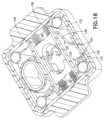
ジョー58は、スプリング98を支持するために突出部材96を含む端面94を有する。スプリング98、または他のバイアス部材は、ハウジング30の内部壁とそれぞれのジョーとの間に設けられて、ジョー58を互いに閉位置に向けてスプリングでバイアスする。一実施形態において、スプリング98は、コイルスプリングである。ジョー58の外側面100は、図15および図17に図示されるように、カムフォロア102を形成する突出部材を含む。示めされる実施形態において、スプリング98は、それぞれの端面94とハウジング30の内部壁との間に延伸してジョーを互いに向けてバイアスするコイルスプリングである。ハウジング30は、ジョー58が閉位置と開位置との間で、実質的に直線方向にスライドすることが可能となるようスロット104を有する内部壁106を含む。図15および図16に図示されるように、それぞれのジョーの側面100から延伸するカムフォロワ102は、内部壁106の中のスロット104を通って延伸する。本実施形態において、スロット104は、ハウジングおよび把持アセンブリ32の長手方向、または軸方向に実質的に垂直な方向に延伸する。
本実施形態において、アクチュエータ108は、ハウジング30に結合されるカバーを画定する。アクチュエータ108は、ジョー58を作動させ、ジョーを閉位置と開位置との間で動かすようハウジングに結合される。本実施形態において、アクチュエータ108は、図5に図示されている延伸位置と図14に図示されている作動位置との間で、ハウジングの外表面上をスライドする。
In this embodiment,
図3に図示されるように、カバーを形成するアクチュエータ108は、ハウジングの外寸法を補完する側壁110と、開下端112と、頂壁114とを有する。側壁110は、ハウジング30に対してアクチュエータ108を操作することを支援するために外向きに突出するタブ116を含む。上壁114は、ペンニードルアセンブリを受け取るために、開口部を画定するカラー118を有する。カラー118は、ハウジングのカラー60の外形および寸法を補完する形状、および寸法を含む内部表面を有することによって、ハウジングに対するアクチュエータの往復運動の間に、カラー118がハウジングのカラー60の上をスライドする。図10に図示されるように、アクチュエータ108は、可動カバーとして図示され、ハウジングに対してアクチュエータ108を誘導することを支援するよう、ハウジング内で上向きに延伸するそれぞれの円筒形ピン122を受け取る下向きに延伸するチャネル120を設ける。
As shown in FIG. 3, the
アクチュエータ108は、ジョーに結合させ、ジョーを開位置と閉位置との間で動かすために、図15および図16に図示されるように、ジョー58、および壁106のそれぞれの反対側に配置される実質的に平面のプレート124を含む。プレート124は、アクチュエータ108に固定され、アクチュエータの動作の間に、アクチュエータ108と共にスライドする。本発明の一実施形態において、それぞれのプレート124は、アクチュエータの動作方向に対して傾斜したカム表面128を画定する2つのスロット126を含む。示されているスロット126は、互いに対して傾斜しており、それぞれのプレート124の下側の端の中心で互いに向い合うように収束している。
本実施形態において、プレート124は、滑らかな動作および移動をもたらすために、ジョーの2つの反対側に関連付けられる。他の実施形態において、単一のプレート、または他のカム機構を設けてよい。図15に図示されるように、スロット126の下側の端は、ハウジングの長手方向に実質的に平行であり、アクチュエータの移動方向に平行で、垂直方向に延伸する底部129を含む。
In this embodiment,
それぞれのジョー58のカムフォロア102は、ハウジング30の内部壁106に形成されるスロット104を通って、プレート124のスロット126へと延伸する。ハウジングに対するアクチュエータ108の下方への動作が、傾斜したカム表面128にジョー58をスライドさせて離す。図15に図示されるように、アクチュエータ108は、ハウジングから延伸する第1の位置にある。カムフォロア102は、それぞれのスロット126で受け取られ、それぞれのスロットの下端に配置され、ジョー58が図15に図示されるように、閉位置にある。図16に図示されるように、アクチュエータ108の下向きの動作は、プレート124におけるカム表面128が、カムフォロア102、およびそれぞれのジョー58を互いに離れるよう動かすことを可能とする。スプリング98は、ジョー58を共に閉位置にバイアスさせ、プレートおよびアクチュエータを元の位置に戻す。他の実施形態において、スプリング、または他の適切なバイアス部材がハウジングに設けられて、アクチュエータ108を図15に図示される元の位置に戻す。
ハウジング30は、患者が内部シールドを取り扱う必要がなく、ペンニードルアセンブリの内部シールド24を取り外すことを支援する抽出機構130を含む。図10および図11に図示されるように、抽出器130は、ハウジングの開上端と下端のキャビティとの間の通路を画定する側壁132を含む。抽出器130は、側壁132に取り付けられた板金クリップから形成することができ、クリップが内部シールドと係合する鋭利なエッジを含む。上壁134は、実質的に鍵穴形状のスロット136を含む。示めされる実施形態において、上壁134は、内部シールド24をスロット136へと誘導することを支援するよう凹面138を有する。キーホール形状のスロット136は、拡大された実質的に円形の開口部140と、円形の開口部140の直径よりも小さい幅を有する長手方向に延伸する開口部142とを有する。円形開口部140は、内部シールド24の最も外側の寸法よりわずかに大きい寸法を有することによって、内部シールドが干渉なしで通過することが可能となる。
The
長手方向部分142の先端144は、円形開口部140に対して内向きに突出し、陥凹領域148を画定する少なくとも1つの歯146を含む。本実施形態の歯146は、鋭い先端150を形成する傾斜面で形成されている。本実施形態において、傾斜面152は、一般的に下向きの方向に傾斜しており、内部シールド24が先端を越えてスライドし、内部シールドが上向きに外れることから抵抗している。歯146は、十分にフレキシブルであることから、内部シールドが開口部を通して押し込まれ、トレイ、またはハウジング内の他の容器へと入り込むことが可能となる。長手方向スロット142の内部長手方向エッジ154は、鋭利なエッジ158に収束する傾斜面156に形成される。傾斜面156は、装置の使用の間に、内部シールドを把持することを支援するよう、ハウジングの下端へ向かって下向きに傾斜している。ハウジングのカバーを形成するアクチュエータ108は、開口部160の内部エッジから延伸する下向きに延伸するカラー162を含む開口部160を含む。図8に図示されるように、カラー162は、抽出器130の側壁132の外寸法を補完する寸法を有することによって、カラー162は、使用の間に抽出器の上をスライドする。
A distal end 144 of
アセンブリは、ユーザがニードルハブ、および露出したカニューレを取り扱う必要がなく、ユーザがハブを搬送ペンに取り付けることを支援するようペンニードルアセンブリを受け取ることが可能である。図6に図示されるように、使用の間に、ラベルは外部カバーから取り外され、ペンニードルアセンブリは、ハウジング30のカラーへと配置されることによって、ペンニードルアセンブリは、ジョー58によって画定された開口領域へと下向きに入る。ペンニードルアセンブリは、ジョー58によって保持され、脚部80の歯92は、底部外部カバー22の外表面と係合する。それぞれのジョーの傾斜面上の戻り止め78は、外部カバーの外表面上のリブと係合して、ジョーに対する外部カバーの回転に抵抗する。
The assembly is capable of receiving the pen needle assembly to assist the user in attaching the hub to the carrier pen without requiring the user to handle the needle hub and exposed cannula. During use, the label is removed from the outer cover and the pen needle assembly is placed into the collar of
図8に図示されるように、次に、搬送ペンが、アクチュエータ108の中のカラー118の開口部、およびハウジング上のカラー162を通して挿入され、ペンニードルアセンブリのニードルハブと係合する。搬送ペンを回転させ、ニードルハブ上の雌ねじと係合させ、搬送ペンに結合する。図9に図示されるように、取り付けられたニードルハブ16を有する搬送ペンは、外部カバー22をジョー58の間に保持したまま、外部カバー22から格納することが可能である。
As illustrated in FIG. 8, the carrier pen is then inserted through the opening of
内部シールド24は、外部カバーから離された場合に、カニューレ20をカバーするようニードルハブ16に取り付けられる。次に、図10および図11に図示されるように、搬送ペンが抽出器130へと挿入され、内部シールド24が長手方向スロット142を通過することによって、エッジ154、および先端150が内部シールドの外表面と係合して内部シールドを把持し、上向きの動作に抵抗する。次に、搬送ペンを抽出して、内部シールド24をスロット142の中に保持したままにしてよい。
An
搬送ペンおよびペンニードルアセンブリ18の使用後に、図12に図示されるように、次に、搬送ペンは、ハウジングのカラー162を通して挿入されることが可能であり、ニードルハブ16が、開口部の中のジョー58の間に保持される外部カバー22の中に再び受け取られる。次に、図13に図示されるように、搬送ペンを回転させ、搬送ペンをニードルハブの雌ねじから接続を解除し、装置から取り外すことが可能である。次に、アクチュエータ108を図14に図示される位置まで押し下げ、カム表面128がジョー58上のそれぞれのカムフォロワ102と係合し、ジョーを直線方向外側へ移動させ、使用済みのニードルハブを含む外部カバー22を解放する。使用済みの外側カバー22、およびニードルハブ16は解放され、開口部を通過し、ハウジングの底部へと入り、そして使用済みのペンニードルアセンブリを収集するためにトレイ40へと入る。アクチュエータ108にかかる下向きの力が解放されることによって、スプリングがアクチュエータ108を元の位置に戻す。
After use of the carrier pen and
新しいペンニードルアセンブリをハウジングの中に配置させることで、手順を繰り返すことができ、搬送ペンをニードルハブに取り付けることが可能である。図15に図示されるように、内部シールド24を有する新しいニードルハブを抽出器130に対する開口部へと挿入させることが可能であり、内部シールドの先端が前のシールドの上端と係合することによって、下向きの力が前のシールドを押し、歯146のフレキシブルエッジ、およびスロット144の長手方向エッジ154を通過する。次に、内部シールド24は、トレイ40へと下向きに落下することが可能である。
The procedure can be repeated by placing a new pen needle assembly into the housing and the carrier pen can be attached to the needle hub. As illustrated in FIG. 15, a new needle hub with
他の実施形態において、搬送デバイスが使用のために準備された後に、後で使用するために内部シールドをニードルハブ16へと戻すことが望ましい場合がある。図17に図示されるように、内部シールド24は、搬送ペンおよびニードルハブを図示される装置へと挿入して戻すことにより、ニードルハブ16のポストへと戻すことが可能である。次に、内部シールド24は、図19および図20に図示されるように、長手方向スロット142に沿って円形の開口部分140までスライドし、内部シールドを抽出器130から解放することが可能である。次に、ニードルハブ、および内部シールド24が取り付けられた搬送ペンを引き出し、後で使用するために保管してよい。
In other embodiments, it may be desirable to return the inner shield to the
図21および図22に図示されるさらなる実施形態において、ニードルハブを搬送ペンから離すことなく、外部カバー22をハブ16に再び取り付けることが可能である。図21に図示されるように、ニードルハブ16が取り付けられた搬送ペンは、カラー、およびハウジングを通して挿入されてよく、そのため、ニードルハブ16は、外部カバー22の中で受け取られる。次に、アクチュエータ108を図22に図示される位置まで押し下げ、ジョー58を離し、外部カバー22を解放することができる。次に、カニューレを保護している外部カバーを用いて搬送ペンを引き出し、不注意による針刺しを回避することが可能となる。
In a further embodiment illustrated in Figures 21 and 22, it is possible to reattach the
図3~図22における実施形態おいて、単一のペンニードルアセンブリを受け取るために、単一の開口ウェルを有する装置が図示されている。代替の実施形態において、アセンブリは、複数のペンニードルアセンブリを収容するために、1つ以上の開口部と、対向するジョーとを有してよい。 In the embodiments in FIGS. 3-22, the device is illustrated with a single open well for receiving a single pen needle assembly. In alternate embodiments, the assembly may have one or more openings and opposing jaws to accommodate multiple pen needle assemblies.
別の実施形態において、アセンブリは、それぞれのペンニードルアセンブリを受け取るために、複数のウェルを有するハウジングを含んでよい。ペンニードルアセンブリの外部カバーを保持するために、把持機構を操作するためにそれぞれのウェルにアクチュエータボタンを設けてよい。 In another embodiment, the assembly may include a housing having multiple wells for receiving respective pen needle assemblies. An actuator button may be provided in each well for operating the gripping mechanism to hold the outer cover of the pen needle assembly.
前述の実施形態、および利点は、単に例示であり、本発明の範囲を限定するものとして解釈されるべきではない。本発明の例示的な実施形態の説明は、例示を意図したものであり、本発明の範囲を限定するものではない。さまざまな修正例、代替例、および変形例は、当業者にとって明らかであり、本発明の範囲内に含まれることが意図されている。異なる実施形態、および請求項の特徴は、互いに矛盾しない限り、互いに組み合わせてよいことを特に留意されたい。したがって、そのようなすべての修正例は、添付の特許請求の範囲、およびそれらの均等物で定義される本発明の範囲内に含まれることが意図されている。 The foregoing embodiments and advantages are exemplary only and should not be construed as limiting the scope of the invention. The description of exemplary embodiments of the invention is intended to be illustrative, not limiting the scope of the invention. Various modifications, alterations, and variations will be apparent to those skilled in the art and are intended to be included within the scope of the invention. It is especially noted that different embodiments and claim features may be combined with each other unless they are inconsistent with each other. Accordingly, all such modifications are intended to be included within the scope of this invention as defined in the following claims and their equivalents.
Claims (27)
第1の位置でペンニードルアセンブリの外部カバーを把持し、第2の位置で前記外部カバーを解放するよう構成された可動把持アセンブリであって、第1の可動ジョーおよび第2の可動ジョーを含む可動把持アセンブリと、
前記可動把持アセンブリに接続され、前記可動把持アセンブリを前記第1の位置から前記第2の位置へ移動させ、前記外部カバーを解放し、それによって前記外部カバーが前記内部キャビティへと入るアクチュエータであって、前記第1の可動ジョーおよび前記第2の可動ジョーとそれぞれ係合するカム表面を含むことにより、前記ペンニードルアセンブリの移動方向と実質的に同一の方向に沿って移動可能に構成された可動カバーを含むアクチュエータと
を備え、
前記可動カバーを前記ハウジングに向けて直線方向に押し下げると、前記第1の可動ジョーおよび第2の可動ジョーが、前記可動カバーの直線方向に垂直となる直線方向に沿って前記第1の位置から前記第2の位置まで移動することを特徴とする、ペンニードルアセンブリ装置。 a housing having an internal cavity, a top end, and a bottom end;
A movable gripping assembly configured to grip an outer cover of a pen needle assembly at a first position and release the outer cover at a second position , the movable gripping assembly including a first movable jaw and a second movable jaw. a movable gripping assembly ;
an actuator connected to the movable gripping assembly to move the movable gripping assembly from the first position to the second position to release the outer cover thereby allowing the outer cover to enter the inner cavity; and is movable along a direction substantially the same as the direction of movement of the pen needle assembly by including cam surfaces respectively engaging the first movable jaw and the second movable jaw. an actuator including a mounted movable cover ;
When the movable cover is pushed down toward the housing in a linear direction, the first movable jaw and the second movable jaw move from the first position along a linear direction perpendicular to the linear direction of the movable cover. A pen needle assembly device , characterized in that it moves to said second position .
前記ハウジングに結合され、前記ペンニードルアセンブリの外部カバーを第1の位置で把持し、第2の位置へ移動させ、前記外部カバーを解放するよう構成された可動把持アセンブリであって、第1の可動ジョーおよび第2の可動ジョーを含む可動把持アセンブリと、
前記ハウジングに結合され、前記外部カバーの外表面を把持するための把持部材を前記第1の位置から前記第2の位置へ移動させ、前記装置から外部カバーを解放する前記可動把持アセンブリに結合されたアクチュエータであって、前記第1の可動ジョーおよび前記第2の可動ジョーとそれぞれ係合するカム表面を含むことにより、前記ペンニードルアセンブリの移動方向と実質的に同一の方向に沿って移動可能に構成された可動カバーを含む、アクチュエータと、
を備え、
前記可動カバーを前記ハウジングに向けて直線方向に押し下げると、前記第1の可動ジョーおよび第2の可動ジョーが、前記可動カバーの直線方向に垂直となる直線方向に沿って前記第1の位置から前記第2の位置まで移動することを特徴とする、ペンニードルアセンブリ装置。 an internal cavity, a bottom portion, an opening top configured to receive a pen needle assembly , and a portion for engaging the internal shield of the pen needle assembly to remove the internal shield from the needle hub of the pen needle assembly. a housing having an opening;
A movable gripping assembly coupled to the housing and configured to grip an outer cover of the pen needle assembly in a first position and move it to a second position to release the outer cover , the first a movable gripping assembly including a movable jaw and a second movable jaw ;
A gripping member coupled to the housing and coupled to the movable gripping assembly for moving a gripping member for gripping an outer surface of the outer cover from the first position to the second position to release the outer cover from the device. an actuator including cam surfaces respectively engaging said first movable jaw and said second movable jaw so as to be movable along a direction substantially the same as the direction of movement of said pen needle assembly; an actuator including a movable cover configured to
with
When the movable cover is pushed down toward the housing in a linear direction, the first movable jaw and the second movable jaw move from the first position along a linear direction perpendicular to the linear direction of the movable cover. A pen needle assembly device , characterized in that it moves to said second position .
ペンニードルアセンブリ装置の中のペンニードルアセンブリを、前記ペンニードルアセンブリの外部カバーを把持し、前記ペンニードルアセンブリへ前記搬送ペンを取り付けるために、可動把持アセンブリの第1の可動ジョーと第2の可動ジョーとの間に配置するステップと、
前記ペンおよびニードルハブを前記外部カバーから取り外し、前記ペンニードルの内部シールドを前記装置の中の開口部へと挿入して前記内部シールドを把持し、前記内部シールドを前記ペンニードルアセンブリの前記ニードルハブから取り外すステップと、
使用後に、前記ニードルハブを前記外部カバーへと挿入し、前記ペンを前記ニードルハブから離すステップと、
アクチュエータが結合されたハウジングに向けて直線方向に前記アクチュエータの可動カバーを押し下げて、前記可動カバーの直線方向に垂直となる直線方向に沿って前記外部カバーを把持する第1の位置から前記外部カバーおよび前記ニードルハブを解放する第2の位置まで前記第1の可動ジョーおよび第2の可動ジョーを移動させるステップであって、前記可動カバーは、前記第1の可動ジョーおよび前記第2の可動ジョーとそれぞれ係合するカム表面を含むことにより、前記ペンニードルアセンブリの移動方向と実質的に同一の方向に沿って移動可能に構成されている、ステップと
を備えた方法。 A method of coupling a pen needle to a carrier pen, the method comprising:
A first movable jaw and a second movable jaw of a movable gripping assembly for gripping an outer cover of said pen needle assembly and attaching said carrier pen to said pen needle assembly in a pen needle assembly apparatus. a step positioned between the jaws;
removing the pen and needle hub from the outer cover; inserting the inner shield of the pen needle into an opening in the device to grasp the inner shield; removing from
after use, inserting the needle hub into the outer cover and releasing the pen from the needle hub;
Depressing the movable cover of the actuator in a linear direction toward the housing to which the actuator is coupled and gripping the outer cover along a linear direction perpendicular to the linear direction of the movable cover from a first position. and moving the first movable jaw and the second movable jaw to a second position that releases the needle hub , wherein the movable cover covers the first movable jaw and the second movable jaw. configured to move along a direction substantially the same as the direction of movement of the pen needle assembly by including cam surfaces respectively engaging with .
前記第2のジョーと係合する第2のカム表面とを有する第2のカム部材とを含み、前記第1のカム部材の前記第1カム表面および第2のカム表面は、前記第1のジョーおよび第2のジョーの第1の側とそれぞれ係合し、前記第2のカム部材の前記第1のカム表面および第2のカム表面が、前記第1のジョーおよび第2のジョーの第2の側とそれぞれ係合する、請求項24に記載のペンニードル装置。 the actuator includes a first cam surface engaging the first jaw;
a second cam member having a second cam surface that engages the second jaw, the first cam surface and the second cam surface of the first cam member being aligned with the first cam surface; The first cam surface and the second cam surface of the second cam member engage the first sides of the jaw and the second jaw, respectively, and the first cam surface and the second cam surface of the first jaw and the second jaw engage the first sides of the first jaw and the second jaw, respectively. 25. The pen needle device of claim 24 , each engaging two sides.
Applications Claiming Priority (5)
| Application Number | Priority Date | Filing Date | Title |
|---|---|---|---|
| CN201711456114.7 | 2017-12-28 | ||
| CN201711456114.7A CN109966596B (en) | 2017-12-28 | 2017-12-28 | Pen Needle Assembly Equipment |
| CN201721886196.4U CN209378203U (en) | 2017-12-28 | 2017-12-28 | Pen needle assembly equipment |
| CN201721886196.4 | 2017-12-28 | ||
| PCT/US2018/066539 WO2019133392A1 (en) | 2017-12-28 | 2018-12-19 | Pen needle assembly apparatus |
Publications (2)
| Publication Number | Publication Date |
|---|---|
| JP2021509047A JP2021509047A (en) | 2021-03-18 |
| JP7246397B2 true JP7246397B2 (en) | 2023-03-27 |
Family
ID=67064134
Family Applications (1)
| Application Number | Title | Priority Date | Filing Date |
|---|---|---|---|
| JP2020535991A Active JP7246397B2 (en) | 2017-12-28 | 2018-12-19 | Pen needle assembly device |
Country Status (5)
| Country | Link |
|---|---|
| US (1) | US11744957B2 (en) |
| EP (1) | EP3731908A4 (en) |
| JP (1) | JP7246397B2 (en) |
| CA (1) | CA3086899A1 (en) |
| WO (1) | WO2019133392A1 (en) |
Citations (3)
| Publication number | Priority date | Publication date | Assignee | Title |
|---|---|---|---|---|
| JP2007014615A (en) | 2005-07-08 | 2007-01-25 | Hideo Takahashi | Assisting tool for insulin injection |
| US20090014462A1 (en) | 2007-07-10 | 2009-01-15 | Pharmadesign, Inc. | Needle dispenser system and hand tool for same |
| JP2015139623A (en) | 2014-01-30 | 2015-08-03 | 邦明 辰己 | Needle disposal container |
Family Cites Families (39)
| Publication number | Priority date | Publication date | Assignee | Title |
|---|---|---|---|---|
| US4375849A (en) * | 1981-05-15 | 1983-03-08 | Sage Products, Inc. | Syringe needle removal and disposal device |
| US4801013A (en) * | 1987-02-10 | 1989-01-31 | John Bruno | Containment device for safely removing, storing and ultimately disposing of needles from hypodermic needle/syringe assemblies |
| US5187850A (en) * | 1987-04-22 | 1993-02-23 | Mccammon John W | Needle disposal system |
| EP0296406A1 (en) * | 1987-06-19 | 1988-12-28 | EXPER-KG DES PERONI GUENTHER & CO.-S.A.S. | Device to remove protection caps and cannula needles from injection syringes |
| US4738362A (en) * | 1987-09-21 | 1988-04-19 | Beral Enterprises | Device for removal and disposal of syringe needles |
| JPH0451789Y2 (en) * | 1988-02-04 | 1992-12-07 | ||
| US4986811A (en) * | 1988-09-23 | 1991-01-22 | Post Medical, Inc. | Apparatus and method for safely removing needles from syringes |
| US4989307A (en) * | 1989-05-11 | 1991-02-05 | Sharpe Kenneth M | Apparatus for facilitating of the removal and disposal of medical needles |
| US5024666A (en) * | 1989-09-18 | 1991-06-18 | Pituch Daniel W | Medical needle sheath holding apparatus |
| US5086922A (en) * | 1990-06-12 | 1992-02-11 | Medical Safety Products, Inc. | Disposal for needles and syringes |
| US5273161A (en) * | 1991-05-31 | 1993-12-28 | Medical Safety Products, Inc. | Needle disposal system comprised of blood collection holder and companion biohazard receptacle |
| US5275280A (en) * | 1992-05-08 | 1994-01-04 | Everhart Shawn L | Device and method of removal and storage of syringe needle |
| US5312346A (en) * | 1993-02-16 | 1994-05-17 | Han Medical Designs, Inc. | Needle removing device |
| US5469964A (en) * | 1994-03-29 | 1995-11-28 | Bailey; Eddy R. | Multiple syringe unsheathing and resheathing device |
| IN189561B (en) * | 1996-06-21 | 2003-03-29 | Bio Plexus Inc | |
| US5947950A (en) * | 1998-02-19 | 1999-09-07 | Med-Safe Systems, Inc. | Gear driven needle removal device |
| DE20119949U1 (en) * | 2001-12-04 | 2002-04-18 | Suppan, Jakob, 74354 Besigheim | Device for the contactless removal and disposal of used disposable cannulas |
| USD482448S1 (en) * | 2002-05-24 | 2003-11-18 | Becton, Dickinson And Company | Needle disposal container |
| WO2004075806A1 (en) * | 2003-02-27 | 2004-09-10 | Showa Yakuhin Kako Co.,Ltd. | Syringe needle removing device for dental cartridge type syringes |
| US7556623B2 (en) * | 2003-09-03 | 2009-07-07 | Amgen Inc. | Tool for use with a medication vial and/or a syringe |
| US7344027B2 (en) * | 2004-06-07 | 2008-03-18 | Ultimed, Inc. | Sharps container for “no-touch,” sequential safe storage of used pen needles |
| GB2415141A (en) * | 2004-06-19 | 2005-12-21 | Stephen Francis Gerard Cooley | Medical needle removal device |
| JP5161622B2 (en) * | 2008-03-19 | 2013-03-13 | テルモ株式会社 | Needle removal device |
| GB0808158D0 (en) | 2008-05-06 | 2008-06-11 | Harrison Nicholas | Needle dispenser |
| AU2009202158A1 (en) | 2008-05-30 | 2009-12-17 | Safety Medical Products Limited | Safety device for a needle pen |
| DK2424598T3 (en) * | 2009-04-30 | 2014-03-17 | Sanofi Aventis Deutschland | The needle collector and process for the removal of the cannula. |
| US8876780B2 (en) * | 2010-08-16 | 2014-11-04 | Becton, Dickinson And Company | Attachable needle changing device for medicament delivery device |
| EP2529777A1 (en) * | 2011-05-30 | 2012-12-05 | Sanofi-Aventis Deutschland GmbH | Needle assembly removal device |
| US8829394B2 (en) * | 2011-06-08 | 2014-09-09 | Becton, Dickinson And Company | Medical needle removal and storage device |
| ITBO20110360A1 (en) * | 2011-06-22 | 2012-12-23 | Health Robotics Srl | EQUIPMENT FOR REMOVING SYRINGE NEEDLES |
| EP2540329A1 (en) * | 2011-06-28 | 2013-01-02 | Sanofi-Aventis Deutschland GmbH | Needle assembly attachment and removal device |
| EP2596825A1 (en) * | 2011-11-24 | 2013-05-29 | Sanofi-Aventis Deutschland GmbH | Needle assembly attachment and removal device |
| WO2013146868A1 (en) * | 2012-03-28 | 2013-10-03 | テルモ株式会社 | Disposal container |
| US8875882B1 (en) * | 2013-04-16 | 2014-11-04 | Maan G. Salloum | Holder and disposal device for hypodermic needles |
| WO2015148257A1 (en) * | 2014-03-25 | 2015-10-01 | Inventive Medical Devices, Llc | Apparatus and method of automatically removing a needle from a hub |
| US10118000B2 (en) * | 2014-04-21 | 2018-11-06 | Stat Medical Devices, Inc. | Pen needle installation and removal safety cover and pen needle assembly utilizing the same |
| JP6346025B2 (en) * | 2014-07-31 | 2018-06-20 | ニプロ株式会社 | Needle disposal container |
| JP6596368B2 (en) * | 2016-03-17 | 2019-10-23 | 日本発條株式会社 | Needle detachment assist device |
| US12370320B2 (en) * | 2021-06-21 | 2025-07-29 | Medtronic Minimed, Inc. | Accessory devices, systems, and methods for medicine administration and tracking |
-
2018
- 2018-12-19 WO PCT/US2018/066539 patent/WO2019133392A1/en not_active Ceased
- 2018-12-19 EP EP18897502.3A patent/EP3731908A4/en not_active Withdrawn
- 2018-12-19 JP JP2020535991A patent/JP7246397B2/en active Active
- 2018-12-19 US US16/957,689 patent/US11744957B2/en active Active
- 2018-12-19 CA CA3086899A patent/CA3086899A1/en active Pending
Patent Citations (3)
| Publication number | Priority date | Publication date | Assignee | Title |
|---|---|---|---|---|
| JP2007014615A (en) | 2005-07-08 | 2007-01-25 | Hideo Takahashi | Assisting tool for insulin injection |
| US20090014462A1 (en) | 2007-07-10 | 2009-01-15 | Pharmadesign, Inc. | Needle dispenser system and hand tool for same |
| JP2015139623A (en) | 2014-01-30 | 2015-08-03 | 邦明 辰己 | Needle disposal container |
Also Published As
| Publication number | Publication date |
|---|---|
| US20200360622A1 (en) | 2020-11-19 |
| EP3731908A4 (en) | 2021-09-15 |
| US11744957B2 (en) | 2023-09-05 |
| WO2019133392A1 (en) | 2019-07-04 |
| EP3731908A1 (en) | 2020-11-04 |
| JP2021509047A (en) | 2021-03-18 |
| CA3086899A1 (en) | 2019-07-04 |
Similar Documents
| Publication | Publication Date | Title |
|---|---|---|
| US12569626B2 (en) | Pen needle removal device for a drug delivery device | |
| US11602600B2 (en) | Apparatus for mounting a pen needle assembly | |
| CN106794315B (en) | Needle device | |
| US20210170092A1 (en) | Pen needle assembly apparatus | |
| JP7266605B2 (en) | pen needle assembly instrument | |
| US20220031959A1 (en) | Pen needle apparatus | |
| CN207119035U (en) | Supporting arrangement and storage device | |
| JP7246397B2 (en) | Pen needle assembly device | |
| CN209378203U (en) | Pen needle assembly equipment | |
| CN209900309U (en) | Pen type needle assembly device | |
| CN109966596B (en) | Pen Needle Assembly Equipment | |
| CN108144159B (en) | Device for mounting a pen needle assembly | |
| CN110898291B (en) | Pen needle equipment | |
| CN109966595B (en) | Pen needle assembly apparatus and method of coupling a pen needle to a delivery pen | |
| CN110384841B (en) | Pen type needle assembly device |
Legal Events
| Date | Code | Title | Description |
|---|---|---|---|
| A621 | Written request for application examination |
Free format text: JAPANESE INTERMEDIATE CODE: A621 Effective date: 20211202 |
|
| A711 | Notification of change in applicant |
Free format text: JAPANESE INTERMEDIATE CODE: A711 Effective date: 20220616 |
|
| A131 | Notification of reasons for refusal |
Free format text: JAPANESE INTERMEDIATE CODE: A131 Effective date: 20221004 |
|
| A977 | Report on retrieval |
Free format text: JAPANESE INTERMEDIATE CODE: A971007 Effective date: 20221007 |
|
| A521 | Request for written amendment filed |
Free format text: JAPANESE INTERMEDIATE CODE: A523 Effective date: 20221209 |
|
| TRDD | Decision of grant or rejection written | ||
| A01 | Written decision to grant a patent or to grant a registration (utility model) |
Free format text: JAPANESE INTERMEDIATE CODE: A01 Effective date: 20230214 |
|
| A61 | First payment of annual fees (during grant procedure) |
Free format text: JAPANESE INTERMEDIATE CODE: A61 Effective date: 20230314 |
|
| R150 | Certificate of patent or registration of utility model |
Ref document number: 7246397 Country of ref document: JP Free format text: JAPANESE INTERMEDIATE CODE: R150 |