JP7246040B2 - Catalyst, method for producing catalyst, and method for producing synthesis gas - Google Patents
Catalyst, method for producing catalyst, and method for producing synthesis gas Download PDFInfo
- Publication number
- JP7246040B2 JP7246040B2 JP2018199298A JP2018199298A JP7246040B2 JP 7246040 B2 JP7246040 B2 JP 7246040B2 JP 2018199298 A JP2018199298 A JP 2018199298A JP 2018199298 A JP2018199298 A JP 2018199298A JP 7246040 B2 JP7246040 B2 JP 7246040B2
- Authority
- JP
- Japan
- Prior art keywords
- catalyst
- zeolite
- particles
- raw material
- metal
- Prior art date
- Legal status (The legal status is an assumption and is not a legal conclusion. Google has not performed a legal analysis and makes no representation as to the accuracy of the status listed.)
- Active
Links
- 239000003054 catalyst Substances 0.000 title claims description 219
- 238000004519 manufacturing process Methods 0.000 title claims description 38
- 230000015572 biosynthetic process Effects 0.000 title claims description 31
- 238000003786 synthesis reaction Methods 0.000 title claims description 28
- 239000010457 zeolite Substances 0.000 claims description 132
- HNPSIPDUKPIQMN-UHFFFAOYSA-N dioxosilane;oxo(oxoalumanyloxy)alumane Chemical compound O=[Si]=O.O=[Al]O[Al]=O HNPSIPDUKPIQMN-UHFFFAOYSA-N 0.000 claims description 125
- 229910021536 Zeolite Inorganic materials 0.000 claims description 123
- 239000002994 raw material Substances 0.000 claims description 83
- 239000002245 particle Substances 0.000 claims description 70
- CURLTUGMZLYLDI-UHFFFAOYSA-N Carbon dioxide Chemical compound O=C=O CURLTUGMZLYLDI-UHFFFAOYSA-N 0.000 claims description 64
- PXHVJJICTQNCMI-UHFFFAOYSA-N Nickel Chemical compound [Ni] PXHVJJICTQNCMI-UHFFFAOYSA-N 0.000 claims description 64
- 229910052751 metal Inorganic materials 0.000 claims description 61
- 239000002184 metal Substances 0.000 claims description 57
- VNWKTOKETHGBQD-UHFFFAOYSA-N methane Chemical compound C VNWKTOKETHGBQD-UHFFFAOYSA-N 0.000 claims description 54
- 239000007789 gas Substances 0.000 claims description 53
- 150000001875 compounds Chemical class 0.000 claims description 42
- 239000010703 silicon Substances 0.000 claims description 37
- 229910052710 silicon Inorganic materials 0.000 claims description 37
- XUIMIQQOPSSXEZ-UHFFFAOYSA-N Silicon Chemical compound [Si] XUIMIQQOPSSXEZ-UHFFFAOYSA-N 0.000 claims description 36
- 229910002092 carbon dioxide Inorganic materials 0.000 claims description 32
- 229910052759 nickel Inorganic materials 0.000 claims description 32
- UGFAIRIUMAVXCW-UHFFFAOYSA-N Carbon monoxide Chemical compound [O+]#[C-] UGFAIRIUMAVXCW-UHFFFAOYSA-N 0.000 claims description 31
- 229910002091 carbon monoxide Inorganic materials 0.000 claims description 31
- 239000007864 aqueous solution Substances 0.000 claims description 30
- 238000006243 chemical reaction Methods 0.000 claims description 30
- 239000011148 porous material Substances 0.000 claims description 29
- 229930195733 hydrocarbon Natural products 0.000 claims description 22
- 150000002430 hydrocarbons Chemical class 0.000 claims description 22
- VYPSYNLAJGMNEJ-UHFFFAOYSA-N Silicium dioxide Chemical compound O=[Si]=O VYPSYNLAJGMNEJ-UHFFFAOYSA-N 0.000 claims description 21
- 239000001569 carbon dioxide Substances 0.000 claims description 21
- 239000000693 micelle Substances 0.000 claims description 19
- UFHFLCQGNIYNRP-UHFFFAOYSA-N Hydrogen Chemical compound [H][H] UFHFLCQGNIYNRP-UHFFFAOYSA-N 0.000 claims description 18
- 238000010438 heat treatment Methods 0.000 claims description 18
- 229910052739 hydrogen Inorganic materials 0.000 claims description 17
- 239000001257 hydrogen Substances 0.000 claims description 17
- 239000004094 surface-active agent Substances 0.000 claims description 17
- 239000002131 composite material Substances 0.000 claims description 16
- 239000003960 organic solvent Substances 0.000 claims description 15
- 239000000243 solution Substances 0.000 claims description 15
- 239000000377 silicon dioxide Substances 0.000 claims description 9
- 238000006555 catalytic reaction Methods 0.000 claims description 5
- 150000002500 ions Chemical class 0.000 claims description 4
- 239000008236 heating water Substances 0.000 claims description 2
- 239000002923 metal particle Substances 0.000 description 94
- 238000000034 method Methods 0.000 description 66
- 238000002407 reforming Methods 0.000 description 65
- 230000000052 comparative effect Effects 0.000 description 59
- 239000007788 liquid Substances 0.000 description 56
- XLYOFNOQVPJJNP-UHFFFAOYSA-N water Substances O XLYOFNOQVPJJNP-UHFFFAOYSA-N 0.000 description 32
- 238000001027 hydrothermal synthesis Methods 0.000 description 28
- 239000000571 coke Substances 0.000 description 24
- 239000000047 product Substances 0.000 description 24
- 238000010304 firing Methods 0.000 description 15
- 150000003839 salts Chemical class 0.000 description 15
- BOTDANWDWHJENH-UHFFFAOYSA-N Tetraethyl orthosilicate Chemical compound CCO[Si](OCC)(OCC)OCC BOTDANWDWHJENH-UHFFFAOYSA-N 0.000 description 14
- 239000003795 chemical substances by application Substances 0.000 description 13
- 230000008569 process Effects 0.000 description 13
- 238000002411 thermogravimetry Methods 0.000 description 13
- LPSKDVINWQNWFE-UHFFFAOYSA-M tetrapropylazanium;hydroxide Chemical compound [OH-].CCC[N+](CCC)(CCC)CCC LPSKDVINWQNWFE-UHFFFAOYSA-M 0.000 description 12
- 108700031620 S-acetylthiorphan Proteins 0.000 description 11
- 150000002739 metals Chemical class 0.000 description 11
- KBJMLQFLOWQJNF-UHFFFAOYSA-N nickel(ii) nitrate Chemical compound [Ni+2].[O-][N+]([O-])=O.[O-][N+]([O-])=O KBJMLQFLOWQJNF-UHFFFAOYSA-N 0.000 description 11
- 230000035484 reaction time Effects 0.000 description 10
- 230000000694 effects Effects 0.000 description 9
- 238000006460 hydrolysis reaction Methods 0.000 description 9
- 229910021645 metal ion Inorganic materials 0.000 description 9
- QGZKDVFQNNGYKY-UHFFFAOYSA-N Ammonia Chemical compound N QGZKDVFQNNGYKY-UHFFFAOYSA-N 0.000 description 8
- XKRFYHLGVUSROY-UHFFFAOYSA-N Argon Chemical compound [Ar] XKRFYHLGVUSROY-UHFFFAOYSA-N 0.000 description 8
- 239000004215 Carbon black (E152) Substances 0.000 description 8
- 238000004458 analytical method Methods 0.000 description 8
- 230000007062 hydrolysis Effects 0.000 description 8
- 238000005259 measurement Methods 0.000 description 8
- 239000004530 micro-emulsion Substances 0.000 description 8
- 238000005580 one pot reaction Methods 0.000 description 8
- 238000005245 sintering Methods 0.000 description 8
- 239000012298 atmosphere Substances 0.000 description 7
- 239000000843 powder Substances 0.000 description 7
- IJGRMHOSHXDMSA-UHFFFAOYSA-N Atomic nitrogen Chemical compound N#N IJGRMHOSHXDMSA-UHFFFAOYSA-N 0.000 description 6
- 238000005119 centrifugation Methods 0.000 description 6
- 229910001873 dinitrogen Inorganic materials 0.000 description 6
- IKDUDTNKRLTJSI-UHFFFAOYSA-N hydrazine hydrate Chemical compound O.NN IKDUDTNKRLTJSI-UHFFFAOYSA-N 0.000 description 6
- BASFCYQUMIYNBI-UHFFFAOYSA-N platinum Chemical group [Pt] BASFCYQUMIYNBI-UHFFFAOYSA-N 0.000 description 6
- -1 polyoxyethylene Polymers 0.000 description 6
- 230000009467 reduction Effects 0.000 description 6
- KDLHZDBZIXYQEI-UHFFFAOYSA-N Palladium Chemical compound [Pd] KDLHZDBZIXYQEI-UHFFFAOYSA-N 0.000 description 5
- 229920003171 Poly (ethylene oxide) Polymers 0.000 description 5
- 229910004298 SiO 2 Inorganic materials 0.000 description 5
- 150000004703 alkoxides Chemical class 0.000 description 5
- 239000003638 chemical reducing agent Substances 0.000 description 5
- 239000011248 coating agent Substances 0.000 description 5
- 238000000576 coating method Methods 0.000 description 5
- 238000004939 coking Methods 0.000 description 5
- 230000007423 decrease Effects 0.000 description 5
- 239000010419 fine particle Substances 0.000 description 5
- 238000001179 sorption measurement Methods 0.000 description 5
- NLXLAEXVIDQMFP-UHFFFAOYSA-N Ammonium chloride Substances [NH4+].[Cl-] NLXLAEXVIDQMFP-UHFFFAOYSA-N 0.000 description 4
- VHUUQVKOLVNVRT-UHFFFAOYSA-N Ammonium hydroxide Chemical compound [NH4+].[OH-] VHUUQVKOLVNVRT-UHFFFAOYSA-N 0.000 description 4
- RTZKZFJDLAIYFH-UHFFFAOYSA-N Diethyl ether Chemical compound CCOCC RTZKZFJDLAIYFH-UHFFFAOYSA-N 0.000 description 4
- XEEYBQQBJWHFJM-UHFFFAOYSA-N Iron Chemical compound [Fe] XEEYBQQBJWHFJM-UHFFFAOYSA-N 0.000 description 4
- 235000011114 ammonium hydroxide Nutrition 0.000 description 4
- 229910052786 argon Inorganic materials 0.000 description 4
- 238000005470 impregnation Methods 0.000 description 4
- 238000002156 mixing Methods 0.000 description 4
- 239000000203 mixture Substances 0.000 description 4
- 239000002244 precipitate Substances 0.000 description 4
- FDCJDKXCCYFOCV-UHFFFAOYSA-N 1-hexadecoxyhexadecane Chemical compound CCCCCCCCCCCCCCCCOCCCCCCCCCCCCCCCC FDCJDKXCCYFOCV-UHFFFAOYSA-N 0.000 description 3
- 239000002253 acid Substances 0.000 description 3
- 230000002776 aggregation Effects 0.000 description 3
- 150000001335 aliphatic alkanes Chemical class 0.000 description 3
- 229910052782 aluminium Inorganic materials 0.000 description 3
- XAGFODPZIPBFFR-UHFFFAOYSA-N aluminium Chemical compound [Al] XAGFODPZIPBFFR-UHFFFAOYSA-N 0.000 description 3
- PNEYBMLMFCGWSK-UHFFFAOYSA-N aluminium oxide Inorganic materials [O-2].[O-2].[O-2].[Al+3].[Al+3] PNEYBMLMFCGWSK-UHFFFAOYSA-N 0.000 description 3
- 230000008859 change Effects 0.000 description 3
- 239000010949 copper Substances 0.000 description 3
- 238000001035 drying Methods 0.000 description 3
- 239000010931 gold Substances 0.000 description 3
- 238000005342 ion exchange Methods 0.000 description 3
- OFBQJSOFQDEBGM-UHFFFAOYSA-N n-pentane Natural products CCCCC OFBQJSOFQDEBGM-UHFFFAOYSA-N 0.000 description 3
- 239000010948 rhodium Substances 0.000 description 3
- 239000011550 stock solution Substances 0.000 description 3
- LFQCEHFDDXELDD-UHFFFAOYSA-N tetramethyl orthosilicate Chemical compound CO[Si](OC)(OC)OC LFQCEHFDDXELDD-UHFFFAOYSA-N 0.000 description 3
- 238000005406 washing Methods 0.000 description 3
- 238000004438 BET method Methods 0.000 description 2
- XDTMQSROBMDMFD-UHFFFAOYSA-N Cyclohexane Chemical compound C1CCCCC1 XDTMQSROBMDMFD-UHFFFAOYSA-N 0.000 description 2
- OAKJQQAXSVQMHS-UHFFFAOYSA-N Hydrazine Chemical compound NN OAKJQQAXSVQMHS-UHFFFAOYSA-N 0.000 description 2
- VEXZGXHMUGYJMC-UHFFFAOYSA-N Hydrochloric acid Chemical compound Cl VEXZGXHMUGYJMC-UHFFFAOYSA-N 0.000 description 2
- ATUOYWHBWRKTHZ-UHFFFAOYSA-N Propane Chemical compound CCC ATUOYWHBWRKTHZ-UHFFFAOYSA-N 0.000 description 2
- KJTLSVCANCCWHF-UHFFFAOYSA-N Ruthenium Chemical compound [Ru] KJTLSVCANCCWHF-UHFFFAOYSA-N 0.000 description 2
- BQCADISMDOOEFD-UHFFFAOYSA-N Silver Chemical compound [Ag] BQCADISMDOOEFD-UHFFFAOYSA-N 0.000 description 2
- PKPDMQHIYXYXTQ-UHFFFAOYSA-N [Ni].NN Chemical compound [Ni].NN PKPDMQHIYXYXTQ-UHFFFAOYSA-N 0.000 description 2
- 150000007513 acids Chemical class 0.000 description 2
- 238000004220 aggregation Methods 0.000 description 2
- 229910021529 ammonia Inorganic materials 0.000 description 2
- 230000005540 biological transmission Effects 0.000 description 2
- 229910052797 bismuth Inorganic materials 0.000 description 2
- 229910052792 caesium Inorganic materials 0.000 description 2
- TVFDJXOCXUVLDH-UHFFFAOYSA-N caesium atom Chemical compound [Cs] TVFDJXOCXUVLDH-UHFFFAOYSA-N 0.000 description 2
- 238000001354 calcination Methods 0.000 description 2
- 239000011575 calcium Substances 0.000 description 2
- 230000003197 catalytic effect Effects 0.000 description 2
- 239000011651 chromium Substances 0.000 description 2
- 229910017052 cobalt Inorganic materials 0.000 description 2
- 239000010941 cobalt Substances 0.000 description 2
- GUTLYIVDDKVIGB-UHFFFAOYSA-N cobalt atom Chemical compound [Co] GUTLYIVDDKVIGB-UHFFFAOYSA-N 0.000 description 2
- 229910052802 copper Inorganic materials 0.000 description 2
- 239000013078 crystal Substances 0.000 description 2
- 238000004993 emission spectroscopy Methods 0.000 description 2
- 238000001704 evaporation Methods 0.000 description 2
- 230000008020 evaporation Effects 0.000 description 2
- 238000001914 filtration Methods 0.000 description 2
- PCHJSUWPFVWCPO-UHFFFAOYSA-N gold Chemical compound [Au] PCHJSUWPFVWCPO-UHFFFAOYSA-N 0.000 description 2
- 229910052737 gold Inorganic materials 0.000 description 2
- 239000001307 helium Substances 0.000 description 2
- 229910052734 helium Inorganic materials 0.000 description 2
- SWQJXJOGLNCZEY-UHFFFAOYSA-N helium atom Chemical compound [He] SWQJXJOGLNCZEY-UHFFFAOYSA-N 0.000 description 2
- 150000002431 hydrogen Chemical class 0.000 description 2
- 230000001771 impaired effect Effects 0.000 description 2
- 238000009616 inductively coupled plasma Methods 0.000 description 2
- 229910052741 iridium Inorganic materials 0.000 description 2
- GKOZUEZYRPOHIO-UHFFFAOYSA-N iridium atom Chemical compound [Ir] GKOZUEZYRPOHIO-UHFFFAOYSA-N 0.000 description 2
- 229910052742 iron Inorganic materials 0.000 description 2
- 239000010955 niobium Substances 0.000 description 2
- 229910052762 osmium Inorganic materials 0.000 description 2
- SYQBFIAQOQZEGI-UHFFFAOYSA-N osmium atom Chemical compound [Os] SYQBFIAQOQZEGI-UHFFFAOYSA-N 0.000 description 2
- 229910052763 palladium Inorganic materials 0.000 description 2
- 229910052697 platinum Inorganic materials 0.000 description 2
- 238000000746 purification Methods 0.000 description 2
- 229910052703 rhodium Inorganic materials 0.000 description 2
- MHOVAHRLVXNVSD-UHFFFAOYSA-N rhodium atom Chemical compound [Rh] MHOVAHRLVXNVSD-UHFFFAOYSA-N 0.000 description 2
- 229910052707 ruthenium Inorganic materials 0.000 description 2
- 229910052709 silver Inorganic materials 0.000 description 2
- 239000004332 silver Substances 0.000 description 2
- 239000011734 sodium Substances 0.000 description 2
- 239000010936 titanium Substances 0.000 description 2
- PHYFQTYBJUILEZ-IUPFWZBJSA-N triolein Chemical compound CCCCCCCC\C=C/CCCCCCCC(=O)OCC(OC(=O)CCCCCCC\C=C/CCCCCCCC)COC(=O)CCCCCCC\C=C/CCCCCCCC PHYFQTYBJUILEZ-IUPFWZBJSA-N 0.000 description 2
- 229910052727 yttrium Inorganic materials 0.000 description 2
- OYPRJOBELJOOCE-UHFFFAOYSA-N Calcium Chemical compound [Ca] OYPRJOBELJOOCE-UHFFFAOYSA-N 0.000 description 1
- OKTJSMMVPCPJKN-UHFFFAOYSA-N Carbon Chemical compound [C] OKTJSMMVPCPJKN-UHFFFAOYSA-N 0.000 description 1
- VYZAMTAEIAYCRO-UHFFFAOYSA-N Chromium Chemical compound [Cr] VYZAMTAEIAYCRO-UHFFFAOYSA-N 0.000 description 1
- RYGMFSIKBFXOCR-UHFFFAOYSA-N Copper Chemical compound [Cu] RYGMFSIKBFXOCR-UHFFFAOYSA-N 0.000 description 1
- 229910052692 Dysprosium Inorganic materials 0.000 description 1
- 229910052691 Erbium Inorganic materials 0.000 description 1
- OTMSDBZUPAUEDD-UHFFFAOYSA-N Ethane Chemical compound CC OTMSDBZUPAUEDD-UHFFFAOYSA-N 0.000 description 1
- VGGSQFUCUMXWEO-UHFFFAOYSA-N Ethene Chemical compound C=C VGGSQFUCUMXWEO-UHFFFAOYSA-N 0.000 description 1
- 239000005977 Ethylene Substances 0.000 description 1
- 229910052693 Europium Inorganic materials 0.000 description 1
- 229910052688 Gadolinium Inorganic materials 0.000 description 1
- GYHNNYVSQQEPJS-UHFFFAOYSA-N Gallium Chemical compound [Ga] GYHNNYVSQQEPJS-UHFFFAOYSA-N 0.000 description 1
- 229910052689 Holmium Inorganic materials 0.000 description 1
- DGAQECJNVWCQMB-PUAWFVPOSA-M Ilexoside XXIX Chemical compound C[C@@H]1CC[C@@]2(CC[C@@]3(C(=CC[C@H]4[C@]3(CC[C@@H]5[C@@]4(CC[C@@H](C5(C)C)OS(=O)(=O)[O-])C)C)[C@@H]2[C@]1(C)O)C)C(=O)O[C@H]6[C@@H]([C@H]([C@@H]([C@H](O6)CO)O)O)O.[Na+] DGAQECJNVWCQMB-PUAWFVPOSA-M 0.000 description 1
- ZOKXTWBITQBERF-UHFFFAOYSA-N Molybdenum Chemical compound [Mo] ZOKXTWBITQBERF-UHFFFAOYSA-N 0.000 description 1
- 229910052779 Neodymium Inorganic materials 0.000 description 1
- VEQPNABPJHWNSG-UHFFFAOYSA-N Nickel(2+) Chemical compound [Ni+2] VEQPNABPJHWNSG-UHFFFAOYSA-N 0.000 description 1
- ZLMJMSJWJFRBEC-UHFFFAOYSA-N Potassium Chemical compound [K] ZLMJMSJWJFRBEC-UHFFFAOYSA-N 0.000 description 1
- 229910052777 Praseodymium Inorganic materials 0.000 description 1
- 229910052772 Samarium Inorganic materials 0.000 description 1
- 239000006087 Silane Coupling Agent Substances 0.000 description 1
- 229910052771 Terbium Inorganic materials 0.000 description 1
- ATJFFYVFTNAWJD-UHFFFAOYSA-N Tin Chemical compound [Sn] ATJFFYVFTNAWJD-UHFFFAOYSA-N 0.000 description 1
- RTAQQCXQSZGOHL-UHFFFAOYSA-N Titanium Chemical compound [Ti] RTAQQCXQSZGOHL-UHFFFAOYSA-N 0.000 description 1
- 238000005054 agglomeration Methods 0.000 description 1
- 150000001298 alcohols Chemical class 0.000 description 1
- 125000003545 alkoxy group Chemical group 0.000 description 1
- 229910000323 aluminium silicate Inorganic materials 0.000 description 1
- 150000003863 ammonium salts Chemical class 0.000 description 1
- 239000008346 aqueous phase Substances 0.000 description 1
- QVGXLLKOCUKJST-UHFFFAOYSA-N atomic oxygen Chemical compound [O] QVGXLLKOCUKJST-UHFFFAOYSA-N 0.000 description 1
- 229910052788 barium Inorganic materials 0.000 description 1
- DSAJWYNOEDNPEQ-UHFFFAOYSA-N barium atom Chemical compound [Ba] DSAJWYNOEDNPEQ-UHFFFAOYSA-N 0.000 description 1
- 239000002199 base oil Substances 0.000 description 1
- 230000008901 benefit Effects 0.000 description 1
- JCXGWMGPZLAOME-UHFFFAOYSA-N bismuth atom Chemical compound [Bi] JCXGWMGPZLAOME-UHFFFAOYSA-N 0.000 description 1
- 239000001273 butane Substances 0.000 description 1
- 229910052793 cadmium Inorganic materials 0.000 description 1
- BDOSMKKIYDKNTQ-UHFFFAOYSA-N cadmium atom Chemical compound [Cd] BDOSMKKIYDKNTQ-UHFFFAOYSA-N 0.000 description 1
- 229910052791 calcium Inorganic materials 0.000 description 1
- 229910052799 carbon Inorganic materials 0.000 description 1
- 125000004432 carbon atom Chemical group C* 0.000 description 1
- 150000001805 chlorine compounds Chemical class 0.000 description 1
- 229910052804 chromium Inorganic materials 0.000 description 1
- 238000013329 compounding Methods 0.000 description 1
- 238000007796 conventional method Methods 0.000 description 1
- 238000006356 dehydrogenation reaction Methods 0.000 description 1
- KBQHZAAAGSGFKK-UHFFFAOYSA-N dysprosium atom Chemical compound [Dy] KBQHZAAAGSGFKK-UHFFFAOYSA-N 0.000 description 1
- UYAHIZSMUZPPFV-UHFFFAOYSA-N erbium Chemical compound [Er] UYAHIZSMUZPPFV-UHFFFAOYSA-N 0.000 description 1
- 150000002170 ethers Chemical class 0.000 description 1
- OGPBJKLSAFTDLK-UHFFFAOYSA-N europium atom Chemical compound [Eu] OGPBJKLSAFTDLK-UHFFFAOYSA-N 0.000 description 1
- 238000004231 fluid catalytic cracking Methods 0.000 description 1
- 239000000446 fuel Substances 0.000 description 1
- UIWYJDYFSGRHKR-UHFFFAOYSA-N gadolinium atom Chemical compound [Gd] UIWYJDYFSGRHKR-UHFFFAOYSA-N 0.000 description 1
- 229910052733 gallium Inorganic materials 0.000 description 1
- 238000010574 gas phase reaction Methods 0.000 description 1
- 229910052735 hafnium Inorganic materials 0.000 description 1
- VBJZVLUMGGDVMO-UHFFFAOYSA-N hafnium atom Chemical compound [Hf] VBJZVLUMGGDVMO-UHFFFAOYSA-N 0.000 description 1
- KJZYNXUDTRRSPN-UHFFFAOYSA-N holmium atom Chemical compound [Ho] KJZYNXUDTRRSPN-UHFFFAOYSA-N 0.000 description 1
- 238000005984 hydrogenation reaction Methods 0.000 description 1
- XLYOFNOQVPJJNP-UHFFFAOYSA-M hydroxide Chemical compound [OH-] XLYOFNOQVPJJNP-UHFFFAOYSA-M 0.000 description 1
- 150000004679 hydroxides Chemical class 0.000 description 1
- 239000012535 impurity Substances 0.000 description 1
- 229910052738 indium Inorganic materials 0.000 description 1
- APFVFJFRJDLVQX-UHFFFAOYSA-N indium atom Chemical compound [In] APFVFJFRJDLVQX-UHFFFAOYSA-N 0.000 description 1
- 239000004615 ingredient Substances 0.000 description 1
- 229910052746 lanthanum Inorganic materials 0.000 description 1
- FZLIPJUXYLNCLC-UHFFFAOYSA-N lanthanum atom Chemical compound [La] FZLIPJUXYLNCLC-UHFFFAOYSA-N 0.000 description 1
- 239000000314 lubricant Substances 0.000 description 1
- 229910000000 metal hydroxide Inorganic materials 0.000 description 1
- 150000004692 metal hydroxides Chemical class 0.000 description 1
- 229910052750 molybdenum Inorganic materials 0.000 description 1
- 239000011733 molybdenum Substances 0.000 description 1
- IJDNQMDRQITEOD-UHFFFAOYSA-N n-butane Chemical compound CCCC IJDNQMDRQITEOD-UHFFFAOYSA-N 0.000 description 1
- QEFYFXOXNSNQGX-UHFFFAOYSA-N neodymium atom Chemical compound [Nd] QEFYFXOXNSNQGX-UHFFFAOYSA-N 0.000 description 1
- 229910001453 nickel ion Inorganic materials 0.000 description 1
- 229910052758 niobium Inorganic materials 0.000 description 1
- GUCVJGMIXFAOAE-UHFFFAOYSA-N niobium atom Chemical compound [Nb] GUCVJGMIXFAOAE-UHFFFAOYSA-N 0.000 description 1
- 150000002823 nitrates Chemical class 0.000 description 1
- 229910000510 noble metal Inorganic materials 0.000 description 1
- 238000000399 optical microscopy Methods 0.000 description 1
- 230000001590 oxidative effect Effects 0.000 description 1
- 239000001301 oxygen Substances 0.000 description 1
- 229910052760 oxygen Inorganic materials 0.000 description 1
- 238000006068 polycondensation reaction Methods 0.000 description 1
- 229910052700 potassium Inorganic materials 0.000 description 1
- 239000011591 potassium Substances 0.000 description 1
- 238000000634 powder X-ray diffraction Methods 0.000 description 1
- PUDIUYLPXJFUGB-UHFFFAOYSA-N praseodymium atom Chemical compound [Pr] PUDIUYLPXJFUGB-UHFFFAOYSA-N 0.000 description 1
- 238000002360 preparation method Methods 0.000 description 1
- 239000001294 propane Substances 0.000 description 1
- QQONPFPTGQHPMA-UHFFFAOYSA-N propylene Natural products CC=C QQONPFPTGQHPMA-UHFFFAOYSA-N 0.000 description 1
- 125000004805 propylene group Chemical group [H]C([H])([H])C([H])([*:1])C([H])([H])[*:2] 0.000 description 1
- 238000006057 reforming reaction Methods 0.000 description 1
- 229910052702 rhenium Inorganic materials 0.000 description 1
- WUAPFZMCVAUBPE-UHFFFAOYSA-N rhenium atom Chemical compound [Re] WUAPFZMCVAUBPE-UHFFFAOYSA-N 0.000 description 1
- 229910052701 rubidium Inorganic materials 0.000 description 1
- IGLNJRXAVVLDKE-UHFFFAOYSA-N rubidium atom Chemical compound [Rb] IGLNJRXAVVLDKE-UHFFFAOYSA-N 0.000 description 1
- KZUNJOHGWZRPMI-UHFFFAOYSA-N samarium atom Chemical compound [Sm] KZUNJOHGWZRPMI-UHFFFAOYSA-N 0.000 description 1
- VSZWPYCFIRKVQL-UHFFFAOYSA-N selanylidenegallium;selenium Chemical compound [Se].[Se]=[Ga].[Se]=[Ga] VSZWPYCFIRKVQL-UHFFFAOYSA-N 0.000 description 1
- 238000000926 separation method Methods 0.000 description 1
- 229910052708 sodium Inorganic materials 0.000 description 1
- 239000012279 sodium borohydride Substances 0.000 description 1
- 229910000033 sodium borohydride Inorganic materials 0.000 description 1
- 229910052712 strontium Inorganic materials 0.000 description 1
- CIOAGBVUUVVLOB-UHFFFAOYSA-N strontium atom Chemical compound [Sr] CIOAGBVUUVVLOB-UHFFFAOYSA-N 0.000 description 1
- 150000003467 sulfuric acid derivatives Chemical class 0.000 description 1
- 229910052715 tantalum Inorganic materials 0.000 description 1
- GUVRBAGPIYLISA-UHFFFAOYSA-N tantalum atom Chemical compound [Ta] GUVRBAGPIYLISA-UHFFFAOYSA-N 0.000 description 1
- 229910052713 technetium Inorganic materials 0.000 description 1
- GKLVYJBZJHMRIY-UHFFFAOYSA-N technetium atom Chemical compound [Tc] GKLVYJBZJHMRIY-UHFFFAOYSA-N 0.000 description 1
- JBQYATWDVHIOAR-UHFFFAOYSA-N tellanylidenegermanium Chemical compound [Te]=[Ge] JBQYATWDVHIOAR-UHFFFAOYSA-N 0.000 description 1
- GZCRRIHWUXGPOV-UHFFFAOYSA-N terbium atom Chemical compound [Tb] GZCRRIHWUXGPOV-UHFFFAOYSA-N 0.000 description 1
- 229940095070 tetrapropyl orthosilicate Drugs 0.000 description 1
- ZQZCOBSUOFHDEE-UHFFFAOYSA-N tetrapropyl silicate Chemical compound CCCO[Si](OCCC)(OCCC)OCCC ZQZCOBSUOFHDEE-UHFFFAOYSA-N 0.000 description 1
- 229910052719 titanium Inorganic materials 0.000 description 1
- 229910052723 transition metal Inorganic materials 0.000 description 1
- 150000003624 transition metals Chemical class 0.000 description 1
- 238000004627 transmission electron microscopy Methods 0.000 description 1
- WFKWXMTUELFFGS-UHFFFAOYSA-N tungsten Chemical compound [W] WFKWXMTUELFFGS-UHFFFAOYSA-N 0.000 description 1
- 229910052721 tungsten Inorganic materials 0.000 description 1
- 239000010937 tungsten Substances 0.000 description 1
- 229930195735 unsaturated hydrocarbon Natural products 0.000 description 1
- LEONUFNNVUYDNQ-UHFFFAOYSA-N vanadium atom Chemical compound [V] LEONUFNNVUYDNQ-UHFFFAOYSA-N 0.000 description 1
- 239000001993 wax Substances 0.000 description 1
- VWQVUPCCIRVNHF-UHFFFAOYSA-N yttrium atom Chemical compound [Y] VWQVUPCCIRVNHF-UHFFFAOYSA-N 0.000 description 1
Images


Classifications
-
- Y—GENERAL TAGGING OF NEW TECHNOLOGICAL DEVELOPMENTS; GENERAL TAGGING OF CROSS-SECTIONAL TECHNOLOGIES SPANNING OVER SEVERAL SECTIONS OF THE IPC; TECHNICAL SUBJECTS COVERED BY FORMER USPC CROSS-REFERENCE ART COLLECTIONS [XRACs] AND DIGESTS
- Y02—TECHNOLOGIES OR APPLICATIONS FOR MITIGATION OR ADAPTATION AGAINST CLIMATE CHANGE
- Y02P—CLIMATE CHANGE MITIGATION TECHNOLOGIES IN THE PRODUCTION OR PROCESSING OF GOODS
- Y02P20/00—Technologies relating to chemical industry
- Y02P20/50—Improvements relating to the production of bulk chemicals
- Y02P20/52—Improvements relating to the production of bulk chemicals using catalysts, e.g. selective catalysts
Landscapes
- Silicates, Zeolites, And Molecular Sieves (AREA)
- Hydrogen, Water And Hydrids (AREA)
- Catalysts (AREA)
Description
本発明は、触媒、触媒の製造方法、及び合成ガスの製造方法に関する。 The present invention relates to a catalyst, a method for producing a catalyst, and a method for producing synthesis gas.
ゼオライトに担持された金属は、様々な化学反応の触媒として利用されている。ゼオライトを含む触媒は、例えば、石油化学の諸プロセス、又は排気ガスの浄化に用いられる。触媒活性を有する金属としては、例えば、ニッケル等の遷移金属、又は白金族元素等の貴金属が用いられる。これらの金属は、粒径のオーダーがナノメールである多数の金属粒子として、ゼオライトに担持される。金属粒子は、反応熱に因り、ゼオライトの表面又は内部を移動し易く、金属粒子同士が凝集し易い。その結果、金属粒子の粒径が増加し、金属粒子がゼオライトの細孔を塞ぎ、触媒の比表面積が減少する。つまり、金属粒子のシンタリング(sintering)に因り、触媒の活性が低下する。 Metals supported on zeolites are used as catalysts for various chemical reactions. Catalysts containing zeolites are used, for example, in petrochemical processes or in the purification of exhaust gases. As metals having catalytic activity, for example, transition metals such as nickel or noble metals such as platinum group elements are used. These metals are supported on the zeolite as a large number of metal particles with particle sizes on the order of nanometers. Due to the heat of reaction, the metal particles tend to move on the surface or inside the zeolite, and the metal particles tend to agglomerate. As a result, the particle size of the metal particles increases, the metal particles block the pores of the zeolite, and the specific surface area of the catalyst decreases. That is, the activity of the catalyst is lowered due to the sintering of the metal particles.
金属粒子のシンタリングを抑制する方法として、触媒をゼオライトで被覆する方法が知られている。(下記特許文献1~3参照。)
As a method of suppressing sintering of metal particles, a method of coating a catalyst with zeolite is known. (See
しかし、触媒の担体のサイズが大きいほど、ゼオライトで被覆された触媒にクラック形成され易く、触媒の表面をゼオライトで均一に被覆し難い。その結果、高温の環境下において金属粒子のシンタリングが起き易く、触媒の活性が低下し易い。 However, the larger the size of the catalyst carrier, the more likely cracks are formed in the zeolite-coated catalyst, and the more difficult it is to uniformly coat the surface of the catalyst with zeolite. As a result, sintering of the metal particles tends to occur in a high-temperature environment, and the activity of the catalyst tends to decrease.
本発明は、上記事情に鑑みてなされたものであり、金属粒子のシンタリングを抑制する触媒、当該触媒の製造方法、及び当該触媒を用いた合成ガスの製造方法を提供することを目的とする。 The present invention has been made in view of the above circumstances, and aims to provide a catalyst that suppresses sintering of metal particles, a method for producing the catalyst, and a method for producing synthesis gas using the catalyst. .
本発明の一側面に係る触媒は、金属を含む複数の粒子と、ゼオライトと、を備える触媒であって、少なくとも一部の粒子が、ゼオライトの内部に存在し、ゼオライトの内部に存在する粒子の粒径が、ゼオライトの細孔径よりも大きく、触媒の比表面積が、400m2/gより大きく700m2/g以下である。 A catalyst according to one aspect of the present invention is a catalyst comprising a plurality of particles containing a metal and zeolite, wherein at least some of the particles are present inside the zeolite, and the particles present inside the zeolite The particle size is larger than the pore size of the zeolite, and the specific surface area of the catalyst is greater than 400 m 2 /g and 700 m 2 /g or less.
空気中で30時間にわたって850℃で加熱された触媒の比表面積が、A1と表されてよく、加熱される前の初期の触媒の比表面積が、A0と表されてよく、(A0-A1)/A0が0%以上30%以下であってよい。 The specific surface area of the catalyst heated at 850° C. for 30 hours in air may be denoted as A1, and the specific surface area of the initial catalyst before heating may be denoted as A0, (A0-A1). /A0 may be 0% or more and 30% or less.
少なくとも一部の金属が、ニッケルであってよい。 At least a portion of the metal may be nickel.
少なくとも一部のゼオライトが、MFI型ゼオライトであってよい。 At least some of the zeolites may be MFI-type zeolites.
本発明の第一側面に係る触媒の製造方法は、上記の触媒を製造する方法であって、金属元素、界面活性剤及び有機溶媒を含む原料液中で、ミセルを形成する工程と、ミセルを含む原料液にケイ素源を添加することにより、複合化合物を形成する工程と、複合化合物を含む水を、オートクレーブ内で加熱する工程と、を備え、ミセルが、金属元素を含む粒子と、粒子を覆う界面活性剤と、を有し、複合化合物が、粒子と、粒子を覆うシリカと、を有する。 A method for producing a catalyst according to the first aspect of the present invention is a method for producing the above catalyst, comprising a step of forming micelles in a raw material liquid containing a metal element, a surfactant, and an organic solvent; By adding a silicon source to the raw material liquid containing and a surfactant coating the complex compound comprising particles and silica coating the particles.
本発明の第二側面に係る触媒の製造方法は、上記の触媒を製造する方法であって、金属のイオン及びケイ素源を含む水溶液を調製する工程と、水溶液を、オートクレーブ内で加熱する工程と、を備える。 A method for producing a catalyst according to the second aspect of the present invention is a method for producing the above catalyst, comprising the steps of preparing an aqueous solution containing metal ions and a silicon source, and heating the aqueous solution in an autoclave. , provided.
本発明の一側面に係る合成ガスの製造方法は、触媒を用いた炭化水素及び二酸化炭素の反応によって、一酸化炭素及び水素を含む合成ガスを得る工程を備え、触媒が、上記の触媒である。 A method for producing a synthesis gas according to one aspect of the present invention comprises a step of obtaining a synthesis gas containing carbon monoxide and hydrogen by reacting hydrocarbons and carbon dioxide using a catalyst, wherein the catalyst is the above catalyst. .
少なくとも一部の炭化水素が、メタンであってよい。 At least some of the hydrocarbons may be methane.
本発明によれば、金属粒子のシンタリングを抑制する触媒、当該触媒の製造方法、及び当該触媒を用いた合成ガスの製造方法が提供される。 ADVANTAGE OF THE INVENTION According to this invention, the catalyst which suppresses the sintering of a metal particle, the manufacturing method of the said catalyst, and the manufacturing method of synthesis gas using the said catalyst are provided.
以下、図面を参照しながら、本発明の好適な実施形態について説明する。図面において、同等の構成要素には同等の符号を付す。本発明は下記実施形態に限定されるものではない。 Preferred embodiments of the present invention will be described below with reference to the drawings. In the drawings, similar components are provided with similar reference numerals. The present invention is not limited to the following embodiments.
図1に示されるように、本実施形態に係る触媒3は、金属を含む複数の粒子1と、ゼオライト2と、を備える。ゼオライト2は多孔質の担体であり、ゼオライト2の細孔2pの内部は反応場である。触媒3の活性点は粒子1の表面に存在する。複数の粒子1のうち少なくとも一部の粒子1は、ゼオライト2の内部に存在する。複数の粒子1がゼオライト2の内部に存在してよい。複数の粒子1がゼオライト2の内部において分散していてよい。触媒3が有する全ての粒子1が、ゼオライト2の内部に存在してもよい。一部の粒子1がゼオライト2の外表面に存在してよい。本発明の効果が得られる限りにおいて、粒子1と同じ金属又はその化合物が、ゼオライト2の外表面に存在してもよい。粒子1と同じ金属又はその化合物が、触媒3の外表面に全く存在していなくてもよい。以下では、金属を含む粒子が、「金属粒子」と表記される。以下では、場合により、図1に示される構造を有する触媒3が「birdcage型触媒」と表記される。
As shown in FIG. 1 , the
本実施形態に係る合成ガスの製造方法は、触媒3の触媒作用に因る炭化水素及び二酸化炭素(CO2)の反応によって、一酸化炭素(CO)及び水素(H2)を含む合成ガスを得る工程を備える。炭化水素及び二酸化炭素が、金属粒子1の表面を介して反応することにより、一酸化炭素及び水素が生成する。合成ガスは、C1化学における基本的な原料である。例えば、合成ガスは、低級アルコール又はエーテルの製造に用いられる。また合成ガスは、フィッシャー・トロプシュ法に基づく燃料、潤滑油(基油)又はワックスの製造においても原料として用いられる。合成ガスの製造方法は、炭化水素のドライリフォーミングと言い換えられてよい。本実施形態に係る触媒3は、ドライリフォーミング用の改質触媒と言い換えられてよい。ただし、本実施形態に係る触媒3の用途は、ドライリフォーミングに限定されない。
In the method for producing synthesis gas according to the present embodiment, synthesis gas containing carbon monoxide (CO) and hydrogen (H 2 ) is produced by the reaction of hydrocarbons and carbon dioxide (CO 2 ) due to the catalytic action of the
金属粒子1に含まれる金属は、鉄(Fe)、コバルト(Co)、ニッケル(Ni)、ルテニウム(Ru)、ロジウム(Rh)、パラジウム(Pd)、白金(Pt)、金(Au)、銀(Ag)、オスミウム(Os)及びイリジウム(Ir)からなる群より選ばれる少なくとも一種であってよい。金属粒子1が、列挙された上記の金属を含むことにより、合成ガスの収率が高まり易い。金属粒子1に含まれる金属の少なくとも一部は、ニッケルであってよい。金属粒子1に含まれる金属の全部が、ニッケルであってもよい。金属粒子1がニッケルのみからなっていてもよい。金属粒子1がニッケルを含む場合、合成ガスの収率が更に高まり易い。金属粒子1は金属のみからなっていてよい。一つの金属粒子1が、複数種の金属を含んでもよい。触媒3は、組成が異なる複数の金属粒子1を有してよい。組成が異なる複数の金属粒子1が、ゼオライト2の内部に存在していてよい。触媒3における金属粒子1の含有量(担持量)は、触媒3の全体の質量に対して、0.1質量%以上10質量%以下であってよい。触媒3の活性が損なわれない限り、金属粒子1は、列挙された上記の金属に加えて、他の金属を含んでもよい。例えば、触媒3は、上記の金属に加えて、ナトリウム(Na)、カリウム(K)、ルビジウム(Rb)、セシウム(Cs)、カルシウム(Ca)、ストロンチウム(Sr)、バリウム(Ba)、ランタン(La)、セシウム(Ce)、プラセオジム(Pr)、ネオジム(Nd)、サマリウム(Sm)、ユウロピウム(Eu)、ガドリニウム(Gd)、テルビウム(Tb)、ジスプロシウム(Dy)、ホルミウム(Ho)、エルビウム(Er)、イットリウム(Yb)、チタン(Ti)、バナジウム(V)、クロム(Cr)、銅(Cu)、ジルコニウム(Zr)、ニオブ(Nb)、モリブデン(Mo)、テクネチウム(Tc)、ハフニウム(Hf)、タンタル(Ta)、タングステン(W)、レニウム(Re)、亜鉛(Zn)、カドミウム(Cd)、ガリウム(Ga)、インジウム(In)、錫(Sn)、鉛(Pb)及びビスマス(Bi)からなる群より選ばれる少なくとも一種を更に含んでよい。触媒3の活性が損なわれない限り、金属粒子1は、金属に加えて、非金属元素を含んでもよい。例えば、金属粒子1が酸素又はケイ素を含んでもよい。
Metals contained in the
ゼオライト2の内部に存在する金属粒子1の粒径d1(長径)は、ゼオライト2の細孔径d2よりも大きい。金属粒子1の粒径d1は算術平均径であってよく、ゼオライト2の細孔径d2も算術平均径であってよい。つまり、ゼオライト2の内部に存在する複数の金属粒子1の粒径d1の算術平均径が、ゼオライト2の細孔径d2の算術平均径よりも大きくてよい。金属粒子1の粒径d1がゼオライト2の細孔径d2よりも大きいため、金属粒子1がゼオライト2の細孔内を移動することは困難である。つまり金属粒子1は、ゼオライト2の骨格(結晶構造)内に包接され、ゼオライト2の骨格によって物理的に拘束されている。金属粒子1がゼオライト2の内部において拘束されているため、金属粒子1が熱によって移動及び凝集することは困難であり、触媒3の比表面積が減少し難い。つまり、金属粒子1がゼオライト2の内部において拘束されているため、金属粒子1同士のシンタリングが起き難く、触媒3の活性が長時間にわたって維持され易い。したがって、合成ガスを高い収率で得ることができる。
The particle diameter d1 (major diameter) of the
金属粒子1は、例えば、球状、針状、又は多面体状であってよい。金属粒子1の粒径d1(長径)は、例えば、1nm以上10nm以下、1nm以上5nm以下、又は2nm以上5nm以下であってよい。ゼオライト2の細孔径d2は、例えば、0.5nm以上0.6nm以下であってよい。触媒3は粉末(多数の粒子)であってよい。つまり、触媒3を構成する個々の粒子が、粒子状のゼオライト2と、粒子状のゼオライト2の内部に存在する複数の金属粒子1とを有していてよい。一つの触媒3の粒子の内部に存在する金属粒子1の数は、例えば、2個以上50個以下であってよい。触媒3の粒径は、例えば、50nm以上1000nm以下であってよい。ただし、触媒3は粉末でなくてもよい。例えば、触媒3は、顆粒状、円柱状、円筒状、球状又は層状であってもよい。金属粒子1の粒径d1は、透過型電子顕微鏡(TEM)、走査型透過電子顕微鏡(STEM)、走査型電子顕微鏡(SEM)又はCOパルス法によって測定されてよい。ゼオライト2の細孔径d2は、窒素ガス吸着法、又はアルゴンガス吸着法によって測定されてよい。触媒3の粒径は、TEM、STEM、SEM又は光学顕微鏡によって測定されてよい。触媒3の組成は、例えば、ICP発光分光分析法(高周波誘導結合プラズマ発光分光分析法)によって特定されてよい。
The
触媒3の比表面積は、400m2/gより大きく700m2/g以下である。触媒3の比表面積が上記範囲内であることにより、触媒3の内部において複数の金属粒子1が分散し易く、複数の金属粒子1が互いに接触し難い。その結果、金属粒子1同士の凝集が抑制される。つまり、触媒3の比表面積が上記範囲内であることにより、金属粒子1のシンタリングが抑制される。同様の理由から、触媒3の比表面積は、405m2/g以上700m2/g以下、410m2/g以上700m2/g以下、420m2/g以上700m2/g以下、430m2/g以上700m2/g以下、440m2/g以上700m2/g以下、450m2/g以上700m2/g以下、460m2/g以上700m2/g以下、470m2/g以上700m2/g以下、470m2/g以上486m2/g以下、又は473m2/g以上486m2/g以下であってよい。触媒3の比表面積は、窒素ガス吸着法又はアルゴンガス吸着法に基づくBET法によって測定されてよい。
The specific surface area of
空気中で30時間にわたって850℃で加熱された触媒3の比表面積は、A1と表される。加熱される前の初期の触媒3の比表面積は、A0と表される。(A0-A1)/A0は、0%以上30%以下であってよい。(A0-A1)/A0は、熱処理に伴う比表面積の減少率(ΔA)と言い換えられてよい。触媒3の比表面積は熱処理に伴って減少し難く、比表面積の減少率(ΔA)は30%以下である。つまり、熱処理後においても触媒3の十分な比表面積が維持され易いため、触媒3の内部において複数の金属粒子1が分散し易く、複数の金属粒子1が互いに接触し難い。その結果、熱処理後においても金属粒子1同士の凝集が抑制され易い。同様の理由から、比表面積の減少率(ΔA)は、好ましくは25%以下、より好ましくは20%以下、さらに好ましくは10%以下であってよい。
The specific surface area of
従来の改質触媒を用いた合成ガスの製造方法では、改質触媒の活性がコーキング(cоking)によって低減し、合成ガスの収率が低下することがある。つまり、合成ガスの生成に伴ってコーク(炭素)が改質触媒の表面に析出し、金属(活性点)がコークで覆われ、改質触媒の表面における触媒反応が起き難くなる。また改質触媒がゼオライトのように多孔質である場合、担体の表面において開いている細孔がコークで塞がれてしまう。その結果、炭化水素及び二酸化炭素が細孔を介して改質触媒の内部に侵入し難くなり、改質触媒内での触媒反応が起き難くなる。 In the conventional method of syngas production using a reforming catalyst, the activity of the reforming catalyst is reduced by coking, and the yield of syngas may decrease. That is, coke (carbon) is deposited on the surface of the reforming catalyst as the synthesis gas is generated, and the metal (active sites) is covered with coke, making it difficult for the catalytic reaction to occur on the surface of the reforming catalyst. Moreover, when the reforming catalyst is porous like zeolite, the open pores on the surface of the carrier are clogged with coke. As a result, it becomes difficult for hydrocarbons and carbon dioxide to enter the inside of the reforming catalyst through the pores, and catalytic reaction within the reforming catalyst hardly occurs.
ゼオライトを有する従来の改質触媒の製造では、含浸法又はイオン交換法によって金属がゼオライトに担持される。したがって、従来の改質触媒の場合、金属がゼオライトの表面(外表面)に担持され易い。ゼオライトの表面に担持された金属が多いほど、合成ガスの生成に伴ってコークが改質触媒の表面に析出し易く、金属がコークで覆われ易い。その結果、改質触媒の表面における触媒反応が起き難くなる。またゼオライトの表面に担持された金属が多いほど、ゼオライトの表面において開いている細孔がコークで塞がれ易く、炭化水素及び二酸化炭素が細孔を介して改質触媒の内部に侵入し難い。その結果、改質触媒内での触媒反応が起き難くなる。 In the production of conventional reforming catalysts with zeolites, metals are loaded onto the zeolites by impregnation or ion exchange techniques. Therefore, in the case of conventional reforming catalysts, metals are likely to be supported on the surface (outer surface) of zeolite. As the amount of metal supported on the surface of the zeolite increases, coke tends to deposit on the surface of the reforming catalyst as synthesis gas is generated, and the metal tends to be covered with coke. As a result, the catalytic reaction on the surface of the reforming catalyst is less likely to occur. In addition, the larger the amount of metal supported on the surface of the zeolite, the more easily the open pores on the surface of the zeolite are clogged with coke, and the more difficult it is for hydrocarbons and carbon dioxide to enter the reforming catalyst through the pores. . As a result, the catalytic reaction within the reforming catalyst is less likely to occur.
従来の改質触媒とは対照的に、本実施形態に係るbirdcage型触媒は、金属粒子1を覆うようにゼオライト2が成長することによって合成される。その結果、金属粒子1はゼオライト2の内部に存在し易く、ゼオライト2の外表面に存在し難い。つまり、birdcage型触媒の活性点はゼオライト2の内部に存在し易く、ゼオライト2の外表面に存在し難い。したがって、従来の改質触媒に比べて、birdcage型触媒の表面におけるコーキングは起き難く、ゼオライト2の表面において開いている細孔2pがコークで塞がれ難い。したがって、合成ガスを高い収率で得ることができる。
In contrast to conventional reforming catalysts, the birdcage-type catalyst according to the present embodiment is synthesized by growing
合成ガスの原料である炭化水素は、例えば、メタン、エタン、プロパン、ブタン、ペンタン、エチレン及びプロピレンからなる群より選ばれる少なくとも一種であってよい。複数種の炭化水素が原料として用いられてよい。炭化水素は、アルカンであってよい。二重結合を有していないアルカンは触媒3によって分解され易いため、アルカン及び二酸化炭素から合成ガスが生成し易い。炭化水素の一部又は全部がメタンであってよい。メタンを用いることにより、合成ガスの収率が高まり易い。
The hydrocarbon that is the raw material of synthesis gas may be, for example, at least one selected from the group consisting of methane, ethane, propane, butane, pentane, ethylene and propylene. Multiple types of hydrocarbons may be used as feedstock. The hydrocarbon may be an alkane. Since alkanes having no double bond are easily decomposed by the
ゼオライト2は、例えば、MFI型ゼオライト、MEL型ゼオライト,MTW型ゼオライト、BEA型ゼオライト、及びFAU型ゼオライトからなる群より選ばれる少なくとも一種であってよい。上記の各アルファベット三文字は、国際ゼオライト協会の構造委員会(The Structure Commission of The International Zeolite Association; IZA‐SC)によって規定されたゼオライトの構造コードである。MFI型ゼオライトは、例えば、ZSM-5及びシリカライトのうち少なくともいずれかであってよい。
ゼオライト2のケイバン比(Silica‐alumina ratio)は、例えば、5以上1000000以下、5以上100000以下、100以上1000000以下、100以上100000以下、1000以上1000000以下、1000以上100000以下、10000以上1000000以下、又は10000以上100000以下であってよい。ゼオライト2のケイバン比が高いほど、金属粒子1がゼオライト2の内部に存在し易く、ゼオライト2の内部に存在する金属粒子1の粒径d1がゼオライト2の細孔径d2よりも大きくなり易い。その結果、コーキングが抑制され易い。換言すれば、ゼオライト2を構成するシリカのモル数がゼオライト2を構成するアルミナのモル数に比べて大きいほど、birdcage型触媒の構造が得られ易く、コーキングが抑制され易い。例えば、MFI型ゼオライト(シリカライト‐1)のケイバン比は著しく高く、MFI型ゼオライトは実質的にアルミニウムを含まない。つまりMFI型ゼオライトの骨格(結晶構造)中にはアルミニウムが実質的に含まれていない。したがって、ゼオライト2がMFI型ゼオライトである場合、birdcage型触媒の構造が得られ易い。ゼオライト2の一部がMFI型ゼオライトであってよい。ゼオライト2の全体がMFI型ゼオライトであってもよい。MFI型ゼオライトは、原料に由来する不純物として、微量のアルミナを含んでいてもよい。
Silica-alumina ratio of
ドライリフォーミングは、気相反応であってよい。つまり、炭化水素及び二酸化炭素を含む原料ガスが反応器内において触媒3に接触すればよい。ドライリフォーミングは、連続式反応(流通式反応)であってよい。ドライリフォーミングの反応温度は、例えば、500℃以上900℃以下であってよい。反応温度は、触媒の温度と言い換えられてよい。反応時間は、原料ガス(炭化水素及び二酸化炭素)の供給量及び反応温度に応じて調整されてよい。反応時間は、例えば5.0時間以上100時間以下であってよい。反応器内の気圧は、例えば、0.01MPaG以上3.0MPaG以下であってよい。触媒3の単位質量(1g)当たりの原料ガスの供給速度は、例えば、3000LSATP・gcat.-1・h-1以上10000LSATP・gcat.-1・h-1以下であってよい。LSATPは、標準状態における原料ガスの体積である。原料ガス中の炭化水素のモル数がMCHと表記され、原料ガス中の二酸化炭素のモル数がMCO2と表記される場合、MCO2/MCHは炭化水素分子の炭素数に応じて調整されてよい。例えば、炭化水素がメタンである場合、MCO2/MCHは0.5以上2.0以下であってよい。原料ガスは、炭化水素及び二酸化炭素に加えて、希ガスを更に含んでもよい。
Dry reforming may be a gas phase reaction. That is, the raw material gas containing hydrocarbons and carbon dioxide should contact the
触媒3を諸化学反応に使用する前に、触媒3が有する金属粒子1が還元されてよい。例えば、水素を含むガス中で触媒3が加熱されることによって、金属粒子1が還元されてよい。水素を含むガス中で触媒3が850℃以上の温度で加熱されてよい。この前処理により、触媒3の活性が向上する可能性がある。
Before using the
(触媒の製造方法)
本実施形態に係る触媒3の製造方法は、金属元素、界面活性剤及び有機溶媒を含む原料液中で、ミセルを形成する工程と、ミセルを含む原料液にケイ素源を添加することにより、複合化合物を形成する工程と、複合化合物を含む水を、オートクレーブ内で加熱する工程(水熱合成工程)と、を備える。ミセルは、金属元素を含む粒子と、当該粒子を覆う界面活性剤と、を有する。複合化合物は、金属元素を含む粒子と、当該粒子を覆うシリカと、を有する。製造方法の詳細は、以下の通りである。以下の製造方法の説明では、金属元素を含む粒子は、「金属粒子」と表記される。金属粒子とは、金属単体の微粒子、金属の水酸化物の微粒子、及び金属の錯イオンの微粒子を含意する。
(Method for producing catalyst)
The method for producing the
原料液は、マイクロエマルジョンであってよい。マイクロエマルジョンは、界面活性剤及び有機溶媒を混合することによって調製される。界面活性剤は、金属粒子と結合してミセルを形成する化合物であればよい。界面活性剤は、例えば、ポリオキシエチレン(15)オレインエーテル又はポリオキシエチレン(15)セチルエーテルであってよい。ポリオキシエチレン(15)オレインエーテル又はポリオキシエチレン(15)セチルエーテルを用いることにより、原料液中での金属粒子の成長が適度に抑制され、小さい金属粒子が得られ易い。有機溶媒中でミセルが形成される限り、有機溶媒は限定されない。有機溶媒は、例えば、シクロヘキサンであってよい。原料液に含まれる界面活性剤のモル数がMsと表されてよく、原料液に含まれる界面活性剤の体積がLsリットルと表されてよく、原料液に含まれる有機溶媒の体積がLоsリットルと表されてよく、Ms/(Ls+Lоs)は、0.1以上0.75以下、又は0.3以上0.6以下であってよい。 The raw material liquid may be a microemulsion. Microemulsions are prepared by mixing surfactants and organic solvents. The surfactant may be any compound that binds to metal particles to form micelles. The surfactant may be, for example, polyoxyethylene (15) olein ether or polyoxyethylene (15) cetyl ether. By using polyoxyethylene (15) olein ether or polyoxyethylene (15) cetyl ether, the growth of metal particles in the raw material solution is moderately suppressed, and small metal particles are easily obtained. The organic solvent is not limited as long as micelles are formed in the organic solvent. The organic solvent can be, for example, cyclohexane. The number of moles of the surfactant contained in the raw material liquid may be represented by Ms, the volume of the surfactant contained in the raw material liquid may be represented by Ls liters, and the volume of the organic solvent contained in the raw material liquid may be represented by Ls liters. and Ms/(Ls+Los) may be 0.1 or more and 0.75 or less, or 0.3 or more and 0.6 or less.
原料液に含まれる金属元素は、原料液に含まれる金属塩に由来してよい。金属塩が水に溶解する限り、金属塩は限定されない。金属塩は、例えば、塩化物、硝酸塩、硫酸塩、及びアンモニウム塩からなる群より選ばれる少なくとも一種であってよい。金属塩は、錯体であってよい。金属塩は、鉄、コバルト、ニッケル、ルテニウム、ロジウム、パラジウム、白金、金、銀、オスミウム及びイリジウムからなる群より選ばれる少なくとも一種の金属を含んでよい。複数種の金属塩が原料液に含まれてよい。金属塩は、水溶液として原料液(マイクロエマルジョン)へ添加されてよい。金属塩は、原料液(マイクロエマルジョン)中の水相(例えば水滴)に含有され易い。 The metal element contained in the raw material liquid may be derived from the metal salt contained in the raw material liquid. The metal salt is not limited as long as the metal salt is soluble in water. The metal salt may be, for example, at least one selected from the group consisting of chlorides, nitrates, sulfates, and ammonium salts. Metal salts may be complexes. The metal salt may contain at least one metal selected from the group consisting of iron, cobalt, nickel, ruthenium, rhodium, palladium, platinum, gold, silver, osmium and iridium. A plurality of kinds of metal salts may be contained in the raw material liquid. The metal salt may be added to the raw material liquid (microemulsion) as an aqueous solution. A metal salt is likely to be contained in an aqueous phase (for example, water droplets) in a raw material liquid (microemulsion).
還元剤が原料液へ添加されることにより、原料液中で金属元素(イオン)が還元されてよい。還元剤は、例えば、アンモニアの水溶液であってよい。還元力に優れたヒドラジン、又は水素化ホウ素ナトリウムが還元剤として原料液へ添加されてもよい。還元剤が添加されるときの原料液の温度は、0℃以上60℃以下、又は40℃以上50℃以下であってよい。原料液の温度が高いほど、金属イオンが還元され易い。原料液の温度が高過ぎる場合、原料液中に生成した金属粒子が凝集し易い。また原料液の温度が高過ぎる場合、還元剤が原料液中の有機溶媒と反応し易く、原料液が発火する恐れがある。Ni、Fe、Co及びCu等の、還元され難い金属元素が原料液に含まれる場合、金属元素を還元することなく、ミセルを形成することも可能である。例えば、原料液中で金属元素から水酸化物が形成されてよく、この水酸化物の微粒子がミセル内に含まれてよい。原料液中で金属元素から錯イオンが形成されてもよく、この錯イオンの微粒子がミセル内に含まれてもよい。 Metal elements (ions) may be reduced in the raw material liquid by adding the reducing agent to the raw material liquid. The reducing agent can be, for example, an aqueous solution of ammonia. Hydrazine having excellent reducing power or sodium borohydride may be added to the raw material liquid as a reducing agent. The temperature of the raw material liquid when the reducing agent is added may be 0° C. or higher and 60° C. or lower, or 40° C. or higher and 50° C. or lower. The higher the temperature of the raw material liquid, the easier the reduction of metal ions. If the temperature of the raw material liquid is too high, the metal particles generated in the raw material liquid tend to agglomerate. Also, if the temperature of the raw material liquid is too high, the reducing agent is likely to react with the organic solvent in the raw material liquid, and the raw material liquid may ignite. When the raw material liquid contains metal elements that are difficult to reduce, such as Ni, Fe, Co, and Cu, it is possible to form micelles without reducing the metal elements. For example, a hydroxide may be formed from a metal element in the raw material solution, and fine particles of this hydroxide may be contained in the micelles. A complex ion may be formed from the metal element in the raw material liquid, and fine particles of this complex ion may be contained in the micelles.
ミセルが原料液中で形成された後、ミセルを含む原料液にケイ素源を添加することにより、複合化合物が原料液中で形成される。複合化合物は、金属粒子と、金属粒子の表面を覆うシリカ(SiO2)と、を有する。つまり、金属粒子を構成する金属とケイ素源に由来するケイ素との結合により、複合化合物が形成される。複合化合物は、金属粒子と、金属粒子の表面を覆うアモルファスシリカと、を有してよい。ケイ素源は、ケイ素のアルコキシドであってよい。ミセルを構成する水滴内で、ケイ素のアルコキシド同士の加水分解反応及び重縮合反応が起きることにより、シリカが金属粒子の表面に形成され易い。ケイ素のアルコキシドは、例えば、オルトケイ酸テトラメチル(TMOS)、オルトケイ酸テトラエチル(TEOS)、及びオルトケイ酸テトラプロピルからなる群より選ばれる少なくとも一種であってよい。アルコキシ基が短いほど、ケイ素のアルコキシドが加水分解され易く、金属粒子を覆うシリカ層の厚みが均一になり易い。したがって、ケイ素のアルコキシドは、オルトケイ酸テトラメチル及びオルトケイ酸テトラエチルのうち少なともいずれかであることが好ましい。ケイ素源は、シランカップリング剤であってもよい。ケイ素源に加えて、アルミニウム源(例えば、アルミノケイ酸塩)が原料液へ添加されてもよい。原料液中のケイ素源の含有量は、例えば、2質量%以上40質量%以下であってよい。 After micelles are formed in the raw material liquid, a complex compound is formed in the raw material liquid by adding a silicon source to the raw material liquid containing micelles. The composite compound has metal particles and silica (SiO 2 ) covering the surfaces of the metal particles. In other words, a composite compound is formed by bonding the metal constituting the metal particles and the silicon derived from the silicon source. The composite compound may have metal particles and amorphous silica coating the surfaces of the metal particles. The silicon source may be an alkoxide of silicon. A hydrolysis reaction and a polycondensation reaction occur between the alkoxides of silicon in the water droplets that form the micelles, whereby silica is likely to be formed on the surface of the metal particles. The alkoxide of silicon may be, for example, at least one selected from the group consisting of tetramethyl orthosilicate (TMOS), tetraethyl orthosilicate (TEOS), and tetrapropyl orthosilicate. The shorter the alkoxy group, the more easily the alkoxide of silicon is hydrolyzed, and the more easily the thickness of the silica layer covering the metal particles becomes uniform. Therefore, the silicon alkoxide is preferably at least one of tetramethyl orthosilicate and tetraethyl orthosilicate. The silicon source may be a silane coupling agent. In addition to the silicon source, an aluminum source (eg, an aluminosilicate) may be added to the stock solution. The content of the silicon source in the raw material liquid may be, for example, 2% by mass or more and 40% by mass or less.
ミセルを含む原料液に対して、ケイ素源と共に水が添加されてよい。水の添加により、ケイ素源が加水分解され、複合化合物が形成され易い。例えば、水の添加によりケイ素のアルコキシドが加水分解され、シリカが金属粒子の表面に形成され易い。水は酸又は塩基を含んでよい。酸又は塩基は、ケイ素源の加水分解を促進する触媒として機能する。酸は、例えば、塩酸であってよい。塩基は、例えば、アンモニアであってよい。 Water may be added together with the silicon source to the raw material solution containing micelles. Addition of water tends to hydrolyze the silicon source and form complex compounds. For example, the addition of water hydrolyzes the alkoxide of silicon and tends to form silica on the surface of the metal particles. The water may contain acids or bases. Acids or bases act as catalysts to promote hydrolysis of the silicon source. The acid can be, for example, hydrochloric acid. The base can be, for example, ammonia.
ケイ素源の加水分解中において、原料液のpHは、7以上11以下であってよい。ケイ素源の加水分解後において、原料液のpHが、7以上11以下であってもよい。原料液のpHが7より低い場合、各複合化合物のSiO2層が互いに反応し易く、複合化合物が凝集し易い。この好ましくない反応により、原料液が固化する場合もある。また、凝集した複合化合物が水熱合成工程に用いられた場合、最終的に得られるゼオライトの粒径が大き過ぎて、触媒の比表面積が小さい。一方、原料液のpHが11より高い場合、複合化合物のSiO2層が溶解し易い。 During the hydrolysis of the silicon source, the pH of the raw material liquid may be 7 or more and 11 or less. After hydrolysis of the silicon source, the raw material liquid may have a pH of 7 or more and 11 or less. When the pH of the raw material solution is lower than 7, the SiO 2 layers of each composite compound tend to react with each other, and the composite compounds tend to aggregate. This unfavorable reaction may cause the raw material liquid to solidify. Moreover, when the aggregated composite compound is used in the hydrothermal synthesis step, the particle size of the finally obtained zeolite is too large, and the specific surface area of the catalyst is small. On the other hand, when the pH of the raw material solution is higher than 11, the SiO 2 layer of the composite compound is easily dissolved.
ケイ素源の加水分解中において、原料液の温度は0℃以上50℃以下であってよい。ケイ素源の加水分解後において、原料液の温度は0℃以上50℃以下であってよい。原料液の温度が0℃より低い場合、SiO2層同士の反応は抑制されるが、ケイ素源の加水分解が進行し難く、SiO2層の形成に要する時間が極端に長い。一方、原料液の温度が50℃より高い場合、ケイ素源の加水分解は進行し易いが、各複合化合物のSiO2層が互いに反応し易く、複合化合物が凝集し易い。 During the hydrolysis of the silicon source, the temperature of the raw material liquid may be 0°C or higher and 50°C or lower. After hydrolysis of the silicon source, the temperature of the raw material liquid may be 0° C. or higher and 50° C. or lower. When the temperature of the raw material liquid is lower than 0° C., the reaction between the SiO 2 layers is suppressed, but the hydrolysis of the silicon source is difficult to proceed, and the time required to form the SiO 2 layer is extremely long. On the other hand, when the temperature of the raw material liquid is higher than 50° C., hydrolysis of the silicon source tends to proceed, but the SiO 2 layers of each composite compound tend to react with each other, and the composite compounds tend to aggregate.
原料液中でのミセルの形成と並行して、複合化合物が原料液中で形成されてよい。換言すれば、原料液中の金属イオンの還元と並行して、ケイ素源が原料液へ形成されてよい。 Complex compounds may be formed in the source liquid in parallel with the formation of micelles in the source liquid. In other words, a source of silicon may be formed in the source liquid concurrently with the reduction of metal ions in the source liquid.
以上の工程を経た原料液から、複合化合物が分離される。複合化合物を原料液から分離する方法は、例えば、濾過、遠心分離、及び、加熱又は減圧による有機溶媒の蒸発、からなる群より選ばれる少なくとも一種であってよい。 A complex compound is separated from the raw material liquid that has undergone the above steps. The method for separating the complex compound from the raw material liquid may be, for example, at least one selected from the group consisting of filtration, centrifugation, and evaporation of the organic solvent by heating or reduced pressure.
マイクロエマルジョンから分離された上記の複合化合物は、水へ添加される。複合化合物を含む水は、密閉されたオートクレーブ中で加熱される。その結果、水熱合成反応が進行して、金属粒子を内包するゼオライトが水中で生成される。 The complex compound separated from the microemulsion is added to water. Water containing complex compounds is heated in a closed autoclave. As a result, a hydrothermal synthesis reaction proceeds to produce zeolite containing metal particles in water.
上記のケイ素源が複合化合物と共に水へ添加されてよい。テンプレート剤が複合化合物と共に水へ添加されてよい。ケイ素源及びテンプレート剤の両方が複合化合物と共に水へ添加されてよい。テンプレート剤は、ゼオライトの構造を規定する化合物である。テンプレート剤はゼオライトの構造に応じて選択されてよく、テンプレート剤は限定されない。ゼオライトがMFI型ゼオライトである場合、テンプレート剤はテトラプロピルアンモニウムヒドロキシドであってよい。水へ添加されるテンプレート剤の質量は、複合化合物に含まれるシリカの質量の0.1倍以上0.5倍以下であってよい。 A silicon source as described above may be added to the water along with the complex compound. A template agent may be added to the water along with the complex compound. Both the silicon source and template agent may be added to the water along with the complex compound. A templating agent is a compound that defines the structure of a zeolite. A template agent may be selected according to the structure of the zeolite, and the template agent is not limited. When the zeolite is an MFI-type zeolite, the template agent may be tetrapropylammonium hydroxide. The mass of the template agent added to water may be 0.1 to 0.5 times the mass of silica contained in the composite compound.
オートクレーブ内の水の温度は、例えば、80℃以上180℃以下、又は80℃以上120℃以下であってよい。水熱合成の時間は、例えば、24時間以上120時間以下であってよい。 The temperature of the water in the autoclave may be, for example, 80° C. or higher and 180° C. or lower, or 80° C. or higher and 120° C. or lower. The hydrothermal synthesis time may be, for example, 24 hours or more and 120 hours or less.
水熱合成工程によって得られた生成物(沈殿物)は、水から分離される。生成物を水から分離する方法は、例えば、濾過、遠心分離、及び、加熱又は減圧による水の蒸発、からなる群より選ばれる少なくとも一種であってよい。減圧雰囲気又は真空雰囲気中で、生成物は乾燥されてよい。加熱により、生成物が乾燥されてもよい。乾燥された生成物を焼成することにより、本実施形態に係る触媒が得られる。テンプレート剤が用いられる場合、生成物を焼成することにより、テンプレート剤が焼失する。焼成温度は、例えば、400℃以上600℃以下であってよい。焼成時間は、例えば、1時間以上48時間以下であってよい。焼成の雰囲気は、大気又は酸化的雰囲気であってよい。焼成温度及び焼成時間が上記範囲内であることにより、テンプレート剤が十分に焼失し易く、金属粒子及びゼオライトの過度の成長及び凝集が抑制される。 The product (precipitate) obtained by the hydrothermal synthesis step is separated from the water. The method of separating the product from water may be, for example, at least one selected from the group consisting of filtration, centrifugation, and evaporation of water by heating or reduced pressure. The product may be dried in a reduced pressure or vacuum atmosphere. Heating may dry the product. The catalyst according to the present embodiment is obtained by calcining the dried product. If a templating agent is used, calcining the product burns off the templating agent. The firing temperature may be, for example, 400° C. or higher and 600° C. or lower. The firing time may be, for example, 1 hour or more and 48 hours or less. The firing atmosphere may be air or an oxidizing atmosphere. When the firing temperature and firing time are within the above ranges, the template agent is sufficiently burnt off, and excessive growth and agglomeration of metal particles and zeolite are suppressed.
以下では、上記の製造方法が「2ステップ法」(Two‐step法)と表記される。2ステップ法の特徴は、水熱合成前に複合化合物を原料液(マイクロエマルジョン)から分離することである。 Hereinafter, the above manufacturing method is referred to as a "two-step method". A feature of the two-step method is to separate the complex compound from the raw material liquid (microemulsion) prior to hydrothermal synthesis.
上記の2ステップ法では、原料液中における複合化合物の形成過程、又は水熱合成の過程において、金属塩から金属粒子(図1に示される金属粒子1)が形成される。そして水熱合成の過程において、ゼオライト2が金属粒子1の周りに成長する。その結果、金属粒子1がゼオライト2内に包接され、金属粒子1がゼオライト2の骨格によって物理的に拘束される。換言すれば、ゼオライト2が金属粒子1の周りに成長するため、ゼオライト2の骨格が損なわれることなく、ゼオライト2の細孔径d2よりも大きい粒径d1を有する金属粒子1がゼオライト2内に包接される。また2ステップ法によれば、触媒3の比表面積を、400m2/gより大きく700m2/g以下である範囲に制御することが可能である。金属粒子1の粒径及び触媒3の比表面積は、金属塩及びケイ素源等の各原料の使用量及び配合比、金属イオンの還元の諸条件、ケイ素源の加水分解の諸条件、水熱合成工程の諸条件、及び生成物の焼成の諸条件等によって制御されてよい。
In the above two-step method, metal particles (
従来の含浸法又はイオン交換法の場合、ゼオライトが合成された後、金属粒子又は金属イオンがゼオライトへ担持される。したがって、ゼオライトの細孔径よりも大きい粒径を有する金属粒子がゼオライトの細孔内へ侵入することは困難である。仮に、金属粒子又は金属イオンがゼオライトの細孔内へ侵入して、金属粒子がゼオライトの内部で成長する場合、金属粒子の粒径がゼオライトの細孔径よりも大きくなることによって、ゼオライト2の骨格が破壊されてしまう。以上の理由から、本実施形態に係る触媒3(birdcage型触媒)を、従来の含浸法又はイオン交換法によって製造することは困難である。
In the conventional impregnation method or ion exchange method, after the zeolite is synthesized, metal particles or metal ions are supported on the zeolite. Therefore, it is difficult for metal particles having a particle size larger than the zeolite pore size to enter the zeolite pores. If the metal particles or metal ions penetrate into the pores of the zeolite and the metal particles grow inside the zeolite, the particle size of the metal particles becomes larger than the pore size of the zeolite, thereby forming the skeleton of the
2ステップ法の比較対象である「ワン‐ポット法」(One‐Pot法)は、以下の通りである。 The "one-pot method" (One-Pot method), which is a comparison target of the two-step method, is as follows.
ワン‐ポット法では、複合化合物が原料液(マイクロエマルジョン)から分離されない。ワン‐ポット法の水熱合成工程では、複合化合物を含む原料液と水との混合物が、オートクレーブ中で加熱される。 In the one-pot method, complex compounds are not separated from the raw material liquid (microemulsion). In the hydrothermal synthesis step of the one-pot method, a mixture of a raw material liquid containing a complex compound and water is heated in an autoclave.
ワン-ポット法によって得られる触媒は、複数の金属粒子と、ゼオライトと、を備え、少なくとも一部の金属粒子が、ゼオライトの内部に存在し、ゼオライトの内部に存在する金属粒子の粒径が、ゼオライトの細孔径よりも大きい。しかし、ワン‐ポット法によって得られる触媒の比表面積は、400m2/gを超えることが困難である。ワン‐ポット法によって得られる触媒は、2ステップ法によって得られる触媒に比べてドライリフォーミングの活性に劣っている。 The catalyst obtained by the one-pot method comprises a plurality of metal particles and zeolite, at least some of the metal particles are present inside the zeolite, and the particle size of the metal particles present inside the zeolite is Larger than the zeolite pore size. However, it is difficult for the specific surface area of the catalyst obtained by the one-pot method to exceed 400 m 2 /g. Catalysts obtained by the one-pot method are inferior in dry reforming activity to catalysts obtained by the two-step method.
以上、本発明の好適な実施形態について説明したが、本発明は必ずしも上述した実施形態に限定されるものではない。 Although the preferred embodiments of the present invention have been described above, the present invention is not necessarily limited to the above-described embodiments.
例えば、本発明に係る触媒を、以下の「1ステップ法」(One‐step法)によって製造することもできる。 For example, the catalyst according to the present invention can also be produced by the following "one-step method" (One-step method).
1ステップ法は、金属のイオン及びケイ素源を含む水溶液を調製する工程と、水溶液をオートクレーブ内で加熱する工程(水熱合成工程)と、を備える。1ステップ法では、界面活性剤及び有機溶媒が原料として用いられず、ミセルが原料液中で形成されない。つまり、1ステップ法において調製される水溶液は、界面活性剤及び有機溶媒を含まない。1ステップ法では、ミセルの形成を経由することなく、触媒が合成される。1ステップ法は、シリカで覆れた金属粒子(複合化合物)を原料液から分離する工程を備えない。 The one-step method comprises the steps of preparing an aqueous solution containing metal ions and a silicon source, and heating the aqueous solution in an autoclave (hydrothermal synthesis step). In the one-step method, surfactants and organic solvents are not used as raw materials, and micelles are not formed in the raw material solution. That is, the aqueous solution prepared in the one-step method does not contain surfactants and organic solvents. In the one-step method, catalysts are synthesized without going through micelle formation. The one-step method does not include the step of separating the silica-coated metal particles (complex compound) from the raw liquid.
1ステップ法の場合も、水溶液中の金属イオンは、金属塩に由来してよい。つまり、1ステップ法で調製される水溶液は、金属塩を含んでよい。1ステップ法で用いられる金属塩は、2ステップ法で用いられる金属塩と同じであってよい。1ステップ法で用いられるケイ素源は、2ステップ法で用いられるケイ素源と同じであってよい。1ステップ法で調製される水溶液は、テンプレート剤を含んでよい。1ステップ法で用いられるテンプレート剤は、2ステップ法で用いられるテンプレート剤と同じであってよい。界面活性剤及び有機溶媒を除いて、2ステップ法で用いられる全原料が、1ステップ法で調製される水溶液に含まれてよい。1ステップ法で用いられる各原料の配合比は、2ステップ法で用いられる各原料の配合比と同じであってよい。1ステップ法の水熱合成工程の諸条件は、2ステップ法の水熱合成工程の諸条件と同じであってよい。 Also for the one-step method, the metal ions in the aqueous solution may originate from the metal salt. That is, the aqueous solution prepared in the one-step method may contain metal salts. The metal salt used in the one-step method may be the same as the metal salt used in the two-step method. The silicon source used in the one-step process can be the same as the silicon source used in the two-step process. The aqueous solution prepared in the one-step method may contain a template agent. The template agent used in the one-step method can be the same as the template agent used in the two-step method. All ingredients used in the two-step process, with the exception of surfactants and organic solvents, may be included in the aqueous solution prepared in the one-step process. The blending ratio of each raw material used in the one-step method may be the same as the blending ratio of each raw material used in the two-step method. The conditions for the one-step hydrothermal synthesis process may be the same as the conditions for the two-step hydrothermal synthesis process.
本発明に係る触媒は、流動接触分解、不飽和炭化水素の水素化、炭化水素の脱水素又は排ガスの浄化に用いられてよい。 The catalyst according to the invention may be used for fluid catalytic cracking, hydrogenation of unsaturated hydrocarbons, dehydrogenation of hydrocarbons or purification of exhaust gases.
以下では実施例及び比較例により本発明をさらに詳細に説明するが、本発明はこれらの例によって何ら限定されるものではない。 EXAMPLES The present invention will be described in more detail below with reference to examples and comparative examples, but the present invention is not limited by these examples.
(実施例1)
[改質触媒の作製]
以下の2ステップ法により、実施例1の触媒を作製した。
(Example 1)
[Preparation of reforming catalyst]
The catalyst of Example 1 was made by the following two-step method.
界面活性剤及び有機溶媒を混合することによって、原料液(マイクロエマルジョン)を得た。界面活性剤としては、ポリオキシエチレン(15)セチルエーテルを用いた。有機溶媒としては、シクロヘキサンを用いた。原料液における界面活性剤の含有量は0.5モル/リットルに調整した。 A raw material liquid (microemulsion) was obtained by mixing the surfactant and the organic solvent. Polyoxyethylene (15) cetyl ether was used as the surfactant. Cyclohexane was used as an organic solvent. The surfactant content in the raw material solution was adjusted to 0.5 mol/liter.
硝酸ニッケル(Ni(NO3)2)の水溶液を上記の原料液へ滴下した後、ヒドラジン一水和物を原料液へ加えて、ニッケル-ヒドラジン錯体を形成した。硝酸ニッケルの水溶液の濃度(硝酸ニッケルの含有量)は、18質量%であった。硝酸ニッケルの水溶液の添加量は、5ccであった。ヒドラジン一水和物の添加量は、6ccであった。ヒドラジン一水和物が添加されるときの原料液の温度は、50℃に調整された。 After an aqueous solution of nickel nitrate (Ni(NO 3 ) 2 ) was added dropwise to the above raw material solution, hydrazine monohydrate was added to the raw material solution to form a nickel-hydrazine complex. The concentration of the nickel nitrate aqueous solution (the content of nickel nitrate) was 18% by mass. The amount of the nickel nitrate aqueous solution added was 5 cc. The amount of hydrazine monohydrate added was 6 cc. The temperature of the stock solution was adjusted to 50°C when hydrazine monohydrate was added.
ニッケル-ヒドラジン錯体の形成後、更にオルトケイ酸テトラエチル(TEOS)及びアンモニア水溶液を原料液に添加した。その結果、ニッケルイオンが還元され、ニッケルからなる金属粒子と、金属粒子を包接するアモルファスシリカと、を有する複合化合物が、原料液中で形成された。原料液へ加えられたオルトケイ酸テトラエチルの質量は、20gであった。アンモニア水溶液の濃度は、1モル/リットルであった。アンモニア水溶液の添加量は、18ccであった。オルトケイ酸テトラエチル及びアンモニア水溶液が添加されるときの原料液の温度は、50℃に調整された。 After formation of the nickel-hydrazine complex, further tetraethyl orthosilicate (TEOS) and aqueous ammonia solution were added to the stock solution. As a result, the nickel ions were reduced, and a composite compound containing metal particles made of nickel and amorphous silica surrounding the metal particles was formed in the raw material liquid. The mass of tetraethyl orthosilicate added to the raw material liquid was 20 g. The concentration of the aqueous ammonia solution was 1 mol/liter. The amount of the aqueous ammonia solution added was 18 cc. The temperature of the raw material liquid was adjusted to 50° C. when the tetraethyl orthosilicate and the aqueous ammonia solution were added.
以上の工程を経た原料液から複合化合物を分離した。分離方法は、遠心分離であった。 A composite compound was separated from the raw material solution that had undergone the above steps. The separation method was centrifugation.
原料液から分離された上記の複合化合物を、水へ加えた。更にテトラプロピルアンモニウムヒドロキシドの水溶液とオルトケイ酸テトラエチルを、水へ加えた。テトラプロピルアンモニウムヒドロキシドの水溶液の濃度(テトラプロピルアンモニウムヒドロキシドの含有量)は、10質量%であった。水へ加えられたテトラプロピルアンモニウムヒドロキシドの水溶液の質量は、41.5gであった。水へ加えられたオルトケイ酸テトラエチルの質量は、10.9gであった。 The above complex compound separated from the raw material liquid was added to water. Further aqueous solutions of tetrapropylammonium hydroxide and tetraethyl orthosilicate were added to the water. The concentration of the aqueous solution of tetrapropylammonium hydroxide (content of tetrapropylammonium hydroxide) was 10% by mass. The mass of the aqueous solution of tetrapropylammonium hydroxide added to water was 41.5 g. The mass of tetraethyl orthosilicate added to the water was 10.9 g.
以上の工程を経た水をオートクレーブに容れてから、オートクレーブを密閉した。オートクレーブ内の水を加熱することにより、オートクレーブ内で水熱合成を進行させた。水熱合成の温度は、100℃に調整した。水熱合成の時間は72時間であった。 The autoclave was sealed after the water passed through the above steps was placed in the autoclave. Hydrothermal synthesis proceeded in the autoclave by heating the water in the autoclave. The temperature of hydrothermal synthesis was adjusted to 100°C. The hydrothermal synthesis time was 72 hours.
上記の水熱合成によって得られた生成物(沈殿物)を、遠心分離によって水から分離離した。水熱合成の生成物を洗浄し、且つ乾燥した後、生成物を焼成した。焼成温度は550℃に調整した。焼成時間は12時間であった。焼成の雰囲気は、大気であった。 The product (precipitate) obtained by the above hydrothermal synthesis was separated from water by centrifugation. After washing and drying the product of hydrothermal synthesis, the product was calcined. The firing temperature was adjusted to 550°C. The firing time was 12 hours. The firing atmosphere was air.
以上の方法により、実施例1の触媒を得た。実施例1の触媒は粉末であった。触媒におけるニッケルの担持量は、1.0質量%に調整した。 The catalyst of Example 1 was obtained by the above method. The catalyst of Example 1 was a powder. The amount of nickel supported in the catalyst was adjusted to 1.0% by mass.
[触媒の分析]
粉末X線回折法によって、触媒のX回折パターンを測定した。X回折パターンは、MFI型ゼオライトに固有の回折線ピークを有していた。透過型電子顕微鏡(TEM)によって、触媒を観察した。TEMによる観察の結果、ニッケルを含む複数の金属粒子(ニッケル粒子)がゼオライトの内部に存在していることが確認された。またTEMによる観察の結果、ゼオライトの内部に存在するニッケル粒子の粒径d1は、およそ2nm以上6nm以下であることが確認された。MFI型ゼオライトの細孔径は0.5nm以上0.6nm以下である。したがって、ゼオライトの内部に存在するニッケル粒子の粒径は、MFI型ゼオライトの細孔径よりも大きいことが確認された。つまり、実施例1の触媒は、birdcage型触媒であった。
[Analysis of catalyst]
The X-diffraction pattern of the catalyst was measured by powder X-ray diffractometry. The X-diffraction pattern had diffraction line peaks unique to MFI-type zeolite. The catalyst was observed by transmission electron microscopy (TEM). As a result of observation by TEM, it was confirmed that a plurality of metal particles (nickel particles) containing nickel existed inside the zeolite. As a result of TEM observation, it was confirmed that the particle size d1 of the nickel particles present inside the zeolite was about 2 nm or more and 6 nm or less. The pore diameter of the MFI zeolite is 0.5 nm or more and 0.6 nm or less. Therefore, it was confirmed that the particle size of the nickel particles present inside the zeolite is larger than the pore size of the MFI zeolite. That is, the catalyst of Example 1 was a birdcage type catalyst.
[ドライリフォーミング]
実施例1の触媒を用いたメタンのドライリフォーミングを実施した。ドライリフォーミングは、下記化学反応式1で表される。以下では、場合により、ドライリフォーミングが「DRM」と表記される。ドライリフォーミングの詳細は以下の通りであった。
CH4+CO2→2CO+2H2 (1)
[Dry reforming]
Dry reforming of methane with the catalyst of Example 1 was performed. Dry reforming is represented by
CH4 + CO2 →2CO+ 2H2 (1)
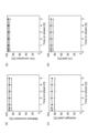
270mgの触媒を固定床流通式反応器内に設置した。前処理では、反応器内の触媒の温度を800℃に維持しながら、水素ガス及び窒素ガスを反応器内へ1時間供給し続けた。反応器内へ供給される水素ガスの流量は、30mLSATP/minであった。反応器内へ供給される窒素ガスの流量は、30mLSATP/minであった。前処理後、反応器内の触媒の温度を600℃に維持しながら、原料ガスを反応器内へ継続的に供給した。そして、反応器から排出される生成物(ガス)を、GC‐TCDで断続的に分析した。GC‐TCDとは、ガスクロマトグラフィー‐熱伝導度型検出器(Gas Chromatography‐Thermal Conductivity Detector; GC‐TCD)を意味する。原料ガスは、メタン(CH4)、二酸化炭素(CO2)、アルゴン(Ar)及びヘリウム(He)からなる混合ガスであった。触媒の単位質量(1g)当たりの原料ガスの供給速度は、20LSATP・gcat.-1・h-1に維持した。反応器内へ供給されるメタンの流量は、20mLSATP/minであった。反応器内へ供給される二酸化炭素の流量は、20mLSATP/minであった。反応器内へ供給されるアルゴンの流量は、40mLSATP/minであった。反応器内へ供給されるヘリウムの流量は、10mLSATP/minであった。以上のドライリフォーミングを5時間にわたって継続した。 270 mg of catalyst was placed in a fixed bed flow reactor. In the pretreatment, hydrogen gas and nitrogen gas were continuously supplied into the reactor for 1 hour while maintaining the temperature of the catalyst in the reactor at 800°C. The flow rate of hydrogen gas supplied into the reactor was 30 mL SATP /min. The flow rate of nitrogen gas supplied into the reactor was 30 mL SATP /min. After the pretreatment, the raw material gas was continuously supplied into the reactor while maintaining the temperature of the catalyst in the reactor at 600°C. The product (gas) discharged from the reactor was intermittently analyzed by GC-TCD. GC-TCD means Gas Chromatography-Thermal Conductivity Detector (GC-TCD). The source gas was a mixed gas consisting of methane ( CH4 ), carbon dioxide ( CO2 ), argon (Ar) and helium (He). The feed rate of the raw material gas per unit mass (1 g) of the catalyst was 20 L SATP ·g cat . -1 ·h was maintained at -1 . The flow rate of methane fed into the reactor was 20 mL SATP /min. The flow rate of carbon dioxide fed into the reactor was 20 mL SATP /min. The flow rate of argon supplied into the reactor was 40 mL SATP /min. The flow rate of helium fed into the reactor was 10 mL SATP /min. The above dry reforming was continued for 5 hours.
GC‐TCDを用いた生成物の分析の結果、生成物が一酸化炭素(CO)及び水素(H2)を含むことが確認された。GC‐TCDを用いた生成物の分析に基づき、メタンの転化率RCH4、二酸化炭素の転化率RCO2、一酸化炭素の収率YCO、及び水素の収率YH2を算出した。RCH4、RCO2、YCO及びYH2其々の定義は以下の各数式によって定義される。各反応時間が経過した時点におけるRCH4、RCO2、YH2及びYCOは、下記表1に示される。
RCH4(mоl%)=100×{[CH4]0-[CH4]1}/[CH4]0 (1)
数式1中の[CH4]0は、単位時間内に原料ガスとして反応器へ供給されたメタンのモル数である。数式1中の[CH4]1は、単位時間内に未反応物として反応器から排出されたメタンの単位時間当たりのモル数である。
RCO2(mоl%)=100×{[CO2]0-[CO2]1}/[CO2]0 (2)
数式2中の[CO2]0は、単位時間内に原料ガスとして反応器へ供給された二酸化炭素のモル数である。数式2中の[CO2]1は、単位時間内に未反応物として反応器から排出された二酸化炭素のモル数である。
YH2(mоl%)=100×[H2]1/2[CH4]0 (3)
数式3中の[CH4]0は、単位時間内に原料ガスとして反応器へ供給されたメタンの単位時間当たりのモル数である。数式3中の[H2]1は、単位時間内に生成物として反応器から排出された水素のモル数である。
YCO(mоl%)=100×[CO]1/2[CH4]0 (4)
数式4中の[CH4]0は、単位時間内に原料ガスとして反応器へ供給されたメタンのモル数である。数式4中の[CO]1は、単位時間内に生成物として反応器から排出された一酸化炭素のモル数である。
Analysis of the product using GC-TCD confirmed that the product contained carbon monoxide (CO) and hydrogen ( H2 ). Based on the analysis of the products using GC-TCD, the methane conversion R CH4 , carbon dioxide conversion R CO2 , carbon monoxide yield Y CO , and hydrogen yield Y H2 were calculated. The definitions of R CH4 , R CO2 , Y CO and Y H2 are defined by the following equations. R CH4 , R CO2 , Y H2 and Y CO at each reaction time are shown in Table 1 below.
R CH4 (mol %) = 100 × {[CH 4 ] 0 - [CH 4 ] 1 }/[CH 4 ] 0 (1)
[CH 4 ] 0 in
R CO2 (mol%) = 100 × {[CO 2 ] 0 - [CO 2 ] 1 }/[CO 2 ] 0 (2)
[CO 2 ] 0 in
YH2 (mol%) = 100 x [ H2 ] 1/2 [ CH4 ] 0 (3)
[CH 4 ] 0 in
Y CO (mol%) = 100 x [CO] 1/2 [CH 4 ] 0 (4)
[CH 4 ] 0 in
メタンの転化率RCH4の経時変化は、図2中の(a)に示される。図2中の(a)の横軸(Time оn stream)は反応時間であり、図2中の(a)の縦軸(Methane cоnversiоn)はメタンの転化率RCH4である。 The change over time in the methane conversion rate R CH4 is shown in FIG. 2(a). The horizontal axis (Time stream) of (a) in FIG. 2 is the reaction time, and the vertical axis (Methane conversion) of (a) in FIG. 2 is the methane conversion rate RCH4 .
二酸化炭素の転化率RCO2の経時変化は、図2中の(b)に示される。図2中の(b)の横軸(Time оn stream)は反応時間であり、図2中の(b)の縦軸(CO2 cоnversiоn)は二酸化炭素の転化率RCO2である。 The change over time of the carbon dioxide conversion rate R CO2 is shown in FIG. 2(b). The horizontal axis (Time stream) of (b) in FIG. 2 is the reaction time, and the vertical axis (CO 2 conversion) of (b) in FIG. 2 is the carbon dioxide conversion rate R CO2 .
水素の収率YH2の経時変化は、図2中の(c)に示される。図2中の(c)の横軸(Time оn stream)は反応時間であり、図2中の(c)の縦軸(Hydrоgen yield)は水素の収率YH2である。 The time course of the hydrogen yield YH2 is shown in FIG. 2(c). The horizontal axis (Time stream) of (c) in FIG. 2 is the reaction time, and the vertical axis (Hydrogen yield) of (c) in FIG. 2 is the hydrogen yield YH2 .
一酸化炭素の収率YCOの経時変化は、図2中の(d)に示される。図2中の(d)の横軸(Time оn stream)は反応時間であり、図2中の(d)の縦軸(CO yield)は一酸化炭素の収率YCOである。 The time course of the carbon monoxide yield YCO is shown in FIG. 2(d). The horizontal axis (Time stream) of (d) in FIG. 2 is the reaction time, and the vertical axis (CO yield) of (d) in FIG. 2 is the yield YCO of carbon monoxide.
[ドライリフォーミング後の触媒の分析]
上記のドライリフォーミング後の触媒を、TEMで観察した。TEMによる観察の結果、ニッケルを含む複数の金属粒子(ニッケル粒子)がゼオライトの内部に存在していることが確認された。またTEMによる観察の結果、ゼオライトの内部に存在するニッケル粒子の粒径d1は、およそ2nm以上6nm以下であることが確認された。つまり、ゼオライトの内部に存在するニッケル粒子の粒径d1は、ドライリフォーミング後においても変化していなかった。
[Analysis of catalyst after dry reforming]
The catalyst after dry reforming was observed by TEM. As a result of observation by TEM, it was confirmed that a plurality of metal particles (nickel particles) containing nickel existed inside the zeolite. As a result of TEM observation, it was confirmed that the particle size d1 of the nickel particles present inside the zeolite was about 2 nm or more and 6 nm or less. That is, the particle size d1 of the nickel particles present inside the zeolite did not change even after the dry reforming.
[熱重量測定]
上記のドライリフォーミングに用いた触媒の熱重量(Thermo Gravimetry; TG)測定を行った。TG測定では、触媒の大気中で加熱して、2.5時間かけて触媒の温度を119℃から900℃まで上昇させた。そして各温度における触媒の質量を測定した。実施例1のTG測定の結果は、図4中の実線によって示される。図4の横軸は触媒の温度(単位:℃)であり、図4の縦軸Δw(単位:質量%)は、下記数式5によって定義される。
Δw=100×(w-wdry)/wdry (5)
数式5中のwは、各温度における触媒の質量である。数式5中のwdryは、120℃における触媒の質量である。
[Thermogravimetry]
A thermogravimetry (TG) measurement was performed on the catalyst used in the above dry reforming. For TG measurements, the temperature of the catalyst was raised from 119° C. to 900° C. over 2.5 hours by heating in the atmosphere of the catalyst. Then, the mass of the catalyst at each temperature was measured. The results of the TG measurement of Example 1 are indicated by the solid line in FIG. The horizontal axis of FIG. 4 is the catalyst temperature (unit: ° C.), and the vertical axis Δw (unit: mass %) of FIG. 4 is defined by
Δw=100×(w−w dry )/w dry (5)
w in
TG測定前の触媒の質量は、11.2mgであった。120℃における触媒の質量wdryは、11.0mgであった。900℃における触媒の質量w0は、10.9mgであった。ドライリフォーミング中に触媒に付着したコークの全ては、900℃において燃焼し、触媒から除去されたことが推測される。したがって、900℃における触媒の質量w0は、コークが除去された触媒の真の質量とみなされる。一方、ドライリフォーミング中に触媒に付着したコークは、120℃において全く燃焼していないことが推測される。したがって、120℃における触媒の質量wdryは、触媒の真の質量w0と、ドライリフォーミング中に触媒に付着したコークの質量wCOKEの和(w0+wCOKE)に等しいとみなされる。つまり、ドライリフォーミング中に触媒に付着したコークの質量wCOKEは、wdry-w0に等しい。wdry及びw0から算出されたwCOKEは、0.1gであった。100×wCOKE/w0は、約0.92質量%であった。以下では、場合により、100×wCOKE/w0が、「コーク量」と表記される。 The mass of the catalyst before TG measurement was 11.2 mg. The mass w dry of the catalyst at 120°C was 11.0 mg. The mass w 0 of the catalyst at 900° C. was 10.9 mg. It is assumed that all of the coke that adhered to the catalyst during dry reforming was burned off at 900°C and removed from the catalyst. Therefore, the mass w 0 of the catalyst at 900° C. is taken as the true mass of the decoked catalyst. On the other hand, it is presumed that the coke attached to the catalyst during dry reforming was not burned at all at 120°C. Therefore, the mass of the catalyst at 120° C. w dry is taken to be equal to the sum of the true mass of the catalyst w 0 and the mass of coke deposited on the catalyst during dry reforming w COKE (w 0 +w COKE ). That is, the mass of coke attached to the catalyst during dry reforming, w COKE , is equal to w dry - w 0 . w COKE calculated from w dry and w 0 was 0.1 g. 100×w COKE /w 0 was about 0.92 wt%. In the following, 100×w COKE /w 0 is sometimes referred to as the “coke amount”.
[比表面積の測定]
未使用の実施例1の触媒の比表面積A0を、窒素ガス吸着法に基づくBET法によって測定した。未使用の実施例1の触媒を、空気中で30時間にわたって850℃で加熱した。加熱後の触媒3の比表面積A1を、A0と同様の方法によって測定した。実施例1の(A0-A1)/A0を算出した。実施例1のA0、A1及び(A0-A1)/A0は、下記表5に示される。下記表5中のΔAは、(A0-A1)/A0を意味する。
[Measurement of specific surface area]
The specific surface area A0 of the unused catalyst of Example 1 was measured by the BET method based on the nitrogen gas adsorption method. The fresh Example 1 catalyst was heated at 850° C. for 30 hours in air. The specific surface area A1 of the
(比較例1)
MFI型ゼオライト(シリカライト‐1)からなる粉末を、硝酸ニッケルの水溶液中に浸漬した。MFI型ゼオライトを硝酸ニッケルの水溶液中に浸漬した後、MFI型ゼオライトを乾燥した。乾燥されたMFI型ゼオライトを550℃で12時間焼成した。以上の含浸法により、比較例1の触媒を作製した。比較例1の触媒は粉末であった。比較例1の触媒におけるニッケルの担持量は、1.0質量%に調整した。
(Comparative example 1)
A powder consisting of MFI-type zeolite (silicalite-1) was immersed in an aqueous solution of nickel nitrate. After the MFI zeolite was immersed in an aqueous solution of nickel nitrate, the MFI zeolite was dried. The dried MFI-type zeolite was calcined at 550° C. for 12 hours. A catalyst of Comparative Example 1 was produced by the impregnation method described above. The catalyst of Comparative Example 1 was powder. The amount of nickel supported in the catalyst of Comparative Example 1 was adjusted to 1.0% by mass.
実施例1と同様の方法で、比較例1の触媒に関する分析及び測定が実施された。分析及び測定の結果は、下記表5に示される。比較例1の触媒の表面には、ニッケルからなる多数の金属粒子が担持されていることが確認された。したがって、多くのニッケル粒子は触媒の外表面に存在していた。つまり、比較例1の触媒は、birdcage型触媒ではなかった。 Analyzes and measurements on the catalyst of Comparative Example 1 were carried out in the same manner as in Example 1. The analysis and measurement results are shown in Table 5 below. It was confirmed that a large number of metal particles made of nickel were supported on the surface of the catalyst of Comparative Example 1. Therefore, many nickel particles were present on the outer surface of the catalyst. That is, the catalyst of Comparative Example 1 was not a birdcage type catalyst.
比較例1の触媒を用いたメタンのドライリフォーミングを実施した。比較例1のドライリフォーミングは2.5時間にわたって継続した。触媒及び継続時間の違いを除いて実施例1と同様の方法で、比較例1のドライリフォーミングを実施した。比較例1のドライリフォーミングの結果は、下記表2、図2中の(a)、図2中の(b)、図2中の(c)及び図2中の(d)に示される。 Dry reforming of methane using the catalyst of Comparative Example 1 was performed. The dry reforming of Comparative Example 1 continued for 2.5 hours. The dry reforming of Comparative Example 1 was carried out in the same manner as in Example 1, except for the difference in catalyst and duration. The dry reforming results of Comparative Example 1 are shown in Table 2 below, (a) in FIG. 2, (b) in FIG. 2, (c) in FIG. 2, and (d) in FIG.
ドライリフォーミングに用いた比較例1の触媒のTG測定を、実施例1と同様の方法で行った。比較例1のTG測定の結果は、図4中の破線によって示される。TG測定前の比較例1の触媒の質量は、9.8mgであった。120℃における比較例1の触媒の質量wdryは、9.6mgであった。900℃における触媒の質量w0は、6.2mgであった。wdry及びw0から算出された比較例1のwCOKEは、3.4であった。100×wCOKE/w0は、約54.84質量%であった。 TG measurement of the catalyst of Comparative Example 1 used for dry reforming was performed in the same manner as in Example 1. The results of the TG measurement of Comparative Example 1 are indicated by the dashed line in FIG. The mass of the catalyst of Comparative Example 1 before TG measurement was 9.8 mg. The mass w dry of the catalyst of Comparative Example 1 at 120° C. was 9.6 mg. The mass w 0 of the catalyst at 900° C. was 6.2 mg. The w COKE of Comparative Example 1 calculated from w dry and w 0 was 3.4. 100×w COKE /w 0 was about 54.84 wt%.


ドライリフォーミングの反応時間の違いに関わらず、実施例1の二酸化炭素の転化率、水素及び一酸化炭素の収率は、比較例1に比べて高かった。実施例1のwCOKEは比較例1のwCOKEよりも著しく小さく、実施例1の100×wCOKE/w0も比較例1の100×wCOKE/w0よりも著しく小さかった。つまり、実施例1の触媒は、コーキングを抑制する点において比較例1の触媒よりも優れていることが確認された。 The conversion rate of carbon dioxide and the yield of hydrogen and carbon monoxide in Example 1 were higher than those in Comparative Example 1, regardless of the difference in the reaction time of dry reforming. w COKE of Example 1 was significantly less than w COKE of Comparative Example 1, and 100×w COKE /w 0 of Example 1 was also significantly less than 100×w COKE /w 0 of Comparative Example 1. That is, it was confirmed that the catalyst of Example 1 is superior to the catalyst of Comparative Example 1 in suppressing coking.
(実施例2)
実施例2のドライリフォーミングでは、実施例1の触媒を用いた。実施例2のドライリフォーミングでは、50mgの触媒を固定床流通式反応器内に設置した。実施例2の前処理では、反応器内の触媒の温度を850℃に維持しながら、水素ガス及び窒素ガスを反応器内へ1時間供給し続けた。実施例2のドライリフォーミングでは、反応器内の触媒の温度を850℃に維持しながら、原料ガスを反応器内へ継続的に供給した。実施例2のドライリフォーミングでは、触媒の単位質量(1g)当たりの原料ガスの供給速度は、108LSATP・gcat.-1・h-1に維持した。
(Example 2)
In the dry reforming of Example 2, the catalyst of Example 1 was used. For the dry reforming of Example 2, 50 mg of catalyst was placed in the fixed bed flow reactor. In the pretreatment of Example 2, hydrogen gas and nitrogen gas were continuously supplied into the reactor for 1 hour while maintaining the temperature of the catalyst in the reactor at 850°C. In the dry reforming of Example 2, the raw material gas was continuously supplied into the reactor while maintaining the temperature of the catalyst in the reactor at 850°C. In the dry reforming of Example 2, the feed rate of the raw material gas per unit mass (1 g) of the catalyst was 108 L SATP ·g cat . -1 ·h was maintained at -1 .
以上の事項を除いて実施例1と同様の方法で、実施例2のドライリフォーミングを実施した。実施例2のドライリフォーミングの結果は、下記表3、図3中の(a)、図3中の(b)、図3中の(c)及び図3中の(d)に示される。 The dry reforming of Example 2 was carried out in the same manner as in Example 1 except for the above items. The dry reforming results of Example 2 are shown in Table 3 below, (a) in FIG. 3, (b) in FIG. 3, (c) in FIG. 3, and (d) in FIG.
(比較例2)
比較例2のドライリフォーミングでは、比較例1の触媒を用いた。触媒の違いを除いて実施例2と同様の方法で、比較例2のドライリフォーミングを実施した。比較例2のドライリフォーミングの結果は、下記表4、図3中の(a)、図3中の(b)、図3中の(c)及び図3中の(d)に示される。
(Comparative example 2)
In the dry reforming of Comparative Example 2, the catalyst of Comparative Example 1 was used. Dry reforming of Comparative Example 2 was carried out in the same manner as in Example 2 except for the difference in catalyst. The dry reforming results of Comparative Example 2 are shown in Table 4 below, (a) in FIG. 3, (b) in FIG. 3, (c) in FIG. 3, and (d) in FIG.


ドライリフォーミングの反応時間の違いに関わらず、実施例2のメタン及び二酸化炭素の転化率、並びに水素及び一酸化炭素の収率のいずれも、比較例2に比べて高かった。実施例2のTG測定では、触媒の質量は殆ど変化しなかった。比較例2のTG測定においても、触媒の質量は殆ど変化しなかった。これらのTG測定の結果は、実施例2及び比較例2其々のドライリフォーミングの反応温度が高かったことに起因する、と推察される。 Both the methane and carbon dioxide conversion rates and the hydrogen and carbon monoxide yields of Example 2 were higher than those of Comparative Example 2, regardless of the difference in dry reforming reaction time. In the TG measurement of Example 2, the mass of the catalyst hardly changed. Also in the TG measurement of Comparative Example 2, the mass of the catalyst hardly changed. These TG measurement results are presumed to be due to the high reaction temperatures of dry reforming in Example 2 and Comparative Example 2, respectively.
(実施例3)
以下の1ステップ法により、実施例3の触媒を作製した。
(Example 3)
The catalyst of Example 3 was made by the following one-step method.
テトラプロピルアンモニウムヒドロキシドの水溶液及びオルトケイ酸テトラエチルを、水へ加えた。テトラプロピルアンモニウムヒドロキシドの水溶液の濃度(テトラプロピルアンモニウムヒドロキシドの含有量)は、10質量%であった。水へ加えられたテトラプロピルアンモニウムヒドロキシドの水溶液の質量は、37.5gであった。水へ加えられたオルトケイ酸テトラエチルの質量は、12gであった。 An aqueous solution of tetrapropylammonium hydroxide and tetraethyl orthosilicate were added to the water. The concentration of the aqueous solution of tetrapropylammonium hydroxide (content of tetrapropylammonium hydroxide) was 10% by mass. The mass of the aqueous solution of tetrapropylammonium hydroxide added to water was 37.5 g. The mass of tetraethyl orthosilicate added to the water was 12 g.
続いて、硝酸ニッケルの水溶液を上記の水へ加えた。硝酸ニッケルの水溶液の濃度(硝酸ニッケルの含有量)は、18質量%であった。硝酸ニッケルの水溶液の添加量は、0.64ccであった。 Subsequently, an aqueous solution of nickel nitrate was added to the above water. The concentration of the nickel nitrate aqueous solution (the content of nickel nitrate) was 18% by mass. The amount of the nickel nitrate aqueous solution added was 0.64 cc.
以上の手順で、硝酸ニッケル、オルトケイ酸テトラエチル、及びテトラプロピルアンモニウムヒドロキシドを含む水溶液が調製された。この水溶液をオートクレーブに容れてから、オートクレーブを密閉した。オートクレーブ内の水を加熱することにより、オートクレーブ内で水熱合成を進行させた。水熱合成の温度は、100℃に調整した。水熱合成の時間は72時間であった。 An aqueous solution containing nickel nitrate, tetraethyl orthosilicate, and tetrapropylammonium hydroxide was prepared by the above procedure. This aqueous solution was placed in an autoclave and then the autoclave was sealed. Hydrothermal synthesis proceeded in the autoclave by heating the water in the autoclave. The temperature of hydrothermal synthesis was adjusted to 100°C. The hydrothermal synthesis time was 72 hours.
上記の水熱合成によって得られた生成物(沈殿物)を、遠心分離によって水から分離離した。水熱合成の生成物を洗浄し、且つ乾燥した後、生成物を焼成した。焼成温度、焼成時間及び焼成の雰囲気は、実施例1と同じであった。 The product (precipitate) obtained by the above hydrothermal synthesis was separated from water by centrifugation. After washing and drying the product of hydrothermal synthesis, the product was calcined. The firing temperature, firing time and firing atmosphere were the same as in Example 1.
以上の方法により、実施例3の触媒を得た。実施例3の触媒は粉末であった。実施例3の触媒におけるニッケルの担持量は、1.0質量%に調整した。 A catalyst of Example 3 was obtained by the above method. The catalyst of Example 3 was a powder. The amount of nickel supported in the catalyst of Example 3 was adjusted to 1.0% by mass.
実施例1と同様の方法で、実施例3の触媒に関する分析及び測定が実施された。分析及び測定の結果は、下記表5に示される。実施例3の場合も、ニッケルを含む複数の金属粒子(ニッケル粒子)がMFI型ゼオライトの内部に存在しており、ゼオライトの内部に存在するニッケル粒子の粒径は、MFI型ゼオライトの細孔径よりも大きかった。つまり、実施例3の触媒は、birdcage型触媒であった。 Analyzes and measurements on the catalyst of Example 3 were carried out in the same manner as in Example 1. The analysis and measurement results are shown in Table 5 below. In the case of Example 3 as well, a plurality of metal particles containing nickel (nickel particles) are present inside the MFI zeolite, and the particle size of the nickel particles present inside the zeolite is larger than the pore size of the MFI zeolite. was also big. That is, the catalyst of Example 3 was a birdcage type catalyst.
実施例1と同様の方法で、実施例3の触媒を用いたドライリフォーミングを実施した。実施例3のドライリフォーミングの結果は、下記表5に示される。 Dry reforming using the catalyst of Example 3 was carried out in the same manner as in Example 1. The dry reforming results of Example 3 are shown in Table 5 below.
(実施例4)
実施例4のドライリフォーミングでは、実施例3の触媒を用いた。触媒の違いを除いて実施例2と同様の方法で、実施例4の触媒を用いたドライリフォーミングを実施した。実施例4のドライリフォーミングの結果は、下記表5に示される。
(Example 4)
In the dry reforming of Example 4, the catalyst of Example 3 was used. Dry reforming using the catalyst of Example 4 was carried out in the same manner as in Example 2 except for the difference in catalyst. The dry reforming results of Example 4 are shown in Table 5 below.
(比較例3)
以下のワン‐ポット法により、比較例3の触媒を作製した。
(Comparative Example 3)
A catalyst of Comparative Example 3 was produced by the following one-pot method.
実施例1と同様の方法で、比較例3の原料液が調製された。実施例1と同様の方法で、比較例3の原料液中において複合化合物が形成された。 A raw material liquid of Comparative Example 3 was prepared in the same manner as in Example 1. A composite compound was formed in the raw material liquid of Comparative Example 3 in the same manner as in Example 1.
しかし、比較例3の場合、複合化合物は原料液から分離されず、テトラプロピルアンモニウムヒドロキシドの水溶液とオルトケイ酸テトラエチルが、複合化合物を含む比較例3の原料液へさらに添加された。比較例3におけるテトラプロピルアンモニウムヒドロキシド及びオルトケイ酸テトラエチル其々の使用量は、実施例1と同じであった。 However, in the case of Comparative Example 3, the complex compound was not separated from the raw material liquid, and an aqueous solution of tetrapropylammonium hydroxide and tetraethyl orthosilicate were further added to the raw material liquid of Comparative Example 3 containing the complex compound. The amounts of tetrapropylammonium hydroxide and tetraethyl orthosilicate used in Comparative Example 3 were the same as in Example 1.
以上の工程を経た原料液をオートクレーブに容れてから、オートクレーブを密閉した。オートクレーブ内の原料液を加熱することにより、オートクレーブ内で水熱合成を進行させた。水熱合成の温度は、100℃に調整した。水熱合成の時間は72時間であった。 The autoclave was sealed after putting the raw material liquid which passed through the above process into the autoclave. Hydrothermal synthesis was advanced in the autoclave by heating the raw material liquid in the autoclave. The temperature of hydrothermal synthesis was adjusted to 100°C. The hydrothermal synthesis time was 72 hours.
上記の水熱合成によって得られた生成物(沈殿物)を、遠心分離によって原料液から分離離した。水熱合成の生成物を洗浄し、且つ乾燥した後、生成物を焼成した。焼成温度、焼成時間及び焼成の雰囲気は、実施例1と同じであった。 The product (precipitate) obtained by the above hydrothermal synthesis was separated from the raw material liquid by centrifugation. After washing and drying the product of hydrothermal synthesis, the product was calcined. The firing temperature, firing time and firing atmosphere were the same as in Example 1.
以上の方法により、比較例3の触媒を得た。比較例3の触媒は粉末であった。比較例3の触媒におけるニッケルの担持量は、1.0質量%に調整した。 A catalyst of Comparative Example 3 was obtained by the above method. The catalyst of Comparative Example 3 was powder. The amount of nickel supported in the catalyst of Comparative Example 3 was adjusted to 1.0% by mass.
実施例1と同様の方法で、比較例3の触媒に関する分析及び測定が実施された。分析及び測定の結果は、下記表5に示される。比較例3の場合も、ニッケルを含む複数の金属粒子(ニッケル粒子)がMFI型ゼオライトの内部に存在しており、ゼオライトの内部に存在するニッケル粒子の粒径は、MFI型ゼオライトの細孔径よりも大きかった。つまり、比較例3の触媒は、birdcage型触媒であった。しかし、比較例3の触媒の比表面積は、400m2/gよりもはるかに小さかった。 Analysis and measurement of the catalyst of Comparative Example 3 were carried out in the same manner as in Example 1. The analysis and measurement results are shown in Table 5 below. In the case of Comparative Example 3 as well, a plurality of metal particles containing nickel (nickel particles) are present inside the MFI zeolite, and the particle size of the nickel particles present inside the zeolite is larger than the pore size of the MFI zeolite. was also big. That is, the catalyst of Comparative Example 3 was a birdcage type catalyst. However, the specific surface area of the catalyst of Comparative Example 3 was much smaller than 400 m 2 /g.
実施例1と同様の方法で、比較例3の触媒を用いたドライリフォーミングを実施した。比較例3のドライリフォーミングの結果は、下記表5に示される。 Dry reforming using the catalyst of Comparative Example 3 was carried out in the same manner as in Example 1. The dry reforming results of Comparative Example 3 are shown in Table 5 below.
(比較例4)
比較例4のドライリフォーミングでは、比較例3の触媒を用いた。触媒の違いを除いて実施例2と同様の方法で、比較例4の触媒を用いたドライリフォーミングを実施した。比較例4のドライリフォーミングの結果は、下記表5に示される。
(Comparative Example 4)
In the dry reforming of Comparative Example 4, the catalyst of Comparative Example 3 was used. Dry reforming using the catalyst of Comparative Example 4 was carried out in the same manner as in Example 2 except for the difference in catalyst. The dry reforming results of Comparative Example 4 are shown in Table 5 below.
下記表5に示されるメタンの転化率は、各反応時間における転化率の平均値である。 The conversion rate of methane shown in Table 5 below is the average value of the conversion rate at each reaction time.

本発明によれば、触媒に含まれる金属粒子のシンタリングを抑制することが可能である。 According to the present invention, sintering of metal particles contained in a catalyst can be suppressed.
1…金属を含む粒子、2…ゼオライト、2p…ゼオライトの細孔、3…改質触媒、d1…ゼオライトの内部に存在する粒子の粒径、d2…ゼオライトの細孔径。 1 Particles containing metal, 2 Zeolite, 2p Pores of zeolite, 3 Reforming catalyst, d1 Particle diameter of particles present inside zeolite, d2 Pore diameter of zeolite.
Claims (6)
少なくとも一部の前記金属が、ニッケルであり、
少なくとも一部の前記粒子が、前記ゼオライトの内部に存在し、
前記ゼオライトの内部に存在する前記粒子の粒径が、前記ゼオライトの細孔径よりも大きく、
前記触媒の比表面積が、400m2/gより大きく700m2/g以下であり、
前記触媒が合成ガスの製造方法に用いられ、
前記合成ガスの前記製造方法が、前記触媒を用いた炭化水素及び二酸化炭素の反応によって、一酸化炭素及び水素を含む合成ガスを得る工程を備え、
少なくとも一部の前記炭化水素が、メタンである、
触媒。 A catalyst comprising a plurality of particles containing a metal and a zeolite,
at least a portion of said metal is nickel,
at least some of the particles are inside the zeolite;
The particle size of the particles present inside the zeolite is larger than the pore size of the zeolite,
The specific surface area of the catalyst is greater than 400 m 2 /g and 700 m 2 /g or less,
The catalyst is used in a method for producing synthesis gas,
The method for producing the synthesis gas comprises obtaining a synthesis gas containing carbon monoxide and hydrogen by reaction of hydrocarbons and carbon dioxide using the catalyst ,
at least some of said hydrocarbons are methane;
catalyst.
加熱される前の初期の前記触媒の比表面積が、A0であり、
(A0-A1)/A0が0%以上30%以下である、
請求項1に記載の触媒。 the specific surface area of the catalyst heated at 850° C. for 30 hours in air is A1;
The initial specific surface area of the catalyst before heating is A0,
(A0-A1)/A0 is 0% or more and 30% or less,
Catalyst according to claim 1.
請求項1又は2に記載の触媒。 at least some of the zeolites are MFI-type zeolites;
A catalyst according to claim 1 or 2 .
金属元素、界面活性剤及び有機溶媒を含む原料液中で、ミセルを形成する工程と、
前記ミセルを含む前記原料液にケイ素源を添加することにより、複合化合物を形成する工程と、
前記複合化合物を含む水を、オートクレーブ内で加熱する工程と、
を備え、
前記金属元素が、ニッケルであり、
前記ミセルが、前記金属元素を含む粒子と、前記粒子を覆う前記界面活性剤と、を有し、
前記複合化合物が、前記粒子と、前記粒子を覆うシリカと、を有する、
触媒の製造方法。 A method for producing the catalyst according to any one of claims 1 to 3 ,
forming micelles in a raw material solution containing a metal element, a surfactant and an organic solvent;
forming a complex compound by adding a silicon source to the raw material solution containing the micelles;
a step of heating water containing the complex compound in an autoclave;
with
the metal element is nickel,
The micelle has particles containing the metal element and the surfactant covering the particles,
wherein the composite compound comprises the particles and silica covering the particles;
A method for producing a catalyst.
前記金属のイオン及びケイ素源を含む水溶液を調製する工程と、
前記水溶液を、オートクレーブ内で加熱する工程と、
を備える、
触媒の製造方法。 A method for producing the catalyst according to any one of claims 1 to 3 ,
preparing an aqueous solution containing ions of the metal and a silicon source;
heating the aqueous solution in an autoclave;
comprising
A method for producing a catalyst.
前記触媒が、請求項1~3のいずれか一項に記載の触媒であり、
少なくとも一部の前記炭化水素が、メタンである、
合成ガスの製造方法。 catalyzed reaction of hydrocarbons and carbon dioxide to obtain synthesis gas comprising carbon monoxide and hydrogen;
The catalyst is the catalyst according to any one of claims 1 to 3 ,
at least some of said hydrocarbons are methane;
A method for producing synthesis gas.
Priority Applications (1)
| Application Number | Priority Date | Filing Date | Title |
|---|---|---|---|
| JP2018199298A JP7246040B2 (en) | 2018-10-23 | 2018-10-23 | Catalyst, method for producing catalyst, and method for producing synthesis gas |
Applications Claiming Priority (1)
| Application Number | Priority Date | Filing Date | Title |
|---|---|---|---|
| JP2018199298A JP7246040B2 (en) | 2018-10-23 | 2018-10-23 | Catalyst, method for producing catalyst, and method for producing synthesis gas |
Publications (2)
| Publication Number | Publication Date |
|---|---|
| JP2020065968A JP2020065968A (en) | 2020-04-30 |
| JP7246040B2 true JP7246040B2 (en) | 2023-03-27 |
Family
ID=70389143
Family Applications (1)
| Application Number | Title | Priority Date | Filing Date |
|---|---|---|---|
| JP2018199298A Active JP7246040B2 (en) | 2018-10-23 | 2018-10-23 | Catalyst, method for producing catalyst, and method for producing synthesis gas |
Country Status (1)
| Country | Link |
|---|---|
| JP (1) | JP7246040B2 (en) |
Citations (6)
| Publication number | Priority date | Publication date | Assignee | Title |
|---|---|---|---|---|
| WO2010097108A1 (en) | 2009-02-27 | 2010-09-02 | Haldor Topsøe A/S | Process for the preparation of hybrid zeolite or zeolite-like materials |
| JP2012170951A (en) | 2011-02-24 | 2012-09-10 | Kyushu Univ | Photocatalyst-adsorbent composite powder |
| WO2014083772A1 (en) | 2012-11-30 | 2014-06-05 | 国立大学法人広島大学 | Method for producing metal nanoparticle complex, and metal nanoparticle complex produced by said method |
| WO2015155216A1 (en) | 2014-04-10 | 2015-10-15 | Danmarks Tekniske Universitet | A general method to incorporate metal nanoparticles in zeolites and zeotypes |
| JP2016529190A (en) | 2013-07-05 | 2016-09-23 | ダンマークス・テクニスケ・ユニヴェルシテット | Method for producing zeolite and zeo type |
| WO2018158883A1 (en) | 2017-03-01 | 2018-09-07 | 東洋ゴム工業株式会社 | Encapsulated catalyst for carbon dioxide modification of methane, and method for producing synthesis gas using same |
-
2018
- 2018-10-23 JP JP2018199298A patent/JP7246040B2/en active Active
Patent Citations (6)
| Publication number | Priority date | Publication date | Assignee | Title |
|---|---|---|---|---|
| WO2010097108A1 (en) | 2009-02-27 | 2010-09-02 | Haldor Topsøe A/S | Process for the preparation of hybrid zeolite or zeolite-like materials |
| JP2012170951A (en) | 2011-02-24 | 2012-09-10 | Kyushu Univ | Photocatalyst-adsorbent composite powder |
| WO2014083772A1 (en) | 2012-11-30 | 2014-06-05 | 国立大学法人広島大学 | Method for producing metal nanoparticle complex, and metal nanoparticle complex produced by said method |
| JP2016529190A (en) | 2013-07-05 | 2016-09-23 | ダンマークス・テクニスケ・ユニヴェルシテット | Method for producing zeolite and zeo type |
| WO2015155216A1 (en) | 2014-04-10 | 2015-10-15 | Danmarks Tekniske Universitet | A general method to incorporate metal nanoparticles in zeolites and zeotypes |
| WO2018158883A1 (en) | 2017-03-01 | 2018-09-07 | 東洋ゴム工業株式会社 | Encapsulated catalyst for carbon dioxide modification of methane, and method for producing synthesis gas using same |
Also Published As
| Publication number | Publication date |
|---|---|
| JP2020065968A (en) | 2020-04-30 |
Similar Documents
| Publication | Publication Date | Title |
|---|---|---|
| JP5442776B2 (en) | Preparation of Fischer-Tropsch catalyst and use thereof | |
| RU2481156C2 (en) | Method of producing fischer-tropsch synthesis catalyst | |
| KR101373823B1 (en) | Cobalt catalysts on metallic foam structures for the selective production of the synthetic oil via fischer-tropsch synthesis reaction and manufacturing method thereof, manufacturing method for synthetic oil using the cobalt catalysts on metallic foam structures | |
| CN105188915B (en) | Alkaline earth metal/metal oxide supported catalyst | |
| US20170001863A1 (en) | Methane steam reforming, using nickel/alumina nanocomposite catalyst or nickel/silica-alumina hybrid nanocomposite catalyst | |
| TWI589355B (en) | Use of production catalyst for higher silane and method for producing higher silane | |
| CN107303512B (en) | Bifunctional catalyst and application thereof in benzene hydroalkylation reaction | |
| JP2004508190A (en) | Catalyst for oxidative dehydrogenation of hydrocarbons | |
| CN111670174A (en) | Indium-based catalysts and precatalysts | |
| JP5837620B2 (en) | catalyst | |
| US8722009B2 (en) | Nanocrystalline copper oxide and method for the production thereof | |
| EP2879787B3 (en) | Method of preparing a catalyst precursor, method of preparing a catalyst, and hydrocarbon synthesis process employing the catalyst support | |
| EP3496856B1 (en) | A cobalt-containing catalyst composition | |
| EP2212022A1 (en) | An improved process to produce high surface area nanoparticle vanadium phosphorus oxide catalyst and product derives thereof | |
| TWI415678B (en) | Preparation method of ruthenium catalyst for ring olefin production, manufacturing method and manufacturing apparatus for cycloolefin | |
| JP2010110671A (en) | PEROVSKITE-BEARING Ni CATALYST MATERIAL FOR MODIFICATION AND METHOD OF MANUFACTURING SYNGAS USING THIS CATALYST MATERIAL | |
| Sun et al. | Direct coating copper–zinc–aluminum oxalate with H-ZSM-5 to fabricate a highly efficient capsule-structured bifunctional catalyst for dimethyl ether production from syngas | |
| WO2018219364A1 (en) | Catalyst, and method for direct conversion of syngas to prepare liquid fuel and to produce light olefins | |
| US11389784B2 (en) | Next generation modified silica materials for increased performance and industrial applications | |
| JP7246040B2 (en) | Catalyst, method for producing catalyst, and method for producing synthesis gas | |
| EP0171297A2 (en) | A method for preparing dual colloid catalyst compositions | |
| KR101421189B1 (en) | The modified catalyst for co2 conversion | |
| US20140083904A1 (en) | A process for preparing a cobalt - containing hydrocarbon synthesis catalyst precursor | |
| US20170304807A1 (en) | Method for preparation of a fischer-tropsch catalyst with vapor treatment | |
| US4764499A (en) | Method for producing dual colloid catalyst composition |
Legal Events
| Date | Code | Title | Description |
|---|---|---|---|
| A621 | Written request for application examination |
Free format text: JAPANESE INTERMEDIATE CODE: A621 Effective date: 20210802 |
|
| A977 | Report on retrieval |
Free format text: JAPANESE INTERMEDIATE CODE: A971007 Effective date: 20220512 |
|
| A131 | Notification of reasons for refusal |
Free format text: JAPANESE INTERMEDIATE CODE: A131 Effective date: 20220607 |
|
| A521 | Request for written amendment filed |
Free format text: JAPANESE INTERMEDIATE CODE: A523 Effective date: 20220621 |
|
| A131 | Notification of reasons for refusal |
Free format text: JAPANESE INTERMEDIATE CODE: A131 Effective date: 20221004 |
|
| A521 | Request for written amendment filed |
Free format text: JAPANESE INTERMEDIATE CODE: A523 Effective date: 20221028 |
|
| TRDD | Decision of grant or rejection written | ||
| A01 | Written decision to grant a patent or to grant a registration (utility model) |
Free format text: JAPANESE INTERMEDIATE CODE: A01 Effective date: 20230228 |
|
| A61 | First payment of annual fees (during grant procedure) |
Free format text: JAPANESE INTERMEDIATE CODE: A61 Effective date: 20230306 |
|
| R150 | Certificate of patent or registration of utility model |
Ref document number: 7246040 Country of ref document: JP Free format text: JAPANESE INTERMEDIATE CODE: R150 |
|
| S533 | Written request for registration of change of name |
Free format text: JAPANESE INTERMEDIATE CODE: R313533 |
|
| R350 | Written notification of registration of transfer |
Free format text: JAPANESE INTERMEDIATE CODE: R350 |