JP7245010B2 - pouring spout - Google Patents
pouring spout Download PDFInfo
- Publication number
- JP7245010B2 JP7245010B2 JP2018147767A JP2018147767A JP7245010B2 JP 7245010 B2 JP7245010 B2 JP 7245010B2 JP 2018147767 A JP2018147767 A JP 2018147767A JP 2018147767 A JP2018147767 A JP 2018147767A JP 7245010 B2 JP7245010 B2 JP 7245010B2
- Authority
- JP
- Japan
- Prior art keywords
- spout
- closing member
- mounting portion
- closing
- container
- Prior art date
- Legal status (The legal status is an assumption and is not a legal conclusion. Google has not performed a legal analysis and makes no representation as to the accuracy of the status listed.)
- Active
Links
Images


Description
本発明は、注出スパウトに関し、さらに詳しくは、所定の容器に注入するための内容物を収容する詰め替え容器を構成するための注出スパウトに関する。
BACKGROUND OF THE
包装容器の中には、別途に設けられた詰め替え容器から内容物を注入し、繰り返し利用するものがある。別途に設けられた詰め替え容器は、内容物を袋本体から注出させて包装容器に注入させるための注出スパウトを備えているものがある。本件特許出願人は、詰め替え容器を構成する、上記の注出スパウトについて種々提案している。 Among packaging containers, there is a packaging container that is refilled with contents from a separately provided refilling container and used repeatedly. Some separately provided refill containers have a spout for pouring out the content from the bag body and pouring it into the packaging container. The applicant of the present patent has made various proposals for the above-described dispensing spout that constitutes the refillable container.
特許文献1で提案している注出スパウトは、本件特許出願人が提案しているものである。この注出スパウトは、注出スパウトから内容物を注出する流路を開閉可能にしている閉鎖部材を備えたものである。具体的に、この注出スパウトは、注出スパウトの本体と流路を閉鎖するための構成体が一体に形成されている。閉鎖するための構成体は、流路の外側をなす一端側に設けられており、一端側で流路を開閉している。閉鎖部材は、袋本体側から加えられる外力によって流路から取り外される形態で流路の一端側の内周面に水平をなしてはめ込まれている。閉鎖部材は、紐状又は帯状の連結部材によって、注出スパウトにつながれている。
The pouring spout proposed in
本件特許出願人は、上述した特許文献1に記載の注出スパウトを提案した後も鋭意注出スパウトについて研究を進めてきた。その結果、注出スパウト本体と閉鎖するための構成体とが一体に構成された構造では、射出成形をするときに、樹脂が全体に行き渡るまでに時間がかかることが判明した。そのため、樹脂が全体に行き渡るまでの時間を短縮し、高品質の注出スパウトを短時間で製造できることが望まれていた。
Even after proposing the pouring spout described in
本発明は、上記課題を解決するためになされたものであり、その目的は、射出成形の時間を短縮することができ、且つ、良質な注出スパウトを提供することにある。 SUMMARY OF THE INVENTION The present invention has been made to solve the above problems, and an object of the present invention is to shorten the injection molding time and to provide a high-quality pouring spout.
上記課題を解決するための本発明に係る注出スパウトは、詰め替え容器に設けられ、前記詰め替え容器に収容された内容物を注出するための注出スパウトであって、前記詰め替え容器を構成する袋本体部に貼り合わされる被貼り合わせ部と、前記内容物を注出する筒状部と、前記内容物を前記詰め替え容器の内部から外部に通すための流路とを、少なくとも備えたスパウト本体と、前記流路を開閉する閉鎖ユニットと、を備え、前記閉鎖ユニットは、前記流路に対して開閉自在な閉鎖部材と、前記スパウト本体に前記閉鎖ユニットを着脱可能に取り付ける取り付け部と、前記閉鎖部材と前記取り付け部をつなぐ連結部材とを有し、前記スパウト本体には、前記取り付け部が着脱可能に取り付けられる被取り付け部が形成されている、ことを特徴とする。 A pouring spout according to the present invention for solving the above-mentioned problems is a pouring spout provided in a refilling container for pouring out contents contained in the refilling container, and constituting the refilling container. A spout body comprising at least a portion to be bonded to be bonded to the bag body, a tubular portion for pouring out the content, and a flow path for passing the content from the inside to the outside of the refill container. and a closing unit that opens and closes the flow path, the closing unit comprising: a closing member that can be freely opened and closed with respect to the flow path; a mounting portion that detachably attaches the closing unit to the spout body; The spout body has a connecting member that connects the closing member and the mounting portion, and the spout body is formed with a mounted portion to which the mounting portion is detachably mounted.
この発明によれば、注出スパウトはスパウト本体と閉鎖ユニットとが別体として構成されているので、スパウト本体及び閉鎖ユニットを射出成形する際に、樹脂が型の隅々まで短時間で供給され、成形時間を短縮することができる。また、注出スパウトはスパウト本体と閉鎖ユニットとが別体であるので、型の隅々まで樹脂を供給することができ、高い品質の注出スパウトを製造することができる。 According to this aspect of the invention, since the spout body and the closing unit of the pouring spout are constructed as separate bodies, the resin can be supplied to every corner of the mold in a short time when the spout body and the closing unit are injection molded. , the molding time can be shortened. In addition, since the spout main body and the closing unit of the pouring spout are separate bodies, the resin can be supplied to every corner of the mold, and a high quality pouring spout can be manufactured.
本発明に係る注出スパウトにおいて、前記閉鎖部材は、前記流路の内周面の形状と同型状に形成され、前記閉鎖部材の外周部が前記流路の内周面に係り合わされることにより前記流路を閉鎖すると共に、前記詰め替え容器の内側からの外力が前記閉鎖部材の一面側に作用することによって、前記流路から取り外されるように構成され、前記連結部材は、紐状又は帯状をなし、前記閉鎖部材の前記一面側とは反対側の他面側と前記取り付け部とをつなぎ、前記取り付け部は、所定の間隔を空けて外側に対向して延びる1対のアームを備え、当該アームの先端には、反対側にそれぞれ突出する爪がそれぞれ形成され、前記被取り付け部は、前記アームが挿入される孔と、当該孔の内側に向かって張り出し、前記爪が係り合わされる係合部とを備えている。 In the pouring spout according to the present invention, the closing member is formed in the same shape as the inner peripheral surface of the flow path, and the outer peripheral portion of the closing member is engaged with the inner peripheral surface of the flow path. The connecting member is configured to be removed from the flow path by closing the flow path and applying an external force from the inside of the refill container to one side of the closing member, and the connecting member has a string-like or belt-like shape. None, connecting the other surface side opposite to the one surface side of the closing member and the mounting portion, the mounting portion having a pair of arms extending outward facing each other at a predetermined interval, At the tips of the arms, claws projecting to opposite sides are formed, respectively, and the mounting part projects into a hole into which the arm is inserted, and engages with the claw to engage with the hole. and
この発明によれば、第1に、詰め替え容器の内側からの外力が閉鎖部材の一面側に作用することによって、流路から取り外されるように構成されているので、内容物が詰め替え容器から入れ替えられる包装容器のスパウトの先端で閉鎖部材を押し上げることにより、詰め替え容器を開放することができる。第2に、紐状又は帯状をなす連結部材が閉鎖部材の一面側とは反対側の他面側と取り付け部とをつないでいるので、閉鎖部材が注出スパウトから切り離されてしまうことがない。第3に、取り付け部は、1対のアームを備え、アームの先端には、反対側にそれぞれ突出する爪がそれぞれ形成され、被取り付け部は、アームが挿入される孔と、その内側に向かって張り出し、爪が係り合わされる係合部と、を備えているので、上述した閉鎖ユニットをスパウト本体に着脱可能に取り付けることができる。 According to the present invention, firstly, the refill container is detached from the flow path by the action of an external force from the inside of the refill container on one side of the closing member, so that the contents can be replaced from the refill container. The refill container can be opened by pushing up the closure member with the tip of the spout of the packaging container. Secondly, since the string-like or belt-like connecting member connects the other side opposite to the one side of the closing member and the mounting portion, the closing member is not separated from the pouring spout. . Thirdly, the attachment section has a pair of arms, and the ends of the arms are formed with claws protruding to opposite sides, respectively. and an engaging portion with which the pawl is engaged, so that the above-described closing unit can be detachably attached to the spout body.
本発明に係る注出スパウトにおいて、前記取り付け部の内側にはスリットが形成され、長手方向の途中に曲がり部が設けられ、前記スリットの延びる方向は前記曲がり部で曲げられて、前記アームの根元側が前記閉鎖部材側から離れる方向にずれている。 In the pouring spout according to the present invention, a slit is formed inside the attachment portion, a bend is provided in the middle of the longitudinal direction, the extending direction of the slit is bent at the bend, and the base of the arm is bent. side is offset away from said closure member side.
この発明によれば、取り付け部の内側にはスリットが上記のように形成されているので、取り付け部の外形をスリットの形状に合わせ、外周部に傾斜部を形成することができる。その結果、連結部材を傾斜部に連結することができ、連結部材が閉鎖部材の開閉の障害となることを抑制することができる。 According to this invention, since the slit is formed inside the mounting portion as described above, the outer shape of the mounting portion can be matched to the shape of the slit, and the inclined portion can be formed on the outer peripheral portion. As a result, the connecting member can be connected to the inclined portion, and the connecting member can be prevented from obstructing the opening and closing of the closing member.
本発明に係る注出スパウトにおいて、前記閉鎖部材の前記他面側における、前記取り付け部と対角をなす位置と、前記取り付け部との少なくとも一方には、前記詰め替え容器の外側に向かって突出する突起部が形成されている。 In the pouring spout according to the present invention, at least one of a position diagonal to the mounting portion and the mounting portion on the other side of the closing member protrudes toward the outside of the refill container. A protrusion is formed.
この発明によれば、閉鎖部材の他面側における、取り付け部と対角をなす位置と、取り付け部との少なくとも一方には、詰め替え容器の外側に向かって突出する突起部が形成されているので、注出ユニットを製造する際に、上記の突起部をスライド用スリットにはめ込ませ、閉鎖ユニットをスパウトに向けて供給することができる。その結果、閉鎖ユニットの向きを一定に保ちながら閉鎖ユニットをスパウトに向けて供給することができる。 According to this aspect of the invention, on the other side of the closing member, at least one of the mounting portion and the position diagonally opposite to the mounting portion is formed with a protrusion projecting outward from the refill container. , when manufacturing the pouring unit, the projection can be fitted into the sliding slit and the closing unit can be fed towards the spout. As a result, the closure unit can be fed towards the spout while maintaining a constant orientation of the closure unit.
本発明によれば、射出成形の時間を短縮することができ、且つ、良質な注出スパウトを提供することができる。 ADVANTAGE OF THE INVENTION According to this invention, the time of injection molding can be shortened and a good quality pouring spout can be provided.
以下、図面を参照しつつ、本発明の実施形態について説明する。本発明は、以下に説明する実施形態及び図面に記載した形態と同じ技術的思想の発明を含むものであり、本発明の技術的範囲は実施形態の記載や図面の記載のみに限定されるものでない。 Hereinafter, embodiments of the present invention will be described with reference to the drawings. The present invention includes inventions having the same technical idea as the embodiments described below and the forms described in the drawings, and the technical scope of the present invention is limited only to the description of the embodiments and the description of the drawings. not.
[基本構成]
本発明は、詰め替え容器1に収容された内容物を注出するために詰め替え容器1に設けられた注出スパウト10である。注出スパウト10は、スパウト本体10Aと、閉鎖ユニット20とで主に構成されている。スパウト本体10Aは、被貼り合わせ部15、筒状部11、及び流路18を少なくとも備えている。被貼り合わせ部15は、詰め替え容器1を構成する袋本体部5に貼り合わされる部位である。筒状部11は、内容物を注出するための構成要素である。流路18は、内容物を詰め替え容器1の内部から外部に通すための構成要素である。
[Basic configuration]
The present invention is a
閉鎖ユニット20は、流路18を開閉する構成体である。閉鎖ユニット20は、閉鎖部材21、取り付け部24、及び連結部材23により構成されている。閉鎖部材21は、流路18に対して開閉自在であって、流路18を閉鎖したり開放したりするための構成要素である。取り付け部24は、スパウト本体10Aに閉鎖ユニット20を着脱可能に取り付けるための構成要素である。連結部材23は、閉鎖部材21と取り付け部24をつなぐための構成要素である。また、スパウト本体10Aには、取り付け部24が着脱可能に取り付けられる被取り付け部40が形成されている。
The
本発明に係る注出スパウト10によれば、射出成形の時間を短縮することができ、且つ、短時間で良質な注出スパウト10を提供することができるという特徴的な効果を奏する。
According to the
以下、注出スパウト10が用いられる詰め替え容器1の概要、注出スパウト10の具体的な構成、詰め替え容器1から内容物が補充される包装容器50の概要、及び注出スパウト10の作用について説明する。
The outline of the
[詰め替え容器]
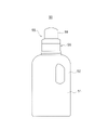
本発明に係る注出スパウト10が用いられる詰め替え容器1は、この詰め替え容器1とは別に使用される包装容器50に内容物を充填したり、補充したりするための容器である。詰め替え容器1の形態や種類は特に限定されない。図1には、詰め替え容器1の一例としてのスタンディングパウチを示している。この詰め替え容器1は、対向する一対の平面部2と、詰め替え容器1の底部を閉じている底面部3と、本発明に係る注出スパウト10と、を有している。
[Refill container]
The
平面部2は、上端縁同士がシールされると共に、両側端縁同士がシールされている。一対の平面部2の下端縁は、底面部3における各平面部2の下端縁に対向する端縁部にそれぞれシールされている。底面部3は、中心の折目4で二つ折りされており、折目4が詰め替え容器1の上側に向かって折り込まれている。底面部3は、折り込まれた形態から詰め替え容器1の平面部2が配置されている方向に広げられることによって、詰め替え容器1の底部を広げることができるように構成されている。
The
本発明に係る注出スパウト10は、詰め替え容器1の上端縁に取り付けられている。注出スパウト10は、スパウト本体10Aと、閉鎖ユニット20とで主に構成されている。スパウト本体10Aは、上述したように、被貼り合わせ部15、筒状部11、及び流路18を有している。なお、図1に示した実施形態では、注出スパウト10が詰め替え容器1の上部中央に取り付けられた形態を一例として取り上げている。ただし、特に図面には示していないが、注出スパウト10が詰め替え容器1の上部において、幅方向の側方にずれた位置に設けてもよい。また、詰め替え容器1に上端縁と側端縁とが斜めに傾斜する傾斜部により連絡された部位を設け、傾斜部に注出スパウト10を取り付けてもよい。
A pouring
詰め替え容器1から内容物を包装容器50に移し替える場合には、注出スパウト10を閉じているキャップ6を取り外し、詰め替え容器1の上下を逆さまにする。そして、注出スパウト10を包装容器50の注出ユニット55に突き刺して、詰め替え容器1から内容物を包装容器50に直接移し替える。なお、この作用は、後ほど詳細に説明する。
When transferring the contents from the
[注出スパウト]
注出スパウト10は、二つの構成部材から構成されている。1つは、スパウト本体10Aであり、もう一つは、閉鎖ユニット20である。
[Extrusion spout]
The
〈スパウト本体〉
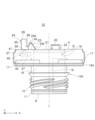
スパウト本体10Aは、図2~図4に示すように、被貼り合わせ部15、筒状部11、及び流路18を少なくとも備えている。スパウト本体10Aにおける被貼り合わせ部15と筒状部11との境目の位置には、図4に示すように、長方形又は略長方形をなすフランジ部15Aが設けられている。
(被貼り合わせ部)
<Spout body>
The
(Part to be bonded)
被貼り合わせ部15は、詰め替え容器1に貼り合わされる部位である。この被貼り合わせ部15は、外形が舟形をなしている。すなわち、図2~図4において、被貼り合わせ部15の両側面は、X方向の中心部でY方向に半円状に張り出す張り出し部16を有している。これに対しX方向の両端部は、両端側に向かって先細りをなし、両側面がX方向の両端部で接続されている。被貼り合わせ部15の外面には、複数の突出部17が形成されている。突出部17は、注出スパウト10と袋本体部5とを貼り合わせしやすくするための構成部である。各突出部17は、Y方向の両端から張り出し部16の途中までの領域に形成されている。
The part to be bonded 15 is a part to be bonded to the
(筒状部)
筒状部11は、詰め替え容器1の内部に収容されている内容物を注出するための注出口として機能する。筒状部11は、円筒状又は略円筒状に形成されている。筒状部11の外周には、キャップ6をねじ込むためのねじ山12が形成されている。
(Cylindrical part)
The
(流路)
流路18は、内周の形状が円形をなしていて、図2及び図3の破線で示すように、被貼り合わせ部15における詰め替え容器1の内側をなす一端部A側と筒状部11の外側に位置する他端部Bとを貫いている。そのため、流路18は、詰め替え容器1の内側と外側とを連通させることができるように構成されている。流路18における被貼り合わせ部15における詰め替え容器1の内側をなす一端部Aには、閉鎖部材21の外周部を係り合わせるための溝20Aが形成されている。閉鎖部材21間は、外周部がこの溝20Aに係り合わされることによって流路18を閉鎖する。
(Flow path)
The
流路18の内周面には、ガイド19が形成されている。ガイド19は、包装容器50の注出ユニット55を構成するノズル58を筒状部11の先端から奥に向けて案内する。ガイド19は、流路18の内周面から中心に向けて突出しており、筒状部11が延びる方向Lと同一の方向に延びるようにして形成されている。ガイド19の断面の形状は、ノズル58を案内することができる形状であれば特に限定されない。
A
(被取り付け部)
被取り付け部40は、被貼り合わせ部15において、詰め替え容器1の内側(一端部A側)に形成されている。この被取り付け部40は、閉鎖ユニット20の取り付け部24が取り付けられる部位である。被取り付け部40は、流路18の外側に形成された孔である。被取り付け部40は、図2及び図3に示すように、取り付け部24を構成しているアーム26が挿入される孔と、この孔の内側に向かって張り出し、アーム26の先端に形成されている爪27が係り合わされる係合部とで構成されている。以下、アーム26が挿入される孔を第1孔41、係合部を第2孔42として説明する。被取り付け部40は、被貼り合わせ部15の一端部A側の端面から一定の深さの位置に形成された幅の小さな第1孔41と、第1孔41の奥に形成された幅の大きな第2孔42とで構成されている。第1孔41と第2孔42との境界部には、肩部43が設けられている。肩部43は、後に詳細を説明するように、取り付け部24に設けられた爪27が係り合わされる部位である。
(Mounted part)
The attached
上述したスパウト本体10Aは、下記の閉鎖ユニット20とは別の構成部品であるため、スパウト本体10Aを射出成形等により製造する場合、樹脂を型の隅々まで短時間で供給でき、短時間で成形することができる。また、注出スパウト10はスパウト本体10Aと閉鎖ユニット20とが別体であるので、型の隅々まで樹脂を供給することができ、高い品質のスパウト本体10Aを製造することができる。
Since the
〈閉鎖ユニット〉
閉鎖ユニット20は、スパウト本体10Aに形成されている流路18を閉鎖したり、開放したりするための構成体である。閉鎖ユニット20は、閉鎖部材21と、取り付け部24と、連結部材23とにより構成されている。
<Closed unit>
The
(閉鎖部材)
閉鎖部材21は、スパウト本体10Aの流路18を開閉できるように構成されている。閉鎖部材21は、流路18の内周部の形状と同形状又はほぼ同形状に形成されており、流路18の内側、具体的は溝20Aにはめ込まれることにより、流路18を閉鎖する。閉鎖部材21の外周部は、図2及び図3に示すように、一面側(他端部B側)から他面側(一端部A側)に向かって先細りとなるようにテーパー状をなしていて、流路18に形成された溝20Aに係り合わせやすくなっている。上述したように、流路18の内周には溝20Aが形成されていて、閉鎖部材21の外周部が流路18の溝20Aに係り合わされることにより、閉鎖部材21が流路18を閉鎖する。一方、流路18を閉鎖している閉鎖部材21に、一面側(他端部B側)から他面側(一端部A側)に向かう外力が与えられると、閉鎖部材21の外周部が流路18の溝20Aから外れる。その際、閉鎖部材21の外周部は詰め替え容器1の外側に向かって先細りとなるテーパー状に形成されているので、閉鎖部材21は溝20Aから円滑に外される。外周部が溝20Aから外れた結果、閉鎖部材21が流路18から取り外され、流路18が開放される。
(Closing member)
The closing
閉鎖部材21の他面側(一端部A側)には第1突起部22が形成されている。具体的に、第1突起部22は、閉鎖部材21の他面側(一端部A側)における、取り付け部24と対角をなす位置に設けられている。この第1突起部22は、必要に応じて設けられる構成部である。第1突起部22は、注出スパウト10を製造する際に、後述するように、閉鎖ユニット20をスパウト本体10Aに供給する際に利用される。この第1突起部22と後述する第2突起部29とは、少なくともどちらか一方だけを設けてもよい。すなわち、第2突起部29を取り付け部24に設けずに、第1突起部22のみを閉鎖部材21に設けてもよい。逆に、第1突起部22を閉鎖部材21に設けずに、第2突起部29だけを取り付け部24に設けてもよい。また、第1突起部22及び第2突起部29の両方を設けてもよい。第1突起部22と第2突起部29の少なくとも一方を設けておけば、後述するように、閉鎖ユニット20をスパウト本体10Aに供給する工程において、閉鎖ユニット20の向きを一定に保つことが可能である。
A
(取り付け部)
取り付け部24は、閉鎖ユニット20をスパウト本体10Aに取り付けるための構成部である。取り付け部24は、図2の上部に示すように、胴部25と、胴部25から下側に延びる1対のアーム26と、胴部25の上側に突出する第2突起部29とで構成されている。但し、第2突起部29は、必要に応じて設けられる構成部である。第2突起部29は、第1突起部22と同様に、注出スパウト10を製造する際に、閉鎖ユニット20をスパウト本体10Aに供給する際に利用される。
(Mounting part)
The
胴部25の内部にはスリット30,31,32が形成されている。スリット30,31,32は取り付け部24の上下方向延びる直線状の直線スリット30と、直線スリット30の下側で、閉鎖部材21側に向かって斜めに形成された傾斜スリット31と、アーム26の間に形成された鉛直スリット32と、で構成されている。取り付け部24の長手方向の途中部分である傾斜スリット31に対応する部位には、曲がり部35が形成されていて、傾斜スリット31は、この曲がり部35の一で直線スリット30に対して傾斜し、アーム26の根元側が閉鎖部材側にずれている。傾斜スリット31の先端は、胴部25の下端部まで延びている。一方、胴部25の外周部には、閉鎖部材21側に向かって突出する連結部取り付け部28が形成されている。連結部取り付け部28には、連結部材23が一体的につながれる。1対のアーム26の根元は、胴部25の下端部にて、傾斜スリット31を間に挟み、所定の間隔を空けて設けられている。1対のアーム26は、傾斜スリット31の溝幅と同じ間隔を空けて胴部25から下側に向かって延びている。傾斜スリット31の溝幅と同じ間隔を空けてなりアーム26の間に形成された部位は、鉛直スリット32である。1対のアーム26の先端には爪27がそれぞれ設けられ、各爪27は、アーム26を起点として反対側に向かってそれぞれ突出している。各爪27は、アーム26の先端側が先細りとなるようにテーパー状をなしている。
(連結部材)
連結部材23は、閉鎖部材21と取り付け部24とをつないでいる構成部であり、紐状又は帯状をなしている。連結部材23は、閉鎖ユニット20を射出成形によって製造する際に、閉鎖部材21及び取り付け部24と一体に成形される。その際、連結部材23の一端は、閉鎖部材21における詰め替え容器1の内側を向いている他面側(一端部A側)につながれる。また、連結部材23の他端は、取り付け部24の連結部材取り付け部28につながれる。但し、閉鎖部材21と取り付け部24とは別々に成形し、一端を閉鎖部材21に取り付け、他端を取り付け部24に取り付けてもよい。
(Connecting member)
The connecting
〈閉鎖ユニットのスパウト本体への取り付け〉
閉鎖ユニット20のスパウト本体10Aへの取り付けについて、図2、図3及び図5を参照して説明する。まず、図5に示すように、閉鎖ユニット20は、スライダー100上をスライドさせて、スパウト本体10Aに供給される。その際、スライダー100の上方に、供給元からスパウト本体10Aまで延びる案内レール110を設けるとよい。案内レール110の内部には、案内溝111が形成されている。案内溝111には、閉鎖部材21の第1突起部22及び取り付け部24に設けられた第2突起部29が挿入される。第1突起部22及び第2突起部29が案内溝111に挿入されることにより、閉鎖ユニット20の向きが定まり、閉鎖ユニット20の体勢を保ちつつ閉鎖ユニット20をスパウト本体10Aに供給することができる。
<Attaching the closing unit to the spout body>
Attachment of the
閉鎖ユニット20のスパウト本体10Aへの取り付けは、閉鎖ユニット20の取り付け部24をスパウト本体10Aの被取り付け部40に挿入して取り付ける。具体的に、図2に示されている取り付け部24のアーム26を図3に示すように、被取り付け部40に形成されている第2孔42まで挿入する。1対のアーム26を第1孔41に挿入する場合、胴部25を第1孔41に向かって押し付けて1対のアーム26を第1孔41に挿入する。1対のアーム26が第1孔41に挿入される際、アーム26は、第1孔41の内周部によって両者の間隔が狭められ、1対のアーム26の先端に形成されている爪27の外面の間隔が第1孔41の幅と同じ寸法かそれよりも小さくなるようにアーム26は変形される。1対のアーム26の爪27の外面は、テーパー状にそれぞれ形成されているので、アーム26を第1孔41に挿入する際、爪27の外面が第1項の内面に引っかかることなくアーム26が第1孔41に円滑に挿入される。
The
1対の爪27が第1孔41に挿入された後、胴部25を更に押し込み、1対の爪27を第2孔42の位置に到達させる。1対の爪27が第2孔42の位置まで到達すると、1対のアーム26は、両者の間に形成されている溝間隔をもとの寸法に戻すように外側に向かって広がる。その結果、1対の爪27は、第1孔41と第2孔42との境界部をなす肩部43に係り合わされる。そのため、取り付け部24は被取り付け部40に取り付けられ、閉鎖ユニット20はスパウト本体10Aと一体化する。なお、閉鎖ユニット20をスパウト本体10Aから取り外すときは、取り付け部24を構成している1対のアーム26の間隔を縮め、爪27部の外周部が第1孔41の内周部の幅よりも小さくし、その状態でアーム26を第1孔41から抜き出せばよい。
After the pair of
上述した閉鎖ユニット20は、下記のスパウト本体10Aとは別の構成部品であるため、閉鎖ユニット20を射出成形等により製造する場合、樹脂を型の隅々まで短時間で供給でき、短時間で成形することができる。また、注出スパウト10はスパウト本体10Aと閉鎖ユニット20とが別体であるため、型の隅々まで樹脂を供給することができ、高い品質の閉鎖ユニット20を製造することができる。とりわけ、取り付け部24における爪27が設けられたアーム26、及び連結部材23の高い精度が要求される部位を確実に成形することができる。
Since the
以上に説明した詰め替え容器1は、以下に説明する包装容器50に内容物を注ぎ入れるために用いられる。包装容器50の構成を簡単に説明する。
The
[包装容器]
包装容器50は、詰め替え容器1に収容された内容物が補充される容器である。包装容器50は、例えば、樹脂等で構成される。図6は、包装容器50の一例を示している。図6に示した包装容器50は、取っ手52が設けられた容器本体51と、容器本体51に収容された内容物を注出するための注出ユニット55とで構成されている。この包装容器50は、詰め替え容器1から移された内容物を必要なときに必要な量だけ包装容器50から注出して用いられる。
[Packaging container]
The
包装容器50の注出ユニット55は、本体部56と本体部56を開閉するためのキャップ59とで構成されている。本体部56は、図7に示すように、周壁面57と、周壁面57の内側に配置されたノズル58とを備えている。周壁面57は、筒状をなし、その内側は空洞になっている。
The pouring
ノズル58は、本体部56の中央又は略中央の位置に配置されている。ノズル58は、周壁面57とつながれており周壁面57と一体をなしている。ノズル58は、本体部56の上側に向かって突出し、その先端が、周壁面57の上端よりも上側に位置するように構成されている。但し、図7は、ノズル58の形状の1つの例を示しており、ノズル58の形状は特に限定されない。
The
[詰め替え容器の内容物を包装容器に補充する手順及び注出スパウトの作用]
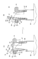
図8を参照し、詰め替え容器1に収容されている内容物を包装容器50に補充する手順と、本実施形態の注出スパウト10の作用について説明する。なお、図8は、注出ユニット55の作用をわかりやすくするために、詰め替え容器1の袋本体部5及び包装容器50の容器本体51については、図示していない。ただし、注出スパウト10は、図1に示した、詰め替え容器1に取り付けられ、注出ユニット55は、図8に示した包装容器50に設けられている。
[Procedure for refilling the contents of the refill container into the packaging container and action of the spout]
The procedure for refilling the
まず、注出スパウト10からキャップ6を取り外し、詰め替え容器1の上下を逆にして、詰め替え容器1の下側に注出スパウト10を位置させる。注出スパウト10の流路18は、閉鎖部材21により閉じられているので、詰め替え容器1に収容されている内容物がこぼれ出すことはない。また、包装容器50の注出ユニット55において、本体部56からキャップ59はあらかじめ取り外されている。
First, the
次に、図8(A)に示すように、注出スパウト10を、包装容器50の注出ユニット55の位置に一致させ、詰め替え容器1を押し下げて、注出ユニット55のノズル58を注出スパウト10の流路18に挿入させる。
Next, as shown in FIG. 8A, the
詰め替え容器1を押し下げると、ノズル58の先端が閉鎖部材21を押し上げる。そのため、図8(B)に示すように、閉鎖部材21が流路18から取り外される。すなわち、閉鎖部材21は、流路18が延びる方向Lにおける一面側(他端部B側)から加えられる外力によって、閉鎖部材21の外周部が流路18の内周面に形成された溝20Aから取り外される。その際、閉鎖部材21の外周部は、一面側(他端部B側)から他面側(一端部A側)に向かって先細りとなるテーパー状をなしているので、閉鎖部材21は、流路18の溝20Aに引っかかることなく円滑に溝20Aから取り外される。
When the
閉鎖部材21は、スパウト本体10Aとは別体として構成されており、且つ、外周部が流路18の溝20Aにはめ込まれて流路18を閉じているだけなので、ノズル58が閉鎖部材21それ自体を破損させることなく流路18から取り外される。その結果、注出スパウト10は破片を発生せずに、包装容器50に内容物だけを移すことができる。
The closing
内容物が詰め替え容器1から包装容器50に補充されている間、流路18に形成されたガイド19が、ノズル58に形成されたスリット60にはめ込まれているため、詰め替え容器1の注出スパウト10が、包装容器50の注出ユニット55の本体部56から外れてしまうことが防止される。
Since the
また、図8(B)に示すように、ノズル58が筒状部11の内部に挿入され、閉鎖部材21がスパウト本体10Aから外されたとき、筒状部11の先端部がノズル58の外周面に接触する。そのため、詰め替え容器1から注出された内容物は、ノズル58の外側に漏れ出さないで、ノズル58を通して包装容器50に移される。
8B, when the
以上に説明したように、本発明によれば、射出成形の時間を短縮することができ、且つ、良質な注出スパウト10を提供することができる。
As described above, according to the present invention, the injection molding time can be shortened, and the pouring
1 詰め替え容器
2 平面部
3 底面部
4 折目
5 袋本体部
6 キャップ
10 注出スパウト
10A スパウト本体
11 筒状部
12 ねじ山
15 被貼り合わせ部
15A フランジ部
16 張り出し部
18 流路
19 ガイド
20 閉鎖ユニット
20A 溝
21 閉鎖部材
22 第1突起部
23 連結部材
24 取り付け部
25 胴部
26 アーム
27 爪
28 連結部材取り付け部
29 第2突起部
30,31,32 スリット
30 直線スリット
31 傾斜スリット
32 鉛直スリット
35 曲がり部
40 被取り付け部
41 第1孔
42 第2孔
43 肩部
50 包装容器
51 容器本体
52 取っ手
55 注出ユニット
56 本体部
57 周壁面
58 ノズル
59 キャップ
60 スリット
100 スライダー
110 案内レール
111 案内溝
1
Claims (3)
前記詰め替え容器を構成する袋本体部に貼り合わされる被貼り合わせ部と、前記内容物を注出する筒状部と、前記内容物を前記詰め替え容器の内部から外部に通すための流路とを、少なくとも備えたスパウト本体と、前記流路を開閉する閉鎖ユニットと、を備え、
前記閉鎖ユニットは、前記流路に対して開閉自在な閉鎖部材と、前記スパウト本体に前記閉鎖ユニットを着脱可能に取り付ける取り付け部と、前記閉鎖部材と前記取り付け部をつなぐ連結部材とを有し、前記取り付け部は、胴部と該胴部から下側に延びる1対のアームと該胴部の上側に突出する突起部とを有し、前記胴部の外周部には、前記閉鎖部材側に向かって突出する連結部材取り付け部が傾斜部として形成され、前記連結部材は、紐状又は帯状をなし、前記閉鎖部材と前記連結部材取り付け部とをつなぎ、
前記取り付け部の内側には、該取り付け部の上下方向延びる直線状の直線スリットと、該直線スリットの下側で前記閉鎖部材側に向かって斜めに形成された傾斜スリットと、前記一対のアームの間に形成された鉛直スリットとが形成され、
前記取り付け部の長手方向の途中部分である前記傾斜スリットに対応する部位には曲がり部が形成されていて、前記傾斜スリットは該曲がり部の位置で前記直線スリットに対して傾斜しており、前記傾斜部は、前記傾斜スリットの形状に合わされた外形をなしており、
前記スパウト本体には、前記取り付け部が着脱可能に取り付けられる被取り付け部が形成されている、ことを特徴とする注出スパウト。 A pouring spout provided in a refillable container for pouring out the contents contained in the refillable container,
A portion to be bonded that is bonded to the bag main body portion that constitutes the refill container, a tubular portion that pours out the contents, and a channel for passing the contents from the inside to the outside of the refill container. , at least a spout body, and a closure unit for opening and closing the flow path,
The closing unit has a closing member that can be freely opened and closed with respect to the flow path, a mounting portion that detachably attaches the closing unit to the spout body, and a connecting member that connects the closing member and the mounting portion, The mounting portion has a body, a pair of arms extending downward from the body, and a protrusion projecting upward from the body. a connecting member mounting portion protruding toward is formed as an inclined portion, the connecting member has a string-like or belt-like shape, and connects the closing member and the connecting member mounting portion;
Inside the mounting portion, a linear slit extending in the vertical direction of the mounting portion, an inclined slit formed obliquely toward the closing member below the linear slit, and the pair of arms. a vertical slit formed between and
A bent portion is formed at a portion corresponding to the inclined slit, which is a middle portion in the longitudinal direction of the mounting portion, and the inclined slit is inclined with respect to the linear slit at the position of the bent portion . The inclined portion has an outer shape that matches the shape of the inclined slit ,
A pouring spout, wherein the spout body is formed with an attached portion to which the attaching portion is detachably attached.
前記連結部材は、前記閉鎖部材の前記一面側とは反対側の他面側と前記連結部材取り付け部とをつなぎ、
前記取り付け部は、所定の間隔を空けて外側に対向して延びる1対のアームを備え、当該アームの先端には、反対側にそれぞれ突出する爪がそれぞれ形成され、
前記被取り付け部は、前記アームが挿入される孔と、当該孔の内側に向かって張り出し、前記爪が係り合わされる係合部とを備える、請求項1に記載の注出スパウト。 The closing member is formed in the same shape as the inner peripheral surface of the flow channel, and the outer peripheral portion of the closing member is engaged with the inner peripheral surface of the flow channel to close the flow channel and It is configured to be removed from the flow path by an external force from the inside of the refill container acting on one side of the closing member,
The connecting member connects the other side of the closing member opposite to the one side and the connecting member mounting portion ,
The attachment portion includes a pair of arms extending outward facing each other at a predetermined interval, and claws protruding to opposite sides are formed at the tips of the arms, respectively,
2. The pouring spout according to claim 1, wherein said attached portion comprises a hole into which said arm is inserted, and an engaging portion projecting toward the inside of said hole and engaging said pawl.
At least one of a position diagonally opposite to the mounting portion and the mounting portion on the other side of the closing member has a protrusion projecting outward from the refill container (on the upper side of the body portion 3. A pouring spout according to claim 1 or 2 , wherein a different projection is formed.
Priority Applications (1)
| Application Number | Priority Date | Filing Date | Title |
|---|---|---|---|
| JP2018147767A JP7245010B2 (en) | 2018-08-06 | 2018-08-06 | pouring spout |
Applications Claiming Priority (1)
| Application Number | Priority Date | Filing Date | Title |
|---|---|---|---|
| JP2018147767A JP7245010B2 (en) | 2018-08-06 | 2018-08-06 | pouring spout |
Publications (2)
| Publication Number | Publication Date |
|---|---|
| JP2020023333A JP2020023333A (en) | 2020-02-13 |
| JP7245010B2 true JP7245010B2 (en) | 2023-03-23 |
Family
ID=69619293
Family Applications (1)
| Application Number | Title | Priority Date | Filing Date |
|---|---|---|---|
| JP2018147767A Active JP7245010B2 (en) | 2018-08-06 | 2018-08-06 | pouring spout |
Country Status (1)
| Country | Link |
|---|---|
| JP (1) | JP7245010B2 (en) |
Citations (3)
| Publication number | Priority date | Publication date | Assignee | Title |
|---|---|---|---|---|
| US20130248540A1 (en) | 2010-11-29 | 2013-09-26 | Ian Darby | Container, container blank, and method of manufacture |
| JP6194132B1 (en) | 2017-03-21 | 2017-09-06 | 藤森工業株式会社 | Container spout |
| JP2018095259A (en) | 2016-12-08 | 2018-06-21 | 藤森工業株式会社 | Pouring spout of refill container and connection structure with pouring unit of packaging container |
Family Cites Families (2)
| Publication number | Priority date | Publication date | Assignee | Title |
|---|---|---|---|---|
| JPS5422521Y2 (en) * | 1974-02-18 | 1979-08-06 | ||
| JP3726334B2 (en) * | 1996-03-14 | 2005-12-14 | 凸版印刷株式会社 | Container with hinged lid |
-
2018
- 2018-08-06 JP JP2018147767A patent/JP7245010B2/en active Active
Patent Citations (3)
| Publication number | Priority date | Publication date | Assignee | Title |
|---|---|---|---|---|
| US20130248540A1 (en) | 2010-11-29 | 2013-09-26 | Ian Darby | Container, container blank, and method of manufacture |
| JP2018095259A (en) | 2016-12-08 | 2018-06-21 | 藤森工業株式会社 | Pouring spout of refill container and connection structure with pouring unit of packaging container |
| JP6194132B1 (en) | 2017-03-21 | 2017-09-06 | 藤森工業株式会社 | Container spout |
Also Published As
| Publication number | Publication date |
|---|---|
| JP2020023333A (en) | 2020-02-13 |
Similar Documents
| Publication | Publication Date | Title |
|---|---|---|
| JP6236139B1 (en) | Connection structure with spout for refilling containers and dispensing unit for packaging containers | |
| JP6194132B1 (en) | Container spout | |
| JP5523899B2 (en) | Refill nozzle | |
| CN207449418U (en) | Ink adding container | |
| US10961025B2 (en) | Pouring spout of container | |
| JP7193305B2 (en) | pouring spout | |
| JP7245010B2 (en) | pouring spout | |
| JP2014129141A (en) | Plug for refill container | |
| US20100252143A1 (en) | Filling structure of a painting device | |
| JP6083855B2 (en) | Refill container stopper | |
| JP5977641B2 (en) | Refill container stopper | |
| JP5290905B2 (en) | Refill container | |
| JP4747262B2 (en) | Dispensing container and refillable bag-like container | |
| JP5367510B2 (en) | Refill container | |
| JP7297484B2 (en) | pouring spout, pouring spout with closure | |
| JP5467818B2 (en) | Refill container | |
| JP4931459B2 (en) | Container with nozzle | |
| JP4734934B2 (en) | Refillable pouch nozzle structure | |
| JP6884474B2 (en) | Refill container | |
| JP2015024864A (en) | Soft packaging container for refilling | |
| JP2012210946A (en) | Refill bag container | |
| JP2013139267A (en) | Tap member for refill container | |
| JP2005186963A (en) | Spout member for discharging | |
| JP2015105110A (en) | Plug for refill container |
Legal Events
| Date | Code | Title | Description |
|---|---|---|---|
| A621 | Written request for application examination |
Free format text: JAPANESE INTERMEDIATE CODE: A621 Effective date: 20210721 |
|
| A977 | Report on retrieval |
Free format text: JAPANESE INTERMEDIATE CODE: A971007 Effective date: 20220627 |
|
| A131 | Notification of reasons for refusal |
Free format text: JAPANESE INTERMEDIATE CODE: A131 Effective date: 20220705 |
|
| A521 | Request for written amendment filed |
Free format text: JAPANESE INTERMEDIATE CODE: A523 Effective date: 20220825 |
|
| A131 | Notification of reasons for refusal |
Free format text: JAPANESE INTERMEDIATE CODE: A131 Effective date: 20221108 |
|
| A521 | Request for written amendment filed |
Free format text: JAPANESE INTERMEDIATE CODE: A523 Effective date: 20230110 |
|
| TRDD | Decision of grant or rejection written | ||
| A01 | Written decision to grant a patent or to grant a registration (utility model) |
Free format text: JAPANESE INTERMEDIATE CODE: A01 Effective date: 20230307 |
|
| A61 | First payment of annual fees (during grant procedure) |
Free format text: JAPANESE INTERMEDIATE CODE: A61 Effective date: 20230310 |
|
| R150 | Certificate of patent or registration of utility model |
Ref document number: 7245010 Country of ref document: JP Free format text: JAPANESE INTERMEDIATE CODE: R150 |