JP7243510B2 - Projector control method and projector - Google Patents
Projector control method and projector Download PDFInfo
- Publication number
- JP7243510B2 JP7243510B2 JP2019138611A JP2019138611A JP7243510B2 JP 7243510 B2 JP7243510 B2 JP 7243510B2 JP 2019138611 A JP2019138611 A JP 2019138611A JP 2019138611 A JP2019138611 A JP 2019138611A JP 7243510 B2 JP7243510 B2 JP 7243510B2
- Authority
- JP
- Japan
- Prior art keywords
- mark
- image
- projection
- line segment
- data
- Prior art date
- Legal status (The legal status is an assumption and is not a legal conclusion. Google has not performed a legal analysis and makes no representation as to the accuracy of the status listed.)
- Active
Links
Images


Classifications
-
- G—PHYSICS
- G06—COMPUTING; CALCULATING OR COUNTING
- G06T—IMAGE DATA PROCESSING OR GENERATION, IN GENERAL
- G06T7/00—Image analysis
- G06T7/30—Determination of transform parameters for the alignment of images, i.e. image registration
- G06T7/33—Determination of transform parameters for the alignment of images, i.e. image registration using feature-based methods
- G06T7/337—Determination of transform parameters for the alignment of images, i.e. image registration using feature-based methods involving reference images or patches
-
- G—PHYSICS
- G06—COMPUTING; CALCULATING OR COUNTING
- G06T—IMAGE DATA PROCESSING OR GENERATION, IN GENERAL
- G06T7/00—Image analysis
- G06T7/30—Determination of transform parameters for the alignment of images, i.e. image registration
- G06T7/33—Determination of transform parameters for the alignment of images, i.e. image registration using feature-based methods
-
- G—PHYSICS
- G06—COMPUTING; CALCULATING OR COUNTING
- G06T—IMAGE DATA PROCESSING OR GENERATION, IN GENERAL
- G06T3/00—Geometric image transformation in the plane of the image
- G06T3/40—Scaling the whole image or part thereof
- G06T3/4038—Scaling the whole image or part thereof for image mosaicing, i.e. plane images composed of plane sub-images
-
- G—PHYSICS
- G06—COMPUTING; CALCULATING OR COUNTING
- G06T—IMAGE DATA PROCESSING OR GENERATION, IN GENERAL
- G06T7/00—Image analysis
- G06T7/10—Segmentation; Edge detection
- G06T7/11—Region-based segmentation
-
- H—ELECTRICITY
- H04—ELECTRIC COMMUNICATION TECHNIQUE
- H04N—PICTORIAL COMMUNICATION, e.g. TELEVISION
- H04N9/00—Details of colour television systems
- H04N9/12—Picture reproducers
- H04N9/31—Projection devices for colour picture display, e.g. using electronic spatial light modulators [ESLM]
- H04N9/3141—Constructional details thereof
- H04N9/3147—Multi-projection systems
-
- H—ELECTRICITY
- H04—ELECTRIC COMMUNICATION TECHNIQUE
- H04N—PICTORIAL COMMUNICATION, e.g. TELEVISION
- H04N9/00—Details of colour television systems
- H04N9/12—Picture reproducers
- H04N9/31—Projection devices for colour picture display, e.g. using electronic spatial light modulators [ESLM]
- H04N9/3179—Video signal processing therefor
- H04N9/3185—Geometric adjustment, e.g. keystone or convergence
-
- H—ELECTRICITY
- H04—ELECTRIC COMMUNICATION TECHNIQUE
- H04N—PICTORIAL COMMUNICATION, e.g. TELEVISION
- H04N9/00—Details of colour television systems
- H04N9/12—Picture reproducers
- H04N9/31—Projection devices for colour picture display, e.g. using electronic spatial light modulators [ESLM]
- H04N9/3191—Testing thereof
- H04N9/3194—Testing thereof including sensor feedback
-
- G—PHYSICS
- G06—COMPUTING; CALCULATING OR COUNTING
- G06T—IMAGE DATA PROCESSING OR GENERATION, IN GENERAL
- G06T2207/00—Indexing scheme for image analysis or image enhancement
- G06T2207/10—Image acquisition modality
- G06T2207/10016—Video; Image sequence
Description
本発明は、プロジェクターの制御方法、及びプロジェクターに関する。 The present invention relates to a projector control method and a projector.
従来、投射面が曲面である等といった平面でない場合であっても、歪みがない画像を投射するために、プロジェクターが投射する画像内の歪みが相殺されるように補正する技術が知られている。例えば、特許文献1には、複数のマークを含む画像を投射面に投射し、投射面に表示される投射画像を撮像して撮像データを取得し、撮像データから複数のマークの位置を特定し、複数のマークの各々の位置と、投射面が平面であると仮定する場合にマークが表示されるべき位置との相違から補正データを生成するプロジェクターが開示されている。
2. Description of the Related Art Conventionally, there has been known a technique for correcting distortion in an image projected by a projector so as to cancel out the distortion in the image projected by the projector in order to project a distortion-free image even when the projection surface is not flat such as a curved surface. . For example, in
しかしながら、画像を投射面に投射することによって投射面に表示される投射画像の歪みによって、投射画像内のマークが表示されるべき位置からずれる場合、複数のマークの位置が揃っていないことがある。このため、画像に含まれる複数のマークのあるマークが、画像を投射面に投射することによって投射面に表示される投射画像に含まれる複数のマークのいずれに対応するか特定することが困難である場合がある。 However, when the projection image displayed on the projection surface is distorted by projecting the image onto the projection surface, and the marks in the projection image deviate from the positions where they should be displayed, the positions of the marks may not be aligned. . For this reason, it is difficult to specify which of the plurality of marks included in the projection image displayed on the projection surface by projecting the image onto the projection surface corresponds to the mark with the plurality of marks included in the image. There are cases.
本発明の好適な態様にかかるプロジェクターの制御方法は、第1線分を含む第1画像を投射面に投射することによって、前記投射面に第1投射画像を表示し、前記第1投射画像を撮像して得られる第1撮像データを取得し、前記第1線分と重なる第1マーク及び第2マークを含む第2画像を前記投射面に投射することによって、前記投射面に第2投射画像を表示し、前記第2投射画像を撮像して得られる第2撮像データを取得し、前記第2撮像データにおける前記第1線分に対応する第2線分上に位置する第3マークと第4マークとの位置関係、及び、前記第1線分上に位置する前記第1マークと前記第2マークとの位置関係に基づき、前記第1撮像データを用いて、前記第1マークと前記第3マークとを対応付け、且つ前記第2マークと前記第4マークとを対応付ける関係データを生成し、前記関係データに基づいて、前記投射面に投射される画像の歪みを補正する補正データを生成し、入力される画像データを前記補正データに基づいて補正し、前記画像データを補正して得られる補正画像データに基づく補正画像を前記投射面に投射する。 A projector control method according to a preferred aspect of the present invention displays a first projection image on a projection surface by projecting a first image including a first line segment onto the projection surface, and displays the first projection image on the projection surface. A second projection image is formed on the projection surface by acquiring first imaging data obtained by imaging and projecting a second image including a first mark and a second mark overlapping the first line segment onto the projection surface. is displayed, second imaged data obtained by imaging the second projection image is obtained, and a third mark positioned on a second line segment corresponding to the first line segment in the second imaged data and a third 4 mark and the positional relationship between the first mark and the second mark located on the first line segment, the first image data is used to determine the first mark and the second mark. 3 mark and generating relational data for corresponding the second mark and the fourth mark, and based on the relational data, generating correction data for correcting the distortion of the image projected onto the projection surface. Then, input image data is corrected based on the correction data, and a corrected image based on the corrected image data obtained by correcting the image data is projected onto the projection surface.
また、本発明の好適な態様にかかるプロジェクターは、画像を投射面に投射する投射部と、前記投射面に投射される前記画像を撮像して得られる撮像データを取得する取得部と、2つの画像に含まれるマーク同士を対応付ける関係データを生成する第1生成部と、前記関係データに基づいて、前記投射面に投射される画像の歪みを補正する補正データを生成する第2生成部と、前記プロジェクターに入力される画像データを補正する補正部と、を備え、前記投射部は、第1線分を含む第1画像を前記投射面に投射することによって、前記投射面に第1投射画像を表示し、前記取得部は、前記第1投射画像を撮像して得られる第1撮像データを取得し、前記投射部は、前記第1線分と重なる第1マーク及び第2マークを含む第2画像を前記投射面に投射することによって、前記投射面に第2投射画像を表示し、前記取得部は、前記第2投射画像を撮像して得られる第2撮像データを取得し、前記第1生成部は、前記第2撮像データにおける前記第1線分に対応する第2線分上に位置する第3マークと第4マークとの位置関係、及び、前記第1線分上に位置する前記第1マーク及び前記第2マークとの位置関係に基づき、前記第1撮像データを用いて前記第1マークと前記第3マークとを対応付け、且つ前記第2マークと前記第4マークとを対応付ける前記関係データを生成し、前記第2生成部は、前記関係データに基づいて、前記補正データを生成し、前記補正部は、前記プロジェクターに入力される前記画像データを前記補正データに基づいて補正し、前記投射部は、前記画像データを補正して得られる補正画像データに基づく補正画像を前記投射面に投射する。 A projector according to a preferred aspect of the present invention includes a projection unit that projects an image onto a projection surface, and an acquisition unit that acquires captured image data obtained by capturing the image projected onto the projection surface. a first generation unit that generates relational data that associates marks included in an image with each other; a second generation unit that generates correction data for correcting distortion of an image projected onto the projection surface based on the relational data; a correction unit configured to correct image data input to the projector, wherein the projection unit projects a first image including a first line segment onto the projection surface, thereby producing a first projection image on the projection surface; is displayed, the acquisition unit acquires first captured data obtained by capturing the first projection image, and the projection unit includes a first mark and a second mark overlapping the first line segment. A second projection image is displayed on the projection surface by projecting two images onto the projection surface, and the acquisition unit acquires second image data obtained by capturing the second projection image, The 1 generation unit determines the positional relationship between a third mark and a fourth mark positioned on a second line segment corresponding to the first line segment in the second imaging data, and a positional relationship between a third mark and a fourth mark positioned on the first line segment. Based on the positional relationship between the first mark and the second mark, the first image data is used to associate the first mark with the third mark, and the second mark and the fourth mark are associated with each other. The relational data to be associated is generated, the second generation unit generates the correction data based on the relational data, and the correction unit corrects the image data input to the projector based on the correction data. The projection unit projects a corrected image on the projection surface based on corrected image data obtained by correcting the image data.
以下、本発明を実施するための形態について図面を参照して説明する。ただし、各図において、各部の寸法及び縮尺は、実際のものと適宜に異ならせてある。また、以下に述べる実施形態は、本発明の好適な具体例であるから、技術的に好ましい種々の限定が付されているが、本発明の範囲は、以下の説明において特に本発明を限定する旨の記載がない限り、これらの形態に限られるものではない。 BEST MODE FOR CARRYING OUT THE INVENTION Hereinafter, embodiments for carrying out the present invention will be described with reference to the drawings. However, in each drawing, the dimensions and scale of each part are appropriately different from the actual ones. In addition, since the embodiments described below are preferred specific examples of the present invention, various technically preferable limitations are attached, but the scope of the present invention is particularly limited in the following description. It is not limited to these forms unless otherwise stated.
A.第1実施形態
以下、第1実施形態にかかるプロジェクター8を説明する。
A. First Embodiment A
A.1.プロジェクションシステム1の概要
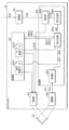
図1に、プロジェクションシステム1を示す。プロジェクションシステム1は、画像提供装置4と、プロジェクター8とを含む。画像提供装置4は、例えば携帯電話、PC、DVDプレーヤー、ゲーム装置、又はUSBメモリーやPCカード等の携帯型情報記憶媒体などである。本実施形態では、投射する画像の歪みを補正可能とするプロジェクター8について説明する。
A. 1. Overview of
画像提供装置4は、画像データGDを、プロジェクター8に入力する。プロジェクター8は、入力される画像データGDを補正し、画像データGDを補正して得られる補正画像データCGDを生成し、補正画像データCGDに基づく補正画像CGを、投射面SCに投射する。
The
画像データGDに施す補正とは、投射面SCに投射される画像の歪みを補正する処理である。画像の歪みが発生する状況としては、例えば以下に示す2つの状況がある。第1状況は、投射面SCが互いに交差する複数の平面からなる場合、投射面SCが曲面である場合、又は投射面SCに凹凸がある場合等、投射面SCが一つの平面ではない場合である。第2状況は、プロジェクター8が投射面SCに対して斜めに画像を投射する場合である。図1に示す投射面SCの形状は、第1平面PL1と第1平面PL1と交差する第2平面PL2とから構成される形状である。
以下の記載では、第1平面PL1と第2平面PL2とから構成される形状を、「コーナー面形状」と称する。また、円柱の側面の形状及び楕円柱の側面の形状を総称して、「シリンダー側面形状」と称する。
プロジェクター8は、投射面SCに投射される画像の歪みが相殺されるように画像データGDを補正し、補正画像データCGDを生成する。
The correction applied to the image data GD is processing for correcting the distortion of the image projected onto the projection surface SC. There are, for example, the following two situations in which image distortion occurs. The first situation is when the projection surface SC is not a single plane, such as when the projection surface SC is composed of a plurality of planes that intersect with each other, when the projection surface SC is curved, or when the projection surface SC has unevenness. be. The second situation is when the
In the following description, the shape composed of the first plane PL1 and the second plane PL2 is referred to as "corner surface shape". In addition, the shape of the side surface of the cylinder and the shape of the side surface of the elliptical cylinder are collectively referred to as "cylinder side surface shape".
The
以下の説明では、図1に示されるX軸、Y軸、及び、Z軸は、以下のように定まる。X軸、Y軸、及び、Z軸は、互いに直交する。プロジェクター8の載置面MSは、XZ平面に平行であるとし、Y軸は、載置面MSに垂直である。さらに、Z軸が、プロジェクター8の光軸に平行である。
In the following description, the X-axis, Y-axis and Z-axis shown in FIG. 1 are defined as follows. The X-axis, Y-axis and Z-axis are orthogonal to each other. The mounting surface MS of the
A.2.第1実施形態の構成
図2に、プロジェクター8の構成例を示す。プロジェクター8は、通信部82と、記憶部83と、投射部84と、撮像部86と、処理部88とを有する。通信部82は、インターネット等のネットワークを介して、画像提供装置4等の他の装置と通信する機器である。通信部82は、無線通信又は有線通信によって他の装置と通信するための回路を有する。通信部82は、画像提供装置4から、画像データGDを受信する。
A. 2. Configuration of First Embodiment FIG. 2 shows a configuration example of the
記憶部83は、処理部88が読み取り可能な記録媒体である。記憶部83は、例えば、ROM(Read Only Memory)、EPROM(Erasable Programmable ROM)、EEPROM(Electrically Erasable Programmable ROM)、RAM(Random Access Memory)等の記憶回路の1種類以上で構成される。記憶部83は、処理部88が実行する制御プログラムを含む複数のプログラム、線分画像データGH1、及び、マーク画像データGH2を記憶する。
線分画像データGH1が示す線分画像G1が、「第1画像」の一例である。マーク画像データGH2が示すマーク画像G2は、「第2画像」の一例である。
The
The line segment image G1 indicated by the line segment image data GH1 is an example of the "first image". The mark image G2 indicated by the mark image data GH2 is an example of the "second image".
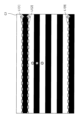
図3に、線分画像G1を示す。線分画像G1は、横方向に平行な矩形で構成された縞模様、いわゆるストライプである。図3に示す線分画像G1は、白色及び黒色を用いている。線分画像G1は、白色と黒色との組み合わせに限らなく、任意の色の組み合わせが可能である。 FIG. 3 shows the line segment image G1. The line segment image G1 is a so-called striped pattern composed of horizontally parallel rectangles. The line segment image G1 shown in FIG. 3 uses white and black. The line segment image G1 is not limited to a combination of white and black, and any combination of colors is possible.
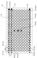
図4に、マーク画像G2を示す。マーク画像G2は、複数のマークM1を含む。図4では、図面の煩雑化を抑えるため、複数のマークM1のうち一部のマークM1のみを代表して符号を付与してある。マークM1は、記号又はしるしである。マークM1は、どのような態様でもよく、図4に示すマーク画像G2では、中心部が最も白色、即ち最高値の輝度を有し、周辺部が黒色である円である。図4に示すマーク画像G2には、黒色の背景に、マークM1として複数の白色の円が格子状に配置されている。 FIG. 4 shows the mark image G2. Mark image G2 includes a plurality of marks M1. In FIG. 4, in order to suppress the complication of the drawing, only a part of the marks M1 out of the plurality of marks M1 are given reference numerals. The mark M1 is a symbol or indicia. The mark M1 may be of any form. In the mark image G2 shown in FIG. 4, the mark M1 is a circle whose center is whitest, ie, has the highest brightness, and whose periphery is black. In the mark image G2 shown in FIG. 4, a plurality of white circles as marks M1 are arranged in a grid on a black background.
さらに、線分画像G1とマーク画像G2とは、次に示す関係がある。 Furthermore, the line segment image G1 and the mark image G2 have the following relationship.
図5に、線分画像G1に含まれる線分L1を示す。線分画像G1には、複数の線分L1として、線分L1[1]~線分L1[YMAX]が含まれる。最大値YMAXは、線分画像G1に含まれる線分L1の個数を示し、1以上の整数である。線分L1は、縞模様を構成する矩形同士の境界線である。図5に示す線分画像G1は、最大値YMAXが9の例である。図5に示す網掛けの矢印及び網掛けの「…」は、線分L1[1]~線分L1[9]を説明するために表示しており、実際の線分画像G1には表示されていない。仮に歪みのない投射面SCに線分画像G1を投射する場合、線分L1[1]~線分L1[9]は、+Y方向から順に、線分L1[1]~線分L1[9]の順番で配置される。線分L1[i]は、X軸に平行である。
なお、線分L1[i]が、「第1線分」の一例である。iは、1から最大値YMAXまでの整数である。
FIG. 5 shows the line segment L1 included in the line segment image G1. Line segment image G1 includes line segment L1[1] to line segment L1[YMAX] as a plurality of line segments L1. The maximum value YMAX indicates the number of line segments L1 included in the line segment image G1, and is an integer of 1 or more. A line segment L1 is a boundary line between rectangles forming a striped pattern. The line segment image G1 shown in FIG. 5 is an example in which the maximum value YMAX is nine. The hatched arrows and hatched "..." shown in FIG. 5 are displayed to explain the line segments L1[1] to L1[9], and are not displayed in the actual line segment image G1. not If the line segment image G1 is projected onto the projection surface SC without distortion, the line segment L1[1] to line segment L1[9] are, in order from the +Y direction, line segment L1[1] to line segment L1[9]. are placed in the order of Line segment L1[i] is parallel to the X-axis.
Note that the line segment L1[i] is an example of the "first line segment." i is an integer from 1 to the maximum value YMAX.
図6に、マーク画像G2に含まれるマークM1を示す。マーク画像G2は、複数のマークM1として、マークM1[1][1]~マークM1[1][XMAX]、マークM1[2][1]~マークM1[2][XMAX]、…、マークM1[YMAX][1]~マークM1[YMAX][XMAX]を含む。線分画像G1及びマーク画像G2を同位置に重ねる場合、マークM1[i][1]~マークM1[i][XMAX]は、線分L1[i]上に位置する。仮に歪みのない投射面SCにマーク画像G2を投射する場合、マークM1[i][1]~マークM1[i][XMAX]は、-X方向から順に、マークM1[i][1]~マークM1[i][XMAX]の順番で配置される。最大値XMAXは、線分L1[i]上に位置するマークM1の個数を示し、2以上の整数である。図6、図9、及び、図11では、最大値YMAXが9であり、最大値XMAXが16である場合の例である。 FIG. 6 shows the mark M1 included in the mark image G2. The mark image G2 includes a plurality of marks M1, including marks M1[1][1] to M1[1][XMAX], marks M1[2][1] to M1[2][XMAX], . Includes M1[YMAX][1] to M1[YMAX][XMAX]. When the line segment image G1 and the mark image G2 are superimposed at the same position, the marks M1[i][1] to M1[i][XMAX] are positioned on the line segment L1[i]. If the mark image G2 is projected onto the projection surface SC with no distortion, the marks M1[i][1] to M1[i][XMAX] are, in order from the -X direction, the marks M1[i][1] to The marks M1[i][XMAX] are arranged in order. The maximum value XMAX indicates the number of marks M1 positioned on the line segment L1[i] and is an integer of 2 or more. 6, 9, and 11 are examples in which the maximum value YMAX is 9 and the maximum value XMAX is 16. FIG.
図6に示すマーク画像G2は、図面の煩雑化を抑えるため、黒色の背景を白色に置き換えて表示している。図6に示す黒色の矢印及び黒色の「…」は、線分L1[1]~線分L1[9]を説明するために表示しており、実際のマーク画像G2には表示されていない。 The mark image G2 shown in FIG. 6 is displayed by replacing the black background with white in order to suppress the complication of the drawing. The black arrows and black "..." shown in FIG. 6 are displayed to explain the line segments L1[1] to L1[9], and are not displayed in the actual mark image G2.
マークM1[i][j]とマークM1[i+1][j]との間の距離、マークM1[i][k]とマークM1[i+1][k]との間の距離、及び、線分L1[i]と線分L1[i+1]との間の距離は、全て距離d1で同一である。j及びkは、1から最大値XMAXまでの整数である。 Distance between mark M1[i][j] and mark M1[i+1][j], distance between mark M1[i][k] and mark M1[i+1][k], and line segment All the distances between L1[i] and the line segment L1[i+1] are the same distance d1. j and k are integers from 1 to the maximum value XMAX.
説明を図2に戻す。投射部84は、画像を投射面SCに投射する。例えば、投射部84は、線分画像G1を投射面SCに投射することによって、図8及び図10に示す線分投射画像PG1を投射面SCに表示する。また、投射部84は、マーク画像G2を投射面SCに投射することによって、図9及び図11に示すマーク投射画像PG2を表示する。
線分投射画像PG1は、線分画像G1が投射面SCの三次元形状に応じて変形した画像である。同様に、マーク投射画像PG2は、マーク画像G2が投射面SCの三次元形状に応じて変形した画像である。
なお、線分投射画像PG1が、「第1投射画像」の一例である。また、マーク投射画像PG2は、「第2投射画像」の一例である。
Returning to FIG. The
The line segment projection image PG1 is an image obtained by deforming the line segment image G1 according to the three-dimensional shape of the projection surface SC. Similarly, the mark projection image PG2 is an image obtained by deforming the mark image G2 according to the three-dimensional shape of the projection surface SC.
Note that the line segment projection image PG1 is an example of the "first projection image". Also, the mark projection image PG2 is an example of the "second projection image".
図7に、投射部84の一例を示す。投射部84は、光源841と、光変調装置の一例である3つの液晶ライトバルブ842R、842G、及び842Bと、投射光学系の一例である投射レンズ843と、ライトバルブ駆動部844等を含む。投射部84は、光源841から射出される光を液晶ライトバルブ842で変調して画像を形成し、画像を投射レンズ843から拡大投射する。これにより、投射レンズ843は、画像を投射面SCに表示する。
FIG. 7 shows an example of the
光源841は、キセノンランプ、超高圧水銀ランプ、LED、又はレーザー光源等から形成される光源部841aと、光源部841aが放射する光の方向のばらつきを低減するリフレクター841bとを含む。LEDは、Light Emitting Diodeの略である。光源841から射出される光は、不図示のインテグレーター光学系によって輝度分布のばらつきが低減され、その後、不図示の色分離光学系によって光の3原色である赤色、緑色、青色の色光成分に分離される。赤色、緑色、青色の色光成分は、それぞれ液晶ライトバルブ842R、842G、842Bに入射する。 The light source 841 includes a light source section 841a formed of a xenon lamp, an extra-high pressure mercury lamp, an LED, a laser light source, or the like, and a reflector 841b that reduces variations in the direction of light emitted from the light source section 841a. LED is an abbreviation for Light Emitting Diode. The light emitted from the light source 841 has its luminance distribution reduced by an integrator optical system (not shown), and is then separated into the three primary colors of light, red, green, and blue, by a color separation optical system (not shown). be done. The red, green, and blue color light components enter liquid crystal light valves 842R, 842G, and 842B, respectively.
液晶ライトバルブ842は、一対の透明基板間に液晶が封入される液晶パネル等によって構成される。液晶ライトバルブ842には、マトリクス状に配列された複数の画素842pからなる矩形の画素領域842aが形成されている。液晶ライトバルブ842では、液晶に対して画素842pごとに駆動電圧を印加することが可能である。ライトバルブ駆動部844が、画像データGDに応じた駆動電圧を各画素842pに印加すると、各画素842pは、画像データGDに応じた光透過率に設定される。このため、光源841から射出される光は、画素領域842aを透過することで変調され、投射面SCに投射する画像が色光ごとに形成される。 The liquid crystal light valve 842 is composed of a liquid crystal panel or the like in which liquid crystal is sealed between a pair of transparent substrates. The liquid crystal light valve 842 is formed with a rectangular pixel region 842a composed of a plurality of pixels 842p arranged in a matrix. In the liquid crystal light valve 842, it is possible to apply a driving voltage to the liquid crystal for each pixel 842p. When the light valve driving section 844 applies a driving voltage corresponding to the image data GD to each pixel 842p, each pixel 842p is set to have a light transmittance corresponding to the image data GD. Therefore, the light emitted from the light source 841 is modulated by passing through the pixel region 842a, and an image projected on the projection surface SC is formed for each color light.
説明を図2に戻す。撮像部86は、投射面SCを撮像し、撮像画像を示す撮像データを出力する装置である。出力される撮像画像は、例えば、行列状に配置される複数の画素で構成される。撮像データは、撮像画像の画素ごとの輝度等に関するデータを含む。撮像部86は、例えば撮像光学系及び撮像素子を含んで構成される。撮像光学系は、少なくとも1つの撮像レンズを含む光学系であり、プリズム等の各種の光学素子を備えてもよいし、ズームレンズやフォーカスレンズ等を備えてもよい。撮像素子は、例えば、CCDイメージセンサー又はCMOSイメージセンサー等で構成される。CCDは、Charge Coupled Deviceの略である。CMOSは、Complementary MOSの略である。
Returning to FIG. The
撮像部86は、線分投射画像PG1を撮像して得られる線分撮像データGI1を出力する。また、撮像部86は、マーク投射画像PG2を撮像して得られるマーク撮像データGI2を出力する。
なお、線分撮像データGI1は、「第1撮像データ」の一例である。マーク撮像データGI2は、「第2撮像データ」の一例である。
The
Note that the line segment image data GI1 is an example of "first image data". The mark imaging data GI2 is an example of "second imaging data".
処理部88は、例えば、CPU等のコンピューターである。CPUは、Central Processing Unitの略である。処理部88は、1又は複数のプロセッサーで構成されてもよい。処理部88は、記憶部83に記憶されるプログラムを読み取り実行することによって、取得部881、第1生成部884、第2生成部886、及び、補正部888として機能する。
The
取得部881は、線分撮像データGI1を取得する。また、取得部881は、マーク撮像データGI2を取得する。
The
第1生成部884は、2つの画像に含まれるマーク同士を対応付ける関係データRDを生成する。より詳細には、第1生成部884は、マーク撮像データGI2における線分L1[i]に対応する投射線分L2[i]上に位置するXMAX個の投射マークM2の位置関係、及び、線分L1[i]上に位置するXMAX個のマークM1の位置関係に基づき、線分撮像データGI1を用いて線分L1[i]上に位置するXMAX個のマークM1の各々に対して、投射線分L2[i]上に位置するXMAX個の投射マークM2のいずれか1つを対応付ける関係データRDを生成する。
なお、投射線分L2が、「第2線分」の一例である。
例えば、最大値XMAXが2である場合、第1生成部884は、投射線分L2[i]上に位置する2個の投射マークM2の位置関係、及び、線分L1[i]上に位置する2個のマークM1の位置関係に基づいて、前述の2個のマークM1のうちいずれか一方のマークM1と前述の2個の投射マークM2のいずれか一方の投射マークM2とを対応付け、且つ、前述の一方のマークM1とは異なる他方のマークM1と前述の2個の投射マークM2の他方の投射マークM2とを対応付ける関係データRDを生成する。
なお、前述の2個のマークM1のうちいずれか一方のマークM1が、「第1マーク」の一例であり、他方のマークM1が、「第2マーク」の一例である。また、前述の2個の投射マークM2のいずれか一方の投射マークM2が、「第3マーク」の一例であり、他方の投射マークM2が、「第4マーク」の一例である。
The
Note that the projected line segment L2 is an example of the "second line segment".
For example, when the maximum value XMAX is 2, the
One of the two marks M1 described above is an example of the "first mark", and the other mark M1 is an example of the "second mark". One of the two projection marks M2 described above is an example of the "third mark", and the other projection mark M2 is an example of the "fourth mark".
図8及び図10を用いて、投射線分L2の一例を示し、図9及び図11を用いて、投射マークM2の一例を示す。 An example of the projection line segment L2 is shown using FIGS. 8 and 10, and an example of the projection mark M2 is shown using FIGS. 9 and 11. FIG.
図8に、投射面SCの三次元形状がシリンダー側面形状である場合の線分投射画像PG1を示す。投射面SCの三次元形状がシリンダー側面形状である場合、線分投射画像PG1は、四角形の上辺及び下辺が四角形の中心から離れるように弧を描く形状となる。線分投射画像PG1には、投射線分L2[1]~投射線分L2[9]が含まれる。線分投射画像PG1の変形に併せて、投射線分L2[1]~投射線分L2[9]も、弧を描くように変形する。図8に示す網掛けの矢印及び網掛けの「…」は、投射線分L2[1]~投射線分L2[9]を説明するために表示しており、実際の線分投射画像PG1には表示されていない。
線分投射画像PG1の変形に併せて投射線分L2[1]~投射線分L2[9]も変形するが、投射線分L2[1]~投射線分L2[9]の位置関係は、線分L1[1]~線分L1[9]の位置関係と同一である。例えば、投射線分L2[2]は、投射線分L2[1]を基準に-X方向に位置する。
FIG. 8 shows a line segment projection image PG1 when the three-dimensional shape of the projection surface SC is a cylinder side surface shape. When the three-dimensional shape of the projection surface SC is a cylinder side surface shape, the line segment projection image PG1 has a shape in which the upper and lower sides of the quadrangle draw arcs away from the center of the quadrangle. The line segment projection image PG1 includes projection line segments L2[1] to L2[9]. Along with the deformation of the line segment projection image PG1, the projection line segments L2[1] to L2[9] are also deformed to draw an arc. The hatched arrows and hatched "..." shown in FIG. is not shown.
Along with the deformation of the line segment projection image PG1, the projection line segment L2[1] to the projection line segment L2[9] are also deformed. This is the same as the positional relationship of line segment L1[1] to line segment L1[9]. For example, the projected line segment L2[2] is located in the -X direction with respect to the projected line segment L2[1].
図9に、投射面SCの三次元形状がシリンダー側面形状である場合のマーク投射画像PG2を示す。投射面SCの三次元形状がシリンダー側面形状である場合、マーク投射画像PG2は、線分投射画像PG1と同様に、四角形の上辺及び下辺が四角形の中心から離れるように弧を描く形状となる。マークM1[1][1]~マークM1[9][16]の各々に対応する投射マークM2[1][1]~投射マークM2[9][16]の位置は、投射線分L2[1]~投射線分L2[9]に併せて移動する。図9に示す黒色の矢印及び黒色の「…」は、投射線分L2[1]~投射線分L2[9]を説明するために表示しており、実際のマーク投射画像PG2には表示されていない。 FIG. 9 shows the mark projection image PG2 when the three-dimensional shape of the projection surface SC is the cylinder side surface shape. When the three-dimensional shape of the projection surface SC is a cylinder side surface shape, the mark projection image PG2 has a shape in which the upper and lower sides of the quadrangle draw arcs away from the center of the quadrangle, similarly to the line segment projection image PG1. The positions of the projection marks M2[1][1] to M2[9][16] corresponding to the marks M1[1][1] to M1[9][16] are the projection line segment L2[ 1] to the projected line segment L2[9]. The black arrows and black "..." shown in FIG. 9 are displayed to explain the projection line segments L2[1] to L2[9], and are not displayed in the actual mark projection image PG2. not
図10に、投射面SCの三次元形状がコーナー面形状である場合の線分投射画像PG1を示す。投射面SCの三次元形状がコーナー面形状である場合、線分投射画像PG1は、四角形が、第1平面PL1と第2平面PL2とが交差する境界線BLで折れ曲がった形状となる。線分投射画像PG1の変形に併せて、投射線分L2[1]~投射線分L2[9]も、境界線BLで折れ曲がるように変形する。図10に示す網掛けの矢印及び網掛けの「…」は、投射線分L2[1]~投射線分L2[9]を説明するために表示しており、実際の線分投射画像PG1には表示されていない。 FIG. 10 shows a line segment projection image PG1 when the three-dimensional shape of the projection surface SC is a corner surface shape. When the three-dimensional shape of projection surface SC is a corner surface shape, line segment projection image PG1 has a shape in which a quadrangle is bent at boundary line BL where first plane PL1 and second plane PL2 intersect. Along with the deformation of the line segment projection image PG1, the projection line segments L2[1] to L2[9] are also deformed so as to bend at the boundary line BL. The hatched arrows and hatched "..." shown in FIG. is not shown.
図11に、投射面SCの三次元元形状がコーナー面形状である場合のマーク投射画像PG2を示す。投射面SCの三次元形状がコーナー面形状である場合、マーク投射画像PG2は、線分投射画像PG1と同様に、境界線BLで折れ曲がった形状となる。マークM1[1][1]~マークM1[9][16]の各々に対応する投射マークM2[1][1]~投射マークM2[9][16]の位置は、投射線分L2[1]~投射線分L2[9]に併せて移動する。図11に示す黒色の矢印及び黒色の「…」は、投射線分L2[1]~投射線分L2[9]を説明するために表示しており、実際のマーク投射画像PG2には表示されていない。 FIG. 11 shows the mark projection image PG2 when the three-dimensional original shape of the projection surface SC is the corner surface shape. When the three-dimensional shape of the projection surface SC is a corner surface shape, the mark projection image PG2 has a shape bent at the boundary line BL, like the segment projection image PG1. The positions of the projection marks M2[1][1] to M2[9][16] corresponding to the marks M1[1][1] to M1[9][16] are the projection line segment L2[ 1] to the projected line segment L2[9]. The black arrows and black "..." shown in FIG. 11 are displayed to explain the projection line segments L2[1] to L2[9], and are not displayed in the actual mark projection image PG2. not
説明を図2に戻す。マークM1[i][1]~マークM1[i][XMAX]の位置関係について、プロジェクター8は、第1マークデータMD1を記憶部83に記憶する。第1マークデータMD1は、マークM1の識別情報と、このマークM1の位置情報と、このマークM1と重なる線分L1の識別情報と、この線分L1上においてこのマークM1が-X方向から何番目に位置するかを示す値とを対応付けるデータである。第1マークデータMD1の生成方法は、以下に示す2つの方法がある。
第1の生成方法は、プロジェクター8の開発者が操作するコンピューターが、開発者がマーク画像G2を見ながらコンピューターを操作することにより、第1マークデータMD1を生成する。
第2の生成方法において、第1生成部884は、マーク画像データGH2を解析し、マーク画像G2内において、例えば輝度が所定値以上の領域を、1つのマークM1として特定し、この領域の重心位置を示す座標値を、マークM1の重心位置を示す座標値として検出する。重心位置を示す座標値は、横方向の座標値と縦方向の座標値とを有する。また、第1生成部884は、線分画像データGH1を解析し、線分画像G1内において、黒色の領域と白色の領域との境界線を、線分L1として特定し、線分L1[1]~線分L1[YMAX]の各々の位置情報を検出する。線分L1の位置情報は、例えば、線分L1の始点の座標値及び終点の座標値である。そして、第1生成部884は、線分L1[1]~線分L1[YMAX]の各々の位置情報に基づいて、マーク画像G2から得られるマークM1が、線分L1[1]~線分L1[YMAX]のうちどの線分L1上に位置するかを特定する。マークM1が線分L1上に位置するか否かの判定について、第1生成部884は、例えば、マークM1の重心位置から所定範囲内に線分L1の一部が含まれる場合、マークM1が線分L1上に位置すると判定する。第1生成部884は、第1マークデータMD1を記憶部83に記憶する。マークM1と重なる線分L1の識別情報が、マークM1[i][j]の「i」に相当し、マークM1が-X方向から何番目に位置するかを示す値が、マークM1[i][j]の「j」に相当し、マークM1[i][1]~マークM1[i][XMAX]の位置関係にも相当する。このように、第1実施形態では、マークM1[i][1]~マークM1[i][XMAX]の位置関係を、マークM1が-X方向から何番目に位置するかにより示している。
投射マークM2[i][1]~投射マークM2[i][XMAX]の位置関係についても、プロジェクター8は、第2マークデータMD2を記憶部83に記憶する。第2マークデータMD2は、投射マークM2の識別情報と、投射マークM2の位置情報と、この投射マークM2と重なる投射線分L2の識別情報と、この投射線分L2上においてこの投射マークM2が-X方向から何番目に位置するかを示す値とを対応付けるデータである。第2マークデータMD2の生成方法は、第1マークデータMD1の第2の生成方法と同様である。具体的には、第1生成部884は、マーク撮像データGI2を解析し、マーク投射画像PG2内において、例えば輝度が所定値以上の領域を、1つの投射マークM2として特定し、この領域の重心位置を示す座標値を、投射マークM2の重心位置を示す座標値として検出する。また、第1生成部884は、線分撮像データGI1を解析し、黒色の領域と白色の領域との境界線を、投射線分L2として特定し、投射線分L2[1]~投射線分L2[YMAX]の各々の位置情報を検出する。投射線分L2の位置情報は、例えば、投射線分L2を構成する各点の座標値である。そして、第1生成部884は、投射線分L2[1]~投射線分L2[YMAX]の各々の位置情報に基づいて、マーク投射画像PG2から得られる投射マークM2が、投射線分L2[1]~投射線分L2[YMAX]のどの投射線分L2に位置するかを特定する。投射マークM2が投射線分L2上に位置するか否かの判定について、第1生成部884は、例えば、投射マークM2の重心位置から所定範囲内に投射線分L2の一部が含まれる場合、投射マークM2が投射線分L2上に位置すると判定する。第1生成部884は、第2マークデータMD2を記憶部83に記憶する。投射マークM2と重なる線分L1の識別情報が、投射マークM2[i][j]の「i」に相当し、投射マークM2が-X方向から何番目に位置するかを示す値が、投射マークM2[i][j]の「j」に相当し、投射マークM2[i][1]~投射マークM2[i][XMAX]の位置関係にも相当する。
Returning to FIG. The
In the first generation method, a computer operated by the developer of the
In the second generation method, the
The
第1生成部884は、第1マークデータMD1及び第2マークデータMD2を参照して、あるマークM1と、このマークM1と重なる線分L1に対応する投射線分L2上に位置する投射マークM2であって、-X方向から数えてこのマークM1と同一個数個目に位置する投射マークM2とを対応付ける関係データRDを生成する。具体的には、第1生成部884は、マークM1[i][1]と投射マークM2[i][1]とを対応付け、…、マークM1[i][j]と投射マークM2[i][j]とを対応付け、…、マークM1[i][XMAX]と投射マークM2[i][XMAX]とを対応付ける関係データRDを生成する。
The
関係データRDは、例えば、以下に示す2つの態様がある。第1の態様における関係データRDは、対応付けたマークM1の位置情報と投射マークM2の位置情報とを示す。マークM1の位置情報は、例えば、マーク画像G2内におけるマークM1の重心位置を示す座標値である。同様に、投射マークM2の位置情報は、例えば、マーク投射画像PG2内における投射マークM2の重心位置を示す座標値である。 The relationship data RD has, for example, the following two aspects. The relational data RD in the first mode indicates the positional information of the mark M1 and the positional information of the projected mark M2 that are associated with each other. The position information of the mark M1 is, for example, coordinate values indicating the barycentric position of the mark M1 in the mark image G2. Similarly, the position information of the projection mark M2 is, for example, coordinate values indicating the center-of-gravity position of the projection mark M2 in the mark projection image PG2.
第2の態様における関係データRDは、対応付けたマークM1の識別情報と投射マークM2の識別情報とを示す。関係データRDがマークM1の位置情報を有さなくとも、第1マークデータMD1を参照することにより、マークM1の位置情報を特定できる。投射マークM2の位置情報についてもマークM1の位置情報と同様である。
以下の説明では、関係データRDは、第2の態様であるとする。
The relational data RD in the second aspect indicates the identification information of the mark M1 and the identification information of the projection mark M2 that are associated with each other. Even if the relational data RD does not have the positional information of the mark M1, the positional information of the mark M1 can be identified by referring to the first mark data MD1. The positional information of the projection mark M2 is the same as the positional information of the mark M1.
In the following description, it is assumed that the relational data RD is of the second mode.
第2生成部886は、関係データRDに基づいて、補正データCDを生成する。補正データCDを生成するためには、マークM1の位置から投射マークM2の位置までのベクトルVを算出する必要がある。図12を用いて、ベクトルVについて説明する。
The
図12に、ベクトルVの例を示す。図12では、図面の煩雑化を抑えるため、黒色の背景を白色に置き換えて表示し、さらに、マークM1を白抜きの円として表示し、投射マークM2を黒色の円として表示してある。また、図12では、最大値YMAXを3とし、最大値XMAXを3とする。さらに、図12では、マークM1同士を破線で結び、投射マークM2同士を実線で結んである。 An example of vector V is shown in FIG. In FIG. 12, in order to suppress the complication of the drawing, the black background is replaced with white for display, the marks M1 are displayed as white circles, and the projection marks M2 are displayed as black circles. Also, in FIG. 12, the maximum value YMAX is 3, and the maximum value XMAX is 3. Furthermore, in FIG. 12, the marks M1 are connected by dashed lines, and the projection marks M2 are connected by solid lines.
第2生成部886は、変数iと変数jとが取り得る複数の組み合わせの各々に対して、投射マークM2[i][j]の重心位置を示す座標値から、関係データRDを参照して特定される投射マークM2[i][j]に対応するマークM1[i][j]の重心位置を示す座標値を減じて得られる値を、ベクトルV[i][j]として算出する。図12の例では、i及びjは1から3までの整数である。図12では、図面の煩雑化を抑えるため、ベクトルV[1][1]~ベクトルV[3][3]のうち、ベクトルV[1][1]のみを代表して表示してある。
The
図13に、ベクトルVに基づく補正データCDの生成例を示す。投射面SCに投射される画像の歪みを相殺するには、入力される画像データGDが示す画像におけるマークM1の位置を、ベクトルVの逆ベクトルV’分移動するように、画像データGDを補正すればよい。補正データCDの内容は、移動後のマークM1’の位置を示す座標値である。図13では、マークM1[i][j]を白抜きの円として表示し、マークM1[i][j]を逆ベクトルV’[i][j]分移動させて得られる移動後のマークM1’[i][j]を黒色の円として表示する。さらに、図13では、マークM1同士を破線で結び、移動後のマークM1’同士を実線で結んである。図13では、図面の煩雑化を抑えるため、逆ベクトルV’[1][1]~逆ベクトルV’[3][3]のうち、逆ベクトルV’[1][1]のみを代表して表示してある。 FIG. 13 shows an example of generation of correction data CD based on vector V. In FIG. In order to cancel the distortion of the image projected onto the projection plane SC, the image data GD is corrected so that the position of the mark M1 in the image indicated by the input image data GD is moved by the inverse vector V' of the vector V. do it. The contents of the correction data CD are coordinate values indicating the position of the mark M1' after movement. In FIG. 13, the marks M1[i][j] are displayed as white circles, and the marks after movement obtained by moving the marks M1[i][j] by an inverse vector V′[i][j] Denote M1′[i][j] as black circles. Furthermore, in FIG. 13, the marks M1 are connected by broken lines, and the marks M1' after movement are connected by solid lines. In FIG. 13, only the inverse vector V'[1][1] is represented among the inverse vectors V'[1][1] to V'[3][3] in order to suppress the complication of the drawing. are displayed.
説明を図2に戻す。補正部888は、画像データGDを補正データCDに基づいて補正する。具体的には、補正部888は、マークM1を頂点とする矩形領域で画像データGDが示す画像を分割し、分割して得られる分割画像を、補正データCDが示す移動後のマークM1を頂点とする領域に収まるように補正する。
Returning to FIG. The
投射部84は、画像データGDを補正して得られる補正画像データCGDに基づく補正画像CGを、投射面SCに投射する。
The
A.3.第1実施形態の動作
次に、図14、図15、及び、図16を用いて、プロジェクター8の動作を示す。プロジェクター8は、補正データCDを生成する補正データ生成処理と、補正データCDに基づいて画像データGDを補正して、補正画像データCGDに基づく補正画像CGを投射する画像データ投射処理とを実行する。
A. 3. Operation of First Embodiment Next, the operation of the
図14及び図15は、補正データ生成処理を示すフローチャートである。第1生成部884は、ステップS1において、線分画像データGH1から、線分L1として、線分L1[1]~線分L1[YMAX]を特定する。次に、第1生成部884は、ステップS2において、マーク画像データGH2から、複数のマークM1を特定する。第1生成部884は、ステップS3において、線分L1[1]~線分L1[YMAX]の位置情報、及び、複数のマークM1の各々の位置情報に基づいて、第1マークデータMD1を生成する。
14 and 15 are flowcharts showing correction data generation processing. In step S1, the
次に、投射部84は、ステップS4において、線分画像G1を投射することによって、線分投射画像PG1を投射面SCに表示する。取得部881は、ステップS5において、撮像部86が線分投射画像PG1を撮像して得られる線分撮像データGI1を取得する。第1生成部884は、ステップS6において、線分撮像データGI1から、投射線分L2として、投射線分L2[1]~投射線分L2[YMAX]を特定する。投射部84は、ステップS7において、マーク画像G2を投射することによって、マーク投射画像PG2を投射面SCに表示する。取得部881は、ステップS8において、撮像部86がマーク投射画像PG2を撮像して得られるマーク撮像データGI2を取得する。第1生成部884は、ステップS9において、マーク撮像データGI2から、複数の投射マークM2を特定する。第1生成部884は、ステップS10において、投射線分L2[1]~投射線分L2[YMAX]の位置情報、及び、複数の投射マークM2の各々の位置情報に基づいて、第2マークデータMD2を生成する。
Next, in step S4, the
第1生成部884は、図15に示すステップS21において、変数iに1を代入する。さらに、第1生成部884は、ステップS22において、変数jに1を代入する。次に、第1生成部884は、第1マークデータMD1及び第2マークデータMD2を参照して、マークM1[i][j]の識別情報と投射マークM2[i][j]の識別情報とを対応付けて、関係データRDに追加する。
なお、マークM1[i][j]の識別情報とは、第1マークデータMD1によって示される、線分L1[i]上に位置するマークM1であって、-X方向からj番目に位置するマークM1の識別情報である。同様に、投射マークM2[i][j]の識別情報とは、第2マークデータMD2によって示される、投射線分L2[i]上に位置する投射マークM2であって、-X方向からj番目に位置する投射マークM2の識別情報である。
The
The identification information of the mark M1[i][j] refers to the mark M1 positioned on the line segment L1[i] indicated by the first mark data MD1 and positioned j-th from the -X direction. This is the identification information of the mark M1. Similarly, the identification information of the projection mark M2[i][j] refers to the projection mark M2 located on the projection line segment L2[i] indicated by the second mark data MD2 and j This is the identification information of the projection mark M2 located at the th position.
ステップS23の処理終了後、第1生成部884は、ステップS24において、変数jの値を1増加し、ステップS25において、変数jの値が最大値XMAX以下か否かを判定する。ステップS25の判定結果が肯定の場合、第1生成部884は、ステップS23の処理を実行する。一方、ステップS25の判定結果が否定の場合、第1生成部884は、ステップS26において、変数iの値を1増加し、ステップS27において、変数iの値が最大値YMAX以下か否かを判定する。ステップS27の判定結果が肯定の場合、第1生成部884は、ステップS22の処理を実行する。
After completing the process of step S23, the
一方、ステップS27の判定結果が否定の場合、第2生成部886は、ステップS28において、関係データRDが示すマークM1と、このマークM1に対応付けられている投射マークM2とを選択する。第2生成部886は、ステップS29において、選択しているマークM1の位置から投射マークM2の位置までのベクトルVを算出する。第2生成部886は、ステップS30において、ベクトルVの逆ベクトルV’から、移動後のマークM1’の位置を算出し、補正データCDに追加する。
On the other hand, if the determination result in step S27 is negative, the
ステップS30の処理終了後、第2生成部886は、ステップS31において、関係データRDが示す全てのマークM1を選択済みか否かを判定する。ステップS31の判定結果が否定の場合、即ち、関係データRDが示すマークM1のうち、まだ選択済みでないマークM1がある場合、第2生成部886は、ステップS28の処理を実行する。ステップS28において、第2生成部886は、関係データRDが示すマークM1のうち、まだ未選択であるマークM1と、このマークM1に対応付けられている投射マークM2とを選択する。
After completing the process of step S30, the
一方、ステップS31の判定結果が肯定の場合、プロジェクター8は、図14及び図15に示す一連の処理を終了する。
On the other hand, if the determination result in step S31 is affirmative, the
図16に、画像データ投射処理を示すフローチャートを示す。処理部88は、ステップS41において、画像提供装置4から画像データGDが入力されたか否かを判定する。ステップS41の判定結果が否定の場合、すなわち画像データGDが入力されていない場合、処理部88は、一定期間経過後に再びステップS41の処理を実行する。
FIG. 16 shows a flowchart showing image data projection processing. The
一方、ステップS41の判定結果が肯定の場合、補正部888は、ステップS42において、補正データCDに基づいて画像データGDを補正する。そして、投射部84は、ステップS43において、補正画像データCGDに基づく補正画像CGを投射面SCに投射する。ステップS43の処理終了後、プロジェクター8は、図16に示す一連の処理を終了する。
On the other hand, if the determination result in step S41 is affirmative, the
A.4.第1実施形態の効果
以上説明したように、第1実施形態によれば、プロジェクター8において、投射部84は、線分L1を含む線分画像G1を投射面SCに投射することによって、投射面SCに線分投射画像PG1を表示し、線分投射画像PG1を撮像して得られる線分撮像データGI1を取得し、最大値XMAXが2である場合に、線分L1と重なるマークM1[i][1]及びマークM1[i][2]を含むマーク画像G2を投射面SCに投射することによって、投射面SCにマーク投射画像PG2を表示し、投射面SCに表示されるマーク投射画像PG2を撮像して得られるマーク撮像データGI2を取得し、マーク撮像データGI2における線分L1に対応する投射線分L2上に位置する2個の投射マークM2の位置関係、及び、線分L1上に位置する2個のマークM1の位置関係に基づき、線分撮像データGI1を用いて前述の2個のマークM1のうちいずれか一方のマークM1と前述の2個の投射マークM2のいずれか一方の投射マークM2とを対応付け、且つ、前述の一方のマークM1とは異なる他方のマークM1と前述の2個の投射マークM2の他方の投射マークM2とを対応付ける関係データRDを生成し、関係データRDに基づいて、投射面SCに投射される画像の歪みを補正する補正データCDを生成し、プロジェクター8に入力される画像データGDを補正データCDに基づいて補正し、画像データGDを補正して得られる補正画像データCGDに基づく補正画像CGを投射面SCに投射する。
投射面SCが平面でない場合であっても、線分L1上におけるマークM1の位置関係は、投射線分L2上における投射マークM2においても維持される。例えば、線分L1[i]において、マークM1[i][j+1]は、マークM1[i][j]から見て+X方向に位置する関係であるので、投射線分L2[i]上においても、投射マークM2[i][j+1]は、投射マークM2[i][j]から見て+X方向に位置する。このように、線分L1上におけるマークM1の位置関係及び投射線分L2上における投射マークM2の位置関係を特定することにより、投射面SCが平面でなく、投射マークM2の位置が揃っていない場合であっても、複数の投射マークM2のある投射マークM2に対応するマークM1を容易に特定できる。ある投射マークM2に対応するマークM1を容易に特定できることにより、ある投射マークM2に対応するマークM1を誤る場合と比較して、投射面SCに投射される補正画像CGの歪みを抑制できる。
A. 4. Effects of the First Embodiment As described above, according to the first embodiment, in the
Even if the projection surface SC is not flat, the positional relationship of the marks M1 on the line segment L1 is also maintained for the projection marks M2 on the projection line segment L2. For example, on the line segment L1[i], the mark M1[i][j+1] is located in the +X direction when viewed from the mark M1[i][j], so on the projected line segment L2[i] Also, the projection mark M2[i][j+1] is positioned in the +X direction when viewed from the projection mark M2[i][j]. By specifying the positional relationship of the marks M1 on the line segment L1 and the positional relationship of the projection marks M2 on the projection line segment L2 in this way, it is possible to determine whether the projection surface SC is not flat and the positions of the projection marks M2 are not aligned. Even in this case, the mark M1 corresponding to the projection mark M2 having the plurality of projection marks M2 can be easily specified. Since the mark M1 corresponding to a certain projection mark M2 can be easily identified, distortion of the corrected image CG projected onto the projection surface SC can be suppressed compared to the case where the mark M1 corresponding to a certain projection mark M2 is incorrect.
また、線分画像G1は、線分L1を含む縞模様である。これにより、マークM1も縞模様に沿って配置されるため、第1生成部884は、マーク画像データGH2から、マークM1の位置座標を特定する場合に、縞模様に沿ってマーク画像G2を解析すればよい。従って、第1マークデータMD1が第2の生成方法によって生成される場合、第1生成部884は、線分画像G1が縞模様でない場合と比較して、第1マークデータMD1を容易に生成することができる。
Also, the line segment image G1 is a striped pattern including the line segment L1. As a result, the marks M1 are also arranged along the striped pattern, so the
また、マーク画像G2は、線分L1[i]上に位置するマークM1を含む複数のマーク
M1を含み、複数のマークM1は、格子点に位置する。
仮に、複数のマークM1が格子点に位置しない場合、補正部888は、矩形ではない領
域で画像データGDが示す画像を分割するため、補正部888の処理が複雑化する。従っ
て、複数のマークM1が格子点に位置することにより、複数のマークM1が格子点に位置
しない場合と比較して、補正部888の処理を容易にできる。
また、第1生成部884は、マーク画像データGH2から、マークM1の位置座標を特
定する場合に、マーク画像G2のうち格子点付近のみを解析すればよい。従って、第1マ
ークデータMD1が第2の生成方法によって生成される場合、第1生成部884は、複数
のマークM1が格子点に位置しない場合と比較して、第1マークデータMD1を容易に生
成できる。
The mark image G2 also includes a plurality of marks M1 including marks M1 positioned on the line segment L1[i], and the plurality of marks M1 are positioned at grid points.
If the plurality of marks M1 are not positioned at grid points, the
Further, when specifying the position coordinates of the mark M1 from the mark image data GH2, the
また、複数のマークM1は、線分L1[i]と隣り合う線分L1[i+1]を含み、複
数のマークM1は、線分L1[i+1]上に位置するマークM1を含み、複数のマークM
1のうち隣り合うマークM1同士の距離と、線分L1[i]と線分L1[i+1]との間
の距離とが、共に距離d1であり同一である。言い換えれば、マーク画像G2内の格子点
の距離と、線分画像G1におけるストライプの太さとが同一である。なお、線分L1[i
+1]が、「第3線分」の一例である。
マーク画像G2内の格子点の距離と、線分画像G1におけるストライプの太さとが同一
であることにより、複数のマークM1の各々が、線分画像G1の線分L1[1]~線分L
1[YMAX]のいずれか1つの線分L1上に位置するので、複数の投射マークM2のあ
る投射マークM2に対応するマークM1を容易に特定できる。
Further, the plurality of marks M1 includes a line segment L1[i+1] adjacent to the line segment L1[i], the plurality of marks M1 includes the mark M1 positioned on the line segment L1[i+1], and the plurality of marks M1 M.
1 and the distance between the line segment L1[i] and the line segment L1[i+1] are both the distance d1 and are the same. In other words, the distance between grid points in the mark image G2 and the thickness of the stripes in the line segment image G1 are the same. Note that the line segment L1[i
+1] is an example of the "third line segment".
Since the distance between the grid points in the mark image G2 and the thickness of the stripes in the line segment image G1 are the same, each of the plurality of marks M1 is aligned with the line segment L1[1] to line segment L in the line segment image G1.
1 [YMAX], the mark M1 corresponding to the projection mark M2 having a plurality of projection marks M2 can be easily identified.
B.変形例
以上の各形態は多様に変形され得る。具体的な変形の態様を以下に例示する。以下の例示から任意に選択された2以上の態様は、相互に矛盾しない範囲内で適宜に併合され得る。なお、以下に例示する変形例において作用や機能が実施形態と同等である要素については、以上の説明で参照した符号を流用して各々の詳細な説明を適宜に省略する。
B. Modifications Each of the above forms can be modified in various ways. Specific modification modes are exemplified below. Two or more aspects arbitrarily selected from the following examples can be combined as appropriate within a mutually consistent range. It should be noted that, in the modifications illustrated below, the reference numerals referred to in the above description will be used for the elements that have the same actions and functions as those of the embodiment, and the detailed description of each will be omitted as appropriate.
上述の形態では、XZ平面に平行な切断面における投射面SCの線分は、切断面のY座標値に関わらず同一の形状である。言い換えれば、投射面SCは、Y軸方向で形状が変化しない。仮に、投射面SCが、X軸方向で形状が変化しない場合、投射部84は、線分画像G1を90度回転して投射面SCに投射すればよい。
In the above embodiment, the line segments of the projection plane SC on the cut plane parallel to the XZ plane have the same shape regardless of the Y coordinate value of the cut plane. In other words, the projection surface SC does not change its shape in the Y-axis direction. If the shape of the projection surface SC does not change in the X-axis direction, the
上述のプロジェクター8は撮像部86を有するが、撮像部86を有さなくてもよい。例えば、プロジェクションシステム1は、プロジェクター8の外部にカメラを有し、プロジェクター8は、カメラから、線分撮像データGI1及びマーク撮像データGI2を取得してもよい。
Although the
上述の各形態では、マーク画像G2に含まれるマークM1は、格子点の位置に配置されているが、線分L1と重なればよく、隣り合うマークM1同士の距離は、同一でなくてもよい。同様に、線分画像G1に含まれる線分L1[1]~線分L1[YMAX]も、横方向に平行でなくてもよい。 In each of the above-described embodiments, the marks M1 included in the mark image G2 are arranged at the positions of the grid points. good. Similarly, the line segments L1[1] to L1[YMAX] included in the line segment image G1 may not be parallel in the horizontal direction.
上述の各形態では、線分L1は直線であるが、これに限らない。例えば、線分L1は、曲線でもよいし、折れ線でもよい。また、線分L1[1]~線分[YMAX]は、交差さえしなければよく、互いに平行でなくてもよい。 Although the line segment L1 is a straight line in each of the above embodiments, it is not limited to this. For example, the line segment L1 may be a curved line or a polygonal line. Also, the line segment L1[1] to line segment [YMAX] need only not intersect and need not be parallel to each other.
上述の各形態では、マークM1[i][1]~マークM1[i][XMAX]の位置関係を、マークM1が-X方向から何番目に位置するかにより示しているが、これに限らない。マークM1[i][1]~マークM1[i][XMAX]の位置関係を、マークM1が+X方向から何番目に位置するかにより示してもよい。同様に、投射マークM2[i][1]~投射マークM2[i][XMAX]の位置関係を、投射マークM2が+X方向から何番目に位置するかにより示してもよい。 In each of the above-described embodiments, the positional relationship between the marks M1[i][1] to M1[i][XMAX] is indicated by the position of the mark M1 in the -X direction. do not have. The positional relationship between the marks M1[i][1] to M1[i][XMAX] may be indicated by the position of the mark M1 in the +X direction. Similarly, the positional relationship between the projection marks M2[i][1] to M2[i][XMAX] may be indicated by the position of the projection mark M2 from the +X direction.
上述の各形態における投射部84では、光変調装置として液晶ライトバルブが用いられたが、光変調装置は液晶ライトバルブに限らず適宜変更可能である。例えば、光変調装置は、3枚の反射型の液晶パネルを用いた構成であってもよい。また、光変調装置は、1枚の液晶パネルを用いた方式、3枚のDMDを用いた方式、1枚のデジタルミラーデバイスを用いた方式等の構成であってもよい。DMDは、Digital Micromirror Deviceの略である。光変調装置として1枚のみの液晶パネル又はDMDが用いられる場合には、色分離光学系や色合成光学系に相当する部材は不要である。また、液晶パネル及びDMD以外にも、光源が発する光を変調可能な構成は、光変調装置として採用できる。
A liquid crystal light valve is used as the light modulation device in the
上述の各態様において、処理部88がプログラムを実行することによって実現される要素の全部又は一部は、例えばFPGA又はASIC等の電子回路によりハードウェアで実現されてもよいし、ソフトウェアとハードウェアとの協働により実現されてもよい。FPGAは、Field Programmable Gate Arrayの略である。ASICは、Application Specific ICの略である。また、上述の各態様にかかるプロジェクター8の制御方法としても特定される。
In each aspect described above, all or part of the elements realized by the
1…プロジェクションシステム、4…画像提供装置、8…プロジェクター、82…通信部、83…記憶部、84…投射部、86…撮像部、88…処理部、881…取得部、884…第1生成部、886…第2生成部、888…補正部、CD…補正データ、CG…補正画像、CGD…補正画像データ、G1…線分画像、G2…マーク画像、GD…画像データ、GH1…線分画像データ、GH2…マーク画像データ、GI1…線分撮像データ、GI2…マーク撮像データ、L1…線分、L2…投射線分、PG1…線分投射画像、PG2…マーク投射画像、RD…関係データ、SC…投射面。
DESCRIPTION OF
Claims (5)
第1線分を含む第1画像を投射面に投射することによって、前記投射面に第1投射画像を表示し、
前記第1投射画像を撮像して得られる第1撮像データを取得し、
前記第1線分と重なる第1マーク及び第2マークを含む第2画像を前記投射面に投射することによって、前記投射面に第2投射画像を表示し、
前記第2投射画像を撮像して得られる第2撮像データを取得し、
前記第2撮像データにおける前記第1線分に対応する第2線分上に位置する第3マークと第4マークとの位置関係、及び、前記第1線分上に位置する前記第1マークと前記第2マークとの位置関係に基づき、前記第1撮像データを用いて、前記第1マークと前記第3マークとを対応付け、且つ前記第2マークと前記第4マークとを対応付ける関係データを生成し、
前記関係データに基づいて、前記投射面に投射される画像の歪みを補正する補正データを生成し、
前記プロジェクターに入力される画像データを前記補正データに基づいて補正し、
前記画像データを補正して得られる補正画像データに基づく補正画像を前記投射面に投射する、
プロジェクターの制御方法。 A control method for a projector,
displaying a first projection image on the projection surface by projecting the first image including the first line segment onto the projection surface;
Acquiring first imaging data obtained by imaging the first projection image;
displaying a second projection image on the projection surface by projecting a second image including a first mark and a second mark overlapping the first line segment onto the projection surface;
Acquiring second imaging data obtained by imaging the second projection image;
positional relationship between a third mark and a fourth mark positioned on a second line segment corresponding to the first line segment in the second imaging data, and the first mark positioned on the first line segment; relationship data that associates the first mark with the third mark and associates the second mark with the fourth mark using the first imaging data based on the positional relationship with the second mark; generate and
generating correction data for correcting distortion of an image projected onto the projection surface based on the relationship data;
correcting the image data input to the projector based on the correction data;
projecting a corrected image based on corrected image data obtained by correcting the image data onto the projection surface;
How to control the projector.
請求項1に記載のプロジェクターの制御方法。 wherein the first image is a striped pattern including the first line segment;
The control method of the projector according to claim 1.
前記複数のマークは、格子点に位置する、
請求項1又は2に記載のプロジェクターの制御方法。 the second image includes a plurality of marks including the first mark and the second mark;
wherein the plurality of marks are located at grid points;
The control method of the projector according to claim 1 or 2.
前記複数のマークは、前記第3線分上に位置するマークを含み、
前記複数のマークのうち隣り合うマーク同士の距離と、前記第1線分と前記第3線分との間の距離が同一である、
請求項3に記載のプロジェクターの制御方法。 The first image includes a third line segment adjacent to the first line segment,
The plurality of marks includes a mark positioned on the third line segment;
A distance between adjacent marks among the plurality of marks and a distance between the first line segment and the third line segment are the same.
The control method of the projector according to claim 3.
画像を投射面に投射する投射部と、
前記投射面に投射される前記画像を撮像して得られる撮像データを取得する取得部と、
2つの画像に含まれるマーク同士を対応付ける関係データを生成する第1生成部と、
前記関係データに基づいて、前記投射面に投射される画像の歪みを補正する補正データを生成する第2生成部と、
前記プロジェクターに入力される画像データを補正する補正部と、
を備え、
前記投射部は、第1線分を含む第1画像を前記投射面に投射することによって、前記投射面に第1投射画像を表示し、
前記取得部は、前記第1投射画像を撮像して得られる第1撮像データを取得し、
前記投射部は、前記第1線分と重なる第1マーク及び第2マークを含む第2画像を前記投射面に投射することによって、前記投射面に第2投射画像を表示し、
前記取得部は、前記第2投射画像を撮像して得られる第2撮像データを取得し、
前記第1生成部は、前記第2撮像データにおける前記第1線分に対応する第2線分上に位置する第3マークと第4マークとの位置関係、及び、前記第1線分上に位置する前記第1マーク及び前記第2マークとの位置関係に基づき、前記第1撮像データを用いて前記第1マークと前記第3マークとを対応付け、且つ前記第2マークと前記第4マークとを対応付ける前記関係データを生成し、
前記第2生成部は、前記関係データに基づいて、前記補正データを生成し、
前記補正部は、前記プロジェクターに入力される前記画像データを前記補正データに基づいて補正し、
前記投射部は、前記画像データを補正して得られる補正画像データに基づく補正画像を前記投射面に投射する、
プロジェクター。 being a projector
a projection unit that projects an image onto a projection surface;
an acquisition unit that acquires imaging data obtained by imaging the image projected onto the projection surface;
a first generation unit that generates relationship data that associates marks included in two images;
a second generation unit that generates correction data for correcting distortion of an image projected onto the projection surface based on the relationship data;
a correction unit that corrects image data input to the projector;
with
The projection unit displays a first projection image on the projection surface by projecting a first image including a first line segment onto the projection surface;
The acquisition unit acquires first image data obtained by imaging the first projection image,
The projection unit displays a second projection image on the projection surface by projecting a second image including a first mark and a second mark overlapping the first line segment, and
The acquisition unit acquires second image data obtained by imaging the second projection image,
The first generating unit generates a positional relationship between a third mark and a fourth mark located on a second line segment corresponding to the first line segment in the second imaging data, and a positional relationship between a third mark and a fourth mark on the first line segment. Based on the positional relationship between the first mark and the second mark, the first imaged data is used to associate the first mark with the third mark, and the second mark is associated with the fourth mark. Generate the relationship data that associates with
The second generation unit generates the correction data based on the relationship data,
The correction unit corrects the image data input to the projector based on the correction data,
The projection unit projects a corrected image based on corrected image data obtained by correcting the image data onto the projection plane.
projector.
Priority Applications (2)
| Application Number | Priority Date | Filing Date | Title |
|---|---|---|---|
| JP2019138611A JP7243510B2 (en) | 2019-07-29 | 2019-07-29 | Projector control method and projector |
| US16/941,023 US11514592B2 (en) | 2019-07-29 | 2020-07-28 | Control method for projector and projector |
Applications Claiming Priority (1)
| Application Number | Priority Date | Filing Date | Title |
|---|---|---|---|
| JP2019138611A JP7243510B2 (en) | 2019-07-29 | 2019-07-29 | Projector control method and projector |
Publications (3)
| Publication Number | Publication Date |
|---|---|
| JP2021021845A JP2021021845A (en) | 2021-02-18 |
| JP2021021845A5 JP2021021845A5 (en) | 2022-05-02 |
| JP7243510B2 true JP7243510B2 (en) | 2023-03-22 |
Family
ID=74259315
Family Applications (1)
| Application Number | Title | Priority Date | Filing Date |
|---|---|---|---|
| JP2019138611A Active JP7243510B2 (en) | 2019-07-29 | 2019-07-29 | Projector control method and projector |
Country Status (2)
| Country | Link |
|---|---|
| US (1) | US11514592B2 (en) |
| JP (1) | JP7243510B2 (en) |
Families Citing this family (1)
| Publication number | Priority date | Publication date | Assignee | Title |
|---|---|---|---|---|
| WO2019054204A1 (en) * | 2017-09-14 | 2019-03-21 | ソニー株式会社 | Image processing device and method |
Citations (6)
| Publication number | Priority date | Publication date | Assignee | Title |
|---|---|---|---|---|
| JP2011257622A (en) | 2010-06-10 | 2011-12-22 | Seiko Epson Corp | Image display device, image supply device, image processing method, and program |
| JP2012118289A (en) | 2010-11-30 | 2012-06-21 | Sanyo Electric Co Ltd | Projection type image display device |
| JP2015139006A (en) | 2014-01-20 | 2015-07-30 | 株式会社リコー | Information processing apparatus and program |
| JP2015158762A (en) | 2014-02-24 | 2015-09-03 | 株式会社リコー | Image processing system, program, and projection device |
| US20180213196A1 (en) | 2017-01-23 | 2018-07-26 | Bruvis Multi Media Creative Co., Ltd. | Method of projection mapping |
| JP2018148261A (en) | 2017-03-01 | 2018-09-20 | セイコーエプソン株式会社 | Projector and control method thereof |
Family Cites Families (10)
| Publication number | Priority date | Publication date | Assignee | Title |
|---|---|---|---|---|
| US7854518B2 (en) * | 2006-06-16 | 2010-12-21 | Hewlett-Packard Development Company, L.P. | Mesh for rendering an image frame |
| US20120069180A1 (en) * | 2009-05-26 | 2012-03-22 | Panasonic Electric Works Co., Ltd. | Information presentation apparatus |
| DE102009046114B4 (en) * | 2009-10-28 | 2011-09-01 | Fraunhofer-Gesellschaft zur Förderung der angewandten Forschung e.V. | Method and apparatus for generating a calibrated projection |
| JP2012151670A (en) * | 2011-01-19 | 2012-08-09 | Renesas Electronics Corp | Image projection system and semiconductor integrated circuit |
| US9482529B2 (en) * | 2011-04-15 | 2016-11-01 | Faro Technologies, Inc. | Three-dimensional coordinate scanner and method of operation |
| JP6015037B2 (en) * | 2012-03-08 | 2016-10-26 | セイコーエプソン株式会社 | Image processing apparatus, image processing method, and projector |
| JP5924042B2 (en) * | 2012-03-14 | 2016-05-25 | セイコーエプソン株式会社 | Projector and projector control method |
| JP2015080190A (en) | 2013-09-11 | 2015-04-23 | 株式会社リコー | Extraction method, program, extraction device, and image projection device |
| CN103530880B (en) * | 2013-10-16 | 2016-04-06 | 大连理工大学 | Based on the camera marking method of projection Gaussian network pattern |
| JP6459705B2 (en) * | 2015-03-27 | 2019-01-30 | セイコーエプソン株式会社 | Interactive projector, interactive projection system, and interactive projector control method |
-
2019
- 2019-07-29 JP JP2019138611A patent/JP7243510B2/en active Active
-
2020
- 2020-07-28 US US16/941,023 patent/US11514592B2/en active Active
Patent Citations (6)
| Publication number | Priority date | Publication date | Assignee | Title |
|---|---|---|---|---|
| JP2011257622A (en) | 2010-06-10 | 2011-12-22 | Seiko Epson Corp | Image display device, image supply device, image processing method, and program |
| JP2012118289A (en) | 2010-11-30 | 2012-06-21 | Sanyo Electric Co Ltd | Projection type image display device |
| JP2015139006A (en) | 2014-01-20 | 2015-07-30 | 株式会社リコー | Information processing apparatus and program |
| JP2015158762A (en) | 2014-02-24 | 2015-09-03 | 株式会社リコー | Image processing system, program, and projection device |
| US20180213196A1 (en) | 2017-01-23 | 2018-07-26 | Bruvis Multi Media Creative Co., Ltd. | Method of projection mapping |
| JP2018148261A (en) | 2017-03-01 | 2018-09-20 | セイコーエプソン株式会社 | Projector and control method thereof |
Also Published As
| Publication number | Publication date |
|---|---|
| US11514592B2 (en) | 2022-11-29 |
| US20210035316A1 (en) | 2021-02-04 |
| JP2021021845A (en) | 2021-02-18 |
Similar Documents
| Publication | Publication Date | Title |
|---|---|---|
| US6932480B2 (en) | Image processing system, projector, program, information storage medium and image processing method | |
| US9426436B2 (en) | Image processing device, projector, and method of controlling projector | |
| US11512945B2 (en) | Control method for projector and projector | |
| JP6331382B2 (en) | Image display device and method for controlling image display device | |
| US10871931B2 (en) | Display device and control method of display device | |
| JP5471830B2 (en) | Light modulation device position adjustment method, light modulation device position adjustment amount calculation device, and projector | |
| JP2015132747A (en) | Projector | |
| JP2005192188A (en) | Projector | |
| JP2019047311A (en) | Image projection system and control method thereof | |
| US20080292304A1 (en) | Projection Type Image Display Apparatus And Projection Type Image Display System | |
| US10771752B2 (en) | Display system, control device, control method for display system, and computer program | |
| JP7243510B2 (en) | Projector control method and projector | |
| JP2019024180A (en) | Projector, multi-projection system, and method for controlling projector | |
| US20210289182A1 (en) | Method of controlling projector and projector | |
| JP2006295361A (en) | Projector and method of forming its image | |
| US11832031B2 (en) | Projection system controlling method, and projector | |
| US10602105B2 (en) | Projector and method for controlling projector | |
| JP6221287B2 (en) | Projector and projector control method | |
| CN113630588A (en) | Control method of image projection system and image projection system | |
| JP7188176B2 (en) | PROJECTOR, IMAGE DISPLAY SYSTEM AND CONTROL METHOD OF IMAGE DISPLAY SYSTEM | |
| US20230188689A1 (en) | Projection method and projector | |
| US20230209026A1 (en) | Projection method and projector | |
| US11754389B2 (en) | Estimation method, measurement method, and estimation apparatus | |
| US20230276036A1 (en) | Method of adjusting projection image, projection system, and control apparatus | |
| JP6056220B2 (en) | Projector and control method thereof |
Legal Events
| Date | Code | Title | Description |
|---|---|---|---|
| RD07 | Notification of extinguishment of power of attorney |
Free format text: JAPANESE INTERMEDIATE CODE: A7427 Effective date: 20200810 |
|
| RD04 | Notification of resignation of power of attorney |
Free format text: JAPANESE INTERMEDIATE CODE: A7424 Effective date: 20210914 |
|
| RD03 | Notification of appointment of power of attorney |
Free format text: JAPANESE INTERMEDIATE CODE: A7423 Effective date: 20211101 |
|
| A521 | Request for written amendment filed |
Free format text: JAPANESE INTERMEDIATE CODE: A523 Effective date: 20220421 |
|
| A621 | Written request for application examination |
Free format text: JAPANESE INTERMEDIATE CODE: A621 Effective date: 20220421 |
|
| A977 | Report on retrieval |
Free format text: JAPANESE INTERMEDIATE CODE: A971007 Effective date: 20221227 |
|
| TRDD | Decision of grant or rejection written | ||
| A01 | Written decision to grant a patent or to grant a registration (utility model) |
Free format text: JAPANESE INTERMEDIATE CODE: A01 Effective date: 20230207 |
|
| A61 | First payment of annual fees (during grant procedure) |
Free format text: JAPANESE INTERMEDIATE CODE: A61 Effective date: 20230220 |
|
| R150 | Certificate of patent or registration of utility model |
Ref document number: 7243510 Country of ref document: JP Free format text: JAPANESE INTERMEDIATE CODE: R150 |