JP7243045B2 - steering controller - Google Patents
steering controller Download PDFInfo
- Publication number
- JP7243045B2 JP7243045B2 JP2018106409A JP2018106409A JP7243045B2 JP 7243045 B2 JP7243045 B2 JP 7243045B2 JP 2018106409 A JP2018106409 A JP 2018106409A JP 2018106409 A JP2018106409 A JP 2018106409A JP 7243045 B2 JP7243045 B2 JP 7243045B2
- Authority
- JP
- Japan
- Prior art keywords
- steering
- state quantity
- grip
- axial force
- vehicle
- Prior art date
- Legal status (The legal status is an assumption and is not a legal conclusion. Google has not performed a legal analysis and makes no representation as to the accuracy of the status listed.)
- Active
Links
Images


Description
本発明は、操舵制御装置に関する。 The present invention relates to a steering control device.
従来、車両用の操舵装置としてモータを駆動源とする電動パワーステアリング装置(EPS)が広く採用されており、こうしたEPSを制御対象とする操舵制御装置では、操舵フィーリングの向上を図るべく種々の補償制御を実行することがある。例えば特許文献1には、タイヤのグリップ状態(例えばタイヤのグリップが失われた度合いを示すグリップロス度)を検出し、グリップロス度に応じて、アシスト力を可変するものが開示されている。なお、グリップロス度は、操舵トルクに基づいて算出されたアシストトルク、アシストトルクを付与するモータの慣性、及び摩擦力に基づいて算出された第1のセルフアライニングトルク(SATa)と、タイヤに働く横力とトレールとの積から得られる第2のセルフアライニングトルク(SATb)との差を算出することにより得られる。
Conventionally, an electric power steering system (EPS) using a motor as a drive source has been widely used as a steering system for vehicles. Compensation controls may be implemented. For example,
さて、近年、開発が進んでいるステアバイワイヤ式の操舵装置では、転舵輪とステアリングホイールとの間の動力伝達が分離されている。そのため、転舵輪が受ける路面反力等が機械的にはステアリングホイールに伝達されないことから、同形式の操舵装置を制御対象とする操舵制御装置では、ステアリングホイールに対して路面情報を考慮した操舵反力を操舵側アクチュエータ(操舵側モータ)によって付与している。例えば特許文献2には、転舵輪に連結される転舵軸に作用する軸力に着目し、ステアリングホイールの目標操舵角に応じた目標転舵角から算出される理想軸力と、転舵側アクチュエータの駆動源である転舵側モータの駆動電流から算出される路面軸力とを所定配分比率で配分した配分軸力を考慮して操舵反力を決定する操舵制御装置が開示されている。
In recent years, in the steer-by-wire type steering system, which has been developed, the power transmission between the steered wheels and the steering wheel is separated. Therefore, the road surface reaction force received by the steered wheels is not mechanically transmitted to the steering wheel. A force is applied by a steering-side actuator (steering-side motor). For example, in
ところで、ステアバイワイヤ式の操舵装置を制御対象とする操舵制御装置においては、より優れた操舵フィーリングの実現が求められている。そこで、上記特許文献2の構成において、路面軸力と理想軸力との差分からグリップ状態の検出を行い、その検出結果に基づいて付与すべき操舵反力を補償することで、例えば低μ路によるグリップロス等の影響を運転者に伝えることが考えられる。
By the way, in a steering control device that controls a steer-by-wire type steering device, realization of a better steering feeling is required. Therefore, in the configuration of
ここで、同構成において、路面軸力は路面情報を反映した成分であるが、理想軸力は目標転舵角に基づいて演算される理想状況下での軸力である。そのため、理想軸力は、例えば車両の挙動が変化する場合等において、実際に転舵軸に作用している軸力に対する乖離が大きくなる。その結果、路面軸力と理想軸力との差分でグリップ状態の判定を行うと、正確なグリップ状態を判定できないおそれがあり、操舵反力を適切に補償できないことが考えられる。 Here, in the same configuration, the road surface axial force is a component reflecting road surface information, but the ideal axial force is the axial force under ideal conditions calculated based on the target steering angle. Therefore, the deviation of the ideal axial force from the axial force actually acting on the steered shaft increases when, for example, the behavior of the vehicle changes. As a result, if the grip state is determined based on the difference between the road surface axial force and the ideal axial force, there is a possibility that an accurate grip state cannot be determined, and it is conceivable that the steering reaction force cannot be compensated appropriately.
なお、上記特許文献1に記載のグリップ状態の検出方法は、グリップロス度の検出に使用するパラメータに、例えばアシストトルク等を使用しているため、ステアバイワイヤ式の操舵装置には、採用できない。
The method for detecting the grip state described in
本発明は、こうした実情に鑑みてなされたものであり、その目的は、グリップ状態に応じた適切な操舵反力を付与できる操舵制御装置を提供することにある。 SUMMARY OF THE INVENTION The present invention has been made in view of such circumstances, and an object of the present invention is to provide a steering control device capable of applying an appropriate steering reaction force according to the grip state.
上記課題を解決する操舵制御装置は、操舵部と、前記操舵部に入力される操舵に応じて転舵輪を転舵させる転舵部とが機械的に分離した構造又は機械的に断接可能な構造を有する操舵装置を制御対象とし、前記操舵部に入力される操舵に抗する力である操舵反力を与える操舵側モータの作動を制御する制御部を備え、前記制御部は、前記転舵輪の転舵角に換算可能な回転軸の回転角に関連する値に基づく理想軸力を演算する理想軸力演算部と、路面情報に基づく路面軸力を演算する路面軸力演算部と、車両の走行状態に応じて変化する車両状態量に基づく車両状態量軸力を演算する車両状態量軸力演算部と、前記理想軸力、前記路面軸力及び前記車両状態量軸力に基づいて複数のグリップ成分を演算し、該複数のグリップ成分を所定配分比率で合算させることによりグリップ状態量を演算するグリップ状態量演算部とを備え、前記グリップ状態量を考慮して前記操舵反力の目標値となる目標反力トルクを演算するものであって、前記グリップ状態量演算部は、車両の走行状態を示す走行状態量が停止状態を含む低速状態であることを示す場合には、前記理想軸力及び前記路面軸力に基づく第1グリップ成分が含まれる配分比率で前記グリップ状態量を演算し、前記走行状態量が前記停止状態よりも速い中高速状態であることを示す場合には、少なくとも前記車両状態量軸力に基づく第2グリップ成分が含まれる配分比率で前記グリップ状態量を演算する。 A steering control device that solves the above problems has a structure in which a steering section and a steered section that steers steered wheels according to steering input to the steering section are mechanically separated or mechanically connectable. A steering device having a structure is a control object, and a control unit is provided for controlling the operation of a steering-side motor that provides a steering reaction force that is a force that resists steering input to the steering unit. An ideal axial force calculation unit that calculates an ideal axial force based on a value related to the rotation angle of the rotation shaft that can be converted to a turning angle of the road surface Axial force calculation unit that calculates the road surface axial force based on the road surface information, a vehicle a vehicle state quantity axial force calculation unit for calculating a vehicle state quantity axial force based on a vehicle state quantity that changes according to a running state; a grip state quantity calculation unit that calculates a grip state quantity by calculating a grip component of the grip component and summing the plurality of grip components at a predetermined distribution ratio, and considering the grip state quantity, the target steering reaction force When the running state quantity indicating the running state of the vehicle indicates that the vehicle is in a low speed state including a stopped state, the grip state quantity calculating section calculates the target reaction force torque to be the ideal When the grip state quantity is calculated with a distribution ratio including the first grip component based on the axial force and the road surface axial force, and the running state quantity indicates that the vehicle is in a medium-high speed state faster than the stopped state, The grip state quantity is calculated with a distribution ratio including at least a second grip component based on the vehicle state quantity axial force.
転舵軸に作用している軸力は、車両の挙動に応じても変化するため、車両状態量に基づく車両状態量軸力を用いることで、転舵軸に実際に作用している軸力を、理想軸力と比べて正確に推定できる。しかし、この車両状態量は、車両の走行状態が停止状態を含む低速状態である場合には、その値が小さくなるため、車両状態量を検出するセンサの出力値に対するノイズの大きさが相対的に大きくなる。この場合、車両状態量では、回転軸の回転角に関連する値と比べて軸力を精度良く検出できない。この点、上記構成によれば、走行状態量が低速状態であり、車両状態量軸力の精度を確保できない場合には、理想軸力及び路面軸力に基づく第1グリップ成分が含まれる配分比率でグリップ状態量を演算する。そして、走行状態量が中高速状態であり、車両状態量軸力の精度を確保できる場合には、少なくとも車両状態量軸力に基づく第2グリップ成分が含まれる配分比率でグリップ状態量を演算する。したがって、適切なグリップ状態量を演算でき、グリップ状態量を考慮して操舵反力を適切に補償できる。 Since the axial force acting on the steering shaft changes depending on the behavior of the vehicle, the axial force actually acting on the steering shaft can be calculated by using the vehicle state quantity axial force based on the vehicle state quantity. can be estimated more accurately than the ideal axial force. However, when the running state of the vehicle is in a low-speed state including a stopped state, the vehicle state quantity becomes small. grow to In this case, the vehicle state quantity cannot accurately detect the axial force compared to the value related to the rotation angle of the rotating shaft. In this regard, according to the above configuration, when the running state quantity is in a low speed state and the accuracy of the vehicle state quantity axial force cannot be ensured, the distribution ratio including the first grip component based on the ideal axial force and the road surface axial force to calculate the grip state quantity. Then, when the running state quantity is in the middle/high speed state and the accuracy of the vehicle state quantity axial force can be ensured, the grip state quantity is calculated with a distribution ratio including at least the second grip component based on the vehicle state quantity axial force. . Therefore, an appropriate grip state quantity can be calculated, and the steering reaction force can be appropriately compensated in consideration of the grip state quantity.
上記操舵制御装置において、前記グリップ状態量演算部は、前記走行状態量が前記低速状態から前記中高速状態に近づくほど、前記第2グリップ成分の配分比率が大きくなるように前記グリップ状態量を演算することが好ましい。 In the above steering control device, the grip state quantity calculating section calculates the grip state quantity such that the distribution ratio of the second grip component increases as the running state quantity approaches the middle/high speed state from the low speed state. preferably.
上記構成によれば、走行状態量が低速状態から中高速状態に近づくほど、第2グリップ成分の配分比率が大きくなるため、より適切にグリップ状態量を演算できる。
上記操舵制御装置において、前記グリップ状態量演算部は、前記走行状態量が前記低速状態であることを示す場合には、前記第1グリップ成分のみが含まれる配分比率で前記グリップ状態量を演算することが好ましい。
According to the above configuration, as the running state quantity approaches from the low speed state to the middle/high speed state, the distribution ratio of the second grip component increases, so that the grip state quantity can be calculated more appropriately.
In the above steering control device, the grip state quantity calculation unit calculates the grip state quantity at a distribution ratio including only the first grip component when the running state quantity indicates the low speed state. is preferred.
上記構成によれば、走行状態量が低速状態であることを示す場合には、第1グリップ成分のみが含まれる、すなわち車両状態量軸力に基づく第2グリップ成分を用いずにグリップ状態量を演算する。第1グリップ成分は、車両の低速状態で精度の良い理想軸力に基づく値であり、車両の中高速状態で精度が低下する車両状態量軸力に基づかないため、上記構成では、より適切にグリップ状態量を演算できる。 According to the above configuration, when the running state quantity indicates a low speed state, only the first grip component is included, that is, the grip state quantity is obtained without using the second grip component based on the vehicle state quantity axial force. Calculate. The first grip component is a value based on the ideal axial force that is highly accurate in the low speed state of the vehicle, and is not based on the vehicle state quantity axial force that is less accurate in the medium to high speed state of the vehicle. Grip state quantity can be calculated.
上記操舵制御装置において、前記グリップ状態量演算部は、前記走行状態量が前記中高速状態であることを示す場合には、前記第2グリップ成分のみが含まれる配分比率で前記グリップ状態量を演算することが好ましい。 In the above steering control device, the grip state quantity calculation unit calculates the grip state quantity with a distribution ratio that includes only the second grip component when the running state quantity indicates that the running state quantity is in the medium-high speed state. preferably.
上記構成によれば、走行状態量が中高速状態であることを示す場合には、第2グリップ成分のみが含まれる、すなわち理想軸力及び路面軸力に基づく第1グリップ成分を用いずにグリップ状態量を演算する。第2グリップ成分は、車両の中高速状態で精度の良い車両状態量軸力に基づく値であり、車両の中高速状態で精度が低下する理想軸力に基づかないため、上記構成では、より適切にグリップ状態量を演算できる。 According to the above configuration, only the second grip component is included when the running state quantity indicates the medium-high speed state, that is, the grip is performed without using the first grip component based on the ideal axial force and the road surface axial force. Calculate the state quantity. The second grip component is a value based on the vehicle state quantity axial force that is accurate in the medium to high speed state of the vehicle, and is not based on the ideal axial force that is less accurate in the medium to high speed state of the vehicle. can calculate the grip state quantity.
上記操舵制御装置において、前記走行状態量は、横加速度及び車速の少なくとも一方を含むことが好ましい。
上記構成によれば、適切な走行状態量に基づいて車両の走行状態を判断し、グリップ状態量を演算できる。
In the above steering control device, it is preferable that the running state quantity includes at least one of lateral acceleration and vehicle speed.
According to the above configuration, the running state of the vehicle can be determined based on the appropriate running state quantity, and the grip state quantity can be calculated.
本発明によれば、グリップ状態に応じて適切な操舵反力を付与できる。 According to the present invention, an appropriate steering reaction force can be applied according to the grip state.
(第1実施形態)
以下、操舵制御装置の第1実施形態を図面に従って説明する。
図1に示すように、操舵制御装置1の制御対象となるステアバイワイヤ式の操舵装置2は、運転者により操舵される操舵部3と、運転者による操舵部3の操舵に応じて転舵輪4を転舵させる転舵部5とを備えている。
(First embodiment)
A first embodiment of the steering control device will be described below with reference to the drawings.
As shown in FIG. 1, a steer-by-
操舵部3は、ステアリングホイール11が固定されるステアリングシャフト12と、ステアリングシャフト12に操舵反力を付与可能な操舵側アクチュエータ13とを備えている。操舵側アクチュエータ13は、駆動源となる操舵側モータ14と、操舵側モータ14の回転を減速してステアリングシャフト12に伝達する操舵側減速機15とを備えている。
The
転舵部5は、転舵輪4の転舵角に換算可能な回転軸としての第1ピニオン軸21と、第1ピニオン軸21に連結された転舵軸としてのラック軸22と、ラック軸22を往復動可能に収容するラックハウジング23とを備えている。第1ピニオン軸21とラック軸22とは、所定の交差角をもって配置されており、第1ピニオン軸21に形成された第1ピニオン歯21aとラック軸22に形成された第1ラック歯22aとを噛合することによって第1ラックアンドピニオン機構24が構成されている。なお、ラック軸22は、第1ラックアンドピニオン機構24によりその軸方向一端側が往復動可能に支持されている。ラック軸22の両端には、ボールジョイントからなるラックエンド25を介してタイロッド26が連結されており、タイロッド26の先端は、転舵輪4が組み付けられた図示しないナックルに連結されている。
The steered
また、転舵部5には、ラック軸22に転舵輪4を転舵させる転舵力を付与する転舵側アクチュエータ31が第2ピニオン軸32を介して設けられている。転舵側アクチュエータ31は、駆動源となる転舵側モータ33と、転舵側モータ33の回転を減速して第2ピニオン軸32に伝達する転舵側減速機34とを備えている。第2ピニオン軸32とラック軸22とは、所定の交差角をもって配置されており、第2ピニオン軸32に形成された第2ピニオン歯32aとラック軸22に形成された第2ラック歯22bとを噛合することによって第2ラックアンドピニオン機構35が構成されている。なお、ラック軸22は、第2ラックアンドピニオン機構35によりその軸方向他端側が往復動可能に支持されている。
Further, the
このように構成された操舵装置2では、運転者によるステアリング操作に応じて転舵側アクチュエータ31により第2ピニオン軸32が回転駆動され、この回転が第2ラックアンドピニオン機構35によりラック軸22の軸方向移動に変換されることで、転舵輪4の転舵角が変更される。このとき、操舵側アクチュエータ13からは、運転者の操舵に抗する操舵反力がステアリングホイール11に付与される。
In the
次に、本実施形態の電気的構成について説明する。
操舵制御装置1は、操舵側アクチュエータ13(操舵側モータ14)及び転舵側アクチュエータ31(転舵側モータ33)に接続されており、これらの作動を制御する。なお、操舵制御装置1は、図示しない中央処理装置(CPU)やメモリを備えており、所定の演算周期ごとにメモリに記憶されたプログラムをCPUが実行することによって、各種制御が実行される。
Next, the electrical configuration of this embodiment will be described.
The
操舵制御装置1には、車両の車速Vを検出する車速センサ41、及びステアリングシャフト12に付与された操舵トルクThを検出するトルクセンサ42が接続されている。なお、トルクセンサ42は、ステアリングシャフト12における操舵側アクチュエータ13(操舵側減速機15)との連結部分よりもステアリングホイール11側に設けられている。また、操舵制御装置1には、操舵部3の操舵量を示す検出値として操舵側モータ14の回転角θsを360°の範囲内の相対角で検出する操舵側回転センサ43、及び転舵部5の転舵量を示す検出値として転舵側モータ33の回転角θtを相対角で検出する転舵側回転センサ44が接続されている。また、操舵制御装置1には、車両のヨーレートγを検出するヨーレートセンサ45、及び車両の横加速度LAを検出する横加速度センサ46が接続されている。なお、操舵トルクTh及び回転角θs,θtは、一方向(本実施形態では、右)に操舵した場合に正の値、他方向(本実施形態では、左)に操舵した場合に負の値として検出する。そして、操舵制御装置1は、これらの各種状態量に基づいて操舵側モータ14及び転舵側モータ33の作動を制御する。
A
以下、操舵制御装置1の構成について詳細に説明する。
図2に示すように、操舵制御装置1は、操舵側モータ制御信号Msを出力する制御部としての操舵側制御部51と、操舵側モータ制御信号Msに基づいて操舵側モータ14に駆動電力を供給する操舵側駆動回路52とを備えている。操舵側制御部51には、操舵側駆動回路52と操舵側モータ14の各相のモータコイルとの間の接続線53を流れる操舵側モータ14の各相電流値Ius,Ivs,Iwsを検出する電流センサ54が接続されている。なお、図2では、説明の便宜上、各相の接続線53及び各相の電流センサ54をそれぞれ1つにまとめて図示している。
The configuration of the
As shown in FIG. 2, the
また、操舵制御装置1は、転舵側モータ制御信号Mtを出力する転舵側制御部55と、転舵側モータ制御信号Mtに基づいて転舵側モータ33に駆動電力を供給する転舵側駆動回路56とを備えている。転舵側制御部55には、転舵側駆動回路56と転舵側モータ33の各相のモータコイルとの間の接続線57を流れる転舵側モータ33の各相電流値Iut,Ivt,Iwtを検出する電流センサ58が接続されている。なお、図2では、説明の便宜上、各相の接続線57及び各相の電流センサ58をそれぞれ1つにまとめて図示している。本実施形態の操舵側駆動回路52及び転舵側駆動回路56には、複数のスイッチング素子(例えば、FET等)を有する周知のPWMインバータがそれぞれ採用されている。そして、操舵側モータ制御信号Ms及び転舵側モータ制御信号Mtは、それぞれ各スイッチング素子のオンオフ状態を規定するゲートオンオフ信号となっている。
The
操舵制御装置1は、所定の演算周期毎に以下の各制御ブロックに示される各演算処理を実行して、操舵側モータ制御信号Ms及び転舵側モータ制御信号Mtを生成する。そして、操舵側モータ制御信号Ms及び転舵側モータ制御信号Mtが操舵側駆動回路52及び転舵側駆動回路56に出力されることにより、各スイッチング素子がオンオフし、操舵側モータ14及び転舵側モータ33に駆動電力がそれぞれ供給される。これにより、操舵側アクチュエータ13及び転舵側アクチュエータ31の作動が制御される。
The
先ず、操舵側制御部51の構成について説明する。
操舵側制御部51には、上記車速V、操舵トルクTh、回転角θs、横加速度LA、ヨーレートγ、各相電流値Ius,Ivs,Iws及びq軸電流値Iqtが入力される。そして、操舵側制御部51は、これら各状態量に基づいて操舵側モータ制御信号Msを生成して出力する。
First, the configuration of the steering-
The steering-
詳しくは、操舵側制御部51は、操舵側モータ14の回転角θsに基づいてステアリングホイール11の操舵角θhを演算する操舵角演算部61と、操舵トルクThに基づいて目標操舵角θh*を生成する目標操舵角演算部64とを備えている。また、操舵側制御部51は、操舵角θh及び目標操舵角θh*に基づいて目標反力トルクTs*を演算する目標反力トルク演算部65と、目標反力トルクTs*に基づいて操舵側モータ制御信号Msを生成する操舵側モータ制御信号生成部66とを備えている。さらに、操舵側制御部51は、グリップ状態量Grを演算するグリップ状態量演算部67と、グリップ状態量Grに応じて第1~第4調整ゲインK1~K4を変更する調整ゲイン演算部68とを備えている。
Specifically, the
操舵角演算部61は、入力される回転角θsを、例えばステアリング中立位置からの操舵側モータ14の回転数をカウントすることにより、360°を超える範囲の絶対角に換算して取得する。そして、操舵角演算部61は、絶対角に換算された回転角に操舵側減速機15の回転速度比に基づく換算係数Ksを乗算することで、操舵角θhを演算する。
The
目標操舵角演算部64には、車速V、操舵トルクTh、第1~第4調整ゲインK1~K4及び転舵側モータ33のq軸電流値Iqtが入力される。そして、目標操舵角演算部64は、後述するようにこれらの状態量に基づいて目標操舵角θh*を演算し、減算器69及び転舵側制御部55に出力する。
The vehicle speed V, the steering torque Th, the first to fourth adjustment gains K1 to K4, and the q-axis current value Iqt of the
目標反力トルク演算部65には、後述する目標操舵角演算部64から出力される入力トルク基礎成分Tb*に加え、減算器69において目標操舵角θh*から操舵角θhが差し引かれた角度偏差Δθsが入力される。そして、目標反力トルク演算部65は、角度偏差Δθsに基づき、操舵角θhを目標操舵角θh*にフィードバック制御するための制御量として操舵側モータ14が付与する操舵反力の基礎となる基礎反力トルクを演算し、該基礎反力トルクに入力トルク基礎成分Tb*を加算して目標反力トルクTs*を演算する。具体的には、目標反力トルク演算部65は、角度偏差Δθsを入力とする比例要素、積分要素及び微分要素のそれぞれの出力値の和を、基礎反力トルクとして演算する。
In addition to the input torque basic component Tb* output from the target steering
操舵側モータ制御信号生成部66には、目標反力トルクTs*に加え、回転角θs及び相電流値Ius,Ivs,Iwsが入力される。本実施形態の操舵側モータ制御信号生成部66は、目標反力トルクTs*に基づいて、d/q座標系におけるq軸上のq軸目標電流値Iqs*を演算する。なお、本実施形態では、d軸上のd軸目標電流値Ids*はゼロに設定される。
In addition to the target reaction torque Ts*, the rotation angle θs and the phase current values Ius, Ivs, and Iws are input to the steering-side motor
操舵側モータ制御信号生成部66は、d/q座標系における電流フィードバック制御を実行することにより、上記操舵側駆動回路52に出力する操舵側モータ制御信号Msを生成(演算)する。具体的には、操舵側モータ制御信号生成部66は、回転角θsに基づいて相電流値Ius,Ivs,Iwsをd/q座標上に写像することにより、d/q座標系における操舵側モータ14の実電流値であるd軸電流値Ids及びq軸電流値Iqsを演算する。そして、操舵側モータ制御信号生成部66は、d軸電流値Idsをd軸目標電流値Ids*に追従させるべく、またq軸電流値Iqsをq軸目標電流値Iqs*に追従させるべく、d軸及びq軸上の各電流偏差に基づいて電圧指令値を演算し、該電圧指令値に基づくデューティ比を有する操舵側モータ制御信号Msを生成する。このように演算された操舵側モータ制御信号Msが上記操舵側駆動回路52に出力されることにより、操舵側モータ制御信号Msに応じた駆動電力が操舵側モータ14に出力され、その作動が制御される。
The steering-side motor
次に、転舵側制御部55について説明する。
転舵側制御部55には、上記回転角θt、目標操舵角θh*及び転舵側モータ33の各相電流値Iut,Ivt,Iwtが入力される。そして、転舵側制御部55は、これら各状態量に基づいて転舵側モータ制御信号Mtを生成して出力する。
Next, the steering-
The rotation angle θt, the target steering angle θh*, and the phase current values Iut, Ivt, and Iwt of the steering-
詳しくは、転舵側制御部55は、転舵輪4の転舵角に換算可能な回転軸である第1ピニオン軸21の回転角(ピニオン角)に相当する転舵対応角θpを演算する転舵対応角演算部71を備えている。また、転舵側制御部55は、転舵対応角θp及び目標操舵角θh*に基づいて目標転舵トルクTt*を演算する目標転舵トルク演算部72と、目標転舵トルクTt*に基づいて転舵側モータ制御信号Mtを生成する転舵側モータ制御信号生成部73とを備えている。なお、本実施形態の操舵装置2では、操舵角θhと転舵対応角θpとの比である舵角比が一定に設定されており、目標転舵対応角は、目標操舵角θh*と等しい。
Specifically, the steered-
転舵対応角演算部71は、入力される回転角θtを、例えば車両が直進する中立位置からの転舵側モータ33の回転数をカウントすることにより、360°を超える範囲の絶対角に換算して取得する。そして、転舵対応角演算部71は、絶対角に換算された回転角に転舵側減速機34の回転速度比、第1及び第2ラックアンドピニオン機構24,35の回転速度比に基づく換算係数Ktを乗算して転舵対応角θpを演算する。つまり、転舵対応角θpは、第1ピニオン軸21がステアリングシャフト12に連結されていると仮定した場合におけるステアリングホイール11の操舵角θhに相当する。
The steering corresponding
目標転舵トルク演算部72には、減算器74において目標操舵角θh*(目標転舵対応角)から転舵対応角θpが差し引かれた角度偏差Δθpが入力される。そして、目標転舵トルク演算部72は、角度偏差Δθpに基づき、転舵対応角θpを目標操舵角θh*にフィードバック制御するための制御量として、転舵側モータ33が付与する転舵力の目標値となる目標転舵トルクTt*を演算する。具体的には、目標転舵トルク演算部72は、角度偏差Δθpを入力とする比例要素、積分要素及び微分要素のそれぞれの出力値の和を、目標転舵トルクTt*として演算する。
The target
転舵側モータ制御信号生成部73には、目標転舵トルクTt*に加え、回転角θt及び相電流値Iut,Ivt,Iwtが入力される。そして、転舵側モータ制御信号生成部73は、目標転舵トルクTt*に基づいて、d/q座標系におけるq軸上のq軸目標電流値Iqt*を演算する。なお、本実施形態では、d軸上のd軸目標電流値Idt*はゼロに設定される。
In addition to the target steering torque Tt*, the rotation angle θt and the phase current values Iut, Ivt, and Iwt are input to the steering-side motor
転舵側モータ制御信号生成部73は、d/q座標系における電流フィードバック制御を実行することにより、上記転舵側駆動回路56に出力する転舵側モータ制御信号Mtを生成(演算)する。具体的には、転舵側モータ制御信号生成部73は、回転角θtに基づいて相電流値Iut,Ivt,Iwtをd/q座標上に写像することにより、d/q座標系における転舵側モータ33の実電流値であるd軸電流値Idt及びq軸電流値Iqtを演算する。そして、転舵側モータ制御信号生成部73は、d軸電流値Idtをd軸目標電流値Idt*に追従させるべく、またq軸電流値Iqtをq軸目標電流値Iqt*に追従させるべく、d軸及びq軸上の電流偏差に基づいて電圧指令値を演算し、該電圧指令値に基づくデューティ比を有する転舵側モータ制御信号Mtを生成する。このように演算された転舵側モータ制御信号Mtが上記転舵側駆動回路56に出力されることにより、転舵側モータ制御信号Mtに応じた駆動電力が転舵側モータ33に出力され、その作動が制御される。なお、転舵側モータ制御信号Mtを生成する過程で演算したq軸電流値Iqtは、上記目標操舵角演算部64に出力される。
The steering-side motor
次に、目標操舵角演算部64の構成について説明する。
図3に示すように、目標操舵角演算部64は、ステアリングホイール11を回転させる力である入力トルク基礎成分Tb*を演算する入力トルク基礎成分演算部81と、ステアリングホイール11の回転に抗する力である反力成分Firを演算する反力成分演算部82とを備えている。また、目標操舵角演算部64は、操舵トルクTh、入力トルク基礎成分Tb*及び反力成分Firに基づいて目標操舵角θh*を演算する目標角演算処理部83を備えている。
Next, the configuration of the target
As shown in FIG. 3 , the target steering
入力トルク基礎成分演算部81には、操舵トルクThが入力される。入力トルク基礎成分演算部81は、操舵トルクThの絶対値が大きいほど、大きな絶対値を有する入力トルク基礎成分(反力基礎成分)Tb*を演算し、乗算器84及び上記目標反力トルク演算部65に出力する。乗算器84は、入力トルク基礎成分Tb*に後述する調整ゲイン演算部68から出力される第1調整ゲインK1を乗算して入力トルク基礎成分Tb*’を演算する。入力トルク基礎成分Tb*’は、操舵トルクThとともに加算器85に入力される。加算器85は、入力トルク基礎成分Tb*’に操舵トルクThを加算することで駆動トルクTcを演算し、減算器86に出力する。減算器86には、駆動トルクTcに加え、後述する反力成分演算部82において演算される反力成分Firが入力される。そして、減算器86において、駆動トルクTcから反力成分Firが差し引かれることで入力トルクTin*が演算される。
The steering torque Th is input to the input torque
目標角演算処理部83には、入力トルクTin*、車速V、第2及び第3調整ゲインK2,K3が入力される。本実施形態の目標角演算処理部83は、入力トルクTin*と目標操舵角θh*とを関係づける下記(1)のモデル(ステアリングモデル)式を利用して、目標操舵角θh*を演算する。
The input torque Tin*, the vehicle speed V, and the second and third adjustment gains K2 and K3 are input to the target angle
Tin*=K3・C・θh*’+(J/K2)・θh*’’…(1)
このモデル式は、ステアリングホイール11(操舵部3)と転舵輪4(転舵部5)とが機械的に連結されたものにおいて、ステアリングホイール11の回転に伴って回転する回転軸のトルクと回転角との関係を定めて表したものである。そして、このモデル式は、操舵装置2の摩擦等をモデル化した粘性係数C、操舵装置2の慣性をモデル化した慣性係数Jを用いて表される。なお、粘性係数C及び慣性係数Jは、車速Vに応じて可変設定される。また、第2及び第3調整ゲインK2,K3は、後述する調整ゲイン演算部68からそれぞれ出力されるものである。そして、このようにモデル式を用いて演算された目標操舵角θh*は、上記減算器69及び転舵側制御部55(図2参照)に加え、反力成分演算部82に出力される。
Tin*=K3.C..theta.h*'+(J/K2)..theta.h*'' (1)
This model formula expresses the torque and rotation It defines and expresses the relationship with the angle. This model formula is expressed using a viscosity coefficient C that models the friction and the like of the
次に、反力成分演算部82の構成について説明する。
反力成分演算部82には、車速V、目標操舵角θh*、転舵側モータ33の実電流値である相電流値Iut,Ivt,Iwt及び第4調整ゲインK4が入力される。反力成分演算部82は、これらの状態量に基づいてラック軸22に作用する軸力に応じた反力成分Fir(ベース反力)を演算し、上記減算器86に出力する。
Next, the configuration of the reaction
The vehicle speed V, the target steering angle θh*, the phase current values Iut, Ivt, and Iwt, which are the actual current values of the steering-
反力成分演算部82は、路面軸力Ferを演算する路面軸力演算部91と、理想軸力Fibを演算する理想軸力演算部92とを備えている。なお、路面軸力Fer及び理想軸力Fibは、トルクの次元(N・m)で演算される。また、反力成分演算部82は、転舵輪4に対して路面から加えられる軸力(路面から伝達される路面情報)が反映されるように、理想軸力Fib及び路面軸力Ferを所定割合で配分した配分軸力Fdを演算する配分軸力演算部93を備えている。
The reaction force
理想軸力演算部92には、目標操舵角θh*(目標転舵対応角)及び車速Vが入力される。理想軸力演算部92は、転舵輪4に作用する軸力(転舵輪4に伝達される伝達力)の理想値であって、路面情報が反映されない理想軸力Fibを目標操舵角θh*に基づいて演算する。具体的には、理想軸力演算部92は、目標操舵角θh*の絶対値が大きくなるにつれて理想軸力Fibの絶対値が大きくなるように演算する。また、理想軸力演算部92は、車速Vが大きくなるにつれて理想軸力Fibの絶対値が大きくなるように演算する。このように演算された理想軸力Fibは、乗算器94及び後述するグリップ状態量演算部67に出力される。
The target steering angle θh* (target steering corresponding angle) and the vehicle speed V are input to the ideal
路面軸力演算部91には、転舵側モータ33のq軸電流値Iqtが入力される。路面軸力演算部91は、転舵輪4に作用する軸力(転舵輪4に伝達される伝達力)の推定値であって、路面情報が反映された路面軸力Ferをq軸電流値Iqtに基づいて演算する。具体的には、路面軸力演算部91は、転舵側モータ33によってラック軸22に加えられるトルクと、転舵輪4に対して路面から加えられる力に応じたトルクとが釣り合うとして、q軸電流値Iqtの絶対値が大きくなるほど、路面軸力Ferの絶対値が大きくなるように演算する。このように演算された路面軸力Ferは、乗算器95及び後述するグリップ状態量演算部67に出力される。
A q-axis current value Iqt of the steering-
配分軸力演算部93には、車速Vに加え、路面軸力Fer及び理想軸力Fibが入力される。配分軸力演算部93は、車速Vに基づいて理想軸力Fibと路面軸力Ferとを配分するためのそれぞれの配分割合である配分ゲインGib、配分ゲインGerを演算する配分ゲイン演算部96を備えている。本実施形態の配分ゲイン演算部96は、車速Vと配分ゲインGib,Gerとの関係を定めたマップを備えており、同マップを参照することにより車速Vに応じた配分ゲインGib,Gerを演算する。配分ゲインGibは、車速Vが大きい場合に小さい場合よりも値が小さくなり、配分ゲインGerは車速Vが大きい場合に小さい場合よりも値が大きくなる。なお、本実施形態では、配分ゲインGib,Gerの和が「1」となるように値が設定されている。このように演算された配分ゲインGibは乗算器94に出力され、配分ゲインGerは乗算器95に出力される。
In addition to the vehicle speed V, the road surface axial force Fer and the ideal axial force Fib are input to the distributed axial
配分軸力演算部93は、乗算器94において理想軸力Fibに配分ゲインGibを乗算するとともに、乗算器95において路面軸力Ferに配分ゲインGerを乗算し、加算器97においてこれらの値を足し合わせて配分軸力Fdを演算する。そして、反力成分演算部82は、乗算器98において配分軸力Fdに後述する第4調整ゲインK4を乗算した値を反力成分Firとして演算し、上記減算器86に出力する。
The distributed
次に、グリップ状態量演算部67について説明する。
図2に示すように、グリップ状態量演算部67には、理想軸力Fib、路面軸力Fer、車速V、ヨーレートγ及び横加速度LAが入力される。グリップ状態量演算部67は、これらの各状態量に基づいてグリップ状態量Grを演算する。
Next, the grip
As shown in FIG. 2, the ideal axial force Fib, the road surface axial force Fer, the vehicle speed V, the yaw rate γ, and the lateral acceleration LA are input to the grip
詳しくは、図4に示すように、グリップ状態量演算部67は、車両状態量軸力Fyrを演算する車両状態量軸力演算部101を備えている。なお、車両状態量軸力Fyrは、トルクの次元(N・m)で演算される。車両状態量軸力演算部101には、車両状態量としてのヨーレートγ及び横加速度LAが入力される。車両状態量軸力演算部101は、下記(2)式にヨーレートγ及び横加速度LAを入力することにより横力Fyを演算する。
More specifically, as shown in FIG. 4, the grip state
横力Fy=Kla×横加速度LA+Kγ×γ’…(2)
なお、「γ’」は、ヨーレートγの微分値を示し、「Kla」及び「Kγ」は、試験等により予め設定された係数を示す。そして、車両状態量軸力演算部101は、このように演算される横力Fyが近似的にラック軸22に作用する軸力とみなすことができることを踏まえ、該横力Fyを車両状態量軸力Fyrとして出力する。
Lateral force Fy=Kla×Lateral acceleration LA+Kγ×γ' (2)
In addition, "γ'" indicates a differential value of the yaw rate γ, and "Kla" and "Kγ" indicate coefficients preset by tests or the like. Based on the fact that the lateral force Fy thus calculated can be approximately regarded as the axial force acting on the
ここで、転舵輪のスリップ角βと該転舵輪に作用する力との関係について、図5及び図6を参照して説明する。
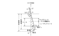
図5は、スリップ角βが付いている転舵輪の接地面を上から見た図である。転舵輪の向きに向かう中心線xが元々の転舵輪の向きを示しており、転舵輪の進行方向はこれに対して線αで示している。同図において、A点が転舵輪の接地開始点で、B点が接地終了点とすると、スリップ角β分だけ、トレッド面が路面に引きずられて中心線xから線αのラインに沿ってずれて撓む。なお、図5において、トレッド面がずれて撓んだ領域をハッチングで示す。この撓んだ領域のうち、A点側の領域が粘着域であり、B点側の領域が滑り域である。そして、このようなスリップ角βで旋回したときの転舵輪の接地面の着力点には、横力Fyが働き、鉛直軸周りのモーメントがセルフアライニングトルクSATとなる。なお、転舵輪の接地中心と着力点間の距離がニューマチックトレールであり、ニューマチックトレールとキャスタトレールの和がトレールである。
Here, the relationship between the slip angle β of the steered wheels and the force acting on the steered wheels will be described with reference to FIGS. 5 and 6. FIG.
FIG. 5 is a top view of the tread of the steerable wheel with a slip angle β. The center line x pointing in the direction of the steerable wheels indicates the original steerable wheel direction, while the direction of travel of the steerable wheels is indicated by line α against this. In the figure, if point A is the contact start point of the steerable wheels and point B is the contact end point, the tread surface is dragged by the road surface by the slip angle β and deviates from the center line x along the line α. bends. In addition, in FIG. 5 , hatching indicates a region in which the tread surface is shifted and bent. Of this bent area, the area on the A point side is the adhesive area, and the area on the B point side is the sliding area. Lateral force Fy acts on the force application point of the contact surface of the steered wheel when turning at such a slip angle β, and the moment about the vertical axis becomes self-aligning torque SAT. The pneumatic trail is the distance between the ground contact center of the steered wheels and the force application point, and the sum of the pneumatic trail and the caster trail is the trail.
図6は、スリップ角βの変化に対する、理想軸力Fib、横力Fy(車両状態量軸力Fyr)、セルフアライニングトルクSAT(路面軸力Fer)、及びニューマチックトレールの変化を示している。同図に示すように旋回中の転舵輪において、スリップ角βが小さい領域では、スリップ角βの増大に従って理想軸力Fib、横力Fy及びセルフアライニングトルクSATがそれぞれ略線形(リニア)に増大し、これらの各値の差は小さい。一方、スリップ角βがある程度大きな領域では、スリップ角βの増大に従って、理想軸力Fibは引き続き略線形に増大するものの、横力Fyは増大を続けた後に略一定又はやや減少傾向を示す。また、セルフアライニングトルクSATは、スリップ角βの増大に従って、しばらくは増大を続けるが、ニューマチックトレールの減少に伴って大きく減少する傾向を示す。このように各値が略線形に変化し、これらの差が小さい領域を通常領域とし、横力Fy及びセルフアライニングトルクSATが非線形に変化し、これらの差が大きくなる領域を限界領域とする。なお、図6に示す通常領域と限界領域との区切りは便宜上のものである。 FIG. 6 shows changes in ideal axial force Fib, lateral force Fy (vehicle state quantity axial force Fyr), self-aligning torque SAT (road surface axial force Fer), and pneumatic trail with respect to changes in slip angle β. . As shown in the figure, in the region where the slip angle β is small, the ideal axial force Fib, the lateral force Fy, and the self-aligning torque SAT increase approximately linearly as the slip angle β increases. and the difference between each of these values is small. On the other hand, in a region where the slip angle β is large to some extent, the ideal axial force Fib continues to increase substantially linearly as the slip angle β increases, but the lateral force Fy continues to increase and then shows a substantially constant or slightly decreasing tendency. Also, the self-aligning torque SAT continues to increase for a while as the slip angle β increases, but exhibits a tendency to greatly decrease as the pneumatic trail decreases. In this way, the region where each value changes approximately linearly and the difference between them is small is defined as the normal region, and the region where the lateral force Fy and the self-aligning torque SAT change non-linearly and the difference between them becomes large is defined as the limit region. . Note that the division between the normal area and the limit area shown in FIG. 6 is for convenience.
ここで、旋回時の軸力をセルフアライニングトルクSATと捉えると、セルフアライニングトルクSATと横力Fyの関係は、図5に示すように、転舵輪と路面との接地中心から横力の着力点までのニューマチックトレールに相当するパラメータを用いた下記(3)式で表現できる。 Here, if the axial force during turning is regarded as the self-aligning torque SAT, the relationship between the self-aligning torque SAT and the lateral force Fy is as shown in FIG. It can be expressed by the following equation (3) using parameters corresponding to the pneumatic trail up to the force application point.
セルフアライニングトルクSAT=横力Fy×ニューマチックトレール…(3)
そして、セルフアライニングトルクSATを「軸力≒路面からの反力」と考えると、転舵側モータ33の駆動電流(すなわち、q軸電流値Iqt)に基づく路面軸力FerがセルフアライニングトルクSATを近似的に表現しているといえる。
Self-aligning torque SAT = lateral force Fy x pneumatic trail (3)
Considering that the self-aligning torque SAT is "axial force ≈ reaction force from the road surface", the road axial force Fer based on the driving current (that is, the q-axis current value Iqt) of the steering-
また、横力Fyは、転舵輪4に発生している力であり、「横力Fy≒車両横向きに発生している力」と置き換えて、横力Fyを横加速度LAによって近似的に表現することができる。なお、横加速度LAだけでは、実際の軸力に対し、動き出し時の応答性が不足するため、応答性を改善するためにヨーレートγの微分を加算して、上記式(2)が得られる。
Further, the lateral force Fy is the force generated in the steered
また、上記(3)式により、転舵輪4がどの程度グリップしているかを示すグリップ度からなるグリップ状態量Grは、下記(4)式のように表わすことができる。
グリップ状態量Gr=セルフアライニングトルクSAT/横力Fy…(4)
そして、路面軸力FerがセルフアライニングトルクSATを近似的に表現でき、車両状態量軸力Fyrが横力を近似的に表現できることを踏まえると、グリップ状態量Grは、下記(5)式のように表すことができる。
Further, the grip state quantity Gr, which is a degree of grip indicating how much the steered
Grip state quantity Gr=self-aligning torque SAT/lateral force Fy (4)
Considering that the road surface axial force Fer can approximately express the self-aligning torque SAT, and the vehicle state quantity axial force Fyr can approximately express the lateral force, the grip state quantity Gr can be expressed by the following equation (5). can be expressed as
グリップ状態量Gr=(Ker×路面軸力)/(Ky×車両状態量軸力)…(5)
なお、「Ker」及び「Ky」は、試験等により予め設定された係数を示す。
ここで、車両状態はその走行状態に応じて変化するため、ヨーレートγ及び横加速度LAに基づく車両状態量軸力Fyrを用いることで、車両の挙動が大きく変化する場合においてラック軸22に実際に作用している軸力を、理想軸力Fibと比べて正確に推定できる。しかし、ヨーレートγ及び横加速度LAは、車両が停止状態を含む低速状態である場合には、その値が小さくなるため、ヨーレートセンサ45及び横加速度センサ46の出力値に対するノイズの大きさが相対的に大きくなる。この場合、ヨーレートγ及び横加速度LAでは、目標操舵角θh*と比べて軸力を精度良く検出できない。
Grip state quantity Gr=(Ker×road surface axial force)/(Ky×vehicle state quantity axial force) (5)
"Ker" and "Ky" indicate coefficients preset by tests or the like.
Here, since the vehicle state changes according to the running state, by using the vehicle state quantity axial force Fyr based on the yaw rate γ and the lateral acceleration LA, the
この点を踏まえ、図4に示すように、本実施形態のグリップ状態量演算部67は、理想軸力Fib及び路面軸力Ferに基づく第1グリップ成分Gr1を演算する第1グリップ成分演算部102と、車両状態量軸力Fyr及び路面軸力Ferに基づく第2グリップ成分Gr2を演算する第2グリップ成分演算部103とを備えている。そして、グリップ状態量演算部67は、車両の走行状態を示す走行状態量としての車速V及び横加速度LAが低速状態であることを示す場合には、第1グリップ成分Gr1が含まれる配分比率でグリップ状態量Grを演算する。一方、グリップ状態量演算部67は、車速V及び横加速度LAが中高速状態であることを示す場合には、第2グリップ成分Gr2が含まれる配分比率でグリップ状態量を演算する。
Based on this point, as shown in FIG. 4, the grip state
詳しくは、第1グリップ成分演算部102には、路面軸力Fer及び理想軸力Fibが入力される。第1グリップ成分演算部102は、路面軸力Ferを理想軸力Fibにより除算することで第1グリップ成分Gr1を演算し、乗算器104に出力する。本実施形態の第1グリップ成分演算部102は、理想軸力Fibの絶対値がゼロ閾値F0以下の場合には、路面軸力Ferを理想軸力Fibによって除算せず、第1グリップ成分Gr1を「0」として出力する。つまり、第1グリップ成分演算部102は、路面軸力Ferをゼロで除算することにより第1グリップ成分Gr1が発散することを防止するゼロ割防止機能を有している。なお、ゼロ閾値F0は、ゼロに近い極小さな値に設定されている。第2グリップ成分演算部103には、路面軸力Fer及び車両状態量軸力Fyrが入力される。第2グリップ成分演算部103は、路面軸力Ferを車両状態量軸力Fyrで除算することで第2グリップ成分Gr2を演算し、乗算器105に出力する。本実施形態の第2グリップ成分演算部103は、ゼロ割防止機能を有しており、車両状態量軸力Fyrの絶対値がゼロ閾値F0以下の場合には除算を行わず、第2グリップ成分Gr2を「0」として出力する。
Specifically, the road surface axial force Fer and the ideal axial force Fib are input to the first grip
グリップ状態量演算部67は、第1グリップ成分Gr1と第2グリップ成分Gr2との配分比率Ggrを設定する配分比率設定部106を備えている。配分比率設定部106には、車速V及び横加速度LAが入力される。配分比率設定部106は、図4に示すようなマップを備えており、同マップを参照することにより配分比率Ggrを設定する。このマップは、車速V及び横加速度LAが低速状態を示す値から中高速状態を示す値に近づくほど、第2グリップ成分Gr2の含まれる比率が大きくなるように配分比率Ggrが設定されている。
The grip state
具体的には、配分比率Ggrは、横加速度LAが横加速度閾値LAth以下の領域では、配分比率Ggrが「0」となり、横加速度LAが横加速度閾値LAthよりも大きくなると、該横加速度LAの増大に応じて配分比率Ggrが大きくなり、その後、配分比率Ggrが一定となるように設定されている。また、配分比率Ggrは、車速Vが車速閾値Vth以下の領域では、配分比率Ggrが「0」となり、車速Vが車速閾値Vthよりも大きくなると、該車速Vの増大に応じて配分比率Ggrが大きくなるように設定されている。なお、配分比率Ggrの最大値は「1」に設定されている。また、横加速度閾値LAth及び車速閾値Vthは、それぞれノイズに対して検出値が大きく、センサの精度を確保できる値であり、予め実験等により設定されている。そして、横加速度LAが横加速度閾値LAth以下である場合には、当該横加速度LAの値は車両の走行状態が低速状態であることを示し、横加速度LAが横加速度閾値LAthよりも大きい場合には、当該横加速度LAの値は車両の走行状態が中高速であることを示す。同様に、車速Vが車速閾値Vth以下である場合には、当該車速Vの値は車両の走行状態が低速状態であることを示し、車速Vが車速閾値Vthよりも大きい場合には、当該車速Vの値は車両の走行状態が中高速であることを示す。 Specifically, when the lateral acceleration LA is equal to or less than the lateral acceleration threshold LAth, the distribution ratio Ggr is "0", and when the lateral acceleration LA exceeds the lateral acceleration threshold LAth, the lateral acceleration LA is It is set so that the allocation ratio Ggr increases with the increase, and then the allocation ratio Ggr becomes constant. Further, the allocation ratio Ggr becomes "0" when the vehicle speed V is equal to or lower than the vehicle speed threshold Vth, and when the vehicle speed V exceeds the vehicle speed threshold Vth, the allocation ratio Ggr decreases as the vehicle speed V increases. set to be large. Note that the maximum value of the distribution ratio Ggr is set to "1". Further, the lateral acceleration threshold value LAth and the vehicle speed threshold value Vth are set in advance through experiments or the like, and are values that have large detection values with respect to noise and can ensure the accuracy of the sensors. When the lateral acceleration LA is equal to or less than the lateral acceleration threshold LAth, the value of the lateral acceleration LA indicates that the vehicle is running at low speed. indicates that the value of the lateral acceleration LA indicates that the running state of the vehicle is middle to high speed. Similarly, when the vehicle speed V is equal to or less than the vehicle speed threshold Vth, the value of the vehicle speed V indicates that the vehicle is running at a low speed. The value of V indicates that the running state of the vehicle is middle to high speed.
このように設定された配分比率Ggrは、減算器107及び乗算器105に出力される。減算器107には、配分比率Ggrに加え、定数「1」が常に入力され、該定数「1」から配分比率Ggrを減算した値を乗算器104に出力する。つまり、第1グリップ成分Gr1の配分比率と第2グリップ成分Gr2の配分比率との和は、「1」となるように設定されている。
The distribution ratio Ggr set in this manner is output to the
グリップ状態量演算部67は、乗算器104において第1グリップ成分Gr1に減算器107からの出力値(1-配分比率Ggr)を乗算した値を第1グリップ配分量Agr1としてグリップ演算処理部108に出力する。また、グリップ状態量演算部67は、乗算器105において第2グリップ成分Gr2に配分比率Ggrを乗算した値を第2グリップ配分量Agr2としてグリップ演算処理部108に出力する。そして、グリップ演算処理部108は、第1グリップ配分量Agr1と第2グリップ配分量Agr2とを足し合わせた値をグリップ状態量Grとして出力する。
The grip state
次に、調整ゲイン演算部68の構成について説明する。
図2に示すように、上記のように演算されたグリップ状態量Grは、調整ゲイン演算部68に入力される。図7に示すように、調整ゲイン演算部68は、第1~第4調整ゲイン演算部111~114を備えており、グリップ状態量Grは、第1~第4調整ゲイン演算部111~114のそれぞれに入力される。
Next, the configuration of the
As shown in FIG. 2 , the grip state quantity Gr calculated as described above is input to the
第1調整ゲイン演算部111は、グリップ状態量Grと第1調整ゲインK1との関係を定めたマップを備えている。第2調整ゲイン演算部112は、グリップ状態量Grと第2調整ゲインK2との関係を定めたマップを備えている。第3調整ゲイン演算部113は、グリップ状態量Grと第3調整ゲインK3との関係を定めたマップを備えている。第4調整ゲイン演算部114は、グリップ状態量Grと第4調整ゲインK4との関係を定めたマップを備えている。
The first adjustment gain calculator 111 has a map that defines the relationship between the grip state quantity Gr and the first adjustment gain K1. The second
図7に示す例では、各マップは、グリップ状態量Grが小さい場合は、第1~第4調整ゲインK1~K4がそれぞれ大きく、グリップ状態量Grが大きくなると第1~第4調整ゲインK1~K4がそれぞれ小さくなるように設定されているが、この関係に限定するものではない。例えばグリップ状態量Grが小さい場合に第1~第4調整ゲインK1~K4がそれぞれ小さく、グリップ状態量Grが大きくなると、第1~第4調整ゲインK1~K4がそれぞれ大きくなるように設定してもよい。また、各マップの示す傾向が相互に異なっていてもよく、例えばグリップ状態量Grが小さい場合に、第1調整ゲインK1及び第4調整ゲインK4がそれぞれ小さく、第2及び第3調整ゲインK2,K3がそれぞれ大きくなるように設定してもよい。 In the example shown in FIG. 7, in each map, the first to fourth adjustment gains K1 to K4 are large when the grip state quantity Gr is small, and the first to fourth adjustment gains K1 to K4 are large when the grip state quantity Gr is large. Although K4 is set to be smaller, it is not limited to this relationship. For example, when the grip state quantity Gr is small, the first to fourth adjustment gains K1 to K4 are small, and when the grip state quantity Gr is large, the first to fourth adjustment gains K1 to K4 are set to be large. good too. Also, the tendencies shown by the respective maps may be different from each other. You may set so that K3 may become large respectively.
図3に示すように、このように演算された第1調整ゲインK1は、乗算器84に出力され、入力トルク基礎成分Tb*に乗算される。これにより、第1調整ゲインK1に応じて入力トルク基礎成分Tb*’が変化する。第2調整ゲインK2は、目標角演算処理部83に出力され、慣性係数Jの逆数に乗算される。これにより、第2調整ゲインK2に応じて慣性項が変化する。第3調整ゲインK3は、目標角演算処理部83に出力され、粘性係数Cに乗算される。これにより、第3調整ゲインK3に応じて粘性項が変化する。第4調整ゲインK4は、乗算器98に出力され、配分軸力Fdに乗算される。これにより、第4調整ゲインK4に応じて反力成分Firが変化する。そして、第1~第4調整ゲインK1~K4が変化することで、目標操舵角θh*が変化し、ひいては目標反力トルクTs*が変化する。
As shown in FIG. 3, the first adjustment gain K1 thus calculated is output to the
次に、第1~第4調整ゲインK1~K4の変化に伴う操舵フィーリングの変化について説明する。
例えば車両が低μ路面を走行し、スリップ角βが大きくなりやすい状況下において、第1~第4調整ゲインK1~K4の各値が、グリップ状態量Grを考慮しない場合に比べ、最終的に目標反力トルクTs*を小さくするように設定された場合を想定する。この場合、例えばスリップ角βが大きくなって限界領域に入る前の段階から、通常よりも操舵側モータ14からステアリングホイール11に付与される操舵反力を小さくでき、所謂抜け感が生じることで、低μ路であるといった路面情報を運転者が認識しやすくなる。
Next, changes in the steering feeling accompanying changes in the first to fourth adjustment gains K1 to K4 will be described.
For example, in a situation where the vehicle runs on a low μ road surface and the slip angle β tends to increase, each value of the first to fourth adjustment gains K1 to K4 is ultimately Assume that the target reaction torque Ts* is set to be small. In this case, the steering reaction force applied from the steering-
一方、同状況下において、第1~第4調整ゲインK1~K4の各値が、グリップ状態量Grを考慮しない場合に比べ、最終的に目標反力トルクTs*を大きくするように設定された場合を想定する。この場合、例えばスリップ角βが大きくなった状態でも、操舵側モータ14からステアリングホイール11に付与される操舵反力を大きくでき、運転者が違和感なく操舵を継続できる。
On the other hand, under the same circumstances, the respective values of the first to fourth adjustment gains K1 to K4 are set so as to ultimately increase the target reaction torque Ts* compared to the case where the grip state quantity Gr is not considered. Assume the case. In this case, for example, even when the slip angle β is large, the steering reaction force applied from the steering-
本実施形態の作用及び効果について説明する。
(1)グリップ状態量演算部67は、横加速度LA及び車速Vが低速状態であることを示し、車両状態量軸力Fyrの精度を確保できない場合には、理想軸力Fib及び路面軸力Ferに基づく第1グリップ成分Gr1が含まれる配分比率でグリップ状態量Grを演算する。そして、横加速度LA及び車速Vが中高速状態であることを示し、車両状態量軸力Fyrの精度を確保できる場合には、車両状態量軸力Fyr及び路面軸力Ferに基づく第2グリップ成分Gr2が含まれる配分比率でグリップ状態量Grを演算する。したがって、適切なグリップ状態量Grを演算でき、グリップ状態量Grを考慮して操舵反力を適切に補償できる。
The action and effect of this embodiment will be described.
(1) The grip
(2)グリップ状態量演算部67は、横加速度LA及び車速Vが低速状態を示す状態から中高速状態を示す状態に近づくほど、第2グリップ成分Gr2の配分比率が大きくなるようにグリップ状態量Grを演算するため、より適切にグリップ状態量Grを演算できる。
(2) The grip state
(3)配分比率設定部106は、横加速度LA及び車速Vに基づいて配分比率を設定したため、適切な走行状態量に基づいて車両の走行状態を判断し、グリップ状態量Grを演算できる。
(3) Since the distribution
(第2実施形態)
次に、操舵制御装置の第2実施形態を図面に従って説明する。なお、説明の便宜上、同一の構成については上記第1実施形態と同一の符号を付してその説明を省略する。
(Second embodiment)
Next, a second embodiment of the steering control device will be described with reference to the drawings. For convenience of explanation, the same components as those of the first embodiment are denoted by the same reference numerals, and the explanation thereof is omitted.
図8に示すように、本実施形態の配分比率設定部106は、同図に示すマップを参照することにより、車速V及び横加速度LAの少なくとも一方が車両の低速状態であることを示す場合には、第1グリップ成分Gr1のみが含まれる配分比率Ggrでグリップ状態量Grを演算する。また、配分比率設定部106は、車速V及び横加速度LAの双方が車両の中高速状態であることを示す場合には、第2グリップ成分Gr2のみが含まれる配分比率Ggrでグリップ状態量Grが演算する。具体的には、同図に示すマップは、横加速度LAが横加速度閾値LAth以下である場合、又は車速Vが車速閾値Vth以下である場合に配分比率Ggrが「0」となり、横加速度LAが横加速度閾値LAthよりも大きく、かつ車速Vが車速閾値Vthよりも大きい場合に配分比率Ggrが「1」に設定されている。
As shown in FIG. 8, the allocation
このように演算されたグリップ状態量Grは、上記第1実施形態と同様に、調整ゲイン演算部68に入力され、第1~第4調整ゲインK1~K4のそれぞれを変更することで、グリップ状態に応じて目標反力トルクTs*が変更される。
The grip state quantity Gr calculated in this way is input to the adjustment
次に、本実施形態の作用及び効果について記載する。なお、本実施形態では、上記第1実施形態の(1),(3)の作用及び効果に加えて以下の効果を有する。
(4)グリップ状態量演算部67は、横加速度LA及び車速Vの少なくとも一方が車両の低速状態であることを示す場合には、理想軸力Fibに基づく第1グリップ成分Gr1のみが含まれる、すなわち車両状態量軸力Fyrに基づく第2グリップ成分Gr2を用いずにグリップ状態量Grを演算する。上記のように第1グリップ成分Gr1は、車両の低速状態で精度の良い理想軸力Fibに基づく値であり、車両の中高速状態で精度が低下する車両状態量軸力Fyrに基づかないため、本実施形態のグリップ状態量演算部67では、より適切にグリップ状態量を演算できる。
Next, the action and effect of this embodiment will be described. The present embodiment has the following effects in addition to the actions and effects (1) and (3) of the first embodiment.
(4) When at least one of the lateral acceleration LA and the vehicle speed V indicates that the vehicle is in a low speed state, the grip state
(5)グリップ状態量演算部67は、横加速度LA及び車速Vの双方が車両の中高速状態であることを示す場合には、車両状態量軸力Fyrに基づく第2グリップ成分Gr2のみが含まれる、すなわち理想軸力Fibに基づく第1グリップ成分Gr1を用いずにグリップ状態量Grを演算する。上記のように第2グリップ成分Gr2は、車両の中高速状態で精度の良い車両状態量軸力Fyrに基づく値であり、車両の中高速状態で精度が低下する理想軸力Fibに基づかないため、本実施形態のグリップ状態量演算部67では、より適切にグリップ状態量Grを演算できる。
(5) When both the lateral acceleration LA and the vehicle speed V indicate that the vehicle is in the medium-to-high speed state, the grip state
(第3実施形態)
次に、操舵制御装置の第3実施形態を図面に従って説明する。なお、説明の便宜上、同一の構成については上記第1実施形態と同一の符号を付してその説明を省略する。
(Third embodiment)
Next, a third embodiment of the steering control device will be described with reference to the drawings. For convenience of explanation, the same components as those of the first embodiment are denoted by the same reference numerals, and the explanation thereof is omitted.
図9に示すように、本実施形態の入力トルク基礎成分演算部81は、駆動トルクTcに対して運転者が入力すべき操舵トルクThの目標値であるトルク指令値Th*を演算するトルク指令値演算部121と、トルクフィードバック演算を行うトルクフィードバック制御部(以下、トルクF/B制御部)122とを備えている。
As shown in FIG. 9, the input torque basic
詳しくは、トルク指令値演算部121には、加算器123において操舵トルクThに入力トルク基礎成分Tb*が足し合わされた駆動トルクTcが入力される。トルク指令値演算部121は、駆動トルクTcの絶対値が大きいほど、より大きな絶対値となるトルク指令値Th*を演算する。
Specifically, the drive torque Tc obtained by adding the input torque basic component Tb* to the steering torque Th in the
トルクF/B制御部122には、減算器124において操舵トルクThからトルク指令値Th*が差し引かれたトルク偏差ΔTが入力される。そして、トルクF/B制御部122は、トルク偏差ΔTに基づき、操舵トルクThをトルク指令値Th*にフィードバック制御するための制御量として入力トルク基礎成分Tb*を演算する。具体的には、トルクF/B制御部122は、トルク偏差ΔTを入力とする比例要素、積分要素及び微分要素のそれぞれの出力値の和を、入力トルク基礎成分Tb*として演算する。
A torque deviation ΔT obtained by subtracting the torque command value Th* from the steering torque Th in a
このように演算された入力トルク基礎成分Tb*は、上記第1実施形態と同様に目標反力トルク演算部65に出力されるとともに、乗算器84に出力され、第1調整ゲインK1が乗算されることで、入力トルク基礎成分Tb*’が演算される。これにより、グリップ状態に応じて目標操舵角θh*が変更され、目標反力トルクTs*が変更される。
The input torque basic component Tb* calculated in this manner is output to the target reaction force
以上、本実施形態では、上記第1実施形態の(1)~(3)の作用及び効果と同様の作用及び効果を有する。
(第4実施形態)
次に、操舵制御装置の第4実施形態を図面に従って説明する。なお、説明の便宜上、同一の構成については上記第1実施形態と同一の符号を付してその説明を省略する。
As described above, the present embodiment has the same actions and effects as the actions and effects (1) to (3) of the first embodiment.
(Fourth embodiment)
Next, a fourth embodiment of the steering control device will be described with reference to the drawings. For convenience of explanation, the same components as those of the first embodiment are denoted by the same reference numerals, and the explanation thereof is omitted.
図10に示すように、本実施形態の操舵側制御部51は、転舵輪4の転舵角に換算可能な転舵対応角θpの目標値である目標転舵対応角θp*を演算する目標転舵対応角演算部131を備えており、目標操舵角演算部64を備えていない。図11に示すように、目標転舵対応角演算部131は、上記第1実施形態の目標操舵角演算部64が目標操舵角θh*を演算する際の演算処理と同様の演算処理によって目標転舵対応角θp*を演算する。なお、説明の便宜上、目標転舵対応角演算部131を構成する各ブロックについて、目標操舵角演算部64を構成する各ブロック(図3参照)と同一の符号を付している。
As shown in FIG. 10, the steering-
図10に示すように、目標転舵対応角演算部131において演算される目標転舵対応角θp*は、転舵側制御部55に出力される。また、上記第1実施形態と同様に、グリップ状態量演算部67には、理想軸力Fib及び路面軸力Ferが出力される。そして、目標転舵対応角演算部131から目標反力トルク演算部65には、目標角演算処理部83に入力される入力トルクTin*が入力される。
As shown in FIG. 10 , the target steering response angle θp* calculated by the target steering response
本実施形態の目標反力トルク演算部65は、入力トルクTin*に基づいて操舵側モータ14が付与する操舵反力の目標値である目標反力トルクTs*を演算する。具体的には、目標反力トルク演算部65は、入力トルクTin*が大きいほど、より大きな絶対値を有する目標反力トルクTs*を演算する。そして、入力トルクTin*は、その基になる入力トルク基礎成分Tb*及び反力成分Firがそれぞれ第1及び第4調整ゲインK1,K4により変更される。これにより、入力トルクTin*に基づく目標反力トルクTs*がグリップ状態に応じて変更される。
The target reaction force
以上、本実施形態では、上記第1実施形態の(1)~(3)の作用及び効果と同様の作用及び効果を有する。
(第5実施形態)
次に、操舵制御装置の第5実施形態を図面に従って説明する。なお、説明の便宜上、同一の構成については上記第4実施形態と同一の符号を付してその説明を省略する。
As described above, the present embodiment has the same actions and effects as the actions and effects (1) to (3) of the first embodiment.
(Fifth embodiment)
Next, a fifth embodiment of the steering control device will be described with reference to the drawings. For convenience of explanation, the same components as those of the fourth embodiment are denoted by the same reference numerals, and the explanation thereof is omitted.
図12に示すように、本実施形態の目標転舵対応角演算部131は、反力成分Firを目標反力トルク演算部65に出力し、入力トルクTin*を出力しない。そして、目標反力トルク演算部65(図10参照)は、反力成分Firの絶対値が大きいほど、また車速Vが大きいほど、より大きな絶対値を有する目標反力トルクTs*を演算する。そして、反力成分Firは、上記のように第4調整ゲインK4により変更される。これにより、反力成分Firに基づく目標反力トルクTs*がグリップ状態に応じて変更される。
As shown in FIG. 12, the target steering corresponding
以上、本実施形態では、上記第1実施形態の(1)~(3)の作用及び効果と同様の作用及び効果を有する。
本実施形態は、以下のように変更して実施することができる。本実施形態及び以下の変形例は、技術的に矛盾しない範囲で互いに組み合わせて実施することができる。
As described above, the present embodiment has the same actions and effects as the actions and effects (1) to (3) of the first embodiment.
This embodiment can be implemented with the following modifications. This embodiment and the following modified examples can be implemented in combination with each other within a technically consistent range.
・上記第4及び第5実施形態では、目標転舵対応角θp*を入力トルクTin*に基づいて演算したが、これに限らず、例えば操舵角θh等、他のパラメータに基づいて演算してもよい。 - In the above-described fourth and fifth embodiments, the target steering corresponding angle θp* is calculated based on the input torque Tin*. good too.
・上記第2実施形態において、車速V及び横加速度LAが車両の中高速状態であることを示す場合には、第2グリップ成分Gr2のみに基づいてグリップ状態量Grを演算し、車速V及び横加速度LAが車両の低速状態であることを示す場合に、第1及び第2グリップ成分Gr1,Gr2に基づいてグリップ状態量Grを演算してもよい。また、車速V及び横加速度LAが車両の低速状態であることを示す場合には、第1グリップ成分Gr1のみに基づいてグリップ状態量Grを演算し、車速V及び横加速度LAが車両の中高速状態であることを示す場合に、第1及び第2グリップ成分Gr1,Gr2に基づいてグリップ状態量Grを演算してもよい。 In the above-described second embodiment, when the vehicle speed V and the lateral acceleration LA indicate that the vehicle is in a medium-to-high speed state, the grip state quantity Gr is calculated based only on the second grip component Gr2, and the vehicle speed V and the lateral acceleration LA are calculated. When the acceleration LA indicates that the vehicle is in a low speed state, the grip state quantity Gr may be calculated based on the first and second grip components Gr1 and Gr2. Further, when the vehicle speed V and the lateral acceleration LA indicate that the vehicle is in a low speed state, the grip state quantity Gr is calculated based only on the first grip component Gr1, and the vehicle speed V and the lateral acceleration LA are in a medium high speed state of the vehicle. When indicating the state, the grip state quantity Gr may be calculated based on the first and second grip components Gr1 and Gr2.
・上記各実施形態において、ゼロ割防止機能の実現態様は適宜変更可能である。例えば、車両状態量軸力Fyrの絶対値がゼロ閾値F0以下である場合には、車両状態量軸力Fyrを予め設定された下限値とすることができる。なお、第1グリップ成分演算部102及び第2グリップ成分演算部103がゼロ割防止機能を有していなくともよい。
- In each of the above-described embodiments, the implementation mode of the zero dividing prevention function can be changed as appropriate. For example, when the absolute value of the vehicle state quantity axial force Fyr is equal to or less than the zero threshold F0, the vehicle state quantity axial force Fyr can be set to a preset lower limit value. Note that the first grip
・上記各実施形態では、配分比率設定部106は、走行状態量として横加速度LA及び車速Vを用いて配分比率Ggrを設定したが、これに限らず、例えば横加速度LA及び車速Vのいずれか一方のみを用いて配分比率Ggrを設定してもよい。また、例えばヨーレートγ等、他のパラメータを用いて配分比率Ggrを設定してもよい。
In each of the above embodiments, the distribution
・上記各実施形態において、路面軸力Ferを理想軸力Fibにより除算したグリップ度を第1グリップ成分Gr1としたが、これに限らず、路面軸力Ferから理想軸力Fibを減算したグリップロス度(転舵輪4のグリップがどの程度失われたかを示す値)を第1グリップ成分Gr1としてもよい。同様に、路面軸力Ferから車両状態量軸力Fyrを減算したグリップロス度を第2グリップ成分Gr2としてもよい。
In each of the above embodiments, the first grip component Gr1 is obtained by dividing the road surface axial force Fer by the ideal axial force Fib. The degree (a value indicating how much the grip of the steered
・上記各実施形態では、路面軸力Fer及び理想軸力Fibに基づく第1グリップ成分Gr1と、路面軸力Fer及び車両状態量軸力Fyrに基づく第2グリップ成分Gr2とを所定配分比率で合算させることによりグリップ状態量Grを演算した。しかし、これに限らず、例えば理想軸力Fib及び車両状態量軸力Fyrに基づく第3グリップ成分を演算し、これらの各グリップ成分を所定配分比率で合算させることによりグリップ状態量Grを演算してもよい。 In each of the above embodiments, the first grip component Gr1 based on the road surface axial force Fer and the ideal axial force Fib and the second grip component Gr2 based on the road surface axial force Fer and the vehicle state quantity axial force Fyr are added at a predetermined distribution ratio. The grip state quantity Gr was calculated by However, not limited to this, for example, a third grip component based on the ideal axial force Fib and the vehicle state quantity axial force Fyr is calculated, and the grip state quantity Gr is calculated by adding these grip components at a predetermined distribution ratio. may
・上記各実施形態では、路面軸力Ferをq軸電流値Iqtに基づいて演算したが、これに限らず、例えばラック軸22に軸力を検出できる圧力センサ等を設け、その検出結果を路面軸力Ferとして用いてもよい。 ・In each of the above embodiments, the road surface axial force Fer was calculated based on the q-axis current value Iqt. It may be used as the axial force Fer.
・上記各実施形態では、理想軸力Fibを目標操舵角θh*(目標転舵対応角)及び車速Vに基づいて演算したが、これに限らず、目標操舵角θh*(目標転舵対応角)のみに基づいて演算してもよく、また、転舵対応角θpに基づいて演算してもよい。さらに、例えば操舵トルクThや車速V等、他のパラメータを加味する等、他の方法で演算してもよい。 ・In each of the above embodiments, the ideal axial force Fib is calculated based on the target steering angle θh* (target steering corresponding angle) and the vehicle speed V. ) alone, or may be calculated based on the steering corresponding angle θp. Furthermore, other methods such as adding other parameters such as the steering torque Th and the vehicle speed V may be used.
・上記各実施形態では、グリップ状態量Grに応じたゲインとして、第1~第4調整ゲインK1~K4を採用したが、これに限らず、少なくともいずれか1つを採用してもよく、また、他の状態量に乗算等されるゲインを追加してもよい。 - In each of the above embodiments, the first to fourth adjustment gains K1 to K4 are used as the gains corresponding to the grip state quantity Gr. , a gain that is multiplied by another state quantity may be added.
・上記各実施形態では、理想軸力Fibと路面軸力Ferとを所定割合で配分して配分軸力Fdを演算したが、これに限らず、例えば理想軸力Fibと車両状態両軸力Fyrとを所定割合で配分して配分軸力Fdを演算してもよく、配分軸力Fdの演算態様は適宜変更可能である。 In each of the above embodiments, the ideal axial force Fib and the road surface axial force Fer are distributed at a predetermined ratio to calculate the distributed axial force Fd. may be distributed at a predetermined ratio to calculate the distributed axial force Fd, and the manner of calculation of the distributed axial force Fd can be changed as appropriate.
・上記実施形態では、ヨーレートγ及び横加速度LAに基づいて車両状態両軸力Fyrを演算したが、これに限らず、例えばヨーレートγ及び横加速度LAのいずれか一方のみに基づいて車両状態両軸力Fyrを演算してもよい。 In the above embodiment, the vehicle state dual axial force Fyr is calculated based on the yaw rate γ and the lateral acceleration LA. A force Fyr may be calculated.
・上記各実施形態において、配分軸力演算部93が車速V以外のパラメータを加味して配分ゲインGib,Gerを演算してもよい。例えば車載のエンジン等の制御パターンの設定状態を示すドライブモードを複数の中から選択可能な車両において、該ドライブモードを配分ゲインGib,Gerを設定するためのパラメータとしてもよい。この場合、配分軸力演算部93がドライブモード毎に車速Vに対する傾向が異なる複数のマップを備え、同マップを参照することにより、配分ゲインGib,Gerを演算する構成を採用できる。
- In each of the above embodiments, the distributed
・上記各実施形態では、反力成分演算部82は、ラック軸22に作用する軸力に応じたベース反力を反力成分Firとして演算したが、これに限らず、例えばベース反力に他の反力を加味した値を反力成分として演算してもよい。こうした反力として、例えばステアリングホイール11の操舵角θhの絶対値が舵角閾値に近づく場合に、更なる切り込み操舵が行われるのに抗する反力であるエンド反力を採用することができる。なお、舵角閾値としては、例えばラックエンド25がラックハウジング23に当接することでラック軸22の軸方向移動が規制される機械的なラックエンド位置よりも中立位置側に設定された仮想ラックエンド位置に対し、さらに所定角度だけ中立位置側に位置する仮想ラックエンド近傍位置での転舵対応角θpを用いることができる。また、舵角閾値としてステアリングホイール11の回転エンド位置での操舵角θhを用いることもできる。
In each of the above embodiments, the reaction
・上記各実施形態では、目標操舵角演算部64が操舵トルクTh及び車速Vに基づいて目標操舵角θh*を設定したが、これに限らず、少なくとも操舵トルクThに基づいて設定されれば、例えば車速Vを用いずともよい。
In each of the above-described embodiments, the target
・上記各実施形態では、操舵角θhと転舵対応角θpとの舵角比を一定としたが、これに限らず、これらが車速等に応じて可変としてもよい。なお、この場合には、目標操舵角θh*と目標転舵対応角とが異なる値になる。 - Although the steering angle ratio between the steering angle θh and the corresponding steering angle θp is constant in each of the above embodiments, the ratio is not limited to this and may be variable according to the vehicle speed or the like. In this case, the target steering angle θh* and the target steering corresponding angle are different values.
・上記各実施形態において、目標操舵角演算部64がサスペンションやホイールアライメント等の仕様によって決定されるバネ係数Kを用いた、所謂バネ項を追加してモデル化したモデル式を利用して目標操舵角θh*を演算してもよい。
In each of the above-described embodiments, the target steering
・上記第1~第3実施形態では、目標反力トルク演算部65が基礎反力トルクに入力トルク基礎成分Tb*を加算して目標反力トルクTs*を演算したが、これに限らず、例えば入力トルク基礎成分Tb*を加算せず、基礎反力トルクをそのまま目標反力トルクTs*として演算してもよい。
・In the first to third embodiments, the target reaction
・上記各実施形態において、第1ラックアンドピニオン機構24に代えて、例えばブッシュ等によりラック軸22を支持してもよい。
・上記各実施形態において、転舵側アクチュエータ31として、例えばラック軸22の同軸上に転舵側モータ33を配置するものや、ラック軸22と平行に転舵側モータ33を配置するもの等を用いてもよい。
- In each of the above embodiments, instead of the first rack and
In each of the above-described embodiments, as the steering-
・上記各実施形態では、操舵制御装置1の制御対象となる操舵装置2を、操舵部3と転舵部5とを機械的に分離したリンクレスのステアバイワイヤ式操舵装置としたが、これに限らず、クラッチにより操舵部3と転舵部5とを機械的に断接可能なステアバイワイヤ式操舵装置としてもよい。
In each of the above embodiments, the
例えば図13に示す例では、操舵部3と転舵部5との間には、クラッチ301が設けられている。クラッチ301は、その入力側要素に固定された入力側中間軸302を介してステアリングシャフト12に連結されるとともに、その出力側要素に固定された出力側中間軸303を介して第1ピニオン軸21に連結されている。そして、操舵制御装置1からの制御信号によりクラッチ301が解放状態となることで、操舵装置2はステアバイワイヤモードとなり、クラッチ301が締結状態となることで、操舵装置2は電動パワーステアリングモードとなる。
For example, in the example shown in FIG. 13 , a clutch 301 is provided between the
1…操舵制御装置、2…操舵装置、3…操舵部、4…転舵輪、5…転舵部、11…ステアリングホイール、12…ステアリングシャフト、13…操舵側アクチュエータ、14…操舵側モータ、51…操舵側制御部(制御部)、64…目標操舵角演算部、65…目標反力トルク演算部、67…グリップ状態量演算部、68…調整ゲイン演算部、81…入力トルク基礎成分演算部、82…反力成分演算部、91…路面軸力演算部、92…理想軸力演算部、93…配分軸力演算部、101…車両状態量軸力演算部、102…第1グリップ成分演算部、103…第2グリップ成分演算部、106…配分比率設定部、111…第1調整ゲイン演算部、112…第2調整ゲイン演算部、113…第3調整ゲイン演算部、114…第4調整ゲイン演算部、121…トルク指令値演算部、122…トルクF/B制御部、131…目標転舵対応角演算部、Agr1…第1グリップ配分量、Agr2…第2グリップ配分量、Fd…配分軸力、Fer…路面軸力、Fib…理想軸力、Fir…反力成分、Fyr…車両状態量軸力、Gr…グリップ状態量、Gr1…第1グリップ成分、Gr2…第2グリップ成分、K1…第1調整ゲイン、K2…第2調整ゲイン、K3…第3調整ゲイン、K4…第4調整ゲイン、LA…横加速度、Tb*…入力トルク基礎成分、Tc…駆動トルク、Th…操舵トルク、Th*…トルク指令値、Tin*…入力トルク、Ts*…目標反力トルク、Tt*…目標転舵トルク、V…車速、γ…ヨーレート、θh…操舵角、θp…転舵対応角、θh*…目標操舵角、θp*…目標転舵対応角。
DESCRIPTION OF
Claims (4)
前記操舵部に入力される操舵に抗する力である操舵反力を与える操舵側モータの作動を制御する制御部を備え、
前記制御部は、
前記転舵輪の転舵角に換算可能な回転軸の回転角に関連する値に基づく理想軸力を演算する理想軸力演算部と、
路面情報に基づく路面軸力を演算する路面軸力演算部と、
車両の走行状態に応じて変化する車両状態量に基づく車両状態量軸力を演算する車両状態量軸力演算部と、
前記理想軸力、前記路面軸力及び前記車両状態量軸力に基づいて複数のグリップ成分を演算し、該複数のグリップ成分を所定配分比率で合算させることによりグリップ状態量を演算するグリップ状態量演算部とを備え、
前記グリップ状態量を考慮して前記操舵反力の目標値となる目標反力トルクを演算するものであって、
前記車両状態量は、車両に設けられたセンサによって検出される横加速度を含む値であって、車両の走行状態を示す走行状態量が停止状態を含む低速状態であることを示す場合には、前記走行状態量が前記低速状態よりも速い中高速状態であることを示す場合と比べて値が小さくなる特性を有し、
前記グリップ状態量演算部は、前記走行状態量が前記低速状態であることを示すことによって、前記走行状態量が前記中高速状態であることを示す場合と比べて、前記車両状態量の値が小さくなることに起因して当該車両状態量の精度が低下する場合には、前記理想軸力及び前記路面軸力に基づく第1グリップ成分が含まれる配分比率で前記グリップ状態量を演算し、前記走行状態量が前記中高速状態であることを示すことによって、前記走行状態量が前記低速状態であることを示す場合と比べて、前記車両状態量の値が大きくなることに起因して当該車両状態量の精度が向上する場合には、少なくとも前記車両状態量軸力に基づく第2グリップ成分が含まれる配分比率で前記グリップ状態量を演算するように構成されており、
前記グリップ状態量演算部は、前記走行状態量が前記中高速状態の場合に前記低速状態の場合よりも前記第2グリップ成分の配分比率が大きくなるように前記グリップ状態量を演算する操舵制御装置。 A steering device having a structure in which a steering unit and a steering unit that steers steered wheels in accordance with steering input to the steering unit are mechanically separated or mechanically connectable and disconnectable, is controlled,
a control unit for controlling the operation of a steering-side motor that provides a steering reaction force that is a force that resists steering input to the steering unit;
The control unit
an ideal axial force calculation unit that calculates an ideal axial force based on a value related to a rotation angle of a rotating shaft that can be converted into a turning angle of the steered wheels;
a road surface axial force calculation unit that calculates a road surface axial force based on road surface information;
a vehicle state quantity axial force calculation unit that calculates a vehicle state quantity axial force based on a vehicle state quantity that changes according to the running state of the vehicle;
A grip state quantity is calculated by calculating a plurality of grip components based on the ideal axial force, the road surface axial force, and the vehicle state quantity axial force, and adding the plurality of grip components at a predetermined distribution ratio. and a computing unit,
A target reaction force torque, which is a target value of the steering reaction force, is calculated in consideration of the grip state quantity,
The vehicle state quantity is a value including lateral acceleration detected by a sensor provided in the vehicle, and when the running state quantity indicating the running state of the vehicle indicates a low speed state including a stopped state, It has a characteristic that the value is smaller than when the running state quantity indicates that it is a medium-high speed state that is faster than the low speed state,
By indicating that the running state quantity is in the low-speed state, the grip state quantity calculation unit increases the value of the vehicle state quantity compared to the case where the running state quantity indicates that the medium-to-high speed state. when the accuracy of the vehicle state quantity decreases due to the decrease in the grip state quantity , the grip state quantity is calculated with a distribution ratio including the first grip component based on the ideal axial force and the road surface axial force, By indicating that the running state quantity is the medium-high speed state, the value of the vehicle state quantity becomes larger than when the running state quantity indicates that the running state quantity is the low speed state. When the accuracy of the vehicle state quantity is improved , the grip state quantity is calculated at a distribution ratio including at least a second grip component based on the vehicle state quantity axial force,
The grip state quantity calculation unit is a steering control device that calculates the grip state quantity so that the distribution ratio of the second grip component becomes larger when the running state quantity is in the middle/high speed state than in the case of the low speed state. .
前記グリップ状態量演算部は、前記走行状態量が前記低速状態であることを示す場合には、前記第1グリップ成分のみが含まれる配分比率で前記グリップ状態量を演算する操舵制御装置。 The steering control device according to claim 1, wherein
The grip state quantity calculation unit calculates the grip state quantity at a distribution ratio including only the first grip component when the running state quantity indicates the low speed state.
前記グリップ状態量演算部は、前記走行状態量が前記中高速状態であることを示す場合には、前記第2グリップ成分のみが含まれる配分比率で前記グリップ状態量を演算する操舵制御装置。 The steering control device according to claim 1 or 2 ,
The grip state quantity calculation unit calculates the grip state quantity at a distribution ratio including only the second grip component when the running state quantity indicates that the running state quantity is the middle/high speed state.
前記走行状態量は、横加速度及び車速の少なくとも一方を含む操舵制御装置。 In the steering control device according to any one of claims 1 to 3 ,
The steering control device, wherein the running state quantity includes at least one of lateral acceleration and vehicle speed.
Priority Applications (4)
| Application Number | Priority Date | Filing Date | Title |
|---|---|---|---|
| JP2018106409A JP7243045B2 (en) | 2018-06-01 | 2018-06-01 | steering controller |
| CN201910456216.1A CN110550093B (en) | 2018-06-01 | 2019-05-29 | Steering control device |
| EP19177350.6A EP3575185B1 (en) | 2018-06-01 | 2019-05-29 | Steering control device |
| US16/424,634 US11097769B2 (en) | 2018-06-01 | 2019-05-29 | Steering control device |
Applications Claiming Priority (1)
| Application Number | Priority Date | Filing Date | Title |
|---|---|---|---|
| JP2018106409A JP7243045B2 (en) | 2018-06-01 | 2018-06-01 | steering controller |
Publications (2)
| Publication Number | Publication Date |
|---|---|
| JP2019209786A JP2019209786A (en) | 2019-12-12 |
| JP7243045B2 true JP7243045B2 (en) | 2023-03-22 |
Family
ID=68844669
Family Applications (1)
| Application Number | Title | Priority Date | Filing Date |
|---|---|---|---|
| JP2018106409A Active JP7243045B2 (en) | 2018-06-01 | 2018-06-01 | steering controller |
Country Status (1)
| Country | Link |
|---|---|
| JP (1) | JP7243045B2 (en) |
Families Citing this family (1)
| Publication number | Priority date | Publication date | Assignee | Title |
|---|---|---|---|---|
| WO2024075278A1 (en) * | 2022-10-07 | 2024-04-11 | 日産自動車株式会社 | Steering control method and steering control device |
Citations (8)
| Publication number | Priority date | Publication date | Assignee | Title |
|---|---|---|---|---|
| JP2004130964A (en) | 2002-10-11 | 2004-04-30 | Aisin Seiki Co Ltd | Road surface status estimating device and vehicle motion controller equipped with the same |
| JP2009040341A (en) | 2007-08-10 | 2009-02-26 | Nsk Ltd | Control device of electric power steering device |
| US20140163822A1 (en) | 2011-08-22 | 2014-06-12 | Zf Lenksysteme Gmbh | Method for determining a steering rock force for a steering device in a vehicle, steering device and open-loop and/or closed-loop control device for a steering device |
| WO2014108984A1 (en) | 2013-01-11 | 2014-07-17 | 日産自動車株式会社 | Steering control device |
| JP2014166805A (en) | 2013-02-28 | 2014-09-11 | Jtekt Corp | Electric power steering system |
| JP2017149359A (en) | 2016-02-26 | 2017-08-31 | 株式会社ジェイテクト | Steering control device |
| JP2017165219A (en) | 2016-03-15 | 2017-09-21 | 株式会社ジェイテクト | Steering control apparatus |
| DE102017105370A1 (en) | 2017-03-14 | 2018-09-20 | Thyssenkrupp Ag | Estimating rack power in a steer-by-wire system |
-
2018
- 2018-06-01 JP JP2018106409A patent/JP7243045B2/en active Active
Patent Citations (8)
| Publication number | Priority date | Publication date | Assignee | Title |
|---|---|---|---|---|
| JP2004130964A (en) | 2002-10-11 | 2004-04-30 | Aisin Seiki Co Ltd | Road surface status estimating device and vehicle motion controller equipped with the same |
| JP2009040341A (en) | 2007-08-10 | 2009-02-26 | Nsk Ltd | Control device of electric power steering device |
| US20140163822A1 (en) | 2011-08-22 | 2014-06-12 | Zf Lenksysteme Gmbh | Method for determining a steering rock force for a steering device in a vehicle, steering device and open-loop and/or closed-loop control device for a steering device |
| WO2014108984A1 (en) | 2013-01-11 | 2014-07-17 | 日産自動車株式会社 | Steering control device |
| JP2014166805A (en) | 2013-02-28 | 2014-09-11 | Jtekt Corp | Electric power steering system |
| JP2017149359A (en) | 2016-02-26 | 2017-08-31 | 株式会社ジェイテクト | Steering control device |
| JP2017165219A (en) | 2016-03-15 | 2017-09-21 | 株式会社ジェイテクト | Steering control apparatus |
| DE102017105370A1 (en) | 2017-03-14 | 2018-09-20 | Thyssenkrupp Ag | Estimating rack power in a steer-by-wire system |
Also Published As
| Publication number | Publication date |
|---|---|
| JP2019209786A (en) | 2019-12-12 |
Similar Documents
| Publication | Publication Date | Title |
|---|---|---|
| JP7155616B2 (en) | steering controller | |
| US11097769B2 (en) | Steering control device | |
| JP5126357B2 (en) | Vehicle steering device | |
| JP5092603B2 (en) | Vehicle steering system | |
| JP7383384B2 (en) | Steering control device | |
| JP7133393B2 (en) | steering controller | |
| US20200130737A1 (en) | Steering control device | |
| US20200130739A1 (en) | Controller for steering device | |
| CN111619657B (en) | Steering control device and method for controlling steering device | |
| JP2020163990A (en) | Steering control device | |
| US20200130738A1 (en) | Steering control device | |
| JP2020049962A (en) | Motor control device | |
| JP7147472B2 (en) | steering controller | |
| JP2019130958A (en) | Steering control device | |
| CN113443005A (en) | Steering control device | |
| JP7376243B2 (en) | Steering control device | |
| JP7322461B2 (en) | steering controller | |
| JP7338520B2 (en) | steering controller | |
| JP2022049967A (en) | Steering control device | |
| JP7243045B2 (en) | steering controller | |
| JP7147473B2 (en) | steering controller | |
| JP2021030838A (en) | Steering control device | |
| JP7259495B2 (en) | steering controller | |
| JP7087688B2 (en) | Steering control device | |
| JP7099056B2 (en) | Steering control device |
Legal Events
| Date | Code | Title | Description |
|---|---|---|---|
| A621 | Written request for application examination |
Free format text: JAPANESE INTERMEDIATE CODE: A621 Effective date: 20210525 |
|
| A977 | Report on retrieval |
Free format text: JAPANESE INTERMEDIATE CODE: A971007 Effective date: 20220511 |
|
| A131 | Notification of reasons for refusal |
Free format text: JAPANESE INTERMEDIATE CODE: A131 Effective date: 20220628 |
|
| A521 | Request for written amendment filed |
Free format text: JAPANESE INTERMEDIATE CODE: A523 Effective date: 20220808 |
|
| A02 | Decision of refusal |
Free format text: JAPANESE INTERMEDIATE CODE: A02 Effective date: 20221025 |
|
| A521 | Request for written amendment filed |
Free format text: JAPANESE INTERMEDIATE CODE: A523 Effective date: 20230111 |
|
| C60 | Trial request (containing other claim documents, opposition documents) |
Free format text: JAPANESE INTERMEDIATE CODE: C60 Effective date: 20230111 |
|
| A911 | Transfer to examiner for re-examination before appeal (zenchi) |
Free format text: JAPANESE INTERMEDIATE CODE: A911 Effective date: 20230118 |
|
| C21 | Notice of transfer of a case for reconsideration by examiners before appeal proceedings |
Free format text: JAPANESE INTERMEDIATE CODE: C21 Effective date: 20230124 |
|
| TRDD | Decision of grant or rejection written | ||
| A01 | Written decision to grant a patent or to grant a registration (utility model) |
Free format text: JAPANESE INTERMEDIATE CODE: A01 Effective date: 20230207 |
|
| A61 | First payment of annual fees (during grant procedure) |
Free format text: JAPANESE INTERMEDIATE CODE: A61 Effective date: 20230220 |
|
| R150 | Certificate of patent or registration of utility model |
Ref document number: 7243045 Country of ref document: JP Free format text: JAPANESE INTERMEDIATE CODE: R150 |