JP7242537B2 - Position detection based on tissue discrimination - Google Patents
Position detection based on tissue discrimination Download PDFInfo
- Publication number
- JP7242537B2 JP7242537B2 JP2019542687A JP2019542687A JP7242537B2 JP 7242537 B2 JP7242537 B2 JP 7242537B2 JP 2019542687 A JP2019542687 A JP 2019542687A JP 2019542687 A JP2019542687 A JP 2019542687A JP 7242537 B2 JP7242537 B2 JP 7242537B2
- Authority
- JP
- Japan
- Prior art keywords
- tissue
- interest
- region
- distal end
- optical
- Prior art date
- Legal status (The legal status is an assumption and is not a legal conclusion. Google has not performed a legal analysis and makes no representation as to the accuracy of the status listed.)
- Active
Links
Images


Classifications
-
- A—HUMAN NECESSITIES
- A61—MEDICAL OR VETERINARY SCIENCE; HYGIENE
- A61B—DIAGNOSIS; SURGERY; IDENTIFICATION
- A61B34/00—Computer-aided surgery; Manipulators or robots specially adapted for use in surgery
- A61B34/20—Surgical navigation systems; Devices for tracking or guiding surgical instruments, e.g. for frameless stereotaxis
-
- A—HUMAN NECESSITIES
- A61—MEDICAL OR VETERINARY SCIENCE; HYGIENE
- A61B—DIAGNOSIS; SURGERY; IDENTIFICATION
- A61B17/00—Surgical instruments, devices or methods, e.g. tourniquets
- A61B17/56—Surgical instruments or methods for treatment of bones or joints; Devices specially adapted therefor
- A61B17/58—Surgical instruments or methods for treatment of bones or joints; Devices specially adapted therefor for osteosynthesis, e.g. bone plates, screws, setting implements or the like
- A61B17/68—Internal fixation devices, including fasteners and spinal fixators, even if a part thereof projects from the skin
- A61B17/70—Spinal positioners or stabilisers ; Bone stabilisers comprising fluid filler in an implant
- A61B17/7001—Screws or hooks combined with longitudinal elements which do not contact vertebrae
- A61B17/7032—Screws or hooks with U-shaped head or back through which longitudinal rods pass
-
- A—HUMAN NECESSITIES
- A61—MEDICAL OR VETERINARY SCIENCE; HYGIENE
- A61B—DIAGNOSIS; SURGERY; IDENTIFICATION
- A61B17/00—Surgical instruments, devices or methods, e.g. tourniquets
- A61B17/56—Surgical instruments or methods for treatment of bones or joints; Devices specially adapted therefor
- A61B17/58—Surgical instruments or methods for treatment of bones or joints; Devices specially adapted therefor for osteosynthesis, e.g. bone plates, screws, setting implements or the like
- A61B17/68—Internal fixation devices, including fasteners and spinal fixators, even if a part thereof projects from the skin
- A61B17/84—Fasteners therefor or fasteners being internal fixation devices
- A61B17/86—Pins or screws or threaded wires; nuts therefor
- A61B17/864—Pins or screws or threaded wires; nuts therefor hollow, e.g. with socket or cannulated
-
- A—HUMAN NECESSITIES
- A61—MEDICAL OR VETERINARY SCIENCE; HYGIENE
- A61B—DIAGNOSIS; SURGERY; IDENTIFICATION
- A61B17/00—Surgical instruments, devices or methods, e.g. tourniquets
- A61B17/56—Surgical instruments or methods for treatment of bones or joints; Devices specially adapted therefor
- A61B17/58—Surgical instruments or methods for treatment of bones or joints; Devices specially adapted therefor for osteosynthesis, e.g. bone plates, screws, setting implements or the like
- A61B17/88—Osteosynthesis instruments; Methods or means for implanting or extracting internal or external fixation devices
- A61B17/8897—Guide wires or guide pins
-
- A—HUMAN NECESSITIES
- A61—MEDICAL OR VETERINARY SCIENCE; HYGIENE
- A61B—DIAGNOSIS; SURGERY; IDENTIFICATION
- A61B34/00—Computer-aided surgery; Manipulators or robots specially adapted for use in surgery
- A61B34/10—Computer-aided planning, simulation or modelling of surgical operations
-
- A—HUMAN NECESSITIES
- A61—MEDICAL OR VETERINARY SCIENCE; HYGIENE
- A61B—DIAGNOSIS; SURGERY; IDENTIFICATION
- A61B5/00—Measuring for diagnostic purposes; Identification of persons
- A61B5/0033—Features or image-related aspects of imaging apparatus classified in A61B5/00, e.g. for MRI, optical tomography or impedance tomography apparatus; arrangements of imaging apparatus in a room
- A61B5/0035—Features or image-related aspects of imaging apparatus classified in A61B5/00, e.g. for MRI, optical tomography or impedance tomography apparatus; arrangements of imaging apparatus in a room adapted for acquisition of images from more than one imaging mode, e.g. combining MRI and optical tomography
-
- A—HUMAN NECESSITIES
- A61—MEDICAL OR VETERINARY SCIENCE; HYGIENE
- A61B—DIAGNOSIS; SURGERY; IDENTIFICATION
- A61B90/00—Instruments, implements or accessories specially adapted for surgery or diagnosis and not covered by any of the groups A61B1/00 - A61B50/00, e.g. for luxation treatment or for protecting wound edges
- A61B90/36—Image-producing devices or illumination devices not otherwise provided for
- A61B90/37—Surgical systems with images on a monitor during operation
-
- A—HUMAN NECESSITIES
- A61—MEDICAL OR VETERINARY SCIENCE; HYGIENE
- A61B—DIAGNOSIS; SURGERY; IDENTIFICATION
- A61B17/00—Surgical instruments, devices or methods, e.g. tourniquets
- A61B2017/00017—Electrical control of surgical instruments
- A61B2017/00022—Sensing or detecting at the treatment site
- A61B2017/00057—Light
- A61B2017/00061—Light spectrum
-
- A—HUMAN NECESSITIES
- A61—MEDICAL OR VETERINARY SCIENCE; HYGIENE
- A61B—DIAGNOSIS; SURGERY; IDENTIFICATION
- A61B34/00—Computer-aided surgery; Manipulators or robots specially adapted for use in surgery
- A61B34/10—Computer-aided planning, simulation or modelling of surgical operations
- A61B2034/101—Computer-aided simulation of surgical operations
- A61B2034/102—Modelling of surgical devices, implants or prosthesis
-
- A—HUMAN NECESSITIES
- A61—MEDICAL OR VETERINARY SCIENCE; HYGIENE
- A61B—DIAGNOSIS; SURGERY; IDENTIFICATION
- A61B34/00—Computer-aided surgery; Manipulators or robots specially adapted for use in surgery
- A61B34/10—Computer-aided planning, simulation or modelling of surgical operations
- A61B2034/107—Visualisation of planned trajectories or target regions
-
- A—HUMAN NECESSITIES
- A61—MEDICAL OR VETERINARY SCIENCE; HYGIENE
- A61B—DIAGNOSIS; SURGERY; IDENTIFICATION
- A61B34/00—Computer-aided surgery; Manipulators or robots specially adapted for use in surgery
- A61B34/20—Surgical navigation systems; Devices for tracking or guiding surgical instruments, e.g. for frameless stereotaxis
- A61B2034/2046—Tracking techniques
- A61B2034/2051—Electromagnetic tracking systems
-
- A—HUMAN NECESSITIES
- A61—MEDICAL OR VETERINARY SCIENCE; HYGIENE
- A61B—DIAGNOSIS; SURGERY; IDENTIFICATION
- A61B34/00—Computer-aided surgery; Manipulators or robots specially adapted for use in surgery
- A61B34/20—Surgical navigation systems; Devices for tracking or guiding surgical instruments, e.g. for frameless stereotaxis
- A61B2034/2046—Tracking techniques
- A61B2034/2055—Optical tracking systems
-
- A—HUMAN NECESSITIES
- A61—MEDICAL OR VETERINARY SCIENCE; HYGIENE
- A61B—DIAGNOSIS; SURGERY; IDENTIFICATION
- A61B34/00—Computer-aided surgery; Manipulators or robots specially adapted for use in surgery
- A61B34/20—Surgical navigation systems; Devices for tracking or guiding surgical instruments, e.g. for frameless stereotaxis
- A61B2034/2046—Tracking techniques
- A61B2034/2061—Tracking techniques using shape-sensors, e.g. fiber shape sensors with Bragg gratings
-
- A—HUMAN NECESSITIES
- A61—MEDICAL OR VETERINARY SCIENCE; HYGIENE
- A61B—DIAGNOSIS; SURGERY; IDENTIFICATION
- A61B34/00—Computer-aided surgery; Manipulators or robots specially adapted for use in surgery
- A61B34/20—Surgical navigation systems; Devices for tracking or guiding surgical instruments, e.g. for frameless stereotaxis
- A61B2034/2046—Tracking techniques
- A61B2034/2065—Tracking using image or pattern recognition
-
- A—HUMAN NECESSITIES
- A61—MEDICAL OR VETERINARY SCIENCE; HYGIENE
- A61B—DIAGNOSIS; SURGERY; IDENTIFICATION
- A61B90/00—Instruments, implements or accessories specially adapted for surgery or diagnosis and not covered by any of the groups A61B1/00 - A61B50/00, e.g. for luxation treatment or for protecting wound edges
- A61B90/06—Measuring instruments not otherwise provided for
- A61B2090/062—Measuring instruments not otherwise provided for penetration depth
-
- A—HUMAN NECESSITIES
- A61—MEDICAL OR VETERINARY SCIENCE; HYGIENE
- A61B—DIAGNOSIS; SURGERY; IDENTIFICATION
- A61B90/00—Instruments, implements or accessories specially adapted for surgery or diagnosis and not covered by any of the groups A61B1/00 - A61B50/00, e.g. for luxation treatment or for protecting wound edges
- A61B90/36—Image-producing devices or illumination devices not otherwise provided for
- A61B2090/364—Correlation of different images or relation of image positions in respect to the body
-
- A—HUMAN NECESSITIES
- A61—MEDICAL OR VETERINARY SCIENCE; HYGIENE
- A61B—DIAGNOSIS; SURGERY; IDENTIFICATION
- A61B90/00—Instruments, implements or accessories specially adapted for surgery or diagnosis and not covered by any of the groups A61B1/00 - A61B50/00, e.g. for luxation treatment or for protecting wound edges
- A61B90/36—Image-producing devices or illumination devices not otherwise provided for
- A61B90/37—Surgical systems with images on a monitor during operation
- A61B2090/371—Surgical systems with images on a monitor during operation with simultaneous use of two cameras
-
- A—HUMAN NECESSITIES
- A61—MEDICAL OR VETERINARY SCIENCE; HYGIENE
- A61B—DIAGNOSIS; SURGERY; IDENTIFICATION
- A61B90/00—Instruments, implements or accessories specially adapted for surgery or diagnosis and not covered by any of the groups A61B1/00 - A61B50/00, e.g. for luxation treatment or for protecting wound edges
- A61B90/36—Image-producing devices or illumination devices not otherwise provided for
- A61B90/37—Surgical systems with images on a monitor during operation
- A61B2090/373—Surgical systems with images on a monitor during operation using light, e.g. by using optical scanners
- A61B2090/3735—Optical coherence tomography [OCT]
-
- A—HUMAN NECESSITIES
- A61—MEDICAL OR VETERINARY SCIENCE; HYGIENE
- A61B—DIAGNOSIS; SURGERY; IDENTIFICATION
- A61B90/00—Instruments, implements or accessories specially adapted for surgery or diagnosis and not covered by any of the groups A61B1/00 - A61B50/00, e.g. for luxation treatment or for protecting wound edges
- A61B90/36—Image-producing devices or illumination devices not otherwise provided for
- A61B90/37—Surgical systems with images on a monitor during operation
- A61B2090/374—NMR or MRI
-
- A—HUMAN NECESSITIES
- A61—MEDICAL OR VETERINARY SCIENCE; HYGIENE
- A61B—DIAGNOSIS; SURGERY; IDENTIFICATION
- A61B90/00—Instruments, implements or accessories specially adapted for surgery or diagnosis and not covered by any of the groups A61B1/00 - A61B50/00, e.g. for luxation treatment or for protecting wound edges
- A61B90/36—Image-producing devices or illumination devices not otherwise provided for
- A61B90/37—Surgical systems with images on a monitor during operation
- A61B2090/376—Surgical systems with images on a monitor during operation using X-rays, e.g. fluoroscopy
- A61B2090/3762—Surgical systems with images on a monitor during operation using X-rays, e.g. fluoroscopy using computed tomography systems [CT]
-
- A—HUMAN NECESSITIES
- A61—MEDICAL OR VETERINARY SCIENCE; HYGIENE
- A61B—DIAGNOSIS; SURGERY; IDENTIFICATION
- A61B90/00—Instruments, implements or accessories specially adapted for surgery or diagnosis and not covered by any of the groups A61B1/00 - A61B50/00, e.g. for luxation treatment or for protecting wound edges
- A61B90/36—Image-producing devices or illumination devices not otherwise provided for
- A61B90/37—Surgical systems with images on a monitor during operation
- A61B2090/378—Surgical systems with images on a monitor during operation using ultrasound
-
- A—HUMAN NECESSITIES
- A61—MEDICAL OR VETERINARY SCIENCE; HYGIENE
- A61B—DIAGNOSIS; SURGERY; IDENTIFICATION
- A61B5/00—Measuring for diagnostic purposes; Identification of persons
- A61B5/0033—Features or image-related aspects of imaging apparatus classified in A61B5/00, e.g. for MRI, optical tomography or impedance tomography apparatus; arrangements of imaging apparatus in a room
-
- A—HUMAN NECESSITIES
- A61—MEDICAL OR VETERINARY SCIENCE; HYGIENE
- A61B—DIAGNOSIS; SURGERY; IDENTIFICATION
- A61B5/00—Measuring for diagnostic purposes; Identification of persons
- A61B5/0059—Measuring for diagnostic purposes; Identification of persons using light, e.g. diagnosis by transillumination, diascopy, fluorescence
- A61B5/0075—Measuring for diagnostic purposes; Identification of persons using light, e.g. diagnosis by transillumination, diascopy, fluorescence by spectroscopy, i.e. measuring spectra, e.g. Raman spectroscopy, infrared absorption spectroscopy
-
- A—HUMAN NECESSITIES
- A61—MEDICAL OR VETERINARY SCIENCE; HYGIENE
- A61B—DIAGNOSIS; SURGERY; IDENTIFICATION
- A61B5/00—Measuring for diagnostic purposes; Identification of persons
- A61B5/0059—Measuring for diagnostic purposes; Identification of persons using light, e.g. diagnosis by transillumination, diascopy, fluorescence
- A61B5/0082—Measuring for diagnostic purposes; Identification of persons using light, e.g. diagnosis by transillumination, diascopy, fluorescence adapted for particular medical purposes
- A61B5/0084—Measuring for diagnostic purposes; Identification of persons using light, e.g. diagnosis by transillumination, diascopy, fluorescence adapted for particular medical purposes for introduction into the body, e.g. by catheters
-
- A—HUMAN NECESSITIES
- A61—MEDICAL OR VETERINARY SCIENCE; HYGIENE
- A61B—DIAGNOSIS; SURGERY; IDENTIFICATION
- A61B5/00—Measuring for diagnostic purposes; Identification of persons
- A61B5/06—Devices, other than using radiation, for detecting or locating foreign bodies ; determining position of probes within or on the body of the patient
- A61B5/065—Determining position of the probe employing exclusively positioning means located on or in the probe, e.g. using position sensors arranged on the probe
Description
本発明は、一般に、生体組織型を検出するシステム及び方法に関する。本発明は更に、様々な組織型の決定に基づいて組織内のデバイスの位置を検出するシステム及び方法に関する。本発明は更に、システムに方法のステップを行わせ、その結果、組織型の決定に基づく組織内のデバイスの位置の検出をもたらすコンピュータプログラムに関する。 The present invention relates generally to systems and methods for detecting biological tissue types. The present invention further relates to systems and methods for locating devices within tissue based on determinations of various tissue types. The invention further relates to a computer program that causes the system to perform the steps of the method, resulting in the detection of the location of the device within tissue based on the tissue type determination.
例えば椎弓根スクリュー固定は、脊椎変性疾患、椎間板疾患、脊椎外傷又は脊椎奇形の治療の主流である。椎弓根スクリュー固定は、運動分節の保存及び脊椎の安定化を可能にする短く、硬い分節安定化を提供する。胸腰椎骨折の治療における骨癒合率及び臨床転帰は、他の治療形態を使用した場合に達成されるものよりも優れているようである。米国医療研究品質調査機構(AHRQ)の報告によると、2011年の米国での入院中に約488,000回の脊椎固定手術が行われ(人口10,000人当たり15.7日の入院率)、これは、手術室の全処置の3.1%を占めていた。 For example, pedicle screw fixation is the mainstay of treatment for spinal degenerative disease, disc disease, spinal trauma or spinal malformations. Pedicle screw fixation provides short, rigid segmental stabilization that allows motion segment preservation and spinal stabilization. Bone union rates and clinical outcomes in treating thoracolumbar fractures appear to be superior to those achieved using other forms of treatment. The Agency for Healthcare Research and Quality (AHRQ) reported that approximately 488,000 spinal fusion surgeries were performed during hospitalizations in the United States in 2011 (15.7 days hospitalization rate per 10,000 population), This represented 3.1% of all procedures in the operating room.
脊椎の安定性を高めるために世界中で使用されているにもかかわらず、脊椎における椎弓根スクリューインスツルメンテーションの安全性及び有効性は疑問視されている。椎弓根スクリュー配置に関する主な懸念は、椎弓根スクリューの正確な位置決めである。実際、椎弓根スクリューはほぼ盲目的に、又は、しばしば不十分な蛍光透視誘導下で挿入されるため、これまでの臨床転帰はあまり芳しくない。 Despite its worldwide use to enhance spinal stability, the safety and efficacy of pedicle screw instrumentation in the spine has been questioned. A major concern with pedicle screw placement is the correct positioning of the pedicle screw. In fact, pedicle screws are inserted almost blindly or often under poor fluoroscopic guidance, and thus far the clinical outcome has been poor.
骨治療の他の分野でも同様の問題が発生する可能性があることが理解されよう。米国特許出願公開第2012/232407号は、骨の中をナビゲートする方法及びデバイスについて説明している。一実施形態では、骨ナビゲーションデバイスが提供され、当該デバイスは、骨に埋め込まれるように構成され、その中に少なくとも1つの光導波路が延在する骨貫通部材を含む。光導波路は、デバイスの周囲の組織を照らし、組織からの反射/透過光を受け取って組織の光学特性を決定する。 It will be appreciated that similar problems may arise in other areas of bone therapy. US Patent Application Publication No. 2012/232407 describes methods and devices for navigating through bone. In one embodiment, a bone navigation device is provided that includes a bone penetrating member configured to be implanted in bone and having at least one optical waveguide extending therein. The optical waveguide illuminates the tissue surrounding the device and receives reflected/transmitted light from the tissue to determine the optical properties of the tissue.
組織型に基づき関心領域に挿入されているデバイスの位置を決定することが目的である。この目的及び他の目的は、それぞれ独立請求項に記載されるシステム及びコンピュータプログラムによって達成される。更なる実施形態は、従属請求項に記載されている。 The goal is to determine the location of the device being inserted into the region of interest based on tissue type. This object and other objects are achieved by a system and a computer program, respectively, as defined in the independent claims. Further embodiments are described in the dependent claims.
つまり、デバイスの方向転換が依然として可能であるように、デバイスが誤配置されているかどうかを早期段階で検出することができるデバイス配置システムを提供することを目的とする。 It is therefore an object to provide a device placement system that can detect at an early stage if a device is misplaced so that it can still be turned around.
上述の問題を解決するために、撮像システムと計画及びナビゲーションシステムとを含む一実施形態によるデバイス配置システムが提供される。撮像システムは、例えば脊椎の関心領域の画像を生成することができ、計画及びナビゲーションシステムは、関心領域へのデバイスの挿入、例えば脊椎の椎骨の1つへの椎弓根スクリューの挿入の計画のために適応される。一方で、デバイス配置中に遭遇する可能性のある組織型がテーブルに保存される。一方で、デバイス配置の誘導を支援する情報を少なくとも提供するナビゲーションシステムは、デバイスにおける又はデバイスの前の組織の決定に基づいて、また、テーブルに保存されている一連の組織型に基づいて、デバイスの実際の位置を決定することができる。これは、関心領域に挿入されているデバイスによって行われてよいリアルタイム組織検知に基づいて行われてよい。このようなデバイスは、K-ワイヤ、突き錐若しくはタップ又はスクリューである。したがって、システムは、撮像によって計画中に決定された予測組織型を、検知によって決定されたリアルタイム測定組織型と比較することができる。 To solve the above problems, a device placement system is provided according to one embodiment that includes an imaging system and a planning and navigation system. The imaging system can, for example, generate images of a region of interest of the spine, and the planning and navigation system can assist in planning the insertion of a device into the region of interest, for example, the insertion of a pedicle screw into one of the vertebrae of the spine. adapted for Meanwhile, a table stores the tissue types that may be encountered during device placement. On the one hand, the navigation system, which at least provides information to assist in guiding device placement, may be able to determine device placement based on tissue determinations at or in front of the device and based on a set of tissue types stored in a table. can be determined. This may be done based on real-time tissue sensing, which may be done by a device inserted in the region of interest. Such devices are K-wires, awls or taps or screws. Thus, the system can compare predicted tissue types determined during planning by imaging to real-time measured tissue types determined by sensing.
一実施形態によるシステムは、光学検知手段と処理ユニットとを含む。光学検知手段は、遠位端を有する光学ガイドを含む。光学ガイドは、関心領域の組織に挿入されるデバイス内に配置される。光学ガイドの遠位端は、デバイスの先端に隣接して配置される。処理ユニットは、(i)様々な組織型を含む関心領域の情報を受信し、(ii)関心領域を通る経路を特定する入力を受信し、(iii)経路に沿った一連の組織型を決定し、(iv)光学検知手段から光学情報を受信し、(v)受信した光学情報に基づいて光学ガイドの遠位端における組織型を決定し、(vi)決定された組織型を、経路上の組織型と比較し、(vii)組織型の比較に基づいて、経路上の光学ガイドの遠位端の可能な位置を決定し、(viii)可能な位置を示す信号を生成することができる。 A system according to one embodiment includes an optical sensing means and a processing unit. The optical sensing means includes an optical guide having a distal end. The optical guide is placed within a device that is inserted into the tissue of interest. The distal end of the optical guide is positioned adjacent to the tip of the device. A processing unit (i) receives information of a region of interest including various tissue types, (ii) receives input identifying a pathway through the region of interest, and (iii) determines a sequence of tissue types along the pathway. (iv) receiving optical information from the optical sensing means; (v) determining tissue type at the distal end of the optical guide based on the received optical information; (vii) determining possible positions of the distal end of the optical guide on the path based on the tissue type comparison; and (viii) generating a signal indicative of the possible positions. .
生成された信号は、デバイスの配置が依然として正しいかどうかを判断するために、ユーザ(例えば医師)によって使用される。差が大きいことは、デバイスの先端が予測位置にないことを意味する。椎弓根スクリューの挿入の場合、これは局所的な組織変形又は患者の外側表面に対する椎骨の変位によって引き起こされる可能性がある。 The generated signal is used by a user (eg, a doctor) to determine if device placement is still correct. A large difference means that the tip of the device is not at the expected position. In the case of pedicle screw insertion, this can be caused by local tissue deformation or displacement of the vertebrae relative to the patient's outer surface.
一実施形態によれば、システムは更に、関心領域に対する光学ガイドの遠位端の位置を追跡する追跡デバイスを含む。可能な位置の決定は、追跡された位置に更に基づく。なお、遠位端は、デバイスの近位端の空間的位置及び向きを特定することによって、デバイスの既知の形状に基づいて、即ち、特定された近位端と遠位端との既知の距離に基づいて追跡することができる。近位端の特定のために、追跡デバイスは、少なくとも1つの追跡カメラと、例えばデバイスにおけるシャフトマーカー及び/又はトレーサープレートとを含んでよく、シャフトマーカー及び/又はトレーサープレートの位置及び向きを、少なくとも1つのカメラによって生成される画像に基づいて特定することができる。カメラベースの追跡システム以外にも、光学形状検出及びEM(電磁)追跡等のソリューションを適用することができる。更に、患者の体も追跡して、テーブル上の患者の位置の変化を決定することができる。両方の追跡を組み合わせることで、結果を向上させることができる。追跡デバイスに関する詳細な情報は、例えばT.Peters及びK.Clearyによる「Image-Guided Interventions」(2008年、スプリンガー・サイエンス+ビジネス・メディア社)の23~44頁に記載されている。 According to one embodiment, the system further includes a tracking device for tracking the position of the distal end of the optical guide relative to the region of interest. Determination of possible positions is further based on the tracked positions. Note that the distal end is determined based on the known shape of the device, i.e., the known distance between the specified proximal and distal ends, by specifying the spatial position and orientation of the proximal end of the device. can be tracked based on For proximal end identification, the tracking device may include at least one tracking camera and, for example, a shaft marker and/or tracer plate in the device, the position and orientation of the shaft marker and/or tracer plate being determined at least It can be determined based on images produced by one camera. Besides camera-based tracking systems, solutions such as optical shape detection and EM (electromagnetic) tracking can be applied. Additionally, the patient's body can also be tracked to determine changes in the patient's position on the table. Combining both tracks can improve results. Detailed information on tracking devices can be found, for example, in T.W. Peters and K. Cleary, Image-Guided Interventions, Springer Science+Business Media, 2008, pages 23-44.
したがって、追跡システムのマーカーが存在し、予測位置と検知位置との差が追跡システムの不正確さによるものである場合でも、特に重要な構造に到達する前に、デバイスの誤配置の早期検出を示すことができる。 Therefore, early detection of device misplacement, especially before reaching critical structures, even when tracking system markers are present and the difference between predicted and sensed positions is due to tracking system inaccuracies. can be shown.
更なる実施形態によれば、システムは、光学検知手段から受信した光学情報に基づいて決定された組織型と、関心領域を通る経路に沿った可能な組織型との不一致を示す信号を生成することができる。この信号は、フラッシュライトのような光信号でも、画面上の単なるテキストでも、アラームのような音響信号でもよい。 According to a further embodiment, the system produces a signal indicative of a discrepancy between tissue types determined based on optical information received from the optical sensing means and possible tissue types along a path through the region of interest. be able to. This signal may be an optical signal, such as a flashing light, or simply text on a screen, or an acoustic signal, such as an alarm.
一実施形態によれば、システムの処理ユニットは更に、関心領域の視覚化を、関心領域に挿入される要素の仮想表現と共に生成することができる。要素の仮想表現の遠位端は、経路上の最も可能性の高い位置に示される。このような視覚化はまた、仮想表現により挿入経路、したがって、その経路に沿った一連の組織を規定することができるため、挿入計画に適している。 According to one embodiment, the processing unit of the system can further generate a visualization of the region of interest with virtual representations of the elements inserted into the region of interest. The distal end of the virtual representation of the element is shown at the most likely location on the path. Such visualization is also suitable for insertion planning because the virtual representation can define the insertion path and thus the sequence of tissues along that path.
別の実施形態によれば、システムは更に、関心領域を含む作業フィールドを撮像するビデオカメラを含んでよく、処理ユニットは更に、作業フィールドと関心領域の内部構造との組み合わされた視覚化を生成する。例えばビデオカメラによって撮像された外部構造は、外部構造と、同時に外部構造の下、即ち、体内にある内部構造との認識を可能にする透明度で視覚化される。 According to another embodiment, the system may further include a video camera imaging a working field containing the region of interest, and the processing unit further generates a combined visualization of the working field and the internal structure of the region of interest. do. An external structure, for example imaged by a video camera, is visualized with a transparency that allows recognition of the external structure and at the same time the internal structure underneath the external structure, ie within the body.
一実施形態によれば、システムは更に、様々な組織型を含む関心領域の情報を生成する撮像システムを含む。撮像システムは、X線撮像システム、MR撮像システム、CT撮像システム及び超音波撮像システムからなる群からの1つである。システムは更に、入力デバイスを含む。例えば挿入経路が入力される。更に及び/又は或いは、システムは、例えば挿入されるデバイスの十分な固定のための十分な安定組織だけでなく、神経のように回避されなければならない解剖学的構造の要件を含む所定基準に基づいて経路を自動的に提案される。 According to one embodiment, the system further includes an imaging system that produces information of regions of interest that include various tissue types. The imaging system is one from the group consisting of an X-ray imaging system, an MR imaging system, a CT imaging system and an ultrasound imaging system. The system also includes an input device. For example, an insertion path is entered. Additionally and/or alternatively, the system may be based on predetermined criteria, including the requirement of anatomical structures that must be avoided, such as nerves, as well as sufficient stable tissue for adequate fixation of an inserted device. automatically suggests a route.
一実施形態によれば、システムは、ビデオカメラと、X線撮像システム、例えばCアームベースのX線システムとを含み、ビデオカメラは、X線システムの検出器に取り付けられる。 According to one embodiment, the system includes a video camera and an X-ray imaging system, such as a C-arm based X-ray system, where the video camera is attached to a detector of the X-ray system.
一実施形態によれば、システムは更に、デバイスを関心領域、例えば骨に挿入するための器具を含む。器具の位置及び向きは、追跡デバイスによって追跡可能である。患者をX線照射に晒すことなく、器具の関心領域に対する関係の表示を含む視覚化を生成することができる。 According to one embodiment, the system further includes an instrument for inserting the device into a region of interest, eg, bone. The position and orientation of the instrument can be tracked by a tracking device. A visualization can be generated that includes an indication of the relationship of the instrument to the region of interest without exposing the patient to X-ray radiation.
上述の実施形態によるシステムは、撮像及びナビゲーションに基づく予測組織特性と、組織検知に基づく測定組織特性との不一致を検出する。このような場合、術中の撮像は、例えば早期段階においてスクリューを正しく配置することを確実にするために、ナビゲーションシステムの計画及び/又は登録を更新するためだけに使用する必要がある。この結果、X線照射が低減され、組織内のデバイスの配置が同時に向上される。 Systems according to the embodiments described above detect discrepancies between predicted tissue properties based on imaging and navigation and measured tissue properties based on tissue sensing. In such cases, intraoperative imaging should only be used to update the planning and/or registration of the navigation system, for example to ensure correct screw placement in the early stages. This results in reduced x-ray exposure and at the same time improved placement of the device within the tissue.
更なる実施形態によれば、椎弓根スクリュー配置システムは、体内の画像を作成可能な撮像システムと、体内画像に基づいて挿入経路を規定可能な計画ソフトウェアと、計画挿入中に遭遇する組織特性のテーブルを生成するアルゴリズムと、計画挿入に従ってスクリューを配置するのを支援するナビゲーションシステムと、挿入されるデバイス(例えばスクリュー、K-ワイヤ、突き錐及び/又はタップ)に組み込まれ、デバイスの前の組織特性をリアルタイムで測定可能なリアルタイム組織センサと、計画挿入経路に基づく予測組織型とリアルタイム組織センサによる測定組織型とを比較可能な処理ユニットとを含み、リアルタイム測定組織型と、計画デバイス(スクリュー)挿入に基づく予測組織型による組織型との差を示す信号を生成することができる。 According to a further embodiment, a pedicle screw placement system includes an imaging system capable of creating images within the body, planning software capable of defining an insertion path based on the in-vivo images, and tissue characteristics encountered during planned insertion. and a navigation system that assists in positioning screws according to planned insertion, and embedded in the device (e.g., screw, K-wire, awl and/or tap) to be inserted, and in front of the device. a real-time tissue sensor capable of measuring tissue characteristics in real time; ) A signal can be generated that indicates the difference in tissue type from the predicted tissue type based on the insertion.
一実施形態によれば、組織の光学特性を検出するシステムは、光源と、光検出器と、プローブと、処理ユニットとを含む。プローブは、長手方向軸及び前端部を有するシャフトと、少なくとも1本のファイバとを有してよい。ファイバの端部は、シャフトの前端部に配置される。ファイバは、光源から放出された光を、シャフトの前端部に隣接する組織に送り、組織から反射された光を光検出器に送ることができる。複数のファイバを使用すると、組織を通る光路が規定される。処理ユニットは、(i)光源を制御して光を放出し、(ii)組織によって反射された光に基づき光検出器によって生成された信号を受信し、(iii)受信した信号に基づき、反射光の光スペクトルを決定し、(iv)少なくとも2つのスペクトルを比較することができる。例えば反射光は分光計に転送されてもよい。 According to one embodiment, a system for detecting optical properties of tissue includes a light source, a photodetector, a probe, and a processing unit. The probe may have a shaft with a longitudinal axis and a front end, and at least one fiber. The ends of the fibers are positioned at the front end of the shaft. The fiber can transmit light emitted from the light source to tissue adjacent the front end of the shaft and transmit light reflected from the tissue to the photodetector. Using multiple fibers defines an optical path through the tissue. The processing unit (i) controls the light source to emit light, (ii) receives a signal generated by the photodetector based on light reflected by the tissue, and (iii) based on the received signal, the reflected An optical spectrum of the light can be determined and (iv) the at least two spectra can be compared. For example, reflected light may be transferred to a spectrometer.
なお、前面の開口部における光ファイバの端面は、傾斜した前面のファイバの実質的に円形の断面の場合、円形又は幾分楕円形である。ファイバがベベル面で終わる角度に応じて、ファイバの端面の形状は影響を受けるため、放出される光又は受け取る光の方向も影響を受ける。 It should be noted that the end face of the optical fiber at the front opening is circular or somewhat elliptical in the case of a substantially circular cross-section of the slanted front fiber. Depending on the angle at which the fiber terminates at the beveled surface, the shape of the fiber end face is affected, and thus the direction of emitted or received light.
一対のファイバ端は、光路を規定し、光は第1のファイバから放出され、組織内で反射され、当該対の第2のファイバ内で受け取られる。各ファイバ端の位置に応じて、光路はプローブのシャフトに対する空間的な向きをもつ。異なるファイバが対を形成するか、プローブが回転するとすぐに、空間的な向きは異なる。 A pair of fiber ends define an optical path, with light emitted from a first fiber, reflected in tissue, and received in a second fiber of the pair. Depending on the position of each fiber end, the optical path has a spatial orientation with respect to the shaft of the probe. The spatial orientation is different as soon as different fibers are paired or the probe is rotated.
一実施形態によれば、システムは更に、光源と、光検出器と、光検出器によって提供された信号を処理する処理ユニットとを含むコンソールを含む。コンソールは、生体内組織検査及び判別に適している。光源は、レーザ、発光ダイオード又はフィルター付き光源の何れかであってよく、コンソールは更に、ファイバースイッチ、ビームスプリッタ又はダイクロイックビームコンバイナの何れかを含む。更に、デバイスは、拡散反射分光法、拡散光トモグラフィ、微分経路長分光法及びラマン分光法からなる群からの少なくとも1つを行うことができる。コンソールは、少なくとも1つの分光計を含む。 According to one embodiment, the system further includes a console including a light source, a photodetector, and a processing unit for processing signals provided by the photodetector. The console is suitable for in-vivo tissue examination and discrimination. The light sources can be either lasers, light emitting diodes or filtered light sources and the console further includes either fiber switches, beam splitters or dichroic beam combiners. Additionally, the device is capable of performing at least one from the group consisting of diffuse reflectance spectroscopy, diffuse optical tomography, differential path length spectroscopy and Raman spectroscopy. The console includes at least one spectrometer.
別の態様によれば、組織内のデバイスの位置を決定する方法が提案される。方法は、(i)関心領域内の特定された経路に沿った一連の組織型を決定するステップと、(ii)光学ガイドの遠位端における組織型を決定するステップと、(iii)決定された組織型を経路上の組織型と比較するステップと、(iv)経路上の光学ガイドの遠位端の可能な位置を決定及び指示するステップとを含む。 According to another aspect, a method of determining the location of a device within tissue is proposed. The method comprises the steps of (i) determining a series of tissue types along an identified path within the region of interest; (ii) determining tissue types at the distal end of the optical guide; and (iv) determining and indicating possible positions of the distal end of the optical guide on the pathway.
一実施形態によれば、方法は更に、追跡デバイスによって光学ガイドの遠位端を追跡するステップを含む。このような実施形態では、挿入されたデバイスの可能な位置の決定は、追跡された位置に基づく。 According to one embodiment, the method further includes tracking the distal end of the optical guide with a tracking device. In such embodiments, determination of possible positions of the inserted device is based on tracked positions.
別の実施形態によれば、方法は更に、関心領域の視覚化を、関心領域内に挿入される要素の仮想表現と共に生成するステップを含む。要素の仮想表現の遠位端は、経路上の最も可能性の高い位置に示される。 According to another embodiment, the method further comprises generating a visualization of the region of interest with a virtual representation of the elements to be inserted within the region of interest. The distal end of the virtual representation of the element is shown at the most likely location on the path.
方法は、様々な情報が新しい情報を提供する目的で組み合わされる情報処理方法である。当該新しい情報は、医師が患者を治療するのに役立つ可能性がある。したがって、一実施形態による方法は、手術による人間又は動物の体を治療するステップを含まない。 A method is an information processing method in which different information is combined with the purpose of providing new information. The new information may help doctors treat patients. Thus, the method according to one embodiment does not include surgically treating the human or animal body.
別の態様によれば、方法は、上述のシステムの処理ユニットで実行されると、システムに上述の方法を行わせるコンピュータプログラム要素の命令のセットの形で実現される。このようなコンピュータプログラム要素は、好適には、データプロセッサの作業メモリにロードされる。したがって、データプロセッサはこの方法を実行するために装備されている。更に、本発明は、コンピュータプログラムが格納されていてよいCD-ROM等のコンピュータ可読媒体に関する。しかし、当該コンピュータプログラムは、ワールドワイドウェブ等のネットワークを介して提示されてもよく、また、このようなネットワークからデータプロセッサの作業メモリにダウンロードすることもできる。 According to another aspect, the method is embodied in the form of a set of computer program element instructions which, when executed on a processing unit of the system described above, cause the system to perform the method described above. Such computer program elements are preferably loaded into the working memory of a data processor. The data processor is therefore equipped to carry out this method. Furthermore, the present invention relates to a computer readable medium such as a CD-ROM on which a computer program may be stored. However, the computer program may also be presented via networks, such as the World Wide Web, and downloaded from such networks into the working memory of the data processor.
本発明の上記態様及び更なる態様、特徴並びに利点はまた、以下に説明される実施形態の例から導き出されてもよく、また、実施形態の例を参照して説明される。以下、実施形態の例を参照しながら本発明をより詳細に説明するが、本発明はこれらに限定されない。 The above aspects and further aspects, features and advantages of the invention may also be derived from the example embodiments described below and are explained with reference to the example embodiments. Hereinafter, the present invention will be described in more detail with reference to examples of embodiments, but the present invention is not limited to these.
図面の例示は概略的に過ぎず、縮尺通りではない。なお、必要に応じて、同様の要素には、異なる図において同じ参照符号が付けられている。 The illustrations in the drawings are only schematic and are not to scale. Where appropriate, similar elements are provided with the same reference numerals in different figures.
図1は、患者の内部のX線画像を提供するX線デバイス104を含むシステム102の概略図である。X線デバイス104は、車輪108によって支持されるベースフレーム106と、可動Cアーム110と、患者114を支持する患者テーブル112とを有する。この特定の例では、患者114は人間であるが、動物であってもよい。Cアーム110は、手術台112の主な向きと一致する方向を有する第1の軸116と、第1の軸に垂直でかつ患者テーブル112と平行な第2の軸118とに対して回転可能である。X線源120と、好適には長方形で平坦な検出器であるX線検出器122とは、X線源とX線検出器とが軸118に沿って互いに向かい合うようにCアーム110に取り付けられる。患者の外部のビデオ画像のストリームを提供するカメラ124が、X線検出器122のわきにCアーム110に取り付けられ、カメラ124は、例えば可視スペクトルの第1の波長範囲に反応する。患者の外部のカメラ画像の更なるストリームを提供する更なるカメラ130が、X線検出器122のわきにCアーム110に追加で取り付けられてもよく、更なるカメラ130は、他の波長、例えば可視スペクトルの別の波長範囲に反応する。更に及び/又は或いは、カメラ124及び130は、カメラの視野内のデバイスにあるトレーサープレートを追跡するために利用されてもよい。
FIG. 1 is a schematic diagram of a
システムは更に、情報を視覚化するための処理ユニット126及びモニタ128を含み、処理ユニットは、一方でX線デバイスと接続され、これにより、処理ユニットはX線画像の生成を制御することができる。処理ユニットは、他方でカメラ124及び130からの画像を制御及び受信する並びに/若しくはデバイスを追跡するためにカメラ124及び130と接続される。処理ユニットは更に、データベースに接続されてもよく、処理ユニットは、データベースから、以前に生成されたX線データだけでなく、組織内へのデバイスの挿入中に検知されたスペクトルの比較のために、特定の組織のスペクトル情報を受信することができる。
The system further includes a
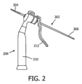
図2は、関心領域内の組織に挿入されるデバイスの一実施形態を示す。本実施形態では、デバイスは、先端部204及び後端部206を有するK-ワイヤ202であり、先端部204には、骨等の硬組織へのK-ワイヤの挿入を容易にする鋭い先端及び/又はねじ山が設けられていてよい。K-ワイヤ202は、グリップ部210及びハンドル212を有する器具208によって挿入することができる。グリップ部の方へハンドル212を動かすことによって、K-ワイヤを前方に、即ち、先端部の方向に押すことができる。
FIG. 2 shows one embodiment of a device that is inserted into tissue within a region of interest. In this embodiment, the device is a K-
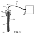
図3は、椎弓根スクリュー220を光学検知デバイス240と共に示す。椎弓根スクリュー220は、本体部222、ネック部224及びヘッド部226を含む。本体部222には、ねじ山の深さが外径と内径との差であるように、ピッチと外径と内径とを有するねじ山が設けられている。椎弓根スクリュー220は、中空シャフトを有し、その中に光学検知デバイス240の光学プローブ又はスタイレット242がスクリュー220の遠位先端228まで延在するように、光学プローブ又はスタイレット242が挿入される。スタイレット242及び光学検知デバイス240全体は、光を送信及び受信することができる光学コンソール246に接続された光ファイバ244といった導波路を含む。受け取った光はスペクトル解析され、これにより、スクリュー220の先端における組織を判別することができる。例えば拡散反射分光法、蛍光分光法、ラマン分光法、OCT等の技術を適用することができる。具体的には、受け取った光は、例えばスクリュー220及び光学スタイレット242の先端の前の組織の脂肪含有量を示すパラメータの決定に使用され、これは次に、骨の場合では、当該組織が骨の柔らかい部分の組織であるか、骨の硬い部分の組織であるかの決定に使用され、これにより、骨にスクリュー220を配置する際のナビゲーション支援を可能にする。光学コンソール246は、図1に示されるシステムの処理ユニット126に接続され、これにより、光学コンソールによって提供される情報も処理ユニットによって処理され、X線デバイス又は追跡デバイス等のシステムの他の部分から受信した情報と組み合わされてもよいことは理解されよう。
FIG. 3 shows
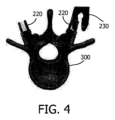
図4は、椎骨300に配置された2つの椎弓根スクリュー220を、骨に当該スクリュー220をねじ込むためのツール230と共に示す。スクリュー挿入配置ソフトウェア及びスクリュー配置によって、椎骨と計画挿入ラインが示される。更に及び/又は或いは、スクリュー挿入配置は、カメラによって誘導されて示される。計画軌道も示されてよく、スクリューの位置は、ナビゲーションシステムに基づいて示される。なお、身体の内部は、身体の内部の以前に撮影された画像に基づいて示される。椎骨の実際の位置は、身体の外部表面と比較して身体の内部構造の変位により異なる場合がある。
FIG. 4 shows two
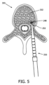
図5には、モデルの一例が示される。当該モデルは、デバイスの挿入中に遭遇する可能性のある組織構造を示す。デバイス250は、先端252が海綿骨302内にある状態で椎骨300内にあるべきである。この海綿骨の脂肪含有量は高い。したがって、例えば組織の脂肪含有量に基づいてルックアップテーブルを作成することを使用して、デバイス配置を誘導することができる。脂肪含有量は、スペクトル組織検知248でリアルタイムに決定することができるパラメータである。デバイス配置計画ソフトウェアに基づき脂肪含有量を予測し、これをスペクトル組織検知に基づきリアルタイムで決定された脂肪含有量に基づく実際の脂肪含有量と比較することは、差を決定する方法である。
An example of a model is shown in FIG. The model represents tissue structures that may be encountered during device insertion.
図6は、スクリュー挿入中に取得されたシーケンスからの4つの画像601、602、603、604を、取得された組織測定値の一例と共に示す。画像601、602では、スクリュー先端は脂肪含有量が高い海綿骨内に配置されていることが観察でき、一方、画像603、604では、スクリュー先端は脂肪含有量が低い皮質骨内に配置されている。
FIG. 6 shows four
撮像/ナビゲーションシステムによって決定された位置によれば、スクリュー先端は皮質骨内にあるべきところ、検知システムによって行われるスペクトル組織解析によってこれが確認されない場合、スクリューは軌道から外れているとみなされ、対応する信号が生成される。組織の脂肪含有量以外にも、他のパラメータもこれに使用することができる。例えば散乱によって、海綿骨から皮質骨への明確な移行も明らかになる場合があり、これも同様に使用することができる。 According to the position determined by the imaging/navigation system, the screw tip should be in the cortical bone, and if the spectral tissue analysis performed by the sensing system does not confirm this, the screw is considered off-track and action is taken. A signal is generated to Besides tissue fat content, other parameters can also be used for this. Scattering, for example, may also reveal a distinct transition from cancellous to cortical bone, which can be used as well.
一例として、スクリュー先端を囲む組織によって反射されて受け取った光のスペクトルの一部を、画像601、602、603、604の右側のグラフ605に表す。これらのグラフでは、横軸に波長(ラムダ)をナノメートル(nm)で表し、縦軸に強度(I)を任意の単位で表す。画像601及び602では、椎体内の海綿骨組織の比較的高い脂肪含有量は、1200nmの波長付近の反射光のスペクトルの比較的顕著な最小値に変換される。
As an example, a portion of the received light spectrum reflected by the tissue surrounding the screw tip is represented in
データ記憶装置が接続されていてもよい処理ユニット126は、光検出器によって測定されたスペクトルを、線源-検出器ファイバの組み合わせの組織状態を示す生理学的パラメータに変換することができる。特定の組織がプローブ(又は埋め込み型デバイス)の前にあるかどうかを判断するには、線源-検出器対の信号をルックアップテーブルと比較することができる。別の方法は、測定されたパラメータを生理学的パラメータに変換し、各組織型についてこれらのパラメータの範囲を定義することである。Duck、F.A.による「Physical properties of tissue: A 30 comprehensive reference book」(1990年、アカデミック・プレス、ハートコート・ブランス・ジョバノービック、パブリッシャーズ)を参照することにより組み込む。この本では、これらの生理学的パラメータに基づいて組織を分類するための分類及び回帰木(CART)分析に基づく方法が説明されている。
A
一般に、所与の組織型からのスペクトルは、似ている傾向がある。それぞれの組織「フィンガープリント」(特徴的なスペクトル)を使用して、組織型を判別することができる。通常、(例えば特徴的な発色団の濃度をフィッティングするか又は主成分を計算することによる)フィンガープリントは、最初に抽出/強調され、次にこれらの派生特徴を使用して、SVM、CART、カットオフ値又はk近傍法といった典型的な機械学習法に基づき組織が判別される。例えば脂肪スペクトルは、筋肉又は骨組織とは異なる特徴的な形状(即ち、フィンガープリント)をもっていることは明らかである。例えば1200nmの波長付近での反射光強度の低下は、筋肉又は皮質骨組織よりも脂肪含有量が比較的高い組織でほぼ常により顕著である(図6の右列グラフ605を参照)。
In general, spectra from a given tissue type tend to be similar. Each tissue "fingerprint" (characteristic spectrum) can be used to distinguish between tissue types. Typically, fingerprints are first extracted/enhanced (e.g., by fitting concentrations of characteristic chromophores or calculating principal components) and then using these derived features, SVM, CART, Tissues are discriminated based on typical machine learning methods such as cut-off values or k-nearest neighbors. It is clear, for example, that the fat spectrum has a different characteristic shape (ie fingerprint) than muscle or bone tissue. For example, the reduction in reflected light intensity near wavelengths of 1200 nm is almost always more pronounced in tissue with a relatively high fat content than in muscle or cortical bone tissue (see
アルゴリズムを利用して、計画スクリュー挿入中に遭遇する可能性のある組織の特性のテーブルを作成することができる。組織特性を決定するには、2つの手法を使用することができる。第1の手法は、セグメンテーションアルゴリズムを使用して、脊椎の椎骨をセグメント化する。解剖学的モデル(例えば図5に示すモデル)をセグメント化された脊椎に適用し、予想されるスペクトル組織測定値を計算するために使用することができる。第2の手法は、スペクトル組織検知で検出することができる脂肪含有量又はその他の組織特性を測定することができる撮像技術を使用する。撮像技術は、ナビゲーションシステムに結果的に登録される術前MRI等の手順の前に取得される。その後、予想されるスペクトル組織測定値を計算するアルゴリズムの入力として、1つ以上の画像シリーズを使用することができる。これらの画像シリーズは、同じ解剖学的構造のMRIからの複数のコントラスト画像又は複数の撮像診断法の組み合わせである。また、MR分光撮像も入力として使用することができる。当然ながら、2つの手法は組み合わされてもよい。 Algorithms can be utilized to create a table of tissue properties likely to be encountered during planned screw insertion. Two approaches can be used to determine tissue properties. A first approach uses a segmentation algorithm to segment the vertebrae of the spine. An anatomical model (eg, the model shown in FIG. 5) can be applied to the segmented spine and used to calculate expected spectral tissue measurements. A second approach uses imaging techniques that can measure fat content or other tissue properties that can be detected with spectral tissue sensing. Imaging techniques are acquired prior to a procedure, such as a preoperative MRI, which is subsequently registered with the navigation system. One or more image series can then be used as input for an algorithm that calculates expected spectral tissue measurements. These image series are a combination of multiple contrast images or multiple imaging modalities from MRI of the same anatomy. MR spectroscopic imaging can also be used as input. Of course, the two approaches may be combined.
図7を参照すると、方法、即ち、ソフトウェアソリューションが説明される。図7のフローチャートは、一実施形態による位置決定原理を説明する。当然ながら、コンピュータベースの方法に関して説明されるステップは主要ステップであり、これらの主要ステップは区別されるか、又は、幾つかのサブステップに分割されてもよい。更に、これらの主要ステップ間にサブステップがあってもよい。サブステップは、当該ステップが本発明による方法の原理の理解に重要である場合にのみ言及される。 Referring to FIG. 7, a method or software solution is described. The flow chart of FIG. 7 illustrates the positioning principle according to one embodiment. Of course, the steps described with respect to the computer-based method are major steps, and these major steps may be distinguished or divided into several sub-steps. Additionally, there may be substeps between these main steps. Sub-steps are only mentioned if the step is important to the understanding of the principle of the method according to the invention.
ステップS1において、様々な組織型を含む関心領域の情報が、処理ユニットによって受信される。このような情報は、前に生成された画像を保存するデータベースから受信されても、及び/又は、受信の直前に情報/データを生成する撮像デバイスから受信されてもよい。 In step S1, information of a region of interest including various tissue types is received by a processing unit. Such information may be received from a database that stores previously generated images and/or from an imaging device that generates the information/data immediately prior to reception.
ステップS2において、関心領域を通る経路を特定する入力が受信される。このような入力は、ユーザによって、タッチスクリーン、コンピュータのマウス又はキーボードを用いて、画像内に直接指示することによって、及び/又は、座標を定義することによって行われてよい。更に及び/又は或いは、入力は、同等の手順に基づき処理ユニットによって自動的に生成されてもよい。即ち、処理ユニットは、組織を通る経路を提案することができる。その後、ユーザは、必要に応じて経路を個別に調整するだけでよい。 At step S2, an input is received specifying a path through the region of interest. Such input may be made by the user by pointing directly into the image using a touch screen, computer mouse or keyboard, and/or by defining coordinates. Additionally and/or alternatively, the input may be automatically generated by the processing unit based on equivalent procedures. That is, the processing unit can suggest a route through the tissue. The user then only has to adjust the route individually as needed.
ステップS3において、経路に沿った一連の組織型が決定される。ステップS1からS3のシーケンスは、計画方法と見なされる。 At step S3, a series of tissue types along the path are determined. The sequence of steps S1 to S3 is considered a planning method.
ステップS4において、関心領域への決定された経路に沿ったデバイスの挿入中に、デバイスの先端にある光学検知手段から光学情報が受信される。このステップは、光を放出するサブステップ、光を受けるサブステップ及び光スペクトルを決定するサブステップを含む。ステップS5において、光学ガイドの当該遠位端における組織型が、受信した光学情報に基づいて決定される。 In step S4, optical information is received from optical sensing means at the tip of the device during insertion of the device along the determined path into the region of interest. This step includes a substep of emitting light, a substep of receiving light and a substep of determining the light spectrum. At step S5, the tissue type at the distal end of the optical guide is determined based on the received optical information.
ステップS6において、ステップS5において決定された組織型が、(ステップS3で決定された)経路上の所定の組織型と比較される。 At step S6, the tissue type determined at step S5 is compared to a predetermined tissue type on the path (determined at step S3).
加えて、ステップS7において、光学ガイドの遠位端を、追跡デバイスによって追跡することができる。実際には、光学ガイドの近位端、即ち、後端の空間的な位置及び向きを、例えばカメラがトレーサープレートを撮像することによって追跡することができる。光学ガイドの既知の形状と、決定された近位の位置及び向きとによって、遠位端を、当該遠位端が現在見えていなくても、決定することができる。 Additionally, at step S7, the distal end of the optical guide can be tracked by a tracking device. In practice, the spatial position and orientation of the proximal or trailing end of the optical guide can be tracked, for example, by imaging the tracer plate with a camera. With the known shape of the optical guide and the determined proximal position and orientation, the distal end can be determined even if it is not currently visible.
ステップS8において、組織を通る光学ガイドの経路における当該光学ガイドの遠位端の可能な位置が、組織型の比較及び/又は追跡位置に基づいて決定される。その決定に基づいて、ステップS9において、可能な位置を示す信号が生成される。 In step S8, possible positions of the distal end of the optical guide in its path through tissue are determined based on the comparison of tissue types and/or tracking positions. Based on that determination, a signal indicating possible positions is generated in step S9.
任意選択的に、ステップS10において、関心領域の視覚化を、関心領域に挿入される要素の仮想表現と共に生成することができる。要素の仮想表現の遠位端は、以前に、即ち、手順の計画段階の間に生成された画像内の経路上の最も可能性の高い位置に示される。 Optionally, in step S10, a visualization of the region of interest can be generated with virtual representations of the elements inserted into the region of interest. The distal end of the virtual representation of the element is shown at the most likely position on the path in the image generated earlier, ie during the planning stage of the procedure.
当然ながら、必要に応じて、関心領域へのデバイスの挿入を制御するために、ステップS4からステップS10を繰り返すことができる。なお、挿入されたデバイスの位置の制御は主としてX線情報に基づいていないため、このような方法によって達成される利点は、患者のX線被曝の低減にも見られる。 Of course, steps S4 to S10 can be repeated to control the insertion of the device into the region of interest as needed. It should be noted that the benefits achieved by such methods are also seen in the reduction of patient X-ray exposure, since the control of the position of the inserted device is not primarily based on X-ray information.
最後に、組織の検知は、スクリュー挿入だけでなく、他の多くの臨床手順にも適していることに留意されたい。例えば生検、脳深部刺激配置、腫瘍焼灼等である。組織検知ハードウェアは、これらの手順に使用される典型的なデバイス向けに考案することができる。高度な撮像及び/又は解剖学的モデリングを使用することにより、ほとんどの解剖学的領域の予想スペクトル組織測定値を計算することができる。例として、次の臨床応用、即ち、(i)頸椎、胸椎及び腰椎における椎弓根スクリュー挿入、(ii)様々な骨外傷における骨折固定、及び、(iii)股関節及び膝関節の関節形成におけるプレートの位置決め、が本発明から恩恵を受けるであろう。 Finally, it should be noted that tissue sensing is suitable not only for screw insertion, but also for many other clinical procedures. For example, biopsy, deep brain stimulation placement, tumor ablation, and the like. Tissue sensing hardware can be devised for typical devices used in these procedures. Using advanced imaging and/or anatomical modeling, it is possible to calculate expected spectral tissue measurements for most anatomical regions. Examples include the following clinical applications: (i) pedicle screw insertion in the cervical, thoracic and lumbar spine, (ii) fracture fixation in various bone traumas, and (iii) plates in hip and knee arthroplasty. , would benefit from the present invention.
本発明は、図面及び前述の説明において詳細に図示及び説明されたが、そのような図示及び説明は、限定的ではなく例示的であると見なされるべきである。本発明は、開示された実施形態に限定されない。開示された実施形態に対する他の変形は、図面、開示及び添付の特許請求の範囲の検討から、請求された発明を実施する際に当業者によって理解及び実施されうる。 While the invention has been illustrated and described in detail in the drawings and foregoing description, such illustration and description are to be considered illustrative rather than restrictive. The invention is not limited to the disclosed embodiments. Other variations to the disclosed embodiments can be understood and effected by those skilled in the art in practicing the claimed invention, from a study of the drawings, the disclosure, and the appended claims.
請求項において、「含む」という語は他の要素を除外せず、単数形は複数を除外しない。特定の手段が相互に異なる従属請求項に記載されていることだけで、これらの手段の組み合わせが有利に使用できないことを示すものではない。請求項中の参照符号は、範囲を限定するものとして解釈されるべきではない。 In the claims, the word "comprising" does not exclude other elements and the singular does not exclude the plural. The mere fact that certain measures are recited in mutually different dependent claims does not indicate that a combination of these measures cannot be used to advantage. Any reference signs in the claims should not be construed as limiting the scope.
102 システム
104 X線デバイス又はシステム
106 ベースフレーム
108 車輪
110 Cアーム
112 テーブル
114 患者
116 第1の軸
118 第2の軸
120 X線源
122 X線検出器
124 カメラ
126 処理ユニット
128 モニタ
130 更なるカメラ
202 K-ワイヤ
204 先端部
206 後端部
208 器具
210 グリップ部
212 ハンドル
220 スクリュー
222 本体部
224 ネック部
226 ヘッド部
230 ツール
240 光学検知デバイス
242 プローブ又はスタイレット
244 光学ガイド又はファイバ
246 光学コンソール
248 組織検知
250 デバイス
252 デバイスの先端
300 椎骨
302 海綿骨
102
Claims (11)
処理ユニットと、
を含む、組織に挿入可能なデバイスの位置を決定するシステムであって、
前記光学ガイドは、前記挿入可能なデバイス内に配置可能であり、
前記処理ユニットは、
(i)様々な種類の組織を含む関心領域の組織の種類の情報を受信し、
(ii)前記関心領域を通る経路を特定する入力を受信し、
(iii)受信した前記組織の種類の情報に基づいて、特定した前記経路に沿った一連の組織の種類を決定し、
(iv)前記光学検知デバイスから光学情報を受信し、
(v)受信した前記光学情報に基づいて、前記光学ガイドの前記遠位端における組織の種類を決定し、
(vi)決定された前記遠位端における組織の種類を、前記経路に沿った前記一連の組織の種類と比較し、
(vii)前記組織の種類の前記比較に基づいて、前記経路上の前記光学ガイドの前記遠位端の可能な位置を決定し、
(viii)受信した前記光学情報に基づいて決定された前記遠位端における組織の種類と、前記関心領域を通る前記経路に沿った前記可能な位置に対する可能な前記組織の種類との不一致を示す信号を生成する、システム。 an optical sensing device including an optical guide having a distal end;
a processing unit;
A system for determining the position of a device insertable in tissue comprising:
the optical guide is positionable within the insertable device;
The processing unit is
(i) receiving tissue type information for a region of interest comprising various types of tissue ;
(ii) receiving input identifying a path through the region of interest;
(iii) determining a sequence of tissue types along the identified path based on the received tissue type information;
(iv) receiving optical information from the optical sensing device;
(v) determining tissue type at the distal end of the optical guide based on the received optical information;
(vi) comparing the determined tissue type at the distal end to the series of tissue types along the path;
(vii) determining possible positions of the distal end of the optical guide on the path based on the comparison of the tissue types ;
(viii) indicating a discrepancy between the tissue type at the distal tip determined based on the received optical information and the possible tissue types for the possible locations along the path through the region of interest; A system that generates a signal.
様々な種類の組織を含む関心領域の組織の種類の情報と、前記関心領域を通る経路を特定する入力とを受信するステップと、
関心領域内に特定された経路に沿った一連の組織の種類を決定するステップと、
光学情報に基づいて、光学ガイドの遠位端における組織の種類を決定するステップと、
前記遠位端における決定された前記組織の種類を、前記経路上の前記組織の種類と比較するステップと、
前記経路上の前記光学ガイドの前記遠位端の可能な位置を決定するステップと、
前記遠位端における決定された前記組織の種類と、前記関心領域を通る前記経路に沿った前記可能な位置に対応する前記一連の組織の種類からの組織の種類との不一致を示すステップと、
を含む、方法。 A method of determining the position of a device insertable in tissue, comprising:
receiving tissue type information for a region of interest comprising different types of tissue and input identifying a route through the region of interest;
determining a series of tissue types along an identified path within the region of interest;
determining a tissue type at the distal end of the optical guide based on the optical information;
comparing the determined tissue type at the distal end to the tissue type on the path;
determining possible positions of the distal end of the optical guide on the path;
indicating a discrepancy between the determined tissue type at the distal end and a tissue type from the set of tissue types corresponding to the possible locations along the path through the region of interest;
A method, including
Applications Claiming Priority (3)
| Application Number | Priority Date | Filing Date | Title |
|---|---|---|---|
| EP17155320 | 2017-02-09 | ||
| EP17155320.9 | 2017-02-09 | ||
| PCT/EP2018/052989 WO2018146112A1 (en) | 2017-02-09 | 2018-02-07 | Position detection based on tissue discrimination |
Publications (3)
| Publication Number | Publication Date |
|---|---|
| JP2020508097A JP2020508097A (en) | 2020-03-19 |
| JP2020508097A5 JP2020508097A5 (en) | 2021-03-18 |
| JP7242537B2 true JP7242537B2 (en) | 2023-03-20 |
Family
ID=58094176
Family Applications (1)
| Application Number | Title | Priority Date | Filing Date |
|---|---|---|---|
| JP2019542687A Active JP7242537B2 (en) | 2017-02-09 | 2018-02-07 | Position detection based on tissue discrimination |
Country Status (5)
| Country | Link |
|---|---|
| US (2) | US11497562B2 (en) |
| EP (1) | EP3579781B1 (en) |
| JP (1) | JP7242537B2 (en) |
| CN (1) | CN110381875B (en) |
| WO (1) | WO2018146112A1 (en) |
Families Citing this family (1)
| Publication number | Priority date | Publication date | Assignee | Title |
|---|---|---|---|---|
| EP3932357A1 (en) * | 2020-07-01 | 2022-01-05 | Koninklijke Philips N.V. | System for assisting a user in placing a penetrating device in tissue |
Citations (5)
| Publication number | Priority date | Publication date | Assignee | Title |
|---|---|---|---|---|
| US20090163901A1 (en) | 2007-12-19 | 2009-06-25 | Depuy Spine, Inc. | Smart pedicle tool |
| US20120059251A1 (en) | 2009-05-28 | 2012-03-08 | Koninklijke Philips Electronics N.V. | Re-calibration of pre-recorded images during interventions using a needle device |
| US20140187917A1 (en) | 2012-12-31 | 2014-07-03 | Biosense Webster (Israel), Ltd. | Catheter with serially connected sensing structures and methods of calibration and detection |
| US20150080712A1 (en) | 2012-03-27 | 2015-03-19 | Koninklijke Philips N.V. | Integration delayed optical feedback in image guidance |
| JP2016174809A (en) | 2015-03-20 | 2016-10-06 | テルモ株式会社 | Image diagnosis apparatus, control method thereof, program and computer-readable storage medium |
Family Cites Families (16)
| Publication number | Priority date | Publication date | Assignee | Title |
|---|---|---|---|---|
| US6470207B1 (en) * | 1999-03-23 | 2002-10-22 | Surgical Navigation Technologies, Inc. | Navigational guidance via computer-assisted fluoroscopic imaging |
| US6869430B2 (en) * | 2000-03-31 | 2005-03-22 | Rita Medical Systems, Inc. | Tissue biopsy and treatment apparatus and method |
| WO2004051579A2 (en) * | 2002-12-04 | 2004-06-17 | Philips Intellectual Property & Standards Gmbh | Apparatus and method for assisting the navigation of a catheter in a vessel |
| US8092455B2 (en) | 2005-02-07 | 2012-01-10 | Warsaw Orthopedic, Inc. | Device and method for operating a tool relative to bone tissue and detecting neural elements |
| WO2006113394A2 (en) * | 2005-04-15 | 2006-10-26 | Surgisense Corporation | Surgical instruments with sensors for detecting tissue properties, and systems using such instruments |
| WO2009111387A1 (en) * | 2008-03-03 | 2009-09-11 | Biospinex, Llc | Methods and devices for in situ tissue navigation |
| EP2375988A1 (en) | 2008-12-11 | 2011-10-19 | Koninklijke Philips Electronics N.V. | System and method for generating images of a patient's interior and exterior |
| US8366719B2 (en) | 2009-03-18 | 2013-02-05 | Integrated Spinal Concepts, Inc. | Image-guided minimal-step placement of screw into bone |
| CN102781336B (en) * | 2009-10-30 | 2016-01-20 | 约翰霍普金斯大学 | For visual tracking and the annotation of the anatomic landmark important clinically of surgical intervention |
| US20110196376A1 (en) | 2010-02-09 | 2011-08-11 | Burak Ozgur | Osteo-navigation |
| EP2744398B1 (en) * | 2011-11-07 | 2017-01-18 | Koninklijke Philips N.V. | Detection apparatus for determining a state of tissue |
| CN104244861B (en) * | 2012-03-23 | 2017-09-08 | 皇家飞利浦有限公司 | It is a kind of to be used for the guiding system of the guide instrument in body |
| RU2608975C2 (en) * | 2012-03-29 | 2017-01-30 | Конинклейке Филипс Н.В. | Method of magnetic resonance imaging (mri) for assigning for individual pixels or voxels the specific for tissue values of positron emission tomography (pet) |
| US20140276200A1 (en) * | 2013-03-15 | 2014-09-18 | Covidien Lp | Microwave energy-delivery device and system |
| WO2014179292A1 (en) * | 2013-04-29 | 2014-11-06 | The Charlotte-Mecklenburg Hospital Authority D/B/A Carolinas Healthcare System | Device, system, and method for insertion of a medical device into a subject |
| EP3337419B1 (en) * | 2015-08-19 | 2020-08-12 | Brainlab AG | Reference array holder |
-
2018
- 2018-02-07 EP EP18706662.6A patent/EP3579781B1/en active Active
- 2018-02-07 JP JP2019542687A patent/JP7242537B2/en active Active
- 2018-02-07 US US16/483,951 patent/US11497562B2/en active Active
- 2018-02-07 WO PCT/EP2018/052989 patent/WO2018146112A1/en unknown
- 2018-02-07 CN CN201880011150.9A patent/CN110381875B/en active Active
-
2022
- 2022-06-24 US US17/848,490 patent/US11712310B2/en active Active
Patent Citations (6)
| Publication number | Priority date | Publication date | Assignee | Title |
|---|---|---|---|---|
| US20090163901A1 (en) | 2007-12-19 | 2009-06-25 | Depuy Spine, Inc. | Smart pedicle tool |
| US20120059251A1 (en) | 2009-05-28 | 2012-03-08 | Koninklijke Philips Electronics N.V. | Re-calibration of pre-recorded images during interventions using a needle device |
| US20150080712A1 (en) | 2012-03-27 | 2015-03-19 | Koninklijke Philips N.V. | Integration delayed optical feedback in image guidance |
| JP2015512709A (en) | 2012-03-27 | 2015-04-30 | コーニンクレッカ フィリップス エヌ ヴェ | Integrated delayed optical feedback in image guidance |
| US20140187917A1 (en) | 2012-12-31 | 2014-07-03 | Biosense Webster (Israel), Ltd. | Catheter with serially connected sensing structures and methods of calibration and detection |
| JP2016174809A (en) | 2015-03-20 | 2016-10-06 | テルモ株式会社 | Image diagnosis apparatus, control method thereof, program and computer-readable storage medium |
Also Published As
| Publication number | Publication date |
|---|---|
| US20200085506A1 (en) | 2020-03-19 |
| CN110381875A (en) | 2019-10-25 |
| JP2020508097A (en) | 2020-03-19 |
| US20220313368A1 (en) | 2022-10-06 |
| EP3579781B1 (en) | 2020-07-15 |
| WO2018146112A1 (en) | 2018-08-16 |
| US11497562B2 (en) | 2022-11-15 |
| CN110381875B (en) | 2023-03-21 |
| US11712310B2 (en) | 2023-08-01 |
| EP3579781A1 (en) | 2019-12-18 |
Similar Documents
| Publication | Publication Date | Title |
|---|---|---|
| JP5121401B2 (en) | System for distance measurement of buried plant | |
| US20190388155A1 (en) | Controlling a surgical intervention to a bone | |
| Helm et al. | Spinal navigation and imaging: history, trends, and future | |
| JP5328137B2 (en) | User interface system that displays the representation of tools or buried plants | |
| CN103997982B (en) | By operating theater instruments with respect to the robot assisted device that patient body is positioned | |
| JP6700401B2 (en) | Intraoperative image-controlled navigation device during a surgical procedure in the area of the spinal column and adjacent areas of the rib cage, pelvis or head | |
| Bledsoe et al. | Accuracy of upper thoracic pedicle screw placement using three-dimensional image guidance | |
| US20230301726A1 (en) | Systems, instruments and methods for surgical navigation with verification feedback | |
| CN114846517A (en) | Determining relative 3D position and orientation between objects in a 2D medical image | |
| US11712310B2 (en) | Position detection based on tissue discrimination | |
| AU2022239314A1 (en) | Robotic spine systems and robotic-assisted methods for tissue modulation | |
| Liu et al. | Monitoring the reduced scattering coefficient of bone tissues on the trajectory of pedicle screw placement using near-infrared spectroscopy | |
| TWM570117U (en) | An augmented reality instrument for accurately positioning pedical screw in minimally invasive spine surgery | |
| US20110196376A1 (en) | Osteo-navigation | |
| US7340291B2 (en) | Medical apparatus for tracking movement of a bone fragment in a displayed image | |
| Sklar et al. | First case report using optical topographic-guided navigation in revision spinal fusion for calcified thoracic disk | |
| US20230134673A1 (en) | Orthopedic pin for optically analyzing a bone region | |
| TWI671763B (en) | An augmented reality instrument for accurately positioning pedical screw in minimally invasive spine surgery | |
| Saghbiny et al. | Protocol for Electrical Conductivity Signal Collection and Processing in Scoliosis Surgery | |
| Swartman et al. | Intraoperative 3D Imaging of the Pelvic Ring | |
| Kalfas | Image-guided spinal navigation: principles and clinical applications | |
| Kalfas | Image-guided spinal navigation | |
| Sama et al. | Computerized frameless stereotactic image guidance in spinal surgery | |
| Hassan et al. | A Study of Bone Thickness Measurement by Using Infrared Sensor for Pedicle Screw Insertion |
Legal Events
| Date | Code | Title | Description |
|---|---|---|---|
| A521 | Request for written amendment filed |
Free format text: JAPANESE INTERMEDIATE CODE: A523 Effective date: 20210204 |
|
| A621 | Written request for application examination |
Free format text: JAPANESE INTERMEDIATE CODE: A621 Effective date: 20210204 |
|
| A131 | Notification of reasons for refusal |
Free format text: JAPANESE INTERMEDIATE CODE: A131 Effective date: 20220328 |
|
| A521 | Request for written amendment filed |
Free format text: JAPANESE INTERMEDIATE CODE: A523 Effective date: 20220622 |
|
| A131 | Notification of reasons for refusal |
Free format text: JAPANESE INTERMEDIATE CODE: A131 Effective date: 20221021 |
|
| TRDD | Decision of grant or rejection written | ||
| A01 | Written decision to grant a patent or to grant a registration (utility model) |
Free format text: JAPANESE INTERMEDIATE CODE: A01 Effective date: 20230208 |
|
| A61 | First payment of annual fees (during grant procedure) |
Free format text: JAPANESE INTERMEDIATE CODE: A61 Effective date: 20230308 |
|
| R150 | Certificate of patent or registration of utility model |
Ref document number: 7242537 Country of ref document: JP Free format text: JAPANESE INTERMEDIATE CODE: R150 |