JP7242184B2 - Goods storage, handling and recovery systems and methods - Google Patents
Goods storage, handling and recovery systems and methods Download PDFInfo
- Publication number
- JP7242184B2 JP7242184B2 JP2017564111A JP2017564111A JP7242184B2 JP 7242184 B2 JP7242184 B2 JP 7242184B2 JP 2017564111 A JP2017564111 A JP 2017564111A JP 2017564111 A JP2017564111 A JP 2017564111A JP 7242184 B2 JP7242184 B2 JP 7242184B2
- Authority
- JP
- Japan
- Prior art keywords
- container
- storage
- containers
- frame
- workstation
- Prior art date
- Legal status (The legal status is an assumption and is not a legal conclusion. Google has not performed a legal analysis and makes no representation as to the accuracy of the status listed.)
- Active
Links
Images


Classifications
-
- B—PERFORMING OPERATIONS; TRANSPORTING
- B65—CONVEYING; PACKING; STORING; HANDLING THIN OR FILAMENTARY MATERIAL
- B65G—TRANSPORT OR STORAGE DEVICES, e.g. CONVEYORS FOR LOADING OR TIPPING, SHOP CONVEYOR SYSTEMS OR PNEUMATIC TUBE CONVEYORS
- B65G1/00—Storing articles, individually or in orderly arrangement, in warehouses or magazines
- B65G1/02—Storage devices
- B65G1/04—Storage devices mechanical
- B65G1/0464—Storage devices mechanical with access from above
-
- B—PERFORMING OPERATIONS; TRANSPORTING
- B65—CONVEYING; PACKING; STORING; HANDLING THIN OR FILAMENTARY MATERIAL
- B65G—TRANSPORT OR STORAGE DEVICES, e.g. CONVEYORS FOR LOADING OR TIPPING, SHOP CONVEYOR SYSTEMS OR PNEUMATIC TUBE CONVEYORS
- B65G1/00—Storing articles, individually or in orderly arrangement, in warehouses or magazines
- B65G1/02—Storage devices
- B65G1/04—Storage devices mechanical
- B65G1/137—Storage devices mechanical with arrangements or automatic control means for selecting which articles are to be removed
- B65G1/1373—Storage devices mechanical with arrangements or automatic control means for selecting which articles are to be removed for fulfilling orders in warehouses
-
- B—PERFORMING OPERATIONS; TRANSPORTING
- B65—CONVEYING; PACKING; STORING; HANDLING THIN OR FILAMENTARY MATERIAL
- B65G—TRANSPORT OR STORAGE DEVICES, e.g. CONVEYORS FOR LOADING OR TIPPING, SHOP CONVEYOR SYSTEMS OR PNEUMATIC TUBE CONVEYORS
- B65G1/00—Storing articles, individually or in orderly arrangement, in warehouses or magazines
- B65G1/02—Storage devices
- B65G1/04—Storage devices mechanical
- B65G1/0485—Check-in, check-out devices
-
- B—PERFORMING OPERATIONS; TRANSPORTING
- B65—CONVEYING; PACKING; STORING; HANDLING THIN OR FILAMENTARY MATERIAL
- B65G—TRANSPORT OR STORAGE DEVICES, e.g. CONVEYORS FOR LOADING OR TIPPING, SHOP CONVEYOR SYSTEMS OR PNEUMATIC TUBE CONVEYORS
- B65G1/00—Storing articles, individually or in orderly arrangement, in warehouses or magazines
- B65G1/02—Storage devices
- B65G1/04—Storage devices mechanical
- B65G1/137—Storage devices mechanical with arrangements or automatic control means for selecting which articles are to be removed
- B65G1/1373—Storage devices mechanical with arrangements or automatic control means for selecting which articles are to be removed for fulfilling orders in warehouses
- B65G1/1378—Storage devices mechanical with arrangements or automatic control means for selecting which articles are to be removed for fulfilling orders in warehouses the orders being assembled on fixed commissioning areas remote from the storage areas
-
- B—PERFORMING OPERATIONS; TRANSPORTING
- B65—CONVEYING; PACKING; STORING; HANDLING THIN OR FILAMENTARY MATERIAL
- B65G—TRANSPORT OR STORAGE DEVICES, e.g. CONVEYORS FOR LOADING OR TIPPING, SHOP CONVEYOR SYSTEMS OR PNEUMATIC TUBE CONVEYORS
- B65G2201/00—Indexing codes relating to handling devices, e.g. conveyors, characterised by the type of product or load being conveyed or handled
- B65G2201/02—Articles
- B65G2201/0235—Containers
Description
本発明は、保管システムからユニットを回収するための保管システム及び方法に関する。特に、これに限定しないが、本発明は、格子状の積み重ねられたユニットを備える倉庫において、集積貯蔵容器(bin)を取り扱うためのロボットシステムに関する。 The present invention relates to storage systems and methods for retrieving units from storage systems. More particularly, but not exclusively, the present invention relates to a robotic system for handling bins in warehouses with grid- stacked units.
本出願は、米国特許第7,861,844号明細書、PCT出願の国際公開第2013/167907号及び国際公開第2015/019055号を参照によりここに組み込む。これらの出願及び文献の内容がこれによって本出願に含まれることが考慮される。 This application incorporates by reference US Pat. No. 7,861,844, PCT application WO2013/167907 and WO2015/019055. The contents of these applications and publications are hereby considered to be incorporated into the present application.
本出願は、2015年6月8日に出願された英国特許出願第1509921.1号に基づく優先権を主張し、その内容が参照によりここに組み込まれる。 This application claims priority to UK Patent Application No. 1509921.1 filed 8 June 2015, the contents of which are incorporated herein by reference.
一部の商業活動や産業活動は、多数の異なる製品の保管及び回収を可能にするシステムを必要とする。多数の製品ラインにおける品物の保管及び回収のためのある既知のシステムは、通路に配置された棚の列に保管用集積貯蔵容器又はコンテナを配置することを含む。各集積貯蔵容器又はコンテナは、1つの製品タイプである複数の製品を保持する。通路は、必要な製品が、通路を巡回する作業員またはロボットによって回収され得るように、棚の列同士の間におけるアクセスを提供する。しかしながら、製品にアクセスするための通路空間を設ける必要があるということは、このようなシステムの保管密度が比較的低いことを意味することが認識される。換言すれば、製品の保管のために実際に使用される空間の大きさは、保管システム全体として必要な空間の大きさと比較すると、比較的小さい。 Some commercial and industrial activities require systems that allow storage and retrieval of many different products. One known system for storing and retrieving items in multiple product lines involves placing storage bins or containers in rows of shelves arranged in an aisle. Each collective bin or container holds multiple products of one product type. Aisles provide access between rows of shelves so that desired products can be retrieved by workers or robots patrolling the aisles. However, it is recognized that the need to provide aisle space for product access means that the storage density of such systems is relatively low. In other words, the amount of space actually used for product storage is relatively small compared to the amount of space required for the storage system as a whole .
上述のシステムのさらなる欠点は、いくつかの物品を含む顧客の注文を少なくとも1つの配送にまとめるためには、単一の注文のためにいくつかの通路にアクセスすることを必要とし得るという要件に起因する。まとめられることになる注文の量が多い場合、これは特に問題になる。 A further drawback of the above-described system is the requirement that consolidating a customer order containing several items into at least one delivery may require accessing several aisles for a single order. to cause. This is especially problematic if the volume of orders to be combined is large.
保管密度の著しい改良を提案する代替手法では、コンテナは、互いの上に積み重ねられ、これら積み重ねが、列をなして配置されている。コンテナは、上方からアクセスされ、列同士の間の通路の必要性をなくし、より多くのコンテナが所定の空間に保管されることを可能にする。 In an alternative approach that offers a significant improvement in storage density, containers are stacked on top of each other and the stacks are arranged in rows. The containers are accessed from above , eliminating the need for aisles between rows and allowing more containers to be stored in a given space .
以下により詳細に説明されるこの方法は、保管システムの全ての部分にアクセスし、かつ、積荷取扱装置を介して全てのワークステーションに全ての物品を移動させる能力を提供するものであるが、これは、格子の上部での積荷取扱装置間の輻輳を引き起こし得る。 This method, which will be described in more detail below, provides access to all parts of the storage system and the ability to move all items to all work stations via the load handling equipment. can cause congestion between load handling equipment at the top of the grate.
列をなして積み重ねられたコンテナを取り扱う方法は、数十年にわたり周知である。いくつかのそのようなシステムでは、例えば、米国特許第2,701,065号明細書に述べられているように、コンテナの自立型の積み重ねが、依然として、必要に応じて特定のコンテナへのアクセスを提供しながら、このようなコンテナの保管と関連付けられた保管体積を減少させるために、列をなして配置されている。所定のコンテナへのアクセスは、コンテナを積み重ねるために、および積み重ねから所定のコンテナを取り出すために使用されることができる比較的複雑な巻上機構を設けることによって可能となる。しかしながら、このようなシステムのコストは、多くの状況において非実用的であり、それらは、主として、大きな運送用コンテナの保管及び取扱いのために商用化されている。 Methods of handling containers stacked in rows have been known for decades. In some such systems, for example, as described in U.S. Pat. No. 2,701,065, self-supporting stacking of containers still allows access to specific containers as needed. are arranged in rows to reduce the storage volume associated with storing such containers while providing a Access to a given container is enabled by providing a relatively complex hoisting mechanism that can be used to stack the containers and to remove a given container from the stack . However, the cost of such systems is impractical in many situations and they are commercialized primarily for the storage and handling of large shipping containers.
コンテナの自立型の積み重ねを使用し、特定のコンテナを回収及び保管するための機構を設ける構想は、例えば、欧州特許第0767113号明細書(Cimcorp)に述べられているように、さらに発展されてきた。Cimcorpは、コンテナの積み重ねのまわりで下げられ、積み重ねの任意の高さでコンテナを把持することができるように構成された矩形チューブの形態のロボット積荷取扱装置を使用して、複数の積み重ねられたコンテナを取り出すための機構を開示している。この方法では、いくつかのコンテナが、積み重ねから一度に持ち上げられ得る。移動可能なチューブは、1つの積み重ねの上部から他の積み重ねの上部にいくつかのコンテナを移動させるために、又は、積み重ねから外部の位置に、また、その逆にコンテナを移動させるために使用されることができる。このようなシステムは、単一の積み重ねの全てのコンテナが同じ製品を含む場合に(単一製品の積み重ねとして知られている)、特に有用であり得る。この積荷取扱装置は、例えば、単一のタイプの製品を含む複数のコンテナを倉庫に追加するために、及び、複数製品の出荷積み重ねを作成するために、2つ以上の単一製品の積み重ねから1つ以上のコンテナを選び出すために、単一製品の積み重ね同士の間でコンテナを移動させるために使用され得る。この一例は、小売店への配送のための複数製品の注文を作成するための中央倉庫における野菜クレートのピッキングである。 The concept of using self-supporting stacks of containers and providing mechanisms for retrieving and storing specific containers has been further developed, for example as described in EP 0 767 113 (Cimcorp). It's been done . Cimcorp uses a robotic load handling device in the form of a rectangular tube that is lowered around a stack of containers and is configured to be able to grip containers at any height in the stack. A mechanism for ejecting a container is disclosed. In this way several containers can be lifted from the stack at once . Movable tubes are used to move some containers from the top of one stack to the top of another stack or to move containers from a stack to an external position and vice versa. can Such a system can be particularly useful when all containers of a single stack contain the same product (known as a single product stack) . The load handling equipment can be used, for example, to add multiple containers containing a single type of product to a warehouse and to create a multiple product shipping stack from two or more single product stacks . It can be used to move containers between stacks of single products to pick out one or more containers. An example of this is the picking of vegetable crates in a central warehouse to create multi- product orders for distribution to retail outlets.
Cimcorpに述べられているシステムでは、チューブの高さは、最も高い積み重ねのコンテナが単独操作で抽出され得るように、コンテナの最も高い積み重ねの高さと少なくとも同じ高さでなければならい。従って、倉庫のような囲われている空間で使用されるとき、積み重ねの最大高さは、積荷取扱装置のチューブを収容する必要性によって制限される。さらに、システムは、複数製品の積み重ねからの単一のコンテナの選択に対してうまく適合されていない。 In the system described in Cimcorp, the height of the tube must be at least as high as the height of the highest stack of containers so that the highest stack of containers can be extracted in a single operation . Therefore, when used in an enclosed space such as a warehouse, the maximum stack height is limited by the need to accommodate the tubes of the load handling equipment. Furthermore, the system is not well adapted for selecting a single container from a multi- product stack .
オンライン食料品店及びスーパーマーケットのような、多数の製品ラインを販売しているオンライン小売りビジネスは、何万から何十万もの異なる製品ラインを保管することができるシステムを必要とする。このような場合における単一製品の積み重ねの使用は、非常に大きな床面積が、必要とされる積み重ねを全て収容するために必要とされるので、非実用的であり得る。さらに、これは、痛みやすいものやめったに注文されない商品など、一部の品物は少量だけ保管することが望ましいことがあり得、単一製品の積み重ねを非効率的な解決策にしている。 Online retail businesses that sell multiple product lines, such as online grocery stores and supermarkets, need systems that can store tens of thousands to hundreds of thousands of different product lines. The use of single product stacks in such cases can be impractical because a very large floor area is required to accommodate all the required stacks . Furthermore, it may be desirable to store only small quantities of some items , such as perishables or infrequently ordered items , making single product stacking an inefficient solution .
参照としてその内容がここに組み込まれる、国際公開第98/049075号(Autostore)は、コンテナの複数製品の積み重ねがフレーム構造内に配置されたシステムを説明している。 WO 98/049075 (Autostore), the contents of which are incorporated herein by reference, describes a system in which a multi- product stack of containers is arranged within a frame structure.
PCT出願の国際公開第2015/185628号(Ocado)は、集積貯蔵容器の積み重ね又はコンテナの積み重ねがフレームワーク構造内に配置されているさらなる周知の保管及びフルフィルメントシステムを説明している。集積貯蔵容器又はコンテナは、フレーム構造の上部に位置する軌道上で動作する積荷取扱装置によってアクセスされる。積荷取扱装置は、積み重ねから集積貯蔵容器又はコンテナを持ち上げて取り出し、複数の積荷取扱装置が、積み重ねの最も低い位置に位置する集積貯蔵容器又はコンテナにアクセスするために協働する。このタイプのシステムが、添付図面の図1ないし図4に概略的に示される。 PCT Application WO2015/185628 (Ocado) describes a further known storage and fulfillment system in which a stack of integrated storage vessels or a stack of containers is arranged within a framework structure . Collective bins or containers are accessed by load handling equipment operating on tracks located on top of the framework. The load handling equipment lifts and removes the pooled storage bin or container from the stack , and multiple load handling devices cooperate to access the bottommost pooled storage bin or container of the stack . A system of this type is shown schematically in Figures 1 to 4 of the accompanying drawings.
図1及び図2に示されるように、集積貯蔵容器10として知られている積み重ね可能なコンテナが、積み重ね12を形成するために互いの上に積み重ねられている。積み重ね12は、倉庫又は製造環境に格子フレームワーク構造14で配置されている。図1は、フレームワーク構造14の概略的な斜視図であり、図2は、フレームワーク構造14内に配置された集積貯蔵容器10の積み重ね12を示す上面図である。各集積貯蔵容器10は、典型的には、複数の製品の品物(図示せず)を保持しており、集積貯蔵容器10内の製品の品物は同一であり得、または、用途に応じて異なる製品タイプのものであり得る。
As shown in FIGS. 1 and 2, stackable containers known as
フレームワーク構造14は、横架材18、20を支持する複数の直立部材16を含む。直立部材16で支持された複数の水平な格子構造を形成するために、第1のセットの平行な横架材18が、第2のセットの平行な横架材20に直交するように配置されている。部材16、18、20は、典型的には、金属で製造される。集積貯蔵容器10は、フレームワーク構造14の部材16、18、20の間に積み重ねられ、これにより、フレームワーク構造14は、集積貯蔵容器10の積み重ね12の水平移動を防ぎ、集積貯蔵容器10の垂直移動をガイドする。
フレーム構造14の最上部は、積み重ね12の最上部にわたって格子パターンに配置されたレール22を含む。図3及び図4をさらに参照すると、レール22は、複数のロボット積荷取扱装置30を支持する。平行なレール22の第1のセット22aは、フレーム構造14の最上部にわたって第1の方向(X)における積荷取扱装置30の移動をガイドし、第1のセット22aに直交するように配置された、平行なレール22の第2のセット22bは、第1の方向に直交する第2の方向(Y)における積荷取扱装置30の移動をガイドする。このように、レール22は、水平なX‐Y平面において二次元での横方向への積荷取扱装置30の移動を可能にするものであり、これにより、積荷取扱装置30は、任意の積み重ね12の上方の位置へと移動されることができる。
The top of
積荷取扱装置30の一形態は、さらに、ノルウェー特許第317366号明細書に説明されており、その内容が参照によりここに組み込まれる。図3a及び図3bは、それぞれ、背面及び正面からの積荷取扱装置30の概略的な斜視図であり、図3cは、集積貯蔵容器10を持ち上げる積荷取扱装置30の概略的な正面の斜視図である。しかしながら、ここに記述されたシステムと組み合わせて使用されることができる積荷取扱装置の他の形態がある。例えば、ロボット積荷取扱装置のさらなる形態は、参照によりここに組み込まれる、PCTの国際公開第2015/019055号(Ocado)に開示されており、ここで、各ロボット積荷取扱装置は、フレームワーク構造の1つの格子空間のみをカバーし、したがって、所定のサイズのシステムについて、より高い密度の積荷取扱装置を可能にし、よって、より高いスループットを可能にする。
One form of
各積荷取扱装置30は、積み重ね12の上方で、フレーム構造14のレール22上をX方向及びY方向に移動するように配置された車両32を含む。車両32の前方にある1対の車輪34と、車両32の後方にある1対の車輪34とからなる第1のセットの車輪34は、レール22の第1のセット22aの2本の隣接するレールと係合するように配置されている。同様に、車両32の両側にある1対の車輪36からなる第2のセットの車輪36は、レール22の第2のセット22bの2本の隣接するレールと係合するように配置されている。車輪34、36の各セットは、第1のセットの車輪34又は第2のセットの車輪36のいずれかが、どの時点においてもそれぞれのレールのセット22a、22bと係合されるように、持ち上げられたり下ろされたりすることができる。
Each
第1のセットの車輪34が第1のレールのセット22aと係合され、第2のセットの車輪36がレール22から離れて持ち上げられるとき、車輪34は、X方向に積荷取扱装置30を移動させるために、車両32に収容された駆動機構(図示せず)によって駆動されることができる。Y方向に積荷取扱装置30を移動させるためには、第1のセットの車輪34が、レール22から離れて持ち上げられ、第2のセットの車輪36が、第2のレールのセット22aと係合するように下げられる。そして、駆動機構は、Y方向における移動を達成するように、第2のセットの車輪36を駆動させるために使用されることができる。
When the first set of
積荷取扱装置30にはリフト装置が装備されている。リフト装置40は、4本のケーブル38によって積荷取扱装置32のボディから懸吊された把持板39を含む。ケーブル38は、車両32の内部に収容された巻き上げ機構(図示せず)に連結されている。ケーブル38は、積荷取扱装置32に巻かれる又は積荷取扱装置32から巻き戻されることができ、これにより、車両32に対する把持板39の位置が、Z方向において調節されることができる。
The
把持板39は、集積貯蔵容器10の最上部と係合するように構成されている。例えば、把持板39は、集積貯蔵容器10の上面を形成している、リムにおける対応する孔(図示せず)と合う複数のピン(図示せず)と、集積貯蔵容器10を把持するためにリムと係合することができるスライドクリップ(図示せず)とを含むことができる。クリップは、把持板39内に収容された適切な駆動機構によって集積貯蔵容器10と係合するように駆動され、ケーブル38自体を通って、又は個別の制御ケーブル(図示せず)を通って伝達される信号によって、電力供給及び制御される。
Gripping
積み重ね12の最上部から集積貯蔵容器10を取り出すために、積荷取扱装置30は、必要に応じてX方向及びY方向に移動され、これにより、把持板39は、積み重ね12の上方に位置付けられる。そして、把持板39は、図3cに示されるように、積み重ね12の最上部にある集積貯蔵容器10と係合するために、Z方向に垂直に下げられる。把持板39は、集積貯蔵容器10を把持し、次いで、集積貯蔵容器10が取り付けられている状態で、ケーブル38で上向きに引っ張り上げられる。その垂直移動の最上部で、集積貯蔵容器10は、車両ボディ32内に収容され、レール22の高さよりも上に保持される。このようにして、積荷取扱装置30は、他の位置へ集積貯蔵容器10を搬送するために、それと共に集積貯蔵容器10を運んで、X-Y平面における他の位置に移動されることができる。ケーブル38は、積荷取扱装置30が、床面高さを含む、積み重ね12の任意の高さから集積貯蔵容器を回収する及び置くことを可能にするのに十分な長さがある。車両32は、集積貯蔵容器10の重量と釣り合うように、かつ、持ち上げプロセスの間に安定したままであるように、十分に重い。車両32の重量は、車輪34、36のための駆動機構に電力供給するために使用されるバッテリーから一部構成され得る。
To remove the accumulated
図4に示されるように、複数の同一の積荷取扱装置30が、各積荷取扱装置30がシステムのスループットを増加させるために同時に動作することができるように、設けられている。図4に示されるシステムは、ポート24として知られている2つの特定の位置を含み、その位置で、集積貯蔵容器10は、システムの内外に移送されることができる。例えば、さらなるコンベヤシステム(図示せず)が、各ポート24に関連付けられており、これにより、積荷取扱装置30によってポート24に搬送された集積貯蔵容器10は、コンベヤシステムによって他の位置へ、例えばピッキングステーション(図示せず)へ移送されることができる。同様に、集積貯蔵容器10は、コンベヤシステムによって外部の位置からポート24へ、例えば集積貯蔵容器充填ステーション(図示せず)へ移動され、システムにおける在庫を補充するために、積荷取扱装置30によって積み重ね12へと搬送されることができる。
As shown in FIG. 4, a plurality of identical
各積荷取扱装置30は、一度に1つの集積貯蔵容器10を持ち上げて移動させることができる。積み重ね12の最上部に位置していない集積貯蔵容器10(「ターゲット集積貯蔵容器」)を回収することが必要な場合、上に重なっている集積貯蔵容器10(「ターゲットでない集積貯蔵容器」)は、ターゲット集積貯蔵容器10へのアクセスを可能にするために最初に移動されなければならない。これは、以下において「掘り出し」(digging)と称される操作で達成される。
Each
図4を参照すると、掘り出し操作中、積荷取扱装置30のうちの1つは、ターゲット集積貯蔵容器10bを含む積み重ね12から各ターゲットでない集積貯蔵容器10aを連続して持ち上げて、他の積み重ね12内の空の位置にそれを置く。その後、ターゲット集積貯蔵容器10bは、積荷取扱装置30によってアクセスされることができ、さらなる搬送のためのポート24に移動される。
Referring to FIG. 4, during an unloading operation, one of the
積荷取扱装置30の各々は、中央コンピューターの制御下にある。システムの個々の集積貯蔵容器10が追跡され、これにより、適切な集積貯蔵容器10が、必要に応じて回収され、搬送され、置き換えられることができる。例えば、掘り出し操作中、ターゲットでない集積貯蔵容器10aの各々の位置が記録され、これにより、ターゲットでない集積貯蔵容器10aが追跡されることができる。
Each of the
図1ないし図4を参照して説明されたシステムは、多くの利点を有し、広範な保管及び回収操作に適している。特に、このシステムは、製品の非常に密な保管を可能にし、集積貯蔵容器10において幅広い異なる品物を保管する非常に経済的な方法を提供するとともに、ピッキングのために必要とされるときに、全ての集積貯蔵容器10への合理的に経済的なアクセスを可能にする。
The system described with reference to Figures 1-4 has many advantages and is suitable for a wide variety of storage and recovery operations. In particular, this system allows for very dense storage of product, provides a very economical way of storing a wide variety of different items in the
しかしながら、このようなシステムにはいくつかの欠点があり、それらは全て、ターゲット集積貯蔵容器10bが積み重ね12の最上部にない場合に行なわれなければならない上述の掘り出し操作に起因する。
However, such a system has several drawbacks, all due to the above-described excavation operation that must be performed when the target accumulation reservoir 10b is not at the top of the
典型的な設置形態では、積み重ね12は、最大24個までの集積貯蔵容器の高さであることができる。これは、積み重ね12の底部のほうにあるターゲット集積貯蔵容器10bにアクセスするためには、多数のターゲットでない集積貯蔵容器10aを最初に取り出すことが必要であることを意味する。掘り出しプロセスは、複数の積荷取扱装置30の動作時間の大部分を消費し、遅延を回避するためには数多くの積荷取扱装置30を設けることが必要になるので、システムの効率を下げ及びコストを増加させる。
In a typical installation, the
掘り出し操作は比較的遅く、積み重ね12の底部のほうに位置しているターゲット集積貯蔵容器10bにアクセスするのに何分もの時間がかかり得る。複数の掘り出し操作がシステムの効率に累積的な負の影響を及ぼすことが認識される。掘り出し操作により引き起こされる遅延を緩和するために、ピッキングプロセスは、前々から、典型的には少なくとも30分、画策される必要がある。その結果、システムは、生産性を著しく損なうことなしには、要求の変化に迅速に対応することができない。
The digging operation is relatively slow and can take many minutes to access the target accumulation reservoir 10b located toward the bottom of the
掘り出し操作に費やされる時間を最小限にするための他の戦略が、最も頻繁にアクセスされる集積貯蔵容器10が積み重ね12の最上部に近いところにあるように、積み重ね12において集積貯蔵容器10を配置することである。しかしながら、このアプローチは、かなり多数の製造ラインから選択された比較的多い数の製品からなる注文を組み立てるために製品が選び出される用途では制限され、これは、時間を消費する掘り出し操作を必要とする、少数の比較的稀にしか注文されない製品が、常に各注文に存在することになる可能性が高いからである。
Another strategy for minimizing the time spent in digging operations is to arrange the pooled storage containers in the
こうした背景から、上述の問題のうちのいくつかを低減する又は緩和するシステム及び方法を提供することが望ましい。 Against this background, it would be desirable to provide systems and methods that reduce or mitigate some of the problems discussed above.
従って、いくつかの用途については、各積み重ねを形成するコンテナが異なる製品を保持し得る複数製品の積み重ねの使用は、システムの保管密度を最大にするために、有利である。保管された品物は、たとえ必要とされる品物のうちのいくつかが、積み重ねのより低い高さにおいて、他のいくつかのコンテナの真下に保管されていても、顧客の注文を履行するのに必要な複数の異なる品物が、効率的なやり方で保管システムから選び出されることができるように、合理的に速く簡単にアクセス可能なままでなければならない。 Therefore, for some applications , the use of multiple product stacks , where the containers forming each stack can hold different products, is advantageous in order to maximize the storage density of the system. Stored items may not fulfill customer orders even if some of the required items are stored at lower stack heights and underneath some other containers. must remain reasonably fast and easily accessible so that a plurality of different items required for storage can be picked from the storage system in an efficient manner.
上述のシステムの欠点は、保管システムのコンテナ内に保管された、回転が速い品物又は頻繁にアクセスされる品物は、積荷取扱装置によって、絶えず取り出され及び置き換えられなければならないことである。これは、積荷取扱装置を過度に使用することにつながり、効率を下げる。 A drawback of the above-described system is that fast-moving or frequently-accessed items stored in the containers of the storage system must be constantly retrieved and replaced by the load handling equipment. This leads to overuse of the load handling equipment and reduces efficiency.
こうした背景から、上述の問題のうちのいくつかを低減する又は緩和するシステム及び方法を提供することが望ましい。 Against this background, it would be desirable to provide systems and methods that reduce or mitigate some of the problems discussed above.
第1の態様によれば、本発明は、保管システムと、複数の積荷取扱装置と、降下ポイントと、ワークステーションとを具備する、物品取扱い及び回収システムに存在し、保管システムは、ワークスペースの上方に格子を形成する2つのセットの実質的に直交するレールを有し、ワークスペースは、複数の積み重ねられたコンテナを含み、ロボット積荷取扱装置は、ワークスペースの上方の格子上で動作し、積荷取扱装置は、複数の車輪に取り付けられたボディを有し、第1のセットの車輪が、第1のセットのレールのうちの少なくとも2本のレールと係合するように配置され、第2のセットの車輪が、第2のセットのレールのうちの少なくとも2本のレールと係合するように配置され、動作時に1つのセットの車輪のみがどの時点においても格子と係合され、それによって、レールと係合した1つのセットの車輪のみを駆動させることにより、コンテナの任意の積み重ねの上方の格子上の任意の点への、レールに沿った積荷取扱装置の移動を可能にするように、第1のセットの車輪は、第2のセットの車輪に対して独立して移動可能かつ駆動可能であり、ここにおいて、少なくとも1つの降下ポイントが、配列部分と係合するように構成され、配列部分は、積荷取扱装置によって少なくとも1つの降下ポイント又は各降下ポイントに運ばれたコンテナを受け取り、前記運ばれたコンテナを所定の順番でワークステーションに移動させるように構成されている。配列部分は、さらに、保管システムに隣接して位置するフレームを有し、フレームには、複数のコンテナ保管場所が設けられ、配列部分には、さらに、所定の順番で、コンテナをフレーム内のコンテナ保管場所からワークステーションに移動させるための移動手段が設けられ、前記所定の順番は、コンテナが降下ポイントに到着した順番とは無関係であり、これにより、コンテナ内に位置する物品がワークステーションにおいてアクセスされることができる。 According to a first aspect, the present invention resides in a material handling and recovery system comprising a storage system, a plurality of load handling devices, a drop point and a workstation, the storage system comprising a workspace the workspace includes a plurality of stacked containers , the robotic load handling device having two sets of substantially orthogonal rails forming a grid above the workspace; Operating on one grid , the load handling device has a body mounted on a plurality of wheels , a first set of wheels engaging at least two of the first set of rails. and the second set of wheels are arranged to engage at least two of the second set of rails, and only one set of wheels is in operation at any one time. is also engaged with the grate , thereby driving the rails to any point on the grate above any stack of containers by driving only one set of wheels engaged with the rail . The first set of wheels is independently movable and drivable relative to the second set of wheels to enable movement of the load handling device along the at least one drop point. is configured to engage an array portion , the array portion receiving containers conveyed by the load handling equipment to the or each of the at least one lowering point and working the conveyed containers in a predetermined order. configured to move to a station . The array portion further includes a frame positioned adjacent to the storage system , the frame provided with a plurality of container storage locations , the array portion further storing the containers in a predetermined order. Moving means are provided for moving containers from storage locations within the frame to the workstation , said predetermined order being independent of the order in which the containers arrived at the drop point, whereby: Items located within the container can be accessed at the workstation .
その中に保管場所を有する配列部分を設けることは、頻繁に必要とされる物品を含む少数の集積貯蔵容器に絶えずアクセスする積荷取扱装置の問題の解決策を提供する。このような場合には、積荷取扱装置は、頻繁に必要とされる物品を含む集積貯蔵容器を一度だけ持ち上げさえすればよく、前記集積貯蔵容器は、物品がそのワークステーションへの移送を必要とするワークステーションに隣接して、必要に応じてワークステーションに到着するように配列されることができる迅速にアクセス可能な保管場所に配置可能である。 Providing an array portion with storage locations therein provides a solution to the problem of cargo handling equipment constantly accessing a small number of accumulation bins containing frequently needed items. In such a case, the load handling equipment need only lift once the accumulation bin containing the frequently needed items, and said accumulation bin is placed in the storage container when the item needs to be transferred to its work station. Adjacent to the work station to which the data is to be sent, it can be placed in a quickly accessible storage location that can be arranged to arrive at the work station as needed.
好ましくは、コンテナ又は各コンテナが保管システムから配列及び保管部分に移送されることができるいくつかの降下ポイントが存在する。所定の配列及び保管部分で所定時間に複数のコンテナを降下させる能力は、格子上の積荷取扱装置の輻輳の影響をさらに低減する。 Preferably , there are several drop points at which the or each container can be transferred from the storage system to the array and storage section. The ability to lower multiple containers at a given time in a given array and storage section further reduces the congestion effects of load handling equipment on the grid.
好ましくは、各配列及び保管部分は、それと関連付けられた複数の降下ポイントを有することができる。しかしながら、配列及び保管部分の構成に応じて、単一の降下ポイントのみが設けられ得ることが認識される。 Preferably, each array and storage portion can have multiple drop points associated with it. However, it is recognized that only a single drop point may be provided , depending on the configuration of the array and storage portion.
有利には、これは、格子上の積荷取扱装置の輻輳を低減させる。 Advantageously , this reduces congestion of the load handling equipment on the grid.
この目的のために、配列及び保管部分は、頻繁に必要とされる物品を含むいくつかの集積貯蔵容器を保管するように構成されることができる。 To this end, the array and storage section can be configured to store several accumulated bins containing frequently needed items.
好ましくは、配列及び保管部分内の移動手段は、フレーム内に移動可能に位置する複数の車両を含むことができ、車両は、フレームを周回してコンテナを運ぶことができる。移動手段は、フレーム内の補助軌道(track)に位置する一連のシャトル(shuttle)を含むことができ、各シャトルは、フレームを周回してコンテナを運ぶように構成されている。 Preferably , the means of movement within the array and storage portion may comprise a plurality of vehicles movably positioned within the frame , the vehicles being capable of transporting containers around the frame . The moving means may include a series of shuttles located in tracks within the frame , each shuttle configured to carry a container around the frame .
保管及及び配列部分のフレームは、好ましくは、ワークステーションに隣接しているアクセスポートを有することができ、これにより、移動手段上でフレームを周回しているコンテナは、前記コンテナがワークステーションにおけるアクセスポートに隣接しているときに、移動手段上にありながらアクセス可能である。 The frame of the storage and alignment section may preferably have an access port adjacent to the work station so that a container circling the frame on the moving means can be moved from the work station to the work station . Accessible while on the vehicle when adjacent to an access port at the station.
好ましくは、保管及び配列部分は、さらに、転換手段を有し、前記転換手段は、コンテナを、移動手段から保管場所へ、及び、保管場所から移動手段へと転換させるように構成されている。 Preferably , the storage and arrangement section further comprises conversion means , said conversion means for converting the containers from the transfer means to the storage location and from the storage location to the transfer means. is configured to
このように、保管及び配列部分に保管されているコンテナは、一時保管場所と、ワークステーションからアクセス可能な位置との間で移送されることができる。 In this manner , containers stored in the storage and arrangement section can be transferred between temporary storage locations and locations accessible from workstations.
好ましくは、転換手段は、コンテナに対して作動する押し引き機構を有し、これにより、移動手段のコンテナは、軌道から保管場所へと押される、又は、保管場所から軌道上へと引っ張られることができる。 Preferably , the diverting means has a push-pull mechanism that operates on the container , whereby the container of the moving means is pushed from the track to the storage location or from the storage location to the track. can be pulled to
本発明の第2の実施形態では、移動手段は、フレームに隣接して位置する少なくとも1つのピッキング手段を含み、ピッキング手段は、フレームから所定のコンテナを選択し、このコンテナをワークステーションに搬送するように構成されている。 In a second embodiment of the invention , the moving means includes at least one picking means positioned adjacent to the frame , the picking means for selecting a given container from the frame and transferring this container to the work . work station.
本発明のこの実施形態では、コンテナが、修正されたコンテナの積み重ねから取り出されるおよび/または置き換えられることができる。好ましくは、修正されたコンテナの積み重ねは、移動手段の上へとターゲットコンテナを取り出している間、ターゲットコンテナの上方の全てコンテナを支持するための手段を使用して、移動手段によって一方の側からアクセスされ得る。同様にして、コンテナは、修正されたコンテナの積み重ねにおいて置き換えられることができる。 In this embodiment of the invention, containers can be removed and/or replaced from a modified stack of containers. Preferably, the modified stack of containers is pushed to one side by the moving means using means for supporting all containers above the target container during removal of the target container onto the moving means. can be accessed from Similarly, a container can be replaced in a modified container stack.
好ましくは、物品取扱いシステムは、さらに、コンテナを選択して、ワークステーションポートへのそれらの到着を必要とされる順番で配列するための制御ユーティリティを含む。 Preferably, the material handling system further includes a control utility for selecting the containers and arranging their arrival at the workstation port in the required order.
好ましくは、物品取扱いシステムは、さらに、コンテナを選択するように構成された選択手段を有し、これにより、任意のコンテナが、ワークステーションへの移動のために選択されることができ、前記選択手段は、システム内の全てのコンテナの位置を制御及び監視するための制御ユーティリティを含む。 Preferably, the goods handling system further comprises selection means adapted to select a container, whereby any container can be selected for transfer to the workstation, said selection The means include a control utility for controlling and monitoring the position of all containers within the system.
このようにして、物品取扱いシステムの配列及び保管部分への1つ又は複数のコンテナの到着の順番は重要ではなく、配列及び保管部分内のコンテナに対して作動する選択手段及び制御ユーティリティは、正しいコンテナが正しい時間に正しい順番でワークステーションに到着することを確実にし、積荷取扱装置によって必要とされる持ち上げ操作数をかなり減少させる。 In this way, the order of arrival of one or more containers in the array and storage portion of the material handling system is immaterial, and the selection means and control utility operating on the containers in the array and storage portion are : It ensures that the correct containers arrive at the work station at the correct time and in the correct order , significantly reducing the number of lifting operations required by the load handling equipment.
本発明のさらなる態様では、コンテナ保管システムからコンテナを回収し、コンテナをワークステーションに搬送する方法であって、(a)ターゲットコンテナを識別するステップと、(b)積荷取扱装置を使用して保管システムからターゲットコンテナを回収するステップと、(c)積荷取扱装置を使用して降下ポイントにコンテナを搬送するステップであって、降下ポイントは、配列部分と関連付けられている、搬送するステップと、を含む。配列部分は、移動手段を使用してワークステーションに隣接している位置への移動のためにターゲットコンテナを配列するための移動手段を備え、コンテナは、所定の順番で、ワークステーションと関連付けられたコンテナアクセスポイントに到着し、所定の順番は、コンテナが配列部分に到着した順番とは無関係である。 In a further aspect of the invention, a method of retrieving a container from a container storage system and transporting the container to a workstation comprises the steps of: (a) identifying a target container; retrieving the target container from the pipe system; and (c) using the load handling equipment to transport the container to a drop point , the drop point being associated with the array section. and C. conveying . The aligning portion includes moving means for aligning the target container for movement to a position adjacent to the work station using the moving means, the container being placed in a predetermined order with the workpieces. Arriving at the container access point associated with the station , the predetermined order is independent of the order in which the containers arrived at the array portion .
好ましくは、コンテナを回収する方法は、保管システムの配列部分と関連付けられた、移動手段にアクセス可能な保管場所にターゲットコンテナを配置するステップをさらに含む。 Preferably, the method of retrieving a container further comprises placing the target container in a storage location accessible to the mobile means associated with the alignment portion of the storage system.
好ましくは、方法は、保管システムの各ターゲットコンテナの位置を監視する制御手段を使用して、コンテナの配列を制御するステップをさらに含む。 Preferably, the method further comprises controlling the arrangement of the containers using control means for monitoring the position of each target container in the storage system.
本発明が、添付図面を参照して説明される。本発明の実施形態は、添付図面の図5a~図13を参照して、単なる例として説明され、ここで、同様の参照符号が同様の特徴に対して使用される。 The present invention will be described with reference to the accompanying drawings. Embodiments of the present invention are described, by way of example only, with reference to Figures 5a to 13 of the accompanying drawings, where like reference numerals are used for like features.
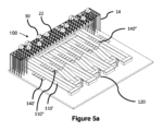
図5aは、本発明の第1の実施形態による物品取扱い、保管及び回収システム100の配列及び保管部分の斜視図である。保管システム100は、概して、図1ないし図4を参照して上述された既知のシステムと同様であり、複数の積み重ね12を形成するために互いの上に積み重ねられた複数の保管コンテナ又は集積貯蔵容器10を含む。積み重ね12は、フレーム構造14内に配置されている。
Figure 5a is a perspective view of an array and storage portion of an item handling, storage and
フレーム構造14は、Z方向に延び横架材18、20を支持している複数の直立部材16を有する。X方向に配置された第1のセットの平行な横架材18が、Y方向に配置された第2のセットの平行な横架材20(図5に図示せず)に直交するように配置されている。横架材18、20は、直立部材16に支持された複数の水平な格子構造を形成している。集積貯蔵容器10は、フレーム構造14の部材16、18、20間に積み重ねられる、これにより、フレーム構造14は、集積貯蔵容器10の積み重ね12の水平移動を防ぎ、集積貯蔵容器10の垂直移動をガイドする。
The
フレーム構造14の最上部は、積み重ね12の最上部にわたって格子パターンに配置されたレール22を含む。平行なレール22の第1のセット22aと平行なレール22の第2のセット22bは、フレーム構造14の最上部にわたって、それぞれ、X方向及びY方向における積荷取扱装置の移動をガイドするように設けられている。
The top of
図5aは、さらに、物品取扱い、保管及び回収システム100に隣接して位置する、本発明の第1の形態による配列及び保管部分を示している。配列及び保管部分は、保管システム100と、ユーザーが保管コンテナ10から配送コンテナDTに入れる物品を選び出すワークステーション120との間に配置された一連のコンベヤ110を有する。図5a及び図5bの実施形態では、保管コンテナ10は、ユーザーが保管コンテナ10から正しい配送コンテナDTに入れる必要な物品を直接選び出すことができるように、ワークステーションへの到着のために配列される。選び出される物品を含む保管コンテナ10は、コンベヤ110’上を移動し、顧客の注文を含む配送コンテナDTは、別個であるが隣接するコンベヤ110’’上を移動する。
FIG. 5a further shows an arrangement and storage portion according to the first aspect of the invention located adjacent to the item handling, storage and
選び出される物品を含む保管コンテナ10は、物品取扱い及び保管システム100に位置している。
A
使用時には、コンピューター制御ユーティリティの制御下で動作する積荷取扱装置30が、保管システム100内の積み重ね12からターゲットコンテナ10を選び出す。積荷取扱装置30は、コンテナ10を降下ポイント130に運ぶ。降下ポイント130は、(図4に示されるような)ポート24を含むことができ、あるいは、図5bに示されるようなコンベヤ110の上方のシュート手段を含むことができる。保管コンテナ10は、積荷取扱装置からコンベヤ110’の上へと下ろされる。保管コンテナ10が、ワークステーションにおいて直ちに選び出され配送コンテナDTに入れられる必要がある物品を含む場合、コンテナ10は、コンベヤ手段110によってワークステーション120に移送される。しかしながら、別の物品を含む保管コンテナ10が、今し方説明された保管コンテナ10より前にワークステーションにおいて必要とされる場合、転換手段(図示せず)が、いくつかの一時保管場所ポイント140’のうちの1つへと現在の保管コンテナ10を転換させるために、ターゲットコンテナに対して作動する。今し方説明されたターゲット保管コンテナ10がワークステーション120において必要であると制御ユーティリティが判断した場合、転換手段は、この保管コンテナを、一時保管場所140’から、ワークステーション120への搬送のために保管コンテナコンベヤ110’の上に戻すように移動させるために、逆のやり方で作動する。
In use, a
同様にして、配送コンテナDTが保管システム100からワークステーション120に移動されるとき、所定の配送コンテナDTの到着は、コンピューターユーティリティ(図示せず)の制御下で、保管コンテナ10に関して説明されたものと同様の方法で、配列されることができる。配送コンテナDTは、配送コンテナコンベヤ110’’に隣接する一時保管場所140’’に保管されることができ、適切な転換手段(図示せず)によってコンベヤ110’’から保管場所140’’へと転換されることができる。再び、保管コンテナ10を参照して説明されたのと同様の方法で、配送コンテナDTがワークステーションにおいて必要とされるとき、転換手段は、配送コンテナDTを、一時保管場所から、ワークステーション120への前進移動のために配送コンベヤ手段110’’へと移動させるように、コンピューターユーティリティの制御下で作動する。
Similarly, when a shipping container DT is moved from
図5a及び図5bに示されるように、配送コンテナコンベヤ110’’及び保管コンテナコンベヤ110’は、コンベヤのループを含み、これにより、保管コンテナ10及び配送コンテナDTは、保管システムから出発して、積荷取扱装置30及びコンベヤ手段110’、110’’を介して、ワークステーション120へ及び保管システム100に戻るように移動する。しかしながら、コンベヤ110’、110’’は、保管システムに戻すのではなく、代替位置からコンテナ10、DTを受け取り、代替位置にコンテナ10、DTを戻し得ることが認識される。
As shown in Figures 5a and 5b, the shipping container conveyor 110'' and the storage container conveyor 110' comprise conveyor loops whereby the
本実施形態は、配送コンテナコンベヤ110’’及び保管コンテナコンベヤ110’の両方が、それぞれ、複数の一時保管場所140’’及び140’を含むシステムについて説明していることが認識される。しかしながら、コンベヤ手段110’’、110’の両方が一時保管場所を含む必要はなく、コンベヤ手段110のうちのいずれか一方が一時保管場所140を含み得る。
It will be appreciated that this embodiment describes a system in which both shipping container conveyor 110'' and storage container conveyor 110' include multiple temporary storage locations 140'' and 140', respectively. However, both conveyor means 110 ″, 110 ′ need not include temporary storage locations, and either one of conveyor means 110 may include
本発明の第2の実施形態が、添付の概略的な図面の図6a、図6b及び図7を参照して説明される。 A second embodiment of the invention will now be described with reference to Figures 6a, 6b and 7 of the accompanying schematic drawings.
図6aは、本発明のさらなる形態による、配列及び保管部分145に隣接して位置する、保管システム100のフレームワーク14を示している。図6aに示されるように、フレーム150が、保管システム100とワークステーション120との間に位置している。フレーム150は、その上に保管コンテナ10が位置する軌道160を含む。図6a及び図6bにさらに示されるように、第2の実施形態のフレーム150は、その上にコンテナ配置位置155を有する軌道160を含む。
FIG. 6a shows
使用時には、保管システム100で動作可能な積荷取扱装置30は、ターゲットコンテナ10を捜し出し、積み重ね12からそのターゲットコンテナ10を持ち上げる。積荷取扱装置30は、配列及び保管部分145のフレーム150の上方の降下ポイント171にコンテナ10を搬送する。フレーム150の上方の所定位置にくると、積荷取扱装置は、フレーム150上の1つの位置に保管コンテナ10を下ろす。フレーム150は、保管システム100からの回転が速い品物又は頻繁に必要とされる品物を含むコンテナ10を保管するために使用されることができるいくつかの位置を含む。軌道160は、フレーム150を周回することができ、それによって、その上に位置するコンテナ10を移動させる。コンテナ10は、ストラット、車両又はシャトル170などの配置手段によって軌道上に配置される。フレーム150を周回するとき、軌道160及び関連する配置手段は、コンテナ10にフレーム150を周回させる。
In use, the
フレーム150は、出力ポイント148を含み、コンテナ10は、コンテナ10が出力ポイントに隣接しているときに、出力ポイントからワークステーション120へと出力されることができる。出力ポイントは、コンテナ10をフレーム150からワークステーション120に向かって移動させるための、前述されたような転換手段を含むことができる。出力されたコンテナ10は、コンベヤ手段のような任意の適切な手段によって、ワークステーション120に向かって移動されることができる。図6aは、矢印によって、ターゲットコンテナ10が取り得る、ワークステーションを通るルートを示している。
前の実施形態を参照して上述されたのと同様の方法で、コンテナ10は、コンテナ10がワークステーションで必要であることを制御ユーティリティが決定するまで、フレーム150内の一時保管場所にとどまる。この時点で、必要なターゲットコンテナが、フレーム150から、所望の物品が選び出されて配送コンテナDTに入れられるワークステーションへとコンテナ10を搬送する手段上に転換される。所望の物品が選び出されると、コンテナ10は、ワークステーション120で再び必要とされるまで、フレーム150に戻される。保管コンテナ10の中身が空にされると、保管コンテナ10は、フレーム150の、又はワークステーションのデカントステーション(decant station)(図示せず)で補充されることができる。
In a manner similar to that described above with reference to the previous embodiment,
図6a、図6b及び図7を参照して説明される実施形態では、フレーム150は、保管コンテナ10のみを取り扱う。図6a及び図6bに示されるように、配送コンテナDTは、保管システム100における降下ポイント171を介してワークステーション120に到着する。積荷取扱装置30は、上方からワークステーション120に配送コンテナDTを下ろす。しかしながら、配送コンテナDTは、任意の適切な手段によって、保管システム100からワークステーションに到着し得ることが認識される。さらに、保管コンテナ10を参照して説明されたような保管及び配列フレーム150が使用され得る。
In the embodiment described with reference to FIGS. 6a, 6b and 7, the
図7に示されるように、2つのつながったフレームを含む2つの配列及び保管部分が、単一のワークステーション120の間で共有されている。第2の実施形態のこの形態では、フレーム内の一時的な位置に保管された保管コンテナ10は、一方又は両方のワークステーション120によって必要とされる物品を含む。制御ユーティリティ(図示せず)が、フレームに位置する全てのコンテナ10の位置を監視し、コンテナ10は、関連するワークステーション120と関連付けられたフレーム出力ポートを介して適切なワークステーション120に移動される。複数の垂直ガイドプロファイルがここに説明されるシステムに設けられることが認識される。しかしながら、明瞭化のために、これらのガイドプロファイルは図示されない。図8a及び図8bは、保管システム100とワークステーション120との間に位置する保管及び配列部分145を含む、本発明の第3の実施形態を示している。
As shown in FIG. 7, two arrays and storage portions containing two contiguous frames are shared between
図8aに示されるように、保管及び配列部分145は、コンテナ10の積み重ね12が側方からアクセスされることを可能にする、フレームワーク14の修正された部分を含む。コンテナ移動装置170は、モーター付き支柱165上に位置し、これにより、装置170は、フレームワークの修正された部分において、任意のコンテナ10にアクセスすることができる。コンテナ移動装置170は、ターゲットコンテナ10より上にあるターゲットでないコンテナを完全に取り出す必要なく、積み重ね12からターゲットコンテナ10を取り出すように作動する。図8bに示されるように、コンテナ移動装置170は、ターゲットコンテナ10に隣接して位置付けられ、次いで、ターゲットコンテナ10のまわりに挿入され、これにより、ターゲットコンテナ10より上にあるターゲットでないコンテナが、ターゲットコンテナから持ち上げられるとともに、ターゲットコンテナより下にあるターゲットでないコンテナは、所定の位置に保持される。次いで、ターゲットコンテナ10は、コンテナ移動装置170上へと移動されて、積み重ね12から引き出される。引き出されると、ターゲットコンテナは、モーター付き支柱165を介してワークステーション120の降下ポイントに移動される。
As shown in FIG. 8a, storage and
コンテナ移動手段170が、ターゲットコンテナ10からターゲットでないコンテナを分離するための手段を含むことが認識される。さらに、コンテナ移動手段170は、積み重ねの外部にコンテナを移動させるためのコンベヤ手段172を含む。積み重ねからコンテナを分離することが可能な分離手段174と、コンテナを積み重ね12の外部に移動することが可能なコンベヤ手段との任意の適切な形態が使用され得ることが認識される。
It will be appreciated that container moving means 170 includes means for separating non-target containers from
モーター付き支柱165が、保管システム100とワークステーション120との間の保管システムのベースに隣接して位置する軌道上を移動可能であることが認識される。コンテナ移動装置170は、適切な駆動手段によって、モーター付き支柱165を上下に移動可能である。さらに、モーター付き支柱165は、適切な軌道手段によって保管システムの側面に沿って移動可能である。
It is recognized that
再び、この実施形態が保管コンテナ10を参照して説明されているが、本発明は、配送コンテナDTの移動に同様に適用可能である。
Again, although this embodiment is described with reference to a
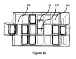
図9a、図9b、図9c及び図9dは、本発明の第4の実施形態を示しており、この実施形態では、保管システム100の配列及び保管部分145は、フレーム250を有し、フレームは、軌道260を有し、車両270がその上で駆動される。車両270は、一時保管場所240を有し、コンテナ10は、ワークステーション120に移動する前にそこに保管されることができる。フレーム250及び関連する軌道と車両は、コンピューター制御されたユーティリティが、コンテナが保管システム100から保管及び配列部分に到着する順番に関係なく、ワークステーション120へのコンテナ10の到着を配列する(順番に並べる)ことを可能にする。図9bに示されるように、追加の保管場所240’がフレームの上面に隣接して設けられ、保管場所240、240’は、回転が速い又は頻繁に必要とされるコンテナ10がワークステーション120の近くに配置されることを可能にして、そのようなコンテナが保管システム100から積荷取扱装置30によって持ち上げられなければならない回数を減らす。
Figures 9a, 9b, 9c and 9d show a fourth embodiment of the invention, in which the array and
本発明の前述の実施形態を参照して上述されたのと同様の方法で、フレーム250には、保管システム100上で動作可能な積荷取扱装置30によってフレーム250に運ばれたコンテナ10が載せられる。
In a manner similar to that described above with reference to previous embodiments of the invention, the
例えば、ワークステーション120で必要とされる物品を含むターゲットコンテナ10が、保管システム100に位置し、積荷取扱装置30によって、それが位置する積み重ね12から選び出される。積荷取扱装置30は、積荷取扱装置30の車両のボディの内部のコンテナ10を、保管システム100の降下ポイント24まで搬送する。
For example, a
コンテナ10は、積荷取扱装置30からフレーム250に隣接する保管場所に降ろされる。あるいは、積荷取扱装置30は、フレーム250の軌道260上の車両位置270によって定義された保管場所240’の1つにコンテナ10を直接降ろすことが可能である。
The
保管場所240又は270に降ろされたコンテナ10は、適切な転換手段によって位置間を移動可能である。
軌道260は、コンピューターユーティリティの制御下でフレーム250を周回する。コンテナ10は、必要に応じて軌道260上へ又は軌道260外へと移動される。フレーム250は、さらに、ワークステーション120に隣接して配置可能な部分を含む。コンテナ10は、車両270上でフレーム250を周回し、車両270は、軌道260上を移動する。フレーム及び軌道は、コンテナ10がワークステーション120に隣接するポイントで、コンテナ10内にある物品が、容易に手を伸ばして取ることができるようにして提示されるように、コンテナ10がワークステーションにおけるオペレーターに提示されるように、相互作用する。このようにして、オペレーターは必要とされる物品を取り出すことができる。図9a、図9b、図9c及び図9dに示されるように、フレーム250、軌道260及び車両270の構成は、安全上の理由から完全に覆われていることが認識される。コンテナ10がアクセス可能な唯一のポイントは、コンテナ10がワークステーション120に隣接しているポイントである。
この実施形態は、保管コンテナ10を参照して再び説明された。しかしながら、同様のシステムが、オンライン小売り環境によって注文された物品及び商品のフルフィルメントシステムの状況の中で、配送コンテナDTの保管及び配列のために使用されることができる。
This embodiment has been described again with reference to
上述の実施形態は、オンライン注文のシナリオに関連して、注文を履行するために回収及びピッキングするための品物を含む保管システムの観点から説明されていることが認識される。しかしながら、このような保管システムは、他の多くの用途での使用のために適合され得、ここで説明される特定の例に限定される必要はないことが認識される。 It will be appreciated that the above-described embodiments are described in terms of a storage system that includes items for collection and picking to fulfill orders in the context of an online ordering scenario . However, it is recognized that such storage systems may be adapted for use in many other applications and need not be limited to the specific examples described herein.
本発明の第5の実施形態では、配列及び保管部分は、保管システム100とワークステーション120との間に置かれている。図10、図11、図12及び図13に示されるような第5の実施形態では、保管及び配列フレーム350が示される。フレーム350は、シャトル370が装着されている軌道360を有する。本発明の第4の実施形態を参照して説明されたのと同様の方法で、コンテナ10は、積荷取扱装置30によって、保管システム100から配列及び保管フレーム350に運ばれる。フレーム350は、軌道360に隣接する固定保管場所340に複数のコンテナ10を保管し得るか、又はシャトル370と関連付けられた軌道360上に移動可能な保管場所にコンテナ10を保管し得る。コンテナ10は、適切な転換手段によって、固定保管場所340から軌道360上のシャトル370上へ、又はシャトル370から固定保管場所340に移動されることができる。
In a fifth embodiment of the invention, the array and storage portion is located between
コンテナ10は、第4の実施形態を参照して説明されたのと同様の方法で、ワークステーション120においてアクセスされ、すなわち、軌道360及びシャトル370は、使用時に、フレームを周回する軌道が、シャトルが各コンテナ10をワークステーションに隣接するポートに順番に提示するように配置されているように、構成されており、シャトル及び軌道は、コンテナ10が容易にアクセス可能なように提示されるように、ワークステーション120に隣接するポイントで相互作用する。
この実施形態は、保管コンテナ10を参照して再び説明された。しかしながら、同様のシステムが、オンライン小売り環境によって注文された物品及び商品のフルフィルメントシステムの状況の中で、配送コンテナDTの保管及び配列のために使用されることができる。
This embodiment has been described again with reference to
上述された全ての実施形態において、配列及び保管部分は、保管システムとワークステーションとの間に置かれている。上述された本発明の全ての実施形態の目的は、システム全体の効率を改良するように、主たる保管システムとワークステーションとの間の部分が作用することである。頻繁にアクセスされることが必要とされるコンテナ、またはワークステーションにおいて定期的に必要とされるコンテナをワークステーションの近くに保管するに際して、掘り出すことによって、又は単に積み重ねの最上部から持ち上げることによってのいずれかで、より少ないコンテナが、積荷取扱装置によるアクセスを必要とするようになる。これは、注文がワークステーションにおいて選び出されることができる速度を改良し、したがって、注文をピッキングするためのリードタイムを減少させる。これにより、システムは、納期により近い変更に対して、より応答性に優れたものになる。 In all the embodiments described above, the array and storage portion are placed between the storage system and the workstation. The purpose of all the embodiments of the invention described above is that the part between the main archiving system and the workstations acts to improve the efficiency of the overall system . By digging or simply from the top of the stack when storing containers that need to be accessed frequently, or that are needed regularly at the workstation, near the workstation. Either by lifting, fewer containers will require access by the load handling equipment. This improves the speed with which orders can be picked at the workstation, thus reducing the lead time for picking orders. This makes the system more responsive to changes closer to the due date.
保管システムとワークステーションとの間に置かれた、仕分けて配列するフレームを使用してこの目的を達成する多くのやり方があることが認識される。上述された実施形態は、単なる例示であって、ここに具体化される本発明の主要な概念を逸脱することなく、特定の実施形態の変形及び変更が想到されうる。本発明の上述の実施形態による特定の機構は、当業者は限定的なものであると解釈するべきではなく、上述の一般的な概念から逸脱することなく、種々の手法によって本発明の機構を達成することができる。 It will be appreciated that there are many ways to accomplish this goal using a sorting and arranging frame placed between the storage system and the workstation. The above-described embodiments are exemplary only, and variations and modifications of the particular embodiments may be envisaged without departing from the core concepts of the invention embodied herein. The specific features according to the above-described embodiments of the invention should not be construed as limiting by those skilled in the art, and without departing from the general concept described above, the features of the invention may be implemented in various ways. can be achieved.
保管及び配列部分が保管システムとワークステーションとの間に置かれていると説明されたが、それは、保管システム又はワークステーションのより近くに物理的に位置し得ることが認識される。さらに、保管及び配列部分は、保管システムの、又はワークステーションの物理的な部分を形成し得る。実際、保管及び配列部分は、保管システムをワークステーションに物理的に接続するために使用され得る。 Although the storage and alignment portion has been described as being located between the storage system and the workstation, it is recognized that it may be physically located closer to the storage system or workstation. Additionally, the storage and alignment portion may form a physical part of the storage system or of the workstation. In fact , the storage and alignment portion can be used to physically connect the storage system to the workstation.
さらに、システムの配列及び保管部分は、保管システムとワークステーションとの両方と物理的に分離され得ることが認識される。 Further, it is recognized that the array and storage portion of the system can be physically separated from both the storage system and the workstation.
さらに、格子の一部が、積荷取扱装置からのコンテナの降下を容易にするために、配列及び保管部分の上に延在し得ることが認識される。あるいは、積荷取扱装置は、保管システムと配列及び保管部分との間の中間位置にコンテナ10を降ろし得る。
Further, it is recognized that a portion of the grid may extend over the array and storage portion to facilitate lowering of the container from the load handling equipment. Alternatively, the load handling equipment may unload the
上述された全ての実施形態では、保管コンテナ及び配送コンテナが参照される。これらのコンテナは、同じ形態又は異なる形態を取ることができ、保管及び配列部分は、コンテナの代替構成のために、適宜サイズ決め及び適合され得ることが認識される。 In all the embodiments described above, reference is made to storage containers and shipping containers. It will be appreciated that these containers may take the same form or different forms, and that the storage and arrangement portions may be sized and adapted accordingly for alternate configurations of the containers .
さらに、フレームに、フレームワーク及び支柱についての全ての参照において、構造部材は、これに限定されないが、アルミニウム及び鋼などの金属、及び適切な構造プラスチック材料を含む任意の適切な材料から形成され得ることが認識される。 Further, in all references to frames, frameworks and struts, the structural members may be formed from any suitable material including, but not limited to, metals such as aluminum and steel, and suitable structural plastic materials. is recognized.
さらに、上述のような保管及び配列部分は、記述された保管システムと全てのワークステーションとの間に、あるいは、ワークステーションの一部と記述されるような保管システムとの間にのみ配置され得ることが認識される。 Further, the storage and sequencing portion as described above can be located between the described storage system and all workstations, or only between the described storage system as part of the workstation. is recognized.
上述の実施形態は、食料品店のオンライン注文のシナリオに関連して、注文を履行するために回収及びピッキングするための品物を含む保管システムの観点から記述されていることが認識される。しかしながら、このような保管システムは、他の多くの用途での使用のために適合され得、ここで説明される特定の例に限定される必要はないことが認識される。例えば、このような保管システムは、郵便物(送付物)取扱いシステムでの小包仕分けに使用されることができる。 It will be appreciated that the above-described embodiments are described in terms of a storage system that includes items for collection and picking to fulfill orders in the context of a grocery store online ordering scenario . However, it is recognized that such storage systems may be adapted for use in many other applications and need not be limited to the specific examples described herein . For example, such a storage system can be used for parcel sorting in a mail (sending) handling system.
説明された特定の実施形態は、ボディ内に位置するキャビティを有する積荷取扱装置を含むシステムであって、キャビティがコンテナを運ぶための手段を含むシステムに関するものであるが、積荷取扱装置の他の形態が想到されることができる。例えば、コンテナを持ち上げるためのカンチレバー部分及びウィンチ手段を有する積荷取扱装置が、上述の積荷取扱装置と置き換えられ得る。 Although the particular embodiment described relates to a system including a load handling device having a cavity located within a body, the cavity including means for conveying a container, other Forms can be envisioned. For example, a cargo handling device having a cantilevered portion and winch means for lifting containers may be substituted for the cargo handling device described above.
保管システムは、上述の積荷取扱装置のさまざまな組み合わせ及び配置を使用して、特定の用途のために設計されることができることが認識される。さらに、添付の特許請求の範囲に規定されるような本発明の範囲から逸脱することなく、上には明示的には記述されない多くの変形及び修正が可能である。
以下に本願の出願当初の特許請求の範囲に記載された発明を付記する。
[C1] 保管システムと、複数の積荷取扱装置と、降下ポイントと、ワークステーションとを具備する、物品取扱い及び回収システムであって、
前記保管システムは、ワークスペースの上方に格子を形成する2つのセットの実質的に直交するレールを有し、前記ワークスペースは、複数の積み重ねられたコンテナを含み、前記ロボット積荷取扱装置は、前記ワークスペースの上方の前記格子上で動作し、前記積荷取扱装置は、複数の車輪に取り付けられたボディを有し、第1のセットの車輪が、第1のセットのレールのうちの少なくとも2本のレールと係合するように配置され、第2のセットの車輪が、第2のセットのレールのうちの少なくとも2本のレールと係合するように配置され、動作時に1つのセットの車輪のみがどの時点においても前記格子と係合され、それによって、前記レールと係合した前記1つのセットの車輪のみを駆動させることにより、コンテナの任意の積み重ねの上方の前記格子上の任意の点への、前記レールに沿った前記積荷取扱装置の移動を可能にするように、前記第1のセットの車輪は、前記第2のセットの車輪に対して独立して移動可能かつ駆動可能であり、
ここにおいて、少なくとも1つの降下ポイントが、配列部分と係合するように構成され、前記配列部分は、積荷取扱装置によって前記少なくとも1つの降下ポイントに運ばれたコンテナを受け取り、前記運ばれたコンテナを所定の順番で前記ワークステーションに移動させるように構成されており、
前記配列部分は、前記保管システムに隣接して位置するフレームを有し、前記フレームには、複数のコンテナ保管場所が設けられ、前記配列部分には、さらに、所定の順番で、コンテナを前記コンテナ保管場所から前記ワークステーションに移動させるための移動手段が設けられ、前記所定の順番は、前記コンテナが前記降下ポイントに到着した順番とは無関係であり、これにより、前記コンテナ内に位置する物品が前記ワークステーションにおいてアクセスされることができる、物品取扱いシステム。
[C2] 前記少なくとも1つの降下ポイント又は各降下ポイントは、配列部分と係合するように構成されている、C1に記載の物品取扱いシステム。
[C3] 前記移動手段は、前記フレーム内に移動可能に位置する複数の車両を含み、前記車両は、前記フレームを周回してコンテナを運ぶ、C1又は2に記載の物品取扱いシステム。
[C4] 前記移動手段は、前記フレーム内の補助軌道上に位置する一連のシャトルを含み、各シャトルは、前記フレームを周回してコンテナを運ぶように構成されている、C1乃至3のいずれか1項に記載の物品取扱いシステム。
[C5] 前記フレームは、ワークステーションに隣接しているアクセスポートを有し、
前記コンテナは、前記移動手段上で前記フレームを周回し、
各コンテナは、前記コンテナが前記ワークステーションにおけるアクセスポートに隣接しているときに、そのコンテナが位置している前記移動手段上にありながらアクセス可能である、C1乃至4のいずれか1項に記載の物品取扱いシステム。
[C6] 前記保管及び配列部分は、さらに、転換手段を有し、
前記転換手段は、コンテナを、前記移動手段から前記保管場所へ、及び、前記保管場所から前記移動手段へと転換させるように構成されている、C1乃至5のいずれか1項に記載の物品取扱いシステム。
[C7] 前記転換手段は、押し引き手段を含む、C6に記載の物品取扱いシステム。
[C8] 前記移動手段は、前記フレームに隣接して位置する少なくとも1つのピッキング手段を含み、前記ピッキング手段は、前記フレームから所定のコンテナを選択し、前記コンテナを前記ワークステーションに搬送するように構成されている、C1又は2に記載の物品取扱いシステム。
[C9] 前記ピッキング手段は、前記フレーム内に位置するコンテナの積み重ねの内部から所定のコンテナを取り出すための取り出し手段を含む、C8に記載の物品取扱いシステム。
[C10] 前記ピッキング手段は、さらに、前記フレーム内に位置するコンテナの積み重ねにおける前記所定のコンテナを置き換えるための置き換え手段を含む、C8又は9に記載の物品取扱いシステム。
[C11] 前記所定のコンテナの前記選択は、ワークステーションにおけるコンテナの到着を正しく配列するように作動するユーティリティによって制御される、C1乃至10のいずれか1項に記載の物品取扱いシステム。
[C12] 前記システムは、コンテナを選択するように構成された選択手段をさらに具備し、これにより、任意のコンテナが、ワークステーションへの移動のために選択されることができ、
前記選択手段は、前記システム内の全てのコンテナの位置を制御及び監視するための制御ユーティリティを含む、C1乃至11のいずれか1項に記載の物品取扱いシステム。
[C13] コンテナ保管システムからコンテナを回収し、前記コンテナをワークステーションに搬送する方法であって、
(a)ターゲットコンテナを識別するステップと、
(b)積荷取扱装置を使用して前記保管システムから前記ターゲットコンテナを回収するステップと、
(c)前記積荷取扱装置を使用して降下ポイントに前記コンテナを搬送するステップであって、前記降下ポイントは、配列部分と関連付けられ、前記配列部分は、移動手段を含む、搬送するステップと、
(d)前記移動手段を使用して前記ワークステーションに隣接している位置への移動のために前記ターゲットコンテナを配列するステップであって、前記コンテナは、所定の順番で、ワークステーションと関連付けられたコンテナアクセスポイントに到着し、前記所定の順番は、前記コンテナが前記配列部分に到着した順番とは無関係である、配列するステップと、を含む、方法。
[C14](e)前記保管システムの前記配列部分と関連付けられた、前記移動手段にアクセス可能な保管場所に前記ターゲットコンテナを配置するさらなるステップを含む、C13に記載のコンテナを回収する方法。
[C15] 前記保管システムの各ターゲットコンテナの位置を監視する制御手段を使用して、前記コンテナの前記配列を制御するさらなるステップを含む、C13又は14に記載の方法。
It is recognized that storage systems can be designed for specific applications using various combinations and arrangements of the load handling equipment described above. Moreover, many variations and modifications not expressly described above are possible without departing from the scope of the invention as defined in the appended claims.
The invention described in the scope of claims at the time of filing of the present application will be additionally described below.
[C1] An item handling and recovery system comprising a storage system, a plurality of load handling devices, a drop point and a workstation, comprising:
The storage system has two sets of substantially orthogonal rails forming a grid above a workspace, the workspace including a plurality of stacked containers, the robotic load handling device comprising: Operating on the grate above the workspace, the load handling device has a body mounted on a plurality of wheels, a first set of wheels on at least two of the first set of rails. and a second set of wheels arranged to engage at least two of the rails of the second set, and only one set of wheels in operation is engaged with the grid at any one time, thereby driving only one set of wheels engaged with the rails to any point on the grid above any stack of containers. wherein said first set of wheels are independently movable and drivable relative to said second set of wheels so as to enable movement of said load handling device along said rails of
wherein at least one lowering point is configured to engage an array portion, said array portion receiving a container conveyed to said at least one lowering point by a load handling device and transporting said conveyed container to said at least one lowering point; configured to be moved to the workstation in a predetermined order,
The array portion includes a frame positioned adjacent to the storage system, the frame provided with a plurality of container storage locations, the array portion further including the containers in a predetermined order. Moving means are provided for moving from storage to said workstation, said predetermined order being independent of the order in which said container arrived at said drop point, whereby items located within said container were An item handling system that can be accessed at the workstation.
[C2] The article handling system of C1, wherein the at least one or each drop point is configured to engage an array portion.
[C3] The article handling system according to C1 or 2, wherein the moving means includes a plurality of vehicles movably positioned within the frame, the vehicles transporting containers around the frame.
[C4] Any of C1-3, wherein the moving means includes a series of shuttles positioned on auxiliary tracks within the frame, each shuttle configured to orbit the frame to carry a container. Item handling system according to
[C5] the frame has an access port adjacent to a workstation;
said container circling said frame on said moving means;
5. The method of any one of C1-4, wherein each container is accessible while on the vehicle on which it is located when the container is adjacent to an access port at the workstation. material handling system.
[C6] the storage and arrangement portion further comprises conversion means;
6. The handling of any one of C1-5, wherein said conversion means is configured to convert containers from said transfer means to said storage location and from said storage location to said transfer means. system.
[C7] The item handling system of C6, wherein the diverting means includes push/pull means.
[C8] said moving means includes at least one picking means positioned adjacent said frame, said picking means for selecting a predetermined container from said frame and transporting said container to said workstation; The item handling system of C1 or 2, configured.
[C9] The item handling system of C8, wherein the picking means includes retrieval means for retrieving a given container from within a stack of containers located within the frame.
[C10] The material handling system of C8 or 9, wherein the picking means further includes replacement means for replacing the given container in the stack of containers located within the frame.
C11. The material handling system of any one of C1-10, wherein said selection of said predetermined container is controlled by a utility operative to properly sequence arrival of containers at a workstation.
[C12] The system further comprises selection means configured to select a container, whereby any container can be selected for transfer to the workstation;
12. The material handling system of any one of Claims C1-11, wherein the selection means includes a control utility for controlling and monitoring the position of all containers within the system.
[C13] A method of retrieving a container from a container storage system and transporting the container to a workstation, comprising:
(a) identifying a target container;
(b) retrieving the target container from the storage system using a load handling device;
(c) conveying said container to a drop point using said load handling equipment, said drop point being associated with an array portion, said array portion including a moving means;
(d) arranging said target container for movement to a position adjacent said workstation using said movement means, said container being associated with said workstation in a predetermined order; and arranging, wherein the predetermined order is independent of the order in which the containers arrived at the arranging portion.
[C14] (e) The method of retrieving a container of C13, including the further step of placing the target container in a storage location accessible to the mobile means associated with the array portion of the storage system.
[C15] The method of C13 or 14, comprising the further step of controlling said arrangement of said containers using control means for monitoring the position of each target container of said storage system.
Claims (12)
前記コンテナ保管システムは、ワークスペースの上方に格子を形成する2つのセットの実質的に直交する複数のレールを有し、前記ワークスペースは、複数の積み重ねられたコンテナを含み、前記ロボット積荷取扱装置は、前記ワークスペースの上方の前記格子上で動作し、前記ロボット積荷取扱装置は、複数の車輪に取り付けられたボディを有し、第1のセットの車輪が、第1のセットのレールのうちの少なくとも2本のレールと係合するように配置され、第2のセットの車輪が、第2のセットのレールのうちの少なくとも2本のレールと係合するように配置され、動作時に1つのセットの車輪のみがどの時点においても前記格子と係合され、それによって、前記レールと係合した前記1つのセットの車輪のみを駆動させることにより、コンテナの任意の積み重ねの上方の前記格子上の任意の点への、前記レールに沿った前記ロボット積荷取扱装置の移動を可能にするように、前記第1のセットの車輪は、前記第2のセットの車輪に対して独立して移動可能かつ駆動可能であり、
ここで、少なくとも1つの降下ポイントが、保管及び配列部分と係合するように構成され、前記保管及び配列部分が、積荷取扱装置によって前記少なくとも1つの降下ポイントに運ばれたコンテナを受け取り、前記運ばれたコンテナを所定の順番で前記ワークステーションに移動させるように構成されており、
前記保管及び配列部分は、前記コンテナ保管システムに隣接して位置するフレームを有し、前記フレームには、複数のコンテナ保管場所が設けられ、前記保管及び配列部分には、さらに、所定の順番で、コンテナを前記コンテナ保管場所から前記ワークステーションに移動させるための移動手段が設けられ、前記所定の順番は、前記コンテナが前記降下ポイントに到着した順番とは無関係であり、これにより、前記コンテナ内に位置する物品が前記ワークステーションにおいてアクセスされることができる、物品取扱い及び回収システム。 A goods handling and collection system comprising a container storage system, a plurality of robotic load handling devices, a drop point for containers exiting a workspace, and a workstation, comprising:
The container storage system has two sets of substantially orthogonal rails forming a grid above a workspace, the workspace including a plurality of stacked containers, and the robotic load handling device. operates on said grid above said workspace, said robotic load handling device having a body mounted on a plurality of wheels, a first set of wheels being aligned with a first set of rails; a second set of wheels arranged to engage at least two rails of the second set of rails, and a second set of wheels arranged to engage at least two of the rails of the second set of Only a set of wheels are engaged with the grate at any one time, thereby driving only the one set of wheels engaged with the rails on the grate above any stack of containers. said first set of wheels being independently movable with respect to said second set of wheels to allow movement of said robotic load handling device along said rails to any point; is drivable,
wherein at least one lowering point is configured to engage a storage and arranging portion, said storing and arranging portion receiving a container conveyed to said at least one lowering point by a load handling device; configured to move the extracted containers to the workstation in a predetermined order;
The storage and arrangement portion includes a frame positioned adjacent to the container storage system, the frame provided with a plurality of container storage locations, the storage and arrangement portion further comprising: means are provided for moving containers from said container storage location to said workstation, said predetermined order being independent of the order in which said containers arrived at said drop point, whereby An item handling and collection system, wherein items located in the workstation can be accessed at the workstation.
前記コンテナは、前記移動手段上で前記フレームを周回し、
各コンテナは、前記コンテナが前記ワークステーションにおけるアクセスポートに隣接しているときに、そのコンテナが位置している前記移動手段上にありながらアクセス可能である、請求項1乃至4のいずれか1項に記載の物品取扱い及び回収システム。 the frame has an access port adjacent to a workstation;
said container circling said frame on said moving means;
5. Each container is accessible while on the mobile means on which it is located when the container is adjacent to an access port at the workstation. The material handling and recovery system described in .
前記転換手段は、コンテナを、前記移動手段から前記コンテナ保管場所へ、及び、前記コンテナ保管場所から前記移動手段へと転換させるように構成されている、請求項1乃至5のいずれか1項に記載の物品取扱い及び回収システム。 the storage and arrangement portion further comprises conversion means;
6. A container according to any one of the preceding claims, wherein said conversion means is arranged to convert containers from said transfer means to said container storage location and from said container storage location to said transfer means. Item handling and recovery system as described.
前記選択手段は、システム内の全てのコンテナの位置を制御及び監視するための制御ユーティリティを含む、請求項1乃至11のいずれか1項に記載の物品取扱い及び回収システム。 The material handling and collection system further comprises selection means configured to select a container, whereby any container can be selected for transfer to the workstation;
12. A material handling and collection system according to any preceding claim, wherein the selection means includes a control utility for controlling and monitoring the position of all containers within the system.
Priority Applications (2)
| Application Number | Priority Date | Filing Date | Title |
|---|---|---|---|
| JP2021092842A JP7225310B2 (en) | 2015-06-08 | 2021-06-02 | Goods storage, handling and recovery systems and methods |
| JP2022195419A JP2023029980A (en) | 2015-06-08 | 2022-12-07 | Article storage, handling, and recovery system and method |
Applications Claiming Priority (3)
| Application Number | Priority Date | Filing Date | Title |
|---|---|---|---|
| GBGB1509921.1A GB201509921D0 (en) | 2015-06-08 | 2015-06-08 | Object storage, handling and retrieving system and method |
| GB1509921.1 | 2015-06-08 | ||
| PCT/EP2016/063059 WO2016198467A1 (en) | 2015-06-08 | 2016-06-08 | Object storage, handling, and retrieving system and method |
Related Child Applications (2)
| Application Number | Title | Priority Date | Filing Date |
|---|---|---|---|
| JP2021092842A Division JP7225310B2 (en) | 2015-06-08 | 2021-06-02 | Goods storage, handling and recovery systems and methods |
| JP2022195419A Division JP2023029980A (en) | 2015-06-08 | 2022-12-07 | Article storage, handling, and recovery system and method |
Publications (3)
| Publication Number | Publication Date |
|---|---|
| JP2018520965A JP2018520965A (en) | 2018-08-02 |
| JP2018520965A5 JP2018520965A5 (en) | 2020-12-10 |
| JP7242184B2 true JP7242184B2 (en) | 2023-03-20 |
Family
ID=53785128
Family Applications (3)
| Application Number | Title | Priority Date | Filing Date |
|---|---|---|---|
| JP2017564111A Active JP7242184B2 (en) | 2015-06-08 | 2016-06-08 | Goods storage, handling and recovery systems and methods |
| JP2021092842A Active JP7225310B2 (en) | 2015-06-08 | 2021-06-02 | Goods storage, handling and recovery systems and methods |
| JP2022195419A Withdrawn JP2023029980A (en) | 2015-06-08 | 2022-12-07 | Article storage, handling, and recovery system and method |
Family Applications After (2)
| Application Number | Title | Priority Date | Filing Date |
|---|---|---|---|
| JP2021092842A Active JP7225310B2 (en) | 2015-06-08 | 2021-06-02 | Goods storage, handling and recovery systems and methods |
| JP2022195419A Withdrawn JP2023029980A (en) | 2015-06-08 | 2022-12-07 | Article storage, handling, and recovery system and method |
Country Status (8)
| Country | Link |
|---|---|
| US (2) | US10822166B2 (en) |
| EP (1) | EP3303185A1 (en) |
| JP (3) | JP7242184B2 (en) |
| KR (3) | KR102417722B1 (en) |
| CN (3) | CN112722659A (en) |
| CA (2) | CA3187021A1 (en) |
| GB (2) | GB201509921D0 (en) |
| WO (1) | WO2016198467A1 (en) |
Families Citing this family (95)
| Publication number | Priority date | Publication date | Assignee | Title |
|---|---|---|---|---|
| GB201509921D0 (en) | 2015-06-08 | 2015-07-22 | Ocado Innovation Ltd | Object storage, handling and retrieving system and method |
| ES2905931T3 (en) | 2015-04-27 | 2022-04-12 | Attabotics Inc | Storage and retrieval system |
| GB201603520D0 (en) * | 2016-02-29 | 2016-04-13 | Ocado Innovation Ltd | Robotic service device and handling method |
| NO343300B1 (en) | 2017-03-10 | 2019-01-21 | Autostore Tech As | Automated storage and retrieval system and method of operating the same |
| NO343848B1 (en) | 2017-06-23 | 2019-06-24 | Autostore Tech As | Automated Storage and Retrieval System Comprising a Container Handling Station |
| NO344236B1 (en) | 2017-06-29 | 2019-10-14 | Autostore Tech As | Automated storage and retrieval system comprising different temperature zones and method for moving a container between temperature zones |
| NO343676B1 (en) * | 2017-09-20 | 2019-05-06 | Autostore Tech As | Container handling vehicle |
| GB201716204D0 (en) * | 2017-10-04 | 2017-11-15 | Ocado Innovation Ltd | Transporting vessel, object handling system and method of relocating a transporting vessel |
| GB201716201D0 (en) | 2017-10-04 | 2017-11-15 | Ocado Innovation Ltd | Object handling coordination system and method of relocating a transporting vessel |
| NO344464B1 (en) | 2017-10-19 | 2019-12-23 | Autostore Tech As | Vehicle for an automated storage and retrieval system and method of operating an automated storage and retrieval system |
| NO346519B1 (en) * | 2017-11-02 | 2022-09-19 | Autostore Tech As | An automated storage and retrieval system, use of a multi trolley vehicle on the system and a method of operating the system |
| NO344517B1 (en) | 2017-11-22 | 2020-01-20 | Autostore Tech As | Storage grid column |
| CN109978423B (en) | 2017-12-28 | 2021-05-25 | 北京京东尚科信息技术有限公司 | Inventory scheduling method, inventory scheduling device and computer-readable storage medium |
| WO2019137866A1 (en) | 2018-01-09 | 2019-07-18 | Autostore Technology AS | A displacement mechanism for a remotely operated vehicle |
| NO20180031A1 (en) | 2018-01-09 | 2019-07-10 | Autostore Tech As | Automated storage and retrieval system, a container handling vehicle which can operate on an automated storage and retrieval system and a method of operating an automated storage and retrieval system |
| NO346347B1 (en) * | 2018-04-25 | 2022-06-20 | Autostore Tech As | Container handling vehicle comprising first and second section and assembly of motors in second section, and system |
| NO346364B1 (en) * | 2018-04-25 | 2022-06-27 | Autostore Tech As | Container handling vehicle with first and second sections and battery in second section, and system. |
| NO344662B1 (en) * | 2018-06-12 | 2020-03-02 | Autostore Tech As | An automated storage and retrieval system and a method of transporting storage containers between an automated storage and retrieval grid and a second location |
| CN111727159B (en) | 2018-01-09 | 2022-04-22 | 自动存储科技股份有限公司 | Displacement mechanism for remotely controlled vehicle |
| NO20181098A1 (en) * | 2018-06-12 | 2019-12-13 | Autostore Tech As | A method of operating an automated storage and retrieval system |
| GB201800961D0 (en) * | 2018-01-22 | 2018-03-07 | Ocado Innovation Ltd | System and method for order picking |
| CN110271827A (en) * | 2018-03-13 | 2019-09-24 | 深圳市三维通机器人系统有限公司 | Track intelligent sorting system |
| NO20180409A1 (en) | 2018-03-23 | 2019-09-24 | Autostore Tech As | Automated storage and retrieval system comprising container identification means and methods of identyfying a container or a vehicle |
| GB201805917D0 (en) | 2018-04-10 | 2018-05-23 | Ocado Innovation Ltd | System and method for picking items |
| NO344302B1 (en) * | 2018-04-25 | 2019-10-28 | Autostore Tech As | Automated storage and retrieval system comprising a relay module and a method of operating such a system |
| CN108584263B (en) * | 2018-05-03 | 2020-12-04 | 华中科技大学无锡研究院 | Layered unidirectional interaction storage device and system |
| NO345231B1 (en) | 2018-05-31 | 2020-11-16 | Autostore Tech As | An automated storage and retrieval system comprising a storage container lift Assembly and a method thereof. |
| CA3102631C (en) | 2018-06-08 | 2023-12-19 | Attabotics Inc. | Storage and retrieval systems sharing a common robotic fleet between a storage grid and external workstations |
| US10913641B2 (en) | 2018-06-08 | 2021-02-09 | Attabotics Inc. | Storage units and robotic storage/retrieval vehicles for a three-dimensional storage system |
| EP3807187B1 (en) | 2018-06-12 | 2023-11-15 | Autostore Technology AS | Storage system |
| NO344619B1 (en) * | 2018-06-12 | 2020-02-10 | Autostore Tech As | Storage system |
| CN112262086B (en) | 2018-06-12 | 2022-10-21 | 自动存储科技股份有限公司 | Automated storage and retrieval system and method of transporting storage containers between an automated storage and retrieval grid and a second location |
| US11498757B2 (en) | 2018-06-12 | 2022-11-15 | Autostore Technology AS | Storage system |
| US11572231B2 (en) | 2018-06-12 | 2023-02-07 | Autostore Technology AS | Storage system with modular container handling vehicles |
| CA3099878A1 (en) | 2018-06-12 | 2019-12-19 | Autostore Technology AS | A delivery vehicle, an automated storage and retrieval system and a method of transporting storage containers between an automated storage and retrieval grid and a second location |
| CA3099086A1 (en) | 2018-06-12 | 2019-12-19 | Autostore Technology AS | System and applicable methods of collecting items from storage containers using robotic operator |
| WO2019238703A1 (en) | 2018-06-12 | 2019-12-19 | Autostore Technology AS | Storage system with modular container handling vehicles |
| CN115123719A (en) | 2018-06-12 | 2022-09-30 | 自动存储科技股份有限公司 | Automatic access system |
| NO344750B1 (en) | 2018-06-12 | 2020-04-06 | Autostore Tech As | Unloading arrangement and unloading station, as well as method of unloading an item from a storage container |
| WO2019238639A1 (en) | 2018-06-12 | 2019-12-19 | Autostore Technology AS | System for storing and transporting storage containers |
| JP7407745B2 (en) | 2018-06-12 | 2024-01-04 | アウトストア・テクノロジー・エーエス | Unloading structures and unloading stations and methods for unloading items from storage containers. |
| NO345886B1 (en) | 2018-06-12 | 2021-09-27 | Autostore Tech As | Vehicle tilting Device and Method of accessing a Storage container |
| CN115009752A (en) * | 2018-06-12 | 2022-09-06 | 自动存储科技股份有限公司 | Container access station with lifting device |
| WO2019238664A1 (en) | 2018-06-12 | 2019-12-19 | Autostore Technology AS | A delivery system with an access point and a method of accessing an access point of the delivery system |
| EP3807182A1 (en) * | 2018-06-12 | 2021-04-21 | Autostore Technology As | A delivery system with an access point and a method of accessing an access point of the delivery system |
| EP3807181B1 (en) | 2018-06-12 | 2023-11-15 | Autostore Technology As | Method for handling malfunctioning vehicles on a rail system and a storage and retrieval system using such a method |
| WO2019238697A1 (en) | 2018-06-12 | 2019-12-19 | Autostore Technology AS | Automated storage system |
| CA3100103A1 (en) | 2018-06-12 | 2019-12-19 | Autostore Technology AS | Storage grid with container accessing station with locking device to lock remotely operated vehicle |
| EP3807175A1 (en) | 2018-06-12 | 2021-04-21 | Autostore Technology As | System for storing and transporting storage containers |
| WO2019238659A2 (en) | 2018-06-12 | 2019-12-19 | Autostore Technology AS | Express bin lift for automated storagage system |
| WO2019238642A1 (en) | 2018-06-12 | 2019-12-19 | Autostore Technology AS | Unloading arrangement and unloading station, as well as method of unloading an item from a storage container |
| CN115108226A (en) * | 2018-06-12 | 2022-09-27 | 自动存储科技股份有限公司 | Method and system for controlling operation of a container handling vehicle and a remotely operated dedicated container handling vehicle and computer program |
| WO2019238670A1 (en) | 2018-06-12 | 2019-12-19 | Autostore Technology AS | A method of operating an automated storage and retrieval system |
| GB201810128D0 (en) * | 2018-06-20 | 2018-08-08 | Ocado Innovation Ltd | System and method of order fulfilment |
| DE102018214214A1 (en) * | 2018-08-22 | 2020-02-27 | Gebhardt Fördertechnik GmbH | Storage system for storing containers |
| NO345994B1 (en) * | 2018-10-09 | 2021-12-13 | Autostore Tech As | Expansion joint, system and method for connecting regions of a rail-based grid storage system |
| NO344944B1 (en) * | 2018-10-12 | 2020-07-27 | Autostore Tech As | An access station for picking storage containers |
| NO344971B1 (en) | 2018-11-06 | 2020-08-03 | Autostore Tech As | Robot vehicle assembly with picking system |
| DE102018218906A1 (en) * | 2018-11-06 | 2020-05-07 | Gebhardt Fördertechnik GmbH | Storage system for storing containers |
| NO20181419A1 (en) | 2018-11-06 | 2020-05-07 | Autostore Tech As | Container handling vehicle with an open top, and method of handling product items into storage container carried by the vehicle |
| NO344852B1 (en) | 2018-11-06 | 2020-06-02 | Autostore Tech As | Robot vehicle with picking system |
| CN116588559A (en) | 2018-11-28 | 2023-08-15 | 自动存储科技股份有限公司 | Storage container for an automated storage and retrieval system |
| DE102019204600B3 (en) * | 2019-04-01 | 2020-07-16 | Trumpf Sachsen Gmbh | System for storing and / or for picking products to be processed and / or processed products of a mechanical workpiece processing and machine arrangement for workpiece processing with such a system |
| NO345730B1 (en) | 2019-04-02 | 2021-07-05 | Autostore Tech As | Storage system, container lift vehicle for storage system and method of transferring a storage container in storage system |
| NO20190546A1 (en) | 2019-04-25 | 2020-10-26 | Autostore Tech As | An automated storage and retrieval system with fire detection device and methods of locating and/or verifying fire or smoke in an automated storage and retrieval system |
| NO20190710A1 (en) * | 2019-06-11 | 2020-04-08 | Autostore Tech As | Storage system |
| CN110255029A (en) * | 2019-06-25 | 2019-09-20 | 上海快仓智能科技有限公司 | Storage and the sorting system with it and method for sorting, device |
| CN110329696B (en) * | 2019-07-15 | 2021-06-22 | 南京翌星自动化系统有限公司 | Handling equipment |
| NO346306B1 (en) * | 2019-08-22 | 2022-05-30 | Autostore Tech As | A delivery system, an automated storage and retrieval system and a method of transporting a container |
| NO347754B1 (en) | 2019-09-02 | 2024-03-18 | Autostore Tech As | Method, and associated system, of providing an operator access to a target storage position in an automated storage and retrieval system |
| NO345647B1 (en) * | 2019-09-25 | 2021-05-25 | Autostore Tech As | Gas isolated storage system |
| NO345671B1 (en) * | 2019-09-25 | 2021-06-07 | Autostore Tech As | Gas isolated storage system |
| NO345828B1 (en) * | 2020-02-18 | 2021-08-30 | Autostore Tech As | Conveyor system and method of using same |
| US11251064B2 (en) * | 2020-03-02 | 2022-02-15 | Taiwan Semiconductor Manufacturing Co., Ltd. | Wafer frame sorter and stocker |
| GB202003047D0 (en) * | 2020-03-03 | 2020-04-15 | Ocado Innovation Ltd | A grid framework structure |
| US20230145325A1 (en) * | 2020-03-31 | 2023-05-11 | Autostore Technology AS | Automated storage tower with multiple rows |
| US20230127239A1 (en) * | 2020-03-31 | 2023-04-27 | Autostore Technology AS | Automated storage system having a storage tower in isolating housing |
| NO346363B1 (en) * | 2020-04-16 | 2022-06-27 | Autostore Tech As | Container handling vehicle comprising a container carrying position, associated system and methods |
| GB202008129D0 (en) * | 2020-05-29 | 2020-07-15 | Ocado Innovation Ltd | Multi-function inventory handling station assembly |
| CN111674816B (en) * | 2020-07-08 | 2021-06-29 | 深圳市鲸仓科技有限公司 | Multilayer warehousing system |
| NO20200927A1 (en) * | 2020-08-26 | 2022-02-28 | Autostore Tech As | Routing of container handling vehicles operating an automated storage system |
| GB202015589D0 (en) * | 2020-10-01 | 2020-11-18 | Ocado Innovation Ltd | Container storage and retrieval system |
| NO346367B1 (en) * | 2020-11-17 | 2022-06-27 | Autostore Tech As | Method, system and computer program product of controlling movement of container handling vehicles |
| CN112978169B (en) * | 2021-01-25 | 2022-08-05 | 太原科技大学 | Bar finishing line material handling robot system |
| US11639266B2 (en) * | 2021-03-10 | 2023-05-02 | Intelligrated Headquarters, Llc | Goods to operator workstation |
| GB202105316D0 (en) * | 2021-04-14 | 2021-05-26 | Ocado Innovation Ltd | An automated load handling system |
| CN113148519B (en) * | 2021-05-10 | 2022-10-14 | 深圳市海柔创新科技有限公司 | Robot control method, device, equipment, system and storage medium |
| CN215247320U (en) * | 2021-05-10 | 2021-12-21 | 深圳市海柔创新科技有限公司 | Warehousing system |
| GB202107894D0 (en) * | 2021-06-02 | 2021-07-14 | Ocado Innovation Ltd | A storage and retrieval system |
| GB202107884D0 (en) * | 2021-06-02 | 2021-07-14 | Ocado Innovation Ltd | A grid framework structure |
| CN113320872B (en) * | 2021-06-08 | 2022-12-06 | 深圳市海柔创新科技有限公司 | Article processing method, device, equipment, system and storage medium |
| KR20240016417A (en) * | 2021-10-26 | 2024-02-06 | 베이징 긱플러스 테크놀러지 씨오., 엘티디. | Warehouse storage systems and methods |
| NO347254B1 (en) * | 2022-01-11 | 2023-08-14 | Autostore Tech As | Storage system |
| DE102022201937A1 (en) | 2022-02-24 | 2023-08-24 | Gebhardt Fördertechnik GmbH | Storage and retrieval system and method for operating a storage and retrieval system |
| WO2024068359A1 (en) * | 2022-09-29 | 2024-04-04 | Autostore Technology AS | A buffer system for temporarily storing containers in an automated storage and retrieval system |
Citations (3)
| Publication number | Priority date | Publication date | Assignee | Title |
|---|---|---|---|---|
| US4909697A (en) | 1986-01-02 | 1990-03-20 | Computer Aided Systems, Inc. | Automated work station |
| JP4116001B2 (en) | 2005-01-31 | 2008-07-09 | シャープ株式会社 | Level shifter circuit and display element driving circuit using the same |
| WO2014203126A1 (en) | 2013-06-17 | 2014-12-24 | Ocado Innovation Limited | Systems and methods for order processing |
Family Cites Families (50)
| Publication number | Priority date | Publication date | Assignee | Title |
|---|---|---|---|---|
| US2701065A (en) | 1950-09-06 | 1955-02-01 | Charles A Bertel | Apparatus for storing and handling containers |
| JPS63160906A (en) * | 1986-12-19 | 1988-07-04 | Daifuku Co Ltd | Storage discharging |
| JPH0350961Y2 (en) | 1987-04-10 | 1991-10-31 | ||
| JPH04116001A (en) * | 1990-09-06 | 1992-04-16 | Itoki Crebio Corp | Storing and delivering device |
| BR9305733A (en) * | 1992-11-12 | 1997-01-28 | Alexander Jun Faller | Apparatus for storing objects in a storage block |
| JP2888404B2 (en) | 1993-07-13 | 1999-05-10 | 花王株式会社 | Picking method of goods |
| FI105668B (en) | 1995-10-02 | 2000-09-29 | Cimcorp Oy | picking system |
| JPH09278117A (en) * | 1996-04-08 | 1997-10-28 | Nkk Corp | Automatic storehouse |
| JPH1087019A (en) * | 1996-09-12 | 1998-04-07 | Shuntoku Cho | Small-quantity multi-item type carry-in/and-out system |
| NO972004D0 (en) | 1997-04-30 | 1997-04-30 | Hatteland Electronic As Jacob | Method for organizing flow of goods for a horizontally layered and deep-stacked inventory with disparate components, as well as transfer equipment for standardized containers for the purpose |
| NO317366B1 (en) | 1999-07-01 | 2004-10-18 | Autostore As | Storage system with remote controlled wagons with two wheelsets and lifting device for operation on rails arranged in cross over columns of storage units separated by vertical profile posts |
| DE19935742A1 (en) * | 1999-07-29 | 2001-02-08 | Juergen Klein | Automated storage system for pallets and containers of different sizes comprises frame with n levels and m storage positions on each level, n-1 undercarriages being mounted on rails beneath these on which pallets are stored |
| ES2233792T3 (en) | 2002-01-29 | 2005-06-16 | Swisslog Italia S.P.A. | SYSTEM AND PROCEDURE TO COMPOSE A SET OF GOODS. |
| AU2003239355A1 (en) | 2002-05-07 | 2003-11-11 | Siemens Aktiengesellschaft | Single pass sequencing assembly and method |
| US8651790B2 (en) * | 2006-09-25 | 2014-02-18 | Charles E. Benedict | Warehouse storage system |
| US7591630B2 (en) * | 2003-08-29 | 2009-09-22 | Casepick Systems, Llc | Materials-handling system using autonomous transfer and transport vehicles |
| ATE337245T1 (en) | 2004-07-06 | 2006-09-15 | Perpetuma | METHOD AND DEVICE FOR TRANSFER OF CARGO |
| FI126245B (en) * | 2005-03-09 | 2016-08-31 | Konecranes Finland Oy | Procedure for placing a palletless goods package on a warehouse shelf and handing it over therefrom and administering the package logistics and equipment for carrying out the procedure |
| JP4666213B2 (en) | 2005-07-05 | 2011-04-06 | 株式会社ダイフク | Goods storage equipment |
| EP1760012B1 (en) | 2005-09-02 | 2008-07-23 | Dematic GmbH & Co. KG | Method and device for arranging transport containers in a predetermined order |
| JP2007076831A (en) | 2005-09-14 | 2007-03-29 | Murata Mach Ltd | Conveyance system |
| DE102006046691A1 (en) * | 2006-09-29 | 2008-04-10 | Siemens Ag | Cargo area of an airport facility |
| JP5562646B2 (en) | 2007-01-12 | 2014-07-30 | オペックス コーポレーション | System for sorting or collecting items |
| DE102009017241B4 (en) * | 2009-04-09 | 2016-12-01 | Fraunhofer-Gesellschaft zur Förderung der angewandten Forschung e.V. | storage system |
| TWI615337B (en) * | 2009-04-10 | 2018-02-21 | 辛波提克有限責任公司 | Automated case unit storage system and method for handling case units that are configured for being arrayed into a palletized load of case units for shipping to or from a storage facility |
| EP2473424A4 (en) * | 2009-09-04 | 2016-10-19 | Sodium Ltd | Container storage and retrieval system and method |
| DE202009014456U1 (en) | 2009-10-26 | 2011-03-10 | Westfalia Intralogistic Gmbh | bearing arrangement |
| ATE543759T1 (en) | 2009-11-27 | 2012-02-15 | Psb Intralogistics Gmbh | PICKING DEVICE AND METHOD FOR PICKING |
| MX2012009828A (en) * | 2010-02-28 | 2013-02-21 | Israel Aerospace Ind Ltd | Method of transferring containers and storage system for containers. |
| CN103003174B (en) * | 2010-03-12 | 2015-05-06 | 西姆伯蒂克有限责任公司 | Replenishment and order fulfillment system |
| JP5229363B2 (en) | 2010-11-04 | 2013-07-03 | 村田機械株式会社 | Transport system and transport method |
| AT510745A1 (en) | 2010-11-24 | 2012-06-15 | Knapp Logistik Automation | PICKING PROCESS AND SYSTEM |
| FR2971493B1 (en) | 2011-02-11 | 2014-01-10 | Savoye | ORDER PREPARATION STATION COMPRISING AT LEAST ONE CHIMNEY OF VERTICAL ACCUMULATION AND SEQUENTIAL DISTRIBUTION OF CONTAINERS |
| FI123447B (en) * | 2011-03-18 | 2013-05-15 | Cimcorp Oy | Bridge robot system and method for using it |
| DE102011050437A1 (en) * | 2011-05-17 | 2012-11-22 | Swisslog Ag | Method for storing and / or picking goods units |
| US9186799B2 (en) * | 2011-07-13 | 2015-11-17 | Brooks Automation, Inc. | Compact direct drive spindle |
| US20130015675A1 (en) * | 2011-07-15 | 2013-01-17 | Douglas Pickard | Apparatus, system, and method for layer picking and order fulfillment for items stored in a warehouse |
| JP5630661B2 (en) * | 2011-12-19 | 2014-11-26 | 株式会社ダイフク | Ceiling-mounted goods transport equipment |
| AT512338B1 (en) * | 2011-12-23 | 2020-07-15 | Tgw Logistics Group Gmbh | PICKING STATION AND METHOD FOR PICKING ITEMS |
| PL2847105T3 (en) | 2012-05-11 | 2022-01-17 | Ocado Innovation Limited | Storage systems and methods for retrieving units from a storage system |
| NO334806B1 (en) * | 2012-11-13 | 2014-06-02 | Jakob Hatteland Logistics As | storage System |
| AT513692B1 (en) | 2012-12-10 | 2020-10-15 | Tgw Logistics Group Gmbh | Sorting system and method for sorting objects in a conveyor system |
| GB201314313D0 (en) | 2013-08-09 | 2013-09-25 | Ocado Ltd | Apparatus for retrieving units from a storage system |
| NO338156B1 (en) * | 2014-02-19 | 2016-08-01 | Jakob Hatteland Logistics As | Cooled storage system |
| GB201409883D0 (en) * | 2014-06-03 | 2014-07-16 | Ocado Ltd | Methods, systems, and apparatus for controlling movement of transporting devices |
| GB201509921D0 (en) | 2015-06-08 | 2015-07-22 | Ocado Innovation Ltd | Object storage, handling and retrieving system and method |
| WO2016198469A1 (en) | 2015-06-09 | 2016-12-15 | Hpf Ip Holding S.A. | Penetration of alpha-hydroxy acids from water-free emulsions |
| EP3424844A4 (en) * | 2016-03-03 | 2019-10-30 | Murata Machinery, Ltd. | Conveyance system |
| GB201617727D0 (en) * | 2016-10-19 | 2016-11-30 | Ocado Innovation Limited | Storage systems and methods |
| AU2018248877B2 (en) * | 2017-04-07 | 2023-08-17 | Dematic Gmbh | Method and system for transporting units within a storage facility |
-
2015
- 2015-06-08 GB GBGB1509921.1A patent/GB201509921D0/en not_active Ceased
-
2016
- 2016-06-08 CN CN202011448817.7A patent/CN112722659A/en active Pending
- 2016-06-08 KR KR1020227005896A patent/KR102417722B1/en active IP Right Grant
- 2016-06-08 KR KR1020227022620A patent/KR20220098296A/en not_active Application Discontinuation
- 2016-06-08 US US15/580,469 patent/US10822166B2/en active Active
- 2016-06-08 KR KR1020177037058A patent/KR102367964B1/en active IP Right Grant
- 2016-06-08 CA CA3187021A patent/CA3187021A1/en active Pending
- 2016-06-08 CA CA2988473A patent/CA2988473C/en active Active
- 2016-06-08 CN CN201680036548.9A patent/CN107922115B/en active Active
- 2016-06-08 WO PCT/EP2016/063059 patent/WO2016198467A1/en active Application Filing
- 2016-06-08 GB GB1610031.5A patent/GB2542651A/en not_active Withdrawn
- 2016-06-08 CN CN202011446693.9A patent/CN112537590A/en active Pending
- 2016-06-08 JP JP2017564111A patent/JP7242184B2/en active Active
- 2016-06-08 EP EP16733888.8A patent/EP3303185A1/en active Pending
-
2020
- 2020-09-16 US US17/022,928 patent/US11807453B2/en active Active
-
2021
- 2021-06-02 JP JP2021092842A patent/JP7225310B2/en active Active
-
2022
- 2022-12-07 JP JP2022195419A patent/JP2023029980A/en not_active Withdrawn
Patent Citations (3)
| Publication number | Priority date | Publication date | Assignee | Title |
|---|---|---|---|---|
| US4909697A (en) | 1986-01-02 | 1990-03-20 | Computer Aided Systems, Inc. | Automated work station |
| JP4116001B2 (en) | 2005-01-31 | 2008-07-09 | シャープ株式会社 | Level shifter circuit and display element driving circuit using the same |
| WO2014203126A1 (en) | 2013-06-17 | 2014-12-24 | Ocado Innovation Limited | Systems and methods for order processing |
Also Published As
| Publication number | Publication date |
|---|---|
| KR102367964B1 (en) | 2022-02-24 |
| CN107922115A (en) | 2018-04-17 |
| GB2542651A (en) | 2017-03-29 |
| CN112537590A (en) | 2021-03-23 |
| CA2988473C (en) | 2023-03-21 |
| KR20220026612A (en) | 2022-03-04 |
| JP2021138548A (en) | 2021-09-16 |
| KR20180016422A (en) | 2018-02-14 |
| KR20220098296A (en) | 2022-07-11 |
| WO2016198467A1 (en) | 2016-12-15 |
| GB201509921D0 (en) | 2015-07-22 |
| JP2018520965A (en) | 2018-08-02 |
| GB201610031D0 (en) | 2016-07-20 |
| JP2023029980A (en) | 2023-03-07 |
| CA2988473A1 (en) | 2016-12-15 |
| CN112722659A (en) | 2021-04-30 |
| US20200407160A1 (en) | 2020-12-31 |
| KR102417722B1 (en) | 2022-07-05 |
| US10822166B2 (en) | 2020-11-03 |
| JP7225310B2 (en) | 2023-02-20 |
| US11807453B2 (en) | 2023-11-07 |
| CA3187021A1 (en) | 2016-12-15 |
| CN107922115B (en) | 2021-01-12 |
| US20180162639A1 (en) | 2018-06-14 |
| EP3303185A1 (en) | 2018-04-11 |
Similar Documents
| Publication | Publication Date | Title |
|---|---|---|
| JP7225310B2 (en) | Goods storage, handling and recovery systems and methods | |
| US11851276B2 (en) | Systems and methods for order processing | |
| US10035651B2 (en) | Storage systems and methods for retrieving units from a storage system | |
| JP2018520965A5 (en) | ||
| CN108430890B (en) | Sorting system and method | |
| US8342792B2 (en) | Article separation directly on storage and retrieval device | |
| WO2019103637A1 (en) | Automatic system and method for storing materials and assembling packages therefrom | |
| KR102537924B1 (en) | Order fulfillment system and method |
Legal Events
| Date | Code | Title | Description |
|---|---|---|---|
| A621 | Written request for application examination |
Free format text: JAPANESE INTERMEDIATE CODE: A621 Effective date: 20190509 |
|
| A977 | Report on retrieval |
Free format text: JAPANESE INTERMEDIATE CODE: A971007 Effective date: 20200630 |
|
| A131 | Notification of reasons for refusal |
Free format text: JAPANESE INTERMEDIATE CODE: A131 Effective date: 20200804 |
|
| A524 | Written submission of copy of amendment under article 19 pct |
Free format text: JAPANESE INTERMEDIATE CODE: A524 Effective date: 20201029 |
|
| A02 | Decision of refusal |
Free format text: JAPANESE INTERMEDIATE CODE: A02 Effective date: 20210202 |
|
| C60 | Trial request (containing other claim documents, opposition documents) |
Free format text: JAPANESE INTERMEDIATE CODE: C60 Effective date: 20210602 |
|
| C22 | Notice of designation (change) of administrative judge |
Free format text: JAPANESE INTERMEDIATE CODE: C22 Effective date: 20210810 |
|
| C13 | Notice of reasons for refusal |
Free format text: JAPANESE INTERMEDIATE CODE: C13 Effective date: 20220920 |
|
| A521 | Request for written amendment filed |
Free format text: JAPANESE INTERMEDIATE CODE: A523 Effective date: 20221207 |
|
| RD02 | Notification of acceptance of power of attorney |
Free format text: JAPANESE INTERMEDIATE CODE: A7422 Effective date: 20230104 |
|
| C23 | Notice of termination of proceedings |
Free format text: JAPANESE INTERMEDIATE CODE: C23 Effective date: 20230110 |
|
| C03 | Trial/appeal decision taken |
Free format text: JAPANESE INTERMEDIATE CODE: C03 Effective date: 20230207 |
|
| C30A | Notification sent |
Free format text: JAPANESE INTERMEDIATE CODE: C3012 Effective date: 20230207 |
|
| A61 | First payment of annual fees (during grant procedure) |
Free format text: JAPANESE INTERMEDIATE CODE: A61 Effective date: 20230308 |
|
| R150 | Certificate of patent or registration of utility model |
Ref document number: 7242184 Country of ref document: JP Free format text: JAPANESE INTERMEDIATE CODE: R150 |