JP7241761B2 - Configurable fluid mixing system housing and supporting hardware - Google Patents
Configurable fluid mixing system housing and supporting hardware Download PDFInfo
- Publication number
- JP7241761B2 JP7241761B2 JP2020539092A JP2020539092A JP7241761B2 JP 7241761 B2 JP7241761 B2 JP 7241761B2 JP 2020539092 A JP2020539092 A JP 2020539092A JP 2020539092 A JP2020539092 A JP 2020539092A JP 7241761 B2 JP7241761 B2 JP 7241761B2
- Authority
- JP
- Japan
- Prior art keywords
- cable
- assembly
- flexible container
- various embodiments
- housing
- Prior art date
- Legal status (The legal status is an assumption and is not a legal conclusion. Google has not performed a legal analysis and makes no representation as to the accuracy of the status listed.)
- Active
Links
Images


Classifications
-
- C—CHEMISTRY; METALLURGY
- C12—BIOCHEMISTRY; BEER; SPIRITS; WINE; VINEGAR; MICROBIOLOGY; ENZYMOLOGY; MUTATION OR GENETIC ENGINEERING
- C12M—APPARATUS FOR ENZYMOLOGY OR MICROBIOLOGY; APPARATUS FOR CULTURING MICROORGANISMS FOR PRODUCING BIOMASS, FOR GROWING CELLS OR FOR OBTAINING FERMENTATION OR METABOLIC PRODUCTS, i.e. BIOREACTORS OR FERMENTERS
- C12M23/00—Constructional details, e.g. recesses, hinges
- C12M23/58—Reaction vessels connected in series or in parallel
-
- C—CHEMISTRY; METALLURGY
- C12—BIOCHEMISTRY; BEER; SPIRITS; WINE; VINEGAR; MICROBIOLOGY; ENZYMOLOGY; MUTATION OR GENETIC ENGINEERING
- C12M—APPARATUS FOR ENZYMOLOGY OR MICROBIOLOGY; APPARATUS FOR CULTURING MICROORGANISMS FOR PRODUCING BIOMASS, FOR GROWING CELLS OR FOR OBTAINING FERMENTATION OR METABOLIC PRODUCTS, i.e. BIOREACTORS OR FERMENTERS
- C12M35/00—Means for application of stress for stimulating the growth of microorganisms or the generation of fermentation or metabolic products; Means for electroporation or cell fusion
- C12M35/04—Mechanical means, e.g. sonic waves, stretching forces, pressure or shear stimuli
-
- B—PERFORMING OPERATIONS; TRANSPORTING
- B01—PHYSICAL OR CHEMICAL PROCESSES OR APPARATUS IN GENERAL
- B01F—MIXING, e.g. DISSOLVING, EMULSIFYING OR DISPERSING
- B01F23/00—Mixing according to the phases to be mixed, e.g. dispersing or emulsifying
- B01F23/20—Mixing gases with liquids
- B01F23/23—Mixing gases with liquids by introducing gases into liquid media, e.g. for producing aerated liquids
- B01F23/233—Mixing gases with liquids by introducing gases into liquid media, e.g. for producing aerated liquids using driven stirrers with completely immersed stirring elements
-
- B—PERFORMING OPERATIONS; TRANSPORTING
- B01—PHYSICAL OR CHEMICAL PROCESSES OR APPARATUS IN GENERAL
- B01F—MIXING, e.g. DISSOLVING, EMULSIFYING OR DISPERSING
- B01F27/00—Mixers with rotary stirring devices in fixed receptacles; Kneaders
- B01F27/05—Stirrers
- B01F27/051—Stirrers characterised by their elements, materials or mechanical properties
- B01F27/054—Deformable stirrers, e.g. deformed by a centrifugal force applied during operation
-
- B—PERFORMING OPERATIONS; TRANSPORTING
- B01—PHYSICAL OR CHEMICAL PROCESSES OR APPARATUS IN GENERAL
- B01F—MIXING, e.g. DISSOLVING, EMULSIFYING OR DISPERSING
- B01F27/00—Mixers with rotary stirring devices in fixed receptacles; Kneaders
- B01F27/05—Stirrers
- B01F27/11—Stirrers characterised by the configuration of the stirrers
- B01F27/114—Helically shaped stirrers, i.e. stirrers comprising a helically shaped band or helically shaped band sections
-
- B—PERFORMING OPERATIONS; TRANSPORTING
- B01—PHYSICAL OR CHEMICAL PROCESSES OR APPARATUS IN GENERAL
- B01F—MIXING, e.g. DISSOLVING, EMULSIFYING OR DISPERSING
- B01F27/00—Mixers with rotary stirring devices in fixed receptacles; Kneaders
- B01F27/21—Mixers with rotary stirring devices in fixed receptacles; Kneaders characterised by their rotating shafts
- B01F27/213—Mixers with rotary stirring devices in fixed receptacles; Kneaders characterised by their rotating shafts characterised by the connection with the drive
-
- B—PERFORMING OPERATIONS; TRANSPORTING
- B01—PHYSICAL OR CHEMICAL PROCESSES OR APPARATUS IN GENERAL
- B01F—MIXING, e.g. DISSOLVING, EMULSIFYING OR DISPERSING
- B01F27/00—Mixers with rotary stirring devices in fixed receptacles; Kneaders
- B01F27/80—Mixers with rotary stirring devices in fixed receptacles; Kneaders with stirrers rotating about a substantially vertical axis
- B01F27/92—Mixers with rotary stirring devices in fixed receptacles; Kneaders with stirrers rotating about a substantially vertical axis with helices or screws
-
- B—PERFORMING OPERATIONS; TRANSPORTING
- B01—PHYSICAL OR CHEMICAL PROCESSES OR APPARATUS IN GENERAL
- B01F—MIXING, e.g. DISSOLVING, EMULSIFYING OR DISPERSING
- B01F35/00—Accessories for mixers; Auxiliary operations or auxiliary devices; Parts or details of general application
- B01F35/30—Driving arrangements; Transmissions; Couplings; Brakes
- B01F35/32—Driving arrangements
- B01F35/32005—Type of drive
- B01F35/3204—Motor driven, i.e. by means of an electric or IC motor
-
- B—PERFORMING OPERATIONS; TRANSPORTING
- B01—PHYSICAL OR CHEMICAL PROCESSES OR APPARATUS IN GENERAL
- B01F—MIXING, e.g. DISSOLVING, EMULSIFYING OR DISPERSING
- B01F35/00—Accessories for mixers; Auxiliary operations or auxiliary devices; Parts or details of general application
- B01F35/40—Mounting or supporting mixing devices or receptacles; Clamping or holding arrangements therefor
- B01F35/41—Mounting or supporting stirrer shafts or stirrer units on receptacles
- B01F35/412—Mounting or supporting stirrer shafts or stirrer units on receptacles by supporting both extremities of the shaft
- B01F35/4121—Mounting or supporting stirrer shafts or stirrer units on receptacles by supporting both extremities of the shaft at the top and at the bottom of the receptacle, e.g. for performing a conical orbital movement about a vertical axis
-
- B—PERFORMING OPERATIONS; TRANSPORTING
- B01—PHYSICAL OR CHEMICAL PROCESSES OR APPARATUS IN GENERAL
- B01F—MIXING, e.g. DISSOLVING, EMULSIFYING OR DISPERSING
- B01F35/00—Accessories for mixers; Auxiliary operations or auxiliary devices; Parts or details of general application
- B01F35/40—Mounting or supporting mixing devices or receptacles; Clamping or holding arrangements therefor
- B01F35/43—Supporting receptacles on frames or stands
-
- B—PERFORMING OPERATIONS; TRANSPORTING
- B01—PHYSICAL OR CHEMICAL PROCESSES OR APPARATUS IN GENERAL
- B01F—MIXING, e.g. DISSOLVING, EMULSIFYING OR DISPERSING
- B01F35/00—Accessories for mixers; Auxiliary operations or auxiliary devices; Parts or details of general application
- B01F35/50—Mixing receptacles
- B01F35/513—Flexible receptacles, e.g. bags supported by rigid containers
-
- C—CHEMISTRY; METALLURGY
- C12—BIOCHEMISTRY; BEER; SPIRITS; WINE; VINEGAR; MICROBIOLOGY; ENZYMOLOGY; MUTATION OR GENETIC ENGINEERING
- C12M—APPARATUS FOR ENZYMOLOGY OR MICROBIOLOGY; APPARATUS FOR CULTURING MICROORGANISMS FOR PRODUCING BIOMASS, FOR GROWING CELLS OR FOR OBTAINING FERMENTATION OR METABOLIC PRODUCTS, i.e. BIOREACTORS OR FERMENTERS
- C12M23/00—Constructional details, e.g. recesses, hinges
- C12M23/50—Means for positioning or orientating the apparatus
-
- C—CHEMISTRY; METALLURGY
- C12—BIOCHEMISTRY; BEER; SPIRITS; WINE; VINEGAR; MICROBIOLOGY; ENZYMOLOGY; MUTATION OR GENETIC ENGINEERING
- C12M—APPARATUS FOR ENZYMOLOGY OR MICROBIOLOGY; APPARATUS FOR CULTURING MICROORGANISMS FOR PRODUCING BIOMASS, FOR GROWING CELLS OR FOR OBTAINING FERMENTATION OR METABOLIC PRODUCTS, i.e. BIOREACTORS OR FERMENTERS
- C12M27/00—Means for mixing, agitating or circulating fluids in the vessel
- C12M27/02—Stirrer or mobile mixing elements
- C12M27/06—Stirrer or mobile mixing elements with horizontal or inclined stirrer shaft or axis
-
- C—CHEMISTRY; METALLURGY
- C12—BIOCHEMISTRY; BEER; SPIRITS; WINE; VINEGAR; MICROBIOLOGY; ENZYMOLOGY; MUTATION OR GENETIC ENGINEERING
- C12M—APPARATUS FOR ENZYMOLOGY OR MICROBIOLOGY; APPARATUS FOR CULTURING MICROORGANISMS FOR PRODUCING BIOMASS, FOR GROWING CELLS OR FOR OBTAINING FERMENTATION OR METABOLIC PRODUCTS, i.e. BIOREACTORS OR FERMENTERS
- C12M41/00—Means for regulation, monitoring, measurement or control, e.g. flow regulation
- C12M41/48—Automatic or computerized control
-
- C—CHEMISTRY; METALLURGY
- C12—BIOCHEMISTRY; BEER; SPIRITS; WINE; VINEGAR; MICROBIOLOGY; ENZYMOLOGY; MUTATION OR GENETIC ENGINEERING
- C12N—MICROORGANISMS OR ENZYMES; COMPOSITIONS THEREOF; PROPAGATING, PRESERVING, OR MAINTAINING MICROORGANISMS; MUTATION OR GENETIC ENGINEERING; CULTURE MEDIA
- C12N5/00—Undifferentiated human, animal or plant cells, e.g. cell lines; Tissues; Cultivation or maintenance thereof; Culture media therefor
- C12N5/06—Animal cells or tissues; Human cells or tissues
- C12N5/0602—Vertebrate cells
-
- B—PERFORMING OPERATIONS; TRANSPORTING
- B01—PHYSICAL OR CHEMICAL PROCESSES OR APPARATUS IN GENERAL
- B01F—MIXING, e.g. DISSOLVING, EMULSIFYING OR DISPERSING
- B01F35/00—Accessories for mixers; Auxiliary operations or auxiliary devices; Parts or details of general application
- B01F35/30—Driving arrangements; Transmissions; Couplings; Brakes
- B01F2035/35—Use of other general mechanical engineering elements in mixing devices
- B01F2035/352—Bearings
-
- B—PERFORMING OPERATIONS; TRANSPORTING
- B01—PHYSICAL OR CHEMICAL PROCESSES OR APPARATUS IN GENERAL
- B01F—MIXING, e.g. DISSOLVING, EMULSIFYING OR DISPERSING
- B01F2101/00—Mixing characterised by the nature of the mixed materials or by the application field
- B01F2101/44—Mixing of ingredients for microbiology, enzymology, in vitro culture or genetic manipulation
-
- B—PERFORMING OPERATIONS; TRANSPORTING
- B01—PHYSICAL OR CHEMICAL PROCESSES OR APPARATUS IN GENERAL
- B01F—MIXING, e.g. DISSOLVING, EMULSIFYING OR DISPERSING
- B01F23/00—Mixing according to the phases to be mixed, e.g. dispersing or emulsifying
- B01F23/20—Mixing gases with liquids
- B01F23/23—Mixing gases with liquids by introducing gases into liquid media, e.g. for producing aerated liquids
- B01F23/233—Mixing gases with liquids by introducing gases into liquid media, e.g. for producing aerated liquids using driven stirrers with completely immersed stirring elements
- B01F23/2336—Mixing gases with liquids by introducing gases into liquid media, e.g. for producing aerated liquids using driven stirrers with completely immersed stirring elements characterised by the location of the place of introduction of the gas relative to the stirrer
- B01F23/23362—Mixing gases with liquids by introducing gases into liquid media, e.g. for producing aerated liquids using driven stirrers with completely immersed stirring elements characterised by the location of the place of introduction of the gas relative to the stirrer the gas being introduced under the stirrer
-
- B—PERFORMING OPERATIONS; TRANSPORTING
- B01—PHYSICAL OR CHEMICAL PROCESSES OR APPARATUS IN GENERAL
- B01F—MIXING, e.g. DISSOLVING, EMULSIFYING OR DISPERSING
- B01F27/00—Mixers with rotary stirring devices in fixed receptacles; Kneaders
- B01F27/80—Mixers with rotary stirring devices in fixed receptacles; Kneaders with stirrers rotating about a substantially vertical axis
- B01F27/90—Mixers with rotary stirring devices in fixed receptacles; Kneaders with stirrers rotating about a substantially vertical axis with paddles or arms
-
- B—PERFORMING OPERATIONS; TRANSPORTING
- B01—PHYSICAL OR CHEMICAL PROCESSES OR APPARATUS IN GENERAL
- B01F—MIXING, e.g. DISSOLVING, EMULSIFYING OR DISPERSING
- B01F35/00—Accessories for mixers; Auxiliary operations or auxiliary devices; Parts or details of general application
- B01F35/30—Driving arrangements; Transmissions; Couplings; Brakes
- B01F35/32—Driving arrangements
- B01F35/321—Disposition of the drive
- B01F35/3214—Disposition of the drive at the upper side of the axis, e.g. driving the stirrer from the top of a receptacle
-
- C—CHEMISTRY; METALLURGY
- C12—BIOCHEMISTRY; BEER; SPIRITS; WINE; VINEGAR; MICROBIOLOGY; ENZYMOLOGY; MUTATION OR GENETIC ENGINEERING
- C12N—MICROORGANISMS OR ENZYMES; COMPOSITIONS THEREOF; PROPAGATING, PRESERVING, OR MAINTAINING MICROORGANISMS; MUTATION OR GENETIC ENGINEERING; CULTURE MEDIA
- C12N2527/00—Culture process characterised by the use of mechanical forces, e.g. strain, vibration
Description
(関連出願の相互参照)
本出願は、2018年7月31日に出願された米国仮特許出願第62/712,343号、2018年5月14日に出願された米国仮特許出願第62/670,934号、および2018年1月17日に出願された米国仮特許出願第62/618,215号に対する優先権を主張し、どちらも特定の参照により本明細書に組み込まれる。
(Cross reference to related applications)
This application is based on U.S. Provisional Patent Application No. 62/712,343 filed July 31, 2018, U.S. Provisional Patent Application No. 62/670,934 filed May 14, 2018, and U.S. Provisional Patent Application No. 62/670,934 filed May 14, 2018; No. 62/618,215, filed Jan. 17, 2003, both of which are hereby incorporated by specific reference.
バイオ医薬品業界は、培地および緩衝剤の調製、細胞および微生物の成長、混合、ならびに懸濁などのさまざまなプロセスに、幅広い混合システムを使用している。バイオリアクタおよび発酵槽を含む、いくつかの従来の混合システムは、醸造所で見られるものと同様の大型のステンレス鋼チャンバーを備える。そのようなシステムは、行程の最後に必要な清掃のために多大な労力の投入を必要とし、それでも汚染問題に悩まされることがよくある。 The biopharmaceutical industry uses a wide variety of mixing systems for various processes such as media and buffer preparation, cell and microbial growth, mixing, and suspension. Some conventional mixing systems, including bioreactors and fermenters, are equipped with large stainless steel chambers similar to those found in breweries. Such systems require significant labor input for the necessary cleaning at the end of the run and still often suffer from contamination problems.
労力を削減し、繊細な操作の無菌性を増加させるために、業界は、多層ポリマーから作製されることが多い可撓性容器を支持する剛性ハウジングを含む単回使用システムに移向しつつある。その利点は、行程の最後にシステムを滅菌するために労力を使用する代わりに、単回使用の可撓性容器を、捨てて、別容器をその場所に置くだけでよいということである。単回使用システムの使用により、多くの歴史的な問題が解決され、生物製剤および細胞治療薬をより安価に製造できるようになったが、追加の問題がもたらされた。 To reduce labor and increase sterility of delicate manipulations, the industry is turning to single-use systems that include rigid housings that support flexible containers, often made from multi-layered polymers. . The advantage is that instead of expending labor to sterilize the system at the end of the run, the single-use flexible container can simply be discarded and another container placed in its place. Although the use of single-use systems has solved many historical problems and made biologics and cell therapeutics cheaper to manufacture, it has introduced additional problems.
単回使用の分野で発生した問題には、多くの場合、さまざまな周辺付属品(例えば、チューブ、センサ、およびその他の機器)の接続を伴う非常に大型の可撓性容器の設置、および無菌可撓性容器内のインペラを駆動する駆動ユニットの無菌ベアリングハウジングへの装着が含まれる。 Issues that have arisen in the single-use field include the installation of very large flexible containers, often with the connection of various peripheral accessories (e.g., tubing, sensors, and other equipment), and sterility. Mounting to the sterile bearing housing of a drive unit that drives the impeller within the flexible container is included.
長年にわたり、ホイストシステムがオペレータを支援するために製造されてきたが、ハウジング内に可撓性容器を安全に設置するには、複数のオペレータが依然として必要である。例えば、一部のシステムでは、オペレータが可撓性容器をホイストに付着し、それらを剛性ハウジングの上に持ち上げて、バッグを剛性ハウジングの中へ降ろす必要がある。この作業は、多くの場合、床の高さでオペレータがホイストをホイストに取り付け、剛性ハウジングの上部またはその上方にある、キャットウォークまたはプラットフォームにいるオペレータが設置プロセスをガイドすることを伴う。 Over the years, hoist systems have been manufactured to assist operators, but multiple operators are still required to safely install a flexible container within a housing. For example, some systems require an operator to attach the flexible containers to the hoist, lift them over the rigid housing, and lower the bag into the rigid housing. This task often involves an operator attaching the hoist to the hoist at floor level and an operator on a catwalk or platform on or above the rigid housing to guide the installation process.
周辺機器の取り付ける際に追加の問題が発生する。多くの場合において、オペレータは、最初に可撓性容器を剛性ハウジングの中に降ろしてから、さまざまなチューブおよび駆動システムを取り付けるプロセスを開始する必要があるが、可撓性容器は、オペレータが硬質容器に到達して、チューブ、センサアセンブリ、および駆動コンポーネントを操作する必要を伴う場合がある。このような作業は、オペレータにとって危険であり、かなりの時間を必要とし、最終的に、設置が不完全または不良であるために実行中のプロセスでの故障につながる可能性がある。 Additional problems arise when attaching peripherals. In many cases, the operator must first lower the flexible container into a rigid housing before beginning the process of attaching various tubes and drive systems, whereas flexible containers require the operator to Reaching the vessel may involve the need to manipulate tubing, sensor assemblies, and drive components. Such work is dangerous for the operator, takes a considerable amount of time, and can ultimately lead to failure of the running process due to incomplete or bad installation.
単回使用バイオ生産の分野で必要なのは、オペレータの怪我を防ぐための保護手段を提供するだけでなく、可撓性容器の整列、周辺機器の取り付け、および駆動接続に関して設置を確実に成功させる設置システムである。追加的に、必要なオペレータの数を多人数ではなく1人に減らすことで、大幅なコスト削減につながる。本明細書に開示される方法およびシステムは、これらの問題のすべてに対処する。 What is needed in the field of single-use bioproduction is an installation that not only provides safeguards to prevent operator injury, but also ensures successful installation in terms of flexible vessel alignment, peripheral attachment, and drive connections. System. Additionally, reducing the number of operators required to one rather than many leads to significant cost savings. The methods and systems disclosed herein address all of these issues.
単回使用バイオ生産の分野で対処されていない別の問題は、システムを修正して、より大きいまたはより小さいバッチサイズに対応できるようにすることである。例えば、バイオ生産の分野では、特定の容量で開始するシステムがあり、追加の容量が必要になると、比較的簡単に容器の容量を増加させる選択肢があれば、コストが削減されると見るであろう。本明細書で開示される方法およびシステムは、この問題に対処する。 Another issue that has not been addressed in the field of single-use bioproduction is modifying the system to accommodate larger or smaller batch sizes. For example, in the area of bioproduction, where you have a system that starts with a certain volume, and when additional volume is required, having the option to increase vessel volume with relative ease would be seen as cost savings. deaf. The methods and systems disclosed herein address this issue.
単回使用バイオ生産の分野で対処されていない別の問題は、駆動シャフトからモータへの接続が簡単になることである。歴史的には、ユニバーサルカップリングまたは可撓性シャフトカプラーが使用されてきた。これらのカップリングは、接続を保持するために止めねじまたはインデックス機能に依拠しており、引張荷重を容易に支持しない。一緒にボルト締めされた対面接続は、引張荷重を支持できるが、それ自体に欠点がある。必要なのは、引張荷重を支持できる、使いやすいカップリングシステムである。本明細書で開示される方法およびシステムは、この問題に対処する。 Another issue that has not been addressed in the field of single-use bioproduction is the simplification of connections from the drive shaft to the motor. Historically, universal couplings or flexible shaft couplers have been used. These couplings rely on set screws or indexing features to hold the connection and do not readily support tensile loads. Face-to-face connections that are bolted together can support tensile loads, but have their own drawbacks. What is needed is an easy-to-use coupling system that can support tensile loads. The methods and systems disclosed herein address this issue.
上記で言及した問題は、チューブの管理にある。ミキサ、バイオリアクタ、および発酵槽は、複雑なチューブセットの使用をしばしば必要とする。伝統的に、オペレータは、チューブをどこでどのように管理するかの決定を任されており、それにより労働力の使用および関連するプロセスのための方法のシステムに非効率が生じる。いくつかの回避策が、その分野でチューブ管理用に作成されているが、必要なのは、使用前、さらに出荷パッケージを開く前にチューブセットを管理するための集中化された簡単に変更可能な方法である。本明細書で開示される方法およびシステムは、この問題に対処する。 The problem mentioned above is in tube management. Mixers, bioreactors, and fermentors often require the use of complex tube sets. Traditionally, operators have been left to decide where and how tubes are managed, thereby creating inefficiencies in the system of methods for labor use and associated processes. Some workarounds have been created for tube management in the field, but what is needed is a centralized, easily modifiable way to manage tubesets prior to use and even before opening the shipping package. is. The methods and systems disclosed herein address this issue.
上記で言及した問題は、剛性ハウジング構造内で可撓性容器を適切な配向に操作することの難しさである。歴史的には、スパイダーリフト機構によって可撓性容器がハウジングの上部に保持され、同時にハウジングの底部にあるペグによって可撓性容器が固定される場所が提供される。いずれの場合も、オペレータは、ハウジングの背後に手を伸ばすか、またははしご、キャットウォーク、もしくは剛性ハウジングの上部にある、その他のプラットフォームの上に立つ必要を伴う取り付けプロセスのために必要とされた。必要なのは、1人で管理できるシステムであり、ユーザが剛性ハウジングの上に立つ必要がなく、または可撓性ハウジングの背後の角に手を伸ばす必要がないことである。本明細書で開示される方法およびシステムは、この問題に対処する。 A problem referred to above is the difficulty in manipulating the flexible container into proper orientation within a rigid housing structure. Historically, a spider lift mechanism held the flexible container to the top of the housing while pegs at the bottom of the housing provided a place to secure the flexible container. In either case, the operator was required for the installation process, which involved reaching behind the housing or standing on a ladder, catwalk, or other platform on top of the rigid housing. . What is needed is a system that can be managed by one person and does not require the user to stand on top of the rigid housing or reach into the corners behind the flexible housing. The methods and systems disclosed herein address this issue.
対処されていない別の問題は、コンデンサの設置に関連している。液体が蒸発して、最終的に凝縮し、システムに戻してリサイクルする必要があるため、コンデンサは、バイオリアクタにおいて一般的に使用されている。歴史的には、コンデンサは、床の高さに設置されていて、バイオリアクタまたは同様のデバイスの上部から延びて、コンデンサに戻るチューブが必要であった。大口径チューブは、これらのレガシーシステムのためには必要であり、コストを大幅に増加させる場合がある。必要なのは、実際に凝縮が必要な剛性ハウジングの上部近くにコンデンサを設置する簡単な方法である。本明細書で開示される方法およびシステムは、この問題に対処する。 Another issue that has not been addressed relates to the placement of capacitors. Condensers are commonly used in bioreactors because the liquid evaporates and eventually condenses and must be recycled back into the system. Historically, condensers were installed at floor level and required tubes extending from the top of the bioreactor or similar device and back to the condenser. Large diameter tubing is required for these legacy systems and can add significant cost. What is needed is an easy way to place the condenser near the top of the rigid housing where condensation is actually desired. The methods and systems disclosed herein address this issue.
一態様において、バイオ処理容器設置システムが開示されている。システムは、内部コンパートメントを有し、かつリフトシステムを含む、剛性ハウジングであって、リフトシステムが、フレームワークに固定されたケーブルを含む、剛性ハウジングと、内部コンパートメント内に配置された可撓性容器であって、複数のコネクタを含む、可撓性容器と、可撓性容器上および内部コンパートメント内に位置付けられ、かつ複数のケーブル取り付けデバイスおよび複数の固定デバイスを含む、移動可能なプラットフォームと、を含み得、ケーブルが、移動可能なプラットフォームを懸吊するようにケーブル取り付けデバイスに動作可能に接続されており、固定デバイスが、コネクタに動作可能に接続されている。いくつかの実施形態において、可撓性容器は、少なくとも2つの隣接するコネクタを有する第1の表面と、少なくとも2つの隣接するコネクタを有する第2の表面と、第1および第2の表面を接合する側壁と、を備え得、第1のベアリングハウジングが、第1の表面に装着されており、第2のベアリングハウジングが、第2の表面に装着されている。いくつかの実施形態において、剛性ハウジングが、剛性ハウジングの床に隣接して装着されている少なくとも2つの退縮可能なケーブルアセンブリをさらに含み得、退縮可能なケーブルアセンブリが、第2の表面の少なくとも2つの隣接するコネクタに取り付けるためのフックを含む。いくつかの実施形態において、可撓性容器は、可撓性容器の第2の表面に接合されている複数のポートをさらに含み得る。いくつかの実施形態において、バイオ処理設置システムは、ポートから延在する複数のチューブを受容するための複数の開口部を有するチューブ管理プレートと、チューブ管理プレートに対する第2のベアリングハウジングの移動を受容および制限するように構成されているベアリング受容部と、をさらに含み得る。いくつかの実施形態において、剛性ハウジングの床は、チューブ管理プレートの外周縁部を受容するための溝によって境界付けられている開口部を含み得る。いくつかの実施形態において、移動可能なプラットフォームは、それに装着されている駆動アセンブリをさらに備え、駆動アセンブリは、可撓性容器の第1のベアリングハウジングを受容するように構成されている第1のベアリング装着部を有するモータを含み得る。いくつかの実施形態において、バイオ処理容器設置システムは、剛性ハウジングの外部に装着されている原動力デバイスと、フレームワークに装着されている複数の配索滑車および懸吊滑車であって、配索滑車が、原動力デバイスから懸吊滑車にケーブルを方向付けるように構成されており、懸吊滑車が、移動可能なプラットフォーム上のケーブル取り付けデバイスにケーブルを方向付ける、複数の配索滑車および懸吊滑車と、をさらに備え得る。いくつかの実施形態において、原動力デバイスは、空気圧シリンダを含み得る。いくつかの実施形態において、移動可能なプラットフォームは、それに装着されている弛みセンサアセンブリをさらに備え、弛みセンサアセンブリは、第1の端部および第2の端部を有するばね仕掛けロッドであって、ばねへの力が変化するときに、第1の位置から第2の位置に作動するように構成されている、ばね仕掛けロッドと、ロッドの第1の端部に付着されているケーブル取り付け部であって、ケーブルを受容するように構成されている、ケーブル取り付け部と、ロッドの第2の端部に付着されているボルトと、ボルトの位置を検出するように構成されている弛みセンサと、を備え得る。いくつかの実施形態において、ボルトの位置変化により、弛みセンサは、コントローラに信号を送信して、原動力デバイスを停止させる。いくつかの実施形態において、フレームワークは、移動可能なプラットフォーム固定アセンブリをさらに備え、移動可能なプラットフォーム固定アセンブリは、複数の突起開口部を有し、かつ第1の位置と第2の位置との間で作動するように構成されている、突起受容部と、移動可能なプラットフォーム固定アセンブリおよび突起受容部の両方に装着されているアクチュエータであって、突起受容部を第1の位置と第2の位置との間で駆動するように構成されている、アクチュエータと、を備え得る。いくつかの実施形態において、複数の突起が、移動可能なプラットフォームに装着されており、複数の突起は、突起受容部が第1の位置にある間に、複数の突起開口部内に延在し、突起受容部が第2の位置に作動するときに、適所にロックされるように構成されている。 In one aspect, a bioprocessing container mounting system is disclosed. The system comprises a rigid housing having an internal compartment and containing a lift system, the rigid housing containing a cable fixed to a framework, and a flexible container positioned within the internal compartment. a flexible container including a plurality of connectors; and a movable platform positioned on the flexible container and within the internal compartment and including a plurality of cable attachment devices and a plurality of securing devices. A cable is operably connected to the cable mounting device to suspend the movable platform, and a fixation device is operably connected to the connector. In some embodiments, the flexible container has a first surface having at least two adjacent connectors, a second surface having at least two adjacent connectors, and joining the first and second surfaces. a side wall to which the first bearing housing is attached to the first surface and a second bearing housing is attached to the second surface. In some embodiments, the rigid housing can further include at least two retractable cable assemblies mounted adjacent to the floor of the rigid housing, the retractable cable assemblies extending from at least two of the second surfaces. Includes hooks for attachment to two adjacent connectors. In some embodiments, the flexible container can further include multiple ports joined to the second surface of the flexible container. In some embodiments, the bioprocessing installation system includes a tube management plate having a plurality of openings for receiving a plurality of tubes extending from the ports, and a second bearing housing for accommodating movement of the second bearing housing relative to the tube management plate. and a bearing receiver configured to constrain. In some embodiments, the floor of the rigid housing may include an opening bounded by a groove for receiving the outer periphery of the tube management plate. In some embodiments, the movable platform further comprises a drive assembly mounted thereon, the drive assembly configured to receive the first bearing housing of the flexible container. It may include a motor with a bearing mount. In some embodiments, the bioprocessing vessel mounting system includes a motive device mounted to the exterior of the rigid housing and a plurality of routing and suspension pulleys mounted to the framework, the routing pulleys is configured to direct the cable from the motive device to the suspension pulley, the suspension pulley directing the cable to the cable mounting device on the movable platform; . In some embodiments, the motive force device may include a pneumatic cylinder. In some embodiments, the movable platform further comprises a slack sensor assembly attached thereto, the slack sensor assembly being a spring-loaded rod having a first end and a second end, comprising: A spring-loaded rod and a cable attachment attached to a first end of the rod configured to actuate from a first position to a second position when the force on the spring changes. a cable mount configured to receive a cable; a bolt attached to the second end of the rod; a slack sensor configured to detect the position of the bolt; can be provided. In some embodiments, a change in position of the bolt causes the slack sensor to send a signal to the controller to stop the motive force device. In some embodiments, the framework further comprises a moveable platform fixation assembly, the moveable platform fixation assembly having a plurality of projection openings and a position between the first position and the second position. A protrusion receiver and an actuator mounted to both the movable platform fixation assembly and the protrusion receiver configured to operate between the first position and the second position; an actuator configured to drive between positions. In some embodiments, the plurality of protrusions is mounted on the movable platform, the plurality of protrusions extending into the plurality of protrusion openings while the protrusion receiver is in the first position; It is configured to be locked in place when the projection receiver is actuated to the second position.
一態様において、バイオ処理容器設置システムが開示されている。いくつかの実施形態において、バイオ処理容器設置システムは、内部コンパートメントを有し、かつリフトシステムを含む剛性ハウジングと、内部コンパートメント内に配置されており、かつコネクタを含む、可撓性容器と、内部コンパートメント内に位置付けされ、かつ取り付けデバイスおよび固定デバイスを含む、移動可能なプラットフォームと、を備え得、リフトシステムが、移動可能なプラットフォームを可撓性容器の上に位置付けするように、取り付けデバイスに動作可能に接続されており、固定デバイスが、移動可能なプラットフォームから可撓性容器を懸吊するように、コネクタに動作可能に接続されている。 In one aspect, a bioprocessing container mounting system is disclosed. In some embodiments, a bioprocessing container mounting system includes a rigid housing having an internal compartment and including a lift system; a flexible container disposed within the internal compartment and including a connector; a movable platform positioned within the compartment and including a mounting device and a securing device, wherein a lift system operates on the mounting device to position the movable platform over the flexible container. A fixation device is operatively connected to the connector to suspend the flexible container from the movable platform.
一態様において、バイオ生産混合システム内にバイオ処理容器を設置するための方法が開示されている。いくつかの実施形態において、バイオ生産混合システム内にバイオ処理容器を設置する方法は、第1の表面と、第2の表面と、第1および第2の表面を接合する側壁と、を有する、可撓性容器を提供することであって、第1のベアリングハウジングが、第1の表面に装着されており、第2のベアリングハウジングおよび複数のチューブが、第2の表面に装着されている、可撓性容器を提供することと、可撓性容器の第2の表面を剛性ハウジングの床に固定することと、可撓性容器の第1の表面を剛性ハウジング内の移動可能なプラットフォームに固定することと、移動可能なプラットフォームを剛性ハウジング内に再位置付けすることと、を含み得る。いくつかの実施形態において、方法は、第2のベアリングハウジングをチューブ管理プレート上のベアリング受容部に固定し、かつチューブをチューブ管理プレート上の複数の開口部に固定するステップをさらに含み得る。いくつかの実施形態において、方法は、チューブ管理プレートを剛性ハウジングの床の開口部に位置付けるステップをさらに含み得る。いくつかの実施形態において、方法は、チューブ管理プレートの外周縁部を剛性ハウジングの床の開口部を境界付ける溝に固定するステップをさらに含み得る。いくつかの実施形態において、方法は、第1のベアリングハウジングをモータに取り付けるステップをさらに含み、モータは、移動可能なプラットフォームに装着されている。いくつかの実施形態において、方法は、原動力デバイスを作動させることを含む、プラットフォームを再位置付けするステップをさらに含み、原動力デバイスが、移動可能なプラットフォームに動作可能に接続されている。いくつかの実施形態において、方法は、再位置付けステップの後に、移動可能なプラットフォームを剛性ハウジングに固定するステップを含み得る。いくつかの実施形態において、移動可能なプラットフォームを固定するステップは、突起の移動を制限するために、移動可能なプラットフォーム固定アセンブリを作動させることをさらに含み得、移動可能なプラットフォーム固定アセンブリが、剛性ハウジングに装着され、突起が、移動可能なプラットフォームに装着されている。 In one aspect, a method for installing a bioprocessing vessel within a bioproduction mixing system is disclosed. In some embodiments, a method of installing a bioprocessing vessel within a bioproduction mixing system has a first surface, a second surface, and a sidewall joining the first and second surfaces. A flexible container is provided, wherein a first bearing housing is attached to the first surface and a second bearing housing and a plurality of tubes are attached to the second surface. Providing a flexible container, securing a second surface of the flexible container to the floor of the rigid housing, and securing a first surface of the flexible container to a movable platform within the rigid housing. and repositioning the moveable platform within the rigid housing. In some embodiments, the method may further include securing the second bearing housing to the bearing receiver on the tube management plate and securing the tubes to the plurality of openings on the tube management plate. In some embodiments, the method may further include positioning the tube management plate at the opening in the floor of the rigid housing. In some embodiments, the method may further include securing the perimeter edge of the tube management plate to the groove bounding the opening in the floor of the rigid housing. In some embodiments, the method further includes attaching the first bearing housing to the motor, the motor mounted to the movable platform. In some embodiments, the method further includes repositioning the platform including actuating a motive device, the motive device operatively connected to the moveable platform. In some embodiments, the method may include securing the movable platform to the rigid housing after the repositioning step. In some embodiments, securing the movable platform may further comprise actuating a movable platform securing assembly to limit movement of the projection, wherein the movable platform securing assembly is rigid. Attached to the housing, the projection is attached to the movable platform.
一態様において、バイオ生産混合システム内にバイオ処理容器を設置するための方法が開示されている。いくつかの実施形態において、バイオ生産混合システム内にバイオ処理容器を設置するための方法は、第1の表面と、第2の表面と、第1および第2の表面を接合する側壁と、を有する、可撓性容器を提供することと、可撓性容器の第1の表面を剛性ハウジング内の移動可能なプラットフォームに固定することと、可撓性容器の第2の表面を剛性ハウジングの表面に固定することと、移動可能なプラットフォームを剛性ハウジング内で再位置付けすることと、を含み得る。 In one aspect, a method for installing a bioprocessing vessel within a bioproduction mixing system is disclosed. In some embodiments, a method for installing a bioprocessing vessel within a bioproduction mixing system comprises: a first surface; a second surface; and a sidewall joining the first and second surfaces. securing a first surface of the flexible container to a movable platform within the rigid housing; and connecting a second surface of the flexible container to a surface of the rigid housing. and repositioning the moveable platform within the rigid housing.
一態様において、バイオ処理容器設置フェイルセーフ機構が開示されている。いくつかの実施形態において、バイオ処理容器設置フェイルセーフ機構は、ドアを含む剛性ハウジングであって、ドアが、開構成および閉構成を有する、剛性ハウジングと、剛性ハウジングに装着され、かつ開位置と閉位置との間で作動するように構成されているキャッチアセンブリであって、キャッチアセンブリが開位置にあるときに、ドアが、閉構成に入ることを物理的に抑制される、キャッチアセンブリと、側壁に隣接する表面、および表面に隣接し、かつ表面から突出するベアリングハウジングを有する可撓性容器であって、キャッチアセンブリが、ベアリングハウジングとの相互作用を通じて閉位置に入る、可撓性容器と、を含み得る。いくつかの実施形態において、キャッチアセンブリは、突出カムを有するキャッチプレートと、突出カムに係合するカムガイドを有するカムプレートと、を備え得、カムプレートが、第1の軸上の第1と第2の位置との間を移動し、キャッチプレートが、第2の軸上の第1と第2の位置との間を移動し、プレートの第1の位置が、キャッチアセンブリの開位置に対応し、プレートの第2の位置が、キャッチアセンブリの閉位置に対応している。いくつかの実施形態において、キャッチアセンブリは、ばね仕掛け抑制プレートをさらに備え、ばね仕掛け抑制プレートは、突出部と、突出部をキャッチアセンブリの開口部内に延在するように構成されているばねと、細長い領域およびスロットを有する溝であって、カムプレートから突出するダボが、溝に係合する、溝と、を備え得、開口部が占有されていないときに、ダボが、スロットに制限され、キャッチアセンブリが、閉位置に留まり、開口部がベアリングハウジングによって占有されているときに、抑制プレートが、退縮し、ダボが、細長い領域に入って、キャッチアセンブリを閉じることができる。いくつかの実施形態において、アームは、カムプレートからドアに向かって延在し得、カムが第1の位置にあるときに、アームは、ドアが閉じるのを物理的に抑制する。一部の実施形態において、アームは、カムプレートに接合されている第1の端部と、ハンドルに接合されている第2の端部と、キャッチアセンブリが開いているときに、アームガイドと相互作用する、第1の凹部と、キャッチアセンブリが閉じているときに、アームガイドと相互作用する、第2の凹部と、を含み得、アームガイドが、アームの移動を制限する、テーパ部を含む。いくつかの実施形態において、剛性ハウジングは、溝によって境界付けられている開口部を有する床を含み得る。いくつかの実施形態において、容器設置フェイルセーフ機構は、外周縁部を有するチューブ管理プレートと、ベアリングハウジングを受容するように構成されているベアリングハウジング受容部とをさらに含み得、外周縁部は、溝に当接している。 In one aspect, a bioprocessing vessel installation fail-safe mechanism is disclosed. In some embodiments, the bioprocessing vessel installation failsafe mechanism is a rigid housing including a door, the door having an open configuration and a closed configuration; a catch assembly configured to operate between a closed position, wherein the door is physically restrained from entering the closed configuration when the catch assembly is in the open position; A flexible container having a surface adjacent to a sidewall and a bearing housing adjacent and projecting from the surface, wherein the catch assembly enters a closed position through interaction with the bearing housing; , can include In some embodiments, the catch assembly may include a catch plate having a projecting cam and a cam plate having a cam guide that engages the projecting cam, the cam plate having first and second positions on the first axis. a second position and the catch plate moves between first and second positions on the second axis, the first position of the plate corresponding to the open position of the catch assembly and the second position of the plate corresponds to the closed position of the catch assembly. In some embodiments, the catch assembly further comprises a spring-loaded restraining plate, the spring-loaded restraining plate comprising a projection, a spring configured to extend the projection into the opening of the catch assembly; a groove having an elongated region and a slot, wherein a dowel projecting from the cam plate engages the groove, the dowel being restricted to the slot when the opening is unoccupied; When the catch assembly remains in the closed position and the opening is occupied by the bearing housing, the restraining plate retracts and the dowels can enter the elongated region to close the catch assembly. In some embodiments, an arm may extend from the cam plate toward the door, and the arm physically restrains the door from closing when the cam is in the first position. In some embodiments, the arm has a first end joined to the cam plate, a second end joined to the handle, and interacts with the arm guide when the catch assembly is open. It may include a first recess that acts and a second recess that interacts with the arm guide when the catch assembly is closed, the arm guide including a tapered portion that limits movement of the arm. . In some embodiments, a rigid housing can include a floor with an opening bounded by a groove. In some embodiments, the container installation failsafe mechanism can further include a tube management plate having an outer perimeter and a bearing housing receiver configured to receive the bearing housing, the outer perimeter comprising: abuts the groove.
一態様において、容器設置フェイルセーフ方法は、表面を有する可撓性容器を提供することであって、ベアリングハウジングが、表面に装着されている、提供することと、ドアと、そこに装着されているキャッチアセンブリを有する表面を含む剛性ハウジングを提供することであって、キャッチアセンブリが、ドアが閉じるのを妨げる、提供することと、ベアリングハウジングをキャッチアセンブリに配置して、障害物の除去を可能にすることと、ドアが閉じるのを防止している障害物を除去することと、を含み得る。いくつかの実施形態において、キャッチアセンブリは、突出カムを有するキャッチプレートと、突出カムに係合するカムガイドを有するカムプレートと、を備え得る。いくつかの実施形態において、方法は、カムプレートを第1の軸上の第1の位置から第2の位置に移動させるステップと、キャッチプレートを第2の軸上の第1の位置から第2の位置に移動させるステップと、ベアリングハウジングをキャッチプレートの開口部内にロックするステップと、をさらに含み得る。いくつかの実施形態において、障害物が、カムプレートに取り付けられ、カムプレートを移動させるステップが、障害物をドアから除去する。いくつかの実施形態において、障害物は、カムプレートから離れるように延在するアームである。いくつかの実施形態において、方法は、ベアリングハウジングとの物理的相互作用を通じて抑制プレートを変位させるステップをさらに含み得る。いくつかの実施形態において、抑制プレートは、突出部と、突出部を開口部内に延在するように構成されているばねと、細長い領域およびスロットを有する溝であって、カムプレートから突出するダボが、溝に係合する、溝と、を備え得、開口部が占有されていないときに、ダボが、スロットに制限され、キャッチアセンブリが、閉位置のままであり、開口部がベアリングハウジングによって占有されているときに、抑制プレートが、退縮し、ダボが、細長い領域に入って、キャッチアセンブリを閉じることができる。 In one aspect, a container installation failsafe method is to provide a flexible container having a surface, a bearing housing attached to the surface, a door, and a door attached thereto. providing a rigid housing including a surface with a catch assembly that prevents the door from closing; and a bearing housing positioned on the catch assembly to allow obstruction removal. and removing obstructions preventing the door from closing. In some embodiments, the catch assembly may include a catch plate with projecting cams and a cam plate with cam guides that engage the projecting cams. In some embodiments, the method includes moving the cam plate from the first position to the second position on the first axis; and moving the catch plate from the first position to the second position on the second axis. and locking the bearing housing into the opening of the catch plate. In some embodiments, an obstruction is attached to the cam plate and moving the cam plate removes the obstruction from the door. In some embodiments, the obstacle is an arm that extends away from the cam plate. In some embodiments, the method may further include displacing the restraining plate through physical interaction with the bearing housing. In some embodiments, the restraining plate is a protrusion, a spring configured to extend the protrusion into the opening, a groove having an elongated region and a slot, the dowel protruding from the cam plate. a groove engaging the groove, the dowel being restricted to the slot when the opening is unoccupied, the catch assembly remaining in the closed position, and the opening being constrained by the bearing housing; When occupied, the restraining plate retracts and the dowels can enter the elongated region to close the catch assembly.
一態様において、単回使用バイオ生産システムのための周辺機器管理システムが開示される。管理システムは、側壁に隣接する表面によって境界付けられているコンパートメントを有する剛性ハウジングであって、表面が、溝によって境界付けられている凹状開口部を含む、剛性ハウジングと、コンパートメント内に配置され、かつ内部を形成する側壁に隣接する表面を有する可撓性容器であって、ベアリングハウジングが、可撓性容器の外部から突出する、可撓性容器と、凸状外周縁部およびベアリング受容部を含む管理プレートであって、ベアリング受容部が、ベアリングハウジングと物理的連通しており、外周縁部が、溝に当接して抑制されている、管理プレートと、を備え得る。いくつかの実施形態において、管理プレートは、複数の開口部、および可撓性容器の表面から延在する複数のチューブをさらに含み得、チューブが、複数の開口部を通過して抑制されている。いくつかの実施形態において、管理プレートは、接合面によって接合されている第1の平面および第2の平面をさらに含み得る。いくつかの実施形態において、管理プレートは、開口部を有するタブをさらに含み得る。いくつかの実施形態において、管理プレートは、可撓性容器からの下方の圧力に耐えるように構成されている複数の構造支持体をさらに含み得る。 In one aspect, a peripheral management system for a single-use bioproduction system is disclosed. a management system disposed within a rigid housing having a compartment bounded by a surface adjacent to a sidewall, the surface including a recessed opening bounded by a groove; and a flexible container having a surface adjacent to a sidewall forming an interior, wherein the bearing housing protrudes from the exterior of the flexible container and comprises a convex outer peripheral edge and a bearing receptacle; A management plate comprising a bearing receiver in physical communication with the bearing housing and an outer peripheral edge constrained against the groove. In some embodiments, the management plate may further include a plurality of openings and a plurality of tubes extending from the surface of the flexible container, the tubes constrained through the plurality of openings. . In some embodiments, the management plate can further include a first planar surface and a second planar surface joined by a mating surface. In some embodiments, the management plate can further include a tab with an opening. In some embodiments, the management plate can further include a plurality of structural supports configured to withstand downward pressure from the flexible container.
一態様において、単回使用バイオ生産システムのための周辺機器管理システムが開示されている。いくつかの実施形態において、周辺機器管理システムは、側壁に隣接する表面によって境界付けられているコンパートメントを有する剛性ハウジングであって、表面が、溝によって境界付けられている開口部を含む、剛性ハウジングと、コンパートメント内に配置され、内部を形成する側壁に隣接する表面を有する可撓性容器であって、チューブが、可撓性容器の外部から延在する、可撓性容器と、外周縁部および開口部を含むチューブ管理プレートであって、開口部が、チューブと物理的連通しており、外周縁部が、溝に当接して抑制されている、チューブ管理プレートと、を備える。いくつかの実施形態において、チューブ管理プレートは、ベアリングハウジングと物理的連通しているベアリング受容部をさらに含み、ベアリングハウジングが、可撓性容器の外部から突出している。いくつかの実施形態において、チューブ管理プレートは、傾斜面によって接合されている第1の平面および第2の平面であって、ベアリングハウジング受容部が、第2の平面上に位置付けされている、第1の平面および第2の平面と、構造支持のためにチューブ管理プレートの表面に接合されている複数の構造支持体と、第1の平面と物理的連通している開口部を含むタブと、をさらに含み得る。 In one aspect, a peripheral management system for a single-use bioproduction system is disclosed. In some embodiments, the peripheral management system is a rigid housing having a compartment bounded by a surface adjacent to a sidewall, the surface including an opening bounded by a groove. and a flexible container disposed within a compartment and having a surface adjacent to a sidewall forming an interior, a tube extending from the exterior of the flexible container; and a tube management plate including an opening, the opening being in physical communication with the tube and having an outer peripheral edge constrained against the groove. In some embodiments, the tube management plate further includes a bearing receiver in physical communication with the bearing housing, the bearing housing projecting from the exterior of the flexible container. In some embodiments, the tube management plate is a first planar surface and a second planar surface joined by an angled surface, and the bearing housing receiver is positioned on the second planar surface. a planar surface and a second planar surface; a plurality of structural supports bonded to a surface of the tube management plate for structural support; a tab including an opening in physical communication with the first planar surface; can further include
一態様において、バイオ処理容器から延在する周辺機器を管理する方法が開示されている。いくつかの実施形態において、周辺機器管理方法は、表面および隣接する側壁を有する可撓性容器を提供することであって、複数のチューブが、表面から延在する、提供することと、チューブをチューブ管理プレート上の開口部に挿入することと、チューブ管理プレートを剛性ハウジングに固定することと、を含む。いくつかの実施形態において、可撓性容器は、表面に隣接しているベアリングハウジングを含み得、チューブ管理プレートは、ベアリング受容部を含む。いくつかの実施形態において、方法は、ベアリングハウジングをベアリング受容部に挿入するステップをさらに含み得る。いくつかの実施形態において、チューブ管理プレートは、外周縁部を含み得、剛性ハウジングは、溝によって境界付けられている開口部を有する表面を含む。いくつかの実施形態において、方法は、チューブ管理プレートを剛性ハウジングに固定するために、チューブ管理プレートの外周縁部を開口部の溝に挿入するステップをさらに含み得る。 In one aspect, a method of managing peripherals extending from a bioprocessing vessel is disclosed. In some embodiments, the peripheral management method is to provide a flexible container having a surface and adjacent sidewalls, a plurality of tubes extending from the surface; inserting into openings on the tube management plate; and securing the tube management plate to the rigid housing. In some embodiments, the flexible container may include a bearing housing adjacent the surface and the tube management plate includes the bearing receiver. In some embodiments, the method may further include inserting the bearing housing into the bearing receiver. In some embodiments, the tube management plate can include an outer peripheral edge and the rigid housing includes a surface having an opening bounded by a groove. In some embodiments, the method may further include inserting the outer periphery of the tube management plate into the groove of the opening to secure the tube management plate to the rigid housing.
一態様において、バイオ生産のためのベアリング装着システムが開示されている。いくつかの実施形態において、ベアリング装着システムは、駆動アセンブリを備え得、駆動アセンブリは、駆動ユニットと、駆動ユニットに装着されているベアリング保持システムと、内部を形成する側壁に隣接している表面を有する可撓性容器であって、ベアリングハウジングが、可撓性容器の表面から突出し、駆動シャフトが、ベアリングハウジングから延在する、可撓性容器と、を含み、駆動シャフトが、駆動ユニットに取り外し可能に係合し、ベアリング保持システムによって位置付けされている。いくつかの実施形態において、ベアリング保持システムは、第1の端部、第2の端部、およびベアリングハウジングを受容するための開口部を有する保持プレートと、第1の端部および第2の端部を有するスイングアームであって、第1の端部が、保持プレートの第1の端部に枢動的に取り付けられ、開構成と閉構成との間で動くように構成されているスイングアームと、をさらに備え得る。いくつかの実施形態において、スイングアームは、開口部およびばね仕掛けピンをさらに含み得、ばね仕掛けピンが、閉構成にある間、保持プレートのピンノッチと係合し、ベアリングハウジングの移動を制限するように構成されている。いくつかの実施形態において、ベアリング保持システムは、ベアリングクランプアセンブリをさらに備え得、ベアリングクランプアセンブリは、ベアリング保持システムに枢動的に装着されているハンドルと、第1の端部および第2の端部を有する枢動部分であって、第1の端部が、ハンドルに枢動的に取り付けられ、第2の端部が、保持プレートに枢動的に取り付けられている、枢動部分と、を含み、枢動部分は、駆動シャフトを駆動ユニットから延在するロッキングスリーブ内に持ち上げるように、第1の位置から第2の位置に移動する。いくつかの実施形態において、ベアリング保持システムは、駆動シャフトを受容して、移動を制限するためのロッキングスリーブ、をさらに備え得る。いくつかの実施形態において、ロックスリーブは、受容部と、受容部上に位置付けされて、開構成と閉構成との間を移動するように構成されている可動カラーであって、駆動シャフトが、開構成で受容され、閉構成で物理的に抑制されている、可動カラーと、をさらに備え得る。いくつかの実施形態において、受容部は、第1の端部でカラー止めを、第2の端部でばね止めをさらに含み得、可動カラーは、第1の端部および第2の端部を含み、第1の端部が、閉構成においてカラー止めに当接し、第2の端部が、開構成においてばね止めに当接する。いくつかの実施形態において、ロックスリーブは、可動カラー上のノッチと受容部上のばね止めとの間の可動カラー上の凹部内に固定されているばねをさらに含み得る。いくつかの実施形態において、システムは、カラーによって受容部上の複数のテーパ状開口部内に固定されている複数のロッキングボールをさらに備え得、カラー上のくぼみが、開構成にある間、テーパ状開口部内でロッキングボールの移動を可能にし、カラー上の側壁が、閉構成にある間、テーパ状開口部内のロッキングボールの移動を制限し、駆動シャフト上の凹部に係合することによって駆動シャフトの移動を制限する。 In one aspect, a bearing mounting system for bioproduction is disclosed. In some embodiments, the bearing mounting system may comprise a drive assembly that includes a drive unit, a bearing retention system mounted to the drive unit, and a surface adjacent to the sidewall forming the interior. a flexible container having a bearing housing projecting from a surface of the flexible container and a drive shaft extending from the bearing housing; the drive shaft being removable from the drive unit; Possibly engaged and positioned by a bearing retention system. In some embodiments, the bearing retention system includes a retention plate having a first end, a second end, and an opening for receiving the bearing housing; a swing arm having a portion, the first end pivotally attached to the first end of the retaining plate and configured to move between an open configuration and a closed configuration; and . In some embodiments, the swing arm may further include an opening and a spring-loaded pin that engages a pin notch in the retaining plate while in the closed configuration to limit movement of the bearing housing. is configured to In some embodiments, the bearing retention system may further comprise a bearing clamp assembly comprising a handle pivotally attached to the bearing retention system and a first end and a second end. a pivot portion having a portion, a first end pivotally attached to the handle and a second end pivotally attached to the retaining plate; and the pivot portion moves from the first position to the second position to lift the drive shaft into a locking sleeve extending from the drive unit. In some embodiments, the bearing retention system may further comprise a locking sleeve for receiving and limiting travel of the drive shaft. In some embodiments, the locking sleeve is a receiver and a movable collar positioned on the receiver and configured to move between an open configuration and a closed configuration, the drive shaft comprising: a movable collar received in the open configuration and physically restrained in the closed configuration. In some embodiments, the receiver may further include a collar detent at the first end and a spring detent at the second end, the movable collar connecting the first end and the second end. The first end abuts the collar stop in the closed configuration and the second end abuts the spring stop in the open configuration. In some embodiments, the locking sleeve may further include a spring secured within a recess on the movable collar between the notch on the movable collar and the spring detent on the receiver. In some embodiments, the system may further comprise a plurality of locking balls secured within the plurality of tapered openings on the receptacle by a collar, wherein the recesses on the collar taper while in the open configuration. A side wall on the collar permits movement of the locking ball within the opening, limits movement of the locking ball within the tapered opening while in the closed configuration, and locks the drive shaft by engaging a recess on the drive shaft. Limit movement.
一態様において、バイオ処理容器のベアリングアセンブリおよび駆動シャフトを駆動ユニットに装着する方法が開示されている。いくつかの実施形態において、ベアリングアセンブリおよび駆動シャフトを装着する方法は、表面および隣接する側壁を有する可撓性容器を提供することであって、ベアリングハウジングが、表面に装着され、駆動シャフトが、ベアリングハウジングから延在している、提供することと、ベアリングハウジングおよび駆動シャフトを保持アセンブリ内に位置付けすることと、ベアリングハウジングおよび駆動シャフトを保持アセンブリに固定することと、を含み得る。いくつかの実施形態において、保持アセンブリは、第1の端部、第2の端部、およびベアリングハウジングを受容するための開口部を有する保持プレートと、第1の端部および第2の端部を有するスイングアームであって、第1の端部が、保持プレートの第1の端部に枢動的に取り付けられ、開構成と閉構成との間で動くように構成されている、スイングアームと、を含み得る。いくつかの実施形態において、方法は、さらに、ベアリングハウジングを保持プレートの開口部内に位置付けするステップと、ベアリングハウジングの移動を制限するように、スイングアームを閉じるステップと、スイングアームを保持プレートに固定するステップと、を含み得る。いくつかの実施形態において、保持アセンブリは、クランプアセンブリを含み得、クランプアセンブリは、保持システムに枢動的に装着されているハンドルと、第1の端部および第2の端部を有する枢動部分であって、第1の端部が、ハンドルに枢動的に取り付けられ、第2の端部が、保持プレートに枢動的に取り付けられている、枢動部分と、を備える。いくつかの実施形態において、方法は、ハンドルを作動させるステップと、駆動シャフトをロッキングスリーブにロックするステップとをさらに含み得、ロッキングスリーブが、モータに固定されている。いくつかの実施形態において、ロッキングスリーブは、受容部と、受容部上に位置付けされた可動カラーと、を含み得る。いくつかの実施形態において、方法は、さらに、駆動シャフトを受容するために、カラーを開位置に移動するステップと、
駆動シャフトを物理的に抑制するために、カラーを閉位置に移動するステップと、を含み得る。
In one aspect, a method of mounting a bearing assembly and drive shaft of a bioprocessing vessel to a drive unit is disclosed. In some embodiments, a method of mounting the bearing assembly and drive shaft is to provide a flexible container having a surface and adjacent sidewalls, the bearing housing mounted to the surface and the drive shaft: providing extending from the bearing housing; positioning the bearing housing and the drive shaft within the holding assembly; and securing the bearing housing and the drive shaft to the holding assembly. In some embodiments, the retention assembly includes a retention plate having a first end, a second end, and an opening for receiving the bearing housing; wherein the first end is pivotally attached to the first end of the retaining plate and configured to move between an open configuration and a closed configuration and may include In some embodiments, the method further comprises positioning the bearing housing within the opening of the retaining plate, closing the swing arm to limit movement of the bearing housing, and securing the swing arm to the retaining plate. and . In some embodiments, the retention assembly can include a clamp assembly having a handle pivotally attached to the retention system and a pivoting arm having a first end and a second end. a pivoting portion having a first end pivotally attached to the handle and a second end pivotally attached to the retaining plate. In some embodiments, the method may further include actuating the handle and locking the drive shaft to a locking sleeve, the locking sleeve being fixed to the motor. In some embodiments, the locking sleeve can include a receiver and a moveable collar positioned on the receiver. In some embodiments, the method further comprises moving the collar to an open position to receive the drive shaft;
moving the collar to a closed position to physically restrain the drive shaft.
一態様において、ケーブル弛みライン検出システムが開示されている。いくつかの実施形態において、ケーブル弛みライン検出システムは、ブラケットに装着されているセンサと、ブラケットとプレートとの間に装着されているばね仕掛けロッドであって、ロッドが、第1の端部および第2の端部を有する、ばね仕掛けロッドと、ロッドの第1の端部に付着されているボルトと、ロッドの第2の端部に付着されている取り付け部と、を備え得、取り付け部に力が加わるときに、ボルトが、第1の位置から第2の位置に移動し、センサが、ボルトの位置を検出する。いくつかの実施形態において、取り付け部は、ケーブルを受容するためのケーブル開口部を含み、ケーブルは、ピンによってケーブル開口部に固定されている。いくつかの実施形態において、ブラケットは、移動可能なプラットフォームに固定され、移動可能なプラットフォームは、ケーブルによって懸吊されている。いくつかの実施形態において、ケーブルの弛みにより力が減少し、ボルト内で位置変化が検出されるとき、移動可能なプラットフォームは、移動を防止される。 In one aspect, a cable slack line detection system is disclosed. In some embodiments, the cable slack line detection system is a sensor mounted on the bracket and a spring-loaded rod mounted between the bracket and the plate, the rod having a first end and a a spring-loaded rod having a second end; a bolt attached to the first end of the rod; and a mounting attached to the second end of the rod; The bolt moves from the first position to the second position when a force is applied to and a sensor detects the position of the bolt. In some embodiments, the mount includes a cable opening for receiving the cable, the cable secured to the cable opening by a pin. In some embodiments, the bracket is fixed to the movable platform and the movable platform is suspended by a cable. In some embodiments, slack in the cable reduces the force and the movable platform is prevented from moving when a change in position is detected within the bolt.
一態様において、ケーブル弛みライン検出システムが開示されている。いくつかの実施形態において、ケーブル弛みライン検出システムは、ケーブルと相互作用するための取り付け部と、取り付け部の場所の変化を検出するように位置付けされているセンサとを備え得、ケーブル上の張力が変化すると、取り付け部の場所が変化する。 In one aspect, a cable slack line detection system is disclosed. In some embodiments, a cable slack line detection system may comprise a mount for interacting with a cable and a sensor positioned to detect a change in the location of the mount to detect tension on the cable. changes, the location of the attachment changes.
一態様において、バイオ生産ホイストアセンブリの弛みを検出する方法が開示されている。いくつかの実施形態において、方法は、プラットフォームに固定されているケーブルおよびリフトシステムを使用して、剛性ハウジングの内部にプラットフォームを懸吊することと、検出システムを使用して、ケーブルの弛みを検出することと、プラットフォームの移動を防止することと、を含む。いくつかの実施形態において、検出システムは、ブラケットに装着されているセンサと、ブラケットとプレートとの間に装着されているばね仕掛けロッドであって、ロッドが、第1の端部および第2の端部を有する、ばね仕掛けロッドと、ロッドの第1の端部に付着されているボルトと、ロッドの第2の端部に付着されている取り付け部と、を含み得、取り付け部に力が加わるときに、ボルトが、第1の位置から第2の位置に移動し、センサが、ボルトの位置を検出する。いくつかの実施形態において、方法は、リフトシステムを停止するステップをさらに含み得る。 In one aspect, a method of detecting slack in a bioproduction hoist assembly is disclosed. In some embodiments, the method includes suspending the platform inside a rigid housing using a cable and lift system secured to the platform and detecting slack in the cable using a detection system. and preventing movement of the platform. In some embodiments, the detection system is a sensor mounted on the bracket and a spring-loaded rod mounted between the bracket and the plate, the rod having a first end and a second end. A spring-loaded rod having ends, a bolt attached to a first end of the rod, and a mounting portion attached to a second end of the rod, wherein the force is applied to the mounting portion. When applied, the bolt moves from the first position to the second position and a sensor detects the position of the bolt. In some embodiments, the method may further include stopping the lift system.
一態様において、バイオ生産混合システムが開示されている。いくつかの実施形態において、バイオ生産混合システムは、内部を取り囲む側壁と第1の縁部および第2の縁部とを有するエキスパンダと、エキスパンダの第1の縁部に装着されているリフト支持体と、側壁および内部の一部を形成する床を有する基部であって、基部の側壁の縁部が、エキスパンダの第2の縁部に装着されている、基部と、を備え得る。いくつかの実施形態において、リフト支持体は、第1の端部および第2の端部を有する脚部を有するフレームワークをさらに含み得、第2の端部は、エキスパンダの第1の縁部および第1の端部に装着されているビームと物理的に連通している。いくつかの実施形態において、滑車システムが、ビームに付着され、滑車システムは、滑車およびケーブルを含み、内部に移動可能なプラットフォームを懸吊する。いくつかの実施形態において、可撓性容器が、内部に移動可能なプラットフォームによって支持されている。いくつかの実施形態において、組み合わされたエキスパンダ、リフト支持体、および基部が、剛性ハウジングを形成し、剛性ハウジングは、剛性ハウジングの外部に付着されているモータであって、ケーブルの第1の端部が、モータに固定されており、滑車システムが、ケーブルの第2の端部を移動可能なプラットフォーム上の取り付け点に方向付けている、モータを備え得る。いくつかの実施形態において、制御システムは、モータと電気的連通している。 In one aspect, a bioproduction mixing system is disclosed. In some embodiments, a bioproduction mixing system includes an expander having an interior surrounding sidewall and first and second edges; and a lift attached to the first edge of the expander. A support and a base having sidewalls and a floor forming part of the interior, wherein edges of the sidewalls of the base are attached to a second edge of the expander. In some embodiments, the lift support may further include a framework having legs having first and second ends, the second end connecting to the first edge of the expander. is in physical communication with the beam attached to the portion and the first end. In some embodiments, a pulley system is attached to the beam, the pulley system includes pulleys and cables, and suspends the movable platform therein. In some embodiments, a flexible container is supported internally by a movable platform. In some embodiments, the combined expander, lift support, and base form a rigid housing, the rigid housing being a motor attached to the exterior of the rigid housing, and the first of the cables. The end may be fixed to the motor and the pulley system may comprise the motor directing the second end of the cable to a mounting point on the movable platform. In some embodiments, the control system is in electrical communication with the motor.
一態様において、単回使用バイオ生産混合システムの容量を拡大する方法が開示されている。いくつかの実施形態において、方法は、側壁および内部の一部を形成する床を有する基部を提供することと、基部の側壁にリフト支持体を装着することと、基部の側壁からリフト支持体を取り外すことと、エキスパンダユニットの側壁の縁部を基部に装着することと、エキスパンダの反対側端部にリフト支持体を装着することと、を含み得る。 In one aspect, a method of expanding the capacity of a single-use bioproduction mixing system is disclosed. In some embodiments, the method includes providing a base having sidewalls and a floor forming part of the interior, attaching lift supports to the sidewalls of the base, and removing the lift supports from the sidewalls of the base. Mounting the edge of the side wall of the expander unit to the base, and mounting the lift support to the opposite end of the expander.
特定の要素または行為の説明を簡単に識別するために、参照番号の最上桁(複数可)の数字は、その要素が最初に導入された図の番号を指す。 To easily identify the description of a particular element or act, the leading digit(s) of a reference number refer to the figure number in which that element is first introduced.
細胞培養のためのシステム、方法、および装置の実施形態は、添付の説明および図面に記載されている。図面において、特定の実施形態の完全な理解を提供するために、多数の具体的な詳細が示されている。当業者は、本明細書に記載される流体または細胞培養培地混合システムが、緩衝液作製、培地再水和、細胞培養、ウイルス不活化、および発酵を含むが、これらに限定されない、さまざまな用途に使用され得ることを理解することができる。さらに、当業者は、特定の実施形態がこれらの具体的な詳細なしで実施され得ることを理解するであろう。さらに、当業者であれば、方法が提示および実施される特定の順序が例示的であることを容易に理解することができ、この順序が変更されてもよく、依然として特定の実施形態の趣旨および範囲内に収まり得ることが企図される。 Embodiments of systems, methods, and devices for cell culture are described in the accompanying description and drawings. In the drawings, numerous specific details are shown to provide a thorough understanding of the particular embodiments. Those skilled in the art will appreciate that the fluid or cell culture media mixing system described herein has a variety of applications including, but not limited to, buffer preparation, media rehydration, cell culture, virus inactivation, and fermentation. It can be understood that it can be used for Moreover, those skilled in the art will understand that certain embodiments may be practiced without these specific details. Moreover, those skilled in the art can readily appreciate that the specific order in which the methods are presented and performed is exemplary and may be altered while still remaining within the spirit and scope of the particular embodiments. It is contemplated that the range may fall within.
本教示を多様な実施形態と併せて記載するが、本教示をかかる実施形態に限定することを意図していない。対照的に、本教示は、当業者に理解されるように、多様な代替物、変形物、および等価物を包含する。 While the present teachings are described in conjunction with various embodiments, it is not intended that the present teachings be limited to such embodiments. In contrast, the present teachings encompass various alternatives, modifications, and equivalents, as will be appreciated by those skilled in the art.
さらに、さまざまな実施形態の記載において、本明細書は、方法および/またはプロセスを特定の順序のステップとして提示している場合がある。しかしながら、本方法またはプロセスが本明細書に記載された特定の順序のステップに依拠しない限り、本方法またはプロセスは、記載された特定の順序のステップに限定されるべきではない。当業者であれば理解するように、他の順序のステップが可能であり得る。したがって、本明細書に記載された特定の順序のステップを、特許請求の範囲に対する限定として解釈するべきではない。加えて、本方法および/またはプロセスを対象とする特許請求の範囲は、記述された順序でのそれらのステップの性能に限定されるべきではなく、当業者であれば、順序が変更されてもよく、それでもなおさまざまな実施形態の趣旨および範囲内に収まり得ることを容易に理解するであろう。 Further, in describing various embodiments, the specification may have presented a method and/or process as a particular order of steps. However, unless the method or process relies on the particular order of steps set forth herein, the method or process should not be limited to the particular order of steps set forth. Other orders of steps may be possible, as will be appreciated by those skilled in the art. Therefore, the particular order of steps set forth herein should not be construed as limitations on the scope of the claims. Additionally, the claims directed to the method and/or process should not be limited to the performance of those steps in the order recited, and those skilled in the art will appreciate that the order may be altered. Well, it will be readily understood that it can still fall within the spirit and scope of various embodiments.
本発明の好ましい実施形態が本明細書において示され、記載されてきたが、かかる実施形態が単に例として提供されることは、当業者には明らかであろう。多くの変化形、変更、および置換が本発明から逸脱することなく当業者に思いつくであろう。本明細書に記載される本発明の実施形態の種々の代替物が本発明の実施に用いられ得ることを理解されたい。以下の特許請求の範囲は、本発明の範囲を定義し、これらの特許請求の範囲の範囲内の方法および構造ならびにそれらの等価物がそれにより網羅されることが意図される。 While preferred embodiments of the invention have been shown and described herein, it will be apparent to those skilled in the art that such embodiments are provided by way of example only. Many variations, modifications, and substitutions will occur to those skilled in the art without departing from the invention. It should be understood that various alternatives to the embodiments of the invention described herein may be used in practicing the invention. It is intended that the following claims define the scope of the invention and that methods and structures within the scope of these claims and their equivalents be covered thereby.
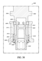
図1および図2は、ボルト、溶接、または当技術分野で既知の任意の取り付け方法によって互いに接着された、フレームワーク102、エキスパンダ112、および基部116を備える剛性ハウジング100の実施形態を図示する。いくつかの実施形態において、剛性ハウジング100は、可撓性容器のための支持を提供するように機能し得る(図6を参照)。そのような実施形態において、事前滅菌された可撓性容器は、細胞培養などのバイオ生産プロセスで使用するために剛性ハウジング100内に設置され得る。プロセスが完了すると、可撓性容器は、除去され、交換され得る。さまざまな実施形態において、剛性ハウジング100は、再利用可能である。
Figures 1 and 2 illustrate an embodiment of a
さまざまな実施形態において、剛性ハウジング100のフレームワーク102は、リフトシステム104が全体的または部分的に装着され得る、構造を提供し得る。リフトシステム104は、滑車システムに動作可能に接続された原動力デバイス106を含み得る。ケーブルは、原動力デバイス106から一組の配索滑車108まで延びていてもよく、その後、懸吊滑車110に方向付けられ得る。その後、懸吊滑車110は、ケーブル(図16を参照)を、それらが取り付けられ得る、移動可能なプラットフォーム130に方向付け得る。上記で開示された実施形態は、剛性ハウジング100内の移動可能なプラットフォーム130の移動を可能にし、それにより、可撓性容器の設置を可能にすることができる。図1は、床118の近くに位置付けされた移動可能なプラットフォーム130を図示し、図2は、剛性ハウジング100の上部でフレームワーク102に近接して位置付けされた移動可能なプラットフォーム130を図示する。図1において、オペレータは、移動可能なプラットフォーム130に、および剛性ハウジング100の床118の表面120の近く、または表面120上の位置に、可撓性容器を取り付けることができる。その後、オペレータは、HMI132と相互作用して、移動可能なプラットフォーム130を図2に見られるような位置まで上げ得る。いくつかの実施形態において、図2に示された移動可能なプラットフォーム130の場所は、設置された構成(図1または図2には示されていない可撓性容器)に位置している。
In various embodiments,
さまざまな実施形態において、エキスパンダ112は、剛性ハウジング100のフレームワーク102部分と基部116部分との間に位置付けされる。エキスパンダ112は、所与のプロセスに望まれる容量に応じて、高さが異なり、剛性ハウジング100に取り付け、または取り外しされ得る。移動可能なプラットフォーム130またはシステムの他の場所にあるさまざまなコンポーネントに電力を供給するための電力ケーブル134などの、さまざまなコンポーネントは、エキスパンダ112に装着され得る。いくつかの実施形態において、原動力デバイス106は、任意選択的に、エキスパンダ112部分にも付着され得る。いくつかの実施形態において、電力ケーブル134は、当技術分野で知られている接着方法によって、剛性ハウジング100上の任意の場所に付着または位置付けされ得る。
In various embodiments,
さまざまな実施形態において、基部116ユニットは、所望のシステム容量に応じて、エキスパンダ112またはフレームワーク102に装着され得る。いくつかの実施形態において、基部116は、表面120と、溝124によって境界付けられ得る、凹状開口部122とを有する床118を含み得る。いくつかの実施形態において、床118の表面120は、ボルト締めまたは溶接を含むがこれらに限定されない、さまざまな取り付け手段を介して側壁114に付着され得る。さまざまな実施形態において、基部116は、剛性ハウジング100内に可撓性容器の挿入を可能にする一組のヒンジ128を有するドア126を含み得る。さまざまな実施形態において、剛性ハウジング100は、エキスパンダ112内に延在し得、さらにフレームワーク102内に延在し得る、内部コンパートメント136を含み得る。
In various embodiments, the base 116 unit may be attached to the
さまざまな実施形態において、コンピュータまたはHMI132は、剛性ハウジング100に装着ることができ、原動力デバイス106の制御による可撓性コンパートメントの設置を含む、バイオ生産プロセスのさまざまな操作を制御し得る。HMI132は、可撓性コンパートメントの環境と直接(電子的、流体的、またはその他の方法で)接触している、移動可能なプラットフォーム130上のさまざまなコンポーネントへの電気的連通を介してバイオプロセスのさまざまな態様をさらに制御し得る。
In various embodiments, a computer or
さまざまな実施形態において、リフトシステム104は、移動可能なプラットフォーム130の移動を可能にする、任意のシステムであり得る。いくつかの実施形態において、移動可能なプラットフォーム130は、剛性ハウジング100の内部に装着されたトラックと相互作用する歯車を有するモータを含み得る。他の実施形態において、移動可能なプラットフォーム130は、剛性ハウジング100の外部または内部のいずれかに位置付けされた磁気原動力デバイス106に依拠し得る。
In various embodiments,
図3は、フレームワーク304、エキスパンダ310、および基部312を含む後部斜視図からの剛性ハウジング300の実施形態を図示する。さまざまな実施形態において、原動力デバイスハウジング302は、原動力デバイス106を収容するために剛性ハウジング300に装着され得る。さまざまな実施形態において、コンポーネントハウジング306は、HMI132と共に、リフトシステム104のコンポーネントも収容し得る。さまざまな実施形態において、退縮可能なケーブルアセンブリ308は、剛性ハウジング300に装着され得る。いくつかの実施形態において、退縮可能なケーブルアセンブリ308は、基部312の後部に装着され得、剛性ハウジング300の開口部を通して内部コンパートメント136内の可撓性容器と相互作用し得る。他の実施形態において、退縮可能なケーブルアセンブリ308は、剛性ハウジング300の内部コンパートメント136か、または剛性ハウジング300内の可撓性容器への動作可能な取り付けを可能にする、他の場所に装着され得る。
FIG. 3 illustrates an embodiment of
図4は、側壁406に接合された第1の表面402および第2の表面404を含む、折り畳まれたまたはパッケージされた構成の可撓性容器400の実施形態を図示する。表面の一方または両方の近くまたはそれに隣接して付着されているのは、コネクタ408、410である。第1の表面402に接合されているのは、第1のベアリングハウジング412であり、第2の表面404に接合されているのは、第2のベアリングハウジング414である。ベアリングハウジング412、414は、それらの間に装着されたらせん駆動アセンブリ416を支持する。
FIG. 4 illustrates an embodiment of
単回使用バイオ処理システムの利点は、単回使用容器(可撓性容器400)を小さなパッケージにパッケージ化し、剛性ハウジング100、200、300の内部に配置されると、後で設置して膨張させることができることである。さまざまな実施形態において、可撓性容器400は、剛性ハウジング100、200、300のドアが開構成にある間に、剛性ハウジング100、200、300に配置され得る。第1のベアリングハウジング412は、移動可能なプラットフォーム130に動作可能に接続され得、第2のベアリングハウジング414は、剛性ハウジング100、200、300の床118に、またはその近くに位置付けされ得る。いくつかの実施形態において、退縮可能なケーブルアセンブリ308は、可撓性容器400の第2の表面404で、またはその近くでコネクタ408、410に接続され得る。いくつかの実施形態において、移動可能なプラットフォーム130は、図2に見られるようにフレームワーク102の近くに再位置付けされ得、これにより、可撓性容器400をすぐに使用できる位置に置く。いくつかの実施形態において、最終的な設置ステップは、適切に位置付けされると、可撓性容器400を膨張させることであり得る。
An advantage of the single-use bioprocessing system is that the single-use container (flexible container 400) can be packaged into a small package and placed inside the
さまざまな実施形態において、コネクタ408、410は、可撓性容器400に溶接、接着、またはクリップされたループまたはフックであってもよく、剛性ハウジング100、200、300と何らかの方法で相互作用して、可撓性容器400を剛性ハウジング100、200、300の内部コンパートメント136内に配置するように設計することができる。いくつかの実施形態において、退縮可能なケーブルアセンブリ308は、剛性ハウジング100、200、300上、またはその中のどこにでも配置、または取り付けられ得、ばね仕掛けケーブル、ストリング、または他の細長い固定要素に取り付けられたフックを備え得る。いくつかの実施形態において、退縮可能なケーブルアセンブリ308は、単純なフックであり得る。
In various embodiments,
さまざまな実施形態において、ベアハウジング412、414は、可撓性容器400の外部から可撓性容器400内のらせん駆動アセンブリ416への回転力の伝達を可能にする、可撓性容器400に付着または接着された、任意のデバイスであり得る。いくつかの実施形態において、らせん状駆動アセンブリ416は、可撓性容器400の第1の表面402から第2の表面404まで延在し得る。いくつかの実施形態において、らせん駆動アセンブリ416は、並列に延びて、インペラおよび安定化ユニットに取り付けるように構成された、1つ、2つ、3つ、またはそれ以上の駆動ラインを含み得る。いくつかの実施形態において、らせん駆動アセンブリ416は、一方または両方のベアリングハウジング412、414を介して、一方または両方の表面に接続された単純な駆動シャフトであり得る。
In various embodiments, the bare housings 412 , 414 are attached to the
図5は、可撓性容器502およびチューブ管理プレート522を備える周辺機器管理アセンブリ500の実施形態を図示する。
FIG. 5 illustrates an embodiment of peripheral management assembly 500 comprising
さまざまな実施形態において、可撓性容器502は、内部508を形成する第2の表面506に接合された側壁504を含み得る。いくつかの実施形態において、第2の表面506は、複数のポート516が延在し得る、外部510を含み得る。いくつかの実施形態において、ポート516構造は、当技術分野で既知の、または使用される任意の方法で、第2の表面506または可撓性容器502上の他のどこかに溶接、接着、または取り付けられ得る。いくつかの実施形態において、ベアリングハウジング520はまた、らせん状駆動アセンブリ416に回転運動を提供するために、可撓性容器502の第2の表面506から延在し得る。いくつかの実施形態において、チューブ518、センサプローブ(図示せず)、または他の任意の周辺デバイスは、複数のポート516を介して、可撓性容器502の内部508と光学的、電気的、流体的、または他の種類で連通し得る。いくつかの実施形態において、チューブ518は、ポート516から離れて延在する。
In various embodiments,
さまざまな実施形態において、チューブ管理プレート522は、チューブ管理プレート522の外周縁部524によって境界付けられた、複数の開口部532およびベアリング受容部526を含み得る。
In various embodiments,
さまざまな実施形態において、複数の開口部532は、複数のポート516またはチューブ518を受け入れ、それらを開口部532内に物理的に抑制するように構成される。いくつかの実施形態において、抑制は、摩擦またはクリップ(図示せず)の使用を通じて起こり、他の実施形態において、チューブ518は、開口部532内のそれらの細長い軸に沿って自由に浮遊し得る。 In various embodiments, multiple openings 532 are configured to receive multiple ports 516 or tubes 518 and physically constrain them within openings 532 . In some embodiments, restraint occurs through friction or the use of clips (not shown); in other embodiments, tubes 518 are free to float along their elongated axes within openings 532. .
さまざまな実施形態において、ベアリング受容部526は、可撓性容器502の第2の表面506から突出するベアリングハウジング520を受容するための単純な開口部であり得る。いくつかの実施形態において、ベアリング受容部526は、狭い部分528および広い部分530を有する開口部を含み得る。いくつかの実施形態において、広い部分530は、ベアリングハウジング520を受容し得、ベアリングハウジング520は、狭い部分528に入るように、チューブ管理プレート522に対してスライドし得、これにより、摩擦力を介して可撓性容器502およびチューブ管理プレート522の互いに対する移動を物理的に制限し得る。
In various embodiments, bearing
さまざまな実施形態において、チューブ管理プレート522は、可撓性容器502から延在する複雑な一組の取り付け部をまとめるための独特で単純化された方法を提供する。歴史的には、オペレータは、チューブおよびベアリングの場所を1つずつ調整するように要求され、これは、労働集約的であり、結果としてシステムが無秩序になる可能性がある。図5に示された実施形態は、少ない労力で管理することができる、周辺機器の単純な配列を可能にする。いくつかの実施形態において、チューブ管理プレート522および可撓性容器502の組み合わせは、エンドユーザが設置のためにアセンブリ全体を剛性ハウジング100、200、300にスライドするだけでよいように、事前構成された方法で出荷することができる。いくつかの実施形態において、エンドユーザは、カスタムまたは既製のチューブセットを注文することができ、これは、その後、カスタムまたは標準化されたチューブ管理プレート522上で事前にまとめられ、その後、使用のために出荷され得る。
In various embodiments,
図6は、側壁606によって接合された第1の表面602および第2の表面604を含む可撓性容器600の実施形態を図示する。さまざまな実施形態において、複数のコネクタ608、610、612、614は、可撓性容器600を剛性ハウジング100、200、300内に位置付けるために、表面602、604のうちの1つ、または側壁606上に組み立てられ得る。いくつかの実施形態において、コネクタ608、610、612、614は、取り付け部を形成することができる、フック、接着剤、磁石、ピン、ループ、または他の任意のものであり得、剛性ハウジング100、200、300に付着または接着された、同じまたは類似の要素に接続され得る。いくつかの実施形態において、可撓性容器600は、可撓性容器600の任意の部分に他の方法で溶接、接着、または取り付けられた、ポート616、618をさらに含み得る。いくつかの実施形態において、駆動アセンブリ626の回転運動を支持するために、第1のベアリングハウジング620は、可撓性容器600の第1の表面602に溶接または接着され得、第2のベアリングハウジング622は、可撓性容器600の第2の表面604に溶接または接着され得る。いくつかの実施形態において、第1の第2のベアリングハウジング622から離れて延在する駆動シャフト624は、可撓性容器600の内部部分内の駆動アセンブリ626に回転運動を提供するように、モータと相互作用(図26を参照)し得る。いくつかの実施形態において、駆動アセンブリ626は、可撓性容器600内の流体を混合するための1つ以上のインペラ628をみ得る。
FIG. 6 illustrates an embodiment of
図7は、剛性ハウジング702の一部を形成する基部700ユニットおよび外部ハウジング704の実施形態を図示する。
FIG. 7 illustrates an embodiment of a base 700 unit and an
さまざまな実施形態において、外部ハウジング704は、さまざまな異なるコンポーネントを収容するためのそれ自体の内部を有する、剛性ハウジング702と分離するか、またはその一部であり得る。いくつかの実施形態において、これらのコンポーネントは、制御システム708と、滑車ケーブル取り付け部および他の接続を含むリフトアセンブリ706の一部と、剛性ハウジング702の内部714内で移動可能なプラットフォーム732を動かすように設計された取り付けデバイスとを含み得る。いくつかの実施形態において、制御システム708またはHMI132は、リフトシステム104、706と電気的に連通しており、移動可能なプラットフォーム130、732の移動を指示し得る。いくつかの実施形態において、制御システム708は、オペレータが移動可能なプラットフォーム130、732の制御を指示するためのユーザインターフェースを有してもよく、または制御は自動化されてもよい。いくつかの実施形態において、外部ハウジング704は、固定された方法で剛性ハウジング702に溶接、もしくはボルト締めされてもよく、またはそれ自体の別個のユニットであってもよい。
In various embodiments, the
さまざまな実施形態において、剛性ハウジング702の基部700は、移動可能なプラットフォーム732が存在し得る内部714を作成するように、床710に溶接、またはボルトによって装着された側壁712を備え得る。さまざまな実施形態において、溝726によって境界付けられた剛性ハウジング702の基部700の床710に、ケーブル開口部728があり得る。いくつかの実施形態において、図5ならびに図面および記載全体に見られるチューブ管理プレート522は、開口部に嵌合するように設計されている。いくつかの実施形態において、チューブ管理プレート522の外周縁部524は、チューブ管理プレート522の移動が、摩擦力により制限される、溝726内の凹状開口部724に嵌合するように構成された、凸部を含み得る。いくつかの実施形態において、溶接または接着を含む追加の制限デバイスが、使用され得、または場合によっては、スイング部718アームが、チューブ管理プレート522が開口部724から出るのを妨げる位置に動かされ、ロックされ得る。そのような実施形態において、チューブ管理プレート522の制限はまた、チューブ管理プレート522が可撓性容器400、502、600に装着されるため、可撓性容器400、502、600の移動を制限する。
In various embodiments, the
さまざまな実施形態において、基部700ユニットは、可撓性容器400、502、600が剛性ハウジング702に適切に設置された後に閉じ得る、ヒンジ722に装着されたドア716を含む。いくつかの実施形態において、キャッチアセンブリ730は、床710または剛性ハウジング702の開口部724内のどこかに装着され得る。いくつかの実施形態において、キャッチアセンブリ730は、第2のベアリングハウジング414、520、622を受容して、適切な構成に配備されると、その移動を制限するように構成され得る。いくつかの実施形態において、スイング部718は、第2のベアリングハウジング414、520、622がキャッチアセンブリ730内で適切に配向されない限り、適切に閉じない。いくつかの実施形態において、スイング部718またはドア716の遮断部分720は、ドア716のまたはスイング部718の閉鎖を防止するように、キャッチアセンブリ730と相互作用し得る。
In various embodiments, the base 700 unit includes a
さまざまな実施形態において、剛性ハウジング702の側壁712または床710は、剛性ハウジング702の外部に位置付けされた退縮可能なケーブルアセンブリ308が剛性ハウジング702の内部714内に収容された可撓性容器400、502、600と相互作用することを可能にする、1つ以上のケーブル開口部728を含み得る。いくつかの実施形態において、フック、ラッチ、または接続デバイスは、可撓性容器600上のコネクタに係合し、その後、設置が完了した後に、それらが可撓性容器400、502、600に損傷を与えないように退縮することができる。場合によっては、フックまたは突出する物体が剛性ハウジング702の内部714内に残っている状態は、物理的相互作用によって可撓性容器に損傷を引き起こし得る。
In various embodiments, the
さまざまな実施形態において、可撓性容器400、502、600は、設置の際に、剛性ハウジング702内の床710と移動可能なプラットフォーム732との間に位置付けされ得る。いくつかの実施形態において、第1のベアリングハウジング412、620は、駆動アセンブリ736に接続することによって移動可能なプラットフォーム732に動作可能に結合し得る。いくつかの実施形態において、第1のポート616またはチューブは、コンデンサ734と相互作用し得、コンデンサ734は、移動可能なプラットフォーム732に装着され得るか、または単に移動可能なプラットフォーム732上に置かれ得る。いくつかの実施形態において、第2のベアリングハウジング414、622は、キャッチアセンブリ730に挿入されて、取り付けられ得る。可撓性容器400、502、600と移動可能なプラットフォーム732およびキャッチアセンブリ730および剛性ハウジング702の他の部分が接続されると、移動可能なプラットフォーム732は、バイオ生産プロセスを開始する前に、図2に示される位置まで上昇され得る。
In various embodiments,
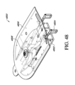
図8は、ケーブル取り付けデバイス804、固定デバイス806、退縮可能なケーブルアセンブリ808、ケーブル弛みセンサアセンブリ810、ケーブルトラッククランプ812、フィルタブラケット814、およびそれに取り付けられたチューブホルダー816を含む上部表面802を備える移動可能なプラットフォーム800の実施形態を図示する。さまざまな実施形態において、移動可能なプラットフォーム800の上部表面802上にあるコンポーネントは、溶接、適所にねじ留め、ボルト締め、または当技術分野で既知もしくは有用である、他の方法で取り付けられ得る。いくつかの実施形態において、移動可能なプラットフォーム800は、ピンまたはねじを取り付けることができる、複数の開口部を含み得る。そのようなシステムは、用途に応じて、さまざまなコンポーネントが任意の望ましい配列で構成されることを可能にし得る。図9は、図8に示されているのと同じ移動可能なプラットフォームの実施形態を下側から図示する。
FIG. 8 comprises
図10および図11は、退縮可能なケーブルアセンブリ1000、1100または固定デバイスの実施形態を図示する。退縮可能なケーブルアセンブリ1000、1100の一般的な実施形態は、移動可能なプラットフォーム1002、1102への接続を可能にする任意のものであり得る。
10 and 11 illustrate embodiments of
退縮可能なケーブルアセンブリ1000、1100のさまざまな実施形態は、ケーブル1108を含むリール1104のためにばね仕掛けコンパートメントを提供するためのケーブルハウジング1004を含み、ボルト1106は、リールを退縮可能なケーブルアセンブリ1000、1100内に位置付けし得る。さまざまな実施形態において、ケーブル1108は、アセンブリから手動で引き出され、退縮することができる。いくつかの実施形態において、フック1012、1114は、フック止め1014、1116に当接し、ケーブル1108が完全に退縮可能なケーブルアセンブリ1000、1100に退縮するのを防止し得る。いくつかの実施形態において、回転可能な滑り部1008、1112は、ケーブルをリール1104からアセンブリの外に方向付けるために、使用され得る。さまざまな実施形態において、退縮可能なケーブルアセンブリ1000、1100は、開口部2 1006を接続するように取り付けられたピンを使用して、移動可能なプラットフォーム1002、1102に装着され得る。
Various embodiments of the
さまざまな実施形態において、退縮可能なケーブルアセンブリ1000、1100は、剛性ハウジング100のドア126の反対側の移動可能なプラットフォーム1002、1102の近く、または後部部分に位置付けされ得る。そのような構成は、ユーザが、コネクタ608、610、612、614でフック1012、1114を可撓性容器600に取り付け、可撓性容器600の一部を剛性ハウジングの後部部分に自動的に退縮させることを可能にし得る。そのような実施形態は、可撓性容器600を配置するために、オペレータが剛性ハウジングに入る必要がないことを保証し、それにより、安全性を増加させながら、ユーザの使い勝手を増加させる。さまざまな実施形態において、剛性ハウジング300の床118の近くの退縮可能なケーブルアセンブリ308は、可撓性容器400、502、600の適切な配置を確実にするように、移動可能なプラットフォーム上に位置付けされた退縮可能なケーブルアセンブリ1000、1100と共に使用されうる。いくつかの実施形態において、退縮可能なケーブルアセンブリ1000、1100は、図11に示されるように、弛みセンサアセンブリ1118の近くに位置付けされ得る。
In various embodiments, the
さまざまな実施形態において、退縮可能なケーブルアセンブリ308、1000、1100の使用は、移動可能なプラットフォーム1002、1102がリフトシステム104、706によって持ち上げられたときに、可撓性容器600の第1の表面602および第2の表面604はが分離され、表面がそれらの折り畳まれた構成から設置構成に引き出されるように、可撓性容器400、502、600を位置付け得、それにより、駆動アセンブリ626を動作構成に拡張し、可撓性容器400、502、600の内容物を効果的に混合することができる。
In various embodiments, the use of
図12は、弛みセンサアセンブリ1202、固定デバイス1204、ケーブル取り付けデバイス1206、およびコーナー止め1208を備える移動可能なプラットフォーム1200の実施形態を図示する。さまざまな実施形態において、コーナー止め1208は、可撓性容器400、502、600の設置後の移動を防止するように、内部714剛性ハウジング100、200、300、702上のハードウェアの一部と相互作用できる、移動可能なプラットフォーム1200の4つのコーナーに配置され得る。このような機構は、主にオペレータの安全を確保し、バイオ生産プロセス中の故障を防ぐためのものである。
FIG. 12 illustrates an embodiment of
さまざまな実施形態において、ケーブル弛みセンサアセンブリ1202は、ケーブル取り付けデバイス1206から延在し、かつ移動可能なプラットフォーム1200をリフトシステム104、706に懸吊するケーブル1600によって移動可能なプラットフォーム1200が適切に支持されていない場合を検出するように、ケーブル取り付けデバイス1206の近くに位置付けされ得る。さまざまな実施形態において、弛みセンサアセンブリ1202は、ケーブル1600の弛みを検出するように、ケーブル1600と直接相互作用する。いくつかの実施形態において、ケーブル1600の弛みは、移動可能なプラットフォーム1200が剛性ハウジング100、200、300、702内で適切に支持されていないことを示している。
In various embodiments, the cable
さまざまな実施形態において、固定デバイス1204は、移動可能なプラットフォーム1200の上部表面に装着され、下に懸吊された可撓性容器400、502、600と相互作用し得る。いくつかの実施形態において、固定デバイス1204は、生体反応または混合で使用するための可撓性容器400、502、600の適切な設置および位置付けを確実にするように、移動可能なプラットフォーム1200および可撓性容器400、502、600の両方と相互作用することができるものならなんでもよい。
In various embodiments, the
図13および図14は、それぞれ、開構成および閉構成での、固定デバイス1300、1400の実施形態を図示する。さまざまな実施形態において、固定デバイス1300、1400は、ピン1308、1408を使用してフック1310、1410に接続するための装着開口部1306、1406を有する装着部1302、1402、および移動可能なプラットフォーム1200と接続するための接続部1304、1404を備え得る。
Figures 13 and 14 illustrate embodiments of
さまざまな実施形態において、接続部1304、1404は、移動可能なプラットフォーム1200への接続を可能にする、開口部、接着剤、ピン、溶接、または任意のものであり得る。いくつかの実施形態において、接続部1304、1404は、固定デバイス1300、1400を固定するための、突起、溶接、接着剤、ねじ、ピン、または移動可能なプラットフォーム1200上で有用な他の任意のものと相互作用し得る。
In various embodiments,
さまざまな実施形態において、フック1310、1410は、ピンまたは他の細長い部材(図示せず)を使用して、装着開口部1306、1406を通して装着部に枢動的に取り付けられ得る。いくつかの実施形態において、開構成は、可撓性容器400、502、600上のコネクタへの容易な接続を可能にしている、フックが移動可能なプラットフォーム1200の上部表面の下に落ちることを可能にする。接続されると、いくつかの実施形態において、フック1310、1410は、移動可能なプラットフォーム1200の凹部内で、または開口部内でスイングバックし得る。そのような実施形態は、フック1310、1410との物理的摩耗による可撓性容器400、502、600の故障を防止するために理想的である。
In various embodiments, the
図15は、移動可能なプラットフォーム1502に取り付けられ、プレート1504、コーナー止め1506、ねじ1508、ワッシャー1510、ねじ受容部1512、開口部1514、ケーブル受容部1516、受容部開口部1518、およびピン開口部1520を備える、ケーブル取り付けデバイス1500の実施形態を図示する。
FIG. 15 shows a
さまざまな実施形態において、ケーブルコーナー止め1506は、剛性ハウジング100、200、300の内部714内の何かしらの上にラッチするためのフック状要素を含み得る。いくつかの実施形態において、コーナー止め1506は、ワッシャー1510を通過し、かつネジ受容部1512によって保持されるネジ1508を使用して移動可能なプラットフォーム1502に装着され得るが、移動可能なプラットフォーム1502とのしっかりした接続を可能にする任意のものを使用することができる。そのような実施形態は、溶接、接着剤、ボルト、または既知または有用な他の任意のものを含み得る。
In various embodiments,
さまざまな実施形態において、ケーブル取り付けデバイス1500は、ケーブル取り付けデバイス1500の位置を調整するための細長い開口部1514を有する追加プレート1504を含み得る。さまざまな実施形態において、コーナー止め1506は、剛性ハウジング100、200、300、702上のハードウェアとよりよく相互作用するように、調整される必要があり得る。いくつかの実施形態において、ねじ1508位置は、ケーブル取り付けデバイス1500の再位置付けを可能にするように、開口部1514内で調整され得る。
In various embodiments,
さまざまな実施形態において、ケーブル受容部1516は、プレート1504またはコーナー止め1506から離れて延在し、ケーブル1600を受容するためのケーブル受容部1516を含み得る。いくつかの実施形態において、ケーブル1600は、ピン開口部1520およびピン取り付け部を使用して、ケーブル受容部1516に固定され得る。しかしながら、他の実施形態は、溶接、接着剤、ねじ、または当分野で既知もしくは有用な別の接続を使用して、ケーブル1600をケーブル受容部1516に接続することを含み得る。さまざまな実施形態において、ケーブル1600は、移動可能なプラットフォーム1502の各コーナーから延在して、プラットフォームを安定した方法で懸吊し、剛性ハウジング100、200、300、702内の可撓性容器400、502、600の適切な位置付けを可能にする。いくつかの実施形態において、ケーブル1600は、移動可能なプラットフォーム1502、可撓性容器400、502、600、および移動可能なプラットフォーム1502の上に載っているさまざまなコンポーネントであって、モータアセンブリ、コンデンサ734、ならびにバイオ生産プロセスに必要なその他のハードウェアおよびチューブを含むがこれらに限定されない、コンポーネントを支持するのに十分な引張強度を有する必要がある。
In various embodiments,
図16は、細長い部分1602、ループ1604、ポリマー1606、およびカラー1608を備える、ケーブル1600の実施形態を図示する。さまざまな実施形態において、ケーブル1600は、構成可能な混合システム全体にわたって使用される。さまざまな実施形態において、リフトシステム104、706は、ケーブル1600を含み得る。さまざまな実施形態において、ケーブル1600は、退縮可能なケーブルアセンブリ308、808、1000、1100内で使用され得る。さまざまな実施形態において、滑車、コネクタ、取り付け部、懸吊デバイス、およびいずれかの場所で有用であることが見出されているケーブル1600を使用する、本明細書で開示される任意のシステムが使用され得るが、明瞭にするために図示されているとは限らない。さまざまな実施形態において、ケーブルは、ベルト、紐、チェーン、ロープ、コード、またはさまざまな異なるコネクタもしくは取り付け要素に取り付けることができる任意の細長いデバイスであり得る。
FIG. 16 illustrates an embodiment of
さまざまな実施形態において、ケーブル1600は、ケーブル1600が相互作用または懸吊し得るさまざまなコンポーネントへの損傷を防ぐように付着されたポリマー1606を有するループ1604を含み得る。さまざまな実施形態において、カラー1608は、ケーブル1600をそれ自体に固定して、ループ1604を作成し得る。
In various embodiments,
懸吊、移動、または電力の伝送を必要とする本明細書に開示されたさまざまな実施形態において、ケーブル1600は、そのような動作を容易にするように、使用され得る。ケーブル1600は、簡略化のためにすべての図面に示されているわけではないが、本明細書に開示されたさまざまな要素と相互作用することが理解されよう。
In various embodiments disclosed herein that require suspension, locomotion, or transmission of power,
図17、図18、および図19は、センサ1708およびそれに装着された読み取り可能な物体1712を有するブラケット1702を備えるケーブル弛みセンサアセンブリ1700の実施形態を図示する。
Figures 17, 18, and 19 illustrate an embodiment of a cable
さまざまな実施形態において、ブラケット1702は、図12に見られるように、ケーブル取り付けデバイス1206の近く、または隣接する移動可能なプラットフォーム1200に装着され得る。いくつかの実施形態において、ブラケット1702は、ブラケット1702内の開口部1704を通って突出し、かつ移動可能なプラットフォーム1200の表面に付着される、ネジ1714で移動可能なプラットフォーム1200に装着され得る。他の実施形態において、ブラケット1702は、既知であるか、または有用である、任意の方法で、移動可能なプラットフォーム1200に溶接、接着、または固定され得る。
In various embodiments,
さまざまな実施形態において、センサ1708は、ブラケット1702に装着され得、読み取り可能な物体1712は、その移動がセンサによって検出され得るように、位置付けされ得る。当業者は、センサ1708および読み取り可能な物体1712を互いに対して位置付ける多くの方法があり、ある位置では読み取り可能な物体1712がセンサ1708に信号を提供し、別の位置では読み取り可能な物体1712がセンサ1708への信号を提供しないことを理解するであろう。いくつかの実施形態において、センサ1708は、光学的変化、磁気的変化、電気的変化、またはセンサ1708が検出できる、既知または有用な、他の種類の変化を検出し得る。
In various embodiments, the
さまざまな実施形態において、読み取り可能な物体1712は、ロッド1718の第1の端部に固定され得、ケーブル取り付け部1722は、ロッド1718の第2の端部に固定され得る。いくつかの実施形態において、ロッド1718、読み取り可能な物体1712、ケーブル取り付け部1722アセンブリは、位置付けプレート1710でブラケット1702上に固定され得る。いくつかの実施形態において、位置付けプレート1710は、プレートを通過して、ブラケット1702の開口部に入る、ネジ1714によって適所に保持され、ナット1716は、ネジ1706をブラケット1702の反対側に固定することができる。いくつかの実施形態において、位置付けプレート1710は、接着剤、溶接、または当技術分野で既知もしくは有用な他の任意の方法を使用して、ブラケット1702に固定することができる。さまざまな実施形態において、ロッド1718、読み取り可能な物体1712、ケーブル取り付け部1722アセンブリは、既知または有用な他の別の方法によってブラケット1702に固定され得る。
In various embodiments,
さまざまな実施形態において、ケーブル取り付け部1722は、ケーブル1600を受容するためのケーブル開口部1724を含み得る。いくつかの実施形態において、ケーブル1600は、ケーブル取り付け部1722の開口部を通過し、付着部1728で付着される、ピン1726を使用して、ケーブル開口部1724内に固定され得る。当業者は、ケーブル1600をケーブル取り付け部1722領域に固定する他の無数の方法が存在することを理解するであろう。
In various embodiments,
さまざまな実施形態において、ばね1720は、読み取り可能な物体1712とロッド1718上のケーブル取り付け部1722との間で、位置付けプレート1710の範囲内に位置付けされる。さまざまな実施形態において、読み取り可能な物体1712の静止位置は、図17および図19に示される。さまざまな実施形態において、ケーブル取り付け部1722上の負荷は、図18に見られるように、読み取り可能な物体1712をセンサ1708上で移動させ得る。
In various embodiments,
さまざまな実施形態において、ケーブル1108は、移動可能なプラットフォーム1200に付着され、ケーブル取り付け部1722を通ってロッド1718に垂直に延び得る。そのような実施形態において、ケーブル取り付けデバイス1206は、ケーブル1600がケーブル取り付け部1722に負荷を加えると、読み取り可能な物体1712がセンサ1708上で移動するように、位置付けされ得る。いくつかの実施形態において、移動可能なプラットフォーム1200は適切に位置付けされているので、負荷が加えられたときに、ケーブル1600は、ピンと張る。さまざまな実施形態において、ケーブル1600は、移動可能なプラットフォーム1200の各コーナーに付着され、各ケーブル1600は、ケーブル弛みセンサアセンブリ1700を通って延びる。移動可能なプラットフォーム1200に機能不全があり、コーナーの1つが他に比べて持ち上がると、ケーブル1600の弛みが生じ、ばねが読み取り可能な物体1712にパチンと嵌まり、図17および図19に示される構成になる。さまざまな実施形態において、ケーブル弛みセンサアセンブリ1700は、その後、原動力デバイス106を停止し、移動可能なプラットフォーム1200の動作を一時停止するように、信号を制御システム708またはHMI132に送信し得る。
In various embodiments,
さまざまな実施形態において、センサ1708は、その張りつめ位置の代わりに、その静止位置で、読み取り可能な物体1712を読み取るように、位置付けされ得る。当業者は、ケーブル1600の弛みを検出することができる、任意のセンサシステムが、本明細書に開示されたさまざまな移動可能なプラットフォーム1200の実施形態に有用であり得ることを理解するであろう。
In various embodiments,
さまざまな実施形態において、読み取り可能な物体は、ボルトまたは他の金属物体である。いくつかの実施形態において、読み取り可能な物体は、センサによって検出可能な、磁石または色を含み得る。 In various embodiments, the readable object is a bolt or other metal object. In some embodiments, readable objects may include magnets or colors that are detectable by sensors.
さまざまな実施形態において、センサシステムは、移動可能なプラットフォーム1200が水平であるかどうかを検出するために、使用され得る。このようなシステムは、ケーブルを含まないが、ベルト、歯車もしくはトラックと統合されたギア駆動、またはその他のシステムを含む、さまざまなリフトシステムで働く。さまざまな実施形態において、そのようなシステムは、気泡および着色染料または水を取り入れてもよく、気泡が望ましくない位置に移動した場合に、光学センサが吸収の変化を検出し得る。
In various embodiments, a sensor system can be used to detect whether
図20は、ケーブルクランプ2002、ブラケット2004、移動可能なプラットフォーム2006、およびネジ2008を備える電力ケーブルクランプアセンブリ2000の実施形態を図示する。
FIG. 20 illustrates an embodiment of power
さまざまな実施形態において、移動可能なプラットフォーム130、732、800、1002、1102、1200、1502、2006上のさまざまなコンポーネントは、原動力デバイス106、ケーブル弛みセンサアセンブリ1700、および原動力デバイス106(移動可能なプラットフォーム上に配備された場合)などの電力を必要とする。
In various embodiments, the various components on the
さまざまな実施形態において、電力ケーブル134は、外部ハウジング704または他の場所から上方に、そして剛性ハウジング100、200、300、702の内部714内に配線され得、その後、電力ケーブルクランプアセンブリ2000を通って移動可能なプラットフォーム2006に配線され得る。いくつかの実施形態において、ブラケット2004は、ネジ2008で、または別の手段によって移動可能なプラットフォーム2006に固定され得、ケーブルクランプ2002は、電力ケーブル134をブラケット2004に固定し得る。その後、さまざまな実施形態において、電力ケーブル134は、電力を必要とする、移動可能なプラットフォーム2006上のさまざまなシステムに配線され得る。
In various embodiments, the
図21は、コントローラ2102、移動可能なプラットフォーム2104、モータ2106、原動力デバイス2108、および弛みセンサアセンブリ2110を備える制御システム2100の実施形態を図示する。
FIG. 21 illustrates an embodiment of
さまざまな実施形態において、コントローラ2102は、原動力デバイス2108に、作動、停止、および前進または後退で動作するように、ならびにそれが動作する速度を指示する。いくつかの実施形態において、オペレータは、コントローラ2102上のインターフェースを通して、原動力デバイス2108のための設定を決定する。いくつかの実施形態において、弛みセンサアセンブリ2110は、移動可能なプラットフォーム2104の配向に関して、情報をコントローラ2102に提供する。さまざまな実施形態において、および上記で説明したように、弛みセンサアセンブリ2110は、原動力デバイス2108がアクティブであるか、または非アクティブであることが適切であるかを、決定し得る。いくつかの実施形態において、信号は、コントローラ2102に伝わり得、コントローラ2102は、原動力デバイス2108に送る制御信号を決定する。
In various embodiments, the
さまざまな実施形態において、弛みセンサアセンブリ2110は、移動可能なプラットフォーム2104上に配備され得、いくつかの実施形態において、それは別個に収容され得る。さまざまな実施形態において、1つ以上のコントローラ2102は、リフトシステム104、706のさまざまな態様を指示するように使用されるか、またはバイオ生産プロセスの一部として、可撓性容器400、5002、600内の変化を感知し、実行し得る。後で、キャッチアセンブリ730は、手動装置として記載されるが、さまざまな態様が、センサおよびアクチュエータと共にコントローラ2102を使用して自動化および制御され得ることが理解されよう。
In various embodiments,
図22は、移動可能なプラットフォーム2104に装着されたブラケット2202を備えるホルダー2200の実施形態を図示する。さまざまな実施形態において、さまざまなコンポーネントは、移動可能なプラットフォーム2104の表面上の適所に保持される必要があり得る。いくつかの実施形態において、ブラケットは、はんだ付け、溶接、ねじ、ピン、または他の任意の固定デバイスによって移動可能なプラットフォーム2104に装着され得る。いくつかの実施形態において、ブラケット2202は、1つ以上のフィルタを移動可能なプラットフォーム2104に固定する、フィルタブラケット814であり得る。いくつかの実施形態において、チューブは、移動可能なプラットフォーム2104、またはバイオ生産において既知または有用な他の任意の物体に固定される必要があり得る。
FIG. 22 illustrates an embodiment of
図23は、移動可能なプラットフォーム2302およびそれに付着されたチューブホルダー2304を備えるチューブホルダーアセンブリ2300の実施形態を図示する。さまざまな実施形態において、チューブホルダー2304は、ピン、ねじ、はんだ、溶接、接着剤、または既知もしくは有用な他の既知の固定方法を使用して、移動可能なプラットフォーム2302に付着され得る。
FIG. 23 illustrates an embodiment of
さまざまな実施形態において、チューブ518は、可撓性容器600の第1の表面602から延在し、移動可能なプラットフォーム2302内のノッチ2308を通ってさらに延在し得る。いくつかの実施形態において、ノッチ2308を通って延在するチューブ518は、チューブホルダー2304の開口部2306内に位置付けされ、チューブホルダー2304との摩擦相互作用によって抑制され得る。さまざまな実施形態において、チューブ518は、コンデンサ734に接続し得、戻りチューブは、移動可能なプラットフォーム2302の下に懸吊された可撓性容器600内に流体または液体が戻って再導入することを可能にし得る。
In various embodiments, tube 518 can extend from
図24は、移動可能なプラットフォーム2402と、移動可能なプラットフォーム2402の表面に付着されたガイド2404とを備えるガイドフックアセンブリ2400の実施形態を図示する。さまざまな実施形態において、フック2508は、ガイド2502内のポケットの中に移動し、一端にハンドル2406を有し、外方に延在する。さまざまな実施形態において、フック2408は、ガイド内に収容されたフック2508の一部分に取り付けられる。さまざまな実施形態において、オペレータは、ロッド上に配備されたフックをガイド内の後方位置から前方位置に移動するように、ハンドル2406を引っ張り得る。退縮可能なケーブルアセンブリ308と同様に、ガイドおよびフックシステムにより、ユーザはフック2408を剛性ハウジング100、200、300、702のドアの近くの前方位置に移動し、コネクタ608、610、612、614をフック2408に取り付けることができる。その後、オペレータは、ハンドル2406を押して、フック2408を後方位置に移動させ、可撓性容器400、502、600を剛性ハウジング100、200、300、702内に正しく配置することができる。いくつかの実施形態において、ロッド2410は、後方位置と前方位置との間の操作を容易にするためにばね仕掛けされ得る。
FIG. 24 illustrates an embodiment of a
図25は、さまざまな実施形態による、ガイド2502、ねじ2504、ロッド2506、およびスロット2510から延在するフック2508を備えるガイドフックアセンブリ2500の拡大を図示する。さまざまな実施形態において、ガイドフックアセンブリ2500は、移動可能なプラットフォーム2512の下側にはんだ付け、溶接、ねじ止め、または接着され得る。さまざまな実施形態において、ロッド2506は、スロット2510内で自由に、前方位置および後方位置に移動する。
FIG. 25 illustrates an enlargement of
図26は、内部2604を有する剛性ハウジング2602を備えるバイオ生産システム2600を図示する。さまざまな実施形態において、エンドユーザは、剛性ハウジング2602を購入して、それを生産施設内で組み立て得る。必要に応じて、エンドユーザは、チューブ管理プレート522に装着されたチューブセットを有する可撓性容器400、502、600を含み得る、バイオ生産システム2600の単回使用部分を購入し得る。単回使用部分全体は、単一パッケージ2606でエンドユーザに出荷され得、その後、オペレータは、消耗品部分を開梱し、設置のために剛性ハウジング2602の内部に挿入し得る。
FIG. 26 illustrates
図27は、モータハウジング2702、モータ2704、ロッキングスリーブ2706、クランプアセンブリ2708、ハンドル2710、枢動部分2712、保持プレート2714、保持プレート開口部2716、ノッチ2718、取り付け領域2720、ジョイント2722、スイングアーム2724、スイング開口部2726、ヒンジ2728、ばね仕掛けピン2730、ベアリングハウジング2732、および駆動シャフト2734を備えるベアリングハウジング保持アセンブリ2700を図示する。
27 shows
さまざまな実施形態において、モータハウジング2702は、移動可能なプラットフォーム(さまざまな図面に示される)に装着する。モータハウジング2702は、モータを固定し得、モータ2704は、それに付着された回転可能なロッキングスリーブ2706を含み得る。
In various embodiments,
さまざまな実施形態において、ベアリングハウジング保持アセンブリ2700は、モータハウジング2702およびモータ2704のいずれかまたは両方に装着し得る。さまざまな実施形態において、ベアリングハウジング保持アセンブリ2700の目的は、駆動シャフト2734がモータ2704と回転整列してロックされ、その後、モータが可撓性容器400、502、600内のらせん駆動アセンブリ416に回転運動を提供し得るように、可撓性容器400、502、600から延在するベアリングハウジング2732および駆動シャフト2734を固定することである。
In various embodiments, bearing
さまざまな実施形態において、可撓性容器400、502、600が剛性ハウジング100、200、300、702、2602内に位置付けされると、ベアリングハウジング2732は、保持プレート2714上に配備された保持プレート開口部2716内に挿入され得る。いくつかの実施形態において、ベアリングハウジング2732は、保持プレート開口部2716と係合する、凹部を含み得る。その後、スイングアーム2724は、ベアリングハウジング2732を固定するため、開構成から閉構成に変化するように、ヒンジ2728の周りで枢動し得る。いくつかの実施形態において、スイングアーム2724は、保持保持プレート開口部2716上のノッチ2718の周りに位置付けされる、スイング開口部2726を含み得る。その後、ベアリングハウジング2732が保持プレート開口部2716に制限されるように、ばね仕掛けピン2730がノッチ2718と係合し、それにより、スイングアーム2724をベアリングハウジング2732にロックし得る。
In various embodiments, when the
さまざまな実施形態において、オペレータは、ハンドル2710を引いて、クランプアセンブリ2708を作動させ、駆動シャフト2734をモータ2704上に配備されたロッキングスリーブ2706内に移動させ得る。さまざまな実施形態において、ハンドル2710は、ハンドル2710の枢動運動を可能にする、ジョイント2722でモータハウジング2702に装着され得る。いくつかの実施形態において、ハンドル2710は、枢動部分2712が保持プレート2714をハンドル2710に接続する取り付け領域2720を含む、枢動部分2712によって保持プレート2714に枢動的に取り付けられ得る。
In various embodiments, an operator can pull handle 2710 to actuate
図27は、スイングアーム2724およびクランプアセンブリ2708の両方が開構成にあり、ベアベアリングハウジング2732を受容する準備ができている、実施形態を図示する。図28は、スイングアーム2724が閉じており、ベアリングハウジング2732が適所にロックされているが、クランプアセンブリ2708が依然として開構成にあるため、可撓性容器400、502、600からの駆動シャフト2734がモータ2704に係合していない、実施形態を図示する。図29は、スイングアーム2724およびクランプアセンブリ2708の両方が閉構成およびロック構成にあり、駆動シャフト2734がロッキングスリーブ2706と係合し、モータ2704と回転連通している、実施形態を図示する。
FIG. 27 illustrates an embodiment in which both
図30、図31、および図32は、さまざまな実施形態によるロッキングスリーブ3000を図示する。さまざまな実施形態において、カラー3012は、受容部3002の上に嵌合し、カラー3012とばね止め3006との間を動く。
Figures 30, 31 and 32 illustrate locking
図30は、カラー3012がばね止め3006に向かって引っ張られており、カラー3012上のノッチ3014が受容部3002上に配備されたばね止め3006に当接している、実施形態を図示する。そのような位置において、ロッキングスリーブ3000は、駆動シャフト3024を受容するように、位置付けされる。さまざまな実施形態において、その後、駆動シャフト3024は、縁部3028が駆動シャフト止め3010に当接するまで、受容部3002に挿入され得る。さまざまな実施形態において、開構成は、一組のロッキングボール3020がテーパ状開口部3008を通ってカラー3012のくぼみ3016に向かって移動して、それにより、駆動シャフト3024が受容部3002内に入ることができるようにする。さまざまな実施形態において、ユーザは、ばね凹部3018内に配備されたばね3022によって生成される力に対抗するために、カラー3012に対して下方の力を加えなければならない。さまざまな実施形態において、ばね3022は、図32に示されるように、カラーおよび受容部を互いに対して位置付けする、力を及ぼす。
FIG. 30 illustrates an embodiment in which the
さまざまな実施形態において、駆動シャフト3024が図31に示すように位置付けされると、ユーザは、カラー3012を解放し得、その後、ばね3022は、カラー3012を上方に押して、ロッキングボール3020をシャフトの凹部3026の中に駆動し、それにより、駆動シャフトをロッキングスリーブ3000の中にロックし、モータ2704との回転連通を可能にし得る。さまざまな実施形態において、ばね3022は、受容部3002およびカラー3012がそれらの閉位置およびロック位置に留まることを、確実にする。
In various embodiments, once the
当業者は、モータ2704と回転連通するように駆動シャフト3024を配置する多くの方法が存在することを理解するであろう。いくつかの実施形態において、駆動シャフト3024は、モータ2704上の駆動シャフトにボルトで固定され得るか、またはピンおよびスリーブ機構が使用され得る。上記に開示されたシステムおよび方法は、しかしながら、ユーザに追加の部品またはツールを要求しない。
Those skilled in the art will appreciate that there are many ways to place
図33は、フレームワーク3302、配索滑車3304、懸吊滑車3306、ターンバックル3308、接続プレート3310、接続プレートバックル3312、接続プレートブラケット3314、および電力ケーブル3316を備えるリフトシステム3300を図示する。
FIG. 33 illustrates
さまざまな実施形態において、ケーブル1600は、その後、配索滑車3304に配線され得る、懸吊滑車3306に、移動可能なプラットフォーム130から配線される。いくつかの実施形態において、配索滑車3304から延在するケーブルは、さまざまなケーブル1600を、接続プレート3310に装着された1つ以上の接続プレートバックル3312から出る、単一または並列ケーブルに統合するように、設計された接続プレートに取り付けられた、ターンバックル3308に接続し得る。さまざまな実施形態において、接続プレート3310は、接続プレートブラケット3314によって電力ケーブル3316に装着され得る。さまざまな実施形態において、電力ケーブル3316および接続プレート3310は、移動可能なプラットフォーム130が動いており、原動力デバイス106によって駆動されている間、同じ速度で動く。さまざまな実施形態において、接続プレートターンバックル3414は、ケーブル1600を接続プレート3410から原動力デバイス106に配線する。
In various embodiments,
図34は、図33に示されるのと同じ実施形態に従った、懸吊滑車3402、配索滑車3404、電力ケーブル3406、ターンバックル3408、接続プレート3410、接続プレートブラケット3412、および接続プレートターンバックル3414を備えるリフトシステム3400の側面図を図示する。
FIG. 34 shows a
図35は、図33および図34に示されるのと同じ実施形態に従った拡大図で、接続プレート3502、接続プレートブラケット3504、ターンバックル3506、および接続プレートターンバックル3508を備えるリフトシステム3500を図示する。
FIG. 35 is an enlarged view according to the same embodiment shown in FIGS. 33 and 34 illustrating a
図36は、以前に示され、記載されたリフトシステム3600の個々のコンポーネントを図示する。原動力デバイス106は、さまざまな実施形態において、負荷を減少させるように、ケーブル1600を通して比率滑車システム3602に動作可能に接続する。いくつかの実施形態において、比率滑車システム3602は、負荷を4対1に減少させる。電力ケーブル3604およびケーブル接続プレートアセンブリ3606は、さまざまな実施形態に従って示されている。
FIG. 36 illustrates individual components of the
図37は、フレームワーク3702と、それに装着された移動可能なプラットフォーム固定アセンブリ3704、ならびにモータ3708、モータプレート3710、および突起3712を含む移動可能なプラットフォーム3706を備える剛性ハウジング3700を図示する。
FIG. 37 illustrates a rigid housing 3700 comprising a
さまざまな実施形態において、いくつかの図面に記載されたモータ3708は、上部領域に装着されたモータプレート3710を含み得、モータプレート3710は、1つ以上の突起3712を含み得る。さまざまな実施形態において、移動可能なプラットフォーム3706は、フレームワーク3702の上部に移動し得、突起3712は、それらの移動が制限され得る、移動可能なプラットフォーム固定アセンブリ3704に入り得る。いくつかの実施形態において、突起3712の移動を制限することは、移動可能なプラットフォーム3706全体およびそれに固定された可撓性容器400、502、600を固定するように作用し得る。突起3712が適所にロックされると、設置は、完了し、バイオ生産プロセスを開始することができる。
In various embodiments, the
図38、図39、および図40は、さまざまな実施形態に従った移動可能なプラットフォーム固定アセンブリ3800を図示する。移動可能なプラットフォーム固定アセンブリ3800は、固定ブラケット3802、受容部プレート3804、突起受容部3806、テーパ状開口部3808、突起3810、凹部3812、ヘッド3814、およびアクチュエータ3816を備え得る。
Figures 38, 39, and 40 illustrate a moveable
さまざまな実施形態において、固定ブラケット3802は、フレームワーク3702に装着され、回転可能な受容部プレート3804を含み得る。いくつかの実施形態において、受容部プレート3804は、1つ以上の突起受容部3806を含み得る。さまざまな実施形態において、突起受容部3806は、モータプレート3710から離れて延在する突起3810を受容し、固定するように、適合され得る。
In various embodiments, fixed
図38は、突起3810を受容する準備ができている、開構成の受容部プレート3804を図示する。突起受容部3806は、狭い部分および広い部分を含む、テーパ状開口部3808を含み得る。開構成において、突起3810は、突起受容部3806の広い部分と整列され得る。
FIG. 38 illustrates
図39は、その開構成で突起3810を突起受容部3806内に配置するように、移動可能なプラットフォーム3706が持ち上げられている、実施形態を図示する。いくつかの実施形態において、センサ3818は、突起3810の存在を検出し、アクチュエータ3816を有効にし得る。オペレータは、アクチュエータ3816を手動で作動させ得、それは、コントローラ2102またはHMI132から行われ得、またはアクチュエータ3816は、遠隔でトリガされ得る。
FIG. 39 illustrates an embodiment in which
図40は、突起受容部3806のテーパ状開口部3808が突起受容部3806の狭い部分を突起3810に係合させ、それにより移動可能なプラットフォーム3706を適所にロックするように、アクチュエータ3816が作動され、受容部プレート3804が回転される実施形態を図示する。
40 illustrates
当業者は、バイオ生産プロセス用の移動可能なプラットフォーム3706を固定する多くの方法が存在することを理解するであろう。例えば、剛性ハウジングからの支持ビームが、移動可能なプラットフォーム3706の凹部内にスライドし得るか、または物理的抑制の他のいくつかの同様の方法が使用され得る。本明細書に記載された移動可能なプラットフォーム固定アセンブリ3800は、追加の部品を必要としない、単純なシステムおよび方法であり、一人のオペレータが、多くの力を使用することなくシステムを係合し得る。
Those skilled in the art will appreciate that there are many ways to secure the
図41は、フレームワーク4102、エキスパンダ4108、および基部4116を備える剛性ハウジング4100を図示する。
FIG. 41 illustrates
さまざまな実施形態において、フレームワーク4102は、一組のビーム4106を支持する1つ以上の脚部4104で構成され得る。さまざまな実施形態において、エキスパンダ4108は、内部4114を取り囲む側壁4118を含み得、縁部4112は、側壁4110のいずれかの端部で開口部を境界付け得る。さまざまな実施形態において、基部4116は、内部4122を取り囲む側壁4118を含み得る。いくつかの実施形態において、エキスパンダ4108と基部4116の組み合わせは、より大きな内部空間をもたらす。いくつかの実施形態において、制御システム4126は、基部4116、エキスパンダ4108、またはその両方の外部4124に装着され得る。
In various embodiments,
さまざまな実施形態において、フレームワーク4102は、一端が1つ以上のビーム4106に取り付けられ、かつ反対側の端部が、エキスパンダ4108部分の縁部4112、または基部4116部分の縁部4120のいずれかに接続するように構成された、1つ以上の脚部4104を含み得る。いくつかの実施形態において、より小ない、またはエントリレベルの容量が、バイオ生産プロセスにとって望ましい場合がある。そのような実施形態において、フレームワーク4102は、基部4116に直接接続し得、使用されたケーブル1600の量は、エキスパンダ4108部分が使用されるときよりも少なくなり得る。
In various embodiments,
さまざまな実施形態において、フレームワーク4102は、エキスパンダ4108の縁部4112に接続し得、エキスパンダの反対側の縁部4112は、基部4116に接続し得る。そのような実施形態において、剛性ハウジング4100の容量が増加し、これにより、より大きな可撓性容器400、502、600が、システム内で使用されることが必要になる。いくつかの実施形態において、ユーザは、生産要求が増加するまで、フレームワーク4102を基部4116に設置することを望み得る。そのとき、ユーザは、次に、エキスパンダ4108部分を目的とし、基部4116からフレームワーク4102を取り外し、その後、その間にエキスパンダ4108を挿入し得る。いくつかの実施形態において、特定の製品に対してより少ない容量またはより少ない需要を必要とする新しい製造プロセスのために、エキスパンダ4108ユニットを取り外す必要があり得る場合に、その反対のことが起こり得る。
In various embodiments,
図42は、さまざまな実施形態に従った、脚部4202、コネクタプレート4204、開口部4206、縁部4208、コネクタプレート4210、および開口部4212を備える剛性ハウジング4200を図示する。さまざまな実施形態において、フレームワーク4102の脚部4202は、1つ以上の開口部4206を含むコネクタプレート4204を含み得る。さまざまな実施形態において、基部4116またはエキスパンダ4108のいずれかから延在する縁部4208は、1つ以上の開口部4212を有するコネクタプレート4210を含み得る。さまざまな実施形態において、開口部4206、4212は、整列され得、ボルト、ねじ、またはロッドが、脚部4202および縁部4208を互いに固定するように、使用され得る。当業者は、溶接、接着剤、クリップ、ピン、または既知の他のデバイスもしくは接合システムもしくは方法を含み得る、2つの物体を接合する多くの方法が存在することを理解するであろう。
FIG. 42 illustrates a rigid housing 4200 comprising
図43は、開口部4306を備えるコネクタプレート4304を有する縁部4302と、開口部4312を備えるコネクタプレート4310を有する別の縁部4308とを含む剛性ハウジング4300を図示する。図2と同様に、さまざまな実施形態は、2つの縁部4302、4308を近接させ、コネクタプレート4304、4310の開口部4306、4312を整列させ、ネジ、ボルト、ピン、またはその他のそのようなデバイスを、開口部を通して、挿入し、ナット、はんだ、接着剤または他のものでそれらを固定することによって接合させることを含み得る。当業者が理解するように、2つの縁部を接合する多くの方法が存在する。
FIG. 43 illustrates a
図44は、さまざまな実施形態に従った、キャッチアセンブリ4402およびチューブ管理プレート4404を備えるプレート装着アセンブリ4400を図示する。この実施形態において、キャッチアセンブリ4402は、開いた状態で、チューブ管理プレートを受容する準備ができている。
FIG. 44 illustrates a
図45は、さまざまな実施形態に従った、ロッド4502、第2の凹部4504、第1の凹部4506、テーパ状開口部4508、およびハンドル4510を備えるアームアセンブリ4500を図示する。
FIG. 45 illustrates
さまざまな実施形態において、ロッドは、テーパ状開口部4508を通って延在し、第1の凹部、第2の凹部、および端部に付着されたハンドル4510を有する。
In various embodiments, the rod extends through tapered
さまざまな実施形態において、ロッド4502は、テーパ状開口部4508内の2つの位置の間を移動するように、その長手方向軸に垂直に操作され得る。いくつかの実施形態において、2つの凹部4504、4506のうちの1つは、テーパ状開口部4508の広い部分から狭い部分528の中にスライドし得る。いくつかの実施形態において、テーパ状開口部4508の狭い部分は、凹状部分を除いて、ロッド4502よりも狭い。このように、ロッド4502は、テーパ状開口部4508と凹部4504、4506との相互作用を通じて、その軸に沿って長手方向に移動することからロックされ得る。
In various embodiments,
さまざまな実施形態において、ハンドル4510は、剛性ハウジング702のドア716がその閉位置に入る場所に延在し、それにより、ドア716の閉鎖を禁止する。いくつかの実施形態において、ベアリングハウジングがキャッチアセンブリ4402内に正しく位置付けされた場合、ロッド4502を押し込むだけで、ドア716閉鎖の抑制を回避することができる。
In various embodiments, the
図46は、プレート取り付けアセンブリ4600が、開いた状態で、受容可能な構成のキャッチアセンブリ4602と、キャッチアセンブリ4602に入るように配向されたチューブ管理プレート4604と、を備えることを図示する。
FIG. 46 illustrates the
さまざまな実施形態において、チューブ管理プレート4604は、接合面4610によって接合された第1の平面4606および第2の平面4608を含み得る。いくつかの実施形態において、チューブ管理プレート4604は、可撓性容器400、502、600からの下方の圧力に耐えることができる支持を提供するように、平面および表面に接続された複数の構造支持体4612を含み得る。チューブ管理プレート4604は、タブ開口部4616を有するタブ4614と、ベアリングハウジング4618(可撓性容器は、図示せず)を位置付けするためのベアリング受容部526とをさらに含むことができる。
In various embodiments,
図47は、一組のハウジングガイド4704を含むキャッチアセンブリ4702と、それに装着されたベアリングハウジング4708を含むチューブ管理プレート4706とを備える、開いた状態で、受容可能な構成のプレート管理アセンブリ4700を図示する。図47に示される実施形態において、オペレータは、ベアリングハウジング4708をハウジングガイド4704の途中までスライドさせた。
FIG. 47 illustrates a
図48は、さまざまな実施形態に従った、キャッチアセンブリ4802と、キャッチアセンブリ4802に完全に挿入された、チューブ管理プレート4806とを備えるプレート装着アセンブリ4800を図示する。いくつかの実施形態において、チューブ管理プレート4806の一部は、適切な位置付けを示すように、剛性ハウジング100の後部側壁114に対して当接する。いくつかの実施形態において、測定デバイスまたはキーが、使用され得る。図48に示す実施形態において、ハンドル4804は、ロッドの第2の凹部がロッドガイド内に位置付けされているため、突出する。この位置から、オペレータは、ロッドをロッド受容部上の広いテーパ状開口部に移動して、それらを前方に押し出そうと試みることができる。この試みは、ベアリングハウジング4808がキャッチアセンブリ4802内に適切に位置付けされたことで、成功する。図49は、オペレータがベアリングハウジング4808をキャッチアセンブリ4802内にうまく設置し、ロッドガイド内のロッドを、ロッドガイドがロッドの第1の凹部を受容する前方位置に再配置することができた、実施形態を図示する。図50は、オペレータがキャッチアセンブリ4802内にベアリングハウジング4808を配置する試みに失敗し、ロッドが前方に移動せず、ハンドル4804が依然として外方に突出し、ドア126が閉じるのを妨げる、実施形態を図示する。その後、オペレータは、ベアリングハウジング4808をキャッチアセンブリ4802内で正しい配向に再配置し得る。
FIG. 48 illustrates a
図51および図52は、さまざまな実施形態に従ったキャッチアセンブリ5100を図示する。図51は、キャッチアセンブリ5100が開いた状態で、ベアリングハウジング4808を受容する準備ができている、実施形態を図示し、図52は、キャッチアセンブリ5100が閉じた状態で、適切な配向(ハウジングは図示せず)でベアリングハウジング4808を受容している、実施形態を図示する。
Figures 51 and 52 illustrate a
さまざまな実施形態において、キャッチアセンブリ5100は、取り付け部5104を通して剛性ハウジング100の床118に装着される、プレート5102を含み得る。いくつかの実施形態において、取り付け部5104は、ねじ、ボルト、溶接、または接着剤であり得る。さまざまな実施形態において、キャッチ機構5106は、プレート5102に固定され、取り付け部5112によってロッド5110に接続されたカムプレート5108を含み得る。いくつかの実施形態において、取り付け部5112は、ピン、ねじ、ボルト、溶接、または他の既知のもしくは有用な他の任意のものを含み得る。
In various embodiments,
さまざまな実施形態において、キャッチアセンブリ5100は、ベアリングハウジング4808を受容するためのキャッチ開口部5114を含み得る。図51において、キャッチ開口部5114は、妨げられておらず、ベアリングハウジング4808を受容する準備ができている。図52において、キャッチ開口部5114は、ベアリングハウジング4808、したがって、可撓性容器400、502、600の移動を抑制するように、キャッチ機構5106によって囲まれている。
In various embodiments,
図53は、さまざまな実施形態に従ったキャッチ機構5300を図示する。キャッチ機構5300は、下部部分5302、上部部分5304、ピン5306、キャッチプレートトラック5308、カムプレートトラック5310、キャッチプレート5312、開口部5314、突起5316、カムプレート5318、ダボ5320、カムガイド5322、開スロット5324、および閉スロット5326を備え得る。
FIG. 53 illustrates a
さまざまな実施形態において、下部部分5302は、ピン5306、ねじ、ボルト、接着剤、または2つの物体を接合する他の任意の既知の方法を使用して、上部部分5304に接合し得る。さまざまな実施形態において、上部部分5304は、軸に沿ったキャッチカムプレート5318の移動を可能にする、キャッチプレートトラック5308と、別の軸に沿ったカムプレート5318の移動を可能にする、カムプレートトラック5310とを含み得る。いくつかの実施形態において、軸は、互いに垂直に延びる。
In various embodiments,
さまざまな実施形態において、キャッチプレート5312は、ベアリングハウジング4808と相互作用してこれを抑制するための開口部5314を含み得、突起5316も含み得、いくつかの実施形態において、突起5316は、カムであり得る。さまざまな実施形態において、カムプレート5318は、ダボ5320、ならびに開スロット5324および閉スロット5326を有するカムガイド5322を含み得る。
In various embodiments, the
さまざまな実施形態において、カムガイド5322は、テーパ状にされ、それにより、カムガイド5322の縁部がキャッチプレート5312上の突起5316と相互作用するときに、キャッチプレート5312の移動を強制し得る。図54は、オペレータがカムプレートを開構成に位置付けし、これにより、キャッチプレートをキャッチ機構5300の内部に引き戻した、実施形態を図示する。図55は、オペレータがカムプレートを閉構成に位置付けし、これにより、アッシュがキャッチプレートを外方に押して、ベアリングハウジングの移動をキャッチおよび制限した、実施形態を示す。
In various embodiments, the
図56および図57は、さまざまな実施形態に従ったキャッチ機構5600を図示する。さまざまな実施形態において、キャッチ機構5600は、カムプレート5602、ダボ5604、抑制部分5606、抑制プレート5608、突出部5610、ばね5612、溝5614、細長い部分5616、およびスロット5618を備え得る。
Figures 56 and 57 illustrate a
さまざまな実施形態において、図53、図54、および図55に図示するように、抑制プレート5608は、キャッチ機構5300に追加することができる。いくつかの実施形態において、抑制部分5606は、上部部分5304に取り付けられ、抑制プレート5608をガイドするための抑制プレートトラック5620を含み得る。さまざまな実施形態において、カムプレート5602は、溝5614に沿って抑制プレート5608と相互作用するためのダボ5604を含み得る。いくつかの実施形態において、抑制プレート5608は、ベアリングハウジング4808がキャッチアセンブリ4802に入り得る、空間内に突出部5610を押し込むように、ばね仕掛けであり得る。このような実施形態において、外方に突き出ている突出部5610は、その静止位置にあり得、カムプレート5602上のダボ5604は、スロット5618に打ち込まれ、溝5614の細長い部分5616内への移動を物理的に抑制され得る。ダボ5604が溝5614のスロット5618内にある間、キャッチプレート5312の突起5316は、カムプレートのカムガイド5322に沿って移動できず、キャッチアセンブリは、図57に示すように、強制的に開構成のままになる。開構成にある間、剛性ハウジング100のドア126は、ロッド4502のハンドル4804による物理的抑制によって閉じない。
In various embodiments, a restraining
図56に図示するように、ベアリングハウジング4808(図示せず)は、キャッチプレート5312の開口部の近くに位置付けされ得、これにより、抑制プレート5608を強制的に後退させ得、ダボ5604が溝5614の細長い部分5616に入ることを可能にし得、その後、カムプレート5602は、キャッチアセンブリ5500の構成を閉構成およびロック構成に変更するように移動し得、それにより、ベアリングハウジング4808を固定し、ドア126が剛性ハウジング100上で閉じることを可能にする。
As shown in FIG. 56, a bearing housing 4808 (not shown) can be positioned near the opening of the
ブロック5802において、ルーチン5800は、第1の表面、第2の表面、ならびに第1および第2の表面を接合する側壁を有する可撓性容器を提供する。ブロック5804において、ルーチン5800では、第1のベアリングハウジングが第1の表面に装着され、第2のベアリングハウジングおよび複数のチューブが第2の表面に装着される。ブロック5806において、ルーチン5800は、可撓性容器の第2の表面を剛性ハウジングの床に固定する。ブロック5808において、ルーチン5800は、可撓性容器の第1の表面を剛性ハウジング内の移動可能なプラットフォームに固定する。ブロック5810において、ルーチン5800は、移動可能なプラットフォームを剛性ハウジング内に再配置する。
At
ブロック5902において、ルーチン5900は、第1の表面、第2の表面、ならびに第1および第2の表面を接合する側壁を有する可撓性容器を提供する。ブロック5904において、ルーチン5900は、可撓性容器の第1の表面を剛性ハウジング内の移動可能なプラットフォームに固定する。ブロック5906において、ルーチン5900は、可撓性容器の第2の表面を剛性ハウジングの表面に固定する。ブロック5908において、ルーチン5900は、移動可能なプラットフォームを剛性ハウジング内に再配置する。
At
ブロック6002において、ルーチン6000は、ベアリングハウジングが表面に装着された、表面を有する可撓性容器を提供する。ブロック6004において、ルーチン6000は、ドアと、それに装着されたキャッチアセンブリであって、ドアが閉じるのを妨げるキャッチアセンブリを有する表面とを含む剛性ハウジングを提供する。ブロック6006において、ルーチン6000は、ベアリングハウジングをキャッチアセンブリ内に置き、障害物の除去を可能にする。ブロック6008において、ルーチン6000は、ドアが閉じるのを妨げている障害物を除去する。
At
ブロック6102において、ルーチン6100は、複数のチューブが表面から延在する、表面および隣接する側壁を有する可撓性容器を提供する。ブロック6104において、ルーチン6100は、チューブをチューブ管理プレート上の開口部に挿入する。ブロック6106において、ルーチン6100は、チューブ管理プレートを剛性ハウジングに固定する。
At
ブロック6202において、ルーチン6200は、ベアリングハウジングが表面に装着され、駆動シャフトがベアリングハウジングから延在する、表面および隣接する側壁を有する可撓性容器を提供する。ブロック6204において、ルーチン6200は、ベアリングハウジングおよび駆動シャフトを保持アセンブリに配置する。ブロック6206において、ルーチン6200は、ベアリングハウジングおよび駆動シャフトを保持アセンブリに固定する。
At
ブロック6302において、ルーチン6300は、プラットフォームおよびリフトシステムに固定されたケーブルを使用して、剛性ハウジングの内部内にプラットフォームを懸吊する。ブロック6304において、ルーチン6300は、検出システムを使用してケーブルの弛みを検出する。ブロック6306において、ルーチン6300は、プラットフォームの移動を防止する。
At
ブロック6402において、ルーチン6400は、内部およびその一部を形成する側壁および床を有する基部を提供する。ブロック6404において、ルーチン6400は、リフト支持体を基部の側壁に装着する。ブロック6406において、ルーチン6400は、基部の側壁からリフト支持体を取り外す。ブロック6408において、ルーチン6400は、エキスパンダユニットの側壁の縁部を基部に装着する。ブロック6410において、ルーチン6400は、リフト支持体をエキスパンダの反対側の縁部に装着する。
At
本教示を多様な実施形態と併せて記載するが、本教示をかかる実施形態に限定することを意図していない。対照的に、本教示は、当業者が理解するように、多様な代替物、変形物、および等価物を包含する。 While the present teachings are described in conjunction with various embodiments, it is not intended that the present teachings be limited to such embodiments. In contrast, the present teachings encompass various alternatives, modifications, and equivalents, as will be appreciated by those skilled in the art.
さらに、さまざまな実施形態の記載において、本明細書は、方法および/またはプロセスを特定の順序のステップとして提示している場合がある。しかしながら、本方法またはプロセスが本明細書に記載された特定の順序のステップに依拠しない限り、本方法またはプロセスは、記載された特定の順序のステップに限定されるべきではない。当業者であれば理解するように、他の順序のステップが可能であり得る。したがって、本明細書に記載された特定の順序のステップを、特許請求の範囲に対する限定として解釈するべきではない。加えて、本方法および/またはプロセスを対象とする特許請求の範囲は、記述された順序でのそれらのステップの性能に限定されるべきではなく、当業者であれば、順序が変更されてもよく、それでもなおさまざまな実施形態の趣旨および範囲内に収まり得ることを容易に理解するであろう。 Further, in describing various embodiments, the specification may have presented a method and/or process as a particular order of steps. However, unless the method or process relies on the particular order of steps set forth herein, the method or process should not be limited to the particular order of steps set forth. Other orders of steps may be possible, as will be appreciated by those skilled in the art. Therefore, the particular order of steps set forth herein should not be construed as limitations on the scope of the claims. Additionally, the claims directed to the method and/or process should not be limited to the performance of those steps in the order recited, and those skilled in the art will appreciate that the order may be altered. Well, it will be readily understood that it can still fall within the spirit and scope of various embodiments.
Claims (19)
内部コンパートメントを有し、かつリフトシステムを含む、剛性ハウジングであって、前記リフトシステムが、フレームワークに固定されたケーブルを含む、剛性ハウジングと、
前記内部コンパートメント内に配置された可撓性容器であって、複数のコネクタを含む、可撓性容器と、
前記可撓性容器上および前記内部コンパートメント内に位置付けられ、かつ複数のケーブル取り付けデバイスおよび複数の固定デバイスを含む、移動可能なプラットフォームと、を備え、
前記ケーブルが、前記移動可能なプラットフォームを懸吊するように前記ケーブル取り付けデバイスに動作可能に接続されており、前記固定デバイスが、前記コネクタに動作可能に接続され、
前記可撓性容器が、
少なくとも2つの隣接するコネクタを有する第1の表面と、
少なくとも2つの隣接するコネクタを有する第2の表面と、
前記第1および第2の表面を接合する側壁と、を備え、
第1のベアリングハウジングが、前記第1の表面に装着されており、第2のベアリングハウジングが、前記第2の表面に装着され、前記第1及び第2のベアリングハウジングが、それらの間に装着された駆動アセンブリを支持する、バイオ処理容器設置システム。 A bioprocessing container installation system,
a rigid housing having an internal compartment and containing a lift system, said lift system containing a cable fixed to a framework;
a flexible container disposed within the internal compartment, the flexible container comprising a plurality of connectors;
a movable platform positioned over the flexible container and within the internal compartment and including a plurality of cable attachment devices and a plurality of securing devices;
the cable is operably connected to the cable mounting device to suspend the movable platform, the fixation device is operably connected to the connector;
The flexible container is
a first surface having at least two adjacent connectors;
a second surface having at least two adjacent connectors;
a sidewall joining the first and second surfaces;
A first bearing housing is mounted on the first surface, a second bearing housing is mounted on the second surface, and the first and second bearing housings are mounted therebetween. a bioprocessing vessel mounting system supporting a mounted drive assembly .
前記フレームワークに装着されている複数の配索滑車および懸吊滑車であって、前記配索滑車が、前記原動力デバイスから前記懸吊滑車に前記ケーブルを方向付けるように構成されており、前記懸吊滑車が、前記移動可能なプラットフォーム上の前記ケーブル取り付けデバイスに前記ケーブルを方向付ける、複数の配索滑車および懸吊滑車と、をさらに備える、請求項1に記載のバイオ処理容器設置システム。 a motive force device mounted to the exterior of said rigid housing;
a plurality of routing and suspension sheaves mounted to the framework, wherein the routing sheaves are configured to direct the cables from the motive device to the suspension sheaves; 2. The bioprocessing vessel installation system of claim 1, wherein the suspension pulleys further comprise a plurality of routing and suspension pulleys that direct the cable to the cable attachment device on the movable platform.
第1の端部および第2の端部を有する、ばね仕掛けロッドであって、前記ばねへの力が変化するときに、前記ばね仕掛けロッドが、第1の位置から第2の位置に作動するように構成されている、ばね仕掛けロッドと、
前記ロッドの前記第1の端部に付着されているケーブル取り付け部であって、前記ケーブルを受容するように構成されている、ケーブル取り付け部と、
前記ロッドの前記第2の端部に付着されている読み取り可能な物体と、
前記読み取り可能な物体の位置を検出するように構成されている弛みセンサと、を備える、請求項7に記載のバイオ処理容器設置システム。 The moveable platform further comprises a slack sensor assembly mounted thereon, the slack sensor assembly comprising:
A spring-loaded rod having a first end and a second end, said spring-loaded rod actuating from a first position to a second position when the force on said spring changes. a spring-loaded rod configured to;
a cable attachment attached to the first end of the rod, the cable attachment configured to receive the cable;
a readable object attached to the second end of the rod;
and a slack sensor configured to detect the position of the readable object .
複数の突起開口部を有し、かつ第1の位置と第2の位置との間で作動するように構成されている、突起受容部と、
前記移動可能なプラットフォーム固定アセンブリおよび前記突起受容部の両方に装着されているアクチュエータであって、前記突起受容部を前記第1の位置と前記第2の位置との間で駆動するように構成されている、アクチュエータと、を備える、請求項1に記載のバイオ処理容器設置システム。 the framework further comprising a moveable platform fixation assembly, the moveable platform fixation assembly comprising:
a projection receiver having a plurality of projection openings and configured to actuate between a first position and a second position;
an actuator mounted to both the movable platform fixation assembly and the protrusion receiver configured to drive the protrusion receiver between the first position and the second position; The bioprocessing vessel placement system of claim 1, comprising: an actuator.
内部コンパートメントを有し、かつリフトシステムを含む、剛性ハウジングであって、前記リフトシステムが、フレームワークに固定されたケーブルを含む、剛性ハウジングと、a rigid housing having an internal compartment and containing a lift system, said lift system containing a cable fixed to a framework;
前記内部コンパートメント内に配置された可撓性容器であって、複数のコネクタを含む、可撓性容器と、a flexible container disposed within the internal compartment, the flexible container comprising a plurality of connectors;
前記可撓性容器上および前記内部コンパートメント内に位置付けられ、かつ複数のケーブル取り付けデバイスおよび複数の固定デバイスを含む、移動可能なプラットフォームと、を備え、a movable platform positioned over the flexible container and within the internal compartment and including a plurality of cable attachment devices and a plurality of securing devices;
前記ケーブルが、前記移動可能なプラットフォームを懸吊するように前記ケーブル取り付けデバイスに動作可能に接続されており、前記固定デバイスが、前記コネクタに動作可能に接続され、the cable is operably connected to the cable mounting device to suspend the movable platform, the fixation device is operably connected to the connector;
前記移動可能なプラットフォームが、それに装着されている弛みセンサアセンブリをさらに備え、前記弛みセンサアセンブリが、The moveable platform further comprises a slack sensor assembly mounted thereon, the slack sensor assembly comprising:
第1の端部および第2の端部を有する、ばね仕掛けロッドであって、前記ばねへの力が変化するときに、前記ばね仕掛けロッドが、第1の位置から第2の位置に作動するように構成されている、ばね仕掛けロッドと、A spring-loaded rod having a first end and a second end, said spring-loaded rod actuating from a first position to a second position when the force on said spring changes. a spring-loaded rod configured to;
前記ロッドの前記第1の端部に付着されている取り付け部であって、前記ケーブルを受容するように構成されている、取り付け部と、a mounting portion attached to the first end of the rod, the mounting portion configured to receive the cable;
前記ロッドの前記第2の端部に付着されている読み取り可能な物体と、a readable object attached to the second end of the rod;
前記読み取り可能な物体の位置を検出するように構成されている弛みセンサと、を備える、バイオ処理容器設置システム。a slack sensor configured to detect the position of the readable object.
Priority Applications (1)
| Application Number | Priority Date | Filing Date | Title |
|---|---|---|---|
| JP2023034912A JP2023067984A (en) | 2018-01-17 | 2023-03-07 | Configurable fluid mixing system housing and support hardware |
Applications Claiming Priority (7)
| Application Number | Priority Date | Filing Date | Title |
|---|---|---|---|
| US201862618215P | 2018-01-17 | 2018-01-17 | |
| US62/618,215 | 2018-01-17 | ||
| US201862670934P | 2018-05-14 | 2018-05-14 | |
| US62/670,934 | 2018-05-14 | ||
| US201862712343P | 2018-07-31 | 2018-07-31 | |
| US62/712,343 | 2018-07-31 | ||
| PCT/US2019/012126 WO2019143478A1 (en) | 2018-01-17 | 2019-01-03 | Configurable fluid mixing system housing and support hardware |
Related Child Applications (1)
| Application Number | Title | Priority Date | Filing Date |
|---|---|---|---|
| JP2023034912A Division JP2023067984A (en) | 2018-01-17 | 2023-03-07 | Configurable fluid mixing system housing and support hardware |
Publications (3)
| Publication Number | Publication Date |
|---|---|
| JP2021510524A JP2021510524A (en) | 2021-04-30 |
| JP2021510524A5 JP2021510524A5 (en) | 2021-12-09 |
| JP7241761B2 true JP7241761B2 (en) | 2023-03-17 |
Family
ID=65199609
Family Applications (6)
| Application Number | Title | Priority Date | Filing Date |
|---|---|---|---|
| JP2020539092A Active JP7241761B2 (en) | 2018-01-17 | 2019-01-03 | Configurable fluid mixing system housing and supporting hardware |
| JP2020539093A Active JP7223012B2 (en) | 2018-01-17 | 2019-01-03 | Fluid mixing system including helical mixing assembly with impeller attachment and method of use |
| JP2020539064A Pending JP2021511033A (en) | 2018-01-17 | 2019-01-03 | Systems and methods for scaling cell culture |
| JP2022192703A Active JP7465331B2 (en) | 2018-01-17 | 2022-12-01 | Fluid mixing system including a helical mixing assembly with an impeller attachment and method of use - Patents.com |
| JP2023034912A Pending JP2023067984A (en) | 2018-01-17 | 2023-03-07 | Configurable fluid mixing system housing and support hardware |
| JP2023098465A Pending JP2023107983A (en) | 2018-01-17 | 2023-06-15 | System and method for cell culture scaling |
Family Applications After (5)
| Application Number | Title | Priority Date | Filing Date |
|---|---|---|---|
| JP2020539093A Active JP7223012B2 (en) | 2018-01-17 | 2019-01-03 | Fluid mixing system including helical mixing assembly with impeller attachment and method of use |
| JP2020539064A Pending JP2021511033A (en) | 2018-01-17 | 2019-01-03 | Systems and methods for scaling cell culture |
| JP2022192703A Active JP7465331B2 (en) | 2018-01-17 | 2022-12-01 | Fluid mixing system including a helical mixing assembly with an impeller attachment and method of use - Patents.com |
| JP2023034912A Pending JP2023067984A (en) | 2018-01-17 | 2023-03-07 | Configurable fluid mixing system housing and support hardware |
| JP2023098465A Pending JP2023107983A (en) | 2018-01-17 | 2023-06-15 | System and method for cell culture scaling |
Country Status (5)
| Country | Link |
|---|---|
| US (6) | US11293003B2 (en) |
| EP (3) | EP3740561A1 (en) |
| JP (6) | JP7241761B2 (en) |
| CN (3) | CN111615554A (en) |
| WO (3) | WO2019143477A1 (en) |
Families Citing this family (13)
| Publication number | Priority date | Publication date | Assignee | Title |
|---|---|---|---|---|
| USD894377S1 (en) | 2019-01-03 | 2020-08-25 | Life Technologies Corporation | Tube management assembly |
| US11535421B2 (en) * | 2019-12-30 | 2022-12-27 | Global Life Sciences Solutions Usa Llc | System and method for packaging a bioprocessing bag and associated components, and packaging for a bioprocessing bag |
| BR112022013998A2 (en) | 2020-02-03 | 2022-10-11 | Life Technologies Corp | FLUID MIXING SYSTEMS WITH MODULAR ROTORS AND RELATED METHODS |
| US20220040648A1 (en) * | 2020-08-06 | 2022-02-10 | Signature Science, Llc | Mixing Chamber Apparatus For High-Volume Sampling |
| CN112246173B (en) * | 2020-09-29 | 2022-11-04 | 广州市爱百伊生物技术有限公司 | Batching jar and production line |
| US20230295554A1 (en) * | 2020-10-08 | 2023-09-21 | Global Life Sciences Solutions Usa Llc | Bioprocessing system and apparatus for reducing cell shear in a bioprocessing system |
| US11649654B2 (en) * | 2020-10-12 | 2023-05-16 | Cytiva Us Llc | Tank with door locking mechanism |
| EP4323093A1 (en) * | 2021-04-16 | 2024-02-21 | EMD Millipore Corporation | Single use flexible sparger |
| WO2023278137A1 (en) * | 2021-06-30 | 2023-01-05 | Corning Incorporated | Macro-sparger for benchtop bioreactors |
| JP7328465B2 (en) * | 2021-08-17 | 2023-08-16 | 日揮株式会社 | Arithmetic device, control device, culture system, and method of designing culture system |
| CN114210520B (en) * | 2021-12-08 | 2023-03-14 | 佛山市亨力豪机械有限公司 | Glue spraying machine |
| CN114917784A (en) * | 2022-04-15 | 2022-08-19 | 哈尔滨工业大学 | Corrosion-resistant stirring device for fused quartz hemispherical harmonic oscillator |
| CN116983871B (en) * | 2023-09-20 | 2023-12-01 | 常州登达适医疗科技有限公司 | Gas-liquid mixing and stirring device and stirring method thereof |
Citations (2)
| Publication number | Priority date | Publication date | Assignee | Title |
|---|---|---|---|---|
| JP2004524103A (en) | 2001-03-19 | 2004-08-12 | バクスター・インターナショナル・インコーポレイテッド | Container support |
| JP2009291192A (en) | 2008-05-22 | 2009-12-17 | Xcellerex Inc | Lift and support assembly and method for collapsible bag container of vessel and bioreactor |
Family Cites Families (87)
| Publication number | Priority date | Publication date | Assignee | Title |
|---|---|---|---|---|
| US1752833A (en) | 1930-04-01 | Thexla u | ||
| US659345A (en) | 1900-04-21 | 1900-10-09 | Clifford E Ivins | Beater. |
| US1778188A (en) | 1927-07-15 | 1930-10-14 | Guy Walter De Motte | Ice-cream attachment for mechanical refrigerators |
| US1711114A (en) | 1928-04-21 | 1929-04-30 | Joseph W Hunt | Agitator |
| US1954093A (en) | 1931-09-11 | 1934-04-10 | Mark W Nelson | Flexible shaft paint mixing apparatus or device |
| US1898724A (en) | 1931-09-23 | 1933-02-21 | Albert R Gifford | Means for making ice cream in an electric refrigerator |
| FR782935A (en) | 1934-09-29 | 1935-07-05 | Pump, compressor or similar centrifugal machines with orientable blades | |
| US2552057A (en) | 1948-12-11 | 1951-05-08 | Abbott Lab | Mixing apparatus |
| US2896926A (en) | 1956-01-10 | 1959-07-28 | Chapman Harold Eric | Device for mixing or treating fluids or free-flowing powders |
| NL272530A (en) | 1960-12-15 | |||
| LU39997A1 (en) | 1961-04-10 | |||
| US3559962A (en) | 1968-06-10 | 1971-02-02 | Binks Res & Dev | Stirring device |
| US3692427A (en) | 1970-07-13 | 1972-09-19 | Colortex Sa | High speed mixing impeller |
| US4083653A (en) | 1975-11-07 | 1978-04-11 | Stiffler Hugh A | Stirring device |
| US4355906A (en) | 1981-04-03 | 1982-10-26 | Bellco Glass Inc. | Stirring apparatus for cell culture |
| USD273709S (en) | 1981-06-15 | 1984-05-01 | Hollister Incorporated | Urinary drainage bag |
| US4722608A (en) | 1985-07-30 | 1988-02-02 | General Signal Corp. | Mixing apparatus |
| US4712922A (en) | 1986-01-03 | 1987-12-15 | Core Industries Inc. | Material mixing apparatus |
| USD336034S (en) | 1990-11-05 | 1993-06-01 | Rebilas Richard R | Condiment bottle refilling container |
| JP3177551B2 (en) | 1993-04-06 | 2001-06-18 | カワセインダストリィー株式会社 | Mixer and its stirring device |
| US5411331A (en) | 1993-06-01 | 1995-05-02 | Westinghouse Electric Corporation | Device for promoting gravity flow of non-free-flowing solids |
| US5454797A (en) | 1994-08-12 | 1995-10-03 | Haswell; John N. | Combined pelvic tray, workstation and fluid collection device |
| USD373709S (en) | 1995-08-11 | 1996-09-17 | Shyh-Shyang Leu | Saucer |
| EP1716885A3 (en) | 1997-05-09 | 2006-11-15 | Pall Corporation | Connector assemblies, fluid systems, and methods for making a connection |
| US5885001A (en) | 1997-06-13 | 1999-03-23 | Cadence Technologies, Inc. | Agitator assembly with a retractable blade assembly |
| FR2766091A1 (en) | 1997-07-18 | 1999-01-22 | Transgene Sa | ANTITUMOR COMPOSITION BASED ON MODIFIED IMMUNOGENIC POLYPEPTIDE WITH CELL LOCATION |
| US6083587A (en) | 1997-09-22 | 2000-07-04 | Baxter International Inc. | Multilayered polymer structure for medical products |
| US5896989A (en) | 1998-02-20 | 1999-04-27 | Bracco Research Usa | Flexible medical container packaging |
| US5941636A (en) | 1998-03-19 | 1999-08-24 | Lu; Chen-Yi | Mixer having mixing blades capable of expanding automatically |
| USD439328S1 (en) | 1999-03-03 | 2001-03-20 | Plm Ab | Container for infusion and other liquids |
| US20030053838A1 (en) | 1999-03-22 | 2003-03-20 | Mike Whitney | Geometric and perforated paint mixer and paint roller cleaner |
| US6494613B2 (en) | 2001-02-06 | 2002-12-17 | Levtech, Inc. | Apparatus and method for mixing materials sealed in a container under sterile conditions |
| US20020131654A1 (en) | 2001-03-19 | 2002-09-19 | Smith Sidney T. | Large volume flexible container |
| US6670171B2 (en) | 2001-07-09 | 2003-12-30 | Wheaton Usa, Inc. | Disposable vessel |
| US20030077466A1 (en) | 2001-10-19 | 2003-04-24 | Smith Sidney T. | Multilayered polymer structure |
| WO2004087320A2 (en) | 2003-03-28 | 2004-10-14 | Hyclone Laboratories, Inc. | Fluid dispensing bins and related methods |
| US7441940B2 (en) | 2003-10-23 | 2008-10-28 | Sport Usa, Llc | Collapsible mixing wand |
| MXPA06011837A (en) | 2004-04-27 | 2007-01-16 | Baxter Int | Stirred-tank reactor system. |
| USD679023S1 (en) | 2004-07-19 | 2013-03-26 | Thermotek, Inc. | Foot wrap |
| US20060196501A1 (en) | 2005-03-02 | 2006-09-07 | Hynetics Llc | Systems and methods for mixing and sparging solutions and/or suspensions |
| US7879599B2 (en) | 2005-04-22 | 2011-02-01 | Hyclone Laboratories, Inc. | Tube ports and related container systems |
| US7682067B2 (en) | 2005-04-22 | 2010-03-23 | Hyclone Laboratories, Inc. | Mixing systems and related mixers |
| US8603805B2 (en) | 2005-04-22 | 2013-12-10 | Hyclone Laboratories, Inc. | Gas spargers and related container systems |
| US20070014187A1 (en) | 2005-07-14 | 2007-01-18 | Randy Kaas | Whisk-a-bowl |
| DE602005008439D1 (en) | 2005-10-21 | 2008-09-04 | Abb Research Ltd | mixer |
| US7487688B2 (en) | 2006-03-20 | 2009-02-10 | Hyclone Laboratories, Inc. | Sampling ports and related container systems |
| DE102006022306B4 (en) | 2006-05-11 | 2009-06-25 | Sartorius Stedim Biotech Gmbh | vibration mixer |
| DE202006009493U1 (en) | 2006-06-14 | 2007-07-26 | Monolith GmbH Bürosysteme | Office paper cutting assembly has opposing springs clamping paper under moving roller |
| US8439554B2 (en) | 2006-07-13 | 2013-05-14 | Randy Kaas | Whisk attachment |
| US8008065B2 (en) | 2006-08-02 | 2011-08-30 | Finesse Solutions, Llc. | Disposable bioreactor vessel port |
| US20080116012A1 (en) * | 2006-11-09 | 2008-05-22 | Ferguson Brock E | Platform Lift for a Vehicle |
| USD662212S1 (en) | 2007-04-10 | 2012-06-19 | Thermotek, Inc. | Butterfly wrap |
| DE102007061664B4 (en) | 2007-12-18 | 2009-11-19 | Sartorius Stedim Biotech Gmbh | Container with flexible wall |
| WO2009122310A2 (en) | 2008-03-19 | 2009-10-08 | Sartorius Stedim Biotech Gmbh | Disposable mixing vessel |
| US8870443B2 (en) | 2008-04-17 | 2014-10-28 | Sartorius Stedim Biotech Gmbh | Flexible pouch with a mixing apparatus |
| DE102008025508A1 (en) | 2008-05-28 | 2009-12-03 | Sartorius Stedim Biotech Gmbh | mixing system |
| DE102008025507A1 (en) | 2008-05-28 | 2009-12-03 | Sartorius Stedim Biotech Gmbh | mixing system |
| EP2313486B1 (en) * | 2008-08-06 | 2015-07-01 | Praxair Technology, Inc. | System and method for controlling a mammalian cell culture process |
| DE102008058338B4 (en) | 2008-11-20 | 2010-11-11 | Sartorius Stedim Biotech Gmbh | Stirrer for bioreactor |
| EP2216395A1 (en) * | 2009-02-09 | 2010-08-11 | Lonza Biologics plc. | Bioreactor for the cultivation of mammalian cells |
| US8348737B2 (en) | 2009-05-21 | 2013-01-08 | Everett Page | Method for conducting an online contest |
| US8641314B2 (en) | 2010-02-01 | 2014-02-04 | Hyclone Laboratories, Inc. | Quick coupling for drive shaft |
| US8506198B2 (en) | 2010-02-01 | 2013-08-13 | Hyclone Laboratories, Inc. | Self aligning coupling for mixing system |
| US8455242B2 (en) | 2010-02-22 | 2013-06-04 | Hyclone Laboratories, Inc. | Mixing system with condenser |
| SE534819C2 (en) | 2010-05-06 | 2012-01-10 | Itt Mfg Enterprises Inc | Stirrer assembly for rot chamber |
| US8960486B2 (en) | 2010-06-16 | 2015-02-24 | Life Technologies Corporation | Fluid mixing system with hangers |
| BR112013013352B1 (en) | 2010-11-30 | 2019-10-15 | Miteco Ag | MIXING INSTALLATION AND MIXING METHOD OF A LIQUID AND / OR A FOLDER |
| CN103391994B (en) | 2011-01-11 | 2015-07-22 | 通用电气医疗集团生物科学公司 | Linearly scalable single use bioreactor system |
| BR112014007807B1 (en) | 2011-09-30 | 2020-11-17 | Life Technologies Corporation | container with film sprayer |
| EP3922712A3 (en) | 2011-10-25 | 2022-03-09 | Life Technologies Corporation | Fluid mixing systems with adjustable mixing element |
| EP3628396A3 (en) | 2012-04-06 | 2020-07-01 | Life Technologies Corporation | Fluid mixing system with flexible drive line and foldable impeller |
| US9388375B2 (en) * | 2012-04-18 | 2016-07-12 | Life Technologies Corporation | Methods and apparatus for gas stream mass transfer with a liquid |
| CN202606066U (en) | 2012-04-25 | 2012-12-19 | 林美复合材料(苏州)有限公司 | Stirring machine |
| CN110172406B (en) | 2013-09-16 | 2023-08-08 | 豪夫迈·罗氏有限公司 | Bioreactor with multiple or adjustable position agitator designs |
| EP3209402B1 (en) * | 2014-10-24 | 2019-11-20 | Life Technologies Corporation | Acoustically settled liquid-liquid sample purification system |
| US9714405B2 (en) * | 2015-04-14 | 2017-07-25 | Pall Corporation | Bioprocessing container tube system and method of use |
| KR102485147B1 (en) | 2015-07-06 | 2023-01-06 | 엘지전자 주식회사 | Deformable display device and operating method thereof |
| US9683208B2 (en) | 2015-07-31 | 2017-06-20 | Ernest Louis Stadler | Horizontal single use pressurizable modular multi-agitator microbial fermentator |
| US10836989B2 (en) | 2015-10-16 | 2020-11-17 | Global Life Sciences Solutions Usa Llc | Disposable container, mixing system and packaging |
| CN113975988A (en) | 2015-12-29 | 2022-01-28 | 生命科技股份有限公司 | Fluid mixing system with laterally displaced flexible drive wire and method of use |
| USD830544S1 (en) | 2016-05-17 | 2018-10-09 | Detectachem Llc | Receptacle |
| WO2017207822A1 (en) * | 2016-06-03 | 2017-12-07 | Lonza Limited | Single use bioreactor |
| US20180010082A1 (en) * | 2016-06-03 | 2018-01-11 | Lonza Ltd | Bioreactor With Higher Agitation Rates |
| USD857188S1 (en) | 2016-09-29 | 2019-08-20 | Mine Survival, Inc. | Rebreather device |
| USD824042S1 (en) | 2016-11-10 | 2018-07-24 | Viacyte, Inc. | Perforated cell encapsulation device |
| USD828653S1 (en) | 2016-12-14 | 2018-09-11 | Brandon Penland | Treatment applicator |
| USD870315S1 (en) | 2017-11-09 | 2019-12-17 | Hemocue Ab | Cuvette |
-
2019
- 2019-01-03 US US16/238,656 patent/US11293003B2/en active Active
- 2019-01-03 WO PCT/US2019/012124 patent/WO2019143477A1/en unknown
- 2019-01-03 EP EP19702136.3A patent/EP3740561A1/en active Pending
- 2019-01-03 CN CN201980009126.6A patent/CN111615554A/en active Pending
- 2019-01-03 EP EP19701745.2A patent/EP3740560A1/en active Pending
- 2019-01-03 CN CN201980009084.6A patent/CN111615553A/en active Pending
- 2019-01-03 WO PCT/US2019/012120 patent/WO2019143476A1/en unknown
- 2019-01-03 CN CN201980009086.5A patent/CN111699240A/en active Pending
- 2019-01-03 US US16/238,618 patent/US11352598B2/en active Active
- 2019-01-03 EP EP19701410.3A patent/EP3740559A1/en active Pending
- 2019-01-03 WO PCT/US2019/012126 patent/WO2019143478A1/en unknown
- 2019-01-03 JP JP2020539092A patent/JP7241761B2/en active Active
- 2019-01-03 JP JP2020539093A patent/JP7223012B2/en active Active
- 2019-01-03 US US16/238,591 patent/US11584910B2/en active Active
- 2019-01-03 JP JP2020539064A patent/JP2021511033A/en active Pending
-
2022
- 2022-01-24 US US17/582,257 patent/US20220145231A1/en active Pending
- 2022-04-22 US US17/726,987 patent/US20220243165A1/en active Pending
- 2022-10-31 US US18/051,126 patent/US20230091993A1/en active Pending
- 2022-12-01 JP JP2022192703A patent/JP7465331B2/en active Active
-
2023
- 2023-03-07 JP JP2023034912A patent/JP2023067984A/en active Pending
- 2023-06-15 JP JP2023098465A patent/JP2023107983A/en active Pending
Patent Citations (2)
| Publication number | Priority date | Publication date | Assignee | Title |
|---|---|---|---|---|
| JP2004524103A (en) | 2001-03-19 | 2004-08-12 | バクスター・インターナショナル・インコーポレイテッド | Container support |
| JP2009291192A (en) | 2008-05-22 | 2009-12-17 | Xcellerex Inc | Lift and support assembly and method for collapsible bag container of vessel and bioreactor |
Also Published As
| Publication number | Publication date |
|---|---|
| JP2021511033A (en) | 2021-05-06 |
| JP2021511036A (en) | 2021-05-06 |
| JP2023067984A (en) | 2023-05-16 |
| CN111615554A (en) | 2020-09-01 |
| US20230091993A1 (en) | 2023-03-23 |
| US11584910B2 (en) | 2023-02-21 |
| CN111699240A (en) | 2020-09-22 |
| WO2019143477A1 (en) | 2019-07-25 |
| US20190218494A1 (en) | 2019-07-18 |
| WO2019143476A1 (en) | 2019-07-25 |
| JP2021510524A (en) | 2021-04-30 |
| JP2023026438A (en) | 2023-02-24 |
| US20220243165A1 (en) | 2022-08-04 |
| US11293003B2 (en) | 2022-04-05 |
| EP3740559A1 (en) | 2020-11-25 |
| US11352598B2 (en) | 2022-06-07 |
| US20190218496A1 (en) | 2019-07-18 |
| CN111615553A (en) | 2020-09-01 |
| EP3740561A1 (en) | 2020-11-25 |
| WO2019143478A1 (en) | 2019-07-25 |
| US20190217261A1 (en) | 2019-07-18 |
| JP7465331B2 (en) | 2024-04-10 |
| US20220145231A1 (en) | 2022-05-12 |
| JP7223012B2 (en) | 2023-02-15 |
| JP2023107983A (en) | 2023-08-03 |
| EP3740560A1 (en) | 2020-11-25 |
Similar Documents
| Publication | Publication Date | Title |
|---|---|---|
| JP7241761B2 (en) | Configurable fluid mixing system housing and supporting hardware | |
| JP6803943B2 (en) | Bioreactor with multiple or adjustable stirrer design | |
| US9283557B2 (en) | Lab members and liquid handling systems and methods including same | |
| US9004720B2 (en) | Retaining bracket for spotlights | |
| CN108026710B (en) | Ditch box and assembling method | |
| JP2022116101A (en) | Fluid mixing system with laterally displaced flexible drive lines and methods of use | |
| JP2008504118A5 (en) | ||
| US20090045015A1 (en) | Process and fixture for installing, removal and servicing of wall or ceiling mounted electronics and hardware | |
| KR101841257B1 (en) | Position adjusting device for plant | |
| US11673763B2 (en) | Hose-reeling apparatus | |
| US11485428B2 (en) | Breakaway system for captive beam system | |
| JP5370775B2 (en) | Goods storage facility | |
| JP6128085B2 (en) | Lifting device and auxiliary drive unit | |
| EP2825625A1 (en) | Bag locking mechanism | |
| WO2018122247A1 (en) | Housing for holding a flexible bioprocess bag | |
| CN103470925B (en) | Automatic-control spatial rotating device | |
| JP2019206328A (en) | Payload engagement systems, vehicles including payload engagement systems, and related methods | |
| CN113939582A (en) | Biological treatment system and pipe and member management apparatus for biological treatment system | |
| CN210619616U (en) | Container loading and unloading device | |
| CA2928650C (en) | Lance drive system | |
| CN220081362U (en) | Well workover power tongs convenient to control | |
| CN216889853U (en) | Counter weight is from hoisting device and hoisting equipment | |
| CN219073246U (en) | Centrifugal processing equipment and gene detection system | |
| WO2024021370A1 (en) | Turnover apparatus | |
| JP2020139333A (en) | Pile gripping jaw attachment and mounting method and mounting system thereof |
Legal Events
| Date | Code | Title | Description |
|---|---|---|---|
| A521 | Request for written amendment filed |
Free format text: JAPANESE INTERMEDIATE CODE: A821 Effective date: 20210813 |
|
| A521 | Request for written amendment filed |
Free format text: JAPANESE INTERMEDIATE CODE: A523 Effective date: 20211101 |
|
| A621 | Written request for application examination |
Free format text: JAPANESE INTERMEDIATE CODE: A621 Effective date: 20211101 |
|
| A977 | Report on retrieval |
Free format text: JAPANESE INTERMEDIATE CODE: A971007 Effective date: 20220831 |
|
| A131 | Notification of reasons for refusal |
Free format text: JAPANESE INTERMEDIATE CODE: A131 Effective date: 20220912 |
|
| A521 | Request for written amendment filed |
Free format text: JAPANESE INTERMEDIATE CODE: A523 Effective date: 20221207 |
|
| TRDD | Decision of grant or rejection written | ||
| A01 | Written decision to grant a patent or to grant a registration (utility model) |
Free format text: JAPANESE INTERMEDIATE CODE: A01 Effective date: 20230206 |
|
| A61 | First payment of annual fees (during grant procedure) |
Free format text: JAPANESE INTERMEDIATE CODE: A61 Effective date: 20230307 |
|
| R150 | Certificate of patent or registration of utility model |
Ref document number: 7241761 Country of ref document: JP Free format text: JAPANESE INTERMEDIATE CODE: R150 |