JP7239434B2 - Gas sensor and protective cover - Google Patents
Gas sensor and protective cover Download PDFInfo
- Publication number
- JP7239434B2 JP7239434B2 JP2019183073A JP2019183073A JP7239434B2 JP 7239434 B2 JP7239434 B2 JP 7239434B2 JP 2019183073 A JP2019183073 A JP 2019183073A JP 2019183073 A JP2019183073 A JP 2019183073A JP 7239434 B2 JP7239434 B2 JP 7239434B2
- Authority
- JP
- Japan
- Prior art keywords
- gas
- protective cover
- sectional area
- measured
- element chamber
- Prior art date
- Legal status (The legal status is an assumption and is not a legal conclusion. Google has not performed a legal analysis and makes no representation as to the accuracy of the status listed.)
- Active
Links
Images


Classifications
-
- G—PHYSICS
- G01—MEASURING; TESTING
- G01N—INVESTIGATING OR ANALYSING MATERIALS BY DETERMINING THEIR CHEMICAL OR PHYSICAL PROPERTIES
- G01N33/00—Investigating or analysing materials by specific methods not covered by groups G01N1/00 - G01N31/00
- G01N33/0004—Gaseous mixtures, e.g. polluted air
-
- G—PHYSICS
- G01—MEASURING; TESTING
- G01N—INVESTIGATING OR ANALYSING MATERIALS BY DETERMINING THEIR CHEMICAL OR PHYSICAL PROPERTIES
- G01N33/00—Investigating or analysing materials by specific methods not covered by groups G01N1/00 - G01N31/00
- G01N33/0004—Gaseous mixtures, e.g. polluted air
- G01N33/0009—General constructional details of gas analysers, e.g. portable test equipment
- G01N33/0027—General constructional details of gas analysers, e.g. portable test equipment concerning the detector
- G01N33/0036—Specially adapted to detect a particular component
-
- G—PHYSICS
- G01—MEASURING; TESTING
- G01D—MEASURING NOT SPECIALLY ADAPTED FOR A SPECIFIC VARIABLE; ARRANGEMENTS FOR MEASURING TWO OR MORE VARIABLES NOT COVERED IN A SINGLE OTHER SUBCLASS; TARIFF METERING APPARATUS; MEASURING OR TESTING NOT OTHERWISE PROVIDED FOR
- G01D11/00—Component parts of measuring arrangements not specially adapted for a specific variable
- G01D11/24—Housings ; Casings for instruments
- G01D11/245—Housings for sensors
-
- G—PHYSICS
- G01—MEASURING; TESTING
- G01D—MEASURING NOT SPECIALLY ADAPTED FOR A SPECIFIC VARIABLE; ARRANGEMENTS FOR MEASURING TWO OR MORE VARIABLES NOT COVERED IN A SINGLE OTHER SUBCLASS; TARIFF METERING APPARATUS; MEASURING OR TESTING NOT OTHERWISE PROVIDED FOR
- G01D11/00—Component parts of measuring arrangements not specially adapted for a specific variable
- G01D11/24—Housings ; Casings for instruments
- G01D11/26—Windows; Cover glasses; Sealings therefor
-
- G—PHYSICS
- G01—MEASURING; TESTING
- G01N—INVESTIGATING OR ANALYSING MATERIALS BY DETERMINING THEIR CHEMICAL OR PHYSICAL PROPERTIES
- G01N27/00—Investigating or analysing materials by the use of electric, electrochemical, or magnetic means
- G01N27/26—Investigating or analysing materials by the use of electric, electrochemical, or magnetic means by investigating electrochemical variables; by using electrolysis or electrophoresis
- G01N27/416—Systems
- G01N27/417—Systems using cells, i.e. more than one cell and probes with solid electrolytes
- G01N27/419—Measuring voltages or currents with a combination of oxygen pumping cells and oxygen concentration cells
-
- G—PHYSICS
- G01—MEASURING; TESTING
- G01N—INVESTIGATING OR ANALYSING MATERIALS BY DETERMINING THEIR CHEMICAL OR PHYSICAL PROPERTIES
- G01N33/00—Investigating or analysing materials by specific methods not covered by groups G01N1/00 - G01N31/00
- G01N33/0004—Gaseous mixtures, e.g. polluted air
- G01N33/0009—General constructional details of gas analysers, e.g. portable test equipment
- G01N33/0011—Sample conditioning
- G01N33/0021—Sample conditioning involving the use of a carrier gas for transport to the sensor
-
- G—PHYSICS
- G01—MEASURING; TESTING
- G01N—INVESTIGATING OR ANALYSING MATERIALS BY DETERMINING THEIR CHEMICAL OR PHYSICAL PROPERTIES
- G01N33/00—Investigating or analysing materials by specific methods not covered by groups G01N1/00 - G01N31/00
- G01N33/0004—Gaseous mixtures, e.g. polluted air
- G01N33/0009—General constructional details of gas analysers, e.g. portable test equipment
- G01N33/0027—General constructional details of gas analysers, e.g. portable test equipment concerning the detector
- G01N33/0036—Specially adapted to detect a particular component
- G01N33/0037—Specially adapted to detect a particular component for NOx
-
- G—PHYSICS
- G01—MEASURING; TESTING
- G01N—INVESTIGATING OR ANALYSING MATERIALS BY DETERMINING THEIR CHEMICAL OR PHYSICAL PROPERTIES
- G01N33/00—Investigating or analysing materials by specific methods not covered by groups G01N1/00 - G01N31/00
- G01N33/0004—Gaseous mixtures, e.g. polluted air
- G01N33/0009—General constructional details of gas analysers, e.g. portable test equipment
- G01N33/0027—General constructional details of gas analysers, e.g. portable test equipment concerning the detector
- G01N33/0036—Specially adapted to detect a particular component
- G01N33/0054—Specially adapted to detect a particular component for ammonia
-
- Y—GENERAL TAGGING OF NEW TECHNOLOGICAL DEVELOPMENTS; GENERAL TAGGING OF CROSS-SECTIONAL TECHNOLOGIES SPANNING OVER SEVERAL SECTIONS OF THE IPC; TECHNICAL SUBJECTS COVERED BY FORMER USPC CROSS-REFERENCE ART COLLECTIONS [XRACs] AND DIGESTS
- Y02—TECHNOLOGIES OR APPLICATIONS FOR MITIGATION OR ADAPTATION AGAINST CLIMATE CHANGE
- Y02A—TECHNOLOGIES FOR ADAPTATION TO CLIMATE CHANGE
- Y02A50/00—TECHNOLOGIES FOR ADAPTATION TO CLIMATE CHANGE in human health protection, e.g. against extreme weather
- Y02A50/20—Air quality improvement or preservation, e.g. vehicle emission control or emission reduction by using catalytic converters
Description
本発明は、ガスセンサ及び保護カバーに関する。 The present invention relates to gas sensors and protective covers.
従来、自動車の排気ガスなどの被測定ガスにおけるNOxや酸素などの所定のガス濃度を検出するガスセンサが知られている。例えば、特許文献1には、外側保護カバーと、外側保護カバーとセンサ素子との間に配置されセンサ素子の先端を覆う有底筒状の内側保護カバーと、を備えたガスセンサが記載されている。特許文献1には、被測定ガスが流入する複数の第1外側ガス孔と、被測定ガスが流出する第2外側ガス孔とを備えた外側保護カバーが記載されている。また、特許文献1には、内側保護カバーの形状を所定の形状にすることで、ガス濃度検出の応答性とセンサ素子の保温性とを両立できるようにすることが記載されている。また、特許文献2には、こうしたガスセンサにおいて、第1外側ガス孔の合計断面積S1と第2外側ガス孔の合計断面積S2との比である断面積比S1/S2を値2.0超過値5.0以下とすることで、ガス濃度検出の応答性をより高めることが記載されている。 2. Description of the Related Art Conventionally, a gas sensor is known that detects the concentration of a predetermined gas such as NOx and oxygen in a gas to be measured such as automobile exhaust gas. For example, Patent Literature 1 describes a gas sensor that includes an outer protective cover and a bottomed cylindrical inner protective cover that is disposed between the outer protective cover and the sensor element and covers the tip of the sensor element. . Patent Literature 1 describes an outer protective cover having a plurality of first outer gas holes through which the gas to be measured flows and second outer gas holes through which the gas to be measured flows out. Further, Patent Document 1 describes that the inner protective cover has a predetermined shape so that both the responsiveness of gas concentration detection and the heat retention of the sensor element can be achieved. Further, in Patent Document 2, in such a gas sensor, the cross-sectional area ratio S1/S2, which is the ratio of the total cross-sectional area S1 of the first outer gas holes and the total cross-sectional area S2 of the second outer gas holes, exceeds 2.0. It is described that by setting the value to 5.0 or less, the responsiveness of gas concentration detection is further enhanced.
ところで、ガス濃度検出の応答性は、ガスセンサの周辺を流れる被測定ガスの流速によっても変化し、流速が低い場合(例えば2m/s未満)には応答性が低下しやすいという問題があった。また、応答性を高めようとすると保温性が低下してしまうことがあった。 By the way, the responsiveness of gas concentration detection also changes depending on the flow velocity of the gas to be measured flowing around the gas sensor, and when the flow velocity is low (for example, less than 2 m/s), there is a problem that the responsiveness tends to decrease. In addition, when an attempt is made to increase responsiveness, heat retention is sometimes lowered.
本発明はこのような課題を解決するためになされたものであり、被測定ガスの低流速時の応答性の低下を低減するとともに、保温性の低下を低減することを主目的とする。 SUMMARY OF THE INVENTION The present invention has been made in order to solve such problems, and its main object is to reduce the decrease in responsiveness when the flow velocity of the gas to be measured is low, and to reduce the decrease in heat retention.
本発明は、上述した主目的を達成するために以下の手段を採った。 The present invention employs the following means in order to achieve the above main object.
本発明のガスセンサは、
被測定ガスを導入するガス導入口を有し、該ガス導入口から内部に流入した該被測定ガスの特定ガス濃度を検出可能なセンサ素子と、
前記センサ素子の先端及び前記ガス導入口が内部に配置されるセンサ素子室を内側に有し、該センサ素子室への入口である1以上の素子室入口と該センサ素子室からの出口である1以上の素子室出口とが配設された内側保護カバーと、
前記被測定ガスの外部からの入口である1以上の外側入口と、前記被測定ガスの外部への出口である1以上の外側出口と、が配設され、前記内側保護カバーの外側に配設された外側保護カバーと、
を備え、
前記外側保護カバー及び前記内側保護カバーは、両者の間の空間として、前記外側入口と前記素子室入口との間の前記被測定ガスの流路の少なくとも一部である第1ガス室と、前記外側出口と前記素子室出口との間の前記被測定ガスの流路の少なくとも一部であり該第1ガス室と直接には連通していない第2ガス室と、を形成しており、
前記外側入口の合計断面積A[mm2]、前記素子室入口の合計断面積B[mm2]、前記素子室出口の合計断面積C[mm2]及び前記外側出口の合計断面積D[mm2]が、B>A>C>Dを満たし、かつ、前記合計断面積Aと前記合計断面積Dとの比である断面積比A/Dが値2.0超過値5.0以下であり、前記合計断面積A~Dの積であるA×B×C×Dが値3000以上値8500以下である、
ものである。
The gas sensor of the present invention is
a sensor element having a gas inlet for introducing a gas to be measured and capable of detecting a specific gas concentration of the gas to be measured that has flowed into the interior from the gas inlet;
It has inside a sensor element chamber in which the tip of the sensor element and the gas introduction port are arranged, and has one or more element chamber entrances that are entrances to the sensor element chamber and exits from the sensor element chamber. an inner protective cover provided with one or more element chamber outlets;
One or more outer inlets, which are inlets of the gas to be measured from the outside, and one or more outer outlets, which are outlets of the gas to be measured to the outside, are arranged outside the inner protective cover. a coated outer protective cover;
with
The outer protective cover and the inner protective cover are composed of, as a space between them, a first gas chamber which is at least a part of the flow path of the gas to be measured between the outer inlet and the element chamber inlet; forming a second gas chamber that is at least part of the flow path of the gas to be measured between the outer outlet and the element chamber outlet and does not directly communicate with the first gas chamber;
The total cross-sectional area A [mm 2 ] of the outer inlet, the total cross-sectional area B [mm 2 ] of the element chamber inlet, the total cross-sectional area C [mm 2 ] of the element chamber outlet, and the total cross-sectional area D [mm 2 ] of the outer outlet mm 2 ] satisfies B>A>C>D, and the cross-sectional area ratio A/D, which is the ratio of the total cross-sectional area A to the total cross-sectional area D, exceeds 2.0 and is 5.0 or less. and A × B × C × D, which is the product of the total cross-sectional areas A to D, is 3000 or more and 8500 or less,
It is.
このガスセンサでは、ガスセンサの周囲を流れる被測定ガスは、外側保護カバーの外側入口から流入し、第1ガス室及び素子室入口を通ってセンサ素子室内のガス導入口に到達する。また、センサ素子室内の被測定ガスは、素子室出口から第2ガス室を通って外側保護カバーの外側出口から流出する。このとき、断面積比A/Dが値2.0超過では、合計断面積Aが比較的大きいことで外側入口から流入する被測定ガスの流量が大きくなりやすく、合計断面積Dが比較的小さいことで外側出口から流入(逆流)しようとする被測定ガスの流量が小さくなりやすい。これらにより、ガス導入口周辺の空間が流入した被測定ガスで置換されやすくなる。したがって、特定ガス濃度検出の応答性が向上する。また、合計断面積Dが小さすぎると外側出口から流出する被測定ガスの流量が小さくなって応答性が低下する場合があるが、断面積比A/Dが値5.0以下では、そのような応答性の低下を低減できる。ところで、被測定ガスの流速が低流速の場合には、外側入口から流入する被測定ガスの流量が小さいため、外側入口からセンサ素子室内に流入する被測定ガスの流量そのものが小さい。このように被測定ガスの流速が低流速の場合において、合計断面積A~DがB>A>C>Dでは、被測定ガスの流れが円滑になり、外側入口から流入する被測定ガスの多くがセンサ素子室内に流入し、センサ素子室内に流入した被測定ガスの多くが逆流することなく外側出口から流出する。つまり、合計断面積Bが合計断面積Aよりも大きいことで、外側入口から流入したガスの多くが素子室入口を通ってセンサ素子室内に流入することで、センサ素子室内に流入する被測定ガスの流量が大きくなりやすい。また、合計断面積Aが合計断面積Cよりも大きいことで、素子室出口から流入(逆流)しようとする被測定ガスの流量が小さくなりやすい。さらに、合計断面積Cが合計断面積Dよりも大きいことで、外側出口から流入(逆流)しようとする被測定ガスの流量が小さくなりやすい。これらにより、被測定ガスの流速が低流速の場合でも、ガス導入口周辺の空間が流入した被測定ガスで置換されやすくなる。したがって、被測定ガスの流速が低流速の場合でも、各出入口の合計断面積A~Dを保温性が低下するほど大きくすることなく、特定ガス濃度検出の応答性を向上させることができる。さらに、合計断面積A~Dの積であるA×B×C×Dが値3000以上では、A~Dのいずれか1以上が極端に小さかったりA~Dが全体的に小さすぎたりすることがないため、被測定ガスの流れが円滑になり、特定ガス濃度検出の応答性を向上させることができる。さらにまた、A×B×C×Dが値8500以下では、A~Dのいずれか1以上が極端に大きかったりA~Dが全体的に大きすぎたりすることがないため、保温性の低下も低減できる。こうして、このガスセンサでは、被測定ガスの低流速時の応答性の低下を低減するとともに、保温性の低下を低減できる。 In this gas sensor, the gas to be measured flowing around the gas sensor flows from the outer inlet of the outer protective cover, passes through the first gas chamber and the element chamber inlet, and reaches the gas inlet in the sensor element chamber. Also, the gas to be measured in the sensor element chamber passes through the second gas chamber from the element chamber outlet and flows out from the outer outlet of the outer protective cover. At this time, when the cross-sectional area ratio A/D exceeds a value of 2.0, the total cross-sectional area A is relatively large, so the flow rate of the gas to be measured flowing from the outer inlet tends to increase, and the total cross-sectional area D is relatively small. As a result, the flow rate of the gas to be measured that tries to flow in (reverse flow) from the outer outlet tends to be small. As a result, the space around the gas inlet is easily replaced with the measured gas that has flowed into the space. Therefore, the responsiveness of specific gas concentration detection is improved. Also, if the total cross-sectional area D is too small, the flow rate of the gas to be measured flowing out from the outer outlet may decrease, resulting in a decrease in responsiveness. decrease in responsiveness can be reduced. Incidentally, when the flow velocity of the gas to be measured is low, the flow rate of the gas to be measured flowing into the sensor element chamber from the outer inlet is small because the flow rate of the gas to be measured flowing from the outer inlet is small. In this way, when the flow velocity of the gas to be measured is low, if the total cross-sectional areas A to D are B>A>C>D, the flow of the gas to be measured becomes smooth, and the flow of the gas to be measured flowing from the outer inlet becomes smooth. Most of the gas to be measured flows into the sensor element chamber, and most of the gas to be measured that has flowed into the sensor element chamber flows out from the outer outlet without backflow. In other words, since the total cross-sectional area B is larger than the total cross-sectional area A, most of the gas that has flowed in from the outer inlet flows into the sensor element chamber through the element chamber inlet. flow rate tends to increase. In addition, since the total cross-sectional area A is larger than the total cross-sectional area C, the flow rate of the gas to be measured that flows (backflows) from the element chamber outlet tends to decrease. Furthermore, since the total cross-sectional area C is larger than the total cross-sectional area D, the flow rate of the gas to be measured that tries to flow in (reverse flow) from the outer outlet tends to be small. As a result, even when the flow velocity of the gas to be measured is low, the space around the gas inlet is easily replaced by the gas to be measured that has flowed into the space. Therefore, even when the flow velocity of the gas to be measured is low, the responsiveness of specific gas concentration detection can be improved without increasing the total cross-sectional area A to D of the inlets and outlets so as to reduce heat retention. Furthermore, if A×B×C×D, which is the product of the total cross-sectional areas A to D, is 3000 or more, one or more of A to D may be extremely small, or A to D may be too small overall. Therefore, the gas to be measured flows smoothly, and the responsiveness of detecting the specific gas concentration can be improved. Furthermore, when A × B × C × D is 8500 or less, any one or more of A to D will not be extremely large, and A to D will not be too large as a whole, so heat retention will not decrease. can be reduced. Thus, in this gas sensor, it is possible to reduce deterioration in responsiveness when the gas to be measured flows at a low flow rate, and to reduce deterioration in heat retention.
本発明のガスセンサにおいて、前記断面積比A/Dは値2.5以上が好ましく、値3.0以上がより好ましく、値3.4以上がさらに好ましい。断面積比A/Dが大きいほど、特定ガス濃度検出の応答性が向上しやすい。 In the gas sensor of the present invention, the cross-sectional area ratio A/D is preferably 2.5 or more, more preferably 3.0 or more, and even more preferably 3.4 or more. The greater the cross-sectional area ratio A/D, the more likely it is that the specific gas concentration detection response will be improved.
本発明のガスセンサにおいて、合計断面積Aは、10mm2以上としてもよいし30mm2以下としてもよい。また、合計断面積Bは、15mm2以上としてもよいし50mm2以下としてもよい。また、合計断面積Cは、5mm2以上としてもよいし15mm2以下としてもよい。また、合計断面積Dは、1.6mm2以上としてもよいし10mm2以下としてもよい。 In the gas sensor of the present invention, the total cross-sectional area A may be 10 mm 2 or more or 30 mm 2 or less. Also, the total cross-sectional area B may be 15 mm 2 or more or 50 mm 2 or less. Also, the total cross-sectional area C may be 5 mm 2 or more or 15 mm 2 or less. Also, the total cross-sectional area D may be 1.6 mm 2 or more or 10 mm 2 or less.
本発明のガスセンサにおいて、前記外側保護カバーは、側部と底部とを有する有底筒状の形状をしており、前記外側出口は、前記外側保護カバーの側部には配設されていないものとしてもよい。ここで、外側保護カバーの側部に配設された外側出口が存在する場合、側部の外側出口と周囲の被測定ガスの流れ方向との位置関係によって、応答性が変化する場合がある。例えば、側部の外側出口が被測定ガスの流れ方向と平行且つ上流に向けて開口している場合、外側保護カバー内から側部の外側出口を通って外部に流出しようとする被測定ガスの流れを、周囲を流れる被測定ガスが妨げてしまい、応答性が低下しやすい。このような側部の外側出口と周囲の被測定ガスの流れ方向との位置関係による応答性の変化が大きいと、例えばガスセンサの取り付けの向きによっては応答性が低下する場合がある。外側出口が側部に配設されていないことで、ガスセンサの取り付けの向きによる応答性への影響を低減できる。この場合において、前記外側出口は、前記底部と、前記側部と前記底部との境界の角部と、の少なくとも一方に配設されていてもよい。また、前記外側出口は、前記底部にのみ配設されていてもよいし、前記角部にのみ配設されていてもよい。 In the gas sensor of the present invention, the outer protective cover has a bottomed cylindrical shape having a side portion and a bottom portion, and the outer outlet is not provided on the side portion of the outer protective cover. may be Here, when there is an outer outlet disposed on the side of the outer protective cover, the responsiveness may change depending on the positional relationship between the outer outlet on the side and the flow direction of the gas to be measured. For example, when the side outer outlet is parallel to the flow direction of the gas to be measured and is open toward the upstream, the gas to be measured that is about to flow out from the inside of the outer protective cover through the side outer outlet to the outside. The flow is obstructed by the gas to be measured flowing around, and the responsiveness tends to decrease. If there is a large change in responsiveness due to the positional relationship between the outer outlet of the side portion and the flow direction of the gas to be measured, the responsiveness may be lowered depending on, for example, the mounting direction of the gas sensor. Since the outer outlet is not arranged on the side, it is possible to reduce the influence of the mounting direction of the gas sensor on the responsiveness. In this case, the outer outlet may be provided on at least one of the bottom portion and a corner portion on the boundary between the side portion and the bottom portion. Further, the outer outlet may be arranged only at the bottom portion, or may be arranged only at the corner portion.
本発明のガスセンサにおいて、前記内側保護カバーは、側部と底部とを有する有底筒状の形状をしており、前記素子室出口は、前記内側保護カバーの底部には配設されていないものとしてもよい。素子室出口の延長線上にセンサ素子がないほうがセンサ素子に水がかかりにくく、素子室出口を内側保護カバーの底部に配設しないほうが、素子室出口の延長線上にセンサ素子がない構成を実現しやすい。 In the gas sensor of the present invention, the inner protective cover has a bottomed cylindrical shape having a side portion and a bottom portion, and the element chamber outlet is not provided at the bottom portion of the inner protective cover. may be If the sensor element is not on the extension line of the element chamber outlet, the sensor element is less likely to be exposed to water. Cheap.
本発明のガスセンサにおいて、前記内側保護カバーは、前記センサ素子の後端から前記先端に向かう方向を先端方向として、前記素子室入口のうち前記センサ素子室側の開口部である素子側開口部が該先端方向に向けて開口するように該素子室入口を形成していてもよい。こうすれば、素子側開口部から流出した被測定ガスがセンサ素子の表面(ガス導入口以外の表面)に垂直に当たることを抑制したり、センサ素子の表面上を長い距離通過してからガス導入口に到達することを抑制したりできる。これにより、センサ素子の保温性の低下をより抑制できる。しかも、素子側開口部の開口の向きを調整することでセンサ素子の保温性の低下を抑制しており、内側保護カバー内の被測定ガスの流量や流速を減らしているわけではないため、特定ガス濃度検出の応答性の低下もより低減できる。ここで、「素子側開口部が該先端方向に向けて開口する」とは、前記センサ素子の先端方向に平行に開口している場合と、前記センサ素子の後端側から先端側に向かうにつれて該センサ素子に近づくように先端方向から傾斜して開口している場合とを含む。 In the gas sensor of the present invention, the inner protective cover has an element-side opening, which is an opening on the sensor element chamber side of the element chamber entrance, with the direction from the rear end of the sensor element toward the tip as the tip direction. The element chamber entrance may be formed so as to open toward the distal end direction. This prevents the measured gas flowing out of the element-side opening from hitting the surface of the sensor element (surface other than the gas inlet port) perpendicularly, or prevents the gas from passing over the surface of the sensor element for a long distance before introducing the gas. You can prevent it from reaching your mouth. As a result, deterioration of heat retention of the sensor element can be further suppressed. Moreover, by adjusting the opening direction of the element-side opening, the deterioration of the heat retention of the sensor element is suppressed. A decrease in gas concentration detection responsiveness can also be reduced. Here, "the element-side opening opens toward the tip direction" means that the opening is parallel to the tip direction of the sensor element, and that the sensor element has an opening extending from the rear end side to the tip side. It also includes the case where the opening is inclined from the tip direction so as to approach the sensor element.
本発明のガスセンサにおいて、前記内側保護カバーは、第1部材と第2部材とを有しており、前記第1部材及び前記第2部材は、両者の間の隙間として、前記素子室入口を形成していてもよい。さらに、前記第1部材は、前記センサ素子を囲む第1円筒部を有しており、前記第2部材は、前記第1円筒部よりも大径の第2円筒部を有しており、前記素子室入口は、前記第1円筒部の外周面と前記第2円筒部の内周面との間の筒状の隙間であってもよい。 In the gas sensor of the present invention, the inner protective cover has a first member and a second member, and the first member and the second member form the element chamber entrance as a gap between them. You may have Further, the first member has a first cylindrical portion surrounding the sensor element, the second member has a second cylindrical portion having a larger diameter than the first cylindrical portion, and The element chamber inlet may be a cylindrical gap between the outer peripheral surface of the first cylindrical portion and the inner peripheral surface of the second cylindrical portion.
本発明の保護カバーは、
被測定ガスを導入するガス導入口を有し該ガス導入口から内部に流入した該被測定ガスの特定ガス濃度を検出可能なセンサ素子を保護するための保護カバーであって、
前記センサ素子の先端及び前記ガス導入口を内部に配置するためのセンサ素子室を内側に有し、該センサ素子室への入口である1以上の素子室入口と該センサ素子室からの出口である1以上の素子室出口とが配設された内側保護カバーと、
前記被測定ガスの外部からの入口である1以上の外側入口と、前記被測定ガスの外部への出口である1以上の外側出口と、が配設され、前記内側保護カバーの外側に配設された外側保護カバーと、
を備え、
前記外側保護カバー及び前記内側保護カバーは、両者の間の空間として、前記外側入口と前記素子室入口との間の前記被測定ガスの流路の少なくとも一部である第1ガス室と、前記外側出口と前記素子室出口との間の前記被測定ガスの流路の少なくとも一部であり該第1ガス室と直接には連通していない第2ガス室と、を形成しており、
前記外側入口の合計断面積A[mm2]、前記素子室入口の合計断面積B[mm2]、前記素子室出口の合計断面積C[mm2]及び前記外側出口の合計断面積D[mm2]が、B>A>C>Dを満たし、かつ、前記合計断面積Aと前記合計断面積Dとの比である断面積比A/Dが値2.0超過値5.0以下であり、前記合計断面積A~Dの積であるA×B×C×Dが値3000以上値8500以下である、
ものである。
The protective cover of the present invention is
A protective cover for protecting a sensor element having a gas introduction port for introducing a gas to be measured and capable of detecting a specific gas concentration of the gas to be measured flowing into the inside from the gas introduction port,
It has a sensor element chamber for arranging the tip of the sensor element and the gas introduction port inside, and has one or more element chamber inlets that are entrances to the sensor element chamber and an outlet from the sensor element chamber. an inner protective cover provided with one or more element chamber outlets;
One or more outer inlets, which are inlets of the gas to be measured from the outside, and one or more outer outlets, which are outlets of the gas to be measured to the outside, are arranged outside the inner protective cover. a coated outer protective cover;
with
The outer protective cover and the inner protective cover are composed of, as a space between them, a first gas chamber which is at least a part of the flow path of the gas to be measured between the outer inlet and the element chamber inlet; forming a second gas chamber that is at least part of the flow path of the gas to be measured between the outer outlet and the element chamber outlet and does not directly communicate with the first gas chamber;
The total cross-sectional area A [mm 2 ] of the outer inlet, the total cross-sectional area B [mm 2 ] of the element chamber inlet, the total cross-sectional area C [mm 2 ] of the element chamber outlet, and the total cross-sectional area D [mm 2 ] of the outer outlet mm 2 ] satisfies B>A>C>D, and the cross-sectional area ratio A/D, which is the ratio of the total cross-sectional area A to the total cross-sectional area D, exceeds 2.0 and is 5.0 or less. and A × B × C × D, which is the product of the total cross-sectional areas A to D, is 3000 or more and 8500 or less,
It is.
この保護カバーのセンサ素子室にセンサ素子の先端及びガス導入口を配置することで、上述した本発明のガスセンサと同様に、被測定ガスの低流速時の応答性の低下を低減するとともに保温性の低下を低減できる、という効果が得られる。本発明の保護カバーにおいて、上述したガスセンサの種々の態様を採用できる。 By arranging the tip of the sensor element and the gas introduction port in the sensor element chamber of the protective cover, it is possible to reduce the decrease in responsiveness when the gas to be measured flows at a low flow rate and to maintain heat retention, as in the case of the gas sensor of the present invention described above. It is possible to obtain the effect of reducing the decrease in Various aspects of the gas sensor described above can be employed in the protective cover of the present invention.
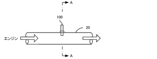
次に、本発明を実施するための形態を図面を用いて説明する。図1は配管20へのガスセンサ100の取り付け状態の概略説明図である。図2は、図1のA-A断面図である。図3は、図2のB-B断面図である。図4は、図3のC-C断面図である。図5は、図3の外側保護カバー140のC-C断面図である。なお、図5は、図4から第1円筒部134,第2円筒部136,先端部138及びセンサ素子110を除いた図に相当する。図6は、図3のD視図である。図7は、図4のE-E断面の一部を拡大した断面図である。
Next, the form for implementing this invention is demonstrated using drawing. FIG. 1 is a schematic illustration of a state in which a
図1に示すように、ガスセンサ100は車両のエンジンからの排気経路である配管20内に取り付けられており、エンジンから排出された被測定ガスとしての排気ガスに含まれるNOxやO2、NH3等のガス成分のうち少なくともいずれか1つの特定ガスの濃度である特定ガス濃度を検出するようになっている。このガスセンサ100は、図2に示すように、ガスセンサ100の中心軸が配管20内の被測定ガスの流れに垂直な状態で配管20内に固定されている。なお、ガスセンサ100の中心軸が配管20内の被測定ガスの流れに垂直且つ鉛直方向に対して所定の角度(例えば45°)だけ傾いた状態で配管20内に固定されていてもよい。
As shown in FIG. 1, the
ガスセンサ100は、図3に示すように、被測定ガス中の特定ガス濃度を検出する機能を有するセンサ素子110と、このセンサ素子110を保護する保護カバー120とを備えている。また、ガスセンサ100は、金属製のハウジング102及び外周面におねじが設けられた金属製のボルト103を備えている。ハウジング102は配管20に溶接され内周面にめねじが設けられた固定用部材22内に挿入されており、さらにボルト103が固定用部材22内に挿入されることでハウジング102が固定用部材22内に固定されている。これにより、ガスセンサ100が配管20内に固定されている。なお、配管20内の被測定ガスの流れる向きは、図3における左から右に向かう方向である。
The
センサ素子110は、細長な長尺の板状体形状の素子であり、ジルコニア(ZrO2)等の酸素イオン伝導性固体電解質層を複数積層した構造を有している。センサ素子110は、被測定ガスを自身の内部に導入するガス導入口111を有しており、ガス導入口111から内部に流入した被測定ガスの特定ガス濃度を検出可能に構成されている。本実施形態では、ガス導入口111は、センサ素子110の先端面(図3におけるセンサ素子110の下面)に開口しているものとした。センサ素子110は、センサ素子110を加熱して保温する温度調整の役割を担うヒーターを内部に備えている。このようなセンサ素子110の構造や特定ガス濃度を検出する原理は公知であり、例えば特開2008-164411号公報に記載されている。センサ素子110は、先端(図3の下端)及びガス導入口111がセンサ素子室124内に配置されている。なお、センサ素子110の後端から先端に向かう方向(図3の下方向)を先端方向と称する。
The
また、センサ素子110は、表面の少なくとも一部を覆う多孔質保護層110aを備えている。本実施形態では、多孔質保護層110aは、センサ素子110の6つの表面のうち5面に形成されて、センサ素子室124内に露出した表面のほとんどを覆っている。具体的には、多孔質保護層110aは、センサ素子110のうちガス導入口111が形成された先端面(図3の下面)を全て覆っている。また、多孔質保護層110aは、センサ素子110の先端面に接続される4つの表面(図4のセンサ素子110における上下左右の面)のうちセンサ素子110の先端面に近い側を覆っている。多孔質保護層110aは、例えば、被測定ガス中の水分等が付着してセンサ素子110にクラックが生じるのを抑制する役割を果たす。また、多孔質保護層110aは、被測定ガスに含まれるオイル成分等がセンサ素子110の表面の図示しない電極等に付着するのを抑制する役割を果たす。多孔質保護層110aは、例えばアルミナ多孔質体、ジルコニア多孔質体、スピネル多孔質体、コージェライト多孔質体,チタニア多孔質体、マグネシア多孔質体などの多孔質体からなる。多孔質保護層110aは、例えばプラズマ溶射,スクリーン印刷,ディッピングなどにより形成することができる。なお、多孔質保護層110aは、ガス導入口111も覆っているが、多孔質保護層110aが多孔質体であるため、被測定ガスは多孔質保護層110aの内部を流通してガス導入口111に到達可能である。多孔質保護層110aの厚さは例えば100μm~700μmである。
The
保護カバー120は、センサ素子110の周囲を取り囲むように配置されている。この保護カバー120は、センサ素子110の先端を覆う有底筒状の内側保護カバー130と、内側保護カバー130を覆う有底筒状の外側保護カバー140とを有している。また、内側保護カバー130と外側保護カバー140とに囲まれた空間として第1ガス室122,第2ガス室126が形成され、内側保護カバー130に囲まれた空間としてセンサ素子室124が形成されている。なお、ガスセンサ100,センサ素子110,内側保護カバー130,外側保護カバー140の中心軸は同軸になっている。保護カバー120は、金属(例えばステンレス鋼)で形成されている。
内側保護カバー130は、第1部材131と、第2部材135と、を備えている。第1部材131は、円筒状の大径部132と、円筒状で大径部132よりも径の小さい第1円筒部134と、大径部132と第1円筒部134とを接続する段差部133と、を有している。第1円筒部134は、センサ素子110の周囲を囲んでいる。第2部材135は、第1円筒部134よりも径が大きい第2円筒部136と、第2円筒部136よりもセンサ素子110の先端方向(図3の下方向)に位置し有底筒状の先端部138と、先端部138の上端に接続して配設され先端部138の外周面よりも外側に突出する段差部139と、第2円筒部136の下端と段差部139とを接続する接続部137と、を有している。先端部138は、側部138dと底部138eとを有している。先端部138には、センサ素子室124と第2ガス室126とに通じ、センサ素子室124からの被測定ガスの出口である1以上の素子室出口138aが形成されている。素子室出口138aは、側部138dに等間隔に形成された複数(本実施形態では4個)の円形の横孔138bを有している。素子室出口138aは、先端部138の底部138eには配設されていない。素子室出口138aの径は、例えば0.5mm~3.0mmであり、好ましくは1.0mm~2.5mmである。本実施形態では、複数の横孔138bの径はいずれも同じ値とした。素子室出口138aは、ガス導入口111よりもセンサ素子110の先端方向(図3の下方向)の位置に形成されている。換言すると、素子室出口138aは、センサ素子110の後端(図3におけるセンサ素子110の図示しない上端)から見てガス導入口111よりも遠く(図3の下方向)に位置している。
The inner
大径部132,第1円筒部134,第2円筒部136,先端部138は中心軸が同一である。大径部132は、ハウジング102に内周面が当接しており、これにより第1部材131がハウジング102に固定されている。第2部材135は、接続部137の外周面が外側保護カバー140の内周面と当接しており溶接などにより固定されている。なお、接続部137の先端側の外径を外側保護カバー140の先端部146の内径よりわずかに大きく形成し、接続部137の先端側を先端部146内に圧入することで、第2部材135を固定してもよい。
The
第2円筒部136の内周面には、第1円筒部134の外周面に向けて突出してこの外周面に接している複数の突出部136aが形成されている。本実施形態では、図4に示すように、突出部136aは3個設けられ、第2円筒部136の内周面の周方向に沿って均等に配置されている。突出部136aは、略半球形状に形成されている。このような突出部136aが設けられていることで、突出部136aによって第1円筒部134と第2円筒部136との位置関係が固定されやすくなっている。なお、突出部136aは、第1円筒部134の外周面を径方向内側に向けて押圧していることが好ましい。こうすれば、突出部136aによって第1円筒部134と第2円筒部136との位置関係をより確実に固定できる。なお、突出部136aは、3個に限らず2個や4個以上としてもよい。なお、第1円筒部134と第2円筒部136との固定が安定化しやすいため、突出部136aは3個以上とすることが好ましい。
The inner peripheral surface of the second
この内側保護カバー130は、第1部材131と第2部材135との隙間でありセンサ素子室124への被測定ガスの入口である素子室入口127(図3,4,7参照)を形成している。素子室入口127は、より具体的には、第1円筒部134の外周面と第2円筒部136の内周面との間の筒状の隙間(ガス流路)として形成されている。素子室入口127は、外側入口144aの配置された空間である第1ガス室122側の開口部である外側開口部128と、ガス導入口111の配置された空間であるセンサ素子室124側の開口部である素子側開口部129と、を有している。外側開口部128は、素子側開口部129よりもセンサ素子110の後端側(図3の上側)に形成されている。そのため、外側入口144aからガス導入口111に達するまでの被測定ガスの経路中で、素子室入口127はセンサ素子110の後端側(図3の上側)から先端側(図3の下側)へ向かう流路となっている。また、素子室入口127は、センサ素子110の後端-先端方向に平行な流路(図3における上下方向の流路)となっている。
The inner
素子側開口部129は、センサ素子110の後端から先端へ向かう方向に開口し且つセンサ素子110の後端-先端方向に平行に開口している。すなわち、素子側開口部129は、図3,7の下方向(真下)に開口している。そのため、センサ素子110は、素子側開口部129から素子室入口127を仮想的に延長した領域(図3,7における素子側開口部129の真下の領域)以外の位置に、配置されている。これにより、素子側開口部129から流出した被測定ガスがセンサ素子110の表面に直接当たることを抑制でき、センサ素子110の保温性の低下を抑制できる。
The element-
第1円筒部134の外周面と第2円筒部136の内周面とは、素子側開口部129において円筒の径方向に距離A4(図7参照)だけ離れており、外側開口部128において円筒の径方向に距離A5だけ離れている。また、第1円筒部134の外周面と第2円筒部136の内周面とは、突出部136aと第1円筒部134とが接触する部分(図4に示した断面)において距離A7だけ離れている。距離A4,距離A5,距離A7は、例えばそれぞれ0.3mm~2.4mmである。距離A4,距離A5の値を調整することで、素子側開口部129の開口面積や外側開口部128の開口面積を調整することができる。本実施形態では、距離A4,距離A5,距離A7は等しいものとし、素子側開口部129の開口面積と外側開口部128の開口面積とが等しいものとした。なお、本実施形態では、距離A4(距離A5,距離A7)は、第1円筒部134の外径と第2円筒部136の内径との差の半分の値と同じである。また、素子側開口部129と外側開口部128との上下方向の距離、すなわち素子室入口127の上下方向の距離L(素子室入口127の経路長に相当)は、例えば0mm超過6.6mm以下である。距離Lは3mm以上としてもよいし、5mm以下としてもよい。
The outer peripheral surface of the first
外側保護カバー140は、図3に示すように、円筒状の大径部142と、大径部142に接続しており大径部142よりも径の小さい円筒状の胴部143と、有底筒状で胴部143よりも内径の小さい先端部146とを有している。また、胴部143は、外側保護カバー140の中心軸方向(図3の上下方向)に沿った側面をもつ側部143aと、胴部143の底部であり側部143aと先端部146とを接続する段差部143bと、を有している。なお、大径部142,胴部143,先端部146の中心軸はいずれも内側保護カバー130の中心軸と同一である。大径部142は、ハウジング102及び大径部132に内周面が当接しており、これにより外側保護カバー140がハウジング102に固定されている。胴部143は、第1円筒部134,第2円筒部136の外周を覆うように位置している。大径部142と胴部143とは、径が同じであってもよい。先端部146は、先端部138を覆うように位置していると共に、内周面が接続部137の外周面と当接している。先端部146は、外側保護カバー140の中心軸方向(図3の上下方向)に沿った側面を有し外径が側部143aの内径よりも小さい側部146aと、外側保護カバー140の底部である底部146bと、側部146aと底部146bとを接続し側部146aから底部146bに向けて縮径するテーパー部146cと、を有している。先端部146は、胴部143よりも先端方向側に位置している。この外側保護カバー140は、胴部143に形成され被測定ガスの外部からの入口である1以上(本実施形態では複数であり、具体的には12個)の外側入口144aと、先端部146に形成され、被測定ガスの外部への出口である1以上(本実施形態では1個)の外側出口147aとを有している。
As shown in FIG. 3, the outer
外側入口144aは、外側保護カバー140の外側(外部)と第1ガス室122とに通じる孔である。外側入口144aは、側部143aに等間隔に形成された1以上(本実施形態では複数であり、具体的には6個)の横孔144bと、段差部143bに等間隔に形成された1以上(本実施形態では複数であり、具体的には6個)の縦孔144cとを有している(図3~6)。この外側入口144a(横孔144b及び縦孔144c)は、円形に開けられた孔である。この12個の外側入口144aの径は、例えば0.5mm~2mmである。外側入口144aの径は、1.5mm以下としてもよい。なお、本実施形態では、複数の横孔144bの径はいずれも同じ値とし、複数の縦孔144cの径はいずれも同じ値とした。また、横孔144bの径は縦孔144cの径よりも大きい値とした。なお、外側入口144aは、図4,5に示すように、外側保護カバー140の周方向に沿って横孔144bと縦孔144cとが交互に等間隔に位置するように形成されている。すなわち、図4,5における横孔144bの中心と外側保護カバー140の中心軸とを結んだ線と、その横孔144bに隣接する縦孔144cの中心と外側保護カバー140の中心軸とを結んだ線と、のなす角が30°(360°/12個)となっている。
The
外側出口147aは、外側保護カバー140の外側(外部)と第2ガス室126とに通じる孔である。この外側出口147aは、先端部146の底部146bの中心に形成された1つの縦孔147cとして構成されている(図3,5,6参照)。なお、外側入口144aとは異なり、外側出口147aは、外側保護カバー140の側部(ここでは先端部146の側部146a)には配設されていない。この外側出口147a(ここでは縦孔147c)は、円形に開けられた孔である。この外側出口147aの径は、例えば0.5mm~3.6mmである。外側出口147aの径は、1.4mm~2.5mmとしてもよい。なお、本実施形態では、縦孔147cの径は、横孔144bや縦孔144cの径よりも大きい値とした。
The
外側保護カバー140及び内側保護カバー130は、胴部143と内側保護カバー130との間の空間として第1ガス室122を形成している。より具体的には、第1ガス室122は、段差部133,第1円筒部134,第2円筒部136,大径部142,側部143a、段差部143bにより囲まれた空間である。センサ素子室124は、内側保護カバー130により囲まれた空間である。外側保護カバー140及び内側保護カバー130は、先端部146と内側保護カバー130との間の空間として第2ガス室126を形成している。より具体的には、第2ガス室126は、先端部138と先端部146とに囲まれた空間である。なお、先端部146の内周面が接続部137の外周面と当接しているため、第1ガス室122と第2ガス室126とは直接には連通していない。
The outer
ここで、ガスセンサ100が特定ガス濃度を検出する際の保護カバー120内の被測定ガスの流れについて説明する。配管20内を流れる被測定ガスは、まず、複数の外側入口144a(横孔144b及び縦孔144c)の少なくともいずれかを通って第1ガス室122内に流入する。次に、被測定ガスは、第1ガス室122から外側開口部128を経て素子室入口127に流入し、素子室入口127を経て素子側開口部129から流出して、センサ素子室124に流入する。素子側開口部129からセンサ素子室124内に流入した被測定ガスは、少なくとも一部がセンサ素子110のガス導入口111に到達する。被測定ガスがガス導入口111に到達してセンサ素子110の内部に流入すると、この被測定ガス中の特定ガス濃度に応じた電気信号(電圧又は電流)をセンサ素子110が発生させ、この電気信号に基づいて特定ガス濃度が検出される。また、センサ素子室124内の被測定ガスは、素子室出口138a(横孔138b)の少なくともいずれかを通って第2ガス室126に流入し、そこから外側出口147aを通って外部に流出する。なお、センサ素子110は、所定の温度を保つように内部のヒーターの出力が例えば図示しないコントローラによって制御される。
Here, the flow of the gas to be measured inside the
ここで、外側保護カバー140は、外側入口144aの合計断面積A[mm2]と外側出口147aの合計断面積D[mm2]との比である断面積比A/Dが値2.0超過値5.0以下となっている。断面積比A/Dが値2.0超過では、合計断面積Aが比較的大きいことで外側入口144aから流入する被測定ガスの流量が大きくなりやすく、合計断面積Dが比較的小さいことで外側出口147aから流入(逆流)しようとする被測定ガスの流量が小さくなりやすい。これらにより、ガス導入口111周辺の空間が流入した被測定ガスで置換されやすくなる。したがって、特定ガス濃度検出の応答性が向上する。また、合計断面積Dが小さすぎると外側出口147aから流出する被測定ガスの流量が小さくなって応答性が低下する場合があるが、断面積比A/Dが値5.0以下では、そのような応答性の低下を低減できる。なお、断面積比A/Dの調整は、例えば外側入口144a及び外側出口147aの数を調整することで行ってもよいし、外側入口144aの各々の断面積及び外側出口147aの各々の断面積を調整することで行ってもよい。
Here, the outer
また、内側保護カバー130は、素子室入口127の合計断面積B[mm2]が素子室出口138aの合計断面積C[mm2]より大きく形成されている。そして、外側保護カバー140及び内側保護カバー130は、合計断面積A~DがB>A>C>Dを満たし、A×B×C×Dが値3000以上値8500以下を満たすようになっている。こうしたガスセンサ100では、被測定ガスの流速が低流速の場合において、被測定ガスの流れが円滑になり、外側入口144aから流入する被測定ガスの多くがセンサ素子室124内に流入するとともに、センサ素子室124内に流入した被測定ガスの多くが逆流することなく外側出口147aから流出する。つまり、合計断面積Bが合計断面積Aよりも大きいことで、外側入口144aから流入したガスの多くが素子室入口127を通ってセンサ素子室124内に流入することで、センサ素子室124内に流入する被測定ガスの流量が大きくなりやすい。また、合計断面積Aが合計断面積Cよりも大きいことで、素子室出口138aから流入(逆流)しようとする被測定ガスの流量が小さくなりやすい。さらに、合計断面積Cが合計断面積Dよりも大きいことで、外側出口147aから流入(逆流)しようとする被測定ガスの流量が小さくなりやすい。これらにより、被測定ガスの流速が低流速の場合でも、ガス導入口111周辺の空間が流入した被測定ガスで置換されやすくなる。したがって、被測定ガスの流速が低流速の場合でも、各出入口の合計断面積A~Dを保温性が低下するほど大きくすることなく、特定ガス濃度検出の応答性を向上させることができる。
Further, the inner
なお、本実施形態では、合計断面積Aは、6個の横孔144bの合計断面積と6個の縦孔144cの合計断面積との和である。合計断面積Cは、4個の横孔138bの合計断面積である。合計断面積Dは、1個の縦孔147cの断面積である。外側入口144aの断面積は、外側入口144aを通過する被測定ガスの向きに垂直な方向の面積とする。本実施形態では、外側入口144aはいずれも円形の孔であるため、この円の面積が断面積となる。素子室出口138a及び外側出口147aについても同様である。また、例えばある1つの外側入口144aにおいて、入口側(外側保護カバー140の外表面側)と出口側(外側保護カバー140の内表面側)とで断面積が異なるなど、外側入口144aの断面積が一定でない場合には、断面積の最小値をその外側入口144aの断面積とする。素子室出口138a及び外側出口147aについても同様である。また、本実施形態では、合計断面積Bは、素子室入口127の断面積であり、第1円筒部134の外周面と第2円筒部136の内周面との間の筒状の隙間の断面積である。素子室入口127の断面積は、素子室入口127を通過する被測定ガスの向きに垂直な方向の面積とする。本実施形態では、第1円筒部134の外周面及び第2円筒部136の内周面はいずれも円形であるため、第2円筒部136の内径を直径とする円の断面積から第1円筒部134の外径を直径とする円の断面積とを差し引いた値が素子室入口127の断面積となる。また、例えば素子室入口127において、外側開口部128と素子側開口部129とで断面積が異なるなど、素子室入口127における被測定ガスの流れの向きに垂直な方向の断面積が一定でない場合には、断面積の最小値をその素子室入口127の断面積とする。本実施形態では、素子室入口127のうち突出部136aが最も突出している断面、つまり図4の断面において素子室入口127の断面積が最小値であるため、図4の断面における素子室入口127の断面積が合計断面積Bとなる。
In this embodiment, the total cross-sectional area A is the sum of the total cross-sectional area of the six
以上詳述した本実施形態のガスセンサ100によれば、断面積比A/Dが値2.0超過値5.0以下であり、かつ、B>A>C>Dを満たし、さらに、合計断面積A~Dの積であるA×B×C×Dが値3000以上値8500以下を満たすことで、被測定ガスの流速が低流速の場合でも特定ガス濃度検出の応答性の低下を低減できるとともに、保温性の低下を低減できる。断面積比A/Dは値2.5以上が好ましく、値3.0以上がより好ましく、値3.4以上がさらに好ましい。断面積比A/Dが大きいほど、特定ガス濃度検出の応答性が向上しやすい。合計断面積Aは、10mm2以上30mm2以下としてもよいし、10mm2以上18mm2以下としてもよい。また、合計断面積Bは、15mm2以上50mm2以下としてもよいし、15mm2以上35mm2以下としてもよいし、20mm2以上35mm2以下としてもよい。また、合計断面積Cは、5mm2以上15mm2以下としてもよいし、5mm2以上10mm2以下としてもよい。また、合計断面積Dは、1.6mm2以上10mm2以下としてもよいし、2.8mm2以上3.5mm2以下としてもよい。さらにまた、合計断面積Bと合計断面積Aとの比である断面積比B/Aは、値1超過(つまりB>A)値4.5以下としてもよいし、値1.4以上値3.3以下としてもよい。また、合計断面積Aと合計断面積Cとの比である断面積比A/Cは、値1超過(つまりA>C)値6.0以下としてもよいし、値1.1以上値3.0以下としてもよい。また、合計断面積Cと合計断面積Dとの比である断面積比C/Dは、値1超過(つまりC>D)値9.4以下としてもよいし、値1.3以上値4.0以下としてもよい。
According to the
また、ガスセンサ100では、外側保護カバー140は、側部146aと底部146bとを有する有底筒状の先端部146を有しており、外側出口147aは、外側保護カバー140の側部146aには配設されていない。ここで、外側保護カバー140の側部146aに配設された外側出口147aが存在する場合、側部146aの外側出口147aと周囲の被測定ガスの流れ方向との位置関係によって、応答性が変化する場合がある。このような側部146aの外側出口147a(ここでは横孔)と周囲の被測定ガスの流れ方向との位置関係による応答性の変化が大きいと、ガスセンサ100の取り付けの向き(外側保護カバー140の中心軸を中心とした回転方向の角度)によっては応答性が低下する場合がある(上述した特許文献2参照)。これに対し、本実施形態のガスセンサ100では、外側出口147aが側部146aには配設されていないため、ガスセンサ100の取り付けの向きによる応答性への影響を低減できる。なお、このようなガスセンサ100の取り付けの向きによる応答性への影響を角度依存性と称する。本実施形態のガスセンサ100では、外側出口147aが側部146aには配設されていないことで、角度依存性を小さくできる。また、外側保護カバー140では、外側出口147aは、底部146bに形成された1つの縦孔147cとして構成されており、縦孔147cの径は比較的大きく、例えば横孔144bや縦孔144cの径よりも大きい。このため、B>A>C>Dを満たすように合計断面積Dを設定しても、外側出口147aにすすがつまりにくい。
Further, in the
さらに、ガスセンサ100では、内側保護カバー130は、側部138dと底部138eとを有する有底筒状の形状をしており、素子室出口138aは、内側保護カバー130の底部138eには配設されていない。一般的に底部138eよりも側部138dの方が面積が大きい場合が多く、その場合には素子室出口138aの合計断面積Cを大きくしやすいため、C>Dを実現しやすい。また、素子室出口138aの延長線上にセンサ素子110がないほうがセンサ素子110に水がかかりにくく、素子室出口138aを内側保護カバー130の側部138dに配設したほうが、素子室出口の延長線上にセンサ素子がない構成を実現しやすい。また、内側保護カバー130の底部138eに素子室出口138aが配設されていると、外側保護カバー140の底部146bに配設された外側出口147aと、内側保護カバー130の底部138eに配設された素子室出口138aとセンサ素子110とが一直線上に配設される場合がある。外側出口147aと素子室出口138aと、センサ素子110とが一直線上に配設されている場合、外側出口147aから侵入した水がセンサ素子110にかかりやすくなることが懸念される。これに対し、本実施形態のガスセンサ100では、素子室出口138aは内側保護カバー130の底部138eには配設されていないため、外側出口147aから侵入した水がセンサ素子110にかかりにくい。
Furthermore, in the
さらにまた、ガスセンサ100において、内側保護カバー130は、素子側開口部129が先端方向に向けて開口するように素子室入口127を形成している。そのため、素子側開口部129から流出した被測定ガスがセンサ素子110の表面(ガス導入口111以外の表面)に垂直に当たることを抑制したり、センサ素子110の表面上を長い距離通過してからガス導入口111に到達することを抑制したりできる。これにより、センサ素子110の保温性の低下をより抑制できる。しかも、素子側開口部129の開口の向きを調整することでセンサ素子110の保温性の低下を抑制しており、内側保護カバー130内の被測定ガスの流量や流速を減らしているわけではないため、特定ガス濃度検出の応答性の低下もより低減できる。
Furthermore, in the
なお、本発明は上述した実施形態に何ら限定されることはなく、本発明の技術的範囲に属する限り種々の態様で実施しうることは言うまでもない。 It goes without saying that the present invention is by no means limited to the above-described embodiments, and can be embodied in various forms as long as they fall within the technical scope of the present invention.
例えば、保護カバー120の形状は上述した実施形態に限られない。保護カバー120の形状や素子室入口127,素子室出口138a,外側入口144a,外側出口147aの形状,個数,配置などは、適宜変更してもよい。例えば、外側保護カバー140の先端部146は、有底筒状で、側部146aと底部146bとテーパー部146cとを有するものとしたが、テーパー部146cを省略した円筒形状としてもよい。また、内側保護カバー130の先端部138は、側部138dの外径が一定で側部138dと底部138eとが同径となるような形状としたが、例えば円錐台を逆さにした形状など、側部138dの外径が底部138eに近づくほど小さくなる傾向を有する形状としてもよい。図8は、外側保護カバー140の先端部146をテーパー部146cを省略した円筒形状とし、内側保護カバー130の先端部138を円錐台を逆さにした形状としたガスセンサ200の縦断面図(ガスセンサ100のB-B断面図に相当)である。図9は図8の外側保護カバー240のF-F断面図であり、図10は図8のG視図である。図8~10では、ガスセンサ100と同じ構成要素については同じ符号を付して、詳細な説明を省略する。図8に示すように、ガスセンサ200の保護カバー220は内側保護カバー130に代えて内側保護カバー230を備え、外側保護カバー140に代えて外側保護カバー240を備えている。内側保護カバー230の第2部材235は、先端部138及び段差部139に代えて円錐台を逆さにした形状の先端部238を有している。また、先端部238には、センサ素子室124と第2ガス室126とに通じ、センサ素子室124からの被測定ガスの出口である素子室出口238aが形成されている。素子室出口238aは、先端部238の底面の中心に形成された円形の縦孔を1つ有している。外側保護カバー240は、先端部146に代えて、有底筒状(円筒形状)で胴部143よりも内径の小さい先端部246を有している。先端部246は、外側保護カバー240の中心軸方向(図8の上下方向)に沿った側面を有し外径が側部143aの内径よりも小さい側部246aと、外側保護カバー240の底部である底部246bと、を有している。また、先端部246には、被測定ガスの外部への出口である複数(ここでは6個)の外側出口247aが形成されている。この外側出口247aは、先端部246の底部246bに外側保護カバー240の周方向に沿って等間隔に形成された複数(ここでは6個)の縦孔247cを有している(図8~10参照)。こうしたガスセンサ200でも、断面積比A/Dが値2.0超過値5.0以下で、かつB>A>C>Dを満たし、さらにA×B×C×Dが値3000以上値8500以下を満たすようにすることで、上述した実施形態と同様の効果が得られる。
For example, the shape of the
上述した実施形態では、素子室入口127は第1部材131と第2部材135との隙間としたが、これに限らず、素子室入口はセンサ素子室124への入口であればどのような形状であってもよい。例えば素子室入口は内側保護カバー130に形成された貫通孔であってもよい。なお、素子室入口が貫通孔である場合も、素子室入口がセンサ素子110の後端側から先端側へ向かう流路を形成していてもよい。例えば素子室入口が縦孔や図3の上下方向から傾斜した孔であってもよい。また、素子側開口部129が先端方向に向けて開口していてもよい。また、素子室入口127の数は1つに限らず複数でもよい。素子室出口138a,外側入口144a,外側出口147aについても、孔に限らず保護カバー120を構成する複数の部材の隙間であってもよいし、各々の数は1以上であればよい。また、外側入口144aは横孔144bと縦孔144cとを有するものとしたが、いずれか一方のみを有するものとしてもよい。また、横孔144b及び縦孔144cに加えて又は代えて、側部143aと段差部143bとの境界の角部に角孔を形成してもよい。素子室入口127,素子室出口138a,外側出口147aについても、同様に横孔,縦孔,角孔のいずれか1以上を有するものとしてもよい。また、外側出口147aは、テーパー部146cに設けられた貫通孔を有するものとしてもよい。ただし、上述したように外側出口147aについては横孔を有さない、すなわち外側出口147aは側部146aには配設されていないことが好ましい。また、上述したように素子室出口138aについては縦孔を有さない、すなわち素子室出口138aは底部138eには配設されていないことが好ましい。
In the above-described embodiment, the
上述した実施形態では、突出部136aは第2円筒部136の内周面に形成されているが、これに限られない。第1円筒部134の外周面と第2円筒部136の内周面との少なくとも一方の面に、他方の面に向けて突出してその面に接する突出部が形成されていればよい。また、上述した実施形態では、図3,4に示すように、第2円筒部136のうち突出部136aが形成されている部分の外周面は内側に窪んでいるが、これに限らず外周面が窪んでいなくてもよい。また、突出部136aは半球形状に限らずどのような形状であってもよい。なお、第1円筒部134の外周面及び第2円筒部136の内周面に突出部136aが形成されていなくてもよい。
In the embodiment described above, the protruding
上述した実施形態では、素子室入口127は第1円筒部134の外周面と第2円筒部136の内周面との間の筒状の隙間としたが、これに限られない。例えば、第1円筒部の外周面と第2円筒部の内周面との少なくとも一方に凹部(溝)が形成されており、素子室入口は、凹部により形成された第1円筒部と第2円筒部との隙間としてもよい。図11は、変形例の素子室入口327を示す断面図である。図11に示すように、第1円筒部334の外周面と第2円筒部336の内周面とは接しており、第1円筒部334の外周面には複数(図11では4個)の凹部334aが等間隔に形成されている。この凹部334aと第2円筒部336の内周面との間の隙間が、素子室入口327となっている。このように素子室入口327が複数の(図11では4箇所)の隙間で構成されている場合には、複数の隙間の合計断面積を合計断面積Bとする。
In the embodiment described above, the
上述した実施形態では、素子室入口127は、センサ素子110の後端-先端方向に平行な流路(図3における上下方向に平行な流路)としたが、これに限られない。例えば、素子室入口は、センサ素子110の後端側から先端側に向かうにつれてセンサ素子110に近づくように後端-先端方向から傾斜した流路としてもよい。図12は、この場合の変形例のガスセンサ400の縦断面図である。図12では、ガスセンサ100,200と同じ構成要素については同じ符号を付して、詳細な説明を省略する。図12に示すように、ガスセンサ400の保護カバー420は、内側保護カバー230に代えて内側保護カバー430を備えている。内側保護カバー430は、第1部材431と、第2部材435と、を備えている。第1部材431は、第1部材131と比べて、第1円筒部134を備えない代わりに、円筒状の胴部434aと、センサ素子110の後端側から先端側に向かうにつれて縮径する円筒状の第1円筒部434bと、を備えている。第1円筒部434bは、センサ素子110の後端側の端部で胴部434aと接続されている。第2部材435は、第2部材235と比べて、第2円筒部136及び接続部137を備えない代わりに、センサ素子110の後端側から先端側に向かうにつれて縮径する円筒状の第2円筒部436を備えている。第2円筒部436は、先端部238と接続されている。第1円筒部434bの外周面と第2円筒部436の内周面とは接しておらず、両者により形成される隙間が素子室入口427となっている。素子室入口427は、第1ガス室122側の開口部である外側開口部428と、センサ素子室124側の開口部である素子側開口部429と、を有している。この素子室入口427は、第1円筒部434b及び第2円筒部436の形状によって、センサ素子110の後端側から先端側に向かうにつれてセンサ素子110に近づくように(内側保護カバー430の中心軸に近づくように)後端-先端方向から傾斜した流路となっている。同様に、素子側開口部429は、センサ素子110の後端側から先端側に向かうにつれてセンサ素子110に近づくように後端-先端方向から傾斜して開口している(図12の拡大図参照)。このように素子室入口427が傾斜した流路である場合や素子側開口部429が傾斜して開口している場合、素子側開口部429からセンサ素子室124に流出する被測定ガスの流れる向きはセンサ素子110の後端-先端方向から傾斜した向きになる。これにより、上述した実施形態の素子室入口127や素子側開口部129と同様の効果が得られる。すなわち、被測定ガスがセンサ素子110の表面(ガス導入口111以外の表面)に垂直に当たることを抑制したり、センサ素子110の表面上を長い距離通過してからガス導入口111に到達することを抑制したりできる。これにより、センサ素子110の保温性の低下を抑制できる。また、図12では、素子室入口427の幅は、センサ素子110の後端側から先端側に向かうにつれて狭くなっている。そのため、素子側開口部429の開口面積は外側開口部428の開口面積よりも小さい。換言すると、素子室入口427は、図7を用いて説明した距離A5よりも距離A4の方が小さくなっている。これにより、被測定ガスが外側開口部428から流入して素子側開口部429から流出することで流入時と比べて流出時の被測定ガスの流速が高まる。そのため、特定ガス濃度検出の応答性を向上させることができる。なお、図12では、素子室入口427がセンサ素子110の後端-先端方向から傾斜した流路となっており、素子側開口部429がセンサ素子110の後端-先端方向から傾斜して開口し、且つ素子側開口部429の開口面積が外側開口部428の開口面積よりも小さくなるようにしているが、これらの3つの特徴のうち1以上を省略してもよいし、ガスセンサがこれらの3つの特徴のうち1以上の特徴を有するようにしてもよい。こうしたガスセンサ400でも、断面積比A/Dが値2.0超過値5.0以下で、かつB>A>C>Dを満たし、さらにA×B×C×Dが値3000以上値8500以下を満たすようにすることで、上述した実施形態と同様の効果が得られる。なお、図12のガスセンサ400では、ガスセンサ200のように、外側保護カバー240の先端部246をテーパー部を省略した円筒形状とし、内側保護カバー430の先端部238を円錐台を逆さにした形状としたが、ガスセンサ100のような先端部138,段差部139及び先端部146を有するものとしてもよい。
In the above-described embodiment, the
上述した実施形態では、素子側開口部129は先端方向に向けて開口していたが、これに限らず、例えば先端方向と垂直な方向に向けてセンサ素子室124に開口していてもよい。また、上述した実施形態では、素子室入口127はセンサ素子110の後端-先端方向に平行な流路としたが、これに限らず、例えば先端方向と垂直な方向に沿った流路としてもよい。
In the above-described embodiment, the element-
上述した実施形態では、外側入口144aと素子室入口127との間の被測定ガスの流路は第1ガス室122のみとしたが、これに限られない。第1ガス室122は、外側入口144aと素子室入口127との間の被測定ガスの流路の少なくとも一部であればよい。例えば、保護カバー120が内側保護カバー130及び外側保護カバー140の他に両者の間に配置された中間保護カバーを備えており、外側入口144aと素子室入口127との間の被測定ガスの流路が複数のガス室を含んでいてもよい。同様に、上述した実施形態では、外側出口147aと素子室出口138aとの間の被測定ガスの流路は第2ガス室126のみとしたが、これに限られない。第2ガス室126は、外側出口147aと素子室出口138aとの間の被測定ガスの流路の少なくとも一部であればよい。
In the above-described embodiment, only the
上述した実施形態では、内側保護カバー130は、第1部材131と第2部材135と2つの部材を備えていたが、第1部材131と第2部材135とは一体化された部材であってもよい。
In the above-described embodiment, the inner
上述した実施形態では、ガス導入口111は、センサ素子110の先端面(図3におけるセンサ素子110の下面)に開口しているものとしたが、これに限られない。例えば、センサ素子110の側面(図4におけるセンサ素子110の上下左右の面)に開口していてもよい。
In the above-described embodiment, the
上述した実施形態では、センサ素子110は多孔質保護層110aを備えているが、多孔質保護層110aを備えていなくてもよい。
Although the
上述した実施形態では、保護カバー120をガスセンサ100の一部として説明したが、保護カバー120は単独で流通してもよい。
Although the
以下には、ガスセンサを具体的に作製した例を実施例として説明する。実験例4~7,9~10,12~14,18,21,23が本発明の実施例に相当し、実験例1~3,8,11,15~17,19~20,22が比較例に相当する。なお、本発明は以下の実施例に限定されるものではない。 An example in which a gas sensor is specifically manufactured will be described below as an example. Experimental Examples 4-7, 9-10, 12-14, 18, 21, 23 correspond to the examples of the present invention, and Experimental Examples 1-3, 8, 11, 15-17, 19-20, 22 are compared. corresponds to the example. In addition, the present invention is not limited to the following examples.
[実験例1]
外側保護カバー240に代えて図13,14に示す外側保護カバー540を用いた以外は図8~10に示したガスセンサ200を実験例1とした。具体的には、内側保護カバー230の第1部材131は、板厚が0.3mm、軸方向長さが10.2mm、大径部132の軸方向長さが1.8mm、大径部132の外径が14.4mm、第1円筒部134の軸方向長さが8.4mm、第1円筒部134の外径が8.48mmとした。第2部材235は、板厚が0.3mm、軸方向長さが11.5mm、第2円筒部136の軸方向長さが4.5mm、第2円筒部136の内径が9.7mm、先端部238の軸方向長さが4.9mm、先端部238の底面の径が3.0mmとした。素子室入口127に関して、距離A4,A5,A7はいずれも0.61mm距離Lは4mmとした。素子室出口238aの径は1.5mmとした。外側保護カバー540は、板厚が0.4mm、軸方向長さが24.35mm、大径部142の軸方向長さが5.85mm、大径部142の外径が15.2mm、胴部143の軸方向長さが8.9mm(胴部143の上端から段差部143bの上面までの軸方向長さが8.5mm)、胴部143の外径が14.6mm、先端部246の軸方向長さが9.6mm、先端部246の外径が8.7mmとした。外側入口144aは、径1mmの横孔144bを6個、径1mmの縦孔144cを6個、それぞれ交互に等間隔(隣接する孔のなす角が30°)に形成した。外側出口547aは、径1mmの横孔547bを3個、径1mmの縦孔547cを3個、それぞれ交互に等間隔(隣接する孔のなす角が60°)に形成した。保護カバー220の材質は、SUS310Sとした。また、ガスセンサ200のセンサ素子110は、幅(図8における左右長さ)が4mm、厚さ(図8における紙面に垂直な方向の長さ)が1.5mmとした。多孔質保護層110aはアルミナ多孔質体とし、厚さは400μmとした。実験例1では、合計断面積Aは9.4mm2とし、合計断面積Bは15.9mm2とし、合計断面積Cは1.8mm2とし、合計断面積Dは4.7mm2とした。断面積比A/Dは値2.0とした。
[Experimental example 1]
The
[実験例2]
図3~7に示したガスセンサ100を実験例2とした。具体的には、内側保護カバー130の第1部材131は、板厚が0.3mm、軸方向長さが10.2mm、大径部132の軸方向長さが1.8mm、大径部132の外径が14.4mm、第1円筒部134の軸方向長さが8.4mm、第1円筒部134の外径が8.48mmとした。第2部材135は、板厚が0.3mm、軸方向長さが11.5mm、第2円筒部136の軸方向長さが4.5mm、第2円筒部136の内径が9.7mm、先端部138の軸方向長さが4.9mm、先端部138の側部138dの外径が5.6mmとした。素子室入口127に関して、距離A4,A5,A7はいずれも0.61mm、距離Lは4mmとした。素子室出口138aは、径1.5mmの横孔138bを4個、等間隔に形成した。外側保護カバー140は、板厚が0.4mm、軸方向長さが24.35mm、大径部142の軸方向長さが5.85mm、大径部142の外径が15.2mm、胴部143の軸方向長さが8.9mm(胴部143の上端から段差部143bの上面までの軸方向長さが8.5mm)、胴部143の外径が14.6mm、先端部146の軸方向長さが9.6mm、先端部146の側部146aの軸方向長さが9.6mm、先端部146の側部146aの外径が8.7mm、先端部146の底部146bの径が2.6mmとした。外側入口144aは、径1.5mmの横孔144bを6個、径1.0mmの縦孔144cを6個、それぞれ交互に等間隔に形成した。外側出口147aの径は、1.0mmとした。保護カバー120の材質は、SUS310Sとした。また、ガスセンサ100のセンサ素子110は、幅(図4における左右長さ)が4mm、厚さ(図4における上下長さ)が1.5mmとした。多孔質保護層110aはアルミナ多孔質体とし、厚さは400μmとした。実験例2では、合計断面積Aは15.3mm2とし、合計断面積Bは15.9mm2とし、合計断面積Cは7.1mm2とし、合計断面積Dは0.8mm2とした。断面積比A/Dは値19.1とした。
[Experimental example 2]
The
[実験例3]
図8~10に示したガスセンサ200を実験例3とした。実験例3では、外側出口247aは横孔を備えず、縦孔247cを6個とし、縦孔247cの径は実験例1と同じ1.0mmとした。横孔144bの径は1.5mmとした。それ以外は実験例1と同じ寸法とした。実験例3では、合計断面積Aは15.3mm2とし、合計断面積Bは15.9mm2とし、合計断面積Cは1.8mm2とし、合計断面積Dは4.7mm2とした。断面積比A/Dは値3.3とした。
[Experimental example 3]
The
[実験例4~23]
実験例4~23では、合計断面積A~Dが表1に示す値となるように外側入口144a,素子室入口127,素子室出口138a,外側出口147aの寸法を調整した以外は、実験例2のガスセンサ100と同様とした。具体的には、実験例5,7~11,16~19では、外側入口144aとして、径1.06mmの横孔144bを6個、径1.06mmの縦孔144cを6個、それぞれ交互に等間隔に形成して、合計断面積Aを10.6mm2とした。また、実験例7,9,11,15,17,19,20,22では、第1円筒部134の外径は8.5mm、第2円筒部136の内径は10.7mmとして、合計断面積Bを31.7mm2とした。実験例23では、第1円筒部134の外径は9.48mm、第2円筒部136の内径は11.0mmとして、合計断面積Bを24.4mm2とした。さらに、実験例6では、素子室出口138aとして、径1.47mmの横孔138bを4個等間隔に形成して、合計断面積Cを6.8mm2とした。実験例8,9,12,13では、素子室出口138aとして、径1.14mmの横孔138bを4個等間隔に形成して、合計断面積Cを4.1mm2とした。実験例10,11,14,15では、素子室出口138aとして、径1.77mmの横孔138bを4個等間隔に形成して、合計断面積Cを9.8mm2とした。そして、実験例4~15,23では、外側出口147aの径を2.0mmとして、合計断面積Dを3.1mm2とした。実験例18,19,21,22では、外側出口147aの径を2.44mmとして、合計断面積Dを4.7mm2とした。
[Experimental Examples 4 to 23]
In Experimental Examples 4 to 23, the dimensions of the
[応答性及び保温性の評価]
実験例1~23のガスセンサをそれぞれ図1,2と同様に配管に取り付けた。大気に酸素を混合して任意の酸素濃度に調節したガスを被測定ガスとし、この被測定ガスを配管内に流速V=1m/s又は流速V=10m/sで流した。そして、配管内に流す被測定ガスの酸素濃度を22.9%から20.2%に変化させた場合における、センサ素子の出力の時間変化及びヒーターの投入パワーの変化を調べた。酸素濃度を変化させる直前のセンサ素子の出力値を0%、酸素濃度の変化後にセンサ素子の出力が変化して安定したときの出力値を100%として、出力値が10%を越えたときから90%を越えるまでの経過時間を特定ガス濃度検出の応答時間(sec)とした。この応答時間が短いほど特定ガス濃度検出の応答性が高いことを意味する。また、出力値が10%を超えたときから90%を超えるまでのセンサ素子のヒーターの投入パワーの最大値をヒーターパワー(W)として測定した。流速が急激に変化すると、センサ素子が冷えることでヒーターパワーが高くなるため、この値が小さいということは、センサ素子が冷えにくいすなわち保温性が高いことを意味する。なお、応答時間及びヒーターパワーの測定は、各実験例について複数回行い、各々の平均値を各実験例についての応答時間及びヒーターパワーとした。
[Evaluation of responsiveness and heat retention]
The gas sensors of Experimental Examples 1 to 23 were attached to pipes in the same manner as in FIGS. A gas adjusted to an arbitrary oxygen concentration by mixing air with oxygen was used as the gas to be measured, and this gas to be measured was flowed through the pipe at a flow velocity of V=1 m/s or V=10 m/s. Then, the time change of the output of the sensor element and the change of the input power of the heater were examined when the oxygen concentration of the gas to be measured flowing in the pipe was changed from 22.9% to 20.2%. When the output value exceeds 10%, the output value of the sensor element immediately before the oxygen concentration is changed is 0%, and the output value when the output of the sensor element changes and stabilizes after the oxygen concentration is changed is 100%. The elapsed time until 90% was exceeded was defined as the response time (sec) for the specific gas concentration detection. It means that the shorter the response time, the higher the responsiveness of detecting the concentration of the specific gas. Further, the maximum value of input power of the heater of the sensor element from when the output value exceeded 10% to 90% was measured as the heater power (W). When the flow velocity changes abruptly, the sensor element cools down, which increases the heater power. Therefore, a small value means that the sensor element is difficult to cool down, that is, it has high heat retention. The response time and heater power were measured multiple times for each experimental example, and the average value of each measurement was used as the response time and heater power for each experimental example.
表1に、実験例1~23のガスセンサにおける合計断面積、合計断面積比、応答性、保温性をまとめた。なお、表1では、被測定ガスの流速を1m/sとして測定した応答時間を応答性の評価に用い、この応答時間が3秒以下の場合に応答性が良好(OK)と判断した。また、被測定ガスの流速を60m/sとして測定したヒーターパワー(電力)を保温性の評価に用い、この電力が10W以下の場合に保温性が良好と判断した。 Table 1 summarizes the total cross-sectional area, total cross-sectional area ratio, responsiveness, and heat retention of the gas sensors of Experimental Examples 1 to 23. In Table 1, the response time measured at a flow velocity of the gas to be measured of 1 m/s was used to evaluate the responsiveness, and when the response time was 3 seconds or less, the responsiveness was judged to be good (OK). The heater power (electric power) measured at a flow velocity of the gas to be measured of 60 m/s was used for evaluation of heat retention.

表1に示すように、合計断面積A~DがB>A>C>Dを満たし(表1ではB/A>1、A/C>1、C/D>1のすべてを満たす)、かつ合計断面積比A/Dが値2.0超過値5.0以下を満たし、A×B×C×Dが値3000以上値8500以下を満たす実験例4~7,9~10,12~14,18,21,23では、応答性及び保温性の両方を良好にできることがわかった。具体的には、A/Dの値が2.0以下の実験例1や、A/Dの値が5.0より大きい実験例2,16,17,20では応答性が低いことから、応答性を高めるためにはA/Dが値2.0超過値5.0以下を満たす必要があると考えられる。また、C/Dが値1以下つまりC≦Dとなる実験例1,3では、応答性が低いことから、応答性を高めるためにはC>Dを満たす必要があると考えられる。さらに、C/D及びA/Cの値が同じでB/Aの値だけの異なる実験例同士、つまり実験例2,20、実験例4,23、実験例5,7、実験例8,9、実験例10,11、実験例12,13、実験例14,15、実験例16,17、実験例18,19、実験例21,22を各々比較すると、B/Aの値が小さいほど応答性が低い傾向が見られた。実験例のうちB/Aの値が最も小さいものでもB/Aは値1超過であることから、応答性を高めるためには、B/Aが値1超過、つまりB>Aを満たす必要があると推察される。さらにまた、B/Aの値が同じでA/Cの値の異なる実験例同士、つまり、実験例3,21、実験例4,6,12,14、実験例5,8,10、実験例7,9,11、実験例13,15を各々比較すると、A/Cの値が小さいほど保温性が低い傾向が見られた。実験例のうちA/Cの値が最も小さいものでもA/Cは値1超過であることから、保温性を高めるためには、A/Cが値1超過、つまりA>Cを満たす必要があると推察される。そして、上述した全てを満たす場合でも、A×B×C×Dの値が3000未満である実験例8では応答性が低いことから、応答性を高めるためにはA×B×C×Dの値が3000以上である必要があると考えられる。また、A×B×C×Dの値が8500を超える実験例11,15,19,22では保温性が低いことから、保温性を高めるためにはA×B×C×Dの値が8500以下である必要があると考えられる。 As shown in Table 1, the total cross-sectional areas A to D satisfy B>A>C>D (in Table 1, all of B/A>1, A/C>1, and C/D>1 are satisfied), Experimental Examples 4-7, 9-10, 12- where the total cross-sectional area ratio A/D satisfies a value exceeding 2.0 and a value of 5.0 or less, and A × B × C × D satisfies a value of 3000 or more and a value of 8500 or less. In 14, 18, 21 and 23, it was found that both responsiveness and heat retention can be improved. Specifically, in Experimental Example 1 in which the A/D value is 2.0 or less, and in Experimental Examples 2, 16, 17, and 20 in which the A/D value is greater than 5.0, the response is low. It is considered that A/D needs to satisfy the value of 2.0 or more and 5.0 or less in order to improve the performance. Also, in Experimental Examples 1 and 3 where C/D is 1 or less, that is, C≤D, the responsiveness is low. Furthermore, experimental examples having the same C/D and A/C values but different only B/A values, that is, experimental examples 2 and 20, experimental examples 4 and 23, experimental examples 5 and 7, and experimental examples 8 and 9 , Experimental Examples 10 and 11, Experimental Examples 12 and 13, Experimental Examples 14 and 15, Experimental Examples 16 and 17, Experimental Examples 18 and 19, and Experimental Examples 21 and 22, the smaller the value of B/A, the better the response. tended to be low. Since even the smallest B/A value among the experimental examples has a B/A value exceeding 1, in order to improve the responsiveness, it is necessary for B/A to exceed a value of 1, that is, to satisfy B>A. It is assumed that there is. Furthermore, experimental examples with the same B/A value and different A/C values, that is, experimental examples 3 and 21, experimental examples 4, 6, 12 and 14, experimental examples 5, 8 and 10, experimental examples Comparing 7, 9, 11 and Experimental Examples 13 and 15, it was found that the lower the A/C value, the lower the heat retention. Even the smallest A/C value among the experimental examples exceeds the value of 1, so in order to increase the heat retention, the A/C value must exceed 1, that is, A>C. It is assumed that there is. Even when all of the above are satisfied, the responsiveness is low in Experimental Example 8 in which the value of A×B×C×D is less than 3000. Therefore, in order to improve the responsiveness, A×B×C×D It is believed that the value should be 3000 or greater. In addition, in Experimental Examples 11, 15, 19, and 22, in which the value of A×B×C×D exceeds 8500, the heat retention is low. It is considered necessary to be:
20 配管、22 固定用部材、100,200,400 ガスセンサ、102 ハウジング、103 ボルト、110 センサ素子、110a 多孔質保護層、111 ガス導入口、120,220,420 保護カバー、122 第1ガス室、124 センサ素子室、126 第2ガス室、127,327,427 素子室入口、128,428 外側開口部、129,429 素子側開口部、130,230,430 内側保護カバー、131,431 第1部材、132 大径部、133 段差部、134,334 第1円筒部、135,235,435 第2部材、136,336,436 第2円筒部、136a 突出部、137 接続部、138,238 先端部、138a,238a素子室出口、138b 横孔、138d 側部、138e 底部、139 段差部、140,240,540 外側保護カバー、142 大径部、143 胴部、143a 側部、143b 段差部、144a 外側入口、144b 横孔、144c 縦孔、146,246 先端部、146a,246a 側部、146b,246b 底部、146c テーパー部、147a,247a,547a 外側出口、147c,247c,547c 縦孔、334a 凹部、434a 胴部、434b 第1円筒部、547b 横孔。
20 piping, 22 fixing member, 100,200,400 gas sensor, 102 housing, 103 bolt, 110 sensor element, 110a porous protective layer, 111 gas inlet, 120,220,420 protective cover, 122 first gas chamber, 124
Claims (9)
前記センサ素子の先端及び前記ガス導入口が内部に配置されるセンサ素子室を内側に有し、該センサ素子室への入口である1以上の素子室入口と該センサ素子室からの出口である1以上の素子室出口とが配設された内側保護カバーと、
前記被測定ガスの外部からの入口である1以上の外側入口と、前記被測定ガスの外部への出口である1以上の外側出口と、が配設され、前記内側保護カバーの外側に配設された外側保護カバーと、
を備え、
前記外側保護カバー及び前記内側保護カバーは、両者の間の空間として、前記外側入口と前記素子室入口との間の前記被測定ガスの流路の少なくとも一部である第1ガス室と、前記外側出口と前記素子室出口との間の前記被測定ガスの流路の少なくとも一部であり該第1ガス室と直接には連通していない第2ガス室と、を形成しており、
前記外側入口の合計断面積A[mm2]、前記素子室入口の合計断面積B[mm2]、前記素子室出口の合計断面積C[mm2]及び前記外側出口の合計断面積D[mm2]が、B>A>C>Dを満たし、かつ、前記合計断面積Aと前記合計断面積Dとの比である断面積比A/Dが値2.0超過値5.0以下であり、前記合計断面積A~Dの積であるA×B×C×Dが値3000以上値8500以下である、
ガスセンサ。 a sensor element having a gas inlet for introducing a gas to be measured and capable of detecting a specific gas concentration of the gas to be measured that has flowed into the interior from the gas inlet;
It has inside a sensor element chamber in which the tip of the sensor element and the gas introduction port are arranged, and has one or more element chamber entrances that are entrances to the sensor element chamber and exits from the sensor element chamber. an inner protective cover provided with one or more element chamber outlets;
One or more outer inlets, which are inlets of the gas to be measured from the outside, and one or more outer outlets, which are outlets of the gas to be measured to the outside, are arranged outside the inner protective cover. a coated outer protective cover;
with
The outer protective cover and the inner protective cover are composed of, as a space between them, a first gas chamber which is at least a part of the flow path of the gas to be measured between the outer inlet and the element chamber inlet; forming a second gas chamber that is at least part of the flow path of the gas to be measured between the outer outlet and the element chamber outlet and does not directly communicate with the first gas chamber;
The total cross-sectional area A [mm 2 ] of the outer inlet, the total cross-sectional area B [mm 2 ] of the element chamber inlet, the total cross-sectional area C [mm 2 ] of the element chamber outlet, and the total cross-sectional area D [mm 2 ] of the outer outlet mm 2 ] satisfies B>A>C>D, and the cross-sectional area ratio A/D, which is the ratio of the total cross-sectional area A to the total cross-sectional area D, exceeds 2.0 and is 5.0 or less. and A × B × C × D, which is the product of the total cross-sectional areas A to D, is 3000 or more and 8500 or less,
gas sensor.
請求項1に記載のガスセンサ。 The cross-sectional area ratio A/D is a value of 2.5 or more,
The gas sensor according to claim 1.
前記外側出口は、前記外側保護カバーの側部には配設されていない、
請求項1~3のいずれか1項に記載のガスセンサ。 The outer protective cover has a bottomed tubular shape having a side portion and a bottom portion,
The outer outlet is not arranged on the side of the outer protective cover,
The gas sensor according to any one of claims 1 to 3.
前記素子室出口は、前記内側保護カバーの底部には配設されていない、
請求項1~4のいずれか1項に記載のガスセンサ。 The inner protective cover has a bottomed cylindrical shape having a side portion and a bottom portion,
The element chamber outlet is not provided at the bottom of the inner protective cover,
The gas sensor according to any one of claims 1 to 4.
請求項1~5のいずれか1項に記載のガスセンサ。 In the inner protective cover, the direction from the rear end of the sensor element to the tip is defined as the tip direction, and the element-side opening portion of the element chamber inlet, which is the opening portion on the sensor element chamber side, is oriented in the tip direction. forming the element chamber entrance so as to open;
The gas sensor according to any one of claims 1 to 5.
前記第1部材及び前記第2部材は、両者の間の隙間として、前記素子室入口を形成している、
請求項1~6のいずれか1項に記載のガスセンサ。 The inner protective cover has a first member and a second member,
The first member and the second member form the element chamber entrance as a gap between them,
The gas sensor according to any one of claims 1-6.
前記第2部材は、前記第1円筒部よりも大径の第2円筒部を有しており、
前記素子室入口は、前記第1円筒部の外周面と前記第2円筒部の内周面との間の筒状の隙間である、
請求項7に記載のガスセンサ。 The first member has a first cylindrical portion surrounding the sensor element,
The second member has a second cylindrical portion having a larger diameter than the first cylindrical portion,
The element chamber entrance is a cylindrical gap between the outer peripheral surface of the first cylindrical portion and the inner peripheral surface of the second cylindrical portion,
The gas sensor according to claim 7.
前記センサ素子の先端及び前記ガス導入口を内部に配置するためのセンサ素子室を内側に有し、該センサ素子室への入口である1以上の素子室入口と該センサ素子室からの出口である1以上の素子室出口とが配設された内側保護カバーと、
前記被測定ガスの外部からの入口である1以上の外側入口と、前記被測定ガスの外部への出口である1以上の外側出口と、が配設され、前記内側保護カバーの外側に配設された外側保護カバーと、
を備え、
前記外側保護カバー及び前記内側保護カバーは、両者の間の空間として、前記外側入口と前記素子室入口との間の前記被測定ガスの流路の少なくとも一部である第1ガス室と、前記外側出口と前記素子室出口との間の前記被測定ガスの流路の少なくとも一部であり該第1ガス室と直接には連通していない第2ガス室と、を形成しており、
前記外側入口の合計断面積A[mm2]、前記素子室入口の合計断面積B[mm2]、前記素子室出口の合計断面積C[mm2]及び前記外側出口の合計断面積D[mm2]が、B>A>C>Dを満たし、かつ、前記合計断面積Aと前記合計断面積Dとの比である断面積比A/Dが値2.0超過値5.0以下であり、前記合計断面積A~Dの積であるA×B×C×Dが値3000以上値8500以下である、
保護カバー。 A protective cover for protecting a sensor element having a gas introduction port for introducing a gas to be measured and capable of detecting a specific gas concentration of the gas to be measured flowing into the inside from the gas introduction port,
It has a sensor element chamber for arranging the tip of the sensor element and the gas introduction port inside, and has one or more element chamber inlets that are entrances to the sensor element chamber and an outlet from the sensor element chamber. an inner protective cover provided with one or more element chamber outlets;
One or more outer inlets, which are inlets of the gas to be measured from the outside, and one or more outer outlets, which are outlets of the gas to be measured to the outside, are arranged outside the inner protective cover. a coated outer protective cover;
with
The outer protective cover and the inner protective cover are composed of, as a space between them, a first gas chamber which is at least a part of the flow path of the gas to be measured between the outer inlet and the element chamber inlet; forming a second gas chamber that is at least part of the flow path of the gas to be measured between the outer outlet and the element chamber outlet and does not directly communicate with the first gas chamber;
The total cross-sectional area A [mm 2 ] of the outer inlet, the total cross-sectional area B [mm 2 ] of the element chamber inlet, the total cross-sectional area C [mm 2 ] of the element chamber outlet, and the total cross-sectional area D [mm 2 ] of the outer outlet mm 2 ] satisfies B>A>C>D, and the cross-sectional area ratio A/D, which is the ratio of the total cross-sectional area A to the total cross-sectional area D, exceeds 2.0 and is 5.0 or less. and A × B × C × D, which is the product of the total cross-sectional areas A to D, is 3000 or more and 8500 or less,
protective cover.
Priority Applications (4)
| Application Number | Priority Date | Filing Date | Title |
|---|---|---|---|
| JP2019183073A JP7239434B2 (en) | 2019-10-03 | 2019-10-03 | Gas sensor and protective cover |
| CN202011030663.XA CN112611836B (en) | 2019-10-03 | 2020-09-27 | Gas sensor and protective cover |
| DE102020005915.5A DE102020005915A1 (en) | 2019-10-03 | 2020-09-28 | GAS SENSOR AND PROTECTIVE COVER |
| US17/038,103 US11226321B2 (en) | 2019-10-03 | 2020-09-30 | Gas sensor and protective cover |
Applications Claiming Priority (1)
| Application Number | Priority Date | Filing Date | Title |
|---|---|---|---|
| JP2019183073A JP7239434B2 (en) | 2019-10-03 | 2019-10-03 | Gas sensor and protective cover |
Publications (3)
| Publication Number | Publication Date |
|---|---|
| JP2021060217A JP2021060217A (en) | 2021-04-15 |
| JP2021060217A5 JP2021060217A5 (en) | 2022-08-09 |
| JP7239434B2 true JP7239434B2 (en) | 2023-03-14 |
Family
ID=74876041
Family Applications (1)
| Application Number | Title | Priority Date | Filing Date |
|---|---|---|---|
| JP2019183073A Active JP7239434B2 (en) | 2019-10-03 | 2019-10-03 | Gas sensor and protective cover |
Country Status (4)
| Country | Link |
|---|---|
| US (1) | US11226321B2 (en) |
| JP (1) | JP7239434B2 (en) |
| CN (1) | CN112611836B (en) |
| DE (1) | DE102020005915A1 (en) |
Families Citing this family (4)
| Publication number | Priority date | Publication date | Assignee | Title |
|---|---|---|---|---|
| JP6984356B2 (en) * | 2017-11-29 | 2021-12-17 | 株式会社デンソー | Sensor device |
| JP2023039141A (en) * | 2021-09-08 | 2023-03-20 | 日本碍子株式会社 | Gas sensor manufacturing method, gas sensor and protective cover |
| CN113884622B (en) * | 2021-09-17 | 2023-11-10 | 煤炭科学技术研究院有限公司 | Protective air chamber structure of sensitive element of mining sensor |
| CN113776570B (en) * | 2021-11-15 | 2022-02-18 | 山东鱼台东源矿用设备有限责任公司 | Protection device for mining machinery sensor |
Citations (9)
| Publication number | Priority date | Publication date | Assignee | Title |
|---|---|---|---|---|
| JP2004301579A (en) | 2003-03-31 | 2004-10-28 | Ngk Insulators Ltd | Gas sensor |
| CN1699987A (en) | 2004-05-20 | 2005-11-23 | 株式会社日立制作所 | Oxygen sensor |
| JP2013127454A (en) | 2011-11-18 | 2013-06-27 | Ngk Insulators Ltd | Gas sensor |
| JP2013238587A (en) | 2012-04-17 | 2013-11-28 | Ngk Spark Plug Co Ltd | Gas sensor |
| JP2015099142A (en) | 2013-10-16 | 2015-05-28 | 日本特殊陶業株式会社 | Gas sensor |
| JP2016109693A (en) | 2014-12-02 | 2016-06-20 | 日本碍子株式会社 | Gas sensor |
| JP2017223619A (en) | 2016-06-17 | 2017-12-21 | 日本碍子株式会社 | Gas sensor |
| JP2017223620A (en) | 2016-06-17 | 2017-12-21 | 日本碍子株式会社 | Gas sensor |
| JP2017223621A (en) | 2016-06-17 | 2017-12-21 | 日本碍子株式会社 | Gas sensor |
Family Cites Families (12)
| Publication number | Priority date | Publication date | Assignee | Title |
|---|---|---|---|---|
| JP2008139281A (en) * | 2006-11-10 | 2008-06-19 | Denso Corp | Gas sensor |
| JP4262743B2 (en) | 2006-12-28 | 2009-05-13 | 日本碍子株式会社 | NOx decomposition electrode and method of manufacturing NOx sensor |
| JP4423309B2 (en) * | 2007-05-10 | 2010-03-03 | 日本特殊陶業株式会社 | Gas sensor |
| CN102216763B (en) * | 2008-11-19 | 2013-12-18 | 丰田自动车株式会社 | Gas sensor control device |
| JP5276149B2 (en) * | 2010-11-10 | 2013-08-28 | 日本特殊陶業株式会社 | Gas sensor |
| JP6154899B2 (en) * | 2013-05-31 | 2017-06-28 | 日本碍子株式会社 | Gas sensor |
| JP6710596B2 (en) * | 2016-07-06 | 2020-06-17 | 日本特殊陶業株式会社 | Gas sensor |
| DE102017206308A1 (en) * | 2017-04-12 | 2018-10-18 | Robert Bosch Gmbh | Exhaust gas sensor, in particular particle sensor |
| USD884523S1 (en) * | 2018-03-14 | 2020-05-19 | Ngk Insulators, Ltd. | Gas concentration detection sensor |
| JP7288833B2 (en) * | 2019-10-03 | 2023-06-08 | 日本碍子株式会社 | Gas sensor and protective cover |
| CN112611834B (en) * | 2019-10-03 | 2023-05-09 | 日本碍子株式会社 | Gas sensor and protective cover |
| JP7261718B2 (en) * | 2019-10-03 | 2023-04-20 | 日本碍子株式会社 | gas sensor |
-
2019
- 2019-10-03 JP JP2019183073A patent/JP7239434B2/en active Active
-
2020
- 2020-09-27 CN CN202011030663.XA patent/CN112611836B/en active Active
- 2020-09-28 DE DE102020005915.5A patent/DE102020005915A1/en active Pending
- 2020-09-30 US US17/038,103 patent/US11226321B2/en active Active
Patent Citations (9)
| Publication number | Priority date | Publication date | Assignee | Title |
|---|---|---|---|---|
| JP2004301579A (en) | 2003-03-31 | 2004-10-28 | Ngk Insulators Ltd | Gas sensor |
| CN1699987A (en) | 2004-05-20 | 2005-11-23 | 株式会社日立制作所 | Oxygen sensor |
| JP2013127454A (en) | 2011-11-18 | 2013-06-27 | Ngk Insulators Ltd | Gas sensor |
| JP2013238587A (en) | 2012-04-17 | 2013-11-28 | Ngk Spark Plug Co Ltd | Gas sensor |
| JP2015099142A (en) | 2013-10-16 | 2015-05-28 | 日本特殊陶業株式会社 | Gas sensor |
| JP2016109693A (en) | 2014-12-02 | 2016-06-20 | 日本碍子株式会社 | Gas sensor |
| JP2017223619A (en) | 2016-06-17 | 2017-12-21 | 日本碍子株式会社 | Gas sensor |
| JP2017223620A (en) | 2016-06-17 | 2017-12-21 | 日本碍子株式会社 | Gas sensor |
| JP2017223621A (en) | 2016-06-17 | 2017-12-21 | 日本碍子株式会社 | Gas sensor |
Also Published As
| Publication number | Publication date |
|---|---|
| DE102020005915A1 (en) | 2021-04-08 |
| CN112611836B (en) | 2023-12-22 |
| JP2021060217A (en) | 2021-04-15 |
| CN112611836A (en) | 2021-04-06 |
| US20210102928A1 (en) | 2021-04-08 |
| US11226321B2 (en) | 2022-01-18 |
Similar Documents
| Publication | Publication Date | Title |
|---|---|---|
| JP7239434B2 (en) | Gas sensor and protective cover | |
| JP6740023B2 (en) | Gas sensor | |
| JP6740024B2 (en) | Gas sensor | |
| EP3006931B1 (en) | Gas sensor | |
| EP2980575B1 (en) | Gas sensor | |
| EP3029457A1 (en) | Gas sensor | |
| JP6654516B2 (en) | Gas sensor | |
| JP6654416B2 (en) | Gas sensor | |
| JP7288833B2 (en) | Gas sensor and protective cover | |
| US11371975B2 (en) | Gas sensor and protective cover | |
| JP7261718B2 (en) | gas sensor | |
| JP7465739B2 (en) | Gas sensor and protective cover | |
| JP7261717B2 (en) | gas sensor | |
| JP6850556B2 (en) | Gas sensor |
Legal Events
| Date | Code | Title | Description |
|---|---|---|---|
| A621 | Written request for application examination |
Free format text: JAPANESE INTERMEDIATE CODE: A621 Effective date: 20220722 |
|
| A521 | Request for written amendment filed |
Free format text: JAPANESE INTERMEDIATE CODE: A523 Effective date: 20220801 |
|
| A977 | Report on retrieval |
Free format text: JAPANESE INTERMEDIATE CODE: A971007 Effective date: 20230209 |
|
| TRDD | Decision of grant or rejection written | ||
| A01 | Written decision to grant a patent or to grant a registration (utility model) |
Free format text: JAPANESE INTERMEDIATE CODE: A01 Effective date: 20230221 |
|
| A61 | First payment of annual fees (during grant procedure) |
Free format text: JAPANESE INTERMEDIATE CODE: A61 Effective date: 20230302 |
|
| R150 | Certificate of patent or registration of utility model |
Ref document number: 7239434 Country of ref document: JP Free format text: JAPANESE INTERMEDIATE CODE: R150 |