JP7237694B2 - Agricultural support system - Google Patents
Agricultural support system Download PDFInfo
- Publication number
- JP7237694B2 JP7237694B2 JP2019066789A JP2019066789A JP7237694B2 JP 7237694 B2 JP7237694 B2 JP 7237694B2 JP 2019066789 A JP2019066789 A JP 2019066789A JP 2019066789 A JP2019066789 A JP 2019066789A JP 7237694 B2 JP7237694 B2 JP 7237694B2
- Authority
- JP
- Japan
- Prior art keywords
- image
- field
- unit
- reference image
- farm
- Prior art date
- Legal status (The legal status is an assumption and is not a legal conclusion. Google has not performed a legal analysis and makes no representation as to the accuracy of the status listed.)
- Active
Links
Images


Landscapes
- Image Analysis (AREA)
- Image Processing (AREA)
- Management, Administration, Business Operations System, And Electronic Commerce (AREA)
Description
本発明は、農業支援システムに関する。 The present invention relates to an agricultural support system.
従来、圃場を空撮する技術として特許文献1及び2が知られている。
特許文献1及び2では、マルチコプター等の飛行体(航空機)を圃場の上空に飛行させ、当該圃場を上空から空撮して、空撮した空撮画像を農作物の植生などの分析に用いている。
Conventionally,
In
さて、特許文献1及び2に示されているように、圃場を上空から撮像した場合、空撮画像と実際の圃場との位置ズレが生じたり、空撮画像が実際の圃場に対して歪んでしまい、正確に圃場の空撮画像を撮像することができないのが実情である。このような場合、空撮画像を農作物の解析に用いた場合、適正に解析できないことがある。
そこで、本発明は上記問題点に鑑み、圃場を撮像した圃場画像を用いて適正に解析することができる農業支援システムを提供することを目的とする。
Now, as shown in
Therefore, in view of the above problems, an object of the present invention is to provide an agricultural support system capable of performing proper analysis using a field image obtained by imaging a field.
この技術的課題を解決するための本発明の技術的手段は、以下に示す点を特徴とする。
農業支援システムは、圃場を撮像した圃場画像であって、位置情報を有する圃場画像を読み込む第1画像入力部と、前記第1画像入力部で読み込んだ前記圃場画像の位置情報に対応する基準画像を取得し、前記読み込んだ前記圃場画像を、前記圃場の位置情報を有する前記取得した基準画像に合わせる展開を行い、且つ、前記展開した画像を解析画像として生成する画像展開部と、を備え、前記画像展開部は、前記基準画像を表示する基準画像表示部と、前記圃場画像及びポインタ部を表示する圃場画像表示部と、前記基準画像又は前記圃場画像の周辺の地図を表示する周辺表示部と、作業者に操作手順を表示するガイダンス表示部とを、並べて同時に画面上に表示させる表示制御部と、前記圃場画像表示部の前記圃場画像の一部が前記ポインタ部によって選択されると、選択された画素に対応する座標点を、前記基準画像の任意点と対応する座標点として取得する座標取得部と、前記座標取得部が取得した複数の座標点を、前記基準画像の複数の任意点に一対一に合わせる画像処理を前記圃場画像に対して行う画像加工部と、を有し、前記表示制御部は、前記基準画像表示部において前記基準画像の外周輪郭を示す複数個(=i個)の予め順番が定められた外周頂点を前記任意点として表示し、前記圃場画像表示部において前記圃場画像の座標点が全く設定されていない場合には、前記基準画像表示部において前記基準画像の1番目の外周頂点に対応するマーカ部を、当該1番目以外の外周頂点に対応する他のマーカ部よりも強調されて表示し、前記圃場画像表示部において前記基準画像の1番目の外周頂点に対応する前記圃場画像の1番目の座標点が前記ポインタ部によって設定されると、当該1番目の座標点に1番を示す番号マーカを表示し、前記基準画像表示部において前記基準画像のi個の外周頂点のうちで次の番号の外周頂点に対応するマーカ部を、当該次の番号以外の外周頂点に対応する他のマーカ部よりも強調されて表示すること、及び、前記圃場画像表示部において前記基準画像の次の番号の外周頂点に対応する前記圃場画像の次の番号の座標点が前記ポインタ部によって設定されると、当該設定された座標点に当該次の番号を示す番号マーカを表示することを、i番目の外周頂点に対応するマーカ部に達するまで行い、前記圃場画像表示部において前記圃場画像に対して、前記基準画像が有するi個の外周頂点と同数の座標点の設定が完了すると、展開ボタンを表示し、前記座標取得部は、前記圃場画像表示部において前記圃場画像に対して、前記基準画像が有するi個の外周頂点と同数の座標点の設定が完了することで、前記i個の外周頂点に一対一に対応するi個の座標点を取得し、前記画像加工部は、前記展開ボタンが選択されると、前記座標取得部が取得した前記i個の座標点を、前記基準画像のi個の外周頂点に一対一に合わせる画像処理を前記圃場画像に対して行う。
The technical means of the present invention for solving this technical problem are characterized by the following points.
An agricultural support system includes a first image input unit that reads a field image that is an image of a field and has position information, and a reference image that corresponds to the position information of the field image read by the first image input unit. and develops the read farm field image so as to match the acquired reference image having the position information of the farm field , and generates the developed image as an analysis image , The image development unit includes a reference image display unit that displays the reference image, a farm field image display unit that displays the farm field image and a pointer portion, and a peripheral display unit that displays a map around the reference image or the farm field image. and a guidance display unit for displaying an operation procedure to the operator, and a display control unit for displaying on the screen at the same time, and when a part of the farm field image of the farm field image display unit is selected by the pointer unit, a coordinate acquisition unit for acquiring a coordinate point corresponding to the selected pixel as a coordinate point corresponding to an arbitrary point of the reference image; an image processing unit that performs image processing for matching points one-to-one to the field image, and the display control unit controls a plurality of (=i ) whose order is determined in advance are displayed as the arbitrary points, and when no coordinate points of the field image are set in the field image display section, the reference image a marker portion corresponding to the first outer peripheral vertex of the reference image is displayed in a more emphasized manner than other marker portions corresponding to outer peripheral vertices other than the first outer peripheral vertex; When the first coordinate point of the agricultural field image corresponding to is set by the pointer unit, a number
前記基準画像は、複数の圃場が一括登録された画像であり、前記圃場画像は、前記基準画像の前記複数の圃場に対応する複数の圃場を含む画像であり、前記画像加工部は、前記展開ボタンが選択されると、前記座標取得部が取得した前記i個の座標点を、前記基準画像のi個の外周頂点に一対一に合わせる画像処理を前記圃場画像に対して行うことにより、複数の圃場を含む前記圃場画像を一括して前記基準画像に展開する。The reference image is an image in which a plurality of farm fields are collectively registered, the farm field image is an image including a plurality of farm fields corresponding to the plurality of farm fields of the reference image, and the image processing unit performs the expansion When the button is selected, the i coordinate points acquired by the coordinate acquisition unit are subjected to image processing for matching the i number of outer vertexes of the reference image one-to-one with the field image, thereby obtaining a plurality of are collectively developed into the reference image.
農業支援システムは、位置情報を有する複数の空撮画像を読み込む第2画像入力部と、前記第2画像入力部が読み込んだ前記空撮画像より前記圃場画像を生成する画像生成部と、を備えている。
前記画像生成部は、前記空撮画像が有する個々の位置情報の位置関係に従って複数の前記空撮画像を合成することで、前記圃場画像を生成する。
The agricultural support system includes a second image input unit that reads a plurality of aerial images having position information, and an image generation unit that generates the field image from the aerial images read by the second image input unit. ing.
The image generation unit generates the farm field image by synthesizing a plurality of the aerial shot images according to the positional relationship of each piece of position information included in the aerial shot images.
農業支援システムは、前記解析画像を解析し且つ、解析した解析結果を出力する画像解析部を備え、前記画像解析部は、前記解析画像から、圃場における農作物の植生指数として、DVI、RVI、NDVI、GNDVI、SAVI、TSAVI、CAI、MTCI、REP、PRI、RSIのいずれかの植生指数を算出し、前記算出した植生指数を前記解析結果として出力する。
前記画像解析部は、前記圃場に対応するフィールドを複数のエリアWn(n=1,2,3・・・n)に格子状に区分し、区分されたエリアWnのそれぞれに入る複数の植生指数Gn[i](n:区分、Gn[i]:植生指数、i:データ数)を平均した平均値を代表値Dn(n=1,2,3・・・n)に設定するか、或いは、区分されたエリアWnのそれぞれに入る複数の植生指数Gn[i]を積算した積算値を代表値Dnに設定するか、或いは、平均値及び積算値をエリアWnの面積で割った面積辺りの数値を代表値Dnに設定し、前記画像解析部は、代表値Dnを求めた後、当該代表値Dnの大きさ(値)に応じて、複数のランクを割り当て、ランク毎に色を変化させることによって、解析結果を示す圃場マップを作成し、前記画像解析部は、前記植生指数に基づいて得られた圃場に関する前記圃場マップを出力する。
農業支援システムは、圃場を撮像した圃場画像であって、位置情報を有する圃場画像を読み込む第1画像入力部と、農業を管理する農業管理部と、前記農業管理部によって農業を管理する圃場を含み且つ当該圃場の緯度及び経度を示す位置情報及び輪郭が含まれる圃場情報を記憶する記憶装置と、前記記憶装置に記憶された圃場情報における圃場の位置及び輪郭と、前記圃場画像とを比較して、前記圃場画像の位置及び輪郭に一致又は相似する圃場を前記圃場情報から抽出し、前記圃場情報から抽出した圃場を基準画像として推定する推定部と、前記圃場画像を、前記推定部にて推定された基準画像に展開し、且つ、前記展開した画像を解析画像として生成する画像展開部と、を備えている。
前記画像展開部は、前記圃場画像と前記推定部にて推定された基準画像との位置が互いにズレている場合は、前記圃場画像を平行移動することにより前記推定部にて推定された基準画像に合わせる平行移動処理を行い、前記圃場画像が前記推定部にて推定された基準画像に対して小さい場合は、当該圃場画像の外周頂点の座標点を前記推定部にて推定された基準画像の外周頂点に合わせる拡大処理を行い、前記圃場画像が前記推定部にて推定された基準画像に対して大きい場合は、当該圃場画像の外周頂点の座標点を前記推定部にて推定された基準画像の外周頂点に合わせる縮小処理を行い、前記圃場画像が前記推定部にて推定された基準画像に対して傾いている場合は、当該圃場画像を回転させることで、外周頂点の座標点を前記推定部にて推定された基準画像の外周頂点に合わせる回転処理を行うことにより、前記圃場画像を、前記推定部にて推定された基準画像に展開し、且つ、前記展開した画像を解析画像として生成する。
The agricultural support system includes an image analysis unit that analyzes the analysis image and outputs the analyzed analysis result. , GNDVI, SAVI, TSAVI, CAI, MTCI, REP, PRI, and RSI, and outputs the calculated vegetation index as the analysis result.
The image analysis unit divides the field corresponding to the farm field into a plurality of areas Wn (n=1, 2, 3, . Set the average value obtained by averaging Gn [i] (n: category, Gn [i]: vegetation index, i: number of data) to the representative value Dn (n = 1, 2, 3 ... n), or , an integrated value obtained by accumulating a plurality of vegetation indices Gn[i] included in each of the divided areas Wn is set as the representative value Dn, or the average value and the integrated value are divided by the area of the area Wn. A numerical value is set as a representative value Dn, and after obtaining the representative value Dn, the image analysis unit assigns a plurality of ranks according to the magnitude (value) of the representative value Dn, and changes the color for each rank. Thus, an agricultural field map showing the analysis result is created, and the image analysis unit outputs the agricultural field map regarding the agricultural field obtained based on the vegetation index.
The agricultural support system includes a first image input unit that reads a field image that is an image of a field and that has position information, an agricultural management unit that manages agriculture, and a field that is managed by the agricultural management unit. and a storage device that stores agricultural field information including position information indicating the latitude and longitude of the agricultural field and the contour, the position and contour of the agricultural field in the agricultural field information stored in the storage device, and the agricultural field image. an estimating unit that extracts from the agricultural field information an agricultural field matching or similar to the position and outline of the agricultural field image and estimates the agricultural field extracted from the agricultural field information as a reference image; an image development unit that develops the estimated reference image and generates the developed image as an analysis image.
When the positions of the field image and the reference image estimated by the estimation unit are deviated from each other, the image developing unit translates the field image to the reference image estimated by the estimation unit. When the field image is smaller than the reference image estimated by the estimation unit, the coordinates of the outer peripheral vertex of the field image are moved to the reference image estimated by the estimation unit. When the field image is larger than the reference image estimated by the estimation unit, the coordinates of the outer periphery of the field image are added to the reference image estimated by the estimation unit. When the farm field image is tilted with respect to the reference image estimated by the estimation unit, the farm field image is rotated so that the coordinate points of the outer circumference vertex are adjusted to the estimated The field image is developed into the reference image estimated by the estimating unit by performing a rotation process to match the outer apex of the reference image estimated by the unit, and the developed image is generated as an analysis image. do.
本発明によれば、圃場を撮像した圃場画像を用いて適正に解析することができる。 ADVANTAGE OF THE INVENTION According to this invention, it can analyze appropriately using the agricultural field image which imaged the agricultural field.
以下、本発明の実施の形態を図面に基づいて説明する。
図1は、農業支援システムを示している。農業支援システムは、農作物の解析を支援するシステムである。農業支援システムでは、例えば、マルチコプター、航空機によって、農作物が作付けされた圃場を上空から撮像(空撮)して、撮像した圃場の空撮画像(圃場画像)を解析する支援を行う。
BEST MODE FOR CARRYING OUT THE INVENTION Hereinafter, embodiments of the present invention will be described with reference to the drawings.
FIG. 1 shows an agricultural support system. The agricultural support system is a system that supports the analysis of agricultural products. In the agricultural support system, for example, a field in which crops are planted is photographed from above (aerial photographing) using a multicopter or an aircraft, and the photographed aerial photographing image (field image) of the agricultural field is analyzed.
まず、空撮画像(圃場画像)について説明する。空撮画像は、マルチコプター、航空機等の飛行体を飛行させながら撮像した画像である。本実施形態では、空撮画像は、無人の飛行体であるマルチコプターを飛行させながら撮像した画像である。なお、本実施形態では、マルチコプターを例示するが、マルチコプターと同等の撮影機能を有するものであれば、マルチコプター以外の飛行体(例えば固定翼ドローンなど)であっても問題はない。 First, an aerial image (field image) will be described. An aerial image is an image captured while flying an aircraft such as a multicopter or an aircraft. In this embodiment, the aerial image is an image captured while flying a multicopter, which is an unmanned aircraft. In this embodiment, a multicopter is used as an example, but flying objects other than multicopters (for example, fixed-wing drones) can be used as long as they have the same shooting function as the multicopter.
図1に示すように、マルチコプター30は、本体30aと、本体30aに設けられたアーム30bと、アーム30bに設けられた回転翼30cと、本体30aに設けられたスキッド30dとを有している。回転翼30cは、飛行するための揚力を発生させる装置で、回転力を付与するロータとロータの駆動によって回転するブレード(プロペラ)とを含んでいる。
As shown in FIG. 1, the
また、マルチコプター30は、撮像装置30eを有している。撮像装置30eは、赤外線カメラ等で構成され、圃場の農作物を撮像可能な装置である。また、マルチコプター30は、位置検出装置30fを有している。位置検出装置30fは、マルチコプター30の位置を検出する装置であって、GPS等の測位衛星のデータに基づいて位置(緯度、経度)を検出する。マルチコプター30は、圃場の上空を飛行して、圃場の農作物を空撮し、撮像装置30eで撮像した画像に、位置検出装置30fで検出した位置情報(緯度、経度)を対応付けて撮像データ(空撮画像)とする。空撮画像は、マルチコプター30の外部接続部30gに挿入したUSBメモリ、SDカード等の電子記録媒体31に記録される。
The
例えば、図2に示すように、マルチコプター30を飛行軌跡K1に沿って飛行させた場合、位置検出装置30fは、少なくとも画像を撮像した位置(撮像位置Pn、n=1~6)における緯度、経度を検出する。また、マルチコプター30は、位置情報である撮像位置Pnと、撮像した画像Gn(n=1~6)をそれぞれ対応付けて、撮像位置Pnと画像Gnとを対応付けたそれぞれの撮像データを、空撮画像として保存を行う。図2では、圃場を6分割して撮像した例(n=1~6)を示しているが、圃場を撮像する場合の分割数(n数)は、限定されない。
For example, as shown in FIG. 2, when the
さて、上述した複数の撮像データ、即ち、複数の空撮画像は、所定の圃場毎(圃場単位)で合成され、合成された画像が圃場画像として、圃場毎に管理される。
図1に示すように、農業支援システムは、画像作成装置13を備えている。画像作成装置13は、画像に関する様々な処理を実行する装置である。画像作成装置13は、第2画像入力部20と、画像生成部21を有している。第2画像入力部20及び画像生成部21は、画像作成装置13に設けられた電気・電子部品、当該画像作成装置13に格納されたプログラム等から構成されている。
Now, the above-described plurality of image data, that is, the plurality of aerial images are combined for each predetermined field (field unit), and the combined image is managed as a field image for each field.
As shown in FIG. 1 , the agricultural support system includes an
第2画像入力部20は、マルチコプター30等によって空撮した複数の空撮画像を読み込むことを実行する。例えば、空撮の終了後、複数の空撮画像が記憶されている電子記録媒体31が、画像作成装置13の入力インタフェースに接続されると、第2画像入力部20は、電子記録媒体31に記憶されている複数の空撮画像を読み込む。図3Aに示すように、電子記憶媒体31が撮像位置Pn(n=1~6)及び画像Gn(n=1~6)に対応する6枚の空撮画像In(n=1~6)を記憶している場合、第2画像入力部20は、6枚の空撮画像In(n=1~6)を電子記録媒体31から取得する。
The second
画像生成部21は、第2画像入力部20が読み込んだ空撮画像Inに基づいて、所定の圃場における圃場画像を生成する。具体的には、画像生成部21は、空撮画像Inが有する個々の位置情報(撮像位置Pn)の位置関係に従って複数の空撮画像Inに含まれる画像Gnを合成(結合)することで、所定の圃場画像を生成する。図3Aに示すように、画像生成部21は、複数の撮像位置Pnを参照し、複数の撮像位置Pnのうちで、隣接する撮像位置Pnを求める。図3Bに示すように、画像生成部21は、隣接する撮像位置Pnに対応する画像Gnの同士を画像処理によって、1つの画像に合成する。画像生成部21は、例えば、画像G1と画像G2との合成、画像G2と画像G3との合成、画像G1と画像G6との合成、画像G2と画像G5との合成、画像G3と画像G4との合成を実行して、合成後の1つの画像G7を生成する。また、画像生成部21は、合成した画像G7に対して位置情報を割り当てることで圃場画像を生成する。なお、画像G7に対する位置情報(緯度、経度)の割り当ては、例えば、撮像位置Pnを含ませてもよいし、1枚の画像G7に対して新たな位置情報(緯度、経度)を割り当ててもよい。画像生成部21によって生成された圃場画像は、図4に示すように、画像作成装置13に設けた記憶装置23に記憶される。
The
なお、画像生成部21は、空撮画像Inが有する撮像位置Pnに基づいて複数の画像を合成していたが、当該画像の合成処理では、特徴点抽出、マッチング等により、空撮画像Inの位置を求めることにより合成を行ってもよい。また、空撮画像Inが有する撮像位置Pnは、圃場画像を解析する際に補足的な情報として用いてもよい。
さて、上述したように、圃場を上空から空撮した空撮画像を合成して所定の圃場における圃場画像を作成した場合、圃場画像の位置や大きさ等が、実際の圃場に一致しない場合がある。例えば、図5Aに示すように、圃場画像H1と、予め定められている圃場の基準画像B1を比較した場合、圃場画像H1の縦及び横の長さが基準画像B1の縦及び横の長さと一致しているものの、基準画像B1に対して圃場画像H1の位置がずれることがある。或いは、図5Bに示すように、圃場画像H1の縦及び横の長さが基準画像B1の縦及び横の長さと異なり、且つ、基準画像B1に対して圃場画像H1の位置がずれることがある。
Note that the
Now, as described above, when a field image of a predetermined field is created by synthesizing aerial images of a field taken from above, the position, size, etc. of the field image may not match the actual field. be. For example, as shown in FIG. 5A, when a field image H1 is compared with a predetermined reference image B1 of a field, the vertical and horizontal lengths of the field image H1 correspond to the vertical and horizontal lengths of the reference image B1. Although they match, the position of the field image H1 may be shifted with respect to the reference image B1. Alternatively, as shown in FIG. 5B, the vertical and horizontal lengths of the field image H1 may differ from the vertical and horizontal lengths of the reference image B1, and the position of the field image H1 may be shifted with respect to the reference image B1. .
農業支援システムでは、圃場画像を解析する前に、基準画像B1に対して圃場画像を展開し、基準画像に対する圃場画像の一致又は不一致等を確認したり、基準画像に圃場画像を一致させることを実行する。
図1に示すように、農業支援システムは、管理装置10と、外部端末11とを備えている。管理装置10は、圃場画像等に関する様々な処理を行う装置であって、例えば、サーバである。外部端末11は、管理者、作業者等が操作可能な端末であって、例えば、農家、営農会社等に設置されたパーソナルコンピュータ(PC)である。なお、外部端末は、スマートフォン、タブレット、PDA等の携帯端末であってもよい。外部端末11と管理装置10とは、LANまたはインターネット等のネットワークを介して接続されており、互いにデータの送受信が行えるようになっている。
In the agricultural support system, before the field image is analyzed, the field image is expanded with respect to the reference image B1 to check whether the field image matches or disagrees with the reference image, or to match the field image with the reference image. Execute.
As shown in FIG. 1, the agricultural support system includes a
管理装置10は、記憶装置(記憶部)12を有している。記憶装置12は、圃場毎の基準画像を生成するための基準画像データを記憶している。基準画像データとは、所定の圃場における基準画像を示すためのデータであって、図6に示すように、所定の圃場において、外周の輪郭(外周輪郭)を「CL1」とした場合、当該外周輪郭CL1の外周頂点Ui(i=1~5)の位置(緯度、経度)を含んでいる。
The
外周輪郭における外周頂点Uiの位置の登録は、例えば、管理者や作業者等が外部端末11を操作して、管理装置10に接続する。そして、外部端末11のモニタ等の表示部に、所定の圃場における外周頂点の数(iの数)と、外周頂点Uiの位置(緯度、経度)とを入力する情報入力部を表示して、管理者等が、外周頂点に対応する位置情報を情報入力部に入力することにより、管理装置10に外周輪郭における外周頂点Uiの位置の登録を行うことができる。或いは、外部端末11のモニタ等の表示部に、サービス会社等が提供する地図画像を表示して、地図画像上で所定の圃場に対応する外周頂点Uiを作業者等がキーボード、マウス等で選択することにより、管理装置10に外周輪郭における外周頂点Uiの位置の登録を行うことができる。
For registration of the position of the outer peripheral vertex Ui in the outer peripheral contour, for example, a manager or an operator operates the
図7は、記憶装置(記憶部)12に記憶された基準画像データを示している。図7に示すように、記憶装置12は、管理番号等の管理情報と、圃場名等の圃場を識別する識別情報と、圃場の外周の輪郭(外周輪郭)を示す外周頂点の位置情報(頂点座標)とを関連付けて記憶している。なお、管理装置10が記憶装置12を有しているが、外部端末11が基準画像データを記憶する記憶装置12を有していてもよい。
FIG. 7 shows reference image data stored in the storage device (storage unit) 12 . As shown in FIG. 7, the
画像作成装置13は、第1画像入力部25と、画像展開部26とを有している。第1画像入力部25及び画像展開部26は、画像作成装置13に設けられた電気・電子部品、当該画像作成装置13に格納されたプログラム等から構成されている。
第1画像入力部25は、位置情報を有する圃場画像を読み込むことを実行する。第1画像入力部25は、管理者等が画像作成装置13に対して所定の操作を行うことによって、所定の圃場における圃場画像の読み込みを指示すると、当該第1画像入力部25は、記憶装置23を参照して、指示された圃場(指示圃場)における圃場画像を読み込む。例えば、図4に示すように、第1圃場の圃場画像を指定した場合には、第1画像入力部25は、第1圃場の圃場画像(緯度、経度)を取得する。
The
The first
画像展開部26は、第1画像入力部25で読み込んだ圃場画像の位置情報に対応する基準画像を取得する。例えば、上述したように、第1画像入力部25が第1圃場における圃場画像を取得した場合、画像展開部26は、第1圃場に対応する位置情報を参照して、当該位置情報が含まれる第1圃場の基準画像(基準画像データ)を取得する。
画像展開部26は、所定の圃場における基準画像を取得後、当該取得した基準画像に圃場画像を合わせる展開を行い、展開した画像を解析画像として生成する。
The
After obtaining a reference image of a predetermined field, the
まず、画像展開部26における基準画像への圃場画像の展開について詳しく説明する。基準画像への圃場画像の展開を行うにあたって、画像展開部26は、基準画像及び圃場画像を表示する。例えば、画像展開部26は、基準画像の任意点及び圃場画像を表示し、且つ、表示した基準画像の任意点に対応する圃場画像の座標点を選択させることで、基準画像の任意点と、圃場画像の座標点とを合わせる展開を実行する。この実施形態では、基準画像の任意点として、外周輪郭CL1を示す複数個の外周頂点Ui(i=1~5)を採用している。
First, the development of the field image onto the reference image in the
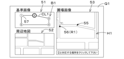
具体的には、画像展開部26は、表示制御部40を有している。表示制御部40は、管理者等が画像作成装置13に対して所定の操作を行うと、図8Aに示すように、展開設定画面Q1を表示する。展開設定画面Q1は、少なくとも基準画像B1と圃場画像とを表示する画面であって、圃場画像を基準画像B1に展開するための画面である。例えば、表示制御部40は、記憶装置12を参照して、第1圃場における外周輪郭CL1を示す複数個の外周頂点Ui(i=1~5)を取得し、取得した複数個の外周頂点Ui(i=1~5)と圃場画像H1とを、展開設定画面Q1に表示させる。
Specifically, the
具体的には、展開設定画面Q1は、基準画像表示部51と、周辺圃場表示部52と、詳細圃場表示部53と、ガイダンス表示部54とを含んでいる。
基準画像表示部51は、基準画像B1(基準画像B1の外周頂点Ui及び外周頂点Uiを結ぶことによって形成される外周輪郭CL1)を表示する部分である。基準画像表示部51において、基準画像B1の外周頂点Uiは、例えば、外周頂点Uiの場所をマーカ部57で示されている。基準画像表示部51において、基準画像B1の外周頂点Uiを示すマーカ部57には、外周頂点Uiの数(iの数)、即ち、外周頂点Uiの番号が付されている。これにより、作業者は、基準画像B1における外周頂点Uiの場所と個数とを把握することができる。
Specifically, the deployment setting screen Q1 includes a reference
The reference
周辺圃場表示部52は、第1画像入力部25が読み込んだ圃場画像H1の周辺の地図、又は、圃場画像H1に対応する基準画像B1の周辺の地図を表示する部分である。具体的には、表示制御部40は、圃場画像H1に対応する位置情報及び基準画像B1の位置情報のいずれかを参照して、参照した位置情報の周辺の地図を周辺圃場表示部52に表示させる。
The peripheral
詳細圃場表示部53は、第1画像入力部25によって読み込まれた圃場画像H1の拡大図を表示する部分である。詳細圃場表示部53は、圃場画像H1における外周頂点と対応する複数の座標点(x座標、y座標)Riを選択(設定)するためのポインタ部55を表示する。ポインタ部55にて、圃場画像H1における外周頂点の座標点Riを選択すると、図8B及び図8Cに示すように、詳細圃場表示部53は、座標点Riを選択したマーカ部56を、頂点の数(iの数)と共に表示する。
The detailed
ガイダンス表示部54は、展開設定画面Q1における作業者(オペレータ)への操作ガイダンスとして、操作手順等を示す領域である。ガイダンス表示部54では、詳細圃場表示部53において、基準画像表示部51に表示した基準画像B1の外周頂点Uiと対応する圃場画像H1の外周頂点の座標点Riを選択する手順等を表示する。図8Aに示すように、展開設定画面Q1において、ガイダンス表示部54は、例えば、「頂点P1と対応する場所をクリックしてください」と表示して、作業者(オペレータ)に圃場画像H1の外周頂点の座標点R1の選択を促している。
The
次に、作業者(オペレータ)による圃場画像H1の座標点Riの設定について詳しく説明する。図8Aに示すように、詳細圃場表示部53において、圃場画像H1の座標点Riが全く設定されていない場合(座標点Riの未設定の場合)には、基準画像表示部51において、基準画像B1の1番目の外周頂点Ui(i=1)に対応するマーカ部57は、他のマーカ部57よりも強調される。これにより、基準画像B1の1番目のマーカ部57に対応する圃場画像H1の座標点Ri(i=1)を、詳細圃場表示部53にて設定する必要があることを作業者は把握することができる。図8Bに示すように、詳細圃場表示部53において、1番目の圃場画像H1の座標点Ri(i=1)の設定が完了すると、基準画像表示部51において、基準画像B1の2番目の外周頂点Ui(i=2)に対応するマーカ部57は、他のマーカ部57よりも強調される。これにより、基準画像B1の2番目のマーカ部57に対応する圃場画像H1の座標点Ri(i=2)を、詳細圃場表示部53にて設定する必要があることを作業者は把握することができる。上述したように、圃場画像H1の座標点Riが設定される毎に、外周頂点を示す数(iの数)がカウントアップされる。
Next, setting of the coordinate points Ri of the field image H1 by the worker (operator) will be described in detail. As shown in FIG. 8A, in the detailed
展開設定画面Q1では、基準画像B1が有する外周頂点Uiに対応して、外周頂点Uiと同数の圃場画像H1の外周頂点の座標点Riを設定することができる。図8Cに示すように、基準画像B1が有する外周頂点Uiと同数の座標点Riの設定が完了すると、展開ボタン58が表示される。
次に、展開設定画面Q1における圃場画像H1の外周頂点(座標点)Riの設定と、画像展開部26における処理について詳しく説明する。
On the development setting screen Q1, the same number of coordinate points Ri of the outer peripheral vertices of the field image H1 as the outer peripheral vertexes Ui can be set corresponding to the outer peripheral vertices Ui of the reference image B1. As shown in FIG. 8C, when the setting of the same number of coordinate points Ri as the outer peripheral vertexes Ui of the reference image B1 is completed, an expand
Next, the setting of the peripheral vertex (coordinate point) Ri of the field image H1 on the development setting screen Q1 and the processing in the
図1に示すように、画像展開部26は、座標取得部41と、画像加工部42とを有している。座標取得部41は、展開設定画面Q1(詳細圃場表示部53)に示した圃場画像H1上で設定された外周頂点、即ち、任意点と対応する複数の座標点Riを取得する。詳しくは、図8Bに示すように、ポインタ部55によって圃場画像H1の一部が選択されると、座標取得部41は、選択された画素に対応する座標点を、外周頂点と対応する座標点Riとして保持する。なお、座標取得部41は、ポインタ部55によって圃場画像H1の一部が選択される毎に、座標点Riのiの数を増加していく。これにより、座標取得部41は、複数の座標点Riを取得することができる。
As shown in FIG. 1 , the
画像加工部42は、座標取得部41が取得した座標点Riを、基準画像B1の外周頂点Uiに合わせる画像処理を、圃場画像H1に対して行う。例えば、詳細圃場表示部53において、複数の座標点Riが設定された後、図8Cに示すように、展開設定画面Q1に表示された展開ボタン58が選択されると、画像加工部42は、画像処理を実行する。
画像加工部42における画像処理では、例えば、射影変換法を用いて、圃場画像H1の座標点Riを、基準画像B1の外周頂点Uiに合わせる変換の処理を実行する。詳しくは、基準画像B1の外周頂点Uiが5点であり、圃場画像H1の外周頂点の座標Riも5点である場合、図9に示すように、座標R1を外周頂点U1、座標R2を外周頂点U2、座標R3を外周頂点U3、座標R4を外周頂点U4、座標R5を外周頂点U5に一致するように、圃場画像H1の画像データ、即ち、ピクセルの座標(位置)を補正する、即ち、圃場画像H1の拡大、縮小、傾き等を補正する。画像展開部26によって基準画像B1に展開された基準画像B1、即ち、補正後の基準画像B1は、基準画像B1とは別に、解析画像として記憶装置23に記憶される。
The
In the image processing in the
以上によれば、画像展開部26、即ち、画像加工部42によって、基準画像B1に対する圃場画像H1の位置のずれ、歪み等が補正することができ、補正後の圃場画像H1を解析画像として記憶することができる。
さて、補正後の圃場画像(解析画像)は、例えば、農作物の解析に用いられる。図1に示すように、管理装置10は、画像解析部14を有している。画像解析部14は、管理装置10に設けられた電気・電子部品、当該管理装置10に格納されたプログラム等から構成されている。
According to the above, the
Now, the corrected field image (analysis image) is used, for example, for analysis of crops. As shown in FIG. 1 , the
画像解析部14は、解析画像を解析するもので、解析画像より圃場における農作物の植生指数を算出する。また、画像解析部14は、植生指数に基づいて得られた圃場に関する圃場地図を表示する。
例えば、外部端末11を管理装置10にログイン後、作業者が所定の操作を行うことで、当該外部端末11から管理装置10に解析を行う指令を送信すると、当該管理装置10の画像解析部14は、図10に示すように、解析を行う解析画面Q2を外部端末11に表示する。解析画面Q2では、画像読込の第1読込ボタン60が表示されている。第1読込ボタン60が選択されると、画像解析部14は、補正後の圃場画像H1である解析画像を記憶している記憶装置23を参照し、解析画面Q2等で指定された圃場に対応する解析画像を抽出する。画像解析部14は、解析画像を抽出後、解析画像の画像データからDVI、RVI、NDVI、GNDVI、SAVI、TSAVI、CAI、MTCI、REP、PRI、RSI等の植生指数を求める。画像解析部14は、植生指数を求めると、解析画面Q2に示した解析結果表示部61に、解析結果を表示(出力)する。
The
For example, after logging in the
例えば、画像解析部14は、解析結果表示部61におけるフィールドを複数のエリアWn(n=1,2,3・・・n)に区分し、区分されたエリアWnのそれぞれに入る複数の植生指数Gn[i](n:区分、Gn[i]:植生指数、i:データ数)を平均した平均値を代表値Dn(n=1,2,3・・・n)に設定する。或いは、画像解析部14は、区分されたエリアWnのそれぞれに入る複数の植生指数Gn[i]を積算した積算値を代表値Dnに設定する。或いは、画像解析部14は、平均値及び積算値をエリアWnの面積で割った面積辺りの数値を代表値Dnに設定する。
For example, the
画像解析部14は、代表値Dnを求めた後、当該代表値Dnの大きさ(値)に応じて、複数のグループ(複数のランク)を割り当て、ランク毎に色等を変化させることによって、解析結果を示す圃場マップを作成し、解析結果表示部61に表示する。
以上によれば、画像解析部14によって、解析画像を解析した結果、即ち、圃場における植生指数を外部端末11に表示することができる。
After obtaining the representative value Dn, the
According to the above, the
なお、上述した実施形態では、基準画像B1の任意点として、外周輪郭CL1を示す複数個の外周頂点Uiを採用していたが、任意点は、上述した例に限定されない。また、上述した実施形態では、1つの圃場を示す基準画像B1に対して、1つの圃場を示す圃場画像H1を展開していたが、これに限定されない。
図12A及び図12Bは、第1変形例を示し、図13A及び図13Bは、第2変形例を示している。
In the above-described embodiment, a plurality of outer peripheral vertexes Ui indicating the outer peripheral contour CL1 are used as arbitrary points of the reference image B1, but the arbitrary points are not limited to the above example. Further, in the above-described embodiment, the field image H1 representing one field is developed with respect to the reference image B1 representing one field, but the present invention is not limited to this.
12A and 12B show a first modification, and FIGS. 13A and 13B show a second modification.
図12A及び図12Bは、基準画像として複数の圃場が一括登録されている場合の展開設定画面の表示例である。このとき、基準画像B1は、6つの圃場の外周輪郭CL1と、位置情報で示された4つの任意点Vi(i=1~4)とを有している。このとき、4つの任意点Vi(i=1~4)は、6つの圃場を内包する外周輪郭の各頂点上に登録されているが、任意点Viの登録位置、登録数は図12で例示した箇所、数に限定されない。 12A and 12B are display examples of the expansion setting screen when a plurality of fields are collectively registered as the reference image. At this time, the reference image B1 has six outer contours CL1 of fields and four arbitrary points Vi (i=1 to 4) indicated by position information. At this time, four arbitrary points Vi (i=1 to 4) are registered on the respective vertices of the outer contour that includes the six fields. It is not limited to the number of places where
第1画像入力部25が、6つの圃場を有する圃場画像H1を読み込むと、画像展開部26は、当該圃場画像H1の位置情報と対応する当該基準画像B1を取得する。表示制御部40は、読み込んだ圃場画像H1と取得した基準画像B1との情報を元に、図12Aで示した基準画像B1と圃場画像H1とを画面上に表示する。図12Bで示すように、作業者が基準画像B1を参考に圃場画像H1に4つの座標点Ri(i=1~4)を設定すると、画像展開部26は、4つの座標点Ri(i=1~4)が設定された領域(6つの圃場を含む領域)の圃場画像H1を基準画像B1の4つの任意点Vi(i=1~4)と一致するように展開する。これにより、1つの基準画像B1を用いて、複数の圃場画像H1を一括展開することができる。
When the first
また、基準画像B1の任意点Viは、基準画像B1において、当該基準画像B1の外周輪郭でなくてよく、当該基準画像B1の内部(内方)にあってもよい。図13A及び図13Bは、基準画像B1の任意点Viを内部に設けた例を示している。具体的には、図13A及び図13Bは、基準画像B1に6つの任意点Vi(i=1~6)を示した例であり、任意点V1~V4は、上述した実施形態と同様であり、基準画像B1の2つの任意点V5、V6は、圃場の内部に登録されていて、上述した実施形態と異なっている。 Further, the arbitrary point Vi of the reference image B1 may not be the outer contour of the reference image B1, and may be inside (inside) the reference image B1. 13A and 13B show an example in which an arbitrary point Vi of the reference image B1 is provided inside. Specifically, FIGS. 13A and 13B are examples showing six arbitrary points Vi (i=1 to 6) in the reference image B1, and the arbitrary points V1 to V4 are the same as in the above embodiment. , two arbitrary points V5 and V6 of the reference image B1 are registered inside the field, which is different from the above embodiment.
図13Bで示すように、作業者が当該基準画像B1を参考にして、圃場画像H1に6つの座標点Ri(i=1~6)を図13Bで示すように設定する。このとき、画像展開部26は、6点の座標点Ri(i=1~6)が設定された領域の圃場画像H1を基準画像B1の6つの任意点Vi(i=1~6)と一致するように展開する。つまり、圃場の内部に設定された2点の座標点R5、R6も一致するように圃場画像H1を展開する。
As shown in FIG. 13B, the operator refers to the reference image B1 and sets six coordinate points Ri (i=1 to 6) on the field image H1 as shown in FIG. 13B. At this time, the
このように、圃場の内部に任意点を設けることで、圃場画像H1の内側に画像の位置ズレや歪みがあった場合にも、画像展開の際の展開精度を向上させることができる。図12及び図13において、基準画像B1に圃場画像H1を展開する前に、例えば、展開設定画面において、基準画像B1の任意点を追加できるようにしてもよい。
農業支援システムは、第1画像入力部25と、画像展開部26とを備えている。画像展開部26は、第1画像入力部25で読み込んだ圃場画像H1の位置情報に対応する基準画像B1を取得し、読み込んだ圃場画像H1を、取得した基準画像B1に合わせる展開を行う。これによれば、第1画像入力部25によって読み込んだ圃場画像を、画像展開部26によって基準画像に合わせるという展開を行った後に、展開後の圃場画像を基に解析を行うことができる。詳しくは、基準画像に対して圃場画像の位置がずれている場合、圃場画像が歪んでいる場合等、画像展開部26によって、位置ズレ、歪を補正することができ、位置ズレや歪が無い補正後の圃場画像(解析画像)を用いて適正に解析することができる。
In this way, by providing an arbitrary point inside the field, it is possible to improve the development accuracy when developing the image even if there is a positional deviation or distortion of the image inside the field image H1. In FIGS. 12 and 13, before the farm field image H1 is expanded on the reference image B1, for example, an arbitrary point of the reference image B1 may be added on the expansion setting screen.
The agriculture support system includes a first
画像展開部26は、基準画像B1と圃場画像H1とを画面上に表示させる表示制御部40と、画面上の圃場画像H1に対して基準画像B1の任意点と対応する複数の座標点Riを取得する座標取得部41と、座標取得部41が取得した座標点Riを、基準画像B1の任意点に合わせる画像処理を圃場画像H1に対して行う画像加工部42と、を有している。これによれば、基準画像B1における任意点に、圃場画像H1の座標点Riを簡単に合わせることができる。即ち、圃場画像H1が基準画像B1に対して歪んでいる場合であっても、歪等を補正することができる。
The
表示制御部40は、基準画像B1の外周輪郭を示す複数個の外周頂点Uiを任意点として表示し、座標取得部41は、外周頂点Uiに対応する複数の座標点Riを取得し、画像加工部42は、座標取得部41が取得した座標点Riを、基準画像B1の外周頂点Uiに合わせる画像処理を圃場画像H1に対して行う。これによれば、表示制御部40によって、基準画像B1と、圃場画像H1の外周輪郭の外周頂点Riとの対応関係を、作業者等が簡単に確認することができる。また、座標取得部41及び画像加工部42によって、圃場画像H1の外周頂点Uiに対応する座標点Riを、簡単に基準画像B1の外周頂点Uiに一致させることができる。
The
農業支援システムは、位置情報を有する複数の空撮画像Inを読み込む第2画像入力部20と、第2画像入力部20が読み込んだ空撮画像Inより圃場画像H1を生成する画像生成部21と、を備えている。これによれば、複数の空撮画像Inから簡単に、1つの圃場画像H1を生成することができる。
画像生成部21は、空撮画像Inが有する個々の位置情報の位置関係に従って複数の空撮画像Inを合成することで、圃場画像H1を生成する。これによれば、例えば、1つの圃場を複数の空撮画像Inで撮像した場合に、簡単に複数の空撮画像Inを1つの圃場に対応する圃場画像H1にすることができる。
The agriculture support system includes a second
The
農業支援システムは、解析画像を解析し且つ、解析した解析結果を出力する画像解析部14を備えている。これによれば、基準画像B1に展開した圃場画像H1である解析画像の解析を画像解析部14によって簡単に解析することができる。
画像解析部14は、解析画像より圃場における農作物の植生指数を算出し、算出した植生指数を解析結果として出力する。これによれば、圃場に作付した農作物の植生(育成)の状態を植生指数によって簡単に把握することができる。
The agricultural support system includes an
The
画像解析部14は、植生指数に基づいて得られた圃場に関する圃場マップを出力する。これによれば、植生指数の分布を圃場マップによって簡単に確認することができる。
また、上述した実施形態では、マルチコプター30で圃場の作物を撮像していたが、圃場に設置された圃場監視装置で、圃場の作物を撮像して、撮像した撮像画像に、当該圃場監視装置に対応付けられた圃場の位置を付加することにより、圃場画像を得るようにしてもよい。
The
In the above-described embodiment, the
また、圃場画像によって植生指数を求めていたが、圃場画像は、農作物が作付けされた圃場の画像でなくてもよく、例えば、農作物を作付する前の圃場画像であってもよい。即ち、圃場画像は、圃場の土壌を撮像した土壌画像であってもよい。
また、上述した実施形態では、画像作成装置13と外部端末11とを別々に構成していたが、画像作成装置13と外部端末11とを一体化してもよい。
In addition, although the vegetation index is obtained from the field image, the field image may not be an image of a field planted with crops, but may be an image of the field before crops are planted, for example. That is, the field image may be a soil image obtained by imaging the soil of the field.
Further, in the above-described embodiment, the
上述した実施形態では、複数の空撮画像Inから圃場画像H1を作成した後、圃場画像H1を基準画像B1に展開し、さらに、基準画像B1に展開した圃場画像である解析画像に対して解析を行っているが、一連の作業をまとめて行って実行してもよい。
この場合、例えば、図11に示すように、外部端末11に解析画面Q3を表示する。解析画面Q3には、基準画像表示部51と、周辺圃場表示部52と、詳細圃場表示部53と、ガイダンス表示部54及び解析結果表示部61が表示される。また、解析画面Q3には、第2読込ボタン63が表示される。第2読込ボタン63が選択されると、第2画像入力部20によって、電子記録媒体31に記憶されている複数の空撮画像Inが読み込まれた後、画像生成部21によって自動的に複数の空撮画像Inを合成した圃場画像H1が生成される。圃場画像H1が生成された後は、解析画面Q3において、図8A~図8Cと同様に、画像展開部26により基準画像B1の外周頂点Uiに対応する圃場画像H1の座標点Riの設定が指示される。圃場画像H1の座標点Riが完了すると、画像展開部26により圃場画像H1が基準画像B1に展開されて、展開後の解析画像が生成される。また、画像展開部26による解析画像の生成後は、画像解析部14が解析画像に基づいて植生指数等を計算し、図10と同様に、解析結果表示部61が表示される。
In the above-described embodiment, after the field image H1 is created from a plurality of aerial images In, the field image H1 is developed into the reference image B1, and the analysis image, which is the field image developed into the reference image B1, is analyzed. However, a series of tasks may be performed collectively.
In this case, for example, an analysis screen Q3 is displayed on the
なお、図14に示すように、管理装置10は、農業に関する様々な事項を管理する装置であってもよい。記憶装置12は、管理者等が外部端末11を用いて所有する圃場(管理圃場)を登録した圃場情報(管理圃場地図情報)が記憶されている。圃場情報は、圃場の位置情報(緯度、経度)及び輪郭が含まれる地図である。例えば、管理者が圃場A~圃場Hまでを管理している場合、記憶装置12は少なくとも管理者が所有する圃場A~圃場Hの圃場情報を記憶している。
In addition, as shown in FIG. 14, the
管理装置10は、農業に関する様々な管理を行う農業管理部80を備えている。農業管理部80は、管理装置10に設けられた電気・電子部品、当該管理装置10に格納されたプログラム等から構成されている。農業管理部80は、FMIS(FarmManagement Information System)を行うものであって、例えば、農作業を行った農業機械81から送信された稼働情報及び農業機械81の位置情報等を受付け、稼働情報及び位置情報に基づいて、例えば、圃場における農作業の可視化等を行う。例えば、圃場の所定位置において散布された散布物(肥料、薬剤)等を表示したり、予め定められた計画に対して農作業の実績等がどうであったかをグラフ等により表示する。なお、上述した農業管理部80は、一例であり、限定されない。
The
画像作成装置13は、推定部43を備えている。推定部43は、画像作成装置13に設けられた電気・電子部品、当該画像作成装置13に格納されたプログラム等から構成されている。画像作成装置13は、圃場画像H1を取得すると、推定部43は、圃場画像H1と管理装置10の記憶装置12に記憶された圃場情報における圃場の位置及び輪郭とを比較して、圃場画像H1の位置及び輪郭に一致又は相似する圃場を抽出し、抽出した圃場を基準画像B1として推定する。即ち、推定部43は、農業管理部80のために用いられる圃場情報と圃場画像H1とから基準画像B1を推定する。
The
なお、管理装置10が推定部43を備えていてもよい。この場合、推定部43は、画像作成装置13から圃場画像H1を取得して、記憶装置12に記憶された圃場情報と圃場画像H1とから基準画像B1を推定する。
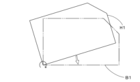
基準画像B1の推定後は、画像作成装置13(画像展開部26)は、圃場画像H1を基準画像B1に展開する処理を行う。図15Aに示すように、圃場画像H1と基準画像B1との位置が互いにズレている場合は、画像展開部26は、圃場画像H1を平行移動することにより基準画像B1に合わせる処理(平行移動処理)を行う。或いは、図9に示すように、圃場画像H1が基準画像B1に対して小さい場合は、画像展開部26は、当該圃場画像H1の外周頂点の座標点R1~R5を基準画像B1の外周頂点U1~U5に合わせる処理(拡大処理)を行う。或いは、図15Bに示すように、圃場画像H1が基準画像B1に対して大きい場合は、画像展開部26は、当該圃場画像H1の外周頂点の座標点R1~R5を基準画像B1の外周頂点U1~U5に合わせる処理(縮小処理)を行う。或いは、図15Cに示すように、圃場画像H1が基準画像B1に対して傾いている場合は、画像展開部26は、当該圃場画像H1を回転させることで、外周頂点の座標点R1~R5を基準画像B1の外周頂点U1~U5に合わせる処理(回転処理)を行う。
Note that the
After estimating the reference image B1, the image creation device 13 (image development unit 26) performs processing to develop the field image H1 into the reference image B1. As shown in FIG. 15A, when the positions of the field image H1 and the reference image B1 are displaced from each other, the
上述した基準画像B1に対する圃場画像H1の展開(補正)を一括して行ってもよい。この場合、図16に示すように、表示制御部40は、管理装置10の記憶装置12が記憶している圃場情報に含まれる地図を外部端末11の設定画面Q4に表示させる。画像展開部26は、外部端末11において周辺地図から複数の基準画像B1をポインタ部55B等の操作に応じて受付を行う。また、画像展開部26は、複数の圃場画像H1を設定画面Q4に表示させ、複数の基準画像B1と同様に、ポインタ部55B等の操作に応じて複数の圃場画像H1の受付を行う。そして、画像展開部26は、受付を行った複数の基準画像B1に対して、受付を行った複数の圃場画像H1の展開、即ち、上述した少なくとも平行移動処理、拡大処理、縮小処理、回転処理のいずれかを実行する。
The development (correction) of the field image H1 with respect to the reference image B1 described above may be performed collectively. In this case, the
以上のように、農業の管理等に用いられる圃場情報により、基準画像B1を推定するようにしているため、圃場画像H1を展開するための基準画像B1を簡単に取り出すことができる。また、画像展開部26は、平行移動処理、拡大処理、縮小処理、回転処理を行うため、圃場画像H1を簡単に基準画像B1に展開することができる。
今回開示された実施の形態はすべての点で例示であって制限的なものではないと考えられるべきである。本発明の範囲は上記した説明ではなくて特許請求の範囲によって示され、特許請求の範囲と均等の意味及び範囲内でのすべての変更が含まれることが意図される。
As described above, since the reference image B1 is estimated based on the field information used for agricultural management, etc., the reference image B1 for developing the field image H1 can be easily extracted. In addition, since the
It should be considered that the embodiments disclosed this time are illustrative in all respects and not restrictive. The scope of the present invention is indicated by the scope of the claims rather than the above description, and is intended to include all modifications within the scope and meaning equivalent to the scope of the claims.
10 管理装置
14 画像解析部
13 画像作成装置
20 第2画像入力部
21 画像生成部
23 記憶装置
25 第1画像入力部
26 画像展開部
30 マルチコプター
30a 本体
30b アーム
30c 回転翼
30d スキッド
30e 撮像装置
30f 位置検出装置
30g 外部接続部
31 電子記録媒体
40 表示制御部
41 座標取得部
42 画像加工部
43 推定部
51 基準画像表示部
52 周辺圃場表示部
53 詳細圃場表示部
54 ガイダンス表示部
55 ポインタ部
56 マーカ部
57 マーカ部
58 展開ボタン
60 読込ボタン
61 解析結果表示部
63 読込ボタン
80 農業管理部
81 農業機械
CL1 外周輪郭
Gn 画像
H1 圃場画像
In 空撮画像
K1 飛行軌跡
Pn 撮像位置
Q1 展開設定画面
Ri 圃場画像の外周頂点の座標
Ui 外周頂点
Vi 任意点
REFERENCE SIGNS
Claims (8)
前記第1画像入力部で読み込んだ前記圃場画像の位置情報に対応する基準画像を取得し、前記読み込んだ前記圃場画像を、前記圃場の位置情報を有する前記取得した基準画像に合わせる展開を行い、且つ、前記展開した画像を解析画像として生成する画像展開部と、
を備え、
前記画像展開部は、
前記基準画像を表示する基準画像表示部と、前記圃場画像及びポインタ部を表示する圃場画像表示部と、前記基準画像又は前記圃場画像の周辺の地図を表示する周辺表示部と、作業者に操作手順を表示するガイダンス表示部とを、並べて同時に画面上に表示させる表示制御部と、
前記圃場画像表示部の前記圃場画像の一部が前記ポインタ部によって選択されると、選択された画素に対応する座標点を、前記基準画像の任意点と対応する座標点として取得する座標取得部と、
前記座標取得部が取得した複数の座標点を、前記基準画像の複数の任意点に一対一に合わせる画像処理を前記圃場画像に対して行う画像加工部と、
を有し、
前記表示制御部は、前記基準画像表示部において前記基準画像の外周輪郭を示す複数個(=i個)の予め順番が定められた外周頂点を前記任意点として表示し、前記圃場画像表示部において前記圃場画像の座標点が全く設定されていない場合には、前記基準画像表示部において前記基準画像の1番目の外周頂点に対応するマーカ部を、当該1番目以外の外周頂点に対応する他のマーカ部よりも強調されて表示し、前記圃場画像表示部において前記基準画像の1番目の外周頂点に対応する前記圃場画像の1番目の座標点が前記ポインタ部によって設定されると、当該1番目の座標点に1番を示す番号マーカを表示し、前記基準画像表示部において前記基準画像のi個の外周頂点のうちで次の番号の外周頂点に対応するマーカ部を、当該次の番号以外の外周頂点に対応する他のマーカ部よりも強調されて表示すること、及び、前記圃場画像表示部において前記基準画像の次の番号の外周頂点に対応する前記圃場画像の次の番号の座標点が前記ポインタ部によって設定されると、当該設定された座標点に当該次の番号を示す番号マーカを表示することを、i番目の外周頂点に対応するマーカ部に達するまで行い、前記圃場画像表示部において前記圃場画像に対して、前記基準画像が有するi個の外周頂点と同数の座標点の設定が完了すると、展開ボタンを表示し、
前記座標取得部は、前記圃場画像表示部において前記圃場画像に対して、前記基準画像が有するi個の外周頂点と同数の座標点の設定が完了することで、前記i個の外周頂点に一対一に対応するi個の座標点を取得し、
前記画像加工部は、前記展開ボタンが選択されると、前記座標取得部が取得した前記i個の座標点を、前記基準画像のi個の外周頂点に一対一に合わせる画像処理を前記圃場画像に対して行う農業支援システム。 a first image input unit that reads a field image that is an image of a field and that has position information;
Acquiring a reference image corresponding to the position information of the field image read by the first image input unit, developing the read field image so as to match the obtained reference image having the position information of the field, and an image development unit that generates the developed image as an analysis image;
with
The image development unit
a reference image display unit that displays the reference image; a field image display unit that displays the farm field image and a pointer portion; a peripheral display unit that displays a map around the reference image or the farm field image; a display control unit for displaying a guidance display unit for displaying a procedure side by side on the screen at the same time;
A coordinate acquisition unit configured to acquire, when a portion of the farm field image of the farm field image display unit is selected by the pointer unit, a coordinate point corresponding to the selected pixel as a coordinate point corresponding to an arbitrary point of the reference image. and,
an image processing unit that performs image processing on the field image to align the plurality of coordinate points acquired by the coordinate acquisition unit with the plurality of arbitrary points of the reference image one-to-one;
has
The display control unit displays, as the arbitrary points, a plurality of (=i) outer perimeter vertices showing the outer perimeter contour of the reference image in the reference image display unit. When the coordinate points of the agricultural field image are not set at all, the marker portion corresponding to the first outer peripheral vertex of the reference image is displayed in the reference image display portion as another marker portion corresponding to the outer peripheral vertex other than the first one. When the first coordinate point of the farm field image corresponding to the first outer peripheral vertex of the reference image is set by the pointer section in the farm field image display section, the first coordinate point is displayed. a numbered marker indicating number 1 is displayed at the coordinate point of the reference image display unit, and the marker portion corresponding to the outer peripheral vertex of the next number among the i outer peripheral vertices of the reference image is and a coordinate point of the next number of the field image corresponding to the next number of the outer circumference vertex of the reference image in the field image display part. is set by the pointer unit, a number marker indicating the next number is displayed at the set coordinate point until the marker unit corresponding to the i-th outer peripheral vertex is reached, and the field image display When the setting of the same number of coordinate points as the i number of outer vertexes of the reference image is completed for the field image in the section, a development button is displayed,
The coordinate acquisition unit completes the setting of the same number of coordinate points as the i peripheral vertices of the reference image in the agricultural field image display unit. Get i coordinate points corresponding to one,
When the development button is selected, the image processing unit performs image processing to align the i coordinate points acquired by the coordinate acquisition unit with the i peripheral vertices of the reference image one-to-one. Agricultural support system for
前記圃場画像は、前記基準画像の前記複数の圃場に対応する複数の圃場を含む画像であり、
前記画像加工部は、前記展開ボタンが選択されると、前記座標取得部が取得した前記i個の座標点を、前記基準画像のi個の外周頂点に一対一に合わせる画像処理を前記圃場画像に対して行うことにより、複数の圃場を含む前記圃場画像を一括して前記基準画像に展開する請求項1に記載の農業支援システム。 The reference image is an image in which a plurality of fields are collectively registered,
The farm field image is an image including a plurality of farm fields corresponding to the plurality of farm fields of the reference image,
When the development button is selected, the image processing unit performs image processing to align the i coordinate points acquired by the coordinate acquisition unit with the i peripheral vertices of the reference image one-to-one. 2. The agricultural support system according to claim 1, wherein the farm field image including a plurality of farm fields is collectively developed into the reference image by performing the processing on the first and second farm fields.
前記第2画像入力部が読み込んだ前記空撮画像より前記圃場画像を生成する画像生成部と、を備えている請求項1又は2に記載の農業支援システム。 a second image input unit that reads a plurality of aerial images having position information;
3. The agricultural support system according to claim 1, further comprising an image generation unit that generates the field image from the aerial image read by the second image input unit.
前記画像解析部は、前記解析画像から、圃場における農作物の植生指数として、DVI、RVI、NDVI、GNDVI、SAVI、TSAVI、CAI、MTCI、REP、PRI、RSIのいずれかの植生指数を算出し、前記算出した植生指数を前記解析結果として出力する請求項1~4のいずれか1項に記載の農業支援システム。 An image analysis unit that analyzes the analysis image and outputs the analyzed analysis result,
The image analysis unit calculates any one of DVI, RVI, NDVI, GNDVI, SAVI, TSAVI, CAI, MTCI, REP, PRI, and RSI as a vegetation index of crops in the field from the analysis image, The agricultural support system according to any one of claims 1 to 4, wherein the calculated vegetation index is output as the analysis result.
前記画像解析部は、代表値Dnを求めた後、当該代表値Dnの大きさ(値)に応じて、複数のランクを割り当て、ランク毎に色を変化させることによって、解析結果を示す圃場マップを作成し、
前記画像解析部は、前記植生指数に基づいて得られた圃場に関する前記圃場マップを出力する請求項5に記載の農業支援システム。 The image analysis unit divides the field corresponding to the farm field into a plurality of areas Wn (n=1, 2, 3, . Set the average value obtained by averaging Gn [i] (n: category, Gn [i]: vegetation index, i: number of data) to the representative value Dn (n = 1, 2, 3 ... n), or , an integrated value obtained by accumulating a plurality of vegetation indices Gn[i] included in each of the divided areas Wn is set as the representative value Dn, or the average value and the integrated value are divided by the area of the area Wn. Set the numerical value to the representative value Dn,
After obtaining the representative value Dn, the image analysis unit assigns a plurality of ranks according to the magnitude (value) of the representative value Dn, and changes the color for each rank to display the analysis result. and create
6. The agricultural support system according to claim 5, wherein the image analysis unit outputs the farm field map regarding the farm field obtained based on the vegetation index.
農業を管理する農業管理部と、
前記農業管理部によって農業を管理する圃場を含み且つ当該圃場の緯度及び経度を示す位置情報及び輪郭が含まれる圃場情報を記憶する記憶装置と、
前記記憶装置に記憶された圃場情報における圃場の位置及び輪郭と、前記圃場画像とを比較して、前記圃場画像の位置及び輪郭に一致又は相似する圃場を前記圃場情報から抽出し、前記圃場情報から抽出した圃場を基準画像として推定する推定部と、
前記圃場画像を、前記推定部にて推定された基準画像に展開し、且つ、前記展開した画像を解析画像として生成する画像展開部と、
を備えている農業支援システム。 a first image input unit that reads a field image that is an image of a field and that has position information;
Agricultural management department that manages agriculture,
a storage device that stores farm field information that includes a farm field managed by the agricultural management unit and that includes position information and an outline indicating the latitude and longitude of the farm field;
The position and contour of the farm field in the farm field information stored in the storage device are compared with the farm field image, and a farm field matching or similar to the position and contour of the farm field image is extracted from the farm field information. an estimating unit for estimating the field extracted from as a reference image;
an image development unit that develops the field image into a reference image estimated by the estimation unit and generates the developed image as an analysis image;
agricultural support system.
Applications Claiming Priority (2)
| Application Number | Priority Date | Filing Date | Title |
|---|---|---|---|
| JP2018078568 | 2018-04-16 | ||
| JP2018078568 | 2018-04-16 |
Publications (2)
| Publication Number | Publication Date |
|---|---|
| JP2019185773A JP2019185773A (en) | 2019-10-24 |
| JP7237694B2 true JP7237694B2 (en) | 2023-03-13 |
Family
ID=68340970
Family Applications (1)
| Application Number | Title | Priority Date | Filing Date |
|---|---|---|---|
| JP2019066789A Active JP7237694B2 (en) | 2018-04-16 | 2019-03-29 | Agricultural support system |
Country Status (1)
| Country | Link |
|---|---|
| JP (1) | JP7237694B2 (en) |
Families Citing this family (7)
| Publication number | Priority date | Publication date | Assignee | Title |
|---|---|---|---|---|
| JP2021005339A (en) * | 2019-06-27 | 2021-01-14 | キヤノン株式会社 | Information processing apparatus, control method for the same, and program |
| JP7215992B2 (en) * | 2019-12-20 | 2023-01-31 | 株式会社クボタ | Agricultural machines |
| JP7586100B2 (en) * | 2020-01-21 | 2024-11-19 | ソニーグループ株式会社 | Information processing device, information processing method, and program |
| JP7470061B2 (en) * | 2021-01-07 | 2024-04-17 | 株式会社クボタ | Agricultural Support System |
| JP7751425B2 (en) * | 2021-09-13 | 2025-10-08 | ヤンマーホールディングス株式会社 | Field management method, field management system, and field management program |
| WO2024142252A1 (en) * | 2022-12-27 | 2024-07-04 | 株式会社クボタ | Sensing system and unmanned aircraft |
| CN118429691B (en) * | 2024-04-03 | 2025-10-21 | 中联智慧农业股份有限公司 | Method, device and processor for determining farmland farming operation information |
Citations (1)
| Publication number | Priority date | Publication date | Assignee | Title |
|---|---|---|---|---|
| JP2017224224A (en) | 2016-06-17 | 2017-12-21 | 株式会社Ihiスター | Map data creation device and map data creation method |
-
2019
- 2019-03-29 JP JP2019066789A patent/JP7237694B2/en active Active
Patent Citations (1)
| Publication number | Priority date | Publication date | Assignee | Title |
|---|---|---|---|---|
| JP2017224224A (en) | 2016-06-17 | 2017-12-21 | 株式会社Ihiスター | Map data creation device and map data creation method |
Non-Patent Citations (1)
| Title |
|---|
| 加島 智子,ICTを活用した経営工学の新展開,経営システム ,日本,公益社団法人日本経営工学会,2016年08月29日, Vol.26 No.3,頁157-164 |
Also Published As
| Publication number | Publication date |
|---|---|
| JP2019185773A (en) | 2019-10-24 |
Similar Documents
| Publication | Publication Date | Title |
|---|---|---|
| JP7237694B2 (en) | Agricultural support system | |
| US10360247B2 (en) | System and method for telecom inventory management | |
| Fernández‐Hernandez et al. | Image‐based modelling from unmanned aerial vehicle (UAV) photogrammetry: an effective, low‐cost tool for archaeological applications | |
| CN105825498B (en) | Measurement data processing device, measurement data processing method, and program | |
| US8107722B2 (en) | System and method for automatic stereo measurement of a point of interest in a scene | |
| US9798928B2 (en) | System for collecting and processing aerial imagery with enhanced 3D and NIR imaging capability | |
| US10681269B2 (en) | Computer-readable recording medium, information processing method, and information processing apparatus | |
| JP5620200B2 (en) | Point cloud position data processing device, point cloud position data processing method, point cloud position data processing system, and point cloud position data processing program | |
| GB2506239A (en) | Projecting maintenance history using optical reference points | |
| Hoegner et al. | Mobile thermal mapping for matching of infrared images with 3D building models and 3D point clouds | |
| Jurado et al. | An efficient method for generating UAV-based hyperspectral mosaics using push-broom sensors | |
| EP4080314A1 (en) | Information processing device, information processing system, information processing method, and program | |
| Grigillo et al. | Automated building extraction from IKONOS images in suburban areas | |
| EP2946366B1 (en) | Method and system for geo-referencing at least one sensor image | |
| Gupta et al. | Augmented reality system using lidar point cloud data for displaying dimensional information of objects on mobile phones | |
| JP4521568B2 (en) | Corresponding point search method, relative orientation method, three-dimensional image measurement method, corresponding point search device, relative orientation device, three-dimensional image measurement device, corresponding point search program, and computer-readable recording medium recording the corresponding point search program | |
| KR100924008B1 (en) | How to upgrade aerial photographs based on numerical mapping technology | |
| Rodríguez‐Gonzálvez et al. | A hybrid approach to create an archaeological visualization system for a Palaeolithic cave | |
| JP2016218626A (en) | Image management apparatus, image management method, and program | |
| KR102814414B1 (en) | Method and apparatus for PROVIDING VISUAL GUIDE FOR ACQUIRING 3D DATA | |
| CN110223270A (en) | A method of it is positioned using GEOGRAPHICAL INDICATION photo and three-dimensional visualization | |
| Gotovac et al. | A model for automatic geomapping of aerial images mosaic acquired by UAV | |
| Piekielek et al. | Evaluating software tools to orthorectify archival aerial photographs | |
| Hoffmann et al. | From UAS Data Acquisition to Actionable Information–How an End-to-End Solution Helps Oil Palm Plantation Operators to Perform a More Sustainable Plantation Management | |
| JP2002135807A (en) | Method and device for calibration for three-dimensional entry |
Legal Events
| Date | Code | Title | Description |
|---|---|---|---|
| A621 | Written request for application examination |
Free format text: JAPANESE INTERMEDIATE CODE: A621 Effective date: 20210622 |
|
| A977 | Report on retrieval |
Free format text: JAPANESE INTERMEDIATE CODE: A971007 Effective date: 20220511 |
|
| A131 | Notification of reasons for refusal |
Free format text: JAPANESE INTERMEDIATE CODE: A131 Effective date: 20220517 |
|
| A601 | Written request for extension of time |
Free format text: JAPANESE INTERMEDIATE CODE: A601 Effective date: 20220705 |
|
| A521 | Request for written amendment filed |
Free format text: JAPANESE INTERMEDIATE CODE: A523 Effective date: 20220907 |
|
| A131 | Notification of reasons for refusal |
Free format text: JAPANESE INTERMEDIATE CODE: A131 Effective date: 20230110 |
|
| A521 | Request for written amendment filed |
Free format text: JAPANESE INTERMEDIATE CODE: A523 Effective date: 20230112 |
|
| TRDD | Decision of grant or rejection written | ||
| A01 | Written decision to grant a patent or to grant a registration (utility model) |
Free format text: JAPANESE INTERMEDIATE CODE: A01 Effective date: 20230131 |
|
| A61 | First payment of annual fees (during grant procedure) |
Free format text: JAPANESE INTERMEDIATE CODE: A61 Effective date: 20230301 |
|
| R150 | Certificate of patent or registration of utility model |
Ref document number: 7237694 Country of ref document: JP Free format text: JAPANESE INTERMEDIATE CODE: R150 |