JP7235320B2 - game machine - Google Patents
game machine Download PDFInfo
- Publication number
- JP7235320B2 JP7235320B2 JP2020032418A JP2020032418A JP7235320B2 JP 7235320 B2 JP7235320 B2 JP 7235320B2 JP 2020032418 A JP2020032418 A JP 2020032418A JP 2020032418 A JP2020032418 A JP 2020032418A JP 7235320 B2 JP7235320 B2 JP 7235320B2
- Authority
- JP
- Japan
- Prior art keywords
- setting
- game
- special
- special symbol
- probability
- Prior art date
- Legal status (The legal status is an assumption and is not a legal conclusion. Google has not performed a legal analysis and makes no representation as to the accuracy of the status listed.)
- Active
Links
Images


Description
本発明は、パチンコ遊技機やパチスロ遊技機等に代表される遊技機に関する。 The present invention relates to gaming machines typified by pachinko gaming machines, pachislot gaming machines, and the like.
従来、パチンコ遊技機などの遊技機においては、発射された遊技球が転動可能な遊技領域に設けられた通過領域を遊技球が通過したことなど、所定の可変表示開始条件の成立により、画像表示装置の表示領域上に識別情報としての図柄を変動表示する制御が実行されて、変動表示された図柄を導出表示する制御が実行され、導出表示された図柄が所定の組合せ(特定の表示態様)となった場合に、遊技者に有利な大当り遊技状態に移行するようにしたものが提供されている(例えば、特許文献1参照)。
2. Description of the Related Art Conventionally, in a game machine such as a pachinko game machine, when a predetermined variable display start condition is established, such as when a game ball has passed through a passage area provided in a game area in which the game ball can roll, an image is displayed. Control is executed to variably display symbols as identification information on the display area of the display device, control is executed to derive and display the variably displayed symbols, and the derived and displayed symbols are combined in a predetermined combination (specific display mode ), there is provided a system in which the game moves to a big win game state that is advantageous to the player (see
本発明者は、上述したような遊技機について、鋭意検討を重ねる過程において、識別情報の変動時間に関して工夫を凝らすことにより、遊技の興趣を向上させることができるのではないかという考えに至った。 The inventor of the present invention, in the process of earnestly examining the above-described gaming machine , came to the idea that it would be possible to improve the interest of the game by devising the change time of the identification information. .
本発明は、上記のような点に鑑みてなされたものであり、遊技の興趣を向上させることが可能な遊技機を提供することを目的とする。 SUMMARY OF THE INVENTION It is an object of the present invention to provide a gaming machine capable of enhancing the interest of a game.
上記目的を達成するため、本発明は、以下の遊技機を提供する。
第1の抽選を行うことが可能な第1抽選手段と、
第2の抽選を行うことが可能な第2抽選手段と、
前記第1抽選手段により行われる前記第1の抽選の結果に基づいて、識別情報を変動表示させた後停止表示させることが可能な第1表示手段と、
前記第2抽選手段により行われる前記第2の抽選の結果に基づいて、識別情報を変動表示させた後停止表示させることが可能な第2表示手段と、
演出を実行することが可能な演出実行手段と、
前記演出実行手段により実行される演出においてアイコンを表示することが可能なアイコン表示制御手段と、
遊技球が入球可能な第1の入賞手段と、
遊技球が入球可能な第2の入賞手段と、
前記第1の抽選の結果が第1の結果である場合に、前記第1の入賞手段に遊技球が入球しやすくなるように前記第1の入賞手段の制御を行うことが可能な第1制御手段と、
前記第2の抽選の結果が特定の結果である場合に、前記第2の入賞手段に遊技球が入球しやすくなるように前記第2の入賞手段の制御を行うことが可能な第2制御手段と、を備え、
前記第1表示手段は、前記第1の抽選の結果が前記第1の結果である場合には、第1の時間に亘って識別情報を変動表示させることが可能である一方、前記第1の抽選の結果が第2の結果である場合には、前記第1の時間よりも長い第2の時間に亘って識別情報を変動表示させることが可能であり、
前記第2表示手段は、前記第2の抽選の結果が前記特定の結果である場合に、前記第2の時間よりも短い第3の時間に亘って識別情報を変動表示させることが可能であり、
前記第1表示手段において識別情報が変動表示されている特定の期間と、前記第1の入賞手段に遊技球が入球しやすくなるように前記第1の入賞手段の制御が行われている所定の期間とを比較したとき、前記特定の期間においては、前記所定の期間よりも、前記第2の入賞手段に遊技球が入球しやすくなるよう制御可能であり、
前記アイコン表示制御手段は、前記演出実行手段により第1の演出が実行されている場合及び第2の演出が実行されている場合において、互いに同系統のアイコンを表示することが可能である、
ことを特徴とする遊技機。
In order to achieve the above object, the present invention provides the following gaming machine.
A first lottery means capable of performing a first lottery;
a second lottery means capable of performing a second lottery;
a first display means capable of variably displaying identification information and then stopping the display based on the result of the first lottery performed by the first lottery means;
a second display means capable of variably displaying identification information and then stopping the display based on the result of the second lottery performed by the second lottery means;
production execution means capable of executing production;
Icon display control means capable of displaying an icon in the effect executed by the effect execution means;
a first prize winning means in which a game ball can enter;
a second winning means in which a game ball can enter;
When the result of the first lottery is the first result, the first winning means can be controlled so that the game ball can easily enter the first winning means. a control means;
When the result of the second lottery is a specific result, a second control capable of controlling the second winning means so that the game ball can easily enter the second winning means comprising means and
The first display means is capable of variably displaying the identification information over a first period of time when the result of the first lottery is the first result. When the result of the lottery is the second result, it is possible to variably display the identification information over a second time longer than the first time,
The second display means is capable of variably displaying the identification information over a third period of time shorter than the second period of time when the result of the second lottery is the specific result. ,
A specific period during which the identification information is variably displayed on the first display means, and a predetermined period during which the first prize winning means is controlled so that game balls can easily enter the first prize winning means . When compared with the period of, in the specific period, control is possible so that game balls enter the second winning means more easily than in the predetermined period,
The icon display control means is capable of displaying icons of the same system when the first effect is being executed and when the second effect is being executed by the effect executing means.
A gaming machine characterized by:
本発明によれば、遊技の興趣を向上させることができる。 According to the present invention, it is possible to improve the interest of the game.
[1.第1実施形態]
先ず、第1実施形態のパチンコ遊技機について説明する。
[1. First Embodiment]
First, the pachinko game machine of the first embodiment will be explained.
[1-1.第1実施形態の遊技機の構成]
[1-1-1.外観構成]
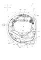
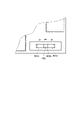
まず、図1~図8を用いて、第1実施形態のパチンコ遊技機1の外観について説明する。図1は、第1実施形態に係るパチンコ遊技機1における外観を示す斜視図の一例である。図2は、第1実施形態に係るパチンコ遊技機1における外観を示す分解斜視図の一例である。図3は、第1実施形態に係るパチンコ遊技機1の操作ボタン群66を示す図の一例である。図4は、第1実施形態に係るパチンコ遊技機1を背面側から示す斜視図である。図5は、第1実施形態に係るパチンコ遊技機1における遊技盤ユニットの外観を示す正面図の一例である。図6は、第1実施形態に係るパチンコ遊技機1における遊技盤ユニット17の外観斜視図を示す一例である。図7は、第1実施形態に係るパチンコ遊技機1における遊技盤ユニット17を右斜め上から見た前方分解斜視図を示す一例である。図8は、第1実施形態に係るパチンコ遊技機1の第1特別図柄表示部73及び第2特別図柄表示部74を含むLEDユニット70を示す正面図の一例である。また、図面に示されている方向は、正面視における方向である。したがって、例えば図面右方向に「左」と記載されているのは、当該図面が背面図であるため、図面上の「右」が正面視における「左」となる。同様に、図面左方向に「右」と記載されているものも、同様の理由により図面上の「左」が正面視における「右」となる。
[1-1. Configuration of Gaming Machine of First Embodiment]
[1-1-1. Appearance configuration]
First, the appearance of the
なお、以下の説明では、特に説明がない限り、パチンコ遊技機1を遊技者から見て、手前側を前側とし、奥側を後側として、前後方向を規定する。また、パチンコ遊技機1を遊技者から見て、左手側を左側とし、右手側を右側として、左右方向を規定する。さらに、正面とは遊技者側から見た場合に視認できる側の面であり、背面とは遊技者の反対側から見た場合に視認できる側の面である。
It should be noted that, in the following description, unless otherwise specified, when the
図1、図2および図4~図7に示すように、パチンコ遊技機1は、木枠11、ベースドア12、ガラスドア13、皿ユニット14、発射装置15、液晶表示装置16、遊技盤ユニット17、払出ユニット18、及び、基板ユニット19を具備する。
As shown in FIGS. 1, 2 and 4 to 7, the
木枠11は、正面視略矩形状の枠体である。木枠11には、前後方向に貫通する開口21が設けられる。木枠11の開口21には、ベースドア12が嵌め込まれる。ベースドア12は、各種の部材を支持するものである。具体的には、ベースドア12は、裏面側に払出ユニット18及び基板ユニット19を支持すると共に、表面側にガラスドア13や、皿ユニット14、発射装置15、液晶表示装置16及び遊技盤ユニット17を支持する。
The
ガラスドア13は、ベースドア12に対して開閉自在に軸着されるものである。ガラスドア13には、開口22、操作ボタン群66が設けられる。ガラスドア13の開口22には、透過性を有する保護ガラス23が配設される。保護ガラス23は、ガラスドア13がベースドア12に対して閉鎖された状態で後述する遊技盤ユニット17と前後方向に対向するように配置される。また、ガラスドア13の上部には、スピーカ24及びLED25が配設される。スピーカ24は、例えば音声での告知や、演出、エラー報知等を行うものである。LED25は、例えば光での告知や、演出等を行う演出用の発光手段であり、発光演出を実行できればLEDに限られず、例えばランプ等であってもよい。
The
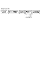
図3に示すように、操作ボタン群66は、メインボタン662とセレクトボタン664とを有する。セレクトボタン664は、上セレクトボタン664a、下セレクトボタン664b、左セレクトボタン664cおよび右セレクトボタン664dを有する。以下において、セレクトボタン664と称するときは、上下左右セレクトボタン664a~664dの総称を意味する。
As shown in FIG. 3 , the
第1実施形態のパチンコ遊技機1は、メインボタン662およびセレクトボタン664のうち少なくともいずれか一方または両方を用いて、後述するガイドメニュー画面やホールメニュー画面等で操作を行うことができる。なお、操作ボタン群66を設ける位置は、ガラスドア13に限られず、皿ユニット14、例えば上皿26上等に設けてもよい。
The
皿ユニット14は、上皿26及び下皿27を一体化したユニット体である。皿ユニット14は、ベースドア12の前下部であって、ガラスドア13の下方に配置される。
The
上皿26は、遊技球を貯留するものであって、上皿26に貯留される遊技球は、発射装置15から後述する遊技領域20に向けて発射される。上皿26には、払出口61及び演出ボタン62が設けられる。貸し出される遊技球や賞球として払い出される遊技球は、払出口61から上皿26に払い出される。演出ボタン62は、所謂「CHANCEボタン」や、「プッシュボタン」等と呼ばれるものである。演出ボタン62は、遊技者によって操作される操作機能の他、所定の演出機能を有してもよい。所定の演出機能としては、例えば後述する特別図柄の大当り判定の結果にもとづいて上方に突出するような機能が相当する。
The
下皿27は、主に上皿26から溢れた遊技球を貯留するためのものである。下皿27には、払出口63が設けられる。上皿26から溢れた遊技球は、払出口63から下皿27に払い出される。
The
発射装置15は、上皿26に貯留された遊技球を、遊技領域20に向けて発射するためのものである。発射装置15は、ベースドア12の前右下部であって、皿ユニット14の右下方に配置される。発射装置15は、パネル体31、駆動装置(不図示)及び発射ハンドル32を具備する。
The
パネル体31は、発射装置15において皿ユニット14の右下部と一体化されるものである。発射ハンドル32は、パネル体31の表面側に配置される。前記駆動装置は、パネル体31の裏面側に配置され、例えば発射ソレノイド(図示せず)により構成される。こうして、発射装置15において、遊技者によって発射ハンドル32が操作されると、操作に応じた前記駆動装置の動作により遊技球が発射される。
The
液晶表示装置16は、特別図柄の大当り判定(以下、特別図柄の大当り判定を単に「大当り判定」や「特別抽選」と称することもある)の結果や、遊技に関する各種の演出画像を表示するものである。演出表示装置16の表示領域に表示される前記各種の演出画像には、例えば演出用識別図柄(装飾図柄)や、大当り判定の結果に応じた演出画像、大当り中の演出画像、デモ演出画像、特別図柄の変動表示(可変表示)の保留数等が含まれる。液晶表示装置16(より詳細には、液晶表示装置16の表示領域)は、遊技盤ユニット17の略中央(後述するセンターレール1742の内周側)に配置される。
The liquid
なお、第1実施形態では、上記各種の演出画像を表示するものとして一つの液晶表示装置16を備えているが、二つの液晶表示装置を設けて、当該二つの液晶表示装置を用いて演出画像を表示するようにしても良い。
In the first embodiment, one liquid
また、図4に示すように、第1実施形態のパチンコ遊技機1は、主制御回路100(後述する図9参照)を有する主制御基板30と、サブ制御回路200(後述する図9参照)を有するサブ制御基板40と、遊技球の払出・発射を制御する払出・発射制御回路300(後述する図9参照)を有する払出・発射制御基板50と、電源を供給する電源供給回路338(後述する図9参照)を有する電源供給ユニット60と、電源スイッチ35と、バックアップクリアスイッチ330(後述する図9参照)とがそれぞれ設けられている。
Further, as shown in FIG. 4, the
第1実施形態のパチンコ遊技機1は、パチンコゲームにかかわる各種データが異なる複数の設定値(第1実施形態では「1」~「6」の6段階)が設けられている。設定「6」が遊技者に最も有利であり、設定値の値が小さくなるにつれて遊技者にとっての有利度も段階的に低くなる。
The
主制御基板30を収容する主基板ケース内には、設定値を変更する際に操作される設定スイッチ332、設定値を変更したり確認したりする際に操作される設定キー328、性能表示モニタ334およびエラー報知モニタ336(いずれも後述の図9参照)が収容されている。性能表示モニタ334には、例えば後述する性能表示データや設定値が表示される。エラー報知モニタ336には、例えば後述するエラーコード等が表示される。なお、設定スイッチ332および設定キー328が主制御基板ケース内に収容されているのは、セキュリティ面を考慮して、パチンコ遊技機1の管理責任者(以下、「遊技機管理責任者」と称する)以外の第三者(例えば遊技者)が設定スイッチ332や設定キー328に容易にアクセスできないようにするためである。尚主基板ケース内とは、正に主基板ケースを開放しないと設定スイッチ332または/および設定キー328にアクセスできないものに加え、主基板ケースの設定スイッチ332および設定キー328の対応箇所にのみ切欠きがあり、遊技機管理責任者が管理する鍵を使用してパチンコ遊技機1を設置している島設備から当該パチンコ遊技機1を回動させて背面を露出させたときに、遊技機管理責任者が設定スイッチ332または/および設定キー328にアクセスできるようにされているものも含む。
In the main board case housing the
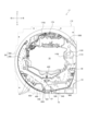
遊技盤ユニット17は、保護ガラス23の後方に位置するように、ベースドア12の前方に配置される。遊技盤ユニット17の前側面には、発射された遊技球が転動流下可能な遊技領域20が形成される。
The
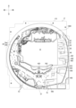
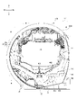
図5~図7に示すように、遊技盤ユニット17は、発射された遊技球が転動流下可能な遊技領域20が形成される透明パネル172と、遊技領域20の略中央部に配置されるセンターユニット174と、普通電動役物ユニット400と、アタッカユニット500(以下、単に「大当り用アタッカユニット500」と称する場合もある)と、通過ゲート49と、裏ユニット176とを備える。センターユニット174、普通電動役物ユニット400、アタッカユニット500、及び通過ゲート49は、透明パネル172の前方側に設けられる。裏ユニット176は、遊技盤ユニット17を装飾するものであって、透明パネル172の後方側に設けられる。この裏ユニット176は、液晶表示装置16の表示領域の上部に配置される上部役物1000等(図7参照)の各役物を備える(以下、「役物群1000」と称する)。これらの各役物1000は、特別抽選の結果にもとづいて動作可能な演出役物として機能する。
As shown in FIGS. 5 to 7, the
透明パネル172には、後述する液晶表示装置16の表示領域が配置される部位に開口1722が形成されている。図5及び図7に示すように、透明パネル172の前面には、ガイドレール28が設けられるとともに遊技釘等が植設されている。発射装置15から発射された遊技球は、ガイドレール28から遊技領域20に向けて飛び出し、遊技釘等と衝突して進行方向を変えながら遊技領域20の下方に向けて流下する。
An
ガイドレール28は、2つのレール状の部材(以下では、「外レール28a」及び「内レール28b」と称する。)により構成される。遊技領域20は、ガイドレール28によって区画(画定)される。内レール28bは、外レール28aと共に、発射された遊技球を遊技領域20の上部に案内するためのものである。内レール28bは、透明パネル172の左側において外レール28aの内側に配置される。
The
センターユニット174は、透明パネル172の開口1722の上方(液晶表示装置16の表示領域の上方)にセンターレール1742を備えており、正面視で円弧状に形成されている。センターレール1742は、遊技領域20の上部に配置されており、遊技領域20における遊技球の流下領域を、当該センターレール1742の左右に区分けするものである。
The
発射装置15によって発射された遊技球は、センターレール1742の左右に区分けされて遊技領域20を流下し、遊技領域20を流下する遊技球は、遊技盤ユニット17(詳しくは透明パネル172)に植設された遊技釘等との衝突により、進行方向を変えながら下方へ向けて流下する。発射された遊技球は、発射ハンドル32の操作量に応じて流下領域が振り分けられる。具体的には、発射ハンドル32の操作量が小さい場合、発射された遊技球はセンターレール1742の左側領域を流下する。一方、発射ハンドル32の操作量が大きい場合、発射された遊技球はセンターレール1742の右側領域を流下する。なお、センターレール1742の左側領域に遊技球を流下させる打ち方は所謂「左打ち」と呼ばれ、センターレール1742の右側領域に遊技球を流下させる打ち方は所謂「右打ち」と呼ばれ、遊技者によって打ち分け可能とされている。
The game balls fired by the
アタッカユニット500は、第1始動口420、大入賞口540及び特別電動役物600を一体化したユニット体である。アタッカユニット500は、遊技領域20内の略右下部であって、通過ゲート49の下方に配置される。
The
大入賞口540は、遊技者に有利な遊技状態である大当り遊技状態の場合に開放可能な部分である。大入賞口540には、大入賞口スイッチ541が配設される(図9参照)。大入賞口540に遊技球が入賞すると、当該入賞した遊技球が大入賞口スイッチ541に検知される。大入賞口スイッチ541に遊技球が検知されると、予め設定された数の遊技球が払出口61から上皿26(又は、払出口63から下皿27)に払い出される。
The
特別電動役物600は、前後方向に進退可能なシャッタ610、及び当該シャッタ610を駆動する大入賞口ソレノイド620(図9参照)を具備する。特別電動役物600は、大入賞口540の上方に配置される。特別電動役物600は、大入賞口ソレノイド620によりシャッタ610が駆動されることによって、大入賞口540への遊技球の入賞を可能(又は容易)とする開放状態と、大入賞口540への遊技球の入賞を不可能(又は困難)とする閉鎖状態と、に移行(駆動)可能に構成される。特別電動役物600(シャッタ610)による開放駆動は、第1始動口420又は後述する第2始動口440に遊技球が入賞したときに行われる大当り判定の結果に基づいて、大当り遊技状態に移行された場合に行われる。なお、第1始動口420又は後述する第2始動口440に遊技球が入賞したときに行われる大当り判定の結果は、第1特別図柄表示部73又は第2特別図柄表示部74において、特別図柄の停止表示態様によって示される。
The special
なお、この明細書において、単に「特別図柄」と称するときは、第1特別図柄および第2特別図柄の両方を意味するものとする。ただし、第1実施形態では特別図柄の数が2つ(第1特別図柄、第2特別図柄)であるが、特別図柄の数は1つであっても良い。 In addition, in this specification, when simply referred to as "special design", it means both the first special design and the second special design. However, in the first embodiment, the number of special symbols is two (first special symbol, second special symbol), but the number of special symbols may be one.
第1始動口420は、遊技球の入賞(通過)を条件に大当り判定の契機を与えると共に、大当り判定の結果を、液晶表示装置16や、後述する第1特別図柄表示部73に表示させる契機を与えるものである。第1始動口420には、第1始動口スイッチ421が配設される(図9参照)。第1始動口スイッチ421を遊技球が通過して第1始動口スイッチ421により検知されると、第1始動口420への遊技球の入賞となる。第1始動口スイッチ421に遊技球が検知されると、パチンコ遊技機1の内部(図9に示すメインCPU101)において大当り判定が行われると共に、予め設定された数の遊技球が払出口61から上皿26に又は払出口63から下皿27に払い出される(排出される)。なお、第1始動口420への遊技球の入賞は、左打ちによって行われる。
The
普通電動役物ユニット400は、第2始動口440、アウト口450及び普通電動役物460を一体化したユニット体である。普通電動役物ユニット400は、遊技領域20の略左下部に配置される。第2始動口440とアウト口450とは互いに隣接して配置されており、第2始動口440が正面視で右側に、アウト口450が正面視で左側に配置されている。従来、普通電動役物ユニット400は例えば第1始動口420の下方に配置されるものが多かった。しかし、近年、液晶表示装置16をより大型化することが要求されており、第1始動口420の下方に配置することが困難となっている。そこで第1実施形態のパチンコ遊技機1では、遊技領域20の略左下部に普通電動役物ユニット400を配置するようにしている。
The ordinary electric
第2始動口440は、遊技球の入賞(通過)を条件に大当り判定の契機を与えると共に、大当り判定の結果を、液晶表示装置16や、後述する第2特別図柄表示部74に表示させる契機を与えるものである。第2始動口440には、第2始動口スイッチ441が配設される(図9参照)。第2始動口スイッチ441を遊技球が通過して第2始動口スイッチ441により検知されると、第2始動口440への遊技球の入賞となる。第2始動口スイッチ441に遊技球が検知されると、パチンコ遊技機1の内部(図9に示すメインCPU101)において大当り判定が行われると共に、予め設定された数の遊技球が、払出口61から上皿26に又は払出口63から下皿27に払い出される(排出される)。第2始動口440は、普通電動役物460によって入賞困難性が決定される。なお、第2始動口440への遊技球の入賞は、原則として右打ちによって行われる。
The
普通電動役物460は、右方向に回動可能な羽根部材4620、電チューソレノイド4630(例えば、図9参照)及び当該電チューソレノイド4630の動力を羽根部材4620に伝達する動力伝達機構(不図示)を具備する。普通電動役物460は、電チューソレノイド4630により羽根部材4620が駆動されることによって、遊技球の通過が容易な開放状態と遊技球の通過が困難な閉鎖状態との間で移行(駆動)可能に構成される。羽根部材4620が駆動されているときに当該羽根部材4620の上方を遊技球が通過すると、当該遊技球は、第2始動口440に入賞するか、アウト口450からパチンコ遊技機1の外部に排出される。普通電動役物460(羽根部材4620)による開閉駆動は、普通図柄表示部71において普通図柄が特定の停止表示態様となった場合に、所定の期間及び回数だけ行われる。
The normal
通過ゲート49は、遊技球の入賞(通過)を条件に普通図柄判定(以下、「普通抽選」と称する)の契機を与えるものである。通過ゲート49は、センターユニット174の下方右側であって、アタッカユニット500の上方右側に配置される。通過ゲート49には、通過ゲートスイッチ491が配設される(図9参照)。通過ゲート49に遊技球が通過すると、当該通過した遊技球が通過ゲートスイッチ491に検知される。通過ゲートスイッチ491に遊技球が検知されると、パチンコ遊技機1の内部(図2に示すメインCPU101)において普通抽選が行われる。なお、通過ゲート49への遊技球の通過は、右打ちによって行われる。
The
アタッカユニット500は、第1始動口420、大入賞口540及び特別電動役物600を一体化したユニット体である。アタッカユニット500は、遊技領域20の略右下部に配置される。アタッカユニット500が遊技領域20の略右下部に配置されるのは、近年、液晶表示装置16をより大型化することが要求されており、アタッカユニット500等の各種部材を遊技領域20に配置するには、かかる大型化された液晶表示装置16を回避する必要があるためである。
The
大入賞口540は、遊技者に有利な遊技状態である大当り遊技状態の場合に開放可能な部分である。大入賞口540には、大入賞口スイッチ541が配設される(図9参照)。大入賞口540に遊技球が入賞すると、当該入賞した遊技球が大入賞口スイッチ541に検知される。大入賞口スイッチ541に遊技球が検知されると、予め設定された数の遊技球が払出口61から上皿26(又は、払出口63から下皿27)に払い出される(排出される)。
The
特別電動役物600は、前後方向に進退可能なシャッタ610、及び当該シャッタ610を駆動する大入賞口ソレノイド620(図9参照)を具備する。特別電動役物600は、大入賞口540の上方に配置される。特別電動役物600は、大入賞口ソレノイド620によりシャッタ610が駆動されることによって、大入賞口540への遊技球の入賞を可能(又は容易)とする開放状態と、大入賞口540への遊技球の入賞を不可能(又は困難)とする閉鎖状態と、に移行(駆動)可能に構成される。特別電動役物600(シャッタ610)による開放駆動は、第1特別図柄表示部73又は第2特別図柄表示部74において特別図柄が特定の停止表示態様となって、大当り遊技状態に移行された場合に行われる。
The special
なお、この明細書において、単に「特別図柄」と称するときは、第1特別図柄および第2特別図柄の両方を意味するものとする。同様に、単に「特別抽選」と称するときは、第1特別図柄の当り判定(以下、「第1特別抽選」と称する)及び第2特別図柄の当り判定(以下、「第2特別抽選」と称する)の両方を意味するものとする(第2実施形態についても同様)。 In addition, in this specification, when simply referred to as "special design", it means both the first special design and the second special design. Similarly, when simply referred to as "special lottery", the first special symbol hit determination (hereinafter referred to as "first special lottery") and the second special symbol hit determination (hereinafter referred to as "second special lottery") (the same applies to the second embodiment).
遊技盤ユニット17の左下部及び右下部には、複数の一般入賞口53が配置されており、一般入賞口53に遊技球が入賞すると、当該入賞した遊技球が一般入賞口スイッチ531に検知される。一般入賞口スイッチ531に遊技球が検知されると、予め設定された数の遊技球が払出装置340から払い出され、払出口61を通って上皿26(又は、払出口63を通って下皿27)に払い出される(排出される)。なお、一般入賞口スイッチ531は、複数の一般入賞口に共通するスイッチとして設けても良いし、複数の一般入賞口のうちいずれの一般入賞口に入賞したかを検知できるように各々の一般入賞口に対応させて設けても良い。
A plurality of general winning
なお、第1実施形態においては、第1始動口420及び第2始動口440の賞球数は3個、一般入賞口53の賞球数は15個、大入賞口540の賞球数は15個にそれぞれ設定されている。この値(賞球数)は、任意に設計変更可能である。
In the first embodiment, the number of prize balls for the
アウト口57は、上述したアウト口450とは別に設けられており、遊技領域20の中央最下部(遊技球の流下方向における最下流位置)に配置される。アウト口57は、発射された遊技球が、いずれの始動口や入賞口にも入賞しなかった場合に、最終的に流入される。
The out
LEDユニット70は、遊技盤ユニット17の右下部であって、ガイドレール41の外側に配置される(図5、図6参照)。LEDユニット70は、各種の表示部を一体化したユニット体である。具体的には、LEDユニット70は、前記各種の表示部として、普通図柄表示部71、普通図柄用保留表示部72、第1特別図柄表示部73、第2特別図柄表示部74、第1特別図柄用保留表示部75及び第2特別図柄用保留表示部76を具備する。
The
普通図柄表示部71は、普通図柄ゲームに対する判定(普通抽選)の結果を表示するものである。ここで、普通図柄ゲームとは、判定(普通抽選)の結果によって普通電動役物460を駆動して開放状態とするか否かを決定するゲームを指す。普通図柄表示部71は、表示LED71a・71bを具備する。表示LED71a・71bは、変動表示(可変表示)の開始条件が成立すると、交互に点灯・消灯を繰り返す変動表示を開始する。表示LED71a・71bの点灯・消灯による組み合わせ(表示パターン)は、普通図柄として表示される。表示LED71a・71bは、変動表示を開始した後、所定の期間経過後に停止表示を行う。
The normal
判定(普通抽選)の結果が当り(以下「普通当り」と称する)である場合、表示LED71a・71bの点灯・消灯の組み合わせ(普通図柄)が特定の停止表示態様となる。こうして、普通図柄が特定の停止表示態様で停止表示されると、普通電動役物460を開放状態とすることが決定し、普通電動役物460が所定のパターンで開閉駆動し、第2始動口440への遊技球の入賞が困難又は不可能な態様から入賞が容易な態様に変更される。
If the result of determination (ordinary lottery) is hit (hereinafter referred to as "ordinary hit"), the combination of lighting and extinguishing of the
普通図柄用保留表示部72は、保留されている普通図柄の変動表示の実行回数(以下、「普通図柄の変動表示の保留数」と称する)を表示するものである。普通図柄用保留表示部72は、表示LED72a・72bを具備する。普通図柄用保留表示部72は、表示LED72a・72bの点灯・消灯の組み合わせによって普通図柄の変動表示の保留数を表示する。例えば、普通図柄の変動表示の実行が1回分保留されている場合には、表示LED72aが点灯すると共に、表示LED72bが消灯する。また、普通図柄の変動表示の実行が2回分保留されている場合には、表示LED72aが点灯すると共に、表示LED72bが点灯する。また、普通図柄の変動表示の実行が3回分保留されている場合には、表示LED72aが点滅すると共に、表示LED72bが点灯する。また、普通図柄の変動表示の実行が4回分保留されている場合には、表示LED72aが点滅すると共に、表示LED72bが点滅する。
The normal symbol reserved
第1特別図柄表示部73及び第2特別図柄表示部74は、特別図柄ゲームに対する判定(大当り判定)の結果を表示するものである。ここで、特別図柄ゲームとは、判定(大当り判定)の結果によって遊技状態の移行又は維持を決定するゲームを指す。
The first special
第1特別図柄表示部73は、8個のLEDからなる表示LED群73aを具備する。表示LED群73aは、第1始動口420への遊技球の入賞(始動入賞)を契機として変動表示を行うと共に、当該遊技球の入賞に基づく大当り判定の結果を表示する。表示LED群73aは、変動表示の開始条件が成立すると、8個のLEDがそれぞれ点灯・消灯を繰り返す変動表示を開始する。表示LED群73aにおいて、8個のLEDの点灯・消灯による組み合わせ(表示パターン)は、特別図柄として表示される。表示LED群73aは、変動表示を開始した後、所定の期間経過後に停止表示を行う。
The first special
第1始動口420への遊技球の入賞に基づく大当り判定の結果が大当りである場合、表示LED群73aの8個のLEDの点灯・消灯の組み合わせ(特別図柄)が特定の停止表示態様となる。こうして、特別図柄が特定の停止表示態様で停止表示されると、遊技状態の移行が決定し、シャッタ610が所定のパターンで開閉駆動し、大入賞口540に遊技球が入賞可能な遊技状態となる。なお、以下の説明では、第1始動口420への遊技球の入賞に基づいて第1特別図柄表示部73に変動表示される特別図柄を、第1特別図柄と称する。
When the result of the jackpot determination based on the winning of the game ball to the
第2特別図柄表示部74は、8個のLEDからなる表示LED群74aを具備する。表示LED群74aは、第2始動口440への遊技球の入賞(始動入賞)を契機として変動表示を行うと共に、当該遊技球の入賞に基づく大当り判定の結果を表示する。表示LED群74aは、変動表示の開始条件が成立すると、8個のLEDがそれぞれ点灯・消灯を繰り返す変動表示を開始する。表示LED群74aにおいて、8個のLEDの点灯・消灯による組み合わせ(表示パターン)は、特別図柄として表示される。表示LED群74aは、変動表示を開始した後、所定の期間経過後に停止表示を行う。
The second special
第2始動口440への遊技球の入賞に基づく大当り判定の結果が大当りである場合、表示LED群74aの8個のLEDの点灯・消灯の組み合わせ(特別図柄)が特定の停止表示態様となる。こうして、特別図柄が特定の停止表示態様で停止表示されると、遊技状態の移行が決定し、シャッタ610が所定のパターンで開閉駆動し、大入賞口540に遊技球が入賞可能な遊技状態となる。なお、以下の説明では、第2始動口440への遊技球の入賞に基づいて第2特別図柄表示部74に変動表示される特別図柄を、第2特別図柄と称する。
When the result of the big hit determination based on the winning of the game ball to the
このように、第1特別図柄表示部73及び第2特別図柄表示部74の表示LED群73a・74aにおいて、第1又は第2特別図柄が特定の停止表示態様で停止表示されると、通常の遊技状態(通常遊技状態)から遊技者に有利な状態である大当り遊技状態への移行が決定する。なお、第1実施形態において、大当り判定は、第1始動口420への遊技球の入賞に基づく大当り判定と、第2始動口440への遊技球の入賞に基づく大当り判定と、が含まれる。すなわち、大当り判定の結果が大当りである場合には、大入賞口540が開放されるラウンド遊技が所定ラウンド数にわたって実行される大当り遊技状態に移行される。
Thus, in the
第1特別図柄用保留表示部75及び第2特別図柄用保留表示部76は、保留されている特別図柄の変動表示の実行回数(以下、「特別図柄の変動表示の保留数」と称する)を表示するものである。第1特別図柄用保留表示部75は、表示LED75a・75bを具備する。第2特別図柄用保留表示部76は、表示LED76a・76bを具備する。第1特別図柄用保留表示部75及び第2特別図柄用保留表示部76は、表示LED75a・75b及び76a・76bの点灯・消灯によって特別図柄の変動表示の保留数を表示する。表示LED75a・75b及び76a・76bの点灯・消灯の表示態様は、普通図柄用保留表示部72の表示LED72a・72bと同様である。
The first special symbol reserved
[1-1-2.電気的構成]
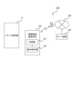
次に、図9を用いて、パチンコ遊技機1の制御回路について説明する。図9は、第1実施形態に係るパチンコ遊技機の制御回路を示すブロック図の一例である。
[1-1-2. electrical configuration]
Next, the control circuit of the
図9に示すように、パチンコ遊技機1は、主に、遊技の制御を行う主制御回路100と、遊技の進行に応じた演出の制御を行うサブ制御回路200と、払出・発射制御回路300と、電源供給回路338と、から構成される。
As shown in FIG. 9, the
主制御回路100は、メインCPU101、メインROM102(読み出し専用メモリ)及びメインRAM103(読み書き可能メモリ)等を具備しており、主基板ケース内に収容されている。
The
メインCPU101には、メインROM102や、メインRAM103等が接続される。メインCPU101は、メインROM102に記憶されたプログラムに従って、各種の処理を実行する機能を有する。
The
メインROM102には、メインCPU101によりパチンコ遊技機1の動作を制御するためのプログラムや、各種のテーブル等が記憶されている。
The
メインRAM103は、メインCPU101の一時記憶領域として種々のフラグや変数の値を記憶する機能を有し、無通電状態であっても書き込まれた情報を記憶保持可能である。なお、第1実施形態においては、メインCPU101の一時記憶領域としてメインRAM103を用いているが、これに限らず、読み書き可能な記憶媒体であればよい。
The
メインRAM103には、特別図柄ゲームの情報が始動記憶として記憶される記憶領域が設けられる。具体的には、メインRAM103には、変動中の第1特別図柄に対応する特別図柄ゲームの情報が始動記憶として記憶される第1特別図柄始動記憶領域(0)と、上限4回分の第1特別図柄に対応する特別図柄ゲームの情報が始動情報として記憶される第1特別図柄始動記憶領域(1)から第1特別図柄始動記憶領域(4)と、が設けられる。また同様に、メインRAM103には、変動中の第2特別図柄に対応する特別図柄ゲームの情報が始動情報として記憶される第2特別図柄始動記憶領域(0)と、上限4回分の第2特別図柄に対応する特別図柄ゲームの情報が始動情報として記憶される第2特別図柄始動記憶領域(1)から第2特別図柄始動記憶領域(4)と、が設けられる。
The
また、主制御回路100は、電源投入時においてリセット信号を生成する初期リセット回路104や、I/Oポート105、コマンド出力ポート106、バックアップコンデンサ107等を具備する。初期リセット回路104は、メインCPU101に接続される。I/Oポート105は、各種のデバイスからの入力信号をメインCPU101に送信したり、メインCPU101からの出力信号を各種の装置に送信したりするものである。コマンド出力ポート106は、メインCPU101からのコマンドをサブ制御回路200に送信するものである。バックアップコンデンサ107は、電断(電源OFF)時において、例えばメインRAM103に対して速やかに電源を供給することにより、メインRAM103に記憶されている各種データを保持するものである。
The
また、主制御回路100には、各種の装置(部材)が接続されている。
Various devices (members) are connected to the
例えば、主制御回路100には、普通図柄表示部71や、普通図柄用保留表示部72、第1特別図柄表示部73、第2特別図柄表示部74、第1特別図柄用保留表示部75、第2特別図柄用保留表示部76、普通電動役物460の羽根部材4620を駆動する電チューソレノイド4630、シャッタ610を駆動する大入賞口ソレノイド620等が接続されている。主制御回路100は、信号を送信することにより、これらの装置(部材)の動作を制御することができる。また、主制御回路100には、ホール係員を呼び出す機能や大当り回数を表示する機能等を有する呼出装置(不図示)や、ホール全体のパチンコ遊技機を管理するホールコンピュータ700にデータ送信するために用いる外部端子板323が接続されている。
For example, the
また、主制御回路100には、第1始動口スイッチ421や、第2始動口スイッチ441、通過ゲートスイッチ491、大入賞口スイッチ541、一般入賞口スイッチ531、性能表示モニタ334等が接続されている。主制御回路100には、これらの部材で遊技球が検知された場合に、当該部材から所定の検知信号が供給される。また、主制御回路100には、電断時におけるバックアップデータを遊技場の管理者の操作に応じてクリアするバックアップクリアスイッチ330等が接続されている。
In addition, the
さらに、主制御回路100には、設定キー328および設定スイッチ332も接続されている。設定キー328は、後述の設定変更処理や設定確認処理を実行するための契機となる鍵または鍵に類するものである。設定スイッチ332は、押下操作可能であり、後述の設定変更処理の際に、セットされている設定値を変更するためのものである。上述したとおり、設定キー328および設定スイッチ332は、遊技機管理責任者以外の第三者(例えば遊技者)が容易にアクセスできないように主基板ケース内に収容されている。
Further, a setting
また、主制御回路100には、払出・発射制御回路300が接続されている。払出・発射制御回路300には、遊技球の払い出しを行う払出装置340や、遊技球の発射を行う発射装置15、カードユニット360等が接続されている。払出装置340は、払出ユニット18に設けられる。カードユニット360には、球貸し操作パネル370が接続され、当該球貸し操作パネル370への遊技者の操作に応じた信号が供給される。
A payout/
払出・発射制御回路300は、主制御回路100から供給される賞球制御コマンドや、カードユニット360から供給される貸し球制御信号を受け取ると、払出装置340に対して所定の信号を送信し、払出装置340に遊技球を払い出させる制御を行う。また、払出・発射制御回路300は、発射ハンドル32が遊技者によって握持され、かつ、時計回り方向へ回動操作されると、その回動角度(回動量)に応じて発射ソレノイド(図示せず)に電力を供給し、遊技球を発射させる制御を行う。
When the payout/
さらに、コマンド出力ポート106には、サブ制御回路200(コマンド入力ポート208)が接続されている。サブ制御回路200は、主制御回路100から供給される各種のコマンドに応じて、液晶表示装置16における表示制御や、スピーカ24から発生させる音声に関する制御、LED25の光に関する制御等を行う。
Furthermore, the
なお、第1実施形態においては、主制御回路100からサブ制御回路200にコマンドを供給する一方、サブ制御回路200から主制御回路100に信号を供給できないように構成したが、これに限らず、サブ制御回路200から主制御回路100に信号を送信できるように構成してもよい。
In the first embodiment, a command is supplied from the
サブ制御回路200は、サブCPU201、プログラムROM202、バックアップメモリとして機能するワークRAM203、表示制御回路204、音声制御回路205、LED制御回路206、役物制御回路207およびコマンド入力ポート208等を具備する。サブ制御回路200は、主制御回路100からの指令に応じて遊技の進行に応じた演出を実行する。また、サブ制御回路200には、演出ボタン62の操作によってON/OFFされる演出ボタンスイッチ621、メインボタン662の操作によってON・OFFされるメインボタンスイッチ6621、および、各セレクトボタン664a~664dの操作によってON・OFFされるセレクトボタンスイッチ6641a~6641dが接続されている。なお、実際には、各セレクトボタン664a~664dに対応するセレクトボタンスイッチ6641a~6641dが夫々設けられているが、図9では、便宜上、これらをまとめてセレクトボタンスイッチ6641と示している。
The
サブCPU201は、プログラムROM202に記憶されたプログラムに従って、各種の処理を実行する機能を有する。特に、サブCPU201は、主制御回路100から供給される各種のコマンドに従って、サブ制御回路200の制御を行う。
The
プログラムROM202には、サブCPU201によりパチンコ遊技機1の遊技演出を制御するためのプログラムや、各種のテーブル等が記憶されている。
The
なお、第1実施形態においては、プログラムやテーブル等が記憶される記憶手段として、メインROM102及びプログラムROM202を用いるように構成したが、これに限らず、制御手段を備えたコンピュータにより読み取り可能な記憶媒体であれば別態様であってもよい。例えば、前記記憶手段として、ハードディスク装置や、CD-ROM及びDVD-ROM、ROMカートリッジ等の記憶媒体を用いてもよい。また、前記プログラムやテーブル等は、予め記録されているものでなくとも、電源投入後にダウンロードされ、ワークRAM203等に記録されるものでもよい。さらに、前記プログラムやテーブル等は、各々異なる記憶媒体に記録されていてもよい。
In the first embodiment, the
ワークRAM203は、サブCPU201の一時記憶領域として種々のフラグや変数の値を記憶する機能を有する。なお、第1実施形態においては、サブCPU201の一時記憶領域としてワークRAM203を用いているが、これに限らず、読み書き可能な記憶媒体であればよい。
The
表示制御回路204は、液晶表示装置16における表示制御を行うための回路である。表示制御回路204は、画像データプロセッサ(以下、VDPと称する)や、各種の画像データを生成するためのデータが記憶されている画像データROM、画像データをバッファするフレームバッファ、画像データを画像信号として変換するD/Aコンバータ等を具備する。
The
表示制御回路204は、サブCPU201から供給されるデータに応じて、液晶表示装置16に画像を表示させるための種々の処理を行うことができる。表示制御回路204は、サブCPU201から供給される画像表示命令に応じて、液晶表示装置16に表示させるための画像データを一時的にフレームバッファに格納する。なお、液晶表示装置16に表示させるための画像データには、装飾図柄を示す装飾図柄画像データや、背景画像データ、演出用画像データ等の、遊技に関する各種の画像データが含まれる。
The
そして、表示制御回路204は、所定のタイミングで、フレームバッファに格納された画像データをD/Aコンバータに供給する。D/Aコンバータは、画像データを画像信号として変換し、当該変換した画像信号を所定のタイミングで液晶表示装置16に供給する。液晶表示装置16に画像信号が供給されると、液晶表示装置16に当該画像信号に関する画像が表示される。こうして、表示制御回路204は、液晶表示装置16に遊技に関する画像を表示させる制御を行うことができる。
Then, the
音声制御回路205は、スピーカ24から発生させる音声に関する制御を行うための回路である。音声制御回路205は、音声に関する制御を行う音源ICや、各種の音声データを記憶する音声データROM、音声信号を増幅するための増幅器(以下、AMPと称する)等を具備する。
The
前記音源ICは、スピーカ24から発生させる音声の制御を行う。音源ICは、サブCPU201から供給される音声発生命令に応じて、音声データROMに記憶されている複数の音声データから一つの音声データを選択する。また、音源ICは、選択された音声データを音声データROMから読み出し、音声データを所定の音声信号に変換し、当該変換した音声信号をAMPに供給する。AMPは、音声信号を増幅させ、スピーカ24から音声を発生させる。
The sound source IC controls sound generated from the
LED制御回路206は、装飾LED等を含むLED25の制御を行うための回路である。LED制御回路206は、LED制御信号を供給するためのドライブ回路や、複数種類のLED装飾パターンが記憶されている装飾データROM等を具備する。
The
役物制御回路207は、各役物の制御を行うための回路である。役物制御回路207は、各役物に対して、駆動信号を供給するための駆動回路や、点灯制御信号を供給するための点灯回路、動作パターンや点灯パターンが記憶されている役物データROM等を有する。
The
また、駆動回路は、サブCPU201から供給される役物作動命令に応じて、役物データROMに記憶されている複数の動作パターンから一つの動作パターンを選択する。そして、選択した動作パターンを役物データROMから読み出し、読み出した動作パターンに対応する駆動信号を供給することにより、各役物の機械的な動作を制御する。また、点灯回路は、サブCPU201から供給される点灯命令に基づいて、役物データROMに記憶されている複数の点灯パターンから一つの点灯パターンを選択する。そして、選択した点灯パターンを役物データROMから読み出し、読み出した点灯パターンに対応する点灯制御信号を供給することにより、各役物の点灯動作を制御する。
Also, the drive circuit selects one motion pattern from a plurality of motion patterns stored in the role product data ROM according to the role product activation command supplied from the
コマンド入力ポート208は、主制御回路100送信されたコマンドを受信するものである。
A
払出・発射制御回路300は、パチンコ遊技機1からの賞球や貸球の払い出しを制御するものであり、この払出・発射制御回路300には、遊技球を払い出すための払出装置340、遊技球を発射するための発射装置15、電断時におけるバックアップデータを遊技場の管理者の操作に応じてクリアするバックアップクリアスイッチ330等が接続されている。
The payout/
電源供給回路338は、パチンコ遊技機1で遊技を行うために必要な電源電圧を、主制御回路100、サブ制御回路200、払出・発射制御回路300等に供給するために作成する電源回路である。
The
電源供給回路338には、電源スイッチ35等が接続されている。電源スイッチ35は、パチンコ遊技機1に必要な電源を供給するときにON操作するものである。
The
なお、設定キー328および設定スイッチ332は、上述したように主制御回路100に接続されているが、これに代えて、電源供給回路338に接続されるようにしても良い。この場合であっても、遊技機管理責任者以外の第三者(例えば遊技者)が設定スイッチ332や設定キー328に容易にアクセスできないように、所定のケース内に収容されていることが好ましい。このような場合であっても、所定のケース内とは、正に当該ケースを開放しないと設定スイッチ332や設定キー328にアクセスできないものに加え、上記ケースの設定スイッチ332および設定キー328の対応箇所にのみ切欠きがあり、遊技機管理責任者が管理する鍵を使用してパチンコ遊技機1を設置している島設備から当該パチンコ遊技機1を回動させて背面を露出させたときに、遊技機管理責任者が設定スイッチ332または/および設定キー328にアクセスできるようにされているものも含む。
Although the setting
ここで、性能表示モニタ334に表示される表示内容について説明する。性能表示モニタ334には、メインCPU101の制御により性能表示データが表示される。性能表示データは、例えば、所定数(例えば60000発)の遊技球の発射に対して大当り遊技状態以外で払い出された遊技球の割合を示すデータであり、ベース値とも呼ばれる。
Here, display contents displayed on the performance display monitor 334 will be described. Performance display data is displayed on the performance display monitor 334 under the control of the
払出・発射制御回路300は、過去の遊技履歴に基づいてベース値を集計し、集計結果をメインRAM103の作業領域のうち後述する特定作業領域に記憶する。この特定作業領域については後述するが、後述のバックアップクリア処理が行われてもデータがクリアされない領域である。なお、ベース値の集計は、所定の操作が行われたことに基づいて行われるようにしても良いし、常に集計を行って性能表示モニタ334にベース値が常時表示されるようにしても良い。
The payout/
払出・発射制御回路300は、初期電源投入(パチンコ遊技機1が製造されたのち初めての電源投入)から現在までの全遊技履歴に基づいて全ベース値の集計を実行する全履歴集計手段と、設定値毎の過去の遊技履歴に基づいて設定値別ベース値の集計を実行する設定値別履歴集計手段とを備える。
The payout/
例えば遊技機管理責任者等によって全ベース値の表示操作が行われると、全履歴集計手段は、上記の全ベース値の集計を実行する。全履歴集計手段により集計された全ベース値は、メインCPU101によって性能表示モニタ334に表示される。また、設定値別ベース値の表示操作が行われると、設定値別履歴集計手段は、設定値別ベース値の集計を実行する。設定値別履歴集計手段により集計された設定値別ベース値は、メインCPU101によって性能表示モニタ334に表示される。
For example, when an operation for displaying all base values is performed by a game machine manager or the like, the all history totalizing means executes totalization of all the base values. The
設定値別履歴集計手段は、要求(操作)に応じて、任意の設定値についてのベース値のみを集計することもできる。この場合、セットされている設定値についてのベース値だけでなく、セットされている設定値以外の他の設定値についてのベース値を集計することもできる。したがって、メインCPU101は、後述する設定変更処理を実行することなく、他の設定値についてのベース値を性能表示モニタ334に表示することができる。
The setting-value-by-setting-value history aggregating means can also aggregate only base values for arbitrary setting values in response to a request (operation). In this case, not only the base values for the set setting values, but also the base values for setting values other than the set setting values can be totaled. Therefore, the
なお、メインCPU101は、例えば遊技機管理責任者等による操作に応じて、全履歴集計手段により集計された全ベース値と、設定値別履歴集計手段により集計された設定値別ベース値との両方を性能表示モニタ334に表示することもできるし、これらのうちいずれか一方のみを選択的に性能表示モニタ334に表示することもできる。
It should be noted that the
また、メインCPU101は、特定の設定値のベース値のみを性能表示モニタ334に表示しても良いし、全設定値のベース値を一覧で表示しても良い。また、全ベース値と設定値別ベース値との両方を一覧で表示しても良い。全設定値のベース値を一覧で表示する場合や、全ベース値と設定値別ベース値との両方を一覧で表示する場合には、性能表示モニタ334と他の表示手段との両方を使って表示するようにしても良い。
Further, the
また、メインCPU101は、全履歴集計手段と設定値別履歴集計手段とを備えるが、これらに加えてまたは設定値別履歴集計手段に代えて、後述する設定変更処理が実行されてから現在までの遊技履歴に基づいて設定変更後ベース値を集計する設定変更後履歴集計手段を備えるようにしても良い。この場合、メインCPU101は、設定変更後ベース値の表示操作に基づいて設定変更後の設定値別ベース値を性能表示モニタ334に表示することができる。
The
このように、全ベース値と、設定値別ベース値または/および設定変更後の設定値別ベース値とのうち全部または一部が性能表示モニタ334に表示されるようにすることで、パチンコ遊技機1における過去の遊技履歴に基づく情報を容易に確認することが可能となる。
In this way, by displaying all or part of the total base value, the base value by setting value and/or the base value by setting value after setting change on the
なお、第1実施形態ではベース値を性能表示モニタ334に表示するようにしたが、遊技球の総払出数に対し、特別電動役物(大入賞口)、普通電動役物への入球により払い出された遊技球数(役物による払出)の割合を表示するようにしてもよい。また、それは総発射数に対する表示でもよく、さらに特別電動役物(大入賞口)により払い出された遊技球数の割合を表示するものでもよい。またそれらを設定別に表示してもよい。
In the first embodiment, the base value is displayed on the
また、エラー報知モニタ336には、後述するエラーコードが表示される。このエラー報知モニタ336には、エラーコードの他に、後述する設定変更処理中であることを示す設定変更中コード、後述設定確認処理中であることを示す設定確認中コード等を表示することもできる。なお、設定変更中において、特別図柄表示装置において通常では表示することのない図柄(設定変更図柄)を表示するようにしてもよい。
Also, an error code, which will be described later, is displayed on the
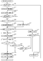
[1-2.機能フロー]
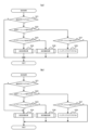
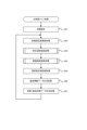
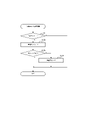
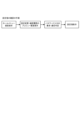
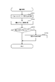
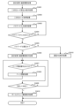
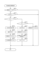
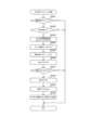
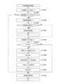
次に、図10を用いて、第1実施形態に係るパチンコ遊技機1の機能フローについて説明する。図10は、第1実施形態に係るパチンコ遊技機1の機能フローを示す図である。
[1-2. Function flow]
Next, the functional flow of the
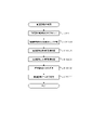
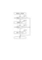
図10に示すように、パチンコゲームは、ユーザの操作により遊技球が発射され、その遊技球が各種入賞した場合に遊技球の払出制御処理が行われるゲームである。また、パチンコゲームには、特別図柄を用いる特別図柄ゲーム、普通図柄を用いる普通図柄ゲームが含まれる。 As shown in FIG. 10, the pachinko game is a game in which a game ball is shot by a user's operation, and game ball payout control processing is performed when the game ball wins various prizes. The pachinko game includes a special symbol game using special symbols and a normal symbol game using normal symbols.
特別図柄ゲームにおいて「大当り」となったときや、普通図柄ゲームにおいて「普通当り」となったときには、相対的に、遊技球が入賞する可能性が増大し、遊技球の払出制御処理が行われ易くなる。 When the special symbol game results in a "jackpot" or the normal symbol game results in a "normal win", the possibility of winning the game ball increases relatively, and the payout control process of the game ball is performed. becomes easier.
また、各種入賞には、特別図柄ゲームにおいて特別図柄の変動表示が行われるための一つの条件である特別図柄始動入賞や、普通図柄ゲームにおいて普通図柄の変動表示が行われるための一つの条件である普通図柄始動入賞も含まれる。 In addition, for various prizes, special symbol start winning, which is one condition for the variable display of special symbols in the special symbol game, and one condition for the variable display of normal symbols in the normal symbol game. Certain normal symbol start prizes are also included.
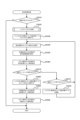
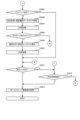
以下、特別図柄ゲーム及び普通図柄ゲームの処理フローの概要を説明する。特別図柄ゲーム及び普通図柄ゲームは、メインCPU101により制御処理として実行される。
The outline of the processing flow of the special symbol game and the normal symbol game will be described below. The special symbol game and the normal symbol game are executed by the
(1)特別図柄ゲームにおいて特別図柄始動入賞があった場合には、各種カウンタ(例えば大当り判定用カウンタや図柄決定用カウンタ)からそれぞれ各種乱数値(例えば大当り判定用乱数値や図柄乱数値)が抽出(取得)され、抽出された各乱数値が記憶される(図10に示す特別図柄ゲーム中の特別図柄始動入賞処理のフロー参照)。 (1) When there is a special symbol starting prize in the special symbol game, various random numbers (for example, random numbers for judging big hits and random numbers for symbols) are generated from various counters (for example, counters for judging big hits and counters for determining symbols). Each of the extracted (acquired) random numbers is stored (see the flow of the special symbol start winning process during the special symbol game shown in FIG. 10).
また、図10に示すように、特別図柄ゲーム中の特別図柄制御処理では、最初に、特別図柄の変動表示を開始する条件が成立したか否かが判別される。この判別処理では、特別図柄始動入賞によって乱数値等の各種データが記憶されているか否かを参照し、乱数値等の各種データが記憶されていることを一つの条件として、特別図柄の変動表示を開始する条件が成立したと判別する。 Further, as shown in FIG. 10, in the special symbol control process during the special symbol game, first, it is determined whether or not the condition for starting the variable display of the special symbols is established. In this discrimination process, it is referred to whether or not various data such as random numbers are stored by the special symbol start winning, and if various data such as random numbers are stored as one condition, variable display of special symbols. It is determined that the conditions for starting are satisfied.
次いで、特別図柄の変動表示を開始する場合、大当り判定用カウンタから抽出された大当り判定用乱数値が参照され、「大当り」とするか否かの大当り判定が行われる。その後、停止図柄決定処理が行われる。この処理では、図柄決定用カウンタから抽出された図柄乱数値と、上述した大当り判定の結果とが参照され、停止表示させる特別図柄を決定する。 Next, when the variable display of the special symbols is started, the big-hit determination random number extracted from the big-hit determination counter is referred to, and the big-hit determination is made as to whether or not to make it a "big-hit". After that, stop symbol determination processing is performed. In this process, the symbol random number value extracted from the symbol determination counter and the result of the above-described big hit determination are referred to, and the special symbol to be stopped and displayed is determined.
次いで、変動パターン決定処理が行われる。この処理では、変動パターン決定用カウンタから乱数値が抽出され、その乱数値と、上述した大当り判定の結果と、上述した停止表示させる特別図柄とが参照され、特別図柄の変動パターン(可変表示パターン)を決定する。 Then, a variation pattern determination process is performed. In this process, a random number is extracted from the variation pattern determination counter, the random number, the result of the above-mentioned big hit determination, and the above-mentioned special symbol to be stopped and displayed are referred to, and the variation pattern of the special symbol (variable display pattern ).
次いで、演出パターン決定処理が行われる。この処理では、演出パターン決定用カウンタから乱数値が抽出され、その乱数値と、上述した大当り判定の結果と、上述した停止表示させる特別図柄と、上述した特別図柄の変動パターンとが参照され、特別図柄の変動表示に伴って実行する演出パターンを決定する。 Next, effect pattern determination processing is performed. In this process, a random number is extracted from the effect pattern determination counter, the random number, the result of the above-mentioned big hit determination, the above-mentioned special symbols to be stopped and displayed, and the above-described special symbol variation pattern are referred to, A performance pattern to be executed with the variable display of special symbols is determined.
次いで、決定された大当り判定の結果、停止表示させる特別図柄、特別図柄の変動パターン、及び、特別図柄の変動表示に伴う演出パターンが参照され、特別図柄の変動表示の制御を行う変動表示制御処理、及び、所定の演出を行う演出制御処理が実行される。 Then, as a result of the determined big hit determination, the special symbol to be stopped and displayed, the variation pattern of the special symbol, and the performance pattern associated with the variable display of the special symbol are referred to, and the variable display control process of controlling the variable display of the special symbol. , and effect control processing for performing a predetermined effect is executed.
そして、変動表示制御処理及び演出表示制御処理が終了すると、「大当り」となるか否かが判定される。この判定処理において、「大当り」となったと判定されると、大当り遊技状態を行う大当り遊技状態制御処理が実行される。なお、大当り遊技状態では、上述した各種入賞の可能性が増大する。一方、「大当り」とならなかったと判定されると、大当り遊技状態制御処理が実行されない。 Then, when the variable display control process and the performance display control process are completed, it is determined whether or not a "jackpot" will be achieved. In this determination process, when it is determined that the "big hit" has occurred, a big win game state control process for performing a big win game state is executed. In addition, in the jackpot game state, the possibility of winning various prizes described above increases. On the other hand, if it is determined that the "jackpot" was not achieved, the jackpot game state control process is not executed.
「大当り」とならなかったと判定された場合、又は、大当り遊技状態制御処理が終了した場合には、遊技状態を移行させるための遊技状態移行制御処理が行われる。この遊技状態移行制御処理では、大当り遊技状態とは異なる通常時の遊技状態の管理が行われる。 When it is determined that a "jackpot" is not achieved, or when the jackpot game state control process is completed, a game state shift control process for shifting the game state is performed. In this game state transition control process, management of the normal game state different from the jackpot game state is performed.
通常時の遊技状態としては、例えば、上述した大当り判定において、所定の確率で「大当り」と判定される遊技状態(以下、「通常遊技状態」という)や、「大当り」と判定される確率が通常遊技状態よりも増大する遊技状態(以下、「高確率遊技状態」という)や、後述する普通当り判定の結果として特別図柄始動入賞が得られやすくなる遊技状態(以下、「時短遊技状態」という)などが挙げられる。その後、再度、特別図柄の変動表示を開始させるか否かの判別処理を行い、その後は、上述した特別図柄制御処理の各種処理が繰り返される。 As the normal game state, for example, in the above-described jackpot determination, a game state in which a "jackpot" is determined with a predetermined probability (hereinafter referred to as a "normal game state"), or a game state in which a "jackpot" is determined. A game state that increases more than the normal game state (hereinafter referred to as "high probability game state") and a game state in which special symbol start winning is easier to obtain as a result of normal hit determination described later (hereinafter referred to as "time saving game state" ) and the like. After that, again, the determination processing of whether or not to start the variable display of the special symbols is performed, and after that, various kinds of processing of the above-described special symbol control processing are repeated.
なお、第1実施形態のパチンコ遊技機1において、特別図柄の変動表示中に遊技球が始動入賞した場合には、該始動入賞時に抽出される各種データ(大当り判定用乱数値、図柄乱数値等)が、特別図柄の変動表示を開始する条件が成立するまで記憶される。このように、特別図柄の変動表示を開始する条件が成立するまで各種データ(例えば大当り判定用乱数値等)を記憶することを「保留」といい、保留される各種データを始動情報という。
In addition, in the
すなわち、特別図柄の変動表示中に遊技球が始動入賞した場合には、該始動入賞に対応する特別図柄の変動表示の実行が保留され、現在実行されている特別図柄の変動表示終了後に保留されている特別図柄の変動表示が順に開始される。以下では、保留されている特別図柄についての各種データを「保留球」ともいう。 That is, when the game ball starts winning during the variable display of the special symbols, the execution of the variable display of the special symbols corresponding to the starting winning is suspended, and is suspended after the completion of the variable display of the special symbols currently being executed. The variable display of the special symbols that are on is started in order. Below, the various data about the reserved special symbol are also referred to as "reserved ball".
また、第1実施形態のパチンコ遊技機1では、後述するように、2種類の特別図柄始動入賞(第1始動口入賞及び第2始動口入賞)を設け、各特別図柄始動入賞に対して最大4個まで特別図柄の変動表示の実行を保留することができる。すなわち、第1実施形態では、第1特別図柄の4個と第2特別図柄の4個とで合計最大8個まで、特別図柄の変動表示の実行を保留することができる。
In addition, in the
なお、図10には示されていないが、第1実施形態のパチンコ遊技機1は、上述した保留球の情報に基づいて保留球の当落(「大当り」当選の有無)を判定し、さらに、その判定結果に基づいて所定の演出を行う機能、すなわち先読み演出機能を備えている。
Incidentally, although not shown in FIG. 10, the
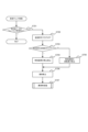
(2)普通図柄ゲームにおいて普通図柄始動入賞があった場合には、普通当り判定用カウンタから乱数値が抽出され、その乱数値が記憶される(図10に示す普通図柄ゲーム中の普通図柄始動入賞処理のフロー参照)。 (2) When there is a normal symbol start winning prize in the normal symbol game, a random value is extracted from the normal hit determination counter, and the random value is stored (normal symbol start during normal symbol game shown in FIG. 10) Refer to the winning process flow).
また、図10に示すように、普通図柄ゲーム中の普通図柄制御処理では、最初に、普通図柄の変動表示を開始する条件が成立したか否かが判別される。この判別処理では、普通図柄始動入賞によって乱数値が記憶されているか否かが参照され、乱数値が記憶されていることを一つの条件として、普通図柄の変動表示を開始する条件が成立したと判別する。 Further, as shown in FIG. 10, in the normal symbol control process during the normal symbol game, first, it is determined whether or not the condition for starting the variable display of the normal symbols is established. In this determination process, it is determined whether or not the random number value is stored by the normal symbol start winning prize, and the condition for starting the variable display of the normal symbol is satisfied with the fact that the random number value is stored as one condition. discriminate.
次いで、普通図柄の変動表示を開始する場合、普通当り判定用カウンタから抽出された乱数値が参照され、「普通当り」とするか否かの普通当り判定が行われる。その後、変動パターン決定処理が行われる。この処理では、普通当り判定の結果が参照され、普通図柄の変動パターンを決定する。 Next, when the variable display of the normal symbols is started, the random number value extracted from the counter for normal hit determination is referred to, and the normal hit determination as to whether or not the "normal hit" is performed. After that, a variation pattern determination process is performed. In this process, the result of normal hit determination is referred to, and the normal pattern variation pattern is determined.
次いで、決定された普通当り判定の結果、及び、普通図柄の変動パターンが参照され、普通図柄の変動表示の制御を行う変動表示制御処理、及び、所定の演出を行う演出制御処理が実行される。 Then, with reference to the result of the determined normal hit determination and the variation pattern of the normal symbols, a variable display control process for controlling the variable display of the normal symbols and an effect control process for performing a predetermined effect are executed. .
変動表示制御処理及び演出表示制御処理が終了すると、「普通当り」となるか否かが判定される。この判定処理において、「普通当り」となると判定されると、普通当り遊技を行う普通当り遊技制御処理が実行される。 When the variable display control process and the effect display control process are completed, it is determined whether or not a "normal win" will be achieved. In this determination process, when it is determined that it will be a "normal hit", a normal winning game control process for performing a normal winning game is executed.
普通当り遊技制御処理では、上述した各種入賞の可能性、特に、特別図柄ゲームにおける遊技球の特別図柄始動入賞の可能性が増大する。一方、「普通当り」とならないと判定されると、普通当り遊技制御処理が実行されない。その後、再度、普通図柄の変動表示を開始させるか否かの判別処理を行い、その後は、上述した普通図柄制御処理の各種処理が繰り返される。 In the normal winning game control process, the possibility of various prizes mentioned above, in particular, the possibility of the special symbol starting prize of the game ball in the special symbol game increases. On the other hand, when it is determined that it does not become a "normal hit", the normal winning game control process is not executed. After that, the process of determining whether or not to start the variable display of normal symbols is performed again, and thereafter, the various processes of the normal symbol control process described above are repeated.
上述のように、パチンコゲームでは、特別図柄ゲームにおいて「大当り」となるか否か、遊技状態の移行状況、普通図柄ゲームにおいて「普通当り」となるか否か等の条件により、遊技球の払出制御処理の行われ易さが変化する。 As described above, in the pachinko game, the payout of game balls depends on conditions such as whether or not a "big win" occurs in a special symbol game, the transition state of the game state, and whether or not a "normal win" occurs in a normal symbol game. The ease with which control processing can be performed changes.
なお、第1実施形態において、各種の乱数値の抽出方式としては、メインCPU101によりプログラムを実行することによって所定の範囲(幅)内で乱数値を生成するソフト乱数方式を用いる。しかしながら、各種の乱数値の抽出方式はこれに限定されず、例えば、パチンコ遊技機が、所定周期で乱数が更新される乱数発生器を備える場合には、その乱数発生器におけるカウンタ(いわゆる、リングカウンタ)から乱数値を抽出するハード乱数方式を、上述した各種乱数値の抽出方式として採用してもよい。
In the first embodiment, as a method for extracting various random numbers, a software random number method is used in which random numbers are generated within a predetermined range (width) by executing a program by the
なお、ハード乱数方式を用いる場合は、所定周期とは異なるタイミングで、乱数値の初期値を決定することによって、所定周期で同じ乱数値が抽出されることを防止することができる。 When the hard random number method is used, it is possible to prevent the same random number from being extracted in the predetermined period by determining the initial value of the random number at a timing different from the predetermined period.
[1-3.パチンコ遊技機の基本仕様]
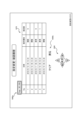
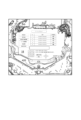
次に、図11~図14を用いて、パチンコ遊技機1の基本仕様について説明する。図11はパチンコ遊技機1の大当りの確率を示すテーブルの一例であり、図12は、特別図柄の大当り判定の結果が大当りであるときの当り種別(以下「メイン図柄」と称する)の選択率についての一例を示す図であり、図13はメインROM102に記憶される特別図柄の変動時間(可変表示時間)決定テーブルの一例を示す図である。図14は、サブ制御回路200のプログラムROM202に記憶される装飾図柄決定テーブルの一例を示す図である。なお、以下の説明において、図11~図14に示されていないメインCPU101およびメインRAM103の用語を用いているが、これらは図9に示されている。
[1-3. Basic specifications of pachinko machines]
Next, the basic specifications of the
図11に示される大当りの確率について説明するにあたり、先ず、パチンコ遊技機1における大当りについて簡単に説明する。
Before explaining the probability of a big win shown in FIG. 11, first, the big win in the
メインCPU101は、第1始動口420(例えば図5参照)への遊技球の入賞を検出すると、大当り判定用カウンタから第1特別図柄の大当り判定用乱数を抽出し、メインRAM103に記憶される第1特別図柄大当り乱数判定テーブル(図示せず)を参照して、抽出された大当り判定用乱数についての大当り判定(以下、「第1特別図柄の大当り判定」と称する)を行う。なお、第1特別図柄の大当り判定用乱数の抽出は、大当り遊技状態に制御されているときであっても行われる。
When the
同様に、メインCPU101は、第2始動口440(例えば図5参照)への遊技球の入賞を検出すると、大当り判定用カウンタから第2特別図柄の大当り判定用乱数を抽出し、メインRAM103に記憶される第2特別図柄大当り乱数判定テーブル(図示せず)を参照して、抽出された大当り判定用乱数についての大当り判定(以下、「第2特別図柄の大当り判定」と称する)を行う。なお、第2特別図柄の大当り判定用乱数の抽出は、大当たり遊技状態に制御されているときであっても行われる。
Similarly, when the
第1特別図柄の大当り判定が行われると、「大当り」および「ハズレ」のいずれかに決定される。また、第2特別図柄の大当り判定が行われると、第1特別図柄の大当り判定と同様に、「大当り」および「ハズレ」のいずれかに決定される。メインRAM103に記憶される第1特別図柄の大当り乱数判定テーブルおよび第2特別図柄の大当り乱数判定テーブルには、それぞれ、確変フラグの値(「0(=オフ)」又は「1(=オン)」)毎に、「大当り」又は「ハズレ」に決定される大当り判定用乱数の範囲(幅)と、それに対応する判定値データ(「大当り判定値データ」及び「ハズレ判定値データ」)との関係が規定されている。
When the jackpot determination of the first special symbol is performed, it is determined to be either "big hit" or "losing". Also, when the second special symbol jackpot determination is performed, it is determined to be either a "big hit" or a "loss" in the same manner as the first special symbol jackpot determination. In the first special symbol jackpot random number determination table and the second special symbol jackpot random number determination table stored in the
第1実施形態では、第1特別図柄および第2特別図柄ともに、総乱数は65536である。すなわち、上記の大当り判定用乱数は0~65535の範囲(幅)で発生する。この範囲は固定値として設定されている。大当り確率は、大当り判定用乱数の範囲に対する大当り判定値データの数によって定められる。なお、大当り判定用乱数の範囲(幅)は、適宜変更することができる。 In the first embodiment, the total random number is 65536 for both the first special symbol and the second special symbol. That is, the random number for judging a big hit is generated within a range (width) of 0-65535. This range is set as a fixed value. The jackpot probability is determined by the number of jackpot determination value data for the range of jackpot determination random numbers. It should be noted that the range (width) of the random number for judging a big hit can be changed as appropriate.
なお、確変フラグは、メインRAM103に格納される管理フラグの一つであり、遊技状態が「高確率遊技状態」であるか否かを管理するためのフラグである。遊技状態が「高確率遊技状態」である場合には、確変フラグは「1」となり、「低確率遊技状態」である場合には、確変フラグは「0」となる。
The variable probability flag is one of the management flags stored in the
また、時短フラグは、メインRAM103に格納される管理フラグの一つであり、遊技状態が「時短遊技状態」であるか否かを管理するためのフラグである。遊技状態が「時短遊技状態」である場合には、時短フラグは「1」(時短フラグON)となり、「非時短遊技状態」である場合には、時短フラグは「0」(時短フラグOFF)となる。なお、時短遊技状態では、時短回数もメインCPU101によって管理されており、特別図柄が1回変動する毎に、メインCPU101により管理される時短カウンタの値が1減算される。
The time saving flag is one of the management flags stored in the
なお、時短フラグがON設定される時短遊技状態では、非時短遊技状態と比べて、普通当り判定において普通当りと判別される確率(普通当り確率)が高められる。そのため、時短遊技状態では、非時短遊技状態と比べて、普通電動役物460が閉鎖状態から開放状態になる頻度、すなわち第2始動口440への遊技球の入賞頻度が高められる。ただし、時短遊技状態において、非時短遊技状態と比べて普通当り確率を高めることに代えて、例えば、普通当り抽選の実行頻度を高める(普通図柄の変動時間が短くする)ことで、普通電動役物460が閉鎖状態から開放状態になる頻度を高めるようにしても良いし、普通電動役物460の開放態様を変えることで当該普通電動役物460に入賞しやすくしても良い。また、上記の三態様のうち二態様または三態様を組み合わせても良い。
In addition, in the time saving game state in which the time saving flag is set to ON, the probability that it is determined as a normal hit in the normal hit determination (normal hit probability) is increased as compared with the non-time saving game state. Therefore, in the time-saving game state, compared to the non-time-saving game state, the frequency that the normal
第1実施形態のパチンコ遊技機1では、確変フラグおよび時短フラグのいずれもがOFFの通常遊技状態と、確変フラグON且つ時短フラグONの確変時短遊技状態と、確変フラグOFF且つ時短フラグONの時短遊技状態とのうち、いずれかの遊技状態にメインCPU101により制御されるように構成されている。
In the
メインCPU101は、第1始動口420(例えば図5参照)への遊技球の入賞を検出して第1特別図柄の大当り判定用乱数を抽出すると、当該抽出した第1特別図柄の大当り判定用乱数値を、第1特別図柄の変動表示が開始されるまで始動情報として保留する。そして、第1特別図柄の変動表示を開始するときに、第1特別図柄の大当り判定を行い、大当りであるかハズレであるかを決定する。
When the
メインCPU101は、第2始動口440(例えば図5参照)への遊技球の入賞を検出して第2特別図柄の大当り判定用乱数を抽出すると、当該抽出した第2特別図柄の大当り判定用乱数値を、第2特別図柄の変動表示が開始されるまで始動情報として保留する。そして、第2特別図柄の変動表示を開始するときに、第2特別図柄の大当り判定を行い、大当りであるかハズレであるかを決定する。
When the
[1-3-1.大当り確率]
図11に示されるように、第1特別図柄の大当り判定においては、セットされている設定値に応じて大当り確率が異なっている。大当り確率が相対的に低い低確率遊技状態(確変フラグOFF)であるとき、設定値毎の大当り確率は、設定1で約300分の1、設定2で約290分の1、設定3で約280分の1、設定4で約270分の1、設定5で約260分の1、設定6で約250分の1となっている。また、大当り確率が相対的に高い高確率遊技状態(確変フラグON)であるとき、設定値毎の大当り確率は、設定1で約30分の1、設定2で約29分の1、設定3で約28分の1、設定4で約27分の1、設定5で約26分の1、設定6で約25分の1となっている。
[1-3-1. jackpot probability]
As shown in FIG. 11, in the jackpot determination of the first special symbol, the jackpot probability differs according to the set value. When the jackpot probability is relatively low low probability gaming state (probability variation flag OFF), the jackpot probability for each setting value is about 1/300 at setting 1, about 1/290 at setting 2, and about 1/290 at setting 3.
すなわち、上述したとおり、第1実施形態では大当り判定用乱数の範囲(幅)が0~65535の範囲に固定値として設定されているため、第1特別図柄の大当り判定値データの数を設定値に応じて変えることで、設定値に応じて大当り確率を異ならせている。例えば、第1特別図柄における低確率遊技状態では、固定値である大当り判定用乱数の範囲(0~65535)に対して、大当り判定値データの数を、設定1で218個、設定2で226個、設定3で234個、設定4で243個、設定5で252個、設定6で262個とすることで、設定値に応じて大当り確率を異ならせている。また、高確率遊技状態における大当り判定値データの数は、設定1で21個、設定2で22個、設定3で23個、設定4で24個、設定5で25個、設定6で26個となっている。 That is, as described above, in the first embodiment, since the range (width) of the jackpot determination random number is set as a fixed value in the range of 0 to 65535, the number of jackpot determination value data in the first special symbol is set to the set value. By changing according to , the big hit probability is varied according to the set value. For example, in the low-probability gaming state in the first special symbol, the number of jackpot determination value data is 218 in setting 1 and 226 in setting 2 for the range of random numbers for jackpot determination which is a fixed value (0 to 65535). 234 at setting 3, 243 at setting 4, 252 at setting 5, and 262 at setting 6, so that the probability of a big hit is varied according to the set value. In addition, the number of big hit determination value data in the high probability game state is 21 at setting 1, 22 at setting 2, 23 at setting 3, 24 at setting 4, 25 at setting 5, and 26 at setting 6. It has become.
また、第2特別図柄の大当り判定においても、セットされている設定値に応じて大当り確率が異なっている。大当り確率が相対的に低い低確率遊技状態(確変フラグOFF)であるとき、設定値毎の大当り確率は、設定1で300分の1、設定2で290分の1、設定3で280分の1、設定4で270分の1、設定5で260分の1、設定6で250分の1となっている。また、大当り確率が相対的に高い高確率遊技状態(確変フラグON)であるとき、設定値毎の大当り確率は、設定1で30分の1、設定2で29分の1、設定3で28分の1、設定4で27分の1、設定5で26分の1、設定6で25分の1となっている。
Also in the big hit determination of the second special symbol, the big hit probability is different according to the set value. When the jackpot probability is relatively low low probability gaming state (probability variation flag OFF), the jackpot probability for each set value is 1/300 at setting 1, 1/290 at setting 2, and 280 at setting 3. 1, setting 4 is 1/270, setting 5 is 1/260, and setting 6 is 1/250. Also, when the jackpot probability is relatively high high probability gaming state (probability variation flag ON), the jackpot probability for each setting value is 1/30 with setting 1, 1/29 with setting 2, and 28 with setting 3.
すなわち、第2特別図柄の大当り確率についても、大当り判定値データの数を設定値に応じて変えることで、設定値に応じて大当り確率を異ならせている。例えば、第2特別図柄における低確率遊技状態では、固定値である大当り判定用乱数の範囲(0~65535)に対して、大当り判定値データの数を、設定1で218個、設定2で226個、設定3で234個、設定4で243個、設定5で252個、設定6で262個とすることで、設定値に応じて大当り確率を異ならせている。また、高確率遊技状態における大当り判定値データの数についても、設定1で21個、設定2で22個、設定3で23個、設定4で24個、設定5で25個、設定6で26個となっている。 That is, the big-hit probability of the second special symbol is also changed according to the set value by changing the number of the big-hit determination value data according to the set value. For example, in the low-probability gaming state in the second special symbol, the number of jackpot determination value data is 218 in setting 1 and 226 in setting 2 for the range of random numbers for jackpot determination which is a fixed value (0 to 65535). 234 at setting 3, 243 at setting 4, 252 at setting 5, and 262 at setting 6, so that the probability of a big hit is varied according to the set value. Also, regarding the number of jackpot determination value data in the high probability game state, 21 in setting 1, 22 in setting 2, 23 in setting 3, 24 in setting 4, 25 in setting 5, and 26 in setting 6. It is individual.
なお、第1特別図柄の大当り判定と第2特別図柄の大当り判定とでは、設定に応じて定められる大当り確率が同じである。すなわち、設定値が同じであれば、第1特別図柄の大当り判定における大当り確率と、第2特別図柄の大当り判定における大当り確率とが同じである。例えば設定3であれば、第1特別図柄の大当り判定における大当り確率は低確率遊技状態で280分の1(高確率遊技状態で28分の1)であり、この大当り確率は、第2特別図柄の大当り判定における大当り確率(低確率遊技状態で280分の1、高確率遊技状態で28分の1)と同じである。 Incidentally, the jackpot determination of the first special symbol and the jackpot determination of the second special symbol have the same jackpot probability determined according to the setting. That is, if the set values are the same, the big-hit probability in the big-hit determination of the first special symbol and the big-hit probability in the big-hit determination of the second special symbol are the same. For example, if the setting is 3, the jackpot probability in the jackpot determination of the first special symbol is 1/280 in the low probability game state (1/28 in the high probability game state), and this jackpot probability is the second special symbol. (1/280 in the low probability game state, 1/28 in the high probability game state).
第1実施形態では、設定値が設定1~設定6の6段階であるが、必ずしも6段階である必要はなく、複数段階であれば任意に定めることができる。 In the first embodiment, the set values are set in six stages from setting 1 to setting 6, but the number of stages does not necessarily have to be six, and any number of stages can be set.
また、第1実施形態では、設定値が異なると大当り確率も異なるように構成しているが、これに限られず、複数の設定値で共通の大当り確率となるようにしても良い。例えば、設定1と設定2とで共通の大当り確率(第1の確率)とし、設定3と設定4とで共通の大当り確率(第1の確率よりも高い第2の確率)とし、設定5と設定6とで共通の大当り確率(第2の確率よりも高い第3の確率)となるようにしても良い。 In addition, in the first embodiment, different set values have different jackpot probabilities. However, the present invention is not limited to this, and a plurality of set values may have a common jackpot probability. For example, setting 1 and setting 2 have a common jackpot probability (first probability), setting 3 and setting 4 have a common jackpot probability (second probability higher than the first probability), setting 5 and A common jackpot probability (a third probability higher than the second probability) may be set for setting 6.
また、第1実施形態では、メインCPU101により発生される大当り判定用乱数の範囲(幅)が0~65535の範囲に固定値として設定されており、固定値であるこの大当り判定用乱数の範囲に対して、大当り判定値データの数を設定値に応じて変えることで、設定値毎に大当り確率を異ならせているが、設定値毎に大当り確率を異ならせる手法はこれに限られず、大当り判定値データの数を全設定共通とし、総乱数としての大当り判定用乱数の範囲(幅)を設定値に応じて変えることで、設定値に応じて大当り確率を異ならせるようにしても良い。例えば、大当り判定値データの数を全設定共通の218個とし、大当り判定用乱数の範囲(幅)を、設定1で0~65535の範囲(大当り確率が約300分の1)、設定2で0~63219の範囲(大当り確率が290分の1)、設定3で0~61039の範囲(大当り確率が280分の1)、設定4で0~58859の範囲(大当り確率が270分の1)、設定5で0~56679の範囲(大当り確率が260分の1)、設定6で0~54499の範囲(大当り確率が250分の1)とし、メインCPU101が設定値に応じた範囲で大当り判定用乱数を発生させることで、設定値に応じて大当り確率を変えることができる。しかも、この手法によれば、分子(大当り判定値データの数)よりも桁数が多い分母(大当り判定用乱数の範囲)を変えることで大当り確率を変えることになるため、大当り判定用乱数の範囲を固定値として大当り判定値データの数を設定値に応じて変える手法と比べて、設定値毎の大当り確率を細かく設定することが可能となる。
Further, in the first embodiment, the range (width) of the big hit determination random numbers generated by the
なお、上記では、大当り判定値データの数を全設定共通とし、総乱数としての大当り判定用乱数の範囲(幅)を設定値に応じて変えているが、大当り判定値データの数を全設定共通とすることは必ずしも必須ではない。例えば、設定1では、大当り判定値データの数218個、大当り判定用乱数の範囲(幅)を0~65535の範囲(大当り確率が約300分の1)とし、設定2では、大当り判定値データの数219個、大当り判定用乱数の範囲(幅)を0~63509の範囲(大当り確率が約290分の1)とし、設定3では、大当り判定値データの数220個、大当り判定用乱数の範囲(幅)を0~61599の範囲(大当り確率が約280分の1)とし、設定4では、大当り判定値データの数221個、大当り判定用乱数の範囲(幅)を0~59669の範囲(大当り確率が約270分の1)とし、設定5では、大当り判定値データの数222個、大当り判定用乱数の範囲(幅)を0~57719の範囲(大当り確率が約260分の1)とし、設定6では、大当り判定値データの数223個、大当り判定用乱数の範囲(幅)を0~55749の範囲(大当り確率が約250分の1)としたように、大当り判定値データおよび大当り判定用乱数の範囲(幅)の両方を設定値に応じて変えた場合であっても、大当り判定用乱数の範囲を固定値として大当り判定値データの数を設定値に応じて変える手法と比べて、設定値毎の大当り確率を細かく設定することが可能となる。 In the above, the number of big hit judgment value data is common to all settings, and the range (width) of the big hit judgment random number as the total random number is changed according to the set value, but the number of big hit judgment value data is all set Commonality is not always essential. For example, in setting 1, the number of jackpot determination value data is 218, the range (width) of the random number for jackpot determination is set to the range of 0 to 65535 (jackpot probability is about 1/300), and in setting 2, the jackpot determination value data number of 219, the range (width) of the random number for judging a big hit is in the range of 0 to 63509 (probability of a big hit is about 1/290), and in setting 3, the number of data for judging a big hit is 220, the random number for judging a big hit The range (width) is set to the range of 0 to 61599 (jackpot probability is about 1/280), and in setting 4, the number of jackpot determination value data is 221, and the range (width) of the random number for jackpot determination is set to the range of 0 to 59669. (The jackpot probability is about 1/270), and in setting 5, the number of jackpot determination value data is 222, and the range (width) of the jackpot determination random number is in the range of 0 to 57719 (the jackpot probability is about 1/260). In setting 6, the number of jackpot judgment value data is 223, and the range (width) of the jackpot judgment random number is in the range of 0 to 55749 (jackpot probability is about 1/250). Even if both the range (width) of the random number for judging a big hit is changed according to the setting value, the range of the random number for judging a big hit is a fixed value and the number of data of the judgment value of the big hit is changed according to the set value. In comparison, it is possible to finely set the jackpot probability for each set value.
なお、メインCPU101は、上記の総乱数としての大当り判定用乱数の範囲(幅)を設定値に応じて変えた場合には、後述するステップS72やステップS82の設定チェック処理(図31参照)において、設定値データが「0」~「5」の範囲内であるか否かの判別に加えてまたはこれに代えて、例えば、総乱数としての大当り判定用乱数の範囲(幅)が設定値に応じた範囲であるか否か、または/および、大当り判定値データの数が設定値に規定された数であるか否か等をチェックするようにしても良い。そして、当該チェックで正常でない(例えば、総乱数としての大当り判定用乱数の範囲(幅)または/および大当り判定値データの数が設定値に応じた範囲外)と判別された場合(後述するステップS721におけるNOに相当する場合)には、メインCPU101は、遊技許可フラグをOFFにし(後述するステップS722)、遊技を進行させることが不可能となる。
When the range (width) of the random number for judging a big hit as the total random number is changed in accordance with the set value, the
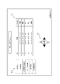
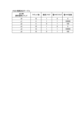
[1-3-2.大当り振分け]
次に、図12を参照して、特別図柄の大当り判定の結果が大当りであるときの大当り振分け、すなわち、特別図柄の停止図柄(メイン図柄)の選択率について説明する。図12に示される例では、メイン図柄の振分は全設定共通となっている。なお、図12に示されるテーブルの内容はメインROM102に記憶されている。
[1-3-2. Jackpot distribution]
Next, with reference to FIG. 12, the jackpot allocation when the result of the jackpot determination of the special symbols is the jackpot, that is, the selection rate of the stop symbols (main symbols) of the special symbols will be described. In the example shown in FIG. 12, the distribution of main symbols is common to all settings. Note that the contents of the table shown in FIG. 12 are stored in the
図12に示されるように、第1特別図柄の大当り判定の結果が大当りであるとき、メインCPU101は、抽出した図柄乱数に基づいて、メイン図柄を、特図1-1(振分確率25.0%)、特図1-2(振分確率25.0%)、特図1-3(振分確率25.0%)、および特図1-4(振分確率25.0%)のうちいずれかに決定する。特図1-1は、ラウンド数4、確変フラグOFF、時短回数100回の大当りである。特図1-2は、ラウンド数4、確変フラグON、次回の大当り遊技状態が実行されるまで時短が継続する(時短フラグは次回の大当り遊技状態が開始されたときにOFFに設定される)大当りである。特図1-3は、ラウンド数10、確変フラグOFF、時短回数100回の大当りである。特図1-4は、ラウンド数10、確変フラグON、次回の大当り遊技状態が実行されるまで時短が継続する大当りである。第1特別図柄の大当り判定の結果が大当りであるとき、メインCPU101は、第1特別図柄を、後述する図13を参照して決定される変動時間にわたって変動表示したのち、上記決定されたメイン図柄で停止させる制御を実行する。
As shown in FIG. 12, when the result of the first special symbol jackpot determination is a big hit, the
なお、第1実施形態では、特別図柄の大当り判定の結果が大当りであるとき、所定の条件が成立すると(第1実施形態では、特図1-2や特図1-4のように確変フラグONとなる大当りであると)、大当り遊技状態が終了したのち、次回の大当り遊技状態が開始されるまで高確率遊技状態が継続する所謂「確変ループ機」と呼ばれるものである。このような確変ループ機では、高確率遊技状態における特別図柄の大当り判定の結果が大当りであって、所定の条件が成立すると、大当り遊技状態が終了したのち、再び、次回の大当り遊技状態が開始されるまで高確率遊技状態が継続する。そして、高確率遊技状態における特別図柄の大当り判定の結果が大当りであって、所定の条件が成立しなければ(第1実施形態では、特図1-1や特図1-3のように確変フラグONとならない大当りであると)、大当り遊技状態が終了したのち、高確率遊技状態に制御されずに低確率遊技状態に制御される。 In addition, in the first embodiment, when the result of the jackpot determination of the special symbol is a jackpot, when a predetermined condition is established (in the first embodiment, the probability variation flag like special figure 1-2 and special figure 1-4 If it is a jackpot that turns ON), after the jackpot game state ends, the high probability game state continues until the next jackpot game state is started. In such a probability variable loop machine, when the result of the jackpot determination of the special symbols in the high probability game state is a jackpot and a predetermined condition is established, the next jackpot game state is started again after the jackpot game state is finished. The high probability game state continues until it is done. Then, if the result of the jackpot determination of the special symbol in the high probability gaming state is a jackpot and a predetermined condition is not satisfied (in the first embodiment, it is possible to When the flag is not turned ON), after the big win game state is completed, it is controlled to the low probability game state without being controlled to the high probability game state.
第2特別図柄の大当り判定の結果が大当りであるとき、メインCPU101は、抽出した図柄乱数に基づいて、メイン図柄を、特図2-1(振分確率50.0%)または特図2-2(振分確率50.0%)に決定する。特図2-1は、ラウンド数10、確変フラグOFF、時短回数100回の大当りである。特図2-2は、ラウンド数10、確変フラグON、次回の大当り遊技状態が実行されるまで時短が継続する大当りである。第2特別図柄の大当り判定の結果が大当りであるとき、メインCPU101は、第2特別図柄を、後述する図13を参照して決定される変動時間にわたって変動表示したのち、上記決定されたメイン図柄で停止させる制御を実行する。
When the result of the second special symbol jackpot determination is a big hit, the
なお、特別図柄の大当り判定の結果がハズレであるとき、メインCPU101は、ハズレ図柄を決定し、当該決定されたハズレ図柄で特別図柄を停止させる制御を実行する。
It should be noted that when the result of the special symbol jackpot determination is a loss, the
また、ラウンド数とは、大当り遊技状態において実行されるラウンド遊技のラウンド数である。また、確変フラグがONであれば大当り遊技状態が終了したのちの遊技状態が高確率遊技状態(確変フラグがONに設定される遊技状態)に制御され、確変フラグがOFFであれば大当り遊技状態が終了したのちの遊技状態が低確率遊技状態(確変フラグがOFFに設定される遊技状態)に制御される。以下において、ラウンド数4、確変フラグOFF、時短回数100回の大当り(例えば、特図1-1の大当り)を「4R通常大当り」と称し、ラウンド数4、確変フラグON、次回の大当たり遊技が実行されるまで時短が継続する大当り(例えば、特図1-2の大当り)を「4R確変大当り」と称し、ラウンド数10、確変フラグOFF、時短回数100回の大当り(例えば、特図1-3、特図2-1の大当り)を「10R通常大当り」と称し、ラウンド数10、確変フラグON、次回の大当たり遊技が実行されるまで時短が継続する大当り(例えば、特図1-4、特図2-2の大当り)を「10R確変大当り」と称する。 Moreover, the number of rounds is the number of rounds of the round game executed in the jackpot game state. Also, if the probability variation flag is ON, the game state after the jackpot game state is completed is controlled to a high probability game state (the probability variation flag is set to ON), and if the probability variation flag is OFF, the jackpot game state. is controlled to a low-probability gaming state (a gaming state in which the variable probability flag is set to OFF). In the following, 4 rounds, variable probability flag OFF, 100 times of time saving jackpot (for example, special figure 1-1 big hit) is called “4R normal jackpot”, 4 rounds, variable probability flag ON, next big hit game A jackpot that continues to save time until it is executed (for example, a special figure 1-2 jackpot) is called a "4R probability variation jackpot", with 10 rounds, probability variation flag OFF, and 100 times of time reduction (for example, special figure 1- 3, special figure 2-1 jackpot) is called “10R normal jackpot”, the number of rounds is 10, the variable probability flag is ON, and the time saving continues until the next jackpot game is executed (for example, special figure 1-4, Special figure 2-2 jackpot) is called “10R probability variable jackpot”.
また、第1実施形態では、大当り判定の結果が大当りであるときは、常に時短フラグがONに設定されるようになっているが、必ずしもこれに限られず、抽出した図柄乱数に基づいて決定されるメイン図柄に応じて、時短フラグをONに設定するかOFFに設定するかを決定するようにしても良い。 In addition, in the first embodiment, when the result of the big hit determination is a big hit, the time saving flag is always set to ON, but it is not necessarily limited to this, and is determined based on the extracted symbol random number. It may be determined whether the time saving flag is set to ON or OFF according to the main symbol to be displayed.
[1-3-3.特別図柄の変動時間]
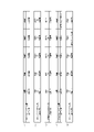
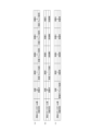
次に、図13を参照して、特別図柄の変動時間が決定されるまでの流れについて説明する。特別図柄の変動時間は、特別図柄の変動パターンと対応しているため、メインCPU101は、特別図柄の変動時間と特別図柄の変動パターンとを同時に決定することとなる。また、特別図柄の変動パターンは、サブ制御回路200(サブCPU201)により液晶表示装置16(例えば図5参照)に表示される演出内容(例えば装飾図柄の変動パターン)とも対応している。第1実施形態のパチンコ遊技機1では、決定される特別図柄の変動パターンが(すなわち変動時間や演出内容についても)設定値に応じて異なりうるように構成されている。なお、図13に示されるテーブルの内容はメインROM102に記憶されている。また、特別図柄の保留個数に応じてリーチ演出の実行確率を変えたり、特別図柄の保留個数が多くなるにつれて通常変動における変動時間が短くなるものもあるが、図13ではこれらを省略している。
[1-3-3. Special pattern fluctuation time]
Next, with reference to FIG. 13, the flow until the fluctuation time of the special symbol is determined will be described. Since the special symbol variation time corresponds to the special symbol variation pattern, the
図13に示されるように、メインCPU101は、第1特別図柄の大当り判定の結果にもとづいて第1特別図柄の変動時間を決定し、第2特別図柄の大当り判定の結果にもとづいて第2特別図柄の変動時間を決定する。
As shown in FIG. 13, the
図13に示されるように、第1実施形態では、第1特別図柄と第2特別図柄とで共通のテーブルを用いて特別図柄の変動時間が決定されるようになっている。ただし、これに代えて、第1特別図柄と第2特別図柄とで別のテーブルを用いて特別図柄の変動時間が決定されるようにしても良い。 As shown in FIG. 13, in the first embodiment, a table common to the first special symbol and the second special symbol is used to determine the fluctuation time of the special symbol. However, instead of this, the variation time of the special symbol may be determined using different tables for the first special symbol and the second special symbol.
また、特別図柄の変動時間決定テーブルは、特別図柄の大当り判定の結果と、遊技状態と、リーチ判定用乱数範囲と、特別図柄の大当り判定の結果が大当りであるときのメイン図柄と、演出選択用乱数範囲と、変動パターン(可変表示パターン)と、変動パターン指定コマンドと、変動時間と、演出内容との関係を規定している。ただし、特別図柄の変動時間を決定するにあたり、確変時短遊技状態と時短遊技状態とは識別されない。また、特別図柄の変動時間を決定する際のリーチ判定用乱数範囲と演出選択用乱数範囲とについては、設定値に応じて異なる乱数範囲が設定されている。 In addition, the special symbol variation time determination table includes the result of the special symbol jackpot determination, the game state, the reach determination random number range, the main symbol when the special symbol jackpot determination result is a big hit, and the effect selection. It defines the relationship between the random number range, the variation pattern (variable display pattern), the variation pattern specification command, the variation time, and the effect content. However, in determining the fluctuation time of the special symbol, the probability variable time-saving gaming state and the time-saving gaming state are not identified. In addition, different random number ranges are set according to set values for the reach determination random number range and the effect selection random number range when determining the fluctuation time of the special symbols.
リーチ判定用乱数範囲は、特別図柄の大当り判定の結果がハズレである場合に、設定値毎に、リーチ演出を実行するか否かの決定に供される乱数である。メインCPU101は、第1始動口420や第2始動口440(いずれも例えば図5参照)に遊技球が入賞したときに、リーチ判定用カウンタからリーチ判定用乱数を抽出し、当該抽出したリーチ判定用乱数をメインRAM103に格納する。上述したとおり、メインCPU101は、特別図柄の変動表示を開始するときに大当り判定用乱数値を用いて大当り判定を行うが、この大当り判定の結果がハズレであるときに、メインRAM103に格納されたリーチ判定用乱数を用いてリーチ演出を実行するか否かを決定する。第1実施形態では、リーチ判定用カウンタから抽出されるリーチ判定用乱数値が0~249の範囲に設定されているが、この範囲は適宜変更することができる。
The reach determination random number range is a random number used for determining whether or not to execute the reach effect for each set value when the result of the special symbol jackpot determination is a loss. The
例えば、通常遊技状態(確変フラグOFF且つ時短フラグOFF)における特別図柄の大当り判定の結果がハズレの場合、リーチ演出を実行する旨が決定されるリーチ判定用乱数範囲は、設定1・2では0~25に規定されており、設定3・4では0~26に規定されており、設定5・6では0~27に規定されている。また、確変時短遊技状態(確変フラグON且つ時短フラグON)における特別図柄の大当り判定の結果がハズレの場合には、リーチ演出を実行する旨が決定されるリーチ判定用乱数範囲は、設定1・2では0~10に規定されており、設定3・4では0~11に規定されており、設定5・6では0~12に規定されている。
For example, if the result of the jackpot determination of the special symbol in the normal game state (probability variation flag OFF and time saving flag OFF) is a loss, the reach determination random number range that is determined to execute the reach effect is 0 in setting 1 and 2 to 25,
このように、第1実施形態のパチンコ遊技機1における特別図柄の大当り判定の結果がハズレの場合、リーチ演出は、設定1・2よりも設定3・4の方が実行されやすく、さらに、設定3・4よりも設定5・6の方が実行されやすくなっている。すなわち、設定値に応じてリーチ演出の実行頻度が異なっており、設定値がより高いほどリーチ演出の実行頻度が高くなる。
As described above, when the result of the jackpot determination of the special symbol in the
なお、第1実施形態では、リーチ演出を実行するか否かの決定に際し、リーチ判定用乱数範囲は、設定1と設定2とで共通し、設定3と設定4とで共通し、設定5と設定6とで共通しているが、これに限られず、全ての設定で異なるようにしても良い。
In the first embodiment, when determining whether or not to execute the ready-to-win effect, the random number range for ready-to-win determination is common to
また、上述したリーチ演出を実行するか否かの決定は、特別図柄の大当り判定の結果がハズレである場合についての説明であるが、特別図柄の大当り判定の結果が大当りである場合、メインCPU101は、リーチ判定用カウンタから抽出されたリーチ判定用乱数の値がいずれであるかにかかわらずリーチ演出を実行する旨を決定する。 Also, the determination of whether or not to execute the ready-to-win effect described above is for the case where the result of the special symbol jackpot determination is a loss. decides to execute the ready-to-win effect regardless of the value of the ready-to-win determination random number extracted from the ready-to-win determination counter.
演出選択用乱数範囲は、設定値毎に、特別図柄の変動時間の決定に供される乱数である。メインCPU101は、第1始動口420や第2始動口440(いずれも例えば図5参照)に遊技球が入賞したときに、演出選択用カウンタから演出選択用乱数を抽出し、当該抽出した演出選択用乱数をメインRAM103に格納する。メインCPU101は、遊技状態と、リーチ演出を実行するか否かの決定(特別図柄の大当り判定の結果がハズレである場合のみ)の結果とに応じて、メインRAM103に格納された演出選択用乱数を用いて特別図柄の変動時間を決定する。第1実施形態では、演出選択用カウンタから抽出される演出選択用乱数値が0~99の範囲に設定されているが、この範囲は適宜変更することができる。なお、メインCPU101は、特別図柄の大当り判定の結果が大当りである場合には、遊技状態に応じて、メインRAM103に格納された演出選択用乱数を用いて特別図柄の変動時間を決定する。
The effect selection random number range is a random number used to determine the variation time of the special symbols for each set value. The
具体的には、通常遊技状態(確変フラグOFF且つ時短フラグOFF)における特別図柄の大当り判定の結果がハズレであって且つリーチ演出を実行する旨が決定された場合の特別図柄の変動時間は、次のように決定される。すなわち、特別図柄の変動時間が20000msec(通常中ノーマルリーチ)に決定される演出選択用乱数範囲は、設定1・2では0~57に規定されており、設定3・4では0~58に規定されており、設定5・6では0~59に規定されている。また、特別図柄の変動時間が30000msec(通常中スーパーリーチA)に決定される演出選択用乱数範囲は、設定1・2では58~89に規定されており、設定3・4では59~89に規定されており、設定5・6では60~89に規定されている。さらに、特別図柄の変動時間が40000msec(通常中スーパーリーチB)に決定される演出選択用乱数範囲は、設定1~6共通で90~99に規定されている。
Specifically, when it is determined that the result of the special symbol jackpot determination in the normal game state (probability variable flag OFF and time saving flag OFF) is a loss and it is determined to execute the reach effect, the fluctuation time of the special symbol is It is determined as follows. That is, the random number range for effect selection, which is determined to be 20,000 msec (normal reach during normal), is specified to be 0 to 57 in
また、通常遊技状態(確変フラグOFF且つ時短フラグOFF)における特別図柄の大当り判定の結果がハズレであって且つリーチ演出を実行しない旨が決定された場合の特別図柄の変動時間は、次のように決定される。すなわち、特別図柄の変動時間が10000msec(通常変動A)に決定される演出選択用乱数範囲は、設定1・2では0~51に規定されており、設定3・4では0~50に規定されており、設定5・6では0~49に規定されている。また、特別図柄の変動時間が5000msec(通常変動B)に決定される演出選択用乱数範囲は、設定1・2では52~99に規定されており、設定3・4では51~99に規定されており、設定5・6では50~99に規定されている。
In addition, when it is determined that the result of the special symbol jackpot determination in the normal game state (probability variation flag OFF and time saving flag OFF) is a loss and that the reach effect is not executed, the special symbol fluctuation time is as follows. is determined by That is, the random number range for effect selection, which is determined to be 10000 msec (normal fluctuation A) for the special symbol fluctuation time, is defined to be 0 to 51 in
また、確変時短遊技状態(確変フラグON且つ時短フラグON)や通常時短遊技状態(確変フラグOFF且つ時短フラグON)における特別図柄の大当り判定の結果がハズレであって且つリーチ演出を実行する旨が決定された場合の特別図柄の変動時間は、次のように決定される。すなわち、特別図柄の変動時間が25000msec(時短中ノーマルリーチ)に決定される演出選択用乱数範囲は、設定1・2では0~57に規定されており、設定3・4では0~58に規定されており、設定5・6では0~59に規定されている。また、特別図柄の変動時間が35000msec(時短中スーパーリーチA)に決定される演出選択用乱数範囲は、設定1・2では58~89に規定されており、設定3・4では59~89に規定されており、設定5・6では60~89に規定されている。さらに、特別図柄の変動時間が45000msec(時短中スーパーリーチB)に決定される演出選択用乱数範囲は、設定1~6共通で90~99に規定されている。
In addition, the result of the special symbol jackpot determination in the probability variable time-saving gaming state (variable probability flag ON and time-saving flag ON) or the normal time-saving gaming state (variable probability flag OFF and time-saving flag ON) is a loss and the reach effect is executed. The fluctuation time of the special design when determined is determined as follows. That is, the random number range for effect selection, which is determined to be 25000 msec (normal reach during time saving), is specified to be 0 to 57 in
また、確変時短遊技状態(確変フラグON且つ時短フラグON)や通常時短遊技状態(確変フラグOFF且つ時短フラグON)における特別図柄の大当り判定の結果がハズレであって且つリーチ演出を実行しない旨が決定された場合の特別図柄の変動時間は、次のように決定される。すなわち、特別図柄の変動時間が4000msec(短縮変動A)に決定される演出選択用乱数範囲は、設定1・2では0~51に規定されており、設定3・4では0~50に規定されており、設定5・6では0~49に規定されている。また、特別図柄の変動時間が2000msec(短縮変動B)に決定される演出選択用乱数範囲は、設定1・2では52~99に規定されており、設定3・4では51~99に規定されており、設定5・6では50~99に規定されている。
In addition, the result of the special symbol jackpot determination in the probability variable time-saving gaming state (variable probability flag ON and time-saving flag ON) and the normal time-saving gaming state (variable probability flag OFF and time-saving flag ON) is a loss and the reach effect is not executed. The fluctuation time of the special design when determined is determined as follows. That is, the random number range for effect selection, which is determined to be 4000 msec (shortened variation A), is specified as 0 to 51 in setting 1 and 2, and is specified in 0 to 50 in setting 3 and 4. It is defined as 0 to 49 in
なお、メイン図柄は、特別図柄の大当り判定の結果が大当りであるときに決定されるものであるため、特別図柄の大当り判定の結果がハズレであるときは、特別図柄の変動時間の決定とはかかわらない。 In addition, the main symbol is determined when the result of the jackpot determination of the special symbol is a big hit, so when the result of the jackpot determination of the special symbol is a loss, the fluctuation time of the special symbol is determined. not involved.
通常遊技状態(確変フラグOFF且つ時短フラグOFF)における特別図柄の大当り判定の結果が大当りである場合の特別図柄の変動時間は、全てのメイン図柄について共通で、次のように決定される。すなわち、特別図柄の変動時間が20000msec(通常中ノーマルリーチ)に決定される演出選択用乱数範囲は、設定1・2では0~1に規定されており、設定3・4では0~2に規定されており、設定5・6では0~3に規定されている。また、特別図柄の変動時間が30000msec(通常中スーパーリーチA)に決定される演出選択用乱数範囲は、設定1・2では2~49に規定されており、設定3・4では3~49に規定されており、設定5・6では4~49に規定されている。さらに、特別図柄の変動時間が40000msec(通常中スーパーリーチB)に決定される演出選択用乱数範囲は、設定1~6共通で90~99に規定されている。
The fluctuation time of the special symbols when the result of the jackpot determination of the special symbols in the normal game state (the probability variation flag is OFF and the time reduction flag is OFF) is a big hit, is common to all the main symbols, and is determined as follows. That is, the random number range for effect selection, which is determined to be 20000 msec (normal reach during normal), is specified to be 0 to 1 in
また、確変時短遊技状態(確変フラグON且つ時短フラグON)や通常時短遊技状態(確変フラグOFF且つ時短フラグON)における特別図柄の大当り判定の結果が大当りである場合の特別図柄の変動時間は、全てのメイン図柄について共通で、次のように決定される。すなわち、特別図柄の変動時間が25000msec(時短中ノーマルリーチ)に決定される演出選択用乱数範囲は、設定1・2では0~1に規定されており、設定3・4では0~2に規定されており、設定5・6では0~3に規定されている。また、特別図柄の変動時間が35000msec(時短中スーパーリーチA)に決定される演出選択用乱数範囲は、設定1・2では2~49に規定されており、設定3・4では3~49に規定されており、設定5・6では4~49に規定されている。さらに、特別図柄の変動時間が45000msec(時短中スーパーリーチB)に決定される演出選択用乱数範囲は、設定1~6共通で50~99に規定されている。
Also, if the result of the special symbol jackpot determination in the probability variable time-saving gaming state (variable probability flag ON and time-saving flag ON) or the normal time-saving gaming state (variable probability flag OFF and time-saving flag ON) is a big hit, The fluctuation time of the special symbol is Common to all main symbols, it is determined as follows. That is, the random number range for effect selection, which is determined to be 25000 msec (normal reach during time saving), is specified to be 0 to 1 in
このように、第1実施形態のパチンコ遊技機1において、遊技状態と、特別図柄の大当り判定の結果と、リーチ演出を実行するか否かの決定の結果とが同じである限り、特別図柄の変動時間は、設定1・2よりも設定3・4の方が短い変動時間に決定されやすく、さらに、設定3・4よりも設定5・6の方が短い変動時間に決定されやすくなっている。そのため、設定値がより高いほど特別図柄の変動時間の平均が短くなり、単位時間あたりの特別図柄の変動回数(すなわち抽選回数)が多くなる。ひいては、単位時間で見たときの大当り遊技状態の実行回数が多くなる期待度が高く、また、単位時間内に大当り遊技状態が実行される確率も高くなり、設定値が高いほど、遊技者にとって有利なゲームの実行が可能となる。
Thus, in the
なお、第1実施形態では、特別図柄の変動時間の決定に際し、演出選択用乱数範囲は、設定1と設定2とで共通し、設定3と設定4とで共通し、設定5と設定6とで共通しているが、これに限られず、全ての設定値で異なるようにしても良い。 In the first embodiment, when determining the fluctuation time of the special symbol, the random number range for selection of the effect is common between setting 1 and setting 2, is common between setting 3 and setting 4, and is common between setting 5 and setting 6. , but it is not limited to this, and all setting values may be different.
また、特別図柄の大当り判定の結果が大当りである場合の特別図柄の変動時間は、全てのメイン図柄について共通で決定されるようにしているが、これに限られず、メイン図柄に応じて特別図柄の変動時間が異なるように構成しても良い。 In addition, when the result of the jackpot judgment of the special symbol is a big hit, the fluctuation time of the special symbol is determined in common for all the main symbols, but it is not limited to this, and the special symbol depends on the main symbol. may be configured to have different fluctuation times.
変動パターンは、変動時間および演出内容を表すデータである。例えば、変動パターン「02H」は、変動時間40000msecの通常中スーパーリーチBを表す。 The variation pattern is data representing variation time and effect content. For example, the variation pattern “02H” represents normal middle super reach B with a variation time of 40000 msec.
変動パターン指定コマンドは、変動時間及び演出内容を表すデータとして、主制御回路100からサブ制御回路200へ送信される。例えば、メインCPU101により決定された変動パターンが「05H」であれば、「83H05H」の変動パターン指定コマンドが主制御回路100からサブ制御回路200へ送信される。このとき、主制御回路100(メインCPU101)により決定されたメイン図柄を特定する図柄指定コマンドもサブ制御回路200へ送信される。
The variation pattern designation command is transmitted from the
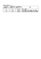
[1-3-4.装飾図柄の停止図柄]
次に、図14を参照して、特別図柄の大当り判定の結果が大当りであるときに、図12に示される選択率でメイン図柄が決定された場合の装飾図柄の停止図柄の一例について説明する。なお、図14に示されるテーブルの内容はサブ制御回路200のプログラムROM202に記憶されている。
[1-3-4. Decorative pattern stop pattern]
Next, with reference to FIG. 14, an example of a decorative symbol stop symbol when the main symbol is determined with the selection rate shown in FIG. . The contents of the table shown in FIG. 14 are stored in the
サブ制御回路200(サブCPU201)は、主制御回路100から送信された図柄指定コマンドを受信すると、設定値にかかわらず、当該図柄指定コマンドにより特定されるメイン図柄にもとづいて装飾図柄の停止図柄を決定する。例えば、主制御回路100から送信された図柄指定コマンドにより特定されるメイン図柄が特図1-2であるとき、サブCPU201は、全ての装飾図柄が同一の特定図柄(例えば「7」図柄)となる態様の振分確率が0%であるから、全ての装飾図柄(第1実施形態では3つの装飾図柄)が同一の偶数図柄となる態様(振分確率30.0%)、または、全ての装飾図柄が同一の奇数図柄となる態様(振分確率70.0%)に決定する。第1実施形態では、特定図柄を「7」図柄としているが、これに限られず、遊技者からみて利益度合いの高い大当りであると認識できれば他の図柄(例えば、「V」図柄)を特定図柄としても良い。
When the sub-control circuit 200 (sub-CPU 201) receives the symbol designation command transmitted from the
なお、上述したとおり、図14に示されるメイン図柄は特別図柄の大当り判定の結果が大当りであるときに決定されるものである。したがって、サブCPU201は、特別図柄の大当り判定の結果が大当りであるときに図14を参照して装飾図柄の停止図柄を決定し、特別図柄の大当り判定の結果がハズレであるときは、図14に示される図柄以外の図柄を、装飾図柄の停止図柄として決定する。図14に示される図柄以外の図柄とは、例えば、全ての装飾図柄のうち少なくとも一つの装飾図柄が他の装飾図柄と異なる図柄等が相当する。
Incidentally, as described above, the main symbols shown in FIG. 14 are determined when the result of the jackpot determination of the special symbols is a jackpot. Therefore, the
このように、図14によると、特別図柄の大当り判定の結果が大当りである場合、全ての装飾図柄が停止したときの態様は、第1特別図柄と第2特別図柄とのうちいずれの大当り判定の結果であるのか、大当り遊技状態が終了したのちの遊技状態が高確率遊技状態に制御される大当りであるか否か、大当り遊技状態において実行されるラウンド遊技のラウンド数が10Rであるか否か、によって異なりうる。 Thus, according to FIG. 14, when the result of the special symbol jackpot determination is a jackpot, the mode when all the decorative symbols are stopped is either the first special symbol or the second special symbol. whether the game state after the jackpot game state is over is a jackpot controlled to a high probability game state, whether the number of rounds of the round game executed in the jackpot game state is 10R or not. or
すなわち、図12を参照して決定されたメイン図柄が特図1-1、特図1-3または特図2-1(確変フラグがON設定されない4R通常大当りまたは10R通常大当り)であるときには、設定値に関係なく、必ず、全ての装飾図柄が同一の偶数図柄となる態様(以下「第1態様」と称する)で停止する。 That is, when the main symbol determined with reference to FIG. 12 is a special figure 1-1, a special figure 1-3 or a special figure 2-1 (4R normal jackpot or 10R normal jackpot where the probability variation flag is not set ON), Regardless of the setting value, the game always stops in a mode (hereinafter referred to as "first mode") in which all the decorative symbols are the same even-numbered symbols.
また、メイン図柄が特図1-2(4R確変大当り)であるときには、設定値に関係なく、第1態様、または、全ての装飾図柄が同一の奇数図柄(特定図柄である「7」図柄以外の奇数図柄)となる態様(以下「第2態様」と称する)で停止する。 Also, when the main design is a special figure 1-2 (4R probability variation jackpot), regardless of the setting value, the first mode or all the decorative designs are the same odd number design (other than the specific design "7" design (Odd number of symbols)) (hereinafter referred to as "second mode").
また、メイン図柄が特図1-4(10R確変大当り)であるときには、設定値に関係なく、全ての装飾図柄が同一の奇数図柄となる態様、または、全ての装飾図柄が同一の特定図柄となる態様(以下「特定態様」と称する)で停止する。 Also, when the main design is a special figure 1-4 (10R probability variation big hit), regardless of the setting value, all the decorative designs are the same odd number design, or all the decorative designs are the same specific design. It stops in a certain mode (hereinafter referred to as "specific mode").
さらに、メイン図柄が特図2-2(10R確変大当り)であるときには、設定値に関係なく、特定態様で停止する。特図1-4および特図2-2はいずれも10R確変大当りであるが、特図1-4は第1始動口420への遊技球の入賞に基づく大当りであるから、通常遊技状態において大当りに当選した可能性が高い。また、特図2-2は第2始動口440への遊技球の入賞に基づく大当りであるから、高確率遊技状態または時短遊技状態において大当りに当選した可能性が高い。
Furthermore, when the main symbol is a special figure 2-2 (10R probability variation big hit), regardless of the setting value, it stops in a specific mode. Both the special figure 1-4 and the special figure 2-2 are 10R probability variable big hits, but the special figure 1-4 is a big hit based on the winning of the game ball to the
このように、特別図柄が特定態様で停止すると、遊技者にとっての利益度合いが最も大きい10R確変大当りが確定し、全ての装飾図柄が同一の奇数図柄となる態様で停止すると、確変大当り(4R確変大当りまたは10R確変大当り)が確定する。一方、第1態様で停止した場合には、遊技者にとっての利益度合いが最も大きい10R確変大当りでないことは確定するものの、4R確変大当りの可能性は残されている。 In this way, when the special symbols stop in a specific mode, the 10R probability variable jackpot with the highest degree of profit for the player is confirmed, and when all the decorative symbols stop in the same odd-numbered pattern, the probability variable jackpot (4R probability variable A jackpot or a 10R probability variable jackpot) is determined. On the other hand, when the game is stopped in the first mode, although it is confirmed that the 10R high probability big hit is not the highest profit degree for the player, the possibility of the 4R high probability big hit remains.
なお、特別図柄の大当り判定の結果が大当りであった場合、当該大当りがいずれの大当りであるかについては、装飾図柄が全て停止したときに遊技者に報知するようにしても良いし、大当り遊技状態の実行中に報知するようにしても良いし、大当り遊技状態が終了する際に報知するようにしても良い。また、第1実施形態のパチンコ遊技機1では採用されていないが、大当り遊技状態が終了したのちの遊技状態が高確率遊技状態に制御される大当りであったにもかかわらず、当該高確率遊技状態に制御されることを遊技者に明示しない所謂「潜伏確変状態」に制御するようにしても良い。
In addition, when the result of the judgment of the big hit of the special symbol is a big hit, the player may be notified of which big hit the particular big hit is when all the decorative symbols are stopped, or the big win game is played. The notification may be made during execution of the state, or the notification may be made when the jackpot game state ends. In addition, although not adopted in the
[1-4.パチンコ遊技機の基本仕様の他の例]
なお、第1実施形態におけるパチンコ遊技機1の基本仕様は上述したとおりであるが、上述の仕様に限られず、適宜変更することができる。以下に、基本仕様を適宜変更した例について説明する。ただし、以下の説明は一例であり、これに限られないことは言うまでもない。
[1-4-1.特別図柄の変動時間の変形例]
次に、図15を参照して、特別図柄の変動時間(すなわち特別図柄の変動パターン)の変形例について説明する。図15は、メインROM102に記憶される特別図柄の変動時間決定テーブルの他の例を示す図である。なお、上述したとおり、特別図柄の保留個数に応じてリーチ演出の実行確率を変えたり、特別図柄の保留個数が多くなるにつれて通常変動における変動時間が短くなるものもあるが、図15においてもこれらを省略している。
[1-4. Other examples of basic specifications of pachinko machines]
Although the basic specifications of the
[1-4-1. Variation of special symbol fluctuation time]
Next, with reference to FIG. 15, a modification of the special symbol variation time (that is, the special symbol variation pattern) will be described. FIG. 15 is a diagram showing another example of the special symbol variation time determination table stored in the
また、図15を参照して説明する特別図柄の変動特別図柄の変形例にかかるパチンコ遊技機のメインCPUは、特別図柄の変動回数(すなわち特別図柄の抽選回数)の実行回数をカウントする抽選回数カウント手段(図示せず)を備えている。この抽選回数カウント手段は、例えば大当り遊技状態の開始時にリセットし、大当り遊技状態が終了したときを起点として特別図柄の変動回数のカウントを開始する。 In addition, the main CPU of the pachinko gaming machine according to the variation of the special symbol variation, which will be described with reference to FIG. A counting means (not shown) is provided. This lottery number counting means is reset, for example, at the start of the big win game state, and starts counting the number of variations of the special symbols when the big win game state ends.
図15に示されるように、他の例では、通常遊技状態(確変フラグOFF且つ時短フラグOFF)における特別図柄の大当り判定の結果がハズレの場合、リーチ演出を実行するか否かの決定は、大当り遊技状態が終了した時点を起点としてカウントされる特別図柄の変動回数と、設定値との両方に応じて行われる。 As shown in FIG. 15, in another example, when the result of the special symbol jackpot determination in the normal game state (probability variation flag OFF and time saving flag OFF) is a loss, the determination of whether or not to execute the reach effect is It is performed according to both the number of times of variation of the special symbols counted from the point of time when the jackpot game state is finished and the set value.
具体的には、特定の時点(例えば大当り遊技状態が終了した時点)を起点とする特別図柄の変動回数が0~1000回の場合、リーチ演出を実行する旨が決定されるリーチ判定用乱数範囲は、設定1・2では0~25に規定されており、設定3・4では0~26に規定されており、設定5・6では0~27に規定されている。これらは図13と同じである。
Specifically, when the number of fluctuations of the special symbol starting from a specific time (for example, when the jackpot game state ends) is 0 to 1000 times, the reach determination random number range in which it is determined that the reach effect is executed is defined to be 0 to 25 for
一方、大当り遊技状態が終了した時点を起点とする特別図柄の変動回数が1001回以上になると、リーチ演出を実行する旨が決定されるリーチ判定用乱数範囲は、設定1・2では0~10に規定されており、設定3・4では0~5に規定されており、設定5・6では0~1に規定されている。すなわち、特別図柄の大当り判定の結果がハズレであれば、設定1・2では設定3・4と比べてリーチ演出の実行確率が2倍と高く、設定3・4では設定5・6と比べてリーチ演出の実行確率が5倍と高い(設定1・2では設定5・6と比べてリーチ演出の実行確率が10と高い)。
On the other hand, when the number of fluctuations of the special symbols starting from the time when the jackpot game state ends is 1001 times or more, the ready-to-win determination random number range for determining the execution of the ready-to-win effect is 0 to 10 in setting 1 and 2. ,
このように、大当り遊技状態が終了した時点を起点とする特別図柄の変動回数が1001回以上になると、大当り遊技状態が終了した時点を起点とする特別図柄の変動回数が0~1000回の場合と比べて、リーチ演出の実行確率が設定に応じて顕著に異なっている。 In this way, when the number of times of variation of the special symbols starting from the point of time when the big win game state is terminated is 1001 times or more, when the number of times of variation of the special symbols is 0 to 1000 times from the point of time when the big win game state is terminated. , the execution probability of the ready-to-win effect is significantly different depending on the setting.
また、通常遊技状態(確変フラグOFF且つ時短フラグOFF)における特別図柄の大当り判定の結果がハズレであって且つリーチ演出を実行する旨が決定された場合、特別図柄の変動時間についても、大当り遊技状態が終了した時点を起点とする特別図柄の変動回数が0~1000回の場合と1001回以上の場合とで、設定差が顕著となっている。 In addition, when it is determined that the result of the jackpot determination of the special symbol in the normal game state (probability variation flag OFF and time saving flag OFF) is a loss and the reach effect is executed, the fluctuation time of the special symbol is also changed to the jackpot game. The setting difference is remarkable between the case where the number of fluctuations of the special symbol is 0 to 1000 times and the case where it is 1001 times or more starting from the time when the state ends.
具体的には、大当り遊技状態が終了した時点を起点とする特別図柄の変動回数が0~1000回の場合、特別図柄の変動時間が20000msec(通常中ノーマルリーチ)に決定される演出選択用乱数範囲は、設定1・2では0~57に規定されており、設定3・4では0~58に規定されており、設定5・6では0~59に規定されている。また、特別図柄の変動時間が30000msec(通常中スーパーリーチA)に決定される演出選択用乱数範囲は、設定1・2では58~89に規定されており、設定3・4では59~89に規定されており、設定5・6では60~89に規定されている。さらに、特別図柄の変動時間が40000msec(通常中スーパーリーチB)に決定される演出選択用乱数範囲は、設定1~6共通で90~99に規定されている。これらは図13と同じである。
Specifically, when the number of fluctuations of special symbols starting from the time when the jackpot game state is completed is 0 to 1000 times, the fluctuation time of special symbols is 20000 msec (normal reach during normal). Random number range for effect selection. is defined to be 0 to 57 for
一方、大当り遊技状態が終了した時点を起点とする特別図柄の変動回数が1001回以上になると、特別図柄の変動時間が20000msec(通常中ノーマルリーチ)に決定される演出選択用乱数範囲は、設定1~4では規定されておらず、設定5・6では0~99に規定されている。また、特別図柄の変動時間が30000msec(通常中スーパーリーチA)に決定される演出選択用乱数範囲は、設定1~4では0~89に規定されており、設定5・6では規定されていない。さらに、特別図柄の変動時間が40000msec(通常中スーパーリーチB)に決定される演出選択用乱数範囲は、設定1~4共通で90~99に規定されており、設定5・6では規定されていない。したがって、大当り遊技状態が終了した時点を起点とする特別図柄の変動回数が1001回以上といった所謂大ハマリした状況下では、実行されるリーチ演出により、セットされている設定値を遊技者に示唆することが可能となる。
On the other hand, when the number of fluctuations of the special symbols is 1001 times or more starting from the time when the jackpot game state ends, the random number range for effect selection, which is determined to be 20000 msec (normal reach during normal), is set to 1. -4 are not defined, and
また、通常遊技状態(確変フラグOFF且つ時短フラグOFF)における特別図柄の大当り判定の結果がハズレであって且つリーチ演出を実行する旨が決定された場合、大当り遊技状態が終了した時点を起点とする特別図柄の変動回数が1001回以上では、設定値が高いほどリーチ演出の実行確率が低い。また、リーチ演出が実行されたとしても、設定値が高いほど特別図柄の変動時間が短いリーチ演出の実行確率が高い。 In addition, when the result of the jackpot determination of the special symbol in the normal game state (probability variation flag OFF and time reduction flag OFF) is a loss and it is determined to execute the reach effect, the starting point is the time when the jackpot game state ends. When the number of fluctuations of the special symbols to be executed is 1001 times or more, the higher the set value is, the lower the execution probability of the ready-to-win effect. Also, even if the ready-to-win effect is executed, the higher the set value is, the higher the probability of executing the ready-to-win effect with the shorter fluctuation time of the special symbols.
このように、大当り遊技状態の終了を起点とする特別図柄の変動回数が1001回以上になると、より設定値が高いほど、1回あたりの特別図柄の変動時間の平均がより一層短くなり、単位時間あたりの特別図柄の変動回数(すなわち抽選回数)がより一層多くなる。ひいては、単位時間で見たときの大当り遊技の実行回数が多くなる期待度がより一層高く、また、単位時間内に大当り遊技が実行される確率もより一層高くなる。 In this way, when the number of fluctuations of the special symbols starting from the end of the jackpot game state is 1001 or more, the higher the set value, the shorter the average of the fluctuation time of the special symbols per one time. The number of fluctuations of special symbols per hour (that is, the number of lotteries) is further increased. As a result, the degree of expectation that the number of executions of the jackpot game will increase in unit time is further increased, and the probability that the jackpot game is executed within the unit time is further increased.
また、大当り遊技状態の終了を起点とする特別図柄の変動回数が1000回未満においては、リーチ演出の実行頻度から、セットされている設定値を推測することは極めて困難であるが、大当り遊技状態の終了を起点とする特別図柄の変動回数が1001回以上になると、設定値に応じてリーチ演出の実行頻度が顕著に異なってくるため、所謂大ハマリしたときには、セットされている設定値を推測できる余地が生じうる。これにより、所謂大ハマリしたときには、ホールに対して直接的な損失を与えることなく(例えば遊技球を遊技者に付与する等を行うことなく)、遊技者に対してセットされている設定値を推測しうる機会を与えることで、遊技者に楽しみを与えることが可能となる。しかも、本来であればリーチ演出になって欲しいと遊技者が考えるところ、第1実施形態では、所謂大ハマリしたときにリーチ演出の実行頻度が低いほど、設定値が高いのではないかといった期待を遊技者が抱くことができるため、リーチ演出の実行頻度が低くても遊技の続行意欲の低下を軽減することができる。 In addition, when the number of variations of the special symbol starting from the end of the big win game state is less than 1000 times, it is extremely difficult to guess the set value from the execution frequency of the ready-to-win effect, but the big win game state. When the number of fluctuations of the special symbols starting from the end of 1,001 times or more, the execution frequency of the reach effect will differ significantly depending on the set value, so when you get hooked, guess the set value. There may be room for improvement. As a result, when the player is hooked, the setting value set for the player can be changed without giving a direct loss to the hole (for example, without giving a game ball to the player). By giving the chance to guess, it is possible to give pleasure to the player. Moreover, although the player originally wants the ready-to-win effect, in the first embodiment, the lower the execution frequency of the ready-to-win effect, the higher the set value. can be held by the player, it is possible to reduce the decrease in desire to continue the game even if the execution frequency of the ready-to-win performance is low.
なお、第1実施形態では、特別図柄の変動回数がカウントされる起点を、大当り遊技状態が終了した時点としたが、これに限られず、例えば、予め決められた期間を経過すると高確率遊技状態が終了する所謂ST機と呼ばれるパチンコ機において高確率遊技状態が終了したときや、時短遊技状態が終了したときなど、任意の時点を起点とすることができる。 In addition, in the first embodiment, the starting point for counting the number of variations of the special symbol is the point in time when the jackpot game state ends, but the present invention is not limited to this. Any time point can be set as a starting point, such as when a high probability game state ends in a pachinko machine called a ST machine, or when a time-saving game state ends.
また、第1実施形態では、特定の時点を起点とする特別図柄の変動回数が1001回以上になると、リーチ演出の実行確率および特別図柄の変動時間が設定値に応じて顕著に異なるが、必ずしも1001回以上である必要はない。例えば、遊技者にとってハマリであると感じられる程度であれば、その回数は特定の回数に限られない。 In addition, in the first embodiment, when the number of fluctuations in special symbols starting from a specific point of time is 1001 times or more, the execution probability of the ready-to-win effect and the fluctuation time of the special symbols differ significantly according to the set values, but not necessarily. It does not have to be 1001 times or more. For example, the number of times is not limited to a specific number as long as the player feels that it is addictive.
また、第1実施形態では、特定の時点を起点とする特別図柄の変動回数が規定回数以上になると、リーチ演出の実行確率および特別図柄の変動時間が設定値に応じて顕著に異なるが、設定値に応じて顕著に異なるのは、必ずしもリーチ演出の実行確率や特別図柄の変動時間に限られない。例えば、メインCPU101は、特別図柄の大当り抽選の結果が大当りであることが決定されてから実際に大当り遊技状態に制御するまでの間に所定の待機時間(以下「オープニング時間」と称する)を設けている。また、メインCPU101は、大当り遊技状態が終了してから特別図柄の変動表示を開始するまでの間にも所定の待機時間(以下「エンディング時間」と称する)を設けている。サブCPU201(表示制御回路204)は、上記のオープニング時間においてオープニング演出を液晶表示装置16に表示し、上記のエンディング時間においてエンディング演出を液晶表示装置16に表示する。オープニング演出では、例えば、特別抽選の結果が大当りであった旨を示す演出や、特別抽選の結果が大当りであった旨を祝福する演出、大当り遊技状態での遊技手法(例えば右打ち等)を教示する演出等が行われる。エンディング演出では、大当り遊技状態において払い出された賞球量を示す演出、大当り遊技状態が継続された回数(連荘回数)を示す演出、大当り遊技状態が終了したのちの遊技状態が高確率遊技状態に制御されることを示す演出、大当り遊技状態が終了したのちの遊技状態での遊技手法(例えば左打ちに戻す等)を教示する演出、パチンコ遊技機1の製造メーカーのロゴを表示する演出等が行われる。
In addition, in the first embodiment, when the number of fluctuations in special symbols starting from a specific point of time is equal to or greater than the specified number of times, the execution probability of the ready-to-win effect and the fluctuation time of the special symbols differ remarkably according to the set values. Remarkably different depending on the value is not necessarily limited to the execution probability of the reach production and the fluctuation time of the special symbol. For example, the
具体的には、上記オープニング時間、上記インターバル時間、および、上記エンディング時間のうち、全部または少なくとも一つの時間を設定値が高くなるほど短くすることによって、設定値が高くなるほど大当り遊技状態に要する時間を短くすることができる。その結果、単位時間あたりの特別図柄の変動回数(すなわち抽選回数)の平均を多くすることが可能となり、設定値が高いほど、遊技者にとって有利なゲームの実行が可能となる。 Specifically, all or at least one of the opening time, the interval time, and the ending time is shortened as the set value increases, so that the higher the set value, the longer the time required for the jackpot game state. can be shortened. As a result, it is possible to increase the average number of special symbol variations per unit time (that is, the number of lotteries), and the higher the set value, the more advantageous the game can be executed for the player.
また、例えば、高設定値ほど出玉期待値が高い(例えば高設定値ほど大当り確率が高い等)パチンコ遊技機1にあっては、低設定値と比べて短時間で多量の賞球が払い出される可能性があることに鑑みれば、上記オープニング時間、上記インターバル時間、および、上記エンディング時間のうち、全部または少なくとも一つの時間を設定値が高くなるほど長くなるように構成しても良い。この場合、出玉期待値が高い高設定値ほど、上記オープニング時間、上記インターバル時間、および、上記エンディング時間のうち、全部または少なくとも一つの時間が長くなるため、高設定値による遊技の面白みを担保しつつ、単位時間で払い出される賞球を抑制することが可能となる。 Further, for example, the higher the set value, the higher the expected ball output value (for example, the higher the set value, the higher the probability of winning a big hit). In view of the possibility that the opening time, the interval time, and the ending time may be set, all or at least one of the opening time, the interval time, and the ending time may be configured to be longer as the set value is higher. In this case, all or at least one of the opening time, the interval time, and the ending time becomes longer as the set value increases as the expected ball output value increases. While doing so, it is possible to suppress the number of prize balls paid out per unit time.
なお、メインCPU101は、上記のオープニング時間、エンディング時間および大当り遊技状態に制御されているときであっても、始動口(第1始動口420,第2始動口440)への遊技球の入賞を検出すると各種乱数を抽出し、後述するステップSステップS74やステップS82の設定チェック処理(図31参照)を実行する。そして、この設定チェック処理において設定値データが「0」~「5」の範囲外であると判別された場合(後述するステップS721におけるNO)には、たとえ大当り遊技状態に制御されていたとしても、メインCPU101は、遊技許可フラグをOFFにし(後述するステップS722)、遊技を進行させることが不可能となる。
It should be noted that the
[1-4-2.大当り振分けおよび装飾図柄の停止図柄の変形例]
次に、図16~図18を参照して、特別図柄の大当り判定の結果が大当りであるときの大当り振分け(メイン図柄の選択率)についての第1変形例および第2変形例と、これら第1変形例および第2変形例のときの装飾図柄の停止図柄について説明する。第1変形例および第2変形例では、メイン図柄の選択率が設定値に応じて異なっている。なお、図16は特別図柄の大当り判定の結果が大当りであるときのメイン図柄の選択率についての第1変形例を示す図であり、図17は特別図柄の大当り判定の結果が大当りであるときのメイン図柄の選択率についての第2変形例を示す図である。また、図18は、サブ制御回路200のプログラムROM202に記憶される装飾図柄決定テーブルの変形例であり、第1変形例および第2変形例に共通で用いられる。
[1-4-2. Variation of jackpot distribution and stop design of decorative design]
Next, referring to FIGS. 16 to 18, a first modified example and a second modified example of jackpot distribution (selection rate of main symbols) when the result of jackpot determination of special symbols is a jackpot, and these The stop symbols of the decorative symbols in the first modified example and the second modified example will be described. In the first modified example and the second modified example, the selection rate of the main symbol differs according to the set value. FIG. 16 is a diagram showing a first modification of the selection rate of the main symbol when the result of the jackpot determination of the special symbols is a big hit, and FIG. is a diagram showing a second modification of the selection rate of the main symbol. Also, FIG. 18 shows a modification of the decorative pattern determination table stored in the
[1-4-2-1.第1変形例]
先ず、図16および図18を参照して、上記第1変形例について説明する。なお、図16に示されるテーブルの内容はメインROM102に記憶されており、図18に示されるテーブルの内容はサブ制御回路200のプログラムROM202に記憶されている。
[1-4-2-1. First modification]
First, the first modification will be described with reference to FIGS. 16 and 18. FIG. 16 are stored in the
図16に示されるように、第1変形例では、特別図柄の大当り判定の結果が大当りであるとき、メインCPU101は、抽出した図柄乱数に基づいて、メイン図柄を、設定値に応じた確率で、特図1-1、特図1-2、特図1-3、特図1-4、特図1-5、特図1-6、特図1-7、および、特図1-8のうちいずれかに決定する。ただし、この第1変形例では、特図1-1と特図1-3とが「4R通常大当り」、特図1-2と特図1-4とが「4R確変大当り」、特図1-5と特図1-7と特図2-1と特図2-3とが「10R通常大当り」、特図1-6と特図1-8と特図2-2と特図2-4とが「10R確変大当り」となっている。
As shown in FIG. 16, in the first modification, when the result of the special symbol jackpot determination is a jackpot, the
具体的には、メインCPU101は、設定1~設定4では共通確率で、メイン図柄を、特図1-1(振分確率12.5%)、特図1-2(振分確率12.5%)、特図1-3(振分確率12.5%)、特図1-4(振分確率12.5%)、特図1-5(振分確率12.5%)、特図1-6(振分確率12.5%)、特図1-7(振分確率12.5%)、および、特図1-8(振分確率12.5%)、のうちいずれかに決定する。これに対して、設定5では、メイン図柄を、特図1-1(振分確率10.0%)、特図1-2(振分確率10.0%)、特図1-3(振分確率15.0%)、特図1-4(振分確率15.0%)、特図1-5(振分確率10.0%)、特図1-6(振分確率10.0%)、特図1-7(振分確率15.0%)、および、特図1-8(振分確率15.0%)、のうちいずれかに決定する。また、設定6では、メイン図柄を、特図1-1(振分確率5.0%)、特図1-2(振分確率5.0%)、特図1-3(振分確率20.0%)、特図1-4(振分確率20.0%)、特図1-5(振分確率5.0%)、特図1-6(振分確率5.0%)、特図1-7(振分確率20.0%)、および、特図1-8(振分確率20.0%)、のうちいずれかに決定する。
Specifically, the
すなわち、大当り種別が共通する特図1-2および特図1-4(いずれも4R確変大当り)は、両者の合成確率は設定に関係なくいずれも25.0%であるものの、高設定値(例えば設定5・6)では、特図1-2の選択率(設定5で10.0%、設定6で5.0%)よりも特図1-4の選択率(設定5で15.0%、設定6で20.0%)の方が高い(設定1~4では共通)。
That is, special figures 1-2 and special figures 1-4 (both 4R probability variable jackpots), which have a common jackpot type, have a high set value ( For example, in
同様に、大当り種別が共通する特図1-6および特図1-8(いずれも10R確変大当り)は、両者の合成確率は設定に関係なくいずれも25.0%であるものの、高設定値(例えば設定5・6)では、特図1-6の選択率(設定5で10.0%、設定6で5.0%)よりも特図1-8の選択率(設定5で15.0%、設定6で20.0%)の方が高い(設定1~4では共通)。
Similarly, special figures 1-6 and special figures 1-8 (both 10R probability variable jackpots), which have a common jackpot type, have a high set value, although the combined probability of both is 25.0% regardless of the setting (For example,
さらに、大当り種別が共通する特図2-2および特図2-4(いずれも10R確変大当り)についても、両者の合成確率は設定に関係なくいずれも50.0%であるものの、高設定値(例えば設定5・6)では、特図2-2の選択率(設定5で20.0%、設定6で10.0%)よりも特図2-4の選択率(設定5で30.0%、設定6で40.0%)の方が高い。 Furthermore, for special figures 2-2 and special figures 2-4 (both 10R probability variable jackpots), which have a common jackpot type, the combined probability of both is 50.0% regardless of the setting, but the high setting value (For example, setting 5 and 6), the selection rate of special figure 2-4 (30. 0%, 40.0% at setting 6) is higher.
ところで、特別図柄の大当り判定の結果が大当りである場合、サブCPU201は、図18に示されるように、特図1-1、特図1-3、特図1-5、特図1-7、特図2-1、特図2-3(確変フラグがON設定されない4R通常大当りまたは10R通常大当り)であるときには、設定値に関係なく、必ず、例えば液晶表示装置16に表示される装飾図柄が第1態様で停止するよう制御する。
By the way, when the result of the special symbol jackpot determination is a jackpot, the
一方、特図1-2(4R確変大当り)であるときには、サブCPU201は、設定値に関係なく、第1態様(選択率50.0%)、または、第2態様(選択率50.0%)で停止するよう制御する。また、メイン図柄が特図1-4(4R確変大当り)であるときには、サブCPU201は、設定値に関係なく、第1態様(選択率25.0%)、または、第2態様(選択率75.0%)で停止するよう制御する。ここで、高設定値(例えば設定5・6)では、特図1-2の選択率(設定5で10.0%、設定6で5.0%)よりも特図1-4の選択率(設定5で15.0%、設定6で20.0%)の方が高い。そのため、特図1-2と特図1-4とは大当り種別(いずれも4R確変大当り)が同じであるにもかかわらず、高設定値では、低設定値(例えば設定1~4)と比べて、装飾図柄が第2態様(遊技者にとって第1態様よりも高い期待度を有する態様)で停止する確率が高くなる。
On the other hand, when the special figure 1-2 (4R probability variable jackpot), the
同様に、特図1-6(10R確変大当り)であるときには、サブCPU201は、設定値に関係なく、必ず、第2態様で停止するよう制御する。また、メイン図柄が特図1-8(10R確変大当り)であるときには、サブCPU201は、設定値に関係なく、第2態様(選択率50.0%)、または、特定態様(選択率50.0%)で停止するよう制御する。ここで、上述したとおり、高設定値(例えば設定5・6)では、特図1-6の選択率(設定5で10.0%、設定6で5.0%)よりも特図1-8の選択率(設定5で15.0%、設定6で20.0%)の方が高い。そのため、特図1-6と特図1-8とは大当り種別(いずれも10R確変大当り)が同じであるにもかかわらず、高設定値では、低設定値(例えば設定1~4)と比べて、装飾図柄が特定態様(遊技者にとって最も高い期待度を有する態様)で停止する確率が高くなる。
Similarly, when the special figure 1-6 (10R probability variable jackpot), the sub CPU201 always controls to stop in the second mode regardless of the set value. Also, when the main symbol is the special figure 1-8 (10R probability variable jackpot), the
さらに同様に、特図2-2(10R確変大当り)であるときには、サブCPU201は、設定値に関係なく、第2態様(選択率50.0%)または特定態様(選択率50.0%)で停止するよう制御する。また、メイン図柄が特図2-4(10R確変大当り)であるときには、サブCPU201は、設定値に関係なく、必ず、特定態様で停止するよう制御する。ここで、上述したとおり、高設定値(例えば設定5・6)では、特図2-2の選択率(設定5で20.0%、設定6で10.0%)よりも特図2-4の選択率(設定5で30.0%、設定6で40.0%)の方が高い。そのため、特図2-2と特図2-4とは大当り種別(いずれも10R確変大当り)が同じであるにもかかわらず、高設定値では、低設定値(例えば設定1~4)と比べて、装飾図柄が特定態様で停止する確率が高くなる。
Furthermore, similarly, when the special figure 2-2 (10R probability variable jackpot), the
このように、特別図柄の大当り判定の結果が大当りである場合には、大当り種別が同じであったとしても、設定値に応じて装飾図柄の停止態様が異なりうるようにすることが実現可能となる。とくに高設定値(例えば設定5・6)であるときには、特別図柄の大当り判定の結果が大当りであるときに特定の大当り種別(例えば10R確変大当り)に決定される合成確率が同じであったとしても、低設定値(例えば設定1~4)であるときと比べて、高い確率で、遊技者にとって相対的に高い期待度を有する態様(例えば特定態様)で装飾図柄を停止させることが可能となる。
In this way, when the result of the judgment of the special symbols is a big win, even if the types of the big wins are the same, it is possible to change the stopping mode of the decorative symbols according to the set value. Become. Especially when the setting value is high (for example, setting 5 or 6), even if the combination probability of being determined to be a specific jackpot type (for example, 10R probability variable jackpot) is the same when the result of the jackpot determination of the special symbol is a jackpot. Also, it is possible to stop the decorative symbols in a mode (eg, a specific mode) that has a relatively high degree of expectation for the player with a high probability compared to the case of low setting values (eg,
[1-4-2-2.第2変形例]
次に、図17および図18を参照して、上記第2変形例について説明する。なお、図17に示されるテーブルの内容はメインROM102に記憶されている。
[1-4-2-2. Second modification]
Next, the second modification will be described with reference to FIGS. 17 and 18. FIG. Note that the contents of the table shown in FIG. 17 are stored in the
第1変形例では、特別図柄の大当り判定の結果が大当りであるときに決定されるメイン図柄に応じて、確変フラグがON設定されるか否かが決定される。これに対して、第2変形例では、特別図柄の大当り判定の結果が大当りであるときに決定されるメイン図柄に応じて、確変フラグがON設定されるか否かがただちに決定されるわけではない。詳述すると、第2変形例では、第1変形例と異なり、確変アタッカー(図示せず)を例えば大入賞口540(例えば図5参照)の内部に備えている。そして、例えば大当り遊技状態に制御されているときに、確変アタッカーへの遊技球の進入が検出されると当該大当り遊技状態が終了したのちの遊技状態が高確率遊技状態に制御され、確変アタッカーへの遊技球の進入が検出されることなく大当り遊技状態が終了したときには当該大当り遊技状態が終了したのちの遊技状態が低確率遊技状態に制御されるようにしたものである。このように、確変アタッカーへの遊技球の進入にもとづいて高確率遊技状態に制御されるパチンコ遊技機も所謂「確変ループ機」である。 In the first modification, whether or not the variable probability flag is set to ON is determined according to the main symbol determined when the result of the jackpot determination of the special symbol is a big hit. On the other hand, in the second modification, whether or not the variable probability flag is set to ON is not immediately determined according to the main symbol determined when the result of the jackpot determination of the special symbol is a big hit. do not have. Specifically, in the second modification, unlike the first modification, a variable probability attacker (not shown) is provided inside, for example, the big winning opening 540 (see, for example, FIG. 5). Then, for example, when the game ball is detected to enter the probability variable attacker while being controlled to the jackpot game state, the game state after the jackpot game state ends is controlled to the high probability game state, and the probability variable attacker is controlled. When the big win game state ends without detecting the entry of the game ball, the game state after the big win game state ends is controlled to the low probability game state. Thus, the pachinko game machine controlled to a high probability game state based on the entry of the game ball into the variable probability attacker is also a so-called "variable probability loop machine".
図17に示されるように、第2変形例では、特別図柄の大当り判定の結果が大当りであるときに決定されるメイン図柄に応じて、確変アタッカーへの遊技球の進入のしやすさが異なっている。例えば、特図1-1では確変アタッカーへの遊技球の進入が困難な態様で大当り遊技状態に制御され、特図1-2では確変アタッカーへの遊技球の進入が容易な態様で大当り遊技状態に制御される。第1実施形態において、「確変アタッカーへの遊技球の進入が困難な態様」での大当りであるときの時短回数は100回であり、「確変アタッカーへの遊技球の進入が容易な態様」での大当りであるときは次回の大当たり遊技が実行されるまで時短が継続する。 As shown in FIG. 17, in the second modification, the ease with which the game ball enters the variable probability attacker differs depending on the main symbol determined when the result of the jackpot determination of the special symbol is a big hit. ing. For example, in the special figure 1-1, the entry of the game ball to the variable attacker is controlled to the jackpot game state in a difficult manner, and in the special figure 1-2, the game ball enters the probability variable attacker in a jackpot game state in an easy manner. controlled by In the first embodiment, the number of times of time saving when the jackpot is hit in "a mode in which it is difficult for the game ball to enter the variable attacker" is 100 times, and in the "mode in which the game ball enters the variable attacker easily". When it is a big win, the time saving continues until the next big win game is executed.
第1実施形態において、「確変アタッカーへの遊技球の進入が困難な態様」は、大当り遊技状態に制御されている間に確変アタッカーに遊技球が進入する可能性がほぼないに等しい(ほぼ100%に近い確率で低確率遊技状態に制御される)態様である。また、「確変アタッカーへの遊技球の進入が容易な態様」は、確変アタッカーの配置部位(例えば大入賞口540(例えば図5参照))に向けて遊技球を発射する限り、大当り遊技状態に制御されている間に確変アタッカーに遊技球がほぼ進入する(ほぼ100%に近い確率で高確率遊技状態に制御される)態様である。したがって、この第2変形例では、「確変アタッカーへの遊技球の進入が困難な態様」での大当りを「通常大当り」と称し、「確変アタッカーへの遊技球の進入が容易な態様」での大当りを「確変大当り」と称する。 In the first embodiment, the ``mode in which it is difficult for the game ball to enter the variable probability attacker'' is almost equal to the possibility that the game ball enters the variable probability attacker while being controlled in the jackpot game state (almost 100 It is controlled to a low probability game state with a probability close to %). In addition, "a mode in which the game ball is easy to enter into the variable probability attacker", as long as the game ball is shot toward the arrangement part of the probability variable attacker (for example, the big winning opening 540 (see, for example, FIG. 5)), the game state is a big hit. It is a mode in which the game ball almost enters the probability variable attacker while being controlled (controlled to a high probability game state with a probability close to 100%). Therefore, in this second modification, the jackpot in "a mode in which it is difficult for the game ball to enter the probability variable attacker" is called a "normal jackpot", and a "mode in which the game ball is easy to enter into the probability variable attacker". A big hit is called a "variable big hit."
ただし、「確変アタッカーへの遊技球の進入が容易な態様」であれば100%に近い確率で高確率遊技状態に制御され、「確変アタッカーへの遊技球の進入が困難な態様」であれば100%に近い確率で低確率遊技状態に制御されることに代えて、「確変アタッカーへの遊技球の進入が容易な態様」であるときに、「確変アタッカーへの遊技球の進入が困難な態様」よりも相対的に高い確率で高確率遊技状態に制御される態様であっても良い。 However, if it is "a mode in which the game ball enters the variable attacker easily", it is controlled to a high probability game state with a probability close to 100%, and if it is "a mode in which it is difficult for the game ball to enter the variable attacker". Instead of being controlled to a low probability gaming state with a probability close to 100%, when it is "a mode in which it is easy for the game ball to enter the variable attacker", "it is difficult for the game ball to enter the variable attacker" It may be a mode controlled to a high probability game state with a relatively higher probability than the mode ".
確変アタッカーへの遊技球の進入が困難な態様と容易な態様とを作り出す方法として、例えば、確変アタッカーを内部に備える大入賞口540(例えば図5参照)とは別に、確変アタッカーを備えていない他の大入賞口(図示せず)を設けることが考えられる。そして、確変アタッカーへの遊技球の進入が容易な態様(例えば、特図1-2、特図1-4、特図1-6、特図1-8、特図2-2、特図2-4)であるときには大入賞口540を開放する大当り遊技状態に制御し、確変アタッカーへの遊技球の進入が困難な態様(例えば、特図1-1、特図1-3、特図1-5、特図1-7、特図2-1、特図2-3)であるときには大入賞口540を開放せずに他の大入賞口を開放する大当り遊技状態に制御することで、確変アタッカーへの遊技球の進入が困難な態様と容易な態様とを作り出すことができる。なお、確変アタッカーへの遊技球の進入が困難な態様と容易な態様とを作り出すことができれば、上記の態様に限定されない。
As a method of creating a difficult mode and an easy mode for the game ball to enter the variable probability attacker, for example, the variable probability attacker is not provided in addition to the large winning opening 540 (see, for example, FIG. 5) equipped with the variable probability attacker inside. It is conceivable to provide other big prize openings (not shown). And, a mode in which it is easy for the game ball to enter the variable attacker (for example, special figure 1-2, special figure 1-4, special figure 1-6, special figure 1-8, special figure 2-2, special figure 2 -4) When it is, it controls to the big hit game state that opens the big winning
また、上記のように、確変アタッカーを内部に備える大入賞口540と、確変アタッカーを備えていない他の大入賞口(図示せず)とを設けた場合、大当り遊技状態において開放される大入賞口に設定差をもたせるようにしても良い。例えば、設定1などの低設定値では、大入賞口540よりも他の大入賞口が開放される大当り遊技状態が選択されやすく、設定6などの高設定値では、他の大入賞口よりも大入賞口540が開放される大当り遊技状態が選択されやすいといったように、高設定値であるほど大入賞口540が開放される大当り遊技状態が選択されやすいようにすることができる。
In addition, as described above, when the large winning
図17に示されるように、このような第2変形例では、特別図柄の大当り判定の結果が大当りであるとき、メインCPU101は、抽出した図柄乱数に基づいて、メイン図柄を、設定値に応じた確率で、特図1-1、特図1-2、特図1-3、特図1-4、特図1-5、特図1-6、特図1-7、および、特図1-8のうちいずれかに決定する。ただし、この第2変形例では、特図1-1と特図1-3とが「4R通常大当り」、特図1-2と特図1-4とが「4R確変大当り」、特図1-5と特図1-7と特図2-1と特図2-3とが「10R通常大当り」、特図1-6と特図1-7と特図2-2と特図2-4とが「10R確変大当り」となっている。
As shown in FIG. 17, in such a second modification, when the result of the special symbol jackpot determination is a jackpot, the
具体的には、メインCPU101は、設定1~設定4では共通確率で、メイン図柄を、特図1-1(振分確率12.5%)、特図1-2(振分確率12.5%)、特図1-3(振分確率12.5%)、特図1-4(振分確率12.5%)、特図1-5(振分確率12.5%)、特図1-6(振分確率12.5%)、特図1-7(振分確率12.5%)、および、特図1-8(振分確率12.5%)、のうちいずれかに決定する。これに対して、設定5では、メイン図柄を、特図1-1(振分確率10.0%)、特図1-2(振分確率10.0%)、特図1-3(振分確率15.0%)、特図1-4(振分確率15.0%)、特図1-5(振分確率10.0%)、特図1-6(振分確率10.0%)、特図1-7(振分確率15.0%)、および、特図1-8(振分確率15.0%)、のうちいずれかに決定する。また、設定6では、メイン図柄を、特図1-1(振分確率5.0%)、特図1-2(振分確率5.0%)、特図1-3(振分確率20.0%)、特図1-4(振分確率20.0%)、特図1-5(振分確率5.0%)、特図1-6(振分確率5.0%)、特図1-7(振分確率20.0%)、および、特図1-8(振分確率20.0%)、のうちいずれかに決定する。
Specifically, the
すなわち、大当り種別が共通する特図1-2および特図1-4(いずれも4R確変大当り)は、両者の合成確率は設定に関係なくいずれも25.0%であるものの、高設定値(例えば設定5・6)では、特図1-2の選択率(設定5で10.0%、設定6で5.0%)よりも特図1-4の選択率(設定5で15.0%、設定6で20.0%)の方が高い(設定1~4では共通)。
That is, special figures 1-2 and special figures 1-4 (both 4R probability variable jackpots), which have a common jackpot type, have a high set value ( For example, in
同様に、大当り種別が共通する特図1-6および特図1-8(いずれも10R確変大当り)は、両者の合成確率は設定に関係なくいずれも25.0%であるものの、高設定値(例えば設定5・6)では、特図1-6の選択率(設定5で10.0%、設定6で5.0%)よりも特図1-8の選択率(設定5で15.0%、設定6で20.0%)の方が高い(設定1~4では共通)。
Similarly, special figures 1-6 and special figures 1-8 (both 10R probability variable jackpots), which have a common jackpot type, have a high set value, although the combined probability of both is 25.0% regardless of the setting (For example,
さらに、大当り種別が共通する特図2-2および特図2-4(いずれも10R確変大当り)についても、両者の合成確率は設定に関係なくいずれも50.0%であるものの、高設定値(例えば設定5・6)では、特図2-2の選択率(設定5で20.0%、設定6で10.0%)よりも特図2-4の選択率(設定5で30.0%、設定6で40.0%)の方が高い。 Furthermore, for special figures 2-2 and special figures 2-4 (both 10R probability variable jackpots), which have a common jackpot type, the combined probability of both is 50.0% regardless of the setting, but the high setting value (For example, setting 5 and 6), the selection rate of special figure 2-4 (30. 0%, 40.0% at setting 6) is higher.
ところで、特別図柄の大当り判定の結果が大当りである場合、サブCPU201は、図18に示されるように、特図1-1、特図1-3、特図1-5、特図1-7、特図2-1、特図2-3(確変フラグがON設定されない4R通常大当りまたは10R通常大当り)であるときには、設定値に関係なく、必ず、例えば液晶表示装置16に表示される装飾図柄が第1態様で停止するよう制御する。
By the way, when the result of the special symbol jackpot determination is a jackpot, the
一方、特図1-2(4R確変大当り)であるときには、サブCPU201は、設定値に関係なく、第1態様(選択率50.0%)、または、第2態様(選択率50.0%)で停止するよう制御する。また、メイン図柄が特図1-4(4R確変大当り)であるときには、サブCPU201は、設定値に関係なく、第1態様(選択率25.0%)、または、第2態様(選択率75.0%)で停止するよう制御する。ここで、高設定値(例えば設定5・6)では、特図1-2の選択率(設定5で10.0%、設定6で5.0%)よりも特図1-4の選択率(設定5で15.0%、設定6で20.0%)の方が高い。そのため、特図1-2と特図1-4とは大当り種別(いずれも4R確変大当り)が同じであるにもかかわらず、高設定値では、低設定値(例えば設定1~4)と比べて、装飾図柄が第2態様(遊技者にとって第1態様よりも高い期待度を有する態様)で停止する確率が高くなる。
On the other hand, when the special figure 1-2 (4R probability variable jackpot), the
同様に、特図1-6(10R確変大当り)であるときには、サブCPU201は、設定値に関係なく、必ず、第2態様で停止するよう制御する。また、メイン図柄が特図1-8(10R確変大当り)であるときには、サブCPU201は、設定値に関係なく、第2態様(選択率50.0%)、または、特定態様(選択率50.0%)で停止するよう制御する。ここで、上述したとおり、高設定値(例えば設定5・6)では、特図1-6の選択率(設定5で10.0%、設定6で5.0%)よりも特図1-8の選択率(設定5で15.0%、設定6で20.0%)の方が高い。そのため、特図1-6と特図1-8とは大当り種別(いずれも10R確変大当り)が同じであるにもかかわらず、高設定値では、低設定値(例えば設定1~4)と比べて、装飾図柄が特定態様(遊技者にとって最も高い期待度を有する態様)で停止する確率が高くなる。
Similarly, when the special figure 1-6 (10R probability variable jackpot), the sub CPU201 always controls to stop in the second mode regardless of the set value. Also, when the main symbol is the special figure 1-8 (10R probability variable jackpot), the
さらに同様に、特図2-2(10R確変大当り)であるときには、サブCPU201は、設定値に関係なく、第2態様(選択率50.0%)または特定態様(選択率50.0%)で停止するよう制御する。また、メイン図柄が特図2-4(10R確変大当り)であるときには、サブCPU201は、設定値に関係なく、必ず、特定態様で停止するよう制御する。ここで、上述したとおり、高設定値(例えば設定5・6)では、特図2-2の選択率(設定5で20.0%、設定6で10.0%)よりも特図2-4の選択率(設定5で30.0%、設定6で40.0%)の方が高い。そのため、特図2-2と特図2-4とは大当り種別(いずれも10R確変大当り)が同じであるにもかかわらず、高設定値では、低設定値(例えば設定1~4)と比べて、装飾図柄が特定態様で停止する確率が高くなる。
Furthermore, similarly, when the special figure 2-2 (10R probability variable jackpot), the
このように、第2変形例においても、第1変形例と同様に、特別図柄の大当り判定の結果が大当りである場合には、大当り種別が同じであったとしても、設定値に応じて装飾図柄の停止態様が異なりうるようにすることが実現可能となる。とくに高設定値(例えば設定5・6)であるときには、特別図柄の大当り判定の結果が大当りであるときに特定の大当り種別(例えば10R確変大当り)に決定される合成確率が同じであったとしても、低設定値(例えば設定1~4)であるときと比べて、高い確率で、遊技者にとって相対的に高い期待度を有する態様(例えば特定態様)で装飾図柄を停止させることが可能となる。
Thus, in the second modification, as in the first modification, when the result of the jackpot determination of the special symbols is a jackpot, even if the jackpot types are the same, the decoration is made according to the set value. It is possible to make it possible to change the stop mode of the symbols. Especially when the setting value is high (for example, setting 5 or 6), even if the combination probability of being determined to be a specific jackpot type (for example, 10R probability variable jackpot) is the same when the result of the jackpot determination of the special symbol is a jackpot. Also, it is possible to stop the decorative symbols in a mode (eg, a specific mode) that has a relatively high degree of expectation for the player with a high probability compared to the case of low setting values (eg,
なお、上述の第1変形例および第2変形例のいずれにおいても、設定値に応じてメイン図柄の選択率を異ならせることで、設定値に応じて装飾図柄の停止図柄が異なりうるように構成している。すなわち、サブCPU201は、設定値に応じて装飾図柄の停止図柄を制御しているのではなく、メイン図柄に応じて装飾図柄の停止図柄を制御し、その結果として、設定値に応じて装飾図柄の停止図柄が異なりうるようになっている。ただし、これに限られず、サブCPU201による制御によって、設定値に応じて装飾図柄の停止図柄が異なりうるように構成しても良い。
In both of the above-described first and second modifications, the selection rate of the main symbols is varied according to the set value, so that the stop symbols of the decorative symbols can be changed according to the set value. are doing. That is, the
上述の第1変形例および第2変形例によれば、設定値に応じて特別図柄の選択率に差を設けること、すなわち、ラウンド数、確変突入率、時短突入率に設定差を設けることが可能となる。 According to the first modification and the second modification described above, providing a difference in the selection rate of special symbols according to the set value, that is, the number of rounds, the probability variable rush rate, and the time saving rush rate. It becomes possible.
[1-5.主制御回路による処理]
次に、図19~図40を参照して、パチンコ遊技機1のメインCPU101で実行される各種の処理について説明する。ただし、以下の説明(メインCPU101における処理の説明)において、電源スイッチ35、設定スイッチ332、設定キー328、性能表示モニタ334、エラー報知モニタ336、外部端子板323、ホールコンピュータ700の各用語を用いているが、これらは図9に示されている。
[1-5. Processing by main control circuit]
Next, various processes executed by the
[1-5-1.電源投入処理]
図19は、メインCPU101による電源投入処理の一例を示すフローチャートである。例えばホール関係者が電源スイッチ35をON操作すると、パチンコ遊技機1の電源が投入される。パチンコ遊技機1の電源が投入されると、同図に示すように、メインCPU101は、電源投入時処理(ステップS10)と、設定値にかかわる設定処理(ステップS20)と、遊技復帰処理(ステップS30)とを、順に実行する。以下に、これらの各処理について説明する。なお、図示はしていないが、メインCPU101は、所定レベルまで電圧が降下していないかを常にチェックしており、停電発生時や電源スイッチ35のOFF操作等により電圧が所定レベルまで降下すると、後述する電源断発生時処理を行う。
[1-5-1. Power-on processing]
FIG. 19 is a flowchart showing an example of power-on processing by the
[1-5-1-1.電源投入時処理]
図20は、電源投入時処理の一例を示すフローチャートである。パチンコ遊技機1の電源が投入されると、同図に示すように、メインCPU101は、初期値をスタックポインタに設定する(ステップS11)。
[1-5-1-1. Power-on processing]
FIG. 20 is a flowchart illustrating an example of power-on processing. When the
次に、メインCPU101は、RWM(メインRAM103)に対するアクセスを許可(ステップS12)したのち、サブ制御回路200が信号を受け付け可能になるまで待機するサブ制御受信受付ウェイト処理を行う(ステップS13)。そしてその後、メインCPU101は、CPU内蔵の各種デバイスについて初期化処理を行う(ステップS14)。
Next, the
次に、メインCPU101は、設定値にかかわるスイッチを有効化する(ステップS15)。設定値にかかわるスイッチとは、ステップS20の設定処理を行う際に用いるスイッチであり、例えば、設定処理を開始・終了させるための設定キー328や、設定値を変更するための設定スイッチ332等が相当する。そして、メインCPU101は、設定にかかわるスイッチを有効化(ステップS15)したのち、各スイッチの読込処理(ステップS16)を行い、その後、遊技許可処理(ステップS17)を行う。
Next, the
図21は、遊技許可処理の一例を示すフローチャートである。ステップS17(図20参照)の遊技許可処理では、遊技の実行を許可するための遊技許可フラグの管理が行われる。遊技許可フラグは、遊技の実行を許可するか否かを示すフラグであり、例えば、RWM(メインRAM103)の作業領域が正常でないとき等、遊技を実行することができないときにOFFに設定される。以下に遊技許可処理(ステップS17)について説明する。 FIG. 21 is a flow chart showing an example of the game permission process. In the game permission process of step S17 (see FIG. 20), a game permission flag for permitting execution of a game is managed. The game permission flag is a flag indicating whether or not to permit the execution of a game, and is set to OFF when the game cannot be executed, for example, when the work area of the RWM (main RAM 103) is not normal. . The game permission process (step S17) will be described below.
メインCPU101は、先ず、電断時状況識別フラグがONであるか否かを判別する(ステップS1710)。電断時状況識別フラグとは、前回の電断発生時の状況を識別するフラグである。すなわち、例えば後述する設定変更処理中等に電断が発生すると、設定変更処理が適正に完了する前に電断している可能性が高いため、電源を投入したときに、そのまま遊技の実行を許可することができない。そこで、電源を投入したときに、前回の電断発生時の状況を識別できるようにしている。第1実施形態では、例えば、通常遊技中や後述する設定確認処理中に電断が発生したときには、電断されるまでの間に、電断時状況識別フラグがONに設定される。一方、後述する設定変更処理中に電断が発生したときには、電断されるまでの間に、電断時状況識別フラグがOFFに設定される。また、後述するステップS722~ステップS727の異常状態中に電断が発生したときにも、電断時状況識別フラグがOFFに設定される。なお、未だ電源投入されたことがない初期状態、または長期間にわたって電源が投入されなかったためにメインRAM103のデータが消失したとき、電断時状況識別フラグはOFFである。上記の「通常遊技中」とは、設定変更処理および設定確認処理のいずれも行われていない遊技中を意味し、確変フラグおよび時短フラグのいずれもがOFFの通常遊技状態を意味するものではない(以下、同じ)。
The
ステップS1710において、メインCPU101は、電断時状況識別フラグがON(ステップS1710におけるYES)であるとステップS1720に移り、電断時状況識別フラグがOFF(ステップS1710におけるNO)であると遊技許可フラグをOFF(ステップS1750)にしたのちステップS1720に移る。
In step S1710, if the power failure situation identification flag is ON (YES in step S1710), the
ステップS1720において、メインCPU101は、メインRAM103の作業領域のチェックを行う。この作業領域のチェックには、セットされている設定値データが規定の範囲内(第1実施形態では「0」~「5」の範囲内)であるか否かのチェックも含まれる。
In step S<b>1720 , the
なお、メインRAM103の作業領域は、後述するバックアップクリア処理が行われたときにデータがクリアされる一般作業領域と、後述するバックアップクリア処理が行われてもデータが原則クリアされずに保持される特定作業領域とに分かれている。この特定作業領域には、例えば、性能表示データやセットされている設定値データ等が記憶されている。設定値を示すデータである。第1実施形態では、6段階の設定値「1」~「6」のそれぞれに、「0」~「5」の設定値データが対応している。すなわち、例えばセットされている設定値が「4」であれば、メインRAM103に記憶される設定値データは「3」である。
The work areas of the
ステップS1730において、メインCPU101は、メインRAM103の作業領域が正常であるか否かを判別し、正常(ステップS1730におけるYES)であるとステップS1740に移り、正常でないすなわち異常(ステップS1730におけるNO)であると遊技許可フラグをOFF(ステップS1760)にしたのちステップS1740に移る。例えば、設定値データが規定の範囲内(第1実施形態では「0」~「5」の範囲内)でないとき、メインCPU101は、メインRAM103の作業領域が正常でないと判別する。
In step S1730,
ステップS1740において、メインCPU101は、遊技許可フラグがONであるか否かを判別する。このステップS1740では、通常遊技中や後述する設定確認処理中に電断が発生し(ステップS1710におけるYES)、メインRAM103の作業領域が正常であれば(ステップS1730におけるYES)、遊技許可フラグがONであると判別される。一方、設定変更処理中や異常状態中に電断が発生したとき(ステップS1710におけるNO)、および、メインRAM103の作業領域が正常でなければ(ステップS1730におけるNO)、遊技許可フラグがOFFであると判別される。そして、遊技許可フラグがON(ステップS1740におけるYES)である場合には、遊技許可処理を終了する。遊技許可フラグがOFF(ステップS1740におけるNO)である場合には、ステップS1770に移る。
In step S1740, the
なお、この明細書において、通常遊技中に発生する電断、設定確認処理中に発生する電断および設定変更処理中に発生する電断を、正常な電断とし、後述するステップS722~ステップS727において発生する電断を異常な電断とする。 It should be noted that in this specification, the power outage that occurs during the normal game, the power outage that occurs during the setting confirmation process, and the power outage that occurs during the setting change process are referred to as normal power outages, and steps S722 to S727, which will be described later. Abnormal power outage is defined as a power outage that occurs in
ステップS1770において、メインCPU101は、設定キー328がON操作された状態で電源投入された(電源スイッチ35がONとなる操作が行われた)か否か、すなわち設定キースイッチ信号がONであるか否かを判別し、設定キースイッチ信号がON(ステップS1770におけるYES)であるとステップS1780に移り、設定キースイッチ信号がOFF(ステップS1770におけるNO)であるとステップS1810に移る。
In step S1770, the
ステップS1780において、メインCPU101は、バックアップクリアスイッチ330の押下操作が行われたか否か、すなわちバックアップクリア信号がONであるか否かを判別し、バックアップクリア信号がON(ステップS1780におけるYES)であるとステップS1790に移り、バックアップクリア信号がOFFであるとステップS1810に移る。
In step S1780,
ステップS1790において、メインCPU101は、遊技許可フラグをONに設定し、ステップS1800に移る。
In step S1790,
このようにメインCPU101は、前回の電断発生時の状況やメインRAM103の作業領域が正常でないこと等によって遊技許可フラグがOFFであったとしても(ステップS1740におけるNO)、設定キースイッチ信号ON(ステップS1770におけるYES)且つバックアップクリア信号ON(ステップS1780におけるYES)であると、ステップS1790において遊技許可フラグをONに設定する。すなわち、設定キー328がON操作された状態で電源投入操作とバックアップクリアスイッチ330の押下操作との両方が行われた場合には、遊技許可フラグがたとえOFFであったとしても遊技許可フラグがONに設定されるが、設定キースイッチ信号とバックアップクリア信号とのうち少なくともいずれか一つでもOFFであれば、遊技許可フラグがOFFからONに設定されることがない。
In this way, the
ステップS1800において、メインCPU101は、バックアップクリアフラグをONに設定し、遊技許可処理を終了する。バックアップクリアフラグは、後述するバックアップクリア処理を行う必要があるか否かを示すフラグであり、バックアップクリア処理を行う必要があるときはバックアップクリアフラグがONに設定され、バックアップクリア処理が行われるとバックアップクリアフラグがOFFに設定される。
In step S1800, the
ステップS1810において、メインCPU101は、遊技の実行が許可されない(遊技許可フラグがOFFである)ことを示すエラーコードがエラー報知モニタ336に表示されるように報知設定する。メインCPU101は、ステップS1810の処理を行うと、遊技許可処理を終了する。このように、エラーコードをエラー報知モニタ336に表示することで、ホール関係者は、エラー報知モニタ336に表示されたエラーコードを確認することで、遊技を実行できる状態でない(遊技許可フラグがOFFである)ことを把握することができる。第1実施形態では、遊技許可フラグがOFFであるとき、設定キースイッチ328がON操作された状態で電源投入操作とバックアップクリアスイッチ330の押下操作との両方が行われた場合に限り、遊技許可フラグをONに設定することが可能となっている。すなわち、遊技許可フラグがOFFであるときは、電断操作を行って電力の供給を一旦停止し、後述する設定変更処理が実行されない限り、遊技許可フラグがONにならない。なお、上記ではステップS1810の処理を行うと遊技許可処理を終了するようにしているが、これに代えて、ステップS1810の処理を行った後、ステップS1740に戻り、遊技許可フラグをONにする条件が成立するまで(図21で言えば、ステップS1780においてYESと判別されるまで)、ステップS1740~ステップS1810の処理をループするようにしても良い。
In step S1810, the
[1-5-1-2.設定処理]
図22(a)は、ステップS20(図19参照)の設定処理の一例を示すフローチャートであり、図22(b)は、ステップS20の設定処理の他の例を示すフローチャートである。図22(a)と図22(b)とで異なる点は、ステップS21において遊技許可フラグがOFFである(ステップS21におけるNO)と判別されたときの処理が異なるだけで、その他の処理(ステップS22~ステップS28の処理)は両者で共通する。以下に、設定処理について説明する。
[1-5-1-2. Setting process]
FIG. 22(a) is a flow chart showing an example of the setting process in step S20 (see FIG. 19), and FIG. 22(b) is a flow chart showing another example of the setting process in step S20. 22(a) and 22(b) differ only in the processing when it is determined that the game permission flag is OFF in step S21 (NO in step S21), and other processing (step S22 to S28) are common to both. Setting processing will be described below.
図22(a)に示されるように、メインCPU101は、先ず、ステップS21において、遊技許可フラグがONであるか否かを判別する。メインCPU101は、遊技許可フラグがON(ステップS21におけるYES)であるとステップS22に移り、遊技許可フラグがOFF(ステップS21におけるNO)であると、設定変更処理(ステップS24)および設定確認処理(ステップS26)のいずれも実行せずに設定処理を終了する。
As shown in FIG. 22(a), the
メインCPU101は、設定キースイッチ信号ON(ステップS22におけるYES)且つバックアップクリア信号ON(ステップS23におけるYES)であると、設定変更処理(ステップS24)を行い、設定キースイッチ信号ON(ステップS22におけるYES)且つバックアップクリア信号OFF(ステップS23におけるNO)であると、設定確認処理(ステップS26)を行う。したがって、設定キー328がON操作された状態で電源投入されると、バックアップクリア信号がONであれば設定変更処理(ステップS24)が実行され、バックアップクリア信号がOFFであれば設定確認処理(ステップS26)が実行される。
When the setting key switch signal is ON (YES in step S22) and the backup clear signal is ON (YES in step S23), the
なお、メインCPU101は、設定キースイッチ信号OFF(ステップS22におけるNO)且つバックアップクリア信号ON(ステップS27におけるYES)であると、バックアップクリアフラグをONに設定し(ステップS28)、設定変更処理(ステップS24)および設定確認処理(ステップS26)のいずれも実行せずに設定処理を終了する。また、メインCPU101は、設定キースイッチ信号OFF(ステップS22におけるNO)且つバックアップクリア信号OFF(ステップS27におけるNO)であると、ステップS28の処理を実行せずに、設定処理を終了する(設定変更処理(ステップS24)および設定確認処理(ステップS26)についても実行されない)。
When the setting key switch signal is OFF (NO in step S22) and the backup clear signal is ON (YES in step S27), the
すなわち、前回の電断が通常遊技中や後述する設定確認処理中に発生した正常な電断であって、且つ、メインRAM103の作業領域が正常であれば、ステップS21においてYESと判別される。このとき、メインCPU101は、電源が投入されたときの設定キー328の操作状況およびバックアップクリアスイッチ330の押下操作の操作状況に応じて、設定変更処理(ステップS24)、設定確認処理(ステップS26)またはバックアップクリアフラグ処理(ステップS28)を実行する。なお、設定キー328およびバックアップクリアスイッチ330のいずれも操作されずに電源が投入された場合には、設定変更処理(ステップS24)、設定確認処理(ステップS26)およびバックアップクリアフラグ処理(ステップS28)のいずれも実行することなく、遊技復帰処理(ステップS30)に移り、この遊技復帰処理(ステップS30)が実行されたのち、遊技の実行が可能となる。
That is, if the previous power outage was a normal power outage that occurred during a normal game or during setting confirmation processing, which will be described later, and if the work area of the
一方、前回の電断が異常な電断であったり、前回の電断が正常な電断であったとしても設定変更処理中に発生した電断であれば、ステップS21においてNOと判別される。このとき、メインCPU101は、電源が投入されたときの設定キー328の操作状況やバックアップクリアスイッチ330の押下操作の操作状況にかかわらず、設定変更処理(ステップS24)、設定確認処理(ステップS26)およびバックアップクリアフラグON(ステップS28)のいずれも実行せずに、設定処理を終了する。したがって、設定変更処理中に電断が発生したり前回の電断が異常な電断である場合には、設定キースイッチ信号ON(ステップS1770におけるYES)且つバックアップクリア信号ON(ステップS1780におけるYES)と判別されて(すなわち、設定キー328がON操作された状態で電源投入操作とバックアップクリアスイッチ330の押下操作との両方が行われて設定変更状態に制御されて)設定値が確定されたときに限り、設定変更処理(ステップS24)が実行されてステップS30の遊技復帰処理に移り、この遊技復帰処理(ステップS30)が実行されたのち、遊技の実行が可能となる。そのため、設定キー328およびバックアップクリアスイッチ330のいずれも操作されなかったり、操作されたとしてもいずれか一方のみが操作されただけであるときには、設定変更処理(ステップS24)、設定確認処理(ステップS26)およびバックアップクリアフラグ処理(ステップS28)のいずれも実行されずに遊技復帰処理(ステップS30)に移る。ただし、この遊技復帰処理(ステップS30)では、異常時処理(後述の図26のステップS38参照)が実行されることとなり、遊技を実行することができず、遊技停止状態となる。
On the other hand, if the previous power outage was an abnormal power outage, or even if the previous power outage was a normal power outage, if the power outage occurred during the setting change process, NO is determined in step S21. . At this time, the
このように、図22(a)のフローチャートで示される設定処理の一例では、設定変更処理中に電断が発生したり前回の電断が異常な電断である場合には、電源が投入されたときの設定キー328の操作状況やバックアップクリアスイッチ330の押下操作の操作状況にかかわらず、設定変更処理(ステップS24)、設定確認処理(ステップS26)およびバックアップクリアフラグON(ステップS28)のいずれも実行せずに、設定処理を終了している。ただし、これに限られず、図22(b)のフローチャートで示される設定処理の他の例のように、設定変更処理中に電断が発生した場合または/および前回の電断が異常な電断である場合に、メインCPU101は、電源が投入されたときの設定キー328の操作状況やバックアップクリアスイッチ330の押下操作の操作状況にかかわらず、強制的に設定変更処理(ステップS24)を実行するようにしてもよい。設定変更処理中に電断が発生したり前回の電断が異常な電断である場合に、電源が投入されたときの設定キー328の操作状況やバックアップクリアスイッチ330の押下操作の操作状況にかかわらず強制的に設定変更処理(ステップS24)が実行されるようにすることで、設定キー328やバックアップクリアスイッチ330の操作をし忘れた状態で電源を投入してしまったときに、再び電断を強いるような煩わしさを軽減することが可能となる。
As described above, in the example of the setting process shown in the flowchart of FIG. 22A, if a power failure occurs during the setting change process or if the previous power failure was an abnormal power failure, the power is turned on. Regardless of the operation status of the setting key 328 or the operation status of the pressing operation of the backup
なお、図22(a)に示されるフローチャートでは、ステップS21においてNOと判別されると、設定キー328の操作状況およびバックアップクリアスイッチ330の押下操作の操作状況のいずれも判別することなく設定処理を終了している。同様に、図22(b)に示されるフローチャートにおいても、ステップS21においてNOと判別されると、設定キー328の操作状況およびバックアップクリアスイッチ330の押下操作の操作状況のいずれも判別することなく設定変更処理(ステップS24)を実行している。ただし、これらに代えて、設定キー328の操作状況または/およびバックアップクリアスイッチ330の押下操作の操作状況を判別し、この判別結果にかかわらず、設定処理を終了したり設定変更処理(ステップS24)を実行したりしてもよい。
In the flowchart shown in FIG. 22(a), if NO is determined in step S21, the setting process is performed without determining either the operation status of the setting key 328 or the pressing operation status of the backup
[1-5-1-3.設定変更処理]
図23は、設定変更処理の一例を示すフローチャートである。ステップS24(図22参照)の設定変更処理は、セットされている設定値を変更するための処理であるが、セットされている設定値と同じ設定値にして設定変更処理を終了することもできる。また、上述したように、遊技許可フラグがOFFであるときには、電断操作を行って電力の供給を一旦停止した上で設定変更処理を実行しない限り、遊技許可フラグがONにならない。
[1-5-1-3. Setting change process]
FIG. 23 is a flowchart illustrating an example of setting change processing. The setting change process in step S24 (see FIG. 22) is a process for changing the setting value that has been set, but it is also possible to end the setting change process with the same setting value as the setting value that has been set. . Further, as described above, when the game permission flag is OFF, the game permission flag is not turned ON unless the setting change process is executed after the electric power is turned off to temporarily stop the power supply.
メインCPU101は、先ず、ステップS2410において、遊技許可フラグがONであるか否かを判別する。遊技許可フラグがOFF(ステップS2410におけるNO)であると、メインCPU101は、設定変更処理を実行することなく当該処理を終了する。なお、電源が投入された時点で遊技許可フラグがOFFであったとしても、設定キースイッチ信号ON且つバックアップクリア信号ONであるときは、ステップS1790(図21参照)において遊技許可フラグがONに設定されるため、設定変更処理が実行される。
First, in step S2410, the
メインCPU101は、遊技許可フラグがONであると(ステップS2410におけるYES)、ステップS2420に移り、バックアップクリア処理を実行する。このバックアップクリア処理については後述する。
When the game permission flag is ON (YES in step S2410),
メインCPU101は、ステップS2420のバックアップクリア処理を実行したのち、ステップS2430に移り、メインRAM103に記憶されている設定値データをレジスタに格納し、ステップS2440に移る。なお、バックアップクリア処理は、設定変更処理が開始されてから終了するまでの間であれば、どのタイミングで実行しても良い。
After executing the backup clear process in step S2420, the
ステップS2440において、メインCPU101は、設定変更セキュリティ信号の出力設定を行う。この設定変更セキュリティ信号は、上述の外部端子板323を介してホールコンピュータ700に送信される。なお、設定変更セキュリティ信号は、同信号の出力期間内で一定時間以上(例えば50msec以上)出力される。
In step S2440,
ステップS2450において、メインCPU101は、設定値情報が性能表示モニタ334に表示されるように報知設定する。この性能表示モニタ334には、レジスタに格納されている設定値データが設定値に変換されて表示される。例えば、レジスタに格納されている設定値データが「3」であるとき、性能表示モニタ334には、設定値データ「3」に対応する設定値「4」が表示される。ただし、レジスタに格納されている設定値データとセットされている設定値とが対応していれば、必ずしも、性能表示モニタには数字が表示される必要はない。例えば、設定値データ「0」~「5」をそれぞれ「A」~「F」と対応させて、レジスタに格納されている設定値データが例えば「3」であるときにはこれに対応する「D」が性能表示モニタ334に表示されるようにしても良い。なお、このステップ2450において、性能表示モニタ334には、レジスタに格納されている設定値データが設定値に変換されて表示されることとしたが、前のデータが破棄されることにより、予め定められた初期値(例えば「1」)が表示されるようにしても良い。また、このパチンコ遊技機1に初めて電源が投入されたときには、メインCPU101は、予め定められた初期値(例えば「1」)や、通常では表示されない値(例えば「8」)などが性能表示モニタ334に表示されるように制御してもよい。メインCPU101は、通常では表示されない値を性能表示モニタ334に表示するときには、ステップS2510において設定スイッチ332が押下されたと判定されない限り、正当な設定値を設定せず、遊技許可フラグをOFFにするようにしてもよい。
In step S<b>2450 ,
ステップS2460において、メインCPU101は、設定変更中であることを示す設定変更中コードがエラー報知モニタ336に表示されるように報知設定する。これにより、ホール関係者は、エラー報知モニタ336の表示を確認することで、設定変更処理中であることを把握することができる。
In step S 2460 ,
ステップS2470において、メインCPU101は、設定キースイッチ信号がOFFであるか否かを判別し、設定キースイッチ信号がOFFでなければ(ステップS2470におけるNO)、ステップS2510に移る。
In step S2470,
ステップS2510において、メインCPU101は、設定スイッチ332が押下されたか否かを判別し、設定スイッチ332が押下されていれば(ステップS251におけるYES)、ステップS2520に移り、レジスタに格納されている設定値データを更新したのち、ステップS2440に戻る。一方、設定スイッチ332が押下されなければ(ステップS2510におけるNO)、ステップS2440に戻る。すなわち、設定変更処理では、設定キースイッチ信号がONであると判別されない限り(ステップS2470においてYESでない限り)、ステップS2510、ステップS2520、ステップS2440~ステップS2470をループする(ステップS2510、ステップS2520、ステップS2440~ステップS2470の処理が繰り返される)こととなる。
In step S2510, the
なお、メインCPU101は、設定スイッチ332が押下された(ステップS2510においてYESと判別した)とき、その後のステップS2450において、更新された設定値情報が性能表示モニタ334に表示されるように報知設定する。
Note that when the setting
また、メインCPU101は、設定キースイッチ信号がOFFである(ステップS2470におけるYES)と判別しない限り、設定スイッチ332が押下される都度、レジスタに格納されている設定値データを「0」~「5」まで循環増加させる(設定値データが「5」であるときに設定スイッチ332が押下されると「0」に戻る)。これにより、設定スイッチ332が押下される都度、性能表示モニタ334における表示も循環表示される。ただし、設定スイッチ332が押下される都度、レジスタに格納されている設定値データを「5」~「0」まで循環減少させるようにしても良いし、設定スイッチ332の押下態様によって循環増加と循環減少との両方を実行できるようにしても良い。
In addition, unless the
ステップS2470において、メインCPU101は、設定キースイッチ信号がOFF(ステップS2470におけるYES)と判別すると、ステップS2480に移る。ステップS2480に移ると、メインCPU101は、ステップS2510、ステップS2520、およびステップS2440~ステップS2470のループを終了する。
In step S2470, when
ステップS2480において、メインCPU101は、レジスタに格納されている設定値データをメインRAM103に記憶する。ステップS2480の処理が実行されると、設定値が確定する。すなわち、設定変更処理では、設定キースイッチ信号がOFFとなる操作が実行されたこと(ステップS2470においてYESと判別されたこと)にもとづいて設定値が確定し、設定キースイッチ信号がOFFとなる操作を実行せずに設定スイッチ332が押下されるだけ(ステップS2510、ステップS2520、ステップS2440~ステップS2470をループするだけ)であれば、レジスタに格納されている設定値データが更新されるだけで、メインRAM103に記憶されている設定値データの更新は行われない。
In step S 2480 ,
なお、ステップS2470において設定キースイッチ信号がOFF(ステップS2470におけるYES)と判別された後、再び設定キー328を戻す操作を行っても、当該操作は検出されず(設定キースイッチ信号がONと検出されず)、電源断操作(電源スイッチ35のOFF操作)を行わない限り、設定値を変更することができない。なお、その際(ステップS2470において設定キースイッチ信号がOFF(ステップS2470におけるYES)と判別された後、再び設定キー328を戻す操作を行った際)、メインCPU101は、レジスタに格納されている設定値データを性能表示モニタ334に表示し、設定確認ができる(設定確認処理を行う)ようにしても良い。その際(設定確認処理を行うようにした際)、メインCPU101は、遊技許可フラグを、設定キースイッチ信号がOFFになるまでOFFとするようにしてもよい。
After the setting key switch signal is determined to be OFF in step S2470 (YES in step S2470), even if the setting
ところで、設定変更処理中に電断が発生したり前回の電断が異常な電断であるときに、その後に電源が投入されたとき(電断復帰時)の設定キー328の操作状況やバックアップクリアスイッチ330の押下操作の操作状況(設定キースイッチ信号やバックアップクリア信号の状態)にかかわらず強制的に設定変更処理(図23参照)を実行するようにした場合(図22(b)参照)には、設定キー328がON操作されなくとも(設定キースイッチ信号がOFFのまま)設定変更処理が実行される。このように、設定キー328がON操作されずに設定変更処理(ステップS24)が実行されたときには、設定キースイッチ信号がOFFのままであることがあるため、メインCPU101は、ステップS2470において設定キースイッチ信号がOFF(ステップS2470におけるYES)であるとただちに判別せずに、設定キー328が一旦ON操作された上でOFF操作されたことをもって、設定キースイッチ信号がOFFであると判別し、ステップS2480に移る(設定値を確定する)。なおこの場合、メインCPU101は、設定キースイッチ信号がONとなったことを検出し、さらに設定キースイッチ信号がOFFとなったことを検出したことをもって、ステップS2480においてYESと判別するようにしてもよいし、設定キースイッチ信号がONとなったことを検出しなくとも、設定キースイッチ信号がONからOFFとなったことを検出したことをもって、ステップS2480においてYESと判別するようにしてもよい。なお、上記において、設定変更処理中に電断が発生したり前回の電断が異常な電断であるとき、電断復帰時の設定キースイッチ信号やバックアップクリア信号の状態にかかわらず強制的に設定変更処理を実行すると記載したが、これに限られない。例えば、メインCPU101により、電断復帰時の設定キースイッチ信号やバックアップクリア信号の状態にかかわらず状態を強制的に設定変更状態に変更することとしてもよい。また、電断復帰時の設定キースイッチ信号やバックアップクリア信号の状態にかかわらず電断が発生したときの設定変更状態で電断復帰する(すなわち、電断発生時にその状態を保持し、その後の電断復帰時に、電断復帰時の設定キースイッチ信号やバックアップクリア信号の状態にかかわらず、保持した状態に戻す処理を実行する)ようにしてもよい。
By the way, when a power failure occurred during the setting change process or when the previous power failure was an abnormal power failure, the operation status of the setting
ステップS2490において、メインCPU101は、性能表示データが性能表示モニタ334に表示されるように報知設定し、ステップS2500において、初期化コードがエラー報知モニタ336に表示されるように報知設定し、設定変更処理を終了する。
In step S2490,
なお、ステップS2470において設定キースイッチ信号がOFF(ステップS2470におけるYES)と判別されることで、設定キースイッチ信号がOFFになったことを示すコマンド、すなわち設定変更処理が終了したことを示すコマンドとして初期化コマンドがサブCPU201に送信されることとなる。
When it is determined in step S2470 that the setting key switch signal is OFF (YES in step S2470), a command indicating that the setting key switch signal has been turned OFF, that is, a command indicating that the setting change process has ended, is executed. An initialization command is transmitted to the
ステップS24(図22参照)の設定変更処理が終了すると、ステップS20(図19参照)の設定処理が終了し、ステップS30(図19参照)の遊技復帰処理に移る。 When the setting change process of step S24 (see FIG. 22) ends, the setting process of step S20 (see FIG. 19) ends, and the process proceeds to the game return process of step S30 (see FIG. 19).
なお、ステップS24(図22参照)の設定変更処理が実行されたのちに後述の遊技復帰処理を経て遊技の実行が可能となった場合、遊技が開始されたのちの一定期間において、または、遊技が開始されたのちの所定のタイミングにおいて、設定変更処理が実行された可能性があることを示唆する情報、設定変更処理によってより高設定値に変更された可能性があることを示唆する情報、設定変更処理によってより低設定値に変更された可能性があることを示唆する情報、設定変更処理によって設定値が複数段階以上変更された(例えば設定6から設定4といったように2段階以上変更された)可能性があることを示唆する情報等、設定変更処理にかかわる情報を、例えば液晶表示装置16等に表示するようにしても良い。例えば、液晶表示装置16等で行われる演出や装飾図柄の変動パターンを、設定変更処理が実行されたときと実行されていないときとで異なりうるようにしたり、設定変更処理によってより高設定値に変更されたときと低設定値に変更されたときとで異なりうるようにしたり、設定変更処理によって設定値が複数段階以上変更されたときと複数段階以上変更されていないときとで異なりうるようにしても良い。
It should be noted that, after the setting change processing of step S24 (see FIG. 22) is executed, if the execution of the game becomes possible through the game return processing described later, during a certain period after the game is started, or information suggesting that the setting change process may have been executed at a predetermined timing after the start of, information suggesting that the setting value may have been changed to a higher value by the setting change process; Information that suggests that the setting value may have been changed to a lower setting value by the setting change process, or that the setting value has been changed by more than one level due to the setting change process (for example, the setting value has been changed by two or more levels, such as from setting 6 to setting 4). (b) Information related to the setting change process, such as information suggesting that there is a possibility, may be displayed on the liquid
また、上述した設定変更セキュリティ信号の出力期間、およびエラー報知モニタ336に設定変更中コードが表示される期間は、設定変更処理が開始されてから当該設定変更処理の終了処理が実行されるまでとなっている。ただし、これらの期間を完全に一致させる必要はない。 Also, the period during which the setting change security signal is output and the period during which the setting change code is displayed on the error notification monitor 336 are from the start of the setting change process to the end of the setting change process. It's becoming However, these periods do not need to match perfectly.
なお、上記の設定変更処理は、内部的に遊技許可フラグがONおよびOFFのいずれであったとしても実行される処理である。また、上記ステップS24における設定変更処理が開始されたこと、ステップS2510において設定スイッチが押下されるごと、ステップS2480の処理を実行する際など、所定のタイミングにおいてサブ制御回路200に対しコマンドを送信することにより液晶表示装置16やスピーカ24、LED25などにおいて、設定変更中である旨の報知、設定値が変更されている旨の報知、設定変更が完了した旨の報知などを行うようにしてもよい。
The setting change process described above is a process that is executed regardless of whether the game permission flag is internally ON or OFF. In addition, a command is transmitted to the
[1-5-1-4.バックアップクリア処理]
図24は、ステップS2420(図23参照)のバックアップクリア処理の一例を示すフローチャートである。このバックアップクリア処理は、メインRAM103の作業領域に記憶されている情報をクリアする処理である。ただし、このバックアップクリア処理では、上述したとおり、一般作業領域に記憶されている情報はクリアされるが、特定作業領域に記憶されている情報は原則としてクリアされない。
[1-5-1-4. Backup clear process]
FIG. 24 is a flowchart showing an example of backup clear processing in step S2420 (see FIG. 23). This backup clear processing is processing for clearing information stored in the work area of the
メインCPU101は、先ず、ステップS2421において、バックアップクリアフラグがOFFであるか否かを判別する。メインCPU101は、バックアップクリアフラグがOFF(ステップS2421におけるYES)であるときはバックアップクリア処理を実行することなく当該処理を終了し、バックアップクリアフラグがON(ステップS2421におけるNO)であるときはステップS2422に移る。
First, in step S2421, the
ステップS2422において、メインCPU101は、RWM(メインRAM103)の作業領域をクリアする。ただし、前回の電断が設定変更処理中に発生していれば、前回の電断が発生した設定変更処理中にバックアップクリア処理の全部または一部が実行されている可能性がある。そのため、前回の電断が設定変更処理中に発生した場合には、前回の電断が発生した設定変更処理中に実行されたバックアップクリア処理とあわせてメインRAM103の作業領域をクリアするようにし、今回のバックアップクリア処理では部分的にクリアするだけとしても良い。
In step S2422, the
なお、ステップS2422の処理では、上述したように、特定作業領域に記憶されている性能表示データや設定値データは原則としてクリアされない。ただし、RWM(メインRAM103)に記憶されている設定値データが異常である(例えば、セットされている設定値データが規定の範囲外である)と判別されたときは、設定値データもクリアされる。また、RWM(メインRAM103)に記憶されている性能表示データが異常であると判別されたときは、性能表示データもクリアされる。なお、設定値データが異常であるときには設定値データもクリアされるようにしているが、その際は遊技許可フラグをOFFにして、設定変更処理(例えば、図23参照)を行わない限り遊技許可フラグをONにしないようにしてもよい。 Note that in the process of step S2422, as described above, the performance display data and set value data stored in the specific work area are not cleared in principle. However, when it is determined that the set value data stored in the RWM (main RAM 103) is abnormal (for example, the set value data is out of the specified range), the set value data is also cleared. be. Further, when it is determined that the performance display data stored in the RWM (main RAM 103) is abnormal, the performance display data is also cleared. When the set value data is abnormal, the set value data is also cleared. In that case, the game permission flag is turned OFF, and the game is permitted unless the setting change processing (for example, see FIG. 23) is performed. The flag may not be turned ON.
ステップS2423において、メインCPU101は、バックアップクリア処理が実行されたことを示す情報(メインRAM103の作業領域がクリアされたことを示す情報)が表示されるように報知設定する。その後、ステップS2424において、メインCPU101は、バックアップクリアフラグをOFFに設定し、バックアップクリア処理を終了する。なお、上記の報知設定(バックアップクリア処理が実行されたことを示す情報)は例えばサブ制御回路200へコマンド送信され、表示制御回路204(図9参照)により、バックアップクリア処理が実行されたことを示す画像が例えば液晶表示装置16に表示される。
In step S2423,
なお、設定変更処理(例えば、図23参照)に伴ってバックアップクリア処理が実行される場合、設定変更処理のステップS2450において、メインCPU101は、設定値情報が性能表示モニタ334に表示されるように報知設定する。これと同様に、設定変更処理を伴わずにバックアップクリア処理が実行される場合にも、設定値情報が性能表示モニタ334に表示されるように報知設定するようにするとよい。
When the backup clear process is executed along with the setting change process (for example, see FIG. 23), the
[1-5-1-5.設定確認処理]
図25は、設定確認処理の一例を示すフローチャートである。ステップS26(図22参照)の設定確認処理は、セットされている設定値を確認するための処理である。セットされている設定値はメインRAM103に格納される。
[1-5-1-5. Setting confirmation process]
FIG. 25 is a flowchart illustrating an example of setting confirmation processing. The setting confirmation process in step S26 (see FIG. 22) is a process for confirming the setting values that have been set. The setting values that have been set are stored in the
メインCPU101は、先ず、ステップS2610において、遊技許可フラグがONであるか否かを判別する。遊技許可フラグがOFF(ステップS2610におけるNO)であると、メインCPU101は、設定確認処理を実行することなく当該処理を終了する。
First, in step S2610, the
メインCPU101は、遊技許可フラグがONであると(ステップS2610におけるYES)、ステップS2620に移り、設定確認セキュリティ信号の出力設定を行う。この設定確認セキュリティ信号は、上述の外部端子板323を介してホールコンピュータ700に送信される。なお、設定確認セキュリティ信号は、同信号の出力期間内で一定時間以上(例えば50msec以上)出力される。
If the game permission flag is ON (YES in step S2610), the
ステップS2630において、メインCPU101は、設定値情報が性能表示モニタ334に表示されるように報知設定する。この性能表示モニタ334に表示される設定値情報は、セットされている設定値データを示す情報である。例えば、メインRAM103に記憶されている設定値データが「3」であるとき、性能表示モニタ334には、設定値データ「3」に対応する「4」が設定値を示す情報として表示される。
In step S<b>2630 ,
ステップS2640において、メインCPU101は、設定確認中であることを示す設定確認中コードがエラー報知モニタ336に表示されるように報知設定する。これにより、ホール関係者は、エラー報知モニタ336の表示を確認することで、設定確認処理中であることを把握することができる。
In step S 2640 ,
ステップS2650において、メインCPU101は、設定キースイッチ信号がOFFであるか否かを判別し、設定キースイッチ信号がOFFでなければ(ステップS2650におけるNO)、ステップS2620に戻る。すなわち、設定確認処理では、設定キースイッチ信号がONであると判別されない限り(ステップS2650においてYESでない限り)、ステップS2620~ステップS2650の処理をループする(ステップS2620~ステップS2650の処理が繰り返される)こととなる。
In step S2650,
ステップS2650において、メインCPU101は、設定キースイッチ信号がOFF(ステップS2650におけるYES)と判別すると、ステップS2660に移る。ステップS2660に移ると、メインCPU101は、ステップS2620~ステップS2650の各処理を終了する。
In step S2650, when
なお、ステップS2650において設定キースイッチ信号がOFF(ステップS2650におけるYES)と判別されることで、後述するステップS37において、設定確認処理が終了したことを示すコマンドとして電断復帰コマンドがサブCPU201に送信されることとなる。
When it is determined in step S2650 that the setting key switch signal is OFF (YES in step S2650), a power failure recovery command is transmitted to the
ステップS2660において、メインCPU101は、性能表示データが性能表示モニタ334に表示されるように報知設定し、ステップS2670において、エラー報知モニタ336に何らの情報も表示されないよう非報知設定し、設定確認処理を終了する。
In step S2660,
ステップS26(図22参照)の設定確認処理が終了すると、ステップS20(図19参照)の設定処理が終了し、ステップS30(図19参照)の遊技復帰処理に移る。 When the setting confirmation process of step S26 (see FIG. 22) ends, the setting process of step S20 (see FIG. 19) ends, and the process proceeds to the game return process of step S30 (see FIG. 19).
[1-5-1-6.遊技復帰処理]
図26は、遊技復帰処理の一例を示すフローチャートである。ステップS30(図19参照)の設定処理では、遊技許可フラグがONであることを前提として、遊技が実行できる状態に復帰させる処理が行われる。以下に、遊技復帰処理について説明する。
[1-5-1-6. Game return processing]
FIG. 26 is a flowchart showing an example of game return processing. In the setting process of step S30 (see FIG. 19), on the premise that the game permission flag is ON, the process of returning to the state where the game can be executed is performed. The game return processing will be described below.
メインCPU101は、先ず、ステップS31において、遊技許可フラグがONであるか否かを判別する。遊技許可フラグがOFF(ステップS31におけるNO)であると、メインCPU101は、ステップS38の異常時処理を実行する。この異常時処理については後述する。
First, in step S31, the
メインCPU101は、遊技許可フラグがON(ステップS31におけるYES)であると、ステップS32に移り、全スイッチを有効化する処理を行う。
If the game permission flag is ON (YES in step S31), the
ステップS33において、メインCPU101は、バックアップクリア信号がOFFであるか否かを判別する。メインCPU101は、バックアップクリア信号がOFFであると(ステップS33におけるYES)、ステップS34に移る。
At step S33, the
ステップS34において、メインCPU101は、電断時状況識別フラグがONであるか否かを判別する。メインCPU101は、電断時状況識別フラグがONであれば(ステップS34におけるYES)、ステップS35に移る。上述したとおり、電断時状況識別フラグは、通常遊技中(設定変更処理および設定確認処理のいずれも行われていない遊技中)や設定確認処理中に電断が発生するとONに設定され、設定変更処理中に電断が発生するとOFFに設定される。したがって、前回の電断が通常遊技中や設定確認処理中に発生した場合に、ステップS35の処理が行われる。
In step S34, the
ステップS35において、メインCPU101は、電断復旧時に初期値を必要とする作業領域の初期設定を行う。
In step S35, the
次に、ステップS36において、メインCPU101は、電断復旧時の遊技状態が高確率遊技状態である場合には、高確率遊技状態であることを示す報知設定を行う。
Next, in step S36, the
次に、ステップS37において、メインCPU101は、電断復帰時のコマンド(電断復帰コマンド)をサブ制御回路200に対して送信する処理を行う。このコマンドには、セットされている設定値についての設定値情報も含まれる。この処理を終了すると、メインCPU101は、ステップS30(図19参照)の遊技復帰処理を終了し、一連の電源投入処理が終了する。これにより、遊技の実行が可能となる。上記の電断復帰コマンドは、電断復帰時であることを示すコマンド、または、設定確認処理が終了したことを示すコマンドとして機能する。
Next, in step S<b>37 , the
ステップS33において、メインCPU101は、バックアップクリア信号がON(ステップS33におけるNO)であると判別すると、ステップS39のバックアップクリア処理に移る。このバックアップクリア処理は、図23に示すステップS2420のバックアップクリア処理(図24に示すバックアップクリア処理)と同様であるため、説明を省略する。
In step S33, when the
ステップS39のバックアップクリア処理が終了すると、メインCPU101は、ステップS40に移り、RWM(メインRAM103)の初期化時に初期値を必要とする作業領域の初期設定を行う。
After completing the backup clearing process in step S39, the
次に、ステップS41において、メインCPU101は、RWM初期化時のコマンド(初期化コマンド)をサブ制御回路200に対して送信する処理を行う。この処理を終了すると、メインCPU101は、ステップS30(図19参照)の遊技復帰処理を終了し、一連の電源投入処理が終了する。これにより、遊技の実行が可能となる。なお、上記の初期化コマンドは、設定変更処理が終了した(バックアップクリア処理も実行されている)ことを示すコマンド、または、設定変更処理を伴わないバックアップクリア処理が実行されたことを示すコマンドとして機能する。
Next, in step S<b>41 , the
また、上記した設定確認セキュリティ信号の出力期間、およびエラー報知モニタ336に設定確認中コードが表示される期間は、設定確認処理が開始されてから当該設定確認処理の終了処理が実行されるまでとなっている。ただし、これらの期間を完全に一致させる必要はない。 The output period of the setting confirmation security signal and the period during which the setting confirmation code is displayed on the error annunciation monitor 336 are from the start of the setting confirmation process to the end process of the setting confirmation process. It's becoming However, these periods do not need to match perfectly.
[1-5-1-7.異常時処理]
図27は、異常時処理の一例を示すフローチャートである。ステップS38(図26参照)の異常時処理は、上述したとおり、ステップS31(図26参照)の処理において、遊技許可フラグがOFF(ステップS31におけるNO)であると判別されたときに実行される処理である。
[1-5-1-7. Abnormal processing]
FIG. 27 is a flow chart showing an example of the abnormal processing. The abnormal process of step S38 (see FIG. 26) is executed when it is determined that the game permission flag is OFF (NO in step S31) in the process of step S31 (see FIG. 26), as described above. processing.
先ず、ステップS381において、メインCPU101は、遊技許可フラグがOFFであること、すなわち遊技を実行することができないことを示す異常コマンドを、サブ制御回路200に対して送信する処理を行う。サブCPU201は、異常コマンドを受信するとバックアップ不良と判断し、パチンコ遊技機1が正常でない旨の情報をサブCPU201(表示制御回路204)の制御により液晶表示装置16に表示することが可能となる。
First, in step S381, the
なお、メインCPU101は、必ずしも異常コマンドを送信しなくてもよい。例えば、サブCPU201は、サブ制御回路200(図9参照)への電源供給が開始されてから所定時間(例えば30秒)、メインCPU101からの正常なコマンドを受信できなかった場合にバックアップ不良と判断するようにしてもよい。
Note that the
ステップS382において、メインCPU101は、異常セキュリティ信号の出力設定を行う。この異常セキュリティ信号は、上述の外部端子板323を介してホールコンピュータ700に送信される。
In step S382, the
ステップS383において、メインCPU101は、遊技の実行が許可されない(遊技許可フラグがOFFである)ことを示すエラーコードがエラー報知モニタ336に表示されるように報知設定する。これにより、ホール関係者は、エラー報知モニタ336の表示を確認することで、遊技を実行できる状態でない(遊技許可フラグがOFFである)ことを把握することができる。
In step S383, the
ステップS384において、メインCPU101は、電断検知信号がONであるか否かを判別する。電断検知信号は、電圧が所定レベルまで降下するとONとなる信号である。そして、メインCPU101は、電断検知信号がON(ステップS384におけるYES)であると判別すると、ステップS385に移り、電源断発生時処理が実行される。一方、電断検知信号がOFFの場合(ステップS384におけるNO)、メインCPU101は、ステップS382~ステップS384をループする(ステップS382~ステップS384の処理が繰り返される)。
In step S384, the
[1-5-1-8.電源断発生時処理]
図28は、電源断発生時処理の一例を示すフローチャートである。上述したように、メインCPU101は、所定レベルまで電圧が降下していないかを常にチェックしており、電圧が所定レベルまで降下すると、電源断発生時処理を行う。
[1-5-1-8. Processing when power failure occurs]
FIG. 28 is a flowchart illustrating an example of processing when power failure occurs. As described above, the
メインCPU101は、先ず、割込処理が実行されないように割込禁止設定を行う(ステップS3851)。そして、メインRAM103の作業領域におけるチェックサムを算出し、この算出結果と各種の遊技データをメインRAM103のバックアップ領域に記憶(保存)する(ステップS3852)。このチェックサムは、復電時に、停電前のメインRAM103の内容が適正に保持されているか否かをチェックするために使用される。このようにして、電力の供給が停止されたとしても、メインRAM103に記憶されている各種の遊技データを保持することが可能となっている。
The
次いで、メインCPU101は、メインRAM103の所定領域に設けられたバックアップフラグに、電断時状況識別フラグを設定する(ステップS3853)。すなわち、上述したとおり、メインCPU101は、電断が通常遊技中(設定変更処理および設定確認処理のいずれも行われていない遊技中)や設定確認処理中に発生したのであれば電断時状況識別フラグをONに設定し、設定変更処理中に発生したのであればOFFに設定する。
Next, the
メインCPU101は、ステップS3851~ステップS3853の処理を終えると、ステップS3854に移り、RWM(メインRAM103)へのアクセスを禁止し、無限ループに入って電力供給の停止に備える。
After finishing the processing of steps S3851 to S3853, the
このように遊技許可フラグがOFFであるときは、上述したとおり、電断操作を行って電力の供給を一旦停止し、後述する設定変更処理が実行されない限り、遊技許可フラグがONにならないようになっている。 When the game permission flag is OFF in this way, as described above, the power supply is temporarily stopped by performing the power-off operation, and the game permission flag is not turned ON unless the setting change processing described later is executed. It's becoming
ところで、この処理では、ごく短時間の停電等(以下「瞬停」と称する)により電源電圧が不安定になって電源断発生時処理が開始されてしまうと、無限ループから復帰することができなくなるおそれがある。かかる弊害を回避するため、メインCPU101には、図示しないウォッチドックタイマが設けられており、所定時間、ウォッチドックタイマが更新されないとリセットがかかるように構成されている。ウォッチドックタイマは、正常に処理が行われている間は定期的に更新されるが、電源断発生時処理に入ると、更新が行われなくなる。その結果、瞬停によって電源断発生時処理に入り、図28の無限ループに入った場合でも所定期間経過後にリセットがかかり、電源投入時と同じプロセスでメインCPU101が起動することになる。
By the way, in this process, if the power supply voltage becomes unstable due to a short-term power failure or the like (hereinafter referred to as "momentary power failure") and the power failure processing is started, the infinite loop cannot be recovered. may disappear. In order to avoid such an adverse effect, the
なお、RWM(メインRAM103)のバックアップ領域に代えて、書き換え可能な不揮発性メモリ(EEPROMなど)を備えるようにしてもよい。この場合、データをバックアップさせるために常時の電力供給を必要としないといったメリットがある。 Note that a rewritable non-volatile memory (EEPROM or the like) may be provided instead of the backup area of the RWM (main RAM 103). In this case, there is an advantage that a constant power supply is not required for backing up data.
若しくは、RWM(メインRAM103)の全領域を、電力の常時供給によってデータがバックアップされるバックアップ領域としてもよい。この場合、電源遮断時において、メインRAM103に記憶されているデータを他の領域に退避させる必要がなくなる。また、電源復帰時にも、退避データを処理領域に読み出す必要がなくなるため、これらの処理に要する負荷が軽減されるようになる。
Alternatively, the entire area of the RWM (main RAM 103) may be used as a backup area in which data is backed up by constant power supply. In this case, there is no need to save the data stored in the
[1-5-1-9.操作者側から見た電源投入処理の流れ]
以上がメインCPU101による電源投入処理の制御フローであるが、操作を行う者(例えばホール関係者等)から見た電源投入処理の流れについて簡単に説明する。
[1-5-1-9. Flow of power-on processing seen from the operator's side]
The control flow of power-on processing by the
[1-5-1-10.設定変更処理の流れ]
先ず、設定変更処理、すなわちセットされている設定値を変更するための流れについて説明する。セットされている設定値を変更するためには、先ずは電源断操作(電源スイッチ35のOFF操作)を行う必要がある。そして、電源が投入されていない状態で、設定キー328をON操作し、バックアップクリアスイッチ330の押下操作および電源スイッチ35のON操作の両方を行う。
[1-5-1-10. Flow of setting change process]
First, a setting change process, that is, a flow for changing set values will be described. In order to change the set value, it is first necessary to turn off the power (turn off the power switch 35). Then, in a state in which the power is not turned on, the setting
電源スイッチ35をON操作すると、全スイッチの操作が無効化を経て、全スイッチのうち設定にかかわる操作(例えば、設定キー328の操作、設定スイッチ332の操作)のみが有効化されて、設定変更処理が開始され、設定変更を行うことが可能な状態となる。
When the
設定変更処理が開始されると、設定変更処理中であることを示す設定変更中コードがエラー報知モニタ336に表示される。さらに、性能表示モニタ334の表示は、電源スイッチ35がON操作された後、消灯状態から、セットされている設定値を示す情報に切り替わる。
When the setting change process is started, a setting change in-progress code is displayed on the error notification monitor 336 to indicate that the setting change process is in progress. Further, the display of the performance display monitor 334 is switched from the off state to the information indicating the set value after the
設定変更処理において、バックアップクリア処理、すなわちメインRAM103の初期化処理(メインRAM103の作業領域のクリア、メインRAM103の作業領域のクリア報知、メインRAM103の作業領域の初期設定、RWMの初期化時のコマンド送信)が実行されると、バックアップクリア処理が実行された旨の音声がスピーカ24から出力される。なお、後述するとおり、バックアップクリア処理が実行された旨の表示は行われないが、スピーカ24からの音声出力に代えてまたは加えて、バックアップクリア処理が実行された旨を液晶表示装置16の表示領域に表示するようにしてもよい。
In the setting change process, the backup clear process, that is, the initialization process of the main RAM 103 (clear the work area of the
設定変更処理では、設定スイッチ332を押下する毎に、性能表示モニタ334に表示されている設定値を示す情報が循環増加表示される。すなわち、設定値を示す情報は、設定値が「1」~「5」であるときは設定スイッチ332を押下する毎に1ずつ増加するが、設定値が「6」であるときは設定スイッチ332を押下すると「1」に戻って表示される。
In the setting change process, each time the setting
設定変更処理中に設定キー328をOFF操作すると設定変更状態が終了し、性能表示モニタ334に表示されている設定値がセットされる。また、エラー報知モニタ336の表示は設定変更中コードから初期化コードに変更され、性能表示モニタ334には性能表示(ベース値)が表示され、全スイッチの操作が有効化される。
When the setting
このように、設定変更処理中は、全スイッチのうち設定にかかわる操作(例えば、設定キー328の操作、設定スイッチ332の操作)のみが有効化され、その他のスイッチは全て無効化されたままである。そして、設定キー328をOFF操作すると、全スイッチが有効化される。
In this way, during the setting change process, only operations related to setting (for example, operation of the setting
[1-5-1-11.設定確認処理の流れ]
次に、設定確認処理、すなわちセットされている設定値を確認するための流れについて説明する。設定確認処理は、内部的に遊技許可フラグがONであることを条件として実行される処理であり、内部的に遊技許可フラグがOFFであるときには実行されない。
[1-5-1-11. Flow of setting confirmation process]
Next, a setting confirmation process, that is, a flow for confirming set values will be described. The setting confirmation process is a process that is internally executed under the condition that the game permission flag is ON, and is not executed when the game permission flag is internally OFF.
セットされている設定値を確認するためには、内部的に遊技許可フラグがONであることを条件として、電源が投入されていない状態で、設定キー328をON操作し、バックアップクリアスイッチ330を押下操作せずに、電源スイッチ35のON操作を行う。
In order to confirm the set value, the setting
電源スイッチ35をON操作すると、全スイッチの操作が無効化を経て、全スイッチのうち設定キー328の操作のみが有効化されて、設定確認処理が開始され、セットされている設定を確認できる状態となる。
When the
設定確認処理が開始されると、設定確認処理中であることを示す設定確認中コードがエラー報知モニタ336に表示される。さらに、性能表示モニタ334の表示は、電源スイッチ35がON操作された後、消灯状態から、セットされている設定値を示す情報に切り替わる。
When the setting confirmation process is started, a setting confirmation code indicating that the setting confirmation process is in progress is displayed on the
なお、設定確認処理中は、設定スイッチ332を押下操作したとしても、性能表示モニタ334に表示されている設定値を示す情報は変化しない。
During the setting confirmation process, even if the setting
設定確認処理中に設定キー328をOFF操作すると設定確認状態が終了し、エラー報知モニタ336の表示は設定確認中コードから非表示に変更され、性能表示モニタ334には性能表示(ベース値)が表示され、全スイッチの操作が有効化される。
When the setting
このように、設定確認処理中は、全スイッチのうち設定キー328のみが有効化され、その他のスイッチは全て無効化されたままである。したがって、設定スイッチ332も無効化されたままである。そして、設定キー328をOFF操作すると、全スイッチが有効化される。なお、上記の通り設定確認処理においては電源スイッチ35の操作に関係なく、通常遊技中において実行可能な処理としてもよい。
Thus, during the setting confirmation process, only the setting
[1-5-1-12.異常時処理における流れ]
上述したとおり、内部的に遊技許可フラグがOFFであるとき、設定変更処理を実行することはできるものの設定確認処理を実行することができない。そのため、内部的に遊技許可フラグがOFFであるときに、設定変更処理を実行するための操作(電源が投入されていない状態で、設定キー328をON操作し、バックアップクリアスイッチ330を押下操作し且つ電源スイッチ35のON操作)を行わずに、設定確認処理を実行するための操作を行った場合、設定変更処理を伴わないバックアップ処理(詳細は後述する)を行った場合、または、ただ単に電源を投入する操作だけを行った場合には、異常時処理が実行される。以下に、異常時処理における流れを説明する。
[1-5-1-12. Flow in abnormal processing]
As described above, when the game permission flag is internally OFF, the setting change process can be executed, but the setting confirmation process cannot be executed. Therefore, when the game permission flag is internally OFF, the operation for executing the setting change process (turning ON the setting
電源スイッチ35をON操作した後、全スイッチの操作が無効化を経て、全スイッチのうち設定にかかわる操作(例えば、設定キー328の操作、設定スイッチ332の操作)のみが有効化される(内部的には異常時処理が開始される)。設定にかかわる操作が有効化される理由は、設定変更処理の実行により遊技許可フラグをONにすることができるようにするためである。
After the
異常時処理が開始されると、遊技を実行できない状態であることを示すエラーコードがエラー報知モニタ336に表示される。これにより、操作者は、遊技を実行できない状態であることを確認できる。さらに、性能表示モニタ334には、エラーであることを示す情報が表示される。
When the abnormality processing is started, an error code indicating that the game cannot be executed is displayed on the error notification monitor 336.例文帳に追加Thereby, the operator can confirm that the game cannot be executed. Further, information indicating an error is displayed on the
さらに、異常時処理が開始されると、設定にかかわる操作についても無効化される。すなわち、全スイッチの操作が無効化される。したがって、異常時処理が開始されると、いずれの操作を実行しても反応しなくなり、電源スイッチ35をOFF操作した上で上述の設定変更処理を行わない限り、遊技を実行できる状態にパチンコ遊技機1を復旧させることができない。なお、全スイッチの操作が無効化とは、サブ制御回路200により制御される各デバイスも一切停止する遊技が一切できない状況であるもの、一部のサブ制御回路200により制御される各デバイス(例えばLED25)は制御可能な状態であるものも含む。
Furthermore, when the abnormal processing is started, operations related to settings are also invalidated. That is, the operation of all switches is invalidated. Therefore, when the abnormal processing is started, it will not respond to any operation, and the pachinko game will be in a state where the game can be executed unless the
[1-5-2.システムタイマ割込処理]
図29は、メインCPU101によるシステムタイマ割込処理の一例を示すフローチャートである。システムタイマ割込処理は、例えば2msごとに実行される。同図に示すように、メインCPU101は、各レジスタの値をメインRAM103のスタックエリアに退避する(ステップS51)。
[1-5-2. System timer interrupt processing]
FIG. 29 is a flowchart showing an example of system timer interrupt processing by the
次に、メインCPU101は、各種の乱数値を更新する乱数更新処理を行う(ステップS52)。
Next, the
次に、メインCPU101は、各種スイッチからの入力信号を検出するためのスイッチ入力検出処理を実行する(ステップS353。スイッチ入力検出処理については、図30を参照して後述する。
Next, the
次に、メインCPU101は、各種タイマの値を更新するタイマ更新処理を行う(ステップS54)。
Next, the
次に、メインCPU101は、サブ制御回路200に各種コマンドを出力(送信)するコマンド出力処理を行う(ステップS55)。
Next, the
次に、メインCPU101は、サブ制御回路200に各種遊技情報を出力(送信)する遊技情報出力処理を行う(ステップS56)。遊技情報は、主制御回路100、サブ制御回路200、払出・発射制御回路300などにおいて処理される遊技に関わる情報であり、サブ制御回路200や払出・発射制御回路300、ホールコンピュータ700に送信される。
Next, the
次に、メインCPU101は、退避した各レジスタの値を復帰させる処理を行う(ステップS57)。この処理を終了すると、メインCPU101は、システムタイマ割込処理を終了する。
Next, the
[1-5-2-1.スイッチ入力検出処理]
図30は、メインCPU101によるスイッチ入力検出処理の一例を示すフローチャートである。スイッチ入力検出処理は、先述したシステムタイマ割込処理の実行中にサブルーチンとして呼び出される。同図に示すように、メインCPU101は、始動口入賞検出処理を実行する(ステップS61)。始動口入賞検出処理については、図31を参照して後述する。
[1-5-2-1. Switch input detection process]
FIG. 30 is a flowchart showing an example of switch input detection processing by the
次に、メインCPU101は、一般入賞口通過検出処理を行う(ステップS62)。一般入賞口通過検出処理では、例えば一般入賞口53への入賞時に払出個数等を示す払出情報をセットする。
Next, the
次に、メインCPU101は、大入賞口通過検出処理を行う(ステップS63)。大入賞口通過検出処理では、例えば大入賞口540への入賞時に払出個数等を示す払出情報をセットする。
Next, the
次に、メインCPU101は、球通過検出器通過検出処理を行う(ステップS65)。球通過検出器通過検出処理では、通過ゲート49(例えば図5参照)への遊技球の通過検出を球通過検出器(図示せず)に検出されたことに基づいて普通図柄ゲームの抽選結果(乱数値)を抽出する。この処理を終了すると、メインCPU101は、スイッチ入力検出処理を終了する。
Next, the
[1-5-2-2.始動口入賞検出処理]
図31は、メインCPU101による始動口入賞検出処理の一例を示すフローチャートである。始動口入賞検出処理は、先述したスイッチ入力検出処理の実行中にサブルーチンとして呼び出される。同図に示すように、まず、メインCPU101は、第1始動口スイッチ421で遊技球を検出したか否かを判別する(ステップS71)。第1始動口スイッチ421で遊技球を検出した場合(ステップS71におけるYES)、メインCPU101は、ステップS52の処理に移る。第1始動口スイッチ421で遊技球を検出していない場合(ステップS71におけるNO)、メインCPU101は、ステップS81の処理に移る。
[1-5-2-2. Starting entrance winning detection process]
FIG. 31 is a flow chart showing an example of the start opening winning detection process by the
ステップS72において、メインCPU101は、設定チェック処理を行う。この設定チェック処理については後述する。
In step S72, the
ステップS73において、メインCPU101は、第1特別図柄についての大当り判定乱数及び図柄乱数等の各種乱数を抽出するとともに、第1始動口入賞に応じた払出情報をセットする処理を行う。
In step S73, the
次に、メインCPU101は、第1始動口入賞の保留個数(第1特別図柄の保留個数)が4個未満であるか否かを判別する(ステップS74)。当該保留個数が4個未満の場合(ステップS74におけるYES)、メインCPU101は、ステップS75の処理に移る。当該保留個数が4個の場合(ステップS74におけるNO)、メインCPU101は、第1始動口420への遊技球の入賞に基づいて抽出した各種乱数を破棄し、ステップS80の処理に移る。
Next, the
ステップS75において、メインCPU101は、第1始動口入賞の保留個数を1加算する処理を行う。
In step S75, the
次に、メインCPU101は、第1始動口420への遊技球の入賞に基づいて抽出した各種乱数を、第1特別図柄の変動開始条件が成立するまでメインRAM103に格納する処理を行う(ステップS76)。これにより、抽出した乱数についての第1特別図柄の変動表示が、変動開始条件が成立するまで保留される。
Next, the
次に、メインCPU101は、第1特別停止図柄判断処理を行う(ステップS77)。第1特別停止図柄判断処理では、第1特別図柄について抽出された大当り判定用乱数値及び図柄乱数値に基づいて、第1特別図柄用の大当り乱数判定テーブル、図柄判定テーブルおよび大当り種類決定テーブルを参照し、メイン図柄(停止表示される予定の第1特別図柄)に係る図柄指定コマンドや当り時選択図柄コマンド等を決定する。
Next, the
次に、メインCPU101は、変動パターン決定処理を実行する(ステップS78)。変動パターン決定処理は、先述した始動口入賞検出処理の実行中にサブルーチンとして呼び出される。また、メインCPU101は、図13(または図15)の特別図柄の変動時間決定テーブルを参照し、大当り判定の結果、リーチ判定用乱数値および演出選択用乱数値に基づいて、変動パターンを選択し、決定する処理を行う。
Next, the
なお、図13や図15に示されるように、変動パターンには、装飾図柄の変動表示時間が対応付けて記憶されているため、上記の変動パターン決定処理において決定された変動パターンに対応する変動パターン指定コマンドは、実質的に、変動時間を表すことが可能な情報となる。 Incidentally, as shown in FIGS. 13 and 15, since the fluctuation display time of the decorative pattern is associated with the fluctuation pattern and stored, the fluctuation corresponding to the fluctuation pattern determined in the above fluctuation pattern determination process The pattern specifying command is substantially information capable of representing variable time.
次に、メインCPU101は、第1始動口入賞の保留個数増加コマンドをセットする処理を行う(ステップS79)。第1始動口入賞の保留個数増加コマンドは、第1特別図柄の保留個数を1増加する旨を示すコマンドであり、ステップS78の処理で決定された変動パターンを示すコマンド等とともにサブ制御回路200へと送信される。
Next, the
ステップS80において、メインCPU101は、第1始動口入賞の保留個数オーバーフローコマンドをセットする処理を行い、ステップS81に移る。第1始動口入賞の保留個数オーバーフローコマンドは、第1特別図柄の保留個数が上限(例えば4個)であるときに第1始動口入賞があった旨を示すコマンドであり、サブ制御回路200へと送信される。
In step S80, the
なお、図31からも明らかであるが、第1始動口入賞の保留個数オーバーフローコマンドがサブ制御回路200に送信されるのは、後述するステップS72の設定チェック処理において設定値データが正常で判別されることが前提である。
As is clear from FIG. 31, the reason why the reserved number overflow command for the first start opening winning prize is transmitted to the
ステップS81において、メインCPU101は、第2始動口スイッチ441で遊技球を検出したか否かを判別する(ステップS81)。第2始動口スイッチ441で遊技球を検出した場合(ステップS81におけるYES)、メインCPU101は、ステップS82の処理に移る。第2始動口スイッチ441で遊技球を検出していない場合(ステップS81におけるNO)、メインCPU101は、始動口入賞検出処理を終了する。
In step S81, the
ステップS82において、メインCPU101は、設定チェック処理を行う。この設定チェック処理については後述するが、ステップS72と同様の処理である。
In step S82, the
ステップS83において、メインCPU101は、第2特別図柄についての大当り判定乱数及び図柄乱数等の各種乱数を抽出するとともに、第2始動口入賞に応じた払出情報をセットする処理を行う。
In step S83, the
次に、メインCPU101は、第2始動口入賞の保留個数(第2特別図柄の保留個数)が4個未満であるか否かを判別する(ステップS84)。当該保留個数が4個未満の場合(ステップS84におけるYES)、メインCPU101は、ステップS85の処理に移る。当該保留個数が4個の場合(ステップS84におけるNO)、メインCPU101は、第2始動口440への遊技球の入賞に基づいて抽出した各種乱数を破棄し、始動口入賞検出処理を終了する。
Next, the
ステップS85において、メインCPU101は、第2始動口入賞の保留個数を1加算する処理を行う。
In step S85, the
次に、メインCPU101は、第2始動口440への遊技球の入賞に基づいて抽出した各種乱数を、第2特別図柄の変動開始条件が成立するまでメインRAM103に格納する処理を行う(ステップS86)。これにより、抽出した乱数についての第2特別図柄の変動表示が、変動開始条件が成立するまで保留される。
Next, the
次に、メインCPU101は、第2特別停止図柄判断処理を行う(ステップS87)。第2特別停止図柄判断処理も、第1特別停止図柄判断処理と同様に、第2特別図柄について抽出された抽出された大当り判定用乱数値及び図柄乱数値に基づいて、第2特別図柄用の大当り乱数判定テーブル、図柄判定テーブルおよび大当り種類決定テーブルを参照し、メイン図柄(停止表示される予定の第2特別図柄)に係る図柄指定コマンドや大当り時選択図柄コマンド等を決定する。
Next, the
次に、メインCPU101は、変動パターン決定処理を実行する(ステップS88)。この変動パターン決定処理は、ステップS78と同様に、先述した始動口入賞検出処理の実行中にサブルーチンとして呼び出され、メインCPU101は、図13(または図15)の特別図柄の変動時間決定テーブルを参照し、大当り判定の結果、リーチ判定用乱数値および演出選択用乱数値に基づいて、変動パターンを選択する処理を行う。
Next, the
次に、メインCPU101は、第2始動口入賞の保留個数増加コマンドをセットする処理を行う(ステップS89)。第2始動口入賞の保留個数増加コマンドは、第2特別図柄の保留個数を1増加する旨を示すコマンドであり、ステップS88の処理で決定された変動パターンを示すコマンド等とともにサブ制御回路200へと送信される。この処理を終了すると、メインCPU101は、始動口入賞検出処理を終了する。
Next, the
なお、第1始動口420への遊技球入賞と第2始動口440への遊技球入賞とが同時検出された場合には、ステップS72の設定チェック処理とステップS82の設定チェック処理とのうちいずれか一方のみを行うようにしても良い。
Incidentally, when the game ball winning to the
また、第1実施形態では、第2始動口スイッチ441で遊技球が検出された場合(ステップS81におけるYES)に、第2始動口入賞の保留個数が4個(ステップS84におけるNO)であったとしても、メインCPU101は、第2始動口入賞の保留個数オーバーフローコマンドをサブ制御回路200に送信せずに、第2始動口440への遊技球の入賞に基づいて抽出した各種乱数を破棄して始動口入賞検出処理を終了している。これは、後述する設定値示唆演出を効果的に行うことができるのは、非時短遊技状態のときであるからである。
Further, in the first embodiment, when the game ball is detected by the second starting opening switch 441 (YES in step S81), the number of pending second starting opening winning prizes is four (NO in step S84). Even so, the
[1-5-2-3.設定チェック処理]
図32は、メインCPU101による設定チェック処理の一例を示すフローチャートであり、この設定チェック処理はステップS72とステップS82(いずれも図31参照)とで同じ処理である。設定チェック処理は、セットされている設定値が正常であるか否かのチェックを行う処理である。この設定チェック処理では、例えばステップS1720(図21参照)において実行されるRWM(メインRAM103)の作業領域チェックと同様の処理を行っても良いが、第1実施形態では、セットされている設定値が正常であるか否かのチェックに重点をおいている。
[1-5-2-3. Setting check process]
FIG. 32 is a flow chart showing an example of setting check processing by the
同図に示すように、メインCPU101は、先ず、ステップS721において、メインRAM103に記憶されている設定値データが適正(例えば規定の範囲内)であるか否かをチェックする。上述したとおり、第1実施形態では、設定値「1」~「6」に対応する設定値データとして「0」~「5」がメインRAM103に記憶されているため、ここでは、設定値データが「0」~「5」の範囲内であるか否かが判別される。設定値データが「0」~「5」の範囲内である場合(ステップS721におけるYES)には、設定チェック処理を終了する。設定値データが「0」~「5」の範囲外である場合(ステップS721におけるNO)には、ステップS722に移る。
As shown in the figure, the
ステップS722において、メインCPU101は、遊技許可フラグをOFFに設定し、ステップS723に移る。
In step S722, the
ステップS723において、メインCPU101は、特別図柄が変動表示中であるか否かを判別する。メインCPU101は、特別図柄が変動表示中であると判別すると(ステップS723におけるYES)、ステップS724に移り、特別図柄が変動表示中でないと判別すると(ステップS723におけるNO)、ステップS725に移る。
In step S723, the
ステップS724において、メインCPU101は、変動表示中の特別図柄の停止を禁止する。すなわち、図13(または図15)に示される特別図柄の変動時間決定テーブルを参照してステップS78またはステップS88(いずれも図31参照)で決定された特別図柄の変動時間が経過したとしても、特別図柄の変動表示が継続され、特別図柄が停止表示されない。そしてその後、ステップS726に移る。
In step S724, the
例えば、メインCPU101により特別図柄の変動表示が行われているときに始動口420,440に遊技球が入賞すると、当該特別図柄の変動表示中(当該特別図柄の変動表示が終了する前)にステップS72(またはステップS82)の設定チェック処理が実行される場合がある。メインCPU101は、この設定チェック処理において正常でない(ステップS721におけるNO)と判別すると、たとえ特別図柄の変動表示中であったとしても(変動表示中の特別図柄の大当り判定の結果が表示されていなくても)、遊技許可フラグをOFFにし、異常時処理を実行する。この場合、電源を一旦落として設定変更処理を実行しない限り遊技を実行することができないため、変動表示中の特別図柄の大当り判定の結果は、保留中のデータも含めてバックアップクリア処理においてクリアされることとなる。
For example, when a game ball enters the starting
ステップS726において、メインCPU101は、遊技球の発射を禁止する。すなわち、払出・発射制御回路300(図9参照)から発射ソレノイド(図示せず)に電力の供給が行われないよう制御される。したがって、遊技者が発射ハンドル32を握持して時計回り方向へ回動操作したとしても、遊技球が発射されず、遊技を行うことが不可能な状態となる。
In step S726, the
メインCPU101は、ステップS726において遊技球の発射を禁止すると、ステップS727の異常時処理に移る。
When the
ステップS725において、メインCPU101は、特別図柄の変動表示を禁止し、次の新しい変動表示が開始されないようにする。例えば、特別図柄が変動表示中でないときに特別図柄の変動表示が保留されたり、特別図柄の変動表示が停止して次の変動表示の開始待ちであったとしても、特別図柄の変動表示が開始されない。メインCPU101は、ステップS725の処理を終了すると、ステップS726に移る。
In step S725, the
ステップS727の異常時処理において、メインCPU101は、ステップS38(図26参照)の異常時処理と同様の処理を行う。すなわち、電断検知信号ONが検出されるまで図27に示されるステップS381~ステップS384の処理が行われ、電断検知信号ONが検出されると、ステップS385の電源断発生時処理、すなわち図28に示されるステップS3851~ステップS3854の処理が行われる。
In the abnormality processing of step S727, the
このように、第1実施形態のパチンコ遊技機1では、第1始動口420への遊技球の入賞時と第2始動口440への遊技球の入賞時とに設定チェック処理を行い、メインRAM103に記憶されている設定値データが正常でなければ遊技の実行が禁止されるようになっている。そのため、遊技の実行中であっても、設定値データが正常でないときは遊技を継続して行うことが不可能となり、電源を一旦落として再び電源を投入して設定変更処理を行わない限り、遊技を実行することができない。これにより、例えば設定が正常でない状態で遊技が継続して行われてしまうことを防止できる。
Thus, in the
また、メインCPU101は、ステップS721において設定値データが適正でないと判別したときには、特別図柄の変動表示が未だ開始されずに保留されていたとしても、上述したとおり、電源を一旦落として再び電源を投入して設定変更処理を行わない限り遊技を実行することができないため、メインRAM103に記憶されている上記保留にかかる各種データ(例えば大当り判定用乱数等)は全てクリアされることとなる。すなわち、保留されている各種データが、第1始動口420への遊技球の入賞に基づくものであるか、第2始動口440への遊技球の入賞に基づくものであるかにかかわらず、全てクリアされる。これにより、上記保留にかかる各種データが正常でない設定値に基づいて処理が行われてしまうことを防止でき、セキュリティ性を高めることが可能となる。
Further, when the
また、上述したとおり、設定チェック処理は、ステップS72とステップS82(いずれも図31参照)とで同じ処理が行われる。したがって、第1始動口420に遊技球が入賞したときに行われた設定チェック処理(ステップS72)において設定値データが正常でないと判別されたとき(ステップS721におけるNO)、ステップS724において、メインCPU101は、変動表示中の特別図柄が第1特別図柄であるときのみならず第2特別図柄であるときも、当該変動表示中の第2特別図柄の停止を禁止する。同様に、第2始動口440に遊技球が入賞したときに行われた設定チェック処理(ステップS82)において設定値データが正常でないと判別されたとき(ステップS721におけるNO)も、ステップS724において、メインCPU101は、変動表示中の特別図柄が第2特別図柄であるときのみならず第1特別図柄であるときも、当該変動表示中の第1特別図柄の停止を禁止する。
Also, as described above, the same setting check processing is performed in steps S72 and S82 (see FIG. 31 for both). Therefore, when it is determined that the setting value data is not normal (NO in step S721) in the setting check process (step S72) performed when the game ball wins the
また、同様に、第1始動口420に遊技球が入賞したときに行われた設定チェック処理(ステップS72)において設定値データが正常でないと判別されたとき(ステップS721におけるNO)、ステップS725において、メインCPU101は、変動表示が保留されている特別図柄が第1特別図柄であるときのみならず第2特別図柄であるときも、当該第2特別図柄の変動表示を禁止する。同様に、第2始動口440に遊技球が入賞したときに行われた設定チェック処理(ステップS82)において設定値データが正常でないと判別されたとき(ステップS721におけるNO)も、ステップS725において、メインCPU101は、変動表示が保留されている特別図柄が第2特別図柄であるときのみならず第1特別図柄であるときも、当該第1特別図柄の変動表示を禁止する。
Also, similarly, when it is determined that the set value data is not normal in the setting check process (step S72) performed when the game ball wins the first starting port 420 (NO in step S721), in step S725 , the
また、第1実施形態では、電源投入時(図21のステップS1730参照)の他、第1始動口420・第2始動口440への遊技球の入賞時に設定チェック処理を行っているが、これに限られず、例えば、設定確認処理時(図22のステップS24参照)、設定変更処理時(図22のステップS26参照)、バックアップクリア処理の実行時(図24参照)、特別図柄の変動表示が開始されるとき、特別図柄の変動停止時、通過ゲートスイッチ491(図9参照)による通過検出時、普通図柄の変動開始時、普通図柄の変動停止時等、所定のタイミングを契機として設定チェック処理を行うようにしても良い。なお、上記の所定のタイミングは例示列挙である。また、設定チェック処理は、特定のタイミングを契機として行うだけでなく、複数のタイミング(例えば、上記の全てまたは一部のタイミング)を契機として行うようにしても良い。このような場合であっても、例えば設定が正常でない状態で遊技が継続して行われてしまうことを防止できる。
In addition, in the first embodiment, setting check processing is performed when the power is turned on (see step S1730 in FIG. 21) and when a game ball enters the
また、第1実施形態では、設定チェック処理において設定値データが正常でないと判別されると、大当り遊技状態中であるか否かにかかわらずただちに遊技許可フラグをOFFにして遊技を進行させることが不可能となるようにしているが、これに限られず、設定チェック処理において設定値データが正常でないと判別したタイミングと、遊技の実行を不可能にするタイミングとをずらすようにしても良い。これにより、第1始動口420または第2始動口440に遊技球が入賞したにもかかわらず変動表示が行われないことによって生じうる遊技者の損失感を軽減することができる。ただし、設定値データが正常でない状態で各種判定処理(例えば大当り判定処理等)が行われることは好ましくないため、各種判定処理を行わず、所定時間にわたって特別図柄の変動表示を行ったのち、当該特別図柄をハズレで停止させるようにすることが好ましい。
In addition, in the first embodiment, when it is determined that the set value data is not normal in the setting check process, the game can be progressed by immediately turning off the game permission flag regardless of whether the game is in the jackpot game state. Although it is set to be impossible, it is not limited to this, and the timing at which it is determined that the set value data is not normal in the setting check process and the timing at which the execution of the game is disabled may be shifted. As a result, it is possible to reduce the player's feeling of loss that may occur due to the fact that the variable display is not performed even though the game ball has entered the
なお、図32では示されていないが、ステップS722において遊技許可フラグがOFFに設定されると、普通図柄が変動表示中であれば当該普通図柄についても停止が禁止されるようにすることが好ましい。また、普通図柄が変動表示中でない場合には、普通図柄の変動表示を禁止にすることが好ましい。 In addition, although not shown in FIG. 32, when the game permission flag is set to OFF in step S722, it is preferable that the normal symbols are prohibited from being stopped if the normal symbols are displayed in a variable manner. . Further, when the normal symbols are not displayed in a variable manner, it is preferable to prohibit the variable display of the normal symbols.
[1-5-3.主制御メイン処理]
図33は、メインCPU101による主制御メイン処理の一例を示すフローチャートである。パチンコ遊技機1に電源が投入されると、同図に示すように、メインCPU101は、初期設定処理を行う(ステップS91)。この処理において、メインCPU101は、先述の電源投入時処理等の処理を行う。
[1-5-3. Main control main processing]
FIG. 33 is a flowchart showing an example of main control main processing by the
次に、メインCPU101は、初期値乱数更新処理を行う(ステップS92)。この処理において、メインCPU101は、初期値乱数カウンタを更新する処理を行う。
Next, the
次に、メインCPU101は、特別図柄制御処理を行う(ステップS93)。特別図柄制御処理については、図34を参照して後述する。
Next, the
次に、メインCPU101は、普通図柄制御処理を行う(ステップS94)。普通図柄制御処理については、図40を参照して後述する。
Next, the
次に、メインCPU101は、図柄表示部制御処理を行う(ステップS95)。この処理において、メインCPU101は、ステップS93及びステップS94でメインRAM103に記憶された特別図柄制御処理の結果及び普通図柄制御処理の結果に応じて、特別図柄表示部(第1特別図柄表示部73、第2特別図柄表示部74)及び普通図柄表示部71を駆動するための制御信号をメインRAM103に記憶する処理を行う。これにより、メインCPU101は、特別図柄表示部(第1特別図柄表示部73、第2特別図柄表示部74)及び普通図柄表示部71に制御信号を送信し、特別図柄表示部(第1特別図柄表示部73、第2特別図柄表示部74)及び普通図柄表示部71は、受信した制御信号に基づいて特別図柄や普通図柄についての変動表示及び停止表示を行う。
Next, the
次に、メインCPU101は、遊技情報データ生成処理を行う(ステップS96)。この処理において、メインCPU101は、サブ制御回路200や払出・発射制御回路300、ホールコンピュータ700に送信するための遊技情報データに関する遊技状態コマンドを生成し、メインRAM103に記憶する。
Next, the
次に、メインCPU101は、記憶・遊技状態データ生成処理を行う(ステップS97)。この処理において、メインCPU101は、確変フラグの値及び時短フラグの値に基づいて、サブ制御回路200に送信する記憶・遊技状態データを生成し、当該記憶・遊技状態データをメインRAM103に記憶する。この処理を終了すると、メインCPU101は、ステップS92の処理に戻る。
Next, the
[1-5-3-1.特別図柄制御処理]
図34は、メインCPU101による特別図柄制御処理の一例を示すフローチャートである。特別図柄制御処理は、先述した主制御メイン処理の実行中にサブルーチンとして呼び出される。なお、同図に示す各処理の右方に括弧書きで記載した数値(「00」~「08」)は、制御状態フラグの値を示す。この制御状態フラグは、メインRAM103内の所定の記憶領域に格納される。メインCPU101は、制御状態フラグの数値に応じた処理を実行することにより、特別図柄ゲームを進行させる。
[1-5-3-1. Special symbol control process]
FIG. 34 is a flowchart showing an example of special symbol control processing by the
図34に示すように、メインCPU101は、制御状態フラグをロードする処理を行う(ステップS101)。この処理において、メインCPU101は、メインRAM103に記憶された制御状態フラグの値を読み出す。メインCPU101は、読み出した制御状態フラグの値に基づいて、後述のステップS102~S110の各処理を実行するか否かを判定する。この制御状態フラグは、特別図柄ゲームの状態を示すものであり、ステップS102~S110のいずれかの処理を実行可能にするものである。また、メインCPU101は、ステップS102~S110の各処理に対して設定された待ち時間などに応じて決定された所定のタイミングで各処理を実行する。なお、この所定のタイミングに至る前は、各処理を実行せずに、他のサブルーチンに係る処理を実行する。もちろん、所定の周期で先述のシステムタイマ割込処理(図29参照)も実行する。
As shown in FIG. 34, the
次に、メインCPU101は、特別図柄記憶チェック処理を行う(ステップS102)。この処理において、メインCPU101は、制御状態フラグが特別図柄記憶チェック処理を示す値(「00」)である場合に、特別図柄の変動表示の保留個数をチェックし、保留個数が「0」でない場合(保留球がある場合)には、始動口入賞検出処理で得られた大当り判定の結果、メイン図柄の決定結果、特別図柄の変動パターンの決定結果等を取得する。また、メインCPU101は、この処理において、制御状態フラグに、後述の特別図柄可変表示時間管理処理(ステップS93)を示す値(「01」)にセットし、今回の処理で取得された変動パターンに対応する特別図柄の変動表示時間を待ち時間タイマにセットする。すなわち、始動口入賞検出処理で決定された変動パターンに対応する特別図柄の変動表示時間が経過した後、後述の特別図柄変動時間管理処理が実行されるように設定される。一方、保留個数が「0」である場合(保留球がない場合)、メインCPU101は、デモ画面を表示するためのデモ表示処理を行う。この特別図柄記憶チェック処理については、図35を参照して詳述する。
Next, the
次に、メインCPU101は、特別図柄変動時間管理処理を行う(ステップS103)。この処理において、メインCPU101は、制御状態フラグが特別図柄変動時間管理処理を示す値(「01」)であり、特別図柄の変動表示時間が経過した場合に、制御状態フラグに、後述の特別図柄表示時間管理処理(ステップS104)を示す値(「02」)をセットし、確定後待ち時間を待ち時間タイマにセットする。すなわち、このステップS103の処理でセットされた確定後待ち時間が経過した後、後述の特別図柄表示時間管理処理が実行されるように設定される。
Next, the
次に、メインCPU101は、特別図柄表示時間管理処理を行う(ステップS104)。この処理において、メインCPU101は、制御状態フラグが特別図柄表示時間管理処理を示す値(「02」)であり、ステップS103の処理でセットされた確定後待ち時間が経過した場合に、大当り判定の結果が「大当り」であるか否かを判別する。そして、大当り判定の結果が「大当り」である場合、メインCPU101は、制御状態フラグに、後述の大当り開始インターバル管理処理(ステップS105)を示す値(「03」)をセットし、大当り開始インターバルに対応する時間を待ち時間タイマにセットする。すなわち、このステップS104の処理でセットされた大当り開始インターバルに対応する時間が経過した後、後述の大当り開始インターバル管理処理が実行されるように設定される。一方、大当り判定の結果が「大当り」でない場合、メインCPU101は、制御状態フラグに、後述の特別図柄ゲーム終了処理(ステップS110)を示す値(「08」)をセットする。すなわち、この場合には、後述の特別図柄ゲーム終了処理が実行されるように設定される。この特別図柄表示時間管理処理については、図36を参照して後述する。
Next, the
次に、メインCPU101は、大当り開始インターバル管理処理を行う(ステップS105)。この処理において、メインCPU101は、制御状態フラグが大当り開始インターバル管理処理を示す値(「03」)であり、ステップS104の処理でセットされた大当り開始インターバルに対応する時間が経過した場合に、大入賞口540を開放させるため、メインROM102から読み出されたデータに基づいて、メインRAM103に位置付けられた変数を更新する。また、この処理において、メインCPU101は、制御状態フラグに、後述の大入賞口開放中処理(ステップS106)を示す値(「04)」をセットするとともに、大入賞口540の開放上限時間(例えば30秒)を大入賞口開放時間タイマにセットする。すなわち、この処理により、後述の大入賞口開放中処理が実行されるように設定される。
Next, the
次に、メインCPU101は、大入賞口開放中処理を行う(ステップS106)。この処理において、まず、メインCPU101は、制御状態フラグが大入賞口開放中処理を示す値(「04」)である場合に、大入賞口入賞カウンタが所定数以上であるという条件、及び、開放上限時間を経過した(大入賞口開放時間タイマが「0」である)という条件の一方が満たされた(所定の閉鎖条件が成立した)か否かを判別する。一方の条件が満たされた場合、メインCPU101は、大入賞口540を閉鎖させるため、メインRAM103に位置付けられた変数を更新する。そして、メインCPU101は、制御状態フラグに、後述の大入賞口内残留球監視処理(ステップS107)を示す値(「05」)をセットするとともに、大入賞口内残留球監視時間を待ち時間タイマにセットする。すなわち、この処理により、ステップS107でセットされた大入賞口内残留球監視時間が経過した後、後述の大入賞口内残留球監視処理が実行されるように設定される。なお、この大入賞口開放中処理の終了直前には、サブ制御回路200に対してラウンド間表示コマンドが送信される。
Next, the
次に、メインCPU101は、大入賞口内残留球監視処理を行う(ステップS107)。この処理において、メインCPU101は、制御状態フラグが大入賞口内残留球監視処理を示す値(「05」)であり、大入賞口内残留球監視時間が経過した場合に、大入賞口開放回数カウンタの値が大入賞口開放回数の最大値以上である(最終ラウンドである)という条件が満たされたか否かを判別する。上記条件を満たさないと判別した場合、メインCPU101は、大入賞口再開放待ち時間管理処理を示す値(「06」)を制御状態フラグにセットする。また、メインCPU101は、ラウンド間インターバルに対応する時間を待ち時間タイマにセットする。すなわち、この処理により、ラウンド間インターバルに対応する時間が経過した後、後述の大入賞口再開放前待ち時間管理処理が実行されるように設定される。一方、ステップS107において、上記条件を満たしたと判別した場合、メインCPU101は、大当り終了インターバル処理を示す値(「07」)を制御状態フラグにセットし、大当り終了インターバルに対応する時間(大当り終了インターバル時間)を待ち時間タイマにセットする。すなわち、この処理でセットされた大当り終了インターバルに対応する時間が経過した後、後述の大当り終了インターバル処理が実行されるように設定される。
Next, the
次に、メインCPU101は、大入賞口開放回数カウンタの値が大入賞口開放回数の最大値以上ではないと判別した場合、大入賞口再開放前待ち時間管理処理を行う(ステップS108)。この処理において、メインCPU101は、制御状態フラグが大入賞口再開放前待ち時間管理処理を示す値(「06」)であり、ラウンド間インターバルに対応する時間が経過した場合に、大入賞口開放回数カウンタの値を「1」増加するように記憶更新する。また、メインCPU101は、大入賞口開放中処理を示す値(「04」)を制御状態フラグにセットする。そして、メインCPU101は、開放上限時間(例えば30秒)を大入賞口開放時間タイマにセットする。すなわち、この処理で上述した大入賞口開放中処理(ステップS106)が再度実行されるように設定される。なお、大入賞口再開放前待ち時間管理処理の終了直前には、サブ制御回路200に対して大入賞口開放中表示コマンドが送信される。
Next, when the
また、メインCPU101は、大入賞口開放回数カウンタの値が大入賞口開放回数の最大値以上であると判別した場合に、大当り終了インターバル処理を行う(ステップS109)。この処理において、メインCPU101は、制御状態フラグが大当り終了インターバル処理を示す値(「07」)であり、大当り終了インターバルに対応する時間が経過した場合に、特別図柄ゲーム終了処理を示す値(「08」)を制御状態フラグにセットする。すなわち、この処理により、ステップS109の処理後に後述の特別図柄ゲーム終了処理が実行されるように設定される。なお、上述したメイン図柄が特図1-2、特図1-8および特図2-2のうちのいずれかである場合、メインCPU101は、遊技状態を高確率遊技状態に移行させる制御を行い、上述したメイン図柄が特図1-1、特図1-3および特図2-1のうちのいずれかである場合には、遊技状態を低確率遊技状態(確変フラグOFF)にする制御を行う。
Further, when the
次に、メインCPU101は、大当り遊技状態が終了した場合、又は、大当り判定の結果が「ハズレ」であった場合、特別図柄ゲーム終了処理を行う(ステップS110)。この処理において、メインCPU101は、制御状態フラグが特別図柄ゲーム終了処理を示す値(「08」)である場合に、保留個数を示すデータ(始動記憶情報)を「1」減少するように記憶更新する。また、メインCPU101は、次回の特別図柄の変動表示を行うために、特別図柄記憶領域の更新を行う。さらに、メインCPU101は、特別図柄記憶チェック処理を示す値(「00」)を制御状態フラグにセットする。すなわち、この処理により、ステップS110の処理後、上述した特別図柄記憶チェック処理(ステップS102)が実行されるように設定される。この特別図柄ゲーム終了処理を終了すると、メインCPU101は、特別図柄制御処理を終了する。
Next, the
上述したように、第1実施形態のパチンコ遊技機1では、制御状態フラグに各種値を順次セットすることにより、特別図柄ゲームを進行させる。具体的に、遊技状態が大当り遊技状態でなく、大当り判定の結果が「ハズレ」である場合に、メインCPU101は、制御状態フラグを「00」、「01」、「02」、「08」の順にセットする。これにより、メインCPU101は、上述した特別図柄記憶チェック処理(ステップS102)、特別図柄変動時間管理処理(ステップS103)、特別図柄表示時間管理処理(ステップS104)及び特別図柄ゲーム終了処理(ステップS110)をこの順で所定のタイミングで実行する。
As described above, in the
また、メインCPU101は、遊技状態が大当り遊技状態でなく、大当り判定の結果が「大当り」である場合、制御状態フラグを「00」、「01」、「02」、「03」の順でセットする。これにより、メインCPU101は、上述した特別図柄記憶チェック処理(ステップS102)、特別図柄変動時間管理処理(ステップS103)、特別図柄表示時間管理処理(ステップS104)及び大当り開始インターバル管理処理(ステップS105)をこの順で所定のタイミングで実行し、大当り遊技状態への移行制御を実行する。
Further, when the game state is not the jackpot game state and the result of the jackpot determination is "jackpot", the
さらに、メインCPU101は、大当り遊技状態への移行制御が実行された場合、制御状態フラグを「04」、「05」、「06」の順でセットする。これにより、メインCPU101は、上述した大入賞口開放中処理(ステップS106)、大入賞口内残留球監視処理(ステップS107)及び大入賞口再開放前待ち時間管理処理(ステップS108)をこの順で所定のタイミングで実行し、大当り遊技状態を実行する。
Furthermore, the
なお、大当り遊技状態中に、当該大当り遊技状態の終了条件が成立した場合、メインCPU101は、制御状態フラグを「04」、「05」、「07」、「08」の順でセットする。これにより、メインCPU101は、上述した大入賞口開放中処理(ステップS106)、大入賞口内残留球監視処理(ステップS107)、大当り終了インターバル処理(ステップS109)及び特別図柄ゲーム終了処理(ステップS110)をこの順で所定のタイミングで実行し、大当り遊技状態を終了する。
It should be noted that, when conditions for ending the jackpot game state are established during the jackpot game state, the
上述したように、特別図柄制御処理では、ステータスに応じて処理フローを分岐させている。また、図33に示す主制御メイン処理中のステップS94の普通図柄制御処理(後述の図40参照)もまた、特別図柄制御処理と同様に、ステータスに応じて処理フローを分岐させる。 As described above, in the special symbol control process, the process flow is branched according to the status. Also, the normal symbol control process (see FIG. 40 described later) of step S94 during the main control main process shown in FIG. 33 also branches the process flow according to the status, like the special symbol control process.
第1実施形態のパチンコ遊技機1における処理プログラムは、ステータスに応じて処理を分岐させて行う場合にコール命令で、小モジュールから親モジュールへの純粋な戻り処理が可能となるように、プログラミングされている。その結果、上記処理を実行するためにジャンプテーブルを配置する場合と比較して、プログラムの容量を削減することができる。
The processing program in the
[1-5-3-2.特別図柄記憶チェック処理]
図35は、メインCPU101による特別図柄記憶チェック処理の一例を示すフローチャートである。特別図柄記憶チェック処理は、先述した特別図柄制御処理の実行中にサブルーチンとして呼び出される。同図に示すように、まず、メインCPU101は、メインRAM103内の所定の記憶領域から制御状態フラグをロード処理によって読み出す(ステップS111)。
[1-5-3-2. Special symbol memory check process]
FIG. 35 is a flow chart showing an example of special symbol storage check processing by the
次に、メインCPU101は、読み出した制御状態フラグが特別図柄記憶チェック処理を示す値(「00」)であるか否かを判別する(ステップS112)。制御状態フラグが「00」でないと判別した場合(ステップS112におけるNO)、メインCPU101は、特別図柄記憶チェック処理を終了する。一方、制御状態フラグが「00」であると判別した場合(ステップS112におけるYES)、メインCPU101は、ステップS113の処理に移る。
Next, the
ステップS113において、メインCPU101は、第2始動口入賞(第2特別図柄の変動表示)の保留個数(第2始動情報数)が「0」であるか否かを判別する。メインCPU101は、第2始動口入賞の保留個数が「0」であると判別した場合(ステップS113におけるYES)、ステップS114の処理に移り、第2始動口入賞の保留個数が「0」でないと判別した場合(ステップS113におけるNO)、ステップS121の処理に移る。
In step S113, the
ステップS114において、メインCPU101は、第1始動口入賞(第1特別図柄の変動表示)の保留個数(第1始動情報数)が「0」であるか否かを判別する。メインCPU101は、第1始動口入賞の保留個数が「0」でないと判別した場合(ステップS114におけるNO)、ステップS115の処理に移り、第1始動口入賞の保留個数が「0」であると判別した場合(ステップS114におけるYES)、ステップS120の処理に移る。
In step S114, the
ステップS115において、メインCPU101は、第1始動口入賞の保留個数に対応する第1始動情報数の値を「1」減算する。第1実施形態において、メインCPU101は、メインRAM103に設けられた第1特別図柄始動記憶領域(0)~第1特別図柄始動記憶領域(4)にデータが記憶されているか否かを判別して、変動表示中又は保留中の第1特別図柄の変動表示に対応する特別図柄ゲームの始動情報があるか否かを判別する。第1特別図柄始動記憶領域(0)には、変動表示中の第1特別図柄の変動表示に対応する特別図柄ゲームのデータ(情報)が始動情報として記憶される。そして、第1特別図柄始動記憶領域(1)~第1特別図柄始動記憶領域(4)には、保留されている4回分の第1特別図柄の変動表示(保留球)に対応する特別図柄ゲームのデータ(情報)が始動情報として記憶される。なお、各第1特別図柄始動記憶領域の始動情報には、例えば、第1始動口420の入賞時に抽出した大当り判定用乱数値や図柄乱数値、決定された変動パターン等を示すデータが含まれる。
In step S115, the
次に、ステップS116において、メインCPU101は、第1始動口入賞に基づいて特別図柄記憶転送処理を行う。この処理において、メインCPU101は、第1特別図柄始動記憶領域(1)~(4)のデータを、それぞれ第1特別図柄始動記憶領域(0)~(3)にシフトする。このときまた、メインCPU101は、サブ制御回路200に対して保留減算コマンドを送信する。その後、メインCPU101は、ステップS117の処理に移る。
Next, in step S116, the
ステップS117において、メインCPU101は、制御状態フラグに特別図柄変動時間管理処理を示す値(「01」)をセットする処理を行う。このときまた、メインCPU101は、サブ制御回路200に対して特別図柄演出開始コマンドを送信する。
In step S117, the
ステップS118において、メインCPU101は、大当り判定処理を行う。この処理において、メインCPU101は、始動口入賞時に抽出され、かつ、第1特別図柄始動記憶領域(0)又は第2特別図柄始動記憶領域(0)において先にセットされた大当り判定用乱数値に基づき、入賞始動口の種別に対応する大当り判定テーブル(図示せず)を参照して、判定値データを取得する。そして、メインCPU101は、取得した判定値データに基づいて、「大当り」であるか「ハズレ」であるかを判定(大当り判定)する。
In step S118, the
次に、ステップS119において、メインCPU101は、ステップS78またはステップS88(いずれも図31参照)の変動パターン決定処理で決定された特別図柄の変動パターンに対応する変動表示時間を待ち時間タイマにセットする。この処理を終了すると、メインCPU101は、特別図柄記憶チェック処理を終了する。
Next, in step S119, the
また、ステップS120において、メインCPU101は、デモ画面を表示するためのデモ表示処理を行う。この処理において、メインCPU101は、サブ制御回路200に対してデモ表示コマンドを送信する。この処理を終了すると、メインCPU101は、特別図柄記憶チェック処理を終了する。
Also, in step S120, the
また、ステップS121において、メインCPU101は、第2始動口入賞の保留個数に対応する第2始動情報数の値を「1」減算する。第1実施形態において、メインCPU101は、メインRAM103に設けられた第2特別図柄始動記憶領域(0)~第2特別図柄始動記憶領域(4)にデータが記憶されているか否かを判別して、変動表示中又は保留中の第2特別図柄の変動表示に対応する特別図柄ゲームの始動情報があるか否かを判別する。第2特別図柄始動記憶領域(0)には、変動表示中の第2特別図柄の変動表示に対応する特別図柄ゲームのデータ(情報)が始動情報として記憶される。そして、第2特別図柄始動記憶領域(1)~第2特別図柄始動記憶領域(4)には、保留されている4回分の第2特別図柄の変動表示(保留球)に対応する特別図柄ゲームのデータ(情報)が始動情報として記憶される。なお、各第2特別図柄始動記憶領域の始動情報には、例えば、第2始動口440の入賞時に抽出した大当り判定用乱数値や図柄乱数値、決定された変動パターン等を示すデータが含まれる。
Further, in step S121, the
次に、メインCPU101は、第2始動口入賞に基づいて特別図柄記憶転送処理を行う(ステップS122)。この処理において、メインCPU101は、第2特別図柄始動記憶領域(1)~(4)のデータを、それぞれ第2特別図柄始動記憶領域(0)~(3)にシフトする。このときまた、メインCPU101は、サブ制御回路200に対して保留減算コマンドを送信する。その後、メインCPU101は、ステップS117の処理に移り、ステップS118およびステップS119の処理を実行したのち、特別図柄記憶チェック処理を終了する。
Next, the
[1-5-3-3.特別図柄表示時間管理処理]
図36は、メインCPU101による特別図柄表示時間管理処理の一例を示すフローチャートである。特別図柄表示時間管理処理は、先述した特別図柄制御処理の実行中にサブルーチンとして呼び出される。同図に示すように、メインCPU101は、制御状態フラグが特別図柄表示時間管理処理を示す値(「02」)であるか否かを判別する(ステップS131)。制御状態フラグが特別図柄表示時間管理処理を示す値(「02」)でないと判別した場合(ステップS131におけるNO)、メインCPU101は、特別図柄表示時間管理処理を終了する。一方、制御状態フラグが特別図柄表示時間管理処理を示す値(「02」)であると判別した場合(ステップS131におけるYES)、メインCPU101は、ステップS132の処理に移る。
[1-5-3-3. Special symbol display time management process]
FIG. 36 is a flowchart showing an example of special symbol display time management processing by the
ステップS132において、メインCPU101は、待ち時間タイマの値(待ち時間)が「0」であるか否かを判別する。この処理において、メインCPU101は、待ち時間タイマにセットされた変動表示確定後の待ち時間(変動表示開始待ち時間)が消化されたか否かを判別する。待ち時間タイマの値が「0」でないと判別した場合(ステップS132におけるNO)、メインCPU101は、特別図柄表示時間管理処理を終了する。一方、待ち時間タイマの値が「0」であると判別した場合(ステップS132におけるYES)、メインCPU101は、ステップS133の処理に移る。
In step S132, the
ステップS133において、メインCPU101は、特別図柄ゲームが「大当り」であるか否かを判別する。特別図柄ゲームが「大当り」であると判別した場合(ステップS133におけるYES)、メインCPU101は、ステップS134の処理に移る。一方、特別図柄ゲームが「大当り」でないと判別した場合(ステップS133におけるNO)、メインCPU101は、ステップS140の処理に移る。
At step S133, the
ステップS134において、メインCPU101は、大当りを示す大当りフラグをセットする処理を行う。この処理を終了すると、メインCPU101は、ステップS135の処理に移る。
In step S134, the
ステップS135において、メインCPU101は、時短カウンタ、並びに時短フラグ及び確変フラグをクリアする処理を行う。この処理を終了すると、メインCPU101は、ステップS136の処理に移る。
In step S135, the
ステップS136において、メインCPU101は、制御状態フラグに大当り開始インターバル管理処理を示す値(「03」)をセットする処理を行う。
In step S136, the
次に、メインCPU101は、特別図柄(第1特別図柄又は第2特別図柄)に対応する大当り開始インターバル時間(例えば、5000ms)を待ち時間タイマにセットする処理を行う(ステップS137)。
Next, the
次に、メインCPU101は、特別図柄に対応する大当り開始コマンドをメインRAM103にセットする処理を行う(ステップS138)。これにより、サブ制御回路200には、大当り開始コマンドが送信される。
Next, the
次に、メインCPU101は、大当り種類決定テーブル(図12、図16または図17参照)を参照し、特別図柄(図柄指定コマンドの種別)に対応するラウンド数上限値(大入賞口開放回数上限値)をメインRAM103にセットし、ラウンド数表示LEDパターンフラグをセットする(ステップS139)。なお、ラウンド数表示LEDパターンフラグは、残りラウンド数を所定パターンで表示するか否かを示すフラグである。この処理を終了すると、メインCPU101は、特別図柄表示時間管理処理を終了する。
Next, the
ステップS140において、メインCPU101は、時短カウンタ減算処理を行う。この時短カウンタ減算処理については、図37を参照して後述する。
In step S140, the
次に、メインCPU101は、制御状態フラグに特別図柄ゲーム終了処理を示す値(「08」)をセットする処理を行う(ステップS141)。この処理を終了すると、メインCPU101は、特別図柄表示時間管理処理を終了する。
Next, the
[1-5-3-4.時短カウンタ減算処理]
図37は、メインCPU101による時短カウンタ減算処理の一例を示すフローチャートである。時短カウンタ減算処理は、先述した特別図柄表示時間管理処理あるいは後述の大当り終了インターバル処理の実行中にサブルーチンとして呼び出される。同図に示すように、メインCPU101は、時短カウンタの値が0であるか否かを判別する(ステップS151)。時短カウンタは、セットされた時短カウンタの値が0になるまで計数する減算カウンタである。時短カウンタの値が0である場合(ステップS151におけるYES)、メインCPU101は、ステップS154の処理に移る。時短カウンタの値が0でない場合(ステップS151におけるNO)、メインCPU101は、時短カウンタ減算処理を終了する。なお、詳細は後述するが、第1実施形態において時短カウンタとしてセットされる回数は100回または10000回である。
[1-5-3-4. Time saving counter subtraction process]
FIG. 37 is a flow chart showing an example of the time saving counter subtraction process by the
ステップS152において、メインCPU101は、時短カウンタの値を1減算する処理を行う。
In step S152, the
次に、メインCPU101は、再び時短カウンタの値が0であるか否かを判別する(ステップS153)。時短カウンタの値が0である場合(ステップS153におけるYES)、メインCPU101は、ステップS154の処理に移る。時短カウンタの値が0でない場合(ステップS153におけるNO)、メインCPU101は、時短カウンタ減算処理を終了する。
Next, the
ステップS154において、メインCPU101は、時短フラグをクリアすなわち「0」にセットする処理を行う。この処理を終了すると、メインCPU101は、時短カウンタ減算処理を終了する。
In step S154, the
[1-5-3-5.大当り終了インターバル処理]
図38は、メインCPU101による大当り終了インターバル処理の一例を示すフローチャートである。大当り終了インターバル処理は、先述した特別図柄制御処理の実行中にサブルーチンとして呼び出される。同図に示すように、メインCPU101は、制御状態フラグが大当り終了インターバル処理を示す値(「07」)であるか否かを判別する(ステップS161)。制御状態フラグが大当り終了インターバル処理を示す値(「07」)でないと判別した場合(ステップS161におけるNO)、メインCPU101は、大当り終了インターバル処理を終了する。一方、制御状態フラグが大当り終了インターバル処理を示す値(「07」)であると判別した場合(ステップS161におけるYES)、ステップS162の処理に移る。
[1-5-3-5. Jackpot end interval processing]
FIG. 38 is a flow chart showing an example of the jackpot end interval processing by the
ステップS162において、メインCPU101は、待ち時間タイマの値が「0」であるか否かを判別する。この処理において、メインCPU101は、待ち時間タイマにセットされた大当り終了インターバル時間が消化されたか否かを判別する。待ち時間タイマの値が「0」でないと判別した場合(ステップS162におけるNO)、メインCPU101は、大当り終了インターバル処理を終了する。一方、待ち時間タイマの値が「0」であると判別した場合(ステップS162におけるYES)、メインCPU101は、ステップS163の処理に移る。
In step S162, the
ステップS163において、メインCPU101は、大入賞口開放回数表示LEDパターンフラグをクリアする。大入賞口開放回数表示LEDパターンフラグは、大当り時のラウンド数をLEDの発光パターンによって表示するか否かを示す管理フラグとして用いられる。
In step S163, the
次に、メインCPU101は、ラウンド数振り分けフラグをクリアする(ステップS164)。このラウンド数振り分けフラグは、メインRAM103に格納される管理フラグの一つであり、1ラウンド中にあっても予め決められた回数だけ大入賞口540を周期的に開閉させるか否かを示すためのフラグである。1ラウンド中でも大入賞口540を周期的に開閉させる場合は、ラウンド数振り分けフラグが「1」となる。このときまた、メインCPU101は、サブ制御回路200に対して特別図柄大当り終了表示コマンドを送信する。
Next, the
次に、メインCPU101は、制御状態フラグに特別図柄ゲーム終了処理を示す値(「08」)をセットする処理を行う(ステップS165)。
Next, the
次に、メインCPU101は、大当りフラグをクリアし(S166)、ステップS167に移る。
Next, the
ステップS167において、メインCPU101は、確変大当りであったか否か、すなわち大当り遊技状態が終了した後の遊技状態において確変フラグをONするか否かを判別する。確変大当りである場合(ステップS167におけるYES)、メインCPU101は、ステップS168の処理に移る。確変大当りでない場合(ステップS167におけるNO)、メインCPU101は、ステップS169の処理に移る。
In step S167, the
ステップS168において、メインCPU101は、確変フラグとして「1」をセットする処理を行う(以下、この明細書において単に「確変フラグをセットする」と称する)。
In step S168, the
次に、ステップS169において、メインCPU101は、時短フラグとして「1」をセットする処理を行う(以下、この明細書において単に「時短フラグをセットする」と称する)。
Next, in step S169, the
次に、メインCPU101は、時短カウンタに規定の時短回数をセットする処理を行う(ステップS170)。例えば第1実施形態では、大当り種類決定テーブル(図12、図16または図17)を参照して、時短回数100回の大当り(例えば、特図1-1、特図1-3、特図2-1など)であるときには時短カウンタに100回をセットし、次回の大当り遊技状態が実行されるまで時短が継続する大当り(例えば、特図1-2、特図1-8、特図2-2など)であるときには時短カウンタに10000回をセットする。ただし、次回の大当り遊技状態が実行されるまで時短が継続する大当りであるときにセットされる時短カウンタは10000回に限定されるものではなく、ホールの開店から閉店まで遊技を継続したとしても現実的に起こりえない回数であれば良い。このように、ホールの開店から閉店まで遊技を継続したとしても現実的に起こりえない回数を時短カウンタにセットすることで、実質的に、次回の大当り遊技状態が実行されるまで時短が継続することとなる。さらには、時短回数100回の大当りであるときにはカウンタ処理を行い(時短カウンタに100回をセットし)、次回の大当り遊技状態が実行されるまで時短が継続する大当りであるときにはフラグ処理を行う(時短フラグがONである限り時短遊技状態を継続する)ようにしても良い。
Next, the
次に、メインCPU101は、変動パターンテーブル設定処理を実行する(ステップS171)。変動パターンテーブル設定処理については、図39を参照して後述する。この処理を終了すると、メインCPU101は、大当り終了インターバル処理を終了する。
Next, the
[1-5-3-6.変動パターンテーブル設定処理]
図39は、メインCPU101による変動パターンテーブル設定処理の一例を示すフローチャートである。変動パターンテーブル設定処理は、先述した電源投入時処理あるいは大当り終了インターバル処理の実行中にサブルーチンとして呼び出される。同図に示すように、メインCPU101は、電源投入時であるか否かを判別する(ステップS181)。電源投入時である場合(ステップS181におけるYES)、メインCPU101は、ステップS182の処理に移る。電源投入時でない場合(ステップS181におけるNO)、メインCPU101は、ステップS183の処理に移る。
[1-5-3-6. Fluctuation pattern table setting process]
FIG. 39 is a flow chart showing an example of the variation pattern table setting process by the
ステップS182において、メインCPU101は、図13(または図15)に示される特別図柄の変動時間決定テーブルを参照する際のテーブルパターンとして、テーブルパターン1をセットする処理を行う。テーブルパターン1は、図13(または図15)に示される特別図柄の変動時間決定テーブルのうち、確変フラグおよび時短フラグのいずれもがONの場合(大当りおよびハズレの両方)のテーブルパターンが相当する。
In step S182, the
次に、メインCPU101は、時短フラグがONであるか否かを判別する(ステップS183)。時短フラグがONである場合(ステップS183におけるYES)、メインCPU101は、ステップS184の処理に移る。時短フラグがOFFである場合(ステップS183におけるNO)、メインCPU101は、ステップS185の処理に移る。
Next, the
ステップS184において、メインCPU101は、図13(または図15)に示される特別図柄の変動時間決定テーブルを参照する際のテーブルパターンとして、テーブルパターン2をセットする処理を行う。この処理を終了すると、メインCPU101は、変動パターンテーブル設定処理を終了する。テーブルパターン2は、図13(または図15)に示される特別図柄の変動時間決定テーブルのうち、時短フラグがOFFの場合(大当りおよびハズレの両方)のテーブルパターンが相当する。
In step S184, the
ステップS185において、メインCPU101は、図13(または図15)に示される特別図柄の変動時間決定テーブルを参照する際のテーブルパターンとして、テーブルパターン3をセットする処理を行う。この処理を終了すると、メインCPU101は、変動パターンテーブル設定処理を終了する。テーブルパターン3は、図13(または図15)に示される特別図柄の変動時間決定テーブルのうち、時短フラグがONの場合(大当りおよびハズレの両方)のテーブルパターンが相当する。
In step S185, the
[1-5-4.普通図柄制御処理]
図40は、メインCPU101による普通図柄制御処理の一例を示すフローチャートである。普通図柄制御処理は、先述した主制御メイン処理の実行中にサブルーチンとして呼び出される。なお、図40に示すフローチャート中の各処理の右方に括弧書きで記載した数値(「00」~「04」)は、普通図柄制御状態フラグを示し、この普通図柄制御状態フラグは、メインRAM103内の所定の記憶領域に格納される。メインCPU101は、普通図柄制御状態フラグの数値に対応する各処理を実行することにより、普通図柄ゲームを進行させる。
[1-5-4. Normal symbol control process]
FIG. 40 is a flow chart showing an example of normal symbol control processing by the
図40に示すように、メインCPU101は、普通図柄制御状態フラグをロードする処理を行う(ステップS191)。この処理において、メインCPU101は、メインRAM103に記憶された普通図柄制御状態フラグを読み出す。メインCPU101は、読み出した普通図柄制御状態フラグの値に基づいて、後述のステップS192~S196の各種の処理を実行するか否かを判定する。この普通図柄制御状態フラグは、普通図柄ゲームの遊技の状態を示すものであり、ステップS192~S196のいずれかの処理を実行可能にするものである。また、メインCPU101は、ステップS162~S166の各処理に対して設定された待ち時間などに応じて決定される所定のタイミングで各処理を実行する。なお、この所定のタイミングに至る前は、各処理を実行せずに他のサブルーチン処理を実行する。もちろん、所定の周期で先述のシステムタイマ割込処理(図29参照)も実行する。
As shown in FIG. 40, the
次に、メインCPU101は、普通図柄記憶チェック処理を行う(ステップS192)。この処理において、メインCPU101は、普通図柄制御状態フラグが普通図柄記憶チェック処理を示す値(「00」)である場合に、普通図柄の変動表示の保留個数をチェックし、保留個数が「0」でないときには、普通当り判定等の処理を行う。また、この処理において、メインCPU101は、普通図柄制御状態フラグに後述の普通図柄変動時間監視処理(ステップS193)を示す値(「01」)をセットし、今回の処理で決定された変動時間を待ち時間タイマにセットする。すなわち、ステップS192の処理により、決定された普通図柄の変動時間が経過した後、後述の普通図柄変動時間監視処理が実行されるように設定される。
Next, the
次に、メインCPU101は、普通図柄変動時間監視処理を行う(ステップS193)。この処理において、メインCPU101は、普通図柄制御状態フラグが普通図柄変動時間監視処理を示す値(「01」)であり、普通図柄の変動時間が経過した場合に、普通図柄制御状態フラグに後述の普通図柄表示時間監視処理(ステップS194)を示す値(「02」)をセットし、確定後待ち時間(例えば0.5秒)を待ち時間タイマにセットする。すなわち、ステップS193の処理により、セットされた確定後待ち時間が経過した後、後述の普通図柄表示時間監視処理が実行されるように設定される。
Next, the
次に、メインCPU101は、普通図柄表示時間監視処理を行う(ステップS194)。この処理において、メインCPU101は、普通図柄制御状態フラグが普通図柄表示時間監視処理を示す値(「02」)であり、ステップS193の処理でセットされた確定後待ち時間が経過した場合に、普通抽選の結果が「普通当り」であるか否かを判別する。そして、普通抽選の結果が「普通当り」である場合、メインCPU101は、普通電動役物開放設定処理を行い、普通図柄制御状態フラグに後述の普通電動役物開放処理(ステップS195)を示す値(「03」)をセットする。すなわち、この処理により、後述の普通電動役物開放処理が実行されるように設定される。一方、普通抽選の結果が「普通当り」でない場合、メインCPU101は、普通図柄制御状態フラグに後述の普通図柄ゲーム終了処理(ステップS195)を示す値(「04」)をセットする。すなわち、この場合には、後述の普通図柄ゲーム終了処理が実行されるように設定される。
Next, the
次に、メインCPU101は、ステップS194において普通当り判定の結果が「普通当り」であると判定された場合、普通電動役物開放処理を行う(ステップS195)。この処理において、メインCPU101は、普通図柄制御状態フラグが普通電動役物開放処理を示す値(「03」)である場合に、普通電動役物460の開放中において所定数の入賞があったという条件、及び、普通電動役物460の開放上限時間を経過した(普通電役開放時間タイマが「0」である)という条件の一方が満たされたか否かを判別する。上記一方の条件が満たされた場合、メインCPU101は、普通電動役物460の羽根部材4620(例えば、図5を参照)を閉鎖状態にするため、メインRAM103に位置付けられた変数を更新する。そして、メインCPU101は、普通図柄制御状態フラグに後述の普通図柄ゲーム終了処理(ステップS196)を示す値(「04」)をセットする。すなわち、この処理により、後述の普通図柄ゲーム終了処理が実行されるように設定される。
Next, the
次に、メインCPU101は、普通図柄ゲーム終了処理を行う(ステップS196)。この処理において、メインCPU101は、普通図柄制御状態フラグが普通図柄ゲーム終了処理を示す値(「04」)である場合に、普通図柄の変動表示の保留個数を示すデータを「1」減少させるように記憶更新する。また、メインCPU101は、次回の普通図柄の変動表示を行うために、普通図柄記憶領域の更新を行う。さらに、メインCPU101は、普通図柄制御状態フラグに普通図柄記憶チェック処理を示す値(「00」)をセットする。すなわち、ステップS196の処理後、上述した普通図柄記憶チェック処理(ステップS192)が実行されるように設定される。この処理を終了すると、メインCPU101は、普通図柄制御処理を終了する。
Next, the
[1-6.サブ制御回路メイン処理]
一方、サブCPU201は、サブ制御回路メイン処理を実行することとなる。このサブ制御回路メイン処理について図41を用いて説明する。図41は、サブCPU201によるメイン処理の一例を示すフローチャートである。なお、このサブ制御回路メイン処理は、電源が投入されたときに開始される処理である。
[1-6. Sub-control circuit main processing]
On the other hand, the
図41に示すように、サブCPU201は、RAMアクセス許可、作業領域の初期化、ハードウェア初期化、デバイス初期化、アプリケーション初期化、バックアップ復帰初期化等といった初期化処理を行う(ステップS201)。
As shown in FIG. 41, the
次に、サブCPU201は、ウォッチドッグタイマのカウンタ値をクリアする処理を行う(ステップS202)。ウォッチドッグタイマは、起動時にリセット時間(例えば2000ms)が設定され、サービスパルスの書き込みが行われなかった場合(タイムアウト時)に電断処理が実行されることとなる。
Next, the
次に、サブCPU201は、操作手段入力処理を実行する(ステップS203)。
Next, the
次に、サブCPU201は、コマンド解析処理を実行する(ステップS204)。コマンド解析処理については、図42を参照して後述する。
Next, the
次に、サブCPU201は、演出態様決定処理を実行する(ステップS205)。演出態様決定処理は、主制御回路100から送信された各種コマンドに基づいて、液晶表示装置16に表示される演出態様を決定する処理である。
Next, the
上記の演出態様決定処理(ステップS205)で決定される演出態様には、セットされている設定値を示唆する設定示唆演出も含まれる。この設定示唆演出について、第1の例および第2の例を挙げて説明する。 The effect mode determined in the effect mode determination process (step S205) includes a setting suggesting effect suggesting the set value. A first example and a second example will be given to explain this setting suggestion effect.
(第1の例)
設定示唆演出の第1の例は、第1始動口420(例えば図5参照)への遊技球の入賞が保留上限を超えて行われたことを条件に行われる。例えば、サブCPU201は、第1始動入賞口オーバーフローポイントをカウントしており、第1始動口入賞の保留個数オーバーフローコマンドが主制御回路100から送信されると、第1始動入賞口オーバーフローポイントに1加算する。そして、この第1始動入賞口オーバーフローポイントが所定のポイント(例えば50ポイント)に達すると、メインCPU101は、上記の演出態様決定処理において、設定示唆演出を実行する旨を決定する。通常遊技状態等の時短フラグがOFFの非時短遊技状態では、第1始動口420への遊技球の入賞が容易でないため、第1始動入賞口オーバーフローが発生すると、遊技者の落胆ははかりしれない。そこで、非時短遊技状態において第1始動入賞口オーバーフローが発生したことを条件に設定示唆演出を行うようにすることで、ホールに直接的な損失を与えることなく遊技者の落胆を抑制することが可能となる。また、遊技者のなかには、第1始動口420への遊技球の入賞が保留上限であると、遊技球の発射を中断する遊技者もいる。この点、第1始動口420の遊技球の入賞が保留上限を超えたことを条件に設定示唆演出を行うようにすることで、遊技を促進させることも可能となる。
(first example)
A first example of the setting suggestion effect is performed on the condition that the winning of the game ball to the first starting port 420 (see, for example, FIG. 5) exceeds the upper limit of the reservation. For example, the
なお、上記設定示唆演出の第1の例では、第1始動入賞口オーバーフローポイントが所定のポイントに達したときに設定示唆演出を行っているが、必ずしもこれに限られず、第1始動口入賞の保留個数オーバーフローコマンドが主制御回路100から送信されたことをもって設定示唆演出を行うようにしても良い。この場合、設定示唆演出の実行頻度が高くなるため、例えば、設定示唆演出が1回行われただけでは設定を推測することが困難な演出であることが好ましい。例えば、1回の設定示唆演出から得られる情報だけでは設定を推測することが困難であるが、複数回の設定示唆演出から得られる複数の情報を集めることで設定を推測することが可能となるようにすることが考えられる。
In the first example of the setting suggestion effect, the setting suggestion effect is performed when the first start winning opening overflow point reaches a predetermined point. The setting suggestion effect may be performed when the reserved number overflow command is transmitted from the
また、上述したとおり、第1始動口入賞の保留個数オーバーフローコマンドがサブ制御回路200に送信されるのは、ステップS72の設定チェック処理において設定値データが正常であると判別されることが前提である。そのため、設定チェック処理において設定値データが正常であると判別されなかったときには、たとえ、第1始動口420(例えば図5参照)への遊技球の入賞が保留上限を超えて行われたとしても、サブCPU201は、第1始動入賞口オーバーフローポイントへの加算を行わない。したがって、第1始動口420(例えば図5参照)への遊技球の入賞が保留上限を超えて行われると第1始動入賞口オーバーフローポイントが所定のポイントに達するような状況下(例えば所定のポイント50ポイントに対して49ポイントであるとき)において、第1始動口420(例えば図5参照)への遊技球の入賞が保留上限を超えて行われたときにステップS72の設定チェック処理(図31参照)において正常でないと判別されると、サブCPU201による設定示唆演出が行われることなく、メインCPU101は、遊技許可フラグをOFFにし(後述するステップS722)、遊技を進行させることが不可能となる。
In addition, as described above, the reason why the reserved number overflow command for the first start opening prize is transmitted to the
また、上記設定示唆演出の第1の例では、第2始動口440(例えば図5参照)への遊技球の入賞が保留上限を超えて行われたとしても設定示唆演出が行われないが(図31参照)、第2始動口440への遊技球の入賞が保留上限を超えたことを条件に、第1始動口420への遊技球の入賞が保留上限を超えたときと同様に、設定示唆演出を行うようにしても良い。
In addition, in the first example of the setting suggestion effect, even if the winning of the game ball to the second starting port 440 (see, for example, FIG. 5) exceeds the upper limit of the reservation, the setting suggestion effect is not performed ( See FIG. 31), on the condition that the winning of the game ball to the
(第2の例)
設定示唆演出の第2の例は、リーチ演出の実行中に、特定の入賞口に遊技球が入賞したときに行われる。例えば、サブCPU201は、リーチ演出の開始時に、第1始動口420、第2始動口440および各一般入賞口53(例えば図5参照)のうち特定の入賞口を、例えば抽選によりランダムに決定する。そして、リーチ演出の実行中に、上記決定された特定の入賞口への遊技球の入賞コマンドが主制御回路100から送信されると、設定示唆演出を実行する旨を決定する。例えば、遊技者のなかには、変動時間が長いリーチ演出が実行されると、遊技球の発射を中断する遊技者がいる。そこで、リーチ演出の実行中に、特定の入賞口への遊技球の入賞検出に基づいて設定示唆演出を実行することで、リーチ演出中であっても遊技球の発射を促すことが可能となる。また、リーチ演出には、リーチ演出が開始された時点で期待度が低いことがただちに分かる場合もある。このような場合、遊技者にとっては、リーチ演出が終了するまで次に変動表示が開始されず、興趣が低下する虞がある。この点、リーチ演出の実行中に、特定の入賞口への遊技球の入賞検出に基づいて設定示唆演出を実行することで、興趣の低下を抑制することが可能となる。しかも、設定値を遊技機管理責任者が設定できるようになると、遊技者は、自らが遊技を行うパチンコ遊技機の設定値が低いのではないかと疑心暗鬼になるおそれがあるが、この第2の例によれば、そのようなおそれを軽減することができ、興趣の低下を抑制することが可能となる。
(Second example)
A second example of the setting suggestion effect is performed when a game ball wins a prize in a specific winning hole during execution of the ready-to-win effect. For example, at the start of the ready-to-win effect, the
なお、上記特定の入賞口を、第1始動口420、第2始動口440および各一般入賞口53(例えば図5参照)のなかから例えば抽選によりランダムに決定した場合、いずれが特定の入賞口であるかを開示せずに秘匿にすることが好ましい。これにより、遊技者は、いずれの入賞口を狙えばいいかといった点に面白みが生まれる。
Incidentally, when the above-mentioned specific prize winning opening is randomly determined, for example, by lottery from among the
また、上記設定示唆演出の第2の例では、上記特定の入賞口を、第1始動口420、第2始動口440および各一般入賞口53(例えば図5参照)のなかから例えば抽選によりランダムに決定するようにしているが、必ずしも特定の入賞口をランダムに決定することに限られず、固定の入賞口を特定の入賞口としても良い。
In addition, in the second example of the setting suggestion effect, the specific winning opening is selected randomly by lottery from among the
また、上記設定示唆演出の第1の例および第2の例では、いずれも、サブCPU201が設定示唆演出を実行する旨を決定しているが、メインCPU101が決定するようにしても良い。
In both the first example and the second example of the setting suggestion effect, the
なお、リーチ演出の実行中に、特定の入賞口に遊技球が入賞した場合、当該特定の入賞口が始動口であればステップS72またはステップS82(いずれも図31参照)の設定チェック処理が行われる。そしてこの場合の設定示唆演出は、上記の設定チェック処理で正常であると判別されたとき(ステップS721におけるYES)に限り行われる。メインCPU101は、上記の設定チェック処理で正常でないと判別したとき(ステップS721におけるNO)は、設定示唆演出を行わないのみならず、ステップS734の処理によって変動表示中の特別図柄についても停止を禁止する。また、サブCPU201についても、リーチ演出を伴う装飾図柄の変動演出中であったとしても、当該装飾図柄の変動演出を継続する。ただし、サブCPU201は、音声制御回路205による音演出の出力を停止しても良いし、出力される音量を小さくしても良い。
It should be noted that, during execution of the ready-to-win effect, if the game ball wins in a specific winning opening, if the specific winning opening is the starting opening, the setting check process of step S72 or step S82 (see FIG. 31 for both) is performed. will be The setting suggestion effect in this case is performed only when it is determined that the setting check process is normal (YES in step S721). When the
次に、サブCPU201は、コマンド送信処理を実行する(ステップS206)。コマンド送信処理については、図43を参照して後述する。
Next, the
次に、表示制御回路204は、描画制御処理を実行する(ステップS207)。この処理において、表示制御回路204は、サブCPU201から送信されたメッセージ(演出指定情報)に基づいて液晶表示装置16に画像を表示させるための描画制御を行う。
Next, the
次に、音声制御回路205は、音声制御処理を実行する(ステップS208)。この処理において、音声制御回路205は、サブCPU201から送信されたメッセージ(演出指定情報)に基づいてスピーカ24に音声を出力させるための音声制御を行う。
Next, the
次に、LED制御回路206は、LED25の発光態様についての制御処理を実行する(ステップS209)。この処理において、LED制御回路206は、サブCPU201から送信されたメッセージ(演出指定情報)に基づいてLED25を点灯あるいは点滅させるための発光制御を行う。
Next, the
次に、役物制御回路207は、役物制御処理を実行する(ステップS210)。この処理において、役物制御回路207は、サブCPU201から送信されたメッセージ(演出指定情報)に基づいて役物群を作動させる演出用駆動モータを動作させるための駆動制御を行う。このようなサブ制御回路メイン処理においては、ステップS201の初期化処理が終了した後、ステップS202~S210の各処理が繰り返し実行される。
Next, the role
[1-6-1.コマンド解析処理]
図42は、サブCPU201によるコマンド解析処理の一例を示すフローチャートである。コマンド解析処理は、先述したサブ制御回路メイン処理の実行中にサブルーチンとして呼び出される。同図に示すように、サブCPU201は、主制御回路100(メインCPU101)から受信後、ワークRAM203の受信バッファに格納されたコマンドを解析する処理を行う(ステップS241)。
[1-6-1. Command analysis processing]
FIG. 42 is a flowchart showing an example of command analysis processing by the
次に、サブCPU201は、受信したコマンドに対して整合性チェックを行う(ステップS242)。整合性チェックは、コマンド受信に際して目的とするデータが存在し、そのデータに誤りや欠けが無いことを検証するために行われる。
Next, the
次に、サブCPU201は、サブ抽選処理を行う(ステップS243)。この処理において、サブCPU201は、受信したコマンドが変動パターン指定コマンドである場合に、当該変動パターン指定コマンドに基づいて抽選により演出パターンを選択する。この処理を終了すると、サブCPU201は、コマンド解析処理を終了する。なお、サブ抽選処理においては、演出パターンを含む演出に係る全ての事項について抽選で選択するようにしてもよいし、演出パターンとして演出の種類(セリフ予告の有無やSU予告の有無等)のみを抽選で選択し、当該演出において実行される演出内容(エフェクトの種類やカットインの種類等)は、別途サブルーチン化された他の処理で演出情報として選択されるようにしてもよい。第1実施形態では、サブ抽選処理において演出の種類を示す演出パターンが選択され、その後、当該演出パターンに基づいて実行される演出内容が演出情報として後述の演出態様決定処理により選択されるようになっている。
Next, the
ところで、第1実施形態のパチンコ遊技機1では、遊技の実行中、ステップS72およびステップS82(図31参照)において設定チェック処理を行い、この設定チェック処理において、設定値データが「0」~「5」の範囲内でなければ(図32のステップS721におけるNO)、ステップS722~ステップS726の処理を実行した上で、ステップS727の異常時処理を実行している。ただし、例えば、主制御基板30が不正に取り替えられたりした場合には、ステップS72またはステップS82の設定チェック処理が実行されない可能性が高い。また、不正信号が入力されてセットされている設定値が変更されるような場合には、設定値データが「0」~「5」の範囲内である可能性がある。そこで、第1実施形態のパチンコ遊技機1では、ステップS72またはステップS82において設定チェック処理が実行されない場合や、設定値が不正に変更された可能性があるにもかかわらず設定値データが「0」~「5」の範囲内である場合(例えば、ステップS721においてYESと判別される場合)を想定し、サブCPU201により設定値情報の適否を判定する設定判定処理を実行するようにしている。この設定判定処理について、図示せずに以下に説明する。
By the way, in the
先ず、メインCPU101は、特定のタイミング(例えば、第1始動口420・第2始動口440への遊技球の入賞時、特別図柄の変動表示が保留されているとき、特別図柄の変動表示が開始されるときなど)で、メインRAM103に記憶されている設定値情報を示すコマンドを送信する。そして、このコマンドを受信したサブCPU201は、今回受信したコマンドで示される設定値情報(以下「今回設定値」と称する)の適否判定を行う。この適否判定は、例えば、前回受信したコマンドで示される設定値情報(以下「前回設定値」と称する)と今回設定値とが一致しているか否かを判別する処理である。
First, the
そして、サブCPU201は、前回設定値と今回設定値とが一致していれば設定値が正常であると判定し、前回設定値と今回設定値とが一致していなければ設定値が異常であると判定する。
Then, the
また、受信した設定値情報が異常であるとき、サブCPU201は、設定値異常時処理を実行する。この異常時実行処理は、例えば、液晶表示装置16の表示領域に、設定値が異常である旨を報知する画像を表示したり、これに代えてまたは加えて、設定値が異常である旨を報知する音声を出力する処理である。
Further, when the received setting value information is abnormal, the
なお、上述した設定値情報の適否判定は、前回設定値と今回設定値とが一致しているか否かの判定に限られず、例えば、3回以上にわたって受信した設定値情報の全てが一致しているか否かを判定するようにしてもよいし、複数回にわたって受信した設定値情報のうち一部(例えば、前々回受信したコマンドで示される設定値および今回設定値)の設定値情報が一致しているか否かを判定するようにしてもよい。ただし、設定変更処理(図22のステップS24参照)が実行された旨を示すコマンド(例えば、設定変更開始コマンドや初期化コマンド)をサブCPU201が受信したときには、今回設定値をワークRAM203に記憶するだけで、前回設定値を含む過去の設定値と今回設定値とが一致しているか否かの判定は行わない。
It should be noted that the determination of suitability of the setting value information described above is not limited to the determination of whether or not the previous setting value and the current setting value match. Alternatively, part of the set value information received a plurality of times (for example, the set value indicated by the command received two times before and the current set value) match each other. You may make it determine whether it exists. However, when the
また、上述の設定判定処理(設定値情報の適否判定)は、遊技の実行中に限らず、電断後に電源投入された場合であっても、設定変更処理が実行されない限り実行することが好ましい。電断後に電源投入された場合に実行される設定判定処理については、図56を参照して後述する。 Also, the above-described setting determination process (determination of suitability of set value information) is preferably performed not only during execution of a game, but also when the power is turned on after power failure, unless the setting change process is executed. . The setting determination process executed when the power is turned on after the power failure will be described later with reference to FIG.
上述のサブCPU201により実行される設定判定処理は、コマンド解析処理(ステップS204)において実行してもよいし、コマンド解析処理のサブルーチンを抜けた後に実行してもよい。
The setting determination process executed by the
[1-6-2.コマンド送信処理]
図43は、サブCPU201によるコマンド送信処理の一例を示すフローチャートである。コマンド送信処理は、先述したサブ制御回路メイン処理の実行中にサブルーチンとして呼び出される。同図に示すように、サブCPU201は、各制御回路204~207に対して制御用のコマンド(メッセージ)を送信する際、メッセージ設定処理を実行する(ステップS251)。この処理において、サブCPU201は、演出態様決定処理で得られた演出情報に基づいてメッセージ(演出指定情報)を生成し、当該メッセージを一時的にワークRAM203のディレクトバッファに格納する処理を行う。このメッセージ設定処理については、図44を参照して後述する。
[1-6-2. Command transmission process]
FIG. 43 is a flowchart showing an example of command transmission processing by the
次に、サブCPU201は、ディレクトテーブル登録処理を実行する(ステップS252)。この処理において、サブCPU201は、ディレクトバッファに格納されたメッセージと演出情報とに基づいて、これらに対応するディレクトテーブルをワークRAM203の所定領域にセットする処理を行う。このディレクトテーブル登録処理については、図45を参照して後述する。
Next, the
次に、サブCPU201は、メッセージ送信処理を実行する(ステップS253)。この処理において、サブCPU201は、ディレクトバッファに格納されたメッセージをディレクトテーブルに基づく所定のタイミングで読み出し、当該メッセージを所定の制御回路204~207に送信する処理を行う。この処理を終了すると、サブCPU201は、コマンド送信処理を終了する。このメッセージ送信処理については、図46を参照して後述する。
Next, the
[1-6-2-1.メッセージ設定処理]
図44は、サブCPU201によるメッセージ設定処理の一例を示すフローチャートである。メッセージ設定処理は、先述したコマンド送信処理の実行中にサブルーチンとして呼び出される。同図に示すように、サブCPU201は、演出情報に基づいて送信するデバイス(制御回路204~207)の設定を行う(ステップS261)。
[1-6-2-1. Message setting process]
FIG. 44 is a flowchart showing an example of message setting processing by the
次に、サブCPU201は、システム動作の有無を設定する処理を行う(ステップS262)。
Next, the
次に、サブCPU201は、ステージ情報や各演出情報の設定を行う(ステップS263)。
Next, the
次に、サブCPU201は、予告パターンの設定を行う(ステップS264)。これにより、ディレクトバッファには、送信先となるデバイス(制御回路204~207)や、システム動作の有無、ステージ情報や各演出情報、予告パターンを示すメッセージが格納される。この処理を終了すると、サブCPU201は、メッセージ設定処理を終了する。
Next, the
[1-6-2-2.ディレクトテーブル登録処理]
図45は、サブCPU201によるディレクトテーブル登録処理の一例を示すフローチャートである。ディレクトテーブル登録処理は、先述したコマンド送信処理の実行中にサブルーチンとして呼び出される。同図に示すように、サブCPU201は、シングルテーブルを登録する処理を行う(ステップS271)。
[1-6-2-2. Direct table registration process]
FIG. 45 is a flow chart showing an example of direct table registration processing by the
次に、サブCPU201は、演出態様決定処理で決定された演出情報に基づいてマスターテーブルを登録する処理を行う(ステップS272)。
Next, the
次に、サブCPU201は、マスターテーブルで使用するスレーブテーブルを登録する処理を行う(ステップS273)。
Next, the
次に、サブCPU201は、ディレクトバッファにセットされたメッセージに対応するディレクトテーブルをスレーブテーブルとして登録する処理を行う(ステップS274)。この処理を終了すると、サブCPU201は、ディレクトテーブル登録処理を終了する。
Next, the
[1-6-2-3.メッセージ送信処理]
図46は、サブCPU201によるメッセージ送信処理の一例を示すフローチャートである。メッセージ送信処理は、先述したコマンド送信処理の実行中にサブルーチンとして呼び出される。同図に示すように、サブCPU201は、ディレクトテーブルに対応するディレクトバッファにメッセージが登録されていれば、当該メッセージに設定された「送信先デバイス」に従い各デバイス(制御回路204~207)にメッセージを送信する処理を行う(ステップS281)。
[1-6-2-3. Message transmission process]
FIG. 46 is a flowchart showing an example of message transmission processing by the
次に、サブCPU201は、メッセージの送信完了後、不要なディレクトテーブルを破棄する処理を行う(ステップS282)。この処理を終了すると、サブCPU201は、メッセージ送信処理を終了する。
After completing the message transmission, the
[1-7.第1実施形態に係る遊技機の拡張性]
上述したとおり、第1実施形態のパチンコ遊技機1では、セットされている設定値に応じて、大当り確率、リーチ確率、特別図柄の変動時間、メイン図柄の選択率(ラウンド数、確変突入率、時短突入率)を変えるようにしたが、必ずしも、設定値に応じてこれらの全部を変える必要はなく、設定値に応じてこれらのうち1つだけ変えても良いし複数を変えても良い。
[1-7. Expandability of Gaming Machine According to First Embodiment]
As described above, in the
また、第1実施形態のパチンコ遊技機1では、普通図柄表示部71において、停止表示された普通図柄が所定の態様(「普通当り」の態様)である場合には、普通電動役物460が所定の期間だけ閉鎖状態から開放状態になる。そこで、普通電動役物460が閉鎖状態から開放状態となるタイミングや開放状態から閉鎖状態となるタイミング(すなわち遊技球の発射タイミング)を遊技者に報知するようにしても良い。この場合、遊技球の発射タイミングの報知を行う頻度を、設定値に応じて変える(高設定値ほど発射タイミングの報知頻度を高める)ようにしても良い。
Further, in the
また、第1実施形態のパチンコ遊技機1では、バックアップクリア処理(例えばステップS39)を行うと、メインRAM103の作業領域のうちの一般作業領域に記憶されているデータがクリアされる。このバックアップクリア処理は、設定変更処理(ステップS24)を実行したときにも必ず行われるため、バックアップクリア処理を行うと、必ず、メインRAM103の作業領域のうちの一般作業領域に記憶されているデータがクリアされる。ただし、これに代えて、設定変更処理を実行したときに行われるバックアップクリア処理と、設定変更処理を実行せずに行われるバックアップクリア処理とで、データがクリアされるメインRAM103のクリアアドレス範囲を異ならせるようにしても良い。例えば、大当り遊技状態が終了したのち、所定数のゲームが実行されるまで(特別図柄が所定回数変動表示されるまで)は高確率遊技状態とし、所定数のゲームの実行が終了したのちは低確率遊技状態に移行するパチンコ遊技機(所謂「ST機」と呼ばれるパチンコ遊技機)において、高確率遊技状態に制御されているとき(所定数のゲームの実行が終了する前)に、設定変更処理を伴わずにバックアップクリア処理が行われたときには確変フラグをOFF設定し、設定変更処理の実行にともなってバックアップクリア処理が行われたときには確変フラグのON設定を継続する(高確率遊技状態の残りゲーム数の記憶を保持する)ようにしても良い。さらには、設定変更処理の実行にともなってバックアップクリア処理が行われたときには、前回と同じ設定値にセットされたときは確変フラグのON設定を継続し、前回と異なる設定値にセットされたときは確変フラグをOFF設定するようにしても良い。
Further, in the
また、第1実施形態のパチンコ遊技機1では、大当り遊技状態における各ラウンドゲームにおいて、大入賞口540は、当該大入賞口540に入賞した遊技球のカウントが10球に達したときと、開放状態の時間が30secに達したときとのうちいずれか一方の条件を満たすと、閉鎖状態となる。そこで、大当り遊技状態における各ラウンドゲームにおいて、大入賞口540が開放状態から閉鎖状態となる条件を、設定値に応じて変えるようにしても良い。例えば、大入賞口540が開放状態から閉鎖状態となる条件を複数用意し(例えば、1ラウンドの間に大入賞口540に遊技球を入賞させることができる遊技球数の期待値が異なる複数の条件を用意し)、設定値に応じてかかる条件を変えることで、高設定値ほど上記期待値が高い条件が選択されやすいようにしても良い。具体例としては、設定値に応じて、ラウンドゲームにおける大入賞口540の開放時間を抽選により決定することで、高設定値ほど大入賞口540の開放時間が長くなりやすいようにすることが考えられる。また、設定値に応じて、ラウンドゲームにおいて大入賞口540が開放状態から閉鎖状態となる遊技球のカウントを変えることで、高設定値ほど大入賞口540への遊技球数が多くなりやすいようにすることも考えられる。
In addition, in the
また、第1実施形態のパチンコ遊技機1では、停止表示された普通図柄が普通当りの態様である場合には、普通電動役物460が所定の期間だけ閉鎖状態から開放状態になるが、普通電動役物460が開放状態となる時間(開放時間)を、設定値に応じて異ならせることで、高設定値ほど、普通電動役物460の開放時間が長くなりやすいようにしても良い。
Further, in the
また、第1実施形態のパチンコ遊技機1では、特図1-2や特図1-4のように確変フラグONとなる大当りであるとき、大当り遊技状態が終了したのち、次回の大当り遊技が実行されるまで高確率遊技状態が継続するが、必ずしもこれに限られず、特定のタイミング(例えば、第1始動口420・第2始動口440への遊技球の入賞時、特別図柄の変動表示が保留されているとき、特別図柄の変動表示が開始されるとき)で、高確率遊技状態から低確率遊技状態に移行させるか否かの移行抽選を、実行するようにしても良い。この場合、高確率遊技状態から低確率遊技状態への移行確率を設定値に応じて異ならることで、高設定値ほど高確率遊技状態の継続確率を高める(高確率遊技状態から低確率遊技状態への移行確率を低くする)ようにしても良い。なお、第1実施形態のパチンコ遊技機1では、例えば第1始動口420・第2始動口440への遊技球の入賞時に設定チェック処理(ステップS72、ステップS82)を行っているが、この設定チェック処理で正常でないと判別されたとき(ステップS721におけるNO)は、設定変更処理(ステップS24)の実行によりバックアップクリア処理(ステップS2420)において上記移行抽選の結果もクリアされる(確変フラグもOFFに設定される)。
In addition, in the
上記のとおり、第1実施形態では、セットされている設定値に応じて、大当り確率、リーチ確率、特別図柄の変動時間、メイン図柄の選択率(ラウンド数、確変突入率、時短突入率)を変えるようにしたパチンコ遊技機1について説明したが、設定差を設けることは上述の実施形態に限られず、一部構成を変更しても良い。以下に、一部構成を変更した他の拡張例について説明する。なお、以下の他の拡張例の説明において特に言及しない構成については、第1実施形態の構成と同様であるが、以下では、ステップ番号を除いて、例えばメインCPU等の各部材にあえて符号を付していない。
As described above, in the first embodiment, according to the set value, the jackpot probability, reach probability, special symbol fluctuation time, main symbol selection rate (number of rounds, probability variable rush rate, short rush rate) Although the
[1-7-1.拡張例1]
拡張例1のパチンコ遊技機は、特別図柄の大当り判定の結果が大当りであるとき、所定の条件が成立すると、大当り遊技状態が終了したのち、次回の大当り遊技状態が開始されるまで高確率遊技状態が継続する所謂「確変ループ機」を例に挙げて説明する。この拡張例1では、大当り遊技状態と高確率遊技状態とが繰り返し実行される回数(以下「ループ回数」と称する)に上限を設け、ループ回数がこの上限に達すると、大当り遊技状態が終了したのちの遊技状態を低確率遊技状態に制御するとともに、設定値に応じて、上記ループ回数の上限(以下「リミッタ回数」と称する)が異なりうるようにしている(このような遊技機は「リミッタ機」とも呼ばれる)。これについて、図47を参照して説明する。なお、図47は、拡張例1のパチンコ遊技機におけるリミッタ回数の選択率の一例を設定値毎に示すテーブルである。
[1-7-1. Extension example 1]
In the pachinko game machine of expansion example 1, when the result of the jackpot determination of the special symbol is a jackpot and a predetermined condition is established, the high probability game is played until the next jackpot game state is started after the jackpot game state is finished. A so-called "variable probability loop machine" in which the state continues will be described as an example. In this expansion example 1, an upper limit is set for the number of times the jackpot game state and the high-probability game state are repeatedly executed (hereinafter referred to as "loop count"), and when the loop count reaches the upper limit, the jackpot game state ends. The later game state is controlled to a low-probability game state, and the upper limit of the number of loops (hereinafter referred to as the "limiter number") can be changed according to the set value (such a game machine has a "limiter (also called machine). This will be described with reference to FIG. Note that FIG. 47 is a table showing an example of the selection rate of the number of limiters in the pachinko game machine of the expansion example 1 for each set value.
拡張例1にかかるパチンコ遊技機のメインCPUは、特別図柄の大当り判定の結果が大当りであるとループ回数をチェックするループ回数チェック手段と、ループ回数が0であるとリミッタ回数抽選を行うリミッタ回数抽選手段と、ループ回数が規定の範囲内(本例では1~4の範囲内)であるとループ回数をインクリメントするループ回数カウント手段と、ループ回数が規定値(本例ではリミッタ上限の5)であると、大当り遊技状態が終了したのちの遊技状態を低確率状態に制御する遊技状態制御手段と、ループ回数が規定値であるとループ回数をリセットするループ回数リセット手段とを備える。なお、リミッタ回数抽選は、大当り判定の結果が大当りであると判別したとき、大当り遊技状態の開始時、大当り遊技状態中、大当り遊技状態の終了時のどのタイミングで行っても良い。 A main CPU of the pachinko game machine according to the expansion example 1 includes a loop number checking means for checking the number of loops when the result of the jackpot determination of the special symbol is a big hit, and a limiter number for performing limiter number lottery when the number of loops is 0. Lottery means, loop number counting means for incrementing the number of loops when the number of loops is within a specified range (within the range of 1 to 4 in this example), and the number of loops being a specified value (in this example, the limiter upper limit is 5). Then, it comprises game state control means for controlling the game state after the jackpot game state ends to a low probability state, and loop number reset means for resetting the number of loops when the number of loops reaches a specified value. The limiter number lottery may be performed at any timing of the start of the big win game state, during the big win game state, or at the end of the big win game state when it is determined that the result of the big win determination is a big win.
図47に示すように、設定1では、リミッタ回数が、例えば、25%の確率で1回に決定され、30%の確率で2回に決定され、25%の確率で3回に決定され、15%の確率で4回に決定され、5%の確率で5回に決定される。設定2では、リミッタ回数が、例えば、25%の確率で1回に決定され、25%の確率で2回に決定され、25%の確率で3回に決定され、20%の確率で4回に決定され、5%の確率で5回に決定される。設定3では、リミッタ回数が、例えば、15%の確率で1回に決定され、25%の確率で2回に決定され、25%の確率で3回に決定され、20%の確率で4回に決定され、15%の確率で5回に決定される。設定4では、リミッタ回数が、例えば、15%の確率で1回に決定され、20%の確率で2回に決定され、25%の確率で3回に決定され、25%の確率で4回に決定され、15%の確率で5回に決定される。設定5では、リミッタ回数が、例えば、5%の確率で1回に決定され、20%の確率で2回に決定され、25%の確率で3回に決定され、25%の確率で4回に決定され、25%の確率で5回に決定される。設定6では、リミッタ回数が、例えば、5%の確率で1回に決定され、10%の確率で2回に決定され、25%の確率で3回に決定され、30%の確率で4回に決定され、25%の確率で5回に決定される。すなわち、高設定値になるほど、より大きなリミッタ回数に決定される期待度が高くなる。 As shown in FIG. 47, in setting 1, the limiter count is determined to be once with a probability of 25%, twice with a probability of 30%, and three times with a probability of 25%. There is a 15% chance that it will be decided 4 times, and a 5% chance that it will be decided 5 times. In setting 2, the limiter count is determined to be once with a probability of 25%, twice with a probability of 25%, three times with a probability of 25%, and four times with a probability of 20%. , with a 5% chance of being determined 5 times. In setting 3, the limiter count is determined to be once with a probability of 15%, twice with a probability of 25%, three times with a probability of 25%, and four times with a probability of 20%. , with a 15% chance of being determined 5 times. In setting 4, the limiter count is determined to be once with a probability of 15%, twice with a probability of 20%, three times with a probability of 25%, and four times with a probability of 25%. , with a 15% chance of being determined 5 times. In setting 5, the limiter count is set to 1 time with a probability of 5%, 2 times with a probability of 20%, 3 times with a probability of 25%, and 4 times with a 25% probability. , and 5 times with a probability of 25%. In setting 6, the number of limiter times is set to 1 time with a probability of 5%, 2 times with a probability of 10%, 3 times with a probability of 25%, and 4 times with a 30% probability. , and 5 times with a probability of 25%. In other words, the higher the set value, the higher the degree of expectation determined by the limiter count.
このように、設定値に応じてリミッタ回数に対する期待度を異ならせて、高設定値ほど、大当り遊技状態と高確率遊技状態とがより多く繰り返されうるようにすることで、ワンチャンス(大当りに1回当選したときに低確率遊技状態に制御されるまでの機会)で遊技者に付与される賞球量を設定値に応じて異ならせることが可能となる。しかも、設定値に応じてリミッタ回数に対する期待値を異ならせてはいるものの、リミッタ回数を抽選により決定しているため、リミッタ回数によって設定値が遊技者に推測されてしまうといったことも防止可能となっている。 In this way, the degree of expectation for the number of limiters is varied according to the set value, and the higher the set value, the more times the big win game state and the high probability game state can be repeated. It is possible to vary the amount of prize balls awarded to the player in the opportunity until the game is controlled to the low-probability game state when winning once. Moreover, although the expected value for the limiter count is varied according to the set value, the limiter count is determined by lottery, so it is possible to prevent the set value from being guessed by the player based on the limiter count. It's becoming
なお、上記拡張例1では、リミッタ回数を設置値に応じて抽選により決定しているが、必ずしも抽選は必須ではなく、例えば、設定値が遊技者に推測されてしまうといった懸念はあるものの、設定1・2では3回、設定3・4では4回、設定5・6では5回といったように、設定値に応じてリミッタ回数を一義的に決定するようにしても良い。
In the expansion example 1, the number of limiter times is determined by lottery according to the setting value, but the lottery is not necessarily required. The number of limiter times may be uniquely determined according to the set value, such as 3 times for
なお、上記のリミッタ回数は、第1特別図柄と第2特別図柄とのそれぞれに対して別に定めても良いし、第1特別図柄と第2特別図柄との両方に対してあわせて定めても良い。 In addition, the above-mentioned limiter number of times may be determined separately for each of the first special symbol and the second special symbol, or may be determined together for both the first special symbol and the second special symbol. good.
例えば、上記のリミッタ回数を第1特別図柄と第2特別図柄とのそれぞれに対して別に定める場合、第1特別図柄の大当り判定の結果が大当りであれば第1特別図柄についての第1リミッタ回数を決定し、ループ中に第1特別図柄の大当り判定の結果に基づく大当り遊技状態に制御されると、第1特別図柄についてのループ回数をインクリメントする。ただし、上記ループ中に第2特別図柄の大当り判定の結果に基づく大当り遊技状態に制御されたときには、第1特別図柄についてのループ回数をインクリメントせずに、第2特別図柄についての第2リミッタ回数を決定する。この場合、第1リミッタ回数と第2リミッタ回数とのうちいずれかがリミッタ回数に達したときにループを終了(低確率遊技状態に制御)しても良いし、第1リミッタ回数と第2リミッタ回数との両方がリミッタ回数に達したときにループを終了するようにしても良い。 For example, when the above-mentioned limiter number of times is determined separately for each of the first special symbol and the second special symbol, if the result of the jackpot determination of the first special symbol is a big hit, the first limiter number of times for the first special symbol is determined, and when it is controlled to a big hit game state based on the result of the big hit determination of the first special symbol during the loop, the number of loops for the first special symbol is incremented. However, when it is controlled to the jackpot game state based on the result of the jackpot determination of the second special symbol during the loop, the second limiter count for the second special symbol is not incremented for the loop count for the first special symbol. to decide. In this case, when one of the first limiter number of times and the second limiter number of times reaches the limiter number of times, the loop may be ended (controlled to a low probability game state), or the first limiter number of times and the second limiter The loop may be terminated when both the number of times and the number of times reach the limiter number of times.
また、例えば、上記のリミッタ回数を第1特別図柄と第2特別図柄との両方に対してあわせて定める場合、第1特別図柄であるか第2特別図柄であるかを問わず大当り判定の結果が大当りであったときにリミッタ回数を決定し、ループ中に、第1特別図柄であるか第2特別図柄であるかを問わず大当り判定の結果に基づく大当り遊技状態に制御されると、ループ回数をインクリメントする。そして、このループ回数がリミッタ回数に達するとループを終了する。 Also, for example, when the above-mentioned limiter number of times is determined together for both the first special symbol and the second special symbol, the result of the big hit determination regardless of whether it is the first special symbol or the second special symbol is a big hit, the limiter number of times is determined, and during the loop, regardless of whether it is the first special symbol or the second special symbol, when it is controlled to the big win game state based on the result of the big win determination, the loop Increment the count. Then, when the loop count reaches the limiter count, the loop is terminated.
さらに、上述した拡張例1のパチンコ遊技機は、所謂確変ループ機であるが、必ずしも確変ループ機である必要はなく、例えば、所謂「ST機」と呼ばれるパチンコ遊技機に上記の技術思想を適用することもできる。「ST機」とは、大当り遊技状態が終了したのちの遊技状態を必ずまたは所定の抽選結果に基づいて高確率遊技状態に制御し、当該高確率遊技状態を所定回数(以下「ST回数」と称する)の特別図柄の変動表示が行われるまで継続し、上記所定回数の特別図柄の変動表示が行われると高確率遊技状態を終了して低確率遊技状態に制御するパチンコ遊技機である。このような「ST機」であっても、設定値に応じてリミッタ回数に対する期待度を異ならせることができる。すなわち、高設定値ほど、大当り遊技状態と高確率遊技状態とがより多く繰り返されうるようにすることで、ワンチャンス(大当りに1回当選したときに低確率遊技状態に制御されるまでの機会)で遊技者に付与される賞球量を設定値に応じて異ならせることが可能である。 Furthermore, the pachinko gaming machine of the expansion example 1 described above is a so-called probability variable loop machine, but it is not necessarily a probability variable loop machine. You can also "ST machine" means that the game state after the end of the jackpot game state is always controlled to a high probability game state based on a predetermined lottery result, and the high probability game state is controlled a predetermined number of times (hereinafter referred to as "ST number") ) is continued until the variable display of the special symbols is performed, and when the variable display of the special symbols is performed for the predetermined number of times, the high probability game state is ended and the low probability game state is controlled. Even with such an "ST machine", it is possible to vary the degree of expectation for the number of limiters according to the set value. In other words, the higher the setting value, the more times the big win game state and the high probability game state are repeated, so that the one chance (the opportunity to control to the low probability game state when the big win is won once) ), it is possible to vary the amount of prize balls given to the player according to the set value.
なお、所謂「ST機」では、「ST回数」を予め定められた回数(例えば70回)に設定することが可能であるが、設定値に応じてST回数が異なりうるようにすることもできる。例えば、「ST機」のメインCPUは、ST回数を抽選により決定し、設定値に応じて決定されるST回数の期待値が異なるようにすることができる。具体例としては、抽選により決定されるST回数の期待値を、設定1で60回、設定2で63回、設定3で66回、設定4で69回、設定5で72回、設定6で75回とすることで、高設定値ほどST回数の期待値を高くすることができる。ただし、上記のST回数を抽選で決定することは必須ではなく、設定値に応じてST回数が一義的に決定されるようにしても良い。なお、設定値に応じてST回数が異なるようにしたときには、時短回数を全設定値で共通にすると好ましい。例えば、ST回数またはST回数の期待値が、設定1で60回、設定2で63回、設定3で66回、設定4で69回、設定5で72回、設定6で75回であるとき、全設定共通で時短回数を例えば60回にすることが考えられる。そして、サブCPUは、ST回数が一定ゲーム数(例えば60ゲーム)に達するまでは高確率遊技状態であることを把握できる演出を例えば液晶表示装置16で行い、ST回数が一定ゲーム数に達すると、高確率遊技状態であるか否かにかかわらず、高確率遊技状態であることを把握し難い演出を例えば液晶表示装置で行うことが好ましい。これにより、遊技者に設定値を察知されないようにしつつ、設定値に応じてST回数やST回数の期待値を異ならせることが可能となる。
In addition, in the so-called "ST machine", it is possible to set the "ST number" to a predetermined number (for example, 70 times), but it is also possible to change the ST number according to the set value. . For example, the main CPU of the "ST machine" can determine the number of STs by lottery so that the expected value of the number of STs determined according to the set value is different. As a specific example, the expected value of the number of STs determined by lottery is 60 times with setting 1, 63 times with setting 2, 66 times with setting 3, 69 times with setting 4, 72 times with setting 5, and 6 times with setting 6. By setting it to 75 times, the higher the set value, the higher the expected value of the number of STs. However, it is not essential to determine the number of STs by lottery, and the number of STs may be uniquely determined according to a set value. In addition, when the number of times of ST is made to differ according to a setting value, it is preferable to make the number of times of time saving common with all the setting values. For example, when the number of STs or the expected value of the number of STs is 60 times with setting 1, 63 times with setting 2, 66 times with setting 3, 69 times with setting 4, 72 times with setting 5, and 75 times with setting 6 , it is conceivable to set the number of times of time saving to 60 times, for example, in common to all settings. Then, the sub CPU performs, for example, the liquid
また、拡張例1のパチンコ遊技機においても、例えば第1始動口・第2始動口への遊技球の入賞時等に設定チェック処理(ステップS72、ステップS82)が行われる。そして、この設定チェック処理で正常でないと判別されたとき(ステップS721におけるNO)は、たとえループ中(すなわち、大当り遊技状態と高確率遊技状態とが繰り返し実行されているとき)であっても、ループ回数がリミッタ回数にいたることなく、設定変更処理(ステップS24)の実行によりバックアップクリア処理(ステップS2420)において上記ループ回数もクリアされる(確変フラグもOFFに設定される)。 Also, in the pachinko gaming machine of the expansion example 1, setting check processing (steps S72 and S82) is performed when a game ball enters the first start hole/second start hole, for example. And when it is determined that this setting check process is not normal (NO in step S721), even during the loop (that is, when the jackpot game state and the high probability game state are repeatedly executed), Without the number of loops reaching the number of limiters, the number of loops is also cleared in the backup clear process (step S2420) by executing the setting change process (step S24) (the variable probability flag is also set to OFF).
[1-7-2.拡張例2-1]
拡張例2のパチンコ遊技機は、特定口が設けられる特定領域を有している。この特定領域は、例えば役物によって遊技球の流下領域と区画形成されており、通常は特定領域内への遊技球の進入が困難(または不可能)とされている。また、特別図柄の大当り判定の結果として、大当りの他に小当りも用意されている。
[1-7-2. Extension example 2-1]
The pachinko game machine of expansion example 2 has a specific area in which a specific opening is provided. This specific area is partitioned from the game ball flow-down area by, for example, accessories, and it is usually difficult (or impossible) for game balls to enter the specific area. In addition to the big hit, a small hit is also prepared as a result of the big hit determination of the special symbol.
具体的には、メインCPUは、設定値に応じて定められた大当り確率で特別図柄の大当り判定を行い、この大当り判定の結果がハズレであるときに小当りの当落判定を行う。そして、小当りの当落判定の結果が小当りであるときに小当り遊技を実行する。すなわち、上記大当りは条件装置の作動を伴う当りであるが、上記小当りは条件装置の作動を伴う当りではない。 Specifically, the main CPU judges a big win of a special symbol with a big win probability determined according to a set value, and judges a small win when the result of the big win judgment is a loss. Then, a small winning game is executed when the result of the hit/loss determination of the small winning is a small winning. That is, the big win is a win accompanied by the operation of the conditional device, but the small win is not a win accompanied by the operation of the conditional device.
また、この拡張例2において、例えば、時短フラグがOFFに設定される非時短遊技状態等の通常遊技状態では、第1始動口への遊技球の入賞に基づく第1特別図柄ゲームと、第2始動口への遊技球の入賞に基づく第2特別図柄ゲームとのうち、第1特別図柄ゲームが主として行われる。一方、時短フラグがONに設定される時短遊技状態等の例えば確変時短遊技状態では、第1特別図柄ゲームと第2特別図柄ゲームとのうち、第2特別図柄ゲームが主として行われる。また、第2特別図柄ゲームでは、大当り判定の結果がハズレであるときに、所定の確率で小当りに当選する。なお、第1特別図柄ゲームにおける大当り判定の結果がハズレであるとき、小当りの当落判定を行っても行わなくて良い。 Further, in this expansion example 2, for example, in a normal game state such as a non-time saving game state in which the time saving flag is set to OFF, the first special symbol game based on the winning of the game ball to the first start port, and the second Among the second special symbol games based on the winning of the game ball into the starting port, the first special symbol game is mainly played. On the other hand, for example, in a probability variable time-saving gaming state such as a time-saving gaming state in which the time-saving flag is set to ON, the second special symbol game is mainly performed among the first special symbol game and the second special symbol game. In addition, in the second special symbol game, when the result of the big win determination is a loss, a small win is won with a predetermined probability. Incidentally, when the result of the big hit determination in the first special symbol game is a loss, even if a small hit is determined, it does not have to be performed.
また、メインCPUは、始動口への遊技球の進入(受け入れ)に基づいて行われる特別図柄についての大当り判定の結果が小当りであると、所定の可動片を作動させて特定領域を閉鎖態様から開放態様にする小当り遊技を実行する小当り遊技実行手段と、小当り遊技の実行により開放態様となった特定領域に遊技球が入賞したことに基づいて、払出・発射制御回路を介して所定個数(例えば10球)の遊技球を賞球として払い出す払出手段とを備える。 Further, when the result of the big hit determination for the special symbols performed based on the entry (acceptance) of the game ball into the starting port is a small hit, the main CPU operates a predetermined movable piece to close the specific area. A small winning game execution means for executing a small winning game to open mode from the beginning, and a payout / launch control circuit based on the fact that the game ball has entered the specific area that has become an open mode due to the execution of the small winning game A payout means for paying out a predetermined number (for example, 10) of game balls as prize balls is provided.
また、この拡張例2では、時短回数が例えば5回に設定されるとともに、特定領域内に特定口が設けられている。そして、例えば5回の時短遊技状態において普通当りとなって始動口に遊技球が入賞した結果、小当りになると、所定の可動片が作動し、特定領域が開放する。このとき、特定領域内に進入した遊技球がさらに特定口に進入したことが検出されると、メインCPUは、大当り遊技を実行する。また、5回の時短遊技状態において普通当りとならなかった場合には、メインCPUは時短遊技状態を終了し、非時短遊技状態に制御する。なお、時短遊技状態では、遊技領域の右側領域に向けて遊技球を発射させる右打ちで遊技が行われ、非時短遊技状態では、遊技領域の左側領域に向けて遊技球を発射させる左打ちで遊技が行われる。 Further, in this expansion example 2, the number of times of time saving is set to, for example, 5 times, and a specific opening is provided in the specific area. Then, for example, in the time-saving game state of five times, as a result of the normal hit and the game ball entering the starting port, when the small hit occurs, a predetermined movable piece is activated and the specific area is opened. At this time, when it is detected that the game ball that has entered the specific area has further entered the specific opening, the main CPU executes a big win game. In addition, when normal winning is not achieved in the time-saving game state five times, the main CPU ends the time-saving game state and controls to a non-time-saving game state. In addition, in the time-saving gaming state, the game is played with a right-handed shot that shoots the game ball toward the right-hand side area of the game area, and in the non-time-saving gaming state, a left-handed shot that shoots the game ball toward the left side area of the game area. A game is played.
このようなパチンコ遊技機にあって、この拡張例2では、少なくとも第2特別図柄ゲームにおける小当り確率を設定値に応じて異ならせることで、第2特別図柄ゲームが主として行われる例えば時短遊技状態において、特定領域の開放頻度ひいては出玉を設定値に応じて異ならせることが可能となる。 In such a pachinko gaming machine, in this expansion example 2, the second special symbol game is mainly performed by varying the small hit probability in at least the second special symbol game according to the set value, for example, a time-saving gaming state , it is possible to vary the frequency of opening the specific area, and thus the number of balls released, according to the set value.
例えば、小当りの確率を、設定1で9分の1、設定2で8分の1、設定3で7分の1、設定4で6分の1、設定5で5分の1、設定6で4分の1とする。この場合、普通図柄の変動時間が高設定であるほど長かったり、普通電動役物の開放態様が高設定ほど始動口に遊技球が入賞し難い態様であったりしない限り、高設定値であるほど始動口に遊技球が入賞しやすくなる。その結果、高設定値であるほど特定領域への遊技球の入賞頻度が高くなり、ひいては、設定値に応じて出玉スピードに差を設けることが可能となる。 For example, the probability of a small hit is 1/9 at setting 1, 1/8 at setting 2, 1/7 at setting 3, 1/6 at setting 4, 1/5 at setting 5, and 6 to 1/4. In this case, the higher the set value, the longer the fluctuation time of the normal symbol is, or the higher the setting of the normal electric accessory, the more difficult it is for the game ball to enter the starting opening. It becomes easy for a game ball to enter the starting port. As a result, the higher the set value is, the higher the frequency of winning of the game balls to the specific area becomes.
なお、この拡張例2では、時短遊技状態において、確変フラグをONに設定しても良いが、必ずしも確変フラグをONに設定する必要はない。 In addition, in this extended example 2, in the time-saving gaming state, the probability variation flag may be set to ON, but it is not necessary to necessarily set the probability variation flag to ON.
また、メインCPUにより特別図柄の変動表示が行われているときに第1始動口または第2始動口に遊技球が入賞すると、この場合も、ステップS72またはステップS82の設定チェック処理が実行される。メインCPUは、この設定チェック処理において正常でない(ステップS721におけるNO)と判別すると、変動表示中の特別図柄についての大当り判定の結果がたとえ小当りであったとしても、遊技許可フラグをOFFにし、異常時処理を実行する。したがって、変動表示中の特別図柄についての大当り判定の結果が小当りであったとしても、設定チェック処理で正常でないと判別されたときには、メインCPUは、上記小当りに基づく小当り遊技を実行することなく、遊技許可フラグをOFFにし、異常時処理を実行する。したがって、変動表示中の特別図柄についての大当り判定の結果が小当りであった旨も含めて各種データがバックアップクリア処理においてクリアされない限り、遊技許可フラグがONに設定されないこととなる。 Also, when a game ball wins in the first or second start opening while the main CPU is performing variable display of special symbols, the setting check process of step S72 or step S82 is executed in this case as well. . When the main CPU determines that this setting check process is not normal (NO in step S721), it turns OFF the game permission flag even if the result of the big hit determination with respect to the special symbols displayed in a variable display is a small hit. Execute abnormal processing. Therefore, even if the result of the big hit determination for the special symbol being changed is a small win, the main CPU executes the small win game based on the small win when it is determined that the setting check processing is not normal. The game permission flag is turned OFF, and abnormal processing is executed. Therefore, the game permission flag is not set to ON unless various data are cleared in the backup clear process, including the fact that the result of the big hit determination for the special symbol being displayed in a variable display is a small hit.
[1-7-3.拡張例2-2]
拡張例2-2のパチンコ遊技機は、第1始動口および第2始動口を備えている。メインCPUは、第1始動口への遊技球の入賞に基づいて第1特別図柄の大当り判定(以下、「第1特別抽選」と称する)を行い、第2始動口への遊技球の入賞に基づいて第2特別図柄の大当り判定(以下、「第2特別抽選」と称する)を行う。
[1-7-3. Extension example 2-2]
The pachinko game machine of the expansion example 2-2 has a first starting port and a second starting port. The main CPU judges a jackpot with the first special symbol (hereinafter referred to as "first special lottery") based on the winning of the game ball to the first start port, and determines the winning of the game ball to the second start port. Based on the second special symbol big hit determination (hereinafter referred to as "second special lottery") is performed.
また、メインCPUは、第1特別抽選と第2特別抽選とのうち、第1特別図柄の抽選(以下、「第1特別抽選」と称する)が主として行われる第1遊技状態(例えば、確変フラグおよび時短フラグの両方がOFFに設定される通常遊技状態)と、第2特別図柄の抽選(以下、「第2特別抽選」と称する)が主として行われる第2遊技状態(例えば、確変フラグがONに設定され且つ時短フラグがOFFに設定される有利遊技状態)とを含む複数の遊技状態のうちいずれかに制御可能な遊技状態制御手段を備える。このパチンコ遊技機では、第1遊技状態において特定の図柄で大当りに当選すると、大当り遊技が終了したのち、第2遊技状態に制御される。 In addition, the main CPU selects a first gaming state (for example, a variable probability flag and a normal game state in which both the time saving flag is set to OFF), and a second game state in which the lottery of the second special symbol (hereinafter referred to as "second special lottery") is mainly performed (for example, the variable probability flag is ON and an advantageous game state in which the time saving flag is set to OFF). In this pachinko game machine, when a big win is won with a specific pattern in the first game state, the game is controlled to the second game state after the big win game is finished.
また、遊技領域の右側領域には普図ゲートが設けられており、普通ゲートに遊技球が通過すると普通図柄抽選(以下、「普通抽選」と称する)が行われる。この普通抽選の結果が特定の結果(例えば普通当り)であると、メインCPUは、所定の可動部材(例えば電動チューリップ)を開放し、これによって第2始動口への遊技球の入賞が容易化される。したがって、遊技領域の右側領域に向けて遊技球を発射させて遊技を行った場合には、遊技領域の左側領域に向けて遊技球を発射させて遊技を行った場合と比べて第2始動口への遊技球の入賞頻度が高められる。 In addition, a normal pattern gate is provided in the right area of the game area, and when the game ball passes through the normal gate, a normal pattern lottery (hereinafter referred to as "normal lottery") is performed. When the result of this normal lottery is a specific result (for example, a normal win), the main CPU releases a predetermined movable member (for example, an electric tulip), thereby facilitating the entry of the game ball into the second starting hole. be done. Therefore, when the game is played by shooting the game ball toward the right side area of the game area, compared to the case where the game ball is shot toward the left side area of the game area and the game is played, the second start opening The winning frequency of game balls to is increased.
メインCPUは、第1特別抽選において、設定値に応じて定められた大当り確率で第1特別図柄の大当り判定を行い、この大当り判定の結果が大当りであるときには、所定の大入賞口が複数ラウンド数にわたって開放される大当り遊技を実行する第1大当り遊技実行手段を備える。 In the first special lottery, the main CPU performs a jackpot determination of the first special symbol with a jackpot probability determined according to a set value, and when the result of the jackpot determination is a jackpot, a predetermined jackpot is opened in a plurality of rounds. A first jackpot game executing means for executing a jackpot game opened over a number is provided.
また、メインCPUは、第2特別抽選において、設定値に応じて定められた大当り確率で第2特別図柄の大当り判定を行い、この大当り判定の結果が大当りであるときには、所定の大入賞口が複数ラウンド数にわたって開放される大当り遊技を実行する第2大当り遊技実行手段を備える。また、メインCPUは、上記第2特別抽選において、上記第2特別図柄の大当り判定の結果がハズレであるときには小当りの当落判定を行い、この小当りの当落判定の結果が小当りであるときに小当り遊技を実行する小当り遊技実行手段も備える。 In addition, in the second special lottery, the main CPU performs a jackpot determination of the second special symbol with a jackpot probability determined according to the set value, and when the result of the jackpot determination is a jackpot, a predetermined jackpot is opened. A second jackpot game executing means for executing a jackpot game opened over a plurality of rounds is provided. Further, in the second special lottery, when the result of the big hit determination of the second special symbol is a loss, the main CPU performs a small win determination, and when the result of the small win determination is a small win. A small winning game executing means for executing a small winning game is also provided.
なお、第1特別抽選における大当り確率と第2特別抽選における大当り確率とは共通している。確変フラグがOFFに設定される第1遊技状態における大当り確率は、例えば、設定1で300分の1、設定2で290分の1、設定3で280分の1、設定4で270分の1、設定5で260分の1、設定6で250分の1とされている。また、確変フラグがONに設定される第2遊技状態における大当り確率は、例えば、設定1で30分の1、設定2で29分の1、設定3で28分の1、設定4で27分の1、設定5で26分の1、設定6で25分の1とされている。 It should be noted that the jackpot probability in the first special lottery and the jackpot probability in the second special lottery are common. The jackpot probability in the first game state in which the variable probability flag is set to OFF is, for example, 1/300 at setting 1, 1/290 at setting 2, 1/280 at setting 3, and 1/270 at setting 4. , setting 5 is 1/260, and setting 6 is 1/250. In addition, the jackpot probability in the second game state in which the variable probability flag is set to ON is, for example, 1/30 at setting 1, 1/29 at setting 2, 1/28 at setting 3, and 27 minutes at setting 4. , setting 5 is 1/26, and setting 6 is 1/25.
メインCPUは、第1特別抽選の結果が大当りであるときに、所定の大入賞口が複数ラウンド数にわたって開放される大当り遊技を実行する第1大当り遊技実行手段と、第2特別抽選の結果が大当りであるときに、所定の大入賞口が複数ラウンド数にわたって開放される大当り遊技を実行する第2大当り遊技実行手段とを有している。第1特別抽選の結果が大当りであるときに開放される大入賞口と、第2特別抽選の結果が大当りであるときに開放される大入賞口とは、共通の大入賞口であっても良いし、異なる大入賞口であっても良い。 The main CPU includes first jackpot game executing means for executing a jackpot game in which a predetermined jackpot is opened over a plurality of rounds when the result of the first special drawing is a jackpot, and the result of the second special drawing is the result. A second big win game execution means for executing a big win game in which a predetermined big win opening is opened over a plurality of rounds when a big win is made. Even if the big winning opening opened when the result of the first special lottery is a big win and the big winning opening opened when the result of the second special lottery is a big win are common big winning openings Alternatively, it may be a different prize winning slot.
また、第1特別抽選における小当り確率は、確変フラグがONおよびOFFのいずれであっても0(設定1~設定6で共通)である。また、第2特別抽選における小当り確率は、確変フラグがONおよびOFFのいずれであっても、例えば、設定1で9分の1、設定2で8分の1、設定3で7分の1、設定4で6分の1、設定5で6分の1とされている。このように、第2特別抽選における小当り確率は、セットされている設定値に応じて異なるものの、いずれの設定値であっても第1特別抽選における小当り確率より高い。 Also, the small hit probability in the first special lottery is 0 (common in setting 1 to setting 6) regardless of whether the variable probability flag is ON or OFF. In addition, the small hit probability in the second special lottery is, for example, 1/9 with setting 1, 1/8 with setting 2, and 1/7 with setting 3, regardless of whether the variable probability flag is ON or OFF. , 1/6 at setting 4, and 1/6 at setting 5. Thus, although the small-hit probability in the second special lottery differs according to the set value, it is higher than the small-hit probability in the first special lottery regardless of the set value.
また、メインCPUは、第2特別抽選の結果が小当りであるとき、小当り遊技を実行する小当り遊技実行手段を有している。小当り遊技では、第2特別抽選の結果が大当りであるときに開放される大入賞口と同じ大入賞口が開放される遊技である。この大入賞口に遊技球が入賞すると、払出・発射制御回路は、払出装置を作動させて、所定数の遊技球が賞として払い出されるよう制御する。ただし、小当り遊技では、大入賞口に入賞させることができる遊技球数が大当り遊技よりも少ないため、遊技者にとっての有利度合いは、大当り遊技よりも小当り遊技の方が低い。 Further, the main CPU has a small winning game executing means for executing a small winning game when the result of the second special lottery is a small winning. The small winning game is a game in which the same big winning opening as the big winning opening opened when the result of the second special lottery is a big winning is opened. When a game ball wins in this big winning hole, the payout/shooting control circuit operates the payout device and controls so that a predetermined number of game balls are paid out as a prize. However, in the small winning game, the number of game balls that can be entered into the big winning opening is smaller than in the big winning game, so the degree of advantage for the player is lower in the small winning game than in the big winning game.
また、上述したとおり、第1特別抽選における小当り確率は0である。すなわち、メインCPUは、第1特別図柄の大当り判定の結果がハズレであるときに、小当り確率が0の小当り判定を行っている。ただし、これに代えて、第1特別図柄の大当り判定の結果がハズレであるときに、メインCPUは、小当り判定そのものを行わないようにしても良い。 Also, as described above, the small hit probability in the first special lottery is zero. That is, the main CPU performs a small-hit determination with a small-hit probability of 0 when the result of the big-hit determination for the first special symbol is a loss. However, instead of this, when the result of the big hit determination of the first special symbol is a loss, the main CPU may not perform the small win determination itself.
なお、上記大当りは条件装置の作動を伴う当りであるが、上記小当りは条件装置の作動を伴う当りではない。 Incidentally, the big win is a win accompanied by the operation of the conditional device, but the small win is not a win accompanied by the operation of the conditional device.
また、メインCPUは、第1始動口への遊技球の入賞に基づいて第1特別図柄の変動表示を行う第1特別図柄変動表示制御手段と、第2始動口への遊技球の入賞に基づいて第2特別図柄の変動表示を行う第2特別図柄変動表示制御手段とを備える。第1特別図柄変動表示制御手段は、第1特別図柄を所定時間にわたって変動表示させた後、第1特別抽選の結果が表示されるように第1特別図柄を停止させる。また、第2特別図柄変動表示制御手段は、第2特別図柄を所定時間にわたって変動表示させた後、第2特別抽選の結果が表示されるように第2特別図柄を停止させる。 In addition, the main CPU includes first special symbol variation display control means for performing a variable display of the first special symbol based on the winning of the game ball to the first start opening, and the first special symbol variation display control means based on the winning of the game ball to the second start opening. and second special symbol variation display control means for performing variation display of the second special symbol. The first special symbol variation display control means variably displays the first special symbol for a predetermined time, and then stops the first special symbol so that the result of the first special lottery is displayed. Further, the second special symbol variation display control means variably displays the second special symbol for a predetermined time, and then stops the second special symbol so that the result of the second special lottery is displayed.
第1特別図柄変動表示制御手段による第1特別図柄の変動表示と、第2特別図柄変動表示制御手段による第2特別図柄の変動表示とは、同じタイミングで行うことが可能に構成されている。すなわち、第1始動口への遊技球の入賞に基づいて第1特別図柄の変動表示が行われているときに第2始動口に遊技球が入賞すると、第1特別図柄が変動表示中であっても第2特別図柄の変動表示が開始される。第2始動口への遊技球の入賞に基づいて第2特別図柄の変動表示が行われているときに第1始動口に遊技球が入賞すると、第2特別図柄が変動表示中であっても第1特別図柄の変動表示が開始される。 The variable display of the first special symbol by the first special symbol variable display control means and the variable display of the second special symbol by the second special symbol variable display control means can be performed at the same timing. That is, when the game ball wins the second starting port while the first special symbol is being variably displayed based on the winning of the game ball to the first starting port, the first special symbol is being variably displayed. Also, the variable display of the second special symbol is started. When the game ball wins in the first starting port while the second special symbol is being variably displayed based on the winning of the game ball in the second starting port, even if the second special symbol is variably displayed. The variable display of the first special symbol is started.
また、第1特別図柄変動表示制御手段により実行される第1特別図柄の変動時間の平均時間は、確変フラグがONである場合とOFFである場合とでほぼ同じであるが、第2特別図柄変動表示制御手段により実行される第2特別図柄の変動時間の平均時間は、確変フラグがONである場合とOFFである場合とで顕著に異なっている。例えば、第1特別図柄の変動時間の平均時間は、第1遊技状態で10sec、第2遊技状態で10secである一方、第2特別図柄の変動時間の平均時間は、第1遊技状態で1000sec、第2遊技状態で1secとされている。特別抽選(第1特別抽選、第2特別抽選)は、特別図柄(第1特別図柄、第2特別図柄)の変動表示が開始されるときに行われるが、特別抽選の結果が表示されるのは特別図柄の変動表示が停止したときである。したがって、第1遊技状態において第2始動口に遊技球が入賞したとき、第2特別抽選はすでに行われているものの、当該第2特別抽選の結果が表示されるまでに相当の時間を要することとなる。 Further, the average time of the variation time of the first special symbol executed by the first special symbol variation display control means is substantially the same when the probability variation flag is ON and when it is OFF, but the second special symbol The average time of the variation time of the second special symbols executed by the variation display control means is significantly different between when the probability variation flag is ON and when it is OFF. For example, the average time of the variation time of the first special symbol is 10 sec in the first game state and 10 sec in the second game state, while the average time of the variation time of the second special symbol is 1000 sec in the first game state. It is 1 sec in the second game state. The special lottery (first special lottery, second special lottery) is performed when the variable display of the special symbols (first special symbol, second special symbol) is started, but the result of the special lottery is displayed. is when the variable display of the special symbol stops. Therefore, when a game ball wins in the second starting hole in the first game state, although the second special lottery has already been performed, it takes a considerable amount of time until the result of the second special lottery is displayed. becomes.
このように、確変フラグがOFFに設定される第1遊技状態では、遊技領域の例えば右側領域に向けて遊技球を発射させて第2始動口に遊技球が入賞したとしても、第2特別図柄の変動表示が停止されるまでに時間を要してしまう。しかも、第2特別図柄は、変動時間が異なる複数のパターンのうちいずれかのパターンで変動表示されるため、仮に第2特別図柄が小当りを示す態様で停止して(小当りであることが確定して)大入賞口が所定時間(例えば1.8秒)開放したとしても、第2特別図柄が小当りであることが確定するタイミングを掴みづらくなっている。そのため、第2特別図柄が小当りであることが確定するタイミングを狙って大入賞口に遊技球を入賞させるといった、所謂狙い打ちを行うことも困難となっている。さらに、第1遊技状態では、遊技領域の例えば右側領域に向けて遊技球を発射させた場合には、例えばサブCPUの制御によってスピーカから警告音が出力される。そのため、第1遊技状態では、遊技領域の例えば左側領域に向けて遊技球を発射させて遊技が行われる。一方、第2遊技状態では、普図ゲートに遊技球を通過させることによって普通抽選をつうじて第2始動口への遊技球の入賞が容易化されるだけでなく第2特別図柄の変動時間も1secと短く、しかも第2特別抽選ではいずれの設定値であっても10分の1よりも高い確率で小当りに当選するため、遊技領域の例えば右側領域に向けて遊技球を発射させる遊技が行われる。 Thus, in the first game state in which the variable probability flag is set to OFF, even if the game ball is launched toward the right side area of the game area and the game ball wins the second start hole, the second special symbol It takes time to stop the fluctuation display of . Moreover, since the second special symbol is variably displayed in one of a plurality of patterns with different variation times, if the second special symbol stops in a manner indicating a small hit Even if the big winning opening opens for a predetermined time (for example, 1.8 seconds), it is difficult to grasp the timing of confirming that the second special symbol is a small hit. Therefore, it is also difficult to perform so-called aiming, such as winning the game ball into the big winning opening aiming at the timing when it is confirmed that the second special symbol is a small winning. Furthermore, in the first game state, when the game ball is shot toward, for example, the right side area of the game area, for example, a warning sound is output from the speaker under the control of the sub CPU. Therefore, in the first game state, a game is played by shooting game balls toward, for example, the left side area of the game area. On the other hand, in the second game state, by allowing the game ball to pass through the normal pattern gate, not only is it easier to win the game ball into the second start port through the ordinary lottery, but also the fluctuation time of the second special pattern is increased. Since it is as short as 1 sec, and in the second special lottery, the probability of winning a small hit is higher than 1/10 regardless of the set value, so there is a game in which a game ball is shot toward, for example, the right side area of the game area. done.
第1遊技状態における第2特別図柄の変動時間の平均時間(例えば、1000sec)は、第1遊技状態における第1特別図柄の変動時間の平均時間(例えば、10sec)の例えば50倍以上であることが好ましいが、少なくとも10倍以上であることが好ましい。 The average time of the fluctuation time of the second special symbol in the first game state (eg, 1000 sec) is, for example, 50 times or more of the average time of the fluctuation time of the first special symbol in the first game state (eg, 10 sec) is preferred, but at least 10 times or more is preferred.
なお、サブCPUは、特別図柄(第1特別図柄、第2特別図柄)の変動表示と同期して、装飾図柄の変動表示が例えば液晶表示装置に表示されるよう制御する装飾図柄変動表示制御手段を備える。ただし、この装飾図柄変動表示制御手段は、第1遊技状態では、第2始動口に遊技球が入賞したとしても、第2特別図柄に同期させる装飾図柄の変動表示を目立つ態様で行わず、第1始動口に遊技球が入賞したときに第1特別図柄に同期させる装飾図柄の変動表示を目立つ態様で行う。 The sub CPU is a decorative symbol variation display control means for controlling the variation display of the decorative symbols to be displayed on, for example, a liquid crystal display device in synchronism with the variation display of the special symbols (first special symbol, second special symbol). Prepare. However, in the first game state, the decorative symbol variation display control means does not perform the variable display of the decorative symbols synchronized with the second special symbol in a conspicuous manner even if the game ball wins the second start hole. When a game ball wins a prize in one starting hole, the variable display of decorative patterns synchronized with a first special pattern is conspicuously displayed.
上記の「目立つ態様」の例について詳述すると、液晶表示装置は、例えば、表示領域の略中央において、左図柄(第1図柄)、中図柄(第2図柄)および右図柄(第3図柄)を変動表示させて特別抽選の結果を表示可能となっている。また、表示領域の四隅のうちの例えば一隅の小さな領域において、第1特別図柄および第2特別図柄それぞれに同期して変動表示(例えば点滅)させることが可能な第4図柄(例えば○や△のような形状)を表示可能となっている。第1図柄~第3図柄が表示領域を占める割合は、第4図柄が表示領域を占める割合と比べると極めて大きいため、遊技者の注視は、第4図柄よりも第1図柄~第3図柄に向くこととなる。そして、例えば、サブCPUは、第1遊技状態において、第2始動口に遊技球が入賞したときは第1図柄~第3図柄を変動表示させずに第4図柄のみ変動表示を行う一方、第1始動口に遊技球が入賞したときは第1図柄~第3図柄を変動表示させるとともに第4図柄の変動表示も行う。このようにして、第1遊技状態では、第2始動口に遊技球が入賞したとしても、第2特別図柄に同期させる装飾図柄の変動表示を目立つ態様で行わず、第1始動口に遊技球が入賞したときに第1特別図柄に同期させる装飾図柄の変動表示を目立つ態様で行うといったことを実現できる。 To elaborate on the example of the above-mentioned "conspicuous aspect", the liquid crystal display device has, for example, a left pattern (first pattern), a middle pattern (second pattern) and a right pattern (third pattern) at substantially the center of the display area. It is possible to display the result of the special lottery by changing the display. In addition, in a small area, for example, one corner of the four corners of the display area, a fourth pattern (for example, ○ or △) that can be displayed variably (for example, blinking) in synchronization with each of the first special pattern and the second special pattern shape) can be displayed. Since the proportion of the display area occupied by the first to third patterns is extremely large compared to the proportion of the display area occupied by the fourth pattern, the player's gaze is more focused on the first to third patterns than on the fourth pattern. It will turn. Then, for example, in the first game state, when the game ball wins the second starting hole, the sub CPU does not variably display the first to third symbols, and variably displays only the fourth symbol. When a game ball wins in the 1 start hole, the first to third symbols are variably displayed, and the fourth symbol is also variably displayed. Thus, in the first game state, even if the game ball wins in the second starting hole, the variable display of the decorative pattern synchronized with the second special pattern is not conspicuously displayed, and the game ball enters the first starting hole. It is possible to realize that the variable display of the decorative pattern to be synchronized with the first special pattern is conspicuously displayed when the is won.
上述した拡張例2-2のパチンコ遊技機によれば、第1遊技状態では、たとえ第2始動口に遊技球が入賞したとしても第2特別抽選の結果がほとんど表示されないが、第2遊技状態では、第2始動口への遊技球の入賞が容易化されるだけでなく第2特別図柄の変動時間の平均時間が1secと短い。しかも、第2遊技状態では、第2始動口に遊技球が入賞したときに、第2特別抽選の結果が小当りとなる確率(設定に応じて9分の1~4分の1)が大当りとなる確率(設定に応じて30分の1~25分の1)よりも高いため、小当り遊技による大入賞口の開放が高い頻度で行われ、時短フラグをセットすることなく(すなわち普通抽選の実行頻度を高めることなく)、賞としての遊技球が払い出される機会を増加させることが可能となる。しかも、第2特別抽選の結果が小当りとなる確率はセットされている設定に応じて異なるため、大当り遊技が実行されていない状態であっても、セットされている設定値に応じて出玉を異ならせることが可能となる。 According to the pachinko game machine of the expansion example 2-2 described above, in the first game state, even if the game ball wins the second start hole, the result of the second special lottery is hardly displayed, but the second game state Then, not only is it easier to win the game ball into the second starting port, but the average time of the fluctuation time of the second special symbol is as short as 1 sec. Moreover, in the second game state, when the game ball enters the second starting hole, the probability that the result of the second special lottery is a small win (1/9 to 1/4 depending on the setting) is a big win. Since it is higher than the probability of becoming (1/30 to 1/25 depending on the setting), the opening of the big winning mouth by the small winning game is performed with high frequency, without setting the time saving flag (that is, normal lottery It is possible to increase the chances of paying out game balls as a prize without increasing the execution frequency of the game. Moreover, since the probability that the result of the second special lottery results in a small win differs according to the set setting, balls are put out according to the set value even in a state where the big win game is not executed. can be made different.
また、メインCPUにより特別図柄の変動表示が行われているときに第1始動口または第2始動口に遊技球が入賞すると、この場合も、ステップS72またはステップS82の設定チェック処理が実行される。したがって、メインCPUは、例えば第2遊技状態において、第2特別図柄の変動表示中に第1始動口に遊技球が入賞した場合にも、ステップS72またはステップS82の設定チェック処理を行う。そして、メインCPUは、この設定チェック処理において正常でない(ステップS721におけるNO)と判別すると、遊技許可フラグをOFFにし、異常時処理を実行する。すなわち、第2遊技状態において、変動表示中の第2特別図柄についての大当り判定の結果がたとえ小当りであったとしても、設定チェック処理で正常でないと判別されたときには、メインCPUは、上記小当りに基づく小当り遊技を実行することなく、遊技許可フラグをOFFにし、異常時処理を実行する。したがって、第2遊技状態において変動表示中の第2特別図柄についての大当り判定の結果がたとえ小当りであったとしても、第2遊技状態である旨の情報および小当りである旨の情報も含めて各種データがバックアップクリア処理においてクリアされない限り、遊技許可フラグがONに設定されないこととなる。 Also, when a game ball wins in the first or second start opening while the main CPU is performing variable display of special symbols, the setting check process of step S72 or step S82 is executed in this case as well. . Therefore, the main CPU performs the setting check process of step S72 or step S82 even when a game ball wins in the first start hole during the variable display of the second special symbol in the second game state, for example. Then, when the main CPU determines that the setting check process is not normal (NO in step S721), it turns off the game permission flag and executes the abnormal process. That is, in the second game state, even if the result of the big hit determination for the second special symbol that is being changed is a small hit, when the setting check process determines that it is not normal, the main CPU A game permission flag is turned off without executing a small winning game based on a winning, and an abnormality processing is executed. Therefore, even if the result of the big hit determination with respect to the second special symbol being displayed in the second game state is a small hit, the information indicating the second game state and the information indicating the small hit are included. The game permission flag is not set to ON unless the various data are cleared in the backup clear process.
[1-7-4.拡張例3]
拡張例3のパチンコ遊技機は、大当り遊技状態に制御されるためのルートが2つあるパチンコ遊技機であり、そのために、特定口が設けられる特定領域を有している。この特定領域は、例えば役物によって遊技球の流下領域と区画形成されており、通常は特定領域内への遊技球の進入が困難(または不可能)とされている。また、特別図柄の大当り判定の結果として、大当りの他に小当りも用意されている。
[1-7-4. Extension example 3]
The pachinko gaming machine of the expansion example 3 is a pachinko gaming machine with two routes for being controlled to the jackpot gaming state, and therefore has a specific area in which a specific opening is provided. This specific area is partitioned from the game ball flow-down area by, for example, accessories, and it is usually difficult (or impossible) for game balls to enter the specific area. In addition to the big hit, a small hit is also prepared as a result of the big hit determination of the special symbol.
具体的には、メインCPUは、設定値に応じて定められた大当り確率で特別図柄の大当り判定を行い、この大当り判定の結果がハズレであるときに小当りの当落判定を行う。そして、小当りの当落判定の結果が小当りであるときに小当り遊技を実行する。すなわち、上記大当りは条件装置の作動を伴う当りであるが、上記小当りは条件装置の作動を伴う当りではない。 Specifically, the main CPU judges a big win of a special symbol with a big win probability determined according to a set value, and judges a small win when the result of the big win judgment is a loss. Then, a small winning game is executed when the result of the hit/loss determination of the small winning is a small winning. That is, the big win is a win accompanied by the operation of the conditional device, but the small win is not a win accompanied by the operation of the conditional device.
また、この拡張例3において、例えば、時短フラグがOFFに設定される非時短遊技状態等の通常遊技状態では、第1始動口への遊技球の入賞に基づく第1特別図柄ゲームと、第2始動口への遊技球の入賞に基づく第2特別図柄ゲームとのうち、第1特別図柄ゲームが主として行われる。一方、時短フラグがONに設定される時短遊技状態等の例えば確変時短遊技状態では、第1特別図柄ゲームと第2特別図柄ゲームとのうち、第2特別図柄ゲームが主として行われる。また、第2特別図柄ゲームでは、大当り判定の結果がハズレであるときに、所定の確率で小当りに当選する。なお、第1特別図柄ゲームにおける大当り判定の結果がハズレであるとき、小当りの当落判定を行っても行わなくて良い。 Further, in this expansion example 3, for example, in a normal game state such as a non-time saving game state in which the time saving flag is set to OFF, the first special symbol game based on the winning of the game ball to the first start port, and the second Among the second special symbol games based on the winning of the game ball into the starting port, the first special symbol game is mainly played. On the other hand, for example, in a probability variable time-saving gaming state such as a time-saving gaming state in which the time-saving flag is set to ON, the second special symbol game is mainly performed among the first special symbol game and the second special symbol game. In addition, in the second special symbol game, when the result of the big win determination is a loss, a small win is won with a predetermined probability. Incidentally, when the result of the big hit determination in the first special symbol game is a loss, even if a small hit is determined, it does not have to be performed.
また、メインCPUは、始動口への遊技球の進入(受け入れ)に基づいて行われる特別図柄についての大当り判定の結果が小当りであると、所定の可動片を作動し、上記特定領域の内部への遊技球の進入を許容する小当り遊技を実行する小当り遊技実行手段を備える。このように所定の可動片が作動したことによって上記特定領域の内部に遊技球の進入し、当該特定領域の内部に進入した遊技球が上記特定口に進入(受け入れ)が検出されると、メインCPUは、大当り遊技状態に制御する。すなわち、メインCPUは、始動口への遊技球の入賞に基づいて行われた大当り判定処理の結果が大当りであるときに、大入賞口を開放するラウンド遊技が複数ラウンドにわたって行われる第1大当り遊技状態に制御する第1大当り遊技制御手段と、上記小当り遊技が実行されたときに上記特定口に遊技球が進入したことに基づいて、上記所定の可動片を作動させるラウンド遊技が複数ラウンドにわたって行われる第2大当り遊技状態に制御する第2大当り遊技制御手段とを備える。 Further, the main CPU operates a predetermined movable piece when the result of the jackpot determination for the special symbol performed based on the entry (acceptance) of the game ball into the starting port is a small hit, and the inside of the specific area is activated. A small winning game executing means for executing a small winning game allowing entry of a game ball into is provided. A game ball enters the specific area by operating a predetermined movable piece in this way, and when it is detected that the game ball that has entered the specific area enters (accepts) the specific opening, the main The CPU controls to a jackpot game state. That is, the main CPU performs a first jackpot game in which a round game of opening the jackpot is performed over a plurality of rounds when the result of the jackpot determination process performed based on the winning of the game ball into the start hole is a jackpot. A first jackpot game control means for controlling a state and a round game for operating the predetermined movable piece based on the entry of the game ball into the specific hole when the small win game is executed over a plurality of rounds. A second big win game control means for controlling to a second big win game state to be performed.
このようなパチンコ遊技機にあって、この拡張例3では、始動口への遊技球の入賞のしやすさ(例えば、小当り遊技の実行頻度や、普通電動役物の開放パターン)を設定値に応じて異ならせている。なお、この拡張例3においても、メインCPUは、遊技者が右打ちしたときに遊技球が通過しうるゲートへの通過を検出したことに基づいて行われる普通抽選の結果が普通当りであるときに、普通電動役物を閉鎖状態から開放状態に制御する。普通電動役物が開放状態になると始動口への遊技球の入賞が容易化される。設定値に応じて小当り遊技の実行頻度を異ならせる手法としては、例えば、普通抽選における普通当りの確率を設定値に応じて異ならせたり、普通図柄の変動時間を設定値に応じて異ならせたりすることで実現できる。 In such a pachinko game machine, in this expansion example 3, the ease of winning a game ball into the starting hole (for example, the execution frequency of a small winning game or the opening pattern of a normal electric accessory) is set as a set value. It varies according to In addition, even in this expansion example 3, when the result of the normal lottery performed based on the detection of passage through the gate through which the game ball can pass when the player hits to the right, the main CPU Second, the normal electric accessory is controlled from the closed state to the open state. When the normal electric accessary is in an open state, winning of game balls into the starting port is facilitated. As a method of varying the execution frequency of the small winning game according to the set value, for example, the probability of the normal winning in the normal lottery is varied according to the set value, or the fluctuation time of the normal design is varied according to the set value. It can be realized by
始動口への遊技球の入賞のしやすさを設定値に応じて異ならせる手法として、普通抽選における普通当りの確率を設定値に応じて異ならせる手法を例に挙げて説明する。 As a method of varying the likelihood of a game ball winning a prize into a starting hole according to a set value, a method of varying the normal winning probability in a normal lottery according to a set value will be described as an example.
例えば、普通当りの確率を、設定1で60分の1、設定2で50分の1、設定3で40分の1、設定4で30分の1、設定5で20分の1、設定6で10分の1とする。この場合、普通図柄の変動時間が高設定であるほど長かったり、普通電動役物の開放態様が高設定ほど始動口に遊技球が入賞し難い態様であったりしない限り、高設定値であるほど始動口に遊技球が入賞しやすくなる。その結果、高設定値であるほど、小当り遊技の実行頻度が高くなり、ひいては、第2大当り遊技制御手段により大当り遊技状態に制御される機会が促進される。このようにして、設定値に応じて出玉スピードに差を設けることが可能となる。 For example, the probability of a normal hit is 1/60 at setting 1, 1/50 at setting 2, 1/40 at setting 3, 1/30 at setting 4, 1/20 at setting 5, setting 6 1/10. In this case, the higher the set value, the longer the fluctuation time of the normal symbol is, or the higher the setting of the normal electric accessory, the more difficult it is for the game ball to enter the starting opening. It becomes easy for a game ball to enter the starting port. As a result, the higher the set value, the higher the frequency of execution of the small-hit game, which in turn promotes the opportunity to be controlled to the big-hit game state by the second big-hit game control means. In this way, it is possible to provide a difference in ball delivery speed according to the set value.
なお、この拡張例3においても、メインCPU101により特別図柄の変動表示が行われているときに第1始動口または第2始動口に遊技球が入賞すると、ステップS72またはステップS82の設定チェック処理が実行される。メインCPU101は、この設定チェック処理において正常でない(ステップS721におけるNO)と判別すると、変動表示中の特別図柄についての大当り判定の結果がたとえ小当りであったとしても、遊技許可フラグをOFFにし、異常時処理を実行する。したがって、変動表示中の特別図柄についての大当り判定の結果が小当りであったとしても、設定チェック処理で正常でないと判別されたときには、メインCPU101は、上記小当りに基づく小当り遊技を実行することなく、遊技許可フラグをOFFにし、異常時処理を実行する。したがって、変動表示中の特別図柄についての大当り判定の結果が小当りであった旨も含めて各種データがバックアップクリア処理においてクリアされない限り、遊技許可フラグがONに設定されないこととなる。
In addition, even in this expansion example 3, when a game ball wins in the first starting hole or the second starting hole while the
[1-7-5.拡張例4]
拡張例4のパチンコ遊技機は、特別図柄の大当り判定の結果が大当りであったとしても、それだけをもってただちに大当り遊技状態に制御されるのではなく、特別図柄の大当り判定の結果が大当りであることに基づいて条件装置が作動し、条件装置が作動したことを前提として遊技球が所定の領域を通過(または進入)したことに基づいて役物連続作動装置が作動するようにしたものである。以下、図48および図49を参照して説明する。図48は役物連続作動右ゲートを遊技球が通過する態様の一例を示す図であり、図49は役物連続作動左ゲートを遊技球が通過する態様の一例を示す図である。
[1-7-5. Extension example 4]
In the pachinko game machine of expansion example 4, even if the result of the jackpot determination of the special symbols is a big hit, the result of the jackpot determination of the special symbols is not immediately controlled to the jackpot game state just because of that, but the result of the jackpot determination of the special symbols is a big hit. The condition device is activated based on the condition device, and the accessory continuous activation device is activated based on the game ball passing (or entering) a predetermined area on the premise that the condition device is activated. Description will be made below with reference to FIGS. 48 and 49. FIG. FIG. 48 is a diagram showing an example of a mode in which a game ball passes through the consecutively operated right gate, and FIG. 49 is a diagram showing an example of a manner in which a game ball passes through the continuously operated left gate.
図48および図49に示されるように、この拡張例4のパチンコ遊技機は、遊技領域に、役物連続作動左ゲート1100および役物連続作動右ゲート1110を備えている。また、遊技領域を流下する遊技球を、役物連続作動左ゲート1100と役物連続作動右ゲート1110とのうちいずれかに振り分けることが可能な振分装置1120が、役物連続作動ゲート1100・1110の上方に配置されている。
As shown in FIGS. 48 and 49, the pachinko game machine of this expansion example 4 has a character continuously operating left
役物連続作動左ゲート1100および役物連続作動右ゲート1110には、それぞれ、遊技球の通過を検出可能な左ゲートセンサおよび右ゲートセンサ(いずれも図示せず)が設けられている。この左ゲートセンサおよび右ゲートセンサは、通常時は遊技球の通過検出が無効化されており、条件装置が作動したことに基づいて有効化される。また、左ゲートセンサおよび右ゲートセンサは、条件装置が作動したことに基づいて有効化されたのち、役物連続作動左ゲート1100と役物連続作動右ゲート1110とのうちいずれかを遊技球が通過したことを検出したことに基づいて無効化される。
The accessory continuous operation left
左ゲートセンサが役物連続作動左ゲート1100への遊技球の通過を検出すると、メインCPUは、例えば8ラウンドのラウンド遊技が実行される8R大当り遊技状態に制御する。また、右ゲートセンサが役物連続作動右ゲート1110への遊技球の通過を検出すると、メインCPUは、2ラウンドのラウンド遊技が実行される2R大当り遊技状態(選択率50%)と、16ラウンドのラウンド遊技が実行される16R大当り遊技状態(選択率50%)とのうちいずれを実行するかを抽選で決定し、当該抽選で決定された大当り遊技状態に制御する。
When the left gate sensor detects the passage of the game ball to the accessory continuous operation left
なお、左ゲートセンサが役物連続作動左ゲート1100への遊技球の通過を検出したときと、右ゲートセンサが役物連続作動右ゲート1110への遊技球の通過を検出したときとで、大当り遊技状態において払い出される賞球量の期待値は同じとなっている。
It should be noted that when the left gate sensor detects the passage of the game ball to the
また、役物連続作動左ゲート1100または役物連続作動右ゲート1110を通過した遊技球は、そのまま遊技領域を流下するが、これに代えて、アウト口からパチンコ遊技機の機外に排出されるように構成しても良い。
In addition, the game ball that has passed through the accessory continuous operation left
振分装置1120は、規則的な動作により、当該振分装置1120の上方に到達した遊技球を、役物連続作動左ゲート1100と役物連続作動右ゲート1110とのうちいずれかに振り分ける。振分装置1120が左側に傾いた第1姿勢では遊技球が役物連続作動右ゲート1110を通過しやすく(図48参照)、振分装置1120が右側に傾いた第2姿勢では遊技球が役物連続作動左ゲート1100を通過しやすい(図49参照)。
The
この拡張例4では、設定値に応じて、役物連続作動左ゲート1100と役物連続作動右ゲート1110とで遊技球の通過のしやすさを異ならせている。例えば、振分装置1120の動作を、設定1では第1姿勢0.5秒と第2姿勢1.5秒とを繰り返す動作、設定2では第1姿勢0.7秒と第2姿勢1.3秒とを繰り返す動作、設定3では第1姿勢0.9秒と第2姿勢1.1秒とを繰り返す動作、設定4では第1姿勢1.1秒と第2姿勢0.9秒とを繰り返す動作、設定5では第1姿勢1.3秒と第2姿勢0.7秒とを繰り返す動作、設定6では第1姿勢1.5秒と第2姿勢0.5秒とを繰り返す動作とすることで、設定値に応じて、大当り遊技状態の態様に変化をもたせることが可能となる。
In this expansion example 4, the easiness of passage of the game ball is differentiated between the accessory continuous operation left
なお、この拡張例4では、左ゲートセンサが役物連続作動左ゲート1100への遊技球の通過を検出したときと、右ゲートセンサが役物連続作動右ゲート1110への遊技球の通過を検出したときとで、大当り遊技状態において払い出される賞球量の期待値が同じである。すなわち、設定値に応じて大当り遊技状態の態様に変化を持たせることはできるものの、設定値に応じて大当り遊技状態において払い出される賞球量に差がないが、これに限られず、左ゲートセンサが役物連続作動左ゲート1100への遊技球の通過を検出したときと、右ゲートセンサが役物連続作動右ゲート1110への遊技球の通過を検出したときとで、大当り遊技状態において払い出される賞球量の期待値を異ならせても良い。例えば、左ゲートセンサが役物連続作動左ゲート1100への遊技球の通過を検出したときは、2R大当り遊技状態(選択率70%)と16R大当り遊技状態(選択率30%)とのうちいずれを実行するかを上記の選択率で行なわれる抽選で決定し、右ゲートセンサが役物連続作動右ゲート1110への遊技球の通過を検出したときは、2R大当り遊技状態(選択率30%)と16R大当り遊技状態(選択率70%)とのうちいずれを実行するかを上記の選択率で行なわれる抽選で決定するようにしても良い。この場合、設定値に応じて大当り遊技状態において払い出される賞球量に差をもたせることができ、高設定値ほど、多量の遊技球が賞球として払い出される期待値の高い大当り遊技状態に制御される可能性を高めることが可能となる。
In addition, in this expansion example 4, when the left gate sensor detects the passage of the game ball to the consecutive action left
また、この拡張例4では、条件装置が作動した状況下で二つのゲート(役物連続作動左ゲート1100,役物連続作動右ゲート1110)のうちいずれかを遊技球が通過すると役物連続作動装置が作動して大当り遊技状態に制御されるように構成されている。ただし、始動口への遊技球の入賞に基づいて行われた特別図柄の大当り判定の結果が大当りであることに基づいて条件装置が作動したとしても、遊技球が上記二つのゲートのいずれをも通過する前に始動口に遊技球が入賞することがある。この場合、条件装置が作動したものの未だ上記二つのゲートのいずれにも遊技球が通過していない状況下で、メインCPU101は、始動口への遊技球の入賞に基づいて設定チェック処理(例えば図31のステップS72参照)を実行し、当該設定チェック処理において正常でない(例えば図32のステップS721におけるNO)と判別されることがある。この場合、たとえ条件装置が作動したいたとしても、メインCPU101は、遊技許可フラグをOFFにし(後述するステップS722)、遊技を進行させることが不可能となる。
In addition, in this expansion example 4, when the game ball passes through one of the two gates (the
また、この拡張例4では、振分装置1120の下方に、条件装置が作動していることを前提として遊技球の通過を検出すると役物連続作動装置が作動する二つのゲート(役物連続作動左ゲート1100,役物連続作動右ゲート1110)が設けられているが、振分装置1120の下方に設けるのは必ずしも役物連続作動ゲートに限られず、例えば、始動口および一般入賞口であっても良い。すなわちこの場合、振分装置1120は、規則的な動作により、当該振分装置1120の上方に到達した遊技球を、特別図柄の大当り判定契機となる始動口と、当該大当り判定契機とならない一般入賞口とのうちいずれかに振り分ける。そして、振分装置1120の動作を、例えば、設定1では第1姿勢0.5秒と第2姿勢1.5秒とを繰り返す動作、設定2では第1姿勢0.7秒と第2姿勢1.3秒とを繰り返す動作、設定3では第1姿勢0.9秒と第2姿勢1.1秒とを繰り返す動作、設定4では第1姿勢1.1秒と第2姿勢0.9秒とを繰り返す動作、設定5では第1姿勢1.3秒と第2姿勢0.7秒とを繰り返す動作、設定6では第1姿勢1.5秒と第2姿勢0.5秒とを繰り返す動作とすることで、設定値に応じて、始動口への入賞率を異ならせることが可能となる。しかも、このようなパチンコ遊技機によれば、設定値に応じて始動口への入賞率を異ならせることが可能ではあるものの、いかなる設定値であったとしても遊技者による遊技球の発射タイミングで始動口への入賞を狙うことができるという面白みをもたせることが可能となる。
In addition, in this expansion example 4, below the
[1-7-6.拡張例5]
拡張例5のパチンコ遊技機は、パチンコ遊技機の基本仕様にかかるデータを設定値に応じて異ならせるものではなく、パチンコ遊技機のゲーム性を設定値に応じて変更できるようにしたものである。なお、この拡張例5では、設定値を設定1~設定5の5段階のうちいずれかにセットすることができるように構成されているが、必ずしも5段階である必要はなく、複数段階であれば任意に定めることができる。
[1-7-6. Extension example 5]
The pachinko game machine of expansion example 5 does not change the data relating to the basic specifications of the pachinko game machine according to the set values, but allows the game characteristics of the pachinko game machine to be changed according to the set values. . In addition, in this expansion example 5, the setting value can be set to any one of the five stages of setting 1 to setting 5, but the number of stages does not necessarily have to be five. can be set arbitrarily.
具体的には、設定値が設定1にセットされた場合、メインCPUは、例えば99分の1の確率特別図柄の大当り判定を行い、当該大当り判定の結果が大当りであると、例えば5ラウンドの大当り遊技状態に制御する。すなわち、設定値が設定1にセットされると、大当り確率が100分の1未満と比較的高い代わりに、1回の大当り遊技状態で払い出される賞球量が比較的少ない、所謂甘デジと呼ばれるゲーム性での遊技を実行することが可能となる。 Specifically, when the setting value is set to 1, the main CPU performs a jackpot determination with a special symbol with a probability of, for example, 1/99. Control to a jackpot game state. That is, when the set value is set to 1, the probability of winning a big win is relatively high, less than 1/100, but the amount of prize balls paid out in one big win game state is relatively small. It becomes possible to execute a game with game nature.
また、設定値が設定2にセットされた場合、メインCPUは、例えば300分の1の確率特別図柄の大当り判定を行い、当該大当り判定の結果が大当りであると、例えば12ラウンド(例えば出玉約1500個)の大当り遊技状態に制御する。すなわち、設定値が設定2にセットされると、大当り確率が300分の1、1回の大当り遊技状態で払い出される賞球量が約1500個といった、一般的なデジパチと呼ばれるゲーム性での遊技を実行することが可能となる。そしてこの遊技機において、メインCPUは、大当り遊技状態が終了したのちの遊技状態を高確率遊技状態に制御し、予め決められた期間を経過すると高確率遊技状態が終了して低確率遊技状態に制御する。すなわち、設定値が設定2にセットされると、所謂ST機と呼ばれるゲーム性での遊技を実行することが可能となる。 Also, when the setting value is set to setting 2, the main CPU performs a jackpot determination with a special symbol with a probability of, for example, 1/300. Approximately 1500 pieces) is controlled to a big hit game state. In other words, when the setting value is set to setting 2, the probability of a big win is 1/300, and the amount of prize balls paid out in one big win game state is about 1,500. can be executed. In this gaming machine, the main CPU controls the game state after the jackpot game state is finished to the high-probability game state, and when a predetermined period elapses, the high-probability game state is finished and the game state is changed to the low-probability game state. Control. That is, when the setting value is set to setting 2, it becomes possible to execute a game with a game characteristic called ST machine.
また、設定値が設定3にセットされた場合、メインCPUは、例えば300分の1の確率特別図柄の大当り判定を行い、当該大当り判定の結果が大当りであると、例えば12ラウンド(例えば出玉約1500個)の大当り遊技状態に制御する。すなわち、設定値が設定2にセットされると、大当り確率が300分の1、1回の大当り遊技状態で払い出される賞球量が約1500個といった、一般的なデジパチと呼ばれるゲーム性での遊技を実行することが可能となる。そしてこの遊技機において、メインCPUは、大当り判定の結果が大当りであるとき、例えば図柄乱数を用いて確変フラグをON設定するか否かを決定し、確変フラグがON設定されると、大当り遊技状態が終了したのちの遊技状態を、次回の大当り遊技状態が実行されるまで高確率遊技状態に制御する。すなわち、設定値が設定3にセットされると、所謂確変ループ機と呼ばれるゲーム性での遊技を実行することが可能となる。 Also, when the setting value is set to setting 3, the main CPU performs a jackpot determination with a probability special symbol of, for example, 1/300. Approximately 1500 pieces) is controlled to a big hit game state. In other words, when the setting value is set to setting 2, the probability of a big win is 1/300, and the amount of prize balls paid out in one big win game state is about 1,500. can be executed. In this gaming machine, when the result of the jackpot determination is a jackpot, the main CPU determines whether or not to set the variable probability flag to ON using, for example, a pattern random number, and when the variable probability flag is set to ON, the big win game is played. The game state after the state is finished is controlled to a high probability game state until the next big winning game state is executed. That is, when the setting value is set to setting 3, it becomes possible to execute a game with a game characteristic called a variable probability loop machine.
また、設定値が設定4にセットされた場合、メインCPUは、例えば300分の1の確率特別図柄の大当り判定を行い、当該大当り判定の結果が大当りであると、例えば12ラウンド(例えば出玉約1500個)の大当り遊技状態に制御する。すなわち、設定値が設定2にセットされると、大当り確率が300分の1、1回の大当り遊技状態で払い出される賞球量が約1500個といった、一般的なデジパチと呼ばれるゲーム性での遊技を実行することが可能となる。そしてこの遊技機において、メインCPUは、大当り判定の結果が大当りであるとき、例えば図柄乱数を用いて確変フラグをON設定するか否かを決定し、確変フラグがON設定されると、大当り遊技状態が終了したのちの遊技状態を、次回の大当り遊技状態が実行されるまで高確率遊技状態に制御する。ただし、大当り遊技状態と高確率遊技状態とが繰り返し実行される回数(上述した「ループ回数」)に上限を設け、ループ回数がこの上限に達すると、メインCPUは、大当り遊技状態が終了したのちの遊技状態を低確率遊技状態に制御する。すなわち、設定値が設定4にセットされると、所謂リミッタ機と呼ばれるゲーム性での遊技を実行することが可能となる。なお、上記のゲーム性では、大当り遊技状態が終了したのちの遊技状態が高確率遊技状態であれば、当該高確率遊技状態は次回の大当り遊技状態が実行されるまで継続するようにしているが、これに限られず、大当り遊技状態が終了したのちの高確率遊技状態を、予め決められた期間が経過すると終了して低確率遊技状態に制御される所謂ST機であっても良い。 Also, when the setting value is set to 4, the main CPU performs a jackpot determination with a special symbol with a probability of, for example, 1/300. Approximately 1500 pieces) is controlled to a big hit game state. In other words, when the setting value is set to setting 2, the probability of a big win is 1/300, and the amount of prize balls paid out in one big win game state is about 1,500. can be executed. In this gaming machine, when the result of the jackpot determination is a jackpot, the main CPU determines whether or not to set the variable probability flag to ON using, for example, a pattern random number, and when the variable probability flag is set to ON, the big win game is played. The game state after the state is finished is controlled to a high probability game state until the next big winning game state is executed. However, an upper limit is set for the number of times the jackpot game state and the high-probability game state are repeatedly executed (the above-mentioned "loop count"), and when the loop count reaches this upper limit, the main CPU will stop the jackpot game state. The game state is controlled to a low probability game state. That is, when the setting value is set to setting 4, it becomes possible to execute a game with a game feature called a limiter machine. In addition, in the above game characteristics, if the game state after the end of the big win game state is the high probability game state, the high probability game state continues until the next big win game state is executed. , Not limited to this, it may be a so-called ST machine in which the high probability game state after the end of the big hit game state is ended when a predetermined period passes and is controlled to a low probability game state.
また、設定値が設定5にセットされた場合、メインCPUは、例えば300分の1の確率特別図柄の大当り判定を行い、当該大当り判定の結果が大当りであると、例えば12ラウンド(例えば出玉約1500個)の大当り遊技状態に制御する。すなわち、設定値が設定2にセットされると、大当り確率が300分の1、1回の大当り遊技状態で払い出される賞球量が約1500個といった、一般的なデジパチと呼ばれるゲーム性での遊技を実行することが可能となる。そしてこの遊技機において、メインCPUは、大当り遊技状態が終了すると、必ずまたは一定の確率で確変フラグをON設定し、確変フラグがON設定されると、大当り遊技状態が終了したのちの遊技状態を、高確率遊技状態に制御する。また、メインCPUは、高確率遊技状態において、特別図柄の大当り判定を行う際に遊技状態移行抽選を行い、当該遊技状態移行抽選において遊技状態を移行する旨を決定すると、確変フラグをOFF設定し、高確率遊技状態から低確率遊技状態に移行させる制御を実行する。すなわち、設定値が設定5にセットされると、高確率遊技状態において低確率遊技状態への移行抽選が行われるゲーム性での遊技を実行することが可能となる。
Also, when the setting value is set to 5, the main CPU performs a jackpot determination with a special symbol with a probability of, for example, 1/300. Approximately 1500 pieces) is controlled to a big hit game state. In other words, when the setting value is set to setting 2, the probability of a big win is 1/300, and the amount of prize balls paid out in one big win game state is about 1,500. can be executed. In this gaming machine, when the big win game state ends, the main CPU always or with a certain probability sets the variable probability flag to ON, and when the variable probability flag is set to ON, the game state after the big win game state ends. , control to a high probability game state. In addition, in the high-probability gaming state, the main CPU performs a game state transition lottery when judging a big hit with a special symbol, and when it is determined to shift the game state in the game state transition lottery, it sets the variable probability flag to OFF. , to execute control to shift from the high probability game state to the low probability game state. That is, when the setting value is set to the
このように、拡張例5のパチンコ遊技機では、設定値に応じて、例えば大当り確率のようなスペックではなく、パチンコ遊技機のゲーム性を変えることができ、バリエーションに富んだゲーム性でのパチンコゲームを1台で実行することが可能となる。 As described above, in the pachinko machine of the expansion example 5, it is possible to change the game characteristics of the pachinko game machine, not the specs such as the jackpot probability, for example, according to the set value, so that the pachinko game can be played with a variety of game characteristics. It is possible to run the game with one machine.
なお、上記では、設定1では所謂甘デジと呼ばれるゲーム性での遊技が実行可能であり、設定2では所謂ST機と呼ばれるゲーム性での遊技を実行することが可能であり、設定3では所謂確変ループ機と呼ばれるゲーム性での遊技を実行することが可能であり、設定4では所謂リミッタ機と呼ばれるゲーム性での遊技を実行することが可能であり、設定5では高確率遊技状態において低確率遊技状態への移行抽選が行われるゲーム性での遊技を実行することが可能であるが、これらの全部のゲーム性を設定値に応じて実行できるようにすることは必須ではない。ただし、設定値に応じて、所謂ST機と呼ばれるゲーム性と、所謂確変ループ機と呼ばれるゲーム性とを切り替えて実行できる方が好ましい。所謂ST機と呼ばれるゲーム性および所謂確変ループ機と呼ばれるゲーム性は、いずれも、大当り遊技状態終了後に高確率遊技状態に制御される可能性がある点で共通するものの、当該高確率遊技状態が次回の大当り遊技状態まで継続するか中途で終了するかで大きく異なる。このように、一見は似ているものの実質的には異なる2つのゲーム性を切り替えて実行できるようにすることで、遊技機の管理責任者等によるパチンコ遊技機の活用の仕方に幅を持たせつつ興趣の向上を図ることが可能なパチンコ遊技機を提供することができる。 In the above description, setting 1 allows execution of a game with a so-called sweet digital game, setting 2 allows execution of a game with a so-called ST machine, and setting 3 allows execution of a game with a so-called ST machine. It is possible to execute a game with a game property called a variable probability loop machine, with setting 4 it is possible to execute a game with a game property called a limiter machine, and with setting 5, it is possible to play a game with a game property called a limiter machine. Although it is possible to execute a game with a game property in which a lottery for transition to the probability game state is performed, it is not essential to enable all of these game properties to be executed according to the set value. However, it is preferable to be able to switch between a so-called ST machine game and a so-called variable probability loop machine game, depending on the set value. The game property called the so-called ST machine and the game property called the so-called variable loop machine are common in that they may be controlled to a high probability game state after the jackpot game state ends, but the high probability game state is It greatly differs depending on whether it continues until the next big hit game state or ends in the middle. In this way, by making it possible to switch between and execute two seemingly similar but substantially different game features, the pachinko machine can be used by the person in charge of managing the machine, and the like. It is possible to provide a pachinko game machine capable of enhancing interest while playing.
[1-8.ホールメニュータスク]
先ず、図50~図53を参照してホールメニュータスクについて説明する。ホールメニュータスクはホールメニューを制御するタスクである。ホールメニュータスクは、サブCPU201によって、所定の周期、第1実施形態では33msec毎に行われる。
[1-8. Hall menu task]
First, the whole menu task will be described with reference to FIGS. 50 to 53. FIG. A hall menu task is a task that controls the hall menu. The hole menu task is performed by the
図50は、サブCPU201により実行されるホールメニュータスクの一例を示すフローチャートである。
FIG. 50 is a flow chart showing an example of the whole menu task executed by the
図50に示されるように、サブCPU201は、先ず、設定変更処理中または設定確認処理中であるかを判別する(ステップS301)。具体的には、サブCPU201は、電源投入時にメインCPU101から送信される設定操作コマンド(設定変更開始コマンド、設定確認開始コマンド)を受信したか否かを判別する。
As shown in FIG. 50, the
サブCPU201は、設定変更処理中または設定確認処理中であると判別、すなわち設定操作コマンドを受信したと判別すると(ステップS301におけるYES)、ステップS302のホールメニュー表示処理を実行する。このホールメニュー表示処理(ステップS302)は、後述のホールメニュー画面を表示制御回路204により液晶表示装置16の表示領域に表示する処理である。なお、ホールメニュー画面は、後述のステップS310の処理が実行されたときも液晶表示装置16の表示領域に表示されるが、ステップS302において表示されるホールメニュー画面と、ステップS310において表示されるホールメニュー画面とでは異なる点があり、これについては後述する。
When
ステップS302のホールメニュー表示処理が実行されたときに液晶表示装置16の表示領域に表示される画像(画面)について、図51~図53を参照して説明する。図51は、ステップS302のホールメニュー表示処理が実行されたときに、ホールメニュー画面が液晶表示装置16の表示領域に表示されたときの一例を示す図である。図52および図53は、ステップS302のホールメニュー表示処理が実行されたときに、液晶表示装置16の表示領域に表示されるホールメニュー画面の一例を示す図である。
An image (screen) displayed in the display area of the liquid
図51~図53に示されるように、ホールメニュー表示処理(ステップS302)が実行されると、液晶表示装置16の表示領域にはホールメニュー画面が表示される。ホールメニュー画面は、図52および図53に示されるように、画面左側領域のホールメニュー項目表示領域1610と、画面下方の左右方向略中央の操作説明領域1620と、画面略中央に配置されるプレビュー表示領域1630と、を有する。
As shown in FIGS. 51 to 53, when the hole menu display process (step S302) is executed, the hole menu screen is displayed in the display area of the liquid
ホールメニュー項目表示領域1610には、ホールメニューの各項目が表示される。図51~図53には、便宜上、ホールメニュー項目として、時刻設定、賞球情報、設定履歴・設定確認履歴、エラー情報履歴、監視履歴、警告表示設定のみが図示されているが、これらの項目の他に、報知設定、省電力設定(省電力モード)、メンテナンス、役物動作確認、液晶輝度設定、液晶確認、音量調節設定等の項目が表示されるようにしてもよい。ただし、ステップS302は、設定変更処理中または設定確認処理中の処理であるため、ホールメニュー画面の表示を終了して遊技画面に復帰させることができない。そのため、ホールメニューの項目の中に、ホールメニュー終了の項目はない。
Hole menu
操作説明領域1620には、操作ボタン群66(図3参照)に対応する画像、すなわちメインボタン662および上下左右の各セレクトボタン664a~664dに対応する画像が表示される。なお、ホールメニュー画面では、操作ボタン群66のうち有効化されている操作ボタンと無効化されている操作ボタンとを区別することができるように表示される。例えば図51~図53では、有効化されている操作ボタンが白塗りで表示されており(メインボタン662および上下セレクトボタン664a,664bが有効化されており)、無効化されている操作ボタンが黒塗りで表示されている(左右セレクトボタン664c,664dが無効化されている)。
An
有効化されているセレクトボタン(上下セレクトボタン664a,664b)を操作者が操作することで、複数のホールメニューの項目のうちいずれかを選択することができる。図51および図52では、実線で囲まれたホールメニュー項目が選択されているホールメニュー項目である。例えば、図51では、実線で囲まれた「時刻設定」が選択されていることを示している。また、図53では、実線で囲まれた「設定変更・確認履歴」が選択されていることを示している。
By operating the activated select buttons (upper and lower
第1実施形態のパチンコ遊技機1において、サブCPU201は、選択されている項目をハイライト表示する。ただし、選択されている項目を操作者が把握しやすい態様であれば必ずしもハイライト表示に限られない。なお、時刻設定の項目が選択されている画面(図51および図52参照)が、ホールメニュー画面の初期画面である。
In the
プレビュー表示領域1630には、複数のホールメニューの項目のうち選択されている項目についてのプレビュー画面が表示される。例えば、「時刻設定」の項目が選択されているときは、時刻設定画面がプレビュー表示され(図51および図52参照)、「設定変更・確認履歴」の項目が選択されているときは、設定変更・確認履歴画面がプレビュー表示される(図53参照)。ただし、設定変更・確認履歴画面のプレビュー画面では、設定値が表示されないようにすることが好ましい。なお、上記のプレビュー画面内では操作を行うことができない。例えば、時刻設定画面がプレビュー表示されているとき、プレビュー表示されている時刻設定画面において時刻を設定する操作を行うことができず、ホールメニュー項目として表示されている時刻設定が選択決定されたことによって表示される時刻設定画面において時刻を設定する操作を行うことができる。
さらに、サブCPU201は、液晶表示装置16の表示領域に、ホールメニュー画面とあわせて、ホールメニュー画面における操作を阻害しないように例えば右下の極小領域に、「設定変更中です」または「設定確認中です」といった文字を表示する。また同時に、サブCPU201は、音声制御回路205(図9参照)を介して「設定変更中です」または「設定確認中です」といった音声がスピーカ24から出力されるよう制御する。さらに、サブCPU201は、LED制御回路206(図9参照)を介してLED25(例えば、図1参照)を白色で全点灯させる制御を実行する。このようにして、設定変更中であるか設定確認中であるかを、ホールメニュー画面における操作を阻害することなく操作者に把握させるようにしている。
Further, the
次に、図50に戻り、サブCPU201は、ステップS303において、ホールメニュー処理を実行する。このホールメニュー処理(ステップS303)についての詳細は後述する。
Next, returning to FIG. 50, the
サブCPU201は、ホールメニュー処理(ステップS303)を実行したのち、設定変更処理または設定確認処理が終了したか否か、すなわち、設定変更処理が終了したことを示すコマンド(初期化コマンド)または設定確認処理が終了したことを示すコマンド(電断復帰コマンド)を、メインCPU101から受信したか否かを判別する(ステップS304)。サブCPU201は、初期化コマンドおよび電断復帰コマンドのいずれをも受信していなければ(ステップS304におけるNO)、ステップS303のホールメニュー処理を継続して実行する。
After executing the hole menu process (step S303), the
また、メインCPU101は、初期化コマンドを送信する場合には、当該コマンドと同じタイミングで、変更後の設定値情報についてもサブCPU201に送信する。
Further, when transmitting an initialization command, the
なお、変更後の設定値情報は、初期化コマンドと必ずしも同じタイミングで送信される必要はなく、設定変更処理と対応付けることができれば異なるタイミングで送信されるようにしてもよい。 Note that the changed setting value information does not necessarily have to be transmitted at the same timing as the initialization command, and may be transmitted at a different timing as long as it can be associated with the setting change process.
また、メインCPU101は、電断復帰コマンドを送信する場合には、設定値が変更されていないため設定値情報をサブCPU201に送信する必要はないが、設定値情報についてもサブCPU201に送信するようにしてもよい。
Further, when transmitting the power failure recovery command, the
サブCPU201は、ステップS304において、設定変更処理または設定確認処理が終了、すなわち初期化コマンドまたは電断復帰コマンドをメインCPU101から受信すると(ステップS304におけるYES)、ワークRAM203に記憶されている履歴数が所定数N以上であるか否かを判別する(ステップS305)。これは、ワークRAM203に記憶されている履歴数に応じて、データの上書きを行うか、空き領域にデータを書き込むかを適宜決定することで、極力多くの履歴データを残しつつ、履歴を記録したいときに記録できないといった事態が発生してしまうことを未然に防止するようにしたものである。なお、所定数Nは、ワークRAM203に記憶できる容量に応じて適宜設定することができるが、第1実施形態では例えば500に設定されている。
When
ワークRAM203に記憶されている履歴情報の履歴数が所定数N以上であれば(ステップS305におけるYES)、ステップS306に移り、履歴情報の上書き処理(ステップS306)を実行する。ステップS306の履歴情報の上書き処理は、ワークRAM203に記憶されている履歴のうち、最も先に記憶された履歴(最も古い履歴情報)から順に上書きされる。
If the history number of history information stored in the
なお、ステップS306の履歴情報の上書き処理では、ワークRAM203にすでに記憶されている履歴情報に対して新たな履歴情報を上書きすることで、ワークRAM203に記憶されている履歴情報が結果的に消去されるようにしているが、これに限られない。例えば、初期化コマンドまたは電断復帰コマンドを受信したときに、新たな履歴情報をワークRAM203に記憶させると所定の上限を超えるおそれがあれば、ワークRAM203に記憶されている履歴情報の少なくとも一部を消去した上で、歴情報を記憶するようにしてもよい。また、初期化コマンドまたは電断復帰コマンドを受信していなくとも、これ以上の履歴情報をワークRAM203に記憶させると上限を超えるおそれがあるときに、ワークRAM203記憶されている設定履歴情報の少なくとも一部を消去するようにしてもよい。
In the overwriting process of history information in step S306, the history information already stored in
サブCPU201は、ワークRAM203に記憶されている履歴数が所定数N未満であれば(ステップS305におけるNO)、ステップS307に移り、ワークRAM203の空き領域に履歴情報を記録する履歴情報記録処理(ステップS307)を実行する。
If the number of histories stored in the
なお、本明細書において、ステップS306の履歴情報の上書き処理およびステップS307の履歴情報記録処理を総称して、履歴記録処理と称する場合がある。 In this specification, the history information overwriting process in step S306 and the history information recording process in step S307 may be collectively referred to as history recording process.
なお、履歴情報とは、初期化コマンドまたは電断復帰コマンドをメインCPU101から受信したときの、RTC209により計時されている時間情報、操作種別情報(設定変更処理が実行された旨の情報または設定確認処理が実行された旨の情報)、および、設定値情報等の情報である。具体的には、初期化コマンドを受信した場合には、初期化コマンドを受信した時間情報と、設定変更処理が実行された旨の情報と、メインCPU101から送信された設定変更後の設定値情報とを対応付けた情報が履歴情報である。また、電断復帰コマンドを受信した場合には、電断復帰コマンドを受信した時間情報と、設定確認処理が実行された旨の情報と、メインCPU101から送信された現在の設定値情報とを対応付けた情報が履歴情報である。電断復帰コマンドを受信した場合に、メインCPU101から送信された現在の設定値情報を履歴情報に含むことは必須ではないが、上述した設定判定処理を実行するために、メインCPU101から送信された現在の設定値情報を履歴情報に含むことが好ましい。また、閲覧履歴も上記の履歴情報に含まれ、ホールメニュー処理(ステップS303)において設定変更・確認履歴の閲覧が行われていれば、ステップS306において閲覧履歴が履歴情報として上書き処理されるか、またはステップS307においてワークRAM203の空き領域に閲覧履歴が履歴情報として記録される。
Note that the history information includes time information measured by the
なお、正常な状態では、電源が投入されると、サブCPU201が起動した後にメインCPU101からはすぐに何らかのコマンド(例えば、電断復帰コマンド、設定操作コマンドなど)が送信されることとなるが、サブCPU201は、起動してから所定時間(例えば30秒)経過してもメインCPU101からのコマンドが受信されないときには異常と判断し、サブ制御回路200側において遊技停止状態とする。サブ制御回路200側において遊技停止状態となったときの表示出力、音声出力およびLED25の各態様については後述する。
In a normal state, when the power is turned on, the
また、ワークRAM203に記憶させる履歴情報の1つである時間情報は、日時の情報のみならず、時分までの情報あるいは時分秒までの情報まで記憶させることが好ましい。
Moreover, the time information, which is one piece of history information to be stored in the
サブCPU201は、ステップS306またはステップS307の処理を実行したのち、ステップS308に移る。
After executing the process of step S306 or step S307, the
サブCPU201は、ステップS308において、設定変更が行われたか否か、すなわち、ステップS304において初期化コマンドを受信したか否かを判別する(ステップS308)。なお、ステップS301において受信した設定操作コマンドが設定変更開始コマンドであるときは、ステップS304において電断復帰コマンドを受信することはなく、ステップS301において受信した設定操作コマンドが設定確認開始コマンドであるときは、ステップS304において初期化コマンドを受信することはない。また、ステップS308の処理では、設定変更が行われたことをサブCPU201が判別できればよいため、ステップS304において受信したコマンドが初期化コマンドであるか否かの判別に代えて、例えば変更後の設定値情報を受信したことをもって設定変更処理が行われたと判別するようにしてもよい。
The
サブCPU201は、設定変更が行われたと判別すると(ステップS308におけるYES)、設定変更初期化処理を行い(ステップS309)、ステップS310に移る。
When the
サブCPU201は、ステップS310において、ホールメニュー再表示処理を実行する。このとき、再表示されるホールメニュー画面は、設定変更中または設定確認中に表示されるホールメニュー画面(ステップS302において表示されるホールメニュー画面)とは異なり、設定変更処理が終了して遊技の実行が可能な状態(またはステップS30の遊技復帰処理中)に表示される画面であり、例えば図54に示されるように、ホールメニューの項目の中の一つに、ホールメニュー終了の項目が表示される。なお、図54は、ステップS310のホールメニュー再表示処理が実行されたときに、液晶表示装置16の表示領域に表示されるホールメニュー画面の一例を示す図である。
In step S310, the
すなわち、設定変更中または設定確認中に表示されるホールメニュー画面(ステップS302において表示されるホールメニュー画面)では、操作者の意思でホールメニュー画面の表示を終了することはできないが、設定変更処理が終了したのちに再表示されるホールメニュー画面(ステップS310において表示されるホールメニュー画面)では、操作者の意思でホールメニュー画面の表示を終了することができるように構成されている。なお、ステップS302において表示されるホールメニュー画面(例えば、図52参照)とステップS310において表示されるホールメニュー画面(図54参照)とは、各項目のうちのいずれかを選択決定して操作できるといった機能面(例えば、設定変更・確認履歴画面を閲覧できるといった機能面)等は共通する。 That is, in the hall menu screen displayed during setting change or setting confirmation (the hall menu screen displayed in step S302), the display of the hall menu screen cannot be ended at will of the operator, but the setting change process is performed. The hall menu screen (the hall menu screen displayed in step S310) which is redisplayed after the end of the operation is configured so that the display of the hall menu screen can be terminated at will by the operator. Note that the hall menu screen displayed in step S302 (see, for example, FIG. 52) and the hall menu screen displayed in step S310 (see FIG. 54) can be operated by selecting and determining one of the items. Such functional aspects (for example, functional aspects such as being able to view a setting change/confirmation history screen) are common.
また、サブCPU201は、ステップS308において設定変更が行われたと判別したとき(ステップS308におけるYES)、ステップS310のホールメニュー再表示処理において、液晶表示装置16の表示領域に、ホールメニュー画面とあわせて、ホールメニュー画面における操作を阻害しないように例えば右下の極小領域に、「設定が変更されました」といった文字を表示する。選択されたホールメニュー項目の画面(例えば、設定変更・確認履歴画面)が表示されたときにも、同様に、当該画面における操作を阻害しないように例えば右下の極小領域に、「設定が変更されました」といった文字を表示する。また同時に、サブCPU201は、音声制御回路205(図9参照)を介して「設定が変更されました。RAMが初期化されました」といった音声がスピーカ24から出力されるよう制御する。これにより、設定が変更されたこと(あわせてバックアップクリア処理が実行されたこと)を、ホールメニュー画面または選択されたホールメニュー項目の画面における操作を阻害することなく操作者に把握させることが可能となる。さらに、サブCPU201は、LED制御回路206(図9参照)を介してLED25(例えば、図1参照)を赤色で全点灯させる制御を実行する。
When the
一方、ステップS308において設定確認が行われたと判別したとき(ステップS308におけるNO)、すなわちステップS304において受信したコマンドが設定確認処理の終了を示す電断復帰コマンドであるとき、サブCPU201は、ステップS309~ステップS314の処理を実行せずに、ステップS315の遊技画面復帰処理を実行する。したがって、設定確認処理が終了したときは、ホールメニュー再表示処理(ステップS310)は実行されない。また、液晶表示装置16の表示領域に設定確認が終了した旨を示す文字も表示しない。さらに、設定確認が終了した旨を示す音声も出力しない。ただし、LED制御回路206(図9参照)を介してLED25(例えば、図1参照)を赤色で全点灯させる制御がサブCPU201により実行される。
On the other hand, when it is determined in step S308 that the setting has been confirmed (NO in step S308), that is, when the command received in step S304 is the power failure recovery command indicating the end of the setting confirmation process, the
ところで、ステップS302の処理が実行されるときおよびステップS310の処理が実行されるときは、いずれも、液晶表示装置16の表示領域にホールメニュー画面が表示されるが、ステップS302の処理が実行されるときは設定確認中または設定変更中であるため遊技を実行することができないのに対し、ステップS310の処理が実行されるときは遊技を実行することができる。しかし、上述したように、ステップS302の処理が実行されるときとステップS310の処理が実行されるときとで、液晶表示装置16の表示領域への文字表示の態様(設定確認終了時は表示されない)、スピーカ24から出力させる音声の態様、および、LED25の発光態様が大きく異なっている。そのため、液晶表示装置16の表示領域にホールメニュー画面や選択されたホールメニュー項目の画面が表示されていたとしても、ホールメニュー画面や選択されたホールメニュー項目の画面における操作(例えば、ホールメニュー項目を選択する操作やページ更新するための操作等)を阻害することなく、パチンコ遊技機1が遊技を実行することが可能な状態であるか不可能な状態であるかを、外観で容易に把握することが可能となっている。
By the way, when the process of step S302 is executed and when the process of step S310 is executed, the whole menu screen is displayed in the display area of the liquid
サブCPU201は、ステップS310の処理を実行すると、ステップS311に移り、ホールメニュー処理を実行する。このステップS311のホールメニュー処理は、基本的にステップS303と同様の処理であるが、後述する図60のステップS3072におけるYESのときの処理が異なっており、これについては後述する。
After executing the process of step S310, the
サブCPU201は、ステップS312において、再表示されたホールメニュー画面において、「ホールメニュー終了」が選択されたか否かを判別する。「ホールメニュー終了」が選択されたと判別すると(ステップS312におけるYES)、サブCPU201は、遊技画面復帰表示処理(ステップS315)を行う。この遊技画面復帰表示処理において、サブCPU201は、液晶表示装置16の表示領域に、遊技を行う際に表示する演出用の映像や、パチンコ遊技機1(例えば発射ハンドル32)が所定期間操作されなかった場合に表示される初期映像を表示する。そして、サブCPU201は、ステップS315の遊技画面復帰処理を実行した後、ステップS316に移る。
In step S312, the
一方、ステップS312において「ホールメニュー終了」が選択されていないと判別すると(ステップS312におけるNO)、サブCPU201は、所定時間(例えば30秒)が経過していないか否かを判別する(ステップS313)。図50では図示を省略しているが、設定変更処理または設定確認処理が終了したとき(ステップS304におけるYES)、ホールメニュー再表示処理(ステップS310)を実行したとき、ホールメニュー処理(ステップS311)においていずれかのホールメニュー項目が選択されたとき等、操作者が何らかの操作を行ったことにもとづいて計時を開始しており、ステップS313の処理は、この計時時間が所定時間経過していないか否かを判別する処理であり、操作者が所定時間以上にわたって何らの操作も実行しなければ、サブCPU201は、ステップS313においてYESと判別する。
On the other hand, if it is determined in step S312 that "end hall menu" has not been selected (NO in step S312), the
サブCPU201は、無操作のまま所定時間(例えば30秒)が経過したと判別すると(ステップS313におけるYES)、再表示されたホールメニュー画面の表示を終了し、ステップS315の遊技画面復帰表示処理を実行する。
When the
また、無操作のまま所定時間(例えば30秒)が経過していなければ(ステップS313におけるNO)、サブCPU201は、演出制御オブジェクトを生成するコマンドを受信したか否かを判別する(ステップS314)。演出制御オブジェクトを生成するコマンドは、遊技が実行されると受信可能となるコマンドであり、例えば、図柄の変動開始コマンド、図柄の変動確定(変動停止)コマンド、大当り遊技の実行開始コマンド、大当り遊技におけるラウンド数を示すコマンド、大当り遊技におけるラウンドインターバルコマンド、大当り遊技の終了コマンド、初期化コマンド、電断復帰コマンド等である。サブCPU201は、ステップS314において、これらの演出制御オブジェクトを生成するコマンドのうちいずれかのコマンドを受信したと判別すると、再表示されたホールメニュー画面の表示を終了し、ステップS315の遊技画面復帰表示処理を実行する。これにより、メインCPU101による遊技の進行にあわせた遊技画面が液晶表示装置16の表示領域に表示されることとなり、例えばメインCPU101による遊技が進行しているにもかかわらず遊技とは無関係の画像が表示される等といった、遊技の進行が阻害されることを防止することが可能となる。一方、演出制御オブジェクトを生成するコマンドを受信していないと判別すると(ステップS314におけるNO)、ステップS311に戻る。
Further, if a predetermined time (for example, 30 seconds) has not elapsed with no operation (NO in step S313), the
サブCPU201は、遊技画面復帰表示処理(ステップS315)を実行すると、ステップS316に移り、ホールメニュー表示禁止処理を実行する。このホールメニュー表示禁止処理は、液晶表示装置16の表示領域に、ホールメニュー画面が再び表示されることを禁止する処理である。すなわち、ホールメニュー表示禁止処理(ステップS316)が実行されると、設定キー328を再びON操作したとしてもホールメニュー画面が表示されず、電源OFF操作を行って設定変更処理または設定確認処理が実行されない限りホールメニュー表示処理(ステップS302)を実行することができない。
After executing the game screen return display process (step S315), the
このように、ホールメニュー画面は、原則的には設定変更処理または設定確認処理の実行中に液晶表示装置16の表示領域に表示される画面である。ただし、設定変更処理が実行されたときには、この設定変更処理が終了したとしても、例えば、ホールメニュー画面において操作者自身が「ホールメニュー終了」の項目を選択しないこと(ステップS312におけるNO)、無操作時間が所定時間経過しないこと(ステップS313におけるNO)、演出制御オブジェクトを生成するコマンドを受信していないこと(ステップS314におけるNO)といった一定条件下では、ステップS311~ステップS314の処理が繰り返し実行され、ホールメニュー画面が継続して表示されることとなる。したがって、ホールメニュー画面または選択されたホールメニュー項目の画面(例えば設定変更・確認履歴画面)において操作者が何らかの操作を行っていれば、ホールメニュー画面または選択されたホールメニュー項目の画面の表示が終了することなく継続して表示されることとなる。これにより、設定変更処理または設定確認処理が終了したとしても、操作者がホームメニュー画面または選択されたホールメニュー項目の画面を操作する時間に猶予を持たせることが可能となる。しかも、操作者が「ホールメニュー終了」を選択し忘れたとしても、所定時間(例えば30秒)にわたって無操作であるとホールメニュー画面または選択されたホールメニュー項目の画面の表示が終了して遊技画面復帰処理(ステップS315)が実行されるため、権限を有しない者(例えば遊技機管理者でないホール係員や遊技者)が設定変更履歴、設定確認履歴、閲覧履歴などの秘匿情報を容易に閲覧することができず、セキュリティ性を担保することが可能となる。
Thus, the hole menu screen is basically a screen displayed in the display area of the liquid
なお、第1実施形態では、ステップS314において、演出制御オブジェクトを生成するコマンドを受信したと判別したときに遊技画面復帰処理(ステップS315)およびホールメニュー表示禁止処理(ステップS316)を行っているが、必ずしもこれに限られず、例えば、発射ハンドル32が操作されたことを示すコマンドを受信したこと等、遊技の実行が開始されると受信可能となる特定のコマンドを受信したことにもとづいて、遊技画面復帰処理(ステップS315)およびホールメニュー表示禁止処理(ステップS316)を行うようにしてもよい。 In the first embodiment, the game screen return process (step S315) and the hole menu display prohibition process (step S316) are performed when it is determined that the command for generating the effect control object is received in step S314. , but not necessarily limited to this, for example, based on receiving a specific command that can be received when the game starts, such as receiving a command indicating that the firing handle 32 has been operated. Screen return processing (step S315) and hall menu display prohibition processing (step S316) may be performed.
ここで、設定変更処理を伴わないバックアップクリア処理を含めて、エラーが発生したときの報知態様について、図55を参照して説明する。図55は、液晶表示装置16の表示領域にエラー内容が表示された画面の一例であり、(a)設定変更処理を伴わないバックアップクリア処理が実行されたことを示す画面、(b)始動口異常入賞エラーが発生したことおよび設定変更処理を伴わないバックアップクリア処理が実行されたことを示す画面、(c)設定変更処理を伴わないバックアップクリア処理が実行されたことおよび始動口異常入賞エラーの両方が発生している状態で、バックアップクリア処理が実行されたことを示す報知期間(例えば30秒)が経過したのちの画面、を示す図である。
Here, a notification mode when an error occurs, including backup clear processing that does not involve setting change processing, will be described with reference to FIG. FIG. 55 shows an example of a screen in which the contents of an error are displayed in the display area of the liquid
図55に示されるように、複数のエラーが発生した場合、サブCPU201は、液晶表示装置16の表示領域に発生したエラー内容を全て表示するとともに、優先順位の高いエラー順に、音声制御回路205(図9参照)を介してスピーカ24から音声を出力するとともに、LED制御回路206(図9参照)を介してLED25の発光制御を実行する。
As shown in FIG. 55, when a plurality of errors occur, the
設定変更処理を伴わないバックアップクリア処理が実行されたとき、他にエラーが発生していない場合には、サブCPU201は、図55(a)に示されるように、液晶表示装置16の表示領域内に「RAMがクリアされました」といった文字が表示されるよう制御するとともに、「RAMがクリアされました」といった音声がスピーカ24から出力されるよう制御し、さらに、LED制御回路206(図9参照)を介してLED25(例えば、図1参照)を赤色で全点灯させる制御を実行する。なお、「RAMがクリアされました」といった文字は、「設定が変更されました」といった文字が表示される上述の極小領域(図54参照)よりも大きな領域を用いて表示される。
When backup clear processing without setting change processing is executed and no other error has occurred, the
すなわち、第1実施形態では、設定変更処理を行うときはバックアップクリア処理も必ず実行され(図23参照)、設定変更処理終了後に実行されるステップS310のホールメニュー再表示処理では、上述したとおり、「設定が変更されました」といった文字が液晶表示装置16の表示領域に表示されるものの、バックアップクリア処理が実行されたことについては表示されず、「設定が変更されました。RAMが初期化されました」といった音声がスピーカ24から出力されるだけにとどまる。これに対し、設定変更処理を伴わずにバックアップクリア処理が実行されたとき、サブCPU201は、液晶表示装置16の表示領域内において、上述の極小領域(図54参照)よりも大きな領域を用いて「RAMがクリアされました」といった文字が表示されるよう制御するとともに、「RAMがクリアされました」といった音声がスピーカ24から出力されるよう制御する(図55(a)参照)。ここで、設定変更処理を伴うバックアップクリア処理における主たる目的は設定値を変更することである(バックアップクリア処理ではない)のに対し、設定変更処理を伴わないバックアップクリア処理ではバックアップクリア処理が主たる目的であると考えられる。そのため、設定変更処理を伴うバックアップクリア処理が実行されたときは、再表示されるホールメニュー画面の操作を阻害しない態様で、バックアップクリア処理が実行されたことを控えめに報知するようにしている。これに対し、設定変更処理を伴わないバックアップクリア処理が実行されたときは、バックアップクリア処理が実行されたことを、設定変更処理を伴うバックアップクリア処理が実行されたときよりも目立つ態様で報知することで、バックアップクリア処理が不正に実行されることを抑制できるようにしている。
That is, in the first embodiment, when the setting change process is performed, the backup clear process is always executed (see FIG. 23). Although the text "The setting has been changed" is displayed in the display area of the liquid
なお、バックアップクリア処理が実行されたあと、他のエラーとして例えば始動口異常入賞エラーも発生していれば、例えば図55(b)に示されるように、始動口異常入賞エラーが発生したことと、バックアップクリア処理が実行されたこととの両方が、液晶表示装置16の表示領域に文字として表示される。このとき、始動口異常入賞エラーよりもバックアップクリア処理が実行されたことの方が優先順位が高いため、発生した順にかかわらず、バックアップクリア処理が実行された旨を示す文字が上位に表示される。また、優先順位が高いバックアップクリア処理が実行されたことを報知する音声がスピーカ24から出力されるとともに、バックアップクリア処理が実行されたことを示す態様でLED25が発光される。
After the backup clear process is executed, if another error such as a startup abnormal winning error has also occurred, it means that a startup abnormal winning error has occurred as shown in FIG. 55(b). , and that the backup clear process has been executed are displayed as characters in the display area of the liquid
また、バックアップクリア処理が実行されたことおよび始動口異常入賞エラーの両方が発生している状態で、バックアップクリア処理が実行されたことについての報知期間(例えば30秒)が経過すると、バックアップクリア処理が実行されたことを示す文字が液晶表示装置16の表示領域から削除され、他のエラーが発生していなければ、始動口異常入賞エラーを示す文字のみが液晶表示装置16の表示領域に表示される。また、スピーカ24から出力される音声は、バックアップクリア処理が実行されたことを報知する音声から始動口異常入賞エラーが発生したことを報知する音声に変化するとともに、LED25の発光態様も、バックアップクリア処理が実行されたことを示す態様から始動口異常入賞エラーが発生したことを示す態様に変化する。このようにして、発生しているエラー内容を容易に把握することができるようになっている。
In addition, in a state in which both the execution of the backup clear process and the start-up abnormal winning error have occurred, when the notification period (for example, 30 seconds) about the execution of the backup clear process has passed, the backup clear process is deleted from the display area of the liquid
なお、上記では、設定変更処理中または設定確認処理中であると判別、すなわち設定操作コマンドを受信したと判別したとき(ステップS301におけるYES)に、ホールメニュー表示処理(ステップS302)を実行する旨を説明したが、設定変更処理を伴わないバックアップクリア処理が実行されたときにも実行するようにするとよい。設定変更処理を伴わないバックアップクリア処理は、電源が投入されていない状態で、設定キー328をON操作せずに、バックアップクリアスイッチ330の押下操作および電源スイッチ35のON操作の両方が行われると実行される(図22参照)。バックアップクリア処理が実行されると、メインCPU101は初期化コマンドをサブCPU201に送信するので、設定操作コマンドを受信せずに初期化コマンドを受信したサブCPU201は、設定変更処理を伴わないバックアップクリア処理が実行されたと判別することができ、ホールメニュー表示処理(ステップS302)およびホールメニュー処理(ステップS303)を実行することができる。
In the above, when it is determined that the setting change process or the setting confirmation process is in progress, that is, when it is determined that the setting operation command is received (YES in step S301), the hall menu display process (step S302) is executed. has been described, but it is preferable to execute it also when backup clear processing without setting change processing is executed. Backup clear processing without setting change processing is performed when both the pressing operation of the backup
[1-9.ホールメニュータスクの他の例]
ところで、第1実施形態のパチンコ遊技機1のメインCPU101は、電源投入時処理(図20参照)の遊技許可処理(ステップS17)において、メインRAM103の作業領域が正常であるか否かを判別しており(図21のステップS1730参照)、例えば、設定値データが規定の範囲内(第1実施形態では「0」~「5」の範囲内)でないとき、メインRAM103の作業領域が正常でないと判別し(ステップS1730におけるNO)、遊技許可フラグをOFFにし(ステップS1760参照)、遊技を実行できないようにしている。ただし、例えば、主制御基板30が不正に取り替えられたりした場合には、RAM103の作業領域チェック処理(ステップS1720)が実行されない可能性が高い。また、不正信号が入力されてセットされている設定値が変更されるような場合には、設定値データが「0」~「5」の範囲内である可能性がある。そこで、遊技の実行中に実行される上述の設定判定処理と同様に、ステップS1720において作業領域チェック処理が実行されない場合や、設定値が不正に変更された可能性があるにもかかわらず設定値データが「0」~「5」の範囲内である場合(例えば、ステップS1730においてYESと判別される場合)を想定し、サブCPU201により設定値情報の適否を判定する設定判定処理(ステップS317およびステップS318の処理)を実行するようにしてもよい。この場合のホールメニュータスクを図56に示す。図56は、サブCPU201により実行されるホールメニュータスクの他の例であって、サブCPU201により設定値情報の適否を判定する設定判定処理を実行する場合のフローチャートである。以下において、ホールメニュータスクの他の例について説明する。ただし、図50と共通する処理についての説明は省略し、設定判定処理についてのみ説明する。
[1-9. Other examples of hall menu tasks]
By the way, the
先ず、メインCPU101は、設定確認処理が終了したことを示す電断復帰コマンドを送信する場合であっても、遊技の進行に用いられる現在の設定値としてメインRAM103に記憶されている設定値情報をサブCPU201に送信する。
First, even when the
一方、電断復帰コマンドを受信したサブCPU201は、設定変更が行われていないと判別し(ステップS308におけるNO)、ステップS317に移る。このステップS317において、サブCPU201は、設定値チェック処理を実行する。この設定値チェック処理(ステップS317)は、現在の設定値情報(電断前にメインCPU101から送信された、ワークRAM203に記憶されている設定値情報)およびメインCPU101から送信された設定値情報(電断後にメインCPU101から送信された設定値情報)を確認する処理である。なお、ステップS308において設定変更が行われていないと判別したとき(ステップS308におけるNO)、ステップS309~ステップS314の処理は実行しない。
On the other hand, the
設定値チェック処理(ステップS317)において現在の設定値情報およびメインCPU101から送信された設定値情報を確認した後、サブCPU201は、設定値適否判断処理すなわち設定値が適正であるか否かを判断する(ステップS318)。このとき、現在の設定値情報とメインCPU101から送信された設定値情報とが一致していれば適正と判断し(ステップS318におけるYES)、ステップS315に移る。ステップS315以降の処理は上述したとおりである。
After confirming the current set value information and the set value information transmitted from the
一方、現在の設定値情報とメインCPU101から送信された設定値情報とが一致していなければ不適であると判断し(ステップS318におけるNO)、ステップS319に移り、サブCPU201は、設定値異常時処理を実行する。
On the other hand, if the current set value information and the set value information transmitted from the
上記の設定値異常時処理は、液晶表示装置16の表示領域に、設定値が異常である旨を報知する画像を表示する処理である。なお、この設定値異常時処理(ステップS319)では、設定値が異常である旨を報知する画像を表示する処理に代えてまたは加えて、設定値が異常である旨を報知する音声を出力する処理を実行するようにしてもよい。
The set value abnormality processing is processing for displaying an image informing that the set value is abnormal in the display area of the liquid
このように、メインCPU101から送信されたコマンドが設定確認処理の終了を示す電断復帰コマンドである場合に、サブCPU201は、設定判定処理(ステップS317およびステップS318の処理)を実行し、設定値が適正でないと判断したときには(ステップS318におけるNO)設定値異常時処理(ステップS319)を実行することで、設定値が適正でないことを遊技機管理者に報知することが可能となる。
In this way, when the command transmitted from the
なお、上述の設定判定処理(ステップS317およびステップS318の処理)は、設定確認処理が終了したときに実行しているが、設定変更処理および設定確認処理のいずれも実行せずに、設定変更処理を伴わないバックアップ処理(電源が投入されていない状態で、設定キー328をON操作せずに、バックアップクリアスイッチ330の押下操作し且つ電源スイッチ35のON操作)を実行した場合や、ただ単に電源を投入しただけの場合にも実行することが好ましい。設定変更処理が実行されない限り、電断前に受信した設定値情報と電断後に受信した設定値情報とが一致しているか否かの判定を実行することで、サブCPU201により設定値情報の適否を判定することが可能だからである。
Note that the above-described setting determination processing (steps S317 and S318) is executed when the setting confirmation processing is completed. When the backup processing without the power is executed (the backup
[1-10.ホールメニュー処理]
次に、図57を参照して、ホールメニュータスク(図50、図56参照)におけるホールメニュー処理(ステップS303)について説明する。図57は、サブCPU201により実行されるホールメニュー処理の一例を示すフローチャートである。
[1-10. Hall menu processing]
Next, referring to FIG. 57, the whole menu processing (step S303) in the whole menu task (see FIGS. 50 and 56) will be described. FIG. 57 is a flowchart showing an example of hole menu processing executed by
まず、サブCPU201は、セレクトボタン664または/およびメインボタン662が操作者に操作されたことに基づいて各種情報・設定の確認や各種設定の変更を行う対象であるホールメニュー項目を選択するホールメニュー選択処理を行う(ステップS3001)。なお、図57のホールメニュー選択処理では、ホールメニュー項目が、時刻設定、賞球情報、設定履歴・設定確認履歴、エラー情報履歴、監視履歴、警告表示設定、報知設定、省電力モード、メンテナンス、役物動作確認、液晶輝度設定、音量調節設定の場合について説明するが、ホールメニュー項目は、上述したとおりこれらに限られない。
First, the
次に、サブCPU201は、ステップS3001で選択したホールメニューは「時刻設定」であるか否かを判別する(ステップS3002)。ステップS3002において、選択したホールメニューが「時刻設定」であると判別した場合(ステップS3002におけるYES)、サブCPU201は、時刻設定処理を行う(ステップS3003)。この時刻設定処理では、サブCPU201は、液晶表示装置16の表示領域に時刻設定画面(不図示)を表示し、操作者が、設定されている時刻の確認及び変更を行うことを可能とする。
Next, the
サブCPU201は、ステップS3001で選択したホールメニューが「時刻設定」でないと判別した場合(ステップS3002におけるNO)、ステップS3001で選択されたホールメニューが「賞球情報」であるか否かを判別する(ステップS3004)。サブCPU201は、選択したホールメニューが「賞球情報」であると判別した場合(ステップS3004におけるYES)、賞球情報処理を行う(ステップS3005)。この賞球情報処理では、サブCPU201は、液晶表示装置16の表示領域に賞球情報画面(不図示)を表示し、操作者によって、賞球情報の確認が行われることを可能とする。賞球情報は、例えば、本日払い出された賞球数情報、本日払い出された賞球数と発射された遊技球数との差分情報、過去数日間に払い出された日毎の賞球数情報、過去数日間に払い出された賞球数と発射された賞球数との差分情報(日毎)等である。
When the
サブCPU201は、ステップS3001で選択したホールメニューが「賞球情報」でないと判別した場合(ステップS3004におけるNO)、ステップS3001で選択したホールメニューが「設定変更・確認履歴」であるか否かを判別する(ステップS3006)。サブCPU201は、選択したホールメニューが「設定変更・確認履歴」であると判別した場合(ステップS3006におけるYES)、設定変更・確認履歴処理を行う(ステップS3007)。この設定変更・確認履歴処理では、サブCPU201は、液晶表示装置16の表示領域に、後述する設定変更・確認履歴画面(例えば、後述の図61参照)を表示し、操作者が、設定の確認履歴、変更履歴及び閲覧履歴を確認することを可能とする。
When the
また、サブCPU201は、セレクトボタン664が操作されて「設定変更・確認履歴」が選択されている状態で、メインボタン662が操作されたことを検知すると、液晶表示装置16の表示領域に、設定変更・確認履歴画面(例えば、後述の図61参照)を表示し、操作者が、設定(設定値)の変更履歴、設定(設定値)の確認履歴、閲覧履歴、確認した設定(設定値)及び変更後の設定(設定値)を確認することを可能とする。なお、設定変更・確認履歴処理の詳細については、図59および図60を参照して後述する。
Further, when the
サブCPU201は、ステップS3001で選択したホールメニューが「設定変更・確認履歴」でないと判別した場合(ステップS3006におけるNO)、ステップS3001で選択したホールメニューが「エラー情報履歴」であるか否かを判別する(ステップS3008)。サブCPU201は、選択したホールメニューが「エラー情報履歴」であると判別した場合(ステップS3008におけるYES)、エラー情報履歴処理を行う(ステップS3009)。このエラー情報履歴処理において、サブCPU201は、液晶表示装置16の表示領域にエラー情報履歴画面(例えば、図58参照)を表示し、操作者がエラー情報履歴の確認や変更を行うことを可能とする。
If the
なお、エラー情報履歴処理において表示されるエラー履歴は、例えば、サブCPU201がバックアップ不良と判断したときにエラー履歴としてワークRAM203に記憶された情報等である。サブCPU201がバックアップ不良と判断するのは、上述したとおり、メインCPU101から異常コマンドを受信したときであってもよいし、メインCPU101から異常コマンドを送信せずに、サブ制御回路200(図9参照)への電源供給が開始されてから所定時間(例えば30秒)、メインCPU101からの正常なコマンドを受信できなかったときであってもよい。
The error history displayed in the error information history process is, for example, information stored in the
図58に示すように、エラー情報履歴画面の略中央には、エラー情報履歴表が配置されている。エラー情報履歴表は、エラーコードが表示されるエラー内容列、エラーコードが記録された日時が表示される発生日時列、エラーが解除された日時が表示される解除日時列を有している。また、エラー情報履歴画面の左下部には、エラー情報履歴画面における操作方法が表示されている。例えば、セレクトボタン664a~664d(図3参照)を操作することでカーソル(不図示)を上下左右に移動することができる旨が示されており、メインボタン662を操作することで決定することができる旨が示されている。
As shown in FIG. 58, an error information history table is arranged substantially in the center of the error information history screen. The error information history table has an error content column that displays error codes, an occurrence date and time column that displays the date and time when the error code was recorded, and a release date and time column that displays the date and time when the error was released. Further, an operation method for the error information history screen is displayed in the lower left part of the error information history screen. For example, it is indicated that the cursor (not shown) can be moved up, down, left and right by operating the
サブCPU201は、ステップS3001で選択したホールメニューが「エラー情報履歴」でないと判別した場合(ステップS3008におけるNO)、ステップS3001で選択したホールメニューが「監視履歴」であるか否かを判別する(ステップS3010)。選択したホールメニューが「監視履歴」であると判別した場合(ステップS3010におけるYES)、サブCPU201は、監視履歴処理を行う(ステップS3011)。この監視履歴処理では、サブCPU201は、液晶表示装置16の表示領域に監視履歴処理画面(不図示)を表示し、操作者が監視履歴の確認を行うことを可能とする。
If the
サブCPU201は、ステップS3001で選択したホールメニューが「監視履歴」でないと判別した場合(ステップS3010におけるNO)、ステップS3001で選択したホールメニューが「警告表示設定」であるか否かを判別する(ステップS3012)。選択したホールメニューが「警告表示設定」であると判別した場合(ステップS3012におけるYES)、サブCPU201は、警告表示設定処理を行う(ステップS3013)。この警告表示設定処理では、サブCPU201は、液晶表示装置16の表示領域に警告表示設定画面(不図示)を表示し、操作者が警告表示設定の確認及び変更を行うことを可能とする。
If the
サブCPU201は、ステップS3001で選択したホールメニューが「警告表示設定」でないと判別した場合(ステップS3012におけるNO)、ステップS3001で選択したホールメニューが「報知設定」であるか否かを判別する(ステップS3014)。選択したホールメニューが「報知設定」であると判別した場合(ステップS3014におけるYES)、サブCPU201は、報知設定処理を行う(ステップS3015)。この報知設定処理では、サブCPU201は、液晶表示装置16の表示領域に報知設定画面(不図示)を表示し、操作者が報知設定の確認及び変更を行うことを可能とする。
If the
サブCPU201は、ステップS3001で選択したホールメニューが「報知設定」でないと判別した場合(ステップS3014におけるNO)、ステップS3001で選択したホールメニューが「省電力モード」であるか否かを判別する(ステップS3016)。選択したホールメニューが「省電力モード」であると判別した場合(ステップS3016におけるYES)、サブCPU201は、省電力モード処理を行う(ステップS3017)。この省電力モード処理では、サブCPU201は、液晶表示装置16の表示領域に省電力モード画面(不図示)を表示し、操作者が省電力モードの設定の確認及び変更を行うことを可能とする。
If the
サブCPU201は、ステップS3001で選択したホールメニューが「省電力モード」でないと判別した場合(ステップS3016におけるNO)、ステップS3001で選択したホールメニューが「メンテナンス」であるか否かを判別する(ステップS3018)。選択したホールメニューが「メンテナンス」であると判別した場合(ステップS3018におけるYES)、サブCPU201は、メンテナンス処理を行う(ステップS3019)。メンテナンス処理の詳細については図72を参照して後述する。
If the
サブCPU201は、ステップS3001で選択したホールメニューが「メンテナンス」でないと判別した場合(ステップS3018におけるNO)、ステップS3001で選択したホールメニューが「役物動作確認」であるか否かを判別する(ステップS3020)。選択したホールメニューが「役物動作確認」であると判別した場合(ステップS3020におけるYES)、サブCPU201は、役物動作確認処理を行う(ステップS3021)。この役物動作確認処理では、サブCPU201は、液晶表示装置16の表示領域に役物動作確認画面(不図示)を表示し、操作者が役物の動作の確認を行うことを可能とする。
If the
サブCPU201は、ステップS3001で選択したホールメニューが「役物動作確認」でないと判別した場合(ステップS3020におけるNO)、ステップS3001で選択したホールメニューが「液晶輝度設定」であるか否かを判別する(ステップS3022)。選択したホールメニューが「液晶輝度設定」であると判別した場合(ステップS3022におけるYES)、サブCPU201は、液晶輝度設定処理を行う(ステップS3023)。この液晶輝度設定処理では、サブCPU201は、液晶表示装置16の表示領域に液晶輝度設定画面(不図示)を表示し、操作者が液晶表示装置16の輝度の設定確認及び変更を行うことを可能とする。
If the
サブCPU201は、ステップS3001で選択したホールメニューが「液晶輝度設定」でないと判別した場合(ステップS3022におけるNO)、ステップS3001で選択したホールメニューが「音量調整設定」であるか否かを判別する(ステップS3024)。選択したホールメニューが「音量調整設定」であると判別した場合(ステップS3024におけるYES)、サブCPU201は、音量調整設定処理を行う(ステップS3025)。この音量調整設定処理では、サブCPU201は、液晶表示装置16に音量調整設定画面(不図示)を表示し、操作者がスピーカ24から出力される音の音量の設定確認及び変更を行うことを可能とする。
If the
ステップS3003、ステップS3005、ステップS3007、ステップS3009、ステップS3011、ステップS3013、ステップS3015、ステップS3017、ステップS3019、ステップS3021、ステップS3023、ステップS3025の処理後、及びステップS3001で選択したホールメニューが「音量調整設定」でないと判別した場合(ステップS3024におけるNO)、サブCPU201は、ホールメニュー処理を終了し、処理をホールメニュータスク(図50参照)のステップS304に戻す。
After the processing of steps S3003, S3005, S3007, S3009, S3011, S3013, S3015, S3017, S3019, S3021, S3023, and S3025, and when the hall menu selected in S3001 is "volume If the
[1-11.設定変更時・設定確認時における各種デバイスの態様等]
設定変更時・設定確認時における各種デバイス(液晶表示装置16、スピーカ24、LED25、メインRAM103、性能表示モニタ334)の態様等については上述したとおりであるが、理解しやすいように以下にまとめて説明する。
[1-11. Modes of various devices when changing/confirming settings]
The aspects of the various devices (liquid
先ず、設定変更時について、各種操作が実行される順に沿って説明する。電源投入前の電源OFF状態では、電源スイッチ35はOFFとなっている。このとき、液晶表示装置16、スピーカ24、LED25および性能表示モニタ334は消灯している。設定変更処理を開始するためには、電源を投入する前に設定キー328をON操作する必要があるが、設定キー328をON操作したとしても、電源が投入されない限り、液晶表示装置16、スピーカ24、LED25および性能表示モニタ334は消灯したままである。
First, when changing settings, the order in which various operations are executed will be described. In the power-off state before power-on, the
次に、設定キー328をON操作した状態でバックアップクリアスイッチ330および電源スイッチ35の両方をON操作すると、メインCPU101は、設定変更状態に制御し、設定操作コマンド(設定変更開始コマンド)を送信する。サブCPU201は、メインCPU101から送信された設定操作コマンド(設定変更開始コマンド)を受信したことに基づいて、設定変更状態に制御された(設定変更状態が開始された)と判断する。設定変更状態に制御されると、遊技を実行できない状態となり、サブCPU201は、表示制御回路204により、液晶表示装置16の表示領域に、ホールメニュー画面を表示するとともに「設定変更中です」といった文字を表示する。また同時に、サブCPU201は、音声制御回路205により「設定変更中です」といった音声をスピーカ24から出力するとともに、LED制御回路206によりLED25を白色で全点灯する。また、メインCPU101は、設定変更セキュリティ信号を、外部端子板323を介してホールコンピュータ700に送信する。さらに、メインCPU101は、メインRAM103の作業領域がクリアされるバックアップクリア処理を実行する。なお、性能表示モニタ334には、セットされている設定値がメインCPU101により表示される。
Next, when both the backup
次に、設定変更状態において設定スイッチ332を操作すると、設定値が更新される。ただし、この段階ではまだ設定値が確定していない。性能表示モニタ334には更新された設定値が表示される。また、液晶表示装置16の表示領域には、ホールメニュー画面が表示されるとともに、「設定変更中です」といった文字が継続して表示されている。また同時に、「設定変更中です」といった音声がスピーカ24から継続して出力されるとともに、LED25が継続して白色で全点灯している。第1実施形態では、設定値が更新されたとしても、確定するまではレジスタに格納されているだけでメインRAM103には記憶されていないが、設定値が確定しなくとも、更新された設定値をメインRAM103の作業領域に記憶するようにしてもよい。また、第1実施形態では、設定スイッチ332を操作することによって設定値が更新されるようにしているが、他の操作手段(例えば、バックアップクリアスイッチ330)を操作することによって設定値が更新されるようにしてもよい。
Next, when the setting
次に、設定キー328をOFF操作すると、メインCPU101は、設定変更状態を終了し、初期化コマンドを送信する。サブCPU201は、メインCPU101から送信された初期化コマンドを受信したことに基づいて、設定変更状態が終了したと判断する。設定変更状態が終了すると、遊技を実行できる状態となる。ただし、設定変更状態が終了したとしても、遊技の実行が開始されない限り(例えば演出制御オブジェクトを生成するコマンドを受信しない限り)、サブCPU201は、少なくとも所定期間(例えば30秒)は、表示制御回路204により液晶表示装置16の表示領域に、ホールメニュー画面または選択されたホールメニュー項目の画面(例えば、設定変更・確認履歴画面)を表示するとともに、「設定が変更されました」といった文字を液晶表示装置16の表示領域に表示する。ただし、バックアップクリア処理が実行されたことについは表示されない。また同時に、サブCPU201は、少なくとも所定期間(例えば30秒)は、音声制御回路205により「設定が変更されました。RAMが初期化されました。」といった音声をスピーカ24から出力するとともに、LED制御回路206によりLED25を赤色で全点灯する。このような、液晶表示装置16の表示領域における表示、スピーカ24からの出力およびLED25の赤色での全点灯は、ホールメニュー画面または選択されたホールメニュー項目の画面において何らかの操作が行われる限り継続され、無操作期間が所定期間継続するか、遊技の実行が開始されると終了する。なお、性能表示モニタ334には、ベース値がメインCPU101により表示される。ところで、上記ではバックアップクリア処理が実行されたことについては表示されないこととしたが、サブCPU201は、「設定が変更されました」という表示に加え、「RAMがクリアされました」という表示を併記するようにしてもよい。
Next, when the setting
このように、設定変更状態が終了したとしても、「設定が変更されました」といった文字表示、「設定が変更されました。RAMが初期化されました。」といった音声出力、LED25の赤色全点灯を少なくとも所定期間(例えば30秒)にわたって行うことで、例えば設定変更・確認履歴画面等が閲覧される等の不正が、権限を有しない第三者によって行われることを抑制することが可能となる。また、設定変更状態中と設定変更状態が終了したときとで少なくともLED25の発光態様が明確に異なるため、遊技を実行できる状態であるか否かを外観で容易に把握することができる。
In this way, even if the setting change state ends, the character display such as "The setting has been changed", the voice output such as "The setting has been changed. The RAM has been initialized." By keeping the light on for at least a predetermined period of time (for example, 30 seconds), it is possible to prevent an unauthorized third party from tampering with, for example, viewing a setting change/confirmation history screen. Become. In addition, since at least the light emission mode of the
以上が、設定変更時における各種デバイス(液晶表示装置16、スピーカ24、LED25、メインRAM103、性能表示モニタ334)の態様等である。
The above is the aspect of various devices (the liquid
次に、設定確認時について、各種操作が実行される順に沿って説明する。電源投入前の電源OFF状態では、電源スイッチ35はOFFとなっている。このとき、液晶表示装置16、スピーカ24、LED25および性能表示モニタ334は消灯している。設定確認処理を開始するためには、電源を投入する前に設定キー328をON操作する必要があるが、設定キー328をON操作したとしても、電源が投入されない限り、液晶表示装置16、スピーカ24、LED25および性能表示モニタ334は消灯したままである。
Next, when confirming settings, various operations will be described in the order in which they are executed. In the power-off state before power-on, the
次に、設定キー328をON操作した状態で電源スイッチ35をON操作すると(バックアップクリアスイッチ330はON操作しない)、メインCPU101は、設定確認状態に制御し、設定操作コマンド(設定確認開始コマンド)を送信する。サブCPU201は、メインCPU101から送信された設定操作コマンド(設定確認開始コマンド)を受信したことに基づいて、設定確認状態に制御された(設定確認状態が開始された)と判断する。設定確認状態に制御されると、遊技を実行できない状態となり、サブCPU201は、表示制御回路204により、液晶表示装置16の表示領域に、ホールメニュー画面を表示するとともに、「設定確認中です」といった文字を表示する。また同時に、サブCPU201は、音声制御回路205により「設定確認中です」といった音声をスピーカ24から出力するとともに、LED制御回路206によりLED25を白色で全点灯する。また、メインCPU101は、設定確認セキュリティ信号を、外部端子板323を介してホールコンピュータ700に送信する。なお、性能表示モニタ334には、セットされている設定値がメインCPU101により表示される。
Next, when the
次に、設定キー328をOFF操作すると、メインCPU101は、設定確認状態を終了し、電断復帰コマンドを送信する。サブCPU201は、メインCPU101から送信された電断復帰コマンドを受信したことに基づいて、設定確認状態が終了したと判断する。設定確認状態が終了すると、遊技を実行できる状態となる。また、サブCPU201は、メインCPU101から送信された電断復帰コマンドを受信したことに基づいて、遊技画面復帰表示処理(ステップS316)を実行する。このとき、サブCPU201は、設定確認が終了した旨を示す文字については表示せず、設定確認が終了した旨を示す音声も出力しない。ただし、サブCPU201は、所定期間(例えば30秒)にわたってLED25を赤色で全点灯し、遊技の実行が開始されるとLED25の赤色全点灯を終了する。なお、性能表示モニタ334には、メインCPU101によりベース値が表示される。
Next, when the setting
このように、設定確認状態が終了したとしても、LED25の赤色全点灯を少なくとも所定期間(例えば30秒)にわたって行うことで、例えば設定変更・確認履歴画面等が閲覧される等の不正が、権限を有しない第三者によって行われることを抑制することが可能となる。また、設定変更状態中と設定変更状態が終了したときとで、少なくともLED25の発光態様が明確に異なるため、遊技を実行できる状態であるか否かを外観で容易に把握することができる。
In this way, even if the setting confirmation state is terminated, by keeping the
なお、上述したとおり、サブCPU201は、起動してから所定時間(例えば30秒)経過してもメインCPU101から何らコマンドが受信されずに異常と判断したときには、遊技停止状態であると判断する。サブCPU201は、遊技停止状態であると判断すると、表示制御回路204および音声制御回路205により「設定値を決定してください」と表示出力および音声出力し、LED制御回路206によりLED25(例えば、図1参照)を白全点滅とする。この状態は、再度メインCPU101により設定変更状態に制御され、この設定変更状態の終了に基づく初期化コマンドをサブCPU201が受信するまで継続する。
As described above, the
以上が、設定確認時における各種デバイス(液晶表示装置16、スピーカ24、LED25、メインRAM103、性能表示モニタ334)の態様等である。
The above is the mode of various devices (liquid
[1-12.設定変更・確認履歴処理]
次に、ホールメニュー処理(図50のステップS303参照)における設定変更・確認履歴処理(ステップS3007)について説明する。設定変更・確認履歴処理においては、設定値の設定変更の履歴、設定値の確認の履歴、設定変更および確認を行った閲覧履歴を液晶表示装置16の表示領域に設定変更・確認履歴情報(後述の「設定変更履歴情報」および「設定確認履歴情報」の総称)として表示する。以下において、設定変更・確認履歴処理を説明する前に、まず、設定変更、設定確認および閲覧について説明する。
[1-12. Setting change/confirmation history processing]
Next, the setting change/confirmation history process (step S3007) in the hall menu process (see step S303 in FIG. 50) will be described. In the setting change/confirmation history process, the setting change/confirmation history information (described later) is displayed in the display area of the liquid
第1実施形態において、設定変更操作は、上述したとおり、設定変更処理において行うことができる。この設定変更処理は、電源が投入されていない状態で、設定キー328をON操作し、バックアップクリアスイッチ330の押下操作および電源スイッチ35のON操作の両方を行うことで開始される。設定変更処理が開始されると、性能表示モニタ334に設定値が表示されることは上述したとおりである。そして、例えば設定スイッチ332を押下することにより、性能表示モニタ334に表示される設定値を「1」~「6」の範囲で増減させ、所望の設定値となったときに設定キースイッチ信号がOFFとなるように操作すると、複数の設定値のうち遊技の進行に供される一の設定値が決定され、設定変更処理が終了する。
In the first embodiment, the setting change operation can be performed in the setting change process as described above. This setting change process is started by turning ON the setting
設定変更の履歴を表示可能とするため、上述したとおり、メインCPU101は、設定変更処理を実行した後、設定変更処理が終了したことを示す初期化コマンドと、変更後の設定値情報とを、サブCPU201に送信する。
In order to be able to display the setting change history, as described above, after executing the setting change process, the
一方、サブCPU201は、設定変更処理が終了したことを示す初期化コマンドを受信すると、操作種別情報(設定変更処理が実行された旨の情報)、設定変更後の設定値を示す設定値情報、および、RTC209により現在計時されている日時データすなわち初期化コマンドを受信した日時データを、設定変更履歴情報としてワークRAM203に記憶させる。このときに記憶される設定変更履歴情報は、例えば、後述する図61に表示される設定変更・確認履歴画面中の「No.3」および「No.4」の欄に表示される情報に相当する。
On the other hand, when the
また、第1実施形態において、設定値の確認を行うときは、上述したとおり、メインCPU101によって設定確認処理が実行される必要がある。この設定確認処理は、電源が投入されていない状態で、設定キー328をON操作することで実行される。設定確認処理が開始されると、性能表示モニタ334に設定値が表示されることは上述したとおりである。そして、設定キースイッチ信号がOFFとなるように操作されると、設定確認処理が終了する。なお、設定キースイッチ信号がOFFとなるように操作された後、再び設定キースイッチ信号がONとなるように操作された場合に、再び設定確認処理が実行されるようにしてもよいことは上述したとおりである。
In addition, in the first embodiment, when confirming the setting values, it is necessary for the
また、設定確認の履歴を表示可能とするため、上述したとおり、メインCPU101は、設定確認処理を実行した後、設定確認処理が終了したことを示すコマンドとして電断復帰コマンドを、サブCPU201に送信する。このとき、設定値は変更されていないが、上述の設定判定処理(ステップS317およびステップS318の処理、図56参照)を実行するために、設定値情報についても、メインCPU101からサブCPU201に送信されることが好ましい。
In addition, in order to display the history of setting confirmation, as described above, after executing the setting confirmation process, the
一方、サブCPU201は、設定確認処理が終了したことを示す電断復帰コマンドを受信すると、操作種別情報(設定確認処理が実行された旨の情報)、および、RTC209により現在計時されている日時データすなわち電断復帰コマンドを受信した日時データを、設定確認履歴情報としてワークRAM203に記憶させる。このときに記憶される設定確認履歴情報は、例えば、後述する図61に表示される設定変更・確認履歴画面中の「No.1」の欄に示される情報に相当する。なお、図61に表示される設定変更・確認履歴画面中の「No.1」の欄に示されるように、設定確認処理が実行された旨の情報および時間情報と対応付けて、設定値情報についてもあわせて表示するようにしてもよい。
On the other hand, when the
なお、第1実施形態に係るワークRAM203は、無通電状態であっても書き込まれた情報を記憶保持可能な記憶保持格納領域を構成している。したがって、操作者によってパチンコ遊技機1の電源が断された場合や停電等によって電断された場合であっても、ワークRAM203に記憶される例えば設定変更・確認履歴情報の記憶が保持される。
It should be noted that the
第1実施形態において、閲覧とは、ホールメニュー画面(図52、図53を参照)において、「設定変更・確認履歴」がハイライト表示されている状態でメインボタン662が押下されて、ワークRAM203に記憶されている設定変更・確認履歴情報が示される設定変更・確認履歴画面(例えば、後述する図61参照)が表示されることをいう。
In the first embodiment, viewing means that the
閲覧の履歴(閲覧履歴)を表示可能とするため、サブCPU201は、以下の処理を実行する。すなわち、設定変更処理中または設定確認処理中であるとき(ステップS301におけるYES)、サブCPU201は、液晶表示装置16の表示領域にホールメニュー画面を表示する(ステップS301)。そして、ホールメニュー処理(ステップS303)において「設定変更・確認履歴」が選択決定されると(ステップS3006におけるYES)、サブCPU201は、「設定変更・確認履歴」をハイライト表示する(図53参照)。この状態で、メインボタン662が押下されると、サブCPU201は、ワークRAM203に記憶されている設定変更・確認履歴情報を読み出し、設定変更・確認履歴画面(例えば、後述する図61参照)を液晶表示装置16の表示領域に表示するとともに、閲覧が行われたことを示す操作種別情報(閲覧されたことを示す情報)と、RTC209により現在計時されている日時データ、すなわち、閲覧されたとき(メインボタン662が押下されたとき)の日時データとを対応付けてワークRAM203に記憶させる。これが、上述の履歴記録処理(ステップS306、ステップS307)において閲覧履歴が記録されるときの処理である。すなわち、閲覧履歴は、設定変更処理中および設定確認処理中のいずれであっても、設定変更・確認履歴画面が液晶表示装置16の表示領域に表示されると、ワークRAM203に記録される。サブCPU201は、閲覧履歴をワークRAM203に記憶させるとき、例えば、上記閲覧履歴を既に記憶されている設定変更・確認履歴情報に統合してワークRAM203に記憶させる。このときに記憶される閲覧履歴は、例えば、後述する図61に表示される設定変更・確認履歴画面中の「No.2」および「No.5」の欄に表示される情報に相当する。
In order to display the browsing history (browsing history), the
ここで、ステップS306、ステップS307の履歴記録処理についてまとめると、以下のとおりである。先ず、ホールメニュー処理(ステップS303)において「設定変更・確認履歴」が選択決定され(ステップS3006におけるYES)、且つ、ステップS304において受信したコマンドが設定変更処理の終了を示す初期化コマンドであるときは、サブCPU201は、設定の変更履歴および閲覧履歴の両方を行う。また、ホールメニュー処理(ステップS303)において「設定変更・確認履歴」が選択決定され(ステップS3006におけるYES)、且つ、ステップS304において受信したコマンドが設定確認処理の終了を示す電断復帰コマンドであるときは、サブCPU201は、設定の確認履歴および閲覧履歴の両方を行う。また、ホールメニュー処理(ステップS303)において「設定変更・確認履歴」が選択決定されず(ステップS3006におけるNO)、且つ、ステップS304において受信したコマンドが初期化コマンドであるときは、サブCPU201は、設定の変更履歴と閲覧履歴とのうち閲覧履歴については行わず設定の変更履歴のみを行う。さらに、ホールメニュー処理(ステップS303)において「設定変更・確認履歴」が選択決定されず(ステップS3006におけるNO)、且つ、ステップS304において受信したコマンドが電断復帰コマンドであるときは、サブCPU201は、設定の確認履歴と閲覧履歴とのうち閲覧履歴については行わず設定の確認履歴のみを行う。したがって、ステップS306、ステップS307の履歴記録処理では、ステップS304で受信したコマンドが初期化コマンドであるか電断復帰コマンドであるかにかかわらず、ホールメニュー処理(ステップS303)において「設定変更・確認履歴」が選択決定されると(ステップS3006におけるYES)、閲覧記録が行われる。
Here, the history record processing in steps S306 and S307 is summarized as follows. First, when "setting change/confirmation history" is selected and determined in the hall menu process (step S303) (YES in step S3006), and the command received in step S304 is an initialization command indicating the end of the setting change process. , the
なお、設定変更処理中または設定確認処理中であるとき以外にも、上述したように設定変更処理を伴わないバックアップクリア処理が実行されたときにホールメニュー表示処理(ステップS302)やホールメニュー処理(ステップS303)を実行する場合には、上記の閲覧記録が行われるようにすることで、遊技店店員の不正監視にもなる。すなわち、設定変更処理または設定確認処理を行うためには専用の鍵(設定キー328の対応箇所にのみ切欠きがあり、遊技機管理責任者が管理する鍵)が必要となり、この専用の鍵を持たない例えば一般の店員では閲覧を行うことができないが、設定変更処理を伴わないバックアップクリア処理については、専用の鍵を持たない一般の遊技店店員や不正遊技者がバックアップ処理を行うことにより閲覧することが可能となる。そこで、設定変更処理を伴わないバックアップクリア処理が実行されたときにもサブCPU201による閲覧記録が行われるようにすることで、その時刻に対応する防犯カメラ(通常店内に設置されている防犯カメラ)等の映像と照合し、閲覧を行った人物を特定することが可能となる。
In addition to the setting change processing or setting confirmation processing, when the backup clear processing without the setting change processing is executed as described above, the hall menu display processing (step S302) and the hall menu processing (step S302) are executed. In the case of executing step S303), by making the above browsing record, it is also possible to monitor fraudulent activities of game store clerks. That is, in order to perform setting change processing or setting confirmation processing, a dedicated key (a key having a notch only corresponding to the setting
なお、ステップS306、ステップS307の履歴記録処理において、ステップS304で受信したコマンドが設定変更処理の終了を示す初期化コマンドであるか設定確認処理の終了を示す電断復帰コマンドであるかにかかわらず、ホールメニュー処理(ステップS303)において「設定変更・確認履歴」が選択決定されると(ステップS3006におけるYES)、閲覧記録が行われることは上述したとおりであるが、必ずしもこれに限られない。例えば、サブCPU201は、ホールメニュー処理(ステップS303)において「設定変更・確認履歴」が選択決定され(ステップS3006におけるYES)、且つ、ステップS304において受信したコマンドが電断復帰コマンドであるときは、設定の確認履歴および閲覧履歴の両方を行うが、ホールメニュー処理(ステップS303)において「設定変更・確認履歴」が選択決定され(ステップS3006におけるYES)、且つ、ステップS304において受信したコマンドが初期化コマンドであるときは、設定の変更履歴と閲覧履歴とのうち設定の変更履歴のみを記録し、閲覧履歴については記録しないようにしてもよい。これにより、閲覧履歴の記録回数を極力抑えることが可能となり、閲覧履歴が不必要に増えて不正を発見しづらくなってしまうことを抑制できる。これについて説明すると、設定変更を伴う不正が行われたときは、遊技機管理責任者の記憶にない設定の変更履歴をもって不正の可能性があることを察知可能であるが、設定の確認履歴を伴う不正については設定の確認履歴だけで不正の可能性があることを察知し難い。そこで、設定変更が行われたときは閲覧されたか否かにかかわらず閲覧履歴を記録せずに、設定確認が行われたときは閲覧(少なくとも設定値情報が閲覧)されていれば閲覧履歴を記録するようにしたものである。不正を行う者は、設定変更後に閲覧するよりも、設定確認後に閲覧することの方が主であると考えられるからである。すなわち、同じ時間帯において、閲覧履歴がなく設定確認履歴だけであれば不正の可能性が低いが、設定確認履歴および閲覧履歴の両方の履歴回数が多いと、不正の可能性があると考えられる。なお、ステップS304において受信したコマンドが初期化コマンドであるか電断復帰コマンドであるかにかかわらず、ホールメニュー処理(ステップS303)において「設定変更・確認履歴」が選択決定されていれば(ステップS3006におけるYES)、設定の変更履歴または設定の確認履歴と閲覧履歴との両方を記録するようにし、液晶表示装置16の表示領域に設定変更・確認履歴画面を表示する際に、設定確認処理が実行された旨の操作種別情報であるときは閲覧履歴についてもあわせて表示するようにし、設定変更処理が実行された旨の操作種別情報であるときは閲覧履歴を表示しないようにしてもよい。
In the history recording process of steps S306 and S307, regardless of whether the command received in step S304 is an initialization command indicating the end of the setting change process or a power failure recovery command indicating the end of the setting confirmation process. As described above, when "setting change/confirmation history" is selected and determined in the hall menu process (step S303) (YES in step S3006), browsing is recorded, but this is not necessarily the case. For example, when "setting change/confirmation history" is selected and determined in the hall menu processing (step S303) (YES in step S3006), and the command received in step S304 is the power failure recovery command, Both setting confirmation history and browsing history are performed, but "setting change/confirmation history" is selected and determined (YES in step S3006) in hall menu processing (step S303), and the command received in step S304 is initialized. If it is a command, only the setting change history may be recorded, and the browsing history may not be recorded. As a result, it is possible to minimize the number of times the browsing history is recorded, and it is possible to prevent an unnecessary increase in the browsing history, which makes it difficult to detect fraud. To explain this, when fraud involving setting changes is committed, it is possible to detect the possibility of fraud based on the setting change history that is not remembered by the person in charge of gaming machine management. As for the associated fraud, it is difficult to perceive that there is a possibility of fraud only from the confirmation history of settings. Therefore, when the setting is changed, the browsing history is not recorded regardless of whether it was browsed, and when the setting is confirmed, the browsing history is recorded if it was browsed (at least the setting value information was browsed). It is designed to be recorded. This is because a person who commits fraud is more likely to browse after confirming the settings rather than after changing the settings. In other words, if there is no browsing history and only setting confirmation history in the same time period, the possibility of fraud is low, but if both setting confirmation history and browsing history are high, there is a possibility of fraud. . Regardless of whether the command received in step S304 is an initialization command or a power failure recovery command, if "setting change/confirmation history" is selected and determined in hall menu processing (step S303) (step YES in S3006), both the setting change history or the setting confirmation history and the browsing history are recorded, and when the setting change/confirmation history screen is displayed in the display area of the liquid
また、ステップS306、ステップS307の履歴記録処理は、ステップS302のホールメニュー表示処理が開始されてからステップS315の遊技画面復帰表示処理が実行されるまでの間に、複数回にわたって閲覧が行われたとしても、閲覧記録は、設定変更処理または設定確認処理が終了したときに実行されるステップS306またはステップS307の1回に限り実行される。例えば、ホールメニュー画面(例えば、図53参照)において「設定変更・確認履歴」を選択して決定すると(ステップS3046におけるYES)、設定変更・確認履歴画面(例えば、図61参照)が表示されるが、この設定変更・確認履歴画面において「戻る」を選択して決定すると再びホールメニュー画面に戻る。そして、このホールメニュー画面において「設定変更・確認履歴」を選択して決定すると再び設定変更・確認履歴画面が表示される。このように、ステップS302~ステップS315の間に複数回にわたって設定変更・確認履歴画面が閲覧されたとしても、閲覧記録は1回となる。 In addition, the history record processing of steps S306 and S307 was performed multiple times during the period from the start of the hole menu display processing of step S302 to the execution of the game screen return display processing of step S315. However, the browsing record is executed only once in step S306 or step S307, which is executed when the setting change process or the setting confirmation process is completed. For example, when "setting change/confirmation history" is selected and confirmed on the hall menu screen (see, for example, FIG. 53) (YES in step S3046), the setting change/confirmation history screen (see, for example, FIG. 61) is displayed. However, when "return" is selected and determined on this setting change/confirmation history screen, the screen returns to the hall menu screen again. When "setting change/confirmation history" is selected and determined on the hall menu screen, the setting change/confirmation history screen is displayed again. In this way, even if the setting change/confirmation history screen is viewed multiple times during steps S302 to S315, the viewing record is one.
ステップS302~ステップS315の間に行われる閲覧記録を1回に限ることが好ましい理由は次のとおりである。すなわち、例えば不正を目的として設定変更、設定確認または閲覧を行った者は、意図的に閲覧記録を増やして履歴数を多くし、不正の発見を困難ならしめる行為を行う可能性がある。そこで、このような行為が行われたとしても、ステップS301~ステップS312の間に、設定変更、設定確認または閲覧が複数回にわたって行われたとしてもこれらの履歴を1回に限り記録し、電源を一旦OFFにして再投入しない限り履歴が記録されないようにすることで、これらの履歴が徒に増えることを防止することが可能となる。 The reason why it is preferable to limit the browsing record performed between steps S302 to S315 to one time is as follows. That is, for example, a person who changes settings, checks settings, or browses for fraudulent purposes may intentionally increase the number of browsing records to increase the number of histories, thereby making it difficult to detect fraud. Therefore, even if such actions are performed, even if setting changes, setting confirmations, or viewings are performed multiple times between steps S301 and S312, these histories are recorded only once. is turned off once and the history is not recorded unless it is turned on again, it is possible to prevent these histories from increasing unnecessarily.
また、第1実施形態のパチンコ遊技機1では、設定変更処理の終了後はホールメニュー再表示処理(ステップS310)が実行され、設定確認処理の終了後はホールメニュー再表示処理が実行されずに遊技画面復帰処理(ステップS315)が実行されるが、例えば、設定キー328をOFF操作して設定変更処理または設定確認処理が終了した後であっても、設定キー328を再びON操作すればホールメニュー画面が表示されるような仕様である場合には、遊技画面に復帰した後、再びホールメニュー画面を表示することができる。この場合、再び表示されたホールメニュー画面において「設定変更・確認履歴」を選択決定したり、設定キー328のON・OFF操作を繰り返し実行する都度、閲覧したことになるが、このような場合であっても閲覧記録を1回にすることが好ましい。
Further, in the
なお、第1実施形態のパチンコ遊技機1は、メインボタン662、セレクトボタン664の他に、電源スイッチ35、発射ハンドル32、ボリュームスイッチ108、設定スイッチ332、設定キー328、バックアップクリアスイッチ330等の操作手段を有している。このうち、メインボタン662、セレクトボタン664および発射ハンドル32は遊技者が操作することができる操作部であるが、電源スイッチ35、ボリュームスイッチ108、設定スイッチ332、設定キー328およびバックアップクリアスイッチ330については、遊技者が操作することができず、遊技機管理者といった特定の者のみが操作できる操作部である。
In addition to the
また、第1実施形態では、設定値を確認可能な設定変更・確認履歴画面(例えば、図61参照)が表示されたことを閲覧履歴として記憶するようにしているが、設定値が表示されない設定変更・確認履歴画面(例えば、後述の図66参照)が表示されたことを閲覧履歴として記憶する構成としてもよい。 In addition, in the first embodiment, the display of the setting change/confirmation history screen (for example, see FIG. 61) that enables confirmation of setting values is stored as a viewing history. The display of the change/confirmation history screen (for example, see FIG. 66 described later) may be stored as the viewing history.
次に、図59、図60および図61~図65を参照して、サブCPU201により実行される設定変更・確認履歴処理と、設定変更・確認履歴処理が実行されたときに液晶表示装置16の表示領域に表示される設定変更・確認履歴画面とを対比しつつ説明する。
Next, referring to FIGS. 59, 60, and 61 to 65, setting change/confirmation history processing executed by
なお、図59は、サブCPU201により実行される設定変更・確認履歴処理の一例を示すフローチャートである。図60は、サブCPU201により実行される設定変更・確認履歴処理の一例であって、図59から続くフローチャートである。図61は、液晶表示装置16の表示領域に表示される設定変更・確認履歴画面の初期画面(設定変更・確認履歴画面に移行したときの画面)の一例を示す図である。図62は、設定変更・確認履歴画面において「Page」が選択されたときの一例を示す図である。図63は、設定変更・確認履歴画面において、ページ更新を行うことができるページ更新画面の一例を示す図である。図64は、設定変更・確認履歴画面において「クリア」が選択されたときの一例を示す図である。図65は、設定変更・確認履歴画面において、各履歴データがクリアされたデータクリア画面の一例を示す図である。
59 is a flowchart showing an example of setting change/confirmation history processing executed by the
ホールメニュー処理(図57参照)において「設定変更・確認履歴」が選択されると(図57のステップS3006におけるYES)、サブCPU201は、設定変更・確認履歴画面表示処理を行う(ステップS3051)。このとき、液晶表示装置16の表示領域には、設定変更・確認履歴画面の初期画面(図61参照)が表示される。この設定変更・確認履歴画面の初期画面では、「戻る」がハイライト表示されている。
When "setting change/confirmation history" is selected in the hole menu processing (see FIG. 57) (YES in step S3006 of FIG. 57), the
なお、液晶表示装置16の表示領域に表示される設定変更・確認履歴画面(例えば図61参照)は、設定変更・確認履歴表示領域1640と、操作説明領域1650と、第1選択領域1660aと、第2選択領域1660bとを有する。図61では、第1選択領域1660aには「Page」が表示され、第2選択領域1660bには「クリア」および「戻る」が表示されている例が示されている。
The setting change/confirmation history screen displayed in the display area of the liquid crystal display device 16 (see, for example, FIG. 61) includes a setting change/confirmation
例えば図61に示されるように、設定変更・確認履歴表示領域1640には、時間情報と、操作種別情報と、設定値情報とが対応付けられて、一覧で表示される。日時の欄には、設定変更・設定確認・閲覧が行われた日時が表示される。操作種別の欄には、操作種別(設定変更、設定確認、閲覧)が表示される。設定値の欄には、設定変更が行われたときは変更後の設定値が表示され、設定確認が行われたときはそのときの設定値が表示される。なお、操作種別の欄には、設定変更の場合は単に「変更」と表示され、設定確認の場合は単に「確認」と表示される。
For example, as shown in FIG. 61, in setting change/confirmation
このように、第1実施形態のパチンコ遊技機1では、設定変更・確認履歴画面の初期画面において、時間情報と、操作種別情報(設定変更、設定確認、閲覧)とが対応付けられて表示される。さらに、操作種別が設定変更であるときには設定後の設定値が、設定確認であるときとにはそのときの設定値が、それぞれ、日時および操作種別と対応付けて表示される。
Thus, in the
サブCPU201は、設定変更・確認履歴画面表示処置(ステップS3051)を実行したのち、計時処理を実行する(ステップS3052)。この計時処理は、サブCPU201に内蔵されるタイマの計時を開始する処理である。ここで、タイマの計時を開始するのは、設定変更・確認履歴画面表示処理(ステップS3051)が実行されてから(液晶表示装置16の表示領域に設定変更・確認履歴画面の初期画面(図61参照)が表示されてから)、所定時間(例えば30秒)以内に何らの処理も行われなかったときに、ホールメニュー画面(例えば、図52参照)が表示されるようにするためである。
After executing the setting change/confirmation history screen display process (step S3051), the
サブCPU201は、ステップS3053において、セレクトボタン664が操作されたか否かを判別する。セレクトボタン664が操作されなければ(ステップS3053におけるNO)、後述するステップS3071に移り、設定変更・確認履歴画面の初期画面(図61参照)において「戻る」に決定されたか否かを判別する。設定変更・確認履歴画面の初期画面では、上述したとおり「戻る」がハイライト表示(選択)されているため、セレクトボタン664が操作されずにメインボタン662を押下操作すると、「戻る」に決定される。
The
サブCPU201は、セレクトボタン664が操作されたと判別すると(ステップS3053におけるYES)、選択された項目をハイライト表示する(ステップS3054)。例えば、「戻る」がハイライト表示されている設定変更・確認履歴画面の初期画面(図61参照)において上セレクトボタン664aを操作すると、ハイライト表示が「戻る」から「Page」に移動する(図62参照)。
When
サブCPU201は、選択された項目をハイライト表示(ステップS3054)した後、計時処理を実行する(ステップS3055)。この計時処理は、ステップS3052で開始されたタイマの計時をクリアし、再び、サブCPU201に内蔵されるタイマの計時を開始する処理である。タイマの計時をクリアして再び計時を開始するのは、設定変更・確認履歴画面において選択された項目がハイライト表示(ステップS3054)されてから所定時間(例えば30秒)以内に何らの処理も行われなかったときに、ホールメニュー画面(例えば、図52参照)が表示されるようにするためである。
After highlighting the selected item (step S3054), the
サブCPU201は、ステップS3056において、「Page」に決定されたか否かを判別する。液晶表示装置16の表示領域に表示される設定変更・確認履歴画面において「Page」が選択された状態(ハイライト表示された状態)で操作者がメインボタン662を押下すると、サブCPU201は、「Page」に決定されたと判別する。
In step S3056, the
サブCPU201は、「Page」に決定されたと判別すると(ステップS3056におけるYES)、ページ更新画面表示処理を実行する(ステップS3057)。ページ更新画面表示処理が実行されると、液晶表示装置16の表示領域には、設定変更・確認履歴画面におけるページ更新画面(図63参照)が表示される。この設定変更・確認履歴画面におけるページ更新画面では、「Page」の表記の左右に、左右セレクトボタン664c,664dを模した画像と、「次ページ」および「前ページ」とが表示される。これにより、左セレクトボタン664cを操作すると設定変更・確認履歴画面が前ページに更新され、下セレクトボタン664dを操作すると設定変更・確認履歴画面が次ページに更新されることを、操作者が把握することができる。なお、設定変更・確認履歴画面の1ページ目が表示されているときに左セレクトボタン664cを操作すると最終ページが表示され、最終ページが表示されているときに右セレクトボタン664dを操作すると1ページ目が表示されるように循環表示すると、利便性を高めることができる。
When the
一方、「Page」に決定されていなければ(ステップS3056におけるNO)、サブCPU201は、後述するステップS3065に移り、設定変更・確認履歴画面において「クリア」に決定されたか否かを判別する。
On the other hand, if "Page" is not determined (NO in step S3056), the
サブCPU201は、ページ更新画面表示処理(ステップ3057)を実行すると、計時処理を実行する(ステップS3058)。この計時処理は、ステップS3055で開始されたタイマの計時をクリアし、再び、サブCPU201に内蔵されるタイマの計時を開始する処理である。タイマの計時をクリアして再び計時を開始するのは、ページ更新画面表示処理(ステップS3057)が実行されてから(設定変更・確認履歴画面におけるページ更新画面(図63参照)が表示されてから)、所定時間(例えば30秒)以内に何らの処理も行われなかったときに、ホールメニュー画面(例えば、図52参照)が表示されるようにするためである。
After executing the page update screen display process (step S3057), the
サブCPU201は、ステップS3059において、ページ更新操作が行われたか否かを判別する。ページ更新操作が行われていなければ(ステップS3059におけるNO)、後述するステップS3062に移る。
The
サブCPU201は、ページ更新操作が行われたと判別すると(ステップS3059におけるYES)、ページ更新処理を実行する(ステップS3060)。液晶表示装置16の表示領域に表示される設定変更・確認履歴画面におけるページ更新画面(図63参照)において左右セレクトボタン664c,664dが操作されると、サブCPU201は、ページ更新処理が行われたと判別し、液晶表示装置16の表示領域に表示される設定変更・確認履歴画面を、次ページまたは前ページの設定変更・確認履歴画面に更新して表示する。なお、次ページまたは前ページの設定変更・確認履歴画面に更新されたときの設定変更・確認履歴画面の図示は省略している。
When
なお、第1実施形態において、サブCPU201は、液晶表示装置16の表示領域に表示される設定変更・確認履歴画面におけるページ更新画面(図63参照)において左右セレクトボタン664c,664dが操作されるとページ更新処理を行うようにしているが、ページ更新処理を行うための操作はこれに限られない。例えば、上下セレクトボタン664a,664bを操作することによって設定変更・確認履歴画面中の「No.1」~「No.5」のうちいずれかを選択できるようにし、下セレクトボタン664bが操作され、且つ、最後の行であると判別されたときにページ更新処理を行うようにしてもよい。後述する設定変更・確認履歴処理の変形例におけるページ更新処理も同様である。
In the first embodiment, when the left and right
サブCPU201は、ページ更新処理(ステップ3060)を実行すると、計時処理を実行する(ステップS3061)。この計時処理は、ステップS3058で開始されたタイマの計時をクリアし、再び、サブCPU201に内蔵されるタイマの計時を開始する処理である。タイマの計時をクリアして再び計時を開始するのは、ページ更新処理(ステップS3060)が実行されてから(次ページまたは前ページの設定変更・確認履歴画面が表示されてから)、所定時間(例えば30秒)以内に何らの処理も行われなかったときに、ホールメニュー画面(例えば、図52参照)が表示されるようにするためである。
After executing the page update process (step S3060), the
サブCPU201は、ステップS3061の計時処理を実行した後、ステップS3059に戻り、ページ更新操作が行われたか否かを判別する。
After executing the timing process in step S3061, the
サブCPU201は、ステップS3062において、セレクトボタン664が操作されたか否かを判別する。セレクトボタン664が操作されなければ(ステップS3062におけるNO)、後述するステップS3072に移る。この場合、ステップS3071ではなくステップS3072に移るのは、設定変更・確認履歴画面のページ更新画面では、設定変更・確認履歴画面の初期画面のように「戻る」がハイライト表示(選択)されているわけではないからである。
The
サブCPU201は、セレクトボタン664が操作されたと判別すると(ステップS3062におけるYES)、選択された項目をハイライト表示する(ステップS3063)。例えば、設定変更・確認履歴画面(図63参照)において下セレクトボタン664bを操作すると、ハイライト表示が「Page」から「クリア」に移動する(図64参照)。
When
サブCPU201は、選択された項目をハイライト表示(ステップS3063)した後、計時処理を実行する(ステップS3064)。この計時処理は、ステップS3061で開始されたタイマの計時をクリアし、再び、サブCPU201に内蔵されるタイマの計時を開始する処理である。タイマの計時をクリアして再び計時を開始するのは、設定変更・確認履歴画面において選択された項目がハイライト表示されてから所定時間(例えば30秒)以内に何らの処理も行われなかったときに、ホールメニュー画面(例えば、図52参照)が表示されるようにするためである。
After highlighting the selected item (step S3063), the
サブCPU201は、ステップS3064の計時処理を実行した後、ステップS3065に移り、「クリア」に決定されたか否かを判別する。液晶表示装置16の表示領域に表示される設定変更・確認履歴画面において「クリア」が選択された状態(ハイライト表示された状態)で操作者がメインボタン662を押下すると、サブCPU201は、「クリア」に決定されたと判別する。
After executing the timing process in step S3064, the
サブCPU201は、「クリア」に決定されたと判別すると(ステップS3065におけるYES)、設定変更・確認履歴データクリア処理を実行する(ステップS3066)。この設定変更・確認履歴データクリア処理は、ワークRAM203に記憶されている設定変更履歴、設定確認履歴および閲覧履歴の全てのデータを消去する処理である。設定変更・確認履歴データクリア処理が実行されると、液晶表示装置16の表示領域における設定変更・確認履歴表示領域1640に表示されていた各履歴データが全て消去される(図65参照)。ステップS3065の設定変更・確認履歴データクリア処理が実行されると、「戻る」の項目がハイライト表示される。
When
なお、上記の設定変更・確認履歴データクリア処理(ステップS3066)では、ワークRAM203に記憶されている設定変更履歴、設定確認履歴および閲覧履歴の全てのデータを消去しているが、必ずしも全てのデータを消去することに限られず、一部のデータのみを消去できるようにしてもよい。一部のデータを消去する態様としては、例えば、図64のNo.1~No.5のうちの特定のNoに対応する時間(日時)情報と操作種別情報と設定値情報とを消去する態様、設定変更・確認履歴画面をページ毎に消去する態様、複数の操作種別(設定変更、設定確認、閲覧)のうち特定の操作種別に対応する日時(時間)情報と操作種別情報と設定値情報とを消去する態様、時間(日時)情報と操作種別情報と設定値情報とのうち特定の情報(例えば設定値情報)のみを消去する態様などが考えられる。
In the setting change/confirmation history data clearing process (step S3066), all the data of the setting change history, setting confirmation history, and viewing history stored in
また、設定変更・確認履歴データクリア処理(ステップS3066)は、特定の条件を満たした者だけで実行されるようにすることが好ましい。例えば、設定変更・確認履歴画面において「クリア」が選択された状態(ハイライト表示された状態)では、例えばパスワードの入力を、メインボタン662の押下が有効化される条件としてもよい。この場合、パスワードを入力せずに操作者がメインボタン662を押下すると、パスワードを要求する画面が表示され、正しいパスワードが入力された場合に限り、設定変更・確認履歴データクリア処理が実行されるようにすることができる。これにより、設定変更履歴、設定確認履歴および閲覧履歴のデータを誤ってクリアしてしまうことを防止できる。また、例えば、不正を目的として設定変更処理や閲覧を行った者は、自らの不正を隠すために設定変更履歴、設定確認履歴および閲覧履歴のデータを消去するおそれがあると考えられる。そこで、例えばパスワードを知っている者等、特定の者だけが設定変更・確認履歴データクリア処理を実行できるようにすることで、不正を目的として設定変更処理や閲覧を行うことを抑制することが可能となる。
Also, the setting change/confirmation history data clearing process (step S3066) is preferably executed only by those who satisfy a specific condition. For example, when "clear" is selected (highlighted) on the setting change/confirmation history screen, the input of a password, for example, may be the condition for enabling pressing of the
サブCPU201は、設定変更・確認履歴データクリア処理(ステップS3066)を実行すると、計時処理を実行する(ステップS3067)。この計時処理は、ステップS3064で開始されたタイマの計時をクリアし、再び、サブCPU201に内蔵されるタイマの計時を開始する処理である。タイマの計時をクリアして再び計時を開始するのは、設定変更・確認履歴データクリア処理(ステップS3066)が実行されてから(設定変更・確認履歴表示領域1640に表示されていた各履歴データが全て消去されてから)、所定時間(例えば30秒)以内に何らの処理も行われなかったときに、ホールメニュー画面(例えば、図52参照)が表示されるようにするためである。
After executing the setting change/confirmation history data clearing process (step S3066), the
サブCPU201は、ステップS3068において、セレクトボタン664が操作されたか否かを判別する。セレクトボタン664が操作されなければ(ステップS3068におけるNO)、後述するステップS3072に移る。この場合、ステップS3072ではなくステップS3071に移るのは、各履歴データがクリアされたデータクリア画面では、セレクトボタン664が操作されない限り、「戻る」がハイライト表示(選択)されているからである。したがって、各履歴データがクリアされたデータクリア画面において「戻る」がハイライト表示されない仕様であれば、ステップS3072に移る。
サブCPU201は、セレクトボタン664が操作されたと判別すると(ステップS3068におけるYES)、選択された項目をハイライト表示する(ステップS3069)。
When
サブCPU201は、選択された項目をハイライト表示(ステップS3069)した後、計時処理を実行する(ステップS3070)。この計時処理は、ステップS3067で開始されたタイマの計時をクリアし、再び、サブCPU201に内蔵されるタイマの計時を開始する処理である。タイマの計時をクリアして再び計時を開始するのは、設定変更・確認履歴画面において選択された項目がハイライト表示(ステップS3069)されてから所定時間(例えば30秒)以内に何らの処理も行われなかったときに、ホールメニュー画面(例えば、図52参照)が表示されるようにするためである。
After highlighting the selected item (step S3069), the
サブCPU201は、ステップS3071において、「戻る」に決定されたか否かを判別する。液晶表示装置16の表示領域に表示される設定変更・確認履歴画面において「戻る」が選択された状態(ハイライト表示された状態)で操作者がメインボタン662を押下すると、サブCPU201は、「戻る」に決定されたと判別する。
The
サブCPU201は、「戻る」に決定されたと判別すると(ステップS3071におけるYES)、ホールメニュー画面表示処理を実行し(ステップS3073)、設定変更・確認履歴処理を終了する。このホールメニュー画面表示処理は、液晶表示装置16の表示領域に、設定変更・確認履歴画面に代えて、ホールメニュー画面の初期画面(図52参照)を表示する処理である。
When
なお、ステップS3071において「戻る」に決定されなければ(ステップS3071におけるNO)、サブCPU201は、所定時間経過したか否かを判別する(ステップS3072)。
If "return" is not determined in step S3071 (NO in step S3071), the
サブCPU201は、ステップS3072において所定時間経過したと判別すると(ステップS3072におけるYES)、ステップS3073に移り、液晶表示装置16の表示領域に表示されている設定変更・確認履歴画面を終了し、ホールメニュー画面の初期画面(図52参照)を表示する。すなわち、操作者の意思で「戻る」の項目を選択決定しなくても、無操作期間が所定期間継続すると、設定変更・確認履歴画面の表示が終了し、ホールメニュー画面の初期画面が表示されることとなる。
When the
一方、ステップS3072において所定時間経過していなければ(ステップS3072におけるNO)、サブCPU201は、ステップS3053に戻り、ステップS3053以降の処理を継続する。
On the other hand, if the predetermined time has not elapsed in step S3072 (NO in step S3072), the
このように、設定変更中または設定確認中に液晶表示装置16に表示される設定変更・確認履歴画面では、何らの操作も行われることなく所定時間が経過すると、設定変更・確認履歴画面が終了し、ホールメニュー画面が表示されるように構成されている。ただし、ホールメニュー画面では、たとえ無操作であったとしても設定変更中または設定確認中である限りホールメニュー画面が終了することなく、サブCPU201は、ホールメニュー画面の表示が継続するよう制御する。この場合、ホールメニュー画面には、ホールメニュー終了の項目は表示されない。
In this manner, on the setting change/confirmation history screen displayed on the liquid
なお、ステップS3072において所定時間経過した(ステップS3072におけるYES)と判別されたときにステップS3073に移る処理は、上述のステップS303(図50、図56参照)のホールメニュー処理(すなわち設定変更中または設定確認中)における処理であり、ステップS311(図50、図56参照)のホールメニュー処理(すなわち設定変更または設定確認が終了したのち)では異なる処理を実行する(不図示)。具体的には、ステップS311のホールメニュー処理における設定変更・確認履歴処理(ステップS3007)において無操作のまま所定時間経過したとき(ステップS311のホールメニュー処理におけるステップS3072において所定時間経過した(ステップS3072におけるYES)と判別されたとき)、サブCPU201は、ステップS315(図50、図56参照)に移り、設定変更・確認履歴画面の表示を終了して遊技画面復帰表示処理(ステップS315)およびホールメニュー表示禁止処理(ステップS316)を実行する。すなわち、設定変更中または設定確認中における設定変更・確認履歴画面では、無操作時間が所定時間にわたって継続するとホールメニュー画面に戻るだけである(再び設定変更・確認履歴画面を閲覧することができる)が、設定変更処理が終了して再表示されたホールメニュー画面を経由して表示される設定変更・確認履歴画面では、無操作時間が所定時間にわたって継続すると、再び設定変更・確認履歴画面を閲覧することができなくなる。
When it is determined in step S3072 that the predetermined time has passed (YES in step S3072), the processing to proceed to step S3073 is the whole menu processing (that is, during setting change or During setting confirmation), different processing is executed (not shown) in the whole menu processing (that is, after setting change or setting confirmation is completed) in step S311 (see FIGS. 50 and 56). Specifically, when a predetermined time has passed without any operation in setting change/confirmation history processing (step S3007) in the whole menu processing of step S311 (a predetermined time has passed in step S3072 in the whole menu processing of step S311 (step S3072). 50 and 56), the
また、ステップS3072において所定時間経過していない(ステップS3072におけるNO)と判別されたときにステップS3053に戻る処理についても、上述のステップS303(図50、図56参照)のホールメニュー処理(すなわち設定変更中または設定確認中)における処理であり、ステップS311(図50、図56参照)のホールメニュー処理(すなわち設定変更または設定確認が終了したのち)では異なる処理を実行する(不図示)。具体的には、ステップS311のホールメニュー処理における設定変更・確認履歴処理(ステップS3007)において無操作期間が所定期間に至っていなくても(ステップS3072におけるNO)、例えば、演出制御オブジェクトを生成するコマンドを受信したと判別されたとき等の所定の終了条件が成立したことにもとづいて、遊技画面復帰処理(ステップS315)およびホールメニュー表示禁止処理(ステップS316)を実行する。すなわち、設定変更中または設定確認中における設定変更・確認履歴画面では、無操作時間が所定時間にわたって継続するとホールメニュー画面に戻るだけである(再び設定変更・確認履歴画面を閲覧することができる)が、設定変更処理が終了して再表示されたホールメニュー画面を経由して表示される設定変更・確認履歴画面では、無操作時間が所定時間にいたっていなくても、再び設定変更・確認履歴画面を閲覧することができなくなる。言い換えると、設定変更処理が終了したのちに再表示されたホールメニュー画面を経由して表示される設定変更・確認履歴画面では、所定期間にわたって無操作期間が継続されず、上記の所定の終了条件が成立しない限り、ステップS3053~ステップS3072の処理が繰り返し実行されることとなる。 Further, when it is determined in step S3072 that the predetermined time has not elapsed (NO in step S3072), the process of returning to step S3053 is also performed in the whole menu process (that is, setting During change or confirmation of setting), a different process is executed (not shown) in the whole menu process of step S311 (see FIGS. 50 and 56) (that is, after change of setting or confirmation of setting is completed). Specifically, even if the non-operation period has not reached the predetermined period (NO in step S3072) in the setting change/confirmation history process (step S3007) in the hall menu process of step S311, for example, the effect control object is generated. When a predetermined termination condition such as when it is determined that a command has been received is established, game screen return processing (step S315) and hall menu display prohibition processing (step S316) are executed. That is, on the setting change/confirmation history screen during setting change or setting confirmation, if no operation continues for a predetermined period of time, the screen simply returns to the hall menu screen (the setting change/confirmation history screen can be viewed again). However, on the setting change/confirmation history screen displayed via the hall menu screen redisplayed after the setting change process is completed, the setting change/confirmation history will The screen cannot be viewed. In other words, on the setting change/confirmation history screen displayed via the hall menu screen redisplayed after the setting change process is completed, the non-operation period does not continue over the predetermined period, and the above predetermined end condition is satisfied. is not established, the processes of steps S3053 to S3072 are repeatedly executed.
このように、設定変更処理が実行されたときには、この設定変更処理が終了したとしても、設定変更や設定確認の履歴といった秘匿情報を操作者が閲覧する時間に猶予を持たせつつ、所定時間(例えば30秒)にわたって無操作であると設定変更・確認履歴画面の表示が終了して遊技画面復帰処理(ステップS315)およびホールメニュー禁止処理(ステップS316)が実行されるため、権限を有しない者(例えば遊技機管理者でないホール係員や遊技者)が設定変更履歴、設定確認履歴、閲覧履歴などの秘匿情報を容易に閲覧することができず、セキュリティ性を担保することが可能となる。 In this way, when the setting change process is executed, even if the setting change process is completed, the operator is allowed to browse the confidential information such as the history of setting changes and setting confirmations, and the operator can view the confidential information for a predetermined time ( For example, if there is no operation for 30 seconds, the display of the setting change/confirmation history screen ends and the game screen return processing (step S315) and hall menu prohibition processing (step S316) are executed. (For example, a hall attendant or a player who is not the manager of the gaming machine) cannot easily view confidential information such as setting change history, setting confirmation history, and viewing history, so that security can be ensured.
また、第1実施形態のパチンコ遊技機1では、例えば図61に示される設定変更・確認履歴画面では、操作種別(設定変更、設定確認、閲覧)にかかわらず、時間情報と操作種別情報と設定値情報との全部が示される一覧画面が表示される。すなわち、設定変更されたときの時間情報と設定値情報とが表示される第1の情報(例えば、図61のNo.3)と、設定確認されたときの時間情報と設定値情報とが表示される第2の情報(例えば、図61のNo.3、No.4)と、閲覧されたときの時間情報と設定値情報とが表示される第3の情報(例えば、図61のNo.2、No.5)とが一覧で表示される。しかし、操作者(例えば遊技機管理者)は、特定の操作種別情報にターゲットを絞り込んで表示させたい場合がある。そこで、時間情報と操作種別情報と設定値情報とが一覧で表示される画面(例えば、図61参照)と、上記の第1の情報と上記の第2の情報と上記の第3の情報とのうち特定の情報のみに絞り込まれた絞込画面とを、操作者の意思によって選択的に液晶表示装置16の表示領域に表示可能に構成するとよい。これにより、操作者の利便性を高めることが可能となる。とくに上記の第1の情報は、不正発見のみならず、その設定値で何日間営業を行ったか等の情報を知ることができるため、営業上における利便性も高い。上記の絞込画面は、特定の操作種別情報にターゲットを絞り込んで表示できればよいため、操作種別とは関係のない情報(例えば、現在時刻情報など)が表示されていてもよい。
Further, in the
[1-13.設定変更・確認履歴処理において表示される表示画面の他の例]
次に、設定変更・確認履歴処理において液晶表示装置16の表示領域に表示される表示画面の他の例について、図66~図70を参照して説明する。ただし、サブCPU201により実行される設定変更・確認履歴処理は、図59および図60と同様であるため、この他の例では、液晶表示装置16の表示領域に表示される画面について説明し、サブCPU201により実行される設定変更・確認履歴処理についての説明は省略する。
[1-13. Other example of display screen displayed in setting change/confirmation history process]
Next, another example of the display screen displayed in the display area of the liquid
図66は、液晶表示装置16の表示領域に表示される設定変更・確認履歴画面の他の例であって、初期画面の例を示す図である。図67は、液晶表示装置16の表示領域に表示される設定変更・確認履歴画面の他の例であって、「設定表示」が選択されたときの一例を示す図である。図68は、液晶表示装置16の表示領域に表示される設定変更・確認履歴画面の他の例であって、設定値が新たに加えて表示されたときの一例を示す図である。図69は、液晶表示装置16の表示領域に表示される設定変更・確認履歴画面の他の例であって、「Page」が選択されたときの一例を示す図である。図70は、液晶表示装置16の表示領域に表示される設定変更・確認履歴画面の他の例であって、ページ更新を行うことができるページ更新画面の例を示す図である。
FIG. 66 is another example of the setting change/confirmation history screen displayed in the display area of the liquid
例えば図66に示されるように、設定変更・確認履歴画面は、設定変更・確認履歴表示領域1670と、操作説明領域1680と、第1選択領域1690aと、第2選択領域1690bとを有する。
For example, as shown in FIG. 66, the setting change/confirmation history screen has a setting change/confirmation
図66に示される設定変更・確認履歴画面の初期画面では、確認設定変更・確認履歴表示領域1670に、時間情報および操作種別情報は表示されるものの、設定値情報については表示されない。すなわち、図66に示される設定変更・確認履歴画面は、時間情報と操作種別情報と設定値情報とのうち時間情報および操作種別情報のみが表示される画面である。なお、時間情報が表示される日時の欄には、設定変更・設定確認・閲覧が行われた日時が表示され、操作種別情報が表示される操作種別の欄には、操作種別(設定変更、設定確認、閲覧)が表示される。
In the initial screen of the setting change/confirmation history screen shown in FIG. 66, time information and operation type information are displayed in confirmation setting change/confirmation
また、設定変更・確認履歴画面の初期画面では、第2選択領域1690bに、「クリア」および「戻る」の他に、「設定表示」も表示される。なお、設定変更・確認履歴の初期画面では、「戻る」が選択表示(ハイライト表示)されている。この他の例においても、セレクトボタン664を操作することによって、ハイライト表示される項目を選択することができるようになっている。
In the initial screen of the setting change/confirmation history screen, the
セレクトボタン664を操作して「設定表示」を選択すると、「設定表示」がハイライト表示される(図67参照)。そして、「設定表示」が選択(ハイライト表示)されている状態で、メインボタン662が押下されたことをサブCPU201が検知すると、時間情報および操作種別情報は表示されるものの設定値情報については表示されない設定変更・確認履歴画面の初期画面に代えて、時間情報と操作種別情報と設定値情報とが一覧で表示された設定変更・確認履歴画面(一覧画面)が表示される(図68参照)。このように、この他の例では、設定変更・確認履歴画面の初期画面では設定値が表示されていないものの、「設定表示」を選択して決定することで、日時および操作種別と対応付けて新たに設定値が一覧で表示されることとなる。なお、設定変更・確認履歴画面の初期画面に代えて、時間情報と操作種別情報と設定値情報とが表示された設定変更・確認履歴画面が表示されると、図68に示されるように「戻る」がハイライト表示される。
When the
時間情報と操作種別情報と設定値情報とが表示された設定変更・確認履歴画面(図68参照)において、セレクトボタン664を操作して「Page」を選択すると、「Page」がハイライト表示される(図69参照)。そして、「Page」が選択(ハイライト表示)されている状態でメインボタン662が押下されたことをサブCPU201が検知すると、サブCPU201によってページ更新処理が実行される。このページ更新処理が実行されると、液晶表示装置16の表示領域には、設定変更・確認履歴画面におけるページ更新画面(図70参照)が表示される。このページ更新画面では、左右セレクトボタン664c,664dを操作することで、次ページまたは前ページに更新することができる。
When the
また、時間情報および操作種別情報は表示されるものの設定値情報が表示されない設定変更・確認履歴画面の初期画面(図66参照)において、「Page」を選択してメインボタン662を押下した場合にも、サブCPU201によってページ更新処理が実行される。ただし、このページ更新処理が実行されたときは、液晶表示装置16の表示領域に、時間情報および操作種別情報は表示されるものの、設定値情報が表示されない設定変更・確認履歴画面におけるページ更新画面が表示される。このページ更新画面では、左右セレクトボタン664c,664dを操作すると、設定値が表示されない設定変更・確認履歴画面の次ページまたは前ページに更新することができる。ただし、時間情報および操作種別情報は表示されるものの設定値情報が表示されない設定変更・確認履歴画面では、ページ更新処理を実行できないように構成してもよい。
Also, when "Page" is selected and the
なお、この他の例では、例えば図66のように時間情報と操作種別情報と設定値情報とのうち時間情報および操作種別情報のみが画面と、例えば図68のように時間情報と操作種別情報と設定値情報とが一覧で表示される画面とを選択的に表示可能となっているが、図66の画面は、時間情報と操作種別情報と設定値情報とのうちいずれか一または二の情報のみが表示される画面であればよい。 In another example, only the time information and the operation type information among the time information, the operation type information, and the set value information are displayed on the screen, for example, as shown in FIG. and setting value information in a list can be selectively displayed. The screen in FIG. Any screen that displays only information may be used.
また、時間情報と操作種別情報と設定値情報とが一覧で表示された設定変更・確認履歴画面は、特定の条件を満たした者(例えば、適正なパスワードを入力した者など)だけが閲覧できるようにしてもよいが、これについては後述する。 In addition, the setting change/confirmation history screen, which displays a list of time information, operation type information, and setting value information, can be viewed only by those who meet specific conditions (for example, those who have entered the correct password). It is possible to do so, which will be discussed later.
図71は、第1実施形態に係るパチンコ遊技機1の液晶表示装置16の表示領域に表示されるホールメニュー画面において、設定値を確認することが可能な設定変更・確認履歴画面が表示されるまでの操作手順の一例を示すフロー図である。図71に示すように、第1実施形態に係るパチンコ遊技機1は、設定変更・確認履歴情報を閲覧するための第1の手順として、設定変更処理または設定確認処理が実行されたときにホールメニュー画面を表示する。上述したとおり、設定変更処理は、電源が投入されていない状態で、設定キー328をON操作し、バックアップクリアスイッチ330の押下操作および電源スイッチ35のON操作の両方を行うことで実行できる。また、設定確認処理は、電源が投入されていない状態で、設定キー328をON操作することで実行できる。なお、設定キー328は、一方向に回す操作を行うことにより設定キースイッチ信号をオンにすることができ、逆方向に回す(元の位置に戻す)ことで設定キースイッチ信号をオフにすることができる構成となっている。
FIG. 71 is a hole menu screen displayed in the display area of the liquid
なお、第1実施形態のパチンコ遊技機1において、設定キー328のON操作は、設定変更処理および設定確認処理のいずれを実行する場合であっても行われる操作であるが、これに限られず、設定変更処理および設定確認処理のうち少なくともいずれか一方の処理を実行するときに行われる操作であってもよい。後述するいずれの変形例においても同様である。
In addition, in the
第2の手順として、第1実施形態のパチンコ遊技機1は、ホールメニュー画面(例えば、図53参照)で、ホールメニューの中の「設定変更・確認履歴」が選択決定されることにより、「設定変更・確認履歴」がハイライト表示され、かつ、日時データおよび操作種別(設定変更、確認、閲覧のうちの対応する操作種別)のみが表示された設定変更・確認履歴情報を含む設定変更・確認履歴画面のプレビュー画面(図53参照)を表示する(設定値は表示されていない)。
As a second procedure, the
第3の手順として、第1実施形態のパチンコ遊技機1は、第2の手順で表示されたホールメニュー画面(図53参照)において、「設定変更・確認履歴」がハイライト表示されている状態でメインボタン662が押下されることにより設定変更・確認履歴画面(図61参照)を、液晶表示装置16の表示領域に表示する。この設定変更・確認履歴画面には、日時データと操作種別(設定変更、確認、閲覧のうちの対応する操作種別)と設定値とが対応付けられている。
As a third procedure, the
よって、設定キー328の使用及び操作することができる者(権限を有する者)は、上記第1~第3の手順を経て表示される設定変更・確認履歴画面(図61参照)の設定変更・確認履歴を見ることで、出玉率を規定する設定値の設定変更、設定変更の確認、設定変更および確認の閲覧の各履歴と対応する設定値とを一目で確認することができるようになる。なお、権限を有する者とは、設定変更、設定変更の確認等に関する権限が与えられた者であって、ホールの店長等を意味する。以下、「権限を有する者」は、「管理権限者」と称することもある。 Therefore, a person who can use and operate the setting key 328 (a person who has authority) can change the settings on the setting change/confirmation history screen (see FIG. 61) displayed through the first to third procedures. By viewing the confirmation history, it is possible to confirm at a glance each history of setting change of the setting value that defines the payout rate, confirmation of the setting change, viewing of the setting change and confirmation, and the corresponding setting value. . It should be noted that the authorized person is a person who is given the authority to change the setting, confirm the setting change, etc., and means the manager of the hall or the like. Hereinafter, the "authorized person" may also be referred to as an "administrative authority."
上述したように、第1実施形態に係る遊技機を構成するパチンコ遊技機1は、各種画像を表示する液晶表示装置16と、メインボタン662及びセレクトボタン664等の操作ボタン群66と、遊技に関わる制御を行う制御部であるメインCPU101と、液晶表示装置16の表示の制御を行う表示制御部であるサブCPU201と、を備え、制御部は、設定値(例えば、設定1~6)の変更又は確認を可能にする設定手段である設定スイッチ332と、サブCPU201に各種データを送信するデータ送信手段と、を備え、表示制御部は、データ送信手段からの各種データを受信する受信手段と、無通電状態であっても書き込まれた情報を記憶保持可能なバックアップメモリとして機能するワークRAM203と、日時を計時するRTC209と、を備え、メインCPU101は、データ送信手段によって、設定変更又は設定確認と設定値とをサブCPU201に送信し、サブCPU201は、データ受信手段によって受信されたデータが設定変更又は設定確認の場合には、ワークRAM203に設定変更又は設定確認、設定値及びRTC209からの日時データを設定変更・確認履歴情報として記憶し、メインRAM203に記憶された設定変更又は設定確認と日時データとを液晶表示装置16に表示する設定表示機能を備え、設定変更又は設定確認と日時データとが表示された状態で、メインボタン662が操作された場合にワークRAM203に記憶された設定値を表示する構成を有している。
As described above, the
この構成により、ワークRAM203に設定変更又は設定確認、設定値及びRTC209からの日時データを設定変更・確認履歴情報として記憶するので、設定変更又は設定確認及び日時データが表示された状態で、メインボタン662が操作された場合にワークRAM203に記憶された設定値を表示することができる。したがって、ホールメニューの「設定変更・確認履歴」が選択された場合に、設定値に関する各履歴を確認することができ、不正な設定変更又は設定確認が行われたか否かを判断することができるようになる。
With this configuration, setting changes or setting confirmations, setting values, and date/time data from the
また、第1実施形態に係るパチンコ遊技機1は、設定値を受信した日時データをRTC209から取得し、設定値と、日時データと、設定変更を表す情報と、を対応づけて記憶する構成としてもよい。
In addition, the
この構成により、変更後の設定値と、変更された日時データと、設定変更を表す情報と、を対応づけて記憶するので、権限を有する者が設定値の変更が行われた日時を特定することができ、設定値を変更する等の不正が行われていた場合にその不正を特定することが可能になる。 With this configuration, the changed setting value, the changed date and time data, and the information representing the setting change are stored in association with each other, so that an authorized person can specify the date and time when the setting value was changed. This makes it possible to identify fraudulent actions such as changing set values.
また、第1実施形態に係るパチンコ遊技機1は、設定値を確認したこと表す情報を受信した日時をRTC209から取得し、日時データと、設定確認を表す情報と、を対応づけて記憶する構成としてもよい。
In addition, the
この構成により、設定値を確認した日時データと、設定確認を表す情報と、を対応づけて記憶するので、権限を有する者が設定値の確認が行われた日時を特定することができ、設定値を確認する等の不正が行われていた場合にその不正を特定することが可能になる。 With this configuration, the date and time data when the setting value is confirmed and the information indicating the setting confirmation are stored in association with each other, so that an authorized person can specify the date and time when the setting value is confirmed, and the setting can be performed. It becomes possible to identify the fraud when the fraud such as checking the value is performed.
また、第1実施形態に係るパチンコ遊技機1は、ワークRAM203の設定変更・確認履歴情報のうち設定変更又は設定確認と、設定値と、日時データとが表示された場合には、表示された日時データを閲覧履歴としてワークRAM203に記憶し、液晶表示装置16に閲覧履歴を表示する構成としてもよい。
Further, in the
この構成により、設定変更・確認履歴情報のうち設定変更又は設定確認と、設定値と、日時データとが表示された場合には、表示された日時データを閲覧履歴としてワークRAM203に記憶し、閲覧履歴を表示することができる。したがって、設定値が表示されないホールメニューの「設定変更・確認履歴」が選択された状態において、設定変更・確認履歴情報のうち設定変更又は設定確認、設定値および日時データの表示に加えて、閲覧履歴を表示することができるので、ゴト行為などの不正の目的で設定変更又は設定確認の閲覧履歴の閲覧が行われたか否かを判断することができる。
With this configuration, when the setting change or setting confirmation, the setting value, and the date/time data among the setting change/confirmation history information are displayed, the displayed date/time data is stored in the
上記構成によって、第1実施形態では、設定変更又は設定確認と、設定値と、日時データとをそれぞれ対応づけた設定変更・確認履歴情報を保存および表示することができるので、設定値に関する各履歴を確認することができ、不正な設定変更又は設定確認が行われたか否かを判断することができるパチンコ遊技機1を提供することができる。
With the above configuration, in the first embodiment, it is possible to save and display setting change/confirmation history information in which setting changes or setting confirmations, setting values, and date/time data are associated with each other. can be confirmed, and it is possible to provide a
また、第1実施形態に係る遊技機を構成するパチンコ遊技機1は、各種画像を表示する液晶表示装置16と、メインボタン662及びセレクトボタン664等の操作部と、遊技に関わる制御を行う制御部であるメインCPU101と、液晶表示装置16の表示の制御を行う表示制御部であるサブCPU201と、を備え、制御部は、設定値(例えば、設定1~6)の変更又は確認を可能にする設定手段である設定スイッチ332と、サブCPU201に各種データを送信するデータ送信手段と、を備え、表示制御部は、データ送信手段からの各種データを受信する受信手段と、無通電状態であっても書き込まれた情報を記憶保持可能なワークRAM203と、日時を計時するRTC209と、を備え、メインCPU101は、データ送信手段によって、設定変更又は設定確認と設定値とをサブCPU201に送信し、サブCPU201は、データ受信手段によって受信されたデータが設定変更又は設定確認の場合には、ワークRAM203に設定変更又は設定確認、設定値及びRTC209からの日時データを設定変更・確認履歴情報として記憶し、ワークRAM203に記憶された設定変更・確認履歴情報を液晶表示装置16に表示する設定表示機能を備え、ワークRAM203に記憶された設定変更・確認履歴情報が液晶表示装置16に表示された場合には日時データを閲覧履歴としてワークRAM203に記憶し、液晶表示装置16に閲覧履歴を表示する構成を有している。
In addition, the
この構成により、ワークRAM203の設定変更・確認履歴情報が表示された場合には、表示された日時データを閲覧履歴としてワークRAM203に記憶し、液晶表示装置16の表示領域に閲覧履歴を表示することができる。したがって、不自然な操作がされたか否かを判断することができるばかりか、不正行為を調査する契機か否かを判断できる。
With this configuration, when the setting change/confirmation history information of the
また、第1実施形態に係るパチンコ遊技機1は、設定変更・確認履歴情報が液晶表示装置16に表示された日時データをRTC209から取得し、日時データと、閲覧履歴を表す情報と、を対応づけて記憶する構成としてもよい。
In addition, the
この構成により、日時データと、閲覧履歴を表す情報と、を対応づけて記憶するので、設定値に関する情報の閲覧が行われた日時を特定することができ、設定値を変更する等の不正が行われていた場合にその不正を特定することが可能になる。 With this configuration, the date and time data and the information representing the browsing history are stored in association with each other, so that the date and time when the information related to the setting value was browsed can be specified, and the illegality such as changing the setting value can be prevented. It becomes possible to identify the fraud if it has been done.
また、第1実施形態に係るパチンコ遊技機1は、ワークRAM203の設定変更・確認履歴情報のうち設定変更又は設定確認と、設定値と、日時データとが表示された場合には、表示された日時データを閲覧履歴としてワークRAM203に記憶し、液晶表示装置16に閲覧履歴を表示する構成としてもよい。
Further, in the
この構成により、設定変更・確認履歴情報のうち設定変更又は設定確認と、設定値と、日時データとが表示された場合には、表示された日時データを閲覧履歴としてワークRAM203に記憶し、液晶表示装置16に閲覧履歴を表示することができる。したがって、設定値が表示されないホールメニューの「設定変更・確認履歴」が選択された状態において、設定変更・確認履歴情報のうち設定変更又は設定確認、設定値および日時データの表示に加えて、閲覧履歴を表示することができるので、ゴト行為などの不正の目的で設定変更又は設定確認の閲覧履歴の閲覧が行われたか否かを判断することができる。
With this configuration, when the setting change or setting confirmation, the set value, and the date/time data among the setting change/confirmation history information are displayed, the displayed date/time data is stored in the
上述した構成によって、第1実施形態では、設定変更確認・履歴情報を閲覧した閲覧履歴と日時データとを対応づけた閲覧履歴情報を保存および表示することができるので、設定値に関する不自然な操作がされたか否かを判断することができるばかりか、不正行為を調査する契機か否かを判断できるパチンコ遊技機1を提供することができる。
With the above-described configuration, in the first embodiment, it is possible to store and display the browsing history information in which the browsing history of setting change confirmation and browsing history information is associated with the date and time data. It is possible to provide a
[1-14.メンテナンス処理]
次に、図72~図74を参照して、サブCPU201により実行されるメンテナンス処理(ステップS3019)と、メンテナンス処理が実行されたときに液晶表示装置16の表示領域に表示されるメンテナンス画面とを対比しつつ説明する。なお、図72は、サブCPU201により実行されるメンテナンス処理の一例を示すフローチャートである。図73は、メンテナンス画面が液晶表示装置16の表示領域に表示されたときの一例を示す図である。図74は、液晶表示装置16の表示領域に表示されるメンテナンス画面の一例である。
[1-14. Maintenance processing]
Next, referring to FIGS. 72 to 74, maintenance processing executed by sub CPU 201 (step S3019) and a maintenance screen displayed in the display area of liquid
メンテナンス処理において、サブCPU201は、メンテナンス画面(図73および図74参照)を液晶表示装置16の表示領域に表示する。このメンテナンス処理では、例えば、演出ボタンスイッチ621、上部役物1000等の演出役物といった、サブCPU201に接続されたデバイス(例えば、各種センサ、作動する各種役物等)をメンテナンス処理の対象とし、これらのデバイスが正常に作動するか否かを操作者に確認させることができる。
In the maintenance process, the
図73および図74に示すように、サブCPU201は、メンテナンス画面(図73および図74参照)の略中央に、各種装置(各種センサや各種役物等)の動作状態表示表を表示する。この動作状態表示表は、例えば28個の各種装置の名称が表示されている名称列と、名称列に表示されている各種装置に付された通し番号(1~28)が表示されている番号列と、各種装置の動作状態を示す動作状態列と、を有している。動作状態列の「OFF」表示は、各種装置からの入力がない旨を表している。各種装置から入力があると、動作状態列の表示は、「OFF」表示から「ON」表示に変更される。例えば、メンテナンス画面の表示中に、演出ボタン1が操作されると、サブCPU201は、演出ボタン1の動作状態列の表示を、「OFF」表示から「ON」表示に変更する。なお、「ON」表示は赤字で表示される。上記の「各装置から入力」とは、サブCPU201による入力ポート等の検出に基づくものである。また、演出役物のそれぞれには少なくとも通常位置(待機位置)に存在することを検出するセンサがあり、通常位置を検出するセンサがONの場合に表示をOFFとして、通常位置を検出するセンサがOFFの場合すなわち演出役物が移動した場合に表示をONとするものとする。
As shown in FIGS. 73 and 74, the
また、サブCPU201は、メンテナンス画面の下方に、メンテナンス画面における操作方法を表示する。具体的には、メインボタン662と上セレクトボタン664aと下セレクトボタン664bとを同時に押下すると、ホールメニュー画面の初期画面(図52参照)に戻る(再表示される)旨が表示されており、さらにその下方には、メインボタン662およびセレクトボタン664夫々に対応する画像が表示されている。図74では、全部のセレクトボタン664a~624dに対応する画像が有効であることを示す白抜きで表示されている。
Further, the
メンテナンス処理(図72参照)において、サブCPU201は、先ず、サブデバイス入力情報を取得する(ステップS3081)。サブデバイス入力情報は、図74に示す動作状態表示表の通し番号21~28が付された各種装置の作動状態の検出結果である。サブデバイス入力情報には、上記各種装置において入力がある状態であるオン状態か入力がない状態であるオフ状態かを示すサブ入力状態情報が含まれている。
In the maintenance process (see FIG. 72), the
次に、サブCPU201は、取得したサブデバイス入力情報におけるサブ入力状態情報を読み出すサブ入力状態情報編集処理を行う(ステップS3082)。
Next, the
次に、サブCPU201は、ステップS3082で読み出したサブ入力状態情報に基づいて、メンテナンス画面(図73、図74参照)を液晶表示装置16の表示領域に表示するメンテナンス画面表示処理を行う(ステップS3083)。この処理で、メンテナンス画面の表示及び表示の更新(例えば、「OFF」表示から「ON」表示への変更)が行われる。
Next, the
次に、サブCPU201は、メインボタン662と上セレクトボタン664aと下セレクトボタン664bとが同時に操作されたか否かを判別する(ステップS3084)。メインボタン662と上セレクトボタン664aと下セレクトボタン664bとが同時に操作されたと判別した場合(ステップS3084におけるYES)、サブCPU201は、メンテナンス処理及びホールメニュー処理(図57参照)を終了し、処理をホールメニュータスク(図50参照)のステップS304に戻す。
Next, the
一方、メインボタン662と上セレクトボタン664aと下セレクトボタン664bとが同時に操作されていないと判別した場合(ステップS3084におけるNO)、サブCPU201は、処理をステップS3081に戻す。
On the other hand, when determining that the
ところで、近年のパチンコ遊技機やパチスロでは、1デバイスで複数の機能を有するものもある。例えば、第1実施形態のパチンコ遊技機1でいえば、演出ボタン62に、操作ボタンとしての機能と、演出ボタンとしての機能とを持たせたような場合である。演出ボタンの機能としては、例えば、特別図柄の抽選結果にもとづいて上方に向けて突出移動するような機能が相当する。そして、図74に示される通し番号21の「演出ボタン1」が選択決定されると、サブCPU201は、演出ボタン62の操作機能についてのメンテナンスを実行する。また、図74に示される通し番号22の「演出ボタン2」が選択決定されると、サブCPU201は、演出ボタン62を上方に突出移動させて、演出機能についてのメンテナンスを実行する。メンテナンス操作の結果が正常判定であれば、サブCPU201は、メンテナンス画面表示処理(ステップS3083)を実行し、メンテナンス画面の表示処理を実行する(「OFF」表示から「ON」表示に変更する)。なお、「メインボタン2」が選択決定されたことによって上方に突出した演出ボタン62は、例えば、正常判定された場合、セレクトボタン664を操作して図74に示される他の通し番号の項目が選択された場合、メインボタン662と上セレクトボタン664aと下セレクトボタン664bとが同時に押下されてメンテナンスモードが終了した場合に、通常状態(上方に突出する前の状態)に戻るようサブCPU201により制御される。
By the way, some recent pachinko machines and pachislot machines have multiple functions in one device. For example, in the
また、近年のパチンコ遊技機やパチスロでは、駆動手段が異なる複数の演出役物が備えられているものもあり、このような遊技機では、駆動手段が異なる複数の演出役物を同時に作動させてメンテナンスを実行してもよいし、駆動手段が異なる複数の演出役物の夫々を異なるタイミングで作動させてメンテナンスを実行してもよいし、単独で作動させてメンテナンスを実行してもよい。例えば、駆動手段が夫々異なる演出役物1~演出役物3を備える遊技機において、例えば図74に示される通し番号14の「演出役物1+2」が選択決定されると、サブCPU201は、演出役物1および演出役物2を同時に作動させてメンテナンスを実行する。また、例えば図74に示される通し番号17の「演出役物1→2」が選択決定されると、サブCPU201は、先ずは演出役物1を作動させ、その後に演出役物2を作動させてメンテナンスを実行する。さらに例えば図74に示される通し番号11の「演出役物1」が選択決定されると、サブCPU201は、演出役物1を単独で作動させてメンテナンスを実行する。なお、例えば演出1と演出3とが同時に作動すると干渉し合って作動不能となる場合には、例えば図74の通し番号15の「演出役物1+3」を選択できないか、または選択しても決定できない(メインボタン662の操作が有効化されない)ように構成されている。図74では、通し番号15の「演出役物1+3」を、選択できない項目として網掛け表示している。ただし、例えば演出1と演出3とが同時に作動した場合には干渉し合って作動不能となるものの、タイミングを異ならせて作動させた場合(例えば、先ずは演出役物1を作動させ、その後に演出役物3を作動させる場合)に干渉しなければ、例えば図74に示される通し番号18の「演出役物1→3」が選択決定できるようにするとよい。このように、複数の演出役物を、複数で作動させたり、タイミングを異ならせて作動させたり、単独で作動させたりすることを可能にするとともに、同時に作動すると干渉するような場合には同時に作動できないようにすることで、トラブルの発生を回避しつつメンテナンス性の向上を図ることが可能となる。
In recent years, some pachinko and pachislot machines are equipped with a plurality of performance accessories with different driving means. Maintenance may be performed, a plurality of production accessories with different drive means may be operated at different timings to perform maintenance, or maintenance may be performed by operating them individually. For example, in a gaming machine provided with
なお、図74には示されていないが、遊技球やメダルの払出センサ、払出担保球センサ、貸出ボタン(球貸ボタンとも称される)、CRカードの返却ボタン、パチスロの精算ボタン、封入された遊技球を循環させることで遊技を可能にしたパチンコ遊技機にあっては、遊技球の発射検出センサなどについても、メンテナンスの対象にすることが好ましい。また、第1実施形態のパチンコ遊技機1では、サブCPU201に接続されるデバイス(各種センサ、各種役物等)をメンテナンス処理の対象として説明したが、これに限られず、メインCPU101に接続されるデバイス(例えば、電源スイッチ35、第1始動口スイッチ421、第2始動口スイッチ441等)をメンテナンス処理の対象としてもよい。さらには、CR機において、貸出ボタンやCRカードの返却ボタンが操作されたことにもとづいて球貸機とパチンコ遊技機との間(CRパチスロの場合は球貸機とパチスロとの間)で擬似的な信号通信を行い、この信号通信の通常状態を検出し、正常であればメンテナンス画面の表示処理を実行する(「OFF」表示から「ON」表示に変更する)ようにしてもよい。
Although not shown in FIG. 74, a game ball or medal payout sensor, a payout collateral ball sensor, a lending button (also called a ball lending button), a CR card return button, a pachislot checkout button, and enclosed In a pachinko game machine that enables a game by circulating game balls, it is preferable to subject the game ball firing detection sensor and the like to maintenance. Further, in the
[1-15.携帯端末連携機能]
次に、図75~図77を参照してパチンコ遊技機1の携帯端末連携機能を例に説明する。
[1-15. Mobile terminal linkage function]
Next, the portable terminal cooperation function of the
パチンコ遊技機1の携帯端末連携機能は、パチンコ遊技機1と携帯端末とを連携させる機能である。パチンコ遊技機1の携帯端末連携機能を使用すると、遊技者が行った遊技に関する詳細な情報を記録したり、所定の条件を満たすことによりパチンコ遊技機1の遊技結果に影響を与えない機能をカスタマイズしたりすることができる。
The mobile terminal cooperation function of the
所定の条件としては、例えば、特別図柄の大当り判定の結果が条件装置の作動を伴わない小当りに決定されることや、特定の演出が実行されたことなどを挙げることができる。また、パチンコ遊技機1の遊技結果に影響を与えない機能をカスタマイズすることとしては、例えば、大当り遊技中や高確率遊技状態中に出力される音楽を特別な曲に変更したり、液晶表示装置16に表示されるキャラクタの衣装を変更したりすること等が挙げられる。
As the predetermined condition, for example, the result of the big hit determination of the special symbol is determined to be a small hit without the operation of the condition device, or the execution of a specific effect can be mentioned. In addition, customizing functions that do not affect the game results of the
携帯端末連携機能を使用する場合は、まず、液晶表示装置16の表示領域にガイドメニュー画面(ガイド初期画像)を表示させる。液晶表示装置16の表示領域に表示される装飾図柄の変動表示が行われていない状態で例えばメインボタン662に対する押圧操作を行うと、液晶表示装置16の表示領域にガイド初期画像が表示される。
When using the portable terminal cooperation function, first, a guide menu screen (guide initial image) is displayed in the display area of the liquid
図75は、液晶表示装置16の表示領域にガイド初期画像が表示されたときの一例を示す図である。ガイド初期画像は、「ユニメモ(登録商標)」という文字と、「好きなメニューを選んで下さい」という文字と、ガイドメニューとを含む。
FIG. 75 is a diagram showing an example when the guide initial image is displayed in the display area of the liquid
図75に示すように、ガイドメニューの項目は、「ユニメモを始める」と、「大当り図柄・ラウンド数」と、「機種サイト」と、「遊技に戻る」とを含む。ガイド初期画像では、「ユニメモを始める」がハイライト表示されている。そして、これら複数のガイドメニューの項目のうちハイライト表示される項目を、上下セレクトボタン664a,664bを操作することによって選択できる。また、メインボタン662を操作すると、ハイライト表示されている項目に決定される。図75では、複数の各項目が実線の枠で囲まれており、ハイライト表示されている「ユニメモを始める」がより太い実線の枠で囲まれている。
As shown in FIG. 75, the items of the guide menu include "start Unimemo", "jackpot design/number of rounds", "model site", and "return to game". In the guide initial image, "start Unimemo" is highlighted. A highlighted item among the items of these guide menus can be selected by operating the up/down
ガイドメニューの「ユニメモを始める」を選択すると、液晶表示装置16の表示領域にユニメモ初期画像が表示される。また、「大当り図柄・ラウンド数」を選択すると、液晶表示装置16の表示領域に大当り図柄・ラウンド数が表示される(不図示)。そして、「機種サイト」を選択すると、液晶表示装置16の表示領域に機種サイト用登録コードが表示される(不図示)。
When "start Unimemo" is selected from the guide menu, a Unimemo initial image is displayed in the display area of the liquid
「ゲームに戻る」を選択すると、液晶表示装置16の表示領域に表示されるガイド初期画像の表示が終了する(ガイドメニューの表示も終了する)。そして、液晶表示装置16の表示領域には、遊技を行う際に表示される演出用の映像や、発射ハンドル32が所定期間操作されなかったり、第1始動口420及び第2始動口440のいずれにも所定期間入賞しなかったりした場合に表示されるデモ映像が表示される。また、ガイドメニューの項目の何れも選択せずに所定の時間が経過した場合も、液晶表示装置16の表示領域には、遊技を行う際に表示する演出用の映像や、上記のデモ映像が表示される。
When "return to game" is selected, the display of the initial guide image displayed in the display area of the liquid
図76は、液晶表示装置16の表示領域にユニメモ初期画像が表示されたときの一例を示す図である。ユニメモ初期画像は、「ユニメモ」という文字と、「好きなキャラクタをカスタマイズしよう」という文字と、ユニメモメニューとが表示される。ユニメモメニューの項目は、「パスワード入力」と、「記録する」と、「記録して終了する」と、「会員登録」と、「遊技に戻る」と、「戻る」とを含む。ユニメモ初期画像では、「パスワード入力」がハイライト表示されている。そして、これら複数のユニメモメニューの項目のうちハイライト表示される項目を、セレクトボタン664a~664dを操作することによって選択できる。また、メインボタン662を操作すると、ハイライト表示されている項目に決定される。図76では、複数の各項目が実線の枠で囲まれており、ハイライト表示されている「パスワード入力」がより太い実線の枠で囲まれている。
FIG. 76 is a diagram showing an example when the Unimemo initial image is displayed in the display area of the liquid
そして、「パスワード入力」が選択されて決定されると、液晶表示装置16の表示領域にパスワード要求画面が表示される(図77参照)。 Then, when "PASSWORD INPUT" is selected and determined, a password request screen is displayed in the display area of the liquid crystal display device 16 (see FIG. 77).
図77は、液晶表示装置16の表示領域にパスワード要求画面が表示されたときの一例を示す図である。パスワード表示画像は、「パスワードを入力して下さい」という文字と、パスワード入力メニューとを含む。
FIG. 77 is a diagram showing an example when a password request screen is displayed in the display area of the liquid
パスワード入力メニューには、複数のパスワード入力メニューの項目が表示される。パスワード入力メニューの項目は、「決定」と、「削除」と、「0」~「9」の数字と、「A」~「F」のアルファベットと、「遊技に戻る」と、「戻る」とを含む。パスワード表示画像では、「0」~「9」及び「A」~「F」のうち、ハイライト表示される項目を、セレクトボタン664a~664dを操作することによって選択でき、メインボタン662を操作すると、ハイライト表示されている数字またはアルファベットに決定される。決定された数字またはアルファベットは、パスワード表示画像に表示される。パスワード入力メニューの「決定」が選択されて決定されると、パスワード表示画像に表示された複数の文字を、入力するパスワードとして決定する。そして、パスワード入力メニューの「削除」が選択されると、最後に入力した文字から1文字ずつ、パスワード表示画像から削除される。
A plurality of password input menu items are displayed in the password input menu. The items of the password input menu are "determine", "delete", numbers "0" to "9", alphabets "A" to "F", "return to game", and "return". including. In the password display image, the highlighted item can be selected from "0" to "9" and "A" to "F" by operating the
パスワード入力メニューの「遊技に戻る」が選択されると、液晶表示装置16の表示領域には、遊技を行う際に表示する演出用の映像や、発射ハンドル32が所定期間操作されなかったり、第1始動口420及び第2始動口440のいずれにも所定期間入賞しなかったりした場合に表示されるデモ映像が表示される。また、パスワード入力メニューの「戻る」が選択されると、液晶表示装置16の表示領域にユニメモ初期画像が表示される。
When "return to game" in the password input menu is selected, the display area of the liquid
[1-16.設定変更・確認履歴処理の変形例]
以下に、設定変更・確認履歴処理の変形例1~3について説明する。
[1-16-1.設定変更・確認履歴処理の変形例1]
先ず、設定変更・確認履歴処理の変形例1について、図78~図83を参照して、設定変更・確認履歴の変形例1について説明する。
[1-16. Modification of setting change/confirmation history processing]
[1-16-1.
First,
この変形例1における設定変更・確認履歴処理は、設定値を閲覧するための認証機能を有する点以外は、図59および図60を参照して上述した設定変更・確認履歴処理と略同一である。以下においては、図59および図60を参照して上述した設定変更・確認履歴処理と異なる点について詳述する。なお、図59および図60を参照して上述した設定変更・確認履歴処理では、所定時間(例えば30秒)以内に何らの処理も行われなかったときにホールメニュー画面(例えば、図52参照)が表示されるようにするために計時処理(図59のステップS3052等を参照)を行う旨を説明した。この変形例1においても、図59および図60を参照して上述した設定変更・確認履歴処理と同様に計時処理を行い、所定時間(例えば30秒)以内に何らの処理も行われなかったときにホールメニュー画面を表示するようにしてもよいが、以下の説明では、計時処理の説明を省略する。
The setting change/confirmation history process in
図78は、サブCPU201により実行される設定変更・確認履歴処理の変形例1を示すフローチャートである。この設定変更・確認履歴処理は、図57のステップS3006において表示中のホールメニュー画面(図52、図53参照)の中から「設定変更・確認履歴」が選択(ハイライト表示)されている状態でメインボタン662が押下されることを条件に開始される。
FIG. 78 is a flow
設定変更・確認履歴処理が開始されると、サブCPU201は、管理者権限を認証する認証処理を行う(ステップS3100)。この認証処理について、図79を参照して説明する。図79は、サブCPU201により実行される設定変更・確認履歴処理の変形例1において、認証処理の例を示すフローチャートである。
When the setting change/confirmation history process is started, the
図79に示されるように、認証処理において、サブCPU201は、先ず、ホールメニュー画面が表示されている液晶表示装置16の表示領域に、例えば図80および図81に示されるように、パスワードを要求するパスワード要求画面をさらに表示する(ステップS3101)。図80は、サブCPU201により実行される設定変更・確認履歴処理の変形例1において、設定変更・確認履歴処理が実行されたときに、パスワード要求画面が液晶表示装置16の表示領域に表示される例を示す図である。図81は、サブCPU201により実行される設定変更・確認履歴処理の変形例1において、液晶表示装置16の表示領域に表示されるパスワード要求画面の例である。
As shown in FIG. 79, in the authentication process, the
なお、本変形例1では、設定変更・確認履歴処理が開始されると(ホールメニュー画面において「設定変更・確認履歴」が選択(ハイライト表示)されている状態でメインボタン662が押下されると)、例えば図80および図81に示されるように、ホールメニュー画面が表示されている状態でパスワード要求画面が表示されるが、必ずしもこれに限られない。例えば、設定変更・確認履歴が開始されると、時間情報と操作種別情報と設定値情報とのうち時間情報および操作種別情報のみが表示される(設定値が表示されない)設定変更・確認履歴画面を表示し、この設定変更・確認履歴画面が表示されている状態でパスワード要求画面が表示されるようにしてもよいし、ホールメニューおよび設定変更・確認履歴画面のいずれも表示することなくパスワード要求画面のみが表示されるようにしてもよい。
Note that in the first modification, when the setting change/confirmation history process is started (the
パスワードが入力されると、サブCPU201は、パスワード入力処理を実行し(ステップS3102)、ステップS3103に移る。
When the password is entered, the
サブCPU201は、ステップS3103において、入力されたパスワードが適正であるか否かを判別し、入力されたパスワードが適正であれば(ステップS3103におけるYES)、認証処理を終了する。一方、入力されたパスワードが適正でないと判別すると(ステップS3103におけるNO)、サブCPU201は、認証NG表示処理を実行する(ステップS3104)。認証NG表示処理が実行されると、液晶表示装置16の表示領域には、例えば図82に示される画面が表示される。ここで、図82は、サブCPU201により実行される設定変更・確認履歴処理の変形例1において、入力したパスワードが不適であったときに液晶表示装置16の表示領域に表示される画面の例を示す図である。
The
サブCPU201は、ステップS3100の認証処理を実行すると、認証結果が正しい、つまり、パスワードが適正であると判別した場合(ステップS3103におけるYES)には認証OKと判別し(ステップS3110におけるYES)、ステップS3120に移る。一方、パスワードが適正でないと判別した場合(ステップS3103におけるNO)に、サブCPU201は、認証OKでないと判別し(ステップS3110におけるNO)、設定変更・確認履歴処理を終了する。
When
なお、サブCPU201は、パスワード要求画面においてパスワードが入力された後、例えばメインボタン662が押下されると、入力されたパスワードの適否を判別する。入力されたパスワードが不適であったり、パスワードを入力せずにメインボタン662を押下した場合には、上述したステップS3103の認証NG処理が実行される。そして、正しいパスワードが入力されて例えばメインボタン662が押下された場合に限り、時間情報と操作種別情報と設定値情報とが表示された設定変更・確認履歴画面が表示されるようにすることができる。これにより、不正を目的として設定値の履歴情報が閲覧されてしまうことを防止することが可能となる。
For example, when the
サブCPU201は、ステップS3120において、設定変更・確認履歴画面表示処理を行う。このとき、液晶表示装置16の表示領域には、日時データと操作種別と設定値とが対応付けて示される設定変更・確認履歴画面(例えば、図61参照)が表示される。
In step S3120, the
ステップS3120の設定変更・確認履歴画面表示処理の後、サブCPU201は、ページ更新操作されたか否かを判別する(ステップS3130)。ページ更新操作が行われたと判別すると(ステップS3130におけるYES)、ページ更新処理を実行し(ステップS3140)、その後、ステップS3130に移る。一方、ページ更新操作が行われていなければ(ステップS3130におけるNO)、ステップS3150に移る。
After the setting change/confirmation history screen display process in step S3120, the
サブCPU201は、ステップS3150において、「クリア」に決定されたか否かを判別する。液晶表示装置16の表示領域に表示される設定変更・確認履歴画面(例えば、図64参照)において「クリア」が選択された状態(ハイライト表示された状態)で操作者がメインボタン662を押下すると、サブCPU201は、「クリア」に決定されたと判別する。
The
サブCPU201は、「クリア」に決定されたと判別すると(ステップS3150におけるYES)、設定変更・確認履歴データクリア処理を実行し(ステップS3160)、ステップS3180に移る。上記の設定変更・確認履歴データクリア処理は、ワークRAM203に記憶されている設定変更履歴、設定確認履歴および閲覧履歴のデータを消去する処理である。設定変更・確認履歴データクリア処理が実行されると、液晶表示装置16の表示領域に表示されていた各履歴データが全て消去される(例えば、図65参照)。一方、「クリア」に決定されていなければ(ステップS3150におけるNO)、ステップS3170に移る。
When
サブCPU201は、ステップS3170において、「戻る」に決定されたか否かを判別する。液晶表示装置16の表示領域に表示される設定変更・確認履歴画面(例えば、図61参照)において「戻る」が選択された状態(ハイライト表示された状態)で操作者がメインボタン662を押下すると、サブCPU201は、「戻る」に決定されたと判別する。
サブCPU201は、「戻る」に決定されたと判別すると(ステップS3170におけるYES)、ホールメニュー画面表示処理を実行し(ステップS3180)、設定変更・確認履歴処理を終了する。一方、「戻る」に決定されなければ(ステップS3170におけるNO)、ステップS3130に移り、ステップS3130移行の処理を継続する。
When
図83は、サブCPU201により実行される設定変更・確認履歴処理の変形例1における液晶表示装置16の表示領域に表示されるホールメニュー画面において、設定値を確認することが可能な設定変更・確認履歴画面が表示されるまでの操作手順の一例を示すフロー図である。図83に示すように、第1実施形態に係るパチンコ遊技機1は、設定変更・確認履歴情報を閲覧するための第1の手順として、設定変更処理または設定確認処理が実行されたときにホールメニュー画面を表示する。上述したとおり、設定変更処理は、電源が投入されていない状態で、設定キー328をON操作し、バックアップクリアスイッチ330の押下操作および電源スイッチ35のON操作の両方を行うことで実行できる。また、設定確認処理は、電源が投入されていない状態で、設定キー328をON操作することで実行できる。なお、設定キー328は、一方向に回す操作を行うことにより設定キースイッチ信号をオンにすることができ、逆方向に回す(元の位置に戻す)ことで設定キースイッチ信号をオフにすることができる構成となっている。
FIG. 83 shows a setting change/confirmation screen on which setting values can be confirmed on the hall menu screen displayed in the display area of the liquid
第2の手順として、パチンコ遊技機1は、ホールメニュー画面(例えば、図53参照)で、ホールメニューの中の「設定変更・確認履歴」が選択決定されることにより、「設定変更・確認履歴」がハイライト表示され、かつ、日時データおよび操作種別(設定変更、確認、閲覧のうちの対応する操作種別)のみが表示された設定変更・確認履歴情報を含む設定変更・確認履歴画面のプレビュー画面(図53参照)を表示する(設定値は表示されていない)。
As a second procedure, the
第3の手順として、パチンコ遊技機1は、パスワードの入力を要求し(図80、図81参照)、入力されたパスワードの適否判定を行う。
As a third procedure, the
第4の手順として、パチンコ遊技機1は、第3の手順で入力されたパスワードが適正であれば、設定値情報、より詳しくは、日時データと操作種別(設定変更、確認、閲覧のうちの対応する操作種別)と設定値とが対応付けられている設定変更・確認履歴画面(例えば、図68参照)を、液晶表示装置16の表示領域に表示する。
As a fourth procedure, if the password input in the third procedure is correct, the
よって、設定キー328の使用及び操作することができる者(権限を有する者)は、上記第1~第4の手順を経て表示される設定変更・確認履歴画面(図61参照)の設定変更・確認履歴を見ることで、出玉率を規定する設定値の設定変更、設定変更の確認、設定変更および確認の閲覧の各履歴と対応する設定値とを一目で確認することができるようになる。なお、権限を有する者とは、設定変更、設定変更の確認等に関する権限が与えられた者であって、ホールの店長等を意味する。以下、「権限を有する者」は、「管理権限者」と称することもある。 Therefore, a person who can use and operate the setting key 328 (a person who has authority) can change the settings on the setting change/confirmation history screen (see FIG. 61) displayed through the first to fourth procedures. By viewing the confirmation history, it is possible to confirm at a glance each history of setting change of the setting value that defines the payout rate, confirmation of the setting change, viewing of the setting change and confirmation, and the corresponding setting value. . It should be noted that the authorized person is a person who is given the authority to change the setting, confirm the setting change, etc., and means the manager of the hall or the like. Hereinafter, the "authorized person" may also be referred to as an "administrative authority."
上述したように、第1実施形態に係る遊技機を構成するパチンコ遊技機1は、各種画像を表示する液晶表示装置16と、メインボタン662及びセレクトボタン664等の操作ボタン群66と、遊技に関わる制御を行う制御部であるメインCPU101と、液晶表示装置16の表示の制御を行う表示制御部であるサブCPU201と、を備え、制御部は、設定値(例えば、設定1~6)の変更又は確認を可能にする設定手段である設定スイッチ332と、サブCPU201に各種データを送信するデータ送信手段と、を備え、表示制御部は、データ送信手段からの各種データを受信する受信手段と、無通電状態であっても書き込まれた情報を記憶保持可能なバックアップメモリとして機能するワークRAM203と、日時を計時するRTC209と、を備え、メインCPU101は、データ送信手段によって、設定変更又は設定確認と設定値とをサブCPU201に送信し、サブCPU201は、データ受信手段によって受信されたデータが設定変更又は設定確認の場合には、ワークRAM203に設定変更又は設定確認、設定値及びRTC209からの日時データを設定変更・確認履歴情報として記憶し、メインRAM203に記憶された設定変更又は設定確認と日時データとを液晶表示装置16に表示する設定表示機能を備え、設定変更又は設定確認と日時データとが表示された状態で、メインボタン662が操作された場合にワークRAM203に記憶された設定値を表示する構成を有している。
As described above, the
この構成により、ワークRAM203に設定変更又は設定確認、設定値及びRTC209からの日時データを設定変更・確認履歴情報として記憶するので、設定変更又は設定確認及び日時データが表示された状態で、メインボタン662が操作された場合にワークRAM203に記憶された設定値を表示することができる。したがって、ホールメニューの「設定変更・確認履歴」が選択された場合に、設定値に関する各履歴を確認することができ、不正な設定変更又は設定確認が行われたか否かを判断することができるようになる。
With this configuration, setting changes or setting confirmations, setting values, and date/time data from the
また、第1実施形態に係るパチンコ遊技機1は、設定値を受信した日時データをRTC209から取得し、設定値と、日時データと、設定変更を表す情報と、を対応づけて記憶する構成としてもよい。
In addition, the
この構成により、変更後の設定値と、変更された日時データと、設定変更を表す情報と、を対応づけて記憶するので、権限を有する者が設定値の変更が行われた日時を特定することができ、設定値を変更する等の不正が行われていた場合にその不正を特定することが可能になる。 With this configuration, the changed setting value, the changed date and time data, and the information representing the setting change are stored in association with each other, so that an authorized person can specify the date and time when the setting value was changed. This makes it possible to identify fraudulent actions such as changing set values.
また、第1実施形態に係るパチンコ遊技機1は、設定値を確認したこと表す情報を受信した日時をRTC209から取得し、日時データと、設定確認を表す情報と、を対応づけて記憶する構成としてもよい。
In addition, the
この構成により、設定値を確認した日時データと、設定確認を表す情報と、を対応づけて記憶するので、権限を有する者が設定値の確認が行われた日時を特定することができ、設定値を確認する等の不正が行われていた場合にその不正を特定することが可能になる。 With this configuration, the date and time data when the setting value is confirmed and the information indicating the setting confirmation are stored in association with each other, so that an authorized person can specify the date and time when the setting value is confirmed, and the setting can be performed. It becomes possible to identify the fraud when the fraud such as checking the value is performed.
また、第1実施形態に係るパチンコ遊技機1は、ワークRAM203の設定変更・確認履歴情報のうち設定変更又は設定確認と、設定値と、日時データとが表示された場合には、表示された日時データを閲覧履歴としてワークRAM203に記憶し、液晶表示装置16に閲覧履歴を表示する構成としてもよい。
Further, in the
この構成により、設定変更・確認履歴情報のうち設定変更又は設定確認と、設定値と、日時データとが表示された場合には、表示された日時データを閲覧履歴としてワークRAM203に記憶し、閲覧履歴を表示することができる。したがって、設定値が表示されないホールメニューの「設定変更・確認履歴」が選択された状態において、設定変更・確認履歴情報のうち設定変更又は設定確認、設定値および日時データの表示に加えて、閲覧履歴を表示することができるので、ゴト行為などの不正の目的で設定変更又は設定確認の閲覧履歴の閲覧が行われたか否かを判断することができる。
With this configuration, when the setting change or setting confirmation, the setting value, and the date/time data among the setting change/confirmation history information are displayed, the displayed date/time data is stored in the
上記構成によって、第1実施形態では、設定変更又は設定確認と、設定値と、日時データとをそれぞれ対応づけた設定変更・確認履歴情報を保存および表示することができるので、設定値に関する各履歴を確認することができ、不正な設定変更又は設定確認が行われたか否かを判断することができるパチンコ遊技機1を提供することができる。
With the above configuration, in the first embodiment, it is possible to save and display setting change/confirmation history information in which setting changes or setting confirmations, setting values, and date/time data are associated with each other. can be confirmed, and it is possible to provide a
また、第1実施形態に係る遊技機を構成するパチンコ遊技機1は、各種画像を表示する液晶表示装置16と、メインボタン662及びセレクトボタン664等の操作部と、遊技に関わる制御を行う制御部であるメインCPU101と、液晶表示装置16の表示の制御を行う表示制御部であるサブCPU201と、を備え、制御部は、設定値(例えば、設定1~6)の変更又は確認を可能にする設定手段である設定スイッチ332と、サブCPU201に各種データを送信するデータ送信手段と、を備え、表示制御部は、データ送信手段からの各種データを受信する受信手段と、無通電状態であっても書き込まれた情報を記憶保持可能なワークRAM203と、日時を計時するRTC209と、を備え、メインCPU101は、データ送信手段によって、設定変更又は設定確認と設定値とをサブCPU201に送信し、サブCPU201は、データ受信手段によって受信されたデータが設定変更又は設定確認の場合には、ワークRAM203に設定変更又は設定確認、設定値及びRTC209からの日時データを設定変更・確認履歴情報として記憶し、ワークRAM203に記憶された設定変更・確認履歴情報を液晶表示装置16に表示する設定表示機能を備え、ワークRAM203に記憶された設定変更・確認履歴情報が液晶表示装置16に表示された場合には日時データを閲覧履歴としてワークRAM203に記憶し、液晶表示装置16に閲覧履歴を表示する構成を有している。
In addition, the
この構成により、ワークRAM203の設定変更・確認履歴情報が表示された場合には、表示された日時データを閲覧履歴としてワークRAM203に記憶し、液晶表示装置16の表示領域に閲覧履歴を表示することができる。したがって、不自然な操作がされたか否かを判断することができるばかりか、不正行為を調査する契機か否かを判断できる。
With this configuration, when the setting change/confirmation history information of the
また、第1実施形態に係るパチンコ遊技機1は、設定変更・確認履歴情報が液晶表示装置16に表示された日時データをRTC209から取得し、日時データと、閲覧履歴を表す情報と、を対応づけて記憶する構成としてもよい。
In addition, the
この構成により、日時データと、閲覧履歴を表す情報と、を対応づけて記憶するので、設定値に関する情報の閲覧が行われた日時を特定することができ、設定値を変更する等の不正が行われていた場合にその不正を特定することが可能になる。 With this configuration, the date and time data and the information representing the browsing history are stored in association with each other, so that the date and time when the information related to the setting value was browsed can be specified, and the illegality such as changing the setting value can be prevented. It becomes possible to identify the fraud if it has been done.
また、第1実施形態に係るパチンコ遊技機1は、ワークRAM203の設定変更・確認履歴情報のうち設定変更又は設定確認と、設定値と、日時データとが表示された場合には、表示された日時データを閲覧履歴としてワークRAM203に記憶し、液晶表示装置16に閲覧履歴を表示する構成としてもよい。
Further, in the
この構成により、設定変更・確認履歴情報のうち設定変更又は設定確認と、設定値と、日時データとが表示された場合には、表示された日時データを閲覧履歴としてワークRAM203に記憶し、液晶表示装置16に閲覧履歴を表示することができる。したがって、設定値が表示されないホールメニューの「設定変更・確認履歴」が選択された状態において、設定変更・確認履歴情報のうち設定変更又は設定確認、設定値および日時データの表示に加えて、閲覧履歴を表示することができるので、ゴト行為などの不正の目的で設定変更又は設定確認の閲覧履歴の閲覧が行われたか否かを判断することができる。
With this configuration, when the setting change or setting confirmation, the set value, and the date/time data among the setting change/confirmation history information are displayed, the displayed date/time data is stored in the
上述した構成によって、第1実施形態では、設定変更確認・履歴情報を閲覧した閲覧履歴と日時データとを対応づけた閲覧履歴情報を保存および表示することができるので、設定値に関する不自然な操作がされたか否かを判断することができるばかりか、不正行為を調査する契機か否かを判断できるパチンコ遊技機1を提供することができる。
With the above-described configuration, in the first embodiment, it is possible to store and display the browsing history information in which the browsing history of setting change confirmation and browsing history information is associated with the date and time data. It is possible to provide a
[1-16-2.設定変更・確認履歴処理の変形例2]
次に、設定変更・確認履歴処理の変形例2について、図84~図88を参照して、設定変更・確認履歴の変形例2について説明する。
[1-16-2. Modified example 2 of setting change/confirmation history processing]
Next,
この設定変更・確認履歴処理の変形例2における設定変更・確認履歴処理は、認証機能の構成が異なる以外は変形例1のものと基本的な構成は略同一である。以下においては、特に変形例1との相違点について詳述する。
The configuration of the setting change/confirmation history processing in
設定変更・確認履歴処理の変形例2に係るパチンコ遊技機1は、スピーカ24の音量を調整する音量調整手段として例えばスライドスイッチを備えるようにし、複数の音量位置(ボリューム位置)、例えば音量「大」、「中」、「小」に対応する3つのボリューム位置のいずれかに切換操作するとともに、所定の操作順序で複数のボリューム位置に切り換え操作するように構成し、その切り換え操作順が予め設定した順序と一致するときに管理者権限を有するユーザとして認証するようにしている。なお、スピーカ24の音量を調整する音量調整手段は、スライドスイッチに限られず、例えば、ジョグダイヤルを回して音量を調整し、ジョグダイヤルを押圧すると音量が確定するようにしてもよい。
The
このように、設定変更・確認履歴処理の変形例2に係るパチンコ遊技機1は、ボリューム位置の変更順序に対応するボリュームパスワードに基づいて認証を行う認証処理機能を有する。この変形例2では、例えば音声制御回路205に上記認証処理機能が付加された制御プログラムが記憶され、サブCPU201が、その制御プログラムにしたがってボリュームパスワードに基づく認証処理を実行する。
As described above, the
図84は、サブCPU201により実行される設定変更・確認履歴処理の変形例2において、認証処理(図85参照)に適用されるボリュームパスワードを発生するボリュームスイッチ108の構成例を示す図である。ボリュームスイッチ108は、例えば、サブ制御回路200の回路基板内に配置されており、初期設定値を設定するスライド操作が可能になっている。例えば、ボリュームスイッチ108は、音量「小」、「中」、「大」に対応する3つのボリューム位置603a、603b、603c(以下、ボリューム位置1、2、3ということもある)のいずれかに切換操作されるとともに、所定の操作順序で複数のボリューム位置1、2、3に順次切り換え操作されるようになっている。具体的には、初期設定値を設定する場合、ボリュームスイッチ108を「大」→「中」→「小」→「中」のようにスライドさせることで、設定できる。すなわち、サブCPU201は、ボリュームスイッチ108のボリューム位置1、2、3を検出する位置検出部を構成する。
FIG. 84 is a diagram showing a configuration example of the
一方、管理者権限を有するユーザ(管理権限者)を設定する場合、所定の管理者設定手順に従って、ボリュームスイッチ108を初期設定時とは異なる順序で、複数のボリューム位置を経由する所定の認証操作パターンで操作し、その複数のボリューム位置および操作順序をメモリに記憶させておく。そして、設定値の変更履歴の閲覧等のために管理者権限が必要な場合に、ボリュームスイッチ108を所定の認証操作パターンで操作し、設定値の変更履歴の閲覧等を可能にする。
On the other hand, when setting a user having administrator authority (administrator authority), according to a predetermined administrator setting procedure, the
上記認証操作パターンとしては、例えば、図84におけるボリューム位置2(音量「中」)からボリューム位置1(音量「小」)への位置変更を表す操作パターン、またはボリューム位置2からボリューム位置3(音量「大」)への位置変更を表す操作パターン等を予め保持しておくことができる。
As the authentication operation pattern, for example, an operation pattern representing a position change from volume position 2 (volume "medium") to volume position 1 (volume "low") in FIG. 84, or from
これにより、サブCPU201は、ボリュームスイッチ108の上記各ボリューム位置を示すボリューム位置情報から操作パターンを認識し、該操作パターンが予め設定されている認証操作パターンと一致するか否かによって管理権限者から否かを判定することができる。
As a result, the
このように、設定変更・確認履歴処理の変形例2において、ボリュームスイッチ108は、ボリューム位置の操作パターンに対応したボリュームパスワードを入力する操作部として機能する。この設定変更・確認履歴処理の変形例2におけるボリュームスイッチ108は、設定スイッチ332、設定キー328、電源スイッチ35、バックアップクリアスイッチ330と同様に、遊技者が操作することができない操作部である。これに対し、例えば、メインボタン662、セレクトボタン664、発射ハンドル32等は、遊技者が操作することができる操作部である。
As described above, in the
図85は、サブCPU201により実行される設定変更・確認履歴処理の変形例2において、認証処理の一例を示すフローチャートである。この認証処理は、図57のステップS3006において表示中のホールメニュー(図52参照)の中から「設定変更・確認履歴」が選択され(ステップS3006におけるYES)、ホールメニュー画面で「設定変更・確認履歴」がハイライト表示されている状態(図53参照)でメインボタン662が押下されることにより開始される。
FIG. 85 is a flow chart showing an example of authentication processing in
この認証処理が開始されると、サブCPU201は、ホールメニュー画面が表示されている液晶表示装置16の表示領域に、ボリュームパスワードの入力を促す画面を表示するボリュームパスワード要求表示処理(ステップS3201)を実行する。
When this authentication process is started, the
図86は、サブCPU201により実行される設定変更・確認履歴処理の変形例2において、設定変更・確認履歴処理が実行されたときに、パスワード要求画面が液晶表示装置16の表示領域に表示される例を示す図である。図87は、サブCPU201により実行される設定変更・確認履歴処理の変形例2において、液晶表示装置16の表示領域に表示されるボリュームパスワード要求表示画面の例である。図86、図87に示すように、図85のステップS3201のボリュームパスワード要求表示処理において、サブCPU201は、液晶表示装置16の表示領域に、例えば、「※ボリュームスイッチを操作してパスワードを入力してください。パスワード入力後に設定値が表示されます。」等のメッセージを、設定変更・確認履歴情報とともに表示する。
FIG. 86 shows a password request screen displayed in the display area of the liquid
なお、本変形例2では、設定変更・確認履歴処理が開始されると(ホールメニュー画面において「設定変更・確認履歴」が選択(ハイライト表示)されている状態でメインボタン662が押下されると)、例えば図86および図87に示されるように、ホールメニュー画面が表示されている状態でボリュームパスワード要求画面が表示されるが、必ずしもこれに限られない。例えば、設定変更・確認履歴が開始されると、時間情報と操作種別情報と設定値情報とのうち時間情報および操作種別情報のみが表示される(設定値が表示されない)設定変更・確認履歴画面を表示し、この設定変更・確認履歴画面が表示されている状態でボリュームパスワード要求画面が表示されるようにしてもよいし、ホールメニューおよび設定変更・確認履歴画面のいずれも表示することなくボリュームパスワード要求画面のみが表示されるようにしてもよい。
In
上記ボリュームパスワード要求表示画面の表示後、サブCPU201は、ボリュームスイッチ108のボリューム位置情報の変更順序、すなわち操作パターンを監視する操作パターン取得処理を継続的に実行する(ステップS3202)。
After the volume password request display screen is displayed, the
上記ボリューム位置情報の入力監視中にボリューム位置情報が入力されると、サブCPU201は、そのボリューム位置情報から当該ボリューム位置情報に対応する操作パターンを抽出して予め設定している認証操作パターンと照合し、両者が一致するか否かにより正しい操作がされたか否かを判定する(ステップS3203)。ここで、正しい操作が行われたことが判定された場合(ステップS3203におけるYES)、サブCPU201は、図78におけるステップS3120以降の処理を実行する。
When the volume position information is input while monitoring the input of the volume position information, the
これに対し、正しい操作が行われなかったことが判定された場合(ステップS3203におけるNO)、サブCPU201は、液晶表示装置16の表示領域に認証がNGである旨を表示する認証NG表示処理を行う(ステップS3204)。これにより、サブCPU201は、認証処理を終了して図78におけるステップS3110の処理に移行する。なお、上記認証NG表示処理では、液晶表示装置16の表示領域に、例えば、「ボリュームパスワードが間違っています。最初からやり直して下さい。」等のメッセージが表示される。
On the other hand, if it is determined that the correct operation has not been performed (NO in step S3203), the
なお、図84においては、本発明に係る操作スイッチとして3つのボリューム位置を有するボリュームスイッチ108を用いる例を挙げているが、これに限らず、例えば、操作スイッチは、少なくとも3つ以上の任意の位置を取り得ることが可能なスイッチであってもよい。この場合、サブCPU201に、操作スイッチの各ボリューム位置を検出可能な位置検出機能を設け、この位置検出機能によって検出された位置情報(ボリューム位置情報を取得し、取得された順序とワークRAM203に予め記憶された所定の操作順序と一致したことを条件に、ワークRAM203に記憶された設定変更・確認履歴情報を表示するように構成してもよい。
Note that FIG. 84 shows an example of using the
図88は、サブCPU201により実行される設定変更・確認履歴処理の変形例2において、設定変更・確認履歴情報の設定値確認手順の一例を示すフロー図である。図88に示すように、設定変更・確認履歴処理の変形例2では、設定変更・確認履歴情報の設定値確認の第1の手順として、設定変更処理または設定確認処理が実行されたときにホールメニュー画面を表示する。上述したとおり、設定変更処理は、電源が投入されていない状態で、設定キー328をON操作し、バックアップクリアスイッチ330の押下操作および電源スイッチ35のON操作の両方を行うことで実行できる。また、設定確認処理は、電源が投入されていない状態で、設定キー328をON操作することで実行できる。なお、設定キー328は、一方向に回す操作を行うことにより設定キースイッチ信号をオンにすることができ、逆方向に回す(元の位置に戻す)ことで設定キースイッチ信号をオフにすることができる構成となっている。
FIG. 88 is a flow chart showing an example of the setting value confirmation procedure of the setting change/confirmation history information in the
第2の手順として、パチンコ遊技機1は、ホールメニュー画面(例えば、図53参照)で、ホールメニューの中の「設定変更・確認履歴」が選択決定されることにより、「設定変更・確認履歴」がハイライト表示され、かつ、日時データおよび操作種別(設定変更、確認、閲覧のうちの対応する操作種別)のみが表示された設定変更・確認履歴情報を含む設定変更・確認履歴画面のプレビュー画面(図53参照)を表示する(設定値は表示されていない)。
As a second procedure, the
第3の手順として、パチンコ遊技機1は、ボリュームパスワードの入力を要求し(図86、図87参照)、入力されたボリュームパスワードを取り込み、取り込んだボリュームパスワードの適否判断を行う。ボリュームパスワードの適否判断は、取り込んだボリュームパスワードと認証操作パターン(認証用パスワード)とを照合することで行われ、両者が一致して認証OKが得られた場合に、ボリュームパスワードが適正であると判断する。
As a third procedure, the
第4の手順として、パチンコ遊技機1は、第3の手順で入力されたボリュームパスワードが適正であれば、設定値情報、より詳しくは、日時データと操作種別(設定変更、確認、閲覧のうちの対応する操作種別)と設定値とが対応付けられている設定変更・確認履歴画面(例えば、図68参照)を、液晶表示装置16の表示領域に表示する。
As a fourth procedure, if the volume password input in the third procedure is correct, the
上述したように、第1実施形態に係る遊技機を構成するパチンコ遊技機1は、各種画像を表示する液晶表示装置16と、少なくとも遊技者の操作を受け付ける操作部であるメインボタン662及びセレクトボタン664と、遊技者が操作することのない非遊技操作部と、遊技に関わる制御を行う制御部であるメインCPU101と、液晶表示装置16の表示の制御を行う表示制御部であるサブCPU201と、を備え、制御部は、設定値(例えば、設定1~6)の変更又は確認を可能にする設定スイッチ332と、表示制御部に各種データを送信するデータ送信手段と、を備え、表示制御部は、データ送信手段からの各種データを受信する受信手段と、無通電状態であっても書き込まれた情報を記憶保持可能なワークRAM203と、日時を計時するRTC209と、を備え、メインCPU101は、データ送信手段によって、設定変更又は設定確認と設定値をサブCPU201に送信し、サブCPU201は、データ受信手段によって受信されたデータが設定変更又は設定確認の場合には、ワークRAM203に設定変更又は設定確認、設定値及びRTC209からの日時データを設定変更・確認履歴情報として記憶し、ワークRAM203に記憶された設定変更・確認履歴情報を液晶表示装置16に表示する設定表示機能を備え、非遊技操作部を所定の順序で操作されたことを条件にワークRAM203に記憶された設定変更・確認履歴情報を表示する構成を有している。
As described above, the
この構成により、非遊技操作部を所定の順序で操作されたことを条件にワークRAM203に記憶された設定変更・確認履歴情報を表示することができる。したがって、所定の操作順序を知った権限を有する者のみ、設定変更・確認履歴情報を保存および表示することができるので、設定値に関する不自然な操作がされたか否かを判断することができるばかりか、不正行為を調査する契機か否かを判断できるようになる。
With this configuration, the setting change/confirmation history information stored in the
また、第1実施形態に係るパチンコ遊技機1は、ワークRAM203の設定変更・確認履歴情報が表示された場合には、表示された日時データを閲覧履歴としてワークRAM203に記憶し、液晶表示装置16に閲覧履歴を表示する構成としてもよい。
Further, when the setting change/confirmation history information of the
この構成により、ワークRAM203の設定変更・確認履歴情報が表示された場合には、表示された日時データを閲覧履歴としてワークRAM203に記憶し、液晶表示装置16に閲覧履歴を表示することができる。したがって、不自然な操作がされたか否かを判断することができるばかりか、不正行為を調査する契機か否かを判断できる。
With this configuration, when the setting change/confirmation history information of the
また、第1実施形態に係るパチンコ遊技機1において、非遊技操作部は、音量を調整する操作スイッチ、例えば、ボリュームスイッチ108である構成としてもよい。
Moreover, in the
この構成により、権限を有する者のみが知っている操作順序で認証することができるので、権限を有するものを識別する操作スイッチを追加することがなく、コストを低減することができる。なお、この操作順序は、パチンコ遊技機1をホールに納品する際に示され、権限を有するもののみが設定変更や設定確認の際に用いる。
With this configuration, authentication can be performed in an operation order known only to an authorized person, so that the cost can be reduced without adding an operation switch for identifying an authorized person. This operation sequence is shown when the
また、第1実施形態に係るパチンコ遊技機1において、操作スイッチは、少なくとも3つ以上の任意の位置を取り得ることが可能なスイッチであって、サブCPU201が、操作スイッチの各ボリューム位置を検出可能な位置検出機能をさらに備え、設定表示機能は、位置検出機能によって検出されたボリューム位置情報を取得し、取得されたボリューム位置情報の順序と予め記憶された所定の操作順序と一致したことを条件に、ワークRAM203に記憶された設定変更・確認履歴情報を表示する構成としてもよい。
Further, in the
この構成により、3つ以上の任意のボリューム位置の操作順序を予め所定の操作順序として記憶しておき、当該操作順序を予め権限を有する者に知らしめておくことで、権限を有するものを識別する操作スイッチを追加することがなく、権限を有する者のみが知っている操作順序で認証することができる。 With this configuration, an operation order of three or more arbitrary volume positions is stored in advance as a predetermined operation order, and an authorized person is identified by letting the authorized person know the operation order in advance. Authentication can be performed in an operational order known only to an authorized person without adding an operation switch.
上述した構成によって、第1実施形態では、権限を有する者のみ設定変更・確認履歴情報を保存および表示することができるので、設定値に関する不自然な操作がされたか否かを判断することができるばかりか、不正行為を調査する契機か否かを判断できるパチンコ遊技機1を提供することができる。
With the above-described configuration, in the first embodiment, only authorized persons can save and display setting change/confirmation history information, so that it is possible to determine whether or not an unnatural operation related to setting values has been performed. In addition, it is possible to provide a
第1実施形態に係るパチンコ遊技機1は、上述したように、設定変更・確認履歴情報を表示する際に、ホールにおける設定値に関する権限を有する者のみ、表示できるようボリュームスイッチ108による操作により認証する構成について説明したが、以下に説明する設定変更・確認履歴処理の変形例3に係るパチンコ遊技機1のように、設定変更・確認履歴情報を表示する際に、パチンコ遊技機1における入力部から入力されるパスワードを用いた認証するよう構成してもよい。
As described above, the
[1-16-3.設定変更・確認履歴処理の変形例3]
次に、設定変更・確認履歴処理の変形例3について、図89~図96を参照して、設定変更・確認履歴の変形例3について説明する。
[1-16-3. Modified example 3 of setting change/confirmation history processing]
Next,
図89は、サブCPU201により実行される設定変更・確認履歴処理の変形例3に係る遊技システム210の構成例を示す図である。この遊技システム210は、パチンコ遊技機1Aと、携帯無線通信端末220と、ネットワーク230に配置されるサーバ装置240と、を備えて構成される。遊技システム210は、後述するように、パチンコ遊技機1A、携帯無線通信端末220、サーバ装置240が協働して設定変更・確認履歴情報の確認に係る認証処理を行う。
FIG. 89 is a diagram showing a configuration example of the
遊技システム210において、パチンコ遊技機1Aは、上述したパチンコ遊技機1の各機能に加えて、設定変更・確認履歴情報およびURL(Uniform Resource Locator)を含む二次元コードを生成する機能、該二次元コードを液晶表示装置16A(図92参照)の表示領域に表示する機能を備えている。二次元コードに含まれる設定変更・確認履歴情報は、具体的には、例えば図61に示す設定変更・確認履歴画面に表示されるような情報内容であり、設定値を含んでいる。パチンコ遊技機1AにおけるサブCPUは、本発明に係る二次元コードを生成する生成手段を構成する。
In the
携帯無線通信端末220は、スマートホン等の移動通信端末であり、制御部221、表示操作部222、カメラ部(図示せず)等を備えて構成される。表示操作部222は、表示部および操作部の機能を備えたものであり、タッチパネル等により構成される。カメラ部は、パチンコ遊技機1Aの液晶表示装置16Aの表示領域に表示された二次元コード161a(登録商標)等(図92参照)を読み取る(撮像する)機能部である。表示操作部222、カメラ部は、それぞれ、本発明における操作表示部、撮像手段を構成する。
The mobile
制御部221は、CPU、ストレージデバイス(フラッシュメモリ、microSDメモリカード等)、RAM、通信回路等を有し、CPUが例えばストレージデバイス又はRAMに記憶されている制御プログラムに従った各種動作の制御を行う。第1実施形態において、制御部221は、撮像された二次元コードを解析し、設定変更・確認履歴情報およびURLを抽出する抽出部、操作表示部222にパスワードを入力するパスワード入力画面(後述の図95参照)を表示する入力画面表示制御部、パスワード入力画面で入力された入力パスワードを上記URLに基づいてサーバ装置240に送信し、サーバ装置240から通知される認証結果を取得する認証結果取得部、取得した認証結果が正しい場合、設定変更・確認履歴情報を設定値を含む態様で表示操作部222に表示する履歴情報表示制御部を有する。抽出部、表示制御部、認証結果取得部、履歴情報表示制御部は、上記ストレージデバイス等に予めインストールした専用アプリケーションに従って作動するCPUにより実現可能な機能である。第1実施形態に係る遊技機を構成するパチンコ遊技機1の制御部221の構成要素である抽出部、入力画面表示制御部、認証結果取得部、履歴情報表示制御部は、それぞれ、本発明における抽出手段、入力画面表示制御手段、認証結果取得手段、履歴情報表示制御手段を構成する。
The
サーバ装置240は、コンピュータにより実現され、上記URLで識別される認証サービスの専用サイトを管理する機能、上記URLへアクセスした携帯無線通信端末220からの入力パスワードを受信し、予め設定されているパスワードと照合してパスワードが正しいか否かを判定し、その認証結果を携帯無線通信端末220に通知する認証サービス機能等を備えている。サーバ装置240は、本発明に認証手段を構成する。
The
図90は、変形例3に係る遊技システム210を構成するパチンコ遊技機1Aにおける設定変更・確認履歴処理の一例を示すフローチャートである。この設定変更・確認履歴処理は、パチンコ遊技機1Aの液晶表示装置16Aの表示領域に表示されたホールメニュー画面(例えば図51参照)に表示される複数のホールメニューの項目の中から「設定変更・確認履歴」が選択決定され、ホールメニュー画面において「設定変更・確認履歴」がハイライト表示されている状態(例えば図53参照)でメインボタン662が押下されることを条件に開始される。
FIG. 90 is a flowchart showing an example of setting change/confirmation history processing in the
なお、図59および図60を参照して上述した設定変更・確認履歴処理では、所定時間(例えば30秒)以内に何らの処理も行われなかったときにホールメニュー画面(例えば、図52参照)が表示されるようにするために計時処理(図59のステップS3052等を参照)を行う旨を説明した。この変形例3においても、図59および図60を参照して上述した設定変更・確認履歴処理と同様に計時処理を行い、所定時間(例えば30秒)以内に何らの処理も行われなかったときにホールメニュー画面を表示するようにしてもよいが、この変形例3における説明では、計時処理の説明を省略している。 In the setting change/confirmation history process described above with reference to FIGS. 59 and 60, when no process is performed within a predetermined time (for example, 30 seconds), the hall menu screen (for example, see FIG. 52) is displayed. It has been explained that the timing process (see step S3052 in FIG. 59, etc.) is performed in order to display . 59 and 60, the timing processing is performed in the same manner as the setting change/confirmation history processing described above with reference to FIGS. Although the hall menu screen may be displayed in the third modification, the description of the timing process is omitted.
この設定変更・確認履歴処理が開始されると、サブCPUは、ワークRAMから設定変更・確認履歴情報を読み出し、この設定変更・確認履歴情報と認証サービスの専用サイトのURLとを含む二次元コード161a(図92参照)を生成する二次元コード生成処理を行う(ステップS3301)。次いで、サブCPU201は、ステップS3301で読み出した設定変更・確認履歴情報と生成した二次元コード161aとを、例えば図92に示す態様で液晶表示装置16Aの表示領域に表示する二次元コード表示処理を実行する(ステップS3302)。
When this setting change/confirmation history process is started, the sub CPU reads the setting change/confirmation history information from the work RAM, and generates a two-dimensional code containing the setting change/confirmation history information and the URL of the dedicated site for the authentication service. 161a (see FIG. 92) is performed (step S3301). Next, the
上記ステップS3302における二次元コード表示処理の実行後、サブCPU201は、メインボタン662、セレクトボタン664の操作に基づくデータクリア要求、カーソル移動(改ページ)要求、処理戻し要求を受け付け可能な受付可能状態に移行する。メインボタン662は処理戻し要求を行うためのボタンである。セレクトボタン664は、カーソル移動(改ページ)要求を行うためのボタンである。また、メインボタン662とセレクトボタン664を一緒に操作することにより、データクリア要求を指示することができる。
After executing the two-dimensional code display process in step S3302, the
上記受付可能状態に移行後、サブCPU201は、ステップS3303~ステップS3305の処理を行う。なお、図90においては、図59に示されるステップS3056~ステップS3064の処理が省略されているが、これらの処理を行うためには、図90のステップS3302とステップS3303との間に、図59に示されるステップS3056~ステップS3064の処理を追加することになる。
After transitioning to the acceptable state, the
図90において、ステップS3302の二次元コード表示処理の後、サブCPU201は、ステップS3303において、「クリア」に決定されたか否かを判別する。液晶表示装置16の表示領域に表示される設定変更・確認履歴画面(例えば図92参照)において「クリア」が選択された状態(ハイライト表示された状態)で操作者がメインボタン662を押下すると、サブCPU201は、「クリア」に決定されたと判別する。
In FIG. 90, after the two-dimensional code display process in step S3302, the
サブCPU201は、「クリア」に決定されたと判別すると(ステップS3303におけるYES)、設定変更・確認履歴データクリア処理を実行し(ステップS3304)、ステップS3306に移る。上記の設定変更・確認履歴データクリア処理は、ワークRAM203に記憶されている設定変更履歴、設定確認履歴および閲覧履歴のデータを消去する処理である。設定変更・確認履歴データクリア処理が実行されると、液晶表示装置16の表示領域の設定変更・確認履歴表示領域に表示されていた各履歴データが全て消去される(図65参照)。一方、「クリア」に決定されていなければ(ステップS3303におけるNO)、ステップS3305に移る。
When the
サブCPU201は、ステップS3305において、「戻る」に決定されたか否かを判別する。液晶表示装置16の表示領域に表示される設定変更・確認履歴画面(例えば、図92参照)において「戻る」が選択された状態(ハイライト表示された状態)で操作者がメインボタン662を押下すると、サブCPU201は、「戻る」に決定されたと判別する。
The
サブCPU201は、「戻る」に決定されたと判別すると(ステップS3305におけるYES)、ホールメニュー画面表示処理を実行し(ステップS3306)、設定変更・確認履歴処理を終了する。一方、「戻る」に決定されなければ(ステップS3305におけるNO)、ステップS3303に移り、ステップS3303以降の処理を継続する。
When
このように、第1実施形態において、サブCPU201は、「クリア」に決定されたと判別すると(ステップS3303におけるYES)、二次元コード161a(図92参照)とともに表示している設定変更・確認履歴情報をクリアするようにしてもよい。この場合、パチンコ遊技機1Aは、二次元コード161aを表示しているが、認証結果を取得していないため、認証結果がOKもしくはNGにかかわらず、設定変更・確認履歴情報をクリアすることができるようになっている。
As described above, in the first embodiment, when the
図91は、変形例3に係る遊技システム210の携帯無線通信端末220およびサーバ装置240における設定変更・確認履歴処理の一例を示すフローチャートである。この処理は、パチンコ遊技機1Aの液晶表示装置16Aの表示領域に表示された二次元コード161aを携帯無線通信端末220で撮影することを条件に開始される。
FIG. 91 is a flowchart showing an example of setting change/confirmation history processing in portable
携帯無線通信端末220で二次元コード161aの撮影が行われると、制御部221は、撮影により得られた画像データを読み込み、該画像データに基づき表示操作部222に例えば図94に示す態様で二次元コード161aを表示する二次元コード読込み表示処理を行う(ステップS3401)。
When the two-
引き続き、携帯無線通信端末220では、制御部221が、読み込んだ二次元コードを解析し、その中に含まれる設定変更・確認履歴情報とURLを抽出して例えばRAM内の所定の記憶領域に一時的に保持する二次元コード取得処理を実行する(ステップS3402)。次いで、制御部221は、上記URLに基づき認証サービスの専用サイトにアクセスしてパスワード入力画面(図95参照)を表示し、パスワードを受け付けるパスワード入力表示処理を実行する(ステップS3403)。
Subsequently, in the portable
ステップS3403でパスワード入力表示処理を実行した後、携帯無線通信端末220の制御部221は、サーバ装置240と連携し、以下のステップS3404およびステップS3405を経てパスワードの認証処理を行う。
After executing the password input display process in step S3403, the
パスワードの認証処理において、携帯無線通信端末220の制御部221は、まず、パスワード表示欄222c(図95参照)に対してパスワードが入力されたか否かを監視しながら(ステップS3404)、テンキー222bからのパスワードの入力を受け付ける処理を行う。ここで、パスワードが入力された場合(ステップS3404におけるYES)、制御部221は、入力されたパスワードをサーバ装置240へ伝送する。
In the password authentication process, the
サーバ装置240では、携帯無線通信端末220から送られてきたパスワードを予め登録されている登録パスワードと照合し、両者が一致するか否かによって認証OKか認証NGかを判定する。サーバ装置240では、上記判定結果を携帯無線通信端末220に通知する。このように、第1実施形態では、認証だけサーバ装置240で行っている。つまり、サーバ装置240は、認証結果のみを携帯無線通信端末220に返すようになっている。
The
これに対し、携帯無線通信端末220の制御部221は、ステップS3404で受け付けた入力パスワードを伝送した後、サーバ装置240からの認証結果の通知を待ち、通知された認証結果が認証OKか認証NGかによってパスワードは正しいか否かを判定する(ステップS3405)。
On the other hand, after transmitting the input password accepted in step S3404, the
ここで、パスワードは正しくないと判定された場合(ステップS3405におけるNO)、制御部221は、表示操作部222にパスワードが認証NGであることを示すメッセージ等を表示する認証NG表示処理を行い(ステップS3410)、その後、処理を終了する。認証NG表示処理では、メッセージ欄222dに例えば、「パスワードが間違っています。最初からやり直して下さい。」等のメッセージが表示される。
Here, if it is determined that the password is not correct (NO in step S3405), the
これに対し、パスワードは正しいと判定された場合(ステップS3405におけるYES)、制御部221は、ステップS3402で一時的に保持しておいた設定変更・確認履歴情報を表示操作部222に表示する設定変更・確認履歴表示処理を行う(ステップS3406)。この設定変更・確認履歴表示処理において、制御部221は、上記ステップS3402で保持しておいた設定変更・確認履歴情報を予め設定されている表示フォーマットに従って埋め込んだ(配置した)表示用の情報を作成し、この表示用の情報に基づき設定変更・確認履歴情報を表示操作部222に表示する(図96参照)処理を行う。
On the other hand, if it is determined that the password is correct (YES in step S3405), the
図92は、変形例3に係る遊技システム210のパチンコ遊技機1Aにおける二次元コードを含む設定変更・確認履歴画面の一例を示す図である。
FIG. 92 is a diagram showing an example of a setting change/confirmation history screen containing a two-dimensional code in the
図92に示すように、パチンコ遊技機1Aにおいて、サブCPU201は、図90の二次元コード表示処理(ステップS3302)において、パチンコ遊技機1Aの液晶表示装置16Aの表示領域に設定変更・確認履歴情報と二次元コード161aとを含む設定変更・確認履歴画面を表示する。設定変更・確認履歴画面116gに表示される二次元コード161aは、上述したように、液晶表示装置16Aの表示領域に表示中の設定変更・確認履歴情報と、認証サービスの専用サイトのURLとを含んでいる。
As shown in FIG. 92, in the
なお、ステップS3302の二次元コード表示処理(図90参照)で二次元コード161aを表示する際、サブCPU201が、液晶表示装置16Aの表示領域に、例えば、「※二次元コードを携帯端末で読み取って認証サービスにアクセスしてください。」等、認証サービスへの移行を促すメッセージを表示する構成としてもよい。
When displaying the two-
図93は、変形例3に係る遊技システム210における設定変更・確認履歴情報の設定値確認手順の一例を示すフロー図である。この設定値確認手順については、便宜上、第1実施形態の最後に説明する。
FIG. 93 is a flow chart showing an example of a setting value confirmation procedure of setting change/confirmation history information in the
図94は、変形例3に係る遊技システム210の携帯無線通信端末220における二次元コード表示画面の一例を示す図である。携帯無線通信端末220は、上記S1101の二次元コード読込み表示処理において、図94に示すような二次元コード222aを表示操作部222に表示する。
FIG. 94 is a diagram showing an example of a two-dimensional code display screen on the mobile
図95は、変形例3に係る遊技システム210の携帯無線通信端末220におけるパスワード入力画面の一例を示す図である。上記ステップS3403のパスワード入力表示処理(図91参照)では、携帯無線通信端末220が、上記URLへアクセスし、図95に示すパスワード入力画面を表示操作部222に表示する。
FIG. 95 is a diagram showing an example of a password input screen in portable
図95に示すように、パスワード入力画面には、「0」~「9」及び「※」、「♯」のキーを有するテンキー222bと、テンキー222bにより入力されるパスワードを表示するパスワード表示欄222cと、メッセージ欄222dが表示される。メッセージ欄222dには、例えば、「※パスワードを入力してください。パスワード入力後に設定値が表示されます。」等、パスワードの入力を促すメッセージが表示されている。携帯無線通信端末220では、図95に示すパスワード入力画面において、テンキー222bを操作してパスワードを入力したパスワード表示欄222cに隠し文字「*」に変換したパスワードを表示させることができる。
As shown in FIG. 95, the password input screen includes a
図96は、変形例3に係る遊技システム210の携帯無線通信端末220における設定変更・確認履歴画面222gの一例を示す図である。図96に示すように、設定変更・確認履歴画面222gは、上記S1102で一時的に保持したおいた設定変更・確認履歴情報が、例えば、図61に示す設定変更・確認履歴画面と同等の表示フォーマットで表示されたものである。すなわち、図96において、設定変更・確認履歴情報は、設定変更・確認日時に対応して設定値が表示されている。
FIG. 96 is a diagram showing an example of a setting change/confirmation history screen 222g in the portable
携帯無線通信端末220において、予めインストールした専用アプリケーションは、上述した表示フォーマット、図96に示す設定変更・確認履歴画面222gの上記表示フォーマット、設定変更・確認履歴情報のスクロール、一括削除の処理機能をサポートしている。これにより、制御部221は、図91における設定変更・確認履歴処理中、S1107での設定変更・確認履歴表示処理を後、設定変更・確認履歴情報とともに表示操作部222に表示されている決定ボタン222e、セレクトボタン664の操作に基づくページ更新要求を受け付け可能
な受付可能状態に移行する。
In the portable
上記受付可能状態に移行後、携帯無線通信端末220の制御部221では、ページ更新操作が行われたか否かを判別する(ステップS3407)。ページ更新操作が行われたか否かの判別は、セレクトボタン664が操作され、且つ、最後の行に至ったと判別されると、ページ更新操作が行われたと判別し(ステップS3407におけるYES)、ページ更新処理を実行する(ステップS3408)。ここで、セレクトボタン664が操作されてページ更新操作が行われたと判別される限り(すなわち、セレクトボタン664が操作され、且つ、最後の行に至ったと判別される限り)、ページのスクロールを続行するページ更新処理を行う(ステップS3408)。
After transitioning to the receivable state, the
制御部221は、ページ更新操作が停止されたと判別すると(ステップS3407におけるNO)、すなわち、セレクトボタン664の操作が停止され、決定ボタン222eが押下されていないと判別すると、ステップS3409に移る。このステップS3409において、「戻る」に決定されたと判別すると(ステップS3071におけるYES)、制御部221は、ホールメニュー画面表示処理(ステップS3410)を実行し、設定変更・確認履歴処理を終了する。一方、「戻る」に決定されていないと判別すると(ステップS3409におけるNO)、制御部221は、ステップS340に戻る。
If the
なお、第1実施形態に係る遊技システム210では、パチンコ遊技機1A側で設定変更・確認履歴情報を所謂生データのままで二次元コードに変換して液晶表示装置16Aの表示領域に表示し(図90のステップS3301、ステップS3302参照)、携帯無線通信端末220側でパチンコ遊技機1Aの液晶表示装置16Aの表示領域に表示された二次元コードを撮影して設定変更・確認履歴情報を生データに戻す処理を行っている(図91のステップS3401、ステップS3402参照)。
In addition, in the
一方で、近年の移動通信端末は、二次元コードを読み取って解析する機能が標準装備されているものも多い。 On the other hand, many recent mobile communication terminals are equipped with a function of reading and analyzing two-dimensional codes as standard equipment.
この点について、第1実施形態に係る遊技システム210では、携帯無線通信端末220に専用のアプリケーションをインストールし、この専用アプリケーションによってパチンコ遊技機1A側と同等の表示フォーマットで表示することを可能としている。
Regarding this point, in the
言い換えると、専用アプリケーションをインストールしていない移動通信端末では、設定変更・確認履歴情報を生データとして見ることができても、パチンコ遊技機1A側と同等の表示フォーマットで表示された状態で見ることができず、設定変更・確認履歴情報を認識することは困難である。
In other words, even if the setting change/confirmation history information can be viewed as raw data on a mobile communication terminal that does not have a dedicated application installed, it cannot be viewed in a display format equivalent to that of the
よって、第1実施形態において、携帯無線通信端末220に専用アプリケーションをインストールして用いることで、権限のある者だけが設定値付きの設定変更・確認履歴情報をみることができるという、十分な機密性を確保することができる。
Therefore, in the first embodiment, by installing and using a dedicated application in the mobile
上述したように、第1実施形態では、二次元コードを読み取った段階で、それによって得られるデータはすべて携帯無線通信端末220に取り込まれるが、専用アプリケーションが有する表示フォーマットに従って上記データが図96のように表示される。したがって、当該表示フォーマットを有する専用アプリケーションを有しなければ、汎用のバーコードリーダで読み取ったとしても、二次元コードを読み取った文字列がどのような表示であるかを理解させることができないので、一定の機密性を確保できる。当該アプリケーションは、パチンコ遊技機1Aの納品時に配布され、権限を有する者だけが取得できるようになっている。
As described above, in the first embodiment, when the two-dimensional code is read, all the data obtained by reading the code are taken into the mobile
第1実施形態において、パスワードの認証をサーバ装置240からの認証結果の通知を受け、通知された認証結果が認証OKか認証NGかによってパスワードは正しいか否かを判定したが、これに限定されず、サーバ装置240からパスワードを携帯無線通信端末220が受け取り、入力したパスワードとサーバ装置240から受け取ったパスワードとの一致を判断して入力されたパスワードが正しいか否かを判断してもよく、又、機密性をさらに確保したい場合には、パチンコ遊技機1A側で設定変更・確認履歴情報を暗号化してから二次元コードを生成して表示し、携帯無線通信端末220にインストールする専用アプリケーションには上記暗号化に対応する設定変更・確認履歴情報の復号化機能を追加する構成としてもよい。
In the first embodiment, the authentication result of password authentication is received from the
次に、第1実施形態に係る遊技システム210における設定変更・確認履歴情報の設定値確認手順について図93のフロー図を参照して説明する。
Next, referring to the flow chart of FIG. 93, a procedure for confirming the setting value of the setting change/confirmation history information in the
図93に示すように、第1実施形態に係る遊技システム210における設定変更・確認履歴情報の設定値確認のための第1の手順として、パチンコ遊技機1Aは、設定変更処理または設定確認処理が実行されたときにホールメニュー画面を表示する。上述したとおり、設定変更処理は、電源が投入されていない状態で、設定キー328をON操作し、バックアップクリアスイッチ330の押下操作および電源スイッチ35のON操作の両方を行うことで実行できる。また、設定確認処理は、電源が投入されていない状態で、設定キー328をON操作することで実行できる。なお、設定キー328は、一方向に回す操作を行うことにより設定キースイッチ信号をオンにすることができ、逆方向に回す(元の位置に戻す)ことで設定キースイッチ信号をオフにすることができる構成となっている。
As shown in FIG. 93, as a first procedure for confirming the setting value of the setting change/confirmation history information in the
第2の手順として、パチンコ遊技機1Aは、ホールメニュー画面(例えば、図53参照)で、ホールメニューの中の「設定変更・確認履歴」が選択決定されることにより、「設定変更・確認履歴」がハイライト表示され、かつ、日時データおよび操作種別(設定変更、確認、閲覧のうちの対応する操作種別)のみが表示された設定変更・確認履歴情報を含む設定変更・確認履歴画面のプレビュー画面(図53参照)を表示する(設定値は表示されていない)。
As a second procedure, the
第3の手順として、パチンコ遊技機1Aは、設定変更・確認履歴画面のプレビュー画面(図53参照)において「設定変更・確認履歴」が選択されている(ハイライト表示されている)状態でメインボタン662が押下されると、ワークRAM203に保持している設定変更・確認履歴情報およびURLを含む二次元コードを生成し、該二次元コードを設定変更・確認履歴情報とともに表示させる(図92参照)。
As a third procedure, the
第4の手順として、携帯無線通信端末220は、パチンコ遊技機1Aに表示された二次元コードを撮影する(図94参照)。二次元コードの撮影後、携帯無線通信端末220は、二次元コードに含まれる設定変更・確認履歴情報およびURLを抽出する。
As a fourth procedure, the portable
第5の手順として、携帯無線通信端末220は、第3の手順で抽出したURLに基づき認証サービスの専用サイトにアクセスし、この専用サイトによって提供されるパスワード入力画面(図95参照)からパスワードの入力を行う。
As a fifth procedure, the mobile
このパスワードは、例えば、遊技システム210のメーカーから取扱い説明書等で開示され、遊技システム210、あるいは個々のパチンコ遊技機1A等に関連付けて登録されているパスワードである。専用サイトでは、サーバ装置240が携帯無線通信端末220からの入力パスワードを受け付け、登録パスワードと照合してパスワード認証を行う。ここで、サーバ装置240は、認証OKの場合にその旨を携帯無線通信端末220に通知する。
This password is, for example, a password disclosed in an instruction manual or the like by the manufacturer of the
第6の手順として、携帯無線通信端末220は、第5の手順で認証OKが得られた場合に、第4の手順で抽出した設定変更・確認履歴情報を所定の表示フォーマットの画面(図96参照)として設定値を含む内容で表示操作部222に表示する。これにより、パスワードを入力した管理権限者は、携帯無線通信端末220の表示操作部222に表示された画面上でこの設定変更・確認履歴情報を設定値とともに確認することができる。
As a sixth procedure, the mobile
上述したように、第1実施形態に係るパチンコ遊技機1Aは、各種画像を表示する液晶表示装置16Aと、各種操作を受け付ける操作部であるメインボタン662及びセレクトボタン664と、遊技に関わる制御を行う制御部であるメインCPU101と、液晶表示装置16Aの表示の制御を行う表示制御部であるサブCPU201と、を備え、制御部は、設定値(例えば、設定1~6)の変更又は確認を可能にする設定スイッチ332、表示制御部に各種データを送信するデータ送信手段と、を備え、表示制御部は、データ送信手段からの各種データを受信する受信手段と、無通電状態であっても書き込まれた情報を記憶保持可能なワークRAM203と、日時を計時するRTC209と、を備え、メインCPU101は、データ送信手段によって、設定変更又は設定確認と設定値とをサブCPU201に送信し、サブCPU201は、データ受信手段によって受信されたデータが設定変更又は設定確認の場合には、ワークRAM203に設定変更又は設定確認、設定値及びRTC209からの日時データを設定変更・確認履歴情報として記憶し、ワークRAM203に記憶された設定変更・確認履歴情報を液晶表示装置16Aの表示領域に表示する設定表示機能を備え、設定表示機能によって設定変更又は設定確認及び日時データが表示された状態で、操作部であるメインボタン662が操作された場合に設定変更・確認履歴情報を二次元コードにより表示する構成を有している。
As described above, the
この構成により、ワークRAM203に設定変更又は設定確認、設定値及び日時計時手段からの日時データを設定変更・確認履歴情報として記憶するので、設定変更又は設定確認及び日時データが表示された状態で、メインボタン662が操作された場合にワークRAM203に記憶された設定変更・確認履歴情報を二次元コードにより表示することができる。したがって、携帯無線通信端末220において二次元コードを読み取って、パスワード認証した後に表示を許可するようにすれば、所定のパスワードを知った権限を有する者のみ、設定変更・確認履歴情報を保存および表示することができるので、設定値に関する不自然な操作がされたか否かを判断することができるばかりか、不正行為を調査する契機か否かを判断できる。
With this configuration, setting change or setting confirmation, setting values, and date/time data from the date/time means are stored in the
また、第1実施形態に係るパチンコ遊技機1Aにおいて、サブCPU201は、設定表示機能によってワークRAM203の設定変更・確認履歴情報が表示された場合には、表示された日時データを閲覧履歴としてワークRAM203に記憶し、液晶表示装置16Aの表示領域に閲覧履歴を表示する構成としてもよい。
Further, in the
この構成により、ワークRAM203の設定変更・確認履歴情報が表示された場合には、表示された日時データを閲覧履歴としてワークRAM203に記憶し、液晶表示装置16Aの表示領域に閲覧履歴を表示することができる。したがって、不自然な操作がされたか否かを判断することができるばかりか、不正行為を調査する契機か否かを判断できる。
With this configuration, when the setting change/confirmation history information of the
また、第1実施形態に係るパチンコ遊技機1Aは、表示制御機能によって表示される二次元コードが携帯無線通信端末220で読み込まれることを契機として所定のサーバ装置240からの情報に基づいて携帯無線通信端末220に設定変更・確認履歴情報を表示する構成としてもよい。
In addition, the
この構成により、表示制御機能によって表示される二次元コードが携帯無線通信端末220で読み込まれることを契機として所定のサーバ装置240からの情報、例えば予め定められたパスワードと、携帯無線通信端末220で入力されたパスワードとが一致したことを条件に、携帯無線通信端末220に設定変更・確認履歴情報を表示することができる。したがって、権限を有する者のみが知っているパスワードで認証することができるので、権限を有するものを識別する入力手段をパチンコ遊技機1A側に追加することがなく、コストを低減することができる。なお、このパスワードは、パチンコ遊技機1Aをホールに納品する際に示され、権限を有するもののみが設定変更や設定確認の際に用いる。
With this configuration, when the two-dimensional code displayed by the display control function is read by the mobile
また、第1実施形態に係る遊技システム210は、上述したパチンコ遊技機1Aと、ネットワーク230に接続され、認証のためのサイトを管理するサーバ装置240と、を有し、パチンコ遊技機1Aは、ワークRAM203に記憶された設定変更・確認履歴情報およびサイトのURLの二次元コードを生成する生成機能をさらに有し、サーバ装置240は、携帯無線通信端末220からのパスワードを予め設定されたパスワードと比較して認証し、認証結果を携帯無線通信端末220に通知する認証サービス機を有し、携帯無線通信端末220は、表示および操作機能を備える表示操作部222と、液晶表示装置16Aの表示領域に表示された二次元コードを撮像するカメラ部と、撮像された二次元コードを解析し、設定変更・確認履歴情報およびURLを抽出する抽出部と、パスワードを入力するパスワード入力画面を表示する入力画面表示制御部と、パスワード入力画面での入力パスワードをURLに基づいてサーバ装置240に送信し、サーバ装置240から通知される認証結果を取得する認証結果取得部と、取得した認証結果が正しい場合、設定変更・確認履歴情報を表示操作部222に表示する履歴情報表示制御部と、を有する構成である。
In addition, the
この構成により、第1実施形態に係る遊技システムは、パチンコ遊技機1Aの表示制御機能によって表示される二次元コードを携帯無線通信端末220で読み取り、サーバ装置240による認証を経て携帯無線通信端末220に設定変更・確認履歴情報を表示できる。したがって、所定のパスワードを知った権限を有する者のみ、設定変更確認情報を保存および表示することができるので、設定値に関する不自然な操作がされたか否かを判断することができるばかりか、不正行為を調査する契機か否かを判断できるようになる。
With this configuration, in the gaming system according to the first embodiment, the two-dimensional code displayed by the display control function of the
上述した構成により、第1実施形態では、権限を有する者のみ設定変更・確認履歴情報を保存および表示することができるので、設定値に関する不自然な操作がされたか否かを判断することができるばかりか、不正行為を調査する契機か否かを判断できるパチンコ遊技機1Aおよび遊技システム210を提供することができる。
With the above-described configuration, in the first embodiment, only authorized persons can save and display setting change/confirmation history information, so that it is possible to determine whether or not an unnatural operation related to setting values has been performed. Moreover, it is possible to provide the
以上、本発明の各実施形態に係る遊技機について、その作用効果も含めて説明した。しかし、本発明は、ここで説明した実施形態に限定されるものではなく、特許請求の範囲に記載した本発明の要旨を逸脱しない限り、種々の実施形態を含むことは言うまでもない。 The game machines according to the respective embodiments of the present invention have been described above, including their functions and effects. However, it goes without saying that the present invention is not limited to the embodiments described herein, and includes various embodiments without departing from the gist of the invention described in the claims.
[1-17.パチスロへの適用例]
例えば、第1実施形態に係る発明をパチスロに適用することもできる。第1実施形態に係る発明をパチスロに適用する場合、設定変更処理および設定確認処理を実行する手順がパチンコ遊技機1と異なる。
[1-17. Example of application to Pachislot]
For example, the invention according to the first embodiment can also be applied to pachislot. When the invention according to the first embodiment is applied to pachislot, the procedures for executing setting change processing and setting confirmation processing are different from those of the
パチスロでは、電源OFFの状態で設定キーをOFFからONに操作したことを条件に設定変更処理に移行し、設定値の変更が可能となる。そして、スタートレバーの操作が検知されたか、もしくは設定キーがONからOFFになったことが検知された場合に、設定変更が確定する。 In the pachislot machine, if the setting key is turned from OFF to ON while the power is OFF, the process shifts to setting change processing, and the setting value can be changed. Then, when the operation of the start lever is detected, or when it is detected that the setting key is changed from ON to OFF, the setting change is confirmed.
設定変更の履歴を表示可能とするため、パチスロのメインCPUは、上述した設定変更が行われ、設定キーの操作によって設定スイッチから発生する信号を入力し、次いで、スタートレバーが操作されたことを示す信号を受信すると、設定変更が行われたことを表すデータと、現在の設定値を示すコマンドとを、サブCPUに送信する。なお、パチスロのメインCPUは、遊技の進行に関わる制御を行う制御部を構成している。メインCPUはまた表示制御部に各種データを送信するデータ送信手段を構成している。 In order to be able to display the history of setting changes, the main CPU of the pachislot machine inputs a signal generated from the setting switch by the operation of the setting key after the above-described setting changes have been made, and then detects that the start lever has been operated. When receiving the signal indicating that the setting has been changed, it transmits data indicating that the setting has been changed and a command indicating the current setting value to the sub CPU. The main CPU of the pachislot machine constitutes a control unit that controls the progress of the game. The main CPU also constitutes data transmission means for transmitting various data to the display control section.
一方、サブCPUは、メインCPUから受信されたデータが設定変更が行われたことを表す初期化コマンドである場合、設定変更であることを示す操作種別情報(設定変更を表す情報)と、RTCにより現在計時されている日時データ、すなわち、初期化コマンドを受信した日時データとを設定変更確認履歴情報としてワークRAM203に記憶する。パチスロのサブCPUは、表示部の表示の制御を行う表示制御部を構成している。また、サブCPUは、データ送信手段からの各種データを受信する受信手段を構成している。
On the other hand, when the data received from the main CPU is an initialization command indicating that the setting has been changed, the sub CPU receives the operation type information (information indicating the setting change) indicating that the setting has been changed, and the RTC The date and time data currently being clocked by , that is, the date and time data at which the initialization command was received is stored in the
パチスロにおいて、設定値の確認とは、設定キーを操作(右方向に回動)し、設定用鍵型スイッチから発生する信号に基づいて7セグ表示機に現在の設定値を表示することをいう。このように、パチスロ1は、電源ON状態で設定キーをOFFからONに操作したことを条件に設定確認処理に移行し、7セグ表示機に設定値が表示されるようになっている。パチスロの設定スイッチは、メインCPUとともに設定値の変更又は確認を可能にする設定手段を構成している。
In pachislot, confirming the setting value means operating the setting key (rotating it to the right) and displaying the current setting value on the 7-segment display based on the signal generated from the setting key-shaped switch. . As described above, the pachi-
設定値の確認の履歴を表示可能とするため、メインCPUは、上述した操作により設定値の確認が行われ、設定キーの操作によって設定スイッチから発生する信号を入力すると、設定値を確認したことを表すデータと、現在の設定値である設定確認コマンドをサブCPUに送信する。 In order to be able to display the history of confirmation of the set values, the main CPU confirms the set values by the operation described above, and when a signal generated from the setting switch by the operation of the setting key is input, the set values are confirmed. and a setting confirmation command, which is the current setting value, to the sub CPU.
一方、サブCPUは、メインCPUから受信されたデータが設定値を確認したことを表す設定確認コマンドである場合、設定値の確認であることを示す操作種別情報(設定確認を表す情報)と、RTCにより現在計時されている日時データ、すなわち、設定値を確認したこと表す設定確認コマンドを受信した日時データとを設定変更確認履歴情報として、バックアップメモリとして機能するワークRAM203に記憶する。このワークRAM203は、無通電状態であっても書き込まれた情報を記憶保持可能となっている。
On the other hand, when the data received from the main CPU is a setting confirmation command indicating that the setting value has been confirmed, the sub CPU receives operation type information (information indicating setting confirmation) indicating confirmation of the setting value, and The date and time data currently clocked by the RTC, that is, the date and time data when the setting confirmation command indicating that the setting value was confirmed is stored as setting change confirmation history information in the
設定変更開始コマンドまたは設定確認コマンドを受信したサブCPUは、設定キーがOFFからONになったと判別する。そして、サブCPUは、設定キーがOFFからONになったと判別すると、パチスロが備える液晶表示装置のメイン画面に、ホールメニュー画面を表示するホールメニュー表示処理を行う。パチスロで表示されるホールメニュー画面は、第1実施形態のパチンコ遊技機1の液晶表示装置16に表示されるホールメニュー画面(例えば図52参照)に表示されている「賞球情報」に代えて「トータルメダル情報」が表示されるなど細かい点で異なる箇所はあるものの、基本的には、第1実施形態のパチンコ遊技機1の液晶表示装置16に表示されるホールメニュー画面と同様の画面である。
The sub CPU that has received the setting change start command or setting confirmation command determines that the setting key has been turned on from off. Then, when the sub CPU determines that the setting key is turned on from off, it performs a whole menu display process for displaying a whole menu screen on the main screen of the liquid crystal display device of the pachislot machine. The hole menu screen displayed for pachislot is replaced with the "prize ball information" displayed on the hole menu screen (for example, see FIG. 52) displayed on the liquid
パチスロにおいて、閲覧とは、設定キーを操作(右方向に回動)し、液晶表示装置のメイン画面に表示されるホールメニュー画面中の「設定変更・確認履歴」が選択(ハイライト表示)されている状態でメインボタンが押下されることを条件に、ワークRAM203に記憶されている設定変更確認履歴情報を、例えば、設定変更・確認履歴画面として表示する。
In pachislot, browsing means operating the setting key (turning it to the right) and selecting (highlighting) "setting change/confirmation history" in the hall menu screen displayed on the main screen of the liquid crystal display device. Setting change confirmation history information stored in the
なお、パチスロのサブCPUは、ホールメニュー処理、設定変更・確認履歴処理、メンテナンス処理、認証処理など、第1実施形態のパチンコ遊技機1のサブCPU201によって実行される処理と同様の処理を実行することができる。また、パチンコ遊技機1の実施形態をパチスロに適用した場合、パチンコ遊技機1の実施形態において説明したホールメニュー画面、設定変更・確認履歴画面、エラー情報履歴画面、ガイドメニューの画面、パスワード要求画面、入力したパスワードが不適であったときに表示される画面、携帯無線通信端末に表示される画面などと同様の画面が、パチスロの液晶表示装置のメイン画面や携帯無線通信端末に表示される。
The pachislot sub CPU executes processing similar to the processing executed by the
なお、パチスロでは、ボーナス抽選により「ボーナス当選」が決定されると、ボーナス振り分け抽選によって「SBB」、「BB」、「RB」の何れかを決定する。しかし、本発明の遊技機としては、ボーナス振り分け抽選によって「SBB又はBB」、「RB」の何れかを決定し、前兆ゲームの終了時に「SBB」、「BB」の何れかを決定するようにしてもよい。 Incidentally, in pachislot, when "bonus winning" is determined by a bonus lottery, one of "SBB", "BB" and "RB" is determined by a bonus distribution lottery. However, in the gaming machine of the present invention, either "SBB or BB" or "RB" is determined by a bonus allocation lottery, and either "SBB" or "BB" is determined at the end of the sign game. may
また、パチスロでは、「SBB」又は「BB」の前兆ゲームが行われている場合に、「BB前兆フラグ」がオンになっている。つまり、「SBB」と「BB」の前兆ゲームは、「BB前兆フラグ」で管理している。しかし、本発明の遊技機としては、「SBB」用の前兆フラグと「BB」用の前兆フラグを設ける構成としてもよい。この場合は、「SBB」に対応する前兆ゲームの演出と、「BB」に対応する前兆ゲームの演出を異ならせてもよい。 In pachislot, the "BB precursor flag" is turned on when the "SBB" or "BB" precursor game is being played. That is, the "SBB" and "BB" precursor games are managed by the "BB precursor flag". However, the gaming machine of the present invention may have a configuration in which a precursor flag for "SBB" and a precursor flag for "BB" are provided. In this case, the effect of the precursor game corresponding to "SBB" and the effect of the precursor game corresponding to "BB" may be different.
また、パチスロでは、第1のART(「SBB」、「BB」、「RB」)及び第2のARTが、それぞれ滞在ゲーム数の遊技を消化したことを条件に終了するが、第1のART及び第2のARTとしては、所定回数のナビ(表示補助情報の報知)が行われたことを条件に終了する構成にしてもよい。 Also, in pachislot, the first ART ("SBB", "BB", "RB") and the second ART finish on the condition that they have completed the number of games they stayed in, but the first ART And the second ART may be configured to end on condition that navigation (notification of auxiliary display information) has been performed a predetermined number of times.
また、パチスロでは、第1のARTにおける「SBB」の滞在ゲーム数を例えば「100」に固定してもよいし、「BB」と同様に、「SBB」中に滞在ゲーム数に上乗せゲーム数が加算(上乗せ)される構成であってもよい。 In addition, in pachislot, the number of staying games of "SBB" in the first ART may be fixed to, for example, "100", or, as with "BB", the number of games may be added to the number of staying games during "SBB". It may be configured to be added (added).
また、パチスロでは、BRで発生する可能性がある追加上乗せA,B,Cの演出を行うゲーム数を例えば「2」に固定してもよい。すなわち、追加上乗せA,B,Cの演出が決定されると、追加上乗せゲーム数カウンタに「2」をセットする構成としてもよい。しかし、追加上乗せA,B,Cの演出を行うゲーム数としては、可変にしてもよい。例えば、追加上乗せ演出の種別(追加上乗せA,B,C)に応じて、追加上乗せゲーム数カウンタにセットする値を異ならせてもよい。 Further, in pachislot, the number of games in which effects of additional additions A, B, and C that may occur in BR may be performed may be fixed to, for example, "2". That is, when the effects of the additional additions A, B, and C are determined, the additional addition game number counter may be set to "2". However, the number of games in which the effects of the additional additions A, B, and C are performed may be variable. For example, the value to be set in the additional game count counter may be changed according to the type of additional game effect (additional game A, B, or C).
また、パチスロでは、第2のARTの滞在ゲーム数として、例えば「50」といった固定のゲーム数に決定されるようにしてもよいし、これに代えて、所定のゲーム数を1セットとし(例えば、1セット「50」ゲーム)、第2のARTのゲーム数を、抽選によって決定した複数のセット数で設定してもよい。例えば、第2のARTの滞在ゲーム数を、1セット「50」ゲームを2セット、すなわち合計「100」ゲームに設定してもよい。また、この場合、セット間に停止順序を報知せず、且つ、遊技毎にARTゲーム数カウンタの値を減算しない所定の期間を設けてもよい。また、この所定の期間における遊技毎に上乗せゲーム数抽選を行ってもよい。そして、この所定の期間が終了する前(この所定の期間を遊技回数が所定の遊技回数に達したときに終了させる場合は、この所定の遊技回数に達する前)に、順押し以外の停止順序で停止操作(変則押し)が行われた場合は、所定の期間を強制的に終了し、変則押しが行われた遊技の次の遊技からARTゲーム数カウンタの値を遊技毎に「1」減算してもよい。 In pachislot, the number of games that the second ART stays in may be determined as a fixed number of games, such as "50", or alternatively, the predetermined number of games may be set as one set (for example, , 1 set "50" games), and the number of games of the second ART may be set by a plurality of sets determined by lottery. For example, the number of staying games of the second ART may be set from one set of "50" games to two sets, that is, a total of "100" games. Also, in this case, a predetermined period may be provided between sets during which the stop order is not notified and the value of the ART game number counter is not decremented for each game. Further, a lottery for the number of additional games may be performed for each game played during this predetermined period. Then, before the predetermined period ends (when the predetermined period is terminated when the number of games reaches the predetermined number of games, before the predetermined number of games is reached), a stop order other than forward pressing If a stop operation (irregular push) is performed at , the predetermined period is forcibly terminated, and the value of the ART game number counter is subtracted by "1" for each game from the game following the game in which the irregular push was performed. You may
また、パチスロでは、パチンコ遊技機1に設ける役物として、ステッピングモータの駆動によって回転する回転役物123を有する回転役物ユニット122を例に説明した。しかし、これに限らず、パチンコ遊技機1に、例えば、ステッピングモータやソレノイドなどの駆動によって左右方向や上下方向又は前後方向に移動する役物を設けてもよい。
In addition, in the
[2.第2実施形態]
次に、第2実施形態のパチンコ遊技機について説明する。なお、この第2実施形態では、第1実施形態と共通する構成及び制御についての記載は省略するが、省略された記載は、この第2実施形態のパチンコ遊技機においても適用される。また、第1実施形態のパチンコ遊技機1の説明において、例えば、「第1実施形態では、~」、「第1実施形態のパチンコ遊技機1では、~」、「第1実施形態において、~」又は「第1実施形態のパチンコ遊技機1において、~」のように、第1実施形態のパチンコ遊技機1に限定されるような記載であったとしても、以下の第2実施形態において特に説明がない限り、第2実施形態における趣旨を逸脱しない範囲で、第2実施形態のパチンコ遊技機にも適用することができる。したがって、第1実施形態に示した各構成(変形例で示した各構成、拡張例で示した各構成も含む)を、第2実施形態で示した構成と部分的に置換したり組み合わせたりすることが可能であることは言うまでもない。なお、第1実施形態のパチンコ遊技機1と異なる形状であったとしても、同様の機能を有する構成については、便宜上、同じ符号を付している場合がある(例えばセンターユニット174等)。また、第1実施形態のパチンコ遊技機1と同じ形状や同じ処理であったとしても、便宜上、異なる符合やステップ番号を付している場合がある(例えば、第1実施形態のステップS101と第2実施形態のステップS1011等)。
[2-1.遊技機の構成]
[2-1-1.外観構成]
まず、図97及び図98を用いて、パチンコ遊技機の外観等について説明する。図97は、第2実施形態に係るパチンコ遊技機における遊技盤ユニットの正面図の一例である。図98は、第2実施形態に係るパチンコ遊技機の第1特別図柄表示部及び第2特別図柄表示部を含むLEDユニットを示す正面図の一例である。図98が図8と異なる点は、図8のLEDユニット70は普通図柄用保留表示部72及び第2特別図柄用保留表示部76を有するのに対し、図98のLEDユニット70はこれらを有しない点である。また、各図面に示されている方向は、正面視における方向である。
[2. Second Embodiment]
Next, the pachinko game machine of the second embodiment will be described. In addition, in the second embodiment, the description of the configuration and control common to the first embodiment is omitted, but the omitted description is also applied to the pachinko game machine of the second embodiment. Also, in the description of the
[2-1. Game machine configuration]
[2-1-1. Appearance configuration]
First, the appearance of the pachinko game machine will be described with reference to FIGS. 97 and 98. FIG. FIG. 97 is an example of a front view of a game board unit in a pachinko game machine according to the second embodiment. FIG. 98 is an example of a front view showing an LED unit including a first special symbol display portion and a second special symbol display portion of a pachinko gaming machine according to the second embodiment. FIG. 98 differs from FIG. 8 in that the
なお、以下の説明では、特に説明がない限り、パチンコ遊技機を遊技者から見て、手前側を前側とし、奥側を後側として、前後方向を規定する。また、パチンコ遊技機を遊技者から見て、左手側を左側とし、右手側を右側として、左右方向を規定する。さらに、正面とは遊技者側から見た場合に視認できる側の面であり、背面とは遊技者の反対側から見た場合に視認できる側の面である。 In the following description, unless otherwise specified, the front side is defined as the front side and the back side is defined as the back side when the pachinko machine is viewed from the player. Also, when the pachinko game machine is viewed from the player, the left-hand side is defined as the left side, and the right-hand side is defined as the right side, thereby defining the left-right direction. Furthermore, the front side is the side that can be visually recognized when viewed from the player side, and the back side is the side that can be visually recognized when viewed from the opposite side of the player.
図97に示すように、遊技盤ユニット17は、発射された遊技球が転動流下可能な遊技領域20が形成される透明パネル172と、遊技領域20の略中央部に配置されるセンターユニット174と、遊技球が通過可能な通過ゲート49と、通過ゲート49の下方に配置される第1始動口420と、第1始動口420の下方に配置される第2始動口440と、遊技領域20を流下する遊技球の一部を第1始動口420に向かう入賞経路に振り分け可能な振分部材800と、振分部材800により入賞経路に振り分けられた遊技球を通過ゲート49及び第1始動口420の上流側に設けられた閉鎖領域836に向けて1個ずつ送り出す送出部材820と、閉鎖領域836に送り出された遊技球を通過ゲート49に導くことが可能な誘導部材840と、普通電動役物ユニット400と、大当り用アタッカユニット500と、小当り入賞口560と、前後方向に進退させることで小当り入賞口560を開閉させることが可能なシャッタ562と、シャッタ562を駆動する小当り入賞口ソレノイド520(図99参照)と、一般入賞口53と、アウト口57とを備える。また、遊技盤ユニット17の後方側には裏ユニット(図97において図示せず)とを備える。
As shown in FIG. 97, the
通過ゲート49は、遊技領域の左右方向の略中央であってセンターユニット174(液晶表示装置16)の下方に配置されている。
The
通過ゲート49の下方には、第1始動口420が配置されており、第1始動口420の下方には、第2始動口440が配置されている。
A
振分部材800は、センターユニット174の左側領域であって、小当り入賞口560の下流側且つ第1始動口420及び第2始動口440のいずれよりも上流側に配置されており、左側領域を流下する全部または略全部の遊技球を、通過ゲート49に向かう流下経路または通過ゲート49に向かわない流下経路に振り分ける。
The
振分部材800によって通過ゲート49に向かう流下経路に振り分けられて通過ゲート49を通過した遊技球は、その全部又は略全部が第1始動口420に入賞する。
All or substantially all of the game balls distributed to the flow-down path toward the
振分部材800によって通過ゲート49に向かわない流下経路に振り分けられた遊技球は、例えば飛び跳ねたり突飛な挙動をしなければ通過ゲート49をほぼ通過することがなく、同様に第1始動口420にもほぼ入賞することがない。ただし、後述する羽根部材4622が開放されると第2始動口440への遊技球の入賞(すなわち、第2始動口スイッチ441への遊技球の通過)が容易となり、振分部材800によって通過ゲート49に向かわない流下経路に振り分けられた遊技球は、第2始動口440に入賞する可能性がある。
A game ball distributed by the
振分部材800は、上部振分部材802と下部振分部材804とを備えており、上部振分部材802及び下部振分部材804は互いに上下となるように配置されている。
The
上部振分部材802は、遊技球が転動できるクルーン状の転動面を有しており、この転動面には、転動する遊技球が通過可能な孔が3つ設けられている。これら3つの孔のうち1つは下部振分部材804に導かれる孔であり、残りの2つは遊技領域20(振分部材800の下方)に戻される孔である。つまり、上部振分部材802の転動面を転動する遊技球の3分の1は下部振分部材804に導かれ、3分の2は遊技領域20に戻される。
The
下部振分部材804も、遊技球が転動できるクルーン状の転動面を有しており、この転動面には、転動する遊技球が通過可能な孔が3つ設けられている。これら3つの孔のうち1つは送出部材820(より詳しくは後述する受止部材810)に導かれる孔であり、残りの2つは遊技領域20(振分部材800の下方)に戻される孔である。つまり、下部振分部材804を転動する遊技球の3分の1は送出部材820に導かれ、3分の2は遊技領域20に戻される。
The
なお、センターユニット174の左側領域に向けて発射された遊技球は、100%又は略100%の確率で振分部材800に受け入れられるように構成されている。
A game ball shot toward the left side area of the
液晶表示装置16の左方であって、下部振分部材804と送出部材820との間には、下部振分部材804から送出部材820に導かれた遊技球を受け止めて一時的に待機させる受止部材810が設けられている。受止部材810で待機できる遊技球は1個のみであるため、受止部材810に遊技球が待機している状態で送出部材820に導かれた遊技球は、受止部材810から落下して遊技領域20を流下するように構成されている。
On the left side of the liquid
なお、第2実施形態のパチンコ遊技機では、下部振分部材804から送出部材820に導かれた遊技球のうち受止部材810で受け止めることができる遊技球の比率は、概ね80%となるように設計されている。すなわち、下部振分部材804から送出部材820に導かれた遊技球のうち概ね20%の遊技球が遊技領域20に落下する。
In addition, in the pachinko game machine of the second embodiment, the ratio of the game balls that can be received by the receiving
送出部材820は、第1回転部材822と第2回転部材828とを備えている。第1回転部材822は、正面視が円形の部材で構成されており、外周縁部に、遊技球を受け入れ可能な複数のポケット824が外周方向に沿って等間隔で形成されている。
第1回転部材822は、正面視で例えば時計周りに一定周期で回転しており、受止部材810に待機している遊技球は、第1回転部材822に形成された複数のポケット824のうちいずれかと対向したときに、対向したポケット824に受け入れられる。なお、第1回転部材822は透明の収納ケース826に収納されているため、第1回転部材822に形成されたポケットに受け入れられた遊技球がポケット824から落下することはない。
The first
第2回転部材828は、第1回転部材822と同じ形状をしており、外周縁部に、遊技球を受け入れ可能な複数のポケット830が外周方向に沿って等間隔で形成されている。また、第1回転部材822と同様に、収納ケース832に収納されているため、第2回転部材828に形成されたポケット830に受け入れられた遊技球がポケット830から落下することはない。
The second rotating member 828 has the same shape as the first rotating
また、第2回転部材828は、正面視で第1回転部材822の右方の奥側に配置されており、正面視で第1回転部材822と反対方向に一定周期で回転している。
The second rotating member 828 is arranged on the far right side of the first rotating
第1回転部材822に形成された複数のポケット824の各々は、第2回転部材828と対向したときに、第2回転部材828に形成された複数のポケット830のうちいずれかのポケット830と連通するようになっている。これにより、第1回転部材822のポケット824に受け入れられた遊技球は、第2回転部材828のポケット830に受け入れられる。
Each of the plurality of
液晶表示装置16の下方であって通過ゲート49及び第1始動口420の上流側には、遊技球を一時的に閉じ込めることができる閉鎖領域836が形成されており、第2回転部材828のポケット830に受け入れられた遊技球は、閉鎖領域836に導かれる。
Below the liquid
正面視で閉鎖領域836の手前側には、閉鎖領域836に閉じ込められている遊技球を通過ゲート49に導くことが可能な誘導部材840が設けられている。
A
誘導部材840は、上方から見た場合に円形の部材で構成されており、外周縁部に、遊技球を受け入れ可能な例えば3つのポケット842が外周方向に沿って形成されている。また、誘導部材840は、上方からみて時計周り又は反時計周りに一定周期で回転している。
The
誘導部材840に形成された3つのポケット842は、受け入れた遊技球の全部又は略全部を通過ゲート49に導くことが出来るように構成されている。第2実施形態のパチンコ遊技機では、閉鎖領域836に閉じ込められた遊技球は、誘導部材840を経由しないと閉鎖領域836から遊技領域20に流下することがないように構成されているため、閉鎖領域836に閉じ込められた遊技球は、100%又は略100%の確率で通過ゲート49に導かれる。また、上述した通り、通過ゲート49を通過した遊技球の全部又は略全部が第1始動口420に入賞する。
Three
なお、閉鎖領域836は、閉鎖領域836に送られてきた遊技球を閉じ込めているが、必ずしも閉鎖領域836とする必要はなく、第2回転部材828から送り出された遊技球の大半を誘導部材840で受け入れることができれば、開放された領域であっても良い。
Although the
以上をまとめると、センターユニット174の左側領域に向けて発射された遊技球の略全部が振分部材800に受け入れられる。振分部材800の上部振分部材802に受け入れられた遊技球は、3分の1の確率で下部振分部材804に導かれる。下部振分部材804に導かれた遊技球は、3分の1の確率で受止部材810に導かれる。受止部材810に導かれた遊技球は、概ね80%の確率で受止部材810に受け止められ、その結果、概ね80%の確率で第1回転部材822のポケット824に受け入れられる。第1回転部材822のポケット824に受け入れられた遊技球は第2回転部材828を経て全て閉鎖領域836に導かれる。閉鎖領域836に導かれた遊技球は、誘導部材840により100%又は略100%の確率で通過ゲート49に導かれる。通過ゲート49を通過した遊技球の全部又は略全部が第1始動口420に入賞する。
In summary, substantially all of the game balls shot toward the left side area of the
したがって、センターユニット174の左側領域に向けて250発の遊技球が発射された場合、250発の遊技球のうち概ね22個(1/3×1/3×0.8×250=22)の遊技球が通過ゲート49を通過すなわち第1始動口420に安定的に入賞する。ここで、遊技球を連続発射させたときに1分間に発射される遊技球数が100球であるとすると、1分間で第1始動口420に入賞する遊技球数は8~9個となる。すなわち、概ね7秒毎といったほぼ一定の周期で安定的に第1始動口420に遊技球が入賞することとなる。
Therefore, when 250 game balls are shot toward the left area of the
この種のパチンコ遊技機では、始動口に遊技球が入賞しない期間が続くことは興趣が低下する一因となる。この点、第2実施形態のパチンコ遊技機によれば、安定して第1始動口420に入賞するため、始動口に遊技球が入賞しないことに起因する興趣の低下を抑制することが可能となる。
In this type of pachinko game machine, the continuous period during which no game balls enter the starting hole is one of the causes of a decrease in interest. In this respect, according to the pachinko game machine of the second embodiment, since the
また、送出部材820に受け入れられた遊技球は、第1回転部材822及び第2回転部材828によって、閉鎖領域836において遊技球が必要以上に渋滞しないようになっている。すなわち、通過ゲート49に遊技球が連続通過ひいては第1始動口420に遊技球が連続入賞し難くなっており、一の遊技球が第1始動口420に入賞してから一定時間が経過した後、他の遊技球が第1始動口420に入賞するように構成されている。上記の一定時間は、後述するLG状態において決定されうる第1特別図柄の変動時間のうち、変動時間が最も短い変動時間よりも長いことが好ましい。
In addition, the game balls received by the
このように、第2実施形態のパチンコ遊技機では、第1始動口420への遊技球の連続入賞を抑制しつつもほぼ一定の周期で第1始動口420に遊技球を入賞させることが可能となる。
Thus, in the pachinko game machine of the second embodiment, it is possible to allow game balls to enter the
なお、第2実施形態のパチンコ遊技機では、送出部材820及び誘導部材840の両方の機能によって、第1始動口420への遊技球の連続入賞を抑制しているが、必ずしもこれに限られず、送出部材820及び誘導部材840のうちいずれか一方を備えて、一の遊技球が第1始動口420に入賞してから一定時間が経過した後、他の遊技球が第1始動口420に入賞させるようにしても良い。
In addition, in the pachinko game machine of the second embodiment, by the functions of both the
大当り用アタッカユニット500は、大入賞口540及び特別電動役物600を一体化したユニット体である。大当り用アタッカユニット500は、遊技領域20内の略右下部に、右側領域を流下した遊技球が入賞可能に配置される。大当り用アタッカユニット500が遊技領域20の略右下部に配置されるのは、近年、液晶表示装置16をより大型化することが要求されており、大当り用アタッカユニット500等の各種部材を遊技領域20に配置するには、かかる大型化された液晶表示装置16を回避する必要があるためである。
The
大入賞口540は、遊技者に有利な遊技状態である大当り遊技状態の場合に開放可能な部分である。大入賞口540には、大入賞口スイッチ541が配設される(図99参照)。大入賞口540に遊技球が入賞すると、当該入賞した遊技球が大入賞口スイッチ541に検知される。大入賞口スイッチ541に遊技球が検知されると、メインCPU101は、予め設定された数(例えば15個)の遊技球を払出装置340から払い出す処理を行う。払出装置340から払い出された遊技球は、払出口61を通って上皿26(又は、払出口63を通って下皿27)に払い出される(排出される)。
The
特別電動役物600は、作動により大入賞口540を開閉させることが可能なシャッタ610、及び当該シャッタ610を駆動する大入賞口ソレノイド620(図99参照)を具備する。特別電動役物600は、大入賞口ソレノイド620によりシャッタ610が駆動されることによって、大入賞口540への遊技球の入賞を可能(又は容易)とする開放状態と、大入賞口540への遊技球の入賞を不可能(又は困難)とする閉鎖状態と、に移行(駆動)可能に構成される。特別電動役物600(シャッタ610)による開放駆動は、第1特別図柄表示部73又は第2特別図柄表示部74において特別図柄が特定の停止表示態様(大当りを示す停止態様)となって、大当り遊技状態に移行された場合に行われる。なお、第1始動口420又は後述する第2始動口440に遊技球が入賞したときに行われる当り判定の結果は、第1特別図柄表示部73又は第2特別図柄表示部74において、特別図柄の停止表示態様によって示される。
The special
なお、この第2実施形態では、特別抽選の結果に小当りも含まれる。すなわち、第1実施形態と異なり、特別抽選には、大当り判定及び小当り判定の両方が含まれる。 In addition, in this 2nd Embodiment, a small hit is also included in the result of a special lottery. That is, unlike the first embodiment, the special lottery includes both big hit determination and small hit determination.
小当り入賞口560は、小当り遊技状態において小当り遊技が実行されるときに、シャッタ562を作動させることで開放される。シャッタ562には、小当り入賞口ソレノイド520が配設される(図99参照)。小当り入賞口560に遊技球が入賞すると、この入賞した遊技球が小当り入賞口スイッチ521に検知される。小当り入賞口スイッチ521に遊技球が検知されると、メインCPU101は、予め設定された数(例えば15個)の遊技球を払出装置340から払い出す処理を行う。払出装置340から払い出された遊技球は、払出口61を通って上皿26(又は、払出口63を通って下皿27)に払い出される。
The small-
第2実施形態では、第1特別抽選の結果が「小当り」であった場合と第2特別抽選の結果が「小当り」であった場合とで同じ小当り入賞口560を開放するものの、メインCPU101は、第1特別抽選の結果が「小当り」であった場合には小当り入賞口560の開放時間を例えば500msecにセットし、第2特別抽選の結果が「小当り」であった場合には小当り入賞口560の開放時間を例えば1800msecにセットするようにしている。
In the second embodiment, when the result of the first special lottery is "small win" and when the result of the second special lottery is "small win", the same small winning prize opening 560 is opened, The
なお、第1特別抽選の結果が「小当り」であった場合及び第2特別抽選の結果が「小当り」であった場合の小当り入賞口560の開放時間は上記に限定されるものではないが、本発明の趣旨によれば、第2特別抽選の結果が「小当り」であった場合には、第1特別抽選の結果が「小当り」であった場合よりも小当り入賞口560の開放時間を長くする等、遊技球が入賞し易い態様で小当り入賞口560を開放させることが好ましい。
In addition, when the result of the first special lottery is "small win" and when the result of the second special lottery is "small win", the opening time of the small
また、第2実施形態では、第1特別抽選の結果が「小当り」であった場合と第2特別抽選の結果が「小当り」であった場合とで共通の小当り入賞口560を開放しているが、これに限られず、第1特別抽選の結果が「小当り」であった場合と第2特別抽選の結果が「小当り」であった場合とで異なるアタッカを開放するようにしても良い。 In addition, in the second embodiment, when the result of the first special lottery is "small win" and when the result of the second special lottery is "small win", the common small winning prize opening 560 is opened. However, it is not limited to this, and different attackers are released depending on whether the result of the first special lottery is a "small win" or the result of the second special lottery is a "small win". can be
第1始動口420は、遊技球の入賞(通過)を条件に当り判定の契機を与えると共に、当り判定の結果を、液晶表示装置16や、後述する第1特別図柄表示部73に表示させる契機を与えるものである。第1始動口420には、第1始動口スイッチ421が配設される(図99参照)。第1始動口420に遊技球が入賞すると、当該入賞した遊技球が第1始動口スイッチ421に検知される。第1始動口スイッチ421に遊技球が検知されると、メインCPU101は、予め設定された数(例えば3個)の遊技球を払出装置340から払い出す処理を行うとともに、第1特別図柄の当り判定(大当り判定、小当り判定)を行う。払出装置340から払い出された遊技球は、払出口61を通って上皿26(又は、払出口63を通って下皿27)に払い出される。なお、第1始動口420への遊技球の入賞は、原則として左打ちによって行われる。
The
普通電動役物ユニット400は、第2始動口440及び普通電動役物460を一体化したユニット体である。普通電動役物ユニット400は、遊技領域20の略中央の下部に配置される。
The ordinary electric
第2始動口440は、遊技球の入賞(通過)を条件に当り判定の契機を与えると共に、当り判定の結果を、液晶表示装置16や、後述する第2特別図柄表示部74に表示させる契機を与えるものである。第2始動口440には、第2始動口スイッチ441が配設される(図99参照)。第2始動口440に遊技球が入賞すると、当該入賞した遊技球が第2始動口スイッチ441に検知される。所定条件下で第2始動口スイッチ441に遊技球が検知されると、メインCPU101は、予め設定された数(例えば1個)の遊技球を払出装置340から払い出す処理を行うとともに、第2特別図柄の当り判定(大当り判定、小当り判定)を行う。払出装置340から払い出された遊技球は、払出口61を通って上皿26(又は、払出口63を通って下皿27)に払い出される。なお、第2始動口440は、常には後述する羽根部材4622が閉鎖することによって遊技球の入賞が困難または不可能とされているが、羽根部材4622が開放すると遊技球の入賞が容易となる。第2始動口440への遊技球の入賞は、原則として左打ちによって行われる。
The
普通電動役物460は、左右方向に回動可能な左右一対の羽根部材4622、電チューソレノイド4630(例えば、図99参照)及び当該電チューソレノイド4630の動力を羽根部材4622に伝達する動力伝達機構(不図示)を具備する。普通電動役物460は、電チューソレノイド4630により羽根部材4622が駆動されることによって、遊技球の通過が容易な開放状態と遊技球の通過が困難な閉鎖状態との間で移行(駆動)可能に構成される。羽根部材4622が駆動されているときに当該羽根部材4622の上方を遊技球が通過すると、当該遊技球は、第2始動口440に入賞する。普通電動役物460(羽根部材4622)による開閉駆動は、普通図柄表示部71において普通図柄が特定の停止表示態様(普通当りを示す停止態様)となった場合に、所定の期間及び回数だけ行われる。
The normal
通過ゲート49は、遊技球の入賞(通過)を条件に普通抽選(以下「普通当り判定」と称することもある)の契機を与えるものである。通過ゲート49は、第1始動口420の直上に配置されており、通過ゲート49を通過した全ての遊技球が第1始動口420に入賞するように構成されている。ただし、通過ゲート49を通過した全ての遊技球が第1始動口420を通過する構成に必ずしも限定されるものではなく、通過ゲート49を通過した遊技球のうち、大部分が第1始動口420に入賞し、一部の僅かな遊技球が第1始動口420に入賞しないような構成であっても良い。
The
また、通過ゲート49には、通過ゲートスイッチ491が配設される(図99参照)。通過ゲート49に遊技球が通過すると、当該通過した遊技球が通過ゲートスイッチ491に検知される。通過ゲートスイッチ491に遊技球が検知されると、メインCPU101は、普通図柄の当り判定を行う。なお、通過ゲート49への遊技球の通過は、左打ちによって行われる。
A
遊技盤ユニット17の左下部及び右下部には、複数の一般入賞口53が配置されており、一般入賞口53に遊技球が入賞すると、当該入賞した遊技球が一般入賞口スイッチ531に検知される。一般入賞口スイッチ531に遊技球が検知されると、予め設定された数の遊技球が払出装置340から払い出され、払出口61を通って上皿26(又は、払出口63を通って下皿27)に払い出される(排出される)。なお、一般入賞口スイッチは、複数の一般入賞口に共通するスイッチとして設けても良いし、複数の一般入賞口のうちいずれの一般入賞口に入賞したかを検知できるように各々の一般入賞口に対応させて設けても良い。
A plurality of general winning
なお、第2実施形態においては、第1始動口420の賞球数は3個、第2始動口440の賞球数は1個、一般入賞口53の賞球数は15個、小当り入賞口560の賞球数は15個、大入賞口540の賞球数は15個にそれぞれ設定されている。この値(賞球数)は、任意に設計変更可能である。
In the second embodiment, the number of prize balls in the
アウト口57は、遊技領域20の中央最下部(遊技球の流下方向における最下流位置)に配置される。アウト口57は、発射された遊技球が、いずれの始動口や入賞口にも入賞しなかった場合に、最終的に流入され、パチンコ遊技機の外部に排出される。
The out
LEDユニット70は、遊技盤ユニット17の右下部であって、ガイドレール28の外側に配置される(図97参照)。LEDユニット70は、各種の表示部を一体化したユニット体である。具体的には、LEDユニット70は、前記各種の表示部として、普通図柄表示部71、第1特別図柄表示部73、第2特別図柄表示部74及び第1特別図柄用保留表示部75を具備する。
The
普通図柄表示部71は、普通図柄ゲームに対する判定(普通抽選)の結果を表示するものである。ここで、普通図柄ゲームとは、判定(普通抽選)の結果によって普通電動役物460を駆動して開放状態とするか否かを決定するゲームを指す。普通図柄表示部71は、表示LED71a・71bを具備する。表示LED71a・71bは、変動表示(可変表示)の開始条件が成立すると、交互に点灯・消灯を繰り返す変動表示を開始する。表示LED71a・71bの点灯・消灯による組み合わせ(表示パターン)は、普通図柄として表示される。表示LED71a・71bは、変動表示を開始した後、所定の期間経過後に停止表示を行う。
The normal
判定(普通抽選)の結果が当り(以下「普通当り」と称する)である場合、表示LED71a・71bの点灯・消灯の組み合わせ(普通図柄)が特定の停止表示態様となる。こうして、普通図柄が特定の停止表示態様(普通当り)で停止表示されると、普通電動役物460を開放状態とすることが決定し、普通電動役物460が所定のパターンで開閉駆動し、第2始動口440への遊技球の入賞が困難な閉鎖態様から入賞が容易な態様に変更される。
If the result of determination (ordinary lottery) is hit (hereinafter referred to as "ordinary hit"), the combination of lighting and extinguishing of the
第1特別図柄表示部73及び第2特別図柄表示部74は、特別図柄ゲームに対する判定(当り判定)の結果を表示するものである。ここで、特別図柄ゲームとは、判定(当り判定)の結果によって遊技状態の移行又は維持を決定するゲームを指す。
The first special
第1特別図柄表示部73は、8個のLEDからなる表示LED群73aを具備する。表示LED群73aは、第1始動口420への遊技球の入賞(始動入賞)を契機として変動表示を行うと共に、当該遊技球の入賞に基づく当り判定の結果を表示する。表示LED群73aは、変動表示の開始条件が成立すると、8個のLEDがそれぞれ点灯・消灯を繰り返す変動表示を開始する。表示LED群73aにおいて、8個のLEDの点灯・消灯による組み合わせ(表示パターン)は、特別図柄として表示される。表示LED群73aは、変動表示を開始した後、所定の期間経過後に停止表示を行う。
The first special
第1始動口420への遊技球の入賞に基づく当り判定の結果が大当りである場合、表示LED群73aの8個のLEDの点灯・消灯の組み合わせ(特別図柄)が特定の停止表示態様となる。こうして、特別図柄が特定の停止表示態様で停止表示されると、遊技状態の移行が決定し、シャッタ610が所定のパターンで開閉駆動し、大入賞口540に遊技球が入賞可能な遊技状態となる。なお、以下の説明では、第1始動口420への遊技球の入賞に基づいて第1特別図柄表示部73に変動表示される特別図柄を、第1特別図柄と称する。
When the result of the hit determination based on the winning of the game ball to the
第2特別図柄表示部74は、8個のLEDからなる表示LED群74aを具備する。表示LED群74aは、第2始動口440への遊技球の入賞(始動入賞)を契機として変動表示を行うと共に、当該遊技球の入賞に基づく当り判定の結果を表示する。表示LED群74aは、変動表示の開始条件が成立すると、8個のLEDがそれぞれ点灯・消灯を繰り返す変動表示を開始する。表示LED群74aにおいて、8個のLEDの点灯・消灯による組み合わせ(表示パターン)は、特別図柄として表示される。表示LED群74aは、変動表示を開始した後、所定の期間経過後に停止表示を行う。
The second special
第2始動口440への遊技球の入賞に基づく当り判定の結果が大当りである場合、表示LED群74aの8個のLEDの点灯・消灯の組み合わせ(特別図柄)が特定の停止表示態様となる。こうして、特別図柄が特定の停止表示態様で停止表示されると、遊技状態の移行が決定し、シャッタ610が所定のパターンで開閉駆動し、大入賞口540に遊技球が入賞可能な遊技状態となる。なお、以下の説明では、第2始動口440への遊技球の入賞に基づいて第2特別図柄表示部74に変動表示される特別図柄を、第2特別図柄と称する。
When the result of the hit determination based on the winning of the game ball to the
このように、第1特別図柄表示部73及び第2特別図柄表示部74の表示LED群73a・74aにおいて、第1又は第2特別図柄が特定の停止表示態様で停止表示されると、通常の遊技状態(通常遊技状態)から遊技者に有利な状態である大当り遊技状態への移行が決定する。なお、第2実施形態において、当り判定は、第1始動口420への遊技球の入賞に基づく当り判定と、第2始動口440への遊技球の入賞に基づく当り判定と、が含まれる。すなわち、当り判定の結果が大当りである場合には、大入賞口540が開放されるラウンド遊技が所定ラウンド数にわたって実行される大当り遊技状態に移行され、当り判定の結果が小当りである場合には、小当り入賞口560が開放される小当り遊技が実行される小当り遊技状態に移行される。
Thus, in the
第1特別図柄用保留表示部75は、保留されている第1特別図柄の変動表示の実行回数(以下、「第1特別図柄の変動表示の保留数」と称する)を表示するものである。第1特別図柄用保留表示部75は、表示LED75a・75b・75c・75dを具備する。第1特別図柄用保留表示部75は、表示LED75a・75b・75c・75dの点灯・消灯によって第1特別図柄の変動表示の保留数を表示する。
The first special symbol pending
なお、詳細は後述するが、第2特別図柄の変動表示の実行回数については保留されない。すなわち、メインCPU101は、第2始動口440に遊技球が入賞したときに、第2始動口入賞が有効であるか否かを判別し、第2始動口入賞が有効でなければ、第2始動口440への入賞に基づいて後述する乱数値(大当り判定用乱数値や図柄乱数値)が抽出(取得)されたとしても破棄され、これらの乱数値が後述の第2特別抽選に供されることがない。なお、第2始動口入賞が有効であると判別される条件については後述する。
Although the details will be described later, the execution count of the variable display of the second special symbol is not reserved. That is, the
[2-1-2.電気的構成]
次に、図99を用いて、パチンコ遊技機の制御回路について説明する。図99は、第2実施形態に係るパチンコ遊技機の制御回路を示すブロック図の一例である。図99が図9と主として異なる点は、例えば、図9では小当り入賞口ソレノイド520及び小当り入賞口スイッチ521が主制御回路100に接続されていないのに対し、図99ではこれらが主制御回路100に接続されている点や、図9では普通図柄用保留表示部72及び第2特別図柄用保留表示部76が主制御回路100に接続されてるのに対し、図99ではこれらが主制御回路100に接続されていない点等である。
[2-1-2. electrical configuration]
Next, the control circuit of the pachinko game machine will be described with reference to FIG. FIG. 99 is an example of a block diagram showing a control circuit of a pachinko game machine according to the second embodiment. 99 mainly differs from FIG. 9 in that, for example, in FIG. 9, the small winning
図99に示すように、パチンコ遊技機は、主に、遊技の制御を行う主制御回路100と、遊技の進行に応じた演出の制御を行うサブ制御回路200と、払出・発射制御回路300と、電源供給回路338と、から構成される。
As shown in FIG. 99, the pachinko game machine mainly includes a
主制御回路100は、メインCPU101、メインROM102(読み出し専用メモリ)及びメインRAM103(読み書き可能メモリ)等を具備しており、主基板ケース内に収容されている。
The
メインCPU101には、メインROM102や、メインRAM103等が接続される。メインCPU101は、メインROM102に記憶されたプログラムに従って、各種の処理を実行する機能を有する。
The
メインROM102には、メインCPU101によりパチンコ遊技機の動作を制御するためのプログラムや、各種のテーブル等が記憶されている。
The
メインRAM103は、メインCPU101の一時記憶領域として種々のフラグや変数の値を記憶する機能を有し、無通電状態であっても書き込まれた情報を記憶保持可能である。なお、第2実施形態においては、メインCPU101の一時記憶領域としてメインRAM103を用いているが、これに限らず、読み書き可能な記憶媒体であればよい。
The
メインRAM103には、特別図柄ゲームの各種データを記憶する記憶領域が設けられる。
The
また、主制御回路100は、電源投入時においてリセット信号を生成する初期リセット回路104や、I/Oポート105、コマンド出力ポート106、バックアップコンデンサ107等を具備する。初期リセット回路104は、メインCPU101に接続される。I/Oポート105は、各種のデバイスからの入力信号をメインCPU101に送信したり、メインCPU101からの出力信号を各種の装置に送信したりするものである。コマンド出力ポート106は、メインCPU101からのコマンドをサブ制御回路200に送信するものである。バックアップコンデンサ107は、電断(電源OFF)時において、例えばメインRAM103に対して速やかに電源を供給することにより、メインRAM103に記憶されている各種データを保持するものである。
The
また、主制御回路100には、各種の装置(部材)が接続されている。
Various devices (members) are connected to the
例えば、主制御回路100には、普通図柄表示部71や、第1特別図柄表示部73、第2特別図柄表示部74、第1特別図柄用保留表示部75、普通電動役物460の羽根部材4622を駆動する電チューソレノイド4630、シャッタ610を駆動する大入賞口ソレノイド620等が接続されている。主制御回路100は、信号を送信することにより、これらの装置(部材)の動作を制御することができる。また、主制御回路100には、ホール係員を呼び出す機能や大当り回数を表示する機能等を有する呼出装置(不図示)や、ホール全体のパチンコ遊技機を管理するホールコンピュータ700にデータ送信するために用いる外部端子板323が接続されている。
For example, the
また、主制御回路100には、第1始動口スイッチ421や、第2始動口スイッチ441、通過ゲートスイッチ491、小当り入賞口スイッチ521、大入賞口スイッチ541、一般入賞口スイッチ531、性能表示モニタ334等が接続されている。主制御回路100には、これらの部材で遊技球が検知された場合に、当該部材から所定の検知信号が供給される。また、主制御回路100には、電断時におけるバックアップデータを遊技場の管理者の操作に応じてクリアするバックアップクリアスイッチ330等が接続されている。なお、第1実施形態と異なり、普通図柄用保留表示部や第2特別図柄用保留表示部は構成として存在していないが、異なる機種で各種部品を流用できるように、主制御回路100に接続されずに普通図柄用保留表示部や第2特別図柄用保留表示部が存在していても良い。
In addition, the
[2-1-2-1.始動情報の保留領域]
次に、図100を用いて、変動開始条件が成立するまで特別図柄の始動情報が保存されるバッファ領域について説明する。図100は、メインRAM103の始動情報を保存するバッファ領域の構成を示す図であり、(A)その一例を示す図、(B)他の例を示す図である。
[2-1-2-1. Reservation area for startup information]
Next, with reference to FIG. 100, the buffer area in which the special symbol start information is stored until the fluctuation start condition is satisfied will be described. FIG. 100 is a diagram showing the structure of a buffer area for storing start-up information in the
なお、この明細書において、特別図柄の変動開始条件すなわち特別抽選を実行することができる条件を変動開始条件と称する。 In addition, in this specification, the fluctuation start condition of the special symbol, that is, the condition under which the special lottery can be executed is referred to as the fluctuation start condition.
図100(A)に示されるように、メインRAM103は、第1特別図柄の始動情報(以下「第1始動情報」と称する)を変動開始条件が成立するまで保存するバッファ領域として保留領域を有するが、第2特別図柄の始動情報(以下「第2始動情報」と称する)を保存する保留領域は有していない。以下に詳述する。
As shown in FIG. 100(A), the
先ず、第1始動口420に遊技球が入賞すると、メインCPU101は、第1始動口入賞が有効であるか否かを判別し、第1始動口入賞が有効であれば、第1始動情報を保留領域に保存する。第1始動口入賞が有効でなければ、メインCPU101は、所定数(第2実施形態では3個)の遊技球を賞球として払い出すものの、取得された第1始動情報を保留領域に保存せずに破棄する。ただし、第1始動情報は、第1始動口入賞が有効でないときには取得しないようにしても良い。
First, when a game ball wins in the
保留領域は、変動開始条件が成立するまで第1始動情報を保存する領域であり、最大で4個まで保留できるように、第1保留領域、第2保留領域、第3保留領域及び第4保留領域を有する。 The reservation area is an area for storing the first start information until the variable start condition is satisfied. have an area.
第1始動口入賞は、第1保留領域~第4保留領域のうち一つ以上の保留領域に第1始動情報を保存できる条件が成立していれば有効と判別され、例えば、第1保留領域~第4保留領域の全部に第1始動情報が保存されていて空きがないときには有効でないと判別される。 The first start opening prize is determined to be valid if the condition that the first start information can be stored in one or more reservation areas of the first reservation area to the fourth reservation area is established, for example, the first reservation area When the first starting information is saved in all of the -fourth reservation areas and there is no space, it is determined that they are not valid.
変動開始条件が成立すると、メインCPU101は、第1保留領域に保存されている第1始動情報を、メインRAM103の保留領域とは異なる変動開始領域(図示せず)に転送する。変動開始領域は、変動開始条件が成立したときに、特別抽選に供される始動情報を格納する領域である。したがって、メインCPU101は、変動開始領域に第1始動情報が格納されている場合には、変動開始領域に格納されている第1始動情報を用いて第1特別抽選を行い、この第1特別抽選の結果に基づいて第1特別図柄の変動表示を実行する。
When the fluctuation start condition is established, the
なお、変動開始条件は、特別抽選及び特別図柄の変動表示を実行することができる状態となったときに成立する条件であり、第2実施形態のパチンコ遊技機では、少なくとも、大当り遊技状態中(インターバルも含む)、小当り遊技状態中(インターバルも含む)又は特別図柄の変動表示中(インターバルも含む)中には成立しない。 In addition, the fluctuation start condition is a condition that is satisfied when the special lottery and the fluctuation display of the special symbols can be executed. (including interval), during the small winning game state (including interval), or during variable display of special symbols (including interval).
上述したように、第2始動口440への遊技球の入賞によって取得した第2始動情報を保存する領域は存在しない。第2始動口440に遊技球が入賞すると、メインCPU101は、第2始動口入賞が有効であるか否かを判別し、第2始動口入賞が有効であれば、取得した第2始動情報を、上述した変動開始領域に格納する。第2始動口入賞が有効でなければ、メインCPU101は、所定数(第2実施形態では1個)の遊技球を賞球として払い出すものの、取得された第2始動情報を変動開始領域に格納せずに破棄する。ただし、第2始動情報は、第2始動口入賞が有効でないときには取得しないようにしても良い。
As described above, there is no area for storing the second starting information obtained by winning a game ball into the
第2始動口入賞は、変動開始条件が成立しているときに限り有効と判別される。 The winning of the second start opening is determined to be effective only when the variable start condition is established.
メインCPU101は、変動開始領域に第2始動情報が格納されている場合には、変動開始領域に格納されている第2始動情報を用いて第2特別抽選を行い、この第2特別抽選の結果に基づいて第2特別図柄の変動表示を実行する。
When the second start information is stored in the fluctuation start area, the
なお、メインCPU101は、変動開始領域に格納されている始動情報が、第1始動情報であるか第2始動情報であるかを判別することができる。
Note that the
次に、図100(B)を用いて、変動開始条件が成立するまで特別図柄の始動情報が保存されるバッファ領域の他の例について説明する。 Next, with reference to FIG. 100(B), another example of the buffer area in which the special symbol start information is stored until the fluctuation start condition is satisfied will be described.
図100(B)に示されるように、メインRAM103は、第1始動情報を変動開始条件が成立するまで保存する保留領域と、保留機能はないものの第2始動情報を一時的に保存する仮保存領域とを有する。第1始動口420に遊技球が入賞したときのメインCPU101による処理は図100(A)と同様であるが、第2始動口440に遊技球が入賞したときのメインCPU101による処理は図100(A)と異なる。
As shown in FIG. 100(B), the
第2始動口440に遊技球が入賞すると、メインCPU101は、第2始動口入賞が有効であるか否か(すなわち変動開始条件が成立しているか否か)を判別し、第2始動口入賞が有効であれば、第2始動情報を仮保存領域に保存する。第2始動口入賞が有効でなければ、メインCPU101は、所定数(第2実施形態では1個)の遊技球を賞球として払い出すものの、取得された第2始動情報を仮保存領域に保存せずに破棄する。
When a game ball wins in the
仮保存領域に第2始動情報が保存されているとき、メインCPU101は、第1保留領域に保存されている第1始動情報を変動開始領域に転送する処理と同様に、仮保存領域に保存されている第2始動情報を変動開始領域に転送する処理を行う。
When the second start information is saved in the temporary save area, the
メインCPU101は、変動開始領域に第1始動情報が格納されている場合には、この第1始動情報を用いて第1特別抽選及び第1特別図柄の変動表示を実行し、変動開始領域に第2始動情報が格納されている場合には、この第2始動情報を用いて第2特別抽選及び第2特別図柄の変動表示を実行する。これにより、仮保存領域に記憶された第2始動情報を変動開始領域に転送するといった処理と、第1保留領域に保存された第1始動情報を変動開始領域に転送する処理とを共通化することができ、制御負荷を軽減することができる。
When the first start information is stored in the variation start area, the
なお、第2実施形態のパチンコ遊技機では、第1始動情報が保存される保留領域、及び、第1始動情報または第2始動情報は、いずれもメインRAM103のバッファ領域であるが、必ずしもメインRAM103が保留領域及び変動開始領域を有しているものに限られず、例えば、メインCPU101が内蔵するメモリが保留領域及び変動開始領域を有していてもよいし、これらのうちいずれか一方をメインRAM103のバッファ領域とし、他方をメインCPU101が内蔵するメモリの領域としても良い。
In addition, in the pachinko game machine of the second embodiment, the reserve area in which the first start information is stored, and the first start information or the second start information are both buffer areas of the
また、第2実施形態のパチンコ遊技機では、第1始動口入賞が有効であると判別されたときは第1始動情報が保留領域に保留され、第2始動口入賞が有効であると判別されたときは変動開始条件が成立しているときに限り有効と判別される。すなわち、第1始動情報については保留されるものの、第2始動情報については保留されないように構成されている。ただし、必ずしもこれに限られず、第1始動口入賞が有効であると判別されたときのメインCPU101による処理を、第2始動口入賞が有効であると判別されたときと同様にしても良い。すなわち、第1始動情報及び第2始動情報のいずれについても保留されないように構成し、第1始動口420に遊技球が入賞したとしても、メインCPU101は、変動開始条件が成立しているときに限り第1始動口入賞を有効と判別するようにしても良い。
Further, in the pachinko game machine of the second embodiment, when it is determined that the first starting opening winning is valid, the first starting information is reserved in the holding area, and it is determined that the second starting opening winning is valid. is determined to be effective only when the fluctuation start condition is satisfied. That is, the first start information is reserved, but the second start information is not reserved. However, it is not necessarily limited to this, and the processing by the
[2-2.機能フロー]
次に、図101を用いて、第2実施形態に係るパチンコ遊技機の機能フローについて説明する。図101は、第2実施形態に係るパチンコ遊技機の機能フローを示す図である。図101が図10と異なる点は、図10では、当り判定の処理として大当り判定して行われないが、図101では、当り判定の処理として大当り判定及び小当り判定が行われる点である。
[2-2. Function flow]
Next, with reference to FIG. 101, the functional flow of the pachinko gaming machine according to the second embodiment will be described. FIG. 101 is a diagram showing the function flow of the pachinko gaming machine according to the second embodiment. FIG. 101 differs from FIG. 10 in that, in FIG. 10, big hit determination is not performed as hit determination processing, but in FIG. 101, big hit determination and small hit determination are performed as hit determination processing.
図101に示すように、パチンコゲームは、ユーザの操作により遊技球が発射され、その遊技球が各種入賞した場合に遊技球の払出制御処理が行われるゲームである。また、パチンコゲームには、特別図柄を用いる特別図柄ゲーム、普通図柄を用いる普通図柄ゲームが含まれる。 As shown in FIG. 101, the pachinko game is a game in which a game ball is shot by a user's operation, and game ball payout control processing is performed when the game ball wins various prizes. The pachinko game includes a special symbol game using special symbols and a normal symbol game using normal symbols.
特別図柄ゲームにおいて「大当り」または「小当り」となったときや、普通図柄ゲームにおいて「普通当り」となったときには、相対的に、遊技球が入賞する可能性が増大し、遊技球の払出制御処理が行われ易くなる。 When a ``big win'' or ``minor win'' is achieved in a special symbol game, or when a ``normal win'' is achieved in a normal symbol game, the possibility of the game ball winning a prize increases relatively, and the game ball is paid out. Control processing becomes easier to perform.
また、各種入賞には、特別図柄ゲームにおいて特別図柄の変動表示が行われるための一つの条件である特別図柄始動入賞や、普通図柄ゲームにおいて普通図柄の変動表示が行われるための一つの条件である普通図柄始動入賞も含まれる。 In addition, for various prizes, special symbol start winning, which is one condition for the variable display of special symbols in the special symbol game, and one condition for the variable display of normal symbols in the normal symbol game. Certain normal symbol start prizes are also included.
以下、特別図柄ゲーム及び普通図柄ゲームの処理フローの概要を説明する。特別図柄ゲーム及び普通図柄ゲームは、メインCPU101により制御処理として実行される。
The outline of the processing flow of the special symbol game and the normal symbol game will be described below. The special symbol game and the normal symbol game are executed by the
(1)特別図柄ゲームにおいて特別図柄始動入賞があった場合には、各種カウンタ(例えば大当り判定用カウンタや図柄決定用カウンタ)からそれぞれ始動情報(例えば大当り判定用乱数値や図柄乱数値等の各種乱数値)が抽出(取得)される。第1特別図柄の始動情報が抽出されたとき、第1始動口入賞が有効であれば抽出された第1始動情報が保留領域に保存され、第1始動口入賞が有効でなければ抽出された第1始動情報は破棄される。また、第2特別図柄の始動情報が抽出されたとき、第2始動口入賞が有効であれば抽出された第2始動情報は変動開始領域に格納され、第2始動口入賞が有効でなければ抽出された第2始動情報は格納されずに破棄される(図101に示す特別図柄ゲーム中の特別図柄始動入賞処理のフロー参照)。 (1) If there is a special symbol start winning in the special symbol game, various counters (for example, counters for judging big hits and counters for determining symbols) start information (for example, random numbers for judging big hits, random numbers for symbols, etc.) random value) is extracted (obtained). When the starting information of the first special pattern is extracted, if the first starting opening prize is valid, the extracted first starting information is stored in a reservation area, and if the first starting opening winning is not valid, it is extracted. The first startup information is discarded. Also, when the start information of the second special symbol is extracted, if the second start opening prize is valid, the extracted second start information is stored in the fluctuation start area, and if the second start opening prize is not valid The extracted second start information is discarded without being stored (see the flow of special symbol start winning processing in the special symbol game shown in FIG. 101).
また、図101に示すように、特別図柄ゲーム中の特別図柄制御処理では、最初に、特別図柄の変動表示を開始する条件が成立したか否かが判別される。この判別処理では、例えば、大当り遊技状態中でないか否か、小当り遊技中でないか否か、特別図柄の変動表示が実行中でないか否か等の一定の条件が成立しているか否かを判別し、これら一定の条件が成立していると、変動開始条件が成立したと判別する。 Further, as shown in FIG. 101, in the special symbol control process during the special symbol game, first, it is determined whether or not the condition for starting the variable display of the special symbols is established. In this discrimination process, for example, it is determined whether or not certain conditions are satisfied, such as whether or not the jackpot game state is in progress, whether or not the small win game is in progress, and whether or not the variable display of special symbols is being executed. If these constant conditions are satisfied, it is determined that the fluctuation start condition is satisfied.
次いで、特別図柄の変動表示を開始する場合、特別図柄の当り判定処理(特別抽選)が行われる。この特別抽選では、大当り判定用カウンタから抽出された大当り判定用乱数値が参照され、特別図柄の当り判定が行われる(先ずは「大当り」とするか否かの大当り判定が行われ、「大当り」でなければ「小当り」とするか否かの小当り判定が行われる)。その後、停止図柄決定処理が行われる。この処理では、図柄決定用カウンタから抽出された図柄乱数値と、上述した特別図柄の当り判定の結果とが参照され、停止表示させる特別図柄を決定する。 Next, when the variable display of the special symbols is started, a special symbol hit determination process (special lottery) is performed. In this special lottery, the random number value for judging the big hit extracted from the counter for judging the big hit is referred to, and the judging of the hit of the special symbol is carried out (first, the judging of whether or not to make the ``big hit'' is performed, If not, a small hit determination is made as to whether or not to be a "small hit"). After that, stop symbol determination processing is performed. In this process, the symbol random number value extracted from the symbol determination counter and the result of the hit determination of the special symbol are referred to, and the special symbol to be stopped and displayed is determined.
次いで、変動パターン決定処理が行われる。この処理では、変動パターン決定用カウンタからリーチ判定用乱数及び演出選択用乱数の乱数値が抽出され、その乱数値と、上述した特別図柄の当り判定の結果と、上述した停止表示させる特別図柄とが参照され、特別図柄の変動パターン(可変表示パターン)を決定する。特別図柄の変動パターンは、詳細は後述するが、変動パターンテーブル番号設定テーブル(後述する図107参照)を参照して変動パターンテーブル番号を設定し、設定された変動パターンテーブル番号に対応する変動パターンテーブル(後述する図108参照)を参照して決定される。 Then, a variation pattern determination process is performed. In this process, a random number for reach determination and a random number for effect selection are extracted from the variation pattern determination counter, and the random number, the result of the hit determination of the special symbol described above, and the special symbol to be stopped and displayed. is referenced to determine the special symbol variation pattern (variable display pattern). Although the details will be described later, the variation pattern of the special symbol sets the variation pattern table number with reference to the variation pattern table number setting table (see FIG. 107 described later), and the variation pattern corresponding to the set variation pattern table number. It is determined by referring to a table (see FIG. 108, which will be described later).
そして、変動表示制御処理が終了し、特別図柄が「大当り」を示す態様で表示されると、大当り遊技状態に制御される大当り遊技制御処理が実行される。また、変動表示制御処理が終了し、「小当り」を示す態様が表示されると、小当り遊技状態に制御される小当り遊技制御処理が実行される。なお、大当り遊技状態や小当り遊技状態では、上述した各種入賞の可能性が増大する。一方、「大当り」を示す態様及び「小当り」を示す態様のいずれも表示されなかった場合には、大当り遊技制御処理及び小当り遊技制御処理のいずれも実行されない。 Then, when the variable display control process is completed and the special symbol is displayed in a mode indicating "big win", a big win game control process is executed to control to a big win game state. Further, when the variation display control process is completed and the mode indicating the "small hit" is displayed, the small win game control process is executed to be controlled to the small win game state. In addition, in the big-hit game state and the small-hit game state, the possibility of winning various prizes described above increases. On the other hand, when neither the mode indicating the "big hit" nor the mode indicating the "small hit" is displayed, neither the big win game control process nor the small win game control process is executed.
大当り遊技制御処理又は小当り遊技制御処理が終了した場合には、遊技状態を非特定遊技状態に移行させるための遊技状態移行制御処理が行われる。この遊技状態移行制御処理により移行された後の遊技状態では、大当り遊技状態及び小当り遊技状態のいずれでもない非特定遊技状態の管理が行われる。 When the big-hit game control process or the small-hit game control process is completed, a game state shift control process is performed for shifting the game state to a non-specific game state. In the game state after being shifted by this game state shift control process, management of non-specific game state which is neither a big hit game state nor a small hit game state is performed.
非特定遊技状態としては、例えば、上述した大当り判定において、所定の確率で「大当り」と判定される遊技状態(以下、「通常遊技状態」という)や、「大当り」と判定される確率が通常遊技状態よりも増大する遊技状態(以下、「高確率遊技状態」という)や、普通電動役物460にかかわる制御や特別図柄の変動時間にかかわる制御が変更される遊技状態(以下、「時短遊技状態」という)などが挙げられる。その後、次遊技として、特別図柄の変動表示を開始させるか否かの判別処理を行い、上述した特別図柄制御処理の各種処理が繰り返される。
As the non-specific game state, for example, in the above-described jackpot determination, a game state (hereinafter referred to as "normal game state") that is determined to be a "jackpot" with a predetermined probability, or a probability of being determined to be a "jackpot" is normal. A game state that increases more than the game state (hereinafter referred to as "high probability game state"), and a game state in which the control related to the normal
なお、第2実施形態のパチンコ遊技機において、例えば第1特別図柄の変動表示中のように変動開始条件が成立していないときに遊技球が始動入賞した場合には、該始動入賞時に抽出される第1始動情報(大当り判定用乱数値、図柄乱数値等)は、変動開始条件が成立するまで記憶される。このように、変動開始条件が成立するまで第1始動情報を記憶することを「保留」という。 In addition, in the pachinko gaming machine of the second embodiment, when the game ball starts winning when the fluctuation start condition is not satisfied, for example, during the fluctuation display of the first special symbol, it is extracted at the time of the start winning. The first start information (random number for judging a big hit, random number for symbols, etc.) is stored until the fluctuation start condition is satisfied. Storing the first start information until the fluctuation start condition is satisfied in this way is called "suspension".
すなわち、変動開始条件が成立していないときに遊技球が第1始動口420に始動入賞した場合には、該始動入賞に対応する第1特別図柄の変動表示の実行が保留され、現在実行されている特別図柄の変動表示終了後に、保留されている第1特別図柄の変動表示が順に開始される。以下では、保留されている第1特別図柄についての第1始動情報を「保留球」ともいう。
That is, when the game ball starts winning in the
また、第2実施形態のパチンコ遊技機では、2種類の特別図柄始動入賞(第1始動口入賞及び第2始動口入賞)を設けているが、第1始動口420に遊技球が入賞した場合に限り、最大4個まで第1特別図柄の変動表示の実行を保留することができる。一方、第2始動口440に遊技球が入賞したとしても、第2特別図柄の変動表示の実行は保留されない。
In addition, in the pachinko game machine of the second embodiment, two types of special symbol start prizes (first start prize and second start prize) are provided. Only, the execution of the variable display of the first special symbol can be suspended up to a maximum of four. On the other hand, even if a game ball wins the
なお、図101には示されていないが、第2実施形態のパチンコ遊技機は、上述した保留球の情報に基づいて保留球の当落(「大当り」当選の有無)を判定し、さらに、その判定結果に基づいて所定の演出を行う機能、すなわち先読み演出機能を備えている。 Incidentally, although not shown in FIG. 101, the pachinko machine of the second embodiment determines whether or not the held ball wins or loses (whether or not a "big hit" is won) based on the above-described information on the held ball, and furthermore, It has a function of performing a predetermined effect based on the determination result, that is, a pre-reading effect function.
(2)普通図柄ゲームにおいて普通図柄始動入賞があった場合には、普通当り判定用カウンタから乱数値が抽出され、その乱数値が記憶される(図101に示す普通図柄ゲーム中の普通図柄始動入賞処理のフロー参照)。 (2) When there is a normal symbol start winning prize in the normal symbol game, a random number is extracted from the normal hit determination counter, and the random value is stored (normal symbol start during normal symbol game shown in FIG. 101) Refer to the winning process flow).
また、図101に示すように、普通図柄ゲーム中の普通図柄制御処理では、最初に、普通図柄の変動表示を開始する条件が成立したか否かが判別される。この判別処理では、普通図柄始動入賞によって乱数値が記憶されているか否かが参照され、乱数値が記憶されていることを一つの条件として、普通図柄の変動表示を開始する条件が成立したと判別する。 Further, as shown in FIG. 101, in the normal symbol control process during the normal symbol game, first, it is determined whether or not the condition for starting the variable display of the normal symbols is established. In this determination process, it is determined whether or not the random number value is stored by the normal symbol start winning prize, and the condition for starting the variable display of the normal symbol is satisfied with the fact that the random number value is stored as one condition. discriminate.
次いで、普通図柄の変動表示を開始する場合、普通当り判定用カウンタから抽出された乱数値が参照され、「普通当り」とするか否かの普通当り判定が行われる。その後、変動パターン決定処理が行われる。この処理では、普通当り判定の結果が参照され、普通図柄の変動パターンを決定する。 Next, when the variable display of the normal symbols is started, the random number value extracted from the counter for normal hit determination is referred to, and the normal hit determination as to whether or not the "normal hit" is performed. After that, a variation pattern determination process is performed. In this process, the result of normal hit determination is referred to, and the normal pattern variation pattern is determined.
次いで、決定された普通当り判定の結果、及び、普通図柄の変動パターンが参照され、普通図柄の変動表示の制御を行う変動表示制御処理が実行される。 Then, with reference to the result of the determined normal hit determination and the variation pattern of the normal symbols, a variable display control process for controlling the variable display of the normal symbols is executed.
変動表示制御処理が終了すると、「普通当り」となるか否かが判定される。この判定処理において、「普通当り」となると判定されると、普通当り遊技を行う普通当り遊技制御処理が実行される。 When the variable display control process is completed, it is determined whether or not a "normal hit" is achieved. In this determination process, when it is determined that it will be a "normal hit", a normal winning game control process for performing a normal winning game is executed.
普通当り遊技制御処理では、上述した各種入賞の可能性、特に、特別図柄ゲームにおける遊技球の特別図柄始動入賞の可能性が増大する。「普通当り」とならないと判定されると、普通当り遊技制御処理が実行されない。その後、再度、普通図柄の変動表示を開始させるか否かの判別処理を行い、その後は、上述した普通図柄制御処理の各種処理が繰り返される。 In the normal winning game control process, the possibility of various prizes mentioned above, in particular, the possibility of the special symbol starting prize of the game ball in the special symbol game increases. When it is determined that it does not become a "normal hit", the normal hit game control process is not executed. After that, the process of determining whether or not to start the variable display of normal symbols is performed again, and thereafter, the various processes of the normal symbol control process described above are repeated.
上述のように、パチンコゲームでは、特別図柄ゲームにおいて「大当り」となるか否か、遊技状態の移行状況、普通図柄ゲームにおいて「普通当り」となるか否か等の条件により、遊技球の払出制御処理の行われ易さが変化する。 As described above, in the pachinko game, the payout of game balls depends on conditions such as whether or not a "big win" occurs in a special symbol game, the transition state of the game state, and whether or not a "normal win" occurs in a normal symbol game. The ease with which control processing can be performed changes.
なお、第2実施形態において、各種の乱数値の抽出方式としては、メインCPU101によりプログラムを実行することによって所定の範囲(幅)内で乱数値を生成するソフト乱数方式を用いる。しかしながら、本発明はこれに限定されず、例えば、パチンコ遊技機が、所定周期で乱数が更新される乱数発生器を備える場合には、その乱数発生器におけるカウンタ(いわゆる、リングカウンタ)から乱数値を抽出するハード乱数方式を、上述した各種乱数値の抽出方式として採用してもよい。
In the second embodiment, as a method for extracting various random numbers, a software random number method is used in which random numbers are generated within a predetermined range (width) by executing a program by the
なお、ハード乱数方式を用いる場合は、所定周期とは異なるタイミングで、乱数値の初期値を決定することによって、所定周期で同じ乱数値が抽出されることを防止することができる。 When the hard random number method is used, it is possible to prevent the same random number from being extracted in the predetermined period by determining the initial value of the random number at a timing different from the predetermined period.
[2-3.パチンコ遊技機の基本仕様]
次に、図102~図108を用いて、パチンコ遊技機の基本仕様について説明する。図102はパチンコ遊技機の大当り及び小当りの確率を示すテーブルの一例、図103はパチンコ遊技機の特別図柄判定テーブルの一例、図104は、非特定遊技状態における各遊技状態の一例を説明するための表、図105はパチンコ遊技機の特別図柄の判定結果が大当りであるときの大当り図柄判定テーブルの一例、図106はパチンコ遊技機の特別図柄の判定結果が小当りであるときの小当り図柄判定テーブルの一例、図107はパチンコ遊技機の特別図柄の変動パターンテーブル番号設定テーブルの一例、図108はパチンコ遊技機の特別図柄の変動パターンテーブル(変動時間決定テーブル)の一例である。図示しない当り乱数判定テーブルを含めて、特別図柄判定テーブル、大当り図柄判定テーブル、小当り図柄判定テーブル、変動パターンテーブル番号設定テーブル及び変動パターンテーブル等のテーブルはメインROM102に記憶される。なお、第2実施形態のパチンコ遊技機の基本仕様は、第1実施形態のパチンコ遊技機1と異なっており、以下に説明する。
[2-3. Basic specifications of pachinko machines]
Next, the basic specifications of the pachinko game machine will be described with reference to FIGS. 102 to 108. FIG. FIG. 102 is an example of a table showing the probability of big wins and small wins in a pachinko game machine, FIG. 103 is an example of a special symbol determination table of a pachinko game machine, and FIG. 104 is an example of each game state in a non-specific game state. FIG. 105 is an example of a big hit symbol determination table when the special symbol determination result of the pachinko game machine is a big hit, and FIG. 106 is a small hit when the special symbol determination result of the pachinko game machine is a small hit. An example of a symbol determination table, FIG. 107 is an example of a pachinko game machine special symbol variation pattern table number setting table, and FIG. 108 is an example of a pachinko game machine special symbol variation pattern table (variation time determination table). Tables such as a special symbol determination table, a big win symbol determination table, a small winning symbol determination table, a variation pattern table number setting table and a variation pattern table are stored in the
図102に示される大当り及び小当りの確率について説明するにあたり、先ず、パチンコ遊技機における遊技の流れについて簡単に説明する。 Before explaining the probability of the big win and the small win shown in FIG. 102, first, the flow of the game in the pachinko gaming machine will be briefly explained.
メインCPU101(図99参照(以下同様))は、通過ゲート49(例えば図97参照)への遊技球の通過を検出すると、普通当り判定用カウンタから乱数を抽出し、抽出された乱数を用いて普通当り判定を行い、この普通当り判定の結果に基づいて普通図柄の変動表示(可変表示)を行う。詳細は後述するが、第2実施形態では、普通当り判定において「普通当り」となる確率(以下「普通当り確率」と称する)は略100%である。また、普通図柄の変動表示中に遊技球が通過ゲート49を通過したときは、抽出された乱数は破棄され、普通当り判定及び普通図柄の変動表示の実行にかかる保留は行われない。ただし、普通当り確率は略100%に限定されるものではなく、例えば100%や95%等であっても良い。また、普通図柄の変動表示中に遊技球が通過ゲート49を通過したときに普通当り判定及び普通図柄の変動表示の実行にかかる保留が行われるようにしても良い。なお、乱数の抽出及び普通当り判定は、特別図柄の変動表示中、大当り遊技状態中及び小当り遊技状態中のいずれであっても行われる。
When the main CPU 101 (see FIG. 99 (same below)) detects that the game ball has passed through the passage gate 49 (see, for example, FIG. 97), it extracts a random number from the normal hit determination counter, and uses the extracted random number. Ordinary hit determination is performed, and variation display (variable display) of ordinary symbols is performed based on the result of the ordinary hit determination. Although the details will be described later, in the second embodiment, the probability of a "normal hit" in normal hit determination (hereinafter referred to as "normal hit probability") is approximately 100%. Further, when the game ball passes through the
第2実施形態のパチンコ遊技機では、上述したとおり、通過ゲート49を通過した全ての遊技球は、第1始動口420に入賞するように構成されている。
In the pachinko game machine of the second embodiment, as described above, all game balls that have passed through the
メインCPU101は、第1始動口420(例えば図97参照)への遊技球の入賞すなわち第1始動口スイッチ421への遊技球の通過を検出すると、大当り判定用カウンタから第1特別図柄の大当り判定用乱数等の第1始動情報を抽出し、第1始動口入賞が有効であれば、抽出された第1始動情報を保留領域に保存する。そして、変動開始条件が成立すると、保留領域のうち第1保留領域に保存されている第1始動情報を変動開始領域に転送(格納)し、メインRAM103に記憶される第1特別図柄の当り乱数判定テーブル(図示せず)を参照して、第1始動情報を用いた第1特別抽選(第1特別図柄の大当り判定及び小当り判定)を行う。一方、第1始動口入賞が有効でなければ、メインCPU101は、抽出された第1始動情報を破棄する。なお、第1始動情報の抽出は、大当り遊技状態や小当り遊技状態に制御されているときであっても行われるが、抽出された第1始動情報は変動開始条件が成立するまで保留され、第1特別抽選及び第1特別図柄の変動表示は、第1始動開始条件が成立したことに基づいて実行される。
When the
メインCPU101は、第2始動口440(例えば図97参照)への遊技球の入賞すなわち第2始動口スイッチ441への遊技球の通過を検出すると、大当り判定用カウンタから第2特別図柄の大当り判定用乱数等の第2始動情報を抽出する。メインCPU101は、第2始動口入賞が有効であれば、抽出された第2始動情報を保留せずに変動開始領域に格納し、メインRAM103に記憶される第2特別図柄の当り乱数判定テーブル(図示せず)を参照して、第2始動情報を用いた第2特別抽選(第2特別図柄の大当り判定及び小当り判定)を行う。一方、第2始動口入賞が有効でなければ、メインCPU101は、抽出された第2始動情報を破棄する。すなわち、第2始動情報の抽出は、第1特別図柄の変動表示中、第2特別図柄の変動表示中、大当たり遊技状態や小当り遊技状態に制御されているときであっても行われるが、この場合の第2始動口入賞は有効ではないため、抽出された第2始動情報は第2特別抽選に供されずに破棄される。
When the
第1特別抽選が行われると、「大当り」、「小当り」および「ハズレ」のいずれかに決定される。また、第2特別抽選が行われた場合にも、「大当り」、「小当り」および「ハズレ」のいずれかに決定される。メインROM102に記憶される第1特別図柄の当り乱数判定テーブルおよび第2特別図柄の当り乱数判定テーブル(いずれも図示せず)には、それぞれ、確変フラグの値(「0(=オフ)」又は「1(=オン)」)毎に、「大当り」「小当り」又は「ハズレ」に決定される大当り判定用乱数の範囲(幅)と、それに対応する判定値データ(「大当り判定値データ」、「小当り判定値データ」及び「ハズレ判定値データ」)との関係が規定されている。
When the first special lottery is performed, it is determined to be one of "big win", "minor win" and "losing". Also, when the second special lottery is performed, it is determined to be one of "big win", "minor win" and "losing". In the first special symbol winning random number determination table and the second special symbol winning random number determination table (neither shown) stored in the
第2実施形態では、第1特別図柄および第2特別図柄ともに、大当り判定用乱数の総乱数は8192である。すなわち、上記の大当り判定用乱数は0~8191の範囲(幅)で発生する。この範囲は固定値として設定されている。大当り確率は、大当り判定用乱数の範囲に対する大当り判定値データの数によって定められ、小当り確率は、大当り判定用乱数の範囲に対する小当り判定値データの数によって定められる。なお、大当り判定用乱数の範囲(幅)は、適宜変更することができ、例えば0~65535の範囲(幅)で発生するようにしても良い。 In the second embodiment, the total random number of the jackpot determination random numbers is 8192 for both the first special symbol and the second special symbol. That is, the random number for judging a big hit is generated in the range (width) of 0-8191. This range is set as a fixed value. The big-hit probability is determined by the number of big-hit determination value data for the range of big-hit determination random numbers, and the small-hit probability is determined by the number of small-hit determination value data for the range of big-hit determination random numbers. The range (width) of the random number for judging a big hit can be changed as appropriate, and may be generated in the range (width) of 0 to 65535, for example.
なお、確変フラグは、メインRAM103に格納される管理フラグの一つであり、遊技状態が「高確率遊技状態」であるか否かを管理するためのフラグである。遊技状態が「高確率遊技状態」である場合には、確変フラグは「1」(確変フラグON)となり、「低確率遊技状態」である場合には、確変フラグは「0」(確変フラグOFF)となる。
The variable probability flag is one of the management flags stored in the
また、時短フラグは、メインRAM103に格納される管理フラグの一つであり、遊技状態が「時短遊技状態」であるか否かを管理するためのフラグである。遊技状態が「時短遊技状態」である場合には、時短フラグは「1」(時短フラグON)となり、「非時短遊技状態」である場合には、時短フラグは「0」(時短フラグOFF)となる。なお、時短遊技状態では、時短回数もメインCPU101によって管理されており、特別図柄が1回変動する毎に、時短回数が1減算される。
The time saving flag is one of the management flags stored in the
なお、詳細は後述するが、メインCPU101は、時短フラグがONである時短遊技状態と時短フラグがOFFである非時短遊技状態とで、普通電動役物460にかかわる制御及び特別図柄の変動時間にかかわる制御を異ならせている。普通電動役物460にかかわる制御としては、例えば、普通電動役物460の開放時間、普通図柄の変動時間及び普通当り確率のうち少なくとも一つ以上の制御を、外観では把握できない程度に時短遊技状態と非時短遊技状態とで異ならせている。また、特別図柄の変動時間にかかわる制御としては、例えば、特別図柄の変動時間の平均を、時短遊技状態と非時短遊技状態とで異ならせている。
In addition, although the details will be described later, the
ただし、時短遊技状態と非時短遊技状態とで、普通電動役物460にかかわる制御及び特別図柄の変動時間にかかわる制御の両方を異ならせることは必須ではない。例えば、時短遊技状態と非時短遊技状態とで、イ)普通電動役物460にかかわる制御を同じとし、特別図柄の変動時間にかかわる制御だけを異ならせるようにしても良いし、ロ)普通電動役物460にかかわる制御を異ならせて、特別図柄の変動時間にかかわる制御を同じとしても良いし、ハ)普通電動役物460にかかわる制御(普通電動役物460の開放時間、普通図柄の変動時間、普通当り確率等)のうちいずれか一部のみの制御を異ならせるようにしても良い。上記ハ)の場合、特別図柄の変動時間にかかわる制御は、時短遊技状態と非時短遊技状態とで同じであっても良いし異ならせても良い。
However, it is not essential to make both the control related to the normal
第2実施形態のパチンコ遊技機において、メインCPU101は、大入賞口540が開放制御されるラウンド遊技を所定ラウンド数にわたって実行される大当り遊技状態、小当り入賞口560が開放制御される小当り遊技状態、または、大当り遊技状態及び小当り遊技状態のいずれでもない非特定遊技状態に制御する。非特定遊技状態には、確変フラグおよび時短フラグのいずれもがOFFの通常遊技状態と、確変フラグON且つ時短フラグONの高確時短遊技状態と、確変フラグOFF且つ時短フラグONの低確時短遊技状態と、確変フラグON且つ時短フラグOFFの高確非時短遊技状態とがあり、メインCPU101は、非特定遊技状態において、通常遊技状態、高確時短遊技状態、低確時短遊技状態及び高確非時短遊技状態のうちいずれかの遊技状態に制御する。非特定遊技状態における各遊技状態の詳細については後述する。
In the pachinko gaming machine of the second embodiment, the
メインCPU101は、第1始動口420(例えば図97参照)への遊技球の入賞を検出して第1特別図柄の大当り判定用乱数等の第1始動情報を抽出すると、第1始動口入賞が有効であるか否かを判別し、第1始動口入賞が有効であれば当該抽出した第1始動情報を、第1特別図柄の変動表示が開始されるまで第1始動情報として保留する。そして、変動開始条件が成立して第1特別図柄の変動表示を開始するときに、第1特別抽選を行い、大当りであるか小当りであるかハズレであるかを決定する。また、第1始動口420(例えば図97参照)への遊技球の入賞を検出して第1始動情報を抽出したとしても、第1始動口入賞が有効でなければ、当該抽出した第1始動情報を保留せず(第1特別抽選にも用いず)に破棄する。
When the
メインCPU101は、第2始動口440(例えば図97参照)への遊技球の入賞を検出して第2特別図柄の大当り判定用乱数等の第2始動情報を抽出すると、第2始動口入賞が有効であるか否かを判別し、第2始動口入賞が有効であれば当該抽出した第2始動情報を用いた第2特別抽選を行い、大当りであるか小当りであるかを決定する。第2実施形態では、第2特別抽選の結果が「ハズレ」となる確率が極めて小さい(例えば8192分の1)。ただし、これに代えて、第2特別抽選の結果に「ハズレ」が含まれていなくても良い(すなわち第2特別抽選の結果が「ハズレ」となる確率が0であっても良い)。また、第2始動口440(例えば図97参照)への遊技球の入賞を検出して第2始動情報を抽出したとしても、第2始動口入賞が有効でなければ、当該抽出した第2始動情報を第2特別抽選に用いずに破棄する。
When the
[2-3-1.大当り確率]
図102に示されるように、第1特別抽選においては、セットされている設定値に応じて大当り確率が異なっている。大当り確率が相対的に低い通常遊技状態や低確時短遊技状態(確変フラグOFF)であるとき、設定値毎の大当り確率は、設定1で8192分の26(約315分の1)、設定2で8192分の27(約303分の1)、設定3で8192分の28(約293分の1)、設定4で8192分の29(約282分の1)、設定5で8192分の30(約273分の1)、設定6で8192分の31(約264分の1)となっている。また、大当り確率が相対的に高い高確時短遊技状態や高確非時短遊技状態(確変フラグON)であるとき、設定値毎の大当り確率は、設定1で8192分の130(約63分の1)、設定2で8192分の135(約61分の1)、設定3で8192分の140(約59分の1)、設定4で8192分の145(約56分の1)、設定5で8192分の150(約55分の1)、設定6で8192分の155(約53分の1)となっている。なお、小当り確率は、確変フラグがONであるか否か及び設定値にかかわらず共通であり、8192分の25(約328分の1)と、確変フラグがOFFであるときの大当り確率とほぼ同じ確率となっている。ただし、小当り確率を、低設定よりも高設定の方が高くなるように、設定値毎に異なる確率にしても良い。
[2-3-1. jackpot probability]
As shown in FIG. 102, in the first special lottery, the big hit probability differs according to the set value. When the jackpot probability is relatively low normal game state or low-probability short-time game state (probability variable flag OFF), the jackpot probability for each setting value is 26/8192 (about 1/315) at setting 1, setting 2 27/8192 (approximately 1/303) at setting 3, 28/8192 (approximately 1/293) at setting 3, 29/8192 (approximately 1/282) at setting 4, 30/8192 at setting 5 (about 1/273), setting 6 is 31/8192 (about 1/264). In addition, when the jackpot probability is relatively high high-probability time-saving gaming state or high-probability non-time-saving gaming state (probability variable flag ON), the jackpot probability for each setting value is 130/8192 (about 63 minutes 1), 135/8192 (about 1/61) at setting 2, 140/8192 (about 1/59) at setting 3, 145/8192 (about 1/56) at setting 4, setting 5 150/8192 (approximately 1/55) at setting 6 and 155/8192 (approximately 1/53) at setting 6. It should be noted that the small hit probability is common regardless of whether or not the variable probability flag is ON and the set value, 25/8192 (about 1/328) and the probability of a big hit when the variable probability flag is OFF almost the same probability. However, the small hit probability may be different for each set value so that the high setting is higher than the low setting.
また、第2特別抽選においても、セットされている設定値に応じて大当り確率が異なっている。具体的には、大当り確率が相対的に低い通常遊技状態や低確時短遊技状態(確変フラグOFF)であるとき、設定値毎の大当り確率は、設定1で8192分の26(約315分の1)、設定2で8192分の27(約303分の1)、設定3で8192分の28(約293分の1)、設定4で8192分の29(約282分の1)、設定5で8192分の30(約273分の1)、設定6で8192分の31(約264分の1)となっている。また、大当り確率が相対的に高い高確時短遊技状態や高確非時短遊技状態(確変フラグON)であるとき、設定値毎の大当り確率は、設定1で8192分の130(約63分の1)、設定2で8192分の135(約61分の1)、設定3で8192分の140(約59分の1)、設定4で8192分の145(約56分の1)、設定5で8192分の150(約55分の1)、設定6で8192分の155(約53分の1)となっている。なお、小当り確率は、確変フラグがONであるか否か及び設定値にかかわらず共通であり、8192分の8036(約1.02分の1)となっている。ただし、図102に示されるように、第2特別抽選の小当り確率は、第1特別抽選の小当り確率と顕著に異なる。 Also in the second special lottery, the big hit probability differs according to the set value. Specifically, when the jackpot probability is relatively low normal game state or low-probability short-time game state (variable probability flag OFF), the jackpot probability for each setting value is 26/8192 (about 315 minutes 1), 27/8192 (about 1/303) at setting 2, 28/8192 (about 1/293) at setting 3, 29/8192 (about 1/282) at setting 4, setting 5 30/8192 (approximately 1/273) at setting 6, and 31/8192 (approximately 1/264) at setting 6. In addition, when the jackpot probability is relatively high high-probability time-saving gaming state or high-probability non-time-saving gaming state (probability variable flag ON), the jackpot probability for each setting value is 130/8192 (about 63 minutes 1), 135/8192 (about 1/61) at setting 2, 140/8192 (about 1/59) at setting 3, 145/8192 (about 1/56) at setting 4, setting 5 150/8192 (approximately 1/55) at setting 6 and 155/8192 (approximately 1/53) at setting 6. It should be noted that the small hit probability is common regardless of whether or not the variable probability flag is ON and the set value, and is 8036/8192 (approximately 1/1.02). However, as shown in FIG. 102, the small-hit probability of the second special lottery is significantly different from the small-hit probability of the first special lottery.
なお、第1特別抽選と第2特別抽選とでは、設定に応じて定められる大当り確率が同じである。すなわち、設定値が同じであれば、第1特別抽選における大当り確率と、第2特別抽選における大当り確率とが同じである。例えば設定3であれば、第1特別抽選における大当り確率は確変フラグがOFFのときで8192分の28(確変フラグがONのときで8192分の140)であり、この大当り確率は、第2特別抽選における大当り確率(確変フラグがOFFのときで8192分の28、確変フラグがONのときで8192分の140)と同じである。ただし、小当り確率については、低設定よりも高設定の方が高くなるように設定値毎に異なる確率にしても良い。 Incidentally, the first special lottery and the second special lottery have the same big hit probability determined according to the setting. That is, if the set values are the same, the big win probability in the first special lottery and the big win probability in the second special lottery are the same. For example, if the setting is 3, the jackpot probability in the first special lottery is 28/8192 when the probability flag is OFF (140/8192 when the probability flag is ON), and this jackpot probability is the second special It is the same as the jackpot probability in the lottery (28/8192 when the variable probability flag is OFF and 140/8192 when the variable probability flag is ON). However, the small hit probability may be different for each set value so that the high setting is higher than the low setting.
また、第2実施形態でも、設定値が設定1~設定6の6段階であるが、必ずしも6段階である必要はなく、複数段階であれば任意に定めることができる。 Also, in the second embodiment, the set values are set in six stages from setting 1 to setting 6, but the number of stages is not necessarily six, and can be arbitrarily set as long as there are a plurality of stages.
[2-3-1.特別図柄判定テーブル]
図103は、上述した通り、主制御回路100のメインROM102に記憶されている特別図柄判定テーブル(第1特別図柄、第2特別図柄)の一例である。特別図柄判定テーブル(第1特別図柄、第2特別図柄)は、第1始動口420あるいは第2始動口440に遊技球が入賞した際に取得される図柄乱数値と先述の判定値データとに基づいて、停止図柄を決定付ける「当り時選択図柄コマンド」及び「図柄指定コマンド」を決定するために参照される。「当り時選択図柄コマンド」は、大当りまたは小当りであるときの当り種類に応じて定められる当り図柄を指定するためのコマンドであり、「図柄指定コマンド」は、特別図柄の変動停止時に表示される図柄を指定するためのコマンドである。図柄乱数値は、例えば0~99(100種類)の中から抽出される。
[2-3-1. Special pattern judgment table]
FIG. 103 is an example of the special symbol determination table (first special symbol, second special symbol) stored in the
第2実施形態の特別図柄判定テーブル(第1特別図柄)において、大当り判定値データが得られた場合であって図柄乱数値が「0」~「19」のいずれかである場合、メインCPU101は、当り時選択図柄コマンドを「z0」に決定し(「z0」の選択確率:100分の20)、図柄指定コマンドを「zA1」に決定する。また、大当り判定値データが得られた場合であって図柄乱数値が「20」~「39」のいずれかである場合、メインCPU101は、当り時選択図柄コマンドを「z1」に決定し(「z1」の選択確率:100分の20)、図柄指定コマンドを「zA2」に決定する。また、大当り判定値データが得られた場合であって図柄乱数値が「40」~「51」のいずれかである場合、メインCPU101は、当り時選択図柄コマンドを「z2」に決定し(「z2」の選択確率:100分の12)、図柄指定コマンドを「zA2」に決定する。また、大当り判定値データが得られた場合であって図柄乱数値が「52」~「58」のいずれかである場合、メインCPU101は、当り時選択図柄コマンドを「z3」に決定し(「z3」の選択確率:100分の7)、図柄指定コマンドを「zA2」に決定する。また、大当り判定値データが得られた場合であって図柄乱数値が「59」~「64」のいずれかである場合、メインCPU101は、当り時選択図柄コマンドを「z4」に決定し(「z4」の選択確率:100分の6)、図柄指定コマンドを「zA2」に決定する。また、大当り判定値データが得られた場合であって図柄乱数値が「65」~「79」のいずれかである場合、メインCPU101は、当り時選択図柄コマンドを「z5」に決定し(「z5」の選択確率:100分の15)、図柄指定コマンドを「zA3」に決定する。また、大当り判定値データが得られた場合であって図柄乱数値が「80」~「89」のいずれかである場合、メインCPU101は、当り時選択図柄コマンドを「z6」に決定し(「z6」の選択確率:100分の10)、図柄指定コマンドを「zA3」に決定する。また、大当り判定値データが得られた場合であって図柄乱数値が「90」~「99」のいずれかである場合、メインCPU101は、当り時選択図柄コマンドを「z7」に決定し(「z7」の選択確率:100分の10)、図柄指定コマンドを「zA3」に決定する。
In the special symbol determination table (first special symbol) of the second embodiment, when the big hit determination value data is obtained and the symbol random number value is any one of "0" to "19", the
また、特別図柄判定テーブル(第1特別図柄)において、小当り判定値データが得られた場合であって図柄乱数値が「0」~「3」のいずれかである場合、メインCPU101は、当り時選択図柄コマンドを「z8」に決定し(「z8」の選択確率:100分の4)、図柄指定コマンドを「zA4」に決定する。また、小当り判定値データが得られた場合であって図柄乱数値が「4」~「7」のいずれかである場合、メインCPU101は、当り時選択図柄コマンドを「z9」に決定し(「z9」の選択確率:100分の4)、図柄指定コマンドを「zA4」に決定する。また、小当り判定値データが得られた場合であって図柄乱数値が「8」~「11」のいずれかである場合、メインCPU101は、当り時選択図柄コマンドを「z10」に決定し(「z10」の選択確率:100分の4)、図柄指定コマンドを「zA4」に決定する。また、小当り判定値データが得られた場合であって図柄乱数値が「12」~「15」のいずれかである場合、メインCPU101は、当り時選択図柄コマンドを「z11」に決定し(「z11」の選択確率:100分の4)、図柄指定コマンドを「zA4」に決定する。また、小当り判定値データが得られた場合であって図柄乱数値が「16」~「19」のいずれかである場合、メインCPU101は、当り時選択図柄コマンドを「z12」に決定し(「z12」の選択確率:100分の4)、図柄指定コマンドを「zA4」に決定する。また、小当り判定値データが得られた場合であって図柄乱数値が「20」~「23」のいずれかである場合、メインCPU101は、当り時選択図柄コマンドを「z13」に決定し(「z13」の選択確率:100分の4)、図柄指定コマンドを「zA4」に決定する。また、小当り判定値データが得られた場合であって図柄乱数値が「24」~「27」のいずれかである場合、メインCPU101は、当り時選択図柄コマンドを「z14」に決定し(「z14」の選択確率:100分の4)、図柄指定コマンドを「zA4」に決定する。また、小当り判定値データが得られた場合であって図柄乱数値が「28」~「31」のいずれかである場合、メインCPU101は、当り時選択図柄コマンドを「z15」に決定し(「z15」の選択確率:100分の4)、図柄指定コマンドを「zA4」に決定する。また、小当り判定値データが得られた場合であって図柄乱数値が「32」~「35」のいずれかである場合、メインCPU101は、当り時選択図柄コマンドを「z16」に決定し(「z16」の選択確率:100分の4)、図柄指定コマンドを「zA4」に決定する。また、小当り判定値データが得られた場合であって図柄乱数値が「36」~「39」のいずれかである場合、メインCPU101は、当り時選択図柄コマンドを「z17」に決定し(「z17」の選択確率:100分の4)、図柄指定コマンドを「zA5」に決定する。また、小当り判定値データが得られた場合であって図柄乱数値が「40」~「99」のいずれかである場合、メインCPU101は、当り時選択図柄コマンドを「z18」に決定し(「z18」の選択確率:100分の60)、図柄指定コマンドを「zA6」に決定する。
Further, in the special symbol determination table (first special symbol), when the small hit determination value data is obtained and the symbol random number value is any one of "0" to "3", the
なお、特別図柄判定テーブル(第1特別図柄)において、ハズレ判定値データが得られた場合、メインCPU101は、いずれの当り時選択図柄コマンドにも決定せず、図柄指定コマンドを「zA7」に決定する。
In addition, in the special symbol determination table (first special symbol), when the loss determination value data is obtained, the
また、特別図柄判定テーブル(第2特別図柄)において、大当り判定値データが得られた場合であって図柄乱数値が「0」~「54」のいずれかである場合、メインCPU101は、当り時選択図柄コマンドを「z19」に決定し(「z19」の選択確率:100分の55)、図柄指定コマンドを「zA2」に決定する。また、大当り判定値データが得られた場合であって図柄乱数値が「55」~「59」のいずれかである場合、メインCPU101は、当り時選択図柄コマンドを「z20」に決定し(「z20」の選択確率:100分の5)、図柄指定コマンドを「zA2」に決定する。また、大当り判定値データが得られた場合であって図柄乱数値が「60」~「62」のいずれかである場合、メインCPU101は、当り時選択図柄コマンドを「z21」に決定し(「z21」の選択確率:100分の3)、図柄指定コマンドを「zA2」に決定する。また、大当り判定値データが得られた場合であって図柄乱数値が「63」~「64」のいずれかである場合、メインCPU101は、当り時選択図柄コマンドを「z22」に決定し(「z22」の選択確率:100分の2)、図柄指定コマンドを「zA2」に決定する。また、大当り判定値データが得られた場合であって図柄乱数値が「65」~「79」のいずれかである場合、メインCPU101は、当り時選択図柄コマンドを「z23」に決定し(「z23」の選択確率:100分の15)、図柄指定コマンドを「zA3」に決定する。また、大当り判定値データが得られた場合であって図柄乱数値が「80」~「89」のいずれかである場合、メインCPU101は、当り時選択図柄コマンドを「z24」に決定し(「z24」の選択確率:100分の10)、図柄指定コマンドを「zA3」に決定する。また、大当り判定値データが得られた場合であって図柄乱数値が「90」~「99」のいずれかである場合、メインCPU101は、当り時選択図柄コマンドを「z25」に決定し(「z25」の選択確率:100分の10)、図柄指定コマンドを「zA3」に決定する。
Also, in the special symbol determination table (second special symbol), when the big hit determination value data is obtained and the symbol random number value is any one of "0" to "54", the
また、特別図柄判定テーブル(第2特別図柄)において、小当り判定値データが得られた場合、メインCPU101は、図柄乱数値が「0」~「99」のいずれかであったとしても、当り時選択図柄コマンドを「z26」に決定し(「z26」の選択確率:100分の100)、図柄指定コマンドを「zA8」に決定す。
Also, in the special symbol determination table (second special symbol), when the small hit determination value data is obtained, the
なお、特別図柄判定テーブル(第2特別図柄)において、ハズレ判定値データが得られた場合には、メインCPU101は、いずれの当り時選択図柄コマンドにも決定せず、図柄指定コマンドを「zA9」に決定する。
In addition, in the special symbol determination table (second special symbol), when the loss determination value data is obtained, the
[2-3-2.非特定遊技状態における各遊技状態]
ここで、非特定遊技状態における各遊技状態について、図104を参照して説明する。図104は、上述した通り、非特定遊技状態における各遊技状態の一例を説明するための表である。なお、図104に示される特定遊技状態には、通常遊技状態、高確時短遊技状態、低確時短遊技状態及び高確非時短遊技状態がある。これら4つの遊技状態を、以下において、遊技状態(大分類)と称する。
[2-3-2. Each game state in non-specific game state]
Here, each game state in the non-specific game state will be described with reference to FIG. FIG. 104 is a table for explaining an example of each game state in the non-specific game state, as described above. In addition, the specific game state shown in FIG. 104 includes a normal game state, a high-probability short-time game state, a low-probability short-time game state, and a high-probability short-time game state. These four game states are hereinafter referred to as game states (major classification).
図104に示されるように、確変フラグOFF且つ時短フラグOFFであるとき、メインCPU101は、遊技状態(大分類)を通常遊技状態に制御する。また、確変フラグON且つ時短フラグONであるとき、メインCPU101は、遊技状態(大分類)を高確時短遊技状態に制御する。また、確変フラグOFF且つ時短フラグONであるとき、メインCPU101は、遊技状態(大分類)を低確時短遊技状態に制御する。また、確変フラグON且つ時短フラグOFFであるとき、メインCPU101は、遊技状態(大分類)を高確非時短遊技状態に制御する。
As shown in FIG. 104, when the variable probability flag is OFF and the time saving flag is OFF, the
上記の通常遊技状態には、遊技状態(中分類)として、単位時間あたりの発射球数に対する賞球数の期待値が通常遊技状態のなかで最も低いローゲーム状態(以下「LG状態」と称する)と、単位時間あたりの発射球数に対する賞球数の期待値がLGよりも高いハイゲーム状態(以下「HG状態」と称する)とがある。ただし、HG状態であったとしても、単位時間あたりの発射球数に対する賞球数の期待値は1より小さい。 The above-mentioned normal game state includes a low game state (hereinafter referred to as "LG state") in which the expected value of the number of prize balls for the number of shot balls per unit time is the lowest among the normal game states. ), and a high game state (hereinafter referred to as “HG state”) in which the expected value of the number of prize balls for the number of shot balls per unit time is higher than LG. However, even in the HG state, the expected value of the number of prize balls for the number of shot balls per unit time is smaller than 1.
さらに、上記のHG状態には、遊技状態(小分類)として、単位時間あたりの発射球数に対する賞球数の期待値が通常遊技状態のなかで最も高いビッグハイゲーム状態(以下「BHG状態」と称する)と、単位時間あたりの発射球数に対する賞球数の期待値がBHG状態よりも低いもののLG状態よりも高いミドルハイゲーム状態(以下「MHG状態」と称する)と、単位時間あたりの発射球数に対する賞球数の期待値がMHGよりも低いもののLG状態よりも高いスモールハイゲーム状態(以下「SHG状態」と称する)とがある。なお、遊技状態(小分類)として、BHG状態、MHG状態及びSHG状態のうちいずれに制御されるかは、後述する遊技モードによって決まる。例えば、小当り図柄判定テーブル(図106参照)に示される当り時選択図柄コマンドが「z8」の小当りに当選したとき、メインCPU101は、小当り遊技状態が終了したのちの遊技モードを8にセットし、小当り遊技状態が終了してから100回の遊技(特別図柄の変動表示)が実行されるまでSHG状態に制御する。また、小当り図柄判定テーブルに示される当り時選択図柄コマンドが「z13」の小当りに当選したとき、メインCPU101は、小当り遊技状態が終了したのちの遊技モードを13にセットし、小当り遊技状態が終了してから10回の遊技が実行されるまでSHG状態に制御し、その後10回の遊技が実行されるまでMHG状態に制御し、さらにその後10回の遊技が実行されるまでBHG状態に制御する。
Furthermore, the HG state includes a game state (small classification), a big high game state (hereinafter referred to as "BHG state") in which the expected value of the number of prize balls for the number of balls fired per unit time is the highest among the normal game states. ), a middle high game state (hereinafter referred to as "MHG state") in which the expected value of the number of prize balls for the number of balls fired per unit time is lower than the BHG state but higher than the LG state; There is a small high game state (hereinafter referred to as “SHG state”) in which the expected value of the number of prize balls for the number of balls is lower than that of MHG but higher than that of LG. It should be noted that which of the BHG state, MHG state, and SHG state is controlled as the game state (small classification) is determined by the game mode described later. For example, when the winning selection symbol command shown in the small winning symbol determination table (see FIG. 106) wins the small winning of "z8", the
第2実施形態において、メインCPU101は、BHG状態における単位時間あたりの発射球数に対する賞球数の期待値が概ね90%、MHG状態における単位時間あたりの発射球数に対する賞球数の期待値が概ね70%、SHG状態における単位時間あたりの発射球数に対する賞球数の期待値が概ね50%となるように制御する。詳細は後述するが、単位時間あたりの発射球数に対する賞球数の期待値は、小当り遊技状態に制御される頻度を変えることによって実現される。なお、単位時間あたりの発射球数に対する賞球数の期待値は上記に限定されないことは言うまでもない。
In the second embodiment, the
このように、第2実施形態のパチンコ遊技機では、単位時間あたりの発射球数に対する賞球数の期待値が1を下回る通常遊技状態(大分類)として、単位時間あたりの発射球数に対する賞球数の期待値が異なる複数の遊技状態(LG状態、HG状態(BHG状態、MHG状態、SHG状態))を設けることで、単調となりがちな通常遊技状態における遊技興趣を高めることが可能となる。 Thus, in the pachinko gaming machine of the second embodiment, the expected value of the number of prize balls per unit time is less than 1, and the prize for the number of balls per unit time is set as a normal game state (major classification). By providing a plurality of game states (LG state, HG state (BHG state, MHG state, SHG state)) with different expected values of the number of balls, it is possible to enhance the game interest in the normal game state, which tends to be monotonous. .
なお、第2実施形態のパチンコ遊技機では、単位時間あたりの発射球数に対する賞球数の期待値が1を下回る通常遊技状態として、単位時間あたりの発射球数に対する賞球数の期待値が最も小さいLG状態の他に、単位時間あたりの発射球数に対する賞球数の期待値が異なる3つのHG状態(BHG状態、MHG状態、SHG状態)が設けられているが、HG状態の数は必ずしも3つである必要はなく、1つ又は2つだけであっても良いし、4つ以上であっても良い。このような場合でも、単調となりがちな通常遊技状態における遊技興趣を高めることが可能となる。 In addition, in the pachinko machine of the second embodiment, the expected value of the number of prize balls to the number of balls to be shot per unit time is assumed to be the normal game state where the expected value of the number of prize balls to the number of balls to be shot per unit time is less than 1. In addition to the smallest LG state, three HG states (BHG state, MHG state, SHG state) with different expected values for the number of prize balls per unit time are provided, but the number of HG states is The number is not necessarily three, and may be one or two, or may be four or more. Even in such a case, it is possible to enhance the game interest in the normal game state, which tends to be monotonous.
高確時短遊技状態及び低確時短遊技状態では、中分類や小分類の遊技状態に分類されない。第2実施形態において、メインCPU101は、高確時短遊技状態及び低確時短遊技状態における単位時間あたりの発射球数に対する賞球数の期待値を、LG状態よりも高い30%~50%となるように制御する。ただし、時短フラグがONにセットされる高確時短遊技状態や低確時短遊技状態では、小当り遊技状態に制御される頻度を変えて賞球数を増やすのではなく、例えば第2始動口440に遊技球が入賞したときに払い出される賞球数を増やして、高確時短遊技状態及び低確時短遊技状態における単位時間あたりの発射球数に対する賞球数の期待値が概ね100%(例えば95~100%)となるようにしても良い。
In the high-probability short-time gaming state and the low-probability short-time gaming state, it is not classified into the middle class or small class game state. In the second embodiment, the
低確時短遊技状態において時短遊技が消化されると(時短カウンタが0になると)、確変フラグOFF且つ時短フラグOFFになるため、メインCPU101は、遊技モードに応じてHG状態又はLG状態に制御する。
When the time-saving game is digested in the low-probability time-saving game state (when the time-saving counter becomes 0), the probability variable flag is turned OFF and the time-saving flag is OFF, so the
また、高確非時短遊技状態では、メインCPU101は、小当り遊技状態に制御される頻度をHG状態よりも高めて、単位時間あたりの発射球数に対する賞球数の期待値が1を超えるラッシュゲーム状態(以下「RG状態」と称する)に制御する。
In addition, in the high-probability non-time-saving gaming state, the
第2実施形態では、大当たり図柄判定テーブル(図105参照)に示されるように、確変フラグがONにセットされるときはHGカウンタが100000にセットされるため、高確非時短遊技状態では、「大当り」に当選して遊技モードが再びセットされない限りRG状態が継続する。すなわち、第2実施形態では、高確非時短遊技状態とRG状態とが同義である。このように、一旦RG状態に制御されると、「大当り」に当選するまでRG状態が継続するため、RG状態に制御されてから当該RG状態が終了するまでの1回のRG状態中に払い出される賞球数が、大当り遊技状態に制御されてから当該大当り遊技状態が終了するまでの1回の大当り遊技状態中に払い出される賞球数よりも多くなる可能性を秘めている。しかも、大当り遊技状態が終了したのちの遊技状態において確変フラグがONとなる大当りに当選した場合には、大当り遊技状態が終了した後ただちに又は時短遊技の消化後さらにRG状態に制御されるため、RG状態は、大当り遊技状態よりも遊技者にとって有利な状態となる可能性のある遊技状態である。 In the second embodiment, as shown in the jackpot symbol determination table (see FIG. 105), when the probability variation flag is set to ON, the HG counter is set to 100000, so in the high probability non-time-saving gaming state, " The RG state continues unless the game mode is set again by winning the "jackpot". That is, in the second embodiment, the high-probability short-time gaming state and the RG state are synonymous. In this way, once controlled to the RG state, the RG state continues until the "jackpot" is won. There is a possibility that the number of prize balls paid out will be larger than the number of prize balls put out during one big win game state from when the big win game state is controlled to when the big win game state ends. Moreover, when winning a big win with a variable probability flag turned ON in the game state after the big win game state is finished, control is made to the RG state immediately after the big win game state is finished or after the time-saving game is completed. The RG state is a game state that may be more advantageous to the player than the jackpot game state.
高確時短遊技状態において時短遊技が消化されると(時短カウンタが0になると)、確変フラグON且つ時短フラグOFFになる。大当り図柄判定テーブル(図105参照)に示されるように、大当り遊技状態が終了したのちに確変フラグがONにセットされる「大当り」に当選したときはHGカウンタが100000にセットされるため(ホールの営業時間中にHGカウンタが0になることがないため)、高確時短遊技状態において時短遊技が消化されると、メインCPU101は、必ず高確非時短遊技状態すなわちRG状態に制御することとなる。
When the time-saving game is completed in the high-probability time-saving game state (when the time-saving counter becomes 0), the probability variable flag is turned ON and the time-saving flag is OFF. As shown in the jackpot symbol determination table (see FIG. 105), after the jackpot gaming state ends, the HG counter is set to 100000 when winning the "jackpot" in which the variable probability flag is set to ON (Hall (because the HG counter does not become 0 during business hours), when the time-saving game is completed in the high-accuracy short-time gaming state, the
[2-3-3.大当り図柄判定テーブル]
図105は、上述した通り、主制御回路100のメインROM102に記憶されている大当り図柄判定テーブルの一例である。特別抽選の結果が「大当り」であるとき、メインCPU101は、大当り図柄判定テーブルを参照し、当り時選択図柄コマンドに応じて、ラウンド数、大当り遊技が終了して非特定遊技状態に移行したのちの遊技状態において確変フラグや時短フラグをオンするか否か、時短回数、遊技モード、HGカウンタをセットする。なお、図105中の「遊技進行パターン」の欄は、分かりやすいように便宜上示したものである。また、図105中の「選択率」の欄は、図103を参照して決定付けられる各当り時選択図柄コマンドの選択率を示したものである。
[2-3-3. Jackpot pattern judgment table]
FIG. 105 is an example of the big hit symbol determination table stored in the
なお、遊技モードは、後述する変動パターンテーブル番号設定テーブル(図107参照)に示されるように、特別図柄の変動パターンを決定する際に参照される変動パターンテーブルの変動パターンテーブル番号を決定する際に用いられるモードであり、大当り図柄判定テーブル(図105参照)や後述する小当り図柄判定テーブル(図106参照)に示されるように、当り時選択図柄コマンドに応じて決定される。 It should be noted that the game mode, as shown in the later-described variation pattern table number setting table (see FIG. 107), when determining the variation pattern table number of the variation pattern table referred to when determining the variation pattern of the special symbol This is a mode used for , and is determined according to the winning selection symbol command as shown in the big hit symbol determination table (see FIG. 105) and the small hit symbol determination table (see FIG. 106) described later.
また、HGカウンタは、HG状態又はRG状態からLG状態(HG状態、RG状態及びLG状態については後述する)に移行するまでの遊技回数を管理するカウンタであり、遊技(特別図柄の変動表示)が実行される都度減算される。ただし、HGカウンタと後述する時短カウンタとが同時に減算されることはなく、遊技が実行されたとしても時短フラグがONであるときはHGカウンタが減算されずに時短カウンタが減算され、時短フラグがOFFであるときに限り、遊技が実行されるとHGカウンタが減算される。 In addition, the HG counter is a counter for managing the number of games played from the HG state or the RG state to the LG state (the HG state, the RG state and the LG state will be described later). is decremented each time is executed. However, the HG counter and the time saving counter described later are not subtracted at the same time, and even if the game is executed, when the time saving flag is ON, the time saving counter is subtracted without the HG counter being subtracted, and the time saving flag is set. Only when it is OFF, the HG counter is decremented when a game is played.
第2実施形態の大当り図柄判定テーブル(第1特別図柄)において、当り時選択図柄コマンドが「z0」である場合、メインCPU101は、ラウンド数10、確変フラグON、時短フラグOFF(時短回数0)、遊技モード1、HGカウンタ100000をセットする(この大当りを以下「MAX大当り」と称する)。この場合、10Rの大当り遊技状態が終了した後、時短遊技が行われることなくただちにRG状態に移行する。RG状態は、大当りに当選するまで継続し、小当りに当選したとしても終了しない。
In the big hit symbol determination table (first special symbol) of the second embodiment, when the hit time selection symbol command is "z0", the
当り時選択図柄コマンドが「z1」である場合、メインCPU101は、ラウンド数4、確変フラグON、時短フラグOFF(時短回数0)、遊技モード1、HGカウンタ100000をセットする(この大当りを以下「RUSH大当り」と称する)。この場合、4Rの大当り遊技状態が終了した後、時短遊技が行われることなくただちにRG状態に移行する。RG状態は、大当りに当選するまで継続し、小当りに当選したとしても終了しない。
When the hit selection symbol command is "z1", the
当り時選択図柄コマンドが「z2」である場合、メインCPU101は、ラウンド数4、確変フラグON、時短フラグON、時短回数4、遊技モード2、HGカウンタ100000をセットする(この大当りを以下「時短4回RUSH大当り」と称する)。この場合、4Rの大当り遊技状態が終了した後、時短遊技を4回実行し、その後RG状態に移行する。RG状態は、大当りに当選するまで継続し、小当りに当選したとしても終了しない。
When the hit selection symbol command is "z2", the
当り時選択図柄コマンドが「z3」である場合、メインCPU101は、ラウンド数4、確変フラグON、時短フラグON、時短回数24、遊技モード3、HGカウンタ100000をセットする(この大当りを以下「時短24回RUSH大当り」と称する)。この場合、4Rの大当り遊技状態が終了した後、時短遊技を24回実行し、その後RG状態に移行する。RG状態は、大当りに当選するまで継続し、小当りに当選したとしても終了しない。
When the hit selection pattern command is "z3", the
当り時選択図柄コマンドが「z4」である場合、メインCPU101は、ラウンド数4、確変フラグON、時短フラグON、時短回数54、遊技モード4、HGカウンタ100000をセットする(この大当りを以下「時短54回RUSH大当り」と称する)。この場合、4Rの大当り遊技状態が終了した後、時短遊技を54回実行し、その後RG状態に移行する。RG状態は、大当りに当選するまで継続し、小当りに当選したとしても終了しない。
When the hit selection symbol command is "z4", the
当り時選択図柄コマンドが「z5」である場合、メインCPU101は、ラウンド数4、確変フラグOFF、時短フラグON、時短回数4、遊技モード5、HGカウンタ0をセットする(この大当りを以下「時短4回通常大当り」と称する)。この場合、4Rの大当り遊技状態が終了した後、時短遊技を4回実行し、その後LG状態に移行する。
When the hit selection symbol command is "z5", the
当り時選択図柄コマンドが「z6」である場合、メインCPU101は、ラウンド数4、確変フラグOFF、時短フラグON、時短回数4、遊技モード6、HGカウンタ100をセットする(この大当りを以下「時短4回SHG大当り」と称する)。この場合、4Rの大当り遊技状態が終了した後、時短遊技を4回実行し、その後SHG状態(最大100回)に移行する。SHG状態において遊技(特別図柄の変動表示)が100回行われるとSHG状態が終了し、LG状態に移行する。SHG状態が終了する前に大当り又は小当りに当選してHGカウンタがセットされると、このSHG状態は終了する。
When the winning selection symbol command is "z6", the
当り時選択図柄コマンドが「z7」である場合、メインCPU101は、ラウンド数4、確変フラグOFF、時短フラグON、時短回数4、遊技モード7、HGカウンタ100をセットする(この大当りを以下「時短4回BHG大当り」と称する)。この場合、4Rの大当り遊技状態が終了した後、時短遊技を4回実行し、その後BHG状態(最大100回)に移行する。BHG状態において遊技(特別図柄の変動表示)が100回行われるとBHG状態が終了し、LG状態に移行する。BHG状態が終了する前に大当り又は小当りに当選してHGカウンタがセットされると、このBHG状態は終了する。
When the hit selection symbol command is "z7", the
また、大当り図柄判定テーブル(第2特別図柄)において、当り時選択図柄コマンドが「z19」である場合、メインCPU101は、ラウンド数4、確変フラグON、時短フラグOFF(時短回数0)、遊技モード1、HGカウンタ100000をセットする(RUSH大当り)。この場合、4Rの大当り遊技状態が終了した後、時短遊技が行われることなくただちにRG状態に移行する。RG状態は、大当りに当選するまで継続し、小当りに当選したとしても終了しない。
In addition, in the jackpot symbol determination table (second special symbol), when the hit time selection symbol command is "z19", the
当り時選択図柄コマンドが「z20」である場合、メインCPU101は、ラウンド数4、確変フラグON、時短フラグON、時短回数4、遊技モード2、HGカウンタ100000をセットする(時短4回RUSH大当り)。この場合、4Rの大当り遊技状態が終了した後、時短遊技を4回実行し、その後RG状態に移行する。RG状態は、大当りに当選するまで継続し、小当りに当選したとしても終了しない。
When the hit time selection symbol command is "z20", the
当り時選択図柄コマンドが「z21」である場合、メインCPU101は、ラウンド数4、確変フラグON、時短フラグON、時短回数24、遊技モード3、HGカウンタ100000をセットする(時短24回RUSH大当り)。この場合、4Rの大当り遊技状態が終了した後、時短遊技を24回実行し、その後RG状態に移行する。RG状態は、大当りに当選するまで継続し、小当りに当選したとしても終了しない。
When the hit time selection symbol command is "z21", the
当り時選択図柄コマンドが「z22」である場合、メインCPU101は、ラウンド数4、確変フラグON、時短フラグON、時短回数54、遊技モード4、HGカウンタ100000をセットする(時短54回RUSH大当り)。この場合、4Rの大当り遊技状態が終了した後、時短遊技を54回実行し、その後RG状態に移行する。RG状態は、大当りに当選するまで継続し、小当りに当選したとしても終了しない。
When the hit time selection symbol command is "z22", the
当り時選択図柄コマンドが「z23」である場合、メインCPU101は、ラウンド数4、確変フラグOFF、時短フラグON、時短回数4、遊技モード5、HGカウンタをセットする(時短4回通常大当り)。この場合、4Rの大当り遊技状態が終了した後、時短遊技を4回実行し、その後LG状態に移行する。
When the hit selection symbol command is "z23", the
当り時選択図柄コマンドが「z24」である場合、メインCPU101は、ラウンド数4、確変フラグOFF、時短フラグON、時短回数4、遊技モード6、HGカウンタ100をセットする(時短4回SHG大当り)。この場合、4Rの大当り遊技状態が終了した後、時短遊技を4回実行し、その後SHG状態(最大100回)に移行する。SHG状態において遊技(特別図柄の変動表示)が100回行われるとSHG状態が終了し、LG状態に移行する。SHG状態が終了する前に大当り又は小当りに当選してHGカウンタがセットされると、このSHG状態は終了する。
When the hit time selection symbol command is "z24", the
当り時選択図柄コマンドが「z25」である場合、メインCPU101は、ラウンド数4、確変フラグOFF、時短フラグON、時短回数4、遊技モード7、HGカウンタ100をセットする(時短4回BHG大当り)。この場合、4Rの大当り遊技状態が終了した後、時短遊技を4回実行し、その後BHG状態(最大100回)に移行する。BHG状態において遊技(特別図柄の変動表示)が100回行われるとBHG状態が終了し、LG状態に移行する。BHG状態が終了する前に大当り又は小当りに当選してHGカウンタがセットされると、このBHG状態は終了する。
When the hit time selection symbol command is "z25", the
このように、第2実施形態のパチンコ遊技機では、大当り図柄(当り時図柄コマンド)に応じて、大当り遊技状態が終了したのちに制御される遊技状態が異なるが、大当り図柄(当り時選択図柄コマンド)は大当り図柄判定テーブル(図105)に示される数に限られない。例えば、大当り図柄判定テーブル(図105)に示される第1特別図柄又は/及び第2特別図柄の大当たり図柄(当り時選択図柄コマンド)に代えて又は加えて、規定回数(以下「天井遊技数」と称する)の遊技(特別図柄の変動表示)が実行されたのちに、例えばHG状態(100回)に制御される所謂天井機能を有する大当り図柄が設けられるようにしても良い。 Thus, in the pachinko gaming machine of the second embodiment, the game state to be controlled after the end of the jackpot game state differs depending on the jackpot pattern (hit time symbol command). command) is not limited to the number shown in the jackpot symbol determination table (FIG. 105). For example, in place of or in addition to the first special symbol or/and the second special symbol jackpot symbol (hit time selection symbol command) shown in the jackpot symbol determination table (Fig. 105), a specified number of times (hereinafter "ceiling game number" ) is executed (variation display of special symbols), for example, a jackpot symbol having a so-called ceiling function that is controlled to the HG state (100 times) may be provided.
天井機能を有する大当り図柄としては、例えば、大当り遊技状態が終了した後、「LG状態での天井遊技が510回→HG状態での遊技が100回」に制御される大当り図柄A(ラウンド数4、確変フラグOFF、時短フラグOFF、時短回数0、HGカウンタ610)、大当り遊技状態が終了した後、「低確時短遊技状態での遊技が4回→LG状態での天井遊技が510回→HG状態での遊技が100回」に制御される大当り図柄B(ラウンド数4、確変フラグOFF、時短フラグON、時短回数4、HGカウンタ614)、大当り遊技状態が終了した後、「低確時短遊技状態での遊技が100回→LG状態での天井遊技が510回→HG状態での遊技が100回」に制御される大当り図柄C(ラウンド数4、確変フラグOFF、時短フラグON、時短回数100、HGカウンタ710)が設けられていても良い。このように天井機能を有する大当りに当選したときは、長きにわたって大当りとならなかったとしても、遊技者の精神的負担を軽減することが可能となる。
As a jackpot pattern having a ceiling function, for example, after the jackpot game state is over, the jackpot pattern A (the number of rounds is 4) is controlled such that "the ceiling game in the LG state is 510 times → the game in the HG state is 100 times". , probability variation flag OFF, time saving flag OFF,
[2-3-4.小当り図柄判定テーブル]
図106は、上述した通り、主制御回路100のメインROM102に記憶されている小当り図柄判定テーブルの一例である。特別抽選の結果が「小当り」であるとき、メインCPU101は、小当り図柄判定テーブルを参照し、当り時選択図柄コマンドに応じて、普通電動役物460の開放パターン、遊技モード、HGカウンタをセットする。なお、図106中の「遊技進行パターン」の欄は、分かりやすいように便宜上示したものである。また、図106中の「選択率」の欄は、図103を参照して決定付けられる各当り時選択図柄コマンドの選択率を示したものである。
[2-3-4. Small hit pattern judgment table]
FIG. 106 is an example of a small winning symbol determination table stored in the
第2実施形態の小当り図柄判定テーブル(第1特別図柄)において、当り時選択図柄コマンドが「z8」である場合、メインCPU101は、開放パターン1、遊技モード8、HGカウンタ100をセットする。この場合、小当り遊技状態が終了した後、SHG状態(最大100回)に移行する。SHG状態において遊技(特別図柄の変動表示)が100回行われるとSHG状態が終了し、LG状態に移行する。SHG状態が終了する前に大当り又は小当りに当選してHGカウンタがセットされると、このSHG状態は終了する。
In the small winning symbol determination table (first special symbol) of the second embodiment, when the winning selection symbol command is "z8", the
当り時選択図柄コマンドが「z9」である場合、メインCPU101は、開放パターン1、遊技モード9、HGカウンタ100をセットする。この場合、小当り遊技状態が終了した後、MHG状態(最大100回)に移行する。MHG状態において遊技(特別図柄の変動表示)が100回行われるとMHG状態が終了し、LG状態に移行する。MHG状態が終了する前に大当り又は小当りに当選してHGカウンタがセットされると、このMHG状態は終了する。
When the winning selection symbol command is "z9", the
当り時選択図柄コマンドが「z10」である場合、メインCPU101は、開放パターン1、遊技モード10、HGカウンタ100をセットする。この場合、小当り遊技状態が終了した後、BHG状態(最大100回)に移行する。BHG状態において遊技(特別図柄の変動表示)が100回行われるとBHG状態が終了し、LG状態に移行する。BHG状態が終了する前に大当り又は小当りに当選してHGカウンタがセットされると、このBHG状態は終了する。
When the winning selection symbol command is "z10", the
当り時選択図柄コマンドが「z11」である場合、メインCPU101は、開放パターン1、遊技モード11、HGカウンタ110をセットする。この場合、小当り遊技状態が終了した後、予め定められた「LG状態10回→SHG状態(最大100回)」の遊技進行パターンで遊技が進行する。上記の遊技進行パターンのうちSHG状態において遊技(特別図柄の変動表示)が100回行われると上記の遊技進行パターンでの遊技が終了し、LG状態に移行する。上記の遊技進行パターンでの遊技中に大当り又は小当りに当選してHGカウンタがセットされると、この遊技進行パターンでの遊技は終了する。
When the winning selection symbol command is "z11", the
当り時選択図柄コマンドが「z12」である場合、メインCPU101は、開放パターン1、遊技モード12、HGカウンタ130をセットする。この場合、小当り遊技状態が終了した後、予め定められた「LG状態30回→MHG状態(最大100回)」の遊技進行パターンで遊技が進行する。上記の遊技進行パターンのうちMHG状態において遊技(特別図柄の変動表示)が100回行われると上記の遊技進行パターンでの遊技が終了し、LG状態に移行する。上記の遊技進行パターンでの遊技中に大当り又は小当りに当選してHGカウンタがセットされると、この遊技進行パターンでの遊技は終了する。
When the winning selection symbol command is "z12", the
当り時選択図柄コマンドが「z13」である場合、メインCPU101は、開放パターン1、遊技モード13、HGカウンタ30をセットする。この場合、小当り遊技状態が終了した後、予め定められた「SHG状態10回→MHG状態10回→BHG状態10回」の遊技進行パターンで遊技が進行する。上記の遊技進行パターンのうち最後のBHG状態において遊技(特別図柄の変動表示)が10回行われると上記の遊技進行パターンでの遊技が終了し、LG状態に移行する。上記の遊技進行パターンでの遊技中に大当り又は小当りに当選してHGカウンタがセットされると、この遊技進行パターンでの遊技は終了する。
When the hit selection symbol command is "z13", the
当り時選択図柄コマンドが「z14」である場合、メインCPU101は、開放パターン1、遊技モード14、HGカウンタ20をセットする。この場合、小当り遊技状態が終了した後、予め定められた「SHG状態10回→MHG状態10回」の遊技進行パターンで遊技が進行する。上記の遊技進行パターンのうちBHG状態において遊技(特別図柄の変動表示)が10回行われると上記の遊技進行パターンでの遊技が終了し、LG状態に移行する。上記の遊技進行パターンでの遊技中に大当り又は小当りに当選してHGカウンタがセットされると、この遊技進行パターンでの遊技は終了する。
When the winning selection symbol command is "z14", the
当り時選択図柄コマンドが「z15」である場合、メインCPU101は、開放パターン1、遊技モード15、HGカウンタ100をセットする。この場合、小当り遊技状態が終了した後、「LG状態10回→BHG状態10回→LG状態10回→BHG状態70回」の遊技進行パターンで遊技が進行する。上記の遊技進行パターンのうちBHG状態において遊技(特別図柄の変動表示)が70回行われると上記の遊技進行パターンでの遊技が終了し、LG状態に移行する。上記の遊技進行パターンでの遊技中に大当り又は小当りに当選してHGカウンタがセットされると、この遊技進行パターンでの遊技は終了する。
When the hit selection symbol command is "z15", the
当り時選択図柄コマンドが「z16」である場合、メインCPU101は、開放パターン1、遊技モード16、HGカウンタ20をセットする。この場合、小当り遊技状態が終了した後、予め定められた「LG状態10回→BHG状態10回」の遊技進行パターンで遊技が進行する。上記の遊技進行パターンのうちBHG状態において遊技(特別図柄の変動表示)が10回行われると上記の遊技進行パターンでの遊技が終了し、LG状態に移行する。上記の遊技進行パターンでの遊技中に大当り又は小当りに当選してHGカウンタがセットされると、この遊技進行パターンでの遊技は終了する。
When the winning selection symbol command is "z16", the
なお、当り時選択図柄コマンドが「z15」である場合に実行される遊技進行パターンと、当り時選択図柄コマンドが「z16」である場合に実行される遊技進行パターンとは、途中まで(LG状態10回→BHG状態10回の後、LG状態に移行するまで)は同じパターンである。
The game progress pattern executed when the winning selection symbol command is "z15" and the game progress pattern executed when the winning selection symbol command is "z16" are halfway (
当り時選択図柄コマンドが「z17」である場合、メインCPU101は、開放パターン1、遊技モード17、HGカウンタ100000をセットする。この場合、小当り遊技状態が終了した後、メインCPU101は、BHG状態に制御する。このBHG状態は、第1特別抽選または第2特別抽選の結果が「大当り」となって大当り遊技状態に制御されるまで継続しうる。ただし、第1特別抽選または第2特別抽選の結果が「大当り」となる前に、第1特別抽選または第2特別抽選の結果が「小当り」となって小当り遊技状態に制御されると、このBHG状態は終了する。なお、第1特別抽選の結果が小当りであって、当り時選択図柄コマンドが「z17」の小当りである場合に、小当り遊技状態が終了した後のBHG状態において、第1特別抽選の結果が「小当り」であったとしても、メインCPU101は、新たにHGカウンタをセットせずにBHG状態を継続する制御を実行しても良い。すなわち、第1特別抽選の結果が「小当り」であるときには、当り時選択図柄コマンドに基づいてHGカウンタがリセットされることが原則であるが、例えば当り時選択図柄コマンドが「z17」の小当りに当選したことによってBHG状態に制御されているような特定条件が成立した場合には、メインCPU101は、HGカウンタをリセットせずにBHG状態を持ち越す制御を行っても良い。
When the winning selection symbol command is "z17", the
当り時選択図柄コマンドが「z18」である場合、メインCPU101は、開放パターン1、遊技モード0、HGカウンタ0をセットする。この場合、小当り遊技状態が終了した後、RG状態及びHG状態に移行することなくただちにLG状態に移行する。
When the winning selection symbol command is "z18", the
このように、小当り図柄(当り時選択図柄コマンド)に応じて遊技進行パターンが異なるようにすることで、通常遊技状態における遊技進行パターンにバリエーションを持たせることができ、単調となりがちな通常遊技状態における遊技興趣を高めることが可能となる。 In this way, by making the game progress pattern different according to the small winning pattern (selected pattern command at the time of winning), variations can be given to the game progress pattern in the normal game state, and the normal game that tends to be monotonous. It is possible to enhance the game interest in the state.
なお、この明細書において、当り時選択図柄コマンドが「z17」のように大当り又は小当りに当選するまでBHG状態が継続する小当りをスーパー小当りと称し、当り時選択図柄コマンドが「z8」、「z9」、「z10」、「z13」及び「z14」のように小当り遊技状態が終了した後ただちに回数が決められたHG状態に移行する小当りを第1小当りと称し、当り時選択図柄コマンドが「z11」、「z12」、「z15」及び「z16」のように小当り遊技状態が終了した後ただちにHG状態に移行するのではなく、LG状態での遊技を行った後にHG状態に移行する小当りを第2小当りと称する。また、当り時選択図柄コマンドが「z18」のようにHG状態に移行しない小当りを非HG小当りと称する。 In this specification, a small hit in which the BHG state continues until a big hit or a small hit is won, such as when the selected symbol command is "z17", is called a super small hit, and when the selected symbol command is "z8". , ``z9'', ``z10'', ``z13'' and ``z14'', which shifts to the HG state of which the number of times is determined immediately after the end of the small-hit game state is called a first small-hit. The selected symbol commands are HG after performing a game in the LG state, instead of shifting to the HG state immediately after the small winning game state is completed like ``z11'', ``z12'', ``z15'' and ``z16''. A small hit that shifts to the state is called a second small hit. Also, a small hit that does not shift to the HG state, such as when the selected symbol command is "z18", is called a non-HG small hit.
第2実施形態のパチンコ遊技機では、第1特別抽選の結果がスーパー小当りであるとき、メインCPU101は、小当り遊技状態が終了したのちの遊技状態を、大当り又は小当りに当選するまでBHG状態に制御するようにしているが、必ずしもBHG状態に制御する必要はなく、MHG状態やSHG状態のようにLG状態よりも単位時間あたりの発射球数に対する賞球数の期待値が高くなる遊技状態に制御するようにしても良い。
In the pachinko gaming machine of the second embodiment, when the result of the first special lottery is a super small win, the
また、例えば、小当り遊技状態が終了したのち、BHG状態に制御される第1スーパー小当り、MHG状態に制御される第2スーパー小当り、SHG状態に制御される第3スーパー小当りのように遊技者にとっての利益度合いが異なる複数のスーパー小当りを用意し、メインCPU101が、小当り図柄に応じていずれかのスーパー小当りに制御するように構成しても良い。
Also, for example, after the small win game state is completed, a first super small win controlled to the BHG state, a second super small win controlled to the MHG state, and a third super small win controlled to the SHG state. Alternatively, a plurality of super small wins having different degrees of profit for the player may be prepared, and the
また、第2特別抽選の結果が「小当り」の場合、すなわち図103の特別図柄判定テーブル(第2特別図柄)において小当り判定値データが得られた場合(当り時選択図柄コマンドが「26」である場合)、メインCPU101は、開放パターン2、遊技モード0をセットし、HGカウンタはセットしない。
Also, when the result of the second special lottery is "small hit", that is, when small hit judgment value data is obtained in the special symbol judgment table (second special symbol) of FIG. ”), the
[2-3-5.変動パターンテーブル番号設定テーブル]
図107は、上述した通り、主制御回路100のメインROM102に記憶されている変動パターンテーブル番号設定テーブルの一例である。第2実施形態のパチンコ遊技機では、特別図柄の変動パターンを決定するための変動パターンテーブル(後述の図108参照)が複数用意されており、変動パターンテーブル番号設定テーブルは、上記の複数の変動パターンテーブルのうち特別図柄の変動パターンを決定する際に参照するテーブル番号を決定するためのテーブルである。
[2-3-5. Fluctuation pattern table number setting table]
FIG. 107 is an example of the variation pattern table number setting table stored in the
第1特別図柄の変動表示が行われるとき、詳細は後述するが、メインCPU101は、第1特別抽選の結果(ハズレ、小当り、大当り)、確変フラグがONであるか否か、時短フラグがONであるか否か、第1特別図柄の始動情報が記憶されているか否か(第1特別図柄の保留の有無)、遊技モード、HGカウンタ(残回数(以下「残回数」の表記は省略する))、リーチ判定用乱数、当り時選択図柄コマンドのうち全部または一部の情報に基づいて、変動パターンテーブル番号を決定する。
When the variable display of the first special symbol is performed, the details will be described later, but the
第2特別図柄の変動表示が行われるとき、メインCPU101は、第2特別抽選の結果がハズレであるときは変動パターンテーブル番号を13に決定し、第2特別抽選の結果が小当りであるときは変動パターンテーブル番号を14に決定し、第2特別抽選の結果が大当りであるときは変動パターンテーブル番号を「15」に決定する。
When the variation display of the second special symbol is performed, the
なお、小当り図柄判定テーブル(図106参照)及び変動パターンテーブル番号設定テーブル(図107参照)に示されるように、遊技モードが0であるとき、遊技モードが11であって且つHGカウンタが100~109のとき、遊技モードが12であって且つHGカウンタが100~129のとき、遊技モードが15であって且つHGカウンタが70~79及び90~99のとき、遊技モードが16であって且つHGカウンタが10~19のときに、メインCPU101はLG状態に制御する。すなわち、LG状態では、リーチ判定用乱数に基づいて、変動パターンテーブル番号が「2」又は「3」に決定される。
In addition, as shown in the small hit symbol determination table (see FIG. 106) and the variation pattern table number setting table (see FIG. 107), when the game mode is 0, the game mode is 11 and the HG counter is 100. ~109, when the game mode is 12 and the HG counter is 100-129, when the game mode is 15 and the HG counter is 70-79 and 90-99, the game mode is 16 Also, when the HG counter is 10 to 19, the
また、遊技モードが10であって且つHGカウンタが0~99のとき、遊技モードが7であって且つHGカウンタが0~99のとき、遊技モードが13であって且つHGカウンタが0~9のとき、遊技モードが14であって且つHGカウンタが0~9のとき、遊技モードが15であって且つHGカウンタが0~69及び80~89のとき、遊技モードが16であって且つHGカウンタが0~9のとき、遊技モードが17であるときに、メインCPU101はBHG状態に制御する。すなわち、BHG状態では、リーチ判定用乱数に基づいて、変動パターンテーブル番号が「2」又は「6」に決定される。
Further, when the game mode is 10 and the HG counter is 0-99, when the game mode is 7 and the HG counter is 0-99, the game mode is 13 and the HG counter is 0-9. When the game mode is 14 and the HG counter is 0-9, when the game mode is 15 and the HG counter is 0-69 and 80-89, the game mode is 16 and HG When the counter is 0 to 9 and the game mode is 17, the
また、遊技モードが9であって且つHGカウンタが0~99のとき、遊技モードが12であって且つHGカウンタが0~99のとき、遊技モードが13であって且つHGカウンタが10~19のときに、メインCPU101はMHG状態に制御する。すなわち、MHG状態では、リーチ判定用乱数に基づいて、変動パターンテーブル番号が「2」又は「5」に決定される。
When the game mode is 9 and the HG counter is 0-99, when the game mode is 12 and the HG counter is 0-99, the game mode is 13 and the HG counter is 10-19. , the
また、遊技モードが6であって且つHGカウンタが0~99のとき、遊技モードが8であって且つHGカウンタが0~99のとき、遊技モードが11であって且つHGカウンタが0~99のとき、遊技モードが13であって且つHGカウンタが20~29のとき、遊技モードが14であって且つHGカウンタが10~19のときに、メインCPU101はSMG状態に制御する。すなわち、SMG状態では、リーチ判定用乱数に基づいて、変動パターンテーブル番号が「2」又は「4」に決定される。
Further, when the game mode is 6 and the HG counter is 0-99, when the game mode is 8 and the HG counter is 0-99, the game mode is 11 and the HG counter is 0-99. At this time, when the game mode is 13 and the HG counter is 20-29, when the game mode is 14 and the HG counter is 10-19, the
このように、第1特別抽選の結果が「小当り」である場合には、小当り入賞口560が開放パターン1で開放されるといった小当り遊技状態の態様は、第1特別抽選の結果が「小当り」となったときの小当り図柄(当り時選択図柄コマンド)にかかわらず同じである。ただし、小当り遊技状態が終了したのちの遊技状態における第1特別図柄の変動パターン(変動時間)については、第1特別抽選の結果が「小当り」となったときの小当り図柄に応じて第1特別図柄の変動パターン番号を異ならせることで、第2始動口入賞が有効と判別される期間の長さの期待値を異ならせることができる。このようにして、第1特別抽選の結果が「小当り」となったときには、小当り遊技状態が終了した後の遊技状態において、第1特別抽選の結果が「小当り」となったときの小当り図柄に応じて、第2特別抽選の結果が「小当り」であることに基づいて小当り遊技状態に制御される頻度を変えることができる。すなわち、第1特別抽選の結果が「小当り」となったとき、小当り遊技状態が終了した後の遊技状態において、第1特別抽選の結果が「小当り」となったときの小当り図柄に応じて第1特別図柄の変動パターンテーブルを異ならせることにより、単位時間あたりの発射球数に対する賞球数の期待値を異ならせることができる。
In this way, when the result of the first special lottery is "small win", the mode of the small win game state in which the small
また、確変フラグがONであって且つ時短フラグがONの高確時短遊技状態、及び、確変フラグがOFFであって且つ時短フラグがONの低確時短遊技状態では、変動パターンテーブル番号が「11」に決定される。 In addition, in the high-probability short-time gaming state in which the probability variable flag is ON and the time-saving flag is ON, and the low-probability short-time gaming state in which the probability variable flag is OFF and the time-saving flag is ON, the variation pattern table number is "11 ” is determined.
また、確変フラグがONであって且つ時短フラグがOFFの高確非時短遊技状態(RG状態)では、変動パターンテーブル番号が「12」に決定される。この場合、第1特別図柄の変動時間が600msecと短いため、大当り遊技状態が終了してただちにRG状態に移行する場合に、第1特別図柄の始動情報が保留領域に保留されていたとしても当該保留にかかる始動情報を用いた第1特別抽選がただちに消化される。そのため、大当り遊技状態が終了してただちにRG状態に移行したとしても、第1始動情報が保留されていることによって第2始動口入賞が有効でないと判別され難いようになっている。 In addition, in the high-probability non-time-saving gaming state (RG state) in which the probability variation flag is ON and the time-saving flag is OFF, the variation pattern table number is determined to be "12". In this case, since the fluctuation time of the first special symbol is as short as 600 msec, even if the starting information of the first special symbol is reserved in the reservation area when the jackpot game state ends and immediately shifts to the RG state. The first special lottery using the pending starting information is immediately consumed. Therefore, even if the jackpot game state ends and immediately shifts to the RG state, the suspension of the first start information makes it difficult to determine that the second start opening prize is not valid.
なお、第1特別図柄又は/及び第2特別図柄の大当たり図柄(当り時選択図柄コマンド)に、天井機能を有する大当り図柄として、上述した大当り図柄A~Cが含まれている場合には、変動パターンテーブル番号設定テーブルを、大当り図柄A~Cのいずれかであったときにも、変動パターンテーブル番号を決定できるようにする必要がある。例えば、大当り図柄Aの場合であれば、HGカウンタが「0~99」(HG状態100回)の場合と「100~609」(LG状態での天井遊技510回)の場合とに応じて、変動パターンテーブル番号を設定する。また、大当り図柄Bの場合であれば、HGカウンタが「0~99」(HG状態100回)の場合と「100~609」(LG状態での天井遊技510回)の場合と「610~613」(時短回数消化までの4回)とに応じて、変動パターンテーブル番号を設定する。また、大当り図柄Cの場合であれば、HGカウンタが「0~99」(HG状態100回)の場合と「100~609」(LG状態での天井遊技510回)の場合と「610~709」(時短回数消化までの100回)とに応じて、変動パターンテーブル番号を設定する。
It should be noted that the first special design or / and the second special design of the jackpot pattern (hit time selection pattern command), as a jackpot pattern having a ceiling function, if the jackpot patterns A ~ C described above are included, the fluctuation The pattern table number setting table needs to be able to determine the variation pattern table number even when the pattern is one of the jackpot symbols A to C. For example, in the case of the jackpot pattern A, depending on whether the HG counter is "0 to 99" (100 times in HG state) or "100 to 609" (510 times in LG state), Set the variation pattern table number. In the case of the big hit pattern B, the HG counter is "0 to 99" (
[2-3-6.変動パターンテーブル]
図108は、上述した通り、主制御回路100のメインROM102に記憶されている特別図柄の変動パターンテーブル(特別図柄の変動時間決定テーブル)の一例である。メインCPU101は、決定された変動パターンテーブル番号の変動パターンテーブルを参照し、設定値に応じて、演出選択用乱数に基づいて変動パターンを決定する。変動パターンが決定されると、変動パターン指定コマンド及び変動時間も同時に決定される。なお、図108中の「演出内容」の欄は、分かりやすいように便宜上示したものであり、サブCPU201により表示制御回路204を介して液晶表示装置16に表示される演出画像(例えば装飾図柄の変動態様)や、サブCPU201により音声制御回路205を介してスピーカ24から出力される音声(例えば装飾図柄の変動音)の内容を示している。
[2-3-6. Fluctuation pattern table]
FIG. 108 is an example of a special symbol variation pattern table (special symbol variation time determination table) stored in the
図108に示される演出選択用乱数範囲は、設定値毎に、特別図柄の変動時間の決定に供される乱数である。メインCPU101は、第1始動口420や第2始動口440(いずれも例えば図97参照)に遊技球が入賞したときに、演出選択用カウンタから演出選択用乱数を抽出し、当該抽出した演出選択用乱数をメインRAM103に格納する。メインCPU101は、図107を参照して決定された変動パターンテーブル番号に対応する変動パターンテーブルを参照し、演出選択用乱数に基づいて変動パターン及び変動パターン指定コマンドを決定する。ただし、特別図柄の変動時間は特別図柄の変動パターンと対応しているため、メインCPU101は、特別図柄の変動時間と特別図柄の変動パターンとを同時に決定することとなる。また、特別図柄の変動パターンは、サブ制御回路200(サブCPU201)により液晶表示装置16(例えば図97参照)に表示される演出内容(例えば装飾図柄の変動パターン)とも対応している。
The effect selection random number range shown in FIG. 108 is a random number used for determining the fluctuation time of the special symbol for each set value. The
なお、図108に示されるリーチ演出Aは第1特別抽選の結果が大当りの可能性があることを示すリーチ演出、リーチ演出Bは第1特別抽選の結果がスーパー小当り以外の小当りの可能性があることを示すリーチ演出、リーチ演出Cは第1特別抽選の結果がスーパー小当りの可能性があることを示すリーチ演出、リーチ演出Dは第1特別抽選の結果がMAX大当りの可能性があることを示すリーチ演出である。 The ready-to-win effect A shown in FIG. 108 is a ready-to-win effect indicating that the result of the first special lottery may result in a big win, and the ready-to-win effect B indicates that the result of the first special lottery may result in a small win other than the super small win. Reach effect indicating that there is a possibility, Reach effect C indicates that the result of the first special lottery may be a super small hit, Reach effect D is the possibility that the result of the first special lottery is a MAX jackpot It is a reach production that shows that there is.
また、第2実施形態では、特別図柄の変動時間の決定に際し、演出選択用乱数範囲は、設定1と設定2とで共通し、設定3と設定4とで共通し、設定5と設定6とで共通しているが、これに限られず、全ての設定値で異なるようにしても良い。 In addition, in the second embodiment, when determining the fluctuation time of the special symbol, the random number range for effect selection is common to setting 1 and setting 2, is common to setting 3 and setting 4, and is common to setting 5 and setting 6. , but it is not limited to this, and all setting values may be different.
変動パターン指定コマンドは、変動時間及び演出内容を表すデータとして、主制御回路100からサブ制御回路200へ送信される。例えば、メインCPU101により決定された変動パターンが「05H」であれば、「83H05H」の変動パターン指定コマンドが主制御回路100からサブ制御回路200へ送信される。このとき、主制御回路100(メインCPU101)により決定された図柄指定コマンドもサブ制御回路200へ送信される。
The variation pattern designation command is transmitted from the
[2-4.主制御回路による処理]
次に、第2実施形態のパチンコ遊技機のメインCPU101により実行される各種の処理のうち、第1実施形態と異なる処理を中心に説明する。
[2-4-1.スイッチ入力検出処理]
図109は、メインCPU101によるスイッチ入力検出処理の一例を示すフローチャートである。スイッチ入力検出処理は、先述したシステムタイマ割込処理の実行中にサブルーチンとして呼び出される。同図に示すように、メインCPU101は、始動口入賞検出処理を実行する(ステップS61)。始動口入賞検出処理については、図110を参照して後述する。
[2-4. Processing by main control circuit]
Next, among various types of processing executed by the
[2-4-1. Switch input detection process]
FIG. 109 is a flow chart showing an example of switch input detection processing by the
次に、メインCPU101は、一般入賞口通過検出処理を行う(ステップS62)。一般入賞口通過検出処理では、例えば一般入賞口53への入賞時に払出個数等を示す払出情報をセットする。
Next, the
次に、メインCPU101は、大入賞口通過検出処理を行う(ステップS63)。大入賞口通過検出処理では、例えば大入賞口540への入賞時に払出個数等を示す払出情報をセットする。
Next, the
次に、メインCPU101は、小当り入賞口通過検出処理を行う(ステップS64)。小当り入賞口通過検出処理では、例えば小当り入賞口560への入賞時に払出個数等を示す払出情報をセットする。
Next, the
次に、メインCPU101は、球通過検出器通過検出処理を行う(ステップS65)。球通過検出器通過検出処理では、通過ゲート49(例えば図97参照)への遊技球の通過検出を球通過検出器(図示せず)に検出されたことに基づいて普通図柄ゲームの抽選結果(乱数値)を抽出する。この処理を終了すると、メインCPU101は、スイッチ入力検出処理を終了する。
Next, the
[2-4-2.始動口入賞検出処理]
図110は、メインCPU101による始動口入賞検出処理の一例を示すフローチャートである。始動口入賞検出処理は、先述したスイッチ入力検出処理の実行中にサブルーチンとして呼び出される。同図に示すように、まず、メインCPU101は、第2始動口スイッチ441(図99参照)で遊技球を検出したか否かを判別する(ステップS731)。第2始動口スイッチ441で遊技球を検出した場合(ステップS731におけるYES)、メインCPU101は、ステップS732の処理に移る。第2始動口スイッチ441で遊技球を検出していない場合(ステップS731におけるNO)、メインCPU101は、ステップS738の処理に移る。
[2-4-2. Starting entrance winning detection process]
FIG. 110 is a flow chart showing an example of the start opening winning detection process by the
ステップS732において、メインCPU101は、設定チェック処理を行う。この設定チェック処理については後述する。
In step S732, the
ステップS733において、メインCPU101は、第2始動情報(第2特別図柄の大当り判定用乱数及び図柄乱数等の各種乱数)を抽出するとともに、第2始動口入賞に応じた払出情報をセットする処理を行う。第2実施形態のパチンコ遊技機では、第2始動口440に遊技球が入賞したことに基づいて払い出される賞球は1個である。
In step S733, the
次に、メインCPU101は、第2始動口入賞が有効であるか否かを判別する(ステップS734)。第2始動口入賞が有効であると判別される条件は、上述した通りである。そして、第2始動口入賞が有効であれば(ステップS734におけるYES)、メインCPU101は、抽出した第2始動情報を変動開始領域に格納し(ステップS735)、ステップS736に移る。一方、第2始動口入賞が有効でなければ(ステップS734におけるNO)、メインCPU101は、ステップS735及びステップS736の処理を実行せずに抽出した第2始動情報を破棄し、ステップS738に移る。
Next, the
ステップS736において、メインCPU101は、第2特別図柄変動開始フラグをONにセットする。第2始動口入賞が有効であるときに第2特別図柄変動開始フラグをONにセットするのは、第2特別抽選及び第2特別図柄の変動表示が必ず実行されることを担保するためである。
In step S736, the
ステップS738において、メインCPU101は、第1始動口スイッチ421で遊技球を検出したか否かを判別する(ステップS738)。第1始動口スイッチ421で遊技球を検出した場合(ステップS738におけるYES)、メインCPU101は、ステップS739の処理に移る。第1始動口スイッチ421で遊技球を検出していない場合(ステップS738におけるNO)、メインCPU101は、始動口入賞検出処理を終了する。
At step S738, the
ステップS739において、メインCPU101は、設定チェック処理を行う。この設定チェック処理については後述するが、ステップS732と同様の処理である。
In step S739, the
ステップS740において、メインCPU101は、第1始動情報(第1特別図柄の大当り判定用乱数及び図柄乱数等の各種乱数)を抽出するとともに、第1始動口入賞に応じた払出情報をセットする処理を行う。第2実施形態のパチンコ遊技機では、第1始動口420に遊技球が入賞したことに基づいて払い出される賞球数は3個である。
In step S740, the
次に、メインCPU101は、第1始動口入賞が有効であるか否かを判別する(ステップS741)。第1始動口入賞が有効であると判別される条件は、上述した通り、第1始動口入賞の保留個数(第1特別図柄の保留個数)が4個未満であることであり、4個であると第1始動口入賞は有効でないと判別される。第1始動口入賞が有効である場合(ステップS741におけるYES)、メインCPU101は、ステップS742の処理に移る。当該保留個数が4個の場合(ステップS741におけるNO)、メインCPU101は、第1始動口420への遊技球の入賞に基づいて抽出した第1始動情報を破棄し、始動口入賞検出処理を終了する。
Next, the
ステップS742において、メインCPU101は、第1始動口入賞の保留個数を1加算する処理を行う。
In step S742, the
次に、メインCPU101は、第1始動口420への遊技球の入賞に基づいて抽出した第1始動情報を、変動開始条件が成立するまで保留領域に保存する(ステップS743)。これにより、抽出した第1始動情報についての第1特別図柄の変動表示は、変動開始条件が成立するまで保留される。
Next, the
次に、メインCPU101は、第1始動口入賞の保留個数増加コマンドをセットする処理を行う(ステップS744)。第1始動口入賞の保留個数増加コマンドは、第1特別図柄の保留個数を1増加する旨を示すコマンドであり、サブ制御回路200へと送信される。この処理を終了すると、メインCPU101は、始動口入賞検出処理を終了する。
Next, the
なお、第1始動口420への遊技球入賞と第2始動口440への遊技球入賞とが同時検出された場合には、ステップS732の設定チェック処理とステップS739の設定チェック処理とのうちいずれか一方のみを行うようにしても良い。
In addition, when the game ball winning to the
また、第2実施形態では、第1始動口スイッチ421で遊技球が検出された場合(ステップS738におけるYES)に、第1始動口入賞の保留個数が4個(ステップS741におけるNO)であったとしても、メインCPU101は、第1始動口入賞の保留個数オーバーフローコマンドをサブ制御回路200に送信せずに、第1始動口420への遊技球の入賞に基づいて抽出した第1始動情報を破棄して始動口入賞検出処理を終了している。これは、後述する設定値示唆演出を効果的に行うことができるのが、時短フラグがOFFの遊技状態のときであるからである。
Also, in the second embodiment, when the game ball is detected by the first starting opening switch 421 (YES in step S738), the number of pending first starting opening winning prizes is four (NO in step S741). However, the
なお、取得した第2始動情報が保留されない第2実施形態において第1実施形態で説明した設定チェック処理(図32参照)を行う場合、第2始動口入賞が有効であるか否かにかかわらず、第2始動口440へ遊技球の入賞に基づいて行われるようにしても良いし、第2始動口入賞が有効であるときに限り行われるようにしても良い。
It should be noted that, in the second embodiment in which the obtained second start information is not reserved, when performing the setting check processing (see FIG. 32) described in the first embodiment, regardless of whether the second start opening prize is valid or not. , it may be performed based on the winning of the game ball to the
[2-4-3.特別図柄制御処理]
図111は、メインCPU101による特別図柄制御処理の一例を示すフローチャートである。図111の特別図柄制御処理が、図34の特別図柄制御処理と異なるのは、図30では第2始動情報を保留できるのに対し、図111では第2始動情報を保留しないことを前提として処理を行う点(特にステップS1012の特別図柄変動開始領域チェック処理)、及び、図40では小当り遊技状態にかかわる処理が行われないのに対し、図111では小当り遊技状態にかかわる処理が行われる点である。
[2-4-3. Special symbol control process]
FIG. 111 is a flowchart showing an example of special symbol control processing by the
特別図柄制御処理は、先述した主制御メイン処理の実行中にサブルーチンとして呼び出される。なお、同図に示す各処理の右方に括弧書きで記載した数値(「00」~「11」)は、制御状態フラグの値を示す。この制御状態フラグは、メインRAM103内の所定の記憶領域に格納される。メインCPU101は、制御状態フラグの数値に応じた処理を実行することにより、特別図柄ゲームを進行させる。
The special symbol control process is called as a subroutine during execution of the main control main process described above. Numerical values (“00” to “11”) written in parentheses on the right side of each process shown in the figure indicate the value of the control state flag. This control state flag is stored in a predetermined storage area within the
図111に示すように、メインCPU101は、制御状態フラグをロードする処理を行う(ステップS1011)。この処理において、メインCPU101は、メインRAM103に記憶された制御状態フラグの値を読み出す。メインCPU101は、読み出した制御状態フラグの値に基づいて、後述のステップS1012~S1023の各処理を実行するか否かを判定する。この制御状態フラグは、特別図柄ゲームの状態を示すものであり、ステップS1012~S1023のいずれかの処理を実行可能にするものである。また、メインCPU101は、ステップS1012~S1023の各処理に対して設定された待ち時間などに応じて決定された所定のタイミングで各処理を実行する。なお、この所定のタイミングに至る前は、各処理を実行せずに、他のサブルーチンに係る処理を実行する。もちろん、所定の周期で先述のシステムタイマ割込処理(図29参照)も実行する。
As shown in FIG. 111, the
次に、メインCPU101は、特別図柄変動開始領域チェック処理を行う(ステップS1012)。この処理において、メインCPU101は、制御状態フラグが特別図柄変動開始領域チェック処理を示す値(「00」)である場合に、変動開始領域に第2始動情報が格納されているか否かをチェックし、変動開始領域に第2始動情報が格納されている場合には、第2始動口入賞検出処理で得られた第2特別抽選の結果、第2特別図柄の停止図柄の決定結果、第2特別図柄の変動パターンの決定結果等を取得する。変動開始領域に第2始動情報が格納されていない場合には、第1特別図柄の変動表示の保留個数等をチェックし、第1始動口入賞検出処理で得られた第1特別抽選の結果、第1特別図柄の停止図柄の決定結果、第1特別図柄の変動パターンの決定結果等を取得する。また、メインCPU101は、この処理において、制御状態フラグに、後述の特別図柄変動時間管理処理(ステップS1013)を示す値(「01」)にセットし、今回の処理で取得された変動パターンに対応する特別図柄の変動時間を待ち時間タイマにセットする。すなわち、始動口入賞検出処理で決定された変動パターンに対応する特別図柄の変動時間が経過した後、後述の特別図柄変動時間管理処理が実行されるように設定される。一方、変動開始領域に第2始動情報が格納されておらず且つ第1特別図柄の保留領域に保存されている第1始動情報の保留個数が「0」である場合(保留球がない場合)、メインCPU101は、デモ画面を表示するためのデモ表示処理を行う。この特別図柄変動開始領域チェック処理については、図112を参照して後述する。
Next, the
次に、メインCPU101は、特別図柄変動時間管理処理を行う(ステップS1013)。この処理において、制御状態フラグが特別図柄変動時間管理処理を示す値(「01」)であり、特別図柄の変動時間が経過した場合に、メインCPU101は、制御状態フラグに、後述の特別図柄表示時間管理処理(ステップS1014)を示す値(「02」)をセットし、確定後待ち時間を待ち時間タイマにセットする。すなわち、このステップS1013の処理でセットされた確定後待ち時間が経過した後、後述の特別図柄表示時間管理処理が実行されるように設定される。
Next, the
次に、メインCPU101は、特別図柄表示時間管理処理を行う(ステップS1014)。この処理において、メインCPU101は、制御状態フラグが特別図柄表示時間管理処理を示す値(「02」)であり、ステップS1013の処理でセットされた確定後待ち時間が経過した場合に、特別抽選の結果が「大当り」であるか否かを判別し、「大当り」でないと判別した場合には、「小当り」であるか否かを判別する。そして、特別抽選の結果が「小当り」である場合、メインCPU101は、制御状態フラグに、後述の小当り開始インターバル管理処理(ステップS1015)を示す値(「03」)をセットし、小当り開始インターバルに対応する時間を待ち時間タイマにセットするとともに、特別図柄の種別に応じた開放パターン(小当り入賞口560の開放パターン)をセットする。例えば、小当り図柄判定テーブル(図106参照)に示される通り、メインCPU101は、第1特別抽選の結果が「小当り」であるときは、例えば遊技球を入賞させることが相対的に困難な開放パターン1(例えば、最大500msecの開放時間)で小当り入賞口560を開放し、第2特別抽選の結果が「小当り」であるときは、例えば遊技球を入賞させることが相対的に容易な開放パターン2(例えば、最大1800msecの開放時間)で小当り入賞口560を開放する。
Next, the
また、特別抽選の結果が「大当り」である場合、メインCPU101は、制御状態フラグに、後述の大当り開始インターバル管理処理(ステップS1018)を示す値(「06」)をセットし、大当り開始インターバルに対応する時間を待ち時間タイマにセットする。このように、ステップS1014の処理でセットされた小当り開始インターバルまたは大当り開始インターバルに対応する時間が経過した後、後述の小当り開始インターバル管理処理または大当り開始インターバル管理処理が実行されるように設定される。一方、特別抽選の結果が「大当り」および「小当り」のいずれでもない場合、メインCPU101は、制御状態フラグに、後述の特別図柄ゲーム終了処理(ステップS1023)を示す値(「11」)をセットする。すなわち、この場合には、小当り開始インターバル管理処理(ステップS1015)および大当り開始インターバル管理処理(ステップS1018)のいずれも実行されず、後述の特別図柄ゲーム終了処理が実行されるように設定される。この特別図柄表示時間管理処理については、図117を参照して後述する。
In addition, when the result of the special lottery is "big win", the
制御状態フラグに、小当り開始インターバル管理処理(ステップS1015)を示す値(「03」)がセットされている場合、メインCPU101は、小当り開始インターバル管理処理を行う(ステップS1015)。この処理において、メインCPU101は、制御状態フラグが小当り開始インターバル管理処理を示す値(「03」)であり、ステップS1014の処理でセットされた小当り開始インターバルに対応する時間が経過した場合に小当り入賞口560を開放させるため、メインROM102から読み出されたデータに基づいて、メインRAM103に位置付けられた変数を更新する。また、この処理において、メインCPU101は、制御状態フラグに、後述の小当りアタッカ開放中処理(ステップS1016)を示す値(「04)」をセットするとともに、小当り入賞口560の開放上限時間(例えば1.8秒)を小当りアタッカ開放時間タイマにセットする。すなわち、この処理により、後述の小当りアタッカ開放中処理(ステップS1016)が実行されるように設定される。
When the value ("03") indicating the small winning start interval management process (step S1015) is set in the control state flag, the
次に、メインCPU101は、小当りアタッカ開放中処理を行う(ステップS1016)。この処理において、まず、メインCPU101は、制御状態フラグが小当りアタッカ開放中処理を示す値(「04」)である場合に、小当りアタッカ入賞カウンタが所定数(例えば3個)以上であるという条件、及び、開放上限時間を経過した(小当りアタッカ開放時間タイマが「0」である)という条件の一方が満たされた(所定の閉鎖条件が成立した)か否かを判別する。一方の条件が満たされた場合、メインCPU101は、小当り入賞口560を閉鎖させるため、メインRAM103に位置付けられた変数を更新する。そして、メインCPU101は、制御状態フラグに、小当り終了インターバル処理を示す値(「05」)をセットし、小当り終了インターバルに対応する時間(小当り終了インターバル時間)を待ち時間タイマにセットする。すなわち、この処理でセットされた小当り終了インターバルに対応する時間が経過した後、後述の小当り終了インターバル処理が実行されるように設定される。
Next, the
また、メインCPU101は、小当り終了インターバルに対応する時間が経過したと判別した場合に、小当り終了インターバル処理を行う(ステップS1017)。この処理において、メインCPU101は、制御状態フラグが小当り終了インターバル処理を示す値(「05」)であり、小当り終了インターバルに対応する時間が経過した場合に、特別図柄ゲーム終了処理を示す値(「11」)を制御状態フラグにセットする。すなわち、この処理により、ステップS1017の処理後に後述の特別図柄ゲーム終了処理が実行されるように設定される。
Further, when the
次に、制御状態フラグに、大当り開始インターバル管理処理(ステップS1018)を示す値(「06」)がセットされている場合、メインCPU101は、大当り開始インターバル管理処理を行う(ステップS1018)。この処理において、メインCPU101は、制御状態フラグが大当り開始インターバル管理処理を示す値(「06」)であり、ステップS1014の処理でセットされた大当り開始インターバルに対応する時間が経過した場合に大入賞口540を開放させるため、メインROM102から読み出されたデータに基づいて、メインRAM103に位置付けられた変数を更新する。また、この処理において、メインCPU101は、制御状態フラグに、後述の大入賞口開放中処理(ステップS1019)を示す値(「07)」をセットするとともに、大入賞口540の開放上限時間(例えば30秒)を大入賞口開放時間タイマにセットする。すなわち、この処理により、後述の大入賞口開放中処理が実行されるように設定される。
Next, when the value ("06") indicating the jackpot start interval management process (step S1018) is set in the control state flag, the
次に、メインCPU101は、大入賞口開放中処理を行う(ステップS1019)。この処理において、まず、メインCPU101は、制御状態フラグが大入賞口開放中処理を示す値(「07」)である場合に、大入賞口入賞カウンタが所定数以上であるという条件、及び、開放上限時間を経過した(大入賞口開放時間タイマが「0」である)という条件の一方が満たされた(所定の閉鎖条件が成立した)か否かを判別する。一方の条件が満たされた場合、メインCPU101は、大入賞口540を閉鎖させるため、メインRAM103に位置付けられた変数を更新する。そして、メインCPU101は、制御状態フラグに、後述の大入賞口内残留球監視処理(ステップS1020)を示す値(「08」)をセットするとともに、大入賞口内残留球監視時間を待ち時間タイマにセットする。すなわち、この処理により、ステップS1020でセットされた大入賞口内残留球監視時間が経過した後、後述の大入賞口内残留球監視処理が実行されるように設定される。なお、この大入賞口開放中処理の終了直前には、サブ制御回路200に対してラウンド間表示コマンドが送信される。
Next, the
次に、メインCPU101は、大入賞口内残留球監視処理を行う(ステップS1020)。この処理において、メインCPU101は、制御状態フラグが大入賞口内残留球監視処理を示す値(「08」)であり、大入賞口内残留球監視時間が経過した場合に、大入賞口開放回数カウンタの値が大入賞口開放回数の最大値以上である(最終ラウンドである)という条件が満たされたか否かを判別する。上記条件を満たさないと判別した場合、メインCPU101は、大入賞口再開放待ち時間管理処理(ステップS1021)を示す値(「09」)を制御状態フラグにセットする。また、メインCPU101は、ラウンド間インターバルに対応する時間を待ち時間タイマにセットする。すなわち、この処理により、ラウンド間インターバルに対応する時間が経過した後、後述の大入賞口再開放前待ち時間管理処理が実行されるように設定される。一方、ステップS1020において、上記条件を満たしたと判別した場合、メインCPU101は、大当り終了インターバル処理を示す値(「10」)を制御状態フラグにセットし、大当り終了インターバルに対応する時間(大当り終了インターバル時間)を待ち時間タイマにセットする。すなわち、この処理でセットされた大当り終了インターバルに対応する時間が経過した後、後述の大当り終了インターバル処理が実行されるように設定される。
Next, the
次に、メインCPU101は、大入賞口開放回数カウンタの値が大入賞口開放回数の最大値以上ではないと判別した場合、大入賞口再開放前待ち時間管理処理を行う(ステップS1021)。この処理において、メインCPU101は、制御状態フラグが大入賞口再開放前待ち時間管理処理を示す値(「09」)であり、ラウンド間インターバルに対応する時間が経過した場合に、大入賞口開放回数カウンタの値を「1」増加するように記憶更新する。また、メインCPU101は、大入賞口開放中処理を示す値(「07」)を制御状態フラグにセットする。そして、メインCPU101は、開放上限時間(例えば30秒)を大入賞口開放時間タイマにセットする。すなわち、この処理で上述した大入賞口開放中処理(ステップS1019)が再度実行されるように設定される。なお、大入賞口再開放前待ち時間管理処理の終了直前には、サブ制御回路200に対して大入賞口開放中表示コマンドが送信される。
Next, when the
また、メインCPU101は、大入賞口開放回数カウンタの値が大入賞口開放回数の最大値以上であると判別した場合に、大当り終了インターバル処理を行う(ステップS1022)。この処理において、メインCPU101は、制御状態フラグが大当り終了インターバル処理を示す値(「10」)であり、大当り終了インターバルに対応する時間が経過した場合に、特別図柄ゲーム終了処理を示す値(「11」)を制御状態フラグにセットする。すなわち、この処理により、ステップS1022の処理後に後述の特別図柄ゲーム終了処理が実行されるように設定される。
Further, when the
次に、メインCPU101は、大当り遊技状態が終了した場合、小当り遊技状態が終了した場合、又は、特別抽選の結果が「ハズレ」であった場合、特別図柄ゲーム終了処理を行う(ステップS1023)。
Next, the
メインCPU101は、上記の特別図柄ゲーム終了処理が第1特別図柄ゲーム終了処理である場合には、変動開始領域をクリアするとともに保留個数を示すデータを「1」減算し、第2特別図柄ゲーム終了処理である場合には、変動開始領域をクリアする。また、メインCPU101は、上記の特別図柄ゲーム終了処理が第1特別図柄ゲーム終了処理である場合には、第1特別図柄の保留領域の更新を行う。さらに、メインCPU101は、特別図柄変動開始領域チェック処理を示す値(「00」)を制御状態フラグにセットする。すなわち、この処理により、ステップS1023の処理後、上述した特別図柄変動開始領域チェック処理(ステップS1012)が実行されるように設定される。この特別図柄ゲーム終了処理を終了すると、メインCPU101は、特別図柄制御処理を終了する。
When the above-mentioned special symbol game end processing is the first special symbol game end processing, the
上述したように、第2実施形態のパチンコ遊技機では、制御状態フラグに各種値を順次セットすることにより、特別図柄ゲームを進行させる。具体的に、遊技状態が大当り遊技状態及び小当り遊技状態のいずれでもなく、特別抽選の結果が「ハズレ」である場合に、メインCPU101は、制御状態フラグを「00」、「01」、「02」、「11」の順にセットする。これにより、メインCPU101は、上述した特別図柄変動開始領域チェック処理(ステップS1012)、特別図柄変動時間管理処理(ステップS1013)、特別図柄表示時間管理処理(ステップS1014)及び特別図柄ゲーム終了処理(ステップS1023)をこの順で所定のタイミングで実行する。
As described above, in the pachinko gaming machine of the second embodiment, the special symbol game is advanced by sequentially setting various values to the control state flags. Specifically, when the game state is neither the big win game state nor the small win game state and the result of the special lottery is "lost", the
また、メインCPU101は、遊技状態が大当り遊技状態及び小当り遊技状態のいずれでもなく、特別抽選の結果が「小当り」である場合、制御状態フラグを「00」、「01」、「02」、「03」の順でセットする。これにより、メインCPU101は、上述した特別図柄変動開始領域チェック処理(ステップS1012)、特別図柄変動時間管理処理(ステップS1013)、特別図柄表示時間管理処理(ステップS1014)及び小当り開始インターバル管理処理(ステップS1015)をこの順で所定のタイミングで実行し、小当り遊技状態への移行制御を実行する。
Further, when the game state is neither the big win game state nor the small win game state, and the result of the special lottery is "small win", the
さらに、メインCPU101は、小当り遊技状態への移行制御が実行された場合、制御状態フラグを「04」、「05」の順でセットする。これにより、メインCPU101は、上述した小当りアタッカ開放中処理(ステップS1016)を実行し、小当り遊技状態を実行する。
Furthermore, the
なお、小当り遊技状態中に、小当り遊技状態の終了条件が成立した場合、メインCPU101は、制御状態フラグを「11」にセットする。これにより、メインCPU101は、小当りアタッカ開放中処理(ステップS1016)及び小当り終了インターバル処理(ステップS1017)をこの順で所定のタイミングで実行し、小当り遊技状態を終了する。
It should be noted that, when the end condition of the small winning game state is established during the small winning game state, the
また、メインCPU101は、遊技状態が大当り遊技状態及び小当り遊技状態のいずれでもなく、特別抽選の結果が「大当り」である場合、制御状態フラグを「00」、「01」、「02」、「06」の順でセットする。これにより、メインCPU101は、上述した特別図柄変動開始領域チェック処理(ステップS1012)、特別図柄変動時間管理処理(ステップS1013)、特別図柄表示時間管理処理(ステップS1014)及び大当り開始インターバル管理処理(ステップS1018)をこの順で所定のタイミングで実行し、大当り遊技状態への移行制御を実行する。
Further, when the game state is neither the big win game state nor the small win game state and the result of the special lottery is "big win", the
さらに、メインCPU101は、大当り遊技状態への移行制御が実行された場合、制御状態フラグを「07」、「08」、「09」の順でセットする。これにより、メインCPU101は、上述した大入賞口開放中処理(ステップS1019)、大入賞口内残留球監視処理(ステップS1020)及び大入賞口再開放前待ち時間管理処理(ステップS1021)をこの順で所定のタイミングで実行し、大当り遊技状態を実行する。
Furthermore, the
なお、大当り遊技状態中に、当該大当り遊技状態の終了条件が成立した場合、メインCPU101は、制御状態フラグを「07」、「08」、「10」、「11」の順でセットする。これにより、メインCPU101は、上述した大入賞口開放中処理(ステップS1019)、大入賞口内残留球監視処理(ステップS1020)、大当り終了インターバル処理(ステップS1022)及び特別図柄ゲーム終了処理(ステップS1023)をこの順で所定のタイミングで実行し、大当り遊技状態を終了する。
It should be noted that, when conditions for ending the jackpot game state are satisfied during the jackpot game state, the
[2-4-4.特別図柄変動開始領域チェック処理]
図112は、メインCPU101による特別図柄変動開始領域チェック処理の一例を示すフローチャートである。特別図柄変動開始領域チェック処理は、先述した特別図柄制御処理の実行中にサブルーチンとして呼び出される。同図に示すように、まず、メインCPU101は、メインRAM103内の所定の記憶領域から制御状態フラグをロード処理によって読み出す(ステップS1211)。
[2-4-4. Special symbol fluctuation start area check process]
FIG. 112 is a flow chart showing an example of special symbol variation start area check processing by the
次に、メインCPU101は、読み出した制御状態フラグが特別図柄変動開始領域チェック処理を示す値(「00」)であるか否かを判別する(ステップS1212)。制御状態フラグが「00」でないと判別した場合(ステップS1212におけるNO)、メインCPU101は、特別図柄変動開始領域チェック処理を終了する。一方、制御状態フラグが「00」であると判別した場合(ステップS1212におけるYES)、メインCPU101は、ステップS1213の処理に移る。
Next, the
ステップS1213において、メインCPU101は、第2特別図柄変動開始フラグがONであるか否かを判別する。メインCPU101は、第2特別図柄変動開始フラグがONであると判別した場合(ステップS1213におけるYES)、第2始動情報がすでに変動開始領域に格納されているため、ステップS1214の処理に移り、第2特別図柄変動開始フラグをクリアすなわちOFFにセットする(ステップS1214)。一方、第2特別図柄変動開始フラグがONでないと判別した場合(ステップS1213におけるNO)、ステップS1215の処理に移る。
In step S1213, the
ステップS1215において、メインCPU101は、第1始動口入賞(第1特別図柄の変動表示)の保留個数(始動情報の記憶数)が「0」より大きいか否かを判別する。すなわち、メインCPU101は、メインRAM103に設けられた第1特別図柄の保留領域(第1保留領域~第4保留領域)にデータが保存されているか否かを判別する。第1保留領域~第4保留領域には、保留されている4回分の第1始動情報が保存される。メインCPU101は、第1始動口入賞の保留個数が「0」より大きいと判別した場合(ステップS1215におけるYES)、ステップS1216の処理に移り、第1始動口入賞の保留個数が「0」より大きくない(すなわち第1始動入賞の保留個数が「0」)と判別した場合(ステップS1215におけるNO)、ステップS1224の処理に移る。
In step S1215, the
ステップS1216において、メインCPU101は、第1始動口入賞の保留個数の値を「1」減算する。
In step S1216, the
次に、ステップS1217において、メインCPU101は、第1始動情報の転送処理を行う。この処理において、メインCPU101は、第1保留領域に保存されている第1始動情報にかかるデータを変動開始領域にシフトするとともに、第2保留領域~第4保留領域に保存されている第1始動情報にかかるデータを、それぞれ第1保留領域~第3保留領域にシフトする。このときまた、メインCPU101は、サブ制御回路200に対して保留減算コマンドを送信する。その後、メインCPU101は、ステップS1218の処理に移る。
Next, in step S1217, the
ステップS1218において、メインCPU101は、制御状態フラグに特別図柄変動時間管理処理を示す値(「01」)をセットする処理を行う。
In step S1218, the
ステップS1219において、メインCPU101は、変動開始領域に格納されている始動情報を用いて、特別図柄の当り判定処理(特別抽選)を行う。この処理において、メインCPU101は、変動開始領域に第2始動情報が格納されている場合には、この第2始動情報を用いて第2特別抽選を行い、変動開始領域に第1始動情報が格納されている場合には、この第1始動情報を用いて第1特別抽選を行う。この当り判定処理において、メインCPU101は、変動開始領域に格納されている大当り判定用乱数値に基づき、第1特別図柄であるか第2特別図柄であるかの種別に対応する当り判定テーブル(図示せず)を参照して、判定値データを取得する。そして、メインCPU101は、取得した判定値データに基づいて、「大当り」であるか否かを判定(大当り判定)し、「大当り」でなかった場合には「小当り」であるか否かを判定(小当り判定)し、「大当り」及び「小当り」のいずれでもなかった場合には「ハズレ」であると判定する。
In step S1219, the
このようにして、第2特別図柄変動開始フラグがONであるときは、第2特別抽選及び第2特別図柄の変動表示が必ず実行されるようにしている。 Thus, when the second special symbol variation start flag is ON, the second special lottery and the variation display of the second special symbol are always executed.
次に、ステップS1220において、メインCPU101は、特別図柄決定処理を行う。この処理において、メインCPU101は、第1特別図柄であるか第2特別図柄であるかの種別に対応する特別図柄判定テーブル(図103参照)を参照して、当り時選択図柄コマンド及び図柄指定コマンドを取得する。そして、特別抽選の結果が大当り又は小当りである場合には、大当り図柄判定テーブル又は小当り図柄判定テーブルを参照して、取得した当り時選択図柄コマンドに対応する大当りの内容(ラウンド数、確変フラグ、時短フラグ、時短回数、遊技モード、HGカウンタ)又は小当りの内容(小当り入賞口560の開放パターン、遊技モード、HGカウンタ)をセットする。なお、メインCPU101は、取得した図柄指定コマンドをサブ制御回路200に対して送信する。
Next, in step S1220, the
次に、ステップS1221において、メインCPU101は、特別図柄変動パターン決定処理を行う。この処理において、メインCPU101は、変動パターンテーブル番号設定テーブル(図107参照)を参照して、変動パターンテーブル番号を決定し、決定された変動パターンテーブル番号に対応する変動パターンテーブル(図108参照)を参照して、特別図柄の変動パターンを決定する。この特別図柄変動パターン決定処理の詳細については後述する。
Next, in step S1221, the
次に、ステップS1222において、メインCPU101は、ステップS1221の特別図柄変動パターン決定処理で決定された特別図柄の変動パターンに対応する変動時間を待ち時間タイマにセットする。その後、メインCPU101は、サブ制御回路200に対して送信する特別図柄演出開始コマンドをセットし(ステップS1223)、特別図柄変動開始領域チェック処理を終了する。
Next, in step S1222, the
また、ステップS1224において、メインCPU101は、デモ画面を表示するためのデモ表示処理を行う。この処理において、メインCPU101は、サブ制御回路200に対してデモ表示コマンドを送信する。この処理を終了すると、メインCPU101は、特別図柄変動開始領域チェック処理を終了する。
Also, in step S1224, the
[2-4-5.特別図柄変動パターン決定処理]
図113は、メインCPU101による特別図柄変動パターン決定処理の一例を示すフローチャートである。特別図柄変動パターン決定処理は、先述した特別図柄変動開始領域チェック処理の実行中にサブルーチンとして呼び出される。同図に示すように、ステップS1311において、メインCPU101は、当り判定処理(ステップS1219で当り判定処理を行った特別図柄の種別が第1特別図柄であるか否かを判別する。ステップS1219において行われた当り判定処理が第1特別図柄の当り判定処理であった場合(ステップS1311におけるYES)、メインCPU101は、第1特別図柄変動パターンテーブル番号設定処理(ステップS1312)を行い、ステップS1219において行われた当り判定処理が第2特別図柄の当り判定処理であった場合(ステップS1311におけるNO)、メインCPU101は、第2特別図柄変動パターンテーブル番号設定処理(ステップS1315)を行う。第1特別図柄変動パターンテーブル番号設定処理(ステップS1312)又は第2特別図柄変動パターンテーブル番号設定処理(ステップS1315)が終了すると、ステップS1316に移り、ステップS1316の処理を行った後、特別図柄変動パターン設定処理を終了する。なお、第1特別図柄変動パターンテーブル番号設定処理(ステップS1312)及び第2特別図柄変動パターンテーブル番号設定処理(ステップS1315)の詳細については後述する。
[2-4-5. Special symbol variation pattern determination process]
FIG. 113 is a flow chart showing an example of special symbol variation pattern determination processing by the
ステップS1316において、メインCPU101は、ステップS1312又はステップS1315でセットされた変動パターンテーブル番号の変動パターンテーブル(図108参照)を参照し、第1始動口420又は第2始動口440(いずれも例えば図97参照)に遊技球が入賞したときに演出選択用カウンタから抽出した演出選択用乱数に基づいて、特別図柄の変動パターン、変動パターン指定コマンド及び変動時間を決定する。例えば、変動パターンテーブル番号が「5」にセットされたとき、メインCPU101は、演出選択用乱数が「40(設定1・2)」であれば特別図柄の変動パターンを通常変動Aに決定し、演出選択用乱数が「60(設定1・2)」であれば特別図柄の変動パターンを通常変動Bに決定し、演出選択用乱数が「80(設定1・2)」であれば特別図柄の変動パターンを通常変動Cに決定する。なお、特別図柄の変動パターンと変動パターン指定コマンドと変動時間とはそれぞれ対応しているため、特別図柄の変動パターンと変動パターン指定コマンドと変動時間とが同時に決定される。なお、メインCPU101は、決定された変動パターン指定コマンドをサブ制御回路200に対して送信する。
In step S1316, the
[2-4-6.第1特別図柄変動パターンテーブル番号設定処理]
図114は、メインCPU101による第1特別図柄変動パターンテーブル番号設定処理の一例を示すフローチャートである。第1特別図柄変動パターンテーブル番号設定処理は、先述した特別図柄変動パターン決定処理の実行中にサブルーチンとして呼び出される。同図に示すように、ステップS13121において、メインCPU101は、ステップS1219(図112参照)において行われた当り判定の結果が「大当り」であるか否かを判別する。ここで「大当り」と判別すると(ステップS13121におけるYES)、ステップS13122に移り、「大当り」でないと判別すると(ステップS13121におけるNO)、ステップS13125に移る。
[2-4-6. First special symbol variation pattern table number setting process]
FIG. 114 is a flow chart showing an example of the first special symbol variation pattern table number setting process by the main CPU101. The first special symbol variation pattern table number setting process is called as a subroutine during execution of the above-described special symbol variation pattern determination process. As shown in the figure, at step S13121, the
ステップS13122において、メインCPU101は、ステップS1220(図112参照)において行われた特別図柄決定処理において取得された当り時選択図柄コマンドが「z0」であるか否かを判別し、当り時選択図柄コマンドが「z0」である場合(ステップS13122におけるYES)には、変動パターンテーブル番号を「9」にセットし(ステップS13123)、第1特別図柄変動パターンテーブル番号設定処理を終了する。また、当り時選択図柄コマンドが「z0」以外である場合(ステップS13122におけるNO)には、変動パターンテーブル番号を「10」にセットし(ステップS13124)、第1特別図柄変動パターンテーブル番号設定処理を終了する。したがって、リーチ演出Dは、遊技者にとっての利益度合いが最も大きい大当り(当り時選択図柄コマンドが「z0」の大当り)に当選したことを確定付けるリーチ演出として機能することとなる。
In step S13122, the
ステップS13125において、メインCPU101は、ステップS1219(図112参照)において行われた当り判定の結果が「小当り」であるか否かを判別する。ここで「小当り」と判別すると(ステップS13125におけるYES)、ステップS13126に移り、「小当り」でないすなわち「ハズレ」であると判別すると(ステップS13125におけるNO)、ステップS13130の第1特別図柄ハズレ時変動パターンテーブル番号設定処理を行い、特別図柄変動パターンテーブル番号設定処理を終了する。なお、第1特別図柄ハズレ時変動パターンテーブル番号設定処理については後述する。
In step S13125, the
ステップS13126において、メインCPU101は、確変フラグ及び時短フラグの両方ともOFFであるか否かを判別し、確変フラグ及び時短フラグの両方ともOFFである場合(ステップS13126におけるYES)にはステップS13127に移り、確変フラグ及び時短フラグのうちいずれか一方でもONである場合(ステップS13126におけるNO)にはステップS13129に移る。
In step S13126, the
ステップS13127において、メインCPU101は、ステップS1220(図112参照)において行われた特別図柄決定処理において取得された当り時選択図柄コマンドが「z17」であるか否かを判別し、当り時選択図柄コマンドが「z17」である場合(ステップS13127におけるYES)には、変動パターンテーブル番号を「7」にセットし(ステップS13128)、第1特別図柄変動パターンテーブル番号設定処理を終了する。また、当り時選択図柄コマンドが「z17」以外である場合(ステップS13127におけるNO)には、ステップS13129に移る。
In step S13127, the
ステップS13129において、メインCPU101は、変動パターンテーブル番号を「8」にセットし、第1特別図柄変動パターンテーブル番号設定処理を終了する。
In step S13129, the
[2-4-7.第1特別図柄ハズレ時変動パターンテーブル番号設定処理]
図115は、メインCPU101による第1特別図柄ハズレ時変動パターンテーブル番号設定処理の一例を示すフローチャートである。第1特別図柄ハズレ時変動パターンテーブル番号設定処理は、先述した特別図柄変動パターンテーブル番号設定処理の実行中に、第1特別抽選の結果が「大当り」及び「小当り」のいずれでもない「ハズレ」のときにサブルーチンとして呼び出される処理である。この第1特別図柄ハズレ時変動パターンテーブル番号設定処理においてセットされる変動パターンテーブル番号は、変動パターンテーブル番号設定テーブル(図107)に示されている。
[2-4-7. Variation pattern table number setting process at the time of first special symbol loss]
FIG. 115 is a flow chart showing an example of the first special symbol losing variation pattern table number setting process by the
図115に示すように、ステップS13131において、メインCPU101は、確変フラグがONであるか否かを判別する。ここで確変フラグがONであると判別すると(ステップS13131におけるYES)、ステップS13132に移り、確変フラグがOFFであると判別すると(ステップS13131におけるNO)、ステップS13135に移る。
As shown in FIG. 115, in step S13131, the
ステップS13132において、メインCPU101は、時短フラグがONであるか否かを判別する。時短フラグがON、すなわち確変フラグ及び時短フラグの両方ともONである場合(ステップS13132におけるYES)、メインCPU101は、変動パターンテーブル番号を「11」にセットし(ステップS13133)、第1特別図柄ハズレ時変動パターンテーブル番号設定処理を終了する。また、時短フラグがONでない、すなわち確変フラグがON且つ時短フラグがOFFである場合(ステップS13132におけるNO)、メインCPU101は、変動パターンテーブル番号を「12」にセットし(ステップS13134)、第1特別図柄ハズレ時変動パターンテーブル番号設定処理を終了する。
In step S13132, the
ステップS13135において、メインCPU101は、時短フラグがONであるか否かを判別する。時短フラグがON、すなわち確変フラグがOFF且つ時短フラグがONである場合(ステップS13135におけるYES)、メインCPU101は、変動パターンテーブル番号を「11」にセットし(ステップS13136)、第1特別図柄ハズレ時変動パターンテーブル番号設定処理を終了する。
In step S13135, the
また、時短フラグがONでない、すなわち確変フラグ及び時短フラグの両方ともOFFである場合(ステップS13135におけるNO)、メインCPU101は、第1特別図柄の保留があるか否か、すなわち第1始動情報が保留領域に保存されているか否かを判別する(ステップS13137)。
Also, if the time saving flag is not ON, that is, if both the variable probability flag and the time saving flag are OFF (NO in step S13135), the
第1特別図柄の保留があるとき(ステップS13137におけるYES)、メインCPU101は、変動パターンテーブル番号を「1」にセットし(ステップS13138)、ステップS13139に移る。このように、第1特別図柄の保留があるときに変動パターンテーブル番号を「1」にセットして短縮変動Aに決定可能とすることで、第1始動情報の保留が極力溜まらないようにすることが可能となる。ただし、第1特別図柄の保留があったとしても、短縮変動Aに決定されないようにし、最短変動時間を例えば6000msecとしても良い。
When the first special symbol is reserved (YES in step S13137), the
ステップS13140において、メインCPU101は、遊技モードが「5」より大きいか否かすなわち「0」でないか否かを判別し、遊技モードが「5」より大きければすなわち「0」でなければ(ステップS13140におけるYES)、遊技モード、HGカウンタ及び設定値に応じたリーチ判定用乱数に基づいて、変動パターンテーブル番号をセットする(ステップS13141)。例えば、遊技モードが「6」、HGカウンタが「50」、リーチ判定用乱数が「10(設定1・2)」であれば、変動パターンテーブル番号が「4」にセットされる(図107参照)。この場合、HGカウンタが0~99のいずれであっても、セットされる変動パターンテーブル番号は共通である。なお、遊技モードが「6」であったとしても、時短フラグがONであるときは、変動パターンテーブル番号が「4」にセットされる。ステップS13141の処理を行うと、メインCPU101は、ステップS13142に移る。
In step S13140, the
また、メインCPU101は、ステップS13139においても遊技モードが「5」より大きいか否かを判別し、遊技モードが「5」より大きければ(ステップS13139におけるYES)、ステップS13142に移り、遊技モードが「5」以下であれば(ステップS13139におけるNO)、第1特別図柄ハズレ時変動パターンテーブル番号設定処理を終了する。
Also, the
ステップS13142において、メインCPU101は、HGカウンタから1を減算する処理を行い、ステップS13143に移る。なお、HGカウンタは、時短フラグがONであるときは第1特別図柄の変動表示が行われたとしても減算されず、時短フラグがOFFであるときに限り減算される。
In step S13142, the
なお、第2実施形態では、遊技モードが「5」より大きいか否かを判別してHGカウンタの減算を行っているが、HGカウンタの減算は必ずしも遊技モードを判別して行う必要はなく、例えば、大当りまたは小当りに当選したときの大当り図柄または小当り図柄(RG状態またはHG状態に制御される図柄であったか否か)と時短フラグの設定とを判別してHGカウンタの減算を行うようにしても良い。 In the second embodiment, the HG counter is decremented by determining whether the game mode is greater than "5". For example, a big hit pattern or a small hit pattern (whether or not it was a pattern controlled to the RG state or the HG state) when winning a big hit or a small hit is discriminated from the setting of the time saving flag, and the HG counter is decremented. You can do it.
ステップS13143において、メインCPU101は、HGカウンタが0であるか否かを判別し、HGカウンタが0であれば(ステップS13143におけるYES)、遊技モードを「0」にセットし(ステップS13144)、第1特別図柄ハズレ時変動パターンテーブル番号設定処理を終了する。HGカウンタが0でなければ(ステップS13143におけるNO)、メインCPU101は、遊技モードを変更することなく第1特別図柄ハズレ時変動パターンテーブル番号設定処理を終了する。
At step S13143, the
ステップS13140において遊技モードが「5」以下すなわち「0」であると判別されると(ステップS13140におけるNO)、メインCPU101は、設定値に応じたリーチ判定用乱数に基づいて、変動パターンテーブル番号を「2」又は「3」にセットし(ステップS13145)、第1特別図柄ハズレ時変動パターンテーブル番号設定処理を終了する。例えば、リーチ判定用乱数が「8(設定1・2)」であれば変動パターンテーブル番号が「2」にセットされ、リーチ判定用乱数が「10(設定1・2)」であれば変動パターンテーブル番号が「3」にセットされる(図107参照)。
When it is determined in step S13140 that the game mode is "5" or less, that is, "0" (NO in step S13140), the
[2-4-8.第2特別図柄変動パターンテーブル番号設定処理]
図116は、メインCPU101による第2特別図柄変動パターンテーブル番号設定処理の一例を示すフローチャートである。第2特別図柄変動パターンテーブル番号設定処理は、先述した特別図柄変動パターン決定処理の実行中にサブルーチンとして呼び出される。同図に示すように、ステップS13151において、メインCPU101は、ステップS1219(図112参照)において行われた当り判定の結果が「大当り」であるか否かを判別する。ここで「大当り」と判別すると(ステップS13151におけるYES)、メインCPU101は、変動パターンテーブル番号を「15」にセットし(ステップS13152)、第2特別図柄変動パターンテーブル番号設定処理を終了する。
[2-4-8. Second special symbol variation pattern table number setting process]
FIG. 116 is a flow chart showing an example of the second special symbol variation pattern table number setting process by the main CPU101. The second special symbol variation pattern table number setting process is called as a subroutine during execution of the above-described special symbol variation pattern determination process. As shown in the figure, at step S13151, the
ステップS1219(図112参照)において行われた当り判定の結果が「大当り」でないと判別すると(ステップS13151におけるNO)、メインCPU101は、上記の当り判定の結果が「小当り」であるか否かを判別する(ステップS13153)。ここで「小当り」と判別すると(ステップS13153におけるYES)、メインCPU101は、変動パターンテーブル番号を「14」にセットし(ステップS13154)、第2特別図柄変動パターンテーブル番号設定処理を終了する。
When determining that the result of the hit determination performed in step S1219 (see FIG. 112) is not a "big hit" (NO in step S13151), the
また、ステップS1219(図112参照)において行われた当り判定の結果が「大当り」及び「小当り」のいずれでもないすなわち「ハズレ」であると判別すると(ステップS13153におけるNO)、メインCPU101は、変動パターンテーブル番号を「13」にセットし(ステップS13155)、第2特別図柄変動パターンテーブル番号設定処理を終了する。第2特別図柄変動パターンテーブル番号設定処理を終了すると、ステップS1316に移り、その後、特別図柄変動パターン設定処理を終了する。
Further, when it is determined that the result of the hit determination performed in step S1219 (see FIG. 112) is neither a "big win" nor a "minor win", that is, it is "losing" (NO in step S13153), the
[2-4-9.特別図柄表示時間管理処理]
図117は、メインCPU101による特別図柄表示時間管理処理の一例を示すフローチャートである。特別図柄表示時間管理処理は、先述した特別図柄制御処理の実行中にサブルーチンとして呼び出される。同図に示すように、メインCPU101は、制御状態フラグが特別図柄表示時間管理処理を示す値(「02」)であるか否かを判別する(ステップS1041)。制御状態フラグが特別図柄表示時間管理処理を示す値(「02」)でないと判別した場合(ステップS1041におけるNO)、メインCPU101は、特別図柄表示時間管理処理を終了する。一方、制御状態フラグが特別図柄表示時間管理処理を示す値(「02」)であると判別した場合(ステップS1041におけるYES)、メインCPU101は、ステップS1042の処理に移る。
[2-4-9. Special symbol display time management process]
FIG. 117 is a flowchart showing an example of special symbol display time management processing by the
ステップS1042において、メインCPU101は、待ち時間タイマの値(待ち時間)が「0」であるか否かを判別する。この処理において、メインCPU101は、待ち時間タイマにセットされた変動表示確定後の待ち時間(変動表示開始待ち時間)が消化されたか否かを判別する。待ち時間タイマの値が「0」でないと判別した場合(ステップS1042におけるNO)、メインCPU101は、特別図柄表示時間管理処理を終了する。一方、待ち時間タイマの値が「0」であると判別した場合(ステップS1042におけるYES)、メインCPU101は、ステップS1043の処理に移る。
In step S1042, the
ステップS1043において、メインCPU101は、当り判定(図112のステップS1219参照)の結果が「大当り」であるか否かを判別する。当り判定の結果が「大当り」であると判別した場合(ステップS1043におけるYES)、メインCPU101は、ステップS1044の処理に移る。一方、特別図柄ゲームが「大当り」でないと判別した場合(ステップS1043におけるNO)、メインCPU101は、ステップS1050の処理に移る。
In step S1043, the
ステップS1044において、メインCPU101は、大当りを示す大当りフラグをセットする処理を行う。この処理を終了すると、メインCPU101は、ステップS1045の処理に移る。
In step S1044, the
ステップS1045において、メインCPU101は、時短カウンタ、HGカウンタ、時短フラグ及び確変フラグをクリアすなわちOFFにセットする処理を行う。この処理を終了すると、メインCPU101は、ステップS1046の処理に移る。
In step S1045, the
ステップS1046において、メインCPU101は、制御状態フラグに大当り開始インターバル管理処理を示す値(「06」)をセットする処理を行う。
In step S1046, the
次に、メインCPU101は、特別図柄(第1特別図柄又は第2特別図柄)に対応する大当り開始インターバル時間(例えば、5000ms)を待ち時間タイマにセットする処理を行う(ステップS1047)。
Next, the
次に、メインCPU101は、特別図柄の種別に対応する大当り開始コマンドをメインRAM103にセットする処理を行う(ステップS1048)。これにより、サブ制御回路200には、大当り開始コマンドが送信される。
Next, the
次に、メインCPU101は、大当り図柄判定テーブル(図105参照)を参照し、当り時選択図柄コマンドに対応するラウンド数(ラウンド数上限値)、確変フラグ及び時短フラグのON/OFF、時短回数(時短カウンタ)、HGカウンタ、遊技モードをメインRAM103にセットし、ラウンド数表示LEDパターンフラグをセットする(ステップS1049)。なお、ラウンド数表示LEDパターンフラグは、残りラウンド数を所定パターンで表示するか否かを示すフラグである。この処理を終了すると、メインCPU101は、特別図柄表示時間管理処理を終了する。
Next, the
ステップS1050において、メインCPU101は、時短カウンタ減算処理を行う。この時短カウンタ減算処理については、図37を参照して上述した通りである。
In step S1050, the
ステップS1051において、メインCPU101は、当り判定(図112のステップS1219参照)の結果が「小当り」であるか否かを判別する。当り判定の結果が「小当り」であると判別した場合(ステップS1051におけるYES)、メインCPU101は、小当りを示す小当りフラグをセットする処理を行う(ステップS1052)。この処理を終了すると、メインCPU101は、後述の小当り開始インターバル管理処理(ステップS105)を示す値(「03」)をセットし(ステップS1053)、小当り開始インターバルに対応する時間を待ち時間タイマにセットする処理を行う(ステップS1054)。
In step S1051, the
次に、メインCPU101は、特別図柄の種別に対応する小当り開始コマンドをメインRAM103にセットする処理を行い(ステップS1055)、特別図柄表示時間管理処理を終了する。ステップS1055の処理を行うことにより、サブ制御回路200には、小当り開始コマンドが送信される。
Next, the
ステップS1051において、上記の当り判定の結果が「小当り」でないすなわち「ハズレ」であると判別した場合(ステップS1051におけるNO)、メインCPU101は、制御状態フラグに特別図柄ゲーム終了処理を示す値(「11」)をセットする処理を行う(テップS1056)。この処理を終了すると、メインCPU101は、特別図柄表示時間管理処理を終了する。
In step S1051, when it is determined that the result of the hit determination is not a "minor win", that is, a "losing" (NO in step S1051), the
[2-4-10.小当り終了インターバル処理]
図118は、メインCPU101による小当り終了インターバル処理の一例を示すフローチャートである。小当り終了インターバル処理は、先述した特別図柄制御処理の実行中にサブルーチンとして呼び出される。同図に示すように、メインCPU101は、制御状態フラグが小当り終了インターバル処理を示す値(「05」)であるか否かを判別する(ステップS1611)。制御状態フラグが小当り終了インターバル処理を示す値(「05」)でないと判別した場合(ステップS1611におけるNO)、メインCPU101は、小当り終了インターバル処理を終了する。一方、制御状態フラグが小当り終了インターバル処理を示す値(「05」)であると判別した場合(ステップS1611におけるYES)、メインCPU101は、ステップS1612の処理に移る。
[2-4-10. Small hit end interval processing]
FIG. 118 is a flow chart showing an example of small hit end interval processing by the
ステップS1612において、メインCPU101は、待ち時間タイマの値が「0」であるか否かを判別する。この処理において、メインCPU101は、待ち時間タイマにセットされた小当り終了インターバル時間が消化されたか否かを判別する。待ち時間タイマの値が「0」でないと判別した場合(ステップS1612におけるNO)、メインCPU101は、小当り終了インターバル処理を終了する。一方、待ち時間タイマの値が「0」であると判別した場合(ステップS1612におけるYES)、メインCPU101は、ステップS1613の処理に移る。
In step S1612, the
ステップS1613において、メインCPU101は、制御状態フラグに特別図柄ゲーム終了処理を示す値(「11」)をセットする処理を行い(ステップS1613)、ステップS1614に移る。
In step S1613, the
ステップS1614において、メインCPU101は、小当りフラグをクリアする処理、すなわち、メインRAM103の所定領域にON設定されている小当りフラグをOFFに設定する処理を行い、ステップS1615に移る。
In step S1614, the
ステップS1615において、メインCPU101は、特別図柄決定処理(図112のステップS1120を参照)において特別図柄判定テーブル(図103参照)を参照して取得された当り時選択図柄コマンドに応じて遊技モードをセットする。当り時選択図柄コマンドに応じた遊技モードは、小当り図柄判定テーブル(図106参照)に示される通りである。例えば、当り時選択図柄コマンドが「z10」のとき、小当り図柄判定テーブルに示されるように、メインCPU101は、遊技モードに「10」をセットする。なお、図118には図示されていないが、確変フラグがONのとき、メインCPU101は、遊技モードをセットせずに(ステップS1615の処理を実行せずに)、ステップS1614の処理を行った後、小当りインターバル処理を終了する(HGカウンタもセットされない)。
In step S1615, the
次に、ステップS1616において、メインCPU101は、ステップS1615でセットされた遊技モードが「8」~「16」のうちのいずれであるか否かを判別する。そして、ステップS1615でセットされた遊技モードが「8」~「16」のうちのいずれかであるとき(ステップS1616におけるYES)、メインCPU101は、ステップS1617に移る。ステップS1615でセットされた遊技モードが「8」~「16」のうちのいずれでもないとき(ステップS1616におけるNO)、メインCPU101は、ステップS1618に移る。
Next, in step S1616, the
ステップS1617において、メインCPU101は、ステップS1220(図112参照)において行われた特別図柄決定処理において特別図柄判定テーブル(図103参照)を参照して取得された当り時選択図柄コマンドに応じたHGカウンタをセットし(ステップS1615)、小当り終了インターバル処理を終了する。なお、ステップS1615でセットされる当り時選択図柄コマンドに応じたHGカウンタは、小当り図柄判定テーブル(図106参照)に示される通りである。例えば、当り時選択図柄コマンドが「z10」のとき、小当り図柄判定テーブルに示されるように、メインCPU101は、HGカウンタに「100」をセットする。
In step S1617, the
ステップS1618において、メインCPU101は、ステップS1615でセットされた遊技モードが「17」であるか否かを判別する。そして、ステップS1615でセットされた遊技モードが「17」であるとき(ステップS1618におけるYES)、メインCPU101は、小当り図柄判定テーブル(図106参照)に示されるように、HGカウンタに「100000」をセットし(ステップS1619)、その後、小当り終了インターバル処理を終了する。なお、セットされる遊技モードは「17」である。一方、ステップS1615でセットされた遊技モードが「17」でないとき(ステップS1618におけるNO)、すなわちステップS1615でセットされた遊技モードが「8」~「17」のうちいずれでもないとき(遊技モードが「0」(当り時選択図柄コマンドが「z18」)のとき)、メインCPU101は、ステップS1620に移る。
At step S1618, the
ステップS1620において、メインCPU101は、HGカウンタを「0」にセットし、小当り終了インターバル処理を終了する。
In step S1620, the
なお、第2実施形態のパチンコ遊技機では、セットされた遊技モードに応じてHGカウンタをセットするようにしているが、これに限られず、例えば小当りに当選したときの小当り図柄に応じてHGカウンタをセットするようにしても良い。 In addition, in the pachinko game machine of the second embodiment, the HG counter is set according to the set game mode. An HG counter may be set.
また、上記のHGカウンタ「100000」は、ホールの営業時間内に実行することが不可能な遊技回数(特別図柄の変動回数)としてセットされるものである。また、当り時選択図柄コマンドが「z17」であるとき、セットされる遊技モードは「17」であるから、小当り遊技状態が終了したのちの遊技状態では、図107に示されるように変動パターンテーブル番号が2又は6にセットされるBHG状態となる。したがって、当り時選択図柄コマンドが「z17」の小当りに当選したときは、第1特別抽選又は第2特別抽選の結果が「大当り」となってHGカウンタが新たにセットされるか、第1特別抽選の結果が「小当り」となってHGカウンタが新たにセットされるまで、メインCPU101は継続してBHG状態に制御する。
Further, the above HG counter "100000" is set as the number of games (the number of fluctuations of special symbols) that cannot be executed during the opening hours of the hall. Further, when the winning selection symbol command is "z17", the game mode to be set is "17". A BHG state is entered in which the table number is set to 2 or 6. Therefore, when the winning selection symbol command is "z17" and a small win is won, the result of the first special lottery or the second special lottery is "big win" and the HG counter is newly set or the first The
また、BHG状態だけに限らず全てのHG状態において、第1特別抽選又は第2特別抽選の結果が「大当り」又は「小当り」になると、遊技モード及びHGカウンタが新たにセットされる。HGカウンタが新たにセットされると、現在のHG状態は終了し、小当り遊技状態の終了後に、新たにセットされたHG状態に制御されるが、非HG小当り(当り時選択コマンド「z18」の小当り)に当選した場合には、HGカウンタが0にセットされるので、小当り遊技状態の終了後、LG状態に制御されることとなる。 In addition, not only in the BHG state but also in all HG states, when the result of the first special lottery or the second special lottery is "big hit" or "small hit", the game mode and HG counter are newly set. When the HG counter is newly set, the current HG state ends, and after the small win game state ends, it is controlled to the newly set HG state. ”), the HG counter is set to 0, so that the LG state is controlled after the end of the small win game state.
なお、第2実施形態のパチンコ遊技機において、メインCPU101は、上記の非HG小当り(当り時選択図柄コマンドが「z18」)に当選した場合にHGカウンタを0にセットしているが、これに限られず、例えば、HGカウンタをセットしないようにしても良い。この場合、HGカウンタが0より大きい状態において、第1特別抽選の結果が小当りであって、その小当り図柄が非HG小当りであったとしても、メインCPU101は、単に小当り入賞口560を開閉させる処理を行うだけで、第1特別図柄の変動パターンを決定する際に用いる変動パターンテーブルを変更せずにそれまで用いていた変動パターンテーブルがそのまま維持される。したがって、例えば当り時選択図柄コマンドが「z17」の小当りに当選したとき、メインCPU101は、第1特別抽選の結果が小当りであって、その小当りが非HG小当りであったとしても、継続してBHG状態に制御することとなる。BHG状態において当り時選択図柄コマンドが「z8」~「z16」のいずれかに当選した場合には、メインCPU101は、小当り図柄(当り時選択図柄コマンド)の種別に応じてHGカウンタをリセットするため、第1特別抽選の結果が小当りであったとき、非HG小当りである方が遊技者にとって好ましい。そのため、当り時選択図柄コマンドが「z17」の小当りの当選に基づいてBHG状態に制御されているとき、第1特別抽選の結果が「小当り」でる場合には、サブCPU201は、小当り図柄の種別を明示しない演出を実行すると、興趣を高めることができる。ここで、上記の「HGカウンタが0より大きい状態」とは、HG状態のみならず、例えば当り時選択図柄コマンドが「z15」のようにHG状態に移行する前にLG状態に制御される場合には当該LG状態も含む趣旨である。
In the pachinko gaming machine of the second embodiment, the
また、第2実施形態のパチンコ遊技機では、第1特別抽選の結果が小当りであって当り時選択図柄コマンドが「z18」であったときに、小当り入賞口560を開閉させる処理に加えてHGカウンタを0にセットする処理を行うようにしても良いし、HGカウンタをセットせずに単に小当り入賞口560を開閉させる処理を行うだけの処理を行うようにしても良い旨を説明したが、そもそも当り時選択図柄コマンドが「z18」の小当りを設けることは必須ではない。 In addition, in the pachinko game machine of the second embodiment, when the result of the first special lottery is a small win and the selection symbol command at the time of winning is "z18", in addition to the processing of opening and closing the small winning prize opening 560 It is explained that the process of setting the HG counter to 0 may be performed by pressing the HG counter, or the process of simply opening and closing the small winning prize opening 560 may be performed without setting the HG counter. However, in the first place, it is not essential to provide a small hit with the selection symbol command "z18" at the time of hit.
なお、ステップS1619においてセットされるHGカウンタは、ホールの営業時間内に実行することが不可能な遊技回数であれば「100000」に限られない。 It should be noted that the HG counter set in step S1619 is not limited to "100000" as long as it is the number of games that cannot be played within the opening hours of the hall.
ところで、小当り終了インターバル処理においてHGカウンタがセットされるのは、第1特別抽選の結果が「小当り」のときであり、小当り図柄判定テーブル(図106参照)に示されるように、第2特別抽選の結果が「小当り」であるときは、HGカウンタはセットされない。したがって、HGカウンタが0より大きいときに第2特別抽選の結果が「小当り」であったとしても、この「小当り」に基づいて新たにHGカウンタがセットされることなく、現状のHGカウンタが継続することとなる。すなわち、メインCPU101は、現在のHG状態が継続するよう制御する。
By the way, the HG counter is set in the small winning end interval process when the result of the first special lottery is "small winning". 2 When the result of the special lottery is a "minor win", the HG counter is not set. Therefore, even if the result of the second special lottery is a "minor win" when the HG counter is greater than 0, the current HG counter is not set anew based on this "minor win". will continue. That is, the
[2-4-11.大当り終了インターバル処理]
図119は、メインCPU101による大当り終了インターバル処理の一例を示すフローチャートである。大当り終了インターバル処理は、先述した特別図柄制御処理の実行中にサブルーチンとして呼び出される。同図に示すように、メインCPU101は、制御状態フラグが大当り終了インターバル処理を示す値(「10」)であるか否かを判別する(ステップS1811)。制御状態フラグが大当り終了インターバル処理を示す値(「10」)でないと判別した場合(ステップS1811におけるNO)、メインCPU101は、大当り終了インターバル処理を終了する。一方、制御状態フラグが大当り終了インターバル処理を示す値(「10」)であると判別した場合(ステップS1811におけるYES)、メインCPU101は、ステップS1812の処理に移る。
[2-4-11. Jackpot end interval processing]
FIG. 119 is a flow chart showing an example of the jackpot end interval processing by the main CPU101. The jackpot end interval process is called as a subroutine during execution of the special symbol control process described above. As shown in the figure, the
ステップS1812において、メインCPU101は、待ち時間タイマの値が「0」であるか否かを判別する。この処理において、メインCPU101は、待ち時間タイマにセットされた大当り終了インターバル時間が消化されたか否かを判別する。待ち時間タイマの値が「0」でないと判別した場合(ステップS1812におけるNO)、メインCPU101は、大当り終了インターバル処理を終了する。一方、待ち時間タイマの値が「0」であると判別した場合(ステップS1812におけるYES)、メインCPU101は、ステップS1813の処理に移る。
In step S1812, the
ステップS1813において、メインCPU101は、大入賞口開放回数表示LEDパターンフラグをクリアする。大入賞口開放回数表示LEDパターンフラグは、大当り時のラウンド数をLEDの発光パターンによって表示するか否かを示す管理フラグとして用いられる。
In step S1813, the
次に、メインCPU101は、ラウンド数振り分けフラグをクリアする(ステップS1814)。このラウンド数振り分けフラグは、メインRAM103に格納される管理フラグの一つであり、1ラウンド中にあっても予め決められた回数だけ大入賞口540を周期的に開閉させるか否かを示すためのフラグである。1ラウンド中でも大入賞口540を周期的に開閉させる場合は、ラウンド数振り分けフラグが「1」となる。このときまた、メインCPU101は、サブ制御回路200に対して特別図柄大当り終了表示コマンドを送信する。
Next, the
次に、メインCPU101は、制御状態フラグに特別図柄ゲーム終了処理を示す値(「11」)をセットする処理を行う(ステップS1815)。
Next, the
次に、メインCPU101は、ステップS1816において、大当りフラグをクリアする処理、すなわち、メインRAM34の所定領域にON設定されている大当りフラグをOFFに設定する処理を行い、ステップS1817に移る。
Next, in step S1816, the
ステップS1817において、メインCPU101は、ステップS1220(図112参照)において行われた特別図柄決定処理において特別図柄判定テーブル(図103参照)を参照して取得された当り時選択図柄コマンドに応じた遊技モードをセットする(ステップS1817)。当り時選択図柄コマンドに応じた遊技モードは、大当り図柄判定テーブル(図105参照)に示される通りである。例えば、当り時選択図柄コマンドが「z3」のとき、大当り図柄判定テーブルに示されるように、メインCPU101は、遊技モードに「3」をセットする。
In step S1817, the
次に、ステップS1818において、メインCPU101は、ステップS1817でセットされた遊技モードが「1」~「4」のうちのいずれであるか否かを判別する。そして、ステップS1817でセットされた遊技モードが「1」~「4」のうちのいずれかであるとき(ステップS1818におけるYES)、メインCPU101は、ステップS1819に移る。ステップS1817でセットされた遊技モードが「1」~「4」のうちのいずれでもないとき(ステップS1818におけるNO)、メインCPU101は、ステップS1820に移る。
Next, in step S1818, the
ステップS1819において、メインCPU101は、確変フラグとして「1」をセットし(すなわち確変フラグをONにし)、ステップS1821に移る。
In step S1819, the
一方、ステップS1820において、メインCPU101は、確変フラグとして「0」をセットし(すなわち確変フラグをOFFにし)、ステップS1821に移る。
On the other hand, in step S1820, the
ステップS1821において、メインCPU101は、ステップS1817でセットされた遊技モードが「2」~「7」のうちのいずれであるか否かを判別する。そして、ステップS1817でセットされた遊技モードが「2」~「7」のうちのいずれかであるとき(ステップS1821におけるYES)、メインCPU101は、ステップS1822に移る。ステップS1817でセットされた遊技モードが「2」~「7」のうちのいずれでもないとき(ステップS1821におけるNO)、メインCPU101は、ステップS1823に移る。
At step S1821, the
ステップS1822において、メインCPU101は、時短フラグとして「1」をセットし(すなわち時短フラグをONにし)、ステップS1824に移る。
In step S1822, the
ステップS1824において、メインCPU101は、時短カウンタに規定の時短回数をセットする処理を行う。第2実施形態では、大当り図柄判定テーブル(図105参照)を参照して、当り時選択図柄コマンドが「z0」、「z1」又は「z19」であるときは時短カウンタに0回をセットし、当り時選択図柄コマンドが「z2」、「z5」~「z7」又は「z20」であるときは時短カウンタに4回をセットし、当り時選択図柄コマンドが「z3」又は「z21」であるときは時短カウンタに24回をセットし、当り時選択図柄コマンドが「z4」又は「z22」であるときは時短カウンタに54回をセットする。メインCPU101は、ステップS1824の処理を終了後、ステップS1825に移る。
In step S<b>1824 , the
一方、ステップS1823において、メインCPU101は、時短フラグとして「0」をセットし(すなわち時短フラグをOFFにし)、ステップS1825に移る。
On the other hand, in step S1823, the
ステップS1825において、メインCPU101は、HGカウンタをセットする処理を行う。第2実施形態では、大当り図柄判定テーブル(図105参照)を参照して、当り時選択図柄コマンドが「z0」~「z4」、「z19」~「z22」であるときはHGカウンタに100000回をセットし、当り時選択図柄コマンドが「z6」、「z7」、「z24」又は「z25」であるときはHGカウンタに100回をセットし、当り時選択図柄コマンドが「z5」又は「z23」であるときはHGカウンタに0をセットする。この処理を終了すると、メインCPU101は、大当り終了インターバル処理を終了する。
In step S1825, the
なお、上記のHGカウンタ「100000」は、ホールの営業時間内に実行することが不可能な遊技回数(特別図柄の変動回数)としてセットされるものである。したがって、当り時選択図柄コマンドが「z0」~「z4」、「z19」~「z22」のうちのいずれかであるとき、メインCPU101は、次回大当り遊技状態に制御されるまで(「大当り」に当選したことによってHGカウンタが再びセットされない限り)、RG状態に制御する。すなわち、「大当り」に当選しなければ、RG状態が継続することとなる。なお、ステップS1825においてセットされるHGカウンタは、ホールの営業時間内に実行することが不可能な遊技回数であれば「100000」に限られない。
The above HG counter "100000" is set as the number of games (the number of variations of special symbols) that cannot be executed during the opening hours of the hall. Therefore, when the winning selection symbol command is any one of "z0" to "z4" and "z19" to "z22", the
なお、第2実施形態のパチンコ遊技機では、セットされた遊技モードに応じて、確変フラグ、時短フラグ及びHGカウンタをセットするようにしているが、これに限られず、例えば大当りに当選したときの大当り図柄に応じて、確変フラグ、時短フラグ及びHGカウンタをセットするようにしても良い。 In addition, in the pachinko game machine of the second embodiment, the variable probability flag, the time saving flag and the HG counter are set according to the set game mode. A variable probability flag, a time saving flag and an HG counter may be set according to the jackpot pattern.
また、第1特別図柄又は/及び第2特別図柄の大当たり図柄(当り時選択図柄コマンド)に、天井機能を有する大当り図柄(上述した大当り図柄A~C)が含まれている場合、メインCPU101は以下のように処理を行う。
Also, when the first special symbol or/and the second special symbol jackpot pattern (hit time selection pattern command) includes a jackpot pattern having a ceiling function (above-mentioned jackpot patterns A to C), the
すなわち、大当り図柄Aの大当りに当選したとき、メインCPU101は、HGカウンタに610回(=天井遊技510回+HG状態100回)をセットし、確変フラグ及び時短フラグをクリアすなわちOFFにセットするとともに時短カウンタに0をセットする。メインCPU101は、HGカウンタが「0~99」のときはHG状態に制御するため、リーチ演出に決定される場合を除き、変動パターンテーブル番号を「4」~「6」のいずれかに決定する。また、メインCPU101は、HGカウンタが「100~609」のときはLG状態に制御するため、リーチ演出に決定される場合を除き、変動パターンテーブル番号を「3」に決定する。すなわち、メインCPU101は、天井遊技が消化されると(HGカウンタが99になると)、特別図柄の変動パターンを決定する際に参照する変動パターンテーブルの変動パターンテーブル番号を、「3」から「4」~「6」のいずれかに変更し、HG状態(100回)に制御する。
That is, when the jackpot pattern A is won, the
また、大当り図柄Bの大当りに当選したとき、メインCPU101は、HGカウンタに610回(=天井遊技510回+HG状態100回)をセットし、確変フラグOFF、時短フラグON、時短カウンタに4回をセットする。メインCPU101は、時短フラグがONであるときは特別図柄の変動表示が行われたとしてもHGカウンタを減算せず、時短フラグがOFFであるときに限りHGカウンタ減算する。したがって、大当り図柄Bに当選したとき、大当り遊技状態が終了したのち、4回の遊技が実行されるまでは、時短カウンタ及びHGカウンタのうち時短カウンタのみが減算される。そして、時短カウンタが0になると、メインCPU101は、遊技が実行される都度、HGカウンタを減算する。メインCPU101は、HGカウンタが「0~99」のときはHG状態に制御するため、リーチ演出に決定される場合を除き、変動パターンテーブル番号を「4」~「6」のいずれかに決定する。また、メインCPU101は、HGカウンタが「100~609」のときはLG状態に制御するため、リーチ演出に決定される場合を除き、変動パターンテーブル番号を「3」に決定する。すなわち、メインCPU101は、時短カウンタが消化され、さらにその後天井遊技が消化されると(HGカウンタが99になると)、特別図柄の変動パターンを決定する際に参照する変動パターンテーブルの変動パターンテーブル番号を、「3」から「4」~「6」のいずれかに変更し、HG状態(100回)に制御する。
Further, when the jackpot pattern B is won, the
さらに、大当り図柄Cの大当りに当選したとき、メインCPU101は、HGカウンタに610回(=天井遊技510回+HG状態100回)をセットし、確変フラグOFF、時短フラグON、時短カウンタに100回をセットする。メインCPU101は、時短フラグがONであるときは特別図柄の変動表示が行われたとしてもHGカウンタを減算せず、時短フラグがOFFであるときに限りHGカウンタ減算する。したがって、大当り図柄Cに当選したとき、大当り遊技状態が終了したのち、100回の遊技が実行されるまでは、時短カウンタ及びHGカウンタのうち時短カウンタのみが減算される。そして、時短カウンタが0になると、メインCPU101は、遊技が実行される都度、HGカウンタを減算する。メインCPU101は、HGカウンタが「0~99」のときはHG状態に制御するため、リーチ演出に決定される場合を除き、変動パターンテーブル番号を「4」~「6」のいずれかに決定する。また、メインCPU101は、HGカウンタが「100~609」のときはLG状態に制御するため、リーチ演出に決定される場合を除き、変動パターンテーブル番号を「3」に決定する。すなわち、メインCPU101は、時短カウンタが消化され、さらにその後天井遊技が消化されると(HGカウンタが99になると)、特別図柄の変動パターンを決定する際に参照する変動パターンテーブルの変動パターンテーブル番号を、「3」から「4」~「6」のいずれかに変更し、HG状態(100回)に制御する。
Furthermore, when the jackpot pattern C is won, the
なお、第2実施形態のパチンコ遊技機のようにHG状態として複数のHG状態(BHG状態、MHG状態、SHG状態)が用意されている場合には、天井遊技が消化されたのち、いずれか特定のHG状態に制御されるようにしても良いし、大当り図柄に応じて制御されるHG状態が異なるようにしても良い。 It should be noted that when a plurality of HG states (BHG state, MHG state, SHG state) are prepared as the HG state as in the pachinko machine of the second embodiment, one of the specified HG state may be controlled, or the HG state controlled according to the big win pattern may be different.
また、HGカウンタがセットされる(すなわち、天井遊技が消化されたのちにHG状態に制御される)大当り図柄と、HGカウンタがセットされない大当り図柄とを用意し、特別抽選の結果が大当りであったときに、サブCPU201により実行される演出を、HGカウンタがセットされる大当り図柄であるか、HGカウンタがセットされない大当り図柄であるかを、外観で把握し難くすると好ましい。さらには、遊技者にとっての利益度合いが異なる複数のHG状態が用意されている場合には、遊技者にとっての利益度合いがより高いHG状態(例えばBHG状態)に制御される可能性があることを遊技者に期待させる演出を行うようにしても良い。
In addition, a big hit pattern in which the HG counter is set (that is, controlled to the HG state after the ceiling game is completed) and a big hit pattern in which the HG counter is not set are prepared, and the result of the special lottery is a big hit. It is preferable to make it difficult to grasp from the appearance whether the effect executed by the
ところで、時短カウンタ及びHGカウンタの各値は、いずれも、メインRAM103に格納される。すなわち、メインRAM103は、上述した保留領域や変動開始領域とは別に、確変フラグや時短フラグの設定、時短カウンタ値及びHGカウンタ値等を格納するバッファ領域を有する。具体的には、第2実施形態におけるメインRAM103のバックアップクリア時のクリア領域は、F0000~F1BDである。確変フラグ、時短フラグ、時短カウンタ、遊技モード及びHGカウンタもこの領域に記憶され、バックアップクリア時に消去されることとなる。詳しくは、確変フラグ、時短フラグ及び時短カウンタ値については、上記領域のうちF1A0~F1AFに記憶され、遊技モード及びHGカウンタ値については、F1B0~F1BDに記憶される。上述したように、バックアップクリア処理が行われると全てが消去されることとなるが、第2実施形態では、設定変更処理を伴うバックアップクリア処理においては、クリア領域をF0000~F1AFとしている。そのため、設定変更を伴うバックアップクリア処理が行われた時には、遊技モード及びHGカウンタ値は消去されずに保持される。
By the way, each value of the time saving counter and the HG counter are both stored in the
上記のバックアップクリア処理について、図120及び図121を参照して説明する。図120は、第2実施形態に係るパチンコ遊技機のメインCPUによる設定変更処理の一例を示すフローチャートである。図121は、第2実施形態に係るパチンコ遊技機のメインCPUによるバックアップクリア処理の一例を示すフローチャートである。 The above backup clear processing will be described with reference to FIGS. 120 and 121. FIG. FIG. 120 is a flowchart showing an example of setting change processing by the main CPU of the pachinko gaming machine according to the second embodiment. FIG. 121 is a flowchart showing an example of backup clear processing by the main CPU of the pachinko gaming machine according to the second embodiment.
図120に示される設定変更処理において、図23に示される設定変更処理と異なる点は、遊技許可フラグがONであるとメインCPU101が判別したとき(ステップS2410におけるYES)の処理である。図23に示される設定変更処理では、遊技許可フラグがONであるとき(ステップS2410におけるYES)、バックアップクリア処理(ステップS2420)が行われる。これに対し、図120でに示される設定変更処理では、遊技許可フラグがONであるとき(ステップS2410におけるYES)、メインCPU101は、設定変更フラグをONにセットし(ステップS2415)、その後、ステップS2420Aのバックアップクリア処理を行う。
The setting change process shown in FIG. 120 differs from the setting change process shown in FIG. 23 in the process when the
次に、図121に示されるバックアップクリア処理において、以下に説明する。メインCPU101は、先ず、ステップS2421Aにおいて、バックアップクリアフラグがOFFであるか否かを判別する。メインCPU101は、バックアップクリアフラグがOFF(ステップS2421AにおけるYES)であるときはバックアップクリア処理を実行することなく当該処理を終了し、バックアップクリアフラグがON(ステップS2421AにおけるNO)であるときはステップS2422Aに移る。
Next, the backup clear processing shown in FIG. 121 will be described below.
ステップS2422Aにおいて、メインCPU101は、設定変更フラグがONであるか否かを判別する。設定変更フラグがONであるとき(ステップS2422AにおけるYES)、メインCPU101は、メインRAM103のF0000~F1AFの領域をクリアする処理を実行し(ステップS2423A)、ステップS2424Aに移る。
In step S2422A,
ステップS2424Aにおいて、メインCPU101は、F0000~F1AFのクリア報知設定を行い、その後、設定変更フラグをOFFにセットし(ステップS2425A)、ステップS2428Aに移る。
In step S2424A,
メインCPU101は、設定変更フラグがONでないと判別したとき(ステップS2422AにおけるNO)、メインRAM103のF0000~F1BDの領域をクリアする処理を実行し(ステップS2426A)、ステップS2427Aに移る。
When determining that the setting change flag is not ON (NO in step S2422A),
ステップS2427Aにおいて、メインCPU101は、F0000~F1BDのクリア報知設定を行い、その後、ステップS2428Aに移る。
In step S2427A,
ステップS2428Aにおいて、メインCPU101は、バックアップクリアフラグをOFFにセットし、バックアップクリア処理を終了する。
In step S2428A,
したがって、例えばホールの遊技機管理者がホールの営業開始前に設定変更処理を行った場合、その後さらに設定変更処理を伴わないバックアップクリア処理を行わなければ、HGカウンタ値がクリアされず、前日のホール営業終了時点でのHGカウンタが引き継がれることとなる。よって、例えばホールの遊技機管理者は、設定変更及びHGカウンタ値の両方をクリアしたい場合には、設定変更処理を行った後さらに設定変更処理を伴わないバックアップクリア処理を行えばよく、確変フラグや時短フラグはOFFにしたいもののHGカウンタを残したい場合には、設定変更処理を伴わないバックアップクリア処理を行わずに設定変更処理を行うようにすれば良い。このようにして、ホールの遊技機管理者が所望する態様でホールの営業を行うことが可能となる。 Therefore, for example, when the game machine manager of the hall performs setting change processing before the opening of the hall, the HG counter value of the previous day will not be cleared unless the backup clear processing without the setting change processing is performed. The HG counter at the end of the hall business will be taken over. Therefore, for example, when the gaming machine manager of the hall wants to clear both the setting change and the HG counter value, after performing the setting change process, the backup clear process without the setting change process can be performed. If it is desired to turn off the time saving flag but leave the HG counter, the setting change process may be performed without performing the backup clear process that is not accompanied by the setting change process. In this way, it is possible to operate the hall in a mode desired by the gaming machine manager of the hall.
なお、第2実施形態では、セットされた遊技モードに応じて、確変フラグ及び時短フラグの設定やHGカウンタの減算を行うようにしているため、その遊技モードを、HGカウンタ値と同じメインRAM103の領域(F1B0~F1BD)に記憶している。ただし、確変フラグ及び時短フラグの設定やHGカウンタの減算に遊技モードを用いない場合には、HGカウンタ値と同じメインRAM103の領域(F1B0~F1BD)に遊技モードを記憶する必要がないことは言うまでもない。
It should be noted that, in the second embodiment, according to the set game mode, setting of the variable probability flag and time saving flag and subtraction of the HG counter are performed. It is stored in the area (F1B0 to F1BD). However, if the game mode is not used for setting the variable probability flag and the time saving flag or subtracting the HG counter, it goes without saying that there is no need to store the game mode in the same area (F1B0 to F1BD) of the
また、第1特別図柄又は/及び第2特別図柄の大当たり図柄(当り時選択図柄コマンド)が上述した大当り図柄B又は大当り図柄C(すなわち時短遊技が消化された後に天井遊技が開始される大当り図柄)であった場合、時短遊技が消化される前(時短カウンタの値が0になる前)に設定変更処理を行ったとき、メインCPU101は、時短フラグ及び時短カウンタ値をクリアするため、時短フラグ及び時短カウンタ値がクリアされるまでに消化された時短回数にかかわらず、天井遊技(残回数)510回からLG状態が開始されることとなる。一方、設定変更処理を伴わずにバックアップクリア処理を行った場合には、メインCPU101がHGカウンタ値もクリアするため、天井遊技数が設定されていない状態で遊技が開始されることとなる。なお、LG状態において設定変更処理を行ったときは、メインCPU101は、設定変更処理が行われる前のHGカウンタ値を引継ぐ。
In addition, the first special symbol or / and the second special symbol jackpot pattern (hit time selection pattern command) is the above-mentioned jackpot pattern B or jackpot pattern C (that is, the jackpot pattern in which the ceiling game is started after the time-saving game is digested. ), when the setting change process is performed before the time-saving game is completed (before the value of the time-saving counter becomes 0), the
また、天井機能を有する大当り図柄(上述した大当り図柄A~C)が含まれている場合に、特別抽選の結果が大当り図柄A~Cのいずれか(天井遊技数がセットされる大当り図柄)であった場合、メインCPU101は、天井遊技数が消化されさらにHG状態(100回)が終了したのちの遊技状態をLG状態に制御するが、この場合は、特別抽選の結果が再び大当り図柄A~Cのいずれかとならない限り、天井遊技数がセットされないようになっている。
In addition, when the jackpot patterns having a ceiling function (the jackpot patterns A to C described above) are included, the result of the special lottery is one of the jackpot patterns A to C (jackpot pattern in which the ceiling game number is set). If there is, the
なお、天井遊技の実行中に特別抽選の結果が大当り又は非特定小当り以外の小当り(第1小当り、第2小当り、スーパー小当り)であった場合には、HGカウンタ値が新たにセットされるため、それまでの天井カウンタ値は引き継がれない。 If the result of the special lottery during execution of the ceiling game is a jackpot or a small win other than a non-specific small win (first small win, second small win, super small win), the HG counter value is renewed. , the previous ceiling counter value is not carried over.
このように、特別抽選の結果に天井機能を有する大当り図柄が含まれるパチンコ遊技機によれば、単調な遊技となりがちな通常遊技状態における遊技興趣を高めることが可能となる。 As described above, according to the pachinko game machine in which the special lottery result includes a jackpot pattern having a ceiling function, it is possible to enhance the game interest in the normal game state, which tends to be monotonous.
[2-4-12.普通図柄制御処理]
図122は、メインCPU101による普通図柄制御処理の一例を示すフローチャートである。図122の普通図柄制御処理が、図40の普通図柄制御処理と異なるのは、図40では普通図柄の始動情報(以下「普通始動情報」と称する)を保留できるのに対し、図122では普通始動情報を保留しないことを前提として処理を行う点である(特にステップS1912の普通図柄変動開始領域チェック処理)。
[2-4-12. Normal symbol control process]
FIG. 122 is a flow chart showing an example of normal symbol control processing by the
普通図柄制御処理は、先述した主制御メイン処理の実行中にサブルーチンとして呼び出される。なお、図122に示すフローチャート中の各処理の右方に括弧書きで記載した数値(「00」~「04」)は、普通図柄制御状態フラグを示し、この普通図柄制御状態フラグは、メインRAM103内の所定の記憶領域に格納される。メインCPU101は、普通図柄制御状態フラグの数値に対応する各処理を実行することにより、普通図柄ゲームを進行させる。
The normal symbol control process is called as a subroutine during execution of the main control main process described above. In addition, the numerical values ("00" to "04") written in parentheses on the right side of each process in the flow chart shown in FIG. stored in a predetermined storage area in the The
図122に示すように、メインCPU101は、普通図柄制御状態フラグをロードする処理を行う(ステップS1911)。この処理において、メインCPU101は、メインRAM103に記憶された普通図柄制御状態フラグを読み出す。メインCPU101は、読み出した普通図柄制御状態フラグの値に基づいて、後述のステップS1912~ステップS1916の各種の処理を実行するか否かを判定する。この普通図柄制御状態フラグは、普通図柄ゲームの遊技の状態を示すものであり、ステップS1912~ステップS1916のいずれかの処理を実行可能にするものである。また、メインCPU101は、ステップS1912~ステップS1916の各処理に対して設定された待ち時間などに応じて決定される所定のタイミングで各処理を実行する。なお、この所定のタイミングに至る前は、各処理を実行せずに他のサブルーチン処理を実行する。もちろん、所定の周期で先述のシステムタイマ割込処理(図29参照)も実行する。
As shown in FIG. 122, the
次に、メインCPU101は、普通図柄変動開始領域チェック処理を行う(ステップS1912)。図40では、普通図柄記憶チェック処理と称したが、図40では普通始動情報が保留されるのに対し、図122では普通始動情報が保留されないため、普通図柄変動開始領域チェック処理と称する。この普通図柄変動開始領域チェック処理において、メインCPU101は、普通図柄制御状態フラグが普通図柄変動開始領域チェック処理を示す値(「00」)である場合に、普通図柄の変動開始領域に普通始動情報が格納されているか否かをチェックし、普通図柄の変動開始領域に普通始動情報が格納されている場合には、普通当り判定等の処理を行う。また、この処理において、メインCPU101は、普通図柄制御状態フラグに後述の普通図柄変動時間監視処理(ステップS193)を示す値(「01」)をセットし、今回の処理で決定された変動時間を待ち時間タイマにセットする。すなわち、ステップS192の処理により、決定された普通図柄の変動時間が経過した後、後述の普通図柄変動時間監視処理が実行されるように設定される。
Next, the
次に、メインCPU101は、普通図柄変動時間監視処理を行う(ステップS1913)。この処理において、メインCPU101は、普通図柄制御状態フラグが普通図柄変動時間監視処理を示す値(「01」)であり、メインCPU101によりセットされた普通図柄の変動時間が経過した場合に、普通図柄制御状態フラグに後述の普通図柄表示時間監視処理(ステップS1914)を示す値(「02」)をセットし、確定後待ち時間(例えば0.5秒)を待ち時間タイマにセットする。すなわち、ステップS1913の処理により、セットされた確定後待ち時間が経過した後、後述の普通図柄表示時間監視処理が実行されるように設定される。
Next, the
なお、第2実施形態において、時短フラグがOFFであるときとONであるときとで普通図柄の変動時間の変化を外観で把握し難いように、メインCPU101は、普通図柄の変動時間を、時短フラグがOFFであるときは例えば510msecにセットし、時短フラグがONであるときは例えば500msecにセットする。なお、普通図柄の変動表示の前後にはインターバルが設定されるため、普通図柄の変動時間とインターバル時間との合計時間は、時短フラグがOFFであるときは例えば1000msec、時短フラグがONであるときは例えば990msecとなる。ただし、普通図柄の変動時間及びインターバル時間が上記に限定されないことは言うまでもない。
In the second embodiment, the
次に、メインCPU101は、普通図柄表示時間監視処理を行う(ステップS1914)。この処理において、メインCPU101は、普通図柄制御状態フラグが普通図柄表示時間監視処理を示す値(「02」)であり、ステップS1913の処理でセットされた確定後待ち時間が経過した場合に、普通抽選の結果が「普通当り」であるか否かを判別する。そして、普通抽選の結果が「普通当り」である場合、メインCPU101は、普通電動役物開放設定処理を行い、普通図柄制御状態フラグに後述の普通電動役物開放処理(ステップS1915)を示す値(「03」)をセットする。すなわち、この処理により、後述の普通電動役物開放処理が実行されるように設定される。また、普通抽選の結果が「普通当り」でないとき、メインCPU101は、普通図柄制御状態フラグに後述の普通図柄ゲーム終了処理(ステップS1916)を示す値(「04」)をセットする。すなわち、この場合には、後述の普通図柄ゲーム終了処理が実行されるように設定される。
Next, the
なお、第2実施形態において、時短フラグがOFFであるときとONであるときとで普通当り確率の変化を外観で把握し難いように、メインCPU101は、普通当り確率を、時短フラグがOFFであるときは例えば32768分の32767にセットし、時短フラグがONであるときは例えば32768分の32768にセットする。ただし、普通当り確率が上記に限定されないことは言うまでもない。
In the second embodiment, when the time saving flag is OFF and when the time saving flag is ON, the
また、上記の普通電動役物開放設定処理においても、時短フラグがOFFであるときとONであるときとで普通電動役物の開放態様の変化を外観で把握し難いように、メインCPU101は、普通電動役物の開放時間を、時短フラグがOFFであるときは例えば3000msecにセットし、時短フラグがONであるときは例えば3100msecにセットする。ただし、普通電動役物の開放時間が上記に限定されないことは言うまでもない。
Also, in the normal electric accessory opening setting process described above, the
次に、メインCPU101は、ステップS1914において普通抽選の結果が「普通当り」であると判定された場合、普通電動役物開放処理を行う(ステップS1915)。この処理において、メインCPU101は、普通図柄制御状態フラグが普通電動役物開放処理を示す値(「03」)である場合に、普通電動役物460の開放中において所定数の入賞があったという条件、及び、普通電動役物460の開放上限時間を経過した(普通電役開放時間タイマが「0」である)という条件の一方が満たされたか否かを判別する。上記一方の条件が満たされた場合、メインCPU101は、普通電動役物460の羽根部材4622(例えば、図97を参照)を閉鎖状態にするため、メインRAM103に位置付けられた変数を更新する。そして、メインCPU101は、普通図柄制御状態フラグに後述の普通図柄ゲーム終了処理(ステップS1916)を示す値(「04」)をセットする。すなわち、この処理により、後述の普通図柄ゲーム終了処理が実行されるように設定される。
Next, when it is determined in step S1914 that the result of the normal lottery is "normal win", the
次に、メインCPU101は、普通図柄ゲーム終了処理を行う(ステップS1915)。なお、この実施形態のパチンコ遊技機には、普通図柄の変動表示は保留されない。すなわち、普通図柄の変動表示が行われておらず且つ普通図柄の変動表示にかかるインターバル中でもないときに通過ゲート49を遊技球が通過した場合に限り、抽出した普通図柄の始動情報にかかる普通抽選及び普通図柄の変動表示が行われ、普通図柄の変動表示が行われているときに通過ゲート49を遊技球が通過したとしても、抽出した普通図柄の始動情報に基づく普通図柄の変動表示は保留されず、抽出した普通図柄の始動情報は破棄される。ステップS1915の処理を終了すると、メインCPU101は、普通図柄制御処理を終了する。
Next, the
なお、第2実施形態では、時短フラグがONであるときは、時短フラグがOFFであるときと比べて、普通図柄の変動時間の短縮、普通当り確率アップ、及び、普通電動役物460の開放時間延長を行っている。ただし、上述した通り、時短フラグがONであるときとOFFであるときとで、普通図柄の変動時間の短縮、普通当り確率アップ、及び、普通電動役物460の開放時間延長のうちいずれか一つまたは二つのみを変えるようにしても良いし、普通電動役物460にかかわる制御(普通図柄の変動時間の短縮、普通当り確率アップ、普通電動役物460の開放時間延長)を変えずに、特別図柄の変動時間を変えるようにしても良い。
In the second embodiment, when the time saving flag is ON, compared with when the time saving flag is OFF, the variation time of normal symbols is shortened, the normal winning probability is increased, and the normal
[2-4-13.普通電動役物の開放タイミングと第1特別図柄の変動時間との関係]
次に、図123を参照して、普通電動役物460の開放タイミングと第1特別図柄の変動時間(第1特別抽選の結果がハズレの場合)との関係について説明する。図123は、普通電動役物460の開放タイミングと第1特別図柄の変動時間との関係の一例を示すタイムチャートである。なお、図123に示される普通図柄の変動時間(1000msec)は、インターバル時間も含めた概ねの時間であり、普通電動役物460の開放時間(3000msec)も概ねの時間である。また、第2始動口入賞が有効であるとメインCPU101により判別される期間を網掛けで示している。
[2-4-13. Relationship between the opening timing of the normal electric accessory and the fluctuation time of the first special symbol]
Next, referring to FIG. 123, the relationship between the opening timing of the normal
なお、第2実施形態のパチンコ遊技機において、通過ゲート49が第1始動口420の直上に配置されており、通過ゲート49を通過した全ての遊技球が第1始動口420に入賞するように構成されている。そのため、普通図柄の変動表示が行われると、変動開始条件が成立していれば必ず第1特別図柄の変動表示も行われる。また、普通当り確率は上述したとおり略100%であるから、通過ゲート49を遊技球が通過すると略100%の確率で普通電動役物460が開放される。
In addition, in the pachinko game machine of the second embodiment, the
図123(a)は、LG状態における普通電動役物460の開放タイミングと第1特別図柄の変動時間との関係の一例を示すタイムチャートである。LG状態では、第1特別抽選の結果がハズレの場合、変動パターンテーブル番号2又は3の変動パターンテーブル(図108参照)に基づいて第1特別図柄の変動表示が行われる。
FIG. 123(a) is a time chart showing an example of the relationship between the release timing of the normal
したがって、LG状態では、図123(a)に示されるように、第1特別図柄の変動パターンが通常変動A及び通常変動Bのいずれに決定されたとしても、普通電動役物460が開放している期間の全期間において第1特別図柄が変動表示されることとなる。そのため、普通電動役物460が開放している期間中にたとえ第2始動口440に遊技球が入賞したとしても、この第2始動口入賞が有効と判別されることに期待を持つことができない。なお、大当り及び小当りの確率を示すテーブル(図102参照)に示されるように、第1特別抽選において「小当り」に当選する確率は相対的に小さく、しかも、第1特別抽選の結果が「小当り」であるときは、第2特別抽選の結果が「小当り」であるときよりも遊技球が入賞し難い態様で小当り入賞口560が開放する。そのため、LG状態では、小当り遊技状態に制御されることによる賞球の払い出しは左程期待できない。
Therefore, in the LG state, as shown in FIG. 123(a), even if the variation pattern of the first special symbol is determined to be normal variation A or normal variation B, the normal
図123(b)は、HG状態における普通電動役物460の開放タイミングと第1特別図柄の変動時間との関係の一例を示すタイムチャートである。HG状態では、第1特別抽選の結果がハズレの場合、変動パターンテーブル番号2又は4~6のいずれかの変動パターンテーブル(図108参照)に基づいて第1特別図柄の変動表示が行われる。
FIG. 123(b) is a time chart showing an example of the relationship between the release timing of the normal
したがって、HG状態では、図123(b)に示されるように、第1特別図柄の変動パターンが通常変動A又は通常変動Bに決定されたときには、普通電動役物460が開放している期間の全期間において第1特別図柄が変動表示されることとなる。一方、第1特別図柄の変動パターンが通常変動Cに決定されたときには、普通電動役物460が開放している期間において第1特別図柄の変動表示が行われない期間が生じる。そのため、普通電動役物460が開放し且つ第1特別図柄の変動表示が行われていない期間に第2始動口440に遊技球が入賞すると、この第2始動口入賞は有効であると判別され、抽出した第2始動情報に基づいて第2特別抽選及び第2特別図柄の変動表示が行われる。ここで、大当り及び小当りの確率を示すテーブル(図102参照)に示されるように、第2特別抽選が行われると、「大当り」でなければ必ず「小当り」に当選する。そのため、HG状態では、LG状態と比べて小当り遊技状態に制御される頻度が高められる。
Therefore, in the HG state, as shown in FIG. 123(b), when the variation pattern of the first special symbol is determined to be the normal variation A or the normal variation B, the period during which the normal
なお、BHG状態とMHG状態とSHG状態とでは、通常変動Cに決定される確率を異ならせることで小当り遊技状態に制御される確率を変えて、単位時間あたりの発射球数に対する賞球数の期待値が異なるようにしている。具体的には、変動パターンテーブル番号4と5と6とでは通常変動Cに決定される確率が異なっており、BHG状態では変動パターンテーブル番号2又は6の変動パターンテーブルに基づいて第1特別図柄の変動表示が行われ、MHG状態では変動パターンテーブル番号2又は5の変動パターンテーブルに基づいて第1特別図柄の変動表示が行われ、SHG状態では変動パターンテーブル番号2又は4の変動パターンテーブルに基づいて第1特別図柄の変動表示が行われるようにしている。
In the BHG state, the MHG state and the SHG state, the probability of being controlled to the normal variation C is changed to change the probability of being controlled to the small winning game state, and the number of prize balls to the number of shot balls per unit time is changed. have different expected values. Specifically, the variation
図123(c)は、RG状態における普通電動役物460の開放タイミングと第1特別図柄の変動時間との関係の一例を示すタイムチャートである。RG状態では、第1特別抽選の結果がハズレの場合、変動パターンテーブル番号12の変動パターンテーブル(図108参照)に基づいて第1特別図柄の変動表示が決定されるため、第1特別図柄の変動パターンは必ず短縮変動Aに決定される。
FIG. 123(c) is a time chart showing an example of the relationship between the opening timing of the normal
したがって、RG状態では、図123(c)に示されるように、第1特別抽選の結果がハズレのときには、普通電動役物460が開放している期間と第1特別図柄の変動表示の実行期間とが重複しない。そのため、普通電動役物460が開放したときに第2始動口440に遊技球が入賞すると、この第2始動口入賞が必ず有効であると判別され、抽出した第2始動情報に基づいて第2特別抽選及び第2特別図柄の変動表示が行われることとなる。また、第2特別抽選が行われると、「大当り」でなければ必ず「小当り」に当選するため、RG状態では、HG状態(BHG状態)よりも小当り遊技状態に制御される頻度が高められ、単位時間当たりの発射球数に対する賞球数の期待値が1を超える。
Therefore, in the RG state, as shown in FIG. 123(c), when the result of the first special lottery is a loss, the period during which the normal
このように、第2実施形態のパチンコ遊技機によれば、第2始動口入賞が有効であるとメインCPU101により判別される期間の長さの期待値を変えるだけで、小当り遊技状態に制御される頻度、すなわち単位時間あたりの発射球数に対する賞球数の期待値を容易に変更することが可能となる。
Thus, according to the pachinko game machine of the second embodiment, only by changing the expected value of the length of the period determined by the
しかも、第2実施形態のパチンコ遊技機では、大当り遊技状態は右打ちで遊技が進行するものの、LG状態のみならずHG状態やRG状態でも左打ちで遊技が進行するため、遊技球の発射強度を変えることなく、単位時間あたりの発射球数に対する賞球数の期待値が異なる複数の遊技状態での遊技を実現することができる。とくに従来のパチンコ遊技機では、例えば、大当り遊技状態では右打ち、通常遊技状態では左打ちで遊技が進行するものが多かったため、左打ちは遊技者にとって不利な遊技状態であるという意識が根強く、左打ち時は遊技が単調となりがちであった。この点、第2実施形態のパチンコ遊技機では、上述したように、大当り遊技状態よりも期間中の出玉が多くなる可能性のあるRG状態では左打ちで遊技が進行するため、これまでの概念を打ち破る新たな遊技性を実現することが可能となる。 Moreover, in the pachinko game machine of the second embodiment, although the game progresses with right-handed hitting in the jackpot game state, the game progresses with left-handed hitting not only in the LG state but also in the HG state and RG state, so the shooting intensity of the game ball is increased. It is possible to realize a game in a plurality of game states with different expected values of the number of prize balls with respect to the number of shot balls per unit time without changing . In particular, in many conventional pachinko machines, for example, in the jackpot game state, the game progresses by hitting to the right, and in the normal game state, the game progresses by hitting to the left. The game tends to be monotonous when hitting left-handed. In this regard, in the pachinko gaming machine of the second embodiment, as described above, in the RG state in which there is a possibility that the number of balls released during the period will be larger than in the jackpot game state, the game proceeds with left-handed hitting. It is possible to realize a new playability that breaks the concept.
また、第2実施形態のパチンコ遊技機では、大当り遊技状態を経由することなくLG状態からHG状態に移行させることが可能となる。従来のパチンコ遊技機では、大当り遊技状態とは別に、通常遊技状態よりも遊技者に有利な遊技状態に制御されるものもあるが、大当りの当選を契機に制御されるものであるため、大当りに当選するまでの通常遊技状態が単調となりがちであった。よって、大当り遊技状態を経由することなくLG状態からHG状態に移行させることで、大当りに当選するまでの単調となりがちな通常遊技状態における遊技の低下を抑制することが可能となる。 Further, in the pachinko gaming machine of the second embodiment, it is possible to shift from the LG state to the HG state without going through the jackpot game state. In some conventional pachinko game machines, apart from the jackpot game state, the game state is controlled to be more advantageous to the player than the normal game state. The normal game state until winning is apt to be monotonous. Therefore, by shifting from the LG state to the HG state without going through the big win game state, it is possible to suppress the deterioration of the game in the normal game state, which tends to be monotonous until the big win is won.
また、第2実施形態のパチンコ遊技機によれば、第2始動口440に入賞したときに払い出される賞球数は1個であるため、第2始動口入賞が有効と判別されることに期待を持つことができないLG状態において、普通電動役物460は、第2始動口440への1個の入賞に対して1個の賞球が払い出されるといったベース確保の機能を有する。これに対し、第2始動口入賞が有効と判別される可能性のある遊技状態(HG状態、高確時短遊技状態、低確時短遊技状態、RG状態)では、第2始動口440に入賞したときに払い出される賞球数(1個)に加えて、小当り入賞口560への1個の入賞に対して15個の賞球が払いだされるため、ベースアップの機能を普通電動役物460に持たせることができる。このように、遊技状態に応じて普通電動役物460の機能を変えることができるといった、これまでにない新たな遊技性を実現することができる。
In addition, according to the pachinko game machine of the second embodiment, since the number of prize balls to be paid out when winning the second start opening 440 is one, it is expected that the second start opening winning is determined to be valid. In the LG state in which it cannot hold, the normal
ところで、一般的な従来のパチンコ遊技機では、保留領域に保存される始動情報の数が多いことは、特別抽選及び特別図柄の変動表示が連続して行われるため、遊技者にとって安心材料となる。しかし、第2実施形態のパチンコ遊技機では、保留領域への第1始動情報の保存(保留)が促進されて第1特別図柄の変動表示が連続して行われると、第1特別図柄の変動パターンがたとえ図123(b)に示される通常変動Cであったとしても、第2始動口入賞が有効と判別される期間が短くなってしまい、かえって興趣が低下してしまう虞がある。 By the way, in a general conventional pachinko game machine, the large number of starting information stored in the holding area is a matter of security for the player because the special lottery and the variable display of the special symbols are continuously performed. . However, in the pachinko gaming machine of the second embodiment, when the storage (holding) of the first start information in the holding area is promoted and the variable display of the first special symbol is continuously performed, the fluctuation of the first special symbol Even if the pattern is the normal variation C shown in FIG. 123(b), the period during which the second start opening winning is determined to be valid will be shortened, and there is a possibility that the interest may decrease.
この点、第2実施形態のパチンコ遊技機では、図97を参照して上述したとおり、送出部材820(第1回転部材822及び第2回転部材828(いずれも図97参照))によって、一の遊技球が第1始動口420に入賞してから一定時間が経過した後に他の遊技球が第1始動口420に入賞するように構成されている。そのため、保留領域への第1始動情報の保留が抑制され、第2始動口入賞が有効と判別される期間が短くなってしまうことを抑制することが可能となる。とくに、上記の一定時間は、LG状態において決定されうる第1特別図柄の変動時間のうち、変動時間が最も短い変動時間よりも長いことが好ましい。第2実施形態のパチンコ遊技機において、LG状態では変動パターンテーブル番号2または3に決定されるため、このうち最も短い第1特別図柄の変動時間は6000msecである。したがって、送出部材820は、一の遊技球が第1始動口420に入賞してから少なくとも6000msecが経過したのちに、他の遊技球が第1始動口420に入賞するように構成されていることが好ましい。
In this respect, in the pachinko game machine of the second embodiment, as described above with reference to FIG. After a certain period of time has elapsed since the game ball entered the
さらに、第2実施形態のパチンコ遊技機では、第1特別図柄の保留があるときは変動パターンテーブル番号が「1」にセットされるため、変動パターンテーブル(図108参照)に示されるように、第1特別図柄の変動パターンが80%(設定1・2の場合)と比較的高い確率で短縮変動Aに決定される。これにより、仮に第1始動情報の保留が一時的にたまったとしても、一時的にたまった第1始動情報を短時間で消化することが可能となり、第2始動口入賞が有効と判別される期間を極力確保することが可能となる。 Furthermore, in the pachinko gaming machine of the second embodiment, when there is a hold of the first special symbol, the variation pattern table number is set to "1", so as shown in the variation pattern table (see FIG. 108), The variation pattern of the first special symbol is determined to be shortened variation A with a relatively high probability of 80% (in the case of setting 1 and 2). As a result, even if the hold of the first starting information temporarily accumulates, the temporarily accumulated first starting information can be digested in a short period of time, and it is determined that the second starting entrance prize is valid. It is possible to secure the period as much as possible.
なお、RG状態では、第1特別図柄の変動パターンが、普通電動役物460が開放している期間と第1特別図柄の変動表示の実行期間とが重複しない短縮変動Aに必ず決定されるようにしているが、これに限られず、短縮変動Aの他に、普通電動役物460が開放している期間の全期間において第1特別図柄が変動表示される変動パターン(例えば通常変動A)に決定されるようにしても良い。この場合であっても、短縮変動Aに決定される確率と通常変動Aに決定される確率とを調整することによって、単位時間当たりの発射球数に対する賞球数の期待値が1を超えるようにすることが可能である。
In the RG state, the variation pattern of the first special symbol is always determined to be a shortened variation A that does not overlap the period in which the normal
なお、第2実施形態では、第2特別抽選の結果が「大当り」でなければ100%に近い確率で「小当り」に当選するようにしているが、これに限られず、本発明の趣旨を逸脱しない範囲で、「小当り」の確率を適宜設定することができる。 In the second embodiment, if the result of the second special lottery is not a "big hit", the probability of winning a "small hit" is close to 100%. The probability of a "small hit" can be appropriately set within a range that does not deviate.
また、第2実施形態では、LG状態において、通常変動A及び通常変動Bのいずれの変動パターンに決定されたとしても、普通電動役物460が開放している期間の全期間において第1特別図柄が変動表示されるようにしているが、これに限られない。例えば、普通電動役物460が開放している期間において第1特別図柄の変動表示が行われない期間が生じる変動パターン(例えば通常変動C)を設けて、このような変動パターンに決定される確率をHG状態と比べて低くなるようにしても良い。
Further, in the second embodiment, in the LG state, even if any of the normal fluctuation A and the normal fluctuation B is determined, the first special symbol is used for the entire period during which the normal
なお、第1特別抽選の結果が「大当り」又は「小当り」であるときには、変動パターンテーブル番号設定テーブル(図107参照)及び変動パターンテーブル(図108参照)に示されるように、通常変動A及び通常変動Bのいずれよりも変動時間が長いリーチ演出A~Dのいずれかに決定される。すなわち、普通電動役物460が開放されている期間と第1特別図柄の変動表示の実行期間とが重複する。そのため、第1特別抽選の結果が「大当り」又は「小当り」であるときには、普通電動役物460が開放したときに第2始動口440に遊技球が入賞したとしても、抽出した第2始動情報が破棄されて第2特別抽選及び第2特別図柄の変動表示が行われない。
In addition, when the result of the first special lottery is "big hit" or "small hit", as shown in the fluctuation pattern table number setting table (see FIG. 107) and fluctuation pattern table (see FIG. 108), normal fluctuation A and any of the ready-to-win effects A to D having a longer variation time than any of the normal variation B is determined. That is, the period during which the normal electric
[2-4-14.普通電動役物の開放タイミングと第1特別図柄の変動時間との関係(他の例)]
次に、図124を参照して、普通電動役物460の開放タイミングと第1特別図柄の変動時間(第1特別抽選の結果がハズレの場合)との関係の他の例について説明する。図124は、各遊技状態における普通電動役物の開放タイミングと第1特別図柄の変動時間との関係の他の例を示すタイムチャートである。なお、図124に示される普通図柄の変動時間(1000msec)は、インターバル時間も含めた概ねの時間であり、普通電動役物460の開放時間(3000msec)も概ねの時間である。また、第2始動口440に遊技球が入賞したときに第2特別抽選及び第2特別図柄の変動表示を実行可能な期間を網掛けで示している。
[2-4-14. Relationship between the opening timing of the normal electric accessory and the fluctuation time of the first special symbol (other example)]
Next, with reference to FIG. 124, another example of the relationship between the opening timing of the normal
図124に示されるように、他の例では、第1特別抽選の結果がハズレの場合、メインCPU101は、第1特別図柄の変動パターンを以下のように決定している。すなわち、RG状態では、普通電動役物460が開放している期間と第1特別図柄の変動表示の実行期間とが重複しない変動パターンに決定する。また、BHG状態では、普通電動役物460が開放している期間と第1特別図柄の変動表示の実行期間との重複期間が相対的に小さい変動パターンに決定する。また、MHG状態では、普通電動役物460が開放している期間において第1特別図柄の変動表示が行われない期間が生じる範囲で、普通電動役物460が開放している期間と第1特別図柄の変動表示の実行期間との重複期間がMHG状態よりも大きい変動パターンに決定する。また、SHG状態では、普通電動役物460が開放している期間において第1特別図柄の変動表示が行われない期間が生じる範囲で、普通電動役物460が開放している期間と第1特別図柄の変動表示の実行期間との重複期間が相対的に大きい変動パターンに決定する。
As shown in FIG. 124, in another example, when the result of the first special lottery is a loss, the
このように、遊技状態毎に第1特別図柄の変動時間を変えることで、第2特別抽選及び第2特別図柄の変動表示の実行頻度、すなわち小当り遊技状態に制御される頻度を変えることができ、遊技状態毎に、単位時間あたりの発射球数に対する賞球数の期待値を異ならせることが可能となる。 Thus, by changing the variation time of the first special symbol for each game state, it is possible to change the execution frequency of the second special lottery and the variation display of the second special symbol, that is, the frequency of being controlled to the small winning game state. It is possible to vary the expected value of the number of prize balls with respect to the number of shot balls per unit time for each game state.
なお、図124に示される第1特別図柄の変動時間は平均変動時間であっても良い。すなわち、各遊技状態において複数の変動パターンが用意されており、第1特別図柄の変動時間の平均が図124に示されるように、第1特別図柄の変動パターンが決定されるようにしても良い。 Incidentally, the variation time of the first special symbol shown in FIG. 124 may be the average variation time. That is, a plurality of variation patterns are prepared in each game state, and the variation pattern of the first special symbol may be determined so that the average variation time of the first special symbol is shown in FIG. .
また、上記設定示唆演出の第1の例では、第2始動口440(例えば図97参照)への遊技球の入賞があったときには設定示唆演出が行われないが、例えば第2始動口入賞が有効でないと判別された回数が規定回数を超えたことを条件に、設定示唆演出を行うようにしても良い。 In addition, in the first example of the setting suggestion effect, the setting suggestion effect is not performed when there is a winning of the game ball to the second starting port 440 (see, for example, FIG. 97), but for example, the second starting port winning is performed. The setting suggestion effect may be performed on the condition that the number of times that it is determined to be invalid exceeds a specified number of times.
また、第2実施形態のパチンコ遊技機では、通過ゲート49を通過した遊技球の略全部が第1始動口420に入賞すること、普通抽選の結果が普通当りであることに基づいて羽根部材4622が開放して第2始動口440への入賞が容易となること、第2始動口440への入賞に基づいて実行される第2特別抽選の結果の略全部が小当りであること、第1特別図柄が変動表示されていないときに第2始動口440に遊技球が入賞したときに限り第2特別抽選が実行されること、といった条件の下、第1特別抽選の結果が小当りであることを契機として第1特別図柄の変動パターンを変更することにより、第2始動口入賞が有効となる期間(羽根部材4622が開放している期間のうち第1特別図柄が変動表示されていない期間)の長さの期待値を変えることで、通常遊技状態を、LG状態、BHG状態、MHG状態及びSHG状態といった複数の状態を実現できるようにしているが、単位時間あたりの発射球数に対する賞球数の期待値が異なる複数の状態を実現する方法はこれに限られない。例えば、左打ちしたときに遊技球が入賞可能な第1始動口と、右打ちしたときに遊技球が入賞可能な第2始動口とを備え、第1状態では第1テーブル(例えば、第1特別図柄の変動時間10000msec、第2特別図柄の変動時間600000msec)を用いて特別図柄の変動パターンを決定するとともに、第1始動口への入賞に基づいて行われる第1特別抽選における小当り確率を例えば300分の1、第2始動口への入賞に基づいて行われる第2特別抽選における小当り確率を例えば10分の1とし、第1特別抽選の結果が小当りであることを契機として、第2テーブル(例えば、第1特別図柄の変動時間10000msec、第2特別図柄の変動時間1000msec)を用いて特別図柄の変動パターンを決定する第2状態に移行するようにしても良い。これにより、第1特別抽選の結果が小当りであることを契機として、単位時間あたりの発射球数に対する賞球数の期待値を高めて、当該期待値が異なる複数の状態を実現することが可能となる。また、このようにして実現できる複数の状態における単位時間あたりの発射球数に対する賞球数の期待値を、それぞれ、例えば、50%、70%、90%と1以下(100%以下)にすれば、通常遊技状態として、単位時間あたりの発射球数に対する賞球数の期待値が異なる複数の状態を実現することができる。なお、上記では、第1特別抽選の結果が小当りであることを契機として、第2特別図柄の変動時間を短くすることで第1状態から第2状態に変更されるようにしたが、これに代えて、第1特別抽選の結果が小当りであることを契機として、第1特別図柄の変動時間を長くするとともに第2特別図柄の変動時間を短くすることで第1状態から第2状態に変更されるようにしても良い。また、変動時間を変更する契機は第2特別抽選の結果が小当りであることとしても良い。
Further, in the pachinko game machine of the second embodiment, the
また、天井機能を有する大当り図柄が設けられたパチンコ遊技機にあっては、特別抽選の結果が大当りであってその大当りの種別が上述の大当り図柄Aであった場合、上述した通り、大当り遊技状態が終了した後、低確時短遊技状態には制御されず、LG状態で510回の遊技が行われるとHG状態に移行する。また、大当り図柄Bであった場合には、大当り遊技状態が終了した後、低確時短遊技状態での遊技が4回実行され、その後、LG状態に移行し、LG状態で510回の遊技が行われるとHG状態に移行する。また、大当り図柄Cであった場合には、大当り遊技状態が終了した後、低確時短遊技状態での遊技が100回実行され、その後、LG状態に移行し、LG状態で510回の遊技が行われるとHG状態に移行する。すなわち、特別抽選の結果が大当りであったときに、大当り図柄A~Cの種別に応じて低確時短遊技状態に制御される回数が異なっている。 Further, in a pachinko game machine provided with a jackpot pattern having a ceiling function, if the result of the special lottery is a jackpot and the type of the jackpot is the jackpot pattern A, as described above, the jackpot game is executed. After the state is terminated, the game is not controlled to the low-probability short working hours game state, and when 510 games are played in the LG state, the state shifts to the HG state. Further, in the case of the jackpot pattern B, after the jackpot game state is completed, the game is executed four times in the low-probability short-working-time game state, and then the state is shifted to the LG state, and the game is played 510 times in the LG state. When done, it transitions to the HG state. Further, in the case of the jackpot pattern C, after the jackpot game state is completed, the game is executed 100 times in the low-probability short-time game state, and then the state is shifted to the LG state, and the game is played 510 times in the LG state. When done, it transitions to the HG state. That is, when the result of the special lottery is a big hit, the number of times to be controlled to the low-probability short-time gaming state differs depending on the type of the big-hit symbols A to C.
ここで、例えば変動パターンテーブル番号設定テーブル(図107)及び変動パターンテーブル(図108)を参照すると分かるように、確変フラグOFF且つ時短フラグがONの低確時短遊技状態では、特別図柄の変動パターンは、稀に(設定1・2で1%の確率で)短縮変動Aに決定されるものの、大部分は通常変動Aまたは通常変動Bに決定される(変動パターンテーブル番号「11」を参照)。そのため、低確時短遊技状態において第2始動口入賞が有効であると判別される確率は、LG状態において第2始動口入賞が有効であると判別される確率とほぼ同じくらいに低い。また、メインCPU101は、セットされた時短回数及び天井遊技数(510回)の両方が消化された後でなければHG状態に制御しない。すなわち、セットされる時短回数にかかわらず、LG状態において510回の遊技が実行されないとHG状態に制御されない。そのため、大当り図柄A~Bのように、セットされる時短回数が異なる天井機能を有する大当り図柄の種別が複数設けられた場合、遊技者にとっては、セットされる時短回数が少ない方が好ましい。そこで、このようにセットされる時短回数が異なる天井機能を有する大当り図柄の種別を複数設けることによって、面白みのある遊技を提供することが可能となる。
Here, for example variation pattern table number setting table (Figure 107) and variation pattern table (Figure 108) as can be seen by referring to, the probability variation flag OFF and time saving flag is ON low probability time saving game state, the variation pattern of the special symbol is rarely determined to be shortened variation A (with a probability of 1% at
また、大当り図柄B又は大当り図柄Cに当選した場合、少なくとも低確時短遊技状態に制御される4回の遊技において、サブCPU201により実行される演出(液晶表示装置16における表示演出やスピーカ24からの音声演出等)を、大当り図柄B及び大当り図柄Cのいずれに当選したのかを把握し難い演出とすることが好ましい。この場合、大当り図柄Aに当選したときには、遊技者に期待を持たせるような演出であることが好ましい。
Also, when the jackpot pattern B or the jackpot pattern C is won, the effect executed by the sub CPU 201 (display effect on the liquid
一方、第2実施形態のパチンコ遊技機では、LG状態と低確時短遊技状態とで特別図柄の変動表示パターン(変動時間)がほとんど変わらない。そのため、大当り図柄Aに当選した場合にも、少なくとも低確時短遊技状態に制御される4回の遊技において、サブCPU201は、大当り図柄A、大当り図柄B及び大当り図柄Cのいずれに当選したのかを把握し難い演出を実行するようにしても良い。
On the other hand, in the pachinko gaming machine of the second embodiment, the variation display pattern (variation time) of the special symbols is almost the same between the LG state and the low-probability short-time gaming state. Therefore, even when the jackpot pattern A is won, the
さらに、LG状態と低確時短遊技状態とで特別図柄の変動表示パターン(変動時間)がほとんど変わらないことを利用して、サブCPU201は、時短遊技が終了したタイミングを外観で把握し難い演出を実行するようにしても良い。例えば、大当り図柄B(時短回数4回)に当選したにもかかわらず、大当り遊技状態が終了したのちの遊技状態において100回の遊技が実行されるまで低確時短遊技状態であることを示す演出を実行しても良い。この場合、本来であればLG状態において天井遊技数(例えば510回)の遊技が実行されなければHG状態に制御されないところ、510回から96回(=100回-4回)を差し引いた414回の遊技が実行されたときにHG状態に移行することとなり、遊技者にサプライズ感を与えることとなる。
Furthermore, by utilizing the fact that the variation display pattern (variation time) of the special symbol is almost the same between the LG state and the low-probability time-saving game state, the
また、大当り遊技状態が終了した後、HG状態に制御されるまでに実行を要する遊技数が、510回(大当り図柄Aの場合)であるのか、514回(大当り図柄Bの場合)であるのか、610回(大当り図柄Cの場合)であるのかを、外観で把握し難い演出をサブCPU201により実行するようにしても良い。
Also, after the jackpot game state ends, the number of games required to be executed before being controlled to the HG state is 510 times (in the case of the jackpot pattern A) or 514 times (in the case of the jackpot pattern B). , 610 times (in the case of the jackpot symbol C), the
[2-5.遊技の流れ]
図125は、遊技状態の遷移にともなってサブCPU201により実行される演出として、液晶表示装置16に表示される演出画像の一例を示す図である。図125中の(イ)~(ヌ)は、イ)LG状態における画像例、(ロ)「大当り」に当選したことを示す画像例、(ハ)「大当り」の種別を示す画像例、(二)RG状態が開始されることを示す画像例、(ホ)大当り遊技状態が終了し、RG状態又はHG状態に移行する可能性があるチャンスステージ(図125では「RG・HG獲得チャンス」と図示)における画像例、(へ)RG状態への移行準備中であることを示すRG天井待機ゾーン(図125では「RUSH GAME天井待機ZONE」と図示)における画像例、(ト)RG状態又はLG状態に移行する可能性があることを示す特定ステージにおける画像例、(チ)HG状態が開始されることを示す画像例、(リ)第1特別抽選において「小当り」に当選したことを示す画像例、(ヌ)HG状態への移行準備中であることを示すHG天井待機ゾーン(図125では「HG天井待機ZONE」と図示)における画像例、である。なお、液晶表示装置16に表示される演出画像は、表示制御回路204を介してサブCPU201により制御される。
[2-5. Game flow]
FIG. 125 is a diagram showing an example of an effect image displayed on the liquid
なお、上記のチャンスステージ、RG天井待機ゾーン、特定ステージ及びHG天井待機ゾーンは、いずれも、サブCPU201により制御される表示上のステージ又はゾーンである。
The chance stage, the RG ceiling standby zone, the specific stage, and the HG ceiling standby zone are all displayed stages or zones controlled by the
先ず、(イ)に示されるLG状態において遊技を実行中、第1特別抽選又は第2特別抽選の結果が「大当り」であると、(ロ)に示されるように、例えば3例の装飾図柄がゾロ目で停止表示される。これにより、遊技者は、大当りに当選したことを把握することができる。 First, during execution of the game in the LG state shown in (a), if the result of the first special lottery or the second special lottery is a "jackpot", as shown in (b), for example, three examples of decorative symbols is displayed as a stop in double eyes. As a result, the player can grasp that he or she has won the big prize.
(ロ)に示される「大当り」に当選したことを示す画像例が表示された後、(ハ)に示されるように、「大当り」の種別を示す画像例が表示される。このとき、特別抽選が実行されたときに大当りの種別が内部的には決まっているものの、液晶表示装置16には、あたかも大当りの種別が再抽選によって決定されたかのような演出画像が表示される。第2実施形態では、特別抽選の結果が「MAX大当り」であるときは「MAX大当り」であることを把握できる演出画像(図125中の(ハ)のaの画像例)が表示され、特別抽選の結果が「RUSH大当り」であるときは「RUSH大当り」であることを把握できる演出画像(図125中の(ハ)のbの画像例)が表示され、特別抽選の結果が「MAX大当り」及び「RUSH大当り」のいずれでもないときは「MAX大当り」や「RUSH大当り」でないことを把握できる演出画像(図125中の(ハ)のcの画像例)が表示される。
After the image example showing that the "big win" shown in (b) is displayed, the image example showing the type of "big win" is displayed as shown in (c). At this time, although the type of jackpot is determined internally when the special lottery is executed, a performance image is displayed on the liquid
図125中の(ハ)の(a)又は(b)の画像例が表示されると、大当り遊技状態が終了した後、(二)の画像例が表示されてRG状態が開始される。RG状態は「大当り」に当選するまで継続し、「大当り」に当選すると、図125では図示されていないが(ロ)の画像例を経由し、「大当り」の種別に応じて(ハ)の(a)~(c)のうちいずれかが表示される。 When the image example (a) or (b) of (c) in FIG. 125 is displayed, the image example (2) is displayed after the jackpot game state ends, and the RG state is started. The RG state continues until the "big win" is won, and when the "big win" is won, although not shown in FIG. One of (a) to (c) is displayed.
図125中の(ハ)の(c)の画像例が表示されると、大当り遊技状態が終了した後、(ホ)のチャンスステージに移行し、低確時短遊技状態又は高確時短遊技状態に制御される。図125中の(ハ)の(c)の画像例が表示されるのは、特別抽選の結果が、「時短4回RUSH大当り」、「時短24回RUSH大当り」、「時短54回RUSH大当り」、「時短4回通常大当り」、「時短4回SHG大当り」又は「時短4回BHG大当り」のときである。すなわち、チャンスステージは、所定回数の時短遊技が消化された後、RG状態、HG状態及びLG状態のいずれにも移行する可能性があるステージである。 When the image example of (c) of (ha) in FIG. 125 is displayed, after the jackpot game state is completed, it shifts to the chance stage of (ho), to the low-probability time-saving game state or high-probability time-saving game state controlled. The image examples of (c) of (ha) in FIG. 125 are displayed because the results of the special lottery are “time saving 4 times RUSH big hit”, “time saving 24 times RUSH big hit”, “time saving 54 times RUSH big hit”. , "time saving 4 times normal jackpot", "time saving 4 times SHG jackpot" or "time saving 4 times BHG jackpot". That is, the chance stage is a stage in which there is a possibility of shifting to any of the RG state, HG state, and LG state after a predetermined number of times of time-saving games are completed.
また、特別抽選の結果が「時短4回RUSH大当り」であるとき、(ホ)のチャンスステージにおいて時短遊技が4回実行されると、(二)の画像例が表示されてRG状態が開始される。 In addition, when the result of the special lottery is "time saving 4 times RUSH big hit", when the time saving game is executed 4 times in the chance stage (E), the image example (2) is displayed and the RG state is started. be.
また、特別抽選の結果が「時短24回RUSH大当り」又は「時短54回RUSH大当り」であって且つ天井待機ゾーン移行条件が成立したとき、(ホ)のチャンスステージにおいて時短遊技が4回実行されると、(へ)の画像例が表示され、RG天井待機ゾーンに移行する。RG天井待機ゾーンは、大当りに当選しない限りRG状態に移行することが確定するゾーンである。そして、特別抽選の結果が「時短24回RUSH大当り」の場合は天井待機ゾーンでの遊技が20回行われた後、特別抽選の結果が「時短54回RUSH大当り」の場合は天井待機ゾーンでの遊技が50回行われた後、(二)の画像例が表示され、RG状態に移行する。 In addition, when the result of the special lottery is "time saving 24 times RUSH jackpot" or "time saving 54 times RUSH jackpot" and the conditions for moving to the ceiling waiting zone are satisfied, the time saving game is executed 4 times in the chance stage (E). Then, the image example (to) is displayed, and the RG ceiling standby zone is entered. The RG ceiling standby zone is a zone in which the transition to the RG state is confirmed unless a big win is won. And if the result of the special lottery is "24 times of short time RUSH big hit", after playing 20 times in the ceiling waiting zone, if the result of the special lottery is "54 times of short time RUSH big hit", in the ceiling waiting zone After the game of (2) is played 50 times, the image example of (2) is displayed, and the state shifts to the RG state.
なお、上記の天井待機ゾーン移行条件は、RG天井待機ゾーンに移行するための条件であり、天井待機ゾーン移行条件の成立可否はサブCPU201により決定される。天井待機ゾーン移行条件が成立しなかった場合には、(ト)の特定ステージに移行する。特定ステージは、RG状態に移行する場合もあればLG状態に移行する場合もあることを示すステージである。
The above ceiling standby zone transition condition is a condition for transitioning to the RG ceiling standby zone, and whether or not the ceiling standby zone transition condition is satisfied is determined by the
また、特別抽選の結果が「時短4回SHG大当り」であるとき、(ホ)のチャンスステージにおいて時短遊技が4回実行されると、(チ)の画像例が表示されてSHG状態が開始される。 In addition, when the result of the special lottery is "time saving 4 times SHG jackpot", when the time saving game is executed 4 times in the chance stage (E), the image example (H) is displayed and the SHG state is started. be.
また、特別抽選の結果が「時短4回BHG大当り」であるとき、(ホ)のチャンスステージにおいて時短遊技が4回実行されると、(チ)の画像例が表示されてBHG状態が開始される。 In addition, when the result of the special lottery is "time saving 4 times BHG big hit", when the time saving game is executed 4 times in the chance stage (E), the image example of (H) is displayed and the BHG state is started. be.
なお、図125の(チ)は、HG状態が開始されることを示す画像例であって、SHG状態、MHG状態及びBHG状態のいずれが開始されるのかまで明示する画像でないが、これに代えて、SHG状態、MHG状態及びBHG状態のいずれが開始されるのかを明示する画像としても良い。 Note that FIG. 125(h) is an example of an image showing that the HG state is started, and does not clearly indicate which of the SHG state, MHG state, and BHG state is started. Therefore, the image may clearly indicate which of the SHG state, MHG state, and BHG state is started.
また、特別抽選の結果が「時短4回通常大当り」であるとき、又は、「時短24回RUSH大当り」若しくは「時短54回RUSH大当り」であって且つ天井待機ゾーン移行条件が成立しなかったとき、(ト)の特定ステージに移行する。 Also, when the result of the special lottery is "4 times short time normal jackpot", or "24 times short time RUSH big hit" or "54 times short time RUSH big hit" and the ceiling standby zone transition condition is not satisfied , (g) to the specific stage.
特別抽選の結果が「時短24回RUSH大当り」であって(ト)の特定ステージに移行したとき、20回の遊技が実行された後(4回は(ホ)のチャンスステージで実行される)、(二)の画像例が表示されてRG状態が開始される。 When the result of the special lottery is "time-saving 24-time RUSH big hit" and the transition to the specific stage (G) is performed, 20 games are performed (four times are performed in the (E) chance stage). , (ii) are displayed and the RG state is initiated.
特別抽選の結果が「時短54回RUSH大当り」であって(ト)の特定ステージに移行したとき、50回の遊技が実行された後(4回は(ホ)のチャンスステージで実行される)、(二)の画像例が表示されてRG状態が開始される。 When the result of the special lottery is "time-saving 54-time RUSH jackpot" and the transition to the specific stage (G) is performed, after 50 games have been played (four times are performed in the (E) chance stage). , (ii) are displayed and the RG state is initiated.
特別抽選の結果が「時短4回通常大当り」であって(ト)の特定ステージに移行したとき、20回又は50回の遊技が実行された後、(イ)のLG状態に移行する。 When the result of the special lottery is ``time-saving four-time normal jackpot'' and the stage shifts to the specific stage (g), the game shifts to the LG state (a) after 20 or 50 games are played.
また、(イ)に示されるLG状態において遊技を実行中、第1特別抽選の結果が「小当り」であると、(リ)に示されるように、「小当り」に当選したことを示す画像例が表示される。これにより、遊技者は、小当りに当選したことを把握することができる。 Also, if the result of the first special lottery is a "minor win" while the game is being executed in the LG state shown in (a), as shown in (i), it indicates that a "minor win" has been won. An example image is displayed. As a result, the player can grasp that he/she has won the small prize.
さらに、第1特別抽選の結果が小当りのうち第1小当り又はスーパー小当りである場合には、(リ)の画像例が表示された後、(チ)の画像例が表示されてHG状態が開始される。一方、第1特別抽選の結果が小当りのうち第2小当りである場合には、(リ)の画像例が表示された後、(ヌ)の画像例が表示されてHG天井待機ゾーンに移行し、HG天井待機ゾーンでの遊技が所定回数実行された後、(チ)の画像例が表示されてHG状態が開始される。HG天井待機ゾーンは、大当り又は小当り(スーパー小当り、第1小当り、第2小当り)に当選しない限りHG状態に移行することが確定するゾーンである。 Further, when the result of the first special lottery is the first small win or the super small win among the small wins, after the image example (i) is displayed, the image example (h) is displayed and HG. state is initiated. On the other hand, if the result of the first special lottery is the second small win among the small wins, after the image example (i) is displayed, the image example (n) is displayed and the HG ceiling standby zone is displayed. After the transition and the game in the HG ceiling waiting zone are executed a predetermined number of times, the image example of (h) is displayed and the HG state is started. The HG ceiling waiting zone is a zone in which the transition to the HG state is determined unless a big win or a small win (super small win, first small win, second small win) is won.
なお、当り時選択図柄コマンドが「z11」~「z16」の小当りのように、LG状態及び複数のHG状態(BHG状態、MHG状態、SHG状態)のうちの二以上の状態の間を予め定められたパターンで移行する遊技進行パターンがセットされる場合、上記遊技進行パターンを構成するLG状態では(ヌ)のHG天井待機ゾーンにおける画像例が液晶表示装置16に表示され、HG状態では(チ)の画像例が表示されてHG状態での遊技が実行される。とくに当り時選択図柄コマンドが「z11」、「z12」、「z15」及び「z16」である場合には、HG状態に制御される前のLG状態において、サブCPU201は、(ヌ)ののHG天井待機ゾーンにおける画像例(HG状態への移行準備中であることを示す画像例)を液晶表示装置16に表示する制御を実行する。
In addition, between two or more states of the LG state and a plurality of HG states (BHG state, MHG state, SHG state) in advance, such as a small hit when the selection symbol command is "z11" to "z16". When a game progress pattern that shifts in a predetermined pattern is set, in the LG state that constitutes the game progress pattern, an example image in the HG ceiling standby zone (N) is displayed on the liquid
このように、第2実施形態のパチンコ遊技機では、単位時間あたりの発射球数に対する賞球数の期待値が1よりも小さい通常遊技状態において、小当り図柄に応じて異なる遊技進行パターンで遊技が実行されうることとなり、単調な遊技となりがちな通常遊技状態における遊技興趣を高めることが可能となる。 Thus, in the pachinko gaming machine of the second embodiment, in the normal game state where the expected value of the number of prize balls for the number of shot balls per unit time is smaller than 1, the game is played in different game progress patterns according to the small winning symbols. can be executed, and it is possible to increase the interest in the game in the normal game state, which tends to be monotonous.
また、小当り図柄判定テーブル(図106)に示されるように、当り時選択図柄コマンドが「z11」の小当りの場合には、HG天井待機ゾーン(LG状態)での遊技が10回実行されのちにSHG状態に移行する。また、当り時選択図柄コマンドが「z12」の小当りの場合には、HG天井待機ゾーン(LG状態)での遊技が30回実行されたのちにMHG状態に移行する。すなわち、小当り図柄に応じて、HG天井待機ゾーンに滞在する遊技実行回数が異なる。これにより、通常遊技状態であったとしても遊技者感情に起伏を与えることができ、遊技興趣を高めることが可能となる。 In addition, as shown in the small winning symbol determination table (Fig. 106), in the case of a small winning with the selected symbol command "z11" at the time of winning, the game in the HG ceiling waiting zone (LG state) is executed 10 times. Afterwards, it shifts to the SHG state. In addition, when the winning selection symbol command is a small win of "z12", a game in the HG ceiling waiting zone (LG state) is executed 30 times, and then the state shifts to the MHG state. That is, the number of game executions to stay in the HG ceiling waiting zone differs according to the small winning pattern. As a result, even in the normal game state, the player's emotions can be varied, and the game can be more interesting.
また、小当り図柄判定テーブル(図106)に示されるように、LG状態において、第1特別抽選の結果が小当りであって当り時選択図柄コマンドが「z18」であるとき、メインCPU101はHGカウンタを「0」にセットし、この小当りに基づいてHG状態に制御しない。ただしこの場合、サブCPU201は、(ヌ)のHG天井待機ゾーンにおける画像例と同じ演出(外観で区別できない程度に似た演出を含む)を実行する。すなわち、LG状態において、第1特別抽選の結果が小当りであって当り時選択図柄コマンドが「z18」であるとき、この小当りに基づいてHG状態には制御されないものの、当り時選択図柄コマンドが「z11」、「z12」、「z15」及び「z16」の小当りに対するガセの小当りとして機能し、HG状態への移行に対する期待感を遊技者に与えることが可能となる。
Further, as shown in the small winning symbol determination table (FIG. 106), in the LG state, when the result of the first special lottery is a small winning and the winning selection symbol command is "z18", the
また、HG状態において、第1特別抽選の結果が小当りであって当り時選択図柄コマンドが「z18」であるとき、この小当りに基づいてHGカウンタが0にセットされるため、サブCPU201により(ヌ)のHG天井待機ゾーンにおける画像例が表示された場合には、当り時選択図柄コマンドが「z11」、「z12」、「z15」及び「z16」のうちいずれかの小当りであるのか、当り時選択図柄コマンドが「z18」の小当りであるのかが明示されないため、興趣を高めることが可能となる。 In addition, in the HG state, when the result of the first special lottery is a small win and the selection symbol command at the time of winning is "z18", the HG counter is set to 0 based on this small win. When the image example in the HG ceiling standby zone of (J) is displayed, which of the small hits "z11", "z12", "z15" and "z16" is selected at the time of winning? , Since it is not specified whether the symbol command selected at the time of winning is a small winning of "z18", it is possible to increase interest.
なお、当り時選択図柄コマンドが「z18」であるときにHGカウンタをリセットしないようにした場合にも、LG状態において、第1特別抽選の結果が小当りであって当り時選択図柄コマンドが「z18」であるとき、サブCPU201は、(ヌ)のHG天井待機ゾーンにおける画像例と同じ演出(外観で区別できない程度に似た演出を含む)を実行する。この場合にも、HG状態への移行に対する期待感を遊技者に与えることが可能となる。また、HG状態において、第1特別抽選の結果が小当りであって当り時選択図柄コマンドが「z18」であるときにも、サブCPU201は、(ヌ)のHG天井待機ゾーンにおける画像例を実行する。この場合、当り時選択図柄コマンドが「z18」の小当りに基づいてHGカウンタがリセットされないため、HG状態が格下げ(現在のHG状態よりも遊技者にとって有利度合いの低いHG状態にリセット)されるよりも、現状のHG状態が維持される当り時選択図柄コマンド「z18」の小当りであることを望むこととなり、興趣を高めることが可能となる。
Even if the HG counter is not reset when the winning selection symbol command is "z18", in the LG state, the result of the first special lottery is a small winning and the winning selection symbol command is "z18". z18”, the
また、上述した通り、当り時選択図柄コマンドが「z15」である場合に実行される遊技進行パターンと、当り時選択図柄コマンドが「z16」である場合に実行される遊技進行パターンとは、途中まで(LG状態10回→BHG状態10回の後、LG状態に移行するまで)は同じパターンである。そのため、当り時選択図柄コマンドが「z15」の小当りの場合に実行される「LG状態10回→BHG状態10回」の後のLG状態と、当り時選択図柄コマンドが「z16」の小当りの場合に実行される「LG状態10回→BHG状態10回」の後のLG状態とで、サブCPU201により実行される演出態様を、外観で把握し難い程度に同様とすることで、上記LG状態においてBHG状態に移行する期待を遊技者に与えることができるため、このLG状態において遊技興趣を高めることが可能となる。
Further, as described above, the game progress pattern executed when the winning selection symbol command is "z15" and the game progress pattern executed when the winning selection symbol command is "z16" The pattern is the same until (10 times in the LG state→10 times in the BHG state and then until the transition to the LG state). Therefore, the LG state after "
なお、第1特別抽選の結果がスーパー小当りである場合には、第1特別抽選の結果が第1小当りや第2小当りであるときに表示される(リ)の画像例に代えて、より大きな利益が遊技者に与えられることを示す特別な演出画像が表示されるようにするとなお良い。 In addition, when the result of the first special lottery is the super small win, instead of the image example (i) displayed when the result of the first special lottery is the first small win or the second small win , it is even better to display a special effect image indicating that a greater profit is given to the player.
また、第1特別抽選の結果が非HG小当りであるときには、サブCPU201は、第1特別抽選の結果がスーパー小当り、第1小当り又は第2小当りであるときのように小当りに当選したことを遊技者に把握させる演出を行うのではなく、小当りに当選したことを遊技者が把握し難い態様(例えば、液晶表示装置16の片隅に小さな画像で表示するとともに、特別抽選の結果がハズレのときと同じ音演出を行う態様等)で演出を行うことが好ましい。第2実施形態では、第1特別抽選における小当りは、HG状態に移行させることを目的として設けたものであり、小当り入賞口560への入賞を主たる目的としていない(それ故、第1特別抽選の結果が小当りであるときには、第2特別抽選の結果が小当りであるときと比べて入賞し難い態様で小当り入賞口560が開放している)。そのため、第1特別抽選の結果が非HG小当りであるときに、小当りに当選したことを遊技者が把握し難かったとしても、遊技者に与える不利益は小さく、むしろ、せっかく小当りに当選したにもかかわらずHGに移行しないことを遊技者に把握されないようにして遊技者を落胆させないメリットの方が大きいと考えられる。
Further, when the result of the first special lottery is a non-HG small win, the
なお、第2特別抽選の結果が小当りである場合には、HG状態に移行することはないものの、小当り入賞口560に入賞させる観点から、小当りに当選したことを示す演出画像が表示される。
In addition, when the result of the second special lottery is a small win, the transition to the HG state does not occur, but from the viewpoint of winning the small
[3.第3実施形態]
次に、第3実施形態のパチンコ遊技機について説明する。この第3実施形態のパチンコ遊技機では、確変フラグがOFFであって後述する普通電動役物460にかかわる機能(以下「普電機能」と称する)が促進作動しない通常遊技状態として、発射球数に対する賞球数の期待値が相対的に小さい状態と、単位時間あたりの発射球数に対する賞球数の期待値が相対的に大きい状態とが用意されている。上記の通常遊技状態において発射球数に対する賞球数の期待値が異なる複数の状態を設けた点は、第2実施形態と同様である。ただし、第3実施形態を説明するにあたり、第1実施形態の構成と共通または類似する点が多いため、以下において、第1実施形態と共通する構成及び制御についての記載は省略する。ただし、省略された記載は、この第3実施形態のパチンコ遊技機においても適用される。
[3. Third Embodiment]
Next, the pachinko game machine of the third embodiment will be explained. In the pachinko game machine of the third embodiment, as a normal game state in which the variable probability flag is OFF and the function related to the normal electric accessory 460 (hereinafter referred to as "general electric function") is not promoted, the number of shot balls A state in which the expected value of the number of prize balls is relatively small and a state in which the expected value of the number of prize balls to the number of shot balls per unit time is relatively large are prepared. It is the same as in the second embodiment that a plurality of states having different expected values of the number of prize balls with respect to the number of shot balls are provided in the normal game state. However, in describing the third embodiment, since there are many points in common with or similar to the configuration of the first embodiment, the description of the configuration and control common to the first embodiment will be omitted below. However, the omitted description is also applied to the pachinko game machine of the third embodiment.
また、第1実施形態のパチンコ遊技機の説明において、例えば、「第1実施形態では、~」、「第1実施形態のパチンコ遊技機1では、~」、「第1実施形態において、~」又は「第1実施形態のパチンコ遊技機1において、~」のように、第1実施形態のパチンコ遊技機1に限定されるような記載であったとしても、以下の第3実施形態において特に説明がない限り、第3実施形態における趣旨を逸脱しない範囲で、第3実施形態のパチンコ遊技機にも適用することができる。同様に、第2実施形態のパチンコ遊技機の説明において、第2実施形態のパチンコ遊技機に限定するような記載についても、以下の第3実施形態において特に説明がない限り、第3実施形態における趣旨を逸脱しない範囲で、第3実施形態のパチンコ遊技機にも適用することができる。したがって、第1実施形態または第2実施形態に示した各構成(変形例で示した各構成、拡張例で示した各構成も含む)を、第3実施形態で示した構成と部分的に置換したり組み合わせたりすることが可能である。
Also, in the description of the pachinko gaming machine of the first embodiment, for example, "in the first embodiment, ~", "in the
なお、第1実施形態のパチンコ遊技機1や第2実施形態のパチンコ遊技機と異なる形状であったとしても、同様の機能を有する構成については、便宜上、同じ符号を付している場合がある。また、第1実施形態のパチンコ遊技機1や第2実施形態のパチンコ遊技機と同じ形状や同じ処理であったとしても、便宜上、異なる符合やステップ番号を付している場合もある。
Even if the shape is different from that of the
[3-1.遊技機の外観構成および電気的構成]
まず、図126および図127を用いて、第3実施形態のパチンコ遊技機の外観構成および電気的構成について、第1実施形態のパチンコ遊技機1と異なる点を主に説明する。図126は、第3実施形態に係るパチンコ遊技機における遊技盤ユニットの正面図の一例である。図127は、第3実施形態に係るパチンコ遊技機の制御回路を示すブロック図の一例である。なお、第3実施形態に係るパチンコ遊技機における第1特別図柄表示部及び第2特別図柄表示部を含むLEDユニットは、第1実施形態のパチンコ遊技機1と同様の構成である(例えば、図8参照)。したがって、第2実施形態のパチンコ遊技機(例えば、図98参照)とは異なり、普通図柄用保留表示部72及び第2特別図柄用保留表示部76も含まれる。
[3-1. Appearance Configuration and Electrical Configuration of Game Machine]
First, with reference to FIGS. 126 and 127, the external configuration and electrical configuration of the pachinko gaming machine of the third embodiment will be mainly described with respect to the points different from the
図126に示すように、遊技盤ユニット17は、発射された遊技球が転動流下可能な遊技領域20を有する。発射ハンドル32の操作量が大きい場合に遊技球が流下する遊技領域20の右側領域には、遊技球が通過可能な通過ゲート49が配置されており、通過ゲート49のさらに下流側には特別電動役物600が設けられている。
As shown in FIG. 126, the
特別電動役物600は、前後方向に進退可能なシャッタ610、当該シャッタ610を駆動する大入賞口ソレノイド620(図127参照)および当該大入賞口ソレノイド620の動力をシャッタ610に伝達する動力伝達機構(不図示)を備える。大入賞口540の上方には特別電動役物600が設けられている。特別電動役物600は、大入賞口ソレノイド620によりシャッタ610が駆動されることによって、大入賞口540への遊技球の入賞を可能(又は容易)とする開放状態と、大入賞口540への遊技球の入賞を不可能(又は困難)とする閉鎖状態と、に移行(駆動)可能に構成される。特別電動役物600(シャッタ610)による開放駆動は、第1特別図柄表示部73又は第2特別図柄表示部74(いずれも図8参照)において特別図柄が特定の停止表示態様となって、大当り遊技状態に移行された場合に行われる。
The special
大入賞口540に入賞しなかった遊技球の流下方向としての下流側には、遊技球の流下経路として上下に2つの流下経路250,260が形成されている。右打ちされて大入賞口540に入賞せずにさらに下流側に向けて流下した遊技球は、例えば図126に示される分岐点255において、上方の流下経路250または下方の流下経路260に振り分けられる。
Two flow-down
第2始動口440Aは上方の流下経路250を流下する遊技球が入賞可能に配置されており、第2始動口440Bは下方の流下経路260を流下する遊技球が入賞可能に配置されている。第2始動口440Bの上方には普通電動役物460が設けられている。
The
また、小当り入賞口560は、下方の流下経路260を流下したものの第2始動口440Bに入賞しなかった遊技球が入賞可能に配置されている。
Also, the small
普通電動役物460は、前後方向に進退させることで第2始動口440Bを開閉させることが可能なシャッタ442、当該シャッタ442を駆動する電チューソレノイド4630(図127参照)および当該電チューソレノイド4630の動力をシャッタ442に伝達する動力伝達機構(不図示)を備える。
The normal
普通電動役物460は、電チューソレノイド4630によりシャッタ442が駆動されることによって、第2始動口440Bへの遊技球の入賞を可能(又は容易)とする開放状態と、第2始動口440Bへの遊技球の入賞を不可能(又は困難)とする閉鎖状態との間で移行(駆動)可能に構成される。普通電動役物460すなわちシャッタ442は、普通図柄表示部71において普通図柄が特定の停止表示態様(普通当りを示す停止態様)となった場合に、所定の期間及び回数だけ閉鎖状態から開放状態への移行が行われる。
The normal
普電機能が促進作動すると、上記開放状態の頻度が高められて、下方の流下経路260を流下した遊技球の略全部が第2始動口440Bに入賞する。そのため、たとえ小当り入賞口560が開放されていたとしても、シャッタ442の作動により小当り入賞口560への遊技球の入賞が阻害される。一方、普電機能が促進作動していなければ、第2始動口440Bへの遊技球の入賞が不可能(又は困難)となるため、下方の流下経路260を流下した遊技球が第2始動口440Bに入賞する頻度は、普電機能が促進作動しているときと比べて低くなる。
When the general electric function is promoted, the frequency of the open state is increased, and substantially all of the game balls that flow down the
第2始動口440Aは、第2始動口440Bのように遊技球の入賞の容易さが可変ではなく、遊技球の入賞の容易さが不変のポケット状に構成されている。また、右打ちされた遊技球についての第2始動口440Aへの入賞の容易さが、左打ちされた遊技球が第1始動口420に入賞することよりも容易となるように構成されている。第2始動口スイッチ441Aは、遊技球の通過により第2始動口440Aへの遊技球の入賞を検出するものである。第2始動口440Aへの入賞により払い出される賞球数は例えば1個である。上方の流下経路250を転動したものの第2始動口440Aに入賞しなかった遊技球は、アウト口57から機外に排出される。ただし、右打ちされた遊技球のうち分岐点255付近まで流下した遊技球を極稀に機外に排出するアウト口を、アウト口57と別に設けてもよい。
Unlike the
なお、図126では第2始動口440Aが小当り入賞口560の上方に配置されているが、第2始動口440Aに入賞しなかった遊技球は小当り入賞口560に入賞しないよう構成されている。
In addition, in FIG. 126, the
第2始動口440Bは、上述した通り、上方に普通電動役物460を備えており、シャッタ442が駆動されることによって開放状態と閉鎖状態との間で移行(駆動)される。第2始動口スイッチ441Bは、遊技球の通過により第2始動口440Bへの遊技球の入賞を検出するものである。第2始動口440Bへの入賞により払い出される賞球数は例えば1個である。シャッタ442は、電チューソレノイド4630(例えば、図127参照)により駆動される。
As described above, the
このように、第2始動口440Aおよび第2始動口440Bのいずれに遊技球が入賞したとしても、メインCPU101は第2特別抽選を行う。なお、払い出される賞球数は、第2始動口440Aへの入賞時および第2始動口440Bへの入賞時のいずれにおいても1個であるが、第2始動口440Bへの入賞時に払い出される賞球数は例えば4個としてもよい。
In this way, the
小当り入賞口560は、前後方向に進退させることで小当り入賞口560を開閉させることが可能なシャッタ562を備えている。シャッタ562は、小当り入賞口ソレノイド520(例えば、図127参照)により駆動される。小当り入賞口560が開放されたときに遊技球が入賞すると、入賞した遊技球が小当り入賞口スイッチ521に検知される。小当り入賞口スイッチ521に遊技球が検知されると、メインCPU101は、予め設定された数(例えば10個)の遊技球を払出装置340から払い出す処理を行う。
The small winning prize opening 560 has a
下方の流下経路260を転動する遊技球は、第2始動口440Bが開放されていれば第2始動口440Bに入賞し、第2始動口440Bが開放されていなければ第2始動口440Bに入賞せずにさらに下流側に流下する。第2始動口440Bに入賞しなかった遊技球は、小当り入賞口560が開放されていれば小当り入賞口560に入賞し、小当り入賞口560が開放されていなければ小当り入賞口560に入賞せずに、アウト口57から機外に排出される。
The game ball rolling down the
なお、通過ゲート49を遊技球が通過すると、メインCPU101は、普通図柄の始動情報(普通当り判定用乱数値や普通図柄乱数値)を最大4個まで保留する。また、メインCPU101は、第1始動口420に遊技球が入賞した場合に第1特別図柄の始動情報(大当り判定用乱数値や図柄乱数値)を最大4個まで保留することは勿論、第2始動口440Aまたは第2始動口440Bに遊技球が入賞した場合にも、第2特別図柄の始動情報(大当り判定用乱数値や図柄乱数値)を最大4個まで保留する。これらは第1実施形態のパチンコ遊技機1と同様である(第2実施形態とは異なる)。なお、通過ゲート49への遊技球の通過に基づいて行われる普通抽選の結果が「普通当り」となる確率は、例えば概ね1分の1である。また、普通図柄の変動時間は例えば100msecである。また、メインCPU101は、特別図柄が変動中であるか否か、大当り遊技状態に制御されているか否か、および、小当り遊技状態に制御されているか否か、にかかわらず、普通抽選および普通図柄の変動表示を実行する(他の実施形態のパチンコ遊技機においても同様)。
When the game ball passes through the
[3-2.第3実施形態に係るパチンコ遊技機の基本仕様]
次に、図128~図131を用いて、第3実施形態に係るパチンコ遊技機の基本仕様について説明する。なお、図128~図131に示される各テーブルは、メインROM102に記憶される。
[3-2. Basic Specifications of Pachinko Machine According to Third Embodiment]
Next, basic specifications of the pachinko game machine according to the third embodiment will be described with reference to FIGS. 128 to 131. FIG. Note that each table shown in FIGS. 128 to 131 is stored in the
[3-2-1.当り乱数判定テーブル]
図128は、第3実施形態に係るパチンコ遊技機の当り乱数判定テーブルの一例である。
[3-2-1. Hit random number judgment table]
FIG. 128 is an example of a winning random number determination table of the pachinko gaming machine according to the third embodiment.
図128に示されるとおり、第1特別抽選が行われると、「大当り」または「ハズレ」に決定される。また、第2特別抽選が行われた場合には、「大当り」、「小当り」および「ハズレ」のうちいずれかに決定される。メインROM102に記憶される当り乱数判定テーブルには、第1始動口420への入賞に基づいて実行される第1特別抽選に用いられるデータとして、確変フラグの値(「0(=オフ)」又は「1(=オン)」)毎に、「大当り」又は「ハズレ」に決定される大当り判定用乱数の範囲(幅)と、それに対応する判定値データ(「大当り判定値データ」、「ハズレ判定値データ」)との関係が規定されている。また、第2始動口440Aまたは第2始動口440Bへの入賞に基づいて実行される第2特別抽選に用いられるデータとして、確変フラグの値(「0(=オフ)」又は「1(=オン)」)毎に、「大当り」、「小当り」又は「ハズレ」に決定される大当り判定用乱数の範囲(幅)と、それに対応する判定値データ(「大当り判定値データ」、「小当り判定値データ」、「ハズレ判定値データ」)との関係が規定されている。
As shown in FIG. 128, when the first special lottery is held, it is determined as a "big win" or "losing". Also, when the second special lottery is conducted, it is determined to be one of "big win", "minor win" and "losing". In the hit random number determination table stored in the
第3実施形態では、第1特別図柄および第2特別図柄ともに、大当り判定用乱数の総乱数は65536である。すなわち、上記の大当り判定用乱数は0~65535の範囲(幅)で発生する。この範囲は固定値として設定されている。大当り確率は、大当り判定用乱数の総乱数に対する大当り判定値データの数によって定められ、小当り確率は、大当り判定用乱数の総乱数に対する小当り判定値データの数によって定められる。なお、大当り判定用乱数の範囲(幅)は、適宜変更しても良い。大当り確率および小当り確率は、図128において選択率として示される。 In the third embodiment, the total random number of the jackpot determination random numbers is 65536 for both the first special symbol and the second special symbol. That is, the random number for judging a big hit is generated within a range (width) of 0-65535. This range is set as a fixed value. The big-hit probability is determined by the number of big-hit determination value data with respect to the total random numbers for big-hit determination, and the small-hit probability is determined by the number of small-hit determination value data with respect to the total random numbers for big-hit determination. It should be noted that the range (width) of the random number for judging a big hit may be changed as appropriate. The jackpot probabilities and minor hit probabilities are shown as selection rates in FIG.
なお、図128には示されていないが、大当り確率および小当り確率は、低設定よりも高設定の方が高くなるように、設定値毎に異なるようにしても良い。 Although not shown in FIG. 128, the big-hit probability and the small-hit probability may differ for each set value so that the high setting is higher than the low setting.
[3-2-2.特別図柄判定テーブル]
図129は、第3実施形態に係るパチンコ遊技機の特別図柄判定テーブルの一例である。
[3-2-2. Special pattern judgment table]
FIG. 129 is an example of a special symbol determination table of the pachinko gaming machine according to the third embodiment.
図129に示されるように、特別図柄判定テーブル(第1特別図柄、第2特別図柄)は、第1始動口420あるいは第2始動口440A,440Bに遊技球が入賞した際に取得される図柄乱数値と先述の判定値データとに基づいて、停止図柄を決定付ける「当り時選択図柄コマンド」及び「図柄指定コマンド」を決定するために参照されるテーブルである。例えば、第1始動口420に遊技球が入賞し、判定値データが「大当り判定値データ」であって図柄乱数値が「77」である場合には、当り時選択図柄コマンドが「z7」、「図柄指定コマンド」が「zA6」に決定される。「当り時選択図柄コマンド」は当り図柄を指定するためのコマンドであり、当り種類は、この「当り時選択図柄コマンド」に応じて定められる。また、「図柄指定コマンド」は、特別図柄の変動停止時に表示される図柄を指定するためのコマンドである。図柄乱数値は、例えば0~99の中から抽出される。
As shown in FIG. 129, the special symbol determination table (first special symbol, second special symbol) is a symbol acquired when the game ball wins the
[3-2-3.大当り種類決定テーブル]
図130は第3実施形態に係るパチンコ遊技機の大当り種類決定テーブルの一例である。
[3-2-3. Jackpot type determination table]
FIG. 130 is an example of a jackpot type determination table of the pachinko gaming machine according to the third embodiment.
図130に示されるように、大当り種類決定テーブルは、先述の当り時選択図柄コマンドに基づいて、大当りの種類(ラウンド数、確変フラグ、特図短縮回数、電サポ回数)を決定するために参照されるテーブルである。例えば、当り時選択図柄コマンドが「z3」であるとき、ラウンド数が「12」、確変フラグがOFF、特図短縮回数が「100」、電サポ回数が「0」、変動モードが「1」に決定される。 As shown in FIG. 130, the jackpot type determination table is referenced to determine the jackpot type (number of rounds, variable probability flag, number of special figure reductions, number of electric supporters) based on the above-described winning time selection symbol command. It is a table where For example, when the hit selection symbol command is "z3", the number of rounds is "12", the probability variation flag is OFF, the number of special figure reductions is "100", the number of electric support is "0", and the variation mode is "1". is determined by
特図短縮回数は、第2特別図柄の変動表示が行われる際に、後述する特別図柄の変動パターンテーブル(図131参照)に示される高速変動A、高速変動Bまたは超速変動で行われる回数である。高速変動A、高速変動Bおよび超速変動は、いずれも、長変動A~Cよりも変動時間が短い。とくに超速変動は、概ね1000msecといった極めて短い時間で第2特別図柄の変動表示が行われる変動パターンである。 The number of special symbol reductions is the number of times performed by high-speed variation A, high-speed variation B, or super-speed variation shown in a special symbol variation pattern table (see FIG. 131) to be described later when the variation display of the second special symbol is performed. be. High-speed fluctuation A, high-speed fluctuation B, and ultra-high-speed fluctuation all have shorter fluctuation times than long fluctuations AC. In particular, the super-speed fluctuation is a fluctuation pattern in which the second special symbol is variably displayed in an extremely short time such as approximately 1000 msec.
このように超速変動は、後述する他の実施形態のパチンコ遊技機も含めて、単位時間あたりの第2特別図柄の変動表示の実行回数の期待値が、他の変動パターン(第3実施形態であれば、リーチ演出A~C、確変中リーチ演出A~F、通常変動A,B、短縮変動A,B、長変動A~C、高速変動A,B)よりも高い。特別図柄の変動時間が短いと、単位時間あたりの第2特別図柄の変動表示の実行回数の期待値が高くなり、特別図柄ゲームが促進される。 In this way, the super-speed fluctuation, including the pachinko gaming machine of another embodiment described later, is that the expected value of the number of executions of the fluctuation display of the second special symbol per unit time is different from the other fluctuation pattern (in the third embodiment If there is, it is higher than reach performance A to C, variable reach performance A to F, normal variation A and B, short variation A and B, long variation A to C, high speed variation A and B). If the special symbol variation time is short, the expected value of the execution frequency of the variation display of the second special symbol per unit time is increased, and the special symbol game is promoted.
電サポ回数は、普電機能が促進作動する特別図柄の変動回数である。普電機能は、普通電動役物460(より詳しくはシャッタ442)を促進作動させて所定の入賞口(第3実施形態に係るパチンコ遊技機においては第2始動口440B)への遊技球の入賞を可能(又は容易)にする機能であり、例えば後述する電サポフラグがONであるときに作動する。普電機能が促進作動すると、メインCPU101は、例えば、普通電動役物460による所定の入賞口の開放時間、普通電動役物460による開放回数、普通図柄の変動時間及び普通当り確率のうち少なくとも一つ以上を、所定の入賞口への入賞が可能(又は容易)となるように変更する。
The number of electricity sapo is the number of fluctuations in the special pattern that promotes the general electricity function. The general electric function is to activate the normal electric accessory 460 (more specifically, the shutter 442) to activate the predetermined winning opening (the second starting opening 440B in the pachinko game machine according to the third embodiment) to win the game ball. It is a function that enables (or facilitates) to When the normal electric function is promoted, the
変動モードは、詳細は後述するが、第2特別抽選の結果が小当りまたはハズレであるときに、第2特別図柄の変動パターンを決定する際に参照されるものである。変動モードが「1」~「3」のうちのいずかであるとき、通常遊技状態と比べて特別図柄の変動時間が短い。なお、変動モードが「1」~「3」のいずれでもなければ(例えば「0」の場合)、通常遊技状態である。 The variation mode, which will be described later in detail, is referred to when determining the variation pattern of the second special symbol when the result of the second special lottery is a small hit or a loss. When the variation mode is one of "1" to "3", the variation time of the special symbols is shorter than in the normal game state. If the variation mode is not one of "1" to "3" (for example, if it is "0"), it is in the normal game state.
[3-2-4.特別図柄の変動パターンテーブル]
図131は、第3実施形態に係るパチンコ遊技機の特別図柄の変動パターンテーブルの一例である。メインCPU101は、第1始動口420に遊技球が入賞したときは第1特別図柄の変動パターンを決定し、第2始動口440A,440Bに遊技球が入賞したときは第2特別図柄の変動パターンを決定する。
[3-2-4. Variation pattern table of special symbols]
FIG. 131 is an example of a special symbol variation pattern table of the pachinko gaming machine according to the third embodiment. The
図131に示されるように、第1特別抽選の結果が大当りである場合、第1特別図柄の変動パターンは、確変フラグの状況(ONであるかOFFであるか)、および第1始動口420に遊技球が入賞したときに抽出された演出選択用乱数に基づいて決定される。また、第1特別抽選の結果がハズレである場合、第1特別図柄の変動パターンは、確変フラグの状況(ONであるかOFFであるか)、第1始動口420に遊技球が入賞したときに抽出されたリーチ判定用乱数および演出選択用乱数に基づいて決定される。
As shown in FIG. 131, when the result of the first special lottery is a big hit, the variation pattern of the first special symbol is the state of the probability variation flag (whether it is ON or OFF), and the
また、第2特別図柄の結果が大当りである場合、第2特別図柄の変動パターンは、確変フラグの状況(ONであるかOFFであるか)、および演出選択用乱数に基づいて決定される。第2特別抽選の結果が小当りである場合およびハズレである場合には、第2特別図柄の変動パターンは、確変フラグの状況、リーチ判定用乱数、上述した変動モード、および、演出選択用乱数に基づいて決定される。例えば、第2特別抽選の結果が小当りまたはハズレ、確変フラグがON、リーチ判定用乱数が「11」~「29」のいずれかである場合において、変動モードが「1」~「3」のいずれでもなければ長時間(例えば、概ね600000msec)にわたって第2特別図柄の変動表示が行われ、変動モードが「1」~「3」のいずれかであれば変動モードが「0」の場合と比べて短い時間で第2特別図柄の変動表示が行われる。さらに、変動モードが「1」の場合と「2」の場合と「3」の場合とでも、第2特別図柄の変動時間が異なる。 Also, when the result of the second special symbol is a big hit, the variation pattern of the second special symbol is determined based on the state of the probability variation flag (whether it is ON or OFF) and the random number for effect selection. If the result of the second special lottery is a small hit and if it is a loss, the variation pattern of the second special symbol is the state of the probability variation flag, the reach determination random number, the above-described variation mode, and the effect selection random number. determined based on For example, if the result of the second special lottery is a small hit or a loss, the probability variation flag is ON, and the random number for reach determination is one of "11" to "29", the variation mode is "1" to "3" If not, the second special symbol is displayed for a long time (for example, approximately 600000 msec), and if the variation mode is one of "1" to "3", compared to the case where the variation mode is "0". The variable display of the second special symbol is performed in a short time. Further, the variation time of the second special symbol differs depending on whether the variation mode is "1", "2" or "3".
なお、特別図柄の変動時間は特別図柄の変動パターンと対応しているため、メインCPU101は、特別図柄の変動時間と特別図柄の変動パターンとを同時に決定することとなる。また、特別図柄の変動パターンは、サブ200(サブCPU201)により液晶表示装置16(例えば図126参照)に表示される演出内容(例えば装飾図柄の変動パターン)とも対応している。
Since the special symbol variation time corresponds to the special symbol variation pattern, the
また、図131中の「演出内容」の欄は、分かりやすいように便宜上示したものであり、サブCPU201により実行される演出の内容を示している。
131 is shown for the sake of convenience, and shows the contents of the effects executed by the
なお、図131には示されていないが、設定値毎に、演出選択用乱数範囲を変えて、決定される特別図柄の変動パターン(変動時間)が異なりうるようにしてもよい。 Although not shown in FIG. 131, the variation pattern (variation time) of the determined special symbol may be varied by changing the random number range for effect selection for each set value.
[3-3.主制御回路による処理]
次に、第3実施形態のパチンコ遊技機のメインCPU101により実行される各種の処理のうち、第1実施形態と異なる処理を中心に説明し、第1実施形態と同様の処理については極力説明を省略する。
[3-3. Processing by main control circuit]
Next, among the various types of processing executed by the
なお、図示しないが、メインCPU101は、第2始動口440Aおよび第2始動口440Bの夫々に第2始動口スイッチ441Aおよび第2始動口スイッチ441Bを設けることによって、第2始動口440Aへの遊技球の入賞検出と、第2始動口440Bへの遊技球の入賞検出とを区別できるようになっている。
Although not shown, the
[3-3-1.特別図柄制御処理]
図132は、第3実施形態に係るパチンコ遊技機のメインCPU101による特別図柄制御処理の一例を示すフローチャートである。
[3-3-1. Special symbol control process]
FIG. 132 is a flowchart showing an example of special symbol control processing by the
特別図柄制御処理は、主制御メイン処理の実行中にサブルーチンとして呼び出される。なお、同図に示す各処理の右方に括弧書きで記載した数値(「00」~「11」)は、制御状態フラグの値を示す。この制御状態フラグは、メインRAM103内の所定の記憶領域に格納される。メインCPU101は、制御状態フラグの数値に応じた処理を実行することにより、特別図柄ゲームを進行させる。
The special symbol control process is called as a subroutine during execution of the main control main process. Numerical values (“00” to “11”) written in parentheses on the right side of each process shown in the figure indicate the value of the control state flag. This control state flag is stored in a predetermined storage area within the
図132に示すように、メインCPU101は、制御状態フラグをロードする処理を行う(ステップS4011)。この処理において、メインCPU101は、メインRAM103に記憶された制御状態フラグの値を読み出す。メインCPU101は、読み出した制御状態フラグの値に基づいて、後述のステップS4012~S4023の各処理を実行するか否かを判定する。この制御状態フラグは、特別図柄ゲームの状態を示すものであり、ステップS4012~S4023のいずれかの処理を実行可能にするものである。また、メインCPU101は、ステップS4012~S4023の各処理に対して設定された待ち時間などに応じて決定された所定のタイミングで各処理を実行する。なお、この所定のタイミングに至る前は、各処理を実行せずに、他のサブルーチンに係る処理を実行する。もちろん、所定の周期で、第1実施形態で説明したシステムタイマ割込処理(図29参照)も実行する。
As shown in FIG. 132, the
次に、メインCPU101は、特別図柄記憶チェック処理を行う(ステップS4012)。この処理において、メインCPU101は、制御状態フラグが特別図柄記憶チェック処理を示す値(「00」)である場合に、特別図柄の変動表示の保留個数をチェックし、保留個数が「0」でない場合(保留球がある場合)には、始動口入賞検出処理で抽出された乱数から各種情報を取得する。また、メインCPU101は、この処理において、制御状態フラグに、後述の特別図柄変動時間管理処理(ステップS4013)を示す値(「01」)をセットし、今回の処理で取得された特別図柄の変動パターンに対応する特別図柄の変動表示時間を待ち時間タイマにセットする。すなわち、始動口入賞検出処理で決定された特別図柄の変動パターンに対応する変動時間が経過した後、後述の特別図柄表示時間管理処理が実行されるように設定される。一方、保留個数が「0」である場合(保留球がない場合)、メインCPU101は、デモ画面を表示するためのデモ表示処理を行う。この特別図柄記憶チェック処理については、図133を参照して後述する。
Next, the
次に、メインCPU101は、特別図柄変動時間管理処理を行う(ステップS4013)。この処理において、制御状態フラグが特別図柄変動時間管理処理を示す値(「01」)であり、特別図柄の変動時間が経過した場合に、メインCPU101は、制御状態フラグに、後述の特別図柄表示時間管理処理(ステップS4014)を示す値(「02」)をセットし、確定後待ち時間を待ち時間タイマにセットする。すなわち、このステップS4013の処理でセットされた確定後待ち時間が経過した後、後述の特別図柄表示時間管理処理が実行されるように設定される。
Next, the
次に、メインCPU101は、特別図柄表示時間管理処理を行う(ステップS4014)。この処理において、メインCPU101は、制御状態フラグが特別図柄表示時間管理処理を示す値(「02」)であり、ステップS4013の処理でセットされた確定後待ち時間が経過した場合に、特別抽選の結果を判別する。そして、特別抽選の結果が「小当り」である場合、メインCPU101は、制御状態フラグに、後述の小当り開始インターバル管理処理(ステップS4015)を示す値(「03」)をセットし、小当り開始インターバルに対応する時間を待ち時間タイマにセットする。
Next, the
また、特別抽選の結果が「大当り」である場合、メインCPU101は、制御状態フラグに、後述の大当り開始インターバル管理処理(ステップS4018)を示す値(「06」)をセットし、大当り開始インターバルに対応する時間を待ち時間タイマにセットする。このように、ステップS4014の処理でセットされた小当り開始インターバルまたは大当り開始インターバルに対応する時間が経過した後、後述の小当り開始インターバル管理処理または大当り開始インターバル管理処理が実行されるように設定される。一方、特別抽選の結果が「大当り」および「小当り」のいずれでもない場合、メインCPU101は、制御状態フラグに、後述の特別図柄ゲーム終了処理(ステップS4023)を示す値(「11」)をセットする。すなわち、この場合には、小当り開始インターバル管理処理(ステップS4015)および大当り開始インターバル管理処理(ステップS4018)のいずれも実行されず、後述の特別図柄ゲーム終了処理が実行されるように設定される。この特別図柄表示時間管理処理については、図134を参照して後述する。
In addition, when the result of the special lottery is "big hit", the
次に、制御状態フラグに、小当り開始インターバル管理処理(ステップS4015)を示す値(「03」)がセットされている場合、メインCPU101は、小当り開始インターバル管理処理を行う(ステップS4015)。この処理において、メインCPU101は、制御状態フラグが小当り開始インターバル管理処理を示す値(「03」)であり、ステップS4014の処理でセットされた小当り開始インターバルに対応する時間が経過した場合に小当り入賞口560を開放させるため、メインROM102から読み出されたデータに基づいて、メインRAM103に位置付けられた変数を更新する。また、この処理において、メインCPU101は、制御状態フラグに、後述の小当りアタッカ開放中処理(ステップS4016)を示す値(「04)」をセットするとともに、小当り入賞口560の開放上限時間(例えば1800msec)を小当りアタッカ開放時間タイマ(図示せず)にセットする。すなわち、この処理により、後述の小当りアタッカ開放中処理(ステップS4016)が実行されるように設定される。
Next, when the value ("03") indicating the small winning start interval management process (step S4015) is set in the control state flag, the
次に、メインCPU101は、小当りアタッカ開放中処理を行う(ステップS4016)。この処理において、まず、メインCPU101は、制御状態フラグが小当りアタッカ開放中処理を示す値(「04」)である場合に、開放時間を経過した(小当りアタッカ開放時間タイマが「0」である)という条件が満たされた(所定の閉鎖条件が成立した)か否かを判別する。一方の条件が満たされた場合、メインCPU101は、小当り入賞口560を閉鎖させるため、メインRAM103に位置付けられた変数を更新する。そして、メインCPU101は、制御状態フラグに、小当り終了インターバル処理を示す値(「05」)をセットし、小当り終了インターバルに対応する時間(小当り終了インターバル時間)を待ち時間タイマにセットする。すなわち、この処理でセットされた小当り終了インターバルに対応する時間が経過した後、後述の小当り終了インターバル処理(ステップS4017)が実行されるように設定される。
Next, the
次に、メインCPU101は、小当り終了インターバルに対応する時間が経過したと判別した場合に、小当り終了インターバル処理を行う(ステップS4017)。この処理において、メインCPU101は、制御状態フラグが小当り終了インターバル処理を示す値(「05」)であり、小当り終了インターバルに対応する時間が経過した場合に、特別図柄ゲーム終了処理を示す値(「11」)を制御状態フラグにセットする。すなわち、この処理により、ステップS4017の処理後に後述の特別図柄ゲーム終了処理が実行されるように設定される。
Next, when the
次に、制御状態フラグに、大当り開始インターバル管理処理(ステップS4018)を示す値(「06」)がセットされている場合、メインCPU101は、大当り開始インターバル管理処理を行う(ステップS4018)。この処理において、メインCPU101は、制御状態フラグが大当り開始インターバル管理処理を示す値(「06」)であり、ステップS4014の処理でセットされた大当り開始インターバルに対応する時間が経過した場合に大入賞口540を開放させるため、メインROM102から読み出されたデータに基づいて、メインRAM103に位置付けられた変数を更新する。また、この処理において、メインCPU101は、制御状態フラグに、後述の大入賞口開放中処理(ステップS4019)を示す値(「07)」をセットするとともに、大入賞口540の開放上限時間(例えば30000msec)を大入賞口開放時間タイマにセットする。すなわち、この処理により、後述の大入賞口開放中処理(ステップS4019)が実行されるように設定される。
Next, when the value ("06") indicating the jackpot start interval management process (step S4018) is set in the control state flag, the
次に、メインCPU101は、大入賞口開放中処理を行う(ステップS4019)。この処理において、まず、メインCPU101は、制御状態フラグが大入賞口開放中処理を示す値(「07」)である場合に、大入賞口入賞カウンタが所定数以上であるという条件、及び、開放上限時間を経過した(大入賞口開放時間タイマが「0」である)という条件の一方が満たされた(所定の閉鎖条件が成立した)か否かを判別する。一方の条件が満たされた場合、メインCPU101は、大入賞口540を閉鎖させるため、メインRAM103に位置付けられた変数を更新する。そして、メインCPU101は、制御状態フラグに、後述の大入賞口内残留球監視処理(ステップS4020)を示す値(「08」)をセットするとともに、大入賞口内残留球監視時間を待ち時間タイマにセットする。すなわち、この処理により、ステップS4019でセットされた大入賞口内残留球監視時間が経過した後、後述の大入賞口内残留球監視処理が実行されるように設定される。なお、この大入賞口開放中処理の終了直前には、サブ制御回路200に対してラウンド間表示コマンドが送信される。
Next, the
次に、メインCPU101は、大入賞口内残留球監視処理を行う(ステップS4020)。この処理において、メインCPU101は、制御状態フラグが大入賞口内残留球監視処理を示す値(「08」)であり、大入賞口内残留球監視時間が経過した場合に、大入賞口開放回数カウンタの値が大入賞口開放回数の最大値以上である(最終ラウンドである)という条件が満たされたか否かを判別する。上記条件を満たさないと判別した場合、メインCPU101は、大入賞口再開放待ち時間管理処理を示す値(「09」)を制御状態フラグにセットする。また、メインCPU101は、ラウンド間インターバルに対応する時間を待ち時間タイマにセットする。すなわち、この処理により、ラウンド間インターバルに対応する時間が経過した後、後述の大入賞口再開放前待ち時間管理処理が実行されるように設定される。一方、ステップS4020において、上記条件を満たしたと判別した場合、メインCPU101は、大当り終了インターバル処理を示す値(「10」)を制御状態フラグにセットし、大当り終了インターバルに対応する時間(大当り終了インターバル時間)を待ち時間タイマにセットする。すなわち、この処理でセットされた大当り終了インターバルに対応する時間が経過した後、後述の大当り終了インターバル処理が実行されるように設定される。
Next, the
次に、メインCPU101は、大入賞口開放回数カウンタの値が大入賞口開放回数の最大値以上ではないと判別した場合、大入賞口再開放前待ち時間管理処理を行う(ステップS4021)。この処理において、メインCPU101は、制御状態フラグが大入賞口再開放前待ち時間管理処理を示す値(「09」)であり、ラウンド間インターバルに対応する時間が経過した場合に、大入賞口開放回数カウンタの値を「1」増加するように記憶更新する。また、メインCPU101は、大入賞口開放中処理を示す値(「07」)を制御状態フラグにセットする。そして、メインCPU101は、開放上限時間(例えば30000msec)を大入賞口開放時間タイマにセットする。すなわち、この処理で上述した大入賞口開放中処理(ステップS4019)が再度実行されるように設定される。なお、大入賞口再開放前待ち時間管理処理の終了直前には、サブ制御回路200に対して大入賞口開放中表示コマンドが送信される。
Next, when the
また、メインCPU101は、大入賞口開放回数カウンタの値が大入賞口開放回数の最大値以上であると判別した場合に、大当り終了インターバル処理を行う(ステップS4022)。この処理において、メインCPU101は、制御状態フラグが大当り終了インターバル処理を示す値(「10」)であり、大当り終了インターバルに対応する時間が経過した場合に、特別図柄ゲーム終了処理を示す値(「11」)を制御状態フラグにセットする。すなわち、この処理により、ステップS4022の処理後に後述の特別図柄ゲーム終了処理が実行されるように設定される。
Further, when the
次に、メインCPU101は、大当り遊技状態が終了した場合、小当り遊技状態が終了した場合、又は、大当り判定の結果が「ハズレ」であった場合、特別図柄ゲーム終了処理を行う(ステップS4023)。この処理において、メインCPU101は、制御状態フラグが特別図柄ゲーム終了処理を示す値(「11」)である場合に、保留個数を示すデータ(始動記憶情報)を「1」減少するように記憶更新する。また、メインCPU101は、次回の特別図柄の変動表示を行うために、特別図柄記憶領域の更新を行う。さらに、メインCPU101は、特別図柄記憶チェック処理を示す値(「00」)を制御状態フラグにセットする。すなわち、この処理により、ステップS4023の処理後、上述した特別図柄記憶チェック処理(ステップS4012)が実行されるように設定される。この特別図柄ゲーム終了処理を終了すると、メインCPU101は、特別図柄制御処理を終了する。
Next, when the big win game state ends, when the small win game state ends, or when the result of the big win determination is "lost", the
上述したように、第3実施形態のパチンコ遊技機では、制御状態フラグに各種値を順次セットすることにより、特別図柄ゲームを進行させる。具体的に、大当り判定の結果が「ハズレ」である場合に、メインCPU101は、制御状態フラグを「00」、「01」、「02」、「11」の順にセットする。これにより、メインCPU101は、上述した特別図柄記憶チェック処理(ステップS4012)、特別図柄変動時間管理処理(ステップS4013)、特別図柄表示時間管理処理(ステップS4014)及び特別図柄ゲーム終了処理(ステップS4023)をこの順で所定のタイミングで実行する。
As described above, in the pachinko gaming machine of the third embodiment, the special symbol game is advanced by sequentially setting various values to the control state flags. Specifically, when the result of the big hit determination is "losing", the
また、メインCPU101は、特別抽選の結果が「小当り」である場合、制御状態フラグを「00」、「01」、「02」、「03」の順でセットする。これにより、メインCPU101は、上述した特別図柄記憶チェック処理(ステップS4012)、特別図柄変動時間管理処理(ステップS4013)、特別図柄表示時間管理処理(ステップS4014)及び小当り開始インターバル管理処理(ステップS4015)をこの順で所定のタイミングで実行し、小当り遊技状態への移行制御を実行する。
Further, when the result of the special lottery is a "minor win", the
さらに、メインCPU101は、小当り遊技状態への移行制御が実行された場合、制御状態フラグを「04」、「05」の順でセットする。これにより、メインCPU101は、上述した小当りアタッカ開放中処理(ステップS4016)を実行し、小当り遊技状態を実行する。
Furthermore, the
なお、小当り遊技状態中に、小当り遊技状態の終了条件が成立した場合、メインCPU101は、制御状態フラグを「11」にセットする。これにより、メインCPU101は、小当りアタッカ開放中処理(ステップS4016)及び小当り終了インターバル処理(ステップS4017)をこの順で所定のタイミングで実行し、小当り遊技状態を終了する。
It should be noted that, when the end condition of the small winning game state is established during the small winning game state, the
また、メインCPU101は、特別抽選の結果が「大当り」である場合、制御状態フラグを「00」、「01」、「02」、「06」の順でセットする。これにより、メインCPU101は、上述した特別図柄記憶チェック処理(ステップS4012)、特別図柄変動時間管理処理(ステップS4013)、特別図柄表示時間管理処理(ステップS4014)及び大当り開始インターバル管理処理(ステップS4018)をこの順で所定のタイミングで実行し、大当り遊技状態への移行制御を実行する。
Further, when the result of the special lottery is "big hit", the
さらに、メインCPU101は、大当り遊技状態への移行制御が実行された場合、制御状態フラグを「07」、「08」、「09」の順でセットする。これにより、メインCPU101は、上述した大入賞口開放中処理(ステップS4019)、大入賞口内残留球監視処理(ステップS4020)及び大入賞口再開放前待ち時間管理処理(ステップS4021)をこの順で所定のタイミングで実行し、大当り遊技状態を実行する。
Furthermore, the
なお、大当り遊技状態中に、当該大当り遊技状態の終了条件が成立した場合、メインCPU101は、制御状態フラグを「07」、「08」、「10」、「11」の順でセットする。これにより、メインCPU101は、上述した大入賞口開放中処理(ステップS4019)、大入賞口内残留球監視処理(ステップS4020)、大当り終了インターバル処理(ステップS4022)及び特別図柄ゲーム終了処理(ステップS4023)をこの順で所定のタイミングで実行し、大当り遊技状態を終了する。
It should be noted that, when conditions for ending the jackpot game state are satisfied during the jackpot game state, the
[3-3-2.特別図柄記憶チェック処理]
図133は、第3実施形態に係るパチンコ遊技機のメインCPU101による特別図柄記憶チェック処理の一例を示すフローチャートである。特別図柄記憶チェック処理は、特別図柄制御処理の実行中にサブルーチンとして呼び出される。
[3-3-2. Special symbol memory check process]
FIG. 133 is a flowchart showing an example of special symbol storage check processing by the
先ず、メインCPU101は、特別図柄制御処理(ステップS4011参照)で読み出した制御状態フラグが特別図柄記憶チェック処理を示す値(「00」)であるか否かを判別する(ステップS40122)。制御状態フラグが「00」でないと判別した場合(ステップS40122におけるNO)、メインCPU101は、特別図柄記憶チェック処理を終了する。一方、制御状態フラグが「00」であると判別した場合(ステップS40122におけるYES)、メインCPU101は、ステップS40123の処理に移る。
First, the
ステップS40123において、メインCPU101は、第2始動口入賞(第2特別図柄の変動表示)の保留個数(第2始動情報数)が「0」であるか否かを判別する。メインCPU101は、第2始動口入賞の保留個数が「0」であると判別した場合(ステップS40123におけるYES)、ステップS40124の処理に移り、第2始動口入賞の保留個数が「0」でないと判別した場合(ステップS40123におけるNO)、ステップS40128の処理に移る。
In step S40123, the
ステップS40124において、メインCPU101は、第1始動口入賞(第1特別図柄の変動表示)の保留個数(第1始動情報数)が「0」であるか否かを判別する。メインCPU101は、第1始動口入賞の保留個数が「0」でないと判別した場合(ステップS40124におけるNO)、ステップS40125の処理に移り、第1始動口入賞の保留個数が「0」であると判別した場合(ステップS40124におけるYES)、ステップS40127の処理に移る。
In step S40124, the
ステップS40125において、メインCPU101は、第1始動口入賞の保留個数(第1始動情報数)の値を「1」減算する。第3実施形態において、メインCPU101は、メインRAM103に設けられた第1特別図柄始動記憶領域(0)~第1特別図柄始動記憶領域(4)にデータが記憶されているか否かを判別して、変動表示中又は保留中の第1特別図柄の変動表示に対応する特別図柄ゲームの始動情報があるか否かを判別する。第1特別図柄始動記憶領域(0)には、変動表示中の第1特別図柄の変動表示に対応する特別図柄ゲームのデータ(情報)が始動情報として記憶される。そして、第1特別図柄始動記憶領域(1)~第1特別図柄始動記憶領域(4)には、保留されている4回分の第1特別図柄の変動表示(保留球)に対応する特別図柄ゲームのデータ(情報)が始動情報として記憶される。なお、各第1特別図柄始動記憶領域の始動情報には、例えば、第1始動口420の入賞時に抽出した大当り判定用乱数値や演出選択用乱数値、決定された変動パターン等を示すデータが含まれる。
In step S40125, the
次に、ステップS40126において、メインCPU101は、第1始動口入賞に基づいて特別図柄記憶転送処理を行う。この処理において、メインCPU101は、第1特別図柄始動記憶領域(1)~(4)のデータを、それぞれ第1特別図柄始動記憶領域(0)~(3)にシフトする。このときまた、メインCPU101は、サブ制御回路200に対して保留減算コマンドを送信する。その後、メインCPU101は、ステップS40130の処理に移る。
Next, in step S40126, the
ステップS40130において、メインCPU101は、制御状態フラグに特別図柄変動時間管理処理を示す値(「01」)をセットする処理を行う。このときまた、メインCPU101は、サブ制御回路200に対して特別図柄演出開始コマンドを送信する。
In step S40130, the
ステップS40131において、メインCPU101は、大当り判定処理を行う。この処理において、メインCPU101は、始動口入賞時に抽出され、かつ、第1特別図柄始動記憶領域(0)又は第2特別図柄始動記憶領域(0)において先にセットされた大当り判定用乱数値に基づき、入賞始動口の種別に対応する大当り判定テーブル(図示せず)を参照して、判定値データを取得する。そして、メインCPU101は、取得した判定値データに基づいて、「大当り」であるか「小当り」であるか「ハズレ」であるかを判定(大当り判定)する。
In step S40131, the
次に、ステップS40132において、メインCPU101は、特別図柄決定処理を行う。この処理において、メインCPU101は、ステップS40131において取得した判定値データ(図128参照)に基づいて当り時選択図柄コマンドを決定する。
Next, in step S40132, the
次に、ステップS40133において、メインCPU101は、特別図柄変動パターン決定処理を行う。この処理において、メインCPU101は、特別図柄の変動パターンテーブル(図131参照)を参照し、ステップS40131において決定した当り時選択図柄コマンドに基づいて、特別図柄の変動パターンを決定する。
Next, in step S40133, the
次に、ステップS40134において、メインCPU101は、特別図柄演出開始コマンドをセットする。これにより、サブ制御回路200には、特別図柄演出開始コマンドが送信される。
Next, in step S40134, the
次に、ステップS40135において、メインCPU101は、ステップS40133の特別図柄変動パターン決定処理で決定された特別図柄の変動パターンに対応する変動表示時間を待ち時間タイマにセットする。この処理を終了すると、メインCPU101は、特別図柄記憶チェック処理を終了する。
Next, in step S40135, the
なお、ステップS40127において、メインCPU101は、デモ画面を表示するためのデモ表示処理を行う。この処理において、メインCPU101は、サブ制御回路200に対してデモ表示コマンドを送信する。この処理を終了すると、メインCPU101は、特別図柄記憶チェック処理を終了する。
In step S40127, the
また、ステップS40128において、メインCPU101は、第2始動口入賞の保留個数(第2始動情報数)の値を「1」減算する。第3実施形態において、メインCPU101は、メインRAM103に設けられた第2特別図柄始動記憶領域(0)~第2特別図柄始動記憶領域(4)にデータが記憶されているか否かを判別して、変動表示中又は保留中の第2特別図柄の変動表示に対応する特別図柄ゲームの始動情報があるか否かを判別する。第2特別図柄始動記憶領域(0)には、変動表示中の第2特別図柄の変動表示に対応する特別図柄ゲームのデータ(情報)が始動情報として記憶される。そして、第2特別図柄始動記憶領域(1)~第2特別図柄始動記憶領域(4)には、保留されている4回分の第2特別図柄の変動表示(保留球)に対応する特別図柄ゲームのデータ(情報)が始動情報として記憶される。なお、各第2特別図柄始動記憶領域の始動情報には、例えば、第2始動口440A,440Bの入賞時に抽出した大当り判定用乱数値や演出選択用乱数値、決定された変動パターン等を示すデータが含まれる。
Further, in step S40128, the
次に、メインCPU101は、第2始動口入賞に基づいて特別図柄記憶転送処理を行う(ステップS40129)。この処理において、メインCPU101は、第2特別図柄始動記憶領域(1)~(4)のデータを、それぞれ第2特別図柄始動記憶領域(0)~(3)にシフトする。このときまた、メインCPU101は、サブ制御回路200に対して保留減算コマンドを送信する。その後、メインCPU101は、ステップS40130の処理に移り、ステップS40131~ステップS40135の処理を実行したのち、特別図柄記憶チェック処理を終了する。
Next, the
[3-3-3.特別図柄表示時間管理処理]
図134は、第3実施形態に係るパチンコ遊技機のメインCPU101による特別図柄表示時間管理処理の一例を示すフローチャートである。特別図柄表示時間管理処理は、特別図柄制御処理の実行中にサブルーチンとして呼び出される。同図に示すように、メインCPU101は、制御状態フラグが特別図柄表示時間管理処理を示す値(「02」)であるか否かを判別する(ステップS40141)。制御状態フラグが特別図柄表示時間管理処理を示す値(「02」)でないと判別した場合(ステップS40141におけるNO)、メインCPU101は、特別図柄表示時間管理処理を終了する。一方、制御状態フラグが特別図柄表示時間管理処理を示す値(「02」)であると判別した場合(ステップS40141におけるYES)、メインCPU101は、ステップS40142の処理に移る。
[3-3-3. Special symbol display time management process]
FIG. 134 is a flowchart showing an example of special symbol display time management processing by the
ステップS40142において、メインCPU101は、待ち時間タイマの値(待ち時間)が「0」であるか否かを判別する。この処理において、メインCPU101は、待ち時間タイマにセットされた変動表示確定後の待ち時間(変動表示開始待ち時間)が消化されたか否かを判別する。待ち時間タイマの値が「0」でないと判別した場合(ステップS40142におけるNO)、メインCPU101は、特別図柄表示時間管理処理を終了する。一方、待ち時間タイマの値が「0」であると判別した場合(ステップS40142におけるYES)、メインCPU101は、ステップS40143の処理に移る。
In step S40142, the
ステップS40143において、メインCPU101は、特別抽選の結果が「大当り」であるか否かを判別する。特別抽選の結果が「大当り」であると判別した場合(ステップS40143におけるYES)、メインCPU101は、ステップS40144の処理に移る。一方、特別抽選の結果が「大当り」でないと判別した場合(ステップS40143におけるNO)、メインCPU101は、ステップS40150の処理に移る。
In step S40143, the
ステップS40144において、メインCPU101は、各フラグおよび各カウンタ値の初期化処理を行う。具体的には、メインCPU101は、電サポカウンタの値、特図短縮カウンタの値、電サポフラグおよび確変フラグをクリアする処理を行う。この処理を終了すると、メインCPU101は、ステップS40145の処理に移る。
In step S40144, the
ステップS40145において、メインCPU101は、大当りを示す大当りフラグをセットする処理を行う。この処理を終了すると、メインCPU101は、ステップS40146の処理に移る。
In step S40145, the
ステップS40146において、メインCPU101は、制御状態フラグに大当り開始インターバル管理処理を示す値(「06」)をセットする処理を行う。
In step S40146, the
次に、メインCPU101は、特別図柄(第1特別図柄又は第2特別図柄)に対応する大当り開始インターバル時間を待ち時間タイマにセットする処理を行う(ステップS40147)。
Next, the
次に、メインCPU101は、特別図柄に対応する大当り開始コマンドをメインRAM103にセットする処理を行う(ステップS40148)。これにより、サブ制御回路200には、大当り開始コマンドが送信される。
Next, the
次に、メインCPU101は、大当り種類決定テーブル(図130参照)を参照し、特別図柄(当り時選択図柄コマンド)に対応するラウンド数上限値(大入賞口開放回数上限値)をメインRAM103にセットし、ラウンド数表示LEDパターンフラグをセットする(ステップS40149)。なお、ラウンド数表示LEDパターンフラグは、残りラウンド数を所定パターンで表示するか否かを示すフラグである。この処理を終了すると、メインCPU101は、特別図柄表示時間管理処理を終了する。
Next, the
ステップS40150において、メインCPU101は、電サポカウンタ減算処理を行う。この電サポカウンタ減算処理については、図135を参照して後述する。
In step S40150, the
次に、メインCPU101は、特図短縮カウンタ減算処理を行う(ステップS40151)。この特図短縮カウンタ減算処理については、図136を参照して後述する。
Next, the
次に、メインCPU101は、特別抽選の結果が「小当り」であるか否かを判別する(ステップS40152)。特別抽選の結果が「小当り」であると判別した場合(ステップS40152におけるYES)、メインCPU101は、ステップS40153の処理に移る。一方、特別抽選の結果が「小当り」でないと判別した場合(ステップS40152におけるNO)、メインCPU101は、ステップS40157の処理に移る。
Next, the
ステップS40153において、メインCPU101は、小当りを示す小当りフラグをセットする処理を行う。この処理を終了すると、メインCPU101は、ステップS40154の処理に移る。
In step S40153, the
ステップS40154において、メインCPU101は、制御状態フラグに小当り開始インターバル管理処理を示す値(「03」)をセットする処理を行う。
In step S40154, the
次に、メインCPU101は、小当り開始インターバル時間を待ち時間タイマにセットする処理を行う(ステップS40155)。
Next, the
次に、メインCPU101は、小当り開始コマンドをメインRAM103にセットする処理を行う(ステップS40156)。これにより、サブ制御回路200には、小当り開始コマンドが送信される。この処理を終了すると、メインCPU101は、特別図柄表示時間管理処理を終了する。
Next, the
また、ステップS40157において、メインCPU101は、制御状態フラグに特別図柄ゲーム終了処理を示す値(「11」)をセットする処理を行う。この処理を終了すると、メインCPU101は、特別図柄表示時間管理処理を終了する。
Further, in step S40157, the
[3-3-4.電サポカウンタ減算処理]
図135は、第3実施形態に係るパチンコ遊技機のメインCPU101による電サポカウンタ減算処理の一例を示すフローチャートである。電サポカウンタ減算処理は、特別図柄表示時間管理処理の実行中にサブルーチンとして呼び出される。同図に示すように、メインCPU101は、先ず、電サポカウンタの値が0より大きいか否かを判別する(ステップS401501)。電サポカウンタは、セットされた電サポカウンタの値が0になるまで計数する減算カウンタである。なお、電サポカウンタは、大当り遊技状態が終了する際にセットされ、セットされる回数は、大当り種類決定テーブル(図130)に示されるように、例えば、0回、50回または100回である。
[3-3-4. Electric support counter subtraction process]
FIG. 135 is a flow chart showing an example of electric support counter subtraction processing by the
電サポカウンタの値が0より大きい場合(ステップS401501におけるYES)、メインCPU101は、電サポカウンタの値を1減算する処理(ステップS401502)を行い、ステップS401503の処理に移る。一方、電サポカウンタの値が0より大きくない場合すなわち0である場合(ステップS401501におけるNO)、メインCPU101は、電サポカウンタ減算処理を終了する。
When the value of the electric support counter is greater than 0 (YES in step S401501), the
ステップS401503において、メインCPU101は、電サポカウンタが0であるか否かを判別する。電サポカウンタが0でなければ(ステップS401503におけるNO)、メインCPU101は、電サポカウンタ減算処理を終了する。一方、電サポカウンタが0であれば(ステップS401503におけるYES)、メインCPU101は、電サポフラグをOFFにセット、すなわち「0」をセットする処理を行う(ステップS401504)。この処理を終了すると、メインCPU101は、電サポカウンタ減算処理を終了する。
In step S401503, the
[3-3-5.特図短縮カウンタ減算処理]
図136は、第3実施形態に係るパチンコ遊技機のメインCPU101による特図短縮カウンタ減算処理の一例を示すフローチャートである。特図短縮カウンタ減算処理は、特別図柄表示時間管理処理の実行中にサブルーチンとして呼び出される。同図に示すように、メインCPU101は、特図短縮カウンタの値が0より大きいか否かを判別する(ステップS401511)。特図短縮カウンタは、セットされた特図短縮カウンタの値が0になるまで計数する減算カウンタである。なお、特図短縮カウンタは、大当り遊技状態が終了する際にセットされ、セットされる回数は、大当り種類決定テーブル(図130)に示されるように、例えば、0回、100回または100000回である。100000回としたのは、ホールの営業時間内に消化することが不可能な遊技回数(特別図柄の変動回数)とするためである。なお、特図短縮カウンタが100000回にセットされるのは、特別抽選の結果が、大当り遊技状態終了後に確変フラグがONにセットされる大当りであった場合である。
[3-3-5. Special figure shortening counter subtraction process]
FIG. 136 is a flowchart showing an example of special figure reduction counter subtraction processing by the
特図短縮カウンタの値が0より大きい場合(ステップS401511におけるYES)、メインCPU101は、特図短縮カウンタの値を1減算する処理(ステップS401512)を行い、ステップS401513の処理に移る。一方、特図短縮カウンタの値が0である場合(ステップS401511におけるNO)、メインCPU101は、特図短縮カウンタ減算処理を終了する。
When the value of the special figure shortening counter is greater than 0 (YES in step S401511), the
ステップS401513において、メインCPU101は、特図短縮カウンタが0であるか否かを判別する。特図短縮カウンタが0でなければ(ステップS401513におけるNO)、メインCPU101は、特図短縮カウンタ減算処理を終了する。一方、特図短縮カウンタが0であれば(ステップS401513におけるYES)、ステップS40514に移る。
In step S401513, the
ステップS40514において、メインCPU101は、変動モードを「0」にセットする。この処理を終了すると、メインCPU101は、特図短縮カウンタ減算処理を終了する。
In step S40514, the
なお、大当り遊技状態終了後に確変フラグがONにセットされる所謂「確変大当り」であるときは、特図短縮回数が100000にセットされるため(図130参照)、特図短縮カウンタが「0」と判別されることは現実的にありえない。そのため、ステップS401513において特図短縮カウンタが「0」(ステップS401503におけるYES)と判別されるのは、大当り遊技状態終了後に確変フラグがONにセットされない大当り(例えば、当り時選択図柄コマンド「z3」)のときである。 In addition, when the probability variation flag is set to ON after the end of the jackpot game state is the so-called "probability variation jackpot", the number of special figure reduction is set to 100000 (see FIG. 130), so the special figure reduction counter is "0" It is practically impossible to be judged as Therefore, in step S401513, the special figure shortening counter is determined to be "0" (YES in step S401503) because the probability variation flag is not set to ON after the end of the jackpot game state (for example, hit selection symbol command "z3") ).
[3-3-6.小当り終了インターバル処理]
図137は、第3実施形態に係るパチンコ遊技機のメインCPU101による小当り終了インターバル処理の一例を示すフローチャートである。小当り終了インターバル処理は、特別図柄制御処理の実行中にサブルーチンとして呼び出される。同図に示すように、メインCPU101は、制御状態フラグが小当り終了インターバル処理を示す値(「05」)であるか否かを判別する(ステップS40171)。制御状態フラグが小当り終了インターバル処理を示す値(「05」)でないと判別した場合(ステップS40171におけるNO)、メインCPU101は、小当り終了インターバル処理を終了する。一方、制御状態フラグが小当り終了インターバル処理を示す値(「05」)であると判別した場合(ステップS40171におけるYES)、メインCPU101は、ステップS40172の処理に移る。
[3-3-6. Small hit end interval processing]
FIG. 137 is a flow chart showing an example of small winning end interval processing by the
ステップS40172において、メインCPU101は、待ち時間タイマの値が「0」であるか否かを判別する。この処理において、メインCPU101は、待ち時間タイマにセットされた小当り終了インターバル時間が消化されたか否かを判別する。待ち時間タイマの値が「0」でないと判別した場合(ステップS40172におけるNO)、メインCPU101は、小当り終了インターバル処理を終了する。一方、待ち時間タイマの値が「0」であると判別した場合(ステップS40172におけるYES)、メインCPU101は、ステップS40173の処理に移る。
In step S40172, the
ステップS40173において、メインCPU101は、制御状態フラグに特別図柄ゲーム終了処理を示す値(「11」)をセットする処理を行い、ステップS40174に移る。
In step S40173, the
ステップS40174において、メインCPU101は、小当りフラグをクリアする処理、すなわち、メインRAM103の所定領域にON設定されている小当りフラグをOFFに設定する処理を行い、小当り終了インターバル処理を終了する。
In step S40174, the
[3-3-7.大当り終了インターバル処理]
図138は、第3実施形態に係るパチンコ遊技機のメインCPU101による大当り終了インターバル処理の一例を示すフローチャートである。大当り終了インターバル処理は、特別図柄制御処理の実行中にサブルーチンとして呼び出される。同図に示すように、メインCPU101は、制御状態フラグが大当り終了インターバル処理を示す値(「10」)であるか否かを判別する(ステップS40221)。制御状態フラグが大当り終了インターバル処理を示す値(「10」)でないと判別した場合(ステップS40221におけるNO)、メインCPU101は、大当り終了インターバル処理を終了する。一方、制御状態フラグが大当り終了インターバル処理を示す値(「10」)であると判別した場合(ステップS40221におけるYES)、メインCPU101は、ステップS40222の処理に移る。
[3-3-7. Jackpot end interval processing]
FIG. 138 is a flowchart showing an example of jackpot end interval processing by the
ステップS40222において、メインCPU101は、待ち時間タイマの値が「0」であるか否かを判別する。この処理において、メインCPU101は、待ち時間タイマにセットされた大当り終了インターバル時間が消化されたか否かを判別する。待ち時間タイマの値が「0」でないと判別した場合(ステップS40222におけるNO)、メインCPU101は、大当り終了インターバル処理を終了する。一方、待ち時間タイマの値が「0」であると判別した場合(ステップS40222におけるYES)、メインCPU101は、ステップS40223の処理に移る。
In step S40222, the
ステップS40223において、メインCPU101は、大入賞口開放回数表示LEDパターンフラグをクリアする。大入賞口開放回数表示LEDパターンフラグは、大当り時のラウンド数をLEDの発光パターンによって表示するか否かを示す管理フラグとして用いられる。
In step S40223, the
次に、メインCPU101は、ラウンド数振り分けフラグをクリアする(ステップS40224)。このラウンド数振り分けフラグは、メインRAM103に格納される管理フラグの一つであり、1ラウンド中にあっても予め決められた回数だけ大入賞口540を周期的に開閉させるか否かを示すためのフラグである。1ラウンド中でも大入賞口540を周期的に開閉させる場合は、ラウンド数振り分けフラグが「1」となる。このときまた、メインCPU101は、サブ制御回路200に対して特別図柄大当り終了表示コマンドを送信する。
Next, the
次に、メインCPU101は、制御状態フラグに特別図柄ゲーム終了処理を示す値(「11」)をセットする処理を行う(ステップS40225)。
Next, the
次に、メインCPU101は、ステップS40226において、大当りフラグをクリアする処理、すなわち、メインRAM34の所定領域にON設定されている大当りフラグをOFFに設定する処理を行い、ステップS40227に移る。
Next, in step S40226, the
ステップS40227において、メインCPU101は、特別図柄決定処理(ステップS40132)において取得された当り時選択図柄コマンドに応じた変動モードをセットする(ステップS40227)。当り時選択図柄コマンドに応じた変動モードは、大当り種類決定テーブル(図130参照)に示される通りである。例えば、当り時選択図柄コマンドが「z7」のとき、メインCPU101は、変動モードとして「3」をセットする。
At step S40227, the
次に、ステップS40228において、メインCPU101は、確変大当りであったか否か、すなわち大当り遊技状態が終了した後の遊技状態において確変フラグをONするか否かを判別する。確変大当りである場合には(ステップS40228におけるYES)、確変フラグをONにセットし(ステップS40229)、ステップS40230に移る。一方、確変大当りでない場合には(ステップS40228におけるNO)、ステップS40230に移る。
Next, in step S40228, the
ステップS40230において、メインCPU101は、特別図柄決定処理(ステップS40132)において取得された当り時選択図柄コマンドに応じた電サポ回数が0より大きいか否かを判別する(ステップS40230)。ここで、電サポ回数が0より大きければ(ステップS40230におけるYES)、ステップS40231に移る。一方、電サポ回数が0であれば(ステップS40230におけるNO)、大当り終了インターバル処理を終了する。
At step S40230, the
ステップS40231において、メインCPU101は、電サポフラグをONにセットする。その後、メインCPU101は、電サポ回数をセットし(ステップS40232)、大当り終了インターバル処理を終了する。
In step S40231, the
[3-4.変動モード]
次に、変動モードについて説明する。特別抽選の結果が「大当り」であるとき、変動モードは「1」~「3」のいずれかにセットされる。
[3-4. Fluctuation mode]
Next, the variation mode will be explained. When the result of the special lottery is "big hit", the variation mode is set to any one of "1" to "3".
変動モードは第2特別図柄の変動パターンを決定する際に参照されるものであり、変動モード「1」~「3」のうち、変動モード「1」の場合の変動時間が最も長く、変動モード「3」の場合の変動時間が最も短い。第2特別抽選では概ね3分の1といった確率で小当りに当選するため、小当り入賞口560への入賞が阻害されなければ(普電機能が促進作動しなければ)、第2特別図柄の変動時間が短いほど、単位時間あたりの発射球数に対する賞球数の期待値が大きくなる。すなわち、変動モード「1」~「3」のうち、単位時間あたりの発射球数に対する賞球数の期待値が最も大きいのは変動モード「3」であり、単位時間あたりの発射球数に対する賞球数の期待値が最も小さいのは変動モード「1」である。
The variation mode is referred to when determining the variation pattern of the second special symbol, and among the variation modes "1" to "3", the variation time in the variation mode "1" is the longest, and the variation mode The fluctuation time in the case of "3" is the shortest. In the second special lottery, a small win is won with a probability of about 1/3, so if the winning to the small
また、確変フラグがOFFであって普電機能が促進作動しない通常遊技状態として、変動モードが「0」の通常遊技状態と、変動モードが「1」の通常遊技状態(以下「第1有利遊技状態」と称する)とがある。 In addition, as a normal game state in which the variable probability flag is OFF and the general electric function does not promote operation, a normal game state in which the variation mode is "0" and a normal game state in which the variation mode is "1" (hereinafter referred to as "first advantageous game state)).
変動モードが「0」に制御されるのは通常遊技状態に限られており、バックアップクリア処理が行われたとき、大当り遊技状態が終了したのちの遊技状態が変動モード「1」の低確低ベース状態(通常遊技状態)であって当該通常遊技状態において特図短縮カウンタが消化されたとき等である。 The variable mode is controlled to be "0" only in the normal game state, and when the backup clear process is performed, the game state after the jackpot game state ends is low probability of the variable mode "1". Such as when the special figure reduction counter is digested in the base state (normal game state) and in the normal game state.
また、変動モードが「1」に制御されるのも、詳細は後述するが通常遊技状態に限られている。 Also, the variation mode is controlled to "1", which will be described in detail later, but is limited to the normal game state.
図131の特別図柄の変動パターンテーブルに示されるように、変動モードが「0」の通常遊技状態の場合、第2特別抽選の結果が「大当り」でなければ、第2特別図柄の変動パターンは、変動モードが「1」の通常遊技状態の場合と比べて変動時間が極めて長い長変動A~Cのいずれかに決定される。この長変動A~Cは、第1始動口420に遊技球が入賞したときに行われる第1特別図柄の変動時間と比べても、変動時間が極めて長い。そのため、変動モードが「0」の通常遊技状態では、一般的な遊技者は左打ちで遊技を行う。この場合の単位時間あたりの発射球数に対する賞球数の期待値は、例えば概ね30~50%である。
As shown in the special symbol variation pattern table of FIG. 131, in the normal game state with the variation mode of "0", if the result of the second special lottery is not "big hit", the variation pattern of the second special symbol is , long variation A to C having extremely long variation time compared to the normal game state with variation mode "1". These long fluctuations A to C are extremely long in fluctuation time even compared to the fluctuation time of the first special symbol performed when the game ball enters the
一方、変動モードが「1」の通常遊技状態の場合、第2特別抽選の結果が「大当り」でなければ、第2特別図柄の変動パターンは、変動モードが「0」の通常遊技状態の場合と比べて変動時間が極めて短い高速変動Aに決定される。また、第2特別抽選が行われたときは概ね3分の1の確率で小当り遊技状態が制御されるのに対し、第1特別抽選が行われたときは小当り遊技状態に制御されることがないため(図128を参照)、変動モードが「1」の通常遊技状態では、一般的な遊技者は右打ちで遊技を行う。この場合の単位時間あたりの発射球数に対する賞球数の期待値は、例えば概ね80~95%である。 On the other hand, in the case of the normal game state with the variation mode of "1", if the result of the second special lottery is not "big hit", the variation pattern of the second special symbol is the normal game state with the variation mode of "0". High-speed fluctuation A, which has an extremely short fluctuation time compared to , is determined. Further, when the second special lottery is performed, the small winning game state is controlled with a probability of approximately one-third, whereas when the first special lottery is performed, the small winning game state is controlled. Since there is no such thing (see FIG. 128), in the normal game state where the variation mode is "1", a typical player plays with the right hand. In this case, the expected value of the number of prize balls to the number of balls shot per unit time is approximately 80 to 95%, for example.
なお、この第3実施形態では、第1特別抽選において小当りが抽選対象に含まれていないが、第2特別抽選における小当り確率と比べて低い確率(例えば300分の1)であれば、第1特別抽選において小当りを抽選対象に含めるようにしてもよい。 In addition, in the third embodiment, the small hit is not included in the lottery target in the first special lottery. In the first special lottery, a small prize may be included in lottery targets.
また、図131の特別図柄の変動パターンテーブルでは、変動モードが「1」の通常遊技状態の場合の第2特別図柄の変動時間と、第1始動口420に遊技球が入賞したときに行われる第1特別図柄の変動時間と同じ変動時間とが同じであるが、これは同じである必要はない。
Also, in the special symbol variation pattern table of FIG. 131, the variation time of the second special symbol in the case of the normal game state in which the variation mode is "1", and when the game ball wins the
[3-5.遊技の流れ]
次に、遊技の流れについて説明する。
[3-5. Game flow]
Next, the game flow will be described.
先ず、変動モード「0」の通常遊技状態では、上述したとおり、一般的な遊技者は左打ちで遊技を行うため、遊技領域20に向けて発射された遊技球は、第2始動口440A,440Bではなく第1始動口420に入賞しうる。
First, in the normal game state of the variation mode "0", as described above, since a general player plays the game with a left hand, the game ball shot toward the
変動モード「0」の通常遊技状態において第1始動口420に遊技球が入賞すると、メインCPU101は、第1特別抽選を行う。通常遊技状態において第1特別抽選の結果が「大当り」となる確率は、当り乱数判定テーブル(図128参照)に示されるように概ね319分の1である。
When a game ball wins in the
通常遊技状態において行われた第1特別抽選の結果が「大当り」であったとき、メインCPU101は、特別図柄判定テーブル(図129参照)を参照して当り時選択図柄コマンドを決定する。その後、メインCPUは、大当り種類決定テーブル(図130参照)を参照し、決定された当り時選択図柄コマンドに基づいて大当りの種類(ラウンド数、確変フラグ、特図短縮回数、電サポ回数、変動モード)を決定し、大当り遊技状態に制御する。
When the result of the first special lottery performed in the normal game state is "big hit", the
なお、図126に示されるように、大入賞口540は右側領域に配置されているため、大当り遊技状態では、右打ちで遊技が行われる。
In addition, as shown in FIG. 126, since the big winning
次に、大当り遊技状態が終了したのちの遊技状態について説明する。 Next, the game state after the jackpot game state is completed will be described.
大当り種類決定テーブル(図130参照)に示されるように、当り時選択図柄コマンドが「z1」、「z2」、「z7」、「z8」、「z10」、「z11」、「z16」および「z17」のうちのいずれかであるとき、メインCPU101は、大当り遊技状態が終了したのちの遊技状態を、確変フラグがON且つ普電機能が促進作動する高確高ベース状態に制御する。このような高確高ベース状態では、下方の流下経路260を遊技球が流下したとしても、かかる遊技球の略全部が第2始動口440Bに入賞してしまい、小当り入賞口560への入賞が阻害される。この場合、単位時間あたりの発射球数に対する賞球数の期待値は、変動モードにかかわらず、例えば90~100%である。そして、セットされた電サポ回数が消化されると、メインCPU101は、高確高ベース状態から、確変フラグがON且つ普電機能が促進作動しない高確低ベース状態に移行させる。なお、高確高ベース状態から移行したのちの高確低ベース状態では、変動モードに応じて単位時間あたりの発射球数に対する賞球数の期待値が異なるが、これについては後述する。
As shown in the jackpot type determination table (see FIG. 130), the winning selection symbol commands are "z1", "z2", "z7", "z8", "z10", "z11", "z16" and " z17”, the
当り時選択図柄コマンドが「z0」、「z6」、「z9」および「z15」のうちのいずれかであるとき、メインCPU101は、大当り遊技状態が終了したのちの遊技状態を、確変フラグがON且つ普電機能が促進作動しない高確低ベース状態に制御する。このような高確低ベース状態では、高確高ベース状態と比べて第2始動口440Bが開放状態となる頻度が低くなり、小当り入賞口560への入賞頻度が高められる。この場合、単位時間あたりの発射球数に対する賞球数の期待値は、変動モードに応じて異なっている。この第3実施形態では、高確低ベース状態での変動モードは「2」または「3」であり(図130参照)、変動モード「2」の高確低ベース(以下「第2有利遊技状態」と称する)では例えば概ね100~110%、変動モード「3」の高確低ベース(以下「第3有利遊技状態」と称する)では例えば概ね110~120%となっている。
When the winning selection symbol command is any one of "z0", "z6", "z9" and "z15", the
なお、第2有利遊技状態および第3有利遊技状態は次回の大当り遊技状態に制御されるまで継続するが、必ずしもこれに限られず、例えば、所謂ST機と呼ばれるパチンコ機のように、一定回数の特別図柄の変動表示が行われると確変フラグをOFFにセットして、第1有利遊技状態または変動モード「0」の通常遊技状態に制御されるようにしてもよい。 In addition, the second advantageous game state and the third advantageous game state continue until the next big hit game state is controlled, but it is not necessarily limited to this. When the variable display of the special symbols is performed, the probability variable flag may be set to OFF, and the game may be controlled to the first advantageous game state or the normal game state of the variable mode "0".
当り時選択図柄コマンドが「z3」または「z12」であるとき、メインCPU101は、大当り遊技状態が終了したのちの遊技状態を、変動モード「1」の低確低ベース状態(通常遊技状態)である第1有利遊技状態に制御する。この場合の単位時間あたりの発射球数に対する賞球数の期待値は、上述したとおり、例えば概ね80~95%であり、変動モード「0」の通常遊技状態と比べると、単位時間あたりの発射球数に対する賞球数の期待値が大きい。そして、セットされた特図短縮カウンタが消化されると、メインCPU101は、変動モードを「0」にセットする。例えば、当り時選択図柄コマンドが「z3」であるとき、特図短縮回数は100回にセットされるため、大当り遊技状態の終了後、変動モード「1」での遊技が100回行われると変動モードが「0」にセットされる。すなわち、第1有利遊技状態での遊技が100回行われると、変動モード「0」の通常遊技状態に移行する。
When the winning selection symbol command is "z3" or "z12", the
当り時選択図柄コマンドが「z4」、「z5」、「z13」および「z14」のうちのいずれかであるとき、メインCPU101は、大当り遊技状態が終了したのちの遊技状態を、変動モード「1」の低確高ベース状態に制御する。このような低確高ベース状態では、高確高ベース状態と同様に小当り入賞口560への入賞が阻害されるため、単位時間あたりの発射球数に対する賞球数の期待値は、例えば90~100%である。そして、セットされた電サポ回数が消化されると、メインCPU101は、低確高ベース状態から、確変フラグがOFF且つ普電機能が促進作動しない通常遊技状態に移行させる。さらに、セットされた特図短縮回数が消化されると、メインCPU101は、変動モードを「0」にセットする。例えば、当り時選択図柄コマンドが「z4」(電サポ回数50回、特図短縮回数100回)であるとき、大当り遊技状態の終了後、変動モード「1」の低確高ベース状態での遊技が50回行われると変動モード「1」の通常遊技状態である第1有利遊技状態に移行し、さらに、第1有利遊技状態での遊技が50回(低確高ベース状態での遊技とあわせて100回)行われると変動モード「0」の通常遊技状態に移行する。また、当り時選択図柄コマンドが「z5」(電サポ回数100回、特図短縮回数100回)であるとき、大当り遊技状態の終了後、変動モード「1」の低確高ベース状態での遊技が100回行われると、第1有利遊技状態に制御されることなく、変動モード「0」の通常遊技状態に移行する。
When the winning selection symbol command is any one of "z4", "z5", "z13" and "z14", the
このように、第3実施形態のパチンコ遊技機によれば、所謂通常大当り(大当り遊技状態が終了したのち、確変フラグがセットされない通常遊技状態に制御される大当り)に当選した場合であっても、変動モード「0」の通常遊技状態と比べて単位時間あたりの発射球数に対する賞球数の期待値が大きい第1有利遊技状態に制御される。そのため、通常大当りに当選したことの落胆を軽減することが可能となる。 Thus, according to the pachinko gaming machine of the third embodiment, even when the so-called normal jackpot (jackpot controlled to the normal game state in which the probability variation flag is not set after the jackpot game state is completed) is elected , is controlled to a first advantageous game state in which the expected value of the number of prize balls for the number of shot balls per unit time is greater than in the normal game state of the variation mode "0". Therefore, it is possible to reduce the disappointment of winning the normal jackpot.
しかも、通常大当りであったとしてもその都度、大当りの種別(当り時選択図柄コマンド)に応じてセットされる電サポ回数が異なるため(例えば、0回、50回または100回)、セットされる電サポ回数に応じて低確高ベース状態から第1有利遊技状態への移行タイミングを異ならせることができ、興趣を高めることが可能となる。 In addition, even if it is a normal jackpot, the number of electric sapots to be set is different (for example, 0 times, 50 times or 100 times) according to the type of jackpot (selection pattern command at the time of winning) each time, so it is set. The transition timing from the low-probability-high base state to the first advantageous game state can be varied according to the number of electric sapo times, and interest can be enhanced.
なお、第3実施形態のパチンコ遊技機では、セットされた電サポ回数の遊技が消化されると低確高ベース状態から第1有利遊技状態に移行するようにしているが、低確高ベース状態から第1有利遊技状態への移行条件はこれに限られない。例えば、小当りが導出された場合等、都度異なりうる条件が成立したときに低確高ベース状態から第1有利遊技状態に移行するようにしてもよい。 In addition, in the pachinko game machine of the third embodiment, when the game of the set electric sapo number of times is digested, it is made to shift from the low certainty high base state to the first advantageous gaming state, but the low certainty high base state to the first advantageous gaming state is not limited to this. For example, when a small hit is derived, the state may be shifted from the low-probability-high base state to the first advantageous game state when a different condition is established.
また、表示制御回路204を介してサブCPU201により液晶表示装置16に表示される表示演出、音声制御回路205を介してサブCPU201によりスピーカ24から出力される音演出、LED制御回路206を介してサブCPU201により実行されるLED25の発光演出、および役物制御回路207を介してサブCPU201により実行される役物群1000の動作演出のうち少なくとも一つ以上の演出を、第1有利遊技状態と、第2有利遊技状態または/および第3有利遊技状態とで同様の演出を行うようにすると、第1有利遊技状態における遊技を、第2有利遊技状態または/および第3有利遊技状態における遊技と同様の遊技であるように見せることができ、興趣を高めることが可能となる。
In addition, the
また、変動モード「0」の通常遊技状態と比べて遊技者に有利な遊技状態として、第1有利遊技状態、第2有利遊技状態および第3有利遊技状態があり、これらは単位時間あたりの発射球数に対する賞球数の期待値が互いに異なる。このように、単位時間あたりの発射球数に対する賞球数の期待値が異なる遊技者に有利な遊技状態を複数設けることにより、第2特別図柄の変動時間を変えるだけといった簡易な構成で遊技者に有利な有利状態のバリエーションを増やすことができ、興趣を高めることが可能となる。 In addition, there are a first advantageous game state, a second advantageous game state and a third advantageous game state as game states advantageous to the player compared to the normal game state of the variation mode "0", and these are the firing per unit time. Expected values of the number of prize balls for the number of balls are different from each other. In this way, by providing a plurality of game states that are advantageous to players with different expected values for the number of prize balls for the number of shot balls per unit time, the player can play with a simple configuration such as only changing the variation time of the second special symbol. It is possible to increase the variations of the advantageous state that is advantageous to the game, and to enhance the interest.
さらに、大当り遊技状態の終了後、電サポ回数が異なる複数の低確高ベース状態のうちのいずれかに制御され、セットされた電サポ回数が消化されると第1有利遊技状態に制御される可能性があるため、遊技者に期待感を持たせつつ低確高ベース状態の遊技を実行することができ、興趣を高めることが可能となる。とくに、サブCPU201により実行される演出を、セットされた電サポ回数(すなわち、第1有利遊技状態に移行するのか否か、第1有利遊技状態に移行する場合には移行タイミング)を外観で把握できない演出とすることにより、上記の作用効果がより顕著に奏される。この場合、メインCPU101による制御についても、セットされた電サポ回数等の情報を外観で把握できないように制御することが好ましい。
Further, after the end of the jackpot game state, it is controlled to one of a plurality of low-probability-high base states with different electric sapo times, and when the set electric sapo times are consumed, it is controlled to the first advantageous game state. Since there is a possibility, it is possible to execute a game in a low-probability-high base state while giving the player a sense of anticipation, and it is possible to increase interest. In particular, the effect executed by the
[4.第4実施形態]
次に、第4実施形態のパチンコ遊技機について説明する。この第4実施形態のパチンコ遊技機では、大当り遊技状態とは別の有利遊技状態として、様々な出玉増加パターンでの有利遊技状態の実現を可能としたものである。この第4実施形態を説明するにあたり、第1実施形態の構成と共通または類似する点が多いため、以下において、第1実施形態と共通する構成及び制御についての記載は省略する。ただし、省略された記載は、この第4実施形態のパチンコ遊技機においても適用される。
[4. Fourth Embodiment]
Next, the pachinko game machine of the fourth embodiment will be explained. In the pachinko gaming machine of the fourth embodiment, it is possible to realize an advantageous game state with various payout increasing patterns as an advantageous game state different from the jackpot game state. In describing the fourth embodiment, since there are many points in common or similar to the configuration of the first embodiment, the description of the configuration and control common to the first embodiment will be omitted below. However, the omitted description is also applied to the pachinko game machine of the fourth embodiment.
また、第1実施形態のパチンコ遊技機の説明において、例えば、「第1実施形態では、~」、「第1実施形態のパチンコ遊技機1では、~」、「第1実施形態において、~」又は「第1実施形態のパチンコ遊技機1において、~」のように、第1実施形態のパチンコ遊技機1に限定されるような記載であったとしても、以下の第4実施形態において特に説明がない限り、第4実施形態における趣旨を逸脱しない範囲で、第4実施形態のパチンコ遊技機にも適用することができる。同様に、第2実施形態および第3実施形態のパチンコ遊技機の説明において、第2実施形態や第3実施形態のパチンコ遊技機に限定するような記載についても、以下の第4実施形態において特に説明がない限り、第4実施形態における趣旨を逸脱しない範囲で、第4実施形態のパチンコ遊技機にも適用することができる。したがって、第1実施形態~第3実施形態に示した各構成(変形例で示した各構成、拡張例で示した各構成も含む)を、第4実施形態で示した構成と部分的に置換したり組み合わせたりすることが可能である。
Also, in the description of the pachinko gaming machine of the first embodiment, for example, "in the first embodiment, ~", "in the
なお、第1実施形態~第3実施形態のパチンコ遊技機と異なる形状であったとしても、同様の機能を有する構成については、便宜上、同じ符号を付している場合がある。また、第1実施形態~第3実施形態のパチンコ遊技機と同じ形状や同じ処理であったとしても、便宜上、異なる符合やステップ番号を付している場合もある。 Even if the shape is different from that of the pachinko game machines of the first to third embodiments, the same reference numerals may be given to the structures having the same functions for the sake of convenience. Also, even if the shape and processing are the same as those of the pachinko gaming machines of the first to third embodiments, different symbols and step numbers may be given for convenience.
[4-1.遊技機の外観構成および電気的構成]
図139は、第4実施形態に係るパチンコ遊技機における遊技盤ユニットの正面図の一例である。なお、第4実施形態に係るパチンコ遊技機の制御回路を示すブロック図は、図127と同様であるため、図示を省略する。
[4-1. Appearance Configuration and Electrical Configuration of Game Machine]
FIG. 139 is an example of a front view of a game board unit in a pachinko game machine according to the fourth embodiment. Note that the block diagram showing the control circuit of the pachinko game machine according to the fourth embodiment is the same as that of FIG. 127, so the illustration is omitted.
図139に示すように、遊技盤ユニット17は、発射された遊技球が転動流下可能な遊技領域20を有する。発射ハンドル32の操作量が大きい場合に遊技球が流下する遊技領域20の右側領域には、遊技球が通過可能な通過ゲート49が配置されており、通過ゲート49のさらに下流側には特別電動役物600が設けられている。右打ちされた遊技球の全部または略全部が通過ゲート49を通過するように構成されている。
As shown in FIG. 139, the
特別電動役物600は、前後方向に進退可能なシャッタ610、当該シャッタ610を駆動する大入賞口ソレノイド620(図127参照)および当該大入賞口ソレノイド620の動力をシャッタ610に伝達する動力伝達機構(不図示)を備える。特別電動役物600は、大入賞口540の上方に配置される。特別電動役物600は、大入賞口ソレノイド620によりシャッタ610が駆動されることによって、大入賞口540への遊技球の入賞を可能(又は容易)とする開放状態と、大入賞口540への遊技球の入賞を不可能(又は困難)とする閉鎖状態と、に移行(駆動)可能に構成される。特別電動役物600(シャッタ610)による開放駆動は、第1特別図柄表示部73又は第2特別図柄表示部74(いずれも図8参照)において特別図柄が特定の停止表示態様となって、大当り遊技状態に移行された場合に行われる。
The special
大入賞口540に入賞しなかった遊技球の流下方向としての下流側には普通電動役物460が設けられている。普通電動役物460は、前後方向に進退させることで第2始動口440Bを開閉させることが可能なシャッタ442、当該シャッタ442を駆動する電チューソレノイド4630(図127参照)および当該電チューソレノイド4630の動力をシャッタ442に伝達する動力伝達機構(不図示)を備える。
A normal
普通電動役物460は、電チューソレノイド4630によりシャッタ442が駆動されることによって、第2始動口440Bへの遊技球の入賞を可能(又は容易)とする開放状態と、第2始動口440Bへの遊技球の入賞を不可能(又は困難)とする閉鎖状態との間で移行(駆動)可能に構成される。普通電動役物460すなわちシャッタ442は、普通図柄表示部71において普通図柄が特定の停止表示態様(普通当りを示す停止態様)となった場合に、所定の期間及び回数だけ行われる。
The normal
第2始動口440Bは、上述した通り、シャッタ442が駆動されることによって開放状態と閉鎖状態との間で移行(駆動)される。第2始動口スイッチ441Bは、遊技球の通過により第2始動口440Bへの遊技球の入賞を検出するものである。第2始動口440Bへの入賞により払い出される賞球数は例えば1個である。シャッタ442は、電チューソレノイド4630(例えば、図127参照)により駆動される。
The
第2始動口440Bに入賞しなかった遊技球の流下方向としての下流側には小当り入賞口560が配置されている。小当り入賞口560は、前後方向に進退させることで小当り入賞口560を開閉させることが可能なシャッタ562を備えており、入賞により払い出される賞球数は例えば10個である。シャッタ562は、小当り入賞口ソレノイド520(例えば、図127参照)により駆動される。
A small winning prize opening 560 is arranged on the downstream side as the flowing direction of the game ball that did not win the second start opening 440B. The small winning prize opening 560 is provided with a
小当り入賞口560に入賞しなかった遊技球の流下方向としての下流側には、第2始動口440Aが配置されている。この第2始動口440Aは、第2始動口440Bのように遊技球の入賞の容易さが可変ではなく、遊技球の入賞の容易さが不変のポケット状に構成されている。
440 A of 2nd starting openings are arrange|positioned at the downstream as a flow-down direction of the game ball which did not win the small hit prize-winning
また、右打ちされた遊技球についての第2始動口440Aへの入賞の容易さと、左打ちされた遊技球についての第1始動口420への入賞の容易さとを比較した場合、前者の方が容易となるように構成されている。この第4実施形態のパチンコ遊技機では、右打ちされて第2始動口440A付近まで流下した遊技球の大半は第2始動口440Aに入賞するように構成されている。
In addition, when comparing the ease of winning a prize to the
第2始動口スイッチ441Aは、遊技球の通過により第2始動口440Aへの遊技球の入賞を検出するものである。第2始動口440Aへの入賞により払い出される賞球数は例えば1個である。
The second
なお、第2始動口440Aおよび第2始動口440Bのいずれに遊技球が入賞したとしても、メインCPU101は第2特別抽選を行う。
It should be noted that the
右打ちされたものの、大入賞口540、第2始動口440B、小当り入賞口560および第2始動口440Aのいずれにも入賞しない遊技球も極稀にあり、このような遊技球はアウト口57から機外に排出される。ただし、例えば普通電動役物460の右方等に、普通電動役物460付近まで流下した遊技球を極稀に機外に排出するアウト口を、アウト口57と別に設けてもよい。
It is extremely rare that there is a game ball that is hit to the right but does not win any of the big winning
次に、右側領域に向けて発射された遊技球の挙動について説明する。特別電動役物600(シャッタ610)の開放駆動により大入賞口540への遊技球の入賞が可能(又は容易)となる開放状態であれば、右側領域を流下する遊技球の略全部が大入賞口540に入賞する。大入賞口540への遊技球の入賞が不可能(又は困難)な閉鎖状態であれば、右側領域を流下する遊技球は、大入賞口540に入賞せずに、さらに下流側の普通電動役物460ひいては第2始動口440Bに向けて流下する。
Next, the behavior of the game ball shot toward the right area will be described. If the special electric accessory 600 (shutter 610) is opened and driven to allow (or facilitate) the game ball to enter the
大入賞口540への遊技球の入賞が不可能(又は困難)な閉鎖状態であって、第2始動口440Bへの遊技球の入賞が可能(又は容易)な開放状態であれば、右側領域を流下する遊技球の略全部が第2始動口440Bに入賞する。大入賞口540および第2始動口440Bのいずれもが閉鎖状態であるとき、右側領域を流下する遊技球は、小当り入賞口560が開放状態であれば小当り入賞口560に入賞する。大入賞口540、第2始動口440Bおよび小当り入賞口560のいずれもが閉鎖状態であれば、右側領域を流下する遊技球は、その大半(少なくとも半分以上)が第2始動口440Aに入賞するように構成されている。
If it is in a closed state where it is impossible (or difficult) to enter the game ball into the big winning
なお、大入賞口540、第2始動口440B、小当り入賞口560および第2始動口440Aのいずれにも入賞しなかった遊技球は、アウト口450から機外に排出される。
Game balls that do not win any of the big winning
また、通過ゲート49を遊技球が通過すると、メインCPU101は、普通図柄の始動情報(普通当り判定用乱数値や普通図柄乱数値)を最大4個まで保留する。また、メインCPU101は、第1始動口420に遊技球が入賞した場合に第1特別図柄の始動情報(大当り判定用乱数値や図柄乱数値)を最大4個まで保留することは勿論、第2始動口440Aまたは第2始動口440Bに遊技球が入賞した場合にも、第2特別図柄の始動情報(大当り判定用乱数値や図柄乱数値)を最大4個まで保留する。これらは第1実施形態のパチンコ遊技機と同様である(第2実施形態とは異なる)。
Further, when the game ball passes through the
[4-2.第4実施形態に係るパチンコ遊技機の基本仕様]
次に、図140~図146を用いて、パチンコ遊技機の基本仕様について説明する。なお、図140~図146に示される各テーブルは、メインROM102に記憶される。
[4-2. Basic Specifications of Pachinko Machine According to Fourth Embodiment]
Next, the basic specifications of the pachinko game machine will be described with reference to FIGS. 140 to 146. FIG. Each table shown in FIGS. 140 to 146 is stored in
[4-2-1.当り乱数判定テーブル]
図140は、第4実施形態に係るパチンコ遊技機の当り乱数判定テーブルの一例である。
[4-2-1. Hit random number judgment table]
FIG. 140 is an example of a winning random number determination table for a pachinko gaming machine according to the fourth embodiment.
図140に示されるとおり、第1特別抽選が行われると、「大当り」または「ハズレ」に決定される。また、第2特別抽選が行われた場合には、「大当り」または「小当り」に決定される。メインROM102に記憶される当り乱数判定テーブルには、第1始動口420への入賞に基づいて実行される第1特別抽選に用いられるデータとして、確変フラグの値(「0(=オフ)」又は「1(=オン)」)毎に、「大当り」又は「ハズレ」に決定される大当り判定用乱数の範囲(幅)と、それに対応する判定値データ(「大当り判定値データ」、「ハズレ判定値データ」)との関係が規定されている。また、第2始動口440Aまたは第2始動口440Bへの入賞に基づいて実行される第2特別抽選に用いられるデータとして、確変フラグの値(「0(=オフ)」又は「1(=オン)」)毎に、「大当り」、「小当り」又は「ハズレ」に決定される大当り判定用乱数の範囲(幅)と、それに対応する判定値データ(「大当り判定値データ」、「小当り判定値データ」、「ハズレ判定値データ」)との関係が規定されている。
As shown in FIG. 140, when the first special lottery is held, it is determined as a "big win" or "losing". Also, when the second special lottery is conducted, it is determined as a "big win" or a "small win". In the hit random number determination table stored in the
なお、第2特別抽選の結果に「ハズレ」が含まれていないが、低い確率(例えば100分の1)で第2特別抽選の結果が「ハズレ」に決定されるようにしてもよい。また、第1特別抽選の結果に「小当り」が含まれていないが、低い確率(例えば300分の1)で第1特別抽選の結果が「小当り」に決定されるようにしてもよい。 Although the result of the second special lottery does not include "losing", the result of the second special lottery may be determined to be "losing" with a low probability (for example, 1/100). In addition, although the result of the first special lottery does not include a "small win", the result of the first special lottery may be determined to be a "small win" with a low probability (for example, 1/300). .
第4実施形態では、第1特別図柄および第2特別図柄ともに、大当り判定用乱数の総乱数は65536である。すなわち、上記の大当り判定用乱数は0~65535の範囲(幅)で発生する。この範囲は固定値として設定されている。大当り確率は、大当り判定用乱数の総乱数に対する大当り判定値データの数によって定められ、小当り確率は、大当り判定用乱数の総乱数に対する小当り判定値データの数によって定められる。なお、大当り判定用乱数の範囲(幅)は、適宜変更しても良い。大当り確率および小当り確率は、図140において選択率として示される。 In the fourth embodiment, the total random number for judging a big hit is 65536 for both the first special symbol and the second special symbol. That is, the random number for judging a big hit is generated within a range (width) of 0-65535. This range is set as a fixed value. The big-hit probability is determined by the number of big-hit determination value data with respect to the total random numbers for big-hit determination, and the small-hit probability is determined by the number of small-hit determination value data with respect to the total random numbers for big-hit determination. It should be noted that the range (width) of the random number for judging a big hit may be changed as appropriate. Jackpot probabilities and small win probabilities are shown as selection rates in FIG.
なお、図140には示されていないが、大当り確率および小当り確率は、低設定よりも高設定の方が高くなるように、設定値毎に異なるようにしても良い。 Although not shown in FIG. 140, the big-hit probability and the small-hit probability may differ for each set value so that the high setting is higher than the low setting.
[4-2-2.特別図柄判定テーブル]
図141は、第4実施形態に係るパチンコ遊技機の特別図柄判定テーブルの一例である。
[4-2-2. Special pattern judgment table]
FIG. 141 is an example of the special symbol determination table of the pachinko gaming machine according to the fourth embodiment.
図141に示されるように、特別図柄判定テーブル(第1特別図柄、第2特別図柄)は、第1始動口420あるいは第2始動口440A,440Bに遊技球が入賞した際に取得される図柄乱数値と先述の判定値データとに基づいて、停止図柄を決定付ける「当り時選択図柄コマンド」及び「図柄指定コマンド」を決定するために参照されるテーブルである。例えば、第1始動口420に遊技球が入賞し、判定値データが「大当り判定値データ」であって図柄乱数値が「77」である場合には、当り時選択図柄コマンドが「z2」、「図柄指定コマンド」が「zA3」に決定される。
As shown in FIG. 141, the special symbol determination table (first special symbol, second special symbol) is a symbol acquired when the game ball wins the
[4-2-3.大当り種類決定テーブル]
図142は、第4実施形態に係るパチンコ遊技機の大当り種類決定テーブルの一例である。
[4-2-3. Jackpot type determination table]
FIG. 142 is an example of a jackpot type determination table of the pachinko gaming machine according to the fourth embodiment.
図142に示されるように、大当り種類決定テーブルは、先述の当り時選択図柄コマンドに基づいて、大当りの種類(ラウンド数、確変フラグ、電サポフラグ、電サポ回数)を決定するために参照されるテーブルである。例えば、当り時選択図柄コマンドが「z3」であるとき、ラウンド数が「15」、確変フラグがON、電サポ回数が「100000」に決定される。 As shown in FIG. 142, the jackpot type determination table is referenced to determine the type of jackpot (number of rounds, variable probability flag, electric support flag, number of electric support) based on the above-described winning time selection symbol command. is a table. For example, when the hit time selection symbol command is "z3", the number of rounds is determined to be "15", the variable probability flag is ON, and the number of electric sapo times is determined to be "100000".
電サポ回数は、普電機能が促進作動する特別図柄の変動回数である。普電機能は、第2始動口440Bへの遊技球の入賞を可能(又は容易)にする機能であり、例えば、普通電動役物460の開放時間(シャッタ442が駆動されることによって第2始動口440Bへの遊技球の入賞が可能(又は容易)な開放状態となる時間)、普通電動役物460の開放回数、普通図柄の変動時間及び普通当り確率のうち少なくとも一つ以上を、第2始動口440Bへの入賞が可能(又は容易)となるように変更する制御である。したがって、普電機能が促進作動すると、上第2始動口440Bへの遊技球の入賞を可能(又は容易)にする頻度が高められる。なお、電サポフラグがONであれば(電サポ回数が0より大きければ)、普電機能が促進作動し、電サポフラグがOFFであれば(電サポ回数が0であれば)、普電機能が促進作動しない。
The number of electricity sapo is the number of fluctuations in the special pattern that promotes the general electricity function. The normal electric function is a function that enables (or facilitates) the winning of game balls to the
[4-2-4.特別図柄の変動パターンテーブル]
図143は、第4実施形態に係るパチンコ遊技機の特別図柄の変動パターンテーブルの一例である。メインCPU101は、第1始動口420に遊技球が入賞したときは第1特別図柄の変動パターンを決定し、第2始動口440A,440Bに遊技球が入賞したときは第2特別図柄の変動パターンを決定する。
[4-2-4. Variation pattern table of special symbols]
FIG. 143 is an example of a special symbol variation pattern table of the pachinko gaming machine according to the fourth embodiment. The
図143に示されるように、第1特別抽選の結果が大当りである場合、第1特別図柄の変動パターンは、確変フラグの状況(ONであるかOFFであるか)、および第1始動口420に遊技球が入賞したときに抽出された演出選択用乱数に基づいて決定される。また、第1特別抽選の結果がハズレである場合、第1特別図柄の変動パターンは、確変フラグの状況、第1始動口420に遊技球が入賞したときに抽出されたリーチ判定用乱数および演出選択用乱数に基づいて決定される。
As shown in FIG. 143, when the result of the first special lottery is a big hit, the variation pattern of the first special symbol is the state of the probability variation flag (whether it is ON or OFF), and the
また、第2特別図柄の変動パターンは、第2特別図柄の結果が大当りおよび小当りのいずれの場合においても、確変フラグの状況(ONであるかOFFであるか)、電サポフラグの状況(ONであるかOFFであるか)、および第2始動口440A,440Bに遊技球が入賞したときに抽出された演出選択用乱数に基づいて決定される。とくに第2特別図柄の結果が小当りである場合、確変フラグおよび電サポフラグのいずれもがOFFである通常遊技状態では、変動時間が概ね600000msecといった長時間にわたって第2特別図柄の変動表示が行われる長変動A~Cのいずれかに決定される。また、確変フラグがONであるとき、および、確変フラグがOFFであったとしても電サポフラグがONであるときは、変動時間が1000msecといった極めて短い時間だけ第2特別図柄の変動表示が行われる超速変動に決定される。 In addition, the variation pattern of the second special symbol is the state of the probability variation flag (whether it is ON or OFF), the state of the electric support flag (ON or OFF) and the effect selection random number extracted when the game ball wins the second start opening 440A, 440B. Especially when the result of the second special symbol is a small hit, in the normal game state in which both the probability variation flag and the electric support flag are OFF, the variation display of the second special symbol is performed for a long period of time such as about 600000 msec. One of the long fluctuations A to C is determined. Also, when the probability variation flag is ON, and when the electric support flag is ON even if the probability variation flag is OFF, the variation time is 1000 msec. determined by fluctuations.
なお、特別図柄の変動時間は特別図柄の変動パターンと対応しているため、メインCPU101は、特別図柄の変動時間と特別図柄の変動パターンとを同時に決定することとなる。また、特別図柄の変動パターンは、サブ200(サブCPU201)により液晶表示装置16(例えば図139参照)に表示される演出内容(例えば装飾図柄の変動パターン)とも対応している。
Since the special symbol variation time corresponds to the special symbol variation pattern, the
また、図143中の「演出内容」の欄は、分かりやすいように便宜上示したものであり、サブCPU201により表示制御回路204を介して液晶表示装置16に表示される演出画像(例えば装飾図柄の変動態様)や、サブCPU201により音声制御回路205を介してスピーカ24から出力される音声(例えば装飾図柄の変動音)の内容を示している。
143 is shown for the sake of convenience, and the
なお、図143には示されていないが、設定値毎に、演出選択用乱数範囲を変えて、決定される特別図柄の変動パターン(変動時間)が異なりうるようにしてもよい。 Although not shown in FIG. 143, the variation pattern (variation time) of the determined special symbol may be changed by changing the random number range for effect selection for each set value.
[4-2-5.普通当り乱数判定テーブル]
図144は、第4実施形態に係るパチンコ遊技機の普通当り乱数判定テーブルの一例である。
[4-2-5. Ordinary hit random number judgment table]
FIG. 144 is an example of a normal hit random number determination table of the pachinko game machine according to the fourth embodiment.
図144に示されるとおり、普通抽選が行われると、「普通当り」または「ハズレ」に決定される。メインROM102に記憶される普通当り乱数判定テーブルには、通過ゲート49への遊技球の通過に基づいて実行される普通抽選に用いられるデータとして、「普通当り」又は「ハズレ」に決定される普通当り判定用乱数の範囲(幅)と、それに対応する判定値データ(「普通当り判定値データ」、「ハズレ判定値データ」)との関係が規定されている。
As shown in FIG. 144, when a normal lottery is held, it is determined as a "normal win" or "losing". In the normal hit random number determination table stored in the
第4実施形態では、普通当り判定用乱数の総乱数は256である。すなわち、上記の普通当り判定用乱数は0~255の範囲(幅)で発生する。この範囲は固定値として設定されている。普通当り確率は、普通当り判定用乱数の範囲に対する普通当り判定値データの数によって定められる。なお、普通当り判定用乱数の範囲(幅)は、適宜変更してもよい。普通当り確率は、図144において選択率として示される。 In the fourth embodiment, the total number of normal hit determination random numbers is 256. That is, the normal hit determination random number is generated in the range (width) of 0-255. This range is set as a fixed value. The normal hit probability is determined by the number of normal hit determination value data for the range of normal hit determination random numbers. In addition, the range (width) of the normal hit determination random number may be changed as appropriate. Normal hit probability is shown as selectivity in FIG.
[4-2-6.普通図柄判定テーブル]
図145は、第4実施形態に係るパチンコ遊技機の普通図柄判定テーブルの一例である。
[4-2-6. Normal pattern judgment table]
FIG. 145 is an example of a normal symbol determination table of the pachinko gaming machine according to the fourth embodiment.
図145に示されるように、普通図柄判定テーブルは、普電機能の状態と、先述の判定値データと、通過ゲート49を遊技球が通過した際に取得される普通図柄乱数値とに基づいて、停止図柄を決定付ける「普通当り時選択図柄コマンド」を決定するために参照されるテーブルである。普電機能が促進作動しているとき(電サポフラグがONであるとき)が高ベース状態であり、普電機能が促進作動していないとき(電サポフラグがOFFであるとき)が低ベース状態である。例えば、低ベース状態において通過ゲート49を遊技球が通過し、判定値データが「普通当り判定値データ」であって図柄乱数値が「777」である場合には、当り時選択図柄コマンドが「fz2」に決定される。「普通当り時選択図柄コマンド」は、普通当り図柄を指定するためのコマンドであり、普通当り種類は、この「普通当り時選択図柄コマンド」に応じて定められる。普通図柄乱数値は、例えば0~1023の中から抽出される。なお、高ベース状態では、当り時選択図柄コマンドが必ず「fz1」に決定され、「fz2」または「fz3」に決定される余地はない。
As shown in FIG. 145, the normal symbol determination table is based on the state of the normal electric function, the aforementioned determination value data, and the normal symbol random number obtained when the game ball passes through the
[4-2-7.普通当り種類決定テーブル]
図146は、第4実施形態に係るパチンコ遊技機の普通当り種類決定テーブルの一例である。
[4-2-7. Normal per type decision table]
FIG. 146 is an example of a normal hit type determination table of the pachinko gaming machine according to the fourth embodiment.
図146に示されるように、普通当り種類決定テーブルは、先述の普通当り時選択図柄コマンドに基づいて、普通当りの種類(普通電動役物開放パターン、普通電動役物開放パターンコマンド)を決定するために参照されるテーブルである。図146中の「備考」の欄は、分かりやすいように便宜上示したものであり、メインCPU101により実行される普通電動役物460ひいてはシャッタ442の開閉制御の開放パターンの態様を示している。例えば、普通当り時選択図柄コマンドが「fz3」であるとき、普通電動役物460ひいてはシャッタ442は、第2始動口440Bを、先ず100msec開放し、その後300000msec閉鎖し、その後100msec開放し、100msec経過するとシャッタ442が閉鎖する。
As shown in FIG. 146, the normal winning type determination table determines the normal winning type (normal electric auditors product open pattern, normal electric auditors product open pattern command) based on the above-described normal winning time selection symbol command. is a table referenced for The "remarks" column in FIG. 146 is shown for convenience to facilitate understanding, and shows the mode of the opening pattern of the opening/closing control of the normal
[4-3.主制御回路による処理]
次に、第4実施形態のパチンコ遊技機のメインCPU101により実行される各種の処理のうち、第1実施形態と異なる処理を中心に説明する。
[4-3. Processing by main control circuit]
Next, among various types of processing executed by the
なお、図示しないが、メインCPU101は、第2始動口440Aおよび第2始動口440Bの夫々に第2始動口スイッチ441Aおよび第2始動口スイッチ441Bを設けることによって、第2始動口440Aへの遊技球の入賞検出と、第2始動口440Bへの遊技球の入賞検出とを区別できるようになっている。
Although not shown, the
[4-3-1.特別図柄制御処理]
第4実施形態に係るパチンコ遊技機のメインCPU101による特別図柄制御処理は、図132に示される特別図柄制御処理と同様の処理であるため、図示および説明を省略する。
[4-3-1. Special symbol control process]
The special symbol control processing by the
[4-3-2.特別図柄記憶チェック処理]
第4実施形態に係るパチンコ遊技機のメインCPU101による特別図柄記憶チェック処理は、図133に示される特別図柄記憶チェック処理と同様の処理であるため、図示および説明を省略する。
[4-3-2. Special symbol memory check process]
The special symbol memory check processing by the
[4-3-3.特別図柄表示時間管理処理]
図147は、第4実施形態に係るパチンコ遊技機のメインCPU101による特別図柄表示時間管理処理の一例を示すフローチャートである。この特別図柄表示時間管理処理は、図134に示される特別図柄表示時間管理処理と異なる処理があるため、重複する記載も含めて以下に説明する。なお、この特別図柄表示時間管理処理は、特別図柄制御処理の実行中にサブルーチンとして呼び出される処理である。
[4-3-3. Special symbol display time management process]
FIG. 147 is a flowchart showing an example of special symbol display time management processing by the
図147に示されるように、メインCPU101は、制御状態フラグが特別図柄表示時間管理処理を示す値(「02」)であるか否かを判別する(ステップS50141)。制御状態フラグが特別図柄表示時間管理処理を示す値(「02」)でないと判別した場合(ステップS50141におけるNO)、メインCPU101は、特別図柄表示時間管理処理を終了する。一方、制御状態フラグが特別図柄表示時間管理処理を示す値(「02」)であると判別した場合(ステップS50141におけるYES)、メインCPU101は、ステップS50142の処理に移る。
As shown in FIG. 147, the
ステップS50142において、メインCPU101は、待ち時間タイマの値(待ち時間)が「0」であるか否かを判別する。この処理において、メインCPU101は、待ち時間タイマにセットされた変動表示確定後の待ち時間(変動表示開始待ち時間)が消化されたか否かを判別する。待ち時間タイマの値が「0」でないと判別した場合(ステップS50142におけるNO)、メインCPU101は、特別図柄表示時間管理処理を終了する。一方、待ち時間タイマの値が「0」であると判別した場合(ステップS50142におけるYES)、メインCPU101は、ステップS50143の処理に移る。
In step S50142, the
ステップS50143において、メインCPU101は、特別抽選の結果が「大当り」であるか否かを判別する。特別抽選の結果が「大当り」であると判別した場合(ステップS50143におけるYES)、メインCPU101は、ステップS50144の処理に移る。一方、特別抽選の結果が「大当り」でないと判別した場合(ステップS50143におけるNO)、メインCPU101は、ステップS50150の処理に移る。
In step S50143, the
ステップS50144において、メインCPU101は、各フラグおよび各カウンタ値の初期化処理を行う。具体的には、メインCPU101は、電サポカウンタの値および確変フラグをクリアする処理を行う。この処理を終了すると、メインCPU101は、ステップS50145の処理に移る。
In step S50144, the
ステップS50145において、メインCPU101は、大当りを示す大当りフラグをセットする処理を行う。この処理を終了すると、メインCPU101は、ステップS50146の処理に移る。
In step S50145, the
ステップS50146において、メインCPU101は、制御状態フラグに大当り開始インターバル管理処理を示す値(「06」)をセットする処理を行う。
In step S50146, the
次に、メインCPU101は、特別図柄(第1特別図柄又は第2特別図柄)に対応する大当り開始インターバル時間を待ち時間タイマにセットする処理を行う(ステップS50147)。
Next, the
次に、メインCPU101は、特別図柄に対応する大当り開始コマンドをメインRAM103にセットする処理を行う(ステップS50148)。これにより、サブ制御回路200には、大当り開始コマンドが送信される。
Next, the
次に、メインCPU101は、大当り種類決定テーブル(図142参照)を参照し、特別図柄(当り時選択図柄コマンド)に対応するラウンド数上限値(大入賞口開放回数上限値)をメインRAM103にセットし、ラウンド数表示LEDパターンフラグをセットする(ステップS50149)。なお、ラウンド数表示LEDパターンフラグは、残りラウンド数を所定パターンで表示するか否かを示すフラグである。この処理を終了すると、メインCPU101は、特別図柄表示時間管理処理を終了する。
Next, the
ステップS50150において、メインCPU101は、電サポカウンタ減算処理を行う。
In step S50150, the
次に、メインCPU101は、特別抽選の結果が「小当り」であるか否かを判別する(ステップS50152)。特別抽選の結果が「小当り」であると判別した場合(ステップS50152におけるYES)、メインCPU101は、ステップS50153の処理に移る。一方、特別抽選の結果が「小当り」でないと判別した場合(ステップS50152におけるNO)、メインCPU101は、ステップS50157の処理に移る。
Next, the
ステップS50153において、メインCPU101は、小当りを示す小当りフラグをセットする処理を行う。この処理を終了すると、メインCPU101は、ステップS50154の処理に移る。
In step S50153, the
ステップS50154において、メインCPU101は、制御状態フラグに小当り開始インターバル管理処理を示す値(「03」)をセットする処理を行う。
In step S50154, the
次に、メインCPU101は、小当り開始インターバル時間を待ち時間タイマにセットする処理を行う(ステップS50155)。
Next, the
次に、メインCPU101は、小当り開始コマンドをメインRAM103にセットする処理を行う(ステップS50156)。これにより、サブ制御回路200には、小当り開始コマンドが送信される。この処理を終了すると、メインCPU101は、特別図柄表示時間管理処理を終了する。
Next, the
また、ステップS50157において、メインCPU101は、制御状態フラグに特別図柄ゲーム終了処理を示す値(「11」)をセットする処理を行う。この処理を終了すると、メインCPU101は、特別図柄表示時間管理処理を終了する。
Also, in step S50157, the
[4-3-4.電サポカウンタ減算処理]
第4実施形態に係るパチンコ遊技機のメインCPU101による電サポカウンタ減算処理は、図133に示される電サポカウンタ減算処理と同様の処理であるため、図示および説明を省略する。
[4-3-4. Electric support counter subtraction processing]
Since the electric support counter subtraction processing by the
[4-3-5.小当り終了インターバル処理]
第4実施形態に係るパチンコ遊技機のメインCPU101による小当り終了インターバル処理は、図137に示される小当り終了インターバル処理と同様の処理であるため、図示および説明を省略する。
[4-3-5. Small hit end interval processing]
Since the small-hit end interval processing by the
[4-3-6.大当り終了インターバル処理]
図148は、第4実施形態に係るパチンコ遊技機のメインCPU101による大当り終了インターバル処理の一例を示すフローチャートである。この大当り終了インターバル処理は、図138に示される大当り終了インターバル処理と異なる処理があるため、重複する記載も含めて以下に説明する。なお、この大当り終了インターバル処理は、特別図柄制御処理の実行中にサブルーチンとして呼び出される処理である。
[4-3-6. Jackpot end interval processing]
FIG. 148 is a flowchart showing an example of jackpot end interval processing by the
図148に示されるように、メインCPU101は、制御状態フラグが大当り終了インターバル処理を示す値(「10」)であるか否かを判別する(ステップS50221)。制御状態フラグが大当り終了インターバル処理を示す値(「10」)でないと判別した場合(ステップS50221におけるNO)、メインCPU101は、大当り終了インターバル処理を終了する。一方、制御状態フラグが大当り終了インターバル処理を示す値(「10」)であると判別した場合(ステップS50221におけるYES)、メインCPU101は、ステップS50222の処理に移る。
As shown in FIG. 148, the
ステップS50222において、メインCPU101は、待ち時間タイマの値が「0」であるか否かを判別する。この処理において、メインCPU101は、待ち時間タイマにセットされた大当り終了インターバル時間が消化されたか否かを判別する。待ち時間タイマの値が「0」でないと判別した場合(ステップS50222におけるNO)、メインCPU101は、大当り終了インターバル処理を終了する。一方、待ち時間タイマの値が「0」であると判別した場合(ステップS50222におけるYES)、メインCPU101は、ステップS50223の処理に移る。
In step S50222, the
ステップS50223において、メインCPU101は、大入賞口開放回数表示LEDパターンフラグをクリアする。大入賞口開放回数表示LEDパターンフラグは、大当り時のラウンド数をLEDの発光パターンによって表示するか否かを示す管理フラグとして用いられる。
In step S50223, the
次に、メインCPU101は、ラウンド数振り分けフラグをクリアする(ステップS50224)。このラウンド数振り分けフラグは、メインRAM103に格納される管理フラグの一つであり、1ラウンド中にあっても予め決められた回数だけ大入賞口540を周期的に開閉させるか否かを示すためのフラグである。1ラウンド中でも大入賞口540を周期的に開閉させる場合は、ラウンド数振り分けフラグが「1」となる。このときまた、メインCPU101は、サブ制御回路200に対して特別図柄大当り終了表示コマンドを送信する。
Next, the
次に、メインCPU101は、制御状態フラグに特別図柄ゲーム終了処理を示す値(「11」)をセットする処理を行う(ステップS50225)。
Next, the
次に、メインCPU101は、ステップS50226において、大当りフラグをクリアする処理、すなわち、メインRAM34の所定領域にON設定されている大当りフラグをOFFに設定する処理を行い、ステップS50228に移る。
Next, in step S50226, the
ステップS50228において、メインCPU101は、確変大当りであったか否か、すなわち大当り遊技状態が終了した後の遊技状態において確変フラグをONするか否かを判別する。確変大当りである場合には(ステップS50228におけるYES)、確変フラグをONにセットし(ステップS50229)、ステップS50230に移る。一方、確変大当りでない場合には(ステップS50228におけるNO)、ステップS50230に移る。
In step S50228, the
ステップS50230において、メインCPU101は、特別図柄決定処理(ステップS50132)において取得された当り時選択図柄コマンドに応じた電サポ回数が0より大きいか否かを判別する(ステップS50230)。ここで、電サポ回数が0より大きければ(ステップS50230におけるYES)、ステップS50231に移る。一方、電サポ回数が0であれば(ステップS50230におけるNO)、大当り終了インターバル処理を終了する。
At step S50230, the
ステップS50231において、メインCPU101は、電サポフラグをONにセットする。その後、メインCPU101は、電サポ回数をセットし(ステップS50232)、大当り終了インターバル処理を終了する。
In step S50231, the
[4-3-7.普通図柄制御処理]
図149は、第4実施形態に係るパチンコ遊技機のメインCPU101による普通図柄制御処理の一例を示すフローチャートである。
[4-3-7. Normal symbol control process]
FIG. 149 is a flow chart showing an example of normal symbol control processing by the
普通図柄制御処理は、主制御メイン処理の実行中にサブルーチンとして呼び出される。なお、同図に示す各処理の右方に括弧書きで記載した数値(「00」~「05」)は、普通図柄制御状態フラグの値を示す。この普通図柄制御状態フラグは、メインRAM103内の所定の記憶領域に格納される。メインCPU101は、普通図柄制御状態フラグの数値に応じた処理を実行することにより、普通図柄ゲームを進行させる。
The normal symbol control process is called as a subroutine during execution of the main control main process. In addition, the numerical values (“00” to “05”) written in parentheses on the right side of each process shown in the figure indicate the values of the normal symbol control state flags. This normal symbol control state flag is stored in a predetermined storage area in the
図149に示すように、メインCPU101は、普通図柄制御状態フラグをロードする処理を行う(ステップS5111)。この処理において、メインCPU101は、メインRAM103に記憶された普通図柄制御状態フラグの値を読み出す。メインCPU101は、読み出した普通図柄制御状態フラグの値に基づいて、後述のステップS5112~S5117の各処理を実行するか否かを判定する。この普通図柄制御状態フラグは、普通図柄ゲームの状態を示すものであり、ステップS5112~S5117のいずれかの処理を実行可能にするものである。また、メインCPU101は、ステップS5112~S5117の各処理に対して設定された待ち時間などに応じて決定された所定のタイミングで各処理を実行する。なお、この所定のタイミングに至る前は、各処理を実行せずに、他のサブルーチンに係る処理を実行する。もちろん、所定の周期で、第1実施形態で説明したシステムタイマ割込処理(図29参照)も実行する。
As shown in FIG. 149, the
次に、メインCPU101は、普通図柄記憶チェック処理を行う(ステップS5112)。この処理において、メインCPU101は、普通図柄制御状態フラグが普通図柄記憶チェック処理を示す値(「00」)である場合に、普通図柄の変動表示の保留個数をチェックし、保留個数が「0」でない場合(保留球がある場合)には、球通過検出器通過検出処理(図30参照)で得られた情報(普通当り判定用乱数値等)を取得する。また、メインCPU101は、この処理において、普通図柄制御状態フラグに、後述の普通図柄変動時間管理処理(ステップS5113)を示す値(「01」)をセットし、今回の処理で取得された普通図柄の変動パターンに対応する普通図柄の変動表示時間を待ち時間タイマにセットする。すなわち、球通過検出器通過検出で決定された普通図柄の変動パターンに対応する変動時間が経過した後、後述の普通図柄表示時間管理処理が実行されるように設定される。
Next, the
次に、メインCPU101は、普通図柄変動時間管理処理を行う(ステップS5113)。この処理において、普通図柄制御状態フラグが普通図柄変動時間管理処理を示す値(「01」)であり、普通図柄の変動時間が経過した場合に、メインCPU101は、普通図柄制御状態フラグに、後述の普通図柄表示時間管理処理(ステップS5114)を示す値(「02」)をセットし、確定後待ち時間を待ち時間タイマにセットする。すなわち、このステップS5113の処理でセットされた確定後待ち時間が経過した後、後述の普通図柄表示時間管理処理が実行されるように設定される。
Next, the
次に、メインCPU101は、普通図柄表示時間管理処理を行う(ステップS5114)。この処理において、メインCPU101は、普通図柄制御状態フラグが普通図柄表示時間管理処理を示す値(「02」)であり、ステップS5113の処理でセットされた確定後待ち時間が経過した場合に、普通抽選の結果を判別する。そして、普通抽選の結果が「普通当り」である場合、メインCPU101は、普通図柄制御状態フラグに、後述の普通電動役物開放処理(ステップS5115)を示す値(「03」)をセットし、普通電動役物開放処理に対応する時間を待ち時間タイマにセットする。そして、ステップS5114の処理でセットされた普通電動役物開放処理に対応する時間が経過した後、普通電動役物開放処理が実行されるように設定される。一方、普通抽選の結果が「ハズレ」である場合、メインCPU101は、普通図柄制御状態フラグに、後述の普通図柄ゲーム終了処理(ステップS5117)を示す値(「05」)をセットする。すなわち、この場合には、普通電動役物開放処理(ステップS5115)が実行されず、後述の普通図柄ゲーム終了処理が実行されるように設定される。この普通図柄表示時間管理処理については、図151を参照して後述する。
Next, the
次に、普通図柄制御状態フラグに、普通電動役物開放処理(ステップS5115)を示す値(「03」)がセットされている場合、メインCPU101は、普通電動役物開放処理(ステップS5115)を行う。この普通電動役物開放処理は、後述するステップS51130でセットされた普通電動役物開放パターンに基づいて、普通電動役物460ひいてはシャッタ442を開放させる処理である。メインCPU101は、上記の普通電動役物開放パターンで、普通電動役物460の開放処理を実行する。そして、普通電動役物開放終了インターバル処理を示す値(「04」)を普通図柄制御状態フラグにセットし、普通電動役物開放終了インターバルに対応する時間を待ち時間タイマにセットする。すなわち、普通電動役物開放処理を終了すると、後述の普通電動役物開放終了インターバル処理が実行されるように設定される。
Next, when the normal symbol control state flag is set to the value ("03") indicating the normal electric accessory opening process (step S5115), the
次に、普通図柄制御状態フラグに、普通電動役物開放終了インターバル処理を示す値(「04」)がセットされている場合、メインCPU101は、普通電動役物開放終了インターバル処理を行う(ステップS5116)。この処理において、メインCPU101は、後述するステップS51144でセットされた普通当りフラグをクリアし、普通図柄ゲーム終了処理を示す値(「05」)を制御状態フラグにセットする。すなわち、この処理により、ステップS5116の処理後に後述の普通図柄ゲーム終了処理が実行されるように設定される。
Next, when the normal symbol control state flag is set to a value (“04”) indicating the normal electric accessory open end interval process, the
次に、メインCPU101は、普通図柄制御状態フラグが普通図柄ゲーム終了処理を示す値(「05」)である場合(普通抽選の結果が「ハズレ」である場合、普通抽選の結果が「普通当り」であって普通電動役物開放処理が終了した場合)、普通図柄ゲーム終了処理を行う(ステップS5117)。この処理において、メインCPU101は、保留個数を示すデータ(始動記憶情報)を「1」減少するように記憶更新する。また、メインCPU101は、次回の普通図柄の変動表示を行うために、普通図柄記憶領域の更新を行う。さらに、メインCPU101は、普通図柄記憶チェック処理を示す値(「00」)を普通図柄制御状態フラグにセットする。すなわち、この処理により、ステップS5117の処理後、上述した普通図柄記憶チェック処理(ステップS5112)が実行されるように設定される。この普通図柄ゲーム終了処理を終了すると、メインCPU101は、普通図柄制御処理を終了する。
Next, when the normal symbol control state flag is a value (“05”) indicating normal symbol game end processing (when the result of the normal lottery is “losing”, the result of the normal lottery is “normal win”). ” and the normal electric accessary product release process is completed), a normal symbol game end process is performed (step S5117). In this process, the
[4-3-8.普通図柄記憶チェック処理]
図150は、第4実施形態に係るパチンコ遊技機のメインCPU101による普通図柄記憶チェック処理の一例を示すフローチャートである。普通図柄記憶チェック処理は、普通図柄制御処理の実行中にサブルーチンとして呼び出される。
[4-3-8. Normal pattern memory check process]
FIG. 150 is a flow chart showing an example of normal symbol storage check processing by the
先ず、メインCPU101は、普通図柄制御処理(ステップS5111参照)で読み出した制御状態フラグが普通図柄記憶チェック処理を示す値(「00」)であるか否かを判別する(ステップS51122)。普通図柄制御状態フラグが「00」でないと判別した場合(ステップS51122におけるNO)、メインCPU101は、普通図柄記憶チェック処理を終了する。一方、普通図柄制御状態フラグが「00」であると判別した場合(ステップS51122におけるYES)、メインCPU101は、ステップS51123の処理に移る。
First, the
ステップS51123において、メインCPU101は、変動表示の実行が保留されている普通図柄の保留個数が「0」であるか否かを判別する。メインCPU101は、普通図柄の保留個数が「0」であると判別した場合(ステップS51123におけるNO)、普通図柄記憶チェック処理を終了する。一方、普通図柄の保留個数が「0」でないと判別した場合(ステップS51123におけるYES)、ステップS51124の処理に移る。
In step S51123, the
ステップS51124において、メインCPU101は、普通図柄の保留個数に対応する普通始動情報数の値を「1」減算する。第4実施形態において、メインCPU101は、メインRAM103に設けられた普通図柄始動記憶領域(0)~普通図柄始動記憶領域(4)にデータが記憶されているか否かを判別して、変動表示中又は保留中の普通図柄の変動表示に対応する普通図柄ゲームの始動情報があるか否かを判別する。普通図柄始動記憶領域(0)には、変動表示中の普通図柄の変動表示に対応する普通図柄ゲームのデータ(情報)が始動情報として記憶される。そして、普通図柄始動記憶領域(1)~普通図柄始動記憶領域(4)には、保留されている4回分の普通図柄の変動表示(保留球)に対応する普通図柄ゲームのデータ(情報)が始動情報として記憶される。なお、普通図柄始動記憶領域の始動情報には、例えば、通過ゲート49への遊技球の通過時に抽出した普通当り判定用乱数値や普通演出選択用乱数値等が含まれる。
In step S51124, the
次に、ステップS51125において、メインCPU101は、普通図柄始動情報の転送処理を行う。この処理において、メインCPU101は、普通図柄始動記憶領域(1)~(4)のデータを、それぞれ普通図柄始動記憶領域(0)~(3)にシフトする。このときまた、メインCPU101は、サブ制御回路200に対して保留減算コマンドを送信する。その後、メインCPU101は、ステップS51126の処理に移る。
Next, in step S51125, the
ステップS51126において、メインCPU101は、普通図柄制御状態フラグに普通図柄変動時間管理処理を示す値(「01」)をセットする処理を行う。このときまた、メインCPU101は、サブ制御回路200に対して普通図柄演出開始コマンドを送信する。
In step S51126, the
ステップS51127において、メインCPU101は、普通当り判定処理を行う。この処理において、メインCPU101は、通過ゲート49への遊技球の通過時に抽出され、かつ、普通図柄始動記憶領域(0)において先にセットされた普通当り判定用乱数値に基づき、普通当り判定テーブル(図示せず)を参照して、普通当り判定値データを取得する。そして、メインCPU101は、取得した普通当り判定値データに基づいて、「普通当り」であるか「ハズレ」であるかを判定(普通当り判定)する。
In step S51127, the
次に、ステップS51128において、メインCPU101は、普通図柄決定処理を行う。この処理において、メインCPU101は、普通図柄判定テーブル(図145参照)を参照し、ステップS51127において取得した普通当り判定値データに基づいて普通当り時選択図柄コマンドを決定する。
Next, in step S51128, the
次に、ステップS51129において、メインCPU101は、普通図柄変動パターン決定処理(普通図柄変動時間決定処理)を行う。この処理において、メインCPU101は、普通図柄の変動パターンを、例えば変動時間100msecの変動パターンに決定する。
Next, in step S51129, the
次に、ステップS51130において、メインCPU101は、普通電動役物開放パターン決定処理を行う。この処理において、メインCPU101は、普通当り種類決定テーブル(図146参照)を参照し、ステップS51128の処理で決定された普通当り時選択図柄コマンドに基づいて、普通電動役物460ひいてはシャッタ442の開放パターンを決定する。
Next, in step S51130, the
なお、普通図柄の変動時間は100msecに限られないが、高ベース状態において小当り入賞口560への遊技球の入賞が阻害されるように、普通電動役物460すなわちシャッタ442がほぼフルオープン状態となることが好ましい。
In addition, although the variation time of the normal symbol is not limited to 100 msec, the normal
次に、ステップS51131において、メインCPU101は、ステップS51129の普通図柄変動パターン決定処理で決定された普通図柄の変動パターンに対応する変動表示時間を待ち時間タイマにセットする。この処理を終了すると、メインCPU101は、普通図柄記憶チェック処理を終了する。
Next, in step S51131, the
[4-3-9.普通図柄表示時間管理処理]
図151は、第4実施形態に係るパチンコ遊技機のメインCPU101による普通図柄表示時間管理処理の一例を示すフローチャートである。普通図柄表示時間管理処理は、普通図柄制御処理の実行中にサブルーチンとして呼び出される。同図に示すように、メインCPU101は、普通図柄制御状態フラグが普通図柄表示時間管理処理を示す値(「02」)であるか否かを判別する(ステップS51141)。普通図柄制御状態フラグが普通図柄表示時間管理処理を示す値(「02」)でないと判別した場合(ステップS51141におけるNO)、メインCPU101は、普通図柄表示時間管理処理を終了する。一方、普通図柄制御状態フラグが普通図柄表示時間管理処理を示す値(「02」)であると判別した場合(ステップS51141におけるYES)、メインCPU101は、ステップS51142の処理に移る。
[4-3-9. Normal symbol display time management process]
FIG. 151 is a flow chart showing an example of normal symbol display time management processing by the
ステップS51142において、メインCPU101は、待ち時間タイマの値(待ち時間)が「0」であるか否かを判別する。この処理において、メインCPU101は、待ち時間タイマにセットされた普通図柄の変動表示確定後の待ち時間(変動表示開始待ち時間)が消化されたか否かを判別する。待ち時間タイマの値が「0」でないと判別した場合(ステップS51142におけるNO)、メインCPU101は、普通図柄表示時間管理処理を終了する。一方、待ち時間タイマの値が「0」であると判別した場合(ステップS51142におけるYES)、メインCPU101は、ステップS51143の処理に移る。
In step S51142, the
ステップS51143において、メインCPU101は、普通図柄ゲームが「普通当り」であるか否かを判別する。普通図柄ゲームが「普通当り」であると判別した場合(ステップS51143におけるYES)、メインCPU101は、ステップS51144の処理に移る。一方、普通図柄ゲームが「普通当り」でないと判別した場合(ステップS51143におけるNO)、メインCPU101は、ステップS51149の処理に移る。
In step S51143, the
ステップS51144において、メインCPU101は、普通当りを示す普通当りフラグをセットする処理を行う。この処理を終了すると、メインCPU101は、ステップS51145の処理に移る。
In step S51144, the
ステップS51145において、メインCPU101は、普通図柄制御状態フラグに普通電動役物開放処理を示す値(「03」)をセットする処理を行う。
In step S51145, the
次に、メインCPU101は、普通当り開始インターバル時間を待ち時間タイマにセットする処理を行う(ステップS51146)。
Next, the
次に、メインCPU101は、普通当り種類決定テーブル(図146参照)を参照し、普通電動役物開放パターンをメインRAM103にセットする処理を行う(ステップS51147)。
Next, the
次に、メインCPU101は、普通電動役物開放パターンコマンドをメインRAM103にセットする処理を行う(ステップS51148)。これにより、サブ制御回路200には、普通当り開始コマンドが送信される。この処理を終了すると、メインCPU101は、普通図柄表示時間管理処理を終了する。
Next, the
また、ステップS51149において、メインCPU101は、普通図柄制御状態フラグに普通図柄ゲーム終了処理を示す値(「04」)をセットする処理を行う。この処理を終了すると、メインCPU101は、普通図柄表示時間管理処理を終了する。
In addition, in step S51149, the
[4-4.遊技の流れ]
次に、上述した各テーブルを用いて上記の各制御処理が実行されたときの遊技の流れとして、確変フラグがOFF且つ普電機能が促進作動しない通常遊技状態において遊技を開始した場合のその後の遊技の流れについて説明する。なお、通常遊技状態では、特別図柄の変動パターンテーブル(図143参照)に示されるように、第2特別図柄の変動パターンは、第1特別図柄の変動パターンとは異なり、変動時間が極めて長い長変動A~Cのいずれかに決定される。そのため、通常遊技状態では、一般的な遊技者は左打ちで遊技を行う。左打ちで遊技が行われると、遊技領域20に向けて発射された遊技球は、第2始動口440A,440Bではなく第1始動口420に入賞しうる。
[4-4. Game flow]
Next, as the flow of the game when each control process is executed using each table described above, when the game is started in a normal game state in which the variable probability flag is OFF and the general electric function does not promote operation The game flow will be explained. In addition, in the normal game state, as shown in the special symbol variation pattern table (see FIG. 143), the second special symbol variation pattern differs from the first special symbol variation pattern in that the variation time is extremely long. One of the variations A to C is determined. Therefore, in the normal game state, a general player plays the game with a left hand. When a game is played left-handed, the game ball shot toward the
通常遊技状態において第1始動口420に遊技球が入賞すると、メインCPU101は、第1特別抽選を行う。通常遊技状態において第1特別抽選の結果が「大当り」となる確率は、当り乱数判定テーブル(図140参照)に示されるように概ね319分の1である。
When a game ball enters the
なお、通常遊技状態において遊技者が右打ちを行った場合であっても、右打ちされた遊技球が通過ゲート49を通過して普通当りの結果が得られると、普通電動役物460が開放し、第2始動口440Bに遊技球が入賞する可能性があるが、第2始動口440Bへの遊技球の入賞によって払い出される賞球は1個である。また、普通電動役物460が開放せずに第2始動口440Aに遊技球が入賞したとしても、第2始動口440Aへの遊技球の入賞によって払い出される賞球は1個である。さらに、第2始動口440A,440Bに遊技球が入賞すると、変動時間が極めて長い長変動A~Cのいずれかで第2特別図柄の変動表示が行われるため、小当り入賞口560が開放される頻度は極めて小さい。一方、第1始動口420に遊技球が入賞したときは、第2始動口440A,Bに遊技球が入賞したときよりも多くの賞球(例えば4個)が払い出される。また、第1始動口420に遊技球が入賞したときの第1特別図柄の変動時間は概ね10000msecである。そのため、通常遊技状態において遊技者が右打ちを行う実益はない。
Even when the player hits to the right in the normal game state, the normal
通常遊技状態において行われた第1特別抽選の結果が「大当り」であったとき、メインCPU101は、特別図柄判定テーブル(図141参照)を参照して当り時選択図柄コマンドを決定する。その後、メインCPUは、大当り種類決定テーブル(図142参照)を参照し、決定された当り時選択図柄コマンドに基づいて大当りの種類(ラウンド数、確変フラグ、電サポ回数)を決定し、大当り遊技状態に制御する。
When the result of the first special lottery performed in the normal game state is "big hit", the
図139に示されるように、大入賞口540は右側領域に配置されているため、大当り遊技状態では、右打ちで遊技が行われる。
As shown in FIG. 139, since the big winning
次に、大当り遊技状態が終了したのちの遊技状態について説明する。 Next, the game state after the jackpot game state is completed will be described.
大当り種類決定テーブル(図142参照)に示されるように、当り時選択図柄コマンドが「z1」または「z4」であるとき、メインCPU101は、大当り遊技状態が終了したのちの遊技状態を、確変フラグがON且つ普電機能が促進作動する高確高ベース状態に制御する。この高確高ベース状態では、第2特別抽選の結果が「小当り」であるとき、第2特別図柄の変動パターンは、変動時間が例えば1000msecと極めて短時間である超速変動に決定される(図143参照)。よって、遊技者は右打ちで遊技を行う。
As shown in the jackpot type determination table (see FIG. 142), when the hit-time selection symbol command is "z1" or "z4", the
また、当り時選択図柄コマンドが「z0」または「z3」であるとき、メインCPU101は、大当り遊技状態が終了したのちの遊技状態を、確変フラグがON且つ普電機能が促進作動しない高確低ベース状態に制御する。この高確低ベース状態では、第2特別抽選の結果が「小当り」であるとき、第2特別図柄の変動パターンは、変動時間が例えば1000msecと極めて短時間である超速変動に決定されるため(図143参照)、右打ちで遊技が行われる。
Further, when the winning selection symbol command is "z0" or "z3", the
さらに、当り時選択図柄コマンドが「z2」または「z5」であるとき、メインCPU101は、大当り遊技状態が終了したのちの遊技状態を、確変フラグがOFF且つ普電機能が促進作動する低確高ベース状態に制御し、電サポ100回が消化されると、通常遊技状態に制御する。低確高ベース状態では、第2特別抽選の結果が「小当り」であるとき、第2特別図柄の変動パターンは、変動時間が例えば1000msecと極めて短時間である超速変動に決定されるため(図143参照)、右打ちで遊技が行われる。なお、電サポ100回が消化されると通常遊技状態に移行するため、通常遊技状態に移行されたのちは左打ちで遊技が行われる。
Furthermore, when the winning selection symbol command is "z2" or "z5", the
普通図柄判定テーブル(図145参照)および普通当り種類決定テーブル(図146)に示されるように、高ベース状態(高確高ベース状態、低確高ベース状態)では、普通抽選の結果が普通当りであるとき、普通当り時選択図柄コマンドが必ず「fz1」に決定されるため、普通電動役物460が6000msec開放される。また、右打ちされた遊技球の全部または略全部が通過ゲート49を通過するとともに、普通図柄の変動時間は例えば100msecと極めて短いため、高ベース状態では普通電動役物460ひいてはシャッタ442がほぼフルオープン状態となる。したがって、高ベース状態では、右打ちされた遊技球の全部または略全部が第2始動口440Bに入賞し、小当り入賞口560への入賞が阻害される。第2始動口440Bに遊技球が入賞したときに払い出される賞球数は、上述した通り1個である。したがって、高ベース状態では、単位時間あたりの発射球数に対する賞球数の期待値が1を超えることはない。
As shown in the normal symbol determination table (see FIG. 145) and the normal hit type determination table (FIG. 146), in the high base state (high probability high base state, low probability high base state), the result of the normal lottery is normal. When , the normal hit time selection symbol command is always determined to be "fz1", so the normal
これに対し、低ベース状態(高確低ベース状態、低確低ベース状態(通常遊技状態))では、普通抽選の結果が普通当りであるとき、概ね3分の1~4分の1の確率で普通当り時選択図柄コマンドが「fz2」または「fz3」に決定される。なお、上述した通り、通常遊技状態において遊技者が右打ちを行う実益はないため、以下では、高確低ベースで右打ちされた場合の遊技の流れについて説明する。 On the other hand, in the low base state (high probability low base state, low probability low base state (normal game state)), when the result of the normal lottery is a normal hit, the probability is about 1/3 to 1/4 , the selection symbol command at normal hit is determined to be "fz2" or "fz3". In addition, as described above, since there is no real benefit for the player to hit right in the normal game state, the flow of the game when hitting right on a high-probability-low base will be described below.
高確低ベース状態において、普通抽選の結果が普通当りであって普通当り時選択図柄コマンドが「fz1」に決定されたときは、普通電動役物460が6000msec開放されるため、普通電動役物460が開放されている間、右打ちされた遊技球の全部または略全部が第2始動口440Bに入賞し、小当り入賞口560への入賞が阻害される。
In the high-probability-low base state, when the result of the normal lottery is normal winning and the selection symbol command for normal winning is determined to be "fz1", the normal
ただし、高確低ベース状態において、普通抽選の結果が普通当りであって普通当り時選択図柄コマンドが「fz2」に決定されたとき、普通電動役物460は、先ず1000msec開放し、その後2000msec閉鎖し、その後1000msec開放し、この1000msecが経過すると普通電動役物460の開放制御が終了する。普通電動役物460の開放制御が終了しないと普通図柄の変動表示が開始されないため、普通電動役物460が閉鎖されている2000msecの間は、右打ちされた遊技球が第2始動口440Bに入賞しない。上述した通り、第2特別抽選が行われたときは大当りでなければ小当りとなるため、右打ちされた遊技球はほぼ小当り入賞口560に入賞することとなる。
However, in the high-probability-low base state, when the result of the normal lottery is normal winning and the selection symbol command for normal winning is determined to be "fz2", the normal
さらに、高確低ベース状態において、普通抽選の結果が普通当りであって普通当り時選択図柄コマンドが「fz3」に決定されたとき、普通電動役物460は、先ず100msec開放し、その後300000msec閉鎖し、その後100msec開放し、この1000msec経過すると普通電動役物460の開放制御が終了する。上述した通り、普通電動役物460の開放制御が終了しなければ普通図柄の変動表示が開始されないため、小当り入賞口560が開放されていれば、普通当り時選択図柄コマンドが「fz2」に決定されたときよりも長時間(300000msec)にわたって、右打ちされた遊技球の大半が小当り入賞口560に入賞できる状態となる。すなわち、普通当り時選択図柄コマンドが「fz3」に決定されたときの出玉増加速度は、普通当り時選択図柄コマンドが「fz2」に決定されたときの出玉増加速度よりも大きい。
Furthermore, in the high-probability-low base state, when the result of the normal lottery is normal winning and the selection symbol command for normal winning is determined to be "fz3", the normal
小当り入賞口560に入賞したときに払い出される賞球数は上述した通り10個であるから、普通当り時選択図柄コマンドが「fz2」または「fz3」に決定されうる高確低ベース状態では、単位時間あたりの発射球数に対する賞球数の期待値が1を超えることとなる。 Since the number of prize balls paid out when winning the small winning prize opening 560 is 10 as described above, in a high probability low base state in which the selection symbol command at the time of normal winning can be determined to be "fz2" or "fz3", The expected value of the number of prize balls with respect to the number of shot balls per unit time exceeds one.
しかも、高確低ベース状態は次回の大当り遊技状態に制御されるまで継続するため、1回の高確低ベース状態の間に、普通当り時選択図柄コマンドが「fz2」および「fz3」のいずれにも決定されないパターンや、普通当り時選択図柄コマンド「fz3」に決定されずに「fz2」に1回しか決定されないパターンや、普通当り時選択図柄コマンド「fz3」が複数回にわたって決定されるパターンなど、さまざまなパターンが生じうる。 Moreover, since the high-probability-low base state continues until it is controlled to the next big-hit game state, during one high-probability-low base state, the selection symbol command at normal hit is either "fz2" or "fz3". A pattern that is not determined even in normal hits, a pattern that is determined only once in "fz2" without being determined by the normal hit selection symbol command "fz3", and a pattern in which the normal hit selection symbol command "fz3" is determined over multiple times Various patterns can occur.
このように、第4実施形態のパチンコ遊技機によれば、普電機能が促進作動すると第2始動口440Bが開放されて第2始動口440Bへの遊技球の入賞が可能(又は容易)となるが、第2始動口440Bが開放されると、たとえ小当り入賞口560が開放されていたとしても、小当り入賞口560への遊技球の入賞が不可能(又は困難)となる。また、普電機能が促進作動せずに第2始動口440Bが閉鎖されていると、小当り入賞口560が開放していれば、この小当り入賞口560への遊技球の入賞が可能(又は容易)となる。なお、上述した通り、第2始動口440Bに遊技球が入賞したときに払い出される賞球数(例えば、1個)よりも、小当り入賞口560に遊技球が入賞したときに払い出される賞球数(例えば、10個)の方が多い。したがって、普通電動役物460の開放パターンを複数パターン設けて普通当り時選択図柄コマンドに応じたパターンで普通電動役物460を開放するだけといった簡易な構成で、大当り遊技状態とは別の遊技者に有利な高確低ベース状態として、様々な出玉増加パターンでの有利遊技状態(高確低ベース状態)の実現を可能ならしめたこれまでにない新たなゲーム性を提供することが可能となり、興趣を高めることができる。
Thus, according to the pachinko game machine of the fourth embodiment, when the general electric function is promoted, the
[4-5.第4実施形態の第1変形例]
次に、第4実施形態の第1変形例のパチンコ遊技機について説明する。第4実施形態のパチンコ遊技機では、普通電動役物460の開放パターンを複数設けることによって、高確低ベース状態において様々な出玉増加パターンを実現可能としたが、第4実施形態の第1変形例のパチンコ遊技機では、変動時間が異なる普通図柄の変動パターンを複数設けることによって、高確低ベース状態において様々な出玉増加パターンを実現可能とするものである。
[4-5. First Modification of Fourth Embodiment]
Next, the pachinko game machine of the 1st modification of 4th Embodiment is demonstrated. In the pachinko game machine of the fourth embodiment, by providing a plurality of opening patterns of the normal
なお、この第4実施形態の第1変形例のパチンコ遊技機を説明するにあたり、第4実施形態と共通または類似する点が多いため、以下において、第4実施形態と共通する構成及び制御についての記載は省略する。ただし、省略された記載は、この第4実施形態の第1変形例のパチンコ遊技機においても適用される。 In describing the pachinko game machine of the first modified example of the fourth embodiment, since there are many common or similar points with the fourth embodiment, the configuration and control common to the fourth embodiment will be described below. Description is omitted. However, the omitted description is also applied to the pachinko game machine of the first modification of the fourth embodiment.
第4実施形態のパチンコ遊技機の説明において用いた図面のうち、パチンコ遊技機における遊技盤ユニットの正面図(図139)、パチンコ遊技機の制御回路を示すブロック図(図127)、パチンコ遊技機の当り乱数判定テーブル(図140)、メインCPU101による特別図柄制御処理を示すフローチャート(図132)、メインCPU101による特別図柄記憶チェック処理を示すフローチャート(図133)、メインCPU101による小当り終了インターバル処理を示すフローチャート(図137)、およびメインCPU101による普通図柄制御処理を示すフローチャート(図149)については、この第4実施形態の第1変形例のパチンコ遊技機においても用いる。
Among the drawings used in the explanation of the pachinko machine of the fourth embodiment, the front view of the game board unit in the pachinko machine (Fig. 139), the block diagram showing the control circuit of the pachinko machine (Fig. 127), the pachinko machine A hit random number determination table (Fig. 140), a flowchart showing special symbol control processing by the main CPU 101 (Fig. 132), a flowchart showing special symbol storage check processing by the main CPU 101 (Fig. 133), a small winning end interval process by the
また、第4実施形態の第1変形例のパチンコ遊技機の説明に用いる以下の図152~図160は、第4実施形態のパチンコ遊技機の説明に用いた図面を改変した図、または第4実施形態のパチンコ遊技機の説明に用いられていない新たな図であるが、詳細は後述する。 152 to 160 used to describe the pachinko game machine of the first modification of the fourth embodiment are modified drawings used to describe the pachinko game machine of the fourth embodiment, or Although it is a new figure that is not used in the description of the pachinko gaming machine of the embodiment, the details will be described later.
なお、第4実施形態のパチンコ遊技機の説明において用いた図面のうち、普通図柄判定テーブル(図145)、普通当り種類決定テーブル(図146)、電サポカウンタ減算処理を示すフローチャート(図135)については、この第4実施形態の第1変形例のパチンコ遊技機の説明において用いない。 In addition, among the drawings used in the explanation of the pachinko game machine of the fourth embodiment, the normal symbol determination table (Fig. 145), the normal winning type determination table (Fig. 146), the flow chart showing the electric support counter subtraction process (Fig. 135) will not be used in the description of the pachinko game machine of the first modification of the fourth embodiment.
[4-5-1.特別図柄判定テーブル]
図152は、図141に代えて用いる図であって、第4実施形態の第1変形例に係るパチンコ遊技機の特別図柄判定テーブルの一例である。
[4-5-1. Special pattern judgment table]
FIG. 152 is a diagram used in place of FIG. 141 and is an example of a special symbol determination table of the pachinko gaming machine according to the first modification of the fourth embodiment.
図152に示されるように、特別図柄判定テーブル(第1特別図柄、第2特別図柄)は、第1始動口420あるいは第2始動口440A,440Bに遊技球が入賞した際に取得される図柄乱数値と先述の判定値データとに基づいて、停止図柄を決定付ける「当り時選択図柄コマンド」及び「図柄指定コマンド」を決定するために参照されるテーブルである。例えば、第1始動口420に遊技球が入賞し、判定値データが「大当り判定値データ」であって図柄乱数値が「77」である場合には、当り時選択図柄コマンドが「z1」、「図柄指定コマンド」が「zA2」に決定される。
As shown in FIG. 152, the special symbol determination table (first special symbol, second special symbol) is a symbol obtained when a game ball wins the
[4-5-2.大当り種類決定テーブル]
図153は、図142に代えて用いる図であって、第4実施形態の第1変形例に係るパチンコ遊技機の大当り種類決定テーブルの一例である。
[4-5-2. Jackpot type determination table]
FIG. 153 is a diagram used in place of FIG. 142, and is an example of a jackpot type determination table of the pachinko gaming machine according to the first modification of the fourth embodiment.
図153に示されるように、大当り種類決定テーブルは、先述の当り時選択図柄コマンドに基づいて、大当りの種類としてラウンド数を決定するために参照されるテーブルである。例えば、当り時選択図柄コマンドが「z3」であるとき、ラウンド数が「4」に決定される。 As shown in FIG. 153, the jackpot type determination table is a table referred to for determining the number of rounds as the jackpot type, based on the above-described winning selection symbol command. For example, when the hit selection symbol command is "z3", the number of rounds is determined to be "4".
なお、第4実施形態の第1変形例のパチンコ遊技機は、所謂初当りしてから大当り遊技状態が所定回数(例えば5回)実行するまでは確変フラグがONにセットされ、大当り遊技状態が所定回数(例えば5回)実行されると確変フラグがOFFにセットされる、所謂リミッタ付きのパチンコ遊技機である。そのため、当り時選択図柄コマンドが「z0」~「z3」のいずれであっても、大当り遊技状態が所定回数(例えば5回)継続して実行されていなければ、大当り遊技状態が終了した後、確変フラグがONにセットされる。ただし、1回目の大当り遊技状態が終了した後は右打ちで遊技が行われため第2特別抽選が行われるが、この第2特別抽選では、大当りに当選したとき、20%の確率で15ラウンドに決定され、80%の確率で4ラウンドに決定される。また、当り時選択図柄コマンドが「z0」~「z3」のいずれであっても、普電機能は促進作動しない(電サポ回数は0回である)。すなわち、第4実施形態の第1変形例のパチンコ遊技機は、普電機能が促進作動することのない遊技機であるが、これに限られるものではない。 In addition, the pachinko game machine of the first modification of the fourth embodiment is set to ON until the jackpot game state executes a predetermined number of times (for example, 5 times) after the so-called first hit, and the jackpot game state is set to ON. It is a pachinko game machine with a so-called limiter, in which the variable probability flag is set to OFF when it is executed a predetermined number of times (for example, 5 times). Therefore, even if the selection symbol command at the time of winning is any of "z0" to "z3", if the big win game state is not continuously executed a predetermined number of times (for example, 5 times), after the big win game state is completed, A probability variation flag is set to ON. However, after the first big win game state is over, the second special lottery is held because the game is played with the right hand, but in this second special lottery, 15 rounds with a probability of 20% when the big win is won. , with an 80% chance of being decided in 4 rounds. Also, even if the selection symbol command at the time of hit is any of "z0" to "z3", the general electric function does not promote operation (the number of times of electric support is 0). That is, the pachinko game machine of the first modified example of the fourth embodiment is a game machine in which the normal/general power function does not perform the promotion operation, but it is not limited to this.
[4-5-3.特別図柄の変動パターンテーブル]
図154は、図143に代えて用いる図であって、第4実施形態の第1変形例に係るパチンコ遊技機の特別図柄の変動パターンテーブルの一例である。メインCPU101は、図153の特別図柄の変動パターンテーブルを参照し、第1始動口420に遊技球が入賞したときは第1特別図柄の変動パターンを決定し、第2始動口440A,440Bに遊技球が入賞したときは第2特別図柄の変動パターンを決定する。
[4-5-3. Variation pattern table of special symbols]
FIG. 154 is a diagram used in place of FIG. 143, and is an example of a special symbol variation pattern table for a pachinko gaming machine according to the first modification of the fourth embodiment. The
図154に示されるように、第1特別抽選の結果が大当りである場合、第1特別図柄の変動パターンは、確変フラグの状況(ONであるかOFFであるか)、および第1始動口420に遊技球が入賞したときに抽出された演出選択用乱数に基づいて決定される。また、第1特別抽選の結果がハズレである場合、第1特別図柄の変動パターンは、確変フラグの状況、第1始動口420に遊技球が入賞したときに抽出されたリーチ判定用乱数および演出選択用乱数に基づいて決定される。
As shown in FIG. 154, when the result of the first special lottery is a big hit, the variation pattern of the first special symbol is the state of the probability variation flag (whether it is ON or OFF), and the
次に、第2特別図柄の変動パターンは、第2特別図柄の結果に応じて、以下に説明する。 Next, the variation pattern of the second special symbol will be explained below according to the result of the second special symbol.
第2特別図柄の結果が大当り場合、第2特別図柄の変動パターンは、確変フラグの状況(ONであるかOFFであるか)、および第2始動口440A,440Bに遊技球が入賞したときに抽出された演出選択用乱数に基づいて決定される。とくに確変フラグがOFFであれば、変動時間が概ね600000msecといった長時間にわたって第2特別図柄の変動表示が行われる長変動A~Cのいずれかに決定され、確変フラグがONであれば確変中リーチ演出D~Fのいずれかに決定される。
When the result of the second special symbol is a big hit, the variation pattern of the second special symbol is the state of the variable probability flag (whether it is ON or OFF), and when the game ball wins the
第2特別図柄の結果が小当りの場合も、第2特別図柄の変動パターンは、確変フラグの状況(ONであるかOFFであるか)、および第2始動口440A,440Bに遊技球が入賞したときに抽出された演出選択用乱数に基づいて決定される。とくに確変フラグがOFFであれば、変動時間が概ね600000msecといった長時間にわたって第2特別図柄の変動表示が行われる長変動A~Cのいずれかに決定され、確変フラグがONであれば変動時間が1000msecといった極めて短い時間だけ第2特別図柄の変動表示が行われる超速変動に決定される。
Even if the result of the second special symbol is a small hit, the variation pattern of the second special symbol is the state of the variable probability flag (whether it is ON or OFF), and the game ball wins in the
第2特別図柄の結果がハズレの場合、第2特別図柄の変動パターンは、確変フラグの状況(ONであるかOFFであるか)、および第2始動口440A,440Bに遊技球が入賞したときに抽出されたリーチ判定用乱数(確変フラグがONのときのみ)および演出選択用乱数に基づいて決定される。とくに確変フラグがOFFであれば、変動時間が概ね600000msecといった長時間にわたって第2特別図柄の変動表示が行われる長変動A~Cのいずれかに決定され、確変フラグがONであれば、確変中リーチ演出に決定されることもあるが、大部分は、変動時間が1000msecといった極めて短い時間だけ第2特別図柄の変動表示が行われる超速変動に決定される。
When the result of the second special symbol is a loss, the variation pattern of the second special symbol is the state of the variable probability flag (whether it is ON or OFF), and when the game ball wins the
なお、特別図柄の変動時間は特別図柄の変動パターンと対応しているため、メインCPU101は、特別図柄の変動時間と特別図柄の変動パターンとを同時に決定することとなる。また、特別図柄の変動パターンは、サブ200(サブCPU201)により液晶表示装置16(例えば図152参照)に表示される演出内容(例えば装飾図柄の変動パターン)とも対応している。
Since the special symbol variation time corresponds to the special symbol variation pattern, the
また、図154中の「演出内容」の欄は、分かりやすいように便宜上示したものであり、サブCPU201により表示制御回路204を介して液晶表示装置16に表示される演出画像(例えば装飾図柄の変動態様)や、サブCPU201により音声制御回路205を介してスピーカ24から出力される音声(例えば装飾図柄の変動音)の内容を示している。
154, the column of "details of effect" in FIG. variation mode) and the content of the sound (for example, the variation sound of the ornamental pattern) output from the
なお、図154には示されていないが、設定値毎に、演出選択用乱数範囲を変えて、決定される特別図柄の変動パターン(変動時間)が異なりうるようにしてもよい。 Although not shown in FIG. 154, the variation pattern (variation time) of the determined special symbol may be varied by changing the random number range for effect selection for each set value.
[4-5-4.普通当り乱数判定テーブル]
図155は、図144に代えて用いる図であって、第4実施形態の第1変形例に係るパチンコ遊技機の普通当り乱数判定テーブルの一例である。
[4-5-4. Ordinary hit random number judgment table]
FIG. 155 is a diagram used in place of FIG. 144, and is an example of a normal hit random number determination table for a pachinko game machine according to the first modification of the fourth embodiment.
図155に示されるとおり、普通抽選が行われると、「普通当り」または「ハズレ」に決定される。メインROM102に記憶される普通当り乱数判定テーブルには、通過ゲート49への遊技球の通過に基づいて実行される普通抽選に用いられるデータとして、「普通当り」又は「ハズレ」に決定される普通当り判定用乱数の範囲(幅)と、それに対応する判定値データ(「普通当り判定値データ」、「ハズレ判定値データ」)との関係が規定されている。
As shown in FIG. 155, when a normal lottery is held, it is determined as a "normal hit" or "losing". In the normal hit random number determination table stored in the
第4実施形態の第1変形例では、普通当り判定用乱数の総乱数は1024である。すなわち、上記の普通当り判定用乱数は0~1023の範囲(幅)で発生する。この範囲は固定値として設定されている。普通当り確率は、普通当り判定用乱数の範囲に対する普通当り判定値データの数によって定められる。なお、普通当り判定用乱数の範囲(幅)は、適宜変更してもよい。普通当り確率は、図155において選択率として示される。すなわち、この第4実施形態の第1変形例では、概ね43回に1回の割合で普通抽選の結果が「ハズレ」となる。図155に示される選択率はこれに限られないことは勿論であるが、概ね30~50回の割合で普通抽選の結果が「ハズレ」となることが好ましい。 In the first modified example of the fourth embodiment, the total random number of normal hit determination random numbers is 1,024. That is, the normal hit determination random number is generated in the range (width) of 0-1023. This range is set as a fixed value. The normal hit probability is determined by the number of normal hit determination value data for the range of normal hit determination random numbers. In addition, the range (width) of the normal hit determination random number may be changed as appropriate. Normal hit probability is shown as selectivity in FIG. That is, in the first modification of the fourth embodiment, the result of the ordinary lottery is "losing" approximately once in 43 times. Of course, the selection rate shown in FIG. 155 is not limited to this, but it is preferable that the result of the ordinary lottery is "lost" about 30 to 50 times.
[4-5-5.普通図柄の変動パターンテーブル]
図156は、新たな図であって、第4実施形態の第1変形例に係るパチンコ遊技機の普通図柄の変動パターンテーブルの一例である。
[4-5-5. Fluctuation pattern table of normal patterns]
FIG. 156 is a new diagram, and is an example of a normal symbol variation pattern table for a pachinko gaming machine according to the first modification of the fourth embodiment.
メインCPU101は、通過ゲート49を遊技球が通過したことに基づいて、例えば図156に示される普通図柄の変動パターンテーブルを用いて、普通図柄の変動パターンを決定する。
The
図156に示されるように、普通抽選の結果が普通当りである場合、普通図柄の変動パターンは、変動時間100msecの変動パターン(01H)に決定される。 As shown in FIG. 156, when the result of the normal lottery is a normal win, the normal symbol variation pattern is determined to be a variation pattern (01H) with a variation time of 100 msec.
また、普通抽選の結果が「ハズレ」である場合、普通図柄の変動パターンは、通過ゲート49を遊技球が通過したときに抽出される普通図柄変動パターン決定用乱数に基づいて、変動時間が異なる複数の変動パターン(02H~05H)のうちいずれかに決定される。とくに普通抽選の結果が「ハズレ」であって普通図柄変動パターン決定用乱数が特定の乱数(98,99)である場合には、例えば600000msecと極めて長い時間にわたって普通図柄の変動表示が行われる特定パターンに決定される。
Further, when the result of the ordinary lottery is "losing", the fluctuation pattern of the ordinary symbol differs in fluctuation time based on the random number for determining the ordinary symbol fluctuation pattern extracted when the game ball passes through the
なお、図156には示されていないが、設定値毎に普通図柄変動パターン決定用乱数範囲を変えて低設定よりも高設定の方が上記の特定パターンに決定される確率が高くなる等、設定値毎に決定される普通図柄の変動パターンが異なるようにしても良い。 In addition, although not shown in FIG. 156, the random number range for normal symbol variation pattern determination is changed for each set value, and the probability that the above specific pattern is determined is higher in the high setting than in the low setting. Variation patterns of normal symbols determined for each set value may be different.
[4-5-6.特別図柄表示時間管理処理]
図157は、図147に代えて用いる図であって、第4実施形態の第1変形例に係るパチンコ遊技機のメインCPU101により実行される特別図柄表示時間管理処理の一例を示すフローチャートである。特別図柄表示時間管理処理は、特別図柄制御処理の実行中にサブルーチンとして呼び出される。同図に示すように、メインCPU101は、制御状態フラグが特別図柄表示時間管理処理を示す値(「02」)であるか否かを判別する(ステップS52141)。制御状態フラグが特別図柄表示時間管理処理を示す値(「02」)でないと判別した場合(ステップS52141におけるNO)、メインCPU101は、特別図柄表示時間管理処理を終了する。一方、制御状態フラグが特別図柄表示時間管理処理を示す値(「02」)であると判別した場合(ステップS52141におけるYES)、メインCPU101は、ステップS52142の処理に移る。
[4-5-6. Special symbol display time management process]
FIG. 157 is a diagram used instead of FIG. 147, and is a flowchart showing an example of special symbol display time management processing executed by the
ステップS52142において、メインCPU101は、待ち時間タイマの値(待ち時間)が「0」であるか否かを判別する。この処理において、メインCPU101は、待ち時間タイマにセットされた変動表示確定後の待ち時間(変動表示開始待ち時間)が消化されたか否かを判別する。待ち時間タイマの値が「0」でないと判別した場合(ステップS52142におけるNO)、メインCPU101は、特別図柄表示時間管理処理を終了する。一方、待ち時間タイマの値が「0」であると判別した場合(ステップS52142におけるYES)、メインCPU101は、ステップS52143の処理に移る。
In step S52142, the
ステップS52143において、メインCPU101は、特別抽選の結果が「大当り」であるか否かを判別する。特別抽選の結果が「大当り」であると判別した場合(ステップS52143におけるYES)、メインCPU101は、ステップS52144の処理に移る。一方、特別抽選の結果が「大当り」でないと判別した場合(ステップS52143におけるNO)、メインCPU101は、ステップS52152の処理に移る。
In step S52143, the
ステップS52144において、メインCPU101は、確変フラグをクリアする処理を行う。この処理を終了すると、メインCPU101は、ステップS52145の処理に移る。
In step S52144, the
ステップS52145において、メインCPU101は、大当りを示す大当りフラグをセットする処理を行う。この処理を終了すると、メインCPU101は、ステップS52146の処理に移る。
In step S52145, the
ステップS52146において、メインCPU101は、大当りカウンタが「0」であるか否かを判別する。大当りカウンタは、所謂初当りしたのち確変フラグがOFFにセットされることなく大当り遊技状態に制御された回数を示すものである。なお、大当りカウンタが「0」であるときは、所謂初当りであることを示す。
In step S52146, the
次に、メインCPU101は、大当りカウンタが「0」であると判別したとき、大当りカウンタに「5」をセットし(ステップS52147)、ステップS52148移る。
Next, when the
ステップS52148において、メインCPU101は、制御状態フラグに大当り開始インターバル管理処理を示す値(「06」)をセットする処理を行う。
In step S52148, the
次に、メインCPU101は、特別図柄(第1特別図柄又は第2特別図柄)に対応する大当り開始インターバル時間を待ち時間タイマにセットする処理を行う(ステップS52149)。
Next, the
次に、メインCPU101は、特別図柄に対応する大当り開始コマンドをメインRAM103にセットする処理を行う(ステップS52150)。これにより、サブ制御回路200には、大当り開始コマンドが送信される。
Next, the
次に、メインCPU101は、大当り種類決定テーブル(図153参照)を参照し、特別図柄(当り時選択図柄コマンド)に対応するラウンド数上限値(大入賞口開放回数上限値)をメインRAM103にセットし、ラウンド数表示LEDパターンフラグをセットする(ステップS52151)。なお、ラウンド数表示LEDパターンフラグは、残りラウンド数を所定パターンで表示するか否かを示すフラグである。この処理を終了すると、メインCPU101は、特別図柄表示時間管理処理を終了する。
Next, the
ステップS52152において、メインCPU101は、特別抽選の結果が「小当り」であるか否かを判別する。特別抽選の結果が「小当り」であると判別した場合(ステップS52152におけるYES)、メインCPU101は、ステップS52153の処理に移る。一方、特別抽選の結果が「小当り」でないと判別した場合(ステップS52152におけるNO)、メインCPU101は、ステップS52157の処理に移る。
In step S52152, the
ステップS52153において、メインCPU101は、小当りを示す小当りフラグをセットする処理を行う。この処理を終了すると、メインCPU101は、ステップS52154の処理に移る。
In step S52153, the
ステップS52154において、メインCPU101は、制御状態フラグに小当り開始インターバル管理処理を示す値(「03」)をセットする処理を行う。
In step S52154, the
次に、メインCPU101は、小当り開始インターバル時間を待ち時間タイマにセットする処理を行う(ステップS52155)。
Next, the
次に、メインCPU101は、小当り開始コマンドをメインRAM103にセットする処理を行う(ステップS52156)。これにより、サブ制御回路200には、小当り開始コマンドが送信される。この処理を終了すると、メインCPU101は、特別図柄表示時間管理処理を終了する。
Next, the
また、ステップS52157において、メインCPU101は、制御状態フラグに特別図柄ゲーム終了処理を示す値(「11」)をセットする処理を行う。この処理を終了すると、メインCPU101は、特別図柄表示時間管理処理を終了する。
Also, in step S52157, the
[4-5-7.大当り終了インターバル処理]
図158は、図148に代えて用いる図であって、第4実施形態の第1変形例に係るパチンコ遊技機のメインCPU101により実行される大当り終了インターバル処理の一例を示すフローチャートである。大当り終了インターバル処理は、特別図柄制御処理の実行中にサブルーチンとして呼び出される。同図に示すように、メインCPU101は、制御状態フラグが大当り終了インターバル処理を示す値(「10」)であるか否かを判別する(ステップS52221)。制御状態フラグが大当り終了インターバル処理を示す値(「10」)でないと判別した場合(ステップS52221におけるNO)、メインCPU101は、大当り終了インターバル処理を終了する。一方、制御状態フラグが大当り終了インターバル処理を示す値(「10」)であると判別した場合(ステップS52221におけるYES)、メインCPU101は、ステップS52222の処理に移る。
[4-5-7. Jackpot end interval processing]
FIG. 158 is a diagram used in place of FIG. 148, and is a flowchart showing an example of jackpot end interval processing executed by the
ステップS52222において、メインCPU101は、待ち時間タイマの値が「0」であるか否かを判別する。この処理において、メインCPU101は、待ち時間タイマにセットされた大当り終了インターバル時間が消化されたか否かを判別する。待ち時間タイマの値が「0」でないと判別した場合(ステップS52222におけるNO)、メインCPU101は、大当り終了インターバル処理を終了する。一方、待ち時間タイマの値が「0」であると判別した場合(ステップS52222におけるYES)、メインCPU101は、ステップS52223の処理に移る。
In step S52222, the
ステップS52223において、メインCPU101は、大入賞口開放回数表示LEDパターンフラグをクリアする。大入賞口開放回数表示LEDパターンフラグは、大当り時のラウンド数をLEDの発光パターンによって表示するか否かを示す管理フラグとして用いられる。
In step S52223, the
次に、メインCPU101は、ラウンド数振り分けフラグをクリアする(ステップS52224)。このラウンド数振り分けフラグは、メインRAM103に格納される管理フラグの一つであり、1ラウンド中にあっても予め決められた回数だけ大入賞口540を周期的に開閉させるか否かを示すためのフラグである。1ラウンド中でも大入賞口540を周期的に開閉させる場合は、ラウンド数振り分けフラグが「1」となる。このときまた、メインCPU101は、サブ制御回路200に対して特別図柄大当り終了表示コマンドを送信する。
Next, the
次に、メインCPU101は、制御状態フラグに特別図柄ゲーム終了処理を示す値(「11」)をセットする処理を行い(ステップS52225)、ステップS52226に移る。
Next, the
次に、メインCPU101は、ステップS52226において、大当りフラグをクリアする処理、すなわち、メインRAM34の所定領域にON設定されている大当りフラグをOFFに設定する処理を行い、ステップS52227に移る。
Next, in step S52226, the
ステップS52227において、メインCPU101は、大当りカウンタの値を1減算する処理を行い、ステップS52228の処理に移る。
In step S52227, the
ステップS52228において、メインCPU101は、大当りカウンタの値が「0」より大きいか否かを判別する。大当りカウンタの値が「0」より大きければ(ステップS52228におけるYES)、ステップS52229に移る。一方、大当りカウンタの値が「0」より小さければ(ステップS52228におけるNO)、ステップS52229の処理をスキップして、大当り終了インターバル処理を終了する。
In step S52228, the
ステップS52229において、メインCPU101は、確変フラグをONにセットし、大当り終了インターバル処理を終了する。
In step S52229, the
[4-5-8.普通図柄記憶チェック処理]
図159は、図150に代えて用いる図であって、第4実施形態に係るパチンコ遊技機のメインCPU101により実行される普通図柄記憶チェック処理の一例を示すフローチャートである。普通図柄記憶チェック処理は、普通図柄制御処理の実行中にサブルーチンとして呼び出される。
[4-5-8. Normal pattern memory check process]
FIG. 159 is a diagram used in place of FIG. 150, and is a flowchart showing an example of normal symbol storage check processing executed by the
先ず、メインCPU101は、普通図柄制御処理(ステップS5111参照)で読み出した制御状態フラグが普通図柄記憶チェック処理を示す値(「00」)であるか否かを判別する(ステップS52122)。普通図柄制御状態フラグが「00」でないと判別した場合(ステップS52122におけるNO)、メインCPU101は、普通図柄記憶チェック処理を終了する。一方、普通図柄制御状態フラグが「00」であると判別した場合(ステップS52122におけるYES)、メインCPU101は、ステップS52123の処理に移る。
First, the
ステップS52123において、メインCPU101は、変動表示の実行が保留されている普通図柄の保留個数が「0」であるか否かを判別する。メインCPU101は、普通図柄の保留個数が「0」であると判別した場合(ステップS52123におけるNO)、普通図柄記憶チェック処理を終了する。一方、普通図柄の保留個数が「0」でないと判別した場合(ステップS52123におけるYES)、ステップS52124の処理に移る。
In step S52123, the
ステップS52124において、メインCPU101は、普通図柄の保留個数に対応する普通始動情報数の値を「1」減算する。第4実施形態の第1変形例において、メインCPU101は、メインRAM103に設けられた普通図柄始動記憶領域(0)~普通図柄始動記憶領域(4)にデータが記憶されているか否かを判別して、変動表示中又は保留中の普通図柄の変動表示に対応する普通図柄ゲームの始動情報があるか否かを判別する。普通図柄始動記憶領域(0)には、変動表示中の普通図柄の変動表示に対応する普通図柄ゲームのデータ(情報)が始動情報として記憶される。そして、普通図柄始動記憶領域(1)~普通図柄始動記憶領域(4)には、保留されている4回分の普通図柄の変動表示(保留球)に対応する普通図柄ゲームのデータ(情報)が始動情報として記憶される。なお、普通図柄始動記憶領域の始動情報には、例えば、通過ゲート49への遊技球の通過時に抽出した普通当り判定用乱数値や普通演出選択用乱数値等が含まれる。
In step S52124, the
次に、ステップS52125において、メインCPU101は、普通図柄始動情報の転送処理を行う。この処理において、メインCPU101は、普通図柄始動記憶領域(1)~(4)のデータを、それぞれ普通図柄始動記憶領域(0)~(3)にシフトする。このときまた、メインCPU101は、サブ制御回路200に対して保留減算コマンドを送信する。その後、メインCPU101は、ステップS52126の処理に移る。
Next, in step S52125, the
ステップS52126において、メインCPU101は、普通図柄制御状態フラグに普通図柄変動時間管理処理を示す値(「01」)をセットする処理を行う。このときまた、メインCPU101は、サブ制御回路200に対して普通図柄演出開始コマンドを送信する。
In step S52126, the
ステップS52127において、メインCPU101は、普通当り判定処理を行う。この処理において、メインCPU101は、通過ゲート49への遊技球の通過時に抽出され、かつ、普通図柄始動記憶領域(0)において先にセットされた普通当り判定用乱数値に基づき、普通当り判定テーブル(図示せず)を参照して、普通当り判定値データを取得する。そして、メインCPU101は、取得した普通当り判定値データに基づいて、「普通当り」であるか「ハズレ」であるかを判定(普通当り判定)する。
In step S52127, the
次に、ステップS52128において、メインCPU101は、普通図柄決定処理を行う。この処理において、メインCPU101は、普通図柄判定テーブル(図152参照)を参照し、ステップS52127において取得した普通当り判定値データに基づいて普通当り時選択図柄コマンドを決定する。
Next, in step S52128, the
次に、ステップS52129において、メインCPU101は、普通図柄変動パターン決定処理(普通図柄変動時間決定処理)を行う。この処理において、メインCPU101は、普通図柄の変動パターンテーブル(図156)を参照し、通過ゲート49を遊技球が通過したことに基づいて抽出された普通図柄変動パターン決定用乱数値に応じて、普通図柄変動パターンを決定する。
Next, in step S52129, the
次に、ステップS52130において、メインCPU101は、ステップS52129において決定された普通図柄変動パターンに応じた変動時間をセットする。これにより、セットされた変動時間にわたって普通図柄の変動表示が行われる。
Next, at step S52130, the
次に、ステップS52131において、メインCPU101は、普通図柄変動パターンコマンドをセットする。これにより、サブ制御回路200には、普通図柄変動パターンコマンドが送信される。この処理を終了すると、メインCPU101は、普通図柄記憶チェック処理を終了する。
Next, in step S52131, the
[4-5-9.普通図柄表示時間管理処理]
図160は、図151に代えて用いる図であって、第4実施形態に係るパチンコ遊技機のメインCPU101により実行される普通図柄表示時間管理処理の一例を示すフローチャートである。普通図柄表示時間管理処理は、普通図柄制御処理の実行中にサブルーチンとして呼び出される。同図に示すように、メインCPU101は、普通図柄制御状態フラグが普通図柄表示時間管理処理を示す値(「02」)であるか否かを判別する(ステップS52141)。普通図柄制御状態フラグが普通図柄表示時間管理処理を示す値(「02」)でないと判別した場合(ステップS52141におけるNO)、メインCPU101は、普通図柄表示時間管理処理を終了する。一方、普通図柄制御状態フラグが普通図柄表示時間管理処理を示す値(「02」)であると判別した場合(ステップS52141におけるYES)、メインCPU101は、ステップS52142の処理に移る。
[4-5-9. Normal symbol display time management process]
FIG. 160 is a diagram used in place of FIG. 151, and is a flowchart showing an example of normal symbol display time management processing executed by the
ステップS52142において、メインCPU101は、待ち時間タイマの値(待ち時間)が「0」であるか否かを判別する。この処理において、メインCPU101は、待ち時間タイマにセットされた普通図柄の変動表示確定後の待ち時間(変動表示開始待ち時間)が消化されたか否かを判別する。待ち時間タイマの値が「0」でないと判別した場合(ステップS52142におけるNO)、メインCPU101は、普通図柄表示時間管理処理を終了する。一方、待ち時間タイマの値が「0」であると判別した場合(ステップS52142におけるYES)、メインCPU101は、ステップS52143の処理に移る。
In step S52142, the
ステップS52143において、メインCPU101は、普通図柄ゲームが「普通当り」であるか否かを判別する。普通図柄ゲームが「普通当り」であると判別した場合(ステップS52143におけるYES)、メインCPU101は、ステップS52144の処理に移る。一方、普通図柄ゲームが「普通当り」でないと判別した場合(ステップS52143におけるNO)、メインCPU101は、ステップS52149の処理に移る。
In step S52143, the
ステップS52144において、メインCPU101は、普通当りを示す普通当りフラグをセットする処理を行う。この処理を終了すると、メインCPU101は、ステップS52145の処理に移る。
In step S52144, the
ステップS52145において、メインCPU101は、普通図柄制御状態フラグに普通電動役物開放処理を示す値(「03」)をセットする処理を行う。
In step S52145, the
次に、メインCPU101は、普通当り開始インターバル時間を待ち時間タイマにセットする処理を行う(ステップS52146)。
Next, the
次に、メインCPU101は、普通電動役物開放パターンとして、普通電動役物460の開放時間および開放時間(例えば1800msecの開放1回)を、メインRAM103にセットする処理を行う(ステップS52147)。この処理を終了すると、メインCPU101は、普通図柄表示時間管理処理を終了する。
Next, the
また、ステップS52148において、メインCPU101は、普通図柄判定の結果(普通抽選の結果)がハズレ(以下「普通ハズレ」と称する)であることを示す普通ハズレコマンドをセットする処理を行う。これにより、サブ制御回路200には、普通ハズレコマンドが送信される。
Further, in step S52148, the
次に、ステップS51149において、メインCPU101は、普通図柄制御状態フラグに普通図柄ゲーム終了処理を示す値(「04」)をセットする処理を行う。この処理を終了すると、メインCPU101は、普通図柄表示時間管理処理を終了する。
Next, in step S51149, the
[4-5-10.遊技の流れ]
確変フラグがOFFである通常遊技状態において遊技を開始した場合のその後の遊技の流れについて説明する。なお、通常遊技状態では、特別図柄の変動パターンテーブル(図154参照)に示されるように、第2特別図柄の変動パターンは、第1特別図柄の変動パターンとは異なり、変動時間が極めて長い長変動A~Cのいずれかに決定される。そのため、通常遊技状態では、一般的な遊技者は左打ちで遊技を行う。左打ちで遊技が行われると、遊技領域20に向けて発射された遊技球は、第2始動口440A,440Bではなく第1始動口420に入賞しうる。
[4-5-10. Game flow]
A description will be given of the subsequent flow of the game when the game is started in the normal game state in which the variable probability flag is OFF. In addition, in the normal game state, as shown in the special symbol variation pattern table (see FIG. 154), the second special symbol variation pattern differs from the first special symbol variation pattern in that the variation time is extremely long. One of the variations A to C is determined. Therefore, in the normal game state, a general player plays the game with a left hand. When a game is played left-handed, the game ball shot toward the
通常遊技状態において第1始動口420に遊技球が入賞すると、メインCPU101は、第1特別抽選を行う。通常遊技状態において第1特別抽選の結果が「大当り」となる確率は、当り乱数判定テーブル(図140参照)に示されるように概ね319分の1である。
When a game ball enters the
なお、通常遊技状態において遊技者が右打ちを行った場合であっても、右打ちされた遊技球が通過ゲート49を通過して普通当りの結果が得られると、普通電動役物460が開放し、第2始動口440Bに遊技球が入賞する可能性があるが、第2始動口440Bへの遊技球の入賞によって払い出される賞球は1個である。また、普通電動役物460が開放せずに第2始動口440Aに遊技球が入賞したとしても、第2始動口440Aへの遊技球の入賞によって払い出される賞球は1個である。さらに、第2始動口440A,440Bに遊技球が入賞すると、変動時間が極めて長い長変動A~Cのいずれかで第2特別図柄の変動表示が行われるため、小当り入賞口560が開放される頻度は極めて小さい。一方、第1始動口420に遊技球が入賞したときは、第2始動口440A,Bに遊技球が入賞したときよりも多くの賞球(例えば4個)が払い出される。また、第1始動口420に遊技球が入賞したときの第1特別図柄の変動時間は概ね10000msecである。そのため、通常遊技状態において遊技者が右打ちを行う実益はない。
Even when the player hits to the right in the normal game state, the normal
通常遊技状態において行われた第1特別抽選の結果が「大当り」であったとき、メインCPU101は、特別図柄判定テーブル(図152参照)を参照して当り時選択図柄コマンドを決定する。その後、メインCPUは、大当り種類決定テーブル(図153参照)を参照し、決定された当り時選択図柄コマンドに基づいて大当りの種類(ラウンド数)を決定し、大当り遊技状態に制御する。
When the result of the first special lottery performed in the normal game state is "big hit", the
図139に示されるように、大入賞口540は右側領域に配置されているため、大当り遊技状態では、右打ちで遊技が行われる。
As shown in FIG. 139, since the big winning
次に、所謂初当りに基づく大当り遊技状態が終了したのちの遊技状態について説明する。 Next, the game state after the big hit game state based on the so-called first hit is completed will be described.
第4実施形態の第1変形例のパチンコ遊技機では、普電機能が促進作動せず、所謂初当りに基づく大当り遊技状態が終了したときは必ず確変フラグがONにセットされるため、初当りに基づく大当り遊技状態が終了した後、メインCPU101は、高確低ベース状態に制御する。この高確低ベース状態では、第2特別抽選の結果が「小当り」であるとき、第2特別図柄の変動パターンは、変動時間が例えば1000msecと極めて短時間である超速変動に決定されるため(図154参照)、右打ちで遊技が行われる。
In the pachinko game machine of the first modification of the fourth embodiment, the general electric function does not promote operation, and when the jackpot game state based on the so-called first hit ends, the probability variation flag is always set to ON, so the first hit After the jackpot gaming state based on is completed, the
初当りに基づく大当り遊技状態が終了した後の高確低ベース状態では、第2特別抽選の結果が大当りでなければ第2特別図柄の変動パターンが超速変動に決定されるとともに小当りが導出されるため、小当り入賞口560が通常遊技状態と比べて極めて高い頻度で繰り返し開放される。しかし、普通抽選の結果が普通当りであるときは、普通図柄の変動パターンが変動時間100msecの変動パターンに決定される。また、右打ちされた遊技球の殆どが通過ゲート49を通過して連続して普通当りとなるため、普通電動役物460ひいてはシャッタ442がほぼフルオープン状態となる。したがって、高確低ベース状態における普通抽選の結果が普通当りであるときは、右打ちされた遊技球の全部または略全部が第2始動口440Bに入賞するため、たとえ小当り入賞口560が高い頻度で開放されたとしても、小当り入賞口560への入賞が阻害される。第2始動口440Bに遊技球が入賞したときに払い出される賞球数は、上述した通り1個である。
In the high-probability-low base state after the big win game state based on the first win is finished, if the result of the second special lottery is not the big win, the variation pattern of the second special symbol is determined to be a super speed variation and the small win is derived. Therefore, the small winning prize opening 560 is repeatedly opened at an extremely high frequency compared to the normal game state. However, when the result of the normal lottery is a normal win, the normal symbol variation pattern is determined to be a variation pattern with a variation time of 100 msec. In addition, most of the right-handed game balls pass through the
これに対し、高確低ベース状態において、普通抽選の結果が普通ハズレであるときは、普通図柄の変動時間が10000msec、20000msec、30000msecおよび600000msecのうちいずれかに決定される。メインCPU101は、普通図柄の変動表示が停止し、普通当りを示す態様が導出されたことに基づいて普通電動役物460ひいてはシャッタ442の開放動作を行うため、普通図柄が変動表示している間や、普通図柄の変動表示が停止したとしても普通当りが導出されなかったときは、普通電動役物460が開放されない。そのため、普通電動役物460が閉鎖している間は小当り入賞口560への入賞が阻害されず、右打ちされた遊技球の大半が小当り入賞口560に入賞することとなる。小当り入賞口560に遊技球が入賞したときに払い出される賞球数は、上述した通り10個である。そのため、普通抽選の結果が普通ハズレに決定されうる高確低ベース状態では、単位時間あたりの発射球数に対する賞球数の期待値が1を超えることとなる。
On the other hand, in the high-probability-low base state, when the result of the normal lottery is normal loss, the fluctuation time of the normal symbol is determined to be one of 10000 msec, 20000 msec, 30000 msec and 600000 msec. Since the
なお、高確低ベース状態において、普通抽選の結果が普通ハズレであるときは、普通図柄の変動時間が長くなるにつれて、出玉増加速度が大きくなる。 In addition, in the high-probability-low base state, when the result of the normal lottery is a normal loss, the increased speed of output balls increases as the fluctuation time of the normal symbols increases.
このように、第4実施形態の第1変形例のパチンコ遊技機は、所定回数(例えば5回)の大当り遊技状態が行われるまでの間に、普通抽選の結果が普通ハズレであって且つより変動時間が長い普通図柄の変動パターンを引くことができるかといったゲーム性である。 Thus, in the pachinko gaming machine of the first modification of the fourth embodiment, the result of the normal lottery is normal loss and more It is a game property such as whether it is possible to draw a variation pattern of normal symbols with a long variation time.
このような第4実施形態の第1変形例のパチンコ遊技機では、高確低ベース状態は次回の大当り遊技状態に制御されるまで継続するため、1回の高確低ベース状態の間に、普通抽選の結果が1度も普通ハズレとならないパターンや、普通抽選の結果が1度だけ普通ハズレであったとしても普通図柄の変動時間が10000msecに決定される場合や、普通抽選の結果が2度普通ハズレとなってしかも2度とも普通図柄の変動時間が600000msecに決定される場合など、さまざまなパターンが生じうる。 In the pachinko game machine of the first modification of such a fourth embodiment, since the high-probability-low base state continues until it is controlled to the next big hit game state, during one high-probability-low base state, A pattern in which the result of the normal lottery is never a normal loss, a case where the fluctuation time of the normal pattern is determined to be 10000 msec even if the result of the normal lottery is a normal loss only once, or the result of the normal lottery is 2 Various patterns can occur, such as a case where the normal pattern is lost twice and the fluctuation time of the normal pattern is determined to be 600000 msec both times.
したがって、第4実施形態の第1変形例のパチンコ遊技機によれば、普通抽選の結果が普通ハズレであるときに、普通図柄の変動時間が異なる複数の変動パターンを設けるだけといった簡易な構成で、大当り遊技状態とは別の遊技者に有利な高確低ベース状態として、様々な出玉増加パターンでの有利遊技状態(高確低ベース状態)の実現を可能ならしめたこれまでにない新たなゲーム性を提供することが可能となり、興趣を高めることができる。 Therefore, according to the pachinko game machine of the first modification of the fourth embodiment, when the result of the normal lottery is normal loss, it is a simple configuration that only provides a plurality of variation patterns with different variation times of normal symbols. , As a high-probability-low base state that is advantageous to the player different from the jackpot game state, it is an unprecedented new state that has made it possible to realize an advantageous game state (high-probability-low base state) in various patterns of increasing ball output. It is possible to provide a variety of game properties, and to enhance interest.
また、高確低ベース状態における普通抽選の結果が普通ハズレであるときに、普通図柄変動パターンコマンドを受信したサブCPU201は、普通図柄の変動時間に基づく演出を実行することが好ましい。すなわち、普通図柄の変動時間が10000msecであるときと、20000msecであるときと、30000msecであると、600000msecとで、獲得しうる賞球量の期待値が異なることから、普通図柄の変動時間に応じて、有利度合い(例えば獲得可能な賞球量の度合い)を把握できる演出を実行してもよい。例えば、普通図柄の変動時間が10000msecであるときには「1ラウンド当り!」のような演出を実行し、普通図柄の変動時間が20000msecであるときには「2ラウンド当り!」のような実行し、普通図柄の変動時間が30000msecであるときには「3ラウンド当り!」のような演出を実行し、普通図柄の変動時間が600000msecであるときには「スーパー当り」のような演出を実行するようにするとよい。このように、単位時間あたりの発射球数に対する賞球数の期待値が1を超える可能性がある有利遊技状態が実行されるとき、有利の度合いを示す演出が実行されるようにすることで、興趣を高めることが可能となる。
Also, when the result of the normal lottery in the high-probability-low base state is normal loss, the
なお、サブCPU201により実行される演出としては、表示制御回路204を介して液晶表示装置16に表示される表示演出、音声制御回路205を介してスピーカ24から出力される音演出、LED制御回路206を介して実行されるLED25の発光演出、および役物制御回路207を介して実行される役物群1000の動作演出のうち少なくとも一つ以上の演出が相当する。
The effects executed by the
ところで、高確低ベース状態において、普通抽選の結果が普通ハズレであって、普通図柄の変動時間が600000msecに決定された場合には、普通図柄の変動が終了する前に例えば第2特別抽選の結果が「大当り」となって大当り遊技状態に制御されることが生じうる。さらには、大当り遊技状態に制御される時間は概ね180000~300000msecであるから、大当り遊技状態が終了したのちも依然として、変動時間600000msecの普通図柄の変動表示が終了せずに継続していることが生じうる。上述した通り、普通図柄が変動表示している間は普通電動役物460が開放されないため、普通電動役物460の開放によって小当り入賞口560への入賞が阻害されず、右打ちされた遊技球の大半が小当り入賞口560に入賞することとなる。このように、普通図柄の変動時間が600000msecに決定された場合には、普通図柄の変動表示が終了する前に大当り遊技状態に制御されたとしても、さらにこの大当り遊技状態が終了したときに普通図柄の変動表示が停止せずに継続していれば、大当り遊技状態が終了した後の遊技状態において普通抽選の結果が「普通ハズレ」とならなくとも、大当り遊技状態の終了後ただちに有利遊技状態に制御されることとなり、大当り遊技状態に制御されている間も遊技興趣を高めることが可能となる。例えば、普通図柄の変動時間が600000msecに決定され、この普通図柄の変動が開始された後に例えば300000msecの大当り遊技状態が開始された場合には、大当り遊技状態終了後の概ね300000msecは、小当り入賞口560へ入賞し放題となり、興趣を高めることが可能となる。
By the way, in the high-probability-low base state, if the result of the normal lottery is normal loss and the fluctuation time of the normal symbol is determined to be 600000 msec, for example, the second special lottery will be held before the normal symbol fluctuation ends. It is possible that the result is a "jackpot" and the game state is controlled to a jackpot game state. Furthermore, since the time during which the jackpot game state is controlled is approximately 180000 to 300000 msec, even after the jackpot game state ends, it is possible that the fluctuation display of the normal symbols with the fluctuation time of 600000 msec continues without ending. can occur. As described above, since the normal
なお、第4実施形態の第1変形例のパチンコ遊技機では普電機能が促進作動することがないが、大当り遊技状態が終了したのちの遊技状態において普電機能が促進作動するパチンコ遊技機にも、本発明を適用することができる。とくに、普通抽選の結果が普通ハズレであって普通図柄の変動時間が600000msecに決定された場合には、大当り遊技状態が終了したのちの遊技状態において普電機能が促進作動するにもかかわらず、右打ちされた遊技球の大半が小当り入賞口560に入賞するといったことを生じさせることが可能となる。 In addition, in the pachinko game machine of the first modification of the fourth embodiment, the general electric function is not promoted, but in the pachinko game machine in which the general electric function is promoted in the game state after the jackpot game state is completed. can also apply the present invention. In particular, when the result of the normal lottery is a normal loss and the fluctuation time of the normal symbols is determined to be 600000 msec, the normal electric function is promoted in the game state after the big win game state is finished. It is possible to cause most of the right-handed game balls to win the small winning prize opening 560.例文帳に追加
[4-6.第4実施形態の第2変形例]
次に、第4実施形態の第2変形例のパチンコ遊技機について説明する。第4実施形態の第2変形例のパチンコ遊技機は、第4実施形態のパチンコ遊技機と大部分で共通しているが、普通抽選の結果が普通当りであったときの普通電動役物460の開放パターンが異なる。また、この第4実施形態の第2変形例のパチンコ遊技機では、普通電動役物460が開放処理されているときに第2始動口440Bに遊技球が1球入賞すると、メインCPU101は、普通電動役物460の開放処理が終了する。
[4-6. Second Modification of Fourth Embodiment]
Next, the pachinko game machine of the 2nd modification of 4th Embodiment is demonstrated. The pachinko game machine of the second modification of the fourth embodiment is mostly common to the pachinko game machine of the fourth embodiment, but the normal
なお、この第4実施形態の第2変形例のパチンコ遊技機を説明するにあたり、第4実施形態の構成と共通または類似する点が多いため、以下において、第4実施形態と共通する構成及び制御についての記載は省略する。ただし、省略された記載は、この第4実施形態の第2変形例のパチンコ遊技機においても適用される。 In addition, in describing the pachinko game machine of the second modification of the fourth embodiment, since there are many points in common or similar to the configuration of the fourth embodiment, the configuration and control common to the fourth embodiment will be described below. Description of is omitted. However, the omitted description is also applied to the pachinko game machine of the second modification of the fourth embodiment.
第4実施形態のパチンコ遊技機の説明において用いた図面のうち、遊技盤ユニットの正面図(図139)、制御回路を示すブロック図(図127)、当り乱数判定テーブル(図140)、特別図柄判定テーブル(図141)、大当り種類決定テーブル(図142)、特別図柄の変動パターンテーブル(図143)、普通当り乱数判定テーブル(図144)、普通図柄判定テーブル(図145)、メインCPU101による特別図柄制御処理を示すフローチャート(図132)、メインCPU101による特別図柄記憶チェック処理を示すフローチャート(図133)、メインCPU101による小当り終了インターバル処理を示すフローチャート(図137)、メインCPU101による特別図柄表示時間管理処理を示すフローチャート(図147)、メインCPU101による電サポカウンタ減算処理を示すフローチャート(図135)、メインCPU101による小当り終了インターバル処理を示すフローチャート(図137)、メインCPU101による大当り終了インターバル処理を示すフローチャート(図148)、メインCPU101による普通図柄制御処理を示すフローチャート(図149)、メインCPU101による普通図柄記憶チェック処理を示すフローチャート(図150)、およびメインCPU101による普通図柄表示時間管理処理を示すフローチャート(図151)については、この第4実施形態の第2変形例のパチンコ遊技機の説明においても用い、普通当り種類決定テーブルについては、図146に代えて図161を用いる。
Of the drawings used in the explanation of the pachinko game machine of the fourth embodiment, the front view of the game board unit (Fig. 139), the block diagram showing the control circuit (Fig. 127), the winning random number determination table (Fig. 140), and the special symbols Determination table (Fig. 141), jackpot type determination table (Fig. 142), special symbol variation pattern table (Fig. 143), normal hit random number determination table (Fig. 144), normal symbol determination table (Fig. 145), special by
[4-6-1.普通当り種類決定テーブル]
図161は、第4実施形態の第2変形例に係るパチンコ遊技機の普通当り種類決定テーブルの一例である。図161に示されるように、普通当り種類決定テーブルは、普通当り時選択図柄コマンドに基づいて、普通当りの種類(普通電動役物開放パターン、普通電動役物開放パターンコマンド)を決定するために参照されるテーブルである。図161中の「備考」の欄は、分かりやすいように便宜上示したものであり、メインCPU101により実行される普通電動役物460ひいてはシャッタ442の開放パターンの態様を示している。
[4-6-1. Normal hit type determination table]
FIG. 161 is an example of a normal winning type determination table for a pachinko gaming machine according to the second modification of the fourth embodiment. As shown in FIG. 161, the normal winning type determination table is used to determine the normal winning type (normal electric auditors product open pattern, normal electric auditors product open pattern command) based on the normal winning time selection symbol command. It is a referenced table. The "remarks" column in FIG. 161 is shown for the sake of convenience, and shows the mode of the opening pattern of the normal
具体的には、普通当り時選択図柄コマンドが「fz1」であるとき、普通電動役物460ひいてはシャッタ442は、6000msec開放する。また、普通当り時選択図柄コマンドが「fz2」であるとき、普通電動役物460ひいてはシャッタ442は、先ず500msec開放し、その後2000msec閉鎖し、その後1000msec開放するといった一連の動作が実行される。さらに、普通当り時選択図柄コマンドが「fz3」であるとき、普通電動役物460ひいてはシャッタ442は、先ず5000msec開放し、その後60000msec閉鎖し、その後1000msec開放するといった一連の動作が実行される。ただし、普通当り時選択図柄コマンドが「fz1」~「fz3」のいずれの場合であっても、シャッタ442が開放されているときに第2始動口440Bに遊技球が入賞すると、その時点で図161の備考欄に示される開放パターン(一連の動作)は中途で終了する。例えば、普通当り時選択図柄コマンドが「fz3」であるとき、シャッタ442の最初の開放時(5000msec開放時)に第2始動口440Bに遊技球が入賞すると、その時点でシャッタ442が閉鎖して普通電動役物460の一連の動作が終了し、その後の60000msecの閉鎖および1000msecの開放は行われない。そして、普通図柄の始動情報が保留されていれば、メインCPU101は、普通図柄の新たな変動表示を開始する。
Specifically, when the normal hit selection symbol command is "fz1", the normal
このような第4実施形態の第2変形例のパチンコ遊技機では、確変フラグがON且つ普電機能が促進作動しない高確低ベース状態において、概ね30%の確率で、小当り入賞口560への遊技球の入賞チャンスがおとずれる。 In such a pachinko game machine of the second modification of the fourth embodiment, in a high-probability low base state where the probability variation flag is ON and the general electric function does not promote operation, with a probability of about 30%, to the small hit winning opening 560 A chance to win a game ball will come.
具体的には、高確低ベース状態において右打ちされた遊技球が通過ゲート49を通過すると、例えば256分の255の確率で普通当りとなり、そのうち例えば28.2%の確率で普通当り時選択図柄コマンドが「fz2」に決定される。この場合、最初の開放時(500msec開放時)に第2始動口440Bに遊技球が入賞してしまうと、普通図柄の新たな変動表示(例えば変動時間100msec)が開始されて普通電動役物460の開放処理が実行される可能性が高いため、小当り入賞口560に遊技球を入賞させるチャンスが喪失されうる。ただし、最初の開放時(500msec開放時)に第2始動口440Bに遊技球が入賞しなければ普通電動役物460が2000msec閉鎖され、しかも第2始動口440A,440Bに遊技球が入賞すると1.01分の1と極めて高い確率で小当りに当選するため、普通電動役物460が2000msec閉鎖されている間、小当り入賞口560への遊技球の入賞が可能となる。
Specifically, when a game ball hit to the right in the high-probability-low base state passes through the
また、高確低ベース状態において右打ちされた遊技球が通過ゲート49を通過して普通当りとなり且つ普通当り時選択図柄コマンドが「fz3」に決定された場合には、最初の開放時(5000msec開放時)に第2始動口440Bに遊技球が入賞してしまうと、60000msecの閉鎖および2回目の開放(1000msec開放)が行われることなく次の普通図柄の変動表示が開始されてしまうため、小当り入賞口560に遊技球を入賞させるチャンスが喪失しかねない。ただし、最初の開放時(5000msec開放時)に第2始動口440Bに遊技球が入賞しなければ普通電動役物460が60000msec閉鎖され、この間、小当り入賞口560への遊技球の入賞が可能となり、単位時間あたりの発射球数に対する賞球数の期待値が1を超える遊技者に有利な有利遊技状態を作り出すことが可能となる。とくに、最初の開放時(5000msec開放時)に第2始動口440Bに遊技球を入賞させてしまうと上記の有利遊技状態に制御されないものの、遊技球を連続発射している遊技者が咄嗟の判断で最初の開放時(5000msec開放時)に第2始動口440Bへの遊技球の入賞を回避することができれば上記の有利遊技状態に制御されるといった、技術介入要素をもたせることでこれまでにない新たなゲーム性を提供することが可能となり、興趣を高めることができる。
In addition, when the game ball hit to the right in the high-probability-low base state passes through the
なお、高確低ベース状態において右打ちされた遊技球が通過ゲート49を通過して普通当りとなり且つ普通当り時選択図柄コマンドが「fz3」に決定された場合には、サブCPU201により、最初の開放時(5000msec開放時)に第2始動口440Bに遊技球が入賞しないように、遊技球の発射の停止を促す演出を実行するようにしてもよい。サブCPU201により実行される演出としては、表示制御回路204を介して液晶表示装置16に表示される表示演出、音声制御回路205を介してスピーカ24から出力される音演出、LED制御回路206を介して実行されるLED25の発光演出、および役物制御回路207を介して実行される役物群1000の動作演出のうち少なくとも一つ以上の演出が相当する。
In addition, when the game ball hit to the right in the high-probability-low base state passes through the
[5.第5実施形態]
次に、第5実施形態のパチンコ遊技機について説明する。この第5実施形態のパチンコ遊技機は、第1特別図柄または第2特別図柄が「大当り」を示す態様で停止したとしても、ただちに大当り遊技状態に制御されるのではなく、後述する大当り開始準備処理を行い、この大当り開始準備処理の間に賞球を獲得可能としたものである。この第5実施形態を説明するにあたり、第1実施形態の構成と共通または類似する点が多いため、以下において、第1実施形態と共通する構成及び制御についての記載は省略する。ただし、省略された記載は、この第5実施形態のパチンコ遊技機においても適用される。
[5. Fifth Embodiment]
Next, the pachinko game machine of the fifth embodiment will be explained. In the pachinko gaming machine of the fifth embodiment, even if the first special symbol or the second special symbol stops in a mode indicating "big win", the game machine is not immediately controlled to the big win game state, but prepares for the start of a big win, which will be described later. Processing is performed, and prize balls can be acquired during this big hit start preparation processing. In describing the fifth embodiment, since there are many points in common with or similar to the configuration of the first embodiment, the description of the configuration and control common to the first embodiment will be omitted below. However, the omitted description is also applied to the pachinko game machine of the fifth embodiment.
また、第5実施形態のパチンコ遊技機の説明において、例えば、「第1実施形態では、~」、「第1実施形態のパチンコ遊技機1では、~」、「第1実施形態において、~」又は「第1実施形態のパチンコ遊技機1において、~」のように、第1実施形態のパチンコ遊技機1に限定されるような記載であったとしても、以下の第5実施形態において特に説明がない限り、第5実施形態における趣旨を逸脱しない範囲で、第5実施形態のパチンコ遊技機にも適用することができる。同様に、第2実施形態~第4実施形態のパチンコ遊技機の説明において、第2実施形態~第4実施形態のパチンコ遊技機に限定するような記載についても、以下の第5実施形態において特に説明がない限り、第5実施形態における趣旨を逸脱しない範囲で、第5実施形態のパチンコ遊技機にも適用することができる。したがって、第1実施形態~第4実施形態に示した各構成(変形例で示した各構成、拡張例で示した各構成も含む)を、第5実施形態で示した構成と部分的に置換したり組み合わせたりすることが可能である。
Also, in the description of the pachinko machine of the fifth embodiment, for example, "in the first embodiment, ~", "in the
なお、第1実施形態~第4実施形態のパチンコ遊技機と異なる形状であったとしても、同様の機能を有する構成については、便宜上、同じ符号を付している場合がある。また、第1実施形態~第4実施形態のパチンコ遊技機と同じ形状や同じ処理であったとしても、便宜上、異なる符合やステップ番号を付している場合もある。 Even if the shape is different from that of the pachinko game machines of the first to fourth embodiments, the same reference numerals may be given to the structures having the same functions for the sake of convenience. Also, even if the shape and processing are the same as those of the pachinko gaming machines of the first to fourth embodiments, different symbols and step numbers may be given for convenience.
[5-1.遊技機の外観構成および電気的構成]
まず、図162および図163を用いて、第5実施形態のパチンコ遊技機の外観構成および電気的構成について、第3実施形態のパチンコ遊技機と異なる点を主に説明する。図162は、第5実施形態に係るパチンコ遊技機における遊技盤ユニットの正面図の一例である。図163は、第5実施形態に係るパチンコ遊技機の制御回路を示すブロック図の一例である。
[5-1. Appearance Configuration and Electrical Configuration of Game Machine]
First, with reference to FIGS. 162 and 163, the external configuration and electrical configuration of the pachinko gaming machine of the fifth embodiment will be mainly described with respect to the points that differ from the pachinko gaming machine of the third embodiment. FIG. 162 is an example of a front view of a game board unit in a pachinko game machine according to the fifth embodiment. FIG. 163 is an example of a block diagram showing a control circuit of a pachinko game machine according to the fifth embodiment.
なお、この第5実施形態のパチンコ遊技機では、第1特別図柄または第2特別図柄が「大当り」を示す態様で停止したとしても、大当り遊技状態に制御するための条件である条件装置と役物連続作動装置とのうち、条件装置のみが作動する。そして、条件装置が作動したことを前提として、遊技領域20に設けられた後述する役連作動ゲートを遊技球が通過したことに基づいて役物連続作動装置が作動し、大当り遊技状態に制御されるように構成されている。
In addition, in the pachinko gaming machine of the fifth embodiment, even if the first special symbol or the second special symbol stops in a mode indicating a "big hit", the condition device and the role are the conditions for controlling the big win game state. Of the continuous actuating devices, only the conditional device is actuated. Then, on the premise that the conditional device is activated, the accessory continuous activation device is activated based on the game ball passing through a combination activation gate, which will be described later, provided in the
図162に示すように、遊技盤ユニット17は、発射された遊技球が転動流下可能な遊技領域20を有する。発射ハンドル32の操作量が大きい場合に遊技球が流下する遊技領域20の右側領域には、役連作動ゲート80が配置されている。
As shown in FIG. 162, the
役連作動ゲート80の上方には役連作動ゲート80に遊技球を導く開口81が形成されているとともに、この開口81を塞ぐ誘導片82が設けられている。この誘導片82は、誘導片ソレノイド811(図163参照)により駆動されることによって、右打ちされた遊技球が開口81から落下して役連作動ゲート80を通過可能な開放態様と、右打ちされた遊技球が開口81を落下しない(役連作動ゲート80を通過することが不可能な)閉鎖態様との間で作動可能に構成されている。誘導片82が開放態様であるとき、右打ちされた遊技球は、必ずまたは殆どが役連作動ゲート80を通過するように構成されている。
An
役連作動ゲート80を遊技球が通過すると、役連作動ゲートスイッチ801により役連作動ゲート80への遊技球の通過が検出される。ただし、メインCPU101は、後述する条件装置が作動していることを前提として、役連作動ゲートスイッチによる役連作動ゲート80の最初の通過検出を有効であると判別する。なお、図示はしないが、メインCPU101により実行される図30のスイッチ入力検出処理では、役連作動ゲートスイッチ801による遊技球の通過検出処理も実行される。
When the game ball passes through the hand-linked
役連作動ゲート80の下方には通過ゲート49が配置されている。この通過ゲート49は、誘導片82が閉鎖態様であるときは遊技球が通過することができず、誘導片82が開放態様となって役連作動ゲート80を通過した遊技球は、必ずまたは殆どが通過するように構成されている。
A
役連作動ゲート80および誘導片82のさらに下流側には、普通電動役物460が設けられている。普通電動役物460は、前後方向に進退させることで入賞口446を開閉させることが可能なシャッタ442、当該シャッタ442を駆動する電チューソレノイド4630(図163参照)および当該電チューソレノイド4630の動力をシャッタ442に伝達する動力伝達機構(不図示)を備える。
Further downstream of the interlocking
入賞口入賞スイッチ447は、入賞口446への遊技球の入賞を検出するものである。入賞口446は、第1始動口420、第2始動口440、大入賞口540、小当り入賞口560および一般入賞口53とは別の入賞口であって、入賞口446に遊技球が入賞すると、メインCPU101は、払出・発射制御回路300を介して例えば10個の賞球を払い出す処理を行う。なお、入賞口446に遊技球が入賞したとしても特別抽選は実行されない。
The winning
また、普通抽選の結果が「普通当り」であると、メインCPU101は、入賞口446に所定数(例えば10個)の遊技球が入賞するかまたは上限時間(例えば5800msec)が経過するまで普通電動役物460の開放処理を実行するが、普通電動役物460には、役連作動ゲート80を通過した遊技球のみならず、右打ちされた全部の遊技球が入賞口446への入賞が可能となっている。
Also, if the result of the normal lottery is a "normal win", the
入賞口446に入賞しなかった遊技球の流下方向としての下流側には、特別電動役物600が設けられている。特別電動役物600は、前後方向に進退可能なシャッタ610、当該シャッタ610を駆動する大入賞口ソレノイド620(図163参照)および当該大入賞口ソレノイド620の動力をシャッタ610に伝達する動力伝達機構(不図示)を備える。特別電動役物600は、大入賞口540の上方に配置される。特別電動役物600は、大入賞口ソレノイド620によりシャッタ610が駆動されることによって、大入賞口540への遊技球の入賞を可能(又は容易)とする開放状態と、大入賞口540への遊技球の入賞を不可能(又は困難)とする閉鎖状態と、に移行(駆動)可能に構成される。特別電動役物600(シャッタ610)による開放駆動は、第1特別図柄表示部73又は第2特別図柄表示部74(いずれも図8参照)において特別図柄が特定の停止表示態様となって、大当り遊技状態に移行された場合に行われる。
A special
大入賞口540に入賞しなかった遊技球の流下方向としての下流側には、第2始動口440が配置されている。この第2始動口440は、入賞口446のように遊技球の入賞の容易さが可変でなく、遊技球の入賞の容易さが一定のポケット状に構成されている。なお、第3実施形態のパチンコ遊技機とは異なり、第2始動口440は一つだけである。
A
また、右打ちされた遊技球についての第2始動口440への入賞の容易さと、左打ちされた遊技球についての第1始動口420への入賞の容易さとを比較した場合、前者の方が容易となるように構成されている。
Also, when comparing the easiness of winning a prize to the
第2始動口スイッチ441は、遊技球の通過により第2始動口440への遊技球の入賞を検出するものである。第2始動口440への入賞により払い出される賞球数は例えば1個である。右打ちされた遊技球のうち、入賞口446および大入賞口540のいずれにも入賞しなかった遊技球の大半は、第2始動口440に入賞するように構成されている。
The second
第2始動口440の下方には小当り入賞口560が配置されている。小当り入賞口560は、小当り入賞口ソレノイド520(図163参照)の動力がシャッタ562に伝達されてシャッタ562が前後方向に進退し、小当り入賞口560を開閉させることが可能となっている。小当り入賞口560への遊技球の入賞により払い出される賞球数は例えば10個である。ただし、右打ちされた遊技球のうち、入賞口446および大入賞口540のいずれにも入賞しなかった遊技球の大半が第2始動口440に入賞するため、小当り入賞口560に遊技球が入賞することはほとんどない。この小当り入賞口560は、第5実施形態のパチンコ遊技機を実現する上で必須の構成ではない。
A small winning prize opening 560 is arranged below the second start opening 440 . The power of the small-hit prize-winning solenoid 520 (see FIG. 163) is transmitted to the
右打ちされたものの、第2始動口440、大入賞口540および小当り入賞口560のいずれにも入賞しなかった遊技球は、アウト口57から機外に排出される。ただし、例えば第2始動口440の右方等に、第2始動口440付近まで流下した遊技球を極稀に機外に排出するアウト口を、アウト口57と別に設けてもよい。
A game ball hit to the right but not winning any of the
なお、通過ゲート49を遊技球が通過すると、メインCPU101は、普通図柄の始動情報(普通当り判定用乱数値や普通図柄乱数値)を最大4個まで保留する。また、メインCPU101は、第1始動口420に遊技球が入賞した場合に第1特別図柄の始動情報(大当り判定用乱数値や図柄乱数値)を最大4個まで保留することは勿論、第2始動口440に遊技球が入賞した場合にも、第2特別図柄の始動情報(大当り判定用乱数値や図柄乱数値)を最大4個まで保留する。これらは第1実施形態のパチンコ遊技機と同様である(第2実施形態とは異なる)。なお、通過ゲート49への遊技球の通過に基づいて行われる普通抽選の結果が「普通当り」となる確率は、例えば概ね1分の1である。また、普通図柄の変動時間は例えば100msecである。
When the game ball passes through the
[5-2.第5実施形態に係るパチンコ遊技機の基本仕様]
次に、図164~図165を用いて、第5実施形態に係るパチンコ遊技機の基本仕様について説明する。図164は第5実施形態に係るパチンコ遊技機の特別図柄判定テーブルの一例、図165は第5実施形態に係るパチンコ遊技機の大当り種類決定テーブルの一例である。これらのテーブルはメインROM102に記憶される。なお、第5実施形態のパチンコ遊技機では、当り乱数判定テーブルは図128と同じであり、特別図柄の変動パターンテーブルは図154と同様である。
[5-2. Basic Specifications of Pachinko Machine According to Fifth Embodiment]
Next, basic specifications of the pachinko game machine according to the fifth embodiment will be described with reference to FIGS. 164 and 165. FIG. FIG. 164 is an example of a special symbol determination table for the pachinko gaming machine according to the fifth embodiment, and FIG. 165 is an example of a jackpot type determination table for the pachinko gaming machine according to the fifth embodiment. These tables are stored in
[5-2-1.特別図柄判定テーブル]
図164に示されるように、特別図柄判定テーブル(第1特別図柄、第2特別図柄)は、第1始動口420あるいは第2始動口440に遊技球が入賞した際に取得される図柄乱数値と先述の判定値データとに基づいて、停止図柄を決定付ける「当り時選択図柄コマンド」及び「図柄指定コマンド」を決定するために参照されるテーブルである。例えば、第1始動口420に遊技球が入賞し、判定値データが「大当り判定値データ」であって図柄乱数値が「77」である場合には、当り時選択図柄コマンドが「z1」、「図柄指定コマンド」が「zA2」に決定される。
[5-2-1. Special pattern judgment table]
As shown in FIG. 164, the special symbol determination table (first special symbol, second special symbol) is a symbol random number obtained when a game ball enters the
[5-2-2.大当り種類決定テーブル]
図165に示されるように、大当り種類決定テーブルは、先述の当り時選択図柄コマンドに基づいて、大当りの種類(ラウンド数、確変フラグ)を決定するために参照されるテーブルである。例えば、当り時選択図柄コマンドが「z1」であるとき、ラウンド数が「10」、確変フラグがONに決定される。なお、第5実施形態のパチンコ遊技機では、確変フラグがONであるときは右打ちにより遊技が行われるが、入賞口446および大入賞口540のいずれかが開放されていなければ右打ちされた遊技球の大半が第2始動口440に入賞するため、遊技者は、遊技球の消費を抑えつつ遊技を行うことができる、ただし、上述した通り、第2始動口440に遊技球が入賞したときの賞球数が1個であるため、確変フラグONの高確遊技状態において、単位時間あたりの発射球数に対する賞球数の期待値が1を超えることはない。
[5-2-2. Jackpot type determination table]
As shown in FIG. 165, the jackpot type determination table is a table that is referenced to determine the jackpot type (number of rounds, variable probability flag) based on the above-described winning selection symbol command. For example, when the hit time selection symbol command is "z1", the number of rounds is determined to be "10" and the probability variation flag is set to ON. In addition, in the pachinko game machine of the fifth embodiment, when the variable probability flag is ON, the game is played by hitting to the right. Since most of the game balls enter the
[5-2-3.特別図柄の変動パターンテーブル]
メインCPU101は、第1始動口420に遊技球が入賞したときは第1特別図柄の変動パターンを決定し、第2始動口440に遊技球が入賞したときは第2特別図柄の変動パターンを決定する。上述したとおり、第5実施形態に係るパチンコ遊技機では、特別図柄の変動パターンテーブルが図154と同様であるため、特別図柄の変動パターンテーブルの図示および説明を省略する。
[5-2-3. Variation pattern table of special symbols]
The
[5-3.主制御回路による処理]
次に、第5実施形態のパチンコ遊技機のメインCPU101により実行される各種の処理のうち、第1実施形態と異なる処理を中心に説明する。
[5-3. Processing by main control circuit]
Next, among various types of processing executed by the
[5-3-1.特別図柄制御処理]
図166は、第5実施形態に係るパチンコ遊技機のメインCPU101による特別図柄制御処理の一例を示すフローチャートである。図166の特別図柄制御処理において、図132に示される特別図柄制御処理と異なる点は、図166に示されるように、大当り開始インターバル管理処理(ステップS6019)の前に、大当り開始準備処理(ステップS6018)の処理が行われる点である。図166に示される特別図柄制御処理について、重複する記載も含めて以下に説明する。
[5-3-1. Special symbol control process]
FIG. 166 is a flowchart showing an example of special symbol control processing by the
特別図柄制御処理は、主制御メイン処理の実行中にサブルーチンとして呼び出される。なお、同図に示す各処理の右方に括弧書きで記載した数値(「00」~「12」)は、制御状態フラグの値を示す。この制御状態フラグは、メインRAM103内の所定の記憶領域に格納される。メインCPU101は、制御状態フラグの数値に応じた処理を実行することにより、特別図柄ゲームを進行させる。
The special symbol control process is called as a subroutine during execution of the main control main process. Numerical values (“00” to “12”) written in parentheses on the right side of each process shown in the figure indicate the value of the control state flag. This control state flag is stored in a predetermined storage area within the
図166に示すように、メインCPU101は、制御状態フラグをロードする処理を行う(ステップS6011)。この処理において、メインCPU101は、メインRAM103に記憶された制御状態フラグの値を読み出す。メインCPU101は、読み出した制御状態フラグの値に基づいて、後述のステップS6012~S6024の各処理を実行するか否かを判定する。この制御状態フラグは、特別図柄ゲームの状態を示すものであり、ステップS6012~S6024のいずれかの処理を実行可能にするものである。また、メインCPU101は、ステップS6012~S6024の各処理に対して設定された待ち時間などに応じて決定された所定のタイミングで各処理を実行する。なお、この所定のタイミングに至る前は、各処理を実行せずに、他のサブルーチンに係る処理を実行する。もちろん、所定の周期で、第1実施形態で説明したシステムタイマ割込処理(図29参照)も実行する。
As shown in FIG. 166, the
次に、メインCPU101は、特別図柄記憶チェック処理を行う(ステップS6012)。この処理において、メインCPU101は、制御状態フラグが特別図柄記憶チェック処理を示す値(「00」)である場合に、特別図柄の変動表示の保留個数をチェックし、保留個数が「0」でない場合(保留球がある場合)には、始動口入賞検出処理で抽出された乱数から各種情報を取得する。また、メインCPU101は、この処理において、制御状態フラグに、後述の特別図柄変動時間管理処理(ステップS6013)を示す値(「01」)をセットし、今回の処理で取得された特別図柄の変動パターンに対応する特別図柄の変動表示時間を待ち時間タイマにセットする。すなわち、始動口入賞検出処理で決定された特別図柄の変動パターンに対応する変動時間が経過した後、後述の特別図柄表示時間管理処理が実行されるように設定される。一方、保留個数が「0」である場合(保留球がない場合)、メインCPU101は、デモ画面を表示するためのデモ表示処理を行う。この特別図柄記憶チェック処理は、図133と同じ処理である。
Next, the
次に、メインCPU101は、特別図柄変動時間管理処理を行う(ステップS6013)。この処理において、制御状態フラグが特別図柄変動時間管理処理を示す値(「01」)であり、特別図柄の変動時間が経過した場合に、メインCPU101は、制御状態フラグに、後述の特別図柄表示時間管理処理(ステップS6014)を示す値(「02」)をセットし、確定後待ち時間を待ち時間タイマにセットする。すなわち、このステップS6013の処理でセットされた確定後待ち時間が経過した後、後述の特別図柄表示時間管理処理が実行されるように設定される。
Next, the
次に、メインCPU101は、特別図柄表示時間管理処理を行う(ステップS6014)。この処理において、メインCPU101は、制御状態フラグが特別図柄表示時間管理処理を示す値(「02」)であり、ステップS6013の処理でセットされた確定後待ち時間が経過した場合に、特別抽選の結果を判別する。そして、特別抽選の結果が「小当り」である場合、メインCPU101は、制御状態フラグに、後述の小当り開始インターバル管理処理(ステップS6015)を示す値(「03」)をセットし、小当り開始インターバルに対応する時間を待ち時間タイマにセットする。このように、ステップS6014の処理でセットされた小当り開始インターバルに対応する時間が経過した後、後述の小当り開始インターバル管理処理が実行されるように設定される。
Next, the
また、特別抽選の結果が「大当り」である場合、メインCPU101は、制御状態フラグに、大当り開始準備処理(ステップS6018)を示す値(「06」)をセットする。
Further, when the result of the special lottery is "big win", the
一方、特別抽選の結果が「大当り」および「小当り」のいずれでもない場合、メインCPU101は、制御状態フラグに、後述の特別図柄ゲーム終了処理(ステップS6024)を示す値(「12」)をセットする。すなわち、この場合には、小当り開始インターバル管理処理(ステップS6015)および大当り開始準備処理(ステップS6018)のいずれも実行されず、後述の特別図柄ゲーム終了処理が実行されるように設定される。この特別図柄表示時間管理処理については、図167を参照して後述する。
On the other hand, if the result of the special lottery is neither a "big win" nor a "minor win", the
制御状態フラグに、小当り開始インターバル管理処理(ステップS6015)を示す値(「03」)がセットされている場合、メインCPU101は、小当り開始インターバル管理処理を行う(ステップS6015)。この処理において、メインCPU101は、制御状態フラグが小当り開始インターバル管理処理を示す値(「03」)であり、ステップS6014の処理でセットされた小当り開始インターバルに対応する時間が経過した場合に小当り入賞口560を開放させるため、メインROM102から読み出されたデータに基づいて、メインRAM103に位置付けられた変数を更新する。また、この処理において、メインCPU101は、制御状態フラグに、後述の小当りアタッカ開放中処理(ステップS6016)を示す値(「04)」をセットするとともに、小当り入賞口560の開放上限時間(例えば1800msec)を小当りアタッカ開放時間タイマ(図示せず)にセットする。すなわち、この処理により、後述の小当りアタッカ開放中処理(ステップS6016)が実行されるように設定される。
When the value ("03") indicating the small winning start interval management process (step S6015) is set in the control state flag, the
次に、メインCPU101は、小当りアタッカ開放中処理を行う(ステップS6016)。この処理において、まず、メインCPU101は、制御状態フラグが小当りアタッカ開放中処理を示す値(「04」)である場合に、開放時間を経過した(小当りアタッカ開放時間タイマが「0」である)という条件が満たされた(所定の閉鎖条件が成立した)か否かを判別する。一方の条件が満たされた場合、メインCPU101は、小当り入賞口560を閉鎖させるため、メインRAM103に位置付けられた変数を更新する。そして、メインCPU101は、制御状態フラグに、小当り終了インターバル処理を示す値(「05」)をセットし、小当り終了インターバルに対応する時間(小当り終了インターバル時間)を待ち時間タイマにセットする。すなわち、この処理でセットされた小当り終了インターバルに対応する時間が経過した後、後述の小当り終了インターバル処理が実行されるように設定される。なお、小当り終了インターバル処理は、図137と同じ処理である。
Next, the
次に、メインCPU101は、小当り終了インターバルに対応する時間が経過したと判別した場合に、小当り終了インターバル処理を行う(ステップS6017)。この処理において、メインCPU101は、制御状態フラグが小当り終了インターバル処理を示す値(「05」)であり、小当り終了インターバルに対応する時間が経過した場合に、特別図柄ゲーム終了処理を示す値(「12」)を制御状態フラグにセットする。すなわち、この処理により、ステップS6017の処理後に後述の特別図柄ゲーム終了処理が実行されるように設定される。
Next, when the
なお、第5実施形態のパチンコ遊技機を実現する上で小当り遊技状態に制御することは必須でないため、ステップS6015~ステップS6017の処理は必須ではない。 In addition, since it is not essential to control to the small hit game state in realizing the pachinko gaming machine of the fifth embodiment, the processing of steps S6015 to S6017 is not essential.
次に、制御状態フラグに、大当り開始準備処理(ステップS6018)を示す値(「06」)がセットされている場合、メインCPU101は、大当り開始準備処理を行う(ステップS6018)。この大当り開始準備処理については、図168を参照して後述する。
Next, when the control state flag is set to a value (“06”) indicating the big hit start preparation process (step S6018), the
次に、制御状態フラグに、大当り開始インターバル管理処理(ステップS6019)を示す値(「07」)がセットされている場合、メインCPU101は、大当り開始インターバル管理処理を行う(ステップS6019)。この処理において、メインCPU101は、後述する大当り開始準備処理でセットされた大当り開始インターバルに対応する時間が経過した場合に大入賞口540を開放させるため、メインROM102から読み出されたデータに基づいて、メインRAM103に位置付けられた変数を更新する。また、この処理において、メインCPU101は、制御状態フラグに、後述の大入賞口開放中処理(ステップS6020)を示す値(「08)」をセットするとともに、大入賞口540の開放上限時間(例えば30000msec)を大入賞口開放時間タイマにセットする。すなわち、この処理により、後述の大入賞口開放中処理(ステップS6020)が実行されるように設定される。
Next, when the value ("07") indicating the jackpot start interval management process (step S6019) is set in the control state flag, the
次に、メインCPU101は、大入賞口開放中処理を行う(ステップS6020)。この処理において、まず、メインCPU101は、制御状態フラグが大入賞口開放中処理(すなわちラウンド遊技中処理)を示す値(「08」)である場合に、大入賞口入賞カウンタが所定数以上であるという条件、及び、開放上限時間を経過した(大入賞口開放時間タイマが「0」である)という条件の一方が満たされた(所定の閉鎖条件が成立した)か否かを判別する。一方の条件が満たされた場合、メインCPU101は、大入賞口540を閉鎖させるため、メインRAM103に位置付けられた変数を更新する。そして、メインCPU101は、制御状態フラグに、後述の大入賞口内残留球監視処理(ステップS6021)を示す値(「09」)をセットするとともに、大入賞口内残留球監視時間を待ち時間タイマにセットする。すなわち、この処理により、ステップS6020でセットされた大入賞口内残留球監視時間が経過した後、後述の大入賞口内残留球監視処理が実行されるように設定される。なお、この大入賞口開放中処理の終了直前には、サブ制御回路200に対してラウンド間表示コマンドが送信される。
Next, the
次に、メインCPU101は、大入賞口内残留球監視処理を行う(ステップS6021)。この処理において、メインCPU101は、制御状態フラグが大入賞口内残留球監視処理を示す値(「09」)であり、大入賞口内残留球監視時間が経過した場合に、大入賞口開放回数カウンタの値が大入賞口開放回数の最大値以上である(最終ラウンドである)という条件が満たされたか否かを判別する。上記条件を満たさないと判別した場合、メインCPU101は、大入賞口再開放待ち時間管理処理を示す値(「10」)を制御状態フラグにセットする。また、メインCPU101は、ラウンド間インターバルに対応する時間を待ち時間タイマにセットする。すなわち、この処理により、ラウンド間インターバルに対応する時間が経過した後、後述の大入賞口再開放前待ち時間管理処理が実行されるように設定される。一方、ステップS6021において、上記条件を満たしたと判別した場合、メインCPU101は、大当り終了インターバル処理を示す値(「11」)を制御状態フラグにセットし、大当り終了インターバルに対応する時間(大当り終了インターバル時間)を待ち時間タイマにセットする。すなわち、この処理でセットされた大当り終了インターバルに対応する時間が経過した後、後述の大当り終了インターバル処理が実行されるように設定される。
Next, the
次に、メインCPU101は、大入賞口開放回数カウンタの値が大入賞口開放回数の最大値以上ではないと判別した場合、大入賞口再開放前待ち時間管理処理を行う(ステップS4021)。この処理において、メインCPU101は、制御状態フラグが大入賞口再開放前待ち時間管理処理を示す値(「09」)であり、ラウンド間インターバルに対応する時間が経過した場合に、大入賞口開放回数カウンタの値を「1」増加するように記憶更新する。また、メインCPU101は、大入賞口開放中処理を示す値(「04」)を制御状態フラグにセットする。そして、メインCPU101は、開放上限時間(例えば30000msec)を大入賞口開放時間タイマにセットする。すなわち、この処理で上述した大入賞口開放中処理(ステップS4019)が再度実行されるように設定される。なお、大入賞口再開放前待ち時間管理処理の終了直前には、サブ制御回路200に対して大入賞口開放中表示コマンドが送信される。
Next, when the
また、メインCPU101は、大入賞口開放回数カウンタの値が大入賞口開放回数の最大値以上であると判別した場合に、大当り終了インターバル処理を行う(ステップS4022)。この処理において、メインCPU101は、制御状態フラグが大当り終了インターバル処理を示す値(「11」)であり、大当り終了インターバルに対応する時間が経過した場合に、特別図柄ゲーム終了処理を示す値(「12」)を制御状態フラグにセットする。すなわち、この処理により、ステップS4022の処理後に後述の特別図柄ゲーム終了処理が実行されるように設定される。
Further, when the
次に、メインCPU101は、大当り遊技状態が終了した場合、小当り遊技状態が終了した場合、又は、大当り判定の結果が「ハズレ」であった場合、特別図柄ゲーム終了処理を行う(ステップS6024)。この処理において、メインCPU101は、制御状態フラグが特別図柄ゲーム終了処理を示す値(「12」)である場合に、保留個数を示すデータ(始動記憶情報)を「1」減少するように記憶更新する。また、メインCPU101は、次回の特別図柄の変動表示を行うために、特別図柄記憶領域の更新を行う。さらに、メインCPU101は、特別図柄記憶チェック処理を示す値(「00」)を制御状態フラグにセットする。すなわち、この処理により、ステップS6024の処理後、上述した特別図柄記憶チェック処理(ステップS6012)が実行されるように設定される。この特別図柄ゲーム終了処理を終了すると、メインCPU101は、特別図柄制御処理を終了する。
Next, when the big win game state ends, when the small win game state ends, or when the result of the big win determination is "lost", the
上述したように、第5実施形態のパチンコ遊技機では、制御状態フラグに各種値を順次セットすることにより、特別図柄ゲームを進行させる。具体的に、大当り判定の結果が「ハズレ」である場合に、メインCPU101は、制御状態フラグを「00」、「01」、「02」、「12」の順にセットする。これにより、メインCPU101は、上述した特別図柄記憶チェック処理(ステップS6012)、特別図柄変動時間管理処理(ステップS6013)、特別図柄表示時間管理処理(ステップS6014)及び特別図柄ゲーム終了処理(ステップS6024)をこの順で所定のタイミングで実行する。
As described above, in the pachinko gaming machine of the fifth embodiment, the special symbol game is advanced by sequentially setting various values to the control state flags. Specifically, when the result of the big hit determination is "losing", the
また、メインCPU101は、特別抽選の結果が「小当り」である場合、制御状態フラグを「00」、「01」、「02」、「03」の順でセットする。これにより、メインCPU101は、上述した特別図柄記憶チェック処理(ステップS6012)、特別図柄変動時間管理処理(ステップS6013)、特別図柄表示時間管理処理(ステップS6014)及び小当り開始インターバル管理処理(ステップS6015)をこの順で所定のタイミングで実行し、小当り遊技状態への移行制御を実行する。
Further, when the result of the special lottery is a "minor win", the
さらに、メインCPU101は、小当り遊技状態への移行制御が実行された場合、制御状態フラグを「04」、「05」の順でセットする。これにより、メインCPU101は、上述した小当りアタッカ開放中処理(ステップS6016)を実行し、小当り遊技状態を実行する。
Furthermore, the
なお、小当り遊技状態中に、小当り遊技状態の終了条件が成立した場合、メインCPU101は、制御状態フラグを「12」にセットする。これにより、メインCPU101は、小当りアタッカ開放中処理(ステップS6016)及び小当り終了インターバル処理(ステップS6017)をこの順で所定のタイミングで実行し、小当り遊技状態を終了する。
It should be noted that when the end condition of the small winning game state is satisfied during the small winning game state, the
また、メインCPU101は、特別抽選の結果が「大当り」である場合、制御状態フラグを「00」、「01」、「02」、「06」の順でセットする。これにより、メインCPU101は、上述した特別図柄記憶チェック処理(ステップS6012)、特別図柄変動時間管理処理(ステップS6013)、特別図柄表示時間管理処理(ステップS6014)及び大当り開始準備処理(ステップS6018)をこの順で所定のタイミングで実行し、大当り遊技状態に移行させる準備する制御を実行する。
Further, when the result of the special lottery is "big hit", the
さらに、メインCPU101は、大当り開始準備処理中に大当りを開始するための全ての条件が成立した場合、制御状態フラグを「07」、「08」、「09」の順でセットする。これにより、メインCPU101は、上述した大当り開始インターバル管理処理(ステップS6019)、大入賞口開放中処理(ステップS6020)、大入賞口内残留球監視処理(ステップS6021)及び大入賞口再開放前待ち時間管理処理(ステップS6022)をこの順で所定のタイミングで実行し、大当り遊技状態を実行する。
Furthermore, the
なお、大当り遊技状態中に、当該大当り遊技状態の終了条件が成立した場合、メインCPU101は、制御状態フラグを「08」、「09」、「11」、「12」の順でセットする。これにより、メインCPU101は、上述した大入賞口開放中処理(ステップS6020)、大入賞口内残留球監視処理(ステップS6021)、大当り終了インターバル処理(ステップS6023)及び特別図柄ゲーム終了処理(ステップS6024)をこの順で所定のタイミングで実行し、大当り遊技状態を終了する。
It should be noted that, when conditions for ending the jackpot game state are met during the jackpot game state, the
[5-3-2.特別図柄表示時間管理処理]
図167は、第5実施形態に係るパチンコ遊技機のメインCPU101による特別図柄表示時間管理処理の一例を示すフローチャートである。特別図柄表示時間管理処理は、特別図柄制御処理の実行中にサブルーチンとして呼び出される。同図に示すように、メインCPU101は、制御状態フラグが特別図柄表示時間管理処理を示す値(「02」)であるか否かを判別する(ステップS60141)。制御状態フラグが特別図柄表示時間管理処理を示す値(「02」)でないと判別した場合(ステップS60141におけるNO)、メインCPU101は、特別図柄表示時間管理処理を終了する。一方、制御状態フラグが特別図柄表示時間管理処理を示す値(「02」)であると判別した場合(ステップS40131におけるYES)、メインCPU101は、ステップS60142の処理に移る。
[5-3-2. Special symbol display time management process]
FIG. 167 is a flowchart showing an example of special symbol display time management processing by the
ステップS60142において、メインCPU101は、待ち時間タイマの値(待ち時間)が「0」であるか否かを判別する。この処理において、メインCPU101は、待ち時間タイマにセットされた変動表示確定後の待ち時間(変動表示開始待ち時間)が消化されたか否かを判別する。待ち時間タイマの値が「0」でないと判別した場合(ステップS60132におけるNO)、メインCPU101は、特別図柄表示時間管理処理を終了する。一方、待ち時間タイマの値が「0」であると判別した場合(ステップS60142におけるYES)、メインCPU101は、ステップS60143の処理に移る。
In step S60142, the
ステップS60143において、メインCPU101は、特別抽選の結果が「大当り」であるか否かを判別する。特別抽選の結果が「大当り」であると判別した場合(ステップS60143におけるYES)、メインCPU101は、ステップS60144の処理に移る。一方、特別抽選の結果が「大当り」でないと判別した場合(ステップS60143におけるNO)、メインCPU101は、ステップS60148の処理に移る。
In step S60143, the
ステップS60144において、メインCPU101は、大当り第1条件成立処理を行う。大当り第1条件成立処理は、大当り遊技状態に制御するための条件の一つである大当り第1条件を成立させる処理であり、例えば、条件装置を作動させたり、役連作動ゲート80への遊技球の通過検出を有効化する等の処理を行う。この処理を終了すると、メインCPU101は、ステップS60145の処理に移る。
In step S60144, the
ステップS60145において、メインCPU101は、確変フラグをクリアする処理を行う。この処理を終了すると、メインCPU101は、ステップS60146の処理に移る。
In step S60145, the
ステップS60146において、メインCPU101は、制御状態フラグに大当り開始準備処理を示す値(「06」)をセットする処理を行い、ステップS60147に移る。
In step S60146, the
ステップS60147において、メインCPU101は、大当り開始準備コマンドセットする。これにより、サブ制御回路200には、大当り開始準備コマンドが送信される。この処理を終了すると、メインCPU101は、特別図柄表示時間管理処理を終了する。
In step S60147, the
ステップS60148において、メインCPU101は、特別抽選の結果が「小当り」であるか否かを判別する。特別抽選の結果が「小当り」であると判別した場合(ステップS60148におけるYES)、メインCPU101は、ステップS60149の処理に移る。一方、特別抽選の結果が「小当り」でないと判別した場合(ステップS60148におけるNO)、メインCPU101は、ステップS60153の処理に移る。
In step S60148, the
ステップS60149において、メインCPU101は、小当りを示す小当りフラグをセットする処理を行う。この処理を終了すると、メインCPU101は、ステップS60150の処理に移る。
In step S60149, the
ステップS60150において、メインCPU101は、制御状態フラグに小当り開始インターバル管理処理を示す値(「03」)をセットする処理を行う。
In step S60150, the
次に、メインCPU101は、小当り開始インターバル時間を待ち時間タイマにセットする処理を行う(ステップS60151)。
Next, the
次に、メインCPU101は、小当り開始コマンドをメインRAM103にセットする処理を行う(ステップS60152)。これにより、サブ制御回路200には、小当り開始コマンドが送信される。この処理を終了すると、メインCPU101は、特別図柄表示時間管理処理を終了する。
Next, the
また、ステップS60153において、メインCPU101は、制御状態フラグに特別図柄ゲーム終了処理を示す値(「12」)をセットする処理を行う。この処理を終了すると、メインCPU101は、特別図柄表示時間管理処理を終了する。
In addition, in step S60153, the
[5-3-3.大当り開始準備処理]
図168は、第5実施形態に係るパチンコ遊技機のメインCPU101による大当り開始準備処理の一例を示すフローチャートである。大当り開始準備処理は、特別図柄制御処理の実行中にサブルーチンとして呼び出される。同図に示すように、メインCPU101は、制御状態フラグが大当り開始準備処理を示す値(「06」)であるか否かを判別する(ステップS60181)。制御状態フラグが特別図柄表示時間管理処理を示す値(「06」)でないと判別した場合(ステップS60181におけるNO)、メインCPU101は、大当り開始準備処理を終了する。一方、制御状態フラグが大当り開始準備処理を示す値(「06」)であると判別した場合(ステップS60181におけるYES)、メインCPU101は、ステップS60182の処理に移る。
[5-3-3. Jackpot start preparation process]
FIG. 168 is a flowchart showing an example of a jackpot start preparation process by the
ステップS60182において、メインCPU101は、大当り第2条件成立処理を行い、ステップS60183に移る。大当り第2条件成立処理は、大当り遊技状態に制御するための条件の一つである大当り第2条件を成立させる処理であり、例えば、誘導片82の開放処理や、役物連続作動装置を作動させる処理等を行う。なお、大当り第2条件成立処理は、大当り第1条件が成立しなければ(ステップS60146に示されるように制御状態フラグに「06」がセットされなければ)実行されない処理である。
In step S60182, the
メインCPU101は、誘導片82の開放処理を行う場合、1分間に100発の遊技球が発射されることを考慮し、通過ゲート49を遊技球が例えば概ね5個通過する程度の時間として例えば3000msecだけ誘導片82を開放させる。また、メインCPU101は、役物連続作動装置を作動させる処理では、役連作動ゲート80への遊技球の通過が有効であると、役物連続作動装置を成立させる。なお、役連作動ゲート80への遊技球の通過が有効となるのは、上述した通り、条件装置が作動していることを前提として最初に遊技球が通過したときである。
The
ステップS60183において、メインCPU101は、大当り第2条件が成立したか否かを判別する。この処理において、メインCPU101は、例えば、役物連続作動装置が成立したか否か等を判別する。
In step S60183, the
メインCPU101は、大当り第2条件が成立していないと判別したとき(ステップS60183におけるNO)、制御状態フラグを新たにセットすることなく大当り開始準備処理を終了する。なお、制御状態フラグは大当り開始準備処理を示す値(「06」)のままであるから、役物連続作動装置が作動しなければ、メインCPU101は、大当り開始インターバル管理処理には移らない。
When the
メインCPU101は、大当り第2条件が成立していると判別すると(ステップS60183におけるYES)、制御状態フラグに大当り開始インターバル管理処理を示す値(「07」)をセットする処理を行う(ステップS60184)。
When the
次に、メインCPU101は、大当り開始インターバル時間を待ち時間タイマにセットする処理を行う(ステップS60185)。この第5実施形態では、少なくとも30000msec以上の時間が待ち時間タイマにセットされることが好ましいが、その理由については後述する。この処理を終了すると、メインCPU101は、ステップS60186の処理に移る。
Next, the
ステップS60186において、大当り開始コマンドをメインRAM103にセットする処理を行う(ステップS60186)。これにより、サブ制御回路200には、大当り開始コマンドが送信される。
In step S60186, processing for setting a jackpot start command in the
次に、メインCPU101は、特別図柄(当り時選択図柄コマンド)に対応するラウンド数上限値(大入賞口開放回数上限値)をメインRAM103にセットし、ラウンド数表示LEDパターンフラグをセットする(ステップS60187)。なお、ラウンド数表示LEDパターンフラグは、残りラウンド数を所定パターンで表示するか否かを示すフラグである。この処理を終了すると、メインCPU101は、大当り開始準備処理を終了する。
Next, the
[5-3-4.大当り終了インターバル処理]
図169は、第5実施形態に係るパチンコ遊技機のメインCPU101による大当り終了インターバル処理の一例を示すフローチャートである。大当り終了インターバル処理は、特別図柄制御処理の実行中にサブルーチンとして呼び出される。同図に示すように、メインCPU101は、制御状態フラグが大当り終了インターバル処理を示す値(「11」)であるか否かを判別する(ステップS60231)。制御状態フラグが大当り終了インターバル処理を示す値(「11」)でないと判別した場合(ステップS60231におけるNO)、メインCPU101は、大当り終了インターバル処理を終了する。一方、制御状態フラグが大当り終了インターバル処理を示す値(「11」)であると判別した場合(ステップS60231におけるYES)、メインCPU101は、ステップS60232の処理に移る。
[5-3-4. Jackpot end interval processing]
FIG. 169 is a flowchart showing an example of jackpot end interval processing by the
ステップS60232において、メインCPU101は、待ち時間タイマの値が「0」であるか否かを判別する。この処理において、メインCPU101は、待ち時間タイマにセットされた大当り終了インターバル時間が消化されたか否かを判別する。待ち時間タイマの値が「0」でないと判別した場合(ステップS60232におけるNO)、メインCPU101は、大当り終了インターバル処理を終了する。一方、待ち時間タイマの値が「0」であると判別した場合(ステップS60232におけるYES)、メインCPU101は、ステップS60233の処理に移る。
In step S60232, the
ステップS60233において、メインCPU101は、大入賞口開放回数表示LEDパターンフラグをクリアする。大入賞口開放回数表示LEDパターンフラグは、大当り時のラウンド数をLEDの発光パターンによって表示するか否かを示す管理フラグとして用いられる。
In step S60233, the
次に、メインCPU101は、ラウンド数振り分けフラグをクリアする(ステップS60234)。このラウンド数振り分けフラグは、メインRAM103に格納される管理フラグの一つであり、1ラウンド中にあっても予め決められた回数だけ大入賞口540を周期的に開閉させるか否かを示すためのフラグである。1ラウンド中でも大入賞口540を周期的に開閉させる場合は、ラウンド数振り分けフラグが「1」となる。このときまた、メインCPU101は、サブ制御回路200に対して特別図柄大当り終了表示コマンドを送信する。
Next, the
次に、メインCPU101は、制御状態フラグに特別図柄ゲーム終了処理を示す値(「12」)をセットする処理を行う(ステップS60235)。
Next, the
次に、メインCPU101は、ステップS60236において、大当り条件クリア処理を行う。大当り条件クリア処理は、条件装置の作動や役物連続装置の作動等をクリアする処理である。この処理を終了すると、メインCPU101は、ステップS60237に移る。
Next, in step S60236, the
次に、ステップS60237において、メインCPU101は、確変大当りであったか否か、すなわち大当り遊技状態が終了した後の遊技状態において確変フラグをONするか否かを判別する。確変大当りである場合には(ステップS60237におけるNO)、大当り終了インターバル処理を終了する。一方、確変大当りでない場合には(ステップS60237におけるYES)、確変フラグをONにセットする処理を行い(ステップS60238)、大当り終了インターバル処理を終了する。
Next, in step S60237, the
[5-4.遊技の流れ]
次に、上述した各テーブルを用いて上記の各制御処理が実行されたときの遊技の流れとして、確変フラグがOFFである通常遊技状態において遊技を開始した場合のその後の遊技の流れについて説明する。
[5-4. Game flow]
Next, as the game flow when each of the above control processes is executed using each of the tables described above, the subsequent game flow when the game is started in the normal game state in which the variable probability flag is OFF will be described. .
なお、通常遊技状態では、特別図柄の変動パターンテーブル(図154参照)に示されるように、第2特別図柄の変動パターンは、第1特別図柄の変動パターンとは異なり、変動時間が極めて長い長変動A~Cのいずれかに決定される。そのため、通常遊技状態では、一般的な遊技者は左打ちで遊技を行う。左打ちで遊技が行われると、遊技領域20に向けて発射された遊技球は、第2始動口440ではなく第1始動口420に入賞しうる。
In addition, in the normal game state, as shown in the special symbol variation pattern table (see FIG. 154), the second special symbol variation pattern differs from the first special symbol variation pattern in that the variation time is extremely long. One of the variations A to C is determined. Therefore, in the normal game state, a general player plays the game with a left hand. When a game is played left-handed, the game ball shot toward the
通常遊技状態において第1始動口420に遊技球が入賞すると、メインCPU101は、第1特別抽選を行う。通常遊技状態において第1特別抽選の結果が「大当り」となる確率は、当り乱数判定テーブル(図127参照)に示されるように概ね319分の1である。
When a game ball enters the
なお、通常遊技状態において遊技者が右打ちを行った場合であっても、大当り第1条件が成立しなければ誘導片82が開放されないため、通過ゲート49を遊技球が通過せず、普通電動役物460の開放処理が行われない。そのため、入賞口446への遊技球の入賞に基づいて賞球が払い出されない。また、大当り遊技状態に制御されなければ大入賞口540が開放されないため、大入賞口540への遊技球の入賞に基づいても、賞球が払い出されない。また、右打ちされた遊技球は第2始動口440に入賞しうるものの、第2始動口440への遊技球の入賞によって払い出される賞球は1個である。さらに、第2始動口440に遊技球が入賞すると、変動時間が極めて長い長変動A~Cのいずれかで第2特別図柄の変動表示が行われる。一方、第1始動口420に遊技球が入賞したときは、第2始動口440に遊技球が入賞したときよりも多くの賞球(例えば4個)が払い出される。また、第1始動口420に遊技球が入賞したときの第1特別図柄の変動時間は概ね10000msecである。そのため、通常遊技状態において遊技者が右打ちを行う実益はない。
Even if the player hits to the right in the normal game state, the
通常遊技状態において行われた第1特別抽選の結果が「大当り」であったとき、メインCPU101は、特別図柄判定テーブル(図164参照)を参照して当り時選択図柄コマンドを決定する。その後、メインCPUは、大当り種類決定テーブル(図165参照)を参照し、決定された当り時選択図柄コマンドに基づいて大当りの種類(ラウンド数、確変フラグ)を決定し、大当り第1条件成立処理として、条件装置の作動および役連作動ゲート80への遊技球の通過検出の有効化等が実行され、右打ちで遊技が行われることとなる。
When the result of the first special lottery performed in the normal game state is "big hit", the
条件装置が作動し、役連作動ゲート80への遊技球の通過検出が有効化されると、大当り第2条件成立処理として、誘導片82を3000msecだけ開放させる開放処理が行われる。誘導片82が開放して右打ちされた遊技球が役連作動ゲート80を通過して有効検出されると、大当り開始インターバル管理処理が実行される。
When the condition device is activated and the detection of the passage of the game ball to the
なお、誘導片82の開放処理が行われたにもかかわらず役連作動ゲート80への遊技球の通過が有効検出されなかった場合には、大当り開始インターバル管理処理には進まず、メインCPU101は、再び誘導片82を3000msecだけ開放させる開放処理を実行する。この処理は、役連作動ゲート80への遊技球の通過が有効検出されるまで実行される。
In addition, when the passage of the game ball to the
ところで、誘導片82の開放処理が行われると、通過ゲート49には5個程度の遊技球が通過可能となる。普通図柄の始動情報は、上述した通り最大4個まで保留可能であり、普通抽選の結果が「普通当り」となる確率は上述した通り概ね1分の1であるから、変動中の普通図柄の始動情報を含めて、普通電動役物460の開放処理が最大で5回実行されることになる。
By the way, when the
また、普通図柄の変動時間は例えば100msecであり、普通当りになったときに開放処理が行われる普通電動役物460の開放時間は例えば最大5800msecである。そして、普通電動役物460が1回開放されたときに最大で例えば10個まで入賞口446に遊技球を入賞させることができる。例えば、1回あたりの普通電動役物460の開放処理時に10個の遊技球が入賞口446に入賞し、それが5回行われた場合、最大で、概ね750個の賞球が払い出されることとなる。
In addition, the fluctuation time of the normal symbol is, for example, 100 msec, and the opening time of the normal
このように、この第5実施形態のパチンコ遊技機によれば、大入賞口540への遊技球の入賞に基づいて払い出される賞球数に加えて、普通電動役物460の開放処理(入賞口446への遊技球の入賞)によっても賞球が払い出されるため、興趣を高めることが可能となる。
Thus, according to the pachinko game machine of the fifth embodiment, in addition to the number of prize balls to be paid out based on the winning of game balls into the big winning
また、メインCPU101は大当り遊技状態に制御されているか否かにかかわらず普通図柄の変動表示を実行するため、上述の大当り開始インターバル管理処理が開始されたとしても普通電動役物460の開放処理が実行され、入賞口446への遊技球の入賞に基づいて賞球の払い出しを受けることができるといった、遊技者に有利な有利状態とすることが可能となる。すなわち、遊技者は、入賞口446への遊技球の入賞に基づく賞球の払い出しと、大入賞口540への遊技球の入賞に基づく賞球の払い出しとの両方の利益を享受することが可能になるといった、これまでにない新たなゲーム性を提供することが可能となる。
In addition, since the
なお、この第5実施形態のパチンコ遊技機では、大当り第2条件を成立させるための処理の一つである誘導片82の開放処理として、例えば、通過ゲート49を遊技球が例えば概ね5個通過する程度の時間として例えば3000msecだけ誘導片82を開放させるようにしている。ただし、誘導片82の開放処理は、所定時間経過で閉鎖させる処理に限られず、例えば、通過ゲート49を所定数(例えば5個)の遊技球が通過するまで誘導片82を開放する(すなわち、所定数の遊技球が通過すると誘導片82を閉鎖する)ようにしてもよいし、誘導片82を遊技球が通過したことを検知するスイッチを設けて所定数(例えば5個)の遊技球が誘導片82を通過するまで開放する(すなわち、所定数の遊技球が通過すると誘導片82を閉鎖する)ようにしてもよい。
In the pachinko gaming machine of the fifth embodiment, as one of the processes for establishing the big hit second condition, for example, approximately five game balls pass through the
また、この第5実施形態のパチンコ遊技機では、役連作動ゲート80と通過ゲート49とをそれぞれ別に備えているが、これに限られず、役連作動ゲート80の機能と通過ゲート49の機能とを兼用する一つの兼用ゲートを備えるようにしてもよい。この場合、大当り第1条件が成立すると、大当り第2条件の成立条件である兼用ゲートに、あらかじめ設定された個数(例えば5個)の遊技球が進入可能となるため、この個数分の遊技球について入賞口446への遊技球の入賞に基づく賞球の払い出しを、大当り遊技状態に制御されることを確定させた上で受けることが可能となり、興趣を高めることができる。
In addition, although the pachinko game machine of the fifth embodiment is provided with the hand-linked
また、最大5回まで行われる上記の普通電動役物460の開放処理は、大当り開始インターバルに対応する時間が経過するまでに行われることが好ましい。上記の普通電動役物460の開放処理が行われている間に大当り開始インターバルに対応する時間が経過してしまうと、右打ちされた遊技球の殆どが入賞口446に入賞してしまい、大入賞口540への入賞が阻害され、その分の賞球の払い出しが受けられなくなるおそれがあるからである。したがって、メインCPU101は、大当り開始インターバル時間を待ち時間タイマにセットする処理(ステップS60185)を行うとき、上記の普通電動役物460の開放処理が5回行われたとしても大入賞口540への遊技球の入賞が阻害されない時間(この第5実施形態では少なくとも30000msec以上)を、待ち時間タイマにセットすることが好ましい。
In addition, it is preferable that the opening processing of the ordinary
また、例えば従来の小当りRUSHであれば大当り遊技状態に制御されると小当りRUSHが中途で終了したため、小当りRUSHの恩恵をどのくらい享受できるかはその時の運であった。しかし、この第4実施形態の第2変形例のパチンコ遊技機によれば、入賞口446への遊技球の入賞に基づいて賞球の払い出しを受けることができる有利状態を、普通図柄の変動時間といった時間で管理することが可能となり、従来の小当りRUSHのように中途で終了するといったことがなく、興趣の低下を抑制することができる。
In addition, for example, if it is a conventional small hit RUSH, when it is controlled to a big hit game state, the small hit RUSH ends in the middle, so how much the benefit of the small hit RUSH can be enjoyed was luck at that time. However, according to the pachinko game machine of the second modified example of the fourth embodiment, the advantageous state in which the payout of the prize balls can be received based on the winning of the game balls into the
[5-5.第5実施形態の変形例]
次に、第5実施形態の変形例のパチンコ遊技機について説明する。図170は、第5実施形態の変形例のパチンコ遊技機における遊技盤ユニットの正面図の一例である。
[5-5. Modification of Fifth Embodiment]
Next, the pachinko game machine of the modification of 5th Embodiment is demonstrated. FIG. 170 is an example of a front view of a game board unit in a pachinko game machine of a modified example of the fifth embodiment.
第5実施形態のパチンコ遊技機では、メインCPU101は、大当り第2条件成立処理における誘導片82の開放処理として、通過ゲート49を遊技球が例えば概ね5個通過する程度の時間(例えば3000msec)だけ誘導片82を開放させる処理を行うようにしたが、第5実施形態の変形例のパチンコ遊技機では、例えば20個以上の遊技球が通過ゲート49を通過できるようにしたものである。
In the pachinko gaming machine of the fifth embodiment, the
この第5実施形態の変形例を実現するにあたり、第5実施形態のパチンコ遊技機と異なる点は、図170に示すように、遊技球を滞留させることが可能な滞留装置83が誘導片82と役連作動ゲート80との間に設けられている点、誘導片82が開放態様とされる時間が第5実施形態のパチンコ遊技機よりも長い点、および、待ち時間タイマにセットされる大当り開始インターバル時間が第5実施形態のパチンコ遊技機よりも長い点であり、その他の構成や制御は共通する。誘導片82が開放態様とされる時間は、通過ゲート49を遊技球が例えば20個以上通過できる程度の時間(例えば12000msec~15000msec)である。また、待ち時間タイマにセットされる大当り開始インターバル時間は例えば120秒である。
In realizing this modification of the fifth embodiment, the difference from the pachinko game machine of the fifth embodiment is that, as shown in FIG. The point that it is provided between the
上記の滞留装置83は、例えばクルーンで構成されており、誘導片82が開放されて開口81から落下した遊技球の全部またはほぼ全部を受け入れるように構成されている。この滞留装置83は、遊技球が1個ずつ時間差を設けて落下する構成であることが好ましい。さらには、普通図柄の変動時間が例えば100msecであり普通電動役物460の開放時間が例えば最大5800msecであるから、滞留装置83から1個の遊技球が落下した後、例えば5900msecの時間が経過した後に次の遊技球が滞留装置83から落下する構成であることが好ましいが、これは必須ではない。
The
また、この第5実施形態の変形例のパチンコ遊技機では、大当り第2条件を成立させるための処理の一つである誘導片82の開放処理として、例えば、通過ゲート49を遊技球が例えば概ね20個通過する程度の時間として例えば12000msec~15000msecだけ誘導片82を開放させるようにしている。ただし、誘導片82の開放処理は、所定時間経過で閉鎖させる処理に限られず、例えば、通過ゲート49を所定数(例えば20個)の遊技球が通過するまで誘導片82を開放する(すなわち、所定数の遊技球が通過すると誘導片82を閉鎖する)ようにしてもよいし、誘導片82を遊技球が通過したことを検知するスイッチを設けて所定数(例えば20個)の遊技球が誘導片82を通過するまで開放する(すなわち、所定数の遊技球が通過すると誘導片82を閉鎖する)ようにしてもよい。
In addition, in the pachinko game machine of the modification of the fifth embodiment, as one of the processes for establishing the jackpot second condition, for example, the opening process of the
また、この第5実施形態の変形例のパチンコ遊技機では、役連作動ゲート80と通過ゲート49とをそれぞれ別に備えているが、これに限られず、第5実施形態のパチンコ遊技機と同様に、役連作動ゲート80の機能と通過ゲート49の機能とを兼用する一つの兼用ゲートを備えるようにしてもよい。この場合、大当り第1条件が成立すると、大当り第2条件の成立条件である兼用ゲートに、あらかじめ設定された個数(例えば20個)の遊技球が進入可能となるため、この個数分の遊技球について入賞口446への遊技球の入賞に基づく賞球の払い出しを、大当り遊技状態に制御されることを確定させた上で受けることが可能となり、興趣を高めることができる。
In addition, in the pachinko machine of the modification of the fifth embodiment, the
普通図柄の始動情報を保留できる個数は上述した通り最大4個であるが、上記の滞留装置83を誘導片82と役連作動ゲート80との間に配置することにより、保留されている普通図柄の始動情報が消化したのちに、滞留装置83から落下した遊技球が役連作動ゲート80および通過ゲート49を通過することが可能となる。このように、第5実施形態の変形例のパチンコ遊技機では、大入賞口540への遊技球の入賞に基づいて払い出される賞球数に加えて、普通電動役物460の開放処理(入賞口446への遊技球の入賞)によっても払い出される賞球を、第5実施形態のパチンコ遊技機よりもさらに多く払い出されるうることとなり、興趣を高めることが可能となる。
As described above, the maximum number of normal symbol starting information that can be reserved is four. After the start information is digested, the game ball dropped from the staying
[6.第6実施形態]
次に、第6実施形態のパチンコ遊技機について説明する。この第6実施形態のパチンコ遊技機は、大当り遊技状態が終了したのち、特別図柄の変動表示が所定回数行われるまでは高確遊技状態(第6実施形態において、以下「ST状態」と称する)に制御され、特別抽選の結果が「大当り」となることなく特別図柄の変動表示が所定回数行われた後、低確率遊技状態に制御される所謂ST機と呼ばれる遊技機である。このような遊技機において、低確率遊技状態であるにもかかわらずST状態と類似する擬似ST状態(以下「GST状態」と称する)に制御可能とすることで、従来より知られている高確遊技状態や時短遊技状態といった遊技者に有利な遊技状態とは別の第三の有利遊技状態の実現を可能としたものである。この第6実施形態を説明するにあたり、第1実施形態と共通する構成及び制御についての記載は省略する。ただし、省略された記載は、この第6実施形態のパチンコ遊技機においても適用される。
[6. Sixth Embodiment]
Next, the pachinko game machine of the sixth embodiment will be described. In the pachinko gaming machine of the sixth embodiment, after the jackpot game state is completed, a high-accuracy game state (hereinafter referred to as "ST state" in the sixth embodiment) is maintained until the variable display of special symbols is performed a predetermined number of times. The game machine is so-called an ST machine which is controlled to a low-probability game state after the variable display of the special symbols is performed a predetermined number of times without the result of the special lottery becoming a "big hit". In such a game machine, although it is a low-probability game state, it can be controlled to a pseudo-ST state (hereinafter referred to as “GST state”) similar to the ST state. To realize a third advantageous game state different from a game state advantageous to a player such as a game state or a time-saving game state. In describing the sixth embodiment, the description of the configuration and control common to the first embodiment will be omitted. However, the omitted description is also applied to the pachinko game machine of the sixth embodiment.
また、第6実施形態のパチンコ遊技機の説明において、例えば、「第1実施形態では、~」、「第1実施形態のパチンコ遊技機1では、~」、「第1実施形態において、~」又は「第1実施形態のパチンコ遊技機1において、~」のように、第1実施形態のパチンコ遊技機1に限定されるような記載であったとしても、以下の第6実施形態において特に説明がない限り、第6実施形態における趣旨を逸脱しない範囲で、第6実施形態のパチンコ遊技機にも適用することができる。同様に、第2実施形態~第5実施形態のパチンコ遊技機の説明において、第2実施形態~第5実施形態のパチンコ遊技機に限定するような記載についても、以下の第6実施形態において特に説明がない限り、第6実施形態における趣旨を逸脱しない範囲で、第6実施形態のパチンコ遊技機にも適用することができる。したがって、第1実施形態~第5実施形態に示した各構成(変形例で示した各構成、拡張例で示した各構成も含む)を、第6実施形態で示した構成と部分的に置換したり組み合わせたりすることが可能である。
Also, in the description of the pachinko machine of the sixth embodiment, for example, "in the first embodiment, ~", "in the
なお、第1実施形態~第5実施形態のパチンコ遊技機と異なる形状であったとしても、同様の機能を有する構成については、便宜上、同じ符号を付している場合がある。また、第1実施形態~第5実施形態のパチンコ遊技機と同じ形状や同じ処理であったとしても、便宜上、異なる符合やステップ番号を付している場合もある。 Even if the shape is different from that of the pachinko game machines of the first to fifth embodiments, the same reference numerals may be given to the structures having the same functions for the sake of convenience. Further, even if the shape and processing are the same as those of the pachinko gaming machines of the first to fifth embodiments, different symbols and step numbers may be given for convenience.
[6-1.遊技機の外観構成および電気的構成]
まず、図171および図172を用いて、第6実施形態のパチンコ遊技機の外観構成および電気的構成について、第3実施形態のパチンコ遊技機と異なる点を主に説明する。図171は、第6実施形態に係るパチンコ遊技機における遊技盤ユニットの正面図の一例である。図172は、第6実施形態に係るパチンコ遊技機の制御回路を示すブロック図の一例である。
[6-1. Appearance Configuration and Electrical Configuration of Game Machine]
First, with reference to FIGS. 171 and 172, the external configuration and electrical configuration of the pachinko gaming machine of the sixth embodiment will be mainly described in terms of differences from the pachinko gaming machine of the third embodiment. FIG. 171 is an example of a front view of a game board unit in a pachinko game machine according to the sixth embodiment. FIG. 172 is an example of a block diagram showing a control circuit of a pachinko game machine according to the sixth embodiment.
図171に示すように、遊技盤ユニット17は、発射された遊技球が転動流下可能な遊技領域20を有する。発射ハンドル32の操作量が大きい場合に遊技球が流下する遊技領域20の右側領域には、遊技球が通過可能な通過ゲート49が配置されており、通過ゲート49のさらに下流側には特別電動役物600が設けられている。
As shown in FIG. 171, the
特別電動役物600は、前後方向に進退可能なシャッタ610、当該シャッタ610を駆動する大入賞口ソレノイド620(図172参照)および当該大入賞口ソレノイド620の動力をシャッタ610に伝達する動力伝達機構(不図示)を備える。特別電動役物600は、大入賞口540の上方に配置される。特別電動役物600は、大入賞口ソレノイド620によりシャッタ610が駆動されることによって、大入賞口540への遊技球の入賞を可能(又は容易)とする開放状態と、大入賞口540への遊技球の入賞を不可能(又は困難)とする閉鎖状態と、に移行(駆動)可能に構成される。特別電動役物600(シャッタ610)による開放駆動は、第1特別図柄表示部73又は第2特別図柄表示部74(いずれも図8参照)において特別図柄が特定の停止表示態様となって、大当り遊技状態に移行された場合に行われる。大入賞口540への遊技球の入賞により払い出される賞球数は例えば15個である。
The special
大入賞口540に入賞しなかった遊技球の流下方向としての下流側には、普通電動役物460が設けられている。普通電動役物460は、前後方向に進退させることで第1始動口420Bを開閉させることが可能なシャッタ442、当該シャッタ442を駆動する電チューソレノイド4630(図172参照)および当該電チューソレノイド4630の動力をシャッタ442に伝達する動力伝達機構(不図示)を備える。
A normal
普通電動役物460は、電チューソレノイド4630によりシャッタ442が駆動されることによって、第1始動口420Bへの遊技球の入賞を可能(又は容易)とする開放状態と、第1始動口420Bへの遊技球の入賞を不可能(又は困難)とする閉鎖状態との間で移行(駆動)可能に構成される。普通電動役物460すなわちシャッタ442は、普通図柄表示部71において普通図柄が特定の停止表示態様(普通当りを示す停止態様)となった場合に、所定の期間及び回数だけ閉鎖状態から開放状態への移行が行われる。
The normal
なお、第1実施形態のパチンコ遊技機1と同様に液晶表示装置16の下方にも第1始動口が配置されているが、両者を区別するために、この明細書において、液晶表示装置16の下方に配置されている第1始動口を第1始動口420Aと称し、普通電動役物460のシャッタ442が作動したときに遊技球が入賞可能となる第1始動口420Bと称する。ただし、第1始動口420Aおよび第1始動口420Bのいずれに遊技球が入賞したとしても、メインCPU101は第1特別抽選を行う。
In addition, although the first start port is arranged below the liquid
このように、第6実施形態のパチンコ遊技機では、第3実施形態のパチンコ遊技機とは異なり、第1始動口420が二つ設けられている。詳しくは、第3実施形態のパチンコ遊技機では、左打ちしたときに入賞可能な第1始動口420が液晶表示装置16の下方に一つだけ設けられているのに対し、第6実施形態のパチンコ遊技機では、左打ちしたときに入賞可能な第1始動口420Aが液晶表示装置16の下方に設けられている他に、右打ちしたときにシャッタ442が開放していれば入賞が可能(又は容易)となる第1始動口420Bが設けられている。
Thus, in the pachinko gaming machine of the sixth embodiment, unlike the pachinko gaming machine of the third embodiment, two
また、第1始動口スイッチ421Aは、遊技球の通過により第1始動口420Aへの遊技球の入賞を検出するものである。また、第1始動口スイッチ421Bは、遊技球の通過により第1始動口420Bへの遊技球の入賞を検出するものである。第1始動口420Aへの遊技球の入賞により払い出される賞球数は例えば4個であるが、第1始動口420Bへの遊技球の入賞により払い出される賞球数は例えば1個である。
Also, the first
第1始動口420Bに入賞しなかった遊技球の流下方向としての下流側には、小当り入賞口560が配置されている。小当り入賞口560は、小当り入賞口ソレノイド520(図172参照)の動力がシャッタ562に伝達されてシャッタ562が前後方向に進退し、小当り入賞口560を開閉させることが可能となっている。
A small winning prize opening 560 is arranged on the downstream side as the flowing direction of the game ball that did not win the first start opening 420B. The power of the small-hit prize-winning solenoid 520 (see FIG. 172) is transmitted to the
通過ゲート49を遊技球が通過すると普通図柄の変動表示が行われ、普通抽選の結果が「普通当り」である図柄態様が表示されると、普通電動役物460が開放されることによって右打ちされた遊技球が第1始動口420Bに入賞し、小当り入賞口560への遊技球の入賞が阻害される。なお、普通図柄が変動表示される時間は例えば100msecであり、普通抽選の結果が「普通当り」となる確率は概ね1分の1であるが、これに限られない。
When the game ball passes through the
右打ちされた遊技球が大入賞口540および第1始動口420Bのいずれにも入賞しなかった場合には、小当り入賞口560に遊技球が入賞することもある。ただし、小当り入賞口560への遊技球の入賞により払い出される賞球数は例えば1個であるため、小当り入賞口560への遊技球の入賞によって所謂出玉の増加は期待できない。なお、小当り入賞口560は、第6実施形態のパチンコ遊技機を実現する上で必須の構成ではない。
If the game ball hit to the right does not win either the big winning
小当り入賞口560に入賞しなかった遊技球の流下方向としての下流側には、第2始動口440が配置されている。この第2始動口440は、第1始動口420Bのように遊技球の入賞の容易さが可変ではなく、遊技球の入賞の容易さが不変のポケット状に構成されている。
A
また、右打ちされた遊技球についての第2始動口440への入賞の容易さと、左打ちされた遊技球についての第1始動口420Aへの入賞の容易さとを比較した場合、前者の方が容易となるように構成されている。
In addition, when comparing the ease of winning the
第2始動口スイッチ441は、遊技球の通過により第2始動口440への遊技球の入賞を検出するものである。第2始動口440への入賞により払い出される賞球数は例えば1個である。右打ちされたものの、大入賞口540、第1始動口420B、小当り入賞口560および第2始動口440のいずれのも入賞しなかった遊技球は、アウト口57から機外に排出される。ただし、右打ちされて第2始動口440に至った遊技球の大半は第2始動口440に入賞するように構成されている。また、例えば普通電動役物460の右方等に、普通電動役物460付近まで流下した遊技球を極稀に機外に排出するアウト口を、アウト口57と別に設けてもよい。
The second
[6-2.第6実施形態に係るパチンコ遊技機の基本仕様]
次に、図173~図176を用いて、第6実施形態のパチンコ遊技機の基本仕様について説明する。なお、図173~図176に示される各テーブルは、メインROM102に記憶される。
[6-2. Basic Specifications of Pachinko Machine According to Sixth Embodiment]
Next, the basic specifications of the pachinko game machine of the sixth embodiment will be described with reference to FIGS. 173-176. Each table shown in FIGS. 173 to 176 is stored in the
[6-2-1.当り乱数判定テーブル]
図173は、第6実施形態に係るパチンコ遊技機の当り乱数判定テーブルの一例である。
[6-2-1. Hit random number judgment table]
FIG. 173 is an example of a winning random number determination table for a pachinko gaming machine according to the sixth embodiment.
図173に示されるとおり、第1特別抽選および第2特別抽選のいずれが行われた場合も、「大当り」、「小当り」または「ハズレ」に決定される。ただし、第1特別抽選が行われたときの小当り確率が概ね819分の1と極めて低いのに対し、第2特別抽選が行われたときの小当り確率は概ね5分の1である。メインROM102に記憶される当り乱数判定テーブルには、第1始動口420Aまたは第1始動口420Bへの入賞に基づいて実行される第1特別抽選に用いられるデータとして、STフラグの値(「0(=オフ)」又は「1(=オン)」)毎に、「大当り」、「小当り」又は「ハズレ」に決定される大当り判定用乱数の範囲(幅)と、それに対応する判定値データ(「大当り判定値データ」、「小当り判定値データ」、「ハズレ判定値データ」)との関係が規定されている。また、第2始動口440への入賞に基づいて実行される第2特別抽選に用いられるデータとして、STフラグの値(「0(=オフ)」又は「1(=オン)」)毎に、「大当り」、「小当り」又は「ハズレ」に決定される大当り判定用乱数の範囲(幅)と、それに対応する判定値データ(「大当り判定値データ」、「小当り判定値データ」、「ハズレ判定値データ」)との関係が規定されている。
As shown in FIG. 173, whether the first special lottery or the second special lottery is performed, it is determined as "big hit", "small hit" or "losing". However, while the small-hit probability when the first special lottery is conducted is extremely low, approximately 1/819, the small-hit probability when the second special lottery is conducted is approximately 1/5. The winning random number determination table stored in the
第6実施形態では、第1特別図柄および第2特別図柄ともに、大当り判定用乱数の総乱数は65536である。すなわち、上記の大当り判定用乱数は0~65535の範囲(幅)で発生する。この範囲は固定値として設定されている。大当り確率は、大当り判定用乱数の総乱数に対する大当り判定値データの数によって定められ、小当り確率は、大当り判定用乱数の総乱数に対する小当り判定値データの数によって定められる。なお、大当り判定用乱数の範囲(幅)は、適宜変更しても良い。大当り確率および小当り確率は、図173において選択率として示される。 In the sixth embodiment, the total random number for judging a big hit is 65536 for both the first special symbol and the second special symbol. That is, the random number for judging a big hit is generated within a range (width) of 0-65535. This range is set as a fixed value. The big-hit probability is determined by the number of big-hit determination value data with respect to the total random numbers for big-hit determination, and the small-hit probability is determined by the number of small-hit determination value data with respect to the total random numbers for big-hit determination. It should be noted that the range (width) of the random number for judging a big hit may be changed as appropriate. The jackpot probabilities and minor hit probabilities are shown as selection rates in FIG.
なお、図173には示されていないが、大当り確率および小当り確率は、低設定よりも高設定の方が高くなるように、設定値毎に異なるようにしても良い。 Although not shown in FIG. 173, the big-hit probability and the small-hit probability may differ for each set value so that the high setting is higher than the low setting.
[6-2-2.特別図柄判定テーブル]
図174、は第6実施形態に係るパチンコ遊技機の特別図柄判定テーブルの一例である。
[6-2-2. Special pattern judgment table]
FIG. 174 is an example of the special symbol determination table of the pachinko gaming machine according to the sixth embodiment.
図174に示されるように、特別図柄判定テーブル(第1特別図柄、第2特別図柄)は、第1始動口420A,420Bあるいは第2始動口440に遊技球が入賞した際に取得される図柄乱数値と先述の判定値データとに基づいて、停止図柄を決定付ける「当り時選択図柄コマンド」及び「図柄指定コマンド」を決定するために参照されるテーブルである。例えば、第1始動口420Bに遊技球が入賞し、判定値データが「大当り判定値データ」であって図柄乱数値が「77」である場合には、当り時選択図柄コマンドが「z4」、「図柄指定コマンド」が「zA1」に決定される。
As shown in FIG. 174, the special symbol determination table (first special symbol, second special symbol) is a symbol obtained when a game ball wins the
[6-2-3.大当り種類決定テーブル]
図175は、図175は第6実施形態に係るパチンコ遊技機の大当り種類決定テーブルの一例である。
[6-2-3. Jackpot type determination table]
FIG. 175 is an example of a jackpot type determination table of the pachinko gaming machine according to the sixth embodiment.
図175に示されるように、大当り種類決定テーブルは、先述の当り時選択図柄コマンドに基づいて、大当りの種類(ラウンド数、STフラグ、GSTフラグ、電サポ回数)を決定するために参照されるテーブルである。なお、電サポ回数は、特別抽選の結果が「大当り」となったときの制御状態に応じて異なる。例えば、特別抽選の結果が「大当り」となったときの制御状態がST状態(電サポ有り)であって、当り時選択図柄コマンドが「z3」であれば、電サポ回数は70回に決定される。なお、この第6実施形態のパチンコ遊技機では、電サポフラグがONとなるのはST状態のときのみであり、GST状態において電サポフラグがONになることはない。 As shown in FIG. 175, the jackpot type determination table is referenced to determine the jackpot type (the number of rounds, the ST flag, the GST flag, and the number of times of electric support) based on the above-described winning timing selection symbol command. is a table. It should be noted that the number of power support times varies depending on the control state when the result of the special lottery is "big hit". For example, when the result of the special lottery is "big hit", the control state is ST state (with electric sapo), and if the selection symbol command at the time of winning is "z3", the number of times of electric sapo is determined to be 70 times. be done. In addition, in the pachinko game machine of the sixth embodiment, the electric support flag is turned ON only in the ST state, and the electric support flag is never turned ON in the GST state.
なお、この第6実施形態のパチンコ機の説明において、特別抽選の結果が「大当り」であるときの大当りの種類を、当り時選択図柄コマンドが「z0」であるときを「特1:3R通常」、当り時選択図柄コマンドが「z1」~「z4」であるときを「特1:3R確変」、当り時選択図柄コマンドが「z5」であるときを「特1:10R確変」、当り時選択図柄コマンドが「z7」であるときを「特2:10R通常」、当り時選択図柄コマンドが「z8」であるときを「特2:10R確変」と称する。 In the description of the pachinko machine of the sixth embodiment, the type of jackpot when the result of the special lottery is "jackpot" is defined as "special 1:3R normal" when the winning selection symbol command is "z0". ”, When the selected symbol command is “z1” to “z4”, “Special 1: 3R probability change”, when the selected symbol command is “z5”, “Special 1: 10R probability change”, When hit When the selected symbol command is "z7", it is called "special 2: 10R normal", and when the selected symbol command at the time of winning is "z8", it is called "special 2: 10R probability variation".
電サポ回数は、普電機能が促進作動する特別図柄の変動回数である。普電機能は、第1始動口420Bへの遊技球の入賞を可能(又は容易)とする機能であり、例えば、普通電動役物460の開放時間(シャッタ442が駆動されることによって第1始動口420Bへの遊技球の入賞が可能(又は容易)な開放状態となる時間)、普通電動役物460の開放回数、普通図柄の変動時間及び普通当り確率のうち少なくとも一つ以上を、第1始動口420Bへの入賞が可能(又は容易)となるように変更する制御である。したがって、普電機能が作動すると、第1始動口420Bへの遊技球の入賞を可能(又は容易)にする頻度が高められる。なお、電サポフラグがONであれば(電サポ回数が0より大きければ)、普電機能が促進作動し、電サポフラグがOFFであれば(電サポ回数が0であれば)普電機能が促進作動しない。
The number of electricity sapo is the number of fluctuations in the special pattern that promotes the general electricity function. The normal electric function is a function that enables (or facilitates) the winning of game balls to the
[6-2-4.特別図柄の変動パターンテーブル]
図176は、第6実施形態に係るパチンコ遊技機の特別図柄の変動パターンテーブルの一例である。メインCPU101は、第1始動口420A,420Bに遊技球が入賞したときは第1特別図柄の変動パターンを決定し、第2始動口440に遊技球が入賞したときは第2特別図柄の変動パターンを決定する。
[6-2-4. Variation pattern table of special symbols]
FIG. 176 is an example of a special symbol variation pattern table for a pachinko gaming machine according to the sixth embodiment. The
図176に示されるように、第1特別抽選の結果が大当りである場合、第1特別図柄の変動パターンは、STフラグの状況(ONであるかOFFであるか)、および第1始動口420A,420Bに遊技球が入賞したときに抽出された演出選択用乱数に基づいて決定される。また、第1特別抽選の結果が小当りである場合およびハズレである場合には、第1特別図柄の変動パターンは、STフラグの状況(ONであるかOFFであるか)、第1始動口420に遊技球が入賞したときに抽出されたリーチ判定用乱数および演出選択用乱数に基づいて決定される。
As shown in FIG. 176, when the result of the first special lottery is a big hit, the variation pattern of the first special symbol is the state of the ST flag (whether it is ON or OFF) and the
また、第2特別図柄の結果が大当りである場合、第2特別図柄の変動パターンは、STフラグの状況(ONであるかOFFであるか)、GSTフラグの状況(ONであるかOFFであるか)、および第2始動口440に遊技球が入賞したときに抽出された演出選択用乱数に基づいて決定される。第2特別抽選の結果が小当りである場合およびハズレである場合には、第2特別図柄の変動パターンは、STフラグの状況(ONであるかOFFであるか)、GSTフラグの状況(ONであるかOFFであるか)、第2始動口440に遊技球が入賞したときに抽出されたリーチ判定用乱数および演出選択用乱数に基づいて決定される。例えば、第2特別抽選の結果が小当りまたはハズレである場合において、STフラグおよびGSTフラグのいずれもがOFFである場合には、変動時間が概ね600000msecといった長時間にわたって第2特別図柄の変動表示が行われる。また、例えば、第2特別抽選の結果が小当りまたはハズレである場合において、STフラグがONである場合や、STフラグがOFFであったとしてもGSTフラグがONである場合(リーチ判定用乱数が5~99の場合)には、変動時間が1000msecといった極めて短い時間だけ第2特別図柄の変動表示が行われる超速変動に決定される。
Also, when the result of the second special symbol is a big hit, the variation pattern of the second special symbol is the status of the ST flag (whether it is ON or OFF), the status of the GST flag (whether it is ON or OFF) ), and the effect selection random number extracted when the game ball enters the
このようにGSTフラグがONであると、STフラグがOFFであった(ST中でなかった)としても、第2特別図柄の変動パターンが超速変動に決定されうる。第2特別図柄の変動パターンは、STフラグまたはGSTフラグの状況に応じて決定されることから、特別抽選の結果が「大当り」であること(より詳しくは大当り遊技状態の終了)を契機として変更されることとなる。 When the GST flag is ON in this way, even if the ST flag is OFF (not during ST), the variation pattern of the second special symbol can be determined to be super speed variation. Since the variation pattern of the second special symbol is determined according to the status of the ST flag or the GST flag, it is changed when the result of the special lottery is "big win" (more specifically, the end of the big win game state). It will be done.
なお、特別図柄の変動時間は特別図柄の変動パターンと対応しているため、メインCPU101は、特別図柄の変動時間と特別図柄の変動パターンとを同時に決定することとなる。また、特別図柄の変動パターンは、サブ200(サブCPU201)により液晶表示装置16(例えば図97参照)に表示される演出内容(例えば装飾図柄の変動パターン)とも対応している。
Since the special symbol variation time corresponds to the special symbol variation pattern, the
また、図176中の「演出内容」の欄は、分かりやすいように便宜上示したものであり、サブCPU201により表示制御回路204を介して液晶表示装置16に表示される演出画像(例えば装飾図柄の変動態様)や、サブCPU201により音声制御回路205を介してスピーカ24から出力される音声(例えば装飾図柄の変動音)の内容を示している。
176 is for the sake of convenience, and the
なお、図176には示されていないが、設定値毎に、演出選択用乱数範囲を変えて、決定される特別図柄の変動パターン(変動時間)が異なりうるようにしてもよい。 Although not shown in FIG. 176, the variation pattern (variation time) of the determined special symbols may be varied by changing the random number range for effect selection for each set value.
[6-3.主制御回路による処理]
次に、第6実施形態のパチンコ遊技機のメインCPU101により実行される各種の処理のうち、第1実施形態と異なる処理を中心に説明する。
[6-3. Processing by main control circuit]
Next, among the various types of processing executed by the
なお、特別図柄制御処理は図132と同様の処理、特別図柄記憶チェック処理は図133と同様の処理、電サポカウンタ減算処理は図135と同様の処理、小当り終了インターバル処理は図137と同様の処理であるため、ここでは説明を省略する。 In addition, the special symbol control processing is the same processing as in FIG. 132, the special symbol storage check processing is the same processing as in FIG. 133, the electric support counter subtraction processing is the same processing as in FIG. , so the description is omitted here.
[6-3-1.特別図柄表示時間管理処理]
図177は、第6実施形態に係るパチンコ遊技機のメインCPU101による特別図柄表示時間管理処理の一例を示すフローチャートである。特別図柄表示時間管理処理は、特別図柄制御処理の実行中にサブルーチンとして呼び出される。同図に示すように、メインCPU101は、制御状態フラグが特別図柄表示時間管理処理を示す値(「02」)であるか否かを判別する(ステップS70141)。制御状態フラグが特別図柄表示時間管理処理を示す値(「02」)でないと判別した場合(ステップS70141におけるNO)、メインCPU101は、特別図柄表示時間管理処理を終了する。一方、制御状態フラグが特別図柄表示時間管理処理を示す値(「02」)であると判別した場合(ステップS70141におけるYES)、メインCPU101は、ステップS70142の処理に移る。
[6-3-1. Special symbol display time management process]
FIG. 177 is a flowchart showing an example of special symbol display time management processing by the
ステップS70142において、メインCPU101は、待ち時間タイマの値(待ち時間)が「0」であるか否かを判別する。この処理において、メインCPU101は、待ち時間タイマにセットされた変動表示確定後の待ち時間(変動表示開始待ち時間)が消化されたか否かを判別する。待ち時間タイマの値が「0」でないと判別した場合(ステップS70142におけるNO)、メインCPU101は、特別図柄表示時間管理処理を終了する。一方、待ち時間タイマの値が「0」であると判別した場合(ステップS70142におけるYES)、メインCPU101は、ステップS70143の処理に移る。
In step S70142, the
ステップS70143において、メインCPU101は、特別抽選の結果が「大当り」であるか否かを判別する。特別抽選の結果が「大当り」であると判別した場合(ステップS70143におけるYES)、メインCPU101は、ステップS70144の処理に移る。一方、特別抽選の結果が「大当り」でないと判別した場合(ステップS70143におけるNO)、メインCPU101は、ステップS70150の処理に移る。
In step S70143, the
ステップS70144において、メインCPU101は、各フラグおよび各カウンタ値の初期化処理を行う。具体的には、メインCPU101は、電サポカウンタ、STフラグおよびGSTフラグをクリアする処理を行う。この処理を終了すると、メインCPU101は、ステップS70145の処理に移る。
In step S70144, the
ステップS70145において、メインCPU101は、大当りを示す大当りフラグをセットする処理を行う。この処理を終了すると、メインCPU101は、ステップS70146の処理に移る。
In step S70145, the
ステップS70146において、メインCPU101は、制御状態フラグに大当り開始インターバル管理処理を示す値(「06」)をセットする処理を行う。
In step S70146, the
次に、メインCPU101は、特別図柄(第1特別図柄又は第2特別図柄)に対応する大当り開始インターバル時間を待ち時間タイマにセットする処理を行う(ステップS70147)。
Next, the
次に、メインCPU101は、特別図柄に対応する大当り開始コマンドをメインRAM103にセットする処理を行う(ステップS70148)。これにより、サブ制御回路200には、大当り開始コマンドが送信される。
Next, the
次に、メインCPU101は、大当り種類決定テーブル(図175参照)を参照し、特別図柄(当り時選択図柄コマンド)に対応するラウンド数上限値(大入賞口開放回数上限値)をメインRAM103にセットし、ラウンド数表示LEDパターンフラグをセットする(ステップS70149)。なお、ラウンド数表示LEDパターンフラグは、残りラウンド数を所定パターンで表示するか否かを示すフラグである。この処理を終了すると、メインCPU101は、特別図柄表示時間管理処理を終了する。
Next, the
ステップS70150において、メインCPU101は、STフラグ・GSTフラグ処理を行い、ステップS70151に移る。STフラグ・GSTフラグ処理については、図178を参照して後述する。
In step S70150, the
ステップS70151において、メインCPU101は、電サポカウンタ減算処理を行う。この電サポカウンタ減算処理は、上述した通り図135と同じ処理であるため説明を省略する。
In step S70151, the
次に、メインCPU101は、特別抽選の結果が「小当り」であるか否かを判別する(ステップS70152)。特別抽選の結果が「小当り」であると判別した場合(ステップS70152におけるYES)、メインCPU101は、ステップS70153の処理に移る。一方、特別抽選の結果が「小当り」でないと判別した場合(ステップS70152におけるNO)、メインCPU101は、ステップS70157の処理に移る。
Next, the
ステップS70153において、メインCPU101は、小当りを示す小当りフラグをセットする処理を行う。この処理を終了すると、メインCPU101は、ステップS70154の処理に移る。
In step S70153, the
ステップS70154において、メインCPU101は、制御状態フラグに小当り開始インターバル管理処理を示す値(「03」)をセットする処理を行う。
In step S70154, the
次に、メインCPU101は、小当り開始インターバル時間を待ち時間タイマにセットする処理を行う(ステップS70155)。
Next, the
次に、メインCPU101は、小当り開始コマンドをメインRAM103にセットする処理を行う(ステップS70156)。これにより、サブ制御回路200には、小当り開始コマンドが送信される。この処理を終了すると、メインCPU101は、特別図柄表示時間管理処理を終了する。
Next, the
また、ステップS70157において、メインCPU101は、制御状態フラグに特別図柄ゲーム終了処理を示す値(「11」)をセットする処理を行う。この処理を終了すると、メインCPU101は、特別図柄表示時間管理処理を終了する。
Also, in step S70157, the
[6-3-2.STフラグ・GSTフラグ処理]
図178は、第6実施形態に係るパチンコ遊技機のメインCPU101によるST・GSTフラグ処理の一例を示すフローチャートである。ST・GSTフラグ処理は、後述する大当り終了インターバル処理においてセットされたゲームカウンタを、特別図柄の変動表示が実行される毎に減算し、ゲームカウンタの値が0になったときに、STフラグまたはGSTフラグをOFFにセットする処理である。このST・GSTフラグ処理は、特別図柄表示時間管理処理の実行中にサブルーチンとして呼び出される。
[6-3-2. ST flag/GST flag processing]
FIG. 178 is a flowchart showing an example of ST/GST flag processing by the
なお、ゲームカウンタは、大当り遊技状態が終了した後、ST状態またはGST状態に制御される回数(特別図柄の変動表示が行われる回数)である。 The game counter is the number of times the game is controlled to the ST state or the GST state (the number of times the variable display of special symbols is performed) after the end of the big win game state.
ステップS701501において、メインCPU101は、ゲームカウンタの値が0より大きいか否かを判別する。ゲームカウンタは、セットされたゲームカウンタの値が0になるまで計数する減算カウンタである。なお、ゲームカウンタは、大当り遊技状態が終了する際にセットされ、セットされる回数は、第6実施形態のパチンコ遊技機では例えば300回である。
In step S701501, the
ゲームカウンタの値が0より大きい場合(ステップS701501におけるYES)、メインCPU101は、ゲームカウンタの値を1減算する処理(ステップS701502)を行い、ステップS701503の処理に移る。一方、ゲームカウンタの値が0である場合(ステップS701501におけるNO)、メインCPU101は、STフラグ・GSTフラグ処理を終了する。
If the value of the game counter is greater than 0 (YES in step S701501), the
ステップS701503において、メインCPU101は、ゲームカウンタが0であるか否かを判別する。ゲームカウンタが0であれば(ステップS701503におけるYES)、メインCPU101は、ステップS701504に移る。一方、ゲームカウンタが0でなければ(ステップS701503におけるNO)、メインCPU101は、STフラグ・GSTフラグ処理を終了する。
In step S701503, the
ステップS701504において、メインCPU101は、STフラグおよびGSTフラグをクリアする。ただし、STフラグおよびGSTフラグのいずれもがONとなることがないため、STフラグおよびGSTフラグの両方をクリアするのではなく、STフラグおよびGSTフラグのうちONにセットされているフラグのみをクリアするようにしてもよい。この処理を終了すると、メインCPU101は、STフラグ・GSTフラグ処理を終了する。
At step S701504, the
[6-3-3.大当り終了インターバル処理]
図179は、第6実施形態に係るパチンコ遊技機のメインCPU101による大当り終了インターバル処理の一例を示すフローチャートである。大当り終了インターバル処理は、特別図柄制御処理の実行中にサブルーチンとして呼び出される。同図に示すように、メインCPU101は、制御状態フラグが大当り終了インターバル処理を示す値(「10」)であるか否かを判別する(ステップS70221)。制御状態フラグが大当り終了インターバル処理を示す値(「10」)でないと判別した場合(ステップS70221におけるNO)、メインCPU101は、大当り終了インターバル処理を終了する。一方、制御状態フラグが大当り終了インターバル処理を示す値(「10」)であると判別した場合(ステップS70221におけるYES)、メインCPU101は、ステップS70222の処理に移る。
[6-3-3. Jackpot end interval processing]
FIG. 179 is a flowchart showing an example of jackpot end interval processing by the
ステップS70222において、メインCPU101は、待ち時間タイマの値が「0」であるか否かを判別する。この処理において、メインCPU101は、待ち時間タイマにセットされた大当り終了インターバル時間が消化されたか否かを判別する。待ち時間タイマの値が「0」でないと判別した場合(ステップS70222におけるNO)、メインCPU101は、大当り終了インターバル処理を終了する。一方、待ち時間タイマの値が「0」であると判別した場合(ステップS70222におけるYES)、メインCPU101は、ステップS70223の処理に移る。
In step S70222, the
ステップS70223において、メインCPU101は、大入賞口開放回数表示LEDパターンフラグをクリアする。大入賞口開放回数表示LEDパターンフラグは、大当り時のラウンド数をLEDの発光パターンによって表示するか否かを示す管理フラグとして用いられる。
In step S70223, the
次に、メインCPU101は、ラウンド数振り分けフラグをクリアする(ステップS70224)。このラウンド数振り分けフラグは、メインRAM103に格納される管理フラグの一つであり、1ラウンド中にあっても予め決められた回数だけ大入賞口540を周期的に開閉させるか否かを示すためのフラグである。1ラウンド中でも大入賞口540を周期的に開閉させる場合は、ラウンド数振り分けフラグが「1」となる。このときまた、メインCPU101は、サブ制御回路200に対して特別図柄大当り終了表示コマンドを送信する。
Next, the
次に、メインCPU101は、制御状態フラグに特別図柄ゲーム終了処理を示す値(「11」)をセットする処理を行う(ステップS70225)。
Next, the
次に、メインCPU101は、ステップS70226において、大当りフラグをクリアする処理、すなわち、メインRAM34の所定領域にON設定されている大当りフラグをOFFに設定する処理を行い、ステップS70227に移る。
Next, in step S70226, the
ステップS70227において、メインCPU101は、STフラグがONにセットされるST大当り(当り時選択図柄コマンド「z1」~「z5」および「z8」)であったか否かを判別する。ST大当りであったと判別した場合(ステップS70227におけるYES)、メインCPU101は、ステップS70228に移る。一方、ST大当りでなかったと判別した場合(ステップS70227におけるNO)、メインCPU101は、ステップS70229に移る。
In step S70227, the
ステップS70228において、メインCPU101は、STフラグをONにセットする処理を行う。STフラグがONにセットされると、STフラグがOFFのときと比べて、特別抽選が行われたときの「大当り」の確率が高められる。この第6実施形態では、図173に示されるように、STフラグがOFFのときの「大当り」の確率は概ね218分の1であるのに対し、STフラグがONのときの「大当り」の確率は概ね145分の1となっている。この処理を終了すると、メインCPU101は、ステップS70231に移る。なお、STフラグがONにセットされているとき、第2特別図柄の変動パターンは、変動時間が例えば1000msecと極めて短い超速変動に決定される(図176参照)。
In step S70228, the
ステップS70229において、メインCPU101は、第2特別図柄での大当り(第2特別抽選の結果が大当り)であったか否かを判別する。第2特別図柄での大当りであった場合(ステップS70229におけるYES)、メインCPU101は、ステップS70230の処理に移る。一方、第2特別図柄での大当りでなかった場合、すなわち第1特別図柄で大当りであった場合には、メインCPU101は、大当り終了インターバル処理を終了する。
In step S70229, the
ステップS70230において、メインCPU101は、GSTフラグをONにセットする処理を行う。GSTフラグがONにセットされると、STフラグがONにセットされたときのように特別抽選が行われたときの「大当り」の確率が高められるわけではないが(「大当り」の確率は概ね218分の1)、第2特別図柄の変動パターンが、リーチ判定用乱数が0~4の範囲内でなければ、STフラグがONにセットされているときと同様に、変動時間が例えば1000msecと極めて短い超速変動に決定される(図176参照)。この処理を終了すると、メインCPU101は、ステップS70231に移る。
In step S70230, the
ステップS70231において、メインCPU101は、ゲームカウンタセット処理を行う。この処理でセットされるゲームカウンタの値は、上述した通り例えば300回である。この処理を終了すると、メインCPU101は、ステップS70232に移る。なお、この処理では、STフラグがONにセットされるときとGSTフラグがONにセットされるときとで、セットされるゲームカウンタの値は同じである。すなわち、ST状態に制御される回数とGST状態に制御される回数とが同じである。
In step S70231, the
ステップS70232において、メインCPU101は、電サポ回数セット処理を行う。ここでセットされる電サポ回数は、大当り種類決定テーブル(図175参照)を参照して決定された回数である。この処理を終了すると、メインCPU101は、大当り終了インターバル処理を終了する。
In step S70232, the
[6-4.遊技の流れ]
次に、図180を参照し、上述した各テーブルを用いて上記の各制御処理が実行されたときの遊技の流れについて説明する。図180は、第6実施形態に係るパチンコ遊技機における遊技の流れを説明するための図である。なお、図180に示される通常状態、第1状態、第2状態および第3状態は、遊技の流れを説明するために、便宜上、外観で把握できる状態として定義したものである。
[6-4. Game flow]
Next, with reference to FIG. 180, the flow of the game when each control process described above is executed using each table described above will be described. FIG. 180 is a diagram for explaining the game flow in the pachinko gaming machine according to the sixth embodiment. It should be noted that the normal state, first state, second state and third state shown in FIG. 180 are defined as states that can be grasped by appearance for convenience in order to explain the flow of the game.
通常状態は、内部的には、メインCPU101のよる制御として、普電機能が促進作動しておらず、STフラグおよびGSTフラグのいずれもがOFFの通常遊技状態である。また、サブCPU201は、通常状態では、通常遊技状態であることを把握できる通常演出が行われる通常演出状態に制御する。
The normal state is a normal game state in which the
第1状態は、通常状態において、第1特別抽選の結果が「大当り」であって、当り時選択図柄コマンドが「z1」~「z4」のいずれかに決定された(大当りの種類が「3R確変」に決定された)ときの大当り遊技状態が終了した後の状態である。第1状態では、STフラグがONであるとともに、普電機能が促進作動する点において、通常遊技状態よりも遊技者にとって有利な状態である。 The first state is the normal state, in which the result of the first special lottery is "big win" and the selection symbol command at the time of winning is determined to be one of "z1" to "z4" (the kind of big win is "3R"). It is the state after the jackpot game state when it is determined to be “probability variation”. In the first state, the ST flag is ON and the general electric function is promoted, which is more advantageous for the player than in the normal game state.
第2状態は、第1状態において、セットされた電サポ回数が消化されてからSTフラグがOFFになるまでの状態である。第2状態は、STフラグがONである点は第1状態と同様であるが、普電機能が促進作動せず、主として第2特別図柄の超速変動により遊技が進行する点で、第1状態よりも遊技者にとって有利な状態である。 The second state is a state from when the set number of times of electric support is exhausted in the first state until the ST flag is turned OFF. The second state is the same as the first state in that the ST flag is ON. This is a more advantageous state for the player.
第3状態は、第2状態において、第2特別抽選の結果が「大当り」であったときに、大当り遊技状態が終了した後の状態である。第3状態は、STフラグがONの場合とOFFの場合とがあるものの、主として第2特別図柄の超速変動により遊技が進行する点で、第2状態と同様である。ただし、第3状態は、最大で300ゲームにわたって滞在する点で、第1状態において電サポ回数が消化された後に移行する第2状態よりは有利である。 The third state is a state after the big win game state is finished when the result of the second special lottery is "big win" in the second state. The 3rd state is the same as the 2nd state in that the game progresses mainly due to the super-speed variation of the second special symbol, although the ST flag may be ON or OFF. However, the third state is more advantageous than the second state, which is shifted to after the number of times of electrical support is exhausted in the first state, in that the third state stays for a maximum of 300 games.
STフラグおよびGSTフラグのいずれもがOFF且つ普電機能が促進作動しない通常遊技状態では、第2特別図柄の変動パターンは、変動時間が極めて長い長変動A~Cのいずれかに決定される(図176参照)。一方、第1特別図柄の変動パターンは、長変動A~Cよりも変動時間が短い通常変動Aや通常変動B等に決定される。そのため、通常遊技状態では、一般的な遊技者は左打ちで遊技を行う。左打ちで遊技が行われると、遊技領域20に向けて発射された遊技球は、第1始動口420Bや第2始動口440ではなく、第1始動口420Aに入賞しうる。
In the normal game state in which both the ST flag and the GST flag are OFF and the general electric function does not promote the operation, the variation pattern of the second special symbol is determined to be one of the long variation AC with an extremely long variation time ( See Figure 176). On the other hand, the variation pattern of the first special symbol is determined as normal variation A, normal variation B, etc., which have shorter variation times than long variations AC. Therefore, in the normal game state, a general player plays the game with a left hand. When the game is played left-handed, the game ball shot toward the
なお、通常遊技状態において遊技者が右打ちを行った場合には、変動時間が極めて長い長変動A~Cのいずれかで第2特別図柄の変動表示が行われるため小当り入賞口560が開放される頻度が低いだけでなく、右打ちされた遊技球が第1始動口420Bや第2始動口440に入賞したとしても払い出される賞球は1個である。一方、第1始動口420Aに遊技球が入賞したときは、第1始動口420Bや第2始動口440に遊技球が入賞したときよりも多くの賞球(例えば4個)が払い出される。また、第1始動口420Aに遊技球が入賞したときの第1特別図柄の変動時間は概ね10000msecである。そのため、通常遊技状態において遊技者が右打ちを行う実益はない。
In addition, when the player hits to the right in the normal game state, the small winning
通常遊技状態において、特別抽選の結果が「大当り」となる確率は概ね218分の1である。左打ちで遊技が行われて第1特別抽選の結果が「大当り」であると、例えば、50%の確率で「特1:3R通常」の大当りに決定され、49%の確率で「特1:3R確変」の大当りに決定され、1%の確率で「特1:10R確変」の大当りに決定される。 In the normal game state, the probability that the result of the special lottery will be a "jackpot" is approximately 1/218. When a game is played with a left hand and the result of the first special lottery is a "jackpot", for example, a "special 1:3R normal" jackpot is determined with a probability of 50%, and a "special 1" with a probability of 49%. : 3R probability variation” is determined to be a hit, and with a probability of 1%, it is determined to be a “Special 1: 10R probability variation” jackpot.
通常遊技状態において「特1:3R通常」の大当りに決定された場合、メインCPU101は、大当り遊技状態が終了した後、通常遊技状態に制御する。そのため、再び第1特別抽選の結果が「大当り」となることを期待して遊技が行われる。通常遊技状態では、サブCPU201は、通常遊技状態であることを把握できる通常演出が行われる通常演出状態に制御する。
When the jackpot of "Special 1: 3R Normal" is determined in the normal game state, the
通常遊技状態において「特1:3R確変」の大当りに決定された場合には、大当り遊技状態が終了した後、第1状態に移行し、通常遊技状態において「特1:10R確変」の大当りに決定された場合には、大当り遊技状態が終了した後、第3状態に移行する。 When the jackpot of ``Special 1: 3R probability variable'' is determined in the normal game state, after the jackpot game state is completed, the state shifts to the first state, and the jackpot of ``Special 1: 10R probability variable'' is determined in the normal game state. When it is determined, after the jackpot game state ends, the state shifts to the third state.
第1状態に移行すると、メインCPU101は、ST状態に制御するとともに普電機能を促進作動させる。すなわち、第1状態は、大当り確率が145分の1の電サポ有りの状態である。第1状態においてセットされる電サポ御回数は、大当り種類決定テーブル(図175参照)に示される通りである。また、第1状態に移行すると、サブCPU201はチャンスゾーン演出状態に制御する。このチャンスゾーン演出状態は、現在の遊技状態が通常遊技状態よりも有利な状態であることを示す演出状態である。
After shifting to the first state, the
第1状態では、普電機能が促進作動し、通常遊技状態と比べて第1始動口420Bへの遊技球の入賞が容易となるため、右打ちで遊技が行われる。この第1状態では、右打ちされた遊技球の殆どが第1始動口420Bに入賞し、第2始動口440への遊技球の入賞が阻害される。そのため、第1状態では、主として第1特別図柄の通常変動A,Bにより遊技が進行する。
In the first state, the normal/universal electric function is activated, and the winning of the game ball to the
第1状態ではSTフラグがONであるから、特別抽選の結果が「大当り」となる確率は概ね145分の1である。 Since the ST flag is ON in the first state, the probability that the result of the special lottery will be a "jackpot" is approximately 1/145.
また、第1状態において、第1特別抽選の結果が「大当り」であると、例えば、50%の確率で「特1:3R通常」の大当りに決定され、49%の確率で「特1:3R確変」の大当りに決定され、1%の確率で「特1:10R確変」の大当りに決定される。 Also, in the first state, if the result of the first special lottery is a "jackpot", for example, it is determined to be a "special 1:3R normal" jackpot with a probability of 50%, and a "special 1:3R" jackpot is determined with a probability of 49%. It is determined to be a "3R probability variation" jackpot, and with a probability of 1%, it is determined to be a "Special 1: 10R probability variation" jackpot.
第1状態において「特1:3R通常」の大当りに決定された場合、大当り遊技状態が終了した後、メインCPU101は通常遊技状態に制御する。そのため、再び第1特別抽選の結果が「大当り」となることを期待して左打ちで遊技が行われる。
In the first state, when the "Special 1: 3R Normal" jackpot is determined, after the jackpot game state ends, the
また、第1状態において「特1:3R確変」の大当りに決定された場合には、大当り遊技状態が終了した後も第1状態となる。すなわち、メインCPU101は、ST状態に制御するとともに普電機能を促進作動させ、サブCPU201は、チャンスゾーン演出状態に制御する。第1状態において「特1:10R確変」の大当りに決定された場合には、大当り遊技状態が終了した後、第3状態に移行する。
Moreover, when the jackpot of "special 1: 3R probability variation" is determined in the first state, the first state is established even after the jackpot gaming state ends. That is, the
第1状態において、セットされた電サポ回数(30回、50回、70回または100回)が消化されて普電機能の促進作動が終了すると、第2状態に移行する。この第1状態において、セットされた電サポ回数が消化される確率はセットされる電サポ回数に応じて異なるが、合成確率は概ね56%である。 In the first state, when the set number of electric sapo times (30, 50, 70, or 100) is exhausted and the acceleration operation of the common electric function is completed, the state shifts to the second state. In this first state, the probability that the set number of times of electrical support is consumed varies depending on the set number of times of electrical support, but the combined probability is approximately 56%.
第2状態に移行すると、メインCPU101は、電サポフラグをOFFにセットし、普電機能の促進作動を終了する。STフラグはONのままである。すなわち第2状態は、大当り確率が概ね145分の1のST状態(電サポなし)である。この第2状態において、サブCPU201は特定ゾーン演出状態に制御する。この特定ゾーン演出状態は、現在の遊技状態が通常遊技状態および第1状態よりも有利な状態であることを示す演出状態である。
After shifting to the second state, the
第2状態では、普電機能が促進作動しないため、右打ちされた遊技球の大半が第2始動口440に入賞し、第2特別図柄は、主として、変動時間が例えば1000msecと極めて短時間の超速変動が行われる。
In the second state, since the general electric function does not promote operation, most of the game balls hit to the right enter the
第2状態において、特別抽選の結果が「大当り」になることなくセットされたゲームカウンタが消化されると、第2状態を終了し、メインCPU101は通常遊技状態に制御するとともに、サブCPU201は通常演出状態に制御する。
In the second state, when the set game counter is consumed without the result of the special lottery becoming a "big win", the second state ends, the
また、第2状態において、第2特別抽選の結果が「大当り」であると、例えば、50%の確率で「特2:10R通常」の大当りに決定され、50%の確率で「特2:10R確変」の大当りに決定される。 Also, in the second state, if the result of the second special lottery is a "jackpot", for example, a "special 2: 10R normal" jackpot is determined with a 50% probability, and a "special 2: 10R" jackpot is determined with a 50% probability. It is determined to be a big hit of 10R probability variation.
第2状態において第2特別抽選の結果が「大当り」であると、大当りの種類が「特2:10R通常」および「特2:10R確変」のいずれに決定されたとしても、大当り遊技状態が終了した後、第3状態に移行する。 If the result of the second special lottery is "big win" in the second state, even if the type of big win is determined to be either "special 2: 10R normal" or "special 2: 10R probability variable", the big win gaming state is maintained. After finishing, it moves to the third state.
第3状態に移行すると、メインCPU101は、第2状態において当選した大当りの種類が「特2:10R通常」であったときには大当り確率が概ね218分の1のGST状態(電サポなし)に制御し、第2状態において当選した大当りの種類が「特2:10R確変」であったときには大当り確率が概ね145分の1のST状態(電サポなし)に制御する。また、サブCPU201は、上記の大当りの種類が「特2:10R通常」および「特2:10R確変」のいずれであったとしても、特別ゾーン演出状態に制御する。この特別ゾーン演出状態は、現在の遊技状態が通常遊技状態および第1状態よりも有利な状態であることを示す演出状態である。
When shifting to the third state, the
第3状態では、ST状態(電サポなし)およびGST状態(電サポなし)のいずれあっても普電機能が促進作動しないため、右打ちされた遊技球の大半が第2始動口440に入賞し、第2特別図柄の変動表示は、主として、変動時間が例えば1000msecと極めて短時間の超速変動で行われる。
In the third state, most of the right-handed game balls win the
第3状態において、特別抽選の結果が「大当り」になることなくセットされたゲームカウンタが消化されると、第3状態を終了し、メインCPU101は通常遊技状態に制御するとともに、サブCPU201は通常演出状態に制御する。
In the third state, when the set game counter is consumed without the result of the special lottery becoming a "jackpot", the third state is terminated, the
また、第3状態において、第2特別抽選の結果が「大当り」であると、例えば、50%の確率で「特2:10R通常」の大当りに決定され、50%の確率で「特2:10R確変」の大当りに決定される。 Also, in the third state, if the result of the second special lottery is a "jackpot", for example, a "special 2: 10R normal" jackpot is determined with a 50% probability, and a "special 2: 10R" jackpot is determined with a 50% probability. It is determined to be a big hit of 10R probability variation.
第3状態において第2特別抽選の結果が「大当り」であると、大当りの種類が「特2:10R通常」および「特2:10R確変」のいずれに決定されたとしても、大当り遊技状態が終了した後、再び第3状態となる。ただし、上記の大当りの種類が「特2:10R通常」であったときには、メインCPU101はGST状態(電サポなし)に制御し、上記の大当りの種類が「特2:10R確変」であったときには、メインCPU101はST状態(電サポなし)に制御する。
When the result of the second special lottery is "big hit" in the third state, even if the type of big win is determined to be either "special 2: 10R normal" or "special 2: 10R probability variation", the big win gaming state is maintained. After finishing, the third state is entered again. However, when the above jackpot type was "special 2: 10R normal", the
なお、この第6実施形態のパチンコ遊技機では、メインCPU101によりST状態(電サポなし)に制御される第3状態において、第3状態が継続する確率(セットされたゲームカウンタ(例えば300ゲーム)が消化される前に第2特別抽選の結果が「大当り」となる確率)は概ね87%である。また、メインCPU101によりGST状態(電サポなし)に制御される第3状態において、第3状態が継続する確率(セットされたゲームカウンタ(例えば300ゲーム)が消化される前に第2特別抽選の結果が「大当り」となる確率)は概ね75%である。
In addition, in the pachinko machine of the sixth embodiment, in the third state controlled by the
このように、第6実施形態のパチンコ遊技機によれば、ST状態と類似するGST状態に制御可能とすることで、第3状態を、従来より知られている高確遊技状態や時短遊技状態といった遊技者に有利な遊技状態とは別の第三の有利遊技状態として位置付けることができる。 Thus, according to the pachinko game machine of the sixth embodiment, by enabling control to the GST state similar to the ST state, the third state is the conventionally known high certainty gaming state and time saving gaming state It can be positioned as a third advantageous game state different from the game state advantageous to the player.
さらに、メインCPU101による制御がST状態およびGST状態のいずれであっても、サブCPU201により共通の演出状態(特別ゾーン演出状態)に制御されるため、GST状態も遊技者に有利な状態であると遊技者に意識付けることが可能となる。また、第3状態における第2特別抽選の結果が「大当り」であるとき、「特2:10R確変」に決定される確率がそれほど高くなくとも(この第6実施形態では50%)、第3状態では「特2:10R通常」に決定される確率と合算した確率(例えば100%の確率)で第3状態が継続するといった、これまでにない新たなゲーム性を提供することができ、興趣を高めることが可能となる。
Furthermore, regardless of whether the control by the
なお、上記の「サブCPU201により共通の演出状態(特別ゾーン演出状態)に制御される」とは、、ST状態においてサブCPU201により行われる演出と、GST状態においてサブCPU201により行われる演出とが全く同一であることに限定されず、外観上把握できない程度に似た演出も含む趣旨である。さらには、例えばGST状態に制御されているときに行われず、ST状態に制御されているときに行われる特定演出を用意して、サブCPU201は、ST状態において所定の条件が成立したときに上記特定演出を実行するようにすることで、ST状態であることを示唆するようにしてもよい。
It should be noted that the above-mentioned "controlled to a common effect state (special zone effect state) by the
ところで、第6実施形態のパチンコ遊技機では、右打ちされて第2始動口440に至った遊技球の大半は第2始動口440に入賞するように構成されているものの、小当り入賞口560に遊技球が入賞したとしても払い出される賞球は1個であるため、第2状態および第3状態のいずれであったとしても、小当り入賞口560への遊技球の入賞によって所謂出玉の増加を期待できないように構成されている。
By the way, in the pachinko game machine of the sixth embodiment, although most of the game balls hit to the right and reached the
また、上述した第6実施形態のパチンコ遊技機では、特別抽選の結果が「大当り」であったことを契機(より詳しくは大当り遊技状態の終了を契機)に第2特別図柄の変動パターンを変更するようにしたが、これに限られない。 In addition, in the pachinko gaming machine of the sixth embodiment described above, the variation pattern of the second special symbol is changed when the result of the special lottery is "jackpot" (more specifically, when the jackpot game state ends). However, it is not limited to this.
例えば、メインCPU101は、例えば大当り遊技状態が終了した後の遊技数(特別図柄の変動回数)をカウントするカウント手段を有し、このカウント手段によりカウントされた遊技数に基づいて第2特別図柄の変動パターンを決定してもよい。例えば、大当り遊技状態が終了したのちの遊技数が規定回数(例えば1000回)にいたるまでは主として長変動A,Bに決定し、該遊技数が上記の規定回数動にいたったことに基づいて主として超速変動に決定するようにしてもよい。これにより、遊技者にとって興趣が低下しうる通常状態が長期間にわたって継続してしまうことを抑制できる。とくに、従来より知られている高確遊技状態や時短遊技状態は、大当り遊技状態が終了した後でなければ制御されることがなかったが、GST状態は、大当り遊技状態が終了した後でなくとも制御することが可能である。
For example, the
また、メインCPU101は、上記のカウント手段によりカウントされた遊技数に基づいて第2特別図柄の変動パターンを次のように決定してもよい。例えば、大当り遊技状態が終了したのちの遊技数が「0~99」では主として超速変動に決定し、該遊技数が「100~299」では主として長変動A,Bに決定し、該遊技数が「300~399」では主として超速変動に決定する等のように、大当り遊技状態が終了したのちの遊技数に応じて第2特別図柄の変動パターンを変更してもよい。これにより、第2特別図柄の変動パターンが超速変動に決定される遊技範囲においては、遊技者の期待感を高めることが可能となる。
Further, the
また、例えば、第2特別図柄の変動パターンが主として長変動A,Bに決定される状態(例えば通常遊技状態)において、特別抽選の結果が小当りであることに基づいて第2特別図柄の変動パターンが主として超速変動に決定されるようにしてもよいし、小当りの種類を複数設けて特別抽選の結果が特定の小当りであることに基づいて第2特別図柄の変動パターンが主として超速変動に決定されるようにしてもよい。これにより、、通常状態において、必ずしも「大当り」であることを示す図柄組合せが導出されなくとも第2有利状態に制御されうるため、興趣を高めることが可能となる。 Further, for example, in a state (for example, normal game state) in which the variation pattern of the second special symbol is mainly determined to be the long variations A and B, the variation of the second special symbol is based on the fact that the result of the special lottery is a small hit. The pattern may be determined mainly for super-fast fluctuation, or a plurality of kinds of small wins may be provided, and based on the result of the special lottery being a specific small win, the fluctuation pattern of the second special symbol is mainly super-fast fluctuation. may be determined to As a result, in the normal state, the game can be controlled to the second advantageous state even if the symbol combination indicating the "big hit" is not necessarily derived, so that the interest can be enhanced.
また、第6実施形態のパチンコ遊技機では、小当り入賞口560への遊技球の入賞によって所謂出玉の増加を期待できない仕様となっているが、小当り入賞口560への遊技球の入賞に基づく出玉の増加を期待できないようにする手法は上記に限られず、例えば、小当り入賞口560が開放されていたとしても小当り入賞口560への遊技球の入賞を不可能(又は困難)に構成する等、様々な手法を採用することができる。このように構成することで、第2始動口440のように遊技球の入賞の容易さが不変のポケット状に構成されていたとしても、第2始動口440への遊技球に基づいて払い出される賞球を1個とすることが可能となる。
In addition, in the pachinko game machine of the sixth embodiment, it is a specification that can not be expected to increase the so-called ball output by winning the game ball to the small
なお、第6実施形態のパチンコ遊技機では、第2特別図柄の変動パターンが主として超速変動に決定される第2状態や第3状態において、小当り入賞口560への遊技球の入賞によって出玉の増加を期待できない仕様となっているが、これは必須ではない。例えば、小当り入賞口560への遊技球の入賞に基づいて払い出される賞球を例えば10個にする等によって、第2特別図柄の変動パターンが主として超速変動に決定される状態において、例えば単位時間あたりの発射球数に対する賞球数の期待値が1を超えるようにする等、出玉が増加するように構成してもよい。またこの場合、単位時間あたりの発射球数に対する賞球数の期待値を、ST状態では1を超えるようにし、GST状態では通常遊技状態よりは高いものの1を超えないようにすることで、同じ有利状態(第2状態、第3状態)であってもそのなかで有利度合いに優劣を設けることができ、メリハリのある遊技性を提供することが可能となる。 In addition, in the pachinko game machine of the sixth embodiment, in the second state and the third state in which the variation pattern of the second special symbol is mainly determined to be a super-speed variation, the ball is released by winning the game ball to the small winning prize opening 560 Although it is a specification that cannot be expected to increase, this is not essential. For example, in a state where the variation pattern of the second special symbol is mainly determined to be a super-speed variation, for example, by setting the number of prize balls to be paid out based on the winning of the game ball to the small winning prize opening 560 to 10, for example, unit time It may be configured such that the number of winning balls is increased, for example, the expected value of the number of prize balls to the number of shot balls per hit exceeds 1. Also, in this case, the expected value of the number of prize balls for the number of shot balls per unit time is set to exceed 1 in the ST state, and is higher than the normal game state in the GST state, but does not exceed 1. Even in the advantageous state (second state, third state), the degree of advantage can be set to be superior or inferior among them, and it is possible to provide a well-balanced game.
[6-5.第6実施形態の変形例]
次に、第6実施形態の変形例のパチンコ遊技機について説明する。第6実施形態のパチンコ遊技機では、第6実施形態のパチンコ遊技機と異なる手法により、低確率遊技状態であるにもかかわらずST状態と類似する擬似ST状態(以下「GST状態」と称する)に制御可能とすることで、従来より知られている高確遊技状態や時短遊技状態といった遊技者に有利な遊技状態とは別の第三の有利遊技状態の実現を可能としたものである。
[6-5. Modification of Sixth Embodiment]
Next, the pachinko game machine of the modification of 6th Embodiment is demonstrated. In the pachinko game machine of the sixth embodiment, by a method different from the pachinko game machine of the sixth embodiment, a pseudo ST state (hereinafter referred to as "GST state") similar to the ST state despite being in a low probability game state By making it controllable, it is possible to realize a third advantageous game state different from the conventionally known game states advantageous to the player such as the high certainty game state and the time-saving game state.
なお、この第6実施形態の変形例のパチンコ遊技機を説明するにあたり、第6実施形態と共通または類似する点が多いため、以下において、第6実施形態と共通する構成及び制御についての記載は省略する。ただし、省略された記載は、この第6実施形態の変形例のパチンコ遊技機においても適用される。 In describing the pachinko game machine of the modified example of the sixth embodiment, since there are many common or similar points with the sixth embodiment, the description of the configuration and control common to the sixth embodiment will be omitted below. omitted. However, the omitted description is also applied to the pachinko game machine of the modification of the sixth embodiment.
第6実施形態のパチンコ遊技機の説明において用いた図面のうち、図176~図179については、この第6実施形態の変形例のパチンコ遊技機においても用いるものとする。ただし、図177および図179については、第6実施形態のパチンコ遊技機と処理が異なる箇所が存在するため、これについては後述する。 Of the drawings used in the explanation of the pachinko gaming machine of the sixth embodiment, FIGS. 176 to 179 shall also be used in the pachinko gaming machine of the modification of the sixth embodiment. However, as for FIGS. 177 and 179, since there are places where processing is different from that of the pachinko gaming machine of the sixth embodiment, this will be described later.
また、第6実施形態の変形例のパチンコ遊技機では特別抽選の結果に「小当り」が含まれていないため、メインCPU101により実行される特別図柄制御処理は図34と同様の処理である。したがって、各処理においてセットされる制御状態フラグは、図34に示される制御状態フラグと整合される(例えば、ステップS70146においてセットされる制御状態フラグは「06」ではなく「03」となる)。
Also, in the pachinko gaming machine of the modification of the sixth embodiment, the result of the special lottery does not include a "minor win", so the special symbol control process executed by the
第6実施形態の変形例のパチンコ遊技機の説明に用いる以下の図181~図186は、第6実施形態のパチンコ遊技機の説明に用いた図面を改変した図である。以下、第6実施形態の変形例について説明する。 181 to 186 used for explaining the pachinko gaming machine of the modification of the sixth embodiment are diagrams modified from the drawings used for explaining the pachinko gaming machine of the sixth embodiment. A modification of the sixth embodiment will be described below.
[6-5-1.遊技機の外観構成および電気的構成]
まず、図181および図182を用いて、第6実施形態の変形例のパチンコ遊技機の外観構成および電気的構成について、第6実施形態のパチンコ遊技機と異なる点を主に説明する。図181は、第6実施形態の変形例に係るパチンコ遊技機における遊技盤ユニットの正面図の一例である。図182は、第6実施形態の変形例に係るパチンコ遊技機の制御回路を示すブロック図の一例である。
[6-5-1. Appearance Configuration and Electrical Configuration of Game Machine]
First, with reference to FIGS. 181 and 182, the external configuration and electrical configuration of the pachinko gaming machine of the modification of the sixth embodiment will be mainly described with respect to the differences from the pachinko gaming machine of the sixth embodiment. FIG. 181 is an example of a front view of a game board unit in a pachinko game machine according to a modification of the sixth embodiment. FIG. 182 is an example of a block diagram showing a control circuit of a pachinko game machine according to a modification of the sixth embodiment.
なお、この第6実施形態の変形例のパチンコ遊技機では、第6実施形態のパチンコ遊技機とは異なり、大入賞口540の内部に確変アタッカーが設けられている。この確変アタッカーについては後述する。
It should be noted that, in the pachinko gaming machine of the modification of the sixth embodiment, unlike the pachinko gaming machine of the sixth embodiment, a probability variable attacker is provided inside the big winning
また、第6実施形態のパチンコ遊技機では、左打ちしたときに入賞可能な第1始動口420Aおよび右打ちしたときにシャッタ442が開放していれば入賞が可能(又は容易)となる第1始動口420Bが設けられているが、この第6実施形態の変形例のパチンコ遊技機では、左打ちしたときに入賞可能な第1始動口420が液晶表示装置16の下方に一つだけ設けられている。
In addition, in the pachinko game machine of the sixth embodiment, if the first start opening 420A that can win when hitting to the left and the
図181に示すように、遊技盤ユニット17は、発射された遊技球が転動流下可能な遊技領域20を有する。発射ハンドル32の操作量が大きい場合に遊技球が流下する遊技領域20の右側領域には、遊技球が通過可能な通過ゲート49が配置されており、通過ゲート49のさらに下流側には特別電動役物600が設けられている。
As shown in FIG. 181, the
特別電動役物600は、第6実施形態と同様の構成であり、特別電動役物600(シャッタ610)による開放駆動は、第1特別図柄表示部73又は第2特別図柄表示部74(いずれも図8参照)において特別図柄が特定の停止表示態様となって、大当り遊技状態に移行された場合に行われる。大入賞口540への遊技球の入賞により払い出される賞球数は例えば15個である。
The special
なお、図示はされていないが、第6実施形態のパチンコ遊技機とは異なり、大入賞口540の内部に確変アタッカーが設けられている。この確変アタッカーは、常には遊技球の進入が不可能であり、大当り遊技状態に制御されたときに、特定のタイミング(例えば、特定のラウンド遊技(例えば1R))において進入可能となるように構成されている。確変アタッカースイッチ551(図182参照)は、確変アタッカーへの遊技球の進入を検出するものである。大当り遊技状態に制御されているときに確変アタッカーへの遊技球の進入が検出されると、メインCPU101は、当該大当り遊技状態が終了したのちの遊技状態を高確率遊技状態(STフラグONの状態)に制御し、確変アタッカーへの遊技球の進入が検出されることなく大当り遊技状態が終了したときには当該大当り遊技状態が終了したのちの遊技状態を低確率遊技状態(STフラグOFFの状態)に制御する。
Although not shown, unlike the pachinko gaming machine of the sixth embodiment, a probability variable attacker is provided inside the big winning
大入賞口540に入賞しなかった遊技球の流下方向としての下流側には、普通電動役物460が設けられている。この普通電動役物460は、第6実施形態と同様の構成であるが、第6実施形態では開放状態になると第1始動口420Bへの遊技球の入賞が可能(又は容易)となっていたのに対し、この第6実施形態の変形例では開放状態になると第2始動口440への遊技球の入賞が可能(又は容易)となる。
A normal
普通電動役物460は、電チューソレノイド4630によりシャッタ442が駆動されると、上述した通り、第2始動口440への遊技球の入賞を可能(又は容易)とする開放状態と、第2始動口440への遊技球の入賞を不可能(又は困難)とする閉鎖状態との間で移行(駆動)可能に構成される。普通電動役物460すなわちシャッタ442は、普通図柄表示部71において普通図柄が特定の停止表示態様(普通当りを示す停止態様)となった場合に、所定の期間及び回数だけ行われる。
When the
右打ちされたものの、大入賞口540および第2始動口440のいずれにも入賞しなかった遊技球は、アウト口57から機外に排出される。ただし、例えば特別電動役物600の右方等に、特別電動役物600付近まで流下した遊技球を極稀に機外に排出するアウト口を、アウト口57と別に設けてもよい。
A game ball that has been hit to the right but has not won a prize in either the big winning
なお、図181では、小当り入賞口560を設ける必要がないため、小当り入賞口560を図示していない。
In addition, in FIG. 181, since it is not necessary to provide the small hit prize-winning
通過ゲート49を遊技球が通過すると普通図柄の変動表示が行われ、普通抽選の結果が「普通当り」である図柄態様が表示されると、普通電動役物460が開放されることによって右打ちされた遊技球が第2始動口440に入賞する。第2始動口440への遊技球の入賞によって払い出される賞球数は例えば1個である。なお、普通図柄が変動表示される時間は例えば100msecであり、普通抽選の結果が「普通当り」となる確率は概ね1分の1であるが、これに限られない。
When the game ball passes through the
[6-5-2.第6実施形態の変形例に係るパチンコ遊技機の基本仕様]
次に、図183~図185を用いて、第6実施形態の変形例のパチンコ遊技機の基本仕様について説明する。なお、図183~図185に示される各テーブルは、メインROM102に記憶される。
[6-5-2. Basic specifications of the pachinko machine according to the modification of the sixth embodiment]
Next, with reference to FIGS. 183 to 185, the basic specifications of the pachinko game machine of the modification of the sixth embodiment will be explained. Each table shown in FIGS. 183 to 185 is stored in the
[6-5-2-1.当り乱数判定テーブル]
図183は、第6実施形態の変形例に係るパチンコ遊技機の当り乱数判定テーブルの一例である。
[6-5-2-1. Hit random number judgment table]
FIG. 183 is an example of a winning random number determination table for a pachinko game machine according to a modification of the sixth embodiment.
図183に示されるとおり、第1特別抽選および第2特別抽選のいずれが行われた場合も、「大当り」または「ハズレ」に決定される。メインROM102に記憶される当り乱数判定テーブルには、第1始動口420への入賞に基づいて実行される第1特別抽選に用いられるデータとして、STフラグの値(「0(=オフ)」又は「1(=オン)」)毎に、「大当り」又は「ハズレ」に決定される大当り判定用乱数の範囲(幅)と、それに対応する判定値データ(「大当り判定値データ」、「ハズレ判定値データ」)との関係が規定されている。また、第2始動口440への入賞に基づいて実行される第2特別抽選に用いられるデータとして、STフラグの値(「0(=オフ)」又は「1(=オン)」)毎に、「大当り」又は「ハズレ」に決定される大当り判定用乱数の範囲(幅)と、それに対応する判定値データ(「大当り判定値データ」、「ハズレ判定値データ」)との関係が規定されている。
As shown in FIG. 183, whether the first special lottery or the second special lottery is performed, it is determined as a "big win" or "losing". The winning random number determination table stored in the
第6実施形態の変形例では、第6実施形態と同様に、第1特別図柄および第2特別図柄ともに、大当り判定用乱数の総乱数は65536であるが、当り判定用乱数の範囲(幅)は、適宜変更しても良い。大当り確率および小当り確率は、図183において選択率として示される。 In the modification of the sixth embodiment, as in the sixth embodiment, the total random number for judging a big hit is 65536 for both the first special symbol and the second special symbol, but the range (width) of the random number for judging a hit is 65536. may be changed as appropriate. Jackpot probabilities and small hit probabilities are shown as selection rates in FIG.
なお、図183には示されていないが、大当り確率および小当り確率は、低設定よりも高設定の方が高くなるように、設定値毎に異なるようにしても良い。 Although not shown in FIG. 183, the big-hit probability and the small-hit probability may differ for each set value so that the high setting is higher than the low setting.
[6-5-2-2.特別図柄判定テーブル]
図184は第6実施形態の変形例に係るパチンコ遊技機の特別図柄判定テーブルの一例である。
[6-5-2-2. Special pattern judgment table]
FIG. 184 is an example of a special symbol determination table for a pachinko gaming machine according to the modification of the sixth embodiment.
図184に示されるように、特別図柄判定テーブル(第1特別図柄、第2特別図柄)は、第1始動口420あるいは第2始動口440に遊技球が入賞した際に取得される図柄乱数値と先述の判定値データとに基づいて、停止図柄を決定付ける「当り時選択図柄コマンド」及び「図柄指定コマンド」を決定するために参照されるテーブルである。例えば、第2始動口440に遊技球が入賞し、判定値データが「大当り判定値データ」であって図柄乱数値が「77」である場合には、当り時選択図柄コマンドが「z5」、「図柄指定コマンド」が「zA5」に決定される。
As shown in FIG. 184, the special symbol determination table (first special symbol, second special symbol) is a symbol random number obtained when a game ball enters the
[6-5-2-3.大当り種類決定テーブル]
図185は、第6実施形態の変形例に係るパチンコ遊技機の大当り種類決定テーブルの一例である。
[6-5-2-3. Jackpot type determination table]
FIG. 185 is an example of a jackpot type determination table for a pachinko gaming machine according to a modification of the sixth embodiment.
図185に示されるように、大当り種類決定テーブルは、先述の当り時選択図柄コマンドに基づいて、大当りの種類(ラウンド数、確変アタッカーへの遊技球の進入が困難であるか容易であるか、GSTフラグ、電サポ回数)を決定するために参照されるテーブルである。例えば、特別抽選の結果が「大当り」となったときの制御状態がGST状態(電サポ100回)であって、当り時選択図柄コマンドが「z3」であれば、ラウンド数「3」、確変アタッカーへの進入困難、GSTフラグON、電サポ回数「0」に決定される。 As shown in FIG. 185, the jackpot type determination table is based on the above-described hit-time selection symbol command. It is a table that is referenced to determine the GST flag and the number of times the power supply is turned on. For example, when the result of the special lottery is "big hit", the control state is the GST state (100 electric sapo), and if the selection symbol command at the time of winning is "z3", the number of rounds is "3", the probability is variable It is determined that it is difficult to enter the attacker, the GST flag is ON, and the number of electric sapo times is "0".
なお、確変アタッカーへの遊技球の進入が困難である場合(当り時選択図柄コマンドが「z0」、「z2」および「z3」のうちいずれかに決定された場合)と、確変アタッカーへの遊技球の進入が容易である場合(当り時選択図柄コマンドが「z1」、「z4」および「z5」のうちいずれかに決定された場合)とで、大当り遊技状態に制御されたときに、確変アタッカーへの遊技球の進入が可能となる特定のラウンド遊技(例えば1R)の開放態様が異なる。例えば、大入賞口540への遊技球の入賞が可能となる時間を、前者の場合には例えば最大で1800msecとし、後者の場合には最大で30000msecとすることで、確変アタッカーへの遊技球の進入の困難性(容易性)を変えることができる。したがって、前者の場合であっても確変アタッカーに遊技球が進入するとSTフラグがONにセットされ、後者の場合であっても確変アタッカーに遊技球が進入しなければSTフラグがONにセットされない。なお、確変アタッカーへの遊技球の進入の困難性(容易性)を変える上記の手法は一例であって、これに限られない。
In addition, if it is difficult to enter the game ball to the probability attacker (when the hit time selection symbol command is determined to be one of "z0", "z2" and "z3"), the game to the probability attacker When the entry of the ball is easy (when the selection symbol command at the time of winning is determined to be one of 'z1', 'z4' and 'z5'), and when controlled to the jackpot game state, the probability varies. The opening mode of a specific round game (for example, 1R) that allows the game ball to enter the attacker is different. For example, the time that allows the game ball to enter the big winning
この第6実施形態の変形例のパチンコ遊技機では、ST状態またはGST状態では電サポフラグがONとなり、ST状態やGST状態において電サポフラグがOFFになることはない。ただし、この第6実施形態の変形例では、電サポフラグがONであるときの普通電動役物460の開放時間が例えば6000msec、電サポフラグがOFFであるときの普通電動役物460の開放時間が例えば5900msecであり、電サポフラグがONであるときとOFFであるときとで普電機能の作動頻度が実質的に大きく変わる点はない。
In the pachinko game machine of the modification of the sixth embodiment, the electric support flag is turned ON in the ST state or the GST state, and the electric support flag is never turned OFF in the ST state or the GST state. However, in the modification of the sixth embodiment, the opening time of the normal
なお、この第6実施形態の変形例パチンコ機の説明において、特別抽選の結果が「大当り」であるときの大当りの種類を、当り時選択図柄コマンドが「z0」であるときを「特1:3R通常」、当り時選択図柄コマンドが「z1」であるときを「特1:10確変」、当り時選択図柄コマンドが「z2」であるときを「特2:10R通常」、当り時選択図柄コマンドが「z3」であるときを「特2:5R通常」、当り時選択図柄コマンドが「z4」であるときを「特2:10R確変」、当り時選択図柄コマンドが「z5」であるときを「特2:5R確変」と称する。 In the description of the modified pachinko machine of the sixth embodiment, the type of jackpot when the result of the special lottery is "jackpot" is defined as "special 1:" when the selection symbol command at the time of winning is "z0". 3R normal", when the selected symbol command is "z1", "special 1: 10 probability variation", when the selected symbol command is "z2", "special 2: 10R normal", when the selected symbol is hit When the command is "z3", "Special 2: 5R normal", when the selected symbol command at the time of hit is "z4", "Special 2: 10R probability change", When the selected symbol command at the time of hit is "z5" is called “special 2: 5R probability variation”.
電サポ回数は、第6実施形態のパチンコ遊技機と同様に、特別抽選の結果が「大当り」となったときの制御状態に応じて異なる。大当り種類決定テーブル(図185参照)の電サポ回数の欄に制御状態として示される「GST状態(電サポ100回)」は、大当り遊技状態が終了したときにセットされた100回の電サポを消化中のGST状態であることを示し、「GST状態(電サポ300回)」は、大当り遊技状態が終了したときにセットされた300回の電サポを消化中のGST状態であることを示している。なお、この第6実施形態の変形例では、ST状態に制御されるときは電サポが例えば300回にセットされる。
As in the pachinko game machine of the sixth embodiment, the number of times of electric support differs depending on the control state when the result of the special lottery is "jackpot". "GST state (
なお、この第6実施形態の変形例のパチンコ機の説明において、特別抽選の結果が「大当り」であるときの大当りの種類を、当り時選択図柄コマンドが「z0」であるときを「特1:3R通常」、当り時選択図柄コマンドが「z1」であるときを「特1:10R確変」、当り時選択図柄コマンドが「z2」であるときを「特2:5R通常」、当り時選択図柄コマンドが「z3」であるときを「特2:10R通常」、当り時選択図柄コマンドが「z4」であるときを「特2:5R確変」、当り時選択図柄コマンドが「z5」であるときを「特2:10R確変」と称する。 In the description of the pachinko machine of the modification of the sixth embodiment, the type of jackpot when the result of the special lottery is "jackpot" and the type of jackpot when the winning selection symbol command is "z0" are "special 1". : 3R normal", when the selected symbol command is "z1", "special 1: 10R probability variation", when the selected symbol command is "z2", "special 2: 5R normal", when selected "Special 2: 10R normal" when the symbol command is "z3", "Special 2: 5R probability change" when the selected symbol command at the time of hit is "z4", and the selected symbol command at the time of hit is "z5" Time is called "special 2: 10R probability change".
また、第6実施形態の変形例のパチンコ遊技機では、第6実施形態のパチンコ遊技機と同様に、第2特別図柄の変動パターンは、STフラグおよびGSTフラグのいずれもがOFFにセットされているときは長変動A~Cに決定されるが、STフラグがONにセットされているときおよびGSTフラグがONにセットされているときは主として超速変動に決定される(図176参照)。 Further, in the pachinko gaming machine of the modification of the sixth embodiment, as in the pachinko gaming machine of the sixth embodiment, the variation pattern of the second special symbol is that both the ST flag and the GST flag are set to OFF. When the ST flag is set to ON and the GST flag is set to ON, it is mainly determined to be the super speed variation (see FIG. 176).
[6-5-3.その他]
上述したとおり、メインCPU101により実行される特別図柄表示時間管理処理(図177参照)、および大当り終了インターバル処理(図179参照)については、第6実施形態のパチンコ遊技機と処理が異なる箇所が存在する。以下において、上記の異なる処理について説明する。
[6-5-3. others]
As described above, the special symbol display time management process (see FIG. 177) and the jackpot end interval process (see FIG. 179) executed by the
先ず、特別図柄表示時間管理処理(図177参照)を参照して、第6実施形態の変形例のパチンコ遊技機において異なる点を説明する。第6実施形態の変形例のパチンコ遊技機では、上述した通り、特別抽選の結果に「小当り」が含まれていない(図183参照)。そのため、図177のステップS70152~ステップS70156の処理は、第6実施形態の変形例のパチンコ遊技機では実行されず、ステップS70151の処理を終了すると、メインCPU101はステップS70157の処理を実行する。なお、セットされる制御状態フラグは整合を図る必要がある(例えば、ステップS70157においてセットされる制御状態フラグは、特別図柄ゲーム終了処理を示す値として、「11」ではなく「08」(例えば図34参照)がセットされる)。
First, with reference to the special symbol display time management process (see FIG. 177), different points in the pachinko game machine of the modification of the sixth embodiment will be described. In the pachinko game machine of the modification of the sixth embodiment, as described above, the result of the special lottery does not include the "minor win" (see FIG. 183). Therefore, the processing of steps S70152 to S70156 in FIG. 177 is not executed in the pachinko gaming machine of the modification of the sixth embodiment, and after finishing the processing of step S70151, the
次に、大当り終了インターバル処理(図179参照)を参照して、第6実施形態の変形例のパチンコ遊技機において異なる2点を説明する。 Next, with reference to the jackpot end interval processing (see FIG. 179), two different points in the pachinko game machine of the modification of the sixth embodiment will be described.
第1点目は、第6実施形態のパチンコ遊技機において、メインCPU101は、ステップS70227において、STフラグがONにセットされるST大当りであったか否かを判別しているが、第6実施形態の変形例のパチンコ遊技機では、これに代えて、大当り遊技状態において確変アタッカーへの遊技球の進入が検出されたか否かを判別している(この処理のステップ番号をステップS702271とする)。そして、確変アタッカーへの遊技球の進入が検出されたと判別した場合(ステップS702271におけるYES)、メインCPU101は、ステップS70228に移る。一方、確変アタッカーへの遊技球の進入が検出されなかったと判別した場合(ステップS702271におけるNO)、メインCPU101は、ステップS70229に移る。
The first point is that in the pachinko gaming machine of the sixth embodiment, the
第2点目は、第6実施形態のパチンコ遊技機では、ステップS70231において、STフラグがONにセットされるときおよびGSTフラグがONにセットされるときのいずれにおいても、セットされるゲームカウンタの値は例えば300回で同じである。これに対し、第6実施形態の変形例のパチンコ遊技機では、特別抽選の結果が「大当り」であってその大当りが、「特1:3R通常」であるときと、「特1:10R確変」、「特2:10R通常」、「特2:5R通常」、「特2:10R確変」または「特2:5R確変」であるときとで異なる。前者の場合はセットされるゲームカウンタの値は例えば100回であり、後者の場合はセットされるゲームカウンタの値は例えば300回である。 The second point is that in the pachinko machine of the sixth embodiment, in step S70231, both when the ST flag is set to ON and when the GST flag is set to ON, the number of game counters to be set is The value is the same for 300 times, for example. On the other hand, in the pachinko game machine of the modification of the sixth embodiment, when the result of the special lottery is "jackpot" and the jackpot is "special 1: 3R normal" and "special 1: 10R probability variable ”, “Special 2: 10R normal”, “Special 2: 5R normal”, “Special 2: 10R probability variation” or “Special 2: 5R probability variation”. In the former case, the value of the game counter to be set is, for example, 100 times, and in the latter case, the value of the game counter to be set is, for example, 300 times.
[6-5-4.遊技の流れ]
次に、図186を参照し、上述した各テーブルを用いて上記の各制御処理が実行されたときの遊技の流れについて説明する。図186は、第6実施形態の変形例に係るパチンコにおける遊技の流れを説明するための図である。なお、図186に示される通常状態、第1状態および第2状態は、遊技の流れを説明するために、便宜上、外観で把握できる状態として定義したものである。
[6-5-4. Game flow]
Next, with reference to FIG. 186, the flow of the game when each of the control processes described above is executed using each of the tables described above will be described. FIG. 186 is a diagram for explaining the game flow in pachinko according to the modification of the sixth embodiment. It should be noted that the normal state, the first state and the second state shown in FIG. 186 are defined as states that can be grasped by appearance for the sake of convenience in explaining the flow of the game.
通常状態は、内部的には、メインCPU101のよる制御として、普電機能が促進作動しておらず、STフラグおよびGSTフラグのいずれもがOFFの通常遊技状態である。また、サブCPU201は、通常状態では、通常遊技状態であることを把握できる通常演出が行われる通常演出状態に制御する。
The normal state is a normal game state in which the
第1状態は、通常状態において、第1特別抽選の結果が「大当り」であってその大当りの種類が「特1:3R通常」に決定されたときの大当り遊技状態が終了した後の状態である。第1状態では、GSTフラグがONであるため、第2特別図柄は、変動時間が例えば1000msecと極めて短時間の超速変動が主として行われる点において、通常遊技状態よりも遊技者にとって有利な状態である。 The first state is a state after the end of the jackpot game state when the result of the first special lottery is "jackpot" and the type of jackpot is determined to be "special 1:3R normal" in the normal state. be. In the first state, since the GST flag is ON, the second special symbol is in a state more advantageous to the player than in the normal game state in that the variation time is, for example, 1000 msec, which is an extremely short period of time and the super-speed variation is mainly performed. be.
第2状態は、通常状態において第1特別抽選の結果が「大当り」であってその大当りの種類が「特1:10確変」に決定されたとき、および、第1状態において第2特別抽選の結果が「大当り」であるとき(大当りの種類は問わず)に、大当り遊技状態が終了した後の状態である。第2状態は、STフラグがONにセットされうる(第1状態ではGSTフラグがONにセットされてSTフラグがONにセットされない)点、および、特別図柄が300回変動表示されるまで普電機能が促進作動しうる(第1状態では特別図柄が100回変動表示されるまでしか普電機能が促進作動しない)点において、第1状態よりも遊技者にとって有利な状態である。 The second state is when the result of the first special lottery is "jackpot" in the normal state and the type of the jackpot is determined to be "special 1:10 probability change", and when the second special lottery is performed in the first state. When the result is "big win" (regardless of the kind of big win), it is the state after the big win game state is finished. The second state is the point where the ST flag can be set to ON (in the first state, the GST flag is set to ON and the ST flag is not set to ON), and the normal power until the special symbol is displayed 300 times. This state is more advantageous to the player than the first state in that the function can be activated (in the first state, the electric power function is activated only until the special symbol is displayed 100 times).
STフラグおよびGSTフラグのいずれもがOFF且つ普電機能が促進作動しない通常遊技状態では、第2特別図柄の変動パターンは、変動時間が極めて長い長変動A~Cのいずれかに決定される(図176参照)。一方、第1特別図柄の変動パターンは、長変動A~Cよりも変動時間が短い通常変動Aや通常変動B等に決定される。そのため、通常遊技状態では、一般的な遊技者は左打ちで遊技を行う。左打ちで遊技が行われると、遊技領域20に向けて発射された遊技球は、第2始動口440ではなく、第1始動口420に入賞しうる。
In the normal game state in which both the ST flag and the GST flag are OFF and the general electric function does not promote the operation, the variation pattern of the second special symbol is determined to be one of the long variation AC with an extremely long variation time ( See Figure 176). On the other hand, the variation pattern of the first special symbol is determined as normal variation A, normal variation B, etc., which have shorter variation times than long variations AC. Therefore, in the normal game state, a general player plays the game with a left hand. When a game is played left-handed, the game ball shot toward the
なお、通常遊技状態において遊技者が右打ちを行った場合には、普通電動役物460にかかる制御が作動していなくとも、上述した通り当該制御が作動しているときと普通電動役物460の開放態様は変わらないものの、変動時間が極めて長い長変動A~Cのいずれかで第2特別図柄の変動表示が行われる。一方、第1始動口420に遊技球が入賞したときは、第2始動口440に遊技球が入賞したときよりも多くの賞球(例えば4個)が払い出される。また、第1始動口420に遊技球が入賞したときの第1特別図柄の変動時間は概ね10000msecである。そのため、通常遊技状態において遊技者が右打ちを行う実益はない。
In addition, when the player hits to the right in the normal game state, even if the control applied to the normal
通常遊技状態において、特別抽選の結果が「大当り」となる確率は概ね238分の1である。左打ちで遊技が行われて第1特別抽選の結果が「大当り」であると、例えば、99%の確率で「特1:3R通常」の大当りに決定され、1%の確率で「特1:10R確変」の大当りに決定される。 In the normal game state, the probability that the result of the special lottery will be a "jackpot" is approximately 1/238. When a game is played with a left hand and the result of the first special lottery is a "jackpot", for example, a "special 1:3R normal" jackpot is determined with a probability of 99%, and a "special 1" with a probability of 1%. : Determined as a big hit of 10R probability variation.
通常遊技状態において「特1:3R通常」の大当りに決定された場合、大当り遊技状態が終了した後、第1状態に移行し、通常遊技状態において「特1:10R確変」の大当りに決定された場合には、大当り遊技状態が終了した後、第2状態に移行する。 When it is determined to be a ``special 1:3R normal'' jackpot in the normal game state, after the jackpot game state is completed, the state shifts to the first state, and in the normal game state it is decided to be a ``special 1: 10R probability variable'' jackpot. If so, after the jackpot game state is completed, the state shifts to the second state.
第1状態に移行すると、メインCPU101は、GST状態に制御するとともにゲームカウンタの値を100回にセットし、大当りに当選しなければ、普電機能を、特別図柄の変動表示が100回行われるまで促進作動させる。すなわち、第1状態は、大当り確率が238分の1の電サポ有り(100回)のGST状態である。また、第1状態に移行すると、サブCPU201は特定ゾーン演出状態に制御する。この特定ゾーン演出状態は、現在の遊技状態が通常遊技状態よりも有利な状態であることを示す演出状態である。
When the state is shifted to the first state, the
第1状態において、特別抽選の結果が「大当り」になることなくセットされた回数(例えば100回)の電サポが消化されると、第1状態は終了し、通常状態に移行する。 In the first state, when the set number of times (for example, 100 times) of electric sapo is consumed without the result of the special lottery becoming a "big hit", the first state ends and shifts to the normal state.
一方。第1状態において、第2特別抽選の結果が「大当り」であると、その大当りの種類が「特2:10R通常」、「特2:5R通常」、「特2:10R確変」および「特2:5確変」のいずれに決定されたとしても、第2状態に移行する。 on the other hand. In the first state, if the result of the second special lottery is "jackpot", the types of jackpots are "special 2: 10R normal", "special 2: 5R normal", "special 2: 10R variable" and "special Even if it is determined to be any of "2:5 probability variation", it shifts to the second state.
第2状態に移行すると、メインCPU101は、第1状態において当選した大当りの種類が「特2:10R通常」または「特2:5R通常」であったときには大当り確率が概ね238分の1のGST状態(電サポ300回)に制御し、第2状態において当選した大当りの種類が「特2:10R確変」または「特2:5R確変」であったときには大当り確率が概ね126分の1のST状態(電サポ300回)に制御する。また、サブCPU201は、メインCPU101によりST状態およびGST状態のいずれに制御されていたとしても、特別ゾーン演出状態に制御する。この特別ゾーン演出状態は、現在の遊技状態が通常遊技状態および第1状態よりも有利な状態であることを示す演出状態である。
When shifting to the second state, the
第2状態において、特別抽選の結果が「大当り」になることなくセットされた回数(例えば400回)の電サポが消化されると、第2状態は終了し、通常状態に移行する。 In the second state, when the set number of times (for example, 400 times) of electric sapo is consumed without the result of the special lottery becoming a "big hit", the second state ends and shifts to the normal state.
また、第2状態において、第2特別抽選の結果が「大当り」であると、例えば、15%の確率で「特2:10R通常」に決定され、15%の確率で「特2:5R通常」に決定され、35%の確率で「特2:10R確変」に決定され、35%の確率で「特2:5R確変」に決定される。 In addition, in the second state, if the result of the second special lottery is a "jackpot", for example, "Special 2: 10R normal" is determined with a probability of 15%, and "Special 2: 5R normal" is determined with a probability of 15%. ”, and with a probability of 35%, it is determined as “Special 2: 10R probability variation”, and with a probability of 35%, it is determined as “Special 2: 5R probability variation”.
第2状態において第2特別抽選の結果が「大当り」であると、大当りの種類を問わず、大当り遊技状態が終了した後、再び第2状態となる。ただし、上記の大当りの種類が「特2:10R通常」または「特2:5R通常」であったときには、メインCPU101はGST状態(電サポ300回)に制御し、上記の大当りの種類が「特2:10R確変」または「特2:5R確変」であったときには、メインCPU101はST状態(電サポ300回)に制御する。
If the result of the second special lottery is "big win" in the second state, the state returns to the second state after the big win game state ends regardless of the kind of big win. However, when the type of the above jackpot is "special 2: 10R normal" or "special 2: 5R normal", the
なお、この第6実施形態の変形例のパチンコ遊技機では、メインCPU101によりST状態(電サポ300回)に制御される第2状態において、第2状態が継続する確率(セットされたゲームカウンタ(例えば300ゲーム)が消化される前に第2特別抽選の結果が「大当り」となる確率)は概ね91%である。また、メインCPU101によりGST状態(電サポ300回)に制御される第2状態において、第2状態が継続する確率(セットされたゲームカウンタ(例えば300ゲーム)が消化される前に第2特別抽選の結果が「大当り」となる確率)は概ね72%である。
In addition, in the pachinko machine of the modification of the sixth embodiment, in the second state controlled by the
このように、第6実施形態の変形例のパチンコ遊技機においても、ST状態と類似するGST状態に制御可能とすることで、第2状態を、従来より知られている高確遊技状態や時短遊技状態といった遊技者に有利な遊技状態とは別の第三の有利遊技状態として位置付けることができる。しかも、第2状態における第2特別抽選の結果が「大当り」であるとき、30%の確率で「特2:10R通常」または「特2:5R通常」に決定されるにもかかわらず、第2状態では例えば100%の確率で第2状態が継続するといった、これまでにない新たなゲーム性を提供することができ、興趣を高めることが可能となる。 Thus, also in the pachinko game machine of the modification of the sixth embodiment, by making it possible to control the GST state similar to the ST state, the second state can be changed to the conventionally known high certainty game state or time saving It can be positioned as a third advantageous game state different from the game state such as the game state that is advantageous to the player. Moreover, when the result of the second special lottery in the second state is a "jackpot", it is determined with a probability of 30% that "special 2: 10R normal" or "special 2: 5R normal" is determined. In two states, for example, the second state continues with a probability of 100%, which makes it possible to provide a new game feature that has never existed before and increase interest.
なお、上述した第6実施形態の変形例のパチンコ遊技機では、特別抽選の結果が「大当り」であったことを契機(より詳しくは大当り遊技状態の終了を契機)に第2特別図柄の変動パターンを変更するようにしたが、これに限られない。 In addition, in the pachinko game machine of the modification of the sixth embodiment described above, the second special symbol changes when the result of the special lottery is "jackpot" (more specifically, when the jackpot game state ends) Although the pattern is changed, it is not limited to this.
例えば、メインCPU101は、第2特別図柄の変動パターンを、大当り遊技状態の終了を起点として、特別図柄の変動回数が規定回数(例えば1000回)にいたるまでは主として長変動A,Bに決定し、特別図柄の変動回数が上記の規定回数動にいたったことに基づいて主として超速変動に決定するようにしてもよい。
For example, the
また、メインCPU101は、第2特別図柄の変動パターンを、大当り遊技状態の終了を起点とする特別図柄の変動回数が「0~99」では主として超速変動に決定し、特別図柄の変動回数が「100~299」では主として長変動A,Bに決定し、特別図柄の変動回数が「300~399」では主として超速変動に決定する等のように、特別図柄の変動回数に応じて第2特別図柄の変動パターンを変更してもよい。
In addition, the
また、第6実施形態の変形例のパチンコ遊技機では特別抽選の結果に「小当り」が含まれていないが、特別抽選の結果に「小当り」を含めて、例えば、特別抽選の結果が小当りであることを契機として、第2特別図柄の変動パターンが主として超速変動に決定されるようにしてもよい。また、小当りの種類を複数設けて特別抽選の結果が特定の小当りであることに基づいて第2特別図柄の変動パターンが主として超速変動に決定されるようにしてもよい。 In addition, in the pachinko game machine of the modification of the sixth embodiment, the result of the special lottery does not include the "small hit", but the result of the special lottery may include the "small hit", for example, the result of the special lottery may be Triggered by a small hit, the variation pattern of the second special symbol may be determined mainly to be a super-speed variation. Further, a plurality of kinds of small wins may be provided, and the fluctuation pattern of the second special symbol may be determined mainly to be super-speed fluctuation based on the fact that the result of the special lottery is a specific small win.
[7.第7実施形態]
次に、第7実施形態のパチンコ遊技機について説明する。この第7実施形態のパチンコ遊技機は、特別抽選の結果が大当りであると大当り遊技状態に制御されるとともに、小当りによって開放する小当りアタッカーに進入した遊技球が小当りアタッカー内のV入賞口に入賞したときにも大当り遊技状態に制御される、所謂1種・2種混合機と呼ばれるパチンコ遊技機である。この第7実施形態に記載される発明は、小当りアタッカー内のV入賞口を開閉させるように常時一定動作するVシャッターを設けるとともに、小当りアタッカーに進入した遊技球をV入賞口の上流側で一旦保持(係止)し、かかる係止が解除されてV入賞口に遊技球が入賞すると大当り遊技状態に制御されることを前提としたものである。なお、第1実施形態のパチンコ機は所謂1種・2種混合機ではないものの、第7実施形態のパチンコ遊技機と第1実施形態のパチンコ遊技機1とが共通乃至類似する箇所がある。そのため、第7実施形態を説明するにあたり、第1実施形態と共通する構成及び制御についての記載は省略するものとする。ただし、省略された記載は、この第7実施形態のパチンコ遊技機においても適用される。
[7. Seventh embodiment]
Next, the pachinko game machine of the seventh embodiment will be described. In the pachinko game machine of the seventh embodiment, when the result of the special lottery is a big win, it is controlled to a big win game state, and a game ball entering a small win attacker opened by a small win wins a prize in the small win attacker. This is a pachinko game machine called a so-called 1-type/2-type mixed machine that is controlled to a jackpot game state even when a prize is won. The invention described in the seventh embodiment is provided with a V shutter that always operates constantly so as to open and close the V winning opening in the small hit attacker, and moves the game ball that has entered the small winning attacker to the upstream side of the V winning opening. is held (locked) once, and when the lock is released and the game ball enters the V winning hole, the control is performed to the big hit game state. Although the pachinko machine of the first embodiment is not a so-called 1-type/2-type mixed machine, the pachinko game machine of the seventh embodiment and the
また、第1実施形態のパチンコ遊技機の説明において、例えば、「第1実施形態では、~」、「第1実施形態のパチンコ遊技機1では、~」、「第1実施形態において、~」又は「第1実施形態のパチンコ遊技機1において、~」のように、第1実施形態のパチンコ遊技機1に限定されるような記載であったとしても、以下の第7実施形態において特に説明がない限り、第7実施形態における趣旨を逸脱しない範囲で、第7実施形態のパチンコ遊技機にも適用することができる。同様に、第2実施形態~第6実施形態のパチンコ遊技機の説明において、第2実施形態~第6実施形態のパチンコ遊技機に限定するような記載についても、以下の第7実施形態において特に説明がない限り、第7実施形態における趣旨を逸脱しない範囲で、第7実施形態のパチンコ遊技機にも適用することができる。したがって、第1実施形態~第6実施形態に示した各構成(変形例で示した各構成、拡張例で示した各構成も含む)を、第7実施形態で示した構成と部分的に置換したり組み合わせたりすることが可能である。
Also, in the description of the pachinko gaming machine of the first embodiment, for example, "in the first embodiment, ~", "in the
なお、第1実施形態~第6実施形態のパチンコ遊技機と異なる形状であったとしても、同様の機能を有する構成については、便宜上、同じ符号を付している場合がある。また、第1実施形態~第6実施形態のパチンコ遊技機と同じ形状や同じ処理であったとしても、便宜上、異なる符合やステップ番号を付している場合もある。 Even if the shape is different from that of the pachinko game machines of the first to sixth embodiments, the same reference numerals may be given to the structures having the same functions for the sake of convenience. Further, even if the shape and processing are the same as those of the pachinko gaming machines of the first to sixth embodiments, different symbols and step numbers may be given for convenience.
[7-1.遊技機の外観構成および電気的構成]
まず、図187および図188を用いて、第7実施形態のパチンコ遊技機のパチンコ遊技機の外観構成および電気的構成について、第3実施形態のパチンコ遊技機と異なる点を主に説明する。図187は、第7実施形態に係るパチンコ遊技機における遊技盤ユニットの正面図の一例である。図188は、第7実施形態に係るパチンコ遊技機の制御回路を示すブロック図の一例である。
[7-1. Appearance Configuration and Electrical Configuration of Game Machine]
First, with reference to FIGS. 187 and 188, the external configuration and electrical configuration of the pachinko game machine of the seventh embodiment will be mainly described with respect to the differences from the pachinko game machine of the third embodiment. FIG. 187 is an example of a front view of a game board unit in a pachinko game machine according to the seventh embodiment. FIG. 188 is an example of a block diagram showing a control circuit of a pachinko game machine according to the seventh embodiment.
図187に示すように、遊技盤ユニット17は、発射された遊技球が転動流下可能な遊技領域20を有する。発射ハンドル32の操作量が大きい場合に遊技球が流下する遊技領域20の右側領域には、遊技球が通過可能な通過ゲート49が配置されている。
As shown in FIG. 187, the
なお、上述した通り第7実施形態のパチンコ遊技機は所謂1・2種混合機であるが、液晶表示装置16の下方に第1始動口420が配置されている点は、第1実施形態~第6実施形態のパチンコ遊技機と同様である。 As described above, the pachinko game machine of the seventh embodiment is a so-called 1/2 type mixing machine. It is the same as the pachinko game machine of the sixth embodiment.
第7実施形態のパチンコ遊技機では、通過ゲート49の下流側に、V入賞装置422が配置されている。V入賞装置422は、V入賞装置422の内部に遊技球が進入できるように開口された開閉入賞口4221と、開閉入賞口4221を開閉させることが可能な小当りアタッカー4222と、開閉入賞口4221からV入賞装置422の内部に進入した遊技球が入賞可能なV入賞口4223と、開閉入賞口4221からV入賞装置422の内部に進入した遊技球のうちV入賞口4223に入賞しなかった遊技球を受け入れ可能なハズレ口4224と、V入賞口4223を開閉させるVシャッター4225と、V入賞装置422の内部に進入した遊技球のうち1球のみを係止(保持)することが可能な係止部材4226とを備える。
In the pachinko game machine of the seventh embodiment, a V winning device 422 is arranged downstream of the
小当りアタッカー4222は、弧状に沿った部材からなり、常には開閉入賞口4221を閉鎖している。そして、特別図柄の変動表示が停止して「小当り」であることを示す図柄組合せが確定表示(導出)されると、特別図柄の変動表示が停止するとほぼ同時に、アタッカーソレノイド4227(図188参照)の駆動により小当りアタッカー4222が例えば1回作動する。小当りアタッカー4222が1回作動すると開閉入賞口4221は例えば1000msec開放する。そして、小当りアタッカー4222の作動により開閉入賞口4221が開放している間、V入賞装置422の内部に制御的に進入可能な遊技球は、1回の開放あたり最大10個である。
The
アタッカースイッチ4228(図188参照)は、V入賞装置422の内部への遊技球の進入を検出するスイッチである。アタッカースイッチ4228によりV入賞装置422の内部への遊技球の進入が検出されると、メインCPU101は、払出・発射制御回路300を介して例えば10個の賞球を払い出す。また、アタッカー入賞カウンタの値が加算される。アタッカー入賞カウンタが規定値に達すると、開閉入賞口4221を開放することができる最大時間(例えば1800msec)が経過していなくても、アタッカーソレノイド4227により小当りアタッカー4222が駆動して開閉入賞口4221が閉鎖される。
Attacker switch 4228 (see FIG. 188) is a switch for detecting entry of a game ball into V winning device 422 . When the
V入賞口4223を開閉させるVシャッター4225は、Vシャッター用ソレノイド4229の駆動により、V入賞口4223への遊技球の入賞が不可能(又は困難)な閉鎖態様と、V入賞口4223への遊技球の入賞が可能(又はは容易)な開放態様との間で、常時一定動作を行っている。この第7実施形態のパチンコ遊技機では、例えば、「4000msec閉鎖⇒1000msec開放⇒4000msec閉鎖」の動作を繰り返す5000msecのサイクル(周期)で常時一定動作を行っている。
The
係止部材4226は、V入賞口4223の上方に設けられており、開閉入賞口4221が開放されてV入賞装置422の内部に進入した遊技球のうち1球のみを保持することができるように構成されている。V入賞装置422に複数の遊技球が進入した場合には、係止部材4226により1球のみが保持され、その他の遊技球はハズレ口4224から機外に排出される。また、係止部材4226は、小当りアタッカー4222が開放してから一定時間(例えば3000msec)経過後に、係止用ソレノイド4230の駆動により遊技球の係止を解除する。係止部材4226における係止が解除された遊技球は、V入賞口4223に向けて落下し、このタイミングでV入賞口4223が開放されていればV入賞口4223に入賞し、このタイミングでV入賞口4223が閉鎖していればハズレ口4224に受け入れられる。
The locking
なお、係止用ソレノイド4230は、特別図柄の変動表示の停止時にV入賞装置422の内部に進入した遊技球を保持可能となるように係止部材4226を作動させて、当該保持可能となってから一定時間が経過すると遊技球の保持が解除されるように係止部材4226を作動させるようにしてもよいし、V入賞装置422の内部に最初の遊技球の進入時に当該遊技球を保持可能となるように係止部材4226を作動させて、当該保持可能となってから一定時間が経過すると遊技球の保持が解除されるように係止部材4226を作動させるようにしてもよい。
It should be noted that the locking
V入賞口スイッチ4231は、遊技球の通過によりV入賞口4223への遊技球の入賞を検出するものである。メインCPU101は、小当りアタッカー4222が開放してから所定時間(例えば4000msec)内にV入賞口4223への遊技球の入賞を検出すると、大当り遊技状態に制御する。
The V winning
V入賞装置422の内部に進入しなかった遊技球の流下方向としての下流側には、特別電動役物600が設けられている。特別電動役物600は、前後方向に進退可能なシャッタ610、当該シャッタ610を駆動する大入賞口ソレノイド620(図127参照)および当該大入賞口ソレノイド620の動力をシャッタ610に伝達する動力伝達機構(不図示)を備える。特別電動役物600は、大入賞口540の上方に配置される。特別電動役物600は、大入賞口ソレノイド620によりシャッタ610が駆動されることによって、大入賞口540への遊技球の入賞を可能(又は容易)とする開放状態と、大入賞口540への遊技球の入賞を不可能(又は困難)とする閉鎖状態と、に移行(駆動)可能に構成される。特別電動役物600(シャッタ610)による開放駆動は、第1特別図柄表示部73又は第2特別図柄表示部74(いずれも図8参照)において特別図柄が特定の停止表示態様となって、大当り遊技状態に移行された場合に行われる。
A special
大入賞口540に入賞しなかった遊技球の流下方向としての下流側には普通電動役物460が設けられている。普通電動役物460は、前後方向に進退させることで第2始動口440を開閉させることが可能なシャッタ442、当該シャッタ442を駆動する電チューソレノイド4630(図188参照)および当該電チューソレノイド4630の動力をシャッタ442に伝達する動力伝達機構(不図示)を備える。
A normal
普通電動役物460は、電チューソレノイド4630によりシャッタ442が駆動されることによって、第2始動口440への遊技球の入賞が可能(又は容易)な開放状態と、第2始動口440への遊技球の入賞が不可能(又は困難)な閉鎖状態との間で移行(駆動)可能に構成される。普通電動役物460すなわちシャッタ442は、普通図柄表示部71において普通図柄が特定の停止表示態様(普通当りを示す停止態様)となった場合に、所定の期間及び回数だけ行われる。
By driving the
時短機能が作動すると、第2始動口440Aへの遊技球の入賞が容易な開放状態の頻度が高められ、小当りアタッカー4222や大入賞口540が開放されていなければ、第2始動口440への遊技球の入賞が可能(又は容易)となる。なお、第2始動口440への遊技球の入賞により払い出される賞球数は例えば1個である。
When the time saving function operates, the frequency of the open state in which the winning of the game ball to the
なお、時短機能は、一般的には、普電機能の促進作動および特別図柄の変動時間の短縮のうち、両方または少なくともいずれか一方が行われる機能であるが、この第7実施形態のパチンコ遊技機では、普電機能の促進作動および特別図柄の変動時間の短縮の両方が行われる機能である。ただし、これは必須ではなく、時短機能と、普電機能の促進作動とを同義と解釈してもよい。 In addition, the time saving function is generally a function in which both or at least one of the promotion operation of the general electricity function and the shortening of the fluctuation time of the special symbol is performed, but the pachinko game of the seventh embodiment In the machine, it is a function that both promotes the general electric function and shortens the fluctuation time of special symbols. However, this is not essential, and it may be interpreted that the time saving function and the acceleration operation of the general electricity function are synonymous.
なお、右打ちされた遊技球のうち、V入賞装置422、大入賞口540および第2始動口440のいずれにも入賞しなかった遊技球は、アウト口57から機外に排出される。
Of the game balls hit to the right, the game balls that have not won any of the V winning device 422, the big winning
なお、通過ゲート49を遊技球が通過すると、メインCPU101は、普通図柄の始動情報(普通当り判定用乱数値や普通図柄乱数値)を最大4個まで保留し、保留された順に普通抽選を行う。普通抽選の結果が「普通当り」となる確率は例えば100分の99であり、極めて高い確率で「普通当り」となる。
When the game ball passes through the
[7-2.第7実施形態に係るパチンコ遊技機の基本仕様]
次に、図189~図192を用いて、パチンコ遊技機の基本仕様について説明する。なお、図189~図192に示される各テーブルは、メインROM102に記憶される。
[7-2. Basic Specifications of Pachinko Machine According to Seventh Embodiment]
Next, the basic specifications of the pachinko game machine will be described with reference to FIGS. 189 to 192. FIG. Each table shown in FIGS. 189 to 192 is stored in the
[7-2-1.当り乱数判定テーブル]
図189は、第7実施形態に係るパチンコ遊技機の当り乱数判定テーブルの一例である。
[7-2-1. Hit random number judgment table]
FIG. 189 is an example of a winning random number determination table for a pachinko gaming machine according to the seventh embodiment.
図189に示されるとおり、第1特別抽選が行われると、「大当り」、「小当り」および「ハズレ」のうちいずれかに決定される。また、第2特別抽選が行われた場合には、「大当り」または「小当り」に決定され、「ハズレ」には決定されないようになっている。ただし、第2特別抽選が行われた場合に「ハズレ」に決定されないようにすることは必須ではなく、例えば「ハズレ」に決定されることがありうるものの「ハズレ」よりも「小当り」に決定される確率が高くなるようにしてもよいし(例えば、300分の240の確率で「小当り」に決定され、300分の1の確率で「大当り」に決定され、300分の59の確率で「ハズレ」に決定されるようにしてもよいし)、例えば300分の1といった極めて低い確率で「ハズレ」に決定されるようにしてもよい。さらには、「ハズレ」に決定される確率が「小当り」に決定される確率よりも高くなるようにしてもよい(例えば、300分の100の確率で「小当り」に決定され、300分の1の確率で「大当り」に決定され、300分の199の確率で「ハズレ」に決定されるようにしてもよい)。 As shown in FIG. 189, when the first special lottery is held, one of "big win", "minor win" and "losing" is determined. In addition, when the second special lottery is conducted, a "big win" or a "minor win" is determined, and a "loss" is not determined. However, if the second special lottery is held, it is not essential to prevent it from being determined as "losing". The probability of being determined may be increased (for example, a 240/300 probability of being determined as a “small hit”, a 1/300 probability of being determined as a “big hit”, a 1/300 probability of being determined as a “big hit”, and a 59/300 It may be determined to be "losing" with probability), or may be determined to be "losing" with an extremely low probability such as 1/300. Furthermore, the probability of being determined to be a "losing" may be higher than the probability of being determined to be a "small hit" (for example, the probability of being determined to be a "small hit" is 100/300, (It may be decided that it is a "big hit" with a probability of 1 of , and that it is decided as a "losing" with a probability of 199/300).
メインROM102に記憶される当り乱数判定テーブルには、第1始動口420への入賞に基づいて実行される第1特別抽選に用いられるデータとして、「大当り」、「小当り」又は「ハズレ」に決定される大当り判定用乱数の範囲(幅)と、それに対応する判定値データ(「大当り判定値データ」、「小当り判定値データ」、「ハズレ判定値データ」)との関係が規定されている。また、第2始動口440への入賞に基づいて実行される第2特別抽選に用いられるデータとして、「大当り」又は「小当り」に決定される大当り判定用乱数の範囲(幅)と、それに対応する判定値データ(「大当り判定値データ」、「小当り判定値データ」)との関係が規定されている。
In the hit random number determination table stored in the
なお、この第7実施形態のパチンコ遊技機では、時短フラグがONにセットされる場合はあるが、確変フラグがONにセットされることはない。 In addition, in the pachinko game machine of the seventh embodiment, the time saving flag may be set to ON, but the probability variation flag is not set to ON.
第7実施形態では、第1特別図柄および第2特別図柄ともに、大当り判定用乱数の総乱数は65536である。すなわち、上記の大当り判定用乱数は0~65535の範囲(幅)で発生する。この範囲は固定値として設定されている。大当り確率は、大当り判定用乱数の総乱数に対する大当り判定値データの数によって定められ、小当り確率は、大当り判定用乱数の総乱数に対する小当り判定値データの数によって定められる。なお、大当り判定用乱数の範囲(幅)は、適宜変更しても良い。大当り確率および小当り確率は、図189において選択率として示される。 In the seventh embodiment, the total random number of the jackpot determination random numbers is 65536 for both the first special symbol and the second special symbol. That is, the random number for judging a big hit is generated within a range (width) of 0-65535. This range is set as a fixed value. The big-hit probability is determined by the number of big-hit determination value data with respect to the total random numbers for big-hit determination, and the small-hit probability is determined by the number of small-hit determination value data with respect to the total random numbers for big-hit determination. It should be noted that the range (width) of the random number for judging a big hit may be changed as appropriate. Jackpot probabilities and small win probabilities are shown as selection rates in FIG.
なお、図189には示されていないが、大当り確率および小当り確率は、低設定よりも高設定の方が高くなるように、設定値毎に異なるようにしても良い。また、大当り確率や小当り確率のみならず、例えば、小当りアタッカー4222の開放時間を設定毎に変えてV入賞装置422への入賞率を変えたり、V入賞口4223の開放頻度や開放時間を設定毎に変えてV入賞口4223への入賞率を変えたり、時短継続回数を設定値毎に変えたりする等、これらのうちの一つまたは二つ以上を採用することにより、大当り遊技状態に制御される期待値が低設定よりも高設定の方が高くなるように構成してもよい。
Although not shown in FIG. 189, the big-hit probability and the small-hit probability may differ for each set value so that the high setting is higher than the low setting. In addition to the big hit probability and the small hit probability, for example, the opening time of the
[7-2-2.特別図柄判定テーブル]
図190は、第7実施形態に係るパチンコ遊技機の特別図柄判定テーブルの一例である。
[7-2-2. Special pattern judgment table]
FIG. 190 is an example of a special symbol determination table for a pachinko gaming machine according to the seventh embodiment.
図190に示されるように、特別図柄判定テーブル(第1特別図柄、第2特別図柄)は、第1始動口420あるいは第2始動口440に遊技球が入賞した際に取得される図柄乱数値と先述の判定値データとに基づいて、停止図柄を決定付ける「当り時選択図柄コマンド」及び「図柄指定コマンド」を決定するために参照されるテーブルである。例えば、第1始動口420に遊技球が入賞し、判定値データが「大当り判定値データ」であって図柄乱数値が「77」である場合には、当り時選択図柄コマンドが「z2」、「図柄指定コマンド」が「zA1」に決定される。
As shown in FIG. 190, the special symbol determination table (first special symbol, second special symbol) is a symbol random number obtained when a game ball enters the
[7-2-3.大当り種類決定テーブル]
図191は、第7実施形態に係るパチンコ遊技機の大当り種類決定テーブルの一例である。
[7-2-3. Jackpot type determination table]
FIG. 191 is an example of a jackpot type determination table of the pachinko gaming machine according to the seventh embodiment.
図191に示されるように、大当り種類決定テーブルは、先述の当り時選択図柄コマンドに基づいて、大当りの種類(ラウンド数、時短回数、時短遊技時の固定変動フラグ、保留遊技時の固定変動フラグ)を決定するために参照されるテーブルである。例えば、当り時選択図柄コマンドが「z5」であるとき、ラウンド数が「15」、時短回数が「4」、時短遊技時の固定変動フラグON、保留遊技時の固定変動フラグOFFに決定される。なお、時短遊技時の固定変動フラグと保留遊技時の固定変動フラグとは別フラグであるが、詳細は後述する。また、図191中の「備考」の欄は、分かりやすいように便宜上示したものである。また、この第7実施形態では、第1特別抽選の結果が「大当り」であったときは時短遊技時の固定変動フラグおよび保留遊技時の固定変動フラグのいずれもONにセットされないが、これに限られない。 As shown in FIG. 191, the jackpot type determination table is based on the above-described hit time selection symbol command, the jackpot type (number of rounds, number of times of reduced working hours, fixed fluctuation flag during reduced working hours game, fixed fluctuation flag during reserved game ) is a table referenced to determine For example, when the winning selection pattern command is "z5", the number of rounds is set to "15", the number of times of time saving is set to "4", the fixed fluctuation flag is set to ON during the time saving game, and the fixed fluctuation flag is set to OFF during the holding game. . In addition, although the fixed fluctuation flag at the time of the time saving game and the fixed fluctuation flag at the time of the holding game are different flags, the details will be described later. In addition, the column of "remarks" in FIG. 191 is shown for the sake of convenience for easy understanding. In addition, in the seventh embodiment, when the result of the first special lottery is "jackpot", neither the fixed variable flag during the time saving game nor the fixed variable flag during the holding game is set to ON. Not limited.
時短回数は、普電機能が促進作動する特別図柄の変動回数である。普電機能は、第2始動口440への遊技球の入賞を可能(又は容易)にする機能である。したがって、普電機能が促進作動すると、第2始動口440への遊技球の入賞を可能(又は容易)にする頻度が高められる。例えば、時短フラグがOFFであるとき、メインCPU101は、普通図柄の変動表示を相対的に長時間(例えば600000msec)にわたって実行するとともに、普通電動役物460を相対的に短い時間(例えば600msec)だけ開放する制御を行う。一方、時短フラグがONであるとき、メインCPU101は、普通図柄の変動表示を相対的に短い時間(例えば1000msec)だけ実行するとともに、普通電動役物460を相対的に長い時間(例えば3000msec)にわたって開放する制御を行う。したがって、時短フラグがOFFであるときにたとえ右打ちしたとしても右打ちされた遊技球が第2始動口440に入賞することは殆どないのに対し、時短フラグがONであるときは1000msec程度で普通電動役物460が開放されるため、右打ちされた遊技球が第2始動口440に入賞しやすくなる。
The number of times of time reduction is the number of times of fluctuation of the special pattern that the general electric function promotes operation. The general electric function is a function that enables (or facilitates) the winning of game balls to the
なお、第7実施形態では、時短回数がセットされる場合、セットされる時短回数は「4回」であるため、V入賞装置422への遊技球の入賞チャンスは少なくとも4回与えられる。ただし、時短遊技状態における最後(例えば4回目)の第2特別図柄の変動表示が終了するまで(特別図柄の変動表示が停止して特別抽選の結果が導出されるまで)は時短フラグがONにセットされているため、時短フラグがOFFにセットされるまでの間に第2始動口440に遊技球が入賞して第2特別図柄の変動表示(第2始動情報)を4個まで保留することができる。したがって、V入賞口4223への遊技球の入賞チャンスは、時短遊技状態における第2特別図柄の変動表示(第7実施形態において「時短遊技」と称する)の4回と、時短フラグがOFFにセットされるまでの間に保留された第2特別図柄の変動表示(第7実施形態において「保留遊技」と称する)の4回と、をあわせて合計8回与えられる可能性がある。
In the seventh embodiment, when the number of times of time saving is set, the number of times of time saving to be set is "four times", so the winning chance of the game ball to the V winning device 422 is given at least four times. However, until the last (for example, 4th) second special symbol variation display in the time saving game state ends (until the special symbol variation display stops and the result of the special lottery is derived), the time saving flag is turned ON. Since it is set, until the time saving flag is set to OFF, the game ball wins in the
また、時短遊技時の固定変動フラグは、時短遊技の4回を、予め決定された変動パターンで変動表示を行うか否かを示すフラグである。すなわち、時短遊技時の固定変動フラグがONであれば、時短遊技の4回を、予め決定された変動パターンで変動表示を行う。一方、時短遊技時の固定変動フラグがOFFであれば、4回の時短遊技において、その都度ランダムで変動パターンが決定される。 In addition, the fixed fluctuation flag at the time of the time saving game is a flag indicating whether or not to display the four times of the time saving game with a fluctuation pattern determined in advance. That is, if the fixed fluctuation flag at the time of the time saving game is ON, four times of the time saving game are displayed with a fluctuation pattern determined in advance. On the other hand, if the fixed variation flag at the time of the time saving game is OFF, the variation pattern is determined at random each time in the time saving game of four times.
また、保留遊技時の固定変動フラグは、保留遊技(最大4回)を、予め決定された変動パターンで変動表示を行うか否かを示すフラグである。すなわち、保留遊技時の固定変動フラグがONであれば、保留遊技(最大4回)を、予め決定された変動パターンで変動表示を行う。一方、保留遊技時の固定変動フラグがOFFであれば、最大4回の保留遊技において、その都度ランダムで変動パターンが決定される。 Further, the fixed variation flag at the time of pending game is a flag indicating whether or not the pending game (up to 4 times) is displayed in a variable manner according to a predetermined variation pattern. That is, if the fixed variation flag at the time of the reserved game is ON, the reserved game (maximum four times) is displayed in a predetermined fluctuation pattern. On the other hand, if the fixed variation flag at the time of the pending game is OFF, the variation pattern is randomly determined each time in the maximum of four pending games.
したがって、例えば当り時選択図柄コマンドが「z5」であれば、時短遊技の4回は予め決定された変動パターンで変動表示が行われ、保留遊技(最大4回)はランダムに決定された変動パターンで変動表示が行われる。 Therefore, for example, if the winning time selection symbol command is "z5", four times of the time-saving game are displayed in a predetermined variation pattern, and the holding game (up to four times) is a randomly determined variation pattern. A variable display is performed at .
[7-2-4.特別図柄の変動パターンテーブル]
図192は、第7実施形態に係るパチンコ遊技機の特別図柄の変動パターンテーブルの一例である。
[7-2-4. Variation pattern table of special symbols]
FIG. 192 is an example of a special symbol variation pattern table for a pachinko gaming machine according to the seventh embodiment.
メインCPU101は、第1始動口420に遊技球が入賞したときは第1特別図柄の変動パターンを決定し、第2始動口440A,440Bに遊技球が入賞したときは第2特別図柄の変動パターンを決定する。
The
図192に示されるように、第1特別抽選の結果が「大当り」または「小当り」である場合、第1特別図柄の変動パターンは、第1始動口420に遊技球が入賞したときに抽出された演出選択用乱数に基づいて決定される。
As shown in FIG. 192, when the result of the first special lottery is "big win" or "minor win", the variation pattern of the first special symbol is extracted when the game ball wins the
また、第1特別抽選の結果が「ハズレ」である場合、第1特別図柄の変動パターンは、時短フラグの状況(ONであるかOFFであるか)、第1始動口420に遊技球が入賞したときに抽出されたリーチ判定用乱数および演出選択用乱数に基づいて決定される。なお、時短遊技状態では通常は右打ちされるため第1始動口420に遊技球が入賞することは殆どないが、時短遊技状態において仮に第1始動口420に遊技球が入賞してしまった場合には、第1始動口420に遊技球が入賞したときに抽出されたリーチ判定用乱数および演出選択用乱数に基づいて第1特別図柄の変動パターンを決定するようにしている。
Also, when the result of the first special lottery is "losing", the variation pattern of the first special symbol is the state of the time saving flag (whether it is ON or OFF), and the game ball wins the
また、第2特別図柄の結果が「大当り」である場合、第2特別図柄の変動パターンは、第2始動口440に遊技球が入賞したときに抽出された演出選択用乱数に基づいて決定される。
Further, when the result of the second special symbol is a "jackpot", the variation pattern of the second special symbol is determined based on the effect selection random number extracted when the game ball wins the
第2特別抽選の結果が「小当り」である場合には、第2特別図柄の変動パターンは、時短フラグの状況(ONであるかOFFであるか)、時短遊技または保留遊技の固定変動フラグの状況(ONであるかOFFであるか)、および演出選択用乱数に基づいて決定される。例えば、第2特別抽選の結果が「小当り」であり、時短フラグON且つ時短遊技の固定変動フラグがONであれば、第2特別図柄の変動パターンは、例えば、変動時間が1000msecの特定短縮演出Cに常に決定される。また、第2特別抽選の結果が「小当り」であり、時短フラグON且つ時短遊技の固定変動フラグがOFFであれば、第2特別図柄の変動パターンは、演出選択用乱数値に応じて、変動時間が互いに異なる特定短縮演出C~Fのうちいずれかに都度決定される。 When the result of the second special lottery is "small hit", the variation pattern of the second special symbol is the status of the time saving flag (whether it is ON or OFF), the fixed variation flag of the time saving game or the reserved game (whether it is ON or OFF) and the random number for effect selection. For example, if the result of the second special lottery is "small hit", and the fixed fluctuation flag of the time saving flag ON and the time saving game is ON, the fluctuation pattern of the second special symbol is, for example, a specific reduction of the fluctuation time of 1000 msec. Production C is always determined. In addition, if the result of the second special lottery is "small hit", and the time saving flag is ON and the fixed fluctuation flag of the time saving game is OFF, the second special symbol fluctuation pattern is, according to the random number for selection of the effect, One of specific shortened effects C to F with different variable times is determined each time.
さらに、第2特別抽選の結果が「小当り」であり、時短フラグOFF且つ保留遊技の固定変動フラグがONであれば、第2特別図柄の変動パターンは、例えば、変動時間が6000msecの特定通常演出Cに常に決定される。また、第2特別抽選の結果が「小当り」であり、時短フラグおよび保留遊技の固定変動フラグのいずれもがOFFであれば、第2特別図柄の変動パターンは、演出選択用乱数値に応じて、変動時間が互いに異なる特定短縮演出C~Fのうちいずれかに都度決定される。 Furthermore, the result of the second special lottery is "small hit", if the time saving flag is OFF and the fixed fluctuation flag of the reserved game is ON, the fluctuation pattern of the second special symbol is, for example, a specific normal with a fluctuation time of 6000 msec Production C is always determined. In addition, if the result of the second special lottery is "small hit" and both the time saving flag and the fixed variation flag of the reserved game are OFF, the variation pattern of the second special symbol is according to the random number for selecting the effect. Then, one of the specific reduction effects C to F with different variable times is determined each time.
なお、第2特別抽選が行われた場合、時短フラグがONであるときの第2特別図柄の変動表示が時短遊技であり、時短フラグがOFFであるときの第2特別図柄の変動表示が保留遊技である。ただし、時短フラグがOFFである場合、たとえ右打ちしたとしても右打ちされた遊技球が第2始動口440に入賞することは殆どないものの、突発的に第2始動口440に入賞してしまう場合がある。この場合、時短フラグOFF且つ保留遊技の固定変動フラグがOFFであるから、第2特別抽選の結果が「大当り」および「小当り」のうちいずれであったとしても、第2始動口440に遊技球が入賞したときに抽出された演出選択用乱数に基づいて第2特別図柄の変動パターンが決定される。
In addition, when the second special lottery is performed, the variation display of the second special symbol when the time saving flag is ON is a time saving game, and the variation display of the second special symbol when the time saving flag is OFF is reserved. It is a game. However, when the time saving flag is OFF, even if the right-handed game ball is hit to the right, it rarely wins the
また、特別図柄の変動時間は特別図柄の変動パターンと対応しているため、メインCPU101は、特別図柄の変動時間と特別図柄の変動パターンとを同時に決定することとなる。また、特別図柄の変動パターンは、サブ200(サブCPU201)により液晶表示装置16(例えば図187参照)に表示される演出内容(例えば装飾図柄の変動パターン)とも対応している。
Further, since the special symbol variation time corresponds to the special symbol variation pattern, the
なお、図192中の「演出内容」の欄は、分かりやすいように便宜上示したものであり、サブCPU201により実行される演出の内容を示している。 It should be noted that the column of "contents of effect" in FIG.
また、図192には示されていないが、設定値毎に、演出選択用乱数範囲を変えて、決定される特別図柄の変動パターン(変動時間)が異なりうるようにしてもよい。 Also, although not shown in FIG. 192, the random number range for effect selection may be changed for each set value so that the variation pattern (variation time) of the determined special symbol may be different.
[7-3.主制御回路による処理]
次に、第7実施形態のパチンコ遊技機のメインCPU101により実行される各種の処理のうち、第1実施形態と異なる処理を中心に説明する。
[7-3. Processing by main control circuit]
Next, among various types of processing executed by the
[7-3-1.特別図柄制御処理]
図193は、第7実施形態に係るパチンコ遊技機のメインCPU101による特別図柄制御処理の一例を示すフローチャートである。
[7-3-1. Special symbol control process]
FIG. 193 is a flow chart showing an example of special symbol control processing by the
特別図柄制御処理は、主制御メイン処理の実行中にサブルーチンとして呼び出される。なお、同図に示す各処理の右方に括弧書きで記載した数値(「00」~「11」)は、制御状態フラグの値を示す。この制御状態フラグは、メインRAM103内の所定の記憶領域に格納される。メインCPU101は、制御状態フラグの数値に応じた処理を実行することにより、特別図柄ゲームを進行させる。
The special symbol control process is called as a subroutine during execution of the main control main process. Numerical values (“00” to “11”) written in parentheses on the right side of each process shown in the figure indicate the value of the control state flag. This control state flag is stored in a predetermined storage area within the
図193に示すように、メインCPU101は、制御状態フラグをロードする処理を行う(ステップS8011)。この処理において、メインCPU101は、メインRAM103に記憶された制御状態フラグの値を読み出す。メインCPU101は、読み出した制御状態フラグの値に基づいて、後述のステップS8012~S8023の各処理を実行するか否かを判定する。この制御状態フラグは、特別図柄ゲームの状態を示すものであり、ステップS8012~S8023のいずれかの処理を実行可能にするものである。また、メインCPU101は、ステップS8012~S8023の各処理に対して設定された待ち時間などに応じて決定された所定のタイミングで各処理を実行する。なお、この所定のタイミングに至る前は、各処理を実行せずに、他のサブルーチンに係る処理を実行する。もちろん、所定の周期で、第1実施形態で説明したシステムタイマ割込処理(図29参照)も実行する。
As shown in FIG. 193, the
次に、メインCPU101は、特別図柄記憶チェック処理を行う(ステップS8012)。この処理において、メインCPU101は、制御状態フラグが特別図柄記憶チェック処理を示す値(「00」)である場合に、特別図柄の変動表示の保留個数をチェックし、保留個数が「0」でない場合(保留球がある場合)には、始動口入賞検出処理で抽出された乱数から各種情報を取得する。また、メインCPU101は、この処理において、制御状態フラグに、後述の特別図柄変動時間管理処理(ステップS8013)を示す値(「01」)をセットし、今回の処理で取得された特別図柄の変動パターンに対応する特別図柄の変動表示時間を待ち時間タイマにセットする。すなわち、始動口入賞検出処理で決定された特別図柄の変動パターンに対応する変動時間が経過した後、後述の特別図柄表示時間管理処理が実行されるように設定される。一方、保留個数が「0」である場合(保留球がない場合)、メインCPU101は、デモ画面を表示するためのデモ表示処理を行う。この特別図柄記憶チェック処理については、図194を参照して後述する。
Next, the
次に、メインCPU101は、特別図柄変動時間管理処理を行う(ステップS8013)。この処理において、制御状態フラグが特別図柄変動時間管理処理を示す値(「01」)であり、特別図柄の変動時間が経過した場合に、メインCPU101は、制御状態フラグに、後述の特別図柄表示時間管理処理(ステップS8014)を示す値(「02」)をセットし、確定後待ち時間を待ち時間タイマにセットする。すなわち、このステップS8013の処理でセットされた確定後待ち時間が経過した後、後述の特別図柄表示時間管理処理が実行されるように設定される。
Next, the
次に、メインCPU101は、特別図柄表示時間管理処理を行う(ステップS8014)。この処理において、メインCPU101は、制御状態フラグが特別図柄表示時間管理処理を示す値(「02」)であり、ステップS8013の処理でセットされた確定後待ち時間が経過した場合に、特別抽選の結果を判別する。そして、特別抽選の結果が「小当り」である場合、メインCPU101は、制御状態フラグに、後述のV入賞装置開放インターバル管理処理(ステップS8015)を示す値(「03」)をセットし、小当り開始インターバルに対応する時間を待ち時間タイマにセットする。
Next, the
また、特別抽選の結果が「大当り」である場合、メインCPU101は、制御状態フラグに、後述の大当り開始インターバル管理処理(ステップS8018)を示す値(「06」)をセットし、大当り開始インターバルに対応する時間を待ち時間タイマにセットする。このように、ステップS8014の処理でセットされた小当り開始インターバルまたは大当り開始インターバルに対応する時間が経過した後、後述のV入賞装置開放インターバル管理処理または大当り開始インターバル管理処理が実行されるように設定される。一方、特別抽選の結果が「大当り」および「小当り」のいずれでもない場合、メインCPU101は、制御状態フラグに、後述の特別図柄ゲーム終了処理(ステップS8023)を示す値(「11」)をセットする。すなわち、この場合には、V入賞装置開放インターバル管理処理(ステップS8015)および大当り開始インターバル管理処理(ステップS8018)のいずれも実行されず、後述の特別図柄ゲーム終了処理が実行されるように設定される。この特別図柄表示時間管理処理については、図197を参照して後述する。
In addition, when the result of the special lottery is "big win", the
制御状態フラグに、V入賞装置開放インターバル管理処理(ステップS8015)を示す値(「03」)がセットされている場合、メインCPU101は、V入賞装置開放インターバル管理処理を行う(ステップS8015)。この処理において、メインCPU101は、制御状態フラグがV入賞装置開放インターバル管理処理を示す値(「03」)であり、ステップS8014の処理でセットされた小当り開始インターバルに対応する時間が経過した場合に、小当りアタッカー4222を作動させて開閉入賞口4221を開放し、V入賞装置422への遊技球の入賞を可能にするため、メインROM102から読み出されたデータに基づいて、メインRAM103に位置付けられた変数を更新する。また、この処理において、メインCPU101は、制御状態フラグに、後述のV入賞装置開放中処理(ステップS8016)を示す値(「04)」をセットするとともに、小当りアタッカー4222の開放上限時間(例えば1800msec)をアタッカ開放時間タイマ(図示せず)にセットする。すなわち、この処理により、後述のV入賞装置開放中処理(ステップS8016)が実行されるように設定される。
When the control state flag is set to a value (“03”) indicating V winning device opening interval management processing (step S8015), the
次に、メインCPU101は、V入賞装置開放中処理を行う(ステップS8016)。詳細は後述するが、この処理において、まず、メインCPU101は、制御状態フラグがV入賞装置開放中処理を示す値(「04」)である場合に、アタッカー入賞カウンタが所定数(例えば5個)以上であるという条件、及び、開放上限時間(例えば1800msec)を経過した(小当りアタッカ開放時間タイマが「0」である)という条件の一方が満たされた(所定の閉鎖条件が成立した)か否かを判別する。一方の条件が満たされた場合、メインCPU101は、アタッカーソレノイド4227により小当りアタッカー4222を駆動させて開閉入賞口4221を閉鎖させるため、メインRAM103に位置付けられた変数を更新する。そして、メインCPU101は、V入賞口スイッチ4231によりV入賞口4223への遊技球の入賞の検出があったか否かを判別し、V入賞口4223への遊技球の入賞の検出がなければ、制御状態フラグに、V入賞装置開放終了インターバル処理を示す値(「05」)をセットし、V入賞装置開放終了インターバルに対応する時間(V入賞装置開放終了インターバル時間)を待ち時間タイマにセットする。すなわち、この処理でセットされたV入賞装置開放終了インターバル時間が経過した後、後述のV入賞装置開放終了インターバル処理が実行されるように設定される。一方、V入賞口4223への遊技球の入賞の検出があったと判別すると、メインCPU101は、制御状態フラグに、後述の大入賞口内残留球監視処理(ステップS4020)を示す値(「08」)をセットし、V入賞装置開放終了インターバル時間を待ち時間タイマにセットする。すなわち、この処理でセットされたV入賞装置開放終了インターバル時間が経過した後、後述の大入賞口内残留球監視時間が実行されるように設定される。なお、後述の大入賞口再開放前待ち時間管理処理(ステップS8021)において大入賞口開放回数カウンタの値が「1」増加するため、上述のV入賞装置開放中処理が、大当り遊技状態における1ラウンド目のラウンド遊技となる。また、図示していないが、V入賞口4223への遊技球の入賞の検出があったと判別すると、メインCPU101は、大当りフラグをセットする処理も実行する。
Next, the
制御状態フラグに、制御状態フラグがV入賞装置開放終了インターバル処理を示す値(「05」)がセットされている場合、メインCPU101は、V入賞装置開放終了インターバル処理を行う(ステップS8017)。この処理において、メインCPU101は、V入賞装置開放終了インターバル時間が経過した場合に、特別図柄ゲーム終了処理を示す値(「11」)を制御状態フラグにセットする。すなわち、この処理により、ステップS8017の処理後に後述の特別図柄ゲーム終了処理が実行されるように設定される。
When the control state flag is set to the value (“05”) indicating the V winning device opening end interval processing, the
次に、制御状態フラグに、大当り開始インターバル管理処理(ステップS8018)を示す値(「06」)がセットされている場合、メインCPU101は、大当り開始インターバル管理処理を行う(ステップS8018)。この処理において、メインCPU101は、制御状態フラグが大当り開始インターバル管理処理を示す値(「06」)であり、ステップS8014の処理でセットされた大当り開始インターバルに対応する時間が経過した場合に大入賞口540を開放させるため、メインROM102から読み出されたデータに基づいて、メインRAM103に位置付けられた変数を更新する。また、この処理において、メインCPU101は、制御状態フラグに、後述の大入賞口開放中処理(ステップS8019)を示す値(「07)」をセットするとともに、大入賞口540の開放上限時間(例えば30000msec)を大入賞口開放時間タイマにセットする。すなわち、この処理により、後述の大入賞口開放中処理(ステップS8019)が実行されるように設定される。
Next, when the value ("06") indicating the jackpot start interval management process (step S8018) is set in the control state flag, the
次に、メインCPU101は、大入賞口開放中処理を行う(ステップS8019)。この処理において、まず、メインCPU101は、制御状態フラグが大入賞口開放中処理を示す値(「07」)である場合に、大入賞口入賞カウンタが所定数以上であるという条件、及び、開放上限時間を経過した(大入賞口開放時間タイマが「0」である)という条件の一方が満たされた(所定の閉鎖条件が成立した)か否かを判別する。一方の条件が満たされた場合、メインCPU101は、大入賞口540を閉鎖させるため、メインRAM103に位置付けられた変数を更新する。そして、メインCPU101は、制御状態フラグに、後述の大入賞口内残留球監視処理(ステップS8020)を示す値(「08」)をセットするとともに、大入賞口内残留球監視時間を待ち時間タイマにセットする。すなわち、この処理により、ステップS8019でセットされた大入賞口内残留球監視時間が経過した後、後述の大入賞口内残留球監視処理が実行されるように設定される。なお、この大入賞口開放中処理の終了直前には、サブ制御回路200に対してラウンド間表示コマンドが送信される。
Next, the
次に、メインCPU101は、大入賞口内残留球監視処理を行う(ステップS8020)。この処理において、メインCPU101は、制御状態フラグが大入賞口内残留球監視処理を示す値(「08」)であり、大入賞口内残留球監視時間が経過した場合に、大入賞口開放回数カウンタの値が大入賞口開放回数の最大値以上である(最終ラウンドである)という条件が満たされたか否かを判別する。上記条件を満たさないと判別した場合、メインCPU101は、大入賞口再開放待ち時間管理処理を示す値(「09」)を制御状態フラグにセットする。また、メインCPU101は、ラウンド間インターバルに対応する時間を待ち時間タイマにセットする。すなわち、この処理により、ラウンド間インターバルに対応する時間が経過した後、後述の大入賞口再開放前待ち時間管理処理が実行されるように設定される。一方、ステップS8020において、上記条件を満たしたと判別した場合、メインCPU101は、大当り終了インターバル処理を示す値(「10」)を制御状態フラグにセットし、大当り終了インターバルに対応する時間(大当り終了インターバル時間)を待ち時間タイマにセットする。すなわち、この処理でセットされた大当り終了インターバルに対応する時間が経過した後、後述の大当り終了インターバル処理が実行されるように設定される。
Next, the
次に、メインCPU101は、大入賞口開放回数カウンタの値が大入賞口開放回数の最大値以上ではないと判別した場合、大入賞口再開放前待ち時間管理処理を行う(ステップS8021)。この処理において、メインCPU101は、制御状態フラグが大入賞口再開放前待ち時間管理処理を示す値(「09」)であり、ラウンド間インターバルに対応する時間が経過した場合に、大入賞口開放回数カウンタの値を「1」増加するように記憶更新する。また、メインCPU101は、大入賞口開放中処理を示す値(「07」)を制御状態フラグにセットする。そして、メインCPU101は、開放上限時間(例えば30000msec)を大入賞口開放時間タイマにセットする。すなわち、この処理で上述した大入賞口開放中処理(ステップS8019)が再度実行されるように設定される。なお、大入賞口再開放前待ち時間管理処理の終了直前には、サブ制御回路200に対して大入賞口開放中表示コマンドが送信される。
Next, when the
また、メインCPU101は、大入賞口開放回数カウンタの値が大入賞口開放回数の最大値以上であると判別した場合に、大当り終了インターバル処理を行う(ステップS8022)。この処理において、メインCPU101は、制御状態フラグが大当り終了インターバル処理を示す値(「10」)であり、大当り終了インターバルに対応する時間が経過した場合に、特別図柄ゲーム終了処理を示す値(「11」)を制御状態フラグにセットする。すなわち、この処理により、ステップS8022の処理後に後述の特別図柄ゲーム終了処理が実行されるように設定される。
Further, when the
なお、V入賞装置開放中処理(ステップS8016)においてV入賞口4223への遊技球の入賞の検出があったと判別された場合には、サブCPU201は、この大当り遊技状態における2ラウンド目以降のラウンド遊技を、シャッタ610を駆動させて大入賞口540への遊技球の入賞を可能とする処理を実行する。ただし、2ラウンド目以降のラウンド遊技の処理はこれに限られず、例えば、小当りアタッカー4222を駆動させてV入賞装置422への遊技球の入賞を可能とする処理を、ラウンド遊技として実行してもよい。
In addition, when it is determined that the winning of the game ball into the
次に、メインCPU101は、大当り遊技状態が終了した場合、小当り遊技状態が終了した場合、又は、大当り判定の結果が「ハズレ」であった場合、特別図柄ゲーム終了処理を行う(ステップS8023)。この処理において、メインCPU101は、制御状態フラグが特別図柄ゲーム終了処理を示す値(「11」)である場合に、保留個数を示すデータ(始動記憶情報)を「1」減少するように記憶更新する。また、メインCPU101は、次回の特別図柄の変動表示を行うために、特別図柄記憶領域の更新を行う。さらに、メインCPU101は、特別図柄記憶チェック処理を示す値(「00」)を制御状態フラグにセットする。すなわち、この処理により、ステップS8023の処理後、上述した特別図柄記憶チェック処理(ステップS8012)が実行されるように設定される。この特別図柄ゲーム終了処理を終了すると、メインCPU101は、特別図柄制御処理を終了する。
Next, when the big win game state ends, when the small win game state ends, or when the result of the big win determination is "lost", the
上述したように、第7実施形態のパチンコ遊技機では、制御状態フラグに各種値を順次セットすることにより、特別図柄ゲームを進行させる。具体的に、大当り判定の結果が「ハズレ」である場合に、メインCPU101は、制御状態フラグを「00」、「01」、「02」、「11」の順にセットする。これにより、メインCPU101は、上述した特別図柄記憶チェック処理(ステップS8012)、特別図柄変動時間管理処理(ステップS8013)、特別図柄表示時間管理処理(ステップS8014)及び特別図柄ゲーム終了処理(ステップS8023)をこの順で所定のタイミングで実行する。
As described above, in the pachinko gaming machine of the seventh embodiment, the special symbol game is advanced by sequentially setting various values to the control state flags. Specifically, when the result of the big hit determination is "losing", the
また、メインCPU101は、特別抽選の結果が「小当り」である場合、制御状態フラグを「00」、「01」、「02」、「03」の順でセットする。これにより、メインCPU101は、上述した特別図柄記憶チェック処理(ステップS8012)、特別図柄変動時間管理処理(ステップS8013)、特別図柄表示時間管理処理(ステップS8014)及びV入賞装置開放インターバル管理処理(ステップS8015)をこの順で所定のタイミングで実行し、小当り遊技状態への移行制御を実行する。
Further, when the result of the special lottery is a "minor win", the
さらに、メインCPU101は、小当り遊技状態への移行制御が実行された場合、制御状態フラグを「04」にセットする。これにより、メインCPU101は、上述したV入賞装置開放中処理(ステップS8016)、すなわち小当り遊技状態を実行することとなる。
Furthermore, the
そして、V入賞装置開放中処理(ステップS8016)において、V入賞口4223への遊技球の入賞の検出があった場合、メインCPU101は、制御状態フラグを「08」、「09」の順でセットする。これにより、メインCPU101は、大入賞口内残留球監視処理(ステップS8020)および大入賞口再開放前待ち時間管理処理(ステップS8021)をこの順で実行し、大当り遊技状態を実行する。
Then, in the V winning device opening process (step S8016), when the winning of the game ball into the
一方、V入賞装置開放中処理(ステップS8016)において、V入賞口4223への遊技球の入賞の検出がなかった場合、メインCPU101は、制御状態フラグを「05」にセットする。これにより、メインCPU101は、上述したV入賞装置開放終了インターバル処理(ステップS8017)を実行し、小当り遊技状態を終了する。
On the other hand, in the V winning device opening process (step S8016), if winning of the game ball into the
また、メインCPU101は、特別抽選の結果が「大当り」である場合、制御状態フラグを「00」、「01」、「02」、「06」の順でセットする。これにより、メインCPU101は、上述した特別図柄記憶チェック処理(ステップS8012)、特別図柄変動時間管理処理(ステップS8013)、特別図柄表示時間管理処理(ステップS8014)及び大当り開始インターバル管理処理(ステップS8018)をこの順で所定のタイミングで実行し、大当り遊技状態への移行制御を実行する。
Further, when the result of the special lottery is "big hit", the
さらに、メインCPU101は、大当り遊技状態への移行制御が実行された場合、制御状態フラグを「07」、「08」、「09」の順でセットする。これにより、メインCPU101は、上述した大入賞口開放中処理(ステップS8019)、大入賞口内残留球監視処理(ステップS8020)及び大入賞口再開放前待ち時間管理処理(ステップS8021)をこの順で所定のタイミングで実行し、大当り遊技状態を実行する。
Furthermore, the
なお、大当り遊技状態中に、当該大当り遊技状態の終了条件が成立した場合、メインCPU101は、制御状態フラグを「07」、「08」、「10」、「11」の順でセットする。これにより、メインCPU101は、上述した大入賞口開放中処理(ステップS8019)、大入賞口内残留球監視処理(ステップS8020)、大当り終了インターバル処理(ステップS4022)及び特別図柄ゲーム終了処理(ステップS8023)をこの順で所定のタイミングで実行し、大当り遊技状態を終了する。
It should be noted that, when conditions for ending the jackpot game state are satisfied during the jackpot game state, the
[7-3-2.特別図柄記憶チェック処理]
図194は、第7実施形態に係るパチンコ遊技機のメインCPU101による特別図柄記憶チェック処理の一例を示すフローチャートである。特別図柄記憶チェック処理は、特別図柄制御処理の実行中にサブルーチンとして呼び出される。
[7-3-2. Special symbol memory check process]
FIG. 194 is a flow chart showing an example of special symbol storage check processing by the
先ず、メインCPU101は、特別図柄制御処理(ステップS8011参照)で読み出した制御状態フラグが特別図柄記憶チェック処理を示す値(「00」)であるか否かを判別する(ステップS80122)。制御状態フラグが「00」でないと判別した場合(ステップS80122におけるNO)、メインCPU101は、特別図柄記憶チェック処理を終了する。一方、制御状態フラグが「00」であると判別した場合(ステップS80122におけるYES)、メインCPU101は、ステップS80123の処理に移る。
First, the
ステップS80123において、メインCPU101は、第2始動口入賞(第2特別図柄の変動表示)の保留個数(第2始動情報数)が「0」であるか否かを判別する。メインCPU101は、第2始動口入賞の保留個数が「0」であると判別した場合(ステップS80123におけるYES)、ステップS80124の処理に移り、第2始動口入賞の保留個数が「0」でないと判別した場合(ステップS80123におけるNO)、ステップS80128の処理に移る。
In step S80123, the
ステップS80124において、メインCPU101は、第1始動口入賞(第1特別図柄の変動表示)の保留個数(第1始動情報数)が「0」であるか否かを判別する。メインCPU101は、第1始動口入賞の保留個数が「0」でないと判別した場合(ステップS80124におけるNO)、ステップS80125の処理に移り、第1始動口入賞の保留個数が「0」であると判別した場合(ステップS80124におけるYES)、ステップS80127の処理に移る。
In step S80124, the
ステップS80125において、メインCPU101は、第1始動口入賞の保留個数に対応する第1始動情報数の値を「1」減算する。第7実施形態において、メインCPU101は、メインRAM103に設けられた第1特別図柄始動記憶領域(0)~第1特別図柄始動記憶領域(4)にデータが記憶されているか否かを判別して、変動表示中又は保留中の第1特別図柄の変動表示に対応する特別図柄ゲームの始動情報があるか否かを判別する。第1特別図柄始動記憶領域(0)には、変動表示中の第1特別図柄の変動表示に対応する特別図柄ゲームのデータ(情報)が始動情報として記憶される。そして、第1特別図柄始動記憶領域(1)~第1特別図柄始動記憶領域(4)には、保留されている4回分の第1特別図柄の変動表示(保留球)に対応する特別図柄ゲームのデータ(情報)が始動情報として記憶される。なお、各第1特別図柄始動記憶領域の始動情報には、例えば、第1始動口420の入賞時に抽出した大当り判定用乱数値や演出選択用乱数値、決定された変動パターン等を示すデータが含まれる。
In step S80125, the
次に、ステップS80126において、メインCPU101は、第1始動口入賞に基づいて特別図柄記憶転送処理を行う。この処理において、メインCPU101は、第1特別図柄始動記憶領域(1)~(4)のデータを、それぞれ第1特別図柄始動記憶領域(0)~(3)にシフトする。このときまた、メインCPU101は、サブ制御回路200に対して保留減算コマンドを送信する。その後、メインCPU101は、ステップS80130の処理に移る。
Next, in step S80126, the
ステップS80130において、メインCPU101は、制御状態フラグに特別図柄変動時間管理処理を示す値(「01」)をセットする処理を行う。このときまた、メインCPU101は、サブ制御回路200に対して特別図柄演出開始コマンドを送信する。
In step S80130, the
ステップS80131において、メインCPU101は、大当り判定処理を行う。この処理において、メインCPU101は、第2特別図柄始動記憶領域(0)に大当り判定用乱数値がセットされているときはこの大当り判定用乱数に基づいて、第2入賞始動口に対応する大当り判定テーブル(図示せず)を参照して、判定値データを取得する。また、第2特別図柄始動記憶領域(0)に大当り判定用乱数値がセットされていなければ、第1特別図柄始動記憶領域(0)にセットされている大当り判定用乱数値に基づいて、第1入賞始動口に対応する大当り判定テーブル(図示せず)を参照して、判定値データを取得する。そして、メインCPU101は、取得した判定値データに基づいて、「大当り」であるか「小当り」であるか「ハズレ」であるかを判定(大当り判定)する。
In step S80131, the
次に、ステップS80132において、メインCPU101は、特別図柄決定処理を行う。この処理において、メインCPU101は、ステップS80131において取得した判定値データに基づいて当り時選択図柄コマンドを決定する(図190参照)。
Next, in step S80132, the
次に、ステップS80133において、メインCPU101は、特別図柄変動パターン決定処理を行う。この特別図柄変動パターン決定処理については、図195および図196を参照して後述する。
Next, in step S80133, the
次に、ステップS80134において、メインCPU101は、特別図柄演出開始コマンドをセットする。これにより、サブ制御回路200には、特別図柄演出開始コマンドが送信される。
Next, in step S80134, the
次に、ステップS80135において、メインCPU101は、ステップS80133の特別図柄変動パターン決定処理で決定された特別図柄の変動パターンに対応する変動表示時間を待ち時間タイマにセットする。この処理を終了すると、メインCPU101は、特別図柄記憶チェック処理を終了する。
Next, in step S80135, the
なお、ステップS80127において、メインCPU101は、デモ画面を表示するためのデモ表示処理を行う。この処理において、メインCPU101は、サブ制御回路200に対してデモ表示コマンドを送信する。この処理を終了すると、メインCPU101は、特別図柄記憶チェック処理を終了する。
In step S80127, the
また、ステップS80128において、メインCPU101は、第2始動口入賞の保留個数に対応する第2始動情報数の値を「1」減算する。第7実施形態において、メインCPU101は、メインRAM103に設けられた第2特別図柄始動記憶領域(0)~第2特別図柄始動記憶領域(4)にデータが記憶されているか否かを判別して、変動表示中又は保留中の第2特別図柄の変動表示に対応する特別図柄ゲームの始動情報があるか否かを判別する。第2特別図柄始動記憶領域(0)には、変動表示中の第2特別図柄の変動表示に対応する特別図柄ゲームのデータ(情報)が始動情報として記憶される。そして、第2特別図柄始動記憶領域(1)~第2特別図柄始動記憶領域(4)には、保留されている4回分の第2特別図柄の変動表示(保留球)に対応する特別図柄ゲームのデータ(情報)が始動情報として記憶される。なお、各第2特別図柄始動記憶領域の始動情報には、例えば、第2始動口440の入賞時に抽出した大当り判定用乱数値、変動スケジュール決定用乱数値、演出選択用乱数値、決定された変動パターン等を示すデータが含まれる。
Further, in step S80128, the
次に、メインCPU101は、第2始動口入賞に基づいて特別図柄記憶転送処理を行う(ステップS80129)。この処理において、メインCPU101は、第2特別図柄始動記憶領域(1)~(4)のデータを、それぞれ第2特別図柄始動記憶領域(0)~(3)にシフトする。このときまた、メインCPU101は、サブ制御回路200に対して保留減算コマンドを送信する。その後、メインCPU101は、ステップS80130の処理に移り、ステップS80131~ステップS80135の処理を実行したのち、特別図柄記憶チェック処理を終了する。
Next, the
[7-3-3.特別図柄変動パターン決定処理]
図195は、第7実施形態に係るパチンコ遊技機のメインCPU101による特別図柄変動パターン決定処理の一例を示すフローチャートである。特別図柄変動パターン決定処理は、特別図柄記憶チェック処理の実行中にサブルーチンとして呼び出される。同図に示すように、まず、メインCPU101は、当り判定の種別が第2特別図柄であって当り判定の結果が「小当り」であるか否かを判別する(ステップS80141)。
[7-3-3. Special symbol variation pattern determination process]
FIG. 195 is a flowchart showing an example of special symbol variation pattern determination processing by the
メインCPU101は、当り判定の種別が第2特別図柄であって当り判定の結果が「小当り」であると判別した場合(ステップS80141におけるYES)、ステップS80142の処理に移り、当り判定の種別が第2特別図柄であって当り判定の結果が「小当り」でないと判別した場合(ステップS80141におけるNO)、ステップS80143の処理に移る。
When the
ステップS80142において、メインCPU101は、第2特別図柄小当り時変動パターン決定処理を行い、ステップS80143に移る。なお、第2特別図柄小当り時変動パターン決定処理の詳細については、図196を参照して後述する。
In step S80142, the
ステップS80143において、メインCPU101は、特別図柄の変動パターンテーブル(図192参照)を参照して、特別図柄の変動パターンを決定する。メインCPU101は、この処理を行うと、特別図柄変動パターン決定処理を終了する。
In step S80143, the
[7-3-4.第2特別図柄小当り時変動パターン決定処理]
図196は、第7実施形態に係るパチンコ遊技機のメインCPU101による第2特別図柄小当り時変動パターン決定処理の一例を示すフローチャートである。第2特別図柄小当り時変動パターン決定処理は、特別図柄変動パターン決定処理の実行中にサブルーチンとして呼び出される。同図に示すように、まず、メインCPU101は、時短フラグがONであるか否かを判別する(ステップS80151)。
[7-3-4. Variation pattern determination process at second special symbol small hit]
FIG. 196 is a flow chart showing an example of second special symbol small hit variation pattern determination processing by the
メインCPU101は、時短フラグがONであると判別すると(ステップS80151におけるYES)、ステップS80152に移る。一方、時短フラグがONでないすなわちOFFであると判別すると(ステップS80151におけるNO)、メインCPU101は、ステップS80155に移る。
When the
ステップS80152において、メインCPU101は、時短遊技時の固定変動フラグがONであるか否かを判別する。
In step S80152, the
メインCPU101は、時短遊技時の固定変動フラグがONであると判別すると(ステップS80152におけるYES)、ステップS80153に移る。一方、時短遊技時の固定変動フラグがONでないすなわちOFFであると判別すると(ステップS80152におけるNO)、メインCPU101は、ステップS80154に移る。
When the
ステップS80153において、メインCPU101は、第2特別図柄の変動パターンを、特定短縮演出C(図192参照)に決定する。メインCPU101は、この処理を行うと、第2特別図柄小当り時変動パターン決定処理を終了する。
In step S80153, the
ステップS80154において、メインCPU101は、第2特別図柄の変動パターンを、演出選択用乱数に基づいて特定短縮演出C~F(図192参照)のいずれかに決定する。メインCPU101は、この処理を行うと、第2特別図柄小当り時変動パターン決定処理を終了する。
In step S80154, the
ステップS80155において、メインCPU101は、保留遊技時の固定変動フラグがONであるか否かを判別する。
In step S80155, the
メインCPU101は、保留遊技時の固定変動フラグがONであると判別すると(ステップS80155におけるYES)、ステップS80156に移る。一方、保留遊技時の固定変動フラグがONでないすなわちOFFであると判別すると(ステップS80155におけるNO)、メインCPU101は、ステップS80157に移る。
When the
ステップS80156において、メインCPU101は、第2特別図柄の変動パターンを、特定通常演出C(図192参照)に決定する。メインCPU101は、この処理を行うと、第2特別図柄小当り時変動パターン決定処理を終了する。
In step S80156, the
ステップS80157において、メインCPU101は、第2特別図柄の変動パターンを、演出選択用乱数に基づいて特定通常演出C~F(図192参照)のいずれかに決定する。メインCPU101は、この処理を行うと、第2特別図柄小当り時変動パターン決定処理を終了する。
In step S80157, the
[7-3-5.特別図柄表示時間管理処理]
図197は、第7実施形態に係るパチンコ遊技機のメインCPU101による特別図柄表示時間管理処理の一例を示すフローチャートである。特別図柄表示時間管理処理は、特別図柄制御処理の実行中にサブルーチンとして呼び出される。同図に示すように、メインCPU101は、制御状態フラグが特別図柄表示時間管理処理を示す値(「02」)であるか否かを判別する(ステップS83141)。制御状態フラグが特別図柄表示時間管理処理を示す値(「02」)でないと判別した場合(ステップS83141におけるNO)、メインCPU101は、特別図柄表示時間管理処理を終了する。一方、制御状態フラグが特別図柄表示時間管理処理を示す値(「02」)であると判別した場合(ステップS83141におけるYES)、メインCPU101は、ステップS83142の処理に移る。
[7-3-5. Special symbol display time management process]
FIG. 197 is a flowchart showing an example of special symbol display time management processing by the
ステップS83142において、メインCPU101は、待ち時間タイマの値(待ち時間)が「0」であるか否かを判別する。この処理において、メインCPU101は、待ち時間タイマにセットされた変動表示確定後の待ち時間(変動表示開始待ち時間)が消化されたか否かを判別する。待ち時間タイマの値が「0」でないと判別した場合(ステップS83142におけるNO)、メインCPU101は、特別図柄表示時間管理処理を終了する。一方、待ち時間タイマの値が「0」であると判別した場合(ステップS83142におけるYES)、メインCPU101は、ステップS83143の処理に移る。
In step S83142, the
ステップS83143において、メインCPU101は、特別抽選の結果が「大当り」であるか否かを判別する。特別抽選の結果が「大当り」であると判別した場合(ステップS83143におけるYES)、メインCPU101は、ステップS83144の処理に移る。一方、特別抽選の結果が「大当り」でないと判別した場合(ステップS83143におけるNO)、メインCPU101は、ステップS83150の処理に移る。
In step S83143, the
ステップS83144において、メインCPU101は、各フラグおよび各カウンタ値の初期化処理を行う。具体的には、メインCPU101は、時短カウンタ、時短フラグをクリア(OFFにセット)する処理を行う。この処理を終了すると、メインCPU101は、ステップS83145の処理に移る。
In step S83144, the
ステップS83145において、メインCPU101は、大当りを示す大当りフラグをセットする処理を行う。この処理を終了すると、メインCPU101は、ステップS83146の処理に移る。
In step S83145, the
ステップS83146において、メインCPU101は、制御状態フラグに大当り開始インターバル管理処理を示す値(「06」)をセットする処理を行う。
In step S83146, the
次に、メインCPU101は、特別図柄(第1特別図柄又は第2特別図柄)に対応する大当り開始インターバル時間を待ち時間タイマにセットする処理を行う(ステップS83147)。
Next, the
次に、メインCPU101は、特別図柄に対応する大当り開始コマンドをメインRAM103にセットする処理を行う(ステップS83148)。これにより、サブ制御回路200には、大当り開始コマンドが送信される。
Next, the
次に、メインCPU101は、大当り種類決定テーブル(図191参照)を参照し、特別図柄(当り時選択図柄コマンド)に対応するラウンド数上限値(大入賞口開放回数上限値)をメインRAM103にセットし、ラウンド数表示LEDパターンフラグをセットする(ステップS83149)。なお、ラウンド数表示LEDパターンフラグは、残りラウンド数を所定パターンで表示するか否かを示すフラグである。この処理を終了すると、メインCPU101は、特別図柄表示時間管理処理を終了する。
Next, the
ステップS83150において、メインCPU101は、時短カウンタ減算処理を行う。この処理を終了すると、メインCPU101は、ステップS83151に移る。なお、時短カウンタ減算処理については、図198を参照して後述する。
In step S83150, the
ステップS83151において、メインCPU101は、変動カウンタ減算処理を行う。変動カウンタは、4回の時短遊技が終了したのちに最大4回まで実行可能な保留遊技の残り回数を示すカウンタである。この処理を終了すると、メインCPU101は、ステップS83152に移る。なお、変動カウンタ減算処理については、図199を参照して後述する。
In step S83151, the
次に、メインCPU101は、特別抽選の結果が「小当り」であるか否かを判別する(ステップS83152)。特別抽選の結果が「小当り」であると判別した場合(ステップS83152におけるYES)、メインCPU101は、ステップS83153の処理に移る。一方、特別抽選の結果が「小当り」でないと判別した場合(ステップS83152におけるNO)、メインCPU101は、ステップS83157の処理に移る。
Next, the
ステップS83153において、メインCPU101は、小当りであることを示す小当りフラグをセットする処理を行う。この処理を終了すると、メインCPU101は、ステップS83154の処理に移る。
In step S83153, the
ステップS83154において、メインCPU101は、制御状態フラグにV入賞装置開放インターバル管理処理を示す値(「03」)をセットする処理を行う。
In step S83154, the
次に、メインCPU101は、小当り開始インターバル時間を待ち時間タイマにセットする処理を行う(ステップS83155)。
Next, the
次に、メインCPU101は、小当り開始コマンドをメインRAM103にセットする処理を行う(ステップS83156)。これにより、サブ制御回路200には、小当り開始コマンドが送信される。この処理を終了すると、メインCPU101は、特別図柄表示時間管理処理を終了する。
Next, the
また、ステップS83157において、メインCPU101は、制御状態フラグに特別図柄ゲーム終了処理を示す値(「11」)をセットする処理を行う。この処理を終了すると、メインCPU101は、特別図柄表示時間管理処理を終了する。
Also, in step S83157, the
[7-3-6.時短カウンタ減算処理]
図198は、第7実施形態に係るパチンコ遊技機のメインCPU101による時短カウンタ減算処理の一例を示すフローチャートである。時短カウンタ減算処理は、特別図柄表示時間管理処理の実行中にサブルーチンとして呼び出される。同図に示すように、メインCPU101は、先ず、時短フラグがONであるか否かを判別する(ステップS831501)。
[7-3-6. Time saving counter subtraction process]
FIG. 198 is a flow chart showing an example of time saving counter subtraction processing by the
時短フラグがONである合(ステップS831501におけるYES)、メインCPU101は、時短カウンタの値を1減算する処理(ステップS831502)を行い、ステップS831503の処理に移る。一方、時短フラグがONでないすなわちOFFである場合(ステップS831501におけるNO)、メインCPU101は、時短カウンタ減算処理を終了する。なお、時短カウンタは、セットされた時短カウンタの値が0になるまで計数する減算カウンタであり、大当り遊技状態が終了する際にセットされる。セットされる回数は、大当り種類決定テーブル(図191)に示されるように、例えば、0回または4回である。
If the time saving flag is ON (YES in step S831501), the
ステップS831503において、メインCPU101は、時短カウンタが0であるか否かを判別する。時短カウンタが0でなければ(ステップS831503におけるNO)、メインCPU101は、時短カウンタ減算処理を終了する。一方、時短カウンタが0であれば(ステップS831503におけるYES)、メインCPU101は、ステップS831504に移る。
In step S831503, the
ステップS831504において、メインCPU101は、時短フラグをクリアすなわちOFFにセットする処理を行う。この処理を終了すると、メインCPU101は、ステップS831505に移る。
In step S831504, the
ステップS831505において、メインCPU101は、時短遊技時の固定変動フラグをクリアする。この処理を終了すると、メインCPU101は、ステップS831506に移る。なお、時短遊技時の固定変動フラグはOFFの場合もあるが、ステップS831505では時短遊技時の固定変動フラグを常にOFFにしている。ただし、これに代えて、時短遊技時の固定変動フラグがONであるかOFFであるかを判別し、時短遊技時の固定変動フラグがONであるときにのみ、時短遊技時の固定変動フラグクリアするようにしてもよい。
In step S831505, the
ステップS831506において、メインCPU101は、第2特別図柄の保留数を変動カウンタにセットする。この処理を終了すると、メインCPU101は、時短カウンタ減算処理を終了する。
In step S831506, the
[7-3-7.変動カウンタ減算処理]
図199は、第7実施形態に係るパチンコ遊技機のメインCPU101による変動カウンタ減算処理の一例を示すフローチャートである。変動カウンタ減算処理は、特別図柄表示時間管理処理の実行中にサブルーチンとして呼び出される。同図に示すように、メインCPU101は、先ず、変動カウンタが0より大きいか否かを判別する(ステップS831511)。変動カウンタが0より大きくないすなわち0であるとき、メインCPU101は、変動カウンタ減算処理を終了する。一方、変動カウンタが0より大きければ(ステップS831511におけるYES)、メインCPU101は、ステップS831512に移る。なお、変動カウンタは、時短遊技状態の終了時(時短フラグのクリア後)にセットされるため、時短フラグがONであるときは、ステップS831511においてNOと判別される。
[7-3-7. Fluctuation counter subtraction process]
FIG. 199 is a flowchart showing an example of variation counter subtraction processing by the
ステップS831512において、メインCPU101は、変動カウンタの値を1減算する処理を行い、ステップS831513の処理に移る。なお、変動カウンタは、セットされた変動カウンタの値が0になるまで計数する減算カウンタであり、上述した通り、時短遊技状態の終了時にセットされる。第2特別図柄は最大4個まで保留できるため、ステップS831506(図198参照)の処理において、変動カウンタにセットされる数の最大値は4である。
In step S831512, the
ステップS831513において、メインCPU101は、変動カウンタが0であるか否かを判別する。変動カウンタが0でなければ(ステップS831513におけるNO)、メインCPU101は、変動カウンタ減算処理を終了する。一方、変動カウンタが0であれば(ステップS831513におけるYES)、メインCPU101は、ステップS831514に移る。
In step S831513, the
ステップS831514において、メインCPU101は、保留遊技時の固定変動フラグをクリアする。この処理を終了すると、メインCPU101は、変動カウンタ減算処理を終了する。なお、保留遊技時の固定変動フラグはOFFの場合もあるが、ステップS831514では保留遊技時の固定変動フラグを常にOFFにしている。ただし、これに代えて、保留遊技時の固定変動フラグがONであるかOFFであるかを判別し、保留遊技時の固定変動フラグがONであるときにのみ、保留遊技時の固定変動フラグをクリアするようにしてもよい。
In step S831514, the
[7-3-8.V入賞装置開放中処理]
図200は、第7実施形態に係るパチンコ遊技機のメインCPU101によるV入賞装置開放中処理の一例を示すフローチャートである。V入賞装置開放中処理は、特別図柄制御処理の実行中にサブルーチンとして呼び出される。同図に示すように、メインCPU101は、制御状態フラグがV入賞装置開放中処理を示す値(「04」)であるか否かを判別する(ステップS80161)。制御状態フラグがV入賞装置開放処理を示す値(「04」)でないと判別した場合(ステップS80161におけるNO)、メインCPU101は、V入賞装置開放中処理を終了する。一方、制御状態フラグがV入賞装置開放中処理を示す値(「04」)であると判別した場合(ステップS80161におけるYES)、メインCPU101は、ステップS80162の処理に移る。
[7-3-8. V winning device opening process]
FIG. 200 is a flow chart showing an example of processing during V winning device opening by the
ステップS80162において、メインCPU101は、V入賞装置422への遊技球の入賞数を示すアタッカー入賞カウンタの値が上限の5個に達したか否かを判別する。アタッカー入賞カウンタの値が5個以上であると判別すると(ステップS80162におけるYES)、メインCPU101は、ステップS80163に移る。一方、アタッカー入賞カウンタの値が5個に達していなければ(ステップS80162におけるNO)、メインCPU101は、ステップS80164に移る。
In step S80162, the
ステップS80163において、メインCPU101は、待ち時間タイマをクリアする。ステップS80163の処理を終了すると、メインCPU101は、ステップS80165に移る。
In step S80163, the
一方、ステップS80164では、メインCPU101は、待ち時間タイマの値が「0」であるか否かを判別する。待ち時間タイマの値が「0」でなければ(ステップS80164におけるNO)、メインCPU101は、V入賞装置開放中処理を終了する。一方、待ち時間タイマの値が「0」であれば(ステップS80164におけるYES)、メインCPU101は、ステップS80165に移る。
On the other hand, in step S80164, the
ステップS80165において、メインCPU101は、V入賞口スイッチ4231によるV入賞口4223への遊技球の入賞検出があったか否かを判別する。V入賞口スイッチ4231によるV入賞口4223への遊技球の入賞検出があれば(ステップS80165におけるYES)、メインCPU101は、ステップS80166に移る。一方、V入賞口スイッチ4231によるV入賞口4223への遊技球の入賞検出がなければ(ステップS80165におけるNO)、メインCPU101は、ステップS80170に移る。
In step S80165, the
ステップS80166において、メインCPU101は、制御状態フラグに、大入賞口内残留球監視処理(ステップS8020)を示す値(「08」)をセットするとともに、大入賞口内残留球監視時間を待ち時間タイマにセットする。すなわち、この処理により、後述の大入賞口内残留球監視処理が実行されるように設定される。この処理を終了すると、メインCPU101は、ステップS80167に移る。
In step S80166, the
ステップS80167において、メインCPU101は、V大当り開始インターバル時間を待ち時間タイマにセットする。この処理を終了すると、メインCPU101は、ステップS80168に移る。
In step S80167, the
ステップS80168において、メインCPU101は、V大当り開始コマンドをセットする。これにより、サブ制御回路200には、V大当り開始コマンドが送信される。この処理を終了すると、メインCPU101は、V入賞装置開放中処理を終了する。
In step S80168, the
ステップS80170では、メインCPU101は、制御状態フラグに、V入賞装置開放終了インターバル処理を示す値(「05」)をセットし、V入賞装置開放中処理を終了する。
[7-3-9.V入賞装置開放終了インターバル処理]
図201は、第7実施形態に係るパチンコ遊技機のメインCPU101によるV入賞装置開放終了インターバル処理の一例を示すフローチャートである。V入賞装置開放終了インターバル処理は、特別図柄制御処理の実行中にサブルーチンとして呼び出される。この処理は、V入賞装置開放中処理(ステップS8016)において、V入賞口スイッチ4231によるV入賞口4223への遊技球の入賞検出がなかった場合に実行される処理である。同図に示すように、メインCPU101は、制御状態フラグがV入賞装置開放終了インターバル処理を示す値(「05」)であるか否かを判別する(ステップS80171)。制御状態フラグがV入賞装置開放終了インターバル処理を示す値(「05」)でないと判別した場合(ステップS80171におけるNO)、メインCPU101は、V入賞装置開放終了インターバル処理を終了する。一方、制御状態フラグがV入賞装置開放終了インターバル処理を示す値(「05」)であると判別した場合(ステップS80171におけるYES)、メインCPU101は、ステップS80172の処理に移る。
In step S80170, the
[7-3-9. V winning device release end interval processing]
FIG. 201 is a flowchart showing an example of V winning device opening end interval processing by the
ステップS80172において、メインCPU101は、待ち時間タイマの値が「0」であるか否かを判別する。この処理において、メインCPU101は、待ち時間タイマにセットされたV入賞装置開放終了インターバル時間が消化されたか否かを判別する。待ち時間タイマの値が「0」でないと判別した場合(ステップS80172におけるNO)、メインCPU101は、V入賞装置開放終了インターバル処理を終了する。一方、待ち時間タイマの値が「0」であると判別した場合(ステップS80172におけるYES)、メインCPU101は、ステップS80173の処理に移る。
In step S80172, the
ステップS80173において、メインCPU101は、制御状態フラグに特別図柄ゲーム終了処理を示す値(「11」)をセットする処理を行い、ステップS80174に移る。
In step S80173, the
ステップS80174において、メインCPU101は、V入賞装置開放終了コマンドをセットする。これにより、サブ制御回路200には、V入賞装置開放終了コマンドが送信される。この処理を終了すると、メインCPU101は、ステップS80175に移る。
In step S80174, the
ステップS80175において、メインCPU101は、小当りフラグをクリアする処理、すなわち、メインRAM103の所定領域にON設定されている小当りフラグをOFFに設定する処理を行い、V入賞装置開放終了インターバル処理を終了する。
In step S80175, the
[7-3-10.大当り終了インターバル処理]
図202は、第7実施形態に係るパチンコ遊技機のメインCPU101による大当り終了インターバル処理の一例を示すフローチャートである。大当り終了インターバル処理は、特別図柄制御処理の実行中にサブルーチンとして呼び出される。同図に示すように、メインCPU101は、制御状態フラグが大当り終了インターバル処理を示す値(「10」)であるか否かを判別する(ステップS80221)。制御状態フラグが大当り終了インターバル処理を示す値(「10」)でないと判別した場合(ステップS80221におけるNO)、メインCPU101は、大当り終了インターバル処理を終了する。一方、制御状態フラグが大当り終了インターバル処理を示す値(「10」)であると判別した場合(ステップS80221におけるYES)、メインCPU101は、ステップS80222の処理に移る。
[7-3-10. Jackpot end interval processing]
FIG. 202 is a flowchart showing an example of jackpot end interval processing by the
ステップS80222において、メインCPU101は、待ち時間タイマの値が「0」であるか否かを判別する。この処理において、メインCPU101は、待ち時間タイマにセットされた大当り終了インターバル時間が消化されたか否かを判別する。待ち時間タイマの値が「0」でないと判別した場合(ステップS80222におけるNO)、メインCPU101は、大当り終了インターバル処理を終了する。一方、待ち時間タイマの値が「0」であると判別した場合(ステップS80222におけるYES)、メインCPU101は、ステップS80223の処理に移る。
In step S80222, the
ステップS80223において、メインCPU101は、大入賞口開放回数表示LEDパターンフラグをクリアする。大入賞口開放回数表示LEDパターンフラグは、大当り時のラウンド数をLEDの発光パターンによって表示するか否かを示す管理フラグとして用いられる。
In step S80223, the
次に、メインCPU101は、ラウンド数振り分けフラグをクリアする(ステップS80224)。このラウンド数振り分けフラグは、メインRAM103に格納される管理フラグの一つであり、1ラウンド中にあっても予め決められた回数だけ大入賞口540を周期的に開閉させるか否かを示すためのフラグである。1ラウンド中でも大入賞口540を周期的に開閉させる場合は、ラウンド数振り分けフラグが「1」となる。このときまた、メインCPU101は、サブ制御回路200に対して特別図柄大当り終了表示コマンドを送信する。
Next, the
次に、メインCPU101は、制御状態フラグに特別図柄ゲーム終了処理を示す値(「11」)をセットする処理を行う(ステップS80225)。
Next, the
次に、メインCPU101は、ステップS80226において、大当りフラグをクリアする処理、すなわち、メインRAM34の所定領域にON設定されている大当りフラグをOFFに設定する処理を行い、ステップS80227に移る。
Next, in step S80226, the
ステップS80227において、メインCPU101は、時短フラグがONにセットされる時短大当りであったか否かを判別する。
In step S80227, the
メインCPU101は、時短大当りでなかった、すなわち時短フラグがONにセットされない通常大当りであったと判別すると(ステップS80227におけるNO)、大当り終了インターバル処理を終了する。一方、時短大当りであったと判別すると(ステップS80227におけるYES)、メインCPU101は、ステップS80228に移る。
When the
なお、図202では図示していないが、小当り経由で大当り遊技状態に制御されたとき、すなわち、特別抽選の結果が「小当り」であることに基づいて小当りアタッカー4222が作動し、V入賞口4223に遊技球が入賞して大当り遊技状態に制御されたときには、必ず時短フラグがONにセットされるようにしている。ただし、これは必須ではなく、例えば特別抽選の結果が「小当り」であるときに、例えば第1始動口420または第2始動口440への遊技球の入賞時に抽出された演出選択用乱数を用いて決定された当り時選択図柄コマンドに応じて、時短フラグをONにセットするか否かや時短回数を決定するようにしてもよい。
In addition, although not shown in FIG. 202, when it is controlled to the big hit gaming state via the small hit, that is, based on the fact that the result of the special lottery is "small hit", the
ステップS80228において、メインCPU101は、時短フラグをONにセットし、この処理を終了するとステップS80229に移る。
In step S80228, the
ステップS80229において、メインCPU101は、時短カウンタをにセットする。第7実施形態のパチンコ遊技機では、大当り種類決定テーブル(図191参照)に示される通り、セットされる時短回数は「4」である。この処理を終了すると、メインCPU101は、ステップS80230に移る。
In step S80229, the
ステップS80230において、メインCPU101は、大当りの種類に応じた固定変動フラグ処理を行う。この処理では、大当りの種類決定テーブル(図191参照)に示される大当りの種類に応じて、時短遊技時の固定変動フラグおよび保留遊技時の固定変動フラグのフラグ処理を行う。例えば、当り時選択図柄コマンドが「z4」であれば、時短遊技時の固定変動フラグおよび保留遊技時の固定変動フラグの両方をONにセットする。また、例えば、当り時選択図柄コマンドが「z5」であれば、時短遊技時の固定変動フラグおよび保留遊技時の固定変動フラグのうち、時短遊技時の固定変動フラグのみをONにセットする。この処理を終了すると、メインCPU101は、大当り終了インターバル処理を終了する。
In step S80230, the
[7-4.遊技の流れ]
次に、上述した各テーブルを用いて上記の各制御処理が実行されたときの遊技の流れについて説明する。
[7-4. Game flow]
Next, the flow of the game when each of the above control processes is executed using each of the above tables will be described.
先ず、時短フラグがOFFの通常遊技状態では、右打ちしたとしても普通図柄の変動時間が例えば600000msecと長時間であるため、遊技者が右打ちする実益はない。そのため、一般的な遊技者は、通常遊技状態では左打ちで遊技を行う。 First, in the normal game state in which the time saving flag is OFF, even if the player hits to the right, the variation time of the normal symbol is as long as 600000 msec, for example, so there is no real benefit for the player to hit to the right. Therefore, a general player plays the game with a left hand in the normal game state.
通常遊技状態において行われた第1特別抽選の結果が「大当り」であったとき、メインCPU101は、特別図柄判定テーブル(図190参照)を参照して当り時選択図柄コマンドを決定する。その後、メインCPUは、大当り種類決定テーブル(図191参照)を参照し、決定された当り時選択図柄コマンドに基づいて大当りの種類(ラウンド数、時短回数、時短遊技時の固定変動フラグ、保留遊技時の固定変動フラグ)を決定し、大当り遊技状態に制御する。
When the result of the first special lottery performed in the normal game state is "big hit", the
なお、図187に示されるように、大入賞口540は右側領域に配置されているため、大当り遊技状態では、右打ちで遊技が行われる。
In addition, as shown in FIG. 187, since the big winning
次に、大当り遊技状態が終了したのちの遊技状態について説明する。 Next, the game state after the jackpot game state is completed will be described.
大当り種類決定テーブル(図191参照)に示されるように、当り時選択図柄コマンドが「z0」、「z1」、および「z4」~「z7」のうちのいずれかであるとき、メインCPU101は、大当り遊技状態が終了したのちの遊技状態を、時短フラグがONにセットされる時短遊技状態に制御する。このような時短遊技状態では、普通図柄の変動時間が例えば1000msecと短縮され、しかも普通抽選の結果は極めて高い確率で「普通当り」となるため、普通電動役物460の開放頻度が高められ、ひいては第2始動口440への遊技球の入賞頻度が高められる。そのため、時短遊技状態では、右打ちで遊技が行われる。
As shown in the jackpot type determination table (see FIG. 191), when the winning selection symbol command is any one of "z0", "z1", and "z4" to "z7", the
第2始動口440に遊技球が入賞すると、メインCPU101は第2特別抽選を行う。この第2特別抽選では、図189に示されるように極めて高い確率で小当りに当選する。小当りに当選すると、メインCPU101は、小当りアタッカー4222を作動させて、開閉入賞口4221からV入賞装置422への遊技球の入賞が可能な状態となる。
When the game ball wins the
なお、上述した通り、セットされる時短回数は「4回」であるため、V入賞装置422への遊技球の入賞チャンスは少なくとも4回与えられる。また、第2特別図柄の変動表示を4個まで保留することができる。そのため、V入賞口4223への遊技球の入賞チャンスは、時短遊技の4回と保留遊技の4回(最大)とをあわせて合計8回与えられる可能性がある。
In addition, as described above, since the set number of times of time saving is "four times", the winning chance of the game ball to the V winning device 422 is given at least four times. In addition, up to four variable displays of the second special symbol can be reserved. Therefore, there is a possibility that the winning chance of the game ball to the
V入賞装置422に遊技球が入賞すると、V入賞装置422に入賞した遊技球数が複数であったとしても、遊技球が1個だけ係止部材4226によって係止される。V入賞装置422に入賞したものの係止部材4226によって係止されなかった遊技球は、そのままハズレ口4224に受けいれられる。
When the game ball wins the V winning device 422, even if the number of the game balls winning the V winning device 422 is plural, only one game ball is locked by the locking member 4226.例文帳に追加A game ball that has won a prize in the V winning device 422 but has not been locked by the locking
係止部材4226はV入賞口4223の上方に配置されており、小当りアタッカー4222の作動によりV入賞口4223が開放されるタイミングで係止部材4226による遊技球の係止が解除されると、係止部材4226による係止が解除された遊技球はV入賞口4223に入賞する。一方、V入賞口4223が閉鎖されているタイミングで係止部材4226による遊技球の係止が解除されると、係止部材4226による係止が解除された遊技球はV入賞口4223に入賞せずにハズレ口4224に受け入れられる。
The locking
V入賞口4223に遊技球が入賞すると、V入賞大当りとなり、メインCPU101は大当り遊技状態に制御する。
When a game ball wins in the
ところで、この第7実施形態のパチンコ遊技機では、上述した通り、第2特別図柄の変動パターンを決定するにあたり、時短遊技においては、時短遊技時の固定変動フラグがONであるときは4回の時短遊技の全部について変動時間1000msecで第2特別図柄の変動表示が行われ、時短遊技時の固定変動フラグがOFFであるときは4回の時短遊技の全部について都度異なりうる変動時間(ランダムな変動時間)で第2特別図柄の変動表示が行われる。また、保留遊技においては、保留遊技時の固定変動フラグがONであるときは最大4回の保留遊技の全部について変動時間1000msecで第2特別図柄の変動表示が行われ、保留遊技時の固定変動フラグがOFFであるときは最大4回の保留遊技の全部について都度異なりうる変動時間(ランダムな変動時間)で第2特別図柄の変動表示が行われる。 By the way, in the pachinko gaming machine of the seventh embodiment, as described above, in determining the variation pattern of the second special symbol, in the time saving game, four times when the fixed variation flag at the time of the time saving game is ON. The variable display of the second special symbol is performed at a variable time of 1000 msec for all of the time-saving games, and when the fixed variation flag at the time of the time-saving games is OFF, the variation time (random fluctuation time), the variable display of the second special symbol is performed. In addition, in the pending game, when the fixed fluctuation flag during the pending game is ON, the variable display of the second special symbol is performed with a fluctuation time of 1000 msec for all of the maximum four pending games, and the fixed variable during the pending game. When the flag is OFF, the variable display of the second special symbol is performed with variable time (random variable time) that can vary each time for all of the maximum four reserved games.
以下、時短遊技における第2特別図柄の変動表示および保留遊技における第2特別図柄の変動表示が実行されたときの遊技の流れについて、図203および図204を参照して説明する。なお、図203は、第7実施形態に係るパチンコ遊技機における第2特別図柄の変動時間の変動時間とV入賞口4223への遊技球の入賞タイミングとの関係を示すタイムチャートの一例であり、(A)Vシャッター4225が閉鎖してから1000msec後に時短遊技1回目の特別図柄の遊技(第2特別図柄の変動表示)を開始した場合、(B)Vシャッター4225が閉鎖してから3000msec後に時短遊技1回目の遊技(第2特別図柄の変動表示)を開始した場合、(C)Vシャッター4225の閉鎖直後に時短遊技1回目の遊技(第2特別図柄の変動表示)を開始した場合、のタイムチャートを示している。また、図204は、第7実施形態に係るパチンコ遊技機において、時短遊技および保留遊技における第2特別図柄の変動表示の実行態様を説明するための図である。
Hereinafter, the flow of the game when the variable display of the second special symbol in the time saving game and the variable display of the second special symbol in the pending game are executed will be described with reference to FIGS. FIG. 203 is an example of a time chart showing the relationship between the variation time of the variation time of the second special symbol and the winning timing of the game ball to the
なお、第7実施形態のパチンコ遊技機では時短遊技が4回であるが、図203では、説明の便宜上、時短遊技が5回以上行われた場合を示す。 In addition, although the time saving game is performed four times in the pachinko gaming machine of the seventh embodiment, FIG. 203 shows a case where the time saving game is performed five times or more for convenience of explanation.
先ず、図203を参照して、第2特別図柄の変動時間の変動時間とV入賞口4223への遊技球の入賞タイミングとの関係について説明する。
First, referring to FIG. 203, the relationship between the variation time of the second special symbol variation time and the winning timing of the game ball to the
なお、図203に示されるタイムチャートは、以下が前提条件となっている。
・小当りアタッカー4222の開放時間が例えば1000msecで固定。
・小当りアタッカー4222の開放時間が例えば1000msecで固定。
・小当りアタッカー4222の開放によりV入賞装置422に入賞した遊技球の排出時間(小当りアタッカー4222が閉鎖してから次変動が開始されるまでのインターバル時間)が2000msecで固定。
・係止部材4226が小当りアタッカー4222と同時に作動し、小当りアタッカー4222が開放されてから2000msecで遊技球の保持を解除。
・係止部材4226による保持が解除された遊技球は、Vシャッター4225の開放時はV入賞口4223に導かれ、Vシャッター4225の閉鎖時はハズレ口4224に導かれる。
・Vシャッター4225は、「4000msec閉鎖⇒1000msec開放」の5000msecのサイクルで常時一定動作。
・第2特別図柄の変動表示(第2特別図柄の保留)が途切れないこと。
・V入賞装置422の内部に制御的に進入可能な遊技球は1回の開放あたり最大10個であるものの、遊技盤の構成上は最大でも9個までしか進入できない構成となっていること。
Note that the time chart shown in FIG. 203 has the following prerequisites.
- The release time of the
- The release time of the
- The discharge time of the game ball won by the V winning device 422 due to the opening of the small hit attacker 4222 (the interval time from when the
- The
- The game ball released from the locking
・The V-
・The variable display of the second special symbol (holding of the second special symbol) should not be interrupted.
- Although the maximum number of game balls that can enter the inside of the V winning device 422 is 10 per opening, the configuration of the game board allows only a maximum of 9 to enter.
なお、図203に示されるa~gは、係止部材4226による遊技球の保持が解除されるタイミングであり、aが1回目の時短遊技における解除タイミング、bが2回目の時短遊技における解除タイミング、cが3回目の時短遊技における解除タイミング、dが4回目の時短遊技における解除タイミング、eが5回目の時短遊技における解除タイミング、fが6回目の時短遊技における解除タイミング、gが7回目の時短遊技における解除タイミングを示す。
Incidentally, a to g shown in FIG. 203 are the timing at which the holding of the game ball by the locking
以下に、係止部材4226による遊技球の保持が解除されるタイミングとVシャッター4225の開放タイミングとの関係、すなわち、係止部材4226による保持が解除された遊技球がV入賞口4223に入賞するか否かを、図203(A)~(C)を参照して説明する。
Below, the relationship between the timing at which the holding of the game ball by the locking
先ず、図203(A)を参照して、Vシャッター4225が閉鎖してから1000msec後に時短遊技1回目の遊技が開始(すなわち第2特別図柄の変動表示が開始)された場合について説明する。
First, with reference to FIG. 203(A), the case where the first time-saving game is started (that is, the variable display of the second special symbol is started) after 1000 msec from the closing of the
なお、この第7実施形態についての以下の説明において、例えば「時短遊技1回目の遊技」は、第2特別図柄の変動表示から開始されてからV入賞装置422に入賞した遊技球の排出時間が経過するまでであり、「時短遊技1回目の遊技が開始」と「第2特別図柄の変動表示の開始」とは同義としている。時短遊技2回目~7回目も同様である。 In addition, in the following description of the seventh embodiment, for example, the "time-saving game first game" is the discharge time of the game ball that won the V winning device 422 after starting from the variable display of the second special symbol. Until the time has elapsed, "start of the first time-saving game" and "start of variable display of the second special symbol" are synonymous. The same applies to the second to seventh times of the time saving game.
時短遊技1回目の遊技では、係止部材4226により遊技球の保持が解除されるタイミングとVシャッター4225の開放タイミングとが合っているため(図203(A)のaを参照)、係止部材4226による保持が解除された遊技球は、V入賞口4223に入賞し、メインCPU101は大当り遊技状態に制御する。本来であれば、V入賞口4223に遊技球が入賞して大当り遊技状態に制御されると、大当り遊技状態が終了するまで次変動が開始されないが、図203(A)では、説明の便宜上、次変動が開始される図を示す。
In the game of the
時短遊技2回目の遊技では、係止部材4226により遊技球の保持が解除されるタイミングとVシャッター4225の開放タイミングとがずれているため(図203(A)のbを参照)、係止部材4226による保持が解除された遊技球はハズレ口4224に導かれ、大当り遊技状態には制御されない。
In the second game of the time saving game, the timing of releasing the holding of the game ball by the locking
同様に、時短遊技3回目~5回目および7回目の遊技においても、係止部材4226により遊技球の保持が解除されるタイミングとVシャッター4225の開放タイミングとがずれているため(図203(A)のc~eおよびgを参照)、係止部材4226による保持が解除された遊技球はハズレ口4224に導かれ、大当り遊技状態には制御されない。
Similarly, in the 3rd to 5th and 7th games of the time saving game, the timing of releasing the game ball by the locking
一方、時短遊技6回目の遊技では、係止部材4226により遊技球の保持が解除されるタイミングとVシャッター4225の開放タイミングとが合っているため(図203(A)のfを参照)、係止部材4226による保持が解除された遊技球は、V入賞口4223に入賞し、メインCPU101は大当り遊技状態に制御する。
On the other hand, in the sixth game of the time-saving game, the timing of releasing the holding of the game ball by the locking
次に、図203(B)を参照して、Vシャッター4225が閉鎖してから3000msec後に時短遊技1回目の遊技が開始された場合について説明する。
Next, with reference to FIG. 203(B), the case where the first time-saving game is started 3000 msec after the
この場合、時短遊技1回目、2回目および4回目~7回目の遊技において、係止部材4226により遊技球の保持が解除されるタイミングとVシャッター4225の開放タイミングとがずれているため(図203(B)のaを参照)、係止部材4226による保持が解除された遊技球はハズレ口4224に導かれ、大当り遊技状態には制御されない。
In this case, in the 1st, 2nd and 4th to 7th games of the time saving game, the timing of releasing the holding of the game ball by the locking
一方、時短遊技3回目の遊技では、係止部材4226により遊技球の保持が解除されるタイミングとVシャッター4225の開放タイミングとが合っているため(図203(B)のcを参照)、係止部材4226による保持が解除された遊技球は、V入賞口4223に入賞し、メインCPU101は大当り遊技状態に制御する。なお、この場合も、本来であれば大当り遊技状態が終了するまで次変動が開始されないが、図203(B)では、説明の便宜上、次変動が開始される図を示す。
On the other hand, in the third game of the time-saving game, the timing of releasing the holding of the game ball by the locking
次に、図203(C)を参照して、Vシャッター4225の閉鎖直後に時短遊技1回目の遊技が開始された場合について説明する。
Next, with reference to FIG.203(C), the case where the game of the
この場合、時短遊技1回目~4回目および6回目において、係止部材4226により遊技球の保持が解除されるタイミングとVシャッター4225の開放タイミングとがずれているため(図203(C)のa~dおよびfを参照)、係止部材4226による保持が解除された遊技球はハズレ口4224に導かれ、大当り遊技状態には制御されない。
In this case, in the 1st to 4th and 6th times of the time-saving game, the timing of releasing the holding of the game ball by the locking
一方、時短遊技5回目では、係止部材4226により遊技球の保持が解除されるタイミングとVシャッター4225の開放タイミングとが合っているため(図203(C)のeを参照)、係止部材4226による保持が解除された遊技球は、V入賞口4223に入賞し、メインCPU101は大当り遊技状態に制御する。なお、この場合も、本来であれば大当り遊技状態が終了するまで次変動が開始されないが、図203(C)では、説明の便宜上、次変動が開始される図を示す。
On the other hand, in the fifth time of the time-saving game, the timing of releasing the holding of the game ball by the locking
このように、V入賞口4223への遊技球のV入賞チャンスは5000msecに1回周期的におとずれ、しかも1回のV入賞チャンスは1000msecである。そのため、第7実施形態のパチンコ遊技機では、時短遊技1回あたりの遊技期間(例えば4000msec)とV入賞チャンスの到来周期(例えば5000msec)とをずらすとともに、複数回(例えば4回)の第2特別図柄の変動時間を予め定めるようにしている。そのため、時短遊技を複数回実行すれば、複数回の第2特別図柄の変動時間を都度ランダムに決めた場合と比べて、係止部材4226により遊技球の係止が解除されるタイミングとVシャッター4225によりV入賞口4223が開放されるタイミングとが合う確率(以下「V入賞確率」と称する)を高めることが可能となる。
In this way, the V winning chance of the game ball to the
なお、上記では時短遊技の場合を例に挙げて説明したが、保留遊技においても同様である。 In addition, although the case of the time-saving game has been described above as an example, the same applies to the pending game.
ただし、4回の時短遊技が終了したとき(時短フラグがクリアされたとき)に、4回目の時短遊技終了後ただちに保留遊技1回目の遊技が開始されると、4回の時短遊技においてV入賞しなかったとしても、保留遊技では必ずV入賞してしまう。そのため、4回の時短遊技が終了したとき、時短遊技状態終了を示す所定のインターバル時間が経過したのちに保留遊技が開始されるようにすることが好ましい。 However, when the 4 times of time-saving games are completed (when the time-saving flag is cleared), immediately after the 4th time-saving game is completed, the first game of the pending game is started, V winning in 4 times of time-saving games Even if you don't do it, you will always win a V prize in the pending game. Therefore, when the time-saving game ends four times, it is preferable to start the pending game after a predetermined interval time indicating the end of the time-saving game state has elapsed.
また、時短遊技状態終了を示す所定のインターバル時間を設けたとしても、かかるインターバル時間と、V入賞チャンスの到来周期とが同じであれば、保留遊技(最大4回)では4回の時短遊技と同じ結果となる。つまり、4回の時短遊技でV入賞しなければ保留遊技でもV入賞しないこととなる。そのため、上記のインターバル時間は、V入賞チャンスの到来周期と異なるようにすることが好ましい。ただし、例えば上記のインターバル時間は、一定の時間である必要はなく例えば抽選等により都度異なりうるようにしてもよい。この場合、結果的に、インターバル時間とV入賞チャンスの到来周期とが同じとなる場合が生じてもよい。 In addition, even if a predetermined interval time indicating the end of the time-saving game state is provided, if the interval time and the arrival period of the V winning chance are the same, the holding game (maximum 4 times) is 4 time-saving games. same result. In other words, if V is not won in four time-saving games, V is not won even in the reserved game. Therefore, it is preferable that the above interval time is different from the arrival cycle of the V winning chance. However, for example, the above-mentioned interval time need not be a fixed time, and may be changed each time, for example, by a lottery or the like. In this case, as a result, there may be a case where the interval time and the arrival period of the V winning chance are the same.
また、上記では、第2特別図柄の停止と小当りアタッカー4222の開放とがほぼ同時であるが、これに限られず、第2特別図柄が停止してから一定時間経過後に小当りアタッカー4222が開放されるようにしてもよい。すなわち、遊技の開始から遊技の終了までの間で、小当りアタッカー4222が開放されてから遊技が終了するまでの時間または第2特別図柄の変動が停止してから遊技が終了するまでの時間が一定であればよい。
Also, in the above, the stop of the second special symbol and the opening of the
また、上記では、4回の時短遊技および最大4回の保留遊技のいずれも、期間中は全遊技において第2特別図柄の変動表示が行われることを前提としている。すなわち、例えば3回目の時短遊技において第1特別図柄の変動表示が行われる等のように、時短遊技期間中または保留遊技期間中に第1特別図柄の変動表示が行われると、係止部材4226により遊技球の保持が解除されるタイミングが変わってしまう。そのため、第7実施形態では、第1特別図柄の保留と第2特別図柄の保留とがある場合、メインCPU101は、第2特別図柄の変動表示を優先して実行するようにしている。
Moreover, in the above description, it is assumed that the variable display of the second special symbol is performed in all games during the period of both the time saving game of four times and the reserved game of maximum four times. That is, for example, when the variable display of the first special symbol is performed during the time-saving game period or during the reserved game period, such as the variation display of the first special symbol is performed in the third time-saving game, the locking
また、上記では第1特別図柄の変動パターンと第2特別図柄の変動パターンとを、互いに異なる変動パターンテーブル(図192参照)を参照して決定しているが、これは、4回の時短遊技および最大4回の保留遊技のいずれも期間中の全遊技において第2特別図柄の変動表示が行われることを前提としているためである。しかし、時短遊技または保留遊技の途中(例えば3回目の時短遊技)で第1特別図柄の変動表示が行われると、係止部材4226により遊技球の保持が解除されるタイミングが変わってしまい、V入賞確率を高めることが困難となる。そこで、第1特別図柄の変動パターンと第2特別図柄の変動パターンとを同じ変動パターンテーブルを参照して決定することで、時短遊技期間中または保留遊技期間中に第1特別図柄の変動表示が行われたとしても、係止部材4226により遊技球の保持が解除されるタイミングが変わらないようにしてもよい。
Also, in the above, the variation pattern of the first special symbol and the variation pattern of the second special symbol are determined with reference to mutually different variation pattern tables (see FIG. 192), but this is a time-saving game of four times. This is because it is based on the premise that the variable display of the second special symbol is performed in all the games during the period of both the and the maximum four reserved games. However, when the variable display of the first special symbol is performed in the middle of the time saving game or the holding game (for example, the third time saving game), the timing of releasing the holding of the game ball by the locking
また、上記では、4回の時短遊技が行われる場合について説明したが、時短遊技の回数はこれに限られず、例えば、100回の時短遊技が行われるようにしてもよいし、「小当り」に決定された回数があらかじめ決められた回数にいたると時短遊技を終了するようにしてもよい。この場合、「ハズレ」に決定されることがありうるようにすることが好ましい。また、「ハズレ」に決定されることがありうるようにした場合、V入賞口4223への遊技球のV入賞チャンスが4回連続で到来しなかったとしても、「ハズレ」に決定されることで例えば5回目にV入賞チャンスが到来することが生じうるため興趣の低下を抑制しうる。
In the above description, the case where four time-saving games are performed has been described, but the number of time-saving games is not limited to this. The time-saving game may be terminated when the number of times determined in the second reaches a predetermined number of times. In this case, it is preferable to allow the possibility of being determined to be "losing". In addition, when it is possible to be determined as "losing", even if the V winning chance of the game ball to the
次に、図204を参照して、時短遊技および保留遊技において、当り時選択図柄コマンド(図191参照)に基づいて第2特別図柄の変動表示が実行されたときの遊技の流れを説明する。 Next, with reference to FIG. 204, the flow of the game when the variation display of the second special symbol is executed based on the winning selection symbol command (see FIG. 191) in the time saving game and the reserved game will be described.
図204に示されるように、当り時選択図柄コマンドが「z4」であるとき、1回目~4回目の時短遊技における第2特別図柄の変動時間は全て1000msecに予め決定され、1回目~4回目の保留遊技における第2特別図柄の変動時間は全て6000msecに予め決定される。この場合、時短遊技(4回)におけるV入賞確率は概ね80%である。また、保留遊技(4回)におけるV入賞確率も概ね80%である。したがって、時短遊技および保留遊技(4回)の合計8回のうちいずれかでV入賞する確率は概ね96%となる。 As shown in FIG. 204, when the winning time selection symbol command is "z4", the fluctuation time of the second special symbol in the first to fourth time-saving games is all determined in advance to 1000 msec, and the first to fourth times The fluctuation time of the second special symbol in the pending game is all determined in advance to 6000 msec. In this case, the V winning probability in the time saving game (4 times) is approximately 80%. Also, the V winning probability in the pending game (4 times) is approximately 80%. Therefore, the probability of winning V in one of the total eight times of the time saving game and the reserved game (4 times) is approximately 96%.
また、当り時選択図柄コマンドが「z5」であるとき、1回目~4回目の時短遊技における第2特別図柄の変動時間は全て1000msecに予め決定され、1回目~4回目の保留遊技における第2特別図柄の変動時間は全て都度決定されるためランダムとなる。この場合、時短遊技(4回)におけるV入賞確率は概ね80%である。また、保留遊技(4回)におけるV入賞確率は概ね59%である。したがって、時短遊技および保留遊技(4回)の合計8回のうちいずれかでV入賞する確率は概ね92%となる。 In addition, when the winning selection symbol command is "z5", the fluctuation time of the second special symbol in the first to fourth time-saving games is all determined in advance to 1000 msec, and the second special symbol in the first to fourth holding games Since the fluctuation time of the special pattern is determined each time, it is random. In this case, the V winning probability in the time saving game (4 times) is approximately 80%. Also, the V winning probability in the pending game (4 times) is approximately 59%. Therefore, the probability of winning V in one of the total eight times of the time saving game and the reserved game (4 times) is approximately 92%.
また、当り時選択図柄コマンドが「z6」であるとき、1回目~4回目の時短遊技における第2特別図柄の変動時間は全て都度決定されるためランダムとなり、1回目~4回目の保留遊技における第2特別図柄の変動時間は全て6000msecに予め決定される。この場合、時短遊技(4回)におけるV入賞確率は概ね59%である。また、保留遊技(4回)におけるV入賞確率は概ね80%である。したがって、時短遊技および保留遊技(4回)の合計8回のうちいずれかでV入賞する確率は概ね92%となる。 In addition, when the winning selection symbol command is "z6", the fluctuation time of the second special symbol in the first to fourth time-saving games is determined at random, so that it is random in the first to fourth holding games. All the variation times of the second special symbols are predetermined to be 6000 msec. In this case, the V winning probability in the time saving game (4 times) is approximately 59%. Also, the V winning probability in the pending game (4 times) is approximately 80%. Therefore, the probability of winning V in one of the total eight times of the time saving game and the reserved game (4 times) is approximately 92%.
また、当り時選択図柄コマンドが「z7」であるとき、1回目~4回目の時短遊技における第2特別図柄の変動時間は全て都度決定されるためランダムとなり、1回目~4回目の保留遊技における第2特別図柄の変動時間も全て都度決定されるランダムとなる。この場合、時短遊技(4回)におけるV入賞確率は概ね59%である。また、保留遊技(4回)におけるV入賞確率も概ね59%である。したがって、時短遊技および保留遊技(4回)の合計8回のうちいずれかでV入賞する確率は概ね83%となる。 In addition, when the winning selection symbol command is "z7", the fluctuation time of the second special symbol in the first to fourth time-saving games is determined at random, so that the second special symbol in the first to fourth holding games The fluctuation time of the second special symbol is also determined randomly each time. In this case, the V winning probability in the time saving game (4 times) is approximately 59%. Also, the V winning probability in the pending game (4 times) is approximately 59%. Therefore, the probability of winning V in one of the total eight times of the time saving game and the reserved game (4 times) is approximately 83%.
このように、時短遊技回数分(4回)および保留遊技回数分(最大4回)の第2特別図柄の変動時間をあらかじめ決定することによって、係止部材4226による保持が解除された遊技球がV入賞口4223に入賞する確率を高めることが可能となる。また、時短遊技(又は保留遊技)1回あたりの遊技期間とV入賞チャンスの到来周期とが同じ時間ではなくずれているため、今回の第2特別図柄の可変表示において係止部材4226による保持が解除された遊技球がV入賞口スイッチ4231を通過しなかったとしても、次回以降の第2特別図柄の可変表示が実行されるたびに、V入賞口スイッチ4231を遊技球が通過する確率が高められていることとなり、興趣を高めることができる。
Thus, by predetermining the fluctuation time of the second special symbol for the number of time-saving games (4 times) and the number of reserved games (maximum 4 times), the game ball held by the locking
また、第2特別図柄の変動時間の決定方法を時短遊技と保留遊技とで異ならせることにより、ただ単にV入賞確率を高めるだけでなく、第2特別図柄の変動時間の決定方法(4回分の変動時間を予め決定するか都度決定するか)を変えるだけで、V入賞確率を複数設けることが可能となる。 In addition, by making the method of determining the variation time of the second special symbol different between the time-saving game and the reserved game, not only the V winning probability is simply increased, but also the method of determining the variation time of the second special symbol (4 times It is possible to set a plurality of V winning probabilities simply by changing the variable time (predetermined or determined each time).
なお、第7実施形態のパチンコ遊技機では、時短遊技と保留遊技との間にインターバル期間を設けて第2特別図柄の変動時間の決定方法を決定しているが、これに限られない。例えば、通常の時短遊技状態と特定の時短遊技状態とを設けて、通常の時短遊技状態では、時短遊技と保留遊技との間にインターバル期間を設けてそれぞれ第2特別図柄の変動時間の決定方法を決めるようにし、特定の時短遊技状態では、時短遊技と保留遊技との間にインターバル期間を設けずに、例えば4回の時短遊技および1回の保留遊技の合計5回分の変動時間を予め決定するようにしてもよい。この場合、特定の時短遊技状態では、V入賞確率を通常の時短遊技状態よりも高くすることが可能となる。さらにこの場合、通常の時短遊技状態に制御されているのか、特定の時短遊技状態に制御されているのかを、例えばサブCPU201により実行される演出等によって外観で把握できないようにすることが好ましい。 In addition, in the pachinko gaming machine of the seventh embodiment, an interval period is provided between the time saving game and the reserved game to determine the method of determining the variation time of the second special symbol, but the method is not limited to this. For example, a normal time-saving game state and a specific time-saving game state are provided, and in the normal time-saving game state, an interval period is provided between the time-saving game and the reserved game to determine the variation time of the second special symbol respectively. is determined, and in a specific time-saving game state, without providing an interval period between the time-saving game and the reserved game, for example, a total of five fluctuation times of four times of the time-saving game and one time of the reserved game is predetermined. You may make it In this case, in the specific time-saving game state, it is possible to make the V winning probability higher than in the normal time-saving game state. Furthermore, in this case, it is preferable that whether the game is controlled in a normal time-saving game state or in a specific time-saving game state cannot be grasped from the appearance, for example, by a performance or the like executed by the sub CPU 201.例文帳に追加
サブCPU201により実行される演出としては、表示制御回路204を介して液晶表示装置16に表示される表示演出、音声制御回路205を介してスピーカ24から出力される音演出、LED制御回路206を介して実行されるLED25の発光演出、および役物制御回路207を介して実行される役物群1000の動作演出のうち少なくとも一つ以上の演出が相当する。
Effects executed by the
また、所謂初当りによる大当り遊技状態の終了後の1回目の時短遊技状態では、時短遊技および保留遊技のいずれにおいても、第2特別図柄の変動時間をその都度ランダムに決定し、時短遊技または保留遊技においてV入賞した場合(所謂連荘した場合)には、時短遊技または/および保留遊技における第2特別図柄の変動時間を予め決定するようにしているが、これに限られず、第1特別抽選の結果が大当りである場合にも、時短遊技時の固定変動フラグまたは/および保留遊技時の固定変動フラグがONにセットされるようにしてもよい。 In addition, in the first time-saving game state after the end of the so-called jackpot game state due to the first hit, in both the time-saving game and the reserved game, the fluctuation time of the second special symbol is randomly determined each time, and the time-saving game or the reserved game is determined. When a V prize is won in a game (so-called continuous game), the fluctuation time of the second special symbol in the time saving game and/or the reserved game is determined in advance, but not limited to this, the first special lottery Also when the result of is a big hit, the fixed variable flag during the time saving game and/or the fixed variable flag during the reserved game may be set to ON.
また、第7実施形態のパチンコ遊技機では、時短回数がセットされるときは例えば「4回」である。すなわち、例えば4回の第2特別図柄の変動表示時間のそれぞれが特定短縮演出Cに決定される。ただし、これに限られず、時短回数がより多くの例えば「5回」にセットされるプレミアム大当りを設けて、例えば5回の第2特別図柄の変動表示時間のそれぞれが特定短縮演出Cに決定されるようにしてもよい。プレミアム大当りに当選してメインCPU101がプレミアム時短遊技状態に制御すると、時短遊技におけるV入賞確率がほぼ100%となる。この場合、例えばサブCPU201により実行される演出も、プレミアム大当り以外の大当り(通常大当りや時短大当り)よりも遊技者に有利であることを把握できるプレミアム演出を行うことが好ましい。
Further, in the pachinko game machine of the seventh embodiment, when the number of times of time saving is set, it is, for example, "four times". That is, for example, each of the four variable display times of the second special symbol is determined as the specific shortened effect C. However, not limited to this, by providing a premium jackpot set to a larger number of times, for example, "5 times," each of the variable display times of the second special symbol, for example, five times, is determined as a specific reduction effect C. You may do so. When the premium jackpot is won and the
さらに、上記のプレミアム大当りに当選してプレミアム時短遊技状態に制御された場合には、このプレミアム時短遊技状態においてV入賞したことに基づく大当り遊技状態が終了した後の遊技状態を、時短回数が「4回」にセットされた通常の時短遊技状態においてV入賞したときと比べて、再びプレミアム時短遊技状態に制御される確率を高めるようにしてもよい。 Furthermore, when the premium jackpot is won and the premium time-saving game state is controlled, the game state after the jackpot game state based on winning V in the premium time-saving game state is changed to the time-saving number of times. The probability of being controlled to the premium time-saving game state again may be increased as compared with the time of V winning in the normal time-saving game state set to "4 times".
なお、サブCPU201は、プレミアム大当りに当選したとしてもプレミアム演出を行わずに、時短回数が「4回」にセットされる通常の時短遊技状態に制御されているのか、プレミアム時短遊技状態に制御されているのかを、外観で把握できない演出を実行してもよい。
In addition, the
また、メインCPU7101は、所謂初当りによる大当り遊技状態に制御されたとき(例えば第1特別抽選の結果として「大当り」が導出されて大当り遊技状態に制御されたとき)は、この大当り遊技状態の終了後、時短回数が例えば「4回」の通常の時短遊技状態に制御し、時短遊技状態においてV入賞口4223に遊技球が入賞したことによって大当り遊技状態に制御されたときは、この大当り遊技状態に終了後、初当りによる大当り遊技状態に制御されたときよりも多くの回数(例えば「5回」)が時短回数としてセットされる特別な時短遊技状態に制御するようにしてもよい。すなわち、所謂初当りによる大当り遊技状態に制御されたときは、この大当り遊技状態の終了後、例えば4回の第2特別図柄の変動表示時間のそれぞれが特定短縮演出Cに決定され、時短遊技状態においてV入賞口4223に遊技球が入賞したことによって大当り遊技状態に制御されたときは、この大当り遊技状態に終了後、例えば5回の第2特別図柄の変動表示時間のそれぞれが特定短縮演出Cに決定されるようにしてもよい。特別な時短遊技状態に制御される場合、サブCPU201は、通常大当りや時短大当りよりも遊技者に有利であることを把握できる特別演出を行うことが好ましい。さらには、V入賞チャンスの到来周期が5000msecよりも大きい(例えば8000msec)場合には、時短遊技状態においてV入賞口4223に遊技球が入賞したことによって大当り遊技状態が継続される回数(所謂連荘回数)が多くなればなるほど、セットされる時短回数が増えるようにしてもよい。
In addition, when the main CPU 7101 is controlled to a so-called first hit big win game state (for example, when a "big win" is derived as a result of the first special lottery and is controlled to a big win game state), the main CPU 7101 is in this big win game state. After the end, the number of times of time saving is controlled to the normal time saving game state, for example, "4 times", and when the game ball enters the
このように、第7実施形態のパチンコ遊技機では、Vシャッター4225の動作態様を変えることなくセットされる時短回数を変えるだけで、大当り遊技状態に制御される確率を高めることが可能となる。
Thus, in the pachinko game machine of the seventh embodiment, it is possible to increase the probability of being controlled to the jackpot game state only by changing the set number of time reductions without changing the operating mode of the
また、この第7実施形態のパチンコ遊技機では、4回の時短遊技において予め第2特別図柄の変動時間を決定する場合には全て1000msecに決め、保留遊技において予め第2特別図柄の変動時間を決定する場合には全て6000msecに決めているが、必ずしも全て同じ時間であることに限定されず、特別抽選の結果が「大当り」であったときの図柄(当り時選択図柄コマンド)に応じて第2特別図柄の変動時間を決定するようにしてもよい。例えば、1回目の時短遊技(又は保留遊技)1000msec、2回目の時短遊技(又は保留遊技)2000mec、3回目の時短遊技(又は保留遊技)1000msec、4回目の時短遊技(又は保留遊技)2000msecとしてもよいし、1回目の時短遊技(又は保留遊技)1000msec、2回目の時短遊技(又は保留遊技)2000mec、3回目の時短遊技(又は保留遊技)3000msec、4回目の時短遊技(又は保留遊技)4000msecとしてもよい。すなわち、時短遊技(又は保留遊技)1回あたりの遊技期間とV入賞チャンスの到来周期とがずれていればよい。ただし、時短遊技(又は保留遊技)1回あたりの遊技期間とV入賞チャンスの到来周期との時間差が、V入賞チャンスの到来周期の公約数であると、時短遊技(又は保留遊技)の回数が増えるにつれて、係止部材4226により遊技球の係止が解除されるタイミングとVシャッター4225によりV入賞口4223が開放されるタイミングとが近づいていく点で好ましい。
Further, in the pachinko gaming machine of the seventh embodiment, when the variation time of the second special symbol is determined in advance in the four time-saving games, it is all determined to be 1000 msec, and in the pending game, the variation time of the second special symbol is determined in advance. In the case of determination, all the time is set to 6000 msec, but it is not necessarily limited to the same time. 2 You may make it determine the fluctuation time of a special design. For example, the first time-saving game (or reserved game) 1000msec, the second time-saving game (or reserved game) 2000msec, the third time-saving game (or reserved game) 1000msec, the fourth time-saving game (or reserved game) 2000msec Also, the first time-saving game (or reserved game) 1000msec, the second time-saving game (or reserved game) 2000msec, the third time-saving game (or reserved game) 3000msec, the fourth time-saving game (or reserved game) It may be 4000 msec. That is, it is sufficient that the game period for one time-saving game (or reserved game) is shifted from the arrival cycle of the V winning chance. However, if the time difference between the game period per one time-saving game (or reserved game) and the arrival cycle of the V winning chance is a common divisor of the arrival cycle of the V winning chance, the number of time-saving games (or reserved games) As the number increases, the timing at which the lock of the game ball is released by the locking
[8.第8実施形態]
次に、第8実施形態のパチンコ遊技機について説明する。この第8実施形態のパチンコ遊技機は、複数の特別図柄(第1特別図柄及び第2特別図柄)を同時変動させることが可能な方式(同時変動タイプ)の遊技機である。この第8実施形態を説明するにあたり、第1実施形態と共通する構成及び制御についての記載は省略する。ただし、省略された記載は、この第8実施形態のパチンコ遊技機においても適用される。
[8. Eighth Embodiment]
Next, the pachinko game machine of the eighth embodiment will be explained. The pachinko gaming machine of the eighth embodiment is a gaming machine of a system (simultaneous variation type) capable of simultaneously varying a plurality of special symbols (first special symbol and second special symbol). In describing the eighth embodiment, the description of the configuration and control common to the first embodiment will be omitted. However, the omitted description is also applied to the pachinko game machine of the eighth embodiment.
また、第8実施形態のパチンコ遊技機の説明において、例えば、「第1実施形態では、~」、「第1実施形態のパチンコ遊技機1では、~」、「第1実施形態において、~」又は「第1実施形態のパチンコ遊技機1において、~」のように、第1実施形態のパチンコ遊技機1に限定されるような記載であったとしても、以下の第8実施形態において特に説明がない限り、第8実施形態における趣旨を逸脱しない範囲で、第8実施形態のパチンコ遊技機にも適用することができる。同様に、第2実施形態~第7実施形態のパチンコ遊技機の説明において、第2実施形態~第7実施形態のパチンコ遊技機に限定するような記載についても、以下の第8実施形態において特に説明がない限り、第8実施形態における趣旨を逸脱しない範囲で、第8実施形態のパチンコ遊技機にも適用することができる。したがって、第1実施形態~第7実施形態に示した各構成(変形例で示した各構成、拡張例で示した各構成も含む)を、第8実施形態で示した構成と部分的に置換したり組み合わせたりすることが可能である。
Also, in the description of the pachinko machine of the eighth embodiment, for example, "in the first embodiment, ~", "in the
なお、第1実施形態~第7実施形態のパチンコ遊技機と異なる形状であったとしても、同様の機能を有する構成については、便宜上、同じ符号を付している場合がある。また、第1実施形態~第7実施形態のパチンコ遊技機と同じ形状や同じ処理であったとしても、便宜上、異なる符合やステップ番号を付している場合もある。 Even if the shape is different from that of the pachinko game machines of the first to seventh embodiments, the same reference numerals may be given to the structures having the same functions for the sake of convenience. Further, even if the pachinko game machines of the first to seventh embodiments have the same shape and the same processing, different symbols and step numbers may be given for convenience.
<特別図柄の同時変動機能>
本実施形態のパチンコ遊技機1は、上述のように、第1特別図柄及び第2特別図柄が同時に変動可能な方式の遊技機である。そして、特別図柄の同時変動機能が作動した際には、次のような各種処理が行われる。
<Simultaneous change function of special symbols>
The
第1特別図柄及び第2特別図柄の一方の特別図柄の変動開始時に、既に、他方の特別図柄が大当りとなる変動中である場合には、一方の特別図柄の変動表示は、ハズレ又は小当りとなる変動表示になるように制御される。すなわち、一方の特別図柄の変動開始時に、既に、他方の特別図柄が大当りとなる変動中である場合には、一方の特別図柄の抽選結果は大当りとなることはなく、内部的に、一方の特別図柄の変動表示に対して、強制的にハズレ又は小当りの図柄確定処理が行われるような変動表示(ハズレ図柄又は小当り図柄)の抽選が行われる。 When one of the first special symbol and the second special symbol starts to fluctuate, if the other special symbol is already fluctuating to become a big hit, the fluctuation display of the one special symbol is a loss or a small hit. The variable display is controlled to be That is, when one of the special symbols starts to fluctuate, if the other special symbol is already fluctuating to become a big hit, the lottery result of one special symbol will not be a big hit, and internally, one of the For the variable display of special symbols, a lottery for variable display (losing symbols or small winning symbols) is performed such that the symbol determination processing for losing or small winning is forcibly performed.
また、第1特別図柄及び第2特別図柄の一方の特別図柄の図柄確定(停止表示)時に一方の特別図柄が大当り図柄(特定の態様)であり、且つ、他方の特別図柄が変動中である場合には、他方の特別図柄の変動表示に対して、強制的にハズレの変動表示(ハズレ図柄)となるような図柄確定処理が行われる。 In addition, when the design of one of the first special design and the second special design is determined (stopped display), one special design is a jackpot design (specific mode), and the other special design is fluctuating. In this case, the symbol determination process is performed such that the variable display of the other special symbol is forcibly changed to a losing symbol (losing symbol).
また、一方の特別図柄の図柄確定時に大当り動作に移行する場合には、他方の特別図柄が変動開始しないようにするための処理が行われる。具体的には、一方の特別図柄の図柄確定時に大当り動作に移行する場合、他方の特別図柄に対して設けられた特別図柄休止フラグをオン状態にセットして、他方の特別図柄が変動開始しないようにし、一方の特別図柄の大当り確定により行われる大当り遊技の終了後に他方の特別図柄の特別図柄休止フラグをオフ状態にセットする(クリアする)。 In addition, when shifting to a big hit operation when one of the special symbols is determined, a process is performed to prevent the other special symbol from starting to fluctuate. Specifically, when shifting to a big hit operation when one of the special symbols is determined, a special symbol pause flag provided for the other special symbol is set to ON state, and the other special symbol does not start to fluctuate. In this way, the special symbol pause flag of the other special symbol is set to the off state (cleared) after the big win game performed by confirming the big win of one special symbol is finished.
また、一方の特別図柄(本実施形態では第2特別図柄)の図柄確定時に小当り動作に移行する場合には、他方の特別図柄が変動表示を中断させるための処理が行われる。具体的には、一方の特別図柄の図柄確定時に小当り動作に移行する場合、他方の特別図柄の特別図柄休止フラグをオン状態にセットして、他方の特別図柄の変動表示を中断し、一方の特別図柄の小当り確定により行われる小当り遊技の終了後に他方の特別図柄の特別図柄休止フラグをオフ状態にセットする(クリアする)。なお、特別図柄の変動表示の中断では、特別図柄の変動時間の計測を中断し、特別図柄を変動させたままにする。 In addition, when one special symbol (in this embodiment, the second special symbol) shifts to a small hit operation when the symbol is determined, processing for interrupting the fluctuation display of the other special symbol is performed. Specifically, when shifting to a small hit operation at the time of design determination of one special symbol, the special symbol pause flag of the other special symbol is set to the ON state, and the fluctuation display of the other special symbol is interrupted. After the end of the small winning game performed by the confirmation of the small winning of the special symbol, the special symbol pause flag of the other special symbol is set to the off state (cleared). It should be noted that, in the interruption of the variable display of the special symbols, the measurement of the fluctuation time of the special symbols is interrupted, and the special symbols are kept fluctuating.
さらに、本実施形態では、例えば、一方の特別図柄の変動表示時間(後述の特別図柄待ち時間)が経過し、一方の特別図柄の確定図柄が大当り図柄であるとき(大当り図柄確定時)に、他方の特別図柄がデモ待ち状態から変動開始に移行する(他方の特別図柄が入賞する)ような場合、すなわち、一方の特別図柄の変動表示が大当り図柄(特定の態様)で終了するときと、他方の特別図柄の変動開始時(入賞時)とが重なるような場合には、次のような処理が行われる。 Furthermore, in the present embodiment, for example, when the fluctuation display time of one special symbol (special symbol waiting time described later) has passed, and when the confirmed symbol of one special symbol is a big hit symbol (at the time of finalizing the big hit symbol), When the other special symbol shifts from the waiting state for the demonstration to the start of variation (the other special symbol wins), that is, when the variable display of one special symbol ends with a jackpot symbol (specific mode), When the other special symbols start to change (at the time of winning), the following processing is performed.
ここで、図205Aを参照しながら、一方の特別図柄の変動表示が大当り図柄で終了するときと、他方の特別図柄の変動開始時とが重なるような場合における処理の一例を説明する。図205Aは、一方の特別図柄の変動表示が大当り図柄(特定の態様)で終了するときと、他方の特別図柄の変動開始時(入賞時)とが重なるような場合における各特別図柄に対する処理内容を説明するためのタイムチャートである。 Here, with reference to FIG. 205A, an example of processing in the case where the fluctuation display of one special symbol ends with a big hit symbol and the fluctuation start time of the other special symbol will be described. FIG. 205A shows the processing contents for each special design when the fluctuation display of one special design ends with a big hit design (specific mode) and the fluctuation start time of the other special design (at the time of winning) overlap. It is a time chart for explaining.
この場合、まず、一方の特別図柄の図柄確定時(大当り確定時:図205A中のt1)に、他方の特別図柄の特別図柄休止フラグをオン状態にセットして、他方の特別図柄が変動開始しないようにする。次いで、一方の特別図柄の大当り確定により行われる大当り遊技の終了後(図205A中のt2)に他方の特別図柄の特別図柄休止フラグをオフ状態にセットする(クリアする)。これにより、他方の特別図柄の変動表示が開始される。なお、大当り遊技終了後に確変遊技状態で電サポが付く遊技性を備える場合には、当該電サポの遊技期間終了後に他方の特別図柄の特別図柄休止フラグがオフ状態にセットされ、他方の特別図柄の変動表示が開始される。また、大当り遊技終了後に電サポが付かない場合には、大当り遊技終了時に他方の特別図柄の特別図柄休止フラグがオフ状態にセットされ、他方の特別図柄の変動表示が開始される。 In this case, first, when one of the special symbols is confirmed (when the big hit is confirmed: t1 in FIG. 205A), the special symbol pause flag of the other special symbol is set to the ON state, and the other special symbol starts to fluctuate. try not to Then, after the big win game performed by the confirmation of the big win of one special symbol ends (t2 in FIG. 205A), the special symbol pause flag of the other special symbol is set to the OFF state (cleared). As a result, the variable display of the other special symbol is started. In addition, in the case of having a game property with an electric sapo in a variable probability game state after the end of the big hit game, after the game period of the electric sapo ends, the special symbol pause flag of the other special symbol is set to the off state, and the other special symbol is set. is started. In addition, when the electric support is not attached after the end of the big win game, the special symbol pause flag of the other special symbol is set to the off state at the end of the big win game, and the variable display of the other special symbol is started.
ただし、この場合には、他方の特別図柄に対して、強制的に停止図柄がハズレ又は小当りとなる変動表示を行わず、他方の特別図柄の抽選結果(大当り抽選の結果等)が維持され、他方の特別図柄の変動表示は開始されない。それゆえ、このような処理を行うことにより、他方の特別図柄の保留球1個分を無駄に消化させないようにすることができる。また、この場合、他方の特別図柄の抽選結果が大当りであるときには、一方の特別図柄の大当り遊技終了後に即座に他方の特別図柄がハズレ図柄で強制的に変動停止されることがなくなるので、同時変動機能に対する遊技の興趣の低下を抑制することができる。 However, in this case, for the other special design, the stop design will not be forcibly displayed as a loss or a small hit, and the lottery result of the other special design (such as the result of the big hit lottery) will be maintained. , The variable display of the other special symbol is not started. Therefore, by performing such a process, it is possible to avoid wastefully digesting one reserved ball of the other special symbol. In this case, when the lottery result of the other special pattern is a big win, the other special pattern will not be forced to stop fluctuating as a losing pattern immediately after the big win game of one special pattern is finished. It is possible to suppress the decrease in interest in the game with respect to the variable function.
なお、本実施形態では、一方の特別図柄の変動表示が大当り図柄で終了するときと、他方の特別図柄の変動開始時(入賞時)とが重なる場合に、他方の特別図柄が変動開始しないように制御する例を説明したが、本発明はこれに限定されない。一方の特別図柄の変動表示が大当り図柄で終了するときと、他方の特別図柄の変動開始時(入賞時)とが重なるような場合だけでなく、図205Bに示すように、他方の特別図柄の変動開始のタイミングが、一方の特別図柄の変動表示が大当り図柄で終了するとき(図205B中のt1)から所定時間前までの期間中(図205B中のΔt=t1-t0)のタイミングであれば、内部的に、他方の特別図柄の特別図柄休止フラグをオン状態にセットして、他方の特別図柄が変動開始しないようにしてもよい。この場合にも、本実施形態と同様の効果が得られる。なお、一方の特別図柄の変動表示が大当り図柄で終了するとき(t1)から所定時間前までの期間(Δt=t1-t0)は適宜設定可能である。 In addition, in the present embodiment, when the fluctuation display of one special symbol ends with a big hit pattern and the start of fluctuation of the other special symbol (at the time of winning) overlap, the other special symbol does not start to fluctuate. Although an example in which the control is performed has been described, the present invention is not limited to this. Not only when the variation display of one special symbol ends with a big hit symbol and when the variation of the other special symbol starts (at the time of winning) overlap, as shown in FIG. 205B, the other special symbol Whether the timing of the start of variation is the timing (Δt=t1-t0 in FIG. 205B) during a period from when the variation display of one special symbol ends with a big hit symbol (t1 in FIG. 205B) to a predetermined time before. For example, internally, the special symbol pause flag of the other special symbol may be set to the ON state so that the other special symbol does not start to fluctuate. Also in this case, the same effects as in the present embodiment can be obtained. Incidentally, the period (Δt=t1-t0) from when the variable display of one special symbol ends with a big winning symbol (t1) to a predetermined time ago can be set as appropriate.
<特別図柄作業領域テーブル及び特別図柄関連定義データテーブルの構成>
次に、図206~図209を参照して、メインRAM103に設けられる各特別図柄作業領域テーブル及び各特別図柄関連定義データテーブルの構成について説明する。なお、図206は、第1特別図柄作業領域テーブルの構成図であり、図207は、第1特別図柄関連定義データテーブルの構成図である。また、図208は、第2特別図柄作業領域テーブルの構成図であり、図209は、第2特別図柄関連定義データテーブルの構成図である。
<Configuration of special symbol work area table and special symbol related definition data table>
Next, with reference to FIGS. 206 to 209, configurations of each special symbol working area table and each special symbol related definition data table provided in the
[第1特別図柄作業領域テーブル]
第1特別図柄作業領域テーブルには、第1特別図柄の変動表示の各種制御処理(各種モジュール)で用いられる各種情報が格納される。
[First special symbol work area table]
The first special symbol work area table stores various information used in various control processes (various modules) for variable display of the first special symbol.
具体的には、第1特別図柄作業領域テーブルには、図206に示すように、格納領域として、第1特別図柄制御状態番号領域、第1特別図柄当りフラグ領域、第1特別図柄保留数領域、第1特別図柄遊技状態番号領域、第1特別図柄番号領域、第1特別図柄デモ表示状態フラグ領域、第1特別図柄遊技状態移行オフセット領域、第1特別図柄待ち時間管理タイマ領域、第1特別図柄休止フラグ領域、第1特別図柄遊技状態指定パラメータ領域、第1特別図柄演出変動テーブルパラメータ領域及び第1特別図柄停止図柄管理番号パラメータ領域が設けられ、これらの格納領域が、第1特別図柄作業領域テーブルの先頭アドレス(「W_T1_YY00」)側からこの順序で配置される。なお、第1特別図柄作業領域テーブル内では、図206に示すように、各格納領域のアドレスは、第1特別図柄作業領域テーブルの先頭アドレスからのオフセット値(相対値)で規定されている。 Specifically, as shown in FIG. 206, the first special symbol work area table includes, as storage areas, a first special symbol control state number area, a first special symbol per flag area, and a first special symbol reserved number area. , 1st special symbol game state number area, 1st special symbol number area, 1st special symbol demonstration display state flag area, 1st special symbol game state transition offset area, 1st special symbol waiting time management timer area, 1st special A symbol pause flag area, a first special symbol gaming state designation parameter area, a first special symbol effect variation table parameter area, and a first special symbol stop symbol management number parameter area are provided, and these storage areas are the first special symbol work. They are arranged in this order from the top address ("W_T1_YY00") side of the area table. In the first special symbol work area table, as shown in FIG. 206, the address of each storage area is defined by an offset value (relative value) from the top address of the first special symbol work area table.
第1特別図柄作業領域テーブルにおいて、第1特別図柄待ち時間管理タイマ領域は、4バイトの領域で構成され、それ以外の各格納領域は1バイトの領域で構成される。 In the first special symbol work area table, the first special symbol waiting time management timer area is composed of a 4-byte area, and each other storage area is composed of a 1-byte area.
なお、第1特別図柄作業領域テーブル内の第1特別図柄当りフラグ領域には、第1始動口入賞時に行われる大当り抽選(第1特別図柄の抽選)の結果(大当り又はハズレ)を示す情報が格納される。また、第1特別図柄休止フラグ領域には、同時変動時の処理制御で用いられる第1特別図柄の特別図柄休止フラグの値(オン値/オフ値)が格納される。 In addition, in the first special symbol winning flag area in the first special symbol working area table, there is information indicating the result (big hit or losing) of the big hit lottery (lottery of the first special symbol) performed at the time of winning the first start opening. Stored. In addition, the value (on value/off value) of the special symbol pause flag of the first special symbol used in the process control at the time of simultaneous variation is stored in the first special symbol pause flag area.
また、第1特別図柄待ち時間管理タイマ領域では、アドレス上、上位側(先頭アドレス側)の2バイト領域で一つのタイマを構成し、下位側の2バイト領域で一つのタイマを構成する。本願明細書では、前者を上位2バイトタイマと称し、後者を下位2バイトタイマと称する。各2バイトタイマは、別個に管理され、各2バイトの領域には、タイマのカウント値が格納される。 In addition, in the first special symbol waiting time management timer area, on the address, one timer is configured with a 2-byte area on the upper side (head address side), and one timer is configured with a 2-byte area on the lower side. In this specification, the former is called the upper 2-byte timer, and the latter is called the lower 2-byte timer. Each 2-byte timer is managed separately, and the count value of the timer is stored in each 2-byte area.
本実施形態のパチンコ遊技機1では、特別図柄(第1及び第2特別図柄)の変動表示時間(特別図柄待ち時間)を、前半の変動表示時間と後半の変動表示時間とに分け、各変動表示時間をそれぞれ2バイトのタイマで別個に管理する。具体的には、本実施形態では、特別図柄の前半の変動表示時間(特別図柄待ち時間)を上位2バイトタイマで管理し、特別図柄の後半の変動表示時間(特別図柄待ち時間)を下位2バイトタイマで管理する。ただし、本発明はこれに限定されず、特別図柄の前半の変動表示時間を下位2バイトタイマで管理し、特別図柄の後半の変動表示時間を上位2バイトタイマで管理してもよい。
In the
また、本実施形態では、第1特別図柄の制御処理において、第1特別図柄の上位2バイトタイマには、第1特別図柄の変動表示時間(特別図柄待ち時間)以外の各種監視時間がセットされる。例えば、後述するように、大当り遊技開始までのインターバル時間(後述の特別図柄当り開始表示時間)、大当り遊技終了までのインターバル時間(後述の特別図柄当り終了表示時間)、特定図柄の確定待ち時間、ラウンド間表示時間等が上位2バイトタイマにセットされる。なお、本発明はこれに限定されず、変動表示時間(特別図柄待ち時間)以外のこれらの監視時間を下位2バイトタイマにセットする構成にしてもよい。 Further, in the present embodiment, in the control processing of the first special symbol, various monitoring times other than the variable display time (special symbol waiting time) of the first special symbol are set in the high-order 2-byte timer of the first special symbol. be. For example, as will be described later, the interval time until the start of the jackpot game (start display time per special symbol described later), the interval time until the end of the jackpot game (end display time per special symbol described later), the confirmation waiting time of the specific symbol, The display time between rounds, etc. is set in the high-order 2-byte timer. In addition, the present invention is not limited to this, and may be configured to set these monitoring times other than the variable display time (special symbol waiting time) to the low-order 2-byte timer.
さらに、本実施形態では、2つのタイマ(上位2バイトタイマ及び下位2バイトタイマ)をともに2バイトで構成する例を説明したが、本発明はこれに限定されず、例えば、演出の仕様、遊技性等に応じて、2つのタイマの構成を任意に設定することができる。例えば、各タイマを2バイト以外のバイト数で構成してもよいし、2つのタイマのバイト数が互いに異なる構成にしてもよい。 Furthermore, in the present embodiment, an example in which two timers (upper 2-byte timer and lower 2-byte timer) are both configured with 2 bytes has been described, but the present invention is not limited to this. The configuration of the two timers can be arbitrarily set according to the nature and the like. For example, each timer may be configured with a number of bytes other than 2 bytes, or the number of bytes of the two timers may be different from each other.
また、本実施形態では、特別図柄の変動表示時間を前半及び後半の変動表示時間に分け、それぞれの時間を上位2バイトタイマ及び下位2バイトタイマで管理する例を説明したが、本発明はこれに限定されない。上位2バイトタイマ及び下位2バイトタイマのそれぞれで管理する期間が互いに異なっていてもよい。例えば、特別図柄の変動表示時間の開始時から2バイトのタイマで計数可能な時間までの期間を上位2バイトタイマで管理し、上位2バイトタイマの計数終了後、残りの期間を下位2バイトタイマで管理してもよい。 Further, in the present embodiment, an example has been described in which the variable display time of the special symbol is divided into the first half and the latter half of the variable display time, and each time is managed by the upper 2-byte timer and the lower 2-byte timer, but the present invention is this. is not limited to The periods managed by the upper 2-byte timer and the lower 2-byte timer may be different from each other. For example, the period from the start of the variable display time of the special symbol to the time that can be counted by the 2-byte timer is managed by the upper 2-byte timer, and after the upper 2-byte timer counts, the remaining period is the lower 2-byte timer can be managed by
さらに、本実施形態では、特別図柄の変動表示時間以外の所定の監視時間に対しても、その時間が長期間(2バイトのタイマで計数し切れない期間)となる場合には、当該監視時間を2分割し、該2分割された監視時間をそれぞれ上位2バイトタイマ及び下位2バイトタイマで管理してもよい。 Furthermore, in this embodiment, even with respect to the predetermined monitoring time other than the variable display time of the special symbol, if the time is long (a period that cannot be counted by a 2-byte timer), the monitoring time may be divided into two, and the divided monitoring time may be managed by an upper 2-byte timer and a lower 2-byte timer, respectively.
上述した構成のタイマを設けることにより、例えば、次のような効果が得られる。 By providing the timer configured as described above, for example, the following effects can be obtained.
本実施形態では、システム周期時間(遊技制御関連の処理周期)は6msecであるので、2バイトのタイマでは監視可能な期間は、65536×6msecとなり、これ以上の長時間を監視する場合には4バイトのタイマが必要となる。例えば、特別図柄の全体の変動表示時間(特別図柄待ち時間)が10分程度の長時間となる場合には、4バイトのタイマが必要となる。しかしながら、例えば、短時間の特別図柄の全体の変動表示時間や、大当り遊技開始までのインターバル時間などのように2バイトのタイマで監視可能である時間を4バイトのタイマで監視すると、4バイト分のタイマ領域のうち、上位2バイト分のタイマ領域が未使用となり、効率的ではない。 In this embodiment, since the system cycle time (game control-related processing cycle) is 6 msec, the period that can be monitored with a 2-byte timer is 65536 x 6 msec. A byte timer is required. For example, when the variable display time (special symbol waiting time) of the entire special symbols is as long as about 10 minutes, a 4-byte timer is required. However, for example, if a 4-byte timer monitors the time that can be monitored by a 2-byte timer, such as the entire fluctuation display time of a short-time special symbol or the interval time until the start of a big win game, 4 bytes will be displayed. Of the timer area, the upper 2 bytes of the timer area are unused, which is not efficient.
それに対して、本実施形態のように、4バイトのタイマを2つの別個の2バイトのタイマで構成し、特別図柄の前半の変動表示時間及び後半の変動表示時間をそれぞれ別個に(独立して)2バイトのタイマで管理する構成にした場合には、特別図柄の全体の変動表示時間が短時間であっても2つの2バイトのタイマの両方を使用するので、未使用となるタイマがなくなる。また、本実施形態の構成では、例えば大当り遊技開始までのインターバル時間などの短時間は、一方の2バイトのタイマを使用して監視する。それゆえ、本実施形態のタイマ構成では、効率よくタイマ領域を使用して各種監視時間を管理することができる。すなわち、本実施形態のタイマ構成では、主制御回路100で行われる各種処理を効率よく実行することができ、主制御回路100の処理負荷を軽減することができる。
On the other hand, as in the present embodiment, the 4-byte timer is composed of two separate 2-byte timers, and the first half variable display time and the second half variable display time of the special symbol are separately (independently ) In the case of a configuration managed by a 2-byte timer, even if the total variable display time of the special symbols is short, both of the two 2-byte timers are used, so there is no unused timer. . In addition, in the configuration of this embodiment, a short period of time such as an interval time until the start of the jackpot game is monitored using one 2-byte timer. Therefore, in the timer configuration of this embodiment, various monitoring times can be managed efficiently using the timer area. That is, with the timer configuration of this embodiment, various processes performed by the
また、例えば、2バイトのタイマを2個設け、短時間の特別図柄の変動表示時間や大当り遊技開始までのインターバル時間などを監視する場合には一方の2バイトのタイマを使用し、長時間の特別図柄の変動表示時間を監視する場合には上位2バイトタイマのカウント値と下位2バイトタイマのカウント値を合算して監視する手法も考えられる。しかしながら、本実施形態のように4バイトのタイマを2つの別個の2バイトのタイマで構成し、特別図柄の前半の変動表示時間及び後半の変動表示時間をそれぞれ別個に(独立して)2バイトのタイマで管理する構成にした場合には、上位2バイトタイマのカウント値と下位2バイトタイマのカウント値を合算する必要がない。この場合、タイマのカウント値の合算処理を省略することができるので、主制御回路100で管理する処理プログラムの容量を削減することができる。なお、本実施形態では、2つのタイマで各種時間を管理する例を説明したが、本発明はこれに限定されず、1つのタイマで各種時間を管理する構成にしてもよい。
Further, for example, two 2-byte timers are provided, and when monitoring the fluctuation display time of a short-time special symbol or the interval time until the start of a big hit game, one of the 2-byte timers is used, and a long-time timer is used. In the case of monitoring the variable display time of the special symbol, a method of monitoring by summing the count value of the upper 2-byte timer and the count value of the lower 2-byte timer is also conceivable. However, as in the present embodiment, the 4-byte timer is configured with two separate 2-byte timers, and the first half variable display time and the second half variable display time of the special symbol are each separately (independently) 2 bytes. , there is no need to add the count value of the upper 2-byte timer and the count value of the lower 2-byte timer. In this case, the process of summing the count values of the timer can be omitted, so the capacity of the processing program managed by the
[第1特別図柄関連定義データテーブル]
第1特別図柄関連定義データテーブル(インデックステーブル)には、第1特別図柄の変動表示の各種制御処理(各種モジュール)で用いられる情報をメインRAM103から読み出す際に必要となる各種情報(格納領域、データ領域、定数定義値のアドレス)が格納される。それゆえ、第1特別図柄の変動表示の各種制御処理では、第1特別図柄関連定義データテーブル内に規定されている各種アドレスを参照することにより、所望の情報をメインRAM103から直接読み出すことができる。なお、ここでいうインデックステーブルとは、参照情報が格納された情報の格納体であればよく、構造体や変数の集合体であってもよい。
[First special symbol related definition data table]
In the first special symbol related definition data table (index table), various information (storage area, data area, addresses of constant definition values) are stored. Therefore, in various control processes for variable display of the first special symbol, desired information can be directly read from the
第1特別図柄関連定義データテーブルには、図207に示すように、第1特別図柄選択値(本実施形態では「0」)の格納領域、第2特別図柄作業領域テーブル内の第2特別図柄当りフラグ領域のアドレス(下位側アドレス)の格納領域、第2特別図柄作業領域テーブル内の第2特別図柄休止フラグ領域のアドレスの格納領域、第1特別図柄保留記憶領域の先頭アドレス(下位側アドレス)の格納領域、第1特別図柄保留記憶リードポインタ領域のアドレス(下位側アドレス)の格納領域、第1特別図柄保留記憶ライトポインタ領域のアドレス(下位側アドレス)の格納領域、第1特別図柄作業領域テーブル内の第1特別図柄待ち時間管理タイマ領域の先頭アドレスの格納領域、第1特別図柄作業領域テーブル内の第1特別図柄遊技状態指定パラメータ領域のアドレスの格納領域、第2特別図柄作業領域テーブルの先頭アドレスの格納領域、第1特別図柄変動開始設定データテーブルの先頭アドレスの格納領域、第1特別図柄確定設定データテーブル1の先頭アドレスの格納領域、第1特別図柄確定設定データテーブル2の先頭アドレスの格納領域、第1特別図柄遊技終了設定データテーブルの先頭アドレスの格納領域、及び、第2特別図柄関連定義データテーブルの先頭アドレスの格納領域が設けられ、これらの格納領域が、第1特別図柄関連定義データテーブルの先頭アドレス(「D_T1_XX00」)側から、この順序で配置される。また、第1特別図柄関連定義データテーブル内では、図207に示すように、各格納領域のアドレスは、第1特別図柄関連定義データテーブルの先頭アドレスからのオフセット値(相対値)で規定されている。 In the first special symbol related definition data table, as shown in FIG. 207, the storage area of the first special symbol selection value ("0" in this embodiment), the second special symbol in the second special symbol work area table Storage area for the address of the hit flag area (lower side address), storage area for the address of the second special symbol pause flag area in the second special symbol work area table, first address of the first special symbol reservation storage area (lower side address ) storage area, storage area of the address (lower side address) of the first special symbol reserved storage read pointer area, storage area of the address (lower side address) of the first special symbol reserved storage write pointer area, first special symbol work Storage area of the first address of the first special symbol waiting time management timer area in the area table, storage area of the address of the first special symbol gaming state specification parameter area in the first special symbol work area table, second special symbol work area storage area of the top address of the table, storage area of the top address of the first special symbol variation start setting data table, storage area of the top address of the first special symbol determination setting data table 1, first special symbol determination setting data table 2 A storage area for the top address, a storage area for the top address of the first special symbol game end setting data table, and a storage area for the top address of the second special symbol related definition data table are provided, and these storage areas are the first. They are arranged in this order from the head address ("D_T1_XX00") side of the special symbol related definition data table. Also, in the first special symbol related definition data table, as shown in FIG. 207, the address of each storage area is defined by an offset value (relative value) from the top address of the first special symbol related definition data table. there is
なお、第1特別図柄関連定義データテーブルでは、第1特別図柄選択値(0)の格納領域、第2特別図柄作業領域テーブル内の第2特別図柄当りフラグ領域のアドレス(下位側アドレス)の格納領域、第1特別図柄保留記憶領域の先頭アドレス(下位側アドレス)の格納領域、第1特別図柄保留記憶リードポインタ領域のアドレス(下位側アドレス)の格納領域、及び、第1特別図柄保留記憶ライトポインタ領域のアドレス(下位側アドレス)の格納領域は、それぞれ、1バイトの領域で構成され、それ以外の各格納領域は、2バイトの領域で構成される。 In addition, in the first special symbol related definition data table, the storage area of the first special symbol selection value (0) and the address (lower side address) of the second special symbol per flag area in the second special symbol work area table are stored. area, the storage area of the head address (lower side address) of the first special symbol reserved storage area, the storage area of the address (lower side address) of the first special symbol reserved storage read pointer area, and the first special symbol reserved storage write Each storage area for the address (lower side address) of the pointer area is composed of a 1-byte area, and each other storage area is composed of a 2-byte area.
上述のように、第1特別図柄関連定義データテーブルには、第1特別図柄の変動表示の制御処理で必要な各種情報のアドレス情報がまとめて格納されている。例えば、第1特別図柄関連定義データテーブルには、図207に示すように、第1特別図柄作業領域テーブル内の第1特別図柄待ち時間管理タイマ領域及び第1特別図柄遊技状態指定パラメータ領域のアドレスが格納される。それゆえ、本実施形態では、第1特別図柄の変動表示の各種制御処理において、第1特別図柄関連定義データテーブルのアドレスを予めIXレジスタ等に設定することにより、第1特別図柄関連定義データテーブル内の各格納領域に格納された情報をメインRAM103の作業領域から直接呼び出すことが可能になる。
As described above, the first special symbol related definition data table collectively stores the address information of various kinds of information necessary for the control processing of the variable display of the first special symbols. For example, in the first special symbol related definition data table, as shown in FIG. 207, the address of the first special symbol waiting time management timer area and the first special symbol gaming state specifying parameter area in the first special symbol work area table is stored. Therefore, in the present embodiment, in the various control processing of the variable display of the first special symbol, by setting the address of the first special symbol related definition data table to the IX register or the like in advance, the first special symbol related definition data table It is possible to directly call the information stored in each storage area in the
すなわち、上記構成の第1特別図柄関連定義データテーブルを設けることにより、メインRAM103の作業領域から必要な情報を読み出す際に、作業領域内に格納された当該情報のアドレスデータの参照処理を省略することができる。この場合、第1特別図柄の変動表示の各種制御処理において、必要な情報を読み出す際に当該情報のアドレスデータを参照するための命令コードが不要となる。それゆえ、上記構成の第1特別図柄関連定義データテーブルを設けた場合には、主制御回路100で管理する処理プログラムの容量を削減することができる。
That is, by providing the first special symbol related definition data table having the above configuration, when reading necessary information from the work area of the
また、第1特別図柄関連定義データテーブルには、図207に示すように、第2特別図柄作業領域テーブルの先頭アドレス、第2特別図柄作業領域テーブル内の第2特別図柄当りフラグ領域及び第2特別図柄休止フラグ領域のアドレスが格納される。このような構成を設けた場合、第1特別図柄の変動表示の各種制御処理において、第2特別図柄作業領域テーブル内の第2特別図柄当りフラグや第2特別図柄休止フラグの情報が必要となる場合には、特別図柄関連定義データテーブルの切り替え処理(IXレジスタ等に予めセットされている第1特別図柄関連定義データテーブルのアドレスを第2特別図柄関連定義データテーブルのアドレスに切り替える処理)を行うことなく、第1特別図柄関連定義データテーブルを用いて、直接、第2特別図柄作業領域テーブルから第2特別図柄当りフラグや第2特別図柄休止フラグの情報を読み出すことができる。 Also, in the first special symbol related definition data table, as shown in FIG. 207, the top address of the second special symbol work area table, the second special symbol per flag area in the second special symbol work area table and the second The address of the special symbol pause flag area is stored. When such a configuration is provided, information of the second special symbol hit flag and the second special symbol pause flag in the second special symbol work area table is required in various control processing of the variable display of the first special symbol. In this case, the switching process of the special symbol related definition data table (the process of switching the address of the first special symbol related definition data table preset in the IX register etc. to the address of the second special symbol related definition data table) is performed. Without using the first special symbol related definition data table, the information of the second special symbol hit flag and the second special symbol pause flag can be read directly from the second special symbol work area table.
この場合、第1特別図柄の変動表示の各種制御処理において、特別図柄関連定義データテーブルの切り替え処理を実行するための命令コードが不要となる。それゆえ、上記構成の第1特別図柄関連定義データテーブルを設けた場合には、主制御回路100で管理する処理プログラムの容量をより一層削減することができる。
In this case, the instruction code for executing the switching process of the special symbol related definition data table becomes unnecessary in the various control processes of the variable display of the first special symbol. Therefore, when the first special symbol related definition data table having the above configuration is provided, the capacity of the processing program managed by the
さらに、第1特別図柄関連定義データテーブルの最後の2バイト分(最終アドレス及びその一つ前のアドレス)の格納領域(最後尾の格納領域)には、第2特別図柄関連定義データテーブルの先頭アドレスが格納される。また、後述するように、第2特別図柄関連定義データテーブルの最後の2バイト分の格納領域には、第1特別図柄関連定義データテーブルの先頭アドレスが格納される(後述の図209参照)。このような構成を設けた場合、第1特別図柄関連定義データテーブル及び第2特別図柄関連定義データテーブル間において、相互乗り入れが可能になり、同時変動時の処理をより効率よく実行することができ、主制御回路100の処理負荷をより一層軽減することができる。
Furthermore, in the storage area (storage area at the end) of the last 2 bytes (the last address and the address before that) of the first special symbol related definition data table, the head of the second special symbol related definition data table Address is stored. Also, as will be described later, the storage area for the last 2 bytes of the second special symbol related definition data table stores the leading address of the first special symbol related definition data table (see FIG. 209 described later). When such a configuration is provided, mutual entry becomes possible between the first special symbol-related definition data table and the second special symbol-related definition data table, and the processing at the time of simultaneous fluctuation can be executed more efficiently. , the processing load of the
[第2特別図柄作業領域テーブル]
第2特別図柄作業領域テーブルには、第2特別図柄の変動表示の各種制御処理(各種モジュール)で用いられる各種情報が格納される。
[Second special symbol work area table]
The second special symbol work area table stores various information used in various control processes (various modules) for variable display of the second special symbol.
具体的には、第2特別図柄作業領域テーブルには、図208に示すように、格納領域として、第2特別図柄制御状態番号領域、第2特別図柄当りフラグ領域、第2特別図柄保留数領域、第2特別図柄遊技状態番号領域、第2特別図柄番号領域、第2特別図柄デモ表示状態フラグ領域、第2特別図柄遊技状態移行オフセット領域、第2特別図柄待ち時間管理タイマ領域、第2特別図柄休止フラグ領域、第2特別図柄遊技状態指定パラメータ領域、第2特別図柄演出変動テーブルパラメータ領域及び第2特別図柄停止図柄管理番号パラメータ領域が設けられ、これらの格納領域が、第2特別図柄作業領域テーブルの先頭アドレス(「W_T2_YY00」)側から、この順序で配置される。なお、図208では、説明の便宜上、第2特別図柄作業領域テーブル内における各格納領域の先頭アドレスからのオフセット値の図示は省略しているが、第2特別図柄作業領域テーブル内では、各格納領域のアドレスは、第2特別図柄作業領域テーブルの先頭アドレスからのオフセット値(相対値)で規定されている。 Specifically, as shown in FIG. 208, the second special symbol work area table includes, as storage areas, a second special symbol control state number area, a second special symbol per flag area, and a second special symbol reserved number area. , 2nd special symbol game state number area, 2nd special symbol number area, 2nd special symbol demo display state flag area, 2nd special symbol game state transition offset area, 2nd special symbol waiting time management timer area, 2nd special A symbol pause flag area, a second special symbol gaming state designation parameter area, a second special symbol effect variation table parameter area, and a second special symbol stop symbol management number parameter area are provided, and these storage areas are used for the second special symbol work. They are arranged in this order from the top address ("W_T2_YY00") side of the area table. In addition, in FIG. 208, for convenience of explanation, the illustration of the offset value from the top address of each storage area in the second special symbol work area table is omitted, but in the second special symbol work area table, each storage The address of the area is defined by an offset value (relative value) from the top address of the second special symbol work area table.
また、第2特別図柄作業領域テーブルにおいて、第2特別図柄待ち時間管理タイマ領域は、4バイトの領域で構成され、それ以外の各格納領域は1バイトの領域で構成される。すなわち、第2特別図柄作業領域テーブルの構成(格納される情報の種別、格納順序、各格納領域のサイズ)は、第1特別図柄作業領域テーブルのそれと同様になる。 Also, in the second special symbol work area table, the second special symbol waiting time management timer area is composed of a 4-byte area, and each other storage area is composed of a 1-byte area. That is, the configuration of the second special symbol work area table (the type of information to be stored, the order of storage, the size of each storage area) is the same as that of the first special symbol work area table.
なお、第2特別図柄作業領域テーブル内の第2特別図柄当りフラグ領域には、第2始動口入賞時に行われる大当り抽選(第2特別図柄の抽選)の結果(大当り、小当り又はハズレ)を示す情報が格納される。また、第2特別図柄休止フラグ領域には、同時変動時の処理制御で用いられる第2特別図柄の特別図柄休止フラグの値(オン値/オフ値)が格納される。 In addition, in the second special symbol winning flag area in the second special symbol work area table, the result (big hit, small win or loss) of the big hit lottery (lottery of the second special symbol) performed at the time of winning the second start opening is displayed. information is stored. In addition, the value (ON value/OFF value) of the special symbol pause flag of the second special symbol used in the process control at the time of simultaneous variation is stored in the second special symbol pause flag area.
また、第2特別図柄待ち時間管理タイマ領域(4バイト領域)は、第1特別図柄管理タイマ領域と同様に、上位2バイトタイマと、下位2バイトタイマとで構成される。 Also, the second special symbol waiting time management timer area (4-byte area) is composed of a high-order 2-byte timer and a low-order 2-byte timer, like the first special symbol management timer area.
そして、本実施形態では、第2特別図柄の前半の変動表示時間を上位2バイトタイマで管理し、第2特別図柄の後半の変動表示時間を下位2バイトタイマで管理する。また、本実施形態では、第2特別図柄の制御処理において、第2特別図柄の変動表示時間(特別図柄待ち時間)以外の監視時間(例えば、大当り遊技開始までのインターバル時間、大当り遊技終了までのインターバル時間、特定図柄の確定待ち時間、ラウンド間表示時間等)を第2特別図柄の上位2バイトタイマで管理するが、これらの監視時間を下位2バイトタイマに管理する構成にしてもよい。 In this embodiment, the variable display time in the first half of the second special symbol is managed by the high-order 2-byte timer, and the variable display time in the second half of the second special symbol is managed by the low-order 2-byte timer. In addition, in the present embodiment, in the control process of the second special symbol, monitoring time other than the variable display time of the second special symbol (special symbol waiting time) (for example, interval time until the start of the big hit game, until the end of the big hit game Interval time, fixed waiting time for specific symbols, display time between rounds, etc.) are managed by the upper 2-byte timer of the second special symbol, but these monitoring times may be managed by the lower 2-byte timer.
上述のように、本実施形態では、上記第2特別図柄のタイマ構成及び監視時間の管理手法は、上記第1特別図柄のそれらと同様になる。それゆえ、上記第2特別図柄のタイマ構成及び監視時間の管理手法を採用することにより、上記第1特別図柄のタイマ構成及び監視時間の管理手法により得られる上述の各種効果と同様の効果が得られる。 As described above, in the present embodiment, the timer configuration and monitoring time management method of the second special symbol are the same as those of the first special symbol. Therefore, by adopting the timer configuration of the second special symbol and the management method of the monitoring time, the same effects as those obtained by the timer configuration of the first special symbol and the management method of the monitoring time can be obtained. be done.
[第2特別図柄関連定義データテーブル]
第2特別図柄関連定義データテーブルには、第2特別図柄の変動表示の各種制御処理(各種モジュール)で用いられる情報をメインRAM103から読み出す際に必要となる各種情報(格納領域、データ領域、定数定義値のアドレス)が格納される。それゆえ、第2特別図柄の変動表示の各種制御処理では、第2特別図柄関連定義データテーブル内に規定されている各種アドレスを参照することにより、所望の情報をメインRAM103から直接読み出すことができる。
[Second special symbol related definition data table]
In the second special symbol related definition data table, various information (storage area, data area, constant definition value address) is stored. Therefore, in various control processes for variable display of the second special symbol, desired information can be read out directly from the
第2特別図柄関連定義データテーブルには、図209に示すように、第2特別図柄選択値(本実施形態では「1」)の格納領域、第1特別図柄作業領域テーブル内の第1特別図柄当りフラグ領域のアドレス(下位側アドレス)の格納領域、第1特別図柄作業領域テーブル内の第1特別図柄休止フラグ領域のアドレスの格納領域、第2特別図柄保留記憶領域の先頭アドレス(下位側アドレス)の格納領域、第2特別図柄保留記憶リードポインタ領域のアドレス(下位側アドレス)の格納領域、第2特別図柄保留記憶ライトポインタ領域のアドレス(下位側アドレス)の格納領域、第2特別図柄作業領域テーブル内の第2特別図柄待ち時間管理タイマ領域の先頭アドレスの格納領域、第2特別図柄作業領域テーブル内の第2特別図柄遊技状態指定パラメータ領域のアドレスの格納領域、第1特別図柄作業領域テーブルの先頭アドレスの格納領域、第2特別図柄変動開始設定データテーブルの先頭アドレスの格納領域、第2特別図柄確定設定データテーブル1の先頭アドレスの格納領域、第2特別図柄確定設定データテーブル2の先頭アドレスの格納領域、第2特別図柄遊技終了設定データテーブルの先頭アドレスの格納領域、及び、第1特別図柄関連定義データテーブルの先頭アドレスの格納領域が設けられ、これらの格納領域が、第2特別図柄関連定義データテーブルの先頭アドレス(「D_T2_XX00」)側から、この順序で配置される。なお、図209では、説明の便宜上、第2特別図柄関連定義データテーブル内における各格納領域の先頭アドレスからのオフセット値の図示は省略しているが、第2特別図柄関連定義データテーブル内では、各格納領域のアドレスは、第2特別図柄関連定義データテーブルの先頭アドレスからのオフセット値(相対値)で規定されている。 In the second special symbol related definition data table, as shown in FIG. 209, the storage area of the second special symbol selection value ("1" in this embodiment), the first special symbol in the first special symbol work area table Storage area for the address of the hit flag area (lower side address), Storage area for the address of the first special symbol pause flag area in the first special symbol work area table, Head address of the second special symbol reservation storage area (lower side address ) storage area, storage area of the address (lower side address) of the second special symbol reserved storage read pointer area, storage area of the address (lower side address) of the second special symbol reserved storage write pointer area, second special symbol work Storage area of the head address of the second special symbol waiting time management timer area in the area table, storage area of the address of the second special symbol gaming state specification parameter area in the second special symbol work area table, first special symbol work area storage area of the top address of the table, storage area of the top address of the second special symbol variation start setting data table, storage area of the top address of the second special symbol determination setting data table 1, second special symbol determination setting data table 2 A storage area for the top address, a storage area for the top address of the second special symbol game end setting data table, and a storage area for the top address of the first special symbol related definition data table are provided, and these storage areas are the second They are arranged in this order from the head address ("D_T2_XX00") side of the special symbol related definition data table. In FIG. 209, for convenience of explanation, the illustration of the offset value from the top address of each storage area in the second special symbol related definition data table is omitted, but in the second special symbol related definition data table, The address of each storage area is defined by an offset value (relative value) from the top address of the second special symbol related definition data table.
また、第2特別図柄関連定義データテーブルでは、第2特別図柄選択値の格納領域、第1特別図柄作業領域テーブル内の第1特別図柄当りフラグ領域のアドレス(下位側アドレス)の格納領域、第2特別図柄保留記憶領域の先頭アドレス(下位側アドレス)の格納領域、第2特別図柄保留記憶リードポインタ領域のアドレス(下位側アドレス)の格納領域、及び、第2特別図柄保留記憶ライトポインタ領域のアドレス(下位側アドレス)の格納領域は、それぞれ、1バイトの領域で構成され、それ以外の各格納領域は、2バイトの領域で構成される。すなわち、第2特別図柄関連定義データテーブルの構成(格納される情報の種別、格納順序、各格納領域のサイズ)は、第1特別図柄関連定義データテーブルのそれと同様になる。 In addition, in the second special symbol related definition data table, the storage area of the second special symbol selection value, the storage area of the address (lower side address) of the first special symbol per flag area in the first special symbol work area table, the second Storage area of the head address (lower side address) of the 2 special symbol reserved storage area, storage area of the address (lower side address) of the second special symbol reserved storage read pointer area, and second special symbol reserved storage write pointer area Each storage area for an address (lower address) is composed of a 1-byte area, and each other storage area is composed of a 2-byte area. That is, the configuration of the second special symbol related definition data table (type of stored information, storage order, size of each storage area) is the same as that of the first special symbol related definition data table.
上述のように、第2特別図柄関連定義データテーブルには、第2特別図柄の変動表示の制御処理で必要な各種情報のアドレス情報がまとめて格納されている。例えば、第2特別図柄関連定義データテーブルには、図209に示すように、第2特別図柄作業領域テーブル内の第2特別図柄待ち時間管理タイマ領域及び第2特別図柄遊技状態指定パラメータ領域のアドレスが格納される。それゆえ、本実施形態では、第2特別図柄の変動表示の各種制御処理において、第2特別図柄関連定義データテーブルのアドレスを予めIXレジスタ等に設定することにより、第2特別図柄関連定義データテーブル内の各格納領域に格納された情報をメインRAM103の作業領域から直接呼び出すことが可能になる。
As described above, the second special symbol related definition data table collectively stores the address information of various kinds of information necessary for the control processing of the variable display of the second special symbols. For example, in the second special symbol related definition data table, as shown in FIG. 209, the addresses of the second special symbol waiting time management timer area and the second special symbol gaming state specifying parameter area in the second special symbol work area table is stored. Therefore, in the present embodiment, in the various control processing of the variable display of the second special symbol, by setting the address of the second special symbol related definition data table to the IX register or the like in advance, the second special symbol related definition data table It is possible to directly call the information stored in each storage area in the
すなわち、上記構成の第2特別図柄関連定義データテーブルを設けることにより、メインRAM103の作業領域から必要な情報を読み出す際に、作業領域内に格納された当該情報のアドレスデータの参照処理を省略することができる。この場合、第2特別図柄の変動表示の各種制御処理において、必要な情報を読み出す際に当該情報のアドレスデータを参照するための命令コードが不要となる。それゆえ、上記構成の第2特別図柄関連定義データテーブルを設けた場合には、主制御回路100で管理する処理プログラムの容量を削減することができる。
That is, by providing the second special symbol related definition data table having the above configuration, when reading necessary information from the work area of the
また、第2特別図柄関連定義データテーブルには、図209に示すように、第1特別図柄作業領域テーブルの先頭アドレス、第1特別図柄作業領域テーブル内の第1特別図柄当りフラグ領域及び第1特別図柄休止フラグ領域のアドレスが格納される。このような構成を設けた場合、第2特別図柄の変動表示の各種制御処理において、第1特別図柄作業領域テーブル内の第1特別図柄当りフラグや第1特別図柄休止フラグの情報が必要となる場合には、特別図柄関連定義データテーブルの切り替え処理(IXレジスタ等に予めセットされている第2特別図柄関連定義データテーブルのアドレスを第1特別図柄関連定義データテーブルのアドレスに切り替える処理)を行うことなく、第2特別図柄関連定義データテーブルを用いて、直接、第1特別図柄作業領域テーブルから第1特別図柄当りフラグや第1特別図柄休止フラグの情報を読み出すことができる。 Also, in the second special symbol related definition data table, as shown in FIG. 209, the top address of the first special symbol work area table, the first special symbol per flag area in the first special symbol work area table and the first The address of the special symbol pause flag area is stored. When such a configuration is provided, information of the first special symbol hit flag and the first special symbol pause flag in the first special symbol work area table is required in various control processing of the variable display of the second special symbol. In this case, the switching process of the special symbol related definition data table (the process of switching the address of the second special symbol related definition data table preset in the IX register etc. to the address of the first special symbol related definition data table) is performed. Without using the second special symbol related definition data table, the information of the first special symbol hit flag and the first special symbol pause flag can be read out directly from the first special symbol work area table.
この場合、第2特別図柄の変動表示の各種制御処理において、特別図柄関連定義データテーブルの切り替え処理を実行するための命令コードが不要となる。それゆえ、上記構成の第2特別図柄関連定義データテーブルを設けた場合には、主制御回路100で管理する処理プログラムの容量をより一層削減することができる。
In this case, the command code for executing the switching process of the special symbol related definition data table becomes unnecessary in the various control processes of the variable display of the second special symbol. Therefore, when the second special symbol related definition data table having the above configuration is provided, the capacity of the processing program managed by the
さらに、第2特別図柄関連定義データテーブルの最後の2バイト分(最終アドレス及びその一つ前のアドレス)の格納領域(最後尾の格納領域)には、第1特別図柄関連定義データテーブルの先頭アドレスが格納される。また、上述のように、第1特別図柄関連定義データテーブルの最後の2バイト分の格納領域には、第2特別図柄関連定義データテーブルの先頭アドレスが格納される(図207参照)。このような構成を設けた場合、第1特別図柄関連定義データテーブル及び第2特別図柄関連定義データテーブル間において、相互乗り入れが可能になり、同時変動時の処理をより効率よく実行することができ、主制御回路100の処理負荷をより一層軽減することができる。
Furthermore, in the storage area (storage area at the end) of the last 2 bytes (the last address and the address before that) of the second special symbol related definition data table, the head of the first special symbol related definition data table Address is stored. Also, as described above, the storage area for the last 2 bytes of the first special symbol related definition data table stores the top address of the second special symbol related definition data table (see FIG. 207). When such a configuration is provided, mutual entry becomes possible between the first special symbol-related definition data table and the second special symbol-related definition data table, and the processing at the time of simultaneous fluctuation can be executed more efficiently. , the processing load of the
[特別図柄作業領域テーブルの各種変形例](1)変形例1
上述のように、本実施形態では、第1特別図柄作業領域テーブルの構成(格納される情報の種別、格納順序、各格納領域のサイズ)と、第2特別図柄作業領域テーブルの構成とが互いに同じである例を説明したが、本発明はこれに限定されない。例えば、第1特別図柄作業領域テーブルの構成と、第2特別図柄作業領域テーブルの構成とが互いに異なっていてもよい。
[Various Modifications of Special Symbol Work Area Table] (1)
As described above, in this embodiment, the configuration of the first special symbol work area table (the type of information to be stored, the order of storage, the size of each storage area) and the configuration of the second special symbol work area table are mutually Although the same example has been described, the invention is not so limited. For example, the configuration of the first special symbol work area table and the configuration of the second special symbol work area table may be different from each other.
なお、本実施形態のように、第1特別図柄作業領域テーブルの構成と、第2特別図柄作業領域テーブルの構成とが互いに同じである場合には、第1特別図柄作業領域テーブルの先頭アドレスから所定項目の情報の格納領域までのアドレスのオフセット値が、第2特別図柄作業領域テーブルの先頭アドレスから所定項目の情報の格納領域までのアドレスのオフセット値とが同じになる。この場合、各特別図柄作業テーブルから所定項目の情報を読み出す際のオフセット値の設定処理を共通化することができ、主制御回路100で管理する処理プログラムの容量をさらに削減することができる。
In addition, as in the present embodiment, when the configuration of the first special symbol work area table and the configuration of the second special symbol work area table are the same as each other, from the top address of the first special symbol work area table The offset value of the address to the storage area of the information of the predetermined item becomes the same as the offset value of the address from the top address of the second special symbol work area table to the storage area of the information of the predetermined item. In this case, it is possible to share the offset value setting process when reading the information of the predetermined item from each special symbol work table, and the capacity of the processing program managed by the
しかしながら、例えば、各特別図柄作業領域テーブルに格納される情報の項目数(種別数)が互いに異なる場合には、第1特別図柄作業領域テーブルの先頭アドレスから所定項目の情報の格納領域までのアドレスのオフセット値が、第2特別図柄作業領域テーブルの先頭アドレスから所定項目の情報の格納領域までのアドレスのオフセット値と異なるような状況が発生する可能性がある。この場合には、第1特別図柄作業領域テーブルから所定項目の情報を読み出す際のオフセット値の設定処理と、第2特別図柄作業領域テーブルから所定項目の情報を読み出す際のオフセット値の設定処理とを別個に設ける必要があり、処理プログラムの容量が増大する可能性もある。 However, for example, if the number of items (number of types) of information stored in each special symbol work area table is different from each other, the address from the first address of the first special symbol work area table to the storage area of the information of the predetermined item is different from the offset value of the address from the top address of the second special symbol work area table to the storage area of the information of the predetermined item. In this case, the offset value setting process when reading the information of the predetermined item from the first special symbol work area table, and the setting process of the offset value when reading the information of the predetermined item from the second special symbol work area table must be provided separately, which may increase the capacity of the processing program.
このような課題を解消するための特別図柄作業領域テーブルの変形例を、図210に示す。図210は、変形例1における第1特別図柄作業領域テーブルの構成を示す図である。
FIG. 210 shows a modification of the special symbol work area table for solving such a problem. 210 is a diagram showing the configuration of the first special symbol work area table in
なお、この例における第1特別図柄作業領域テーブルに設けられる格納領域の項目(種別)、配置順序、各格納領域のサイズは、図206に示す本実施形態の構成と同じである。また、図示しないが、この例では、第1特別図柄作業領域テーブル内の第1特別図柄遊技状態指定パラメータ領域以降(最終アドレス側)の構成と、第2特別図柄作業領域テーブル内の第2特別図柄遊技状態指定パラメータ領域以降の構成とは同じとし、第1特別図柄作業領域テーブル内の第1特別図柄遊技状態指定パラメータ領域より先頭アドレス側の構成は、第2特別図柄作業領域テーブル内の第2特別図柄遊技状態指定パラメータ領域より先頭アドレス側の構成と異なるものとする。 The items (types) of the storage areas provided in the first special symbol work area table in this example, the order of arrangement, and the size of each storage area are the same as the configuration of this embodiment shown in FIG. Also, although not shown, in this example, the configuration after the first special symbol gaming state specifying parameter area (last address side) in the first special symbol work area table, and the second special in the second special symbol work area table The configuration after the symbol gaming state specifying parameter area is the same, and the configuration on the top address side from the first special symbol gaming state specifying parameter area in the first special symbol work area table is the first in the second special symbol work area table. 2 It shall be different from the configuration on the top address side from the special symbol gaming state specification parameter area.
この例では、第1特別図柄作業領域テーブル内において、第1特別図柄作業領域テーブルの先頭アドレス(「W_T1_YY0A」)を第1の先頭アドレス(先頭アドレスA)として規定するともに、第1特別図柄遊技状態指定パラメータ領域の一つ前(上位側)のアドレス(「W_T1_YY0B」)を第2の先頭アドレス(先頭アドレスB)として規定する。そして、図210に示すように、第1特別図柄遊技状態指定パラメータ領域、第1特別図柄演出変動テーブルパラメータ領域及び第1特別図柄停止図柄管理番号パラメータ領域に対して、それぞれのアドレスを、先頭アドレスAからのオフセット値及び先頭アドレスBからのオフセット値の2種類で規定する。 In this example, in the first special symbol work area table, the head address ("W_T1_YY0A") of the first special symbol work area table is defined as the first head address (head address A), and the first special symbol game The address ("W_T1_YY0B") immediately before (on the upper side of) the state designation parameter area is defined as the second start address (start address B). Then, as shown in FIG. 210, for the first special symbol gaming state designation parameter area, the first special symbol performance variation table parameter area, and the first special symbol stop symbol management number parameter area, each address is set to the top address. Two types of offset value from A and offset value from the top address B are specified.
また、図示しないが、この例では、第2特別図柄作業領域テーブル内においても、第2特別図柄作業領域テーブルの先頭アドレス(「W_T2_YY0C」)を第1の先頭アドレス(先頭アドレスC)として規定するともに、第2特別図柄遊技状態指定パラメータ領域の一つ前(上位側)のアドレス(「W_T2_YY0D」)を第2の先頭アドレス(先頭アドレスD)として規定する。そして、第2特別図柄遊技状態指定パラメータ領域、第2特別図柄演出変動テーブルパラメータ領域及び第2特別図柄停止図柄管理番号パラメータ領域に対して、それぞれのアドレスを、先頭アドレスCからのオフセット値及び先頭アドレスDからのオフセット値の2種類で規定する。 Also, although not shown, in this example, the top address ("W_T2_YY0C") of the second special symbol work area table is also defined as the first top address (top address C) in the second special symbol work area table. Together, the address ("W_T2_YY0D") one before (upper side) of the second special symbol gaming state specifying parameter area is defined as the second top address (top address D). Then, for the second special symbol gaming state designation parameter area, the second special symbol effect variation table parameter area, and the second special symbol stop symbol management number parameter area, each address is set to the offset value from the top address C and the top Two types of offset values from address D are specified.
第1特別図柄作業領域テーブル及び第2特別図柄作業領域テーブルの構成としてこの例の構成を採用した場合、第1特別図柄作業領域テーブル内における第1特別図柄遊技状態指定パラメータ領域以降の各項目の格納領域の先頭アドレスBからのオフセット値が、第2特別図柄作業領域テーブル内における第2特別図柄遊技状態指定パラメータ領域以降の各項目の格納領域の先頭アドレスDからのオフセット値と同じになる。この場合、先頭アドレスB及び先頭アドレスDをオフセット値の基準とすることにより、第1特別図柄作業領域テーブルから第1特別図柄遊技状態指定パラメータ領域以降の情報を読み出す際のオフセット値の設定処理と、第2特別図柄作業領域テーブルから第2特別図柄遊技状態指定パラメータ領域以降の情報を読み出す際のオフセット値の設定処理とを共通化することができる。さらに、この場合、第1特別図柄遊技状態指定パラメータ領域以降の情報の読み出し処理と、第2特別図柄遊技状態指定パラメータ領域以降の情報を読み出し処理とを共通化することができる。それゆえ、この例における第1特別図柄作業領域テーブル及び第2特別図柄作業領域テーブルの上記構成を採用した場合には、両者のテーブル構成が互いに異なっていても主制御回路100で管理する処理プログラムの容量を削減することができる。
When the configuration of this example is adopted as the configuration of the first special symbol work area table and the second special symbol work area table, each item after the first special symbol gaming state designation parameter area in the first special symbol work area table The offset value from the top address B of the storage area becomes the same as the offset value from the top address D of the storage area of each item after the second special symbol gaming state specifying parameter area in the second special symbol work area table. In this case, by using the top address B and the top address D as the reference of the offset value, the setting processing of the offset value when reading the information after the first special symbol gaming state specifying parameter area from the first special symbol work area table , It is possible to share the setting process of the offset value when reading the information after the second special symbol gaming state designation parameter area from the second special symbol work area table. Furthermore, in this case, it is possible to share the reading processing of the information after the first special symbol gaming state designation parameter area and the reading processing of the information after the second special symbol gaming state designation parameter area. Therefore, when the above configurations of the first special symbol work area table and the second special symbol work area table in this example are adopted, even if the two table configurations are different from each other, the processing program managed by the
(2)変形例2
本実施形態では、第1特別図柄作業領域テーブルには、第1特別図柄に関する情報のみを規定し、第2特別図柄作業領域テーブルには、第2特別図柄に関する情報のみを規定する構成を説明したが、本発明はこれに限定されない。一方の特別図柄作業領域テーブルに、他方の特別図柄に関する情報の少なくとも一部を規定し、一方の特別図柄作業領域テーブルに格納される他方の特別図柄に関する情報の格納位置を、同種項目の一方の特別図柄に関する情報の格納位置(格納アドレス)の1つ下位側の位置(次の格納アドレス)にしてもよい。
(2)
In this embodiment, the first special symbol working area table defines only the information about the first special symbol, and the second special symbol working area table defines only the information about the second special symbol. However, the invention is not so limited. At least part of the information on the other special symbol is defined in one special symbol work area table, and the storage position of the information on the other special symbol stored in the one special symbol work area table is set to one of the similar items. It may be set to a position (next storage address) one lower than the storage position (storage address) of the information on the special design.
例えば、図206に示す第1特別図柄作業領域テーブル内の第1特別図柄当りフラグ領域の次(1つ下位側)のアドレスに第2特別図柄当りフラグ領域を設け、図208に示す第2特別図柄作業領域テーブル内の第2特別図柄当りフラグ領域の次(1つ下位側)のアドレスに第1特別図柄当りフラグ領域を設けた構成にしてもよい。 For example, a second special symbol per flag area is provided at the next (one lower side) address of the first special symbol per flag area in the first special symbol work area table shown in FIG. The first special symbol per flag area may be provided at the next (one lower side) address of the second special symbol per flag area in the symbol work area table.
この場合、第1特別図柄の変動表示の制御処理において、第1特別図柄当りフラグ(自身の情報)を参照する際には、アドレスの補正を行わずに、第1特別図柄作業領域テーブルから第1特別図柄当りフラグを読み出し、第2特別図柄当りフラグ(相手の情報)を参照する際には、アドレスを1加算(+1)する補正をして、第1特別図柄作業領域テーブルから第2特別図柄当りフラグを読み出す。一方、第2特別図柄の変動表示の制御処理において、第2特別図柄当りフラグ(自身の情報)を参照する際には、アドレスの補正を行わずに、第2特別図柄作業領域テーブルから第2特別図柄当りフラグを読み出し、第1特別図柄当りフラグ(相手の情報)を参照する際には、アドレスを1加算(+1)する補正をして、第2特別図柄作業領域テーブルから第1特別図柄当りフラグを読み出す。 In this case, in the control processing of the variable display of the first special symbol, when referring to the first special symbol hit flag (own information), the address is not corrected, and the first special symbol work area table is changed to the first special symbol work area table. When reading the 1 special symbol per flag and referring to the 2nd special symbol per flag (opponent's information), the address is corrected by adding 1 (+1), and the 2nd special symbol is read from the 1st special symbol work area table. Read the pattern per flag. On the other hand, in the control processing of the variable display of the second special symbol, when referring to the second special symbol hit flag (own information), the address is not corrected, and the second special symbol work area table is changed to the second special symbol work area table. When reading the special symbol per flag and referring to the first special symbol per flag (opponent's information), the address is corrected by adding 1 (+1), and the first special symbol is read from the second special symbol work area table. Read the hit flag.
すなわち、この例では、第1特別図柄の変動表示の制御処理において、第1特別図柄作業領域テーブルから第1特別図柄に関する情報(自身の情報)又は第2特別図柄に関する情報(相手の情報)を読み出す際の処理(アドレスのセット処理)と、第2特別図柄の変動表示の制御処理において、第2特別図柄作業領域テーブルから第2特別図柄に関する情報(自身の情報)又は第1特別図柄に関する情報(相手の情報)を読み出す際の処理(アドレスのセット処理)とが同じになるので、両処理を共通化することができる。それゆえ、この例の特別図柄作業領域テーブルの構成を採用した場合には、主制御回路100で管理する処理プログラムの容量を削減することができる。
That is, in this example, in the control processing of the variable display of the first special symbol, information on the first special symbol (own information) or information on the second special symbol (information on the other party) from the first special symbol work area table. In the reading process (address setting process) and the control process of the variable display of the second special symbol, information on the second special symbol (own information) or information on the first special symbol from the second special symbol work area table Since the processing (address setting processing) for reading (opposite party information) is the same, both processing can be made common. Therefore, when the configuration of the special symbol work area table of this example is adopted, the capacity of the processing program managed by the
(3)変形例3
本実施形態では、第1特別図柄作業領域テーブルには、第1特別図柄に関する情報のみを規定し、第2特別図柄作業領域テーブルには、第2特別図柄に関する情報のみを規定する構成を説明したが、本発明はこれに限定されない。
(3)
In this embodiment, the first special symbol working area table defines only the information about the first special symbol, and the second special symbol working area table defines only the information about the second special symbol. However, the invention is not so limited.
例えば、本実施形態の第1特別図柄関連定義データテーブル(図207参照)及び第2特別図柄関連定義データテーブル(図209参照)と同様に、第1特別図柄作業領域テーブルの最後の2バイト分(最終アドレス及びその一つ前のアドレス)の格納領域(最後尾の格納領域)に第2特別図柄作業領域テーブルの先頭アドレスを格納し、第2特別図柄作業領域テーブルの最後の2バイト分の格納領域に第1特別図柄作業領域テーブルの先頭アドレスを格納するような構成にしてもよい。このような構成を設けた場合には、第1特別図柄作業領域テーブル及び第2特別図柄作業領域テーブル間において、相互乗り入れが可能になり、同時変動時の処理をより効率よく実行することができ、主制御回路100の処理負荷をより一層軽減することができる。
For example, like the first special symbol related definition data table (see FIG. 207) and the second special symbol related definition data table (see FIG. 209) of this embodiment, the last 2 bytes of the first special symbol work area table Store the top address of the second special symbol work area table in the storage area (last storage area) of (last address and one address before that), and last 2 bytes of the second special symbol work area table It may be configured such that the top address of the first special symbol work area table is stored in the storage area. When such a configuration is provided, it is possible to enter each other between the first special symbol work area table and the second special symbol work area table, and the process at the time of simultaneous fluctuation can be executed more efficiently. , the processing load of the
なお、本発明では、例えば、第1特別図柄作業領域テーブル及び第2特別図柄作業領域テーブルの構成を、上記変形例2と上記変形例3とを組み合わせた構成にしてもよい。この場合にも上記変形例2及び変形例3で得られる効果と同様の効果が得られる。
In addition, in the present invention, for example, the configuration of the first special symbol work area table and the second special symbol work area table may be a combination of
[特別図柄関連定義データテーブルの変形例]
上述のように、本実施形態では、第1特別図柄関連定義データテーブル及び第2特別図柄関連定義データテーブルを別個に設ける例を説明したが、本発明はこれに限定されない。例えば、第1特別図柄関連定義データテーブル及び第2特別図柄関連定義データテーブルを一つの特別図柄関連定義データテーブル(インデックステーブル)で構成してもよい。なお、このような構成においても、特別図柄関連定義データテーブル内では、各格納領域のアドレスを、特別図柄関連定義データテーブルの先頭アドレスからのオフセット値(相対値)で規定することができる。
[Modified example of special symbol related definition data table]
As described above, in this embodiment, the example in which the first special symbol related definition data table and the second special symbol related definition data table are provided separately has been described, but the present invention is not limited to this. For example, the first special symbol related definition data table and the second special symbol related definition data table may be composed of one special symbol related definition data table (index table). Also in such a configuration, the address of each storage area can be defined by an offset value (relative value) from the head address of the special symbol related definition data table.
この場合、各特別図柄関連定義データテーブルの最後の2バイト分(最終アドレス及びその一つ前のアドレス)の格納領域(最後尾の格納領域)に格納されている相互乗り入れ用のデータ(相手側の特別図柄関連定義データテーブルの先頭アドレス)が不要となり、主制御回路100で管理するデータの容量をより一層削減することができる。
In this case, data for mutual entry (partner side head address of the special symbol related definition data table) becomes unnecessary, and the volume of data managed by the
また、後述のように、特別図柄の変動表示の制御処理において、第1特別図柄に対する処理を行う場合には、第1特別図柄関連定義データテーブルの先頭アドレスをIXレジスタにセットし、第2特別図柄に対する処理を行う場合には、第2特別図柄関連定義データテーブルの先頭アドレスをIXレジスタにセットする。すなわち、特別図柄の変動表示の制御処理では、処理対象となる特別図柄の種別に応じて、特別図柄関連定義データテーブルの先頭アドレスのIXレジスタへのセット処理の切り替えが行われる。しかしながら、第1特別図柄関連定義データテーブル及び第2特別図柄関連定義データテーブルを一つの特別図柄関連定義データテーブルとして構成した場合には、特別図柄の変動表示の制御処理において、特別図柄関連定義データテーブルの先頭アドレスのIXレジスタへのセット処理の切り替えが不要となり、主制御回路100で管理する処理プログラムの容量をさらに削減することができる。
Also, as will be described later, in the process of controlling the variable display of special symbols, when performing processing for the first special symbol, the head address of the first special symbol related definition data table is set in the IX register, and the second special When processing the symbol, the top address of the second special symbol related definition data table is set in the IX register. That is, in the control processing of the variable display of special symbols, switching of setting processing to the IX register of the top address of the special symbol related definition data table is performed according to the type of the special symbol to be processed. However, when the first special symbol related definition data table and the second special symbol related definition data table are configured as one special symbol related definition data table, special symbol related definition data Switching the setting process to the IX register of the top address of the table becomes unnecessary, and the capacity of the processing program managed by the
<主制御回路の動作説明>
次に、図211~図244を参照して、主制御回路100のメインCPU101により実行される各種処理(各種モジュール)の内容について説明する。
<Description of the operation of the main control circuit>
Next, contents of various processes (various modules) executed by the
[外部マスカブル割込み処理]
最初に、図211を参照して、メインCPU101の制御により実行される外部マスカブル割込み処理について説明する。この処理は、例えば電断時等に発生する外部割込み要求に応じて行われる割込み処理である。なお、図211は、外部マスカブル割込み処理の手順を示すフローチャートである。
[External maskable interrupt processing]
First, referring to FIG. 211, external maskable interrupt processing executed under the control of
まず、メインCPU101は、保護レジスタの退避処理を行う(S11001)。この処理で退避処理の対象となる保護レジスタは、アキュームレータA,A′、フラグ・レジスタF,F′、ペアレジスタBC,B′C′、ペアレジスタDE,D′E′、ペアレジスタHL,H′L′、IXレジスタ及びIYレジスタである。
First, the
次いで、メインCPU101は、入力ポート2の状態を読み出す(S11002)。
Next, the
主制御回路100では、入力ポート0、入力ポート1及び入力ポート2の3種類の入力ポートが設けられている。入力ポート0では、各始動口入賞球スイッチ、設定キー328、アウト球カウントスイッチ(不図示)等のオン/オフ状態がセットされる。入力ポート1では、大入賞口スイッチ541、一般入賞口スイッチ531、排出口スイッチ、通過ゲートスイッチ491等のオン/オフ状態がセットされる。また、入力ポート2では、電断信号、バックアップクリアスイッチ330、センサ異常検知信号、枠電波センサ、開放信号、磁気センサ、振動センサ、ソレノイド監視センサ等のオン/オフ状態がセットされる。
The
次いで、メインCPU101は、電断信号を検知中であるか否かを判定する(S11003)。
Next, the
S11003において、メインCPU101が、電断信号を検知中でないと判定した場合(S11003がNO判定の場合)、メインCPU101は、後述のS11005の処理を行う。一方、S11003において、メインCPU101が、電断信号を検知中であると判定した場合(S11003がYES判定の場合)、メインCPU101は、XINT検知フラグをオン状態(オン値)にセットする(S11004)。なお、XINT検知フラグは電断中であるか否かを示すフラグであり、その値は、メインRAM103の作業領域内のXINT検知フラグ領域に格納される。
In S11003, when the
S11004の処理後、又は、S11003がNO判定の場合、メインCPU101は、S11001で退避させた保護レジスタの復帰処理を行う(S11005)。次いで、メインCPU101は、割込み許可処理を行い(S11006)、外部マスカブル割込み処理を終了する。
After the process of S11004, or if the determination in S11003 is NO, the
[システムタイマ割込み処理]
次に、図212を参照して、メインCPU101の制御により、2msecの周期(割込み周期)で実行されるシステムタイマ割込み処理について説明する。なお、図212は、システムタイマ割込み処理の手順を示すフローチャートである。
[System timer interrupt processing]
Next, with reference to FIG. 212, system timer interrupt processing executed at a cycle of 2 msec (interrupt cycle) under the control of the
まず、メインCPU101は、保護レジスタの退避処理を行う(S11011)。この処理で退避処理の対象となる保護レジスタは、アキュームレータA,A′、フラグ・レジスタF,F′、ペアレジスタBC,B′C′、ペアレジスタDE,D′E′、ペアレジスタHL,H′L′、IXレジスタ及びIYレジスタである。
First, the
次いで、メインCPU101は、XINT検知フラグがオン状態であるか否かを判定する(S11012)。
Next, the
S11012において、メインCPU101が、XINT検知フラグがオン状態(電断検知時)であると判定した場合(S11012がYES判定の場合)、メインCPU101は、後述のS11026の処理を行う。一方、S11012において、メインCPU101が、XINT検知フラグがオン状態でないと判定した場合(S11012がNO判定の場合)、メインCPU101は、割込み許可処理を行う(S11013)。
In S11012, when the
次いで、メインCPU101は、入力ポートの状態の読み込み処理を行う(S11014)。
Next, the
次いで、メインCPU101は、遊技許可状態であるか否かを判定する(S11015)。この処理では、メインCPU101は、起動制御フラグの値(起動状態)に基づいて、遊技許可状態であるか否かを判定する。
Next, the
なお、起動制御フラグは、電断復帰、設定変更、設定確認、RAMクリア等の起動状態の種別を判別するためのフラグであり、メインRAM103内の起動制御フラグ領域に格納される。起動制御フラグの値は、電源投入時におけるバックアップクリアスイッチ330の状態情報(オン値(Low)又はオフ値(High):操作情報)、及び、設定キー328の状態情報(オン値(High)又はオフ値(Low):操作情報)で構成される。そして、本実施形態では、両状態情報の組合せ(起動制御フラグの値)により、現在の起動状態の種別(電断復帰/設定変更/設定確認/RAMクリア)を判別する。
The activation control flag is a flag for determining the type of activation state such as recovery from power failure, setting change, setting confirmation, RAM clear, etc., and is stored in the activation control flag area in the
具体的には、バックアップクリアスイッチ330がオフ値(High)であり、且つ、設定キー328がオフ値(Low)である場合(例えば、起動制御フラグの値=「10B」)には、電断復帰時と判定される。バックアップクリアスイッチ330がオン値(Low)であり、且つ、設定キー328がオン値(High)である場合(例えば、起動制御フラグの値=「01B」)には、設定変更中と判定され、バックアップクリアスイッチ330がオフ値(High)であり、且つ、設定キー328がオン値(High)である場合(例えば、起動制御フラグの値=「11B」)には、設定確認中と判定される。また、バックアップクリアスイッチ330がオン値(Low)であり、且つ、設定キー328がオフ値(Low)である場合(例えば、起動制御フラグの値=「00B」)には、RAMクリア時と判定される。そして、S11015の判定処理では、起動制御フラグの値が、設定変更及び設定確認以外を示す値であれば、YES判定(遊技許可状態)となる。なお、本実施形態では、バックアップクリアスイッチ330のオン値をLowレベルとし、オフ値をHighレベルとする例を説明したが、バックアップクリアスイッチ330のオン値をHighレベルとし、オフ値をLowレベルとしてもよい。また、本実施形態では、設定キー328のオン値をHighレベルとし、オフ値をLowレベルとする例を説明したが、設定キー328のオン値をLowレベルとし、オフ値をHighレベルとしてもよい。
Specifically, when the backup
S11015において、メインCPU101が、遊技許可状態でないと判定した場合(S11015がNO判定の場合)、メインCPU101は、設定制御処理を行う(S11016)。この処理では、メインCPU101は、設定変更処理又は設定確認処理を行う。すなわち、本実施形態では、設定変更処理及び設定確認処理は、2msec周期で行われるシステムタイマ割込み処理内で行われ、遊技不許可状態の場合に行われる。なお、設定制御処理の詳細については、後述の図213を参照しながら後で説明する。そして、S11016の処理後、メインCPU101は、後述のS11026の処理を行う。
In S11015, when the
一方、S11015において、メインCPU101が、遊技許可状態であると判定した場合(S11015がYES判定の場合)、メインCPU101は、割込みカウンタの値を1加算する(S11017)。なお、割込みカウンタは、後述する主制御メイン処理(後述の図222~図225参照)中の割込み禁止区間を計数(管理)するためのカウンタであり、割込みカウンタの計数値は、メインRAM103の作業領域内の割込カウンタ領域に格納される。
On the other hand, when the
次いで、メインCPU101は、割込み周期タイマの更新処理を行う(S11018)。なお、割込み周期タイマは、割込み周期(2msec)管理用のタイマであり、割込み周期タイマの計数値は、メインRAM103の作業領域内の割込み周期管理タイマ領域に格納される。
Next, the
次いで、メインCPU101は、各種乱数値の更新処理を行う(S11019)。次いで、メインCPU101は、スイッチ入力検知処理を行う(S11020)。なお、スイッチ入力検知処理の詳細については、後述の図218を参照しながら後で説明する。
Next, the
次いで、メインCPU101は、入賞情報コマンド設定処理を行う(S11021)。この処理では、メインCPU101は、演出制御コマンド(入賞情報コマンド)の送信予約処理を行う。
Next, the
次いで、メインCPU101は、演出制御コマンド送信処理を行う(S11022)。この処理では、メインCPU101は、送信予約されているコマンドを主制御回路100からサブ制御回路200に送信する。
Next, the
次いで、メインCPU101は、レジスタの退避処理を行う(S11023)。なお、この処理で退避処理の対象となるレジスタは、アキュームレータA,A′及びフラグ・レジスタF,F′である。
Next, the
次いで、メインCPU101は、性能表示モニタ334の制御処理を行う(S11024)。この処理では、メインCPU101は、遊技判定処理、賞球加算判定処理、性能表示モニタ334の表示内容更新処理等を行う。また、この処理は、メインRAM103内の領域外作業領域を使用して行われる。次いで、メインCPU101は、S11023で退避させたレジスタの復帰処理を行う(S11025)。
Next, the
S11025或いはS11016の処理後、又は、S11012がYES判定の場合、メインCPU101は、S11011で退避させた保護レジスタの復帰処理を行い(S11026)、システムタイマ割込み処理を終了する。
After the processing of S11025 or S11016, or if the determination in S11012 is YES, the
上述のように、本実施形態のシステムタイマ割込み処理では、現在の起動状態が遊技不許可状態である場合(S11015がNO判定の場合)に、設定制御処理(設定変更処理又は設定確認処理)を行い、遊技許可状態時に実行される各種処理(例えば、割込み周期タイマの更新処理(S11018)、乱数値の更新処理(S11019)、性能表示モニタ334の制御処理(S11024)等)を行わない。この場合、遊技不許可状態時に不要な処理を行わないようにすることができ、処理を簡略化することができる。それゆえ、システムタイマ割込み処理において上述した処理を行うことにより、主制御回路100で行われる処理をより効率よく実行することができ、主制御回路100の処理負荷を軽減することができる。
As described above, in the system timer interrupt process of the present embodiment, when the current activation state is the game disallowed state (NO determination in S11015), the setting control process (setting change process or setting confirmation process) is executed. , and various processes (for example, interrupt cycle timer update process (S11018), random number update process (S11019), control process of performance display monitor 334 (S11024), etc.) that are executed in the game permitted state are not performed. In this case, it is possible to prevent unnecessary processing from being performed when the game is not permitted, thereby simplifying the processing. Therefore, by performing the above-described processing in the system timer interrupt processing, the processing performed by the
また、上述のように、本実施形態では、電源投入時におけるバックアップクリアスイッチ330の状態情報と設定キー328の状態情報との組合せで構成された起動制御フラグを用いて、現在の起動状態の種別(電断復帰/設定変更/設定確認/RAMクリア)を判別することができる。すなわち、起動状態の種別(電断復帰/設定変更/設定確認/RAMクリア)を共通のフラグを用いて判別することができる(起動状態の種別毎に判別フラグを設ける必要が無くなる)ので、本実施形態では、主制御回路100で管理するデータの容量をより削減することができる。
Further, as described above, in the present embodiment, the type of the current activation state is determined using the activation control flag configured by the combination of the state information of the backup
[設定制御処理]
次に、図213を参照して、システムタイマ割込み処理(図212参照)中のS11016で行う設定制御処理について説明する。なお、図213は、設定制御処理の手順を示すフローチャートである。
[Setting control processing]
Next, with reference to FIG. 213, setting control processing performed in S11016 during system timer interrupt processing (see FIG. 212) will be described. Note that FIG. 213 is a flowchart showing the procedure of the setting control process.
まず、メインCPU101は、起動制御フラグの値が設定変更を示す値であるか否かを判定する(S11031)。
First, the
S11031において、メインCPU101が、起動制御フラグの値が設定変更を示す値であると判定した場合(S11031がYES判定の場合)、メインCPU101は、設定変更処理を行う(S11032)。なお、設定変更処理の詳細については、後述の図214を参照しながら後で説明する。
In S11031, when the
一方、S11031において、メインCPU101が、起動制御フラグの値が設定変更を示す値でないと判定した場合(S11031がNO判定の場合)、メインCPU101は、設定確認処理を行う(S11033)。なお、設定確認処理の詳細については、後述の図215を参照しながら後で説明する。
On the other hand, when the
S11032又はS11033の処理後、メインCPU101は、設定操作表示処理を行う(S11034)。この処理では、現在、セットされている設定値の表示処理が行われる。
After the processing of S11032 or S11033, the
次いで、メインCPU101は、演出制御コマンド送信処理を行う(S11035)。この処理では、メインCPU101は、設定変更処理(S11032)又は設定確認処理(S11033)内で送信予約されているコマンド(初期化コマンド又は電断復帰コマンド)をサブ制御回路200に送信する。
Next, the
次いで、メインCPU101は、WDT(watchdog timer)の出力処理を行う(S11036)。この処理では、メインCPU101は、WDTクリアレジスタアドレスの読み込み処理、内蔵WDTのクリア処理及び内蔵WDTのリスタート処理をこの順で行う。そして、S11036の処理後、メインCPU101は、設定制御処理を終了し、処理を、システムタイマ割込み処理(図212)のS11026の処理に戻す。
Next, the
[設定変更処理]
次に、図214を参照して、設定制御処理(図213参照)中のS11032で行う設定変更処理について説明する。なお、図214は、設定変更処理の手順を示すフローチャートである。
[Setting change process]
Next, referring to FIG. 214, setting change processing performed in S11032 in the setting control processing (see FIG. 213) will be described. Note that FIG. 214 is a flowchart showing the procedure of the setting change process.
まず、メインCPU101は、バックアップクリアスイッチ330が押下されたか否かを判定する(S11041)。この判定処理は、読み込まれた各種入力ポートの情報に含まれるバックアップクリアスイッチ330のオン/オフ状態の情報に基づいて行われる。
First, the
S11041において、メインCPU101が、バックアップクリアスイッチ330が押下されていないと判定した場合(S11041がNO判定の場合)、メインCPU101は、後述のS11043の処理を行う。一方、S11041において、メインCPU101が、バックアップクリアスイッチ330が押下されていると判定した場合(S11041がYES判定の場合)、メインCPU101は、設定値の範囲内更新処理を行う(S11042)。
In S11041, when the
S11042の処理後、又は、S11041がNO判定の場合、メインCPU101は、設定キー328がオフされたか否かを判定する(S11043)。この処理では、メインCPU101は、今回のシステムタイマ割込み処理で読み込まれた入力ポートの情報に含まれる設定キー328のオン/オフ情報と、前回のシステムタイマ割込み処理で読み込まれた入力ポートの情報に含まれる設定キー328のオン/オフ情報とを比較し(排他論理和演算でマスキングし)、その比較結果に基づいて、設定キー328の状態がオン状態からオフ状態に変化したか否か、すなわち、設定キー328のオフエッジが検出されたか否かを判定する。
After the processing of S11042, or when the determination in S11041 is NO, the
なお、設定制御処理は、設定キー328のオンエッジ(設定キー328の状態がオフ状態からオン状態に変化したとき)を検出することにより実行されるが、この際にも、今回のシステムタイマ割込み処理で読み込まれた設定キー328のオン/オフ情報と、前回のシステムタイマ割込み処理で読み込まれた設定キー328のオン/オフ情報とを比較し(排他論理和演算でマスキングし)、その比較結果に基づいて設定キー328のオンエッジを検出する。すなわち、本実施形態では、設定キー328のオフエッジ及びオンエッジの検知において、今回のシステムタイマ割込み処理で読み込まれた設定キー328のオン/オフ情報と、前回のシステムタイマ割込み処理で読み込まれた設定キー328のオン/オフ情報との比較結果(排他論理和演算の結果)を共通のフラグとして用いることにより、設定制御処理の開始及び終了を判定する。
The setting control process is executed by detecting the ON edge of the setting key 328 (when the state of the setting key 328 changes from the OFF state to the ON state). The ON/OFF information of the setting key 328 read in the above is compared with the ON/OFF information of the setting key 328 read in the previous system timer interrupt processing (masked by exclusive OR operation), and the comparison result is Based on this, the ON edge of the setting
S11043において、メインCPU101が、設定キー328がオフされていないと判定した場合(S11043がNO判定の場合)、メインCPU101は、設定変更処理を終了し、処理を、設定制御処理(図213)のS11034の処理に戻す。
If the
一方、S11043において、メインCPU101が、設定キー328がオフされたと判定した場合(S11043がYES判定の場合)、メインCPU101は、第1通常遊技前処理を行う(S11044)。この処理では、RAMクリア時の各種設定処理が行われる。なお、第1通常遊技前処理の詳細については、後述の図216を参照しながら後で説明する。そして、S11044の処理後、メインCPU101は、設定変更処理を終了し、処理を、設定制御処理(図213)のS11034の処理に戻す。
On the other hand, when the
[設定確認処理]
次に、図215を参照して、設定制御処理(図213参照)中のS11033で行う設定確認処理について説明する。なお、図215は、設定確認処理の手順を示すフローチャートである。
[Setting confirmation process]
Next, referring to FIG. 215, the setting confirmation process performed in S11033 in the setting control process (see FIG. 213) will be described. Note that FIG. 215 is a flowchart showing the procedure of the setting confirmation process.
まず、メインCPU101は、設定キー328がオフされたか否かを判定する(S11051)。この判定処理は、上述した設定変更処理(図214参照)中のS11043の処理と同様にして行われる。
First, the
S11051において、メインCPU101が、設定キー328がオフされていないと判定した場合(S11051がNO判定の場合)、メインCPU101は、設定確認処理を終了し、処理を、設定制御処理(図213)のS11034の処理に戻す。
If the
一方、S11051において、メインCPU101が、設定キー328がオフされたと判定した場合(S11051がYES判定の場合)、メインCPU101は、第2通常遊技前処理を行う(S11052)。この処理では、電断復帰時の各種設定処理が行われる。なお、第2通常遊技前処理の詳細については、後述の図217を参照しながら後で説明する。そして、S11052の処理後、メインCPU101は、設定確認処理を終了し、処理を、設定制御処理(図213)のS11034の処理に戻す。
On the other hand, when the
[第1通常遊技前処理]
次に、図216を参照して、設定変更処理(図214参照)中のS11044で行う第1通常遊技前処理について説明する。図216は、第1通常遊技前処理の手順を示すフローチャートである。なお、後述するように、設定変更処理(図214参照)中のS11044で行われる第1通常遊技前処理は、主制御メイン処理(後述の図222~図225参照)中の遊技制御関連の処理の前に行われる起動時初期設定処理(後述の図227参照)において、RAMクリア時の初期設定処理としても実行される。
[First normal game pre-processing]
Next, referring to FIG. 216, the first normal game pre-processing performed at S11044 during the setting change processing (see FIG. 214) will be described. FIG. 216 is a flow chart showing the procedure of the first normal game pre-processing. In addition, as will be described later, the first normal game pre-processing performed in S11044 in the setting change processing (see FIG. 214) is the game control-related processing during the main control main processing (see FIGS. 222 to 225 described later). It is also executed as an initial setting process when the RAM is cleared in the initial setting process at startup (see FIG. 227 described later) performed before .
まず、メインCPU101は、バックアップクリア時のRAM設定処理を行う(S11061)。この処理では、メインCPU101は、バックアップクリア時(バックアップクリアスイッチ330の押下時)のRAM設定データテーブルをロードし、このデータテーブルのデータをメインRAM103内の所定領域に格納する。このRAM設定処理により遊技許可状態となる。
First, the
次いで、メインCPU101は、第1特別図柄アドレス設定処理を行う(S11062)。この処理では、メインCPU101は、メインRAM103内の第1特別図柄関連定義データテーブル(図207参照)のアドレスをIXレジスタにセットし、第1特別図柄作業領域テーブル(図206参照)のアドレスをIYレジスタにセットする。
Next, the
次いで、メインCPU101は、遊技状態指定パラメータの設定処理を行う(S11063)。この処理では、メインCPU101は、遊技状態を指定する各種データ(パラメータ)を生成し、該生成したデータを、第1特別図柄作業領域テーブル(図206参照)内の所定領域に格納する。具体的には、メインCPU101は、第1特別図柄作業領域テーブル内の第1特別図柄遊技状態番号領域、第1特別図柄遊技状態指定パラメータ及び第1特別図柄演出変動テーブルパラメータ領域のそれぞれに格納されるデータ(パラメータ)を生成し、生成したデータを対応する領域に格納する。
Next, the
次いで、メインCPU101は、初期化コマンドの送信予約処理を行う(S11064)。なお、当該第1通常遊技前処理が設定変更処理で呼び出されたものである場合には、S11064の処理で予約された初期化コマンドのサブ制御回路200への送信は、設定制御処理(図213参照)中の演出制御コマンド送信処理(S11035)で行われる。また、当該第1通常遊技前処理が主制御メイン処理中の起動時初期設定処理(後述の図227参照)で呼び出されたものである場合には、S11064の処理で予約された初期化コマンドのサブ制御回路200への送信は、次回のシステムタイマ割込み処理(図212)中の演出制御コマンド送信処理(S11022)で行われる。すなわち、本実施形態では、RAMクリア時に行われるサブ制御回路200への初期化コマンドの送信処理が、設定変更処理が実行された際にも行われる。
Next, the
そして、S11064の処理後、メインCPU101は、第1通常遊技前処理を終了するとともに設定変更処理(図214)も終了する。
After the processing of S11064, the
[第2通常遊技前処理]
次に、図217を参照して、設定確認処理(図215参照)中のS11052で行う第2通常遊技前処理について説明する。図217は、第2通常遊技前処理の手順を示すフローチャートである。なお、後述するように、設定確認処理(図215参照)中のS11052で行われる第2通常遊技前処理は、主制御メイン処理(後述の図222~図225参照)中の遊技制御関連の処理の前に行われる起動時初期設定処理(後述の図227参照)において、電断復帰時の初期設定処理としても実行される。
[Second normal game pre-processing]
Next, with reference to FIG. 217, the second normal game pre-processing performed at S11052 in the setting confirmation processing (see FIG. 215) will be described. FIG. 217 is a flow chart showing the procedure of the second normal game pre-processing. In addition, as will be described later, the second normal game pre-processing performed at S11052 in the setting confirmation process (see FIG. 215) is the game control-related process during the main control main process (see FIGS. 222 to 225 described later). It is also executed as the initial setting process at the time of power failure recovery in the initial setting process at startup (see FIG. 227 described later) performed before .
まず、メインCPU101は、電断復帰時のRAM設定データテーブルを読み出す(S11071)。また、この処理では、読み出したデータをメインRAM103内の所定領域に格納する。このRAM設定処理により遊技許可状態となる。
First, the
次いで、メインCPU101は、遊技状態が確変遊技状態(高確率遊技状態)であるか否かを判定する(S11072)。なお、この判定処理は、メインRAM103内に設けられた特別図柄確変状態フラグ領域に格納されたデータ(特別図柄確変状態フラグ値)に基づいて行われる。なお、特別図柄確変状態フラグは、現在の遊技状態が確変遊技状態であるか否かを示すフラグであり、現在の遊技状態が確変遊技状態である場合にオン状態にセットされる。
Next, the
S11072において、メインCPU101が、遊技状態が確変遊技状態でない(低確率遊技状態である)と判定した場合(S11072がNO判定の場合)、メインCPU101は、後述のS11074の処理を行う。一方、S11072において、メインCPU101が、遊技状態が確変遊技状態であると判定した場合(S11072がYES判定の場合)、メインCPU101は、特別図柄確変状態報知フラグ値をオン状態(オン値)にセットする(S11073)。
In S11072, when the
なお、特別図柄確変状態報知フラグは、現在の遊技状態が確変遊技状態であることを報知するか否かを示すフラグであり、現在の遊技状態が確変遊技状態である場合にオン状態にセットされる。また、特別図柄確変状態報知フラグ値は、メインRAM103内に設けられた特別図柄確変状態報知フラグ領域に格納される。なお、本実施形態では、遊技状態が確変遊技状態であることを報知する確変ランプと呼ばれるものが設けられているが、この確変ランプは、電断時に確変遊技状態であり、その電断からの復帰時に特別図柄確変状態報知フラグがオン状態になれば点灯するが、それ以外の場合には、特別図柄確変状態報知フラグがオン状態であっても確変ランプが点灯しない構成になっている。なお、本実施形態では、遊技状態が時短遊技状態であることを報知する時短ランプと呼ばれるものも設けられており、時短遊技状態中には、時短ランプが点灯する。
In addition, the special symbol probability variation state notification flag is a flag indicating whether or not to notify that the current gaming state is the probability variation gaming state, and is set to the ON state when the current gaming state is the probability variation gaming state. be. Also, the special symbol probability variation state notification flag value is stored in a special symbol probability variation state notification flag area provided in the
S11073の処理後、又は、S11072がNO判定の場合、メインCPU101は、電断復帰コマンドの送信予約処理を行う(S11074)。なお、当該第2通常遊技前処理が設定変更処理で呼び出されたものである場合には、S11074の処理で予約された電断復帰コマンドのサブ制御回路200への送信は、設定制御処理(図213参照)中の演出制御コマンド送信処理(S11035)で行われる。また、当該第2通常遊技前処理が主制御メイン処理中の起動時初期設定処理(後述の図227参照)で呼び出されたものである場合には、S11074の処理で予約された電断復帰コマンドのサブ制御回路200への送信は、次回のシステムタイマ割込み処理(図212)中の演出制御コマンド送信処理(S11022)で行われる。すなわち、本実施形態では、電断復帰時に行われるサブ制御回路200への電断復帰コマンドの送信処理が、設定変更処理が実行された際にも行われる。
After the process of S11073, or when the determination in S11072 is NO, the
そして、S11074の処理後、メインCPU101は、第2通常遊技前処理を終了するとともに設定確認処理(図215)も終了する。
After the processing of S11074, the
上述のように、本実施形態のパチンコ遊技機1では、設定制御処理(設定変更処理及び設定確認処理)は、2msec周期で行われるシステムタイマ割込み処理内で行われる。また、設定制御処理が行われた際には、上述のように、その制御種別(設定変更又は設定確認)に応じた通常遊技前処理(第1又は第2通常遊技前処理)が行われる。そして、この設定制御処理内で行われる通常遊技前処理(第1及び第2通常遊技前処理)は、主制御メイン処理(後述の図222~図225参照)内において遊技制御関連の処理の前に行われる通常遊技前処理(初期設定処理)と同様の処理となる。それゆえ、本実施形態では、設定制御処理内で行われる通常遊技前処理(第1及び第2通常遊技前処理)と、主制御メイン処理中の遊技制御関連の処理の前に行われる通常遊技前処理(初期設定処理)とを共通化することでき、主制御回路100で管理する処理プログラムの容量を削減することができる。
As described above, in the
[スイッチ入力検知処理]
次に、図218を参照して、システムタイマ割込み処理(図212参照)中のS11020で行うスイッチ入力検知処理について説明する。なお、図218は、スイッチ入力検知処理の手順を示すフローチャートである。
[Switch input detection processing]
Next, with reference to FIG. 218, switch input detection processing performed at S11020 during system timer interrupt processing (see FIG. 212) will be described. Note that FIG. 218 is a flow chart showing the procedure of the switch input detection process.
まず、メインCPU101は、異常状態監視処理を行う(S11081)。なお、異常状態監視処理の詳細については、後述の図219を参照しながら後で説明する。
First, the
次いで、メインCPU101は、普通図柄関連チェック処理を行う(S11082)。この処理では、メインCPU101は、第1始動口スイッチ421、通過ゲートスイッチ491、第2始動口スイッチ441(普通電動役物460)のチェック処理を行う。このチェック処理において、第1始動口スイッチ421のオンエッジ又は通過ゲートスイッチ491のオンエッジが検知された場合には、乱数取得処理、乱数転送処理等が行われる。また、このチェック処理において、第2始動口スイッチ441のオンエッジが検知された場合には、状況に応じて、普通電動役物入賞カウンタの更新処理、入賞無効化処理等が行われる。
Next, the
次いで、メインCPU101は、特別図柄関連チェック処理を行う(S11083)。この処理では、メインCPU101は、大入賞口スイッチ541、第1始動口スイッチ421、第2始動口スイッチ441のチェック処理を行う。このチェック処理において、大入賞口スイッチ541のオンエッジが検知された場合には、状況に応じて、特別電動役物入賞カウンタの更新処理、入賞無効化処理等が行われる。また、このチェック処理において、各始動口入賞球スイッチのオンエッジが検出され(特別図柄の保留個数が更新され)、且つ、先読み演出が実施される場合には、特定保留加算コマンドの送信予約処理が行われる。一方、このチェック処理において、各始動口入賞球スイッチのオンエッジが検出され(特別図柄の保留個数が更新され)、且つ、先読み演出が実施されない場合には、保留加算コマンドの送信予約処理が行われる。
Next, the
次いで、メインCPU101は、賞球関連スイッチチェック処理を行う(S11084)。この処理では、メインCPU101は、賞球時に、払出管理テーブルに格納されたデータ(賞球管理ポインタ値)の更新処理を行う。そして、S11084の処理後、メインCPU101は、スイッチ入力検知処理を終了し、処理を、システムタイマ割込み処理(図212)のS11021の処理に戻す。
Next, the
[異常状態監視処理]
次に、図219を参照して、スイッチ入力検知処理(図218参照)中のS11081で行う異常状態監視処理について説明する。なお、図219は、異常状態監視処理の手順を示すフローチャートである。
[Abnormal state monitoring process]
Next, referring to FIG. 219, the abnormal condition monitoring process performed at S11081 in the switch input detection process (see FIG. 218) will be described. Note that FIG. 219 is a flowchart showing the procedure of the abnormal condition monitoring process.
まず、メインCPU101は、異常状態監視前処理を行う(S11091)。この処理では、メインCPU101は、異常検知情報(入力ポート2の各種センサビットの情報)の更新処理を行う。なお、異常状態監視前処理の詳細については、後述の図220を参照しながら後で説明する。
First, the
次いで、メインCPU101は、汎用異常検知判定処理を行う(S11092)。この処理では、メインCPU101は、監視対象毎(異常項目毎)に異常があるか否かの判定処理を行う。なお、汎用異常検知判定処理の詳細については、後述の図221を参照しながら後で説明する。
Next, the
次いで、メインCPU101は、誘導磁界監視処理を行う(S11093)。この処理では、メインCPU101は、誘導磁界検知中であるか否かの判定し、誘導磁界検知中でなければ、誘導磁界検知情報ビットをオン状態(オン値)にセットする。そして、S11093の処理後、メインCPU101は、異常状態監視処理を終了し、処理を、スイッチ入力検知処理(図218)のS11082の処理に戻す。
Next, the
[異常状態監視前処理]
次に、図220を参照して、異常状態監視処理(図219参照)中のS11091で行う異常状態監視前処理について説明する。なお、図220は、異常状態監視前処理の手順を示すフローチャートである。
[Abnormal state monitoring preprocessing]
Next, referring to FIG. 220, the abnormal state monitoring preprocessing performed in S11091 during the abnormal state monitoring processing (see FIG. 219) will be described. Note that FIG. 220 is a flow chart showing the procedure of the abnormal condition monitoring pre-processing.
まず、メインCPU101は、異常検知情報(入力ポート2の各種センサビットの情報)の読み込み処理を行う(S11101)。次いで、メインCPU101は、扉・枠開放中であるか否か(ベースドア12及び/又はガラスドア13が開放されているか否か)を判定する(S11102)。
First, the
S11102において、メインCPU101が、扉・枠開放中でないと判定した場合(S11102がNO判定の場合)、メインCPU101は、後述のS11104の処理を行う。一方、S11102において、メインCPU101が、扉・枠開放中であると判定した場合(S11102がYES判定の場合)、メインCPU101は、入力ポート2の磁気センサビットをクリアする(S11103)。これにより、磁気センサの検知レベルがオフ状態となり、磁気センサによる異常検知が行われなくなる。
In S11102, when the
S11103の処理後、又は、S11102がNO判定の場合、メインCPU101は、異常検知情報の更新処理を行う(S11104)。そして、S11104の処理後、メインCPU101は、異常状態監視前処理を終了し、処理を、異常状態監視処理(図219)のS11092の処理に戻す。
After the process of S11103, or when the determination in S11102 is NO, the
なお、本実施形態の異常状態監視前処理では、上述のように、扉・枠開放中(S11102がYES判定の場合)には、入力ポート2の磁気センサビットをクリア(S11103)して、磁気センサの検知レベルをオフ状態(非検知レベル)にする例を説明したが、本発明はこれに限定されない。例えば、扉・枠開放中には、磁気センサの検知レベルを下げる構成にしてもよい。この際、システムタイマ割込み処理毎(2msec周期)に、徐々に磁気センサの検知レベルを下げて、最終的に磁気センサの検知レベルをオフ状態にするような制御を行ってもよいし、検知レベルを扉・枠開放時の磁気の乱れの影響を受けない程度の低レベルに低下させて、その後、当該検知レベルを維持するような制御を行ってもよい。また、本実施形態では、扉・枠開放中(S11102がYES判定の場合)には、入力ポート2の磁気センサビットをクリア(S11103)する例を説明したが、本発明はこれに限定されない。振動センサが設けられている場合には、扉・枠開放中、入力ポート2の磁気センサビットだけでなく、振動センサビットもクリアしてもよい。
In the abnormal state monitoring preprocessing of the present embodiment, as described above, while the door/frame is open (when S11102 determines YES), the magnetic sensor bit of the
上述のように、本実施形態では、扉・枠開放中には、異常状態監視前処理において、異常検知用の各種センサ(例えば、磁気センサ、振動センサ等)の検知レベルを下げる又はオフ状態にする。それゆえ、このような構成を設けた場合には、パチンコ遊技機1の扉・枠(ベースドア12及び/又はガラスドア13)の開放時に磁気の乱れや振動が発生しても、遊技機に設けられた各種センサ(例えば、磁気センサ、振動センサ等)への悪影響を抑制することができる。
As described above, in the present embodiment, while the door/frame is open, the detection level of various sensors for abnormality detection (for example, the magnetic sensor, the vibration sensor, etc.) is lowered or turned off in the abnormal state monitoring preprocessing. do. Therefore, when such a configuration is provided, even if magnetic disturbance or vibration occurs when the door/frame (
[汎用異常検知判定処理]
次に、図221を参照して、異常状態監視処理(図219参照)中のS11092で行う汎用異常検知判定処理について説明する。なお、図221は、汎用異常検知判定処理の手順を示すフローチャートである。
[General-purpose anomaly detection judgment processing]
Next, referring to FIG. 221, general-purpose abnormality detection determination processing performed in S11092 in the abnormal state monitoring processing (see FIG. 219) will be described. Note that FIG. 221 is a flowchart showing the procedure of the general-purpose anomaly detection determination process.
まず、メインCPU101は、異常の監視対象数(監視対象となる異常項目数)を取得する(S11111)。この処理では、メインCPU101は、異常監視テーブルの先頭アドレスの一つ前のアドレスを参照して、当該アドレスに格納されている監視対象数(監視チェック数)を読み出す。なお、本実施形態では、監視対象(異常項目)は、例えば、センサ異常監視、磁気監視、扉・枠開閉監視、受け皿満タン監視、払出異常監視、タッチ状態監視等である。
First, the
次いで、メインCPU101は、現在、処理対象となっている監視対象(異常項目)に異常があるか否かを判定する(S11112)。
Next, the
ここで、S11112の判定処理の内容を詳述する。この処理では、メインCPU101は、現在、処理対象となっている監視対象の監視対象領域に格納されている情報と、異常状態検知用マスク値(監視特定情報)との論理積演算を行う。なお、監視対象の監視対象領域に格納されている情報は当該監視対象の異常の有無を示す情報であり、異常状態検知用マスク値は当該監視対象が異常検知のチェック対象であるか否かを示す情報である。
Here, the details of the determination processing in S11112 will be described in detail. In this process, the
異常状態検知用マスク値は、例えば、1バイトのデータで構成され、各ビットのデータ(「0」又は「1」)には、対応する監視対象の異常検知チェック処理を行うか否かが規定される。そして、異常検知チェック処理を行う監視対象に対応するビットには「1」が格納され、異常検知チェック処理を行わない監視対象に対応するビットには「0」が格納される。 The abnormal condition detection mask value is composed of, for example, 1-byte data, and each bit of data (“0” or “1”) specifies whether or not to perform abnormality detection check processing for the corresponding monitoring target. be done. "1" is stored in the bit corresponding to the monitoring target for which the abnormality detection check process is performed, and "0" is stored in the bit corresponding to the monitoring target for which the abnormality detection check process is not performed.
それゆえ、現在、処理対象となっている監視対象がチェック対象であり且つ当該監視対象に異常が発生している場合には、当該監視対象の監視対象領域に格納されている情報と異常状態検知用マスク値との論理積演算の結果は「1」となり、S11112では異常有りと判定され、それ以外の場合には、論理積演算の結果は「0」となり、S11112では異常無しと判定される。すなわち、現在、処理対象となっている監視対象が異常検知チェック処理の対象で無い場合には、当該監視対象に異常が発生していても、異常無しと判定される。この場合、後述の異常状態フラグに関する各種処理(異常検知時処理)は行われない。 Therefore, when a monitoring target currently being processed is a check target and an abnormality has occurred in the monitoring target, the information stored in the monitoring target area of the monitoring target and the abnormal state detection The result of the logical product operation with the mask value is "1", and it is determined that there is an abnormality in S11112. Otherwise, the result of the logical product operation is "0", and it is determined that there is no abnormality in S11112. . In other words, if the monitoring target currently being processed is not the target of the abnormality detection check process, it is determined that there is no abnormality even if an abnormality occurs in the monitoring target. In this case, various processes (abnormality detection processing) related to the abnormal state flag, which will be described later, are not performed.
例えば、監視対象数が「8」であり、異常状態検知用マスク値が「00111100B」である場合には、図221に示す汎用異常検知判定処理において、S11112~S11119の処理(異常検知チェック処理)が8回繰り返され、そのうち、汎用異常検知判定処理の開始から3回目~6回目までの処理で対象となる監視対象に対してのみ、実質、異常検知チェック処理が行われ、1回目、2回目、7回目及び8回目の処理で対象となる監視対象に対しては、全て異常無しと判定され、異常検知チェック処理は行われない。 For example, when the number of monitored objects is "8" and the abnormal state detection mask value is "00111100B", in the general-purpose abnormality detection determination process shown in FIG. is repeated 8 times, of which, the abnormality detection check process is actually performed only for the monitoring target that is the object of the third to sixth processes from the start of the general-purpose abnormality detection determination process, and the first and second times , 7th and 8th processing, it is determined that there is no abnormality in all of the monitoring targets, and the abnormality detection check processing is not performed.
ここで、再度、図221の説明に戻って、S11112において、メインCPU101が、監視対象に異常がないと判定した場合(S11112がNO判定の場合)、メインCPU101は、後述のS11114の処理を行う。一方、S11112において、メインCPU101が、監視対象に異常があると判定した場合(S11112がYES判定の場合)、メインCPU101は、監視対象の異常状態フラグを設定する(S11113)。
Here, returning to the description of FIG. 221 again, when the
S11113の処理後、又は、S11112がNO判定の場合、メインCPU101は、監視対象の異常状態フラグに変化があるか否かを判定する(S11114)。
After the process of S11113, or when the determination in S11112 is NO, the
S11114において、メインCPU101が、異常状態フラグに変化がないと判定した場合(S11114がNO判定の場合)、メインCPU101は、後述のS11116の処理を行う。一方、S11114において、メインCPU101が、異常状態フラグに変化があると判定した場合(S11114がYES判定の場合)、メインCPU101は、監視タイマをセットする(S11115)。
In S11114, when the
S11115の処理後、又は、S11114がNO判定の場合、メインCPU101は、監視タイマが経過したか否かを判定する(S11116)。
After the process of S11115, or when the determination in S11114 is NO, the
S11116において、メインCPU101が、監視タイマが経過していないと判定した場合(S11116がNO判定の場合)、メインCPU101は、後述のS11119の処理を行う。一方、S11116において、メインCPU101が、監視タイマが経過したと判定した場合(S11116がYES判定の場合)、メインCPU101は、異常状態フラグに変化があるか否かを判定する(S11117)。
In S11116, when the
S11117において、メインCPU101が、異常状態フラグに変化がないと判定した場合(S11117がNO判定の場合)、メインCPU101は、後述のS11119の処理を行う。一方、S11117において、メインCPU101が、異常状態フラグに変化があると判定した場合(S11117がYES判定の場合)、メインCPU101は、異常状態フラグを更新する(S11118)。
In S11117, when the
S11118の処理後、又は、S11116或いはS11117がNO判定の場合、メインCPU101は、監視対象数を1減算して更新し、更新後の監視対象数が「0」であるか否かを判定する(S11119)。
After the process of S11118, or if the determination in S11116 or S11117 is NO, the
S11119において、メインCPU101が、更新後の監視対象数が「0」でないと判定した場合(S11119がNO判定の場合)、メインCPU101は、監視対象を更新後の監視対象数に対応する監視対象に変えて、S11112以降の処理を行う。一方、S11119において、メインCPU101が、更新後の監視対象数が「0」であると判定した場合(S11119がYES判定の場合)、メインCPU101は、汎用異常検知判定処理を終了し、処理を、異常状態監視処理(図219)のS11093の処理に戻す。
In S11119, when the
上述のように、本実施形態の汎用異常検知判定処理では、異常状態検知用マスク値によりチェック対象(「1」)であると規定されている監視対象に対してのみ異常検知チェック処理を行い、異常状態検知用マスク値により非チェック対象(「0」)であると規定されている監視対象に対しては、異常無しと判定して、実質、異常検知チェック処理を行わない。このような処理を行った場合、汎用異常検知判定処理をより簡便化することができる。それゆえ、この場合、主制御回路100で行われる処理をより効率よく実行することができ、主制御回路100の処理負荷を軽減することができる。
As described above, in the general-purpose anomaly detection determination process of the present embodiment, the anomaly detection check process is performed only for the monitoring target specified as the check target ("1") by the anomaly detection mask value, For a monitoring target specified as a non-check target (“0”) by the abnormal state detection mask value, it is determined that there is no abnormality, and substantially no abnormality detection check processing is performed. When such processing is performed, the general-purpose anomaly detection determination processing can be simplified. Therefore, in this case, the processing performed by the
[主制御メイン処理]
次に、図222~図225を参照して、メインCPU101の制御によるメイン処理(主制御メイン処理)について説明する。なお、図222~図225は、主制御メイン処理の手順を示すフローチャートである。
[Main control main processing]
Next, the main processing (main control main processing) controlled by the
まず、メインCPU101は、スタックポインタの設定処理を行う(S11201)。次いで、メインCPU101は、割込みベクタテーブルのアドレスの設定処理を行う(S11202)。この処理では、割込みベクタテーブルのアドレスがIレジスタに格納される。
First, the
次いで、メインCPU101は、電断信号がHighレベルであるか否かを判定する(S11203)。S11203において、メインCPU101が、電断信号がHighレベルでないと判定した場合(S11203がNO判定の場合)、メインCPU101は、S11203の判定処理を繰り返す。
Next, the
一方、S11203において、メインCPU101が、電断信号がHighレベルであると判定した場合(S11203がYES判定の場合)、メインCPU101は、バックアップクリアスイッチ330、及び、設定キー328のフラグ管理処理を行う(S11204)。この処理では、メインCPU101は、バックアップクリアスイッチ330の状態情報、及び、設定キー328の状態情報の退避処理を行う。
On the other hand, if the
次いで、メインCPU101は、ウェイト処理を行う(S11205)。この処理では、メインCPU101は、サブ制御回路200側の起動待ち処理を行う。起動待ち時間(ウェイト期間)は12000.07msecである。また、この起動待ち時間において、メインCPU101は、割込み要求信号のチェック処理、割込み要求信号発生時のWDTの出力処理、所定のタイミングでの磁気センサ初期化信号の出力処理を行う。なお、ウェイト処理の詳細については、後述の図226を参照しながら後で説明する。
Next, the
次いで、メインCPU101は、当該起動前の電断が正常電断であったか否かを判定する(S11206)。この処理では、メインRAM103は、メインRAM103内の電断検知フラグ領域に格納された値と予め定められた電断検知フラグの値(「0A5H」)とを比較し、両者が同じであれば、正常電断であったと判定する(YES判定)が、両者が異なれば、異常電断であったと判定する(NO判定)。
Next, the
S11206において、メインCPU101が、正常電断でなかったと判定した場合(S11206がNO判定の場合)、メインCPU101は、後述のS11210の処理を行う。
In S11206, when the
一方、S11206において、メインCPU101が、正常電断であったと判定した場合(S11206がYES判定の場合)、メインCPU101は、メインRAM103内に格納された作業領域のチェックサム値を算出する(S11207)。次いで、メインCPU101は、作業領域のチェックサム値の照合処理を行う(S11208)。
On the other hand, when the
次いで、メインCPU101は、照合結果が正常であるか否かを判定する(S11209)。
Next, the
S11209において、メインCPU101が、照合結果が正常であると判定した場合(S11209がYES判定の場合)、メインCPU101は、後述のS11217の処理を行う。一方、S11209において、メインCPU101が、照合結果が正常でないと判定した場合(S11209がNO判定の場合)、メインCPU101は、後述のS11210の処理を行う。
In S11209, when the
S11206又はS11209がNO判定の場合、メインCPU101は、設定キー328及びバックアップクリアスイッチ330がオン状態であるか否かを判定する(S11210)。この判定処理は、入力ポート0の設定キースイッチビットの値(オン/オフ値)及び入力ポート2のRAMクリアビットの値を参照して行われる。
If the determination in S11206 or S11209 is NO, the
S11210において、メインCPU101が、設定キー328及びバックアップクリアスイッチ330がオン状態であると判定した場合(S11210がYES判定の場合)、メインCPU101は、後述のS11216の処理を行う。一方、S11210において、メインCPU101が、設定キー328及びバックアップクリアスイッチ330がオン状態でないと判定した場合(S11210がNO判定の場合)、メインCPU101は、外部端子のセキュリティ信号(出力ポートのセキュリティビット)をオン状態にセットする(S11211)。
In S11210, when the
次いで、メインCPU101は、性能表示モニタ334によりエラー表示を行う(S11212)。この処理では、メインCPU101は、性能表示モニタ334への出力ポートにエラー表示用のビットデータをセットする。これにより、性能表示モニタ334内の所定のLEDが点灯し、エラー発生が表示される。
Next, the
次いで、メインCPU101は、WDTクリアレジスタアドレスの設定処理を行う(S11213)。次いで、メインCPU101は、内蔵WDTのクリア処理を行う(S11214)。この処理では、メインCPU101は、内蔵WDTクリア値をセットする。次いで、メインCPU101は、内蔵WDTのリスタート処理を行う(S11215)。この処理では、メインCPU101は、内蔵WDTリスタート値をセットする。そして、S11215の処理後、メインCPU101は、S11213~S11215の処理(WDTの出力処理)を電源断となるまで繰り返す(永久ループ処理を行う)。
Next, the
ここで、再度、S11210の処理に戻って、S11210がYES判定の場合、メインCPU101は、設定変更状態値をメインRAM103内の起動制御フラグ領域に格納する(S11216)。この処理により、設定変更状態値が起動制御フラグの値として格納される。
Here, returning to the process of S11210 again, if the determination in S11210 is YES, the
S11216の処理後、又は、S11209がYES判定の場合、メインCPU101は、メインRAM103内のXINT検知フラグ領域及び電断検知フラグ領域のクリア処理を行う(S11217)。
After the process of S11216, or if the determination in S11209 is YES, the
次いで、メインCPU101は、起動状態判定処理を行う(S11218)。この処理では、メインCPU101は、起動制御フラグ領域に格納された値(起動制御フラグの値)に基づいて、現在の起動状態(電断復帰/設定変更/設定確認/RAMクリア)を判定する。
Next, the
次いで、メインCPU101は、起動時のRAMクリア処理を行う(S11219)。この処理では、メインCPU101は、メインRAM103内の起動時の指定エリアのクリア処理を行う。
Next, the
次いで、メインCPU101は、起動時初期設定処理を行う(S11220)。この処理では、メインCPU101は、現在の起動状態(電断復帰/設定変更/設定確認/RAMクリア)に応じた初期設定処理を行う。なお、起動時初期設定処理の詳細については、後述の図227を参照しながら後で説明する。
Next, the
次いで、メインCPU101は、割込み禁止処理を行う(S11221)。次いで、メインCPU101は、電断処理を行う(S11222)。なお、電断処理の詳細については、後述の図229を参照しながら後で説明する。
Next, the
次いで、メインCPU101は、初期値乱数の更新処理を行う(S11223)。この処理では、メインCPU101は、特別図柄抽選用初期値乱数の更新処理を行う。
Next, the
次いで、メインCPU101は、遊技可能状態であるか否かを判定する(S11224)。なお、この判定処理は、起動制御フラグの値に基づいて行われ、起動制御フラグの値(現在の起動状態)が電断復帰に対応する値である場合には、S11224はYES判定となり、起動制御フラグの値が電断復帰に対応する値以外の値である場合には、S11224はNO判定となる。
Next, the
S11224において、メインCPU101が、遊技可能状態でないと判定した場合(S11224がNO判定の場合)、メインCPU101は、割込み許可処理を行う(S11225)。そして、S11225の処理後、メインCPU101は、処理をS11221の処理に戻し、S11221以降の処理を行う。
In S11224, when the
一方、S11224において、メインCPU101が、遊技可能状態であると判定した場合(S11224がYES判定の場合)、メインCPU101は、レジスタの退避処理を行う(S11226)。なお、この処理では、メインCPU101は、アキュームレータA及びフラグ・レジスタFの退避処理を行う。
On the other hand, if the
次いで、メインCPU101は、性能表示モニタ集計減算処理を行う(S11227)。この処理では、メインCPU101は、各種ベース値を算出し、更新する。また、この処理は、メインRAM103内の領域外作業領域を使用して行われる。
Next, the
次いで、メインCPU101は、S11226で退避させたレジスタの復帰処理を行う(S11228)。次いで、メインCPU101は、割込み許可処理を行う(S11229)。
Next, the
次いで、メインCPU101は、システム周期時間(6msec:割込み周期(2mses)の3倍)が経過したか否かを判定する(S11230)。具体的には、メインCPU101は、メインRAM103内の割込みカウンタ領域に格納された値(現在の割込みカウンタの計数値)から3減算した値が「0」であるか否かを判定する。なお、割込みカウンタの値は、システムタイマ割込み処理毎に1加算され(図212中のS11017参照)、システム周期時間経過時には「3」となる。それゆえ、割込みカウンタの値から3減算した値が「0」である場合には、S11230はYES判定となり、割込みカウンタの値から3減算した値が「0」でない場合には、S11230はNO判定となる。
Next, the
S11230において、メインCPU101が、システム周期時間が経過していないと判定した場合(S11230がNO判定の場合)、メインCPU101は、処理をS11221の処理に戻し、S11221以降の処理を行う。
In S11230, when the
一方、S11230において、メインCPU101が、システム周期時間が経過したと判定した場合(S11230がYES判定の場合)、メインCPU101は、割込みカウンタ領域に格納された値(割込みカウンタの値)から1減算する処理を3回行う(S11231)。この処理により、主制御メイン処理内の割込み禁止区間を管理する割込みカウンタの値がリセットされる(「0」になる)。
On the other hand, if the
上述のように、本実施形態では、主制御メイン処理内において、後述する遊技制御に関する各種処理の実行前に、6msecの割込み禁止区間(S11221~S11230の処理区間)が設けられる。それゆえ、本実施形態では、後述する遊技制御に関する各種処理は、6msec毎(システム周期毎)に実行されることになる。なお、本実施形態では、割込み禁止区間を割込み周期の3倍とする例を説明したが、本発明はこれに限定されず、例えば、割込み禁止区間を割込み周期の2倍以上で且つ3倍以外の値にしてもよい。 As described above, in the present embodiment, in the main control main process, before the execution of various processes related to the game control described later, interrupt prohibition section of 6msec (processing section of S11221~S11230) is provided. Therefore, in this embodiment, various processes related to game control, which will be described later, are executed every 6 msec (every system period). In this embodiment, an example in which the interrupt disabled section is three times the interrupt cycle has been described, but the present invention is not limited to this. can be the value of
次いで、メインCPU101は、システムタイマの更新処理を行う(S11232)。なお、システムタイマは、システム周期(6msec)管理用のタイマであり、システムタイマの値は、メインRAM103の作業領域内のシステム周期管理タイマ領域に格納される。
Next, the
次いで、メインCPU101は、主制御コマンド送受信処理を行う(S11233)。この処理では、メインCPU101は、主に、払出制御のコマンド送受信処理を行う。
Next, the
次いで、メインCPU101は、特別図柄制御処理を行う(S11234)。この処理では、メインCPU101は、特別図柄ゲームの制御処理を行う。なお、特別図柄制御処理の詳細については、後述の図230及び図231を参照しながら後で説明する。
Next, the
次いで、メインCPU101は、普通図柄制御処理を行う(S11235)。この処理では、メインCPU101は、普通図柄ゲームの制御処理を行う。なお、普通図柄制御処理の詳細については、後述の図244を参照しながら後で説明する。
Next, the
次いで、メインCPU101は、遊技動作表示ユニット制御処理を行う(S11236)。この処理では、メインCPU101は、第1特別図柄表示LED、第2特別図柄表示LED、普通図柄表示LED、保留表示LED等に出力する表示データの設定処理を行う。
Next, the
次いで、メインCPU101は、遊技情報データ生成処理を行う(S11237)。この処理では、メインCPU101は、外部端子板パルス信号の制御処理、出力データの設定処理、試射試験信号の生成処理等を行う。なお、試射試験信号の生成処理は、メインRAM103内の領域外作業領域を使用して行われる。
Next, the
次いで、メインCPU101は、ポート出力処理を行う(S11238)。この処理では、メインCPU101は、出力ポートへの出力データのセット(転送)処理、WDTの出力処理を行う。
Next, the
次いで、メインCPU101は、状態監視処理を行う(S11239)。この処理では、メインCPU101は、発射位置判定処理(発射位置に変化があれば、発射位置コマンドの送信予約処理を行う)、遊技異常検知判定処理(異常があれば、遊技異常検知コマンドの送信予約処理を行う)、払出異常検知判定処理(異常があれば、払出異常検知コマンドの送信予約処理を行う)を行う。
Next, the
そして、S11239の処理後、メインCPU101は、処理をS11221の処理に戻し、S11221以降の処理を行う。
After the processing of S11239, the
上述のように、本実施形態の主制御メイン処理では、起動後、ウェイト処理(S11205)の実行前(チェックサムの照合が終わる前)に、バックアップクリアスイッチ330の状態情報、及び、設定キー328の状態情報の退避処理(S11204のフラグ管理処理)を行う。このような処理を設けた場合、例えばウェイト期間中に設定キー328に対して操作が行われても(オン/オフされても)、電源投入時における起動制御フラグの値(起動時の状態情報)を確保することができる。それゆえ、本実施形態では、起動時の設定キー328の操作状況及びバックアップクリアスイッチ330の操作状況をより確実に把握して、パチンコ遊技機1の起動状態を正確に識別することができる。
As described above, in the main control main process of the present embodiment, the state information of the backup
また、上述のように、本実施形態では、主制御メイン処理内において、遊技制御に関する各種処理(S11231以降の処理)の実行前に、6msecの割込み禁止区間(S11221~S11230の処理区間)を設け、割込み禁止区間内で電断処理(S11222)、初期値乱数更新処理(S11223)、性能表示モニタ集計減算処理(S11227)等が行われる。すなわち、本実施形態では、遊技の出玉性能等に影響を与える値や遊技全体を通じて集計される値の管理処理を割込み禁止区間で行う。それゆえ、このような割込み禁止区間を設けることにより、遊技の管理が簡便になり、主制御回路100で行われる処理をより効率よく実行することができ、主制御回路100の処理負荷を軽減することができる。
In addition, as described above, in the present embodiment, within the main control main process, before the execution of various processes related to game control (processes after S11231), 6msec interruption prohibition section (S11221 ~ S11230 processing section) provided , power-off processing (S11222), initial value random number update processing (S11223), performance display monitor tally subtraction processing (S11227), and the like are performed in the interruption prohibited section. That is, in the present embodiment, management processing of values that affect the ball payout performance of the game and values that are aggregated throughout the game is performed in the interruption prohibited section. Therefore, by providing such an interrupt prohibition section, the management of the game is simplified, the processing performed by the
さらに、本実施形態では、主制御メイン処理内の割込み禁止区間において、遊技可能な状態である場合にのみ性能表示モニタ集計減算処理(S11227)が行われる。すなわち、本実施形態では、遊技可能な場合にのみ、性能表示モニタ334の更新が行われるので、処理がより簡便になる。それゆえ、このような処理の構成では、主制御回路100で行われる処理をより一層効率よく実行することができ、主制御回路100の処理負荷をさらに軽減することができる。
Furthermore, in this embodiment, the performance display monitor tally subtraction process (S11227) is performed only when the game is available in the interruption prohibited section in the main control main process. That is, in this embodiment, the performance display monitor 334 is updated only when the game is possible, so the processing becomes simpler. Therefore, with such a processing configuration, the processing performed by the
[ウェイト処理]
次に、図226を参照して、主制御メイン処理(図222~図225参照)中のS11205で行うウェイト処理について説明する。なお、図226は、ウェイト処理の手順を示すフローチャートである。
[Wait processing]
Next, referring to FIG. 226, the wait process performed at S11205 in the main control main process (see FIGS. 222-225) will be described. Note that FIG. 226 is a flow chart showing the procedure of the wait process.
まず、メインCPU101は、第1ループ回数に例えば「60」をセットする(S11301)。次いで、メインCPU101は、第2ループ回数に例えば「47761」をセットする(S11302)。なお、第1ループ回数及び第2ループ回数は、ウェイト期間の経過を管理するためのパラメータであり、第1ループ回数はBレジスタにセットされ、第2ループ回数はDEレジスタにセットされる。
First, the
次いで、メインCPU101は、現タイミングが磁気センサ初期化信号の出力タイミング以外のタイミングであるか否かを判定する(S11303)。なお、本実施形態では、第1ループ回数が例えば10回である場合に磁気センサ初期化信号のビットデータを対応する出力ポート(出力ポート1)に出力する。それゆえ、S11303の判定処理では、メインCPU101は、第1ループ回数が例えば10回以外の回数であるか否かを判定し、第1ループ回数が例えば10回以外の回数である場合には、S11303の判定結果はYES判定となり、第1ループ回数が例えば10回である場合には、S11303の判定結果はNO判定となる。
Next, the
S11303において、メインCPU101が、現タイミングが磁気センサ初期化信号の出力タイミング以外のタイミングであると判定した場合(S11303がYES判定の場合)、メインCPU101は、後述のS11305の処理を行う。一方、S11303において、メインCPU101が、現タイミングが磁気センサ初期化信号の出力タイミング以外のタイミングでないと判定した場合(S11303がNO判定の場合)、メインCPU101は、磁気センサ初期化信号のビットデータを対応する出力ポート(出力ポート1)のアドレスに出力する(S11304)。
In S11303, if the
S11304の処理後、又は、S11303がYES判定の場合、メインCPU101は、割込み待ちモニタレジスタのアドレス情報を取得する(S11305)。次いで、メインCPU101は、割込み待ちモニタレジスタに格納されているデータをチェックする(S11306)。
After the processing of S11304, or when the determination is YES in S11303, the
次いで、メインCPU101は、割込み要求信号が発生しているか否かを判定する(S11307)。この判定処理では、メインCPU101は、割込み待ちモニタレジスタ内の特定ビットのオン/オフ情報に応じて割込み要求信号が発生しているか否かを判定し、特定ビットがオン状態であれば、S11307の判定結果はYES判定となり、特定ビットがオフ状態であれば、S11307の判定結果はNO判定となる。
Next, the
S11307において、メインCPU101が、割込み要求信号が発生していないと判定した場合(S11307がNO判定の場合)、メインCPU101は、処理をS11306の処理に戻し、S11306以降の処理を行う。
In S11307, when the
一方、S11307において、メインCPU101が、割込み要求信号が発生していると判定した場合(S11307がYES判定の場合)、メインCPU101は、WDTクリアレジスタアドレスの設定処理を行う(S11308)。次いで、メインCPU101は、内蔵WDTのクリア処理を行う(S11309)。次いで、メインCPU101は、内蔵WDTのリスタート処理を行う(S11310)。
On the other hand, if the
次いで、メインCPU101は、第2ループ回数を1減算し、減算結果を新たな第2ループ回数としてセット(更新)する(S11311)。次いで、メインCPU101は、第2ループ回数が「0」でないか否かを判定する(S11312)。
Next, the
S11312において、メインCPU101が、第2ループ回数が「0」でないと判定した場合(S11312がYES判定の場合)、メインCPU101は、処理をS11305の処理に戻し、S11305以降の処理を行う。
In S11312, when the
一方、S11312において、メインCPU101が、第2ループ回数が「0」であると判定した場合(S11312がNO判定の場合)、メインCPU101は、第1ループ回数を1減算し、減算結果を新たな第1ループ回数としてセット(更新)し、減算結果(更新後の第1ループ回数)が「0」でないか否かを判定する(S11313)。
On the other hand, when the
S11313において、メインCPU101が、更新後の第1ループ回数が「0」でないと判定した場合(S11313がYES判定の場合)、メインCPU101は、処理をS11302の処理に戻し、S11302以降の処理を行う。
In S11313, when the
一方、S11313において、メインCPU101が、更新後の第1ループ回数が「0」であると判定した場合(S11313がNO判定の場合)、メインCPU101は、ウェイト処理を終了し、処理を、主制御メイン処理(図222~図225)のS11206の処理に戻す。
On the other hand, if the
上述のように、本実施形態のパチンコ遊技機1では、ウェイト処理中の所定のタイミング(第1ループ回数が例えば10回)で、磁気センサ初期化信号の出力処理(S11304)が行われ、磁気センサが初期化される。それゆえ、本実施形態では、パチンコ遊技機1の扉・枠(ベースドア12及び/又はガラスドア13)の開放時に磁気の乱れが発生しても、この処理により、磁気センサがリセットされるので、磁気の乱れによる磁気センサへの悪影響を抑制することができる。
As described above, in the
なお、ここでいう「磁気センサを初期化(クリア)する」とは「磁気センサが初期化される」ことを含み得るものであり、「磁気センサそのものの設定(ドライバ等)を初期化すること」、「磁気センサの検出状態を初期化する(例えば、強制的に検出をOFFにする、又は、検出信号=0のとき、磁気を検出したものとするならば検出信号を0以外の値とする)こと」が可能である。また、磁気センサ初期化信号としては、磁気センサの検出状態を変更するべく検出信号=0のとき、磁気を検出したものとするならば、磁気センサ初期化信号として0以外の値を送信することも可能であり、又は、磁気センサそのものの設定(ドライバ等)を初期化することを可能とするべく、磁気センサの所定の入力端子(ポート等)に所定の信号(1や0等)を送信することも可能である。 It should be noted that "initializing (clearing) the magnetic sensor" as used herein can include "initializing the magnetic sensor", and "initializing the settings (driver, etc.) of the magnetic sensor itself". ", "Initialize the detection state of the magnetic sensor (for example, forcibly turn off the detection, or change the detection signal to a value other than 0 if it is assumed that magnetism is detected when the detection signal = 0. to do) is possible. Also, as the magnetic sensor initialization signal, when the detection signal=0 to change the detection state of the magnetic sensor, if magnetism is detected, a value other than 0 is transmitted as the magnetic sensor initialization signal. Alternatively, a predetermined signal (1, 0, etc.) is sent to a predetermined input terminal (port, etc.) of the magnetic sensor in order to initialize the settings (driver, etc.) of the magnetic sensor itself. It is also possible to
[起動時初期設定処理]
次に、図227を参照して、主制御メイン処理(図222~図225参照)中のS11220で行う起動時初期設定処理について説明する。なお、図227は、起動時初期設定処理の手順を示すフローチャートである。
[Initial setting process at startup]
Next, with reference to FIG. 227, the startup initial setting process performed at S11220 in the main control main process (see FIGS. 222 to 225) will be described. Note that FIG. 227 is a flow chart showing the procedure of the startup initial setting process.
まず、メインCPU101は、起動制御フラグの読み出し処理を行う(S11321)。
First, the
次いで、メインCPU101は、起動状態が電断復帰であるか否かを判定する(S11322)。なお、この判定処理は、起動制御フラグの値に基づいて行われる。
Next, the
S11322において、メインCPU101が、起動状態が電断復帰であると判定した場合(S11322がYES判定の場合)、メインCPU101は、図217を参照して説明した第2通常遊技前処理(電断復帰時の各種初期設定処理)を行う(S11323)。そして、S11323の処理後、メインCPU101は、起動時初期設定処理を終了し、処理を、主制御メイン処理(図222~図225)のS11221の処理に戻す。
In S11322, when the
一方、S11322において、メインCPU101が、起動状態が電断復帰でないと判定した場合(S11322がNO判定の場合)、メインCPU101は、起動状態が設定変更又は設定確認であるか否かを判定する(S11324)。なお、この判定処理は、起動制御フラグの値に基づいて行われる。
On the other hand, if the
S11324において、メインCPU101が、起動状態が設定変更又は設定確認であると判定した場合(S11324がYES判定の場合)、メインCPU101は、設定操作前処理を行う(S11325)。なお、設定操作前処理の詳細については、後述の図228を参照しながら後で説明する。そして、S11325の処理後、メインCPU101は、起動時初期設定処理を終了し、処理を、主制御メイン処理(図222~図225)のS11221の処理に戻す。
In S11324, when the
一方、S11324において、メインCPU101が、起動状態が設定変更及び設定確認のいずれでもないと判定した場合(S11324がNO判定の場合)、メインCPU101は、図216を参照して説明した第1通常遊技前処理(RAMクリア時の各種設定処理)を行う(S11326)。そして、S11326の処理後、メインCPU101は、起動時初期設定処理を終了し、処理を、主制御メイン処理(図222~図225)のS11221の処理に戻す。
On the other hand, when the
[設定操作前処理]
次に、図228を参照して、起動時初期設定処理(図227参照)中のS11325で行う設定操作前処理について説明する。なお、図228は、設定操作前処理の手順を示すフローチャートである。
[Setting operation preprocessing]
Next, referring to FIG. 228, the setting operation pre-processing performed in S11325 in the startup initial setting process (see FIG. 227) will be described. Note that FIG. 228 is a flowchart showing the procedure of the setting operation pre-processing.
設定操作前処理では、メインCPU101は、設定操作コマンドの送信予約処理を行う(S11331)。なお、この処理で予約された設定操作コマンドのサブ制御回路200への送信は、次回のシステムタイマ割込み処理(図212)中の演出制御コマンド送信処理(S11022)で行われる。
In the setting operation pre-processing, the
そして、S11331の処理後、メインCPU101は、設定操作前処理を終了するとともに、起動時初期設定処理(図227)も終了する。
Then, after the process of S11331, the
上述のように、本実施形態では、設定変更処理(図214参照)又は設定確認処理(図215参照)は、システムタイマ割込み処理(図212参照)内で行われるが、設定変更又は設定確認が行われた際に主制御回路100からサブ制御回路200に送信される設定操作コマンドの送信予約処理は、主制御メイン処理内で行われる。
As described above, in this embodiment, the setting change process (see FIG. 214) or the setting confirmation process (see FIG. 215) is performed within the system timer interrupt process (see FIG. 212). Transmission reservation processing of the setting operation command to be transmitted from the
設定操作コマンドの送信予約処理をシステムタイマ割込み処理内で行うと、実行された設定操作に対して割込み処理毎に設定操作コマンドの送信予約処理が行われるので、設定操作コマンドの送信予約処理が複数回実行される可能性がある。一方、本実施形態のように、主制御メイン処理内で設定操作コマンドの送信予約処理を行った場合には、実行された設定操作に対して設定操作コマンドの送信予約処理を1回実行するだけ済む。それゆえ、本実施形態では、余分な設定操作コマンドの送信予約処理を実行することが無くなる。その結果、本実施形態では、主制御回路100で行われる処理をより効率よく実行することができ、主制御回路100の処理負荷を軽減することができる。
If the transmission reservation processing of the setting operation command is performed in the system timer interrupt processing, the transmission reservation processing of the setting operation command is performed for each interrupt processing for the executed setting operation. may be executed multiple times. On the other hand, when the setting operation command transmission reservation processing is performed in the main control main processing as in the present embodiment, the setting operation command transmission reservation processing is executed only once for the executed setting operation. done. Therefore, in this embodiment, unnecessary transmission reservation processing for setting operation commands is not executed. As a result, in this embodiment, the processing performed by the
[電断処理]
次に、図229を参照して、主制御メイン処理(図222~図225参照)中のS11222で行う電断処理について説明する。なお、図229は、電断処理の手順を示すフローチャートである。
[Power failure processing]
Next, with reference to FIG. 229, power-off processing performed at S11222 in the main control main processing (see FIGS. 222 to 225) will be described. Note that FIG. 229 is a flow chart showing the procedure of power-off processing.
まず、メインCPU101は、XINT検知フラグがオン状態であるか否かを判定する(S11341)。
First, the
S11341において、メインCPU101が、XINT検知フラグがオン状態でないと判定した場合(S11341がNO判定の場合)、メインCPU101は、電断処理を終了し、処理を、主制御メイン処理(図222~図225)のS11223の処理に戻す。一方、S11341において、メインCPU101が、XINT検知フラグがオン状態であると判定した場合(S11341がYES判定の場合)、メインCPU101は、チェックサム値の算出処理を行う(S11342)。
In S11341, when the
次いで、メインCPU101は、チェックサム値の算出処理が完了したか否かを判定する(S11343)。
Next, the
S11343において、メインCPU101が、チェックサム値の算出処理が完了していないと判定した場合(S11343がNO判定の場合)、メインCPU101は、処理をS11342に戻し、S11342以降の処理を行う。一方、S11343において、メインCPU101が、チェックサム値の算出処理が完了したと判定した場合(S11343がYES判定の場合)、メインCPU101は、チェックサム値及び電断検知フラグ値(「0A5H」)をメインRAM103内の対応する所定の格納領域にそれぞれ格納する(S11344)。
In S11343, when the
次いで、メインCPU101は、XINT検知フラグのクリア処理を行う(S11345)。次いで、メインCPU101は、RAMアクセス禁止値の設定処理を行う(S11346)。そして、S11346の処理後、メインCPU101は、CPUリセット待ち処理(S11347)を繰り返す。
Next, the
[特別図柄制御処理]
次に、図230及び図231を参照して、主制御メイン処理(図222~図225参照)中のS11234で行う特別図柄制御処理について説明する。なお、図230及び図231は、特別図柄制御処理の手順を示すフローチャートである。
[Special symbol control process]
Next, with reference to Figures 230 and 231, the special symbol control process performed at S11234 in the main control main process (see Figures 222 to 225) will be described. In addition, FIG.230 and FIG.231 is a flowchart which shows the procedure of special design control processing.
まず、メインCPU101は、第1特別図柄アドレス設定処理を行う(S11401)。この処理では、メインCPU101は、メインRAM103内の第1特別図柄関連定義データテーブル(図207参照)のアドレスをIXレジスタにセットし、第1特別図柄作業領域テーブル(図206参照)のアドレスをIYレジスタにセットする。
First, the
次いで、メインCPU101は、特別図柄関連タイマ更新処理を行う(S11402)。この処理では、メインCPU101は、主に、第1特別図柄の変動表示時間(第1特別図柄待ち時間)の更新(減算)処理、第1特別図柄の変動表示時間が経過したか否かの判定処理等を行う。特別図柄関連タイマ更新処理の詳細については、後述の図232を参照しながら後で説明する。なお、本実施形態の特別図柄(第1及び第2特別図柄)の変動表示時間の管理処理では、上述のように、前半の変動表示時間及び後半の変動表示時間は、それぞれ上位2バイトタイマ及び下位2バイトタイマで別個に管理される。
Next, the
次いで、メインCPU101は、第2特別図柄アドレス設定処理を行う(S11403)。この処理では、メインCPU101は、メインRAM103内の第2特別図柄関連定義データテーブル(図209参照)のアドレスをIXレジスタにセットし、第2特別図柄作業領域テーブル(図208参照)のアドレスをIYレジスタにセットする。
Next, the
次いで、メインCPU101は、特別図柄関連タイマ更新処理を行う(S11404)。この処理では、メインCPU101は、主に、第2特別図柄の変動表示時間(第2特別図柄待ち時間)の更新(減算)処理、第2特別図柄の変動表示時間が経過したか否かの判定処理等を行う。なお、特別図柄関連タイマ更新処理の詳細については、後述の図232を参照しながら後で説明する。また、本実施形態では、S11404で呼び出される特別図柄関連タイマ更新処理は、S11402で呼び出されるそれと同じであり、両処理では、共通の処理が呼び出されて実行される。
Next, the
次いで、メインCPU101は、メインRAM103内の第2特別図柄作業領域テーブル(図208参照)を参照して、第2特別図柄制御状態番号領域に格納されている第2特別図柄の制御状態番号を読み出す(S11405)。なお、特別図柄の制御状態番号は、特別図柄の変動表示(特別図柄ゲーム)に関する制御処理の状態(制御状態)の移行先(遷移先)を示す番号(本実施形態では、後述のように「0」~「6」のいずれか)である。
Next, the
次いで、メインCPU101は、第2特別図柄の制御状態が第2特別図柄の変動開始であるか否かを判定する(S11406)。この判定処理では、S11405で読み出された第2特別図柄の制御状態番号が特別図柄変動開始値(「0」)であるか否かが判定される。
Next, the
S11406において、メインCPU101が、第2特別図柄の制御状態が第2特別図柄の変動開始であると判定した場合(S11406がYES判定の場合)、メインCPU101は、後述のS11409の処理を行う。
In S11406, when the
一方、S11406において、メインCPU101が、第2特別図柄の制御状態が第2特別図柄の変動開始でないと判定した場合(S11406がNO判定の場合)、メインCPU101は、第2特別図柄アドレス設定処理を行う(S11407)。なお、この処理では、S11403で行われた処理と同様の処理が行われる。
On the other hand, in S11406, when the
次いで、メインCPU101は、特別図柄管理処理を行う(S11408)。この処理では、メインCPU101は、主に、S11405で読み出された第2特別図柄の制御状態番号に対応する制御処理を行う。なお、特別図柄管理処理の詳細については、後述の図233を参照しながら後で説明する。
Next, the
S11408の処理後、又は、S11406がYES判定の場合、メインCPU101は、メインRAM103内の第1特別図柄作業領域テーブル(図206参照)を参照して、第1特別図柄制御状態番号領域に格納されている第1特別図柄の制御状態番号を読み出す(S11409)。
After the processing of S11408, or if the determination in S11406 is YES, the
次いで、メインCPU101は、第1特別図柄の制御状態が第1特別図柄の変動開始であるか否かを判定する(S11410)。この判定処理では、S11409で読み出された第1特別図柄の制御状態番号が特別図柄変動開始値(「0」)であるか否かが判定される。
Next, the
S11410において、メインCPU101が、第1特別図柄の制御状態が第1特別図柄の変動開始であると判定した場合(S11410がYES判定の場合)、メインCPU101は、後述のS11413の処理を行う。
In S11410, when the
一方、S11410において、メインCPU101が、第1特別図柄の制御状態が第1特別図柄の変動開始でないと判定した場合(S11410がNO判定の場合)、メインCPU101は、第1特別図柄アドレス設定処理を行う(S11411)。なお、この処理では、S11401で行われた処理と同様の処理が行われる。
On the other hand, in S11410, when the
次いで、メインCPU101は、特別図柄管理処理を行う(S11412)。この処理では、メインCPU101は、主に、S11409で読み出された第1特別図柄の制御状態番号に対応する制御処理を行う。なお、特別図柄管理処理の詳細については、後述の図233を参照しながら後で説明する。また、本実施形態では、S11412で呼び出される特別図柄管理処理は、S11408で呼び出されるそれと同じであり、両処理では、共通の処理が呼び出されて実行される。
Next, the
S11412の処理後、又は、S11410がYES判定の場合、メインCPU101は、メインRAM103内の第2特別図柄作業領域テーブル(図208参照)を参照して、第2特別図柄制御状態番号領域に格納されている第2特別図柄の制御状態番号を読み出す(S11413)。
After the processing of S11412, or if the determination in S11410 is YES, the
次いで、メインCPU101は、第2特別図柄の制御状態が第2特別図柄の変動開始であるか否かを判定する(S11414)。なお、この処理では、S11406で行われた判定処理と同様の処理が行われる。
Next, the
S11414において、メインCPU101が、第2特別図柄の制御状態が第2特別図柄の変動開始でないと判定した場合(S11414がNO判定の場合)、メインCPU101は、後述のS11417の処理を行う。
In S11414, when the
一方、S11414において、メインCPU101が、第2特別図柄の制御状態が第2特別図柄の変動開始であると判定した場合(S11414がYES判定の場合)、メインCPU101は、第2特別図柄アドレス設定処理を行う(S11415)。なお、この処理では、S11403で行われた処理と同様の処理が行われる。
On the other hand, in S11414, when the
次いで、メインCPU101は、特別図柄管理処理を行う(S11416)。この処理では、メインCPU101は、主に、S11413で読み出された第2特別図柄の制御状態番号に対応する制御処理を行う。なお、特別図柄管理処理の詳細については、後述の図233を参照しながら後で説明する。また、本実施形態では、S11416で呼び出される特別図柄管理処理は、S11408及びS11412のそれぞれで呼び出されるそれと同じであり、これらの処理では、共通の処理が呼び出されて実行される。
Next, the
S11416の処理後、又は、S11414がNO判定の場合、メインCPU101は、メインRAM103内の第1特別図柄作業領域テーブル(図206参照)を参照して、第1特別図柄制御状態番号領域に格納されている第1特別図柄の制御状態番号を読み出す(S11417)。
After the processing of S11416, or if the determination in S11414 is NO, the
次いで、メインCPU101は、第1特別図柄の制御状態が第1特別図柄の変動開始であるか否かを判定する(S11418)。なお、この処理では、S11410で行われた判定処理と同様の処理が行われる。
Next, the
S11418において、メインCPU101が、第1特別図柄の制御状態が第1特別図柄の変動開始でないと判定した場合(S11418がNO判定の場合)、メインCPU101は、特別図柄制御処理を終了し、処理を、主制御メイン処理(図222~図225)のS11235の処理に戻す。
In S11418, when the
一方、S11418において、メインCPU101が、第1特別図柄の制御状態が第1特別図柄の変動開始であると判定した場合(S11418がYES判定の場合)、メインCPU101は、第1特別図柄アドレス設定処理を行う(S11419)。なお、この処理では、S11401で行われた処理と同様の処理が行われる。
On the other hand, in S11418, when the
次いで、メインCPU101は、特別図柄管理処理を行う(S11420)。この処理では、メインCPU101は、主に、S11417で読み出された第1特別図柄の制御状態番号に対応する制御処理を行う。なお、特別図柄管理処理の詳細については、後述の図233を参照しながら後で説明する。また、本実施形態では、S11420で呼び出される特別図柄管理処理は、S11408、S11412及びS11416のそれぞれで呼び出されるそれと同じであり、これらの処理では、共通の処理が呼び出されて実行される。そして、S11420の処理後、メインCPU101は、特別図柄制御処理を終了し、処理を、主制御メイン処理(図222~図225)のS11235の処理に戻す。
Next, the
上述のように、本実施形態では、特別図柄関連タイマ処理及び特別図柄管理処理のそれぞれが実行される前に、特別図柄アドレス設定処理を行い、処理対象となる特別図柄(第1特別図柄又は第2特別図柄)の特別図柄作業領域テーブルのアドレスをIYレジスタにセットする。この場合、特別図柄関連タイマ処理及び特別図柄管理処理で使用される各種データを作業領域テーブルから読み出す(取得する)際に、IYレジスタにセットされたアドレスに基づいて、特別図柄作業領域テーブルから直接、必要なデータを読み出す(取得する)ことができる。すなわち、本実施形態では、特別図柄関連タイマ処理及び特別図柄管理処理で使用される各種データを作業領域テーブルから読み出す(取得する)際に、特別図柄作業領域テーブルのアドレスの参照処理を行う必要がなくなる。それゆえ、このような特別図柄アドレス設定処理を設けた場合には、特別図柄作業領域テーブルのアドレスの参照処理を省略することができるので、主制御回路100で管理する処理プログラムの容量を削減することができる。
As described above, in the present embodiment, the special symbol address setting process is performed before the special symbol related timer process and the special symbol management process are executed, and the special symbol to be processed (first special symbol or first 2 special symbols) is set in the IY register. In this case, when reading (obtaining) from the work area table various data used in the special design related timer processing and special design management processing, based on the address set in the IY register, directly from the special design work area table , the necessary data can be read (obtained). That is, in the present embodiment, when reading (obtaining) various data used in special symbol related timer processing and special symbol management processing from the work area table, it is necessary to refer to the address of the special symbol work area table. Gone. Therefore, when such a special symbol address setting process is provided, it is possible to omit the process of referring to the address of the special symbol work area table, so that the capacity of the processing program managed by the
[特別図柄関連タイマ更新処理]
次に、図232を参照して、特別図柄制御処理(図230及び図231参照)中のS11402及びS11404で行う特別図柄関連タイマ更新処理について説明する。図232は、特別図柄関連タイマ更新処理の手順を示すフローチャートである。
[Special symbol-related timer update process]
Next, with reference to FIG. 232, the special symbol related timer update process performed at S11402 and S11404 in the special symbol control process (see FIGS. 230 and 231) will be described. FIG. 232 is a flow chart showing the procedure of special symbol related timer update processing.
なお、以下に説明する特別図柄関連タイマ更新処理において、処理対象となる「特別図柄」は、当該特別図柄関連タイマ更新処理の開始時にIYレジスタにセットされている特別図柄作業領域テーブルのアドレスに対応する特別図柄である。例えば、特別図柄関連タイマ更新処理が特別図柄制御処理中のS11402において呼び出されて実行される場合には、以下の説明で処理対象となる「特別図柄」は第1特別図柄となる。一方、例えば、特別図柄関連タイマ更新処理が特別図柄制御処理中のS11404において呼び出されて実行される場合には、以下の説明で処理対象となる「特別図柄」は第2特別図柄となる。 In the special symbol-related timer update process described below, the "special symbol" to be processed corresponds to the address of the special symbol work area table set in the IY register at the start of the special symbol-related timer update process. It is a special design to do. For example, when the special symbol related timer update process is called and executed in S11402 during the special symbol control process, the "special symbol" to be processed in the following description is the first special symbol. On the other hand, for example, when the special symbol related timer update process is called and executed in S11404 during the special symbol control process, the "special symbol" to be processed in the following description becomes the second special symbol.
まず、メインCPU101は、特別図柄の制御状態番号(本実施形態では、後述のように「0」~「6」のいずれか)を読み出す(S11431)。この処理では、メインCPU101は、IYレジスタにセットされている特別図柄作業領域テーブルのアドレスを用いて、特別図柄作業領域テーブル内の特別図柄制御状態番号領域(図206中の第1特別図柄制御状態番号領域又は図208中の第2特別図柄制御状態番号領域)から特別図柄の制御状態番号を読み出す。この場合、メインCPU101は、当該特別図柄作業領域テーブルのアドレス参照処理を行うことなく、メインRAM103内の作業領域から特別図柄の制御状態番号を直接読み出すことができる。
First, the
次いで、メインCPU101は、特別図柄が変動中であるか否かを判定する(S11432)。この判定処理では、S11431で読み出された特別図柄の制御状態番号が特別図柄変動終了値(「1」)であるか否かが判定され、特別図柄の制御状態番号が特別図柄変動終了値(「1」)でなければ、特別図柄が変動中であると判定(YES判定)される。
Next, the
S11432において、メインCPU101が、特別図柄が変動中でないと判定した場合(S11432がNO判定の場合)、メインCPU101は、後述のS11435の処理を行う。
In S11432, when the
一方、S11432において、メインCPU101が、特別図柄が変動中であると判定した場合(S11432がYES判定の場合)、メインCPU101は、当該特別図柄の特別図柄休止フラグの値を読み出す(S11433)。この処理では、上記S11431の処理と同様に、メインCPU101は、IYレジスタにセットされている特別図柄作業領域テーブルのアドレスを用いて、特別図柄作業領域テーブル内の特別図柄休止フラグ領域(図206中の第1特別図柄休止フラグ領域又は図208中の第2特別図柄休止フラグ領域)から特別図柄休止フラグの値を読み出す。この場合、メインCPU101は、当該特別図柄作業領域テーブルのアドレス参照処理を行うことなく、メインRAM103内の作業領域から特別図柄休止フラグの値を直接読み出すことができる。なお、特別図柄休止フラグは、第1特別図柄及び第2特別図柄の同時変動時に、後発の特別図柄の変動開始の停止又は変動中断を設定するためのフラグ、すなわち、後発の特別図柄の変動表示の制御態様を決定するためのフラグであり、第1特別図柄及び第2特別図柄に対してそれぞれ別個に設けられている。
On the other hand, when the
次いで、メインCPU101は、処理対象の特別図柄に対して特別図柄休止フラグがセットされているか否かを判定する(S11434)。この処理では、メインCPU101は、特別図柄休止フラグがオン状態であるか否か(当該特別図柄の変動開始の停止又は変動中断が設定されているか否か)を判定し、特別図柄休止フラグがオン状態であれば、S11434はYES判定となり、特別図柄休止フラグがオフ状態であれば、S11434はNO判定となる。
Next, the
S11434において、メインCPU101が、処理対象の特別図柄に対して特別図柄休止フラグがセットされていると判定した場合(S11434がYES判定の場合)、メインCPU101は、特別図柄関連タイマ更新処理を終了し、処理を、特別図柄制御処理(図230及び図231参照)に戻す。この際、特別図柄関連タイマ更新処理が特別図柄制御処理中のS11402で呼び出されている場合には処理をS11403の処理に戻し、特別図柄関連タイマ更新処理が特別図柄制御処理中のS11404で呼び出されている場合には処理をS11405の処理に戻す。
In S11434, when the
一方、S11434において、メインCPU101が、処理対象の特別図柄に対して特別図柄休止フラグがセットされていないと判定した場合(S11434がNO判定の場合)、又は、S11432がNO判定の場合、メインCPU101は、当該特別図柄の特別図柄待ち時間管理タイマ領域のアドレスに格納された値(上位2バイトタイマの値)を読み出す(S11435)。この処理では、メインCPU101は、IYレジスタにセットされている特別図柄作業領域テーブルのアドレスを用いて、特別図柄作業領域テーブル内の特別図柄待ち時間管理タイマ領域(図206中の第1特別図柄待ち時間管理タイマ領域又は図208中の第2特別図柄待ち時間管理タイマ領域)に格納された上位2バイトタイマの値を読み出す。この場合、メインCPU101は、当該特別図柄作業領域テーブルのアドレス参照処理を行うことなく、メインRAM103内の作業領域から特別図柄の上位2バイトタイマの値を直接読み出すことができる。
On the other hand, in S11434, when the
次いで、メインCPU101は、ワードカウンタ減算処理を行う(S11436)。この処理では、メインCPU101は、S11435で読み出された上位2バイトタイマ(特別図柄の前半の特別図柄待ち時間)の減算処理(更新処理)を行う。
Next, the
次いで、メインCPU101は、減算後の上位2バイトタイマの値に基づいて、特別図柄の前半の特別図柄待ち時間が経過したか否かを判定する(S11437)。
Next, the
S11437において、メインCPU101が、特別図柄の前半の特別図柄待ち時間が経過していないと判定した場合(S11437がNO判定の場合)、メインCPU101は、特別図柄関連タイマ更新処理を終了し、処理を、特別図柄制御処理(図230及び図231参照)に戻す。この際、特別図柄関連タイマ更新処理が特別図柄制御処理中のS11402で呼び出されている場合には処理をS11403の処理に戻し、特別図柄関連タイマ更新処理が特別図柄制御処理中のS11404で呼び出されている場合には処理をS11405の処理に戻す。
In S11437, when the
一方、S11437において、メインCPU101が、特別図柄の前半の特別図柄待ち時間が経過したと判定した場合(S11437がYES判定の場合)、メインCPU101は、現タイミングが特別図柄の前半の特別図柄待ち時間(上位2バイトタイマの値)が「0」になったタイミングであるか否かを判定する(S11438)。具体的には、メインCPU101は、今回のS11436の減算処理により、特別図柄の前半の特別図柄待ち時間(上位2バイトタイマの値)が丁度「0」になったか否かを判定する。
On the other hand, in S11437, when the
なお、このような上位2バイトタイマの値が丁度「0」になったか否かの判定処理を行わない場合、すなわち、上位2バイトタイマの経過判定処理をS11437の処理のみとした場合には、上位2バイトタイマの値が丁度「0」になったタイミング(前半の特別図柄待ち時間の計数終了時)においても後述のS11440の処理(下位2バイトタイマ(特別図柄の後半の特別図柄待ち時間)の減算処理)が行われることになる。この場合には、下位2バイトタイマの減算(更新)処理を行うべきときではないタイミング(後半の特別図柄待ち時間の最初の減算処理よりも前のタイミング)で下位2バイトタイマの減算処理が1回行われることになるので、特別図柄の後半の特別図柄待ち時間を正確に計数することができなくなる。しかしながら、本実施形態のように、上記S11438の処理を設けた場合、上位2バイトタイマの値が丁度「0」になったタイミングでは下位2バイトタイマの減算処理が行われないので、このような下位2バイトタイマのカウント処理の不具合を防止し、特別図柄の後半の特別図柄待ち時間を正確に計数することできる。 If the process of judging whether or not the value of the upper 2-byte timer has just become "0" is not performed, that is, if the process of judging the passage of the upper 2-byte timer is performed only in S11437, Even at the timing when the value of the high-order 2-byte timer has just become "0" (at the end of counting the first half of the special symbol waiting time), the processing of S11440 (lower-order 2-byte timer (special symbol waiting time in the second half of the special symbol)) subtraction processing) is performed. In this case, the subtraction process of the lower 2-byte timer is 1 at the timing (prior to the first subtraction process of the special symbol waiting time in the second half) when the subtraction (update) process of the lower 2-byte timer should not be performed. Since it is performed twice, it becomes impossible to accurately count the special symbol waiting time in the second half of the special symbol. However, when the processing of S11438 is provided as in the present embodiment, the subtraction processing of the lower 2-byte timer is not performed at the timing when the value of the upper 2-byte timer just becomes "0". It is possible to prevent troubles in the counting process of the lower 2-byte timer and accurately count the special design waiting time in the second half of the special design.
S11438において、メインCPU101が、特別図柄の前半の特別図柄待ち時間が「0」になったタイミングであると判定した場合(S11438がYES判定の場合)、メインCPU101は、特別図柄関連タイマ更新処理を終了し、処理を、特別図柄制御処理(図230及び図231参照)に戻す。この際、特別図柄関連タイマ更新処理が特別図柄制御処理中のS11402で呼び出されている場合には処理をS11403の処理に戻し、特別図柄関連タイマ更新処理が特別図柄制御処理中のS11404で呼び出されている場合には処理をS11405の処理に戻す。
In S11438, when the
一方、S11438において、メインCPU101が、特別図柄の前半の特別図柄待ち時間が「0」になったタイミングでない(今回のS11436の減算処理以前に前半の特別図柄待ち時間がすでに「0」になっている場合)と判定した場合、メインCPU101は、特別図柄の特別図柄待ち時間管理タイマ領域の先頭アドレスに2加算したアドレス(2バイト分先のアドレス)に格納された下位2バイトタイマの値(特別図柄の後半の特別図柄待ち時間)を読み出す(S11439)。
On the other hand, in S11438, the
次いで、メインCPU101は、ワードカウンタ減算処理を行う(S11440)。この処理では、メインCPU101は、S11439で読み出された下位2バイトタイマ(特別図柄の後半の特別図柄待ち時間)の減算処理(更新処理)を行う。
Next, the
そして、S11440の処理後、メインCPU101は、特別図柄関連タイマ更新処理を終了し、処理を、特別図柄制御処理(図230及び図231参照)に戻す。この際、特別図柄関連タイマ更新処理が特別図柄制御処理中のS11402で呼び出されている場合には処理をS11403の処理に戻し、特別図柄関連タイマ更新処理が特別図柄制御処理中のS11404で呼び出されている場合には処理をS11405の処理に戻す。
After the process of S11440, the
[特別図柄管理処理]
次に、図233を参照して、特別図柄制御処理(図230及び図231参照)中のS11408、S11412、S11416及びS11420で行う特別図柄管理処理について説明する。図233は、特別図柄管理処理の手順を示すフローチャートである。
[Special symbol management process]
Next, with reference to FIG. 233, the special symbol management processing performed at S11408, S11412, S11416 and S11420 in the special symbol control processing (see FIGS. 230 and 231) will be described. FIG. 233 is a flow chart showing the procedure of special symbol management processing.
なお、以下に説明する特別図柄管理処理において、処理対象となる「特別図柄」は、当該特別図柄管理処理の開始時にIYレジスタにセットされている特別図柄作業領域テーブルのアドレスに対応する特別図柄である。例えば、特別図柄管理処理が特別図柄制御処理中のS11408又はS11416で呼び出されて実行される場合には、以下の説明で処理対象となる「特別図柄」は第2特別図柄となり、特別図柄管理処理が特別図柄制御処理中のS11412又はS11420で呼び出されて実行される場合には、以下の説明で処理対象となる「特別図柄」は第1特別図柄となる。 In the special symbol management process described below, the "special symbol" to be processed is a special symbol corresponding to the address of the special symbol work area table set in the IY register at the start of the special symbol management process. be. For example, when the special symbol management process is called in S11408 or S11416 during the special symbol control process and executed, the "special symbol" to be processed in the following description becomes the second special symbol, and the special symbol management process is called and executed at S11412 or S11420 during the special symbol control process, the "special symbol" to be processed in the following description is the first special symbol.
また、図233に示す各処理ステップの符号に並記した括弧書きの数値(「0」~「6」)は、処理対象となる特別図柄の制御状態番号であり、特別図柄作業領域テーブル内の特別図柄制御状態番号領域(図206中の第1特別図柄制御状態番号領域又は図208中の第2特別図柄制御状態番号領域)に格納される。そして、メインCPU101は、制御状態番号に対応する各処理ステップを実行することにより、特別図柄ゲームを進行させる。
Also, the numerical values in parentheses ("0" to "6") written in parallel with the symbols of each processing step shown in FIG. 233 are the control state numbers of the special symbols to be processed, and It is stored in the special symbol control state number area (the first special symbol control state number area in FIG. 206 or the second special symbol control state number area in FIG. 208). Then, the
まず、メインCPU101は、上位2バイトタイマの値を読み出し、特別図柄の前半の特別図柄待ち時間がある(前半の特別図柄待ち時間管理タイマ値≠0である)か否かを判定する(S11451)。この処理では、メインCPU101は、IYレジスタにセットされている特別図柄作業領域テーブルのアドレスを用いて、当該特別図柄作業領域テーブル内の特別図柄待ち時間管理タイマ領域(図206中の第1特別図柄待ち時間管理タイマ領域又は図208中の第2特別図柄待ち時間管理タイマ領域)に格納された上位2バイトタイマの値を読み出す。この場合、メインCPU101は、当該特別図柄作業領域テーブルのアドレス参照処理を行うことなく、メインRAM103内の作業領域から特別図柄の上位2バイトタイマの値を直接読み出すことができる。
First, the
S11451において、メインCPU101が、特別図柄の前半の特別図柄待ち時間があると判定した場合(S11451がYES判定の場合)、メインCPU101は、特別図柄管理処理を終了し、処理を、特別図柄制御処理(図230及び図231参照)に戻す。この際、特別図柄管理処理が特別図柄制御処理中のS11408で呼び出されている場合には処理をS11409の処理に戻し、特別図柄管理処理が特別図柄制御処理中のS11412で呼び出されている場合には処理をS11413の処理に戻す。また、特別図柄管理処理が特別図柄制御処理中のS11416で呼び出されている場合には処理をS11417の処理に戻し、特別図柄管理処理が特別図柄制御処理中のS11420で呼び出されている場合には、特別図柄制御処理も終了する。
In S11451, when the
一方、S11451において、メインCPU101が、特別図柄の前半の特別図柄待ち時間がないと判定した場合(S11451がNO判定の場合)、メインCPU101は、下位2バイトタイマの値を読み出し、特別図柄の後半の特別図柄待ち時間がある(後半の特別図柄待ち時間管理タイマ値≠0である)か否かを判定する(S11452)。この処理では、メインCPU101は、IYレジスタにセットされている特別図柄作業領域テーブルのアドレスを用いて、当該特別図柄作業領域テーブル内の特別図柄待ち時間管理タイマ領域(図206中の第1特別図柄待ち時間管理タイマ領域又は図208中の第2特別図柄待ち時間管理タイマ領域)に格納された下位2バイトタイマの値を読み出す。この場合、メインCPU101は、当該特別図柄作業領域テーブルのアドレス参照処理を行うことなく、メインRAM103内の作業領域から特別図柄の下位2バイトタイマの値を直接読み出すことができる。
On the other hand, in S11451, when the
S11452において、メインCPU101が、特別図柄の後半の特別図柄待ち時間があると判定した場合(S11452がYES判定の場合)、メインCPU101は、特別図柄管理処理を終了し、処理を、特別図柄制御処理(図230及び図231参照)に戻す。この際、特別図柄管理処理が特別図柄制御処理中のS11408で呼び出されている場合には処理をS11409の処理に戻し、特別図柄管理処理が特別図柄制御処理中のS11412で呼び出されている場合には処理をS11413の処理に戻す。また、特別図柄管理処理が特別図柄制御処理中のS11416で呼び出されている場合には処理をS11417の処理に戻し、特別図柄管理処理が特別図柄制御処理中のS11420で呼び出されている場合には、特別図柄制御処理も終了する。
In S11452, when the
一方、S11452において、メインCPU101が、特別図柄の後半の特別図柄待ち時間がないと判定した場合(S11452がNO判定の場合)、メインCPU101は、特別図柄の制御状態番号を読み出す(S11453)。この処理では、メインCPU101は、IYレジスタにセットされている特別図柄作業領域テーブルのアドレスを用いて、当該特別図柄作業領域テーブル内の特別図柄制御状態番号領域(図206中の第1特別図柄制御状態番号領域又は図208中の第2特別図柄制御状態番号領域)に格納された特別図柄の制御状態番号を読み出す。この場合、メインCPU101は、当該特別図柄作業領域テーブルのアドレス参照処理を行うことなく、メインRAM103内の作業領域から特別図柄の制御状態番号を直接読み出すことができる。
On the other hand, when the
次いで、メインCPU101は、特別図柄制御分岐テーブルの参照処理を行う(S11454)。なお、特別図柄制御分岐テーブルでは、特別図柄の各制御状態番号(「0」~「6」)と、対応する処理プログラムの格納アドレスとの対応関係が規定されている。
Next, the
そして、メインCPU101は、S11453で読み出した特別図柄の制御状態番号に応じてS11455以降の処理を行う。なお、S11455以降の処理内容は、例えば、S11453で読み出された特別図柄の制御状態番号(「0」~「6」のいずれか)、各処理ステップ内での特別図柄の制御状態番号の更新の有無等、すなわち、特別図柄ゲームの遊技状況等に応じて変化する。
Then, the
まず、メインCPU101は、特別図柄変動開始処理を行う(S11455)。ただし、S11455の処理は、該処理の開始時点において、特別図柄の制御状態番号が「0」(特別図柄変動開始値)である場合に行われる。この処理では、メインCPU101は、特別図柄の変動表示(特別図柄ゲーム)を開始するための各種処理を行う。なお、特別図柄変動開始処理の詳細については、後述の図234を参照しながら後で説明する。一方、S11455の処理の開始時点において、特別図柄の制御状態番号が「0」以外である場合には、内部的には、S11455の処理は行われず、次の処理ステップに移行する。
First, the
次いで、メインCPU101は、特別図柄変動終了処理を行う(S11456)。ただし、S11456の処理は、該処理の開始時点において、特別図柄の制御状態番号が「1」(特別図柄変動終了値)である場合に行われる。この処理では、メインCPU101は、特別図柄の変動表示を終了する際の各種処理を行う。なお、特別図柄変動終了処理の詳細については、後述の図236及び図237を参照しながら後で説明する。一方、S11456の処理の開始時点において、特別図柄の制御状態番号が「1」以外である場合には、内部的には、S11456の処理は行われず、次の処理ステップに移行する。
Next, the
次いで、メインCPU101は、特別図柄遊技判定処理を行う(S11457)。ただし、S11457の処理は、該処理の開始時点において、特別図柄の制御状態番号が「2」(特別図柄遊技判定値)である場合に行われる。この処理では、メインCPU101は、特別図柄の導出結果(大当り/小当り/ハズレ)の判定処理を行う。なお、特別図柄遊技判定処理の詳細については、後述の図238及び図239を参照しながら後で説明する。一方、S11457の処理の開始時点において、特別図柄の制御状態番号が「2」以外である場合には、内部的には、S11457の処理は行われず、次の処理ステップに移行する。
Next, the
次いで、メインCPU101は、大入賞口開放準備処理を行う(S11458)。ただし、S11458の処理は、該処理の開始時点において、特別図柄の制御状態番号が「3」(大入賞口開放開始値)である場合に行われる。この処理では、メインCPU101は、例えば、大入賞口(特別電動役物)の種別、大入賞口の開放パターン等の選択処理、特別電動役物の開閉制御データの生成処理等を行う。なお、大入賞口開放準備処理の詳細については、後述の図241を参照しながら後で説明する。一方、S11458の処理の開始時点において、特別図柄の制御状態番号が「3」以外である場合には、内部的には、S11458の処理は行われず、次の処理ステップに移行する。
Next, the
次いで、メインCPU101は、大入賞口開放制御処理を行う(S11459)。ただし、S11459の処理は、該処理の開始時点において、特別図柄の制御状態番号が「4」(大入賞口開放制御値)である場合に行われる。この処理では、メインCPU101は、例えば、特別電動役物(大入賞口)の開閉制御処理等を行う。なお、大入賞口開放制御処理の詳細については、後述の図242を参照しながら後で説明する。一方、S11459の処理の開始時点において、特別図柄の制御状態番号が「4」以外である場合には、内部的には、S11459の処理は行われず、次の処理ステップに移行する。
Next, the
次いで、メインCPU101は、大入賞口開放準備処理を行う(S11460)。ただし、S11460の処理は、該処理の開始時点において、特別図柄の制御状態番号が「5」(大入賞口開放準備値)である場合に行われる。この処理では、メインCPU101は、例えば、大入賞口の種別、大入賞口の開放パターン等の選択処理、特別電動役物の開閉制御データの生成処理等を行う。なお、大入賞口開放準備処理の詳細については、後述の図241を参照しながら後で説明する。一方、S11460の処理の開始時点において、特別図柄の制御状態番号が「5」以外である場合には、内部的には、S11460の処理は行われず、次の処理ステップに移行する。
Next, the
次いで、メインCPU101は、特別図柄当り終了処理を行う(S11461)。ただし、S11461の処理は、該処理の開始時点において、特別図柄の制御状態番号が「6」(特別図柄当り終了値)である場合に行われる。この処理では、メインCPU101は、特別図柄当り時の遊技(特別図柄ゲーム)を終了する際の各種処理を行う。なお、特別図柄当り終了処理の詳細については、後述の図243を参照しながら後で説明する。一方、S11461の処理の開始時点において、特別図柄の制御状態番号が「6」以外である場合には、内部的には、S11461の処理は行われず、次の処理ステップに移行する。
Next, the
そして、S11461の処理後、メインCPU101は、特別図柄管理処理を終了し、処理を、特別図柄制御処理(図230及び図231参照)に戻す。この際、特別図柄管理処理が特別図柄制御処理中のS11408で呼び出されている場合には処理をS11409の処理に戻し、特別図柄管理処理が特別図柄制御処理中のS11412で呼び出されている場合には処理をS11413の処理に戻す。また、特別図柄管理処理が特別図柄制御処理中のS11416で呼び出されている場合には処理をS11417の処理に戻し、特別図柄管理処理が特別図柄制御処理中のS11420で呼び出されている場合には、特別図柄制御処理も終了する。
After the process of S11461, the
[特別図柄変動開始処理]
次に、図234を参照して、特別図柄管理処理(図233参照)中のS11455で行う特別図柄変動開始処理について説明する。図234は、特別図柄変動開始処理の手順を示すフローチャートである。なお、以下に説明する特別図柄変動開始処理において、処理対象となる「特別図柄」は、特別図柄変動開始処理の開始時にIYレジスタにセットされている特別図柄作業領域テーブルのアドレスに対応する特別図柄である。
[Special Symbol Fluctuation Start Processing]
Next, with reference to FIG. 234, the special symbol variation start process performed at S11455 in the special symbol management process (see FIG. 233) will be described. FIG. 234 is a flow chart showing the procedure of special symbol variation start processing. In the special symbol variation start process described below, the "special symbol" to be processed is a special symbol corresponding to the address of the special symbol work area table set in the IY register at the start of the special symbol variation start process. is.
まず、メインCPU101は、特別図柄の制御状態番号が「0」であるか否かを判定する(S11471)。
First, the
S11471において、メインCPU101が、特別図柄の制御状態番号が「0」でないと判定した場合(S11471がNO判定の場合)、メインCPU101は、特別図柄変動開始処理を終了し、処理を、特別図柄管理処理(図233)のS11456の処理に戻す。
In S11471, when the
一方、S11471において、メインCPU101が、特別図柄の制御状態番号が「0」であると判定した場合(S11471がYES判定の場合)、メインCPU101は、特別図柄遊技待機処理を行う(S11472)。この処理では、メインCPU101は、主に、遊技状態(「遊技開始」又は「遊技待機」)のチェック処理を行う。なお、特別図柄遊技待機処理の詳細については、後述の図235を参照しながら後で説明する。
On the other hand, in S11471, when the
次いで、メインCPU101は、遊技状態が「遊技待機」であるか否かを判定する(S11473)。
Next, the
S11473において、メインCPU101が、遊技状態が「遊技待機」であると判定した場合(S11473がYES判定の場合)、メインCPU101は、特別図柄変動開始処理を終了し、処理を、特別図柄管理処理(図233)のS11456の処理に戻す。
In S11473, when the
一方、S11473において、メインCPU101が、遊技状態が「遊技待機」でない(「遊技開始」である)と判定した場合(S11473がNO判定の場合)、メインCPU101は、特別図柄記憶転送処理を行う(S11474)。この処理では、メインCPU101は、特別図柄保留数の減算処理、乱数値(抽選結果)の転送処理、保留減算コマンドの送信予約処理等を行う。なお、乱数値(抽選結果)の転送処理では、変動開始する特別図柄の入賞時に乱数格納領域に格納された乱数値が特別図柄の乱数作業領域に転送される。また、この際、次変動の特別図柄の入賞時に取得された乱数値を乱数記憶領域に移動させる処理(保留球をずらす処理)も行われる。
On the other hand, in S11473, when the
次いで、メインCPU101は、特別図柄当り判定処理を行う(S11475)。この処理では、メインCPU101は、抽選結果(大当り/小当り/ハズレ)の判定処理を行う。なお、特別図柄当り判定処理では、まず、大当りであるか否かの判定処理を行い、この処理で大当りでないと判定された場合には、小当りであるか否かの判定処理を行い、この処理で小当りでないと判定された場合には、判定結果はハズレであると判定される。特別図柄当り判定処理(S11475)の内容については後で詳述する。
Next, the
次いで、メインCPU101は、特別図柄決定処理を行う(S11476)。この処理では、メインCPU101は、抽選判定結果(大当り/小当り/ハズレ)に対応する特別図柄の停止図柄の決定処理を行う。
Next, the
次いで、メインCPU101は、特別図柄変動パターン設定処理を行う(S11477)。この処理では、メインCPU101は、抽選判定結果(大当り/小当り/ハズレ)に対応する、特別図柄の前半の変動表示パターン及び後半の変動表示パターンの抽選処理を行い、各変動表示パターンを設定する。次いで、メインCPU101は、特別図柄変動表示時間の設定処理を行う(S11478)。この処理では、メインCPU101は、特別図柄の前半の変動表示時間(前半の特別図柄待ち時間)及び後半の変動表示時間(後半の特別図柄待ち時間)をそれぞれ上位2バイトタイマ及び下位2バイトタイマにセットする。
Next, the
次いで、メインCPU101は、指定記憶領域のクリア処理を行う(S11479)。この処理では、メインRAM103内の特別図柄の乱数作業領域のクリア処理が行われ、当該変動開始される特別図柄の入賞時に取得された乱数値がクリアされる。
Next, the
次いで、メインCPU101は、特別図柄の制御状態番号に「1」をセットする(S11480)。この特別図柄の制御状態番号の更新処理により、当該特別図柄変動開始処理の終了後に、特別図柄変動終了処理(S11456)が行われる。
Next, the
次いで、メインCPU101は、遊技状態指定パラメータ設定処理を行う(S11481)。この処理では、メインCPU101は、特別図柄作業領域テーブル(図206又は図208参照)内の遊技状態番号領域、遊技状態指定パラメータ領域及び演出変動テーブルパラメータ領域の設定(更新)処理、遊技状態指定パラメータの転送処理を行う。
Next, the
次いで、メインCPU101は、割込み禁止処理を行う(S11482)。
Next, the
次いで、メインCPU101は、遊技状態管理処理を行う(S11483)。この処理では、メインCPU101は、主に、遊技状態の管理に関する各種フラグの更新処理を行う。なお、それ以外の処理としては、メインCPU101は、例えば、遊技状態オフセット値生成処理、特別図柄演出モード管理処理等を行う。
Next, the
次いで、メインCPU101は、特別図柄演出開始コマンドの送信予約処理を行う(S11484)。なお、この処理で予約された特別図柄演出開始コマンドのサブ制御回路200への送信は、次回のシステムタイマ割込み処理(図212)中の演出制御コマンド送信処理(S11022)で行われる。
Next, the
次いで、メインCPU101は、割込み許可処理を行う(S11485)。そして、S11485の処理後、メインCPU101は、特別図柄変動開始処理を終了し、処理を、特別図柄管理処理(図233)のS11456の処理に戻す。
Next, the
(特別図柄当り判定処理の内容)
ここで、S11475で行われる特別図柄当り判定処理の内容をより詳細に説明する。まず、同時変動機能が作動中である場合における特別図柄当り判定処理の内容を説明する。
(Contents of special design hit determination processing)
Here, the contents of the special symbol hit determination processing performed in S11475 will be described in more detail. First, the contents of the special symbol hit determination process when the simultaneous variation function is in operation will be described.
特別図柄当り判定処理では、処理対象となっていない特別図柄(他方の特別図柄)が既に変動中である場合には、処理対象となっている特別図柄(一方の特別図柄)に対して、大当りか否かの判定処理を行わず、小当り又はハズレの判定処理を行う。この際、一方の特別図柄の乱数値(抽選結果)が小当り又はハズレに対応する乱数値である場合には、判定結果は、それぞれ小当り又はハズレとなるが、一方の特別図柄の乱数値が大当りに対応する乱数値である場合には、当該乱数値は小当り以外の乱数値(ハズレに対応する乱数値)である判定され、強制的に判定結果がハズレとなる。すなわち、特別図柄当り判定処理で処理対象となっている一方の特別図柄の変動開始時に、処理対象となっていない他方の特別図柄が既に変動中である場合には、一方の特別図柄の乱数値が大当りに対応する乱数値であっても(抽選結果が大当りであっても)、一方の特別図柄の変動表示がハズレ対応の変動表示になるように制御される。 In the special symbol hit determination process, if the special symbol (the other special symbol) that is not the object of processing is already fluctuating, the special symbol that is the object of processing (one of the special symbols) is a big hit. Without performing the determination processing of whether or not, the determination processing of small hit or loss is performed. At this time, if the random number value (lottery result) of one of the special symbols is a random number value corresponding to a small hit or a loss, the judgment result will be a small hit or a loss, respectively, but the random value of one special symbol is a random value corresponding to a big hit, the random value is determined to be a random value other than a small win (random value corresponding to a loss), and the determination result is forced to be a loss. That is, at the start of fluctuation of one of the special symbols to be processed in the special symbol hit determination process, if the other special symbol that is not to be processed is already varying, the random value of one special symbol is a random number corresponding to a big hit (even if the lottery result is a big win), the variable display of one special pattern is controlled to be a variable display corresponding to a loss.
次に、特別図柄当り判定処理(S11475)内で行われる大当り/小当り/ハズレの抽選判定処理の具体的な内容を、より詳細に説明する。 Next, specific contents of the lottery determination process of big hit/small hit/losing performed in the special symbol hit determination process (S11475) will be described in more detail.
まず、メインCPU101は、処理対象となっている特別図柄の大当り判定値データテーブル(不図示)のアドレスを読み出す。なお、特別図柄の大当り判定値データテーブルでは、設定値(「1」~「6」)毎に設定された大当りとなる乱数値の範囲(抽選値)が規定されている。また、特別図柄の大当り判定値データテーブルでは、各設定値に対して通常遊技状態(低確率遊技状態)時及び確変遊技状態(高確率遊技状態)時の大当りとなる乱数値の範囲が規定されている。そして、特別図柄の大当り判定値データテーブルでは、先頭アドレス側から、設定値の小さい順で大当りとなる乱数値の範囲が規定されている。具体的には、特別図柄の大当り判定値データテーブルでは、先頭アドレス側から、設定「1」で且つ通常遊技状態である場合に大当りとなる乱数値の範囲、設定「1」で且つ確変遊技状態である場合に大当りとなる乱数値の範囲、設定「2」で且つ通常遊技状態である場合に大当りとなる乱数値の範囲、設定「2」で且つ確変遊技状態である場合に大当りとなる乱数値の範囲、…、設定「6」で且つ通常遊技状態である場合に大当りとなる乱数値の範囲、設定「6」で且つ確変遊技状態である場合に大当りとなる乱数値の範囲が、この順で格納されている。
First, the
次いで、メインCPU101は、設定値を読み出す(メインRAM103内の設定値領域の内容をロードする)。次いで、メインCPU101は、読み出した設定値を2倍し、さらに当該2倍した値に特別図柄確変状態フラグ値(通常遊技状態であれば「0」、確変遊技状態であれば「1」)を加算する。これにより、特別図柄の大当り判定値データテーブル内で参照する乱数値の範囲(抽選値)が格納された格納領域のアドレスオフセット値(先頭アドレスからのオフセット値)が算出される。そして、特別図柄の大当り判定値データテーブルの先頭アドレスにアドレスオフセット値を加算することにより、大当り判定値データテーブル内の参照する乱数値の範囲(抽選値)の格納領域を指定して、当該乱数値の範囲(抽選値)を得ることができる。
Next, the
次いで、メインCPU101は、抽選判定処理を呼び出し、乱数値と抽選値とを参照して抽選判定処理を実行し、大当りの抽選判定結果を取得する。この際、特別図柄が大当りである場合には抽選判定結果は「0(00H)」以外の値(例えば「FFH」)となり、特別図柄が大当りでない場合には抽選判定結果は「0」となる。次いで、メインCPU101は、抽選判定結果と、予め設定された大当りフラグ値(例えば「001H」等の「0」以外の値)との論理積演算を行う。そして、メインCPU101は、論理積演算の結果が「1」であれば、処理対象となっている特別図柄が大当りであると判定し、論理積演算の結果が「0」であれば、特別図柄が大当りでないと判定する。
Next, the
次いで、上述した論理積演算の結果が「0」であり、特別図柄が大当りでないと判定された場合には、メインCPU101は、特別図柄選択値を読み出す。なお、この処理では、メインCPU101は、IXレジスタにセットされている特別図柄関連定義データテーブルのアドレスを用いて、処理対象となっている特別図柄関連定義データテーブル内の特別図柄選択値の格納領域に格納されている特別図柄選択値(図207中の第1特別図柄選択値の格納領域又は図209中の第2特別図柄選択値の格納領域)を読み出す。特別図柄選択値は、特別図柄の種別(第1特別図柄又は第2特別図柄)を示す値であり、処理対象の特別図柄が第1特別図柄である場合には「0」であり、処理対象の特別図柄が第2特別図柄である場合には「1」である。
Next, when the result of the above-described AND operation is "0" and it is determined that the special symbol is not a big hit, the
次いで、メインCPU101は、特別図柄小当り判定値データ選択テーブル(不図示)のアドレスを読み出す。なお、特別図柄小当り判定値データ選択テーブルには、特別図柄の種別毎に特別図柄の小当り判定値データテーブル(不図示)のアドレスが規定される。ただし、特別図柄の抽選結果として小当りが設けられていない特別図柄の種別に対しては、特別図柄小当り判定値データ選択テーブルにおいて、特別図柄の小当り判定値データテーブルのアドレスは規定されていない。すなわち、本実施形態では、第1特別図柄に対する小当り判定値データテーブルのアドレスは、特別図柄小当り判定値データ選択テーブルに規定されていない。
Next, the
次いで、メインCPU101は、特別図柄選択値(特別図柄の種別)と、特別図柄小当り判定値データ選択テーブルとを参照して、処理対象となっている特別図柄の抽選結果に小当りが設けられているか否か(特別図柄小当り判定値データ選択テーブルに特別図柄の小当り判定値データテーブルのアドレスが規定さているか否か)を判定する。
Next, the
この判定処理で、処理対象となっている特別図柄の抽選結果に小当りが設けられていると判定された場合には、メインCPU101は、特別図柄の小当り判定値データテーブル内で参照する乱数値の範囲(抽選値)のアドレスを算出する。なお、この判定処理で、処理対象となっている特別図柄の抽選結果に小当りが設けられていないと判定された場合には、メインCPU101は、特別図柄がハズレであると判定する。
In this determination process, when it is determined that a small hit is provided in the lottery result of the special symbol to be processed, the
次いで、特別図柄の抽選結果に小当りが設けられている場合には、メインCPU101は、抽選判定処理を呼び出し、乱数値と抽選値とを参照して抽選判定処理を実行し、小当りの抽選判定結果を取得する。この際、特別図柄が小当りである場合には抽選判定結果は「0」以外の値となり、特別図柄が小当りでない場合には抽選判定結果は「0」となる。なお、この小当りの判定処理で読み出される抽選判定処理は、上述した大当りの判定処理で読み出される抽選判定処理と同じである。すなわち、本実施形態では、大当り/小当り/ハズレの抽選判定処理には共通の処理(モジュール)が用いられる。
Next, when a small win is provided in the special symbol lottery result, the
次いで、メインCPU101は、小当りの抽選判定結果と、予め設定された小当りフラグ値(例えば「002H」等の「0」以外の値)との論理積演算を行う。そして、メインCPU101は、論理積演算の結果が「1」であれば、処理対象となっている特別図柄が小当りであると判定し、論理積演算の結果が「0」であれば、特別図柄がハズレであると判定する。
Next, the
上述のように、本実施形態では、特別図柄当り判定処理(S11475)内で行われる大当り/小当り/ハズレの抽選判定処理には共通の処理(モジュール)が用いられる。それゆえ、本実施形態では、主制御回路100で管理する処理プログラムの容量を削減することができる。
As described above, in the present embodiment, a common process (module) is used for the big hit/small hit/losing lottery determination process performed in the special symbol winning determination process (S11475). Therefore, in this embodiment, the capacity of the processing program managed by the
なお、本実施形態では、上述のように、特別図柄の小当り判定値データ選択テーブルを参照し、処理対象となっている特別図柄の抽選結果に小当りが設けられている場合にのみ、小当りの抽選判定処理を行う例を説明したが、本発明はこれに限定されない。 In addition, in the present embodiment, as described above, with reference to the small hit determination value data selection table of the special symbol, only when the small hit is provided in the lottery result of the special symbol to be processed, the small hit Although the example of performing the winning lottery determination process has been described, the present invention is not limited to this.
例えば、読み出された特別図柄選択値を抽選判定処理の引数(特別図柄の種別を示す識別子)として用い、この引数に対応する乱数値及び抽選値を参照して抽選判定処理を実行し、小当りの抽選判定結果を取得するようにしてもよい。この場合には、上述した特別図柄小当り判定値データ選択テーブルを設ける必要が無くなり、主制御回路100で管理するデータの容量をより一層削減することができる。また、この場合には、特別図柄小当り判定値データ選択テーブルを参照して実行される各種処理を省略することができるので、主制御回路100で管理する処理プログラムの容量も削減することができる。
For example, the read special symbol selection value is used as an argument (identifier indicating the type of special symbol) of the lottery determination process, and the random number value and lottery value corresponding to this argument are used to execute the lottery determination process, and the small A win lottery determination result may be acquired. In this case, there is no need to provide the special symbol small hit determination value data selection table described above, and the volume of data managed by the
[特別図柄遊技待機処理]
次に、図235を参照して、特別図柄変動開始処理(図234参照)中のS11472で行う特別図柄遊技待機処理について説明する。図235は、特別図柄遊技待機処理の手順を示すフローチャートである。なお、以下に説明する特別図柄遊技待機処理において、処理対象となる「特別図柄」は、特別図柄遊技待機処理の開始時にIYレジスタにセットされている特別図柄作業領域テーブルのアドレスに対応する特別図柄である。
[Special symbol game standby process]
Next, with reference to FIG. 235, the special symbol game standby process performed at S11472 during the special symbol variation start process (see FIG. 234) will be described. FIG. 235 is a flow chart showing the procedure of the special symbol game standby process. In the special symbol game standby process described below, the "special symbol" to be processed is a special symbol corresponding to the address of the special symbol work area table set in the IY register at the start of the special symbol game standby process. is.
まず、メインCPU101は、特別図柄休止フラグの値を読み出す(S11491)。この処理では、メインCPU101は、IYレジスタにセットされている特別図柄作業領域テーブルのアドレスを用いて、特別図柄作業領域テーブル内の特別図柄休止フラグ領域(図206中の第1特別図柄休止フラグ領域又は図208中の第2特別図柄休止フラグ領域)に格納された特別図柄休止フラグの値を読み出す。この場合、メインCPU101は、当該特別図柄作業領域テーブルのアドレス参照処理を行うことなく、メインRAM103内の作業領域から特別図柄休止フラグの値を直接読み出すことができる。
First, the
次いで、メインCPU101は、特別図柄休止フラグがセットされているか(オン状態であるか)否かを判定する(S11492)。
Next, the
S11492において、メインCPU101が、特別図柄休止フラグがセットされていると判定した場合(S11492がYES判定の場合)、メインCPU101は、後述のS11503の処理を行う。
In S11492, when the
一方、S11492において、メインCPU101が、特別図柄休止フラグがセットされていないと判定した場合(S11492がNO判定の場合)、メインCPU101は、特別図柄の保留数を読み出す(S11493)。この処理では、メインCPU101は、IYレジスタにセットされている特別図柄作業領域テーブルのアドレスを用いて、特別図柄作業領域テーブル内の特別図柄保留数領域(図206中の第1特別図柄保留数領域又は図208中の第2特別図柄保留数領域)に格納された特別図柄の保留数を読み出す。この場合、メインCPU101は、当該特別図柄作業領域テーブルのアドレス参照処理を行うことなく、メインRAM103内の作業領域から特別図柄の保留数を直接読み出すことができる。
On the other hand, when the
次いで、メインCPU101は、特別図柄の保留数が「0」であるか否かを判定する(S11494)。
Next, the
S11494において、メインCPU101が、特別図柄の保留数が「0」でないと判定した場合(S11494がNO判定の場合)、メインCPU101は、遊技状態に「遊技開始」をセットする(S11495)。そして、S11495の処理後、メインCPU101は、特別図柄遊技待機処理を終了し、処理を、特別図柄変動開始処理(図234)のS11473の処理に戻す。
In S11494, when the
一方、S11494において、メインCPU101が、特別図柄の保留数が「0」であると判定した場合(S11494がYES判定の場合)、メインCPU101は、特別図柄デモフラグ値を読み出す(S11496)。特別図柄デモフラグは、現在の遊技状態がデモ中(待機中)であるか否かを示すフラグであり、現在の遊技状態が待機状態であれば、特別図柄デモフラグがオン状態となる。この処理では、メインCPU101は、IYレジスタにセットされている特別図柄作業領域テーブルのアドレスを用いて、特別図柄作業領域テーブル内の特別図柄デモ表示状態フラグ領域(図206中の第1特別図柄デモ表示状態フラグ領域又は図208中の第2特別図柄デモ表示状態フラグ領域)に格納された特別図柄デモフラグ値を読み出す。この場合、メインCPU101は、当該特別図柄作業領域テーブルのアドレス参照処理を行うことなく、メインRAM103内の作業領域から特別図柄デモフラグ値を直接読み出すことができる。
On the other hand, when the
次いで、メインCPU101は、S11496で読み出した特別図柄デモフラグの値に基づいて、現在の遊技状態がデモ中であるか否かを判定する(S11497)。
Next, the
S11497おいて、メインCPU101が、現在の遊技状態がデモ中であると判定した場合(S11497がYES判定の場合)、メインCPU101は、後述のS11503の処理を行う。
In S11497, when the
一方、S11497おいて、メインCPU101が、現在の遊技状態がデモ中でないと判定した場合(S11497がNO判定の場合)、メインCPU101は、デモ表示コマンド送信済フラグをセットする(S11498)。この処理では、メインCPU101は、IYレジスタにセットされているデータ(特別図柄作業領域テーブルのアドレス)を用いて、特別図柄作業領域テーブル内の特別図柄デモ表示状態フラグ領域の値を1減算する。
On the other hand, when the
次いで、メインCPU101は、割込み禁止処理を行う(S11499)。次いで、メインCPU101は、遊技状態指定パラメータ設定処理を行う(S11500)。この処理では、メインCPU101は、特別図柄作業領域テーブル(図206又は図208参照)内の遊技状態番号領域、遊技状態指定パラメータ領域及び演出変動テーブルパラメータ領域の設定(更新)処理、遊技状態指定パラメータの転送処理を行う。
Next, the
次いで、メインCPU101は、デモ表示コマンドの送信予約処理を行う(S11501)。なお、この処理で予約されたデモ表示コマンドのサブ制御回路200への送信は、次回のシステムタイマ割込み処理(図212)中の演出制御コマンド送信処理(S11022)で行われる。次いで、メインCPU101は、割込み許可処理を行う(S11502)。
Next, the
S11502の処理後、又は、S11492或いはS11497がYES判定の場合、メインCPU101は、遊技状態に「遊技待機」をセットする(S11503)。そして、S11503の処理後、メインCPU101は、特別図柄遊技待機処理を終了し、処理を、特別図柄変動開始処理(図234)のS11473の処理に戻す。
After the processing of S11502, or if the determination in S11492 or S11497 is YES, the
上述のように、本実施形態の特別図柄遊技待機処理では、処理対象となっている特別図柄に対して特別図柄休止フラグがセットされている(オン状態である)場合には、特別図柄の保留数に係る各種処理、デモ表示に係る各種処理等を含むS11493~S11502の一連の処理が実行されない。それゆえ、本実施形態のパチンコ遊技機1では、特別図柄遊技待機処理を簡略化することができる。この場合、主制御回路100で管理する処理プログラムの容量を削減することができるとともに、主制御回路100で行われる処理をより効率よく実行し、主制御回路100の処理負荷を軽減することができる。
As described above, in the special symbol game standby process of the present embodiment, when the special symbol pause flag is set for the special symbol to be processed (it is ON), the special symbol is suspended. A series of processes from S11493 to S11502 including various processes related to the number and various processes related to demo display are not executed. Therefore, in the
[特別図柄変動終了処理]
次に、図236及び図237を参照して、特別図柄管理処理(図233参照)中のS11456で行う特別図柄変動終了処理について説明する。図236及び図237は、特別図柄変動終了処理の手順を示すフローチャートである。なお、以下に説明する特別図柄変動終了処理において、処理対象となる「一方の特別図柄」は、特別図柄変動終了処理の開始時にIYレジスタにセットされている特別図柄作業領域テーブルのアドレスに対応する特別図柄であり、「他方の特別図柄」は、特別図柄変動終了処理の開始時にIYレジスタにセットされていない特別図柄作業領域テーブルのアドレスに対応する特別図柄である。
[Special symbol fluctuation end processing]
Next, with reference to FIGS. 236 and 237, the special symbol variation ending process performed at S11456 during the special symbol management process (see FIG. 233) will be described. Figures 236 and 237 are flowcharts showing the procedure of the special symbol variation end process. In the special symbol variation end processing described below, "one special symbol" to be processed corresponds to the address of the special symbol work area table set in the IY register at the start of the special symbol variation end processing. It is a special symbol, and "the other special symbol" is a special symbol corresponding to the address of the special symbol work area table which is not set in the IY register at the start of the special symbol variation end process.
まず、メインCPU101は、一方の特別図柄の制御状態番号が「1」であるか否かを判定する(S11511)。
First, the
S11511において、メインCPU101が、一方の特別図柄の制御状態番号が「1」でないと判定した場合(S11511がNO判定の場合)、メインCPU101は、特別図柄変動終了処理を終了し、処理を、特別図柄管理処理(図233)のS11457の処理に戻す。
In S11511, when the
一方、S11511において、メインCPU101が、一方の特別図柄の制御状態番号が「1」であると判定した場合(S11511がYES判定の場合)、メインCPU101は、一方の特別図柄の特別図柄休止フラグ値を読み出す(S11512)。この処理では、メインCPU101は、IYレジスタにセットされている一方の特別図柄作業領域テーブルのアドレスを用いて、一方の特別図柄作業領域テーブル内の特別図柄休止フラグ領域(図206中の第1特別図柄休止フラグ領域又は図208中の第2特別図柄休止フラグ領域)に格納された特別図柄休止フラグ値を読み出す。この場合、メインCPU101は、当該一方の特別図柄作業領域テーブルのアドレス参照処理を行うことなく、メインRAM103内の作業領域から一方の特別図柄の特別図柄休止フラグ値を直接読み出すことができる。
On the other hand, in S11511, when the
次いで、メインCPU101は、一方の特別図柄の特別図柄休止フラグがセットされているか(オン状態であるか)否かを判定する(S11513)。
Next, the
S11513において、メインCPU101が、一方の特別図柄の特別図柄休止フラグがセットされていると判定した場合(S11513がYES判定の場合)、メインCPU101は、特別図柄変動終了処理を終了し、処理を、特別図柄管理処理(図233)のS11457の処理に戻す。
In S11513, when the
一方、S11513において、メインCPU101が、一方の特別図柄の特別図柄休止フラグがセットされていないと判定した場合(S11513がNO判定の場合)、メインCPU101は、一方の特別図柄の制御状態番号に「2」をセットする(S11514)。この一方の特別図柄の制御状態番号の更新処理により、一方の特別図柄に対して、当該特別図柄変動終了処理の終了後に、特別図柄遊技判定処理(S11457)が行われる。
On the other hand, in S11513, when the
次いで、メインCPU101は、一方の特別図柄の特別図柄演出停止コマンドの送信予約処理を行う(S11515)。なお、この処理で予約された一方の特別図柄の特別図柄演出停止コマンドのサブ制御回路200への送信は、次回のシステムタイマ割込み処理(図212)中の演出制御コマンド送信処理(S11022)で行われる。
Next, the
次いで、メインCPU101は、図柄確定数カウンタの値を1加算する(S11516)。図柄確定数カウンタは、特別図柄の確定回数(特別図柄の変動表示の回数)を計数するためのカウンタであり、その計数値は、メインRAM103内の図柄確定数カウンタ領域に格納される。
Next, the
次いで、メインCPU101は、他方の特別図柄の特別図柄休止フラグ値の格納領域のアドレスを読み出す(S11517)。この処理では、メインCPU101は、IXレジスタにセットされている一方の特別図柄関連定義データテーブルのアドレスを用いて、一方の特別図柄関連定義データテーブル内に格納されている他方の特別図柄の特別図柄休止フラグ格納領域のアドレス(図207中の第2特別図柄休止フラグ領域のアドレスの格納領域又は図209中の第1特別図柄休止フラグ領域のアドレスの格納領域)を読み出す。この場合、メインCPU101は、他方の特別図柄関連定義データテーブルのアドレス参照処理(読み出し処理)、及び、IXレジスタにセットされる特別図柄関連定義データテーブルのアドレスの切り替え処理を行うことなく、メインRAM103内の作業領域(一方の特別図柄関連定義データテーブル)から他方の特別図柄の特別図柄休止フラグ値の格納領域のアドレスを直接読み出すことができる。
Next, the
次いで、メインCPU101は、小当り確認処理を行う(S11518)。この処理では、メインCPU101は、一方の特別図柄作業領域テーブル内の特別図柄当りフラグ領域(図206中の第1特別図柄当りフラグ領域又は図208中の第2特別図柄当りフラグ領域)に格納されている値に基づいて、一方の特別図柄の変動表示が小当りに対応するものである否かの確認処理を行う。
Next, the
次いで、メインCPU101は、一方の特別図柄の変動表示が小当りであるか否かを判定する(S11519)。
Next, the
S11519において、メインCPU101が、一方の特別図柄の変動表示が小当りでないと判定した場合(S11519がNO判定の場合)、メインCPU101は、後述のS11521の処理を行う。一方、S11519において、メインCPU101が、一方の特別図柄の変動表示が小当りであると判定した場合(S11519がYES判定の場合)、メインCPU101は、他方の特別図柄休止フラグ領域に特別図柄休止フラグ値(オン値)をセットする(S11520)。
In S11519, when the
S11520の処理後、又は、S11519がNO判定の場合、メインCPU101は、大当り確認処理を行う(S11521)。この処理では、メインCPU101は、一方の特別図柄作業領域テーブル内の特別図柄当りフラグ領域(図206中の第1特別図柄当りフラグ領域又は図208中の第2特別図柄当りフラグ領域)に格納されている値に基づいて、一方の特別図柄の変動表示が大当りに対応するものである否かの確認処理を行う。
After the processing of S11520, or when the determination in S11519 is NO, the
次いで、メインCPU101は、一方の特別図柄の変動表示が大当りであるか否かを判定する(S11522)。
Next, the
S11522において、メインCPU101が、一方の特別図柄の変動表示が大当りでないと判定した場合(S11522がNO判定の場合)、メインCPU101は、特別図柄変動終了処理を終了し、処理を、特別図柄管理処理(図233)のS11457の処理に戻す。
In S11522, when the
一方、S11522において、メインCPU101が、一方の特別図柄の変動表示が大当りであると判定した場合(S11522がYES判定の場合)、メインCPU101は、他方の特別図柄休止フラグ領域に特別図柄休止フラグ値(オン値)をセットする(S11523)。
On the other hand, in S11522, when the
次いで、メインCPU101は、メインRAM103内の他方の特別図柄関連定義データテーブルのアドレスをIXレジスタにセットし、他方の特別図柄作業領域テーブルのアドレスをIYレジスタにセットする(S11524)。
Next, the
次いで、メインCPU101は、他方の特別図柄が変動表示中であるか否かを判定する(S11525)。この処理では、メインCPU101は、他方の特別図柄作業領域テーブル内の特別図柄制御状態番号領域(図206中の第1特別図柄制御状態番号領域又は図208中の第2特別図柄制御状態番号領域)に格納されている他方の特別図柄の制御状態番号が「1」であるか否かを判定し、他方の特別図柄の制御状態番号が「1」である場合にはS11525の判定処理はYES判定となり、他方の特別図柄の制御状態番号が「1」でない場合にはS11525の判定処理はNO判定となる。
Next, the
S11525において、メインCPU101が、他方の特別図柄が変動表示中でないと判定した場合(S11525がNO判定の場合)、メインCPU101は、特別図柄変動終了処理を終了し、処理を、特別図柄管理処理(図233)のS11457の処理に戻す。
In S11525, when the
一方、S11525において、メインCPU101が、他方の特別図柄が変動表示中であると判定した場合(S11525がYES判定の場合)、メインCPU101は、図柄確定数カウンタの値を1加算する(S11526)。
On the other hand, when the
次いで、メインCPU101は、変動停止フラグの設定処理を行う(S11527)。この処理により試射試験信号が外部に出力されるようになる。
Next, the
次いで、メインCPU101は、他方の特別図柄の当りフラグにハズレをセットする(S11528)。具体的には、メインCPU101は、他方の特別図柄作業領域テーブル内の特別図柄当りフラグ領域(図206中の第1特別図柄当りフラグ領域又は図208中の第2特別図柄当りフラグ領域)にハズレに対応する値をセットする。
Next, the
次いで、メインCPU101は、他方の特別図柄の変動表示に関連する作業領域のクリア処理を行う(S11529)。次いで、メインCPU101は、他方の特別図柄の特別図柄待ち時間管理用の上位2バイトタイマに所定の確定待ち時間をセットする(S11530)。
Next, the
次いで、メインCPU101は、他方の特別図柄の制御状態番号に「2」をセットする(S11531)。この他方の特別図柄の制御状態番号の更新処理により、他方の特別図柄に対して、特別図柄変動終了処理が行われなくなる。
Next, the
次いで、メインCPU101は、他方の特別図柄の遊技状態指定パラメータ設定処理を行う(S11532)。この処理では、メインCPU101は、他方の特別図柄作業領域テーブル(図206又は図208参照)内の遊技状態番号領域、遊技状態指定パラメータ領域及び演出変動テーブルパラメータ領域の設定(更新)処理、遊技状態指定パラメータの転送処理を行う。
Next, the
次いで、メインCPU101は、他方の特別図柄の特別図柄演出停止コマンドの送信予約処理を行う(S11533)。なお、この処理で予約された他方の特別図柄の特別図柄演出停止コマンドのサブ制御回路200への送信は、次回のシステムタイマ割込み処理(図212)中の演出制御コマンド送信処理(S11022)で行われる。そして、S11533の処理後、メインCPU101は、特別図柄変動終了処理を終了し、処理を、特別図柄管理処理(図233)のS11457の処理に戻す。
Next, the
上述のように、本実施形態の特別図柄変動終了処理では、一方の特別図柄に対して特別図柄休止フラグがセットされている(オン状態である)場合には、一方の特別図柄の小当り確認処理や大当り確認処理などを含むS11514以降の処理を行わない。それゆえ、本実施形態のパチンコ遊技機1では、特別図柄変動終了処理を簡略化することができる。この場合、主制御回路100で管理する処理プログラムの容量を削減することができるとともに、主制御回路100で行われる処理をより効率よく実行し、主制御回路100の処理負荷を軽減することができる。
As described above, in the special symbol variation end processing of the present embodiment, when the special symbol pause flag is set for one special symbol (it is ON), the small hit confirmation of one special symbol The processing after S11514 including processing, big hit confirmation processing, etc. is not performed. Therefore, in the
また、上述のように、本実施形態の特別図柄変動終了処理では、S11518~S11524の一連の処理において、一方の特別図柄の抽選結果が大当り又は小当りである場合には、いずれの場合においても、他方の特別図柄に対して特別図柄休止フラグをセットする(オン状態にする)。すなわち、一方の特別図柄の抽選結果が大当り又は小当りである場合には、他方の特別図柄の変動開始の中止又は中断を共通のフラグ(特別図柄休止フラグ)で制御することができる。それゆえ、本実施形態のパチンコ遊技機1では、特別図柄変動終了処理を簡略化することができ、主制御回路100で管理する処理プログラムの容量を削減することができる。
Further, as described above, in the special symbol variation end process of the present embodiment, in a series of processes of S11518 to S11524, if the lottery result of one special symbol is a big hit or a small hit, in any case , Set the special symbol pause flag for the other special symbol (turn it on). That is, when the lottery result of one of the special symbols is a big hit or a small hit, the stop or interruption of the start of fluctuation of the other special symbol can be controlled by a common flag (special symbol pause flag). Therefore, in the
さらに、上述のように、本実施形態の特別図柄変動終了処理では、一方の特別図柄に対して特別図柄休止フラグがセットされておらず、一方の特別図柄の抽選結果が大当りであり、且つ、他方の特別図柄が変動表示中である場合には、他方の特別図柄の変動表示をハズレ確定にする制御処理(ハズレ確定処理)を強制的に行う。具体的には、ハズレ確定処理では、他方の特別図柄の特別図柄当りフラグをハズレにセットする(S11528)、他方の特別図柄の制御状態番号を「2」にセットする(S11531:他方の特別図柄の特別図柄変動終了処理が行われないようにする)等の処理が行われる。このようなハズレ確定処理を設けた場合、一方の特別図柄に対して特別図柄休止フラグがセットされておらず、一方の特別図柄の抽選結果が大当りであり、且つ、他方の特別図柄が変動表示中であるときには、他方の特別図柄の変動表示を強制的にハズレにして、他方の特別図柄の制御状態番号を進行させるので、他方の特別図柄に対する大当りや小当りの確認処理等の不要な処理(特別図柄変動終了処理)を省略することができる。すなわち、本実施形態のように同時変動機能を備えたパチンコ遊技機において、S11531の上記処理を設けた場合、通常は特別図柄の変動表示時間が経過した時に特別図柄の変動終了時処理を行うが、本実施形態では、一方の識別情報の変動表示の停止態様が特別遊技状態に移行させるものである場合には、他方の特別図柄の変動終了時処理を簡略化することができる。それゆえ、本実施形態では、上述したハズレ確定処理を設けることにより、特別図柄変動終了処理を簡略化することができる。この結果、主制御回路100で行われる処理をより効率よく実行することができ、主制御回路100の処理負荷を軽減することができる。
Furthermore, as described above, in the special symbol variation end processing of the present embodiment, the special symbol pause flag is not set for one special symbol, the lottery result of the one special symbol is a big hit, and When the other special symbol is being variably displayed, a control process (loss determination process) for confirming the variability of the other special symbol is forcibly performed. Specifically, in the losing determination process, the special symbol hit flag of the other special symbol is set to lose (S11528), the control state number of the other special symbol is set to "2" (S11531: the other special symbol The special symbol variation end process is not performed) and other processes are performed. When such a loss determination process is provided, the special symbol pause flag is not set for one special symbol, the lottery result of one special symbol is a big hit, and the other special symbol is variable display. When it is in the middle, the variable display of the other special pattern is forcibly lost, and the control state number of the other special pattern is advanced, so unnecessary processing such as confirmation processing of big hits and small hits for the other special pattern is performed. (Special symbol variation end process) can be omitted. That is, in a pachinko game machine having a simultaneous variation function as in the present embodiment, when the above processing of S11531 is provided, normally, when the special symbol variation display time elapses, the special symbol variation end processing is performed. In the present embodiment, when the stop mode of the variable display of one of the identification information is to shift to the special game state, the processing at the end of the variation of the other special symbol can be simplified. Therefore, in the present embodiment, by providing the above-described loss determination process, the special symbol variation end process can be simplified. As a result, the processing performed by the
[特別図柄遊技判定処理]
次に、図238及び図239を参照して、特別図柄管理処理(図233参照)中のS11457で行う特別図柄遊技判定処理について説明する。図238及び図239は、特別図柄遊技判定処理の手順を示すフローチャートである。なお、以下に説明する特別図柄遊技判定処理において、処理対象となる「特別図柄」は、特別図柄遊技判定処理の開始時にIYレジスタにセットされている特別図柄作業領域テーブルのアドレスに対応する特別図柄である。
[Special symbol game determination process]
Next, with reference to FIGS. 238 and 239, the special symbol game determination process performed at S11457 during the special symbol management process (see FIG. 233) will be described. Figures 238 and 239 are flowcharts showing the procedure of the special symbol game determination process. In the special symbol game determination process described below, the "special symbol" to be processed is a special symbol corresponding to the address of the special symbol work area table set in the IY register at the start of the special symbol game determination process. is.
まず、メインCPU101は、特別図柄の制御状態番号が「2」であるか否かを判定する(S11541)。
First, the
S11541において、メインCPU101が、特別図柄の制御状態番号が「2」でないと判定した場合(S11541がNO判定の場合)、メインCPU101は、特別図柄遊技判定処理を終了し、処理を、特別図柄管理処理(図233)のS11458の処理に戻す。一方、S11541において、メインCPU101が、特別図柄の制御状態番号が「2」であると判定した場合(S11541がYES判定の場合)、メインCPU101は、割込み禁止処理を行う(S11542)。
In S11541, when the
次いで、メインCPU101は、大当り確認処理を行う(S11543)。この処理では、メインCPU101は、IYレジスタにセットされているデータ(特別図柄作業領域テーブルのアドレス)を用いて、特別図柄作業領域テーブル内の特別図柄当りフラグ領域(図206中の第1特別図柄当りフラグ領域又は図208中の第2特別図柄当りフラグ領域)から特別図柄の当りフラグ値を直接読み出し、この当りフラグ値に基づいて、特別図柄の抽選結果が大当りである否かの確認処理を行う。
Next, the
次いで、メインCPU101は、大当り時であるか否かを判定する(S11544)。
Next, the
S11544において、メインCPU101が、大当り時であると判定した場合(S11544がYES判定の場合)、メインCPU101は、後述のS11549の処理を行う。
In S11544, when the
一方、S11544において、メインCPU101が、大当り時でないと判定した場合(S11544がNO判定の場合)、メインCPU101は、小当り確認処理を行う(S11545)。この処理では、メインCPU101は、IYレジスタにセットされているデータ(特別図柄作業領域テーブルのアドレス)を用いて、特別図柄作業領域テーブル内の特別図柄当りフラグ領域(図206中の第1特別図柄当りフラグ領域又は図208中の第2特別図柄当りフラグ領域)から特別図柄の当りフラグ値を直接読み出し、この当りフラグ値に基づいて、特別図柄の抽選結果が小当りである否かの確認処理を行う。
On the other hand, when the
次いで、メインCPU101は、小当り時であるか否かを判定する(S11546)。
Next, the
S11546において、メインCPU101が、小当り時であると判定した場合(S11546がYES判定の場合)、メインCPU101は、後述のS11549の処理を行う。
In S11546, when the
一方、S11546において、メインCPU101が、小当り時でないと判定した場合(S11546がNO判定の場合)、メインCPU101は、特別図柄遊技終了処理を行う(S11547)。なお、特別図柄遊技終了処理の詳細については、後述の図240を参照しながら後で説明する。
On the other hand, when the
次いで、メインCPU101は、割込み許可処理を行う(S11548)。そして、S11548の処理後、メインCPU101は、特別図柄遊技判定処理を終了し、処理を、特別図柄管理処理(図233)のS11458の処理に戻す。
Next, the
ここで、再度、S11544及びS11546の処理に戻って、S11544又はS11546がYES判定の場合、メインCPU101は、大当り時又は小当り時の特別図柄の変動表示の開始設定処理を行う(S11549)。この処理では、メインCPU101は、指定された特別図柄(特別図柄選択値)に応じた、外部端子板6140を介して出力される特別図柄当り信号(大当り信号又は小当り信号)の生成及び更新処理を行う。
Here, returning to the processing of S11544 and S11546 again, if the determination in S11544 or S11546 is YES, the
次いで、メインCPU101は、指定された特別図柄に応じたラウンド表示LEDデータのセット処理を行う(S11550)。次いで、メインCPU101は、指定された特別図柄に応じた大入賞口開放回数の上限値のセット処理を行う(S11551)。
Next, the
次いで、メインCPU101は、指定された特別図柄に応じた大入賞口動作選択オフセット値のセット処理を行う(S11552)。なお、大入賞口動作選択オフセット値は、大入賞口開閉動作パターンを選択テーブルから決定する際の当該選択テーブルの先頭アドレスからの相対アドレス値である。次いで、メインCPU101は、指定された特別図柄に応じた大当り信号のセット処理を行う(S11553)。
Next, the
次いで、メインCPU101は、特別図柄当り開始表示時間をセットする(S11554)。この処理では、メインCPU101は、特別図柄当り開始表示時間を、特別図柄作業領域テーブル内の特別図柄待ち時間管理タイマ領域(図206中の第1特別図柄待ち時間管理タイマ領域又は図208中の第2特別図柄待ち時間管理タイマ領域)の上位2バイトタイマにセットする。
Next, the
次いで、メインCPU101は、特別図柄の制御状態番号に「3」をセットする(S11555)。この特別図柄の制御状態番号の更新処理により、当該特別図柄遊技判定処理の終了後に、大入賞口開放準備処理(S11458)が行われる。
Next, the
次いで、メインCPU101は、特別図柄の遊技状態指定パラメータ設定処理を行う(S11556)。この処理では、メインCPU101は、特別図柄作業領域テーブル(図206又は図208参照)内の遊技状態番号領域、遊技状態指定パラメータ領域及び演出変動テーブルパラメータ領域の設定(更新)処理、遊技状態指定パラメータの転送処理を行う。
Next, the
次いで、メインCPU101は、特別図柄当り開始表示コマンドの送信予約処理を行う(S11557)。なお、この処理で予約された特別図柄当り開始表示コマンドのサブ制御回路200への送信は、次回のシステムタイマ割込み処理(図212)中の演出制御コマンド送信処理(S11022)で行われる。
Next, the
次いで、メインCPU101は、割込み許可処理を行う(S11558)。そして、S11558の処理後、メインCPU101は、特別図柄遊技判定処理を終了し、処理を、特別図柄管理処理(図233)のS11458の処理に戻す。
Next, the
[特別図柄遊技終了処理]
次に、図240を参照して、特別図柄遊技判定処理(図238及び図239参照)中のS11547で行う特別図柄遊技終了処理について説明する。図240は、特別図柄遊技終了処理の手順を示すフローチャートである。なお、以下に説明する特別図柄遊技終了処理において、処理対象となる「特別図柄」は、特別図柄遊技終了処理の開始時にIYレジスタにセットされている特別図柄作業領域テーブルのアドレスに対応する特別図柄である。
[Special symbol game end processing]
Next, with reference to FIG. 240, the special symbol game end processing performed at S11547 in the special symbol game determination processing (see FIGS. 238 and 239) will be described. FIG. 240 is a flow chart showing the procedure of the special symbol game ending process. In the special symbol game end processing described below, the "special symbol" to be processed is a special symbol corresponding to the address of the special symbol work area table set in the IY register at the start of the special symbol game end process. is.
まず、メインCPU101は、特別図柄の制御状態番号に「0」をセットする(S11561)。次いで、メインCPU101は、特別図柄の遊技状態指定パラメータ設定処理を行う(S11562)。この処理では、メインCPU101は、特別図柄作業領域テーブル(図206又は図208参照)内の遊技状態番号領域、遊技状態指定パラメータ領域及び演出変動テーブルパラメータ領域の設定(更新)処理、遊技状態指定パラメータの転送処理を行う。
First, the
次いで、メインCPU101は、特別図柄遊技終了コマンドの送信予約処理を行う(S11563)。なお、この処理で予約された特別図柄遊技終了コマンドのサブ制御回路200への送信は、次回のシステムタイマ割込み処理(図212)中の演出制御コマンド送信処理(S11022)で行われる。そして、S11563の処理後、メインCPU101は、特別図柄遊技終了処理を終了し、処理を、特別図柄遊技判定処理(図238及び図239)のS11548の処理に戻す。
Next, the
[大入賞口開放準備処理]
次に、図241を参照して、特別図柄管理処理(図233参照)中のS11458及びS11460で行う大入賞口開放準備処理について説明する。図241は、大入賞口開放準備処理の手順を示すフローチャートである。なお、以下に説明する大入賞口開放準備処理において、処理対象となる「特別図柄」は、大入賞口開放準備処理の開始時にIYレジスタにセットされている特別図柄作業領域テーブルのアドレスに対応する特別図柄である。
[Preparation processing for opening the big prize opening]
Next, with reference to FIG. 241, the special winning opening opening preparation processing performed at S11458 and S11460 in the special symbol management processing (see FIG. 233) will be described. FIG. 241 is a flow chart showing the procedure of the big winning opening preparation process. In addition, in the big winning opening opening preparation process described below, the "special symbol" to be processed corresponds to the address of the special symbol work area table set in the IY register at the start of the big winning opening opening preparation process. It is a special design.
まず、メインCPU101は、特別図柄の制御状態番号が「3」又は「5」であるか否かを判定する(S11571)。
First, the
S11571において、メインCPU101が、特別図柄の制御状態番号が「3」及び「5」のいずれでもないと判定した場合(S11571がNO判定の場合)、メインCPU101は、大入賞口開放準備処理を終了し、処理を、特別図柄管理処理(図233)に戻す。この際、大入賞口開放準備処理が特別図柄管理処理中のS11458で呼び出された場合には処理をS11459の処理に戻し、大入賞口開放準備処理が特別図柄管理処理中のS11460で呼び出された場合には処理をS11461の処理に戻す。
In S11571, when the
一方、S11571において、メインCPU101が、特別図柄の制御状態番号が「3」又は「5」であると判定した場合(S11571がYES判定の場合)、メインCPU101は、大入賞口開放回数カウンタ値を読み出す(S11572)。大入賞口開放回数カウンタは、大入賞口の開放回数を計数するカウンタであり、その計数値(大入賞口開放回数カウンタ値)は、メインRAM103内の大入賞口開放回数カウンタ領域に格納される。
On the other hand, in S11571, when the
次いで、メインCPU101は、大入賞口開放回数カウンタ値が大入賞口開放回数の上限値であるか否かを判定する(S11573)。
Next, the
S11573において、メインCPU101が、大入賞口開放回数カウンタ値が大入賞口開放回数の上限値でないと判定した場合(S11573がNO判定の場合)、メインCPU101は、後述のS11578の処理を行う。
In S11573, when the
一方、S11573において、メインCPU101が、大入賞口開放回数カウンタ値が大入賞口開放回数の上限値であると判定した場合(S11573がYES判定の場合)、メインCPU101は、特別図柄当り終了表示時間をセットする(S11574)。この処理では、メインCPU101は、特別図柄当り終了表示時間を、特別図柄作業領域テーブル内の特別図柄待ち時間管理タイマ領域(図206中の第1特別図柄待ち時間管理タイマ領域又は図208中の第2特別図柄待ち時間管理タイマ領域)の上位2バイトタイマにセットする。
On the other hand, when the
次いで、メインCPU101は、特別図柄の制御状態番号に「6」をセットする(S11575)。この特別図柄の制御状態番号の更新処理により、当該大入賞口開放準備処理の終了後に、特別図柄当り終了処理(S11461)が行われる。
Next, the
次いで、メインCPU101は、特別図柄の遊技状態指定パラメータ設定処理を行う(S11576)。この処理では、メインCPU101は、特別図柄作業領域テーブル(図206又は図208参照)内の遊技状態番号領域、遊技状態指定パラメータ領域及び演出変動テーブルパラメータ領域の設定(更新)処理、遊技状態指定パラメータの転送処理を行う。
Next, the
次いで、メインCPU101は、特別図柄当り終了表示コマンドの送信予約処理を行う(S11577)。なお、この処理で予約された特別図柄当り終了表示コマンドのサブ制御回路200への送信は、次回のシステムタイマ割込み処理(図212)中の演出制御コマンド送信処理(S11022)で行われる。そして、S11577の処理後、メインCPU101は、大入賞口開放準備処理を終了し、処理を、特別図柄管理処理(図233)に戻す。なお、この際、大入賞口開放準備処理が特別図柄管理処理中のS11458で呼び出された場合には処理をS11459の処理に戻し、大入賞口開放準備処理が特別図柄管理処理中のS11460で呼び出された場合には処理をS11461の処理に戻す。
Next, the
ここで、再度、S11573の処理に戻って、S11573がNO判定の場合、メインCPU101は、大入賞口開放回数カウンタ値を1加算する(S11578)。次いで、メインCPU101は、大入賞口の開放パターンの選択処理を行う(S11579)。次いで、メインCPU101は、大入賞口の選択処理を行う(S11580)。
Here, returning to the process of S11573 again, if the determination in S11573 is NO, the
次いで、メインCPU101は、選択された大入賞口のラウンド内の開放パターンの選択処理を行う(S11581)。次いで、メインCPU101は、選択された大入賞口の開放制御用の設定データ(テーブル)の選択処理を行う(S11582)。
Next, the
次いで、メインCPU101は、特別電動役物の開閉制御処理を行う(S11583)。この処理では、メインCPU101は、特別電動役物(シャッタ610)の開閉制御データの生成処理を行う。
Next, the
次いで、メインCPU101は、特別図柄の制御状態番号に「4」をセットする(S11584)。この特別図柄の制御状態番号の更新処理により、当該大入賞口開放準備処理の終了後に、大入賞口開放制御処理(S11459)が行われる。
Next, the
次いで、メインCPU101は、特別図柄の遊技状態指定パラメータ設定処理を行う(S11585)。この処理では、メインCPU101は、特別図柄作業領域テーブル(図206又は図208参照)内の遊技状態番号領域、遊技状態指定パラメータ領域及び演出変動テーブルパラメータ領域の設定(更新)処理、遊技状態指定パラメータの転送処理を行う。
Next, the
次いで、メインCPU101は、大入賞口開放中表示コマンドの送信予約処理を行う(S11586)。なお、この処理で予約された大入賞口開放中表示コマンドのサブ制御回路200への送信は、次回のシステムタイマ割込み処理(図212)中の演出制御コマンド送信処理(S11022)で行われる。そして、S11586の処理後、メインCPU101は、大入賞口開放準備処理を終了し、処理を、特別図柄管理処理(図233)に戻す。なお、この際、大入賞口開放準備処理が特別図柄管理処理中のS11458で呼び出された場合には処理をS11459の処理に戻し、大入賞口開放準備処理が特別図柄管理処理中のS11460で呼び出された場合には処理をS11461の処理に戻す。
Next, the
[大入賞口開放制御処理]
次に、図242を参照して、特別図柄管理処理(図233参照)中のS11459で行う大入賞口開放制御処理について説明する。図242は、大入賞口開放制御処理の手順を示すフローチャートである。なお、以下に説明する大入賞口開放制御処理において、処理対象となる「特別図柄」は、大入賞口開放制御処理の開始時にIYレジスタにセットされている特別図柄作業領域テーブルのアドレスに対応する特別図柄である。
[Grand Prize Opening Control Processing]
Next, with reference to FIG. 242, the big winning opening opening control process performed at S11459 during the special symbol management process (see FIG. 233) will be described. FIG. 242 is a flow chart showing the procedure of the big winning opening control process. In addition, in the big winning mouth opening control process described below, the "special symbol" to be processed corresponds to the address of the special symbol working area table set in the IY register at the start of the big winning mouth opening control process. It is a special design.
まず、メインCPU101は、特別図柄の制御状態番号が「4」であるか否かを判定する(S11591)。
First, the
S11591において、メインCPU101が、特別図柄の制御状態番号が「4」でないと判定した場合(S11591がNO判定の場合)、メインCPU101は、大入賞口開放制御処理を終了し、処理を、特別図柄管理処理(図233)のS11460の処理に戻す。
In S11591, when the
一方、S11591において、メインCPU101が、特別図柄の制御状態番号が「4」であると判定した場合(S11591がYES判定の場合)、メインCPU101は、大入賞口入賞カウンタ値を読み出す(S11592)。大入賞口入賞カウンタは、大入賞口の入賞回数(ラウンド数)を計数するカウンタであり、その計数値(大入賞口入賞カウンタ値)は、メインRAM103内の大入賞口入賞カウンタ領域に格納される。
On the other hand, when the
次いで、メインCPU101は、大入賞口に規定数入賞済みであるか否かを判定する(S11593)。S11593において、メインCPU101が、大入賞口に規定数入賞済みであると判定した場合(S11593がYES判定の場合)、メインCPU101は、後述のS11597の処理を行う。
Next, the
一方、S11593において、メインCPU101が、大入賞口に規定数入賞済みでないと判定した場合(S11593がNO判定の場合)、メインCPU101は、特別電動役物動作管理タイマの時間が経過したか否かを判定する(S11594)。
On the other hand, in S11593, when the
S11594において、メインCPU101が、特別電動役物動作管理タイマの時間が経過していないと判定した場合(S11594がNO判定の場合)、メインCPU101は、大入賞口開放制御処理を終了し、処理を、特別図柄管理処理(図233)のS11460の処理に戻す。
In S11594, when the
一方、S11594において、メインCPU101が、特別電動役物動作管理タイマの時間が経過したと判定した場合(S11594がYES判定の場合)、メインCPU101は、特別電動役物(シャッタ610)の開閉制御処理を行う(S11595)。この処理では、メインCPU101は、特別電動役物の作動状態の継続又は終了を設定するとともに、継続時には特別電動役物の開閉制御データの生成処理を行う。なお、S11595で呼び出される特別電動役物の開閉制御処理は、大入賞口開放準備処理(図241参照)中のS11583で呼び出される特別電動役物の開閉制御処理と同じ処理であり、両処理間では、共通の処理が用いられる。
On the other hand, when the
次いで、メインCPU101は、特別電動役物(シャッタ610)の作動状態を継続するか否かを判定する(S11596)。
Next, the
S11596において、メインCPU101が、特別電動役物の作動状態を継続すると判定した場合(S11596がYES判定の場合)、メインCPU101は、大入賞口開放制御処理を終了し、処理を、特別図柄管理処理(図233)のS11460の処理に戻す。一方、S11596において、メインCPU101が、特別電動役物の作動状態を継続しないと判定した場合(S11596がNO判定の場合)、又は、S11593がYES判定の場合、メインCPU101は、大入賞口の閉鎖設定処理を行う(S11597)。
In S11596, when the
次いで、メインCPU101は、ラウンド間表示時間を設定する(S11598)。この処理では、メインCPU101は、ラウンド間表示時間を、特別図柄作業領域テーブル内の特別図柄待ち時間管理タイマ領域(図206中の第1特別図柄待ち時間管理タイマ領域又は図208中の第2特別図柄待ち時間管理タイマ領域)の上位2バイトタイマにセットする。
Next, the
次いで、メインCPU101は、特別図柄の制御状態番号に「5」をセットする(S11599)。この特別図柄の制御状態番号の更新処理により、当該大入賞口開放制御処理の終了後に、大入賞口開放準備処理(S11460)が行われる。
Next, the
次いで、メインCPU101は、特別図柄の遊技状態指定パラメータ設定処理を行う(S11600)。この処理では、メインCPU101は、特別図柄作業領域テーブル(図206又は図208参照)内の遊技状態番号領域、遊技状態指定パラメータ領域及び演出変動テーブルパラメータ領域の設定(更新)処理、遊技状態指定パラメータの転送処理を行う。
Next, the
次いで、メインCPU101は、ラウンド間表示コマンドの送信予約処理を行う(S11601)。なお、この処理で予約されたラウンド間表示コマンドのサブ制御回路200への送信は、次回のシステムタイマ割込み処理(図212)中の演出制御コマンド送信処理(S11022)で行われる。そして、S11601の処理後、メインCPU101は、大入賞口開放制御処理を終了し、処理を、特別図柄管理処理(図233)のS11460の処理に戻す。
Next, the
[特別図柄当り終了処理]
次に、図243を参照して、特別図柄管理処理(図233参照)中のS11461で行う特別図柄当り終了処理について説明する。図243は、特別図柄当り終了処理の手順を示すフローチャートである。なお、以下に説明する特別図柄当り終了処理において、処理対象となる「特別図柄」は、特別図柄当り終了処理の開始時にIYレジスタにセットされている特別図柄作業領域テーブルのアドレスに対応する特別図柄である。
[End processing per special symbol]
Next, with reference to FIG. 243, the special symbol per end process performed at S11461 in the special symbol management process (see FIG. 233) will be described. FIG. 243 is a flow chart showing the procedure of the special symbol per end process. In addition, in the special symbol per end process described below, the "special symbol" to be processed is a special symbol corresponding to the address of the special symbol work area table set in the IY register at the start of the special symbol per end process. is.
まず、メインCPU101は、特別図柄の制御状態番号が「6」であるか否かを判定する(S11611)。
First, the
S11611において、メインCPU101が、特別図柄の制御状態番号が「6」でないと判定した場合(S11611がNO判定の場合)、メインCPU101は、特別図柄当り終了処理を終了するとともに、特別図柄管理処理(図233)も終了する。一方、S11611において、メインCPU101が、特別図柄の制御状態番号が「6」であると判定した場合(S11611がYES判定の場合)、メインCPU101は、割込み禁止処理を行う(S11612)。
In S11611, when the
次いで、メインCPU101は、特別図柄当り終了共通データのセット処理を行う(S11613)。次いで、メインCPU101は、特別図柄の特別図柄休止フラグをリセット(オフ)する(S11614)。この処理では、メインCPU101は、特別図柄作業領域テーブル内の特別図柄休止フラグ領域(図206中の第1特別図柄休止フラグ領域又は図208中の第2特別図柄休止フラグ領域)に格納されている特別図柄休止フラグ値をオフ値にセットする。
Next, the
次いで、メインCPU101は、特別図柄当り終了設定データの選択処理を行う(S11615)。次いで、メインCPU101は、特別図柄遊技の終了設定処理を行う(S11616)。
Next, the
次いで、メインCPU101は、図240で説明した特別図柄遊技終了処理を行う(S11617)。なお、この処理により、特別図柄の制御状態番号が「0」に更新される。
Next, the
次いで、メインCPU101は、割込み許可処理を行う(S11618)。そして、S11618の処理後、メインCPU101は、特別図柄当り終了処理を終了するとともに、特別図柄管理処理(図233)も終了する。
Next, the
[普通図柄制御処理]
次に、図244を参照して、主制御メイン処理(図222~図225参照)中のS11235で行う普通図柄制御処理について説明する。図244は、普通図柄制御処理の手順を示すフローチャートである。
[Normal symbol control process]
Next, with reference to FIG. 244, the normal symbol control processing performed at S11235 in the main control main processing (see FIGS. 222 to 225) will be described. FIG. 244 is a flow chart showing the procedure of normal symbol control processing.
なお、図244に示す各処理ステップの処理名に並記した括弧書きの数値(「0」~「4」)は普通図柄の制御状態番号であり、この制御状態番号は、メインRAM103内の普通図柄制御状態番号領域に格納される。メインCPU101は、普通図柄の制御状態番号に対応する各処理ステップを実行することにより、普通図柄ゲームを進行させる。
It should be noted that the numbers in parentheses (“0” to “4”) written together with the process name of each process step shown in FIG. It is stored in the pattern control state number area. The
まず、メインCPU101は、普通図柄待ち時間(普通図柄の残りの変動表示時間)があるか否か(普通図柄待ち時間管理タイマ値≠0であるか否か)を判定する(S11701)。
First, the
S11701において、メインCPU101が、普通図柄待ち時間があると判定した場合(S11701がYES判定の場合)、メインCPU101は、普通図柄制御処理を終了し、処理を、主制御メイン処理(図222~図225)のS11236の処理に戻す。なお、S11701において、メインCPU101が、普通図柄待ち時間がないと判定した場合(S11701がNO判定の場合)、メインCPU101は、普通図柄の制御状態番号を読み出す(S11702)。
In S11701, when the main CPU101 determines that there is a normal symbol waiting time (when S11701 determines YES), the main CPU101 ends the normal symbol control process, and the main control main process (Fig. 222 to Fig. 225) is returned to the processing of S11236. In S11701, when the
そして、メインCPU101は、読み出した普通図柄の制御状態番号に応じてS11703以降の処理を行う。なお、S11703以降の処理内容は、例えば、S11702で読み出された普通図柄の制御状態番号(「0」~「4」のいずれか)、各処理ステップ内での普通図柄の制御状態番号の更新の有無、すなわち、普通図柄ゲームの遊技状況等に応じて変化する。
Then, the
まず、メインCPU101は、普通図柄変動開始処理を行う(S11703)。ただし、S11703の処理は、この処理の開始時点において、普通図柄の制御状態番号が「0」である場合に行われる。この処理では、メインCPU101は、例えば、普通図柄情報の転送処理、普通図柄の当り判定処理、普通図柄決定処理、普通図柄の変動時間の設定処理、普通図柄の制御状態番号を「1」に更新する処理等の各種処理を適宜行う。なお、S11703の処理の開始時点において、普通図柄の制御状態番号が「0」以外である場合には、内部的には、S11703の処理は行われず、次の処理ステップに移行する。
First, the
次いで、メインCPU101は、普通図柄変動終了処理を行う(S11704)。ただし、S11704の処理は、この処理の開始時点において、普通図柄の制御状態番号が「1」である場合に行われる。この処理では、メインCPU101は、例えば、普通図柄確定後待ち時間の選択処理、普通図柄の制御状態番号を「2」に更新する処理等の普通図柄の変動表示を終了する際の各種処理を適宜行う。なお、S11704の処理の開始時点において、普通図柄の制御状態番号が「1」以外である場合には、内部的には、S11704の処理は行われず、次の処理ステップに移行する。
Next, the
次いで、メインCPU101は、普通図柄遊技判定処理を行う(S11705)。ただし、S11705の処理は、この処理の開始時点において、普通図柄の制御状態番号が「2」である場合に行われる。この処理では、メインCPU101は、例えば、普通図柄の抽選結果が当りであれば、普通図柄の制御状態番号を「3」に更新する処理を行い、普通図柄の抽選結果がハズレであれば、普通図柄の制御状態番号を「0」に更新する処理を行う。なお、S11705の処理の開始時点において、普通図柄の制御状態番号が「2」以外である場合には、内部的には、S11705の処理は行われず、次の処理ステップに移行する。
Next, the
次いで、メインCPU101は、普通電動役物開放処理を行う(S11706)。ただし、S11706の処理は、この処理の開始時点において、普通図柄の制御状態番号が「3」である場合に行われる。この処理では、メインCPU101は、例えば、普通電動役物460の入賞回数が入賞規定数に達していれば、普通図柄の制御状態番号を「4」に更新する処理等を行う。また、この処理では、メインCPU101は、例えば、普通電動役物460の動作時間が所定時間経過していなければ、普通図柄の制御状態番号を更新することなく、S11706の処理を終了する。さらに、この処理では、メインCPU101は、例えば、普通電動役物460の動作時間が所定時間経過し、普通図柄の作動状態を継続しない場合には、普通図柄の制御状態番号を「4」に更新する処理を行う。なお、S11706の処理の開始時点において、普通図柄の制御状態番号が「3」以外である場合には、内部的には、S11706の処理は行われず、次の処理ステップに移行する。
Next, the
次いで、メインCPU101は、普通図柄当り終了処理を行う(S11707)。ただし、S11707の処理は、この処理の開始時点において、普通図柄の制御状態番号が「4」である場合に行われる。この処理では、メインCPU101は、普通図柄ゲームを終了させるための各種処理(例えば、普通図柄の制御状態番号を「0」に更新する処理等を含む)を行う。なお、S11707の処理の開始時点において、普通図柄の制御状態番号が「4」以外である場合には、内部的には、S11707の処理は行われない。
Next, the
そして、S11707の処理後、メインCPU101は、普通図柄制御処理を終了し、処理を、主制御メイン処理(図222~図225)のS11236の処理に戻す。
After the processing of S11707, the
[9.第9実施形態]
以上、第1実施形態~第8実施形態について説明した。以下、第9実施形態について説明する。第9実施形態に係るパチンコ遊技機1の基本的な構成は、第1実施形態~第8実施形態に係るパチンコ遊技機1と同じである。以下においては、第1実施形態~第8実施形態に係るパチンコ遊技機1の構成要素と同一の構成要素には、同一の符号を付して説明することとする。また、第1実施形態~第8実施形態における説明が第9実施形態においても当てはまる部分については、説明を省略することとする。
[9. Ninth Embodiment]
The first to eighth embodiments have been described above. The ninth embodiment will be described below. The basic configuration of the
なお、以上の説明において、例えば、「第1実施形態では、~」や「第1実施形態のパチンコ遊技機1では、~」のように、第1実施形態に係るパチンコ遊技機1に限定されるような記載であったとしても、第9実施形態における趣旨を逸脱しない範囲で、第9実施形態に係るパチンコ遊技機1にも適用することができる。同様に、以上の説明において、第2実施形態~第8実施形態に係るパチンコ遊技機1に限定するような記載についても、第9実施形態における趣旨を逸脱しない範囲で、第9実施形態に係るパチンコ遊技機1にも適用することができる。従って、第1実施形態~第8実施形態に示した各構成(変形例で示した各構成及び拡張例で示した各構成も含む)を、第9実施形態で示した構成と部分的に置換したり組み合わせたりすることが可能である。
In the above description, for example, "in the first embodiment, ~" or "in the
また、第1実施形態~第8実施形態に係るパチンコ遊技機1と異なる形状であったとしても、同様の機能を有する構成については、便宜上、同じ符号を付している場合がある。また、第1実施形態~第8実施形態に係るパチンコ遊技機1と同じ形状や同じ処理であったとしても、便宜上、異なる符合やステップ番号を付している場合もある。
Further, even if the shape is different from that of the
第9実施形態に係るパチンコ遊技機1は、大当り遊技状態が終了した後、特別図柄の変動表示が所定回数(50回)行われるまでは高確率遊技状態に制御され、特別抽選の結果が「大当り」となることなく特別図柄の変動表示が所定回数(50回)行われた後、低確率遊技状態に制御される所謂ST機と呼ばれるパチンコ遊技機である。また、第9実施形態に係るパチンコ遊技機1は、所謂初当りしてから大当り遊技状態が所定回数(5回)実行されるまでは確変フラグがONにセットされ、大当り遊技状態が所定回数(5回)実行されると確変フラグがOFFにセットされる、所謂リミッタ付きのパチンコ遊技機である。
The
第9実施形態に係るパチンコ遊技機1は、第4実施形態と同様の遊技盤ユニット17(図139参照)を備えている。これにより、特別電動役物600(シャッタ610)の開放駆動により大入賞口540への遊技球の入賞が可能(又は容易)となる開放状態であれば、右側領域を流下する遊技球の略全部が大入賞口540に入賞する。大入賞口540への遊技球の入賞が不可能(又は困難)な閉鎖状態であれば、右側領域を流下する遊技球は、大入賞口540に入賞せずに、さらに下流側の普通電動役物460ひいては第2始動口440Bに向けて流下する。
The
大入賞口540への遊技球の入賞が不可能(又は困難)な閉鎖状態であって、第2始動口440Bへの遊技球の入賞が可能(又は容易)な開放状態であれば、右側領域を流下する遊技球の略全部が第2始動口440Bに入賞する。大入賞口540および第2始動口440Bのいずれもが閉鎖状態であるとき、右側領域を流下する遊技球は、小当り入賞口560が開放状態であれば小当り入賞口560に入賞する。大入賞口540、第2始動口440Bおよび小当り入賞口560のいずれもが閉鎖状態であれば、右側領域を流下する遊技球は、その大半(少なくとも半分以上)が第2始動口440Aに入賞するように構成されている。
If it is in a closed state where it is impossible (or difficult) to enter the game ball into the big winning
また、通過ゲート49を遊技球が通過すると、メインCPU101は、普通図柄の始動情報(普通当り判定用乱数値や普通図柄変動パターン決定用乱数)を最大4個まで保留する。また、メインCPU101は、第1始動口420に遊技球が入賞した場合に第1特別図柄の始動情報(大当り判定用乱数値や図柄乱数値)を最大4個まで保留することは勿論、第2始動口440Aまたは第2始動口440Bに遊技球が入賞した場合にも、第2特別図柄の始動情報(大当り判定用乱数値や図柄乱数値)を最大4個まで保留する。
Further, when the game ball passes through the
[第9実施形態に係るパチンコ遊技機の基本仕様]
次に、図245~図250を用いて、パチンコ遊技機の基本仕様について説明する。なお、図245~図250に示される各テーブルは、メインROM102に記憶される。
[Basic Specifications of Pachinko Machine According to Ninth Embodiment]
Next, the basic specifications of the pachinko game machine will be described with reference to FIGS. 245 to 250. FIG. 245 to 250 are stored in the
[当り乱数判定テーブル]
図245は、第9実施形態に係るパチンコ遊技機の当り乱数判定テーブルの一例である。
[Random hit judgment table]
FIG. 245 is an example of a winning random number determination table for a pachinko gaming machine according to the ninth embodiment.
図245に示されるとおり、第1特別抽選が行われると、「大当り」又は「ハズレ」に決定される。また、第2特別抽選が行われた場合には、「大当り」、「小当り」、又は「ハズレ」に決定される。メインROM102に記憶される当り乱数判定テーブルには、第1始動口420への入賞に基づいて実行される第1特別抽選に用いられるデータとして、確変フラグの値(「0(=オフ)」又は「1(=オン)」)毎に、「大当り」又は「ハズレ」に決定される大当り判定用乱数の範囲(幅)と、それに対応する判定値データ(「大当り判定値データ」、「ハズレ判定値データ」)との関係が規定されている。また、第2始動口440Aまたは第2始動口440Bへの入賞に基づいて実行される第2特別抽選に用いられるデータとして、確変フラグの値(「0(=オフ)」又は「1(=オン)」)毎に、「大当り」、「小当り」又は「ハズレ」に決定される大当り判定用乱数の範囲(幅)と、それに対応する判定値データ(「大当り判定値データ」、「小当り判定値データ」、「ハズレ判定値データ」)との関係が規定されている。
As shown in FIG. 245, when the first special lottery is held, it is determined as a "big win" or "losing". Also, when the second special lottery is conducted, it is determined as a "big win", a "minor win", or a "loss". In the hit random number determination table stored in the
第9実施形態では、第1特別図柄および第2特別図柄ともに、大当り判定用乱数の総乱数は65536である。すなわち、上記の大当り判定用乱数は0~65535の範囲(幅)で発生する。この範囲は固定値として設定されている。大当り確率は、大当り判定用乱数の総乱数に対する大当り判定値データの数によって定められ、小当り確率は、大当り判定用乱数の総乱数に対する小当り判定値データの数によって定められる。なお、大当り判定用乱数の範囲(幅)は、適宜変更しても良い。大当り確率および小当り確率は、図245において選択率として示される。 In the ninth embodiment, the total random number of the jackpot determination random numbers is 65536 for both the first special symbol and the second special symbol. That is, the random number for judging a big hit is generated within a range (width) of 0-65535. This range is set as a fixed value. The big-hit probability is determined by the number of big-hit determination value data with respect to the total random numbers for big-hit determination, and the small-hit probability is determined by the number of small-hit determination value data with respect to the total random numbers for big-hit determination. It should be noted that the range (width) of the random number for judging a big hit may be changed as appropriate. Jackpot probabilities and small win probabilities are shown as selection rates in FIG.
なお、図245には示されていないが、大当り確率および小当り確率は、低設定よりも高設定の方が高くなるように、設定値毎に異なるようにしても良い。 Although not shown in FIG. 245, the big-hit probability and the small-hit probability may differ for each set value so that the high setting is higher than the low setting.
[特別図柄判定テーブル]
図246は、第9実施形態に係るパチンコ遊技機の特別図柄判定テーブルの一例である。
[Special symbol judgment table]
FIG. 246 is an example of a special symbol determination table for a pachinko gaming machine according to the ninth embodiment.
図246に示されるように、特別図柄判定テーブル(第1特別図柄、第2特別図柄)は、第1始動口420あるいは第2始動口440A,440Bに遊技球が入賞した際に取得される図柄乱数値と先述の判定値データとに基づいて、停止図柄を決定付ける「当り時選択図柄コマンド」及び「図柄指定コマンド」を決定するために参照されるテーブルである。例えば、第2始動口440Aに遊技球が入賞し、判定値データが「大当り判定値データ」であって図柄乱数値が「77」である場合には、当り時選択図柄コマンドが「z2」、「図柄指定コマンド」が「zA4」に決定される。
As shown in FIG. 246, the special symbol determination table (first special symbol, second special symbol) is a symbol obtained when a game ball wins the
[4-2-3.大当り種類決定テーブル]
図247は、第9実施形態に係るパチンコ遊技機の大当り種類決定テーブルの一例である。
[4-2-3. Jackpot type determination table]
FIG. 247 is an example of a jackpot type determination table of the pachinko gaming machine according to the ninth embodiment.
図247に示されるように、大当り種類決定テーブルは、先述の当り時選択図柄コマンドに基づいて、大当りの種類(ラウンド数、確変フラグ)を決定するために参照されるテーブルである。例えば、当り時選択図柄コマンドが「z1」であるとき、ラウンド数が「10」、確変フラグがONに決定される。 As shown in FIG. 247, the jackpot type determination table is a table that is referenced to determine the jackpot type (number of rounds, variable probability flag) based on the above-described winning selection symbol command. For example, when the hit time selection symbol command is "z1", the number of rounds is determined to be "10" and the probability variation flag is set to ON.
当り時選択図柄コマンドが「z0」~「z2」のいずれであっても、大当り遊技状態が所定回数(例えば、5回)継続して実行されていなければ、大当り遊技状態が終了した後、確変フラグがONにセットされる。ただし、1回目の大当り遊技状態が終了した後は右打ちで遊技が行われるため第2特別抽選が行われるが、この第2特別抽選では、大当りに当選したとき、10%の確率で10ラウンドに決定され、90%の確率で2ラウンドに決定される。 Even if the selection pattern command at the time of winning is any of "z0" to "z2", if the big win game state is not continuously executed a predetermined number of times (for example, 5 times), the probability is changed after the big win game state is completed. A flag is set to ON. However, after the first big win game state is over, the second special lottery is held because the game is played with the right hand, and in this second special lottery, 10 rounds are performed with a probability of 10% when the big win is won. , with a 90% chance of being decided in two rounds.
また、当り時選択図柄コマンドが「z0」~「z2」のいずれであっても、普電機能は促進作動しない(電サポ回数は0回である)。すなわち、第9実施形態に係るパチンコ遊技機は、普電機能が促進作動することのない遊技機であるが、これに限られるものではない。なお、普電機能は、第2始動口440Bへの遊技球の入賞を可能(又は容易)にする機能であり、例えば、普通電動役物460の開放時間(シャッタ442が駆動されることによって第2始動口440Bへの遊技球の入賞が可能(又は容易)な開放状態となる時間)、普通電動役物460の開放回数、普通図柄の変動時間及び普通当り確率のうち少なくとも一つ以上を、第2始動口440Bへの入賞が可能(又は容易)となるように変更する制御である。したがって、普電機能が促進作動すると、第2始動口440Bへの遊技球の入賞を可能(又は容易)にする頻度が高められる。
In addition, even if the selection symbol command at the time of hit is any of "z0" to "z2", the general electric function does not promote operation (the number of times of electric support is 0). In other words, the pachinko game machine according to the ninth embodiment is a game machine in which the normal/general electric function is not activated, but it is not limited to this. In addition, the general electric function is a function that enables (or facilitates) the winning of game balls to the
[特別図柄の変動パターンテーブル]
図248は、第9実施形態に係るパチンコ遊技機の特別図柄の変動パターンテーブルの一例である。メインCPU101は、第1始動口420に遊技球が入賞したときは第1特別図柄の変動パターンを決定し、第2始動口440A,440Bに遊技球が入賞したときは第2特別図柄の変動パターンを決定する。
[Variation pattern table of special symbols]
FIG. 248 is an example of a special symbol variation pattern table for a pachinko gaming machine according to the ninth embodiment. The
図248に示されるように、第1特別抽選の結果が大当りである場合、第1特別図柄の変動パターンは、確変フラグの状況(ONであるかOFFであるか)、および第1始動口420に遊技球が入賞したときに抽出された演出選択用乱数に基づいて決定される。また、第1特別抽選の結果がハズレである場合、第1特別図柄の変動パターンは、確変フラグの状況、第1始動口420に遊技球が入賞したときに抽出されたリーチ判定用乱数および演出選択用乱数に基づいて決定される。
As shown in FIG. 248, when the result of the first special lottery is a big hit, the variation pattern of the first special symbol is the state of the probability variation flag (whether it is ON or OFF), and the
また、第2特別抽選の結果が大当りである場合、第2特別図柄の変動パターンは、確変フラグの状況(ONであるかOFFであるか)、および第2始動口440A,440Bに遊技球が入賞したときに抽出された演出選択用乱数に基づいて決定される。とくに確変フラグがOFFであれば、変動時間が概ね600000msecといった長時間にわたって第2特別図柄の変動表示が行われる長変動A~Cのいずれかに決定され、確変フラグがONであれば確変中リーチ演出D~Fのいずれかに決定される。
In addition, when the result of the second special lottery is a big hit, the variation pattern of the second special symbol is the state of the variable probability flag (whether it is ON or OFF), and the game ball is in the
第2特別抽選の結果が小当りの場合も、第2特別図柄の変動パターンは、確変フラグの状況(ONであるかOFFであるか)、および第2始動口440A,440Bに遊技球が入賞したときに抽出された演出選択用乱数に基づいて決定される。とくに確変フラグがOFFであれば、変動時間が概ね600000msecといった長時間にわたって第2特別図柄の変動表示が行われる長変動A~Cのいずれかに決定され、確変フラグがONであれば変動時間が1000msecといった極めて短い時間だけ第2特別図柄の変動表示が行われる超速変動に決定される。
Even if the result of the second special lottery is a small hit, the variation pattern of the second special symbol is the state of the variable probability flag (whether it is ON or OFF), and the game ball wins in the
第2特別抽選の結果がハズレの場合、第2特別図柄の変動パターンは、確変フラグの状況(ONであるかOFFであるか)、および第2始動口440A,440Bに遊技球が入賞したときに抽出されたリーチ判定用乱数(確変フラグがONのときのみ)および演出選択用乱数に基づいて決定される。とくに確変フラグがOFFであれば、変動時間が概ね600000msecといった長時間にわたって第2特別図柄の変動表示が行われる長変動A~Cのいずれかに決定され、確変フラグがONであれば、確変中リーチ演出に決定されることもあるが、大部分は、変動時間が1000msecといった極めて短い時間だけ第2特別図柄の変動表示が行われる超速変動に決定される。
When the result of the second special lottery is a loss, the variation pattern of the second special symbol is the state of the variable probability flag (whether it is ON or OFF), and when the game ball wins the
なお、特別図柄の変動時間は特別図柄の変動パターンと対応しているため、メインCPU101は、特別図柄の変動時間と特別図柄の変動パターンとを同時に決定することとなる。また、特別図柄の変動パターンは、サブ制御回路200(サブCPU201)により液晶表示装置16に表示される演出内容(例えば、装飾図柄の変動パターン)とも対応している。
Since the special symbol variation time corresponds to the special symbol variation pattern, the
また、図248中の「演出内容」の欄は、分かりやすいように便宜上示したものであり、サブCPU201により表示制御回路204を介して液晶表示装置16に表示される演出画像(例えば、装飾図柄の変動態様)や、サブCPU201により音声制御回路205を介してスピーカ24から出力される音声(例えば、装飾図柄の変動音)の内容を示している。
248, the column of "details of effect" in FIG. ) and the contents of the sound (for example, the fluctuating sound of decorative patterns) output from the
なお、図248には示されていないが、設定値毎に、演出選択用乱数範囲を変えて、決定される特別図柄の変動パターン(変動時間)が異なりうるようにしてもよい。 Although not shown in FIG. 248, the variation pattern (variation time) of the determined special symbol may be varied by changing the random number range for selection of effect for each set value.
図248に示す特別図柄の変動時間は一例であり、特別図柄の変動時間としては、特別抽選の結果に応じて、任意の変動時間を適宜設定することが可能である。例えば、第1特別抽選の結果がハズレであり確変フラグがONである場合における特別図柄の変動時間と、第2特別抽選の結果がハズレであり確変フラグがONである場合における特別図柄の変動時間とが、同一の変動時間(例えば、4500ms)となるように構成してもよい。また、第2特別抽選の結果が大当りであり確変フラグがOFFである場合における特別図柄の変動時間が最も長時間(例えば、299500ms)となるように構成してもよい。また、第1特別抽選の結果が大当りであり確変フラグがONである場合における特別図柄の変動時間が短時間(例えば、2000ms)となるように構成してもよい。また、第2特別抽選の結果が2R大当りであり確変フラグがONである場合における特別図柄の変動時間(例えば、4500ms)、及び、第2特別抽選の結果が10R大当りであり確変フラグがONである場合における特別図柄の変動時間(例えば、29500ms)が、第1特別抽選の結果が大当りであり確変フラグがONである場合における特別図柄の変動時間(例えば、2000ms)よりも長くなるように構成してもよい。また、第2特別抽選の結果が小当りであり確変フラグがONである場合における特別図柄の変動時間が最も短時間(例えば、500ms)となるように構成してもよい。 The variation time of the special symbol shown in FIG. 248 is an example, and any variation time can be appropriately set as the variation time of the special symbol according to the result of the special lottery. For example, the variation time of the special symbol when the result of the first special lottery is a loss and the probability variation flag is ON, and the variation time of the special symbol when the result of the second special lottery is a loss and the probability variation flag is ON may be configured to have the same fluctuation time (for example, 4500 ms). Further, it may be configured such that the variation time of the special symbol is the longest (for example, 299500 ms) when the result of the second special lottery is a big hit and the probability variation flag is OFF. In addition, when the result of the first special lottery is a big hit and the probability variation flag is ON, the variation time of the special symbol may be set to a short time (for example, 2000 ms). In addition, the second special lottery result is a 2R jackpot and the probability variation flag is ON, the special symbol variation time (for example, 4500 ms), and the second special lottery result is a 10R jackpot and the probability variation flag is ON. The fluctuation time (for example, 29500 ms) of special symbols in a certain case is configured to be longer than the fluctuation time (for example, 2000 ms) of special symbols when the result of the first special lottery is a big hit and the probability variation flag is ON. You may In addition, the variation time of the special symbol may be set to the shortest time (for example, 500 ms) when the result of the second special lottery is a small hit and the probability variation flag is ON.
[普通当り乱数判定テーブル]
図249は、第9実施形態に係るパチンコ遊技機の普通当り乱数判定テーブルの一例である。
[Normal per random number judgment table]
FIG. 249 is an example of a normal hit random number determination table of the pachinko game machine according to the ninth embodiment.
図249に示されるとおり、普通抽選が行われると、「普通当り」または「ハズレ」に決定される。メインROM102に記憶される普通当り乱数判定テーブルには、通過ゲート49への遊技球の通過に基づいて実行される普通抽選に用いられるデータとして、「普通当り」又は「ハズレ」に決定される普通当り判定用乱数の範囲(幅)と、それに対応する判定値データ(「普通当り判定値データ」、「ハズレ判定値データ」)との関係が規定されている。
As shown in FIG. 249, when a normal lottery is held, it is determined to be either a "normal hit" or a "loss". In the normal hit random number determination table stored in the
第9実施形態では、普通当り判定用乱数の総乱数は1024である。すなわち、上記の普通当り判定用乱数は0~1023の範囲(幅)で発生する。この範囲は固定値として設定されている。普通当り確率は、普通当り判定用乱数の範囲に対する普通当り判定値データの数によって定められる。なお、普通当り判定用乱数の範囲(幅)は、適宜変更してもよい。普通当り確率は、図249において選択率として示される。すなわち、この第9実施形態では、概ね43回に1回の割合で普通抽選の結果が「ハズレ」となる。図249に示される選択率はこれに限られないことは勿論であるが、概ね30~50回の割合で普通抽選の結果が「ハズレ」となることが好ましい。 In the ninth embodiment, the total number of normal hit determination random numbers is 1,024. That is, the normal hit determination random number is generated in the range (width) of 0-1023. This range is set as a fixed value. The normal hit probability is determined by the number of normal hit determination value data for the range of normal hit determination random numbers. In addition, the range (width) of the normal hit determination random number may be changed as appropriate. Normal hit probability is shown as selectivity in FIG. That is, in the ninth embodiment, the result of the ordinary lottery is "losing" approximately once every 43 times. Of course, the selection rate shown in FIG. 249 is not limited to this, but it is preferable that the result of the ordinary lottery is "lost" about 30 to 50 times.
[普通図柄の変動パターンテーブル]
図250は、第9実施形態に係るパチンコ遊技機の普通図柄の変動パターンテーブルの一例である。
[Normal pattern variation pattern table]
FIG. 250 is an example of a variation pattern table of normal symbols of the pachinko gaming machine according to the ninth embodiment.
メインCPU101は、通過ゲート49を遊技球が通過したことに基づいて、例えば図250に示される普通図柄の変動パターンテーブルを用いて、普通図柄の変動パターンを決定する。
The
図250に示されるように、普通抽選の結果が普通当りである場合、普通図柄の変動パターンは、変動時間500msecの変動パターン(01H)に決定される。 As shown in FIG. 250, when the result of the normal lottery is a normal win, the normal symbol variation pattern is determined to be a variation pattern (01H) with a variation time of 500 msec.
また、普通抽選の結果が「ハズレ」である場合、普通図柄の変動パターンは、通過ゲート49を遊技球が通過したときに抽出される普通図柄変動パターン決定用乱数に基づいて、変動時間が異なる複数の変動パターン(02H~05H)のうちいずれかに決定される。とくに普通抽選の結果が「ハズレ」であって普通図柄変動パターン決定用乱数が特定の乱数(98,99)である場合には、例えば600000msecと極めて長い時間にわたって普通図柄の変動表示が行われる特定パターンに決定される。
Further, when the result of the ordinary lottery is "losing", the fluctuation pattern of the ordinary symbol differs in fluctuation time based on the random number for determining the ordinary symbol fluctuation pattern extracted when the game ball passes through the
なお、図250には示されていないが、設定値毎に普通図柄変動パターン決定用乱数範囲を変えて低設定よりも高設定の方が上記の特定パターンに決定される確率が高くなる等、設定値毎に決定される普通図柄の変動パターンが異なるようにしても良い。 In addition, although not shown in FIG. 250, the random number range for normal symbol variation pattern determination is changed for each set value, and the probability that the above specific pattern is determined is higher in the high setting than in the low setting. Variation patterns of normal symbols determined for each set value may be different.
[遊技の流れ]
確変フラグがOFFである通常遊技状態において遊技を開始した場合のその後の遊技の流れについて説明する。なお、通常遊技状態では、特別図柄の変動パターンテーブル(図248参照)に示されるように、第2特別図柄の変動パターンは、第1特別図柄の変動パターンとは異なり、変動時間が極めて長い長変動A~Cのいずれかに決定される。そのため、通常遊技状態では、一般的な遊技者は左打ちで遊技を行う。左打ちで遊技が行われると、遊技領域20に向けて発射された遊技球は、第2始動口440A,440Bではなく第1始動口420に入賞しうる。
[Game flow]
A description will be given of the subsequent flow of the game when the game is started in the normal game state in which the variable probability flag is OFF. In the normal game state, as shown in the special symbol variation pattern table (see FIG. 248), the second special symbol variation pattern differs from the first special symbol variation pattern in that the variation time is extremely long. One of the variations A to C is determined. Therefore, in the normal game state, a general player plays the game with a left hand. When a game is played left-handed, the game ball shot toward the
通常遊技状態において第1始動口420に遊技球が入賞すると、メインCPU101は、第1特別抽選を行う。通常遊技状態において第1特別抽選の結果が「大当り」となる確率は、当り乱数判定テーブル(図245参照)に示されるように概ね319分の1である。
When a game ball enters the
なお、通常遊技状態において遊技者が右打ちを行った場合であっても、右打ちされた遊技球が通過ゲート49を通過して普通当りの結果が得られると、普通電動役物460が開放し、第2始動口440Bに遊技球が入賞する可能性があるが、第2始動口440Bへの遊技球の入賞によって払い出される賞球は1個である。また、普通電動役物460が開放せずに第2始動口440Aに遊技球が入賞したとしても、第2始動口440Aへの遊技球の入賞によって払い出される賞球は1個である。さらに、第2始動口440A,440Bに遊技球が入賞すると、変動時間が極めて長い長変動A~Cのいずれかで第2特別図柄の変動表示が行われるため、小当り入賞口560が開放される頻度は極めて小さい。一方、第1始動口420に遊技球が入賞したときは、第2始動口440A,Bに遊技球が入賞したときよりも多くの賞球(例えば4個)が払い出される。また、第1始動口420に遊技球が入賞したときの第1特別図柄の変動時間は概ね10000msecである。そのため、通常遊技状態において遊技者が右打ちを行う実益はない。
Even when the player hits to the right in the normal game state, the normal
また、通常遊技状態において、普通抽選の結果が普通当りとなる確率(普通電動役物460の開放確率)が高く(図249参照)、普通抽選の結果が普通当りとなった場合における普通図柄の変動時間が相対的に短いため(図250参照)、遊技者が右打ちを行った場合には、普通電動役物460が相当程度開放した状態となる。従って、通過ゲート49を通過した遊技球は、第2始動口440Bに入賞する可能性が高く、第2特別抽選の結果が小当りとなったとしても、第2始動口440Bよりも下流に配設された小当り入賞口560に遊技球が流入するような状況は発生し難くなっている。また、仮に、通常遊技状態において、普通抽選の結果がハズレとなり、普通電動役物460が開放しなかったとしても、第2特別抽選の結果が小当りである場合における第2特別図柄の変動時間が極めて長いため、小当りによる出玉はやはり得られ難くなっている。
In addition, in the normal game state, the probability that the result of the normal lottery is a normal win (probability of opening the normal electric accessory 460) is high (see FIG. 249), and the number of normal symbols when the result of the normal lottery is a normal win is high. Since the fluctuation time is relatively short (see FIG. 250), when the player hits to the right, the normal
なお、大当りの際に開放する大入賞口と小当りの際に開放する大入賞口とは、異なる大入賞口であってもよいし、同一の大入賞口であってもよい。また、大当りの際に開放する大入賞口及び小当りの際に開放する大入賞口の配置位置は、適宜設計することが可能である。例えば、小当りの際に開放する大入賞口を普通電動役物460よりも下流に設け、大当りの際に開放する大入賞口を普通電動役物460よりも上流に設けることとしてもよい。また、大当りの際に開放する大入賞口及び小当りの際に開放する大入賞口の双方を、普通電動役物460よりも下流に設けることとしてもよい。また、大当り又は小当りの際に開放する大入賞口(兼用の大入賞口)を普通電動役物460よりも下流に設けることとしてもよい。また、本実施形態では、小当りの際に開放する大入賞口に入賞しなかった遊技球、大当りの際に開放する大入賞口に入賞しなかった遊技球、第2始動口440Bに入賞しなかった遊技球等が入賞し得る第2始動口440A(普通電動役物の設けられていない特図2用の始動口)が配設されている。第2始動口440Aの配置位置としては、普通電動役物460よりも下流且つ小当りの際に開放する大入賞口よりも下流(下方)や、普通電動役物460と小当りの際に開放する大入賞口との間等を想定することが可能である。このような第2始動口440Aを配設する場合であっても、大当りの際に開放する大入賞口と小当りの際に開放する大入賞口とを兼用することとしてもよい。また、大当りの際に開放する大入賞口が小当りの際に開放する大入賞口よりも下流に設けられるような態様においては、小当りの際に開放する大入賞口と大当りの際に開放する大入賞口との間に第2始動口440Aを配設する場合や、大当りの際に開放する大入賞口よりも下流に第2始動口440Aを配設する場合等を想定することが可能である。また、本実施形態では、普通電動役物の設けられている始動口として、特図2用の始動口(第2始動口440B)を配設する例について説明しているが、普通電動役物の設けられている始動口として、特図1用の始動口を配設することとしてもよい。例えば、第1始動口420A(普通電動役物の設けられていない特図1用の始動口)とは別途、第1始動口420B(普通電動役物の設けられている特図1用の始動口)を配設することとしてもよい。
The big winning opening opened at the time of the big win and the big winning opening opened at the time of the small winning may be different big winning openings or may be the same big winning opening. Further, it is possible to appropriately design the arrangement positions of the big winning opening that opens when a big win and the big winning opening that opens when a small win occurs. For example, the big winning opening opened at the time of a small hit may be provided downstream of the normal
通常遊技状態において行われた第1特別抽選の結果が「大当り」であったとき、メインCPU101は、特別図柄判定テーブル(図246参照)を参照して当り時選択図柄コマンドを決定する。その後、メインCPU101は、大当り種類決定テーブル(図247参照)を参照し、決定された当り時選択図柄コマンドに基づいて大当りの種類(ラウンド数)を決定し、大当り遊技状態に制御する。
When the result of the first special lottery performed in the normal game state is "big hit", the
図139に示されるように、大入賞口540は右側領域に配置されているため、大当り遊技状態では、右打ちで遊技が行われる。
As shown in FIG. 139, since the big winning
次に、所謂初当りに基づく大当り遊技状態が終了したのちの遊技状態について説明する。 Next, the game state after the big hit game state based on the so-called first hit is completed will be described.
第9実施形態に係るパチンコ遊技機1では、普電機能が促進作動せず、所謂初当りに基づく大当り遊技状態が終了したときは必ず確変フラグがONにセットされるため、初当りに基づく大当り遊技状態が終了した後、メインCPU101は、高確低ベース状態に制御する。この高確低ベース状態では、第2特別抽選の結果が「小当り」であるとき、第2特別図柄の変動パターンは、変動時間が例えば1000msecと極めて短時間である超速変動に決定されるため(図248参照)、右打ちで遊技が行われる。
In the
初当りに基づく大当り遊技状態が終了した後の高確低ベース状態では、高い確率で第2特別図柄の変動パターンが超速変動に決定されるとともに小当りが導出されるため、小当り入賞口560が通常遊技状態と比べて極めて高い頻度で繰り返し開放される。しかし、普通抽選の結果が普通当りであるときは、普通図柄の変動パターンが変動時間500msecの変動パターンに決定される。また、右打ちされた遊技球の殆どが通過ゲート49を通過して連続して普通当りとなるため、普通電動役物460ひいてはシャッタ442がほぼフルオープン状態となる。したがって、高確低ベース状態における普通抽選の結果が普通当りであるときは、右打ちされた遊技球の全部または略全部が第2始動口440Bに入賞するため、たとえ小当り入賞口560が高い頻度で開放されたとしても、小当り入賞口560への入賞が阻害される。第2始動口440Bに遊技球が入賞したときに払い出される賞球数は、上述した通り1個である。
In the high-probability-low base state after the end of the big-hit game state based on the first hit, the fluctuation pattern of the second special symbol is determined to be super-speed fluctuation with high probability and the small-hit is derived, so that the small-
これに対し、高確低ベース状態において、普通抽選の結果が普通ハズレであるときは、普通図柄の変動時間が10000msec、20000msec、30000msecおよび600000msecのうちいずれかに決定される。メインCPU101は、普通図柄の変動表示が停止し、普通当りを示す態様が導出されたことに基づいて普通電動役物460ひいてはシャッタ442の開放動作を行うため、普通図柄が変動表示している間や、普通図柄の変動表示が停止したとしても普通当りが導出されなかったときは、普通電動役物460が開放されない。そのため、普通電動役物460が閉鎖している間は小当り入賞口560への入賞が阻害されず、右打ちされた遊技球の大半が小当り入賞口560に入賞することとなる。小当り入賞口560に遊技球が入賞したときに払い出される賞球数は、上述した通り10個である。そのため、普通抽選の結果が普通ハズレに決定されうる高確低ベース状態では、単位時間あたりの発射球数に対する賞球数の期待値が1を超えることとなる。
On the other hand, in the high-probability-low base state, when the result of the normal lottery is normal loss, the fluctuation time of the normal symbol is determined to be one of 10000 msec, 20000 msec, 30000 msec and 600000 msec. Since the
なお、高確低ベース状態において、普通抽選の結果が普通ハズレであるときは、普通図柄の変動時間が長くなるにつれて、出玉増加速度が大きくなる。 In addition, in the high-probability-low base state, when the result of the normal lottery is a normal loss, the increased speed of output balls increases as the fluctuation time of the normal symbols increases.
このように、第9実施形態に係るパチンコ遊技機1は、所定回数(例えば、5回)の大当り遊技状態が行われるまでの間に、普通抽選の結果が普通ハズレであって且つより変動時間が長い普通図柄の変動パターンを引くことができるかといったゲーム性である。
Thus, the
このような第9実施形態に係るパチンコ遊技機1では、1回の高確低ベース状態の間に、普通抽選の結果が1度も普通ハズレとならないパターンや、普通抽選の結果が1度だけ普通ハズレであったとしても普通図柄の変動時間が10000msecに決定される場合や、普通抽選の結果が2度普通ハズレとなってしかも2度とも普通図柄の変動時間が600000msecに決定される場合など、さまざまなパターンが生じうる。
In the
したがって、第9実施形態に係るパチンコ遊技機1によれば、普通抽選の結果が普通ハズレであるときに、普通図柄の変動時間が異なる複数の変動パターンを設けるだけといった簡易な構成で、大当り遊技状態とは別の遊技者に有利な高確低ベース状態として、様々な出玉増加パターンでの有利遊技状態(高確低ベース状態)の実現を可能ならしめたこれまでにない新たなゲーム性を提供することが可能となり、興趣を高めることができる。
Therefore, according to the
また、高確低ベース状態における普通抽選の結果が普通ハズレであるときに、普通図柄変動パターンコマンドを受信したサブCPU201は、普通図柄の変動時間に基づく演出を実行することが好ましい。すなわち、普通図柄の変動時間が10000msecであるときと、20000msecであるときと、30000msecであると、600000msecとで、獲得しうる賞球量の期待値が異なることから、普通図柄の変動時間に応じて、有利度合い(例えば獲得可能な賞球量の度合い)を把握できる演出を実行してもよい。例えば、普通図柄の変動時間が10000msecであるときには「1ラウンド当り!」のような演出を実行し、普通図柄の変動時間が20000msecであるときには「2ラウンド当り!」のような実行し、普通図柄の変動時間が30000msecであるときには「3ラウンド当り!」のような演出を実行し、普通図柄の変動時間が600000msecであるときには「スーパー当り」のような演出を実行するようにするとよい。このように、単位時間あたりの発射球数に対する賞球数の期待値が1を超える可能性がある有利遊技状態が実行されるとき、有利の度合いを示す演出が実行されるようにすることで、興趣を高めることが可能となる。
Also, when the result of the normal lottery in the high-probability-low base state is normal loss, the
なお、サブCPU201により実行される演出としては、表示制御回路204を介して液晶表示装置16に表示される表示演出、音声制御回路205を介してスピーカ24から出力される音演出、LED制御回路206を介して実行されるLED25の発光演出、および役物制御回路207を介して実行される役物群1000の動作演出のうち少なくとも一つ以上の演出が相当する。
The effects executed by the
ところで、高確低ベース状態において、普通抽選の結果が普通ハズレであって、普通図柄の変動時間が600000msecに決定された場合には、普通図柄の変動が終了する前に例えば第2特別抽選の結果が「大当り」となって大当り遊技状態に制御されることが生じうる。さらには、大当り遊技状態に制御される時間は概ね180000~300000msecであるから、大当り遊技状態が終了したのちも依然として、変動時間600000msecの普通図柄の変動表示が終了せずに継続していることが生じうる。上述した通り、普通図柄が変動表示している間は普通電動役物460が開放されないため、普通電動役物460の開放によって小当り入賞口560への入賞が阻害されず、右打ちされた遊技球の大半が小当り入賞口560に入賞することとなる。このように、普通図柄の変動時間が600000msecに決定された場合には、普通図柄の変動表示が終了する前に大当り遊技状態に制御されたとしても、さらにこの大当り遊技状態が終了したときに普通図柄の変動表示が停止せずに継続していれば、大当り遊技状態が終了した後の遊技状態において普通抽選の結果が「普通ハズレ」とならなくとも、大当り遊技状態の終了後ただちに有利遊技状態に制御されることとなり、大当り遊技状態に制御されている間も遊技興趣を高めることが可能となる。例えば、普通図柄の変動時間が600000msecに決定され、この普通図柄の変動が開始された後に例えば300000msecの大当り遊技状態が開始された場合には、大当り遊技状態終了後の概ね300000msecは、小当り入賞口560へ入賞し放題となり、興趣を高めることが可能となる。
By the way, in the high-probability-low base state, if the result of the normal lottery is normal loss and the fluctuation time of the normal symbol is determined to be 600000 msec, for example, the second special lottery will be held before the normal symbol fluctuation ends. It is possible that the result is a "jackpot" and the game state is controlled to a jackpot game state. Furthermore, since the time during which the jackpot game state is controlled is approximately 180000 to 300000 msec, even after the jackpot game state ends, it is possible that the fluctuation display of the normal symbols with the fluctuation time of 600000 msec continues without ending. can occur. As described above, since the normal
なお、本実施形態では、大当り遊技状態中や小当り遊技状態中においても、普通図柄の変動時間が消化されることとして説明しているが、大当り遊技状態中や小当り遊技状態中においては、普通図柄の変動時間が消化されない(変動時間の経過を停止する)ように構成してもよい。例えば、普通図柄の変動時間が600000msecに決定され、普通図柄の変動が開始されてから300000msecが経過した時点で大当り遊技状態が開始したような場合、当該大当り遊技状態が終了した後、300000msecに亘って普通図柄の変動を継続する(大当り遊技状態中、普通図柄変動の残り時間が減らない)こととしてもよい。 In addition, in this embodiment, it is explained that the variation time of the normal symbol is digested even during the big win game state and the small win game state, but during the big win game state and the small win game state, It may be configured so that the variation time of normal symbols is not digested (the elapse of the variation time is stopped). For example, when the fluctuation time of the normal design is determined to be 600000 msec, and when the big hit game state starts at the time when 300000 msec has passed since the start of the normal design fluctuation, after the big hit game state ends, it lasts for 300000 msec. (During the jackpot game state, the remaining time of the normal symbol variation does not decrease).
なお、第9実施形態に係るパチンコ遊技機1では普電機能が促進作動することがないが、大当り遊技状態が終了したのちの遊技状態において普電機能が促進作動するパチンコ遊技機にも、本発明を適用することができる。とくに、普通抽選の結果が普通ハズレであって普通図柄の変動時間が600000msecに決定された場合には、大当り遊技状態が終了したのちの遊技状態において普電機能が促進作動するにもかかわらず、右打ちされた遊技球の大半が小当り入賞口560に入賞するといったことを生じさせることが可能となる。
In addition, in the
<演出モードの遷移フロー>
図251(a)は、第9実施形態に係る演出モードの移行遷移を示す図である。図251(b)は、第9実施形態に係る演出モードの移行条件をまとめた表である。
<Transition flow of production mode>
FIG. 251(a) is a diagram showing the transition of the production mode according to the ninth embodiment. FIG.251(b) is the table|surface which put together the transition conditions of the production mode which concerns on 9th Embodiment.
本実施形態では、図251(a)に示すような演出モード(サブ遊技状態)がサブ制御回路200によって管理されている。演出モードとしては、通常モード、初当りモード、確変モード、及び、ボーナスモードが設けられている。
In this embodiment, the
図251(a)及び図251(b)を参照して具体的に説明すると、通常モードにおいて大当り遊技状態が開始すると(図157のステップS52150参照)、サブ制御回路200は、通常モードから初当りモードへと演出モードを移行させる(移行条件(1)参照)。
Specifically, with reference to FIGS. 251(a) and 251(b), when the jackpot game state starts in the normal mode (see step S52150 in FIG. 157), the
初当りモードにおいて大当り遊技状態が終了すると(図158参照)、サブ制御回路200は、初当りモードから確変モードへと演出モードを移行させる(移行条件(2)参照)。確変モードにおいて特別図柄の変動表示(特別図柄変動)が所定回数(50回)行われると、サブ制御回路200は、確変モードから通常モードへと演出モードを移行させる(移行条件(3)参照)。
When the jackpot game state ends in the first hit mode (see FIG. 158), the
確変モードにおいて大当り遊技状態が開始すると、サブ制御回路200は、確変モードからボーナスモードへと演出モードを移行させる(移行条件(4)参照)。また、確変モードにおいて、変動パターン「05H」(図250参照)による普通図柄の変動表示(普通図柄ハズレ長変動)が開始すると、サブ制御回路200は、確変モードからボーナスモードへと演出モードを移行させる(移行条件(4)参照)。
When the jackpot game state starts in the variable probability mode, the
ボーナスモードにおいて普通図柄ハズレ長変動が終了すると、サブ制御回路200は、ボーナスモードから確変モードへと演出モードを移行させる(移行条件(5)参照)。また、ボーナスモードにおいて大当り遊技状態が終了したとき、初当りから実行された大当り遊技状態の回数が所定回数(5回)未満であれば(リミッタに到達していなければ)、サブ制御回路200は、ボーナスモードから確変モードへと演出モードを移行させる(移行条件(5)参照)。なお、ボーナスモードにおいて大当り遊技状態が終了したときに普通図柄ハズレ長変動の実行中であればボーナスモードを維持し、また、ボーナスモードにおいて普通図柄ハズレ長変動が終了したときに大当り遊技状態中であればボーナスモードを維持することとしてもよい。
When the normal symbol losing length variation ends in the bonus mode, the
ボーナスモードにおいて大当り遊技状態が終了したとき、初当りから実行された大当り遊技状態の回数が所定回数(5回)であれば(リミッタに到達していれば)、サブ制御回路200は、ボーナスモードから通常モードへと演出モードを移行させる(移行条件(6)参照)。
When the jackpot game state ends in the bonus mode, if the number of times of the jackpot game state executed from the first win is a predetermined number (five times) (if the limiter is reached), the
なお、通常モードは、通常遊技状態において制御される演出モードである。通常モードにおいては、演出ステージがサブ制御回路200によって管理されている。演出ステージとしては、第1演出ステージ、第2演出ステージ、及び、第3演出ステージが設けられている。各演出ステージについては、後に詳述する。
It should be noted that the normal mode is an effect mode that is controlled in the normal game state. In the normal mode, the
また、図示しないが、通常モード(通常遊技状態において制御される演出モード)として、特殊演出モードが設けられることとしてもよい。特殊演出モードは、ボーナスモードが終了してから特別図柄の変動表示(特別図柄変動)が所定回数(例えば、50回)行われるまでの間に制御される演出モードとすることが可能である。 Also, although not shown, a special effect mode may be provided as a normal mode (an effect mode controlled in the normal game state). The special performance mode can be a performance mode that is controlled from the end of the bonus mode until the variable display of the special symbols (special symbol variation) is performed a predetermined number of times (for example, 50 times).
<第1演出ステージ予告内容抽選処理>
図252は、第9実施形態に係る第1演出ステージ予告内容抽選処理を示すフローチャートである。
<Lottery processing for first production stage notice content>
FIG. 252 is a flow chart showing the lottery process for first effect stage announcement content according to the ninth embodiment.
図252に示す第1演出ステージ予告内容抽選処理は、第1演出ステージ(図251(a)参照)において、第1始動口420に遊技球が入賞した後、当該始動入賞に係る特別図柄変動が開始するときに、サブ制御回路200により演出態様決定処理(図41のステップS205参照)において行われる処理である。なお、サブ制御回路200は、特別図柄演出開始コマンド(図133のステップS40134参照)を受信することにより、特別図柄変動が開始することを認識することができる。
The lottery process for the notice contents of the first production stage shown in FIG. 252 is performed in the first production stage (see FIG. 251(a)), after the game ball has entered the
第1演出ステージ予告内容抽選処理において、まず、サブCPU201は、擬似連段階演出概要抽選処理を実行する(ステップS9001)。この処理において、サブCPU201は、乱数値に基づく抽選を行うことにより、サブ変動パターンに基づいて、当該第1始動口入賞に係る特別図柄変動中に行われる演出の概要を決定する。詳細については後述するが、サブCPU201は、図252に示す第1演出ステージ予告内容抽選処理が開始されるよりも前に、当該第1始動口入賞に係る特別図柄変動に対応するサブ変動パターンを決定している。サブ変動パターンは、擬似連演出に関する情報を含んでいる。
In the first effect stage notice content lottery process, first, the
擬似連演出とは、1つの始動記憶に基づき特別図柄が変動表示されてから最終的に確定表示されるまでの間に、装飾図柄があたかも停止表示(仮停止表示)されるような演出である。仮停止表示の状態は、装飾図柄が振動等している状態であり、完全に停止表示されたとは言えない状態である。本明細書では、擬似連演出を単に「擬似連」と呼ぶことがあり、また、擬似連が発生しない演出を「擬似無し」と呼ぶことがある。本実施形態における擬似連演出としては、仮停止表示が1回発生する擬似連演出、及び、仮停止表示が2回発生する擬似連演出が設けられている。仮停止表示が1回発生する擬似連演出を「擬似2」と呼び、仮停止表示が2回発生する擬似連演出を「擬似3」と呼ぶこととする。 The pseudo-continuous effect is a effect in which the decorative symbols are displayed as if they were stopped (temporary stop display) during the period from when the special symbols were variably displayed based on one start memory until when they were finally fixedly displayed. . The state of the temporary stop display is a state in which the decorative symbols are vibrating or the like, and it cannot be said that the display is completely stopped. In this specification, the pseudo-continuation effect may be simply called "pseudo-continuation", and the effect in which the pseudo-continuation does not occur may be referred to as "no pseudo-continuation". As the pseudo-continuous effect in this embodiment, a pseudo-continuous effect in which the temporary stop display occurs once and a pseudo-continuous effect in which the temporary stop display occurs twice are provided. A pseudo continuous effect in which the temporary stop indication occurs once is called "pseudo 2", and a pseudo continuous effect in which the temporary stop indication occurs twice is called "pseudo 3".
「擬似2」では、装飾図柄の仮停止表示が1回発生した後、当該仮停止表示状態から装飾図柄の変動表示が再開された(2回目の擬似的な変動表示が行われた)後に装飾図柄が最終的に停止表示される。「擬似3」では、装飾図柄の仮停止表示が1回発生し、当該仮停止表示状態から装飾図柄の変動表示が再開された(2回目の擬似的な変動表示が行われた)後に2回目の仮停止表示が発生し、当該仮停止表示状態から装飾図柄の変動表示が再開された(3回目の擬似的な変動表示が行われた)後に装飾図柄が最終的に停止表示される。なお、1回目の仮停止表示が発生するまでの段階を「擬似1」と呼び、2回目の擬似的な変動表示が開始してから2回目の仮停止表示が発生するまでの段階を「擬似2」と呼び、3回目の擬似的な変動表示が開始した後の段階を「擬似3」と呼ぶことがある。また、「擬似無し」の演出において装飾図柄の変動表示が開始されてから装飾図柄が停止表示されるまでを「擬似1」と呼ぶこともある。
In the "pseudo 2", after the temporary stop display of the decorative pattern occurs once, the variable display of the decorative pattern is resumed from the temporary stop display state (the second pseudo variable display is performed). The symbol is finally stopped and displayed. In "pseudo 3", the temporary stop display of the decorative pattern occurs once, and the second time after the variable display of the decorative pattern is resumed from the temporary stop display state (the second pseudo variable display is performed). is generated, and after the variable display of the decorative symbols is resumed from the temporary stopped display state (the third pseudo-variable display is performed), the decorative symbols are finally stopped and displayed. The stage until the first temporary stop display occurs is called "pseudo 1", and the stage from the start of the second pseudo fluctuation display to the second temporary stop display is called "pseudo 2”, and the stage after the start of the third pseudo-variation display is sometimes called “pseudo 3”. In addition, in the effect of "no simulation", the process from the start of the variable display of the decorative symbols to the stop display of the decorative symbols may be called "
サブ変動パターンは、擬似連演出に関する情報として、擬似連演出の発生の有無を示す情報、装飾図柄の仮停止表示状態の発生回数(擬似連演出がどの段階まで進行するか)を示す情報、及び、擬似連演出における各段階で行われる演出の大枠を示す情報を含んでいる。例えば、「擬似1」が20秒の演出であり、「擬似2」が16秒の演出であり、「擬似3」でリーチが成立した後発展しスーパーリーチ後半に繋がるという情報を含むサブ変動パターンが決定されている場合、ステップS9001の処理において、サブCPU201は、「擬似1」において(装飾図柄が20秒間に亘って変動している間)どのような演出を経由して後述する「ベル」アイコンを停止させるか、「擬似2」において(装飾図柄が16秒間に亘って変動している間)どのような演出を経由して後述する「スイカ」アイコンを停止させるか、といった演出の概要を決定する。これにより、擬似連における各段階及び最終変動における演出の概要が決定されることになる。
The sub-fluctuation pattern includes, as information related to the pseudo-continuous effect, information indicating whether or not the pseudo-continuous effect occurs, information indicating the number of occurrences of the temporary stop display state of the decorative pattern (to what stage the pseudo-continuous effect progresses), and , contains information indicating the outline of the production performed at each stage in the pseudo-continuous production. For example, "pseudo 1" is a 20-second production, "pseudo 2" is a 16-second production, and sub-fluctuation pattern containing information that develops after reach is established in "pseudo 3" and leads to the latter half of super reach has been determined, in the process of step S9001, the
擬似連演出における各段階で行われる演出の大枠としては、例えば、[24]10秒リーチ(ボーナス)パターンや[24]6秒演出(ボーナス)パターン等が設けられている。[24]10秒リーチ(ボーナス)パターンにおいては、装飾図柄の変動開始(再開)から10秒経過時点でテンパイとなった後、装飾図柄の変動開始(再開)から22秒経過時点から24秒経過時点に亘ってアイコンが表示され、その後4秒間に亘ってアイコン停止後予告が発生する(例えば、図258に示す演出番号「14」「18」「23」「27」参照)。[24]6秒演出(ボーナス)パターンにおいては、装飾図柄の変動開始(再開)から6秒経過時点から演出が開始した後、演出に成功して、装飾図柄の変動開始(再開)から22秒経過時点から24秒経過時点に亘ってアイコンが表示され、その後4秒間に亘ってアイコン停止後予告が発生する(例えば、図264に示す演出番号「76」参照)。 [24] 10-second reach (bonus) pattern, [24] 6-second effect (bonus) pattern, and the like are provided as a general framework of effects performed at each stage in the pseudo-continuous effect. [24] In the 10-second reach (bonus) pattern, after 10 seconds have passed since the start of the variation of the decorative design (restart), it has become tenpai, and 24 seconds have passed since 22 seconds have passed since the start of the variation of the decorative design (restart). Icons are displayed for a period of time, and after that, for four seconds, an advance notice occurs after the icons stop (see, for example, effect numbers "14", "18", "23", and "27" shown in FIG. 258). [24] In the 6-second production (bonus) pattern, after the production starts 6 seconds after the start (restart) of the decorative pattern fluctuation, the production is successful, and 22 seconds after the start (restart) of the decorative pattern fluctuation. The icon is displayed for 24 seconds after the lapsed time, and the notice after the icon stops is generated for 4 seconds thereafter (see, for example, effect number "76" shown in FIG. 264).
次に、サブCPU201は、演出強度抽選処理を実行する(ステップS9002)。この処理において、サブCPU201は、乱数値に基づく抽選を行うことにより、サブ変動パターンに基づいて、擬似連の各段階における演出強度を決定する。具体的に、サブCPU201は、「擬似無し」に対応するサブ変動パターンが決定されている場合には、擬似1用の演出強度を決定し、「擬似2」に対応するサブ変動パターンが決定されている場合には、擬似1用の演出強度及び擬似2用の演出強度を決定し、「擬似3」に対応するサブ変動パターンが決定されている場合には、擬似1用の演出強度、擬似2用の演出強度、及び、擬似3用の演出強度を決定する。演出強度は、擬似連の各段階において行われる演出の期待度を示す指標となるものである。演出強度としては、レベル1~7が設けられており、レベルが上昇するほど、大当り期待度の高い演出が行われやすくなっている。なお、擬似2用の演出強度(レベル)は、擬似1用の演出強度(レベル)以上に設定されており、擬似3用の演出強度(レベル)は、擬似2用の演出強度(レベル)以上に設定されている。
Next, the
次に、サブCPU201は、サブ変動パターンに含まれる情報に基づいて、擬似連演出が発生するか否かを判断する(ステップS9003)。擬似連演出が発生すると判断した場合、サブCPU201は、サブ変動パターンに含まれる情報に基づいて、擬似連演出が「擬似3」まで進行するか否かを判断する(ステップS9004)。擬似連演出が「擬似3」まで進行すると判断した場合、サブCPU201は、擬似3用予告内容抽選処理を実行する(ステップS9005)。擬似3用予告内容抽選処理については、後に図253を用いて説明する。
Next, the
ステップS9004において擬似連演出が「擬似3」まで進行しないと判断した場合、又は、ステップS9005の処理を実行した後、サブCPU201は、擬似2用予告内容抽選処理を実行する(ステップS9006)。擬似2用予告内容抽選処理については、後に図254を用いて説明する。
When it is determined in step S9004 that the pseudo-continuous effect does not progress to "pseudo 3", or after executing the process of step S9005, the
ステップS9003において擬似連演出が発生しないと判断した場合、又は、ステップS9006の処理を実行した後、サブCPU201は、擬似1用予告内容抽選処理を実行する(ステップS9007)。擬似1用予告内容抽選処理については、後に図255を用いて説明する。ステップS9007の処理を実行した後、サブCPU201は、本サブルーチンを終了する。
When it is determined in step S9003 that the pseudo-continuous effect does not occur, or after executing the processing of step S9006, the
<擬似3変動主予告内容抽選処理>
図253は、第9実施形態に係る擬似3変動主予告内容抽選処理を示すフローチャートである。
<
FIG. 253 is a flowchart showing pseudo 3rd change main notice content lottery processing according to the ninth embodiment.
図253に示す擬似3変動主予告内容抽選処理は、擬似3用予告内容抽選処理(図252のステップS9005参照)において行われる処理である。 The pseudo 3 change main notice content lottery process shown in FIG. 253 is a process performed in the pseudo 3 change main notice content lottery process (see step S9005 in FIG. 252).
擬似3変動主予告内容抽選処理において、サブCPU201は、図252のステップS9002で決定した擬似3演出強度(擬似3用の演出強度)に基づいて、擬似3変動主予告内容を決定する(ステップS9011)。この処理において、サブCPU201は、乱数値に基づく抽選を行うことにより、擬似連演出における「擬似3」の段階で行われる大当り予告演出の種別、及び、当該大当り予告演出の内容を決定する。本実施形態では、「擬似3」の段階で行われ得る大当り予告演出として、複数種類の大当り予告演出(第1予告演出、第2予告演出、第3予告演出、第4予告演出・・・等)が設けられている。また、各大当り予告演出の内容として、複数の演出内容が設けられている。例えば、第1予告演出の内容として、第1予告演出内容A、第1予告演出内容B、第1予告演出内容C、第1予告演出内容D・・・等が設けられている。第1予告演出、第2予告演出、第3予告演出、及び、第4予告演出については、後に詳述する。
In the pseudo 3 change main notice content lottery process, the
ステップS9011の処理において、サブCPU201は、擬似3変動主予告内容として、複数種類の大当り予告演出のなかから一の大当り予告演出(例えば、第1予告演出)を決定するとともに、当該大当り予告演出の内容として一の演出内容(例えば、第1予告演出内容A)を決定する。その後、サブCPU201は、本サブルーチンを終了する。
In the process of step S9011, the
なお、擬似3用予告内容抽選処理(図252のステップS9005参照)においては、図253に示す擬似3変動主予告内容抽選処理を行うのに先立ち、リーチ演出の概要を決定する処理を行うこととしてもよい。リーチ演出は、装飾図柄がリーチ態様で表示される(左側に位置する装飾図柄(左装飾図柄)、右側に位置する装飾図柄(右装飾図柄)、及び、中央に位置する装飾図柄(中装飾図柄)のうち、2つの装飾図柄が同じ図柄で停止表示され、残りの1つの装飾図柄が変動表示される)演出である。この場合、ステップS9011の処理において、サブCPU201は、装飾図柄の変動表示が開始(再開)されてからリーチが成立するまでの時間よりも演出時間の短い演出内容を決定するようにしてもよい。例えば、10秒以内に完結可能な演出内容と完結するのに10秒以上を要する演出内容とが設けられている場合において、装飾図柄の変動表示が開始(再開)されてからリーチが成立するまでの時間が10秒であるようなリーチ演出が決定されているときに、擬似3変動主予告内容として、10秒以内に完結可能な演出内容を決定することが可能なように構成してもよい。
In the pseudo 3 preliminary announcement content lottery process (see step S9005 in FIG. 252), prior to performing the pseudo 3 fluctuation main announcement content lottery process shown in FIG. good too. In the ready-to-win effect, decorative patterns are displayed in a ready-to-win mode (decorative pattern located on the left side (left decorative pattern), decorative pattern located on the right side (right decorative pattern), and decorative pattern located in the center (middle decorative pattern ), two decorative patterns are statically displayed in the same pattern, and the remaining one decorative pattern is variably displayed). In this case, in the processing of step S9011, the
<擬似2変動主予告内容抽選処理>
図254は、第9実施形態に係る擬似2変動主予告内容抽選処理を示すフローチャートである。
<
FIG. 254 is a flowchart showing pseudo 2 change main notice content lottery processing according to the ninth embodiment.
図254に示す擬似2変動主予告内容抽選処理は、擬似2用予告内容抽選処理(図252のステップS9006参照)において行われる処理である。 The pseudo-2 change main notice content lottery process shown in FIG. 254 is a process performed in the pseudo-2 change main notice content lottery process (see step S9006 in FIG. 252).
擬似2変動主予告内容抽選処理において、まず、サブCPU201は、図252のステップS9002で決定した擬似2演出強度(擬似2用の演出強度)に基づいて、擬似2変動主予告内容(仮)を選択する(ステップS9021)。この処理において、サブCPU201は、乱数値に基づく抽選を行うことにより、擬似連演出における「擬似2」の段階で行われ得る大当り予告演出の種別、及び、当該大当り予告演出の内容を決定する。本実施形態では、「擬似2」の段階で行われ得る大当り予告演出として、「擬似3」の段階で行われ得る大当り予告演出と同種の大当り予告演出(第1予告演出、第2予告演出、第3予告演出、第4予告演出・・・等)が設けられている。また、各大当り予告演出の内容として、「擬似3」の段階で行われ得る大当り予告演出の内容と同じ内容が設けられている。
In the pseudo 2 change main notice content lottery process, first, the
ステップS9021の処理において、サブCPU201は、擬似2変動主予告内容(仮)として、複数種類の大当り予告演出のなかから一の大当り予告演出(例えば、第1予告演出)を選択するとともに、当該大当り予告演出の内容として一の演出内容(例えば、第1予告演出内容B)を選択する。なお、ここで選択される擬似2変動主予告内容(仮)は、仮のものであり、擬似2変動主予告内容は、別の演出内容に差し替えられる可能性がある(ステップS9024参照)。
In the process of step S9021, the
次に、サブCPU201は、擬似2変動主予告内容(仮)として選択された大当り予告演出の種別が特定の大当り予告演出であるか否かを判断する(ステップS9022)。特定の大当り予告演出は、擬似連における各段階で行われる演出がストーリー性を有しており、擬似連の段階が進行するのに伴って、所定のストーリーが展開されるような大当り予告演出である。例えば、特定の大当り予告演出の1つである上記第1予告演出は、キャラクタが会話をする演出であり、擬似連における各段階で発せられるキャラクタのセリフが互いに関連付けられている。例えば、「擬似3」における会話内容は、「擬似2」における会話内容を前提とした内容となっており、これにより、擬似連の段階が進行するのにつれて会話も進行するような演出態様となっている。なお、会話内容は、大当り期待度を示す指標として設定されている。本実施形態では、特定の大当り予告演出として、第1予告演出の他に第5予告演出が設けられている。一方、上記第2予告演出、第3予告演出、及び、第4予告演出は、特定の大当り予告演出に該当しない。
Next, the
擬似2変動主予告内容(仮)として選択された大当り予告演出の種別が特定の大当り予告演出であると判断した場合、サブCPU201は、擬似2変動主予告内容(仮)として選択された大当り予告演出の種別が、擬似3変動主予告内容として決定された大当り予告演出の種別(図253のステップS9011参照)と同じであるか否かを判断する(ステップS9023)。この処理において、例えば、擬似2変動主予告内容(仮)として選択された大当り予告演出の種別、及び、擬似3変動主予告内容として決定された大当り予告演出の種別が、ともに第1予告演出である場合、サブCPU201は、これらの種別が同じであると見做す。これに対し、擬似2変動主予告内容(仮)として選択された大当り予告演出の種別、及び、擬似3変動主予告内容として決定された大当り予告演出の種別のうち、一方が第1予告演出であり他方が第5予告演出である場合、サブCPU201は、これらの種別は異なると見做す。なお、擬似連演出が「擬似3」まで進行しない場合(図252のステップS9005の処理が実行されていない場合)、サブCPU201は、擬似2変動主予告内容(仮)として選択された大当り予告演出の種別が、擬似3変動主予告内容として決定された大当り予告演出の種別と同じではないと判断する。
When the
擬似2変動主予告内容(仮)として選択された大当り予告演出の種別が、擬似3変動主予告内容として決定された大当り予告演出の種別と同じであると判断した場合、サブCPU201は、擬似2変動主予告内容(仮)を他の演出内容に差し替え、差替後の演出内容を正式な擬似2変動主予告内容として決定する(ステップS9024)。
When the
この処理において、サブCPU201は、主予告内容差替テーブルを参照することにより、差替後の演出内容を決定する。主予告内容差替テーブルとしては、例えば、会話内容差替テーブルが設けられている。図示しないが、会話内容差替テーブルにおいては、差替前の演出内容(会話内容)ごとに、既に決定された会話内容(擬似3変動主予告内容)に対して差替後の演出内容(既に決定された擬似3変動主予告内容に対して選択可能な会話内容)が規定されている。これにより、例えば、擬似3変動主予告内容として第1予告演出が決定されている状況において、擬似2変動主予告内容(仮)として第1予告演出が選択された場合に、「擬似2」における会話内容が「擬似3」における会話内容に対して違和感のない内容となるように(例えば、「擬似2」における会話内容の期待度が「擬似3」における会話内容の期待度よりも高くなることのないように)調整することが可能となっている。なお、ステップS9024の処理において、サブCPU201は、大当り予告演出の種別については擬似2変動主予告内容(仮)として選択された大当り予告演出の種別を維持しつつ、当該大当り予告演出の内容のみを差し替える。
In this process, the
ステップS9022において擬似2変動主予告内容(仮)として選択された大当り予告演出の種別が特定の大当り予告演出ではないと判断した場合、又は、ステップS9023において擬似2変動主予告内容(仮)として選択された大当り予告演出の種別が擬似3変動主予告内容として決定された大当り予告演出の種別と同じではないと判断した場合、サブCPU201は、ステップS9021で選択された擬似2変動主予告内容(仮)を正式な擬似2変動主予告内容として決定する(ステップS9025)。
If it is determined in step S9022 that the type of the big hit notice effect selected as the pseudo 2 fluctuation main notice content (provisional) is not a specific jackpot notice effect, or in step S9023 it is selected as the pseudo 2 change main notice content (provisional). If the
ステップS9024又はステップS9025の処理を実行した後、サブCPU201は、本サブルーチンを終了する。
After executing the process of step S9024 or step S9025, the
<擬似1変動主予告内容抽選処理>
図255は、第9実施形態に係る擬似1変動主予告内容抽選処理を示すフローチャートである。
<
FIG. 255 is a flowchart showing pseudo 1 change main notice content lottery processing according to the ninth embodiment.
図255に示す擬似1変動主予告内容抽選処理は、擬似1用予告内容抽選処理(図252のステップS9007参照)において行われる処理である。 The pseudo 1 change main notice content lottery process shown in FIG. 255 is a process performed in the pseudo 1 change main notice content lottery process (see step S9007 in FIG. 252).
擬似1変動主予告内容抽選処理において、まず、サブCPU201は、図252のステップS9002で決定した擬似1演出強度(擬似1用の演出強度)に基づいて、擬似1変動主予告内容(仮)を選択する(ステップS9031)。この処理において、サブCPU201は、乱数値に基づく抽選を行うことにより、擬似連演出又は「擬似無し」の演出における「擬似1」の段階で行われ得る大当り予告演出の種別、及び、当該大当り予告演出の内容を決定する。本実施形態では、「擬似1」の段階で行われ得る大当り予告演出として、「擬似3」の段階で行われ得る大当り予告演出と同種の大当り予告演出(第1予告演出、第2予告演出、第3予告演出、第4予告演出・・・等)が設けられている。また、各大当り予告演出の内容として、「擬似3」の段階で行われ得る大当り予告演出の内容と同じ内容が設けられている。
In the pseudo 1 change main notice content lottery process, first, the
ステップS9031の処理において、サブCPU201は、擬似1変動主予告内容(仮)として、複数種類の大当り予告演出のなかから一の大当り予告演出(例えば、第1予告演出)を選択するとともに、当該大当り予告演出の内容として一の演出内容(例えば、第1予告演出内容C)を選択する。なお、ここで選択される擬似1変動主予告内容(仮)は、仮のものであり、擬似1変動主予告内容は、別の演出内容に差し替えられる可能性がある(ステップS9034及びステップS9036参照)。
In the process of step S9031, the
次に、サブCPU201は、擬似1変動主予告内容(仮)として選択された大当り予告演出の種別が特定の大当り予告演出であるか否かを判断する(ステップS9032)。上述したように、本実施形態では、特定の大当り予告演出として、第1予告演出及び第5予告演出が設けられている。
Next, the
擬似1変動主予告内容(仮)として選択された大当り予告演出の種別が特定の大当り予告演出であると判断した場合、サブCPU201は、擬似1変動主予告内容(仮)として選択された大当り予告演出の種別が、擬似2変動主予告内容として決定された大当り予告演出の種別(図254のステップS9024及びステップS9025参照)と同じであるか否かを判断する(ステップS9033)。この処理において、擬似連演出が発生しない場合(図252のステップS9006の処理が実行されていない場合)、サブCPU201は、擬似1変動主予告内容(仮)として選択された大当り予告演出の種別が、擬似2変動主予告内容として決定された大当り予告演出の種別と同じではないと判断する。
When the
擬似1変動主予告内容(仮)として選択された大当り予告演出の種別が、擬似2変動主予告内容として決定された大当り予告演出の種別と同じであると判断した場合、サブCPU201は、擬似1変動主予告内容(仮)を他の演出内容に差し替え、差替後の演出内容を正式な擬似1変動主予告内容として決定する(ステップS9034)。この処理において、サブCPU201は、主予告内容差替テーブルを参照することにより、差替後の演出内容を決定する。上述したように、主予告内容差替テーブルとしては、例えば、会話内容差替テーブルが設けられている。ここでは、既に決定された会話内容は、擬似2変動主予告内容となる。なお、ステップS9034の処理において、サブCPU201は、大当り予告演出の種別については擬似1変動主予告内容(仮)として選択された大当り予告演出の種別を維持しつつ、当該大当り予告演出の内容のみを差し替える。
When judging that the type of the big hit notice effect selected as the pseudo 1 variation main notice content (provisional) is the same as the type of the big win notice effect decided as the pseudo 2 change main notice content, the
ステップS9033において擬似1変動主予告内容(仮)として選択された大当り予告演出の種別が擬似2変動主予告内容として決定された大当り予告演出の種別と同じではないと判断した場合、サブCPU201は、擬似1変動主予告内容(仮)として選択された大当り予告演出の種別が、擬似3変動主予告内容として決定された大当り予告演出の種別(図253のステップS9011参照)と同じであるか否かを判断する(ステップS9035)。この処理において、擬似連演出が発生しない場合又は擬似連演出が「擬似3」まで進行しない場合(図252のステップS9005の処理が実行されていない場合)、サブCPU201は、擬似1変動主予告内容(仮)として選択された大当り予告演出の種別が、擬似3変動主予告内容として決定された大当り予告演出の種別と同じではないと判断する。
When it is determined in step S9033 that the type of the big-hit announcement effect selected as the pseudo 1-variation main announcement content (provisional) is not the same as the type of the big-hit announcement effect determined as the pseudo-2-variation main announcement content, the
擬似1変動主予告内容(仮)として選択された大当り予告演出の種別が、擬似3変動主予告内容として決定された大当り予告演出の種別と同じであると判断した場合、サブCPU201は、擬似1変動主予告内容(仮)を他の演出内容に差し替え、差替後の演出内容を正式な擬似1変動主予告内容として決定する(ステップS9036)。この処理において、サブCPU201は、主予告内容差替テーブルを参照することにより、差替後の演出内容を決定する。上述したように、主予告内容差替テーブルとしては、例えば、会話内容差替テーブルが設けられている。ここでは、既に決定された会話内容は、擬似3変動主予告内容となる。なお、ステップS9036の処理において、サブCPU201は、大当り予告演出の種別については擬似1変動主予告内容(仮)として選択された大当り予告演出の種別を維持しつつ、当該大当り予告演出の内容のみを差し替える。
When the
ステップS9032において擬似1変動主予告内容(仮)として選択された大当り予告演出の種別が特定の大当り予告演出ではないと判断した場合、又は、ステップS9035において擬似1変動主予告内容(仮)として選択された大当り予告演出の種別が擬似3変動主予告内容として決定された大当り予告演出の種別と同じではないと判断した場合、サブCPU201は、ステップS9031で選択された擬似1変動主予告内容(仮)を正式な擬似2変動主予告内容として決定する(ステップS9037)。
If it is determined that the type of the big hit notice effect selected as the pseudo 1 change main notice content (provisional) in step S9032 is not a specific jackpot notice effect, or in step S9035 it is selected as the pseudo 1 change main notice content (provisional) If the
ステップS9034、ステップS9036、又は、ステップS9037の処理を実行した後、サブCPU201は、本サブルーチンを終了する。
After executing the process of step S9034, step S9036, or step S9037, the
<大当り予告演出(第1演出ステージ専用)>
図252~図255を用いて説明したように、第1予告演出、第2予告演出、第3予告演出、及び、第4予告演出は、それぞれ、「擬似1」~「擬似3」の各段階で発生し得る。例えば、「擬似1」~「擬似3」の全ての段階で第1予告演出が発生したり、「擬似1」~「擬似3」の全ての段階で第2予告演出が発生したり、「擬似1」~「擬似3」の全ての段階で第3予告演出が発生したり、「擬似1」~「擬似3」の全ての段階で第4予告演出が発生したり、「擬似1」及び「擬似2」で第1予告演出が発生し「擬似3」で第2予告演出が発生したり、「擬似1」及び「擬似2」で第2予告演出が発生し「擬似3」で第3予告演出が発生したり、「擬似1」で第1予告演出が発生し「擬似2」及び「擬似3」で第3予告演出が発生したり、「擬似1」で第1予告演出が発生し「擬似2」で第2予告演出が発生し「擬似3」で第3予告演出が発生したりする。
<Big hit notice production (only for the first production stage)>
As described using FIGS. 252 to 255, the first notice effect, the second notice effect, the third notice effect, and the fourth notice effect are respectively stages of “pseudo 1” to “pseudo 3”. can occur in For example, the first notice effect occurs in all stages of "pseudo 1" to "pseudo 3", the second notice effect occurs in all stages of "pseudo 1" to "pseudo 3", and the "pseudo 1” to “pseudo 3”, the third notice effect occurs at all stages of “pseudo 1” to “pseudo 3”, or the fourth notice effect occurs at all stages of “pseudo 1” and “pseudo 1” and “ The first notice effect occurs in "
このように、「擬似1」~「擬似3」の各段階で行われる大当り予告演出の種別は、他の段階で行われる大当り予告演出の種別とは無関係に決定される。ただし、複数の段階に亘って第1予告演出が行われる場合には、これらの第1予告演出で発生する会話内容に違和感がないように(擬似連の段階が進むにつれて期待度が低下することのないように)所定の制御が行われている(図254のステップS9024、並びに、図255のステップS9034及びステップS9036参照)。 In this way, the type of the big-hit advance notice effect performed in each stage of "pseudo-1" to "pseudo-3" is determined independently of the type of the big-hit advance notice effect performed in the other stages. However, when the first notice effect is performed over multiple stages, the conversation content that occurs in these first notice effects should not be uncomfortable (see step S9024 in FIG. 254 and steps S9034 and S9036 in FIG. 255).
ここで、本実施形態では、擬似連演出における段階が進む際に、アイコンが表示される場合がある。例えば、「擬似1」において「ベル」アイコンが表示されると「擬似2」に移行したり、「擬似2」において「スイカ」アイコンが表示されると「擬似3」に移行したり、「擬似3」において「チェリー」アイコンが表示されるとスーパーリーチ(リーチのうち相対的に大当り期待度の高いもの)に移行したりする。以上を前提に、以下、第1予告演出、第2予告演出、第3予告演出、及び、第4予告演出について説明する。 Here, in the present embodiment, an icon may be displayed when the stages of the pseudo-continuous effect progress. For example, when the “bell” icon is displayed in “pseudo 1”, the transition to “pseudo 2” occurs, when the “watermelon” icon is displayed in “pseudo 2”, the transition to “pseudo 3” occurs, and the “pseudo 2” transitions to “pseudo 3”. 3", when the "cherry" icon is displayed, the game shifts to super reach (a reach with a relatively high expectation of a big hit). Based on the above, the first notice effect, the second notice effect, the third notice effect, and the fourth notice effect will be described below.
<第1予告演出>
図256(a)は、第1予告演出のフローを示す図である。図256(b)は、第1予告演出のタイムチャートを示す図である。
<First notice production>
FIG. 256(a) is a diagram showing the flow of the first notice effect. FIG. 256(b) is a diagram showing a time chart of the first notice effect.
図256(a)及び図256(b)に示す第1予告演出は、第1演出ステージ(図251(a)参照)において特別図柄変動が行われているときに発生し得る演出である。 The first notice effect shown in FIGS. 256(a) and 256(b) is a effect that can occur when the special symbol variation is performed in the first effect stage (see FIG. 251(a)).
演出番号「1」に対応する演出は、装飾図柄の変動開始(再開)から3秒経過時点から6.5秒経過時点に亘って、1段目用の会話として所定のキャラクタのセリフが液晶表示装置16に表示された後、フェイドアウトとなる演出である。演出番号「2」に対応する演出は、装飾図柄の変動開始(再開)から3秒経過時点から6.5秒経過時点に亘って、1段目用の会話として所定のキャラクタのセリフが液晶表示装置16に表示され、装飾図柄の変動開始(再開)から6.5秒経過時点から10秒経過時点に亘って、2段目用の会話として所定のキャラクタのセリフが液晶表示装置16に表示され、その後、フェイドアウトとなる演出である。演出番号「3」に対応する演出は、装飾図柄の変動開始(再開)から3秒経過時点から6.5秒経過時点に亘って、1段目用の会話として所定のキャラクタのセリフが液晶表示装置16に表示され、装飾図柄の変動開始(再開)から6.5秒経過時点から10秒経過時点に亘って、2段目用の会話として所定のキャラクタのセリフが液晶表示装置16に表示され、装飾図柄の変動開始(再開)から10秒経過時点から13.5秒経過時点に亘って、3段目用の会話として所定のキャラクタのセリフが液晶表示装置16に表示され、その後、フェイドアウトとなる演出である。
The effect corresponding to the effect number "1" is a liquid crystal display of a predetermined character's dialogue as a conversation for the first stage from 3 seconds after the start (resume) of the decorative pattern fluctuation to 6.5 seconds. This is an effect that fades out after being displayed on the
演出番号「4」に対応する演出は、装飾図柄の変動開始(再開)から3秒経過時点から7.5秒経過時点に亘って、1段目用の会話として所定のキャラクタのセリフが液晶表示装置16に表示された後、ボタン画像が液晶表示装置16に表示され、その後、装飾図柄の変動開始(再開)から10秒経過時点から13.5秒経過時点に亘って、2段目用の会話又は3段目用の会話として所定のキャラクタのセリフが液晶表示装置16に表示され、フェイドアウトとなる演出である。ボタン画像は、演出ボタン62を模した画像である。ボタン有効時間は、装飾図柄の変動開始(再開)から8秒経過時点から10秒経過時点に設定されている。ボタン有効時間中に演出ボタン62が操作された場合には、演出ボタン62が操作された時点から3.5秒間に亘って、2段目用の会話又は3段目用の会話として所定のキャラクタのセリフが液晶表示装置16に表示されるようにしてもよい。また、ボタン有効時間中に演出ボタン62が操作されなかった場合には、所定のキャラクタのセリフが液晶表示装置16に表示されないようにしてもよい。
The effect corresponding to the effect number "4" is a liquid crystal display of a predetermined character's dialogue as a conversation for the first stage from the time point of 3 seconds to the time point of 7.5 seconds after the start (restart) of the variation of the decorative pattern. After being displayed on the
演出番号「5」に対応する演出は、装飾図柄の変動開始(再開)から3秒経過時点から7.5秒経過時点に亘って、1段目用の会話として所定のキャラクタのセリフが液晶表示装置16に表示された後、ボタン画像が液晶表示装置16に表示され、その後、装飾図柄の変動開始(再開)から10秒経過時点から13秒経過時点に亘って、アイコンが液晶表示装置16に表示される演出である。ボタン有効時間は、装飾図柄の変動開始(再開)から8秒経過時点から10秒経過時点に設定されている。ボタン有効時間中に演出ボタン62が操作された場合には、演出ボタン62が操作された時点から、アイコンが液晶表示装置16に表示されるようにしてもよい。このとき、演出ボタン62が操作されたタイミングにかかわらず、装飾図柄の変動開始(再開)から12秒経過時点まで、アイコンが液晶表示装置16に表示されるようにしてもよい。また、ボタン有効時間中に演出ボタン62が操作されなかった場合にも、装飾図柄の変動開始(再開)から10秒経過時点から12秒経過時点に亘って、アイコンが液晶表示装置16に表示されるようにしてもよい。アイコンが表示された場合には、その後、アイコン停止後予告に移行する。アイコン停止後予告については後述する。
The effect corresponding to the effect number "5" is that the lines of a predetermined character are displayed on the liquid crystal display as the conversation for the first stage from the point of 3 seconds to the point of 7.5 seconds after the start (restart) of the decorative pattern variation. After being displayed on the
1段目用の会話、2段目用の会話、及び、3段目用の会話としては、それぞれ、複数の会話内容(セリフ)が設けられており、一の会話内容が選択される。各会話内容は、所定の文字色と対応付けられており、対応する文字の色で液晶表示装置16に表示される。文字の色は、大当り期待度と対応付けられている。例えば、擬似連が発生する場合には、擬似連が発生しない場合と比較して大当り期待度が高いところ、会話内容が紫色で表示されることは、擬似連が発生することを示唆している。また、スーパーリーチ(SP)が発生する場合には、スーパーリーチが発生しない場合と比較して大当り期待度が高いところ、会話内容が赤色で表示されることは、スーパーリーチが発生する(紫色よりも期待度が高い)ことを示唆している。また、会話内容が金色で表示されることは、大当りである蓋然性が非常に高い(赤色よりも期待度が高い)ことを示唆している。また、会話内容が虹色で表示されることは、大当りであること(プレミアSPが発生すること)が確定した(金色よりも期待度が高い)ことを示唆している。なお、1段目用の会話としては、デフォルト色、紫色、赤色、及び、金色のうち、何れかの色で会話内容が表示され、2段目用の会話としては、デフォルト色、紫色、赤色、及び、金色のうち、何れかの色で会話内容が表示され、3段目用の会話としては、赤色、金色、及び、虹色のうち、何れかの色で会話内容が表示される。
A plurality of dialogue contents (lines) are provided for each of the conversation for the first stage, the conversation for the second stage, and the conversation for the third stage, and one conversation contents is selected. Each conversation content is associated with a predetermined character color, and displayed on the liquid
第1予告演出において表示され得るアイコンとしては、「ベル」アイコン、「スイカ」アイコン、「チェリー」アイコン、第1特定アイコン(「プレミアム」アイコン)、及び、第2特定アイコンが設けられている。本実施形態において、「ベル」アイコンは、「擬似1」においてのみ表示され得るアイコンであり、「擬似1」において「ベル」アイコンが表示されると「擬似2」に移行する。「スイカ」アイコンは、「擬似2」においてのみ表示され得るアイコンであり、「擬似2」において「スイカ」アイコンが表示されると「擬似3」に移行する。「チェリー」アイコンは、「擬似3」においてのみ表示され得るアイコンであり、「擬似3」において「チェリー」アイコンが表示されると所定のスーパーリーチに移行する。第1特定アイコンは、「擬似3」においてのみ表示され得るアイコンであり、第1特定アイコンが表示されると第1特定スーパーリーチ(プレミアSP)に移行する。第2特定アイコンは、「擬似1」~「擬似3」の何れの段階においても表示され得るアイコンであり、第2特定アイコンが表示されると第2特定スーパーリーチに移行する。
As icons that can be displayed in the first notice effect, a "bell" icon, a "watermelon" icon, a "cherry" icon, a first specific icon (a "premium" icon), and a second specific icon are provided. In this embodiment, the "bell" icon is an icon that can be displayed only in "pseudo 1", and when the "bell" icon is displayed in "pseudo 1", it shifts to "pseudo 2". The "watermelon" icon is an icon that can be displayed only in "pseudo 2", and when the "watermelon" icon is displayed in "pseudo 2", it shifts to "pseudo 3". The "cherry" icon is an icon that can be displayed only in "pseudo 3", and when the "cherry" icon is displayed in "pseudo 3", it shifts to a predetermined super reach. The first specific icon is an icon that can be displayed only in "pseudo 3", and when the first specific icon is displayed, it shifts to the first specific super reach (premier SP). The second specific icon is an icon that can be displayed in any stage of "
<第2予告演出>
図257は、第2予告演出のフローを示す図である。図258は、第2予告演出のタイムチャートを示す図である。図259は、第2予告演出と装飾図柄の変動パターンとの関係を示す図である。
<Second notice performance>
FIG. 257 is a diagram showing the flow of the second advance notice effect. FIG. 258 is a diagram showing a time chart of the second advance notice effect. FIG. 259 is a diagram showing the relationship between the second notice effect and the variation pattern of decorative symbols.
図257及び図258に示す第2予告演出は、第1演出ステージ(図251(a)参照)において特別図柄変動が行われているときに発生し得る演出である。 The second notice effect shown in FIGS. 257 and 258 is a effect that can occur when the special symbol variation is performed in the first effect stage (see FIG. 251(a)).
演出番号「11」に対応する演出は、装飾図柄の変動開始(再開)から1.5秒経過時点から3秒経過時点に亘って、所定のキャラクタのカットが液晶表示装置16に表示された後、フェイドアウトとなる演出である。演出番号「12」に対応する演出は、装飾図柄の変動開始(再開)から1.5秒経過時点から3秒経過時点に亘って、所定のキャラクタのカットが液晶表示装置16に表示され、装飾図柄の変動開始(再開)から3秒経過時点から4.5秒経過時点に亘って、液晶表示装置16の画面が左回転しているような態様で表示され、装飾図柄の変動開始(再開)から4.5秒経過時点から7.5秒経過時点に亘って、アイテムが液晶表示装置16に表示される演出である。ここで表示され得るアイテムとしては、少なくともリーチが発生することを示唆するアイテム、少なくともスーパーリーチが発生することを示唆するアイテム、少なくとも特定のスーパーリーチが発生することを示唆するアイテム、ガセアイテム等を挙げることができる。
The effect corresponding to the effect number "11" is after the cut of a predetermined character is displayed on the liquid
演出番号「13」に対応する演出は、装飾図柄の変動開始(再開)から1.5秒経過時点から3秒経過時点に亘って、所定のキャラクタのカットが液晶表示装置16に表示され、装飾図柄の変動開始(再開)から3秒経過時点から6秒経過時点に亘って、液晶表示装置16の画面が左回転しているような態様で表示され、装飾図柄の変動開始(再開)から6秒経過時点から8秒経過時点に亘って、所定のミッションの開始に係る画像が液晶表示装置16に表示され、装飾図柄の変動開始(再開)から8秒経過時点から19秒経過時点に亘って、ミッションの実行中に係る画像が液晶表示装置16に表示され、装飾図柄の変動開始(再開)から19秒経過時点から22秒経過時点に亘って、ミッションの結果が失敗となったことに対応する画像が液晶表示装置16に表示され、その後、液晶表示装置16がワイプ表示となって通常背景へと戻る演出である。
In the effect corresponding to the effect number “13”, a cut of a predetermined character is displayed on the liquid
演出番号「14」に対応する演出は、装飾図柄の変動開始(再開)から1.5秒経過時点から3秒経過時点に亘って、所定のキャラクタのカットが液晶表示装置16に表示され、装飾図柄の変動開始(再開)から3秒経過時点から6秒経過時点に亘って、液晶表示装置16の画面が左回転しているような態様で表示され、装飾図柄の変動開始(再開)から6秒経過時点から8秒経過時点に亘って、所定のミッションの開始に係る画像が液晶表示装置16に表示され、装飾図柄の変動開始(再開)から8秒経過時点から19秒経過時点に亘って、ミッションの実行中に係る画像が液晶表示装置16に表示され、装飾図柄の変動開始(再開)から19秒経過時点から22秒経過時点に亘って、ミッションの結果が成功となったことに対応する画像が液晶表示装置16に表示され、その後、装飾図柄の変動開始(再開)から22秒経過時点から24秒経過時点に亘って、アイコンが液晶表示装置16に表示される演出である。アイコンが表示された場合には、その後、アイコン停止後予告に移行する。アイコン停止後予告については後述する。なお、ミッションの実行中には、ミッション成功時に付与される報酬(アイコン)が示唆されており、ミッション成功により当該アイコンが確定的に表示されることになる。
The effect corresponding to the effect number “14” is that a cut of a predetermined character is displayed on the liquid
演出番号「15」に対応する演出は、装飾図柄の変動開始(再開)から1.5秒経過時点から3秒経過時点に亘って、所定のキャラクタのカットが液晶表示装置16に表示され、装飾図柄の変動開始(再開)から3秒経過時点から4.5秒経過時点に亘って、液晶表示装置16の画面が右回転しているような態様で表示され、装飾図柄の変動開始(再開)から4.5秒経過時点から10秒経過時点に亘って、複数のアイテムが変動表示されるルーレット演出の結果として信頼度系アイテムが液晶表示装置16に表示される演出である。信頼度系アイテムとしては、互いに大当り期待度の異なる複数のアイテム(例えば、大当り期待度の低い第1のアイテム、大当り期待度が中程度の第2のアイテム、大当り期待度の高い第3のアイテム等)が設けられている。例えば、ハズレの場合には、第1のアイテムが選択されやすく、大当りの場合には、第3のアイテムが選択されやすくなっている。これらのアイテムのうちの一のアイテムが表示されることによって、大当り期待度が示唆されるようになっている。
The effect corresponding to the effect number “15” is that a cut of a predetermined character is displayed on the liquid
演出番号「16」に対応する演出は、装飾図柄の変動開始(再開)から1.5秒経過時点から3秒経過時点に亘って、所定のキャラクタのカットが液晶表示装置16に表示され、装飾図柄の変動開始(再開)から3秒経過時点から4.5秒経過時点に亘って、液晶表示装置16の画面が右回転しているような態様で表示され、装飾図柄の変動開始(再開)から4.5秒経過時点から10秒経過時点に亘って、複数のアイテムが変動表示されるルーレット演出の結果としてアイコン示唆系アイテムが液晶表示装置16に表示され、その後、装飾図柄の変動開始(再開)から10秒経過時点から12秒経過時点に亘って、アイコンが液晶表示装置16に表示される演出である。アイコンが表示された場合には、その後、アイコン停止後予告に移行する。アイコン停止後予告については後述する。
In the effect corresponding to the effect number “16”, a cut of a predetermined character is displayed on the liquid
アイコン示唆系アイテムとしては、「ベル」アイコン停止示唆アイテム、「スイカ」アイコン停止示唆アイテム、「チェリー」アイコン停止示唆アイテム、第1特定アイコン停止示唆アイテム、及び、第2特定アイコン停止示唆アイテムが設けられている。ルーレット演出の結果として「ベル」アイコン停止示唆アイテムが表示された場合には、直後に「ベル」アイコンが表示される。ルーレット演出の結果として「スイカ」アイコン停止示唆アイテムが表示された場合には、直後に「スイカ」アイコンが表示される。ルーレット演出の結果として「チェリー」アイコン停止示唆アイテムが表示された場合には、直後に「チェリー」アイコンが表示される。ルーレット演出の結果として第1特定アイコン停止示唆アイテムが表示された場合には、直後に第1特定アイコンが表示される。ルーレット演出の結果として第2特定アイコン停止示唆アイテムが表示された場合には、直後に第2特定アイコンが表示される。 As the icon suggesting items, there are provided a "bell" icon suggesting stop item, a "watermelon" icon suggesting stop item, a "cherry" icon suggesting stop item, a first specific icon stop suggesting item, and a second specific icon stopping suggesting item. It is When the "bell" icon stop suggestion item is displayed as a result of the roulette effect, the "bell" icon is displayed immediately afterward. When the "watermelon" icon stop suggestion item is displayed as a result of the roulette effect, the "watermelon" icon is displayed immediately afterward. When the "cherry" icon stop suggestion item is displayed as a result of the roulette effect, the "cherry" icon is displayed immediately afterward. When the first specific icon stop suggestion item is displayed as a result of the roulette effect, the first specific icon is displayed immediately afterward. When the second specific icon stop suggestion item is displayed as a result of the roulette effect, the second specific icon is displayed immediately afterward.
なお、第2予告演出において表示され得るアイコンとしては、「ベル」アイコン、「スイカ」アイコン、「チェリー」アイコン、第1特定アイコン、第2特定アイコン、及び、第3特定アイコンが設けられている。「ベル」アイコン、「スイカ」アイコン、「チェリー」アイコン、第1特定アイコン、及び、第2特定アイコンは、第1予告演出においても表示され得るアイコンであり、これらのアイコンについては、上述した通りである。第2予告演出においては、これらのアイコンに加え、第3特定アイコンが表示され得ることとされている。第3特定アイコンは、「擬似1」~「擬似3」の何れの段階においても表示され得るアイコンであり、第3特定アイコンが表示されると第3特定スーパーリーチに移行する。
As icons that can be displayed in the second notice effect, a "bell" icon, a "watermelon" icon, a "cherry" icon, a first specific icon, a second specific icon, and a third specific icon are provided. . The "bell" icon, the "watermelon" icon, the "cherry" icon, the first specific icon, and the second specific icon are icons that can be displayed in the first notice effect as well, and these icons are as described above. is. In addition to these icons, a third specific icon can be displayed in the second advance notice effect. The third specific icon is an icon that can be displayed in any stage of "
演出番号「17」に対応する演出は、装飾図柄の変動開始(再開)から3秒経過時点から6秒経過時点に亘って、液晶表示装置16の画面が右回転しているような態様で表示される点を除いて、演出番号「13」に対応する演出と同様の演出である。演出番号「18」に対応する演出は、装飾図柄の変動開始(再開)から3秒経過時点から6秒経過時点に亘って、液晶表示装置16の画面が右回転しているような態様で表示される点を除いて、演出番号「14」に対応する演出と同様の演出である。
The effect corresponding to the effect number "17" is displayed in such a manner that the screen of the liquid
演出番号「19」に対応する演出は、装飾図柄の変動開始(再開)から1.5秒経過時点から3秒経過時点に亘って、所定のキャラクタのカットが液晶表示装置16に表示され、装飾図柄の変動開始(再開)から3秒経過時点から4.5秒経過時点に亘って、液晶表示装置16の画面が上回転しているような態様で表示され、装飾図柄の変動開始(再開)から4.5秒経過時点から10秒経過時点に亘って、味方キャラクタと敵キャラクタとが戦うバトル演出に係る画像が液晶表示装置16に表示され、装飾図柄の変動開始(再開)から10秒経過時点から12秒経過時点に亘って、バトル演出の結果が失敗となったことに対応する画像が液晶表示装置16に表示される演出である。
In the effect corresponding to the effect number “19”, a cut of a predetermined character is displayed on the liquid
演出番号「20」に対応する演出は、装飾図柄の変動開始(再開)から1.5秒経過時点から3秒経過時点に亘って、所定のキャラクタのカットが液晶表示装置16に表示され、装飾図柄の変動開始(再開)から3秒経過時点から4.5秒経過時点に亘って、液晶表示装置16の画面が上回転しているような態様で表示され、装飾図柄の変動開始(再開)から4.5秒経過時点から10秒経過時点に亘って、味方キャラクタと敵キャラクタとが戦うバトル演出に係る画像が液晶表示装置16に表示され、装飾図柄の変動開始(再開)から10秒経過時点から12秒経過時点に亘って、バトル演出の結果が成功となったことに対応する画像が液晶表示装置16に表示され、その後、装飾図柄の変動開始(再開)から12秒経過時点から14秒経過時点に亘って、上述した信頼度系アイテムが液晶表示装置16に表示される演出である。
The effect corresponding to the effect number “20” is that a cut of a predetermined character is displayed on the liquid
演出番号「21」に対応する演出は、装飾図柄の変動開始(再開)から1.5秒経過時点から3秒経過時点に亘って、所定のキャラクタのカットが液晶表示装置16に表示され、装飾図柄の変動開始(再開)から3秒経過時点から4.5秒経過時点に亘って、液晶表示装置16の画面が上回転しているような態様で表示され、装飾図柄の変動開始(再開)から4.5秒経過時点から10秒経過時点に亘って、味方キャラクタと敵キャラクタとが戦うバトル演出に係る画像が液晶表示装置16に表示され、装飾図柄の変動開始(再開)から10秒経過時点から12秒経過時点に亘って、バトル演出の結果が成功となったことに対応する画像が液晶表示装置16に表示され、装飾図柄の変動開始(再開)から12秒経過時点から14秒経過時点に亘って、上述したアイコン示唆系アイテムが液晶表示装置16に表示され、その後、装飾図柄の変動開始(再開)から14秒経過時点から16秒経過時点に亘って、アイコン示唆系アイテムに対応するアイコンが液晶表示装置16に表示される演出である。アイコンが表示された場合には、その後、アイコン停止後予告に移行する。アイコン停止後予告については後述する。
In the effect corresponding to the effect number “21”, a cut of a predetermined character is displayed on the liquid
演出番号「22」に対応する演出は、装飾図柄の変動開始(再開)から3秒経過時点から6秒経過時点に亘って、液晶表示装置16の画面が上回転しているような態様で表示される点を除いて、演出番号「13」に対応する演出と同様の演出である。演出番号「23」に対応する演出は、装飾図柄の変動開始(再開)から3秒経過時点から6秒経過時点に亘って、液晶表示装置16の画面が上回転しているような態様で表示される点を除いて、演出番号「14」に対応する演出と同様の演出である。
The effect corresponding to the effect number "22" is displayed in such a manner that the screen of the liquid
演出番号「24」に対応する演出は、装飾図柄の変動開始(再開)から1.5秒経過時点から3秒経過時点に亘って、所定のキャラクタのカットが液晶表示装置16に表示され、装飾図柄の変動開始(再開)から3秒経過時点から4.5秒経過時点に亘って、液晶表示装置16の画面が下回転しているような態様で表示され、装飾図柄の変動開始(再開)から4.5秒経過時点から9秒経過時点に亘って、連打演出の開始に係る画像が液晶表示装置16に表示され、装飾図柄の変動開始(再開)から9秒経過時点から15秒経過時点(演出ボタン62の連打を受け付ける時間)に亘って、ボタン画像が液晶表示装置16に表示され、装飾図柄の変動開始(再開)から15秒経過時点から18秒経過時点に亘って、連打演出の結果が失敗となったことに対応する画像が液晶表示装置16に表示され、その後、液晶表示装置16がワイプ表示となって通常背景へと戻る演出である。
In the effect corresponding to the effect number “24”, cuts of a predetermined character are displayed on the liquid
演出番号「25」に対応する演出は、装飾図柄の変動開始(再開)から1.5秒経過時点から3秒経過時点に亘って、所定のキャラクタのカットが液晶表示装置16に表示され、装飾図柄の変動開始(再開)から3秒経過時点から4.5秒経過時点に亘って、液晶表示装置16の画面が下回転しているような態様で表示され、装飾図柄の変動開始(再開)から4.5秒経過時点から9秒経過時点に亘って、連打演出の開始に係る画像が液晶表示装置16に表示され、装飾図柄の変動開始(再開)から9秒経過時点から15秒経過時点(演出ボタン62の連打を受け付ける時間)に亘って、ボタン画像が液晶表示装置16に表示され、装飾図柄の変動開始(再開)から15秒経過時点から18秒経過時点に亘って、連打演出の結果が成功となったことに対応する画像が液晶表示装置16に表示され、その後、装飾図柄の変動開始(再開)から18秒経過時点から20秒経過時点に亘って、アイコンが液晶表示装置16に表示される演出である。アイコンが表示された場合には、その後、アイコン停止後予告に移行する。アイコン停止後予告については後述する。なお、連打演出の実行中には、連打演出成功時に付与される報酬(アイコン)が示唆されており、連打演出成功により当該アイコンが確定的に表示されることになる。
In the effect corresponding to the effect number “25”, cuts of a predetermined character are displayed on the liquid
演出番号「26」に対応する演出は、装飾図柄の変動開始(再開)から3秒経過時点から6秒経過時点に亘って、液晶表示装置16の画面が下回転しているような態様で表示される点を除いて、演出番号「13」に対応する演出と同様の演出である。演出番号「27」に対応する演出は、装飾図柄の変動開始(再開)から3秒経過時点から6秒経過時点に亘って、液晶表示装置16の画面が下回転しているような態様で表示される点を除いて、演出番号「14」に対応する演出と同様の演出である。
The effect corresponding to the effect number "26" is displayed in such a manner that the screen of the liquid
図259(a)では、演出番号「24」に対応する演出と装飾図柄の変動パターンとの関係を示している。演出番号「24」に対応する演出は、装飾図柄の変動時間が20秒間であるようなサブ変動パターンが決定されているときに発生する可能性がある。図259(a)に示す例において、左装飾図柄、中装飾図柄、及び、右装飾図柄は、それぞれ同じ挙動を示し、変動開始(再開)から18秒経過時点まで高速で変動し、その後2秒かけて停止し、図柄確定となる。これにより、遊技者からは、第2予告演出が終了して通常背景に戻ると、各装飾図柄が停止しているように見えることになる。このような装飾図柄の変動パターンは、演出番号「24」に対応する演出が行われるとき専用の変動パターンである。 FIG. 259(a) shows the relationship between the effect corresponding to the effect number "24" and the variation pattern of the decorative symbols. The effect corresponding to the effect number "24" may occur when a sub-variation pattern is determined such that the variation time of the decorative symbols is 20 seconds. In the example shown in FIG. 259(a), the left decorative design, the middle decorative design, and the right decorative design show the same behavior, and fluctuate at high speed until 18 seconds have passed since the fluctuation start (restart), and then for 2 seconds. It stops over and the pattern is confirmed. As a result, when the second notice effect ends and the background returns to the normal background, it appears to the player that the decorative symbols are stopped. Such a variation pattern of decorative symbols is a variation pattern exclusively used when the effect corresponding to the effect number "24" is performed.
図259(b)では、演出番号「25」に対応する演出と装飾図柄の変動パターンとの関係を示している。演出番号「25」に対応する演出は、装飾図柄の変動時間が20秒間であるようなサブ変動パターンが決定されているときに発生する可能性がある。図259(b)に示す例において、左装飾図柄、中装飾図柄、及び、右装飾図柄は、それぞれ同じ挙動を示し、変動開始(再開)から20秒経過時点まで高速で変動した状態を維持する。このような装飾図柄の変動パターンは、演出番号「25」に対応する演出が行われるとき専用の変動パターンである。 FIG. 259(b) shows the relationship between the effect corresponding to the effect number "25" and the variation pattern of decorative symbols. The effect corresponding to the effect number "25" may occur when a sub-variation pattern is determined such that the variation time of decorative symbols is 20 seconds. In the example shown in FIG. 259(b), the left decorative design, the middle decorative design, and the right decorative design each exhibit the same behavior, and maintain a state of high-speed fluctuation until 20 seconds have passed since the fluctuation start (restart). . Such a variation pattern of decorative symbols is a variation pattern exclusively used when the effect corresponding to the effect number "25" is performed.
図259(c)では、演出番号「13」「17」「22」「26」に対応する演出と装飾図柄の変動パターンとの関係を示している。演出番号「13」「17」「22」「26」に対応する演出は、装飾図柄の変動時間が24秒間であるようなサブ変動パターンが決定されているときに発生する可能性がある。図259(c)に示す例において、左装飾図柄、中装飾図柄、及び、右装飾図柄は、それぞれ同じ挙動を示し、変動開始(再開)から22秒経過時点まで高速で変動し、その後2秒かけて停止し、図柄確定となる。これにより、遊技者からは、第2予告演出が終了して通常背景に戻ると、各装飾図柄が停止しているように見えることになる。このような装飾図柄の変動パターンは、演出番号「13」「17」「22」「26」に対応する演出が行われるとき専用の変動パターンである。 FIG. 259(c) shows the relationship between the effects corresponding to the effect numbers "13", "17", "22", and "26" and the variation patterns of the decorative symbols. The effects corresponding to the effect numbers '13', '17', '22', and '26' may occur when a sub-variation pattern is determined such that the variation time of the decorative pattern is 24 seconds. In the example shown in FIG. 259(c), the left decorative design, the middle decorative design, and the right decorative design show the same behavior, and fluctuate at high speed until 22 seconds have passed since the fluctuation start (restart), and then 2 seconds It stops over and the pattern is confirmed. As a result, when the second notice effect ends and the background returns to the normal background, it appears to the player that the decorative symbols are stopped. Such a variation pattern of decorative symbols is a variation pattern exclusively for performing effects corresponding to the effect numbers "13", "17", "22", and "26".
図259(d)では、演出番号「14」「18」「23」「27」に対応する演出と装飾図柄の変動パターンとの関係を示している。演出番号「14」「18」「23」「27」に対応する演出は、装飾図柄の変動時間が24秒間であるようなサブ変動パターンが決定されているときに発生する可能性がある。図259(d)に示す例において、左装飾図柄、中装飾図柄、及び、右装飾図柄は、それぞれ同じ挙動を示し、変動開始(再開)から24秒経過時点まで高速で変動した状態を維持する。このような装飾図柄の変動パターンは、演出番号「14」「18」「23」「27」に対応する演出が行われるとき専用の変動パターンである。 FIG. 259(d) shows the relationship between the effects corresponding to the effect numbers "14", "18", "23", and "27" and the variation patterns of the decorative symbols. The effects corresponding to the effect numbers '14', '18', '23', and '27' may occur when a sub-variation pattern is determined such that the variation time of the decorative pattern is 24 seconds. In the example shown in FIG. 259(d), the left decorative design, the middle decorative design, and the right decorative design each show the same behavior, and maintain a high-speed fluctuating state from the fluctuation start (resume) until 24 seconds have elapsed. . Such a variation pattern of decorative symbols is a variation pattern exclusively for performing effects corresponding to the effect numbers "14", "18", "23", and "27".
<第3予告演出>
図260は、第3予告演出のフローを示す図である。図261は、第3予告演出のタイムチャートを示す図である。図262は、第3予告演出と装飾図柄の変動パターンとの関係を示す図である。
<3rd notice production>
FIG. 260 is a diagram showing the flow of the third advance notice effect. FIG. 261 is a diagram showing a time chart of the third advance notice effect. FIG. 262 is a diagram showing the relationship between the third notice effect and the variation pattern of decorative symbols.
図260及び図261に示す第3予告演出は、第1演出ステージ(図251(a)参照)において特別図柄変動が行われているときに発生し得る演出である。 The third notice effect shown in FIGS. 260 and 261 is a effect that can occur when the special symbol variation is performed in the first effect stage (see FIG. 251(a)).
演出番号「41」「42」に対応する演出は、「擬似1」においてのみ発生し得る。演出番号「43」~「48」に対応する演出は、「擬似2」においてのみ発生し得る。演出番号「49」~「52」に対応する演出は、「擬似3」においてのみ発生し得る。第3予告演出において表示され得るアイコンとしては、「ベル」アイコン、「スイカ」アイコン、及び、「チェリー」アイコンが設けられている。「擬似1」で表示されるアイコンは、「ベル」アイコンに定められており、「擬似2」で表示されるアイコンは、「スイカ」アイコンに定められており、「擬似3」で表示されるアイコンは、「チェリー」アイコンに定められており、「擬似3」で「チェリー」アイコンが表示されると、所定のスーパーリーチに発展するようになっている。なお、第3予告演出では、第1特定アイコン、第2特定アイコン、及び、第3特定アイコンが表示されることはない。
Effects corresponding to effect numbers "41" and "42" can occur only in "
「擬似2」及び「擬似3」においては、敵攻撃演出が行われる。敵攻撃演出においては、3つの数字図柄の変動と停止が繰り返し行われ、継続出目が停止表示される毎に、味方キャラクタが敵キャラクタを攻撃する。継続出目(3つの数字図柄の組合せ)としては、「1・2・2」、「2・3・3」、「3・4・4」、「4・5・5」、「5・6・6」、「6・7・7」、及び、「7・1・1」が設けられている。味方キャラクタが敵キャラクタを攻撃すると、敵キャラクタの体力ゲージが減少する。体力ゲージは、アイコンの獲得可能性を示唆している。アイコンが停止するか否かの煽り(アイコン停止煽り)に連動して敵キャラクタが倒れると、アイコンの獲得やテンパイ(SPへの展開)といった状況が、遊技者に対して付与されることになる。なお、敵キャラクタを撃破したことに伴い、所定の文字が表示されることがあり、当該文字の色によって大当り期待度が示唆される。
In "
具体的に、演出番号「41」に対応する演出は、第3予告演出のタイトル完成煽りに係る画像が液晶表示装置16に表示された後、フェイドアウトとなる演出である。演出番号「42」に対応する演出は、第3予告演出のタイトル完成煽りに係る画像が液晶表示装置16に表示された後、当該タイトル完成煽りに成功したことに対応する画像が液晶表示装置16に表示され、その後、「ベル」アイコンが液晶表示装置16に確定的に表示される(停止する)演出である。「ベル」アイコンが表示された(「ベル」アイコンを獲得した)場合には、その後、アイコン停止後予告に移行する。
Specifically, the effect corresponding to the effect number “41” is a effect of fading out after the image related to the third notice effect title completion hype is displayed on the liquid
タイトル完成煽りが発生し得るタイミングとしては、4つのタイミングが設けられている。具体的に、装飾図柄の変動開始から1秒経過時点からタイトル完成煽りに係る画像が液晶表示装置16に表示される場合(タイミング1)と、装飾図柄の変動開始から5秒経過時点からタイトル完成煽りに係る画像が液晶表示装置16に表示される場合(タイミング2)と、装飾図柄の変動開始から9秒経過時点からタイトル完成煽りに係る画像が液晶表示装置16に表示される場合(タイミング3)と、装飾図柄の変動開始から13秒経過時点からタイトル完成煽りに係る画像が液晶表示装置16に表示される場合(タイミング4)と、が設けられている。タイトル完成煽りは、これらの4つのタイミングのうちの一のタイミングで発生する。
Four timings are provided as the timings at which the urge to complete the title may occur. Specifically, when the image related to the title completion sway is displayed on the liquid
演出番号「43」に対応する演出は、敵攻撃演出が行われた後、アイコン停止煽り(1回目)に係る画像が液晶表示装置16に表示され、その後、「スイカ」アイコンが液晶表示装置16に確定的に表示される(停止する)演出である。「スイカ」アイコンが表示された(「スイカ」アイコンを獲得した)場合には、その後、アイコン停止後予告に移行する。演出番号「44」に対応する演出は、敵攻撃演出が行われた後、アイコン停止煽り(1回目)に係る画像が液晶表示装置16に表示され、さらに、継続出目が液晶表示装置16に停止表示された後、アイコン停止煽り(2回目)に係る画像が液晶表示装置16に表示され、アイコン停止煽りに失敗したことに対応する画像が液晶表示装置16に表示され、その後、液晶表示装置16がワイプ表示となって通常背景へと戻る演出である。
The effect corresponding to the effect number “43” is that after the enemy attack effect is performed, an image related to the icon stop swaying (first time) is displayed on the liquid
演出番号「45」に対応する演出は、敵攻撃演出が行われた後、アイコン停止煽り(1回目)に係る画像が液晶表示装置16に表示され、さらに、継続出目が液晶表示装置16に停止表示された後、アイコン停止煽り(2回目)に係る画像が液晶表示装置16に表示され、その後、「スイカ」アイコンが液晶表示装置16に確定的に表示される(停止する)演出である。「スイカ」アイコンが表示された(「スイカ」アイコンを獲得した)場合には、その後、アイコン停止後予告に移行する。演出番号「46」に対応する演出は、敵攻撃演出が行われた後、アイコン停止煽り(1回目)に係る画像が液晶表示装置16に表示され、さらに、継続出目が液晶表示装置16に停止表示された後、アイコン停止煽り(2回目)に係る画像が液晶表示装置16に表示され、さらに、継続出目が液晶表示装置16に停止表示された後、アイコン停止煽り(3回目)に係る画像が液晶表示装置16に表示され、アイコン停止煽りに失敗したことに対応する画像が液晶表示装置16に表示され、その後、液晶表示装置16がワイプ表示となって通常背景へと戻る演出である。
The effect corresponding to the effect number "45" is that after the enemy attack effect is performed, an image related to the icon stop swaying (first time) is displayed on the liquid
演出番号「47」に対応する演出は、敵攻撃演出が行われた後、アイコン停止煽り(1回目)に係る画像が液晶表示装置16に表示され、さらに、継続出目が液晶表示装置16に停止表示された後、アイコン停止煽り(2回目)に係る画像が液晶表示装置16に表示され、さらに、継続出目が液晶表示装置16に停止表示された後、アイコン停止煽り(3回目)に係る画像が液晶表示装置16に表示され、その後、「スイカ」アイコンが液晶表示装置16に確定的に表示される(停止する)演出である。「スイカ」アイコンが表示された(「スイカ」アイコンを獲得した)場合には、その後、アイコン停止後予告に移行する。演出番号「48」に対応する演出は、敵攻撃演出が行われた後、アイコン停止煽り(1回目)に係る画像が液晶表示装置16に表示され、さらに、継続出目が液晶表示装置16に停止表示された後、アイコン停止煽り(2回目)に係る画像が液晶表示装置16に表示され、さらに、継続出目が液晶表示装置16に停止表示された後、アイコン停止煽り(3回目)に係る画像が液晶表示装置16に表示され、その後、数字図柄がテンパイ態様で液晶表示装置16に表示され、所定のつなぎ演出を経て第3特定スーパーリーチ(前半)に発展する演出である。
In the effect corresponding to the effect number "47", after the enemy attack effect is performed, an image related to the icon stop swaying (first time) is displayed on the liquid
演出番号「49」に対応する演出は、敵攻撃演出が行われた後、アイコン停止煽り(1回目)に係る画像が液晶表示装置16に表示され、その後、「チェリー」アイコンが液晶表示装置16に確定的に表示される(停止する)演出である。「チェリー」アイコンが表示された(「チェリー」アイコンを獲得した)場合には、その後、アイコン停止後予告に移行する。演出番号「50」に対応する演出は、敵攻撃演出が行われた後、アイコン停止煽り(1回目)に係る画像が液晶表示装置16に表示され、さらに、継続出目が液晶表示装置16に停止表示された後、アイコン停止煽り(2回目)に係る画像が液晶表示装置16に表示され、その後、「チェリー」アイコンが液晶表示装置16に確定的に表示される(停止する)演出である。「チェリー」アイコンが表示された(「チェリー」アイコンを獲得した)場合には、その後、アイコン停止後予告に移行する。
The effect corresponding to the effect number "49" is that after the enemy attack effect is performed, an image related to the icon stop fanning (first time) is displayed on the liquid
演出番号「51」に対応する演出は、敵攻撃演出が行われた後、アイコン停止煽り(1回目)に係る画像が液晶表示装置16に表示され、さらに、継続出目が液晶表示装置16に停止表示された後、アイコン停止煽り(2回目)に係る画像が液晶表示装置16に表示され、さらに、継続出目が液晶表示装置16に停止表示された後、アイコン停止煽り(3回目)に係る画像が液晶表示装置16に表示され、その後、「チェリー」アイコンが液晶表示装置16に確定的に表示される(停止する)演出である。「チェリー」アイコンが表示された(「チェリー」アイコンを獲得した)場合には、その後、アイコン停止後予告に移行する。演出番号「52」に対応する演出は、敵攻撃演出が行われた後、アイコン停止煽り(1回目)に係る画像が液晶表示装置16に表示され、さらに、継続出目が液晶表示装置16に停止表示された後、アイコン停止煽り(2回目)に係る画像が液晶表示装置16に表示され、さらに、継続出目が液晶表示装置16に停止表示された後、アイコン停止煽り(3回目)に係る画像が液晶表示装置16に表示され、その後、数字図柄がテンパイ態様で液晶表示装置16に表示され、所定のつなぎ演出を経て第3特定スーパーリーチ(後半)に発展する演出である。
The effect corresponding to the effect number “51” is that after the enemy attack effect is performed, an image related to the icon stop swaying (first time) is displayed on the liquid
なお、演出番号「49」~「52」に対応する演出においては、アイコン停止煽り(1回目)、アイコン停止煽り(2回目)、乃至、アイコン停止煽り(3回目)に係る画像が液晶表示装置16に表示されているときに、ボタン画像も併せて液晶表示装置16に表示される。これにより、演出ボタン62の操作を受け付けるようになっている。ボタン画像が表示される場合には、所定のボタン有効時間(例えば、アイコン停止煽りに係る画像が表示される2秒間・・・図261参照)が設定されている。ボタン有効時間中に演出ボタン62が操作された場合には、演出ボタン62が操作された時点で(ボタン有効時間が満了していなくても、当該操作直後に)、当該アイコン停止煽りに続く表示(「チェリー」アイコンの表示、継続出目の表示、又は、数字図柄のテンパイ表示)が行われる。一方、ボタン有効時間中に演出ボタン62が操作されなかった場合には、ボタン有効時間の終了時点で(ボタン有効時間が終了した瞬間に)、当該アイコン停止煽りに続く表示(アイコンの表示、継続出目の表示、又は、数字図柄のテンパイ表示)が行われる。このようなボタン画像は、演出番号「43」~「48」に対応する演出においては表示されない。すなわち、演出番号「43」~「48」に対応する演出においては、仮に、アイコン停止煽りに係る画像が表示されている間に演出ボタン62が操作されたとしても、当該操作を契機として(アイコン停止煽りに係る画像が表示される2秒間が満了する前に)、アイコン停止煽りに続く表示(「チェリー」アイコンの表示、継続出目の表示、又は、数字図柄のテンパイ表示)が行われることはない。また、敵攻撃演出が開始するときには、所定の可動役物が動作することにより、大当り期待度を示唆することが可能となっている。可動役物の動作態様と大当り期待度との関係は、後述するアイコン停止後予告と同様である。
In the effects corresponding to the effect numbers "49" to "52", the images related to the icon stop stimulus (first time), the icon stop stimulus (second time), and the icon stop stimulus (third time) are displayed on the liquid crystal display device. 16, the button image is also displayed on the liquid
図262(a)では、演出番号「42」(タイミング1)に対応する演出と装飾図柄の変動パターンとの関係を示している。演出番号「42」(タイミング1)に対応する演出は、「擬似1」における装飾図柄の変動時間が12秒間であるようなサブ変動パターンが決定されているときに発生する可能性がある。図262(a)に示す例において、左装飾図柄、中装飾図柄、及び、右装飾図柄は、それぞれ同じ挙動を示し、変動開始から2秒経過時点まで高速で変動し、その後1秒かけて減速し、1秒間停止した後、再度高速で変動する。このような装飾図柄の変動パターンは、演出番号「42」(タイミング1)に対応する演出が行われるとき専用の変動パターンである。
FIG. 262(a) shows the relationship between the effect corresponding to the effect number "42" (timing 1) and the variation pattern of the decorative symbols. An effect corresponding to the effect number "42" (timing 1) may occur when a sub-variation pattern is determined such that the variation time of the decorative pattern in "
図262(b)では、演出番号「42」(タイミング2)に対応する演出と装飾図柄の変動パターンとの関係を示している。演出番号「42」(タイミング2)に対応する演出は、「擬似1」における装飾図柄の変動時間が16秒間であるようなサブ変動パターンが決定されているときに発生する可能性がある。図262(b)に示す例において、左装飾図柄は、変動開始から3.5秒経過時点まで高速で変動し、その後1秒かけて減速し、1秒間停止し、2.5秒間に亘って揺れた後、再度高速で変動する。中装飾図柄は、変動開始から6秒経過時点まで高速で変動し、その後1秒かけて減速し、1秒間停止した後、再度高速で変動する。右装飾図柄は、変動開始から4秒経過時点まで高速で変動し、その後1秒かけて減速し、1秒間停止し、2秒間に亘って揺れた後、再度高速で変動する。このような装飾図柄の変動パターンは、演出番号「42」(タイミング2)に対応する演出が行われるとき専用の変動パターンである。 FIG. 262(b) shows the relationship between the effect corresponding to the effect number "42" (timing 2) and the variation pattern of the decorative symbols. An effect corresponding to the effect number "42" (timing 2) may occur when a sub-variation pattern is determined such that the variation time of the ornamental pattern in "pseudo 1" is 16 seconds. In the example shown in FIG. 262(b), the left decorative pattern fluctuates at high speed from the start of fluctuation until 3.5 seconds have elapsed, then decelerates over 1 second, stops for 1 second, and continues for 2.5 seconds. After shaking, it fluctuates again at high speed. The middle decorative pattern fluctuates at high speed until 6 seconds have elapsed from the start of fluctuation, then decelerates over one second, stops for one second, and then fluctuates again at high speed. The right decorative pattern fluctuates at high speed until 4 seconds have elapsed from the start of fluctuation, then decelerates over 1 second, stops for 1 second, swings for 2 seconds, and then fluctuates at high speed again. Such a variation pattern of decorative symbols is a variation pattern exclusively for when an effect corresponding to the effect number "42" (timing 2) is performed.
図262(c)では、演出番号「42」(タイミング3)に対応する演出と装飾図柄の変動パターンとの関係を示している。演出番号「42」(タイミング3)に対応する演出は、「擬似1」における装飾図柄の変動時間が20秒間であるようなサブ変動パターンが決定されているときに発生する可能性がある。図262(c)に示す例において、左装飾図柄は、変動開始から7秒経過時点まで高速で変動し、その後1.5秒かけて減速し、1秒間停止し、2.5秒間に亘って揺れた後、再度高速で変動する。中装飾図柄は、変動開始から10.5秒経過時点まで高速で変動し、その後1.5秒かけて減速した後、再度高速で変動する。右装飾図柄は、変動開始から8.5秒経過時点まで高速で変動し、その後1.5秒かけて減速し、1秒間停止し、1秒間に亘って揺れた後、再度高速で変動する。このような装飾図柄の変動パターンは、演出番号「42」(タイミング3)に対応する演出が行われるとき専用の変動パターンである。
FIG. 262(c) shows the relationship between the effect corresponding to the effect number "42" (timing 3) and the variation pattern of the decorative symbols. An effect corresponding to the effect number "42" (timing 3) may occur when a sub-variation pattern is determined such that the variation time of the decorative pattern in "
図262(d)では、演出番号「42」(タイミング4)に対応する演出と装飾図柄の変動パターンとの関係を示している。演出番号「42」(タイミング4)に対応する演出は、「擬似1」における装飾図柄の変動時間が24秒間であるようなサブ変動パターンが決定されているときに発生する可能性がある。図262(d)に示す例において、左装飾図柄は、変動開始から11秒経過時点まで高速で変動し、その後1.5秒かけて減速し、1秒間停止し、2.5秒間に亘って揺れた後、再度高速で変動する。中装飾図柄は、変動開始から14.5秒経過時点まで高速で変動し、その後1.5秒かけて減速した後、再度高速で変動する。右装飾図柄は、変動開始から12.5秒経過時点まで高速で変動し、その後1.5秒かけて減速し、1秒間停止し、1秒間に亘って揺れた後、再度高速で変動する。このような装飾図柄の変動パターンは、演出番号「42」(タイミング4)に対応する演出が行われるとき専用の変動パターンである。 FIG. 262(d) shows the relationship between the effect corresponding to the effect number "42" (timing 4) and the variation pattern of the decorative symbols. The effect corresponding to the effect number "42" (timing 4) may occur when a sub-variation pattern is determined such that the variation time of the ornamental pattern in "pseudo 1" is 24 seconds. In the example shown in FIG. 262(d), the left decorative pattern fluctuates at high speed from the start of fluctuation until 11 seconds have passed, then decelerates over 1.5 seconds, stops for 1 second, and continues for 2.5 seconds. After shaking, it fluctuates again at high speed. The middle decorative pattern fluctuates at high speed until 14.5 seconds have elapsed from the start of the fluctuation, then decelerates over 1.5 seconds, and then fluctuates at high speed again. The right decorative pattern fluctuates at high speed from the start of fluctuation until 12.5 seconds have elapsed, then decelerates over 1.5 seconds, stops for 1 second, swings for 1 second, and then fluctuates at high speed again. Such a variation pattern of decorative symbols is a variation pattern exclusively used when an effect corresponding to effect number "42" (timing 4) is performed.
なお、図262における装飾図柄の「停止」とは、仮停止表示を意味している。上述したように、仮停止表示の状態は、装飾図柄が振動等している状態であり、完全に停止表示されたとは言えない状態である。 It should be noted that the decorative symbol "stop" in FIG. 262 means a temporary stop display. As described above, the temporary stop display state is a state in which the decorative symbols vibrate or the like, and cannot be said to be a completely stop display state.
<第4予告演出>
図263は、第4予告演出のフローを示す図である。図264は、第4予告演出のタイムチャートを示す図である。図265は、第4予告演出と装飾図柄の変動パターンとの関係を示す図である。
<Fourth notice production>
FIG. 263 is a diagram showing the flow of the fourth advance notice effect. FIG. 264 is a diagram showing a time chart of the fourth advance notice effect. FIG. 265 is a diagram showing the relationship between the fourth advance notice effect and the variation pattern of decorative symbols.
図263及び図264に示す第4予告演出は、第1演出ステージ(図251(a)参照)において特別図柄変動が行われているときに発生し得る演出である。 The fourth advance notice effect shown in FIGS. 263 and 264 is a effect that can occur when the special symbol variation is performed in the first effect stage (see FIG. 251(a)).
演出番号「71」「72」に対応する演出は、「擬似1」においてのみ発生し得る。演出番号「73」~「77」に対応する演出は、「擬似2」又は「擬似3」において発生し得る。第4予告演出において表示され得るアイコンとしては、「ベル」アイコン、「スイカ」アイコン、及び、「チェリー」アイコンが設けられている。「擬似1」で表示されるアイコンは、「ベル」アイコンに定められており、「擬似2」で表示されるアイコンは、「スイカ」アイコンに定められており、「擬似3」で表示されるアイコンは、「チェリー」アイコンに定められており、「擬似3」で「チェリー」アイコンが表示されると、所定のスーパーリーチに発展するようになっている。なお、第4予告演出では、第1特定アイコン、第2特定アイコン、及び、第3特定アイコンが表示されることはない。 Effects corresponding to effect numbers "71" and "72" can occur only in "pseudo 1". Effects corresponding to effect numbers "73" to "77" can occur in "pseudo 2" or "pseudo 3". As icons that can be displayed in the fourth advance notice effect, a "bell" icon, a "watermelon" icon, and a "cherry" icon are provided. The icon displayed in "pseudo 1" is defined as the "bell" icon, the icon displayed in "pseudo 2" is defined as the "watermelon" icon, and is displayed in "pseudo 3". The icon is defined as a "cherry" icon, and when the "cherry" icon is displayed in "pseudo 3", it develops into a predetermined super reach. Note that the first specific icon, the second specific icon, and the third specific icon are not displayed in the fourth advance notice effect.
具体的に、演出番号「71」に対応する演出は、左装飾図柄として「4」図柄が停止し、「4」図柄がテンパイとなるか否かの煽り(4図柄テンパイ煽り)に係る画像が液晶表示装置16に表示された後、4図柄テンパイ煽りに失敗したことに対応する画像が液晶表示装置16に表示され、液晶表示装置16がワイプ表示となって通常背景へと戻る演出である。演出番号「72」に対応する演出は、左装飾図柄として「4」図柄が停止し、「4」図柄がテンパイとなるか否かの煽り(4図柄テンパイ煽り)に係る画像が液晶表示装置16に表示された後、4図柄テンパイ煽りに成功したことに対応する画像が液晶表示装置16に表示され、成功後の専用背景状態においてノーマルリーチとなる画像が液晶表示装置16に表示され、その後、アイコンが液晶表示装置16に表示される演出である。アイコンが表示された場合には、その後、アイコン停止後予告に移行する。
Specifically, the effect corresponding to the effect number "71" is that the "4" pattern is stopped as the left decorative pattern, and the image related to the fanning of whether or not the "4" pattern becomes a tenpai (four-pattern tenpai fanning) is displayed. After being displayed on the liquid
4図柄テンパイ煽りが発生し得るタイミングとしては、2つのタイミングが設けられている。具体的に、装飾図柄の変動開始から3.5秒経過時点から4図柄テンパイ煽りに係る画像が液晶表示装置16に表示される場合(タイミング1)と、装飾図柄の変動開始から7秒経過時点から4図柄テンパイ煽りに係る画像が液晶表示装置16に表示される場合(タイミング2)と、が設けられている。4図柄テンパイ煽りは、これらの2つのタイミングのうちの一のタイミングで発生する。
Two timings are provided as timings at which the 4-symbol Tenpai swing can occur. Specifically, when the image related to the 4-pattern tenpai swaying is displayed on the liquid
演出番号「73」に対応する演出は、専用背景状態となった後、「4」図柄がテンパイとなるか否かの煽り(4図柄テンパイ煽り)に係る画像及び当該「4」図柄が滑る画像が液晶表示装置16に表示され、その後、アイコンが液晶表示装置16に表示される演出である。アイコンが表示された場合には、その後、アイコン停止後予告に移行する。演出番号「74」に対応する演出は、専用背景状態となった後、「4」図柄がテンパイとなるか否かの煽り(4図柄テンパイ煽り)に係る画像及び当該「4」図柄が滑る画像が液晶表示装置16に表示され、「7」図柄がテンパイとなるか否かの煽り(7図柄テンパイ煽り)に係る画像及び当該「7」図柄が滑る画像が液晶表示装置16に表示され、その後、アイコンが液晶表示装置16に表示される演出である。アイコンが表示された場合には、その後、アイコン停止後予告に移行する。
The effect corresponding to the effect number "73" is, after entering the dedicated background state, an image related to the fanning of whether or not the "4" symbol will become a tenpai (4 symbol tenpai fanning) and an image in which the "4" symbol slides. is displayed on the liquid
演出番号「75」に対応する演出は、専用背景状態となった後、「4」図柄がテンパイとなるか否かの煽り(4図柄テンパイ煽り)に係る画像及び当該「4」図柄が滑る画像が液晶表示装置16に表示され、「7」図柄がテンパイとなるか否かの煽り(7図柄テンパイ煽り)に係る画像及び当該「7」図柄が滑る画像が液晶表示装置16に表示され、「4」図柄がテンパイとなるか否かの煽り(4図柄テンパイ煽り)に係る画像及び当該「4」図柄が滑る画像が液晶表示装置16に表示され、「7」図柄がテンパイとなるか否かの煽り(7図柄テンパイ煽り)に係る画像及び当該「7」図柄が滑る画像が液晶表示装置16に表示され、その後、アイコンが液晶表示装置16に表示される演出である。アイコンが表示された場合には、その後、アイコン停止後予告に移行する。
The effect corresponding to the effect number "75" is, after entering the dedicated background state, an image related to the fanning of whether or not the "4" symbol will become a tenpai (4 symbol tenpai fanning) and an image of the "4" symbol sliding. is displayed on the liquid
演出番号「76」に対応する演出は、専用背景状態となった後、「4」図柄がテンパイとなるか否かの煽り(4図柄テンパイ煽り)に係る画像及び当該「4」図柄が滑る画像が液晶表示装置16に表示され、「7」図柄がテンパイとなるか否かの煽り(7図柄テンパイ煽り)に係る画像及び当該「7」図柄が滑る画像が液晶表示装置16に表示され、「4」図柄がテンパイとなるか否かの煽り(4図柄テンパイ煽り)に係る画像及び当該「4」図柄が滑る画像が液晶表示装置16に表示され、「7」図柄がテンパイとなるか否かの煽り(7図柄テンパイ煽り)に係る画像及び当該「7」図柄が滑る画像が液晶表示装置16に表示され、「4」図柄と「7」図柄とのうち何れの図柄がテンパイとなるかの煽りに係る画像が液晶表示装置16に表示され、その後、アイコンが液晶表示装置16に表示される演出である。アイコンが表示された場合には、その後、アイコン停止後予告に移行する。
The effect corresponding to the effect number "76" is, after entering the dedicated background state, an image related to the fanning of whether the "4" symbol will become a tenpai (4 symbol tenpai fanning) and an image in which the "4" symbol slides. is displayed on the liquid
演出番号「77」に対応する演出は、専用背景状態となった後、「4」図柄がテンパイとなるか否かの煽り(4図柄テンパイ煽り)に係る画像及び当該「4」図柄が滑る画像が液晶表示装置16に表示され、「7」図柄がテンパイとなるか否かの煽り(7図柄テンパイ煽り)に係る画像及び当該「7」図柄が滑る画像が液晶表示装置16に表示され、「4」図柄がテンパイとなるか否かの煽り(4図柄テンパイ煽り)に係る画像及び当該「4」図柄が滑る画像が液晶表示装置16に表示され、「7」図柄がテンパイとなるか否かの煽り(7図柄テンパイ煽り)に係る画像及び当該「7」図柄が滑る画像が液晶表示装置16に表示され、「4」図柄と「7」図柄とのうち何れの図柄がテンパイとなるかの煽りに係る画像が液晶表示装置16に表示され、その後、「4」図柄と「7」図柄とのうち何れかの図柄がテンパイ態様で液晶表示装置16に表示され、所定のつなぎ演出を経て第3特定スーパーリーチに発展する演出である。
The effect corresponding to the effect number "77" is, after entering the dedicated background state, an image related to the fanning of whether or not the "4" symbol will become a tenpai (4 symbol tenpai fanning) and an image of the "4" symbol sliding. is displayed on the liquid
なお、「擬似1」において演出番号「72」に対応する演出を経由してアイコン停止後予告が行われた後、「擬似2」において演出番号「73」~「77」に対応する演出が行われる場合、「擬似2」における演出番号「73」~「77」に対応する演出においては、専用背景状態となる前に、「擬似1」における演出の結果として「4」図柄がテンパイとなった後の背景が表示される。また、「擬似2」において演出番号「73」~「76」に対応する演出のうちの何れかの演出を経由してアイコン停止後予告が行われた後、「擬似3」において演出番号「73」~「77」に対応する演出が行われる場合、「擬似3」における演出番号「73」~「77」に対応する演出においては、専用背景状態となる前に、「擬似2」における演出の結果として「4」図柄がテンパイとなった後の背景が表示される。
In addition, after the announcement after icon stop is performed via the effect corresponding to the effect number “72” in “
図265(a)では、演出番号「71」(タイミング1)に対応する演出と装飾図柄の変動パターンとの関係を示している。演出番号「71」(タイミング1)に対応する演出は、装飾図柄の変動時間が20秒間であるようなサブ変動パターンが決定されているときに発生する可能性がある。図265(a)に示す例において、左装飾図柄は、変動開始から3.5秒経過時点まで高速で変動し、その後、1.5秒かけて減速し、1秒間停止し、9秒間に亘って揺れた後、さらに、0.5秒間高速で変動し、1秒かけて減速し、1秒間停止し、2.5秒間に亘って揺れた後、図柄確定となる。中装飾図柄は、変動開始から18秒経過時点まで高速で変動し、その後、1秒かけて減速し、1秒間停止し、図柄確定となる。右装飾図柄は、変動開始から8秒経過時点まで高速で変動し、その後、3秒かけて減速し、1秒間に亘って滑り、1秒間停止し、2秒間に亘って揺れた後、さらに、1秒間高速で変動し、1秒かけて減速し、1秒間停止し、2秒間に亘って揺れた後、図柄確定となる。これにより、遊技者からは、第4予告演出が終了して通常背景に戻った後、装飾図柄の変動時間が8秒間であるようなサブ変動パターンが決定されているときにおけるデフォルト変動と同様の態様で各装飾図柄が変動するように見えることになる。このような装飾図柄の変動パターンは、演出番号「71」(タイミング1)に対応する演出が行われるとき専用の変動パターンである。なお、デフォルト変動については後述する。 FIG. 265(a) shows the relationship between the effect corresponding to the effect number "71" (timing 1) and the variation pattern of the decorative symbols. The effect corresponding to effect number "71" (timing 1) may occur when a sub-variation pattern is determined such that the variation time of decorative symbols is 20 seconds. In the example shown in FIG. 265(a), the left decorative pattern fluctuates at high speed from the start of fluctuation until 3.5 seconds have elapsed, then decelerates over 1.5 seconds, stops for 1 second, and continues for 9 seconds. After shaking, it fluctuates at high speed for 0.5 seconds, decelerates over 1 second, stops for 1 second, shakes for 2.5 seconds, and then the pattern is determined. The middle decorative pattern fluctuates at high speed until 18 seconds have elapsed from the start of fluctuation, then decelerates over one second, stops for one second, and the pattern is determined. The right decorative pattern fluctuates at high speed from the start of fluctuation until 8 seconds have passed, then decelerates over 3 seconds, slides for 1 second, stops for 1 second, shakes for 2 seconds, and then It fluctuates at high speed for 1 second, decelerates over 1 second, stops for 1 second, shakes for 2 seconds, and then the pattern is determined. As a result, from the player, after the fourth notice effect ends and the background returns to the normal background, the sub-variation pattern is determined such that the variation time of the decorative pattern is 8 seconds, which is the same as the default variation. Each decorative design will appear to vary in a manner. Such a variation pattern of decorative symbols is a variation pattern exclusively used when an effect corresponding to effect number "71" (timing 1) is performed. Note that default fluctuations will be described later.
図265(b)では、演出番号「71」(タイミング2)に対応する演出と装飾図柄の変動パターンとの関係を示している。演出番号「71」(タイミング2)に対応する演出は、装飾図柄の変動時間が24秒間であるようなサブ変動パターンが決定されているときに発生する可能性がある。図265(b)に示す例において、左装飾図柄は、変動開始から7秒経過時点まで高速で変動し、その後、2秒かけて減速し、1秒間停止し、9秒間に亘って揺れた後、さらに、0.5秒間高速で変動し、1秒かけて減速し、1秒間停止し、2.5秒間に亘って揺れた後、図柄確定となる。中装飾図柄は、変動開始から22秒経過時点まで高速で変動し、その後、1秒かけて減速し、1秒間停止し、図柄確定となる。右装飾図柄は、変動開始から11.5秒経過時点まで高速で変動し、0.5秒間に亘って揺れた後、3秒かけて減速し、1秒間に亘って滑り、1秒間停止し、2秒間に亘って揺れた後、さらに、1秒間高速で変動し、1秒かけて減速し、1秒間停止し、2秒間に亘って揺れた後、図柄確定となる。このような装飾図柄の変動パターンは、演出番号「71」(タイミング2)に対応する演出が行われるとき専用の変動パターンである。 FIG. 265(b) shows the relationship between the effect corresponding to the effect number "71" (timing 2) and the variation pattern of the decorative symbols. The effect corresponding to the effect number "71" (timing 2) may occur when a sub-variation pattern is determined such that the variation time of the decorative symbols is 24 seconds. In the example shown in FIG. 265(b), the left decorative pattern fluctuates at high speed from the start of fluctuation until 7 seconds have elapsed, then decelerates over 2 seconds, stops for 1 second, and shakes for 9 seconds. , Further, it fluctuates at a high speed for 0.5 seconds, decelerates in 1 second, stops for 1 second, shakes for 2.5 seconds, and then the pattern is determined. The middle decorative pattern fluctuates at high speed until 22 seconds have elapsed from the start of fluctuation, then decelerates over one second, stops for one second, and the pattern is determined. The right decorative pattern fluctuates at high speed from the start of fluctuation to 11.5 seconds, shakes for 0.5 seconds, decelerates for 3 seconds, slides for 1 second, stops for 1 second, After shaking for 2 seconds, it fluctuates at a high speed for 1 second, decelerates for 1 second, stops for 1 second, shakes for 2 seconds, and then the pattern is determined. Such a variation pattern of decorative symbols is a variation pattern exclusively used when an effect corresponding to the effect number "71" (timing 2) is performed.
図265(c)では、演出番号「72」(タイミング1)に対応する演出と装飾図柄の変動パターンとの関係を示している。演出番号「72」(タイミング1)に対応する演出は、「擬似1」における装飾図柄の変動時間が20秒間であるようなサブ変動パターンが決定されているときに発生する可能性がある。図265(c)に示す例において、左装飾図柄は、変動開始から3.5秒経過時点まで高速で変動し、その後、1.5秒かけて減速し、1秒間停止し、12秒間に亘って揺れた後、さらに、2秒間高速で変動する。中装飾図柄は、変動開始から14秒経過時点まで高速で変動した後、0.5秒毎に1コマ送りとなる速度で動作し、その後さらに、2秒間高速で変動する。右装飾図柄は、変動開始から8秒経過時点まで高速で変動し、その後、3秒かけて減速し、7秒間に亘って揺れた後、さらに、2秒間高速で変動する。このような装飾図柄の変動パターンは、演出番号「72」(タイミング1)に対応する演出が行われるとき専用の変動パターンである。 FIG. 265(c) shows the relationship between the effect corresponding to the effect number "72" (timing 1) and the variation pattern of the decorative design. The effect corresponding to the effect number '72' (timing 1) may occur when a sub-variation pattern is determined such that the variation time of the decorative pattern in 'Pseudo 1' is 20 seconds. In the example shown in FIG. 265(c), the left decorative pattern fluctuates at high speed from the start of fluctuation until 3.5 seconds have elapsed, then decelerates over 1.5 seconds, stops for 1 second, and continues for 12 seconds. After shaking, it fluctuates at high speed for 2 seconds. The middle decorative pattern fluctuates at high speed until 14 seconds have elapsed from the start of fluctuation, then operates at a speed of one frame feed every 0.5 seconds, and then fluctuates at high speed for 2 seconds. The right decorative pattern fluctuates at high speed until 8 seconds have elapsed from the start of fluctuation, then decelerates over 3 seconds, shakes for 7 seconds, and then fluctuates at high speed for 2 seconds. Such a variation pattern of decorative symbols is a variation pattern exclusively for when an effect corresponding to the effect number "72" (timing 1) is performed.
図265(d)では、演出番号「72」(タイミング2)に対応する演出と装飾図柄の変動パターンとの関係を示している。演出番号「72」(タイミング2)に対応する演出は、「擬似1」における装飾図柄の変動時間が24秒間であるようなサブ変動パターンが決定されているときに発生する可能性がある。図265(d)に示す例において、左装飾図柄は、変動開始から11秒経過時点まで高速で変動し、その後、1.5秒かけて減速し、1秒間停止し、8.5秒間に亘って揺れた後、さらに、2秒間高速で変動する。中装飾図柄は、変動開始から18秒経過時点まで高速で変動した後、0.5秒毎に1コマ送りとなる速度で動作し、その後さらに、2秒間高速で変動する。右装飾図柄は、変動開始から12秒経過時点まで高速で変動し、その後、3秒かけて減速し、7秒間に亘って揺れた後、さらに、2秒間高速で変動する。このような装飾図柄の変動パターンは、演出番号「72」(タイミング2)に対応する演出が行われるとき専用の変動パターンである。 FIG. 265(d) shows the relationship between the effect corresponding to the effect number "72" (timing 2) and the variation pattern of the decorative symbols. An effect corresponding to the effect number "72" (timing 2) may occur when a sub-variation pattern is determined such that the variation time of the decorative pattern in "Pseudo 1" is 24 seconds. In the example shown in FIG. 265(d), the left decorative pattern fluctuates at high speed from the start of fluctuation until 11 seconds have elapsed, then decelerates over 1.5 seconds, stops for 1 second, and continues for 8.5 seconds. After shaking, it fluctuates at high speed for 2 seconds. The middle decorative pattern fluctuates at high speed until 18 seconds have passed since the start of fluctuation, then operates at a speed of one frame feed every 0.5 seconds, and then fluctuates at high speed for 2 seconds. The right decorative pattern fluctuates at high speed from the start of fluctuation until 12 seconds have elapsed, then decelerates over 3 seconds, shakes for 7 seconds, and then fluctuates at high speed for 2 seconds. Such a variation pattern of decorative symbols is a variation pattern exclusively used when an effect corresponding to the effect number "72" (timing 2) is performed.
<アイコン停止後予告>
図266は、アイコン停止後予告の演出内容を示す図である。図267及び図268は、アイコン停止後予告と装飾図柄の変動パターンとの関係を示す図である。
<Notice after the icon stops>
FIG. 266 is a diagram showing the effect content of the notice after icon stop. 267 and 268 are diagrams showing the relationship between the notice after icon stop and the variation pattern of decorative symbols.
演出番号「91」に対応するアイコン停止後予告は、「ベル」アイコン又は「スイカ」アイコンが停止した(確定的に表示された)後に行われる演出である。演出番号「91」に対応するアイコン停止後予告においては、第1のつなぎ演出が行われた後、所定の可動役物が第1の態様で動作する。演出番号「92」に対応するアイコン停止後予告は、「ベル」アイコン又は「スイカ」アイコンが停止した(確定的に表示された)後に行われる演出である。演出番号「92」に対応するアイコン停止後予告においては、第1のつなぎ演出が行われた後、所定の可動役物が第2の態様で動作する。 The post-icon stop notice corresponding to the effect number “91” is an effect performed after the “bell” icon or the “watermelon” icon has stopped (deterministically displayed). In the notice after the icon stops corresponding to the effect number "91", the predetermined movable accessory operates in the first mode after the first connecting effect is performed. The post-icon stop notice corresponding to the effect number “92” is an effect performed after the “bell” icon or the “watermelon” icon has stopped (deterministically displayed). In the notice after the icon stops corresponding to the effect number "92", the predetermined movable accessory operates in the second mode after the first connecting effect is performed.
演出番号「93」に対応するアイコン停止後予告は、「チェリー」アイコンが停止した(確定的に表示された)後に行われる演出である。演出番号「93」に対応するアイコン停止後予告においては、第2のつなぎ演出が行われる。演出番号「94」に対応するアイコン停止後予告は、第1特定アイコンが停止した(確定的に表示された)後に行われる演出である。演出番号「94」に対応するアイコン停止後予告においては、第3のつなぎ演出が行われる。演出番号「95」に対応するアイコン停止後予告は、第2特定アイコンが停止した(確定的に表示された)後に行われる演出である。演出番号「95」に対応するアイコン停止後予告においては、第4のつなぎ演出が行われる。演出番号「96」に対応するアイコン停止後予告は、第3特定アイコンが停止した(確定的に表示された)後に行われる演出である。演出番号「96」に対応するアイコン停止後予告においては、第5のつなぎ演出が行われる。演出番号「93」~「96」に対応するアイコン停止後予告においては、所定の可動役物は動作しない。 The post-icon stop notice corresponding to the effect number “93” is an effect performed after the “cherry” icon has stopped (deterministically displayed). In the post-icon stop notice corresponding to the effect number "93", the second connecting effect is performed. The post-icon stop notice corresponding to the effect number “94” is an effect performed after the first specific icon is stopped (deterministically displayed). In the post-icon stop notice corresponding to the effect number "94", the third connecting effect is performed. The post-icon stop notice corresponding to the effect number “95” is an effect performed after the second specific icon is stopped (deterministically displayed). In the post-icon stop notice corresponding to the effect number "95", a fourth connecting effect is performed. The post-icon stop notice corresponding to the effect number “96” is an effect performed after the third specific icon is stopped (deterministically displayed). In the post-icon stop notice corresponding to the effect number "96", the fifth transition effect is performed. Predetermined movable accessories do not operate in the post-stop notices of the icons corresponding to the production numbers "93" to "96".
なお、「アイコンが停止した(確定的に表示された)」とは、装飾図柄とは別途アイコンが停止表示されることを指している。本実施形態で詳細に説明しているように、アイコンは、擬似連乃至スーパーリーチにおける次段階に発展することを示す目印となっている。従って、アイコンが停止表示される時点において、大当り判定の結果はいまだ導出されておらず、当該時点では、左装飾図柄、中装飾図柄、及び、右装飾図柄のうちの少なくとも一の装飾図柄が変動表示された状態となっている。また、一のアイコンが停止表示されるに当たり、当該表示が確定する前に当該アイコンが暫定的に表示される状況が想定されるため、上記では「確定的に表示された」という表現により、そのような暫定的な表示ではないことを明確にしている。「暫定的な表示」とは、一のアイコンが確定表示される可能性が存在することを示唆するような態様で当該アイコンが表示される(当該アイコンが停止表示されることを煽るような演出が行われる)ことを指している。 It should be noted that "the icon is stopped (definitely displayed)" means that the icon is stopped and displayed separately from the decorative pattern. As explained in detail in this embodiment, the icon serves as a mark indicating the development to the next stage in pseudo-run or super-reach. Therefore, at the time when the icon is stopped and displayed, the result of the big hit determination has not yet been derived, and at that time, at least one of the left decorative design, the middle decorative design, and the right decorative design fluctuates. It is in the displayed state. In addition, when one icon is statically displayed, it is assumed that the icon will be temporarily displayed before the display is finalized. It clarifies that it is not such a provisional display. "Temporary display" means that the icon is displayed in a manner that suggests that there is a possibility that the icon will be displayed as fixed (an effect that encourages the icon to be stopped and displayed) is performed).
図267(a)では、演出番号「91」に対応するアイコン停止後予告と装飾図柄の変動パターンとの関係を示している。演出番号「91」に対応するアイコン停止後予告においては、4秒間に亘って第1のつなぎ演出が行われた後、1秒間に亘って電飾が点灯し、1秒間に亘って所定の可動役物が第1の態様で動作し、その後、当該可動役物が収納される。第1のつなぎ演出は、所定の背景画像(第1の背景画像)が液晶表示装置16に表示される演出である。一方、左装飾図柄、中装飾図柄、及び、右装飾図柄は、高速で変動する状態が継続する。「擬似1」において「ベル」アイコンが表示されることにより演出番号「91」に対応するアイコン停止後予告が発生した場合、アイコン停止後予告の開始から4秒経過後には、「擬似2」となる。また、「擬似2」において「スイカ」アイコンが表示されることにより演出番号「91」に対応するアイコン停止後予告が発生した場合、アイコン停止後予告の開始から4秒経過後には、「擬似3」となる。すなわち、所定の可動役物の動作は、擬似連における次の段階で行われる。
FIG. 267(a) shows the relationship between the post-icon stop notice corresponding to the effect number "91" and the variation pattern of the decorative symbols. In the post-stop notice of the icon corresponding to the effect number "91", after the first connecting effect is performed for 4 seconds, the illumination lights up for 1 second and moves to a predetermined position for 1 second. The accessory operates in the first mode, and then the movable accessory is stored. The first connecting effect is a effect in which a predetermined background image (first background image) is displayed on the liquid
図267(b)では、演出番号「92」に対応するアイコン停止後予告と装飾図柄の変動パターンとの関係を示している。演出番号「92」に対応するアイコン停止後予告においては、4秒間に亘って第1のつなぎ演出が行われた後、1秒間に亘って電飾が点灯し、2.5秒間に亘って所定の可動役物が第2の態様で動作し、その後、当該可動役物が収納される。一方、左装飾図柄、中装飾図柄、及び、右装飾図柄は、高速で変動する状態が継続する。「擬似1」において「ベル」アイコンが表示されることにより演出番号「92」に対応するアイコン停止後予告が発生した場合、アイコン停止後予告の開始から4秒経過後には、「擬似2」となる。また、「擬似2」において「スイカ」アイコンが表示されることにより演出番号「92」に対応するアイコン停止後予告が発生した場合、アイコン停止後予告の開始から4秒経過後には、「擬似3」となる。すなわち、所定の可動役物の動作は、擬似連における次の段階で行われる。 FIG. 267(b) shows the relationship between the notice after icon stop corresponding to effect number "92" and the variation pattern of decorative symbols. In the post-stop notice of the icon corresponding to the effect number “92”, after the first connecting effect is performed for 4 seconds, the illumination is turned on for 1 second, and then for 2.5 seconds. The movable accessory operates in the second mode, and then the movable accessory is stored. On the other hand, the left decorative design, the middle decorative design, and the right decorative design continue to fluctuate at high speed. When the notice after icon stop corresponding to effect number "92" is generated by displaying the "bell" icon in "pseudo 1", "pseudo 2" occurs 4 seconds after the start of the notice after icon stop. Become. In addition, when the "watermelon" icon is displayed in "pseudo 2" and the notice after icon stop corresponding to effect number "92" is generated, "pseudo 3 ”. That is, the motion of the predetermined movable role is performed in the next stage of the pseudo-ream.
所定の可動役物は、第1の状態と第2の状態と第3の状態との間で変位することが可能なように構成されている。具体的に、所定の可動役物は、第1の状態から第3の状態に変位する際には、第2の状態を経由する。すなわち、所定の可動役物は、第1の状態から第2の状態に変位した後、第2の状態から第3の状態に変位することにより、第1の状態から第3の状態に変位することが可能である。演出番号「91」に対応するアイコン停止後予告においては、所定の可動役物が第1の状態から第2の状態に変位する(1段階の変位)。一方、演出番号「92」に対応するアイコン停止後予告においては、所定の可動役物が第1の状態から第3の状態に変位する(2段階の変位)。第1の状態は、所定の可動役物が所定の位置に収納された状態であり、アイコン停止後予告が終了するとき、所定の可動役物は、第1の状態に戻る。 The predetermined movable accessory is configured to be displaceable among a first state, a second state, and a third state. Specifically, when the predetermined movable accessory is displaced from the first state to the third state, it goes through the second state. That is, the predetermined movable accessory is displaced from the first state to the second state, and then from the second state to the third state, thereby being displaced from the first state to the third state. Is possible. In the notice after the icon stops corresponding to the effect number "91", the predetermined movable accessory is displaced from the first state to the second state (displacement of one step). On the other hand, in the post-icon stop notice corresponding to the effect number "92", the predetermined movable accessory is displaced from the first state to the third state (displacement in two stages). The first state is a state in which a predetermined movable accessory is housed in a predetermined position, and when the notice ends after the icons stop, the predetermined movable accessory returns to the first state.
また、演出番号「92」に対応するアイコン停止後予告において所定の可動役物が動作している時間は、演出番号「91」に対応するアイコン停止後予告において所定の可動役物が動作している時間よりも長くなっている。所定の可動役物が動作している時間は、大当り期待度に対応しており、当該時間が長いほど、大当り期待度が高くなっている。大当り期待度は、今回の特別図柄変動に係る大当り判定の結果が大当りである確率であり、当該演出発生時に大当りであることをどの程度期待できるのかを示す指標となっている。これにより、演出番号「92」に対応するアイコン停止後予告が発生した場合には、演出番号「91」に対応するアイコン停止後予告が発生した場合と比較して、遊技者に対して、大当りへの期待感を大きく抱かせることができる。 Further, during the time period during which the predetermined movable accessory is operating in the notice after the icon stops corresponding to the effect number "92", the predetermined movable accessory is operating in the notice after the icon stops corresponding to the effect number "91". It's been longer than it has been. The time during which the predetermined movable accessory is operating corresponds to the degree of expectation for the big win, and the longer the time, the higher the degree of expectation for the big win. The degree of expectation of a big hit is a probability that the result of the judgment of a big hit related to this special symbol variation is a big hit, and serves as an index showing how much a big hit can be expected when the effect occurs. As a result, when the notice after the stop of the icon corresponding to the performance number "92" is generated, the player gets a big hit compared to the case where the notice after the stop of the icon corresponding to the performance number "91" is generated. It can give you a great sense of anticipation.
図268(a)では、演出番号「93」に対応するアイコン停止後予告と装飾図柄の変動パターンとの関係を示している。演出番号「93」に対応するアイコン停止後予告においては、4秒間に亘って第2のつなぎ演出が行われる。第2のつなぎ演出は、所定の背景画像(第2の背景画像)が液晶表示装置16に表示される演出である。一方、左装飾図柄、中装飾図柄、及び、右装飾図柄は、高速で変動する状態が継続する。「擬似3」において「チェリー」アイコンが表示されることにより演出番号「93」に対応するアイコン停止後予告が発生した場合、アイコン停止後予告の開始から4秒経過後に、所定のスーパーリーチとなる。
FIG. 268(a) shows the relationship between the post-stop notice of the icon corresponding to the effect number "93" and the variation pattern of the decorative symbols. In the post-icon stop notice corresponding to the effect number "93", the second transition effect is performed for four seconds. The second connecting effect is a effect in which a predetermined background image (second background image) is displayed on the liquid
図268(b)では、演出番号「94」に対応するアイコン停止後予告と装飾図柄の変動パターンとの関係を示している。演出番号「94」に対応するアイコン停止後予告においては、4秒間に亘って第3のつなぎ演出が行われる。第3のつなぎ演出は、所定の背景画像(第3の背景画像)が液晶表示装置16に表示される演出である。一方、左装飾図柄、中装飾図柄、及び、右装飾図柄は、高速で変動する状態が継続する。第1特定アイコンが表示されることにより演出番号「94」に対応するアイコン停止後予告が発生した場合、アイコン停止後予告の開始から4秒経過後に、第1特定スーパーリーチとなる。
FIG. 268(b) shows the relationship between the post-stop notice of the icon corresponding to the effect number "94" and the variation pattern of the decorative symbols. In the post-icon stop notice corresponding to the effect number "94", the third connecting effect is performed for four seconds. A third transition effect is a effect in which a predetermined background image (third background image) is displayed on the liquid
図268(c)では、演出番号「95」に対応するアイコン停止後予告と装飾図柄の変動パターンとの関係を示している。演出番号「95」に対応するアイコン停止後予告においては、4秒間に亘って第4のつなぎ演出が行われる。第4のつなぎ演出は、所定の背景画像(第4の背景画像)が液晶表示装置16に表示される演出である。一方、左装飾図柄、中装飾図柄、及び、右装飾図柄は、高速で変動する状態が継続する。第2特定アイコンが表示されることにより演出番号「95」に対応するアイコン停止後予告が発生した場合、アイコン停止後予告の開始から4秒経過後に、第2特定スーパーリーチとなる。
FIG. 268(c) shows the relationship between the post-stop notice of the icon corresponding to the effect number "95" and the variation pattern of the decorative symbols. In the post-icon stop notice corresponding to the effect number "95", the fourth connecting effect is performed for four seconds. A fourth transition effect is a effect in which a predetermined background image (fourth background image) is displayed on the liquid
図268(d)では、演出番号「96」に対応するアイコン停止後予告と装飾図柄の変動パターンとの関係を示している。演出番号「96」に対応するアイコン停止後予告においては、4秒間に亘って第5のつなぎ演出が行われる。第5のつなぎ演出は、所定の背景画像(第5の背景画像)が液晶表示装置16に表示される演出である。一方、左装飾図柄、中装飾図柄、及び、右装飾図柄は、高速で変動する状態が継続する。第3特定アイコンが表示されることにより演出番号「96」に対応するアイコン停止後予告が発生した場合、アイコン停止後予告の開始から4秒経過後に、第3特定スーパーリーチとなる。
FIG. 268(d) shows the relationship between the notice after icon stop corresponding to effect number "96" and the variation pattern of decorative symbols. In the post-icon stop notice corresponding to the effect number "96", the fifth transition effect is performed for four seconds. A fifth transition effect is a effect in which a predetermined background image (fifth background image) is displayed on the liquid
第1のつなぎ演出、第2のつなぎ演出、第3のつなぎ演出、第4のつなぎ演出、及び、第5のつなぎ演出においては、互いに異なる背景画像(第1の背景画像~第5の背景画像)が液晶表示装置16に表示される。「ベル」アイコンが表示された場合と「スイカ」アイコンが表示された場合とでは、基本的に同じつなぎ演出(第1のつなぎ演出)が行われるが、第1のつなぎ演出としては、第1のつなぎ演出(共通)及び第1のつなぎ演出(専用)が設けられている。第3予告演出以外の大当り予告演出において「ベル」アイコン又は「スイカ」アイコンが表示されることにより発生するアイコン停止後予告においては、第1のつなぎ演出(共通)が行われる。一方、第3予告演出において「ベル」アイコン又は「スイカ」アイコンが表示されることにより発生するアイコン停止後予告においては、第1のつなぎ演出(専用)が行われる。第1のつなぎ演出(専用)において表示される背景画像は、第1のつなぎ演出(共通)において表示される背景画像と僅かに異なっている。第3予告演出においては、第3予告演出用の背景画像として通常とは異なる背景画像が表示されるところ、アイコン停止後予告において表示される背景画像としても第3予告演出専用の背景画像を採用している。これにより、第3予告演出に続いて発生するアイコン停止後予告において通常の背景画像が表示されることに起因する違和感を払拭することができるようになっている。
In the first transition effect, the second transition effect, the third transition effect, the fourth transition effect, and the fifth transition effect, different background images (first background image to fifth background image) ) is displayed on the liquid
同様に、第2のつなぎ演出としては、第2のつなぎ演出(共通)及び第2のつなぎ演出(専用)が設けられている。第3予告演出以外の大当り予告演出において「チェリー」アイコンが表示されることにより発生するアイコン停止後予告においては、第2のつなぎ演出(共通)が行われる。一方、第3予告演出において「チェリー」アイコンが表示されることにより発生するアイコン停止後予告においては、第2のつなぎ演出(専用)が行われる。第2のつなぎ演出(専用)において表示される背景画像は、第2のつなぎ演出(共通)において表示される背景画像と僅かに異なっている。上述したように、第3予告演出においては、第1特定アイコン、第2特定アイコン、及び、第3特定アイコンが表示されることがないため、第3のつなぎ演出、第4のつなぎ演出、第5のつなぎ演出については、第3予告演出専用の演出は設けられていない。 Similarly, as the second transition effect, a second transition effect (common) and a second transition effect (dedicated) are provided. In the post-icon stop notice generated by the display of the "cherry" icon in the big hit notice effect other than the third notice effect, the second connection effect (common) is performed. On the other hand, in the post-icon stop notice generated by displaying the "cherry" icon in the third notice effect, the second transition effect (dedicated) is performed. The background image displayed in the second connection effect (dedicated) is slightly different from the background image displayed in the second connection effect (common). As described above, in the third notice effect, the first specific icon, the second specific icon, and the third specific icon are not displayed. As for the connection effect of 5, no effect dedicated to the third notice effect is provided.
なお、本明細書において、「つなぎ演出」とは、一の演出の終了時と他の演出の開始時との隙間時間を埋めるために背景画像が表示される演出を指している。第1のつなぎ演出は、「ベル」アイコン又は「スイカ」アイコンが表示された場合専用のつなぎ演出である。また、第2のつなぎ演出は、「チェリー」アイコンが表示された場合専用のつなぎ演出であり、第3のつなぎ演出は、第1特定アイコンが表示された場合専用のつなぎ演出であり、第4のつなぎ演出は、第2特定アイコンが表示された場合専用のつなぎ演出であり、第5のつなぎ演出は、第3特定アイコンが表示された場合専用のつなぎ演出である。 In this specification, the “connecting effect” refers to a effect in which a background image is displayed to fill the gap between the end of one effect and the start of another effect. The first transition effect is a transition effect exclusively for when the "bell" icon or the "watermelon" icon is displayed. The second transition effect is a transition effect exclusively for when the "cherry" icon is displayed, the third transition effect is a transition effect exclusively for when the first specific icon is displayed, and the fourth transition effect is a transition effect exclusively for when the first specific icon is displayed. The connecting effect is a connecting effect exclusively for when the second specific icon is displayed, and the fifth connecting effect is a connecting effect exclusively for when the third specific icon is displayed.
また、「ベル」アイコンは、第3特定スーパーリーチ(前半)中に表示される場合があり、「チェリー」アイコンは、第3特定スーパーリーチ(後半)中に表示される場合がある。第3特定スーパーリーチ中に「ベル」アイコンが表示された場合には、アイコン停止後予告として第1のつなぎ演出が行われるが、その際に表示される背景画像は、第1のつなぎ演出(共通)において表示される背景画像と僅かに異なっている。同様に、第3特定スーパーリーチ中に「チェリー」アイコンが表示された場合には、アイコン停止後予告として第2のつなぎ演出が行われるが、その際に表示される背景画像は、第2のつなぎ演出(共通)において表示される背景画像と僅かに異なっている。第3特定スーパーリーチにおいては、味方キャラクタ(第1味方キャラクタ)と敵キャラクタとの対戦が行われる。第3特定スーパーリーチ(前半)中に「ベル」アイコンが表示された場合には、第3特定スーパーリーチ(後半)に移行する。第3特定スーパーリーチ(後半)中に「チェリー」アイコンが表示された場合には、所定のスーパーリーチに移行する。 Also, the "bell" icon may be displayed during the third specific super reach (first half), and the "cherry" icon may be displayed during the third specific super reach (second half). When the "bell" icon is displayed during the third specific super reach, the first connecting effect is performed as a notice after the icon stops, but the background image displayed at that time is the first connecting effect ( Common) is slightly different from the background image displayed in. Similarly, when the "cherry" icon is displayed during the third specific super reach, a second connecting effect is performed as a notice after the icon stops, but the background image displayed at that time is the second It is slightly different from the background image displayed in the connection effect (common). In the third specific super reach, a battle between an ally character (first ally character) and an enemy character is performed. When the "bell" icon is displayed during the third specific super reach (first half), the game shifts to the third specific super reach (second half). When the "cherry" icon is displayed during the third specific super reach (second half), the game shifts to a predetermined super reach.
第3特定スーパーリーチは、第1演出ステージ(図251(a)参照)においてのみ発生し得るスーパーリーチである。これに対し、所定のスーパーリーチは、第1演出ステージ、第2演出ステージ、及び、第3演出ステージのうち何れの演出ステージにおいても発生し得るスーパーリーチである。大当り予告演出において「チェリー」アイコンが表示された場合には、当該大当り予告演出の種別にかかわらず、同じスーパーリーチ(所定のスーパーリーチ)に移行する。所定のスーパーリーチにおいては、一の味方キャラクタに対して他の味方キャラクタが参戦する。第1演出ステージ、第2演出ステージ、及び、第3演出ステージには、それぞれ、メインの味方キャラクタ(登場頻度の高い味方キャラクタ)が対応付けられており、第1演出ステージにおいては基本的に第1味方キャラクタが登場し、第2演出ステージにおいては基本的に第2味方キャラクタが登場し、第3演出ステージにおいては基本的に第3味方キャラクタが登場する。例えば、上述した第1予告演出、第2予告演出、及び、第3予告演出において登場する所定のキャラクタ(味方キャラクタ)は、全て第1味方キャラクタである。第1演出ステージにおいて所定のスーパーリーチが発生した場合には、第1味方キャラクタに対して第2味方キャラクタが参戦する。また、第2演出ステージにおいて所定のスーパーリーチが発生した場合には、第2味方キャラクタに対して第3味方キャラクタが参戦し、第3演出ステージにおいて所定のスーパーリーチが発生した場合には、第3味方キャラクタに対して第1味方キャラクタが参戦する。 The third specific super reach is a super reach that can occur only in the first production stage (see FIG. 251(a)). On the other hand, the predetermined super reach is a super reach that can occur in any one of the first effect stage, the second effect stage, and the third effect stage. When the "cherry" icon is displayed in the big hit announcement performance, the same super reach (predetermined super reach) is entered regardless of the type of the big win announcement performance. In a predetermined super reach, another ally character participates in the fight against one ally character. Each of the first production stage, the second production stage, and the third production stage is associated with a main friendly character (a friendly character that appears frequently). A first teammate character appears, a second teammate character basically appears in the second production stage, and a third teammate character basically appears in the third production stage. For example, the predetermined characters (ally characters) appearing in the above-described first notice effect, second notice effect, and third notice effect are all first friend characters. When a predetermined super reach occurs in the first production stage, the second teammate character participates in the fight against the first teammate character. Further, when predetermined super reach occurs in the second production stage, the third teammate character participates in the fight against the second teammate character, and when predetermined super reach occurs in the third production stage, the third teammate character participates in the battle. The first ally character participates in the battle against the 3 ally characters.
以上で説明したように、大当り予告演出においてアイコンが表示された場合には、左装飾図柄、中装飾図柄、及び、右装飾図柄は、高速で変動する状態が継続する。本実施形態では、擬似連演出における一の段階から次の段階に発展する際に、装飾図柄が仮停止表示されてもよいし仮停止表示されなくてもよい。擬似連演出における一の段階から次の段階に発展する際に装飾図柄が仮停止表示されない場合には、アイコンが表示されることが、次の段階に発展するための条件となる。 As described above, when the icon is displayed in the big hit announcement effect, the left decorative pattern, the middle decorative pattern, and the right decorative pattern continue to fluctuate at high speed. In this embodiment, the decorative symbols may or may not be temporarily stopped when progressing from one stage to the next stage in the pseudo continuous effect. If the decorative symbols are not temporarily stopped when progressing from one stage to the next stage in the pseudo-continuous effect, displaying the icon is a condition for progressing to the next stage.
<大当り予告演出の具体的態様>
図269~図271は、第1予告演出の具体的態様を示す図である。図272~図274は、第2予告演出の具体的態様を示す図である。図275~図278は、第3予告演出の具体的態様を示す図である。図279~図281は、第4予告演出の具体的態様を示す図である。図282及び図283は、アイコン停止後予告の具体的態様を示す図である。図284は、アイコンの例について説明するための図である。
<Specific aspects of jackpot announcement effect>
269 to 271 are diagrams showing specific aspects of the first advance notice effect. 272 to 274 are diagrams showing specific aspects of the second advance notice effect. 275 to 278 are diagrams showing specific aspects of the third advance notice effect. 279 to 281 are diagrams showing specific aspects of the fourth advance notice effect. FIG. 282 and FIG. 283 are diagrams showing a specific aspect of the notice after icon stop. FIG. 284 is a diagram for explaining examples of icons.
図269では、演出番号「3」に対応する演出(図256(a)参照)において液晶表示装置16に表示される画像の一例を示している。図269に示す演出においては、まず、液晶表示装置16において装飾図柄9001の変動が開始し(図269(a)参照)、続いて、第1味方キャラクタ9002が登場し(図269(b)参照)、続いて、1段目用の会話として第1味方キャラクタ9002のセリフ(「熱いかな?」)が液晶表示装置16に表示され(図269(c)参照)、続いて、2段目用の会話として第1味方キャラクタ9002のセリフ(「熱いぜ!」)が液晶表示装置16に表示され(図269(d)参照)、続いて、3段目用の会話として第1味方キャラクタ9002のセリフ(「熱すぎる!」)が液晶表示装置16に表示され(図269(e)参照)、その後、装飾図柄9001がリーチ態様となる(図269(f)参照)。
FIG. 269 shows an example of an image displayed on the liquid
図270では、演出番号「5」に対応する演出(図256(a)参照)において液晶表示装置16に表示される画像の一例を示している。図270に示す演出においては、まず、「擬似1」における演出として、液晶表示装置16において装飾図柄9001の変動が開始し(図270(a)参照)、続いて、第1味方キャラクタ9002が登場するとともに、1段目用の会話として第1味方キャラクタ9002のセリフ(「ボタンを押して」)が液晶表示装置16に表示され(図270(b)参照)、続いて、ボタン画像9003が液晶表示装置16に表示され(図270(c)参照)、続いて、「ベル」アイコン確定画像9011が液晶表示装置16において大きく表示され(図270(d)参照)、続いて、擬似連段階報知用ベル画像9021が液晶表示装置16において「ベル」アイコン確定画像9011よりも小さく表示され(図270(e)参照)、その後、「擬似2」に移行する(図270(f)参照)。「ベル」アイコン確定画像9011は、「ベル」アイコンが確定的に表示されたことに対応する画像である。擬似連段階報知用ベル画像9021は、擬似連の段階が「擬似2」であることに対応する画像であり、「擬似2」の間、液晶表示装置16における所定位置に継続的に表示される。
FIG. 270 shows an example of an image displayed on the liquid
図271では、「擬似1」において図270に示す演出が行われた後、「擬似2」及び「擬似3」において演出番号「5」に対応する演出(図256(a)参照)が行われる場合に液晶表示装置16に表示される画像の一例を示している。図271に示す演出においては、図270(f)に示すように「擬似2」に移行した後、第1味方キャラクタ9002の会話及びボタン画像9003の表示を経て(図示せず)、「スイカ」アイコン確定画像9012が液晶表示装置16において大きく表示され(図271(a)参照)、擬似連段階報知用スイカ画像9022が液晶表示装置16に表示されて、「擬似3」に移行する(図271(b)参照)。「スイカ」アイコン確定画像9012は、「スイカ」アイコンが確定的に表示されたことに対応する画像である。擬似連段階報知用スイカ画像9022は、擬似連の段階が「擬似3」であることに対応する画像であり、「擬似3」の間、液晶表示装置16における所定位置に継続的に表示される。
In FIG. 271, after the effect shown in FIG. 270 is performed in "
その後、第1味方キャラクタ9002の会話及びボタン画像9003の表示を経て(図示せず)、「チェリー」アイコン確定画像9013が液晶表示装置16において大きく表示され(図271(c)参照)、擬似連段階報知用チェリー画像9023が液晶表示装置16に表示されて(図271(d)参照)、所定のスーパーリーチに移行する(図示せず)。「チェリー」アイコン確定画像9013は、「チェリー」アイコンが確定的に表示されたことに対応する画像である。擬似連段階報知用チェリー画像9023は、「擬似3」においてスーパーリーチに発展することに対応する画像であり、スーパーリーチ中、液晶表示装置16における所定位置に継続的に表示される。その後、大当り判定の結果が大当りであれば、大当りに対応する態様で装飾図柄9001が停止表示され(図271(e)参照)、大当りとなる(図271(f)参照)。
After that, through the conversation of the
図272では、演出番号「13」に対応する演出(図257参照)において液晶表示装置16に表示される画像の一例を示している。図272に示す演出においては、まず、液晶表示装置16において装飾図柄9001の変動が開始し(図272(a)参照)、続いて、第1味方キャラクタ9002のカットが液晶表示装置16に大きく表示され(図272(b)参照)、続いて、第1味方キャラクタ9002の表示が縮小され(図272(c)参照)、続いて、第1味方キャラクタ9002が左回転しているような態様で表示され(図272(d)参照)、続いて、ミッションの説明及び開始に係る画像が液晶表示装置16に表示され(図272(e)及び(f)参照)、その後、ミッションの結果が失敗となったことに対応して、ハズレに対応する態様で装飾図柄9001が停止表示される(図272(g)参照)。
FIG. 272 shows an example of an image displayed on the liquid
図273及び図274では、演出番号「16」に対応する演出(図257参照)において液晶表示装置16に表示される画像の一例を示している。図273及び図274に示す演出においては、まず、液晶表示装置16において装飾図柄9001の変動が開始し(図273(a)参照)、続いて、第1味方キャラクタ9002のカットが液晶表示装置16に大きく表示され(図273(b)参照)、続いて、第1味方キャラクタ9002の表示が縮小され(図273(c)参照)、続いて、第1味方キャラクタ9002が右回転しているような態様で表示され(図273(d)参照)、続いて、複数のアイテム(ここでは、「チャンス」、「CHANCE」、「ちゃんす」、「ゲキアツ」、「激熱」、「鉄板」、「NEXT」、及び、「ベル」アイコン停止示唆アイテム9031)のなかから一のアイテムを選択するルーレット演出が行われ(図273(e)~図274(a)参照)、続いて、ルーレット演出の結果として「ベル」アイコン停止示唆アイテム9031が選択され(図274(b)及び(c)参照)、続いて、「ベル」アイコン確定画像9011が液晶表示装置16において大きく表示され(図274(d)参照)、続いて、擬似連段階報知用ベル画像9021が液晶表示装置16において「ベル」アイコン確定画像9011よりも小さく表示され(図274(e)参照)、その後、「擬似2」に移行する(図274(f)参照)。
273 and 274 show an example of an image displayed on the liquid
図275では、演出番号「41」に対応する演出(図260参照)において液晶表示装置16に表示される画像の一例を示している。図275に示す演出においては、まず、液晶表示装置16において装飾図柄9001の変動が開始し(図275(a)参照)、続いて、タイトル完成煽り画像9004が液晶表示装置16に表示され(図275(b)参照)、続いて、タイトル完成煽りに失敗したことに対応して、タイトル完成煽り画像9004が消えるとともに、ハズレに対応する態様で装飾図柄9001が停止表示される(図275(c)及び(d)参照)。
FIG. 275 shows an example of an image displayed on the liquid
図276では、演出番号「42」に対応する演出(図260参照)において液晶表示装置16に表示される画像の一例を示している。図276に示す演出においては、まず、「擬似1」における演出として、液晶表示装置16において装飾図柄9001の変動が開始し(図276(a)参照)、続いて、タイトル完成煽り画像9004が液晶表示装置16に表示され(図276(b)参照)、続いて、タイトル完成煽りに成功したことに対応して、タイトル完成煽り成功画像9005が液晶表示装置16に表示されたことに伴い(図276(c)参照)、装飾図柄9001がリーチ態様となり(図276(d)参照)、続いて、「ベル」アイコン確定画像9011が液晶表示装置16において大きく表示され(図276(e)参照)、続いて、擬似連段階報知用ベル画像9021が液晶表示装置16において「ベル」アイコン確定画像9011よりも小さく表示され(図276(f)参照)、その後、「擬似2」に移行する(図276(g)参照)。
FIG. 276 shows an example of an image displayed on the liquid
図277では、「擬似1」において図276に示す演出が行われた後、「擬似2」において演出番号「43」に対応する演出(図260参照)が行われる場合に液晶表示装置16に表示される画像の一例を示している。図277に示す演出においては、図276(g)に示すように「擬似2」に移行した後、液晶表示装置16において敵キャラクタ9006が出現し(図277(a)参照)、続いて、継続出目(例えば、「2・3・3」)が停止表示される毎に第1味方キャラクタ9002が敵キャラクタ9006を攻撃する演出(敵攻撃演出)が行われ(図277(b)~(d)参照)、続いて、液晶表示装置16における煽り用スイカ画像9007の表示がどんどん大きくなるアイコン停止煽りが行われ(図277(e)及び(f)参照)、続いて、アイコン停止煽りに成功したことに対応して、敵キャラクタ9006が倒れるとともに、「スイカ」アイコン確定画像9012が液晶表示装置16において大きく表示され(図277(g)参照)、続いて、擬似連段階報知用スイカ画像9022が液晶表示装置16において「スイカ」アイコン確定画像9012よりも小さく表示され(図277(h)参照)、その後、「擬似3」に移行する。
In FIG. 277, after the effect shown in FIG. 276 is performed in "
図278では、「擬似2」において図277に示す演出が行われた後、「擬似3」において演出番号「49」に対応する演出(図260参照)が行われる場合に液晶表示装置16に表示される画像の一例を示している。図278に示す演出においては、「擬似3」に移行した後、液晶表示装置16において敵キャラクタ9008が出現し(図278(a)参照)、続いて、継続出目(例えば、「3・4・4」)が停止表示される毎に第1味方キャラクタ9002が敵キャラクタ9008を攻撃する演出(敵攻撃演出)が行われ(図278(b)~(d)参照)、続いて、液晶表示装置16における煽り用チェリー画像9009の表示がどんどん大きくなるアイコン停止煽りが行われ(図278(e)及び(f)参照)、続いて、アイコン停止煽りに成功したことに対応して、敵キャラクタ9008が倒れるとともに、「チェリー」アイコン確定画像9013が液晶表示装置16において大きく表示され(図278(g)参照)、続いて、擬似連段階報知用チェリー画像9023が液晶表示装置16において「チェリー」アイコン確定画像9013よりも小さく表示され(図278(h)参照)、その後、スーパーリーチに移行する。
In FIG. 278, after the effect shown in FIG. 277 is performed in "pseudo 2", the effect (see FIG. 260) corresponding to the effect number "49" is performed in "pseudo 3" is displayed on the liquid
なお、第3予告演出において「ベル」アイコン又は「スイカ」アイコンが表示された場合には、次の擬似連段階においても必ず第3予告演出を行うようにしてもよい。すなわち、演出番号「41」「42」に対応する演出(「擬似1」)において「ベル」アイコンが表示されると、「擬似2」として、演出番号「43」~「48」に対応する演出のうちの何れかの演出を必ず実行するようにしてもよい。また、演出番号「43」~「48」に対応する演出(「擬似2」)において「スイカ」アイコンが表示されると、「擬似3」として、演出番号「49」~「52」に対応する演出のうちの何れかの演出を必ず実行するようにしてもよい。 Incidentally, when the "bell" icon or the "watermelon" icon is displayed in the third foretelling effect, the third foretelling effect may always be performed in the next pseudo continuous stage. That is, when the "bell" icon is displayed in the effects ("pseudo 1") corresponding to the effect numbers "41" and "42", the effect corresponding to the effect numbers "43" to "48" is set as the "pseudo 2". You may make it always perform the production|presentation of any of. In addition, when the "watermelon" icon is displayed in the effect ("pseudo 2") corresponding to the effect numbers "43" to "48", the "pseudo 3" corresponds to the effect numbers "49" to "52". Any one of the effects may be always executed.
図279では、演出番号「72」に対応する演出(図263参照)において液晶表示装置16に表示される画像の一例を示している。図279に示す演出においては、まず、「擬似1」における演出として、液晶表示装置16において装飾図柄9001の変動が開始し(図279(a)参照)、続いて、左装飾図柄9001Lとして「4」図柄が停止し(図279(b)及び(c)参照)、続いて、右装飾図柄9001Rとして「4」図柄の表示がどんどん大きくなる4図柄テンパイ煽りが行われ(図279(d)参照)、続いて、4図柄テンパイ煽りに成功したことに対応して、4図柄テンパイ煽りに成功したときにのみ表示される背景(4図柄テンパイ成功後背景)となるとともに(図示せず)、左装飾図柄9001L及び右装飾図柄9001Rとして「4」図柄が大きく表示され(図279(e)参照)、続いて、中装飾図柄9001Cが横回転した状態のリーチとなり(図279(f)参照)、続いて、「ベル」アイコン確定画像9011が液晶表示装置16において大きく表示され(図279(g)参照)、続いて、擬似連段階報知用ベル画像9021が液晶表示装置16において「ベル」アイコン確定画像9011よりも小さく表示され(図279(h)参照)、その後、「擬似2」に移行する。なお、4図柄テンパイ成功後背景となる前(装飾図柄9001の変動開始時)には、液晶表示装置16において通常背景が表示されている。
FIG. 279 shows an example of an image displayed on the liquid
図280では、「擬似1」において図279に示す演出が行われた後、「擬似2」において演出番号「73」に対応する演出(図263参照)が行われる場合に液晶表示装置16に表示される画像の一例を示している。図280に示す演出の開始時点(「擬似2」に移行したとき)においては、特定の背景となっている。当該背景は、上記4図柄テンパイ成功後背景と同じ背景であってもよいし、上記4図柄テンパイ成功後背景と異なる背景であってもよい。そして、以降の演出は、専用背景状態において行われる。専用背景状態における背景は、上記4図柄テンパイ成功後背景と同じ背景であってもよいし、上記4図柄テンパイ成功後背景と異なる背景であってもよく、上記特定の背景と同じ背景であってもよいし、上記特定の背景と異なる背景であってもよい。専用背景状態において、左装飾図柄9001L及び右装飾図柄9001Rとして「4」図柄が高速で変動する4図柄テンパイ煽りが行われ(図280(a)及び(b)参照)、当該「4」図柄の表示が消えた後、「スイカ」アイコン確定画像9012が液晶表示装置16において大きく表示され(図280(c)参照)、続いて、擬似連段階報知用スイカ画像9022が液晶表示装置16において「スイカ」アイコン確定画像9012よりも小さく表示され(図280(d)参照)、その後、「擬似3」に移行する。
In FIG. 280, after the effect shown in FIG. 279 is performed in "
図281では、「擬似2」において図280に示す演出が行われた後、「擬似3」において演出番号「75」に対応する演出(図263参照)が行われる場合に液晶表示装置16に表示される画像の一例を示している。図281に示す演出の開始時点(「擬似3」に移行したとき)においては、上記特定の背景となっている。そして、以降の演出は、上記専用背景状態において行われる。専用背景状態において、左装飾図柄9001L及び右装飾図柄9001Rとして「4」図柄が高速で変動する4図柄テンパイ煽りが行われ(図281(a)参照)、続いて、左装飾図柄9001L及び右装飾図柄9001Rとして「7」図柄が高速で変動する7図柄テンパイ煽りが行われ(図281(b)参照)、続いて、左装飾図柄9001L及び右装飾図柄9001Rとして「4」図柄が高速で変動する4図柄テンパイ煽りが行われ(図281(c)参照)、続いて、左装飾図柄9001L及び右装飾図柄9001Rとして「7」図柄が高速で変動する7図柄テンパイ煽りが行われ(図281(d)参照)、当該「7」図柄の表示が消えた後、「チェリー」アイコン確定画像9013が液晶表示装置16において大きく表示され(図281(e)参照)、続いて、擬似連段階報知用チェリー画像9023が液晶表示装置16において「チェリー」アイコン確定画像9013よりも小さく表示され(図281(f)参照)、その後、スーパーリーチに移行する。
In FIG. 281, after the effect shown in FIG. 280 is performed in "pseudo 2", the effect (see FIG. 263) corresponding to the effect number "75" is performed in "pseudo 3" is displayed on the liquid
なお、4図柄テンパイ煽り乃至7図柄テンパイ煽りの態様は、特に限定されず、以上で説明したように、「4」図柄乃至「7」図柄を高速で変動させることとしてもよいし、「4」図柄乃至「7」図柄を振動させることとしてもよい。 It should be noted that the modes of the 4-symbol ten-pie swing to the 7-symbol ten-pie swing are not particularly limited. It is also possible to vibrate the pattern to the "7" pattern.
図282(a)及び図282(b)では、演出番号「91」に対応するアイコン停止後予告(図266参照)において液晶表示装置16に表示される画像及び可動役物9041の一例を示している。図282(c)及び図282(d)では、演出番号「92」に対応するアイコン停止後予告(図266参照)において液晶表示装置16に表示される画像及び可動役物9041の一例を示している。図282(a)及び図282(b)に示すアイコン停止後予告においては、「ベル」アイコン確定画像9011(又は「スイカ」アイコン確定画像9012)が表示された後(図282(a)参照)、可動役物9041が第1の態様で動作する(図282(b)参照)。図282(c)及び図282(d)に示すアイコン停止後予告においては、「スイカ」アイコン確定画像9012(又は「ベル」アイコン確定画像9011)が表示された後(図282(c)参照)、可動役物9041が第2の態様で動作する(図282(d)参照)。可動役物9041は、所定のキャラクタを模した役物であり、第1の状態(収納状態)と第2の状態(キャラクタが腕を下げた状態・・・図282(b)参照)と第3の状態(キャラクタが腕を上げた状態・・・図282(d)参照)との間で変位することが可能なように構成されている。
FIGS. 282(a) and 282(b) show an example of an image and a
図283では、演出番号「93」に対応するアイコン停止後予告(図266参照)において液晶表示装置16に表示される画像の一例を示している。図283に示すアイコン停止後予告においては、「チェリー」アイコン確定画像9013が表示された後(図283(a)参照)、背景画像9042が液晶表示装置16に表示される(図283(b)参照)。その後、所定のスーパーリーチに発展して、味方キャラクタ(例えば、第1味方キャラクタ9002)と敵キャラクタ9043との対戦が行われ(図283(c)~(e)参照)、大当り判定の結果が大当りであれば、大当りに対応する態様で装飾図柄9001が停止表示される(図283(f)参照)。
FIG. 283 shows an example of an image displayed on the liquid
以上、図269~図283を用いて、大当り予告演出の具体例について説明した。この例では、「ベル」アイコン確定画像9011、「スイカ」アイコン確定画像9012、「チェリー」アイコン確定画像9013等のように、所定の絵柄をアイコンとして採用する場合について説明した。本実施形態におけるアイコンは、文字、図形、記号、若しくは、色彩、又は、これらの組合せ等により構成されるアイコンを適宜採用することが可能である。例えば、図284(a)では、第1特定アイコンの一例として、「7」及び「PREMIUM」という数字乃至文字を含む図柄により構成される第1特定アイコン確定画像9014を示している。また、例えば、「NEXT」という文字画像をアイコンとして採用し、「NEXT」が表示されたことを契機として、擬似連における次段階へと発展させることとしてもよい。
A specific example of the big hit announcement effect has been described above with reference to FIGS. 269-283. In this example, a case has been described in which predetermined patterns such as the "bell" icon confirmed
また、例えば、「ベル」アイコン確定画像9011、「スイカ」アイコン確定画像9012、及び、「チェリー」アイコン確定画像9013に代えて、図284(b)~(d)に示すような「X」アイコン確定画像9051、「Y」アイコン確定画像9052、及び、「Z」アイコン確定画像9053を採用してもよい。このように、本実施形態におけるアイコンとしては、所定の文字(例えば、英単語)を四角で囲んだ図柄を適宜採用することが可能である。この場合、擬似連段階報知用ベル画像9021、擬似連段階報知用スイカ画像9022、及び、擬似連段階報知用チェリー画像9023に代えて、擬似連段階報知用X画像9061、擬似連段階報知用Y画像9062、及び、擬似連段階報知用Z画像9063を採用してもよい(図284(e)及び(f)参照)。図284(e)では、擬似連段階報知用X画像9061及び擬似連段階報知用Y画像9062が明るく表示されている一方、擬似連段階報知用Z画像9063は暗く表示されており、これにより、「擬似3」であることが示されている。この状態で「Z」アイコン確定画像9053が表示されることにより、図284(e)では、擬似連段階報知用X画像9061、擬似連段階報知用Y画像9062、及び、擬似連段階報知用Z画像9063が全て明るく表示されている。これにより、その後、スーパーリーチに発展することになる。
Further, for example, instead of the “bell”
また、以上では、液晶表示装置16において、装飾図柄9001が大きく(液晶表示装置16の中央に)表示されたり、装飾図柄9001が小さく(液晶表示装置16の右下隅に)表示されたりする例について説明した。本実施形態では、アイコンが表示されている間及びアイコンが表示される前後において、大きい方の装飾図柄9001を表示しなかったり、小さい方の装飾図柄9001を表示しなかったり、あるいは、双方の装飾図柄9001を表示しなかったりするように構成してもよい。また、アイコンが表示されたときに、小さい方の装飾図柄9001のうちの一部の図柄(例えば、中装飾図柄9001C)として、当該アイコンに対応する図柄を表示させてもよいし、当該一部の図柄(例えば、中装飾図柄9001C)を変動表示させたまま(左装飾図柄9001L及び右装飾図柄9001Rは停止表示させる)にしてもよいし、左装飾図柄9001L、中装飾図柄9001C、及び、右装飾図柄9001Rを、全て変動表示させたままにしてもよい。
Further, in the above, in the liquid
<大当り予告演出(各演出ステージ共通)>
以上で説明した第1予告演出、第2予告演出、第3予告演出、及び、第4予告演出は、第1演出ステージ、第2演出ステージ、及び、第3演出ステージ(図251(a)参照)のうち、第1演出ステージにおいてのみ発生し得る。これに対し、以下で説明する第6予告演出及び第7予告演出は、第1演出ステージ、第2演出ステージ、及び、第3演出ステージの何れの演出ステージにおいても発生し得る。また、第1予告演出、第2予告演出、第3予告演出、及び、第4予告演出が擬似連演出中に発生し得る演出であるのに対し、第6予告演出乃至第7予告演出が発生する場合、擬似連演出は発生しない。以下では、各演出ステージにおける装飾図柄の変動パターンについて説明した後、第6予告演出及び第7予告演出について説明する。
<Big hit notice production (common to each production stage)>
The first notice effect, the second notice effect, the third notice effect, and the fourth notice effect described above are the first effect stage, the second effect stage, and the third effect stage (see FIG. 251(a)). ), it can occur only in the first production stage. On the other hand, the sixth and seventh advance notice effects described below can occur in any of the first effect stage, the second effect stage, and the third effect stage. Further, the first notice effect, the second notice effect, the third notice effect, and the fourth notice effect are effects that can occur during the pseudo continuous effect, while the sixth to seventh notice effects occur. If you do, the pseudo-continuous effect does not occur. In the following, after explaining the variation patterns of decorative symbols in each production stage, the sixth and seventh advance notice effects will be explained.
<装飾図柄の変動パターン>
図285は、第1演出ステージにおける装飾図柄の変動パターンを示す図である。図286は、第2演出ステージにおける装飾図柄の変動パターンを示す図である。図287は、第3演出ステージにおける装飾図柄の変動パターンを示す図である。
<Variation patterns of decorative patterns>
FIG. 285 is a diagram showing variation patterns of decorative symbols in the first production stage. FIG. 286 is a diagram showing variation patterns of decorative symbols in the second production stage. FIG. 287 is a diagram showing variation patterns of decorative symbols in the third production stage.
図285(a)では、第1演出ステージにおいて装飾図柄の変動時間が4秒間である場合について示している。この場合、左装飾図柄、中装飾図柄、及び、右装飾図柄は、それぞれ同じ挙動を示し、変動開始から2秒経過時点まで高速で変動し、その後1秒かけて減速し、1秒間停止し、図柄確定となる。 FIG. 285(a) shows the case where the variation time of the decorative pattern is 4 seconds in the first production stage. In this case, the left decorative pattern, the middle decorative pattern, and the right decorative pattern show the same behavior, respectively, fluctuating at high speed until 2 seconds have elapsed from the start of fluctuation, then decelerating over 1 second, stopping for 1 second, The pattern is confirmed.
図285(b)では、第1演出ステージにおいて装飾図柄の変動時間が8秒間である場合について示している。この場合、左装飾図柄は、変動開始から3.5秒経過時点まで高速で変動し、その後1秒かけて減速し、1秒間停止し、2.5秒間に亘って揺れた後、図柄確定となる。中装飾図柄は、変動開始から6秒経過時点まで高速で変動し、その後1秒かけて減速し、1秒間停止し、図柄確定となる。右装飾図柄は、変動開始から4秒経過時点まで高速で変動し、その後1秒かけて減速し、1秒間停止し、2秒間に亘って揺れた後、図柄確定となる。 FIG. 285(b) shows the case where the variation time of the decorative pattern is 8 seconds in the first production stage. In this case, the left decorative pattern fluctuates at high speed from the start of fluctuation until 3.5 seconds have elapsed, then decelerates over 1 second, stops for 1 second, shakes for 2.5 seconds, and then the pattern is determined. Become. The middle decorative pattern fluctuates at high speed until 6 seconds have elapsed from the start of fluctuation, then decelerates over 1 second, stops for 1 second, and the pattern is determined. The right decorative pattern fluctuates at high speed until 4 seconds have elapsed from the start of fluctuation, then decelerates over 1 second, stops for 1 second, swings for 2 seconds, and then the pattern is determined.
図285(c)では、第1演出ステージにおいて装飾図柄の変動時間が13秒間である場合について示している。この場合、左装飾図柄は、変動開始から7秒経過時点まで高速で変動し、その後1.5秒かけて減速し、1秒間停止し、3.5秒間に亘って揺れた後、図柄確定となる。中装飾図柄は、変動開始から10.5秒経過時点まで高速で変動し、その後1.5秒かけて減速し、1秒間停止し、図柄確定となる。右装飾図柄は、変動開始から8.5秒経過時点まで高速で変動し、その後1.5秒かけて減速し、1秒間停止し、2秒間に亘って揺れた後、図柄確定となる。 FIG. 285(c) shows the case where the variation time of the decorative symbol is 13 seconds in the first production stage. In this case, the left decorative pattern fluctuates at high speed from the start of fluctuation until 7 seconds have elapsed, then decelerates over 1.5 seconds, stops for 1 second, shakes for 3.5 seconds, and then determines the pattern. Become. The medium decorative pattern fluctuates at high speed until 10.5 seconds have elapsed from the start of fluctuation, then decelerates over 1.5 seconds, stops for one second, and is finalized. The right decorative pattern fluctuates at high speed until 8.5 seconds have elapsed from the start of fluctuation, then decelerates over 1.5 seconds, stops for 1 second, swings for 2 seconds, and then the pattern is determined.
図285(d)では、第1演出ステージにおいて装飾図柄の変動時間が17秒間である場合について示している。この場合、左装飾図柄は、変動開始から11秒経過時点まで高速で変動し、その後1.5秒かけて減速し、1秒間停止し、3.5秒間に亘って揺れた後、図柄確定となる。中装飾図柄は、変動開始から14.5秒経過時点まで高速で変動し、その後1.5秒かけて減速し、1秒間停止し、図柄確定となる。右装飾図柄は、変動開始から12.5秒経過時点まで高速で変動し、その後1.5秒かけて減速し、1秒間停止し、2秒間に亘って揺れた後、図柄確定となる。 FIG. 285(d) shows the case where the decorative symbol variation time is 17 seconds in the first effect stage. In this case, the left decorative pattern fluctuates at high speed from the start of fluctuation until 11 seconds have elapsed, then decelerates over 1.5 seconds, stops for 1 second, shakes for 3.5 seconds, and then determines the pattern. Become. The middle decorative pattern fluctuates at high speed until 14.5 seconds have elapsed from the start of fluctuation, then decelerates over 1.5 seconds, stops for one second, and the pattern is determined. The right decorative pattern fluctuates at high speed from the start of fluctuation until 12.5 seconds have elapsed, then decelerates over 1.5 seconds, stops for 1 second, swings for 2 seconds, and then the pattern is determined.
図286(a)では、第2演出ステージにおいて装飾図柄の変動時間が4秒間である場合について示している。この場合、左装飾図柄、中装飾図柄、及び、右装飾図柄は、それぞれ同じ挙動を示し、変動開始から3秒経過時点まで高速で変動し、その後0.5秒かけて減速し、0.5秒間停止し、図柄確定となる。 FIG. 286(a) shows the case where the variation time of the decorative pattern is 4 seconds in the second production stage. In this case, the left decorative design, the middle decorative design, and the right decorative design each show the same behavior, and fluctuate at high speed until 3 seconds have elapsed from the start of fluctuation, and then decelerate over 0.5 seconds to reach 0.5. It stops for seconds, and the pattern is confirmed.
図286(b)では、第2演出ステージにおいて装飾図柄の変動時間が8秒間である場合について示している。この場合、左装飾図柄、中装飾図柄、及び、右装飾図柄は、それぞれ同じ挙動を示し、変動開始から7秒経過時点まで高速で変動し、その後0.5秒かけて減速し、0.5秒間停止し、図柄確定となる。 FIG. 286(b) shows the case where the variation time of the decorative pattern is 8 seconds in the second production stage. In this case, the left decorative design, the middle decorative design, and the right decorative design each show the same behavior, and fluctuate at high speed until 7 seconds have elapsed from the start of fluctuation, and then decelerate over 0.5 seconds to reach 0.5 It stops for seconds, and the pattern is confirmed.
図286(c)では、第2演出ステージにおいて装飾図柄の変動時間が13秒間である場合について示している。この場合、左装飾図柄、中装飾図柄、及び、右装飾図柄は、それぞれ同じ挙動を示し、変動開始から12秒経過時点まで高速で変動し、その後0.5秒かけて減速し、0.5秒間停止し、図柄確定となる。 FIG. 286(c) shows the case where the decorative pattern variation time is 13 seconds in the second effect stage. In this case, the left decorative design, the middle decorative design, and the right decorative design each show the same behavior, fluctuating at high speed until 12 seconds have elapsed from the start of fluctuation, and then slowing down over 0.5 seconds to reach 0.5 It stops for seconds, and the pattern is confirmed.
図286(d)では、第2演出ステージにおいて装飾図柄の変動時間が17秒間である場合について示している。この場合、左装飾図柄、中装飾図柄、及び、右装飾図柄は、それぞれ同じ挙動を示し、変動開始から16秒経過時点まで高速で変動し、その後0.5秒かけて減速し、0.5秒間停止し、図柄確定となる。 FIG. 286(d) shows the case where the variation time of the decorative pattern is 17 seconds in the second production stage. In this case, the left decorative design, the middle decorative design, and the right decorative design each show the same behavior, and fluctuate at high speed until 16 seconds have elapsed from the start of fluctuation, and then decelerate over 0.5 seconds to reach 0.5 It will stop for a second, and the pattern will be confirmed.
図287(a)では、第3演出ステージにおいて装飾図柄の変動時間が4秒間である場合について示している。この場合、左装飾図柄、中装飾図柄、及び、右装飾図柄は、それぞれ同じ挙動を示し、変動開始から2.5秒経過時点まで高速で変動し、その後0.5秒かけて減速し、1秒間停止し、図柄確定となる。 FIG. 287(a) shows the case where the decorative pattern variation time is 4 seconds in the third production stage. In this case, the left decorative design, the middle decorative design, and the right decorative design each show the same behavior, fluctuating at high speed until 2.5 seconds have elapsed from the start of fluctuation, and then slowing down over 0.5 seconds, It stops for seconds, and the pattern is confirmed.
図287(b)では、第3演出ステージにおいて装飾図柄の変動時間が8秒間である場合について示している。この場合、左装飾図柄は、変動開始から4.5秒経過時点まで高速で変動し、その後0.5秒かけて減速し、1秒間停止し、2秒間に亘って揺れた後、図柄確定となる。中装飾図柄は、変動開始から6.5秒経過時点まで高速で変動し、その後0.5秒かけて減速し、1秒間停止し、図柄確定となる。右装飾図柄は、変動開始から5.5秒経過時点まで高速で変動し、その後0.5秒かけて減速し、1秒間停止し、1秒間に亘って揺れた後、図柄確定となる。 FIG. 287(b) shows the case where the variation time of the decorative pattern is 8 seconds in the third production stage. In this case, the left decorative pattern fluctuates at high speed from the start of fluctuation until 4.5 seconds have elapsed, then decelerates over 0.5 seconds, stops for 1 second, shakes for 2 seconds, and then determines the pattern. Become. The medium decorative pattern fluctuates at high speed until 6.5 seconds have elapsed from the start of fluctuation, then decelerates over 0.5 seconds, stops for one second, and the pattern is determined. The right decorative pattern fluctuates at high speed until 5.5 seconds have elapsed since the start of fluctuation, then decelerates over 0.5 seconds, stops for 1 second, swings for 1 second, and then the pattern is determined.
図287(c)では、第3演出ステージにおいて装飾図柄の変動時間が13秒間である場合について示している。この場合、左装飾図柄は、変動開始から7.5秒経過時点まで高速で変動し、その後0.5秒かけて減速し、1秒間停止し、4秒間に亘って揺れた後、図柄確定となる。中装飾図柄は、変動開始から11.5秒経過時点まで高速で変動し、その後0.5秒かけて減速し、1秒間停止し、図柄確定となる。右装飾図柄は、変動開始から9.5秒経過時点まで高速で変動し、その後0.5秒かけて減速し、1秒間停止し、2秒間に亘って揺れた後、図柄確定となる。 FIG. 287(c) shows the case where the variation time of the decorative pattern is 13 seconds in the third production stage. In this case, the left decorative pattern fluctuates at high speed from the start of fluctuation until 7.5 seconds have elapsed, then decelerates over 0.5 seconds, stops for 1 second, shakes for 4 seconds, and then the pattern is determined. Become. The medium decorative pattern fluctuates at high speed until 11.5 seconds have elapsed from the start of fluctuation, then decelerates over 0.5 seconds, stops for one second, and is finalized. The right decorative pattern fluctuates at high speed until 9.5 seconds have elapsed from the start of fluctuation, then decelerates over 0.5 seconds, stops for 1 second, swings for 2 seconds, and then the pattern is determined.
図287(d)では、第3演出ステージにおいて装飾図柄の変動時間が17秒間である場合について示している。この場合、左装飾図柄は、変動開始から11.5秒経過時点まで高速で変動し、その後0.5秒かけて減速し、1秒間停止し、4秒間に亘って揺れた後、図柄確定となる。中装飾図柄は、変動開始から15.5秒経過時点まで高速で変動し、その後0.5秒かけて減速し、1秒間停止し、図柄確定となる。右装飾図柄は、変動開始から13.5秒経過時点まで高速で変動し、その後0.5秒かけて減速し、1秒間停止し、2秒間に亘って揺れた後、図柄確定となる。 FIG. 287(d) shows the case where the variation time of the decorative symbols is 17 seconds in the third production stage. In this case, the left decorative pattern fluctuates at high speed from the start of fluctuation until 11.5 seconds have elapsed, then decelerates over 0.5 seconds, stops for 1 second, shakes for 4 seconds, and then confirms the pattern. Become. The middle decorative pattern fluctuates at high speed until 15.5 seconds have elapsed from the start of fluctuation, then decelerates over 0.5 seconds, stops for one second, and is finalized. The right decorative pattern fluctuates at high speed until 13.5 seconds have passed since the start of fluctuation, then decelerates over 0.5 seconds, stops for 1 second, swings for 2 seconds, and then the pattern is determined.
図285~図287に示す装飾図柄の変動パターンは、デフォルトの変動パターンであり、本実施形態では、別途説明する場合(例えば、図259、図262、図265、図290等)を除いて、装飾図柄は、基本的に上記変動パターンで変動する。 The variation pattern of the decorative symbols shown in FIGS. 285 to 287 is the default variation pattern, and in this embodiment, unless otherwise described (for example, FIG. 259, FIG. 262, FIG. 265, FIG. 290, etc.), The decorative pattern basically fluctuates according to the above fluctuation pattern.
<第6予告演出>
図288は、第6予告演出のフローを示す図である。図289は、第6予告演出のタイムチャートを示す図である。図290は、第6予告演出と装飾図柄の変動パターンとの関係を示す図である。
<6th notice performance>
FIG. 288 is a diagram showing the flow of the sixth advance notice effect. FIG. 289 is a diagram showing a time chart of the sixth advance notice effect. FIG. 290 is a diagram showing the relationship between the sixth advance notice effect and the variation pattern of decorative symbols.
図288及び図289に示す第6予告演出は、第1演出ステージ、第2演出ステージ、又は、第3演出ステージ(図251(a)参照)において特別図柄変動が行われているときに発生し得る演出である。第6予告演出では、第1特殊ゾーン突入煽りが行われ、当該煽りに成功すると、第1特殊ゾーンに突入する。第1特殊ゾーンは、第4特定スーパーリーチに発展する前段階の特殊ゾーンである。 The sixth notice effect shown in FIGS. 288 and 289 occurs when the special symbol variation is performed in the first effect stage, the second effect stage, or the third effect stage (see FIG. 251(a)). It is a performance that can be obtained. In the sixth advance notice effect, the first special zone rushing is performed, and when the said stirring is successful, the player enters the first special zone. The first special zone is a pre-stage special zone that develops into the fourth specific super reach.
具体的に、演出番号「101」に対応する演出は、第1弾の予兆(1段目用のエフェクト)が発生した後、フェイドアウトとなる演出である。演出番号「102」に対応する演出は、第1弾の予兆(1段目用のエフェクト)が発生した後、第2弾の予兆(2段目用のエフェクト)が発生し、その後、フェイドアウトとなる演出である。演出番号「103」に対応する演出は、第1弾の予兆(1段目用のエフェクト)が発生した後、第2弾の予兆(2段目用のエフェクト)が発生し、さらに、第3弾の予兆(3段目用のエフェクト)が発生し、その後、フェイドアウトとなる演出である。 Specifically, the effect corresponding to the effect number “101” is a effect of fading out after the first indication (effect for the first stage) occurs. The effect corresponding to the effect number "102" is that after the first sign (effect for the first stage) occurs, the second sign (effect for the second stage) occurs, and then fades out. It is a performance. In the effect corresponding to the effect number "103", after the first sign (effect for the first step) occurs, the second sign (effect for the second step) occurs, and then the third sign (effect for the second step) occurs. A sign of bullets (effect for the third hit) is generated, and then fades out.
演出番号「104」に対応する演出は、第1弾の予兆(1段目用のエフェクト)が発生した後、第2弾の予兆(2段目用のエフェクト)が発生し、さらに、第3弾の予兆(3段目用のエフェクト)が発生し、続いて、第1特殊ゾーン突入煽りに係る画像が液晶表示装置16に表示され、その後、第1特殊ゾーン突入煽りに失敗したことに対応する画像が液晶表示装置16に表示される演出である。演出番号「105」に対応する演出は、第1弾の予兆(1段目用のエフェクト)が発生した後、第2弾の予兆(2段目用のエフェクト)が発生し、さらに、第3弾の予兆(3段目用のエフェクト)が発生し、続いて、第1特殊ゾーン突入煽りに係る画像が液晶表示装置16に表示され、第1特殊ゾーン突入煽りに成功したことに対応する画像が液晶表示装置16に表示され、第1特殊ゾーンのタイトルに係る画像が液晶表示装置16に表示され、その後、第1特殊ゾーンに突入する演出である。第1特殊ゾーンが終了すると、その後、第4特定スーパーリーチに移行する。
In the production corresponding to the production number "104", after the first indication (effect for the first step) occurs, the second indication (effect for the second step) occurs, and then the third indication (effect for the second step) occurs. Corresponds to the occurrence of a bullet sign (effect for the 3rd stage), followed by the display of an image related to the first special zone rushing on the liquid
演出番号「106」に対応する演出は、第3弾の予兆(3段目用のエフェクト)が発生し、続いて、第1特殊ゾーン突入煽りに係る画像が液晶表示装置16に表示され、その後、第1特殊ゾーン突入煽りに失敗したことに対応する画像が液晶表示装置16に表示される演出である。演出番号「107」に対応する演出は、第3弾の予兆(3段目用のエフェクト)が発生し、続いて、第1特殊ゾーン突入煽りに係る画像が液晶表示装置16に表示され、第1特殊ゾーン突入煽りに成功したことに対応する画像が液晶表示装置16に表示され、第1特殊ゾーンのタイトルに係る画像が液晶表示装置16に表示され、その後、第1特殊ゾーンに突入する演出である。第1特殊ゾーンが終了すると、その後、第4特定スーパーリーチに移行する。
In the effect corresponding to the effect number "106", the third sign (effect for the third stage) is generated, and then an image related to the first special zone rush is displayed on the liquid
第1特殊ゾーンにおいては、第1のキャラクタに応じた画面と第2のキャラクタに応じた画面との間で切り替えが行われ、何れかの画面において装飾図柄がテンパイする。その後、液晶表示装置16がワイプ表示となって第4特定スーパーリーチに発展し、第4特定スーパーリーチにおいては、当該テンパイが発生した画面に応じたキャラクタに対応した演出が行われる。なお、第1弾の予兆、第2弾の予兆、乃至、第3弾の予兆においては、所定のエフェクトを発生させるのに代えて(あるいは加えて)、第1特殊ゾーン突入煽りに係る画像を液晶表示装置16に表示させることとしてもよい。この場合、演出番号「106」及び「107」に対応する演出においては、予兆を経由することなく、第1特殊ゾーン突入煽りが突如発生することとなる。第1始動口420に遊技球が入賞した後、当該始動入賞に係る特別図柄変動が開始する前に先読み演出が行われる場合(先読み演出を経由して第6予告演出が発生する場合)には、当該特別図柄変動時に発生する第6予告演出において、必ず予兆を経由させることとしてもよい。一方、先読み演出を経由せずに第6予告演出が発生する場合には、当該特別図柄変動時に発生する第6予告演出において、予兆を経由させてもよいし経由させなくてもよい。
In the first special zone, the screen is switched between the screen corresponding to the first character and the screen corresponding to the second character, and the decoration pattern is tense in either screen. After that, the liquid
図290(a)では、演出番号「104」に対応する演出と装飾図柄の変動パターンとの関係を示している。演出番号「104」に対応する演出は、装飾図柄の変動時間が17秒間であるようなサブ変動パターンが決定されているときに発生する可能性がある。図290(a)に示す例において、左装飾図柄、中装飾図柄、及び、右装飾図柄は、それぞれ同じ挙動を示し、変動開始から15秒経過時点まで高速で変動し、その後1秒かけて減速し、1秒間停止し、図柄確定となる。 FIG. 290(a) shows the relationship between the effect corresponding to the effect number "104" and the variation pattern of decorative symbols. An effect corresponding to the effect number "104" may occur when a sub-variation pattern is determined such that the variation time of the decorative symbols is 17 seconds. In the example shown in FIG. 290(a), the left decorative design, the middle decorative design, and the right decorative design show the same behavior, fluctuating at high speed until 15 seconds have elapsed from the start of fluctuation, and then decelerating over one second. Then, it stops for 1 second, and the pattern is determined.
図290(b)では、演出番号「105」に対応する演出と装飾図柄の変動パターンとの関係を示している。図290(b)に示す例において、左装飾図柄、中装飾図柄、及び、右装飾図柄は、それぞれ同じ挙動を示し、変動開始から少なくとも第1特殊ゾーンに突入するまでは高速で変動する。 FIG. 290(b) shows the relationship between the effect corresponding to the effect number "105" and the variation pattern of the decorative symbols. In the example shown in FIG. 290(b), the left decorative design, the middle decorative design, and the right decorative design each show the same behavior, and fluctuate at high speed from the start of fluctuation until at least entering the first special zone.
図290(c)では、演出番号「106」に対応する演出と装飾図柄の変動パターンとの関係を示している。演出番号「106」に対応する演出は、装飾図柄の変動時間が17秒間であるようなサブ変動パターンが決定されているときに発生する可能性がある。図290(c)に示す例において、左装飾図柄、中装飾図柄、及び、右装飾図柄は、それぞれ同じ挙動を示し、変動開始から15秒経過時点まで高速で変動し、その後1秒かけて減速し、1秒間停止し、図柄確定となる。 FIG. 290(c) shows the relationship between the effect corresponding to the effect number "106" and the variation pattern of decorative symbols. An effect corresponding to the effect number "106" may occur when a sub-variation pattern is determined such that the variation time of the decorative symbols is 17 seconds. In the example shown in FIG. 290(c), the left decorative design, the middle decorative design, and the right decorative design show the same behavior, fluctuating at high speed until 15 seconds have elapsed from the start of fluctuation, and then decelerating over one second. Then, it stops for 1 second, and the pattern is determined.
図290(d)では、演出番号「107」に対応する演出と装飾図柄の変動パターンとの関係を示している。図290(d)に示す例において、左装飾図柄、中装飾図柄、及び、右装飾図柄は、それぞれ同じ挙動を示し、変動開始から少なくとも第1特殊ゾーンに突入するまでは高速で変動する。 FIG. 290(d) shows the relationship between the effect corresponding to the effect number "107" and the variation pattern of decorative symbols. In the example shown in FIG. 290(d), the left decorative design, the middle decorative design, and the right decorative design each show the same behavior, and fluctuate at high speed from the start of fluctuation until at least entering the first special zone.
ここで、演出番号「104」及び「106」に対応する演出においては、装飾図柄の変動開始から11秒経過時点から、第1特殊ゾーン突入煽りに係る画像が液晶表示装置16に表示される。一方で、第1演出ステージ及び第3演出ステージにおけるデフォルトの変動パターン(図285(d)及び図287(d)参照)では、当該タイミングで左装飾図柄の減速及び停止が行われる。装飾図柄が停止する際には、所定の停止音(例えば、ハズレであることが確定するような音)がスピーカ24から出力されるところ、仮に、第1特殊ゾーン突入煽りが行われているときに、当該停止音が発生すると、当該第1特殊ゾーン突入煽りの最中で、当該煽りの結果が遊技者に把握されてしまう可能性がある。この点に鑑み、演出番号「104」乃至「106」に対応する演出が行われる場合には、図290(a)乃至(c)に示すような専用の変動パターン(第1特殊ゾーン突入煽りの終了後に装飾図柄が停止するような変動パターン)で装飾図柄を変動させることとしている。これにより、装飾図柄の停止音を通じて、第1特殊ゾーン突入煽りの成否がネタバレしてしまうことを回避することが可能となっている。なお、大当り判定の結果がハズレである場合、装飾図柄の停止音は、ハズレに特有の音(ハズレの場合にのみ発生し得る音)とすることが可能である。
Here, in the effects corresponding to the effect numbers "104" and "106", the image related to the first special zone rush is displayed on the liquid
このような図290(a)乃至(c)に示す変動パターンは、第1演出ステージ又は第3演出ステージにおいて演出番号「104」「106」に対応する演出が行われる場合に採用される一方、第2演出ステージにおいて演出番号「104」「106」に対応する演出が行われる場合には、図290(a)乃至(c)に示す変動パターンではなく、デフォルトの変動パターン(図286(d)参照)で、装飾図柄を変動させることとしてもよい。図286(d)に示す変動パターンでは、装飾図柄の減速及び停止が行われるタイミングが遅くなっているため、演出番号「104」「106」に対応する演出が行われる場合に、当該変動パターンで装飾図柄を変動させたとしても、上記のようなネタバレの懸念は生じない。もっとも、第2演出ステージで演出番号「104」「106」に対応する演出が行われる場合においても、図290(a)乃至(c)に示す変動パターンで装飾図柄を変動させることとしてもよい。 Such variation patterns shown in FIGS. 290(a) to (c) are employed when the effects corresponding to the effect numbers "104" and "106" are performed in the first effect stage or the third effect stage, When the effects corresponding to the effect numbers "104" and "106" are performed in the second effect stage, the default variation pattern (FIG. 286(d)) is used instead of the variation patterns shown in FIGS. ), the decorative pattern may be varied. In the variation pattern shown in FIG. 286(d), the timing at which the decorative symbols are decelerated and stopped is delayed. Even if the decorative pattern is changed, there is no concern of spoiling as described above. However, even when the effects corresponding to the effect numbers "104" and "106" are performed in the second effect stage, the decorative symbols may be varied according to the variation patterns shown in FIGS. 290(a) to (c).
なお、第1演出ステージで演出番号「104」「106」に対応する演出が行われる場合と第3演出ステージで演出番号「104」「106」に対応する演出が行われる場合とで、変動パターンを異ならせることとしてもよい。例えば、第3演出ステージで演出番号「104」「106」に対応する演出が行われる場合においては、図290(a)乃至(c)に示す変動パターンよりも、各装飾図柄が高速変動される時間を所定時間(例えば、0.5秒間)長くし、減速時間を所定時間(例えば、0.5秒間)短くしてもよい。また、第1演出ステージ、第2演出ステージ、及び、第3演出ステージのうち、一の演出ステージ(例えば、第2演出ステージ)において、先読み演出の実行中は第6予告演出が行われないように構成してもよい。この場合、当該一の演出ステージ以外の演出ステージ(例えば、第1演出ステージ及び第3演出ステージ)においては、先読み演出の実行中にも第6予告演出が行われ得るように構成してもよい。 It should be noted that there is a variation pattern between when the effects corresponding to the effect numbers "104" and "106" are performed in the first effect stage and when the effects corresponding to the effect numbers "104" and "106" are performed in the third effect stage. may be different. For example, when the effects corresponding to the effect numbers "104" and "106" are performed in the third effect stage, each decorative pattern is varied at a higher speed than the variation patterns shown in FIGS. 290(a) to (c). The time may be lengthened for a predetermined time (for example, 0.5 seconds) and the deceleration time may be shortened for a predetermined time (for example, 0.5 seconds). Also, in one production stage (for example, the second production stage) among the first production stage, the second production stage, and the third production stage, the sixth advance notice production is not performed during the execution of the look-ahead production. can be configured to In this case, in a production stage other than the one production stage (for example, the first production stage and the third production stage), the sixth advance notice production may be performed even during execution of the look-ahead production. .
<第7予告演出>
図291(a)は、第7予告演出のフローを示す図である。図291(b)は、第7予告演出のタイムチャートを示す図である。
<7th notice performance>
FIG. 291(a) is a diagram showing the flow of the seventh advance notice effect. FIG. 291(b) is a diagram showing a time chart of the seventh advance notice effect.
図291に示す第7予告演出は、第1演出ステージ、第2演出ステージ、又は、第3演出ステージ(図251(a)参照)において特別図柄変動が行われているときに発生し得る演出である。第7予告演出では、第2特殊ゾーン突入煽りが行われ、当該煽りに成功すると、第2特殊ゾーンに突入する。第2特殊ゾーンは、第5特定スーパーリーチに発展する前段階の特殊ゾーンである。 The seventh notice effect shown in FIG. 291 is a effect that can occur when the special symbol variation is performed in the first effect stage, the second effect stage, or the third effect stage (see FIG. 251(a)). be. In the seventh advance notice performance, a temptation to enter the second special zone is performed, and if the temptation is successful, the game enters the second special zone. The second special zone is a special zone before developing into the fifth specific super reach.
具体的に、演出番号「121」に対応する演出は、液晶表示装置16が消灯したかのように画面が暗くなった(画面がフリーズした)後、当該フリーズから復帰して、第2特殊ゾーン突入煽りに係る画像が液晶表示装置16に表示され、ボタン画像が液晶表示装置16に表示されて演出ボタン62の操作が受け付けられ、その後、第2特殊ゾーン突入煽りに失敗したことに対応する画像が液晶表示装置16に表示される演出である。その後は、液晶表示装置16がワイプ表示となって通常背景へと戻る。
Specifically, the effect corresponding to the effect number “121” is that after the screen darkens (the screen freezes) as if the liquid
演出番号「122」に対応する演出は、液晶表示装置16が消灯したかのように画面が暗くなった(画面がフリーズした)後、当該フリーズから復帰して、第2特殊ゾーン突入煽りに係る画像が液晶表示装置16に表示され、ボタン画像が液晶表示装置16に表示されて演出ボタン62の操作が受け付けられ、その後、第2特殊ゾーン突入煽りに成功したことに対応する画像(第2特殊ゾーン突入煽り成功画像)が液晶表示装置16に表示される演出である。第2特殊ゾーンに突入すると、所定の味方キャラクタが登場した後、所定の敵キャラクタを撃破する様子が液晶表示装置16に表示される。その後、第5特定スーパーリーチに発展し、第5特定スーパーリーチにおいては、敵キャラクタとの最終決戦に対応した演出が行われる。第5特定スーパーリーチは、(大当りが確定する第1特定スーパーリーチを除いて)大当り期待度が最も高いリーチである。
The effect corresponding to the effect number "122" is that after the screen darkens (the screen freezes) as if the liquid
画面のフリーズが発生し得るタイミングとしては、2つのタイミングが設けられている。具体的に、装飾図柄の変動開始から6秒経過時点から画面がフリーズする場合(タイミング1)と、装飾図柄の変動開始から12秒経過時点から画面がフリーズする場合(タイミング2)と、が設けられている。画面のフリーズは、これらの2つのタイミングのうちの一のタイミングで発生する。タイミング2においては、タイミング1と比較して、フリーズに続く全ての演出が6秒遅れで発生する。
Two timings are provided as timings at which screen freezing may occur. Specifically, the case where the screen freezes 6 seconds after the start of the variation of the decorative pattern (timing 1) and the case where the screen freezes 12 seconds after the start of the fluctuation of the decorative pattern (timing 2) are provided. It is Screen freezing occurs at one of these two timings. At
また、ボタン画像の表示中は、所定のボタン有効時間が設定されている。ボタン有効時間中に演出ボタン62が操作された場合には、演出ボタン62が操作された時点で(ボタン有効時間が満了していなくても、当該操作直後に)、第2特殊ゾーン突入煽りに失敗又は成功したことに対応する演出が行われる。一方、ボタン有効時間中に演出ボタン62が操作されなかった場合には、ボタン有効時間の終了時点で(ボタン有効時間が終了した瞬間に)、第2特殊ゾーン突入煽りに失敗又は成功したことに対応する演出が行われる。
Further, a predetermined button valid time is set while the button image is being displayed. When the
図示しないが、第2特殊ゾーン突入煽りに成功したことに対応する演出(第2特殊ゾーン突入煽り成功演出)としては、第2特殊ゾーン突入煽り成功画像(例えば、第2特殊ゾーンのタイトルに係る画像及び所定のアイコンに係る画像)が表示される演出の他に、所定の装飾ランプ(ロゴランプ)が発光する演出が行われる。ロゴランプは、ロゴカバーの背面側に設けられた複数のLEDにより構成されている。ロゴカバーは、遊技盤ユニット17の所定箇所(例えば、液晶表示装置16の上側)に設けられるとともに、透光性の素材(例えば、アクリル樹脂等)により形成されている。また、ロゴカバーには、機種に応じたロゴ等を示す文字(例えば、アイコンとして表示される文字)形状を象った装飾が施されている。ロゴランプには、フルカラーLEDが採用されており、赤色、青色、及び、緑色を含む複数種類の色を発することが可能であり、ロゴカバーのエフェクト色を変化させることができるようになっている。 Although not shown, as an effect corresponding to the success of the second special zone entry promotion (second special zone entry promotion success production), a second special zone entry promotion success image (for example, a second special zone entry related to the title In addition to an effect in which an image and an image related to a predetermined icon) are displayed, an effect in which a predetermined decoration lamp (logo lamp) emits light is performed. The logo lamp is composed of a plurality of LEDs provided on the back side of the logo cover. The logo cover is provided at a predetermined portion of the game board unit 17 (for example, above the liquid crystal display device 16), and is made of translucent material (for example, acrylic resin, etc.). Further, the logo cover is decorated in the shape of letters (for example, letters displayed as icons) indicating a logo or the like according to the model. A full-color LED is adopted for the logo lamp, and it is possible to emit multiple kinds of colors including red, blue, and green, and it is possible to change the effect color of the logo cover.
なお、第2特殊ゾーン突入煽り成功演出(例えば、ロゴランプの発光)は、演出ボタン62の操作の有無乃至操作タイミングにかかわらず、予め定められた時間(3秒間)に亘って行われる。ボタン有効時間中に演出ボタン62が操作された場合であっても、当該時間が延長されることはない。第2特殊ゾーンに突入するタイミング(所定の味方キャラクタが登場するタイミング)は決まっているため(上記タイミング1であれば装飾図柄の変動開始から30秒経過時点、上記タイミング2であれば装飾図柄の変動開始から36秒経過時点)、ボタン有効時間中に演出ボタン62が操作された場合には、第2特殊ゾーン突入煽り成功演出の終了時点と第2特殊ゾーンに突入するタイミングとの間に隙間が生じることになるが、当該隙間時間は、上記所定のアイコンが揺れた状態で表示されることにより、埋め合わせが行われる。
It should be noted that the second special zone rushing success effect (e.g., light emission of a logo lamp) is performed for a predetermined time (3 seconds) regardless of whether or not the
<ステージチェンジ>
図292(a)は、ステージチェンジ予告演出のフローを示す図である。図292(b)は、ステージチェンジ予告演出のタイムチャートを示す図である。図292(c)は、ステージチェンジが発生する前後におけるキャラランプの状態を示す図である。
<Stage change>
FIG. 292(a) is a diagram showing the flow of the stage change announcement effect. FIG. 292(b) is a diagram showing a time chart of the stage change announcement effect. FIG. 292(c) is a diagram showing the state of the character lamp before and after the stage change occurs.
本実施形態において、各演出ステージ(第1演出ステージ、第2演出ステージ、又は、第3演出ステージ)には、基本的に、特別図柄変動が所定回数(20回)行われる間、継続的に滞在する。一の演出ステージに移行した後、特別図柄変動が所定回数(20回)行われると、当該一の演出ステージから他の演出ステージに移行し得る。一方で、第7予告演出が発生する場合には、一の演出ステージに移行してから行われた特別図柄変動の回数が所定回数(20回)に到達していなくても、必ず演出ステージの移行が発生する。 In this embodiment, in each production stage (first production stage, second production stage, or third production stage), basically, while the special symbol fluctuation is performed a predetermined number of times (20 times), continuously Stay. After shifting to one production stage, when the special symbol variation is performed a predetermined number of times (20 times), the one production stage can be shifted to another production stage. On the other hand, when the seventh notice effect occurs, even if the number of special symbol variations performed after shifting to one effect stage does not reach the predetermined number (20 times), the effect stage is always performed. A transition occurs.
本明細書では、このような演出ステージの移行を「ステージチェンジ」とも呼ぶこととする。なお、移行後の演出ステージは、抽選によりランダムに決定されるところ、移行後の演出ステージとして、移行前の演出ステージと同じ演出ステージが決定される場合もある。演出ステージの移行(ステージチェンジ)は、このような場合も含む概念である。 In this specification, such transition of production stage is also referred to as "stage change". Note that the production stage after the transition is randomly determined by lottery, but the same production stage as the production stage before the transition may be determined as the production stage after the transition. The transition of the production stage (stage change) is a concept that includes such a case.
ステージチェンジが行われる際には、図292に示すステージチェンジ予告演出が行われる。演出番号「131」に対応する演出(ステージチェンジ予告演出)は、移行後の演出ステージに対応する背景遷移用画像が液晶表示装置16に表示された後、移行後の演出ステージの名称を示す画像が液晶表示装置16に表示されるとともに、液晶表示装置16におけるカウンタ画像の表示内容がリセット(回復)される演出である。
When a stage change is performed, a stage change announcement effect shown in FIG. 292 is performed. The effect (stage change notice effect) corresponding to the effect number "131" is an image indicating the name of the effect stage after the transition after the background transition image corresponding to the effect stage after the transition is displayed on the liquid
背景遷移用画像としては、第1背景遷移用画像、第2背景遷移用画像、及び、第3背景遷移用画像が設けられている。第1背景遷移用画像は、第1演出ステージを示唆する画像であり、移行後の演出ステージが第1演出ステージである場合には、第1背景遷移用画像が表示される。第2背景遷移用画像は、第2演出ステージを示唆する画像であり、移行後の演出ステージが第2演出ステージである場合には、第2背景遷移用画像が表示される。第3背景遷移用画像は、第3演出ステージを示唆する画像であり、移行後の演出ステージが第3演出ステージである場合には、第3背景遷移用画像が表示される。 As background transition images, a first background transition image, a second background transition image, and a third background transition image are provided. The first background transition image is an image suggesting the first effect stage, and when the effect stage after transition is the first effect stage, the first background transition image is displayed. The second background transition image is an image suggesting the second effect stage, and when the effect stage after transition is the second effect stage, the second background transition image is displayed. The third background transition image is an image suggesting the third effect stage, and when the effect stage after transition is the third effect stage, the third background transition image is displayed.
カウンタ画像は、ステージチェンジの発生後に行われた特別図柄変動の回数に対応する画像である。ステージチェンジが発生すると、リセット後のカウンタ画像として「0/20」が表示される。分母の数字(20)は、ステージチェンジの発生条件に係る特別図柄変動の回数(20回)を示すものである。分子の数字は、ステージチェンジの発生後に行われた特別図柄変動の回数を示すものである。カウンタ画像は、各演出ステージ(第1演出ステージ、第2演出ステージ、又は、第3演出ステージ)に滞在している間、液晶表示装置16の所定箇所において、基本的に常に(一部の演出が行われている間を除いて)表示されている。ステージチェンジの発生後に行われた特別図柄変動の回数が増えるにつれて、カウンタ画像は、「1/20」、「2/20」・・・「19/20」といったように変化する。 The counter image is an image corresponding to the number of special symbol variations performed after the occurrence of the stage change. When a stage change occurs, "0/20" is displayed as the post-reset counter image. The number (20) in the denominator indicates the number of special symbol variations (20 times) related to the stage change occurrence condition. The number in the numerator indicates the number of special symbol variations that occurred after the stage change occurred. The counter image is basically always (part of the effect is displayed) except while As the number of special symbol variations after the occurrence of the stage change increases, the counter image changes like "1/20", "2/20", . . . "19/20".
ここで、ステージチェンジ発生時におけるカウンタ画像(0/20)は、各種の色(白色、青色、緑色、紫色、赤色、虹色、又は、金色)で表示される。本実施形態では、第1実施形態と同様に、パチンコゲームに関する各種データが互いに異なる複数の設定値(「1」~「6」の6段階)が設けられている。白色、青色、緑色、紫色、赤色、及び、虹色は、それぞれ、「1」~「6」の設定値と対応しており、ステージチェンジ発生時に表示されるカウンタ画像(0/20)の色は、設定値に対応する色となっている。これにより、当該カウンタ画像(0/20)により、設定値が示唆されるようになっている。
Here, the counter image (0/20) when a stage change occurs is displayed in various colors (white, blue, green, purple, red, iridescent, or gold). In the present embodiment, as in the first embodiment, a plurality of set values (six levels from "1" to "6") are provided for different types of data relating to pachinko games. White, blue, green, purple, red, and rainbow colors correspond to set
なお、カウンタ画像により設定値を示唆する方法は、この例に限定されず、例えば、設定値に対応する数字(「1」~「6」)を含むカウンタ画像を表示することとしてもよい。例えば、設定値が「6」である場合には、「0/66」というカウンタ画像を表示することとしてもよい。この点、本実施形態において、ステージチェンジの発生条件に係る特別図柄変動の回数は、規定値(20回)となっているが、当該特別図柄変動の回数は、抽選により決定されることとしてもよい。その上で、例えば、設定値が「6」である場合には、当該特別図柄変動の回数として「66」が相対的に決定されやすくなるように構成することも可能である。 The method of suggesting the set value by the counter image is not limited to this example, and for example, a counter image including numbers (“1” to “6”) corresponding to the set value may be displayed. For example, when the set value is "6", a counter image of "0/66" may be displayed. In this regard, in the present embodiment, the number of times of special symbol fluctuations related to the stage change occurrence condition is a specified value (20 times), but the number of times of special symbol fluctuations may be determined by lottery. good. On top of that, for example, when the set value is "6", it is possible to configure so that "66" is relatively likely to be determined as the number of times of the special symbol variation.
また、ステージチェンジ発生時におけるカウンタ画像(0/20)が金色で表示された場合には、第2特殊ゾーンに突入することが確定する。この点、第7予告演出としては、演出番号「121」に対応する演出及び演出番号「122」に対応する演出が設けられている。これらの演出のうち何れの演出が発生する場合においても、ステージチェンジは必ず発生する。その上で、演出番号「122」に対応する演出が行われることに基づいてステージチェンジが発生する場合にのみ、ステージチェンジ発生時におけるカウンタ画像(0/20)を金色で表示することが可能なように構成されている。 Also, when the counter image (0/20) at the time of stage change occurrence is displayed in gold, it is confirmed that the player enters the second special zone. In this regard, as the seventh advance notice effect, an effect corresponding to the effect number "121" and an effect corresponding to the effect number "122" are provided. A stage change always occurs in any of these effects. In addition, the counter image (0/20) at the time of the stage change can be displayed in gold only when the stage change occurs based on the performance corresponding to the effect number "122". is configured as
ステージチェンジ予告演出の開始タイミングとしては、2つのタイミングが設けられている。具体的に、装飾図柄の変動開始当初から背景遷移用画像が表示される場合(タイミング1)と、装飾図柄の変動開始から6秒経過時点から背景遷移用画像が表示される場合(タイミング2)と、が設けられている。ステージチェンジ予告演出は、これらの2つのタイミングのうちの一のタイミングで発生する。タイミング2においては、タイミング1と比較して、全ての演出が6秒遅れで発生する。
Two timings are provided as the start timing of the stage change announcement effect. Specifically, when the background transition image is displayed from the beginning of the decorative pattern fluctuation (timing 1), and when the background transition image is displayed 6 seconds after the decorative pattern fluctuation starts (timing 2). and is provided. The stage change announcement effect occurs at one of these two timings. At the
第7予告演出が発生することに基づいてステージチェンジが発生する場合、演出番号「131」に対応する演出の行われるタイミングは、演出番号「121」又は「122」に対応する演出の行われるタイミングに対応している。すなわち、演出番号「121」(タイミング1)に対応する演出又は演出番号「122」(タイミング1)に対応する演出が行われることに基づいてステージチェンジが発生する場合には、演出番号「131」(タイミング1)に対応する演出が行われる。一方、演出番号「121」(タイミング2)に対応する演出又は演出番号「122」(タイミング2)に対応する演出が行われることに基づいてステージチェンジが発生する場合には、演出番号「131」(タイミング2)に対応する演出が行われる。 When a stage change occurs based on the occurrence of the seventh advance notice effect, the timing at which the effect corresponding to the effect number "131" is performed is the timing at which the effect corresponding to the effect number "121" or "122" is performed. corresponds to That is, when a stage change occurs based on the effect corresponding to the effect number "121" (timing 1) or the effect corresponding to the effect number "122" (timing 1) is performed, the effect number "131" An effect corresponding to (timing 1) is performed. On the other hand, when a stage change occurs based on the effect corresponding to the effect number "121" (timing 2) or the effect corresponding to the effect number "122" (timing 2) is performed, the effect number "131" An effect corresponding to (timing 2) is performed.
これに対し、特別図柄変動の回数が所定回数(20回)に到達したことに基づいてステージチェンジが行われる場合には、基本的に、演出番号「131」(タイミング1)に対応する演出が行われる。この場合には、装飾図柄の変動開始後すぐに、ステージチェンジ予告演出が行われることになる。例外的に、特別図柄変動の回数が所定回数(20回)に到達したことに基づいてステージチェンジが行われることになる特別図柄変動(規定数到達ゲーム)において、第7予告演出が発生する場合には、演出番号「131」(タイミング2)に対応する演出が行われる。すなわち、ステージチェンジの発生条件としては、下記条件(I)及び(II)が設けられているところ、双方の条件が同一の特別図柄変動において成立した場合には、装飾図柄の変動開始から6秒経過時点から、ステージチェンジ予告演出が行われる On the other hand, when the stage change is performed based on the number of special symbol variations reaching a predetermined number (20 times), basically, the effect corresponding to the effect number "131" (timing 1) is displayed. done. In this case, the stage change announcement effect is performed immediately after the start of the variation of the decorative pattern. Exceptionally, when the seventh advance notice effect occurs in a special symbol variation (regular number reaching game) in which a stage change is performed based on the number of special symbol variations reaching a predetermined number (20 times). , an effect corresponding to the effect number “131” (timing 2) is performed. That is, as conditions for stage change occurrence, the following conditions (I) and (II) are provided. A stage change notice effect will be performed from the point of passage
条件(I):一の演出ステージに移行してからカウントされた特別図柄変動の回数が所定回数(20回)に到達すること
条件(II):第7予告演出が発生すること(演出番号「121」又は「122」に対応する演出が選択されること)
Condition (I): The number of special symbol variations counted after shifting to one production stage reaches a predetermined number (20 times) Condition (II): The seventh advance notice production occurs (production number " 121” or “122” is selected)
特別図柄変動の回数が所定回数(20回)に到達したことは、カウンタ画像を通じて遊技者が把握することが可能であるところ、特別図柄変動の回数が所定回数(20回)に到達したとき、遊技者としては、ステージチェンジが発生することを意識している蓋然性が高いものと考えられる。この点、上記のように構成することにより、規定数到達ゲームにおいて、ステージチェンジ予告演出が装飾図柄の変動開始後すぐに行われないことについて、遊技者に対して違和感を与えることができる。なお、この場合、演出番号「121」又は「122」に対応する演出は、上記タイミング2で行われる。これにより、ステージチェンジ予告演出が行われた後、第7予告演出が発生すること(第2特殊ゾーンに突入すること)に対して、遊技者を期待させることができる。
The fact that the number of special symbol variations has reached the predetermined number (20 times) can be grasped by the player through the counter image, and when the number of special symbol variations reaches the predetermined number (20 times), It is considered highly probable that the player is conscious of the occurrence of the stage change. In this regard, the configuration as described above makes it possible to make the player feel uncomfortable that the stage change notice effect is not performed immediately after the start of the variation of the decorative symbols in the specified number reaching game. In this case, the effect corresponding to the effect number "121" or "122" is performed at the
また、上述したように、第1演出ステージ、第2演出ステージ、及び、第3演出ステージには、それぞれ、第1味方キャラクタ、第2味方キャラクタ、及び、第3味方キャラクタが対応付けられている。図示しないが、遊技盤ユニット17には、第1キャラランプ、第2キャラランプ、及び、第3キャラランプが設けられている。第1キャラランプは、第1キャラ装飾部の背面側に設けられた複数のLEDにより構成され、第2キャラランプは、第2キャラ装飾部の背面側に設けられた複数のLEDにより構成され、第3キャラランプは、第3キャラ装飾部の背面側に設けられた複数のLEDにより構成されている。
Further, as described above, the first production stage, the second production stage, and the third production stage are associated with the first teammate character, the second teammate character, and the third teammate character, respectively. . Although not shown, the
第1キャラ装飾部は、遊技盤ユニット17の第1所定箇所(例えば、液晶表示装置16の右側)に設けられ、第2キャラ装飾部は、遊技盤ユニット17の第2所定箇所(例えば、液晶表示装置16の左上側)に設けられ、第3キャラ装飾部は、遊技盤ユニット17の第3所定箇所(例えば、液晶表示装置16の左下側)に設けられている。第1キャラ装飾部、第2キャラ装飾部、及び、第3キャラ装飾部には、それぞれ、第1味方キャラクタ、第2味方キャラクタ、及び、第3味方キャラクタを象った装飾が施されている。また、第1キャラ装飾部、第2キャラ装飾部、及び、第3キャラ装飾部は、それぞれ、透光性の素材(例えば、アクリル樹脂等)により形成されている。第1キャラランプ、第2キャラランプ、及び、第3キャラランプには、それぞれ、フルカラーLEDが採用されており、赤色、青色、及び、緑色を含む複数種類の色を発することが可能である。これにより、第1キャラ装飾部、第2キャラ装飾部、及び、第3キャラ装飾部のエフェクト色を変化させることができるようになっている。
The first character decoration section is provided at a first predetermined location (for example, the right side of the liquid crystal display device 16) of the
本実施形態では、第1演出ステージに滞在している間は、基本的に第1キャラランプが点灯しており、第2キャラランプ及び第3キャラランプは消灯している。第2演出ステージに滞在している間は、基本的に第2キャラランプが点灯しており、第1キャラランプ及び第3キャラランプは消灯している。第3演出ステージに滞在している間は、基本的に第3キャラランプが点灯しており、第1キャラランプ及び第2キャラランプは消灯している。図示しないが、ステージチェンジ予告演出においては、第1キャラランプ、第2キャラランプ、及び、第3キャラランプのうちの何れか(移行後の演出ステージに対応するキャラランプ)が点滅する。 In this embodiment, while staying in the first production stage, basically the first character lamp is lit, and the second character lamp and the third character lamp are extinguished. While staying in the second production stage, basically the second character lamp is on, and the first character lamp and the third character lamp are off. While staying in the third production stage, basically the third character lamp is on, and the first character lamp and the second character lamp are off. Although not shown, in the stage change notice effect, one of the first character lamp, the second character lamp, and the third character lamp (character lamp corresponding to the effect stage after transition) blinks.
具体的に、移行後の演出ステージが第1演出ステージである場合には、第1キャラランプが点滅し、移行後の演出ステージが第2演出ステージである場合には、第2キャラランプが点滅し、移行後の演出ステージが第3演出ステージである場合には、第3キャラランプが点滅する。このようなキャラランプの点滅は、1.5秒間に亘って行われ、当該点滅期間は、上記背景遷移用画像の表示期間と一致している。すなわち、第1背景遷移用画像が表示されている間は、第1キャラランプが1.5秒間に亘って点滅し、第2背景遷移用画像が表示されている間は、第2キャラランプが1.5秒間に亘って点滅し、第3背景遷移用画像が表示されている間は、第3キャラランプが1.5秒間に亘って点滅する。 Specifically, when the effect stage after transition is the first effect stage, the first character lamp blinks, and when the effect stage after transition is the second effect stage, the second character lamp blinks. Then, when the production stage after transition is the third production stage, the third character lamp blinks. Such blinking of the character lamp is performed for 1.5 seconds, and the blinking period coincides with the display period of the background transition image. That is, while the first background transition image is displayed, the first character lamp blinks for 1.5 seconds, and while the second background transition image is displayed, the second character lamp blinks. It blinks for 1.5 seconds, and while the third background transition image is being displayed, the third character lamp blinks for 1.5 seconds.
図292(c)では、第1演出ステージから第2演出ステージに移行する前後における各キャラランプの状態を示している。規定数到達ゲームの前回ゲームでは、第1キャラランプが点灯し、第2キャラランプ及び第3キャラランプは消灯している。規定数到達ゲームが開始すると、第1キャラランプが点灯状態から消灯状態に切り替わり、第2キャラランプは消灯状態から点滅状態に切り替わり、第3キャラランプは消灯状態のままである。その後、第2キャラランプは、1.5秒間に亘って点滅した後、点灯状態となる。その後、次回のステージチェンジ予告演出が発生するまで、第2キャラランプの点灯状態が継続し、第1キャラランプ及び第3キャラランプの消灯状態が継続する。 FIG. 292(c) shows the state of each character lamp before and after the transition from the first production stage to the second production stage. In the previous game of the specified number reaching game, the first character lamp is lit, and the second character lamp and the third character lamp are extinguished. When the specified number reaching game starts, the first character lamp switches from the lit state to the extinguished state, the second character lamp switches from the extinguished state to the flashing state, and the third character lamp remains in the extinguished state. After that, the second character lamp blinks for 1.5 seconds and then turns on. After that, the lighting state of the second character lamp continues and the state of extinguishing the first character lamp and the third character lamp continues until the next stage change notice effect is generated.
ステージチェンジ予告演出が行われた後は、移行後の演出ステージ(第1演出ステージ、第2演出ステージ、又は、第3演出ステージ)に対応する背景へと移行する。なお、上述したように、演出番号「121」に対応する演出が行われた後は、通常背景に戻る。また、演出番号「122」に対応する演出を経由して移行する第5特定スーパーリーチにおける演出が終了した後は、通常背景に戻る。当該通常背景は、(移行前の演出ステージではなく)移行後の演出ステージに対応する背景である。 After the stage change notice effect is performed, the background corresponding to the effect stage after transition (first effect stage, second effect stage, or third effect stage) is shifted. It should be noted that, as described above, after the effect corresponding to the effect number "121" is performed, the normal background is restored. Also, after the effect in the fifth specific super ready-to-win that moves via the effect corresponding to the effect number "122" is completed, the background returns to normal. The normal background is the background corresponding to the production stage after transition (not the production stage before transition).
以上では、ステージチェンジの発生条件として、上記条件(I)及び(II)が設けられていることとして説明した。ここで、上記条件(I)について、特別図柄変動の回数は、第1特別図柄表示部73における変動表示(第1始動口420への遊技球の入賞に対応する変動表示)が行われた場合にはカウントされるが、第2特別図柄表示部74における変動表示(第2始動口440への遊技球の入賞に対応する変動表示)が行われた場合にはカウントされない。従って、通常遊技状態において、仮に、遊技者が右打ちで遊技を行うことにより、第2特別図柄表示部74における変動表示が繰り返し行われたとしても、当該カウントは行われず、この場合、ステージチェンジが行われることはない。なお、当該カウントは、特別図柄変動が開始するときに行われる。
In the above description, the above conditions (I) and (II) are provided as conditions for the stage change to occur. Here, regarding the above condition (I), the number of times of special symbol variation is when the variation display in the first special symbol display section 73 (variation display corresponding to the winning of the game ball to the first start port 420) is performed. However, it is not counted when the variable display (variable display corresponding to the winning of the game ball to the second starting port 440) in the second special
また、詳細については後述するが、本実施形態では、上記条件(I)又は(II)が成立した場合以外にも、ステージチェンジが行われる可能性がある。具体的に、一の演出ステージに移行してから行われた特別図柄変動の回数が所定回数(20回)に到達していない状況において、特別図柄変動が行われているときに行われる演出として、特定のスーパーリーチ(例えば、第5特定スーパーリーチを除く任意のスーパーリーチ)が発生する場合には、規定数到達前演出ステージ移行抽選が行われる。そして、規定数到達前演出ステージ移行抽選に当選したことを条件として、演出ステージの移行が発生する。 Further, although the details will be described later, in this embodiment, there is a possibility that the stage change will be performed in a case other than when the above condition (I) or (II) is satisfied. Specifically, in a situation where the number of special symbol variations performed after shifting to one stage has not reached a predetermined number of times (20 times), as an effect performed when special symbol variations are performed , When a specific super reach (for example, any super reach except for the fifth specific super reach) occurs, a production stage shift lottery before reaching the specified number is performed. Then, on the condition that the lottery for the stage transition to the stage before reaching the specified number is won, the transition of the stage to the stage occurs.
また、一の演出ステージに移行してから行われた特別図柄変動の回数が所定回数(20回)に到達しても、ステージチェンジが行われない可能性もある。具体的に、規定数到達ゲームにおいて特定のスーパーリーチ(例えば、第5特定スーパーリーチを除く任意のスーパーリーチ)が発生する場合には、規定数到達時演出ステージ移行保留抽選が行われる。規定数到達時演出ステージ移行保留抽選に当選しなかった場合には、当該規定数到達ゲームにおいて演出ステージの移行が発生する。一方、規定数到達時演出ステージ移行保留抽選に当選した場合には、当該規定数到達ゲームにおいては演出ステージの移行が発生せず、当該規定数到達ゲームの次回の特別図柄変動において演出ステージの移行が発生する。 Also, even if the number of special symbol variations performed after shifting to one production stage reaches a predetermined number (20 times), there is a possibility that the stage change will not be performed. Specifically, when a specific super reach (for example, any super reach except for the fifth specific super reach) occurs in the specified number reaching game, a lottery holding lottery to suspend production stage transition at the time of reaching the specified number is performed. If the lottery for suspending production stage transition at the time of reaching the specified number is not won, a transition to the production stage occurs in the specified number reaching game. On the other hand, if you win the production stage transition suspension lottery when the specified number is reached, the production stage does not change in the specified number reaching game, and the production stage moves in the next special symbol change of the specified number reaching game. occurs.
<ステージチェンジ区間保留球>
図293~図295は、ステージチェンジ区間保留球について説明するための図である。
<Stage change section holding ball>
293 to 295 are diagrams for explaining the stage change section holding ball.
詳細については後述するが、第1始動口420に遊技球が入賞すると、サブ制御回路200では、抽選によりサブ変動パターンが選択される。ここで、当該抽選(サブ変動パターン選択抽選)の結果は、当該第1始動口入賞に係る特別図柄変動中に滞在する演出ステージに応じて異なり得るところ、当該第1始動口入賞が発生してから当該第1始動口入賞に係る特別図柄変動が行われるまでの間にステージチェンジが発生する場合、移行後の演出ステージは、当該ステージチェンジの行われる特別図柄変動(ステージチェンジゲーム)が開始するまで決定されない。従って、このような第1始動口入賞については、少なくとも当該ステージチェンジゲームが開始するまで、サブ変動パターンの選択を行うことができない。そして、先読み演出に係る抽選は、サブ変動パターンに基づいて行われるところ、サブ変動パターンが選択されないと、先読み演出に係る抽選も行うことができない。
Although the details will be described later, when the game ball wins the
この点に鑑み、本実施形態では、「ステージチェンジ区間保留球」という概念を設けている。ステージチェンジ区間保留球は、ステージチェンジゲームに係る第1始動口入賞に対応する保留球、及び、ステージチェンジゲームに係る第1始動口入賞が発生してから当該ステージチェンジゲームに係る特別図柄変動が開始するまでの間に発生した第1始動口入賞に対応する保留球を指している。このようなステージチェンジ区間保留球については、先読み演出が行われないこととされている。なお、ステージチェンジ区間保留球のうち、ステージチェンジゲームに係る第1始動口入賞に対応する保留球を、特に「ステージチェンジ区間当該保留球」とも呼ぶ。 In view of this point, in the present embodiment, the concept of "stage change section holding ball" is provided. The stage change section reserved ball is a reserved ball corresponding to the first start winning prize related to the stage change game, and a special symbol change related to the stage change game after the first start winning prize related to the stage change game occurs. It refers to the reserved ball corresponding to the first starting entrance winning that occurred before the start. For such a stage change section holding ball, it is assumed that the look-ahead effect is not performed. In addition, among the stage change section reserved balls, the reserved ball corresponding to the first start opening winning prize related to the stage change game is particularly called "stage change section relevant reserved ball".
図293(a)では、現在の演出ステージに移行してから16回目の特別図柄変動が行われている状態且つ保留球が存在しない状態を示している。図293(b)では、図293(a)に示す状態の後、当該16回目の特別図柄変動が行われている間に、第1始動口420に4個の遊技球が入賞した状態を示している。この状態において、1個目~4個目の保留球に対応する特別図柄変動は、現在の演出ステージに移行してから17回目~20回目の特別図柄変動となる。図293(c)では、図293(b)に示す状態の後、現在の演出ステージに移行してから17回目の特別図柄変動が開始された状態を示している。この状態において、1個目~3個目の保留球に対応する特別図柄変動は、現在の演出ステージに移行してから18回目~20回目の特別図柄変動となる。なお、4個目の保留球は存在しない。
FIG. 293(a) shows a state in which the 16th special symbol variation is performed after shifting to the current production stage and a state in which there is no reserved ball. In Figure 293 (b), after the state shown in Figure 293 (a), while the 16th special symbol variation is being performed, shows a state in which four game balls have won the
図293(d)では、図293(c)に示す状態の後、当該17回目の特別図柄変動が行われている間に、第1始動口420に1個の遊技球が入賞した状態を示している。この状態において、4個目の保留球に対応する特別図柄変動は、現在の演出ステージに移行してから21回目の特別図柄変動となる。当該21回目の特別図柄変動においては、ステージチェンジが発生し、当該21回目の特別図柄変動は、移行後の演出ステージにおいて行われる。すなわち、当該4個目の保留球に対応する特別図柄変動は、次の演出ステージに移行してから1回目の特別図柄変動となる。これにより、当該4個目の保留球は、ステージチェンジ区間保留球(ステージチェンジ区間当該保留球)であり、当該4個目の保留球については、先読み演出を行うことができない。
In FIG. 293(d), after the state shown in FIG. 293(c), while the 17th special symbol variation is being performed, one game ball wins in the
図293(e)では、図293(d)に示す状態の後、現在の演出ステージに移行してから18回目の特別図柄変動が開始された状態を示している。この状態において、1個目~2個目の保留球に対応する特別図柄変動は、現在の演出ステージに移行してから19回目~20回目の特別図柄変動となり、3個目の保留球に対応する特別図柄変動は、次の演出ステージに移行してから1回目の特別図柄変動となる。なお、4個目の保留球は存在しない。 FIG. 293(e) shows a state in which the 18th special symbol variation is started after shifting to the current production stage after the state shown in FIG. 293(d). In this state, the special symbol variations corresponding to the 1st to 2nd held balls are the 19th to 20th special symbol variations after shifting to the current production stage, and correspond to the 3rd held ball. The special symbol variation to be performed is the first special symbol variation after shifting to the next production stage. It should be noted that there is no fourth ball on hold.
図294(a)では、図293(e)に示す状態の後、当該18回目の特別図柄変動が行われている間に、第1始動口420に1個の遊技球が入賞した状態を示している。この状態において、4個目の保留球に対応する特別図柄変動は、次の演出ステージに移行してから2回目の特別図柄変動となる。当該4個目の保留球は、ステージチェンジ区間保留球であり、当該4個目の保留球については、先読み演出を行うことができない。
In Figure 294 (a), after the state shown in Figure 293 (e), while the 18th special symbol variation is being performed, the
図294(b)では、図294(a)に示す状態の後、18回目~20回目の特別図柄変動が行われ、その間に第1始動口420に2個の遊技球が入賞し、その後、ステージチェンジが発生し、次の演出ステージに移行してから1回目の特別図柄変動が行われている状態を示している。この状態において、1個目~3個目の保留球に対応する特別図柄変動は、ステージチェンジが発生してから2回目~4回目の特別図柄変動となる。当該1個目~3個目の保留球は、ステージチェンジ区間保留球であり、当該1個目~3個目の保留球については、先読み演出を行うことができない。なお、4個目の保留球は存在しない。
In FIG. 294(b), after the state shown in FIG. 294(a), the 18th to 20th special symbol variations are performed, during which two game balls enter the
図294(c)では、図294(b)に示す状態の後、当該1回目の特別図柄変動が行われている間に、第1始動口420に1個の遊技球が入賞した状態を示している。この状態において、4個目の保留球に対応する特別図柄変動は、ステージチェンジが発生してから5回目の特別図柄変動となる。当該4個目の保留球は、ステージチェンジ区間当該保留球に対応する特別図柄変動(ステージチェンジゲームに係る特別図柄変動)が開始した後に発生した第1始動口入賞に対応する保留球である。従って、当該4個目の保留球は、ステージチェンジ区間保留球ではなく、当該4個目の保留球については、先読み演出を行うことが可能である。
In Figure 294 (c), after the state shown in Figure 294 (b), while the first special symbol variation is being performed, shows a state in which one game ball has won the
図294(d)では、図294(c)に示す状態の後、ステージチェンジが発生してから1回目~2回目の特別図柄変動が行われ、その間に第1始動口420に2個の遊技球が入賞し、その後、ステージチェンジが発生してから3回目の特別図柄変動が行われている状態を示している。この状態において、1個目の保留球に対応する特別図柄変動は、ステージチェンジが発生してから4回目の特別図柄変動となる。当該1個目の保留球は、ステージチェンジ区間保留球であり、当該1個目の保留球については、先読み演出を行うことができない。これに対し、2個目~4個目の保留球に対応する特別図柄変動は、ステージチェンジが発生してから5回目~7回目の特別図柄変動となる。当該2個目~4個目の保留球は、ステージチェンジ区間当該保留球に対応する特別図柄変動(ステージチェンジゲームに係る特別図柄変動)が開始した後に発生した第1始動口入賞に対応する保留球である。従って、当該2個目~4個目の保留球は、ステージチェンジ区間保留球ではなく、当該2個目~4個目の保留球については、先読み演出を行うことが可能である。
In FIG. 294(d), after the state shown in FIG. 294(c), the first to second special symbol fluctuations are performed after the stage change occurs, during which two games are placed in the
図295(a)では、保留球が存在しない状態で、現在の演出ステージに移行してから20回目の特別図柄変動が開始された後、当該20回目の特別図柄変動が行われている間に、第1始動口420に4個の遊技球が入賞した状態を示している。この状態において、1個目~4個目の保留球に対応する特別図柄変動は、現在の演出ステージに移行してから21回目~24回目の特別図柄変動となる。当該21回目の特別図柄変動においては、ステージチェンジが発生し、当該21回目~24回目の特別図柄変動は、移行後の演出ステージにおいて行われる。すなわち、当該1個目~4個目の保留球に対応する特別図柄変動は、次の演出ステージに移行してから1回目~4回目の特別図柄変動となる。これにより、当該1個目~4個目の保留球は、ステージチェンジ区間保留球であり、当該1個目~4個目の保留球については、先読み演出を行うことができない。
In FIG. 295(a), in a state where there is no reserved ball, after the 20th special symbol variation is started after shifting to the current production stage, while the 20th special symbol variation is being performed , shows a state in which four game balls have entered the
図295(b)では、保留球が存在しない状態で、現在の演出ステージに移行してから20回目の特別図柄変動が開始された後、当該20回目の特別図柄変動が行われている間に、第1始動口420に1個の遊技球が入賞した状態を示している。この状態において、1個目の保留球に対応する特別図柄変動は、現在の演出ステージに移行してから21回目の特別図柄変動となる。当該21回目の特別図柄変動においては、ステージチェンジが発生し、当該21回目の特別図柄変動は、移行後の演出ステージにおいて行われる。すなわち、当該1個目の保留球に対応する特別図柄変動は、次の演出ステージに移行してから1回目の特別図柄変動となる。これにより、当該1個目の保留球は、ステージチェンジ区間保留球であり、当該1個目の保留球については、先読み演出を行うことができない。なお、2個目~4個目の保留球は存在しない。
In FIG. 295(b), in a state where there is no reserved ball, after the 20th special symbol variation is started after shifting to the current production stage, while the 20th special symbol variation is being performed , shows a state in which one game ball has won the
図295(c)では、図295(b)に示す状態の後、当該20回目の特別図柄変動が行われ、その後、ステージチェンジが発生し、次の演出ステージに移行してから1回目の特別図柄変動が行われている間に第1始動口420に4個の遊技球が入賞した状態を示している。この状態において、1個目~4個目の保留球に対応する特別図柄変動は、ステージチェンジが発生してから2回目~5回目の特別図柄変動となる。当該1個目~4個目の保留球は、ステージチェンジ区間当該保留球に対応する特別図柄変動(ステージチェンジゲームに係る特別図柄変動)が開始した後に発生した第1始動口入賞に対応する保留球である。従って、当該1個目~4個目の保留球は、ステージチェンジ区間保留球ではなく、当該1個目~4個目の保留球については、先読み演出を行うことが可能である。
In FIG. 295(c), after the state shown in FIG. 295(b), the 20th special symbol variation is performed. It shows a state in which four game balls have entered the
以上で説明したように、図295(a)に示す例では、先読み演出を行うことができない特別図柄変動の回数が4回であるのに対し、図295(b)及び(c)に示す例では、先読み演出を行うことができない特別図柄変動の回数が1回である。このように、本実施形態では、先読み演出を行うことができない特別図柄変動の回数が一律固定されているのではなく、ステージチェンジの発生タイミングと第1始動口420への遊技球の入賞タイミングとの前後関係に応じて、当該回数が変化するようになっている。
As described above, in the example shown in FIG. 295(a), the number of times of special symbol variation that cannot perform the look-ahead effect is 4, whereas the examples shown in FIGS. 295(b) and (c) Then, the number of times of special symbol variation that cannot perform the look-ahead effect is one time. As described above, in this embodiment, the number of times of special symbol variation that cannot perform the look-ahead effect is not uniformly fixed, but the timing of occurrence of the stage change and the winning timing of the game ball to the
<第1始動口入賞時処理>
図296は、第9実施形態に係る第1始動口入賞時処理を示すフローチャートである。図297は、第9実施形態に係るステージチェンジ区間判定処理を示すフローチャートである。図298及び図299は、先読み演出について説明するための図である。
<First start gate winning process>
FIG. 296 is a flow chart showing the process at the time of winning the first starting opening according to the ninth embodiment. FIG. 297 is a flowchart showing stage change section determination processing according to the ninth embodiment. 298 and 299 are diagrams for explaining the look-ahead effect.
図296に示す第1始動口入賞時処理は、第1始動口420に遊技球が入賞したことを契機として、サブ制御回路200により演出態様決定処理(図41のステップS205参照)において行われる処理である。なお、サブ制御回路200は、第1始動口入賞の保留個数増加コマンド(図110のステップS744参照)を受信することにより、第1始動口420に遊技球が入賞したことを認識することができる。
296 is a process performed in the effect mode determination process (see step S205 in FIG. 41) by the
第1始動口入賞時処理において、まず、サブCPU201は、ステージチェンジ区間判定処理を実行する(ステップS9001)。以下、ステージチェンジ区間判定処理について、図297を用いて説明する。
In the first start opening winning processing, first, the
ステージチェンジ区間判定処理において、まず、サブCPU201は、保留されている上限4回分の保留球のなかにステージチェンジ区間当該保留球が存在するか否かを判断する(ステップS9151)。図293~図295を用いて説明したように、ステージチェンジ区間当該保留球は、ステージチェンジゲーム(ステージチェンジの行われる特別図柄変動)に係る第1始動口入賞に対応する保留球である。ステップS9151の処理において、サブCPU201は、ステージチェンジ区間当該保留球を示す情報(ステージチェンジ区間当該保留球情報)がワークRAM203の所定領域に記憶されているか否かを判断する。
In the stage change section determination process, first, the
具体的に、ワークRAM203には、第1サブ保留領域(0)、第1サブ保留領域(1)、第1サブ保留領域(2)、第1サブ保留領域(3)、及び、第1サブ保留領域(4)が設けられている。第1サブ保留領域(0)には、今回の特別図柄変動(当該変動)に対応する情報が記憶され、第1サブ保留領域(1)~第1サブ保留領域(4)には、保留されている4回分の特別図柄変動に対応する情報が記憶される。すなわち、第1サブ保留領域(0)~第1サブ保留領域(4)は、それぞれ、メインRAM103に設けられた第1特別図柄始動記憶領域(0)~第1特別図柄始動記憶領域(4)と対応している。主制御回路100から送信される第1始動口入賞の保留個数増加コマンド(図110のステップS744参照)には、大当り判定の結果を示す情報や特別図柄の変動パターンを示す情報が含まれている。サブCPU201は、第1始動口入賞の保留個数増加コマンドを受信することにより、これらの情報に対応する情報を、今回の第1始動口入賞に対応する第1サブ保留領域に記憶させる。
Specifically, the
また、一の特別図柄変動においてステージチェンジが行われる場合、サブCPU201は、当該特別図柄変動に対応する第1サブ保留領域に、ステージチェンジ区間当該保留球情報を記憶させる(ステップS9155参照)。ステップS9151の処理において、サブCPU201は、第1サブ保留領域(1)~第1サブ保留領域(3)の何れかにステージチェンジ区間当該保留球情報が記憶されているか否かを判断する。なお、一の特別図柄変動が終了して次の特別図柄変動が開始するとき、サブCPU201は、第1サブ保留領域(1)~第1サブ保留領域(4)に記憶されている情報を、それぞれ、第1サブ保留領域(0)~第1サブ保留領域(3)にシフトさせる。その際、ステージチェンジ区間当該保留球情報が第1サブ保留領域(1)に記憶されている場合、サブCPU201は、第1サブ保留領域(1)から第1サブ保留領域(0)への情報の転送に伴い、ステージチェンジ区間当該保留球情報を消去する。従って、ステージチェンジ区間当該保留球情報が第1サブ保留領域(0)に記憶されているという状況は発生しない。
Also, when a stage change is performed in one special symbol variation, the
ステップS9151において、保留されている上限4回分の保留球のなかにステージチェンジ区間当該保留球が存在すると判断した場合、サブCPU201は、今回の第1始動口入賞に係る保留球をステージチェンジ区間保留球として特定する(ステップS9152)。この処理において、サブCPU201は、今回の第1始動口入賞に対応する第1サブ保留領域に、ステージチェンジ区間保留球であることを示す情報(ステージチェンジ区間保留球情報)を記憶させる。これにより、例えば、第1サブ保留領域(3)にステージチェンジ区間当該保留球情報が記憶されている状況において、4個目の保留球に対応する第1始動口入賞が発生した場合には、第1サブ保留領域(4)にステージチェンジ区間保留球情報が記憶されることになる(図294(a)参照)。
In step S9151, if it is determined that there is a stage change section holding ball among the reserved balls for the upper limit of four times, the
ステップS9151において、保留されている上限4回分の保留球のなかにステージチェンジ区間当該保留球が存在しないと判断した場合、サブCPU201は、現在の演出ステージに移行してからカウントされた特別図柄変動の回数(ステージ移行後変動カウント回数)が、今回の第1始動口入賞に対応する特別図柄変動において所定回数(20回)に到達するか否かを判断する(ステップS9153)。ステージ移行後変動カウント回数は、ワークRAM203に記憶されており、特別図柄変動が行われるごとにその値が更新されるようになっている。
In step S9151, when it is determined that the stage change section relevant held ball does not exist among the held balls for the upper limit of four times, the
今回の第1始動口入賞に対応する特別図柄変動においてステージ移行後変動カウント回数が所定回数(20回)に到達しないと判断した場合、サブCPU201は、今回の第1始動口入賞に対応する特別図柄変動において第7予告演出が発生するか否かを判断する(ステップS9154)。この処理において、サブCPU201は、今回の第1始動口入賞に対応する特別図柄変動における変動パターン(メイン変動パターン)が、第7予告演出(演出番号「121」又は「122」に対応する演出)に対応する変動パターンであるか否かを判断する。主制御回路100から送信される第1始動口入賞の保留個数増加コマンド(図110のステップS744参照)には、特別図柄の変動パターンを示す情報が含まれているため、第1始動口入賞の保留個数増加コマンドを受信することにより、サブCPU201は、今回の第1始動口入賞に対応する特別図柄変動における変動パターンを認識することができる。また、当該変動パターンは、当該特別図柄変動中に行われる演出に対応する情報を含んでいる。サブCPU201は、当該情報に基づいて、当該特別図柄変動中に第7予告演出が行われるか否かを判断する。
In the special symbol variation corresponding to the first start winning prize this time, if the
ステップS9153において、今回の第1始動口入賞に対応する特別図柄変動においてステージ移行後変動カウント回数が所定回数(20回)に到達すると判断した場合、又は、今回の第1始動口入賞に対応する特別図柄変動において第7予告演出が発生すると判断した場合、サブCPU201は、今回の第1始動口入賞に係る保留球をステージチェンジ区間当該保留球として特定する(ステップS9155)。この処理において、サブCPU201は、今回の第1始動口入賞に対応する第1サブ保留領域に、ステージチェンジ区間当該保留球情報を記憶させる。これにより、例えば、今回の(4個目の保留球に対応する)第1始動口入賞に対応する特別図柄変動が、現在の演出ステージに移行してから21回目の特別図柄変動である場合には、第1サブ保留領域(4)にステージチェンジ区間当該保留球情報が記憶されることになる(図293(d)参照)。また、図示しないが、例えば、今回の(4個目の保留球に対応する)第1始動口入賞に対応する特別図柄変動中に第7予告演出が発生する場合には、第1サブ保留領域(4)にステージチェンジ区間当該保留球情報が記憶されることになる。
In step S9153, when it is determined that the number of fluctuation counts after the stage shift reaches a predetermined number (20 times) in the special symbol variation corresponding to the first starting opening winning this time, or corresponding to the first starting opening winning this time When it is determined that the seventh notice effect will occur in the special symbol variation, the
なお、図示しないが、同様に、今回の第1始動口入賞に対応する特別図柄変動中に特定のスーパーリーチ(例えば、第5特定スーパーリーチを除く任意のスーパーリーチ)が発生することになり、且つ、規定数到達前演出ステージ移行抽選に当選した場合、今回の第1始動口入賞に対応する第1サブ保留領域に、ステージチェンジ区間当該保留球情報を記憶させることとしてもよい。また、今回の第1始動口入賞に対応する特別図柄変動においてステージ移行後変動カウント回数が所定回数(20回)に到達するとともに、当該特別図柄変動中に特定のスーパーリーチ(例えば、第5特定スーパーリーチを除く任意のスーパーリーチ)が発生することになり、且つ、規定数到達時演出ステージ移行保留抽選に当選しなかった場合、今回の第1始動口入賞に対応する第1サブ保留領域に、ステージチェンジ区間当該保留球情報を記憶させることとしてもよい。一方、今回の第1始動口入賞に対応する特別図柄変動においてステージ移行後変動カウント回数が所定回数(20回)に到達するとともに、当該特別図柄変動中に特定のスーパーリーチ(例えば、第5特定スーパーリーチを除く任意のスーパーリーチ)が発生することになり、且つ、規定数到達時演出ステージ移行保留抽選に当選した場合、次回の第1始動口入賞に対応する第1サブ保留領域に、ステージチェンジ区間当該保留球情報を記憶させることとしてもよい。 Although not shown, similarly, a specific super reach (for example, any super reach except for the fifth specific super reach) occurs during the special symbol variation corresponding to the first start winning prize this time, In addition, when winning the performance stage shift lottery before reaching the prescribed number, the stage change section relevant reserved ball information may be stored in the first sub-reserved area corresponding to the current first start opening winning prize. In addition, in the special symbol variation corresponding to the first starting entrance winning this time, the number of variation counts after the stage transition reaches a predetermined number (20 times), and a specific super reach (for example, the 5th specific Any super reach except super reach) will occur, and if you do not win the production stage transition reservation lottery when the specified number is reached, in the first sub-reservation area corresponding to the first start entrance prize this time , the stage change section relevant held ball information may be stored. On the other hand, in the special symbol variation corresponding to the first starting entrance winning this time, the number of variation counts after the stage transition reaches a predetermined number (20 times), and a specific super reach (for example, the 5th specific Any super reach except super reach) will occur, and if you win the production stage transition reservation lottery when the specified number is reached, the stage will be in the first sub-reservation area corresponding to the next first start entrance winning It is also possible to store change section pertinent held ball information.
ステップS9152若しくはステップS9155の処理を実行した後、又は、ステップS9153において今回の第1始動口入賞に対応する特別図柄変動において第7予告演出が発生しないと判断した場合、サブCPU201は、本サブルーチンを終了する。
After executing the process of step S9152 or step S9155, or when it is determined in step S9153 that the seventh notice effect does not occur in the special symbol variation corresponding to the first start opening prize this time, the
以上、図297を用いて、図296のステップS9101で行われるステージチェンジ区間判定処理について説明した。図296に説明を戻す。 The stage change section determination processing performed in step S9101 of FIG. 296 has been described above with reference to FIG. Returning to FIG. 296 .
ステップS9101の処理を実行した後、サブCPU201は、今回の第1始動口入賞に係る保留球がステージチェンジ区間保留球(ステージチェンジ区間当該保留球を含む)であるか否かを判断する(ステップS9102)。今回の第1始動口入賞に係る保留球がステージチェンジ区間保留球であると判断した場合、サブCPU201は、本サブルーチンを終了する。
After executing the processing of step S9101, the
一方、今回の第1始動口入賞に係る保留球がステージチェンジ区間保留球ではないと判断した場合、サブCPU201は、今回の第1始動口入賞に対応する特別図柄変動における変動パターンが固定値に対応するものであるか否かを判断する(ステップS9103)。図示しないが、本実施形態では、第1特別図柄に係る大当り判定の結果として、遊技者にとって相対的に有利な第1の大当り(例えば、ラウンド数の多い大当りや時短有大当り)と相対的に不利な第2の大当り(例えば、ラウンド数の少ない大当りや時短無大当り)とを設けることとしてもよい。その上で、第1の大当りとなった場合に所定の変動パターン(固定値)が選択される確率と第2の大当りとなった場合に所定の変動パターン(固定値)が選択される確率とが同じである一方、第1の大当りとなった場合に所定の変動パターン(不定大当り)が選択される確率と第2の大当りとなった場合に所定の変動パターン(不定大当り)が選択される確率とが異なるように構成してもよい。この場合、所定の変動パターン(固定値)と所定の変動パターン(不定大当り)とでは、同一の変動パターンで特別図柄変動を行うようにしてもよい。ステップS9103の処理において、サブCPU201は、今回の第1始動口入賞に対応する特別図柄変動における変動パターンが所定の変動パターン(不定大当り)以外の変動パターン(固定値に対応する変動パターン)であるか否かを判断する。今回の第1始動口入賞に対応する特別図柄変動における変動パターンが固定値に対応する変動パターンではないと判断した場合、サブCPU201は、本サブルーチンを終了する。
On the other hand, if the
一方、今回の第1始動口入賞に対応する特別図柄変動における変動パターンが固定値に対応する変動パターンであると判断した場合、サブCPU201は、今回の第1始動口入賞が発生したタイミングが、ステージチェンジの行われる特別図柄変動が開始してから所定時間(例えば、41フレームに相当する時間)以内であるか否かを判断する(ステップS9104)。今回の第1始動口入賞が発生したタイミングがステージチェンジの行われる特別図柄変動が開始してから所定時間以内であると判断した場合、サブCPU201は、本サブルーチンを終了する。
On the other hand, if the
一方、今回の第1始動口入賞が発生したタイミングがステージチェンジの行われる特別図柄変動が開始してから所定時間以内ではないと判断した場合、サブCPU201は、サブ変動パターン(後半)抽選処理を実行する(ステップS9105)。サブ変動パターンは、前半部分と後半部分とにより構成されており、また、メイン変動パターン(特別図柄の変動パターン)も、前半部分と後半部分とにより構成されている。ステップS9105の処理において、サブCPU201は、主制御回路100から送信される第1始動口入賞の保留個数増加コマンド(図110のステップS744参照)に含まれているメイン変動パターン情報(特別図柄の変動パターンを示す情報)と、現在の演出ステージとに基づいて、乱数値に基づく抽選を行うことにより、サブ変動パターンにおける後半部分の内容を決定する。
On the other hand, if it is determined that the timing at which the current first start opening winning prize is generated is not within a predetermined time after the start of the special symbol variation in which the stage change is performed, the
次に、サブCPU201は、サブ変動パターン(前半)抽選処理を実行する(ステップS9106)。この処理において、サブCPU201は、乱数値に基づく抽選を行うことにより、ステップS9105で決定したサブ変動パターン(後半)とメイン変動パターンと現在の演出ステージとに基づいて、サブ変動パターンにおける前半部分の内容を決定する。なお、ワークRAM203の演出ステージフラグ格納領域(図示せず)には、現在の演出ステージを示す情報が格納されており、サブCPU201は、演出ステージフラグ格納領域を参照することにより、現在の演出ステージを認識することができる。
Next, the
次に、サブCPU201は、第2特別図柄の変動表示中であるか否かを判断する(ステップS9107)。第2特別図柄の変動表示中であると判断した場合、サブCPU201は、当該第2特別図柄変動に対応する第2特別抽選の結果がハズレ又は小当りであるか否かを判断する(ステップS9108)。当該第2特別抽選の結果がハズレ又は小当りではない(大当りである)と判断した場合、サブCPU201は、本サブルーチンを終了する。本実施形態では、第8実施形態と同様に、第1特別図柄及び第2特別図柄を同時変動させることが可能な方式(同時変動タイプ)が採用されている。そのため、第2特別図柄に係る大当りが突然発生するような状況も想定されるが、ステップS9107及びステップS9108の処理を実行することにより、このような状況においても、意図しない遊技性が生じることがないようになっている。
Next, the
ステップS9107において第2特別図柄の変動表示中ではないと判断した場合、又は、ステップS9108において当該第2特別抽選の結果がハズレ又は小当りである(大当りではない)と判断した場合、サブCPU201は、先読み演出抽選処理を実行する(ステップS9109)。この処理において、サブCPU201は、乱数値に基づく抽選を行うことにより、ステップS9105及びステップS9106で決定されたサブ変動パターンに基づいて、今回の第1始動口入賞について(当該サブ変動パターンに対して)先読み演出を発生させるか否かを決定するとともに、先読み演出を発生させる場合には当該先読み演出の内容(例えば、図305に示す先読み演出パターン)を決定する(ステップS9109)。
If it is determined in step S9107 that the second special symbol is not being changed and displayed, or if it is determined in step S9108 that the result of the second special lottery is a loss or a small hit (not a big hit), the
次に、サブCPU201は、ステップS9109における先読み演出抽選処理の結果に基づいて、今回の第1始動口入賞について先読み演出が発生するか否かを判断する(ステップS9110)。今回の第1始動口入賞について先読み演出が発生すると判断した場合、サブCPU201は、先読みフラグをオンにセットする(ステップS9111)。先読みフラグは、一の第1始動口入賞について先読み演出が発生することを示すフラグであり、当該第1始動口入賞に対応する特別図柄変動が開始すると、オフにセットされる。これにより、当該第1始動口入賞が発生してから当該第1始動口入賞に対応する特別図柄変動が開始するまでの間に、当該第1始動口入賞に係る第1特別抽選の結果を示唆する演出(先読み演出)が行われることになる。
Next, the
ステップS9110において今回の第1始動口入賞について先読み演出が発生しないと判断した場合、又は、ステップS9111の処理を実行した後、サブCPU201は、本サブルーチンを終了する。
When it is determined in step S9110 that the look-ahead effect will not occur for the current first starting opening winning, or after executing the process of step S9111, the
なお、ステップS9109~ステップS9111の処理は、以下のように構成されていてもよい。今回の第1始動口入賞について先読み演出が発生しないと判断した場合、サブCPU201は、今回の第1始動口入賞に係る保留球が先読み演出を行うことができる保留球であるか否かを判断する。先読み演出を行うことができる保留球は、特定のサブ変動パターン(例えば、図304に示すサブ変動パターン「1」~「20」)であり、且つ、固定値に対応するメイン変動パターンに基づいて決定されたサブ変動パターンによる演出が行われる保留球である。今回の第1始動口入賞に係る保留球が先読み演出を行うことができる保留球であると判断した場合、サブCPU201は、今回の第1始動口入賞に対応する第1サブ保留領域に、先読み可情報(先読み演出を行うことができることを示す情報)を記憶させる。今回の第1始動口入賞に係る保留球が先読み演出を行うことができない保留球であると判断した場合、サブCPU201は、今回の第1始動口入賞に対応する第1サブ保留領域に、先読み不可情報(先読み演出を行うことができないことを示す情報)を記憶させる。
Note that the processing of steps S9109 to S9111 may be configured as follows. When it is determined that the look-ahead effect does not occur for the first start-up prize this time, the
図298(a)では、一の特別図柄変動が行われている間に第1始動口420に1個の遊技球が入賞し、1個目の保留球に対応する第1サブ保留領域に先読み可情報が記憶された状態を示している。図298(b)では、図298(a)に示す状態の後、当該一の特別図柄変動が継続している間に第1始動口420に1個の遊技球が入賞し、2個目の保留球に対応する第1サブ保留領域に先読み可情報が記憶された状態を示している。図299(a)では、一の特別図柄変動が行われている間に第1始動口420に1個の遊技球が入賞し、1個目の保留球に対応する第1サブ保留領域に先読み可情報が記憶された状態を示している。図299(b)では、図299(a)に示す状態の後、当該一の特別図柄変動が継続している間に第1始動口420に1個の遊技球が入賞し、2個目の保留球に対応する第1サブ保留領域に先読み不可情報が記憶された状態を示している。図299(c)では、図299(b)に示す状態の後、当該一の特別図柄変動が継続している間に第1始動口420に1個の遊技球が入賞し、3個目の保留球に対応する第1サブ保留領域に先読み可情報が記憶された状態を示している。
In FIG. 298(a), one game ball wins in the
今回の第1始動口入賞について先読み演出が発生すると判断した場合、サブCPU201は、今回の第1始動口入賞に対応する第1サブ保留領域に、当該第1始動口入賞について先読み演出が行われることを示す情報(先読み当該情報)を記憶させる。そして、今回の第1始動口入賞以前の第1始動口入賞に対応する全ての第1サブ保留領域(第1サブ保留領域(0)を除く)において先読み可情報が記憶されている場合、サブCPU201は、これらの第1サブ保留領域に記憶されている先読み可情報を先読み中情報に書き換える。先読み中情報は、先読み当該情報が記憶されている第1サブ保留領域に対応する特別図柄変動が開始するまでの間、先読み演出が行われることを示す情報である。
When it is determined that a prefetch effect will occur for the current first start winning prize, the
図298(c)では、図298(b)に示す状態の後、当該一の特別図柄変動が継続している間に第1始動口420に1個の遊技球が入賞し、3個目の保留球に対応する第1サブ保留領域に先読み当該情報が記憶された状態を示している。このとき、1個目~2個目の保留球に対応する第1サブ保留領域には、先読み可情報に代えて先読み中情報が記憶されている。これにより、1個目~2個目の保留球に対応する特別図柄変動が行われている間、3個目の保留球に係る大当り判定の結果を示唆する先読み演出が行われることになる。なお、図298(d)では、図298(c)に示す状態の後、当該一の特別図柄変動が継続している間に第1始動口420に1個の遊技球が入賞し、4個目の保留球に対応する第1サブ保留領域に先読み不可情報が記憶された状態を示している。このように、一の保留球に対応する第1サブ保留領域に先読み当該情報が記憶されると、次の保留球に対応する第1サブ保留領域には先読み不可情報が記憶される。
In FIG. 298(c), after the state shown in FIG. 298(b), one game ball enters the
また、今回の第1始動口入賞について先読み演出が発生すると判断した場合において、今回の第1始動口入賞以前の第1始動口入賞に対応する第1サブ保留領域(第1サブ保留領域(0)を除く)のなかに、先読み不可情報が記憶されている第1サブ保留領域が存在する場合、当該第1サブ保留領域(先読み不可情報が記憶されている第1サブ保留領域が複数存在する場合には、最も番号が大きな第1サブ保留領域)よりも番号の大きな第1サブ保留領域に記憶されている先読み可情報を先読み中情報に書き換える。図299(d)では、図299(c)に示す状態の後、当該一の特別図柄変動が継続している間に第1始動口420に1個の遊技球が入賞し、4個目の保留球に対応する第1サブ保留領域に先読み当該情報が記憶された状態を示している。このとき、3個目の保留球に対応する第1サブ保留領域には、先読み可情報に代えて先読み中情報が記憶されている。これにより、1個目~2個目の保留球に対応する特別図柄変動が行われている間は、先読み演出を行うことができず、3個目の保留球に対応する特別図柄変動が行われている間、4個目の保留球に係る大当り判定の結果を示唆する先読み演出が行われることになる。
In addition, when it is determined that the look-ahead effect will occur for the first start-up winning this time, the first sub-holding area (first sub-holding area (0 )), if there is a first sub-reserving area in which pre-reading disabling information is stored, there are a plurality of first sub-reserving areas in which pre-reading disabling information is stored In this case, the read-ahead enabled information stored in the first sub-reservation area with a larger number than the first sub-reservation area with the largest number is rewritten to the pre-reading information. In FIG. 299(d), after the state shown in FIG. 299(c), one game ball enters the
なお、今回の第1始動口入賞に係る保留球がステージチェンジ区間保留球である場合には、今回の第1始動口入賞に対応する第1サブ保留領域に先読み不可情報を記憶させることとしてもよい。例えば、図294(d)に示す状態において、4個目の保留球について先読み演出を発生させると決定された場合、1個目の保留球に対応する第1サブ保留領域に記憶されている先読み不可情報はそのままで、2個目~3個目の保留球に対応する第1サブ保留領域に記憶されている先読み可情報を先読み中情報に書き換えることとしてもよい。この場合には、1個目の保留球に対応する特別図柄変動が行われている間は先読み演出を行うことができず、2個目~3個目の保留球に対応する特別図柄変動が行われている間、4個目の保留球に係る大当り判定の結果を示唆する先読み演出が行われることになる。 It should be noted that, if the pending ball related to the first starting point winning prize this time is a stage change section pending ball, the first sub-reserving area corresponding to the first starting point winning prize of this time may be stored with unpredictable information. good. For example, in the state shown in FIG. 294(d), when it is determined to generate the prefetch effect for the fourth reserved ball, the prefetch stored in the first sub-reserved area corresponding to the first reserved ball The non-readable information may be left as it is, and the prefetchable information stored in the first sub-holding area corresponding to the second to third holding balls may be rewritten to the prereading information. In this case, while the special symbol variation corresponding to the first reserved ball is being performed, the look-ahead effect cannot be performed, and the special symbol variation corresponding to the second to third reserved balls cannot be performed. While being performed, a look-ahead effect suggesting the result of the big hit determination relating to the fourth ball on hold is performed.
あるいは、今回の第1始動口入賞に係る保留球がステージチェンジ区間当該保留球である場合には、今回の第1始動口入賞に対応する第1サブ保留領域に先読み不可情報を記憶させる一方、今回の第1始動口入賞に係る保留球がステージチェンジ区間当該保留球以外のステージチェンジ区間保留球である場合には、今回の第1始動口入賞に対応する第1サブ保留領域に先読み可情報を記憶させることとしてもよい。例えば、図294(d)に示す状態において、4個目の保留球について先読み演出を発生させると決定された場合、1個目~3個目の保留球に対応する第1サブ保留領域に記憶されている先読み可情報を先読み中情報に書き換えることとしてもよい。この場合には、1個目~3個目の保留球に対応する特別図柄変動が行われている間、4個目の保留球に係る大当り判定の結果を示唆する先読み演出が行われることになる。 Alternatively, if the reserved ball related to the first start opening prize this time is the reserved ball in the stage change section, while prefetching disabled information is stored in the first sub-holding area corresponding to the first start opening prize this time, If the reserved ball related to the first starting entrance winning this time is a stage change section holding ball other than the stage change section concerned holding ball, the first sub-reserving area corresponding to the first starting entrance winning this time Prefetchable information may be stored. For example, in the state shown in FIG. 294(d), if it is determined to generate a look-ahead effect for the 4th reserved ball, it is stored in the first sub-reserved area corresponding to the 1st to 3rd reserved balls. It is also possible to rewrite the pre-readable information that is currently read-ahead information to pre-read information. In this case, while the special symbol variations corresponding to the 1st to 3rd held balls are being performed, a look-ahead effect suggesting the result of the big hit judgment relating to the 4th held ball is performed. Become.
なお、上述したように、第1サブ保留領域は、ワークRAM203に設けられており、メインRAM103に設けられた第1特別図柄始動記憶領域と対応している。ワークRAM203の第1サブ保留領域に記憶されている情報と同様の情報は、メインRAM103の第1特別図柄始動記憶領域にも記憶されるように構成することが可能である。この場合、ワークRAM203の第1サブ保留領域に記憶される情報は、メインRAM103の第1特別図柄始動記憶領域に記憶されている情報に応じて、サブ制御回路200が生成するように制御することが可能である。また、先読み演出を行うか否かの判定は、メインRAM103の第1特別図柄始動記憶領域に記憶されている情報に基づいて、主制御回路100が行うように構成してもよい。また、ワークRAM203の第1サブ保留領域に記憶されている情報について、遊技者が認識可能な程度に当該情報に応じた示唆演出が行われるように構成してもよい。
In addition, as described above, the first sub-holding area is provided in the
<第1特別図柄変動開始時処理>
図300は、第9実施形態に係る第1特別図柄変動開始時処理を示すフローチャートである。図301は、第9実施形態に係るステージチェンジ発生有無決定処理を示すフローチャートである。図302は、第9実施形態に係るステージカウント処理を示すフローチャートである。図303は、第9実施形態に係るステージチェンジ発生抽選処理を示すフローチャートである。図304は、サブ変動パターン選択テーブルを示す図である。図305は、サブ変動パターン差替テーブルを示す図である。
<Processing at the start of the first special symbol variation>
FIG. 300 is a flow chart showing the process at the start of the first special symbol variation according to the ninth embodiment. FIG. 301 is a flowchart showing stage change occurrence presence/absence determination processing according to the ninth embodiment. FIG. 302 is a flowchart showing stage count processing according to the ninth embodiment. FIG. 303 is a flowchart showing stage change generation lottery processing according to the ninth embodiment. FIG. 304 is a diagram showing a sub-variation pattern selection table. FIG. 305 is a diagram showing a sub-fluctuation pattern replacement table.
図300に示す第1特別図柄変動開始時処理は、通常モード(図251(a)参照)において、第1始動口420に遊技球が入賞した後、当該始動入賞に係る特別図柄変動が開始するときに、サブ制御回路200により演出態様決定処理(図41のステップS205参照)において行われる処理である。なお、サブ制御回路200は、特別図柄演出開始コマンド(図133のステップS40134参照)を受信することにより、特別図柄変動が開始することを認識することができる。また、図300に示す処理を実行するのに先立ち、サブCPU201は、第1サブ保留領域(1)~第1サブ保留領域(4)に記憶されている情報を、それぞれ、第1サブ保留領域(0)~第1サブ保留領域(3)にシフトさせている。
In the first special symbol variation start time process shown in FIG. 300, in the normal mode (see FIG. 251(a)), after the game ball wins the
第1特別図柄変動開始時処理において、まず、サブCPU201は、ステージチェンジ発生有無決定処理を実行する(ステップS9201)。以下、ステージチェンジ発生有無決定処理について、図301を用いて説明する。
In the first special symbol variation start processing, first, the
ステージチェンジ発生有無決定処理において、まず、サブCPU201は、今回の特別図柄変動が通常モードに移行してから初めての特別図柄変動であるか否かを判断する(ステップS9251)。今回の特別図柄変動が通常モードに移行してから初めての特別図柄変動であると判断した場合、サブCPU201は、ステージチェンジフラグをオンにセットする(ステップS9252)。ステージチェンジフラグは、ステージチェンジの発生条件が成立したことを示すフラグであり、ステージチェンジフラグがオンにセットされることにより、ステージチェンジが行われることになる。ステップS9252の処理を実行した後、サブCPU201は、本サブルーチンを終了する。
In the stage change occurrence presence/absence determination processing, first, the
一方、ステップS9251において今回の特別図柄変動が通常モードに移行してから初めての特別図柄変動ではないと判断した場合、サブCPU201は、ステージカウント処理を実行する(ステップS9253)。以下、ステージカウント処理について、図302を用いて説明する。
On the other hand, when determining in step S9251 that this special symbol variation is not the first special symbol variation after shifting to the normal mode, the
ステージカウント処理において、まず、サブCPU201は、ステージ移行後変動回数カウンタの値に1加算する(ステップS9261)。ステージ移行後変動回数カウンタの値は、現在の演出ステージに移行してからカウントされた第1特別図柄変動の回数(ステージ移行後変動カウント回数)を示し、ワークRAM203に記憶されている。サブCPU201は、第1特別図柄変動(第1特別図柄表示部73における変動表示)が行われるごとにステージ移行後変動回数カウンタの値を加算する一方、第2特別図柄変動(第2特別図柄表示部74における変動表示)が行われてもステージ移行後変動回数カウンタの値を加算しない。
In the stage count process, first, the
次に、サブCPU201は、ステージ移行後変動回数カウンタの値が20であるか否かを判断する(ステップS9262)。ステージ移行後変動回数カウンタの値が20ではないと判断した場合、サブCPU201は、本サブルーチンを終了する。一方、ステージ移行後変動回数カウンタの値が20であると判断した場合、サブCPU201は、規定数到達フラグをオンにセットする(ステップS9263)。規定数到達フラグは、ステージ移行後変動カウント回数がステージチェンジの発生条件に係る特別図柄変動の回数(20回)に到達したことを示すフラグである。一の特別図柄変動が開始するときに規定数到達フラグがオンにセットされた場合には、基本的に(規定数到達時演出ステージ移行保留抽選(図303のステップS9273参照)に当選しない限り)、当該特別図柄変動においてステージチェンジが行われることになる。
Next, the
ステップS9263の処理を実行した後、サブCPU201は、ステージ移行後変動回数カウンタに「0」をセット(ステージ移行後変動回数カウンタの値をクリア)する(ステップS9264)。その後、サブCPU201は、本サブルーチンを終了する。
After executing the process of step S9263, the
以上、図302を用いて、図301のステップS9253で行われるステージカウント処理について説明した。図301に説明を戻す。 The stage count processing performed in step S9253 in FIG. 301 has been described above with reference to FIG. Returning to FIG. 301 .
ステップS9253の処理を実行した後、サブCPU201は、先読みフラグ(図296のステップS9111参照)がオンにセットされているか否かを判断する(ステップS9254)。先読みフラグがオンにセットされていないと判断した場合、サブCPU201は、ステージチェンジ発生抽選処理を実行する(ステップS9255)。以下、ステージチェンジ発生抽選処理について、図303を用いて説明する。
After executing the process of step S9253, the
ステージチェンジ発生抽選処理において、まず、サブCPU201は、次変動時チェンジフラグがオンにセットされているか否かを判断する(ステップS9271)。次変動時チェンジフラグは、一の特別図柄変動においてステージ移行後変動カウント回数がステージチェンジの発生条件に係る特別図柄変動の回数(20回)に到達したが、ステージチェンジの発生が次回の特別図柄変動まで持ち越されていることを示すフラグである(ステップS9279参照)。次変動時チェンジフラグがオンにセットされていると判断した場合、サブCPU201は、ステージチェンジフラグをオンにセットする(ステップS9272)。これにより、今回の特別図柄変動においてステージチェンジが行われることになる。ステップS9272の処理を実行した後、サブCPU201は、次変動時チェンジフラグをオフにセットし(ステップS9273)、本サブルーチンを終了する。
In the stage change occurrence lottery process, first, the
ステップS9271において次変動時チェンジフラグがオンにセットされていないと判断した場合、サブCPU201は、規定数到達フラグ(図302のステップS9263参照)がオンにセットされているか否かを判断する(ステップS9274)。規定数到達フラグがオンにセットされていると判断した場合、サブCPU201は、今回の特別図柄変動中に特定のスーパーリーチ(例えば、第5特定スーパーリーチを除く任意のスーパーリーチ)が発生するか否かを判断する(ステップS9275)。この処理において、サブCPU201は、今回の特別図柄変動における変動パターンが、特定のスーパーリーチに対応する変動パターンであるか否かを判断する。上述したように、主制御回路100から送信される第1始動口入賞の保留個数増加コマンド(図110のステップS744参照)に特別図柄の変動パターンを示す情報が含まれており、サブCPU201は、当該情報に基づいて、今回の特別図柄変動中に発生し得る演出を認識することが可能である。
If it is determined in step S9271 that the next change change flag is not set to ON, the
今回の特別図柄変動中に特定のスーパーリーチが発生すると判断した場合、サブCPU201は、規定数到達時演出ステージ移行保留抽選を実行する(ステップS9276)。この処理において、サブCPU201は、乱数値に基づく抽選を行うことにより、当選又は非当選を決定する。次に、サブCPU201は、規定数到達時演出ステージ移行保留抽選に当選したか否かを判断する(ステップS9277)。
When it is determined that a specific super reach occurs during this special symbol variation, the
ステップS9275において今回の特別図柄変動中に特定のスーパーリーチが発生しないと判断した場合、又は、ステップS9277において規定数到達時演出ステージ移行保留抽選に当選していないと判断した場合、サブCPU201は、ステージチェンジフラグをオンにセットする(ステップS9278)。これにより、今回の特別図柄変動においてステージチェンジが行われることになる。ステップS9278の処理を実行した後、サブCPU201は、本サブルーチンを終了する。
When it is determined in step S9275 that a specific super reach does not occur during this special symbol variation, or when it is determined in step S9277 that the production stage transition suspension lottery at the time of reaching the specified number is not won, the sub CPU 201 A stage change flag is set to ON (step S9278). As a result, the stage change will be performed in this special symbol variation. After executing the process of step S9278, the
ステップS9277において規定数到達時演出ステージ移行保留抽選に当選したと判断した場合、サブCPU201は、次変動時チェンジフラグをオンにセットする(ステップS9279)。これにより、次回の特別図柄変動においてステージチェンジが行われることになる。ステップS9279の処理を実行した後、サブCPU201は、本サブルーチンを終了する。
If it is determined in step S9277 that the lottery for holding production stage shift upon reaching the specified number has been won, the
ステップS9274において規定数到達フラグがオンにセットされていないと判断した場合、サブCPU201は、今回の特別図柄変動中に第7予告演出が発生するか否かを判断する(ステップS9280)。この処理において、サブCPU201は、図297のステップS9154の処理結果を参照する。ステップS9154の処理において、サブCPU201は、当該第1始動口入賞に対応する特別図柄変動において第7予告演出が発生すると判断した場合、当該第1始動口入賞に対応する第1サブ保留領域に、当該第1始動口入賞に対応する特別図柄変動中に第7予告演出が発生することを示す情報(第7予告演出発生情報)を記憶させている。ステップS9280の処理を実行する時点において、当該第1サブ保留領域に記憶された情報は、第1サブ保留領域(0)にシフトされている。ステップS9280の処理において、サブCPU201は、第1サブ保留領域(0)に第7予告演出発生情報が記憶されている場合に、今回の特別図柄変動中に第7予告演出が発生すると判断する。
If it is determined in step S9274 that the specified number reaching flag is not set to ON, the
今回の特別図柄変動中に第7予告演出が発生すると判断した場合、サブCPU201は、ステージチェンジフラグをオンにセットする(ステップS9281)。これにより、今回の特別図柄変動においてステージチェンジが行われることになる。ステップS9281の処理を実行した後、サブCPU201は、本サブルーチンを終了する。
When determining that the seventh notice effect will occur during this special symbol variation, the
一方、今回の特別図柄変動中に第7予告演出が発生しないと判断した場合、サブCPU201は、今回の特別図柄変動中に特定のスーパーリーチ(例えば、第5特定スーパーリーチを除く任意のスーパーリーチ)が発生するか否かを判断する(ステップS9282)。この処理は、ステップS9275の処理と同様の処理である。今回の特別図柄変動中に特定のスーパーリーチが発生すると判断した場合、サブCPU201は、規定数到達前演出ステージ移行抽選を実行する(ステップS9283)。この処理において、サブCPU201は、乱数値に基づく抽選を行うことにより、当選又は非当選を決定する。その際、サブCPU201は、ステージ移行後変動回数カウンタの値に応じて、規定数到達前演出ステージ移行抽選の当選確率を異ならせる。
On the other hand, if it is determined that the seventh notice effect does not occur during this special symbol variation, the
次に、サブCPU201は、規定数到達前演出ステージ移行抽選に当選したか否かを判断する(ステップS9284)。規定数到達前演出ステージ移行抽選に当選したと判断した場合、サブCPU201は、ステージチェンジフラグをオンにセットする(ステップS9285)。これにより、今回の特別図柄変動においてステージチェンジが行われることになる。ステップS9282において今回の特別図柄変動中に特定のスーパーリーチが発生しないと判断した場合、ステップS9284において規定数到達前演出ステージ移行抽選に当選していないと判断した場合、又は、ステップS9285の処理を実行した後、サブCPU201は、本サブルーチンを終了する。
Next, the
以上、図303を用いて、図301のステップS9255で行われるステージチェンジ発生抽選処理について説明した。図301に説明を戻す。 The stage change generation lottery process performed in step S9255 in FIG. 301 has been described above with reference to FIG. Returning to FIG. 301 .
ステップS9254において先読みフラグがオンにセットされていると判断した場合、又は、ステップS9255の処理を実行した後、サブCPU201は、本サブルーチンを終了する。なお、今回の特別図柄変動中に第7予告演出が発生する場合において、今回の特別図柄変動が開始される時点で存在する保留球は、全てステージチェンジ区間保留球である(図297参照)。ステージチェンジ区間保留球については先読み演出が行われないため(図296参照)、今回の特別図柄変動中に第7予告演出が発生する場合、ステップS9254の判断結果は、必ず「NO」となる。
If it is determined in step S9254 that the prefetch flag is set to ON, or after executing the process of step S9255, the
以上、図301を用いて、図300のステップS9201で行われるステージチェンジ発生有無決定処理について説明した。図300に説明を戻す。 The stage change occurrence presence/absence determination processing performed in step S9201 of FIG. 300 has been described above with reference to FIG. Returning to FIG. 300 .
ステップS9201の処理を実行した後、サブCPU201は、ステージチェンジフラグ(図303のステップS9273、ステップS9278、ステップS9281、及び、ステップS9285参照)がオンにセットされているか否かを判断する(ステップS9202)。
After executing the processing of step S9201, the
ステージチェンジフラグがオンにセットされていると判断した場合、サブCPU201は、ステージチェンジ先抽選処理を実行する(ステップS9203)。この処理において、サブCPU201は、ステージチェンジ先抽選テーブルを参照して、乱数値に基づく抽選を行うことにより、ステージチェンジによる移行後の演出ステージを決定する。図示しないが、ステージチェンジ先抽選テーブルにおいては、移行後の演出ステージとなり得る各演出ステージ(第1演出ステージ、第2演出ステージ、及び、第3演出ステージ)と乱数値範囲とが対応付けて規定されている。ステージチェンジ先抽選テーブルとしては、第1演出ステージ用ステージチェンジ先抽選テーブル、第2演出ステージ用ステージチェンジ先抽選テーブル、及び、第3演出ステージ用ステージチェンジ先抽選テーブルが設けられており、これらのステージチェンジ先抽選テーブルにおいては、乱数値範囲が互いに異なっている。サブCPU201は、現在の演出ステージが第1演出ステージである場合には、第1演出ステージ用ステージチェンジ先抽選テーブルを参照して抽選を行い、現在の演出ステージが第2演出ステージである場合には、第2演出ステージ用ステージチェンジ先抽選テーブルを参照して抽選を行い、現在の演出ステージが第3演出ステージである場合には、第3演出ステージ用ステージチェンジ先抽選テーブルを参照して抽選を行う。
When determining that the stage change flag is set to ON, the
これにより、移行後の演出ステージが決定されると、サブCPU201は、決定された演出ステージに移行させる制御を行う。具体的に、サブCPU201は、演出ステージフラグ格納領域に格納されている情報を、移行後の演出ステージに対応する情報に更新する。そして、サブCPU201は、ステージ移行後変動回数カウンタに「0」をセット(ステージ移行後変動回数カウンタの値をクリア)する(ステップS9204)。
Thus, when the production stage after transition is determined, the
ステップS9202においてステージチェンジフラグがオンにセットされていないと判断した場合、サブCPU201は、今回の特別図柄変動に対応する第1始動口入賞が発生したときにサブ変動パターン(図296のステップS9105及びステップS9106参照)が決定されたか否かを判断する(ステップS9205)。今回の特別図柄変動に対応する第1始動口入賞が発生したときにサブ変動パターンが決定されたと判断した場合、サブCPU201は、今回の特別図柄変動に対応する第1始動口入賞が発生したときの(図296のステップS9105及びステップS9106の処理を実行した時点における)演出ステージと現在の演出ステージとが同じであるか否かを判断する(ステップS9206)。
If it is determined that the stage change flag is not set to ON in step S9202, the
ステップS9205において今回の特別図柄変動に対応する第1始動口入賞が発生したときにサブ変動パターン(図296のステップS9105及びステップS9106参照)が決定されていないと判断した場合、又は、ステップS9206において今回の特別図柄変動に対応する第1始動口入賞が発生したときの(図296のステップS9105及びステップS9106の処理を実行した時点における)演出ステージと現在の演出ステージとが同じではないと判断した場合、サブCPU201は、サブ変動パターン(後半)抽選処理を実行し(ステップS9207)、さらにサブ変動パターン(前半)抽選処理を実行する(ステップS9208)。ステップS9207及びステップS9208の処理は、図296のステップS9105及びステップS9106の処理と同様の処理であるため、ここでの説明は省略する。
If it is determined that the sub-variation pattern (see step S9105 and step S9106 in FIG. 296) is not determined when the first start opening winning corresponding to this special symbol variation occurs in step S9205, or in step S9206 It was determined that the production stage when the first start opening prize corresponding to this special symbol variation occurred (at the time of executing the processing of steps S9105 and S9106 in FIG. 296) and the current production stage are not the same. In this case, the
ステップS9206において今回の特別図柄変動に対応する第1始動口入賞が発生したときの(図296のステップS9105及びステップS9106の処理を実行した時点における)演出ステージと現在の演出ステージとが同じであると判断した場合、又は、ステップS9208の処理を実行した後、サブCPU201は、先読みフラグ(図296のステップS9111参照)がオンにセットされているか否かを判断する(ステップS9209)。
In step S9206, when the first starting opening winning corresponding to this special symbol variation occurs (at the time of executing the processing of steps S9105 and S9106 in FIG. 296), the production stage and the current production stage are the same. If so, or after executing the process of step S9208, the
先読みフラグがオンにセットされていると判断した場合、サブCPU201は、サブ変動パターン差し替え処理を実行する(ステップS9210)。この処理において、サブCPU201は、既に決定されたサブ変動パターンを他のサブ変動パターンへと、必要に応じて差し替える処理を行う。以下、図304及び図305を用いて具体的に説明する。
When determining that the look-ahead flag is set to ON, the
図304に示すサブ変動パターン選択テーブルにおいては、メイン変動パターンとサブ変動パターンとが対応付けて規定されている。メイン変動パターンとしては、メイン変動パターン「1」、メイン変動パターン「2」、メイン変動パターン「3」・・・が設けられている。例えば、図示しないが、メイン変動パターン「10」は、第7予告演出(演出番号「121」又は「122」に対応する演出)に対応するメイン変動パターン(図297のステップS9154参照)となっている。一のメイン変動パターンには、複数のサブ変動パターンが対応付けられており、当該一のメイン変動パターンが選択された場合には、当該複数のサブ変動パターンのうちの何れかのサブ変動パターンが選択されるようになっている。例えば、図296のステップS9105及びステップS9106の処理において、サブCPU201は、主制御回路100から変動パターンコマンドとして、メイン変動パターン「1」であることを示す情報を受信している場合、サブ変動パターン「1」~「30」(30種類のサブ変動パターン)のなかから一のサブ変動パターンを選択する。
In the sub-variation pattern selection table shown in FIG. 304, the main variation pattern and the sub-variation pattern are defined in association with each other. As the main fluctuation patterns, main fluctuation pattern "1", main fluctuation pattern "2", main fluctuation pattern "3", and so on are provided. For example, although not shown, the main variation pattern "10" is the main variation pattern (see step S9154 in FIG. 297) corresponding to the seventh notice effect (effect corresponding to effect number "121" or "122"). there is One main variation pattern is associated with a plurality of sub-variation patterns, and when the one main variation pattern is selected, any sub-variation pattern out of the plurality of sub-variation patterns selected. For example, in the processing of steps S9105 and S9106 in FIG. 296, the
サブ変動パターンには、先読み演出を行うことができるサブ変動パターン(先読み可サブ変動パターン)と、先読み演出を行うことができないサブ変動パターン(先読み不可サブ変動パターン)とが存在する。図304では、各サブ変動パターンが、先読み可サブ変動パターンと先読み不可サブ変動パターンとのうち何れに分類されるのかについても、併せて示している。例えば、サブ変動パターン「1」~「20」は、先読み可サブ変動パターンであり、サブ変動パターン「21」~「30」は、先読み不可サブ変動パターンである。例えば、図296のステップS9110において今回の第1始動口入賞について先読み演出が発生しないと判断した場合、サブCPU201は、ステップS9105及びステップS9106で決定されたサブ変動パターンが先読み可サブ変動パターンであれば、今回の第1始動口入賞に対応する第1サブ保留領域に、先読み可情報(先読み演出を行うことができることを示す情報)を記憶させる。一方、ステップS9105及びステップS9106で決定されたサブ変動パターンが先読み不可サブ変動パターンであれば、今回の第1始動口入賞に対応する第1サブ保留領域に、先読み不可情報(先読み演出を行うことができないことを示す情報)を記憶させる。
The sub-variation patterns include a sub-variation pattern (read-ahead possible sub-variation pattern) that can perform a look-ahead effect and a sub-variation pattern (a look-ahead impossible sub-variation pattern) that cannot perform a look-ahead effect. FIG. 304 also shows whether each sub-variation pattern is classified into a pre-readable sub-variation pattern or a non-pre-readable sub-variation pattern. For example, sub-variation patterns "1" to "20" are pre-readable sub-variation patterns, and sub-variation patterns "21" to "30" are pre-readable sub-variation patterns. For example, if it is determined in step S9110 in FIG. 296 that the look-ahead effect does not occur for the first start-up winning this time, the
その後、第1始動口入賞が発生し、当該第1始動口入賞について先読み演出が発生する場合(ステップS9111において先読みフラグがオンにセットされた場合)には、図298及び図299を用いて説明したように、サブCPU201は、第1サブ保留領域に記憶されている先読み可情報を先読み中情報に書き換える。図300のステップS9210の処理において、サブCPU201は、今回の特別図柄変動に対応する第1サブ保留領域(第1サブ保留領域(0))に先読み中情報が記憶されている場合(ステップS9105及びステップS9106で決定されたサブ変動パターンが先読み可サブ変動パターンである場合)、サブ変動パターンの差し替えを行う。一方、サブCPU201は、今回の特別図柄変動に対応する第1サブ保留領域(第1サブ保留領域(0))に先読み不可情報が記憶されている場合(ステップS9105及びステップS9106で決定されたサブ変動パターンが先読み不可サブ変動パターンである場合)、サブ変動パターンの差し替えを行わない。
After that, when the first starting opening winning occurs and the look-ahead effect occurs for the first starting opening winning (when the look-ahead flag is set to ON in step S9111), description will be made using FIGS. 298 and 299. As described above, the
図305に示すサブ変動パターン差替テーブルにおいては、差し替え前のサブ変動パターンごとに、差し替え後のサブ変動パターンが先読み演出パターンと対応付けて規定されている。差し替え前のサブ変動パターンとしては、先読み可サブ変動パターンと先読み不可サブ変動パターンとのうち、先読み可サブ変動パターンのみが規定されている。先読み演出パターンは、先読み演出の種別を示すものであり、先読み演出抽選処理(図296のステップS9109参照)において決定される。差し替え後のサブ変動パターンは、先読み演出に対応させたサブ変動パターン(先読み用サブ変動パターン)である。図305では、先読み用サブ変動パターンの例として、メイン変動パターン「1」に対応する先読み用サブ変動パターン「31」~「50」を示している。先読み用サブ変動パターン「31」~「35」は、先読み可サブ変動パターン「1」~「5」と対応付けられており、先読み用サブ変動パターン「36」~「40」は、先読み可サブ変動パターン「6」~「10」と対応付けられており、先読み用サブ変動パターン「41」~「45」は、先読み可サブ変動パターン「11」~「15」と対応付けられており、先読み用サブ変動パターン「46」~「50」は、先読み可サブ変動パターン「16」~「20」と対応付けられている。 In the sub-variation pattern replacement table shown in FIG. 305, for each sub-variation pattern before replacement, the sub-variation pattern after replacement is defined in association with the look-ahead effect pattern. As the sub-variation pattern before replacement, only the pre-readable sub-variation pattern is specified among the pre-readable sub-variation pattern and the non-prefetchable sub-variation pattern. The look-ahead effect pattern indicates the type of look-ahead effect, and is determined in the look-ahead effect lottery process (see step S9109 in FIG. 296). The sub-variation pattern after replacement is a sub-variation pattern (pre-reading sub-variation pattern) corresponding to the look-ahead effect. In FIG. 305, as an example of the look-ahead sub-variation pattern, the look-ahead sub-variation patterns "31" to "50" corresponding to the main variation pattern "1" are shown. Pre-reading sub-variation patterns "31" to "35" are associated with pre-readable sub-variation patterns "1" to "5", and pre-reading sub-variation patterns "36" to "40" are pre-readable sub It is associated with the fluctuation patterns "6" to "10", and the pre-reading sub-variation patterns "41" to "45" are associated with the pre-readable sub-variation patterns "11" to "15". The sub-variation patterns for "46" to "50" are associated with the pre-readable sub-variation patterns "16" to "20".
図300のステップS9210の処理において、サブCPU201は、サブ変動パターン差替テーブルを参照することにより、既に決定されたサブ変動パターン(先読み可サブ変動パターン)に代えて、先読み用サブ変動パターンを新たなサブ変動パターンとして決定する。例えば、図296のステップS9105及びステップS9106で決定されたサブ変動パターンがサブ変動パターン「1」であり、先読み演出抽選処理(図296のステップS9109参照)で決定された先読み演出パターンが先読み演出パターンAである場合、サブCPU201は、差し替え後のサブ変動パターンとして、先読み用サブ変動パターン「31」を決定する。また、図296のステップS9105及びステップS9106で決定されたサブ変動パターンがサブ変動パターン「10」であり、先読み演出抽選処理(図296のステップS9109参照)で決定された先読み演出パターンが先読み演出パターンBである場合、サブCPU201は、差し替え後のサブ変動パターンとして、先読み用サブ変動パターン「37」を決定する。
In the process of step S9210 in FIG. 300, the
このように、例えば、メイン変動パターン「1」が選択された場合には、サブ変動パターン「1」~「50」のうちの何れかのサブ変動パターンが選択され得るが、サブ変動パターン選択テーブルにおいては、先読み用サブ変動パターン「31」~「50」が規定されていない。これにより、先読み演出が行われる場合及び先読み演出が行われない場合の双方の場合において、図296のステップS9105及びステップS9106で共通の方法によりサブ変動パターンの選択を行うことが可能であり、サブ変動パターンの決定に係る処理の効率化を図ることができる。その上で、先読み演出が行われる場合には、サブ変動パターン差替テーブルが参照されることにより、先読み演出パターンに対応した先読み用サブ変動パターンに差し替えることにより、先読み演出に合わせたサブ変動パターンで装飾図柄を変動させることができるようになっている。なお、サブ変動パターン選択テーブル及びサブ変動パターン差替テーブルは、プログラムROM202に記憶されている。
Thus, for example, when the main variation pattern "1" is selected, one of the sub variation patterns "1" to "50" can be selected, but the sub variation pattern selection table , the look-ahead sub-variation patterns “31” to “50” are not defined. As a result, in both cases where the look-ahead effect is performed and when the look-ahead effect is not performed, it is possible to select a sub-variation pattern by a common method in steps S9105 and S9106 in FIG. It is possible to improve the efficiency of the processing related to determination of the variation pattern. On top of that, when the look-ahead effect is performed, by referring to the sub-variation pattern replacement table, by replacing it with the look-ahead sub-variation pattern corresponding to the look-ahead effect pattern, the sub-variation pattern that matches the look-ahead effect It is possible to change the decorative pattern with . The sub-variation pattern selection table and sub-variation pattern replacement table are stored in the
また、図示しないが、サブ変動パターン選択テーブルとしては、第1演出ステージ用サブ変動パターン選択テーブル、第2演出ステージ用サブ変動パターン選択テーブル、及び、第3演出ステージ用サブ変動パターン選択テーブルが設けられている。これらのサブ変動パターン選択テーブルにおいては、各サブ変動パターンに対して割り振られた乱数値範囲が互いに異なっており、また、第1演出ステージにおいてのみ選択され得るサブ変動パターン、第2演出ステージにおいてのみ選択され得るサブ変動パターン、及び、第3演出ステージにおいてのみ選択され得るサブ変動パターンが、それぞれ設定されている。サブCPU201は、現在の演出ステージが第1演出ステージである場合には、第1演出ステージ用サブ変動パターン選択テーブルを参照することによりサブ変動パターンを選択し、現在の演出ステージが第2演出ステージである場合には、第2演出ステージ用サブ変動パターン選択テーブルを参照することによりサブ変動パターンを選択し、現在の演出ステージが第3演出ステージである場合には、第3演出ステージ用サブ変動パターン選択テーブルを参照することによりサブ変動パターンを選択する。
Also, although not shown, as sub-variation pattern selection tables, a sub-variation pattern selection table for the first production stage, a sub-variation pattern selection table for the second production stage, and a sub-variation pattern selection table for the third production stage are provided. It is In these sub-variation pattern selection tables, the random value range assigned to each sub-variation pattern is different from each other, and the sub-variation pattern that can be selected only in the first production stage, only in the second production stage A sub-variation pattern that can be selected and a sub-variation pattern that can be selected only in the third production stage are set respectively. When the current production stage is the first production stage, the
同様に、サブ変動パターン差替テーブルとしては、第1演出ステージ用サブ変動パターン差替テーブル、第2演出ステージ用サブ変動パターン差替テーブル、及び、第3演出ステージ用サブ変動パターン差替テーブルが設けられている。これらのサブ変動パターン差替テーブルにおいては、差し替え前のサブ変動パターンと差し替え後のサブ変動パターンとの対応関係が互いに異なっており、また、先読み演出パターンの種別の一部が互いに異なっている。サブCPU201は、現在の演出ステージが第1演出ステージである場合には、第1演出ステージ用サブ変動パターン差替テーブルを参照することによりサブ変動パターンを差し替え、現在の演出ステージが第2演出ステージである場合には、第2演出ステージ用サブ変動パターン差替テーブルを参照することによりサブ変動パターンを差し替え、現在の演出ステージが第3演出ステージである場合には、第3演出ステージ用サブ変動パターン差替テーブルを参照することによりサブ変動パターンを差し替える。
Similarly, the sub-variation pattern replacement table includes a sub-variation pattern replacement table for the first production stage, a sub-variation pattern replacement table for the second production stage, and a sub-variation pattern replacement table for the third production stage. is provided. In these sub-variation pattern replacement tables, the correspondence relationships between the sub-variation patterns before replacement and the sub-variation patterns after replacement are different from each other, and some of the types of the look-ahead effect patterns are different from each other. When the current production stage is the first production stage, the
ステップS9209において先読みフラグがオンにセットされていないと判断した場合、又は、ステップS9210の処理を実行した後、サブCPU201は、既に決定されたサブ変動パターンを変動尺に応じたサブ変動パターンへと差し替える処理を行う(ステップS9211)。この処理において、サブCPU201は、既に決定されたサブ変動パターンが通常系のサブ変動パターン(図285~図287に示すデフォルトの変動パターンに対応するサブ変動パターン)である場合、必要に応じて変動時間を変更する。例えば、今回の特別図柄変動に対応する第1始動口入賞が発生した時点においては、当該第1始動口入賞が4個目の保留球に対応するものであり、4秒変動に対応するサブ変動パターンが選択されたが、その後保留が全て消化されて当該特別図柄変動に至った場合に、13秒変動に対応するサブ変動パターンに差し替える処理を行う。
If it is determined in step S9209 that the look-ahead flag is not set to ON, or after executing the process of step S9210, the
次に、サブCPU201は、ステージチェンジフラグ(図303のステップS9273、ステップS9278、ステップS9281、及び、ステップS9285参照)がオンにセットされているか否かを判断する(ステップS9212)。ステージチェンジフラグがオンにセットされていると判断した場合、サブCPU201は、ステージチェンジワイプ色抽選処理を実行する(ステップS9213)。以下、ステージチェンジワイプ色抽選処理について説明する。
Next, the
上述したように、特別図柄変動の回数(ステージ移行後変動カウント回数)が所定回数(20回)に到達したことに基づいてステージチェンジが行われる場合、演出番号「131」に対応する演出(図292参照)が行われる。演出番号「131」に対応する演出が行われた後は、液晶表示装置16がワイプ表示となって、移行後の演出ステージ(第1演出ステージ、第2演出ステージ、又は、第3演出ステージ)に対応する背景へと移行する。また、第7予告演出が発生することに基づいてステージチェンジが発生する場合、演出番号「121」に対応する演出又は演出番号「122」に対応する演出(図291参照)が行われる。演出番号「121」に対応する演出が行われた後は、液晶表示装置16がワイプ表示となって、移行後の演出ステージ(第1演出ステージ、第2演出ステージ、又は、第3演出ステージ)に対応する背景へと移行する。また、演出番号「122」に対応する演出を経由して移行する第5特定スーパーリーチにおける演出が終了した後は、液晶表示装置16がワイプ表示となって、移行後の演出ステージ(第1演出ステージ、第2演出ステージ、又は、第3演出ステージ)に対応する背景へと移行する。
As described above, when the stage change is performed based on the number of special symbol variations (variation count after stage transition) reaching a predetermined number (20 times), the effect corresponding to effect number "131" (Fig. 292) is performed. After the effect corresponding to the effect number "131" is performed, the liquid
このようにして移行後の演出ステージに対応する背景へと移行する際には、所定のワイプ画像が液晶表示装置16に表示される。ワイプ画像は、各種の色(デフォルト色、金色、又は、特殊色)で表示することが可能となっている。具体的に、移行後の演出ステージが第1演出ステージである場合には、デフォルト色の第1演出ステージ用ワイプ画像、金色の第1演出ステージ用ワイプ画像、又は、特殊色の第1演出ステージ用ワイプ画像が表示される。移行後の演出ステージが第2演出ステージである場合には、デフォルト色の第2演出ステージ用ワイプ画像、金色の第2演出ステージ用ワイプ画像、又は、特殊色の第2演出ステージ用ワイプ画像が表示される。移行後の演出ステージが第3演出ステージである場合には、デフォルト色の第3演出ステージ用ワイプ画像、金色の第3演出ステージ用ワイプ画像、又は、特殊色の第3演出ステージ用ワイプ画像が表示される。ステップS9213の処理において、サブCPU201は、ステージチェンジワイプ色抽選テーブルを参照して、乱数値に基づく抽選を行うことにより、ワイプ画像の色を決定する。図示しないが、ステージチェンジワイプ色抽選テーブルにおいては、移行後の演出ステージとなり得る各演出ステージ(第1演出ステージ、第2演出ステージ、及び、第3演出ステージ)ごとに、各種の色(デフォルト色、金色、及び、特殊色)と乱数値範囲とが対応付けて規定されている。
A predetermined wipe image is displayed on the liquid
また、ステージチェンジワイプ色抽選テーブルとしては、第1ステージチェンジワイプ色抽選テーブル、第2ステージチェンジワイプ色抽選テーブル、第3ステージチェンジワイプ色抽選テーブル、第4ステージチェンジワイプ色抽選テーブル、第5ステージチェンジワイプ色抽選テーブル、及び、第6ステージチェンジワイプ色抽選テーブルが設けられており、これらのステージチェンジワイプ色抽選テーブルにおいては、乱数値範囲が互いに異なっている。第1ステージチェンジワイプ色抽選テーブル~第6ステージチェンジワイプ色抽選テーブルは、それぞれ、「1」~「6」の設定値に対応しており、サブCPU201は、現在の設定値に対応するステージチェンジワイプ色抽選テーブルを参照するようになっている。そして、各ステージチェンジワイプ色抽選テーブルにおいては、設定値が大きくなるにつれて特殊色が選択される確率が高くなるように、特殊色に対する乱数値範囲が設定されている。例えば、設定値が「2」である場合よりも「4」である場合の方が、特殊色のワイプ画像が表示される確率が高く、設定値が「4」である場合よりも「6」である場合の方が、特殊色のワイプ画像が表示される確率が高くなっている。これにより、特殊色のワイプ画像の出現頻度を通じて、設定値が示唆されるようになっている。
Stage change wipe color lottery tables include a first stage change wipe color lottery table, a second stage change wipe color lottery table, a third stage change wipe color lottery table, a fourth stage change wipe color lottery table, and a fifth stage. A change wipe color lottery table and a sixth stage change wipe color lottery table are provided, and these stage change wipe color lottery tables have different random value ranges. The 1st stage change wipe color lottery table to the 6th stage change wipe color lottery table respectively correspond to the setting values "1" to "6", and the
なお、以上では、一例として、第7予告演出が発生することに基づいてステージチェンジが発生する場合(規定数到達ゲームにおいて第7予告演出が発生する場合を含む)に、演出番号「121」に対応する演出又は演出番号「122」に対応する演出が行われる前に、演出番号「131」に対応する演出が行われることとして説明した。しかし、この場合には、演出番号「121」に対応する演出又は演出番号「122」に対応する演出のみが行われ、演出番号「131」に対応する演出は行われないこととしてもよい。また、演出番号「121」に対応する演出又は演出番号「122」に対応する演出、及び、演出番号「131」に対応する演出の双方の演出が行われることとしつつ、演出番号「131」に対応する演出が行われた後はワイプ画像が表示されず、演出番号「121」に対応する演出又は演出番号「122」に対応する演出が行われた後にのみワイプ画像が表示されることとしてもよい。このような構成を採用する場合、1回のステージチェンジにおいてワイプ画像が表示されるのは、1度だけということになる。これにより、当該ワイプ画像に対して、遊技者をより注目させることができる。 In the above, as an example, when the stage change occurs based on the occurrence of the seventh notice effect (including the case where the seventh notice effect occurs in the game reaching the specified number), the effect number "121" It has been explained that the effect corresponding to the effect number "131" is performed before the corresponding effect or effect corresponding to the effect number "122" is performed. However, in this case, only the effect corresponding to the effect number "121" or the effect corresponding to the effect number "122" may be performed, and the effect corresponding to the effect number "131" may not be performed. In addition, both the effect corresponding to the effect number "121" or the effect corresponding to the effect number "122" and the effect corresponding to the effect number "131" are performed. Even if the wipe image is not displayed after the corresponding effect is performed, and the wipe image is displayed only after the effect corresponding to the effect number "121" or the effect corresponding to the effect number "122" is performed. good. When adopting such a configuration, the wipe image is displayed only once in one stage change. Thereby, it is possible to make the player pay more attention to the wipe image.
また、詳細な説明は省略するが、所定の先読み演出が発生する場合には、ステージチェンジワイプ色抽選処理を、ステージチェンジゲームの前回の特別図柄変動中に行うこととしてもよい。所定の先読み演出は、ステージチェンジゲームにおけるメイン変動パターンとして、第7予告演出に対応する変動パターンが決定された場合に、ステージチェンジゲームの前回の特別図柄変動中に行われ得る先読み演出である。当該先読み演出においては、所定の画像が表示された状態でフリーズし、その状態のままステージチェンジゲームに移行する。この場合には、ステージチェンジゲームにおいて、ステップS9212及びステップS9213の処理を行わないようにしてもよい(前回の特別図柄変動中に行われたステージチェンジワイプ色抽選処理の結果に基づいて、ワイプ画像を表示することとしてもよい)。また、所定の先読み演出は、一の演出ステージ(例えば、第2演出ステージ)においてのみ発生し得るように構成してもよい。 Further, although detailed description is omitted, when a predetermined look-ahead effect occurs, the stage change wipe color lottery process may be performed during the previous special symbol variation of the stage change game. The predetermined look-ahead performance is a look-ahead performance that can be performed during the previous special pattern variation of the stage change game when a variation pattern corresponding to the seventh advance notice performance is determined as a main variation pattern in the stage change game. In the look-ahead effect, the game freezes in a state where a predetermined image is displayed, and shifts to the stage change game in that state. In this case, in the stage change game, the processing of steps S9212 and S9213 may not be performed (wipe image may be displayed). Also, the predetermined look-ahead effect may be configured to occur only in one effect stage (for example, the second effect stage).
ステップS9212においてステージチェンジフラグがオンにセットされていないと判断した場合、又は、ステップS9213の処理を実行した後、サブCPU201は、演出ステージに応じた演出抽選処理を実行する(ステップS9214)。この処理において、サブCPU201は、乱数値に基づく抽選を行うことにより、最終的に決定されたサブ変動パターン(ステップS9211の処理を実行することにより確定したサブ変動パターン)と、現在の演出ステージとに基づいて、具体的な演出内容を決定するための処理を行う。例えば、現在の演出ステージが第1演出ステージである場合、サブCPU201は、第1演出ステージ予告内容抽選処理(図252参照)を実行する。また、現在の演出ステージが第2演出ステージである場合、サブCPU201は、第2演出ステージ予告内容抽選処理を実行し、現在の演出ステージが第3演出ステージである場合、サブCPU201は、第3演出ステージ予告内容抽選処理を実行する。第2演出ステージ予告内容抽選処理及び第3演出ステージ予告内容抽選処理においても、第1演出ステージ予告内容抽選処理と同様に、サブ変動パターンに基づいて、当該第1始動口入賞に係る特別図柄変動中に行われる演出の内容が決定される。ステップS9214の処理を実行した後、サブCPU201は、本サブルーチンを終了する。
If it is determined in step S9212 that the stage change flag is not set to ON, or after executing the process of step S9213, the
<各演出ステージにおける基本画面表示>
図306(a)は、第1演出ステージにおいて液晶表示装置に表示される画像の一例を示す図である。図306(b)は、第2演出ステージにおいて液晶表示装置に表示される画像の一例を示す図である。図306(c)は、第3演出ステージにおいて液晶表示装置に表示される画像の一例を示す図である。
<Basic screen display in each production stage>
FIG. 306(a) is a diagram showing an example of an image displayed on the liquid crystal display device in the first effect stage. FIG. 306(b) is a diagram showing an example of an image displayed on the liquid crystal display device in the second effect stage. FIG. 306(c) is a diagram showing an example of an image displayed on the liquid crystal display device in the third production stage.
図306(a)に示すように、第1演出ステージにおいては、液晶表示装置16における所定位置(例えば、左上)に、第1演出ステージの名称を示す第1演出ステージ名画像9101が表示される。図306(b)に示すように、第2演出ステージにおいては、液晶表示装置16における所定位置(例えば、左上)に、第2演出ステージの名称を示す第2演出ステージ名画像9102が表示される。図306(c)に示すように、第3演出ステージにおいては、液晶表示装置16における所定位置(例えば、左上)に、第3演出ステージの名称を示す第3演出ステージ名画像9103が表示される。第1演出ステージ名画像9101、第2演出ステージ名画像9102、及び、第3演出ステージ名画像9103は、それぞれ、液晶表示装置16における同じ位置に表示されるようになっている。
As shown in FIG. 306(a), in the first production stage, a first production
また、各演出ステージにおいては、カウンタ画像9104が液晶表示装置16に表示される。上述したように、カウンタ画像9104は、ステージチェンジの発生後に行われた特別図柄変動の回数(ステージ移行後変動カウント回数)に対応する画像である。分母の数字(20)は、ステージチェンジの発生条件に係る特別図柄変動の回数(20回)を示すものである。分子の数字は、現在のステージ移行後変動カウント回数を示すものである。
Also, in each production stage, a
また、図306(a)に示すように、第1演出ステージにおいては、擬似連段階報知用ベル画像9021、擬似連段階報知用スイカ画像9022、及び、擬似連段階報知用チェリー画像9023が表示されている。上述したように、擬似連段階報知用ベル画像9021、擬似連段階報知用スイカ画像9022、及び、擬似連段階報知用チェリー画像9023は、それぞれ、暗い態様と明るい態様とのうちの何れかの態様で表示することが可能である(図284参照)。その上で、擬似連段階報知用ベル画像9021、擬似連段階報知用スイカ画像9022、及び、擬似連段階報知用チェリー画像9023は、第1演出ステージに滞在している間、常に表示されるようになっている。
Further, as shown in FIG. 306(a), in the first effect stage, a pseudo continuous stage
具体的に、擬似連演出が発生していない場合、及び、擬似連演出が発生しており擬似連の段階が「擬似1」である場合、擬似連段階報知用ベル画像9021、擬似連段階報知用スイカ画像9022、及び、擬似連段階報知用チェリー画像9023は、暗く表示される。擬似連演出が発生しており擬似連の段階が「擬似2」である場合には、擬似連段階報知用ベル画像9021が明るく表示され、擬似連段階報知用スイカ画像9022及び擬似連段階報知用チェリー画像9023が暗く表示される。擬似連演出が発生しており擬似連の段階が「擬似3」である場合には、擬似連段階報知用ベル画像9021及び擬似連段階報知用スイカ画像9022が明るく表示され、擬似連段階報知用チェリー画像9023が暗く表示される。擬似連演出を経由してスーパーリーチに発展した場合には、当該スーパーリーチ中、擬似連段階報知用ベル画像9021、擬似連段階報知用スイカ画像9022、及び、擬似連段階報知用チェリー画像9023が明るく表示される。
Specifically, when the pseudo-continuous effect is not occurring, or when the pseudo-continuous effect is occurring and the stage of the pseudo-continuous stage is "pseudo 1", the pseudo-continuous stage
また、図306(b)に示すように、第2演出ステージにおいては、ストックタイマ画像9110が表示されている。ストックタイマ画像9110は、「00:00」~「99:99」の何れかの数値(「PLAY TIME」)に対応する画像である。「PLAY TIME」は、スーパーリーチが行われる時間の長さを示しており、ストックタイマ画像9110の示す「PLAY TIME」に応じた時間に亘って、スーパーリーチにおける演出が行われることになる。このような「PLAY TIME」は、第2演出ステージ中に行われる演出(タイムストック予告)に応じて加算(ストック)される。
Further, as shown in FIG. 306(b), a
図示しないが、タイムストック予告としては、第1タイムストック予告、第2タイムストック予告、及び、第3タイムストック予告が設けられている。第1タイムストック予告においては、所定のアイテムランプが発光するとともに、所定のアイテム装飾部(可動役物)がガタガタ動作し、当該アイテム装飾部が前方に飛び出すと同時に「PLAY TIME」として示される数値が増加する。アイテムランプは、アイテム装飾部の背面側に設けられた複数のLEDにより構成されている。アイテム装飾部は、遊技盤ユニット17の所定箇所に(例えば、第2キャラ装飾部の一部として)設けられるとともに、透光性の素材(例えば、アクリル樹脂等)により形成されている。また、アイテム装飾部には、所定のアイテムを象った装飾が施されている。第2タイムストック予告においては、第1タイムストック予告のようなアイテムランプの発光及びアイテム装飾部のガタガタ動作はなく、突然「PLAY TIME」として示される数値が増加する。第3タイムストック予告においては、所定のエフェクトが液晶表示装置16に出現した後、当該エフェクトがアイテム装飾部に吸収されるような画像表示となると同時に「PLAY TIME」として示される数値が増加する。
Although not shown, as the time stock notice, a first time stock notice, a second time stock notice, and a third time stock notice are provided. In the first time stock notice, a predetermined item lamp lights up, a predetermined item decoration part (movable part) rattles, and at the same time the item decoration part jumps forward, a numerical value indicated as "PLAY TIME" is displayed. increases. The item lamp is composed of a plurality of LEDs provided on the back side of the item decoration. The item decoration portion is provided at a predetermined portion of the game board unit 17 (for example, as part of the second character decoration portion), and is made of translucent material (for example, acrylic resin, etc.). Also, the item decoration portion is decorated with a predetermined item. In the second time stock notice, there is no light emission of the item lamp and rattling movement of the item decoration portion as in the first time stock notice, and the numerical value indicated as "PLAY TIME" suddenly increases. In the third time stock notice, after a predetermined effect appears on the liquid
また、ストックタイマ画像9110の表示パターンは、背景画像の表示パターンと対応している。ストックタイマ画像9110として「00:00」が表示されている場合、背景画像は、デフォルトのパターンで表示される。ストックタイマ画像9110として「05:00」~「30:00」の何れかの数値が表示されている場合、背景画像は、エフェクトレベル1パターンで表示される。ストックタイマ画像9110として「35:00」~「60:00」の何れかの数値が表示されている場合、背景画像は、エフェクトレベル2パターンで表示される。ストックタイマ画像9110として「65:00」~「95:00」の何れかの数値が表示されている場合、背景画像は、エフェクトレベル3パターンで表示される。ストックタイマ画像9110として「99:99」が表示されている場合、背景画像は、エフェクトレベルMAXパターンで表示される。なお、ストックタイマ画像9110として、「00:01」~「04:99」、「30:01」~「34:99」、「60:01」~「64:99」、「95:01」~「99:98」の数値は表示されないようになっている。
Also, the display pattern of the
エフェクトレベル1パターンは、デフォルトのパターンと比較して大当り期待度が高く、エフェクトレベル2パターンは、エフェクトレベル1パターンと比較して大当り期待度が高く、エフェクトレベル3パターンは、エフェクトレベル2パターンと比較して大当り期待度が高く、エフェクトレベルMAXパターンは、大当り期待度が最も高くなっている。エフェクトレベル1パターン~エフェクトレベル3パターンでは、オレンジ色をベースとした背景画像が表示され、エフェクトレベルが高くなるにつれて、派手な表示態様となっている。エフェクトレベルMAXパターンでは、赤色をベースとした背景画像が表示される。
The
また、図306(c)に示すように、第3演出ステージにおいては、キャラ登場用メーター画像9120が表示されている。キャラ登場用メーター画像9120は、左キャラ登場用メーター画像9120L及び右キャラ登場用メーター画像9120Rを含んで構成されている。左キャラ登場用メーター画像9120L及び右キャラ登場用メーター画像9120Rは、それぞれ、メーターを模した画像となっている。
Further, as shown in FIG. 306(c), in the third production stage, a character
具体的に、左キャラ登場用メーター画像9120L及び右キャラ登場用メーター画像9120Rは、それぞれ、初期表示態様(メーターが溜まっていない状態)、レベル1表示態様(メーターが1段階溜まっている状態)、レベル2表示態様(メーターが2段階溜まっている状態)、レベル3表示態様(メーターが3段階溜まっている状態)、及び、レベルMAX表示態様(メーターが満タンになっている状態)のうちの何れかの態様で表示することができるようになっている。
Specifically, the left character
キャラ登場用メーター画像9120の示すメーターは、第3演出ステージ中に行われる演出(メーターUP予告)に応じて溜まっていく。メーターUP予告においては、メーターが1段階溜まる場合と2段階溜まる場合と3段階溜まる場合とがある。左キャラ登場用メーター画像9120Lの表示態様がレベルMAX表示態様になると、左キャラクタ9121Lが液晶表示装置16に登場する(スタンバイ状態になる)。右キャラ登場用メーター画像9120Rの表示態様がレベルMAX表示態様になると、右キャラクタ9121Rが液晶表示装置16に登場する(スタンバイ状態になる)。
The meter indicated by the character
左キャラクタ9121Lと右キャラクタ9121Rとのうち、左キャラクタ9121Lのみがスタンバイ状態になると、左キャラクタ9121Lに応じたスーパーリーチ(左キャラクタ用スーパーリーチ)に発展する。左キャラクタ9121Lと右キャラクタ9121Rとのうち、右キャラクタ9121Rのみがスタンバイ状態になると、右キャラクタ9121Rに応じたスーパーリーチ(右キャラクタ用スーパーリーチ)に発展する。左キャラクタ9121L及び右キャラクタ9121Rの双方のキャラクタがスタンバイ状態になると、双方のキャラクタに応じたスーパーリーチ(双方キャラクタ用スーパーリーチ)に発展する。
When only the
左キャラクタ用スーパーリーチにおいて、右キャラクタ9121Rが液晶表示装置16に登場すると、双方キャラクタ用スーパーリーチに移行し、右キャラクタ用スーパーリーチにおいて、左キャラクタ9121Lが液晶表示装置16に登場すると、双方キャラクタ用スーパーリーチに移行する。また、左キャラクタ用スーパーリーチにおいて、第1味方キャラクタが液晶表示装置16に登場すると、所定のスーパーリーチに発展する。同様に、右キャラクタ用スーパーリーチにおいて、第1味方キャラクタが液晶表示装置16に登場すると、所定のスーパーリーチに発展する。また、双方キャラクタ用スーパーリーチにおいて、ボタン連打演出に成功すると、所定のスーパーリーチに発展する。これらの所定のスーパーリーチは、第1演出ステージにおいて「チェリー」アイコンが表示された場合に移行するスーパーリーチ(図268(a)参照)と同じスーパーリーチである。
When the
なお、キャラ登場用メーター画像9120の示すメーターが満タンではない場合においても、左キャラクタ9121L及び右キャラクタ9121Rのシルエットが液晶表示装置16に表示されている。具体的に、左キャラ登場用メーター画像9120Lの表示態様が初期表示態様である場合には、左キャラクタ9121Lのシルエットが液晶表示装置16にデフォルト状態で表示され、右キャラ登場用メーター画像9120Rの表示態様が初期表示態様である場合には、右キャラクタ9121Rのシルエットが液晶表示装置16にデフォルト状態で表示される。左キャラ登場用メーター画像9120Lの表示態様がレベル1表示態様である場合には、左キャラクタ9121Lのシルエットが青色に点滅表示され、右キャラ登場用メーター画像9120Rの表示態様がレベル1表示態様である場合には、右キャラクタ9121Rのシルエットが青色に点滅表示される。
The silhouettes of the
左キャラ登場用メーター画像9120Lの表示態様がレベル2表示態様である場合には、左キャラクタ9121Lのシルエットが緑色に点滅表示され、右キャラ登場用メーター画像9120Rの表示態様がレベル2表示態様である場合には、右キャラクタ9121Rのシルエットが緑色に点滅表示される。左キャラ登場用メーター画像9120Lの表示態様がレベル3表示態様である場合には、左キャラクタ9121Lのシルエットが赤色に点灯表示され、右キャラ登場用メーター画像9120Rの表示態様がレベル3表示態様である場合には、右キャラクタ9121Rのシルエットが赤色に点灯表示される。このように、キャラ登場用メーター画像9120の示すメーターの段階が上がるにつれて、大当り期待度が高くなっていく。
When the display mode of the left character
なお、キャラ登場用メーター画像9120の示すメーターが満タンにならなくても、左キャラクタ9121L乃至右キャラクタ9121Rがスタンバイ状態になる場合がある。具体的に、装飾図柄がリーチ態様で表示されると、液晶表示装置16の画面が回転しているような態様で表示され、当該回転の終了後、各種アイコンが停止表示されることがある。このようにして停止表示され得るアイコンとしては、左キャラクタアイコン、右キャラクタアイコン、「チェリー」アイコン等が設けられている。左キャラクタアイコンが停止表示されると、左キャラクタ用スーパーリーチに移行する。右キャラクタアイコンが停止表示されると、右キャラクタ用スーパーリーチに移行する。「チェリー」アイコンが停止表示されると、上記所定のスーパーリーチに移行する。
Note that even if the meter indicated by the character
<第8予告演出>
図307(a)は、第8予告演出のフローを示す図である。図307(b)は、第8予告演出のタイムチャートを示す図である。図307(c)は、第8予告演出と装飾図柄の変動パターンとの関係を示す図である。
<8th notice production>
FIG. 307(a) is a diagram showing the flow of the eighth notice effect. FIG. 307(b) is a diagram showing a time chart of the eighth notice effect. FIG. 307(c) is a diagram showing the relationship between the eighth notice effect and the variation pattern of the decorative symbols.
図307に示す第8予告演出は、第2演出ステージ(図251(a)参照)において特別図柄変動が行われているときに発生し得る演出である。第8予告演出は、第2演出ステージにおいてのみ発生し得る。 The eighth notice effect shown in FIG. 307 is a effect that can occur when the special symbol variation is performed in the second effect stage (see FIG. 251(a)). The eighth notice effect can occur only in the second effect stage.
演出番号「151」~「155」に対応する演出においては、まず、装飾図柄がテンパイする(リーチ態様となる)予兆が発生する。当該予兆は、第2キャラランプ(図292(c)参照)が点滅することにより、テンパイ煽りが発生することを示唆するものである。なお、以上では、各演出ステージに滞在している間、対応するキャラランプを常に点灯させることとして説明した。しかし、規定数到達ゲーム以外のゲームでは、対応するキャラランプを基本的に消灯させることとしてもよい。このように構成する場合には、第2キャラランプが点灯することを上記予兆としてもよい。 In the effects corresponding to the effect numbers "151" to "155", first, a sign that the decorative symbols will become tenpai (reaching state) is generated. The sign suggests that the second character lamp (see FIG. 292(c)) blinks, and that the ten-pai jolt will occur. In the above explanation, it is assumed that the corresponding character lamp is always lit while staying in each production stage. However, in a game other than the specified number reaching game, the corresponding character lamp may basically be extinguished. In such a configuration, the indication may be that the second character lamp is turned on.
演出番号「151」に対応する演出は、上記予兆が発生した後、フェイドアウトとなる演出である。演出番号「152」に対応する演出は、上記予兆が発生した後、所定の可動役物が動作するとともに、装飾図柄がテンパイとなるか否かの煽り(テンパイ煽り)に係る画像が液晶表示装置16に表示され、その後、テンパイ煽りに失敗したことに対応する画像(テンパイ煽り失敗画像)が液晶表示装置16に表示され、液晶表示装置16がワイプ表示となって通常背景へと戻る演出である。演出番号「153」に対応する演出は、上記予兆が発生した後、所定の可動役物が動作するとともに、装飾図柄がテンパイとなるか否かの煽り(テンパイ煽り)に係る画像が液晶表示装置16に表示され、その後、テンパイ煽りに成功したことに対応する画像(テンパイ煽り成功画像)が液晶表示装置16に表示される演出である。テンパイ煽り成功画像が表示されると、その後、テンパイ成功後予告に移行する。
The effect corresponding to the effect number “151” is a effect that fades out after the occurrence of the sign. In the effect corresponding to the effect number "152", after the occurrence of the sign, a predetermined movable accessory operates, and an image related to the effect of whether or not the decorative pattern will become Tenpai (temperate effect) is displayed on the liquid crystal display device. 16, after that, an image corresponding to the failure of the ten-pie fanning (failed ten-pie fanning image) is displayed on the liquid
演出番号「154」に対応する演出は、上記予兆が発生した後、所定の可動役物が動作するとともに、装飾図柄がテンパイとなるか否かの煽り(テンパイ煽り)に係る画像が液晶表示装置16に表示され、その後、テンパイ煽りに成功したことに対応する画像(テンパイ煽り成功画像)が液晶表示装置16に表示されるとともに、「PLAY TIME」がストックされる演出である。テンパイ煽り成功画像が表示されると、その後、テンパイ成功後予告に移行する。演出番号「155」に対応する演出は、上記予兆が発生した後、所定の可動役物が動作するとともに、装飾図柄がテンパイとなるか否かの煽り(テンパイ煽り)に係る画像が液晶表示装置16に表示され、その後、テンパイ煽りに成功したことに対応する画像(テンパイ煽り成功画像)が液晶表示装置16に表示される演出である。テンパイ煽り成功画像が表示されると、その後、激熱予告に移行する。
In the effect corresponding to the effect number "154", after the occurrence of the sign, a predetermined movable accessory operates, and an image related to the effect of whether or not the decorative pattern will become Tenpai is displayed on the liquid crystal display device. 16, after that, an image corresponding to the success of the ten pie-fighting (successful ten-fighting image) is displayed on the liquid
演出番号「152」~「155」に対応する演出において動作する所定の可動役物は、アイコン停止後予告において動作する可動役物(図267参照)と同じ可動役物である。また、演出番号「153」~「155」に対応する演出においてテンパイ煽り成功画像が表示されると、装飾図柄がリーチ態様で表示される。また、演出番号「153」「154」に対応する演出が行われた後、テンパイ成功後予告に移行し、テンパイ成功後予告が終了すると、第6特定スーパーリーチ、第7特定スーパーリーチ、及び、第1特定スーパーリーチのうちの何れかのスーパーリーチに発展する。テンパイ成功後予告においては、発展先のスーパーリーチに対応するつなぎ演出が行われる。 The predetermined movable accessory that operates in the presentation corresponding to the presentation numbers "152" to "155" is the same movable accessory that operates in the notice after the icon stops (see FIG. 267). Further, when the ten-pie-flavoring success image is displayed in the effects corresponding to the effect numbers "153" to "155", the decoration pattern is displayed in the ready-to-win mode. Further, after the effects corresponding to the effect numbers "153" and "154" are performed, the transition is made to the advance notice after the success of the tenpai, and when the notice is completed after the success of the tenpai, the sixth specific super reach, the seventh specific super reach, and Develop into any super-reach of the first specified super-reach. In the notice after the success of Tenpai, a connecting effect corresponding to the development destination Super Reach will be performed.
特に、第6特定スーパーリーチに発展する場合には、テンパイ成功後予告において、第6特定スーパーリーチのタイトルを示す画像が液晶表示装置16に表示される。第6特定スーパーリーチにおいては、所定のスロットゲームが行われる。当該スロットゲームにおいては、「チェリー」アイコンを含む複数種類のアイコンが液晶表示装置16上の左・中・右の3列で変動表示された後停止表示される。スロットゲームにおいて「チェリー」アイコンが左・中・右の3列で停止表示されると(3つ揃うと)、所定のスーパーリーチに発展する。当該所定のスーパーリーチは、第1演出ステージにおいて「チェリー」アイコンが表示された場合に移行するスーパーリーチ(図268(a)参照)と同じスーパーリーチである。従って、当該スロットゲームは、所定のスーパーリーチに移行するためのミッションと言える。
In particular, when it develops to the 6th specific super reach, an image showing the title of the 6th specific super reach is displayed on the liquid
スロットゲームが開始すると、ストックタイマ画像9110の示す「PLAY TIME」が漸次減っていく。「PLAY TIME」が残存している(0よりも大きな値である)間、スロットゲームが繰り返し行われる。そして、「PLAY TIME」が0になったとき、スロットゲームが終了する。すなわち、スロットゲームは、「PLAY TIME」に応じた時間に亘って行われる。当該時間内に「チェリー」アイコンが3つ揃うとミッションをクリアしたことになり、所定のスーパーリーチに発展する。換言すれば、「PLAY TIME」は、ミッションをクリアするために与えられた制限時間ということになる。
When the slot game starts, "PLAY TIME" indicated by the
なお、上記のように、演出番号「154」に対応する演出においては、「PLAY TIME」がストックされるが、当該ストックは、上記第2タイムストック予告が行われたことによるものである。第2演出ステージにおいては、一の特別図柄変動中に、タイムストック予告と大当り予告演出(例えば、第8予告演出)との双方が発生する場合がある。 As described above, "PLAY TIME" is stocked in the effect corresponding to the effect number "154", but this stock is due to the second time stock notice. In the second effect stage, both the time stock notice and the big hit notice effect (for example, the eighth notice effect) may occur during one special pattern variation.
演出番号「155」に対応する演出が行われた後に移行する激熱予告においては、第1味方キャラクタ、第2味方キャラクタ、及び、第3味方キャラクタのうち、一又は複数のキャラクタが液晶表示装置16に登場する。そして、登場したキャラクタの組合せに応じたスーパーリーチへと発展する。激熱予告は、第1演出ステージ及び第3演出ステージにおいても発生し得る。 In the intense heat notice that shifts after the effect corresponding to the effect number "155" is performed, one or more of the first friend character, the second friend character, and the third friend character are displayed on the liquid crystal display device. Appears on 16. Then, it develops into super reach according to the combination of characters that have appeared. The intense heat notice can also occur in the first production stage and the third production stage.
上記予兆が発生し得るタイミングとしては、4つのタイミングが設けられている。具体的に、装飾図柄の変動開始から4.5秒経過時点から予兆が発生する場合(タイミング1)と、装飾図柄の変動開始から8.5秒経過時点から予兆が発生する場合(タイミング2)と、装飾図柄の変動開始から12.5秒経過時点から予兆が発生する場合(タイミング3)と、装飾図柄の変動開始から16.5秒経過時点から予兆が発生する場合(タイミング4)と、が設けられている。予兆は、これらの4つのタイミングのうちの一のタイミングで発生する。タイミング2においては、タイミング1と比較して、予兆に続く全ての演出が4秒遅れで発生し、タイミング3においては、タイミング2と比較して、予兆に続く全ての演出が4秒遅れで発生し、タイミング4においては、タイミング3と比較して、予兆に続く全ての演出が4秒遅れで発生する。図307(b)では、タイミング1についてのみ例示している。
Four timings are provided as timings at which the sign may occur. Specifically, when the sign occurs 4.5 seconds after the start of the variation of the decorative pattern (timing 1), and when the sign occurs 8.5 seconds after the start of the variation of the decorative pattern (timing 2). , when the sign occurs 12.5 seconds after the start of the variation of the decorative pattern (timing 3), when the sign occurs 16.5 seconds after the start of the variation of the decorative pattern (timing 4), is provided. A sign occurs at one of these four timings. At
なお、図307(c)に示すように、演出番号「152」に対応する演出(タイミング1)においては、各装飾図柄(左装飾図柄、中装飾図柄、及び、右装飾図柄)が変動開始から11秒経過時点(テンパイ煽り失敗画像の表示が終了する時点)で停止するようになっている。これにより、遊技者に対しては、テンパイ煽りに失敗した後ワイプ表示となって通常背景へと戻ったときに各装飾図柄が停止しているように見せることができる。その結果、テンパイ煽りの最中で、当該煽りの結果が遊技者に把握されてしまうことを防止することができる。タイミング2~4についても、同様の観点から、各装飾図柄の停止タイミングが、それぞれ、変動開始から15秒経過時点、変動開始から19秒経過時点、変動開始から23秒経過時点となっている。
Incidentally, as shown in FIG. 307(c), in the production (timing 1) corresponding to the production number "152", each decorative design (left decorative design, middle decorative design, and right decorative design) changes from the start of fluctuation. When 11 seconds have passed (when the display of the failed image of the ten-pie fanning ends), the process is stopped. As a result, it is possible to make it appear to the player that each decorative pattern is stopped when the normal background returns to the wipe display after failing in the tenpai fanning. As a result, it is possible to prevent the player from grasping the results of the tenpai-fighting. For
<ロゴランプ予告演出>
図308(a)は、ロゴランプ予告演出のフローを示す図である。図308(b)及び図308(c)は、ロゴランプ予告演出のタイムチャートを示す図である。
<Logo lamp preview>
FIG. 308(a) is a diagram showing the flow of the logo lamp announcement effect. 308(b) and 308(c) are diagrams showing time charts of the logo lamp announcement effect.
上述したように、遊技盤ユニット17の所定箇所(例えば、液晶表示装置16の上側)にはロゴカバーが設けられており、ロゴカバーの背面側にはロゴランプが設けられている。以下、ロゴランプについて、さらに詳細に説明する。 As described above, a logo cover is provided at a predetermined portion of the game board unit 17 (for example, the upper side of the liquid crystal display device 16), and a logo lamp is provided on the back side of the logo cover. The logo lamp will be described in more detail below.
ロゴカバーは、第1ロゴ部、第2ロゴ部、及び、第3ロゴ部を備えている。第1ロゴ部には、第1ワードを示す形状を象った装飾が施されており、第2ロゴ部には、第2ワードを示す形状を象った装飾が施されており、第3ロゴ部には、第3ワードを示す形状を象った装飾が施されている。第1ワード、第2ワード、及び、第3ワードは、それぞれ、所定の単語(文字列)であり、本明細書では、便宜上、第1ワードを「X」、第2ワードを「Y」、第3ワードを「Z」と呼ぶ場合がある。第1ロゴ部は、ロゴカバーにおける左側部分に設けられており、第2ロゴ部は、ロゴカバーにおける中央部分に設けられており、第3ロゴ部は、ロゴカバーにおける右側部分に設けられている。 The logo cover has a first logo portion, a second logo portion and a third logo portion. The first logo portion is decorated with a shape representing the first word, the second logo portion is decorated with a shape representing the second word, and the third logo portion is decorated with a shape representing the second word. The logo portion is decorated with a shape representing the third word. The first word, the second word, and the third word are respectively predetermined words (character strings). The third word is sometimes referred to as "Z". The first logo portion is provided on the left portion of the logo cover, the second logo portion is provided on the central portion of the logo cover, and the third logo portion is provided on the right portion of the logo cover. .
ロゴランプは、第1ロゴランプと第2ロゴランプと第3ロゴランプとによって構成されている。第1ロゴランプは、第1ロゴ部の背面側に設けられた複数のLEDにより構成されており、第2ロゴランプは、第2ロゴ部の背面側に設けられた複数のLEDにより構成されており、第3ロゴランプは、第3ロゴ部の背面側に設けられた複数のLEDにより構成されている。これにより、第1ロゴランプを発光させることにより「X」の文字が点灯し、第2ロゴランプを発光させることにより「Y」の文字が点灯し、第3ロゴランプを発光させることにより「Z」の文字が点灯するような外観を作り出すことができる。 The logo lamp is composed of a first logo lamp, a second logo lamp, and a third logo lamp. The first logo lamp is composed of a plurality of LEDs provided on the back side of the first logo portion, and the second logo lamp is composed of a plurality of LEDs provided on the back side of the second logo portion, The third logo lamp is composed of a plurality of LEDs provided on the back side of the third logo portion. Thus, by lighting the first logo lamp, the letter "X" is lit, by lighting the second logo lamp, the letter "Y" is lit, and by lighting the third logo lamp, the letter "Z" is lit. can create the appearance of lighting up
本実施形態では、このようなロゴランプを用いてロゴランプ予告演出が行われる。図308に示すロゴランプ予告演出は、第1演出ステージ、第2演出ステージ、又は、第3演出ステージ(図251(a)参照)において特別図柄変動が行われているときに発生し得る演出である。ロゴランプ予告演出は、一の特別図柄変動中に、他の大当り予告演出と複合的に発生し得る演出となっている。 In this embodiment, the logo lamp announcement effect is performed using such a logo lamp. The logo lamp notice effect shown in FIG. 308 is a effect that can occur when the special symbol variation is performed in the first effect stage, the second effect stage, or the third effect stage (see FIG. 251(a)). . The logo lamp notice effect is an effect that can occur in combination with other big hit notice effects during one special pattern variation.
具体的に、演出番号「161」に対応する演出は、第1ロゴランプ(「X」の文字)が所定時間(1秒間)に亘って点灯した後、第1ロゴランプ(「X」の文字)が消灯する演出である。演出番号「162」に対応する演出は、第1ロゴランプ(「X」の文字)が所定時間(1秒間)に亘って点灯した後、第2ロゴランプ(「Y」の文字)が所定時間(1秒間)に亘って点灯し(その間、第1ロゴランプ(「X」の文字)の点灯が継続し)、その後、第1ロゴランプ(「X」の文字)及び第2ロゴランプ(「Y」の文字)が消灯する演出である。 Specifically, the effect corresponding to the effect number “161” is that after the first logo lamp (character “X”) lights up for a predetermined time (1 second), the first logo lamp (character “X”) turns off. It is a performance to turn off the lights. The effect corresponding to the effect number “162” is that after the first logo lamp (character “X”) lights up for a predetermined time (1 second), the second logo lamp (character “Y”) is turned on for a predetermined time (1 seconds) (during which the first logo lamp (character “X”) continues to be illuminated), and then the first logo lamp (character “X”) and the second logo lamp (character “Y”) It is a production that lights out.
演出番号「163」に対応する演出は、第1ロゴランプ(「X」の文字)が所定時間(1秒間)に亘って点灯した後、第2ロゴランプ(「Y」の文字)が所定時間(1秒間)に亘って点灯し(その間、第1ロゴランプ(「X」の文字)の点灯が継続し)、その後、第3ロゴランプ(「Z」の文字)が点灯する(第1ロゴランプ(「X」の文字)及び第2ロゴランプ(「Y」の文字)の点灯が継続する)演出である。第1ロゴランプ(「X」の文字)、第2ロゴランプ(「Y」の文字)、及び、第3ロゴランプ(「Z」の文字)の点灯は、当該特別図柄変動の終了時点まで継続する。 The effect corresponding to the effect number “163” is that after the first logo lamp (character “X”) lights up for a predetermined time (1 second), the second logo lamp (character “Y”) is turned on for a predetermined time (1 seconds) (during which the first logo lamp (character “X”) continues to be illuminated), and then the third logo lamp (character “Z”) is illuminated (first logo lamp (character “X”). character) and the second logo lamp (character "Y") continues to light up). Lighting of the first logo lamp (character "X"), the second logo lamp (character "Y"), and the third logo lamp (character "Z") continues until the end of the special symbol variation.
演出番号「161」~「163」に対応する演出は、装飾図柄がテンパイとなるか否かの煽り(テンパイ煽り)に係る演出となっている。「X」→「Y」→「Z」のように文字が順次点灯するにつれて、装飾図柄がテンパイとなる可能性が上がっていく。そして、全ての文字が点灯した場合(演出番号「163」に対応する演出が行われた場合)には、装飾図柄がテンパイとなることが確定する(必ずリーチ態様となる)。すなわち、ロゴランプ予告演出は、点灯しているロゴランプの個数が増えるにつれて大当り期待度が高まる演出となっている。 The effects corresponding to the effect numbers "161" to "163" are effects related to the influence of whether or not the decorative pattern will become Tenpai. As the characters are lit up in sequence like "X"→"Y"→"Z", the possibility that the decorative pattern will be Tenpai increases. Then, when all the characters are lit (when the effect corresponding to the effect number "163" is performed), it is determined that the decorative pattern is tenpai (always in the ready-to-win mode). That is, the logo lamp forewarning effect is a effect in which the degree of expectation for a big win increases as the number of lit logo lamps increases.
図308(b)では、第1演出ステージ又は第3演出ステージでロゴランプ予告演出が行われる場合におけるタイムチャートを示している。ここでは、ロゴランプの点灯タイミングとして、2つのタイミングが設けられている。具体的に、装飾図柄の変動開始から5.5秒経過時点から第1ロゴランプ(「X」の文字)が点灯する場合(10秒テンパイ用)と、装飾図柄の変動開始から9.5秒経過時点から第1ロゴランプ(「X」の文字)が点灯する場合(14秒テンパイ用)と、が設けられている。第1演出ステージ及び第3演出ステージにおいては、装飾図柄がデフォルトの変動パターンで変動する場合、変動開始から10秒後にリーチ態様となるとき(10秒テンパイ)と変動開始から14秒後にリーチ態様となるとき(14秒テンパイ)とがある(図285及び図287参照)。 FIG. 308(b) shows a time chart when the logo lamp announcement effect is performed in the first effect stage or the third effect stage. Here, two timings are provided as lighting timings of the logo lamp. Specifically, when the first logo lamp (“X” character) lights up 5.5 seconds after the start of the variation of the decorative design (for 10 seconds tenpai), and when 9.5 seconds have passed since the start of the variation of the decorative design A case where the first logo lamp (character "X") lights up from the point of time (for 14 seconds tenpai) is provided. In the 1st production stage and the 3rd production stage, when the decorative pattern fluctuates with the default fluctuation pattern, when it becomes a reach mode after 10 seconds from the start of fluctuation (10 seconds tenpai) and after 14 seconds from the start of fluctuation With a reach mode There is a time (14 seconds tenpai) (see FIGS. 285 and 287).
図308(b)における2つのタイミングは、このような2種類のテンパイタイミングに対応している。これにより、装飾図柄が変動開始から10秒後にリーチ態様となる場合には、図308(b)における「10秒テンパイ用」に示されるタイミングでロゴランプを点灯させることが可能となっている。また、装飾図柄が変動開始から14秒後にリーチ態様となる場合には、図308(b)における「14秒テンパイ用」に示されるタイミングでロゴランプを点灯させることが可能となっている。
The two timings in FIG. 308(b) correspond to such two types of tenpai timings. As a result, when the decorative pattern enters the ready-to-
第2演出ステージでロゴランプ予告演出が行われる場合には、ロゴランプの点灯タイミングとして、4つのタイミングが設けられている。具体的に、装飾図柄の変動開始から6秒経過時点から第1ロゴランプ(「X」の文字)が点灯する場合(タイミング1)と、装飾図柄の変動開始から10秒経過時点から第1ロゴランプ(「X」の文字)が点灯する場合(タイミング2)と、装飾図柄の変動開始から14秒経過時点から第1ロゴランプ(「X」の文字)が点灯する場合(タイミング3)と、装飾図柄の変動開始から18秒経過時点から第1ロゴランプ(「X」の文字)が点灯する場合(タイミング4)と、が設けられている。図308(c)では、タイミング1についてのみ例示している。これらの4つのタイミングは、それぞれ、上述した第8予告演出が行われる4つのタイミングと対応している。これにより、第8予告演出においてテンパイ煽りが行われているタイミングで、ロゴランプを点灯させることが可能となっている。 When the logo lamp advance notice effect is performed in the second effect stage, four timings are provided as lighting timings of the logo lamp. Specifically, when the first logo lamp (“X” character) lights up 6 seconds after the start of the variation of the decorative pattern (timing 1), and when 10 seconds have passed since the start of the variation of the decorative pattern, the first logo lamp ( (timing 2), when the first logo lamp (character "X") lights up after 14 seconds from the start of the variation of the decorative design (timing 3), and when the decorative design A case (timing 4) is provided in which the first logo lamp (character "X") is turned on after 18 seconds have elapsed from the start of the fluctuation. In FIG. 308(c), only timing 1 is illustrated. These four timings respectively correspond to the four timings at which the above-described eighth notice effect is performed. As a result, it is possible to light the logo lamp at the timing when the tenpai fanning is being performed in the eighth notice effect.
以上で説明したロゴランプ予告演出は、擬似連演出の各段階においても行われる場合がある。すなわち、擬似連演出における「擬似1」、「擬似2」、及び「擬似3」のそれぞれで、演出番号「161」~「163」に対応する演出の何れかが発生し得る。例えば、「擬似1」において装飾図柄の変動開始から所定時間経過時点から第1ロゴランプ(「X」の文字)が点灯し、「擬似2」において装飾図柄の変動再開から所定時間経過時点から第1ロゴランプ(「X」の文字)が点灯し、「擬似3」において装飾図柄の変動再開から所定時間経過時点から第1ロゴランプ(「X」の文字)が点灯する。このとき、例えば、「擬似1」において演出番号「161」「162」に対応する演出が行われた場合には「擬似2」に移行しない一方、「擬似1」において演出番号「163」に対応する演出が行われた場合には「擬似2」に移行するようにしてもよい。また、「擬似2」において演出番号「161」「162」に対応する演出が行われた場合には「擬似3」に移行しない一方、「擬似2」において演出番号「163」に対応する演出が行われた場合には「擬似3」に移行するようにしてもよい。また、「擬似3」において演出番号「161」「162」に対応する演出が行われた場合にはスーパーリーチに移行しない一方、「擬似3」において演出番号「163」に対応する演出が行われた場合にはスーパーリーチに移行するようにしてもよい。
The logo lamp advance notice effect described above may also be performed at each stage of the pseudo-continuous effect. That is, any of the effects corresponding to the effect numbers "161" to "163" can occur in each of the "pseudo 1", "pseudo 2", and "pseudo 3" in the pseudo continuous effect. For example, in "pseudo 1", the first logo lamp ("X" character) is lit after a predetermined time has elapsed since the start of variation in the decorative design, and in "pseudo 2", the first logo lamp has been lit after a predetermined time has elapsed since the start of variation in the decorative design. The logo lamp (character "X") lights up, and in "
<第1演出ステージロゴランプ予告内容抽選処理>
図309は、第9実施形態に係る第1演出ステージロゴランプ予告内容抽選処理を示すフローチャートである。図310は、第9実施形態に係る擬似3用ロゴランプ予告内容抽選処理を示すフローチャートである。図311は、第9実施形態に係る擬似2用ロゴランプ予告内容抽選処理を示すフローチャートである。図312は、第9実施形態に係る擬似1用ロゴランプ予告内容抽選処理を示すフローチャートである。
<Lottery processing for the content of the first production stage logo lamp notice>
FIG. 309 is a flow chart showing the first production stage logo lamp notice content lottery process according to the ninth embodiment. FIG. 310 is a flowchart showing pseudo 3 logo lamp notice content lottery processing according to the ninth embodiment. FIG. 311 is a flowchart showing pseudo-2 logo lamp notice content lottery processing according to the ninth embodiment. FIG. 312 is a flowchart showing pseudo 1 logo lamp notice content lottery processing according to the ninth embodiment.
図309に示す第1演出ステージロゴランプ予告内容抽選処理は、第1特別図柄変動開始時処理(図300参照)のステップS9214において、現在の演出ステージが第1演出ステージである場合に、第1演出ステージ予告内容抽選処理(図252参照)の後に、サブ制御回路200により行われる処理である。
The first effect stage logo lamp notice content lottery process shown in FIG. This is a process performed by the
第1演出ステージロゴランプ予告内容抽選処理において、まず、サブCPU201は、サブ変動パターンに含まれる情報に基づいて、擬似連演出が発生するか否かを判断する(ステップS9301)。擬似連演出が発生すると判断した場合、サブCPU201は、サブ変動パターンに含まれる情報に基づいて、擬似連演出が「擬似3」まで進行するか否かを判断する(ステップS9302)。擬似連演出が「擬似3」まで進行すると判断した場合、サブCPU201は、擬似3用ロゴランプ予告内容抽選処理を実行する(ステップS9303)。以下、擬似3用ロゴランプ予告内容抽選処理について、図310を用いて説明する。
In the first effect stage logo lamp notice content lottery process, first, the
擬似3用ロゴランプ予告内容抽選処理において、まず、サブCPU201は、擬似連演出における「擬似3」の段階で10秒テンパイ又は14秒テンパイが発生するか否かを判断する(ステップS9321)。この処理において、サブCPU201は、今回の特別図柄変動に対応するサブ変動パターンが、「擬似3」において装飾図柄が変動開始から10秒後にリーチ態様となるようなサブ変動パターン(10秒テンパイ変動パターン)と、「擬似3」において装飾図柄が変動開始から14秒後にリーチ態様となるようなサブ変動パターン(14秒テンパイ変動パターン)とのうちの何れかのサブ変動パターンであるか否かを判断する。
In the pseudo 3 logo lamp notice content lottery process, first, the
擬似連演出における「擬似3」の段階で10秒テンパイ又は14秒テンパイが発生すると判断した場合、サブCPU201は、今回の特別図柄変動に対応するサブ変動パターンに基づいて、擬似3用ロゴランプ予告内容を決定する(ステップS9322)。この処理において、サブCPU201は、乱数値に基づく抽選を行うことにより、「擬似3」において行われるロゴランプ予告演出の内容を決定する。これにより、「擬似3」において行われるロゴランプ予告演出として、演出番号「161」~「163」に対応する演出のうちの何れかの演出が決定されることになる。
When it is determined that a 10-second tenpai or a 14-second tenpai occurs at the stage of "pseudo 3" in the pseudo continuous effect, the
一方、擬似連演出における「擬似3」の段階で10秒テンパイも14秒テンパイも発生しないと判断した場合、サブCPU201は、「擬似3」においてロゴランプ予告演出を行わない旨決定する(ステップS9323)。ステップS9322又はステップS9323の処理を実行した後、サブCPU201は、本サブルーチンを終了する。
On the other hand, if it is determined that neither the 10-second tenpai nor the 14-second tenpai will occur at the stage of "pseudo-3" in the pseudo-continuous effect, the
以上、図310を用いて、図309のステップS9303で行われる擬似3用ロゴランプ予告内容抽選処理について説明した。図309に説明を戻す。 The pseudo 3 logo lamp notice lottery process performed in step S9303 of FIG. 309 has been described above with reference to FIG. Returning to FIG. 309 .
ステップS9302において擬似連演出が「擬似3」まで進行しないと判断した場合、又は、ステップS9303の処理を実行した後、サブCPU201は、擬似2用ロゴランプ予告内容抽選処理を実行する(ステップS9304)。以下、擬似2用ロゴランプ予告内容抽選処理について、図311を用いて説明する。
If it is determined in step S9302 that the pseudo continuous effect does not progress to "pseudo 3", or after executing the process of step S9303, the
擬似2用ロゴランプ予告内容抽選処理において、まず、サブCPU201は、擬似連演出における「擬似2」の段階で10秒テンパイ又は14秒テンパイが発生するか否かを判断する(ステップS9341)。この処理において、サブCPU201は、今回の特別図柄変動に対応するサブ変動パターンが、「擬似2」において装飾図柄が変動開始から10秒後にリーチ態様となるようなサブ変動パターン(10秒テンパイ変動パターン)と、「擬似2」において装飾図柄が変動開始から14秒後にリーチ態様となるようなサブ変動パターン(14秒テンパイ変動パターン)とのうちの何れかのサブ変動パターンであるか否かを判断する。
In the pseudo 2 logo lamp notice content lottery process, first, the
擬似連演出における「擬似2」の段階で10秒テンパイ又は14秒テンパイが発生すると判断した場合、サブCPU201は、擬似3用ロゴランプ予告内容が決定されているか否かを判断する(ステップS9342)。この処理において、サブCPU201は、図310のステップS9322の処理が実行されている場合には、擬似3用ロゴランプ予告内容が決定されていると判断する一方、それ以外の場合(図310のステップS9323の処理が実行されている場合、又は、擬似連演出が「擬似3」まで進行しない場合)には、擬似3用ロゴランプ予告内容が決定されていないと判断する。
When determining that the 10-second tenpai or the 14-second tenpai occurs at the stage of "pseudo-2" in the pseudo-continuous effect, the
擬似3用ロゴランプ予告内容が決定されていると判断した場合、サブCPU201は、擬似3用ロゴランプ予告内容に基づいて、擬似2用ロゴランプ予告内容を決定する(ステップS9343)。この処理において、サブCPU201は、乱数値に基づく抽選を行うことにより、「擬似2」において行われるロゴランプ予告演出の内容を決定する。例えば、サブCPU201は、「擬似3」において行われるロゴランプ予告演出として演出番号「163」に対応する演出が決定されている場合、「擬似2」において行われるロゴランプ予告演出として、演出番号「161」~「163」に対応する演出のうちの何れかの演出を決定する。また、サブCPU201は、「擬似3」において行われるロゴランプ予告演出として演出番号「162」に対応する演出が決定されている場合、「擬似2」において行われるロゴランプ予告演出として、演出番号「161」「162」に対応する演出のうちの何れかの演出を決定する。また、サブCPU201は、「擬似3」において行われるロゴランプ予告演出として演出番号「161」に対応する演出が決定されている場合、「擬似2」において行われるロゴランプ予告演出として、演出番号「161」に対応する演出を決定する。
If the
一方、擬似3用ロゴランプ予告内容が決定されていないと判断した場合、サブCPU201は、今回の特別図柄変動に対応するサブ変動パターンに基づいて、擬似2用ロゴランプ予告内容を決定する(ステップS9344)。この処理において、サブCPU201は、乱数値に基づく抽選を行うことにより、「擬似2」において行われるロゴランプ予告演出の内容を決定する。これにより、「擬似2」において行われるロゴランプ予告演出として、演出番号「161」~「163」に対応する演出のうちの何れかの演出が決定されることになる。
On the other hand, if it is determined that the content of the pseudo 3 logo lamp notice has not been determined, the
ステップS9341において擬似連演出における「擬似2」の段階で10秒テンパイも14秒テンパイも発生しないと判断した場合、サブCPU201は、「擬似2」においてロゴランプ予告演出を行わない旨決定する(ステップS9345)。ステップS9343、ステップS9344、又は、ステップS9345の処理を実行した後、サブCPU201は、本サブルーチンを終了する。
If it is determined in step S9341 that neither the 10-second tenpai nor the 14-second tenpai will occur at the stage of "pseudo 2" in the pseudo-continuous effect, the
以上、図311を用いて、図309のステップS9304で行われる擬似2用ロゴランプ予告内容抽選処理について説明した。図309に説明を戻す。 The pseudo-2 logo lamp notice lottery process performed in step S9304 of FIG. 309 has been described above with reference to FIG. Returning to FIG. 309 .
ステップS9301において擬似連演出が発生しないと判断した場合、又は、ステップS9304の処理を実行した後、サブCPU201は、擬似1用ロゴランプ予告内容抽選処理を実行する(ステップS9305)。以下、擬似1用ロゴランプ予告内容抽選処理について、図312を用いて説明する。
When it is determined in step S9301 that the pseudo continuous effect does not occur, or after executing the process of step S9304, the
擬似1用ロゴランプ予告内容抽選処理において、まず、サブCPU201は、擬似連演出又は「擬似無し」の演出における「擬似1」の段階で10秒テンパイ又は14秒テンパイが発生するか否かを判断する(ステップS9361)。この処理において、サブCPU201は、今回の特別図柄変動に対応するサブ変動パターンが、「擬似1」において装飾図柄が変動開始から10秒後にリーチ態様となるようなサブ変動パターン(10秒テンパイ変動パターン)と、「擬似1」において装飾図柄が変動開始から14秒後にリーチ態様となるようなサブ変動パターン(14秒テンパイ変動パターン)とのうちの何れかのサブ変動パターンであるか否かを判断する。
In the
擬似連演出又は「擬似無し」の演出における「擬似1」の段階で10秒テンパイ又は14秒テンパイが発生すると判断した場合、サブCPU201は、擬似2用ロゴランプ予告内容が決定されているか否かを判断する(ステップS9362)。この処理において、サブCPU201は、図311のステップS9343又はステップS9344の処理が実行されている場合には、擬似2用ロゴランプ予告内容が決定されていると判断する一方、それ以外の場合(図311のステップS9345の処理が実行されている場合、又は、擬似連演出が発生しない場合)には、擬似2用ロゴランプ予告内容が決定されていないと判断する。
If it is determined that the 10-second tenpai or the 14-second tenpai will occur at the stage of "pseudo 1" in the pseudo-continuous effect or the effect of "no pseudo", the
擬似2用ロゴランプ予告内容が決定されていると判断した場合、サブCPU201は、擬似2用ロゴランプ予告内容に基づいて、擬似1用ロゴランプ予告内容を決定する(ステップS9363)。この処理において、サブCPU201は、乱数値に基づく抽選を行うことにより、「擬似1」において行われるロゴランプ予告演出の内容を決定する。例えば、サブCPU201は、「擬似2」において行われるロゴランプ予告演出として演出番号「163」に対応する演出が決定されている場合、「擬似1」において行われるロゴランプ予告演出として、演出番号「161」~「163」に対応する演出のうちの何れかの演出を決定する。また、サブCPU201は、「擬似2」において行われるロゴランプ予告演出として演出番号「162」に対応する演出が決定されている場合、「擬似1」において行われるロゴランプ予告演出として、演出番号「161」「162」に対応する演出のうちの何れかの演出を決定する。また、サブCPU201は、「擬似2」において行われるロゴランプ予告演出として演出番号「161」に対応する演出が決定されている場合、「擬似1」において行われるロゴランプ予告演出として、演出番号「161」に対応する演出を決定する。
If the
一方、擬似2用ロゴランプ予告内容が決定されていないと判断した場合、サブCPU201は、擬似3用ロゴランプ予告内容が決定されているか否かを判断する(ステップS9364)。この処理において、サブCPU201は、図310のステップS9322の処理が実行されている場合には、擬似3用ロゴランプ予告内容が決定されていると判断する一方、それ以外の場合(図310のステップS9323の処理が実行されている場合、擬似連演出が「擬似3」まで進行しない場合、又は、擬似連演出が発生しない場合)には、擬似3用ロゴランプ予告内容が決定されていないと判断する。
On the other hand, when determining that the content of the pseudo 2 logo lamp notice has not been determined, the
擬似3用ロゴランプ予告内容が決定されていると判断した場合、サブCPU201は、擬似3用ロゴランプ予告内容に基づいて、擬似1用ロゴランプ予告内容を決定する(ステップS9365)。この処理において、サブCPU201は、乱数値に基づく抽選を行うことにより、「擬似1」において行われるロゴランプ予告演出の内容を決定する。例えば、サブCPU201は、「擬似3」において行われるロゴランプ予告演出として演出番号「163」に対応する演出が決定されている場合、「擬似1」において行われるロゴランプ予告演出として、演出番号「161」~「163」に対応する演出のうちの何れかの演出を決定する。また、サブCPU201は、「擬似3」において行われるロゴランプ予告演出として演出番号「162」に対応する演出が決定されている場合、「擬似1」において行われるロゴランプ予告演出として、演出番号「161」「162」に対応する演出のうちの何れかの演出を決定する。また、サブCPU201は、「擬似3」において行われるロゴランプ予告演出として演出番号「161」に対応する演出が決定されている場合、「擬似1」において行われるロゴランプ予告演出として、演出番号「161」に対応する演出を決定する。
If the
一方、擬似3用ロゴランプ予告内容が決定されていないと判断した場合、サブCPU201は、今回の特別図柄変動に対応するサブ変動パターンに基づいて、擬似1用ロゴランプ予告内容を決定する(ステップS9366)。この処理において、サブCPU201は、乱数値に基づく抽選を行うことにより、「擬似1」において行われるロゴランプ予告演出の内容を決定する。これにより、「擬似1」において行われるロゴランプ予告演出として、演出番号「161」~「163」に対応する演出のうちの何れかの演出が決定されることになる。
On the other hand, when judging that the content of the pseudo 3 logo lamp notice is not determined, the
ステップS9361において擬似連演出又は「擬似無し」の演出における「擬似1」の段階で10秒テンパイも14秒テンパイも発生しないと判断した場合、サブCPU201は、「擬似1」においてロゴランプ予告演出を行わない旨決定する(ステップS9367)。ステップS9363、ステップS9365、ステップS9366、又は、ステップS9367の処理を実行した後、サブCPU201は、本サブルーチンを終了する。
If it is determined in step S9361 that neither the 10-second tenpai nor the 14-second tenpai will occur at the stage of "pseudo 1" in the pseudo-continuous effect or the effect of "no pseudo", the
以上、図312を用いて、図309のステップS9305で行われる擬似1用ロゴランプ予告内容抽選処理について説明した。図309に説明を戻す。
The
ステップS9305の処理を実行した後、サブCPU201は、本サブルーチンを終了する。
After executing the process of step S9305, the
<第2演出ステージロゴランプ予告内容抽選処理>
図313は、第9実施形態に係る第2演出ステージロゴランプ予告内容抽選処理を示すフローチャートである。
<Lottery processing for the content of the second production stage logo lamp notice>
FIG. 313 is a flow chart showing the lottery process for second production stage logo lamp announcement content according to the ninth embodiment.
図313に示す第2演出ステージロゴランプ予告内容抽選処理は、第1特別図柄変動開始時処理(図300参照)のステップS9214において、現在の演出ステージが第2演出ステージである場合に、第2演出ステージ予告内容抽選処理の後に、サブ制御回路200により行われる処理である。
The second effect stage logo lamp notice content lottery process shown in FIG. This is a process performed by the
第2演出ステージロゴランプ予告内容抽選処理において、まず、サブCPU201は、今回の特別図柄変動中に第8予告演出(図307参照)が発生するか否かを判断する(ステップS9401)。この処理を実行するのに先立ち、サブCPU201は、第2演出ステージ予告内容抽選処理において、今回の特別図柄変動に対応するサブ変動パターンに基づいて、当該特別図柄変動中に行われる演出の内容を決定している。ステップS9401の処理において、サブCPU201は、今回の特別図柄変動中に行われる演出として第8予告演出が決定されたか否かを判断する。
In the second effect stage logo lamp notice content lottery process, first, the
今回の特別図柄変動中に第8予告演出が発生すると判断した場合、サブCPU201は、今回の特別図柄変動に対応するサブ変動パターンに基づいて、ロゴランプ予告内容を決定する(ステップS9402)。この処理において、サブCPU201は、乱数値に基づく抽選を行うことにより、ロゴランプ予告演出の内容を決定する。これにより、ロゴランプ予告演出として、演出番号「161」~「163」に対応する演出のうちの何れかの演出が決定されることになる。
When determining that the eighth notice effect will occur during this special symbol variation, the
一方、今回の特別図柄変動中に第8予告演出が発生しないと判断した場合、サブCPU201は、ロゴランプ予告演出を行わない旨決定する(ステップS9403)。ステップS9402又はステップS9403の処理を実行した後、サブCPU201は、本サブルーチンを終了する。
On the other hand, when determining that the eighth notice effect will not occur during this special symbol change, the
<第3演出ステージロゴランプ予告内容抽選処理>
図314は、第9実施形態に係る第3演出ステージロゴランプ予告内容抽選処理を示すフローチャートである。図315は、第9実施形態に係る擬似2用ロゴランプ予告内容抽選処理を示すフローチャートである。図316は、第9実施形態に係る擬似1用ロゴランプ予告内容抽選処理を示すフローチャートである。
<Lottery process for third production stage logo lamp notice content>
FIG. 314 is a flow chart showing the lottery process for third production stage logo lamp announcement content according to the ninth embodiment. FIG. 315 is a flowchart showing pseudo-2 logo lamp notice content lottery processing according to the ninth embodiment. FIG. 316 is a flowchart showing pseudo 1 logo lamp notice content lottery processing according to the ninth embodiment.
図314に示す第3演出ステージロゴランプ予告内容抽選処理は、第1特別図柄変動開始時処理(図300参照)のステップS9214において、現在の演出ステージが第3演出ステージである場合に、第3演出ステージ予告内容抽選処理の後に、サブ制御回路200により行われる処理である。
The third effect stage logo lamp notice content lottery process shown in FIG. This is a process performed by the
第3演出ステージロゴランプ予告内容抽選処理において、まず、サブCPU201は、サブ変動パターンに含まれる情報に基づいて、擬似連演出が発生するか否かを判断する(ステップS9451)。擬似連演出が発生すると判断した場合、サブCPU201は、擬似2用ロゴランプ予告内容抽選処理を実行する(ステップS9452)。第3演出ステージにおいては、擬似連演出における段階が「擬似2」までしか進行しないこととされている。以下、擬似2用ロゴランプ予告内容抽選処理について、図315を用いて説明する。
In the third effect stage logo lamp notice content lottery process, first, the
擬似2用ロゴランプ予告内容抽選処理において、まず、サブCPU201は、擬似連演出における「擬似2」の段階で10秒テンパイ又は14秒テンパイが発生するか否かを判断する(ステップS9461)。この処理を実行するのに先立ち、サブCPU201は、今回の特別図柄変動に対応するサブ変動パターンに基づいて、当該特別図柄変動中において、「擬似2」の段階で装飾図柄をどのようなパターンで停止させるのか(装飾図柄停止パターン)を決定している。ステップS9461の処理において、サブCPU201は、当該装飾図柄停止パターンが、「擬似2」において装飾図柄が変動開始から10秒後にリーチ態様となるような装飾図柄停止パターン(10秒テンパイ停止パターン)と、「擬似2」において装飾図柄が変動開始から14秒後にリーチ態様となるような装飾図柄停止パターン(14秒テンパイ停止パターン)とのうちの何れかの装飾図柄停止パターンであるか否かを判断する。
In the pseudo 2 logo lamp notice content lottery process, first, the
擬似連演出における「擬似2」の段階で10秒テンパイ又は14秒テンパイが発生すると判断した場合、サブCPU201は、今回の特別図柄変動に対応するサブ変動パターンに基づいて、擬似2用ロゴランプ予告内容を決定する(ステップS9462)。この処理において、サブCPU201は、乱数値に基づく抽選を行うことにより、「擬似2」において行われるロゴランプ予告演出の内容を決定する。これにより、「擬似2」において行われるロゴランプ予告演出として、演出番号「161」~「163」に対応する演出のうちの何れかの演出が決定されることになる。
When it is determined that a 10-second tenpai or a 14-second tenpai occurs at the stage of "pseudo 2" in the pseudo continuous effect, the
一方、擬似連演出における「擬似2」の段階で10秒テンパイも14秒テンパイも発生しないと判断した場合、サブCPU201は、「擬似2」においてロゴランプ予告演出を行わない旨決定する(ステップS9463)。ステップS9462又はステップS9463の処理を実行した後、サブCPU201は、本サブルーチンを終了する。
On the other hand, if it is determined that neither the 10-second tenpai nor the 14-second tenpai will occur at the stage of "pseudo 2" in the pseudo-continuous effect, the
以上、図315を用いて、図314のステップS9452で行われる擬似2用ロゴランプ予告内容抽選処理について説明した。図314に説明を戻す。 The pseudo-2 logo lamp notice lottery process performed in step S9452 of FIG. 314 has been described above with reference to FIG. Returning to FIG. 314 .
ステップS9451において擬似連演出が発生しないと判断した場合、又は、ステップS9452の処理を実行した後、サブCPU201は、擬似1用ロゴランプ予告内容抽選処理を実行する(ステップS9453)。以下、擬似1用ロゴランプ予告内容抽選処理について、図316を用いて説明する。
When it is determined in step S9451 that the pseudo continuous effect does not occur, or after executing the process of step S9452, the
擬似1用ロゴランプ予告内容抽選処理において、まず、サブCPU201は、擬似連演出又は「擬似無し」の演出における「擬似1」の段階で10秒テンパイ又は14秒テンパイが発生するか否かを判断する(ステップS9471)。この処理を実行するのに先立ち、サブCPU201は、今回の特別図柄変動に対応するサブ変動パターンに基づいて、当該特別図柄変動中において、「擬似1」の段階で装飾図柄をどのようなパターンで停止させるのか(装飾図柄停止パターン)を決定している。ステップS9471の処理において、サブCPU201は、当該装飾図柄停止パターンが、「擬似1」において装飾図柄が変動開始から10秒後にリーチ態様となるような装飾図柄停止パターン(10秒テンパイ停止パターン)と、「擬似1」において装飾図柄が変動開始から14秒後にリーチ態様となるような装飾図柄停止パターン(14秒テンパイ停止パターン)とのうちの何れかの装飾図柄停止パターンであるか否かを判断する。
In the
擬似連演出又は「擬似無し」の演出における「擬似1」の段階で10秒テンパイ又は14秒テンパイが発生すると判断した場合、サブCPU201は、擬似2用ロゴランプ予告内容が決定されているか否かを判断する(ステップS9472)。この処理において、サブCPU201は、図315のステップS9462の処理が実行されている場合には、擬似2用ロゴランプ予告内容が決定されていると判断する一方、それ以外の場合(図310のステップS9463の処理が実行されている場合、又は、擬似連演出が発生しない場合)には、擬似2用ロゴランプ予告内容が決定されていないと判断する。
If it is determined that the 10-second tenpai or the 14-second tenpai will occur at the stage of "pseudo 1" in the pseudo-continuous effect or the effect of "no pseudo", the
擬似2用ロゴランプ予告内容が決定されていると判断した場合、サブCPU201は、擬似2用ロゴランプ予告内容に基づいて、擬似1用ロゴランプ予告内容を決定する(ステップS9473)。この処理において、サブCPU201は、乱数値に基づく抽選を行うことにより、「擬似1」において行われるロゴランプ予告演出の内容を決定する。例えば、サブCPU201は、「擬似2」において行われるロゴランプ予告演出として演出番号「163」に対応する演出が決定されている場合、「擬似1」において行われるロゴランプ予告演出として、演出番号「161」~「163」に対応する演出のうちの何れかの演出を決定する。また、サブCPU201は、「擬似2」において行われるロゴランプ予告演出として演出番号「162」に対応する演出が決定されている場合、「擬似1」において行われるロゴランプ予告演出として、演出番号「161」「162」に対応する演出のうちの何れかの演出を決定する。また、サブCPU201は、「擬似2」において行われるロゴランプ予告演出として演出番号「161」に対応する演出が決定されている場合、「擬似1」において行われるロゴランプ予告演出として、演出番号「161」に対応する演出を決定する。
If the
一方、擬似2用ロゴランプ予告内容が決定されていないと判断した場合、サブCPU201は、今回の特別図柄変動に対応するサブ変動パターンに基づいて、擬似1用ロゴランプ予告内容を決定する(ステップS9474)。この処理において、サブCPU201は、乱数値に基づく抽選を行うことにより、「擬似1」において行われるロゴランプ予告演出の内容を決定する。これにより、「擬似1」において行われるロゴランプ予告演出として、演出番号「161」~「163」に対応する演出のうちの何れかの演出が決定されることになる。
On the other hand, when judging that the content of the pseudo 2 logo lamp notice has not been determined, the
ステップS9471において擬似連演出又は「擬似無し」の演出における「擬似1」の段階で10秒テンパイも14秒テンパイも発生しないと判断した場合、サブCPU201は、「擬似1」においてロゴランプ予告演出を行わない旨決定する(ステップS9475)。ステップS9473、ステップS9474、又は、ステップS9475の処理を実行した後、サブCPU201は、本サブルーチンを終了する。
If it is determined in step S9471 that neither the 10-second tenpai nor the 14-second tenpai will occur at the stage of "pseudo 1" in the pseudo-continuous effect or the effect of "no pseudo", the
以上、図316を用いて、図314のステップS9453で行われる擬似1用ロゴランプ予告内容抽選処理について説明した。図314に説明を戻す。 The pseudo 1 logo lamp notice content lottery process performed in step S9453 of FIG. 314 has been described above with reference to FIG. Returning to FIG. 314 .
ステップS9453の処理を実行した後、サブCPU201は、本サブルーチンを終了する。
After executing the process of step S9453, the
<確変モードにおける画面表示>
図317は、確変モードにおいて液晶表示装置に表示される画像の一例を示す図である。
<Screen display in probability mode>
FIG. 317 is a diagram showing an example of an image displayed on the liquid crystal display device in the variable probability mode.
上述したように、確変モードにおいて、普通図柄ハズレ長変動(変動時間が600000msecとなるような普通図柄の変動表示)が開始すると、ボーナスモードに移行する(図251(a)参照)。当該ボーナスモードにおいては、普通図柄の変動表示(普通図柄変動)が行われている間(600000msecに亘って)、右打ちされた遊技球の大半が小当り入賞口560に入賞し、多数の遊技球が払い出される。
As described above, in probability variation mode, when normal symbol losing length variation (variation display of normal symbols such that the variation time is 600000 msec) starts, the game moves to bonus mode (see FIG. 251(a)). In the bonus mode, while the variation display of normal symbols (normal symbol variation) is performed (over 600000 msec), most of the game balls hit to the right enter the small
従って、確変モードにおいて、遊技者は、普通図柄変動パターンとして変動時間が600000msecである変動パターン(図250に示す変動パターン「05H」)が決定されることを期待しながら遊技を行う。このことから、確変モードにおいては、普通図柄変動が行われるごとに、当該普通図柄変動のパターンに応じた演出(ドラム変動演出)が行われるようになっている。 Therefore, in the probability variation mode, the player plays the game expecting that a variation pattern with a variation time of 600000 msec (variation pattern "05H" shown in FIG. 250) will be determined as the normal symbol variation pattern. From this, in the probability variation mode, whenever the normal pattern variation is performed, an effect (drum variation effect) corresponding to the pattern of the normal pattern variation is performed.
図317に示すように、確変モードにおいては、ドラム画像9201(左ドラム画像9201L、中ドラム画像9201C、及び、右ドラム画像9201R)が液晶表示装置16に表示される。ドラム画像9201は、ドラム(リール)を模した画像となっている。そして、各ドラム画像9201が表示される領域において、ドラム図柄9202(左ドラム図柄9202L、中ドラム図柄9202C、及び、右ドラム図柄9202R)の変動表示及び停止表示を行うことが可能となっている。
As shown in FIG. 317, in the variable probability mode, drum images 9201 (left
図317(a)に示す例では、左ドラム図柄9202L、中ドラム図柄9202C、及び、右ドラム図柄9202Rが、それぞれ変動しているような態様で表示されている。図317(b)に示す例では、左ドラム図柄9202L、中ドラム図柄9202C、及び、右ドラム図柄9202Rが、それぞれ、「ベル」図柄、「スイカ」図柄、及び「チェリー」図柄として停止しているような態様で表示されている。このように、確変モードにおいては、普通図柄変動が行われるごとに、リールの変動表示及び停止表示(スロットゲーム)を模した演出(ドラム変動演出)が行われる。
In the example shown in FIG. 317(a), the
なお、図317に示すように、確変モードにおいては、残りST回数画像9203及び賞球数画像9204も液晶表示装置16に表示される。残りST回数画像9203は、確変モードにおいて行われる特別図柄変動の残り回数(残りST回数)に対応する画像である。確変モードが開始すると、残りST回数画像9203として「50」が表示され、その後、特別図柄変動が1回行われるごとに、残りST回数画像9203として示される数字が1ずつ減っていく。残りST回数画像9203として示される数字が「0」になると、確変モードが終了し、通常モードへと移行する。賞球数画像9204は、初当りモードに移行してから払い出された遊技球の合計数に対応する画像である。
In addition, as shown in FIG. 317, in the variable probability mode, the number of remaining
ここで、本明細書では、普通図柄ハズレ長変動の開始を契機として移行するボーナスモードを、第1ボーナスモードと呼ぶこととする。第1ボーナスモードにおいては、確変モードと同様に、特別図柄変動が1回行われるごとに残りST回数を示す値が更新(1減算)される。そして、残りST回数を示す値が0になると、第1ボーナスモードから通常モードに移行する。そこで、確変モードと第1ボーナスモードとを合わせて、残りST回数減算モードとも呼ぶこととする。なお、確変モードから第1ボーナスモードに移行した場合、確変モードにおける残りST回数は、リセットされず、第1ボーナスモードにおいても当該残りST回数が引き継がれる。本明細書では、残りST回数減算モードのことを、確変モードと呼んでいる場合もある。 Here, in this specification, the bonus mode that shifts with the start of the normal symbol losing length variation as a trigger is called the first bonus mode. In the first bonus mode, similarly to the variable probability mode, the value indicating the number of remaining STs is updated (subtracted by 1) each time the special symbol variation is performed. Then, when the value indicating the number of remaining STs becomes 0, the first bonus mode is shifted to the normal mode. Therefore, the variable probability mode and the first bonus mode are combined and called the remaining ST number subtraction mode. In addition, when shifting from the probability variable mode to the first bonus mode, the remaining ST number in the probability variable mode is not reset, and the remaining ST number is inherited in the first bonus mode. In this specification, the remaining ST number subtraction mode may also be called probability variable mode.
これに対し、確変モードにおいて大当り遊技状態の開始条件が成立した場合にも、ボーナスモードに移行する(図251(a)参照)。本明細書では、大当り遊技状態の開始を契機として移行するボーナスモードを、第2ボーナスモードと呼ぶこととする。第2ボーナスモードに移行すると、残りST回数はリセットされ、第2ボーナスモードにおいて、残りST回数は更新(管理)されない。第2ボーナスモードが終了するとき、リミッタに到達していなければ、残りST回数として「50」がセットされる。 On the other hand, even when the conditions for starting the jackpot gaming state are established in the variable probability mode, the game shifts to the bonus mode (see FIG. 251(a)). In this specification, the bonus mode that shifts when the jackpot gaming state starts is referred to as the second bonus mode. When shifting to the second bonus mode, the remaining ST count is reset, and in the second bonus mode, the remaining ST count is not updated (managed). When the second bonus mode ends, if the limiter has not been reached, "50" is set as the remaining number of STs.
<ドラム変動演出決定処理>
図318は、第9実施形態に係るドラム変動演出決定処理を示すフローチャートである。
<Drum fluctuation effect determination processing>
FIG. 318 is a flow chart showing drum fluctuation effect determination processing according to the ninth embodiment.
図318に示すドラム変動演出決定処理は、遊技球が通過ゲート49を通過したこと(ゲート通過)を契機として、サブ制御回路200により演出態様決定処理(図41のステップS205参照)において行われる処理である。なお、サブ制御回路200は、球通過検出器通過検出コマンドを受信することにより、遊技球が通過ゲート49を通過したことを認識することができる。球通過検出器通過検出コマンドは、球通過検出器通過検出処理(図109のステップS65参照)において主制御回路100によりセットされ、サブ制御回路200に送信される。
The drum fluctuation effect determination process shown in FIG. 318 is a process performed in the effect mode determination process (see step S205 in FIG. 41) by the
ドラム変動演出決定処理において、まず、サブCPU201は、現在の演出モードが確変モード(図251(a)参照)であるか否かを判断する(ステップS9501)。ワークRAM203の演出モードフラグ格納領域(図示せず)には、演出モードを示す情報が格納されており、サブCPU201は、演出モードフラグ格納領域を参照することにより、現在の演出モードを認識することができる。
In the drum fluctuation effect determination process, first, the
現在の演出モードが確変モードではないと判断した場合、サブCPU201は、本サブルーチンを終了する。一方、現在の演出モードが確変モードであると判断した場合、サブCPU201は、今回のゲート通過を契機として決定された普通図柄変動パターンが普通図柄ハズレ長変動に対応するパターン(図250に示す変動パターン「05H」)であるか否かを判断する(ステップS9502)。球通過検出器通過検出コマンドに普通図柄変動パターンを示す情報が含まれているため、球通過検出器通過検出コマンドを受信することにより、サブCPU201は、今回のゲート通過に対応する普通図柄変動パターンを認識することができる。
When determining that the current effect mode is not the variable probability mode, the
今回のゲート通過を契機として決定された普通図柄変動パターンが普通図柄ハズレ長変動に対応するパターンであると判断した場合、サブCPU201は、残りST回数が所定回数(10回)以上であるか否かを判断する(ステップS9503)。残りST回数は、残りST回数減算モード(確変モード及び第1ボーナスモード)において行われる特別図柄変動の残り回数である。残りST回数を示す値は、ワークRAM203に記憶されており、特別図柄変動が行われるごとにその値が更新されるようになっている。
When it is determined that the normal symbol variation pattern determined with the current gate passage as a trigger is a pattern corresponding to the normal symbol loss length variation, the
残りST回数が所定回数(10回)未満であると判断した場合、サブCPU201は、ST回復が確定しているか(大当り遊技状態に移行することが決定されているか)否かを判断する(ステップS9504)。この処理において、サブCPU201は、現在行われている特別図柄変動及び保留球に対応する特別図柄変動のうちの少なくとも一の特別図柄変動に係る大当り判定の結果が大当りである場合、ST回復が確定している(大当り遊技状態に移行することが決定されている)と判断する。上述したように、大当り遊技状態の終了後は、確変フラグがONにセットされ(図247参照)、確変モードに復帰する(STが回復する)。ただし、当該大当り遊技状態が実行されることにより、初当りから実行された大当り遊技状態の回数が所定回数(5回)となる場合(リミッタに到達する場合)には、確変モードに復帰せず、通常モードに移行する。そこで、この場合には、ST回復が確定していないと判断することとしてもよい。
When determining that the number of remaining STs is less than the predetermined number of times (10 times), the
ステップS9502において今回のゲート通過を契機として決定された普通図柄変動パターンが普通図柄ハズレ長変動に対応するパターンではないと判断した場合、又は、ステップS9504においてST回復が確定していない(大当り遊技状態に移行することが決定されていない)と判断した場合、サブCPU201は、ドラム変動演出パターンをハズレパターンに決定する(ステップS9505)。ハズレパターンとしては、全部ハズレパターン及び一部ハズレパターンが設けられている。全部ハズレパターンは、左ドラム図柄9202L、中ドラム図柄9202C、及び、右ドラム図柄9202Rとして、全て異なる図柄が停止表示されるようなドラム変動演出パターンである。一部ハズレパターンは、左ドラム図柄9202L、中ドラム図柄9202C、及び、右ドラム図柄9202Rのうち、2つの図柄として同じ図柄が停止表示され、残りの1つの図柄として当該2つの図柄とは異なる図柄が停止表示されるようなドラム変動演出パターンである。
If it is determined that the normal symbol variation pattern determined in step S9502 with the current gate passage as a trigger is not a pattern corresponding to normal symbol loss length variation, or ST recovery is not confirmed in step S9504 (jackpot game state is not determined), the
全部ハズレパターンとしては、例えば、左ドラム図柄9202Lとして「ベル」図柄が停止表示され、中ドラム図柄9202Cとして「スイカ」図柄が停止表示され、右ドラム図柄9202Rとして「チェリー」図柄が停止表示されるようなパターンや、左ドラム図柄9202Lとして「スイカ」図柄が停止表示され、中ドラム図柄9202Cとして「チェリー」図柄が停止表示され、右ドラム図柄9202Rとして「ベル」図柄が停止表示されるようなパターン等の複数のパターンが設けられている。一部ハズレパターンとしては、例えば、左ドラム図柄9202Lとして「ベル」図柄が停止表示され、中ドラム図柄9202Cとして「ベル」図柄が停止表示され、右ドラム図柄9202Rとして「スイカ」図柄が停止表示されるようなパターンや、左ドラム図柄9202Lとして「スイカ」図柄が停止表示され、中ドラム図柄9202Cとして「スイカ」図柄が停止表示され、右ドラム図柄9202Rとして「チェリー」図柄が停止表示されるようなパターン等の複数のパターンが設けられている。
For example, as the all-losing pattern, a "bell" symbol is stopped and displayed as the
ステップS9505の処理において、サブCPU201は、乱数値に基づく抽選を行うことにより、このような複数のハズレパターン(複数の全部ハズレパターン及び複数の一部ハズレパターン)のなかから一のハズレパターンを、今回のゲート通過に対応する普通図柄変動中に行われるドラム変動演出のパターンとして決定する。ステップS9505の処理を実行した後、サブCPU201は、本サブルーチンを終了する。
In the processing of step S9505, the
ステップS9503において残りST回数が所定回数(10回)以上であると判断した場合、又は、ステップS9504においてST回復が確定している(大当り遊技状態に移行することが決定されている)と判断した場合、サブCPU201は、ドラム変動演出パターンを当りパターンに決定する(ステップS9506)。当りパターンは、左ドラム図柄9202L、中ドラム図柄9202C、及び、右ドラム図柄9202Rとして、全て同じ図柄が停止表示されるようなドラム変動演出パターンである。当りパターンとしては、例えば、左ドラム図柄9202L、中ドラム図柄9202C、及び、右ドラム図柄9202Rとして、全て「ベル」図柄が停止表示されるパターン、全て「スイカ」図柄が停止表示されるパターン、全て「チェリー」図柄が停止表示されるパターン等の複数のパターンが設けられている。ステップS9506の処理において、サブCPU201は、乱数値に基づく抽選を行うことにより、このような複数の当りパターンのなかから一の当りパターンを、今回のゲート通過に対応する普通図柄変動中に行われるドラム変動演出のパターンとして決定する。
If it is determined that the remaining ST number of times is a predetermined number of times (10 times) or more in step S9503, or ST recovery is determined in step S9504 (it is determined to shift to the big hit game state) In this case, the
次に、サブCPU201は、ハズレ長変動先読み抽選を実行する(ステップS9507)。この処理において、サブCPU201は、乱数値に基づく抽選を行うことにより、当選又は非当選を決定する。次に、サブCPU201は、ハズレ長変動先読み抽選に当選したか否かを判断する(ステップS9508)。ハズレ長変動先読み抽選に当選したと判断した場合、サブCPU201は、ハズレ長変動先読みフラグをオンにセットする(ステップS9509)。これにより、以降のドラム変動演出において、普通図柄ハズレ長変動が決定されたことが示唆される(ハズレ長変動先読み演出が行われる)ことになる(図319参照)。ハズレ長変動先読みフラグは、今回のゲート通過に対応する普通図柄変動(普通図柄ハズレ長変動)が開始するときにオフにセットされる。
Next, the
ステップS9508においてハズレ長変動先読み抽選に当選していないと判断した場合、又は、ステップS9509の処理を実行した後、サブCPU201は、本サブルーチンを終了する。
If it is determined in step S9508 that the winning length variable look-ahead lottery has not been won, or after executing the process of step S9509, the
<ドラム変動演出開始時処理>
図319は、第9実施形態に係るドラム変動演出開始時処理を示すフローチャートである。
<Processing at the start of drum variation effect>
FIG. 319 is a flow chart showing processing at the start of drum fluctuation effect according to the ninth embodiment.
図319に示すドラム変動演出開始時処理は、遊技球が通過ゲート49を通過した後、当該ゲート通過に係る普通図柄変動が開始するときに、サブ制御回路200により演出態様決定処理(図41のステップS205参照)において行われる処理である。なお、サブ制御回路200は、普通図柄変動開始コマンドを受信することにより、普通図柄変動が開始することを認識することができる。普通図柄変動開始コマンドは、例えば、普通図柄記憶チェック処理(図40のステップS192参照)において、普通図柄変動が開始するときに主制御回路100によりセットされ、サブ制御回路200に送信される。
319, after the game ball has passed through the
ドラム変動演出開始時処理において、まず、サブCPU201は、現在の演出モードが確変モード(図251(a)参照)であるか否かを判断する(ステップS9521)。ワークRAM203の演出モードフラグ格納領域(図示せず)には、演出モードを示す情報が格納されており、サブCPU201は、演出モードフラグ格納領域を参照することにより、現在の演出モードを認識することができる。
In the drum fluctuation production start time process, first, the
現在の演出モードが確変モードではないと判断した場合、サブCPU201は、本サブルーチンを終了する。一方、現在の演出モードが確変モードであると判断した場合、サブCPU201は、今回の普通図柄変動に対応するゲート通過が発生したときに決定されたドラム変動演出パターンがハズレパターン(図318のステップS9505参照)であるか否かを判断する(ステップS9522)。
When determining that the current effect mode is not the variable probability mode, the
今回の普通図柄変動に対応するゲート通過が発生したときに決定されたドラム変動演出パターンがハズレパターンではないと判断した場合、サブCPU201は、本サブルーチンを終了する。一方、今回の普通図柄変動に対応するゲート通過が発生したときに決定されたドラム変動演出パターンがハズレパターンであると判断した場合、サブCPU201は、ハズレ長変動先読みフラグ(図318のステップS9509参照)がオンにセットされているか否かを判断する(ステップS9523)
If the
ハズレ長変動先読みフラグがオンにセットされていないと判断した場合、サブCPU201は、本サブルーチンを終了する。一方、ハズレ長変動先読みフラグがオンにセットされていると判断した場合、サブCPU201は、ドラム変動演出パターンを先読みパターンに変更する(ステップS9524)。先読みパターンは、上述した一部ハズレパターンである。
If the
ステップS9524の処理において、サブCPU201は、今回の普通図柄変動に対応するゲート通過が発生したときに決定されたドラム変動演出パターン(図318のステップS9505参照)が全部ハズレパターンである場合、乱数値に基づく抽選を行うことにより、複数の一部ハズレパターンのなかから一の一部ハズレパターンを選択し、今回の普通図柄変動中に行われるドラム変動演出のパターンを、当該選択された一部ハズレパターンに差し替える。なお、今回の普通図柄変動に対応するゲート通過が発生したときに決定されたドラム変動演出パターンが一部ハズレパターンである場合、サブCPU201は、このような差し替え処理は行わず、既に決定されているドラム変動演出パターンを維持する。ステップS9524の処理を実行した後、サブCPU201は、本サブルーチンを終了する。
In the process of step S9524, the
<ドラム変動演出の具体的態様>
図320は、現在行われている普通図柄変動及び保留球に対応する普通図柄変動の変動時間を示す図である。図321~図323は、ドラム変動演出の具体的態様を示す図である。
<Specific aspects of drum variation production>
FIG. 320 is a diagram showing the variation time of the normal symbol variation and the normal symbol variation corresponding to the currently performed normal symbol variation and the reserved ball. 321 to 323 are diagrams showing specific aspects of the drum variation effect.
上述したように、本実施形態では、普通図柄の始動情報(普通当り判定用乱数値や普通図柄変動パターン決定用乱数)が最大4個まで保留される。図320(a)では、一の普通図柄変動が行われている状況において3個の保留球が存在し、今回の普通図柄変動の変動時間として500msが決定されており、1個目の保留球に対応する普通図柄変動の変動時間として500msが決定されており、2個目の保留球に対応する普通図柄変動の変動時間として500msが決定されており、3個目の保留球に対応する普通図柄変動の変動時間として500msが決定されている状態を示している。
As described above, in the present embodiment, up to four normal symbol start information (normal hit determination random number and normal symbol variation pattern determination random number) are reserved. In FIG. 320(a), there are three reserved balls in the situation where one normal symbol variation is being performed, and 500 ms is determined as the variation time of this normal symbol variation, and the first retained
図320(b)では、図320(a)に示す状態の後、当該普通図柄変動が行われている間に、1個の遊技球が通過ゲート49を通過し、当該通過に伴う普通抽選(4個目の保留球)に対応する普通図柄変動の変動時間として600000msが決定された状態を示している。図320(c)では、図320(b)に示す普通図柄変動が終了し、次の普通図柄変動(500ms)が行われている状態を示している。図320(d)では、図320(c)に示す普通図柄変動が終了し、次の普通図柄変動(500ms)が行われている状態を示している。図320(e)では、図320(d)に示す普通図柄変動が終了し、次の普通図柄変動(500ms)が行われている状態を示している。図320(f)では、図320(e)に示す普通図柄変動が終了し、次の普通図柄変動(600000ms)が行われている状態を示している。
In FIG. 320(b), after the state shown in FIG. 320(a), one game ball passes through the
図321(a)では、図320(a)及び(b)に示す状態において、左ドラム図柄9202L、中ドラム図柄9202C、及び、右ドラム図柄9202Rが変動表示されている様子を示している。図321(b)では、図321(a)に示す変動表示が終了し、左ドラム図柄9202L、中ドラム図柄9202C、及び、右ドラム図柄9202Rが停止表示された様子を示している。図320(a)及び(b)に示す普通図柄変動の変動時間が500msであることに対応して、図321(b)では、左ドラム図柄9202L、中ドラム図柄9202C、及び、右ドラム図柄9202Rが、ハズレパターンで停止表示されている。
FIG. 321(a) shows how the
図321(c)では、図320(c)に示す状態において、左ドラム図柄9202L、中ドラム図柄9202C、及び、右ドラム図柄9202Rが変動表示されている様子を示している。図321(d)では、図321(c)に示す変動表示が終了し、左ドラム図柄9202L、中ドラム図柄9202C、及び、右ドラム図柄9202Rが停止表示された様子を示している。図320(c)に示す普通図柄変動の変動時間が500msであることに対応して、図321(d)では、左ドラム図柄9202L、中ドラム図柄9202C、及び、右ドラム図柄9202Rが、ハズレパターンで停止表示されている。
FIG. 321(c) shows how the
図321(e)では、図320(d)に示す状態において、左ドラム図柄9202L、中ドラム図柄9202C、及び、右ドラム図柄9202Rが変動表示されている様子を示している。図321(f)では、図321(e)に示す変動表示が終了し、左ドラム図柄9202L、中ドラム図柄9202C、及び、右ドラム図柄9202Rが停止表示された様子を示している。図320(d)に示す普通図柄変動の変動時間が500msであることに対応して、図321(f)では、左ドラム図柄9202L、中ドラム図柄9202C、及び、右ドラム図柄9202Rが、ハズレパターンで停止表示されている。
FIG. 321(e) shows how the
図321(g)では、図320(e)に示す状態において、左ドラム図柄9202L、中ドラム図柄9202C、及び、右ドラム図柄9202Rが変動表示されている様子を示している。図321(h)では、図321(g)に示す変動表示が終了し、左ドラム図柄9202L、中ドラム図柄9202C、及び、右ドラム図柄9202Rが停止表示された様子を示している。図320(e)に示す普通図柄変動の変動時間が500msであることに対応して、図321(h)では、左ドラム図柄9202L、中ドラム図柄9202C、及び、右ドラム図柄9202Rが、ハズレパターンで停止表示されている。
FIG. 321(g) shows how the
図321(i)では、図320(f)に示す状態において、左ドラム図柄9202L、中ドラム図柄9202C、及び、右ドラム図柄9202Rが変動表示されている様子を示している。図321(j)では、図321(i)に示す変動表示が終了し、左ドラム図柄9202L、中ドラム図柄9202C、及び、右ドラム図柄9202Rが停止表示された様子を示している。図320(f)に示す普通図柄変動の変動時間が600000msであることに対応して、図321(j)では、左ドラム図柄9202L、中ドラム図柄9202C、及び、右ドラム図柄9202Rが、当りパターンで停止表示されている。図321(k)では、「BONUS」が開始する(ボーナスモードに移行する)ことに対応する画像が液晶表示装置16に表示されている。
FIG. 321(i) shows how the
以上のように、1回のドラム変動演出は、左ドラム図柄9202L、中ドラム図柄9202C、及び、右ドラム図柄9202Rの変動表示、並びに、左ドラム図柄9202L、中ドラム図柄9202C、及び、右ドラム図柄9202Rの停止表示により構成される。左ドラム図柄9202L、中ドラム図柄9202C、及び、右ドラム図柄9202Rの変動表示は、普通図柄変動の開始と同時に開始し、500msに亘って行われ、各ドラム図柄9202は、同時に停止する。ここで、普通抽選の結果が普通当りである場合には、普通図柄変動の変動時間が500msであるため、左ドラム図柄9202L、中ドラム図柄9202C、及び、右ドラム図柄9202Rの停止タイミングは、普通図柄の停止タイミングと一致している。
As described above, one drum fluctuation effect includes the fluctuation display of the
また、左ドラム図柄9202L、中ドラム図柄9202C、及び、右ドラム図柄9202Rの停止表示は、1500msに亘って行われる。従って、一のドラム変動演出において左ドラム図柄9202L、中ドラム図柄9202C、及び、右ドラム図柄9202Rの変動が停止してから1500ms経過後に、次回のドラム変動演出の変動表示を開始させることが可能である。一方、普通抽選の結果が普通当りである場合、普通図柄変動が終了してから(普通図柄が停止してから)普通電動役物460の開放が終了するまでの時間は、1500msである。従って、一の普通図柄変動において普通図柄が停止してから1500ms経過後に、次回の普通図柄変動を開始させることが可能である。これにより、ドラム変動演出のサイクルと普通図柄変動のサイクルとを一致させることができるようになっている。
Further, the stop display of the
図321では、普通図柄変動パターンとして普通図柄ハズレ長変動に対応するパターンが決定されたものの、ハズレ長変動先読み抽選に当選しなかった例について示している。これに対し、図322では、普通図柄変動パターンとして普通図柄ハズレ長変動に対応するパターンが決定され、ハズレ長変動先読み抽選に当選した例について示している。 FIG. 321 shows an example in which the pattern corresponding to the normal symbol losing length variation is determined as the normal symbol variation pattern, but the losing length variation look-ahead lottery is not won. On the other hand, FIG. 322 shows an example in which a pattern corresponding to a normal symbol losing length variation is determined as a normal symbol variation pattern, and the losing length variation look-ahead lottery is won.
図322(a)では、図320(a)及び(b)に示す状態において、左ドラム図柄9202L、中ドラム図柄9202C、及び、右ドラム図柄9202Rが変動表示されている様子を示している。図322(b)では、図322(a)に示す変動表示が終了し、左ドラム図柄9202L、中ドラム図柄9202C、及び、右ドラム図柄9202Rが停止表示された様子を示している。図320(a)及び(b)に示す普通図柄変動の変動時間が500msであることに対応して、図322(b)では、左ドラム図柄9202L、中ドラム図柄9202C、及び、右ドラム図柄9202Rが、ハズレパターンで停止表示されている。
FIG. 322(a) shows how the
図322(c)では、図320(c)に示す状態において、左ドラム図柄9202L、中ドラム図柄9202C、及び、右ドラム図柄9202Rが変動表示されている様子を示している。図322(d)では、図322(c)に示す変動表示が終了し、左ドラム図柄9202L、中ドラム図柄9202C、及び、右ドラム図柄9202Rが停止表示された様子を示している。図320(c)に示す普通図柄変動の変動時間が500msであり、且つ、ハズレ長変動先読み抽選に当選していることに対応して、図322(d)では、左ドラム図柄9202L、中ドラム図柄9202C、及び、右ドラム図柄9202Rが、一部ハズレパターンで停止表示されている。
FIG. 322(c) shows how the
図322(e)では、図320(d)に示す状態において、左ドラム図柄9202L、中ドラム図柄9202C、及び、右ドラム図柄9202Rが変動表示されている様子を示している。図322(f)では、図322(e)に示す変動表示が終了し、左ドラム図柄9202L、中ドラム図柄9202C、及び、右ドラム図柄9202Rが停止表示された様子を示している。図320(d)に示す普通図柄変動の変動時間が500msであり、且つ、ハズレ長変動先読み抽選に当選していることに対応して、図322(f)では、左ドラム図柄9202L、中ドラム図柄9202C、及び、右ドラム図柄9202Rが、一部ハズレパターンで停止表示されている。
FIG. 322(e) shows how the
図322(g)では、図320(e)に示す状態において、左ドラム図柄9202L、中ドラム図柄9202C、及び、右ドラム図柄9202Rが変動表示されている様子を示している。図322(h)では、図322(g)に示す変動表示が終了し、左ドラム図柄9202L、中ドラム図柄9202C、及び、右ドラム図柄9202Rが停止表示された様子を示している。図320(e)に示す普通図柄変動の変動時間が500msであり、且つ、ハズレ長変動先読み抽選に当選していることに対応して、図322(h)では、左ドラム図柄9202L、中ドラム図柄9202C、及び、右ドラム図柄9202Rが、一部ハズレパターンで停止表示されている。
FIG. 322(g) shows how the
図322(i)では、図320(f)に示す状態において、左ドラム図柄9202L、中ドラム図柄9202C、及び、右ドラム図柄9202Rが変動表示されている様子を示している。図322(j)では、図322(i)に示す変動表示が終了し、左ドラム図柄9202L、中ドラム図柄9202C、及び、右ドラム図柄9202Rが停止表示された様子を示している。図320(f)に示す普通図柄変動の変動時間が600000msであることに対応して、図322(j)では、左ドラム図柄9202L、中ドラム図柄9202C、及び、右ドラム図柄9202Rが、当りパターンで停止表示されている。図322(k)では、「BONUS」が開始する(ボーナスモードに移行する)ことに対応する画像が液晶表示装置16に表示されている。
FIG. 322(i) shows how the
このように、図322に示す例では、左ドラム図柄9202L、中ドラム図柄9202C、及び、右ドラム図柄9202Rが、当りパターンで停止表示される(図322(j)参照)よりも前に、左ドラム図柄9202L、中ドラム図柄9202C、及び、右ドラム図柄9202Rが、一部ハズレパターンで停止表示されており(図322(d)、図322(f)、及び、図322(h)参照)、これにより、普通図柄ハズレ長変動が決定された(普通図柄ハズレ長変動に当選した)ことが示唆されている。なお、普通図柄ハズレ長変動に当選していない場合であっても、左ドラム図柄9202L、中ドラム図柄9202C、及び、右ドラム図柄9202Rが一部ハズレパターンで停止表示される可能性は存在する(図318のステップS9505参照)。普通図柄ハズレ長変動に当選していないにもかかわらず、一部ハズレパターンが出現した場合、当該一部ハズレパターンの停止表示は、ガセ演出であると言える。
Thus, in the example shown in FIG. 322, the
以上では、ハズレ長変動先読み演出として、一部ハズレパターンが停止表示される例について説明した。ハズレ長変動先読み演出は、この例に限定されず、例えば、図323に示すようなハズレ長変動先読み演出を採用することとしてもよい。 In the above, an example in which some of the losing patterns are stopped and displayed as the losing length variable look-ahead effect has been described. The loss length variable look-ahead effect is not limited to this example, and for example, a loss length variable look-ahead effect as shown in FIG. 323 may be employed.
図323(a)では、図320(a)及び(b)に示す状態において、左ドラム図柄9202L、中ドラム図柄9202C、及び、右ドラム図柄9202Rが変動表示されている様子を示している。図323(b)では、図323(a)に示す変動表示が終了し、左ドラム図柄9202L、中ドラム図柄9202C、及び、右ドラム図柄9202Rが停止表示された様子を示している。図320(a)及び(b)に示す普通図柄変動の変動時間が500msであることに対応して、図323(b)では、左ドラム図柄9202L、中ドラム図柄9202C、及び、右ドラム図柄9202Rが、ハズレパターンで停止表示されている。
FIG. 323(a) shows how the
図323(c)では、図320(c)に示す状態において、左ドラム図柄9202L、中ドラム図柄9202C、及び、右ドラム図柄9202Rが変動表示されている様子を示している。図323(d)では、図323(c)に示す変動表示が終了し、左ドラム図柄9202L、中ドラム図柄9202C、及び、右ドラム図柄9202Rが停止表示された様子を示している。図320(c)に示す普通図柄変動の変動時間が500msであることに対応して、図323(d)では、左ドラム図柄9202L、中ドラム図柄9202C、及び、右ドラム図柄9202Rが、ハズレパターンで停止表示されている。
FIG. 323(c) shows how the
図323(e)では、図320(d)及び(e)に示す状態において、左ドラム図柄9202L、中ドラム図柄9202C、及び、右ドラム図柄9202Rが変動表示されている様子を示している。上述したように、左ドラム図柄9202L、中ドラム図柄9202C、及び、右ドラム図柄9202Rの変動表示は、通常500msに亘って行われる。これに対し、図323(e)に示す変動表示は、4500msに亘って行われる。図323(f)では、図323(e)に示す変動表示が終了し、左ドラム図柄9202L、中ドラム図柄9202C、及び、右ドラム図柄9202Rが停止表示された様子を示している。図320(d)及び(e)に示す普通図柄変動の変動時間が500msであることに対応して、図323(f)では、左ドラム図柄9202L、中ドラム図柄9202C、及び、右ドラム図柄9202Rが、ハズレパターンで停止表示されている。
FIG. 323(e) shows how the
図323(g)では、図320(f)に示す状態において、左ドラム図柄9202L、中ドラム図柄9202C、及び、右ドラム図柄9202Rが変動表示されている様子を示している。図323(h)では、図323(g)に示す変動表示が終了し、左ドラム図柄9202L、中ドラム図柄9202C、及び、右ドラム図柄9202Rが停止表示された様子を示している。図320(f)に示す普通図柄変動の変動時間が600000msであることに対応して、図323(h)では、左ドラム図柄9202L、中ドラム図柄9202C、及び、右ドラム図柄9202Rが、当りパターンで停止表示されている。図323(i)では、「BONUS」が開始する(ボーナスモードに移行する)ことに対応する画像が液晶表示装置16に表示されている。
FIG. 323(g) shows how the
図323に示す例では、図320(d)に示す普通図柄変動及び図320(e)に示す普通図柄変動(2回の普通図柄変動)が行われる間に、1回のドラム変動演出が行われることとされている。これにより、普通図柄ハズレ長変動に当選したことが示唆されるようになっている。このように、ハズレ長変動先読み演出としては、複数回の普通図柄変動が行われる間に1回のドラム変動演出が行われるように構成してもよい。なお、このような通常よりも長いドラム変動演出(長時間ドラム変動演出)は、普通図柄ハズレ長変動に当選している場合に行われることが望ましいが、普通図柄ハズレ長変動に当選していない場合にも行われることとしてもよい。普通図柄ハズレ長変動に当選している場合及び普通図柄ハズレ長変動に当選していない場合の双方の場合に長時間ドラム変動演出が行われ得るような形態においては、普通図柄ハズレ長変動に当選している場合に、普通図柄ハズレ長変動に当選していない場合と比較して、高確率で長時間ドラム変動演出が行われ得るように構成するとよい。 In the example shown in FIG. 323, while the normal symbol fluctuation shown in FIG. 320 (d) and the normal symbol fluctuation (two normal symbol fluctuations) shown in FIG. It is supposed to be As a result, it is suggested that you have won the normal symbol loss length variation. In this way, as the loss length variation look-ahead effect, one drum variation effect may be performed while the normal symbol variation is performed a plurality of times. It should be noted that such a longer than usual drum fluctuation production (long-time drum fluctuation production) is preferably performed when the normal pattern losing length fluctuation is won, but the normal pattern losing length fluctuation is not won. It may be done in any case. In the case where the normal symbol losing length variation is won and when the normal symbol losing length variation is not won, in the form where the drum variation effect can be performed for a long time, the normal symbol losing length variation is won. When it is, compared with the case where the normal symbol losing length variation is not won, it is preferable to configure so that the drum variation performance can be performed for a long time with a high probability.
以上、図321~図323では、残りST回数が所定回数(10回)以上である状況においてゲート通過が発生し、当該ゲート通過に対応する普通図柄変動パターンとして、普通図柄ハズレ長変動に対応するパターンが決定された例について説明した。この場合には、左ドラム図柄9202L、中ドラム図柄9202C、及び、右ドラム図柄9202Rが、当りパターンで停止表示される。これに対し、残りST回数が所定回数(10回)未満である状況においてゲート通過が発生し、当該ゲート通過に対応する普通図柄変動パターンとして、普通図柄ハズレ長変動に対応するパターンが決定された場合には、左ドラム図柄9202L、中ドラム図柄9202C、及び、右ドラム図柄9202Rが、ハズレパターンで停止表示される(図318のステップS9503参照)。
As described above, in FIGS. 321 to 323, gate passage occurs in a situation where the number of remaining STs is a predetermined number of times (10 times) or more, and the normal symbol variation pattern corresponding to the gate passage corresponds to normal symbol loss length variation. An example in which a pattern has been determined has been described. In this case, the
普通図柄ハズレ長変動は、長時間(600000ms)に亘って行われるところ、残りST回数が少なくなってから普通図柄ハズレ長変動が発生する場合には、普通図柄ハズレ長変動が行われている途中で、確変モード(確変遊技状態)が終了することになる。確変遊技状態が終了すると、第2特別抽選の結果が小当りとなった場合に第2特別図柄の変動時間が非常に長くなるため(図248参照)、小当り入賞口560に遊技球を入賞させることがほとんどできなくなってしまう。従って、この場合には、普通図柄ハズレ長変動に当選した意義が没却されてしまうため、当りパターンを出現させることを控えることとしている。
The normal symbol losing length variation is performed over a long period of time (600000 ms), and when the normal symbol losing length variation occurs after the number of remaining STs has decreased, the normal symbol losing length variation is being performed. Then, the probability variation mode (probability variation gaming state) ends. When the probability variable gaming state is completed, when the result of the second special lottery is a small hit, the variation time of the second special symbol becomes very long (see FIG. 248), so the game ball wins the small
なお、普通図柄ハズレ長変動の変動時間は、600000msであることとして説明しているが、この例に限定されない。例えば、普通図柄ハズレ長変動の変動時間として、60秒、90秒、120秒、150秒、180秒、210秒、240秒、270秒、300秒、及び、600秒といった複数の変動時間が設けられることとしてもよい。この場合、当りパターンを出現させることが可能な残りST回数を、普通図柄ハズレ長変動の変動時間に応じて異ならせることとしてもよい。例えば、普通図柄ハズレ長変動の変動時間として、T1秒(例えば、60秒)及びT2秒(例えば、120秒)(T1<T2)が設けられている場合、T1秒の普通図柄ハズレ長変動が決定されたときには残りST回数がN1回(例えば、10回)以上であることを条件として当りパターンを出現させる一方、T2秒の普通図柄ハズレ長変動が決定されたときには残りST回数がN2回(例えば、20回)以上(N1<N2)であることを条件として当りパターンを出現させることとしてもよい。 In addition, although the variation time of the normal symbol loss length variation is described as being 600000 ms, it is not limited to this example. For example, as the variation time of normal pattern loss length variation, a plurality of variation times such as 60 seconds, 90 seconds, 120 seconds, 150 seconds, 180 seconds, 210 seconds, 240 seconds, 270 seconds, 300 seconds, and 600 seconds are provided It may be possible to In this case, the number of remaining STs for which a winning pattern can appear may be varied according to the variation time of the normal symbol losing length variation. For example, as the variation time of normal symbol loss length variation, T 1 seconds (eg, 60 seconds) and T 2 seconds (eg, 120 seconds) (T 1 <T 2 ) is provided, T 1 seconds normal When the pattern losing length variation is determined, the winning pattern appears under the condition that the remaining ST number is N 1 times (for example, 10 times) or more, while when the normal symbol losing length variation of T 2 seconds is determined A winning pattern may appear under the condition that the number of remaining STs is N 2 times (for example, 20 times) or more (N 1 <N 2 ).
また、普通図柄ハズレ長変動が決定されたときの残りST回数に応じて、当りパターンの態様を異ならせることとしてもよい。例えば、普通図柄ハズレ長変動が決定されたときの残りST回数が40回以上である場合には、ドラム図柄9202として「チェリー」図柄を停止表示させ、普通図柄ハズレ長変動が決定されたときの残りST回数が20回以上40回未満である場合には、ドラム図柄9202として「スイカ」図柄を停止表示させ、普通図柄ハズレ長変動が決定されたときの残りST回数が20回未満である場合には、ドラム図柄9202として「ベル」図柄を停止表示させることとしてもよい。 In addition, it is also possible to vary the mode of the winning pattern according to the number of remaining STs when the normal symbol losing length variation is determined. For example, when the remaining ST count is 40 times or more when the normal symbol losing length variation is determined, the "cherry" symbol is stopped and displayed as the drum symbol 9202, and the normal symbol losing length variation is determined. When the remaining ST number is 20 times or more and less than 40 times, the "watermelon" symbol is stopped and displayed as the drum symbol 9202, and when the normal symbol losing length variation is determined, the remaining ST number is less than 20 times. , a "bell" pattern may be stopped and displayed as the drum pattern 9202. FIG.
また、以上では、左ドラム図柄9202L、中ドラム図柄9202C、及び、右ドラム図柄9202Rの変動表示が、普通図柄変動の開始と同時に開始されることとして説明した。ドラム図柄9202の変動表示の開始タイミングは、この例に限定されず、普通図柄変動が行われている途中で、ドラム図柄9202の変動表示が開始されることとしてもよい。例えば、普通図柄変動が開始されてから1000ms経過時点から、左ドラム図柄9202L、中ドラム図柄9202C、及び、右ドラム図柄9202Rの変動表示が開始されることとしてもよい。この場合には、例えば、一の普通図柄変動が開始されてから1000ms経過時点から1500ms経過時点に亘って、左ドラム図柄9202L、中ドラム図柄9202C、及び、右ドラム図柄9202Rの変動表示が行われ、当該普通図柄変動が開始されてから1500ms経過時点から、次の普通図柄変動が開始されてから1000ms経過時点までの間、左ドラム図柄9202L、中ドラム図柄9202C、及び、右ドラム図柄9202Rの停止表示が行われるように構成することが可能である。
Further, in the above description, it is assumed that the variation display of the
このように、2回の普通図柄変動に跨るようにして、ドラム図柄9202の変動表示及び停止表示を行うことにより、例えば、図320(e)に示す普通図柄変動が行われている間に(例えば、当該普通図柄変動が開始されてから1500ms経過時点から)、左ドラム図柄9202L、中ドラム図柄9202C、及び、右ドラム図柄9202Rを、当りパターン(図321(j)参照)で停止表示させることが可能となる。これにより、図320(f)に示す普通図柄ハズレ長変動が開始される前に、図321(j)に示す停止表示が行われることになるため、結果として、普通図柄ハズレ長変動が開始された後、即座に、図321(k)に示すような画像を表示することができるようになる。この観点から、図321(j)に示す停止表示は、普通図柄ハズレ長変動が開始される前、あるいは、普通図柄ハズレ長変動の開始と同時に終了することとしてもよい。
In this way, by performing the fluctuation display and the stop display of the drum pattern 9202 across two normal pattern fluctuations, for example, while the normal pattern fluctuation shown in FIG. For example, 1500 ms after the start of the normal symbol variation), the
なお、以上では、図321(j)に示す停止表示が行われてから図321(k)に示すような画像が表示され、その後又はそれと同時に普通図柄ハズレ長変動が開始することとして説明した。普通図柄ハズレ長変動が開始するに当たっては、図321(j)に示す停止表示と図321(k)に示すような画像の表示とのうちの何れか一方を行わないように構成してもよいし、双方の表示を行わないように構成してもよい。また、図321(j)に示す停止表示及び図321(k)に示すような画像の表示に代えて(又は、それらの表示に加えて)、小さな図柄を表示することにより、普通図柄ハズレ長変動が開始することを示すように構成してもよい。 In the above description, it has been explained that after the stop display shown in FIG. 321(j) is performed, the image as shown in FIG. At the start of the normal symbol losing length variation, either the stop display shown in FIG. 321(j) or the image display shown in FIG. 321(k) may be configured not to be performed. However, it may be configured not to display both. In addition, instead of the stop display shown in FIG. 321(j) and the display of the image shown in FIG. It may be configured to indicate the start of fluctuation.
<普通図柄ハズレ長変動残り時間示唆演出>
図324及び図325は、普通図柄ハズレ長変動残り時間示唆演出の一例を示す図である。
<Normal pattern loss length fluctuation Remaining time indication effect>
Figures 324 and 325 are diagrams showing an example of a normal symbol losing length variation remaining time suggestive effect.
以上で説明したように、確変モード(図251(a)参照)において、普通図柄ハズレ長変動(変動時間が600000msecとなるような普通図柄の変動表示)が開始すると、第1ボーナスモードに移行する。第1ボーナスモードにおいては、普通図柄ハズレ長変動残り時間示唆演出が行われる。普通図柄ハズレ長変動残り時間示唆演出においては、普通図柄ハズレ長変動残り時間画像が液晶表示装置16に表示される。普通図柄ハズレ長変動残り時間画像は、普通図柄ハズレ長変動の残り時間に対応する時間を示す画像であり、普通図柄ハズレ長変動残り時間画像を通じて、普通図柄ハズレ長変動の残り時間が示唆される。 As described above, in probability variation mode (see FIG. 251 (a)), when normal symbol losing length variation (variation display of normal symbol such that variation time is 600000 msec) starts, it shifts to the first bonus mode. . In the first bonus mode, a normal symbol losing length fluctuation remaining time suggesting effect is performed. In the normal symbol losing length fluctuation remaining time suggesting effect, a normal symbol losing length fluctuation remaining time image is displayed on the liquid crystal display device 16.例文帳に追加The normal symbol losing length fluctuation remaining time image is an image showing the time corresponding to the remaining time of the normal symbol losing length fluctuation, and the remaining time of the normal symbol losing length fluctuation is suggested through the normal symbol losing length fluctuation remaining time image. .
図324(a)では、普通図柄ハズレ長変動残り時間画像9210aが液晶表示装置16に表示されている。普通図柄ハズレ長変動残り時間画像9210aは、左ドラム図柄9202L、中ドラム図柄9202C、及び、右ドラム図柄9202Rが、当りパターンで停止表示された後(図321(j)参照)、当該ドラム図柄9202の表示が終了したときに表示される。普通図柄ハズレ長変動残り時間画像9210aは、「BONUS」が開始する(第1ボーナスモードに移行する)ことに対応する画像(図321(k)参照)の一例である。この例では、普通図柄ハズレ長変動として600000msの普通図柄変動が開始したことに伴って、普通図柄ハズレ長変動残り時間画像9210aは、「600:00」という数字に対応する画像となっている。
In FIG. 324( a ), a normal symbol losing length fluctuation remaining
図324(a)に示す状態の後、普通図柄ハズレ長変動残り時間画像は、図324(b)~(j)に示すように、普通図柄ハズレ長変動残り時間画像9210b→普通図柄ハズレ長変動残り時間画像9210c→普通図柄ハズレ長変動残り時間画像9210d→普通図柄ハズレ長変動残り時間画像9210e→普通図柄ハズレ長変動残り時間画像9210f→普通図柄ハズレ長変動残り時間画像9210g→普通図柄ハズレ長変動残り時間画像9210h→普通図柄ハズレ長変動残り時間画像9210i→普通図柄ハズレ長変動残り時間画像9210jと、漸次切り替わっていく。普通図柄ハズレ長変動残り時間画像9210a~jは、それぞれ、順次短時間(例えば、500ms程度)表示され、当該画像によって示される数字が経時的に減少していく。
After the state shown in FIG. 324(a), normal symbol losing length fluctuation remaining time image is normal symbol losing length fluctuation remaining
図には現れていないが、普通図柄ハズレ長変動残り時間画像9210a~jは、それぞれ、色の濃さが異なっており、普通図柄ハズレ長変動残り時間画像9210a→普通図柄ハズレ長変動残り時間画像9210b→普通図柄ハズレ長変動残り時間画像9210c→普通図柄ハズレ長変動残り時間画像9210d→普通図柄ハズレ長変動残り時間画像9210e→普通図柄ハズレ長変動残り時間画像9210f→普通図柄ハズレ長変動残り時間画像9210g→普通図柄ハズレ長変動残り時間画像9210h→普通図柄ハズレ長変動残り時間画像9210i→普通図柄ハズレ長変動残り時間画像9210jと、当該画像によって示される数字が変化するにつれて、当該画像の色が薄くなっていく。普通図柄ハズレ長変動残り時間画像9210jの色は、かなり薄くなっており、普通図柄ハズレ長変動残り時間画像9210jが表示された後、普通図柄ハズレ長変動残り時間画像の表示が消えるようになっている。
Although not shown in the figure, the normal symbol losing length fluctuation remaining
以上では、第1ボーナスモードの開始時に普通図柄ハズレ長変動残り時間画像が表示される例について説明したが、第1ボーナスモードの途中で普通図柄ハズレ長変動残り時間画像が表示されることもある。 In the above, an example in which the normal symbol losing length fluctuation remaining time image is displayed at the start of the first bonus mode has been described, but the normal symbol losing length fluctuation remaining time image may be displayed in the middle of the first bonus mode. .
第1ボーナスモードにおいては、第2特別抽選の結果が大当りとなった可能性を示唆する演出として、第1ボーナスモード中バトル演出が行われる場合がある。第1ボーナスモード中バトル演出においては、味方キャラクタと敵キャラクタとが戦う様子が液晶表示装置16に表示される。このような第1ボーナスモード中バトル演出において味方キャラクタが敵キャラクタを撃破したときに、普通図柄ハズレ長変動残り時間画像が表示されることがある。すなわち、普通図柄ハズレ長変動残り時間画像は、第2特別抽選の結果が大当りとなったことの期待度が相対的に高い状況において表示され得るようになっている。
In the first bonus mode, a battle effect during the first bonus mode may be performed as an effect suggesting the possibility that the result of the second special lottery is a big win. In the battle effect in the first bonus mode, the liquid
図325(a)では、普通図柄ハズレ長変動残り時間画像9211aが液晶表示装置16に表示されている。この例では、第1ボーナスモード中バトル演出において味方キャラクタが敵キャラクタを撃破した時点における普通図柄ハズレ長変動の残り時間が約30000msであることに対応して、普通図柄ハズレ長変動残り時間画像9211aは、「30:00」という数字に対応する画像となっている。
In FIG. 325( a ), a normal symbol losing length fluctuation remaining
図325(a)に示す状態の後、普通図柄ハズレ長変動残り時間画像は、図325(b)~(j)に示すように、普通図柄ハズレ長変動残り時間画像9211b→普通図柄ハズレ長変動残り時間画像9211c→普通図柄ハズレ長変動残り時間画像9211d→普通図柄ハズレ長変動残り時間画像9211e→普通図柄ハズレ長変動残り時間画像9211f→普通図柄ハズレ長変動残り時間画像9211g→普通図柄ハズレ長変動残り時間画像9211h→普通図柄ハズレ長変動残り時間画像9211i→普通図柄ハズレ長変動残り時間画像9211jと、漸次切り替わっていく。普通図柄ハズレ長変動残り時間画像9211a~jは、それぞれ、順次短時間(例えば、500ms程度)表示され、当該画像によって示される数字が経時的に減少していく。
After the state shown in FIG. 325(a), normal symbol losing length fluctuation remaining time image is normal symbol losing length fluctuation remaining
普通図柄ハズレ長変動残り時間画像9210a~jと同様に、図には現れていないが、普通図柄ハズレ長変動残り時間画像9211a~jは、それぞれ、色の濃さが異なっており、普通図柄ハズレ長変動残り時間画像9211a→普通図柄ハズレ長変動残り時間画像9211b→普通図柄ハズレ長変動残り時間画像9211c→普通図柄ハズレ長変動残り時間画像9211d→普通図柄ハズレ長変動残り時間画像9211e→普通図柄ハズレ長変動残り時間画像9211f→普通図柄ハズレ長変動残り時間画像9211g→普通図柄ハズレ長変動残り時間画像9211h→普通図柄ハズレ長変動残り時間画像9211i→普通図柄ハズレ長変動残り時間画像9211jと、当該画像によって示される数字が変化するにつれて、当該画像の色が薄くなっていく。普通図柄ハズレ長変動残り時間画像9211jの色は、かなり薄くなっており、普通図柄ハズレ長変動残り時間画像9211jが表示された後、普通図柄ハズレ長変動残り時間画像の表示が消えるようになっている。
Like the normal symbol losing length fluctuation remaining
なお、普通図柄ハズレ長変動残り時間画像によって示される数字は、必ずしも、普通図柄ハズレ長変動の残り時間に厳密に対応しているわけではない。普通図柄ハズレ長変動残り時間画像としては、複数の残り時間(例えば、10秒、30秒、60秒、90秒、120秒、150秒、180秒、210秒、240秒、270秒、300秒、及び、600秒)に対応する画像が設けられている。普通図柄ハズレ長変動残り時間画像が表示されるとき、当該時点における普通図柄ハズレ長変動の(実際の)残り時間に最も近い残り時間に対応する画像が選択され、当該選択された普通図柄ハズレ長変動残り時間画像が表示される。図324に示す普通図柄ハズレ長変動残り時間画像9210は、600秒に対応する普通図柄ハズレ長変動残り時間画像であり、図325に示す普通図柄ハズレ長変動残り時間画像9211は、30秒に対応する普通図柄ハズレ長変動残り時間画像である。 In addition, the number indicated by the normal symbol losing length fluctuation remaining time image does not necessarily strictly correspond to the remaining time of the normal symbol losing length fluctuation. As a normal pattern loss length fluctuation remaining time image, a plurality of remaining times (for example, 10 seconds, 30 seconds, 60 seconds, 90 seconds, 120 seconds, 150 seconds, 180 seconds, 210 seconds, 240 seconds, 270 seconds, 300 seconds , and 600 seconds) are provided. When the normal symbol losing length fluctuation remaining time image is displayed, an image corresponding to the remaining time closest to the (actual) remaining time of the normal symbol losing length fluctuation at the time point is selected, and the selected normal symbol losing length A variable remaining time image is displayed. A normal symbol losing length fluctuation remaining time image 9210 shown in FIG. 324 is a normal symbol losing length fluctuation remaining time image corresponding to 600 seconds, and a normal symbol losing length fluctuation remaining time image 9211 shown in FIG. 325 corresponds to 30 seconds. It is a normal symbol loss length fluctuation remaining time image.
本実施形態では、以上で説明したような普通図柄ハズレ長変動残り時間画像が液晶表示装置16に表示されているとき、ドラム変動演出が行われない(左ドラム図柄9202L、中ドラム図柄9202C、及び、右ドラム図柄9202Rが液晶表示装置16に表示されない)ようになっている。
In this embodiment, when the normal symbol losing length fluctuation remaining time image as described above is displayed on the liquid
<第1ボーナスモード中大当り時処理>
図326は、第9実施形態に係る第1ボーナスモード中大当り時処理を示すフローチャートである。
<First bonus mode middle jackpot processing>
FIG. 326 is a flow chart showing the first bonus mode middle jackpot process according to the ninth embodiment.
図326に示す第1ボーナスモード中大当り時処理は、第1ボーナスモードにおいて大当り遊技状態の開始条件が成立し、当該大当り遊技状態が開始するときに、サブ制御回路200により演出態様決定処理(図41のステップS205参照)において行われる処理である。上述したように、第1ボーナスモードは、普通図柄ハズレ長変動の開始を契機として移行するボーナスモードである。なお、サブ制御回路200は、大当り開始コマンド(図134のステップS40148参照)を受信することにより、大当り遊技状態が開始することを認識することができる。
In the first bonus mode middle jackpot time process shown in FIG. 326, when the condition for starting the jackpot game state is established in the first bonus mode and the jackpot game state starts, the
第1ボーナスモード中大当り時処理において、まず、サブCPU201は、賞球数カウンタ加算処理を実行する(ステップS9601)。賞球数カウンタ加算処理については、後に図329を用いて説明する。
In the first bonus mode middle jackpot process, first, the
次に、サブCPU201は、第1ボーナスモードから第2ボーナスモードへと演出モードを移行させる(ステップS9602)。第2ボーナスモードは、確変モード又は第1ボーナスモードにおいて大当り遊技状態の開始条件が成立したことを契機として移行するボーナスモードである。ステップS9602の処理において、サブCPU201は、ワークRAM203の演出モードフラグ格納領域(図示せず)に、第2ボーナスモードを示す情報を格納する。その後、サブCPU201は、本サブルーチンを終了する。
Next, the
<第2ボーナスモード終了時処理>
図327は、第9実施形態に係る第2ボーナスモード終了時処理を示すフローチャートである。
<Processing at the end of the second bonus mode>
FIG. 327 is a flow chart showing processing at the end of the second bonus mode according to the ninth embodiment.
図327に示す第2ボーナスモード終了時処理は、第2ボーナスモードにおいて大当り遊技状態が終了するときに、サブ制御回路200により演出態様決定処理(図41のステップS205参照)において行われる処理である。なお、サブ制御回路200は、大当り終了コマンドを受信することにより、大当り遊技状態が終了することを認識することができる。大当り終了コマンドは、例えば、大当りフラグがクリアされたとき(図138のステップS40226参照)に主制御回路100によりセットされ、サブ制御回路200に送信される。
The second bonus mode termination process shown in FIG. 327 is a process performed by the
第2ボーナスモード終了時処理において、まず、サブCPU201は、今回の大当り遊技状態によりリミッタ回数に到達したか否かを判断する(ステップS9621)。この処理において、サブCPU201は、初当りから実行された大当り遊技状態の回数が所定回数(5回)である(今回終了する大当り遊技状態が初当り以降(初当りを含めて)5回目の大当り遊技状態である)か否かを判断する。
In the process at the end of the second bonus mode, first, the
今回の大当り遊技状態によりリミッタ回数に到達していないと判断した場合、サブCPU201は、普通図柄ハズレ長変動中である(現在、普通図柄ハズレ長変動が行われているところである)か否かを判断する(ステップS9622)。この処理において、サブCPU201は、普通図柄ハズレ長変動に係る普通図柄の変動表示が開始した後、当該普通図柄変動に係る変動パターンの変動時間が満了したか否かを判断する。サブCPU201は、上述した普通図柄変動開始コマンドを受信することにより、普通図柄変動が開始することを認識することができる。また、普通図柄変動開始コマンドには、普通図柄変動パターンの種別(図250参照)を示す情報が含まれているため、普通図柄変動開始コマンドを受信することにより、サブCPU201は、当該普通図柄変動パターンの変動時間を認識することができる。そして、普通図柄ハズレ長変動が行われている間、普通図柄ハズレ長変動の残り時間がサブ制御回路200によって管理されている。普通図柄ハズレ長変動の残り時間は、所定の周期で行われるタイマ更新処理(図示せず)によって更新される。ステップS9622の処理において、サブCPU201は、普通図柄ハズレ長変動の残り時間が0よりも大きい場合に、普通図柄ハズレ長変動中であると判断する。
When it is determined that the number of limiter times has not been reached due to the state of the big hit game this time, the
普通図柄ハズレ長変動中であると判断した場合、サブCPU201は、第2ボーナスモードから第1ボーナスモードへと演出モードを移行させる(ステップS9623)。この処理において、サブCPU201は、ワークRAM203の演出モードフラグ格納領域(図示せず)に、第1ボーナスモードを示す情報を格納する。
When determining that the normal symbol losing length is fluctuating, the
一方、普通図柄ハズレ長変動中ではないと判断した場合、サブCPU201は、第2ボーナスモードから確変モードへと演出モードを移行させる(ステップS9624)。この処理において、サブCPU201は、ワークRAM203の演出モードフラグ格納領域(図示せず)に、確変モードを示す情報を格納する。
On the other hand, when judging that the normal symbol losing length is not fluctuating, the
次に、サブCPU201は、普通図柄ハズレ長変動に当選しているか否かを判断する(ステップS9625)。この処理において、サブCPU201は、保留されている普通図柄変動のうちの少なくとも一の普通図柄変動の変動パターンが普通図柄ハズレ長変動に対応するパターン(図250に示す変動パターン「05H」)である場合、普通図柄ハズレ長変動に当選していると判断する。なお、本実施形態では、大当り遊技状態中に遊技球が通過ゲート49を通過した場合においても、非大当り遊技状態中と同様に、普通抽選が行われる(普通図柄変動パターンが決定される)こととしている。当該ゲート通過に対応する普通図柄変動は、大当り遊技状態中に行われることとしてもよいし、大当り遊技状態の終了後に行われることとしてもよい。
Next, the
普通図柄ハズレ長変動に当選していないと判断した場合、サブCPU201は、大当りに当選しているか否かを判断する(ステップS9626)。この処理において、サブCPU201は、保留されている特別図柄変動のうちの少なくとも一の特別図柄変動に係る大当り判定の結果が大当りである場合、大当りに当選していると判断する。
When determining that the normal symbol losing length variation has not been won, the
ステップS9623の処理を実行した後、ステップS9625において普通図柄ハズレ長変動に当選していると判断した場合、又は、ステップS9626において大当りに当選していると判断した場合、サブCPU201は、賞球数カウンタ加算処理を実行する(ステップS9627)。賞球数カウンタ加算処理については、後に図329を用いて説明する。ステップS9627の処理を実行した後、サブCPU201は、本サブルーチンを終了する。
After executing the process of step S9623, when it is determined that the normal symbol losing length variation is won in step S9625, or when it is determined that the big hit is won in step S9626, the
ステップS9621において今回の大当り遊技状態によりリミッタ回数に到達したと判断した場合、サブCPU201は、第2ボーナスモードから通常モードへと演出モードを移行させる(ステップS9628)。この処理において、サブCPU201は、ワークRAM203の演出モードフラグ格納領域(図示せず)に、通常モードを示す情報を格納する。
When it is determined in step S9621 that the number of times of the limiter has been reached due to the current jackpot game state, the
ステップS9626において大当りに当選していないと判断した場合、又は、ステップS9628の処理を実行した後、サブCPU201は、ボーナスモード中結果表示処理を実行する(ステップS9629)。ボーナスモード中結果表示処理については、後に図330を用いて説明する。ステップS9629の処理を実行した後、サブCPU201は、本サブルーチンを終了する。
If it is determined in step S9626 that the jackpot has not been won, or after executing the process of step S9628, the
<第1ボーナスモード終了時処理>
図328は、第9実施形態に係る第1ボーナスモード終了時処理を示すフローチャートである。
<Processing at the end of the first bonus mode>
FIG. 328 is a flow chart showing processing at the end of the first bonus mode according to the ninth embodiment.
図328に示す第1ボーナスモード終了時処理は、第1ボーナスモードにおいて普通図柄ハズレ長変動が終了するときに、サブ制御回路200により演出態様決定処理(図41のステップS205参照)において行われる処理である。なお、上述したように、普通図柄ハズレ長変動が行われている間、普通図柄ハズレ長変動の残り時間がサブ制御回路200によって管理されており、サブ制御回路200は、普通図柄ハズレ長変動の残り時間を参照することにより、普通図柄ハズレ長変動が終了することを認識することができる。
328 is a process performed by the
第1ボーナスモード終了時処理において、まず、サブCPU201は、普通図柄ハズレ長変動に当選しているか否かを判断する(ステップS9641)。この処理において、サブCPU201は、保留されている普通図柄変動のうちの少なくとも一の普通図柄変動の変動パターンが普通図柄ハズレ長変動に対応するパターン(図250に示す変動パターン「05H」)である場合、普通図柄ハズレ長変動に当選していると判断する。
In the process at the end of the first bonus mode, first, the
普通図柄ハズレ長変動に当選していないと判断した場合、サブCPU201は、大当りに当選しているか否かを判断する(ステップS9642)。この処理において、サブCPU201は、保留されている特別図柄変動のうちの少なくとも一の特別図柄変動に係る大当り判定の結果が大当りである場合、大当りに当選していると判断する。
When determining that the normal symbol losing length variation has not been won, the
テップS9641において普通図柄ハズレ長変動に当選していると判断した場合、又は、ステップS9642において大当りに当選していると判断した場合、サブCPU201は、賞球数カウンタ加算処理を実行する(ステップS9643)。賞球数カウンタ加算処理については、後に図329を用いて説明する。
If it is determined that the normal symbol losing length variation is won in step S9641, or if it is determined that the big hit is won in step S9642, the
ステップS9642において大当りに当選していないと判断した場合、サブCPU201は、ボーナスモード中結果表示処理を実行する(ステップS9644)。ボーナスモード中結果表示処理については、後に図330を用いて説明する。
If it is determined in step S9642 that the jackpot has not been won, the
ステップS9643又はステップS9644の処理を実行した後、サブCPU201は、第1ボーナスモードから確変モードへと演出モードを移行させる(ステップS9645)。この処理において、サブCPU201は、ワークRAM203の演出モードフラグ格納領域(図示せず)に、確変モードを示す情報を格納する。その後、サブCPU201は、本サブルーチンを終了する。
After executing the process of step S9643 or step S9644, the
<賞球数カウンタ加算処理>
図329は、第9実施形態に係る賞球数カウンタ加算処理を示すフローチャートである。
<Number of prize balls counter addition processing>
FIG. 329 is a flow chart showing the number-of-balls counter addition process according to the ninth embodiment.
図329に示す賞球数カウンタ加算処理は、第1ボーナスモード中大当り時処理(図326のステップS9601参照)、第2ボーナスモード終了時処理(図327のステップS9627参照)、又は、第1ボーナスモード終了時処理(図327のステップS9643参照)において行われる処理である。 The prize ball number counter addition process shown in FIG. 329 is the first bonus mode middle jackpot process (see step S9601 in FIG. 326), the second bonus mode end process (see step S9627 in FIG. 327), or the first bonus. This is the process performed in the mode termination process (see step S9643 in FIG. 327).
賞球数カウンタ加算処理において、まず、サブCPU201は、エキストラゲームフラグがオンにセットされているか否かを判断する(ステップS9661)。エキストラゲームフラグは、エキストラゲームが発生したことを示すフラグである。本実施形態では、確変モードから第1ボーナスモード又は第2ボーナスモードに移行し、当該第1ボーナスモード又は第2ボーナスモードが終了した後、さらに第1ボーナスモード又は第2ボーナスモードに滞在する場合がある。この場合には、ボーナスモードが継続(連荘)していると見做すこととする。以下では、確変モードから最初に移行した第1ボーナスモード又は第2ボーナスモードを当初ゲームと呼ぶこととする。また、当初ゲームの終了後継続的に滞在する第1ボーナスモード又は第2ボーナスモードをエキストラゲームと呼ぶこととする。
In the prize ball number counter addition process, first, the
エキストラゲームフラグがオンにセットされていないと判断した場合、サブCPU201は、当初ゲーム賞球数カウンタをセットする(ステップS9662)。当初ゲーム賞球数カウンタの値は、今回のボーナスモード(当初ゲームとしての第1ボーナスモード又は第2ボーナスモード)中に払い出された遊技球の合計数を示している。今回のボーナスモード中に払い出された遊技球の合計数は、ワークRAM203において随時管理されている。ステップS9662の処理において、サブCPU201は、当該合計数を当初ゲーム賞球数カウンタの値として、ワークRAM203の所定領域に格納する。続いて、サブCPU201は、エキストラゲームフラグをオンにセットする(ステップS9663)。
When judging that the extra game flag is not set to ON, the
一方、エキストラゲームフラグがオンにセットされていると判断した場合、サブCPU201は、エキストラゲーム賞球数カウンタの値に、今回のボーナスモード(エキストラゲームとしての第1ボーナスモード又は第2ボーナスモード)中に払い出された遊技球の合計数を加算する(ステップS9664)。エキストラゲーム賞球数カウンタの値は、エキストラゲーム中に払い出された遊技球の合計数を示しており、ワークRAM203に記憶されている。ステップS9664の処理において、サブCPU201は、ワークRAM203に記憶されているエキストラゲーム賞球数カウンタの値に、今回のエキストラゲーム(第1ボーナスモード又は第2ボーナスモード)中に払い出された遊技球の合計数を加えた値を、新たなエキストラゲーム中賞球数カウンタの値としてワークRAM203に記憶させる。
On the other hand, when determining that the extra game flag is set to ON, the
ステップS9663又はステップS9664の処理を実行した後、サブCPU201は、本サブルーチンを終了する。
After executing the process of step S9663 or step S9664, the
<ボーナスモード中結果表示処理>
図330は、第9実施形態に係るボーナスモード中結果表示処理を示すフローチャートである。
<Result display processing during bonus mode>
FIG. 330 is a flowchart showing a bonus mode result display process according to the ninth embodiment.
図330に示すボーナスモード中結果表示処理は、第2ボーナスモード終了時処理(図327のステップS9629参照)、又は、第1ボーナスモード終了時処理(図328のステップS9644参照)において行われる処理である。 The bonus mode result display process shown in FIG. 330 is a process performed in the second bonus mode end process (see step S9629 in FIG. 327) or the first bonus mode end process (see step S9644 in FIG. 328). be.
ボーナスモード中結果表示処理において、まず、サブCPU201は、エキストラゲームフラグ(図329のステップS9663参照)がオンにセットされているか否かを判断する(ステップS9681)。
In the bonus mode result display process, first, the
エキストラゲームフラグがオンにセットされていないと判断した場合、サブCPU201は、今回のボーナスモード(当初ゲームとしての第1ボーナスモード又は第2ボーナスモード)中に払い出された遊技球の合計数(当初ゲーム賞球数カウンタの値)を液晶表示装置16に表示させる(ステップS9682)。
When determining that the extra game flag is not set to ON, the
一方、エキストラゲームフラグがオンにセットされていると判断した場合、サブCPU201は、当初ゲーム賞球数カウンタの値とエキストラゲーム賞球数カウンタの値との合計値を液晶表示装置16に表示させる(ステップS9683)。当該合計値は、確変モードから当初ゲームに移行してから現在に至るまでの間(ボーナスモード連荘区間)において払い出された遊技球の合計数に対応している。続いて、サブCPU201は、エキストラゲームフラグをオフにセットする(ステップS9684)。
On the other hand, when determining that the extra game flag is set to ON, the
ステップS9682又はステップS9684の処理を実行した後、サブCPU201は、本サブルーチンを終了する。
After executing the process of step S9682 or step S9684, the
<第2ボーナスモード終了時演出処理>
図331は、第9実施形態に係る第2ボーナスモード終了時演出処理を示すフローチャートである。
<Effect processing at the end of the second bonus mode>
FIG. 331 is a flow chart showing effect processing at the end of the second bonus mode according to the ninth embodiment.
図331に示す第2ボーナスモード終了時演出処理は、例えば、図327のステップS9622において普通図柄ハズレ長変動中であると判断された場合、ステップS9623の処理が行われる前に、サブ制御回路200により行われる。 In the second bonus mode termination effect processing shown in FIG. 331, for example, when it is determined that the normal symbol losing length is fluctuating in step S9622 of FIG. performed by
第2ボーナスモード終了時演出処理において、まず、サブCPU201は、普通図柄ハズレ長変動の残り時間が10秒以上であるか否かを判断する(ステップS9701)。上述したように、普通図柄ハズレ長変動が行われている間、普通図柄ハズレ長変動の残り時間がサブ制御回路200によって管理されており、サブCPU201は、普通図柄ハズレ長変動の残り時間を認識することができる。
In the effect processing at the end of the second bonus mode, first, the
普通図柄ハズレ長変動の残り時間が10秒未満であると判断した場合、サブCPU201は、確変モード復帰用演出データをセットする(ステップS9702)。確変モード復帰用演出データは、確変モードに復帰することを示す演出(確変モード復帰演出)に対応する演出データであり、プログラムROM202に記憶されている。ステップS9702の処理が実行されることにより、確変モード復帰演出が行われることになる。例えば、確変モード復帰画像(確変モードに復帰することを示す画像)が液晶表示装置16に表示される。
When determining that the remaining time of the normal symbol losing length fluctuation is less than 10 seconds, the
一方、普通図柄ハズレ長変動の残り時間が10秒以上であると判断した場合、サブCPU201は、エキストラゲーム突入用演出データをセットする(ステップS9703)。エキストラゲーム突入用演出データは、エキストラゲームに突入することを示す演出(エキストラゲーム突入演出)に対応する演出データであり、プログラムROM202に記憶されている。ステップS9703の処理が実行されることにより、エキストラゲーム突入演出が行われることになる。例えば、エキストラゲーム突入画像(エキストラゲームに突入することを示す画像)が液晶表示装置16に表示される。
On the other hand, when determining that the remaining time of the normal symbol losing length fluctuation is 10 seconds or more, the
ステップS9702又はステップS9703の処理を実行した後、サブCPU201は、本サブルーチンを終了する。
After executing the process of step S9702 or step S9703, the
なお、ステップS9702の処理を実行した場合、サブCPU201は、図327のステップS9625の処理に移ることとしてもよい。また、図327のステップS9622において普通図柄ハズレ長変動中ではないと判断した場合、サブCPU201は、ステップS9702でセットされる確変モード復帰用演出データと同じ(ステップS9703でセットされるエキストラゲーム突入用演出データとは異なる)演出データをセットすることとしてもよいし、当該確変モード復帰用演出データとは異なる(エキストラゲーム突入用演出データとも異なる)演出データをセットすることとしてもよい。
Note that when the process of step S9702 is executed, the
<第1ボーナスモード中処理>
図332は、第9実施形態に係る第1ボーナスモード中処理を示すフローチャートである。
<1st bonus mode middle process>
FIG. 332 is a flow chart showing processing during the first bonus mode according to the ninth embodiment.
図332に示す第1ボーナスモード中処理は、第1ボーナスモードにおいて、サブ制御回路200により演出態様決定処理(図41のステップS205参照)において所定のタイミングで行われる処理である。例えば、第1ボーナスモード中処理は、第1ボーナスモードにおいて第2特別図柄変動が開始するときに行われる。
The processing during the first bonus mode shown in FIG. 332 is processing performed at a predetermined timing in the effect mode determination processing (see step S205 in FIG. 41) by the
第1ボーナスモード中処理において、まず、サブCPU201は、普通図柄ハズレ長変動の残り時間が15秒以上であるか否かを判断する(ステップS9721)。上述したように、普通図柄ハズレ長変動が行われている間、普通図柄ハズレ長変動の残り時間がサブ制御回路200によって管理されており、サブCPU201は、普通図柄ハズレ長変動の残り時間を認識することができる。
In the process during the first bonus mode, first, the
普通図柄ハズレ長変動の残り時間が15秒以上であると判断した場合、サブCPU201は、第1ボーナスモード中処理(I)を実行する(ステップS9722)。第1ボーナスモード中処理(I)については、後に図333を用いて説明する。
When determining that the remaining time of normal symbol losing length fluctuation is 15 seconds or longer, the
一方、普通図柄ハズレ長変動の残り時間が15秒未満であると判断した場合、サブCPU201は、普通図柄ハズレ長変動に当選しているか否かを判断する(ステップS9723)。この処理において、サブCPU201は、保留されている普通図柄変動のうちの少なくとも一の普通図柄変動の変動パターンが普通図柄ハズレ長変動に対応するパターン(図250に示す変動パターン「05H」)である場合、普通図柄ハズレ長変動に当選していると判断する。
On the other hand, when determining that the remaining time of the normal symbol losing length variation is less than 15 seconds, the
普通図柄ハズレ長変動に当選していないと判断した場合、サブCPU201は、第1ボーナスモード中処理(II)を実行する(ステップS9724)。第1ボーナスモード中処理(II)については、後に図334を用いて説明する。
When determining that the normal symbol losing length variation is not won, the
一方、普通図柄ハズレ長変動に当選していると判断した場合、サブCPU201は、第1ボーナスモード中処理(III)を実行する(ステップS9725)。第1ボーナスモード中処理(III)については、後に図335を用いて説明する。
On the other hand, when determining that the normal symbol losing length variation is won, the
ステップS9722、ステップS9724、又は、ステップS9725の処理を実行した後、サブCPU201は、本サブルーチンを終了する。
After executing the process of step S9722, step S9724, or step S9725, the
<第1ボーナスモード中処理(I)>
図333は、第9実施形態に係る第1ボーナスモード中処理(I)を示すフローチャートである。
<First bonus mode middle processing (I)>
FIG. 333 is a flow chart showing processing (I) during the first bonus mode according to the ninth embodiment.
図333に示す第1ボーナスモード中処理(I)は、第1ボーナスモード中処理(図332のステップS9722参照)において行われる処理である。 The first bonus mode process (I) shown in FIG. 333 is a process performed in the first bonus mode process (see step S9722 in FIG. 332).
第1ボーナスモード中処理(I)において、まず、サブCPU201は、残りST回数が5回以上であるか否かを判断する(ステップS9741)。上述したように、残りST回数は、残りST回数減算モードにおいて行われる特別図柄変動の残り回数である。残りST回数を示す値は、ワークRAM203に記憶されており、特別図柄変動が行われるごとにその値が更新されるようになっている。
In the first bonus mode processing (I), first, the
残りST回数が5回以上であると判断した場合、サブCPU201は、大当りに当選しているか否かを判断する(ステップS9742)。この処理において、サブCPU201は、今回行われる特別図柄変動及び保留球に対応する特別図柄変動のうちの少なくとも一の特別図柄変動に係る大当り判定の結果が大当りである場合、大当りに当選していると判断する。
When determining that the number of remaining STs is 5 or more, the
大当りに当選していると判断した場合、サブCPU201は、第1ボーナスモード中演出(A)を実行する(ステップS9743)。第1ボーナスモード中演出(A)は、第1ボーナスモードにおいて、普通図柄ハズレ長変動の残り時間が15秒以上であり、残りST回数が5回以上であり、且つ、大当りに当選している場合に行われる演出である。ステップS9743の処理において、例えば、サブCPU201は、ボーナスモードが当面継続することを示唆するような画像を液晶表示装置16に表示させる。あるいは、サブCPU201は、第1ボーナスモード終了煽り抽選を実行し、当該抽選に当選した場合に、第1ボーナスモード終了煽り画像を液晶表示装置16に表示させる。第1ボーナスモード終了煽り画像は、第1ボーナスモードが終了することを煽るような画像である。ステップS9743の処理を実行した後、サブCPU201は、本サブルーチンを終了する。
When determining that the jackpot has been won, the
ステップS9742において大当りに当選していないと判断した場合、サブCPU201は、第1ボーナスモード中演出(B)を実行する(ステップS9744)。第1ボーナスモード中演出(B)は、第1ボーナスモードにおいて、普通図柄ハズレ長変動の残り時間が15秒以上であり、残りST回数が5回以上であり、且つ、大当りに当選していない場合に行われる演出である。ステップS9744の処理において、例えば、サブCPU201は、ボーナスモードが当面継続することを示唆するような画像を液晶表示装置16に表示させる。ステップS9744の処理により表示される画像は、第1ボーナスモード中演出(A)において表示され得る画像と、同じ画像であってもよいし異なる画像であってもよい。ステップS9744の処理を実行した後、サブCPU201は、本サブルーチンを終了する。
If it is determined in step S9742 that the jackpot has not been won, the
ステップS9741において残りST回数が5回未満であると判断した場合、サブCPU201は、大当りに当選しているか否かを判断する(ステップS9745)。この処理において、サブCPU201は、今回行われる特別図柄変動及び保留球に対応する特別図柄変動のうちの少なくとも一の特別図柄変動に係る大当り判定の結果が大当りである場合、大当りに当選していると判断する。
When determining that the number of remaining STs is less than 5 in step S9741, the
大当りに当選していると判断した場合、サブCPU201は、第1ボーナスモード中演出(C)を実行する(ステップS9746)。第1ボーナスモード中演出(C)は、第1ボーナスモードにおいて、普通図柄ハズレ長変動の残り時間が15秒以上であり、残りST回数が5回未満であり、且つ、大当りに当選している場合に行われる演出である。ステップS9746の処理において、例えば、サブCPU201は、ST回数が残り少なくなっているがST回復が確定していることを示唆するような画像を液晶表示装置16に表示させる。ステップS9746の処理により表示される画像は、第1ボーナスモード中演出(A)乃至(B)において表示され得る画像と、同じ画像であってもよいし異なる画像であってもよい。ステップS9746の処理を実行した後、サブCPU201は、本サブルーチンを終了する。
When determining that the jackpot has been won, the
ステップS9745において大当りに当選していないと判断した場合、サブCPU201は、第1ボーナスモード中演出(D)を実行する(ステップS9747)。第1ボーナスモード中演出(D)は、第1ボーナスモードにおいて、普通図柄ハズレ長変動の残り時間が15秒以上であり、残りST回数が5回未満であり、且つ、大当りに当選していない場合に行われる演出である。ステップS9747の処理において、例えば、サブCPU201は、ST回数が残り少なくなっておりボーナスモードが間もなく終了してしまうことを示唆するような画像を液晶表示装置16に表示させる。ステップS9747の処理により表示される画像は、第1ボーナスモード中演出(A)~(C)において表示され得る画像と、同じ画像であってもよいし異なる画像であってもよい。ステップS9747の処理を実行した後、サブCPU201は、本サブルーチンを終了する。
When determining in step S9745 that the jackpot has not been won, the
<第1ボーナスモード中処理(II)>
図334は、第9実施形態に係る第1ボーナスモード中処理(II)を示すフローチャートである。
<First Bonus Mode Middle Processing (II)>
FIG. 334 is a flow chart showing processing (II) during the first bonus mode according to the ninth embodiment.
図334に示す第1ボーナスモード中処理(II)は、第1ボーナスモード中処理(図332のステップS9724参照)において行われる処理である。 The first bonus mode processing (II) shown in FIG. 334 is processing performed in the first bonus mode processing (see step S9724 in FIG. 332).
第1ボーナスモード中処理(II)において、まず、サブCPU201は、残りST回数が5回以上であるか否かを判断する(ステップS9761)。上述したように、残りST回数は、残りST回数減算モードにおいて行われる特別図柄変動の残り回数である。残りST回数を示す値は、ワークRAM203に記憶されており、特別図柄変動が行われるごとにその値が更新されるようになっている。
In the first bonus mode processing (II), first, the
残りST回数が5回以上であると判断した場合、サブCPU201は、大当りに当選しているか否かを判断する(ステップS9762)。この処理において、サブCPU201は、今回行われる特別図柄変動及び保留球に対応する特別図柄変動のうちの少なくとも一の特別図柄変動に係る大当り判定の結果が大当りである場合、大当りに当選していると判断する。
When determining that the number of remaining STs is 5 or more, the
大当りに当選していると判断した場合、サブCPU201は、第1ボーナスモード中演出(E)を実行する(ステップS9763)。第1ボーナスモード中演出(E)は、第1ボーナスモードにおいて、普通図柄ハズレ長変動の残り時間が15秒未満であり、普通図柄ハズレ長変動に当選しておらず、残りST回数が5回以上であり、且つ、大当りに当選している場合に行われる演出である。ステップS9763の処理において、例えば、サブCPU201は、普通図柄ハズレ長変動がもうすぐ終了することを示唆するような画像を液晶表示装置16に表示させる。ステップS9763の処理により表示される画像は、第1ボーナスモード中演出(A)において表示され得る画像と、同じ画像であってもよいし異なる画像であってもよい。ステップS9763の処理を実行した後、サブCPU201は、本サブルーチンを終了する。
When determining that the jackpot has been won, the
ステップS9762において大当りに当選していないと判断した場合、サブCPU201は、第1ボーナスモード中演出(F)を実行する(ステップS9764)。第1ボーナスモード中演出(F)は、第1ボーナスモードにおいて、普通図柄ハズレ長変動の残り時間が15秒未満であり、普通図柄ハズレ長変動に当選しておらず、残りST回数が5回以上であり、且つ、大当りに当選していない場合に行われる演出である。ステップS9764の処理において、例えば、サブCPU201は、普通図柄ハズレ長変動がもうすぐ終了することを示唆するような画像を液晶表示装置16に表示させる。ステップS9764の処理により表示される画像は、第1ボーナスモード中演出(E)において表示され得る画像と、同じ画像であってもよいし異なる画像であってもよい。また、ステップS9767の処理により表示される画像は、第1ボーナスモード中演出(B)において表示され得る画像と、同じ画像であってもよいし異なる画像であってもよい。ステップS9764の処理を実行した後、サブCPU201は、本サブルーチンを終了する。
If it is determined in step S9762 that the jackpot has not been won, the
ステップS9761において残りST回数が5回未満であると判断した場合、サブCPU201は、大当りに当選しているか否かを判断する(ステップS9765)。この処理において、サブCPU201は、今回行われる特別図柄変動及び保留球に対応する特別図柄変動のうちの少なくとも一の特別図柄変動に係る大当り判定の結果が大当りである場合、大当りに当選していると判断する。
When determining that the number of remaining STs is less than 5 in step S9761, the
大当りに当選していると判断した場合、サブCPU201は、第1ボーナスモード中演出(G)を実行する(ステップS9766)。第1ボーナスモード中演出(G)は、普通図柄ハズレ長変動の残り時間が15秒未満であり、普通図柄ハズレ長変動に当選しておらず、残りST回数が5回未満であり、且つ、大当りに当選している場合に行われる演出である。ステップS9766の処理において、例えば、サブCPU201は、ST回数が残り少なくなっているがST回復が確定していることを示唆するような画像を液晶表示装置16に表示させる。ステップS9766の処理により表示される画像は、第1ボーナスモード中演出(E)乃至(F)において表示され得る画像と、同じ画像であってもよいし異なる画像であってもよい。また、ステップS9766の処理により表示される画像は、第1ボーナスモード中演出(C)において表示され得る画像と、同じ画像であってもよいし異なる画像であってもよい。ステップS9766の処理を実行した後、サブCPU201は、本サブルーチンを終了する。
When determining that the jackpot has been won, the
ステップS9765において大当りに当選していないと判断した場合、サブCPU201は、第1ボーナスモード中演出(H)を実行する(ステップS9767)。第1ボーナスモード中演出(H)は、第1ボーナスモードにおいて、普通図柄ハズレ長変動の残り時間が15秒未満であり、普通図柄ハズレ長変動に当選しておらず、残りST回数が5回未満であり、且つ、大当りに当選していない場合に行われる演出である。ステップS9767の処理において、例えば、サブCPU201は、ST回数が残り少なくなっておりボーナスモードが間もなく終了してしまうことを示唆するような画像を液晶表示装置16に表示させる。ステップS9767の処理により表示される画像は、第1ボーナスモード中演出(E)~(G)において表示され得る画像と、同じ画像であってもよいし異なる画像であってもよい。また、ステップS9767の処理により表示される画像は、第1ボーナスモード中演出(D)において表示され得る画像と、同じ画像であってもよいし異なる画像であってもよい。ステップS9767の処理を実行した後、サブCPU201は、本サブルーチンを終了する。
When determining in step S9765 that the jackpot has not been won, the
<第1ボーナスモード中処理(III)>
図335は、第9実施形態に係る第1ボーナスモード中処理(III)を示すフローチャートである。
<First bonus mode middle process (III)>
FIG. 335 is a flow chart showing processing (III) during the first bonus mode according to the ninth embodiment.
図335に示す第1ボーナスモード中処理(III)は、第1ボーナスモード中処理(図332のステップS9725参照)において行われる処理である。 The first bonus mode process (III) shown in FIG. 335 is a process performed in the first bonus mode process (see step S9725 in FIG. 332).
第1ボーナスモード中処理(III)において、まず、サブCPU201は、残りST回数が5回以上であるか否かを判断する(ステップS9781)。上述したように、残りST回数は、残りST回数減算モードにおいて行われる特別図柄変動の残り回数である。残りST回数を示す値は、ワークRAM203に記憶されており、特別図柄変動が行われるごとにその値が更新されるようになっている。
In the first bonus mode processing (III), first, the
残りST回数が5回以上であると判断した場合、サブCPU201は、大当りに当選しているか否かを判断する(ステップS9782)。この処理において、サブCPU201は、今回行われる特別図柄変動及び保留球に対応する特別図柄変動のうちの少なくとも一の特別図柄変動に係る大当り判定の結果が大当りである場合、大当りに当選していると判断する。
When determining that the number of remaining STs is 5 or more, the
大当りに当選していると判断した場合、サブCPU201は、第1ボーナスモード中演出(I)を実行する(ステップS9783)。第1ボーナスモード中演出(I)は、第1ボーナスモードにおいて、普通図柄ハズレ長変動の残り時間が15秒未満であり、普通図柄ハズレ長変動に当選しており、残りST回数が5回以上であり、且つ、大当りに当選している場合に行われる演出である。ステップS9783の処理において、例えば、サブCPU201は、普通図柄ハズレ長変動の残り時間が少なくなっているが再度普通図柄ハズレ長変動に当選したことを示唆するような画像を液晶表示装置16に表示させる。ステップS9783の処理により表示される画像は、第1ボーナスモード中演出(A)乃至(E)において表示され得る画像と、同じ画像であってもよいし異なる画像であってもよい。
When determining that the jackpot has been won, the
ステップS9782において大当りに当選していないと判断した場合、サブCPU201は、第1ボーナスモード中演出(J)を実行する(ステップS9784)。第1ボーナスモード中演出(J)は、第1ボーナスモードにおいて、普通図柄ハズレ長変動の残り時間が15秒未満であり、普通図柄ハズレ長変動に当選しており、残りST回数が5回以上であり、且つ、大当りに当選していない場合に行われる演出である。ステップS9784の処理において、例えば、サブCPU201は、普通図柄ハズレ長変動の残り時間が少なくなっているが再度普通図柄ハズレ長変動に当選したことを示唆するような画像を液晶表示装置16に表示させる。ステップS9784の処理により表示される画像は、第1ボーナスモード中演出(I)において表示され得る画像と、同じ画像であってもよいし異なる画像であってもよい。また、ステップS9784の処理により表示される画像は、第1ボーナスモード中演出(B)乃至(F)において表示され得る画像と、同じ画像であってもよいし異なる画像であってもよい。
When determining in step S9782 that the jackpot has not been won, the
ステップS9781において残りST回数が5回未満であると判断した場合、サブCPU201は、大当りに当選しているか否かを判断する(ステップS9785)。この処理において、サブCPU201は、今回行われる特別図柄変動及び保留球に対応する特別図柄変動のうちの少なくとも一の特別図柄変動に係る大当り判定の結果が大当りである場合、大当りに当選していると判断する。
When determining that the number of remaining STs is less than 5 in step S9781, the
大当りに当選していると判断した場合、サブCPU201は、第1ボーナスモード中演出(K)を実行する(ステップS9786)。第1ボーナスモード中演出(K)は、普通図柄ハズレ長変動の残り時間が15秒未満であり、普通図柄ハズレ長変動に当選しており、残りST回数が5回未満であり、且つ、大当りに当選している場合に行われる演出である。ステップS9786の処理において、例えば、サブCPU201は、ST回数が残り少なくなっているがST回復が確定していることを示唆するような画像を液晶表示装置16に表示させる。ステップS9786の処理により表示される画像は、第1ボーナスモード中演出(I)乃至(J)において表示され得る画像と、同じ画像であってもよいし異なる画像であってもよい。また、ステップS9786の処理により表示される画像は、第1ボーナスモード中演出(C)乃至(G)において表示され得る画像と、同じ画像であってもよいし異なる画像であってもよい。
When determining that the jackpot has been won, the
ステップS9785において大当りに当選していないと判断した場合、サブCPU201は、第1ボーナスモード中演出(L)を実行する(ステップS9787)。第1ボーナスモード中演出(L)は、第1ボーナスモードにおいて、普通図柄ハズレ長変動の残り時間が15秒未満であり、普通図柄ハズレ長変動に当選しており、残りST回数が5回未満であり、且つ、大当りに当選していない場合に行われる演出である。ステップS9787の処理において、例えば、サブCPU201は、ST回数が残り少なくなっておりボーナスモードが間もなく終了してしまうことを示唆するような画像を液晶表示装置16に表示させる。ステップS9787の処理により表示される画像は、第1ボーナスモード中演出(I)~(K)において表示され得る画像と、同じ画像であってもよいし異なる画像であってもよい。また、ステップS9787の処理により表示される画像は、第1ボーナスモード中演出(D)乃至(H)において表示され得る画像と、同じ画像であってもよいし異なる画像であってもよい。
If it is determined in step S9785 that the jackpot has not been won, the
ステップS9783、ステップS9784、ステップS9786、又は、ステップS9787の処理を実行した後、サブCPU201は、普通図柄ハズレ長変動の残り時間を延長する(ステップS9788)。この処理において、サブCPU201は、普通図柄ハズレ長変動の残り時間として、当選普通図柄変動の変動時間(例えば、600000ms)をセットする。当選普通図柄変動は、保留されている普通図柄変動のうち、普通図柄ハズレ長変動に係る普通図柄変動である。なお、保留されている普通図柄変動のなかに、当選普通図柄変動が複数含まれる場合、サブCPU201は、当該複数の当選普通図柄変動のうち最初に変動が開始することになる当選普通図柄変動の変動時間を、普通図柄ハズレ長変動の残り時間としてセットする。このようにしてセットされた新たな普通図柄ハズレ長変動の残り時間は、当該当選普通図柄変動が開始するまではタイマ更新処理によって更新されず、当該当選普通図柄変動の開始後に減算される。
After executing the processing of step S9783, step S9784, step S9786, or step S9787, the
ステップS9788の処理を実行した後、サブCPU201は、本サブルーチンを終了する。これにより、以降においては、新たな普通図柄ハズレ長変動の残り時間に応じた演出が行われることとなる。換言すれば、演出内容が決定されるに当たって、普通図柄ハズレ長変動の残り時間が延長されたかのように取り扱われる。例えば、今回の第2特別図柄変動においては、図332のステップS9725の処理が行われたことに起因して、図335に示す第1ボーナスモード中演出(I)~(L)の何れかが行われるのに対し、次回の第2特別図柄変動においては、図332のステップS9722の処理が行われ、図333に示す第1ボーナスモード中演出(A)~(D)の何れかが行われることになる。
After executing the process of step S9788, the
以上、図332~図335を用いて説明した第1ボーナスモード中処理は、上述した当初ゲームとしての第1ボーナスモードにおいて行われてもよいし、エキストラゲーム(図329参照)としての第1ボーナスモードにおいて行われてもよいし、これら双方の第1ボーナスモードにおいて行われてもよい。以上で説明したように、第1ボーナスモードにおいては、普通図柄ハズレ長変動の残り時間、普通図柄ハズレ長変動への当選の有無、残りST回数、及び、大当りへの当選の有無を含む複数の要素のうちの一又は任意の2以上の要素に応じた演出が行われ得るようになっている。 The processing during the first bonus mode described above with reference to FIGS. 332 to 335 may be performed in the first bonus mode as the initial game described above, or in the first bonus mode as an extra game (see FIG. 329). mode, or both of these first bonus modes. As described above, in the first bonus mode, the remaining time of the normal symbol losing length fluctuation, the presence or absence of winning the normal symbol losing length variation, the remaining ST number, and the presence or absence of winning the big hit. Rendering can be performed according to one of the elements or any two or more elements.
なお、第1ボーナスモードにおいては、特別図柄変動の変動パターンに応じた演出として、上述したドラム変動演出が行われることとしてもよい。例えば、一の特別図柄変動に係る大当り判定の結果が大当りである場合、当該特別図柄変動に対応する(当該特別図柄変動中に行われる)ドラム変動演出として、ドラム図柄9202が当りパターンで停止表示され、一の特別図柄変動に係る大当り判定の結果が大当りではない場合、当該特別図柄変動に対応する(当該特別図柄変動中に行われる)ドラム変動演出として、ドラム図柄9202がハズレパターンで停止表示されることとしてもよい。また、一の特別図柄変動に係る大当り判定の結果が大当りである場合に、当該特別図柄変動が開始される前に、先読み演出(例えば、上述したハズレ長変動先読み演出と同様の演出)が行われることとしてもよい。このような先読み演出としては、残りST回数にかかわらず同様の演出が行われることとしてもよいし、残りST回数に応じて(例えば、残りST回数が5回以上である場合と5回未満である場合とで)異なる演出が行われ得ることとしてもよい。 In addition, in the first bonus mode, the above-described drum variation effect may be performed as an effect corresponding to the variation pattern of the special symbol variation. For example, when the result of the big hit determination related to one special symbol variation is a big hit, the drum symbol 9202 is stopped and displayed in a winning pattern as a drum variation effect (performed during the special symbol variation) corresponding to the special symbol variation. If the result of the big hit determination related to one special symbol variation is not a big hit, the drum symbol 9202 is stop-displayed in a losing pattern as a drum variation effect (performed during the special symbol variation) corresponding to the special symbol variation. It may be assumed that Also, if the result of the big hit determination related to one special symbol variation is a big hit, before the special symbol variation starts, the look-ahead effect (for example, the same effect as the above-mentioned loss length variation look-ahead effect) is performed. It may be assumed that As such a look-ahead effect, the same effect may be performed regardless of the number of remaining STs, or depending on the number of remaining STs Different effects may be performed depending on the case.
また、特別図柄変動に応じた演出としてドラム変動演出が行われる場合、1回の特別図柄変動に複数回のドラム変動演出が対応付けられていてもよい。例えば、一の特別図柄変動が行われている間に、当該特別図柄変動に係る大当り判定の結果を示唆する演出として、複数回のドラム変動演出が行われることとしてもよい。また、一の特別図柄変動が開始される前に、当該特別図柄変動に係る大当り判定の結果を示唆する演出として、複数回のドラム変動演出が行われることとしてもよい。1回のドラム変動演出は、上述したように2秒程度で完了することとし、複数回のドラム変動演出が繰り返し行われるように構成することが可能である。 Further, when a drum variation effect is performed as an effect corresponding to the special symbol variation, a plurality of drum variation effects may be associated with one special symbol variation. For example, while one special symbol variation is being performed, a drum variation effect may be performed a plurality of times as an effect suggesting the result of the big hit determination related to the special symbol variation. In addition, before one special symbol variation is started, a drum variation effect may be performed a plurality of times as an effect suggesting the result of the big hit determination related to the special symbol variation. One drum variation effect is completed in about 2 seconds as described above, and it is possible to configure such that the drum variation effect is repeatedly performed a plurality of times.
<残りST回数調整処理>
図336は、第9実施形態に係る残りST回数調整処理を示すフローチャートである。
<Remaining ST count adjustment processing>
FIG. 336 is a flowchart showing remaining ST count adjustment processing according to the ninth embodiment.
以上では、確変モード(残りST回数減算モード)において、残りST回数画像9203が液晶表示装置16に表示されることとして説明した(図317参照)。残りST回数画像9203は、残りST回数の正確な値を示すものであってもよいし、必ずしも残りST回数の正確な値を示さない(残りST回数を示唆する)ものであってもよい。以下では、残りST回数画像9203が残りST回数を示唆するものとして説明する。
In the above description, the remaining
図336に示す残りST回数調整処理は、残りST回数減算モードにおいて所定のタイミングで行われる処理である。例えば、残りST回数調整処理は、第1ボーナスモードが開始するときや第1ボーナスモードが終了するときに行われる。 The remaining ST number adjustment process shown in FIG. 336 is a process performed at a predetermined timing in the remaining ST number subtraction mode. For example, the remaining ST count adjustment process is performed when the first bonus mode starts or when the first bonus mode ends.
残りST回数調整処理において、まず、サブCPU201は、表示用残りST回数の値と実際残りST回数の値との間に差があるか否かを判断する(ステップS9801)。実際残りST回数の値は、残りST回数の正確な値であり、以上で説明したように特別図柄変動が行われるごとにその値が更新される(1減算される)ものである。表示用残りST回数の値は、残りST回数の概算値であり、所定時間(例えば、5秒)が経過するごとにその値が更新される(1減算される)ものである。残りST回数画像9203として示される数字は、表示用残りST回数の値に対応している。実際残りST回数の値及び表示用残りST回数の値は、それぞれ、ワークRAM203に記憶されている。
In the remaining ST count adjustment processing, first, the
表示用残りST回数の値と実際残りST回数の値との間に差があると判断した場合、サブCPU201は、表示用残りST回数の値に実際残りST回数の値をセットする(ステップS9802)。これにより、表示用残りST回数の値が実際残りST回数の値に変更され、残りST回数画像9203が残りST回数の正確な値を示すように是正されることになる。例えば、第1ボーナスモード(普通図柄ハズレ長変動)が開始するときや第1ボーナスモード(普通図柄ハズレ長変動)が終了するときに、残りST回数画像9203として示される数字が増えたり減ったりする。
When determining that there is a difference between the value of the remaining ST count for display and the value of the actual remaining ST count, the
ステップS9801において表示用残りST回数の値と実際残りST回数の値との間に差がないと判断した場合、又は、ステップS9802の処理を実行した後、サブCPU201は、本サブルーチンを終了する。
If it is determined in step S9801 that there is no difference between the value of the remaining ST count for display and the value of the actual remaining ST count, or after executing the processing of step S9802, the
なお、ST回数調整処理としては、図336に示す処理に限定されない。例えば、通常時においては、所定時間(例えば、5秒)が経過するごとに表示用残りST回数の値が更新される(1減算される)ところ、表示用残りST回数の値が実際残りST回数の値よりも大きい(小さい)場合には、更新頻度を増やしたり(減らしたり)、1回の更新で減算する値を大きくしたり(小さくしたり)するように構成することが可能である。 Note that the ST number adjustment process is not limited to the process shown in FIG. For example, during normal operation, the value of the remaining ST count for display is updated (decremented by 1) every time a predetermined time (for example, 5 seconds) elapses. If it is larger (smaller) than the value of the number of times, it can be configured to increase (decrease) the update frequency or increase (decrease) the value to be subtracted in one update. .
<表示用残りST回数更新処理>
図337は、第9実施形態に係る表示用残りST回数更新処理を示すフローチャートである。
<Remaining ST count update process for display>
FIG. 337 is a flowchart showing display remaining ST count update processing according to the ninth embodiment.
以上では、所定時間(例えば、5秒)が経過するごとに、表示用残りST回数の値が更新される(1減算される)こととして説明した。表示用残りST回数の値が更新されるタイミングは、この例に限定されない。例えば、ドラム変動演出が1回行われるごとに(ドラム図柄9202の変動が開始するときに)表示用残りST回数の値が更新されることとしてもよいし、特別図柄変動(第1特別図柄変動乃至第2特別図柄変動)が開始するときに表示用残りST回数の値が更新されることとしてもよい。以下では、第2特別図柄変動が開始するときに表示用残りST回数の値が更新される例について説明する。 In the above description, the value of the number of remaining STs for display is updated (decremented by 1) each time a predetermined time (for example, 5 seconds) elapses. The timing at which the value of the number of remaining STs for display is updated is not limited to this example. For example, each time the drum variation effect is performed (when the variation of the drum pattern 9202 starts), the value of the remaining ST number for display may be updated, or the special symbol variation (first special symbol variation The value of the remaining ST number for display may be updated when the second special symbol variation) starts. Below, an example in which the value of the number of remaining STs for display is updated when the second special symbol variation starts will be described.
図337に示す表示用残りST回数更新処理は、残りST回数減算モードにおいて、第2始動口440に遊技球が入賞した後、当該始動入賞に係る特別図柄変動が開始するときに、サブ制御回路200により演出態様決定処理(図41のステップS205参照)において行われる処理である。なお、サブ制御回路200は、特別図柄演出開始コマンド(図133のステップS40134参照)を受信することにより、特別図柄変動が開始することを認識することができる。
In the remaining ST number update process for display shown in FIG. 337, in the remaining ST number subtraction mode, after the game ball has won the
表示用残りST回数更新処理において、まず、サブCPU201は、今回の特別図柄変動に係る大当り判定の結果が大当りであるか否かを判断する(ステップS9821)。今回の特別図柄変動に係る大当り判定の結果が大当りであると判断した場合、サブCPU201は、今回の大当りが10R大当り(図247参照)であるか否かを判断する(ステップS9822)。特別図柄演出開始コマンドには、大当り判定の結果及び大当りの種別を示す情報が含まれているため、特別図柄演出開始コマンドを受信することにより、サブCPU201は、これらの判断を行うことが可能である。
In the remaining ST count update process for display, first, the
ステップS9821において今回の特別図柄変動に係る大当り判定の結果が大当りではない(ハズレ又は小当りである)と判断した場合、又は、ステップS9822において今回の大当りが10R大当りではない(2R大当りである)と判断した場合、サブCPU201は、表示用残りST回数の誤差が所定値(10)であるか否かを判断する(ステップS9823)。表示用残りST回数の誤差は、実際残りST回数の値から表示用残りST回数の値を減じて得られる値である。ここで、残りST回数減算モードが開始すると、実際残りST回数の値として50がセットされ、表示用残りST回数の値として40がセットされる。従って、表示用残りST回数の誤差の初期値は、10である。
If it is determined in step S9821 that the result of the big hit determination related to this special symbol variation is not a big hit (losing or a small hit), or in step S9822, the big hit this time is not a 10R big hit (it is a 2R big hit). If so, the
表示用残りST回数の誤差が所定値(10)であると判断した場合、サブCPU201は、ワークRAM203に記憶されている表示用残りST回数の値を1減算する(ステップS9824)。その後、サブCPU201は、本サブルーチンを終了する。
When determining that the error of the remaining ST count for display is the predetermined value (10), the
一方、表示用残りST回数の誤差が所定値(10)ではないと判断した場合、表示用残りST回数の誤差が所定値(10)よりも大きいか否かを判断する(ステップS9825)。表示用残りST回数の誤差が所定値(10)よりも大きいと判断した場合、サブCPU201は、ワークRAM203に記憶されている表示用残りST回数の値を1加算する(ステップS9826)。なお、この処理において、サブCPU201は、抽選を行うことにより、表示用残りST回数の値を1加算する処理と表示用残りST回数の値を維持する処理とのうち、何れの処理を行うかを決定することとしてもよい。ステップS9826の処理を実行した後、サブCPU201は、本サブルーチンを終了する。
On the other hand, if it is determined that the error in the remaining ST count for display is not the predetermined value (10), it is determined whether the error in the remaining ST count for display is greater than the predetermined value (10) (step S9825). When determining that the error of the remaining ST count for display is larger than the predetermined value (10), the
表示用残りST回数の誤差が所定値(10)よりも小さいと判断した場合、サブCPU201は、ワークRAM203に記憶されている表示用残りST回数の値を2減算する(ステップS9827)。その後、サブCPU201は、本サブルーチンを終了する。
When determining that the error of the remaining ST count for display is smaller than the predetermined value (10), the
ステップS9822において今回の大当りが10R大当りであると判断した場合、サブCPU201は、ワークRAM203に記憶されている表示用残りST回数の値を3減算する(ステップS9827)。ここで、10R大当りに係る特別図柄変動の変動時間は、15秒となっている。サブCPU201は、当該特別図柄変動が行われている間、5秒経過するごとに、ワークRAM203に記憶されている表示用残りST回数の値を1減算する(合計3減算する)こととしてもよい。ステップS9827の処理を実行した後、サブCPU201は、本サブルーチンを終了する。
If it is determined in step S9822 that the current jackpot is a 10R jackpot, the
なお、2R大当り(図247参照)に係る特別図柄変動の変動時間と当該特別図柄変動が終了してから大入賞口540の開放が終了するまでの時間との合計時間は、10秒となっている。また、小当りに係る特別図柄変動の変動時間と当該特別図柄変動が終了してから小当り入賞口560の開放が終了するまでの時間との合計時間は、5秒となっている。また、ハズレに係る特別図柄変動の変動時間は、5秒となっている。また、大当り遊技状態が発生した場合、表示用残りST回数の値は、リセットされてもよいしリセットされなくてもよいが、図337に示す表示用残りST回数更新処理が行われる形態においては、リセットされない(第2ボーナスモードの終了後に、第2ボーナスモードの開始前における表示用残りST回数の値が引き継がれる)ように構成するとよい。
It should be noted that the total time of the variation time of the special symbol variation related to the 2R big hit (see FIG. 247) and the time from the end of the special symbol variation to the end of opening the big winning
以上では、残りST回数画像9203として示される数字によって残りST回数が示唆されることとして説明した。本実施形態では、残りST回数を示唆する画像として、残りST回数画像9203の代わりに、ランク画像(図示せず)が液晶表示装置16に表示されることとしてもよい。ランク画像は、例えば、「A」、「B」、「C」、「D」・・・等の文字に対応する画像であり、当該文字(ランク)によって残りST回数が示唆される。例えば、残りST回数減算モードが開始するとき、図337の処理において管理される表示用残りST回数として100がセットされ、当該表示用残りST回数が60以上である場合にはランク画像として「A」が表示され、当該表示用残りST回数が40以上60未満である場合にはランク画像として「B」が表示され、当該表示用残りST回数が20以上40未満である場合にはランク画像として「C」が表示され、当該表示用残りST回数が5以上20未満である場合にはランク画像として「D」が表示されるような構成を採用することが可能である。当該表示用残りST回数が5未満となった場合には、ランク画像を消去することとしてもよい。
In the above description, the number shown as the remaining
また、実際残りST回数の値が所定値(例えば、5)となるときに、表示用残りST回数の値が必ず特定値(例えば、0)になるように、表示用残りST回数の値の更新を(減算乃至加算)を制御することとしてもよい。例えば、残りST回数減算モードが開始するとき、表示用残りST回数として100をセットし、その後特別図柄変動が行われるごとに(特別図柄変動が終了するとき)、表示用残りST回数を5ずつ減算し、表示用残りST回数の値が30になった後は、特別図柄変動が行われても抽選により表示用残りST回数が減算されない(加算又は維持される)場合があるように制御する。これにより、実際残りST回数の値が11になったときに表示用残りST回数の値が30になると、その後特別図柄変動が行われるごとに(特別図柄変動が終了するとき)、表示用残りST回数を5ずつ減算し、実際残りST回数の値が5になったときに表示用残りST回数の値が0になる。このような構成を採用することが可能である。なお、実際残りST回数の値が所定値(例えば、5)以下となった場合(表示用残りST回数の値が特定値(例えば、0)となった場合)には、実際残りST回数の値が所定値(例えば、5)よりも大きい場合とは異なる背景の表示されるモードに移行することとしてもよい。 In addition, the value of the remaining ST count for display is set so that the value of the remaining ST count for display always becomes a specific value (eg, 0) when the actual remaining ST count reaches a predetermined value (eg, 5). It is also possible to control update (subtraction or addition). For example, when the remaining ST number subtraction mode starts, 100 is set as the remaining ST number for display, and after that, every time a special symbol variation is performed (when the special symbol variation ends), the remaining ST number for display is set by 5. After subtraction and the value of the remaining ST number for display reaches 30, the remaining ST number for display may not be subtracted (added or maintained) by lottery even if the special pattern variation is performed. . As a result, if the value of the remaining ST count for display becomes 30 when the value of the actual remaining ST count reaches 11, then every time the special symbol variation is performed (when the special symbol variation ends), the remaining display ST count becomes 30. The ST count is decremented by 5, and when the value of the actual remaining ST count becomes 5, the value of the remaining ST count for display becomes 0. It is possible to employ such a configuration. Note that when the actual remaining ST number becomes a predetermined value (eg, 5) or less (when the value of the remaining ST number for display becomes a specific value (eg, 0)), the actual remaining ST number If the value is greater than a predetermined value (eg, 5), the mode may shift to a mode in which a different background is displayed.
また、以上では、大当り判定の結果乃至大当りの種別に基づいて表示用残りST回数(ランク)が更新されることとして説明したが、普通抽選の結果乃至普通図柄変動パターンの種別に基づいて表示用残りST回数(ランク)が更新されるように構成してもよい。例えば、普通図柄ハズレ長変動に当選している場合には、普通図柄ハズレ長変動に当選していない場合と比較して、1回の更新で減算又は加算する値を大きく(小さく)してもよい。同様に、大当り判定の結果が大当りである場合には、大当り判定の結果が大当りではない場合と比較して、1回の更新で減算又は加算する値を大きく(小さく)してもよい。これにより、残りST回数画像9203やランク画像を通じて、大当りへの当選の有無や普通図柄ハズレ長変動への当選の有無を示唆することができる。
In the above description, the remaining ST count (rank) for display is updated based on the result of the jackpot determination or the type of the jackpot. It may be configured such that the number of remaining STs (rank) is updated. For example, if you have won the normal symbol losing length variation, compared to the case where you have not won the normal symbol losing length variation, even if the value to be subtracted or added in one update is larger (smaller) good. Similarly, when the result of the big win determination is a big win, the value to be subtracted or added in one update may be increased (smaller) than when the result of the big win determination is not a big win. As a result, it is possible to suggest the presence or absence of winning to the big hit and the presence or absence of winning to the normal symbol losing length variation through the remaining
<確変モード中普図先読み演出処理>
図338は、第9実施形態に係る確変モード中普図先読み演出処理を示すフローチャートである。
<Possible change mode mid-normal map look-ahead effect processing>
FIG. 338 is a flow chart showing probable variable mode mid-normal figure look-ahead effect processing according to the ninth embodiment.
図338に示す確変モード中普図先読み演出処理は、確変モードにおいて、第2始動口440に遊技球が入賞した後、当該始動入賞に係る特別図柄変動が開始するときに、サブ制御回路200により演出態様決定処理(図41のステップS205参照)において行われる処理である。なお、サブ制御回路200は、特別図柄演出開始コマンド(図133のステップS40134参照)を受信することにより、特別図柄変動が開始することを認識することができる。
Normal figure prefetch effect processing in probability variable mode shown in FIG. This is a process performed in the effect mode determination process (see step S205 in FIG. 41). Incidentally, the
確変モード中普図先読み演出処理において、まず、サブCPU201は、普図先読み抽選を実行する(ステップS9841)。この処理において、サブCPU201は、乱数値に基づく抽選を行うことにより、当選又は非当選を決定する。
In the probable variable mode mid-normal pattern look-ahead effect processing, first, the
次に、サブCPU201は、普図先読み抽選に当選したか否かを判断する(ステップS9842)。普図先読み抽選に当選していないと判断した場合、サブCPU201は、本サブルーチンを終了する。
Next, the
一方、普図先読み抽選に当選したと判断した場合、サブCPU201は、今回の特別図柄変動に係る大当り判定の結果が大当りであるか否かを判断する(ステップS9843)。特別図柄演出開始コマンドには、大当り判定の結果を示す情報が含まれているため、特別図柄演出開始コマンドを受信することにより、サブCPU201は、当該判断を行うことが可能である。
On the other hand, if it is determined that the general pattern pre-reading lottery has been won, the
今回の特別図柄変動に係る大当り判定の結果が大当りであると判断した場合、サブCPU201は、普通図柄ハズレ長変動に当選しているか否かを判断する(ステップS9844)。この処理において、サブCPU201は、保留されている普通図柄変動のうちの少なくとも一の普通図柄変動の変動パターンが普通図柄ハズレ長変動に対応するパターン(図250に示す変動パターン「05H」)である場合、普通図柄ハズレ長変動に当選していると判断する。
When judging that the result of the big hit determination related to the special symbol variation this time is a big hit, the
普通図柄ハズレ長変動に当選していると判断した場合、サブCPU201は、普図先読み演出(A)を実行する(ステップS9845)。普図先読み演出(A)は、確変モードにおいて、普図先読み抽選に当選し、今回の特別図柄変動に係る大当り判定の結果が大当りであり、且つ、普通図柄ハズレ長変動に当選している場合に行われる演出である。ステップS9845の処理において、例えば、サブCPU201は、大当り及び普通図柄ハズレ長変動の双方に当選したことを示唆するような画像を液晶表示装置16に表示させる。サブCPU201は、大当りの種別(2R大当り又は10R大当り)に応じて異なる画像を液晶表示装置16に表示させることとしてもよい。ステップS9845の処理を実行した後、サブCPU201は、本サブルーチンを終了する。
When determining that the normal symbol losing length variation is won, the
ステップS9844において普通図柄ハズレ長変動に当選していないと判断した場合、サブCPU201は、普図先読み演出(B)を実行する(ステップS9846)。普図先読み演出(B)は、確変モードにおいて、普図先読み抽選に当選し、今回の特別図柄変動に係る大当り判定の結果が大当りであり、且つ、普通図柄ハズレ長変動に当選していない場合に行われる演出である。ステップS9846の処理において、例えば、サブCPU201は、大当りに当選したことを示唆するような画像を液晶表示装置16に表示させる。サブCPU201は、大当りの種別(2R大当り又は10R大当り)に応じて異なる画像を液晶表示装置16に表示させることとしてもよい。ステップS9846の処理により表示される画像は、普図先読み演出(A)において表示され得る画像と、同じ画像であってもよいし異なる画像であってもよい。ステップS9846の処理を実行した後、サブCPU201は、本サブルーチンを終了する。
When it is determined in step S9844 that the normal symbol losing length variation is not won, the
ステップS9843において今回の特別図柄変動に係る大当り判定の結果が大当りではないと判断した場合、サブCPU201は、今回の特別図柄変動に係る大当り判定の結果が小当りであるか否かを判断する(ステップS9847)。特別図柄演出開始コマンドには、大当り判定の結果を示す情報が含まれているため、特別図柄演出開始コマンドを受信することにより、サブCPU201は、当該判断を行うことが可能である。
If it is determined in step S9843 that the result of the big hit determination related to this special symbol variation is not a big hit, the
今回の特別図柄変動に係る大当り判定の結果が小当りであると判断した場合、サブCPU201は、普通図柄ハズレ長変動に当選しているか否かを判断する(ステップS9848)。この処理において、サブCPU201は、保留されている普通図柄変動のうちの少なくとも一の普通図柄変動の変動パターンが普通図柄ハズレ長変動に対応するパターン(図250に示す変動パターン「05H」)である場合、普通図柄ハズレ長変動に当選していると判断する。
When determining that the result of the big hit determination related to this special symbol variation is a small hit, the
普通図柄ハズレ長変動に当選していると判断した場合、サブCPU201は、普図先読み演出(C)を実行する(ステップS9849)。普図先読み演出(C)は、確変モードにおいて、普図先読み抽選に当選し、今回の特別図柄変動に係る大当り判定の結果が小当りであり、且つ、普通図柄ハズレ長変動に当選している場合に行われる演出である。ステップS9849の処理において、例えば、サブCPU201は、小当り及び普通図柄ハズレ長変動の双方に当選したことを示唆するような画像を液晶表示装置16に表示させる。ステップS9849の処理により表示される画像は、普図先読み演出(A)乃至(B)において表示され得る画像と、同じ画像であってもよいし異なる画像であってもよい。ステップS9849の処理を実行した後、サブCPU201は、本サブルーチンを終了する。
When determining that the normal symbol losing length variation is won, the
ステップS9848において普通図柄ハズレ長変動に当選していないと判断した場合、サブCPU201は、普図先読み演出(D)を実行する(ステップS9850)。普図先読み演出(D)は、確変モードにおいて、普図先読み抽選に当選し、今回の特別図柄変動に係る大当り判定の結果が小当りであり、且つ、普通図柄ハズレ長変動に当選していない場合に行われる演出である。ステップS9850の処理において、例えば、サブCPU201は、小当りに当選したことを示唆するような画像を液晶表示装置16に表示させる。ステップS9850の処理により表示される画像は、普図先読み演出(A)~(C)において表示され得る画像と、同じ画像であってもよいし異なる画像であってもよい。ステップS9850の処理を実行した後、サブCPU201は、本サブルーチンを終了する。
When it is determined in step S9848 that the normal symbol losing length variation is not won, the
ステップS9847において今回の特別図柄変動に係る大当り判定の結果が小当りではないと判断した場合、サブCPU201は、普通図柄ハズレ長変動に当選しているか否かを判断する(ステップS9851)。この処理において、サブCPU201は、保留されている普通図柄変動のうちの少なくとも一の普通図柄変動の変動パターンが普通図柄ハズレ長変動に対応するパターン(図250に示す変動パターン「05H」)である場合、普通図柄ハズレ長変動に当選していると判断する。
When it is determined in step S9847 that the result of the big hit determination related to this special symbol variation is not a small hit, the
普通図柄ハズレ長変動に当選していると判断した場合、サブCPU201は、普図先読み演出(E)を実行する(ステップS9852)。普図先読み演出(E)は、確変モードにおいて、普図先読み抽選に当選し、今回の特別図柄変動に係る大当り判定の結果がハズレであり、且つ、普通図柄ハズレ長変動に当選している場合に行われる演出である。ステップS9852の処理において、例えば、サブCPU201は、普通図柄ハズレ長変動に当選したことを示唆するような画像を液晶表示装置16に表示させる。ステップS9852の処理により表示される画像は、普図先読み演出(A)~(D)において表示され得る画像と、同じ画像であってもよいし異なる画像であってもよい。ステップS9852の処理を実行した後、サブCPU201は、本サブルーチンを終了する。
When determining that the normal symbol losing length variation is won, the
ステップS9851において普通図柄ハズレ長変動に当選していないと判断した場合、サブCPU201は、普図先読み演出(F)を実行する(ステップS9853)。普図先読み演出(F)は、確変モードにおいて、普図先読み抽選に当選し、今回の特別図柄変動に係る大当り判定の結果がハズレであり、且つ、普通図柄ハズレ長変動に当選していない場合に行われる演出である。ステップS9853の処理において、例えば、サブCPU201は、大当り乃至小当りにも普通図柄ハズレ長変動にも当選していないことを示唆するような画像を液晶表示装置16に表示させる。ステップS9853の処理により表示される画像は、普図先読み演出(A)~(E)において表示され得る画像と、同じ画像であってもよいし異なる画像であってもよい。ステップS9853の処理を実行した後、サブCPU201は、本サブルーチンを終了する。
When it is determined in step S9851 that the normal symbol losing length variation is not won, the
普図先読み演出(A)、普図先読み演出(C)、及び、普図先読み演出(E)においては、普図先読み演出(B)、普図先読み演出(D)、及び、普図先読み演出(F)と比較して高確率で、特定の画像(普通図柄ハズレ長変動に当選したことを示唆するような画像)が表示される。これにより、特別図柄変動中に、普通図柄ハズレ長変動に当選したことが示唆されるようになっている。普図先読み演出(A)、普図先読み演出(C)、及び、普図先読み演出(E)において表示され得る画像としては、他の演出では表示され得ない画像(普通図柄ハズレ長変動に当選したことが確定する画像)を設けることとしてもよい。 In the general map look-ahead effect (A), the general map look-ahead effect (C), and the general map look-ahead effect (E), the general map look-ahead effect (B), the general map look-ahead effect (D), and the general map look-ahead effect A specific image (an image suggesting that the normal symbol losing length variation is won) is displayed with a high probability compared to (F). As a result, during the special symbol variation, it is suggested that the normal symbol loss length variation is won. As an image that can be displayed in the general pattern look-ahead effect (A), the general pattern look-ahead effect (C), and the general pattern look-ahead effect (E), images that cannot be displayed in other effects (normal pattern loss length variation) An image that confirms that the
本実施形態では、上述したように、普通図柄ハズレ長変動の変動時間として、複数の変動時間(例えば、60秒、90秒、120秒、150秒、180秒、210秒、240秒、270秒、300秒、及び、600秒)を設けることとしてもよい。この場合、普図先読み演出(A)、普図先読み演出(C)、及び、普図先読み演出(E)においては、当選している普通図柄ハズレ長変動の変動時間に応じて異なる画像を液晶表示装置16に表示させることとしてもよい。
In this embodiment, as described above, as the variation time of the normal symbol loss length variation, a plurality of variation times (for example, 60 seconds, 90 seconds, 120 seconds, 150 seconds, 180 seconds, 210 seconds, 240 seconds, 270 seconds , 300 seconds, and 600 seconds) may be provided. In this case, in the general pattern look-ahead effect (A), the general pattern look-ahead effect (C), and the general pattern look-ahead effect (E), liquid crystal displays different images according to the fluctuation time of the winning normal pattern loss length fluctuation It may be displayed on the
また、以上では、図338に示す確変モード中普図先読み演出処理が確変モードにおいて行われることとして説明したが、第1ボーナスモードにおいても、ステップS9841~ステップS9853の処理と同様の処理が行われることとしてもよい。 Further, in the above, it was explained that the probability variation mode medium map look-ahead effect processing shown in FIG. You can do it.
<確変モード中特図先読み演出処理>
図339は、第9実施形態に係る確変モード中特図先読み演出処理を示すフローチャートである。
<Special figure look-ahead effect processing in probability mode>
FIG. 339 is a flow chart showing special figure prefetch effect processing during probability variation mode according to the ninth embodiment.
図339に示す確変モード中特図先読み演出処理は、確変モードにおいて、遊技球が通過ゲート49を通過した後、当該ゲート通過に係る普通図柄変動が開始するときに、サブ制御回路200により演出態様決定処理(図41のステップS205参照)において行われる処理である。なお、サブ制御回路200は、普通図柄変動開始コマンドを受信することにより、普通図柄変動が開始することを認識することができる。普通図柄変動開始コマンドは、例えば、普通図柄記憶チェック処理(図40のステップS192参照)において、普通図柄変動が開始するときに主制御回路100によりセットされ、サブ制御回路200に送信される。
The special figure prefetch effect processing in the probability variation mode shown in FIG. This is the process performed in the determination process (see step S205 in FIG. 41). In addition, the
確変モード中特図先読み演出処理において、まず、サブCPU201は、特図先読み抽選を実行する(ステップS9861)。この処理において、サブCPU201は、乱数値に基づく抽選を行うことにより、当選又は非当選を決定する。
In the probability variation mode special figure prefetch effect processing, first, the
次に、サブCPU201は、特図先読み抽選に当選したか否かを判断する(ステップS9862)。特図先読み抽選に当選していないと判断した場合、サブCPU201は、本サブルーチンを終了する。
Next, the
一方、特図先読み抽選に当選したと判断した場合、サブCPU201は、今回の普通図柄変動の変動パターンが普通図柄ハズレ長変動に対応するパターン(図250に示す変動パターン「05H」)であるか否かを判断する(ステップS9863)。普通図柄変動開始コマンドには、普通図柄変動パターンの種別(図250参照)を示す情報が含まれているため、普通図柄変動開始コマンドを受信することにより、サブCPU201は、当該判断を行うことが可能である。
On the other hand, when it is determined that the special figure prefetch lottery is won, the
今回の普通図柄変動の変動パターンが普通図柄ハズレ長変動に対応するパターンであると判断した場合、サブCPU201は、大当りに当選しているか否かを判断する(ステップS9864)。この処理において、サブCPU201は、保留球に対応する特別図柄変動のうちの少なくとも一の特別図柄変動に係る大当り判定の結果が大当りである場合、大当りに当選していると判断する。
When determining that the variation pattern of the current normal symbol variation is a pattern corresponding to the normal symbol losing length variation, the
大当りに当選していると判断した場合、サブCPU201は、特図先読み演出(A)を実行する(ステップS9865)。特図先読み演出(A)は、確変モードにおいて、特図先読み抽選に当選し、今回の普通図柄変動の変動パターンが普通図柄ハズレ長変動に対応するパターンであり、且つ、大当りに当選している場合に行われる演出である。ステップS9865の処理において、例えば、サブCPU201は、大当り及び普通図柄ハズレ長変動の双方に当選したことを示唆するような画像(例えば、図338のステップS9845において表示される画像と同じ画像)を液晶表示装置16に表示させる。サブCPU201は、大当りの種別(2R大当り又は10R大当り)に応じて異なる画像を液晶表示装置16に表示させることとしてもよい。ステップS9865の処理を実行した後、サブCPU201は、本サブルーチンを終了する。
When judging that the big hit is won, the
ステップS9864において大当りに当選していないと判断した場合、サブCPU201は、特図先読み演出(B)を実行する(ステップS9866)。特図先読み演出(B)は、確変モードにおいて、特図先読み抽選に当選し、今回の普通図柄変動の変動パターンが普通図柄ハズレ長変動に対応するパターンであり、且つ、大当りに当選していない場合に行われる演出である。ステップS9866の処理において、例えば、サブCPU201は、普通図柄ハズレ長変動に当選したことを示唆するような画像(例えば、図338のステップS9852において表示される画像と同じ画像)を液晶表示装置16に表示させる。ステップS9866の処理により表示される画像は、特図先読み演出(A)において表示され得る画像と、同じ画像であってもよいし異なる画像であってもよい。ステップS9866の処理を実行した後、サブCPU201は、本サブルーチンを終了する。
When it is determined that the big hit has not been won in step S9864, the
ステップS9863において今回の普通図柄変動の変動パターンが普通図柄ハズレ長変動に対応するパターンではないと判断した場合、サブCPU201は、大当りに当選しているか否かを判断する(ステップS9867)。この処理において、サブCPU201は、保留球に対応する特別図柄変動のうちの少なくとも一の特別図柄変動に係る大当り判定の結果が大当りである場合、大当りに当選していると判断する。
When determining in step S9863 that the variation pattern of the current normal symbol variation is not a pattern corresponding to the normal symbol losing length variation, the
大当りに当選していると判断した場合、サブCPU201は、特図先読み演出(C)を実行する(ステップS9868)。特図先読み演出(C)は、確変モードにおいて、特図先読み抽選に当選し、今回の普通図柄変動の変動パターンが普通図柄ハズレ長変動に対応するパターンではなく、且つ、大当りに当選している場合に行われる演出である。ステップS9868の処理において、例えば、サブCPU201は、大当りに当選したことを示唆するような画像(例えば、図338のステップS9846において表示される画像と同じ画像)を液晶表示装置16に表示させる。サブCPU201は、大当りの種別(2R大当り又は10R大当り)に応じて異なる画像を液晶表示装置16に表示させることとしてもよい。ステップS9868の処理により表示される画像は、特図先読み演出(A)乃至(B)において表示され得る画像と、同じ画像であってもよいし異なる画像であってもよい。ステップS9868の処理を実行した後、サブCPU201は、本サブルーチンを終了する。
When judging that the jackpot has been won, the
ステップS9867において大当りに当選していないと判断した場合、サブCPU201は、特図先読み演出(D)を実行する(ステップS9869)。特図先読み演出(D)は、確変モードにおいて、特図先読み抽選に当選し、今回の普通図柄変動の変動パターンが普通図柄ハズレ長変動に対応するパターンではなく、且つ、大当りに当選していない場合に行われる演出である。ステップS9869の処理において、例えば、サブCPU201は、大当りにも普通図柄ハズレ長変動にも当選していないことを示唆するような画像(例えば、図338のステップS9853において表示される画像と同じ画像)を液晶表示装置16に表示させる。ステップS9869の処理により表示される画像は、特図先読み演出(A)~(C)において表示され得る画像と、同じ画像であってもよいし異なる画像であってもよい。ステップS9869の処理を実行した後、サブCPU201は、本サブルーチンを終了する。
When judging that the jackpot has not been won in step S9867, the
特図先読み演出(A)及び特図先読み演出(C)においては、特図先読み演出(B)及び特図先読み演出(D)と比較して高確率で、特定の画像(大当りに当選したことを示唆するような画像)が表示される。これにより、普通図柄変動中に、大当りに当選したことが示唆されるようになっている。特図先読み演出(A)及び特図先読み演出(C)において表示され得る画像としては、他の演出では表示され得ない画像(大当りに当選したことが確定する画像)を設けることとしてもよい。また、特図先読み演出(A)~(D)においては、それぞれ、残りST回数に応じて(例えば、残りST回数が10回以上である場合と5回以上10回未満である場合と5回未満である場合とで)異なる画像が表示されるように構成してもよい。また、特図先読み演出(A)~(D)としては、上述したドラム変動演出が行われるように構成してもよい。 In the special pre-reading effect (A) and the special pre-reading effect (C), a specific image (that you won the jackpot) has a higher probability than the special pre-reading effect (B) and the special pre-reading effect (D) image) is displayed. As a result, it is suggested that a big hit is won during normal symbol fluctuation. As an image that can be displayed in the special figure foreseeing performance (A) and the special figure foreseeing performance (C), an image that cannot be displayed in other performances (an image that confirms winning of the jackpot) may be provided. Also, in the special figure look-ahead effects (A) to (D), respectively, depending on the number of remaining STs (for example, when the number of remaining STs is 10 times or more, 5 times or more and less than 10 times, 5 times It may be configured such that a different image is displayed when it is less than). Further, as the special figure look-ahead effects (A) to (D), the above-described drum variation effects may be performed.
本実施形態では、上述したように、普通図柄ハズレ長変動の変動時間として、複数の変動時間(例えば、60秒、90秒、120秒、150秒、180秒、210秒、240秒、270秒、300秒、及び、600秒)を設けることとしてもよい。この場合、特図先読み演出(A)及び特図先読み演出(B)においては、当選している普通図柄ハズレ長変動の変動時間に応じて異なる画像を液晶表示装置16に表示させることとしてもよい。
In this embodiment, as described above, as the variation time of the normal symbol loss length variation, a plurality of variation times (for example, 60 seconds, 90 seconds, 120 seconds, 150 seconds, 180 seconds, 210 seconds, 240 seconds, 270 seconds , 300 seconds, and 600 seconds) may be provided. In this case, in the special figure look-ahead effect (A) and the special figure look-ahead effect (B), different images may be displayed on the liquid
また、以上では、図339に示す確変モード中特図先読み演出処理が確変モードにおいて行われることとして説明したが、第2ボーナスモードにおいても、ステップS9861~ステップS9869の処理と同様の処理が行われることとしてもよい。 In the above, it was explained that the special figure prefetch effect processing during the probability variation mode shown in FIG. You can do it.
なお、普通図柄変動の変動パターンが普通図柄ハズレ長変動に対応するパターンとなった場合には、基本的に、普通図柄ハズレ長変動が開始することに対応する演出(図321(j)及び(k)参照)が行われることになるが、大当りに当選している場合(例えば、ステップS9865の処理が行われた場合)には、当該演出を行わないように構成してもよい。すなわち、この場合には、普通図柄ハズレ長変動(第1ボーナスモード)が開始した後間もなくして大当り遊技状態(第2ボーナスモード)に移行するところ、当該大当り遊技状態の開始時点まで、「BONUS」が開始することに対応する演出が行われるのを保留することとしてもよい。例えば、ステップS9865の処理が行われた場合には、(普通図柄ハズレ長変動に当選しているにもかかわらず)ドラム図柄9202をハズレパターンで停止表示させることとしてもよいし、ドラム図柄9202を当りパターンで停止表示させつつその時点では当り告知演出(図321(k)参照)を行わないようにしてもよい。その後、大当り遊技状態に移行するときに、「BONUS」が開始することを盛り上げる演出(当り告知演出)を行うように構成することが可能である。 In addition, when the variation pattern of the normal symbol variation becomes a pattern corresponding to the normal symbol loss length variation, basically, the production corresponding to the start of the normal symbol loss length variation (Fig. 321 (j) and ( k)) will be performed, but if a big hit is won (for example, if the process of step S9865 is performed), the effect may not be performed. That is, in this case, when the normal symbol losing length variation (first bonus mode) starts, the state shifts to the big win game state (second bonus mode) soon after, until the start time of the big win game state, "BONUS ” may be suspended from being performed. For example, when the process of step S9865 is performed, the drum pattern 9202 may be stopped and displayed in the losing pattern (even though the normal pattern losing length variation is won), or the drum pattern 9202 may be stopped. It may be arranged such that, while the winning pattern is stopped and displayed, the winning notification effect (see FIG. 321(k)) is not performed at that time. After that, when shifting to the jackpot game state, it is possible to perform an effect (hit notification effect) to excite the start of the "BONUS".
<アイコン停止示唆予告演出>
図340(a)は、第1演出ステージにおいて液晶表示装置に表示される画像の一例を示す図である。図340(b)は、アイコン停止示唆予告演出のパターンを示す図である。
<Icon stop suggestion notice effect>
FIG. 340(a) is a diagram showing an example of an image displayed on the liquid crystal display device in the first production stage. FIG. 340(b) is a diagram showing a pattern of the icon stop suggestion advance notice effect.
図340(a)に示すように、第1演出ステージにおいては、アイコン停止示唆用メーター画像9301(「ベル」アイコン停止示唆用メーター画像9301a、「スイカ」アイコン停止示唆用メーター画像9301b、及び、「チェリー」アイコン停止示唆用メーター画像9301c)が、液晶表示装置16に表示されている。「ベル」アイコン停止示唆用メーター画像9301a、「スイカ」アイコン停止示唆用メーター画像9301b、及び、「チェリー」アイコン停止示唆用メーター画像9301cは、それぞれ、メーターを模した画像となっている。
As shown in FIG. 340(a), in the first production stage, the icon stop suggestion meter image 9301 ("Bell" icon stop
具体的に、「ベル」アイコン停止示唆用メーター画像9301a、「スイカ」アイコン停止示唆用メーター画像9301b、及び、「チェリー」アイコン停止示唆用メーター画像9301cは、それぞれ、初期表示態様(メーターが溜まっていない状態)、レベル1表示態様(メーターが1段階溜まっている状態)、レベル2表示態様(メーターが2段階溜まっている状態)、及び、レベルMAX表示態様(メーターが満タンになっている状態)のうちの何れかの態様で表示することができるようになっている。
Specifically, the “bell” icon stop-
アイコン停止示唆用メーター画像9301の示すメーターは、第1演出ステージ中に行われる演出(アイコン停止示唆予告演出)に応じて溜まっていく。図340(b)に示すアイコン停止示唆予告演出は、第1演出ステージ(図251(a)参照)において特別図柄変動が行われているときに発生し得る演出である。アイコン停止示唆予告演出は、一の特別図柄変動中に、他の大当り予告演出と複合的に発生し得る演出となっている。なお、アイコン停止示唆予告演出は、第1演出ステージにおいてのみ行われ得る演出である。
The meter indicated by the icon stop
具体的に、演出番号「171」に対応する演出は、「ベル」アイコン停止示唆用メーター画像9301aの表示態様がレベル1表示態様となる演出である。演出番号「172」に対応する演出は、「ベル」アイコン停止示唆用メーター画像9301aの表示態様がレベル2表示態様となる演出である。演出番号「173」に対応する演出は、「ベル」アイコン停止示唆用メーター画像9301aの表示態様がレベルMAX表示態様となる演出である。
Specifically, the effect corresponding to the effect number “171” is a effect in which the display mode of the “bell” icon stop
演出番号「171」~「173」に対応する演出は、上述した「ベル」アイコンが(停止)表示される可能性を示唆する演出となっている。「ベル」アイコン停止示唆用メーター画像9301aの表示態様がレベル1表示態様である場合には、「ベル」アイコン停止示唆用メーター画像9301aの表示態様が初期表示態様である場合よりも、「ベル」アイコンが(停止)表示される可能性が高い。「ベル」アイコン停止示唆用メーター画像9301aの表示態様がレベル2表示態様である場合には、「ベル」アイコン停止示唆用メーター画像9301aの表示態様がレベル1表示態様である場合よりも、「ベル」アイコンが(停止)表示される可能性が高い。「ベル」アイコン停止示唆用メーター画像9301aの表示態様がレベルMAX表示態様である場合には、「ベル」アイコン停止示唆用メーター画像9301aの表示態様がレベル2表示態様である場合よりも、「ベル」アイコンが(停止)表示される可能性が高い。「ベル」アイコン停止示唆用メーター画像9301aの表示態様がレベルMAX表示態様である場合には、「ベル」アイコンが必ず(停止)表示される。すなわち、この場合には、「擬似2」に移行することが確定する。
The effects corresponding to the effect numbers "171" to "173" are effects suggesting the possibility that the above-described "bell" icon is (stopped) displayed. When the display mode of the "bell" icon stop-
演出番号「174」に対応する演出は、「スイカ」アイコン停止示唆用メーター画像9301bの表示態様がレベル1表示態様となる演出である。演出番号「175」に対応する演出は、「スイカ」アイコン停止示唆用メーター画像9301bの表示態様がレベル2表示態様となる演出である。演出番号「176」に対応する演出は、「スイカ」アイコン停止示唆用メーター画像9301bの表示態様がレベルMAX表示態様となる演出である。
The effect corresponding to the effect number “174” is a effect in which the display mode of the “watermelon” icon stop suggesting
演出番号「174」~「176」に対応する演出は、上述した「スイカ」アイコンが(停止)表示される可能性を示唆する演出となっている。「スイカ」アイコン停止示唆用メーター画像9301bの表示態様がレベル1表示態様である場合には、「スイカ」アイコン停止示唆用メーター画像9301bの表示態様が初期表示態様である場合よりも、「スイカ」アイコンが(停止)表示される可能性が高い。「スイカ」アイコン停止示唆用メーター画像9301bの表示態様がレベル2表示態様である場合には、「スイカ」アイコン停止示唆用メーター画像9301bの表示態様がレベル1表示態様である場合よりも、「スイカ」アイコンが(停止)表示される可能性が高い。「スイカ」アイコン停止示唆用メーター画像9301bの表示態様がレベルMAX表示態様である場合には、「スイカ」アイコン停止示唆用メーター画像9301bの表示態様がレベル2表示態様である場合よりも、「スイカ」アイコンが(停止)表示される可能性が高い。「スイカ」アイコン停止示唆用メーター画像9301bの表示態様がレベルMAX表示態様である場合には、「スイカ」アイコンが必ず(停止)表示される。すなわち、この場合には、「擬似3」に移行することが確定する。
The effects corresponding to the effect numbers "174" to "176" are effects suggesting the possibility that the above-described "watermelon" icon is (stopped) displayed. When the display mode of the "watermelon" icon stop-suggesting
演出番号「177」に対応する演出は、「チェリー」アイコン停止示唆用メーター画像9301cの表示態様がレベル1表示態様となる演出である。演出番号「178」に対応する演出は、「チェリー」アイコン停止示唆用メーター画像9301cの表示態様がレベル2表示態様となる演出である。演出番号「179」に対応する演出は、「チェリー」アイコン停止示唆用メーター画像9301cの表示態様がレベルMAX表示態様となる演出である。
The effect corresponding to the effect number “177” is a effect in which the display mode of the “cherry” icon stop suggesting
演出番号「177」~「179」に対応する演出は、上述した「チェリー」アイコンが(停止)表示される可能性を示唆する演出となっている。「チェリー」アイコン停止示唆用メーター画像9301cの表示態様がレベル1表示態様である場合には、「チェリー」アイコン停止示唆用メーター画像9301cの表示態様が初期表示態様である場合よりも、「チェリー」アイコンが(停止)表示される可能性が高い。「チェリー」アイコン停止示唆用メーター画像9301cの表示態様がレベル2表示態様である場合には、「チェリー」アイコン停止示唆用メーター画像9301cの表示態様がレベル1表示態様である場合よりも、「チェリー」アイコンが(停止)表示される可能性が高い。「チェリー」アイコン停止示唆用メーター画像9301cの表示態様がレベルMAX表示態様である場合には、「チェリー」アイコン停止示唆用メーター画像9301cの表示態様がレベル2表示態様である場合よりも、「チェリー」アイコンが(停止)表示される可能性が高い。「チェリー」アイコン停止示唆用メーター画像9301cの表示態様がレベルMAX表示態様である場合には、「チェリー」アイコンが必ず(停止)表示される。すなわち、この場合には、所定のスーパーリーチに移行することが確定する。
The effects corresponding to the effect numbers "177" to "179" are effects suggesting the possibility that the above-described "cherry" icon is (stopped) displayed. When the display mode of the "cherry" icon stop-
演出番号「171」~「179」に対応する演出は、基本的に、第1始動口420に遊技球が入賞した後、当該始動入賞に係る特別図柄変動が行われているときに、当該特別図柄変動中に行われる擬似連演出がどの段階まで進行するのかを示唆するための演出として行われる。すなわち、一の特別図柄変動中における「ベル」アイコン停止示唆用メーター画像9301aの表示態様は、当該特別図柄変動中に「ベル」アイコンが表示される可能性を示唆している。同様に、一の特別図柄変動中における「スイカ」アイコン停止示唆用メーター画像9301bの表示態様は、当該特別図柄変動中に「スイカ」アイコンが表示される可能性を示唆している。また、一の特別図柄変動中における「チェリー」アイコン停止示唆用メーター画像9301cの表示態様は、当該特別図柄変動中に「チェリー」アイコンが表示される可能性を示唆している。
The production corresponding to the production numbers "171" to "179" is basically, after the game ball has won the
これに対し、演出番号「171」~「173」に対応する演出は、第1始動口420に遊技球が入賞した後、当該始動入賞に係る特別図柄変動が開始する前に先読み演出が行われる場合に、当該先読み演出のなかで、当該特別図柄変動中に行われる擬似連演出がどの段階まで進行するのかを示唆するための演出として行われることもある。この場合、一の特別図柄変動中における「ベル」アイコン停止示唆用メーター画像9301aの表示態様は、次回以降の(先読みの対象となる)特別図柄変動中に「ベル」アイコンが表示される可能性を示唆することになる。従って、一の始動入賞についての先読み演出において、「ベル」アイコン停止示唆用メーター画像9301aの表示態様がレベルMAX表示態様となった場合には、当該始動入賞に係る特別図柄変動中に行われる擬似連演出において、少なくとも「擬似2」までは移行することが確定したことになる。
On the other hand, in the effects corresponding to the effect numbers "171" to "173", after the game ball has entered the
<アイコン停止示唆予告内容抽選処理>
図341は、第9実施形態に係るアイコン停止示唆予告内容抽選処理を示すフローチャートである。
<Lottery process for icon stop suggestion notification contents>
FIG. 341 is a flowchart showing icon stop suggestion notice content lottery processing according to the ninth embodiment.
図341に示すアイコン停止示唆予告内容抽選処理は、第1特別図柄変動開始時処理(図300参照)のステップS9214において、現在の演出ステージが第1演出ステージである場合に、第1演出ステージ予告内容抽選処理(図252参照)の後に、サブ制御回路200により行われる処理である。
The lottery process for icon stop suggestion notice contents shown in FIG. This is a process performed by the
アイコン停止示唆予告内容抽選処理において、まず、サブCPU201は、サブ変動パターンに含まれる情報に基づいて、今回の特別図柄変動中に先読み演出が発生するか否かを判断する(ステップS9901)。この処理において、サブCPU201は、今回の特別図柄変動に対応するサブ変動パターンが先読み用サブ変動パターン(図305参照)であるか否かを判断する。
In the icon stop suggestion notice content lottery process, first, the
今回の特別図柄変動中に先読み演出が発生すると判断した場合、サブCPU201は、サブ変動パターンに含まれる情報に基づいて、擬似連演出が発生するか否かを判断する(ステップS9902)。擬似連演出が発生すると判断した場合、サブCPU201は、サブ変動パターンに含まれる情報に基づいて、擬似連演出が「擬似3」まで進行するか否かを判断する(ステップS9903)。
When determining that the look-ahead effect will occur during this special symbol variation, the
擬似連演出が「擬似3」まで進行すると判断した場合、サブCPU201は、擬似3用アイコン停止示唆予告内容抽選処理を実行する(ステップS9904)。この処理において、サブCPU201は、乱数値に基づく抽選を行うことにより、「擬似3」においてアイコン停止示唆予告演出を行うか否かを決定するとともに、「擬似3」においてアイコン停止示唆予告演出を行う場合には、当該演出の内容を決定する。具体的に、サブCPU201は、「擬似3」において行われるアイコン停止示唆予告演出として、演出番号「177」~「179」に対応する演出のうちの何れかの演出を決定する。これにより、「擬似3」において、「チェリー」アイコン停止示唆用メーター画像9301cの表示態様が変化し得る。
If the
ステップS9903において擬似連演出が「擬似3」まで進行しないと判断した場合、又は、ステップS9904の処理を実行した後、サブCPU201は、擬似2用アイコン停止示唆予告内容抽選処理を実行する(ステップS9905)。この処理において、サブCPU201は、乱数値に基づく抽選を行うことにより、「擬似2」においてアイコン停止示唆予告演出を行うか否かを決定するとともに、「擬似2」においてアイコン停止示唆予告演出を行う場合には、当該演出の内容を決定する。具体的に、サブCPU201は、「擬似2」において行われるアイコン停止示唆予告演出として、演出番号「174」~「176」に対応する演出のうちの何れかの演出を決定する。これにより、「擬似2」において、「スイカ」アイコン停止示唆用メーター画像9301bの表示態様が変化し得る。
When it is determined in step S9903 that the pseudo continuous effect does not progress to "pseudo 3", or after executing the process of step S9904, the
ステップS9903において擬似連演出が発生しないと判断した場合、又は、ステップS9905の処理を実行した後、サブCPU201は、擬似1用アイコン停止示唆予告内容抽選処理を実行する(ステップS9906)。この処理において、サブCPU201は、乱数値に基づく抽選を行うことにより、「擬似1」においてアイコン停止示唆予告演出を行うか否かを決定するとともに、「擬似1」においてアイコン停止示唆予告演出を行う場合には、当該演出の内容を決定する。具体的に、サブCPU201は、「擬似1」において行われるアイコン停止示唆予告演出として、演出番号「171」~「173」に対応する演出のうちの何れかの演出を決定する。これにより、「擬似1」において、「ベル」アイコン停止示唆用メーター画像9301aの表示態様が変化し得る。
If it is determined in step S9903 that the pseudo-continuous effect will not occur, or after executing the processing of step S9905, the
ステップS9901において今回の特別図柄変動中に先読み演出が発生すると判断した場合、サブCPU201は、先読み用アイコン停止示唆予告内容抽選処理を実行する(ステップS9907)。この処理において、サブCPU201は、乱数値に基づく抽選を行うことにより、先読み演出においてアイコン停止示唆予告演出を行うか否かを決定するとともに、先読み演出においてアイコン停止示唆予告演出を行う場合には、当該演出の内容を決定する。具体的に、サブCPU201は、先読み演出において行われるアイコン停止示唆予告演出として、演出番号「171」~「173」に対応する演出のうちの何れかの演出を決定する。これにより、先読み演出において、「ベル」アイコン停止示唆用メーター画像9301aの表示態様が変化し得る。
When it is determined in step S9901 that the look-ahead effect will occur during the current special symbol change, the
ステップS9906又はステップS9907の処理を実行した後、サブCPU201は、本サブルーチンを終了する。
After executing the process of step S9906 or step S9907, the
<当該保留変化演出抽選処理>
図342及び図343は、第9実施形態に係る当該保留変化演出抽選処理を示すフローチャートである。
<Relevant hold change effect lottery processing>
342 and 343 are flowcharts showing the holding change effect lottery process according to the ninth embodiment.
図340(a)に示すように、第1演出ステージにおいては、当該保留球画像9302が液晶表示装置16に表示されている。当該保留球画像9302は、今回の(現在行われている)特別図柄変動(当該保留球)に対応する画像である。また、保留されている特別図柄変動の数に応じて、第1保留球画像9303a、第2保留球画像9303b、第3保留球画像9303c、及び、第4保留球画像9303dのうちの一又は複数の画像が表示される。第1保留球画像9303aは、1個目の保留球に対応する画像であり、第2保留球画像9303bは、2個目の保留球に対応する画像であり、第3保留球画像9303cは、3個目の保留球に対応する画像であり、第4保留球画像9303dは、4個目の保留球に対応する画像である。
As shown in FIG. 340(a), the held ball image 9302 is displayed on the liquid
本実施形態では、当該保留球画像9302の色を変化させる演出(当該保留変化演出)が行われる。当該保留球画像9302の色を通じて、今回の特別図柄変動に係る大当り判定の結果が示唆される。当該保留変化演出は、第1演出ステージ(図251(a)参照)において特別図柄変動が行われているときに発生し得る演出である。当該保留変化演出は、一の特別図柄変動中に、他の大当り予告演出と複合的に発生し得る演出となっている。なお、先読み演出により、第1保留球画像9303a、第2保留球画像9303b、第3保留球画像9303c、及び、第4保留球画像9303dの色が変化することもある。 In this embodiment, an effect of changing the color of the pending ball image 9302 (the pending change effect) is performed. Through the color of the reserved ball image 9302, the result of the big hit determination related to this special symbol variation is suggested. The pending change effect is a effect that can occur when the special symbol variation is performed in the first effect stage (see FIG. 251(a)). The pending change performance is a performance that can occur in combination with other big hit announcement performance during one special pattern variation. Note that the colors of the first reserved ball image 9303a, the second reserved ball image 9303b, the third reserved ball image 9303c, and the fourth reserved ball image 9303d may change due to the look-ahead effect.
図342及び図343に示す当該保留変化演出抽選処理は、第1特別図柄変動開始時処理(図300参照)のステップS9214において、現在の演出ステージが第1演出ステージである場合に、第1演出ステージ予告内容抽選処理(図252参照)の後に、サブ制御回路200により行われる処理である。なお、当該保留変化演出抽選処理は、現在の演出ステージが第2演出ステージ又は第3演出ステージである場合においても行われることとしてもよい。
The holding change effect lottery process shown in FIGS. 342 and 343 is the first effect when the current effect stage is the first effect stage in step S9214 of the first special symbol variation start time process (see FIG. 300). This is a process performed by the
当該保留変化演出抽選処理において、まず、サブCPU201は、保留変化パターン組合せ抽選処理を実行する(ステップS9921)。この処理において、サブCPU201は、乱数値に基づく抽選を行うことにより、当該保留変化演出の内容(どのようなタイミングで、当該保留球画像9302の色をどのように変化させるか)を決定する。当該保留変化演出の内容は、保留変化パターンの組合せにより規定される。保留変化パターンとしては、保留変化パターン(1)、保留変化パターン(2)、保留変化パターン(3)、保留変化パターン(4)、保留変化パターン(5)、保留変化パターン(6)、保留変化パターン(7)、保留変化パターン(8)、及び、保留変化パターン(9)が設けられている。
In the pending change effect lottery process, first, the
保留変化パターンの組合せとしては、例えば、保留変化パターン(1)及び保留変化パターン(9)という組合せ、保留変化パターン(1)、保留変化パターン(2)、保留変化パターン(3)、及び、保留変化パターン(9)という組合せ、保留変化パターン(1)、保留変化パターン(2)、保留変化パターン(3)、保留変化パターン(4)、保留変化パターン(7)、保留変化パターン(8)、及び、保留変化パターン(9)という組合せ、保留変化パターン(1)、保留変化パターン(2)、保留変化パターン(3)、保留変化パターン(4)、保留変化パターン(5)、保留変化パターン(6)、保留変化パターン(8)、及び、保留変化パターン(9)という組合せ等が設けられている。保留変化パターンの組合せのなかには、保留変化パターン(9)が必ず含まれている。また、保留変化パターンの組合せのなかに保留変化パターン(7)が含まれる場合には、当該組合せのなかに保留変化パターン(8)も必ず含まれている。ステップS9921の処理において、サブCPU201は、予め複数設けられた保留変化パターンの組合せのなかから、一の組合せを選択する。
Combinations of pending change patterns include, for example, a combination of pending change pattern (1) and pending change pattern (9), pending change pattern (1), pending change pattern (2), pending change pattern (3), and pending change pattern (3). The combination of change pattern (9), pending change pattern (1), pending change pattern (2), pending change pattern (3), pending change pattern (4), pending change pattern (7), pending change pattern (8), And, a combination of pending change pattern (9), pending change pattern (1), pending change pattern (2), pending change pattern (3), pending change pattern (4), pending change pattern (5), pending change pattern ( 6), pending change pattern (8), and pending change pattern (9). A combination of pending change patterns always includes a pending change pattern (9). In addition, when the combination of pending change patterns includes the pending change pattern (7), the combination must also include the pending change pattern (8). In the process of step S9921, the
次に、サブCPU201は、ステップS9921で決定された保留変化パターンの組合せのなかに保留変化パターン(1)が含まれるか否かを判断する(ステップS9922)。保留変化パターン(1)は、擬似連演出又は「擬似無し」の演出における「擬似1」の段階が開始するとき(今回の特別図柄変動が開始するとき)に当該保留球画像9302の色を変化させるようなパターンである。
Next,
保留変化パターンの組合せのなかに保留変化パターン(1)が含まれると判断した場合、サブCPU201は、保留変化パターン(1)に基づいて、保留変化内容を決定する(ステップS9923)。この処理において、サブCPU201は、擬似連演出又は「擬似無し」の演出における「擬似1」の段階が開始するときに当該保留球画像9302の色をどのように変化させるかを決定する。例えば、サブCPU201は、ステップS9922の処理が行われるまでに決定されている当該保留球画像9302の色を基準として、「色変化無し」、「点滅→青」、「点滅→緑」、「青→緑」、「点滅→紫」、「青→紫」、「緑→紫」、「点滅→赤」、「青→赤」、「緑→赤」、「紫→赤」のうちの何れかの態様を決定する。これにより、当該「擬似1」の開始時に、決定された態様で当該保留球画像9302の色が変化することになる。なお、ステップS9922の処理が行われるまでに決定されている当該保留球画像9302の色は、今回の特別図柄変動が開始される直前における第1保留球画像9303aの色と同じである。先読み演出により保留球画像9303の色が変化している場合、サブCPU201は、当該第1保留球画像9303aの色を基準として、当該保留球画像9302の色変化態様を決定する。
When determining that the pending change pattern (1) is included in the combination of pending change patterns, the
ステップS9922において保留変化パターンの組合せのなかに保留変化パターン(1)が含まれないと判断した場合、又は、ステップS9923の処理を実行した後、サブCPU201は、ステップS9921で決定された保留変化パターンの組合せのなかに保留変化パターン(2)が含まれるか否かを判断する(ステップS9924)。保留変化パターン(2)は、擬似連演出又は「擬似無し」の演出における「擬似1」の段階においてテンパイが発生するときに当該保留球画像9302の色を変化させるようなパターンである。保留変化パターン(2)が含まれる組合せは、「擬似1」において装飾図柄がリーチ態様となるようなサブ変動パターンが決定されている場合にのみ選択され得るようになっている。
If it is determined in step S9922 that the pending change pattern (1) is not included in the combination of pending change patterns, or after executing the processing in step S9923, the
保留変化パターンの組合せのなかに保留変化パターン(2)が含まれると判断した場合、サブCPU201は、保留変化パターン(2)に基づいて、保留変化内容を決定する(ステップS9925)。この処理において、サブCPU201は、擬似連演出又は「擬似無し」の演出における「擬似1」の段階においてテンパイが発生するときに当該保留球画像9302の色をどのように変化させるかを決定する。例えば、サブCPU201は、ステップS9924の処理が行われるまでに決定されている当該保留球画像9302の色を基準として、「色変化無し」、「点滅→青」、「点滅→緑」、「青→緑」、「点滅→紫」、「青→紫」、「緑→紫」、「点滅→赤」、「青→赤」、「緑→赤」、「紫→赤」のうちの何れかの態様を決定する。これにより、当該「擬似1」の段階におけるテンパイ発生時に、決定された態様で当該保留球画像9302の色が変化することになる。なお、ステップS9924の処理が行われるまでに決定されている当該保留球画像9302の色は、ステップS9923の処理が行われている場合には、ステップS9923の処理により決定された変化後の色であり、ステップS9923の処理が行われていない場合には、ステップS9922の処理が行われるまでに決定されている当該保留球画像9302の色である。
When determining that the pending change pattern (2) is included in the combination of pending change patterns, the
ステップS9924において保留変化パターンの組合せのなかに保留変化パターン(2)が含まれないと判断した場合、又は、ステップS9925の処理を実行した後、サブCPU201は、ステップS9921で決定された保留変化パターンの組合せのなかに保留変化パターン(3)が含まれるか否かを判断する(ステップS9926)。保留変化パターン(3)は、擬似連演出における「擬似2」の段階が開始するときに当該保留球画像9302の色を変化させるようなパターンである。保留変化パターン(3)が含まれる組合せは、擬似連演出が発生する場合にのみ選択され得るようになっている。
When it is determined in step S9924 that the pending change pattern (2) is not included in the combination of pending change patterns, or after executing the process of step S9925, the
保留変化パターンの組合せのなかに保留変化パターン(3)が含まれると判断した場合、サブCPU201は、保留変化パターン(3)に基づいて、保留変化内容を決定する(ステップS9927)。この処理において、サブCPU201は、擬似連演出における「擬似2」の段階が開始するときに当該保留球画像9302の色をどのように変化させるかを決定する。例えば、サブCPU201は、ステップS9926の処理が行われるまでに決定されている当該保留球画像9302の色を基準として、「色変化無し」、「点滅→青」、「点滅→緑」、「青→緑」、「点滅→紫」、「青→紫」、「緑→紫」、「点滅→赤」、「青→赤」、「緑→赤」、「紫→赤」のうちの何れかの態様を決定する。これにより、当該「擬似2」の開始時に、決定された態様で当該保留球画像9302の色が変化することになる。なお、ステップS9926の処理が行われるまでに決定されている当該保留球画像9302の色は、ステップS9925の処理が行われている場合には、ステップS9925の処理により決定された変化後の色であり、ステップS9925の処理が行われていない場合には、ステップS9924の処理が行われるまでに決定されている当該保留球画像9302の色である。
When determining that the pending change pattern (3) is included in the combination of pending change patterns, the
ステップS9926において保留変化パターンの組合せのなかに保留変化パターン(3)が含まれないと判断した場合、又は、ステップS9927の処理を実行した後、サブCPU201は、ステップS9921で決定された保留変化パターンの組合せのなかに保留変化パターン(4)が含まれるか否かを判断する(ステップS9928)。保留変化パターン(4)は、擬似連演出における「擬似2」の段階においてテンパイが発生するときに当該保留球画像9302の色を変化させるようなパターンである。保留変化パターン(4)が含まれる組合せは、擬似連演出が発生するとともに、「擬似2」において装飾図柄がリーチ態様となるようなサブ変動パターンが決定されている場合にのみ選択され得るようになっている。
When it is determined in step S9926 that the pending change pattern (3) is not included in the combination of pending change patterns, or after executing the process of step S9927, the
保留変化パターンの組合せのなかに保留変化パターン(4)が含まれると判断した場合、サブCPU201は、保留変化パターン(4)に基づいて、保留変化内容を決定する(ステップS9929)。この処理において、サブCPU201は、擬似連演出における「擬似2」の段階においてテンパイが発生するときに当該保留球画像9302の色をどのように変化させるかを決定する。例えば、サブCPU201は、ステップS9928の処理が行われるまでに決定されている当該保留球画像9302の色を基準として、「色変化無し」、「点滅→青」、「点滅→緑」、「青→緑」、「点滅→紫」、「青→紫」、「緑→紫」、「点滅→赤」、「青→赤」、「緑→赤」、「紫→赤」のうちの何れかの態様を決定する。これにより、当該「擬似2」の段階におけるテンパイ発生時に、決定された態様で当該保留球画像9302の色が変化することになる。なお、ステップS9928の処理が行われるまでに決定されている当該保留球画像9302の色は、ステップS9927の処理が行われている場合には、ステップS9927の処理により決定された変化後の色であり、ステップS9927の処理が行われていない場合には、ステップS9926の処理が行われるまでに決定されている当該保留球画像9302の色である。
When determining that the pending change pattern (4) is included in the pending change pattern combination, the
ステップS9928において保留変化パターンの組合せのなかに保留変化パターン(4)が含まれないと判断した場合、又は、ステップS9929の処理を実行した後、サブCPU201は、ステップS9921で決定された保留変化パターンの組合せのなかに保留変化パターン(5)が含まれるか否かを判断する(ステップS9930)。保留変化パターン(5)は、擬似連演出における「擬似3」の段階が開始するときに当該保留球画像9302の色を変化させるようなパターンである。保留変化パターン(5)が含まれる組合せは、擬似連演出が発生するとともに、当該擬似連演出が「擬似3」の段階まで進行する場合にのみ選択され得るようになっている。
If it is determined in step S9928 that the pending change pattern (4) is not included in the combination of pending change patterns, or after executing the process of step S9929, the
保留変化パターンの組合せのなかに保留変化パターン(5)が含まれると判断した場合、サブCPU201は、保留変化パターン(5)に基づいて、保留変化内容を決定する(ステップS9931)。この処理において、サブCPU201は、擬似連演出における「擬似3」の段階が開始するときに当該保留球画像9302の色をどのように変化させるかを決定する。例えば、サブCPU201は、ステップS9930の処理が行われるまでに決定されている当該保留球画像9302の色を基準として、「色変化無し」、「点滅→青」、「点滅→緑」、「青→緑」、「点滅→紫」、「青→紫」、「緑→紫」、「点滅→赤」、「青→赤」、「緑→赤」、「紫→赤」のうちの何れかの態様を決定する。これにより、当該「擬似3」の開始時に、決定された態様で当該保留球画像9302の色が変化することになる。なお、ステップS9930の処理が行われるまでに決定されている当該保留球画像9302の色は、ステップS9929の処理が行われている場合には、ステップS9929の処理により決定された変化後の色であり、ステップS9929の処理が行われていない場合には、ステップS9928の処理が行われるまでに決定されている当該保留球画像9302の色である。
When determining that the pending change pattern (5) is included in the combination of pending change patterns, the
ステップS9930において保留変化パターンの組合せのなかに保留変化パターン(5)が含まれないと判断した場合、又は、ステップS9931の処理を実行した後、サブCPU201は、ステップS9921で決定された保留変化パターンの組合せのなかに保留変化パターン(6)が含まれるか否かを判断する(ステップS9932)。保留変化パターン(6)は、擬似連演出における「擬似3」の段階においてテンパイが発生するときに当該保留球画像9302の色を変化させるようなパターンである。保留変化パターン(6)が含まれる組合せは、擬似連演出が発生するとともに、当該擬似連演出が「擬似3」の段階まで進行し、且つ、「擬似3」において装飾図柄がリーチ態様となるようなサブ変動パターンが決定されている場合にのみ選択され得るようになっている。
When it is determined in step S9930 that the pending change pattern (5) is not included in the combination of pending change patterns, or after executing the process of step S9931, the
保留変化パターンの組合せのなかに保留変化パターン(6)が含まれると判断した場合、サブCPU201は、保留変化パターン(6)に基づいて、保留変化内容を決定する(ステップS9933)。この処理において、サブCPU201は、擬似連演出における「擬似3」の段階においてテンパイが発生するときに当該保留球画像9302の色をどのように変化させるかを決定する。例えば、サブCPU201は、ステップS9932の処理が行われるまでに決定されている当該保留球画像9302の色を基準として、「色変化無し」、「点滅→青」、「点滅→緑」、「青→緑」、「点滅→紫」、「青→紫」、「緑→紫」、「点滅→赤」、「青→赤」、「緑→赤」、「紫→赤」のうちの何れかの態様を決定する。これにより、当該「擬似3」の段階におけるテンパイ発生時に、決定された態様で当該保留球画像9302の色が変化することになる。なお、ステップS9932の処理が行われるまでに決定されている当該保留球画像9302の色は、ステップS9931の処理が行われている場合には、ステップS9931の処理により決定された変化後の色であり、ステップS9931の処理が行われていない場合には、ステップS9930の処理が行われるまでに決定されている当該保留球画像9302の色である。
When determining that the pending change pattern (6) is included in the combination of pending change patterns, the
ステップS9932において保留変化パターンの組合せのなかに保留変化パターン(6)が含まれないと判断した場合、又は、ステップS9933の処理を実行した後、サブCPU201は、ステップS9921で決定された保留変化パターンの組合せのなかに保留変化パターン(7)が含まれるか否かを判断する(ステップS9934)。保留変化パターン(7)は、当該保留球画像9302が最終的な色に至るまでに発生する色変化があと2回残っている状況において当該保留球画像9302の色を変化させるようなパターンである。保留変化パターン(7)に基づく色変化のタイミングとしては、例えば、スーパーリーチの前半等を挙げることができる。
If it is determined in step S9932 that the pending change pattern (6) is not included in the combination of pending change patterns, or after executing the process of step S9933, the
保留変化パターンの組合せのなかに保留変化パターン(7)が含まれると判断した場合、サブCPU201は、保留変化パターン(7)に基づいて、保留変化内容を決定する(ステップS9935)。この処理において、サブCPU201は、当該保留球画像9302が最終的な色に至るまでに発生する色変化があと2回残っている状況において当該保留球画像9302の色をどのように変化させるかを決定する。例えば、サブCPU201は、ステップS9934の処理が行われるまでに決定されている当該保留球画像9302の色を基準として、「色変化無し」、「点滅→青」、「点滅→緑」、「青→緑」、「点滅→紫」、「青→紫」、「緑→紫」、「点滅→赤」、「青→赤」、「緑→赤」、「紫→赤」のうちの何れかの態様を決定する。これにより、当該色変化があと2回残っている状況で、決定された態様で当該保留球画像9302の色が変化することになる。なお、ステップS9934の処理が行われるまでに決定されている当該保留球画像9302の色は、ステップS9933の処理が行われている場合には、ステップS9933の処理により決定された変化後の色であり、ステップS9933の処理が行われていない場合には、ステップS9932の処理が行われるまでに決定されている当該保留球画像9302の色である。
When determining that the pending change pattern (7) is included in the combination of pending change patterns, the
ステップS9934において保留変化パターンの組合せのなかに保留変化パターン(7)が含まれないと判断した場合、又は、ステップS9935の処理を実行した後、サブCPU201は、ステップS9921で決定された保留変化パターンの組合せのなかに保留変化パターン(8)が含まれるか否かを判断する(ステップS9936)。保留変化パターン(8)は、当該保留球画像9302が最終的な色に至るまでに発生する色変化があと1回残っている状況において当該保留球画像9302の色を変化させるようなパターンである。保留変化パターン(8)に基づく色変化のタイミングとしては、例えば、スーパーリーチの前半や後半等を挙げることができる。
When it is determined in step S9934 that the pending change pattern (7) is not included in the combination of pending change patterns, or after executing the process of step S9935, the
保留変化パターンの組合せのなかに保留変化パターン(8)が含まれると判断した場合、サブCPU201は、保留変化パターン(8)に基づいて、保留変化内容を決定する(ステップS9937)。この処理において、サブCPU201は、当該保留球画像9302が最終的な色に至るまでに発生する色変化があと1回残っている状況において当該保留球画像9302の色をどのように変化させるかを決定する。例えば、サブCPU201は、ステップS9936の処理が行われるまでに決定されている当該保留球画像9302の色を基準として、「色変化無し」、「点滅→青」、「点滅→緑」、「青→緑」、「点滅→紫」、「青→紫」、「緑→紫」、「点滅→赤」、「青→赤」、「緑→赤」、「紫→赤」のうちの何れかの態様を決定する。これにより、当該色変化があと1回残っている状況で、決定された態様で当該保留球画像9302の色が変化することになる。なお、ステップS9936の処理が行われるまでに決定されている当該保留球画像9302の色は、ステップS9935の処理が行われている場合には、ステップS9935の処理により決定された変化後の色であり、ステップS9935の処理が行われていない場合には、ステップS9934の処理が行われるまでに決定されている当該保留球画像9302の色である。
When determining that the pending change pattern (8) is included in the pending change pattern combination, the
ステップS9936において保留変化パターンの組合せのなかに保留変化パターン(8)が含まれないと判断した場合、又は、ステップS9937の処理を実行した後、サブCPU201は、ステップS9921で決定された保留変化パターンの組合せのなかに保留変化パターン(9)が含まれるか否かを判断する(ステップS9938)。保留変化パターン(9)は、当該保留球画像9302の色を最終的な色に変化させるために用いられるパターンである。詳細な説明は省略するが、図342及び図343に示す当該保留変化演出抽選処理が行われる前に、乱数値に基づく抽選により、当該保留球画像9302の色を最終的にどの色に変化させるのか(当該保留球画像9302の最終色)が決定されている。ステップS9938の処理において、サブCPU201は、必ず、保留変化パターンの組合せのなかに保留変化パターン(9)が含まれると判断する。保留変化パターン(9)に基づく色変化のタイミングとしては、例えば、「擬似1」の段階におけるテンパイ発生時、「擬似2」の開始時、「擬似2」の段階におけるテンパイ発生時、「擬似3」の開始時、「擬似3」の段階におけるテンパイ発生時、スーパーリーチの前半や後半等を挙げることができる。
When it is determined in step S9936 that the pending change pattern (8) is not included in the combination of pending change patterns, or after executing the process of step S9937, the
保留変化パターンの組合せのなかに保留変化パターン(9)が含まれると判断した場合、サブCPU201は、保留変化パターン(9)に基づいて、保留変化内容を決定する(ステップS9939)。この処理において、サブCPU201は、当該保留球画像9302の色を最終的な色に変化させるために、当該保留球画像9302の色をどのように変化させるかを決定する。例えば、サブCPU201は、ステップS9938の処理が行われるまでに決定されている当該保留球画像9302の色を基準として、「色変化無し」、「点滅→青」、「点滅→緑」、「青→緑」、「点滅→紫」、「青→紫」、「緑→紫」、「点滅→赤」、「青→赤」、「緑→赤」、「紫→赤」のうちの何れかの態様を決定する。これにより、決定された態様で当該保留球画像9302の色が変化し、当該保留球画像9302の色は、図342及び図343に示す当該保留変化演出抽選処理が行われる前に行われた抽選(元々の抽選)により決定された最終色となる。なお、ステップS9938の処理が行われるまでに決定されている当該保留球画像9302の色は、ステップS9937の処理が行われている場合には、ステップS9937の処理により決定された変化後の色であり、ステップS9937の処理が行われていない場合には、ステップS9936の処理が行われるまでに決定されている当該保留球画像9302の色である。
When determining that the pending change pattern (9) is included in the combination of pending change patterns, the
ステップS9938において保留変化パターンの組合せのなかに保留変化パターン(9)が含まれないと判断した場合、又は、ステップS9939の処理を実行した後、サブCPU201は、本サブルーチンを終了する。
If it is determined in step S9938 that the pending change pattern (9) is not included in the combination of pending change patterns, or after executing the process of step S9939, the
なお、ステップS9938の処理が行われるまでに決定されている当該保留球画像9302の色が既に上記最終色となっている場合、サブCPU201は、ステップS9938の処理において「NO」と判断することとしてもよい。この場合、サブCPU201は、当該保留球画像9302を当該最終色で表示させることとしてもよいし、他の色(デフォルト色)で表示させることとしてもよい。当該保留球画像9302の色が最終色となった後に、当該保留球画像9302の色が他の色に変化する場合、当該保留変化演出がガセ演出であることが確定することとしてもよい。
If the color of the reserved ball image 9302 determined before the process of step S9938 is already the final color, the
<第6特定スーパーリーチ中スロットゲーム>
図344は、第6特定スーパーリーチにおける演出ブロックの内容を示す図である。図345は、第9実施形態に係る第6特定スーパーリーチ内容抽選処理を示すフローチャートである。
<Slot game in the 6th specific super reach>
FIG. 344 is a diagram showing the contents of effect blocks in the sixth specific super reach. FIG. 345 is a flowchart showing the sixth specific super reach lottery process according to the ninth embodiment.
上述したように、第2演出ステージ(図251(a)参照)においては、第8予告演出(図307参照)が行われる場合があり、第8予告演出が行われた場合には、第6特定スーパーリーチに発展する可能性がある。第6特定スーパーリーチにおいては、複数種類のアイコンが液晶表示装置16上の左・中・右の3列で変動表示された後停止表示されるゲーム(第6特定スーパーリーチ中スロットゲーム)が行われる。第6特定スーパーリーチ中スロットゲームにおいて「チェリー」アイコンが左・中・右の3列で停止表示されると(3つ揃うと)、所定のスーパーリーチに発展する。第6特定スーパーリーチ中スロットゲームは、複数の演出ブロックから構成されている。図344では、演出ブロックの内容を例示している。
As described above, in the second effect stage (see FIG. 251(a)), the eighth notice effect (see FIG. 307) may be performed. There is a possibility that it will develop into a specific super reach. In the sixth specific super reach, a game (slot game during the sixth specific super reach) is performed in which a plurality of types of icons are variably displayed in three columns of left, middle, and right on the liquid
演出ブロック「1」においては、第6特定スーパーリーチ中スロットゲームの説明に対応する画像が液晶表示装置16に表示される。演出ブロック「2」においては、第6特定スーパーリーチ中スロットゲームに成功したこと(所定のスーパーリーチに発展すること)を示す画像(例えば、所定のスーパーリーチのタイトルを示す画像)が液晶表示装置16に表示される。演出ブロック「3」においては、第6特定スーパーリーチ中スロットゲームに失敗したこと(第6特定スーパーリーチ中スロットゲームが終了すること)を示す画像が液晶表示装置16に表示される。
In the effect block “1”, the liquid
演出ブロック「4」においては、複数種類のアイコンが液晶表示装置16上の左・中・右の3列で8秒間に亘って変動表示されるとともに、「アディショナル」アイコンが揃うことを煽るような画像が液晶表示装置16に表示された後、「アディショナル」アイコンが左・中・右の3列で停止表示されない(「アディショナル」アイコンが揃わない)。演出ブロック「4」に対応する演出が行われた場合には、第6特定スーパーリーチ中スロットゲームが終了する。演出ブロック「5」においては、複数種類のアイコンが液晶表示装置16上の左・中・右の3列で8秒間に亘って変動表示されるとともに、「アディショナル」アイコンが揃うことを煽るような画像が液晶表示装置16に表示された後、「アディショナル」アイコンが左・中・右の3列で停止表示される(「アディショナル」アイコンが3つ揃う)。演出ブロック「5」に対応する演出が行われた場合には、上述した「PLAY TIME」(図306(b)参照)の値が所定数加算され、第6特定スーパーリーチ中スロットゲームが継続する。
In the effect block "4", a plurality of types of icons are variably displayed on the liquid
演出ブロック「6」においては、複数種類のアイコンが液晶表示装置16上の左・中・右の3列で8秒間に亘って変動表示されるとともに、「ミッション」アイコンが揃うことを煽るような画像が液晶表示装置16に表示された後、「ミッション」アイコンが左・中・右の3列で停止表示されない(「ミッション」アイコンが揃わない)。演出ブロック「6」に対応する演出が行われた場合には、第6特定スーパーリーチ中スロットゲームが終了する。演出ブロック「7」「8」においては、複数種類のアイコンが液晶表示装置16上の左・中・右の3列で8秒間に亘って変動表示されるとともに、「ミッション」アイコンが揃うことを煽るような画像が液晶表示装置16に表示された後、「ミッション」アイコンが左・中・右の3列で停止表示され(「ミッション」アイコンが3つ揃い)、所定のミッションに突入する。その後、演出ブロック「7」においては当該ミッションに失敗し、演出ブロック「8」においては当該ミッションに成功する。演出ブロック「7」に対応する演出が行われた場合には、第6特定スーパーリーチ中スロットゲームが継続し、演出ブロック「8」に対応する演出が行われた場合には、所定のスーパーリーチに発展する。
In the production block "6", a plurality of types of icons are variably displayed on the liquid
演出ブロック「9」においては、複数種類のアイコンが液晶表示装置16上の左・中・右の3列で8秒間に亘って変動表示されるとともに、「チェリー」アイコンが揃うことを煽るような画像が液晶表示装置16に表示された後、「チェリー」アイコンが左・中・右の3列で停止表示されない(「チェリー」アイコンが揃わない)。演出ブロック「9」に対応する演出が行われた場合には、第6特定スーパーリーチ中スロットゲームが継続する。演出ブロック「10」においては、複数種類のアイコンが液晶表示装置16上の左・中・右の3列で8秒間に亘って変動表示されるとともに、「チェリー」アイコンが揃うことを煽るような画像が液晶表示装置16に表示された後、「チェリー」アイコンが左・中・右の3列で停止表示される(「チェリー」アイコンが3つ揃う)。演出ブロック「10」に対応する演出が行われた場合には、所定のスーパーリーチに発展する。
In the production block "9", a plurality of types of icons are variably displayed on the liquid
図345に示す第6特定スーパーリーチ内容抽選処理は、第1特別図柄変動開始時処理(図300参照)のステップS9214において、現在の演出ステージが第2演出ステージである場合に、演出番号「153」又は「154」に対応する演出が行われると決定されたときに、サブ制御回路200により行われる処理である。第6特定スーパーリーチ内容抽選処理が行われることにより、各演出ブロックの内容が決定されることになる。
The sixth specific super ready-to-win content lottery process shown in FIG. 345 is performed when the current effect stage is the second effect stage in step S9214 of the first special symbol variation start time process (see FIG. 300), effect number "153". ” or “154” is performed by the
第6特定スーパーリーチ内容抽選処理において、まず、サブCPU201は、最終の演出ブロックの内容を決定する(ステップS9941)。この処理において、サブCPU201は、今回の特別図柄変動に対応するサブ変動パターンが、所定のスーパーリーチに発展するようなサブ変動パターンである場合、最終の演出ブロックとして演出ブロック「2」を決定する。一方、サブCPU201は、今回の特別図柄変動に対応するサブ変動パターンが、所定のスーパーリーチに発展しないようなサブ変動パターンである場合、最終の演出ブロックとして演出ブロック「3」を決定する。
In the sixth specific super reach content lottery process, first, the
次に、サブCPU201は、最終の演出ブロックの直前段階における演出ブロックの内容を決定する(ステップS9942)。この処理において、サブCPU201は、最終の演出ブロックとして演出ブロック「2」が決定された場合には、乱数値に基づく抽選を行うことにより、最終の演出ブロックの直前段階における演出ブロックとして、演出ブロック「8」又は「10」を決定する。一方、サブCPU201は、最終の演出ブロックとして演出ブロック「3」が決定された場合には、乱数値に基づく抽選を行うことにより、最終の演出ブロックの直前段階における演出ブロックとして、演出ブロック「4」又は「6」を決定する。
Next, the
次に、サブCPU201は、ストックタイマの値を減算する(ステップS9943)。この処理において、サブCPU201は、第6特定スーパーリーチが開始する時点におけるストックタイマの値から、ステップS9942で決定された演出ブロックに対応する時間に相当する値を減じた値を、新たなストックタイマの値としてワークRAM203に記憶させる。第6特定スーパーリーチが開始する時点におけるストックタイマの値は、今回の特別図柄変動中に第6特定スーパーリーチ中スロットゲームが開始する時点においてストックタイマ画像9110の示す「PLAY TIME」の値に対応している。当該値は、第6特定スーパーリーチ内容抽選処理が開始される前に決定されている。
Next, the
ここで、演出ブロック「4」に対応する時間は、演出ブロック「4」に対応する演出を行うのに要する時間(8秒)である。演出ブロック「6」に対応する時間は、演出ブロック「6」に対応する演出を行うのに要する時間(8秒)である。演出ブロック「8」に対応する時間は、演出ブロック「8」に対応する演出(ミッションを除く)を行うのに要する時間(8秒)である。演出ブロック「10」に対応する時間は、演出ブロック「10」に対応する演出を行うのに要する時間(8秒)である。なお、第6特定スーパーリーチが開始する時点におけるストックタイマの値は、必ず8秒以上に相当する値となっている。 Here, the time corresponding to the effect block "4" is the time (8 seconds) required to perform the effect corresponding to the effect block "4". The time corresponding to effect block "6" is the time (8 seconds) required to perform the effect corresponding to effect block "6". The time corresponding to the effect block "8" is the time (8 seconds) required to perform the effect (excluding the mission) corresponding to the effect block "8". The time corresponding to the effect block "10" is the time (8 seconds) required to perform the effect corresponding to the effect block "10". Note that the value of the stock timer at the time when the sixth specific super reach is started is always a value corresponding to 8 seconds or more.
次に、サブCPU201は、ストックタイマの値が0よりも大きいか否かを判断する(ステップS9944)。ストックタイマの値が0よりも大きいと判断した場合、サブCPU201は、未決定の演出ブロックのうち最後の演出ブロックの内容を決定する(ステップS9945)。この処理において、サブCPU201は、乱数値に基づく抽選を行うことにより、当該最後の演出ブロックとして、演出ブロック「5」、演出ブロック「7」、及び、演出ブロック「9」のうちの何れかの演出ブロックを決定する。
Next, the
次に、サブCPU201は、ストックタイマの値を減算する(ステップS9946)。この処理において、サブCPU201は、ワークRAM203に記憶されているストックタイマの値から、ステップS9945で決定された演出ブロックに対応する時間に相当する値を減じた値を、新たなストックタイマの値としてワークRAM203に記憶させる。ここで、演出ブロック「5」に対応する時間は、演出ブロック「5」に対応する演出を行うのに要する時間(8秒)である。演出ブロック「7」に対応する時間は、演出ブロック「7」に対応する演出(ミッションを除く)を行うのに要する時間(8秒)である。演出ブロック「9」に対応する時間は、演出ブロック「9」に対応する演出を行うのに要する時間(8秒)である。なお、ステップS9945において演出ブロック「5」が決定された場合、サブCPU201は、ストックタイマの値を減算するとともに、所定数(アディショナルタイム)分だけ、ストックタイマの値を加算する。ストックタイマの値は、8秒のN倍(Nは整数)となるように構成されている。
Next, the
ステップS9946の処理を実行した後、サブCPU201は、ステップS9944に処理を移す。ステップS9944においてストックタイマの値が0であると判断した場合、サブCPU201は、最初の演出ブロックの内容を決定する(ステップS9947)。この処理において、サブCPU201は、最初の演出ブロックとして演出ブロック「1」を決定する。ステップS9947の処理を実行した後、サブCPU201は、本サブルーチンを終了する。
After executing the process of step S9946, the
以上で説明した第6特定スーパーリーチ内容抽選処理が実行されることにより、第6特定スーパーリーチ中スロットゲームの内容が決定される。例えば、第6特定スーパーリーチ内容抽選処理において順次、ステップS9941で演出ブロック「2」が決定され、ステップS9942で演出ブロック「10」が決定され、ステップS9945で演出ブロック「9」が決定され、さらにステップS9945で演出ブロック「5」が決定され、さらにステップS9945で演出ブロック「7」が決定され、その後ステップS9947で演出ブロック「1」が決定されたような場合、第6特定スーパーリーチでは、演出ブロック「1」→演出ブロック「7」→演出ブロック「5」→演出ブロック「9」→演出ブロック「10」→演出ブロック「2」の順序(第6特定スーパーリーチ内容抽選処理で決定された順序とは逆の順序)で、各演出ブロックに対応する演出が行われることになる。 The content of the sixth specific super reachable slot game is determined by executing the sixth specific super reachable lottery process described above. For example, in the sixth specific super reach content lottery process, effect block "2" is determined in step S9941, effect block "10" is determined in step S9942, effect block "9" is determined in step S9945, and further. Effect block "5" is determined in step S9945, effect block "7" is determined in step S9945, and then effect block "1" is determined in step S9947. The order of block "1" → production block "7" → production block "5" → production block "9" → production block "10" → production block "2" (the order determined in the 6th specific super reach content lottery process ), an effect corresponding to each effect block is performed.
<液晶画面上のエフェクトとロゴランプ>
図346(a)は、第1演出ステージ用ロゴエフェクト予告演出のフローを示す図である。図346(b)は、第2演出ステージ用ロゴエフェクト予告演出のフローを示す図である。図347~図349は、第2演出ステージ用ロゴエフェクト予告演出の具体的態様を示す図である。
<Effects and logo lamps on the LCD screen>
FIG. 346(a) is a diagram showing the flow of the first presentation stage logo effect announcement presentation. FIG. 346(b) is a diagram showing the flow of the second presentation stage logo effect announcement presentation. 347 to 349 are diagrams showing specific aspects of the second production stage logo effect forewarning production.
上述したように、遊技盤ユニット17の所定箇所(例えば、液晶表示装置16の上側)にはロゴカバーが設けられており、ロゴカバーの背面側にはロゴランプが設けられている。このようなロゴランプを用いた演出として、第1演出ステージ用ロゴエフェクト予告演出及び第2演出ステージ用ロゴエフェクト予告演出が行われる場合がある。 As described above, a logo cover is provided at a predetermined portion of the game board unit 17 (for example, the upper side of the liquid crystal display device 16), and a logo lamp is provided on the back side of the logo cover. As effects using such logo lamps, there are cases where a first effect stage logo effect forewarning effect and a second effect stage foreground logo effect effect are performed.
図346(a)に示す第1演出ステージ用ロゴエフェクト予告演出は、第1演出ステージにおいて特別図柄変動が行われているときに発生し得る演出である。第1演出ステージ用ロゴエフェクト予告演出は、第1演出ステージにおいてのみ発生し得る。また、第1演出ステージ用ロゴエフェクト予告演出は、一の特別図柄変動中に、他の大当り予告演出と複合的に発生し得る演出となっている。 The first effect stage logo effect forewarning effect shown in FIG. 346(a) is an effect that can occur when the special symbol variation is performed in the first effect stage. The logo effect forewarning effect for the first effect stage can occur only in the first effect stage. Further, the logo effect forewarning performance for the first production stage is a performance that can occur in combination with other big hit forewarning performances during one special pattern variation.
図示しないが、演出番号「181」~「184」に対応する演出が行われるのに先立ち、まず、装飾図柄が変動開始から10秒後にテンパイとなる。その後、演出番号「181」~「184」に対応する演出においては、ボタン画像が液晶表示装置16に表示されて演出ボタン62の操作が受け付けられる。そして、所定のエフェクトが液晶表示装置16に出現し、当該エフェクトがロゴカバーに吸収されるような画像表示となる。その後、演出番号「181」に対応する演出においては、特に何も起こらず、演出が終了する。これに対し、演出番号「182」~「184」に対応する演出においては、当該エフェクトの吸収から所定時間(1秒間)経過するのを待って、ロゴランプが所定の態様で発光する。
Although not shown, before the effects corresponding to the effect numbers "181" to "184" are performed, first, the decorative symbols become tenpai after 10 seconds from the start of fluctuation. After that, in the effects corresponding to the effect numbers "181" to "184", the button image is displayed on the liquid
具体的に、演出番号「182」に対応する演出においては、ロゴランプが白色に発光する。これにより、第1ロゴ部、第2ロゴ部、及び、第3ロゴ部において、それぞれ、「X」「Y」「Z」の文字が白色に点灯するような外観が作り出される。また、演出番号「183」に対応する演出においては、ロゴランプが赤色に発光する。これにより、第1ロゴ部、第2ロゴ部、及び、第3ロゴ部において、それぞれ、「X」「Y」「Z」の文字が赤色に点灯するような外観が作り出される。 Specifically, in the effect corresponding to the effect number "182", the logo lamp emits white light. As a result, the characters "X", "Y", and "Z" are illuminated in white in the first logo portion, the second logo portion, and the third logo portion, respectively. Further, in the effect corresponding to the effect number "183", the logo lamp emits red light. As a result, an appearance is created in which the letters "X", "Y", and "Z" are lit in red in the first logo portion, the second logo portion, and the third logo portion, respectively.
演出番号「184」に対応する演出においては、ロゴランプが白色に発光する。これにより、ロゴカバー全体において、所定の単語(例えば、「CHANCE」)が白色に点灯するような外観が作り出される。ロゴカバーの背面側には、多数のLEDがマトリクス状(格子状)に並置されており、発光させるLEDを適宜選択することにより、任意の単語を形成することができるようになっている。 In the effect corresponding to the effect number "184", the logo lamp emits white light. This creates the appearance that a given word (eg, "CHANCE") is lit white throughout the logo cover. A large number of LEDs are arranged in a matrix (grid) on the back side of the logo cover, and any word can be formed by appropriately selecting the LEDs to emit light.
演出番号「182」に対応する演出は、演出番号「181」に対応する演出と比較して大当り期待度が高く、演出番号「183」に対応する演出は、演出番号「182」に対応する演出と比較して大当り期待度が高く、演出番号「184」に対応する演出は、大当り期待度が最も高くなっている。 The performance corresponding to the performance number ``182'' has a higher expectation for a big hit than the performance corresponding to the performance number ``181'', and the performance corresponding to the performance number ``183'' is the performance corresponding to the performance number ``182''. , and the effect corresponding to the effect number "184" has the highest degree of expectation for a big hit.
図346(b)に示す第2演出ステージ用ロゴエフェクト予告演出は、第2演出ステージにおいて特別図柄変動が行われているときに発生し得る演出である。第2演出ステージ用ロゴエフェクト予告演出は、第2演出ステージにおいてのみ発生し得る。また、第2演出ステージ用ロゴエフェクト予告演出は、一の特別図柄変動中に、他の大当り予告演出と複合的に発生し得る演出となっている。 The logo effect forewarning effect for the second effect stage shown in FIG. 346(b) is an effect that can occur when the special symbol variation is performed in the second effect stage. The logo effect forewarning effect for the second effect stage can occur only in the second effect stage. Further, the logo effect forewarning performance for the second performance stage is a performance that can occur in combination with other big hit forewarning performances during one special pattern variation.
演出番号「191」~「193」に対応する演出においては、装飾図柄が変動を開始(図347(a)参照)した後、液晶表示装置16の画面(モニタ)が縮小するような画像表示となる(図347(b)参照)。そして、縮小したモニタ(装飾図柄)が左に移動するような画像表示となり(図347(c)参照)、装飾図柄の代わりに複数のアイコンが表示されるとともに、各アイコンが順次光った態様で表示されるルーレット演出が行われ(図347(d)参照)、ボタン画像が液晶表示装置16に表示されて演出ボタン62の操作が受け付けられる(図347(e)参照)。その後、ルーレット演出の結果として一のアイコンが選択されて、当該アイコンに対応する演出のタイトルを示す画像(例えば、図347(f)に示す「CHANCE」)が液晶表示装置16に表示される。「CHANCE」は、液晶表示装置16上のエフェクトがロゴカバーに吸収される演出(例えば、図348及び図349に示す演出)のタイトルを示すものである。
In the effects corresponding to the effect numbers "191" to "193", after the decorative pattern starts to change (see FIG. 347(a)), the screen (monitor) of the liquid
なお、ボタン画像の表示中は、所定のボタン有効時間が設定されている。ボタン有効時間中に演出ボタン62が操作された場合には、演出ボタン62が操作された時点で(ボタン有効時間が満了していなくても、当該操作直後に)、次の画面(例えば、「CHANCE」が選択されたことを示す画面)に移行する。一方、ボタン有効時間中に演出ボタン62が操作されなかった場合には、ボタン有効時間の終了時点で(ボタン有効時間が終了した瞬間に)次の画面(例えば、「CHANCE」が選択されたことを示す画面)に移行する。
Note that a predetermined button effective time is set while the button image is being displayed. If the
その後、演出番号「191」~「193」に対応する演出においては、液晶表示装置16上のエフェクトがロゴカバーに吸収される演出(エフェクト吸収演出)が行われる。エフェクト吸収演出においては、所定のエフェクトが液晶表示装置16に出現し、当該エフェクトがロゴカバーに吸収されるような画像表示となる。その後、演出番号「191」に対応する演出においては、ロゴランプが所定の態様で発光せず、エフェクト吸収演出の結果が失敗となったことに対応する画像が液晶表示装置16に表示され、液晶表示装置16がワイプ表示となって通常背景へと戻る。
After that, in the effects corresponding to the effect numbers "191" to "193", an effect (effect absorption effect) is performed in which the effect on the liquid
これに対し、演出番号「192」「193」に対応する演出においては、ロゴランプが所定の態様で発光する。これにより、第1ロゴ部、第2ロゴ部、及び、第3ロゴ部において、それぞれ、「X」「Y」「Z」の文字が所定の色に点灯するような外観が作り出される。なお、所定のエフェクトとして、互いに色の異なる複数種類のエフェクト(白色のエフェクトや赤色のエフェクト等)を設けることとし、出現したエフェクトの色と同じ色でロゴランプを発光させるように構成してもよい。ロゴランプが発光した後、装飾図柄がテンパイとなる。このとき、演出番号「193」に対応する演出においては、「PLAY TIME」がストックされる。その後、テンパイ成功後予告に移行する。上述したように、テンパイ成功後予告においては、発展先のスーパーリーチに対応するつなぎ演出が行われる(図307(b)参照)。 On the other hand, in the effects corresponding to the effect numbers "192" and "193", the logo lamp emits light in a predetermined manner. As a result, an appearance is created in which the letters "X", "Y", and "Z" are lit in predetermined colors in the first logo portion, the second logo portion, and the third logo portion, respectively. As the predetermined effect, a plurality of types of effects with different colors (white effect, red effect, etc.) may be provided, and the logo lamp may be configured to emit light in the same color as the color of the appearing effect. . After the logo lamp emits light, the decorative pattern becomes Tenpai. At this time, "PLAY TIME" is stocked in the effect corresponding to the effect number "193". After that, it shifts to the notice after the success of Tenpai. As described above, in the notice after the success of Tenpai, a connecting effect corresponding to the development destination Super Reach is performed (see FIG. 307(b)).
図348では、演出番号「192」に対応する演出においてエフェクト吸収演出の開始後に液晶表示装置16に表示される画像の一例を示している。図348に示すように、エフェクト吸収演出が開始されると、第1エフェクト画像9402が液晶表示装置16に表示された(図348(a)参照)後、第1エフェクト画像9402が徐々に縮小されながら第1ロゴ部9401Lに接近するような態様で表示され(図348(b)参照)、第1エフェクト画像9402が第1ロゴ部9401Lと重畳する位置まで移動したとき、第1エフェクト画像9402が消えるとともに、第1ロゴ部9401Lが発光する。これにより、第1エフェクト画像9402が第1ロゴ部9401Lに吸収されたように見えるとともに、「X」の文字9410Lが形成されるようにロゴランプが点灯する(図348(c)参照)。
FIG. 348 shows an example of an image displayed on the liquid
続いて、第2エフェクト画像9403が液晶表示装置16に表示された後、第2エフェクト画像9403が徐々に縮小されながら第2ロゴ部9401Cに接近するような態様で表示され(図348(c)参照)、第2エフェクト画像9403が第2ロゴ部9401Cと重畳する位置まで移動したとき、第2エフェクト画像9403が消えるとともに、第2ロゴ部9401Cが発光する。これにより、第2エフェクト画像9403が第2ロゴ部9401Cに吸収されたように見えるとともに、「Y」の文字9410Cが形成されるようにロゴランプが点灯する(図348(d)参照)。
Subsequently, after the
続いて、第3エフェクト画像9404が液晶表示装置16に表示された後、第3エフェクト画像9404が徐々に縮小されながら第3ロゴ部9401Rに接近するような態様で表示され(図348(d)参照)、第3エフェクト画像9404が第3ロゴ部9401Rと重畳する位置まで移動したとき、第3エフェクト画像9404が消えるとともに、第3ロゴ部9401Rが発光する。これにより、第3エフェクト画像9404が第3ロゴ部9401Rに吸収されたように見えるとともに、「Z」の文字9410Rが形成されるようにロゴランプが点灯する(図348(e)参照)。その後、縮小したモニタ(装飾図柄)が右に移動するような画像表示となり(図348(e)参照)、装飾図柄9001がリーチ態様となる(図348(f)参照)。
Subsequently, after the
図349では、演出番号「191」に対応する演出においてエフェクト吸収演出の開始後に液晶表示装置16に表示される画像の一例を示している。図349に示すように、エフェクト吸収演出が開始されると、第1エフェクト画像9402が液晶表示装置16に表示された(図349(a)参照)後、第1エフェクト画像9402が徐々に縮小されながら第1ロゴ部9401Lに接近するような態様で表示され(図349(b)参照)、第1エフェクト画像9402が第1ロゴ部9401Lと重畳する位置まで移動したとき、第1エフェクト画像9402が消えるとともに、第1ロゴ部9401Lが発光する。これにより、第1エフェクト画像9402が第1ロゴ部9401Lに吸収されたように見えるとともに、「X」の文字9410Lが形成されるようにロゴランプが点灯する(図349(c)参照)。
FIG. 349 shows an example of an image displayed on the liquid
続いて、第2エフェクト画像9403が液晶表示装置16に表示された後、第2エフェクト画像9403が徐々に縮小されながら第2ロゴ部9401Cに接近するような態様で表示され(図349(c)参照)、第2エフェクト画像9403が第2ロゴ部9401Cと重畳する位置まで移動したとき、第2エフェクト画像9403が消えるとともに、第2ロゴ部9401Cが発光する。これにより、第2エフェクト画像9403が第2ロゴ部9401Cに吸収されたように見えるとともに、「Y」の文字9410Cが形成されるようにロゴランプが点灯する(図349(d)参照)。
Subsequently, after the
続いて、第3エフェクト画像9404が液晶表示装置16に表示された後、第3エフェクト画像9404が徐々に縮小されながら第3ロゴ部9401Rに接近するような態様で表示され(図349(d)参照)、第3エフェクト画像9404が第3ロゴ部9401Rと重畳する位置まで移動したとき、第3エフェクト画像9404が消えるが、第3ロゴ部9401Rは発光しない。これにより、第3エフェクト画像9404が第3ロゴ部9401Rに吸収されたように見えるが、「Z」の文字9410Rは形成されない。その後、ロゴランプが消灯する(「X」の文字9410L及び「Y」の文字9410Cが消える)とともに、縮小したモニタ(装飾図柄)が右に移動するような画像表示となり(図349(e)参照)、ハズレに対応する態様で装飾図柄9001が停止表示される(図349(f)参照)。
Subsequently, after the
以上、図348及び図349を用いて説明したように、第2演出ステージ用ロゴエフェクト予告演出においては、液晶表示装置16上のエフェクトがロゴカバーに吸収される演出(エフェクト吸収演出)が行われる。図示しないが、第1演出ステージ用ロゴエフェクト予告演出においても、同様のエフェクト吸収演出が行われる。エフェクト吸収演出は、ロゴカバー近傍に表示されている画像が小さくなったり消えたりすることにより、当該画像がロゴカバーに対して作用する(ロゴカバーに吸収される)かのような外観を呈する演出である。
As described above with reference to FIGS. 348 and 349, in the logo effect forewarning effect for the second effect stage, an effect in which the effect on the liquid
なお、図348及び図349では、第1ロゴ部9401L、第2ロゴ部9401C、及び、第3ロゴ部9401Rが分割されている(隣り合うロゴ部が連続的に形成されておらず、間隙が形成されている)例について説明したが、第1ロゴ部9401L、第2ロゴ部9401C、及び、第3ロゴ部9401Rは、一体的に形成されていてもよい。特に、演出番号「184」に対応する演出のように、ロゴカバー全体において任意の単語を表示する場合には、ロゴカバー全体が一体的に形成されている方が望ましい。
348 and 349, the
以上、本発明の一実施形態として、第9実施形態に係るパチンコ遊技機1について説明した。
The
<付記A>
従来、パチンコ遊技機などの遊技機においては、発射された遊技球が転動可能な遊技領域に設けられた通過領域を遊技球が通過したことなど、所定の可変表示開始条件の成立により、画像表示装置の表示領域上に識別情報としての図柄を変動表示する制御が実行されて、変動表示された図柄を導出表示する制御が実行され、導出表示された図柄が所定の組合せ(特定の表示態様)となった場合に、遊技者に有利な大当り遊技状態に移行するようにしたものが提供されている。
<Appendix A>
2. Description of the Related Art Conventionally, in a game machine such as a pachinko game machine, when a predetermined variable display start condition is established, such as when a game ball has passed through a passage area provided in a game area in which the game ball can roll, an image is displayed. Control is executed to variably display symbols as identification information on the display area of the display device, control is executed to derive and display the variably displayed symbols, and the derived and displayed symbols are combined in a predetermined combination (specific display mode ), the game is shifted to a jackpot game state that is advantageous to the player.
このような従来の遊技機として、各種演出を行うように構成された遊技機が知られている(例えば、特開2017-221523号公報参照)。 As such a conventional game machine, a game machine configured to perform various effects is known (see, for example, JP-A-2017-221523).
本発明者は、遊技機において行われる各種演出について、鋭意検討を重ねる過程において、演出の展開に関して工夫を凝らすことにより、遊技の興趣を向上させることができるのではないかという考えに至った。 The inventor of the present invention came to the idea that, in the process of earnestly examining various effects performed in a gaming machine, it would be possible to improve the interest of the game by devising the development of the effects.
本発明は、上記のような点に鑑みてなされたものであり、遊技の興趣を向上させることが可能な遊技機を提供することを目的とする。 SUMMARY OF THE INVENTION It is an object of the present invention to provide a gaming machine capable of enhancing the interest of a game.
この点、第9実施形態に係るパチンコ遊技機1は、以下の特徴を備えている。
In this regard, the
(A-1) 演出を実行することが可能な演出実行手段と、
前記演出実行手段により実行される演出においてアイコン(「ベル」アイコン、「スイカ」アイコン、「チェリー」アイコン等)を表示することが可能なアイコン表示手段と、を備え、
前記アイコン表示手段は、前記演出実行手段により第1の演出(第1予告演出)が実行されている場合及び第2の演出(第2予告演出)が実行されている場合において、互いに同系統のアイコン(「ベル」アイコン)を表示することが可能であり、
前記演出実行手段は、前記第1の演出において前記同系統のアイコンが表示された場合と、前記第2の演出において前記同系統のアイコンが表示された場合とで、該アイコンの表示後に互いに異なる演出を実行することが可能である、
ことを特徴とする遊技機。
(A-1) production executing means capable of executing production;
icon display means capable of displaying icons (“bell” icon, “watermelon” icon, “cherry” icon, etc.) in the effect executed by the effect execution means;
The icon display means has the same system when the first effect (first notice effect) is being executed by the effect execution means and when the second effect (second notice effect) is being executed. It is possible to display an icon (a "bell" icon),
The effect executing means is configured to provide different effects after the icon is displayed when the icon of the same system is displayed in the first effect and when the icon of the same system is displayed in the second effect. It is possible to perform a rendition,
A gaming machine characterized by:
第9実施形態に係るパチンコ遊技機1によれば、第1の演出(第1予告演出)が実行されている場合及び第2の演出(第2予告演出)が実行されている場合において、互いに同系統のアイコン(「ベル」アイコン)を表示することが可能である。そして、第1の演出(第1予告演出)において同系統のアイコン(「ベル」アイコン)が表示された場合と、第2の演出(第2予告演出)において同系統のアイコン(「ベル」アイコン)が表示された場合とで、該アイコン(「ベル」アイコン)の表示後に互いに異なる演出を実行することが可能なように構成されている。これにより、アイコンが表示される前後において行われる演出にバリエーションを持たせつつ、それらの演出の間に表示されるアイコンを同系統とすることで、遊技者の見た目上、演出の展開を分かりやすくすることができる。その結果、遊技の興趣を向上させることができる。
According to the
第9実施形態で説明したように、本発明におけるアイコンとしては、文字、図形、記号、若しくは、色彩、又は、これらの組合せ等により構成されるアイコンを適宜採用することが可能である。「互いに同系統のアイコン」とは、一のアイコンと他のアイコンとにおいて、文字、図形、記号、及び、色彩のうちの少なくとも一部が同じであることを指している。例えば、「X」アイコン確定画像9051(図284(b)参照)をアイコンとして採用する場合、第1の演出(第1予告演出)が実行されている場合及び第2の演出(第2予告演出)が実行されている場合において、全く同じ「X」アイコン確定画像9051が表示され得ることとしてもよいし、第1の演出(第1予告演出)が実行されている場合には、「X」の文字が第1の色(例えば、青色)である「X」アイコン確定画像9051が表示され、第2の演出(第2予告演出)が実行されている場合には、「X」の文字が第2の色(例えば、赤色)である「X」アイコン確定画像9051が表示されることとしてもよい。また、第1の演出(第1予告演出)が実行されている場合には、「X」の文字が所定の色(例えば、黄色)である「X」アイコン確定画像9051が表示され、第2の演出(第2予告演出)が実行されている場合には、「Y」の文字が当該「X」の文字と同じ色(例えば、黄色)である「Y」アイコン確定画像9052(図284(c)参照)が表示されることとしてもよい。
As described in the ninth embodiment, as icons in the present invention, icons composed of characters, graphics, symbols, colors, or a combination thereof can be appropriately employed. “Icons of the same family” means that one icon and another icon have at least part of the same characters, figures, symbols, and colors. For example, when the "X" icon confirmation image 9051 (see FIG. 284(b)) is adopted as an icon, the first effect (first notice effect) is being executed and the second effect (second notice effect ) is being executed, the completely same “X”
なお、第9実施形態において、各種アイコン(「ベル」アイコン、「スイカ」アイコン、「チェリー」アイコン、第1特定アイコン、第2特定アイコン、及び、第3特定アイコン)は、それぞれ、各種大当り予告演出(第1予告演出、第2予告演出、第3予告演出、及び、第4予告演出)において、「互いに同系統のアイコン」として表示される。例えば、第1の演出(第1予告演出)において表示される各種アイコン(「ベル」アイコン、「スイカ」アイコン、「チェリー」アイコン、第1特定アイコン、及び、第2特定アイコン)は、それぞれ、第2の演出(第2予告演出)において表示される各種アイコン(「ベル」アイコン、「スイカ」アイコン、「チェリー」アイコン、第1特定アイコン、及び、第2特定アイコン)と「同系統」である。 In the ninth embodiment, various icons (“bell” icon, “watermelon” icon, “cherry” icon, first specific icon, second specific icon, and third specific icon) are respectively various jackpot announcements. In the effects (first notice effect, second notice effect, third notice effect, and fourth notice effect), they are displayed as “mutually similar icons”. For example, various icons ("bell" icon, "watermelon" icon, "cherry" icon, first specific icon, and second specific icon) displayed in the first effect (first notice effect) are Various icons ("bell" icon, "watermelon" icon, "cherry" icon, first specific icon, and second specific icon) displayed in the second effect (second notice effect) and "same system" be.
(A-2) 前記(A-1)の遊技機であって、
前記演出実行手段は、前記第1の演出において前記同系統のアイコンが表示された場合と、前記第2の演出において前記同系統のアイコンが表示された場合とで、共通の演出(図266に示す演出番号「91」又は「92」に対応するアイコン停止後予告)を実行した後、前記互いに異なる演出を実行することが可能である、
ことを特徴とする。
(A-2) The gaming machine of (A-1),
The effect execution means provides a common effect (see FIG. 266 After executing the notice after stopping the icon corresponding to the shown effect number "91" or "92", it is possible to execute the different effects from each other,
It is characterized by
第9実施形態に係るパチンコ遊技機1によれば、第1の演出(第1予告演出)において同系統のアイコン(「ベル」アイコン)が表示された場合と、第2の演出(第2予告演出)において同系統のアイコン(「ベル」アイコン)が表示された場合とで、共通の演出(図266に示す演出番号「91」又は「92」に対応するアイコン停止後予告)を実行することが可能なように構成されている。これにより、遊技者に対して、共通の演出(図266に示す演出番号「91」又は「92」に対応するアイコン停止後予告)を通じて演出の進行態様を把握させやすくなるため、演出の展開を一層分かりやすくすることができる。また、同系統のアイコン(「ベル」アイコン)が表示された場合に行われる演出用のデータとして、第1の演出(第1予告演出)用のデータ及び第2の演出(第2予告演出)用のデータの双方を記憶しておく必要がないため、演出制御を簡便にすることができる。
According to the
(A-3) 前記(A-1)又は(A-2)の遊技機であって、
前記演出実行手段は、前記同系統のアイコンとして第1のアイコン(「ベル」アイコン)が表示された場合と、前記第1のアイコンとは異なる第2のアイコン(「スイカ」アイコン)が表示された場合とで、共通の演出(図266に示す演出番号「91」又は「92」に対応するアイコン停止後予告)を実行することが可能である、
ことを特徴とする。
(A-3) The gaming machine of (A-1) or (A-2),
The effect executing means displays a first icon (“bell” icon) as the icon of the same system, and a second icon (“watermelon” icon) different from the first icon. It is possible to execute a common effect (announcement after stopping the icon corresponding to the effect number "91" or "92" shown in FIG. 266) in both cases.
It is characterized by
第9実施形態に係るパチンコ遊技機1によれば、同系統のアイコンとして第1のアイコン(「ベル」アイコン)が表示された場合と、第1のアイコン(「ベル」アイコン)とは異なる第2のアイコン(「スイカ」アイコン)が表示された場合とで、共通の演出(図266に示す演出番号「91」又は「92」に対応するアイコン停止後予告)を実行することが可能なように構成されている。これにより、遊技者に対して、共通の演出(図266に示す演出番号「91」又は「92」に対応するアイコン停止後予告)を通じて演出の進行態様を把握させやすくなるため、演出の展開を一層分かりやすくすることができる。また、アイコンが表示された場合に行われる演出用のデータとして、第1のアイコン(「ベル」アイコン)用のデータ及び第2のアイコン(「スイカ」アイコン)用のデータの双方を記憶しておく必要がないため、演出制御を簡便にすることができる。
According to the
なお、「共通」とは、上述した「同系統」と同様に、「同じ種類」とも換言し得る概念であり、一の演出と他の演出とが全く同じでなくてもよい。一の演出と他の演出とにおいて、少なくとも一部に同じ要素が含まれていれば、これらの演出は、共通の演出と言うことが可能である。例えば、一の演出で表示される背景画像及び他の演出で表示される背景画像において、基本的な風景が同じであれば、風景の一部が微妙に異なっていたとしても、これらの背景画像は、「共通」と見なしてよい。 It should be noted that "common" is a concept that can be rephrased as "same type" as in the case of "same system" described above, and one effect may not be exactly the same as another effect. If one performance and another performance include at least a part of the same element, these performances can be said to be a common performance. For example, in the background image displayed in one effect and the background image displayed in another effect, if the basic scenery is the same, even if a part of the scenery is subtly different, these background images may be considered "common".
(A-4) 前記(A-1)~(A-3)の何れかの遊技機であって、
可動部材と、
遊技者にとって有利な制御を行うことが可能な有利制御手段と、を備え、
前記演出実行手段(図282に示す演出を行うサブ制御回路200)は、前記同系統のアイコンが表示された場合に、前記可動部材の動作時間を通じて、前記有利な制御が行われることに対する期待度を示唆することが可能である、
ことを特徴とする。
(A-4) The gaming machine according to any one of (A-1) to (A-3) above,
a movable member;
Advantageous control means capable of performing control advantageous to the player,
The effect executing means (the
It is characterized by
第9実施形態に係るパチンコ遊技機1によれば、同系統のアイコン(「ベル」アイコン)が表示された場合に、可動部材の動作時間を通じて、遊技者にとって有利な制御が行われることに対する期待度を示唆することが可能なように構成されている。これにより、同系統のアイコン(「ベル」アイコン)が表示されることに対する遊技者の関心を高めることが可能であるとともに、同系統のアイコン(「ベル」アイコン)の表示から可動部材の動作に至る演出の展開に対して、遊技者の注意を惹き付けることができる。
According to the
(A-5) 前記(A-1)~(A-4)の何れかの遊技機であって、
可動部材と、
遊技者にとって有利な制御を行うことが可能な有利制御手段と、を備え、
前記演出実行手段は、
前記同系統のアイコンとして第1のアイコン(「ベル」アイコン)が表示された場合に行われる第1の特定演出(図266に示す演出番号「91」又は「92」に対応するアイコン停止後予告)において、前記可動部材の動作時間を通じて、前記有利な制御が行われることに対する期待度を示唆することが可能である一方、前記第1のアイコンとは異なる第3のアイコン(「チェリー」アイコン)が表示された場合に行われる第2の特定演出(図266に示す演出番号「93」に対応するアイコン停止後予告)においては、前記可動部材を動作させる制御を行わない、
ことを特徴とする。
(A-5) The gaming machine according to any one of (A-1) to (A-4) above,
a movable member;
Advantageous control means capable of performing control advantageous to the player,
The production executing means is
A first specific effect performed when the first icon (“bell” icon) is displayed as the icon of the same system (announcement after stopping the icon corresponding to the effect number “91” or “92” shown in FIG. 266) ), a third icon (“cherry” icon) different from the first icon, while it is possible to suggest the degree of expectation for the advantageous control to be performed through the operating time of the movable member. In the second specific effect (announcement after stopping the icon corresponding to the effect number “93” shown in FIG. 266) that is performed when is displayed, the movable member is not controlled to operate.
It is characterized by
第9実施形態に係るパチンコ遊技機1によれば、同系統のアイコンとして第1のアイコン(「ベル」アイコン)が表示された場合に行われる第1の特定演出(図266に示す演出番号「91」又は「92」に対応するアイコン停止後予告)において、可動部材の動作時間を通じて、遊技者にとって有利な制御が行われることに対する期待度を示唆することが可能なように構成されている。これにより、同系統のアイコン(「ベル」アイコン)が表示されることに対する遊技者の関心を高めることが可能であるとともに、同系統のアイコン(「ベル」アイコン)の表示から可動部材の動作に至る演出の展開に対して、遊技者の注意を惹き付けることができる。一方、第1のアイコン(「ベル」アイコン)とは異なる第3のアイコン(「チェリー」アイコン)が表示された場合に行われる第2の特定演出(図266に示す演出番号「93」に対応するアイコン停止後予告)においては、可動部材を動作させる制御を行わないように構成されている。このように、表示されるアイコンの種別に応じて可動部材の動作の有無を異ならせることにより、表示されるアイコンの種別とアイコンが表示された後の演出態様とを対応付けることが可能であり、アイコンが表示された後の演出の展開を一層分かりやすくすることができる。
According to the
なお、可動部材の動作は、同系統のアイコン(「ベル」アイコン)の表示が終了した後に開始されることとしてもよいし、可動部材の動作が行われている間も、同系統のアイコン(「ベル」アイコン)の表示が継続されることとしてもよい。 It should be noted that the movement of the movable member may be started after the display of the icon of the same type ("bell" icon) is finished, or the icon of the same type ("bell" icon) may be started while the movement of the movable member is being performed. "Bell" icon) may continue to be displayed.
(A-6) 前記(A-1)~(A-5)の何れかの遊技機であって、
前記演出実行手段は、
前記第1の演出において前記同系統のアイコンが表示された場合に特定演出(図266に示す演出番号「91」又は「92」に対応するアイコン停止後予告)を実行することが可能である一方、前記第2の演出において前記同系統のアイコンが表示された場合にも前記特定演出を実行することが可能であり、
前記第2の演出においては、前記同系統のアイコンが表示される前に、該同系統のアイコンが表示されることを示唆する事前演出(図257に示す演出番号「16」に対応する演出におけるアイコン示唆系アイテムの表示)を実行することが可能である、
ことを特徴とする。
(A-6) The gaming machine according to any one of (A-1) to (A-5) above,
The production executing means is
While it is possible to execute a specific effect (announcement after stopping the icon corresponding to the effect number "91" or "92" shown in FIG. 266) when the icon of the same system is displayed in the first effect. , it is possible to execute the specific effect even when the icon of the same system is displayed in the second effect,
In the second effect, before the icon of the same system is displayed, a preliminary effect suggesting that the icon of the same system is displayed ( Display of icon suggestive items) can be executed,
It is characterized by
第9実施形態に係るパチンコ遊技機1によれば、第1の演出(第1予告演出)において同系統のアイコン(「ベル」アイコン)が表示された場合に特定演出(図266に示す演出番号「91」又は「92」に対応するアイコン停止後予告)を実行することが可能である一方、第2の演出(第2予告演出)において同系統のアイコン(「ベル」アイコン)が表示された場合にも特定演出(図266に示す演出番号「91」又は「92」に対応するアイコン停止後予告)を実行することが可能なように構成されている。これにより、遊技者に対して、特定演出(図266に示す演出番号「91」又は「92」に対応するアイコン停止後予告)を通じて演出の進行態様を把握させやすくなるため、演出の展開を一層分かりやすくすることができる。また、第2の演出(第2予告演出)においては、同系統のアイコン(「ベル」アイコン)が表示される前に、該同系統のアイコン(「ベル」アイコン)が表示されることを示唆する事前演出(図257に示す演出番号「16」に対応する演出におけるアイコン示唆系アイテムの表示)を実行することが可能なように構成されている。これにより、同系統のアイコン(「ベル」アイコン)が表示されることが示唆された場合には、遊技者に対して、一足先に演出の展開を予測させることができる。
According to the
(A-7) 前記(A-1)~(A-6)の何れかの遊技機であって、
遊技者にとって有利な制御を行うことが可能な有利制御手段を備え、
前記演出実行手段は、
前記第1の演出において前記同系統のアイコンが表示された場合に特定演出(図266に示す演出番号「91」又は「92」に対応するアイコン停止後予告)を実行することが可能である一方、前記第2の演出において前記同系統のアイコンが表示された場合にも前記特定演出を実行することが可能であり、
前記第2の演出において、所定演出(ルーレット演出)を実行することが可能な所定演出実行手段を備え、
前記所定演出実行手段は、
前記同系統のアイコンが表示されることを示唆することが可能な第1示唆手段(図257に示す演出番号「16」に対応する演出を行うサブ制御回路200)と、
前記有利な制御が行われることに対する期待度を示唆することが可能な第2示唆手段(図257に示す演出番号「15」に対応する演出を行うサブ制御回路200)と、を備え、
前記演出実行手段は、
前記第2の演出において前記第1示唆手段により前記同系統のアイコンが表示されることが示唆された場合には、前記同系統のアイコンが表示された後、前記特定演出を実行することが可能である一方、前記第2の演出において前記第2示唆手段により前記期待度が示唆された場合には、前記特定演出を実行しない、
ことを特徴とする。
(A-7) The gaming machine according to any one of (A-1) to (A-6) above,
Equipped with advantageous control means capable of performing advantageous control for the player,
The production executing means is
While it is possible to execute a specific effect (announcement after stopping the icon corresponding to the effect number "91" or "92" shown in FIG. 266) when the icon of the same system is displayed in the first effect. , it is possible to execute the specific effect even when the icon of the same system is displayed in the second effect,
In the second effect, a predetermined effect execution means capable of executing a predetermined effect (roulette effect) is provided,
The predetermined effect execution means is
a first suggesting means (a
A second suggesting means (
The production executing means is
When the first suggesting means suggests that the icon of the same system should be displayed in the second effect, the specific effect can be executed after the icon of the same system is displayed. On the other hand, when the expectation degree is suggested by the second suggesting means in the second effect, the specific effect is not executed,
It is characterized by
第9実施形態に係るパチンコ遊技機1によれば、第1の演出(第1予告演出)において同系統のアイコン(「ベル」アイコン)が表示された場合に特定演出(図266に示す演出番号「91」又は「92」に対応するアイコン停止後予告)を実行することが可能である一方、第2の演出(第2予告演出)において同系統のアイコン(「ベル」アイコン)が表示された場合にも特定演出(図266に示す演出番号「91」又は「92」に対応するアイコン停止後予告)を実行することが可能なように構成されている。これにより、遊技者に対して、特定演出(図266に示す演出番号「91」又は「92」に対応するアイコン停止後予告)を通じて演出の進行態様を把握させやすくなるため、演出の展開を一層分かりやすくすることができる。また、第2の演出(第2予告演出)においては、所定演出(ルーレット演出)を実行することが可能であり、所定演出(ルーレット演出)においては、同系統のアイコン(「ベル」アイコン)が表示されることが示唆される場合と、遊技者にとって有利な制御が行われることに対する期待度が示唆される場合とがある。そして、第2の演出(第2予告演出)において同系統のアイコン(「ベル」アイコン)が表示されることが示唆された場合には、同系統のアイコン(「ベル」アイコン)が表示された後、特定演出(図266に示す演出番号「91」又は「92」に対応するアイコン停止後予告)を実行することが可能である一方、第2の演出(第2予告演出)において上記期待度が示唆された場合には特定演出(図266に示す演出番号「91」又は「92」に対応するアイコン停止後予告)を実行しないように構成されている。これにより、同系統のアイコン(「ベル」アイコン)が表示されることが示唆された場合には、遊技者に対して一足先に演出の展開を予測させることができる。一方、上記期待度が示唆された場合には、当該演出の展開無しでも遊技者の期待感を創出することが可能であるため、第2の演出(第2予告演出)の魅力を向上させることができる。
According to the
(A-8) 前記(A-1)~(A-7)の何れかの遊技機であって、
前記演出実行手段は、
前記第1の演出において前記同系統のアイコンが表示された場合と、前記第2の演出において前記同系統のアイコンが表示された場合とで、共通の特定演出(第1のつなぎ演出(共通))を実行した後、前記互いに異なる演出を実行することが可能であり、
前記第1の演出及び前記第2の演出とは異なる第3の演出(第3予告演出)において前記同系統のアイコンが表示された場合には、前記共通の特定演出とは異なる特定演出(第1のつなぎ演出(専用))を実行することが可能である、
ことを特徴とする。
(A-8) The gaming machine according to any one of (A-1) to (A-7) above,
The production executing means is
A common specific effect (first connecting effect (common)) in the case where the icon of the same system is displayed in the first effect and the case where the icon of the same system is displayed in the second effect ), it is possible to execute the different effects from each other,
When the icon of the same system is displayed in a third effect (third notice effect) different from the first effect and the second effect, a specific effect (third 1 connecting effect (dedicated)) can be executed,
It is characterized by
第9実施形態に係るパチンコ遊技機1によれば、第1の演出(第1予告演出)において同系統のアイコン(「ベル」アイコン)が表示された場合と、第2の演出(第2予告演出)において同系統のアイコン(「ベル」アイコン)が表示された場合とで、共通の特定演出(第1のつなぎ演出(共通))を実行することが可能なように構成されている。これにより、遊技者に対して、共通の特定演出(第1のつなぎ演出(共通))を通じて演出の進行態様を把握させやすくなるため、演出の展開を一層分かりやすくすることができる。また、同系統のアイコン(「ベル」アイコン)が表示された場合に行われる演出用のデータとして、第1の演出(第1予告演出)用のデータ及び第2の演出(第2予告演出)用のデータの双方を記憶しておく必要がないため、演出制御を簡便にすることができる。さらに、第3の演出(第3予告演出)において同系統のアイコン(「ベル」アイコン)が表示された場合には、上記共通の特定演出(第1のつなぎ演出(共通))とは異なる特定演出(第1のつなぎ演出(専用))を実行することが可能なように構成されている。これにより、第1の演出(第1予告演出)及び第2の演出(第2予告演出)とは異なる第3の演出(第3予告演出)の内容に応じた適切な特定演出を実現することができる。
According to the
本発明において、上記共通の特定演出(第1のつなぎ演出(共通))とは異なる特定演出は、第3の演出(第3予告演出)において同系統のアイコン(「ベル」アイコン)が表示された場合にのみ出現し得るものであってもよいし、第3の演出(第3予告演出)以外の演出において同系統のアイコン(「ベル」アイコン)が表示された場合にも出現し得るものであってもよい。また、本発明においては、第3の演出(第3予告演出)において同系統のアイコン(「ベル」アイコン)が表示された場合にも、上記共通の特定演出(第1のつなぎ演出(共通))が行われることとしてもよい。 In the present invention, a specific effect different from the common specific effect (first transition effect (common)) is displayed with a similar icon (“bell” icon) in the third effect (third advance notice effect). It may appear only when the third effect (third notice effect) is displayed, and it may also appear when the icon of the same type ("Bell" icon) is displayed in the effect other than the third effect (third notice effect). may be In addition, in the present invention, even when the icon of the same system (“bell” icon) is displayed in the third effect (third notice effect), the common specific effect (first connecting effect (common) ) may be performed.
(A-9) 前記(A-1)~(A-8)の何れかの遊技機であって、
遊技者による操作を受け付けることが可能な操作手段(演出ボタン62)を備え、
前記アイコン表示手段は、
前記操作手段が操作された場合(図260に示す演出番号「49」~「52」に対応する演出において演出ボタン62が操作された場合)にアイコンを表示することが可能な第1アイコン表示手段と、
前記操作手段が操作されなかった場合(図260に示す演出番号「43」~「48」に対応する演出において演出ボタン62が操作されなかった場合)にアイコンを表示することが可能な第2アイコン表示手段と、を備え、
前記演出実行手段は、前記第1アイコン表示手段によりアイコンが表示された場合及び前記第2アイコン表示手段によりアイコンが表示された場合の何れの場合においても、特定演出(つなぎ演出)を実行することが可能である、
ことを特徴とする。
(A-9) The gaming machine according to any one of (A-1) to (A-8),
Equipped with an operation means (production button 62) capable of accepting an operation by a player,
The icon display means is
First icon display means capable of displaying an icon when the operation means is operated (when the
A second icon capable of displaying an icon when the operation means is not operated (when the
The effect executing means executes a specific effect (connecting effect) in both cases when the icon is displayed by the first icon display means and when the icon is displayed by the second icon display means. is possible,
It is characterized by
第9実施形態に係るパチンコ遊技機1によれば、操作手段(演出ボタン62)が操作されたときにアイコンが表示される場合と、操作手段(演出ボタン62)が操作されなくてもアイコンが表示される場合とがある。そして、何れの状況でアイコンが表示された場合においても、特定演出(つなぎ演出)を実行することが可能なように構成されている。これにより、操作手段(演出ボタン62)が操作されたときに特定演出(つなぎ演出)が実行される状況と操作手段(演出ボタン62)が操作されなくても特定演出(つなぎ演出)が実行される状況とを作り出すことが可能であり、このような状況を通じて、演出の展開にバリエーションを設けることができる。
According to the
なお、操作手段(演出ボタン62)が操作された場合に実行される特定演出(つなぎ演出)と、操作手段(演出ボタン62)が操作されなかった場合に実行される特定演出(つなぎ演出)とは、共通の演出(一部が異なる演出)であってもよいし、全く同じ演出であってもよい。 In addition, a specific effect (connection effect) that is executed when the operation means (production button 62) is operated, and a specific effect (connection effect) that is executed when the operation means (production button 62) is not operated may be a common presentation (partially different presentation), or may be completely the same presentation.
(A-10) 前記(A-1)~(A-9)の何れかの遊技機であって、
前記演出実行手段は、
図柄が表示される図柄演出を実行することが可能な図柄演出実行手段と、
第1の演出状態(通常背景が表示される状態)で行われる前記図柄演出において特定の図柄表示(4図柄テンパイ煽りに係る画像表示)が行われた場合に、前記第1の演出状態から第2の演出状態(4図柄テンパイ成功後背景が表示される状態)に切り替えることが可能な演出状態切替手段と、を備え、
前記アイコン表示手段は、
前記第1の演出状態で行われる前記図柄演出において前記特定の図柄表示が行われた場合に、前記同系統のアイコンとして第1のアイコン(「ベル」アイコン)を表示することが可能であり、
前記演出状態切替手段により前記第2の演出状態に切り替えられた後、前記図柄演出において前記特定の図柄表示が行われた場合に、前記第1のアイコンとは異なる第2のアイコン(「スイカ」アイコン)を表示することが可能である、
ことを特徴とする。
(A-10) The gaming machine according to any one of (A-1) to (A-9) above,
The production executing means is
a pattern effect executing means capable of executing a pattern effect in which a pattern is displayed;
When a specific pattern display (image display related to 4-symbol Tenpai swaying) is performed in the pattern production performed in the first production state (the state in which the normal background is displayed), the first production state is changed from the first production state to the first display. a production state switching means capable of switching to the production state of 2 (the state in which the background is displayed after the success of the 4-symbol tenpai);
The icon display means is
When the specific symbol display is performed in the symbol effect performed in the first effect state, it is possible to display a first icon (a "bell" icon) as the icon of the same system,
After switching to the second effect state by the effect state switching means, when the specific symbol display is performed in the symbol effect, a second icon ("watermelon") different from the first icon is displayed. icon),
It is characterized by
第9実施形態に係るパチンコ遊技機1によれば、第1の演出状態(通常背景が表示される状態)で行われる図柄演出において特定の図柄表示(4図柄テンパイ煽りに係る画像表示)が行われた場合に、第1の演出状態(通常背景が表示される状態)から第2の演出状態(4図柄テンパイ成功後背景が表示される状態)に切り替えることが可能であり、また、同系統のアイコンとして第1のアイコン(「ベル」アイコン)を表示することが可能である。そして、第2の演出状態(4図柄テンパイ成功後背景が表示される状態)に切り替えられた後、図柄演出において特定の図柄表示(4図柄テンパイ煽りに係る画像表示)が行われた場合に、第1のアイコン(「ベル」アイコン)とは異なる第2のアイコン(「スイカ」アイコン)を表示することが可能なように構成されている。このように、第1のアイコン(「ベル」アイコン)及び第2のアイコン(「スイカ」アイコン)を段階的に表示させるとともに、特定の図柄表示(4図柄テンパイ煽りに係る画像表示)及び演出状態の切り替えを関連付けることで、魅力的な演出の展開を創出することができる。
According to the
なお、第1の演出状態と第2の演出状態とは、互いに異なる背景が表示される状態であってもよいし、所定の演出(例えば、所定のキャラクタが表示される演出)の出現頻度が互いに異なる状態であってもよい。例えば、第1の演出状態においては第2の演出よりも第1の演出が行われる確率が高い一方、第2の演出状態においては第1の演出よりも第2の演出が行われる確率が高くなるように構成されていてもよい。また、第1の演出状態においては第2のキャラクタよりも第1のキャラクタの出現する確率が高い一方、第2の演出状態においては第1のキャラクタよりも第2のキャラクタの出現する確率が高くなるように構成されていてもよい。 Note that the first effect state and the second effect state may be states in which different backgrounds are displayed, or the appearance frequency of a predetermined effect (for example, an effect in which a predetermined character is displayed) is They may be in different states. For example, the probability that the first effect is performed is higher than the second effect in the first effect state, while the probability that the second effect is performed is higher than the first effect in the second effect state. It may be configured to be In addition, while the probability that the first character appears is higher than the second character in the first production state, the probability that the second character appears is higher than the first character in the second production state. It may be configured to be
(A-11) 前記(A-1)~(A-10)の何れかの遊技機であって、
図柄の変動表示及び停止表示を行うことが可能な図柄表示手段を備え、
前記図柄表示手段は、図柄が最終的に停止表示される前に、図柄を暫定的に停止表示させることが可能であり、
前記演出実行手段は、図柄の変動表示が開始された後図柄が暫定的に停止表示されるまでの第1擬似遊技(「擬似1」)において前記同系統のアイコンが表示された場合に、図柄の変動表示が再開された後の第2擬似遊技(「擬似2」)において前記互いに異なる演出を実行することが可能である、
ことを特徴とする。
(A-11) The gaming machine according to any one of (A-1) to (A-10),
Equipped with a pattern display means capable of performing variable display and stop display of patterns,
The pattern display means can temporarily stop and display the pattern before the pattern is finally stopped and displayed,
The effect executing means, when the icon of the same system is displayed in the first pseudo game ("pseudo 1") from when the variable display of the symbol is started until the symbol is temporarily stopped and displayed, the symbol It is possible to execute the different effects from each other in the second pseudo game ("pseudo 2") after the variable display of is resumed,
It is characterized by
第9実施形態に係るパチンコ遊技機1によれば、図柄の変動表示が開始された後図柄が暫定的に停止表示されるまでの第1擬似遊技(「擬似1」)において同系統のアイコン(「ベル」アイコン)が表示された場合に、図柄の変動表示が再開された後の第2擬似遊技(「擬似2」)において上記互いに異なる演出を実行することが可能なように構成されている。これにより、同系統のアイコン(「ベル」アイコン)が表示されることを目印として、第1擬似遊技(「擬似1」)から第2擬似遊技(「擬似2」)へと移行させることが可能であり、演出の展開を一層分かりやすくすることができる。
According to the
本発明においては、図柄の変動表示が開始されてから図柄が最終的に停止表示されるまでを1回の単位遊技(特別図柄変動ゲーム)として構成している。1回の単位遊技(特別図柄変動ゲーム)は、1回の特別図柄始動入賞(1個の保留球)と対応しており、図柄が暫定的に停止表示されても保留球の個数は減少しないように構成することが可能である。 In the present invention, one unit game (special symbol variation game) is formed from the start of symbol variation display until the symbol is finally stopped and displayed. One unit game (special symbol variation game) corresponds to one special symbol start winning (one reserved ball), and even if the symbol is temporarily stopped and displayed, the number of reserved balls does not decrease. It is possible to configure
<付記B>
従来、パチンコ遊技機などの遊技機においては、発射された遊技球が転動可能な遊技領域に設けられた通過領域を遊技球が通過したことなど、所定の可変表示開始条件の成立により、画像表示装置の表示領域上に識別情報としての図柄を変動表示する制御が実行されて、変動表示された図柄を導出表示する制御が実行され、導出表示された図柄が所定の組合せ(特定の表示態様)となった場合に、遊技者に有利な大当り遊技状態に移行するようにしたものが提供されている。
<Appendix B>
2. Description of the Related Art Conventionally, in a game machine such as a pachinko game machine, when a predetermined variable display start condition is established, such as when a game ball has passed through a passage area provided in a game area in which the game ball can roll, an image is displayed. Control is executed to variably display symbols as identification information on the display area of the display device, control is executed to derive and display the variably displayed symbols, and the derived and displayed symbols are combined in a predetermined combination (specific display mode ), the game is shifted to a jackpot game state that is advantageous to the player.
このような従来の遊技機として、各種演出を行うように構成された遊技機が知られている(例えば、特開2017-221523号公報参照)。 As such a conventional game machine, a game machine configured to perform various effects is known (see, for example, Japanese Patent Application Laid-Open No. 2017-221523).
本発明者は、遊技機において行われる各種演出について、鋭意検討を重ねる過程において、演出の展開に関して工夫を凝らすことにより、遊技の興趣を向上させることができるのではないかという考えに至った。 The inventor of the present invention came to the idea that, in the process of earnestly examining various effects performed in a gaming machine, it would be possible to improve the interest of the game by devising the development of the effects.
本発明は、上記のような点に鑑みてなされたものであり、遊技の興趣を向上させることが可能な遊技機を提供することを目的とする。 SUMMARY OF THE INVENTION It is an object of the present invention to provide a gaming machine capable of enhancing the interest of a game.
この点、第9実施形態に係るパチンコ遊技機1は、以下の特徴を備えている。
In this regard, the
(B-1) 複数の演出モード(第1演出ステージ、第2演出ステージ、及び、第3演出ステージ)のうちの何れかの演出モードに制御可能な演出モード制御手段を備え、
前記複数の演出モードにおいては、各演出の発生割合が互いに異なっており、
前記演出モード制御手段は、特定の条件(一の演出ステージに移行してからカウントされた特別図柄変動の回数が所定回数(20回)に到達すること)が成立した場合に、一の演出モードから他の演出モードへと遷移させることが可能である、
ことを特徴とする遊技機。
(B-1) Equipped with production mode control means capable of controlling any one of a plurality of production modes (first production stage, second production stage, and third production stage),
In the plurality of production modes, the occurrence ratio of each production is different from each other,
The production mode control means, when a specific condition (the number of special symbol variations counted after shifting to one production stage reaches a predetermined number of times (20 times)) is established, one production mode It is possible to transition from to another production mode,
A gaming machine characterized by:
第9実施形態に係るパチンコ遊技機1によれば、複数の演出モード(第1演出ステージ、第2演出ステージ、及び、第3演出ステージ)においては、各演出の発生割合が互いに異なっており、特定の条件(一の演出ステージに移行してからカウントされた特別図柄変動の回数が所定回数(20回)に到達すること)が成立した場合に、一の演出モード(演出ステージ)から他の演出モード(演出ステージ)へと遷移させることが可能なように構成されている。これにより、遊技の進行につれて、演出の傾向が互いに異なる演出モード(演出ステージ)間を漸次遷移することを通じて、現在どの演出モード(演出ステージ)に滞在していて次はどの演出モード(演出ステージ)に移行するのかということに関して、遊技者に興味を抱かせることができる。その結果、面白みのある演出の展開を創出することが可能であり、遊技の興趣を向上させることができる。
According to the
第9実施形態では、複数の演出モード(第1演出ステージ、第2演出ステージ、及び、第3演出ステージ)において、それぞれ、乱数値に基づく抽選を行うことにより、演出抽選テーブルに基づいて、発生する演出の内容が決定される。各演出モード(第1演出ステージ、第2演出ステージ、及び、第3演出ステージ)においては、互いに異なる演出抽選テーブルが用いられる。各演出モード(第1演出ステージ、第2演出ステージ、及び、第3演出ステージ)で用いられる演出抽選テーブルにおいては、各演出に対して規定されている抽選値(乱数値範囲)のうちの少なくとも一部が異なっている。これにより、何れの演出モード(第1演出ステージ、第2演出ステージ、及び、第3演出ステージ)においても発生し得る所定の演出が設けられている場合において、演出モード(第1演出ステージ、第2演出ステージ、及び、第3演出ステージ)ごとに当該演出の発生確率(頻度)が異なっていたり、一の演出モード(例えば、第1演出ステージ)で発生し得る演出が他の演出モード(例えば、第2演出ステージ及び第3演出ステージ)では発生しなかったりする。すなわち、各演出モード(第1演出ステージ、第2演出ステージ、及び、第3演出ステージ)においては、演出の傾向(系統)が互いに異なっている。例えば、第1演出ステージにおいては、第2演出ステージ及び第3演出ステージと比較して、擬似連演出が発生しやすくなっている。また、タイムストック予告は、第2演出ステージにおいてのみ発生し得るようになっている。また、メーターUP予告は、第3演出ステージにおいてのみ発生し得るようになっている。 In the ninth embodiment, in a plurality of production modes (first production stage, second production stage, and third production stage), by performing a lottery based on a random number value, based on the production lottery table, The content of the production to be performed is determined. Different production lottery tables are used in each production mode (first production stage, second production stage, and third production stage). In the production lottery table used in each production mode (first production stage, second production stage, and third production stage), at least one of the lottery values (random value range) specified for each production Some are different. As a result, when a predetermined effect that can occur in any of the effect modes (the first effect stage, the second effect stage, and the third effect stage) is provided, the effect mode (the first effect stage, the third effect stage, the The occurrence probability (frequency) of the production is different for each production stage (second production stage, and the third production stage), or the production that can occur in one production mode (for example, the first production stage) is different from another production mode (for example, the first production stage). , second production stage and third production stage). That is, in each production mode (first production stage, second production stage, and third production stage), the tendencies (systems) of production are different from each other. For example, in the first production stage, pseudo-continuous production is more likely to occur than in the second production stage and the third production stage. Also, the time stock notice can occur only in the second production stage. Also, the meter UP notice can occur only in the third production stage.
第9実施形態では、特定の条件(ステージチェンジの発生条件)が成立した場合、遷移先の演出モード(第1演出ステージ、第2演出ステージ、又は、第3演出ステージ)が抽選により決定されることとして説明した。本発明において、遷移先の演出モード(第1演出ステージ、第2演出ステージ、又は、第3演出ステージ)の決定方法は、特に限定されない。例えば、特定の条件(ステージチェンジの発生条件)が成立するごとに、予め定められた順序(例えば、第1演出ステージ→第2演出ステージ→第3演出ステージ)で、演出モード(第1演出ステージ、第2演出ステージ、又は、第3演出ステージ)を順次移行させることとしてもよい。また、遷移先の演出モード(第1演出ステージ、第2演出ステージ、又は、第3演出ステージ)が抽選により決定されるモード(ランダムモード)と、予め定められた順序で演出モード(第1演出ステージ、第2演出ステージ、又は、第3演出ステージ)が移行するモード(順番モード)と、のうち何れかのモードを遊技者がボタン等を操作することにより選択することが可能なように構成してもよい。さらに、任意の一の演出モード(第1演出ステージ、第2演出ステージ、又は、第3演出ステージ)で遊技を行うことを、遊技者がボタン等を操作することにより選択することが可能なように構成してもよい。例えば、ランダムモードと順番モードと第1演出ステージ固定モード(第1演出ステージのみで遊技を行うモード)と第2演出ステージ固定モード(第2演出ステージのみで遊技を行うモード)と第3演出ステージ固定モード(第3演出ステージのみで遊技を行うモード)とのうち何れかのモードを遊技者がボタン等を操作することにより選択することが可能なように構成してもよい。このとき、第1演出ステージ固定モード、第2演出ステージ固定モード、又は、第3演出ステージ固定モードが選択されている場合においても、特定の条件(ステージチェンジの発生条件)が成立するごとに、ステージチェンジ予告演出を発生させるようにしてもよい。 In the ninth embodiment, when a specific condition (stage change generation condition) is satisfied, the transition destination production mode (first production stage, second production stage, or third production stage) is determined by lottery. explained as a thing. In the present invention, the method of determining the transition destination production mode (first production stage, second production stage, or third production stage) is not particularly limited. For example, each time a specific condition (stage change occurrence condition) is satisfied, the production mode (first production stage , second production stage, or third production stage) may be sequentially shifted. In addition, a mode (random mode) in which the transition destination production mode (first production stage, second production stage, or third production stage) is determined by lottery, and a production mode (first production A stage, a second production stage, or a third production stage) is configured so that the player can select one of the modes (order mode) by operating a button or the like. You may Furthermore, the player can select by operating a button or the like to play the game in any one production mode (first production stage, second production stage, or third production stage). can be configured to For example, a random mode, an order mode, a first production stage fixed mode (a mode in which the game is played only on the first production stage), a second production stage fixed mode (a mode in which the game is played only on the second production stage), and a third production stage It may be configured such that the player can select one of the fixed mode (the mode in which the game is played only in the third effect stage) by operating a button or the like. At this time, even when the first production stage fixed mode, the second production stage fixed mode, or the third production stage fixed mode is selected, each time a specific condition (stage change occurrence condition) is satisfied, A stage change announcement performance may be generated.
第9実施形態では、特定の条件(ステージチェンジの発生条件)として、一の演出ステージに移行してからカウントされた特別図柄変動の回数が所定回数(20回)に到達することという条件や、図291に示す演出番号「121」又は「122」に対応するメイン変動パターンが選択されることという条件を採用した例について説明した。本発明における特定の条件(ステージチェンジの発生条件)は、特に限定されず、任意の条件を適宜採用することが可能である。例えば、上記所定回数を予め定められた数値ではなく、複数の数値(例えば、0~99)のなかから抽選により選択された一の数値としてもよい。例えば、一の特別図柄変動の開始時(例えば、図300のステップS9203の処理を実行した後)に、抽選により一の数値を選択し、当該数値に相当する回数分の特別図柄変動が行われた(抽選結果に応じた特定の条件が成立した)場合に、演出モード(第1演出ステージ、第2演出ステージ、又は、第3演出ステージ)を遷移させることとしてもよい。このとき、抽選により0が選択された場合には、一の特別図柄変動において演出モード(第1演出ステージ、第2演出ステージ、又は、第3演出ステージ)をいったん遷移させた後、当該特別図柄変動において再度演出モード(第1演出ステージ、第2演出ステージ、又は、第3演出ステージ)を遷移させることとしてもよい。あるいは、所定の入賞(例えば、第1始動口420への遊技球の入賞)に応じて特定の条件が成立した場合に、演出モード(第1演出ステージ、第2演出ステージ、又は、第3演出ステージ)を遷移させることとしてもよい。 In the ninth embodiment, as a specific condition (stage change occurrence condition), the condition that the number of special symbol variations counted after shifting to one production stage reaches a predetermined number (20 times), An example using the condition that the main variation pattern corresponding to the effect number "121" or "122" shown in FIG. 291 is selected has been described. A specific condition (stage change occurrence condition) in the present invention is not particularly limited, and any condition can be appropriately adopted. For example, the predetermined number of times may be a numerical value selected by lottery from a plurality of numerical values (eg, 0 to 99) instead of a predetermined numerical value. For example, at the start of one special symbol variation (for example, after executing the process of step S9203 in FIG. 300), one numerical value is selected by lottery, and special symbol variation for the number of times corresponding to the numerical value is performed. However, when (a specific condition corresponding to the lottery result is established), the production mode (first production stage, second production stage, or third production stage) may be changed. At this time, when 0 is selected by lottery, after once transitioning the production mode (first production stage, second production stage, or third production stage) in one special design variation, the special design In the variation, the production mode (first production stage, second production stage, or third production stage) may be changed again. Alternatively, when a specific condition is established according to a predetermined winning (for example, winning of a game ball to the first start port 420), the production mode (first production stage, second production stage, or third production stage) may be changed.
なお、RAMクリアが実行された場合には、所定の演出モード(例えば、第1演出ステージ)に滞在させることとしてもよい。また、このとき、ステージ移行後変動回数カウンタ(図302のステップS9261参照)に「0」をセットすることとしてもよい。RAMクリアは、第1実施形態で説明したバックアップクリア処理(図24参照)と同様の処理であり、メインRAMの作業領域に記憶されている情報をクリアする処理である。RAMクリア(バックアップクリア処理)が実行されると、RAMクリア(バックアップクリア処理)が実行されたことを示す情報が、主制御回路100からサブ制御回路200にコマンド送信される。該コマンドを受信することにより、サブ制御回路200は、RAMクリア(バックアップクリア処理)が実行されたことを認識することができる。なお、第1実施形態で説明したように、RAMクリア(バックアップクリア処理)では、一般作業領域に記憶されている情報はクリアされるが、特定作業領域に記憶されている情報は原則としてクリアされない。
It should be noted that when the RAM clear is executed, it may be made to stay in a predetermined production mode (for example, the first production stage). At this time, the post-transition fluctuation number counter (see step S9261 in FIG. 302) may be set to "0". RAM clear is the same process as the backup clear process (see FIG. 24) described in the first embodiment, and is a process of clearing information stored in the work area of the main RAM. When the RAM clear (backup clear processing) is executed, information indicating that the RAM clear (backup clear processing) has been executed is sent from the
また、電源が投入された際には、サブ制御回路200によって管理される演出ステージとしては、所定の演出モード(例えば、第1演出ステージ)に滞在させることとしてもよい。これにより、主制御回路100によって管理される遊技状態にかかわらず、液晶表示装置16には当該演出モード(例えば、第1演出ステージ)に対応する画像が表示されることになる。また、このとき、ステージ移行後変動回数カウンタに「0」をセットすることとしてもよい。
Further, when the power is turned on, the effect stage managed by the
第9実施形態では、主制御回路100によって管理される遊技状態として、通常遊技状態及び確変遊技状態(高確率遊技状態)が設けられており、確変遊技状態において特別図柄変動が所定回数(50回)行われると、確変遊技状態から通常遊技状態へと移行することとして説明した。ここで、確変遊技状態から通常遊技状態へ移行させる際に、他の遊技状態(介在遊技状態)を経由させることとしてもよい。例えば、確変遊技状態において特別図柄変動が所定回数(例えば、50回)行われると、確変遊技状態から介在遊技状態へと移行し、介在遊技状態において特別図柄変動が規定回数(例えば、2回)行われると、介在遊技状態から通常遊技状態へと移行するように構成することが可能である。介在遊技状態においては、通常遊技状態及び確変遊技状態で用いられる各種テーブル(例えば、特別図柄の変動パターンテーブル)とは異なるテーブルを用いて抽選を行うこととしてもよい。
In the ninth embodiment, as the gaming state managed by the
また、サブ制御回路200によって管理される演出モードとして、介在遊技状態に対応する演出モード(介在モード)を設けるようにしてもよい。例えば、確変モードにおいて特別図柄変動が所定回数(例えば、50回)行われると、確変モードから介在モードへと移行し、介在モードにおいて特別図柄変動が規定回数(例えば、2回)行われると、介在モードから通常モードへと移行するように構成することが可能である。例えば、確変モードが終了するときに、ボーナス中の結果に対応するリザルト画面(例えば、初当りモードに移行してから払い出された遊技球の合計数を示すような画像)を表示することが考えられるところ、介在モードにおいてもリザルト画面の表示を継続することとしてもよい。
As the performance mode managed by the
このような介在モードから通常モードに移行した場合には、ステージチェンジを必ず発生させる(抽選により決定された演出ステージに遷移させる)こととしてもよい。また、イレギュラー(電断等)が発生した場合やRAMクリアが実行された場合、主制御回路100によって管理される遊技状態が介在遊技状態である一方、サブ制御回路200によって管理される演出モードは所定の演出モードである(例えば、第1演出ステージに対応する画像表示が行われる)というような状況が発生し得るように構成してもよい。この場合には、特別図柄変動の回数が所定回数(20回)に到達するまで、当該所定の演出モード(例えば、第1演出ステージ)に滞在させることとしてもよい。
When such an intervening mode shifts to the normal mode, a stage change may always occur (transition to a production stage determined by lottery). In addition, when an irregularity (power failure, etc.) occurs or when the RAM is cleared, the game state managed by the
(B-2) 前記(B-1)の遊技機であって、
複数の設定値のうちの一の設定値に基づいて遊技の実行に関する制御を行うことが可能な遊技制御手段と、
前記設定値を示唆することが可能な設定値示唆手段と、を備え、
前記複数の演出モードは、第1の演出モード(第1演出ステージ)及び第2の演出モード(第2演出ステージ)を含んでおり、
前記演出モード制御手段は、前記特定の条件が成立した場合に、前記第1の演出モードから前記第2の演出モードへと遷移させることが可能であり、
前記設定値示唆手段は、前記特定の条件を示す表示(ステージチェンジ発生時におけるカウンタ画像の表示)によって前記設定値を示唆することが可能である、
ことを特徴とする。
(B-2) The gaming machine of (B-1) above,
game control means capable of controlling the execution of a game based on one set value among a plurality of set values;
setting value suggesting means capable of suggesting the setting value;
The plurality of production modes include a first production mode (first production stage) and a second production mode (second production stage),
The production mode control means is capable of transitioning from the first production mode to the second production mode when the specific condition is satisfied,
The setting value suggesting means can suggest the setting value by displaying the specific condition (displaying a counter image when a stage change occurs).
It is characterized by
第9実施形態に係るパチンコ遊技機1によれば、特定の条件(一の演出ステージに移行してからカウントされた特別図柄変動の回数が所定回数(20回)に到達すること)が成立した場合に、第1の演出モード(第1演出ステージ)から第2の演出モード(第2演出ステージ)へと遷移させることが可能であり、該特定の条件を示す表示(ステージチェンジ発生時におけるカウンタ画像の表示)によって設定値を示唆することが可能なように構成されている。このように、該特定の条件を示す表示(ステージチェンジ発生時におけるカウンタ画像の表示)が行われるため、第1の演出モード(第1演出ステージ)から第2の演出モード(第2演出ステージ)へと遷移するための条件について、遊技者に対して興味を抱かせることができる。同時に、該表示(ステージチェンジ発生時におけるカウンタ画像の表示)を通じて、遊技者に対して設定値を予測させることが可能であるため、該条件に対する遊技者の関心を高めることができる。
According to the
第9実施形態では、移行後の演出モード(演出ステージ)の名称を示す画像が表示されている間に、特定の条件を示す表示(ステージチェンジ発生時におけるカウンタ画像の表示)の内容がリセット(回復)されることとして説明した。このように、本発明においては、特定の条件(ステージチェンジの発生条件)が成立した場合に、遷移先の演出モード(第1演出ステージ、第2演出ステージ、又は、第3演出ステージ)に対応する画像(背景や名称等)の表示中に、特定の条件を示す表示(ステージチェンジ発生時におけるカウンタ画像の表示)を変化させるように構成することが可能である。 In the ninth embodiment, while the image indicating the name of the post-transition production mode (production stage) is being displayed, the content of the display indicating the specific condition (display of the counter image when the stage change occurs) is reset ( recovery). Thus, in the present invention, when a specific condition (stage change generation condition) is established, the production mode of the transition destination (first production stage, second production stage, or third production stage) corresponds to It is possible to change the display indicating the specific condition (display of the counter image when the stage change occurs) while the image (background, name, etc.) to be displayed is displayed.
本発明において、特定の条件を示す表示としては、ステージチェンジが発生する際におけるカウンタ画像の表示を採用することが可能である。当該カウンタ画像は、ステージチェンジゲーム(ステージチェンジの行われる特別図柄変動)において表示されるカウンタ画像であってもよいし、ステージチェンジゲーム以前のゲーム(例えば、ステージチェンジの行われる特別図柄変動の1つ前の特別図柄変動)において表示されるカウンタ画像であってもよい。例えば、ステージチェンジの行われる特別図柄変動の1つ前の特別図柄変動において、カウンタ画像の色を設定値に対応する色に変化させるような演出が行われ得るように構成してもよい。 In the present invention, display of a counter image when a stage change occurs can be used as the display indicating the specific condition. The counter image may be a counter image displayed in a stage change game (special symbol variation in which a stage change is performed), or a game before the stage change game (for example, a special symbol variation in which a stage change is performed). It may be a counter image displayed in the previous special symbol variation). For example, in the special symbol variation immediately before the special symbol variation in which the stage change is performed, the effect may be performed such that the color of the counter image is changed to the color corresponding to the set value.
(B-3) 前記(B-1)又は(B-2)の遊技機であって、
演出を実行することが可能な演出実行手段を備え、
前記演出実行手段は、
第1の演出態様(図288に示す演出番号「101」~「103」に対応する演出態様)及び第2の演出態様(図288に示す演出番号「104」「106」に対応する演出態様)を含む複数の演出態様のうちの何れかの演出態様で、特定の演出(第6予告演出)を実行することが可能であり、
前記特定の演出が前記第1の演出態様で実行される場合と、前記特定の演出が前記第2の演出態様で実行される場合とで、互いに異なるパターンで図柄の表示を行うことが可能である、
ことを特徴とする。
(B-3) The gaming machine of (B-1) or (B-2),
Equipped with production execution means capable of executing production,
The production executing means is
First effect mode (result mode corresponding to effect numbers "101" to "103" shown in FIG. 288) and second effect mode (result mode corresponding to effect numbers "104" and "106" shown in FIG. 288) It is possible to execute a specific effect (sixth advance notice effect) in any one of a plurality of effect modes including
It is possible to display patterns in mutually different patterns when the specific effect is executed in the first effect mode and when the specific effect is executed in the second effect mode. be,
It is characterized by
第9実施形態に係るパチンコ遊技機1によれば、第1の演出態様(図288に示す演出番号「101」~「103」に対応する演出態様)及び第2の演出態様(図288に示す演出番号「104」「106」に対応する演出態様)を含む複数の演出態様のうちの何れかの演出態様で、特定の演出(第6予告演出)を実行することが可能であり、特定の演出(第6予告演出)が第1の演出態様(図288に示す演出番号「101」~「103」に対応する演出態様)で実行される場合と、特定の演出(第6予告演出)が第2の演出態様(図288に示す演出番号「104」「106」に対応する演出態様)で実行される場合とで、互いに異なるパターンで図柄の表示を行うことが可能なように構成されている。これにより、演出態様に応じたパターンで図柄を表示することが可能であり、当該演出態様と図柄表示とを適切に連携させた演出を実現することができる。
According to the
(B-4) 前記(B-1)~(B-3)の何れかの遊技機であって、
識別情報の変動表示及び停止表示を行うことが可能な識別情報表示手段(液晶表示装置16)と、
演出を実行することが可能な演出実行手段と、を備え、
前記複数の演出モードは、第1の演出モード(第1演出ステージ)及び第2の演出モード(第2演出ステージ)を含んでおり、
前記複数の演出モードのうち前記第1の演出モードにおいてのみ実行可能な演出として、第1の演出(第1予告演出、第2予告演出、第3予告演出、及び、第4予告演出)が設けられており、
前記複数の演出モードのうち前記第2の演出モードにおいてのみ実行可能な演出として、第2の演出(第8予告演出)が設けられており、
前記第1の演出モード及び前記第2の演出モードの双方において実行可能な演出として、第3の演出(第6予告演出)が設けられており、
前記演出実行手段は、
第1の演出態様(図288に示す演出番号「101」~「103」に対応する演出態様)及び第2の演出態様(図288に示す演出番号「104」「106」に対応する演出態様)を含む複数の演出態様のうちの何れかの演出態様で、前記第3の演出を実行することが可能であり、
前記第3の演出が前記第1の演出態様で実行される場合と、前記第3の演出が前記第2の演出態様で実行される場合とで、識別情報の変動表示を開始してから識別情報を停止表示させるまでの識別情報の変動パターンとして、互いに異なる変動パターンで識別情報の表示を行うことが可能である、
ことを特徴とする。
(B-4) The gaming machine according to any one of (B-1) to (B-3) above,
Identification information display means (liquid crystal display device 16) capable of performing variable display and static display of identification information;
and a production execution means capable of executing production,
The plurality of production modes include a first production mode (first production stage) and a second production mode (second production stage),
A first effect (a first notice effect, a second notice effect, a third notice effect, and a fourth notice effect) is provided as a effect that can be executed only in the first effect mode among the plurality of effect modes. and
A second effect (eighth notice effect) is provided as an effect that can be executed only in the second effect mode among the plurality of effect modes,
A third effect (sixth advance notice effect) is provided as an effect that can be executed in both the first effect mode and the second effect mode,
The production executing means is
First effect mode (result mode corresponding to effect numbers "101" to "103" shown in FIG. 288) and second effect mode (result mode corresponding to effect numbers "104" and "106" shown in FIG. 288) It is possible to execute the third effect in any one of a plurality of effect modes including
Identifying after starting variable display of identification information in the case where the third effect is executed in the first effect mode and the case where the third effect is executed in the second effect mode It is possible to display the identification information with different variation patterns as the variation pattern of the identification information until the information is stopped and displayed.
It is characterized by
第9実施形態に係るパチンコ遊技機1によれば、第1の演出態様(図288に示す演出番号「101」~「103」に対応する演出態様)及び第2の演出態様(図288に示す演出番号「104」「106」に対応する演出態様)を含む複数の演出態様のうちの何れかの演出態様で、第3の演出(第6予告演出)を実行することが可能であり、第3の演出(第6予告演出)が第1の演出態様(図288に示す演出番号「101」~「103」に対応する演出態様)で実行される場合と、第3の演出(第6予告演出)が第2の演出態様(図288に示す演出番号「104」「106」に対応する演出態様)で実行される場合とで、識別情報の変動表示を開始してから識別情報を停止表示させるまでの識別情報の変動パターンとして、互いに異なる変動パターンで識別情報の表示を行うことが可能なように構成されている。これにより、演出態様に応じた変動パターンで識別情報を表示することが可能であり、当該演出態様と識別情報の表示とを適切に連携させた演出を実現することができる。また、第1の演出(第1予告演出、第2予告演出、第3予告演出、及び、第4予告演出)及び第2の演出(第8予告演出)がそれぞれ第1の演出モード(第1演出ステージ)及び第2の演出モード(第2演出ステージ)においてのみ実行可能な演出であるのに対し、第3の演出(第6予告演出)は、第1の演出モード(第1演出ステージ)及び第2の演出モード(第2演出ステージ)の双方において実行可能な演出となっている。従って、特定の条件(ステージチェンジの発生条件)が成立することにより、例えば、第1の演出モード(第1演出ステージ)から第2の演出モード(第2演出ステージ)へと遷移した場合には、第1の演出(第1予告演出、第2予告演出、第3予告演出、及び、第4予告演出)が行われなくなる一方、第2の演出(第8予告演出)が行われるようになり、また、第3の演出(第6予告演出)は引き続き行われる、という状況を作り出すことができる。これにより、各演出モード(演出ステージ)及び特定の条件(ステージチェンジの発生条件)に対する遊技者の関心を増大させることができる。
According to the
第9実施形態では、演出番号「104」乃至「106」に対応する演出が行われる場合には、図290(a)乃至(c)に示すような専用の変動パターンで装飾図柄を変動させることとして説明した。これに対し、演出番号「101」~「103」に対応する演出が行われる場合には、例えば、図285(d)に示すようなデフォルトの変動パターン(図290(a)乃至(c)に示す変動パターンと比較して、装飾図柄が停止するタイミングが早い変動パターン)で装飾図柄を変動させることが可能である。 In the ninth embodiment, when the effects corresponding to the effect numbers "104" to "106" are performed, the decorative patterns are varied according to a dedicated variation pattern as shown in FIGS. 290(a) to (c). explained as. On the other hand, when the effects corresponding to the effect numbers "101" to "103" are performed, for example, the default variation patterns shown in FIG. It is possible to fluctuate the decorative design with a fluctuation pattern in which the timing at which the decorative design is stopped is earlier than the fluctuation pattern shown.
(B-5) 前記(B-1)~(B-4)の何れかの遊技機であって、
前記特定の条件は、第1の図柄の変動表示(第1特別図柄変動)に応じて成立し得る一方、第2の図柄の変動表示(第2特別図柄変動)に応じては成立し得ない、
ことを特徴とする。
(B-5) The gaming machine according to any one of (B-1) to (B-4) above,
The specific condition can be established according to the first symbol fluctuation display (first special symbol fluctuation), but cannot be established according to the second symbol fluctuation display (second special symbol fluctuation). ,
It is characterized by
第9実施形態に係るパチンコ遊技機1によれば、特定の条件(ステージチェンジの発生条件)が、第1の図柄の変動表示(第1特別図柄変動)に応じて成立し得る一方、第2の図柄の変動表示(第2特別図柄変動)に応じては成立し得ないように構成されている。これにより、第2の図柄の変動表示(第2特別図柄変動)が行われる状況においては演出モード(演出ステージ)の遷移が発生しないが、第1の図柄の変動表示(第1特別図柄変動)が行われる状況においては演出モード(演出ステージ)の遷移が発生することになる。その結果、第2の図柄の変動表示(第2特別図柄変動)が行われる状況に対して、第1の図柄の変動表示(第1特別図柄変動)が行われる状況を、演出モード(演出ステージ)の遷移が発生する状況として特徴付けることが可能であり、第1の図柄の変動表示(第1特別図柄変動)が行われる状況を興趣に富んだものとすることができる。
According to the
(B-6) 前記(B-1)~(B-5)の何れかの遊技機であって、
識別情報の変動表示及び停止表示を行うことが可能な識別情報表示手段(第1特別図柄表示部73)と、
所定の条件(第1始動口420への遊技球の入賞)が成立した場合に、所定の抽選(大当り判定)を行うことが可能な抽選手段と、
前記抽選手段により行われる前記所定の抽選の結果に基づいて、前記識別情報表示手段において識別情報を変動表示させた後停止表示させることが可能な表示制御手段と、
前記所定の抽選の結果に関する示唆(先読み演出)を行うことが可能な示唆手段と、を備え、
前記示唆手段は、
前記所定の条件が複数回に亘って成立した場合において、該複数回の所定の条件成立のうち一の所定の条件成立(ステージチェンジ区間当該保留球)に基づく識別情報の変動表示が前記表示制御手段により行われることに応じて前記演出モード制御手段による演出モードの遷移が行われる場合、該一の所定の条件成立に基づく識別情報の変動表示が開始された後に前記所定の条件が成立したことに応じて行われた前記所定の抽選については、該抽選の結果に関する示唆を行い得る一方、該一の所定の条件成立に基づく識別情報の変動表示が開始される前に前記所定の条件が成立したことに応じて行われた前記所定の抽選については、該抽選の結果に関する示唆を行い得ない、
ことを特徴とする。
(B-6) The gaming machine according to any one of (B-1) to (B-5) above,
Identification information display means (first special symbol display unit 73) capable of performing variable display and stop display of identification information;
A lottery means capable of performing a predetermined lottery (jackpot determination) when a predetermined condition (winning of a game ball to the first start port 420) is established;
display control means capable of causing the identification information display means to variably display the identification information based on the result of the predetermined lottery performed by the lottery means, and then stop displaying the identification information;
Suggestion means capable of making a suggestion (pre-reading effect) regarding the result of the predetermined lottery,
The suggesting means is
When the predetermined condition is satisfied a plurality of times, the variable display of the identification information based on the satisfaction of one of the predetermined conditions (retained ball in the stage change section) among the plurality of times the predetermined condition is satisfied is the display control. When the transition of the production mode by the production mode control means is performed in accordance with the execution by the means, the predetermined condition is satisfied after the variable display of the identification information based on the establishment of the one predetermined condition is started. With regard to the predetermined lottery conducted in response to the above, while the result of the lottery can be suggested, the predetermined condition is satisfied before the variable display of the identification information based on the establishment of the one predetermined condition is started. With respect to the predetermined lottery conducted in response to the selection, no suggestion can be made regarding the outcome of the lottery.
It is characterized by
第9実施形態に係るパチンコ遊技機1によれば、所定の条件(第1始動口420への遊技球の入賞)が複数回に亘って成立した場合において、該複数回の所定の条件(第1始動口420への遊技球の入賞)成立のうち一の所定の条件成立(ステージチェンジ区間当該保留球)に基づく識別情報の変動表示が行われることに応じて演出モード(演出ステージ)の遷移が行われる場合、該一の所定の条件成立(ステージチェンジ区間当該保留球)に基づく識別情報の変動表示が開始された後に所定の条件(第1始動口420への遊技球の入賞)が成立したことに応じて行われた所定の抽選(大当り判定)については、該抽選の結果に関する示唆(先読み演出)を行い得る一方、該一の所定の条件成立(ステージチェンジ区間当該保留球)に基づく識別情報の変動表示が開始される前に所定の条件(第1始動口420への遊技球の入賞)が成立したことに応じて行われた所定の抽選(大当り判定)については、該抽選の結果に関する示唆(先読み演出)を行い得ないように構成されている。これにより、各所定の条件(第1始動口420への遊技球の入賞)成立のタイミングと演出モード(演出ステージ)の遷移が行われることになる変動表示のタイミングとの前後関係に応じて、結果に関する示唆(先読み演出)の行われ得る所定の抽選(大当り判定)の数が変化することになる。従って、結果に関する示唆(先読み演出)の行われ得ない所定の抽選(大当り判定)の数が予め定められている場合と比較して、当該示唆(先読み演出)の行われ得る所定の抽選の数(大当り判定)を増やすことができる可能性があり、遊技者に対して、所定の抽選の結果に関する示唆(先読み演出)が行われる機会を多く提供することができる。
According to the
(B-7) 前記(B-1)~(B-6)の何れかの遊技機であって、
所定の抽選(大当り判定)を行うことが可能な抽選手段と、
前記所定の抽選の結果に関する示唆(先読み演出)を行うことが可能な示唆手段と、
遷移先の演出モードを決定することが可能な遷移先演出モード決定手段(図300のステップS9203の処理を実行するサブCPU201)と、を備え、
前記演出モード制御手段は、前記特定の条件が成立した場合に、一の演出モードから、前記遷移先演出モード決定手段により決定された遷移先の演出モードへと遷移させることが可能であり、
前記示唆手段は、
前記所定の抽選が複数回行われた場合において、該複数回の所定の抽選のうち、前記遷移先演出モード決定手段により遷移先の演出モードが決定された後に行われた前記所定の抽選については、該抽選の結果に関する示唆を行い得る一方、前記遷移先演出モード決定手段により遷移先の演出モードが決定される前に行われた前記所定の抽選については、該抽選の結果に関する示唆を行い得ない、
ことを特徴とする。
(B-7) The gaming machine according to any one of (B-1) to (B-6) above,
Lottery means capable of performing a predetermined lottery (jackpot determination);
Suggestion means capable of making a suggestion (prefetch effect) regarding the result of the predetermined lottery;
A transition destination production mode determination means (
The production mode control means, when the specific condition is satisfied, from one production mode, it is possible to transition to the transition destination production mode determined by the transition destination production mode determination means,
The suggesting means is
When the predetermined lottery is performed multiple times, the predetermined lottery performed after the transition destination production mode is determined by the transition destination production mode determination means among the predetermined lotteries of the plurality of times , while the result of the lottery can be suggested, the result of the lottery can be suggested for the predetermined lottery performed before the transition destination production mode is determined by the transition destination production mode determination means. do not have,
It is characterized by
第9実施形態に係るパチンコ遊技機1によれば、所定の抽選(大当り判定)が複数回行われた場合において、該複数回の所定の抽選(大当り判定)のうち、遷移先の演出モード(演出ステージ)が決定された後に行われた所定の抽選(大当り判定)については、該抽選の結果に関する示唆(先読み演出)を行い得る一方、遷移先の演出モード(演出ステージ)が決定される前に行われた所定の抽選(大当り判定)については、該抽選の結果に関する示唆(先読み演出)を行い得ないように構成されている。これにより、各所定の抽選(大当り判定)が行われるタイミングと遷移先の演出モード(演出ステージ)が決定されるタイミングとの前後関係に応じて、結果に関する示唆(先読み演出)の行われ得る所定の抽選(大当り判定)の数が変化することになる。従って、結果に関する示唆(先読み演出)の行われ得ない所定の抽選(大当り判定)の数が予め定められている場合と比較して、当該示唆(先読み演出)の行われ得る所定の抽選(大当り判定)の数を増やすことができる可能性があり、遊技者に対して、所定の抽選の結果に関する示唆(先読み演出)が行われる機会を多く提供することができる。
According to the
(B-8) 前記(B-1)~(B-7)の何れかの遊技機であって、
演出を実行することが可能な演出実行手段を備え、
前記演出モード制御手段は、前記特定の条件として第1の条件(一の演出ステージに移行してからカウントされた特別図柄変動の回数が所定回数(20回)に到達すること)が成立した場合に、一の演出モードから他の演出モードへと遷移させることが可能であり、
前記演出実行手段は、
前記第1の条件が成立したことに応じて前記演出モード制御手段による演出モードの遷移が行われる場合に、第4の演出(図292に示す演出番号「131」に対応する演出)を実行することが可能な第1演出実行手段と、
前記第4の演出とは異なる第5の演出(図291に示す演出番号「121」又は「122」に対応する演出)を実行することが可能な第2演出実行手段と、を備え、
前記演出モード制御手段(図303のステップS9281の処理を実行するサブCPU201)は、前記第1の条件が成立していなくても、前記第5の演出に関する第2の条件(図291に示す演出番号「121」又は「122」に対応するメイン変動パターンが選択されること)が成立した場合には、一の演出モードから他の演出モードへと遷移させることが可能である、
ことを特徴とする。
(B-8) The gaming machine according to any one of (B-1) to (B-7) above,
Equipped with production execution means capable of executing production,
The production mode control means, when the first condition (the number of special symbol variations counted after shifting to one production stage reaches a predetermined number of times (20 times)) is established as the specific condition In addition, it is possible to transition from one production mode to another production mode,
The production executing means is
When the transition of the production mode by the production mode control means is performed in response to the establishment of the first condition, the fourth production (the production corresponding to the production number "131" shown in FIG. 292) is executed. a first effect executing means capable of
A second effect execution means capable of executing a fifth effect (effect corresponding to effect number "121" or "122" shown in FIG. 291) different from the fourth effect,
The effect mode control means (the
It is characterized by
第9実施形態に係るパチンコ遊技機1によれば、第1の条件(一の演出ステージに移行してからカウントされた特別図柄変動の回数が所定回数(20回)に到達すること)が成立した場合に、一の演出モード(演出ステージ)から他の演出モード(演出ステージ)へと遷移させることが可能であり、第1の条件(一の演出ステージに移行してからカウントされた特別図柄変動の回数が所定回数(20回)に到達すること)が成立したことに応じて演出モード(演出ステージ)の遷移が行われる場合に、第4の演出(図292に示す演出番号「131」に対応する演出)を実行することが可能である。また、第1の条件(一の演出ステージに移行してからカウントされた特別図柄変動の回数が所定回数(20回)に到達すること)が成立していなくても、第4の演出(図292に示す演出番号「131」に対応する演出)とは異なる第5の演出(図291に示す演出番号「121」又は「122」に対応する演出)に関する第2の条件(図291に示す演出番号「121」又は「122」に対応するメイン変動パターンが選択されること)が成立した場合には、一の演出モード(演出ステージ)から他の演出モード(演出ステージ)へと遷移させることが可能なように構成されている。これにより、第1の条件(一の演出ステージに移行してからカウントされた特別図柄変動の回数が所定回数(20回)に到達すること)及び第2の条件(図291に示す演出番号「121」又は「122」に対応するメイン変動パターンが選択されること)、並びに、第4の演出(図292に示す演出番号「131」に対応する演出)及び第5の演出(図291に示す演出番号「121」又は「122」に対応する演出)について、どの条件が成立してどの演出が発生するのかということに関し、遊技者に対して興味を抱かせることができる。その結果、演出モード(演出ステージ)の遷移に係る演出の展開を一層興趣に富んだものとすることができる。
According to the
(B-9) 前記(B-1)~(B-8)の何れかの遊技機であって、
演出を実行することが可能な演出実行手段と、
前記演出実行手段により実行される演出を選択することが可能な演出選択手段と、を備え、
前記演出モード制御手段は、前記演出選択手段により所定の演出(図291(a)に示す演出番号「121」又は「122」に対応する演出)が選択された場合に、一の演出モードから他の演出モードへと遷移させることが可能であり、
前記演出実行手段は、第1のタイミング(図291(b)に示すタイミング1)及び第2のタイミング(図291(b)に示すタイミング2)を含む複数のタイミングのうちの何れかのタイミングで、前記所定の演出を実行することが可能である、
ことを特徴とする。
(B-9) The gaming machine according to any one of (B-1) to (B-8) above,
production execution means capable of executing production;
and a production selection means capable of selecting the production executed by the production execution means,
The effect mode control means, when a predetermined effect (effect corresponding to the effect number "121" or "122" shown in FIG. 291(a)) is selected by the effect selection means, is selected from one effect mode to another effect mode. It is possible to transition to the production mode of
The effect executing means, at any one of a plurality of timings including a first timing (
It is characterized by
第9実施形態に係るパチンコ遊技機1によれば、所定の演出(図291(a)に示す演出番号「121」又は「122」に対応する演出)が選択された場合に、一の演出モード(演出ステージ)から他の演出モード(演出ステージ)へと遷移させることが可能であり、第1のタイミング(図291(b)に示すタイミング1)及び第2のタイミング(図291(b)に示すタイミング2)を含む複数のタイミングのうちの何れかのタイミングで、所定の演出(図291(a)に示す演出番号「121」又は「122」に対応する演出)を実行することが可能なように構成されている。これにより、演出モード(演出ステージ)を遷移させるための条件に係る所定の演出(図291(a)に示す演出番号「121」又は「122」に対応する演出)が第1のタイミング(図291(b)に示すタイミング1)で発生したり第2のタイミング(図291(b)に示すタイミング2)で発生したりするため、演出モード(演出ステージ)の遷移に関連して、バリエーションに富んだ演出の展開を創出することができる。
According to the
なお、所定の演出(図291(a)に示す演出番号「121」又は「122」に対応する演出)の実行タイミングとしては、第1のタイミング(図291(b)に示すタイミング1)及び第2のタイミング(図291(b)に示すタイミング2)以外に、一又は複数のタイミングが設けられていてもよい。例えば、第2のタイミング(図291(b)に示すタイミング2)を第1のタイミング(図291(b)に示すタイミング1)よりも所定時間(例えば、6秒)遅いタイミングとしつつ、さらに、第2のタイミング(図291(b)に示すタイミング2)よりも所定時間(例えば、6秒)遅い第3のタイミングで所定の演出(図291(a)に示す演出番号「121」又は「122」に対応する演出)を実行することが可能なように構成してもよい。
In addition, as the execution timing of the predetermined effect (effect corresponding to the effect number "121" or "122" shown in FIG. 291(a)), the first timing (
(B-10) 前記(B-1)~(B-9)の何れかの遊技機であって、
所定の抽選(大当り判定)を行うことが可能な抽選手段と、
演出を実行することが可能な演出実行手段と、
前記演出実行手段により実行される演出に応じた演出パターン(サブ変動パターン)を選択することが可能な演出パターン選択手段と、
前記演出パターン選択手段により選択された演出パターンを他の演出パターンに差し替えることが可能な演出パターン差替手段(図300のステップS9210の処理を実行するサブCPU201)と、を備え、
前記演出実行手段は、前記所定の抽選の結果に関して示唆し得る示唆演出(先読み演出)を行うことが可能な示唆演出実行手段を備え、
前記演出パターン差替手段は、前記示唆演出実行手段により前記示唆演出が行われる場合において、前記演出パターン選択手段により第1の演出パターン(図304に示すサブ変動パターン「1」~「20」)が選択されている場合には演出パターンの差し替えを行う一方、前記演出パターン選択手段により第2の演出パターン(図304に示すサブ変動パターン「21」~「30」)が選択されている場合には演出パターンの差し替えを行わない、
ことを特徴とする。
(B-10) The gaming machine according to any one of (B-1) to (B-9) above,
Lottery means capable of performing a predetermined lottery (jackpot determination);
production execution means capable of executing production;
production pattern selection means capable of selecting a production pattern (sub-fluctuation pattern) corresponding to the production executed by the production execution means;
Effect pattern replacement means (
The effect executing means includes a suggestive effect executing means capable of performing a suggestive effect (prefetch effect) that can suggest the result of the predetermined lottery,
When the suggestive effect is performed by the suggestive effect executing means, the effect pattern replacing means selects a first effect pattern (sub-fluctuation patterns "1" to "20" shown in FIG. 304) by the effect pattern selecting means. is selected, the production pattern is replaced, while the second production pattern (sub-fluctuation patterns "21" to "30" shown in FIG. 304) is selected by the production pattern selection means. does not replace the production pattern,
It is characterized by
第9実施形態に係るパチンコ遊技機1によれば、所定の抽選(大当り判定)の結果に関して示唆し得る示唆演出(先読み演出)が行われる場合において、第1の演出パターン(図304に示すサブ変動パターン「1」~「20」)が選択されている場合には演出パターン(サブ変動パターン)の差し替えを行う一方、第2の演出パターン(図304に示すサブ変動パターン「21」~「30」)が選択されている場合には演出パターン(サブ変動パターン)の差し替えを行わないように構成されている。このように、演出パターン(サブ変動パターン)を決定するための第1段階として、示唆演出(先読み演出)が行われるか否かを考慮せずに一の演出パターン(サブ変動パターン)を選択し、その上で第2段階として、示唆演出(先読み演出)が行われる場合には必要に応じて演出パターン(サブ変動パターン)を差し替えることを通じて、示唆演出(先読み演出)に応じた適切な演出パターン(サブ変動パターン)を決定するに当たり、処理の効率化を図ることができる。
According to the
(B-11) 前記(B-1)~(B-10)の何れかの遊技機であって、
演出を実行することが可能な演出実行手段を備え、
前記演出モード制御手段は、
前記特定の条件として第1の条件(一の演出ステージに移行してからカウントされた特別図柄変動の回数が所定回数(20回)に到達すること)が成立した場合に、一の演出モードから他の演出モードへと遷移させることが可能な第1演出モード制御手段と、
前記特定の条件として第2の条件(図291に示す演出番号「121」又は「122」に対応するメイン変動パターンが選択されること)が成立した場合に、一の演出モードから他の演出モードへと遷移させることが可能な第2演出モード制御手段と、を備え、
前記演出実行手段は、
前記第1の条件が成立したことに応じて前記第1演出モード制御手段による演出モードの遷移が行われる場合に、第4の演出(図292に示す演出番号「131」に対応する演出)を実行することが可能な第1演出実行手段と、
前記第2の条件が成立したことに応じて前記第2演出モード制御手段による演出モードの遷移が行われる場合に、第5の演出(図291に示す演出番号「121」又は「122」に対応する演出)を実行することが可能な第2演出実行手段と、を備え、
前記第1の条件及び前記第2の条件の双方の条件が成立した場合には、前記第1演出実行手段による前記第4の演出の実行はせずに、前記第2演出実行手段による前記第5の演出の実行をすることが可能である、
ことを特徴とする。
(B-11) The gaming machine according to any one of (B-1) to (B-10),
Equipped with production execution means capable of executing production,
The production mode control means is
When the first condition as the specific condition (the number of special symbol variations counted after shifting to one production stage reaches a predetermined number (20 times)) is established, from one production mode A first production mode control means capable of transitioning to another production mode;
When the second condition (that the main variation pattern corresponding to the production number "121" or "122" shown in FIG. 291 is selected) is satisfied as the specific condition, from one production mode to another production mode A second production mode control means that can be transitioned to,
The production executing means is
When the transition of the production mode by the first production mode control means is performed in response to the establishment of the first condition, the fourth production (the production corresponding to the production number "131" shown in FIG. 292) a first effect execution means that can be executed;
When the transition of the production mode by the second production mode control means is performed in response to the establishment of the second condition, the fifth production (corresponding to the production number "121" or "122" shown in FIG. 291 and a second effect execution means capable of executing the effect to
When both the first condition and the second condition are satisfied, the fourth effect is not executed by the first effect executing means, and the second effect executing means executes the fourth effect. It is possible to perform the production of 5,
It is characterized by
第9実施形態に係るパチンコ遊技機1によれば、第1の条件(一の演出ステージに移行してからカウントされた特別図柄変動の回数が所定回数(20回)に到達すること)が成立した場合に、一の演出モード(演出ステージ)から他の演出モード(演出ステージ)へと遷移させることが可能であり、第1の条件(一の演出ステージに移行してからカウントされた特別図柄変動の回数が所定回数(20回)に到達すること)が成立したことに応じて演出モード(演出ステージ)の遷移が行われる場合に、第4の演出(図292に示す演出番号「131」に対応する演出)を実行することが可能である。また、第2の条件(図291に示す演出番号「121」又は「122」に対応するメイン変動パターンが選択されること)が成立した場合に、一の演出モード(演出ステージ)から他の演出モード(演出ステージ)へと遷移させることが可能であり、第2の条件(図291に示す演出番号「121」又は「122」に対応するメイン変動パターンが選択されること)が成立したことに応じて演出モード(演出ステージ)の遷移が行われる場合に、第5の演出(図291に示す演出番号「121」又は「122」に対応する演出)を実行することが可能である。そして、第1の条件(一の演出ステージに移行してからカウントされた特別図柄変動の回数が所定回数(20回)に到達すること)及び第2の条件(図291に示す演出番号「121」又は「122」に対応するメイン変動パターンが選択されること)の双方の条件が成立した場合には、第4の演出(図292に示す演出番号「131」に対応する演出)の実行はせずに第5の演出(図291に示す演出番号「121」又は「122」に対応する演出)の実行をすることが可能なように構成されている。このように、第1の条件(一の演出ステージに移行してからカウントされた特別図柄変動の回数が所定回数(20回)に到達すること)及び第2の条件(図291に示す演出番号「121」又は「122」に対応するメイン変動パターンが選択されること)の双方の条件が成立した場合に、第4の演出(図292に示す演出番号「131」に対応する演出)よりも第5の演出(図291に示す演出番号「121」又は「122」に対応する演出)を優先的に実行することを通じて、第4の演出(図292に示す演出番号「131」に対応する演出)が発生しないことによる意外性を遊技者に与えるとともに、第5の演出(図291に示す演出番号「121」又は「122」に対応する演出)に対する遊技者の関心を高めることができる。
According to the
第9実施形態では、第4の演出(図292に示す演出番号「131」に対応する演出)よりも第5の演出(図291に示す演出番号「121」又は「122」に対応する演出)が優先的に実行され得ることとして説明した。これに対し、所定の演出と第4の演出(図292に示す演出番号「131」に対応する演出)とが行われ得る状況において、所定の演出よりも第4の演出(図292に示す演出番号「131」に対応する演出)が優先的に実行されるように構成してもよい。所定の演出としては、特別図柄変動が開始するときに行われる演出(例えば、図柄アクション予告演出)が挙げられる。図柄アクション予告演出は、特別図柄変動の開始時に装飾図柄に対して所定のエフェクトを発生させる演出である。一の特別図柄変動の開始時に図柄アクション予告演出を発生させることが決定されていた場合においても、当該特別図柄変動においてステージチェンジが行われる場合には、図柄アクション予告演出が行われないように構成することが可能である。 In the ninth embodiment, the fifth effect (the effect corresponding to the effect number “121” or “122” shown in FIG. 291) rather than the fourth effect (the effect corresponding to the effect number “131” shown in FIG. 292) is preferentially executed. On the other hand, in a situation where the predetermined effect and the fourth effect (the effect corresponding to the effect number “131” shown in FIG. 292) can be performed, the fourth effect (the effect shown in FIG. 292) is preferred over the predetermined effect. The effect corresponding to the number "131") may be preferentially executed. As the predetermined production, there is an production performed when the special symbol variation starts (for example, a design action announcement production). The symbol action notice effect is a effect of generating a predetermined effect on the decorative symbol at the start of the special symbol variation. Even when it is decided to generate a symbol action notice performance at the start of one special symbol variation, when a stage change is performed in the special symbol variation, the symbol action notice performance is not performed. It is possible to
(B-12) 前記(B-1)~(B-11)の何れかの遊技機であって、
図柄の変動表示及び停止表示を行うことが可能な図柄表示手段と、
複数の演出パターン(図308に示す演出番号「161」~「163」に対応する演出パターン)のうちの一の演出パターンで、演出を実行することが可能な演出実行手段と、
前記演出実行手段により実行される演出のパターンとして、前記複数の演出パターンのうちの一の演出パターンを選択することが可能な演出パターン選択手段と、を備え、
前記図柄表示手段は、図柄が最終的に停止表示される前に、図柄を暫定的に停止表示させることが可能であり、
前記演出実行手段は、図柄の変動表示が開始された後図柄が暫定的に停止表示されるまでの第1擬似遊技(「擬似1」)において、前記複数の演出パターンのうちの一の演出パターンで演出を実行した後、図柄の変動表示が再開された後の第2擬似遊技(「擬似2」)において、前記複数の演出パターンのうちの一の演出パターンで演出を実行することが可能であり、
前記演出パターン選択手段(図312のステップS9363の処理及び図316のステップS9473の処理を実行するサブCPU201)は、前記第2擬似遊技において行われる演出のパターンを選択した後、該パターンに基づいて、前記第1擬似遊技において行われる演出のパターンを選択することが可能である、
ことを特徴とする。
(B-12) The gaming machine according to any one of (B-1) to (B-11),
a symbol display means capable of performing variable display and stop display of symbols;
an effect execution means capable of executing an effect in one of a plurality of effect patterns (effect patterns corresponding to effect numbers "161" to "163" shown in FIG. 308);
production pattern selection means capable of selecting one production pattern from the plurality of production patterns as a production pattern executed by the production execution means;
The pattern display means can temporarily stop and display the pattern before the pattern is finally stopped and displayed,
The effect execution means selects one effect pattern among the plurality of effect patterns in a first pseudo game ("pseudo 1") from when the variable display of the symbols is started until the symbols are temporarily stopped and displayed. After executing the production in , in the second pseudo-game ("pseudo 2") after the variable display of the pattern is resumed, it is possible to execute the production with one production pattern among the plurality of production patterns. can be,
The effect pattern selection means (
It is characterized by
第9実施形態に係るパチンコ遊技機1によれば、図柄の変動表示が開始された後図柄が暫定的に停止表示されるまでの第1擬似遊技(「擬似1」)において、複数の演出パターン(図308に示す演出番号「161」~「163」に対応する演出パターン)のうちの一の演出パターンで演出を実行した後、図柄の変動表示が再開された後の第2擬似遊技(「擬似2」)において、複数の演出パターン(図308に示す演出番号「161」~「163」に対応する演出パターン)のうちの一の演出パターンで演出を実行することが可能である。そして、第2擬似遊技(「擬似2」)において行われる演出のパターンを選択した後、該パターンに基づいて、第1擬似遊技(「擬似1」)において行われる演出のパターンを選択することが可能なように構成されている。これにより、第1擬似遊技(「擬似1」)から第2擬似遊技(「擬似2」)にかけて行われる演出の展開を設計しやすくすることができる。
According to the
<付記C>
従来、パチンコ遊技機などの遊技機においては、発射された遊技球が転動可能な遊技領域に設けられた通過領域を遊技球が通過したことなど、所定の可変表示開始条件の成立により、画像表示装置の表示領域上に識別情報としての図柄を変動表示する制御が実行されて、変動表示された図柄を導出表示する制御が実行され、導出表示された図柄が所定の組合せ(特定の表示態様)となった場合に、遊技者に有利な大当り遊技状態に移行するようにしたものが提供されている(例えば、特開2010-110576号公報参照)。
<Appendix C>
2. Description of the Related Art Conventionally, in a game machine such as a pachinko game machine, when a predetermined variable display start condition is established, such as when a game ball has passed through a passage area provided in a game area in which the game ball can roll, an image is displayed. Control is executed to variably display symbols as identification information on the display area of the display device, control is executed to derive and display the variably displayed symbols, and the derived and displayed symbols are combined in a predetermined combination (specific display mode ), the game is shifted to a jackpot game state that is advantageous to the player (see, for example, Japanese Unexamined Patent Application Publication No. 2010-110576).
本発明者は、上述したような遊技機について、鋭意検討を重ねる過程において、識別情報の変動時間に関して工夫を凝らすことにより、遊技の興趣を向上させることができるのではないかという考えに至った。 The inventor of the present invention, in the process of earnestly examining the above-described gaming machine, came to the idea that it would be possible to improve the interest of the game by devising the change time of the identification information. .
本発明は、上記のような点に鑑みてなされたものであり、遊技の興趣を向上させることが可能な遊技機を提供することを目的とする。 SUMMARY OF THE INVENTION It is an object of the present invention to provide a gaming machine capable of enhancing the interest of a game.
この点、第9実施形態に係るパチンコ遊技機1は、以下の特徴を備えている。
In this regard, the
(C-1) 第1の抽選(普通抽選)を行うことが可能な第1抽選手段と、
第2の抽選(第2特別抽選)を行うことが可能な第2抽選手段と、
前記第1抽選手段により行われる前記第1の抽選の結果に基づいて、識別情報を変動表示させた後停止表示させることが可能な第1表示手段(普通図柄表示部71)と、
前記第2抽選手段により行われる前記第2の抽選の結果に基づいて、識別情報を変動表示させた後停止表示させることが可能な第2表示手段(第2特別図柄表示部74)と、を備え、
前記第1表示手段は、前記第1の抽選の結果が第1の結果(普通当り)である場合には、第1の時間(500ms)に亘って識別情報を変動表示させることが可能である一方、前記第1の抽選の結果が第2の結果(普通ハズレ)である場合には、前記第1の時間よりも長い第2の時間(600000ms)に亘って識別情報を変動表示させることが可能であり、
前記第2表示手段は、前記第2の抽選の結果が特定の結果(小当り)である場合に、前記第2の時間よりも短い第3の時間(1000ms)に亘って識別情報を変動表示させることが可能である、
ことを特徴とする遊技機。
(C-1) first lottery means capable of conducting a first lottery (ordinary lottery);
A second lottery means capable of performing a second lottery (second special lottery);
A first display means (normal symbol display section 71) capable of displaying the identification information in a variable manner and then stopped based on the result of the first lottery performed by the first lottery means;
a second display means (second special symbol display section 74) capable of displaying the identification information in a variable manner and then stopped based on the result of the second lottery performed by the second lottery means; prepared,
The first display means can variably display the identification information over a first period of time (500 ms) when the result of the first lottery is a first result (ordinary winning). On the other hand, when the result of the first lottery is the second result (normal loss), the identification information can be variably displayed over a second time (600000 ms) longer than the first time. is possible and
The second display means variably displays the identification information over a third time (1000 ms) shorter than the second time when the result of the second lottery is a specific result (small win). It is possible to let
A gaming machine characterized by:
第9実施形態に係るパチンコ遊技機1によれば、第1の抽選(普通抽選)の結果が第1の結果(普通当り)である場合には、第1の時間(500ms)に亘って識別情報を変動表示させることが可能である一方、第1の抽選(普通抽選)の結果が第2の結果(普通ハズレ)である場合には、第1の時間(500ms)よりも長い第2の時間(600000ms)に亘って識別情報を変動表示させることが可能である。また、第2の抽選(第2特別抽選)の結果が特定の結果(小当り)である場合に、第2の時間(600000ms)よりも短い第3の時間(1000ms)に亘って識別情報を変動表示させることが可能なように構成されている。これにより、第1の抽選(普通抽選)の結果が第2の結果(普通ハズレ)である場合における識別情報の変動表示(第1の変動表示)が行われている間に、第2の抽選(第2特別抽選)の結果が特定の結果(小当り)である場合における識別情報の変動表示(第2の変動表示)を完了させることができる。従って、第2の変動表示が終了した後、第1の変動表示が終了するまでの時間を用いて、斬新な遊技性を創出することが可能であり、遊技の興趣を向上させることができる。
According to the
(C-2) 前記(C-1)の遊技機であって、
遊技球が入球可能な第1の入賞手段(普通電動役物ユニット400)と、
遊技球が入球可能な第2の入賞手段(小当り入賞口560)と、
前記第1の抽選の結果が前記第1の結果である場合に、前記第1の入賞手段に遊技球が入球しやすくなるように前記第1の入賞手段の制御を行うことが可能な第1制御手段と、
少なくとも前記第1表示手段により前記第2の時間に亘って識別情報を変動表示させているときに、前記第2の抽選の結果が前記特定の結果である場合に、前記第2の入賞手段に遊技球が入球しやすくなるように前記第2の入賞手段の制御を行うことが可能な第2制御手段と、を備える、
ことを特徴とする。
(C-2) The gaming machine of (C-1) above,
A first winning means (ordinary electric accessory unit 400) in which game balls can enter,
A second prize winning means (small hit prize opening 560) in which a game ball can enter,
When the result of the first lottery is the first result, it is possible to control the first winning means so that the game ball can easily enter the first winning means. 1 control means;
When the identification information is variably displayed over the second period of time by at least the first display means and the result of the second lottery is the specific result, the second prize winning means a second control means capable of controlling the second prize winning means so that game balls are easier to enter;
It is characterized by
第9実施形態に係るパチンコ遊技機1によれば、第1の抽選(普通抽選)の結果が第1の結果(普通当り)である場合に、第1の入賞手段(普通電動役物ユニット400)に遊技球が入球しやすくなるように第1の入賞手段(普通電動役物ユニット400)の制御を行うことが可能であり、また、少なくとも第1表示手段(普通図柄表示部71)により第2の時間(600000ms)に亘って識別情報を変動表示させているときに、第2の抽選(第2特別抽選)の結果が特定の結果(小当り)である場合に、第2の入賞手段(小当り入賞口560)に遊技球が入球しやすくなるように第2の入賞手段(小当り入賞口560)の制御を行うことが可能なように構成されている。これにより、第1の入賞手段(普通電動役物ユニット400)に遊技球が入球しやすくなる制御が行われる契機となる第1の結果(普通当り)とは異なる第2の結果(普通ハズレ)が発生した場合、当該第2の結果(普通ハズレ)に基づく識別情報の変動表示(第1の変動表示)が行われている間に、第2の入賞手段(小当り入賞口560)に遊技球が入球しやすくなる制御を行うことが可能であり、第1の変動表示が終了するまでの時間を用いて、第2の入賞手段(小当り入賞口560)に遊技球が入球しやすい状況を創出することができる。
According to the
第9実施形態では、第2の結果(普通ハズレ)に基づく識別情報の変動表示(普通図柄ハズレ長変動)が行われている間に、第2の入賞手段(小当り入賞口560)に遊技球が入球しやすい状況が創出されることとして説明した。本発明における第2の結果は、ハズレ(普通ハズレ)に限定されず、当り(普通当り)であってもよい。なお、上記第2の時間は、上記第1の時間の10倍~100000倍(あるいは、100倍~10000倍、500倍~5000倍、1000倍~2000倍等)程度の時間とすることが可能であり、上記第3の時間の5倍~10000倍(あるいは、100倍~5000倍、500倍~1000倍等)程度の時間とすることが可能である。また、第1の入賞手段(普通電動役物ユニット400)に遊技球が入球しやすくなる制御が行われる時間は、上記第1の時間の0.5倍~50倍(あるいは、1倍~10倍、2倍~5倍等)程度の時間とすることが可能である。また、第2の入賞手段(小当り入賞口560)に遊技球が入球しやすくなる制御が行われる時間は、上記第3の時間の0.5倍~100倍(あるいは、1倍~50倍、2倍~10倍等)程度の時間とすることが可能である。 In the ninth embodiment, while the variation display of the identification information (normal symbol loss length variation) based on the second result (normal loss) is being performed, the game is played to the second winning means (small winning prize opening 560). It was explained as creating a situation where it is easy for the ball to enter the ball. The second result in the present invention is not limited to loss (normal loss), but may be hit (normal win). It should be noted that the second time can be about 10 to 100,000 times (or 100 to 10,000 times, 500 to 5,000 times, 1,000 to 2,000 times, etc.) the first time. , and it is possible to set the time to about 5 to 10,000 times (or 100 to 5,000 times, 500 to 1,000 times, etc.) the third time. In addition, the time during which control is performed to make it easier for game balls to enter the first winning means (ordinary electric accessory unit 400) is 0.5 to 50 times (or 1 to 1) the first time. 10 times, 2 times to 5 times, etc.). In addition, the time during which control is performed to make it easier for game balls to enter the second winning means (small winning prize opening 560) is 0.5 to 100 times (or 1 to 50 times) the third time. times, 2 times to 10 times, etc.).
(C-3) 前記(C-1)又は(C-2)の遊技機であって、
図柄を表示することが可能な図柄表示手段(液晶表示装置16)と、
前記図柄表示手段において複数の図柄が表示される図柄演出(ドラム変動演出)を実行することが可能な図柄演出実行手段と、を備え、
前記図柄演出実行手段は、前記第1の抽選の結果が前記第1の結果である場合には、前記複数の図柄のうちの一の図柄が残りの図柄のうちの少なくとも一の図柄と異なるように前記図柄演出を実行することが可能である一方、前記第1の抽選の結果が前記第2の結果である場合には、前記複数の図柄が全て同じ図柄となるように前記図柄演出を実行することが可能である、
ことを特徴とする。
(C-3) The gaming machine of (C-1) or (C-2),
A pattern display means (liquid crystal display device 16) capable of displaying patterns;
a pattern effect executing means capable of executing a pattern effect (drum variation effect) in which a plurality of patterns are displayed on the pattern display means;
When the result of the first lottery is the first result, the symbol effect executing means is arranged such that one symbol among the plurality of symbols is different from at least one symbol among the remaining symbols. On the other hand, when the result of the first lottery is the second result, the pattern effect is executed so that the plurality of patterns are all the same pattern. it is possible to
It is characterized by
第9実施形態に係るパチンコ遊技機1によれば、第1の抽選(普通抽選)の結果が第1の結果(普通当り)である場合には、複数の図柄のうちの一の図柄が残りの図柄のうちの少なくとも一の図柄と異なるように図柄演出(ドラム変動演出)を実行することが可能である一方、第1の抽選(普通抽選)の結果が第2の結果(普通ハズレ)である場合には、複数の図柄が全て同じ図柄となるように図柄演出(ドラム変動演出)を実行することが可能なように構成されている。これにより、複数の図柄として全て同じ図柄が表示されることを通じて、相対的に長い時間(第2の時間(600000ms))に亘って識別情報の変動表示が行われることを遊技者に把握させることができる。
According to the
(C-4) 前記(C-1)~(C-3)の何れかの遊技機であって、
画像を表示することが可能な画像表示手段(液晶表示装置16)と、
前記画像表示手段における画像表示を制御することが可能な画像表示制御手段と、
第1の状態(通常モード)及び第2の状態(確変モード)を含む複数の状態のうちの何れかの状態に制御可能な状態制御手段と、を備え、
前記画像表示制御手段は、前記第2の状態に制御されている場合には、前記第1表示手段における識別情報の表示態様に対応する所定の画像(左ドラム図柄9202L、中ドラム図柄9202C、及び、右ドラム図柄9202R)を前記画像表示手段に表示させることが可能である一方、前記第1の状態に制御されている場合には、前記所定の画像を前記画像表示手段に表示させない、
ことを特徴とする。
(C-4) The gaming machine according to any one of (C-1) to (C-3) above,
an image display means (liquid crystal display device 16) capable of displaying an image;
an image display control means capable of controlling image display on the image display means;
A state control means that can be controlled to any one of a plurality of states including a first state (normal mode) and a second state (probability variable mode),
When the image display control means is controlled to the second state, predetermined images corresponding to the display mode of the identification information on the first display means (left
It is characterized by
第9実施形態に係るパチンコ遊技機1によれば、第2の状態(確変モード)に制御されている場合には、第1表示手段(普通図柄表示部71)における識別情報の表示態様に対応する所定の画像(左ドラム図柄9202L、中ドラム図柄9202C、及び、右ドラム図柄9202R)を表示することが可能である一方、第1の状態(通常モード)に制御されている場合には、該所定の画像(左ドラム図柄9202L、中ドラム図柄9202C、及び、右ドラム図柄9202R)を表示しないように構成されている。これにより、第1の状態(通常モード)と比較して第2の状態(確変モード)を、第1表示手段(普通図柄表示部71)における識別情報の表示態様に対応する演出(所定の画像(左ドラム図柄9202L、中ドラム図柄9202C、及び、右ドラム図柄9202R)を用いた演出)が行われる状態として、遊技者に意識付けることができる。
According to the
(C-5) 前記(C-1)~(C-4)の何れかの遊技機であって、
演出を実行することが可能な演出実行手段と、
第1の状態(通常モード)及び第2の状態(確変モード)を含む複数の状態のうちの何れかの状態に制御可能な状態制御手段と、を備え、
前記状態制御手段は、前記第2の状態において所定回数(50回)の単位遊技が行われた場合に、前記第2の状態を終了させることが可能であり、
前記演出実行手段は、前記第1の抽選の結果が前記第2の結果である場合において、前記第2の状態において実行可能な単位遊技の残り回数に応じて、所定の演出(当りパターンによるドラム変動演出)を実行する場合と該所定の演出を実行しない場合とがある、
ことを特徴とする。
(C-5) The gaming machine according to any one of (C-1) to (C-4) above,
production execution means capable of executing production;
A state control means that can be controlled to any one of a plurality of states including a first state (normal mode) and a second state (probability variable mode),
The state control means is capable of terminating the second state when a predetermined number of unit games (50 times) are played in the second state,
The effect executing means, when the result of the first lottery is the second result, provides a predetermined effect (drum by winning pattern) according to the remaining number of unit games that can be executed in the second state. There are cases where the variable production) is executed and cases where the predetermined production is not executed,
It is characterized by
第9実施形態に係るパチンコ遊技機1によれば、第2の状態(確変モード)において所定回数(50回)の単位遊技が行われた場合に、第2の状態(確変モード)を終了させることが可能である。また、第1の抽選(普通抽選)の結果が第2の結果(普通ハズレ)である場合において、第2の状態(確変モード)において実行可能な単位遊技の残り回数に応じて、所定の演出(当りパターンによるドラム変動演出)を実行する場合と該所定の演出(当りパターンによるドラム変動演出)を実行しない場合とがあるように構成されている。この点、第2の状態(確変モード)において実行可能な単位遊技の残り回数が少ない場合(例えば、第2の状態(確変モード)における残りの単位遊技を実行するのに要する時間が、第1の抽選(普通抽選)の結果が第2の結果(普通ハズレ)である場合における識別情報の変動表示時間(第2の時間(600000ms))と比較して相対的に短くなるような状況)においては、第1の抽選(普通抽選)の結果が第2の結果(普通ハズレ)となった意義が減殺されてしまう可能性がある。(5)の発明によれば、このような場合に所定の演出(当りパターンによるドラム変動演出)を発生させないようにすることが可能であるため、遊技の状況に応じた演出を適宜実現することができる。
According to the
第9実施形態では、第2の状態(確変モード)において実行可能な単位遊技の残り回数が特定回数(10回)以上である場合に、第1の抽選(普通抽選)の結果が第2の結果(普通図柄ハズレ長変動)となったことに基づく所定の演出(当りパターンによるドラム変動演出)が行われることとして説明した。ここで、第2の結果(普通図柄ハズレ長変動)として、複数の変動時間(例えば、60秒、90秒、120秒、150秒、180秒、210秒、240秒、270秒、300秒、及び、600秒等)が設けられている場合には、決定された変動時間に応じて、上記特定回数を異ならせてもよい。例えば、確変遊技状態において、第2の抽選(第2特別抽選)の結果がハズレである場合における識別情報の変動表示時間が5秒であり、第2の抽選(第2特別抽選)の結果が小当りである場合における識別情報の変動表示時間と第2の入賞手段(小当り入賞口560)の開放時間との合計時間が5秒であるとする。このような形態において、第2の結果(普通図柄ハズレ長変動)に対応する変動時間として60秒が決定された場合、第2の状態(確変モード)において実行可能な単位遊技の残り回数が12回以上であれば、第2の状態(確変モード)中に当該変動表示を概ね完了させることができる。この場合には、上記特定回数を12回とすることが可能である。このように、決定された普通図柄変動時間を、特別図柄変動時間(小当りについては、特別図柄変動時間と小当り入賞口の開放時間との合計時間)の期待値で除して得られる値に応じた回数を、上記特定回数として定めることとしてもよい。 In the ninth embodiment, when the remaining number of unit games that can be executed in the second state (variable probability mode) is a specific number of times (10 times) or more, the result of the first lottery (ordinary lottery) is the second It was explained that the predetermined production (drum fluctuation production by hit pattern) based on the result (normal symbol losing length fluctuation) is performed. Here, as the second result (normal symbol loss length fluctuation), a plurality of fluctuation times (for example, 60 seconds, 90 seconds, 120 seconds, 150 seconds, 180 seconds, 210 seconds, 240 seconds, 270 seconds, 300 seconds, and 600 seconds, etc.), the specific number of times may be varied according to the determined variable time. For example, in the variable probability gaming state, the identification information variation display time is 5 seconds when the result of the second lottery (second special lottery) is a loss, and the result of the second lottery (second special lottery) is Assume that the total time of the variable display time of the identification information in the case of a small hit and the opening time of the second winning means (small hit winning opening 560) is 5 seconds. In such a form, when 60 seconds is determined as the variation time corresponding to the second result (normal symbol loss length variation), the remaining number of executable unit games in the second state (probability variation mode) is 12. If it is more than once, the variable display can be almost completed during the second state (probability variable mode). In this case, it is possible to set the specific number of times to 12 times. In this way, the value obtained by dividing the determined normal design fluctuation time by the expected value of the special design fluctuation time (for the small hit, the total time of the special design fluctuation time and the opening time of the small winning prize opening) may be determined as the specific number of times.
また、第9実施形態では、第2の状態(確変モード)において実行可能な単位遊技の残り回数(残りST回数)が特定回数(10回)以上であるか否かの判断が、第1の抽選(普通抽選)の契機となったゲート通過が発生したときに行われることとして説明した。本発明において、当該判断は、当該ゲート通過に対応する普通図柄変動が開始するときに行われることとしてもよい。従って、ゲート通過が発生した時点における当該残り回数(残りST回数)が特定回数(10回)以上であったとしても、当該普通図柄変動が開始する時点における当該残り回数(残りST回数)が特定回数(10回)未満であれば、所定の演出(当りパターンによるドラム変動演出)が行われないこととしてもよい。 In addition, in the ninth embodiment, the determination of whether or not the remaining number of unit games that can be executed in the second state (variable probability mode) (remaining ST number) is a specific number of times (10 times) or more is the first It has been explained that the lottery (ordinary lottery) is performed when passing through the gate that triggered the lottery (ordinary lottery) occurs. In the present invention, the determination may be made when the normal symbol variation corresponding to the gate passage starts. Therefore, even if the remaining number of times (remaining ST number) at the time when gate passage occurs is a specific number (10 times) or more, the remaining number of times (remaining ST number) at the time when the normal symbol variation starts is specified If it is less than the number of times (10 times), the predetermined effect (drum variation effect by winning pattern) may not be performed.
第9実施形態で説明したように、当りパターンによる所定の画像(左ドラム図柄9202L、中ドラム図柄9202C、及び、右ドラム図柄9202R)は、第2の結果(普通ハズレ)に基づく識別情報の変動表示(普通図柄ハズレ長変動)が開始される前に停止表示されるように構成することが可能である。所定の画像(左ドラム図柄9202L、中ドラム図柄9202C、及び、右ドラム図柄9202R)の停止表示が終了した後は、当り告知演出(図321(k)参照)が行われる。当り告知演出は、普通図柄ハズレ長変動の開始と同時に終了するとよい。これにより、当り告知演出が行われている間は確変モードである一方、当り告知演出が行われた後は第1ボーナスモードであるといったように、演出モードを区分することができる。確変モードにおいては、例えば、図338や図339に示す処理が行われ、第1ボーナスモードにおいては、例えば、図332~図335に示す処理が行われる。なお、当り告知演出が行われているときに、第2表示手段(第2特別図柄表示部74)において大当り(例えば、10R大当り)に対応する態様で識別情報が停止表示された場合(大当り遊技状態の開始条件が成立した場合)には、所定の大当り演出が行われる。これにより、第1ボーナスモードに移行することになる。当該所定の大当り演出は、確変モード中の他のタイミングで(当り告知演出が行われていないときに)大当り遊技状態の開始条件が成立した場合に行われる演出と同じ演出とすることが可能である。一方、第1ボーナスモードにおいて大当り遊技状態の開始条件が成立した場合には、当該所定の大当り演出とは異なる演出が行われることとしてもよい。
As described in the ninth embodiment, the predetermined images (the
(C-6) 前記(C-1)~(C-5)の何れかの遊技機であって、
画像を表示することが可能な画像表示手段(液晶表示装置16)と、
前記画像表示手段における画像表示を制御することが可能な画像表示制御手段と、を備え、
前記画像表示制御手段は、前記画像表示手段において、前記第1表示手段における識別情報の変動時間に応じた表示を行うとともに、該表示が漸次薄くなるように該表示の態様を経時的に変化させることが可能である、
ことを特徴とする。
(C-6) The gaming machine according to any one of (C-1) to (C-5) above,
an image display means (liquid crystal display device 16) capable of displaying an image;
and image display control means capable of controlling image display in the image display means,
The image display control means performs display on the image display means in accordance with the change time of the identification information on the first display means, and changes the display mode over time so that the display gradually becomes lighter. Is possible,
It is characterized by
第9実施形態に係るパチンコ遊技機1によれば、第1表示手段(普通図柄表示部71)における識別情報の変動時間に応じた表示を行うとともに、該表示が漸次薄くなるように該表示の態様を経時的に変化させることが可能なように構成されている。これにより、第1表示手段(普通図柄表示部71)における識別情報の変動時間を遊技者の脳裏に焼き付け、当該時間を遊技者に強く意識させることができる。
According to the
(C-7) 前記(C-1)~(C-6)の何れかの遊技機であって、
画像を表示することが可能な画像表示手段(液晶表示装置16)と、
前記画像表示手段における画像表示を制御することが可能な画像表示制御手段と、を備え、
前記画像表示制御手段は、
前記第1表示手段における識別情報の表示態様に対応する所定の画像(左ドラム図柄9202L、中ドラム図柄9202C、及び、右ドラム図柄9202R)を前記画像表示手段に表示させることが可能な第1画像表示制御手段と、
前記第1表示手段における識別情報の変動時間に応じた時間表示(普通図柄ハズレ長変動残り時間画像の表示)を前記画像表示手段において行うことが可能な第2画像表示制御手段と、を備え、
前記第1画像表示制御手段は、前記時間表示が行われている場合に、前記所定の画像を前記画像表示手段に表示させない、
ことを特徴とする。
(C-7) The gaming machine according to any one of (C-1) to (C-6) above,
an image display means (liquid crystal display device 16) capable of displaying an image;
and image display control means capable of controlling image display in the image display means,
The image display control means is
A first image capable of causing the image display means to display a predetermined image (left
a second image display control means capable of performing time display (display of normal symbol losing length fluctuation remaining time image) corresponding to the fluctuation time of the identification information on the first display means on the image display means,
The first image display control means does not cause the image display means to display the predetermined image when the time display is being performed.
It is characterized by
第9実施形態に係るパチンコ遊技機1によれば、第1表示手段(普通図柄表示部71)における識別情報の表示態様に対応する所定の画像(左ドラム図柄9202L、中ドラム図柄9202C、及び、右ドラム図柄9202R)を表示することが可能であり、また、第1表示手段(普通図柄表示部71)における識別情報の変動時間に応じた時間表示(普通図柄ハズレ長変動残り時間画像の表示)を行うことが可能である。そして、当該時間表示(普通図柄ハズレ長変動残り時間画像の表示)が行われている場合には、所定の画像(左ドラム図柄9202L、中ドラム図柄9202C、及び、右ドラム図柄9202R)を表示しないように構成されている。これにより、遊技者を時間表示(普通図柄ハズレ長変動残り時間画像の表示)に注目させることが可能であり、当該時間を遊技者に強く意識させることができる。
According to the
第9実施形態では、第1の抽選(普通抽選)の結果が第2の結果(普通図柄ハズレ長変動)である場合に、時間表示(普通図柄ハズレ長変動残り時間画像の表示)が行われることとして説明した(図324参照)。当該時間は、一の普通図柄ハズレ長変動が開始する時点における当該普通図柄ハズレ長変動の残り時間(すなわち、当該普通図柄ハズレ長変動に係る普通図柄変動の変動時間そのもの)であってもよいし、一の普通図柄ハズレ長変動が行われている途中時点における当該普通図柄ハズレ長変動の残り時間であってもよい。 In the ninth embodiment, when the result of the first lottery (normal lottery) is the second result (normal symbol losing length variation), time display (normal symbol losing length variation remaining time image display) is performed. (See FIG. 324). The time may be the remaining time of the normal symbol losing length variation at the time when one normal symbol losing length variation starts (that is, the variation time itself of the normal symbol variation related to the normal symbol losing length variation). , It may be the remaining time of the normal symbol losing length variation at the time when one normal symbol losing length variation is being performed.
本発明において、時間表示(普通図柄ハズレ長変動残り時間画像の表示)が行われる状況は、特に限定されず、第1の抽選(普通抽選)の結果が第1の結果(普通当り)である場合や第2の抽選(第2特別抽選)の結果が所定の結果(ハズレ又は大当り)である場合等に、時間表示(普通図柄ハズレ長変動残り時間画像の表示)が行われることとしてもよい。例えば、普通図柄ハズレ長変動残り時間が所定時間(例えば、15秒)未満となった状況において、保留されている全ての普通図柄変動の変動パターンが第1の結果(普通当り)に対応する変動パターンである場合、又は、保留されている全ての特別図柄変動に係る大当り判定の結果がハズレである場合に、時間表示(普通図柄ハズレ長変動残り時間画像の表示)が行われるような構成を採用することが可能である。これにより、普通図柄ハズレ長変動残り時間が少なくなってきたことを遊技者に意識させることができる。 In the present invention, the situation in which time display (normal symbol losing length fluctuation remaining time image display) is performed is not particularly limited, and the result of the first lottery (normal lottery) is the first result (normal win). When the result of the second lottery (second special lottery) is a predetermined result (losing or big hit), etc., time display (normal symbol losing length fluctuation remaining time image display) may be performed. . For example, in a situation where the normal symbol losing length fluctuation remaining time is less than a predetermined time (for example, 15 seconds), the fluctuation pattern of all the normal symbol fluctuations being held is a variation corresponding to the first result (normal hit) If it is a pattern, or if the result of the big hit determination related to all the reserved special symbol fluctuations is a loss, time display (normal symbol losing length fluctuation remaining time image display) is configured to be performed. It is possible to adopt. As a result, it is possible to make the player aware that the normal symbol losing length fluctuation remaining time has decreased.
(C-8) 前記(C-1)~(C-7)の何れかの遊技機であって、
演出を実行することが可能な演出実行手段と、
特定の状態(第2ボーナスモード)を含む複数の状態のうちの何れかの状態に制御可能な状態制御手段と、を備え、
前記演出実行手段は、前記特定の状態が終了する場合に、前記第2の時間のうちの一部又は全部が経過しているとき、該第2の時間の残り時間(普通図柄ハズレ長変動の残り時間)に応じた演出を実行することが可能である、
ことを特徴とする。
(C-8) The gaming machine according to any one of (C-1) to (C-7) above,
production execution means capable of executing production;
a state control means capable of controlling any one of a plurality of states including a specific state (second bonus mode);
When the specific state ends, the effect executing means, when part or all of the second time has passed, the remaining time of the second time (normal symbol loss length fluctuation) It is possible to execute a production according to the remaining time),
It is characterized by
第9実施形態に係るパチンコ遊技機1によれば、特定の状態(第2ボーナスモード)が終了する場合に、第2の時間(600000ms)のうちの一部又は全部が経過しているとき、該第2の時間の残り時間(普通図柄ハズレ長変動の残り時間)に応じた演出を実行することが可能なように構成されている。これにより、第1の抽選(普通抽選)の結果が第2の結果(普通ハズレ)である場合における識別情報の変動表示(第1の変動表示)と特定の状態(第2ボーナスモード)とが重畳的に発生したような状況において、特定の状態(第2ボーナスモード)が終了する時点において当該変動表示の時間(第2の時間)がどの程度残っているかに応じて、演出内容を異ならせることができる。その結果、当該第2の時間の残り時間(普通図柄ハズレ長変動の残り時間)に遊技者を注目させることが可能であり、当該残り時間を遊技者に強く意識させることができる。
According to the
第9実施形態では、特定の状態(第2ボーナスモード)が終了する時点において第1の変動表示(普通図柄ハズレ長変動)が継続している場合に、第2の時間の残り時間(普通図柄ハズレ長変動の残り時間)に応じた演出が行われることとして説明した。本発明においては、特定の状態(第2ボーナスモード)が終了する時点において第1の変動表示(普通図柄ハズレ長変動)が終了していてもよい。すなわち、特定の状態(第2ボーナスモード)が終了する場合において、第1の変動表示(普通図柄ハズレ長変動)が終了している場合(第2の時間の残り時間が0である場合)と第1の変動表示(普通図柄ハズレ長変動)が継続している場合(第2の時間の残り時間が0ではない場合)とで、互いに異なる演出が行われることとしてもよい。 In the ninth embodiment, when the first variation display (normal symbol loss length variation) continues at the time when the specific state (second bonus mode) ends, the remaining time of the second time (normal symbol It was explained that the production is performed according to the remaining time of the loss length fluctuation). In the present invention, the first variation display (normal symbol loss length variation) may end at the time when the specific state (second bonus mode) ends. That is, when the specific state (second bonus mode) ends, when the first variation display (normal symbol loss length variation) ends (when the remaining time of the second time is 0) and When the first variable display (normal symbol loss length variation) continues (when the remaining time of the second time is not 0), different effects may be performed.
特定の状態(第2ボーナスモード)が終了する時点において第1の変動表示(普通図柄ハズレ長変動)が継続している場合としては、第2の状態(確変モード)において第1の抽選(普通抽選)の結果が第2の結果(普通ハズレ)となり、当該第1の抽選(普通抽選)に対応する第1の変動表示(普通図柄ハズレ長変動)が発生し、当該第1の変動表示(普通図柄ハズレ長変動)が行われている間に特定の状態(第2ボーナスモード)に移行し、当該特定の状態(第2ボーナスモード)が終了する時点においても当該第1の変動表示(普通図柄ハズレ長変動)が継続している場合、及び、特定の状態(第2ボーナスモード)において第1の抽選(普通抽選)の結果が第2の結果(普通ハズレ)となり、当該第1の抽選(普通抽選)に対応する第1の変動表示(普通図柄ハズレ長変動)が発生し、特定の状態(第2ボーナスモード)が終了する時点において当該第1の変動表示(普通図柄ハズレ長変動)が継続している場合を想定することができる。ここで、特定の状態(第2ボーナスモード)において第1の抽選(普通抽選)の結果が第2の結果(普通ハズレ)となり、当該第1の抽選(普通抽選)に対応する第1の変動表示(普通図柄ハズレ長変動)が発生する場合には、第2の状態(確変モード)において第1の抽選(普通抽選)の結果が第2の結果(普通ハズレ)となり、当該第1の抽選(普通抽選)に対応する第1の変動表示(普通図柄ハズレ長変動)が発生する場合に行われる演出とは異なる演出(特殊な演出)が行われるようにしてもよい。 When the first variation display (normal symbol loss length variation) continues at the time the specific state (second bonus mode) ends, the first lottery (normal The result of the lottery) becomes the second result (normal loss), the first variation display (normal symbol loss length variation) corresponding to the first lottery (normal lottery) occurs, and the first variation display ( While the normal symbol losing length variation) is being performed, the first variation display (normal If the pattern losing length fluctuation) continues, and in a specific state (second bonus mode), the result of the first lottery (normal lottery) becomes the second result (normal losing), and the first lottery A first variation display (normal symbol losing length variation) corresponding to (normal lottery) occurs, and the first variation display (normal symbol losing length variation) occurs at the time when a specific state (second bonus mode) ends. can be assumed to continue. Here, in a specific state (second bonus mode), the result of the first lottery (normal lottery) becomes the second result (normal loss), and the first variation corresponding to the first lottery (normal lottery) When the display (normal symbol loss length variation) occurs, the result of the first lottery (normal lottery) in the second state (variable probability mode) becomes the second result (normal loss), and the first lottery An effect (special effect) different from the effect performed when the first variation display (normal symbol losing length variation) corresponding to (ordinary lottery) occurs may be performed.
(C-9) 前記(C-1)~(C-8)の何れかの遊技機であって、
演出を実行することが可能な演出実行手段と、
第1の状態(通常モード)及び第2の状態(残りST回数減算モード)を含む複数の状態のうちの何れかの状態に制御可能な状態制御手段と、を備え、
前記状態制御手段は、前記第2の状態において所定回数(50回)の単位遊技が行われた場合に、前記第2の状態を終了させることが可能であり、
前記演出実行手段は、前記第2の時間に亘って識別情報が変動表示されている場合に、前記第2の状態において実行可能な単位遊技の残り回数(残りST回数)に応じた演出を実行することが可能である、
ことを特徴とする。
(C-9) The gaming machine according to any one of (C-1) to (C-8) above,
production execution means capable of executing production;
a state control means capable of being controlled to any one of a plurality of states including a first state (normal mode) and a second state (remaining ST number subtraction mode);
The state control means is capable of terminating the second state when a predetermined number of unit games (50 times) are played in the second state,
The effect executing means executes an effect corresponding to the remaining number of executable unit games (remaining number of STs) in the second state when the identification information is variably displayed over the second time period. it is possible to
It is characterized by
第9実施形態に係るパチンコ遊技機1によれば、第2の状態(残りST回数減算モード)において所定回数(50回)の単位遊技が行われた場合に、第2の状態(残りST回数減算モード)を終了させることが可能である。また、第2の時間(600000ms)に亘って識別情報が変動表示されている場合に、第2の状態(残りST回数減算モード)において実行可能な単位遊技の残り回数(残りST回数)に応じた演出を実行することが可能なように構成されている。これにより、第2の状態(残りST回数減算モード)において実行可能な単位遊技の残り回数(残りST回数)が多い場合(第2の状態(残りST回数減算モード)が当面継続するような状況)や、第2の状態(残りST回数減算モード)において実行可能な単位遊技の残り回数(残りST回数)が少ない場合(第2の状態(残りST回数減算モード)の終了が近づいてきているような状況)において、遊技の状況に応じた演出を適宜実現することができる。
According to the
第9実施形態では、第2の状態(残りST回数減算モード)において実行可能な単位遊技の残り回数(残りST回数)が所定回数(5回)以上である場合と所定回数(5回)未満である場合とで、演出内容が異なり得ることとして説明した。本発明においては、第2の状態(残りST回数減算モード)を複数の期間に区分し、各期間において行われる演出内容を異ならせることが可能である。当該複数の期間としては、例えば、第2の状態(残りST回数減算モード)において実行可能な単位遊技の残り回数(残りST回数)が第1所定回数(例えば、30回)以上である期間(第1の期間)、第2の状態(残りST回数減算モード)において実行可能な単位遊技の残り回数(残りST回数)が第2所定回数(例えば、10回)以上第1所定回数(例えば、30回)未満である期間(第2の期間)、第2の状態(残りST回数減算モード)において実行可能な単位遊技の残り回数(残りST回数)が第3所定回数(例えば、5回)以上第2所定回数(例えば、10回)未満である期間(第3の期間)、第2の状態(残りST回数減算モード)において実行可能な単位遊技の残り回数(残りST回数)が第4所定回数(例えば、2回)以上第3所定回数(例えば、5回)未満である期間(第4の期間)、第2の状態(残りST回数減算モード)において実行可能な単位遊技の残り回数(残りST回数)が第5所定回数(例えば、1回)である期間(第5の期間)等を設定することができる。 In the ninth embodiment, when the remaining number of executable unit games (remaining ST number) in the second state (remaining ST number subtraction mode) is a predetermined number of times (5 times) or more and less than a predetermined number of times (5 times) It has been explained that the content of the presentation may differ between the case of . In the present invention, it is possible to divide the second state (remaining ST number subtraction mode) into a plurality of periods, and to vary the content of the effect performed in each period. As the plurality of periods, for example, a period in which the remaining number of executable unit games (remaining ST number) in the second state (remaining ST number subtraction mode) is a first predetermined number (for example, 30 times) or more ( first period), the remaining number of executable unit games (remaining ST number) in the second state (remaining ST number subtraction mode) is a second predetermined number (for example, 10 times) or more first predetermined number (for example, 30 times), the remaining number of unit games (remaining ST number) that can be executed in the second state (remaining ST number subtraction mode) is the third predetermined number (for example, 5 times). A period (third period) that is less than the second predetermined number of times (for example, 10 times), the remaining number of executable unit games (remaining ST number) in the second state (remaining ST number subtraction mode) is the fourth The remaining number of unit games that can be executed in the second state (remaining ST number subtraction mode) during the period (fourth period) in which the predetermined number of times (for example, 2 times) or more is less than the third predetermined number of times (for example, 5 times) It is possible to set a period (fifth period) in which (remaining number of STs) is the fifth predetermined number of times (for example, once).
(C-10) 前記(C-1)~(C-9)の何れかの遊技機であって、
演出を実行することが可能な演出実行手段を備え、
前記演出実行手段は、前記第2表示手段において識別情報が変動表示されている間に、前記第1の抽選の結果が前記第2の結果となったことを示唆し得る示唆演出(普図先読み演出)を実行することが可能である、
ことを特徴とする。
(C-10) The gaming machine according to any one of (C-1) to (C-9) above,
Equipped with production execution means capable of executing production,
The effect executing means is configured to provide a suggestive effect that can suggest that the result of the first lottery has become the second result while the identification information is being variably displayed on the second display means. directing) can be performed,
It is characterized by
第9実施形態に係るパチンコ遊技機1によれば、第2表示手段(第2特別図柄表示部74)において識別情報が変動表示されている間に、第1の抽選(普通抽選)の結果が第2の結果(普通ハズレ)となったことを示唆し得る示唆演出(普図先読み演出)を実行することが可能なように構成されている。これにより、第2表示手段(第2特別図柄表示部74)において識別情報が変動表示されている間に行われる示唆演出(普図先読み演出)を通じて、第1表示手段(普通図柄表示部71)において相対的に長い時間(第2の時間(600000ms))に亘って識別情報の変動表示が行われることを遊技者に期待させることができる。
According to the
[10.その他]
第1実施形態~第9実施形態の各パチンコ遊技機に記載された各構成は、遊技媒体を用いて遊技を行い、その遊技の結果に基づいて特典が付与される形態全ての遊技機について、適用することができる。すなわち、物理的な遊技者の動作によって遊技媒体が発射されたり投入されたりすることで遊技を行い、その遊技の結果に基づいて遊技媒体が払い出される形態のみならず、主制御回路100自体が、遊技者が保有する遊技媒体を電磁的に管理し、封入された遊技球を循環させて行う遊技やメダルレスで行う遊技を可能とするものであってもよい。また、遊技者が保有する遊技媒体を電磁的に管理するのは、主制御回路100に装着され(接続され)、遊技媒体を管理する遊技媒体管理装置であってもよい。
[10. others]
Each configuration described in each pachinko game machine of the first embodiment to the ninth embodiment performs a game using a game medium, and for all game machines of the form in which a privilege is given based on the result of the game, can be applied. That is, a game is played by shooting or inserting game media by the physical action of the player, and not only is the game media paid out based on the result of the game, but also the
封入された遊技球を循環させて遊技を行うパチンコ遊技機の場合、遊技媒体としての遊技球が外部に排出されずに遊技可能に構成されているため、入賞したとき、賞球が払い出されることに代えて遊技媒体としての賞球データが付与される。この明細書において、賞には、賞球および賞球データのいずれの意味も含まれる。例えば、賞球数が15個の入賞口に入賞した場合、封入式の遊技機であれば、15個の賞球に対応する価値の賞球データが付与される。また、賞は、賞球および賞球データのみならず、賞球や賞球データに相当する遊技価値であってもよい。 In the case of a pachinko machine in which a game is played by circulating enclosed game balls, the game balls as game media are not discharged to the outside so that the game can be played. Prize ball data as a game medium is given instead. In this specification, the prize includes both prize balls and prize ball data. For example, when the player wins a winning slot with 15 prize balls, prize ball data having a value corresponding to 15 prize balls is provided in the case of an enclosed game machine. Also, the prize may be not only prize balls and prize ball data, but also game values corresponding to prize balls and prize ball data.
主制御回路100に接続された遊技媒体管理装置が管理する場合、遊技媒体管理装置は、ROMおよびRWM(あるいはRAM)を有して、遊技機に設けられる装置であって、図示しない外部の遊技媒体取扱い装置と所定のインターフェイスを介して双方向通信機能に接続されるものであり、遊技媒体の貸出動作(すなわち、遊技者が遊技媒体の投入操作を行う上で、必要な遊技媒体を提供する動作)若しくは遊技媒体の払出に係る役に入賞(当該役が成立)した場合の、遊技媒体の払出動作(すなわち、遊技者に対して遊技媒体の払出を行上で、必要な遊技媒体を獲得させる動作)、または遊技の用に供する遊技媒体を電磁的に記録する動作を行い得るものとすればよい。また、遊技媒体管理装置は、これら実際の遊技媒体数の管理のみならず、例えば、その遊技媒体数の管理結果に基づいて、パチンコ遊技機1の前面に、保有する遊技媒体数を表示する保有遊技媒体数表示装置(不図示)を設けることとし、この保有遊技媒体数表示装置に表示される遊技媒体数を管理するものであってもよい。すなわち、遊技媒体管理装置は、遊技者が遊技の用に供することができる遊技媒体の総数を電磁的方法により記録し、表示することができるものとすればよい。
When managed by a game media management device connected to the
また、この場合、遊技媒体管理装置は、遊技者が、記録された遊技媒体数を示す信号を、外部の遊技媒体取扱装置に対して自由に送信させることができる性能を有し、また、遊技者が直接操作する場合の他、記録された遊技媒体数を減ずることができない性能を有し、また、外部の遊技媒体取扱装置との間に外部接続端子板(不図示)が設けられている場合には、その外部接続端子板を介してでなければ、遊技者が、記録された遊技媒体数を示す信号を送信できない性能を有することが望ましい。 Further, in this case, the game medium management device has the capability of allowing the player to freely transmit a signal indicating the number of recorded game media to an external game medium handling device. In addition to being directly operated by the player, it has the performance that the number of recorded game media cannot be reduced, and an external connection terminal plate (not shown) is provided between it and an external game media handling device. In some cases, it is desirable that the player has the ability to transmit a signal indicating the number of recorded game media only through the external connection terminal board.
遊技機には上記の他、遊技者が操作可能な貸出操作手段、返却(精算)操作手段、外部接続端子板が設けられ、遊技媒体取扱装置には紙幣等の有価価値の投入口、記録媒体(例えばICカード)の挿入口、携帯端末から電子マネー等の入金を行うための非接触通信アンテナ等、その他貸出操作手段、返却操作手段等各種操作手段、遊技媒体取扱装置側外部接続端子板が設けられるようにしてもよい(いずれも不図示)。 In addition to the above, the game machine is provided with lending operation means, return (settlement) operation means, and an external connection terminal board that can be operated by the player. (e.g. IC card) insertion slot, non-contact communication antenna for depositing electronic money etc. from a mobile terminal, other operating means such as lending operation means, return operation means, etc., external connection terminal board on the side of the game media handling device may be provided (neither is shown).
その際の遊技の流れとしては、例えば、遊技者が遊技媒体取扱装置に対しいずれかの方法で有価価値を入金し、上記いずれかの貸出操作手段の操作に基づいて所定数の有価価値を減算し、遊技媒体取扱装置から遊技媒体管理装置に対し減算した有価価値に対応する遊技媒体を増加させる。そして遊技者は遊技を行い、さらに遊技媒体が必要な場合には上記操作を繰り返し行う。その後遊技の結果所定数の遊技媒体を獲得し、遊技を終了する際にはいずれかの返却操作手段を操作することにより遊技媒体管理装置から遊技媒体取扱装置に対し遊技媒体数を送信し、遊技媒体取扱装置はその遊技媒体数を記録した記録媒体を排出する。遊技媒体管理装置は遊技媒体数を送信したときに自身が記憶する遊技媒体数をクリアする。遊技者は排出された記録媒体を景品交換するために景品カウンタ等に持っていくか、または他の台で記録された遊技媒体に基づいて遊技を行うために遊技台を移動する。 As the game flow at that time, for example, the player deposits valuable value into the game medium handling device by any method, and subtracts a predetermined number of valuable value based on the operation of one of the lending operation means. Then, the game media corresponding to the subtracted value are increased from the game media handling device to the game media management device. Then, the player plays the game, and repeats the above operation when the game medium is required. After that, a predetermined number of game media are acquired as a result of the game, and when the game is finished, the number of game media is transmitted from the game medium management device to the game medium handling device by operating one of the return operation means, and the game is played. The medium handling device ejects the recording medium recording the number of game media. The game medium management device clears the number of game media stored by itself when transmitting the number of game media. The player takes the ejected recording medium to a prize counter or the like to exchange for prizes, or moves the game machine to play a game based on the game medium recorded on another machine.
なお、上記例では全遊技媒体を遊技媒体取扱装置に対して送信したが、遊技機または遊技媒体取扱装置側で遊技者が所望する遊技媒体数のみを送信し、遊技者が所持する遊技媒体を分割して処理することとしてもよい。また、記録媒体を排出するだけに限らず、現金または現金等価物を排出するようにしてもよいし、携帯端末等に記憶させるようにしてもよい。また、遊技媒体取扱装置は遊技場の会員記録媒体を挿入可能とし、会員記録媒体に貯留して後日再遊技可能とするようにしてもよい。 In the above example, all game media are sent to the game medium handling device, but only the number of game media desired by the player is sent from the gaming machine or the game medium handling device, and the game media possessed by the player are sent. It is good also as dividing and processing. Moreover, it is not limited to ejecting the recording medium, and cash or cash equivalents may be ejected, or may be stored in a portable terminal or the like. Further, the game medium handling device may be configured so that the member recording medium of the game parlor can be inserted, and the member recording medium is stored so that the game can be played again at a later date.
また、遊技機または遊技媒体取扱装置において、図示しない所定の操作手段を操作することにより遊技媒体取扱装置または遊技媒体管理装置に対し遊技媒体または有価価値のデータ通信をロックするロック操作を実行可能としてもよい。その際にはワンタイムパスワード等遊技者にしか知り得ない情報を設定することや遊技媒体取扱装置に設けられた撮像手段により遊技者を記録するようにしてもよい。 Further, in the game machine or the game medium handling device, by operating a predetermined operation means (not shown), it is possible to execute a lock operation to lock the game medium or valuable value data communication to the game medium handling device or the game medium management device. good too. In this case, information that only the player can know, such as a one-time password, may be set, or the player may be recorded by imaging means provided in the game medium handling device.
また、上記では、遊技媒体管理装置を、パチンコ遊技機に適用する場合について説明しているが、パチスロ機や、遊技球を用いるスロットマシンや、封入式遊技機においても同様に遊技媒体管理装置を設け、遊技者の遊技媒体が管理されるようにすることもできる。 In the above description, the game media management device is applied to a pachinko game machine. It can also be provided so that the game media of the player can be managed.
このように、上述した遊技媒体管理装置を設けることにより、遊技媒体が物理的に遊技に供される場合と比べて、遊技機内部の部品点数を減らすことができ、遊技機の原価および製造コストを削減できるのみならず、遊技者が直接遊技媒体に接触しないようにすることもでき、遊技環境が改善し、騒音も減らすことができるとともに、部品を減らしたことにより遊技機の消費電力を減らすことにもなる。また、遊技媒体や遊技媒体の投入口や払出口を介した不正行為を防止することができる。すなわち、遊技機をとりまく種々の環境を改善することができる遊技機を提供することが可能となる。 Thus, by providing the above-described game medium management device, the number of parts inside the game machine can be reduced compared to the case where the game medium is physically provided for the game, and the cost and manufacturing cost of the game machine can be reduced. not only can be reduced, but also the player can be prevented from directly contacting the game medium, the game environment can be improved, the noise can be reduced, and the power consumption of the game machine can be reduced by reducing the number of parts. It will also happen. In addition, it is possible to prevent fraudulent acts through game media or through the slot for inserting or paying out game media. That is, it is possible to provide a gaming machine capable of improving various environments surrounding the gaming machine.
また、遊技媒体が外部に排出されずに遊技可能に構成された封入式の遊技機と、該遊技機に対して、遊技媒体の消費、貸出および払出に伴う遊技媒体の増減に関するデータを通信ケーブルを介して光信号によって送受信が可能に接続された遊技媒体管理装置と、を有する遊技システムに本発明を適用した場合には、遊技システムを以下のように構成してもよい。 In addition, an enclosed type game machine configured so that the game medium can be played without being discharged to the outside, and a communication cable for transmitting data related to the increase or decrease in the game medium associated with consumption, lending, and payout of the game medium to the game machine. When the present invention is applied to a game system having a game medium management device connected to enable transmission and reception by optical signals via a game system, the game system may be configured as follows.
以下に、封入式の遊技機の概略を説明する。封入式の遊技機において、発射装置は、遊技領域の上方に位置し、遊技領域に対して上方から遊技媒体としての遊技球を発射する。遊技者がハンドルを操作すると、払出制御回路により球送りソレノイドが駆動させられ、球送り杵が発射台の方向へと、待機状態の遊技球を押し出す。これにより、遊技球が発射台へ移動する。また、待機位置から発射台への経路には減算センサが設けられており、発射台へ移動する遊技球を検出する。減算センサによって遊技球が検出された場合には、持ち球数が1減算される。このように、遊技領域に対して上方から遊技媒体としての遊技球を発射するように構成されているため、封入式の遊技機ではいわゆる戻り球(ファール球)を回避することができる。そして、遊技領域を転動した後に遊技領域から排出された遊技球は、球磨き装置によって磨かれる。球磨き装置によって磨かれた遊技球は、揚送装置によって上方へと搬送され、発射装置に導かれる。遊技球は封入式の遊技機の外部に排出されずに、当該遊技機において一定数(例えば、50個)の遊技球が一連の経路を循環するように構成されている。 The outline of the enclosed game machine will be described below. In the enclosed type game machine, the shooting device is positioned above the game area and shoots game balls as game media from above to the game area. When the player operates the handle, the ball feed solenoid is driven by the payout control circuit, and the ball feed pestle pushes the game ball in the waiting state toward the launch pad. As a result, the game ball moves to the launch pad. Also, a subtraction sensor is provided on the route from the standby position to the launch pad, and detects a game ball moving to the launch pad. When a game ball is detected by the subtraction sensor, 1 is subtracted from the number of possessed balls. In this way, since game balls as game media are shot from above into the game area, so-called return balls (foul balls) can be avoided in enclosed type game machines. The game ball discharged from the game area after rolling in the game area is polished by the ball polishing device. The game ball polished by the ball polishing device is conveyed upward by the lifting device and guided to the shooting device. Game balls are not discharged to the outside of the enclosed type game machine, and a fixed number (for example, 50) of game balls circulate through a series of paths in the game machine.
封入式の遊技機では、遊技球が遊技機の外部に排出されないため、遊技球を一時的に保持するための上皿や下皿は設けられていない。封入式の遊技機では遊技球が外部に排出されないことから、遊技者の手元に遊技球が実際にあるわけではなく、遊技を行うことにより遊技球が現実に増減するわけではない。封入式の遊技機において、遊技者は遊技媒体管理装置からの貸出により持ち球を得てから遊技を開始する。ここで、持ち球を得るとは、遊技者が、データ管理上、遊技媒体を得ることをいう。そして、発射装置から遊技球が発射されることにより持ち球が消費され、持ち球数が減少する。また、遊技球が遊技領域に設けられた各入賞口等を通過することにより、入賞口に応じて設定された条件に従った数だけ払出が行われ、持ち球数が増加する。さらに、遊技媒体管理装置からの貸出によっても、持ち球数が増加する。なお、「遊技媒体の消費、貸出および払出」とは、持ち球の消費、貸出および払出が行われることを示す。また、「遊技媒体の増減」とは、消費、貸出および払出によって持ち球数が増減することを示す。また、「遊技媒体の消費、貸出および払出に伴う遊技媒体の増減に関するデータ」とは遊技球が発射されることによる持ち球の減少と、貸出および払出による持ち球の増加とに関するデータである。 Since game balls are not ejected to the outside of the game machine, enclosed type game machines are not provided with an upper tray or a lower tray for temporarily holding game balls. Since the game balls are not discharged to the outside in the closed-type game machine, the game balls are not actually in the hands of the player, and the number of game balls does not actually increase or decrease as the game is played. In an enclosed type game machine, a player starts a game after obtaining a ball by lending it from a game medium management device. Here, obtaining a ball means that a player obtains a game medium in terms of data management. As game balls are shot from the shooting device, the balls in the player's possession are consumed, and the number of balls in the player's possession decreases. In addition, when the game balls pass through the respective prize winning openings provided in the game area, the number of payouts according to the conditions set according to the winning openings is performed, and the number of possessed balls is increased. Furthermore, the number of balls in possession is increased by lending out from the game medium management device. It should be noted that "consumption, lending, and payout of game media" indicates consumption, lending, and payout of held balls. Also, "increase or decrease in game media" means that the number of balls held increases or decreases due to consumption, lending, or payout. Also, "data on increase/decrease in game media associated with consumption, lending, and payout of game media" is data on decrease in possessed balls due to shooting game balls and increase in possessed balls due to lending and payout.
封入式の遊技機は、払出制御回路およびタッチパネル式である液晶表示装置を有している。払出制御回路は、遊技球が各入賞口等の通過を検出する各種センサに接続されている。払出制御回路は、持ち球数を管理している。例えば、遊技球が各入賞口を通過した場合には、そのことによる遊技球の払出個数を持ち球数に加算する。また、遊技球が発射されると持ち球数を減算する。払出制御回路は、遊技者の操作により、持ち球数に関するデータを遊技媒体管理装置へ送信する。また、上記の液晶表示装置は遊技機の上部に位置し、遊技媒体管理装置で管理する遊技価値から持ち球への変換(球貸し)や、持ち球の計数(返却)の要求を受け付ける。そして、これらの要求を遊技媒体管理装置を介して払出制御回路に伝え、払出制御回路が現在の持ち球数に関するデータを遊技媒体管理装置に送信するように指示する。ここで、「遊技価値」とは、貨幣・紙幣、プリペイド媒体、トークン、電子マネーおよびチケット等であり、遊技媒体管理装置によって持ち球に変換することが可能であるものを示す。なお、第1実施形態において、遊技媒体管理装置は、いわゆるCRユニットであり、紙幣およびプリペイド媒体等を受付可能に構成されている。また、計数された持ち球は、遊技システムが設置される遊技場などにおいて、景品交換等に用いることができる。 The enclosed type game machine has a payout control circuit and a touch panel type liquid crystal display device. The payout control circuit is connected to various sensors for detecting the passage of game balls through the winning openings. The payout control circuit manages the number of balls held. For example, when a game ball passes through each winning hole, the number of game balls to be paid out is added to the number of balls. Also, when a game ball is shot, the number of possessed balls is subtracted. The payout control circuit transmits data regarding the number of balls held by the player to the game medium management device. The liquid crystal display device is positioned above the gaming machine and receives requests for conversion of game values managed by the game medium management device to possession balls (ball lending) and counting (return) of possession balls. Then, these requests are transmitted to the payout control circuit via the game medium management device, and the payout control circuit instructs the game medium management device to transmit data regarding the current number of balls in possession. Here, the "game value" includes money/banknotes, prepaid media, tokens, electronic money, tickets, and the like, which can be converted into holding balls by the game media management device. Note that in the first embodiment, the game media management device is a so-called CR unit, and is configured to be able to accept bills, prepaid media, and the like. In addition, the counted number of balls in hand can be used for prize exchanges and the like in a game arcade where the game system is installed.
また、封入式の遊技機は、バックアップ電源を有している。これにより、夜間等に電源をOFFにした場合であっても、OFFにする直前のデータを保持することができる。また、このバックアップ電源により、例えば、扉開放センサによる扉枠開放の検出を継続して実行させてもよい。これにより、夜間に不正行為を行われることも防止することができる。なお、この場合は、扉枠が開放された回数等の情報を記憶するものであってもよい。さらに、電源が投入された際に、扉枠が開放された回数等の情報を、遊技機の液晶表示装置等に出力するものであってもよい。 In addition, the enclosed game machine has a backup power supply. As a result, even if the power is turned off at night or the like, the data immediately before the power is turned off can be retained. In addition, this backup power supply may be used to continuously detect opening of the door frame by the door opening sensor, for example. As a result, it is possible to prevent fraudulent acts at night. In this case, information such as the number of times the door frame has been opened may be stored. Furthermore, information such as the number of times the door frame has been opened may be output to a liquid crystal display device or the like of the game machine when the power is turned on.
遊技媒体管理装置は、遊技機接続基板を有している。遊技媒体管理装置は、遊技機接続基板を介して、遊技機とのデータ(送信信号)の送受信を行うように構成されている。送受信されるデータは、主制御回路に設けられたCPUの固有ID、払出制御回路に設けられたCPUの固有ID、遊技機に記憶された遊技機製造業者コード、セキュリティチップの製造業者コード、遊技機の型式コードなどの情報である。そして、遊技機および前記遊技媒体管理装置のいずれか一方を送信元とし他方を送信先として、送信元が送信信号を送信した際に、上記送信信号を受信した送信先が上記送信信号と同じ信号である確認用信号を上記送信元に送信し、上記送信元は、上記送信信号と上記確認用信号とを比較して、これらが同一か否かを判別するようにしている。 The game medium management device has a game machine connection board. The game medium management device is configured to transmit and receive data (transmission signal) to and from the game machine via the game machine connection board. The transmitted and received data includes the unique ID of the CPU provided in the main control circuit, the unique ID of the CPU provided in the payout control circuit, the gaming machine manufacturer code stored in the gaming machine, the security chip manufacturer code, the game This is information such as the model code of the machine. Then, when one of the game machine and the game medium management device is the transmission source and the other is the transmission destination, when the transmission source transmits the transmission signal, the transmission destination that receives the transmission signal is the same signal as the transmission signal. is transmitted to the transmission source, and the transmission source compares the transmission signal and the confirmation signal to determine whether they are the same.
このように、送信元において、送信先から送信された確認用信号を送信信号と比較して、これらが同一か否かを判別することにより、送信元から送信した信号が改ざんされることなく、送信元に送信されていることを確認することができる。これにより、遊技機と遊技媒体管理装置との間での送受信信号を改ざんする等の不正行為を抑制することができる。 In this manner, the transmission source compares the confirmation signal transmitted from the transmission destination with the transmission signal and determines whether or not they are the same. It is possible to confirm that the message has been sent to the sender. As a result, it is possible to suppress cheating such as falsification of transmission/reception signals between the game machine and the game medium management device.
また、上記遊技システムにおいて、上記送信元は信号を変調する変調部を有し、該変調部により変調された信号を上記送信信号として送信し、上記送信先は上記変調部により変調された信号を復調する復調部を有することとしてもよい。 Further, in the gaming system, the transmission source has a modulation section for modulating a signal, the signal modulated by the modulation section is transmitted as the transmission signal, and the transmission destination transmits the signal modulated by the modulation section. It is also possible to have a demodulator for demodulation.
これにより、仮に、遊技機と遊技媒体管理装置との間での送受信信号を読み取られたとしても、この信号の解読は困難であり、遊技機と遊技媒体管理装置との間での送受信信号を改ざんする等の不正行為を抑制することができる。 As a result, even if the transmission/reception signal between the game machine and the game media management device is read, it is difficult to decipher the signal. Unauthorized acts such as falsification can be suppressed.
また、上記遊技システムにおいて、上記送信先は、上記送信元からの上記送信信号を受信した際に、上記送信信号を受信したことを示す信号である承認信号を、上記確認用信号とは別に上記送信元に送信することとしてもよい。 Further, in the gaming system, when the transmission signal is received from the transmission source, the transmission destination transmits an acknowledgment signal, which is a signal indicating that the transmission signal has been received, separately from the confirmation signal. It may be sent to the sender.
これにより、送信信号と確認用信号とを比較することにより、正規の信号の送受信が行われたことを確認するだけでなく、承認信号に基づいて正規の信号の送受信が行われたことを確認することができるので、不正行為の抑制をより強化することができる。 As a result, by comparing the transmission signal and the confirmation signal, it is possible not only to confirm that the normal signal has been transmitted and received, but also to confirm that the normal signal has been transmitted and received based on the approval signal. Therefore, it is possible to further strengthen the suppression of fraudulent acts.
なお、第1実施形態~第9実施形態ではパチンコ遊技機に適用した場合の実施形態について説明したが、本明細書に記載された全ての発明は、その発明の趣旨を逸脱しない範囲で、パチンコ機、ゲームマシン、スロットマシンその他の全ての遊技機において適用することができる。 Although the first to ninth embodiments have been described for the case of application to a pachinko game machine, all the inventions described in this specification can be applied to pachinko machines without departing from the gist of the invention. Machines, game machines, slot machines and all other gaming machines.
16 液晶表示装置
24 スピーカ
49 通過ゲート
73 第1特別図柄表示部
74 第2特別図柄表示部
80 役連作動ゲート
102 メインROM
103 メインRAM
201 サブCPU
420 第1始動口
422 V入賞装置
440 第2始動口
460 普通電動役物
540 大入賞口
560 小当り用入賞口
600 特別電動役物
16 liquid
103 Main RAM
201 Sub CPU
420 1st starting opening 422
Claims (1)
第2の抽選を行うことが可能な第2抽選手段と、
前記第1抽選手段により行われる前記第1の抽選の結果に基づいて、識別情報を変動表示させた後停止表示させることが可能な第1表示手段と、
前記第2抽選手段により行われる前記第2の抽選の結果に基づいて、識別情報を変動表示させた後停止表示させることが可能な第2表示手段と、
演出を実行することが可能な演出実行手段と、
前記演出実行手段により実行される演出においてアイコンを表示することが可能なアイコン表示制御手段と、
遊技球が入球可能な第1の入賞手段と、
遊技球が入球可能な第2の入賞手段と、
前記第1の抽選の結果が第1の結果である場合に、前記第1の入賞手段に遊技球が入球しやすくなるように前記第1の入賞手段の制御を行うことが可能な第1制御手段と、
前記第2の抽選の結果が特定の結果である場合に、前記第2の入賞手段に遊技球が入球しやすくなるように前記第2の入賞手段の制御を行うことが可能な第2制御手段と、を備え、
前記第1表示手段は、前記第1の抽選の結果が前記第1の結果である場合には、第1の時間に亘って識別情報を変動表示させることが可能である一方、前記第1の抽選の結果が第2の結果である場合には、前記第1の時間よりも長い第2の時間に亘って識別情報を変動表示させることが可能であり、
前記第2表示手段は、前記第2の抽選の結果が前記特定の結果である場合に、前記第2の時間よりも短い第3の時間に亘って識別情報を変動表示させることが可能であり、
前記第1表示手段において識別情報が変動表示されている特定の期間と、前記第1の入賞手段に遊技球が入球しやすくなるように前記第1の入賞手段の制御が行われている所定の期間とを比較したとき、前記特定の期間においては、前記所定の期間よりも、前記第2の入賞手段に遊技球が入球しやすくなるよう制御可能であり、
前記アイコン表示制御手段は、前記演出実行手段により第1の演出が実行されている場合及び第2の演出が実行されている場合において、互いに同系統のアイコンを表示することが可能である、
ことを特徴とする遊技機。 A first lottery means capable of performing a first lottery;
a second lottery means capable of performing a second lottery;
a first display means capable of variably displaying identification information and then stopping the display based on the result of the first lottery performed by the first lottery means;
a second display means capable of variably displaying identification information and then stopping the display based on the result of the second lottery performed by the second lottery means;
production execution means capable of executing production;
Icon display control means capable of displaying an icon in the effect executed by the effect execution means;
a first prize winning means in which a game ball can enter;
a second winning means in which a game ball can enter;
When the result of the first lottery is the first result, the first winning means can be controlled so that the game ball can easily enter the first winning means. a control means;
When the result of the second lottery is a specific result, a second control capable of controlling the second winning means so that the game ball can easily enter the second winning means comprising means and
The first display means is capable of variably displaying the identification information over a first period of time when the result of the first lottery is the first result. When the result of the lottery is the second result, it is possible to variably display the identification information over a second time longer than the first time,
The second display means is capable of variably displaying the identification information over a third period of time shorter than the second period of time when the result of the second lottery is the specific result. ,
A specific period during which the identification information is variably displayed on the first display means, and a predetermined period during which the first prize winning means is controlled so that game balls can easily enter the first prize winning means . When compared with the period of, in the specific period, control is possible so that game balls enter the second winning means more easily than in the predetermined period,
The icon display control means is capable of displaying icons of the same system when the first effect is being executed and when the second effect is being executed by the effect executing means.
A gaming machine characterized by:
Priority Applications (1)
| Application Number | Priority Date | Filing Date | Title |
|---|---|---|---|
| JP2020032418A JP7235320B2 (en) | 2020-02-27 | 2020-02-27 | game machine |
Applications Claiming Priority (1)
| Application Number | Priority Date | Filing Date | Title |
|---|---|---|---|
| JP2020032418A JP7235320B2 (en) | 2020-02-27 | 2020-02-27 | game machine |
Publications (3)
| Publication Number | Publication Date |
|---|---|
| JP2021132936A JP2021132936A (en) | 2021-09-13 |
| JP2021132936A5 JP2021132936A5 (en) | 2022-03-22 |
| JP7235320B2 true JP7235320B2 (en) | 2023-03-08 |
Family
ID=77662161
Family Applications (1)
| Application Number | Title | Priority Date | Filing Date |
|---|---|---|---|
| JP2020032418A Active JP7235320B2 (en) | 2020-02-27 | 2020-02-27 | game machine |
Country Status (1)
| Country | Link |
|---|---|
| JP (1) | JP7235320B2 (en) |
Families Citing this family (2)
| Publication number | Priority date | Publication date | Assignee | Title |
|---|---|---|---|---|
| JP7185934B2 (en) * | 2020-02-27 | 2022-12-08 | 株式会社ユニバーサルエンターテインメント | game machine |
| JP7185935B2 (en) * | 2020-02-27 | 2022-12-08 | 株式会社ユニバーサルエンターテインメント | game machine |
Citations (6)
| Publication number | Priority date | Publication date | Assignee | Title |
|---|---|---|---|---|
| JP2009172005A (en) | 2008-01-21 | 2009-08-06 | Sankyo Co Ltd | Game machine |
| JP2016215043A (en) | 2016-09-29 | 2016-12-22 | 株式会社三共 | Game machine |
| JP2017176343A (en) | 2016-03-29 | 2017-10-05 | 京楽産業.株式会社 | Game machine |
| JP2020018901A (en) | 2019-11-06 | 2020-02-06 | 株式会社三共 | Game machine |
| JP2021132937A (en) | 2020-02-27 | 2021-09-13 | 株式会社ユニバーサルエンターテインメント | Game machine |
| JP2021132938A5 (en) | 2020-02-27 | 2022-03-22 |
Family Cites Families (1)
| Publication number | Priority date | Publication date | Assignee | Title |
|---|---|---|---|---|
| JP7185935B2 (en) * | 2020-02-27 | 2022-12-08 | 株式会社ユニバーサルエンターテインメント | game machine |
-
2020
- 2020-02-27 JP JP2020032418A patent/JP7235320B2/en active Active
Patent Citations (6)
| Publication number | Priority date | Publication date | Assignee | Title |
|---|---|---|---|---|
| JP2009172005A (en) | 2008-01-21 | 2009-08-06 | Sankyo Co Ltd | Game machine |
| JP2017176343A (en) | 2016-03-29 | 2017-10-05 | 京楽産業.株式会社 | Game machine |
| JP2016215043A (en) | 2016-09-29 | 2016-12-22 | 株式会社三共 | Game machine |
| JP2020018901A (en) | 2019-11-06 | 2020-02-06 | 株式会社三共 | Game machine |
| JP2021132937A (en) | 2020-02-27 | 2021-09-13 | 株式会社ユニバーサルエンターテインメント | Game machine |
| JP2021132938A5 (en) | 2020-02-27 | 2022-03-22 |
Also Published As
| Publication number | Publication date |
|---|---|
| JP2021132936A (en) | 2021-09-13 |
Similar Documents
| Publication | Publication Date | Title |
|---|---|---|
| JP7219480B2 (en) | game machine | |
| JP7219483B2 (en) | game machine | |
| JP7219479B2 (en) | game machine | |
| JP7219484B2 (en) | game machine | |
| JP7219481B2 (en) | game machine | |
| JP7219482B2 (en) | game machine | |
| JP7219478B2 (en) | game machine | |
| JP7235320B2 (en) | game machine | |
| JP7185935B2 (en) | game machine | |
| JP7185934B2 (en) | game machine | |
| JP7202745B2 (en) | game machine | |
| JP2021132942A (en) | Game machine | |
| JP7241417B2 (en) | game machine | |
| JP7241412B2 (en) | game machine | |
| JP7250347B2 (en) | game machine | |
| JP7241416B2 (en) | game machine | |
| JP7241418B2 (en) | game machine | |
| JP7241409B2 (en) | game machine | |
| JP7241410B2 (en) | game machine | |
| JP7241414B2 (en) | game machine | |
| JP7241420B2 (en) | game machine | |
| JP7241419B2 (en) | game machine | |
| JP7241411B2 (en) | game machine | |
| JP7235321B2 (en) | game machine | |
| JP7241413B2 (en) | game machine |
Legal Events
| Date | Code | Title | Description |
|---|---|---|---|
| A621 | Written request for application examination |
Free format text: JAPANESE INTERMEDIATE CODE: A621 Effective date: 20211018 |
|
| A521 | Request for written amendment filed |
Free format text: JAPANESE INTERMEDIATE CODE: A523 Effective date: 20220311 |
|
| RD02 | Notification of acceptance of power of attorney |
Free format text: JAPANESE INTERMEDIATE CODE: A7422 Effective date: 20220406 |
|
| RD04 | Notification of resignation of power of attorney |
Free format text: JAPANESE INTERMEDIATE CODE: A7424 Effective date: 20220421 |
|
| A977 | Report on retrieval |
Free format text: JAPANESE INTERMEDIATE CODE: A971007 Effective date: 20220817 |
|
| A131 | Notification of reasons for refusal |
Free format text: JAPANESE INTERMEDIATE CODE: A131 Effective date: 20220823 |
|
| A521 | Request for written amendment filed |
Free format text: JAPANESE INTERMEDIATE CODE: A523 Effective date: 20221019 |
|
| A131 | Notification of reasons for refusal |
Free format text: JAPANESE INTERMEDIATE CODE: A131 Effective date: 20221115 |
|
| A521 | Request for written amendment filed |
Free format text: JAPANESE INTERMEDIATE CODE: A523 Effective date: 20230113 |
|
| TRDD | Decision of grant or rejection written | ||
| A01 | Written decision to grant a patent or to grant a registration (utility model) |
Free format text: JAPANESE INTERMEDIATE CODE: A01 Effective date: 20230207 |
|
| A61 | First payment of annual fees (during grant procedure) |
Free format text: JAPANESE INTERMEDIATE CODE: A61 Effective date: 20230216 |
|
| R150 | Certificate of patent or registration of utility model |
Ref document number: 7235320 Country of ref document: JP Free format text: JAPANESE INTERMEDIATE CODE: R150 |