JP7232568B2 - Liquid container with filling plug with integrated air path and seal assurance with automatic opening - Google Patents
Liquid container with filling plug with integrated air path and seal assurance with automatic opening Download PDFInfo
- Publication number
- JP7232568B2 JP7232568B2 JP2019557484A JP2019557484A JP7232568B2 JP 7232568 B2 JP7232568 B2 JP 7232568B2 JP 2019557484 A JP2019557484 A JP 2019557484A JP 2019557484 A JP2019557484 A JP 2019557484A JP 7232568 B2 JP7232568 B2 JP 7232568B2
- Authority
- JP
- Japan
- Prior art keywords
- plug
- container
- main body
- sealing
- liquid
- Prior art date
- Legal status (The legal status is an assumption and is not a legal conclusion. Google has not performed a legal analysis and makes no representation as to the accuracy of the status listed.)
- Active
Links
Images


Classifications
-
- B—PERFORMING OPERATIONS; TRANSPORTING
- B65—CONVEYING; PACKING; STORING; HANDLING THIN OR FILAMENTARY MATERIAL
- B65D—CONTAINERS FOR STORAGE OR TRANSPORT OF ARTICLES OR MATERIALS, e.g. BAGS, BARRELS, BOTTLES, BOXES, CANS, CARTONS, CRATES, DRUMS, JARS, TANKS, HOPPERS, FORWARDING CONTAINERS; ACCESSORIES, CLOSURES, OR FITTINGS THEREFOR; PACKAGING ELEMENTS; PACKAGES
- B65D47/00—Closures with filling and discharging, or with discharging, devices
- B65D47/04—Closures with discharging devices other than pumps
- B65D47/20—Closures with discharging devices other than pumps comprising hand-operated members for controlling discharge
- B65D47/30—Closures with discharging devices other than pumps comprising hand-operated members for controlling discharge with plug valves, i.e. valves that open and close a passageway by turning a cylindrical or conical plug without axial passageways
-
- B—PERFORMING OPERATIONS; TRANSPORTING
- B65—CONVEYING; PACKING; STORING; HANDLING THIN OR FILAMENTARY MATERIAL
- B65D—CONTAINERS FOR STORAGE OR TRANSPORT OF ARTICLES OR MATERIALS, e.g. BAGS, BARRELS, BOTTLES, BOXES, CANS, CARTONS, CRATES, DRUMS, JARS, TANKS, HOPPERS, FORWARDING CONTAINERS; ACCESSORIES, CLOSURES, OR FITTINGS THEREFOR; PACKAGING ELEMENTS; PACKAGES
- B65D47/00—Closures with filling and discharging, or with discharging, devices
- B65D47/04—Closures with discharging devices other than pumps
- B65D47/20—Closures with discharging devices other than pumps comprising hand-operated members for controlling discharge
- B65D47/24—Closures with discharging devices other than pumps comprising hand-operated members for controlling discharge with poppet valves or lift valves, i.e. valves opening or closing a passageway by a relative motion substantially perpendicular to the plane of the seat
- B65D47/248—Closures with discharging devices other than pumps comprising hand-operated members for controlling discharge with poppet valves or lift valves, i.e. valves opening or closing a passageway by a relative motion substantially perpendicular to the plane of the seat the valve being opened or closed by imparting a motion to the valve stem
-
- B—PERFORMING OPERATIONS; TRANSPORTING
- B65—CONVEYING; PACKING; STORING; HANDLING THIN OR FILAMENTARY MATERIAL
- B65D—CONTAINERS FOR STORAGE OR TRANSPORT OF ARTICLES OR MATERIALS, e.g. BAGS, BARRELS, BOTTLES, BOXES, CANS, CARTONS, CRATES, DRUMS, JARS, TANKS, HOPPERS, FORWARDING CONTAINERS; ACCESSORIES, CLOSURES, OR FITTINGS THEREFOR; PACKAGING ELEMENTS; PACKAGES
- B65D47/00—Closures with filling and discharging, or with discharging, devices
- B65D47/04—Closures with discharging devices other than pumps
- B65D47/32—Closures with discharging devices other than pumps with means for venting
Description
本発明は、飲用又は非飲用の、注液プラグを備えた液体用容器に関する。上記の容器は、剛性又は(好ましくは)半剛性又は可撓性のあるタイプのものである。特に、本発明は、空気経路と自動開封を伴うシール保証とを統合して具備する注液プラグを備えた飲用液体用容器に関する。 The present invention relates to containers for liquids, drinkable or non-drinkable, with fill plugs. Said container is of the rigid or (preferably) semi-rigid or flexible type. In particular, the present invention relates to a drinking liquid container with a fill plug that integrates an air path and seal assurance with automatic opening.
本発明の目的は、完全にプラスチック材料で作られ(したがって、容易にリサイクル可能である)、既に市場に存在する容器に適合でき、現在市販されている古いバージョンのプラグに現実的に置き換わる「不正開封防止」システムを備えた自動開封を伴う注液プラグを作り出すことである。
特に、キッコーマン社から市販された醤油用容器については、美的レベルと製造サイクル内でのプラグの管理の両方で特殊な統合が求められる。キッコーマン社は、他の全ての醤油製造者の「基準」となり牽引する存在となっている容器を数年前に市場に投入し、1961年の開発以来3億本もの売り上げを記録している。したがって、本発明のプラグは、美的レベルを棄損/変更することなく上記のキッコーマン社のディスペンサーに統合されるものである。
The object of the present invention is to create a "rogue plug" that is made entirely of plastic material (and is therefore easily recyclable), can fit into containers already on the market, and is a realistic replacement for older versions of plugs currently on the market. The goal is to create a filling plug with automatic opening with an anti-tampering system.
In particular, the soy sauce containers marketed by Kikkoman Corporation require special integration both on an aesthetic level and in the management of the plugs within the manufacturing cycle. Kikkoman brought to market a few years ago a container that has become the "standard" and leading force for all other soy sauce producers, and has sold 300 million bottles since its development in 1961. Thus, the plug of the present invention is integrated into the above-mentioned Kikkoman dispenser without compromising/altering the aesthetic level.
したがって、本発明は、新しい概念を既存のシステムに統合する必要があり、最も複雑な例であるため、新しい概念の注液プラグをキッコーマン社醤油用ディスペンサーに統合/適合する例として説明する。しかしながら、上記解決策は一例にすぎず、本出願の発明概念を制限するものではない。 Therefore, the present invention will be described as an example of integrating/fitting a new concept filling plug into a Kikkoman soy sauce dispenser, as this is the most complex example, requiring integration of the new concept into an existing system. However, the above solution is only an example and does not limit the inventive concept of the present application.
上記発明概念は市場に存在するあらゆるタイプの容器/製品に適合されうるものである。
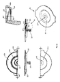
したがって、図16、17及び18に参照されるような、キッコーマン社によって製造及び販売されているプラグに関しては、最初に開封する際にエンドユーザーによってこのタイプの規定の操作/作動原理が行われる。
‐ ステップ1:プラグ全体を覆う外部熱収縮スリーブ(図示せず)を取り外す。
‐ ステップ2:プラグ0.1を取り外す。
‐ ステップ3:プラグ0.5を取り外す。プラグ0.5は輸送及び保管時における主要シールである。
‐ ステップ4:Oリング(OR-ring)0.6があることを確認する。
‐ ステップ5:プラグを瓶にねじ締め直し、使用する。
The above inventive concept can be adapted to any type of container/product existing on the market.
Thus, with respect to the plugs manufactured and sold by Kikkoman, Inc., see FIGS. 16, 17 and 18, this type of prescribed operating/operating principle is followed by the end-user upon first opening.
- Step 1: Remove the outer heat shrink sleeve (not shown) that covers the entire plug.
- Step 2: Remove plug 0.1.
- Step 3: Remove plug 0.5. Plug 0.5 is the primary seal during shipping and storage.
- Step 4: Make sure there is an O-ring 0.6.
- Step 5: Re-screw the plug onto the bottle and use.
しかしながら、図16を観察すると、5つの部品(外部熱収縮スリーブ、上部プラグ0.1、主本体0.3、ワッシャー/Oリング(OR-ring)0.6及び下部シーリングプラグ0.5)で形成される上記プラグは、いくつかの欠点を有する。
‐ 複数のパーツ/部品によって形成された大変コストの掛かるプラグである。
‐ 成形コストについては、主本体0.3のようにいくつかのパーツが、使用されたプラスチックのレベルに関して幾何学的に面が多すぎる。実際に、部品は重量を最適化し、その結果使用プラスチックが少なくなるため非常に迅速かつそれゆえ低コストの射出成形によって生産サイクルも最適化するよう、発展させることができる(そしてこれが本発明の注液プラグで行われている内容である。)。
‐ その結果、生産及び組み立てコストは非常に高くなる。
‐ 外部熱収縮スリーブの存在及び必要性は、製品が未開封であり偽造品でないことの唯一の保証のためであり、保証されるのは最初の開封時にのみである。さらに、そのスリーブは瓶に液体が充填されプラグをねじ締めされたあとでなければ装着できない。この追加のステップにより生産プロセスは複雑で遅いものとなる。
‐ さらに、そのスリーブは一旦取り外されると、取り出す(dispensed of)ために最終顧客/エンドユーザーが追加の操作を行う必要がある。
However, observing FIG. 16, with five parts (external heat shrink sleeve, top plug 0.1, main body 0.3, washer/O-ring 0.6 and bottom sealing plug 0.5) The plugs formed have several drawbacks.
- A very costly plug formed by multiple parts/parts.
- For molding costs, some parts, like the main body 0.3, are geometrically too faceted with respect to the level of plastic used. In fact, the parts can be developed to optimize the weight and thus also the production cycle by means of injection molding which is very rapid and therefore low cost due to the use of less plastic (and this is the focus of the present invention). This is what is done with the liquid plug.).
- As a result, production and assembly costs are very high.
- The presence and necessity of the external heat shrink sleeve is for the sole guarantee that the product is unopened and not counterfeit and is only guaranteed upon first opening. Moreover, the sleeve can only be fitted after the bottle has been filled with liquid and the plug has been screwed on. This additional step makes the production process complicated and slow.
- Moreover, once the sleeve is removed, it requires additional manipulation by the end customer/end user to be dispensed of.
キッコーマン社から製造及び販売されているプラグは、シールを保証する多様なパーツが組み立てられているため、簡単に使用することができず、使い方を即座に理解することもできない。
そのプラグは、それを使用(最初に使用)する前に、準備作業を行わなければならない。より理解してもらうため説明を加えると、製品の注液を開始するにはプラグをねじ外し、パーツ0.5を取り外す必要がある(図16、17及び18)。
この場合にもまた、エンドユーザーは取り外したプラグの廃棄を管理するために追加の作業を行う必要がある。
The plugs manufactured and sold by Kikkoman are not easy to use or immediately understandable because they are assembled from multiple parts to ensure a seal.
The plug must undergo preparatory work before it can be used (first use). For better understanding, it is necessary to unscrew the plug and remove the part 0.5 to start filling the product (Figs. 16, 17 and 18).
Again, the end user must do additional work to manage the disposal of removed plugs.
時には、最初に使用する際に必要な作業であるプラグの取り外しの際にワッシャー/Oリング(OR-ring)0.6を紛失し、そのため内部シーリング要素0.6がもはやないまま瓶に再びねじ締めされたプラグは、瓶と残りのプラグアセンブリの間から液漏れが発生する原因となる。
さらに、エンドユーザーへの真正の保証が何らない偽造された液体を容器に再び充填させることによって、その容器を再利用することが可能となる(i twill)。
Occasionally, the washer/O-ring 0.6 is lost during plug removal, a necessary operation for first use, so the bottle is re-screwed without the internal sealing element 0.6 anymore. A tightened plug causes leakage between the vial and the rest of the plug assembly.
Furthermore, it will be possible to reuse the container by having it refilled with a counterfeit liquid that provides no assurance of authenticity to the end user.
上記のようなプラグには偽造や単純に開封されたことを指摘することができる本当の意味でのシール保証があるとはいえず、瓶に入れられた製品を埃や汚れから保護することを目的とする小さな「埃防止」プラグがあるのみである。したがって、現在のところ、エンドユーザーが気付かないうちに小さなプラグを簡単に取り外して再挿入できるため、瓶に入れられた製品の偽造に対する保証はない(熱収縮スリーブがあるため、最初の使用時を除く)。そのため、難なく、とりわけエンドユーザーに感知されることなく、偽造された製品を流通させることが可能となる。 Such plugs do not have a true seal guarantee that can indicate counterfeiting or simply being tampered with, and are not intended to protect the bottled product from dust and dirt. There is only a small "anti-dust" plug for the purpose. Therefore, there is currently no guarantee against counterfeiting of the bottled product, as the small plug can be easily removed and reinserted without the end user noticing (there is a heat shrink sleeve so the first use is except). It is thus possible to distribute counterfeit products without difficulty and above all without being noticed by the end user.
米国特許出願公開第2007/0181615号明細書、米国特許第5299718号、米国特許出願公開第2009/0250461号明細書及び米国特許出願公開第2011/0174842号明細書の文献は、請求項1のプリアンブルに該当するプラグを備えた液体用容器について開示している。 The documents US2007/0181615, US5299718, US2009/0250461 and US2011/0174842 describe the preamble of claim 1. discloses a liquid container with a plug corresponding to
本発明の目的は、エンドユーザーが即座に使用でき、環境適合性があり、顧客が製品の偽造を指摘できるシステムを有するが、美的レベルや製造プロセスを修正する必要なく市場(marked)に存在する容器に適合させることができる、革新的で単純なプラグを提供することである。 It is an object of the present invention to have a system that is ready to use by the end user, environmentally friendly, and allows customers to point out product counterfeiting, but is marketed without the need to modify aesthetic levels or manufacturing processes. To provide an innovative and simple plug that can be adapted to a container.
本発明の更なる目的は、プラグをねじ外したりプラグから構成要素を取り外したりすることなく、輸送/保管位置から製品を注液するための「開封」位置までの自動開封を伴うプラグを提供することである。プラグをねじ外したりプラグから構成要素を取り外したりすることは、現在市販されているオリジナルプラグで生じていることである。
本発明の別の目的は、プラグが開かれたかどうかをエンドユーザーが目視できる統合されたシステムを提供し、その結果、新しいプラグに統合された「不正開封防止」システムを提供することである。現在の市販バージョンでは、プラグは、一旦開封位置に設定された後は(最初の開封でスリーブと下部プラグは取り外される)、容器に入れられた食品がなくなった後、再び開封し、偽造品の可能性がある製品でさえ充填することが可能となっている。
本発明の更なる目的は、プラグを取り外すことを可能にしない(したがって、可能性のあった製品偽造を不可能にする)、瓶の上に固定されたシステムを提供することである。
本発明の別の目的は、既存のシステムに適合し、したがって、プラグを既存の容器にねじ締めることができ、美的及び機能的レベルの両方で既存の解決策に完全に適するプラグを提供することである。
A further object of the present invention is to provide a plug with automatic opening from a shipping/storage position to an "open" position for product infusion without unscrewing the plug or removing components from the plug. That is. Unscrewing the plug or removing components from the plug is what occurs with the original plugs currently on the market.
Another object of the present invention is to provide an integrated system that allows the end user to see if a plug has been opened, thus providing an integrated "tamper evident" system for new plugs. In the current commercial version, once the plug is set in the open position (the sleeve and bottom plug are removed on the first opening), it is opened again after the container is empty of food and the counterfeit product is detected. Even possible products can be filled.
A further object of the present invention is to provide a system fixed on the bottle that does not allow removal of the plug (thus making possible product counterfeiting impossible).
Another object of the present invention is to provide a plug that fits into existing systems and thus allows the plug to be screwed onto existing containers, making it perfectly compatible with existing solutions on both an aesthetic and functional level. is.
本発明の更なる目的は、プラグに統合された、液体をシーリングする進化したシステムを提供し、紛失の可能性がある追加の構成要素(現在市販されているプラグのようなOリング(OR-ring))を使用するリスクを取り除くことである。
本発明の別の目的は、機能的特徴を変更することなく、プラグを形成する構成要素を最小限まで削減することである。
本発明の更なる目的は、2つ以上の出口を備え、一方を液体出口として使用し、他方を空気入口として使用して、剛性又は半剛性容器から取り出された液体の連続的な注液を可能とするプラグを提供することである。
本発明の別の目的は、容易に管理することができ、管理及び廃棄されるパーツの数を最小限にするプラグ装置を提供することである。
It is a further object of the present invention to provide an advanced system for sealing liquids integrated into the plug, without additional components that may be lost (O-rings (OR-rings) like plugs currently on the market. ring)) is to remove the risk of using
Another object of the invention is to reduce the components forming the plug to a minimum without changing its functional characteristics.
A further object of the present invention is to provide two or more outlets, one used as a liquid outlet and the other as an air inlet, for continuous priming of liquid drawn from a rigid or semi-rigid container. It is to provide a plug that enables.
Another object of the present invention is to provide a plug device that is easily managed and minimizes the number of parts to manage and discard.
本発明の上記及び他の目的及び効果は、以下の説明の結果として、請求項1に記載の注液プラグによって得られる。本発明の好ましい実施形態及び非自明の変形は、従属請求項の主題である。 The above and other objects and effects of the present invention are obtained by the liquid filling plug according to claim 1 as a result of the following description. Preferred embodiments and non-obvious variants of the invention are subject matter of the dependent claims.
添付の特許請求の範囲のすべては、本説明の不可欠な部分であることが意図されている。
酸素に対して高い遮蔽性がある発明性のあるプラグは、無菌用途にも適している。
本発明は、添付の図面を参照しながら、非限定的な例として提供されるその好ましい実施形態によってよりよく説明されるだろう。
All of the appended claims are intended to be an integral part of this description.
Inventive plugs with high oxygen barrier properties are also suitable for sterile applications.
The invention will be better explained by means of its preferred embodiments, given as non-limiting examples, with reference to the accompanying drawings.
図面を参照して、本発明の注液プラグ1の実施形態の非限定的な例が示され、説明されている。説明された注液プラグは、同等の形状、サイズ及びパーツで作成でき、剛性、半剛性又はその他のものといった様々なタイプの容器に使用でき、常に本発明の範囲内であることは当業者には明らかであろう。 Non-limiting examples of embodiments of the fill plug 1 of the present invention are shown and described with reference to the drawings. It will be appreciated by those skilled in the art that the priming plugs described can be made of equivalent shapes, sizes and parts and can be used in various types of containers, rigid, semi-rigid or otherwise, while remaining within the scope of the present invention. would be clear.
図面、特に図1、2及び3を参照すると、本発明の注液プラグ1は、取り外し防止/偽造防止の形状を有する容器5に係る、圧力固定された構成であり、容器から液体を注液するために使用されるもので、概ね以下のものを備える。:
‐ 容器5の注液端に配置された主本体3、
‐ 容器5の内側へ方向付けられた側から主本体3の内側に配置された下部封止ピストン4、及び
‐ 容器5の外側へ方向付けられた側から主本体3の内部に配置された、中央パーツで制御される折り畳み式膜/押ボタン2.1,2.7。
With reference to the drawings, particularly FIGS. 1, 2 and 3, the fill plug 1 of the present invention is a pressure-locked configuration for a
- a
- a lower sealing piston 4 arranged inside the
図6を参照すると、いくつかの詳細断面図を見ることができる。これらは、容器5の首部上にあるフィッティング構成3.1(図6)を有する主本体3(図9)を備え、取り外し防止形状5.1及びプラグセンタリング形状5.2(図6)が組み合わされた状態で封止/輸送を機能する動作位置にある、主本体3を備える発明性のあるプラグ1の構成を明確に図示している。
Referring to FIG. 6, some detailed cross-sectional views can be seen. These comprise a main body 3 (Fig. 9) with a fitting arrangement 3.1 (Fig. 6) on the neck of the
主本体3は、作動的に結合された形状3.2及び5.5により、容器5の首部でシーリング位置にある。形状5.3は、ディスペンサーの現在の生産サイクル内で瓶の取り扱いレベルを何ら変更しないよう使用され、そのため、以下に説明するように、そのような形状はオリジナル容器のサイズと位置に完全に従う。
本体3の小口縁3.3と衝突する段4.2により正しいシーリング位置に配置された形状4.1及び3.4の干渉により、下部封止ピストン4は本体3の動作位置に配置される。
The
The lower sealing piston 4 is placed in the operating position of the
ピストン4の上部パーツについては、以下で説明するように、折り畳み式膜/押ボタン2.1,2.7を有する上蓋2の下部パーツ2.4の台座として機能し、使用位置での変位/開封を可能にし、誘導する誘導シリンダー4.3がある。
「不正開封防止」として機能する中央折り畳み式膜/押ボタン2.1,2.7を有する上蓋2は、適切な位置を決定する形状2.6によって方向を決められて、主本体3の上に配置され、それから主本体3に安定して溶接される(熱溶接又は超音波溶接)。上蓋2は中央押ボタン2.1を有し、これは内部脆弱点2.3及び2.2により、エンドユーザー/顧客が中央に圧力を加えることで、図6に示す封止位置から図8に示す使用/開封位置まで動くことができ、この構成を維持し、それによって下部封止ピストン4を開いたままにする。
As for the upper part of the piston 4, it serves as a base for the lower part 2.4 of the
A
図7及び図8は、上部の不正開封防止要素(中央折り畳み式押ボタン2.1,2.7)が開封位置にあり、開封が行われた(エンドユーザー向けの)証拠を伴う動作位置の発明性のあるプラグのアセンブリの断面を示している。
図8を参照すると、上蓋2の中央押ボタン2.7に加えられた圧力が、制御された対称的な方法でそれを崩壊することに注目することができる。ステムの形状4.3と中央押ボタンの形状2.4との干渉接触により、脆弱要素2.2及び2.3は、下部封止ピストン4の容易かつ制御された降下を可能にする。押ボタンは、一旦開封位置に崩壊すると、その開封位置で安定したままになり、次の3つの主な利点をもたらす。
1.当技術分野(図16、17及び18を参照して以下に説明される)で生じているような内部保護を取り除くためにプラグを取り外す作業はもはや不要となる。その結果、上蓋2の上部膜の制御された崩壊により及びそれに誘導されるディスペンサーの即座かつ自動的な開封がなされる。
2.中央押ボタン2.7は、開封位置に安定して留まり、追加の操作を行う必要なく、プラグを常に開封された状態に保つ。
3.ユーザーは、特に、注液プラグシステム1が取り外し防止/偽造防止形状5.1を備えた特別な容器5に固定されているこのバージョンでは、開封された証拠と、注液された製品が新鮮でオリジナル状態であることの保証を得る。
Figures 7 and 8 show the operating position with the upper tamper-proof element (central folding pushbutton 2.1, 2.7 ) in the unsealed position, with evidence (to the end user) that unsealing has taken place. 1 shows a cross-section of an inventive plug assembly;
Referring to Figure 8, it can be noted that the pressure applied to the central push button 2.7 of the
1. It is no longer necessary to remove the plug to remove internal protection as occurs in the art (described below with reference to Figures 16, 17 and 18). The result is immediate and automatic opening of the dispenser guided by and guided by the controlled collapse of the top membrane of the
2. The central pushbutton 2.7 remains stable in the unsealed position and keeps the plug unsealed at all times without the need for additional manipulation.
3. The user can, in particular, in this version in which the injection plug system 1 is fixed in a
図9を参照して、プラグ1の主本体の第1の実施形態を説明する。この第1の実施形態は、取り外し防止/偽造防止首部を備えた容器5上に安定かつ取り外しできないように組み立てられており、安全なプラグ1/容器5のシステムを構築し、消費者を保護する。
注目されるように、2つの細長い端部3.8があり、これらは液体注液容器5がどのように傾けられるかに応じて液体出口及び/又は空気入口としてそれぞれ機能する。主本体3の上部パーツにはシーリングリング3.7があり、これは一旦プラグ1を組み立てると、折り畳み式膜を有する上蓋2の斜面部2.5と協働し、2つの構成要素間で液体シール動作を行う。
A first embodiment of the main body of the plug 1 is described with reference to FIG. This first embodiment is stably and permanently assembled on
As will be noted, there are two elongated ends 3.8 which act as liquid outlets and/or air inlets, respectively, depending on how the
小型縦断面(A bit-type profile)3.6も示されており、これはエネルギー誘導要素として機能し、折り畳み式膜を有する上蓋2の内部平面2.9での超音波溶接を可能にする。内部には、中央開封部3.5が観察でき、これは形状4.1及び3.4により、下部ピストン4とのシール機能で協働する。
下側には、容器(瓶)5の特殊な首部に作り出された取り外し防止形状5.1に安定的にかつ作動的に接続された固定歯3.1を確認できる。さらに、主内部シーリングコーン3.2にも注目でき、これはシールを機能させる位置において、瓶5の首部の内径5.5と協働して、追加のOリング(OR-rings)を使用することなく液体シールをもたらす。追加のOリングの使用は、現在の市販バージョン(図16、17及び18)で生じていることである。
A bit-type profile 3.6 is also shown, which acts as an energy directing element and allows ultrasonic welding at the inner plane 2.9 of the
On the underside one can see the fixing tooth 3.1 which is stably and operatively connected to the anti-removal shape 5.1 produced in the special neck of the container (bottle) 5. FIG. Also noteworthy is the main inner sealing cone 3.2, which uses additional O-rings in cooperation with the inner diameter 5.5 of the neck of the
図10を参照して、注液プラグの革新的なパーツについて、説明する。すなわち、制御された変形を伴う可撓性膜を有する上蓋2について説明する。注目されるように、それは、平面形状2.9を備え、その上に中央押ボタン2.7の座面が設けられており、これは、この場合、2つの内部脆弱点2.2及び2.3を備えた制御された状態で崩壊する非限定的な形状によって与えられる。しかしながら、押ボタンは他の方法で成形することもでき、同じ結果が得られ、本発明の範囲内に常に収まる。例としてドーム型(図示せず)が挙げられ、この場合、内部的には斜面部2.5と、本体3上に設けられているシーリングリング、より正確には形状3.7とで形成される液体シーリング領域と一致し、さらに押ボタンを偶発的な開封から保護する領域とも一致する。上記の保護は、シール(図示せず)と呼ばれる追加の(オプションの)部品と統合させることもでき、追加の部品は折り畳み式膜/押ボタン2.1,2.7を偶発的な開封からさらに保護し、同時に2つの液体出口/空気入口孔を埃から保護するものであり、注液プラグの作動/開封前の最初の操作として取り除く必要があるものである。あるいは、オプションであり図示されていない上記で説明されたシールの代わりに、熱収縮スリーブ(図示せず)も使用できる。
Referring to Figure 10, the innovative part of the fill plug is described. Thus, a
図6及び図8を参照すると、折り畳み式膜/押ボタン2.7及び2.1は、内部溝(放出/脆弱要素)2.2及び2.3によって制御された状態で崩壊するドームとして成形されることが好ましい。可撓性のあるドームの下には、その内部にあるステム4の上部シリンダー4.3との干渉によって作動的に接続されているステム(上蓋の下部パーツ)2.4がある。 6 and 8, the folding membranes/pushbuttons 2.7 and 2.1 are domes that collapse in a controlled manner by internal grooves (release/weakening elements) 2.2 and 2.3. It is preferably molded as Underneath the flexible dome is a stem (bottom part of the top lid) 2.4 which is operatively connected by interference with the top cylinder 4.3 of the stem 4 inside it.
容器を最初に開くときに指で押ボタンを押すと、押ボタン2.7の第1のパーツは、その下にある、ステムの内部シリンダー4.3と作動的に接続されたステム2.4と共に、内部破壊2.2を利用して下降する。一旦曲げ限界に達すると、第2のエッジ2.1も移動し、内部破壊2.3により、それもまた曲げ限界に達するまでたわめられる。この動作は、順番に、下部封止ピストン4のシリンダー4.3と作動的に接続されている内部のステム2.4の変位量を決定し、下部封止ピストン4の開封し安定した最終位置を決定し、注液を可能にする。 When the push button is pressed by a finger when the container is first opened, the first part of the push button 2.7 is the underlying stem 2.4 which is operatively connected to the inner cylinder 4.3 of the stem. At the same time, it descends using internal destruction 2.2. Once the bending limit is reached, the second edge 2.1 also moves and due to the internal fracture 2.3 is deflected until it too reaches the bending limit. This action in turn determines the amount of displacement of the inner stem 2.4, which is operatively connected to the cylinder 4.3 of the lower sealing piston 4, and the unsealed stable final position of the lower sealing piston 4. to determine and enable injection.
この自動的に進む手順は、退屈な機械的操作を行わずにディスペンサーを自動的に開くことができるため、エンドユーザーにとってのいくつかの利点をもたらす。さらに、管理対象の廃棄物が発生しない。管理対象の廃棄物は、開封前はスリーブの廃棄物を、開封後は下部シーリングプラグ0.5(図16及び17)の廃棄物を管理する必要があるので、オリジナルプラグでは生じていることである。さらに、これは顧客に対して開封の証拠を提供し、とりわけ、プラグ5.1の取り外し防止/偽造防止形状を備えた容器5を使用する機会を提供する。
This self-advancing procedure offers several advantages for the end-user as the dispenser can be automatically opened without tedious mechanical manipulation. Furthermore, no managed waste is generated. The waste to be managed should be the waste of the sleeve before opening and the waste of the lower sealing plug 0.5 (Figs. 16 and 17) after opening, which is what occurs with the original plug. be. Furthermore, this provides the customer with evidence of tampering and, inter alia, the opportunity to use a
下部パーツには、主本体3の平面形状3.9に隣接する別の小形(but-shaped)エネルギー誘導要素2.8もある。2つの壁2.8があり、これらはプラグ3の液体出口/空気入口領域3.8と結合し、主本体3上の上蓋2の液体シールを完全なものに決定づけ、とりわけ2つの組み立てられた構成要素の正しい向きを決定付け、それらの組み立てを容易にする。
The lower part also has another but-shaped energy directing element 2.8 adjoining the planar shape 3.9 of the
図11を参照して、注液プラグ1の封止及び開封を決定する下部封止ピストンについて説明する。中央には、上記で説明したように、中央ステムと共に機能する誘導シリンダー4.3があり、これは可撓性のある折り畳み式膜/押ボタン2.1,2.7の下部パーツにあり、内径4.5と干渉する。
続いて、主本体3の内部可撓性口縁3.4と協働するシーリング領域4.1がある。主本体3の可撓性口縁3.5の内側の領域4.1の適切なシール量を決定し、形状3.3とぶつかる「停止」板4.2がある。下部領域の内部では、部品の堅固形状4.6に注目することができ、その目的は、上蓋2の中央にあり、最初の操作での開封を可能にする、制御された変形を伴う可撓性のある折り畳み式膜/押ボタン2.1,2.7によって押下される力(及びそれによる動き)をより良く伝達することである。
With reference to FIG. 11, the lower sealing piston that determines sealing and unsealing of the injection plug 1 will be described. In the middle there is an induction cylinder 4.3, working with the central stem, as explained above, in the lower part of the flexible folding membranes/ pushbuttons 2.1, 2.7 , Interference with inner diameter 4.5.
Subsequently there is a sealing area 4.1 cooperating with the internal flexible rim 3.4 of the
図12を参照すると、注液プラグ1の特殊な取り外し防止/偽造防止首部を備えた瓶5に注目することができる。図12の詳細を観察すると、刃を持つ2つの外歯5.1及び5.2と、球形の断面を持つ1つの歯5.3があることに注目でき、1つの歯5.3は、サイズ、形状及び位置に関しては、市販されている瓶に現在見られるものと同一であり、既存の生産サイクルを何ら修正することなく使用される。歯5.2は、注液プラグ1を所定の位置及び軸方向に保持するために使用され、一方、歯5.1は、主本体3の内歯3.1と協働し、そのシールを保証し、とりわけ注液プラグ1自体の取り外し防止機能を保証する。
With reference to FIG. 12, attention can be paid to a
内側では、シーリング径5.5の安全対策として、内径の壁薄部5.4に注目することができる。瓶首部の起こりうる欠陥は、内部領域5.4で止まり、瓶5のための注液プラグ1のシーリング領域5.5まで入らない。
環境適合性の理由により、ディスペンサーを完全にプラスチック製としリサイクルを可能とするため、瓶5はPET製が望ましい。しかしながら、そのような瓶5は、他の材料(例えばガラス)でも生産することができ、常に本発明の範囲内に入る。
On the inside, the inner wall thinning 5.4 can be noted as a security measure for the sealing diameter 5.5. A possible defect in the neck of the bottle stops at the inner area 5.4 and does not enter the sealing area 5.5 of the filling plug 1 for the
For ecological reasons, the
図13を参照すると、瓶6は、ねじ締め(図14)に有用な雌ねじ7.1を有する本体を備えた注液プラグ1の特殊なねじ締めタイプの首部と共に図示されている。図13の詳細を観察すると、雄ねじ6.1と、球形の断面を持つ歯6.2とがあり、歯6.2は歯5.3と同じもので、市販されている瓶で現在見られるものとサイズ、形状及び位置が同一であり、既存の生産サイクルを何ら修正する必要なく使用される。内径6.3は、ねじ締め形状7.2(図14)を有する主本体7の形状と共に、シールを発揮する。この場合、現在市販されている瓶の形状は完全に模倣されているので、プラグ1の取り外し防止は保証されない。したがって、最初の開封前にプラグが取り除かれていないことを顧客に保証するためには、オプションであり図示されていない熱収縮スリーブとシステムとを可能であれば統合する必要がある。主本体7を有するこのバージョンの大きな利点は、生産サイクルに簡単に適合でき、現在の、管理レベルが複雑で面倒なプラグに置き換わることができることにある(図16、17及び18)。したがって、修正を必要とせずに現在の生産サイクルに適合する準備が既にできている、上で説明されたオリジナルプラグ0.1(図16、17及び18)の欠点の大部分を克服する、自動開封を伴う「不正開封防止」プラグが提供できる。 With reference to Figure 13, the bottle 6 is shown with a special screw-on type neck of the filling plug 1 with a body having an internal thread 7.1 useful for screwing (Figure 14). Observing the detail in Figure 13, there is an external thread 6.1 and a tooth 6.2 with a spherical cross-section, which is the same as tooth 5.3 and which is currently found in commercially available bottles. It is identical in size , shape and position to the original and can be used without any modification to existing production cycles. The inner diameter 6.3 provides a seal with the shape of the main body 7 having a threaded shape 7.2 (Fig. 14). In this case, prevention of removal of the plug 1 is not guaranteed, since the shape of the bottle currently on the market is completely imitated. Therefore, an optional, not shown, heat shrink sleeve should be integrated with the system if possible to assure the customer that the plug has not been removed prior to the first opening. The great advantage of this version with the main body 7 is that it can be easily adapted to the production cycle and can replace the current plugs which are complicated and cumbersome to manage (Figs. 16, 17 and 18). Thus, the automatic, which overcomes most of the drawbacks of the original Plug 0.1 described above (Figs. 16, 17 and 18), is already ready to fit into current production cycles without the need for modifications. A "tamper evident" plug can be provided that involves opening.
図14を参照すると、注液プラグの別の実施形態が示されており、これはキッコーマン社によって販売されている容器に即座に適合する。この場合、本体7(図15)は、既存の瓶6にあるねじ山と、より具体的には形状6.1と安定して結合されるように適合されたねじ山7.1をその中に有する。この場合、注液プラグ1は、顧客や製造業者に何らの修正を必要とせず、部品の重心や重さの変更に伴う技術的な調整のみで、既存の生産ステップに即座に適することができるように、(全体的なサイズに関して)外面は正確なコピーとなる。
この場合、必要な形状を持たない既存の容器にプラグを適合させる必要があるため、瓶からプラグの取り外しを防止することは別として、前述の実施形態について説明したすべての利点がある。この実施形態には、瓶6の内部首部6.3と注液プラグ1との間に、可撓性がありかつシーリング口縁を備えた別のシステム7.2もあり、これは図9に示す本体3にも製造することができる。このように、追加のOリング(OR-Ring)は回避できる。追加のOリングは、図16、17及び18に図示されるような標準的なアセンブリ0.1で生じていることである。
Referring to FIG. 14, another embodiment of a fill plug is shown, which readily fits the container sold by Kikkoman. In this case, the body 7 (Fig. 15) has a thread 7.1 adapted to be stably coupled with the thread present in the existing bottle 6 and more specifically with the shape 6.1. have inside. In this case, the injection plug 1 does not require any modification by the customer or the manufacturer, and can be immediately adapted to existing production steps with only technical adjustments due to changes in the center of gravity and weight of the part. As such, the exterior (in terms of overall size) is an exact copy.
In this case, apart from preventing removal of the plug from the bottle, it has all the advantages described for the previous embodiments, as the plug must fit into an existing container that does not have the required shape . In this embodiment there is also another system 7.2 with a flexible and sealing lip between the inner neck 6.3 of the bottle 6 and the filling plug 1, which is shown in FIG. The
可撓性があるシーリング膜を備えた開封システムは、既に上で説明したものと同様である。したがって、簡潔にいうと、本体7の小口縁7.3と衝突する段4.2により正しいシーリング位置に配置された形状4.1及び7.4の干渉により、下部ピストン4は本体7の動作位置に配置される。注目されるように、ピストン4の上部パーツには、以下で説明するように、折り畳み式膜/押ボタン2.1,2.7を有する上蓋2の下部パーツ2.4の台座として機能し、使用位置での変位/開封を可能にする誘導シリンダー4.3がある。「不正開封防止」要素として機能する中央折り畳み式膜/押ボタン2.1,2.7を有する上蓋2は、適切な位置を決定する形状2.6によって方向付けられた主本体7の上に配置され、それからその上に安定して溶接される(熱溶接又は超音波溶接)。
The opening system with flexible sealing membrane is similar to that already described above. Briefly, therefore, the interference of the shapes 4.1 and 7.4 placed in the correct sealing position by the step 4.2 impinging on the fore edge 7.3 of the body 7 causes the lower piston 4 to move out of the body 7. placed in the operating position. It will be noted that the upper part of the piston 4 serves as a base for the lower part 2.4 of the
上蓋2は、中央押ボタン2.1を有し、これは内部脆弱点2.3及び2.2により、エンドユーザー/顧客が中央に加える圧力のおかげで、図14に示す封止位置から使用/開封位置(図示せず)まで動くことができ、この構成を維持し、それによってその後下部封止ピストン4を開いたままにする。
The
ねじ締め本体を有する注液プラグ7は、上部不正開封防止要素(中央押ボタン2.1)が開封位置にあるという動作位置(図示せず)のとき、開封が行われた証拠(エンドユーザーにとっては利点)を提供する。上蓋2(図10)の中央押ボタン2.1に加えられた圧力は、制御されかつ対称的な方法でそれを崩壊する。ステムの形状4.3と中央押ボタンの形状2.4との干渉接触により、脆弱要素2.2及び2.3は、下部封止ピストン4の容易かつ制御された下降を可能にする。押ボタンは、一旦開封位置に崩壊させられると、その位置で安定したままになり、次の3つの主な利点をもたらす。 The fill plug 7 with its screw- on body provides evidence of unsealing (end-user benefits). Pressure applied to the central pushbutton 2.1 of the top cover 2 (Fig. 10) collapses it in a controlled and symmetrical manner. Through interference contact between the stem shape 4.3 and the central pushbutton shape 2.4, the weakened elements 2.2 and 2.3 allow an easy and controlled lowering of the lower sealing piston 4. . Once collapsed to the unfolded position, the pushbutton remains stable in that position, providing three main advantages.
1.当技術分野(図16、17及び18を参照して以下に説明される)で生じているような、内部保護0.5(図16及び17)を取り外すためにプラグを取り外す作業はもはや不要となる。その結果、上蓋2の上部膜の制御された崩壊により及びそれに誘導されるディスペンサーの即座かつ自動的な開封がなされる。
2.中央押ボタンは、開封位置に安定して留まり、追加の操作を行う必要なく、プラグを常に開封された状態に保つ。
3.ユーザーは、物品や廃棄物を管理する必要がなくなる。物品や廃棄物の管理は、オリジナルバージョンで最初の開封の際に、輸送及び保管のため(図16及び17)の熱収縮スリーブとシーリングプラグが取り外され廃棄され(廃棄物の発生)なければならない場合に生じていることである。
1. It is no longer necessary to remove the plug to remove the inner protection 0.5 (FIGS. 16 and 17) as occurs in the art (described below with reference to FIGS. 16, 17 and 18). Become. The result is immediate and automatic opening of the dispenser guided by and guided by the controlled collapse of the top membrane of the
2. The central pushbutton remains stable in the unsealed position, keeping the plug unsealed at all times without the need for additional manipulation.
3. Users no longer need to manage goods and waste. Material and waste management must be removed and discarded (waste generation) for shipping and storage (Figs. 16 and 17) heat shrink sleeves and sealing plugs for shipping and storage when first opened in the original version This is what is happening in the case.
図14を参照して、発明性のあるプラグの主本体の第2の実施形態を詳細に説明する。先に説明したように、この第2の実施形態7は、容器の首部6.1と本体7の内側に、正確に言うと形状7.1に存在するねじ山の手段によって安定的に組み立てられる。注目されるように、容器が液体を注液するためにどのように傾けられるかに応じて液体出口及び/又は空気入口としてそれぞれ機能する2つの細長い端部7.6がある。 Referring to FIG. 14, a second embodiment of the main body of the inventive plug will be described in detail. As explained earlier, this second embodiment 7 is stably assembled by means of threads present inside the neck 6.1 and body 7 of the container, more precisely in shape 7.1. be done. As will be noted, there are two elongated ends 7.6 which act as liquid outlets and/or air inlets, respectively, depending on how the container is tilted for filling with liquid.
主本体7の上部パーツにはシーリングリング7.7があり、これは一旦プラグを組み立てると、折り畳み式膜を有する上部プラグ2の斜面部2.5と協働して、液体シーリングとしての機能を果たす。小形縦断面(a bit-shaped profile)7.5があることにも注目でき、これは、エネルギー誘導要素として機能し、折り畳み式膜を有する上蓋2の内部平面2.9での超音波溶接を可能にする。
The upper part of the main body 7 has a sealing ring 7.7 which, once the plug is assembled, cooperates with the bevel 2.5 of the
内部には、中央開封部7.4があり、これは、形状4.1及び7.4により、下部ピストン4と共に協働してシーリングとして機能する。下部パーツには、市場にある標準的な瓶6の首部6.1上にあるねじ山に安定して作動的に接続されたねじ山7.1がある。 Inside there is a central opening 7.4 which cooperates with the lower piston 4 to act as a seal due to the shapes 4.1 and 7.4. The lower part has a thread 7.1 which is stably and operatively connected to the thread on the neck 6.1 of a standard bottle 6 on the market.
さらに、主内部シーリングコーン7.2があり、これはシーリングを機能させる位置において、瓶6の首部6.1の内径6.3と協働して、追加のOリング(OR-rings)の使用を必要とすることなく液体シールをもたらす。追加のOリングの使用は、今日の市販バージョン(図16、17及び18)で生じていることである。 In addition, there is a main internal sealing cone 7.2, which cooperates with the inner diameter 6.3 of the neck 6.1 of the bottle 6 in a position to effect the sealing and the use of additional O-rings. Provides a liquid seal without the need for The use of additional O-rings is what occurs in today's commercial versions (Figs. 16, 17 and 18).
図16、17を参照すると、現在販売されているキッコーマンシステムが図示されている。これは、上で説明したように、実用的とは言い難く、即座に使えるものではなく、安全とは言い難いシステム0.1であり、これは、ガラス容器6を塞いでいる。5つの部品、すなわち熱収縮スリーブ(図示せず)、単純な上部プラグ0.1、主本体0.3、シーリングワッシャー/Oリング(OR-ring)0.6並びに輸送及び保管のためのシーリングプラグ0.5から構成されている。 Referring to Figures 16 and 17, the currently marketed Kikkoman system is illustrated. This is, as explained above, a less than practical, less than ready-to-use, less than safe system 0.1, which closes the glass container 6 . Five parts: heat shrink sleeve (not shown), simple top plug 0.1, main body 0.3, sealing washer/O-ring (OR-ring) 0.6 and sealing plug for shipping and storage. 0.5.
図18を参照すると、顧客によって(最初の注液用に)準備されたプラグ0.1は、開封位置にあることが観察できる。顧客によって手作業で、(図16及び図17で先に示したアセンブリを分解することにより)アセンブリから下部プラグ0.5と熱収縮スリーブが取り外されていることに注目できる。これにより、最終顧客は廃棄物を生み出し管理する必要に迫られる。さらに、プラグは、開封の証拠がなく、容器に偽造液体を充填し、消費者及び製造業者に損害を与えることにより、何度も使用することが可能となる。さらに、すでに使用されているプラグと容器を再度使用することは衛生的に正しくない。 Referring to Figure 18, it can be observed that the plug 0.1 prepared by the customer (for the first filling) is in the open position. It can be noted that the bottom plug 0.5 and heat shrink sleeve have been removed from the assembly manually by the customer (by disassembling the assembly previously shown in FIGS. 16 and 17). This forces the end customer to create and manage waste. Furthermore, the plug can be used multiple times without evidence of tampering, by filling the container with counterfeit liquids and causing damage to consumers and manufacturers. Moreover, it is not hygienically correct to reuse plugs and containers that have already been used.
最後に、発明性のあるプラグ1の両方の実施形態について、上で説明した注液プラグ1(両実施形態において瓶上に取り外し防止/偽造防止嵌合を備えた、第2の実施形態において市販瓶のねじ締めタイプのプラグを備えた)の上部パーツの上にシールタイプのプラグ(図示せず)を追加することが可能であり、そのようなシールプラグは、折り畳み式膜/押ボタンを偶発的な開封から保護し、同時に2つの液体出口/空気入口孔を埃から保護し、注液プラグ1を作動/開封する前の最初の操作として取り外される必要がある。また、現在市販されているプラグのように、熱収縮スリーブを適用することも可能である。 Finally, for both embodiments of the inventive plug 1, the filling plug 1 described above (with anti-removal/anti-counterfeit fitting on the bottle in both embodiments, commercial It is possible to add a sealing-type plug (not shown) on top of the top part of the bottle (with screw-on type plug), such a sealing plug to prevent the folding membrane/ push button from accidentally It must be removed as a first operation before actuating/opening the fill plug 1 to protect it against destructive opening and at the same time protect the two liquid outlet/air inlet holes from dust. It is also possible to apply a heat-shrinkable sleeve, like the plugs currently on the market.
Claims (7)
前記注液プラグ(1)は、
前記容器(5、6)の注液端に配置された主本体(3、7)と、
前記容器(5、6)の内側へ方向付けられた側から前記主本体(3、7)の内部の下部封止ピストン(4)と、
前記容器(5、6)の外側へ方向付けられた側から前記主本体(3、7)の内部に配置された折り畳み式膜/押ボタン(2.1,2.7)を有する上蓋(2)とを備え、
前記主本体(3、7)に固定された前記折り畳み式膜/押ボタン(2.1,2.7)を有する上蓋(2)は、内部溝(2.2)及び内部溝(2.3)を有する中央押ボタン(2.1)を備え、該中央押ボタン(2.1)を押し下げることで、前記下部封止ピストン(4)を封止位置から使用/開封位置まで移動させ、このとき前記内部溝(2.2)及び前記内部溝(2.3)によって制御された変形を生じさせて、該使用/開封位置において前記下部開封ピストン(4)は開いたままとなり、前記下部封止ピストン(4)及び前記中央押ボタン(2.1)は元には戻らないものであり、
前記主本体(3、7)は、前記容器(5、6)が液体を注液するためにどのように傾けられるかに応じて液体出口及び/又は空気入口として機能するよう適合された2つの細長い端部(3.8、7.6)を備え、
前記主本体(3、7)は、折り畳み式膜/押ボタン(2.1,2.7)を有する前記上蓋(2)の傾斜部(2.5)と協働して液体シール動作を行うように適合されたシーリングリング(3.7、7.7)を備え、
前記折り畳み式膜/押ボタン(2.1,2.7)を有する前記上蓋(2)は、形状(2.6)によって液体出口及び空気入口として方向付けられて配置された前記主本体(3、7)に、溶接されており、
前記上蓋(2)の内部平面(2.9)は、小形要素(3.6、7.5)に溶接エネルギー又は溶接熱が正確に印加可能で、かつ、超音波溶接の場合は、最終的に取り外すことのできない機能的な溶接及び液体シーリングとなるエネルギー誘導要素として機能することを特徴とする注液プラグ(1)を備えた液体用容器(5、6)。 A liquid container (5, 6) with a liquid injection plug (1),
The injection plug (1) is
a main body (3, 7) located at the filling end of said container (5, 6);
a lower sealing piston (4) inside said main body (3, 7) from the side directed towards the inside of said container (5, 6);
A top lid (2) with a folding membrane/push button (2.1, 2.7) arranged inside said main body (3, 7) from the outwardly oriented side of said container (5, 6) ) and
A top cover (2) with said folding membrane/pushbuttons (2.1, 2.7) fixed to said main body (3, 7) has an internal groove (2.2) and an internal groove (2.3) ), which is depressed to move said lower sealing piston (4) from the sealing position to the use /opening position. , then causing a controlled deformation by said internal grooves (2.2) and said internal grooves (2.3) such that in said use/opening position said lower opening piston (4) remains open and said the lower sealing piston (4) and said central push button (2.1) are irreversible,
Said main body (3,7) has two parts adapted to act as liquid outlets and/or air inlets depending on how said containers (5,6) are tilted for injecting liquid. with elongated ends (3.8, 7.6);
Said main body (3, 7) cooperates with the sloping portion (2.5) of said top cover (2) with folding membrane/push button (2.1, 2.7) for liquid sealing action. with sealing rings (3.7, 7.7) adapted for
Said top cover (2) with said foldable membrane/push button (2.1, 2.7) is arranged in said main body (3) oriented as liquid outlet and air inlet by shape (2.6). , 7) are welded,
The internal plane (2.9) of said top cover (2) allows the precise application of welding energy or welding heat to the small elements (3.6, 7.5) and, in the case of ultrasonic welding, the final Containers (5, 6) for liquids with a fill plug (1), characterized in that it acts as an energy-conducting element resulting in a non-removable functional weld and liquid sealing.
前記下部封止ピストン(4)をそれぞれの干渉縦断面(4.1)及び(3.4、7.4)によって前記主本体(3、7)に対する適切なシール位置へ配置できるようにすることを特徴とする請求項1記載の注液プラグ(1)を備えた液体用容器(5、6)。 said lower sealing piston (4) comprises a step (4.2) adjacent to the ends (3.3, 7.3) of said main body (3, 7);
enabling said lower sealing piston (4) to be placed in a suitable sealing position with respect to said main body (3, 7) by means of respective interference longitudinal sections (4.1) and (3.4, 7.4); A liquid container (5, 6) with a filling plug (1) according to claim 1.
前記歯(5.2)は、前記プラグ(1)を所定の位置及び軸方向に保持する機能を有し、
前記歯(5.1)は、前記主本体(3)の内歯(3.1)と協働して用いられ、
前記注液プラグ(1)のシールと取り外し防止機能を保証することを特徴とする請求項1~6のいずれかに記載の注液プラグ(1)を備えた液体用容器(5)。 said container (5) comprises at least two external teeth (5.1) and (5.2) with blades,
said teeth (5.2) have the function of holding said plug (1) in place and axially,
said teeth (5.1) are used in cooperation with internal teeth (3.1) of said main body (3),
A liquid container (5) with a fill plug (1) according to any of the preceding claims, characterized in that it ensures a sealing and anti-removal function of the fill plug (1).
Applications Claiming Priority (3)
| Application Number | Priority Date | Filing Date | Title |
|---|---|---|---|
| IT102017000053123A IT201700053123A1 (en) | 2017-05-17 | 2017-05-17 | Liquid container with dispenser cap with integrated air flow and automatic opening guarantee seal |
| IT102017000053123 | 2017-05-17 | ||
| PCT/IT2018/000026 WO2018211536A1 (en) | 2017-05-17 | 2018-02-28 | Container for liquids equipped with delivering plug with integrated air passage and warranty seal with automatic opening |
Publications (3)
| Publication Number | Publication Date |
|---|---|
| JP2020525360A JP2020525360A (en) | 2020-08-27 |
| JP2020525360A5 JP2020525360A5 (en) | 2021-03-11 |
| JP7232568B2 true JP7232568B2 (en) | 2023-03-03 |
Family
ID=60020375
Family Applications (1)
| Application Number | Title | Priority Date | Filing Date |
|---|---|---|---|
| JP2019557484A Active JP7232568B2 (en) | 2017-05-17 | 2018-02-28 | Liquid container with filling plug with integrated air path and seal assurance with automatic opening |
Country Status (5)
| Country | Link |
|---|---|
| US (1) | US10752411B2 (en) |
| EP (1) | EP3625139B1 (en) |
| JP (1) | JP7232568B2 (en) |
| IT (1) | IT201700053123A1 (en) |
| WO (1) | WO2018211536A1 (en) |
Families Citing this family (1)
| Publication number | Priority date | Publication date | Assignee | Title |
|---|---|---|---|---|
| NL2023402B1 (en) * | 2019-06-28 | 2021-02-01 | Smartseal As | Sealing device for sealing a receptacle |
Citations (6)
| Publication number | Priority date | Publication date | Assignee | Title |
|---|---|---|---|---|
| JP2002165707A (en) | 2000-11-29 | 2002-06-11 | Zojirushi Corp | Liquid vessel |
| US20020121525A1 (en) | 2001-03-05 | 2002-09-05 | Acorn Bay, Llc | Drink spout system |
| JP2007276786A (en) | 2004-10-25 | 2007-10-25 | Coca Cola Co:The | Bottle cap |
| JP2008531403A (en) | 2005-02-22 | 2008-08-14 | カムラボ リミテッド | Reliable sample collection |
| JP2009526189A (en) | 2006-02-08 | 2009-07-16 | インターナシヨナル・デイスペンシング・コーポレーシヨン | Anti-drip distribution valve for fluid |
| US20090250461A1 (en) | 2008-04-04 | 2009-10-08 | Yves Syrkos | Liquid container |
Family Cites Families (15)
| Publication number | Priority date | Publication date | Assignee | Title |
|---|---|---|---|---|
| FR2086518A5 (en) * | 1969-11-19 | 1971-12-31 | Captocap Ltd | |
| JPS5620375Y2 (en) * | 1976-03-18 | 1981-05-14 | ||
| US4691836A (en) * | 1983-01-06 | 1987-09-08 | Victor Wassilieff | Apertured closure device with depressible disc portion |
| JPH0667357U (en) * | 1993-03-03 | 1994-09-22 | 凸版印刷株式会社 | Valve cap |
| US5299718A (en) * | 1993-06-01 | 1994-04-05 | Shwery Roy P | Bottle closures |
| BR0105791B1 (en) * | 2000-04-07 | 2011-04-05 | valve to dispense fluids. | |
| US6631823B2 (en) * | 2001-03-05 | 2003-10-14 | Acorn Bay, Llc | Drink spout system |
| US6662978B2 (en) * | 2002-05-13 | 2003-12-16 | Shin-Shuoh Lin | Stopper with interchangeable plug |
| US7040514B2 (en) * | 2004-04-21 | 2006-05-09 | Mihail Octavian Colan | Membrane activated carbonated beverage dispenser |
| US8272532B2 (en) * | 2007-12-21 | 2012-09-25 | Helen Of Troy Limited | Beverage container lid |
| WO2010041286A2 (en) * | 2008-10-09 | 2010-04-15 | Vitop Moulding S.R.L. | Tap for delivering liquids from vessels |
| EP2238873A2 (en) * | 2009-02-12 | 2010-10-13 | Browne & Co | Travel mug |
| NL2012469B1 (en) * | 2014-03-18 | 2015-12-15 | Ipn Ip Bv | A liquid dispensing tap and liquid container provided with said tap. |
| EP3142940A4 (en) * | 2014-05-13 | 2017-12-13 | Cool Gear International, LLC | Mechanically sealed container cap |
| US9708108B2 (en) * | 2015-09-22 | 2017-07-18 | Rubbermaid Incorporated | Portable beverage container and lid assembly |
-
2017
- 2017-05-17 IT IT102017000053123A patent/IT201700053123A1/en unknown
-
2018
- 2018-02-28 US US16/608,058 patent/US10752411B2/en active Active
- 2018-02-28 WO PCT/IT2018/000026 patent/WO2018211536A1/en unknown
- 2018-02-28 JP JP2019557484A patent/JP7232568B2/en active Active
- 2018-02-28 EP EP18712695.8A patent/EP3625139B1/en active Active
Patent Citations (6)
| Publication number | Priority date | Publication date | Assignee | Title |
|---|---|---|---|---|
| JP2002165707A (en) | 2000-11-29 | 2002-06-11 | Zojirushi Corp | Liquid vessel |
| US20020121525A1 (en) | 2001-03-05 | 2002-09-05 | Acorn Bay, Llc | Drink spout system |
| JP2007276786A (en) | 2004-10-25 | 2007-10-25 | Coca Cola Co:The | Bottle cap |
| JP2008531403A (en) | 2005-02-22 | 2008-08-14 | カムラボ リミテッド | Reliable sample collection |
| JP2009526189A (en) | 2006-02-08 | 2009-07-16 | インターナシヨナル・デイスペンシング・コーポレーシヨン | Anti-drip distribution valve for fluid |
| US20090250461A1 (en) | 2008-04-04 | 2009-10-08 | Yves Syrkos | Liquid container |
Also Published As
| Publication number | Publication date |
|---|---|
| US20200180825A1 (en) | 2020-06-11 |
| US10752411B2 (en) | 2020-08-25 |
| JP2020525360A (en) | 2020-08-27 |
| EP3625139A1 (en) | 2020-03-25 |
| EP3625139B1 (en) | 2023-03-29 |
| IT201700053123A1 (en) | 2017-08-17 |
| WO2018211536A1 (en) | 2018-11-22 |
Similar Documents
| Publication | Publication Date | Title |
|---|---|---|
| US7249690B2 (en) | Independent off-bottle dispensing closure | |
| FR2867761A1 (en) | RECHARCHE FOR COSMETIC PRODUCT DISTRIBUTOR | |
| EP0244327A1 (en) | Container spout provided with means for preventing refilling after dispensing with the initial contents | |
| BR112018010908B1 (en) | Closing and container system | |
| KR20160022880A (en) | A cap with a cutting element | |
| KR101630314B1 (en) | A bottle with a secure cap | |
| EP2125535B1 (en) | Vial for receiving a predetermined dose of a liquid | |
| JP7232568B2 (en) | Liquid container with filling plug with integrated air path and seal assurance with automatic opening | |
| CA2149993A1 (en) | Pouring spout with tamper-evident membrane seal | |
| JP4954695B2 (en) | Refill container | |
| JP5121144B2 (en) | Pouch plug, pouch with plug, and package | |
| JP5696374B2 (en) | Pouch outlet plug and pouch using the same | |
| JP4424538B2 (en) | Thin container | |
| JP7416442B2 (en) | double container | |
| JP5294722B2 (en) | container | |
| JP6880653B2 (en) | Sealed spout | |
| JP6848360B2 (en) | Sealed spout | |
| RU2777382C1 (en) | Integral capping tool for a container | |
| EP0805113A1 (en) | Tamper-evident closure for containers,in particular for bottles or vials | |
| JP6722612B2 (en) | container | |
| JP6449705B2 (en) | Caps and containers with caps | |
| JP2002059956A (en) | Container | |
| JP6055178B2 (en) | Refill container | |
| JP4608939B2 (en) | Tamper-proof mouth cap with sealing ring | |
| KR20180003299U (en) | Double cap with liner cap to hold liquid storage container |
Legal Events
| Date | Code | Title | Description |
|---|---|---|---|
| A521 | Request for written amendment filed |
Free format text: JAPANESE INTERMEDIATE CODE: A523 Effective date: 20210128 |
|
| A621 | Written request for application examination |
Free format text: JAPANESE INTERMEDIATE CODE: A621 Effective date: 20210128 |
|
| A977 | Report on retrieval |
Free format text: JAPANESE INTERMEDIATE CODE: A971007 Effective date: 20211210 |
|
| A131 | Notification of reasons for refusal |
Free format text: JAPANESE INTERMEDIATE CODE: A131 Effective date: 20211221 |
|
| A601 | Written request for extension of time |
Free format text: JAPANESE INTERMEDIATE CODE: A601 Effective date: 20220314 |
|
| A521 | Request for written amendment filed |
Free format text: JAPANESE INTERMEDIATE CODE: A523 Effective date: 20220523 |
|
| A02 | Decision of refusal |
Free format text: JAPANESE INTERMEDIATE CODE: A02 Effective date: 20220809 |
|
| A521 | Request for written amendment filed |
Free format text: JAPANESE INTERMEDIATE CODE: A523 Effective date: 20221031 |
|
| C60 | Trial request (containing other claim documents, opposition documents) |
Free format text: JAPANESE INTERMEDIATE CODE: C60 Effective date: 20221031 |
|
| A521 | Request for written amendment filed |
Free format text: JAPANESE INTERMEDIATE CODE: A523 Effective date: 20221115 |
|
| A911 | Transfer to examiner for re-examination before appeal (zenchi) |
Free format text: JAPANESE INTERMEDIATE CODE: A911 Effective date: 20221212 |
|
| C21 | Notice of transfer of a case for reconsideration by examiners before appeal proceedings |
Free format text: JAPANESE INTERMEDIATE CODE: C21 Effective date: 20221213 |
|
| TRDD | Decision of grant or rejection written | ||
| A01 | Written decision to grant a patent or to grant a registration (utility model) |
Free format text: JAPANESE INTERMEDIATE CODE: A01 Effective date: 20230207 |
|
| A61 | First payment of annual fees (during grant procedure) |
Free format text: JAPANESE INTERMEDIATE CODE: A61 Effective date: 20230218 |
|
| R150 | Certificate of patent or registration of utility model |
Ref document number: 7232568 Country of ref document: JP Free format text: JAPANESE INTERMEDIATE CODE: R150 |