JP7228551B2 - rolling bearing - Google Patents
rolling bearing Download PDFInfo
- Publication number
- JP7228551B2 JP7228551B2 JP2020161340A JP2020161340A JP7228551B2 JP 7228551 B2 JP7228551 B2 JP 7228551B2 JP 2020161340 A JP2020161340 A JP 2020161340A JP 2020161340 A JP2020161340 A JP 2020161340A JP 7228551 B2 JP7228551 B2 JP 7228551B2
- Authority
- JP
- Japan
- Prior art keywords
- outer ring
- inner ring
- ring
- hole
- rolling bearing
- Prior art date
- Legal status (The legal status is an assumption and is not a legal conclusion. Google has not performed a legal analysis and makes no representation as to the accuracy of the status listed.)
- Active
Links
Images


Classifications
-
- F—MECHANICAL ENGINEERING; LIGHTING; HEATING; WEAPONS; BLASTING
- F16—ENGINEERING ELEMENTS AND UNITS; GENERAL MEASURES FOR PRODUCING AND MAINTAINING EFFECTIVE FUNCTIONING OF MACHINES OR INSTALLATIONS; THERMAL INSULATION IN GENERAL
- F16C—SHAFTS; FLEXIBLE SHAFTS; ELEMENTS OR CRANKSHAFT MECHANISMS; ROTARY BODIES OTHER THAN GEARING ELEMENTS; BEARINGS
- F16C19/00—Bearings with rolling contact, for exclusively rotary movement
- F16C19/22—Bearings with rolling contact, for exclusively rotary movement with bearing rollers essentially of the same size in one or more circular rows, e.g. needle bearings
- F16C19/34—Bearings with rolling contact, for exclusively rotary movement with bearing rollers essentially of the same size in one or more circular rows, e.g. needle bearings for both radial and axial load
- F16C19/36—Bearings with rolling contact, for exclusively rotary movement with bearing rollers essentially of the same size in one or more circular rows, e.g. needle bearings for both radial and axial load with a single row of rollers
-
- F—MECHANICAL ENGINEERING; LIGHTING; HEATING; WEAPONS; BLASTING
- F16—ENGINEERING ELEMENTS AND UNITS; GENERAL MEASURES FOR PRODUCING AND MAINTAINING EFFECTIVE FUNCTIONING OF MACHINES OR INSTALLATIONS; THERMAL INSULATION IN GENERAL
- F16C—SHAFTS; FLEXIBLE SHAFTS; ELEMENTS OR CRANKSHAFT MECHANISMS; ROTARY BODIES OTHER THAN GEARING ELEMENTS; BEARINGS
- F16C19/00—Bearings with rolling contact, for exclusively rotary movement
- F16C19/02—Bearings with rolling contact, for exclusively rotary movement with bearing balls essentially of the same size in one or more circular rows
- F16C19/04—Bearings with rolling contact, for exclusively rotary movement with bearing balls essentially of the same size in one or more circular rows for radial load mainly
- F16C19/06—Bearings with rolling contact, for exclusively rotary movement with bearing balls essentially of the same size in one or more circular rows for radial load mainly with a single row or balls
-
- F—MECHANICAL ENGINEERING; LIGHTING; HEATING; WEAPONS; BLASTING
- F16—ENGINEERING ELEMENTS AND UNITS; GENERAL MEASURES FOR PRODUCING AND MAINTAINING EFFECTIVE FUNCTIONING OF MACHINES OR INSTALLATIONS; THERMAL INSULATION IN GENERAL
- F16C—SHAFTS; FLEXIBLE SHAFTS; ELEMENTS OR CRANKSHAFT MECHANISMS; ROTARY BODIES OTHER THAN GEARING ELEMENTS; BEARINGS
- F16C19/00—Bearings with rolling contact, for exclusively rotary movement
- F16C19/22—Bearings with rolling contact, for exclusively rotary movement with bearing rollers essentially of the same size in one or more circular rows, e.g. needle bearings
- F16C19/34—Bearings with rolling contact, for exclusively rotary movement with bearing rollers essentially of the same size in one or more circular rows, e.g. needle bearings for both radial and axial load
- F16C19/36—Bearings with rolling contact, for exclusively rotary movement with bearing rollers essentially of the same size in one or more circular rows, e.g. needle bearings for both radial and axial load with a single row of rollers
- F16C19/361—Bearings with rolling contact, for exclusively rotary movement with bearing rollers essentially of the same size in one or more circular rows, e.g. needle bearings for both radial and axial load with a single row of rollers with cylindrical rollers
- F16C19/362—Bearings with rolling contact, for exclusively rotary movement with bearing rollers essentially of the same size in one or more circular rows, e.g. needle bearings for both radial and axial load with a single row of rollers with cylindrical rollers the rollers being crossed within the single row
-
- F—MECHANICAL ENGINEERING; LIGHTING; HEATING; WEAPONS; BLASTING
- F16—ENGINEERING ELEMENTS AND UNITS; GENERAL MEASURES FOR PRODUCING AND MAINTAINING EFFECTIVE FUNCTIONING OF MACHINES OR INSTALLATIONS; THERMAL INSULATION IN GENERAL
- F16C—SHAFTS; FLEXIBLE SHAFTS; ELEMENTS OR CRANKSHAFT MECHANISMS; ROTARY BODIES OTHER THAN GEARING ELEMENTS; BEARINGS
- F16C33/00—Parts of bearings; Special methods for making bearings or parts thereof
- F16C33/30—Parts of ball or roller bearings
- F16C33/58—Raceways; Race rings
- F16C33/60—Raceways; Race rings divided or split, e.g. comprising two juxtaposed rings
-
- F—MECHANICAL ENGINEERING; LIGHTING; HEATING; WEAPONS; BLASTING
- F16—ENGINEERING ELEMENTS AND UNITS; GENERAL MEASURES FOR PRODUCING AND MAINTAINING EFFECTIVE FUNCTIONING OF MACHINES OR INSTALLATIONS; THERMAL INSULATION IN GENERAL
- F16C—SHAFTS; FLEXIBLE SHAFTS; ELEMENTS OR CRANKSHAFT MECHANISMS; ROTARY BODIES OTHER THAN GEARING ELEMENTS; BEARINGS
- F16C33/00—Parts of bearings; Special methods for making bearings or parts thereof
- F16C33/30—Parts of ball or roller bearings
- F16C33/58—Raceways; Race rings
- F16C33/62—Selection of substances
-
- F—MECHANICAL ENGINEERING; LIGHTING; HEATING; WEAPONS; BLASTING
- F16—ENGINEERING ELEMENTS AND UNITS; GENERAL MEASURES FOR PRODUCING AND MAINTAINING EFFECTIVE FUNCTIONING OF MACHINES OR INSTALLATIONS; THERMAL INSULATION IN GENERAL
- F16C—SHAFTS; FLEXIBLE SHAFTS; ELEMENTS OR CRANKSHAFT MECHANISMS; ROTARY BODIES OTHER THAN GEARING ELEMENTS; BEARINGS
- F16C33/00—Parts of bearings; Special methods for making bearings or parts thereof
- F16C33/30—Parts of ball or roller bearings
- F16C33/58—Raceways; Race rings
- F16C33/64—Special methods of manufacture
-
- F—MECHANICAL ENGINEERING; LIGHTING; HEATING; WEAPONS; BLASTING
- F16—ENGINEERING ELEMENTS AND UNITS; GENERAL MEASURES FOR PRODUCING AND MAINTAINING EFFECTIVE FUNCTIONING OF MACHINES OR INSTALLATIONS; THERMAL INSULATION IN GENERAL
- F16C—SHAFTS; FLEXIBLE SHAFTS; ELEMENTS OR CRANKSHAFT MECHANISMS; ROTARY BODIES OTHER THAN GEARING ELEMENTS; BEARINGS
- F16C43/00—Assembling bearings
- F16C43/04—Assembling rolling-contact bearings
Landscapes
- Engineering & Computer Science (AREA)
- General Engineering & Computer Science (AREA)
- Mechanical Engineering (AREA)
- Manufacturing & Machinery (AREA)
- Rolling Contact Bearings (AREA)
Description
本発明は、転がり軸受に関するものである。 The present invention relates to rolling bearings.
外輪、内輪のそれぞれが一対の板部材からなる転がり軸受が知られている(たとえば特許文献1参照)。
A rolling bearing is known in which each of an outer ring and an inner ring is formed of a pair of plate members (see
薄型で取り扱いやすい転がり軸受に対するニーズが存在する。そこで、薄型で取り扱いやすい転がり軸受を提供することを目的の1つとする。 There is a need for rolling bearings that are thin and easy to handle. Accordingly, one object is to provide a thin rolling bearing that is easy to handle.
本開示に従った転がり軸受は、鋼製の外輪と、外輪と共通の中心軸を有し、外輪の内周側に配置される鋼製の内輪と、外輪の内周面および内輪の外周面上を転動可能に配置される複数の転動体と、を備える。外輪は、第1外輪と、中心軸の延びる方向である第1軸方向において第1外輪に並べて配置されると共に第1外輪に対して固定される第2外輪と、を含む。内輪は、第1内輪と、第1軸方向において第1内輪に並べて配置されると共に第1内輪に対して固定される第2内輪と、を含む。第1外輪および第2外輪、ならびに、第1内輪および第2内輪は、それぞれ、それらの相対する部分において、一方に突出部が形成され、他方に前記突出部に対応する貫通孔が形成されており、突出部と貫通孔とが嵌合され、かつ、突出部と貫通孔とが互いに接着されている。 A rolling bearing according to the present disclosure includes an outer ring made of steel, an inner ring made of steel having a common central axis with the outer ring and arranged on the inner peripheral side of the outer ring, an inner peripheral surface of the outer ring, and an outer peripheral surface of the inner ring. and a plurality of rolling elements arranged to roll thereon. The outer ring includes a first outer ring and a second outer ring arranged side by side with the first outer ring in the first axial direction, which is the direction in which the central axis extends, and fixed to the first outer ring. The inner ring includes a first inner ring and a second inner ring arranged side by side with the first inner ring in the first axial direction and fixed to the first inner ring. The first outer ring and second outer ring, and the first inner ring and second inner ring are each formed with a protrusion on one side and a through hole corresponding to the protrusion on the other side, respectively, at their facing portions. The projecting portion and the through hole are fitted together, and the projecting portion and the through hole are adhered to each other.
上記転がり軸受によれば、薄型で取り扱いやすい転がり軸受が提供される。 According to the above rolling bearing, a thin rolling bearing that is easy to handle is provided.
[実施形態の概要]
最初に本開示の実施態様を列記して説明する。本開示の転がり軸受は、鋼製の外輪と、外輪と共通の中心軸を有し、外輪の内周側に配置される鋼製の内輪と、外輪の内周面および内輪の外周面上を転動可能に配置される複数の転動体と、を備える。外輪は、第1外輪と、中心軸の延びる方向である第1軸方向において第1外輪に並べて配置されると共に第1外輪に対して固定される第2外輪と、を含む。内輪は、第1内輪と、第1軸方向において第1内輪に並べて配置されると共に第1内輪に対して固定される第2内輪と、を含む。第1外輪および第2外輪、ならびに、第1内輪および第2内輪は、それぞれ、それらの相対する部分において、一方に突出部が形成され、他方に前記突出部に対応する貫通孔が形成されており、突出部と貫通孔とが嵌合され、かつ、突出部と貫通孔とが互いに接着されている。
[Overview of embodiment]
First, the embodiments of the present disclosure are listed and described. The rolling bearing of the present disclosure includes a steel outer ring, a steel inner ring having a central axis common to the outer ring, a steel inner ring arranged on the inner peripheral side of the outer ring, and an inner peripheral surface of the outer ring and an outer peripheral surface of the inner ring. and a plurality of rolling elements arranged to be able to roll. The outer ring includes a first outer ring and a second outer ring arranged side by side with the first outer ring in the first axial direction, which is the direction in which the central axis extends, and fixed to the first outer ring. The inner ring includes a first inner ring and a second inner ring arranged side by side with the first inner ring in the first axial direction and fixed to the first inner ring. The first outer ring and second outer ring, and the first inner ring and second inner ring are each formed with a protrusion on one side and a through hole corresponding to the protrusion on the other side, respectively, at their facing portions. The projecting portion and the through hole are fitted together, and the projecting portion and the through hole are adhered to each other.
従来、転がり軸受として例えば特許文献1に開示されるものが公知である。特許文献1に開示される転がり軸受は、転がり軸受を構成する外輪および内輪が、それぞれ軸方向に分割された一対の部材(外輪分割輪、内輪分割輪と称されている)からなる。特許文献1の転がり軸受において、外輪分割輪および内輪分割輪は、プレス加工等によってそれぞれ所定の形状に形成された後、一対の部材のうちの一方に形成された凸部と他方に形成された凹部とを嵌合することによって、互いに固定される。
2. Description of the Related Art Conventionally, a rolling bearing disclosed in
特許文献1によれば薄く軽量な転がり軸受が実現されるが、依然として小型で薄い転がり軸受に対するニーズは継続している。例えば、転がり軸受を一層薄く軽量にするため、鋼板の板厚を薄くすることが考えられる。この場合、凸部が短くなり、また、凹部も浅くなることから篏合による固定力が不足し、輸送時等に強い振動が加わった場合に外輪分割輪、内輪分割輪が分離するおそれがある。
According to
本開示の転がり軸受において、外輪は、第1外輪と当該第1外輪に固定される第2外輪から構成される。内輪も同様に、第1内輪と当該第1内輪に固定される第2内輪から構成される。第1外輪および第2外輪、第1内輪及び第2内輪はそれぞれ、それらの相対する部分において、一方に突出部が形成され、他方に前記突出部に対応する貫通孔が形成されている。そして、突出部と前記貫通孔とが嵌合されると共に、突出部と貫通孔とが互いに接着されている。この構成によって、第1外輪と第2外輪、また、第1内輪と第2内輪を確実に固定できる。その結果、外輪および内輪の固定の耐久性を向上させることができる。このように、本開示の転がり軸受によれば、転がり軸受の厚みが薄い場合であっても、外輪同士、内輪同士が確実に固定され、取り扱い性に優れる。 In the rolling bearing of the present disclosure, the outer ring is composed of a first outer ring and a second outer ring fixed to the first outer ring. The inner ring is also composed of a first inner ring and a second inner ring fixed to the first inner ring. The first outer ring and second outer ring, and the first inner ring and second inner ring each have a protrusion formed on one side and a through hole corresponding to the protrusion formed on the other side at their facing portions. The projecting portion and the through hole are fitted together, and the projecting portion and the through hole are adhered to each other. With this configuration, the first outer ring and the second outer ring, and the first inner ring and the second inner ring can be securely fixed. As a result, the durability of fixing the outer ring and the inner ring can be improved. As described above, according to the rolling bearing of the present disclosure, even when the thickness of the rolling bearing is small, the outer rings and the inner rings are reliably fixed to each other, and the handling is excellent.
上記転がり軸受において、第1外輪、第2外輪、第1内輪および第2内輪は、それぞれ、突出部および貫通孔の両方を有してもよい。かかる構成であることによって、外輪同士、内輪同士をより確実に固定することができる。また、かかる構成であることによって、第1外輪と第2外輪の区別、第1内輪と第2内輪の区別を無くし、同一の形状の部材とすることができる。かかる構成によれば、転がり軸受を構成する部品の種類を低減できるため、製造工程および品質管理において有利である。また、転がり軸受の表裏の区別が無くなるため、転がり軸受の使用における利便性に優れる。 In the rolling bearing described above, the first outer ring, the second outer ring, the first inner ring, and the second inner ring may each have both protrusions and through holes. With such a configuration, it is possible to more reliably fix the outer rings and the inner rings to each other. Moreover, with such a configuration, the distinction between the first outer ring and the second outer ring and the distinction between the first inner ring and the second inner ring can be eliminated, and members having the same shape can be used. This configuration is advantageous in terms of manufacturing processes and quality control, since the number of types of parts constituting the rolling bearing can be reduced. In addition, since there is no need to distinguish between the front and back of the rolling bearing, the convenience in using the rolling bearing is excellent.
上記転がり軸受において、さらに、第1外輪と第2外輪の相対面、および、第1内輪と第2内輪の相対面において、突出部と貫通孔とが嵌合してなる嵌合部の周囲が接着されるものとしてもよい。本開示の転がり軸受は、嵌合部である突出部と貫通孔とが互いに接着されている。すなわち、突出部を構成する壁面と貫通孔の内周壁とが互いに接着されており、接着面は転がり軸受の軸方向に延在する面である。これに加えて、外輪同士、内輪同士の相対面における嵌合部の周囲を接着することによって、外輪ないし内輪は、転がり軸受の面方向にも接着固定される。嵌合部に加えて嵌合部の周囲の面を接着することで、軸方向および面方向にわたって連続する一つの接着層を形成することができる。このような接着層によれば、外輪同士、内輪同士の固定をより確実にできる。 In the above-described rolling bearing, further, in the facing surfaces of the first outer ring and the second outer ring and the facing surfaces of the first inner ring and the second inner ring, the periphery of the fitting portion formed by fitting the protrusion and the through hole is It may be glued. In the rolling bearing of the present disclosure, the protruding portion, which is the fitting portion, and the through hole are adhered to each other. That is, the wall surface forming the protruding portion and the inner peripheral wall of the through hole are adhered to each other, and the adhered surface is a surface extending in the axial direction of the rolling bearing. In addition to this, by bonding the periphery of the fitting portion on the facing surfaces of the outer rings and the inner rings, the outer rings and/or inner rings are also bonded and fixed in the surface direction of the rolling bearing. By bonding the surface around the fitting portion in addition to the fitting portion, it is possible to form one adhesive layer that is continuous in the axial direction and the surface direction. Such an adhesive layer can more reliably fix the outer rings to each other and the inner rings to each other.
上記転がり軸受において、第1外輪と前記第2外輪の相対面ないし第1内輪と第2内輪の相対面において、貫通孔の周囲が粗面化されていてもよく、または、貫通孔の周囲に凹部が形成されていてもよい。この構成によれば、接着面積を増大させて固定をより確実なものとできる。また、この構成によれば、接着剤が相対面において流延し、転がり軸受の転走面に侵入することを防止できる。 In the above-described rolling bearing, in the facing surfaces of the first outer ring and the second outer ring or the facing surfaces of the first inner ring and the second inner ring, the periphery of the through hole may be roughened, or the periphery of the through hole may be roughened. A recess may be formed. According to this configuration, the bonding area can be increased to ensure more reliable fixation. Moreover, according to this configuration, it is possible to prevent the adhesive from flowing on the opposing surface and entering the rolling surface of the rolling bearing.
上記転がり軸受において、第1外輪は、外輪の内周面を構成する円環状の第1転走面を有し、第2外輪は、外輪の内周面を構成する円環状の第2転走面を有し、第1内輪は、第2転走面に対向すると共に内輪の外周面を構成する円環状の第3転走面を有し、第2内輪は、第1転走面に対向すると共に第1転走面の中心軸を含む断面において第1転走面とをつなぐ線分が第2転走面と第3転走面とをつなぐ線分に交差し、内輪の外周面を構成する円環状の第4転走面を有し、第1から第4の転走面が、転動体が転動可能である円環状の軌道路を規定するものとしてもよい。このとき、第1外輪と第2外輪との相対面、および、第1内輪と第2内輪との相対面において、軌道路と嵌合部との間に溝が形成されていてもよい。この構成によれば、接着剤が軌道路に侵入することを防止でき、転走面への接着剤の侵入を防止できる。 In the above rolling bearing, the first outer ring has an annular first rolling surface that forms the inner peripheral surface of the outer ring, and the second outer ring has an annular second rolling surface that forms the inner peripheral surface of the outer ring. The first inner ring has an annular third raceway surface that faces the second raceway surface and constitutes the outer peripheral surface of the inner ring, and the second inner ring faces the first raceway surface. At the same time, in a cross section including the central axis of the first raceway surface, a line segment connecting the first raceway surface intersects a line segment connecting the second raceway surface and the third raceway surface, and the outer peripheral surface of the inner ring A fourth annular raceway surface may be provided, and the first to fourth raceway surfaces may define an annular raceway on which the rolling elements can roll. At this time, grooves may be formed between the raceway and the fitting portion on the facing surfaces of the first outer ring and the second outer ring and on the facing surfaces of the first inner ring and the second inner ring. According to this configuration, it is possible to prevent the adhesive from entering the raceway and prevent the adhesive from entering the raceway surface.
上記転がり軸受において、第1外輪と第2外輪との相対面における溝の両端は、外輪の外周に向けて開口するものとできる。また、第1内輪と第2内輪との相対面における溝の両端は、内輪の内周に向けて開口するものとできる。この構成によれば、溝の体積を超える量の接着剤が侵入した場合であっても、接着剤が軸受の外部に排出されるため、接着剤が転走面に入り込むことを防止できる。 In the above rolling bearing, both ends of the groove in the facing surfaces of the first outer ring and the second outer ring may open toward the outer circumference of the outer ring. Also, both ends of the groove in the facing surfaces of the first inner ring and the second inner ring can be opened toward the inner circumference of the inner ring. According to this configuration, even if the amount of adhesive that exceeds the volume of the groove enters, the adhesive is discharged to the outside of the bearing, so that the adhesive can be prevented from entering the rolling surface.
上記転がり軸受において、転がり軸受の中心軸を含む断面において、第1外輪を構成する鋼の鍛流線は第1転走面に沿って延び、第2外輪を構成する鋼の鍛流線は第2転走面に沿って延び、第1内輪を構成する鋼の鍛流線は第3転走面に沿って延び、第2内輪を構成する鋼の鍛流線は第4転走面に沿って延びるものとできる。この構成によれば、鋼の鍛流線の端部に転動体が接触することを抑制し、内輪及び外輪の耐久性を向上させることができる。前述の構成によって内輪同士、外輪同士の固定を確実にすることに加えて、内輪および外輪を構成する鋼の鍛流線を前記の構成とすることによって、薄く、取扱性に優れ、耐久性にも優れる転がり軸受を得ることができる。 In the above rolling bearing, in a cross section including the central axis of the rolling bearing, the grain flow lines of the steel forming the first outer ring extend along the first rolling surface, and the grain flow lines of the steel forming the second outer ring extend along the first rolling surface. The grain flow lines of the steel forming the first inner ring extend along the third rolling surface, and the grain flow lines of the steel forming the second inner ring extend along the fourth rolling surface. It can be extended. According to this configuration, it is possible to suppress the contact of the rolling elements with the ends of the grain flows of steel, and improve the durability of the inner ring and the outer ring. In addition to ensuring the fixation of the inner rings and the outer rings to each other by the above-described structure, the grain flows of the steel forming the inner and outer rings have the above-described structure. It is possible to obtain a rolling bearing that is also excellent.
[実施形態の具体例]
次に、本開示の転がり軸受の具体的な実施の形態の一例を、図面を参照しつつ説明する。以下の図面において同一または相当する部分には同一の参照番号を付しその説明は繰返さない。
[Specific example of embodiment]
Next, an example of specific embodiments of the rolling bearing of the present disclosure will be described with reference to the drawings. In the following drawings, the same or corresponding parts are given the same reference numerals, and the description thereof will not be repeated.
(実施の形態1)
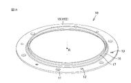
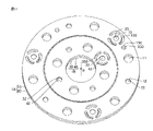
図1は、本開示の一実施の形態(実施の形態1)における転がり軸受の構造を示す概略斜視図である。図2A、図2Bは実施の形態1における転がり軸受を構成する外輪の概略斜視図である。図3A、図3Bは実施の形態1における転がり軸受を構成する内輪の概略斜視図である。図4は、実施の形態1における転がり軸受から、外輪および内輪の一部を取り除いて示す概略斜視図である。図1におけるZ軸方向は、転がり軸受の中心軸Rが延びる方向である第1軸方向に沿った方向である。Z軸方向は、転がり軸受の厚み方向である。これに対して、図1におけるXY平面は、転がり軸受の径方向の平面である。
(Embodiment 1)
FIG. 1 is a schematic perspective view showing the structure of a rolling bearing according to one embodiment (Embodiment 1) of the present disclosure. 2A and 2B are schematic perspective views of an outer ring that constitutes the rolling bearing according to
図1~図4を参照して、実施の形態1における転がり軸受1は、外輪1Aと、内輪1Bと、複数の転動体としてのころ1Cと、を備える。外輪1Aと内輪1Bとは、共通する中心軸Rを有する。外輪1Aおよび内輪1Bは、鋼製である。内輪1Bは、外輪1Aの内周側に配置される。実施の形態1において、外輪1Aおよび内輪1Bは、所定の形状に加工された鋼板からなる。実施の形態1において、外輪1Aおよび内輪1Bを構成する鋼は、例えば、JIS規格に規定されるSCM415である。
1 to 4, a rolling
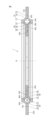
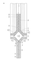
図5は、転がり軸受1を図1中のA-Aで切断した場合の断面図である。図5は、第1ころ51(図4)の断面を含む断面図である。図6は、図5の第1ころ51の周辺を拡大して示す断面図である。
FIG. 5 is a cross-sectional view of the rolling
図1を参照して、外輪1Aは、円環状の第1外輪10と、円環状の第2外輪20と、を含む。実施の形態1において、第1外輪10および第2外輪20は、互いに同一の形状を有する。図2Aおよび図2Bは、第1外輪10を異なる角度で見る斜視図である。図2A、図2Bおよび図5を参照して、第1外輪10は、第1部分15と、第2部分16と、第3部分17と、を含む。実施の形態1において、第1部分15、第2部分16および第3部分17は、同一の厚みを有する。第1部分15は、円盤環状の形状を有する。第1部分15は、転がり軸受1の中心軸Rと共通の中心軸を有する。第2部分16は、筒状の形状を有する。第2部分16の外形形状は、円錐台状である。第2部分16は、第1部分15の内縁からZ軸方向において第1部分15から離れるにしたがって内径が小さくなるように延びる。第2部分16は、円環状の内周面16Aを有する。内周面16Aは、転がり軸受1の中心軸Rと共通の中心軸を有する。第3部分17は、円筒状の形状を有する。第3部分17は、転がり軸受1の中心軸Rと共通の中心軸を有する。第3部分17は、第2部分16のZ軸方向における第1部分15とは反対側の端部に接続され、Z軸方向に沿って延びる。
Referring to FIG. 1 , the
図5、図6を参照して、内周面16Aは、第1領域としての円環状の第1の面161と、第2領域としての円環状の第2の面162と、第3領域としての円環状の第3の面163と、を含む。実施の形態1においては、第1の面161、第2の面162および第3の面163は、転がり軸受1の中心軸Rと共通の中心軸を有する。第1の面161は、第1部分15の第4部分25と接触する側の面15Aと、第2の面162とを接続する。実施の形態1では、中心軸Rを含む断面において、第1の面161は、曲線状の形状を有する。中心軸Rを含む断面において、第2の面162は、平坦な形状を有する。第3の面163は、第2の面162と第3部分17の内周面17Aとを接続する。実施の形態1では、中心軸Rを含む断面において、第3の面163は、曲線状の形状を有する。
5 and 6, the inner
図2A、図2Bおよび図4を参照して、第1部分15には、厚み方向(中心軸Rの方向)に貫通した取り付け用孔11が周方向において等間隔に複数(実施の形態1においては6つ)形成されている。第1部分15には、隣り合う取り付け用孔11の間に、周方向に並べて、突出部13および貫通孔12のいずれか一方が交互に形成されている。なお、転がり軸受1の相手部材への固定は、例えば、取り付け用孔11にボルトを挿入し、相手部材のねじ孔にボルトをねじ込んで固定することができる。
2A, 2B and 4,
実施の形態1において、突出部13は、第1部分15の周方向に等間隔に3つ形成されている。突出部13は、第1部分15の面15Aに形成されている。突出部13は、面15Aから厚み方向に突出する円柱状の突出部である。突出部13は、面15Aから立ち上がる円筒状の側面13Aと、円筒の端面を規定する円形の端面13Cとによって規定される。なお、実施の形態1では、3つの突出部13が形成されているが、突出部の数は制限されず、例えば2~16箇所程度とすることができる。
In
実施の形態1において、貫通孔12は、第1部分15の周方向に等間隔に3つ形成されている。貫通孔12は、第1部分15の面15Aから面15Bへと第1部分15の厚み方向に貫通する、貫通孔である。貫通孔12は、面15Aと面15Bとを接続するよう延在する、円筒状の内周壁12Aによって規定される。貫通孔12は、突出部13に対応する形状である。すなわち、突出部13および貫通孔12の直径は一致する。(本明細書において、一致するとは、数学的に同一の値であることのみを意味するのではなく、互いに嵌合可能である程度に異なる直径を有する場合も含む。)なお、実施の形態1では、3つの貫通孔12が形成されているが、貫通孔の数は制限されず、例えば2~16箇所程度とすることができる。面15Aにおいて、貫通孔12の周囲に、貫通孔12を包囲する環状の凹部101が形成されている。面15Aにおいて、貫通孔12と第2部分16との間に、貫通孔12を囲い、第1外輪10の外周側に開口する両端を有する溝102が形成されている。すなわち、溝102は、貫通孔12と第2部分16との間を区画している。
In
図1、図5および図6を参照して、第2外輪20は、Z軸方向において第1外輪10に並べて配置されると共に、第1外輪10に対して固定される。第2外輪20は、第4部分25と、第5部分26と、第6部分27と、を含む。実施の形態1において、第4部分25、第5部分26および第6部分27は、同一の厚みを有する。実施の形態1において、第1外輪10の厚みと第2外輪20の厚みとは一致する。第4部分25は、円盤環状の形状を有する。第1外輪10の面15Aと、第2外輪20の第4部分25の一方の面25Aとは相対し、接触している。第4部分25は、転がり軸受1の中心軸Rと共通の中心軸を有する。第5部分26は、筒状の形状を有する。第5部分26の外形形状は、円錐台状である。第5部分26は、第4部分25の内縁からZ軸方向において第4部分25から離れるにしたがって内径が小さくなるように延びる。第5部分26は、Z軸方向において第2部分16とは反対側に延びる。第5部分26は、円環状の内周面26Aを有する。内周面26Aは、転がり軸受1の中心軸Rと共通の中心軸を有する。第6部分27は、円筒状の形状を有する。第6部分27は、転がり軸受1の中心軸Rと共通の中心軸を有する。第6部分27は、第5部分26のZ軸方向における第4部分25とは反対側の端部に接続され、Z軸方向に沿って第3部分17とは反対側に延びる。
1, 5 and 6, second
内周面26Aは、円環状の第4の面261と、円環状の第5の面262と、円環状の第6の面263と、を含む。第4の面261、第5の面262および第6の面263は、転がり軸受1の中心軸Rと共通の中心軸を有する。第4の面261は、第4部分25の面25Aと第5の面262とを接続する。中心軸Rを含む断面において、第4の面261は、曲線状の形状を有する。中心軸Rを含む断面において、第5の面262は、平坦な形状を有する。第6の面263は、第5の面262と第6部分27の内周面27Aとを接続する。中心軸Rを含む断面において、第6の面263は、曲線状の形状を有する。
The inner
図4を参照して、第2外輪20の第4部分25には、厚み方向(Z軸方向)に貫通した取り付け用孔21が周方向において等間隔に複数(実施の形態1においては6つ)形成されている。第4部分25には、隣り合う取り付け用孔21の間に、周方向に並べて、突出部22および貫通孔23のいずれか一方が交互に形成されている。
Referring to FIG. 4, a
実施の形態1において、突出部22は、第4部分25の周方向に等間隔に3つ形成されている。突出部22は、第4部分25の面25Aから厚み方向(Z軸方向)に突出する円柱状の突出部である。突出部22は、面25Aから立ち上がる円筒状の側面22Aと、円筒の端面を規定する円形の端面22Cとによって規定される。なお、実施の形態1では、3つの突出部22が形成されているが、突出部の数は制限されず、例えば2~16箇所程度とすることができる。
In
実施の形態1において、第2外輪20の貫通孔23は、第2部分25の周方向に等間隔に3つ形成されている。貫通孔23は、面25Aから面25Bへと、第2部分25の厚み方向に貫通する、貫通孔である。貫通孔23は、面25Aと面25Bとを接続するよう延在する円筒状の内周壁23Aによって規定される。貫通孔23は、突出部22に対応する形状である。すなわち、突出部13および貫通孔12の直径は一致する。なお、実施の形態1では、3つの貫通孔23が形成されているが、貫通孔の数は制限されず、例えば2~16箇所程度とすることができる。面25Aにおいて、貫通孔23の周囲には、貫通孔23を包囲する環状の凹部201が形成されている。また面25Aにおいて、貫通孔23と第5部分26との間に、貫通孔23を囲い、第2外輪20の外周側に開口する両端を有する溝202が形成されている。すなわち、溝202は、貫通孔23と第5部分26との間を区画している。
In
図5、図6を参照して、第1外輪10と第2外輪20とは、第1外輪10における第1部分15の面15Aおよび第2外輪20における第4部分25の一方の面25Aにおいて相対し、互いに固定されている。具体的に、第1部分15の貫通孔12と第2部分25の突出部22とが嵌合され、また、第1部分15の突出部13と第4部分25の貫通孔23とが嵌合されている。さらに、貫通孔12と突出部22、突出部13と貫通孔23の嵌合部はそれぞれ、接着剤によって接着されている。具体的に示すと、貫通孔12、23の内周壁12A,23Aと、突出部13、22の側面13A、22Aとの間に、接着剤の層100が形成されている。
Referring to FIGS. 5 and 6, first
実施の形態1において、接着剤の層100は、突出部13、22と貫通孔12、23との嵌合部の周囲である、面15Aと面25Aとの相対面に延在している。層100は、貫通孔12、23を包囲する溝101、201に至っている。すなわち、溝101、201は層100を構成する接着剤(固形樹脂)で充填されている。なお、実施の形態1においては、接着剤の層100が面15Aと面25Aの相対面に延在しているが、別の態様として、接着剤の層は突出部と貫通孔との嵌合部、すなわち、貫通孔の内周壁と突出部の側面との間のみに存在する態様としてもよい。接着剤の層が嵌合部から相対面にわたって延在する場合、転がり軸受の軸方向および面方向の2方向において接着されることによって、第1外輪と第2外輪を固定する接着強度が、より向上する。
In
図1を参照して、内輪1Bは、円環状の第1内輪30と、円環状の第2内輪40と、を含む。実施の形態1においては、第1内輪30および第2内輪40は同一の形状を有する。図3Aおよび図3Bは、第1内輪30を異なる角度で見る斜視図である。
Referring to FIG. 1 , the
図3A、図3B、図5および図6を参照して、第1内輪30は、第7部分35と、第8部分36と、第9部分37と、を含む。実施の形態1において、第7部分35、第8部分36および第9部分37は、同一の厚みを有する。実施の形態1において、第1外輪10の厚みと第1内輪30の厚みとは一致する。第7部分35は、円盤環状の形状を有する。第7部分35は、転がり軸受1の中心軸Rと共通の中心軸を有する。第8部分36は、筒状の形状を有する。第8部分36の外形形状は、円錐台状である。第8部分36は、第7部分35の外縁からZ軸方向において第7部分35から離れるにしたがって外径が大きくなるように延びる。第8部分36は、円環状の外周面36Aを有する。外周面36Aは、転がり軸受1の中心軸Rと共通の中心軸を有する。第9部分37は、円筒状の形状を有する。第9部分37は、転がり軸受1の中心軸Rと共通の中心軸を有する。第9部分37は、第8部分36のZ軸方向における第7部分35とは反対側の端部に接続され、Z軸方向に沿って延びる。
3A, 3B, 5 and 6, the first
図6を参照して、外周面36Aは、円環状の第7の面361と、円環状の第8の面362と、円環状の第9の面363と、を含む。第7の面361、第8の面362および第9の面363は、転がり軸受1の中心軸Rと共通の中心軸を有する。第7の面361は、第7部分35の第10部分45と接触する側の面35Aと、第8の面362とを接続する。中心軸Rを含む断面において、第7の面361は、曲線状の形状を有する。中心軸Rを含む断面において、第8の面362は、平坦な形状を有する。第8の面362は、第5の面262に対向する。実施の形態1においては、中心軸Rを含む断面における第8の面362と第5の面262とは平行に配置される。第9の面363は、第8の面362と第9部分37の外周面37Aとを接続する。中心軸Rを含む断面において、第9の面363は、曲線状の形状を有する。
Referring to FIG. 6 , the outer
図3A、図3Bおよび図5を参照して、第7部分35には、厚み方向(Z軸方向)に貫通した取り付け用孔31が周方向において等間隔に複数(本実施の形態においては6つ)形成されている。第7部分35には、周方向において隣り合う取り付け用孔31の間に、周方向に並べて、突出部33および貫通孔32のいずれか一方が交互に形成されている。
3A, 3B and 5, the
実施の形態1において、突出部33は、第7部分35の周方向に等間隔に3つ形成されている。突出部33は、第7部分35の面35Aから厚み方向に突出する円柱状の突出部である。突出部33は、面35Aから立ち上がる円筒状の側面33Aと、円筒の端面を規定する円形の端面33Cとによって規定される。なお、実施の形態1では、3つの突出部33が形成されているが、突出部の数は制限されず、例えば2~16箇所程度とすることができる。
In
実施の形態1において、貫通孔32は、第7部分35の周方向に等間隔に3つ形成されている。貫通孔32は、第7部分35の面35Aから面35Bへと厚み方向に貫通する、貫通孔である。貫通孔32は、面35Aと面35Bとを接続するよう延在する円筒状の側面32Aによって規定される。貫通孔32は、突出部33に対応する形状である。すなわち、貫通孔32と突出部33の直径は一致する。なお、実施の形態1では、3つの貫通孔32が形成されているが、貫通孔の数は制限されず、例えば2~16箇所程度とすることができる。面35Aにおいて、貫通孔32の周囲には、貫通孔32を包囲する環状の凹部301が形成されている。また、面35Aにおいて、貫通孔32と第8部分36との間に、貫通孔32を囲い、第1内輪30の内周側に開口する両端を有する溝302が形成されている。溝302は、貫通孔32と第8部分36とを区画している。
In
図4、図5および図6を参照して、第2内輪40は、Z軸方向において第1内輪30に並べて配置されると共に、第1内輪30に対して固定される。第2内輪40は、第10部分45と、第11部分46と、第12部分47と、を含む。実施の形態1において、第10部分45、第11部分46および第12部分47は、同一の厚みを有する。実施の形態1において、第2内輪40の厚みと第1外輪10の厚みは一致する。第10部分45は、円盤環状の形状を有する。第1内輪30の面35Aと、第2内輪40の第10部分の一方の面45Aとは相対し、接触する。第10部分45は、転がり軸受1の中心軸Rと共通の中心軸を有する。第11部分46は、筒状の形状を有する。第11部分46の外形形状は、円錐台状である。第11部分46は、第10部分45の外縁からZ軸方向において第10部分45から離れるにしたがって外径が大きくなるように延びる。第11部分46は、Z軸方向において第8部分36とは反対側に延びる。第11部分46は、円環状の外周面46Aを有する。外周面46Aは、転がり軸受1の中心軸Rと共通の中心軸を有する。第12部分47は、円筒状の形状を有する。第12部分47は、転がり軸受1の中心軸Rと共通の中心軸を有する。第12部分47は、第11部分46のZ軸方向における第10部分45とは反対側の端部に接続され、Z軸方向に沿って第9部分37とは反対側に延びる。
4, 5 and 6, the second
外周面46Aは、円環状の第10の面461と、円環状の第11の面462と、円環状の第12の面463と、を含む。第10の面461、第11の面462および第12の面463は、転がり軸受1の中心軸Rと共通の中心軸を有する。第10の面461は、第10部分45の第7部分35と接触する側の面45Aと第11の面462とを接続する。中心軸Rを含む断面において、第10の面461は、曲線状の形状を有する。中心軸Rを含む断面において、第11の面462は平坦な形状を有する。第11の面462は、第2の面162に対向する。実施の形態1においては、中心軸Rを含む断面における第11の面462と第2の面162とは平行に配置される。中心軸Rを含む断面において、第2の面162と第11の面462とをつなぐ線分は、第5の面262と第8の面362とをつなぐ線分に交差する(直交する)。第12の面463は、第11の面462と第12部分47の外周面47Aとを接続する。中心軸Rを含む断面において、第12の面463は、曲線状の形状を有する。
The outer
図4を参照して、第10部分45には、厚み方向(Z軸方向)に貫通した取り付け用孔41が周方向において等間隔に複数(本実施の形態においては6つ)形成されている。第10部分45には、周方向において隣り合う取り付け用孔41の間に、周方向に並べて、突出部42および貫通孔43のいずれか一方が交互に形成されている。
Referring to FIG. 4, the
実施の形態1において、突出部42は、第10部分45の周方向に等間隔に3つ形成されている。突出部42は、第10部分45の面45Aから厚み方向に突出する円柱状の突出部である。突出部42は、面45Aから立ち上がる円筒状の側面42Aと、円筒の端面を規定する円形の端面42Cとによって規定される。なお、実施の形態1では、3つの突出部42が形成されているが、突出部の数は制限されず、例えば2~16箇所程度とすることができる。
In
実施の形態1において、貫通孔43は、第10部分45の周方向に等間隔に3つ形成されている。貫通孔43は、第10部分45の面45Aから面45Bへと厚み方向に貫通する、貫通孔である。貫通孔43は、面45Aと面45Bとを接続するよう延在する円筒状の側面43Aによって規定される。貫通孔43は、突出部42に対応する形状である。すなわち、貫通孔43の直径と突出部42の直径は一致する。なお、実施の形態1では、3つの貫通孔43が形成されているが、貫通孔の数は制限されず、例えば2~16箇所程度とすることができる。面45Aにおいて、貫通孔43の周囲には、貫通孔43を包囲する環状の凹部401が形成されている。また面45Aにおいて、貫通孔43と第11部分46との間に、貫通孔43を囲い、第2内輪40の内周側に開口する両端を有する溝402が形成されている。溝402は、貫通孔43と第11部分46とを区画している。
In
第1内輪30と第2内輪40とは、第1内輪30における第7部分35の面35Aおよび第2内輪40における第10部分45の一方の面45Aにおいて相対し、互いに固定されている。具体的に、第7部分35の貫通孔32と第10部分45の突出部42とが嵌合され、また、第7部分35の突出部33と第10部分45の貫通孔43とが嵌合されている。さらに、貫通孔32と突出部42、突出部33と貫通孔43の嵌合部はそれぞれ、接着剤によって接着されている。より具体的に示すと、貫通孔32、43の内周壁32A,43Aと、突出部33、42の側面33A、42Aとの間に、接着剤からなる層200が形成されている。
The first
実施の形態1において、接着剤からなる層200は、突出部33、42と貫通孔32、43との嵌合部の周囲、すなわち面35Aと45Aの相対面に延在している。また層200は貫通孔32、43を包囲する溝301、401に至っている。溝301、401は層200を構成する接着剤で充填されている。なお、実施の形態1においては、接着剤の層200が面35Aと面45Aの相対面に延在しているが、別の態様として、接着剤の層は突出部と貫通孔との嵌合部、すなわち、貫通孔の内周壁と突出部の側面との間のみに存在する態様としてもよい。接着剤の層が嵌合部から相対面にわたって延在する場合には、転がり軸受の軸方向および面方向の2方向において接着されることによって、第1内輪30と第2内輪40とを固定する接着強度がより向上する。
In
図7は、転がり軸受1を図1中のA-Aで切断した場合の断面における鍛流線を示す図である。図6、図7を参照して、第1外輪10において、第1部分15の面15A、第2部分16の内周面16Aおよび第3部分17の内周面17Aに沿って、第1外輪10を構成する鋼の鍛流線111が延びる。内周面16Aの第1の面161、第2の面162および第3の面163に沿って、鍛流線111が延びる。実施の形態1においては、鍛流線111は第2の面162と平行に延びる。同様に、第2外輪20において、第4部分25の面25A、第5部分26の内周面26Aおよび第6部分27の内周面27Aに沿って、第2外輪20を構成する鋼の鍛流線211が延びる。内周面26Aの第4の面261、第5の面262および第6の面263に沿って、鍛流線211が延びる。実施の形態1においては、鍛流線211は第5の面262と平行に延びる。また同様に、第1内輪30において、第7部分35の面35A、第8部分36の外周面36Aおよび第9部分37の外周面37Aに沿って、第1内輪30を構成する鋼の鍛流線311が延びる。外周面36Aの第7の面361、第8の面362および第9の面363に沿って、鍛流線311が延びる。実施の形態1においては、鍛流線311は第8の面362と平行に延びる。また同様に、第2内輪40において、第10部分45の面45A、第11部分46の外周面46Aおよび第12部分47の外周面47Aに沿って、第2内輪40を構成する鋼の鍛流線411が延びる。外周面46Aの第10の面461、第11の面462および第12の面463に沿って、鍛流線411が延びる。本実施の形態においては、鍛流線411は第11の面462と平行に延びる。
FIG. 7 is a diagram showing grain flow lines in a cross section of the rolling
鍛流線111,211,311,411はそれぞれ、第3の面163、第6の面263、第9の面363および第12の面463に沿って連続して形成される。このような構成を採用することで、第1外輪10、第2外輪20、第1内輪30および第2内輪40を他の部材に対して取り付ける際の第1外輪10、第2外輪20、第1内輪30および第2内輪40の剛性の低下を抑制できる。
The grain flows 111, 211, 311, 411 are formed continuously along the
図4を参照して、複数のころ1Cは、複数の第1ころ51と、複数の第2ころ52と、を含む。実施の形態1において、第1ころ51および第2ころ52は、鋼製である。本実施の形態において、第1ころ51および第2ころ52は、例えば、JIS規格に規定されるSUJ2である。実施の形態1においては、ころ1Cは、27個の第1ころ51と、27個の第2ころ52を含む。第1ころ51および第2ころ52は、円筒状の形状を有する。第1ころ51は、円筒状の外周面51Aと、外周面51Aの両端に円形の端面51B、51Cとを有する。第2ころ52は、円筒状の外周面52Aと、外周面52Aの両端に円形の端面52B、52Cとを有する。第1ころ51および第2ころ52は、周方向において交互に配置される。
Referring to FIG. 4 ,
図6を参照して、第1ころ51は、第1外輪10の第2部分16の円環状の内周面16Aにおける第2の面162に、外周面51Aにおいて接触しつつ転動可能に配置される。第1外輪10の第2の面162は、第1転走面511を構成する。また、第1ころ51は、第2内輪40の第11部分46の円環状の外周面46Aにおける第11の面462に、外周面51Aにおいて接触しつつ転動可能に配置される。第2内輪の第11の面462は、第4転走面514を構成する。第1転走面511および第4転走面514は、転がり軸受1の中心軸Rと共通の中心軸を有する。第1ころ51の軸方向における一方の端面51Bと、第1内輪30の第8の面362とは対向する。また、第1ころ51の軸方向における他方の端面51Cと、第2外輪の第5の面262とは接触する。本実施の形態において、第1の面161、第4の面261および第1ころ51によって取り囲まれた環状の空間M1が形成されている。
Referring to FIG. 6, the
また、鋼の鍛流線111,211,311,411が、第1の面161、第4の面261、第7の面361および第10の面461に沿って連続して形成されている。このような構成を採用することで、第1ころ51および第2ころ52によって第1転走面511、第2転走面512、第3転走面513および第4転走面514に負荷を受けた際の第1外輪10、第2外輪20、第1内輪30および第2内輪40の曲げ強度を向上させることができる。
Further, grain flows 111 , 211 , 311 , 411 of steel are continuously formed along the
実施の形態1における転がり軸受1において、中心軸Rを含む断面において、第1外輪10、第2外輪20、第1内輪30および第2内輪40を構成する鋼の鍛流線は、それぞれ第1転走面511、第2転走面512、第3転走面513および第4転走面514に沿って延びる。すなわち、第1転走面511、第2転走面512、第3転走面513および第4転走面514における各鍛流線は、切れ目なく連続して形成されている。その結果、第1ころ51および第2ころ52が鋼の鍛流線の端部に接触することを抑制することができる。この構成によって、内輪1Bおよび外輪1Aの耐久性を向上させることができる。このように実施の形態1における転がり軸受1は、耐久性が向上している。
In the rolling
図8は、転がり軸受1を図1中のB-Bで切断した場合の断面図である。図8は、第2ころ52の断面を含む断面である。図9は、図8の第2ころの周辺を拡大して示す断面図である。図8および図9を参照して、第2ころ52は、第2外輪20の第5の面262および第1内輪30の第8の面362に、外周面52Aにおいて接触しつつ転動可能に配置される。第2外輪20の第5の面262は、第2転走面512を構成する。第1内輪40の第8の面362は、第3転走面513を構成する。第2転走面512および第3転走面513は、転がり軸受1の中心軸Rと共通の中心軸を有する。第2ころ52の軸方向における一方の端面52Bと、第1外輪10の第2の面162とは接触する。第2ころ52の軸方向における他方の端面52Cと、第2内輪20の第11の面462とは対向する。実施の形態1においては、第1の面161、第4の面261および第2ころ52によって取り囲まれた環状の空間M1が形成されている(図9参照)。図6および図9を参照して、第1ころ51の中心軸と、第2ころ52の中心軸とは交差する(直交する)。ここで、第1ころ51の中心軸と第2ころ52の中心軸とが交差する状態とは、転がり軸受1の回転時において、第1ころ51および第2ころ52の重心が所定の点を通るとき、第1ころ51の中心軸と、第2ころ52の中心軸とが交差する(直交する)ことを意味する。第1転走面511、第2転走面512、第3転走面513および第4転走面514によって、第1ころ51および第2ころ52が転動可能である、転がり軸受1の軌道路が規定される。そして、軌道路と嵌合部との間に溝102、202、302、402が形成されている。
FIG. 8 is a cross-sectional view of the rolling
次に、実施の形態1における転がり軸受1の製造方法について説明する。まず、平板状の形状を有する第1鋼板、第2鋼板、第3鋼板および第4鋼板が準備される。次に、第1鋼板、第2鋼板、第3鋼板および第4鋼板に対して、それぞれプレス加工が実施される。このようにして、図2A、Bおよび図3A、Bに示す形状を有する第1外輪10、第2外輪20、第1内輪30および第2内輪40が形成される。
Next, a method for manufacturing the rolling
次に、図5を参照して、第2部分16の内周面16A、第5部分26の内周面26A、第8部分36の内周面36Aおよび第11部分46の内周面46Aに対して公知の熱処理が実施される。より具体的には、浸炭や浸炭窒化処理、および焼入れ焼戻し等が実施される。熱処理を実施することで、内周面16A,26A,36A,46Aの硬度を向上させることができる。実施の形態1においては、内周面16A,26A,36A,46Aに対して研削加工は実施されない。次に、第1内輪30に対して第2内輪40が取り付けられ、内輪1Bが形成される。より具体的には、突出部33、42および貫通孔43、43の周囲に接着剤が塗布された後、突出部33が貫通孔43に嵌め込まれると共に、突出部42が貫通孔32に嵌め込まれる。このようにして形成された内輪1Bと、第2外輪20とが治具に取り付けられる。この際に、第12部分47の外周面47Aと、第6部分27の内周面27Aとが対向するように取り付けられる(図5参照)。次に、内輪1Bと、第2外輪20とによって取り囲まれた空間に、第1ころ51と第2ころ52とが交互に配置される。次に、第2外輪20に対して第1外輪10が取り付けられ、外輪1Aが形成される。より具体的には、突出部13、22および貫通孔23、23の周囲に接着剤が塗布された後、突出部13が貫通孔23に嵌め込まれると共に、突出部22が貫通孔12に嵌め込まれる。
Next, referring to FIG. 5, the inner
第1外輪10と第2外輪20、第1内輪30と第2内輪40をそれぞれ接着するための接着剤としては、公知の接着剤を用いることができる。例えば、嫌気性接着剤、エポキシ接着剤等の樹脂系接着剤を用いることができるが、これらに制限されるものではない。
As the adhesive for bonding the first
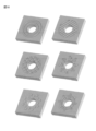
(変形例1)
実施の形態1における転がり軸受1の変形例について説明する。実施の態様1において、貫通孔12、23、32、43の周囲に貫通孔を包囲する環状の凹部101、201、301、401が形成されていたが、凹部の形状はこれに制限されない。図10は、貫通孔の周囲に形成される凹部の形状の別の例を示す。図10に示されるとおり、凹部の形状は、多重環状でもよく、互いに平行に一方向に延在する複数の直線状溝であってもよい。また、凹部の形状は、複数の直線溝が互いに交差する格子状の溝であってもよく、くさび型の溝が貫通孔の周囲に周方向に並行して配置されてもよい。また、凹部は、ドット状の複数の凹部が分散的に配置される態様であってもよく、環状溝と放射状に延在する直線溝とが組み合わされる態様であってもよい。さらに、貫通孔の周囲を粗面化してもよい。貫通孔の周囲に凹部を設けること、あるいは粗面化することによって、接着面積を増大させ、接着強度をより向上できる。また、凹部ないし粗面によって接着剤を保持することができ、意図しない部分に接着剤が流延することを抑止できる。
(Modification 1)
A modification of the rolling
(変形例2)
実施の態様1において、貫通孔の周囲に凹部および溝が形成されているが、貫通孔の周囲に代えて、突出部の周囲に凹部および溝を形成することもできる。また、貫通孔の周囲に加えて、突出部の周囲に凹部および溝を形成することもできる。突出部の周囲は貫通孔の周囲よりも剛性が高い。そのため、凹部や溝を形成することによって剛性が損なわれるおそれが低い。このことから、突出部の周囲に凹部や溝を設けることが好ましい場合もある。
(Modification 2)
In
(変形例3)
実施の形態1では、転動体として鋼製の第1ころ51および第2ころ52を採用する場合について説明したが、これに限られず、セラミック(例えばアルミナや窒化珪素)製や樹脂製の第1ころ51および第2ころ52を採用してもよい。上記のようなころを採用することで転がり軸受1の軽量化を達成できる。また、実施の形態1では、第1ころ51および第2ころ52が互いに隣接して配置されているが、第1ころと第2ころとの間にセパレータを配置することもできる。
(Modification 3)
In
(実施の態様2)
次に、本開示にかかる転がり軸受の実施の形態2について説明する。実施の形態2における転がり軸受1は、基本的に実施の形態1の転がり軸受と同様の構造を有し、同様の効果を有する。しかしながら、実施の形態2においては、外輪1Aおよび内輪1Bが扁平に形成されている点、転動体が玉である点、スリットおよびピン孔が形成されている点において実施の形態1と異なる。以下、実施の形態1と異なる点を中心に説明する。
(Embodiment 2)
Next, Embodiment 2 of the rolling bearing according to the present disclosure will be described. A rolling
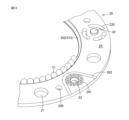
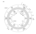
図11は、実施の形態2における転がり軸受1の斜視図である。図12は、実施の形態2における転がり軸受1から、第1外輪10および第1内輪30の取り除いて示す斜視図である。図13は、実施の形態2における第2外輪20および転動体1Cの一部を拡大し、転動体1Cの一部を取り除いて示す斜視図である。
FIG. 11 is a perspective view of rolling
図11を参照して、実施の形態2における外輪1Aは、中心軸Rの方向に突出する部分を有さず、扁平に形成されている。第1外輪10の貫通孔12と第2外輪20の突出部22とが嵌合され、かつ、第1外輪10の突出部13と第2外輪20の貫通孔23とが嵌合されている。これらの嵌合部は、接着されている。さらに、突出部13の周囲には、第1外輪10を厚み方向に貫通するスリット130が形成されている。スリット130は、突出部13と同心の仮想円の円弧の一部に沿う弧状のスリットである。突出部13の周囲に、3つのスリット130が配置されている。
Referring to FIG. 11,
実施の形態2における内輪1Bは、中心軸Rの方向に突出する部分を有さず、扁平に形成されている。第1内輪30の貫通孔32と第2内輪40の突出部42とが嵌合され、かつ、第1内輪30の突出部33と第2内輪40の貫通孔43とが嵌合されている。これらの嵌合部は、接着されている。さらに、突出部33の周囲には、第1内輪30を厚み方向に貫通するスリット330が形成されている。スリット330は、突出部33と同心の仮想円の円弧の一部に沿う弧状のスリットである。突出部33の周囲に、3つのスリット330が配置されている。
The
図11、図12を参照して、第2外輪20は第1外輪10と同一の形状であり、第2内輪40は第1内輪30と同一の形状であり、共通する説明を省略する。第2外輪20において、貫通孔23の周囲には格子状の凹部201が形成されている。また、凹部201に隣接して溝202が形成されている。同様に、第2外輪40において、貫通孔43の周囲に、格子状の凹部401が形成されている。格子状の凹部201、401に接着剤が侵入することによって、接着面積を増大させ、外輪同士、内輪同士をそれぞれ確実に接着できる。また、凹部401に隣接して溝402が形成されている。凹部201、401と溝202、402がそれぞれ隣接することによって、過剰量の接着剤が塗布された場合であっても、接着剤が転走面に侵入することなく、転がり軸受の外部に排出されうる。
11 and 12, the second
実施の形態2においては、スリット130、230、330、430が設けられていることによって、嵌合されるべき突出部と貫通孔との間で若干の位置ずれがある場合でも、位置ずれから生じる内輪や外輪の変形を吸収できる。具体的に、突出部と貫通孔に位置ずれがあるにも関わらず両者を嵌合させると、内輪や外輪に歪みが生じる場合がある。このような場合、スリットが存在すると、周囲と比較して剛性の低いスリット部分において変形が生じる。スリット部分が変形することによって、スリット以外の部分、特に転走面に変形が生じることを防止できる。
In the second embodiment, since the
実施の形態2においては、取付け孔11、21、31、41に加えて、厚み方向に貫通する小貫通孔150、250が形成されている。小貫通孔150、250には、転がり軸受1を相手部材に取り付ける際の位置決めに用いるためのピン(不図示)を挿入できる。実施の形態2は外輪1Aおよび内輪1Bが扁平であるため、外輪1Aや内輪1Bの突出部分を位置決めの基準として用いることができない。そこで、小貫通孔150、250を設け、小貫通孔150、250に位置決めピンを挿入することによって、位置決めを行うことができる。かかる構成によれば、突出部が無いため厚みがより薄く、かつ確実に位置決めできる、転がり軸受1を得られる。
In the second embodiment, in addition to mounting
(変形例4)
図14は、実施の形態1にかかる転がり軸受1の変形例である。図14では、転がり軸受1から、第1外輪および第1内輪を取りはずした状態を示している。第2外輪20における突出部22の周囲に、スリット230が設けられている。同様に、第2内輪40における突出部42の周囲に、スリット430が設けられている。図14の変形例によれば、薄い転がり軸受であっても第1外輪および第2外輪、第1内輪および第2内輪が確実に固定されるとともに、突出部と貫通孔の間に位置ずれがあっても、内輪や外輪の全体に影響が及ぶことなく、真円度等の精度の高い転走面を有する転がり軸受が得られる。
(Modification 4)
FIG. 14 shows a modification of the rolling
今回開示された実施の形態はすべての点で例示であって、どのような面からも制限的なものではないと理解されるべきである。本発明の範囲は上記した説明ではなく、請求の範囲によって規定され、請求の範囲と均等の意味および範囲内でのすべての変更が含まれることが意図される。 It should be understood that the embodiments disclosed this time are illustrative in all respects and are not restrictive in any aspect. The scope of the present invention is defined by the scope of the claims rather than the above description, and is intended to include all changes within the meaning and scope of equivalence to the scope of the claims.
1 転がり軸受、1A 外輪、1B 内輪、1C ころ、10 第1外輪、11,21,31,41 取り付け用孔、12,23,32,43,54A 貫通孔、13,22,33,42 突出部、15 第1部分、15A,18A,25A,28A,35A,38A,45A,48A 面、16 第2部分、16A,17A,26A,27A,36A,36B,37B,46A,46B,47B 内周面、16B,17B,26B,27B,36A,37A,46A,47A,51A,51B,52A,52B,55A 外周面、17 第3部分、17C,27B,37C,47B,51B,51C,52B,52C 端面、20 第2外輪、25 第4部分、26 第5部分、27 第6部分、30 第1内輪、35 第7部分、36 第8部分、37 第9部分、40 第2内輪、45 第10部分、46 第11部分、47 第12部分、51 第1ころ、52 第2ころ、100、200 層、101、201、301、401 凹部、102、202、302、402 溝、130、230、330、430 スリット、111,211,311,411 鍛流線、150、250 小貫通孔、161 第1の面、162 第2の面、163 第3の面、261 第4の面、262 第5の面、263 第6の面、361 第7の面、362 第8の面、363 第9の面、461 第10の面、462 第11の面、463 第12の面、511 第1転走面、512 第2転走面、513 第3転走面、514 第4転走面。 1 Rolling Bearing 1A Outer Ring 1B Inner Ring 1C Roller 10 First Outer Ring 11, 21, 31, 41 Mounting Hole 12, 23, 32, 43, 54A Through Hole 13, 22, 33, 42 Projection , 15 first portion, 15A, 18A, 25A, 28A, 35A, 38A, 45A, 48A surface, 16 second portion, 16A, 17A, 26A, 27A, 36A, 36B, 37B, 46A, 46B, 47B inner peripheral surface , 16B, 17B, 26B, 27B, 36A, 37A, 46A, 47A, 51A, 51B, 52A, 52B, 55A outer peripheral surface, 17 third portion, 17C, 27B, 37C, 47B, 51B, 51C, 52B, 52C end surface , 20 second outer ring, 25 fourth portion, 26 fifth portion, 27 sixth portion, 30 first inner ring, 35 seventh portion, 36 eighth portion, 37 ninth portion, 40 second inner ring, 45 tenth portion , 46 eleventh portion, 47 twelfth portion, 51 first roller, 52 second roller, 100, 200 layer, 101, 201, 301, 401 recess, 102, 202, 302, 402 groove, 130, 230, 330, 430 slit 111,211,311,411 grain flow line 150,250 small through hole 161 first surface 162 second surface 163 third surface 261 fourth surface 262 fifth surface , 263 sixth surface, 361 seventh surface, 362 eighth surface, 363 ninth surface, 461 tenth surface, 462 eleventh surface, 463 twelfth surface, 511 first rolling surface, 512 second raceway surface, 513 third raceway surface, 514 fourth raceway surface.
Claims (7)
前記外輪と共通の中心軸を有し、前記外輪の内周側に配置される鋼製の内輪と、
前記外輪の内周面および前記内輪の外周面上を転動可能に配置される複数の転動体と、を備える転がり軸受であって、
前記外輪は、
第1外輪と、前記中心軸の延びる方向である第1軸方向において前記第1外輪に並べて配置されると共に前記第1外輪に対して固定される第2外輪と、を含み、
前記内輪は、
第1内輪と、前記第1軸方向において前記第1内輪に並べて配置されると共に前記第1内輪に対して固定される第2内輪と、を含み、
前記第1外輪および前記第2外輪ならびに前記第1内輪及び前記第2内輪はそれぞれ、それらの相対する部分において、一方に突出部が形成され、他方に前記突出部に対応する貫通孔が形成されており、前記突出部と前記貫通孔とが嵌合され、かつ、前記突出部と前記貫通孔とが互いに接着されており、
前記相対する部分において、前記貫通孔または前記貫通孔の周囲が粗面化されている、または、前記貫通孔または前記貫通孔の周囲に凹部が形成されている、
転がり軸受。 a steel outer ring;
a steel inner ring having a central axis common to the outer ring and arranged on the inner peripheral side of the outer ring;
A rolling bearing comprising: an inner peripheral surface of the outer ring and a plurality of rolling elements arranged to roll on the outer peripheral surface of the inner ring,
The outer ring is
a first outer ring; and a second outer ring arranged side by side with the first outer ring in a first axial direction, which is the direction in which the central axis extends, and fixed to the first outer ring,
The inner ring is
a first inner ring and a second inner ring arranged side by side with the first inner ring in the first axial direction and fixed to the first inner ring;
Each of the first outer ring and the second outer ring and the first inner ring and the second inner ring has a projecting portion formed on one side and a through hole corresponding to the projecting portion formed on the other side, respectively. wherein the protruding portion and the through hole are fitted together, and the protruding portion and the through hole are adhered to each other;
In the facing portion, the through hole or the periphery of the through hole is roughened, or a recess is formed around the through hole or the through hole.
rolling bearing.
請求項1または請求項2に記載の転がり軸受。 Further, on the facing surfaces of the first outer ring and the second outer ring and on the facing surfaces of the first inner ring and the second inner ring, the periphery of the fitting portion formed by fitting the protrusion and the through hole is bonded. ing,
A rolling bearing according to claim 1 or 2.
前記第2外輪は、前記外輪の前記内周面を構成する円環状の第2転走面を有し、
前記第1内輪は、前記第2転走面に対向すると共に前記内輪の前記外周面を構成する円環状の第3転走面を有し、
前記第2内輪は、前記第1転走面に対向すると共に前記第1転走面の中心軸を含む断面において前記第1転走面とをつなぐ線分が前記第2転走面と前記第3転走面とをつなぐ線分に交差し、前記内輪の前記外周面を構成する円環状の第4転走面を有し、
前記第1転走面、前記第2転走面、前記第3転走面および前記第4転走面は、前記転動体が転動可能である円環状の軌道路を規定しており、
前記第1外輪と前記第2外輪との相対面、および、前記第1内輪と前記第2内輪との相対面において、前記軌道路と前記突出部と前記貫通孔とが嵌合してなる嵌合部との間に溝が形成されている、
請求項1から請求項3のいずれか1項に記載の転がり軸受。 The first outer ring has an annular first raceway surface forming the inner peripheral surface of the outer ring,
The second outer ring has an annular second raceway surface forming the inner peripheral surface of the outer ring,
The first inner ring has an annular third rolling contact surface that faces the second rolling contact surface and constitutes the outer peripheral surface of the inner ring,
In the second inner ring, in a cross section facing the first raceway surface and including the central axis of the first raceway surface, a line segment connecting the first raceway surface is the second raceway surface and the second raceway surface. 3 has an annular fourth rolling surface that intersects the line segment connecting the rolling surfaces and constitutes the outer peripheral surface of the inner ring;
The first raceway surface, the second raceway surface, the third raceway surface, and the fourth raceway surface define an annular raceway on which the rolling elements can roll,
A fitting formed by fitting the raceway, the projecting portion, and the through hole on the facing surfaces of the first outer ring and the second outer ring and on the facing surfaces of the first inner ring and the second inner ring. A groove is formed between the joints,
A rolling bearing according to any one of claims 1 to 3.
Priority Applications (4)
| Application Number | Priority Date | Filing Date | Title |
|---|---|---|---|
| JP2020161340A JP7228551B2 (en) | 2020-09-25 | 2020-09-25 | rolling bearing |
| US17/904,238 US20240200602A1 (en) | 2020-09-25 | 2021-09-17 | Rolling Bearing |
| CN202180007876.7A CN114901958A (en) | 2020-09-25 | 2021-09-17 | Rolling bearing |
| PCT/JP2021/034371 WO2022065248A1 (en) | 2020-09-25 | 2021-09-17 | Roller bearing |
Applications Claiming Priority (1)
| Application Number | Priority Date | Filing Date | Title |
|---|---|---|---|
| JP2020161340A JP7228551B2 (en) | 2020-09-25 | 2020-09-25 | rolling bearing |
Publications (2)
| Publication Number | Publication Date |
|---|---|
| JP2022054259A JP2022054259A (en) | 2022-04-06 |
| JP7228551B2 true JP7228551B2 (en) | 2023-02-24 |
Family
ID=80845332
Family Applications (1)
| Application Number | Title | Priority Date | Filing Date |
|---|---|---|---|
| JP2020161340A Active JP7228551B2 (en) | 2020-09-25 | 2020-09-25 | rolling bearing |
Country Status (4)
| Country | Link |
|---|---|
| US (1) | US20240200602A1 (en) |
| JP (1) | JP7228551B2 (en) |
| CN (1) | CN114901958A (en) |
| WO (1) | WO2022065248A1 (en) |
Families Citing this family (1)
| Publication number | Priority date | Publication date | Assignee | Title |
|---|---|---|---|---|
| JP7228552B2 (en) * | 2020-09-25 | 2023-02-24 | 日本トムソン株式会社 | rolling bearing |
Citations (1)
| Publication number | Priority date | Publication date | Assignee | Title |
|---|---|---|---|---|
| JP2019178735A (en) | 2018-03-30 | 2019-10-17 | 日本トムソン株式会社 | Slewing bearing |
Family Cites Families (12)
| Publication number | Priority date | Publication date | Assignee | Title |
|---|---|---|---|---|
| JPS50112643A (en) * | 1974-02-18 | 1975-09-04 | ||
| US4362344A (en) * | 1981-08-03 | 1982-12-07 | General Motors Corporation | Sealed ball bearing with stamped races |
| JPH03213714A (en) * | 1990-01-17 | 1991-09-19 | Nippon Thompson Co Ltd | Resin-made direct-acting guide unit |
| JPH0889625A (en) * | 1994-09-28 | 1996-04-09 | Fuji Shoji Kk | Obstacle device for ball game machine |
| JPH0889624A (en) * | 1994-09-28 | 1996-04-09 | Fuji Shoji Kk | Obstacle device for ball game machine |
| JP4678479B2 (en) * | 2004-08-06 | 2011-04-27 | ミネベア株式会社 | Color wheel |
| DE102010019951A1 (en) * | 2010-05-08 | 2011-12-01 | Mahle International Gmbh | Bearing assembly and method for its manufacture |
| JP2017026027A (en) * | 2015-07-22 | 2017-02-02 | 株式会社ジェイテクト | Rolling bearing |
| JP7455540B2 (en) * | 2019-09-27 | 2024-03-26 | 日本トムソン株式会社 | rolling bearing |
| JP2021054195A (en) * | 2019-09-27 | 2021-04-08 | 日本トムソン株式会社 | Caster |
| WO2021060489A1 (en) * | 2019-09-27 | 2021-04-01 | 日本トムソン株式会社 | Rolling bearing |
| JP7228552B2 (en) * | 2020-09-25 | 2023-02-24 | 日本トムソン株式会社 | rolling bearing |
-
2020
- 2020-09-25 JP JP2020161340A patent/JP7228551B2/en active Active
-
2021
- 2021-09-17 CN CN202180007876.7A patent/CN114901958A/en active Pending
- 2021-09-17 WO PCT/JP2021/034371 patent/WO2022065248A1/en not_active Ceased
- 2021-09-17 US US17/904,238 patent/US20240200602A1/en active Pending
Patent Citations (1)
| Publication number | Priority date | Publication date | Assignee | Title |
|---|---|---|---|---|
| JP2019178735A (en) | 2018-03-30 | 2019-10-17 | 日本トムソン株式会社 | Slewing bearing |
Also Published As
| Publication number | Publication date |
|---|---|
| WO2022065248A1 (en) | 2022-03-31 |
| CN114901958A (en) | 2022-08-12 |
| US20240200602A1 (en) | 2024-06-20 |
| JP2022054259A (en) | 2022-04-06 |
Similar Documents
| Publication | Publication Date | Title |
|---|---|---|
| JP7228552B2 (en) | rolling bearing | |
| JP7491958B2 (en) | Slewing bearing | |
| JP7847987B2 (en) | Rolling bearings | |
| EP3343051B1 (en) | Slewing bearing | |
| CN105339690B (en) | Manufacturing method of wave cage and wave cage | |
| JP7228551B2 (en) | rolling bearing | |
| JP2019158135A (en) | Top-type ball screw | |
| US9273728B2 (en) | Rolling bearing having rings with stepped surfaces opposite to the raceways | |
| WO2021059962A1 (en) | Rolling bearing | |
| US7547144B2 (en) | Crossed roller bearing | |
| JP7524590B2 (en) | Rolling bearings | |
| JP6376316B1 (en) | Rolling bearing | |
| WO2016152529A1 (en) | Roller bearing | |
| JP2014156876A (en) | Cage for rolling bearing, rolling bearing, and method of manufacturing rolling bearing | |
| JP2007332997A (en) | Split type cage for roller bearing and split type roller bearing | |
| JP7739146B2 (en) | bearings | |
| JP4244114B2 (en) | Rolling bearing unit | |
| JP2009236223A (en) | Rolling bearing | |
| JP4278693B2 (en) | Rolling bearing unit | |
| WO2025177551A1 (en) | Rolling bearing | |
| JP2005114029A (en) | Split type rolling bearing | |
| JP2006144990A (en) | Rolling bearing device | |
| JP2024148460A (en) | Cross roller bearing | |
| JP2003336639A (en) | Ball bearing | |
| JP2002206529A (en) | Spherical roller bearing device |
Legal Events
| Date | Code | Title | Description |
|---|---|---|---|
| A521 | Request for written amendment filed |
Free format text: JAPANESE INTERMEDIATE CODE: A523 Effective date: 20220107 |
|
| A621 | Written request for application examination |
Free format text: JAPANESE INTERMEDIATE CODE: A621 Effective date: 20220107 |
|
| A131 | Notification of reasons for refusal |
Free format text: JAPANESE INTERMEDIATE CODE: A131 Effective date: 20221004 |
|
| A521 | Request for written amendment filed |
Free format text: JAPANESE INTERMEDIATE CODE: A523 Effective date: 20221017 |
|
| TRDD | Decision of grant or rejection written | ||
| A01 | Written decision to grant a patent or to grant a registration (utility model) |
Free format text: JAPANESE INTERMEDIATE CODE: A01 Effective date: 20230207 |
|
| A61 | First payment of annual fees (during grant procedure) |
Free format text: JAPANESE INTERMEDIATE CODE: A61 Effective date: 20230213 |
|
| R150 | Certificate of patent or registration of utility model |
Ref document number: 7228551 Country of ref document: JP Free format text: JAPANESE INTERMEDIATE CODE: R150 |
|
| R250 | Receipt of annual fees |
Free format text: JAPANESE INTERMEDIATE CODE: R250 |