JP7226928B2 - surveying equipment - Google Patents
surveying equipment Download PDFInfo
- Publication number
- JP7226928B2 JP7226928B2 JP2018104483A JP2018104483A JP7226928B2 JP 7226928 B2 JP7226928 B2 JP 7226928B2 JP 2018104483 A JP2018104483 A JP 2018104483A JP 2018104483 A JP2018104483 A JP 2018104483A JP 7226928 B2 JP7226928 B2 JP 7226928B2
- Authority
- JP
- Japan
- Prior art keywords
- unit
- gesture
- output
- surveying instrument
- input
- Prior art date
- Legal status (The legal status is an assumption and is not a legal conclusion. Google has not performed a legal analysis and makes no representation as to the accuracy of the status listed.)
- Active
Links
Images


Classifications
-
- G—PHYSICS
- G01—MEASURING; TESTING
- G01C—MEASURING DISTANCES, LEVELS OR BEARINGS; SURVEYING; NAVIGATION; GYROSCOPIC INSTRUMENTS; PHOTOGRAMMETRY OR VIDEOGRAMMETRY
- G01C15/00—Surveying instruments or accessories not provided for in groups G01C1/00 - G01C13/00
- G01C15/002—Active optical surveying means
-
- G—PHYSICS
- G01—MEASURING; TESTING
- G01S—RADIO DIRECTION-FINDING; RADIO NAVIGATION; DETERMINING DISTANCE OR VELOCITY BY USE OF RADIO WAVES; LOCATING OR PRESENCE-DETECTING BY USE OF THE REFLECTION OR RERADIATION OF RADIO WAVES; ANALOGOUS ARRANGEMENTS USING OTHER WAVES
- G01S17/00—Systems using the reflection or reradiation of electromagnetic waves other than radio waves, e.g. lidar systems
- G01S17/02—Systems using the reflection of electromagnetic waves other than radio waves
- G01S17/06—Systems determining position data of a target
- G01S17/08—Systems determining position data of a target for measuring distance only
-
- G—PHYSICS
- G06—COMPUTING; CALCULATING OR COUNTING
- G06F—ELECTRIC DIGITAL DATA PROCESSING
- G06F3/00—Input arrangements for transferring data to be processed into a form capable of being handled by the computer; Output arrangements for transferring data from processing unit to output unit, e.g. interface arrangements
- G06F3/01—Input arrangements or combined input and output arrangements for interaction between user and computer
- G06F3/017—Gesture based interaction, e.g. based on a set of recognized hand gestures
-
- G—PHYSICS
- G06—COMPUTING; CALCULATING OR COUNTING
- G06F—ELECTRIC DIGITAL DATA PROCESSING
- G06F3/00—Input arrangements for transferring data to be processed into a form capable of being handled by the computer; Output arrangements for transferring data from processing unit to output unit, e.g. interface arrangements
- G06F3/16—Sound input; Sound output
- G06F3/167—Audio in a user interface, e.g. using voice commands for navigating, audio feedback
-
- G—PHYSICS
- G06—COMPUTING; CALCULATING OR COUNTING
- G06V—IMAGE OR VIDEO RECOGNITION OR UNDERSTANDING
- G06V40/00—Recognition of biometric, human-related or animal-related patterns in image or video data
- G06V40/20—Movements or behaviour, e.g. gesture recognition
-
- G—PHYSICS
- G06—COMPUTING; CALCULATING OR COUNTING
- G06V—IMAGE OR VIDEO RECOGNITION OR UNDERSTANDING
- G06V40/00—Recognition of biometric, human-related or animal-related patterns in image or video data
- G06V40/20—Movements or behaviour, e.g. gesture recognition
- G06V40/28—Recognition of hand or arm movements, e.g. recognition of deaf sign language
-
- G—PHYSICS
- G01—MEASURING; TESTING
- G01S—RADIO DIRECTION-FINDING; RADIO NAVIGATION; DETERMINING DISTANCE OR VELOCITY BY USE OF RADIO WAVES; LOCATING OR PRESENCE-DETECTING BY USE OF THE REFLECTION OR RERADIATION OF RADIO WAVES; ANALOGOUS ARRANGEMENTS USING OTHER WAVES
- G01S17/00—Systems using the reflection or reradiation of electromagnetic waves other than radio waves, e.g. lidar systems
- G01S17/66—Tracking systems using electromagnetic waves other than radio waves
-
- G—PHYSICS
- G02—OPTICS
- G02B—OPTICAL ELEMENTS, SYSTEMS OR APPARATUS
- G02B23/00—Telescopes, e.g. binoculars; Periscopes; Instruments for viewing the inside of hollow bodies; Viewfinders; Optical aiming or sighting devices
- G02B23/16—Housings; Caps; Mountings; Supports, e.g. with counterweight
Description
本発明は、測量装置に関し、より詳細には、測量装置のユーザインタフェイスに関する。 The present invention relates to surveying instruments and, more particularly, to surveying instrument user interfaces.
従来、測量装置のユーザインタフェイスは、ディスプレイ表示とキー入力の組み合わせまたはタッチパネル入力であった。例えば特許文献1には、作業者の操作感覚と装置の動きとがマッチングする様にしたタッチパネル式の操作制御パネルを備える測量機が開示されている。 Conventionally, the user interface of a surveying instrument has been a combination of display display and key input or touch panel input. For example, Patent Literature 1 discloses a surveying instrument equipped with a touch panel type operation control panel that matches the operation feeling of the operator and the movement of the device.
このように、マンマシンインタフェイスとしての操作性が向上した操作制御パネルは種々提案されているが、ディスプレイを見ないと測量装置を操作できず、ディスプレイが小さかったり、暗かったり、表面反射したりして見づらい場合がある。 Thus, various operation control panels with improved operability as a man-machine interface have been proposed. may be difficult to see.
また、ディスプレイ、キーボードを搭載すると、機械が全体として大型化するという問題があった。また、入力の際は、測量装置に作業者が直接触れるため、測量装置が設置場所から動いて、測定角度が変わったり、測量装置が振動したりすることがあるという問題があった。このため、直接触れずに操作することができる測量装置として、ジェスチャインタフェイスを有する測量装置の開発が求められていた。 Moreover, there was a problem that the size of the machine as a whole increased when the display and keyboard were mounted. In addition, since the operator directly touches the surveying instrument when inputting data, the surveying instrument may move from its installation location, resulting in a change in measurement angle or vibration of the surveying instrument. Therefore, as a surveying device that can be operated without direct contact, development of a surveying device with a gesture interface has been demanded.
本発明は、かかる事情を鑑みてなされたものであり、ジェスチャインタフェイスを有する測量装置を提供することを目的とする。 SUMMARY OF THE INVENTION It is an object of the present invention to provide a surveying instrument having a gesture interface.
上記目的を達成するために、本発明の一つの態様に係る測量装置は、ターゲットを測量可能な測量部と画像を取得可能な撮像部と、前記測量部および前記撮像部を制御するように構成された演算制御部と、記憶部とを備える測量装置であって、前記記憶部は、入力ジェスチャである作業者の所定の動作と、測量装置へのオペレーションとを関連付けた入力識別情報を有し、前記演算制御部は、前記画像から入力ジェスチャを認識する画像認識部、および該画像認識部で認識された入力ジェスチャに対応する測量装置へのオペレーションを、入力ジェスチャの示す内容として識別する画像識別部を備えることを特徴とする。 To achieve the above object, a surveying apparatus according to one aspect of the present invention is configured to control a surveying unit capable of surveying a target, an imaging unit capable of acquiring an image, and controlling the surveying unit and the imaging unit. and a storage unit, wherein the storage unit has input identification information that associates a predetermined action of a worker, which is an input gesture, with an operation to the surveying apparatus. , the arithmetic control unit includes an image recognition unit that recognizes an input gesture from the image, and an image identification unit that identifies an operation to the surveying instrument corresponding to the input gesture recognized by the image recognition unit as content indicated by the input gesture. A part is provided.
また、本発明の別の態様に係る測量装置は、ターゲットを測量可能な測量部と前記測量部を備える望遠鏡と、前記望遠鏡を鉛直軸周りに水平回転する水平回転駆動部と、前記望遠鏡を水平軸周りに鉛直回転する鉛直回転駆動部と、前記測量部、前記水平回転駆動部および前記鉛直回転駆動部を制御する演算制御部と記憶部とを備える測量装置であって、前記記憶部は、作業者に対する出力内容と、測量装置の動作としての出力ジェスチャとを関連付けた出力変換情報を有し、前記演算制御部は、前記出力変換情報に基いて作業者に対する出力内容を出力ジェスチャに変換し、前記水平回転駆動部および前記鉛直回転駆動部を回転駆動することにより出力ジェスチャを実行するジェスチャ実行部を備えることを特徴とする。 A surveying apparatus according to another aspect of the present invention includes a surveying unit capable of surveying a target, a telescope including the surveying unit, a horizontal rotation drive unit configured to horizontally rotate the telescope about a vertical axis, and a horizontal rotation driving unit configured to rotate the telescope horizontally. A surveying instrument comprising: a vertical rotation driving unit that vertically rotates around an axis; an arithmetic control unit that controls the surveying unit, the horizontal rotation driving unit, and the vertical rotation driving unit; and a storage unit, wherein the storage unit comprises: It has output conversion information that associates the output content for the worker and the output gesture as the operation of the surveying instrument, and the arithmetic control unit converts the output content for the worker into the output gesture based on the output conversion information. and a gesture execution unit that executes an output gesture by rotationally driving the horizontal rotation driving unit and the vertical rotation driving unit.
上記態様において、前記測量部を備える望遠鏡と、前記望遠鏡を鉛直軸周りに水平回転する水平回転駆動部と、前記望遠鏡を水平軸周りに鉛直回転する鉛直回転駆動部と、前記測量部、前記水平回転駆動部および前記鉛直回転駆動部を制御する演算制御部と記憶部とを備える測量装置であって、前記記憶部は、作業者に対する出力内容と、測量装置の動作としての出力ジェスチャとを関連付けた出力変換情報を有し、前記演算制御部は、前記出力変換情報に基いて作業者に対する出力内容を出力ジェスチャに変換し、前記水平回転駆動部および前記鉛直回転駆動部を回転駆動することにより出力ジェスチャを実行するジェスチャ実行部を備えることも好ましい。 In the above aspect, a telescope including the surveying unit, a horizontal rotation driving unit that horizontally rotates the telescope about a vertical axis, a vertical rotation driving unit that vertically rotates the telescope about the horizontal axis, the surveying unit, the horizontal A surveying instrument comprising a rotation drive section, an arithmetic control section for controlling the vertical rotation drive section, and a storage section, wherein the storage section associates an output content for a worker with an output gesture as an operation of the surveying instrument. Based on the output conversion information, the arithmetic control unit converts the output content for the worker into an output gesture, and rotates the horizontal rotation drive unit and the vertical rotation drive unit. It is also preferred to have a gesture performer that performs the output gesture.
また、上記態様において、第1の照明用発光部を備え、前記ジェスチャ実行部は、前記第1の照明用発光部を制御することにより、ジェスチャを表現することも好ましい。 In the above aspect, it is also preferable that a first lighting light emitting unit is provided, and the gesture execution unit expresses a gesture by controlling the first lighting light emitting unit.
また、上記態様において、第2の照明用発光部を備え前記第2の照明用発光部は、前記測量装置自体を照明することも好ましい。 Further, in the above aspect, it is also preferable that a second illumination light emitting unit is provided, and the second illumination light emitting unit illuminates the surveying instrument itself.
また、上記態様において、第3の照明用発光部を備え、前記第3の照明用発光部は、前記入力ジェスチャを行う作業者を照明することも好ましい。 In the above aspect, it is also preferable that a third lighting light emitting unit is provided, and the third lighting light emitting unit illuminates the worker performing the input gesture.
また、上記態様において、音声入力部と、音声出力部とを備え、前記演算制御部は、前記音声入力部から入力された音声を認識する音声認識部、および作業者に対する出力内容を音声メッセージに変換し、前記音声出力部に出力する音声変換部を備えることを特徴とすることも好ましい。 Further, in the above aspect, a voice input unit and a voice output unit are provided, and the arithmetic control unit includes a voice recognition unit that recognizes voice input from the voice input unit, and outputs content to the worker as a voice message. It is also preferable to include an audio conversion unit for converting and outputting to the audio output unit.
上記構成によれば、ジェスチャインタフェイスを有する測量装置の提供が可能となる。 According to the above configuration, it is possible to provide a surveying instrument having a gesture interface.
本発明の好適な実施の形態について、図面を参照しながら説明する。以下の実施の形態において、同一の構成には同一の符号を付し、重複する説明を省略する。 Preferred embodiments of the present invention will be described with reference to the drawings. In the following embodiments, the same configurations are denoted by the same reference numerals, and overlapping descriptions are omitted.
第1の実施の形態
(測量機の構成)
図1は、本発明の第1の実施の形態にかかる測量装置TSの構成ブロック図、図2は測量装置TSの右方斜視図である。
First Embodiment (Configuration of Surveying Instrument)
FIG. 1 is a configuration block diagram of a surveying instrument TS according to the first embodiment of the present invention, and FIG. 2 is a right perspective view of the surveying instrument TS.
測量装置TSは、トータルステーションである。図2に示す通り、測量装置TSは、外観上、整準器の上に設けられた基盤部2a、基盤部2a上を水平回転する托架部2b、および托架部2bの中央で鉛直回転する望遠鏡2cを備える。望遠鏡2cは、ターゲットを視準する視準光学系を備える。
The surveying instrument TS is a total station. As shown in FIG. 2, the surveying instrument TS has, in appearance, a
また、測量装置TSは、機能的には、図1に示すように、EDM11、水平角検出器12、鉛直角検出器13、傾斜センサ14、自動視準部15、水平回転駆動部16、鉛直回転駆動部17、追尾部18、演算制御部20、記憶部30、入力部41、表示部42、第1の照明用発光部43、第2の照明用発光部44、第3の照明用発光部45および撮像部46を備える。
1, the surveying instrument TS is functionally composed of an
EDM11は、発光素子、測距光学系および受光素子を備える。EDM11は、望遠鏡2cの内部に配置され、測距光学系は、視準光学系と光学要素を共有する。EDM11は、発光素子から測距光を出射し、ターゲットからの反射光を受光素子で受光して、ターゲットを測距する。
The
水平角検出器12および鉛直角検出器13は、ロータリーエンコーダであり、後述する水平回転駆動部16および鉛直回転駆動部17でそれぞれ駆動される托架部2bおよび望遠鏡2cの回転軸周りの回転角度を検出し、視準光軸Aの水平角および鉛直角を求める。
The
EDM11、水平角検出器12、および鉛直角検出器13は、測量装置TSの要部である測量部10を形成している。
The
傾斜センサ14は、整準器に備えられ、測量機本体の傾斜を検出し水平に整準するために使用される。
The
自動視準部15は、視準光学系、視準用光源、画像センサ等から構成され、視準光を視準用光源から出射し、ターゲットからの反射視準光を画像センサで受光して、受光結果に基づいて、視準光軸をターゲットに合致させる自動視準を行う。
The
水平回転駆動部16および鉛直回転駆動部17はモータであり、演算制御部20に制御されて、それぞれ托架部2bを水平回転させ、望遠鏡2cを鉛直回転させる。
The horizontal
追尾部18は、発光素子、追尾光学系および受光素子を備え、測距光学系と光学要素を共有する。追尾部18は、測距光とは異なる波長の赤外レーザ光を追尾対象物(ターゲット)に投射し、該追尾対象物からの反射光を受光し、受光結果に基づいて追尾対象物の追尾を行う様に構成されている。
The
演算制御部20は、CPU(Central・Processing・Unit)、GPU(Graphical・Processing・Unit)を備える。演算制御部20は、測量装置TSの機能を発揮するための種々の処理を行う。
The
また、演算制御部20は、機能部として、画像認識部21、画像識別部22、およびジェスチャ実行部23を備える。
The
画像認識部21は、後述する撮像部46により取得された画像を認識する。具体的には、撮像部46で取得した画像から、作業者の動作を、入力ジェスチャとして認識する。
The
なお、本明細書において、用語「画像」は、撮影対象が動作を行っている状態を撮影した動画像、および撮影対象の動作が一定時間停止している状態を撮影した静止画像を含む。 In this specification, the term "image" includes a moving image captured while the subject is moving and a still image captured while the subject is not moving for a certain period of time.
画像識別部22は、後述する、記憶部30に記憶された、入力ジェスチャである作業者の所定の動作と測量装置へのオペレーションとを関連付けた入力識別情報から、画像認識部21で認識された入力ジェスチャに対応する測量装置TSへのオペレーションを、入力ジェスチャの示す内容として識別する。
The
ジェスチャ実行部23は、記憶部30に記憶された、作業者に対する出力内容と、測量装置TSの動作としての出力ジェスチャとを関連付けた変換情報に基いて、作業者に対する出力内容を出力ジェスチャに変換する。また、ジェスチャ実行部23は、少なくとも水平回転駆動部16および鉛直回転駆動部17を回転駆動することにより出力ジェスチャを実行する。
The
各機能部は、人工知能により制御されるソフトウェアとして構成されていてもよいし、専用の演算回路によって構成されていてもよい。また、ソフトウェア的に構成された機能部と、専用の演算回路によって構成された機能部が混在していてもよい。 Each functional unit may be configured as software controlled by artificial intelligence, or may be configured by a dedicated arithmetic circuit. Also, a functional unit configured in software and a functional unit configured by a dedicated arithmetic circuit may coexist.
記憶部30は、ROM(Read・Only・Memory)およびRAM(Ramdam・Access・Memory)を備える。
The
ROMには、測量装置TS全体の動作に必要なプログラムおよびデータを格納する。これらプログラムは、RAMに読み出されて演算制御部20による実行が開始され、本実施の形態に測量装置TSの各種処理を行う。
The ROM stores programs and data necessary for the operation of the surveying instrument TS as a whole. These programs are read out to the RAM and are started to be executed by the
RAMは、ジェスチャ入力処理およびジェスチャ出力を行うためのソフトウェアに従って作成されたプログラムおよびジェスチャ入力のデータおよびジェスチャ出力のデータを一時的に保持する。 The RAM temporarily holds a program created according to software for performing gesture input processing and gesture output, gesture input data, and gesture output data.
記憶部30は、入力ジェスチャである作業者の所定の動作と、測量装置TSへのオペレーションとを関連付けた入力識別情報および作業者に対する出力内容と、出力ジェスチャとを関連付けた出力変換情報を記憶する。
The
入力部41は、例えば、操作ボタンであり、これにより、作業者は、指令を入力したり、設定の選択を行ったりできる。
The
表示部42は、例えば、液晶ディスプレイであり、演算制御部20の指令に応じて測定結果、環境情報、設定情報等種々の情報を表示する。また、入力部41より、作業者によって入力された指令を表示する。
The
なお、入力部41と表示部42とを一体的に構成して、タッチパネル式ディスプレイとしてもよい。
Note that the
第1の照明用発光部43は、ガイドライトまたはレーザ照準であり、測設ラインまでの概略誘導を行う光を照射する。光源としては、例えば赤または緑のレーザ光を選択的に発光するLEDが用いられるが、これに限らず可視光を発光するものであってもよい。
The first illumination
また、第1の照明用発光部43は、ジェスチャ実行部23の制御に従って、点灯、点滅等を行う。第1の照明用発光部43の光は、水平回転駆動部16および鉛直回転駆動部17による望遠鏡2cの出力ジェスチャに伴って、測量装置TSの出力ジェスチャを構成することもできる。
In addition, the first lighting light-emitting
第2の照明用発光部44は、例えば、測量装置TS本体の上部に備えらえれ(図2においては図示せず)、測量装置TS自体を照明する。また、光源としては白色のLED等を用いることができる。
The second illumination
第3の照明用発光部45は、例えば、望遠鏡2cの側面に、その光軸が、視準光軸Aに平行となるように設けられている。第3の照明用発光部45は、入力ジェスチャを行う作業者を照明する。また、光源としては、白色のLED等を用いることができる。
The third illumination
撮像部46は、ジェスチャ入力を行う手段であり、例えばカメラである。カメラとしては、作業者の身体の動きを撮影可能なRGBカメラ、赤外線カメラ、距離画像カメラや、作業者の身体の動きを検知可能な超音波カメラ、ステレオカメラ等を用いることができる。
The
撮像部46は、図2のように望遠鏡2cの上部に、その光軸が、視準光軸Aと平行になるように配置されている。
The
(ジェスチャ入力のフロー)
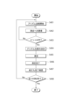
図3は、ジェスチャ入力における測量装置TSの動作のフローチャートである。
(Gesture input flow)
FIG. 3 is a flow chart of the operation of the surveying instrument TS in gesture input.
まず、ジェスチャ入力が開始すると、ステップS101で、画像認識部21は、撮像部46の入力を監視しながら、入力ジェスチャの入力を待機する。
First, when a gesture input is started, in step S101, the
次いで、ステップS102では、画像認識部21が、撮像部46で取得した画像から、作業者の動作を入力ジェスチャとして認識する。
Next, in step S<b>102 , the
画像が入力ジェスチャとして認識されない場合(No)、ステップS101に戻り、画像認識部21は、再度入力を待機する。
If the image is not recognized as an input gesture (No), the process returns to step S101, and the
画像が入力ジェスチャとして認識された場合(Yes)、ステップS103で、画像識別部22が、記憶部30に記憶されている、入力ジェスチャである作業者の所定の動作と、測量装置TSへのオペレーションとを関連付けた入力識別情報に基いて、画像認識部21で認識された入力ジェスチャに対応する測量装置TSへのオペレーションを、入力ジェスチャの示す内容として識別する。
If the image is recognized as an input gesture (Yes), in step S103, the
次いで、ステップS104では、ステップS103における識別結果に基いて、入力ジェスチャに対応する測量装置TSへのオペレーションを実行する。 Next, in step S104, an operation to the surveying instrument TS corresponding to the input gesture is executed based on the identification result in step S103.
図4は、入力識別情報として記憶部30に記憶された入力ジェスチャの例を示す。なお、以下、作業者および測量装置TSのジェスチャの例を示す図の説明において、「左」、「右」、「前」、「後」等の方向は、作業者のジェスチャに関しては、作業者から見た方向を意味し、測量装置TSのジェスチャに関しては、測量装置TSに向かって見た方向を意味するものとする。
FIG. 4 shows an example of input gestures stored in the
また、動作の方向は、単なる例示であり、発明の内容を限定するものではない。例えば、図4(c)は、左手を右から左へと動かす入力ジェスチャにより、望遠鏡2cを左方向へと旋回するというオペレーションに関連付けられた例を示すが、これとは反対に、右手を左から右へと動かすジェスチャにより、望遠鏡2cを右方向へと旋回するというような左右対象なジェスチャも可能である。
Also, the direction of operation is merely an example and does not limit the scope of the invention. For example, FIG. 4(c) shows an example associated with the operation of turning the
このように、本実施の形態に係る測量装置TSによれば、作業者の入力ジェスチャにより測量装置TSに所定の動作を実行させることができるので、測量装置TSに直接触れずに操作することができる。したがって、入力の際に、測量装置TSに作業者が直接触れるために、測量装置が設置場所から動いて測定角度が変わったり、測量装置が振動したりする虞がない。 As described above, according to the surveying device TS according to the present embodiment, it is possible to cause the surveying device TS to perform a predetermined operation by means of an input gesture of the operator. can. Therefore, since the operator directly touches the surveying instrument TS at the time of inputting, there is no possibility that the surveying instrument will move from the installation location and the measurement angle will change or the surveying instrument will vibrate.
なお、本実施の形態において、第3の照明用発光部45を備え、遠隔で入力ジェスチャを行う作業者を照明することは、必須ではないが、このようにすると、画像認識部21による入力ジェスチャの認識が容易になるため好ましい。
In the present embodiment, it is not essential to include the third illumination
(ジェスチャ出力のフロー)
次に、ジェスチャ出力における測量装置TSの動作について、図5,図6を参照しながら説明する。
(Gesture output flow)
Next, the operation of the surveying instrument TS in gesture output will be described with reference to FIGS. 5 and 6. FIG.
記憶部30には、図6に示すような、作業者に対する出力内容と、測量装置TSの動作としての出力ジェスチャとを関連付けた出力変換情報が記憶されている。
The
測量装置TSがジェスチャ出力を開始すると、ステップS201において、ジェスチャ実行部23は、記憶部30に記憶された出力変換情報に基いて作業者に対する出力内容を出力ジェスチャに変換する。
When the surveying instrument TS starts gesture output, in step S201, the
次に、ステップS202において、ジェスチャ実行部23は、水平回転駆動部16および鉛直回転駆動部17を制御して、回転駆動することにより、指定した出力ジェスチャを実行し、処理を終了する。例えば、水平回転駆動部16と鉛直回転駆動部17との回転駆動の組み合わせにより、図6(a)~図6(d)に示すような出力ジェスチャを実行する。
Next, in step S202, the
あるいは、水平回転駆動部16と鉛直回転駆動部17との回転駆動の組み合わせに併せて第1の照明用発光部43を発光制御し、出力ジェスチャを表現してもよい。例えば、図6(e)に示すように、望遠鏡2cを左右に細かく動かすと共に第1の照明用発光部43を速く点滅させるという出力ジェスチャにより、測量装置TSにトラブルが発生したことを作業者に報知するようになっていてもよい。
Alternatively, the output gesture may be expressed by controlling the light emission of the first illumination
このように、本実施の形態に係る測量装置TSによれば、測量装置TSの出力ジェスチャにより、測量装置TSから作業者に対する指示等を認識することができるので、作業者は表示部42を確認することなく作業を行うことができる。 As described above, according to the surveying device TS according to the present embodiment, the output gesture of the surveying device TS allows the worker to recognize instructions and the like from the surveying device TS to the operator. You can work without
また、本実施の形態において、水平回転駆動部16と鉛直回転駆動部17との回転駆動の組み合わせに併せて、第1の照明用発光部43が、ジェスチャ実行部23の制御に従って、点灯、点滅等を行い、出力ジェスチャを表現することは必須ではないが、このようにすると、多様な出力内容に対応することができるため好ましい。さらに、第1の照明用発光部43の発光により、測量装置の動作が視認されやすくなるので好ましい。
In addition, in the present embodiment, in accordance with the combination of the rotation driving of the horizontal
また、本実施の形態において、第2の照明用発光部44を備え、測量装置TS自体を照明することは、必須ではないが、このようにすると、作業者が遠隔にいる場合に、測量装置TSのジェスチャの視認性が高くなるので好ましい。
In addition, in the present embodiment, it is not essential to provide the second illumination light-emitting
なお、入力識別情報および出力変換情報のリストは、出荷時に予め設定されていてもよいが、編集可能である。また、作業者により、測量機の所定の機能から随時設定可能に構成されていてもよい。 The list of input identification information and output conversion information may be set in advance at the time of shipment, but can be edited. Further, the operator may be configured to be able to set the predetermined functions of the surveying instrument at any time.
あるいは、画像認識部21による認識結果および画像識別部22による識別結果から、複数の作業者の身体的差異やジェスチャの動作的差異等による、誤差を回避できる程度の許容範囲を自律的に学習して、設定内容を自動的に追加および累加されるように構成されていてもよい。
Alternatively, it autonomously learns an allowable range for avoiding errors due to physical differences among workers, differences in gestures, etc., from the recognition results of the
<実施例1>
(ジェスチャインタフェイスを用いた現況測量)
このような測量装置TSのジェスチャインタフェイスを用いて現況測量を行う例を、図7,8を参照しながら説明する。
<Example 1>
(Current situation survey using gesture interface)
An example of surveying the current situation using the gesture interface of the surveying device TS will be described with reference to FIGS.
図7は、現況測量に係る測量装置TSの動作のフローチャートである。現況測量では、測量装置TSに、基準点の座標データを予め読み込ませ、記憶部30に記憶させている。作業者は、測量装置TSを設置し、現況測量動作を開始すると、作業者は、ポールプリズム(上部にプリズムを備える指示棒)を持って、基準点まで移動する。
FIG. 7 is a flow chart of the operation of the surveying instrument TS relating to the current survey. In the current survey, the surveying device TS is made to read in advance the coordinate data of the reference point and stored in the
ステップS301で、基準点において、作業者が測量装置TSに向かい、図8(a)のように、右手を真上に挙げてから正面に下ろすという入力ジェスチャを行うと、測量装置TSは基準点の測定を行う。測定が終わると作業者は変化点(土地の傾斜が変化する点)に移動する。 In step S301, when the operator faces the surveying instrument TS at the reference point and performs an input gesture of raising the right hand straight up and then lowering it in front as shown in FIG. measurement. After the measurement is completed, the operator moves to the change point (the point where the slope of the land changes).
次に、ステップS302で、作業者が変化点において、測量装置TSに向かい、図8(b)のように、右手を斜め上にあげてくるくる回すという入力ジェスチャを行うと、測量装置TSは、変化点の測定を行う。測定が終わると作業者は終了点に移動する。 Next, in step S302, when the operator faces the surveying instrument TS at the change point and makes an input gesture of raising the right hand diagonally upward and turning it around as shown in FIG. 8(b), the surveying instrument TS Measure the change point. When the measurement ends, the worker moves to the end point.
次に、ステップS303で、作業者が終了点において、測量装置TSに向い、図8(c)のように、右手を横にパンチを出すように突き出すという入力ジェスチャを行うと、測量装置TSは、終了点の測定を行う。測定が終わると測量装置TSは処理を終了する。 Next, in step S303, when the operator makes an input gesture of facing the surveying instrument TS at the end point and thrusting out the right hand sideways as if punching as shown in FIG. 8(c), the surveying instrument TS , to measure the end point. When the measurement is completed, the surveying instrument TS terminates the processing.
なお、各測定において、測量装置TSが、第1の照明用発光部43を点灯することにより、各測定の終了を作業者に報知するようになっていても良い。
In addition, in each measurement, the surveying instrument TS may turn on the first illumination
通常、現況測量は、測量装置TS側に1名の作業者と、ポールプリズム側に1名の作業者という2人一組として、測量装置TS側の作業者が、測量装置を操作しつつ、ポールプリズム側の作業者と連携して行う。 Usually, the current survey is conducted as a group of two workers, one worker on the side of the surveying device TS and one worker on the side of the pole prism. This is done in cooperation with the workers on the pole prism side.
しかし、本実施の形態に係る測量装置TSによれば、ポールプリズム側の作業者は、入力ジェスチャにより、遠隔地から測量装置TSを操作することが可能であるので、ポールプリズム側の作業者1名でも現況測量を行うことが可能となる。 However, according to the surveying instrument TS according to the present embodiment, the operator on the pole prism side can operate the surveying instrument TS from a remote location by input gestures. It will be possible to conduct a survey of the current situation even with a name.
<実施例2>
(ジェスチャインタフェイスを用いた杭打ち作業)
このような測量装置TSのジェスチャインタフェイスを用いて杭打ち作業を行う例を図9~図11を参照しながら説明する。
<Example 2>
(Staking work using a gesture interface)
An example of a stakeout operation using such a gesture interface of the surveying device TS will be described with reference to FIGS. 9 to 11. FIG.
図9は、杭打ち作業に係る測量装置TSの動作のフローチャートである。測量装置TSには、あらかじめ杭打ちを実施する複数の測点の設計値データを読み込ませておく。まず作業者は、測量装置TSを設置し、杭打ち作業用プログラムの実行を開始し、ポールプリズムを持って最初の測点まで移動する。 FIG. 9 is a flow chart of the operation of the surveying device TS relating to the piling work. The surveying device TS is made to read in advance design value data of a plurality of survey points where stakeout is to be performed. First, the operator installs the surveying device TS, starts execution of the piling work program, and moves to the first survey point holding the pole prism.
最初の測点の近傍まで来たら、作業者は、例えば、図10(a)のように、両手で大きな丸を作るという入力ジェスチャにより、測量装置TSに対してプリズム追尾開始の指示を行う。すると、測量装置TSは、ステップS401で、プリズムの追尾を開始する。 When the operator reaches the vicinity of the first survey point, the operator instructs the surveying instrument TS to start tracking the prism by making a large circle with both hands, for example, as shown in FIG. 10(a). Then, the surveying instrument TS starts tracking the prism in step S401.
次に、ステップS402で、測量装置TSは、ポールプリズムの現在位置と、設定された第1の測点の位置とを比較して、ポールプリズムが測点に近づく方向と距離とを算出する。測量装置TSは、ポールプリズムが測点に合致するように、ジェスチャで作業者を誘導する。 Next, in step S402, the surveying instrument TS compares the current position of the pole prism with the position of the first set measuring point, and calculates the direction and distance in which the pole prism approaches the measuring point. The surveying instrument TS guides the operator with a gesture so that the pole prism matches the survey point.
具体的には、例えば、ポールプリズムを右へ大きく移動する必要がある場合には、図11(a)のように、望遠鏡2cを右へ大きくすばやく2度振る。あるいは、ポールプリズムを上に少し移動する必要がある場合には、図11(b)のように望遠鏡2cを上へ小さくゆっくり2度振る。これにより、作業者は、測量装置TSからの指示に従って、ポールプリズムを移動する。
Specifically, for example, when it is necessary to move the pole prism to the right by a large amount, the
次に、ステップS403で、測量装置TSは、ポールプリズムが第1の測点に合致したかどうか、例えば、ポールプリズムが測点から±1cm以内に入ったか否かを判断する。 Next, in step S403, the surveying instrument TS determines whether the pole prism matches the first measuring point, for example, whether the pole prism is within ±1 cm from the measuring point.
ポールプリズムが測点から±1cm以内に入っていない場合(No)、ステップS402に戻り、測量装置TSは、再度出力ジェスチャによる測点への誘導を行う。 If the pole prism is not within ±1 cm from the survey point (No), the process returns to step S402, and the surveying instrument TS again guides the user to the survey point using the output gesture.
一方、ポールプリズムが測点から±1cm以内に入った場合(Yes)、ステップS404において、杭打ち点にポールプリズムの位置が決定される。 On the other hand, if the pole prism is within ±1 cm from the measurement point (Yes), the position of the pole prism is determined at the stakeout point in step S404.
次いで、ステップS405で、測量装置TSは、ポールプリズムの測定を行う。測定が終了すると、ステップS405で、測量装置TSは、図11(c)のように、望遠鏡2cを水平方向および鉛直方向にそれぞれ1回転し、測定の終了をジェスチャで出力する。
Next, in step S405, the surveying instrument TS measures the pole prism. When the measurement is completed, in step S405, the surveying instrument TS rotates the
測定が完了すると、作業者は、杭打ちを行い、例えば図10(b)のように、ジェスチャにより、杭打ち完了を測量装置TSに報告する。測量装置TSは、ステップS407で入力を確認する。 When the measurement is completed, the operator performs stakeout and reports the completion of stakeout to the surveying device TS by gesture, for example, as shown in FIG. 10(b). The surveying instrument TS confirms the input in step S407.
次に、ステップS408において、測量装置TSは、予め設定された全ての測点について、測定が終わっているか否かを判断する。 Next, in step S408, the surveying instrument TS determines whether or not all the preset survey points have been measured.
全ての測点の測定が終わっている場合(Yes)、杭打ち作業の処理は終了する。 If all measurement points have been measured (Yes), the pile driving process ends.
一方、全ての測点の測定が終わっていない場合(No)、ステップS401に戻り、次の測点に関してプリズムの追尾を開始し、全ての測点について杭打ちが完了するまでステップS401~S405の処理を繰り返す。 On the other hand, if the measurement of all the measuring points has not been completed (No), the process returns to step S401, the tracking of the prism is started for the next measuring point, and steps S401 to S405 are performed until the stakeout is completed for all the measuring points. Repeat process.
なお、本実施例では、追尾部18は、作業者のジェスチャ入力により、自動追尾を開始し、設計値データに基いて測点を自動追尾するように設定されている。しかし、作業者が測量装置TSから移動する時点で、測量装置TSの自動追尾を開始し、自動追尾し続けるように構成されていてもよい。
In this embodiment, the
また、ステップS408の後、次の測点に移動するまでの間に、作業者が図10(c)の入力ジェスチャを入力することにより、測量装置TSが追尾を中断し、WAITモードになるように構成されていてもよい。 Further, after step S408, when the operator inputs the input gesture shown in FIG. may be configured to
通常、杭打ち作業は、測量装置TS側に1名の作業者と、ポールプリズム側に1名の作業者という2人一組として、測量装置TS側の作業者が、測量装置を操作しつつ、ポールプリズム側の作業者と連携して行う。 Normally, piling work is performed by a group of two workers, one worker on the side of the surveying device TS and one worker on the side of the pole prism, and the worker on the side of the surveying device TS operates the surveying device , in cooperation with the workers on the pole prism side.
しかし、本実施の形態に係る測量装置TSによれば、ポールプリズム側の作業者は、入力ジェスチャにより、遠隔地から測量装置TSを操作することが可能であり、また、測量装置TS側の動作状況を出力ジェスチャにより確認することができるので、ポールプリズム側の作業者1名でも杭打ち作業を行うことが可能となる。 However, according to the surveying instrument TS according to the present embodiment, the operator on the side of the pole prism can operate the surveying instrument TS from a remote location by input gestures. Since the situation can be confirmed by the output gesture, even one worker on the pole prism side can perform the piling work.
<変形例>
なお、本実施の形態において、測量装置TSを遠隔から操作可能なリモートコントローラを備え、ジェスチャ入力に代えて、リモートコントローラによる入力を行い、出力のみを測量装置TSのジェスチャ出力とすることもできる。
<Modification>
In the present embodiment, a remote controller that can operate the surveying instrument TS from a remote location may be provided, and input by the remote controller may be performed in place of the gesture input, and only the output may be the gesture output of the surveying instrument TS.
第2の実施の形態
(測量機の構成)
図12は、本発明の第2の実施の形態にかかる測量装置TSaの構成ブロック図である。測量装置TSaは、第1の実施の形態に係る測量装置TSに加えて音声入力部47および音声出力部48を備える点で異なる。また、演算制御部20aが、第1の実施形態に係る演算制御部20に加えて、音声認識部24および 音声変換部25を備える点で異なる。
Second Embodiment (Configuration of Surveying Instrument)
FIG. 12 is a configuration block diagram of a surveying instrument TSa according to the second embodiment of the present invention. The surveying instrument TSa differs from the surveying instrument TS according to the first embodiment in that it includes an
音声入力部47は、音声を入力する手段であり、例えば、集音マイク、指向性マイクである。音声入力部47は、托架部2bに備えられている。また、音声入力部47は、作業者が発する音声を集音し、音声信号に変換して演算制御部20aに出力する。
The
音声出力部48は、音声を出力する手段であり、例えば、スピーカである。音声出力部48は、托架部2bに備えられている。また、音声出力部48は、演算制御部20aからの指示に基いて、音声変換部25から出力されたメッセージを音声として出力する。
The
音声認識部24は、音声入力部47から入力された音声を、自然言語処理機能により認識し、テキスト指令に変換する。
The
音声変換部25は、演算制御部20aによる、作業者への出力内容を、音声メッセージに変換し、音声出力部48に出力する。
The
(入力のフロー)
図13は、ジェスチャ入力と音声入力を組み合わせた場合の測量装置TSaの動作のフローチャートである。
(input flow)
FIG. 13 is a flow chart of the operation of the surveying instrument TSa when gesture input and voice input are combined.
まず、入力モードが開始すると、ステップS401で、画像認識部21および音声認識部24は、撮像部46および音声入力部47の入力を監視しながら、入力を待機する。
First, when the input mode starts, in step S401, the
次いで、ステップS402で、画像または音声の入力が発生すると、画像認識部21および音声認識部24が入力を検知し、画像が入力された場合には、撮像部46で取得した画像から、入力された画像を入力ジェスチャとして認識する。また、音声が入力された場合には、音声入力部47が取得した音声を、入力音声として認識する。
Next, in step S402, when an image or voice input occurs, the
ステップS402で画像も、音声も認識されない場合(No)、処理はステップS401に戻り、画像認識部21および音声認識部24が再度入力を待機する。
If neither the image nor the voice is recognized in step S402 (No), the process returns to step S401, and the
ステップS402で、画像が入力ジェスチャとして認識された場合(ジェスチャ)、ステップS403で、画像識別部22が、記憶部30に記憶されている、入力ジェスチャである作業者の所定の動作と、測量装置へのオペレーションとを関連付けた入力識別情報に基いて、画像認識部21で認識された入力ジェスチャに対応する測量装置TSへのオペレーションを、入力ジェスチャの示す内容として識別する。
In step S402, if the image is recognized as an input gesture (gesture), in step S403, the
次いで、ステップS404では、ステップS403における識別結果に基いて、入力ジェスチャに対応する測量装置TSへのオペレーションを実行し、入力を終了する。 Next, in step S404, based on the identification result in step S403, an operation to the surveying instrument TS corresponding to the input gesture is executed, and the input ends.
ステップS403で、音声が入力音声として認識された場合(音声)、ステップS405で、音声認識部24が、入力音声をテキスト指令に変換する。
If the speech is recognized as the input speech (speech) in step S403, the
次いで、ステップS406で、指令に対応するオペレーションを実行し、入力を終了する。 Then, in step S406, the operation corresponding to the command is executed and the input ends.
(出力のフロー)
図14は、ジェスチャ出力と音声出力を組み合わせた場合の測量装置TSaの動作のフローチャートである。
(output flow)
FIG. 14 is a flow chart of the operation of the surveying instrument TSa when gesture output and voice output are combined.
出力が発生すると、ステップS501において、演算制御部20aは、出力内容について、予め定めされた出力形式を選択する。
When an output is generated, in step S501, the
ステップS501において出力形式がジェスチャの場合(ジェスチャ)、ステップS502で、ジェスチャ実行部23は、記憶部30に記憶された出力変換情報に基いて作業者に対する出力内容を出力ジェスチャに変換する。
If the output format is a gesture in step S501 (gesture), the
次いで、ステップS503で、ジェスチャ実行部23は、水平回転駆動部16および鉛直回転駆動部17を制御して、回転駆動することにより、指定した出力ジェスチャを実行し、処理を終了する。
Next, in step S503, the
一方、ステップS501において、出力形式が音声の場合(音声)、ステップS504で、音声変換部25は、出力内容から、出力内容に応じた音声メッセージに変換し、音声出力部48に出力する。
On the other hand, if the output format is audio (audio) in step S501, the
次いで、ステップS505で、音声出力部48は、音声変換部25から入力された音声メッセージを音声として出力し、処理を終了する。
Next, in step S505, the
このように、第1の実施の形態に係る、ジェスチャインタフェイスは、音声入出力を用いた場合にも測量装置TSaに適用することができる。 Thus, the gesture interface according to the first embodiment can be applied to the surveying apparatus TSa even when voice input/output is used.
以上、本発明の好ましい実施の形態について述べたが、上記の実施の形態および実施例は本発明の一例であり、それぞれの構成を当業者の知識に基づいて組み合わせることが可能であり、そのような形態も本発明の範囲に含まれる。 Preferred embodiments of the present invention have been described above. forms are also included in the scope of the present invention.
TS 測量装置
TSa 測量装置
2c 望遠鏡
16 水平回転駆動部
17 鉛直回転駆動部
20 演算制御部
20a 演算制御部
21 画像認識部
22 画像識別部
23 ジェスチャ実行部
24 音声認識部
25 音声変換部
30 記憶部
43 第1の照明用発光部
44 第2の照明用発光部
45 第3の照明用発光部
46 撮像部
TS Surveying device
Claims (5)
画像を取得可能な撮像部と、
前記測量部を備える望遠鏡と、
前記望遠鏡を鉛直軸周りに水平回転する水平回転駆動部と、
前記望遠鏡を水平軸周りに鉛直回転する鉛直回転駆動部と、
測量装置照明用発光部と、
前記測量部、前記撮像部、前記水平回転駆動部、前記鉛直回転駆動部および前記測量装置照明用発光部を制御するように構成された演算制御部と、
記憶部とを備える測量装置であって、
前記記憶部は、入力ジェスチャである作業者の身体の動作である所定の動作と、測量装置へのオペレーションとを関連付けた入力識別情報を有し、
前記画像は、前記作業者が前記動作を行っている状態を撮像した動画像、および前記作業者の前記動作が一定時間停止している状態を撮影した静止画像、を含み、
前記演算制御部は、前記画像から入力ジェスチャを認識する画像認識部、および該画像認識部で認識された入力ジェスチャに対応する測量装置へのオペレーションを、入力ジェスチャの示す内容として識別する画像識別部を備え、
前記記憶部は、作業者に対する出力内容と、測量装置の動作としての出力ジェスチャとを関連付けた出力変換情報を有し、
前記演算制御部は、前記出力変換情報に基いて作業者に対する出力内容を出力ジェスチャに変換し、前記水平回転駆動部および前記鉛直回転駆動部を回転駆動することにより出力ジェスチャを実行するジェスチャ実行部を備え、
前記出力ジェスチャは前記望遠鏡の水平回転および鉛直回転の組み合わせにより構成され、
前記測量装置照明用発光部は、前記測量装置自体を照明する、
ことを特徴とする測量装置。 a surveying unit capable of surveying a target ;
an imaging unit capable of acquiring an image;
a telescope comprising the surveying unit;
a horizontal rotation driving unit that horizontally rotates the telescope about a vertical axis;
a vertical rotation driving unit that vertically rotates the telescope about a horizontal axis;
a light emitting unit for lighting a surveying instrument;
an arithmetic control unit configured to control the surveying unit , the imaging unit , the horizontal rotation driving unit, the vertical rotation driving unit, and the surveying instrument illumination light emitting unit ;
A surveying instrument comprising a storage unit,
The storage unit has input identification information that associates a predetermined action, which is an input gesture of the worker's body, with an operation to the surveying instrument,
The image includes a moving image of the worker performing the action and a still image of the worker stopping the action for a certain period of time,
The arithmetic control unit includes an image recognition unit that recognizes an input gesture from the image, and an image identification unit that identifies an operation to the surveying instrument corresponding to the input gesture recognized by the image recognition unit as content indicated by the input gesture. with
The storage unit has output conversion information that associates an output content for a worker with an output gesture as an operation of the surveying instrument,
The arithmetic control unit converts the output content for the worker into an output gesture based on the output conversion information, and executes the output gesture by rotationally driving the horizontal rotation driving unit and the vertical rotation driving unit. with
said output gesture comprises a combination of horizontal and vertical rotation of said telescope;
the surveying device illumination light emitting unit illuminates the surveying device itself;
A surveying instrument characterized by:
前記出力ジェスチャは、前記ジェスチャ照明用発光部の発光を含むことを特徴とする請求項1に記載の測量装置。 Equipped with a light-emitting part for gesture lighting ,
2. The surveying instrument according to claim 1 , wherein the output gesture includes light emitted from the gesture illumination light emitting unit .
前記作業者照明用発光部は、前記入力ジェスチャを行う作業者を照明すること
を特徴とする請求項1または2に記載の測量装置。 Equipped with a light-emitting part for worker lighting ,
3. The surveying instrument according to claim 1 , wherein the worker illumination light emitting unit illuminates the worker performing the input gesture.
音声出力部とを備え、
前記演算制御部は、前記音声入力部から入力された音声を認識する音声認識部、および作業者に対する出力内容を音声メッセージに変換し、前記音声出力部に出力する音声変換部を備えることを特徴とする請求項1~3のいずれかに記載の測量装置。 a voice input unit;
and an audio output unit,
The arithmetic control unit is characterized by comprising a voice recognition unit that recognizes voice input from the voice input unit, and a voice conversion unit that converts output content to a worker into a voice message and outputs the voice message to the voice output unit. The surveying instrument according to any one of claims 1 to 3 .
Priority Applications (2)
| Application Number | Priority Date | Filing Date | Title |
|---|---|---|---|
| JP2018104483A JP7226928B2 (en) | 2018-05-31 | 2018-05-31 | surveying equipment |
| US16/424,012 US20190369380A1 (en) | 2018-05-31 | 2019-05-28 | Surveying instrument |
Applications Claiming Priority (1)
| Application Number | Priority Date | Filing Date | Title |
|---|---|---|---|
| JP2018104483A JP7226928B2 (en) | 2018-05-31 | 2018-05-31 | surveying equipment |
Publications (3)
| Publication Number | Publication Date |
|---|---|
| JP2019211222A JP2019211222A (en) | 2019-12-12 |
| JP2019211222A5 JP2019211222A5 (en) | 2021-07-26 |
| JP7226928B2 true JP7226928B2 (en) | 2023-02-21 |
Family
ID=68694709
Family Applications (1)
| Application Number | Title | Priority Date | Filing Date |
|---|---|---|---|
| JP2018104483A Active JP7226928B2 (en) | 2018-05-31 | 2018-05-31 | surveying equipment |
Country Status (2)
| Country | Link |
|---|---|
| US (1) | US20190369380A1 (en) |
| JP (1) | JP7226928B2 (en) |
Families Citing this family (1)
| Publication number | Priority date | Publication date | Assignee | Title |
|---|---|---|---|---|
| JP1691841S (en) * | 2020-01-17 | 2021-08-02 |
Citations (3)
| Publication number | Priority date | Publication date | Assignee | Title |
|---|---|---|---|---|
| JP3098781U (en) | 2003-06-24 | 2004-03-11 | ユート工業株式会社 | Electronic flat plate surveying device |
| US20140327920A1 (en) | 2013-05-01 | 2014-11-06 | Faro Technologies, Inc. | Method and apparatus for using gestures to control a laser tracker |
| WO2017151196A1 (en) | 2016-02-29 | 2017-09-08 | Faro Technologies, Inc. | Laser tracker system |
Family Cites Families (5)
| Publication number | Priority date | Publication date | Assignee | Title |
|---|---|---|---|---|
| WO2000068932A1 (en) * | 1999-05-10 | 2000-11-16 | Sony Corporation | Control device and method therefor, information processing device and method therefor, and medium |
| US9116619B2 (en) * | 2013-05-10 | 2015-08-25 | Seagate Technology Llc | Displaying storage device status conditions using multi-color light emitting diode |
| JP6735013B2 (en) * | 2016-05-31 | 2020-08-05 | パナソニック株式会社 | robot |
| JP6354796B2 (en) * | 2016-06-23 | 2018-07-11 | カシオ計算機株式会社 | Robot, robot control method and program |
| CN109421044A (en) * | 2017-08-28 | 2019-03-05 | 富泰华工业(深圳)有限公司 | Intelligent robot |
-
2018
- 2018-05-31 JP JP2018104483A patent/JP7226928B2/en active Active
-
2019
- 2019-05-28 US US16/424,012 patent/US20190369380A1/en not_active Abandoned
Patent Citations (3)
| Publication number | Priority date | Publication date | Assignee | Title |
|---|---|---|---|---|
| JP3098781U (en) | 2003-06-24 | 2004-03-11 | ユート工業株式会社 | Electronic flat plate surveying device |
| US20140327920A1 (en) | 2013-05-01 | 2014-11-06 | Faro Technologies, Inc. | Method and apparatus for using gestures to control a laser tracker |
| WO2017151196A1 (en) | 2016-02-29 | 2017-09-08 | Faro Technologies, Inc. | Laser tracker system |
Also Published As
| Publication number | Publication date |
|---|---|
| JP2019211222A (en) | 2019-12-12 |
| US20190369380A1 (en) | 2019-12-05 |
Similar Documents
| Publication | Publication Date | Title |
|---|---|---|
| US10940573B2 (en) | Hand-held tool system | |
| JP4354343B2 (en) | Position measurement system | |
| JP6333075B2 (en) | Surveying equipment | |
| EP2068116B1 (en) | Surveying system | |
| EP3211369B1 (en) | Surveying instrument and program | |
| US9581442B2 (en) | Surveying instrument | |
| US7564538B2 (en) | Measuring system | |
| JP5124321B2 (en) | Measuring system | |
| EP3771886A1 (en) | Surveying apparatus, surveying method, and surveying program | |
| JP7226928B2 (en) | surveying equipment | |
| JP6394135B2 (en) | Image display device | |
| JP2012213042A (en) | Mobile setting terminal and monitoring system | |
| JP2006078416A (en) | Total station | |
| JP5863482B2 (en) | Angle measuring device | |
| JP2004037140A (en) | Surveying method in pipe-jacking method | |
| JP3854168B2 (en) | Total station controller | |
| JP7353126B2 (en) | surveying system | |
| JP4933077B2 (en) | Surveying instrument and surveying method using this surveying instrument | |
| JP6112927B2 (en) | Surveying target, surveying system, and surveying instrument | |
| JP2006078415A (en) | Total station | |
| JP2020159823A (en) | measuring device | |
| JP2023042128A (en) | Image editing support method and image editing support device | |
| JP2019191328A (en) | Projector system | |
| JP2003240551A (en) | Surveying machine |
Legal Events
| Date | Code | Title | Description |
|---|---|---|---|
| A521 | Request for written amendment filed |
Free format text: JAPANESE INTERMEDIATE CODE: A523 Effective date: 20210512 |
|
| A621 | Written request for application examination |
Free format text: JAPANESE INTERMEDIATE CODE: A621 Effective date: 20210512 |
|
| A977 | Report on retrieval |
Free format text: JAPANESE INTERMEDIATE CODE: A971007 Effective date: 20220427 |
|
| A131 | Notification of reasons for refusal |
Free format text: JAPANESE INTERMEDIATE CODE: A131 Effective date: 20220516 |
|
| A521 | Request for written amendment filed |
Free format text: JAPANESE INTERMEDIATE CODE: A523 Effective date: 20220715 |
|
| A601 | Written request for extension of time |
Free format text: JAPANESE INTERMEDIATE CODE: A601 Effective date: 20220715 |
|
| A131 | Notification of reasons for refusal |
Free format text: JAPANESE INTERMEDIATE CODE: A131 Effective date: 20221019 |
|
| A521 | Request for written amendment filed |
Free format text: JAPANESE INTERMEDIATE CODE: A523 Effective date: 20221219 |
|
| TRDD | Decision of grant or rejection written | ||
| A01 | Written decision to grant a patent or to grant a registration (utility model) |
Free format text: JAPANESE INTERMEDIATE CODE: A01 Effective date: 20230207 |
|
| A61 | First payment of annual fees (during grant procedure) |
Free format text: JAPANESE INTERMEDIATE CODE: A61 Effective date: 20230209 |
|
| R150 | Certificate of patent or registration of utility model |
Ref document number: 7226928 Country of ref document: JP Free format text: JAPANESE INTERMEDIATE CODE: R150 |