JP7226900B2 - Synchronization of configuration changes within the process plant - Google Patents
Synchronization of configuration changes within the process plant Download PDFInfo
- Publication number
- JP7226900B2 JP7226900B2 JP2018115311A JP2018115311A JP7226900B2 JP 7226900 B2 JP7226900 B2 JP 7226900B2 JP 2018115311 A JP2018115311 A JP 2018115311A JP 2018115311 A JP2018115311 A JP 2018115311A JP 7226900 B2 JP7226900 B2 JP 7226900B2
- Authority
- JP
- Japan
- Prior art keywords
- objects
- dependent
- module
- control
- modified
- Prior art date
- Legal status (The legal status is an assumption and is not a legal conclusion. Google has not performed a legal analysis and makes no representation as to the accuracy of the status listed.)
- Active
Links
Images


Classifications
-
- G—PHYSICS
- G05—CONTROLLING; REGULATING
- G05B—CONTROL OR REGULATING SYSTEMS IN GENERAL; FUNCTIONAL ELEMENTS OF SUCH SYSTEMS; MONITORING OR TESTING ARRANGEMENTS FOR SUCH SYSTEMS OR ELEMENTS
- G05B19/00—Programme-control systems
- G05B19/02—Programme-control systems electric
- G05B19/418—Total factory control, i.e. centrally controlling a plurality of machines, e.g. direct or distributed numerical control [DNC], flexible manufacturing systems [FMS], integrated manufacturing systems [IMS], computer integrated manufacturing [CIM]
-
- G—PHYSICS
- G05—CONTROLLING; REGULATING
- G05B—CONTROL OR REGULATING SYSTEMS IN GENERAL; FUNCTIONAL ELEMENTS OF SUCH SYSTEMS; MONITORING OR TESTING ARRANGEMENTS FOR SUCH SYSTEMS OR ELEMENTS
- G05B19/00—Programme-control systems
- G05B19/02—Programme-control systems electric
- G05B19/04—Programme control other than numerical control, i.e. in sequence controllers or logic controllers
- G05B19/042—Programme control other than numerical control, i.e. in sequence controllers or logic controllers using digital processors
- G05B19/0426—Programming the control sequence
-
- G—PHYSICS
- G05—CONTROLLING; REGULATING
- G05B—CONTROL OR REGULATING SYSTEMS IN GENERAL; FUNCTIONAL ELEMENTS OF SUCH SYSTEMS; MONITORING OR TESTING ARRANGEMENTS FOR SUCH SYSTEMS OR ELEMENTS
- G05B19/00—Programme-control systems
- G05B19/02—Programme-control systems electric
- G05B19/418—Total factory control, i.e. centrally controlling a plurality of machines, e.g. direct or distributed numerical control [DNC], flexible manufacturing systems [FMS], integrated manufacturing systems [IMS], computer integrated manufacturing [CIM]
- G05B19/41865—Total factory control, i.e. centrally controlling a plurality of machines, e.g. direct or distributed numerical control [DNC], flexible manufacturing systems [FMS], integrated manufacturing systems [IMS], computer integrated manufacturing [CIM] characterised by job scheduling, process planning, material flow
-
- G—PHYSICS
- G05—CONTROLLING; REGULATING
- G05B—CONTROL OR REGULATING SYSTEMS IN GENERAL; FUNCTIONAL ELEMENTS OF SUCH SYSTEMS; MONITORING OR TESTING ARRANGEMENTS FOR SUCH SYSTEMS OR ELEMENTS
- G05B19/00—Programme-control systems
- G05B19/02—Programme-control systems electric
- G05B19/418—Total factory control, i.e. centrally controlling a plurality of machines, e.g. direct or distributed numerical control [DNC], flexible manufacturing systems [FMS], integrated manufacturing systems [IMS], computer integrated manufacturing [CIM]
- G05B19/4188—Total factory control, i.e. centrally controlling a plurality of machines, e.g. direct or distributed numerical control [DNC], flexible manufacturing systems [FMS], integrated manufacturing systems [IMS], computer integrated manufacturing [CIM] characterised by CIM planning or realisation
-
- G—PHYSICS
- G05—CONTROLLING; REGULATING
- G05B—CONTROL OR REGULATING SYSTEMS IN GENERAL; FUNCTIONAL ELEMENTS OF SUCH SYSTEMS; MONITORING OR TESTING ARRANGEMENTS FOR SUCH SYSTEMS OR ELEMENTS
- G05B15/00—Systems controlled by a computer
- G05B15/02—Systems controlled by a computer electric
-
- G—PHYSICS
- G05—CONTROLLING; REGULATING
- G05B—CONTROL OR REGULATING SYSTEMS IN GENERAL; FUNCTIONAL ELEMENTS OF SUCH SYSTEMS; MONITORING OR TESTING ARRANGEMENTS FOR SUCH SYSTEMS OR ELEMENTS
- G05B19/00—Programme-control systems
- G05B19/02—Programme-control systems electric
- G05B19/418—Total factory control, i.e. centrally controlling a plurality of machines, e.g. direct or distributed numerical control [DNC], flexible manufacturing systems [FMS], integrated manufacturing systems [IMS], computer integrated manufacturing [CIM]
- G05B19/41845—Total factory control, i.e. centrally controlling a plurality of machines, e.g. direct or distributed numerical control [DNC], flexible manufacturing systems [FMS], integrated manufacturing systems [IMS], computer integrated manufacturing [CIM] characterised by system universality, reconfigurability, modularity
-
- G—PHYSICS
- G05—CONTROLLING; REGULATING
- G05B—CONTROL OR REGULATING SYSTEMS IN GENERAL; FUNCTIONAL ELEMENTS OF SUCH SYSTEMS; MONITORING OR TESTING ARRANGEMENTS FOR SUCH SYSTEMS OR ELEMENTS
- G05B19/00—Programme-control systems
- G05B19/02—Programme-control systems electric
- G05B19/418—Total factory control, i.e. centrally controlling a plurality of machines, e.g. direct or distributed numerical control [DNC], flexible manufacturing systems [FMS], integrated manufacturing systems [IMS], computer integrated manufacturing [CIM]
- G05B19/4185—Total factory control, i.e. centrally controlling a plurality of machines, e.g. direct or distributed numerical control [DNC], flexible manufacturing systems [FMS], integrated manufacturing systems [IMS], computer integrated manufacturing [CIM] characterised by the network communication
- G05B19/41855—Total factory control, i.e. centrally controlling a plurality of machines, e.g. direct or distributed numerical control [DNC], flexible manufacturing systems [FMS], integrated manufacturing systems [IMS], computer integrated manufacturing [CIM] characterised by the network communication by local area network [LAN], network structure
-
- G—PHYSICS
- G05—CONTROLLING; REGULATING
- G05B—CONTROL OR REGULATING SYSTEMS IN GENERAL; FUNCTIONAL ELEMENTS OF SUCH SYSTEMS; MONITORING OR TESTING ARRANGEMENTS FOR SUCH SYSTEMS OR ELEMENTS
- G05B19/00—Programme-control systems
- G05B19/02—Programme-control systems electric
- G05B19/418—Total factory control, i.e. centrally controlling a plurality of machines, e.g. direct or distributed numerical control [DNC], flexible manufacturing systems [FMS], integrated manufacturing systems [IMS], computer integrated manufacturing [CIM]
- G05B19/4185—Total factory control, i.e. centrally controlling a plurality of machines, e.g. direct or distributed numerical control [DNC], flexible manufacturing systems [FMS], integrated manufacturing systems [IMS], computer integrated manufacturing [CIM] characterised by the network communication
- G05B19/4186—Total factory control, i.e. centrally controlling a plurality of machines, e.g. direct or distributed numerical control [DNC], flexible manufacturing systems [FMS], integrated manufacturing systems [IMS], computer integrated manufacturing [CIM] characterised by the network communication by protocol, e.g. MAP, TOP
-
- G—PHYSICS
- G05—CONTROLLING; REGULATING
- G05B—CONTROL OR REGULATING SYSTEMS IN GENERAL; FUNCTIONAL ELEMENTS OF SUCH SYSTEMS; MONITORING OR TESTING ARRANGEMENTS FOR SUCH SYSTEMS OR ELEMENTS
- G05B2219/00—Program-control systems
- G05B2219/20—Pc systems
- G05B2219/23—Pc programming
- G05B2219/23255—Object oriented programming, OOP
-
- G—PHYSICS
- G05—CONTROLLING; REGULATING
- G05B—CONTROL OR REGULATING SYSTEMS IN GENERAL; FUNCTIONAL ELEMENTS OF SUCH SYSTEMS; MONITORING OR TESTING ARRANGEMENTS FOR SUCH SYSTEMS OR ELEMENTS
- G05B2219/00—Program-control systems
- G05B2219/20—Pc systems
- G05B2219/25—Pc structure of the system
- G05B2219/25067—Graphic configuration control system
-
- G—PHYSICS
- G05—CONTROLLING; REGULATING
- G05B—CONTROL OR REGULATING SYSTEMS IN GENERAL; FUNCTIONAL ELEMENTS OF SUCH SYSTEMS; MONITORING OR TESTING ARRANGEMENTS FOR SUCH SYSTEMS OR ELEMENTS
- G05B2219/00—Program-control systems
- G05B2219/20—Pc systems
- G05B2219/25—Pc structure of the system
- G05B2219/25232—DCS, distributed control system, decentralised control unit
-
- G—PHYSICS
- G05—CONTROLLING; REGULATING
- G05B—CONTROL OR REGULATING SYSTEMS IN GENERAL; FUNCTIONAL ELEMENTS OF SUCH SYSTEMS; MONITORING OR TESTING ARRANGEMENTS FOR SUCH SYSTEMS OR ELEMENTS
- G05B2219/00—Program-control systems
- G05B2219/30—Nc systems
- G05B2219/32—Operator till task planning
- G05B2219/32154—Object, attribute for geometry, technology, function oop
-
- G—PHYSICS
- G05—CONTROLLING; REGULATING
- G05B—CONTROL OR REGULATING SYSTEMS IN GENERAL; FUNCTIONAL ELEMENTS OF SUCH SYSTEMS; MONITORING OR TESTING ARRANGEMENTS FOR SUCH SYSTEMS OR ELEMENTS
- G05B2219/00—Program-control systems
- G05B2219/30—Nc systems
- G05B2219/32—Operator till task planning
- G05B2219/32404—Scada supervisory control and data acquisition
-
- Y—GENERAL TAGGING OF NEW TECHNOLOGICAL DEVELOPMENTS; GENERAL TAGGING OF CROSS-SECTIONAL TECHNOLOGIES SPANNING OVER SEVERAL SECTIONS OF THE IPC; TECHNICAL SUBJECTS COVERED BY FORMER USPC CROSS-REFERENCE ART COLLECTIONS [XRACs] AND DIGESTS
- Y02—TECHNOLOGIES OR APPLICATIONS FOR MITIGATION OR ADAPTATION AGAINST CLIMATE CHANGE
- Y02P—CLIMATE CHANGE MITIGATION TECHNOLOGIES IN THE PRODUCTION OR PROCESSING OF GOODS
- Y02P90/00—Enabling technologies with a potential contribution to greenhouse gas [GHG] emissions mitigation
- Y02P90/02—Total factory control, e.g. smart factories, flexible manufacturing systems [FMS] or integrated manufacturing systems [IMS]
Description
本発明は、概して、プロセスプラント、より具体的には、プロセスプラントまたはプロセス制御システムのランタイム中の実行のために関連するオブジェクトを同時に同期させることに関する。 The present invention relates generally to process plants, and more particularly to simultaneously synchronizing related objects for execution during runtime of a process plant or process control system.
化学プラント、石油プラント、または他のプロセスプラント内で使用されるもののような、分散型プロセス制御システムは、アナログバス、デジタルバス、または混合アナログ/デジタルバスを介して1つ以上のフィールドデバイスに通信可能に連結された1つ以上のプロセスコントローラを典型的に含む。フィールドデバイスは、例えば、バルブ、バルブポジショナ、スイッチ、及び送信機(例えば、温度センサ、圧力センサ、レベルセンサ、及び流量センサ)であり得るが、プロセス環境内に配置され、バルブを開くことまたは閉じること、プロセスパラメータを測定すること等のようなプロセス機能を実行する。公知のFieldbusプロトコルに従うフィールドデバイス等のスマートフィールドデバイスもまた、コントローラ内に共通して実装された制御計算、警報機能、及び他の制御機能を実行し得る。プロセスコントローラは、これもまた典型的にはプラント環境内に配置されるが、フィールドデバイスによって行われるプロセス測定を示す信号、及び/またはフィールドデバイスに関する他の情報を受信し、例えば、プロセス制御決定を行い、受信した情報に基づき制御信号を生成し、HART及びFOUNDATION(登録商標)Fieldbusフィールドデバイス等のフィールドデバイスで実行されている制御モジュールまたはブロックと連携する、異なる制御モジュールを実行するコントローラアプリケーションを実行する。コントローラ内の制御モジュールは、制御信号を通信線上でフィールドデバイスに送信し、これによってプロセスプラントの動作を制御する。 Distributed process control systems, such as those used within chemical, petroleum, or other process plants, communicate to one or more field devices via analog, digital, or mixed analog/digital buses. It typically includes one or more process controllers that are operably linked. Field devices, which can be, for example, valves, valve positioners, switches, and transmitters (eg, temperature sensors, pressure sensors, level sensors, and flow sensors), are placed within the process environment to open or close valves. perform process functions such as processing, measuring process parameters, and the like. Smart field devices, such as field devices that follow the well-known Fieldbus protocol, may also perform control calculations, alarm functions, and other control functions commonly implemented in controllers. Process controllers, which are also typically located in the plant environment, receive signals indicative of process measurements made by field devices and/or other information about the field devices and, for example, make process control decisions. , generate control signals based on the information received, and run controller applications that run different control modules that interact with control modules or blocks running on field devices such as HART and FOUNDATION® Fieldbus field devices do. A control module within the controller transmits control signals over communication lines to the field devices, thereby controlling operation of the process plant.
フィールドデバイス及びコントローラからの情報は、制御室またはより過酷なプラント環境から離れた他の位置内に典型的に配置されたオペレータワークステーション、パーソナルコンピュータ、データヒストリアン、レポートジェネレータ、集中データベース等のような1つ以上の他のハードウェアデバイスに通信ネットワーク上で通常、利用可能とされる。これらのハードウェアデバイスは、アプリケーションを実行させ、これは、例えば、オペレータまたはエンジニアが、プロセス制御ルーチンの設定変更、コントローラまたはフィールドデバイス内の制御モジュールの動作の修正、プロセスの現在の状態の閲覧、フィールドデバイス及びコントローラによって生成された警報の閲覧、従業員の訓練またはプロセス制御ソフトウェアのテストの目的のためのプロセスの動作の模擬、構成データベースの維持及び更新等のような、プロセスに関する機能を実行することを可能にする。 Information from field devices and controllers, such as operator workstations, personal computers, data historians, report generators, centralized databases, etc., typically located within the control room or other location remote from the more hostile plant environment. typically made available over a communications network to one or more other hardware devices. These hardware devices run applications that, for example, allow operators or engineers to change the settings of process control routines, modify the operation of control modules in controllers or field devices, view the current state of processes, Perform process-related functions such as viewing alarms generated by field devices and controllers, simulating process operation for purposes of employee training or process control software testing, maintaining and updating configuration databases, etc. make it possible.
例として、Emerson Process Managementによって販売されている、DeltaV(商標)制御システムは、プロセスプラント内の多様な場所に配置された異なる装置内に記憶され、それらの異なる装置によって実行される複数のアプリケーションを含む。1つ以上のオペレータワークステーション内に備わる、構成アプリケーションは、ユーザによる、プロセス制御モジュールの作成または変更、及びデータハイウェイを介した、これらのプロセス制御モジュールの、専用分散型コントローラへのダウンロードを可能にする。典型的には、これらの制御モジュールは、通信可能に相互接続された機能ブロックで構成され、これらの機能ブロックは、それに対する入力に基づき制御スキーム内で機能を実行し、出力を制御スキーム内の他の機能ブロックに提供するオブジェクト指向プログラミングプロトコル内のオブジェクトである。また、構成アプリケーションは、データをオペレータに対して表示するため、かつプロセス制御ルーチン内の設定点等の設定のオペレータによる変更を可能にするために表示アプリケーションが使用するオ
ペレータインターフェイスを、構成設計者が作成または変更することを可能にし得る。各専用コントローラ、及び一部の場合においては、1つ以上のフィールド装置は、実際のプロセス制御機能を実装するために、それらに割り当てられてダウンロードされた制御モジュールを実行するそれぞれのコントローラアプリケーションを記憶及び実行する。閲覧アプリケーションは、1つ以上のオペレータワークステーション上(またはオペレータワークステーション及びデータハイウェイと通信接続状態にある1つ以上の遠隔コンピューティングデバイス上)で実行され得るが、データハイウェイを介してコントローラアプリケーションからデータを受信し、ユーザインターフェースを使用してこのデータをプロセスコントローラシステム設計者、オペレータ、またはユーザに表示し、オペレータのビュー、エンジニアのビュー、技術者のビュー等のような、任意の数の異なるビューを提供し得る。データヒストリアンアプリケーションは、データヒストリアンデバイス内に典型的に記憶され、かつそれによって実行され、データヒストリアンデバイスは、データハイウェイにわたって提供されたデータの一部または全部を収集及び記憶するが、一方で設定データベースアプリケーションは、現在のプロセス制御ルーチン構成及びそれらと関連付けられたデータを記憶するためにデータハイウェイに属するまたさらなるコンピュータ内で実行し得る。あるいは、構成データベースは、構成アプリケーションと同じワークステーション内に配置されてもよい。
As an example, the DeltaV™ control system, sold by Emerson Process Management, stores multiple applications in and executed by different devices located at various locations within the process plant. include. A configuration application, residing within one or more operator workstations, allows users to create or modify process control modules and download these process control modules to dedicated distributed controllers via the data highway. do. Typically, these control modules are made up of communicatively interconnected functional blocks that perform functions within the control scheme based on inputs to them and provide outputs within the control scheme. An object within an object-oriented programming protocol that provides other functional blocks. The configuration application also provides the operator interface that the display application uses to display data to the operator and to allow operator modification of settings such as setpoints within the process control routines. can be created or modified. Each dedicated controller, and in some cases one or more field devices, stores a respective controller application that executes their assigned and downloaded control modules to implement the actual process control functions. and execute. The viewing application may run on one or more operator workstations (or on one or more remote computing devices in communicative connection with the operator workstation and the data highway), but from the controller application via the data highway. Receive data and use a user interface to display this data to a process controller system designer, operator, or user and display it in any number of different views, such as an operator's view, an engineer's view, a technician's view, etc. can provide a view. Data historian applications are typically stored in and executed by data historian devices, which collect and store some or all of the data provided over the data highway, while A configuration database application may run in yet a further computer belonging to the data highway for storing current process control routine configurations and data associated therewith. Alternatively, the configuration database may be located within the same workstation as the configuration application.
現在、構成アプリケーションは、機能ブロックテンプレートオブジェクト、及び一部の場合において制御モジュールテンプレートオブジェクト等の、テンプレートオブジェクトまたはテンプレートアイテムのライブラリを典型的に含む。これらの構成アプリケーションは、プロセスプラントのための制御方策を構成するために、及びプロセスプラントのユーザインターフェースで表示ビューを提供するために使用される。テンプレートオブジェクトは全て、デフォルトパラメータ、設定、及びそれらと関連付けられた方法を有する。構成アプリケーションを使用するエンジニアは、これらのテンプレートオブジェクトを選択し、モジュール、例えば、制御モジュールを展開するために、選択したテンプレートオブジェクトのコピーを構成画面内に本質的に配置することができる。テンプレートオブジェクトを選択して構成画面内に配置するプロセス中に、エンジニアは、これらのオブジェクトの入力及び出力を相互接続させ、プロセスプラント内の特定用途のための特定制御モジュールを作成するためにそれらのパラメータ、名称、タグ、及び他のプロパティを変更する。1つ以上のこのような制御モジュールを作成した後、エンジニアは、作成されたモジュールをライブラリ内または構成データ記憶エリア内に記憶し得る。エンジニアは、その後、制御モジュールをインスタンス化し(例えば、作成される制御モジュールに対応する実行可能ファイルを生じさせる)、それを適切な1つまたは複数のコントローラ、フィールドデバイス、及びプロセスプラントの動作中の実行のための他のプロセス要素にダウンロードする。 Currently, configuration applications typically include a library of template objects or template items, such as function block template objects and, in some cases, control module template objects. These configuration applications are used to configure control strategies for the process plant and to provide display views at the process plant's user interface. All template objects have default parameters, settings, and methods associated with them. An engineer using a configuration application can select these template objects and essentially place a copy of the selected template objects into the configuration screen to deploy a module, eg, a control module. During the process of selecting template objects and placing them in a configuration screen, engineers interconnect the inputs and outputs of these objects and connect them to create specific control modules for specific applications within the process plant. Change parameters, names, tags, and other properties. After creating one or more such control modules, the engineer may store the created modules in a library or in a configuration data storage area. The engineer then instantiates the control module (e.g., produces an executable file corresponding to the created control module) and installs it in the appropriate one or more controllers, field devices, and process plant operations. Download to other process elements for execution.
その後、エンジニアは、表示作成アプリケーション内で表示オブジェクトを選択及び構築することによってプロセスプラント内でオペレータ、保守従業員等に対する1つ以上の表示を概して作成する。これらの表示は、ワークステーションのうちの1つ以上内でシステム基盤全体に典型的に実装され、プラント内の制御システムまたはデバイスの動作状態に関してオペレータまたは保守従業員に予め構成された表示を提供する。典型的に、これらの表示は、プロセスプラント内のコントローラまたはデバイスによって生成された警報を受信及び表示する警報表示、コントローラ及びプロセスプラント内で制御される他のデバイスの動作状態を示す制御表示、プロセスプラント内のデバイスの機能状態を示す保守表示等の形式をとる。これらの表示は、既知の様式で、プロセス制御モジュール、デバイス、またはプロセスプラント内の他のプロセス要素から受信した情報またはデータを表示するように概して予め構成される。一部の既知のシステムにおいて、表示は、物理的要素または論理的要素と関連付けられた図形を各々有し、かつ物理的要素または論理的要素に関するデータを受信するために物理的要素または論理的要素に各々通信可能に紐付けられ
るオブジェクトの使用を通して作成される。オブジェクトは、例えば、タンクが半分満たされていることを例解する、流量センサによって測定された流量を例解する等のために、受信したデータに基づいて表示画面上で図形を変更し得る。
The engineer then generally creates one or more displays for operators, maintenance personnel, etc. within the process plant by selecting and building display objects within the display creation application. These displays are typically implemented throughout the system infrastructure within one or more of the workstations to provide preconfigured displays to operators or maintenance personnel regarding the operational status of control systems or devices within the plant. . Typically, these displays include alarm displays that receive and display alarms generated by controllers or devices within the process plant, control displays that indicate the operational status of controllers and other devices controlled within the process plant, process It takes the form of a maintenance display or the like that indicates the functional status of devices in the plant. These displays are generally preconfigured to display information or data received from process control modules, devices, or other process elements within the process plant in a known manner. In some known systems, the displays each have a graphic associated with a physical or logical element, and a physical or logical element to receive data about the physical or logical element. are created through the use of objects that are each communicatively bound to the . The object may change graphics on the display screen based on the data received, for example, to illustrate that the tank is half full, illustrate the flow rate measured by the flow sensor, and so on.
制御構成アプリケーションと同様、表示作成アプリケーションは、タンク、バルブ、センサ、スライドバーのようなオペレータ制御ボタン、オン/オフスイッチ等のようなテンプレート図形表示アイテムを有し得、これらは、オペレータ表示、保守表示等を作成するために任意の所望の構成で画面上に配置され得る。テンプレート図形表示アイテムは、構成オブジェクトと共にテンプレートライブラリ内に記憶され得るか、または異なるテンプレートライブラリ内に記憶され得る。画面上に配置されるとき、個々の図形アイテムは、プロセスプラントの内部作業の一部の情報または表示を異なるユーザに提供する様式で画面上に相互接続され得る。しかしながら、図形表示をアニメーション化するために、表示作成者は、図形アイテムとプロセスプラント内の関連するデータソースとの間の通信リンクを特定することによって、センサによって測定されたデータまたはバルブ位置の指標等のようなプロセスプラント内で生成されたデータに図形アイテムの各々を手動で結び付けなければならない。さらに、表示が一度作成されると、それは、その構成及びレイアウト内で静止する。 Similar to the control configuration application, the display creation application can have template graphical display items such as tanks, valves, sensors, operator control buttons like slide bars, on/off switches, etc., which can be used for operator displays, maintenance They can be arranged on the screen in any desired configuration to create a display or the like. Template graphical display items can be stored in a template library with the configuration object or can be stored in a different template library. When placed on the screen, individual graphical items may be interconnected on the screen in a manner that provides different users with some information or display of the internal workings of the process plant. However, in order to animate the graphical display, the display creator can generate data measured by sensors or indicators of valve position by specifying communication links between graphical items and relevant data sources within the process plant. Each graphical item must be manually bound to data generated within the process plant, such as. Furthermore, once a display is created, it remains static in its composition and layout.
制御構成アプリケーション内の制御テンプレートオブジェクト及び表示作成アプリケーション内の表示アイテムは、それらが多くの異なる制御モジュール及び図形表示を作成するためにコピー及び使用されることができるので、便利であるが、プロセスプラント内の異なる設備及びディスプレイのための大量の同一制御モジュール及び図形表示を作成する必要性がしばしば存在する。例えば、大規模プロセスプラントに対する多くの媒体は、同一の基本汎用制御モジュール及びディスプレイを使用して制御及び閲覧され得る同一または類似設備の大量のインスタンスを有する。 Control template objects in the control configuration application and display items in the display creation application are convenient because they can be copied and used to create many different control modules and graphical displays, but the process plant There is often a need to create large numbers of identical control modules and graphical representations for different equipment and displays within a home. For example, many media for large scale process plants have numerous instances of the same or similar equipment that can be controlled and viewed using the same basic general control module and display.
この問題に対処するために、米国特許第7,043,311号(この開示の全体は、本明細書の参照によって本明細書に明白に組み込まれる)は、ユーザが大量の制御モジュール、ユニットもしくは設備モジュール、または表示モジュールを共通モジュールクラスオブジェクトから作成することを可能にするように、モジュールクラスオブジェクトとも呼ばれるクラスオブジェクト(また本明細書ではクラスオブジェクトまたはクラスと概して称される)を使用するプロセスプラント構成システムを開示する。これらの制御モジュール、設備モジュール、または表示モジュールは、モジュールクラスオブジェクトまたはクラスオブジェクトのインスタンスとして作成され、モジュールクラスオブジェクトの特徴及びプロパティの全てを含み、これによって単一または共通クラスモジュールオブジェクトから複数の類似制御オブジェクト、設備オブジェクト、または表示オブジェクトを作成することを容易にする。インスタンスは、次に、それら自体の子オブジェクトを有し得、このためオブジェクトは、複数世代関係または複数レベル関係を有し得る。 To address this problem, U.S. Pat. No. 7,043,311 (the entire disclosure of which is expressly incorporated herein by reference) provides a way for a user to control a large number of control modules, units or A process plant that uses class objects, also called module class objects (also referred to generally herein as class objects or classes), to allow equipment modules, or display modules, to be created from common module class objects. A configuration system is disclosed. These control modules, equipment modules, or display modules are created as instances of module class objects or class objects and contain all of the features and properties of the module class object, thereby allowing multiple similar modules from a single or common class module object. Facilitates the creation of control, equipment or display objects. Instances can then have child objects of their own, and thus objects can have multi-generational or multi-level relationships.
現在、エンジニアがオブジェクトのうちの1つの構成に変更を行うとき(例えば、エンジニアがデフォルトパラメータ、設定、またはそれと関連付けられた方法のうちの1つを変更する、パラメータを追加するか、または削除する等)、エンジニアは、オブジェクトの更新された構成を保存し、ランタイム中に更新された構成を実行するために、更新された構成を表示アプリケーションまたはコントローラにダウンロードする。複数オブジェクトが互いに依存するとき(例えば、第2のオブジェクトが第1のオブジェクトを参照するか、または第2のオブジェクトが第1のオブジェクトによって参照されるとき)、エンジニアは、依存オブジェクトを識別し、次のランタイムサイクル中にオブジェクトを実行する前に両方のオブジェクトが適宜、更新されるために生じるように依存オブジェクトの各々に対するダウンロードを調整する。例えば、プロセスプラント内の2つのデバイスに対応する第1のオブジェクト及び第2のオブジェクトが互いに独立であり、かつオブジェク
トのうちの1つの構成が更新されるとき、エンジニアは、他のオブジェクトの構成を識別及び更新し、その後、2つのオブジェクトを同時にまたは互いと併せてダウンロードする。その後、エンジニアは、デバイスに対応するモジュールを識別し、モジュールに対応するオブジェクトをダウンロードする。またさらに、エンジニアは、デバイス及びモジュールに対応する表示ビューを識別し得、表示ビューに対応するオブジェクトをダウンロードし得る。このプロセスは、冗長であり、時間がかかり、エラーを伴い得る。
Currently, when an engineer makes a change to the configuration of one of the objects (e.g., an engineer changes one of the default parameters, settings, or methods associated with it, adds or removes a parameter etc.), the engineer saves the updated configuration of the object and downloads the updated configuration to the display application or controller to execute the updated configuration during runtime. When multiple objects depend on each other (e.g., when a second object references a first object or a second object is referenced by a first object), the engineer identifies the dependent objects, Coordinate the download for each of the dependent objects so that both objects are updated accordingly before executing the object during the next runtime cycle. For example, when a first object and a second object corresponding to two devices in a process plant are independent of each other and the configuration of one of the objects is updated, the engineer changes the configuration of the other object. Identify and update, then download the two objects simultaneously or together with each other. The engineer then identifies the module corresponding to the device and downloads the object corresponding to the module. Still further, the engineer may identify display views corresponding to devices and modules, and download objects corresponding to the display views. This process is tedious, time consuming and can be error prone.
さらに、エンジニアが、パラメータを追加しないもしくは削除しない、またはランタイム論理に影響を与えないオブジェクト内のパラメータ値に対する変更等の、オブジェクトのうちの1つに対する軽微な変更を行うとき、エンジニアは、ランタイム中に更新された構成を実行するために、表示アプリケーションまたはコントローラにオブジェクトの更新された構成全体を保存及びダウンロードしなければならない。これは、オブジェクトのランタイム論理の実行を中断させ得、更新された構成全体をダウンロードするときに通信ネットワーク上で貴重な帯域幅を奪う。例えば、軽微な変更を行うために、オンライン動作が、修正されたオブジェクトがダウンロードされる前に停止され、その後、オンライン動作が再開される必要があり得る。 Additionally, when an engineer makes a minor change to one of the objects, such as a change to a parameter value within the object that does not add or remove parameters, or that does not affect the run-time logic, the engineer The entire updated configuration of the object must be saved and downloaded to the display application or controller in order to execute the updated configuration on the display. This can disrupt the execution of the object's run-time logic, robbing valuable bandwidth on the communication network when downloading the entire updated configuration. For example, to make a minor change, online activity may need to be stopped before the modified object is downloaded, and then online activity resumed.
プロセスプラント内のエンジニアがオブジェクト(例えば、モジュールクラスオブジェクト)を修正するとき、エンジニアは、修正されたオブジェクトを表示アプリケーション、コントローラ、フィールドデバイス、またはランタイム中の実行のための他のプロセス要素に同期させることを要求し得る。プロセスプラント内の同期システムは、その後、未確定の修正または構成変更をまた有する、修正されたオブジェクトに関する依存オブジェクトを識別する。本明細書で使用される「依存オブジェクト(dependent object)」は、別のオブジェクトを参照するか、または別のオブジェクトによって参照されるオブジェクトを意味し得る。加えて、「ダウンロード(download)」という用語は、ランタイム中の実行のためのオンラインシステムへの修正されたオブジェクトのインスタンス化を意味するように本明細書で使用される。「同期させる(sync)」という用語は、単一動作を使用する両方向性更新を意味するように本明細書で使用される。これは、修正されたオブジェクトの構成またはインスタンス化、及びオンラインシステムによる修正されたオブジェクトのランタイム実行を含む。両方向性更新は、オンライン動作を中断させることなくオンラインシステム内で局所的になされた構成変更を更新するために、ダウンロード及びアップロードが別個に実行される代替アプローチよりも有利である。 When an engineer within the process plant modifies an object (e.g., module class object), the engineer synchronizes the modified object to the display application, controller, field device, or other process element for execution during runtime. can be demanded. A synchronization system within the process plant then identifies dependent objects for the modified object that also have pending modifications or configuration changes. As used herein, a "dependent object" may mean an object that references or is referenced by another object. Additionally, the term "download" is used herein to mean the instantiation of the modified object into the online system for execution during runtime. The term "sync" is used herein to mean a bidirectional update using a single operation. This includes construction or instantiation of the modified object and runtime execution of the modified object by the online system. Bi-directional updates are advantageous over alternative approaches in which downloads and uploads are performed separately to update configuration changes made locally within an online system without disrupting online operations.
依存オブジェクトを識別するに際し、同期システムは、同時に、または修正されたオブジェクトと併せて同期させるように依存オブジェクトのサブセットを選択するためにエンジニアに依存オブジェクトを提示する。その後、同期システムは、オブジェクト及び選択された依存オブジェクトのサブセットの修正された構成が実行中に含まれ得るために、修正されたオブジェクト及び選択された依存オブジェクトのサブセットを同期させる。このように、同期は、知的かつ効率的に実行される。 Upon identifying the dependent objects, the synchronization system presents the dependent objects to the engineer to select a subset of the dependent objects to synchronize at the same time or in conjunction with the modified object. The synchronization system then synchronizes the modified object and the selected subset of dependent objects so that the modified configuration of the object and the selected subset of dependent objects can be included during execution. Thus, synchronization is performed intelligently and efficiently.
加えて、エンジニアが、オブジェクト内のパラメータ値に対する変更等の、軽微な変更を行うとき、同期システムは、軽微な変更を表示アプリケーション、コントローラ、フィールドデバイス、またはランタイム中にオブジェクトを実行する他の要素に提供する。オブジェクトを実行する要素は、その後、現在のパラメータ値を上書きし、次回、要素が、対応するパラメータにアクセスし、更新されたパラメータ値が、使用のために利用可能になり得る。このように、軽微な変更は、ランタイム中に更新され得、それによりオンライン動作は、軽微な変更が実行中に同期され含まれる前に中断されない。一部のシナリオにおいて、エンジニアは、オンライン動作が途切れずに続くようにオブジェクトに対する軽
微な変更のための同期を実行するために、「軽微同期(sync-lite)」選択肢を選択し得る。他のシナリオにおいて、同期システムは、エンジニアが軽微な変更を行った後にオブジェクトを同期させることを要求するとき、軽微同期手順を自動的に識別及び実行する。
Additionally, when an engineer makes minor changes, such as changes to parameter values within an object, the synchronization system displays minor changes to the application, controller, field device, or other element executing the object during runtime. provide to The element executing the object can then overwrite the current parameter values, and the next time the element accesses the corresponding parameter, the updated parameter value will be available for use. In this way, minor changes can be updated during runtime so that online operation is not interrupted before the minor changes are synchronized and included during execution. In some scenarios, engineers may select the "sync-lite" option to perform synchronization for minor changes to objects so that online operations can continue uninterrupted. In other scenarios, the synchronization system automatically identifies and performs a minor synchronization procedure when an engineer requests to synchronize an object after making minor changes.
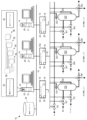
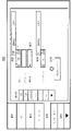
ここで図1を参照すると、プロセスプラント10は、例えば、イーサーネット接続またはバス15を介して大量のワークステーション14に連結された1つ以上のプロセスコントローラ12を含む。コントローラ12はまた、複数の組の通信線またはバス18を介してプロセスプラント10内のデバイスまたは設備に連結されるが、図1に例解されているコントローラ12aに接続された一組の通信線18のみを伴う。通信線またはバス18は、例えば、有線接続、無線接続、または有線接続及び無線接続の組み合わせであり得る。コントローラ12は、Fisher-Rosemount Systems,Inc.によって販売されているDeltaV(商標)コントローラのみを使用する例によって実装され得るが、プロセスプラント10全体に分散されたフィールドデバイス及びフィールドデバイス内の機能ブロック等の制御要素と通信することができることで、1つ以上のプロセス制御ルーチン19を実行し、これによってプロセスプラント10またはプロセスプラ
ント10内の1つ以上のプロセス動作の所望の制御を実装する。ワークステーション14(例えば、パーソナルコンピュータであり得る)は、コントローラ12によって実行されることになるプロセス制御ルーチン19、及びワークステーション14または他のコンピュータによって実行されることになる表示ルーチンを設計し、かつこのようなプロセス制御ルーチン19をコントローラ12で同期させるためにコントローラ12と通信するために1人以上の構成エンジニアによって使用され得る。さらに、ワークステーション14は、プロセスプラント10の動作中にプロセスプラント10またはその要素に属する情報を受信及び表示する表示ルーチンを実行し得る。
Referring now to FIG. 1, a
ワークステーション14の各々は、構成設計アプリケーション、及び表示アプリケーションまたは閲覧アプリケーション等のアプリケーションを記憶するための、ならびにプロセスプラント10の構成に属する構成データ等のデータを記憶するためのメモリ20を含む。ワークステーション14の各々はまた、構成エンジニアがプロセス制御ルーチン及び他のルーチンを設計することを可能にし、かつこれらのプロセス制御ルーチンをコントローラ12でもしくは他のコンピュータに同期させるか、またはプロセスプラント10の動作中にユーザに対して情報を収集及び表示するようにアプリケーションを実行するプロセッサ21を含む。いくつかの実施形態において、遠隔コンピューティングデバイスは、構成エンジニアがワークステーション14から遠隔でアプリケーションを実行し得るように、ワークステーション14と通信可能に接続している(例えば、ネットワークまたはウェブ基盤インターフェースを介して)。
Each
またさらに、コントローラ12の各々は、制御アプリケーション及び通信アプリケーションを記憶するメモリ22、ならびに任意の既知の様式で制御アプリケーション及び通信アプリケーションを実行するプロセッサ24を含む。1つの場合において、コントローラ12の各々は、複数の異なる、独立して実行される制御モジュールまたはブロック19を使用して制御方策を実装するコントローラアプリケーションを記憶及び実行する。制御モジュール19は、機能ブロックとして一般に称されるものから各々なり得、各機能ブロックは、制御ルーチン全体の一部またはサブルーチンであり、例えば、プロセスプラント10によって実行される1つ以上のプロセスの動作を制御するために、プロセスプラント10内のプロセス制御ループを実装するように他の機能ブロックと併せて動作する(リンクと呼ばれる通信を介して)。
Still further, each
公知のように、機能ブロックは、オブジェクト指向プログラミングプロトコル内のオブジェクトであり得るが、送信機、センサ、または他のプロセスパラメータ測定デバイス等のフィールドデバイスと関連付けられるような入力機能か、PID、ファジー論理等の制御を実行する制御ルーチンと関連付けられるような制御機能か、またはプロセスプラント10内の一部の物理的機能を実行するために、バルブまたは他のフィールドデバイス等の一部のデバイスの動作を制御する出力機能のうちの1つを典型的に実行する。当然のことながら、モデル予測コントローラ(MPC)、オプティマイザ等の複合タイプ及び他のタイプの複雑な機能ブロックも存在する。Fieldbusプロトコル及びDeltaVシステムプロトコルは、オブジェクト指向プログラミングプロトコル内で設計及び実装された制御モジュール及び機能ブロックを使用するが、制御モジュールは、例えば、シーケンシャルファンクションチャート、ラダーロジック等を含む任意の所望の制御プログラミングスキームを使用して設計されてもよく、機能ブロックまたは任意の他の特定プログラミング技術を使用して設計されることに限定されない。
As is known, a function block may be an object within an object-oriented programming protocol, but may be an input function such as associated with a field device such as a transmitter, sensor, or other process parameter measurement device, PID, fuzzy logic, etc. or control the operation of some device, such as a valve or other field device, to perform some physical function within the
ワークステーション14は、プロセス制御ルーチン19内の制御要素を例解する表示画面及びこれらの制御要素が、プロセスプラント10の制御を提供するように構成される様式を介して、コントローラ12内のプロセス制御ルーチン19の図形描写をユーザに提供し得る。図1のシステムにおいて、構成データベース25は、コントローラ12及びワー
クステーション14によって使用される構成データを記憶し、かつ一部の場合において将来の使用のためにプロセスプラント10内で生成されたデータを収集及び記憶することによってデータヒストリアンとして働くように、イーサーネットバス15に接続される。実施形態において、構成データベース25は、ライブラリアイテム(例えば、テンプレート及びクラスモジュール)及び構成データに対応するシステム構成アイテム(例えば、ライブラリアイテムから作成されたオブジェクト)を含み得る。このように、構成データベース25は、ライブラリデータ記憶エリアとシステム構成記憶エリアとに論理的及び/または物理的に仕切られ得る。
図1に例解されるプロセスプラント10において、コントローラ12aは、バス18を介して、ここでは3つの反応装置_01、反応装置_02、及び反応装置_03と称される3組の類似構成の反応装置(プラント10内の複製設備である)に通信可能に接続される。反応装置_01は、反応装置容器または反応装置タンク100、反応装置容器100内に酸、アルカリ、及び水をそれぞれ提供する流体入口ラインを制御するために接続された3つの入力バルブシステム(設備実体である)101、102及び103、ならびに反応装置容器100の流体流出を制御するために接続された出口バルブシステム104を含む。センサ105は、レベルセンサ、温度センサ、圧力センサ等の任意の所望のタイプのセンサであり得るが、反応装置容器100内またはその近傍に配設される。この考察の目的に対して、センサ105は、レベルセンサであると仮定される。さらに、共有ヘッダバルブシステム110は、反応装置の各々、反応装置_01、反応装置_02、及び反応装置_03の上流の水ライン上に接続されることで、これらの反応装置の各々への水の流れを制御するためのマスター制御を提供する。
In the
同様に、反応装置_02は、反応装置容器200、3つの入力バルブシステム201、202及び203、出口バルブシステム204、ならびにレベルセンサ205を含み、一方で反応装置_03は、反応装置容器300、3つの入力バルブシステム301、302及び303、出口バルブシステム304ならびにレベルセンサ305を含む。図1の例において、反応装置である、反応装置_01、反応装置_02、及び反応装置_03は、入力バルブシステム101、201及び301が酸を提供すること、入力バルブシステム102、202及び302がアルカリを提供すること、ならびに入力バルブシステム103、203及び303が、共有水ヘッダ110と併せて、水を反応装置容器100に提供することによって、塩を生産し得る。出口バルブシステム104、204及び304は、図1の右に導かれる流れラインの外に生成物を送り、図1の下に導かれる流れラインの外に廃棄物または望まれない物質を排出するように動作され得る。
Similarly, reactor_02 includes
コントローラ12aは、反応装置ユニット、反応装置-01、反応装置_02、及び反応装置_03に関する1つ以上の動作を実行するためにこれらの要素の動作を制御するように、バス18を介してバルブシステム101~104、110、201~204及び301~304、ならびにセンサ105、205及び305に通信可能に連結される。このような動作は、概してフェーズと呼ばれるが、例えば、反応装置容器100、200、300を充填すること、反応装置容器100、200、300内の物質を加熱すること、反応装置容器100、200、300の廃棄物を放出すること、反応装置容器100、200、300を洗浄すること等を含み得る。
図1に例解されたバルブ、センサ、及び他の設備は、例えば、Fieldbusデバイス、標準4~20maデバイス、HARTデバイス、無線HARTデバイス等を含む任意の所望の種類またはタイプの設備であり得、Fieldbusプロトコル、HARTプロトコル、無線HARTプロトコルまたは他の無線プロトコル、4~20maアナログプロトコル等のような、任意の既知または所望の通信プロトコルを使用するコントローラ12(例えば、コントローラ12または12aのいずれか)と通信し得る。概して、プロセス
環境内に配置され、かつプロセスの制御に直接影響を与える機能(例えば、開閉バルブ、制御アルゴリズムもしくはループ内で使用されることになる測定機能、及び/または他の機能)を実行するデバイスは、本明細書で「フィールドデバイス(field device)」と称される。
The valves, sensors, and other equipment illustrated in FIG. 1 can be any desired kind or type of equipment, including, for example, Fieldbus devices, standard 4-20 ma devices, HART devices, wireless HART devices, etc. a controller 12 (eg, either
またさらに、他のタイプのデバイスは、本明細書で考察される原理によって、コントローラ12に接続され、それによって制御され得る。例えば、コントローラ12は、1つ以上の入力/出力(I/O)デバイス(図示せず)に接続され得、次に、1つ以上のフィールドデバイスに接続され得る。I/Oデバイスは、典型的には、1つ以上のフィールドデバイス、コントローラ12、及び/またはプロセス制御システム間の通信を可能にするようにコントローラ12によって使用される。このように、I/Oデバイスはまた、プロセスを制御するために制御アルゴリズムまたはループの直接的な実行の参加者であり得る。したがって、コントローラ、I/Oデバイス、及びフィールドデバイスは、本明細書で「プロセス制御デバイス(process control device)」として概して及び分類上、称される。当然のことながら、「プロセス制御デバイス」という用語は、コントローラ、I/Oデバイス、及びフィールドデバイスのみに限定されず、プロセスプラントまたはプロセス制御システム内でプロセスを制御するために実行されることになる制御アルゴリズム、及び/またはループに参加するか、もしくはそれらに対して要求される他のデバイスも含み得る。
Still further, other types of devices can be connected to and controlled by
加えて、他の数及びタイプのコントローラが、プロセスプラント10と関連付けられた他のデバイスまたはエリアを制御するためにプラント10内で接続され得、このような追加のコントローラの動作は、任意の所望の様式で図1に例解されたコントローラ12aの動作と調整され得る。いくつかの実施形態において、図1のプロセスプラント10は、アクセスポイント、プラント10内の無線ネットワーク及び有線ネットワーク間のゲートウェイ、他のネットワークへのゲートウェイ、中継器、ルータ等のような、プロセスプラント10内の無線通信(図示せず)のためのプラント10内または外等の1つ以上のノードを含む。無線通信のためのこれらのノードは、コントローラ12、ワークステーション14、構成データベース25、フィールドデバイス、他の無線有効ノード、及び他のデータベースまたはデータ記憶デバイスに通信可能に連結され得る(有線プロトコル、無線プロトコル、またはそれらの組み合わせを使用して)。
Additionally, other numbers and types of controllers may be connected within
概して言うと、図1のプロセスプラント10は、例えば、ワークステーション14またはコントローラ12aの一方がバッチ実行ルーチンを実行するバッチプロセスを実装するように使用され得、バッチ実行ルーチンは、特定タイプの塩等の製品を生産するために必要とされる一連の異なるステップ(一般にフェーズと称される)を実行するために反応装置ユニット(及び他の設備)の1つ以上の動作を指図する高位制御ルーチンである。異なるフェーズを実装するために、バッチ実行ルーチンは、実行されることになるステップ、ステップと関連付けられた量及び時間、ならびにステップの順序を特定する、レシピと一般に称されるものを使用する。1つのレシピに対するステップは、例えば、適切な物質または成分で反応装置容器を充填すること、反応装置容器内で物質を混合すること、一定時間、一定温度に反応装置容器内の物質を加熱すること、反応装置容器を空にすること、及びその後、次のバッチ運転のための調製のために反応装置容器を洗浄することを含み得る。ステップの各々は、バッチ運転のフェーズを定義し、コントローラ12a内のバッチ実行ルーチンは、これらのフェーズの各々1つに対して異なる制御アルゴリズムを実行することになる。当然のことながら、特定の物質、物質の量、加熱温度、時間等は、異なるレシピに対して異なり得、その結果、これらのパラメータは、製造または生産される製品及び使用されるレシピに応じてバッチ運転ごとに変更され得る。当業者は、制御ルーチン及び構成が、図1に例解された反応装置内のバッチ運転について本明細書で説明されるが、制御ルーチンが、所望される場合に、任意の所望のバッチプロセス運転を実行するために
、または連続プロセス運転を実行するために、他の所望のデバイスを制御するために使用され得ることを理解するであろう。
Generally speaking, the
また理解されるように、バッチプロセスの同一フェーズまたは同一ステップが、同一時間または異なる時間に図1の異なる反応装置ユニットの各々に実装され得る。さらに、図1の反応装置ユニットが同数及び同一タイプの設備を概して含むので、特定フェーズのための同一の包括的フェーズ制御ルーチンは、この包括的フェーズ制御ルーチンが、異なる反応装置ユニットと関連付けられた異なるハードウェアまたは設備を制御するために修正される必要があることを除いて、異なる反応装置ユニットの各々を制御するために使用され得る。例えば、反応装置_01に対する充填フェーズ(反応装置ユニットが充填される)を実装するために、充填制御ルーチンが、一定時間、例えば、容器100が充填されたことをレベルメータ105が検知するまで、入力バルブシステム101、102及び103と関連付けられた1つ以上のバルブを開くことになる。しかしながら、この同一制御ルーチンは、バルブシステム101、102及び103の代わりにバルブシステム201、202及び203と関連付けられたものとなる入力バルブの指定を単に変更することによって、かつレベルメータ105の代わりにレベルメータ205になるようにレベルメータの指定を変更することによって、反応装置_02に対する充填フェーズを実装するために使用され得る。
It will also be appreciated that the same phases or steps of a batch process can be implemented in each of the different reactor units of Figure 1 at the same or different times. Further, since the reactor units of FIG. 1 generally contain the same number and type of equipment, the same global phase control routine for a particular phase may be similar to the one the global phase control routine was associated with different reactor units. It can be used to control each of the different reactor units, except that it needs to be modified to control different hardware or equipment. For example, to implement a fill phase for Reactor_01 (reactor unit is filled), the fill control routine enters the input One or more valves associated with
プロセス構成を作成及び変更するために、図1のワークステーション14のうちの1つ内に記憶された構成アプリケーション50は、プロセス制御プラント10を構成することに使用するための一式のモジュールクラスオブジェクト52を含む。モジュールクラスオブジェクトは、大量の複製設備組を有するプラントを構成するときに特に有用である。概して言うと、異なるモジュールクラスオブジェクト52は、プロセスプラント10内で複製または使用される各々異なるタイプの物理的ユニットまたは設備、プロセスプラント10内で複製または使用される各タイプの制御活動、プロセスプラント10内で複製または使用される各々異なるタイプの表示アプリケーション等に対して作成され得る。一度作成されると、モジュールクラスオブジェクト52は、モジュールクラスオブジェクトに対応するプロセスプラント10の要素を構成するために使用され得る。
To create and modify process configurations, a
モジュールクラスオブジェクト52は、本質的に包括的バージョンのプロセス実体であり、かつ任意の特定プロセス実体に紐付けられていないが、それらと関連付けられたより低位のオブジェクトまたはインスタンス53、54、55及び56(本明細書ではモジュールオブジェクトまたはモジュールブロックと称される)を有し得る。本明細書で使用される「プロセス実体(process entity)」という用語は、一体的に識別、分類またはグループ化され得るプロセスプラント10または環境のサブセットを概して意味する。例えば、プロセス実体は、プラントの物理的エリア、設備のタイプ、制御機能のタイプ、関連する表示グループ、または他の分類であり得る。プロセス実体は、他のプロセス実体を含み得る。例えば、「バルブ(valve)」に対応するプロセス実体は、「ガスバルブ(gas valve)」または「水バルブ(water valve)」等のより低位のプロセス実体を含み得、より低位のプロセス実体「水バルブ」は、「単一方向水バルブ(unidirectional water valve)」及び「両方向水バルブ(bidirectional water valve)」等のさらに低位のプロセス実体を含み得る。
A
上記のように、本明細書で使用される、モジュールクラスオブジェクトは、概して、プロセス実体の包括的または分類上の指標である。モジュールオブジェクト53、54、55、56は、モジュールクラスオブジェクトから作成または派生され得、したがって作成元または派生元のモジュールクラスオブジェクトと同一構造及び同一プロパティを受け継ぎ得る。しかしながら、各モジュールオブジェクトは、プロセスプラント10内の特定の
実体に紐付けられる。したがって、単一モジュールクラスオブジェクト52は、特定タイプの反応装置ユニットを表すように作成され得るが(それらの反応装置ユニットがプラント10内に存在する数にかかわらず)、一方で異なるモジュールオブジェクト53が、そのタイプがプラント10内に実際に存在する異なる反応装置ユニットの各々に対して存在し得るか、または作成され得る。
As noted above, a module class object, as used herein, is generally a generic or categorical index of a process entity. A
モジュールクラスオブジェクトから作成または派生されたモジュールオブジェクトは、モジュールクラスオブジェクトと関連付けられ、かつモジュールクラスオブジェクトによって所有される。結果として、モジュールクラスオブジェクトになされた変更は、そのモジュールクラスオブジェクトと関連付けられたモジュールオブジェクトの各々内で反映され得るか、またはそれらに伝播され得る。それゆえに、多数のモジュールオブジェクトが特定モジュールクラスオブジェクトから作成されていると共に、異なるプロセス実体に紐付けられた異なるモジュールオブジェクトの各々を伴うとき、異なるモジュールオブジェクトの各々は、モジュールクラスオブジェクトを単純に変更し、かつ関連するモジュールオブジェクトに下位に伝播される変更を有することによって変更され得る。考察されるように、伝播は、モジュールクラスオブジェクトが変更されたときに自動的に生じ得るか、または伝播の時間は選択され得る。 A module object created or derived from a module class object is associated with and owned by the module class object. As a result, changes made to a module class object can be reflected in or propagated to each of the module objects associated with that module class object. Therefore, when multiple module objects are created from a particular module class object, with each different module object tied to a different process entity, each different module object simply modifies the module class object. and having changes propagated down to associated module objects. As discussed, propagation can occur automatically when a module class object is changed, or the time of propagation can be selected.
図1のモジュールクラスオブジェクト52は、オブジェクト指向プログラミング環境またはオブジェクト指向プログラミング言語でオブジェクトと一般に称されるものであり得る。結果として、これらのオブジェクトは、他のオブジェクトを所有するか、またはそれらを参照する能力を有する。概して言うと、モジュールクラスオブジェクト52は、制御ルーチン、設備またはプロセス実体と関連付けられた他の要素等の個々の要素の指標または定義と共に、これらの個々の要素が、物理的要素が相互接続される方式または論理的要素が物理的要素と併せて動作する方式等の、互いに相互作用する様式の定義または指標を含み得る高位のオブジェクトである。言い換えると、モジュールクラスオブジェクトは、例えば、オブジェクト指向プログラミング言語内のオブジェクトであり得、これは、プロセスプラント10内の設備、制御要素、ディスプレイ等の特定の1つまたはグループの制御及び閲覧のための基盤を提供し、プロセス制御プラント10内の異なる複製設備を構成するために使用されることになるその要素の多くのインスタンスを作成するために有用であり得る。
The
基本的に、各モジュールクラスオブジェクトは、異なる制御アプリケーション及び/または表示アプリケーションの全ての形式のプロセス実体の包括的定義、またはその実体を制御するためにコントローラ12によって、もしくはその実体に関する表示活動を実行するためにワークステーション14によって使用されることになるその実体に適用可能なルーチンを含む構成コンテナである。モジュールクラスオブジェクトは、ユニット、設備の部品、制御実体、表示アプリケーション等のような、任意の性質のプロセス実体を表し得る。プロセスプラント10の構成中、モジュールクラスオブジェクトは、モジュールクラスオブジェクトによって提供された定義に順応する任意の数の異なるプロセス実体の構成インスタンスを作成するために使用され得、各構成インスタンス(モジュールクラスオブジェクトから作成されたモジュールオブジェクト)が、異なる実際のプロセス実体と関連付けられているか、またはそれに紐付けられていることを伴う。これらの異なるモジュールオブジェクトは、とりわけ、プロセスプラント10内に配設されるときに特定プロセス実体に結び付けられた制御ルーチン及び/または表示ルーチンを含み、これらの制御ルーチンが、プロセス実体上で実際の制御活動を実行するために図1のコントローラ12内で同期及び使用されることができ、表示ルーチンが、プロセスプラント10の動作中に実体に関する実際の表示活動を実行するためにワークステーション14で同期され得ることを伴う。
Essentially, each module class object is a generic definition of a process entity of all types of different control and/or display applications or to perform display activities by or on the
異なるタイプのモジュールクラスオブジェクトは、異なる範囲のプロセス実体を反映し得、それゆえに、異なる範囲のプロセス実体上またはそれに関して動作するように構成された制御ルーチン及び/または表示ルーチンを含有する。ユニット等のプロセス実体の範囲がより広くなればなるほど、より多くの制御ルーチン及び/または表示ルーチンがモジュールクラスオブジェクトと典型的に関連付けられることになり、それらのモジュールクラスオブジェクトを使用してプラントの区分を構成することがより簡単になる。しかしながら、モジュールクラスオブジェクトと関連付けられたプロセス実体の範囲が広くなればなるほど、プロセスがその範囲で複製設備を含むことになる見込みが低下し、したがって、モジュールクラスオブジェクトが大規模に有用である見込みが低下する。逆に言えば、モジュールクラスオブジェクトと関連付けられたプロセス実体の範囲が狭くなればなるほど、モジュールクラスオブジェクトがプラントの様々な異なる位置で使用され得る見込みが増加するが、任意の特定インスタンス内でそのモジュールクラスオブジェクトを使用するときに実行される構成数が低下する。任意の事象において、モジュールクラスオブジェクトは、構成が制御モジュールレベルよりも高位の抽象概念で異なる複製設備に対して実行されることを可能にし、これは、特に、ユニットレベル等の広い範囲のモジュールクラスオブジェクトを使用するときに複製ユニット及び他の設備を含むプロセスプラントを構成することをより簡単かつより短時間で行う。 Different types of module class objects may reflect different scopes of process entities and, therefore, contain control and/or display routines configured to operate on or with respect to different scopes of process entities. The wider the range of process entities, such as units, the more control and/or display routines will typically be associated with a module class object, which are used to partition the plant. is easier to configure. However, the greater the scope of the process entity associated with the module class object, the less likely it is that the process will include replication facilities in its scope, and thus the less likely it is that the module class object will be useful on a large scale. descend. Conversely, the narrower the scope of the process entity associated with the module class object, the greater the likelihood that the module class object can be used in a variety of different locations in the plant, but not within any particular instance of that module. Fewer configurations are performed when using class objects. In any event, the module class object allows configuration to be performed at a higher level of abstraction than the control module level for different replication facilities, which is particularly useful for a wide range of module classes such as the unit level. It makes it easier and faster to configure process plants, including duplicate units and other equipment when using objects.
その結果、複数レベルのオブジェクトが可能である。例えば、モジュールクラスオブジェクト52から作成されたインスタンス53、54、55、56に対応するオブジェクト(例えば、「インスタンスオブジェクト(instance object)」)は、それ自体が一組の1つ以上の子オブジェクト(図示せず)に対する親オブジェクトであり得る。インスタンス子オブジェクトの1つ以上は、さらに別のレベルの子オブジェクトに対する親オブジェクト等であり得る。本明細書で使用される、「プロセス要素オブジェクト(process element object)」は、バルブ、センサ、図形形状、またはコントローラ等の構成が同期される要素のプロセス実体に対応する最低位のオブジェクトを意味する。したがって、プロセス要素オブジェクトは、子オブジェクトを有しないインスタンスオブジェクトであり得る。
As a result, multiple levels of objects are possible. For example, the objects (e.g., "instance objects") corresponding to the
一例において、プロセス制御システムを構成するとき、構成エンジニアは、図1の異なる反応装置用等の、プロセスプラント内で複製された異なる要素に対する単一モジュールクラスオブジェクトを作成し得る。その後、構成エンジニアは、図1の実際の反応装置の各々に対するモジュールクラスオブジェクト(モジュールオブジェクト)のインスタンスを作成し得る。各々このように作成されたモジュールオブジェクトは、図1の反応装置のうちの1つを動作させるようにコントローラ12aによって使用される制御ルーチンを含むことになり、図1の反応装置のうちの1つ内の設備に具体的に紐付けられるか、または結び付けられる。これらの制御ルーチンは、その後、コントローラ12aで同期され、プロセスプラント10の動作中に使用され得る。しかしながら、一度作成されると、モジュールオブジェクトの各々は、モジュールクラスオブジェクトに依然として紐付けられ、モジュールオブジェクト等へのアクセスを提供または拒絶するために、変更されることになるモジュールクラスオブジェクトによって制御され得る。
In one example, when configuring a process control system, a configuration engineer may create a single module class object for different elements replicated within a process plant, such as for different reactors in FIG. The configuration engineer can then create an instance of the module class object (module object) for each of the actual reactors of FIG. Each module object thus created will contain a control routine that is used by the
加えて、制御ルーチンがコントローラ12aで同期され得るが、制御ルーチン及び表示ルーチンはまた、図1のワークステーション14のうちの1つ内に記憶された表示アプリケーション48で同期され得る。表示アプリケーション48は、1つ以上のプロセス表示を作成するためにランタイム中に表示ルーチンを動作または実装し、そしてフィールドデバイスを制御するためのコントローラ12aに対する命令を提供するために、かつコントローラ12aから通信を受信するためにランタイム中に制御ルーチンを動作または実装し得る。例えば、表示アプリケーション48は、プロセスプラントの一部分内のプロセス実体の図形描写及びプロセス実体に対応するパラメータに対するパラメータ値を表示するた
めに表示ルーチンを動作させ得る。表示アプリケーション48はまた、図示されたプロセス実体を制御するための、及び図示されたプロセス実体からオンラインプロセス制御システム内のパラメータ値を受信するためのコントローラ12aに対する命令を提供するように制御ルーチンを動作させ得る。表示アプリケーション48は、その後、表示ルーチンを介してオンラインプロセス制御システムから受信したパラメータ値を表示し得る。他の実施形態において、制御ルーチン、表示ルーチン、及び/または任意の他の適切なプロセスルーチンは、コントローラ12a、表示アプリケーション48、フィールドデバイス、またはランタイム中にプロセスルーチンを実行する任意の他のプロセス要素の組み合わせにおいて同期され得る。
Additionally, although the control routines may be synchronized with the
プロセスプラント内で構成活動を実行するためにプロセスプラント内で作成または使用され得る、多くの異なる可能なタイプのモジュールクラスオブジェクトが存在するが、例として本明細書で考察される4つの具体的なタイプは、ユニットモジュールクラスオブジェクト、設備モジュールクラスオブジェクト、制御モジュールクラスオブジェクト、及び表示モジュールクラスオブジェクトを含む。概して言うと、各々異なるタイプのモジュールクラスオブジェクトは、プロセスプラント10内の異なる範囲の制御または使用に対して設計または意図される。ユニットモジュールクラスオブジェクトは、プロセスプラント内の設備の幅広い範囲に対する制御活動を表すために(及び構成するために)使用されることが意図される。特に、ユニットモジュールクラスオブジェクトは、例えば、図1の反応装置等の、一部の既知の様式で互いに共同して機能する個々の要素を有する相互関係のある一組の設備をモデル化すること、またはそれらを構成するために使用されることが意図される。
Although there are many different possible types of module class objects that can be created or used within a process plant to perform configuration activities within the process plant, four specific types are considered here as examples: Types include unit module class objects, equipment module class objects, control module class objects, and display module class objects. Generally speaking, each different type of module class object is designed or intended for a different range of control or use within
設備モジュールクラスオブジェクトは、プロセスプラント内のより狭い範囲の物理的設備に対する制御活動を表すために(及び構成するために)使用されることが意図される。設備モジュールクラスオブジェクトと関連付けられた設備は、概して、ユニットのサブシステムを作成するバルブ、流量計等のような、1つ以上の物理的実体であり、設備モジュールクラスオブジェクトは、設備の部品上で実行されることになる、コマンド駆動型アルゴリズム(CDA)、状態駆動型アルゴリズム(SDA)、シーケンシャルファンクションチャート(SFC)アルゴリズム、機能ブロック図(FBD)アルゴリズム、フェーズアルゴリズム等であり得る、1つ以上のコマンドまたはアルゴリズムを含み得る。したがって、設備モジュールクラスオブジェクトは、ユニット内で使用されるその設備上で基礎的な一組の機能を提供するためにユニット内の複数低位構成要素または実体の制御を構成することを目的とする。既知のように、コマンド駆動型アルゴリズム(コマンド駆動型制御論理)は、低位構成要素が機能を実現するために複数ステップを通して調整されなければならないときに使用される。例えば、バルブは、別のバルブが開かれて、その後、閉じられる間に、特定時間開かれた後に、閉じられる必要があり得る。 Equipment module class objects are intended to be used to represent (and configure) control activities for a narrower range of physical equipment within a process plant. The equipment associated with an equipment module class object is generally one or more physical entities such as valves, flow meters, etc. that make up a subsystem of the unit. One or more algorithms to be executed, which may be Command Driven Algorithm (CDA), State Driven Algorithm (SDA), Sequential Function Chart (SFC) algorithm, Functional Block Diagram (FBD) algorithm, Phase Algorithm, etc. It may contain commands or algorithms. Therefore, the equipment module class object is intended to organize the control of multiple low-level components or entities within a unit to provide a basic set of functions on that equipment used within the unit. As is known, command-driven algorithms (command-driven control logic) are used when low-level components must be coordinated through multiple steps to achieve a function. For example, a valve may need to be closed after being open for a certain amount of time while another valve is opened and then closed.
制御モジュールクラスオブジェクトは、プロセスプラント内の個々の制御要素または制御モジュールを表すために(及び構成するために)使用されることが意図される。制御モジュールクラスオブジェクトは、バルブ、メータ等のようなプラント実体上、設備の部品上またはさらにユニット上で実行されることになる特定タイプの制御を提供または特定する。概して言うと、制御モジュールクラスオブジェクトは、コントローラ内で実行されることになる一部の制御モジュールを定義する一組の通信可能に相互接続された機能ブロック等の、プロセスプラント内の反復制御活動を実行するために有用な特定タイプの制御プログラミングを提供する。ほとんどの場合において、制御モジュールクラスオブジェクトは、単一デバイスまたは関連する一組のデバイスを操作するために包括的制御方策を提供し得る。 A control module class object is intended to be used to represent (and configure) individual control elements or control modules within a process plant. A control module class object provides or specifies a particular type of control to be performed on a plant entity such as a valve, meter, etc., on a piece of equipment or even on a unit. Generally speaking, a control module class object represents repetitive control activities within a process plant, such as a set of communicatively interconnected function blocks that define some control module to be executed within the controller. It provides a specific type of control programming that is useful to implement. In most cases, a control module class object can provide a generic control strategy for operating a single device or set of related devices.
表示モジュールクラスオブジェクトは、プロセスプラント10の動作中に、制御オペレ
ータ等のユーザによって閲覧されることになる表示活動を表すために(及び構成するために)使用されることが意図される。したがって、表示モジュールクラスオブジェクトは、図1のオペレータワークステーション14内の一定タイプの表示を生成するために必要とされるプログラミング及びその表示がプラント10の動作中にプラントから適切な情報を取得することを可能にするためにワークステーション14(及びプロセスプラント10内の任意の他のデバイス)のうちの1つ以上内で動かされることを必要とされるプログラミングを特定し得る。表示クラスモジュールのタイプは、例えば、警報表示、構成閲覧表示、動作閲覧表示、診断表示等を含む。当然のことながら、表示モジュールクラスオブジェクトは、プロセスプラント内の物理的要素もしくは実体の任意の所望の範囲を表す表示か、またはそれに紐付けられた表示を提供し得る。例えば、表示モジュールクラスオブジェクトは、エリア全体、ユニット、設備の部品、制御要素、またはプロセスプラント10内のこれらの要素の任意の組み合わせに関する情報を表示し得る。
A display module class object is intended to be used to represent (and organize) display activities that will be viewed by a user, such as a control operator, during operation of the
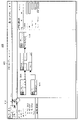
図2を参照すると、階層図式は、構成アプリケーション50内で使用され、かつ図1の表示アプリケーション48によって実行される異なるタイプのモジュールクラスオブジェクト間の相互接続、及びモジュールクラスオブジェクトとこれらのモジュールクラスオブジェクトから展開されたモジュールオブジェクトとの間の相互関係を例解する。図2の図式の最上位で始まる、モジュールクラスオブジェクト(または本明細書では互換的に言及される「クラスオブジェクト(class object)」)は、モジュールクラスタイプによってユニットモジュールクラスタイプ400、設備モジュールクラスタイプ402、制御モジュールクラスタイプ404、及び表示モジュールクラスタイプ406のうちの1つに分割される。当然のことながら、他のタイプのモジュールクラスオブジェクトが、単に例示的なモジュールクラスタイプである本明細書で例解された4つのタイプを伴って、同様に提供または使用されてもよい。個々のモジュールクラスオブジェクト(これは、例えば、オブジェクト指向プログラミング言語の高位オブジェクトであり得、明瞭化のために二重輪郭線によって図2に表される)は、異なるタイプのモジュールクラス400、402、404及び406の各々に属する。特に、プロセスプラント10内の異なるユニットまたはユニットタイプに対する大量の異なるユニットモジュールクラスオブジェクトが存在し得る。例えば、反応装置ユニットクラスモジュールオブジェクト410は、プロセスプラント10内の反応装置の特定のタイプまたは構成を表し得る。同様に、パッケージャユニットモジュールクラスオブジェクト412は、プロセスプラント10内のパッケージユニットの特定のタイプまたは構成を表し得、乾燥機ユニットクラスモジュールオブジェクト414は、プロセスプラント10内の乾燥機ユニットの特定のタイプまたは構成を表し得る。当然のことながら、物理的構成において互いとは異なる反応装置を表すように1つよりも多い反応装置ユニットモジュールクラスオブジェクトが存在してもよい。さらに、ユニットモジュールオブジェクトによって表され得るか、またはモデル化され得るプラント内の異なるタイプのユニットの全てをリスト化するように試みるものではなく、当業者は、ユニットモジュールクラスオブジェクトによってモデル化され得るか、または表され得る異なるタイプのプラント内の多くの異なるタイプのユニットが存在することを認識するであろう。
Referring to FIG. 2, a hierarchy diagram is used within the
同様に、プロセスプラント10内の異なるタイプの設備を表す、モデル化及び構成するために使用される多くの異なる設備モジュールクラスオブジェクトが存在し得る。図2に例解される例は、集計器設備モジュールクラスオブジェクト416及び出口バルブ設備モジュールクラスオブジェクト418を含み、この各々は、プロセスプラント10内の異なるタイプの設備(及び好ましくは複製設備)と関連付けられる。同じように、オン/オフバルブ制御モジュールクラスオブジェクト422、レベルセンサ制御モジュールクラスオブジェクト424、及び流量計制御モジュールクラスオブジェクト426として図2に例解された、多くの異なるタイプの制御モジュールクラスオブジェクトが存在し得る。そのうえ、表示クラスモジュールは、警報表示モジュールクラスオブジェクト432、閲覧表
示モジュールクラスオブジェクト434、及び診断表示モジュールクラスオブジェクト436として図2に例解される。当然のことながら、任意の他の所望のユニットモジュールクラスオブジェクト、設備モジュールクラスオブジェクト、制御モジュールクラスオブジェクト、及び表示モジュールクラスオブジェクトが、本明細書で説明される原理によって、プロセスプラント10の構成アプリケーション50内で作成及び使用されてもよい。
Similarly, there may be many different equipment module class objects used to model and configure, representing different types of equipment within the
各モジュールクラスオブジェクトは、それらと関連付けられるか、またはそれらによって所有されるサブオブジェクトを有し得る。これらのサブオブジェクトは、それら自身内のモジュールクラスオブジェクトであり得るか、または図2に例解されるように、それらが属するモジュールクラスオブジェクトのインスタンスとして作成されるモジュールオブジェクトであり得る。このようなインスタンスは、それらの基になるか、またはそれらが作成される、モジュールクラスオブジェクトの「モジュールオブジェクト(module
object)」、「インスタンス(instance)」、「インスタンスオブジェクト(instance object)」もしくは「モジュールインスタンスオブジェクト(module instance object)」として本明細書では互換的に言及される。図2は、反応装置ユニットモジュールクラスオブジェクト410が、3つの反応装置モジュールオブジェクトである、それらと関連付けられて名付けられた反応装置_01(符号440a)、反応装置_02(符号440b)、及び反応装置_03(符号440c)を有することを例解し、これらの反応装置モジュールオブジェクトが、それぞれの反応装置クラスオブジェクト410に対応する(つまり結び付けられる)ことを伴う。図2はまた、水1、酸1、酸2、アルカリ1、及びアルカリ2(符号440d~440h)と名付けられた5つの異なる子モジュールオブジェクトを有するか、または所有するとして、集計器設備モジュールクラスオブジェクト416を例解する。同様に、オン/オフバルブ制御モジュールクラスオブジェクト422は、粗大_バルブ1、粗大_バルブ2、粗大_バルブ3、精密_バルブ1、精密_バルブ2、及び精密_バルブ3(符号440i~440n)と名付けられた子モジュールオブジェクトを含むとして例解される。加えて、図2は、警報表示モジュールオブジェクト432に基づく警報_A図形要素オブジェクト440o、閲覧表示モジュールオブジェクト434に基づく温度_センサ_B図形要素440p及び制御_モジュール_C図形要素440q、ならびに診断表示モジュールオブジェクト436に基づくテスト_モジュール_D図形要素440r及びポンプ_E図形要素440sを例解する。同様に、図2の他のユニットモジュールクラスオブジェクト、設備モジュールクラスオブジェクト、制御モジュールクラスオブジェクト、及び表示モジュールクラスオブジェクトの各々は、それらと関連付けられた1つ以上のモジュールオブジェクトを有し得る。しかしながら、簡素化のため、これらのモジュールオブジェクトは、図2に例解されない。
Each module class object may have sub-objects associated with them or owned by them. These sub-objects may be module class objects within themselves or, as illustrated in FIG. 2, module objects created as instances of the module class object to which they belong. Such instances are called the "module object" of the module class object on which they are based or from which they are created.
are referred to interchangeably herein as "object", "instance", "instance object" or "module instance object". FIG. 2 shows that the reactor unit
図2の図式において、反応装置_01ユニットモジュールオブジェクト、反応装置_02ユニットモジュールオブジェクト、及び反応装置_03ユニットモジュールオブジェクト、酸1集計器(設備)モジュールオブジェクト、酸2集計器(設備)モジュールオブジェクト、アルカリ1集計器(設備)モジュールオブジェクト、アルカリ2集計器(設備)モジュールオブジェクト及び水1集計器(設備)モジュールオブジェクト(符号440a~h)、粗大_バルブ1制御モジュールオブジェクト、粗大_バルブ2制御モジュールオブジェクト、粗大_バルブ3制御モジュールオブジェクト、精密_バルブ1制御モジュールオブジェクト、精密_バルブ2制御モジュールオブジェクト及び精密_バルブ3制御モジュールオブジェクト(符号440i~440n)、警報_A図形要素オブジェクト、温度_センサ_B図形要素オブジェクト、制御_モジュール_C図形要素オブジェクト、テスト_モジュール_D図形要素オブジェクト、ポンプ_E図形要素オブジェクト(符号440o~440s)、ならびに他のユニットモジュールオブジェクト、設備モジュールオブジェクト、制御モジュールオブジェクト、及び表示モジュールオブジェクトの各々は、プロセスプラント10内のユニット、設備、制御モジュール、表示アプリケーション、及
び図形または図形表示要素等の、プロセスプラント10内の実際のプロセス要素に紐付けられた個々のオブジェクトである。このように、オブジェクト440a~440sは、「プロセス要素オブジェクト(process element object)」、「プロセス要素モジュールオブジェクト(process element module object)」、または「要素オブジェクト(element object)」として本明細書では互換的に言及される。同様に、オブジェクト440a~440sは、そのそれぞれの「親(parent)」または「親オブジェクトparent object」410~436の「子(child)」または「子オブジェクト(child object)」である。例えば、プラント10内で使用される複数物理的酸集計器が存在するので、構成ルーチン内で作成された複数酸集計器プロセス要素モジュールオブジェクトが存在することになり、プラント10内に存在する個々の酸集計器の各々に対して存在する別個の子酸集計器プロセス要素モジュールオブジェクトを伴う。しかしながら、子である別個の集計器プロセス要素モジュールオブジェクトの各々は、同一の親集計器モジュールクラスオブジェクト416に紐付けられるか、または所有される。当然のことながら、図2の図式は、限定された数のモジュールクラスオブジェクト、モジュールオブジェクト、インスタンスオブジェクト、及びそれらと関連付けられたプロセス要素オブジェクトのみを例解するが、他のタイプのモジュールクラスオブジェクトが提供されてもよく、任意の所望の数のモジュールオブジェクト、インスタンスオブジェクト、及びプロセス要素オブジェクトが異なるモジュールクラスオブジェクトの各々から作成されてもよいことが理解されるであろう。
In the diagram of FIG. 2, Reactor_01 unit module object, Reactor_02 unit module object, and Reactor_03 unit module object,
さらに、親オブジェクトの子であるオブジェクトは、それ自体が子オブジェクトを有し得る。例えば、クラスオブジェクト流量計制御モジュール426は、2つの子インスタンスオブジェクト、例えば、「水_流量計モジュール(Water_Flow_Meter
module)」及び「溶媒_流量計モジュール(Solvent_Flow_Meter module)」(例解せず)を含み得る。水_流量計モジュールは、「水_流量計_1(Water_Flow_Meter_1)」及び「水_流量計_2(Water_Flow_Meter_2)」等の、プロセスプラント10内のそれぞれの実際の流量計要素に対応するそれぞれの子プロセス要素モジュールオブジェクトを含み得る。このように、プロセス要素オブジェクト「水_流量計_1」及び「水_流量計_2」は、流量計制御モジュール426に基づいた「水_流量計モジュール」に基づく。
Additionally, objects that are children of parent objects may themselves have child objects. For example, the
and "Solvent_Flow_Meter module" (not illustrated). The Water_Flowmeter module has each child process corresponding to each actual flowmeter element in the
図2のモジュールクラスオブジェクトの各々(及びそれゆえに図2のモジュールオブジェクトの各々)は、オブジェクトの一部として、モジュールを定義または構成する物理的または論理的プロセス要素の定義または指標を含み得、所望される場合、これらのプロセス要素が、プロセスプラント10内の一部の活動を実行するために物理的または論理的のいずれかにおいて互いに相互作用する様式を含み得る。例えば、ユニットモジュールクラスオブジェクトは、ユニットとして定義されているプロセス実体内のまたはそれを構成する物理的かつ制御要素の全ての指標を典型的に含むことになる。ユニットモジュールクラスオブジェクトはまた、個々の一部の特定の構成及びそれらの一部がユニットとして動作するようにどのように物理的に共に紐付けられるかを定義し得る。同様に、設備モジュールクラスオブジェクトは、設備の部品及び命令として定義された実体を制御するために使用されることになる制御ルーチンまたは制御モジュールを典型的に含むことになり、これは、一部が、プラント10内に配設されたときに設備の部品として動作するように、物理的または論理的のいずれかにおいて相互作用する様式を定義するために制御ルーチンまたは制御モジュールを使用する。同様に、各制御モジュールクラスオブジェクトは、プラント内で実行されることになる、典型的に何らかの制御アルゴリズムの形式で、制御活動を定義することになる。また、各表示モジュールクラスオブジェクトは、とりわけ、表示画面構成、表示されることになる情報、及びプロセスプラント10の様々な要素を表して表示画面上に提示されることになる図形または図形要素、ならびに、もしあれば、特定タイ
プのユニット、設備、プラントのエリア、またはプラント10内の任意の他の物理的もしくは論理的実体について、収集されることになるデータ、及び収集されたデータ上で実行されることになるデータ操作を定義し得る。
Each of the module class objects of FIG. 2 (and thus each of the module objects of FIG. 2) may include, as part of the object, definitions or indicators of the physical or logical process elements that define or make up the module, and any desired If so, these process elements may include the manner in which they interact with each other, either physically or logically, to perform some activity within
モジュールクラス定義の一部として、モジュールクラスオブジェクトは、それらの中で組み込まれるか、または使用されることになる他のモジュールクラスオブジェクトを指定もしくは定義し得る。この場合、そのモジュールクラスオブジェクトから作成されたモジュールオブジェクトは、モジュールクラスレベルで定義された関係に従って他のモジュールクラスオブジェクトから作成された他のモジュールオブジェクトを組み込むか、参照するか、または含むことになる。別のモジュールオブジェクトもしくはモジュールクラスオブジェクトを参照するか、またはそれらによって参照されるモジュールオブジェクトは、本明細書では、モジュールオブジェクトを参照するか、またはそれによって参照されるモジュールオブジェクトもしくはモジュールクラスオブジェクトに関する「依存オブジェクト(dependent object)」もしくは「依存モジュールオブジェクト(dependent module object)」と称される。加えて、別のモジュールクラスオブジェクトもしくはモジュールオブジェクトを参照するか、またはそれらによって参照されるモジュールクラスオブジェクトは、本明細書では、モジュールクラスオブジェクトを参照するか、またはそれによって参照されるモジュールクラスオブジェクトもしくはモジュールオブジェクトに関する「依存オブジェクト」もしくは「依存モジュールオブジェクト」と称される。 As part of a module class definition, module class objects may specify or define other module class objects to be embedded or used within them. In this case, module objects created from that module class object will embed, reference, or contain other module objects created from other module class objects according to the relationships defined at the module class level. . A module object that references or is referenced by another module object or module class object is referred to herein as a "dependent" on the module object or module class object that references or is referenced by that module object. Also referred to as the "dependent object" or "dependent module object". In addition, a module class object that references or is referenced by another module class object or module object is herein referred to as a module class object or module class object that references or is referenced by a module class object. Referred to as the "dependent object" or "dependent module object" for the module object.
厳密に必要ではないが、ユニットモジュールクラスオブジェクトは、他のユニットモジュールクラスオブジェクト、設備モジュールクラスオブジェクト、制御モジュールクラスオブジェクト、及び表示モジュールクラスオブジェクトを組み込み得るが、一方で設備モジュールクラスオブジェクトは、他の設備モジュールクラスオブジェクト、制御モジュールクラスオブジェクト、及び表示モジュールクラスオブジェクトを組み込み得る。制御モジュールクラスオブジェクトは、他の制御モジュールクラスオブジェクト及び表示モジュールクラスオブジェクトを組み込むか、または参照し得る。しかしながら、所望される場合、他のモジュールクラスオブジェクト相互関係が同様に使用されてもよい。これらの組み込み関係は、図2の図式の下部で大きい矢印によって例解され、表示モジュールクラスオブジェクトのいずれかが、制御モジュールクラスオブジェクト、設備モジュールクラスオブジェクト、及びユニットモジュールクラスオブジェクトのいずれかに含まれ得るか、またはそれらによって参照され得ること、制御モジュールクラスオブジェクトのいずれかが、設備モジュールクラスオブジェクト及びユニットモジュールクラスオブジェクトのいずれかに含まれ得るか、またはそれらによって参照され得ること、ならびに設備モジュールクラスオブジェクトのいずれかが、ユニットモジュールクラスオブジェクトのいずれかに含まれ得るか、またはそれらによって参照され得ることを示す。モジュールクラスオブジェクトが同一タイプの他のモジュールクラスオブジェクトを組み込み得ることが理解されるであろう。例えば、ユニットモジュールクラスオブジェクトは、その定義の一部として、別のユニットモジュールクラスオブジェクトを組み込み得る。同様に、設備モジュールクラスオブジェクトは、別の設備モジュールクラスオブジェクトを含み得、制御モジュールクラスオブジェクトは、別の制御モジュールクラスオブジェクトを含み得、そして表示モジュールクラスオブジェクトは、別の表示モジュールクラスオブジェクトを含み得る。当然のことながら、所望される場合、モジュールクラスオブジェクトは、複数回、別のモジュールクラスオブジェクトを使用または組み込み得る。例えば、反応装置ユニットモジュールクラスオブジェクトは、反応装置ユニットモジュールクラスオブジェクトによってモデル化されている反応装置が集計器の複数インスタンスを含むので、集計器設備モジュールクラスオブジェクトを多数回、組み込むか、または使用し得る。 Although not strictly necessary, unit module class objects may embed other unit module class objects, equipment module class objects, control module class objects, and display module class objects, while equipment module class objects may include other A facility module class object, a control module class object, and a display module class object may be included. Control module class objects may embed or reference other control module class objects and display module class objects. However, other module class object relationships may be used as well, if desired. These embedding relationships are illustrated by the large arrows at the bottom of the diagram of FIG. any of the control module class objects may be contained in or referenced by any of the equipment module class objects and the unit module class objects; Indicates that any of the objects can be contained in or referenced by any of the unit module class objects. It will be appreciated that module class objects may embed other module class objects of the same type. For example, a unit module class object may incorporate another unit module class object as part of its definition. Similarly, an equipment module class object may contain another equipment module class object, a control module class object may contain another control module class object, and a display module class object may contain another display module class object. obtain. Of course, a module class object may use or embed another module class object multiple times if desired. For example, a reactor unit module class object incorporates or uses an aggregator equipment module class object multiple times because the reactor modeled by the reactor unit module class object contains multiple instances of the aggregator. obtain.
第1のモジュールクラスオブジェクトが第2のモジュールクラスオブジェクトを組み込
むか、または使用するとき、第1のモジュールクラスオブジェクトから作成されたか、またはそのインスタンスとしての任意のモジュールオブジェクトが、第2のモジュールクラスオブジェクトから作成されたか、またはそのインスタンスとしてのモジュールオブジェクトを組み込むか、または使用することになることがまた理解されるであろう。したがって、反応装置ユニットモジュールクラスオブジェクト410は、その要素または一部として集計器モジュールクラスオブジェクト416を使用し、反応装置_01モジュールオブジェクトは、その要素または一部として、酸1モジュールオブジェクト440e等の集計器モジュールオブジェクトのうちの1つを使用するか、または含むことになる。同様に、集計器設備モジュールクラスオブジェクトが出口バルブ設備モジュールクラスオブジェクトを組み込むか、または含む場合、集計器設備モジュールクラスオブジェクトから作成されたモジュールオブジェクトは、例えば、集計器_1のように一意的に命名されることになるが、出口バルブ設備モジュールクラスオブジェクトから作成され、かつ、例えば、出口_バルブ_2として一意的に命名されたモジュールオブジェクトを含むことになる。このように、モジュールクラスオブジェクトレベルで定義されるモジュールクラスオブジェクト間の関係は、これらのモジュールクラスオブジェクトから展開または作成されたモジュールオブジェクト内で反映される。モジュールクラスオブジェクト(及びそれゆえにモジュールオブジェクト)間のこの相互関係または参照は、構成活動中のオブジェクトの優れた可変性及び高い移動可能性を可能にし、そのため、制御モジュールクラスオブジェクト及び設備モジュールクラスオブジェクト等の初期モジュールクラスオブジェクトが作成された後、ユニットモジュールクラスオブジェクト等のより複雑なモジュールクラスオブジェクトが、初期モジュールクラスオブジェクトを参照することによって、容易に作成され得る。当然のことながら、モジュールクラスオブジェクトが他のモジュールクラスオブジェクトを参照または使用し得るが、それらはさらにまたは代わりに、関連するモジュールクラスオブジェクトを有しない、バルブ、センサ等の単なるオブジェクトまたはプロセス要素オブジェクトを定義または使用することができる。これらの単なるオブジェクトまたはプロセス要素オブジェクトは、モジュールクラスオブジェクト自体の中で、それらのために使用される制御ルーチンに関して完全に定義されることになる。
When a first module class object embeds or uses a second module class object, any module object created from or as an instance of the first module class object It will also be understood that one will incorporate or use a module object created from or as an instance thereof. Thus, the Reactor_01
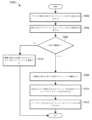
エンジニアが、図1の構成アプリケーション50を介して、モジュールクラスオブジェクト、モジュールオブジェクト等のオブジェクトの構成を変更または修正するとき、エンジニアは、構成アプリケーション50を介して変更を保存し得る。エンジニアは、その後、ランタイム中の実行及び動作のために修正されたオブジェクトを同期させるように図3に示されるユーザ制御を提示され得る。エンジニアがユーザ制御を選択するとき、構成アプリケーション50は、修正されたオブジェクトをインスタンス化する要求を受信する。
When an engineer changes or modifies the configuration of an object such as a module class object, module object, etc. via
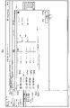
図3は、構成アプリケーション50によって提示された例示的な画面表示500を例解する。例示的な画面表示500は、モジュールオブジェクトFT-10125(符号504)、LIC-10125(符号506)、及びFV-10125(符号508)を参照する制御モジュールオブジェクトFIC-10125(符号502)を提示する。したがって、モジュールオブジェクトFT-10125(符号504)、LIC-10125(符号506)、及びFV-10125(符号508)は、制御モジュールオブジェクトFIC-10125(符号502)に関する依存オブジェクトである。エンジニアは、パラメータを追加または削除すること、パラメータ値を変更すること、モジュールオブジェクトFT-10125(符号504)、LIC-10125(符号506)、及びFV-10125(符号508)のうちの1つ等の別のオブジェクトに対する参照を追加または削除すること、モジュールオブジェクトFT-10125(符号504)、LIC-10125(符号506)、及びFV-10125(符号508)間の接続またはリンクを変更すること等によって制御モジュールオブジェクトFIC-10125(符号502)の構成を修正し得る。その後、ユーザは、制御モジュールオブジェクトFIC-10125(符号502)の修正された構成を保存するようにユーザ制御を選択し得る。
FIG. 3 illustrates an
例示的な表示画面500はまた、修正された制御モジュールオブジェクトFIC-10125(符号502)を同期させるためのユーザ制御510を含み得る。エンジニアが同期ユーザ制御510を選択するとき、構成アプリケーション50は、修正された制御モジュールオブジェクトFIC10125(符号502)をインスタンス化する。より具体的には、構成アプリケーション50は、修正された制御モジュールオブジェクトFIC-10125(符号502)をコントローラ12a、表示アプリケーション48、またはランタイム中にプロセスルーチンを実行する他のプロセス要素で同期させる。
加えて、ユーザ制御510の選択を受信することに際して、構成アプリケーション50は、制御モジュールオブジェクトFIC-10125(符号502)を参照するか、またはそれによって参照され、かつ未確定の修正を有するモジュールクラスオブジェクト及びモジュールオブジェクト等のオブジェクトを識別する。依存するオブジェクトに対する未確定の修正は、依存オブジェクトが依存するオブジェクト(例えば、制御モジュールオブジェクトFIC-10125(符号502))に対する修正の結果であり得るか、または制御モジュールオブジェクトFIC-10125(符号502)に対する修正から独立したものであり得る。
In addition, upon receiving a selection of
例えば、制御モジュールオブジェクトFIC-10125(符号502)に対する修正は、制御モジュールオブジェクトFIC-10125(符号502)の先の構成内に含まれなかった別のモジュールオブジェクトに対する参照の追加であり得る。パラメータがモジュールオブジェクトFT-10125(符号504)内に追加されるとき、これは、制御モジュールオブジェクトFIC-10125(符号502)に対する修正から独立している依存オブジェクト(モジュールオブジェクトFT-10125(符号504))に対する修正の例であり得る。別の例において、原油_ユニット1に対するユニットモジュールオブジェクトは、制御モジュールオブジェクトFIC-10125(符号502)を参照し得る。制御モジュールオブジェクトFIC-10125(符号502)に対する修正が存在するとき、原油_ユニット1に対するユニットモジュールオブジェクトは、制御モジュールオブジェクトFIC-10125(符号502)に対する修正の結果として未確定の修正を有する制御モジュールオブジェクトFIC-10125(符号502)に関する依存オブジェクトであり得る。
For example, a modification to control module object FIC-10125 (502) may be the addition of a reference to another module object that was not included in the previous configuration of control module object FIC-10125 (502). When a parameter is added in module object FT-10125 (504), it becomes dependent object (module object FT-10125 (504) independent of modifications to control module object FIC-10125 (502). ) can be an example of a modification to In another example, the unit module object for
本明細書で使用される未確定の修正は、ランタイム中の実行のためのインスタンス化がまだ行われていないオブジェクトに対する修正を意味し得る。例えば、エンジニアがオブジェクトに対する修正を行う、及び/または修正されたオブジェクトを保存するが、修正されたオブジェクトを同期させるためのユーザ制御510を選択していないとき、その後、オブジェクトに対する修正が未確定のままになる。
As used herein, pending modifications may refer to modifications to objects that have not yet been instantiated for execution during runtime. For example, when an engineer makes modifications to an object and/or saves the modified object but does not select the
任意の事象において、構成アプリケーション50は、オブジェクトに関する依存オブジェクトの各々を識別し、未確定の修正を有しないそれらの依存オブジェクトを除去し得る。構成アプリケーション50は、その後、未確定の修正を有する依存オブジェクトの指標を伴って、例示的な画面表示500の上に重ねられたオブジェクト選択表示を生成及び提示し得る。オブジェクト選択表示はまた、選択されたオブジェクト(例えば、制御モジュールオブジェクトFIC-10125(符号502))の指標を含み得る。いくつかの実施形態において、オブジェクト選択表示は、明白な参照によって選択されたオブジェクトに直接依存するか、または選択されたオブジェクト(直接依存オブジェクト)によって参照されているそれらの依存オブジェクトを含む。例えば、モジュールオブジェクトFT-10125(符号504)は、制御モジュールオブジェクトFIC-10125(符号502)に関する直接依存オブジェクトである。別の依存オブジェクト(間接依存オブジェクト)によって選択されたオブジェクトに依存する依存オブジェクトは、含まれない場合
がある。例えば、依存モジュールオブジェクトFT-10125(符号504)に依存するモジュールオブジェクトは、制御モジュールオブジェクトFIC-10125(符号502)に関する間接依存オブジェクトであり得る。他の実施形態において、オブジェクト選択表示は、選択されたオブジェクトに直接的にまたは間接的に依存する全ての依存オブジェクトを含む。
In any event,
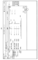
例示的なオブジェクト選択画面520が図4に例解される。オブジェクト選択表示520は、ユーザが同期ユーザ制御510を選択するとき、図3に示されるように画面表示500の上に重ねられ得る。オブジェクト選択表示520は、同期させるためにエンジニアに対するオブジェクト522a~528aの指標を含む。オブジェクト522a~528aの指標の各々は、それぞれの選択制御522b~528bを有し得、これは、それぞれの選択制御522b~528bに対応するオブジェクトを同期させるために選択され得る。指標522a~528aは、制御モジュールオブジェクトFIC-10125(符号522a)、ならびにモジュールオブジェクトLIC-10125(符号524a)、FT-10125(符号526a)、及びFV-10125(符号528a)を含む制御モジュールオブジェクトFIC-10125の直接依存オブジェクトを含み得る。オブジェクト選択表示520はまた、選択されたときに、依存オブジェクトLIC-10125、FT-10125、及びFV-10125に依存する制御モジュールオブジェクトFIC-10125に対する間接依存オブジェクトを表示するユーザ制御530を含み得る。オブジェクト選択表示520に示されるように、選択制御522bのみが制御モジュールオブジェクトFIC-10125(符号522a)に対応して選択される。他の選択制御524b~528bは、選択されず、したがって、直接依存オブジェクト524a~528aは、制御モジュールオブジェクトFIC-10125(符号522a)と同期させるために選択されない。
An exemplary
選択制御522b~528bを介して同期させるオブジェクトを選択することに際して、エンジニアは、ランタイム中にプロセスルーチンを実行するプロセス要素で生成されることになる修正されたオブジェクトのインスタンス化を行わせるために、「同期開始(Start Sync)」ボタン532を選択し得る。修正されたオブジェクトは、その後、システムが修正された構成を含むようにオブジェクトを更新し得るとき、ランタイム中または後続のランタイムサイクル中に実行され得る。「同期開始」ボタン532は、同期させるように選択されたオブジェクトの数の指標532aを含み得る。例示的なオブジェクト選択表示520において、エンジニアは、制御モジュールオブジェクトFIC-10125(符号522a)を同期させ、したがって、指標532aが、同期させる1つのオブジェクトが存在することを示す。
Upon selecting an object to synchronize via the selection controls 522b-528b, the engineer may, during runtime, cause the instantiation of the modified object to be created in the process element executing the process routine: A “Start Sync”
図5は、オブジェクト選択表示520に類似する別の例示的なオブジェクト選択表示540を例解する。この例示的なオブジェクト選択表示540において、エンジニアは、選択制御522b~528bを介して同期させる全4つのオブジェクトを選択する。したがって、「同期開始」ボタン532内の指標532aは、同期させる4つのオブジェクトが存在することを示す。
FIG. 5 illustrates another exemplary
上記の例で別のモジュールオブジェクト(例えば、制御モジュールオブジェクトFIC-10125)によって参照されるか、またはそれを参照するモジュールオブジェクトである依存オブジェクトを説明するが、依存オブジェクトはまた、モジュールクラスオブジェクトを含み得る。 Although the above example describes a dependent object that is a module object that is referenced by or references another module object (eg, control module object FIC-10125), dependent objects also include module class objects. obtain.
図6~8は、制御モジュールオブジェクトFIC-10125に対する間接依存オブジェクトを表示するためにエンジニアがユーザ制御530を選択する例示的なシナリオを例解する。図6の例示的なオブジェクト選択表示550に示されるように、エンジニアは、
マウスクリックまたはタッチ選択を介してユーザ制御530を選択する。ユーザ制御530の選択を受信することに応答して、構成アプリケーション50は、依存オブジェクトLIC-10125、FT-10125、及びFV-10125によって参照されるか、またはそれらを参照し、かつ未確定の修正を有するオブジェクトの各々を識別する。図7は、それぞれ、図4~6に示されるオブジェクト選択表示520、540、550に類似するさらに別の例示的なオブジェクト選択表示560を例解する。オブジェクト選択表示560は、エンジニアがユーザ制御530を選択することに応答して提示され得、構成アプリケーション50が依存オブジェクトLIC-10125、FT-10125、及びFV-10125の直接依存オブジェクトを読み込んでいることの指標562を含み得る。これらの直接依存オブジェクトは、制御モジュールオブジェクトFIC-10125に関する間接依存オブジェクトであり得る。
6-8 illustrate an exemplary scenario in which an engineer selects
図8は、それぞれ、図4~6に示されるオブジェクト選択表示520、540、550に類似し、かつ間接依存オブジェクトの指標を含む、別の例示的なオブジェクト選択表示570を例解する。例えば、制御モジュールオブジェクトFIC-10125(符号522a)、ならびにモジュールオブジェクトLIC-10125(符号524a)、FT-10125(符号526a)、及びFV-10125(符号528a)を含む制御モジュールオブジェクトFIC-10125の直接依存オブジェクトの指標を表示することに加えて、例示的なオブジェクト選択表示570は、直接依存オブジェクトLIC-10125(符号524a)に依存する間接依存オブジェクトLT-10125(符号572a)の指標を含む。オブジェクト選択表示570はまた、他の選択されたオブジェクトと同期させるために間接依存オブジェクトLT-10125(符号572a)を選択するための選択制御572bを含む。加えて、オブジェクト選択表示570は、直接依存オブジェクトFT-10125、及びFV-10125(図示せず)に依存する間接依存オブジェクトの指標を含み得る。オブジェクト選択表示570は、選択されたときに、間接依存オブジェクトLT-10125に依存する制御モジュールオブジェクトFIC-10125に対する間接依存オブジェクトを表示するユーザ制御580をさらに含む。追加のユーザ制御(図示せず)がまた、含まれてもよく、これは、選択されたときにオブジェクト選択表示570内で提示された他の間接依存オブジェクトに依存する間接依存オブジェクトを表示する。
FIG. 8 illustrates another exemplary
いくつかの実施形態において、構成アプリケーション50は、オブジェクト選択表示520~570内に既に含まれていた依存オブジェクトに関する直接依存オブジェクトを提示しない。例えば、LIC-10125直接依存ヘッダの下で、制御モジュールオブジェクトFIC-10125の指標は、符号522aとして上記に含まれるので、含まれない。しかしながら、制御モジュールオブジェクトFIC-10125は、制御モジュールオブジェクトオブジェクトFIC-10125がモジュールオブジェクトLIC-10125を参照するので、モジュールオブジェクトLIC-10125の直接依存オブジェクトである。このように、同一オブジェクトの指標は、循環依存を回避するために、オブジェクト選択表示570全体を通して繰り返されない。
In some embodiments,
任意の事象において、エンジニアは、「同期開始」ボタン532を選択することによって互いに同時にまたは互いに併せて同期させるために、オブジェクト、直接依存オブジェクト、及び間接依存オブジェクトを含む任意の適切な数のオブジェクトを選択し得る。その後、構成アプリケーション50は、ランタイム中にプロセスルーチンを実行するプロセス要素で生成されることになる修正されたオブジェクトのインスタンス化を生じさせ得る。例えば、構成アプリケーション50は、修正されたオブジェクトを表示アプリケーション48またはコントローラ12aで同期させ得る。修正されたオブジェクトは、その後、システムが修正された構成を含むようにオブジェクトを更新し得るとき、ランタイム中または後続のランタイムサイクル中に表示アプリケーション48またはコントローラ12a
によって実行され得る。
In any event, the engineer may select any suitable number of objects, including objects, direct dependent objects, and indirect dependent objects, to synchronize with each other simultaneously or in conjunction with each other by selecting the "Start Synchronization"
can be performed by
より具体的には、一部のシナリオにおいて、ランタイム中にプロセスルーチンを実行するプロセス要素は、システムのオンライン動作に影響を及ぼすオブジェクトの現在のバージョンの実行を一時停止することなく修正されたオブジェクトをインスタンス化、及び実行することができない。したがって、プロセス要素は、修正されたオブジェクトをインスタンス化、及び実行するためにオブジェクトの現在のバージョンのランタイム実行を停止し得る。一部の実施形態において、プロセス要素は、所定時間、例えば、プロセスプラント10の動作の低速期間中またはオブジェクトに対応する制御モジュール、プロセス実体等が利用されていない期間中、オブジェクトの現在のバージョンのランタイム実行を停止する。他の実施形態において、エンジニアは、オブジェクトの現在のバージョンのランタイム実行を停止するときを選択する。任意の事象において、プロセス要素は、その後、実行を再開すること、及び次のランタイムサイクル内で修正されたオブジェクトを実行する前に、同時または同一インスタンス化サイクル内でエンジニアによって選択された修正されたオブジェクトの各々をインスタンス化する。
More specifically, in some scenarios, a process element that executes a process routine during run time can execute a modified object without suspending execution of the current version of the object that affects the online behavior of the system. Cannot be instantiated and executed. Accordingly, the process element may suspend runtime execution of the current version of the object to instantiate and execute the modified object. In some embodiments, the process element may not be updated with the current version of the object for a predetermined period of time, e.g., during slow periods of operation of the
一部のシナリオにおいて、特にオブジェクトに対する修正が軽微であるとき、ランタイム中に修正されたオブジェクトの実行を一時停止または停止しないことに利点があり得る。オブジェクトに対する軽微な修正は、オブジェクトのパラメータを追加または削除しない、オブジェクト内のパラメータについての単一パラメータ値(または閾値未満の数のパラメータ値)に対する変更を含み得る。例えば、図2に示される警報_A図形要素オブジェクト440oに対して、警報限界パラメータに対する警報限界を変更することは、軽微な修正であり得る。軽微な修正はまた、修正されているオブジェクトのランタイム論理に影響を与えない任意の他の適切な修正を含み得る。 In some scenarios, especially when the modifications to the object are minor, it may be advantageous not to suspend or halt execution of modified objects during runtime. Minor modifications to an object may include changes to single parameter values (or less than a threshold number of parameter values) for parameters within the object that do not add or remove parameters of the object. For example, for the ALARM_A graphic element object 440o shown in FIG. 2, changing the alarm limits to the alarm limits parameter may be a minor modification. Minor modifications may also include any other suitable modifications that do not affect the runtime logic of the object being modified.
エンジニアが軽微な修正をモジュールクラスオブジェクトまたはモジュールオブジェクト等のオブジェクトに保存し、かつ軽微な修正を同期させることを要求するとき(例えば、図3に示されるユーザ制御510を介して)、構成アプリケーション50は、オブジェクトに対する修正を軽微な修正として識別し得る。修正されたオブジェクト全体を表示アプリケーション48またはコントローラ12aに同期させるのではなく、かつ修正されたオブジェクトを実行する前にランタイム中のオブジェクトの現在のバージョンの実行を一時停止または停止するのではなく、構成アプリケーション50は、オブジェクトを実行するプロセス要素に軽微な修正を提供する。オブジェクトを実行するプロセス要素は、その後、例えば、更新されたパラメータ値によってオブジェクトに対して現行パラメータ値を上書きし得る。その後、次回、プロセス要素は、対応するパラメータにアクセスし、更新されたパラメータ値は、使用のために利用可能となり得る。このように、軽微な変更は、ランタイム中に更新され得、それによりオンライン動作は、軽微な変更が実行中に同期され含まれる前に中断されない。これは、ランタイムシステム内のダウンタイム時間、及びプロセス制御ネットワーク上で送信される情報量を低減し、これによってネットワーク帯域幅要求を減少させる。オブジェクトの現在のバージョンのランタイム実行を中断することなく、オブジェクトを実行するプロセス要素にオブジェクトに対する軽微な修正を提供するプロセスは、本明細書では「軽微同期手順(sync-lite procedure)」と称され得る。一部の実施形態において、構成アプリケーション50は、オブジェクトに対する軽微な修正を自動的に識別し、修正されたオブジェクト全体がインスタンス化されない軽微同期手順を開始する。他の実施形態において、エンジニアは、軽微同期手順を開始するために軽微同期制御を選択し得る。
When an engineer saves a minor modification to an object such as a module class object or module object and requests to synchronize the minor modification (eg, via
図9は、図2に示される警報_A図形要素オブジェクト440o等のオブジェクトに軽微な修正を行うための構成アプリケーション50によって提示された例示的な画面表示600を例解する。画面表示600は、警報パラメータ値を調節するためのユーザ制御60
2~606を含む警報_A等の警報用のフェースプレートの図形表現であり得る。例えば、警報パラメータ値は、警報限界602、警報優先レベル604、及びヒステリシス量606を含み得る。エンジニアは、対応するユーザ制御602~606を介してこれらのパラメータ値の各々を調節し得、修正を警報_A図形要素オブジェクト440oに同期させるために「同期オンライン(Sync Online)」ボタン610を選択し得る。
FIG. 9 illustrates an
It can be a graphical representation of a faceplate for an alert, such as Alert_A, which includes 2-606. For example, alarm parameter values may include
一部の実施形態において、構成アプリケーション50は、修正が軽微であるか否かを判定するために警報_A図形要素オブジェクト440oに対する修正を分析する。例えば、構成アプリケーション50は、修正され得るパラメータ値の最大閾値の数(例えば、3)等の、オブジェクトに対する修正が軽微であるか否か、パラメータが追加もしくは削除されたか否か、別のオブジェクトに対する参照が追加もしくは削除されたか否か、オブジェクトによって参照されるオブジェクト間の相互接続が修正されたか否か、これらの任意の適切な組み合わせを判定するための一組の規則、または修正が軽微であるか否かを判定するための追加の規則を記憶し得る。構成アプリケーション50が、修正が軽微であると判定したとき、構成アプリケーション50は、上記の軽微同期手順を開始する。より具体的には、修正された警報限界602、修正された警報優先レベル604、及び/または修正されたヒステリシス量606が、コントローラ12a、表示アプリケーション48、または警報_A図形要素オブジェクト440oを実行する他のプロセス要素に提供される。コントローラ12a、表示アプリケーション48、または他のプロセス要素は、その後、警報_A図形要素オブジェクト440oのランタイム実行中に現在の警報限界を修正された警報限界602によって、現在の警報優先レベルを修正された警報優先レベル604によって、及び/または現在のヒステリシス量を修正されたヒステリシス量606によって上書きする。その後、次回、警報限界が実行されたか否かをプロセス要素が検出するとき、プロセス要素は、修正された警報限界602を使用する。
In some embodiments,
一方で、構成アプリケーション50が、修正が著しいか、または軽微ではないと判定したとき、構成アプリケーション50は、完全同期手順を開始する。これは、コントローラ12a、表示アプリケーション48、またはランタイム中もしくは後続のランタイムサイクル中の実行のための他のプロセス要素において、プロセス要素が修正を含めるように警報_A図形要素オブジェクト440oを更新することができるときに、修正された警報_A図形要素オブジェクト440o全体を同期させることを含む。
On the other hand, when
他の実施形態において、エンジニアは、構成アプリケーション50が完全同期手順または軽微同期手順を実行することになるか否かを判定する。例えば、画面表示600は、「完全同期(Full Sync)」ボタン及び「軽微同期」ボタン(図示せず)等の完全同期及び軽微同期に対する別個のユーザ制御を含み得る。エンジニアは、その後、オブジェクトに対する修正が、パラメータ値に対する変更等の軽微であるとき、「軽微同期」ボタンを選択し得る。
In other embodiments, the engineer determines whether the
いくつかの実施形態において、構成アプリケーション50は、修正されたオブジェクトを参照する依存オブジェクトに含む修正されたオブジェクトの数個のインスタンスに対して1つまたは数個のパラメータ値を上書きする。例えば、表示モジュールオブジェクトは、警報_A図形要素オブジェクト440oを参照し得る。警報限界が警報A_図形要素オブジェクト440oに対して修正されるとき、構成アプリケーション50は、警報_A図形要素オブジェクト440oに対する依存オブジェクトの各々を識別し(上記と類似様式で)、警報_A図形要素オブジェクト440oを参照する依存オブジェクト内の1つまたは数個のパラメータ値を上書きする。
In some embodiments,
一部の実施形態において、構成アプリケーション50及び/またはランタイム中にオブジェクトを実行するプロセス要素は、エンジニアに対して完全同期手順または軽微同期手
順の状態の指標を提供する。例えば、状態は、パラメータが上書きされたか、または修正されたオブジェクトがランタイム中にインスタンス化及び実行されたとき、「同期成功(Sync Successful)」となり得る。状態は、パラメータが上書きされる前または修正されたオブジェクトがインスタンス化される前、「未確定(Pending)」となり得る。
In some embodiments, the
また一部の実施形態において、軽微同期手順は、エンジニアまたは構成アプリケーション50によって特定の時間にスケジュールされる。軽微同期手順を実行するための特定の時間は、プロセス制御ネットワークの現在の帯域幅、コントローラ12aの動作状態、表示アプリケーション48、またはオブジェクトを実行する他のプロセス要素等に基づいて判定され得る。例えば、軽微同期手順は、プロセス制御ネットワークが利用可能なネットワーク帯域幅の最小閾値の量を超えるとき、スケジュールされ得る。その後、構成アプリケーション50は、特定の時間で1つまたは数個のパラメータ値を上書きするように、コントローラ12、表示アプリケーション48、または他のプロセス要素に対する命令を提供する。
Also, in some embodiments, the minor synchronization procedure is scheduled at a specific time by an engineer or
図10は、プロセスプラント内で関連するオブジェクトを同期させるための例示的な方法1000のフロー図を図示する。方法1000は、オペレータワークステーション14、サーバ、または任意の他の適切なコンピューティングデバイス上で実行され得る。一部の実施形態において、方法1000は、非一時的コンピュータ可読メモリ上に記憶された構成アプリケーション50内に実装され得、オペレータワークステーション14の1つ以上のプロセッサ、サーバ、または任意の他の適切なコンピューティングデバイス上で実行可能であり得る。
FIG. 10 illustrates a flow diagram of an
ブロック1002において、構成アプリケーション50は、プロセスプラント内のプロセス実体に対応するオブジェクト(第1のオブジェクト)に対するエンジニアによる修正を受信する。修正は、パラメータを追加及び削除すること、パラメータ値を変更すること、別のオブジェクトに対する参照を追加または除去すること、オブジェクト間の接続またはリンクを変更すること等を含み得る。構成アプリケーション50はまた、修正された第1のオブジェクトをインスタンス化する要求を受信し得る(ブロック1004)。例えば、エンジニアは、修正された第1のオブジェクトを同期させるために、図3の画面表示500内に示されるユーザ制御510に類似するユーザ制御を選択し得る。
At block 1002, the
一部の実施形態において、構成アプリケーション50は、その後、第1のオブジェクトに対する修正が軽微または著しいものであるか否かを判定し得る(ブロック1006)。オブジェクトに対する軽微な修正は、オブジェクトのパラメータを追加または削除しない、オブジェクト内のパラメータについての単一パラメータ値(または閾値未満の数のパラメータ値)に対する変更を含み得る。より一般的に、軽微な修正は、修正されるオブジェクトのランタイム論理に影響を与えない任意の適切な修正を含み得る。他の実施形態において、構成アプリケーション50は、軽微な修正用及び著しい修正用の別個のユーザ制御を提供し得、それによりエンジニアは、修正が軽微であるか否かを指定し得る。例えば、エンジニアは、修正が軽微であるときに「軽微同期」ボタンを選択し得、修正が著しいか、または軽微ではないときに「完全同期」を選択し得る。その後、構成アプリケーション50は、どちらのユーザ制御が選択されたかに基づいて修正が軽微であるか否かを判定する。
In some embodiments,
修正が軽微であるとき、構成アプリケーション50は、第1のオブジェクトを実行しているプロセス要素に軽微な修正を提供し得る(ブロック1014)。第1のオブジェクトを実行しているプロセス要素は、その後、例えば、更新されたパラメータ値によって第1のオブジェクトに対する現在のパラメータ値を上書きし得る。その後、次回、プロセス要
素は、対応するパラメータにアクセスし、更新されたパラメータ値は、使用のために利用可能となり得る。このように、軽微な変更は、ランタイム中に更新され得、それによりオンライン動作は、軽微な変更が実行中に同期され含まれる前に中断されない。
When the correction is minor,
一方で修正が軽微ではないとき、構成アプリケーション50は、修正されたオブジェクトを参照するか、またはそれによって参照され、かつ未確定の修正を有するオブジェクト(第2の依存オブジェクト)を識別する(ブロック1008)。第2の依存オブジェクトに対する未確定の修正は、第2の依存オブジェクトが依存する第1のオブジェクトに対する修正の結果であり得るか、または第1のオブジェクトに対する修正から独立したものであり得る。
On the other hand, if the modification is non-minor,
一部の実施形態において、構成アプリケーション50は、未確定の修正を有する依存オブジェクトの指標を含むオブジェクト選択表示を生成及び提示し得る。オブジェクト選択表示は、修正された第1のオブジェクトと同期させるように、対応する第2の依存(直接または間接)オブジェクトを選択するために、修正されたオブジェクト、直接依存オブジェクト、間接依存オブジェクト、及びエンジニア用の選択制御を含み得る。選択制御を介して同期させるオブジェクトを選択することに際して、エンジニアは、ランタイム中にプロセスルーチンを実行するプロセス要素で生成されることになる修正された第1のオブジェクト及び選択された第2の依存オブジェクトのインスタンス化を要求するために、「同期開始」ボタンを選択し得る。
In some embodiments,
その後、ブロック1010において、構成アプリケーション50は、ランタイム中にプロセスルーチンを実行するプロセス要素で生成されることになる修正された第1のオブジェクト及び第2の依存オブジェクトのインスタンス化を生じさせ得る。構成アプリケーション50はまた、インスタンス化された第1のオブジェクト及び第2の依存オブジェクトがプロセス要素でランタイム中に実行されることを生じさせ得る。例えば、構成アプリケーション50は、修正された第1のオブジェクト及び第2の依存オブジェクトをプロセス要素で同期させ得、プロセス要素は、修正された第1のオブジェクト及び第2の依存オブジェクトをランタイム中に実行する(ブロック1012)。
Thereafter, at block 1010,
一部のシナリオにおいて、ランタイム中にプロセスルーチンを実行するプロセス要素は、システムのオンライン動作に影響を及ぼす現在のバージョンのオブジェクトの実行を一時停止することなく、修正されたオブジェクトをインスタンス化及び実行することができない。したがって、プロセス要素は、修正されたオブジェクトをインスタンス化及び実行するためにオブジェクトの現在のバージョンのランタイム実行を停止し得る。一部の実施形態において、プロセス要素は、所定時間、例えば、プロセスプラント10の動作の低速期間中またはオブジェクトに対応する制御モジュール、プロセス実体等が利用されていない期間中、オブジェクトの現在のバージョンのランタイム実行を停止する。他の実施形態において、エンジニアは、オブジェクトの現在のバージョンのランタイム実行を停止するときを選択する。任意の事象において、プロセス要素は、その後、実行を再開すること及び次のランタイムサイクル内で修正されたオブジェクトを実行する前に、同時または同一インスタンス化サイクル内でエンジニアによって選択された修正されたオブジェクトの各々をインスタンス化する。
In some scenarios, process elements executing process routines during runtime instantiate and execute modified objects without suspending execution of current versions of the objects that affect the online operation of the system. I can't. Accordingly, the process element may suspend runtime execution of the current version of the object to instantiate and execute the modified object. In some embodiments, the process element may not be updated with the current version of the object for a predetermined period of time, e.g., during slow periods of operation of the
さらに、本明細書で説明された技術、システム、及び方法は、プロセス制御システムまたはプラント10のライブラリ(例えば、テンプレート及び/もしくはユーザ作成ライブラリオブジェクト)内に記憶されたアイテムまたはオブジェクトに適用する。代替的または追加的に、本技術、システム、及び方法は、プロセス制御システムまたはプラント10の構成データベース25内に記憶されたアイテムまたはオブジェクトに適用し、これは、一部の場合において、ライブラリアイテムもしくはオブジェクトから少なくとも部分的に
作成されるか、または派生される。
Additionally, the techniques, systems, and methods described herein apply to items or objects stored within libraries (eg, templates and/or user-created library objects) of the process control system or
またさらに、本明細書で説明された同期技術及びオブジェクトのうちの1つ以上は、図1のプロセスプラント10等のプロセスプラント内、または他の適切なプロセスプラントもしくはプロセス制御システム内で使用され得る。一例において、本明細書で説明された技術のうちの1つ以上は、図1の1つ以上のワークステーション14上で実行される構成アプリケーション50によって実行される。別の例において、本明細書で説明された技術のうちの1つ以上は、アプリケーションにアクセスする遠隔アプリケーション(例えば、ウェブクライアントまたは他の遠隔アクセス手段)によって少なくとも部分的に実行される。一部の実施形態において、同期技術のうちの1つ以上は、本明細書で説明されたもの以外の他の同期技術との組み合わせで使用される。
Still further, one or more of the synchronization techniques and objects described herein may be used within a process plant, such as
さらに、本明細書で説明された同期技術及びオブジェクトは、図2に説明されたもの等のモジュールクラスを使用して実装される。本明細書で説明された同期技術は、しかしながら、他の適切なモジュールクラス、ソフトウェアアーキテクチャ、及び/またはプログラミング技術を使用して実装され得る。 Further, the synchronization techniques and objects described herein are implemented using modular classes such as those illustrated in FIG. The synchronization techniques described herein, however, may be implemented using other suitable module classes, software architectures, and/or programming techniques.
アイテムまたはオブジェクト: Item or Object:
先で考察されるように、本明細書で説明された同期技術、システム、及び方法の実施形態は、ランタイムプロセスプラントまたはランタイムプロセス制御システムに不利に影響を及ぼし得るダウンロードを必要とすることなく、ユーザがライブラリ構成アイテムまたはライブラリ構成オブジェクト、及びシステム構成アイテムまたはシステム構成オブジェクトに対する変更を行うことを可能にする。ライブラリアイテムまたはライブラリオブジェクトは、概して、集中的にアクセス可能な位置またはライブラリ(例えば、ワークステーション14に対して、ならびに他のインターフェース及びコンピューティングデバイスに対してアクセス可能である、構成データベース25または他の記憶デバイス)内に記憶されたテンプレートオブジェクトである。システム構成アイテムまたはシステム構成オブジェクト(及び一部のライブラリアイテムまたはライブラリオブジェクト)は、概して、1つ以上のライブラリアイテムに基づくか、またはそれらから派生される。一部のアイテム及びオブジェクトについて、少なくとも一部の態様は、ユーザによってカスタマイズされる。
As discussed above, embodiments of the synchronization techniques, systems, and methods described herein provide a Allows users to make changes to library configuration items or objects and system configuration items or objects. A library item or library object is generally a centrally accessible location or library (e.g.,
本明細書で使用される「アイテム(item)」という用語は、クラスオブジェクト、インスタンスオブジェクト、またはプロセス要素オブジェクト等のオブジェクトを概して意味する。アイテムは、ライブラリ内に記憶され得るか(例えば、「ライブラリアイテム(library item)」または「ライブラリオブジェクト(library object)」)、もしくはアイテムは、システム構成データ記憶エリア内に記憶され得る(例えば、「構成アイテム(configuration item)」または「構成オブジェクト(configuration object)」)。加えて、本明細書で使用される「アイテム」という用語はまた、オブジェクト、例えば、オブジェクトのコンテンツの少なくとも一部に対する内部であり、かつそれによって定義されるアイテムを概して意味する。オブジェクトの可能な内部アイテムは、例えば、方法、動作、データフィールドまたは他の属性、入力、出力、I/Oのタイプ(例えば、コントローラ、例えば、図1のコントローラ12または12aがシステムと通信するための入力/出力カードまたは入力/出力デバイスのタイプ)、機能または用途、定義、パラメータ値、親オブジェクトに対する参照、子オブジェクトに対する参照、親オブジェクトでも子オブジェクトでもない別のオブジェクトに対する参照、及び他の内部アイテムを含む。内部アイテムは、絶対的に定義され得るか(例えば、データフィールドが定数値もしくは定数式を記憶する)、または内部アイテムは、絶対値、絶対式、別のオブジェクト、もしくは別の参照を参照
することによる等、相対的に定義され得る。例えば、図形表示要素オブジェクトによって定義された内部アイテムは、親オブジェクト、1つ以上のフィールド、トリガー、機能、ビュー定義、イベントハンドラ、アニメーション、プレースホルダ、パラメータ、表等に対する参照を含み得る。別の例において、制御モジュール要素オブジェクトによって定義された内部アイテムは、親オブジェクト、1つ以上の入力、出力、パラメータ、機能ブロック、相互接続、フィールド式、外部参照、動作、アルゴリズム、遷移等を含み得る。
As used herein, the term "item" generally refers to an object such as a class object, instance object, or process element object. Items may be stored within a library (e.g., "library item" or "library object"), or items may be stored within a system configuration data storage area (e.g., "library object"). "configuration item" or "configuration object"). In addition, the term "item" as used herein also generally refers to an item that is internal to and defined by an object, eg, at least part of the content of the object. Possible internal items of an object include, for example, methods, actions, data fields or other attributes, inputs, outputs, types of I/O (eg, controllers, such as
本明細書で使用される「現在のアイテム(current item)」または「現在のオブジェクト(current object)」という用語は、インスタンス化され(及び一部の場合において同期された)、かつプロセスプラント10内の対応するプロセス要素のランタイム中に実行され得るアイテムまたはオブジェクトを指す。例えば、現在のプロセス要素制御オブジェクトがインスタンス化されたとき、現在のプロセス要素制御オブジェクトに対応する実行可能な構成は、図1のコントローラ12または12a等のプロセス要素で同期され、コントローラ12または12aは、ランタイム中に、インスタンス化された現在のプロセス要素制御オブジェクトによって定義される、機能、入力、出力、及び他の条件に従って動作するように構成される。別の例において、現在の図形表示ビューオブジェクトは、現在の図形表示ビューオブジェクト内に含まれた定義に対応するビューがユーザインターフェース上で構築及び提示されたとき、ユーザインターフェースでインスタンス化される。典型的には、オブジェクトによって定義された特定の内部アイテムになされた変更は、オブジェクトによって定義された他の内部アイテムに典型的に影響を及ぼさない。
As used herein, the term "current item" or "current object" refers to the instantiated (and in some cases synchronized) and refers to an item or object that can be executed during the runtime of the corresponding process element of the . For example, when the current process element control object is instantiated, the executable configuration corresponding to the current process element control object is synchronized with the process element, such as
「修正(modification)」という用語は、本明細書では、オブジェクトのコンテンツに対する、その親オブジェクトへのリンクを維持しつつ行われる、1つ以上の変更を指すために使用される。現在のアイテムまたはオブジェクトに対する修正または変更の一例は、現在のアイテムまたはオブジェクトに対する、新しいパラメータまたは動作の追加等の新しい内部アイテムの追加である。追加的または代替的に、修正は、現在のプロセス要素オブジェクトの既存アイテムを削除することを含み得る、及び/またはオブジェクトによる定義済みのアイテムの値、式、もしくは参照を変更することを含み得る。一部のシナリオにおいて、修正は、特定アイテムの無効化を含み、これにより特定アイテムは、インスタンス化中に無視される。例えば、特定インスタンスオブジェクトにおいて、ユーザは、親クラスオブジェクト内で定義されるアイテムを無効化し得る。このような能力は、ユーザが、クラスの残りのものよりも低機能を有するが、依然としてコアクラス機能を含むインスタンスを定義することを可能にする。任意の無効化されたコンテンツが、視覚的に弱められるか、不可視化されるか、またはそうでなければ描画されず、ランタイム中に使用されない。無効化されたコンテンツは、任意の時間にユーザによって再び有効化され得る。概して、修正は、親オブジェクト内の参照がそれぞれの子オブジェクト内の定数値に対して解決されるとき等の、定数値または定数式に対する参照を解決することを含み得る。 The term "modification" is used herein to refer to one or more changes made to the content of an object while maintaining a link to its parent object. An example of a modification or change to a current item or object is the addition of new internal items, such as the addition of new parameters or actions, to the current item or object. Additionally or alternatively, modification may include deleting existing items of the current process element object and/or changing values, expressions, or references of items defined by the object. In some scenarios, modifications include disabling specific items so that they are ignored during instantiation. For example, in a particular instance object, the user can override items defined within the parent class object. Such capabilities allow users to define instances that have less functionality than the rest of the class, but still include core class functionality. Any disabled content is visually dimmed, made invisible, or otherwise not rendered and not used during runtime. Disabled content can be re-enabled by the user at any time. In general, modification may involve resolving references to constant values or constant expressions, such as when references in parent objects are resolved to constant values in their respective child objects.
任意の修正、変更、及びそれらの組み合わせが、クラスアイテムもしくはクラスオブジェクト、インスタンスアイテムもしくはインスタンスオブジェクト、プロセス要素アイテムもしくはプロセス要素オブジェクト、または内部アイテムに対して行われ得る。インスタンスオブジェクト及び他の子オブジェクトの場合において、子オブジェクトに対する変更または修正は、一実施形態において、その親から除去されている子オブジェクト内では結果として生じない。例えば、インスタンスオブジェクトに対する修正は、インスタンスオブジェクトをそのクラスから除去せず、さらに、ユーザによってそのように指定されない限り、同一クラスの他のインスタンスに影響を与えない。 Any modifications, changes, and combinations thereof may be made to class items or class objects, instance items or instance objects, process element items or process element objects, or internal items. In the case of instance objects and other child objects, changes or modifications to the child object do not result in the child object being removed from its parent in one embodiment. For example, modifications to an instance object do not remove the instance object from its class, nor do they affect other instances of the same class unless so specified by the user.
インスタンス化: Instantiate:
オブジェクトは、一実施形態において、ユーザによってインスタンス化のために選択され得る。選択されたオブジェクトのインスタンス化は、選択されたオブジェクトによって定義された内部アイテムに従って、ランタイム中に実行する対応するプロセス要素を結果としてもたらす。例えば、制御オブジェクトの場合において、ユーザは、ランタイムシステム内の対応するデバイスで同期されるべき制御オブジェクトの特定の修正された構成を望む。ユーザは、更新された構成を選択された構成から生成し、かつ更新された構成をランタイムシステム内のプロセス要素に送信するようにシステムに命令する。このように、ランタイム中に、プロセス要素は、制御オブジェクトの実行構成を実行し、ここで、実行構成は、制御オブジェクトに対する修正を含む。別の例において、ユーザは、表示ビュー上に含まれる図形表示要素オブジェクトをインスタンス化するように構成システムに命令する。構成システムは、図形表示要素オブジェクトの実行構成を作成する。対応する表示ビューがランタイムで構築されるとき、図形表示オブジェクトの実行構成が実行され、表示ビュー上に含まれているそれぞれの図形要素を結果としてもたらす。複数構成が利用可能であるとき、ユーザは、複数構成のうちのインスタンス化されるべきものを選択し得る。 Objects may be selected for instantiation by a user in one embodiment. Instantiation of the selected object results in the corresponding process element executing during runtime according to the internal items defined by the selected object. For example, in the case of control objects, a user desires a particular modified configuration of control objects to be synchronized with corresponding devices in the runtime system. The user instructs the system to generate an updated configuration from the selected configuration and send the updated configuration to process elements within the runtime system. Thus, during runtime, the process element executes the run configuration of the control object, where the run configuration includes modifications to the control object. In another example, the user instructs the configuration system to instantiate graphical display element objects contained on the display view. The configuration system creates a running configuration of graphical display element objects. When the corresponding display view is constructed at runtime, the running composition of the graphic display object is executed, resulting in each graphic element contained on the display view. When multiple configurations are available, the user may select which of the multiple configurations to be instantiated.
本開示に説明された技術の実施形態は、以下の態様の任意の番号を、単独または組み合わせのいずれかにおいて含み得る。 Embodiments of the technology described in this disclosure may include any number of the following aspects, either alone or in combination.
1.プロセスプラント内で依存オブジェクトを同期させるためのコンピューティングデバイスであって、コンピューティングデバイスは、1つ以上のプロセッサと、1つ以上のプロセッサに連結された非一時的コンピュータ可読媒体であって、そこに構成アプリケーションを記憶し、構成アプリケーションが、1つ以上のプロセッサによって実行されたとき、コンピューティングデバイスに、第1のプロセス実体に対応する第1のオブジェクトに対する修正を受信することと、ランタイムでの動作のために修正された第1のオブジェクトをインスタンス化する要求を受信することと、少なくとも1つの未確定の修正を有する、修正された第1のオブジェクトに関する1つ以上の第2の依存オブジェクトを識別することであって、1つ以上の第2の依存オブジェクトが、それぞれの第2のプロセスプラント実体に各々対応する、識別することと、修正された第1のオブジェクトのインスタンス化、及び生成されることになる1つ以上の第2の依存オブジェクトのうちの少なくとも1つのインスタンス化を引き起こすことと、第1のプロセス実体及び第2のプロセス実体が、それぞれ、修正された第1のオブジェクトのインスタンス化、及び少なくとも1つの第2の依存オブジェクトのインスタンス化に従ってランタイムで動作するように、修正された第1のオブジェクトのインスタンス化、及び実行されることになる少なくとも1つの第2の依存オブジェクトのインスタンス化を引き起こすことと、を行わせる、非一時的コンピュータ可読媒体と、を備える、コンピューティングデバイス。 1. A computing device for synchronizing dependent objects within a process plant, the computing device comprising one or more processors and a non-transitory computer-readable medium coupled to the one or more processors, wherein storing a configuration application in a , and when the configuration application is executed by one or more processors, receiving, in a computing device, modifications to a first object corresponding to the first process entity; receiving a request to instantiate a modified first object for operation; and one or more second dependent objects for the modified first object having at least one pending modification. identifying, instantiating the modified first object, and generating one or more second dependent objects, each corresponding to a respective second process plant entity; causing the instantiation of at least one of the one or more second dependent objects to be modified; an instantiation of the first object and an instance of the at least one second dependent object to be executed, modified to operate at runtime according to the instantiation of the instantiation of the at least one second dependent object and the instantiation of the at least one second dependent object; and a non-transitory computer-readable medium that causes the transformation to take place.
2.構成アプリケーションは、コンピューティングデバイスに、1つ以上の第2の依存オブジェクトの指標をユーザに提示することと、1つ以上の第2の依存オブジェクトのうちの少なくとも1つの選択をユーザから受信することと、生成されることになる少なくとも1つの第2の依存オブジェクトのインスタンス化を引き起こすことと、をさらに行わせる、態様1に記載のコンピューティングデバイス。 2. A configuration application presents an indication of one or more second dependent objects to a user on a computing device and receives a selection of at least one of the one or more second dependent objects from the user. and causing instantiation of at least one second dependent object to be generated.
3.1つ以上の第2の依存オブジェクトの指標をユーザに提示するために、構成アプリケーションは、コンピューティングデバイスに、修正された第1のオブジェクトによって直接参照されるか、または修正された第1のオブジェクトを直接参照する、1つ以上の第2の依存オブジェクトのうちの少なくとも1つの指標を提示することを行わせる、態様1または態様2に記載のコンピューティングデバイス。
3. To present to the user an indication of one or more second dependent objects, the configuration application directs the computing device to the first object directly referenced by the modified first object or the modified first 3. A computing device according to
4.構成アプリケーションは、コンピューティングデバイスに、ユーザによる、少なくとも1つの第2の依存オブジェクトに関する第3の依存オブジェクトを提示する要求を受信することと、少なくとも1つの第2の依存オブジェクトに関する1つ以上の第3の依存オブジェクトの指標を提示することと、をさらに行わせる、態様1~3のいずれか1つに記載のコンピューティングデバイス。 4. The configuration application receives at the computing device a request by the user to present a third dependent object for the at least one second dependent object and one or more second dependent objects for the at least one second dependent object. 4. The computing device of any one of aspects 1-3, further causing: presenting an indication of the dependent object of 3.
5.構成アプリケーションは、コンピューティングデバイスに、少なくとも1つの第2の依存オブジェクトに関する1つ以上の第3の依存オブジェクトを識別することと、少なくとも1つの第2の依存オブジェクトに関する1つ以上の第3の依存オブジェクトのうちの少なくとも1つの指標が既に提示されていると判定することと、既に提示されている少なくとも1つの第3の依存オブジェクトの指標を提示しないことと、をさらに行わせる、態様1~4のいずれか1つに記載のコンピューティングデバイス。 5. The configuration application instructs the computing device to identify one or more third dependent objects for the at least one second dependent object and one or more third dependent objects for the at least one second dependent object. determining that the index of at least one of the objects has already been presented; and not presenting the index of the already-presented at least one third dependent object, aspects 1-4 A computing device according to any one of
6.第1のオブジェクトに対する修正は、第1のオブジェクト内のパラメータ値に対する変更を含み、構成アプリケーションは、コンピューティングデバイスに、生成及び実行されることになる修正された第1のオブジェクトのインスタンス化を引き起こす前に、ランタイム中に現在実行されている第1のオブジェクト内の変更されたパラメータ値を更新することをさらに行わせる、態様1~5のいずれか1つに記載のコンピューティングデバイス。 6. The modification to the first object includes changes to parameter values within the first object, and the configuration application causes the computing device to instantiate the modified first object to be generated and executed. 6. The computing device of any one of aspects 1-5, further causing updating changed parameter values in the first object currently being executed during runtime before.
7.構成アプリケーションは、コンピューティングデバイスに、第1のオブジェクトに関する複数の第3の依存オブジェクト内の変更されたパラメータ値を更新することをさらに行わせる、態様1~6のいずれか1つに記載のコンピューティングデバイス。 7. 7. The computing device of any one of aspects 1-6, wherein the configuration application further causes the computing device to update changed parameter values in the plurality of third dependent objects for the first object. device.
8.修正された第1のオブジェクトのインスタンス化、及び少なくとも1つの第2の依存オブジェクトのインスタンス化は、同時に生成される、態様1~7のいずれか1つに記載のコンピューティングデバイス。 8. A computing device according to any one of aspects 1-7, wherein the instantiation of the modified first object and the instantiation of the at least one second dependent object are generated at the same time.
9.プロセスプラント内で依存オブジェクトを同期させる方法であって、方法は、構成アプリケーションを実行する1つ以上のプロセッサによって、第1のプロセス実体に対応する第1のオブジェクトに対する修正を受信することと、1つ以上のプロセッサによって、ランタイムでの動作のための修正された第1のオブジェクトをインスタンス化する要求を受信することと、1つ以上のプロセッサによって、少なくとも1つの未確定の修正を有する、修正された第1のオブジェクトに関する1つ以上の第2の依存オブジェクトを識別することであって、1つ以上の第2の依存オブジェクトが、それぞれの第2のプロセスプラント実体に各々対応する、識別することと、1つ以上のプロセッサによって、修正された第1のオブジェクトのインスタンス化、及び生成されることになる1つ以上の第2の依存オブジェクトのうちの少なくとも1つのインスタンス化を引き起こすことと、1つ以上のプロセッサによって、第1のプロセス実体及び第2のプロセス実体が、それぞれ、修正された第1のオブジェクトのインスタンス化、及び少なくとも1つの第2の依存オブジェクトのインスタンス化に従ってランタイムで動作するように、修正された第1のオブジェクトのインスタンス化、及び実行されることになる少なくとも1つの第2の依存オブジェクトのインスタンス化を引き起こすことと、を含む、方法。 9. 1. A method of synchronizing dependent objects within a process plant, the method comprising: receiving modifications to a first object corresponding to a first process entity by one or more processors executing a configuration application; receiving a request to instantiate a modified first object for operation at runtime by one or more processors; identifying one or more second dependent objects related to the first object, the one or more second dependent objects each corresponding to a respective second process plant entity; and causing instantiation of the modified first object and at least one of the one or more second dependent objects to be generated by the one or more processors; The one or more processors cause the first process entity and the second process entity to operate at runtime according to the modified instantiation of the first object and the instantiation of the at least one second dependent object, respectively. and causing instantiation of the modified first object and instantiation of at least one second dependent object to be executed.
10.1つ以上のプロセッサによって、1つ以上の第2の依存オブジェクトの指標をユーザに提示することと、1つ以上のプロセッサによって、1つ以上の第2の依存オブジェクトのうちの少なくとも1つの選択をユーザから受信することと、1つ以上のプロセッサによって、生成されることになる少なくとも1つの第2の依存オブジェクトのインスタンス化を引き起こすことと、をさらに含む、態様9に記載の方法。 10. Presenting an indication of one or more second dependent objects to a user by one or more processors; 10. The method of aspect 9, further comprising receiving a selection from a user and causing instantiation of at least one second dependent object to be generated by the one or more processors.
11.1つ以上の第2の依存オブジェクトの指標をユーザに提示することは、1つ以上のプロセッサによって、修正された第1のオブジェクトによって直接参照されるか、または修正された第1のオブジェクトを直接参照する、1つ以上の第2の依存オブジェクトのうちの少なくとも1つの指標を提示することを含む、態様9または態様10に記載の方法。
11. Presenting an indication of the one or more second dependent objects to the user may be directly referenced by the modified first object or modified by the one or more processors. 11. The method of aspect 9 or
12.1つ以上のプロセッサによって、ユーザによる、少なくとも1つの第2の依存オブジェクトに関する第3の依存オブジェクトを提示する要求を受信することと、1つ以上のプロセッサによって、少なくとも1つの第2の依存オブジェクトに関する1つ以上の第3の依存オブジェクトの指標を提示することと、をさらに含む、態様9~11のいずれか1つに記載の方法。 12. Receiving, by one or more processors, a request by a user to present a third dependent object with respect to at least one second dependent object; presenting an indication of one or more third dependent objects for the object. The method according to any one of aspects 9-11.
13.1つ以上のプロセッサによって、少なくとも1つの第2の依存オブジェクトに関する1つ以上の第3の依存オブジェクトを識別することと、1つ以上のプロセッサによって、少なくとも1つの第2の依存オブジェクトに関する1つ以上の第3の依存オブジェクトのうちの少なくとも1つの指標が既に提示されていると判定することと、既に提示されている少なくとも1つの第3の依存オブジェクトの指標を提示しないことと、をさらに含む、態様9~12のいずれか1つに記載の方法。 13. identifying, by one or more processors, one or more third dependent objects for the at least one second dependent object; and identifying, by one or more processors, for the at least one second dependent object. further determining that the index of at least one of the one or more third dependent objects has already been presented; and not presenting the index of the at least one already-presented third dependent object. 13. The method of any one of aspects 9-12, comprising:
14.第1のオブジェクトに対する修正は、第1のオブジェクト内のパラメータ値に対する変更を含み、1つ以上のプロセッサによって、生成及び実行されることになる修正された第1のオブジェクトのインスタンス化を引き起こす前に、ランタイム中に現在実行されている第1のオブジェクト内の変更されたパラメータ値を更新することをさらに含む、態様9~13のいずれか1つに記載の方法。 14. Modifications to the first object include changes to parameter values within the first object, prior to causing instantiation of the modified first object to be generated and executed by one or more processors. 14. The method of any one of aspects 9-13, further comprising updating changed parameter values in the first object currently being executed during runtime.
15.1つ以上のプロセッサによって、第1のオブジェクトに関する複数の第3の依存オブジェクト内の変更されたパラメータ値を更新することをさらに含む、態様9~14のいずれか1つに記載の方法。 15. The method of any one of aspects 9-14, further comprising updating, by one or more processors, changed parameter values in a plurality of third dependent objects for the first object.
16.修正された第1のオブジェクトのインスタンス化、及び生成されることになる少なくとも1つの第2の依存オブジェクトのインスタンス化を引き起こすことは、修正された第1のオブジェクトのインスタンス化、及び生成されることになる少なくとも1つの第2の依存オブジェクトのインスタンス化を、同時に引き起こすことを含む、態様9~15のいずれか1つに記載の方法。 16. causing the instantiation of the modified first object and the instantiation of at least one second dependent object to be created; 16. The method of any one of aspects 9-15, comprising simultaneously causing instantiation of at least one second dependent object that becomes
17.プロセスプラント内でオブジェクトに対するパラメータ値変更を同期させる方法であって、方法は、ランタイム中にプロセス実体に対応するオブジェクトを実行することと、オブジェクト内のパラメータに対する変更された値の指標を受信することと、オブジェクトのランタイム実行を中断させることなく、オブジェクトの実行中に、変更された値によってオブジェクト内のパラメータを更新することと、を含む、方法。 17. A method of synchronizing parameter value changes to an object within a process plant, the method comprising executing an object corresponding to the process entity during runtime and receiving an indication of a changed value for a parameter within the object. and updating parameters in the object with changed values during execution of the object without interrupting runtime execution of the object.
18.パラメータを更新することは、変更された値によってパラメータに対する現在値を上書きすることを含む、態様17に記載の方法。 18. 18. The method of aspect 17, wherein updating the parameters includes overwriting current values for the parameters with changed values.
19.ランタイム中にプロセス実体に対応するオブジェクトを実行することは、コントローラによって、ランタイム中にプロセス実体に対応するオブジェクトを実行することを含む、態様17または態様18に記載の方法。
19. 19. The method of aspect 17 or
20.変更された値によってオブジェクト内のパラメータを更新することは、パラメータに対する変更された値をコントローラに提供することであって、コントローラが、変更
された値によってパラメータに対する現在値を上書きする、提供することを含む、態様17~19のいずれか1つに記載の方法。
20. Updating a parameter in an object with a changed value provides the changed value for the parameter to the controller, which overwrites the current value for the parameter with the changed value. 20. The method of any one of aspects 17-19, comprising
21.実行中に変更された値によってパラメータを更新するか、またはパラメータに対する変更された値を含むオブジェクトの修正されたバージョンをインスタンス化するか否かを自動的に判定することをさらに含み、オブジェクトの修正されたバージョンは、後続のランタイムサイクル中に実行される、態様17~20のいずれか1つに記載の方法。 21. automatically determining whether to update the parameter with the changed value during execution or to instantiate a modified version of the object containing the changed value for the parameter; 21. The method of any one of aspects 17-20, wherein the modified version is executed during a subsequent runtime cycle.
22.オブジェクトに関する複数の依存オブジェクト内のパラメータを、オブジェクト及び複数の依存オブジェクトの実行中に、変更された値によって更新することをさらに含む、態様17~21のいずれか1つに記載の方法。 22. 22. The method of any one of aspects 17-21, further comprising updating parameters in a plurality of dependent objects for the object with changed values during execution of the object and the plurality of dependent objects.
加えて、本開示の先の態様は、単に例示的なものであり、本開示の範囲を限定することを意図しない。 Additionally, the foregoing aspects of the disclosure are exemplary only and are not intended to limit the scope of the disclosure.
以下の追加の検討が上記の考察に適用される。本明細書全体を通して、任意のデバイスまたはルーチンによって実行されるものとして説明される動作は、機械可読命令に従ってデータを操作または変換するプロセッサの動作またはプロセスを概して意味する。機械可読命令は、プロセッサに通信可能に連結されたメモリデバイス上に記憶され、それから取得され得る。つまり、本明細書で説明された方法は、図1に例解されるような、コンピュータ可読媒体上(つまり、メモリデバイス上)に記憶された一組の機械可読命令によって具現化され得る。命令は、対応するデバイス(例えば、サーバ、オペレータワークステーション等)の1つ以上のプロセッサによって実行されたとき、プロセッサに方法を実行させる。命令、ルーチン、モジュール、プロセッサ、サービス、プログラム、及び/またはアプリケーションが本明細書ではコンピュータ可読メモリ上またはコンピュータ可読媒体上に記憶または保存されるとして言及されるが、「記憶(stored)」及び「保存(saved)」という語は、一時的信号を除外することが意図される。 The following additional considerations apply to the discussion above. Throughout this specification, operations described as being performed by any device or routine generally refer to processor operations or processes that manipulate or transform data according to machine-readable instructions. Machine-readable instructions may be stored on and retrieved from a memory device communicatively coupled to the processor. That is, the methods described herein may be embodied by a set of machine-readable instructions stored on a computer-readable medium (ie, on a memory device) as illustrated in FIG. The instructions, when executed by one or more processors of corresponding devices (eg, servers, operator workstations, etc.), cause the processors to perform the methods. Although instructions, routines, modules, processors, services, programs, and/or applications are referred to herein as being stored or saved on computer-readable memory or on computer-readable media, the terms "stored" and " The term "saved" is intended to exclude transient signals.
さらに、「オペレータ(operator)」、「従業員(personnel)」、「人物(person)」、「ユーザ(user)」、「技術者(technician)」、「エンジニア(engineer)」という用語、及び同様の他の用語が本明細書で説明されたシステム、装置、及び方法を使用またはそれらと対話し得るプロセスプラント環境内の人物を説明するために使用されるが、これらの用語は、限定を意図するものではない。特定の用語が説明で使用されるところで、用語は、一部において、プラント従業員が従事する従来の活動に起因して使用されるが、特定の活動に従事し得る従業員を限定することを意図しない。 Additionally, the terms “operator,” “personnel,” “person,” “user,” “technician,” “engineer,” and the like are used to describe persons within a process plant environment who may use or interact with the systems, devices, and methods described herein, these terms are intended to be limiting. not something to do. Where specific terms are used in the description, the terms are used in part due to the traditional activities in which plant personnel engage, but are intended to limit the employees who may engage in specific activities. Not intended.
加えて、本明細書全体を通して、複数のインスタンスが単一インスタンスとして説明された構成要素、動作、または構造を実装し得る。1つ以上の方法の個々の動作が別個の動作として例解及び説明されたが、個々の動作のうちの1つ以上が同時に実行されてもよく、例解された順序で動作が実行される必要はない。例示的な構成内で別個の構成要素として提示された構造及び機能は、組み合わせられた構造または構成要素として実装されてもよい。同様に、単一構成要素として提示された構造及び機能は、別個の構成要素として実装されてもよい。これらの及び他の変形、修正、追加、及び改善は、本明細書の主題の範囲内に収まる。 In addition, throughout this specification, multiple instances may implement a component, act, or structure described as a single instance. Although individual acts of one or more methods have been illustrated and described as separate acts, one or more of the individual acts may be performed simultaneously, and the acts are performed in the order illustrated. No need. Structures and functions presented as separate components in exemplary configurations may be implemented as a combined structure or component. Similarly, structures and functionality presented as a single component may be implemented as separate components. These and other variations, modifications, additions and improvements fall within the scope of the subject matter herein.
別途特に記載されない限り、「処理すること(processing)」、「コンピューティングすること(computing)」、「計算すること(calculating)」、「判定すること(determining)」、「識別すること(identifying)」、「提示すること(presenting)」、「提示させること(ca
using to be presented)」、「表示させること(causing
to be displayed)」、「表示すること(displaying)」等のような語を使用する本明細書の考察は、1つ以上のメモリ(例えば、揮発性メモリ、不揮発性メモリ、もしくはそれらの組み合わせ)、レジスタ、または情報を受信、記憶、送信、もしくは表示する他の機械構成要素内の物理(例えば、電気、磁気、生体、もしくは光)量として表されたデータを操作または変換する機械(例えば、コンピュータ)の動作またはプロセスを意味し得る。
Unless otherwise specified, "processing", "computing", "calculating", "determining", "identifying" ”, “presenting”, “ca
"using to be presented", "causing
Discussion herein using terms such as "to be displayed", "displaying", etc. refers to one or more memories (e.g., volatile memory, non-volatile memory, or combinations thereof). A machine that manipulates or transforms data expressed as physical (e.g., electrical, magnetic, biological, or optical) quantities in , registers, or other machine components that receive, store, transmit, or display information (e.g., computer) operations or processes.
ソフトウェア内に実装されるとき、本明細書で説明されたアプリケーション、サービス、及びエンジンのいずれかは、コンピュータもしくはプロセッサのRAMもしくはROM内の磁気ディスク、レーザディスク、ソリッドステートメモリデバイス、分子メモリ記憶デバイス、または他の記憶媒体等の任意の有形の非一時的コンピュータ可読メモリ内に記憶され得る。本明細書で開示される例示的なシステムは、他の構成要素の中でも、ハードウェア上で実行されるソフトウェア及び/またはファームウェアを含むとして開示されるが、このようなシステムは単に例解的であることが留意されるべきであり、限定として考慮されるべきではない。例えば、これらのハードウェア、ソフトウェア、及びファームウェア構成要素は、ハードウェア内で排他的に、ソフトウェア内で排他的に、またはハードウェア及びソフトウェアの任意の組み合わせ内で具現化され得ることが考えられる。したがって、当業者は、提供された例がこのようなシステムを実装する唯一の方式ではないことを容易に理解するであろう。 When implemented in software, any of the applications, services, and engines described herein can be stored on magnetic disks, laser disks, solid state memory devices, molecular memory storage devices in the RAM or ROM of a computer or processor. , or in any tangible non-transitory computer-readable memory such as other storage media. Although example systems disclosed herein are disclosed as including, among other components, software and/or firmware executing on hardware, such systems are merely illustrative. One should be noted and should not be considered as a limitation. For example, it is contemplated that these hardware, software, and firmware components may be embodied exclusively in hardware, exclusively in software, or in any combination of hardware and software. Accordingly, those skilled in the art will readily appreciate that the examples provided are not the only way to implement such a system.
このように、本発明が特定の例を参照して説明されてきたが、これは、単に例解的であることを意図するものであり、本発明を限定することを意図するものではなく、当業者にとって、変更、追加、または削除が、本発明の概念及び範囲から逸脱することなく、開示された実施形態になされ得ることが明らかであろう。 Thus, although the present invention has been described with reference to particular examples, this is intended to be illustrative only and is not intended to limit the invention. It will be apparent to those skilled in the art that modifications, additions, or deletions can be made to the disclosed embodiments without departing from the spirit and scope of the invention.
用語が、本特許において「本明細書で使用される、「______」という用語は、...を意味するようにこれによって定義される」という文、または類似の文を使用して明白に定義されない限り、明示的に、または示唆によるいずれかにおいて、その平易または通常の意味を超えて、その用語の意味を限定する意図は存在せず、このような用語は、本特許の任意の文節内でなされた任意の記述(請求項の文言以外)に基づいた範囲において限定されるように解釈されるべきではないということも理解されるべきである。本特許の最後で請求項内に記載された任意の用語が単一の意味と矛盾しない様式で本特許内において参照されるという点で、それは、読み手を混乱させないために単に明瞭化のためになされ、このような請求項の用語が、示唆またはその他の点で、その単一の意味に限定されることを意図するものではない。最後に、請求項の要素が「手段(means)」という語及び任意の構造の詳述を有しない機能を記載することによって定義されない限り、任意の請求項の要素の範囲が米国特許法第112条(f)及び/または旧米国特許法第112条の第6段落の適用に基づいて解釈されることを意図するものではない。 As the term "________" is used herein in this patent, the term "________" means . . . beyond its plain or ordinary meaning, either expressly or by implication, unless expressly defined using the phrase "defined herein to mean", or a similar sentence. There is no intention to limit the meaning of any term, and such term shall be construed to be limited in scope based on any statement (other than the claim language) made in any passage of this patent. It should also be understood that it should not. To the extent that any term set forth in a claim at the end of this patent is referred to within this patent in a manner consistent with a single meaning, it is merely for clarity in order not to confuse the reader. It is not intended, by implication or otherwise, that such claim terms be limited to their single meaning. Finally, unless the claim element is defined by the word "means" and a recitation of a function without any structural specification, the scope of any claim element is not limited to 35 U.S.C. It is not intended to be interpreted under the application of section (f) and/or the sixth paragraph of former 35 U.S.C. 112.
さらに、上記の文章は多くの異なる実施形態の詳細な説明を明らかにしたが、本特許の範囲が本特許の最後に明らかにされる請求項の語によって定義されることが理解されるべきである。詳細な説明は、単に例示的なものとして解釈されるべきであり、全ての可能な実施形態を説明することは、不可能ではない場合でも非現実的であるので、全ての可能な実施形態を説明するものではない。多くの代替的実施形態が、現在の技術または本特許の出願日の後に開発された技術のいずれかを使用して実装され得るが、これらは、依然として請求項の範囲内に収まるであろう。 Furthermore, while the above text sets forth a detailed description of many different embodiments, it should be understood that the scope of this patent is defined by the claim language disclosed at the end of this patent. be. The detailed description is to be construed as exemplary only, and since it would be impractical, if not impossible, to describe every possible embodiment. It is not an explanation. Many alternative embodiments could be implemented, using either current technology or technology developed after the filing date of this patent, and still fall within the scope of the claims.
Claims (6)
1つ以上のプロセッサと、
前記1つ以上のプロセッサに連結された非一時的コンピュータ可読媒体であって、そこに構成アプリケーションを記憶し、前記構成アプリケーションが、前記1つ以上のプロセッサによって実行されたとき、前記コンピューティングデバイスに、
第1のプロセス実体に対応する第1のオブジェクトに対する修正を受信することと、
ランタイムでの動作のために前記修正された第1のオブジェクトをインスタンス化する要求を受信することと、
少なくとも1つの未確定の修正を有する、前記修正された第1のオブジェクトに関する1つ以上の第2の依存オブジェクトを識別することであって、前記1つ以上の第2の依存オブジェクトが、それぞれの第2のプロセス実体に各々対応する、識別することと、
前記修正された第1のオブジェクトのインスタンス化、及び生成されることになる前記1つ以上の第2の依存オブジェクトのうちの少なくとも1つのインスタンス化を引き起こすことと、
前記第1のプロセス実体及び前記第2のプロセス実体が、それぞれ、前記修正された第1のオブジェクトの前記インスタンス化、及び前記少なくとも1つの第2の依存オブジェクトの前記インスタンス化に従ってランタイムで動作するように、前記修正された第1のオブジェクトの前記インスタンス化、及び実行されることになる前記少なくとも1つの第2の依存オブジェクトの前記インスタンス化を引き起こすことと、を行わせる、非一時的コンピュータ可読媒体と、を備える、コンピューティングデバイス。 A computing device for synchronizing dependent objects within a process plant, said computing device comprising:
one or more processors;
a non-transitory computer-readable medium coupled to said one or more processors for storing a configuration application therein, said configuration application being transferred to said computing device when executed by said one or more processors; ,
receiving a modification to a first object corresponding to a first process entity;
receiving a request to instantiate the modified first object for operation at runtime;
identifying one or more second dependent objects for the modified first object having at least one pending modification, wherein the one or more second dependent objects are each identifying, each corresponding to a second process entity;
causing instantiation of the modified first object and at least one of the one or more second dependent objects to be created;
such that the first process entity and the second process entity operate at runtime according to the instantiation of the modified first object and the instantiation of the at least one second dependent object, respectively. causing the instantiation of the modified first object and the instantiation of the at least one second dependent object to be executed. and a computing device.
前記修正された第1のオブジェクトによって直接参照されるか、または前記修正された第1のオブジェクトを直接参照する、前記1つ以上の第2の依存オブジェクトの指標をユーザに提示することと、
前記1つ以上の第2の依存オブジェクトのうちの少なくとも1つの選択を前記ユーザから受信することと、
生成されることになる前記少なくとも1つの第2の依存オブジェクトのインスタンス化
を引き起こすことと、をさらに行わせる、請求項1に記載のコンピューティングデバイス。 The configuration application causes the computing device to:
presenting to a user an index of the one or more second dependent objects directly referenced by the modified first object or directly referencing the modified first object;
receiving from the user a selection of at least one of the one or more second dependent objects;
3. The computing device of claim 1, further causing instantiation of the at least one second dependent object to be generated.
前記ユーザによる、前記少なくとも1つの第2の依存オブジェクトに関する第3の依存オブジェクトを提示する要求を受信することと、
前記少なくとも1つの第2の依存オブジェクトに関する1つ以上の第3の依存オブジェクトの指標を提示することと、
前記少なくとも1つの第2の依存オブジェクトに関する前記1つ以上の第3の依存オブジェクトを識別することと、
前記少なくとも1つの第2の依存オブジェクトに関する前記1つ以上の第3の依存オブジェクトのうちの少なくとも1つの指標が既に提示されていると判定することと、
既に提示されている前記少なくとも1つの第3の依存オブジェクトの前記指標を提示しないことと、をさらに行わせる、請求項2に記載のコンピューティングデバイス。 The configuration application causes the computing device to:
receiving a request by the user to present a third dependent object with respect to the at least one second dependent object;
presenting an indication of one or more third dependent objects for the at least one second dependent object;
identifying the one or more third dependent objects for the at least one second dependent object;
determining that an indication of at least one of the one or more third dependent objects for the at least one second dependent object has already been presented;
3. The computing device of claim 2, further causing: not presenting the indication of the at least one third dependent object that has already been presented.
生成及び実行されることになる前記修正された第1のオブジェクトの前記インスタンス化を引き起こす前に、ランタイム中に現在実行されている前記第1のオブジェクト内の前記変更されたパラメータ値を更新することと、
前記第1のオブジェクトに関する複数の第3の依存オブジェクト内の前記変更されたパラメータ値を更新することをさらに行わせる、請求項1から3のいずれか1項に記載のコンピューティングデバイス。 The modification to the first object includes changes to parameter values within the first object, the configuration application instructing the computing device to:
Updating the modified parameter values in the currently executing first object during runtime prior to causing the instantiation of the modified first object to be created and executed. and,
4. The computing device of any one of claims 1-3, further causing updating of the changed parameter values in a plurality of third dependent objects for the first object.
構成アプリケーションが1つ以上のプロセッサに実行されることによって、請求項1から5のいずれか1項に記載のコンピューティングデバイスに行わせる各ステップを実行することを含む、方法。 A method for synchronizing dependent objects within a process plant, comprising:
A method comprising performing the steps caused by a computing device according to any one of claims 1 to 5 by a configuration application being executed on one or more processors.
Priority Applications (1)
| Application Number | Priority Date | Filing Date | Title |
|---|---|---|---|
| JP2022154742A JP7404478B2 (en) | 2017-06-19 | 2022-09-28 | Synchronization of configuration changes within a process plant |
Applications Claiming Priority (2)
| Application Number | Priority Date | Filing Date | Title |
|---|---|---|---|
| US15/626,658 | 2017-06-19 | ||
| US15/626,658 US10365641B2 (en) | 2017-06-19 | 2017-06-19 | Synchronization of configuration changes in a process plant |
Related Child Applications (1)
| Application Number | Title | Priority Date | Filing Date |
|---|---|---|---|
| JP2022154742A Division JP7404478B2 (en) | 2017-06-19 | 2022-09-28 | Synchronization of configuration changes within a process plant |
Publications (3)
| Publication Number | Publication Date |
|---|---|
| JP2019003652A JP2019003652A (en) | 2019-01-10 |
| JP2019003652A5 JP2019003652A5 (en) | 2021-07-26 |
| JP7226900B2 true JP7226900B2 (en) | 2023-02-21 |
Family
ID=62812400
Family Applications (2)
| Application Number | Title | Priority Date | Filing Date |
|---|---|---|---|
| JP2018115311A Active JP7226900B2 (en) | 2017-06-19 | 2018-06-18 | Synchronization of configuration changes within the process plant |
| JP2022154742A Active JP7404478B2 (en) | 2017-06-19 | 2022-09-28 | Synchronization of configuration changes within a process plant |
Family Applications After (1)
| Application Number | Title | Priority Date | Filing Date |
|---|---|---|---|
| JP2022154742A Active JP7404478B2 (en) | 2017-06-19 | 2022-09-28 | Synchronization of configuration changes within a process plant |
Country Status (5)
| Country | Link |
|---|---|
| US (1) | US10365641B2 (en) |
| JP (2) | JP7226900B2 (en) |
| CN (2) | CN115933577A (en) |
| DE (1) | DE102018114592A1 (en) |
| GB (2) | GB2564251B (en) |
Families Citing this family (13)
| Publication number | Priority date | Publication date | Assignee | Title |
|---|---|---|---|---|
| US10609114B1 (en) | 2019-03-26 | 2020-03-31 | Samsara Networks Inc. | Industrial controller system and interactive graphical user interfaces related thereto |
| US11349901B1 (en) | 2019-03-26 | 2022-05-31 | Samsara Inc. | Automated network discovery for industrial controller systems |
| US11451611B1 (en) | 2019-03-26 | 2022-09-20 | Samsara Inc. | Remote asset notification |
| US11451610B1 (en) | 2019-03-26 | 2022-09-20 | Samsara Inc. | Remote asset monitoring and control |
| US11127130B1 (en) | 2019-04-09 | 2021-09-21 | Samsara Inc. | Machine vision system and interactive graphical user interfaces related thereto |
| US11137744B1 (en) * | 2020-04-08 | 2021-10-05 | Samsara Inc. | Systems and methods for dynamic manufacturing line monitoring |
| US11314216B2 (en) * | 2020-04-30 | 2022-04-26 | Fisher-Rosemount Systems, Inc. | Remote deployment and commissioning of workstations within a distributed control system |
| US11158177B1 (en) | 2020-11-03 | 2021-10-26 | Samsara Inc. | Video streaming user interface with data from multiple sources |
| US11131986B1 (en) | 2020-12-04 | 2021-09-28 | Samsara Inc. | Modular industrial controller system |
| CN113157784B (en) * | 2020-12-30 | 2023-02-21 | 浪潮云信息技术股份公司 | Plug-in implementation method of database data export tool |
| EP4083721A1 (en) * | 2021-04-29 | 2022-11-02 | Siemens Aktiengesellschaft | Contextualising editors in a process system engineering system |
| US11741760B1 (en) | 2022-04-15 | 2023-08-29 | Samsara Inc. | Managing a plurality of physical assets for real time visualizations |
| US11861955B1 (en) | 2022-06-28 | 2024-01-02 | Samsara Inc. | Unified platform for asset monitoring |
Citations (4)
| Publication number | Priority date | Publication date | Assignee | Title |
|---|---|---|---|---|
| JP2006318197A (en) | 2005-05-12 | 2006-11-24 | Fuji Electric Fa Components & Systems Co Ltd | Controller support device and program |
| JP2013168031A (en) | 2012-02-15 | 2013-08-29 | Fuji Electric Co Ltd | Programmable controller system, support device thereof, and program |
| US20140129002A1 (en) | 2012-11-02 | 2014-05-08 | Rockwell Automation Technologies, Inc. | Configuration and monitoring via design diagram representation |
| WO2016157489A1 (en) | 2015-04-01 | 2016-10-06 | 富士電機株式会社 | Built-in plc function type drive control device |
Family Cites Families (14)
| Publication number | Priority date | Publication date | Assignee | Title |
|---|---|---|---|---|
| SE504943C2 (en) * | 1994-12-09 | 1997-06-02 | Ericsson Telefon Ab L M | Synchronization procedure that permits state transfer |
| US6167455A (en) * | 1995-05-05 | 2000-12-26 | Apple Computer, Inc. | Method and system for synchronous operation of linked command objects |
| WO2001082068A1 (en) * | 2000-04-21 | 2001-11-01 | Togethersoft Corporation | Methods and systems for identifying dependencies between object-oriented elements |
| US7146231B2 (en) | 2002-10-22 | 2006-12-05 | Fisher-Rosemount Systems, Inc.. | Smart process modules and objects in process plants |
| US7043311B2 (en) | 2003-02-18 | 2006-05-09 | Fisher-Rosemount Systems, Inc. | Module class objects in a process plant configuration system |
| US9043716B2 (en) | 2008-03-26 | 2015-05-26 | Fisher-Rosemount Systems, Inc. | Methods and apparatus to create process control graphics based on process control information |
| US8127060B2 (en) * | 2009-05-29 | 2012-02-28 | Invensys Systems, Inc | Methods and apparatus for control configuration with control objects that are fieldbus protocol-aware |
| US8155761B2 (en) * | 2009-07-23 | 2012-04-10 | Fisher-Rosemount Systems, Inc. | Process control system with integrated external data sources |
| US7908348B2 (en) * | 2009-11-30 | 2011-03-15 | General Electric Company | Dynamic installation and uninstallation system of renewable energy farm hardware |
| US8898782B2 (en) * | 2012-05-01 | 2014-11-25 | Harris Corporation | Systems and methods for spontaneously configuring a computer network |
| US9792004B2 (en) * | 2012-10-08 | 2017-10-17 | Fisher-Rosemount Systems, Inc. | Derived and linked definitions with override |
| GB2522338B (en) * | 2014-01-03 | 2020-12-16 | Fisher Rosemount Systems Inc | Reusable graphical elements with quickly editable features for use in user displays of plant monitoring systems |
| US9703546B1 (en) * | 2015-12-21 | 2017-07-11 | Schneider Electric Software, Llc | Monitoring application states for deployment during runtime operations |
| EP3264208B1 (en) * | 2016-06-30 | 2021-01-06 | Siemens Aktiengesellschaft | Method for updating process objects in an engineering system |
-
2017
- 2017-06-19 US US15/626,658 patent/US10365641B2/en active Active
-
2018
- 2018-05-25 GB GB1808672.8A patent/GB2564251B/en active Active
- 2018-05-25 GB GB2201559.8A patent/GB2600361B/en active Active
- 2018-06-18 JP JP2018115311A patent/JP7226900B2/en active Active
- 2018-06-18 DE DE102018114592.6A patent/DE102018114592A1/en active Pending
- 2018-06-19 CN CN202310120758.8A patent/CN115933577A/en active Pending
- 2018-06-19 CN CN201810630364.6A patent/CN109143993B/en active Active
-
2022
- 2022-09-28 JP JP2022154742A patent/JP7404478B2/en active Active
Patent Citations (4)
| Publication number | Priority date | Publication date | Assignee | Title |
|---|---|---|---|---|
| JP2006318197A (en) | 2005-05-12 | 2006-11-24 | Fuji Electric Fa Components & Systems Co Ltd | Controller support device and program |
| JP2013168031A (en) | 2012-02-15 | 2013-08-29 | Fuji Electric Co Ltd | Programmable controller system, support device thereof, and program |
| US20140129002A1 (en) | 2012-11-02 | 2014-05-08 | Rockwell Automation Technologies, Inc. | Configuration and monitoring via design diagram representation |
| WO2016157489A1 (en) | 2015-04-01 | 2016-10-06 | 富士電機株式会社 | Built-in plc function type drive control device |
Also Published As
| Publication number | Publication date |
|---|---|
| GB201808672D0 (en) | 2018-07-11 |
| JP2022180580A (en) | 2022-12-06 |
| JP2019003652A (en) | 2019-01-10 |
| US20180364686A1 (en) | 2018-12-20 |
| US10365641B2 (en) | 2019-07-30 |
| GB2600361B (en) | 2022-12-14 |
| CN115933577A (en) | 2023-04-07 |
| CN109143993B (en) | 2023-06-06 |
| JP7404478B2 (en) | 2023-12-25 |
| GB2564251A (en) | 2019-01-09 |
| GB2564251B (en) | 2022-12-14 |
| CN109143993A (en) | 2019-01-04 |
| DE102018114592A1 (en) | 2018-12-20 |
| GB2600361A (en) | 2022-04-27 |
Similar Documents
| Publication | Publication Date | Title |
|---|---|---|
| JP7226900B2 (en) | Synchronization of configuration changes within the process plant | |
| US11599251B2 (en) | Derived and linked definitions with override | |
| US7043311B2 (en) | Module class objects in a process plant configuration system | |
| JP7224805B2 (en) | Reconcile runtime and configuration discrepancies | |
| US7117052B2 (en) | Version control for objects in a process plant configuration system | |
| US9285795B2 (en) | Graphic display configuration framework for unified control system interface | |
| US8788071B2 (en) | Security for objects in a process plant configuration system | |
| EP3451095B1 (en) | Configuration element for graphic elements | |
| US11314216B2 (en) | Remote deployment and commissioning of workstations within a distributed control system |
Legal Events
| Date | Code | Title | Description |
|---|---|---|---|
| A521 | Request for written amendment filed |
Free format text: JAPANESE INTERMEDIATE CODE: A523 Effective date: 20210611 |
|
| A621 | Written request for application examination |
Free format text: JAPANESE INTERMEDIATE CODE: A621 Effective date: 20210611 |
|
| A977 | Report on retrieval |
Free format text: JAPANESE INTERMEDIATE CODE: A971007 Effective date: 20220615 |
|
| A131 | Notification of reasons for refusal |
Free format text: JAPANESE INTERMEDIATE CODE: A131 Effective date: 20220628 |
|
| A521 | Request for written amendment filed |
Free format text: JAPANESE INTERMEDIATE CODE: A523 Effective date: 20220928 |
|
| TRDD | Decision of grant or rejection written | ||
| A01 | Written decision to grant a patent or to grant a registration (utility model) |
Free format text: JAPANESE INTERMEDIATE CODE: A01 Effective date: 20230110 |
|
| A61 | First payment of annual fees (during grant procedure) |
Free format text: JAPANESE INTERMEDIATE CODE: A61 Effective date: 20230207 |
|
| R150 | Certificate of patent or registration of utility model |
Ref document number: 7226900 Country of ref document: JP Free format text: JAPANESE INTERMEDIATE CODE: R150 |