JP7223704B2 - Method of operating dental instruments and automatic manufacturing system for dental instruments - Google Patents
Method of operating dental instruments and automatic manufacturing system for dental instruments Download PDFInfo
- Publication number
- JP7223704B2 JP7223704B2 JP2019550170A JP2019550170A JP7223704B2 JP 7223704 B2 JP7223704 B2 JP 7223704B2 JP 2019550170 A JP2019550170 A JP 2019550170A JP 2019550170 A JP2019550170 A JP 2019550170A JP 7223704 B2 JP7223704 B2 JP 7223704B2
- Authority
- JP
- Japan
- Prior art keywords
- shell portion
- dental
- dental appliance
- spacer
- teeth
- Prior art date
- Legal status (The legal status is an assumption and is not a legal conclusion. Google has not performed a legal analysis and makes no representation as to the accuracy of the status listed.)
- Active
Links
- 238000000034 method Methods 0.000 title claims description 72
- 238000004519 manufacturing process Methods 0.000 title claims description 65
- 125000006850 spacer group Chemical group 0.000 claims description 165
- 229920000642 polymer Polymers 0.000 claims description 155
- 239000000463 material Substances 0.000 claims description 38
- 238000011282 treatment Methods 0.000 description 55
- 230000001815 facial effect Effects 0.000 description 28
- 238000013461 design Methods 0.000 description 23
- 210000002455 dental arch Anatomy 0.000 description 16
- 238000000547 structure data Methods 0.000 description 16
- 230000008569 process Effects 0.000 description 15
- 210000004283 incisor Anatomy 0.000 description 13
- 238000010586 diagram Methods 0.000 description 12
- 210000004513 dentition Anatomy 0.000 description 11
- 238000003384 imaging method Methods 0.000 description 11
- 238000007639 printing Methods 0.000 description 11
- 238000003860 storage Methods 0.000 description 11
- 230000036346 tooth eruption Effects 0.000 description 11
- 239000000203 mixture Substances 0.000 description 8
- 238000007726 management method Methods 0.000 description 7
- NIXOWILDQLNWCW-UHFFFAOYSA-M Acrylate Chemical compound [O-]C(=O)C=C NIXOWILDQLNWCW-UHFFFAOYSA-M 0.000 description 6
- 150000001252 acrylic acid derivatives Chemical class 0.000 description 6
- 210000000214 mouth Anatomy 0.000 description 6
- 238000013519 translation Methods 0.000 description 6
- 230000014616 translation Effects 0.000 description 6
- 238000010146 3D printing Methods 0.000 description 5
- 238000002591 computed tomography Methods 0.000 description 5
- JOYRKODLDBILNP-UHFFFAOYSA-N Ethyl urethane Chemical compound CCOC(N)=O JOYRKODLDBILNP-UHFFFAOYSA-N 0.000 description 4
- 230000008859 change Effects 0.000 description 4
- 238000007408 cone-beam computed tomography Methods 0.000 description 4
- 238000003745 diagnosis Methods 0.000 description 4
- 230000006870 function Effects 0.000 description 4
- 238000005259 measurement Methods 0.000 description 4
- 239000000178 monomer Substances 0.000 description 4
- 229920000193 polymethacrylate Polymers 0.000 description 4
- 238000009877 rendering Methods 0.000 description 4
- CERQOIWHTDAKMF-UHFFFAOYSA-M Methacrylate Chemical compound CC(=C)C([O-])=O CERQOIWHTDAKMF-UHFFFAOYSA-M 0.000 description 3
- -1 Rohm Plex 6661-0) Chemical class 0.000 description 3
- 239000000654 additive Substances 0.000 description 3
- 230000000996 additive effect Effects 0.000 description 3
- 238000004458 analytical method Methods 0.000 description 3
- 238000013500 data storage Methods 0.000 description 3
- 230000007423 decrease Effects 0.000 description 3
- MHCLJIVVJQQNKQ-UHFFFAOYSA-N ethyl carbamate;2-methylprop-2-enoic acid Chemical class CCOC(N)=O.CC(=C)C(O)=O MHCLJIVVJQQNKQ-UHFFFAOYSA-N 0.000 description 3
- 238000010438 heat treatment Methods 0.000 description 3
- 150000002734 metacrylic acid derivatives Chemical class 0.000 description 3
- 230000004048 modification Effects 0.000 description 3
- 238000012986 modification Methods 0.000 description 3
- 230000003287 optical effect Effects 0.000 description 3
- 229920005989 resin Polymers 0.000 description 3
- 239000011347 resin Substances 0.000 description 3
- 239000007779 soft material Substances 0.000 description 3
- 238000003856 thermoforming Methods 0.000 description 3
- VZXPHDGHQXLXJC-UHFFFAOYSA-N 1,6-diisocyanato-5,6-dimethylheptane Chemical compound O=C=NC(C)(C)C(C)CCCCN=C=O VZXPHDGHQXLXJC-UHFFFAOYSA-N 0.000 description 2
- LEJBBGNFPAFPKQ-UHFFFAOYSA-N 2-(2-prop-2-enoyloxyethoxy)ethyl prop-2-enoate Chemical compound C=CC(=O)OCCOCCOC(=O)C=C LEJBBGNFPAFPKQ-UHFFFAOYSA-N 0.000 description 2
- KUDUQBURMYMBIJ-UHFFFAOYSA-N 2-prop-2-enoyloxyethyl prop-2-enoate Chemical compound C=CC(=O)OCCOC(=O)C=C KUDUQBURMYMBIJ-UHFFFAOYSA-N 0.000 description 2
- BAPJBEWLBFYGME-UHFFFAOYSA-N Methyl acrylate Chemical compound COC(=O)C=C BAPJBEWLBFYGME-UHFFFAOYSA-N 0.000 description 2
- 239000002202 Polyethylene glycol Substances 0.000 description 2
- PPBRXRYQALVLMV-UHFFFAOYSA-N Styrene Chemical compound C=CC1=CC=CC=C1 PPBRXRYQALVLMV-UHFFFAOYSA-N 0.000 description 2
- 239000000853 adhesive Substances 0.000 description 2
- 230000001070 adhesive effect Effects 0.000 description 2
- 229920003232 aliphatic polyester Polymers 0.000 description 2
- 230000008901 benefit Effects 0.000 description 2
- 210000004763 bicuspid Anatomy 0.000 description 2
- 210000000988 bone and bone Anatomy 0.000 description 2
- 238000005266 casting Methods 0.000 description 2
- 238000006243 chemical reaction Methods 0.000 description 2
- 230000001055 chewing effect Effects 0.000 description 2
- 239000002131 composite material Substances 0.000 description 2
- 238000010276 construction Methods 0.000 description 2
- 238000012937 correction Methods 0.000 description 2
- 238000005516 engineering process Methods 0.000 description 2
- 230000009969 flowable effect Effects 0.000 description 2
- 210000004195 gingiva Anatomy 0.000 description 2
- 238000001746 injection moulding Methods 0.000 description 2
- 238000002844 melting Methods 0.000 description 2
- 230000008018 melting Effects 0.000 description 2
- 239000002184 metal Substances 0.000 description 2
- 229910052751 metal Inorganic materials 0.000 description 2
- 238000003801 milling Methods 0.000 description 2
- 210000003254 palate Anatomy 0.000 description 2
- 239000004033 plastic Substances 0.000 description 2
- 229920003023 plastic Polymers 0.000 description 2
- 229920000728 polyester Polymers 0.000 description 2
- 229920001223 polyethylene glycol Polymers 0.000 description 2
- 229920002635 polyurethane Polymers 0.000 description 2
- 239000004814 polyurethane Substances 0.000 description 2
- 230000004044 response Effects 0.000 description 2
- 238000012552 review Methods 0.000 description 2
- 239000000523 sample Substances 0.000 description 2
- 238000003756 stirring Methods 0.000 description 2
- 229920001187 thermosetting polymer Polymers 0.000 description 2
- 238000012546 transfer Methods 0.000 description 2
- 239000013598 vector Substances 0.000 description 2
- LGPAKRMZNPYPMG-UHFFFAOYSA-N (3-hydroxy-2-prop-2-enoyloxypropyl) prop-2-enoate Chemical compound C=CC(=O)OC(CO)COC(=O)C=C LGPAKRMZNPYPMG-UHFFFAOYSA-N 0.000 description 1
- OAKFFVBGTSPYEG-UHFFFAOYSA-N (4-prop-2-enoyloxycyclohexyl) prop-2-enoate Chemical compound C=CC(=O)OC1CCC(OC(=O)C=C)CC1 OAKFFVBGTSPYEG-UHFFFAOYSA-N 0.000 description 1
- MYWOJODOMFBVCB-UHFFFAOYSA-N 1,2,6-trimethylphenanthrene Chemical compound CC1=CC=C2C3=CC(C)=CC=C3C=CC2=C1C MYWOJODOMFBVCB-UHFFFAOYSA-N 0.000 description 1
- TZWRCIUTYJXMNN-UHFFFAOYSA-N 1-propan-2-yl-4-propoxybenzene Chemical compound CCCOC1=CC=C(C(C)C)C=C1 TZWRCIUTYJXMNN-UHFFFAOYSA-N 0.000 description 1
- PUGOMSLRUSTQGV-UHFFFAOYSA-N 2,3-di(prop-2-enoyloxy)propyl prop-2-enoate Chemical compound C=CC(=O)OCC(OC(=O)C=C)COC(=O)C=C PUGOMSLRUSTQGV-UHFFFAOYSA-N 0.000 description 1
- SMZOUWXMTYCWNB-UHFFFAOYSA-N 2-(2-methoxy-5-methylphenyl)ethanamine Chemical compound COC1=CC=C(C)C=C1CCN SMZOUWXMTYCWNB-UHFFFAOYSA-N 0.000 description 1
- HWSSEYVMGDIFMH-UHFFFAOYSA-N 2-[2-[2-(2-methylprop-2-enoyloxy)ethoxy]ethoxy]ethyl 2-methylprop-2-enoate Chemical compound CC(=C)C(=O)OCCOCCOCCOC(=O)C(C)=C HWSSEYVMGDIFMH-UHFFFAOYSA-N 0.000 description 1
- UEKHZPDUBLCUHN-UHFFFAOYSA-N 2-[[3,5,5-trimethyl-6-[2-(2-methylprop-2-enoyloxy)ethoxycarbonylamino]hexyl]carbamoyloxy]ethyl 2-methylprop-2-enoate Chemical compound CC(=C)C(=O)OCCOC(=O)NCCC(C)CC(C)(C)CNC(=O)OCCOC(=O)C(C)=C UEKHZPDUBLCUHN-UHFFFAOYSA-N 0.000 description 1
- 125000003903 2-propenyl group Chemical group [H]C([*])([H])C([H])=C([H])[H] 0.000 description 1
- GGRBZHPJKWFAFZ-UHFFFAOYSA-N 3,4-bis(2-methylprop-2-enoyloxy)butyl 2-methylprop-2-enoate Chemical compound CC(=C)C(=O)OCCC(OC(=O)C(C)=C)COC(=O)C(C)=C GGRBZHPJKWFAFZ-UHFFFAOYSA-N 0.000 description 1
- HTWRFCRQSLVESJ-UHFFFAOYSA-N 3-(2-methylprop-2-enoyloxy)propyl 2-methylprop-2-enoate Chemical compound CC(=C)C(=O)OCCCOC(=O)C(C)=C HTWRFCRQSLVESJ-UHFFFAOYSA-N 0.000 description 1
- GFLJTEHFZZNCTR-UHFFFAOYSA-N 3-prop-2-enoyloxypropyl prop-2-enoate Chemical compound C=CC(=O)OCCCOC(=O)C=C GFLJTEHFZZNCTR-UHFFFAOYSA-N 0.000 description 1
- JTHZUSWLNCPZLX-UHFFFAOYSA-N 6-fluoro-3-methyl-2h-indazole Chemical compound FC1=CC=C2C(C)=NNC2=C1 JTHZUSWLNCPZLX-UHFFFAOYSA-N 0.000 description 1
- FHVDTGUDJYJELY-UHFFFAOYSA-N 6-{[2-carboxy-4,5-dihydroxy-6-(phosphanyloxy)oxan-3-yl]oxy}-4,5-dihydroxy-3-phosphanyloxane-2-carboxylic acid Chemical compound O1C(C(O)=O)C(P)C(O)C(O)C1OC1C(C(O)=O)OC(OP)C(O)C1O FHVDTGUDJYJELY-UHFFFAOYSA-N 0.000 description 1
- 241000282465 Canis Species 0.000 description 1
- FBPFZTCFMRRESA-FSIIMWSLSA-N D-Glucitol Natural products OC[C@H](O)[C@H](O)[C@@H](O)[C@H](O)CO FBPFZTCFMRRESA-FSIIMWSLSA-N 0.000 description 1
- FBPFZTCFMRRESA-JGWLITMVSA-N D-glucitol Chemical compound OC[C@H](O)[C@@H](O)[C@H](O)[C@H](O)CO FBPFZTCFMRRESA-JGWLITMVSA-N 0.000 description 1
- 239000004641 Diallyl-phthalate Substances 0.000 description 1
- 239000004593 Epoxy Substances 0.000 description 1
- JIGUQPWFLRLWPJ-UHFFFAOYSA-N Ethyl acrylate Chemical compound CCOC(=O)C=C JIGUQPWFLRLWPJ-UHFFFAOYSA-N 0.000 description 1
- WOBHKFSMXKNTIM-UHFFFAOYSA-N Hydroxyethyl methacrylate Chemical compound CC(=C)C(=O)OCCO WOBHKFSMXKNTIM-UHFFFAOYSA-N 0.000 description 1
- 206010061274 Malocclusion Diseases 0.000 description 1
- CERQOIWHTDAKMF-UHFFFAOYSA-N Methacrylic acid Chemical compound CC(=C)C(O)=O CERQOIWHTDAKMF-UHFFFAOYSA-N 0.000 description 1
- VVQNEPGJFQJSBK-UHFFFAOYSA-N Methyl methacrylate Chemical compound COC(=O)C(C)=C VVQNEPGJFQJSBK-UHFFFAOYSA-N 0.000 description 1
- DAKWPKUUDNSNPN-UHFFFAOYSA-N Trimethylolpropane triacrylate Chemical compound C=CC(=O)OCC(CC)(COC(=O)C=C)COC(=O)C=C DAKWPKUUDNSNPN-UHFFFAOYSA-N 0.000 description 1
- 241001024096 Uleiota Species 0.000 description 1
- XSQUKJJJFZCRTK-UHFFFAOYSA-N Urea Chemical compound NC(N)=O XSQUKJJJFZCRTK-UHFFFAOYSA-N 0.000 description 1
- HVVWZTWDBSEWIH-UHFFFAOYSA-N [2-(hydroxymethyl)-3-prop-2-enoyloxy-2-(prop-2-enoyloxymethyl)propyl] prop-2-enoate Chemical compound C=CC(=O)OCC(CO)(COC(=O)C=C)COC(=O)C=C HVVWZTWDBSEWIH-UHFFFAOYSA-N 0.000 description 1
- NIXOWILDQLNWCW-UHFFFAOYSA-N acrylic acid group Chemical group C(C=C)(=O)O NIXOWILDQLNWCW-UHFFFAOYSA-N 0.000 description 1
- 230000009471 action Effects 0.000 description 1
- 238000012644 addition polymerization Methods 0.000 description 1
- 229940072056 alginate Drugs 0.000 description 1
- 229920000615 alginic acid Polymers 0.000 description 1
- 235000010443 alginic acid Nutrition 0.000 description 1
- 125000001931 aliphatic group Chemical group 0.000 description 1
- 125000003368 amide group Chemical group 0.000 description 1
- 210000003484 anatomy Anatomy 0.000 description 1
- 238000013459 approach Methods 0.000 description 1
- 238000005452 bending Methods 0.000 description 1
- PIPBVABVQJZSAB-UHFFFAOYSA-N bis(ethenyl) benzene-1,2-dicarboxylate Chemical compound C=COC(=O)C1=CC=CC=C1C(=O)OC=C PIPBVABVQJZSAB-UHFFFAOYSA-N 0.000 description 1
- AJCHRUXIDGEWDK-UHFFFAOYSA-N bis(ethenyl) butanedioate Chemical compound C=COC(=O)CCC(=O)OC=C AJCHRUXIDGEWDK-UHFFFAOYSA-N 0.000 description 1
- JZQAAQZDDMEFGZ-UHFFFAOYSA-N bis(ethenyl) hexanedioate Chemical compound C=COC(=O)CCCCC(=O)OC=C JZQAAQZDDMEFGZ-UHFFFAOYSA-N 0.000 description 1
- QUDWYFHPNIMBFC-UHFFFAOYSA-N bis(prop-2-enyl) benzene-1,2-dicarboxylate Chemical compound C=CCOC(=O)C1=CC=CC=C1C(=O)OCC=C QUDWYFHPNIMBFC-UHFFFAOYSA-N 0.000 description 1
- 239000004202 carbamide Substances 0.000 description 1
- 239000000919 ceramic Substances 0.000 description 1
- 239000007795 chemical reaction product Substances 0.000 description 1
- 150000001875 compounds Chemical class 0.000 description 1
- 230000006835 compression Effects 0.000 description 1
- 238000007906 compression Methods 0.000 description 1
- 238000004590 computer program Methods 0.000 description 1
- 238000005094 computer simulation Methods 0.000 description 1
- 239000012141 concentrate Substances 0.000 description 1
- 230000001054 cortical effect Effects 0.000 description 1
- 230000008878 coupling Effects 0.000 description 1
- 238000010168 coupling process Methods 0.000 description 1
- 238000005859 coupling reaction Methods 0.000 description 1
- 238000004132 cross linking Methods 0.000 description 1
- 230000007547 defect Effects 0.000 description 1
- KPUWHANPEXNPJT-UHFFFAOYSA-N disiloxane Chemical class [SiH3]O[SiH3] KPUWHANPEXNPJT-UHFFFAOYSA-N 0.000 description 1
- 238000006073 displacement reaction Methods 0.000 description 1
- 229920001971 elastomer Polymers 0.000 description 1
- 239000000806 elastomer Substances 0.000 description 1
- 239000013536 elastomeric material Substances 0.000 description 1
- 230000005670 electromagnetic radiation Effects 0.000 description 1
- 239000003822 epoxy resin Substances 0.000 description 1
- UHESRSKEBRADOO-UHFFFAOYSA-N ethyl carbamate;prop-2-enoic acid Chemical class OC(=O)C=C.CCOC(N)=O UHESRSKEBRADOO-UHFFFAOYSA-N 0.000 description 1
- STVZJERGLQHEKB-UHFFFAOYSA-N ethylene glycol dimethacrylate Chemical compound CC(=C)C(=O)OCCOC(=O)C(C)=C STVZJERGLQHEKB-UHFFFAOYSA-N 0.000 description 1
- 238000001914 filtration Methods 0.000 description 1
- 238000007667 floating Methods 0.000 description 1
- LNMQRPPRQDGUDR-UHFFFAOYSA-N hexyl prop-2-enoate Chemical compound CCCCCCOC(=O)C=C LNMQRPPRQDGUDR-UHFFFAOYSA-N 0.000 description 1
- 239000011796 hollow space material Substances 0.000 description 1
- 125000002768 hydroxyalkyl group Chemical group 0.000 description 1
- 239000007943 implant Substances 0.000 description 1
- 230000000977 initiatory effect Effects 0.000 description 1
- 238000009434 installation Methods 0.000 description 1
- 238000005495 investment casting Methods 0.000 description 1
- 238000003698 laser cutting Methods 0.000 description 1
- CDOSHBSSFJOMGT-UHFFFAOYSA-N linalool Chemical compound CC(C)=CCCC(C)(O)C=C CDOSHBSSFJOMGT-UHFFFAOYSA-N 0.000 description 1
- 238000002595 magnetic resonance imaging Methods 0.000 description 1
- 150000002739 metals Chemical class 0.000 description 1
- 238000002156 mixing Methods 0.000 description 1
- 239000003607 modifier Substances 0.000 description 1
- 210000002200 mouth mucosa Anatomy 0.000 description 1
- SYSQUGFVNFXIIT-UHFFFAOYSA-N n-[4-(1,3-benzoxazol-2-yl)phenyl]-4-nitrobenzenesulfonamide Chemical class C1=CC([N+](=O)[O-])=CC=C1S(=O)(=O)NC1=CC=C(C=2OC3=CC=CC=C3N=2)C=C1 SYSQUGFVNFXIIT-UHFFFAOYSA-N 0.000 description 1
- 230000007935 neutral effect Effects 0.000 description 1
- NJPPVKZQTLUDBO-UHFFFAOYSA-N novaluron Chemical compound C1=C(Cl)C(OC(F)(F)C(OC(F)(F)F)F)=CC=C1NC(=O)NC(=O)C1=C(F)C=CC=C1F NJPPVKZQTLUDBO-UHFFFAOYSA-N 0.000 description 1
- 239000013307 optical fiber Substances 0.000 description 1
- PNJWIWWMYCMZRO-UHFFFAOYSA-N pent‐4‐en‐2‐one Natural products CC(=O)CC=C PNJWIWWMYCMZRO-UHFFFAOYSA-N 0.000 description 1
- 230000000737 periodic effect Effects 0.000 description 1
- 210000002379 periodontal ligament Anatomy 0.000 description 1
- 239000011505 plaster Substances 0.000 description 1
- 229920000647 polyepoxide Polymers 0.000 description 1
- 238000006116 polymerization reaction Methods 0.000 description 1
- 229920001296 polysiloxane Polymers 0.000 description 1
- 238000012805 post-processing Methods 0.000 description 1
- 238000012545 processing Methods 0.000 description 1
- 239000000047 product Substances 0.000 description 1
- QTECDUFMBMSHKR-UHFFFAOYSA-N prop-2-enyl prop-2-enoate Chemical compound C=CCOC(=O)C=C QTECDUFMBMSHKR-UHFFFAOYSA-N 0.000 description 1
- BOQSSGDQNWEFSX-UHFFFAOYSA-N propan-2-yl 2-methylprop-2-enoate Chemical compound CC(C)OC(=O)C(C)=C BOQSSGDQNWEFSX-UHFFFAOYSA-N 0.000 description 1
- 230000005855 radiation Effects 0.000 description 1
- 238000005070 sampling Methods 0.000 description 1
- 230000011218 segmentation Effects 0.000 description 1
- 239000004065 semiconductor Substances 0.000 description 1
- 238000010008 shearing Methods 0.000 description 1
- 239000007787 solid Substances 0.000 description 1
- 239000000600 sorbitol Substances 0.000 description 1
- 230000001360 synchronised effect Effects 0.000 description 1
- 230000026676 system process Effects 0.000 description 1
- 230000001225 therapeutic effect Effects 0.000 description 1
- 239000012815 thermoplastic material Substances 0.000 description 1
- 230000008719 thickening Effects 0.000 description 1
- 210000001519 tissue Anatomy 0.000 description 1
- 238000003325 tomography Methods 0.000 description 1
- 230000009466 transformation Effects 0.000 description 1
- 238000000844 transformation Methods 0.000 description 1
- 229920006352 transparent thermoplastic Polymers 0.000 description 1
- 238000002604 ultrasonography Methods 0.000 description 1
- 150000003673 urethanes Chemical class 0.000 description 1
- 230000001720 vestibular Effects 0.000 description 1
- 125000000391 vinyl group Chemical group [H]C([*])=C([H])[H] 0.000 description 1
- 229920002554 vinyl polymer Polymers 0.000 description 1
- 238000011179 visual inspection Methods 0.000 description 1
Images


Classifications
-
- A—HUMAN NECESSITIES
- A61—MEDICAL OR VETERINARY SCIENCE; HYGIENE
- A61C—DENTISTRY; APPARATUS OR METHODS FOR ORAL OR DENTAL HYGIENE
- A61C7/00—Orthodontics, i.e. obtaining or maintaining the desired position of teeth, e.g. by straightening, evening, regulating, separating, or by correcting malocclusions
- A61C7/08—Mouthpiece-type retainers or positioners, e.g. for both the lower and upper arch
-
- A—HUMAN NECESSITIES
- A61—MEDICAL OR VETERINARY SCIENCE; HYGIENE
- A61C—DENTISTRY; APPARATUS OR METHODS FOR ORAL OR DENTAL HYGIENE
- A61C9/00—Impression cups, i.e. impression trays; Impression methods
- A61C9/004—Means or methods for taking digitized impressions
-
- B—PERFORMING OPERATIONS; TRANSPORTING
- B33—ADDITIVE MANUFACTURING TECHNOLOGY
- B33Y—ADDITIVE MANUFACTURING, i.e. MANUFACTURING OF THREE-DIMENSIONAL [3-D] OBJECTS BY ADDITIVE DEPOSITION, ADDITIVE AGGLOMERATION OR ADDITIVE LAYERING, e.g. BY 3-D PRINTING, STEREOLITHOGRAPHY OR SELECTIVE LASER SINTERING
- B33Y80/00—Products made by additive manufacturing
-
- B—PERFORMING OPERATIONS; TRANSPORTING
- B33—ADDITIVE MANUFACTURING TECHNOLOGY
- B33Y—ADDITIVE MANUFACTURING, i.e. MANUFACTURING OF THREE-DIMENSIONAL [3-D] OBJECTS BY ADDITIVE DEPOSITION, ADDITIVE AGGLOMERATION OR ADDITIVE LAYERING, e.g. BY 3-D PRINTING, STEREOLITHOGRAPHY OR SELECTIVE LASER SINTERING
- B33Y10/00—Processes of additive manufacturing
Description
本開示は、歯列矯正、より具体的には、歯科器具に関する。歯列矯正の分野は、患者の歯を再配置し機能及び審美的外観を向上することに関係する。従来、歯列矯正行為は、特定の患者に合った適正な装置の選択、口の中への器具の配置、及び治療全体を通じた器具の調整などの手で行われる工程に頼っていた。より最近では、技術の進歩に伴い、これらの工程の一部はコンピュータの使用によって支援されるようになりつつある。例えば、コンピュータを使用して個々の患者の歯の配列を表すデータの取得を案内することができる。次いで、このようなデータを使用して患者の歯列を可視化し、治療の任意の段階において、診断すると共に、歯列矯正治療計画を支援することができる。更に、このようなデータを、患者に合わせてカスタマイズされた歯科器具などの器具を製造する際に使用することができる。 The present disclosure relates to orthodontics and, more particularly, to dental appliances. The field of orthodontics is concerned with repositioning a patient's teeth to improve function and aesthetic appearance. Traditionally, orthodontic practice has relied on manual steps such as selecting the correct appliance for a particular patient, placing the appliance in the mouth, and adjusting the appliance throughout treatment. More recently, as technology advances, some of these steps are being assisted by the use of computers. For example, a computer can be used to guide the acquisition of data representing an individual patient's tooth arrangement. Such data can then be used to visualize the patient's dentition to diagnose and assist in orthodontic treatment planning at any stage of treatment. Further, such data can be used in manufacturing appliances such as dental appliances that are customized for the patient.
歯科器具は、歯列矯正に関する病気を治療するのに有用であり得る。器具は、透明なプラスチックトレイとすることができる。トレイは、第1の位置において患者の1つ以上の歯に適合する成形部分を含むことができる。最初に、現在の不正咬合位置からわずかに前進している所望の将来の位置に歯群を据えることによって調整を行う。次いで、これらの所望の位置における歯群の物理的モデルを、例えば3次元(3D)印刷によってレンダリングし、透明な熱可塑性樹脂のシートを物理的モデルの上で加熱して形成し、それによって、所望の相対位置で歯科解剖学的構造を再現する。次いで、余分な材料をトリミングして除去し、歯群と、任意選択的に歯肉の一部分とのみを残す。各トレイは、歯群をわずかな量だけ前進させ、典型的にはアライナ毎に歯冠が0.15~0.25mm変位する。したがって、歯群が数ミリメートル及び/又は数十度変位している目標歯列状態に向かって段階的に歯群を前進させるためには、一連のトレイが必要とされる。典型的には、熱成形することによって熱可塑性材料からトレイを作製することができ、これは、トレイが、加熱されたときに元の形態にクリープして戻るなどの機械的欠陥に悩まされることにつながる。 Dental appliances can be useful in treating orthodontic-related ailments. The device can be a clear plastic tray. The tray can include molded portions that conform to one or more of the patient's teeth in the first position. Adjustments are made by first placing the teeth in the desired future position slightly advanced from the current malocclusion position. A physical model of the teeth at these desired locations is then rendered, for example by three-dimensional (3D) printing, and a sheet of transparent thermoplastic is heated and formed over the physical model, thereby Reproduce the dental anatomy at the desired relative position. Excess material is then trimmed away, leaving only the teeth and optionally a portion of the gingiva. Each tray advances the teeth by a small amount, typically 0.15-0.25 mm of crown displacement per aligner. Therefore, a series of trays is required to advance the teeth in steps toward a target dentition condition in which the teeth are displaced by millimeters and/or tens of degrees. Typically, trays can be made from thermoplastic materials by thermoforming, which suffers from mechanical defects such as trays creeping back to their original shape when heated. leads to
様々な技術は、熱成形による3D印刷を使用してきたが、その場合、ポリマーは、印刷時にモノマー又はオリゴマーから作製されるので、3D印刷プロセスで使用されるものなどの熱硬化性樹脂は機械的欠陥に悩まされない。熱硬化性樹脂は、以前の幾何学的形状を記憶していない。 Various techniques have used 3D printing by thermoforming, where polymers are made from monomers or oligomers at the time of printing, so thermosetting resins such as those used in 3D printing processes are mechanically Don't suffer from flaws. Thermosets do not remember their previous geometry.
様々な歯科器具は、(歯群に適合する)成形部分とは別個のアーチ部材を付加してきた。この構成は、成形部分に対向しているアーチ部材に対して応力を集中させることができるが、アーチ部材は、典型的には、歯群を再配置するための強度を有していないことがあり、また、壊れやすく、器具の設置及び取り外しの乱用に耐える堅牢性を欠いていることがある。結果として、薄いアーチ部材は、患者の口の中で破損することがある。 Various dental appliances have added an arch member that is separate from the molded portion (which conforms to the teeth). While this configuration can concentrate stresses on the arch members facing the molded portion, the arch members typically do not have the strength to reposition the teeth. and may be fragile and lack the robustness to withstand abuse of installation and removal of the appliance. As a result, the thin arch member may fracture in the patient's mouth.
加えて、アーチ部材は、複数の歯にわたる複数の回転軸に対して調整を行う能力を欠いていることがある。 In addition, arch members may lack the ability to adjust to multiple axes of rotation across multiple teeth.
本開示の態様は、歯科器具を提供する。歯科器具は、1つ以上の歯に取り外し可能に適合するように内部に成形された1つ以上のキャビティを有する第1のポリマーシェル部分を含む。歯科用位置合わせ器具は、少なくとも1つのスペーサを更に含む。少なくとも1つのスペーサは、第1のポリマーシェル部分に連結されている。歯科器具はまた、少なくとも1つのスペーサに連結されており、かつ、1つ以上の歯を第1の向きから第1の向きとは異なる第2の向きに再配置するために必要な力の少なくとも一部を提供するように構成されている、第1のアーチ部材を有することができる。本開示の別の態様は、審美的歯列矯正治療の方法である。本方法は、患者の歯科構造を測定することを含む。本方法はまた、歯科構造に対する歯の所定の移動を決定することを含む。この方法はまた、歯の所定の移動に基づいて歯科器具を形成することを含む。 Aspects of the present disclosure provide a dental appliance. The dental appliance includes a first polymeric shell portion having one or more cavities molded therein to removably fit one or more teeth. The dental alignment instrument further includes at least one spacer. At least one spacer is connected to the first polymer shell portion. The dental appliance is also coupled to the at least one spacer and has at least the force required to reposition the one or more teeth from a first orientation to a second orientation different from the first orientation. There can be a first arch member configured to provide a portion. Another aspect of the present disclosure is a method of aesthetic orthodontic treatment. The method includes measuring a patient's dental structure. The method also includes determining a predetermined movement of the tooth relative to the dental structure. The method also includes forming the dental appliance based on the predetermined movement of the tooth.
用語「含む(comprises)」及びこの変化形は、明細書及び「特許請求の範囲」においてこれらの用語が現れる箇所で、限定的な意味を持たない。このような用語は、記載されたある1つの工程若しくは要素、又は複数の工程若しくは要素の群が含まれることを意味し、いかなる他の工程若しくは要素、又は複数の工程若しくは要素の群も排除されないことを意味するものと理解される。「からなる(consisting of)」とは、この語句「からなる」に続くあらゆるものを含み、これらに限定されることを意味する。したがって、語句「からなる」は、列挙された要素が必要又は必須であり、他の要素が存在し得ないことを示す。「から本質的になる(consisting essentially of)」とは、この語句の前に列挙されるあらゆる要素を含み、これらの列挙された要素に関して本開示で特定した作用若しくは機能に干渉又は寄与しない他の要素に限定されることを意味する。したがって、語句「から本質的になる」は、列挙された要素が必要又は必須であるが、他の要素は任意であり、列挙された要素の作用若しくは機能に実質的に影響を及ぼすか否かに応じて存在してもよい、又は、しなくてもよいことを意味する。 The term "comprises" and variations thereof do not have a limiting meaning wherever they appear in the specification and claims. Such terms are meant to include a given step or element, or group of steps or elements, and not exclude any other step or element or group of steps or elements. is understood to mean By "consisting of" is meant including and limited to whatever follows the phrase "consisting of." Thus, the phrase "consisting of" indicates that the listed element is required or required and that other elements cannot be present. “consisting essentially of” includes any elements listed before this phrase and other means to be limited to elements. Thus, the phrase "consisting essentially of" indicates that the listed element is required or essential, but that other elements are optional, whether or not they materially affect the action or function of the listed element. may or may not be present depending on the
「好ましい(preferred)」及び「好ましくは(preferably)」という言葉は、一定の状況下で一定の利益を提供できる、本開示の実施形態を指す。しかし、他の実施形態もまた、同じ又は他の状況において好ましい場合がある。更には、1つ以上の好ましい実施形態の記載は、他の実施形態が有用ではないことを示唆するものではなく、本開示の範囲から他の実施形態を排除することを意図するものではない。 The words "preferred" and "preferably" refer to embodiments of the disclosure that may provide certain benefits under certain circumstances. However, other embodiments may also be preferred in the same or other circumstances. Furthermore, a description of one or more preferred embodiments is not intended to suggest that other embodiments are not useful, nor is it intended to exclude other embodiments from the scope of the present disclosure.
本出願では、「a」、「an」、及び「the」等の用語は、単数の実体のみを指すことを意図するものではなく、例示のために具体例が使用され得る一般的な部類を含むことを意図するものである。用語「a」、「an」及び「the」は、用語「少なくとも1つの(at least one)」と互換的に使用される。列挙に後続する「~のうちの少なくとも1つ(at least one of)」及び「~のうちの少なくとも1つを含む(comprises at least one of)」という語句は、列挙内の項目のうちのいずれか1つ、及び、列挙内の2つ以上の項目のいずれかの組み合わせを指す。 In this application, terms such as "a," "an," and "the" are not intended to refer to singular entities only, but to define general classes in which specific examples may be used for purposes of illustration. intended to include The terms "a," "an," and "the" are used interchangeably with the term "at least one." The phrases "at least one of" and "comprises at least one of" following a list refer to any of the items in the list. or one, and any combination of two or more items in the enumeration.
本明細書で使用するとき、用語「又は(or)」は、内容が明確にそれ以外を指示しない限り、一般的に「及び/又は(and/or)」を含む通常の意味で使用される。 As used herein, the term "or" is used in its ordinary sense, generally including "and/or," unless the context clearly dictates otherwise. .
用語「及び/又は」は、列挙された要素の1つ若しくは全て、又は列挙された要素のうちの任意の2つ以上の組み合わせを意味する。 The term "and/or" means one or all of the listed elements or any combination of two or more of the listed elements.
また、本明細書においては、全ての数は「約(about)」という用語で修飾されるものと想定され、好ましくは「厳密に(exactly)」という用語で修飾されると想定される。本明細書で使用するとき、測定した量との関連において、用語「約」は、測定を行い、測定の目的及び使用される測定機器の精度に見合う水準の注意を払う当業者によって予測されるような測定量の変動を指す。 Also, in this specification all numbers are assumed to be modified by the term "about," preferably by the term "exactly." As used herein, the term "about," in relation to the quantity measured, is predicted by one of ordinary skill in the art making the measurement and exercising a level of care commensurate with the purpose of the measurement and the precision of the measuring equipment used. It refers to the fluctuation of the measured quantity.
また、本明細書では、端点による数値範囲の記載は、その範囲内に包含される全ての数及びその端点を含む(例えば、1~5は、1、1.5、2、2.75、3、3.80、4、5などを含む)。 Also, herein, the recitation of numerical ranges by endpoints includes all numbers subsumed within that range and their endpoints (eg, 1 to 5, 1, 1.5, 2, 2.75, 3, 3.80, 4, 5, etc.).
特性又は属性に対する修飾語として本明細書で使用する場合、用語「概して(generally)」とは、特に定めのない限り、その特性又は属性が、当業者によって容易に認識されるものであるが、絶対的な精度又は完全な一致を必要とするものではないこと(例えば、定量化可能な特性に関しては、+/-20%の範囲内)を意味する。用語「実質的に(substantially)」とは、特に定めのない限り、高い近似度(例えば、定量化可能な特性に関しては、+/-10%の範囲内)を意味するが、この場合もまた、絶対的な精度又は完全な一致を必要とするものではない。同一の、等しい、均一な、一定の、厳密に、などの用語は、絶対的な精度又は完全な一致を必要とするものではなく、特定の状況に適用可能な、通常の許容誤差又は計測誤差の範囲内にあるものと理解される。 When used herein as a modifier to a property or attribute, unless otherwise specified, the term "generally" means that the property or attribute is readily recognized by one skilled in the art; Means that absolute accuracy or perfect agreement is not required (eg, within +/-20% for quantifiable properties). The term "substantially" means a high degree of approximation (e.g., within +/−10% for quantifiable properties) unless otherwise specified, but again , does not require absolute accuracy or perfect agreement. Terms such as identical, equal, uniform, constant, exact, etc., do not require absolute precision or perfect correspondence, but rather include ordinary tolerances or errors of measurement, applicable to a particular situation. is understood to be within the range of
本開示の上記の概要は、開示される各々の実施形態、又は本開示の全ての実装形態を説明することを目的としたものではない。以下の説明は、例示的な実施形態をより具体的に例示する。本出願を通していくつかの箇所において、例を列挙することによって指針が示されるが、それらの例は様々な組み合わせで使用することができる。いずれの場合にも、記載された列挙は、代表的な群としての役割のみを果たすものであり、排他的な列挙として解釈されるべきではない。 The above summary of the present disclosure is not intended to describe each disclosed embodiment or every implementation of the present disclosure. The description that follows more particularly exemplifies illustrative embodiments. In several places throughout the application, guidance is provided through lists of examples, which examples can be used in various combinations. In any event, the set forth list serves only as a representative group and is not to be construed as an exclusive list.
上記で特定された図は、本開示のいくつかの実施形態を説明するものであるが、本明細書で言及されるとおり、他の実施形態もまた企図される。全ての場合において、本開示は、限定ではなく代表例の提示によって、本発明を提示する。当業者によって多数の他の改変及び実施形態が考案され得、それらは、本発明の原理の範囲内及び趣旨内に含まれることを理解されたい。 While the figures identified above illustrate certain embodiments of the present disclosure, other embodiments are also contemplated, as noted herein. In all cases, this disclosure presents the invention by way of representation and not limitation. It is to be understood that numerous other modifications and embodiments can be devised by those skilled in the art and are included within the scope and spirit of the principles of the invention.
定義
本明細書で使用する場合、
「近心」とは、湾曲に沿って患者の歯列弓の中心線に向かう方向を意味する。
「遠心」とは、湾曲に沿って患者の歯列弓の正中線から離れる方向を意味する。
「咬合側」とは、全般的に、歯の咀嚼面に関すること、あるいは歯の咬合平面又は咬合面に向かう方向を意味する。
「歯肉側」とは、患者の歯茎又は歯肉に向かう方向を意味する。
「顔面側」とは、通常は口の中央から外向きの、歯の顔面に向かう方向を意味する。歯列弓内における歯の特定の位置が重要ではないときには、この用語を「唇側」及び「頬側」と互換的に使用してもよい。
「唇側」とは、患者の唇に向かう方向を意味する。これは、前歯を基準にした場合のみ、「顔側」と同義で使用される。
「頬側」とは、患者の頬に向いた方向を意味する。これは、臼歯を基準にした場合のみ、「顔側」と同義で使用される。
「舌側」とは、患者の舌に向かう方向を意味する。
「口腔」とは、舌又は口蓋に向かう歯の内側表面を意味する。舌側又は口蓋の総称として用語「口腔」を使用してもよい。
「前庭」とは、頬又は唇に向かう外側表面を意味する。頬側、唇側又は顔側の総称として用語「前庭」を使用してもよい。
歯の種類に応じて、歯の咬合面又は切歯面の総称として「咀嚼面」を使用してもよい。
「近位」とは、付近又は近傍を意味する。
「連結された」とは、直接的又は間接的のいずれかで物理的に一緒に連結されていることを意味する。間接的連結は、他の構成要素を介して行うことができる。また、直接連結は、2つの部材が、一体的に形成されている、又は一緒に接着されていることを指すことができる。例えば、アーチ部材と一体的に形成することによって、スペーサをアーチ部材に連結することができる。
「キャビティ」とは、ポリマーシェル部分の内側の、ポリマーシェル部分によって包囲されている中空の空間を意味する。本明細書に記載される場合、ポリマーシェル部分は、歯を受容する又は歯に適合するようになっている1つ以上のキャビティ(例えば、第1のキャビティ及び/又は第2のキャビティ)を有することができる。例えば、少なくとも1つの第1のキャビティは、ポリマーシェル部分から形成され、歯を受容するようになっている。ポリマーシェル部分の側壁は、第1のキャビティの一部と見なされる。第1のキャビティは、1つ以上の第2のキャビティを有することができ、第2のキャビティは、ポリマーシェル部分からそれぞれ形成され、歯の咬頭又は他のトポグラフィ特徴部を包含するようになっていてもよい。複数の第2のキャビティ内に歯の複数の咬頭を受容することができる。第1のキャビティを、複数の歯(固定歯又は可動歯(例えば、ブリッジ)のいずれか)を受容するようにすることが可能である。本明細書で使用する場合、「キャビティ」は、明示的に記載されない限り、第1のキャビティ、第2のキャビティ、又は両方のいずれも指す。
DEFINITIONS As used herein,
"Mesial" means along the curve toward the centerline of the patient's dental arch.
"Distal" means along the curve and away from the midline of the patient's dental arch.
"Occlusal" means generally referring to the chewing surfaces of the teeth or in a direction toward the occlusal plane or occlusal surfaces of the teeth.
"Gingival" means toward the patient's gums or gums.
"Facial" means the direction of the teeth, usually outward from the center of the mouth, toward the face of the teeth. The terms may be used interchangeably with "labial" and "buccal" when the particular position of the tooth within the dental arch is not critical.
"Labial" means the direction toward the patient's lips. It is used synonymously with "face" only when referring to the anterior teeth.
"Buccal" means in the direction toward the patient's cheek. It is used synonymously with "facial" only when relative to the molars.
"Lingual" means in the direction toward the patient's tongue.
"Oral" means the inner surface of the teeth facing the tongue or palate. The term "oral cavity" may be used as a generic term for the lingual or palate.
"Vestibule" means the outer surface facing the cheeks or lips. The term "vestibule" may be used as a generic term for buccal, labial or facial.
Depending on the type of tooth, "chewing surface" may be used as a generic term for the occlusal or incisal surfaces of the teeth.
"Proximal" means near or near.
"Linked" means physically connected together, either directly or indirectly. Indirect linkages can be made through other components. Direct coupling can also refer to two members being integrally formed or glued together. For example, spacers can be connected to the arch members by being integrally formed with the arch members.
"Cavity" means a hollow space inside a polymer shell portion and enclosed by the polymer shell portion. As described herein, the polymer shell portion has one or more cavities (e.g., a first cavity and/or a second cavity) adapted to receive or conform to teeth. be able to. For example, at least one first cavity is formed from a polymer shell portion and adapted to receive a tooth. The sidewalls of the polymer shell portion are considered part of the first cavity. The first cavity can have one or more second cavities, each formed from a polymer shell portion and adapted to contain the cusp or other topographical feature of the tooth. may A plurality of cusps of teeth can be received in the plurality of second cavities. The first cavity can be adapted to receive a plurality of teeth, either fixed teeth or mobile teeth (eg bridges). As used herein, "cavity" refers to either the first cavity, the second cavity, or both, unless explicitly stated otherwise.
本開示の一態様は、アーチ部材によって歯を再配置するために必要な力の少なくとも一部をスペーサが提供することである。この構成により、各歯における回転軸に対する微調整を行うことができる。いくつかの実施形態では、本開示の態様はまた、堅牢なアーチ部材を提供する。 One aspect of the present disclosure is that the spacer provides at least a portion of the force required to reposition the tooth by the arch member. With this configuration, fine adjustments can be made with respect to the rotation axis of each tooth. In some embodiments, aspects of the present disclosure also provide rigid arch members.
以下のセクションでは、歯科器具、及びそれに関連する方法を対象とする、例示的な実施形態について説明する。これらの実施形態は、例示的なものであり、したがって、本発明を過度に制限するものとして解釈されるべきではない。例えば、当業者は、開示される装置及び方法を、歯の唇側表面若しくは舌側表面のいずれかへの取り付けに適合させるか、同じ歯列弓内の異なる歯への取り付けに適合させる(例えば、その歯列弓の近心側半体及び遠心側半体上の対応する器具)か、又は、上歯列弓若しくは下歯列弓のいずれかに位置する歯への取り付けに適合させることができる点を理解されたい。 The following sections describe exemplary embodiments directed to dental appliances and methods associated therewith. These embodiments are illustrative and therefore should not be construed as unduly limiting the invention. For example, one skilled in the art will adapt the disclosed devices and methods for attachment to either the labial or lingual surfaces of teeth, or to different teeth within the same dental arch (e.g., , corresponding appliances on the mesial and distal halves of that arch), or to teeth located in either the upper or lower dental arch. Please understand that you can.
本明細書で説明される器具及び方法は、任意選択的に、治療を受けている個々の患者に合わせてカスタマイズすることができる。材料及び寸法上の仕様もまた、特許請求される発明の範囲から逸脱することなく、本明細書で開示されるものから変更することができる。別段の指定がない限り、提供される器具及び構成要素は、当業者には既知の、様々な金属材料、セラミック材料、ポリマー材料、エラストマー材料、及び複合材料のうちのいずれかで構築することが可能である。更には、別段の指示がない限り、これらの器具及びそれらの構成要素に関連付けられる寸法は、決定的なものではなく、添付図面は、必ずしも一定の縮尺で描かれているものではない。 The instruments and methods described herein can optionally be customized for the individual patient undergoing treatment. Materials and dimensional specifications may also vary from those disclosed herein without departing from the scope of the claimed invention. Unless otherwise specified, the provided instruments and components can be constructed from any of a variety of metallic, ceramic, polymeric, elastomeric, and composite materials known to those skilled in the art. It is possible. Further, unless otherwise indicated, dimensions associated with these instruments and their components are not critical and the accompanying drawings are not necessarily drawn to scale.
この実施形態及び他の実施形態の歯科器具は、別段の指示がない限り、本明細書では、上顎又は下顎上の歯の表面に取り付けられる基準フレームを使用して説明される。したがって、歯科器具を説明するために使用される、唇側、舌側、近心、遠心、咬合側、及び歯肉側などの用語は、その選択された基準フレームに対するものである。しかしながら、歯科器具は、口腔内部で、他の歯に対して他の向きで使用することができるので、それらの実施形態は、選択された基準フレーム及び記述用語に限定されるものではない。例えば、歯科器具を、歯の唇側面又は頬側面に連結してもよい。 The dental appliances of this and other embodiments are described herein using a reference frame that attaches to the surface of a tooth on the upper or lower jaw unless otherwise indicated. Accordingly, terms such as labial, lingual, mesial, distal, occlusal, and gingival used to describe a dental appliance are relative to its chosen frame of reference. However, these embodiments are not limited to the selected frame of reference and descriptive terminology, as the dental appliance can be used in other orientations relative to other teeth within the oral cavity. For example, a dental appliance may be attached to the labial or buccal side of a tooth.
基準フレームに変更がある場合、本明細書で使用される記述用語を直接適用することができない点が、当業者には認識されるであろう。それにもかかわらず、これらの実施形態は、口腔内部での場所及び向きとは無関係であることが意図され、歯列矯正器具の実施形態を説明するために使用される、これらの相対的用語は、図面内の実施形態の明確な説明を単に提供するためのものにすぎない。したがって、唇側(又は頬側)、舌側、近心、遠心、咬合側、及び歯肉側という相対的用語は、いかなる方式でも、これらの実施形態を、特定の場所又は向きに限定するものではない。 Those skilled in the art will recognize that the descriptive terminology used herein cannot be directly applied when there is a change in the frame of reference. Nonetheless, these embodiments are intended to be independent of location and orientation within the oral cavity, and these relative terms used to describe the orthodontic appliance embodiments are: , merely to provide a clear description of the embodiments in the drawings. Thus, the relative terms labial (or buccal), lingual, mesial, distal, occlusal, and gingival in no way limit these embodiments to particular locations or orientations. do not have.
図1には、単一の歯110に連結された歯科器具100の一部分が示されている。図示のように、歯110は、露出している歯冠と、歯肉線112の下の歯根領域とを有する第2大臼歯とすることができる。歯科器具100は、歯110の歯冠、又は更には歯頸に連結することができる。
A portion of a
歯科器具100は、第1のポリマーシェル部分120を有することができる。ポリマーシェル部分120は、歯110と取り外し可能に適合するように内部に成形された1つ以上のキャビティを含むことができる。例えば、ポリマーシェル部分120は、歯110の咬頭が1つ以上のキャビティ119に嵌合して、歯110に対するポリマーシェル部分120の移動を防止するように形成することができる。キャビティは、必ずしも歯冠表面の大部分を覆わなくてもよく、省略することができる。歯の変化に応じて、キャビティのサイズ、形状、及び曲率を大幅に変化させることができるが、キャビティは全般的に、少なくとも90度の弧を包囲する表面として画定することができる。しかしながら、より小さい弧度を包囲するキャビティが可能であり、前述の定義を制限要因として解釈すべきではない。
ポリマーシェル部分120は、歯110との厳しい公差を維持し、第1のポリマーシェル部分120の移動を防止するようにして適合することができる。また、接着剤を使用して、第1のポリマーシェル部分120を歯110に更に連結してもよい。少なくとも1つの実施形態では、ポリマーシェル部分120は、歯110の少なくとも1つの近位面(例えば、近心面/遠位面)の一部分、及び歯110の前庭面及び/又は口腔面の少なくとも一部分と接触することができる。
The
例えば、ポリマーシェル部分120のキャビティは、歯110の近位面、顔面側表面118、舌側表面114、咬合面(又は切歯面)116、又はこれらの組み合わせの少なくとも一部分と接触することができる。ポリマーシェル部分120は、歯110の様々な表面に対応する別個の部分を有することができる。例えば、部分128は、歯110の咬合面116に対応することができ、部分122は歯110の顔面側表面118に対応することができ、部分126は歯110の舌側表面114に対応することができる。
For example, the cavity of the
いくつかの実施形態では、歯の唇側表面と咬合面と舌側表面との間の境界部は、咬合状態になったときに上歯と下歯との間の境界面によって画定され得る。したがって、咬合面と唇側表面又は舌側表面との間の境界部は、咬合平面に概ね追従する鋸状の線となる。いくつかの実施形態では、アーチ部材138の剛性を選択位置で増大又は減少させるために、機械的理由により、アーチ部材138が咬合平面の境界部を横断することもまた有利であり得る。
In some embodiments, the boundaries between the labial, occlusal and lingual surfaces of the teeth may be defined by the interfaces between the upper and lower teeth when in occlusion. Thus, the interface between the occlusal surface and the labial or lingual surface is a serrated line that generally follows the occlusal plane. In some embodiments, it may also be advantageous for mechanical reasons for the
任意選択的に、部分128と部分126又は部分122のいずれかとの間の境界部は、歯の咬合平面(すなわち、線)139に対して平行な少なくとも1つの平面に部分的に基づいて確立され得る。例えば、部分128は、歯110の咬合平面139に対して平行な平面から確立することができ、咬合平面139は、ポリマーシェル部分120と交差する。咬合平面139は、切歯の切縁と臼歯の咬合している表面の先端とに理論的に接触する仮想面を指す。少なくとも1つの実施形態では、部分128と部分126又は部分122のいずれかとの間の境界部は、歯110の咬合面116には接触しない。別の実施形態では、部分128と部分126又は部分122のいずれかとの間の境界部は、歯110の軸方向平面に対して平行な平面146を越えて延在しない。
Optionally, the boundary between
ポリマーシェル部分120は、1つ以上のキャビティ119によって画定される第1の表面領域を有する第1の(内側)表面120Aを有することができる。第1の表面120Aは、歯110に接触することができる。ポリマーシェル部分120はまた、第1の表面120Aの反対側にあり、第2の表面領域を有する第2の(外側)表面120Bを有することができる。第2の表面120Bは、ポリマーシェル部分120の外側部分を形成し、患者の舌又は口腔粘膜に接触することができる。第1の表面領域は、歯110が全体的に凸状であること起因して、第2の表面領域よりも小さい。
ポリマーシェル部分120は、特定の高さh1を有することができる。少なくとも1つの実施形態では、高さh1は、歯110の顔面側表面118に接触する第1のポリマーシェル部分122の第1の表面120Aによって画定される。高さh2は、歯110の舌側表面126に接触するポリマーシェル部分122によって画定され得る。歯110の軸方向平面146に対して平行な平面に沿ったポリマーシェル部分120の最も咬合側の端部とポリマーシェル部分120の最も歯肉側の端部との間の距離によって、高さh1又はh2のいずれかを画定することができる。ポリマーシェル部分120の高さは、h1及びh2のうちのより大きいものから決定される。
The
ポリマーシェル部分120は、様々なレベルの厚さを有することができる。ポリマーシェル部分120の厚さは、材料特性とアーチ部材138によって印加される力の量とに依存する。例えば、厚さt1は、肉厚部分の厚さt2の厚さよりも小さくてもよい。
歯科器具100はまた、少なくとも1つのスペーサ132を有することができる。図示のように、歯科器具100は、2つのスペーサ132及び129を有する。スペーサは、ポリマーシェル部分120の第2の表面120Bに連結することができる。いくつかの実施形態では、スペーサは、ポリマーシェル部分120と一体的に形成される。スペーサはまた、ポリマーシェル部分120又はアーチ部材138のいずれかとは異なる材料から作製することもできる。いくつかの実施形態では、ポリマーシェル部分120は、(本明細書に記載される)第1のポリマー成分を含み、第1のスペーサ132は第2のポリマー成分を含む。少なくとも1つの実施形態では、第1のポリマー成分の弾性率は、第2のポリマー成分よりも高い(つまり、第2のポリマー成分は、より可撓性である)。例えば、スペーサ132が可撓性である場合、ポリマーシェル部分120に対して作用するアーチ部材138に依拠しない剛性ブレースにむしろ近い、より硬質のアーチ部材138を使用することができる。
第2のポリマー成分は、剛性ポリマーと比較すると破損前の弾性率が比較的低く、伸長率が高い弾性ポリマー(例えば、エラストマー)で作製することができる。このような特性により、器具100内の機械的応力をスペーサ(例えば、128又は132)に集中させ、結果として歪み変形をより大きくすることができる。
The second polymer component can be made of an elastic polymer (eg, an elastomer) that has a relatively low modulus of elasticity before failure and a high elongation when compared to a rigid polymer. Such properties allow mechanical stresses within the
歯110に対して十分な圧力をかけ、アーチ部材138を用いて歯の正味の並進及び/又は回転を引き起こすように、ポリマーシェル部分120の表面のうちの1つに第1のスペーサ132を配置することができる。例えば、回転軸、すなわち半径から変位される点に対して力が作用した結果として、回転が生じる。この軸は、抵抗の中心であってもよく、あるいは、所与の半径によって同様に変位される、対向する2つの力によって形成された中立軸であってもよい。いくつかの実施形態では、第1のスペーサ132は、部分126の第2の表面(すなわち、外側表面)に連結されている。
A
各スペーサの厚さは非ゼロである。例えば、第1のスペーサ132は厚さt3を有し、第2のスペーサ129は厚さt4を有する。第1のスペーサ132は、ポリマーシェル部分120と(本明細書に記載する)アーチ部材138の少なくとも一部分との間に形成された間隙139を提供する。間隙139は、第1のスペーサ132の厚さt3と等しくすることができる。様々な厚さが提供されるが、スペーサの可撓性は、その厚さと直径と弾性率との関数であることに留意されたい。具体的には、スペーサの直径が増大すると可撓性が低下するのに対し、スペーサの厚さが増大すると可撓性が増大する。また、可撓性は材料の弾性率に反比例する。ポリマーシェル部分120及びアーチ部材138の形状及び厚さもまた、システムの可撓性全体において役割を果たす。したがって、これらの他のパラメータを同様に定義せずに特定の厚さ範囲を画定することは困難である。
Each spacer has a non-zero thickness. For example, the
いくつかの実施形態では、間隙139は、アーチ部材138とポリマーシェル部分120との間に干渉を引き起こすことなく、歯の所定の移動を可能にするのに十分である。例えば、間隙139はまた、アーチ部材138がポリマーシェル部分120に接触することを可能にすることなく所定の歯の移動を可能にするのに十分であり得る。間隙の厚さは、スペーサの数による影響を受けることがある。
In some embodiments,
いくつかの実施形態では、厚さt3は、第1のポリマーシェル部分120の第2の表面120Bからアーチ部材138までの距離によって画定され得る。少なくとも1つの実施形態では、厚さt1又はt2は、一般に、t3又はt4の厚さよりも小さくなり得る。他の実施形態では、厚さt3が、t1又はt2よりも小さくてもよい。例えば、スペーサを回転の中心を確立する枢動点として使用してもよい。したがって、間隙の厚さは、スペーサのすぐ近傍のスペーサの厚さに等しくてもよく、回転の中心の周りのポリマー製の歯シェル120の回転角度に応じて、より遠い点において厚さを増大させるか、又は減少させるかのいずれかであり得る。また、間隙の厚さは、スペーサを中心としたアクティブな回転角度にかかわらず、表面120Bに沿った公称変動を有し得る。
In some embodiments, thickness t 3 may be defined by the distance from second surface 120B of first
したがって、ポリマー製の歯シェル120とアーチ部材138との間の距離は、必ずしも均一ではない。これらの2つの表面の間の空間量は、方向及び程度を含めて、歯の所定の動きに応じて変わる。並進及び回転は、様々な量及び形状の空間を必要とする。例えば、3次元変換は、並進と回転の両方を含むことができ、その結果、運動経路が曲線状になる。アーチ部材138は、所定の運動経路上でのポリマー製の歯シェル120との干渉を回避するように設計され得る。
Therefore, the distance between the
歯科器具100は、アーチ部材138を有することができる。第1のアーチ部材138は、1つ以上の歯110を再配置するために、第1のシェル部分120と任意選択的に第2のシェル部分との間で力を伝達することができる。アーチ部材138は、スペーサ132を介して、歯110を再配置するために更に印加される力を提供する構成要素であり得る。アーチ部材138は、弛緩状態の1つ以上の屈曲部を有することができる。応力を受けたとき、アーチ部材138は、ポリマーシェル部分138を著しく変形させることなく力を印加することができる。
アーチ部材138は、特定の高さh3を有することができる。高さh3は、歯の咬合側-歯肉側軸(例えば、146)に沿ったアーチ部材138の最も咬合側の範囲からアーチ部材138の最も歯肉側の端部までの距離と定義することができる。いくつかの実施形態では、アーチ部材138の高さh3は、咬合側-歯肉側軸146に沿った第1のアーチ部材138の第1の端部142から第1のアーチ部材138の第2の端部144までの距離と定義することができる。少なくとも1つの実施形態では、アーチ部材138はリボン形状であってもよく、つまり、アーチ部材138の高さh3は、ポリマーシェル部分120の高さの少なくとも10%である。例えば、ワイヤ状のアーチ部材138の高さは、ポリマーシェル部分120の高さの約6%とすることができる。少なくとも1つの実施形態では、アーチ部材の高さは、ポリマーシェル部分120の高さの少なくとも10%、少なくとも20%、少なくとも30%、少なくとも40%、少なくとも50%、少なくとも60%、少なくとも70%、少なくとも80%、又は少なくとも90%であり、その結果、ポリマー製の歯科器具の強度が高められる。
少なくとも1つの実施形態では、スペーサ132の直径は、アーチ部材138の高さh3以下であり得る。いくつかの実施形態では、(例えば、スペーサを包含する最大円から測定した)直径は、第1のアーチ部材138の高さh3の75%以下、50%以下、又は25%以下であり得る。
In at least one embodiment, the diameter of
本開示の一態様は、アーチ部材138(内側表面)が、ポリマーシェル部分120の第2の表面領域120Bの少なくとも10%、少なくとも20%、少なくとも30%、少なくとも40%、少なくとも50%、少なくとも60%、少なくとも70%、少なくとも80%、又は少なくとも90%と重なることである。アーチ部材138は、第1のポリマーシェル部分120又は任意の第2のポリマーシェル部分内の複数のスペーサに跨っている場合、歯110を再配置するために回転軸又は並進軸に対して調節可能な調整を行うことができる。更に、アーチ部材138は、部分128の第2の表面領域120Bの少なくとも5%、少なくとも10%、少なくとも20%、少なくとも30%、少なくとも40%、少なくとも50%、少なくとも60%、少なくとも70%、少なくとも80%、又は少なくとも90%と更に重なることができる。
One aspect of the present disclosure is that the arch member 138 (inner surface) is at least 10%, at least 20%, at least 30%, at least 40%, at least 50%, at least 60% of the second surface area 120B of the
アーチ部材138とスペーサは両方とも、同様の弾性率を有し、かつ、同様の寸法を有し、その結果、同様の可撓性を有する材料で構成されることによって弾力を有し得る。アーチ部材138は、いくらかの弾力性を有してもよく、したがって、歯を再配置するために必要な力の一部を提供し、スペーサのうちの少なくともいくつかは、歯を再配置するために必要な力の少なくとも一部を提供するように構成されている。スペーサは、エラストマー材料から形成することができ、あるいは別の場合には、スペーサの直径をアーチ部材138の直径よりも相対的に小さくすることによってより可撓性にすることができる。いくつかの実施形態では、スペーサは、アーチ部材138の材料よりも弾力がある(すなわち、弾性率がより低い)ことがある。
Both the
少なくとも1つの実施形態では、第1のアーチ部材138は、部分126に加えて、部分122の第2の表面領域の少なくとも一部分と重なる。
In at least one embodiment, first
本開示のポリマー成分は、参照により組み込まれる、2016年6月30日に出願された米国特許出願第62/356,871号のポリマー成分に対応することができる。 The polymer components of the present disclosure can correspond to those of US Patent Application No. 62/356,871, filed Jun. 30, 2016, which is incorporated by reference.
本開示のポリマー成分は、少なくとも1つの重合性成分を含む。本明細書で参照する目的では、「重合性成分」は、硬化して3D印刷された物品を提供することのできる、モノマー又はオリゴマーなどの硬質化可能成分を含む。例えば、いくつかの実施形態では、硬質化は、重合又は架橋結合反応を開始するために十分なエネルギーを有する電磁放射線を照射することを含む。例えば、いくつかの実施形態では、紫外線(UV)放射を使用することができる。 The polymeric component of the present disclosure includes at least one polymerizable component. For purposes of reference herein, "polymerizable component" includes hardenable components such as monomers or oligomers that can be cured to provide a 3D printed article. For example, in some embodiments, hardening includes applying electromagnetic radiation having sufficient energy to initiate a polymerization or cross-linking reaction. For example, in some embodiments, ultraviolet (UV) radiation can be used.
いくつかの実施形態では、好適な重合性成分は、少なくとも1つのエチレン性不飽和結合を含有し、付加重合を経ることができる。このようなフリーラジカル重合性成分としては、(メタ)アクリレートセグメント及び/又はウレタンセグメントを有するモノマー又はオリゴマーが挙げられる。例えば、重合性成分としては、メチルアクリレート、メチルメタクリレート、エチルアクリレート、イソプロピルメタクリレート、n-ヘキシルアクリレート、ステアリルアクリレート、アリルアクリレート、グリセロールジアクリレート、2-ヒドロキシエチルメタクリレート(HEMA)と2,2,4-トリメチルヘキサメチレンジイソシアネート(TMDI)との反応生成物であるUDMAと呼ばれるジウレタンジメタクリレート(異性体の混合物、例えば、Rohm Plex6661-0)、グリセロールトリアクリレート、エチレングリコールジアクリレート、ジエチレングリコールジアクリレート、トリエチレングリコールジメタクリレート、1,3-プロパンジオールジアクリレート、1,3-プロパンジオールジメタクリレート、トリメチロールプロパントリアクリレート、1,2,4-ブタントリオールトリメタクリレート、1,4-シクロヘキサンジオールジアクリレート、ペンタエリスリトールトリアクリレート、ペンタエリスリトールテトラアクリレート、ペンタエリスリトールテトラメタクリレート、ソルビトールヘキサアクリレート、ビス[1-(2-アクリルオキシ)]-p-エトキシフェニルジメチルメタン、ビス[1-(3-アクリルオキシ-2-ヒドロキシ)]-p-プロポキシフェニルジメチルメタン、及びトリスヒドロキシエチル-イソシアヌレートトリメタクリレートなどの、モノ-、ジ-、若しくはポリ-アクリレート及びメタクリレート;分子量200~500のポリエチレングリコールのビス-アクリレート及びビス-メタクリレート、米国特許第4,652,274号(Boettcherら)に記載されたものなどのアクリル化モノマーの共重合性混合物、並びに米国特許第4,642,126号(Zadorら)に記載されたものなどのアクリル化オリゴマー;並びにスチレン、ジアリルフタレート、ジビニルスクシネート、ジビニルアジペート、及びジビニルフタレートなどのビニル化合物;欧州特許第2008636号(Hechtら)に記載されたもののような、ウレタン、尿素、若しくはアミド基を含む多官能性(メタ)アクリレート、又はこれらの組み合わせが挙げられる。重合性成分は、シリコーンアクリレートオリゴマー、エポキシ(メタ)アクリレートオリゴマー、ポリエステル(メタ)アクリレートオリゴマー又は塩素化ポリエステル(メタ)アクリレート、アリル系オリゴマー及び(メタ)アクリルオリゴマーを更に含んでもよい。所望により、これらのフリーラジカル重合性成分のうちの2つ以上の混合物を使用することができる。 In some embodiments, suitable polymerizable components contain at least one ethylenically unsaturated bond and are capable of undergoing addition polymerization. Such free radically polymerizable components include monomers or oligomers having (meth)acrylate segments and/or urethane segments. For example, polymerizable components include methyl acrylate, methyl methacrylate, ethyl acrylate, isopropyl methacrylate, n-hexyl acrylate, stearyl acrylate, allyl acrylate, glycerol diacrylate, 2-hydroxyethyl methacrylate (HEMA) and 2,2,4- Diurethane dimethacrylate called UDMA (mixture of isomers, e.g. Rohm Plex 6661-0), reaction product with trimethylhexamethylene diisocyanate (TMDI), glycerol triacrylate, ethylene glycol diacrylate, diethylene glycol diacrylate, triethylene Glycol dimethacrylate, 1,3-propanediol diacrylate, 1,3-propanediol dimethacrylate, trimethylolpropane triacrylate, 1,2,4-butanetriol trimethacrylate, 1,4-cyclohexanediol diacrylate, pentaerythritol Triacrylate, pentaerythritol tetraacrylate, pentaerythritol tetramethacrylate, sorbitol hexaacrylate, bis[1-(2-acryloxy)]-p-ethoxyphenyldimethylmethane, bis[1-(3-acryloxy-2-hydroxy) ]-mono-, di-, or poly-acrylates and methacrylates such as p-propoxyphenyldimethylmethane and trishydroxyethyl-isocyanurate trimethacrylate; bis-acrylates and bis-methacrylates of polyethylene glycol with a molecular weight of 200-500; Copolymerizable mixtures of acrylated monomers such as those described in U.S. Pat. No. 4,652,274 (Boettcher et al.) and Acrylated oligomers; and vinyl compounds such as styrene, diallyl phthalate, divinyl succinate, divinyl adipate, and divinyl phthalate; urethane, urea, or amide groups such as those described in EP 2008636 (Hecht et al.). or combinations thereof. The polymerizable component may further include silicone acrylate oligomers, epoxy (meth)acrylate oligomers, polyester (meth)acrylate oligomers or chlorinated polyester (meth)acrylates, allyl oligomers and (meth)acrylic oligomers. Mixtures of two or more of these free radically polymerizable components can be used if desired.
重合性成分は、好ましくは1つ以上のポリ(メタ)アクリレートを含み、例えば、ジ、トリ、テトラ又はペンタ官能性のモノマー又はオリゴマーの脂肪族、脂環式又は芳香族のアクリレート又はメタクリレートなどである。現在好ましい実装形態では、重合性成分は高粘度ポリ(メタ)アクリレートを含む。ポリマー成分に使用するための好ましいポリ(メタ)アクリレートは、室温では流動性でなく、25℃で20,000cPより高い粘度を有する。本明細書で使用されるとき、「流動性である」とは、室温(例えば、20~25℃)において重合性成分が自重で変形又は流動することを意味する。本明細書に記載するいくつかの実施形態では、ウレタン(メタ)アクリレート又は他のポリ(メタ)アクリレートは、ASTM D4287に従う様式で測定したときに、約25℃で約20,000cP~300,000cPの範囲の粘度を有する。メタクリレートは、印刷性及び製品を歯に結合する能力を理由に、本開示の実施形態において特に有用であり得る。メタクリレート樹脂から作製されたポリマーシェル部分は、メタクリレート系接着剤を使用すると歯にしっかりと結合することが見出されている。 The polymerizable component preferably comprises one or more poly(meth)acrylates, such as di-, tri-, tetra- or penta-functional monomeric or oligomeric aliphatic, cycloaliphatic or aromatic acrylates or methacrylates. be. In currently preferred implementations, the polymerizable component comprises a high viscosity poly(meth)acrylate. Preferred poly(meth)acrylates for use in the polymer component are not flowable at room temperature and have viscosities greater than 20,000 cP at 25°C. As used herein, "flowable" means that the polymerizable components deform or flow under their own weight at room temperature (eg, 20-25°C). In some embodiments described herein, the urethane (meth)acrylate or other poly(meth)acrylate has a has a viscosity in the range of Methacrylates may be particularly useful in embodiments of the present disclosure because of their printability and ability to bond the product to teeth. Polymer shell portions made from methacrylate resins have been found to bond securely to teeth using methacrylate-based adhesives.
例えば、重合性成分は、多官能性ウレタンアクリレート又はウレタンメタクリレートを含むことができる。これらのウレタン(メタ)アクリレートは当業者に公知であり、例えば、ヒドロキシル基末端ポリウレタンとアクリル酸若しくはメタクリル酸を反応させるか、又は、イソシアネート末端プレポリマーとヒドロキシアルキル(メタ)アクリレートを反応させてウレタン(メタ)アクリレートを得ることによって公知の方法で調製することができる。好適な工程が、とりわけ、米国特許第8,329,776号(Hechtら)及び同第9,295,617号(Cubら)に開示されている。好適なウレタンメタクリレートとしては、PEGDMA(約400の分子量を有するポリエチレングリコールジメタクリレート)、脂肪族ウレタンメタクリレート、脂肪族ポリエステルウレタンメタクリレート、脂肪族ポリエステルトリウレタンアクリレートを挙げることができる。 For example, the polymerizable component can include multifunctional urethane acrylates or urethane methacrylates. These urethane (meth)acrylates are known to those skilled in the art, for example, by reacting hydroxyl-terminated polyurethanes with acrylic or methacrylic acid, or by reacting isocyanate-terminated prepolymers with hydroxyalkyl (meth)acrylates to form urethanes. It can be prepared by known methods by obtaining (meth)acrylates. Suitable processes are disclosed, inter alia, in US Pat. Nos. 8,329,776 (Hecht et al.) and 9,295,617 (Cub et al.). Suitable urethane methacrylates may include PEGDMA (polyethylene glycol dimethacrylate having a molecular weight of about 400), aliphatic urethane methacrylates, aliphatic polyester urethane methacrylates, aliphatic polyester triurethane acrylates.
本明細書に記載のポリマー成分は、既知の技術によって混合することができる。いくつかの実施形態では、例えば、本明細書に記載のポリマー成分を調製するための方法は、ポリマー成分の全て又はほぼ全ての成分を混合するステップと、混合物を融解させるステップと、溶融混合物を濾過するステップとを含む。混合物を融解させることは、いくつかの実施形態では、約50℃の温度又は約50℃~約85℃の範囲の温度で行われる。いくつかの実施形態では、本明細書に記載のポリマー成分は、組成物の全て又はほぼ全ての成分を反応容器に入れて、生じた混合物を約50℃~約85℃の範囲内の温度まで攪拌しながら加熱することによって生産される。加熱及び攪拌は、混合物がほぼ均質化された溶融状態に達するまで継続される。 The polymer components described herein can be mixed by known techniques. In some embodiments, for example, a method for preparing a polymer component described herein comprises mixing all or substantially all of the components of the polymer component, melting the mixture, and and filtering. Melting the mixture, in some embodiments, is performed at a temperature of about 50°C or a temperature in the range of about 50°C to about 85°C. In some embodiments, the polymeric components described herein are prepared by placing all or substantially all of the components of the composition in a reaction vessel and heating the resulting mixture to a temperature within the range of about 50°C to about 85°C. Produced by heating with stirring. Heating and stirring are continued until the mixture reaches a substantially homogenized molten state.
図2A~図2Eでは、歯科器具200が示されている。歯科器具200には、複数のポリマーシェル部分が示されている。図2~図6に示す歯科器具200は、複数のスペーサを介してアーチ部材238に連結された複数のポリマーシェル部分と共に歯科器具200が示されていることを除いて、図1の歯科器具100と同様であり得る。
2A-2E, a
複数のポリマーシェル部分は、少なくとも第1のポリマーシェル部分265及び第2のポリマーシェル部分250を含む。また、ポリマーシェル部分221及び259も示されている。本明細書に記載のポリマーシェル部分は、図1に示したポリマーシェル部分120と同様であり得る。ポリマーシェル部分221、259、265及び250は、1つ以上のスペーサを介してアーチ部材238に連結されている。
The plurality of polymer shell portions includes at least first
例えば、スペーサ264を介して部分265をアーチ部材238に連結することができ、スペーサ248を介して部分250をアーチ部材238に連結することができ、スペーサ233を介して部分221をアーチ部材238に連結することができ、スペーサ260を介して部分259をアーチ部材238に連結することができる。
For example,
第1のポリマーシェル部分265は、第2のポリマーシェル部分250とは別個なので、第1のポリマーシェル部分265及び第2のポリマーシェル部分250は、2つのキャビティを有するポリマーシェル部分とは区別することができ、それらはそれぞれが、(歯群のブロックとは対照的に)個別の歯に適合することができる。
Because the first
スペーサは、歯を再配置するために、歯の位置を維持するために、又は他の歯を移動させる際にアンカーとなるように、十分な任意の寸法のものであってもよい。例えば、10mm2以下、5mm2以下、又は1mm2以下の表面領域に再配置力を集束させることができる。他の実施形態では、(特定の歯が最小限の矯正を必要とするときなどには)再配置力をアーチ部材238から分散させることが望ましい場合がある。スペーサ233及び260のそれぞれは、伸長させることによって回転軸を実現することができる。例えば、回転軸は、部分221の下にある歯の先端を向けることができる伸長軸230に沿って形成される。
The spacer may be of any size sufficient to reposition a tooth, maintain the position of a tooth, or anchor other teeth while moving. For example, the repositioning force can be focused on a surface area of 10 mm 2 or less, 5 mm 2 or less, or 1 mm 2 or less. In other embodiments, it may be desirable to distribute the repositioning force away from the arch member 238 (such as when certain teeth require minimal correction). Each of the
第1のポリマーシェル部分265、スペーサ264、及び第1のアーチ部材238を単一の部品として形成することができる。いくつかの実施形態では、ポリマーシェル部分265とスペーサ264と第1のアーチ部材238とが一緒に成形される。他の実施形態では、第2のポリマーシェル部分250、スペーサ248、及び第1のアーチ部材238もまた、第1のポリマーシェル部分265及びスペーサ264を有する単一の部品として形成することができる。例えば、3D印刷、付加製造、ミリング加工、又は射出成形によって形成を実行することができる。
The first
アーチ部材238は、大臼歯及び小臼歯の咬合面の一部分を覆うことができる。覆われている表面領域の割合は、各ポリマーシェル部分について異なっていてもよい。本開示の一態様は、アーチ部材238が、ポリマーシェル部分の表面領域の少なくとも10%と重なることである。いくつかの実施形態では、アーチ部材238は、ポリマーシェル部分の外側表面領域の110%未満と重なる。
The
図3~図5は、複数のポリマーシェル部分上の複数のスペーサの様々な構成を強調して示している。スペーサは、下にある歯における回転軸を作り出すのに十分なほとんどあらゆる形状をとることができる。いくつかの実施形態では、スペーサは、アーチ部材とポリマーシェル部分との間に間隙を形成するように機能することができる。スペーサは、アーチ部材に接触する表面領域を有することができる。いくつかの実施形態では、アーチ部材に接触する表面領域は、ポリマーシェル部分の第2の(外側)表面領域よりも小さい。他の実施形態では、スペーサのシェル部分に接合している表面領域は、ポリマーシェル部分の表面領域の90%以下、80%以下、70%以下、60%以下、50%以下、40%以下、30%以下、20%以下、10%以下である。ポリマーシェル部分に対して表面領域がより小さくなった結果、効果的なことに、下にある歯の回転軸を明白にすることができるので、スペーサは、厚いポリマーシェル部分とは区別される。スペーサは、ポリマーシェル部分とスペーサとアーチ部材とを備える器具の脆弱点であるので、応力を受けたスペーサは、歯がそれを中心に回転できる枢動点として効果的に作用する。屈曲モード及び捻転モードの変形が促進される。しかしながら、圧縮、引張、及び剪断も可能であり、それによって歯の並進が可能になる。 3-5 highlight various configurations of spacers on polymer shell portions. Spacers can take on almost any shape sufficient to create an axis of rotation in the underlying teeth. In some embodiments, spacers can function to form a gap between the arch member and the polymeric shell portion. The spacer can have a surface area that contacts the arch member. In some embodiments, the surface area contacting the arch member is smaller than the second (outer) surface area of the polymer shell portion. In other embodiments, the surface area in contact with the shell portion of the spacer is 90% or less, 80% or less, 70% or less, 60% or less, 50% or less, 40% or less of the surface area of the polymer shell portion; 30% or less, 20% or less, or 10% or less. The spacer is distinguished from the thick polymer shell portion because the smaller surface area for the polymer shell portion can effectively reveal the rotation axis of the underlying tooth. Since the spacer is the weak point of the appliance comprising the polymer shell portion, spacer and arch member, the stressed spacer effectively acts as a pivot point about which the tooth can rotate. Flexural and torsional modes of deformation are promoted. However, compression, tension and shear are also possible, thereby allowing tooth translation.
図3では、スペーサ260は、下顎切歯に連結されるポリマーシェル部分259に取り付けられており、長さ261を有することができる。図4では、第2のポリマーシェル部分221にスペーサ233を連結することができる。歯の咬合面に対応する部分にスペーサを配置することができる。スペーサ233は263の長さを有することができる。図5では、ポリマーシェル部分265にスペーサ264を連結することができる。歯の咬合面及び他の表面に対応するポリマーシェル部分の部分にスペーサを配置することができる。スペーサ233は、部分265の湾曲した外側表面に沿って測定した長さを有することができる。
In FIG. 3,
図6では、歯科器具200は、患者に対応する複数の歯210上に配置されている。歯科器具200の一部分は、患者の歯肉領域212に接触する。図6は、全体に、スペーサ233、248、260、264などの複数のスペーサを示す。いくつかの実施形態では、スペーサは、歯の側面(例えば、舌側表面又は顔面側表面)に対応するポリマーシェル部分の少なくとも一部分に接触することができる。様々なスペーサ(例えば、スペーサ233、264)はまた、歯の咬合面に対応するポリマーシェル部分の一部分に接触することができる。
In FIG. 6,
スペーサのうちのいずれかを、その長さに沿って不均一な厚さとすることができる。例えば、厚さが変動するスペーサは、特定の角度で再配置力を印加するのに有用であり得る。 Any of the spacers can have a non-uniform thickness along their length. For example, spacers of varying thickness can be useful for applying repositioning forces at specific angles.
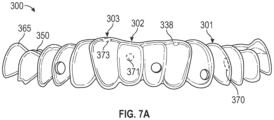
図7A~図7B、図8~図10には、歯科器具300が示されている。歯科器具300は、歯科器具300のアーチ部材338が、歯科器具200が覆っている度合に対して、少なくとも1つのポリマーシェル部分のより大きな第2の表面領域を覆っていることを除いて、図2~図6の歯科器具200と同様であり得る。
A
歯科器具300は、ポリマーシェル部分301、ポリマーシェル部分302、及びポリマーシェル部分303などの複数のポリマーシェル部分を有することができる。
例えば、ポリマーシェル部分301は、小臼歯用に形成されたキャビティを内部に有することができ、ポリマーシェル部分302は、中切歯用に形成されたキャビティを内部に有することができ、ポリマーシェル部分303は、側切歯用に形成されたキャビティを内部に有することができる。
For example,
複数のポリマーシェル部分のそれぞれは、1つ以上のスペーサを有することができる。例えば、ポリマーシェル部分301は、顔面側表面にスペーサ370を有し、ポリマーシェル部分302は、顔面側表面にスペーサ371を有し、かつ、舌側表面にスペーサ372を有し、ポリマーシェル部分303は、咬合面に、より具体的には、切縁にスペーサ373を有する。
Each of the multiple polymer shell portions can have one or more spacers. For example,
具体的には、アーチ部材338は、ポリマーシェル部分の表面を覆っているので、歯の舌側表面、顔面側表面、及び/又は咬合面上の複数のスペーサ、又はこれらの組み合わせが役立ち得る。歯科器具300は、歯の顔面側表面及び舌側表面から矯正力を印加することができ、これにより、金属ではなくポリマーなど、従来の器具において使用されるよりも剛性の低い材料をアーチ部材338に使用できるようにすることができる。複数のスペーサは、顔面側方向に向かって舌側表面に力を加えること、及び/又は舌側方向に向かって顔面側表面に力を印加することによって、歯群に対する微調整された矯正を更に実現することができる。373などの咬合側スペーサは、スペーサを通過する軸を中心として379などの歯シェルを回転させる間、アーチ部材338の形状を維持することができる。
Specifically, since the
いくつかの実施形態では、咬合側スペーサ373により、歯の切縁を中心とした回転が可能になり得る。例えば、(歯の長軸を中心とした)1次回転が規定される。スペーサ373は、垂直軸を中心に回転するように捻じれている。いくつかの実施形態では、咬合側スペーサ373を使用して、スペーサ373に加えられた屈曲モーメントを通じて、歯の矢状面又は前頭面において歯にトルクをかけることもできる。また、スペーサ373を通過する任意の斜交軸を中心とした回転も促進され得る。
In some embodiments, the
図7Bは、第1大臼歯350及び第2大臼歯365のための少なくとも1つのキャビティを有するポリマーシェル部分を示しており、第1大臼歯350及び第2大臼歯365のポリマーシェル部分が一緒に融合されている。例えば、ポリマーシェル部分は、第1大臼歯及び第2大臼歯(例えば、350、365)に対応する第1のキャビティと、第1大臼歯及び第2大臼歯の様々な咬頭に対応する複数の第2のキャビティとを有することができる。第1大臼歯及び第2大臼歯のためのポリマーシェル部分は、互いに対して移動しない若干固定された歯群を表す。この例では、大臼歯をオーバートレイ/アーチ部材338に直接接続して、他の歯シェルがてことするアンカーを提供する。
FIG. 7B shows a polymer shell portion having at least one cavity for a
図8では、アーチ部材338は、ポリマーシェル部分301の表面領域の少なくとも100パーセントと重なっている。図示のように、アーチ部材338の非充填部分及びポリマーシェル部分301から間隙339が形成される。スペーサ370は、間隙339を維持し、小臼歯に位置合わせ力を提供することができる。隣接するポリマーシェル部分(図示せず)にスペーサを配置することによって、間隙339を潰れにくくすることができる。例えば、隣接するポリマーシェル部分上の咬合側スペーサは、間隙339を維持することができる。
In FIG. 8,
図9では、アーチ部材は、ポリマーシェル部分302の表面領域の少なくとも100パーセントを覆っている。ポリマーシェル部分302は、アーチ部材338に連結された2つのスペーサ371及び372を有する。スペーサ371が歯を貫通する距離だけスペーサ372から変位しているので、回転軸331を形成することができる。したがって、軸331を中心にして切歯にトルクをかけることができ、それによって、歯の前頭面における歯冠の移動を実現することができる。
In FIG. 9, the arch members cover at least 100 percent of the surface area of
他のスペーサがなくても、スペーサ371又はスペーサ372のいずれかを中心にした回転が可能である。しかし、ポリマーシェル部分の両側に配置されたスペーサの両方を有することによって、スペーサ372と371の両方を通過する軸331に回転が完全に制約される。これにより、歯の回転に対して、より優れた制御が行われる。
Rotation about either
垂直軸334などの他の軸を中心とした回転も可能である。例えば、対向する力ベクトルが近心方向及び遠心方向にある概ね垂直な平面に沿ってスペーサ371及び372を剪断配置した場合、垂直軸334を中心としたトルクをもたらす連結が形成される。また、同様の構成により、垂直方向に対向する力ベクトルに沿ってスペーサ371及び372を剪断配置することによって、近心-遠心軸を中心としたトルクをもたらすことができる。
Rotation about other axes, such as
図10では、アーチ部材338は、ポリマーシェル部分303の表面領域の少なくとも100パーセントを覆っている。ポリマーシェル部分303は、側切歯の咬合面(又は切縁)に対応する一部分に位置する1つのスペーサ373を有することができる。スペーサ373は、アーチ部材338とポリマーシェル部分303との間に形成された間隙378及び379を提供することができる。間隙378は、歯の唇側面に対応するポリマーシェル部分とアーチ部材338との間の領域に対応する。間隙379は、歯の舌側表面に対応するポリマーシェル部分とアーチ部材338との間の領域に対応する。図10に示した垂直軸334は、回転軸を表すことができる。結果として、スペーサ373は捻じれることになる。
In FIG. 10,
図11A~図11Dにおいて、歯科器具400は、アーチ部材438が、共に形成された切り抜き部分を有することを除いて、図7A~図7Bの歯科器具300と同様であり得る。切り抜き部分は、アーチ部材438から形成され得る。切り抜き部分は、歯科器具400に必要とされる材料の量を低減することができ、嵩を低減することができ、より良好な咬頭嵌合を可能にすることができ、かつ、歯の再配置を選択的に可能にすることができる。歯科器具の固定を補助するためにポリマーシェル部分は固定歯上にあり得る。
11A-11D,
例示的な例として、歯科器具400は、3つの切り抜き部分、すなわち、切り抜き部分480、切り抜き部分481及び切り抜き部分482を有する。各切り抜き部分は、アーチ部材438から形成され、ポリマーシェル部分の表面(例えば、咬合面)の少なくとも一部分を露出させることができる。例えば、切り抜き部分480は、ポリマーシェル部分405の一部分及びポリマーシェル部分402の一部分を露出させる。切り抜き部分481は、少なくとも2つのポリマーシェル部分の少なくともいくつかの咬合面を露出させる。切り抜き部分482は、ポリマーシェル部分404を含む少なくとも2つのポリマーシェル部分の少なくともいくつかの咬合面を露出させる。
As an illustrative example,
歯科器具400の例示的な例では、ポリマーシェル部分405の咬合面は、アーチ部材438の不要な部分を除去することによって露出される。側切歯が(歯の長軸を中心とした)1次回転を規定しているので、アーチ部材438は、側切歯上にあり、側切歯のそれぞれの切縁にはスペーサ435又は437が必要とされる。アーチ部材438の一部分は、スペーサ435又は437を支持している。
In the illustrative example of
切り抜き部分の縁部は、肉厚部分又はフランジ(図示せず)で補強され得る。歯科器具400は、歯の舌側表面と顔面側表面の両方に対応するポリマーシェル部分の両側にアーチ部材438が重なっている状態で示されているが、アーチ部材438はまた、歯の咬合面に対応する側にあってもよい。
The edges of the cutout may be reinforced with thickenings or flanges (not shown). Although the
図12には、ポリマーシェル部分404が示されている。ポリマーシェル部分404は、アーチ部材438の切り抜き部分482を通じて露出させることができる。いくつかの実施形態では、アーチ部材438は、スペーサ474に連結され、スペーサ474は、ポリマーシェル部分404に更に連結される。アーチ部材438の一部分は、歯の口腔面に対応するポリマーシェル部分404の側に連結されていなくてもよい。連結されていない側は、隣接するポリマーシェル部分に連結して、歯に再配置力を提供することができ、あるいは浮動して、歯の明確な回転軸をしないことも可能である。
いくつかの実施形態では、歯科器具400はまた、第1のアーチ部材とは別個であり得る第2のアーチ部材(図示せず)を有することができる。例えば、第2のアーチ部材は、歯の舌側表面に対応する歯科器具400の側面に連結されているスペーサに連結することができ、一方で、第1のアーチ部材は、歯の顔面側表面に対応する歯科器具400の側面に連結される。
In some embodiments, the
図13A~図13Bには、第1のアーチ部材538と第2のアーチ部材541とを有する歯科器具500を含む歯科構造の概略図(縮尺とおりではない)が示されている。歯科構造は、歯510及び歯552を含むことができる。歯科器具500の構成要素は、図2A~図2Eの歯科器具100及び歯科器具200の構成要素と同様であり得る。
13A-13B show schematic illustrations (not to scale) of a dental structure including a
第1のポリマーシェル部分520は、歯510に取り外し可能に連結することができ、一方で、第2のポリマーシェル部分550は、歯552に取り外し可能に連結することができる。各ポリマーシェル部分は、ポリマーシェル部分が歯に対して回転移動しないように歯に固定され得る。
First
第1のアーチ部材538は、歯の顔面側表面に対応する表面のスペーサ532を介して第1のポリマーシェル部分520に連結することができる。第1のアーチ部材538は、歯の舌側表面に対応する表面のスペーサ547を介して第2のポリマーシェル部分550に連結することができる(図13Bを参照)。第1のアーチ部材538は、歯552を、歯510に向かって553に示すように近心方向に引くと共に、歯552の咬合側端部の先端を顔面側に向けることができる。いくつかの実施形態では、アーチ部材538の構成によって、並進及び回転などの他の移動を促進することができる。
A first
第2のアーチ部材541は、顔面側でスペーサ530及びスペーサ548をそれぞれ介して、第1のポリマーシェル部分520及び第2のポリマーシェル部分550に連結することができる。第2のアーチ部材541は、歯552が歯510に向かって並進されるようにスペーサ530とスペーサ548との間に張力を引き起こす長さを有することができる。
The second
図13A及び図13Bの実施形態では、歯の間に張力が提供される。いくつかの実施形態では、器具500は、一連の異なる器具を使用して段階的な所望の移動を引き起こす漸増的器具であり得る。
In the embodiment of Figures 13A and 13B, tension is provided between the teeth. In some embodiments,
本明細書に記載されるように、医師は、一連の異なる器具を処方することができる。各歯科器具は、段階的な歯列状態を処方することができる。患者は、第1の歯列状態に対応する第1の歯科器具を歯に取り付けることができる。更に、任意選択的に、結合化合物で第1の歯科器具を取り付けることができる。歯列状態が達成されると、歯の第2の歯列状態に対応する第2の歯科器具を適用することができる。 As described herein, a physician may prescribe a range of different devices. Each dental appliance can prescribe graduated dentition conditions. The patient can attach a first dental appliance to the teeth corresponding to the first dentition condition. Additionally, the first dental appliance can optionally be attached with a bonding compound. Once a dentition condition is achieved, a second dental appliance corresponding to a second dentition condition of the tooth can be applied.
本開示の態様はまた、非一時的なコンピュータ可読媒体に関連することができる。上述のように、本発明の態様は、コンピュータ可読プログラムコードが内部に具現化されたコンピュータ可読媒体に具現化されたコンピュータプログラム製品の形態をとってもよい。また、コンピュータ可読媒体の任意の組み合わせを利用してもよい。コンピュータ可読媒体は、コンピュータ可読信号媒体又はコンピュータ可読記憶媒体であってもよい。コンピュータ可読記憶媒体は、例えば、電子、磁気、光学、電磁、赤外線、若しくは半導体のシステム、装置若しくはデバイス、又は前述の任意の好適な組み合わせであり得るが、これらに限定されない。コンピュータ可読記憶媒体のより具体的な例(非網羅的リスト)として、1つ以上のワイヤを有する電気接続、ポータブルコンピュタディスケット、ハードディスク、ランダムアクセスメモリ(RAM)、読み出し専用メモリ(ROM)、消去可能なプログラマブル読み出し専用メモリ(EPROM又はフラッシュメモリ)、光ファイバ、ポータブルコンパクトディスク読み出し専用メモリ(CD-ROM)、光学記憶デバイス、磁気記憶デバイス、又は前述の任意の好適な組み合わせが挙げられる。本文書の文脈では、コンピュータ可読記憶媒体は、命令を実行するシステム、装置又はデバイスによって、あるいはそれらに関連して使用するためのプログラムを含む又は記憶することができる任意の有形媒体であってもよい。 Aspects of the present disclosure can also relate to non-transitory computer-readable media. As noted above, aspects of the present invention may take the form of a computer program product embodied on a computer-readable medium having computer-readable program code embodied therein. Also, any combination of computer readable media may be utilized. A computer-readable medium may be a computer-readable signal medium or a computer-readable storage medium. A computer-readable storage medium can be, for example, but not limited to, an electronic, magnetic, optical, electromagnetic, infrared, or semiconductor system, apparatus or device, or any suitable combination of the foregoing. More specific examples (non-exhaustive list) of computer readable storage media include electrical connections with one or more wires, portable computer diskettes, hard disks, random access memory (RAM), read only memory (ROM), erasable programmable read-only memory (EPROM or flash memory), optical fiber, portable compact disc read-only memory (CD-ROM), optical storage devices, magnetic storage devices, or any suitable combination of the foregoing. In the context of this document, a computer-readable storage medium is any tangible medium that can contain or store a program for use by or in connection with a system, apparatus, or device that executes instructions. good.
図14~図18は、本明細書に開示したシェル部分の様々な態様の治療計画及びデジタル設計を示している。 14-18 illustrate treatment planning and digital design of various aspects of the shell portions disclosed herein.
図14は、診療所44と製造施設48とが、患者42用の取り外し可能な歯科器具52のセットの製造プロセス全体を通じて情報を伝達する、例示的なコンピュータ環境40を示すブロック図である。まず、診療所44の歯列矯正医が任意の適切な画像化技術を使用して患者42の歯科構造の1つ以上の画像を生成し、デジタル歯科構造データ46(例えば、患者42の歯構造のデジタル表現)を生成する。例えば、医師は、デジタル走査され得るX線画像を生成し得る。あるいは、医師は、患者の歯構造のデジタル画像を、例えば、従来のコンピュータ断層撮影(computed tomography、CT)、レーザ走査、口腔内走査、歯科印象のCTスキャン、印象から注入された歯科用模型の走査、超音波計測、磁気共鳴映像法(magnetic resonance imaging、MRI)、又は3Dデータ取得の任意の他の適切な方法を使用して取り込んでもよい。他の実施形態では、デジタル画像は、Brontes Technologies,Inc.(Lexington,MA)によって開発され、PCT国際公開第2007/084727号(Boerjesら)に記載される、能動波面サンプリングを使用する口腔内スキャナなどの、手持ち式口腔内スキャナを使用して提供され得る。また、他の口腔内スキャナ又は口腔内接触プローブを使用することもできる。別の選択肢として、患者の歯の陰印象を走査することによってデジタル構造データ46を提供してもよい。更に別の選択肢として、患者の歯の陽の物理的モデルを画像化することにより、又は患者の歯のモデルに対し接触プローブを使用することにより、デジタル構造データ46を提供してもよい。走査に使用されるモデルは、例えば、アルギネート又はポリビニルシロキサン(PVS)等の好適な印象材から、患者の歯列の印象を鋳造し、鋳造材料(例えば、歯列矯正石膏又はエポキシ樹脂)を印象材に注ぎ、鋳造材料を硬化させることによって作製され得る。上記のものを含む任意の好適な走査技法を用いてモデルを走査してもよい。他の可能な走査方法は、例えば、米国特許出願公開第2007/0031791号(Cinaderら)に記載されている。
FIG. 14 is a block diagram illustrating an
歯の露出面を走査してデジタル画像を提供することに加え、歯列の隠れた特徴部、例えば、患者の歯根、及び患者の顎骨を画像化することが可能である。いくつかの実施形態では、デジタル歯構造データは、これら特徴部のいくつかの3次元(3D)画像を用意し、続いて、それらを共に「縫い合わせる」ことによって形成される。これらの異なる画像は、同じ画像化技術を使用して提供される必要はない。例えば、CTスキャンで提供される歯根のデジタル画像が、口内可視光線スキャナで提供される歯冠のデジタル画像と一体化してもよい。3D歯科画像を用いた2次元(2D)歯科画像のスケーリング及び登録は、米国特許第6,845,175号(Kopelmanら)、及び米国特許公開第2004/0029068号(Baduraら)に記載されており、発行された米国特許第7,027,642号(Imgrundら)及び同第7,234,937号(Sachdeviaら)は、様々な3D源から提供されるデジタル画像を一体化する技術を用いて説明している。したがって、用語「画像化」は、これが本明細書において使用される際、視覚的に明らかな構造の、通常の写真画像化に限定されず、視界から隠れた歯科構造の画像化をも含む。歯科構造としては、歯列弓の1つ以上の歯の歯冠及び/又は歯根、歯肉、歯周靭帯、歯槽骨、皮質骨、インプラント、人工歯冠、ブリッジ、ベニア、義歯、歯列矯正器具、又は治療前、治療中若しくは治療後に歯列の一部とみなされ得る任意の構造物の任意の一部分が挙げられ得るが、これらに限定されない。 In addition to scanning the exposed surfaces of the teeth to provide digital images, it is possible to image hidden features of the dentition, such as the patient's tooth roots and the patient's jawbone. In some embodiments, digital tooth structure data is formed by taking several three-dimensional (3D) images of these features and then "stitching" them together. These different images need not be provided using the same imaging technique. For example, a digital image of the root provided by a CT scan may be merged with a digital image of the crown provided by an intraoral visible light scanner. Two-dimensional (2D) dental image scaling and registration with 3D dental images is described in US Pat. No. 6,845,175 (Kopelman et al.) and US Patent Publication No. 2004/0029068 (Badura et al.) and issued U.S. Pat. Nos. 7,027,642 (Imgrund et al.) and 7,234,937 (Sachdevia et al.) use techniques to integrate digital images provided by various 3D sources. is explained. Thus, the term "imaging" as it is used herein is not limited to conventional photographic imaging of visually apparent structures, but also includes imaging of dental structures hidden from view. Dental structures include crowns and/or roots of one or more teeth of the dental arch, gums, periodontal ligaments, alveolar bone, cortical bone, implants, artificial crowns, bridges, veneers, dentures, orthodontic appliances. , or any portion of any structure that may be considered part of the dentition before, during or after treatment.
デジタル歯構造データ46を生成するために、コンピュータは、画像化システムからの未加工データを、使用可能なデジタルモデルに変換する。例えば、コンピュータが受け取る歯の形状を表す未加工データにおいて、未加工データは、多くの場合、3D空間内の点群にすぎない。通常、この点群を表面に構成し、1つ以上の歯、歯肉組織及び他の周囲口腔構造を含む患者の歯列の3Dオブジェクトモデルを作製する。このデータが歯列矯正診断及び治療において有用となるために、コンピュータは歯列表面を「セグメント化」し、個々の歯を表す1つ以上の個別の移動可能な3D歯オブジェクトモデルを生成してもよい。コンピュータはこれら歯モデルを歯肉から別個のオブジェクトへと更に分離してもよい。
To generate the digital
セグメント化によって、ユーザは、歯の配列を個々のオブジェクトのセットとして特性評価し、操作することが可能となる。有利なことに、コンピュータは、これらモデルから、歯列弓周長、噛み合わせなどの診断情報、及び更にはAmerican Board of Orthodontics(ABO)の客観的評価を得てもよい。更なる利点として、デジタル歯列矯正セットアップは製造プロセスに柔軟性をもたらしてもよい。物理的プロセスをデジタルプロセスで置き換えることによって、データ取得工程とデータ操作工程とを、歯型又は印象をある場所から別の場所へ輸送する必要なく、別々の場所で実行することが可能である。物理オブジェクトをあちこちに輸送する必要を低減する又はなくすことにより、顧客及びカスタマイズされた器具の製造者の両者にとって大幅なコストの節減につながり得る。 Segmentation allows the user to characterize and manipulate the tooth arrangement as a set of individual objects. Advantageously, the computer may obtain from these models diagnostic information such as arch circumference, bite, and even objective assessments of the American Board of Orthodontics (ABO). As a further advantage, the digital orthodontic set-up may provide flexibility in the manufacturing process. By replacing the physical process with a digital process, the data acquisition and data manipulation steps can be performed at separate locations without the need to transport impressions or impressions from one location to another. Reducing or eliminating the need to transport physical objects around can lead to significant cost savings for both customers and manufacturers of customized instruments.
デジタル歯科構造データ46の生成後、診療所44はデジタル歯科構造データ46をデータベースの患者記録内に保存してもよい。診療所44は、例えば、複数の患者記録を有するローカルデータベースを更新してもよい。あるいは、診療所44はネットワーク50を通じて(任意選択的に製造施設48内の)中央データベースを遠隔的に更新してもよい。デジタル歯構造データ46を保存した後、診療所44は、デジタル歯科構造データ46を製造施設48に電子的に通信する。あるいは、製造施設48はデジタル歯科構造データ46を中央データベースから取り出してもよい。
After generating the digital
診療所44は、また、医師の診断と患者42の治療計画とに関する全般的な情報を伝える処方データ47を製造施設48に転送してもよい。いくつかの例では、処方データ47はより具体的であってもよい。例えば、デジタル歯科構造データ46は患者42の歯科構造のデジタル表現であってもよく、診療所44の医師は、このデジタル表現を精査し、デジタル歯科構造データ46を製造施設48に転送するのに先だって、取り外し可能な歯科器具52のセットによる治療後の患者42の個々の歯の所望の移動量、間隔又は最終位置を示してもよい。製造施設48は別の場所にあっても、診療所44にあってもよい。
Clinic 44 may also forward
例えば、臨床的環境において、治療計画及びデジタル設計を、ローカルにインストールされたソフトウェアを使用することで臨床医又は助手が完全に実施できるように、それぞれの診療所44は製造施設48のための独自の設備を含んでもよい。製造は3Dプリンタの使用によって(又は付加製造の他の方法によって)診療所内でも行ってよい。3Dプリンタは、歯科器具の複雑な特徴又は患者42の歯科構造の物理的表現の製造を付加製造によって可能にする。3Dプリンタは、患者42の本来の歯科構造及び患者42の所望の歯科構造の繰り返しデジタル設計を使用し、患者42の所望の歯科構造を作成するようにカスタマイズされた複数のデジタル器具及び/又はデジタル器具パターンを作成してもよい。製造は、未硬化樹脂及び支持構造を除去する、又は様々な部品を組み付ける後処理を含んでもよく、後処理は、必要なことがあり、臨床的環境においても実行することができる。
For example, in a clinical environment, each clinic 44 may have its own for
製造施設48では、患者42の歯を再配置するために、患者42のデジタル歯科構造データ46を用いて取り外し可能な歯科器具52のセットを構築する。その後しばらく経って、製造施設48は取り外し可能な歯科器具52のセットを診療所44に、又はその代わりに、患者42に直接送る。例えば、取り外し可能な歯科器具52のセットは、順序付けられた取り外し可能な歯科器具のセットであってもよい。患者42は、その後、患者42の歯を再配置するために、取り外し可能な歯科器具52のセット内の取り外し可能な歯科器具を所定のスケジュールに従って長い時間にわたり順次装着する。例えば、患者42は、取り外し可能な歯科器具52のセット内のそれぞれの取り外し可能な歯科器具を約3週間~約10週間又は約4週間~約8週間など、約1週間~約12週間の期間にわたって装着してもよい。任意選択的に、患者42は取り外し可能な歯科器具52による治療の経過の定期的な観察のために診療所44に戻ってもよい。
A
このような定期的な観察の際、臨床医は、取り外し可能な歯科器具52のセット内の取り外し可能な歯科器具を長い時間にわたり順次装着する患者42の所定のスケジュールを調整してもよい。観察には、一般に、患者42の歯の目視検査を含むと共に、デジタル歯構造データを生成するための画像化も含んでよい。いくつかの比較的一般的でない状況において、臨床医は、例えば、新たな取り外し可能な歯科器具のセットを作成するために、新たに生成したデジタル歯科構造データを製造施設48に送信することによって、取り外し可能な歯科器具52のセットによる患者42の治療の中断を決定してもよい。同じ又は異なる例では、臨床医は、取り外し可能な歯科器具52による治療の所定のスケジュールの完了後に、新たに生成したデジタル歯科構造データを製造施設48に送信してもよい。加えて、取り外し可能な歯科器具52による治療の所定のスケジュールの完了後に、臨床医は新たな取り外し可能な歯科器具のセットを製造施設48に要求し、患者42の治療を継続してもよい。
During such regular observations, the clinician may arrange a predetermined schedule for the patient 42 to wear the removable dental appliances in the set of removable
図15は、本開示の一例による、診療所44で実施されるプロセス60を示すフロー図である。ブロック62において、診療所44にいる医師が、患者42から患者の識別情報及び他の情報を収集し、患者記録を作成する。記載されているように、患者記録は診療所44内に配置されていてもよく、任意選択的に、製造施設48内のデータベースとデータを共有するように構成されていてもよい。あるいは、患者記録は、診療所44がネットワーク50を通じてリモートアクセス可能な製造施設48のデータベース内に、又は製造施設48と診療所44との両方によりリモートアクセス可能なデータベース内に配置されていてもよい。
FIG. 15 is a flow
ブロック64において、任意の適切な技術を用いて患者42の歯科構造のデジタルデータ46を生成し、これにより、仮想歯科構造を作成し、保存してもよい。デジタルデータ46は歯科構造の2次元(2D)画像及び/又は3次元(3D)表示から構成されていてもよい。
At
一例では、歯科構造の3D表示は、Imaging Sciences International,LLC(1910 N Penn Road,Hatfield,PA)から入手可能なi-CAT 3D歯科画像化デバイスなどのコーンビームコンピュータ断層撮影(cone beam computerized tomography、CBCT)スキャナを用いて生成される。診療所44は、CBCTスキャナにより生成した(放射線画像の形態の)3Dデータ46を、診療所44内、又はその代わりに、製造施設48内に配置されたデータベースに保存する。コンピューティングシステムはCBCTスキャナからのデジタルデータ46(このデータは複数のスライスの形態であってもよい)を処理し、3Dモデリング環境内で操作され得る歯構造のデジタル表現を計算する。
In one example, a 3D representation of a dental structure is obtained using cone beam computerized tomography, such as the i-CAT 3D dental imaging device available from Imaging Sciences International, LLC (1910 N Penn Road, Hatfield, Pa.). CBCT) scanner. Clinic 44 stores 3D data 46 (in the form of radiographic images) generated by the CBCT scanner in a database located within clinic 44 or, alternatively, manufacturing
ブロック65において、コンピューティングシステムは、データが歯構造の3Dデータを含んでいるかどうかを判定することができる。含んでいない場合、ブロック66において、医師は、3Dデジタルデータを更に生成してもよい。3Dデータ46は、例えば、患者42の歯構造の物理的印象又は模型を形成し、その後、それをデジタル走査することによって生成してもよい。例えば、患者42の歯列弓の物理的印象又は模型は、Laser Design,Inc.(Minneapolis,MN)から入手可能なOM-3Rスキャナなどの可視光スキャナを用いて走査してもよい。その代わりとして、医師は、咬合科の3Dデータ46を、患者42の歯列弓の口腔内走査又は既存の3D歯データを使用することで生成してもよい。一例では、「REGISTERING PHYSICAL AND VIRTUAL TOOTH STRUCTURES WITH PEDESTALS」という名称で、2013年7月23日に発行済みの米国特許第8,491,306号に記載されている、模型又は印象からデジタル走査を形成する方法を使用してもよい。同じ又は異なる例において、「ORTHODONTIC DIGITAL SETUPS」という名称で、2013年12月5日に公開された米国特許第8,897,902号に記載されているような仮想歯面及び仮想歯座標系を画定するための技術を使用してもよい。いずれの場合においても、デジタルデータは3Dモデリング環境内にデジタルで位置合わせされ、歯根及び咬合面を含み得る歯構造の複合的なデジタル表現を形成する。
At
一例では、歯列弓の咬合面の2D放射線画像及び3Dデジタルデータは、放射線画像及び3Dデジタルスキャンの両方を生成する前に、まず、レジストレーションマーカ(例えば、位置合わせマーカ又は既知の幾何学的形状寸法を有するペデスタル)を患者42の歯構造に取り付けることによって位置合わせされる。その後、2D放射線画像及び3Dデジタルデータ内のレジストレーションマーカのデジタル表現は、米国特許第8,491,306号に記載されている位置合わせ技術を用いて、3Dモデリング環境内で位置合わせしてもよい。 In one example, the 2D radiographic image and 3D digital data of the occlusal surface of the dental arch are first processed with registration markers (e.g., registration markers or known geometric pedestal) to the patient's 42 tooth structure. The digital representations of the registration markers in the 2D radiographic image and 3D digital data can then be registered within the 3D modeling environment using registration techniques described in U.S. Pat. No. 8,491,306. good.
別の例では、歯構造の3Dデジタルデータは歯構造の2つの3Dデジタル表現を組み合わせることによって生成される。例えば、第1の3Dデジタル表現は、CBCTスキャナ(例えば、i-CAT 3D歯科画像化デバイス)から取得した歯根の比較的低解像度の画像であってもよく、第2の3Dデジタル表現は、患者の歯列弓の模型の印象又は可視光(例えば、レーザ)走査の産業用CTスキャンから取得した歯冠の比較的高解像の画像であってもよい。3Dデジタル表現は、3D表現をコンピュータ環境内で操作することを可能にするソフトウェアプログラム(例えば、3D Systems,Inc.(333 Three D Sustems Circle,Rock Hill,SC)から入手可能なGeomagic Studioソフトウェアを用いて位置合わせしてもよく、又はその代わりに、米国特許第8,491,306号に記載されている位置合わせ技術を使用してもよい。 In another example, the 3D digital data of the tooth structure is generated by combining two 3D digital representations of the tooth structure. For example, the first 3D digital representation may be a relatively low resolution image of a tooth root obtained from a CBCT scanner (eg, i-CAT 3D dental imaging device), and the second 3D digital representation may be a patient impression of a dental arch model or a relatively high resolution image of the crown obtained from an industrial CT scan with visible light (eg, laser) scanning. 3D digital representations were created using software programs that allow 3D representations to be manipulated within a computer environment (e.g., Geomagic Studio software available from 3D Systems, Inc. (333 Three D Systems Circle, Rock Hill, SC)). or alternatively, the alignment technique described in US Pat. No. 8,491,306 may be used.
ブロック65においてデータが歯構造の3Dデータを含んでいる場合、プロセス60は、ブロック67に進むことができる。ブロック67において、コンピュータシステムは、診断及び治療情報でデータベースを更新することができる。次に、3Dモデリングソフトウェアを実行するコンピュータシステムが、患者の歯列弓の咬合面及び歯根構造を含む歯構造の合成されたデジタル表現をレンダリングする。モデリングソフトウェアは、医師が3D空間内の歯のデジタル表現を患者の歯列弓のデジタル表現に対し操作することを可能にするユーザインターフェースを提供する。コンピュータシステムとの対話によって、医師は、例えば、所望の最終位置又は患者42の歯の表示を選択することにより治療情報を生成する。
If the data at
ブロック68において、データベースを更新して、患者記録をデジタル歯構造データ記録と関連付ける。例えば、医師が3D環境内において診断及び治療計画に関する全般的な情報の伝達を完了したときに、コンピュータシステムは患者記録に関連付けられたデータベースを更新し、医師が指定した診断及び治療計画に関する全般的な情報を伝える処方データ47を記録する。
At
ブロック69において、取り外し可能な歯科器具52などの1つ以上の取り外し可能な歯科器具を製造施設48が構築するために、処方データ47(例えば、診断及び治療情報、並びにデジタル歯構造)を製造施設48に中継する。
At block 69,
矯正歯科診療所にいる歯列矯正医に関して記載したが、プロセス60に関して記載した工程の1つ以上は、製造施設48にいるユーザなどの遠隔ユーザによって実行してもよい。例えば、歯列矯正医は放射線画像データと患者の印象又は模型とを製造施設48に送信するのみであってもよく、製造施設48で、ユーザがコンピュータシステムと対話し、3Dモデリング環境内において治療計画を策定する。
Although described with respect to an orthodontist at an orthodontic office, one or more of the steps described with respect to process 60 may be performed by a remote user, such as a user at
任意選択的に、3Dモデリング環境内における治療計画のデジタル表現は、その後、診療所44の歯列矯正医に送信してもよく、歯列矯正医は治療計画を精査し、自身の承認を返送するか所望の変更を示すかのいずれかであってもよい。 Optionally, the digital representation of the treatment plan within the 3D modeling environment may then be sent to an orthodontist at clinic 44, who reviews the treatment plan and returns his approval. or indicate the desired change.
図16は、ネットワーク50を介して製造施設48に接続されたクライアントコンピューティングデバイス80の一例を示すブロック図である。図示される例では、クライアントコンピューティングデバイス80は、モデリングソフトウェア82の動作環境を提供する。モデリングソフトウェア82は、患者42の歯の3D表現をモデリングし、かつ描画するためのモデリング環境を提供する。図示される例では、モデリングソフトウェア82は、ユーザインターフェース84と、アライメントモジュール86と、レンダリングエンジン88と、を含む。
FIG. 16 is a block diagram illustrating an example of a
ユーザインターフェース84は、患者42の歯の3D表示を視覚的に表示するグラフィカルユーザインターフェース(GUI)を提供する。加えて、ユーザインターフェース84は、モデル化された歯列弓内の患者42の歯を操作するために、診療所44(図10)の医師89から、例えば、キーボード及びポインティングデバイスによる入力を受け取るためのインターフェースを提供する。
モデリングソフトウェア82はネットワークインターフェース81を通じて製造施設48にアクセス可能であってもよい。モデリングソフトウェア82はデータベース90と対話して、治療データ92、患者42の歯構造に関する3Dデータ94、及び患者データ96などの様々なデータにアクセスする。データベース90は、データ格納ファイル、ルックアップテーブル、又は1つ以上のデータベースサーバで実行されるデータベース管理システム(DBMS)を含む、様々な形態で提示してもよい。データベース管理システムは、リレーショナルデータベース管理システム(RDBMS)、階層型データベース管理システム(HDBMS)、多次元データベース管理システム(MDBMS)、オブジェクト指向データベース管理システム(ODBMS若しくはOODBMS)、又はオブジェクトリレーショナルデータベース管理システム(ORDBMS)であってもよい。データは、例えば、Microsoft Corporation製のSQLサーバなど、単一のリレーショナルデータベース内に記憶してもよい。データベース90は、クライアントコンピューティングデバイス80のローカルとして示されているが、クライアントコンピューティングデバイスからリモートに位置し、公共ネットワーク又は私設ネットワーク、例えばネットワーク50を介してクライアントコンピューティングデバイスに連結してもよい。
治療データ92は、医師89によって選択されて、3Dモデリング環境内に配置される、患者42の歯の診断及び/又は再配置情報を表す。
患者データ96は、医師89に関連する1人以上の患者の一群、例えば、患者42を表す。例えば、患者データ96は、各患者に関する氏名、出生日、及び歯科疾病歴のような一般的な情報を特定する。
レンダリングエンジン88は、3Dデータ94にアクセスしてレンダリングし、ユーザインターフェース84により医師89に提示される3D図を生成する。より具体的には、3Dデータ94は、3D環境内で各歯(任意選択的に歯根を含む)及び顎骨を表す3Dオブジェクトを定義する情報を含む。レンダリングエンジン88は各オブジェクトを加工し、3D環境内で医師89の視点に基づき、3D三角メッシュをレンダリングする。ユーザインターフェース84は、レンダリングされた3D三角メッシュを医師89に対して表示し、医師89が3D環境内で視点を変更し、オブジェクトを調節することを可能にする。
2012年6月5日に発行済みの「PLANAR GUIDES TO VISUALLY AID ORTHODONTIC APPLIANCE PLACEMENT WITHIN A THREE-DIMENSIONAL(3D)ENVIRONMENT」という名称の米国特許第8,194,067号、及び2010年6月8日に発行済みの「USER INTERFACE HAVING CROSS SECTION CONTROL TOOL FOR DIGITAL ORTHODONTICS」という名称の米国特許第7,731,495号は、本明細書中に記載される技術と共に使用され得るユーザインターフェースを有するコンピュータシステム及び3Dモデリングソフトウェアの他の例について記載している。 U.S. Patent No. 8,194,067, entitled "PLANAR GUIDES TO VISUALLY AID ORTHODONTIC APPLIANCE PLACEMENT WITHIN A THREE-DIMENSIONAL (3D) ENVIRONMENT," issued Jun. 5, 2012; Issued U.S. Pat. No. 7,731,495, entitled "USER INTERFACE HAVING CROSS SECTION CONTROL TOOL FOR DIGITAL ORTHODONTICS," describes a computer system and 3D computer system having a user interface that can be used with the techniques described herein. Other examples of modeling software are described.
クライアントコンピューティングデバイス80は、モデリングソフトウェア82を保存し、かつ実行するために、プロセッサ83とメモリ85とを含む。メモリ85は、任意の揮発性又は不揮発性ストレージ要素を意味してもよい。例としては、シンクロナスダイナミックランダムアクセスメモリ(SDRAM)、読み出し専用メモリ(ROM)、不揮発性ランダムアクセスメモリ(NVRAM)、電気的消去可能プログラマブル読み出し専用メモリ(EEPROM)及びフラッシュメモリなどのランダムアクセスメモリ(RAM)を含む。例としては、また、ハードディスク、磁気テープ、磁気又は光データストレージ媒体、コンパクトディスク(CD)、デジタル多用途ディスク(DVD)、Blu-rayディスク、及びホログラフィックデータストレージ媒体などの不揮発性ストレージを含んでもよい。
プロセッサ83は、汎用マイクロプロセッサ、特別設計のプロセッサ、特定用途用集積回路(ASIC)、フィールドプログラマブルゲートアレイ(FPGA)、ディスクリート論理回路のコレクション、又は本明細書中に記載される技術を実行することができる任意の種類の処理デバイスなどの1つ以上のプロセッサを意味する。一例では、メモリ85は、プロセッサ83によって実行されて、本明細書中に記載される技術を実行するプログラム命令(例えば、ソフトウェア命令)を記憶してもよい。他の例では、技術はプロセッサ83の特別にプログラムされた回路によって実行してもよい。これら又は他の手法では、プロセッサ83は、本明細書中に記載される技術を実行するように構成されていてもよい。
Processor 83 may be a general purpose microprocessor, a specially designed processor, an application specific integrated circuit (ASIC), a field programmable gate array (FPGA), a collection of discrete logic circuits, or to implement the techniques described herein. means one or more processors, such as any kind of processing device capable of In one example,
クライアントコンピューティングデバイス80は、患者の3D歯構造のデジタル表現と、任意選択的に、治療データ92及び/又は患者データ96とを製造施設48のコンピュータ70にネットワーク50を通じて送信するように構成されている。コンピュータ70は、ユーザインターフェース72を含む。ユーザインターフェース72は、歯のデジタルモデルの3D表示を視覚的に表示するGUIを提供する。加えて、ユーザインターフェース72は、患者の3D歯構造のデジタル表現内の患者の歯を操作するための、例えば、キーボード及びポインティングデバイスによる入カをユーザから受け取るためのインターフェースを提供する。
コンピュータ70は、更に、患者の取り外し可能な歯科器具のセットの寸法及び形状を決定するように構成されていてもよく、取り外し可能な歯科器具の寸法及び形状は、取り外し可能な歯科器具が患者によって装着されたときに、患者の1つ以上の歯をそれらの初期位置から調整位置へと再配置するように構成されている。コンピュータ70は、取り外し可能な歯科器具のセットを作製するために、患者の取り外し可能な歯科器具のセットの寸法及び形状を自動製造システム74に提供してもよい。
The
クライアントコンピューティングデバイス80及びコンピュータ70は例示的なコンピュータシステムの単なる概念的な表現である。いくつかの例では、クライアントコンピューティングデバイス80及び/又はコンピュータ70のものに関して記載した機能を1つのコンピューティングデバイスに組み合わせてもよく、又は、コンピュータシステム内の複数のコンピューティングデバイス間で分散させてもよい。例えば、本明細書中に記載される歯科器具のデジタル設計にクラウドコンピューティングを用いてもよい。一例では、歯構造のデジタル表現が診療所の1つのコンピュータで受信される一方で、歯科器具の形状及び寸法はコンピュータ70などの異なるコンピュータを用いて決定される。加えて、コンピュータ70などのその異なるコンピュータは形状及び寸法の決定のために同一データを全て受信する必要がない場合がある。形状及び寸法は、少なくとも一部、対象症例の完全な3D表示を受け取ることなく歴史的症例又は例示的症例の仮想モデルの分析を通じて得た知識に基づき決定してもよい。このような例では、クライアントコンピューティングデバイス80とコンピュータ70との間で送信される、又は別の方式で特別仕様の歯科器具を設計するために利用されるデータは、患者の完全なデジタル歯科モデルを示す全データセットよりも大幅に小さくてもよい。
図17は、取り外し可能な歯科器具52の構築のために製造施設48において行われるプロセス26を示すフロー図である。いくつかの例では、取り外し可能な歯科器具52は、本明細書で論じられるような取り外し可能な歯科器具のうちの1つ以上を含んでもよい。ブロック21において、製造施設48にあるコンピュータ70は、患者42から診療所44を介して、デジタル歯構造データ46を受け取る、したがって、診療所44からの患者の1つ以上の歯の初期位置及び処方データ47を提供する。あるいは、コンピュータ70は、コンピュータ70内にある又はそうでなければコンピュータ70によってアクセス可能なデータベースから情報を取り出す。診療所44が既に行っていない場合には、コンピュータ70に関わる訓練されたユーザがコンピュータ70上で実行されているコンピュータ化モデリング環境と対話し、患者の歯構造のデジタル表現に対し治療計画を策定し、処方データ47を生成してもよい。他の例では、コンピュータ70は患者の歯構造及び既定の設計制約のみに基づき治療計画を自動的に策定してもよい。
FIG. 17 is a flow diagram showing the
ブロック22において、コンピュータ70は、患者の取り外し可能な歯科器具の寸法及び形状を決定する。取り外し可能な歯科器具の寸法及び形状は、取り外し可能な歯科器具が患者によって装着されたときに患者の1つ以上の歯をそれらの初期位置から調整位置へと再配置するように構成されている。同じ又は更なる例では、コンピュータ70は患者の取り外し可能な歯科器具のセットの寸法及び形状を決定し、患者の取り外し可能な歯科器具のセットは順次装着されるように構成されている。
At
いくつかの例では、取り外し可能な歯科器具の寸法及び形状を決定することは、コンピュータ70によって、取り外し可能な歯科器具の寸法及び形状を既定の設計制約のセットに従って選択することを含む。既定の設計制約のセットには、取り囲まれた歯の1つ以上に印加される最大局所化力、取り囲まれた歯の1つ以上に印加される最大回転力、取り囲まれた歯の1つ以上に印加される最大並進力、取り囲まれた歯の1つ以上に印加される最大合力、及び取り囲まれた歯がそれらの初期位置にあるときに、取り外し可能な歯科器具の患者による装着時に印加される最大歪みを含むが、これらに限定されない1つ以上の因子が含まれ得る。
In some examples, determining the size and shape of the removable dental appliance includes selecting, by the
コンピュータ70は、取り外し可能な歯科器具の寸法及び形状の決定時に、有限要素法(Finite Element Analysis、FEA)を使用して、患者の歯及び取り外し可能な歯科器具にかかる力を分析してもよい。例えば、コンピュータ70は、順序付けられた取り外し可能な歯科器具のセットを含む治療を示す、モデル化された歯がそれらの初期位置からそれらの最終位置へと移動する際の患者の歯のソリッドモデルにFEAを適用してもよい。コンピュータ70は、所望の力を歯に印加するための適切な取り外し可能な歯科器具を選択するために、FEA技術を使用してもよい。加えて、コンピュータ70は、治療中のモデル化された歯の移動全体を通した歯間の接点を決定するために、仮想咬合器を使用してもよい。コンピュータ70は、順序付けられた取り外し可能な歯科器具のセット内の取り外し可能な歯科器具の設計時、FEA力分析において、デバイスからの力と併せて、咬頭嵌合力などの咬合接触力を更に含んでもよい。
The
同じ又は異なる例では、取り外し可能な歯科器具の寸法及び形状を決定することは、取り外し可能な歯科器具が患者によって装着されたときに患者の1つ以上の歯をそれらの初期位置から調整位置へと再配置するのに適した剛性を付与するために、コンピュータ70によって、歯科器具本体の顔側部及び舌側部の厚さを選択することを含む。異なる例では、このような選択された厚さは、厚さ約0.5~約2.0ミリメートルなど、厚さ約0.5ミリメートル~約1.0ミリメートルの範囲であってもよい。いくつかの例では、コンピュータ70は、既定の設計制約に従って、又は厚さを必ずしも増加させることなく所望の剛性特性を付与するために、取り外し可能な歯科器具の少なくとも一部分(例えば、顔面側本体部分及び舌側本体部分)の材料を更に選択してもよい。
In the same or a different example, determining the size and shape of the removable dental appliance moves one or more teeth of the patient from their initial position to the adjusted position when the removable dental appliance is worn by the patient. and selecting by the
ブロック23において、コンピュータ70のユーザインターフェース72を通じて、患者の取り外し可能な歯科器具の寸法及び形状をユーザに提示し得る。取り外し可能な歯科器具の寸法及び形状がコンピュータ70のユーザインターフェース72を通じてユーザに提示される例では、ユーザは、設計データが自動製造システムに送られる前に、設計制約を調整する又は取り外し可能な歯科器具の寸法及び形状を直接調整する機会を有してもよい。
At
ブロック23において、あるいは又は付加的に、患者の取り外し可能な歯科器具の寸法及び形状は、コンピュータ70によって直接、自動製造システム74によって製造される取り外し可能な歯科器具としてユーザに提示してもよい。このような例では、コンピュータ70は取り外し可能な歯科器具のデジタルモデルを自動製造システム74に送り、自動製造システム74は取り外し可能な歯科器具をコンピュータ70からのデジタルモデルに従って製造する。
Alternatively or additionally, at
ブロック24において、コンピュータ70は、ユーザ承認後、(更には、患者の取り外し可能な歯科器具の寸法及び形状が、コンピュータ70のユーザインターフェース72を介してユーザに提示され得る例であっても)取り外し可能な歯科器具のデジタルモデルを自動製造システム74に送る。
At
ブロック25において、自動製造システム74は、コンピュータ70からのデジタルモデルに従って取り外し可能な歯科器具を製造する。
At
いくつかの例では、自動製造システム74は3Dプリンタを含んでもよい。プロセス26の技術は、患者の順序付けられた取り外し可能な歯科器具のセットのそれぞれの設計及び製造に適用されてもよい。例えば、順序付けられた取り外し可能な歯科器具のセット内のそれぞれの取り外し可能な歯科器具は、患者の歯を段階的に再配置するように構成していてもよい。このようにして、順序付けられた取り外し可能な歯科器具のセットは、取り外し可能な歯科器具のセット内の取り外し可能な歯科器具のいずれか1つよりも大きな程度まで患者の歯を再配置するように構成されていてもよい。このような患者の順序付けられた取り外し可能な歯科器具のセットは、患者の順序付けられた取り外し可能な歯科器具のセットの取り外し可能な歯科器具が患者によって順次装着されるにつれて、患者の1つ以上の歯をそれらの初期位置から最終調整位置に段階的に再配置するように特別に構成されていてもよい。
In some examples,
いくつかの例では、プロセス26に関し記載した技術を、クライアントコンピューティングデバイス80及び/又はコンピュータ70のコンピュータ可読記憶媒体などのコンピュータ可読記憶媒体内で具現化してもよい。コンピュータ可読記憶媒体は、実行されると、プロセス26に関して記載した技術を実行するようにプロセッサを構成するコンピュータ実行可能命令を記憶する。
In some examples, the techniques described with respect to process 26 may be embodied within a computer-readable storage medium, such as the computer-readable storage medium of
取り外し可能な歯科器具52の設計後、製造施設48は取り外し可能な歯科器具52をデジタル歯構造データ46及び処方データ47に従って作製する。取り外し可能な歯科器具52の構築には、3D印刷、熱成形、射出成形、ロストワックス鋳造、5軸ミリング加工、レーザ切削加工、スナップ嵌合及びオーバーモールドなどのハイブリッド式プラスチック及び金属製造技術、並びに他の製造技術を含んでもよい。
After designing removable
図18は、順序付けられた取り外し可能な歯科器具のセットを使用した治療の連続的な繰り返しを示すフロー図71である。順序付けられた取り外し可能な歯科器具のセットは、患者の1つ以上の歯を再配置するように構成されている。様々な例では、順序付けられた取り外し可能な歯科器具のセットは、本明細書に記載した取り外し可能な歯科器具のうちの1つ以上を含んでもよい。したがって、治療は、本明細書中に記載される複数の取り外し可能な歯科器具を特徴としてもよく、1つの特定の歯科器具実施形態の繰り返しに限定される必要はない場合がある。1つの例示的な実装形態では、治療はまず、本明細書に記載した1つ以上の取り外し可能な歯科器具の繰り返しから開始してもよく、患者の歯が特定の所望の量移動すると、本明細書に記載した取り外し可能な歯科器具の繰り返しによって治療が継続し得る。 FIG. 18 is a flow diagram 71 showing successive repetitions of treatment using an ordered set of removable dental appliances. An ordered set of removable dental appliances is configured to reposition one or more teeth of a patient. In various examples, an ordered set of removable dental appliances may include one or more of the removable dental appliances described herein. Accordingly, a treatment may feature multiple removable dental appliances described herein and need not be limited to repeating one particular dental appliance embodiment. In one exemplary implementation, treatment may first begin with repetition of one or more of the removable dental appliances described herein, and once the patient's teeth have moved a certain desired amount, the present treatment may begin. Treatment may continue with repetition of the removable dental appliances described herein.
ブロック73において、治療の第1の繰り返しにより治療が開始される。治療の第1の繰り返しの開始時、患者の歯は、ブロック75の歯列状態Xによって示されるような歯の初期位置にある。ブロック76において、順序付けられた取り外し可能な歯科器具のセットの設計を容易にするために患者の歯の走査を行う。患者の歯の走査から、コンピュータは、順序付けられたセット内の取り外し可能な歯科器具の2つの異なる形状及び寸法、すなわち、設計77a及び設計77bを決定する。患者の歯のデジタルモデルを作成するための例示的な技術は、「METHODS OF PREPARING A VIRTUAL DENTITION MODEL AND FABRICATING A DENTAL RETAINER THEREFROM」という名称の、2014年5月27日に発行済みの米国特許第8,738,165号(Cinaderら)に記載されている。コンピュータは、順序付けられたセット内の取り外し可能な歯科器具の2つの異なる形状及び寸法を、まず患者の歯のデジタルモデルを調整し、治療後の患者の歯の所望の位置のモデルを作成することによって決定してもよい。その後、コンピュータは、順序付けられたセット内の取り外し可能な歯科器具の形状及び寸法を、患者の歯を初期位置からそれらの所望の位置に移動させるために必要な時間及び力に基づき作成してもよい。例えば、コンピュータモデルは、順序付けられたセット内の取り外し可能な歯科器具のばね状要素の厚さ及び他の寸法を調整し、患者の歯を初期位置からそれらの所望の位置に移動させるために必要な力を生成してもよい。
At
順序付けられたセット内の取り外し可能な歯科器具によって印加されるモデル化された力は、更に、治療中の患者の歯の段階的位置移動に基づいてもよい。このようにして、コンピュータは、順序付けられたセット内の取り外し可能な歯科器具を患者が装着する治療時における予想位置に関して歯に印加される予想される力に従って、順序付けられたセット内の取り外し可能な歯科器具のそれぞれの形状及び寸法を設計してもよい。 The modeled forces applied by the removable dental appliances in the ordered set may also be based on incremental positional movements of the patient's teeth during treatment. In this way, the computer determines the removable dental appliances in the ordered set according to the expected forces to be applied to the teeth with respect to their expected position during treatment with the patient wearing the removable dental appliances in the ordered set. Each shape and size of the dental appliance may be designed.
いくつかの例では、取り外し可能な歯科器具のセット内の3つなどの、1つより多い異なる取り外し可能な歯科器具は、2つの異なる形状及び寸法のそれぞれを用いて、取り外し可能な歯科器具のセット内に6つの取り外し可能な歯科器具を作成することで製造することができる。順序付けられた歯科器具のセット内の第1の歯科器具から第3の歯科器具は、同じ形状及び寸法のものであるが、異なる剛性特性を持つ材料を含む。第2の歯科器具及び第3の歯科器具は第1の歯科器具よりも高い剛性特性を有し、第3の歯科器具はまた、第2の歯科器具よりも高い剛性特性を有する。同様に、順序付けられた歯科器具のセット内の第4の歯科器具から第6の歯科器具は同じ形状及び寸法のものであるが、異なる剛性特性を持つ材料を含む。第5の歯科器具及び第6の歯科器具は第4の歯科器具よりも高い剛性特性を有し、第6の歯科器具はまた、第5の歯科器具よりも高い剛性特性を有する。いくつかの例では、第1の歯科器具は第4の歯科器具と同じ剛性特性を有してもよい。 In some examples, more than one different removable dental appliance, such as three in a set of removable dental appliances, use two different shapes and sizes each of the removable dental appliance. It can be manufactured by creating 6 removable dental appliances in a set. The first through third dental appliances in the ordered set of dental appliances are of the same shape and size but comprise materials with different stiffness properties. The second dental appliance and the third dental appliance have higher stiffness properties than the first dental appliance, and the third dental appliance also has higher stiffness properties than the second dental appliance. Similarly, the fourth through sixth dental appliances in the ordered set of dental appliances are of the same shape and size, but comprise materials with different stiffness properties. The fifth dental appliance and the sixth dental appliance have higher stiffness properties than the fourth dental appliance, and the sixth dental appliance also has higher stiffness properties than the fifth dental appliance. In some examples, the first dental appliance may have the same stiffness characteristics as the fourth dental appliance.
同様に、いくつかの例では、第2の歯科器具は、第5の歯科器具と同じ剛性特性を有してもよい。更に、いくつかの例では、第3の歯科器具は第6の歯科器具と同じ剛性特性を有してもよい。 Similarly, in some examples, the second dental appliance may have the same stiffness characteristics as the fifth dental appliance. Additionally, in some examples, the third dental appliance may have the same stiffness characteristics as the sixth dental appliance.
1つの例示的な治療法では、順序付けられた取り外し可能な歯科器具のセット内の第1の取り外し可能な歯科器具77a1は、比較的軟質のポリマー材料などの比較的軟質の材料から作製されている。順序付けられた取り外し可能な歯科器具のセット内の第1の取り外し可能な歯科器具は、設計77aに一致しており、比較的軟質のポリマー材料などの比較的軟質の材料から作製されている。順序付けられた取り外し可能な歯科器具のセット内の第2の取り外し可能な歯科器具77a2は、設計77aに一致しており、順序付けられた取り外し可能な歯科器具のセット内の第1の取り外し可能な歯科器具よりも比較的より硬質のポリマー材料などの中程度の剛性の材料から作製されている。順序付けられた取り外し可能な歯科器具のセット内の第3の取り外し可能な歯科器具77a3は、設計77aに一致しており、順序付けられた取り外し可能な歯科器具のセット内の第2の取り外し可能な歯科器具よりも比較的より硬質のポリマー材料などの高い剛性の材料から作製されている。順序付けられた取り外し可能な歯科器具のセット内の第4の取り外し可能な歯科器具77b1は、設計77bに一致しており、比較的軟質の材料から作製されている。順序付けられた取り外し可能な歯科器具のセット内の第5の取り外し可能な歯科器具77b2は、設計77bに一致しており、中程度の剛性の材料から作製されている。順序付けられた取り外し可能な歯科器具のセット内の第6の取り外し可能な歯科器具77b3は、設計77bに一致しており、高い剛性の材料から作製されている。
In one exemplary treatment method, the first removable dental appliance 77a1 in the ordered set of removable dental appliances is made of a relatively soft material, such as a relatively soft polymeric material. . A first removable dental appliance in the ordered set of removable dental appliances conforms to design 77a and is made of a relatively soft material, such as a relatively soft polymeric material. The second removable dental appliance 77a2 in the ordered removable dental appliance set conforms to design 77a and is the first removable dental appliance in the ordered removable dental appliance set. It is made from a moderately stiff material, such as a polymeric material that is relatively harder than the device. A third removable dental appliance 77a3 in the ordered set of removable dental appliances conforms to design 77a and a second removable dental appliance in the ordered set of removable dental appliances. It is made from a highly rigid material, such as a polymeric material that is relatively harder than the device. A fourth removable dental appliance 77b1 in the ordered set of removable dental appliances conforms to the
順序付けられた取り外し可能な歯科器具のセット内の第1から第6の取り外し可能な歯科器具は患者により長期間にわたって順に装着される。例えば、順序付けられた取り外し可能な歯科器具のセット内の取り外し可能な歯科器具のそれぞれは、約3週間~約10週間又は約4週間~約8週間など、約2週間~約12週間装着されてもよい。第1から第6の取り外し可能な歯科器具を使用した治療計画後、患者の歯は、歯列(detention)状態X+1を示すブロック78によって示されるような、治療の第1の繰り返しにおける歯の最終位置にある。
The first through sixth removable dental appliances in the ordered set of removable dental appliances are worn sequentially by the patient over time. For example, each of the removable dental appliances in the ordered set of removable dental appliances has been worn for about 2 weeks to about 12 weeks, such as from about 3 weeks to about 10 weeks or from about 4 weeks to about 8 weeks. good too. After treatment planning using the first through sixth removable dental appliances, the patient's teeth are in the final state of the teeth in the first iteration of treatment as indicated by
ブロック79において、患者は臨床医の元に戻ってもよく、臨床医は治療の第1の繰り返しの結果を評価してもよい。治療の第1の繰り返しの結果、患者の歯の最終的な配置に成功した場合には、ブロック87において、治療を終了してもよい。しかしながら、治療の第1の繰り返しによって、患者の歯の所望の移動が完了しなかった場合、1回以上の追加の治療の繰り返しを実施してもよく、プロセスはブロック73に進むことができる。治療の次の繰り返しを開始するために、臨床医は、ブロック76において、順序付けられた取り外し可能な歯科器具のセットの設計が容易になるように、患者の歯の走査をもう一度行ってもよい。いくつかの例では、治療の第1の繰り返しの結果の評価には、患者の歯の走査をもう一度行うことを含んでもよく、この場合、治療の次の繰り返しを開始することには、患者の順序付けられた取り外し可能な歯科器具の別のセットが患者の歯の新たな位置に基づき製造され得るように、患者の歯のデジタルモデルを製造施設に送ることを単に含んでもよい。更に別の例では、新たに取得した走査を用いて、取り外し可能な歯科器具の1回以上の繰り返しを、臨床医の施設において作成してもよい。
At
フロー図71の技術は1つの特定の例を示すものであり、フロー図71の技術に本開示の趣旨の範囲内において種々の修正を行ってもよい。例えば、順序付けられた取り外し可能な歯科器具のセットは、6つよりも多い又は少ない取り外し可能な歯科器具を含んでもよい。別の例として、順序付けられた取り外し可能な歯科器具のセット内のそれぞれの取り外し可能な歯科器具は、固有の形状及び寸法を有してもよい。 The technique of flow diagram 71 illustrates one particular example, and various modifications may be made to the technique of flow diagram 71 within the spirit of this disclosure. For example, an ordered set of removable dental appliances may include more or less than six removable dental appliances. As another example, each removable dental appliance in an ordered set of removable dental appliances may have a unique shape and size.
例示的な実施形態の列挙
実施形態1.1つ以上の歯に取り外し可能に適合するように内部に成形された1つ以上のキャビティを有する第1のポリマーシェル部分と、
少なくとも1つのスペーサと、
少なくとも1つのスペーサに連結されており、かつ、1つ以上の歯を第1の向きから第1の向きとは異なる第2の向きに再配置するために必要な力の少なくとも一部を提供するように構成されている、第1のアーチ部材と、
を備える、歯科器具。
Listing of
at least one spacer;
coupled to at least one spacer and providing at least a portion of the force required to reposition the one or more teeth from a first orientation to a second orientation different from the first orientation a first arch member configured to:
A dental instrument.
実施形態2.第1のポリマーシェル部分は、1つ以上のキャビティによって画定される第1の表面領域を有する第1の表面と、第1の表面の反対側にあり、第2の表面領域を有する第2の表面と、を有する、実施形態1に記載の歯科器具。
Embodiment 2. The first polymeric shell portion has a first surface having a first surface area defined by one or more cavities and a second surface opposite the first surface and having a second surface area. 2. The dental instrument of
実施形態3.第1のスペーサは、第1のポリマーシェル部分の第2の表面に連結されている、実施形態2に記載の歯科器具。
実施形態4.第1のスペーサは、第1のポリマーシェル部分の第2の表面に配置されている、実施形態2に記載の歯科器具。 Embodiment 4. 3. A dental device according to embodiment 2, wherein the first spacer is disposed on the second surface of the first polymeric shell portion.
実施形態5.第1のアーチ部材は、第1のポリマーシェル部分の第2の表面領域の少なくとも5%と重なっている、実施形態2~4のいずれか1つに記載の歯科器具。 Embodiment 5. 5. A dental appliance according to any one of embodiments 2-4, wherein the first arch member overlaps at least 5% of the second surface area of the first polymeric shell portion.
実施形態5a.第1のアーチ部材は、第1のポリマーシェル部分の第2の表面領域の少なくとも10%と重なっている、実施形態2~4のいずれか1つに記載の歯科器具。 Embodiment 5a. 5. A dental appliance according to any one of embodiments 2-4, wherein the first arch member overlaps at least 10% of the second surface area of the first polymeric shell portion.
実施形態6.第1のアーチ部材は、第1のポリマーシェル部分の第2の表面領域の少なくとも20%と重なっている、請求項2~5のいずれか1つに記載の歯科器具。 Embodiment 6. The dental appliance of any one of claims 2-5, wherein the first arch member overlaps at least 20% of the second surface area of the first polymeric shell portion.
実施形態7.第1のアーチ部材は、第1のポリマーシェル部分の第2の表面領域の少なくとも30%と重なっている、請求項2~6のいずれかに記載の歯科器具。 Embodiment 7. A dental appliance according to any of claims 2-6, wherein the first arch member overlaps at least 30% of the second surface area of the first polymeric shell portion.
実施形態8.重なりは、歯の近心面に対応する第1のポリマーシェル部分の表面を含まない、実施形態5~7のいずれかに記載の歯科器具。 Embodiment 8. 8. A dental appliance according to any of embodiments 5-7, wherein the overlap does not include the surface of the first polymeric shell portion corresponding to the mesial surface of the tooth.
実施形態9.重なりは、歯の遠位面に対応する第1のポリマーシェル部分の表面を含まない、実施形態5~7のいずれかに記載の歯科器具。 Embodiment 9. 8. A dental appliance according to any of embodiments 5-7, wherein the overlap does not include the surface of the first polymeric shell portion corresponding to the distal surface of the tooth.
実施形態10.第1のポリマーシェル部分に連結される第2のスペーサを更に備え、第1のアーチ部材は、第2のスペーサ及び第1のスペーサに連結されている、実施形態3~9のいずれかに記載の歯科器具。 Embodiment 10. 10. According to any of embodiments 3-9, further comprising a second spacer connected to the first polymeric shell portion, the first arch member being connected to the second spacer and the first spacer. dental instruments.
実施形態11.1つ以上の歯に取り外し可能に適合するように内部に成形された1つ以上のキャビティを有する第2のポリマーシェル部分を更に備え、第2のポリマーシェル部分は、1つ以上のキャビティによって画定される第1の表面領域を有する第1の表面と、第1の表面の反対側にあり、第2の表面領域を有する第2の表面と、を有する、実施形態1~10のいずれかに記載の歯科器具。 Embodiment 11. Further comprising a second polymeric shell portion having one or more cavities molded therein to removably fit one or more teeth, wherein the second polymeric shell portion comprises one or more and a second surface opposite the first surface and having a second surface region. A dental instrument according to any one of
実施形態12.第2のポリマーシェル部分の第2の表面に連結された第3のスペーサを更に備える、実施形態11に記載の歯科器具。 Embodiment 12. 12. A dental device according to embodiment 11, further comprising a third spacer coupled to the second surface of the second polymeric shell portion.
実施形態13.第1のアーチ部材は、第3のスペーサに連結されている、実施形態12に記載の歯科器具。 Embodiment 13. 13. A dental appliance according to embodiment 12, wherein the first arch member is connected to the third spacer.
実施形態14.1つ以上の歯は、咬合面又は切歯面、顔面側表面、及び舌側表面を含む、実施形態1~13のいずれかに記載の歯科器具。 Embodiment 14. A dental appliance according to any of embodiments 1-13, wherein the one or more teeth comprises an occlusal or incisal surface, a facial surface, and a lingual surface.
実施形態15.第1のポリマーシェル部分の第1の表面は、1つ以上の歯の、咬合面又は切歯面、顔面側表面の少なくとも一部分、及び舌側表面の少なくとも一部分に接触している、実施形態1~14のいずれかに記載の歯科器具。
Embodiment 15.
実施形態16.第1のアーチ部材は、第1の表面の反対側にある第2の表面の少なくとも一部分と重なっており、第1の表面は、1つ以上の歯の咬合面の少なくとも一部分に接触している、実施形態2~15のいずれかに記載の歯科器具。 Embodiment 16. The first arch member overlaps at least a portion of a second surface opposite the first surface, the first surface contacting at least a portion of the occlusal surface of one or more teeth. , a dental device according to any of embodiments 2-15.
実施形態17.第1のアーチ部材は、1つ以上の歯の顔面側表面に対応する第2の表面領域の少なくとも40%と重なっている、実施形態1~16のいずれかに記載の歯科器具。 Embodiment 17. 17. A dental appliance according to any preceding embodiment, wherein the first arch member overlaps at least 40% of the second surface area corresponding to the facial surface of the one or more teeth.
実施形態18.第1のアーチ部材は、1つ以上の歯の舌側表面に対応する第2の表面領域の少なくとも40%と重なっている、実施形態1~17のいずれかに記載の歯科器具。 Embodiment 18. 18. A dental appliance according to any preceding embodiment, wherein the first arch member overlaps at least 40% of the second surface area corresponding to the lingual surface of the one or more teeth.
実施形態19.第1のアーチ部材は、1つ以上の歯の咬合面に対応する第2の表面領域の少なくとも5%と重なっている、実施形態1~18のいずれかに記載の歯科器具。 Embodiment 19. 19. A dental appliance according to any preceding embodiment, wherein the first arch member overlaps at least 5% of the second surface area corresponding to the occlusal surface of one or more teeth.
実施形態20.第1のアーチ部材は、第1のポリマーシェル部分の第2の表面領域及び第2のポリマーシェル部分の100%未満と重なっている、実施形態7~19のいずれかに記載の歯科器具。 Embodiment 20. 20. A dental appliance according to any of embodiments 7-19, wherein the first arch member overlaps the second surface area of the first polymeric shell portion and less than 100% of the second polymeric shell portion.
実施形態21.第1のスペーサは第1の材料から作製されており、第1のアーチ部材は第2の材料から作製されている、実施形態1~20のいずれかに記載の歯科器具。
実施形態22.第1のスペーサは第1の材料から作製されており、第1のアーチ部材は第2の材料から作製されており、第1のポリマーシェル部分は第3の材料から作製されている、実施形態1~20のいずれかに記載の歯科器具。
実施形態23.第1の材料は第2の材料とは異なる、実施形態21又は22に記載の歯科器具。
実施形態24.第1の材料の弾性率は、第2の材料と比較してより低い、実施形態21~23のいずれかに記載の歯科器具。
実施形態25.第1のポリマーシェル部分、第1のスペーサ、及び第1のアーチ部材は、単一の部品である、実施形態1~25のいずれかに記載の歯科器具。
実施形態26.第1のポリマーシェル部分、第2のポリマーシェル部分、第1のスペーサ、第3のスペーサ、及び第1のアーチ部材は、単一の連続部品である、実施形態1~24のいずれかに記載の歯科器具。
実施形態27.第1のアーチ部材は、第1のポリマーシェル部分の一部分を露出させるように構成されている、共に形成された切り抜き部分を有する、実施形態1~26のいずれかに記載の歯科器具。 Embodiment 27. 27. A dental appliance according to any preceding embodiment, wherein the first arch member has a co-formed cutout portion configured to expose a portion of the first polymeric shell portion.
実施形態28.切り抜き部分は、切り抜き部分の外周を取り囲むフランジで補強されている、実施形態27に記載の歯科器具。 Embodiment 28. 28. A dental appliance according to embodiment 27, wherein the cutout portion is reinforced with a flange surrounding the perimeter of the cutout portion.
実施形態29.肉厚部分は、第1のアーチ部材の平均厚さに対してより厚い、実施形態28に記載の歯科器具。 Embodiment 29. 29. A dental appliance according to embodiment 28, wherein the thickened portion is thicker relative to the average thickness of the first arch member.
実施形態30.切り抜き部分は、歯の咬合面に対応する第1のポリマーシェル部分の表面の少なくとも40%を露出させる、実施形態27~29のいずれかに記載の歯科器具。 Embodiment 30. 30. A dental appliance according to any of embodiments 27-29, wherein the cut-out portion exposes at least 40% of the surface of the first polymeric shell portion corresponding to the occlusal surface of the tooth.
実施形態31.第1のスペーサは、歯の舌側表面に対応する第1のポリマーシェル部分の第2の表面に連結されている、実施形態1~30のいずれかに記載の歯科器具。 Embodiment 31. 31. A dental appliance according to any preceding embodiment, wherein the first spacer is coupled to a second surface of the first polymeric shell portion corresponding to the lingual surface of the tooth.
実施形態31a.第1のスペーサは、歯の顔面側表面に対応する第1のポリマーシェル部分の第2の表面に連結されている、実施形態1~30のいずれかに記載の歯科器具。 Embodiment 31a. 31. A dental appliance according to any preceding embodiment, wherein the first spacer is coupled to a second surface of the first polymeric shell portion corresponding to the facial surface of the tooth.
実施形態32.第1のスペーサは、歯の咬合面に対応する第1のポリマーシェル部分の第2の表面に連結されている、実施形態1~30のいずれかに記載の歯科器具。 Embodiment 32. 31. A dental appliance according to any preceding embodiment, wherein the first spacer is coupled to the second surface of the first polymeric shell portion corresponding to the occlusal surface of the tooth.
実施形態33.第1のポリマーシェル部分に連結された第4のスペーサを更に備える、実施形態1~32のいずれかに記載の歯科器具。 Embodiment 33. 33. The dental device of any of embodiments 1-32, further comprising a fourth spacer coupled to the first polymeric shell portion.
実施形態34.第1のアーチ部材は、第4のスペーサに連結されている、実施形態33に記載の歯科器具。 Embodiment 34. 34. A dental appliance according to embodiment 33, wherein the first arch member is connected to the fourth spacer.
実施形態34a.第2のポリマーシェル部分は、第1のアーチ部材に連結された第5のスペーサを備える、実施形態34に記載の歯科器具。 Embodiment 34a. 35. A dental appliance according to embodiment 34, wherein the second polymeric shell portion comprises a fifth spacer connected to the first arch member.
実施形態35.第2のスペーサは、歯の咬合面に対応する第2のポリマーシェル部分の第2の表面の一部分に連結されている、実施形態10~34のいずれかに記載の歯科器具。 Embodiment 35. 35. A dental appliance according to any of embodiments 10-34, wherein the second spacer is coupled to a portion of the second surface of the second polymeric shell portion corresponding to the occlusal surface of the tooth.
実施形態36.第2のアーチ部材を更に備える、実施形態1~35のいずれかに記載の取り外し可能な歯科器具。 Embodiment 36. 36. A removable dental appliance according to any preceding embodiment, further comprising a second arch member.
実施形態37.第2のアーチ部材は、第2のスペーサに連結されている、実施形態36に記載の歯科器具。 Embodiment 37. 37. A dental appliance according to embodiment 36, wherein the second arch member is connected to the second spacer.
実施形態37a.第2のアーチ部材は、第2のポリマーシェル部分の第5のスペーサ又は第3のスペーサに連結されている、実施形態36に記載の歯科器具。 Embodiment 37a. 37. A dental appliance according to embodiment 36, wherein the second arch member is connected to the fifth spacer or the third spacer of the second polymeric shell portion.
実施形態38.第1のスペーサの弾性率は、第1のアーチ部材以下である、実施形態1~37のいずれかに記載の取り外し可能な歯科器具。 Embodiment 38. 38. The removable dental appliance of any of embodiments 1-37, wherein the modulus of elasticity of the first spacer is less than or equal to that of the first arch member.
実施形態39.第1のスペーサの厚さは、ゼロではない、実施形態1~38のいずれかに記載の歯科器具。 Embodiment 39. 39. A dental device according to any of embodiments 1-38, wherein the thickness of the first spacer is non-zero.
実施形態40.第1のスペーサの高さは、第1のポリマーシェル部分の第2の表面から第1のアーチ部材までで画定される、実施形態1~39のいずれかに記載の歯科器具。
実施形態41.第1のスペーサの高さは、4mm以下である、実施形態1~40のいずれかに記載の歯科器具。 Embodiment 41. 41. A dental instrument according to any of embodiments 1-40, wherein the height of the first spacer is 4 mm or less.
実施形態42.第1のアーチ部材の高さは、第1のアーチ部材の最も歯肉側の縁部から第1のアーチ部材の最も咬合側の縁部までの距離として画定される、実施形態1~41のいずれかに記載の歯科器具。
実施形態43.高さは、第1のアーチ部材の最も歯肉側の縁部から第1のアーチ部材の最も咬合側の表面までの距離として画定され、第1アーチ部材の少なくとも一部分は、歯シェルの舌側表面又は歯シェルの顔面側表面のうちの少なくとも1つと重なっており、第1のアーチ部材の少なくとも一部分は、歯シェルの咬合面の少なくとも一部分と重なっている、実施形態1~42のいずれかに記載の歯科器具。 Embodiment 43. The height is defined as the distance from the most gingival edge of the first arch member to the most occlusal surface of the first arch member, at least a portion of the first arch member extending from the lingual surface of the tooth shell. or at least one of the facial surfaces of the tooth shell, and at least a portion of the first arch member overlaps at least a portion of the occlusal surface of the tooth shell. dental instruments.
実施形態44.第1のアーチ部材はポリマー成分から形成されている、実施形態1~43のいずれかに記載の歯科器具。 Embodiment 44. 44. A dental appliance according to any preceding embodiment, wherein the first arch member is formed from a polymeric component.
実施形態45.第1のアーチ部材は、降伏点よりも低い破断点を有する、実施形態44に記載の歯科器具。 Embodiment 45. 45. A dental appliance according to embodiment 44, wherein the first arch member has a breaking point that is lower than the yield point.
実施形態46.第1のアーチ部材は、ポリウレタンセグメントを含む、実施形態44又は45に記載の歯科器具。
実施形態47.第1のアーチ部材は、アクリレートセグメント又はメタクリレートセグメントを含む、実施形態44又は45に記載の歯科器具。
実施形態48.第1のアーチ部材は、第1のシェル部分と第2のシェル部分との間で力を伝達して1つ以上の歯を再配置する、実施形態1~47のいずれかに記載の歯科器具。
実施形態49.アーチ部材は、弛緩状態の1つ以上の屈曲部又は捻転部を有する、実施形態1~48のいずれかに記載の歯科器具。 Embodiment 49. 49. A dental appliance according to any preceding embodiment, wherein the arch member has one or more bends or twists in a relaxed state.
実施形態50.第1のアーチ部材は、リボン形状である、実施形態1~49のいずれかに記載の歯科器具。
実施形態51.第1のポリマーシェル部分は第1のポリマー成分を含み、第1のスペーサは第2のポリマー成分を含む、実施形態1~50のいずれかに記載の歯科器具。 Embodiment 51. 51. A dental device according to any preceding embodiment, wherein the first polymeric shell portion comprises a first polymeric component and the first spacer comprises a second polymeric component.
実施形態52.第1のスペーサは第1のポリマー成分を含み、第1のアーチ部材は第2のポリマー成分を含む、実施形態1~50のいずれかに記載の歯科器具。
実施形態53.第1のポリマー成分の弾性率は、第2のポリマー成分よりも低い、実施形態51又は52に記載の歯科器具。
Embodiment 53. 53. A dental device according to
実施形態54.第1のスペーサは、第1のアーチ部材の少なくとも一部分と第1のポリマーシェル部分との間に形成された間隙を提供する、実施形態1~53のいずれかに記載の歯科器具。 Embodiment 54. 54. A dental appliance according to any preceding embodiment, wherein the first spacer provides a gap formed between at least a portion of the first arch member and the first polymeric shell portion.
実施形態55.間隙は、第1のアーチ部材と第1のポリマーシェル部分との間に干渉を引き起こすことなく、歯の所定の移動を可能にするのに十分である、実施形態54に記載の歯科器具。 Embodiment 55. 55. A dental appliance according to embodiment 54, wherein the gap is sufficient to allow the predetermined movement of the tooth without causing interference between the first arch member and the first polymeric shell portion.
実施形態56.間隙は、第1のアーチ部材が第1のポリマーシェル部分に接触させずに、歯の所定の移動を可能にするのに十分である、実施形態54又は55に記載の歯科器具。 Embodiment 56. 56. A dental appliance according to embodiment 54 or 55, wherein the gap is sufficient to allow the predetermined movement of the tooth without the first arch member contacting the first polymeric shell portion.
実施形態57.患者の歯科構造のデジタル表現を受け取ることと、
取り外し可能な歯科器具の寸法及び形状を、取り外し可能な歯科器具を患者が装着したときに初期位置から調整位置へと歯科構造を修正するために必要な力に基づいて決定することと、
実施形態1~56のいずれかに記載の取り外し可能な歯科器具を形成することと、
を含む、歯列矯正治療の方法。
Embodiment 57. receiving a digital representation of a patient's dental structure;
determining the size and shape of the removable dental appliance based on the force required to correct the dental structure from the initial position to the adjusted position when the removable dental appliance is worn by the patient;
forming a removable dental appliance according to any of embodiments 1-56;
A method of orthodontic treatment, comprising:
実施形態58.歯科器具を形成することは、
ポリマー材料から、1つ以上の歯に取り外し可能に適合するように成形された少なくとも1つのキャビティをそれぞれが有する、少なくとも1つのポリマーシェル部分を形成すること、
を更に含む、実施形態57に記載の方法。
Embodiment 58. forming a dental appliance
forming at least one polymeric shell portion from a polymeric material, each having at least one cavity molded to removably fit one or more teeth;
58. The method of embodiment 57, further comprising:
実施形態59.歯科器具を形成することは、
ポリマー材料から、少なくとも1つのポリマーシェル部分に連結される、実施形態1~56のいずれかに記載の少なくとも1つのスペーサを形成すること、
を更に含む、請求項57又は58に記載の方法。
Embodiment 59. forming a dental appliance
forming at least one spacer according to any of embodiments 1-56, linked to at least one polymeric shell portion, from a polymeric material;
59. The method of claim 57 or 58, further comprising:
実施形態60.歯科器具を形成することは、
実施形態1~56の前記第1のアーチ部材を形成すること、
を更に含む、請求項57~59のいずれかに記載の方法。
forming the first arch member of embodiments 1-56;
60. The method of any of claims 57-59, further comprising
実施形態61.少なくとも1つのポリマーシェル部分を形成することと、少なくとも1つのスペーサを形成することとは、実質的に同時に行われる、実施形態59のいずれかに記載の方法。 Embodiment 61. 60. The method of any embodiment 59, wherein forming at least one polymer shell portion and forming at least one spacer are performed substantially simultaneously.
実施形態62.少なくとも1つのポリマーシェル部分を形成することと、少なくとも1つのスペーサを形成することとは、少なくとも1つのポリマーシェル部分を印刷することと、少なくとも1つのスペーサを印刷することと、を含む、実施形態61に記載の方法。
実施形態63.少なくとも1つのポリマーシェル部分を形成することと、少なくとも1つのスペーサを形成することと、第1のアーチ部材を形成することとは、実質的に同時に行われる、請求項57~62のいずれかに記載の方法。 Embodiment 63. 63. Any of claims 57-62, wherein forming the at least one polymer shell portion, forming the at least one spacer, and forming the first arch member are performed substantially simultaneously. described method.
実施形態64.少なくとも1つのポリマーシェル部分を形成することと、少なくとも1つのスペーサを形成することと、第1のアーチ部材を形成することとは、
少なくとも1つのポリマーシェル部分を印刷することと、
少なくとも1つのポリマーシェル部分を印刷したことに応答して、少なくとも1つのスペーサを印刷することと、
少なくとも1つのスペーサを印刷したことに応答して、第1のアーチ部材を印刷することと、
を含む、実施形態60~63のいずれかに方法。
printing at least one polymer shell portion;
printing at least one spacer in response to printing at least one polymer shell portion;
printing the first arch member in response to printing the at least one spacer;
64. The method of any of embodiments 60-63, comprising:
実施形態65.歯科器具を形成することは、
実施形態1~56のいずれかに記載の第1のスペーサを、歯科構造の修正を実行するのに十分な位置で少なくとも1つのシェル部分に連結すること、
を更に含む、請求項57~64のいずれかに記載の方法。
connecting a first spacer according to any of embodiments 1-56 to at least one shell portion at a position sufficient to perform the modification of the dental structure;
65. The method of any of claims 57-64, further comprising
実施形態66.歯科器具を歯科構造に取り付けることを更に含む、実施形態57~65のいずれかに記載の方法。
実施形態67.歯科器具の寸法及び形状に従って、歯科器具が歯科構造に対して並進又は回転のうちの少なくとも1つを引き起こすことを可能にすることを更に含む、実施形態66に記載の方法。
実施形態68.第1の重合性成分の第1の層を付与することと、
第1の層を硬化させて、第1の厚さを有する第1のポリマー成分を形成することと、
第2の重合性成分の第2の層を第1の層に付与することと、
第2の層を硬化させて、第2の厚さを有するポリマー成分を形成することと、
を含む、歯科器具の製造方法。
curing the first layer to form a first polymeric component having a first thickness;
applying a second layer of a second polymerizable component to the first layer;
curing the second layer to form a polymer component having a second thickness;
A method of manufacturing a dental instrument, comprising:
実施形態69.歯科器具の厚さは、第1の厚さと第2の厚さとの和である、実施形態68に記載の方法。
Embodiment 69. 69. The method of
実施形態70.第1の重合性成分は第2の重合性成分とは異なる、実施形態68又は69に記載の方法。
実施形態71.第1の厚さは第2の厚さと同じである、実施形態68~70に記載の方法。
実施形態72.非一時的機械可読媒体から、実施形態1~56のいずれかに記載の歯科器具の製造に使用するのに好適なデジタルオブジェクトを表すデータを取り出すことと、
1つ以上のプロセッサによって、上記データを使用する製造デバイスとインターフェースする3D印刷アプリケーションを実行することと、
製造デバイスによって、歯科器具の物理オブジェクトを生成することと、
を含む、方法。
executing, by one or more processors, a 3D printing application that interfaces with a manufacturing device that uses the data;
generating physical objects for dental appliances by means of a manufacturing device;
A method, including
実施形態73.実施形態69の方法を使用して生成された歯科器具。
実施形態74.実施形態1~56のいずれかに記載の歯科器具の3Dモデルを表示するディスプレイと、
ユーザによって選択された3Dモデルに応じて、3Dプリンタに歯科器具の物理オブジェクトを作製させる、1つ以上のプロセッサと、
を備える、システム。
one or more processors that cause a 3D printer to create a physical object of the dental appliance according to the 3D model selected by the user;
A system comprising:
実施形態75.3Dプリンタとインターフェースする1つ以上のプロセッサによってアクセスされたときに、3Dプリンタに歯科器具を作製させる、実施形態1~56のいずれかに記載の歯科器具の製造に使用するのに好適な3次元モデルを表すデータを有する、非一時的機械可読媒体。
実施形態76.患者の歯科構造のデジタル表現を受け取り、
取り外し可能な歯科器具が患者によって装着されたときに、初期位置から調整位置へと歯科構造を修正するために必要な力に基づいて、取り外し可能な歯科器具の寸法及び形状を決定し、
製造デバイスに命令を提供する、
ように構成されている、1つ以上のプロセッサ回路と、
命令に基づいて、実施形態1~56のいずれかに記載の取り外し可能な歯科器具を形成する、製造デバイスと、
を備える、歯列矯正治療のためのシステム。
determining the size and shape of the removable dental appliance based on the force required to correct the dental structure from the initial position to the adjusted position when the removable dental appliance is worn by the patient;
providing instructions to manufacturing devices,
one or more processor circuits configured to
a manufacturing device that, on command, forms a removable dental appliance according to any of embodiments 1-56;
A system for orthodontic treatment, comprising:
実施形態77.歯科器具を形成することは、
ポリマー材料から、1つ以上の歯に取り外し可能に適合するように成形された少なくとも1つのキャビティをそれぞれが有する、少なくとも1つのポリマーシェル部分を形成すること、
を更に含む、実施形態76に記載のシステム。
Embodiment 77. forming a dental appliance
forming at least one polymeric shell portion from a polymeric material, each having at least one cavity molded to removably fit one or more teeth;
77. The system of
実施形態78.歯科器具を形成することは、
ポリマー材料から、少なくとも1つのポリマーシェル部分に連結された、実施形態1~56のいずれかに記載の少なくとも1つのスペーサを形成すること、
を更に含む、実施形態76又は77に記載のシステム。
forming from a polymeric material at least one spacer according to any of embodiments 1-56 linked to at least one polymeric shell portion;
78. A system according to
実施形態79.歯科器具を形成することは、
実施形態1~56の第1のアーチ部材を形成すること、
を更に含む、実施形態76~78のいずれかに記載のシステム。
forming the first arch member of embodiments 1-56;
79. The system according to any of embodiments 76-78, further comprising:
実施形態80.少なくとも1つのポリマーシェル部分を形成することと、少なくとも1つのスペーサを形成することとは、実質的に同時に行われる、実施形態79に記載のシステム。
実施形態81.少なくとも1つのポリマーシェル部分を形成することと、少なくとも1つのスペーサを形成することとは、少なくとも1つのポリマーシェル部分を印刷することと、少なくとも1つのスペーサを印刷することと、を含む、実施形態80に記載の方法。
実施形態82.少なくとも1つのポリマーシェル部分を形成することと、少なくとも1つのスペーサを形成することと、第1のアーチ部材を形成することとは、実質的に同時に行われる、請求項76~81のいずれかに記載のシステム。
Claims (6)
前記第1のポリマーシェル部分に連結された少なくとも1つのスペーサと、
前記少なくとも1つのスペーサに連結されており、かつ、1つ以上の歯を第1の向きから前記第1の向きとは異なる第2の向きに再配置するために必要な力の少なくとも一部を提供するように構成されている、第1のアーチ部材と、
を備え、
前記少なくとも1つのスペーサは、前記第1のアーチ部材と一体形成されている、歯科器具。 a first polymeric shell portion having one or more cavities molded therein to removably fit one or more teeth;
at least one spacer connected to the first polymer shell portion;
coupled to the at least one spacer and absorbing at least a portion of the force required to reposition one or more teeth from a first orientation to a second orientation different from the first orientation; a first arch member configured to provide;
with
A dental appliance, wherein the at least one spacer is integrally formed with the first arch member.
前記自動製造システムの1つ以上のプロセッサ回路が、患者の歯科構造のデジタル表現を受け取ることと、
前記1つ以上のプロセッサ回路が、取り外し可能な歯科器具の寸法及び形状を、前記取り外し可能な歯科器具を前記患者が装着したときに初期位置から調整位置へと歯科構造を修正するために必要な力に基づいて決定することと、
前記自動製造システムの製造デバイスが、前記1つ以上のプロセッサ回路が決定した前記寸法及び形状に基づいて、請求項1~4のいずれか一項に記載の取り外し可能な歯科器具を形成することと、
を含む、歯科器具の自動製造システムの作動方法。 A method of operating an automated dental instrument manufacturing system comprising:
one or more processor circuits of the automated manufacturing system receiving a digital representation of a patient's dental structure;
The one or more processor circuits are required to modify the size and shape of the removable dental appliance to modify the dental structure from an initial position to an adjusted position when the removable dental appliance is worn by the patient. making power-based decisions;
manufacturing devices of the automated manufacturing system forming the removable dental appliance of any one of claims 1-4 based on the dimensions and shapes determined by the one or more processor circuits; ,
A method of operating an automated dental instrument manufacturing system comprising:
ポリマー材料から、1つ以上の歯に取り外し可能に適合するように内部に成形された少なくとも1つのキャビティを有する少なくとも1つのポリマーシェル部分を形成することと、
ポリマー材料から、前記少なくとも1つのポリマーシェル部分に連結される少なくとも1つのスペーサを形成することと、
前記少なくとも1つのスペーサに連結される第1のアーチ部材を形成することと、
を更に含み、
前記少なくとも1つのポリマーシェル部分を形成することと、少なくとも1つのスペーサを形成することと、前記第1のアーチ部材を形成することとは、実質的に同時に行われる、請求項5に記載の方法。 Forming the dental appliance comprises:
forming from a polymeric material at least one polymeric shell portion having at least one cavity molded therein to removably fit one or more teeth;
forming at least one spacer from a polymeric material coupled to the at least one polymeric shell portion;
forming a first arch member coupled to the at least one spacer;
further comprising
6. The method of claim 5, wherein forming the at least one polymeric shell portion, forming the at least one spacer, and forming the first arch member occur substantially simultaneously. .
Applications Claiming Priority (3)
| Application Number | Priority Date | Filing Date | Title |
|---|---|---|---|
| US201762471650P | 2017-03-15 | 2017-03-15 | |
| US62/471,650 | 2017-03-15 | ||
| PCT/IB2018/051524 WO2018167616A1 (en) | 2017-03-15 | 2018-03-08 | Removable orthodontic appliance system |
Publications (3)
| Publication Number | Publication Date |
|---|---|
| JP2020511224A JP2020511224A (en) | 2020-04-16 |
| JP2020511224A5 JP2020511224A5 (en) | 2021-04-15 |
| JP7223704B2 true JP7223704B2 (en) | 2023-02-16 |
Family
ID=63523844
Family Applications (1)
| Application Number | Title | Priority Date | Filing Date |
|---|---|---|---|
| JP2019550170A Active JP7223704B2 (en) | 2017-03-15 | 2018-03-08 | Method of operating dental instruments and automatic manufacturing system for dental instruments |
Country Status (5)
| Country | Link |
|---|---|
| US (1) | US11737854B2 (en) |
| EP (1) | EP3595572B1 (en) |
| JP (1) | JP7223704B2 (en) |
| CN (1) | CN110418622B (en) |
| WO (1) | WO2018167616A1 (en) |
Families Citing this family (18)
| Publication number | Priority date | Publication date | Assignee | Title |
|---|---|---|---|---|
| US20180368954A1 (en) | 2017-06-21 | 2018-12-27 | SmileDirectClub LLC | Dental impression kit and methods therefor |
| US20180368941A1 (en) | 2017-06-21 | 2018-12-27 | SmileDirectClub LLC | Dental impression kit and methods therefor |
| US10636522B2 (en) | 2017-06-21 | 2020-04-28 | SmileDirectClub LLC | Arrangements for intraoral scanning |
| US11337778B2 (en) | 2017-06-21 | 2022-05-24 | Sdc U.S. Smilepay Spv | Distributed system for fabricating dental aligners |
| GB2601016B (en) * | 2018-04-19 | 2023-04-05 | SmileDirectClub LLC | Arrangements for intraoral scanning |
| US11523881B2 (en) | 2018-09-27 | 2022-12-13 | Align Technology, Inc. | Prediction of aligner progressive damage using simulation |
| EP3866726A4 (en) * | 2018-10-19 | 2022-10-26 | The Regents of the University of California | Photocurable resin composition, photocurable resin article, and methods of fabricating the article |
| EP3880113B1 (en) * | 2018-11-15 | 2024-05-01 | Solventum Intellectual Properties Company | Removable dental appliance with interproximal reinforcement |
| US11737856B2 (en) | 2018-11-15 | 2023-08-29 | 3M Innovative Properties Company | Removable dental appliance with gingival ridges |
| EP3656342B1 (en) * | 2018-11-26 | 2022-09-21 | Université de Genève | Dental splint |
| US11622843B2 (en) | 2019-06-25 | 2023-04-11 | James R. Glidewell Dental Ceramics, Inc. | Processing digital dental impression |
| US20220346912A1 (en) | 2019-10-16 | 2022-11-03 | 3M Innovative Properties Company | System and method for determining a force vector on a virtual dentition |
| EP4076269A1 (en) * | 2019-12-18 | 2022-10-26 | VITA-ZAHNFABRIK H. Rauter GmbH & Co. KG | Method for defining at least one boundary surface inside an artificial tooth element |
| CN111904631B (en) * | 2020-09-18 | 2021-09-14 | 孙博慧 | Orthodontic accelerator |
| US20220241054A1 (en) * | 2021-02-02 | 2022-08-04 | Jeffrey Seymour | Orthodontic appliance |
| CN117295797A (en) | 2021-05-07 | 2023-12-26 | 3D系统公司 | Additives for build materials and related printed 3D articles |
| WO2023278894A1 (en) * | 2021-07-02 | 2023-01-05 | Daniel Lee | Smart orthodontic appliances with hierarchical structures and materials |
| KR102538373B1 (en) * | 2021-10-14 | 2023-06-08 | 박성원 | Transparent orthodontic device and method of preparing the same |
Family Cites Families (66)
| Publication number | Priority date | Publication date | Assignee | Title |
|---|---|---|---|---|
| GB814417A (en) | 1956-10-15 | 1959-06-03 | Thomas Cropper Ryley Shepherd | Improvements in or relating to controlling the flow of liquids in dish washing machines |
| US3835540A (en) * | 1972-12-27 | 1974-09-17 | Orthodontic Int Services Inc | Orthopedic appliance |
| US4642126A (en) | 1985-02-11 | 1987-02-10 | Norton Company | Coated abrasives with rapidly curable adhesives and controllable curvature |
| US4652274A (en) | 1985-08-07 | 1987-03-24 | Minnesota Mining And Manufacturing Company | Coated abrasive product having radiation curable binder |
| US4793803A (en) * | 1987-10-08 | 1988-12-27 | Martz Martin G | Removable tooth positioning appliance and method |
| JPH0349749A (en) | 1989-07-18 | 1991-03-04 | Masahiko Tsuruta | Plastic wire for correction |
| US5067896A (en) | 1991-04-24 | 1991-11-26 | Marcel Korn | Orthodontic appliance |
| US5267855A (en) | 1992-12-18 | 1993-12-07 | American Orthodontics Corporation | Bonding base and method of making the same for a plastic orthodontic bracket |
| US5975893A (en) * | 1997-06-20 | 1999-11-02 | Align Technology, Inc. | Method and system for incrementally moving teeth |
| US11026768B2 (en) * | 1998-10-08 | 2021-06-08 | Align Technology, Inc. | Dental appliance reinforcement |
| IL126838A (en) | 1998-11-01 | 2003-04-10 | Cadent Ltd | Dental image processing method and system |
| WO2001080762A2 (en) | 2000-04-25 | 2001-11-01 | Align Technology, Inc. | Embedded features and methods of a dental appliance |
| US20020192617A1 (en) * | 2000-04-25 | 2002-12-19 | Align Technology, Inc. | Embedded features and methods of a dental appliance |
| US7234937B2 (en) | 1999-11-30 | 2007-06-26 | Orametrix, Inc. | Unified workstation for virtual craniofacial diagnosis, treatment planning and therapeutics |
| US6454565B2 (en) * | 2000-04-25 | 2002-09-24 | Align Technology, Inc. | Systems and methods for varying elastic modulus appliances |
| US7027642B2 (en) | 2000-04-28 | 2006-04-11 | Orametrix, Inc. | Methods for registration of three-dimensional frames to create three-dimensional virtual models of objects |
| US7717708B2 (en) | 2001-04-13 | 2010-05-18 | Orametrix, Inc. | Method and system for integrated orthodontic treatment planning using unified workstation |
| CN1257703C (en) * | 2002-04-29 | 2006-05-31 | 北京时代天使生物科技有限公司 | Dental jaw deformity corrector and manufacturing method thereof |
| US7328706B2 (en) * | 2002-05-06 | 2008-02-12 | Dynamic Mouth Devices Llc | Therapeutic and protective dental device useful as an intra-oral delivery system |
| US6790036B2 (en) | 2002-05-23 | 2004-09-14 | Neil John Graham | Orthodontic tooth repositioner |
| US7104790B2 (en) * | 2002-05-31 | 2006-09-12 | Cronauer Edward A | Orthodontic appliance with embedded wire for moving teeth and method |
| EP1539020A4 (en) | 2002-07-03 | 2005-12-21 | Univ Connecticut | Advanced thermoplastics for orthodontics |
| US7963765B2 (en) | 2002-09-20 | 2011-06-21 | Ortho-Tain, Inc | System of dental appliances having various sizes and types and a method for treating malocclusions of patients of various ages without adjustments or appointments |
| US20040166462A1 (en) * | 2003-02-26 | 2004-08-26 | Align Technology, Inc. | Systems and methods for fabricating a dental template |
| US8194067B2 (en) | 2004-02-04 | 2012-06-05 | 3M Innovative Properties Company | Planar guides to visually aid orthodontic appliance placement within a three-dimensional (3D) environment |
| US20050277084A1 (en) | 2004-06-10 | 2005-12-15 | 3M Innovative Properties Company | Orthodontic brace with polymeric arch member |
| US7234936B2 (en) * | 2004-11-08 | 2007-06-26 | 3M Innovative Properties Company | Orthodontic systems with resilient appliances |
| US8308478B2 (en) | 2005-03-01 | 2012-11-13 | Dentsply International Inc. | Methods for indirect bonding of orthodontic appliances |
| US20070031791A1 (en) | 2005-08-03 | 2007-02-08 | 3M Innovative Properties Company | Scanning models for digital orthodontics |
| US8491306B2 (en) | 2005-08-03 | 2013-07-23 | 3M Innovative Properties Company | Registering physical and virtual tooth structures with pedestals |
| US7731495B2 (en) | 2005-12-20 | 2010-06-08 | 3M Innovative Properties Company | User interface having cross section control tool for digital orthodontics |
| US7912257B2 (en) | 2006-01-20 | 2011-03-22 | 3M Innovative Properties Company | Real time display of acquired 3D dental data |
| US7637262B2 (en) | 2006-06-12 | 2009-12-29 | Bailey Dennis R | Anti-retrusion oral appliance |
| EP2008636A1 (en) | 2007-06-29 | 2008-12-31 | 3M Innovative Properties Company | Dental composition containing a polyfunctional (meth)acrylate comprising urethane, urea or amide groups, method of production and use thereof |
| US8738165B2 (en) | 2007-12-21 | 2014-05-27 | 3M Innovative Properties Company | Methods of preparing a virtual dentition model and fabricating a dental retainer therefrom |
| US8172569B2 (en) * | 2008-06-12 | 2012-05-08 | Align Technology, Inc. | Dental appliance |
| GB0814417D0 (en) | 2008-08-06 | 2008-09-10 | Ortho Pro Teknica Ltd | Orthodontic space closing appliances |
| US8517726B2 (en) * | 2008-09-12 | 2013-08-27 | Align Technology, Inc. | Dental appliance with resilient portion |
| US20100279245A1 (en) * | 2009-05-04 | 2010-11-04 | Navarro Carlos F | Removable Orthodontic Appliance and Method of Forming the Same |
| US8356993B1 (en) | 2009-07-06 | 2013-01-22 | Marston Blake E | Orthodontic appliance system |
| US8765031B2 (en) | 2009-08-13 | 2014-07-01 | Align Technology, Inc. | Method of forming a dental appliance |
| KR20120085275A (en) * | 2009-10-02 | 2012-07-31 | 파올라 키아라몬데 | Orthodontic archwire with integral elements exerting force on the teeth |
| US8272866B2 (en) * | 2009-11-27 | 2012-09-25 | James Jiwen Chun | Removable orthodontic appliance |
| FR2959929B1 (en) | 2010-05-17 | 2012-07-20 | H 32 | INDIVIDUALIZED TEMPLATE FOR ORTHODONTIC APPARATUS, ASSEMBLY FORMED BY THIS TEMPLATE, BASE AND ATTACHMENT, AND DESIGN METHODS THEREOF. |
| EP2481390A1 (en) | 2011-01-31 | 2012-08-01 | 3M Innovative Properties Company | Dental composition, method of producing and use thereof |
| EP3569167B1 (en) | 2011-02-18 | 2021-06-16 | 3M Innovative Properties Co. | Orthodontic digital setups |
| US8641414B2 (en) | 2011-10-10 | 2014-02-04 | Align Technology, Inc. | Automatic placement of precision cuts |
| EP2581062A3 (en) | 2011-10-12 | 2015-07-22 | Ormco Corporation | Direct manufacture of an orthodontic aligner |
| US9022781B2 (en) | 2012-02-15 | 2015-05-05 | Align Technology, Inc. | Orthodontic appliances that accommodate incremental and continuous tooth movement, systems and methods |
| CA2882942A1 (en) * | 2012-09-24 | 2014-03-27 | Orthoaccel Technologies, Inc. | Vibrating orthodontic strip |
| EP2837356A1 (en) * | 2013-08-14 | 2015-02-18 | 3M Innovative Properties Company | An orthodontic bracket and a method of making an orthodontic bracket |
| US20150132707A1 (en) | 2013-09-11 | 2015-05-14 | Ormco Corporation | Braces to aligner transition in orthodontic treatment |
| GB201319341D0 (en) | 2013-11-01 | 2013-12-18 | Tal Nimrod | Orthodontic device |
| EP2881076B1 (en) * | 2013-12-06 | 2019-07-31 | 3M Innovative Properties Company | Labial attachment device for use with orthodontic auxiliary and lingual appliance system |
| US10555792B2 (en) * | 2014-01-31 | 2020-02-11 | Align Technology, Inc. | Direct fabrication of orthodontic appliances with elastics |
| EP2907476A1 (en) * | 2014-02-12 | 2015-08-19 | 3M Innovative Properties Company | A method of making a customized orthodontic bracket |
| US9795460B2 (en) * | 2014-03-13 | 2017-10-24 | Martin G. Martz | Tooth-positioning appliance for closing spaces |
| US9498302B1 (en) * | 2014-04-28 | 2016-11-22 | Ruchir Ramesh Patel | Magnetic orthodontic assembly |
| US20150305832A1 (en) * | 2014-04-28 | 2015-10-29 | Ruchir Patel | System for moving and aligning teeth |
| US9943991B2 (en) * | 2014-05-21 | 2018-04-17 | Align Technology, Inc. | Mold with separable features |
| CN204049880U (en) * | 2014-09-04 | 2014-12-31 | 张淑振 | For the jacket of tooth |
| US9993317B2 (en) * | 2014-09-08 | 2018-06-12 | Kottemann Orthodontics Pllc | Class II malocclusion correction appliance for removable aligners |
| BR112017014088A2 (en) | 2014-12-30 | 2018-01-09 | 3M Innovative Properties Company | dental appliance that provides exposed occlusal surfaces |
| US10874483B2 (en) * | 2015-07-07 | 2020-12-29 | Align Technology, Inc. | Direct fabrication of attachment templates with adhesive |
| CN205459133U (en) * | 2016-01-18 | 2016-08-17 | 杭州雅美口腔医疗器材厂 | Tooth sockets |
| MX2019000134A (en) | 2016-06-30 | 2019-04-01 | 3M Innovative Properties Co | Printable compositions including highly viscous components and methods of creating 3d articles therefrom. |
-
2018
- 2018-03-08 JP JP2019550170A patent/JP7223704B2/en active Active
- 2018-03-08 EP EP18768382.6A patent/EP3595572B1/en active Active
- 2018-03-08 CN CN201880017562.3A patent/CN110418622B/en active Active
- 2018-03-08 WO PCT/IB2018/051524 patent/WO2018167616A1/en unknown
- 2018-03-08 US US16/493,140 patent/US11737854B2/en active Active
Also Published As
| Publication number | Publication date |
|---|---|
| US20200113652A1 (en) | 2020-04-16 |
| JP2020511224A (en) | 2020-04-16 |
| CN110418622A (en) | 2019-11-05 |
| US11737854B2 (en) | 2023-08-29 |
| EP3595572A4 (en) | 2020-12-30 |
| CN110418622B (en) | 2022-01-18 |
| EP3595572B1 (en) | 2022-06-01 |
| WO2018167616A1 (en) | 2018-09-20 |
| EP3595572A1 (en) | 2020-01-22 |
Similar Documents
| Publication | Publication Date | Title |
|---|---|---|
| JP7223704B2 (en) | Method of operating dental instruments and automatic manufacturing system for dental instruments | |
| US11103328B2 (en) | Dental appliance providing exposed occlusal surfaces | |
| US11517401B2 (en) | Removable dental appliance including spring bellows | |
| JP7129747B2 (en) | Elastomer orthodontic bracket | |
| US20200397537A1 (en) | Removable dental appliance including bendable flaps | |
| US20220061962A1 (en) | Removable dental appliance including spring member | |
| US11395718B2 (en) | Removable dental appliance including jumpers | |
| US20220168069A1 (en) | Removable dental appliances including bendable flaps and arcuate members | |
| JP7153648B2 (en) | orthodontic bracket footing |
Legal Events
| Date | Code | Title | Description |
|---|---|---|---|
| A521 | Request for written amendment filed |
Free format text: JAPANESE INTERMEDIATE CODE: A523 Effective date: 20210305 |
|
| A621 | Written request for application examination |
Free format text: JAPANESE INTERMEDIATE CODE: A621 Effective date: 20210305 |
|
| A131 | Notification of reasons for refusal |
Free format text: JAPANESE INTERMEDIATE CODE: A131 Effective date: 20220222 |
|
| RD03 | Notification of appointment of power of attorney |
Free format text: JAPANESE INTERMEDIATE CODE: A7423 Effective date: 20220322 |
|
| A521 | Request for written amendment filed |
Free format text: JAPANESE INTERMEDIATE CODE: A523 Effective date: 20220406 |
|
| A131 | Notification of reasons for refusal |
Free format text: JAPANESE INTERMEDIATE CODE: A131 Effective date: 20220802 |
|
| A521 | Request for written amendment filed |
Free format text: JAPANESE INTERMEDIATE CODE: A523 Effective date: 20221027 |
|
| TRDD | Decision of grant or rejection written | ||
| A01 | Written decision to grant a patent or to grant a registration (utility model) |
Free format text: JAPANESE INTERMEDIATE CODE: A01 Effective date: 20230110 |
|
| A61 | First payment of annual fees (during grant procedure) |
Free format text: JAPANESE INTERMEDIATE CODE: A61 Effective date: 20230206 |
|
| R150 | Certificate of patent or registration of utility model |
Ref document number: 7223704 Country of ref document: JP Free format text: JAPANESE INTERMEDIATE CODE: R150 |
|
| S111 | Request for change of ownership or part of ownership |
Free format text: JAPANESE INTERMEDIATE CODE: R313111 |