JP7223248B2 - Display device - Google Patents

Display device Download PDF

Info

Publication number
JP7223248B2
JP7223248B2 JP2018206386A JP2018206386A JP7223248B2 JP 7223248 B2 JP7223248 B2 JP 7223248B2 JP 2018206386 A JP2018206386 A JP 2018206386A JP 2018206386 A JP2018206386 A JP 2018206386A JP 7223248 B2 JP7223248 B2 JP 7223248B2
Authority
JP
Japan
Prior art keywords
diffraction element
light
image light
optical
optical section
Prior art date
Legal status (The legal status is an assumption and is not a legal conclusion. Google has not performed a legal analysis and makes no representation as to the accuracy of the status listed.)
Active
Application number
JP2018206386A
Other languages
Japanese (ja)
Other versions
JP2020071417A5 (en
JP2020071417A (en
Inventor
光隆 井出
Current Assignee (The listed assignees may be inaccurate. Google has not performed a legal analysis and makes no representation or warranty as to the accuracy of the list.)
Seiko Epson Corp
Original Assignee
Seiko Epson Corp
Priority date (The priority date is an assumption and is not a legal conclusion. Google has not performed a legal analysis and makes no representation as to the accuracy of the date listed.)
Filing date
Publication date
Application filed by Seiko Epson Corp filed Critical Seiko Epson Corp
Priority to JP2018206386A priority Critical patent/JP7223248B2/en
Priority to CN201911037207.5A priority patent/CN111142248B/en
Priority to US16/669,632 priority patent/US11506894B2/en
Publication of JP2020071417A publication Critical patent/JP2020071417A/en
Publication of JP2020071417A5 publication Critical patent/JP2020071417A5/ja
Application granted granted Critical
Publication of JP7223248B2 publication Critical patent/JP7223248B2/en
Active legal-status Critical Current
Anticipated expiration legal-status Critical

Links

Images

Classifications

    • GPHYSICS
    • G02OPTICS
    • G02BOPTICAL ELEMENTS, SYSTEMS OR APPARATUS
    • G02B17/00Systems with reflecting surfaces, with or without refracting elements
    • G02B17/08Catadioptric systems
    • G02B17/0836Catadioptric systems using more than three curved mirrors
    • GPHYSICS
    • G02OPTICS
    • G02BOPTICAL ELEMENTS, SYSTEMS OR APPARATUS
    • G02B27/00Optical systems or apparatus not provided for by any of the groups G02B1/00 - G02B26/00, G02B30/00
    • G02B27/01Head-up displays
    • G02B27/017Head mounted
    • G02B27/0172Head mounted characterised by optical features
    • GPHYSICS
    • G02OPTICS
    • G02BOPTICAL ELEMENTS, SYSTEMS OR APPARATUS
    • G02B17/00Systems with reflecting surfaces, with or without refracting elements
    • G02B17/08Catadioptric systems
    • G02B17/0856Catadioptric systems comprising a refractive element with a reflective surface, the reflection taking place inside the element, e.g. Mangin mirrors
    • G02B17/086Catadioptric systems comprising a refractive element with a reflective surface, the reflection taking place inside the element, e.g. Mangin mirrors wherein the system is made of a single block of optical material, e.g. solid catadioptric systems
    • GPHYSICS
    • G02OPTICS
    • G02BOPTICAL ELEMENTS, SYSTEMS OR APPARATUS
    • G02B27/00Optical systems or apparatus not provided for by any of the groups G02B1/00 - G02B26/00, G02B30/00
    • G02B27/0025Optical systems or apparatus not provided for by any of the groups G02B1/00 - G02B26/00, G02B30/00 for optical correction, e.g. distorsion, aberration
    • G02B27/0037Optical systems or apparatus not provided for by any of the groups G02B1/00 - G02B26/00, G02B30/00 for optical correction, e.g. distorsion, aberration with diffracting elements
    • GPHYSICS
    • G02OPTICS
    • G02BOPTICAL ELEMENTS, SYSTEMS OR APPARATUS
    • G02B27/00Optical systems or apparatus not provided for by any of the groups G02B1/00 - G02B26/00, G02B30/00
    • G02B27/42Diffraction optics, i.e. systems including a diffractive element being designed for providing a diffractive effect
    • G02B27/4205Diffraction optics, i.e. systems including a diffractive element being designed for providing a diffractive effect having a diffractive optical element [DOE] contributing to image formation, e.g. whereby modulation transfer function MTF or optical aberrations are relevant
    • G02B27/4211Diffraction optics, i.e. systems including a diffractive element being designed for providing a diffractive effect having a diffractive optical element [DOE] contributing to image formation, e.g. whereby modulation transfer function MTF or optical aberrations are relevant correcting chromatic aberrations
    • GPHYSICS
    • G02OPTICS
    • G02BOPTICAL ELEMENTS, SYSTEMS OR APPARATUS
    • G02B27/00Optical systems or apparatus not provided for by any of the groups G02B1/00 - G02B26/00, G02B30/00
    • G02B27/42Diffraction optics, i.e. systems including a diffractive element being designed for providing a diffractive effect
    • G02B27/4272Diffraction optics, i.e. systems including a diffractive element being designed for providing a diffractive effect having plural diffractive elements positioned sequentially along the optical path
    • G02B27/4277Diffraction optics, i.e. systems including a diffractive element being designed for providing a diffractive effect having plural diffractive elements positioned sequentially along the optical path being separated by an air space
    • GPHYSICS
    • G06COMPUTING; CALCULATING OR COUNTING
    • G06FELECTRIC DIGITAL DATA PROCESSING
    • G06F1/00Details not covered by groups G06F3/00 - G06F13/00 and G06F21/00
    • G06F1/16Constructional details or arrangements
    • G06F1/1613Constructional details or arrangements for portable computers
    • G06F1/163Wearable computers, e.g. on a belt
    • GPHYSICS
    • G02OPTICS
    • G02BOPTICAL ELEMENTS, SYSTEMS OR APPARATUS
    • G02B27/00Optical systems or apparatus not provided for by any of the groups G02B1/00 - G02B26/00, G02B30/00
    • G02B27/01Head-up displays
    • G02B27/0101Head-up displays characterised by optical features
    • G02B2027/011Head-up displays characterised by optical features comprising device for correcting geometrical aberrations, distortion
    • GPHYSICS
    • G02OPTICS
    • G02BOPTICAL ELEMENTS, SYSTEMS OR APPARATUS
    • G02B27/00Optical systems or apparatus not provided for by any of the groups G02B1/00 - G02B26/00, G02B30/00
    • G02B27/01Head-up displays
    • G02B27/0101Head-up displays characterised by optical features
    • G02B2027/0112Head-up displays characterised by optical features comprising device for genereting colour display
    • G02B2027/0116Head-up displays characterised by optical features comprising device for genereting colour display comprising devices for correcting chromatic aberration
    • GPHYSICS
    • G02OPTICS
    • G02BOPTICAL ELEMENTS, SYSTEMS OR APPARATUS
    • G02B27/00Optical systems or apparatus not provided for by any of the groups G02B1/00 - G02B26/00, G02B30/00
    • G02B27/01Head-up displays
    • G02B27/0101Head-up displays characterised by optical features
    • G02B2027/0132Head-up displays characterised by optical features comprising binocular systems
    • G02B2027/0134Head-up displays characterised by optical features comprising binocular systems of stereoscopic type
    • GPHYSICS
    • G02OPTICS
    • G02BOPTICAL ELEMENTS, SYSTEMS OR APPARATUS
    • G02B27/00Optical systems or apparatus not provided for by any of the groups G02B1/00 - G02B26/00, G02B30/00
    • G02B27/01Head-up displays
    • G02B27/017Head mounted
    • G02B27/0172Head mounted characterised by optical features
    • G02B2027/0174Head mounted characterised by optical features holographic
    • GPHYSICS
    • G02OPTICS
    • G02BOPTICAL ELEMENTS, SYSTEMS OR APPARATUS
    • G02B27/00Optical systems or apparatus not provided for by any of the groups G02B1/00 - G02B26/00, G02B30/00
    • G02B27/01Head-up displays
    • G02B27/017Head mounted
    • G02B2027/0178Eyeglass type

Description

本発明は、回折素子を利用して画像を表示する表示装置に関するものである。 The present invention relates to a display device that displays images using diffraction elements.

ホログラフィック素子等の回折素子を用いた表示装置として、画像光生成装置から出射された画像光を回折素子によって観察者の眼に向けて偏向するものが提案されている。回折素子では、特定波長で最適な回折角度と回折効率が得られるように干渉縞が最適化されている。しかしながら、画像光は、特定波長を中心にして所定のスペクトル幅を有していることから、特定波長からずれた周辺波長の光は、画像の解像度を低下させる原因となる。そこで、画像光生成装置から出射された画像光を反射型の第1回折素子によって、前方に配置された第2回折素子に向けて出射し、第1回折素子から出射された画像光を第2回折素子によって観察者の眼に向けて偏向する表示装置が提案されている。かかる構成によれば、第1回折素子によって周辺波長の光を補償して色収差をキャンセルすることができ、特定波長からずれた周辺波長の光に起因する画像の解像度の低下を抑制することができる(例えば、下記特許文献1参照)。 2. Description of the Related Art As a display device using a diffraction element such as a holographic element, there has been proposed one in which image light emitted from an image light generation device is deflected toward an observer's eye by the diffraction element. In the diffraction element, the interference fringes are optimized so that the optimum diffraction angle and diffraction efficiency can be obtained at a specific wavelength. However, since image light has a predetermined spectral width centered on a specific wavelength, light with peripheral wavelengths that deviate from the specific wavelength causes a reduction in image resolution. Therefore, the image light emitted from the image light generation device is emitted toward the second diffraction element arranged in front by the reflective first diffraction element, and the image light emitted from the first diffraction element is emitted to the second diffraction element. Display devices have been proposed in which a diffractive element deflects the light toward the viewer's eye. With such a configuration, the first diffraction element can compensate for the light of the peripheral wavelengths to cancel the chromatic aberration, and it is possible to suppress the deterioration of the resolution of the image caused by the light of the peripheral wavelengths deviating from the specific wavelength. (For example, see Patent Document 1 below).

特開2002-139695号公報JP-A-2002-139695

上記表示装置において、画像光は、観察者の眼の前に配置された第2回折素子に対して斜入射するため、第2回折素子における画像光の入射形状が歪な形となる。上記特許文献1には、第2回折素子に入射する画像光の形状を補正することについて開示も示唆もされないため、十分な波長補償を行うことができず、画像の解像度が低下してしまう。 In the display device described above, the image light is obliquely incident on the second diffraction element arranged in front of the observer's eyes, so the incident shape of the image light on the second diffraction element is distorted. Since Patent Document 1 does not disclose or suggest correcting the shape of the image light incident on the second diffraction element, sufficient wavelength compensation cannot be performed, resulting in a decrease in image resolution.

上記課題を解決するために、本発明の第一態様に係る表示装置は、第1光線と第2光線とを含む画像光を出射する画素を有する画像光生成装置と、前記画像光の光路において、正のパワーを有し、前記画像光生成装置と第1中間像との間に設けられる第1光学部と、正のパワーを有し、前記第1光学部と瞳との間に設けられる第1回折素子を有する第2光学部と、正のパワーを有し、前記第2光学部と第2中間像との間に設けられる第3光学部と、正のパワーを有し、前記第3光学部と射出瞳との間に設けられる第2回折素子を有する第4光学部と、前記第2光学部と前記第4光学部との間に設けられ、前記画像光の前記第1光線が通過する領域の厚さが前記画像光の前記第2光線が通過する領域の厚さよりも厚いプリズム部材と、を備え、前記第2回折素子において、前記画像光の前記第1光線の入射角度は、前記画像光に含まれる光線において相対的に大きく、前記画像光の前記第2光線の入射角度は、前記画像光に含まれる光線において相対的に小さい、ことを特徴とする。

In order to solve the above problems, a display device according to a first aspect of the present invention includes an image light generation device having pixels that emit image light including a first light ray and a second light ray, and , a first optical section having positive power and provided between said image light generating device and a first intermediate image; and a first optical section having positive power and provided between said first optical section and a pupil. a second optical section having a first diffraction element; a third optical section having positive power and provided between the second optical section and the second intermediate image; 3. a fourth optical section having a second diffraction element provided between the optical section and an exit pupil; and the first ray of the image light provided between the second optical section and the fourth optical section. and a prism member in which the thickness of the region through which the second ray of the image light passes is thicker than the thickness of the region through which the second ray of the image light passes, and in the second diffraction element, the incident angle of the first ray of the image light is relatively large in the rays included in the image light, and the incident angle of the second ray of the image light is relatively small in the rays included in the image light .

本発明の第二態様に係る表示装置は、画像光生成装置から出射された画像光の光路に沿って、正のパワーを有し、複数のレンズを含む第1光学部と、第1回折素子を含み、正のパワーを有する第2光学部と、正のパワーを有する第3光学部と、第2回折素子を含み、正のパワーを有する第4光学部と、備え、前記光路において、前記第1光学部における前記複数のレンズのうち最も前記画像光生成装置側に位置する第1レンズと前記第3光学部との間に前記画像光の第1中間像が形成され、前記第2光学部と前記第4光学部の間に瞳が形成され、前記第3光学部と前記第4光学部との間に前記画像光の第2中間像が形成され、前記第4光学部の前記第3光学部とは反対側に射出瞳が形成されており、前記第2光学部と前記第4光学部との間に、前記画像光の光線形状を補正するプリズム部材が設けられていることを特徴とする。 A display device according to a second aspect of the present invention has a positive power along an optical path of image light emitted from an image light generation device, and includes a first optical section including a plurality of lenses, and a first diffraction element. a second optical section with positive power, a third optical section with positive power, and a fourth optical section with positive power, including a second diffraction element; A first intermediate image of the image light is formed between a first lens positioned closest to the image light generating device among the plurality of lenses in the first optical section and the third optical section, and the fourth optical section, a second intermediate image of the image light is formed between the third optical section and the fourth optical section, and the fourth optical section of the fourth optical section forms a second intermediate image of the image light. 3, an exit pupil is formed on the opposite side of the optical section, and a prism member for correcting the shape of the image light is provided between the second optical section and the fourth optical section. Characterized by

上記第二態様に係る表示装置において、前記第1中間像は、前記第1光学部の中に形成されることが好ましい。 In the display device according to the second aspect, it is preferable that the first intermediate image is formed in the first optical section.

上記態様に係る表示装置において、前記プリズム部材は、前記第3光学部と前記第4光学部との間に設けられていることが好ましい。 In the display device according to the above aspect, it is preferable that the prism member is provided between the third optical section and the fourth optical section.

上記態様に係る表示装置において、前記第1光学部、前記第2光学部、前記第3光学部および前記第4光学部は所定の曲線の一方側に沿って配置されており、前記曲線の前記一方側において該曲線から離れていく方向を外側とし、前記一方側において該曲線に近づいていく方向を内側としたとき、前記プリズム部材は、前記第2中間像の前記第3光学部側に設けられ、前記外側の厚みが前記内側の厚みよりも大きいことが好ましい。 In the display device according to the above aspect, the first optical section, the second optical section, the third optical section, and the fourth optical section are arranged along one side of a predetermined curve, and the The prism member is provided on the third optical section side of the second intermediate image when the direction away from the curve on one side is the outside and the direction approaching the curve on the one side is inside. and the thickness of the outer side is preferably greater than the thickness of the inner side.

上記態様に係る表示装置において、前記プリズム部材は、前記第2回折素子と一体に設けられることが好ましい。 In the display device according to the above aspect, it is preferable that the prism member is provided integrally with the second diffraction element.

上記態様に係る表示装置において、前記第1光学部、前記第2光学部、前記第3光学部および前記第4光学部は所定の曲線の一方側に沿って配置されており、前記曲線の前記一方側において該曲線から離れていく方向を外側とし、前記一方側において該曲線に近づいていく方向を内側としたとき、前記プリズム部材は、前記内側の厚みが前記外側の厚みよりも大きいことが好ましい。 In the display device according to the above aspect, the first optical section, the second optical section, the third optical section, and the fourth optical section are arranged along one side of a predetermined curve, and the When the direction away from the curve on one side is defined as the outside and the direction closer to the curve on the one side is defined as the inside, the thickness of the inner side of the prism member may be greater than the thickness of the outer side. preferable.

上記態様に係る表示装置において、前記プリズム部材は曲率を有する面を含むことが好ましい。 In the display device according to the above aspect, it is preferable that the prism member includes a curved surface.

第一実施形態の表示装置の外観の一態様を示す外観図。1 is an external view showing one aspect of the external appearance of a display device according to a first embodiment; FIG. 表示装置の別の外観の一態様を示す外観図。FIG. 10 is an external view showing another aspect of the external appearance of the display device; 表示装置の光学系の一態様を示す説明図。1A and 1B are explanatory views showing one mode of an optical system of a display device; FIG. 回折素子の干渉縞の説明図である。FIG. 4 is an explanatory diagram of interference fringes of a diffraction element; 回折素子の干渉縞の別の形態の説明図。FIG. 4 is an explanatory diagram of another form of interference fringes of a diffraction element; 第1、第2回折素子を構成する体積ホログラムにおける回折特性の説明図。FIG. 4 is an explanatory diagram of diffraction characteristics of volume holograms forming the first and second diffraction elements; 第2回折素子で発生する色収差をキャンセルする原理の説明図。FIG. 4 is an explanatory diagram of the principle of canceling chromatic aberration generated by the second diffraction element; 第1、第2回折素子が共役関係にある場合の説明図。FIG. 4 is an explanatory diagram when the first and second diffraction elements are in a conjugate relationship; 第1、第2回折素子が共役関係にない場合の説明図。FIG. 4 is an explanatory diagram when the first and second diffraction elements are not in a conjugate relationship; 第1、第2回折素子が共役関係にない場合の説明図。FIG. 4 is an explanatory diagram when the first and second diffraction elements are not in a conjugate relationship; 第1、第2回折素子の共役関係からのずれの許容差を示す説明図。FIG. 4 is an explanatory diagram showing tolerances for deviations from the conjugate relationship between the first and second diffraction elements; 第1、第2回折素子の共役関係からのずれの許容差を示す別形態の説明図。FIG. 5 is an explanatory diagram of another form showing the tolerance of deviation from the conjugate relationship between the first and second diffraction elements; 光学系における光線図。Ray diagram in the optical system. 斜入射を考慮した場合の画像光の光束形状の一例を示す図。FIG. 10 is a diagram showing an example of a luminous flux shape of image light when oblique incidence is taken into consideration; 第二実施形態の光学系の構成を示す図。The figure which shows the structure of the optical system of 2nd embodiment. 第三実施形態の光学系の構成を示す図。The figure which shows the structure of the optical system of 3rd embodiment. 第一変形例に係る光学系の光線図。The ray diagram of the optical system which concerns on a 1st modification. 第二変形例に係る光学系の光線図。The ray diagram of the optical system which concerns on a 2nd modification. 第三変形例に係る光学系の光線図。The ray diagram of the optical system which concerns on a 3rd modification. 第四変形例に係る光学系の光線図。FIG. 11 is a ray diagram of an optical system according to a fourth modified example; 本変形例に係る第1光学部の説明図。Explanatory drawing of the 1st optical part which concerns on this modification. 第五変形例に係る光学系の説明図。Explanatory drawing of the optical system which concerns on a fifth modification. 第六変形例に係る表示装置の説明図。Explanatory drawing of the display apparatus which concerns on a sixth modification. 第七変形例に係る表示装置の説明図。Explanatory drawing of the display apparatus which concerns on a 7th modification. 水平方向および垂直方向における中間像の位置が異なる場合の光線図。FIG. 10 is a ray diagram when the positions of the intermediate images in the horizontal direction and the vertical direction are different; 第八変形例に係る表示装置の説明図。Explanatory drawing of the display apparatus which concerns on an eighth modification. 第九変形例に係る表示装置の説明図。Explanatory drawing of the display apparatus which concerns on a ninth modification. 第十変形例に係る表示装置の説明図。Explanatory drawing of the display apparatus which concerns on a tenth modification. 第十変形例に係る第1、第2回折素子との略共役関係を示す説明図。FIG. 12 is an explanatory diagram showing a substantially conjugate relationship with the first and second diffraction elements according to the tenth modification; 略共役関係のときに第2回折素子から出射される光の説明図。FIG. 5 is an explanatory diagram of light emitted from the second diffraction element when in a substantially conjugate relationship; 光が眼に入射する様子を示す説明図。Explanatory drawing which shows a mode that light injects into eyes.

(第一実施形態)
以下、本発明の実施形態について、図面を参照して説明する。なお、以下の各図においては、各層や各部材を認識可能な程度の大きさにするため、各層や各部材の尺度や角度を実際とは異ならせしめている。
(First embodiment)
BEST MODE FOR CARRYING OUT THE INVENTION Hereinafter, embodiments of the present invention will be described with reference to the drawings. In each drawing below, the scale and angle of each layer and each member are made different from the actual ones in order to make each layer and each member recognizable.

図1は、本実施形態の表示装置100の外観の一態様を示す外観図である。図2は、表示装置100の別の外観の一態様を示す外観図である。図3は、図1に示す表示装置100の光学系10の一態様を示す説明図である。なお、以下に示す図面においては必要に応じて、表示装置を装着した観察者に対する前後方向をZ軸に沿う方向とし、前後方向の一方側として表示装置を装着した観察者の前方を前側Z1とし、前後方向の他方側として表示装置を装着した観察者の後方を後側Z2としてある。また、表示装置を装着した観察者に対する左右方向をX軸に沿う方向とし、左右方向の一方側として表示装置を装着した観察者の右方を右側X1とし、左右方向の他方側として表示装置を装着した観察者の左方を左側X2としてある。また、表示装置を装着した観察者に対する上下方向をY軸方向に沿う方向とし、上下方向の一方側として表示装置を装着した観察者の上方を上側Y1とし、上下方向の他方側として表示装置を装着した観察者の下方を下側Y2としてある。 FIG. 1 is an external view showing one aspect of the external appearance of the display device 100 of this embodiment. FIG. 2 is an external view showing another aspect of the external appearance of the display device 100. As shown in FIG. FIG. 3 is an explanatory diagram showing one aspect of the optical system 10 of the display device 100 shown in FIG. In the drawings shown below, the front-rear direction with respect to the observer wearing the display device is defined as a direction along the Z-axis, and the front of the observer wearing the display device as one side of the front-rear direction is defined as the front side Z1. , the rear side Z2 is the rear side of the observer wearing the display device as the other side in the front-rear direction. In addition, the horizontal direction with respect to the observer wearing the display device is the direction along the X axis, the right side of the observer wearing the display device as one side in the horizontal direction is the right side X1, and the other side in the horizontal direction is the display device. The left side of the observer who wears it is set as the left side X2. In addition, the vertical direction with respect to the viewer wearing the display device is the direction along the Y-axis direction, the upper side of the viewer wearing the display device is the upper side Y1 as one side in the vertical direction, and the display device is the other side in the vertical direction. A lower side Y2 is defined as the lower side of the observer wearing the device.

図1に示す表示装置100は、頭部装着型の表示装置であり、画像光L0aを右眼Eaに入射させる右眼用光学系10aと、画像光L0bを左眼Ebに入射させる左眼用光学系10bとを有している。表示装置100は、例えば、眼鏡のような形状に形成される。具体的に、表示装置100は、右眼用光学系10aと左眼用光学系10bとを保持する筐体90をさらに備えている。表示装置100は、筐体90によって観察者の頭部に装着される。 The display device 100 shown in FIG. 1 is a head-mounted display device, and includes a right-eye optical system 10a that causes the image light L0a to enter the right eye Ea, and a left-eye optical system 10a that causes the image light L0b to enter the left eye Eb. and an optical system 10b. The display device 100 is formed in a shape like eyeglasses, for example. Specifically, the display device 100 further includes a housing 90 that holds the right-eye optical system 10a and the left-eye optical system 10b. The display device 100 is mounted on the observer's head by the housing 90 .

表示装置100は、筐体90として、フレーム91と、フレーム91の右側に設けられ、観察者の右耳に係止されるテンプル92aと、フレーム91の左側に設けられ、観察者の左耳に係止されるテンプル92bと、を備えている。フレーム91は、両側部に収納空間91sを有しており、収納空間91s内に、後述する光学系10を構成する画像光投射装置等の各部品が収容されている。テンプル92a,92bは、ヒンジ95によってフレーム91に対して折り畳み可能に連結されている。 The display device 100 includes a frame 91 as a housing 90, a temple 92a provided on the right side of the frame 91 and engaged with the observer's right ear, and a temple 92a provided on the left side of the frame 91 and attached to the observer's left ear. and a temple 92b to be locked. The frame 91 has storage spaces 91s on both sides, and each component such as an image light projection device constituting the optical system 10, which will be described later, is stored in the storage spaces 91s. The temples 92a and 92b are connected to the frame 91 by hinges 95 so as to be foldable.

右眼用光学系10aと左眼用光学系10bとは基本的な構成が同一である。従って、以下の説明では、右眼用光学系10aと左眼用光学系10bとを区別せずに光学系10として説明する。 The optical system for right eye 10a and the optical system for left eye 10b have the same basic configuration. Therefore, in the following description, the optical system 10a for the right eye and the optical system 10b for the left eye will be described as the optical system 10 without distinguishing between them.

また、図1に示す表示装置100では、画像光L0をX軸に沿う左右方向に進行させたが、図2に示すように、画像光L0を上側Y1から下側Y2に進行させて観察者の眼Eに出射させる場合や、頭頂部から眼Eの前にわたって光学系10が配置されるように構成される場合もある。 Further, in the display device 100 shown in FIG. 1, the image light L0 is caused to travel in the horizontal direction along the X axis, but as shown in FIG. In some cases, the optical system 10 is arranged from the top of the head to the front of the eyes E.

図3を参照して表示装置100の光学系10の基本的な構成を説明する。図3は、図1に示す表示装置100の光学系10の一態様を示す説明図である。 A basic configuration of the optical system 10 of the display device 100 will be described with reference to FIG. FIG. 3 is an explanatory diagram showing one aspect of the optical system 10 of the display device 100 shown in FIG.

図3に示すように、光学系10では、画像光生成装置31から出射された画像光L0の光路方向に沿って、正のパワーを有する第1光学部L10と、正のパワーを有する第2光学部L20と、正のパワーを有する第3光学部L30と、正のパワーを有する第4光学部L40とが配置されている。 As shown in FIG. 3, in the optical system 10, along the optical path direction of the image light L0 emitted from the image light generation device 31, there are a first optical section L10 having positive power and a second optical section L10 having positive power. An optical section L20, a third optical section L30 having positive power, and a fourth optical section L40 having positive power are arranged.

かかる光学系10において、画像光L0の進行方向に着目すると、画像光生成装置31は、投射光学系32に向けて画像光L0を出射し、投射光学系32は入射した画像光L0をミラー40に向けて出射する。ミラー40は反射面40aを有し、画像光L0を第1回折素子50に向けて反射する。ミラー40の反射面40aで反射された画像光L0は第1回折素子50に入射する。第1回折素子50で回折された画像光L0は導光系60に向けて出射される。導光系60は、入射した画像光L0を第2回折素子70に出射し、第2回折素子70は、入射した画像光L0を観察者の眼Eに向けて出射する。 Focusing on the traveling direction of the image light L0 in the optical system 10, the image light generator 31 emits the image light L0 toward the projection optical system 32, and the projection optical system 32 transmits the incident image light L0 to the mirror 40. emit toward The mirror 40 has a reflecting surface 40 a and reflects the image light L 0 toward the first diffraction element 50 . The image light L 0 reflected by the reflecting surface 40 a of the mirror 40 enters the first diffraction element 50 . The image light L 0 diffracted by the first diffraction element 50 is emitted toward the light guide system 60 . The light guide system 60 emits the incident image light L0 to the second diffraction element 70, and the second diffraction element 70 emits the incident image light L0 toward the eye E of the observer.

本実施形態において、画像光生成装置31は画像光L0を生成する。
画像光生成装置31は、有機エレクトロルミネッセンス表示素子等の表示パネル310を備えている態様を採用することができる。かかる態様によれば、小型で高画質な画像表示が可能な表示装置100を提供することができる。また、画像光生成装置31は、照明光源(図示せず)と、照明光源から出射された照明光を変調する液晶表示素子等の表示パネル310とを備えている態様を採用してもよい。かかる態様によれば、照明光源の選択が可能なため、画像光L0の波長特性の自由度が広がるという利点がある。ここで、画像光生成装置31は、カラー表示可能な1枚の表示パネル310を有する態様を採用することができる。また、画像光生成装置31は、各色に対応する複数の表示パネル310と、複数の表示パネル310から出射された各色の画像光を合成する合成光学系とを有する態様を採用してもよい。さらに、画像光生成装置31は、レーザー光をマイクロミラーデバイスで変調する態様を採用してもよい。
In this embodiment, the image light generator 31 generates image light L0.
The image light generation device 31 may employ a mode having a display panel 310 such as an organic electroluminescence display element. According to this aspect, it is possible to provide the display device 100 that is small and capable of displaying high-quality images. In addition, the image light generating device 31 may employ a mode including an illumination light source (not shown) and a display panel 310 such as a liquid crystal display element that modulates the illumination light emitted from the illumination light source. According to this aspect, since the illumination light source can be selected, there is an advantage that the degree of freedom of the wavelength characteristics of the image light L0 is increased. Here, the image light generating device 31 can employ a mode having one display panel 310 capable of color display. Further, the image light generating device 31 may employ a mode having a plurality of display panels 310 corresponding to each color and a synthesizing optical system for synthesizing the image light of each color emitted from the plurality of display panels 310 . Furthermore, the image light generation device 31 may employ a mode in which the laser light is modulated by a micromirror device.

投射光学系32は画像光生成装置31が生成した画像光L0を投射する光学系であって、第1レンズ301、第2レンズ302および第3レンズ303によって構成されている。第1レンズ301、第2レンズ302および第3レンズ303は自由曲面レンズや回転対称のレンズで構成される。また、投射光学系32は偏心光学系であってもよい。図3では、投射光学系32におけるレンズの数を3枚とした場合を例に挙げたが、レンズの枚数はこれに限定されることはなく、投射光学系32が5枚以上のレンズを備えていてもよい。また、各レンズは貼り合わせて投射光学系32を構成してもよい。 The projection optical system 32 is an optical system for projecting the image light L0 generated by the image light generation device 31, and is composed of a first lens 301, a second lens 302 and a third lens 303. As shown in FIG. The first lens 301, the second lens 302, and the third lens 303 are composed of free-form surface lenses or rotationally symmetrical lenses. Also, the projection optical system 32 may be a decentered optical system. FIG. 3 shows an example in which the number of lenses in the projection optical system 32 is three, but the number of lenses is not limited to this, and the projection optical system 32 may include five or more lenses. may be Also, each lens may be bonded to form the projection optical system 32 .

導光系60は、周辺部より中央が凹んだ反射面62aを有するミラー62で構成されており、正のパワーを有している。ミラー62は、前後方向に向けて斜めに傾いた反射面62aを有している。なお、反射面62aは球面、非球面、または自由曲面からなる。本実施形態において、ミラー62は自由曲面からなる反射面62aを有した全反射ミラーである。但し、ミラー62をハーフミラーとしてもよく、この場合、外光を視認できる範囲を広くすることができる。 The light guide system 60 is composed of a mirror 62 having a reflecting surface 62a whose center is recessed from its periphery, and has positive power. The mirror 62 has a reflecting surface 62a obliquely inclined in the front-rear direction. In addition, the reflecting surface 62a consists of a spherical surface, an aspherical surface, or a free-form surface. In this embodiment, the mirror 62 is a total reflection mirror having a free curved reflection surface 62a. However, the mirror 62 may be a half mirror, and in this case, the range in which external light can be visually recognized can be widened.

続いて、第1回折素子50および第2回折素子70の構成について説明する。
本実施形態において、第1回折素子50および第2回折素子70は基本的な構成が同一である。以下では、第2回折素子70の構成を例に挙げて説明する。
Next, configurations of the first diffraction element 50 and the second diffraction element 70 will be described.
In this embodiment, the first diffraction element 50 and the second diffraction element 70 have the same basic configuration. The configuration of the second diffraction element 70 will be described below as an example.

図4Aは、図3に示す第2回折素子70の干渉縞751の説明図である。図4Aに示すように、第2回折素子70は、反射型体積ホログラフィック素子75を備えており、反射型体積ホログラフィック素子75は部分反射型回折光学素子である。このため、第2回折素子70は、部分透過反射性のコンバイナーを構成している。従って、外光も第2回折素子70を介して眼Eに入射するため、観察者は、画像光生成装置31で形成した画像光L0と外光(背景)とが重畳した画像を認識することができる。 FIG. 4A is an explanatory diagram of interference fringes 751 of the second diffraction element 70 shown in FIG. As shown in FIG. 4A, the second diffractive element 70 comprises a reflective volume holographic element 75, which is a partially reflective diffractive optical element. Thus, the second diffractive element 70 constitutes a partially transflective combiner. Therefore, since external light also enters the eye E via the second diffraction element 70, the observer can recognize an image in which the image light L0 formed by the image light generating device 31 and the external light (background) are superimposed. can be done.

第2回折素子70は、観察者の眼Eと対向しており、画像光L0が入射する第2回折素子70の入射面71は、眼Eから離れる方向に凹んだ凹曲面になっている。換言すれば、入射面71は、画像光L0の入射方向において、周辺部に対して中央部が凹んで湾曲した形状となっている。このため、画像光L0を観察者の眼Eに向けて効率良く集光させることができる。 The second diffraction element 70 faces the observer's eye E, and an incident surface 71 of the second diffraction element 70 on which the image light L0 is incident is a concave curved surface that is recessed in a direction away from the eye E. In other words, the incident surface 71 has a curved shape in which the central portion is recessed with respect to the peripheral portion in the incident direction of the image light L0. Therefore, the image light L0 can be efficiently condensed toward the eye E of the observer.

第2回折素子70は、特定波長に対応するピッチを有した干渉縞751を有している。干渉縞751は屈折率等の差としてホログラム感光層に記録されており、干渉縞751は特定の入射角度に対応するように、第2回折素子70の入射面71に対して一方方向に傾いている。従って、第2回折素子70は、画像光L0を所定の方向に回折して偏向する。特定波長および特定の入射角度とは、画像光L0の波長と入射角度に対応する。かかる構成の干渉縞751は、参照光Lrおよび物体光Lsを用いてホログラフィック感光層に干渉露光を行うことにより形成することができる。 The second diffraction element 70 has interference fringes 751 with a pitch corresponding to a specific wavelength. The interference fringes 751 are recorded in the hologram photosensitive layer as a difference in refractive index, etc., and the interference fringes 751 are inclined in one direction with respect to the incident surface 71 of the second diffraction element 70 so as to correspond to a specific incident angle. there is Therefore, the second diffraction element 70 diffracts and deflects the image light L0 in a predetermined direction. The specific wavelength and specific incident angle correspond to the wavelength and incident angle of the image light L0. The interference fringes 751 having such a configuration can be formed by subjecting the holographic photosensitive layer to interference exposure using the reference light Lr and the object light Ls.

本実施形態では、画像光L0がカラー表示用であるため、後述する赤色光LR、緑色光LGおよび青色光LBを含む。このため、第2回折素子70は、特定波長に対応するピッチで形成された干渉縞751R、751G、751Bを有している。例えば、干渉縞751Rは、580nmから700nmの波長範囲のうち、例えば、波長615nmの赤色光LRに対応するピッチで形成される。干渉縞751Gは、500nmから580nmの波長範囲のうち、例えば、波長535nmの緑色光LGに対応するピッチで形成される。干渉縞751Bは、400nmから500nmの波長範囲のうち、例えば、波長460nmの青色光LBに対応するピッチで形成される。かかる構成は、各波長に対応する感度を有するホログラフィック感光層を形成した状態で、各波長の参照光LrR、LrG、LrB、および物体光LsR、LsG、LsBを用いてホログラフィック感光層に干渉露光を行うことにより形成することができる。 In this embodiment, since the image light L0 is for color display, it includes red light LR, green light LG, and blue light LB, which will be described later. Therefore, the second diffraction element 70 has interference fringes 751R, 751G, and 751B formed at pitches corresponding to specific wavelengths. For example, the interference fringes 751R are formed at a pitch corresponding to the red light LR having a wavelength of 615 nm, for example, within the wavelength range of 580 nm to 700 nm. The interference fringes 751G are formed at a pitch corresponding to the green light LG with a wavelength of 535 nm, for example, within the wavelength range of 500 nm to 580 nm. The interference fringes 751B are formed at a pitch corresponding to blue light LB with a wavelength of 460 nm, for example, within a wavelength range of 400 nm to 500 nm. In such a configuration, in a state in which a holographic photosensitive layer having sensitivity corresponding to each wavelength is formed, reference light beams LrR, LrG and LrB and object light beams LsR, LsG and LsB of each wavelength are used to interfere with the holographic photosensitive layer. It can be formed by exposure.

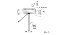
なお、各波長に対応する感度を有する感光材料をホログラフィック感光層に分散させておき、各波長の参照光LrR、LrG、LrBおよび物体光LsR、LsG、LsBを用いてホログラフィック感光層に干渉露光を行うことによって、図4Bに示すように1つの層に干渉縞751R、751G、751Bを重畳した干渉縞751を形成してもよい。また、参照光LrR、LrG、LrBおよび物体光LsR、LsG、LsBとして球面波の光を用いてもよい。 A photosensitive material having a sensitivity corresponding to each wavelength is dispersed in the holographic photosensitive layer, and the reference beams LrR, LrG, and LrB and the object beams LsR, LsG, and LsB of each wavelength are used to interfere with the holographic photosensitive layer. By performing exposure, interference fringes 751 in which interference fringes 751R, 751G, and 751B are superimposed on one layer as shown in FIG. 4B may be formed. Further, spherical wave light may be used as the reference lights LrR, LrG, LrB and the object lights LsR, LsG, LsB.

第2回折素子70と基本的な構成が同一である第1回折素子50は、反射型体積ホログラフィック素子55を備えている。第1回折素子50は、画像光L0が入射する入射面51が、凹んだ凹曲面になっている。換言すれば、入射面51は、画像光L0の入射方向において、周辺部に対して中央部が凹んで湾曲した形状となっている。そのため、画像光L0を導光系60に向けて効率良く偏向させることができる。 The first diffractive element 50 , which has the same basic configuration as the second diffractive element 70 , comprises a reflective volume holographic element 55 . The first diffraction element 50 has an incident surface 51 on which the image light L0 is incident, which is a concavely curved surface. In other words, the incident surface 51 has a curved shape in which the central portion is recessed with respect to the peripheral portion in the incident direction of the image light L0. Therefore, the image light L0 can be efficiently deflected toward the light guide system 60 .

図5は、図3に示す第1回折素子50および第2回折素子70を構成する体積ホログラムにおける回折特性を説明した図である。図5は、体積ホログラム上の1点に光線が入射したときの、特定波長と周辺波長の回折角の差を示したものである。図5には、特定波長を531nmとしたとき、波長が526nmの周辺波長の光の回折角度のずれを実線L526で示し、波長が536nmの周辺波長の光の回折角度のずれを点線L536で示してある。図5に示すように、ホログラムに記録された同じ干渉縞に光線が入射した場合でも、長波長の光線程、大きく回折し、短波長の光線程、回折しにくい。そのため、本実施形態のように2つの回折素子、すなわち第1回折素子50および第2回折素子70を用いた際、特定波長に対する長波長の光および短波長の光における光線角度をそれぞれ考慮して入射させないと適正に波長補償できない。すなわち第2回折素子70で発生する色収差をキャンセルできなくなる。また、干渉縞の本数によって回折角が異なるので、干渉縞を考慮する必要がある。 FIG. 5 is a diagram for explaining the diffraction characteristics of volume holograms forming the first diffraction element 50 and the second diffraction element 70 shown in FIG. FIG. 5 shows the difference in diffraction angle between a specific wavelength and peripheral wavelengths when a light beam is incident on one point on the volume hologram. In FIG. 5, when the specific wavelength is 531 nm, a solid line L526 indicates the deviation of the diffraction angle of light with a wavelength around 526 nm, and a dotted line L536 shows the deviation of the diffraction angle of light with a wavelength around 536 nm. There is. As shown in FIG. 5, even when rays are incident on the same interference fringes recorded in the hologram, rays with longer wavelengths are diffracted more and rays with shorter wavelengths are less diffracted. Therefore, when two diffraction elements, that is, the first diffraction element 50 and the second diffraction element 70 are used as in the present embodiment, the ray angles of the long-wavelength light and the short-wavelength light with respect to the specific wavelength are taken into account. If the light is not incident, proper wavelength compensation cannot be performed. That is, it becomes impossible to cancel the chromatic aberration generated by the second diffraction element 70 . Also, since the diffraction angle differs depending on the number of interference fringes, it is necessary to consider the interference fringes.

図3に示す光学系10では、特開2017-167181号公報に記載されているように、第1回折素子50と第2回折素子70との間での中間像の形成回数と、ミラー62での反射回数の和が奇数か偶数かに対応して、第2回折素子70への入射方向等を適正化してあるため、波長補償、すなわち色収差をキャンセル可能である。 In the optical system 10 shown in FIG. 3, as described in Japanese Patent Application Laid-Open No. 2017-167181, the number of intermediate images formed between the first diffraction element 50 and the second diffraction element 70 and the number of intermediate images formed by the mirror 62 Since the incident direction and the like to the second diffraction element 70 are optimized according to whether the sum of the number of times of reflection is an odd number or an even number, wavelength compensation, that is, chromatic aberration can be canceled.

図6は第2回折素子70で発生する色収差をキャンセルする原理について説明した図である。なお、図6には、画像光L0の特定波長の光L1(実線)に加えて、長波長側の光L2(一点鎖線)、および特定波長に対して短波長側の光L3(点線)も図示してある。 6A and 6B are diagrams for explaining the principle of canceling the chromatic aberration generated by the second diffraction element 70. FIG. In FIG. 6, in addition to the light L1 (solid line) of the specific wavelength of the image light L0, light L2 (chain line) on the long wavelength side and light L3 (dotted line) on the short wavelength side with respect to the specific wavelength are also shown. Illustrated.

具体的に、第1回折素子50に入射した画像光L0は、図6に示すように、第1回折素子50によって回折されることで偏向する。このとき、特定波長に対して長波長側の光L2の回折角度θは、特定波長の光L1の回折角度θより大きくなる。また、特定波長に対して短波長側の光L3の回折角度θは、特定波長の光L1の回折角度θより小さくなる。従って、第1回折素子50を出射した画像光L0は、波長毎に偏向されて分散することとなる。 Specifically, the image light L0 incident on the first diffraction element 50 is deflected by being diffracted by the first diffraction element 50, as shown in FIG. At this time, the diffraction angle θ2 of the light L2 on the long wavelength side with respect to the specific wavelength becomes larger than the diffraction angle θ1 of the light L1 of the specific wavelength. Further, the diffraction angle θ3 of the light L3 on the short wavelength side with respect to the specific wavelength is smaller than the diffraction angle θ1 of the light L1 of the specific wavelength. Therefore, the image light L0 emitted from the first diffraction element 50 is deflected and dispersed for each wavelength.

第1回折素子50を出射した画像光L0は、導光系60を介して第2回折素子70に入射し、第2回折素子70によって回折されることで偏向する。その際、第1回折素子50から第2回折素子70までの光路において、中間像の形成が1回行われるとともに、ミラー62での反射が1回行われる。従って、画像光L0と第2回折素子70の入射面法線との間の角度を入射角とすると、特定波長に対して長波長側の光L2は、特定波長の光L1における入射角θ11よりも大きな入射角θ12となり、特定波長に対して短波長側の光L3は、特定波長の光L1における入射角θ11よりも小さな入射角θ13となる。また、上述したように特定波長に対して長波長側の光L2の回折角度θは、特定波長の光L1の回折角度θよりも大きくなり、特定波長に対して短波長側の光L3の回折角度θは、特定波長の光L1の回折角度θよりも小さくなる。 The image light L0 emitted from the first diffraction element 50 enters the second diffraction element 70 via the light guide system 60 and is diffracted by the second diffraction element 70 to be deflected. At that time, in the optical path from the first diffraction element 50 to the second diffraction element 70, the formation of the intermediate image is performed once and the reflection by the mirror 62 is performed once. Therefore, when the angle between the image light L0 and the normal to the incident surface of the second diffraction element 70 is the incident angle, the light L2 on the long wavelength side with respect to the specific wavelength is incident at an incident angle θ 11 with respect to the light L1 of the specific wavelength. , and the light L3 on the short wavelength side with respect to the specific wavelength has an incident angle .theta.13 smaller than the incident angle .theta.11 of the light L1 with the specific wavelength. Further, as described above, the diffraction angle θ2 of the light L2 on the long wavelength side with respect to the specific wavelength becomes larger than the diffraction angle θ1 of the light L1 with the specific wavelength, and the light L3 on the short wavelength side with respect to the specific wavelength becomes larger. is smaller than the diffraction angle θ 1 of the light L1 of the specific wavelength.

従って、特定波長に対して長波長側の光L2は、特定波長の光L1よりも大きな入射角で第1回折素子50に入射するが、特定波長に対して長波長側の光L2の回折角度が、特定波長の光L1の回折角度よりも大きいため、結果として第2回折素子70から出射するときには、特定波長に対して長波長側の光L2と特定波長の光L1は略平行な光となる。これに対して、特定波長に対して短波長側の光L3は、特定波長の光L1よりも小さな入射角で第1回折素子50に入射するが、特定波長に対して短波長側の光L3の回折角度が、特定波長の光L1の回折角度よりも小さいため、結果として第2回折素子70から出射するときには、特定波長に対して短波長側の光L3と特定波長の光L1は略平行な光となる。このようにして、図6に示すように、第2回折素子70を出射した画像光L0は、略平行な光として観察者の眼Eに入射するので、波長毎の網膜E0での結像位置ずれが抑制される。従って、第2回折素子70で発生する色収差をキャンセルできる。 Therefore, the light L2 on the long wavelength side with respect to the specific wavelength is incident on the first diffraction element 50 at a larger incident angle than the light L1 with the specific wavelength, but the diffraction angle of the light L2 on the long wavelength side with respect to the specific wavelength is is larger than the diffraction angle of the light L1 of the specific wavelength. As a result, when the light L1 of the specific wavelength is emitted from the second diffraction element 70, the light L2 on the longer wavelength side and the light L1 of the specific wavelength are substantially parallel light. Become. On the other hand, the light L3 on the short wavelength side with respect to the specific wavelength enters the first diffraction element 50 at a smaller incident angle than the light L1 with the specific wavelength, but the light L3 on the short wavelength side with respect to the specific wavelength is smaller than the diffraction angle of the light L1 of the specific wavelength, as a result, the light L3 on the short wavelength side with respect to the specific wavelength and the light L1 of the specific wavelength are substantially parallel when emitted from the second diffraction element 70. light. In this manner, as shown in FIG. 6, the image light L0 emitted from the second diffraction element 70 is incident on the observer's eye E as substantially parallel light. Displacement is suppressed. Therefore, the chromatic aberration generated by the second diffraction element 70 can be canceled.

続いて、第1回折素子50と第2回折素子70との共役関係について説明する。
図7Aは、第1回折素子50と第2回折素子70とが共役関係にある場合の説明図である。図7Bおよび図7Cは第1回折素子50と第2回折素子70とが共役関係にない場合の説明図である。図8Aおよび図8Bは、図7Bおよび図7Cに示す第1回折素子50と第2回折素子70との共役関係からのずれの許容差を示す説明図である。図8Aおよび図8Bには、特定波長の光を実線Leで示し、波長が特定波長-10nmの光を一点鎖線Lfで示し、波長が特定波長+10nmの光を二点鎖線Lgで示してある。なお、図7A~Cおよび図8Aおよび図8Bでは、光の進行が分かりやすいように、第1回折素子50、第2回折素子70および導光系60を透過型として示し、第1回折素子50、第2回折素子70および導光系60を矢印で示してある。
Next, the conjugate relationship between the first diffraction element 50 and the second diffraction element 70 will be described.
FIG. 7A is an explanatory diagram when the first diffraction element 50 and the second diffraction element 70 are in a conjugate relationship. 7B and 7C are explanatory diagrams when the first diffraction element 50 and the second diffraction element 70 are not in a conjugate relationship. FIGS. 8A and 8B are explanatory diagrams showing tolerances for deviations from the conjugate relationship between the first diffraction element 50 and the second diffraction element 70 shown in FIGS. 7B and 7C. 8A and 8B, a solid line Le indicates light of a specific wavelength, a dashed-dotted line Lf indicates light of a wavelength of −10 nm, and a two-dot chain line Lg indicates light of a wavelength of +10 nm. 7A to C and FIGS. 8A and 8B, the first diffraction element 50, the second diffraction element 70, and the light guide system 60 are shown as transmissive so that the progress of light can be easily understood. , the second diffraction element 70 and the light guide system 60 are indicated by arrows.

図7Aに示すように、第1回折素子50と第2回折素子70とを共役の関係とした場合、第1回折素子50のA点(第1の位置)から出射した発散光は正パワーを持つ導光系60(レンズ)によって集光され、第2回折素子70のB点(第1の位置に対応する第2の位置)に入射する。従って、B点で発生する回折による色収差をA点で補償することができる。 As shown in FIG. 7A, when the first diffraction element 50 and the second diffraction element 70 are in a conjugate relationship, the divergent light emitted from point A (first position) of the first diffraction element 50 has a positive power. The light is condensed by the light guide system 60 (lens) provided and enters point B (second position corresponding to the first position) of the second diffraction element 70 . Therefore, the chromatic aberration due to diffraction generated at the B point can be compensated at the A point.

これに対して、図7Bおよび図7Cに示すように、第1回折素子50と第2回折素子70とが共役の関係にない場合、第1回折素子50のA点から出射した発散光は、中央の正パワーを持つ導光系60によって集光されるが、第2回折素子70上のB点よりも遠い位置、あるいは近い位置で交わって入射する。このため、A点とB点とが1対1の関係になっていない。ここで、領域内の干渉縞が一様の場合に補償効果が高まることから、第1回折素子50と第2回折素子70とが共役の関係にない場合、補償効果が弱くなる。一方、第1回折素子50によって、第2回折素子70の投影領域全体を補償することは困難である。それ故、図7Bおよび図7Cに示す態様の場合、十分な波長補償を行うことができないので、解像度の劣化が発生する。 On the other hand, as shown in FIGS. 7B and 7C, when the first diffraction element 50 and the second diffraction element 70 are not in a conjugate relationship, the divergent light emitted from the point A of the first diffraction element 50 is The light is condensed by the light guide system 60 having positive power in the center, but crosses and enters at a position farther or nearer than point B on the second diffraction element 70 . Therefore, points A and B do not have a one-to-one relationship. Here, since the compensation effect is enhanced when the interference fringes in the region are uniform, the compensation effect is weakened when the first diffraction element 50 and the second diffraction element 70 are not in a conjugate relationship. On the other hand, it is difficult to compensate the entire projection area of the second diffraction element 70 with the first diffraction element 50 . Therefore, in the case of the embodiments shown in FIGS. 7B and 7C, since sufficient wavelength compensation cannot be performed, resolution degradation occurs.

なお、特定波長に対して±10nmの波長の光では、特定波長の光が到達するB点から±0.4mm程度の誤差が存在するが、解像度の低下は目立たない。かかる許容範囲を検討した結果、図8Aに示すように、特定波長の光が到達する理想的な第2回折素子70上のB点よりも手前で交わり±0.8mmの範囲内に入射する場合には、解像度の低下は目立たない。また、図8Bに示すように、特定波長の光が到達する理想的な第2回折素子70上のB点よりも後方で交わり±0.8mmの範囲内に入射する場合には、解像度の低下は目立たない。従って、第1回折素子50と第2回折素子70とにおいては、完全な共役関係になくても、略共役関係にあって、理想的なB点から±0.8mmの範囲内に到達する場合には、解像度の低下を許容することができる。すなわち、本実施形態において、第1回折素子50と第2回折素子70とが共役関係を有するとは、特定波長の光の入射位置が理想的な入射点から±0.8mmの誤差範囲に収まることをいう。 In the case of light with a wavelength of ±10 nm with respect to the specific wavelength, there is an error of about ±0.4 mm from the point B where the light with the specific wavelength reaches, but the decrease in resolution is not conspicuous. As a result of examining such an allowable range, as shown in FIG. 8A, when light of a specific wavelength intersects in front of the ideal point B on the second diffraction element 70 and is incident within a range of ±0.8 mm resolution loss is not noticeable. In addition, as shown in FIG. 8B, when light of a specific wavelength intersects behind point B on the ideal second diffraction element 70 and is incident within a range of ±0.8 mm, resolution decreases. is inconspicuous. Therefore, even if the first diffraction element 50 and the second diffraction element 70 are not in a perfect conjugate relationship, they are in a substantially conjugate relationship, and when reaching within ±0.8 mm from the ideal point B, can tolerate a loss of resolution. That is, in the present embodiment, the conjugate relationship between the first diffraction element 50 and the second diffraction element 70 means that the incident position of light of a specific wavelength falls within the error range of ±0.8 mm from the ideal incident point. Say things.

図9は、本実施形態の光学系10における光線図である。図9、および後で参照する図では、光軸に沿って配置された各光学部を太い矢印で示してある。また、画像光生成装置31の1つの画素から出射した光線を実線Laで示し、画像光生成装置31の端部から出射される主光線を一点鎖線Lbで示し、第1回折素子50と共役関係となる位置を長い破線Lcで示してある。ここで、「中間像」とは、1画素から出射された光線(実線La)が集まる個所であり、「瞳」とは、各画角の主光線(一点鎖線Lb)が集まる個所である。また、図9は、画像光生成装置31から出射された光の進行を示すものである。なお、図9においては、図を簡略化するため、すべての光学部を透過型として図示している。 FIG. 9 is a ray diagram in the optical system 10 of this embodiment. In FIG. 9 and the figures to be referred to later, each optical section arranged along the optical axis is indicated by a thick arrow. Further, a light ray emitted from one pixel of the image light generation device 31 is indicated by a solid line La, a principal ray emitted from an end of the image light generation device 31 is indicated by a dashed line Lb, and a conjugate relationship with the first diffraction element 50. A long broken line Lc indicates the position where . Here, the “intermediate image” is a place where rays (solid line La) emitted from one pixel gather, and the “pupil” is a place where principal rays (chain line Lb) of each angle of view gather. 9 shows the progress of light emitted from the image light generating device 31. As shown in FIG. In addition, in FIG. 9, in order to simplify the drawing, all the optical units are shown as transmission type.

図9に示すように、本実施形態の光学系10では、画像光生成装置31から出射された画像光の光路に沿って、正のパワーを有する第1光学部L10と、第1回折素子50を備え、正のパワーを有する第2光学部L20と、正のパワーを有する第3光学部L30と、第2回折素子70を備え、正のパワーを有する第4光学部L40とが設けられている。 As shown in FIG. 9, in the optical system 10 of the present embodiment, along the optical path of the image light emitted from the image light generation device 31, the first optical section L10 having positive power and the first diffraction element 50 A second optical section L20 having positive power, a third optical section L30 having positive power, and a fourth optical section L40 having positive power and having a second diffraction element 70 are provided. there is

第1光学部L10の焦点距離はL/2であり、第2光学部L20、第3光学部L30、および第4光学部L40の焦点距離はいずれもLである。従って、第2光学部L20から第3光学部L30までの光学距離と第3光学部L30から第4光学部L40までの光学距離とが等しい。 The focal length of the first optical section L10 is L/2, and the focal lengths of the second optical section L20, the third optical section L30, and the fourth optical section L40 are all L. Therefore, the optical distance from the second optical section L20 to the third optical section L30 is equal to the optical distance from the third optical section L30 to the fourth optical section L40.

かかる光学系10では、第1光学部L10と第3光学部L30との間に画像光の第1中間像P1が形成され、第2光学部L20と第4光学部L40との間に瞳R1が形成され、第3光学部L30と第4光学部L40との間に画像光の第2中間像P2が形成され、第4光学部L40は、画像光を平行光化して射出瞳R2を形成する。その際、第3光学部L30は、第2光学部L20から射出された画像光を発散光あるいは収束光あるいは平行光と自在に制御して第4光学部L40に入射させる。第2光学部L20は、第1光学部L10から射出された画像光を収束光として第3光学部L30に入射させる。本実施形態の光学系10において、瞳R1は、第2光学部L2と第4光学部L40との間のうち、第3光学部L30の近傍に形成される。第3光学部L30の近傍とは、第2光学部L20と第3光学部L30の間のうち、第2光学部L20より第3光学部L30に近い位置、または第3光学部L30と第4光学部L40の間のうち、第4光学部L40より第3光学部L30に近い位置を意味する。 In the optical system 10, a first intermediate image P1 of image light is formed between the first optical section L10 and the third optical section L30, and a pupil R1 is formed between the second optical section L20 and the fourth optical section L40. is formed, a second intermediate image P2 of the image light is formed between the third optical unit L30 and the fourth optical unit L40, and the fourth optical unit L40 collimates the image light to form an exit pupil R2. do. At that time, the third optical section L30 freely controls the image light emitted from the second optical section L20 as divergent light, convergent light, or parallel light, and causes the light to enter the fourth optical section L40. The second optical section L20 causes the image light emitted from the first optical section L10 to enter the third optical section L30 as convergent light. In the optical system 10 of this embodiment, the pupil R1 is formed in the vicinity of the third optical section L30 between the second optical section L2 and the fourth optical section L40. The vicinity of the third optical section L30 refers to a position between the second optical section L20 and the third optical section L30 that is closer to the third optical section L30 than the second optical section L20, or a position between the third optical section L30 and the fourth optical section L30. It means a position closer to the third optical part L30 than the fourth optical part L40 among the optical parts L40.

また、第3光学部L30は、画像光生成装置31の1点からの画像光について、第1回折素子50により偏向されて特定波長からずれた周辺波長の光を第2回折素子70の所定の範囲に入射させる。すなわち、第1回折素子50と第2回折素子70は共役あるいは略共役の関係にある。ここで、第1回折素子50の第3光学部L30による第2回折素子70上の射影の倍率の絶対値は0.5倍から10倍までであり、かかる倍率の絶対値は1倍から5倍までであることが好ましい。 In addition, the third optical unit L30 converts the image light from one point of the image light generation device 31 into the light of the peripheral wavelength that is deflected by the first diffraction element 50 and deviated from the specific wavelength by the second diffraction element 70. Make it incident on the range. That is, the first diffraction element 50 and the second diffraction element 70 are in a conjugate or substantially conjugate relationship. Here, the absolute value of the magnification of the projection onto the second diffraction element 70 by the third optical section L30 of the first diffraction element 50 is from 0.5 times to 10 times, and the absolute value of such magnification is from 1 time to 5 times. Up to double is preferred.

従って、本実施形態の光学系10によれば、投射光学系32と導光系60との間に画像光の第1中間像P1が形成され、導光系60の近傍に瞳R1が形成され、導光系60と第2回折素子70との間に画像光の第2中間像P2が形成され、第2回折素子70は、画像光を平行光化して射出瞳R2を形成する。 Therefore, according to the optical system 10 of the present embodiment, the first intermediate image P1 of the image light is formed between the projection optical system 32 and the light guide system 60, and the pupil R1 is formed near the light guide system 60. , a second intermediate image P2 of the image light is formed between the light guide system 60 and the second diffraction element 70, and the second diffraction element 70 collimates the image light to form an exit pupil R2.

本実施形態の光学系10において、第1中間像P1は、第1光学部L10(投射光学系32)と第2光学部L20(第1回折素子50)との間に形成される。 In the optical system 10 of this embodiment, the first intermediate image P1 is formed between the first optical section L10 (projection optical system 32) and the second optical section L20 (first diffraction element 50).

ここで、上述のように第1回折素子50および第2回折素子70が共役関係或いは略共役関係を満たすためには、第1回折素子50における画像光の入射状態と第2回折素子70における画像光の入射状態とを同じにする必要がある。つまり、観察者の眼Eに入射する画像光の光線形状が例えば円形である場合、第1回折素子50および第2回折素子70に入射する画像光の結像光線も円形にする必要がある。 Here, in order for the first diffraction element 50 and the second diffraction element 70 to satisfy the conjugate relationship or substantially conjugate relationship as described above, the incident state of the image light on the first diffraction element 50 and the image on the second diffraction element 70 It is necessary to make it the same as the incident state of light. In other words, if the shape of the image light incident on the eye E of the observer is circular, for example, the imaging light rays of the image light incident on the first diffraction element 50 and the second diffraction element 70 must also be circular.

図3に示したように、本実施形態の光学系10では、第2回折素子70を観察者の眼Eの前に配置する構造を採用するため、画像光L0が第2回折素子70に対して斜め方向から入射する。以下、画像光L0が斜め方向から入射する状態を単に「斜入射」と呼ぶ。 As shown in FIG. 3, the optical system 10 of the present embodiment employs a structure in which the second diffraction element 70 is arranged in front of the observer's eye E. incident from an oblique direction. Hereinafter, the state in which the image light L0 is incident from an oblique direction is simply referred to as "oblique incidence".

図3に示される画像光は、主光線および光軸を含む面であるメリジオナル平面内を通過するメリジオナル光線である。 The image light shown in FIG. 3 is a meridional ray that passes through the meridional plane, which is a plane containing the principal ray and the optical axis.

以下、図3の説明において、画像光の主光線に直交し観察者の顔の輪郭から離間する方向をy軸とし、該y方向および図3の紙面に直交する方向をx軸とするxy座標系を用いる。 In the following description of FIG. 3, the y-axis is the direction orthogonal to the principal ray of the image light and away from the contour of the observer's face, and the x-axis is the y-direction and the direction orthogonal to the plane of FIG. system.

図3において画像光を示す複数のメリジオナル光線のうち、画像形成装置31から右側X1に出射され、第2中間像P2の形成位置を通過して第2回折素子70に入射する光線を「マイナス側光線MK」と呼ぶ。 Among the plurality of meridional rays representing image light in FIG. ray MK”.

また、図3において画像光を示す複数のメリジオナル光線のうち、画像形成装置31から左側X2側に出射され、第2中間像P2の形成位置を通過して第2回折素子70に入射するメリジオナル光線を「プラス側光線PK」と呼ぶ。 In addition, among the plurality of meridional rays representing image light in FIG. is called "positive side ray PK".

図3に示されるように、マイナス側光線MKは第2中間像P2の形成位置に対してより+y側から入射する光線ほど第2中間像P2から第2回折素子70までの光路長が長くなる。すなわち、マイナス側光線MKは第2回折素子70に対する入射角度が相対的に大きくなる。 As shown in FIG. 3, the optical path length from the second intermediate image P2 to the second diffraction element 70 from the second intermediate image P2 to the second diffraction element 70 is longer for the minus side light ray MK that is incident from the +y side with respect to the formation position of the second intermediate image P2. . That is, the incident angle of the minus side ray MK with respect to the second diffraction element 70 becomes relatively large.

一方、図3に示されるように、プラス側光線PKは第2中間像P2の形成位置に対してより-y側から入射する光線ほど第2中間像P2から第2回折素子70までの光路長が短くなる。すなわち、プラス側光線PKは第2回折素子70に対する入射角度が相対的に小さくなる。 On the other hand, as shown in FIG. 3, the optical path length from the second intermediate image P2 to the second diffraction element 70 from the second intermediate image P2 to the second diffraction element 70 increases as the plus side ray PK enters from the -y side of the formation position of the second intermediate image P2. becomes shorter. That is, the angle of incidence of the plus-side light ray PK on the second diffraction element 70 becomes relatively small.

このように画像光が第2回折素子70に対して斜入射する場合、第2回折素子70上における画像光の光線形状が歪な形状となって円形と異なる形状にならなくなる。すると、観察者の眼Eに入射する画像光の光線形状と、第1回折素子50および第2回折素子70に入射する画像光の結像光線の形状とが異なってしまう。よって、第1回折素子50と第2回折素子70とは共役関係或いは略共役関係を満たすことができず、波長補償を適正に行うことができなくなる。 When the image light is obliquely incident on the second diffraction element 70 in this manner, the beam shape of the image light on the second diffraction element 70 becomes distorted and does not differ from a circular shape. As a result, the shape of the image light incident on the observer's eye E differs from the shape of the imaging light beam of the image light incident on the first diffraction element 50 and the second diffraction element 70 . Therefore, the first diffraction element 50 and the second diffraction element 70 cannot satisfy a conjugate relationship or a substantially conjugate relationship, and wavelength compensation cannot be properly performed.

そのため、第2回折素子70に対して画像光を斜入射させる場合において、上述したように第2回折素子70上における画像光の光線形状が円形となるように、斜入射によって生じる歪みを考慮して予め画像光の光束形状を所望の形に補正する必要がある。
ここで、斜入射によって生じる歪みを考慮して予め画像光の光束形状を補正するとは、斜入射する画像光の光線形状が第2回折素子70上において例えば円形等の所望形状となるように画像光の光線形状を補正することを意味する。
Therefore, when the image light is obliquely incident on the second diffraction element 70, the distortion caused by the oblique incidence is taken into consideration so that the beam shape of the image light on the second diffraction element 70 becomes circular as described above. Therefore, it is necessary to correct the luminous flux shape of the image light to a desired shape in advance.
Here, correcting the luminous flux shape of the image light in advance in consideration of the distortion caused by the oblique incidence means that the ray shape of the obliquely incident image light becomes a desired shape such as a circle on the second diffraction element 70 . It means to correct the ray shape of light.

図10は斜入射を考慮した場合の画像光の光束形状の一例を示す図である。図10は図3の符号Aで示した位置における画像光のxy平面に沿う断面に相当し、第2中間像P2の近傍における画像光の光束断面形状を示す。 FIG. 10 is a diagram showing an example of the luminous flux shape of image light when oblique incidence is taken into consideration. FIG. 10 corresponds to a cross section of the image light along the xy plane at the position indicated by symbol A in FIG. 3, and shows the cross-sectional shape of the image light in the vicinity of the second intermediate image P2.

図10に示すように、画像光における光線形状の+y側はマイナス側光線MKで形成され、画像光における光線形状の-y側はプラス側光線PKで形成される。
ここで、マイナス側光線MKは第2回折素子70に対する入射角度が相対的に大きい、つまり中間像位置から対象物までの距離が長いことから、第2回折素子70上に形成する照明領域の面積が拡がる。一方、プラス側光線PKは第2回折素子70に対する入射角度が相対的に小さい、つまり中間像位置から対象物までの距離が短いことから、第2回折素子70上に形成する照明領域の面積がマイナス側光線MKよりも拡がらない。
As shown in FIG. 10, the +y side of the ray shape of the image light is formed by the minus side ray MK, and the -y side of the ray shape of the image light is formed by the plus side ray PK.
Here, since the angle of incidence of the minus side ray MK on the second diffraction element 70 is relatively large, that is, the distance from the intermediate image position to the object is long, the area of the illumination region formed on the second diffraction element 70 spreads. On the other hand, the incident angle of the plus side ray PK with respect to the second diffraction element 70 is relatively small, that is, the distance from the intermediate image position to the object is short. It does not spread more than the minus side ray MK.

このような理由から、斜入射を考慮した場合における画像光の光線形状は、第2回折素子70上で照明領域が大きく拡がるマイナス側光線MKを含む+y側ほど光線を細くし、第2回折素子70上で照明領域が拡がり難いプラス側光線PKを含む-y側ほど光線を太くしている。従って、図10に示すように斜入射を考慮した場合における画像光の光線形状は、x方向における幅が+y側ほど狭くなったいびつな形状となる。このように斜入射を考慮した場合の画像光の光束形状はマイナス側光線MKおよびプラス側光線PKの入射状況に応じて決まる。 For this reason, the ray shape of the image light when oblique incidence is taken into account is such that the ray becomes thinner toward the +y side including the minus side ray MK whose illumination area is greatly expanded on the second diffraction element 70, and the second diffraction element 70 The ray is made thicker toward the -y side including the plus side ray PK where the illumination area is less likely to spread on 70 . Therefore, as shown in FIG. 10, the beam shape of the image light when oblique incidence is taken into account becomes a distorted shape in which the width in the x direction becomes narrower toward the +y side. In this way, the shape of the image light flux when oblique incidence is taken into account is determined according to the incident conditions of the minus side ray MK and the plus side ray PK.

ところで、第2回折素子70上における画像光の光線形状の補正は、第1光学部L10から第3光学部L30までの間で行う必要がある。上述のように第1回折素子50および第2回折素子70が共役関係或いは略共役関係を満たすためには、第1回折素子50および第2回折素子70は画像光の入射形状を一致させる必要がある。そのため、画像光の光線形状の補正に第1回折素子50および第2回折素子70を利用することはできない。そこで、第3光学部L30を用いることで画像光の光線形状を図10に示した形状に補正することも考えられる。 By the way, it is necessary to correct the beam shape of the image light on the second diffraction element 70 between the first optical section L10 and the third optical section L30. In order for the first diffraction element 50 and the second diffraction element 70 to satisfy the conjugate relationship or the substantially conjugate relationship as described above, the first diffraction element 50 and the second diffraction element 70 need to match the incident shape of the image light. be. Therefore, the first diffraction element 50 and the second diffraction element 70 cannot be used to correct the beam shape of the image light. Therefore, it is conceivable to correct the light beam shape of the image light to the shape shown in FIG. 10 by using the third optical part L30.

しかしながら、第3光学部L30を用いて画像光の光線形状を補正する場合、瞳径が大きくなったり、画面サイズが大きくなることで収差の増大へと繋がる。その結果、画像の解像度の低下という新たな問題が生じてしまう。 However, when the third optical unit L30 is used to correct the light beam shape of the image light, the pupil diameter increases and the screen size increases, leading to an increase in aberration. As a result, a new problem of deterioration in image resolution arises.

これに対し、本実施形態の光学系10では、図3に示したように、第2光学部L20と第4光学部L40との間に、画像光L0の光線形状を補正するプリズム部材45を設けている。本実施形態において、プリズム部材45は、第3光学部L30と第4光学部L40との間に設けられており、第2回折素子70に斜入射する画像光L0の光線形状を予め補正することで、画像光L0が第2回折素子70上において例えば円形等といった所望の光線形状に形成することができる。 On the other hand, in the optical system 10 of the present embodiment, as shown in FIG. 3, a prism member 45 for correcting the shape of the image light L0 is provided between the second optical section L20 and the fourth optical section L40. are provided. In the present embodiment, the prism member 45 is provided between the third optical section L30 and the fourth optical section L40, and corrects the shape of the image light L0 obliquely incident on the second diffraction element 70 in advance. Thus, the image light L0 can be formed into a desired light beam shape such as a circular shape on the second diffraction element 70 .

図3に示したように、本実施形態の光学系10において、第1光学部L10、第2光学部L20、第3光学部L30および第4光学部L40は観察者の輪郭の曲線MC(所定の曲線)の一方側に沿って配置されている。 As shown in FIG. 3, in the optical system 10 of the present embodiment, the first optical section L10, the second optical section L20, the third optical section L30, and the fourth optical section L40 are the observer's contour curve MC (predetermined curve)).

本実施形態のプリズム部材45は、第2中間像P2の第3光学部L30側に設けられている。プリズム部材45における入射面および出射面は曲率を有する曲面を含んでいる。曲面としては、例えば、球面、非球面、シリンドリカル面あるいは自由曲面のいずれでもよい。このように入射面および出射面を曲面で構成することで画像光の補正自由度を向上させることができる。なお、プリズム部材45における入射面および出射面は平面で構成されていてもよい。 The prism member 45 of this embodiment is provided on the third optical part L30 side of the second intermediate image P2. The entrance surface and exit surface of the prism member 45 include curved surfaces having curvature. The curved surface may be, for example, a spherical surface, an aspherical surface, a cylindrical surface, or a free curved surface. By forming the incident surface and the exit surface with curved surfaces in this way, the degree of freedom in correcting the image light can be improved. The entrance surface and the exit surface of the prism member 45 may be flat.

図10に示した斜入射を考慮した場合の画像光の光束形状はマイナス側光線MKおよびプラス側光線PKの入射状況に応じて変化する。つまり、プリズム部材45の形状はマイナス側光線MKおよびプラス側光線PKの入射状況によって一意に決まる。 The luminous flux shape of the image light when the oblique incidence shown in FIG. 10 is taken into consideration changes according to the incident conditions of the minus side ray MK and the plus side ray PK. That is, the shape of the prism member 45 is uniquely determined by the incident conditions of the minus side ray MK and the plus side ray PK.

本実施形態のプリズム部材45は、第2回折素子70に対して大きい入射角度で入射するマイナス側光線MKにおける補正力を相対的に強め、第2回折素子70に対して小さい入射角度で入射するプラス側光線PKにおける補正力を相対的に弱める形状を有する。 The prism member 45 of the present embodiment relatively strengthens the correction force for the minus side ray MK that is incident on the second diffraction element 70 at a large incident angle, and is incident on the second diffraction element 70 at a small incident angle. It has a shape that relatively weakens the correction force in the plus side ray PK.

より具体的に、本実施形態のプリズム部材45は、図3に示したように、プラス側光線PKが通過する-y側の厚みよりもマイナス側光線MKが通過する+y側の厚みを厚くなる形状を有している。プリズム部材45は、マイナス側光線MKが通過する領域の厚みが大きいため、マイナス側光線MKを強く曲げることができる。よって、マイナス側光線MKをプラス側光線PKよりも細くすることで画像光の光線形状を図10に示した形状に予め補正することができる。 More specifically, as shown in FIG. 3, the prism member 45 of the present embodiment has a thickness on the +y side through which the minus side light ray MK passes, which is thicker than the thickness on the -y side through which the plus side light ray PK passes. have a shape. Since the prism member 45 has a large thickness in the region through which the minus side ray MK passes, it can strongly bend the minus side ray MK. Therefore, by making the minus side ray MK thinner than the plus side ray PK, the ray shape of the image light can be corrected in advance to the shape shown in FIG.

図3に示すように本実施形態のプリズム部材45は、輪郭の曲線MCから離れるにつれて厚みを増す形状を有する。ここで、曲線MCの一方側、つまり曲線MCにおける光学系10が配置される側において該曲線MCから離れていく方向を外側とし、曲線MCに近づいていく方向を内側とする。すなわち、プリズム部材45は、観察者の顔に近い側である曲線MCの内側における厚みよりも観察者の顔から遠い側である曲線MCの外側における厚みが大きくなる形状を有すると換言できる。 As shown in FIG. 3, the prism member 45 of this embodiment has a shape whose thickness increases with distance from the contour curve MC. Here, one side of the curve MC, that is, the side of the curve MC on which the optical system 10 is arranged, the direction away from the curve MC is defined as the outside, and the direction approaching the curve MC is defined as the inside. That is, it can be said that the prism member 45 has a shape in which the thickness on the outside of the curve MC, which is the side farther from the observer's face, is greater than the thickness on the inside of the curve MC, which is the side closer to the observer's face.

なお、プリズム部材45の形状は、該プリズム部材45を配置する位置によっても変化する。例えば、図3において、第2中間像P2の形成位置よりも第3光学部L30側にプリズム部材45を配置したが、プリズム部材45は第2中間像P2の形成位置よりも第4光学部L40側に配置してもよい。この場合、プリズム部材45に対するマイナス側光線MKおよびプラス側光線PKの入射位置の関係が図3に示した場合と逆になるため、プリズム部材45における形状は+y側よりも-y側を厚くした形状となる。 The shape of the prism member 45 also changes depending on the position where the prism member 45 is arranged. For example, in FIG. 3, the prism member 45 is arranged closer to the third optical section L30 than the formation position of the second intermediate image P2. Can be placed on the side. In this case, the relationship between the incident positions of the minus side ray MK and the plus side ray PK with respect to the prism member 45 is opposite to the case shown in FIG. shape.

本実施形態の光学系10によれば、以下に示す4つの条件(条件1、2、3、4)を満たすことができる。
条件1:画像光生成装置31の1つの点から出射した光線は、網膜E0に1つの点として結像される。
条件2:光学系の入射瞳と眼球の瞳が共役である。
条件3:周辺波長を補償するように第1回折素子50と第2回折素子70とを適正に配置する。
条件4:第1回折素子50と第2回折素子70とが共役または略共役の関係にある。
According to the optical system 10 of this embodiment, the following four conditions (conditions 1, 2, 3 and 4) can be satisfied.
Condition 1: A light ray emitted from one point of the image light generating device 31 is imaged as one point on the retina E0.
Condition 2: The entrance pupil of the optical system and the pupil of the eyeball are conjugate.
Condition 3: Properly arrange the first diffraction element 50 and the second diffraction element 70 so as to compensate for the peripheral wavelength.
Condition 4: The first diffraction element 50 and the second diffraction element 70 are in a conjugate or substantially conjugate relationship.

より具体的には、図9に示した実線Laから分かるように、画像光生成装置31の1つの点から出射した光線は、網膜E0に1つの点として結像されるという条件1を満たすので、観察者は1画素を視認することができる。また、図9に示した実線Laから分かるように、光学系10の入射瞳と眼Eの瞳E1とが共役(瞳の共役)の関係にあるという条件2を満たすので、画像光生成装置31で生成した画像の全域を視認することができる。また、周辺波長を補償するように第1回折素子50と第2回折素子70とを適正に配置するという条件3を満たすため、波長補償を行うことによって第2回折素子70で発生する色収差をキャンセル可能である。 More specifically, as can be seen from the solid line La shown in FIG. 9, the light ray emitted from one point of the image light generating device 31 satisfies condition 1 that it is imaged as one point on the retina E0. , the observer can see one pixel. 9, the entrance pupil of the optical system 10 and the pupil E1 of the eye E are in a conjugate relationship (pupil conjugate). It is possible to visually recognize the entire area of the image generated in . Further, in order to satisfy the condition 3 that the first diffraction element 50 and the second diffraction element 70 are appropriately arranged so as to compensate for the peripheral wavelength, the chromatic aberration generated in the second diffraction element 70 is canceled by performing wavelength compensation. It is possible.

本実施形態の光学系10によれば、第3光学部L30と第4光学部L40との間に設けられたプリズム部材45によって第2回折素子70に斜入射する画像光L0の光線形状を予め補正することで、第1回折素子50における画像光の入射状態と第2回折素子70における画像光の入射状態とを同じにすることができる。よって、本実施形態の光学系10によれば、画像光が第2回折素子70に対して斜入射する場合であっても、図9の長い破線Lcで示される第1回折素子50と第2回折素子70とが共役または略共役の関係にあるという条件4を満たすことができる。よって、第1回折素子50および第2回折素子70は、光線を干渉縞が同一な個所に入射させることが可能となるので、上述の波長補償を適正に行うことができる。よって、画像光の解像度の劣化を良好に抑えることができる。 According to the optical system 10 of the present embodiment, the beam shape of the image light L0 obliquely incident on the second diffraction element 70 is determined in advance by the prism member 45 provided between the third optical portion L30 and the fourth optical portion L40. By correcting, the incident state of the image light on the first diffraction element 50 and the incident state of the image light on the second diffraction element 70 can be made the same. Therefore, according to the optical system 10 of the present embodiment, even if the image light is obliquely incident on the second diffraction element 70, the first diffraction element 50 and the second diffraction element 50 shown by the long dashed line Lc in FIG. It is possible to satisfy the condition 4 that it is in a conjugate or substantially conjugate relationship with the diffraction element 70 . Therefore, since the first diffraction element 50 and the second diffraction element 70 can make the light beams incident on the locations where the interference fringes are the same, the wavelength compensation described above can be properly performed. Therefore, it is possible to satisfactorily suppress the deterioration of the resolution of the image light.

本実施形態の光学系10は、第2光学部L20および第3光学部L30を覆うカバー部材を設けてもよい。この場合において、プリズム部材45をカバー部材の一部で形成しても良い。このようにすれば、プリズム部材45とカバー部材とを一体化することで、組立公差の低減を図ることができる。 The optical system 10 of this embodiment may be provided with a cover member that covers the second optical section L20 and the third optical section L30. In this case, the prism member 45 may be formed of a part of the cover member. In this way, the assembly tolerance can be reduced by integrating the prism member 45 and the cover member.

(第二実施形態)
続いて、第二実施形態に係る光学系について説明する。本実施形態と上記実施形態との違いはプリズム部材を配置する位置であり、それ以外の構成を共通する。そのため、上記実施形態と共通の部材については同じ符号を付し、その詳細については説明を省略する。
(Second embodiment)
Next, an optical system according to the second embodiment will be described. The difference between this embodiment and the above-described embodiment is the position where the prism member is arranged, and the rest of the configuration is common. Therefore, the same reference numerals are assigned to the members common to the above embodiment, and detailed descriptions thereof will be omitted.

図11は本実施形態の光学系の構成を示す図である。
図11に示すように、本実施形態の光学系11は、第2光学部L20と第4光学部L40との間にプリズム部材145を設けている。プリズム部材145は、光入射側と反対の裏面にミラー62を設けることで、第3光学部L30を構成する導光系60の役割を兼ねている。
FIG. 11 is a diagram showing the configuration of the optical system of this embodiment.
As shown in FIG. 11, the optical system 11 of this embodiment has a prism member 145 between the second optical section L20 and the fourth optical section L40. The prism member 145 has a mirror 62 on the back surface opposite to the light incident side, so that the prism member 145 also serves as the light guide system 60 that constitutes the third optical section L30.

プリズム部材145は第2回折素子70に斜入射する画像光L0の光線形状を予め補正することで、第2回折素子70上において画像光L0を所望の光線形状とすることができる。
プリズム部材145は、第2回折素子70に対して大きい入射角度で入射するマイナス側光線MKにおける補正力を相対的に強め、第2回折素子70に対して小さい入射角度で入射するプラス側光線PKにおける補正力を相対的に弱める形状を有する。
具体的に、本実施形態のプリズム部材145は、図11に示すように、プラス側光線PKが通過するミラー62の後側Z2における厚みよりもマイナス側光線MKが通過するミラー62の前側Z1における厚みを大きくした形状を有する。これにより、プリズム部材145は、マイナス側光線MKが通過する領域の厚みが大きいため、マイナス側光線MKを強く曲げることができる。よって、マイナス側光線MKをプラス側光線PKよりも細くすることで画像光の光線形状を図10に示した形状に予め補正することができる。
The prism member 145 corrects the shape of the image light L0 obliquely incident on the second diffraction element 70 in advance, so that the image light L0 can be formed into a desired shape on the second diffraction element 70 .
The prism member 145 relatively strengthens the correction force for the minus side ray MK that is incident on the second diffraction element 70 at a large angle of incidence, and the plus side ray PK that is incident on the second diffraction element 70 at a small angle of incidence. It has a shape that relatively weakens the correction force in.
Specifically, as shown in FIG. 11, the prism member 145 of the present embodiment has a thickness on the front side Z1 of the mirror 62 through which the minus side ray MK passes, rather than on the rear side Z2 of the mirror 62 through which the plus side ray PK passes. It has a shape with increased thickness. As a result, since the prism member 145 has a large thickness in the area through which the minus side light ray MK passes, it can strongly bend the minus side light ray MK. Therefore, by making the minus side ray MK thinner than the plus side ray PK, the ray shape of the image light can be corrected in advance to the shape shown in FIG.

本実施形態の光学系11においても、上述した4つの条件を満たすことができる。
また、本実施形態の光学系11によれば、第3光学部L30と第4光学部L40との間に設けられたプリズム部材145によって第2回折素子70に斜入射する画像光L0の光線形状を予め補正することで、第1回折素子50における画像光の入射状態と第2回折素子70における画像光の入射状態とを同じにすることができる。よって、本実施形態の光学系11によれば、画像光が第2回折素子70に対して斜入射する場合であっても、上述の波長補償を適正に行うことで、画像光の解像度の劣化を良好に抑えることができる。
また、本実施形態の光学系11では、プリズム部材145がミラー62を有することで第3光学部L30の役割を兼ねるので、組立公差を低減するとともに部品点数の増加を抑えることができる。
The optical system 11 of this embodiment can also satisfy the four conditions described above.
Further, according to the optical system 11 of the present embodiment, the beam shape of the image light L0 obliquely incident on the second diffraction element 70 is determined by the prism member 145 provided between the third optical section L30 and the fourth optical section L40. is corrected in advance, the incident state of the image light on the first diffraction element 50 and the incident state of the image light on the second diffraction element 70 can be made the same. Therefore, according to the optical system 11 of the present embodiment, even when the image light is obliquely incident on the second diffraction element 70, the resolution of the image light can be reduced by properly performing the above-described wavelength compensation. can be well suppressed.
In addition, in the optical system 11 of the present embodiment, the prism member 145 has the mirror 62 and thus also serves as the third optical section L30, so assembly tolerances can be reduced and an increase in the number of parts can be suppressed.

(第三実施形態)
続いて、第三実施形態に係る光学系について説明する。本実施形態と上記実施形態との違いはプリズム部材を配置する位置であり、それ以外の構成を共通する。そのため、上記実施形態と共通の部材については同じ符号を付し、その詳細については説明を省略する。
(Third embodiment)
Next, an optical system according to the third embodiment will be described. The difference between this embodiment and the above-described embodiment is the position where the prism member is arranged, and the rest of the configuration is common. Therefore, the same reference numerals are assigned to the members common to the above embodiment, and detailed descriptions thereof will be omitted.

図12は本実施形態の光学系の構成を示す図である。図12では、画像光生成装置31の3つの画素から出射した光線を示しており、各光線をそれぞれ3本の線で図示した。
図12に示すように、本実施形態の光学系12は、画像光L0の光路上における第2光学部L20と第4光学部L40との間にプリズム部材245を設けている。また、本実施形態の光学系12において、プリズム部材245は、画像光L0の光路上における第1光学部L10と第2光学部L20との間に設けられていると換言できる。より具体的に、プリズム部材245は、第2光学部L20を構成する第1回折素子50の光入射面側に設けられている。
FIG. 12 is a diagram showing the configuration of the optical system of this embodiment. FIG. 12 shows light beams emitted from three pixels of the image light generating device 31, and each light beam is illustrated by three lines.
As shown in FIG. 12, the optical system 12 of this embodiment has a prism member 245 between the second optical section L20 and the fourth optical section L40 on the optical path of the image light L0. In other words, in the optical system 12 of the present embodiment, the prism member 245 is provided between the first optical section L10 and the second optical section L20 on the optical path of the image light L0. More specifically, the prism member 245 is provided on the light incident surface side of the first diffraction element 50 forming the second optical section L20.

プリズム部材245は第2光学部L2と第3光学部L30との間に設けられることで、第2回折素子70に斜入射する画像光L0の光線形状を予め補正して、第2回折素子70上において画像光L0を所望の光線形状とする機能を有している。プリズム部材245は、第2回折素子70に対して大きい入射角度で入射するマイナス側光線MKに対する補正力を相対的に強くし、第2回折素子70に対して小さい入射角度で入射するプラス側光線PKに対する補正力を相対的に弱くした形状を有する。 The prism member 245 is provided between the second optical section L2 and the third optical section L30, so that the beam shape of the image light L0 obliquely incident on the second diffraction element 70 is corrected in advance, and the second diffraction element 70 It has a function of forming the image light L0 into a desired light beam shape. The prism member 245 relatively strengthens the correction force for the minus side ray MK incident on the second diffraction element 70 at a large incident angle, and the plus side ray MK incident on the second diffraction element 70 at a small incident angle. It has a shape with a relatively weak correction force for PK.

本実施形態の光学系12において、第1光学部L10、第2光学部L20、第3光学部L30および第4光学部L40は観察者の輪郭の曲線MC(所定の曲線)の一方側に沿って配置されている。 In the optical system 12 of the present embodiment, the first optical section L10, the second optical section L20, the third optical section L30, and the fourth optical section L40 are arranged along one side of the observer's contour curve MC (predetermined curve). are placed.

具体的に本実施形態のプリズム部材245は、図12に示すように、点線で示されるプラス側光線PKに相当する光線が通過する第1回折素子50の投射光学系32側における厚みよりも一点鎖線で示されるマイナス側光線MKに相当する光線が通過する第1回折素子50の投射光学系32と反対側における厚みを大きくした形状を有する。 Specifically, as shown in FIG. 12, the prism member 245 of this embodiment is one point thicker than the thickness of the projection optical system 32 side of the first diffraction element 50 through which the light ray corresponding to the plus side light PK indicated by the dotted line passes. The thickness of the first diffraction element 50 on the side opposite to the projection optical system 32 through which the light ray corresponding to the minus side light ray MK shown by the dashed line passes is increased.

本実施形態のプリズム部材245は、マイナス側光線MKが通過する領域の厚みが大きいため、マイナス側光線MKを強く曲げることができる。よって、マイナス側光線MKをプラス側光線PKよりも細くすることで画像光の光線形状を図10に示した形状に予め補正することができる。 Since the prism member 245 of the present embodiment has a large thickness in the region through which the minus side ray MK passes, it can strongly bend the minus side ray MK. Therefore, by making the minus side ray MK thinner than the plus side ray PK, the ray shape of the image light can be corrected in advance to the shape shown in FIG.

また、本実施形態のプリズム部材245は、観察者の顔における輪郭の曲線MCから離れる外側の厚みが曲線MCに近づく内側における厚みよりも小さい。すなわち、本実施形態のプリズム部材245は、観察者の顔に近い側である曲線MCの内側の厚みよりも観察者の顔から遠い側である曲線MCの外側の厚みを小さくした形状を有すると換言できる。 In addition, the thickness of the prism member 245 of the present embodiment is smaller on the outer side away from the curve MC of the contour of the observer's face than on the inner side closer to the curve MC. That is, the prism member 245 of the present embodiment has a shape in which the thickness of the outside of the curve MC, which is the side closer to the observer's face, is smaller than the thickness of the inside of the curve MC, which is the side closer to the observer's face. In other words.

本実施形態の光学系12においても、上述した4つの条件を満たすことができる。
また、本実施形態の光学系12によれば、第1回折素子50と一体に設けられたプリズム部材245によって第2回折素子70に斜入射する画像光L0の光線形状を予め補正することで、第1回折素子50における画像光の入射状態と第2回折素子70における画像光の入射状態とを同じにすることができる。よって、本実施形態の光学系12によれば、画像光が第2回折素子70に対して斜入射する場合であっても、上述の波長補償を適正に行うことで、画像光の解像度の劣化を良好に抑えることができる。
The optical system 12 of this embodiment can also satisfy the four conditions described above.
Further, according to the optical system 12 of the present embodiment, by correcting in advance the beam shape of the image light L0 obliquely incident on the second diffraction element 70 by the prism member 245 provided integrally with the first diffraction element 50, The incident state of the image light on the first diffraction element 50 and the incident state of the image light on the second diffraction element 70 can be made the same. Therefore, according to the optical system 12 of the present embodiment, even when the image light is obliquely incident on the second diffraction element 70, the resolution of the image light can be reduced by properly performing the above-described wavelength compensation. can be well suppressed.

ところで、本実施形態の光学系12は、例えば、第1回折素子50における干渉縞を形成する際の物体光の照射位置および参照光の集光位置を概ね瞳位置に対応させるように設計している。これにより、画像光の画角を決める瞳位置の効率を高くすることで観察者の眼に均一な光を入射させるようにしている。 By the way, the optical system 12 of the present embodiment is designed, for example, so that the irradiation position of the object light and the condensing position of the reference light when forming the interference fringes in the first diffraction element 50 approximately correspond to the pupil position. there is As a result, by increasing the efficiency of the pupil position that determines the angle of view of the image light, uniform light is made incident on the eyes of the observer.

第1回折素子50はブラッグの回折条件を満たす場合、第2回折素子70に向けて画像光を最も効率よく回折可能である。ここで、ブラッグの回折条件を満たすには、第1回折素子50の物体点に相当する瞳Rと画像光の中間像とを一致させるように配置すればよい。 When the first diffraction element 50 satisfies Bragg's diffraction condition, it can most efficiently diffract the image light toward the second diffraction element 70 . Here, in order to satisfy the Bragg diffraction condition, the pupil R corresponding to the object point of the first diffraction element 50 and the intermediate image of the image light should be arranged so as to coincide with each other.

しかしながら、本実施形態の光学系12では、図12に示すように、画像光の中間像P1,P2の位置と瞳R,R1の位置とが異なっている。具体的に、第1回折素子50の物体点に相当する瞳Rに対して、画像光の第1中間像P1は第1回折素子50の近くに位置する。そのため、本実施形態の光学系12において、第1回折素子50はブラッグの回折条件から外れるため、所謂ブラッグのミスマッチ光が発生することで回折効率が低下してしまう。 However, in the optical system 12 of this embodiment, as shown in FIG. 12, the positions of the intermediate images P1 and P2 of the image light are different from the positions of the pupils R and R1. Specifically, the first intermediate image P1 of the image light is located near the first diffraction element 50 with respect to the pupil R corresponding to the object point of the first diffraction element 50 . Therefore, in the optical system 12 of the present embodiment, since the first diffraction element 50 does not meet the Bragg diffraction condition, so-called Bragg mismatch light is generated, resulting in a decrease in diffraction efficiency.

そこで本実施形態の光学系12では、上述のようにプリズム部材245を第1回折素子50の光入射面側に一体に設けることで、プリズム部材245を第1光学部L10と第2光学部L20との間に配置している。これにより、プリズム部材245は、後述のように第1回折素子50の回折効率を向上させる機能を有する。 Therefore, in the optical system 12 of the present embodiment, the prism member 245 is integrally provided on the light incident surface side of the first diffraction element 50 as described above, so that the prism member 245 is arranged in the first optical section L10 and the second optical section L20. is placed between Thereby, the prism member 245 has a function of improving the diffraction efficiency of the first diffraction element 50 as described later.

本実施形態の光学系12において、ミラー40で反射された画像光はプリズム部材245を介して第1回折素子50に入射する。画像光はプリズム部材245に入射する際に屈折される。 In the optical system 12 of this embodiment, the image light reflected by the mirror 40 enters the first diffraction element 50 via the prism member 245 . The image light is refracted as it enters the prism member 245 .

ここで、第1回折素子50から見て、第1回折素子50に対する画像光の入射角度がプリズム形状によって補正されることから、より物体点に近い位置から画像光が出射されたとみなせる。そのため、画像光がプリズム部材245を透過することで、画像光は見掛け上、物体点に近い位置から出射されるというよりブラッグの回折条件を満たす状態で第1回折素子50に入射するので、ブラッグのミスマッチ光が低減される。 Since the angle of incidence of the image light on the first diffraction element 50 is corrected by the shape of the prism as viewed from the first diffraction element 50, it can be considered that the image light is emitted from a position closer to the object point. Therefore, when the image light passes through the prism member 245, the image light appears to enter the first diffraction element 50 in a state that satisfies Bragg's diffraction condition rather than appearing to be emitted from a position close to the object point. mismatch light is reduced.

従って、本実施形態の光学系12によれば、プリズム部材245を第1回折素子50と一体に設けることで部品点数を増やすことなく、上述した第2回折素子70に斜入射する場合における画像光の解像度の劣化の抑制と第1回折素子50の回折効率の向上とを両立させることができる。また、本実施形態の光学系12では、プリズム部材245と第1回折素子50と一体化することで、組立公差を低減するとともに部品点数の増加を抑えることができる。 Therefore, according to the optical system 12 of the present embodiment, the prism member 245 is provided integrally with the first diffraction element 50, so that the image light when obliquely incident on the second diffraction element 70 described above can be obtained without increasing the number of parts. It is possible to achieve both suppression of deterioration in resolution and improvement in the diffraction efficiency of the first diffraction element 50 . In addition, in the optical system 12 of the present embodiment, by integrating the prism member 245 and the first diffraction element 50, assembly tolerance can be reduced and an increase in the number of parts can be suppressed.

(第一変形例)
図13は、第一変形例に係る光学系10Aの光線図である。図13に示すように、本変形例の光学系10Aでは、画像光生成装置31から出射された画像光の光路に沿って、正のパワーを有する第1光学部L10(投射光学系32)と、第1回折素子50を備え、正のパワーを有する第2光学部L20と、正のパワーを有する第3光学部L30(導光系60)と、反射型の第2回折素子70を備え、正のパワーを有する第4光学部L40とが設けられている。
(first modification)
FIG. 13 is a ray diagram of the optical system 10A according to the first modified example. As shown in FIG. 13, in the optical system 10A of this modified example, along the optical path of the image light emitted from the image light generation device 31, the first optical unit L10 (projection optical system 32) having positive power and the , comprising a first diffraction element 50, a second optical section L20 having positive power, a third optical section L30 (light guide system 60) having positive power, and a reflective second diffraction element 70, A fourth optical section L40 having positive power is provided.

第1光学部L10の焦点距離は4L/11であり、第2光学部L20の焦点距離は6L/11であり、第3光学部L30の焦点距離は3L/4であり、第4光学部L40の焦点距離はLである。従って、第2光学部L20から第3光学部L30までの光学距離と第3光学部L30から第4光学部L40までの光学距離との比は1:2であり、第2光学部L20から第3光学部L30までの光学距離は、第3光学部L30から第4光学部L40までの光学距離より短い。従って、光学系10を小型化した場合でも、視界が第3光学部L30によって遮られにくい。 The focal length of the first optical section L10 is 4L/11, the focal length of the second optical section L20 is 6L/11, the focal length of the third optical section L30 is 3L/4, and the focal length of the fourth optical section L40 has a focal length L. Therefore, the ratio of the optical distance from the second optical section L20 to the third optical section L30 to the optical distance from the third optical section L30 to the fourth optical section L40 is 1:2. The optical distance to the third optical section L30 is shorter than the optical distance from the third optical section L30 to the fourth optical section L40. Therefore, even when the optical system 10 is downsized, the field of view is less likely to be blocked by the third optical section L30.

本変形例でも、図9を参照して説明した第一実施形態の構成と同様、第1光学部L10と第3光学部L30との間に画像光の第1中間像P1が形成され、第3光学部L30近傍に瞳R1が形成され、第3光学部L30と第4光学部L40との間に画像光の第2中間像P2が形成され、第4光学部L40は、画像光を平行光化して射出瞳R2を形成する。本変形例において、第一実施形態の構成と同様、第1中間像P1は、第1光学部L10(投射光学系32)と第2光学部L20(第1回折素子50)との間に形成される。 Also in this modification, similarly to the configuration of the first embodiment described with reference to FIG. A pupil R1 is formed near the third optical section L30, a second intermediate image P2 of the image light is formed between the third optical section L30 and the fourth optical section L40, and the fourth optical section L40 collimates the image light. It is photonized to form an exit pupil R2. In this modified example, as in the configuration of the first embodiment, the first intermediate image P1 is formed between the first optical section L10 (projection optical system 32) and the second optical section L20 (first diffraction element 50). be done.

また、本変形例の光学系10Aにおいても、第一実施形態の構成と同様、画像光生成装置31の1つの点から出射した光線は、網膜E0に1つの点として結像されるという条件1を満たす。また、光学系10Aの入射瞳と眼Eの瞳E1とが共役(瞳の共役)の関係にあるという条件2を満たす。また、第1回折素子50と第2回折素子70とを適正に配置するという条件3を満たす。また、第1回折素子50と第2回折素子70とが共役または略共役の関係にあるという条件4を満たすため、第1回折素子50と第2回折素子70とでは、光線を干渉縞が同一な個所に入射させることが可能であり、波長補償を適正に行うことで色収差をキャンセルできる。よって、画像光の解像度の劣化を抑えることができる。 Also in the optical system 10A of this modified example, similarly to the configuration of the first embodiment, condition 1 that a light ray emitted from one point of the image light generation device 31 is imaged as one point on the retina E0. meet. Moreover, the condition 2 that the entrance pupil of the optical system 10A and the pupil E1 of the eye E are in a conjugate relationship (pupil conjugate) is satisfied. Moreover, the condition 3 is satisfied that the first diffraction element 50 and the second diffraction element 70 are properly arranged. Further, in order to satisfy the condition 4 that the first diffraction element 50 and the second diffraction element 70 are in a conjugate or substantially conjugate relationship, the first diffraction element 50 and the second diffraction element 70 have the same interference fringes for light beams. chromatic aberration can be canceled by appropriately performing wavelength compensation. Therefore, deterioration of resolution of image light can be suppressed.

本変形例の光学系10Aにおいても、上述した実施形態に係る光学系10,11,12と同様、プリズム部材45,145,245のいずれかを備えることで、画像光L0における光線形状を斜入射を考慮した形状に補正できる。よって、第2回折素子70に対して画像光が斜入射することに起因する解像度の低下を抑制できる。従って、本変形例の光学系10Aによれば、高い画質を得ることができる。 Also in the optical system 10A of this modified example, similarly to the optical systems 10, 11, and 12 according to the above-described embodiments, any one of the prism members 45, 145, and 245 is provided so that the light beam shape of the image light L0 is obliquely incident. can be corrected to a shape that takes account of Therefore, it is possible to suppress deterioration in resolution caused by oblique incidence of the image light on the second diffraction element 70 . Therefore, according to the optical system 10A of this modified example, high image quality can be obtained.

(第二変形例)
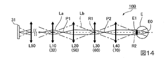
図14は、第二変形例に係る光学系10Bの光線図である。図14に示すように、本変形例の光学系10Bでは、画像光生成装置31から出射された画像光の光路に沿って、正のパワーを有する第1光学部L10(投射光学系32)と、第1回折素子50を備え、正のパワーを有する第2光学部L20と、正のパワーを有する第3光学部L30(導光系60)と、反射型の第2回折素子70を備え、正のパワーを有する第4光学部L40とが設けられている。本変形例では、画像光生成装置31と投射光学系32との間に第5光学部L50が設けられている。
(Second modification)
FIG. 14 is a ray diagram of an optical system 10B according to a second modification. As shown in FIG. 14, in the optical system 10B of this modified example, along the optical path of the image light emitted from the image light generation device 31, the first optical unit L10 (projection optical system 32) having positive power and the , comprising a first diffraction element 50, a second optical section L20 having positive power, a third optical section L30 (light guide system 60) having positive power, and a reflective second diffraction element 70, A fourth optical section L40 having positive power is provided. In this modified example, a fifth optical section L50 is provided between the image light generation device 31 and the projection optical system 32 .

本変形例でも、図9を参照して説明した第一実施形態の構成と同様、第1光学部L10と第3光学部L30との間に画像光の第1中間像P1が形成され、第3光学部L30近傍に瞳R1が形成され、第3光学部L30と第4光学部L40との間に画像光の第2中間像P2が形成され、第4光学部L40は、画像光を平行光化して射出瞳R2を形成する。本変形例においても、第一実施形態の構成と同様、第1中間像P1は、第1光学部L10(投射光学系32)と第2光学部L20(第1回折素子50)との間に形成される。すなわち、図9を参照して説明した第一実施形態の構成において、画像光生成装置31が配置されていた位置を仮想パネル位置とした場合、図14に示す構成では、画像光生成装置31を仮想パネル位置より第1光学部L10とは反対側に配置されており、画像光生成装置31と第1光学部L10との距離は、図9を参照して説明した第一実施形態の構成における画像光生成装置31と第1光学部L10との距離より長い。このような場合でも、画像光生成装置31と投射光学系32との間に第5光学部L50が設けられているため、画像光生成装置31から出射された光線は、第1光学部L10に到達した以降、図9を参照して説明した第一実施形態の構成と同様となる。 Also in this modification, similarly to the configuration of the first embodiment described with reference to FIG. A pupil R1 is formed near the third optical section L30, a second intermediate image P2 of the image light is formed between the third optical section L30 and the fourth optical section L40, and the fourth optical section L40 collimates the image light. It is photonized to form an exit pupil R2. Also in this modified example, similarly to the configuration of the first embodiment, the first intermediate image P1 is positioned between the first optical section L10 (projection optical system 32) and the second optical section L20 (first diffraction element 50). It is formed. That is, in the configuration of the first embodiment described with reference to FIG. 9, when the position where the image light generation device 31 was arranged is assumed to be the virtual panel position, in the configuration shown in FIG. It is arranged on the side opposite to the first optical unit L10 from the virtual panel position, and the distance between the image light generating device 31 and the first optical unit L10 is the same as in the configuration of the first embodiment described with reference to FIG. It is longer than the distance between the image light generator 31 and the first optical section L10. Even in such a case, since the fifth optical section L50 is provided between the image light generating device 31 and the projection optical system 32, the light beam emitted from the image light generating device 31 is directed to the first optical section L10. After arriving, the configuration is the same as that of the first embodiment described with reference to FIG.

それ故、本変形例の光学系10Bにおいても、第一実施形態の構成と同様、画像光生成装置31の1つの点から出射した光線は、網膜E0に1つの点として結像されるという条件1を満たす。また、光学系10Bの入射瞳と眼Eの瞳E1とが共役(瞳の共役)の関係にあるという条件2を満たす。また、第1回折素子50と第2回折素子70とを適正に配置するという条件3を満たす。また、第1回折素子50と第2回折素子70とが共役または略共役の関係にあるという条件4を満たすため、第1回折素子50と第2回折素子70とでは、光線を干渉縞が同一な個所に入射させることが可能であり、波長補償を適正に行うことで色収差をキャンセルできる。よって、画像光の解像度の劣化を抑えることができる。 Therefore, in the optical system 10B of this modified example, as in the configuration of the first embodiment, the condition is that the light beam emitted from one point of the image light generation device 31 is imaged as one point on the retina E0. 1 is satisfied. Moreover, the condition 2 that the entrance pupil of the optical system 10B and the pupil E1 of the eye E are in a conjugate relationship (pupil conjugate) is satisfied. Moreover, the condition 3 is satisfied that the first diffraction element 50 and the second diffraction element 70 are properly arranged. Further, in order to satisfy the condition 4 that the first diffraction element 50 and the second diffraction element 70 are in a conjugate or substantially conjugate relationship, the first diffraction element 50 and the second diffraction element 70 have the same interference fringes for light beams. chromatic aberration can be canceled by appropriately performing wavelength compensation. Therefore, deterioration of resolution of image light can be suppressed.

本変形例の光学系10Bにおいても、上述した実施形態に係る光学系10,11,12と同様、プリズム部材45,145,245のいずれかを備えることで、画像光L0における光線形状を斜入射を考慮した形状に補正できる。よって、第2回折素子70に対して画像光が斜入射することに起因する解像度の低下を抑制できる。従って、本変形例の光学系10Bによれば、高い画質を得ることができる。 Like the optical systems 10, 11, and 12 according to the above-described embodiments, the optical system 10B of this modification also includes any one of the prism members 45, 145, and 245 so that the light beam shape of the image light L0 is obliquely incident. can be corrected to a shape that takes account of Therefore, it is possible to suppress deterioration in resolution caused by oblique incidence of the image light on the second diffraction element 70 . Therefore, according to the optical system 10B of this modified example, high image quality can be obtained.

(第三変形例)
図15は、第三変形例に係る光学系10Cの光線図である。図15に示すように、本変形例の光学系10Cでは、画像光生成装置31から出射された画像光の光路に沿って、正のパワーを有する第1光学部L10(投射光学系32)と、第1回折素子50を備え、正のパワーを有する第2光学部L20と、正のパワーを有する第3光学部L30(導光系60)と、反射型の第2回折素子70を備え、正のパワーを有する第4光学部L40とが設けられている。
(Third modification)
FIG. 15 is a ray diagram of the optical system 10C according to the third modification. As shown in FIG. 15, in the optical system 10C of this modified example, along the optical path of the image light emitted from the image light generation device 31, the first optical unit L10 (projection optical system 32) having positive power and the , comprising a first diffraction element 50, a second optical section L20 having positive power, a third optical section L30 (light guide system 60) having positive power, and a reflective second diffraction element 70, A fourth optical section L40 having positive power is provided.

本変形例でも、第一実施形態、第一変形例および第二変形例の構成と同様、第1光学部L10と第3光学部L30との間に画像光の第1中間像P1が形成され、第3光学部L30近傍に瞳R1が形成され、第3光学部L30と第4光学部L40との間に画像光の第2中間像P2が形成され、第4光学部L40は、画像光を平行光化して射出瞳R2を形成する。 In this modified example, similarly to the configurations of the first embodiment, the first modified example, and the second modified example, the first intermediate image P1 of the image light is formed between the first optical unit L10 and the third optical unit L30. , a pupil R1 is formed near the third optical section L30, a second intermediate image P2 of the image light is formed between the third optical section L30 and the fourth optical section L40, and the fourth optical section L40 forms the image light are collimated to form an exit pupil R2.

本変形例では、第一実施形態、第一変形例および第二変形例の構成と異なり、第1中間像P1は、第2光学部L20(第1回折素子50)と第3光学部L30(導光系60)との間に形成される。 In this modified example, unlike the configurations of the first embodiment, the first modified example, and the second modified example, the first intermediate image P1 is formed by the second optical section L20 (the first diffraction element 50) and the third optical section L30 ( It is formed between the light guide system 60).

かかる光学系10Cでも、第一実施形態の構成と同様、画像光生成装置31の1つの点から出射した光線は、網膜E0に1つの点として結像されるという条件1を満たす。また、光学系10Cの入射瞳と眼Eの瞳E1とが共役(瞳の共役)の関係にあるという条件2を満たす。また、第1回折素子50と第2回折素子70とを適正に配置するという条件3を満たす。なお、本変形例の光学系10Cでは、第1回折素子50と第2回折素子70とが共役または略共役の関係にあるという条件4を満たさない。この場合でも、第3光学部L30は、画像光生成装置31の1点からの画像光について、第1回折素子50により偏向されて特定波長からずれた光を第2回折素子70の所定の範囲に入射させることができる。このため、干渉縞が異なる場所に入射するという問題は、第3光学部L30によって補償される。従って、波長が特定波長の周辺波長の光も特定波長の光の近傍に入射可能となり、波長補償を行うことで色収差を概ねキャンセルできる。よって、解像度の劣化を抑えることができる。すなわち、本変形例の光学系10Cによれば、第一実施形態の構成等と比較して、波長補償効果は弱いが、開口率が小さい場合は一定の波長補償効果が得られる。 The optical system 10C also satisfies Condition 1 that a light ray emitted from one point of the image light generating device 31 is imaged as one point on the retina E0, similarly to the configuration of the first embodiment. Moreover, the condition 2 that the entrance pupil of the optical system 10C and the pupil E1 of the eye E are in a conjugate relationship (pupil conjugate) is satisfied. Moreover, the condition 3 is satisfied that the first diffraction element 50 and the second diffraction element 70 are properly arranged. Note that the optical system 10C of this modified example does not satisfy the condition 4 that the first diffraction element 50 and the second diffraction element 70 are in a conjugate or substantially conjugate relationship. Even in this case, the third optical unit L30 converts image light from one point of the image light generation device 31 into a predetermined range of the second diffraction element 70, which is deflected by the first diffraction element 50 and deviates from the specific wavelength. can be made incident on Therefore, the problem that the interference fringes are incident on different places is compensated for by the third optical section L30. Therefore, light with wavelengths around the specific wavelength can also be incident in the vicinity of the light with the specific wavelength, and chromatic aberration can be substantially canceled by performing wavelength compensation. Therefore, deterioration of resolution can be suppressed. That is, according to the optical system 10C of this modified example, although the wavelength compensation effect is weaker than that of the configuration of the first embodiment, etc., a certain wavelength compensation effect can be obtained when the aperture ratio is small.

本変形例の光学系10Cにおいても、上述した実施形態に係る光学系10,11,12と同様、プリズム部材45,145,245のいずれかを備えることで、画像光L0における光線形状を斜入射を考慮した形状に補正できる。よって、第2回折素子70に対して画像光が斜入射することに起因する解像度の低下を抑制できる。従って、本変形例の光学系10Cによれば、高い画質を得ることができる。 As with the optical systems 10, 11, and 12 according to the above-described embodiments, the optical system 10C of this modified example is also provided with one of the prism members 45, 145, and 245 so that the light beam shape of the image light L0 is obliquely incident. can be corrected to a shape that takes account of Therefore, it is possible to suppress deterioration in resolution caused by oblique incidence of the image light on the second diffraction element 70 . Therefore, according to the optical system 10C of this modified example, high image quality can be obtained.

(第四変形例)
図16は、第四変形例に係る光学系10Dの光線図である。図17は、本変形例に係る第1光学部L10の説明図である。図16に示すように、本変形例の光学系10Dでは、図9を参照して説明した第一実施形態の構成と同様、正のパワーを有する第1光学部L10(投射光学系32)と、第1回折素子50を備え、正のパワーを有する第2光学部L20と、正のパワーを有する第3光学部L30(導光系60)と、反射型の第2回折素子70を備え、正のパワーを有する第4光学部L40とが設けられている。ここで、画像光生成装置31は、レーザー光源316と、コリメートレンズ317と、マイクロミラーデバイス318とを有しており、マイクロミラーデバイス318を駆動することによりレーザー光源316を走査することにより、画像を生成する。従って、画像光生成装置31自身が画角の光を形成する。
(Fourth modification)
FIG. 16 is a ray diagram of an optical system 10D according to a fourth modification. FIG. 17 is an explanatory diagram of the first optical unit L10 according to this modification. As shown in FIG. 16, in an optical system 10D of this modified example, similarly to the configuration of the first embodiment described with reference to FIG. , comprising a first diffraction element 50, a second optical section L20 having positive power, a third optical section L30 (light guide system 60) having positive power, and a reflective second diffraction element 70, A fourth optical section L40 having positive power is provided. Here, the image light generating device 31 has a laser light source 316, a collimating lens 317, and a micromirror device 318. By driving the micromirror device 318 to scan the laser light source 316, an image is generated. to generate Therefore, the image light generating device 31 itself forms the light of the angle of view.

このため、図17に示すように、図9を参照して説明した第一実施形態の構成において、第1光学部L10に用いたレンズL11、L12の間に瞳を形成する場合と比較すると、画像光生成装置31とレンズL11とが上述したレーザー光源316、コリメートレンズ317およびマイクロミラーデバイス318で置き換えられる。 For this reason, as shown in FIG. 17, in the configuration of the first embodiment described with reference to FIG. The image light generator 31 and lens L11 are replaced by the laser light source 316, collimating lens 317 and micromirror device 318 described above.

かかる光学系10Dによれば、表示装置100を装着した際、体温や表示装置100自身の熱によって温度変化が発生してレーザー光のスペクトラム幅等が変動した場合でも、波長補償によって画像の画質を向上させることができる。 According to the optical system 10D, when the display device 100 is worn, even if the spectrum width of the laser beam or the like changes due to temperature changes caused by the body temperature or the heat of the display device 100 itself, the image quality of the image can be improved by wavelength compensation. can be improved.

本変形例の光学系10Dにおいても、上述した実施形態に係る光学系10,11,12と同様、プリズム部材45,145,245のいずれかを備えることで、画像光L0における光線形状を斜入射を考慮した形状に補正できる。よって、第2回折素子70に対して画像光が斜入射することに起因する解像度の低下を抑制できる。従って、本変形例の光学系10Dによれば、高い画質を得ることができる。 Like the optical systems 10, 11, and 12 according to the above-described embodiments, the optical system 10D of this modification also includes any one of the prism members 45, 145, and 245 so that the light beam shape of the image light L0 is obliquely incident. can be corrected to a shape that takes account of Therefore, it is possible to suppress deterioration in resolution caused by oblique incidence of the image light on the second diffraction element 70 . Therefore, according to the optical system 10D of this modified example, high image quality can be obtained.

(第五変形例)
図18は、第五変形例に係る光学系10Eの説明図である。図18に示す光学系10Eは、図2に示したように上下方向に沿って配置されており、頭頂部に配置された画像光生成装置31から眼Eの前の第2回折素子70までの間に投射光学系32、第1回折素子50、および導光系60が配置されている。本変形例において、導光系60は、周辺部より中央が凹んだ反射面620を有するミラー62によって構成されており、正のパワーを有している。反射面620は、球面、非球面、または自由曲面からなる。本変形例において、反射面620は自由曲面からなる。第1回折素子50は、透過型体積ホログラフィック素子とレンズとが一体化されており、正のパワーを有している。なお、第1回折素子50自身が正のパワーを有するように構成されることもある。
(Fifth Modification)
FIG. 18 is an explanatory diagram of an optical system 10E according to a fifth modification. The optical system 10E shown in FIG. 18 is arranged along the vertical direction as shown in FIG. A projection optical system 32, a first diffraction element 50, and a light guide system 60 are arranged therebetween. In this modification, the light guide system 60 is composed of a mirror 62 having a reflecting surface 620 whose center is recessed from its periphery, and has positive power. The reflective surface 620 consists of a spherical surface, an aspherical surface, or a free-form surface. In this modified example, the reflecting surface 620 is a free-form surface. The first diffraction element 50 is a transmissive volume holographic element integrated with a lens, and has positive power. Note that the first diffraction element 50 itself may be configured to have positive power.

本変形例の光学系10Eでは、図13を参照して説明した第一変形例と同様、画像光生成装置31から出射された画像光の光路に沿って、正のパワーを有する第1光学部L10(投射光学系32)と、第1回折素子50を備え、正のパワーを有する第2光学部L20と、正のパワーを有する第3光学部L30(導光系60のミラー62)と、反射型の第2回折素子70を備え、正のパワーを有する第4光学部L40とが設けられている。従って、第1光学部L10と第3光学部L30との間に画像光の第1中間像P1が形成され、第3光学部L30近傍に瞳R1が形成され、第3光学部L30と第4光学部L40との間に画像光の第2中間像P2が形成され、第4光学部L40は、画像光を平行光化して射出瞳R2を形成する。 In the optical system 10E of this modification, as in the first modification described with reference to FIG. 13, along the optical path of the image light emitted from the image light generation device 31, the first optical unit L10 (projection optical system 32), a second optical section L20 having a positive power and having a first diffraction element 50, a third optical section L30 having a positive power (mirror 62 of light guide system 60), A fourth optical section L40 having a positive power and including a reflective second diffraction element 70 is provided. Therefore, a first intermediate image P1 of image light is formed between the first optical section L10 and the third optical section L30, a pupil R1 is formed near the third optical section L30, and a pupil R1 is formed near the third optical section L30 and the fourth optical section L30. A second intermediate image P2 of the image light is formed between it and the optical section L40, and the fourth optical section L40 collimates the image light to form an exit pupil R2.

また、本変形例の光学系10Eでは、第一実施形態に係る光学系10と同様、プリズム部材45を第3光学部L30と第4光学部L40との間に設けている。これにより、画像光L0における光線形状を斜入射を考慮した形状に補正することができる。 Further, in the optical system 10E of this modified example, similarly to the optical system 10 according to the first embodiment, the prism member 45 is provided between the third optical section L30 and the fourth optical section L40. As a result, the light beam shape of the image light L0 can be corrected in consideration of oblique incidence.

ここで、第3光学部L30は、正のパワーを有するミラー62によって構成されている。従って、第2光学部L20で回折した発散光は、ミラー62によって集光される。また、集光された光は、第4光学部L40(第2回折素子70)の特定波長の光が入射する点および近傍に入射する。 Here, the third optical section L30 is composed of a mirror 62 having positive power. Therefore, the divergent light diffracted by the second optical section L20 is condensed by the mirror 62. FIG. Further, the condensed light is incident on and near the point where the light of the specific wavelength of the fourth optical section L40 (second diffraction element 70) is incident.

本変形例の光学系10Eでも、図13を参照して説明した第一変形例1と同様、画像光生成装置31の1つの点から出射した光線は、網膜E0に1つの点として結像されるという条件1を満たす。また、光学系10Eの入射瞳と眼Eの瞳E1とが共役(瞳の共役)の関係にあるという条件2を満たす。また、第1回折素子50と第2回折素子70とを適正に配置するという条件3を満たす。また、第1回折素子50と第2回折素子70とが共役または略共役の関係にあるという条件4を満たすため、第1回折素子50と第2回折素子70とでは、光線を干渉縞が同一な個所に入射させることが可能であり、波長補償を適正に行うことで色収差をキャンセルできる。よって、画像光の解像度の劣化を抑えることができる。 In the optical system 10E of this modified example as well, similarly to the first modified example 1 described with reference to FIG. satisfies condition 1 that Moreover, the condition 2 that the entrance pupil of the optical system 10E and the pupil E1 of the eye E are in a conjugate relationship (pupil conjugate) is satisfied. Moreover, the condition 3 is satisfied that the first diffraction element 50 and the second diffraction element 70 are properly arranged. Further, in order to satisfy the condition 4 that the first diffraction element 50 and the second diffraction element 70 are in a conjugate or substantially conjugate relationship, the first diffraction element 50 and the second diffraction element 70 have the same interference fringes for light beams. chromatic aberration can be canceled by appropriately performing wavelength compensation. Therefore, deterioration of resolution of image light can be suppressed.

また、本変形例の光学系10Eによれば、プリズム部材45を備えるため、第2回折素子70に対して画像光が斜入射することに起因する解像度の低下を抑制することで、より高い画質を得ることができる。
なお、本変形例では、プリズム部材45を備える場合を例に挙げたが、プリズム部材145,245を組み合わせてもよい。
Further, according to the optical system 10E of the present modification, since the prism member 45 is provided, a decrease in resolution caused by oblique incidence of the image light to the second diffraction element 70 is suppressed, thereby achieving higher image quality. can be obtained.
In this modified example, the prism member 45 is provided, but the prism members 145 and 245 may be combined.

(第六変形例)
図19は、第六変形例に係る表示装置の説明図である。図18に示した光学系10Eは、第1光学部L10(投射光学系32)と第2光学部L20(第1回折素子50)とが別体であったが、本変形例の光学系10Fは、図19に示すように、第1光学部L10(投射光学系)と第2光学部L20(第1回折素子50)とが一体である。より具体的には、第1光学部L10(投射光学系32)は、複数の反射面185a、185bを備えたプリズム185によって構成されており、プリズム185の出射面185cに第2光学部L20(透過型の第1回折素子50)が構成されている。
(Sixth modification)
FIG. 19 is an explanatory diagram of a display device according to a sixth modification. In the optical system 10E shown in FIG. 18, the first optical section L10 (projection optical system 32) and the second optical section L20 (first diffraction element 50) are separate bodies. 19, the first optical section L10 (projection optical system) and the second optical section L20 (first diffraction element 50) are integrated. More specifically, the first optical section L10 (projection optical system 32) is composed of a prism 185 having a plurality of reflecting surfaces 185a and 185b. A transmissive first diffraction element 50) is constructed.

その他の構成は、図18を参照して説明した第五変形例と共通である。従って、図18に示す態様と同様、波長補償を適正に行うことで色収差をキャンセルできる。よって、画像光の解像度の劣化を抑えることができる。また、プリズム185を用いることにより、第1光学部L10(投射光学系32)と第2光学部L20(第1回折素子50)とを一体化したため、組立公差の低減や頭部前後方向の小型化等を図ることができる。また、第2回折素子70に対して画像光が斜入射することに起因する解像度の低下を抑制できる。よって、より高い画質を得ることができる。 Other configurations are common to the fifth modification described with reference to FIG. Therefore, similarly to the mode shown in FIG. 18, chromatic aberration can be canceled by appropriately performing wavelength compensation. Therefore, deterioration of resolution of image light can be suppressed. Also, by using the prism 185, the first optical section L10 (the projection optical system 32) and the second optical section L20 (the first diffraction element 50) are integrated. It is possible to achieve In addition, it is possible to suppress deterioration in resolution caused by image light obliquely entering the second diffraction element 70 . Therefore, higher image quality can be obtained.

(第七変形例)
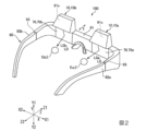
図20は、第七変形例に係る表示装置の説明図である。図20に示す光学系10Gは、図1および図3を参照して説明した態様と同様、側頭部に配置された画像光生成装置31から眼Eの前の第2回折素子70までの間に、投射光学系32、第1回折素子50、および導光系60が配置されている。本変形例において、投射光学系32は、回転対称のレンズ326と、自由曲面のレンズ327とを有している。導光系60は、周辺部より中央が凹んだ反射面620を有するミラー62によって構成されており、正のパワーを有している。反射面620は、球面、非球面、または自由曲面からなる。本変形例において、反射面620は自由曲面からなる。第1回折素子50は、反射型体積ホログラムからなる。投射光学系32から第1回折素子50に到る光路の途中位置にミラー40が配置されており、投射光学系32は、ミラー40の反射面またはその近傍に中間像(第1中間像P1)を形成する。ミラー40は、反射面400が凹曲面になっており、正のパワーを有している。ミラー40の反射面400が正のパワーを有する場合、ミラー40を投射光学系32の構成要素に含めるようにしてもよい。すなわち、ミラー40が正のパワーを有する場合、第1光学部L10がミラー40を含むようにしてもよい。なお、ミラー40の反射面400が、平面になっており、パワーを有しないように構成してもよい。
(Seventh modification)
FIG. 20 is an explanatory diagram of a display device according to a seventh modification. The optical system 10G shown in FIG. 20, similarly to the embodiment described with reference to FIGS. A projection optical system 32, a first diffraction element 50, and a light guide system 60 are arranged at the bottom. In this modified example, the projection optical system 32 has a rotationally symmetrical lens 326 and a free-form lens 327 . The light guide system 60 is composed of a mirror 62 having a reflecting surface 620 whose center is recessed from its periphery, and has positive power. The reflective surface 620 consists of a spherical surface, an aspherical surface, or a free-form surface. In this modified example, the reflecting surface 620 is a free-form surface. The first diffraction element 50 is composed of a reflective volume hologram. A mirror 40 is arranged in the middle of the optical path from the projection optical system 32 to the first diffraction element 50, and the projection optical system 32 projects an intermediate image (first intermediate image P1) on the reflecting surface of the mirror 40 or in the vicinity thereof. to form The mirror 40 has a concave curved reflecting surface 400 and has positive power. If the reflective surface 400 of the mirror 40 has positive power, the mirror 40 may be included as a component of the projection optical system 32 . That is, the first optical section L10 may include the mirror 40 when the mirror 40 has positive power. Note that the reflecting surface 400 of the mirror 40 may be flat and have no power.

このように構成した光学系10Gでは、図13を参照して説明した第一変形例と同様、画像光生成装置31から出射された画像光の光路に沿って、正のパワーを有する第1光学部L10(投射光学系32)と、第1回折素子50を備え、正のパワーを有する第2光学部L20と、正のパワーを有する第3光学部L30(導光系60のミラー62)と、反射型の第2回折素子70を備え、正のパワーを有する第4光学部L40とが設けられている。 In the optical system 10G configured in this manner, the first optical system having a positive power along the optical path of the image light emitted from the image light generation device 31, as in the first modification described with reference to FIG. A portion L10 (projection optical system 32), a second optical portion L20 having positive power and having first diffraction element 50, and a third optical portion L30 having positive power (mirror 62 of light guide system 60) , and a fourth optical section L40 having a positive power, which includes a reflective second diffraction element 70 .

また、本変形例の光学系10Gでは、第一実施形態に係る光学系10と同様、プリズム部材45を第3光学部L30と第4光学部L40との間に設けている。これにより、画像光における光線形状を斜入射を考慮した形状に補正することができる。 Further, in the optical system 10G of this modified example, similarly to the optical system 10 according to the first embodiment, the prism member 45 is provided between the third optical section L30 and the fourth optical section L40. As a result, the beam shape of the image light can be corrected in consideration of oblique incidence.

本変形例の光学系10Gにおいて、第1光学部L10は複数のレンズ326,327を含む。複数のレンズ326,327のうちレンズ326は、最も画像光生成装置31側に位置するレンズである。
本変形例の光学系10Gにおいて、第1光学部L10におけるレンズ326とレンズ327との間に瞳R0が形成され、第3光学部L30近傍に瞳R1が形成され、第3光学部L30と第4光学部L40との間に画像光の第2中間像P2が形成され、第4光学部L40は、画像光を平行光化して射出瞳R2を形成する。
In the optical system 10G of this modified example, the first optical section L10 includes a plurality of lenses 326,327. Among the plurality of lenses 326 and 327, the lens 326 is the lens closest to the image light generating device 31 side.
In the optical system 10G of this modified example, a pupil R0 is formed between the lens 326 and the lens 327 in the first optical section L10, a pupil R1 is formed near the third optical section L30, and a pupil R1 is formed near the third optical section L30 and the third optical section L30. A second intermediate image P2 of the image light is formed between it and the fourth optical section L40, and the fourth optical section L40 collimates the image light to form an exit pupil R2.

本変形例の光学系10Gにおいて、第1中間像P1は、第1光学部L10(投射光学系32)の中に形成される。図20に示す第1中間像P1および第2中間像P2は、紙面に沿う水平方向に拡がった画像光における中間像である。画像光生成装置31から出射された画像光は、水平方向のみならず図20の紙面に直交する垂直方向にも拡がることから、垂直方向に拡がった画像光の中間像も存在する。本変形例において、垂直方向の中間像が水平方向の中間像の近傍に存在している。
なお、本実施形態の光学系14において、第1中間像P1はミラー40の近傍に形成されるが、第1光学部L10(投射光学系32)の中に形成されても良い。
In the optical system 10G of this modified example, the first intermediate image P1 is formed in the first optical section L10 (the projection optical system 32). A first intermediate image P1 and a second intermediate image P2 shown in FIG. 20 are intermediate images in the image light spread in the horizontal direction along the plane of the paper. Since the image light emitted from the image light generator 31 spreads not only in the horizontal direction but also in the vertical direction perpendicular to the plane of FIG. 20, an intermediate image of the vertically spread image light also exists. In this modification, the vertical intermediate image exists in the vicinity of the horizontal intermediate image.
Although the first intermediate image P1 is formed near the mirror 40 in the optical system 14 of the present embodiment, it may be formed in the first optical section L10 (projection optical system 32).

また、水平方向の中間像と垂直方向の中間像とは異なる位置に存在していてもよい。図21は水平方向および垂直方向における中間像の位置が異なる場合の光線図であり、図21は水平方向および垂直方向の画像光における光線図である。図21において、符号Lは水平方向の画像光を示し、符号P1は水平方向の画像光Lにおける第1中間像を示し、符号Lは垂直方向の画像光を示し、符号P1は垂直方向の画像光Lにおける第1中間像を示す。また、図21では、光軸に沿って配置される、画像光生成装置31、第1光学部L10(投射光学系32)およびミラー40を模式化して示している。また、図21では、投射光学系32を構成するレンズ326,327の形状も簡略化している。 Further, the intermediate image in the horizontal direction and the intermediate image in the vertical direction may exist at different positions. FIG. 21 is a ray diagram when the position of the intermediate image is different in the horizontal direction and the vertical direction, and FIG. 21 is a ray diagram of image light in the horizontal direction and the vertical direction. In FIG. 21, reference LH denotes horizontal image light, reference P1H denotes a first intermediate image in horizontal image light LH , reference LV denotes vertical image light, and reference P1V. denotes the first intermediate image in the vertical image light LV . 21 schematically shows the image light generating device 31, the first optical section L10 (the projection optical system 32), and the mirror 40 arranged along the optical axis. In addition, in FIG. 21, the shapes of lenses 326 and 327 constituting the projection optical system 32 are also simplified.

図21に示すように、水平方向の第1中間像P1はミラー40の近傍に位置しており、垂直方向の第1中間像P1は水平方向の第1中間像P1よりも第1光学部L10の近傍に位置している。 As shown in FIG. 21, the first horizontal intermediate image P1H is positioned closer to the mirror 40, and the first vertical intermediate image P1V is closer to the first intermediate image P1H than the first horizontal intermediate image P1H . It is located near the optical part L10.

図21では、第1中間像P1において水平方向と垂直方向とで中間像の位置が異なる場合を示したが、第2中間像においても水平方向と垂直方向とで位置が異なっていてもよい。また、第1中間像P1において水平方向と垂直方向とで中間像の位置が異なる場合において、第1中間像P1および第1中間像P1の一方が第1光学部L10の中に形成され、第1中間像P1および第1中間像P1の他方が第1光学部L10の外側に形成されてもよい。 FIG. 21 shows the case where the positions of the intermediate images are different in the horizontal direction and the vertical direction in the first intermediate image P1, but the positions in the second intermediate image may also be different in the horizontal direction and the vertical direction. Further, when the position of the intermediate image in the first intermediate image P1 differs between the horizontal direction and the vertical direction, one of the first intermediate image P1H and the first intermediate image P1V is formed in the first optical section L10. , the other of the first intermediate image P1- H and the first intermediate image P1- V may be formed outside the first optical section L10.

本変形例の光学系10Gにおいても、図13を参照して説明した第一変形例と同様、画像光生成装置31の1つの点から出射した光線は、網膜E0に1つの点として結像されるという条件1を満たす。また、光学系10の入射瞳と眼Eの瞳E1とが共役(瞳の共役)の関係にあるという条件2を満たす。また、第1回折素子50と第2回折素子70とを適正に配置するという条件3を満たす。また、第1回折素子50と第2回折素子70とが共役または略共役の関係にあるという条件4を満たすため、第1回折素子50と第2回折素子70とでは、光線を干渉縞が同一な個所に入射させることが可能であり、波長補償を適正に行うことで色収差をキャンセルできる。よって、画像光の解像度の劣化を抑えることができる。 Also in the optical system 10G of this modified example, similarly to the first modified example described with reference to FIG. satisfies condition 1 that Moreover, the condition 2 that the entrance pupil of the optical system 10 and the pupil E1 of the eye E are in a conjugate relationship (pupil conjugate) is satisfied. Moreover, the condition 3 is satisfied that the first diffraction element 50 and the second diffraction element 70 are properly arranged. Further, in order to satisfy the condition 4 that the first diffraction element 50 and the second diffraction element 70 are in a conjugate or substantially conjugate relationship, the first diffraction element 50 and the second diffraction element 70 have the same interference fringes for light beams. chromatic aberration can be canceled by appropriately performing wavelength compensation. Therefore, deterioration of resolution of image light can be suppressed.

また、本変形例の光学系10Gによれば、プリズム部材45を備えるため、第2回折素子70に対して画像光が斜入射することに起因する解像度の低下を抑制することで、より高い画質を得ることができる。
なお、本変形例では、プリズム部材45を備える場合を例に挙げたが、プリズム部材145,245を組み合わせてもよい。
Further, according to the optical system 10G of this modified example, since the prism member 45 is provided, the deterioration of the resolution caused by the oblique incidence of the image light to the second diffraction element 70 is suppressed, thereby achieving higher image quality. can be obtained.
In this modified example, the prism member 45 is provided, but the prism members 145 and 245 may be combined.

また、図20に示す部材のうち、透光性部材を構成するプラスチック、ガラス等には、高分散と低分散を組合せた光学部材を使用している。また、第3光学部L30にミラー62を用いているため、第1光学部L10で色消し状態としている。このため、光学系10Gの重心位置が後側Z2に移るため、使用者の鼻への負担を軽減できる等の利点がある。また、ミラー62については、透明樹脂もしくはガラスなどの透明部材にスパッター法等により半透過型ミラー層や角度選択性のミラー層を形成すれば、ミラー62を介して外界を視認することができる。 In addition, among the members shown in FIG. 20, optical members having a combination of high dispersion and low dispersion are used for the plastic, glass, or the like constituting the translucent member. Further, since the mirror 62 is used in the third optical section L30, the first optical section L10 is in an achromatic state. As a result, the position of the center of gravity of the optical system 10G is moved to the rear side Z2, which has the advantage of reducing the burden on the user's nose. As for the mirror 62, if a transflective mirror layer or an angle-selective mirror layer is formed on a transparent member such as transparent resin or glass by a sputtering method or the like, the external world can be visually recognized through the mirror 62.

(第八変形例)
図22は、第八変形例に係る表示装置の説明図である。図22に示す光学系10Hは、図20を参照して説明した第七変形例と同様、側頭部に配置された画像光生成装置31から眼Eの前の第2回折素子70(第4光学部L40)までの間に投射光学系32(第1光学部L10)、ミラー40、第1回折素子50(第2光学部L20)、および導光系60のミラー62(第3光学部L30)が配置されている。
(Eighth modification)
FIG. 22 is an explanatory diagram of a display device according to an eighth modification. The optical system 10H shown in FIG. 22, like the seventh modification described with reference to FIG. Optical section L40), projection optical system 32 (first optical section L10), mirror 40, first diffraction element 50 (second optical section L20), and mirror 62 of light guide system 60 (third optical section L30 ) are placed.

本変形例では、ミラー40とミラー62とが、共通の部材181の異なる面に構成されている。その他の構成は、図20に示す第七変形例と共通である。従って、図20に示す第七変形例と同様、波長補償を適正に行うことができる。また、ミラー40とミラー62とが、共通の部材181に構成されているため、組立公差の低減等を図ることができる。また、ミラーを製造する金型の種類を減らすことができるので、コストの削減を図ることができる。 In this modification, mirrors 40 and 62 are configured on different surfaces of a common member 181 . Other configurations are common to the seventh modification shown in FIG. Therefore, wavelength compensation can be appropriately performed, as in the seventh modification shown in FIG. Moreover, since the mirror 40 and the mirror 62 are configured by the common member 181, it is possible to reduce the assembly tolerance. Also, since the number of molds for manufacturing the mirror can be reduced, the cost can be reduced.

(第九変形例)
図23は、第九変形例に係る表示装置の説明図である。図23に示す光学系10Iは、図16を参照して説明した第七変形例と同様、側頭部に配置された画像光生成装置31から眼Eの前の第2回折素子70(第4光学部L40)までの間に投射光学系32(第1光学部L10)、ミラー40、第1回折素子50(第2光学部L20)、および導光系60のミラー62(第3光学部L30)が配置されている。
(Ninth Modification)
FIG. 23 is an explanatory diagram of a display device according to a ninth modification. The optical system 10I shown in FIG. 23, like the seventh modification described with reference to FIG. Optical section L40), projection optical system 32 (first optical section L10), mirror 40, first diffraction element 50 (second optical section L20), and mirror 62 of light guide system 60 (third optical section L30 ) are placed.

本変形例では、ミラー62と第2回折素子70とが、共通の部材182の異なる面に構成されている。その他の構成は、図20に示す第七変形例と共通である。従って、図20に示す第七変形例と同様、波長補償を適正に行うことができる。また、ミラー62と第2回折素子70とが、共通の部材182に構成されているため、組立公差の低減等を図ることができる。また、ミラーを製造する金型の種類を減らすことができるので、コストの削減を図ることができる。
なお、本変形例において、プリズム部材45が部材182と一体に形成されていてもよい。これにより、組立公差の低減等を図ることができる。
In this modification, the mirror 62 and the second diffraction element 70 are configured on different surfaces of the common member 182 . Other configurations are common to the seventh modification shown in FIG. Therefore, wavelength compensation can be appropriately performed, as in the seventh modification shown in FIG. In addition, since the mirror 62 and the second diffraction element 70 are formed by the common member 182, it is possible to reduce the assembly tolerance. Also, since the number of molds for manufacturing the mirror can be reduced, the cost can be reduced.
In addition, in this modified example, the prism member 45 may be formed integrally with the member 182 . This makes it possible to reduce the assembly tolerance and the like.

(第十変形例)
図24は、第十変形例に係る表示装置の説明図である。図24に示す光学系10Jは、図20を参照して説明した第七変形例と同様、側頭部に配置された画像光生成装置31から眼Eの前の第2回折素子70(第4光学部L40)までの間に投射光学系32(第1光学部L10)、ミラー40、第1回折素子50(第2光学部L20)、および導光系60のミラー62(第3光学部L30)が配置されている。
(Tenth Modification)
FIG. 24 is an explanatory diagram of a display device according to a tenth modification. The optical system 10J shown in FIG. 24, like the seventh modification described with reference to FIG. Optical section L40), projection optical system 32 (first optical section L10), mirror 40, first diffraction element 50 (second optical section L20), and mirror 62 of light guide system 60 (third optical section L30 ) are placed.

本変形例では、ミラー40、ミラー62、および第2回折素子70が、共通の部材183の異なる面に構成されている。その他の構成は、図20に示す第七変形例と共通である。従って、図20に示す第七変形例と同様、波長補償を適正に行うことができる。また、ミラー40、ミラー62、および第2回折素子70が共通の部材183に構成されているため、組立公差の低減等を図ることができる。また、ミラーを製造する金型の種類を減らすことができるので、コストの削減を図ることができる。
なお、本変形例において、プリズム部材45が部材183と一体に形成されていてもよい。これにより、組立公差の低減等を図ることができる。
In this modification, mirror 40 , mirror 62 , and second diffraction element 70 are configured on different surfaces of common member 183 . Other configurations are common to the seventh modification shown in FIG. Therefore, wavelength compensation can be appropriately performed, as in the seventh modification shown in FIG. In addition, since the mirror 40, the mirror 62, and the second diffraction element 70 are configured by the common member 183, it is possible to reduce the assembly tolerance. Also, since the number of molds for manufacturing the mirror can be reduced, the cost can be reduced.
In addition, in this modification, the prism member 45 may be formed integrally with the member 183 . This makes it possible to reduce the assembly tolerance and the like.

(第十一変形例)
続いて、第十一変形例に係る光学系について説明する。本変形例の光学系では、第1回折素子50と第2回折素子70とが略共役関係となっている。以下、第1回折素子50と第2回折素子70との略共役関係について説明する。
(Eleventh modification)
Next, an optical system according to the eleventh modification will be described. In the optical system of this modified example, the first diffraction element 50 and the second diffraction element 70 are in a substantially conjugate relationship. The substantially conjugate relationship between the first diffraction element 50 and the second diffraction element 70 will be described below.

図25は、本変形例の光学系10Kにおける第1回折素子50と第2回折素子70との略共役関係を示す説明図である。図26は、図25に示す略共役関係のときに第2回折素子70から出射される光の説明図である。図27は、図26に示す光が眼Eに入射する様子を示す説明図である。なお、図21には、特定波長の光を実線Leで示し、波長が特定波長-10nmの光を一点鎖線Lfで示し、波長が特定波長+10nmの光を二点鎖線Lgで示してある。図27には、図面に向かって最も左側に、波長が特定波長-10nmの光(図26に一点鎖線Lfで示す光)が眼Eに入射する様子を示し、図面に向かって最も右側に、波長が特定波長+10nmの光(図26に二点鎖線Lgで示す光)が眼Eに入射する様子を示し、その間には、特定波長-10nmから特定波長+10nmまで波長を変化させた光が眼Eに入射する様子を示してある。なお、図27には、特定波長の光が眼Eに入射する様子を示していないが、特定波長の光が眼Eに入射する様子は、左から3番目に示す様子と左から4番目に示す様子との中間の様子となる。 FIG. 25 is an explanatory diagram showing a substantially conjugate relationship between the first diffraction element 50 and the second diffraction element 70 in the optical system 10K of this modified example. FIG. 26 is an explanatory diagram of light emitted from the second diffraction element 70 in the substantially conjugate relationship shown in FIG. FIG. 27 is an explanatory diagram showing how the light shown in FIG. 26 enters the eye E. FIG. In FIG. 21, light of a specific wavelength is indicated by a solid line Le, light of a wavelength of -10 nm is indicated by a dashed line Lf, and light of a wavelength of +10 nm is indicated by a two-dot chain line Lg. In FIG. 27, on the leftmost side of the drawing, light with a specific wavelength of −10 nm (light indicated by a dashed line Lf in FIG. 26) is shown entering the eye E, and on the rightmost side of the drawing, Light with a wavelength of a specific wavelength of +10 nm (light indicated by a two-dot chain line Lg in FIG. 26) is incident on the eye E. In the meantime, light with a wavelength changed from the specific wavelength of −10 nm to the specific wavelength of +10 nm enters the eye. The state of incidence on E is shown. Although FIG. 27 does not show how the light of the specific wavelength is incident on the eye E, the appearance of the light of the specific wavelength being incident on the eye E is shown in the third from the left and the fourth from the left. It will be an intermediate state with the state shown.

上記実施形態および変形例等では、第1回折素子50と第2回折素子70とを共役関係にすることが好ましかったが、本変形例では、上述したように第1回折素子50と第2回折素子70とを略共役の関係としている。この場合、図25に示すように、特定波長からずれた周辺波長の光では、第2回折素子70に入射する状態が異なる。ここで、第2回折素子70では、光軸に近づくほど干渉縞数が少なくなり、光を曲げる力が弱い。このため、長波長側の光を光軸側に入射させ、短波長側の光を端の方に入射させれば、特定波長の光、および周辺波長の光は平行光化されるため、波長補償と同様な効果を得ることができる。 In the above-described embodiment and modifications, etc., it is preferable that the first diffraction element 50 and the second diffraction element 70 are in a conjugate relationship. It has a substantially conjugate relationship with the two-diffraction element 70 . In this case, as shown in FIG. 25, light of peripheral wavelengths deviated from the specific wavelength is incident on the second diffraction element 70 in a different state. Here, in the second diffraction element 70, the closer to the optical axis, the smaller the number of interference fringes, and the weaker the light bending force. For this reason, if light with longer wavelengths is incident on the optical axis side and light with shorter wavelengths is incident on the edge, light of a specific wavelength and light of peripheral wavelengths are collimated. An effect similar to compensation can be obtained.

この場合、波長によって光線位置がずれるため、図26に示すように、瞳に入射する光線径が径φaから径φbへと大きくなる。その時の瞳孔に入射する光線強度の様子を示したのが図27である。図27から分かるように、特定波長近傍では瞳孔を満たす事ができないが、周辺波長の光は、特定波長の光とずれた位置に入射するため、瞳孔径を満たすことができる。その結果、観察者は画像を見やすくなる等の利点を得ることができる。 In this case, the position of the ray is shifted depending on the wavelength, so that the diameter of the ray incident on the pupil increases from the diameter φa to the diameter φb as shown in FIG. FIG. 27 shows the state of the light intensity incident on the pupil at that time. As can be seen from FIG. 27, the pupil cannot be filled in the vicinity of the specific wavelength, but the peripheral wavelength light can fill the pupil diameter because it is incident at a position shifted from the specific wavelength light. As a result, the observer can obtain advantages such as easier viewing of the image.

[他の表示装置への適用]
上記実施形態および変形例では、頭部装着型の表示装置100を例示したが、ヘッドアップディスプレイやハンドヘルドディスプレイやプロジェクター用光学系等に対して本発明を適用してもよい。
[Application to other display devices]
Although the head-mounted display device 100 has been exemplified in the above embodiment and modifications, the present invention may be applied to a head-up display, a handheld display, an optical system for a projector, and the like.

31…画像光生成装置、45,145,245…プリズム部材、50…第1回折素子、70…第2回折素子、100…表示装置、R1…瞳、L0…画像光、L10…第1光学部、L20…第2光学部、L30…第3光学部、L40…第4光学部、MC…曲線、P1…第1中間像、P2…第2中間像、R2…射出瞳。 31... Image light generating device 45, 145, 245... Prism member 50... First diffraction element 70... Second diffraction element 100... Display device R1... Pupil L0... Image light L10... First optical section , L20...second optical section, L30...third optical section, L40...fourth optical section, MC...curve, P1...first intermediate image, P2...second intermediate image, R2...exit pupil.

Claims (7)

第1光線と第2光線とを含む画像光を出射する画素を有する画像光生成装置と、
前記画像光の光路において、
正のパワーを有し、前記画像光生成装置と第1中間像との間に設けられる第1光学部と、
正のパワーを有し、前記第1光学部と瞳との間に設けられる第1回折素子を有する第2光学部と、
正のパワーを有し、前記第2光学部と第2中間像との間に設けられる第3光学部と、
正のパワーを有し、前記第3光学部と射出瞳との間に設けられる第2回折素子を有する第4光学部と、
前記第2光学部と前記第4光学部との間に設けられ、前記画像光の前記第1光線が通過する領域の厚さが前記画像光の前記第2光線が通過する領域の厚さよりも厚いプリズム部材と、を備え、
前記第2回折素子において、前記画像光の前記第1光線の入射角度は、前記画像光に含まれる光線において相対的に大きく、前記画像光の前記第2光線の入射角度は、前記画像光に含まれる光線において相対的に小さい、ことを特徴とする表示装置。
an image light generating device having pixels that emit image light including a first light ray and a second light ray ;
In the optical path of the image light ,
a first optical unit having positive power and provided between the image light generating device and a first intermediate image;
a second optical section having a positive power and having a first diffraction element provided between the first optical section and the pupil;
a third optical section having positive power and provided between the second optical section and the second intermediate image;
a fourth optical section having a positive power and having a second diffraction element provided between the third optical section and the exit pupil;
The thickness of a region provided between the second optical section and the fourth optical section through which the first ray of the image light passes is greater than the thickness of a region through which the second ray of the image light passes. a thick prism member;
In the second diffraction element, the incident angle of the first ray of the image light is relatively large among the rays included in the image light, and the incident angle of the second ray of the image light is large relative to the image light. A display device characterized in that it is relatively small in the rays it contains .
前記第1光学部は、第1レンズと第2レンズとを有し、
前記光路において、前記第1レンズは、前記第2レンズよりも前記画像光生成装置に近く、かつ、前記画像光生成装置と前記第1中間像との間に設けられる、ことを特徴とする請求項1に記載の表示装置。
The first optical section has a first lens and a second lens,
The first lens is closer to the image light generating device than the second lens in the optical path, and is provided between the image light generating device and the first intermediate image. Item 1. The display device according to item 1.
前記光路において、前記第2レンズは、前記第1中間像と前記第2光学部との間に設けられる、ことを特徴とする請求項2に記載の表示装置。 3. The display device according to claim 2, wherein the second lens is provided between the first intermediate image and the second optical section in the optical path. 前記光路において、前記プリズム部材は、前記第3光学部と前記第4光学部との間に設けられる、ことを特徴とする請求項1から3のいずれか一項に記載の表示装置。 4. The display device according to claim 1, wherein the prism member is provided between the third optical section and the fourth optical section in the optical path. 観測者に対する左右方向において、前記画像光の前記第1光線は、前記観測者から遠い側の光線であり、前記画像光の前記第2光線は、前記観測者から近い側の光線である、ことを特徴とする請求項1から4のいずれか一項に記載の表示装置。 The first light ray of the image light is a light ray farther from the observer, and the second light ray of the image light is a light ray closer to the observer in the horizontal direction with respect to the observer. The display device according to any one of claims 1 to 4, characterized by: 前記プリズム部材は、前記第1回折素子と一体に設けられる、ことを特徴とする請求項1から3のいずれか一項に記載の表示装置。 4. The display device according to claim 1, wherein the prism member is provided integrally with the first diffraction element. 前記プリズム部材は曲率を有する面を含む、ことを特徴とする請求項1から6のいずれか一項に記載の表示装置。 7. The display device according to any one of claims 1 to 6, wherein the prism member includes a curved surface.
JP2018206386A 2018-11-01 2018-11-01 Display device Active JP7223248B2 (en)

Priority Applications (3)

Application Number Priority Date Filing Date Title
JP2018206386A JP7223248B2 (en) 2018-11-01 2018-11-01 Display device
CN201911037207.5A CN111142248B (en) 2018-11-01 2019-10-29 Display device
US16/669,632 US11506894B2 (en) 2018-11-01 2019-10-31 Display device

Applications Claiming Priority (1)

Application Number Priority Date Filing Date Title
JP2018206386A JP7223248B2 (en) 2018-11-01 2018-11-01 Display device

Publications (3)

Publication Number Publication Date
JP2020071417A JP2020071417A (en) 2020-05-07
JP2020071417A5 JP2020071417A5 (en) 2021-11-18
JP7223248B2 true JP7223248B2 (en) 2023-02-16

Family

ID=70459718

Family Applications (1)

Application Number Title Priority Date Filing Date
JP2018206386A Active JP7223248B2 (en) 2018-11-01 2018-11-01 Display device

Country Status (3)

Country Link
US (1) US11506894B2 (en)
JP (1) JP7223248B2 (en)
CN (1) CN111142248B (en)

Families Citing this family (2)

* Cited by examiner, † Cited by third party
Publication number Priority date Publication date Assignee Title
CN110082926B (en) * 2018-01-26 2022-04-12 精工爱普生株式会社 Display device
JP2023043250A (en) * 2021-09-16 2023-03-29 株式会社リコー Propagation optical system, virtual image display device and head-mounted display

Citations (4)

* Cited by examiner, † Cited by third party
Publication number Priority date Publication date Assignee Title
JP2011022530A (en) 2009-07-21 2011-02-03 Fujifilm Corp Projector
JP2017167181A (en) 2016-03-14 2017-09-21 セイコーエプソン株式会社 Display divice and light guide device
JP2018054977A (en) 2016-09-30 2018-04-05 セイコーエプソン株式会社 Virtual image display device
JP2018141874A (en) 2017-02-28 2018-09-13 セイコーエプソン株式会社 Head-mounted display device and image forming optical system

Family Cites Families (20)

* Cited by examiner, † Cited by third party
Publication number Priority date Publication date Assignee Title
US4611877C1 (en) * 1984-08-31 2002-09-17 Bae Sys Electronics Ltd Optical projectors for head up displays
GB8719854D0 (en) * 1987-08-21 1987-09-30 Secr Defence Optical system
DE69325607T2 (en) * 1992-04-07 2000-04-06 Raytheon Co Wide spectral band virtual image display optical system
US5287218A (en) * 1992-04-07 1994-02-15 Hughes Aircraft Company Re-imaging optical system including refractive and diffractive optical elements
GB9304944D0 (en) * 1993-03-11 1993-04-28 Pilkington Perkin Elmer Ltd Head-up displays
FR2784201B1 (en) * 1998-10-06 2003-01-31 Sextant Avionique OPTICAL DEVICE FOR A HELMET SIGHT COMPRISING A DIFFRACTIVE MIRROR
FR2922322A1 (en) * 1998-12-08 2009-04-17 Sextant Avionique Sa OPTICAL DEVICE FOR NIGHT VISION WITH STANDARD LIGHT INTENSIFIER
US6636356B2 (en) 2000-08-02 2003-10-21 Olympus Optical Co., Ltd. Observation optical system
JP2002139695A (en) 2000-08-02 2002-05-17 Olympus Optical Co Ltd Optical system for observation
DE10316533A1 (en) 2003-04-10 2004-11-04 Carl Zeiss Head-mounted display, has two sub-lens units including diffractive lens units for compensating for their dispersion errors
US9406166B2 (en) * 2010-11-08 2016-08-02 Seereal Technologies S.A. Display device, in particular a head-mounted display, based on temporal and spatial multiplexing of hologram tiles
JP6209456B2 (en) 2013-05-31 2017-10-04 株式会社Qdレーザ Image projection apparatus and projection apparatus
JP6490926B2 (en) 2014-08-29 2019-03-27 アクア株式会社 Drum washing machine
JP6424552B2 (en) * 2014-10-02 2018-11-21 セイコーエプソン株式会社 Image display device
JP6402991B2 (en) 2014-10-02 2018-10-10 セイコーエプソン株式会社 Image display device
CN106896496B (en) * 2015-10-30 2019-11-08 洪维毅 Field-curvature virtual image display system
JP6992251B2 (en) 2016-11-30 2022-01-13 セイコーエプソン株式会社 Video display device and light guide device
US20200393677A1 (en) * 2017-03-09 2020-12-17 Arizona Board Of Regents On Behalf Of The University Of Arizona Head-Mounted Light Field Display with Integral Imaging and Waveguide Prism
CN110082926B (en) * 2018-01-26 2022-04-12 精工爱普生株式会社 Display device
JP2020076880A (en) * 2018-11-08 2020-05-21 セイコーエプソン株式会社 Image display unit

Patent Citations (4)

* Cited by examiner, † Cited by third party
Publication number Priority date Publication date Assignee Title
JP2011022530A (en) 2009-07-21 2011-02-03 Fujifilm Corp Projector
JP2017167181A (en) 2016-03-14 2017-09-21 セイコーエプソン株式会社 Display divice and light guide device
JP2018054977A (en) 2016-09-30 2018-04-05 セイコーエプソン株式会社 Virtual image display device
JP2018141874A (en) 2017-02-28 2018-09-13 セイコーエプソン株式会社 Head-mounted display device and image forming optical system

Also Published As

Publication number Publication date
CN111142248A (en) 2020-05-12
JP2020071417A (en) 2020-05-07
US20200142195A1 (en) 2020-05-07
CN111142248B (en) 2022-06-24
US11506894B2 (en) 2022-11-22

Similar Documents

Publication Publication Date Title
CN110082926B (en) Display device
JP7192396B2 (en) Display device
CN111123516B (en) Display device
CN112444983B (en) Head-mounted display
CN109557668B (en) Display device
JP2018054977A (en) Virtual image display device
JP7223248B2 (en) Display device
CN111142249B (en) Display device
CN111736342B (en) Display device, optical element, and method for manufacturing optical element
JP7259462B2 (en) Display device
JP7293993B2 (en) Display device
CN111736345B (en) Display device

Legal Events

Date Code Title Description
RD07 Notification of extinguishment of power of attorney

Free format text: JAPANESE INTERMEDIATE CODE: A7427

Effective date: 20200810

RD04 Notification of resignation of power of attorney

Free format text: JAPANESE INTERMEDIATE CODE: A7424

Effective date: 20210917

A521 Request for written amendment filed

Free format text: JAPANESE INTERMEDIATE CODE: A523

Effective date: 20211005

A621 Written request for application examination

Free format text: JAPANESE INTERMEDIATE CODE: A621

Effective date: 20211005

RD03 Notification of appointment of power of attorney

Free format text: JAPANESE INTERMEDIATE CODE: A7423

Effective date: 20211108

A977 Report on retrieval

Free format text: JAPANESE INTERMEDIATE CODE: A971007

Effective date: 20220714

A131 Notification of reasons for refusal

Free format text: JAPANESE INTERMEDIATE CODE: A131

Effective date: 20220802

A521 Request for written amendment filed

Free format text: JAPANESE INTERMEDIATE CODE: A523

Effective date: 20220928

A131 Notification of reasons for refusal

Free format text: JAPANESE INTERMEDIATE CODE: A131

Effective date: 20221101

A521 Request for written amendment filed

Free format text: JAPANESE INTERMEDIATE CODE: A523

Effective date: 20221226

TRDD Decision of grant or rejection written
A01 Written decision to grant a patent or to grant a registration (utility model)

Free format text: JAPANESE INTERMEDIATE CODE: A01

Effective date: 20230105

A61 First payment of annual fees (during grant procedure)

Free format text: JAPANESE INTERMEDIATE CODE: A61

Effective date: 20230118

R150 Certificate of patent or registration of utility model

Ref document number: 7223248

Country of ref document: JP

Free format text: JAPANESE INTERMEDIATE CODE: R150