JP7223014B2 - Method and apparatus for processing video signals using reduced transform - Google Patents
Method and apparatus for processing video signals using reduced transform Download PDFInfo
- Publication number
- JP7223014B2 JP7223014B2 JP2020541390A JP2020541390A JP7223014B2 JP 7223014 B2 JP7223014 B2 JP 7223014B2 JP 2020541390 A JP2020541390 A JP 2020541390A JP 2020541390 A JP2020541390 A JP 2020541390A JP 7223014 B2 JP7223014 B2 JP 7223014B2
- Authority
- JP
- Japan
- Prior art keywords
- transform
- block
- index
- primary
- current block
- Prior art date
- Legal status (The legal status is an assumption and is not a legal conclusion. Google has not performed a legal analysis and makes no representation as to the accuracy of the status listed.)
- Active
Links
Images


Classifications
-
- H—ELECTRICITY
- H04—ELECTRIC COMMUNICATION TECHNIQUE
- H04N—PICTORIAL COMMUNICATION, e.g. TELEVISION
- H04N19/00—Methods or arrangements for coding, decoding, compressing or decompressing digital video signals
- H04N19/44—Decoders specially adapted therefor, e.g. video decoders which are asymmetric with respect to the encoder
-
- H—ELECTRICITY
- H04—ELECTRIC COMMUNICATION TECHNIQUE
- H04N—PICTORIAL COMMUNICATION, e.g. TELEVISION
- H04N19/00—Methods or arrangements for coding, decoding, compressing or decompressing digital video signals
- H04N19/60—Methods or arrangements for coding, decoding, compressing or decompressing digital video signals using transform coding
- H04N19/625—Methods or arrangements for coding, decoding, compressing or decompressing digital video signals using transform coding using discrete cosine transform [DCT]
-
- H—ELECTRICITY
- H04—ELECTRIC COMMUNICATION TECHNIQUE
- H04N—PICTORIAL COMMUNICATION, e.g. TELEVISION
- H04N19/00—Methods or arrangements for coding, decoding, compressing or decompressing digital video signals
- H04N19/10—Methods or arrangements for coding, decoding, compressing or decompressing digital video signals using adaptive coding
- H04N19/102—Methods or arrangements for coding, decoding, compressing or decompressing digital video signals using adaptive coding characterised by the element, parameter or selection affected or controlled by the adaptive coding
- H04N19/12—Selection from among a plurality of transforms or standards, e.g. selection between discrete cosine transform [DCT] and sub-band transform or selection between H.263 and H.264
-
- H—ELECTRICITY
- H04—ELECTRIC COMMUNICATION TECHNIQUE
- H04N—PICTORIAL COMMUNICATION, e.g. TELEVISION
- H04N19/00—Methods or arrangements for coding, decoding, compressing or decompressing digital video signals
- H04N19/10—Methods or arrangements for coding, decoding, compressing or decompressing digital video signals using adaptive coding
- H04N19/102—Methods or arrangements for coding, decoding, compressing or decompressing digital video signals using adaptive coding characterised by the element, parameter or selection affected or controlled by the adaptive coding
- H04N19/103—Selection of coding mode or of prediction mode
- H04N19/105—Selection of the reference unit for prediction within a chosen coding or prediction mode, e.g. adaptive choice of position and number of pixels used for prediction
-
- H—ELECTRICITY
- H04—ELECTRIC COMMUNICATION TECHNIQUE
- H04N—PICTORIAL COMMUNICATION, e.g. TELEVISION
- H04N19/00—Methods or arrangements for coding, decoding, compressing or decompressing digital video signals
- H04N19/10—Methods or arrangements for coding, decoding, compressing or decompressing digital video signals using adaptive coding
- H04N19/102—Methods or arrangements for coding, decoding, compressing or decompressing digital video signals using adaptive coding characterised by the element, parameter or selection affected or controlled by the adaptive coding
- H04N19/103—Selection of coding mode or of prediction mode
- H04N19/11—Selection of coding mode or of prediction mode among a plurality of spatial predictive coding modes
-
- H—ELECTRICITY
- H04—ELECTRIC COMMUNICATION TECHNIQUE
- H04N—PICTORIAL COMMUNICATION, e.g. TELEVISION
- H04N19/00—Methods or arrangements for coding, decoding, compressing or decompressing digital video signals
- H04N19/10—Methods or arrangements for coding, decoding, compressing or decompressing digital video signals using adaptive coding
- H04N19/102—Methods or arrangements for coding, decoding, compressing or decompressing digital video signals using adaptive coding characterised by the element, parameter or selection affected or controlled by the adaptive coding
- H04N19/119—Adaptive subdivision aspects, e.g. subdivision of a picture into rectangular or non-rectangular coding blocks
-
- H—ELECTRICITY
- H04—ELECTRIC COMMUNICATION TECHNIQUE
- H04N—PICTORIAL COMMUNICATION, e.g. TELEVISION
- H04N19/00—Methods or arrangements for coding, decoding, compressing or decompressing digital video signals
- H04N19/10—Methods or arrangements for coding, decoding, compressing or decompressing digital video signals using adaptive coding
- H04N19/134—Methods or arrangements for coding, decoding, compressing or decompressing digital video signals using adaptive coding characterised by the element, parameter or criterion affecting or controlling the adaptive coding
- H04N19/146—Data rate or code amount at the encoder output
- H04N19/147—Data rate or code amount at the encoder output according to rate distortion criteria
-
- H—ELECTRICITY
- H04—ELECTRIC COMMUNICATION TECHNIQUE
- H04N—PICTORIAL COMMUNICATION, e.g. TELEVISION
- H04N19/00—Methods or arrangements for coding, decoding, compressing or decompressing digital video signals
- H04N19/10—Methods or arrangements for coding, decoding, compressing or decompressing digital video signals using adaptive coding
- H04N19/134—Methods or arrangements for coding, decoding, compressing or decompressing digital video signals using adaptive coding characterised by the element, parameter or criterion affecting or controlling the adaptive coding
- H04N19/157—Assigned coding mode, i.e. the coding mode being predefined or preselected to be further used for selection of another element or parameter
- H04N19/159—Prediction type, e.g. intra-frame, inter-frame or bidirectional frame prediction
-
- H—ELECTRICITY
- H04—ELECTRIC COMMUNICATION TECHNIQUE
- H04N—PICTORIAL COMMUNICATION, e.g. TELEVISION
- H04N19/00—Methods or arrangements for coding, decoding, compressing or decompressing digital video signals
- H04N19/10—Methods or arrangements for coding, decoding, compressing or decompressing digital video signals using adaptive coding
- H04N19/169—Methods or arrangements for coding, decoding, compressing or decompressing digital video signals using adaptive coding characterised by the coding unit, i.e. the structural portion or semantic portion of the video signal being the object or the subject of the adaptive coding
- H04N19/17—Methods or arrangements for coding, decoding, compressing or decompressing digital video signals using adaptive coding characterised by the coding unit, i.e. the structural portion or semantic portion of the video signal being the object or the subject of the adaptive coding the unit being an image region, e.g. an object
- H04N19/176—Methods or arrangements for coding, decoding, compressing or decompressing digital video signals using adaptive coding characterised by the coding unit, i.e. the structural portion or semantic portion of the video signal being the object or the subject of the adaptive coding the unit being an image region, e.g. an object the region being a block, e.g. a macroblock
-
- H—ELECTRICITY
- H04—ELECTRIC COMMUNICATION TECHNIQUE
- H04N—PICTORIAL COMMUNICATION, e.g. TELEVISION
- H04N19/00—Methods or arrangements for coding, decoding, compressing or decompressing digital video signals
- H04N19/46—Embedding additional information in the video signal during the compression process
-
- H—ELECTRICITY
- H04—ELECTRIC COMMUNICATION TECHNIQUE
- H04N—PICTORIAL COMMUNICATION, e.g. TELEVISION
- H04N19/00—Methods or arrangements for coding, decoding, compressing or decompressing digital video signals
- H04N19/60—Methods or arrangements for coding, decoding, compressing or decompressing digital video signals using transform coding
- H04N19/61—Methods or arrangements for coding, decoding, compressing or decompressing digital video signals using transform coding in combination with predictive coding
-
- H—ELECTRICITY
- H04—ELECTRIC COMMUNICATION TECHNIQUE
- H04N—PICTORIAL COMMUNICATION, e.g. TELEVISION
- H04N19/00—Methods or arrangements for coding, decoding, compressing or decompressing digital video signals
- H04N19/70—Methods or arrangements for coding, decoding, compressing or decompressing digital video signals characterised by syntax aspects related to video coding, e.g. related to compression standards
-
- H—ELECTRICITY
- H04—ELECTRIC COMMUNICATION TECHNIQUE
- H04N—PICTORIAL COMMUNICATION, e.g. TELEVISION
- H04N19/00—Methods or arrangements for coding, decoding, compressing or decompressing digital video signals
- H04N19/10—Methods or arrangements for coding, decoding, compressing or decompressing digital video signals using adaptive coding
- H04N19/102—Methods or arrangements for coding, decoding, compressing or decompressing digital video signals using adaptive coding characterised by the element, parameter or selection affected or controlled by the adaptive coding
- H04N19/132—Sampling, masking or truncation of coding units, e.g. adaptive resampling, frame skipping, frame interpolation or high-frequency transform coefficient masking
-
- H—ELECTRICITY
- H04—ELECTRIC COMMUNICATION TECHNIQUE
- H04N—PICTORIAL COMMUNICATION, e.g. TELEVISION
- H04N19/00—Methods or arrangements for coding, decoding, compressing or decompressing digital video signals
- H04N19/10—Methods or arrangements for coding, decoding, compressing or decompressing digital video signals using adaptive coding
- H04N19/169—Methods or arrangements for coding, decoding, compressing or decompressing digital video signals using adaptive coding characterised by the coding unit, i.e. the structural portion or semantic portion of the video signal being the object or the subject of the adaptive coding
- H04N19/18—Methods or arrangements for coding, decoding, compressing or decompressing digital video signals using adaptive coding characterised by the coding unit, i.e. the structural portion or semantic portion of the video signal being the object or the subject of the adaptive coding the unit being a set of transform coefficients
Description
本発明は、ビデオ信号を処理する方法及び装置に関し、より具体的には一次変換に適用することができる縮小された変換の設計及び適用方法に関する。 The present invention relates to methods and apparatus for processing video signals, and more particularly to designing and applying reduced transforms that can be applied to primary transforms.
次世代ビデオコンテンツは、高解像度(high spatial resolution)、高フレーム率(high frame rate)及び画像表現の高次元化(high dimensionality of scene representation)という特徴を有する。そのようなコンテンツを処理するためには、メモリ格納(memory storage)、メモリアクセス率(memory access rate)及び処理電力(processing power)の側面で多大な増加をもたらすだろう。 Next-generation video contents are characterized by high spatial resolution, high frame rate, and high dimensionality of scene representation. In order to process such content, there will be a great increase in terms of memory storage, memory access rate and processing power.
従って、次世代ビデオコンテンツをより効率的に処理するためのコーディングツールをデザインする必要がある。特に、変換(transform)を適用するとき、コーディング効率と複雑度の側面ではるかに効率的な変換を設計する必要がある。 Therefore, there is a need to design coding tools to process next-generation video content more efficiently. In particular, when applying transforms, there is a need to design transforms that are much more efficient in terms of coding efficiency and complexity.
本発明の目的は、特定の条件に応じて、予め定義された領域に対して、一次変換(primary transform)を実行する方法を提案する。 The object of the invention is to propose a method of performing a primary transform on a predefined region according to certain conditions.
本発明において解決しようとする技術的課題は、以上で言及した技術的課題に限定されず、言及していないまた他のの技術的課題は、下の記載から、本発明が属する技術分野で通常の知識を有する者に明確に理解されることができる。 The technical problems to be solved by the present invention are not limited to the technical problems mentioned above, and other technical problems not mentioned are common in the technical field to which the present invention belongs from the description below. can be clearly understood by those who have knowledge of
本発明の1つの様相は、縮小された変換(Reduced transform)に基づいて、ビデオ信号のデコード方法において、現在のブロックに変換スキップ(transform skip)が適用されるかどうかを確認する段階と、前記現在のブロックに前記変換スキップが適用されない場合、前記ビデオ信号から前記現在のブロックの変換カーネル(transform kernel)を指示する変換インデックス(transform index)を獲得する段階と、前記変換インデックスによって指示される変換カーネル及び前記現在のブロックのサイズに基づいて、前記現在のブロックの一次変換(primary transform)が適用される領域を決定する段階と、前記一次変換が適用される領域に対し、前記変換インデックスによって指示される変換カーネルを用いて、逆方向一次変換(inverse primary transform)を実行する段階を含むことができる。 One aspect of the present invention is a method of decoding a video signal based on a reduced transform, the steps of checking whether a transform skip is applied to a current block; obtaining a transform index indicating a transform kernel of the current block from the video signal if the transform skip is not applied to the current block; and a transform indicated by the transform index. determining a region to which a primary transform of the current block is applied based on a kernel and a size of the current block; performing an inverse primary transform using the transformed transform kernels.
好ましくは、前記一次変換が適用される領域を決定する段階は、前記現在のブロック内において、前記一次変換が適用される領域以外の残りの領域の係数を0とみなすステップを含むことができる。 Preferably, the step of determining the region to which the primary transform is applied may include the step of regarding coefficients of remaining regions other than the region to which the primary transform is applied in the current block as zero.
好ましくは、前記一次変換が適用される領域を決定する段階は、前記変換インデックスによって指示される変換カーネルが予め定義された変換であり、前記現在のブロックの幅(width)、及び/または高さ(height)が予め定義さされたサイズより大きい場合、前記予め定義されたサイズの幅及び/または高さを有する領域を前記一次変換が適用される領域に決定することにより行うことができる。 Preferably, the step of determining the region to which the primary transform is applied is a transform whose transform kernel indicated by the transform index is a predefined transform, and the width and/or height of the current block. If (height) is greater than a predefined size, it can be done by determining a region having a width and/or height of said predefined size to be the region to which said primary transformation is applied.
好ましくは、前記予め定義された変換は、DST7及び/またはDCT8の組み合わせで構成された複数の変換の組み合わせの内、いずれか1つで有り得る。 Preferably, said predefined transform can be any one of a combination of multiple transforms comprising a combination of DST7 and/or DCT8.
好ましくは、前記予め定義されたサイズは、16で有り得る。 Preferably, said predefined size may be sixteen.
好ましくは、前記一次変換が適用される領域を決定する段階は、前記変換インデックスによって指示される変換カーネルが第1変換グループに属する場合、前記現在のブロックの幅(width)と32の内小さい方の値を前記一次変換が適用される領域の幅と決定し、前記現在のブロックの高さ(height)及び32の内小さい方の値を前記一次変換が適用される領域の高さと決定し、前記変換インデックスによって指示される変換カーネルが第2変換グループに属する場合、前記現在のブロックの幅及び16の内、小さな値を前記一次変換が適用される領域の幅と決定し、前記現在のブロックの高さ及び16の内、小さな値を前記一次変換が適用される領域の高さと決定することにより行うことができる。 Preferably, the step of determining the region to which the primary transform is applied includes determining the smaller of the width of the current block and 32 if the transform kernel indicated by the transform index belongs to the first transform group. is the width of the region to which the primary transformation is applied, and the smaller value of the height of the current block and 32 is determined to be the height of the region to which the primary transformation is applied; if the transform kernel indicated by the transform index belongs to a second transform group, determining the smaller value of the width of the current block and 16 as the width of the region to which the primary transform is applied; and 16, by determining the smaller value as the height of the region to which the primary transform is applied.
好ましくは、前記第1変換グループは、DCT2を含み、前記第2変換グループはDST7及び/またはDCT8の組み合わせで構成された複数の変換の組み合わせを含むことができる。 Preferably, the first transform group includes DCT2, and the second transform group may include a combination of multiple transforms composed of a combination of DST7 and/or DCT8.
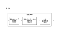
本発明の他の一様相は、縮小された変換(Reduced transform)に基づいて、ビデオ信号をデコードする装置において、現在のブロックに変換スキップ(transform skip)が適用されるかどうかを確認する変換スキップ確認部と、前記現在のブロックに前記変換スキップが適用されない場合、前記ビデオ信号から前記現在のブロックの変換カーネル(transform kernel)を指示する変換インデックス(transform index)を獲得する変換インデックス獲得部と、前記変換インデックスによって指示される変換カーネル及び前記現在のブロックのサイズに基づいて、前記現在のブロックに一次変換(primary transform)が適用される領域を決定し、前記一次変換が適用される領域に対して、前記変換インデックスによって指示される変換カーネルを用いて、逆方向一次変換(inverse primary transform)を実行する一次逆変換部を含むことができる。 Another aspect of the invention is a transform skip method for determining whether a transform skip is applied to a current block in an apparatus for decoding a video signal based on a reduced transform. a validator and a transform index acquirer for acquiring a transform index indicating a transform kernel of the current block from the video signal if the transform skip is not applied to the current block; determining a region in which a primary transform is applied to the current block based on a transform kernel indicated by the transform index and a size of the current block; and a primary inverse transform unit that performs an inverse primary transform using the transform kernels indicated by the transform indices.
好ましくは、前記一次変換部は、前記現在のブロック内において、前記一次変換が適用される領域以外の残りの領域の係数を0とみなすことができる。 Preferably, the primary transform unit may consider coefficients of remaining regions other than the region to which the primary transform is applied to be zero within the current block.
好ましくは、前記一次変換部は、前記変換インデックスによって指示される変換カーネルが予め定義された変換であり、前記現在のブロックの幅(width)、及び/または高さ(height)が予め定義されたサイズより大きい場合、前記予め定義されたサイズの幅及び/または高さを有する領域を前記一次変換が適用される領域に決定することができる。 Preferably, the primary transform unit is a transform whose transform kernel indicated by the transform index is predefined, and the width and/or height of the current block is predefined. If larger than the size, a region having a width and/or height of the predefined size can be determined as the region to which the primary transformation is applied.
好ましくは、前記予め定義された変換は、DST7及び/またはDCT8の組み合わせで構成された複数の変換の組み合わせの内、いずれか1つで有り得る。 Preferably, said predefined transform can be any one of a combination of multiple transforms comprising a combination of DST7 and/or DCT8.
好ましくは、前記予め定義されたサイズは、16で有り得る。 Preferably, said predefined size may be sixteen.
好ましくは、 前記一次変換部は、前記変換インデックスによって指示される変換カーネルが第1変換グループに属する場合、前記現在のブロックの幅(width)及び32の内、小さい方の値を前記一次変換が適用される領域の幅と決定し、前記現在のブロックの高さ(height)及び32の内、小さい方の値を前記一次変換が適用される領域の高さと決定し、前記変換インデックスによって指示される変換カーネルが第2変換グループに属する場合、前記現在のブロックの幅及び16の内、小さな値を前記一次変換が適用される領域の幅と決定し、前記現在のブロックの高さ及び16の内、小さな値を前記一次変換が適用される領域の高さと決定することができる。 Preferably, when the transform kernel indicated by the transform index belongs to the first transform group, the primary transform unit converts the width of the current block and 32, whichever is smaller, into the primary transform. Determine the width of the region to be applied, and determine the height of the region to which the primary transform is applied, the smaller of the height of the current block and 32, indicated by the transform index. If the transform kernel belongs to the second transform group, the width of the current block and 16 is determined as the width of the region to which the primary transform is applied, and the width of the current block and 16 is determined as the smaller value Among them, the smaller value can be determined as the height of the region to which the primary transform is applied.
好ましくは、前記第1変換グループは、DCT2を含み、前記第2変換グループはDST7及び/またはDCT8の組み合わせで構成された複数の変換の組み合わせを含むことができる。 Preferably, the first transform group includes DCT2, and the second transform group may include a combination of multiple transforms composed of a combination of DST7 and/or DCT8.
本発明の実施形態に係ると、特定の条件に応じて、予め定義された領域にのみ変換を実行することで、複雑度を著しく減少させることができる。 According to embodiments of the present invention, complexity can be significantly reduced by performing transformations only on predefined regions depending on certain conditions.
本発明で得られる効果は、以上で言及した効果に制限されず、言及また異なる効果は以下の記載から、本発明が属する技術分野で通常の知識を有する者に明確に理解される。 The effects obtained by the present invention are not limited to the effects mentioned above, and the mentioned and different effects will be clearly understood by those having ordinary knowledge in the technical field to which the present invention belongs from the following description.
以下、添付された図面を参照して、本発明の実施形態の構成とその作用を説明し、図面によって説明される本発明の構成と作用は、一つの実施形態として説明されるものであり、これによって、本発明の技術的思想とその核心構成及び作用が制限されることはない。 Hereinafter, the configuration and operation of the embodiments of the present invention will be described with reference to the attached drawings. The technical idea of the present invention and its core configuration and operation are not limited by this.
さらに、本発明で使用される用語は、できる限り、現在広く使用される一般的な用語を選択したが、特定の場合には、出願人が任意に選定した用語を使用して説明する。そのような場合には、該当部分の詳細な説明で、その意味を明確に記載するため、本発明の説明で使用された用語の名称のみで単純に解釈されてはならないものであり、その対応する用語の意味まで把握して解釈されるべきであることを明らかにしておく。 Furthermore, the terms used in the present invention have been selected to be general terms that are currently widely used as much as possible, but in specific cases, terms arbitrarily selected by the applicant will be used for explanation. In such cases, the detailed description of the relevant part should not be construed simply by the names of the terms used in the description of the invention in order to clearly state their meaning, and the corresponding It should be clarified that it should be interpreted by grasping the meaning of the term used.
また、本発明で使用される用語は、発明を説明するために選択された一般的な用語であるが、同様の意味を有する他の用語がある場合、より適切な解釈のために代替可能である。例えば、信号、データ、サンプル、ピクチャ、フレーム、ブロックなどの場合、各コーディングの過程で適切に代替されて解釈されることができる。また、パーティショニング(partitioning)、分解(decomposition)、スプリーツ加工(splitting)及び分割(division)などの場合にも、各コーディングの過程で適切に代替されて解釈されることができる。 Also, the terms used in the present invention are general terms selected to describe the invention, but if there are other terms with similar meanings, they may be substituted for a more appropriate interpretation. be. For example, signals, data, samples, pictures, frames, blocks, etc. can be appropriately replaced and interpreted during each coding process. In addition, partitioning, decomposition, splitting, division, etc. can be appropriately substituted and interpreted in each coding process.
本文書でMTS(Multiple Transform Selection、以下「MTS」と称する)とは、少なくとも2つ以上の変換タイプを用いて変換を実行する方法を意味することができる。これはAMT(Adaptive Multiple Transform)またはEMT(Explicit Multiple Transform)にも表現することができ、同様に、Mts_idx もAMT_idx、EMT_idx、tu_Mts_idx 、AMT_TU_idx、EMT_TU_idx、変換インデックスまたは変換の組み合わせのインデックスなどのように表現することができ、本発明は、このような表現に限定されない。 In this document, MTS (Multiple Transform Selection, hereinafter referred to as 'MTS') can mean a method of performing a transform using at least two or more transform types. This can also be expressed in AMT (Adaptive Multiple Transform) or EMT (Explicit Multiple Transform), and similarly Mts_idx can be expressed as AMT_idx, EMT_idx, tu_Mts_idx, AMT_TU_idx, EMT_TU_idx, transform index or transform combination index, etc. representation, and the invention is not limited to such representation.
図1は、本発明が適用される実施形態として、ビデオ信号のエンコーディングが行われるエンコーダの概略的なブロック図を示す。 FIG. 1 shows a schematic block diagram of an encoder in which a video signal is encoded, as an embodiment to which the invention is applied.
図1を参照すると、エンコーダ100は、映像分割部110、変換部120、量子化部130、逆量子化部140、逆変換部150、フィルタリング部160、復号ピクチャバッファ(DPB:Decoded Picture Buffer)170、インター予測部180、イントラ予測部185及びエントロピーエンコーディング部190を含みから構成されることができる。
Referring to FIG. 1 , the encoder 100 includes a
映像分割部110は、エンコーダ100に入力された入力画像(Input image)(または、ピクチャ、フレーム)を1つ以上の処理ユニットに分割することができる。例えば、前記処理ユニットは、コーディングツリーユニット(CTU:Coding Tree Unit)、コーディングユニット(CU:Coding Unit)、予測ユニット(PU:Prediction Unit)または変換ユニット(TU:Transform Unit)で有り得る。
The video dividing
ただし、前記用語は、本発明の説明の便宜のために用いるだけであり、本発明は、当該用語の定義に限定されない。また、本明細書においては、説明の便宜のために、ビデオ信号をエンコードまたはデコードする過程で用いられる単位としてコーディングユニットという用語を使用するが、本発明は、それに限定されず発明の内容に応じて適切に解釈可能である。 However, the terms are used only for the convenience of describing the present invention, and the present invention is not limited to the definitions of the terms. Also, in the present specification, for convenience of explanation, the term "coding unit" is used as a unit used in the process of encoding or decoding a video signal, but the present invention is not limited thereto and may be used according to the contents of the present invention. can be properly interpreted by
エンコーダ100は、入力映像信号からインター予測部180またはイントラ予測部185から出力された予測信号(prediction signal)を減算して残りの信号(residual signal)を生成することができ、生成された残りの信号は、変換部120に転送される。
The encoder 100 may generate a residual signal by subtracting a prediction signal output from the inter prediction unit 180 or the
変換部120は、残りの信号に変換手法を適用して変換係数(transform coefficient)を生成することができる。変換プロセスは、クワッドツリー(quadtree)構造の正方形ブロック、バイナリツリー(binarytree)構造、三進ツリー(ternary)構造または非対称ツリー(asymmetric)構造によって分割されたブロック(正方形または長方形)に適用することができる。
A
前記変換部120は、複数個の変換(または変換の組み合わせ)に基づいて変換を実行することができ、このような変換方式をMTS(Multiple Transform Selection)と呼ぶことができる。前記MTSはAMT(Adaptive Multiple Transform)またはEMT(Enhanced Multiple Transform)と呼ぶこともできる。
The
前記(MTSまたはAMT、EMT)は、複数個の変換(または変換の組み合わせ)から適応的に選択される変換(または変換の組み合わせ)に基づいて実行される変換方式を意味することができる。 The (MTS or AMT, EMT) may refer to a transform scheme performed based on a transform (or combination of transforms) adaptively selected from a plurality of transforms (or combination of transforms).
前記複数個の変換(または変換の組み合わせ)は、本明細書の図6で説明する変換(または変換の組み合わせ)を含むことができる。本明細書において、前記の変換または変換タイプは、例えば、DCT-Type 2、DCT-II、DCT2、DCT2のように表記することができる。
The plurality of transforms (or combination of transforms) can include the transforms (or combination of transforms) described in FIG. 6 herein. In this specification, the transforms or transform types can be denoted as DCT-
前記変換部120は次の実施形態を実行することができる。
The
本発明は、4x4ブロックに適用することができるRSTの設計方法を提供する。 The present invention provides a RST design method that can be applied to 4x4 blocks.
本発明は、4x4 RSTを適用する領域の構成、4x4 RST適用後生成された変換係数の配置方法、配置された変換係数のスキャン順、ブロックごとに生成された変換係数を整列して合わせる方法などを提供する。 The present invention provides a configuration of a region to which 4x4 RST is applied, a method of arranging transform coefficients generated after applying 4x4 RST, a scan order of the arranged transform coefficients, a method of aligning and aligning transform coefficients generated for each block, and the like. I will provide a.
本発明は、4x4 RSTを指定する変換インデックスをコーディングする方法を提供する。 The present invention provides a method of coding transform indices that specify a 4x4 RST.
本発明は、4x4 RSTを適用したとき許容されない領域に0でない変換係数が存在することを確認して対応する変換インデックスを条件付きでコーディングする方法を提供する。 The present invention provides a method to conditionally code the corresponding transform indices by checking for the presence of non-zero transform coefficients in regions that are not allowed when 4x4 RST is applied.
本発明は、最後の0でない変換係数の位置をコーディングした後に、その変換インデックスを条件付きでコーディングした後、許容されない位置に対しては、関連するレジデュアルコーディングを省略する方法を提供する。 After coding the position of the last non-zero transform coefficient and then conditionally coding its transform index, the present invention provides a method that omits the associated residual coding for disallowed positions.
本発明は、4x4 RST適用時ルマブロックとクロマブロックに別々異なる変換インデックスのコーディングとレジデュアルコーディングを適用する方法を提供する。 The present invention provides a method of applying different transform index coding and residual coding to luma blocks and chroma blocks when 4x4 RST is applied.
これに対する具体的な実施形態は、本明細書でさらに詳細に説明する。 Specific embodiments for this are described in further detail herein.
量子化部130は、変換係数を量子化してエントロピーエンコーディング部190に転送し、エントロピーエンコーディング部190は、量子化された信号(quantized signal)をエントロピーコーディングしてビットストリームに出力することができる。
The
前記変換部120と、前記量子化部130は、別個の機能ユニットで説明されるが、本発明はこれに限定されず、一つの機能ユニットに結合することができる。前記逆量子化部140と、前記逆変換部150の場合にも、同様に一つの機能ユニットに結合することができる。
Although the
量子化部130から出力された量子化された信号(quantized signal)は、予測信号を生成するために用いることができる。例えば、量子化された信号(quantized signal)は、ループ内の逆量子化部140及び逆変換部150を介して逆量子化及び逆変換を適用することにより、残りの信号を復元することができる。復元された残りの信号をインター予測部180またはイントラ予測部185から出力された予測信号(prediction signal)に加えることで復元信号(reconstructed signal)が生成されることができる。
A quantized signal output from the
一方、前記のような圧縮過程で発生した量子化エラーによってブロック境界が見える劣化が発生することができる。このような現象をブロッキング劣化(blocking artifacts)と呼ばれ、これは画質を評価する重要な要素の一つです。このような劣化を低減するためにフィルタ過程を行うことができる。このようなフィルタ処理を介してブロッキング劣化を除去するとともに、現在ピクチャの誤差を減らすことによって、画質を向上させることになる。 On the other hand, a quantization error generated in the compression process as described above may cause deterioration in which block boundaries are visible. Such a phenomenon is called blocking artifacts, and it is one of the important factors for evaluating image quality. A filtering process can be performed to reduce such degradation. Through such filtering, the blocking degradation is removed and the error of the current picture is reduced, thereby improving the image quality.
フィルタリング部160は、復元信号にフィルタリングを適用して、これを再生装置に出力したり、復号ピクチャバッファ170に転送する。復号ピクチャバッファ170に転送されたフィルタリングされた信号は、インター予測部180から参照ピクチャとして用いられる。このように、フィルタリングされたピクチャを画面間予測モードで参照ピクチャとして用いることにより、画質だけでなく、符号化]効率も向上させることができる。
The
復号ピクチャバッファ170は、フィルタ処理されたピクチャをインター予測部180からの参照ピクチャとして使用するために格納することができる。
インター予測部180は、復元ピクチャ(reconstructed picture)を参照して、時間的重複性及び/または空間的重複性を除去するために時間的予測、及び/または空間的予測を行う。ここで、予測を実行するために用いる参照ピクチャは、以前の時間に符号化/復号化時のブロック単位で量子化と逆量子化を経て変換された信号であるので、ブロッキングアーティファクト(blocking artifact)やリンギングアーティファクト(ringing artifact)が存在することができる。 The inter prediction unit 180 performs temporal prediction and/or spatial prediction to remove temporal redundancy and/or spatial redundancy with reference to a reconstructed picture. Here, the reference picture used to perform prediction is a signal that has been transformed through quantization and inverse quantization on a block-by-block basis during encoding/decoding in the previous time. and ringing artifacts can be present.
したがって、インター予測部180は、このような信号の不連続や量子化による性能低下を解決するために、ローパスフィルタ(lowpass filter)を適用することにより、ピクセル間の信号をサブピクセル単位で補間することができる。ここで、サブピクセルは、補間フィルタを適用して生成された仮想のピクセルを意味し、整数ピクセルは、復元されたピクチャに存在する実際のピクセルを意味する。補間方法としては、線形補間、バイリニア補間(bi-linear interpolation)、ウィーナーフィルタ(wiener filter)などが適用されることができる。 Therefore, the inter prediction unit 180 interpolates the signal between pixels on a sub-pixel basis by applying a low-pass filter in order to solve the performance degradation due to such signal discontinuity and quantization. be able to. Here, sub-pixels refer to virtual pixels generated by applying an interpolation filter, and integer pixels refer to actual pixels existing in the reconstructed picture. As an interpolation method, linear interpolation, bi-linear interpolation, wiener filter, etc. can be applied.
補間フィルタは、復元ピクチャ(reconstructed picture)に適用され、予測の精密度を向上させることができる。例えば、インター予測部180は、整数ピクセルに補間フィルタを適用して補間ピクセルを生成し、補間ピクセル(interpolated pixels)で構成された補間ブロック(interpolated block)を予測ブロック(prediction block)として使用して予測を行うことができる。 Interpolation filters can be applied to reconstructed pictures to improve prediction accuracy. For example, the inter prediction unit 180 applies an interpolation filter to integer pixels to generate interpolation pixels, and uses an interpolation block formed of the interpolation pixels as a prediction block. Predictions can be made.
一方、イントラ予測部185は、現在符号化を進行しようとするブロックの周辺にあるサンプルを参照して、現在のブロックを予測することができる。前記イントラ予測部185は、イントラ予測を実行するために、次のような過程を実行することができる。まず、予測信号を生成するために必要な参照サンプルを準備することができる。そして、準備されたサンプルを用いて予測信号を生成することができる。以後、予測モードを符号化することになる。このとき、参照サンプルは、参照サンプルパディング及び/または参照サンプルのフィルタリングを介して準備することができる。参照サンプルは、予測及び復元過程を経たため、量子化誤差が存在することができる。したがって、このようなエラーを減らすためにイントラ予測に用いられる各予測モードに対して参照サンプルのフィルタリング過程が実行されることができる。
Meanwhile, the
前記インター予測部180または前記イントラ予測部185を介して生成された予測信号(prediction signal)は、復元信号を生成するために用いられるか、または残りの信号を生成するために用いられる。
A prediction signal generated by the inter predictor 180 or the
図2は、本発明が適用される実施形態として、ビデオ信号のデコードが行われるデコーダの概略的なブロック図を示す。 FIG. 2 shows a schematic block diagram of a decoder in which a video signal is decoded, as an embodiment to which the invention is applied.
図2を参照すると、デコーダ200は、解析部(図示せず)、エントロピーデコード部210、逆量子化部220、逆変換部230、フィルタリング部240、復号ピクチャバッファ(DPB: Decoded Picture Buffer Unit)250、インター予測部260及びイントラ予測部265を含んで構成されることができる。
Referring to FIG. 2, the decoder 200 includes an analysis unit (not shown), an
そして、デコーダ200を介して出力された復元映像信号(reconstructed video signal)は、再生装置を介して再生することができる。 Then, the reconstructed video signal output via the decoder 200 can be played back via a playback device.
デコーダ200は、図1のエンコーダ100から出力された信号を受信することができ、受信された信号は、エントロピーデコード部210を介して、エントロピーデコードすることができる。
The decoder 200 can receive the signal output from the encoder 100 of FIG. 1 and entropy-decode the received signal through the
逆量子化部220においては、量子化ステップサイズ情報を用いて、エントロピーデコードされた信号から変換係数(transform coefficient)を獲得する。
The
逆変換部230においては、変換係数を逆変換して残りの信号(residual signal)を獲得することになる。
The
ここで、本発明は、予測モード、ブロックサイズまたはブロック状(block shape)の内、少なくとも1つによって区分される変換設定のグループ(transform configuration group)別に変換の組み合わせ(transform combination)を構成する方法を提供し、前記逆変換部230は、本発明によって構成された変換の組み合わせに基づいて逆変換を行うことができる。また、本明細書で説明した実施形態が適用されることができる。
Here, the present invention is a method of configuring a transform combination for each transform configuration group classified by at least one of prediction mode, block size or block shape. and the
前記逆変換部230は次の実施形態を実行することができる。
The
本発明は、縮小された2次変換に基づいて、ビデオ信号を復元する方法を提供する。 The present invention provides a method for reconstructing a video signal based on a reduced quadratic transform.
前記逆変換部230は、2次変換インデックスに対応する2次変換(secondary transform)を誘導し、前記2次変換を用いて、変換係数のブロックに対して逆方向2次変換を実行し、前記逆方向2次変換が行われたブロックの逆方向1次変換を実行することができる。ここで、前記2次変換は、縮小された2次変換を意味し、前記縮小された2次変換は、N個のレジデュアルデータ(Nx1レジデュアルベクトル)が入力されてL個(L <N)の変換係数データ(Lx1変換係数ベクトル)が出力される変換を示す。
The
本発明において、前記縮小された2次変換は、前記現在のブロックの特定領域に適用され、前記特定領域は、前記現在のブロック内の左上側MxM(M≦N)領域であることを特徴とする。 In the present invention, the reduced quadratic transform is applied to a specific region of the current block, and the specific region is an upper left M×M (M≦N) region within the current block. do.
本発明において、前記逆方向2次変換が実行されるとき、前記現在のブロック内の分割された4x4ブロックのそれぞれについて、4x4縮小された2次変換が適用されることを特徴とする。 In the present invention, when the inverse quadratic transform is performed, a 4x4 downscaled quadratic transform is applied to each of the divided 4x4 blocks in the current block.
本発明において、前記2次変換インデックスを獲得するかどうかは、前記変換係数ブロック内の最後の0でない変換係数の位置に基づいて決定されることを特徴とする。 In the present invention, whether to obtain the secondary transform index is determined based on the position of the last non-zero transform coefficient in the transform coefficient block.
本発明において、前記最後の0でない変換係数が、特定領域に位置しない場合に前記2次変換インデックスは獲得され、前記特定領域は、前記縮小された2次変換が適用される場合、スキャン順序によって変換係数を配置したとき、0でない変換係数が存在することができる位置を除外した残りの領域を表すことを特徴とする。 In the present invention, the secondary transform index is obtained when the last non-zero transform coefficient is not located in a specific region, and the specific region is determined according to the scan order when the reduced secondary transform is applied. It is characterized by representing the remaining area excluding the positions where non-zero transform coefficients can exist when the transform coefficients are arranged.
前記逆変換部230は、1次変換インデックスに対応する変換の組み合わせを誘導し、前記変換の組み合わせを用いて、逆方向1次変換を実行することができる。ここで前記1次変換インデックスは、DST7及び/またはDCT8の組み合わせで構成された複数個の変換の組み合わせの内、いずれか1つに対応し、前記変換の組み合わせは、水平変換及び垂直変換で構成される。この時、前記水平変換及び前記垂直変換は、前記DST7または前記DCT8の内、いずれかに1つに対応する。
The
前記逆量子化部220と、前記逆変換部230は、別個の機能ユニットで説明されるが、本発明はこれに限定されず、一つの機能ユニットとして結合することができる。
Although the
獲得された残りの信号をインター予測部260またはイントラ予測部265から出力された予測信号(prediction signal)に加えることで復元信号(reconstructed signal)が生成される。 A reconstructed signal is generated by adding the obtained remaining signal to the prediction signal output from the inter prediction unit 260 or the intra prediction unit 265 .
フィルタリング部240は、復元信号(reconstructed signal)にフィルタリングを適用して、これを再生装置に出力したり、復号ピクチャバッファ部250に転送する。復号ピクチャバッファ部250に転送され、フィルタリングされた信号は、インター予測部260から参照ピクチャとして用いられる。 The filtering unit 240 applies filtering to the reconstructed signal and outputs it to the reproducing device or transfers it to the decoded picture buffer unit 250 . The signal transferred to the decoded picture buffer unit 250 and filtered is used by the inter prediction unit 260 as a reference picture.
本明細書において、エンコーダ100の変換部120及び各機能ユニットで説明された実施形態は、それぞれデコーダの逆変換部230及び対応する機能ユニットにも同様に適用することができる。
Embodiments described herein for the
図3は、本発明が適用されることができる実施形態として、図3Aは、QT(QuadTree、以下「QT」とする)、図3Bは、BT(Binary Tree、以下「BT」という)、図3Cは、TT(Ternary Tree、以下「TT」という)図3DはAT(Asymmetric Tree、以下「AT」という)によるブロック分割構造を説明するための図である。 FIG. 3 is an embodiment to which the present invention can be applied. FIG. 3A is a QT (QuadTree, hereinafter referred to as "QT"), FIG. 3C is a diagram for explaining a block division structure by TT (Ternary Tree, hereinafter referred to as "TT") and FIG. 3D is AT (Asymmetric Tree, hereinafter referred to as "AT").
ビデオコーディングの1つのブロックは、QT(QuadTree)に基づいて分割されることができる。また、QTによって分割された一つのサブブロック(sub block)は、QTを使用して再帰的にさらに分割されることができる。もはやQT分割されないリーフブロック(leaf block)は、BT(Binary Tree)、TT(Ternary Tree)またはAT(Asymmetric Tree)の内、少なくとも一つの方式によって分割されることができる。 BTはhorizontal BT(2NxN、2NxN)とvertical BT(Nx2N、Nx2N)の二つの形態の分割を有することができる。 TTはhorizontal TT(2Nx1/2N、2NxN、2Nx1/2N)とvertical TT(1/2Nx2N、Nx2N、1/2Nx2N)の二つの形態の分割を有することができる。 ATはhorizontal-up AT(2Nx1/2N、2Nx3/2N)、horizontal-down AT(2Nx3/ 2N、2Nx1/2N)、vertical-left AT(1/2Nx2N、3/2Nx2N)、vertical-right AT(3/2Nx2N、1/2Nx2N)の四つの形態の分割を有することができる。それぞれのBT、TT、ATはBT、TT、ATを使用して再帰的にさらに分割されることができる。 A block of video coding can be divided based on QT (QuadTree). Also, one sub block divided by QT can be recursively further divided using QT. A leaf block that is no longer QT-partitioned can be partitioned by at least one of BT (Binary Tree), TT (Ternary Tree), and AT (Asymmetric Tree). BT can have two forms of partitioning: horizontal BT (2NxN, 2NxN) and vertical BT (Nx2N, Nx2N). TT can have two forms of division, horizontal TT (2Nx1/2N, 2NxN, 2Nx1/2N) and vertical TT (1/2Nx2N, Nx2N, 1/2Nx2N). AT is horizontal-up AT (2Nx1/2N, 2Nx3/2N), horizontal-down AT (2Nx3/2N, 2Nx1/2N), vertical-left AT (1/2Nx2N, 3/2Nx2N), vertical-right AT (3 /2Nx2N, 1/2Nx2N). Each BT, TT, AT can be recursively subdivided using BT, TT, AT.
前記図3Aは、QT分割の例を示す。ブロックAは、QTによって4つのサブブロック(A0、A1、A2、A3)に分割されることができる。サブブロックA1は、再びQTによって4つのサブブロック(B0、B1、B2、B3)に分割されることができる。 FIG. 3A above shows an example of a QT split. Block A can be divided into four sub-blocks (A0, A1, A2, A3) by QT. Sub-block A1 can again be divided into four sub-blocks (B0, B1, B2, B3) by QT.
前記図3Bは、BT分割の例を示す。 QTによってもはや分割されないブロックB3は、vertical BT(C0、C1)またはhorizontal BT(D0、D1)に分割されることができる。ブロックC0のように、それぞれのサブブロックは、horizontal BT(E0、E1)またはvertical BT(F0、F1)の形態のように再帰的にさらに分割されることができる。 FIG. 3B shows an example of BT partitioning. Block B3, which is no longer split by QT, can be split into vertical BT (C0, C1) or horizontal BT (D0, D1). Like block C0, each sub-block can be recursively further divided in the form of horizontal BT (E0, E1) or vertical BT (F0, F1).
前記3Cは TT分割の例を示す。QTによってもはや分割されないブロックB3は、vertical TT(C0、C1、C2)またはhorizontal TT(D0、D1、D2)に分割されることができる。ブロックC1のように、それぞれのサブブロックは、horizontal TT(E0、E1、E2)またはvertical TT(F0、F1、F2)の形態のように再帰的にさらに分割されることができる。 3C above shows an example of TT partitioning. Block B3, which is no longer split by QT, can be split into vertical TTs (C0, C1, C2) or horizontal TTs (D0, D1, D2). Like block C1, each sub-block can be recursively subdivided in the form of horizontal TT (E0, E1, E2) or vertical TT (F0, F1, F2).
前記3DはAT分割の例を示す。QTによってもはや分割されないブロックB3は、vertical AT(C0、C1)またはhorizontal AT(D0、D1)に分割されることができる。ブロックC1のように、それぞれのサブブロックは、horizontal AT(E0、E1)またはvertical TT(F0、F1)の形態のように再帰的にさらに分割されることができる。 The 3D shows an example of AT segmentation. Block B3, which is no longer split by QT, can be split into vertical ATs (C0, C1) or horizontal ATs (D0, D1). Like block C1, each sub-block can be recursively subdivided in the form of horizontal AT (E0, E1) or vertical TT (F0, F1).
一方、BT、TT、AT分割は一緒に使用して分割が可能である。たとえば、BTによって分割されたサブブロックは、TTまたはATによる分割が可能である。また、TTによって分割されたサブブロックは、BTまたはATによる分割が可能である。ATによって分割されたサブブロックは、BTまたはTTによる分割が可能である。たとえば、horizontal BT分割以後、それぞれのサブブロックがvertical BTに分割されることができ、またはvertical BT分割以後、それぞれのサブブロックがhorizontal BTに分割されることもできる。前記二種類の分割方法は、分割手順は異なるが、最終的に分割される形は同じである。 On the other hand, BT, TT, and AT divisions can be used together for division. For example, a subblock partitioned by BT can be partitioned by TT or AT. Also, a subblock divided by TT can be divided by BT or AT. A sub-block partitioned by AT can be partitioned by BT or TT. For example, after horizontal BT partitioning, each subblock can be partitioned into vertical BTs, or after vertical BT partitioning, each subblock can be partitioned into horizontal BTs. The two types of division methods have different division procedures, but the final division is the same.
また、ブロックが分割されると、ブロックを探索する順序を多様に定義することができる。一般的に、左側から右側に、上端から下端に探索を行い、ブロックを探索するということは、各分割されたサブブロックの追加的なブロックが分割するかどうかを決定する順序を意味するか、ブロックがもはや分割されない場合、各サブブロックの符号化順序を意味するか、またはサブブロックで他の隣接ブロックの情報を参照するときの探索順序を意味することができる。 In addition, when the blocks are divided, the order of searching the blocks can be variously defined. In general, searching from left to right and from top to bottom, searching a block means the order in which additional blocks of each divided sub-block determine whether to divide, or If the block is no longer divided, it can mean the coding order of each sub-block, or the search order when referring to the information of other adjacent blocks in the sub-block.
図4及び図5は、本発明が適用される実施形態として、図4は、エンコーダ内の変換及び量子化部(120/130)、逆量子化及び逆変換部(140/150)の概略的なブロック図を示し、図5デコーダ内の逆量子化及び逆変換部(220/230)の概略的なブロック図を示す。 4 and 5 are embodiments to which the present invention is applied. FIG. 4 is a schematic diagram of transform and quantization units (120/130) and inverse quantization and inverse transform units (140/150) in the encoder. 5 shows a schematic block diagram of the inverse quantization and inverse transform unit (220/230) in the decoder.
前記図4を注意深く見ると、変換、及び量子化部(120/130)は、1次変換部(primary transform unit)121、2次変換部(secondary transform unit)122及び量子化部130を含むことがことができる。逆量子化及び逆変換部(140/150)は、逆量子化部140、逆方向2次変換部(inverse secondary transform unit)151及び逆1次変換部(inverse primary transform unit)152を含むことがことができる。
4, the transform and quantization unit (120/130) includes a
前記図5を注意深く見ると、逆量子化及び逆変換部(220/230)は、逆量子化部220、逆2次変換部(inverse secondary transform unit)231と逆1次変換部(inverse primary transform unit) 232を含むことができる。
5, the inverse quantization and
本発明において、変換を実行するときに、複数の段階を経て変換を実行することができる。例えば、図4のように、1次変換(primary transform)、2次変換(secondary transform)の2段階を適用することができ、またはアルゴリズムに基づいて、それ以上の変換ステップが用いられる。ここで、前記1次変換(primary transform)は、主要な変換(core transform)と呼ぶこともできる。 In the present invention, when performing a transformation, the transformation can be performed in multiple stages. For example, two stages can be applied, a primary transform, a secondary transform, as in FIG. 4, or more transform steps are used, depending on the algorithm. Here, the primary transform can also be called the core transform.
前記1次変換部(primary transform unit121は、残りの信号に対して1次変換(primary transform)を適用することができ、ここで前記1次変換(primary transform)は、エンコーダ及び/またはデコーダでテーブルに予め定義することができる。
The
前記1次変換(primary transform)の場合、Discrete Cosine Transform type 2(以下、「DCT2」という)が適用されることができる。 For the primary transform, a Discrete Cosine Transform type 2 (hereinafter referred to as 'DCT2') can be applied.
または、特定の場合に限定してDiscrete Sine Transform-type 7(以下、「DST7」という)が適用されることもある。例えば、イントラ予測モードで4x4ブロックに対してDST7が適用されることができる。 Alternatively, Discrete Sine Transform-type 7 (hereinafter referred to as “DST7”) may be applied only in specific cases. For example, DST7 can be applied to 4x4 blocks in intra prediction mode.
また、前記1次変換(primary transform)の場合、MTS(Multiple Transform Selection)の多くの変換(DST 7、DCT 8、DST 1、DCT 5)の組み合わせが適用されることもある。例えば、図6が適用されることがある。
Also, in the case of the primary transform, a combination of multiple transforms (
前記2次変換部(secondary transform unit)122は、1次変換された信号に対して2次変換(secondary transform)を適用することができ、ここで前記2次変換(secondary transform)は、エンコーダ及び/またはデコーダでテーブルに予め定義することができる。
The
一実施形態として、前記2次変換(secondary transform)は、Non-Separable Secondary Transform(以下、「NSST」という)を条件付きで適用することができる。例えば、前記NSSTはイントラ予測ブロックの場合にのみ適用され、予測モードグループごとに適用可能な変換セットを有することができる。 As one embodiment, the secondary transform can conditionally apply a Non-Separable Secondary Transform (hereinafter referred to as "NSST"). For example, the NSST may be applied only for intra-predicted blocks and have an applicable transform set for each prediction mode group.
ここで、前記予測モードグループは、予測方向の対称性に基づいて設定されることができる。例えば、予測モード52と予測モード16は、予測モード34(対角方向)に基づいて対称なので、1つのグループを形成して、同じ変換セット(transform set)が適用されることができる。この時、前記予測モード52の変換を適用するときに入力データをトランスポーズ(transpose)した後に適用し、これは予測モード16と変換セットが同じであるからである。
Here, the prediction mode group can be set based on the symmetry of the prediction direction. For example, prediction mode 52 and
一方、プランナーモード(Planar mode)とDCモード(DC mode)の場合、方向の対称性が存在しないため、それぞれの変換セットを有し、該変換セットは、2つの変換で構成されることができる。残りの方向性モードにたいしては、変換セットごとに3つの変換で構成されることができる。 On the other hand, for Planar mode and DC mode, since there is no directional symmetry, we have a respective set of transforms, which can be composed of two transforms. . For the remaining directional modes, each transform set can consist of three transforms.
他の実施形態として、前記2次変換(secondary transform)の場合、MTS(Multiple Transform Selection)の多くの変換(DST 7、DCT 8、DST 1、DCT 5)の組み合わせが適用されることもできる。例えば、図6が適用されることができる。
As another embodiment, in the case of the secondary transform, a combination of multiple transforms (
他の実施形態として、DST7が2次変換(secondary transform)で適用されることもできる。 Alternatively, DST7 can be applied in a secondary transform.
他の実施形態として、 前記2次変換は、1次変換されたブロック全体に適用されるものではなく左上側(top-left)の特定領域にのみ適用されることができる。例えば、ブロックのサイズが8x8以上の場合は、8x8 NSSTが適用され、8x8未満の場合は、4x4の2次変換が適用されることができる。この際、4x4ブロックに割った後、それぞれ4x4 2次変換が適用されることができる。 In another embodiment, the secondary transform may be applied only to a specific top-left region instead of being applied to the entire block that has undergone the primary transform. For example, if the block size is greater than or equal to 8x8, 8x8 NSST may be applied, and if the block size is less than 8x8, 4x4 quadratic transform may be applied. At this time, after dividing into 4x4 blocks, a 4x4 quadratic transform may be applied to each.
他の実施形態として、4xN/Nx4(N> = 16)である場合にも、4x4の2次変換が適用されることができる。 As another embodiment, a quadratic transform of 4x4 can be applied even in the case of 4xN/Nx4 (N>=16).
前記2次変換(例えば、NSST)、4x4の2次変換と8x8の2次変換については、以下で図12~15及び明細書の内の他の実施形態を介してより詳細に説明する。 The quadratic transforms (eg, NSST), 4x4 quadratic transforms and 8x8 quadratic transforms are described in more detail below through FIGS. 12-15 and other embodiments within the specification.
前記量子化部130は、2次変換された信号に対して量子化を行うことができる。
The
前記逆量子化及び逆変換部(140/150)は、先に説明した過程を逆に実行し、重複する説明は省略する。
The inverse quantization and
図5は、デコーダ内の逆量子化及び逆変換部(220/230)の概略的なブロック図を示す。 FIG. 5 shows a schematic block diagram of the inverse quantization and inverse transform unit (220/230) within the decoder.
前記図5を注意深く見ると、逆量子化及び逆変換部(220/230)は、逆量子化部220、逆2次変換部(inverse secondary transform unit)231及び逆1次変換部(inverse primary transform unit)232を含むことができる。
Looking carefully at FIG. 5, the inverse quantization and inverse transform unit (220/230) includes an
前記逆量子化部220においては、量子化ステップサイズ情報を用いて、エントロピーデコードされた信号から変換係数(transform coefficient)を獲得する。
The
前記逆2次変換部(inverse secondary transform unit)231においては、前記変換係数に対して逆2次変換を実行する。ここで、前記逆2次変換は、前記図4で説明した前記2次変換(secondary transform)の逆変換を示す。
The inverse
他の実施形態として、前記2次変換の場合には、MTS(Multiple Transform Selection)の多くの変換(DST 7、DCT 8、DST 1、DCT 5)の組み合わせが適用されることもできる。例えば、図6が適用されることができる。
As another embodiment, in the case of the secondary transform, a combination of multiple transforms (
前記逆1次変換部(inverse primary transform unit)232は、逆2次変換された信号(またはブロック)について逆1次変換を実行し、残りの信号(residualsignal)を獲得することになる。ここで、前記逆1次変換は、前記図4で説明した前記1次変換(primary transform)の逆変換を示す。 The inverse primary transform unit 232 performs an inverse primary transform on the inverse secondary transformed signal (or block) to obtain a residual signal. Here, the inverse primary transform indicates an inverse transform of the primary transform described in FIG.
一実施形態で、前記1次変換(primary transform)の場合、MTS(Multiple Transform Selection)の多くの変換(DST 7、DCT 8、DST 1、DCT 5)の組み合わせが適用されることもできる。例えば、図6が適用されることができる。
In one embodiment, for the primary transform, a combination of multiple transforms (
本発明の一実施形態として、DST7が1次変換(primary transform)で適用されることもできる。 As an embodiment of the invention, DST7 can also be applied in the primary transform.
本発明の一実施形態として、DCT8が1次変換(primary transform)に適用されることもできる。 As an embodiment of the invention, DCT8 can also be applied to the primary transform.
本発明は、予測モード、ブロックサイズまたはブロック状(block shape)の内、少なくとも1つによって区分される変換設定のグループ(transform configuration group)別に変換の組み合わせ(transform combination)を構成する方法を提供し、前記逆1次変換部(inverse primary transform unit)232は、本発明によって構成された変換の組み合わせに基づいて逆変換を行うことができる。また、本明細書で説明した実施形態が適用されることができる。 The present invention provides a method of configuring transform combinations by transform configuration groups that are partitioned by at least one of prediction mode, block size or block shape. , the inverse primary transform unit 232 is capable of performing an inverse transform based on a combination of transforms constructed according to the present invention. Also, the embodiments described herein can be applied.
図6は、本発明が適用される実施形態として、MTS、(Multiple Transform Selection)が適用される変換設定のグループ(transform configuration group)を示す表である。 FIG. 6 is a table showing a transform configuration group to which MTS (Multiple Transform Selection) is applied as an embodiment to which the present invention is applied.
MTS(Multiple Transform Selection)が適用される変換設定のグループA group of transform settings to which MTS (Multiple Transform Selection) is applied.
本明細書においては、変換設定のグループGiのj番目の変換の組み合わせの候補を次の数式(1)のようなペア(対)で表示する。 In this specification, candidates for the j-th combination of transformations in the group Gi of transformation settings are displayed in pairs as shown in the following formula (1).
[数1]
(H(Gi、j)、V(Gi、j))
[Number 1]
(H(Gi, j), V(Gi, j))
ここで、 H(Gi、j)は、j番目の候補の水平変換(horizontal transform)を指し、V(Gi、j)は、j番目の候補の垂直変換(vertical transform)を指す。例えば、図6でH(G3、2)= DST7、V(G3、2)= DCT8のように表記することができる。文脈に応じてH(Gi、j)またはV(Gi、j)に割り当てられる値は、前記の例示のように変換を区分するための表示上の値(nominal value)で有り得、該変換を指すインデックス値で有り得、該変換の2D行列(2 Dimensional matrix)で有り得る。 where H(Gi,j) refers to the horizontal transform of the jth candidate and V(Gi,j) refers to the vertical transform of the jth candidate. For example, H(G3, 2)=DST7 and V(G3, 2)=DCT8 in FIG. The value assigned to H(Gi,j) or V(Gi,j), depending on the context, can be a nominal value for distinguishing a transform as in the example above and refers to the transform. It can be an index value and can be a 2 Dimensional matrix of the transform.
また、本明細書において、DCTとDSTの2D行列の値を次の数式2~3のように表記することができる。
Also, in this specification, values of 2D matrices of DCT and DST can be expressed as
[数2]
DCT type 2:、DCT type 8:
[Number 2]
DCT type 2:, DCT type 8:
[数3]
DST type 7:、DST type 4:
[Number 3]
DST type 7:, DST type 4:
ここで、DSTまたはDCTであるかどうかは、SまたはCで表し、type数字はローマ数字の形で上添字表記し、下部添字のNはNxN変換であることを示す。また、前記
![]()
![]()
![]()
![]()
前記図6を注意深く見ると、変換設定のグループ(transform configuration group)は、予測モードに基づいて決定され、グループの数は、総6個(G0~G5)で有り得る。そして、G0~G4は、イントラ予測が適用される場合に該当しG5はインター予測によって生成された残差(residual)ブロックに適用される変換の組み合わせ(または変換セット、変換の組み合わせセット)を示す。 Looking carefully at FIG. 6, transform configuration groups are determined based on the prediction mode, and the number of groups can be a total of 6 (G0-G5). G0 to G4 apply when intra prediction is applied, and G5 indicates a transform combination (or transform set, transform combination set) applied to a residual block generated by inter prediction. .
一つの変換の組み合わせは、該2Dブロックの行(row)に適用される水平変換(horizontal transform)(または行変換(rowtransform))と列(column)に適用される垂直変換(vertical transform)(または列変換(column transform))で行うことができる。 One transform combination is a horizontal transform (or rowtransform) applied to the rows of the 2D block and a vertical transform (or can be done with a column transform.
ここで、すべての変換設定のグループは、各4つの変換の組み合わせ候補を有することができる。前記4つの変換の組み合わせ候補は0~3の変換の組み合わせのインデックスを介して選択または決定することができ、エンコーダからデコーダに前記変換の組み合わせのインデックスをエンコードして転送することができる。 Here, all conversion setting groups can each have four conversion combination candidates. The four transform combination candidates can be selected or determined via a transform combination index from 0 to 3, and the transform combination index can be encoded and transferred from the encoder to the decoder.
一実施形態として、イントラ予測を介して獲得された残差データ(または残差信号)は、イントラ予測モードに応じて、その統計的特性がそれぞれ異なることができる。したがって、前記図6に示すように、イントラ予測モードごとに、一般的なコサイン変換ではなく、別の変換を適用することができる。 As one embodiment, residual data (or residual signals) obtained through intra prediction may have different statistical characteristics according to intra prediction modes. Therefore, as shown in FIG. 6, different transforms can be applied for each intra-prediction mode instead of the general cosine transform.
前記図6を注意深く見ると、35個のイントラ予測モードを用いる場合と67個のイントラ予測モードを用いる場合を示す。各イントラ予測モードの列で区分された変換設定グループごとに複数個の変換の組み合わせが適用されることができる。例えば、前記複数個の変換の組み合わせは、4つの(行方向の変換、列方向変換)組み合わせで構成されることができる。具体例として、グループ0では、行(水平)方向と列(垂直)方向の全てDST-7とDCT-5が適用されることができ、総4つの組み合わせが可能である。
A careful look at FIG. 6 shows a case of using 35 intra prediction modes and a case of using 67 intra prediction modes. A combination of multiple transforms can be applied to each transform setting group divided by columns of each intra prediction mode. For example, the combination of multiple transforms can consist of four (row-wise transform, column-wise transform) combinations. As a specific example, in
各イントラ予測モードに対して、総4つの変換カーネルの組み合わせが適用されることがあるので、それらの内、いずれか1つを選択するための変換の組み合わせのインデックスが変換ユニット(transform unit)ごとに転送されることができる。本明細書において、前記変換の組み合わせのインデックスは、MTSインデックス(MTS index)と呼ぶことができ、Mts_idx で表現されることができる。 For each intra-prediction mode, a total of four transform kernel combinations may be applied, so the transform combination index for selecting any one of them is per transform unit. can be transferred to In this specification, the transform combination index may be referred to as an MTS index and represented by Mts_idx.
また、前記図6に提示した変換カーネル以外にも、残差信号(residual signal)の特性上、行方向と列方向全てに対してDCT2が最適な場合が発生することができる。したがって、コーディングユニット(Coding Unit)毎にMTSフラグを定義することにより、適応的に変換を実行することができる。ここで、MTSフラグが0であれば、行方向と列方向の全てに対してDCT2を適用し、MTSフラグが1であれば、MTSインデックスを介して、4つの組み合わせの内、いずれか1つを選択または決定することができる。 Also, in addition to the transform kernel shown in FIG. 6, DCT2 may be optimal for both the row and column directions due to the characteristics of the residual signal. Therefore, by defining the MTS flag for each Coding Unit, adaptive conversion can be performed. Here, if the MTS flag is 0, DCT2 is applied to all rows and columns, and if the MTS flag is 1, one of four combinations is selected via the MTS index. can be selected or determined.
一実施形態として、MTSフラグが1である場合、1つの変換ユニットに対して0ではない変換係数の数がしきい値より大きくなければ、前記図6の変換カーネルを適用せずに行方向と列方向の全てにDST- 7を適用することができる。例えば、前記しきい値は2で設定されることができ、これはブロックサイズまたは変換ユニットのサイズに基づいて、異なるように設定することができる。これは明細書の他の実施形態でおいても適用可能である。 As an embodiment, when the MTS flag is 1, if the number of non-zero transform coefficients for one transform unit is not greater than a threshold, the transform kernel of FIG. DST-7 can be applied to all columns. For example, the threshold may be set at 2, which may be set differently based on block size or transform unit size. This is also applicable in other embodiments of the specification.
一実施形態として、変換係数の値を先に解析して、0でない変換係数の数がしきい値より大きくなければ、MTS、インデックスを解析せずにDST-7を適用することにより、付加情報転送量を削減することができる。 In one embodiment, the values of the transform coefficients are first analyzed, and if the number of non-zero transform coefficients is not greater than a threshold, the additional information is obtained by applying DST-7 without analyzing the MTS and index. Transfer volume can be reduced.
一実施形態として、MTSフラグが1である場合、1つの変換ユニットに対して0ではない変換係数の数がしきい値より大きいとMTSインデックスを解析して、MTSインデックスに基づいて、水平変換と垂直変換を決定することができる。 In one embodiment, when the MTS flag is 1, the MTS index is analyzed when the number of non-zero transform coefficients for one transform unit is greater than a threshold, and the horizontal transform and the horizontal transform are performed based on the MTS index. A vertical transformation can be determined.
一実施形態として、MTSは変換ユニットの幅と高さが全て32以下の場合にのみ、適用することができる。 As an embodiment, MTS can only be applied when the width and height of the transform unit are all 32 or less.
一実施形態として、前記図6は、オフライントレーニング(off-line training)を介して既設定されることができる。 As an embodiment, FIG. 6 can be preset through off-line training.
一実施形態として、前記MTSインデックスは、水平変換と垂直変換の組み合わせを同時に指すことができる1つのインデックスとして定義することができる。または、前記MTSインデックスは、水平変換のインデックスと垂直変換インデックスを別々に定義することもできる。 As one embodiment, the MTS index can be defined as one index that can simultaneously point to a combination of horizontal and vertical transforms. Alternatively, the MTS index may define a horizontal transform index and a vertical transform index separately.
一実施形態として、前記MTSフラグまたは前記MTSインデックスは、シーケンス、ピクチャ、スライス、ブロック、コーディングユニット、変換ユニット、または予測ユニットの内、少なくとも一つのレベルで定義することができる。例えば、前記MTSフラグまたは前記MTSインデックスはSPS(Sequence Parameter Set)、コーディングユニットまたは変換ユニットの内、少なくとも一つのレベルで定義することができる。また、一例として、MTSのenable / disableのための構文フラグはSPS(Sequence Parameter Set)、PPS(Picture parameter set)またはスライスヘッダ(slice header)の内、少なくとも一つのレベルで定義することができる。 In one embodiment, the MTS flag or the MTS index may be defined at at least one level of sequence, picture, slice, block, coding unit, transform unit, or prediction unit. For example, the MTS flag or the MTS index can be defined at at least one level of an SPS (Sequence Parameter Set), a coding unit, or a transform unit. Also, as an example, a syntax flag for enable/disable of MTS can be defined at least one level among SPS (Sequence Parameter Set), PPS (Picture Parameter Set), or slice header.
他の実施形態として、変換インデックスに対応する変換の組み合わせ(水平変換、垂直変換)は、MTSフラグ、予測モード及び/またはブロックの形とに依存せず構成することができる。例えば、前記の変換の組み合わせは、DCT2、DST7及び/またはDCT8の内、少なくとも一つで構成されることができる。具体例として、変換インデックスが0、1、2、3、4であれば、それぞれ前記変換の組み合わせは、(DCT2、DCT2)、(DST7、DST7)、(DCT8、DST7)、(DST7、DCT8)、(DCT8、DCT8 )で有り得る。 As another embodiment, a combination of transforms (horizontal transform, vertical transform) corresponding to a transform index can be configured independent of MTS flags, prediction modes and/or block shapes. For example, the combination of transforms may comprise at least one of DCT2, DST7 and/or DCT8. As a specific example, if the transform indices are 0, 1, 2, 3, and 4, the transform combinations are (DCT2, DCT2), (DST7, DST7), (DCT8, DST7), (DST7, DCT8). , (DCT8, DCT8).
図7は、本発明が適用される実施形態として、MTS(Multiple Transform Selection)が行われるエンコード過程を示すすフローチャートである。 FIG. 7 is a flowchart showing an encoding process in which MTS (Multiple Transform Selection) is performed as an embodiment to which the present invention is applied.
本明細書においては、基本的に、水平方向と垂直方向に対し分離して変換を適用する実施形態を説明しているが、変換の組み合わせは、非分離変換(non-separable transform)にも構成が可能である。 Although this specification basically describes embodiments in which the transforms are applied separately in the horizontal and vertical directions, the combination of transforms can also be constructed as non-separable transforms. is possible.
または、分離可能な変換(separable transform)と非分離変換(non-separable transform)の混合でも構成することができる。この場合、非分離変換(non-separable transform)がもちいられると、行/列(row / column)別の変換選択や水平/垂直(horizontal / vertical)方向別の選択は不要になり、分離可能な変換(separable transform)が選択される場合にのみ、前記図6の変換の組み合わせが用いられる。 Alternatively, it can consist of a mixture of separable and non-separable transforms. In this case, if a non-separable transform is used, there is no need to select a transform for each row/column or for each horizontal/vertical direction. The combination of transforms of FIG. 6 is used only if a separable transform is selected.
また、本明細書で提案する方式は、1次変換(primary transform)や2次変換(secondary transform)に関係なく適用することができる。即ち、二つの内、とちらか一方にのみ適用されなければならないという制約がなく、両方とも適用することができる。ここで、前記1次変換(primary transform)は、残差(residual)ブロックを最初に変換するための変換を意味することができ、前記2次変換(secondary transform)は、前記1次変換の結果として生成されたブロックにについての変換を適用するための変換を意味することができる。 Also, the scheme proposed here can be applied regardless of the primary transform or the secondary transform. That is, both can be applied without the restriction that only one or the other must be applied. Here, the primary transform can mean a transform for first transforming a residual block, and the secondary transform is the result of the primary transform. can denote a transform for applying a transform for to a block generated as .
まず、エンコーダは、現在のブロックに対応する変換設定のグループを決定することができる(S710)。ここで、前記変換設定のグループは、前記図6の変換設定のグループを意味することができるが、本発明はこれに限定されず、他の変換の組み合わせで構成されることもできる。 First, the encoder may determine the group of transform settings corresponding to the current block (S710). Here, the group of conversion settings may refer to the group of conversion settings in FIG. 6, but the present invention is not limited thereto, and may be configured with other combinations of conversions.
前記エンコーダは、前記変換設定グループ内の利用可能な候補変換の組み合わせに対して変換を実行することができる(S720)。 The encoder may perform transforms on combinations of available candidate transforms in the transform settings group (S720).
前記変換実行結果、前記エンコーダは、RD(Rate Distortion)コストが最小の変換の組み合わせを決定または選択することができる(S730)。 As a result of the transformation execution, the encoder can determine or select a combination of transformations with the lowest RD (Rate Distortion) cost (S730).
前記エンコーダは、前記選択された変換の組み合わせに対応する変換の組み合わせのインデックスをエンコードすることができる(S740)。 The encoder may encode a transform combination index corresponding to the selected transform combination (S740).
図8は、本発明が適用される実施形態として、MTS(Multiple Transform Selection)が行われるデコード過程を示すフローチャートである。 FIG. 8 is a flowchart showing a decoding process in which MTS (Multiple Transform Selection) is performed as an embodiment to which the present invention is applied.
まず、デコーダは、現在のブロックのための変換設定のグループを決定することができる(S810)。 First, the decoder may determine a group of transform settings for the current block (S810).
前記デコーダは、ビデオ信号から変換の組み合わせのインデックスを解析(または獲得)することができ、ここで前記変換の組み合わせのインデックスは、前記変換設定グループ内の複数個の変換の組み合わせの内、いずれか1つに対応することができる(S820)。例えば、前記変換設定のグループは、DST7(Discrete Sine Transform type 7)及びDCT8(Discrete Cosine Transform type 8)を含むことができる。前記変換の組み合わせのインデックスは、MTSインデックスと呼ぶことができる。 The decoder may parse (or obtain) a transform combination index from a video signal, wherein the transform combination index is any of a plurality of transform combinations in the transform settings group. One can be supported (S820). For example, the group of transform settings may include DST7 (Discrete Sine Transform type 7) and DCT8 (Discrete Cosine Transform type 8). The transform combination index can be referred to as the MTS index.
一実施形態として、前記変換設定のグループは、現在のブロックの予測モード、ブロックサイズまたはブロック状の内、少なくとも一つに基づいて設定されることができる。 In one embodiment, the group of transform settings may be set based on at least one of prediction mode, block size or block shape of the current block.
前記デコーダは、前記変換の組み合わせのインデックスに対応する変換の組み合わせを誘導することができる(S830)。ここで、前記変換の組み合わせは、水平変換及び垂直変換で構成され、前記DST-7またはDCT-8の内、少なくとも一つを含むことができる。 The decoder may derive a transform combination corresponding to the transform combination index (S830). Here, the transform combination is composed of a horizontal transform and a vertical transform, and may include at least one of the DST-7 or DCT-8.
また、前記変換の組み合わせは、前記図6で説明した変換の組み合わせを意味することができるが、本発明はこれに限定されない。すなわち、本明細書の内、他の実施形態に係る他の変換の組み合わせによる構成も可能である。 Also, the combination of transformations may mean the combination of transformations described with reference to FIG. 6, but the present invention is not limited thereto. That is, other combinations of transforms according to other embodiments are possible within this specification.
前記デコーダは、前記変換の組み合わせに基づいて前記現在のブロックの逆変換を行うことができる(S840)。前記変換の組み合わせが行(水平)変換と列(垂直)変換で構成された場合、行(水平)変換を先に適用した後、列(垂直)変換を適用することができる。ただし、本発明はこれに限定されず、逆に適用されるか、または非分離変換で構成された場合には、すぐに非分離変換が適用されることができる。 The decoder may perform an inverse transform of the current block based on the combination of transforms (S840). If the combination of transforms consists of a row (horizontal) transform and a column (vertical) transform, the row (horizontal) transform may be applied first, followed by the column (vertical) transform. However, the present invention is not limited to this, and can be applied inversely, or when configured with non-separable transforms, non-separable transforms can be applied immediately.
実施形態として、前記垂直変換または前記水平変換が、前記DST-7またはDCT-8である場合、前記DST-7の逆変換またはDCT-8の逆変換を列ごとに適用した後、行ごとに適用することができる。 As an embodiment, when said vertical transform or said horizontal transform is said DST-7 or DCT-8, after applying said inverse DST-7 or inverse DCT-8 transform column by column, can be applied.
一実施形態として、前記垂直変換または前記水平変換は、各行ごとに、及び/または各列(ごと)に別の変換が適用されることができる。 As an embodiment, the vertical transform or the horizontal transform may be applied for each row and/or another transform for each column (per column).
一実施形態として、前記変換の組み合わせのインデックスは、MTSが実行されるかどうかを示すMTSフラグに基づいて獲得することができる。すなわち、前記変換の組み合わせのインデックスは、前記MTSフラグに基づいてMTSが実行される場合に獲得することができる。 As one embodiment, the transform combination index can be obtained based on an MTS flag indicating whether MTS is performed. That is, the transform combination index can be obtained when MTS is performed based on the MTS flag.
一実施形態として、前記デコーダは、0でない変換係数の数がしきい値より大きいかどうかを確認することができる。この際、前記変換の組み合わせのインデックスは、前記0でない変換係数の数がしきい値より大きい場合に獲得することができる。 In one embodiment, the decoder may check whether the number of non-zero transform coefficients is greater than a threshold. At this time, the transform combination index can be obtained when the number of the non-zero transform coefficients is greater than a threshold.
一実施形態として、前記MTSフラグまたは前記MTSインデックスは、シーケンス、ピクチャ、スライス、ブロック、コーディングユニット、変換ユニット、または予測ユニットの内、少なくとも一つのレベルで定義することができる。 In one embodiment, the MTS flag or the MTS index may be defined at at least one level of sequence, picture, slice, block, coding unit, transform unit, or prediction unit.
一実施形態として、前記逆変換は、変換ユニットの幅と高さの全てが32以下の場合にのみ、適用することができる。 As an embodiment, the inverse transform can only be applied if the width and height of the transform unit are all 32 or less.
一方、他の一実施形態として、変換設定のグループを決定する過程と変換の組み合わせのインデックスを解析(parsing)する過程は、同時に実行することができる。または前記S810のステップは、エンコーダ及び/またはデコーダで既設定されて省略されることができる。 However, in another embodiment, the process of determining the group of transform settings and the process of parsing the transform combination index can be performed simultaneously. Alternatively, the step of S810 may be preset in the encoder and/or decoder and omitted.
図9は、本発明が適用される実施形態として、MTSフラグ及びMTSインデックスをエンコードする過程を説明するためのフローチャートである。 FIG. 9 is a flow chart illustrating a process of encoding MTS flags and MTS indices as an embodiment to which the present invention is applied.
エンコーダは、現在のブロックのMTS(Multiple Transform Selection)が適用されるかどうかを決定することができる(S910)。 The encoder can determine whether MTS (Multiple Transform Selection) of the current block is applied (S910).
もし、MTS(Multiple Transform Selection)が適用される場合、前記エンコーダは、MTSフラグ= 1でエンコードすることができる(S920)。 If MTS (Multiple Transform Selection) is applied, the encoder can encode with MTS flag=1 (S920).
そして、前記エンコーダは、前記現在のブロックの予測モード、水平変換、垂直変換の内、少なくとも一つに基づいて、MTSインデックスを決定することができる(S930)。ここで、MTSインデックスは、各イントラ予測モードに対して複数個の変換の組み合わせの内、いずれか1つを指すインデックスを意味し、前記MTSインデックスは、変換ユニット(transform unit)ごとに転送されることができる。 The encoder may then determine an MTS index based on at least one of a prediction mode, horizontal transform, and vertical transform of the current block (S930). Here, the MTS index means an index indicating one of a plurality of transform combinations for each intra prediction mode, and the MTS index is transmitted for each transform unit. be able to.
前記MTSインデックスが決定されると、前記エンコーダは、前記MTSインデックスをエンコードすることができる(S940)。 Once the MTS index is determined, the encoder can encode the MTS index (S940).
一方、 前記MTS Multiple Transform Selection)が適用されない場合、前記エンコーダは、MTSフラグ= 0にエンコードすることができる(S950)。 On the other hand, if the MTS Multiple Transform Selection is not applied, the encoder may encode to MTS flag=0 (S950).
図10は、本発明が適用される実施形態として、MTS、フラグとMTSインデックスに基づいて、水平変換または垂直変換を行または列に適用するデコード過程を説明するためのフローチャートである。 FIG. 10 is a flow chart illustrating a decoding process applying horizontal or vertical transform to rows or columns based on MTS, flags and MTS indices as an embodiment to which the present invention is applied.
デコーダは、ビットストリームからMTSフラグを解析することができる(S1010)。ここで、MTSフラグは、現在のブロックのMTS(Multiple Transform Selection)が適用されるかどうかを示すことができる。 The decoder can parse the MTS flags from the bitstream (S1010). Here, the MTS flag may indicate whether MTS (Multiple Transform Selection) of the current block is applied.
前記デコーダは、前記MTSフラグに基づいて、現在のブロックのMTS(Multiple Transform Selection)が適用されるかどうかを確認することができる(S1020)。例えば、前記のMTSフラグが1かであるかうかを確認することができる。 The decoder can check whether MTS (Multiple Transform Selection) of the current block is applied based on the MTS flag (S1020). For example, it can be checked whether the MTS flag is 1 or not.
もし、前記MTSフラグが1である場合、前記デコーダは、0でない変換係数の数がしきい値よりも大きいか(またはそれ以上であるか)かどうかを確認することができる(S1030)。例えば、前記しきい値は2に設定されることができ、これはブロックサイズまたは変換ユニットのサイズに基づいて、異なるように設定することができる。 If the MTS flag is 1, the decoder can check whether the number of non-zero transform coefficients is greater than (or greater than) a threshold (S1030). For example, the threshold may be set to 2, which may be set differently based on block size or transform unit size.
前記0でない変換係数の数がしきい値より大きい場合、前記デコーダはMTS、インデックスを解析することができる(S1040)。ここで、前記MTSインデックスは、各イントラ予測モードまたはインター予測モードについて複数個の変換の組み合わせの内、いずれか1つを指すインデックスを意味し、前記MTSインデックスは、変換ユニット(transform unit)ごとに転送されることができる。または、前記MTSインデックスは既設定され変換の組み合わせテーブルに定義されたいずれか1つの変換の組み合わせを指すインデックスを意味することができ、ここで前記既設定された変換の組み合わせのテーブルは、前記図6を意味することができるが、本発明はこれに限定されない。 If the number of non-zero transform coefficients is greater than a threshold, the decoder can parse the MTS index (S1040). Here, the MTS index means an index indicating any one of a plurality of combinations of transforms for each intra prediction mode or inter prediction mode, and the MTS index is for each transform unit. can be transferred. Alternatively, the MTS index may mean an index pointing to any one transformation combination defined in a preset transformation combination table, wherein the preset transformation combination table is 6, but the invention is not so limited.
前記デコーダは、前記MTSインデックスまたは予測モードの内、少なくとも一つに基づいて、水平変換及び垂直変換を誘導または決定することができる(S1050)。 The decoder may derive or determine horizontal transform and vertical transform based on at least one of the MTS index or prediction mode (S1050).
または、前記デコーダは、前記MTSインデックスに対応する変換の組み合わせを誘導することができる。例えば、前記デコーダは、前記MTSインデックスに対応される水平変換及び垂直変換を誘導または決定することができる。 Alternatively, the decoder can derive transform combinations corresponding to the MTS indices. For example, the decoder can derive or determine horizontal and vertical transforms corresponding to the MTS indices.
一方、前記0でない変換係数の数がしきい値より大きくない場合、前記デコーダは既設定された垂直逆変換を列ごとに適用することができる(S1060)。例えば、前記垂直逆変換は、DST7の逆変換で有り得る。 On the other hand, if the number of non-zero transform coefficients is not greater than the threshold, the decoder may apply a preset vertical inverse transform column by column (S1060). For example, the vertical inverse transform can be the inverse transform of DST7.
そして、前記デコーダは既設定された水平逆変換を行ごとに適用することができる(S1070)。例えば、前記水平逆変換は、DST7の逆変換で有り得る。すなわち、前記0でない変換係数の数がしきい値より大きくない場合には、エンコーダまたはデコーダで既設定された変換カーネルが用いられることができる。例えば、前記図6のような変換の組み合わせテーブルで定義されたものではなく、多く用いられる変換カーネル(例えば、DCT-2、DST-7、DCT-8)が用いられる。 Then, the decoder can apply a preset horizontal inverse transform for each row (S1070). For example, the horizontal inverse transform can be the inverse transform of DST7. That is, if the number of non-zero transform coefficients is not greater than a threshold, a preset transform kernel may be used in the encoder or decoder. For example, frequently used transform kernels (eg, DCT-2, DST-7, DCT-8) are used instead of those defined by the transform combination table shown in FIG.
一方、前記MTSフラグが0である場合、前記デコーダは既設定された垂直逆変換を列ごとに適用することができる(S1080)。例えば、前記垂直逆変換は、DCT2の逆変換で有り得る。 On the other hand, if the MTS flag is 0, the decoder can apply the preset vertical inverse transform column by column (S1080). For example, the vertical inverse transform can be the inverse transform of DCT2.
そして、前記デコーダは、既設定された水平逆変換を行ごとに適用することができる(S1090)。例えば、前記水平逆変換は、DCT2の逆変換で有り得る。つまり、MTSフラグが0である場合には、エンコーダまたはデコーダで既設定された変換カーネルが用いられる。例えば、前記図6のような変換の組み合わせテーブルで定義されたものではなく、多く用いられる変換カーネルが利用されることができる。 Then, the decoder can apply a preset horizontal inverse transform to each row (S1090). For example, the horizontal inverse transform can be the inverse transform of DCT2. That is, if the MTS flag is 0, the transform kernel preset in the encoder or decoder is used. For example, a commonly used transform kernel can be used instead of the one defined in the transform combination table as shown in FIG.
図11は、本発明が適用される実施形態として、変換関連パラメータに基づいて逆変換を実行するフローチャートを示す。 FIG. 11 shows a flow chart for performing inverse transform based on transform-related parameters, as an embodiment to which the present invention is applied.
本発明が適用されるデコーダは、sps_mts_intra_enabled_flagまたはsps_mts_inter_enabled_flagを獲得することができる(S1110)。ここで、sps_mts_intra_enabled_flagはtu_mts_flagがイントラコーディングユニットのレジデュアルコーディング構文に存在するかどうかを示す。たとえば、sps_mts _intra_enabled_flag = 0であれば、tu_mts_flagがイントラコーディングユニットのレジデュアルコーディング構文に存在せず、sps_mts_intra_enabled_flag = 0であれば、tu_mts_flagがイントラコーディングユニットのレジデュアルコーディング構文に存在する。そして、sps_mts_inter_enabled_flagはtu_mts flagがインターコーディングユニットのレジデュアルコーディング構文に存在するかどうかを示す。たとえば、sps_mts_inter_enabled_flag = 0であれば、tu_mts_flagがインターコーディングユニットのレジデュアルコーディング構文に存在せず、sps_mts_inter_enabled_flag = 0であれば、tu_mts_flagがインターコーディングユニットのレジデュアルコーディング構文に存在する。 A decoder to which the present invention is applied can acquire sps_mts_intra_enabled_flag or sps_mts_inter_enabled_flag (S1110). Here, sps_mts_intra_enabled_flag indicates whether tu_mts_flag is present in residual coding syntax of intra coding unit. For example, if sps_mts_intra_enabled_flag=0, then tu_mts_flag is not present in the intra coding unit's residual coding syntax, and if sps_mts_intra_enabled_flag=0, then tu_mts_flag is present in the intra coding unit's residual coding syntax. And sps_mts_inter_enabled_flag indicates whether the tu_mts flag is present in the residual coding syntax of the inter coding unit. For example, if sps_mts_inter_enabled_flag=0, then tu_mts_flag is not present in the residual coding syntax of the inter coding unit, and if sps_mts_inter_enabled_flag=0, then tu_mts_flag is present in the residual coding syntax of the inter coding unit.
前記デコーダは、sps_mts_intra_enabled_flagまたはsps_mts_inter_enabled_flagに基づいてtu_mts_flagを獲得することができる(S1120)。たとえば、 sps_mts_intra_enabled_flag=1またはsps_mts_inter_enabled_flag=1の時、前記デコーダはtu_mts_flagを獲得することがある。ここで、tu_mts_flagは多変換の選択(multiple transform selection、以下「MTS」という)がルマ変換ブロックのレジデュアルサンプルに適用されるかどうかを示す。たとえば、tu_mts_flag = 0の場合、MTSがルマ変換ブロックのレジデュアルサンプルに適用されず、tu_mts_flag = 1であればMTSがルマ変換ブロックのレジデュアルサンプルに適用される。 The decoder can obtain tu_mts_flag based on sps_mts_intra_enabled_flag or sps_mts_inter_enabled_flag (S1120). For example, the decoder may obtain tu_mts_flag when sps_mts_intra_enabled_flag=1 or sps_mts_inter_enabled_flag=1. Here, tu_mts_flag indicates whether multiple transform selection (hereinafter "MTS") is applied to the residual samples of the luma transform block. For example, if tu_mts_flag = 0, MTS is not applied to the residual samples of the luma transform block, and if tu_mts_flag = 1, MTS is applied to the residual samples of the luma transform block.
他の例として、前記tu_mts_flagについて本文書の実施形態の内、少なくとも1つが適用されることができる。 As another example, at least one of the embodiments of this document can be applied to the tu_mts_flag.
前記デコーダはtu_mts_flagに基づいて mts_idxを獲得することができる(S1130)。たとえば、tu_mts_flag = 1のとき、前記デコーダはmts_idxを獲得することができる。ここで、mts_idxはどの変換カーネルが現在の変換ブロックの水平及び/または垂直方向に沿ったルマレジデュアルサンプルに適用されるかを示す。 The decoder can obtain mts_idx based on tu_mts_flag (S1130). For example, when tu_mts_flag=1, the decoder can obtain mts_idx. where mts_idx indicates which transform kernel is applied to the luma residual samples along the horizontal and/or vertical direction of the current transform block.
例えば、mts_idxについて、本文書の実施形態の内、少なくとも1つが適用されることができる。具体例として、前記図6の実施形態の内、少なくとも1つが適用されることができる。 For example, for mts_idx, at least one of the embodiments of this document can be applied. As a specific example, at least one of the embodiments of FIG. 6 can be applied.
前記デコーダはmts_idxに対応する変換カーネルを誘導することができる(S1140)。例えば、前記mts_idx に対応する変換カーネルは、水平変換及び垂直変換に区分されて定義することができる。 The decoder can derive a transform kernel corresponding to mts_idx (S1140). For example, the transform kernel corresponding to mts_idx can be divided into horizontal transform and vertical transform and defined.
他の例として、前記水平変換及び垂直変換は、互いに異なる変換カーネルが適用されることができる。ただし、本発明はこれに限定されず、前記水平変換及び垂直変換は、同じ変換カーネルが適用されることもある。 As another example, different transform kernels may be applied to the horizontal transform and the vertical transform. However, the present invention is not limited to this, and the same transform kernel may be applied to the horizontal transform and the vertical transform.
一実施形態で、mts _idxは、以下の表1に示すように定義することができる。 In one embodiment, mts_idx may be defined as shown in Table 1 below.

そして、前記デコーダは、前記変換カーネルに基づいて逆変換を行うことができる(S1150)。 The decoder may then perform an inverse transform based on the transform kernel (S1150).
前記図11では、MTSが適用するかどうかを決定するためにtu_mts_flagを獲得し、以後獲得られたtu_mts_flag値に基づいてmts_idxを獲得して、変換カーネルを決定する実施形態を中心に説明したが、本発明はこれに限定されない。一例として、デコーダは、tu_mts_flag解析せずにmts_idxをすぐ直接に解析して変換カーネルを決定することができる。この場合、前述した表1が用いられる。つまり、mts_idx値が0を指示する場合、水平/垂直方向にDCT-2を適用し、 mts_idx値が0以外の値を指示する場合、mts_idx値に基づいてDST-7及び/またはDCT-8を適用することができる。 In FIG. 11, an embodiment in which tu_mts_flag is obtained to determine whether MTS is applied, mts_idx is obtained based on the subsequently obtained tu_mts_flag value, and a transform kernel is determined has been described. The invention is not limited to this. As an example, the decoder can immediately parse mts_idx directly to determine the transform kernel without parsing tu_mts_flag. In this case, Table 1 described above is used. That is, if the mts_idx value indicates 0, DCT-2 is applied horizontally/vertically, and if the mts_idx value indicates a non-zero value, DST-7 and/or DCT-8 is applied based on the mts_idx value. can be applied.
本発明の他の実施形態として、変換過程を実行するデコード過程を説明する。 As another embodiment of the present invention, a decoding process that performs a conversion process is described.
デコーダは、変換サイズ(nTbS)を確認することができる(S10)。ここで、前記変換サイズ(nTbS)は、スケールされた変換係数の水平方向のサンプルサイズを表す変数で有り得る。 The decoder can check the transform size (nTbS) (S10). Here, the transform size (nTbS) can be a variable representing the horizontal sample size of the scaled transform coefficients.
前記デコーダは、変換カーネルタイプ(trType)を確認することができる(S20)。ここで、前記変換カーネルタイプ(trType)は変換カーネルのタイプを表す変数で有り得、本文書の様々な実施形態が適用されることができる。前記変換カーネルタイプ(trType)は、水平変換カーネルタイプ(trTypeHor)と垂直変換カーネルタイプ(trTypeVer)を含むことができる。 The decoder can identify a transform kernel type (trType) (S20). Here, the transformation kernel type (trType) can be a variable representing the type of transformation kernel, to which various embodiments of this document can be applied. The transform kernel type (trType) may include a horizontal transform kernel type (trTypeHor) and a vertical transform kernel type (trTypeVer).
前記表1を参照すれば、前記変換カーネルタイプ(trType)が0であうと、DCT2を示し、1であるとDST7を示し、2であるとDCT8を示すことができる。 Referring to Table 1, when the transformation kernel type (trType) is 0, it indicates DCT2, when it is 1, it indicates DST7, and when it is 2, it indicates DCT8.
前記デコーダは、変換サイズ(nTbS)または変換カーネルタイプの内、少なくとも一つに基づいて、変換行列の乗算を行うことができる(S30)。 The decoder may perform transform matrix multiplication based on at least one of transform size (nTbS) or transform kernel type (S30).
他の例として、変換カーネルタイプが1であり、変換サイズが4であれば、変換行列の乗算を実行する際既決定された変換行列1が適用されることができる。
As another example, if the transform kernel type is 1 and the transform size is 4, the
他の例として、変換カーネルタイプが1であり、変換サイズが8であれば、変換行列の乗算の実行際既決定された変換行列2が適用されることができる。
As another example, if the transform kernel type is 1 and the transform size is 8, the
他の例として、変換カーネルタイプが1であり、変換サイズが16であれば、変換行列の乗算の実行際既決定された変換行列3が適用されることができる。
As another example, if the transform kernel type is 1 and the transform size is 16, the
他の例として、変換カーネルタイプが1であり、変換サイズが32であれば、既定議された変換行列4が適用されることができる。
As another example, if the transform kernel type is 1 and the transform size is 32, the
同様に、変換カーネルタイプが2であり、変換サイズが4、8、16、または32であれば、それぞれ既定議された変換行列(5)、(6)、(7)、(8)が適用されることができる。 Similarly, if the transform kernel type is 2 and the transform size is 4, 8, 16, or 32, the default transform matrices (5), (6), (7), and (8) apply, respectively. can be
ここで、前記既定議された変換行列(1)~(8)は、それぞれ、様々なタイプの変換行列の内、いずれか1つに対応することができる。一例として、前記図6に例示されたタイプの変換行列が適用されることができる。 Here, each of the transformation matrices (1) to (8) mentioned above can correspond to any one of various types of transformation matrices. As an example, a transformation matrix of the type illustrated in FIG. 6 can be applied.
前記デコーダは、変換行列の乗算に基づいて変換サンプル(または変換係数)を誘導することができる(S40)。 The decoder may derive transform samples (or transform coefficients) based on multiplication of transform matrices (S40).
前記実施形態は、それぞれ用いられるが、本発明はこれに限定されず、前記実施形態及び本明細書の他の実施形態と組み合わせて用いられる。 While each of the above embodiments may be used individually, the invention is not limited thereto and may be used in combination with the above embodiments and other embodiments herein.
図12は、本発明が適用される実施形態として、NSSTでイントラ予測モードごとに変換セット(transform set)を割り当てることを示すテーブルである。 FIG. 12 is a table showing allocation of a transform set for each intra prediction mode in NSST as an embodiment to which the present invention is applied.
Non-Separable Secondary Transform(NSST)Non-Separable Secondary Transform (NSST)
2次変換部(secondary transform unitは、1次変換された信号に対して2次変換(secondary transform)を適用することができ、ここで前記2次変換(secondary transform)は、エンコーダ及び/またはデコーダでテーブルに既定儀されることができる。 A secondary transform unit is capable of applying a secondary transform to the primary transformed signal, wherein said secondary transform is an encoder and/or decoder. can be set to the table with
一実施形態として、前記2次変換(secondary transform)は、Non-Separable SecondaryTransform(以下、「NSST」という)を条件付きで適用することができる。例えば、前記NSSTはイントラ予測ブロックの場合にのみ適用され、予測モードグループごとに適用可能な変換セットを有することができる。 As one embodiment, the secondary transform can conditionally apply a Non-Separable Secondary Transform (hereinafter referred to as "NSST"). For example, the NSST may be applied only for intra-predicted blocks and have an applicable transform set for each prediction mode group.
ここで、前記予測モードグループは、予測方向の対称性に基づいて設定されることができる。例えば、予測モード52と予測モード16は、予測モード34(対角方向)に基づいて対称なので、1つのグループを形成して、同じ変換セット(transform set)が適用されることができる。この時、前記予測モード52の変換を適用するときに入力データをトランスポーズ(transpose)した後に適用し、これは予測モード16と変換セットが同じだからである。
Here, the prediction mode group can be set based on the symmetry of the prediction direction. For example, prediction mode 52 and
一方、プランナーモード(Planar mode)とDCモード(DC mode)の場合、方向の対称性が存在しないため、それぞれの変換セットを有し、該変換セットは、2つの変換で構成されることができる。残りの方向性モードに対しては、変換セットごとに3つの変換で構成されることができる。ただし、本発明はこれに限定されず、各変換セットは、複数個の変換で構成されることができる。 On the other hand, for Planar mode and DC mode, since there is no directional symmetry, we have a respective set of transforms, which can be composed of two transforms. . For the remaining directional modes, each transform set can consist of three transforms. However, the present invention is not limited to this, and each transform set can consist of multiple transforms.
一実施形態において、図12に示されるところと他の変換セットテーブルが定義されることができる。たとえば、次の表2のように、イントラ予測モード(またはイントラ予測モードグループ)に基づいて、予め定義されたテーブルからの変換セットを決定することができる。イントラ予測モードに応じて決定された変換セット内で特定の変換を指示する構文がエンコーダからデコーダにシグナリングすることができる。 In one embodiment, transformation set tables other than those shown in FIG. 12 can be defined. For example, a transform set from a predefined table can be determined based on the intra-prediction mode (or intra-prediction mode group), as in Table 2 below. A syntax can be signaled from the encoder to the decoder that indicates a particular transform within the transform set determined according to the intra-prediction mode.

表2を参照すると、グループ化されたイントラ予測モード(またはイントラ予測モードグループ)に予め定義された変換セット(transform set)を割り当てることができる。ここで、IntraPredMode値はWAIP(Wide Angle Intra Prediction)を考慮して、変換されたモード値で有り得る。 Referring to Table 2, a predefined transform set can be assigned to grouped intra-prediction modes (or intra-prediction mode groups). Here, the IntraPredMode value can be a transformed mode value considering WAIP (Wide Angle Intra Prediction).
図13は、本発明が適用される実施形態であって、ギボンズ回転(Givens rotation)の計算フロー図を示す。 FIG. 13 is an embodiment to which the present invention is applied and shows a calculation flow diagram of Givens rotation.
他の実施形態として、前記NSSTは1次変換されたブロック全体に適用されるものではなく左上側(top-left)8x8領域にのみ適用されることができる。例えば、ブロックのサイズが8x8以上の場合は、8x8 NSSTが適用され、8x8未満の場合は、4x4 NSSTが適用されるが、この時、4x4ブロックに分けた後、それぞれ4x4 NSSTが適用される。 Alternatively, the NSST may be applied only to the top-left 8x8 region instead of being applied to the entire primary transformed block. For example, if the block size is 8x8 or more, 8x8 NSST is applied, and if it is less than 8x8, 4x4 NSST is applied. At this time, after dividing into 4x4 blocks, 4x4 NSST is applied to each.
他の実施形態として、4xN / Nx4(N> = 16)である場合にも、4x4 NSSTが適用されることができる。 As another embodiment, 4x4 NSST can be applied even when 4xN/Nx4 (N>=16).
8x8 NSSTと4x4 NSSTすべて本文書で説明する変換の組み合わせの構成にしたがって、非分離変換(non-separable transform)であるため、8x8 NSSTは64個のデータの入力を受け、64個のデータを出力し、4x4 NSSTは、16個の入力と16個の出力を有する。 The 8x8 NSST and 4x4 NSST are all non-separable transforms according to the composition of the transform combinations described in this document, so the 8x8 NSST takes 64 data inputs and outputs 64 data. and a 4x4 NSST has 16 inputs and 16 outputs.
8x8 NSSTと4x4 NSSTすべてギボンズ回転(Givens rotation)の階層的な組み合わせで構成される。一つのギボンズ回転(Givens rotation)に対応する行列は次の数式(4)と同じであり、行列の積は次数式5の通りである。
The 8x8 NSST and 4x4 NSST are all constructed with a hierarchical combination of Givens rotations. A matrix corresponding to one Givens rotation is the same as Equation (4) below, and the product of the matrices is as


前記図13のように、一つのギボンズ回転(Givens rotation)は、2つのデータを回転させるので、64個(8x8 NSSTの場合)または16個の(4x4 NSSTの場合)のデータを処理するためには、それぞれ総32個または8つのギボンズ回転(Givens rotation)が必要である。 As shown in FIG. 13, one Givens rotation rotates two data, so 64 (for 8×8 NSST) or 16 (for 4×4 NSST) data are processed. require a total of 32 or 8 Givens rotations, respectively.
したがって、32個または8個を束にしてギボンズ回転層(Givens rotation layer)を形成する。一つのギボンズ回転層の出力データが決まった置換(permutation)を次のギボンズ回転層の入力データとして転達される。 Therefore, 32 or 8 are bundled together to form a Givens rotation layer. The output data of one Gibbons rotation layer is transferred with a determined permutation as the input data of the next Gibbons rotation layer.
図14は、本発明が適用される実施形態であって、ギボンズ回転層(Givens rotation layer)と置換(permutation)で構成された4x4 NSSTでの1ラウンド構成を示す。 FIG. 14 is an embodiment to which the present invention is applied, showing a 1-round configuration in a 4×4 NSST configured with a Gibbons rotation layer and permutation.
前記図14を注意深く見ると、4x4 NSSTの場合について、4つのギボンズ回転層が順次処理される様子を示している。前記図14のようにしたギボンズ回転層の出力データが決まった置換(i.e. shuffling)を経て、次のギボンズ回転層の入力データとして転達される。 A closer look at FIG. 14 above shows how four Gibbons rotation layers are processed sequentially for the 4×4 NSST case. The output data of the Gibbons rotation layer as shown in FIG. 14 is transferred as the input data of the next Gibbons rotation layer through predetermined shuffling (i.e. shuffling).
前記図14のように置換されるパターンは、規則的に決まっており、4x4 NSSTの場合は、4つのギボンズ回転層と該置換を合わせて一つのラウンド(round)をなす。 Patterns to be replaced as shown in FIG. 14 are regularly determined, and in the case of 4×4 NSST, four Gibbons rotation layers and the permutation are combined to form one round.
8x8 NSSTの場合は、6つのギボンズ回転層と該置換が一つのラウンドを形成する。4x4 NSSTは2回のラウンドを経され、8x8 NSSTは4回のラウンドを経ることになる。互いに異なるラウンド同士は同じ置換パターンを使用するが適用されるギボンズ回転角度は、それぞれ異なる。したがって、各変換を構成するすべてのギボンズ回転の角度データを格納しなければならない。 For an 8x8 NSST, six Gibbons rotation layers and the permutations form one round. A 4x4 NSST will go through two rounds and an 8x8 NSST will go through four rounds. Different rounds use the same permutation pattern, but apply different Gibbons rotation angles. Therefore, the angular data for all Gibbons rotations that make up each transform must be stored.
最後のステップでギボンズ回転層を経て出力されたデータに対して、最終的に一度の置換をさらに行うようになり、該置換情報は、変換ごとに別に格納されている。順方向NSSTにおいては最後に該置換が行われ、逆方向NSSTでは逆に、最初に、該逆置換が適用される。 The data output through the Gibbons rotation layer in the last step is finally permuted once, and the permutation information is stored separately for each transformation. In the forward NSST, the permutation is performed last, and in the reverse NSST, the inverse permutation is applied first.
逆方向NSSTの場合は、順方向NSSTで適用されたギボンズ回転層と置換を逆の順序で実行すると、され、各ギボンズ回転の角度にたいしても(-)の値をとって回転させる。 For the backward NSST, the Gibbons rotation layers and permutations applied in the forward NSST are performed in reverse order, and the angle of each Gibbons rotation is also rotated by a (-) value.
図15は、本発明が適用される実施形態として、順方向縮小変換(forward reduced transform)及び逆方向縮小変換(forward reduced transform)の動作を説明するためのブロック図である。 FIG. 15 is a block diagram for explaining operations of a forward reduced transform and a forward reduced transform as an embodiment to which the present invention is applied.
Reduced Secondary Transform(RST)Reduced Secondary Transform (RST)
一変換を表す直交行列がNxNの形態を有するとしたとき、縮小された変換(Reduced Transform、以下「RT」という)は、N個の変換基底ベクトルの中R個だけ残すものである(R <N)。変換係数を生成する順方向RTの行列は、以下の数式(6)のように与えられる。 Assuming that an orthogonal matrix representing a transform has the form of N×N, the reduced transform (hereinafter referred to as “RT”) leaves only R out of the N transform basis vectors (R< N). A forward RT matrix that generates transform coefficients is given by Equation (6) below.

逆方向RTの行列は、順方向RT行列の転置行列(transpose matrix)となるので、順方向RTと逆方向RTの適用を図示すると、前記図15と同じである。ここで、Reduction factorは、R / N(R <N)で定義される。 Since the backward RT matrix is the transpose matrix of the forward RT matrix, the application of forward RT and backward RT is the same as in FIG. Here, the Reduction factor is defined as R/N (R<N).
縮小された変換の要素数は、R * Nとして、全体行列のサイズ(N * N)より小さい。つまり、必要な行列は、全体行列のR/Nである。また、必要な乗算の数はRxNであり、元のNxNよりR/Nだけ低い。縮小された変換を適用すると、R個の係数を有するため、N係数の代わりにR個の係数の値だけ転送することができる。 The number of elements of the reduced transform, as R*N, is smaller than the size of the overall matrix (N*N). That is, the required matrix is the R/N of the overall matrix. Also, the number of multiplications required is RxN, which is R/N lower than the original NxN. If we apply the reduced transform, we have R coefficients, so we can transfer only the values of R coefficients instead of N coefficients.
1次変換を経た変換ブロックの左上端8x8ブロックのRTを適用する場合を仮定すると、前記RTを8x8縮小2次変換(8x8 RST)と命名することができる。 Assuming that the RT of the upper left 8x8 block of the transform block that has undergone the primary transform is applied, the RT can be named 8x8 reduced secondary transform (8x8 RST).
前記数式6でのR値を16とするとき、順方向8x8 RSTは16x64行列の形を有し、逆方向8x8 RSTは64x16行列の形を有する。
Assuming that the R value in
また、8x8 RSTに対しても、前記図12と同じ変換のセットの構成を適用することができる。すなわち、前記図12での変換セットに基づいて対応する8x8 RSTが適用されることができる。 Also, the same transformation set configuration as in FIG. 12 can be applied to the 8×8 RST. That is, a corresponding 8x8 RST can be applied based on the transform set in FIG.
一実施形態であり、前記図12において1つの変換セットがイントラ予測モードに応じて、2つまたは3つの変換で構成されているときに、2次変換を適用しない場合を含め、最大4つの変換の内、一つを選択するように構成されることができる。ここで、1つの変換は、恒等行列と見ることができる。 In one embodiment, when one transform set in FIG. 12 is composed of two or three transforms depending on the intra prediction mode, up to four transforms including the case where the secondary transform is not applied can be configured to select one of Here, one transform can be viewed as an identity matrix.
前記4つの変換に対して、それぞれ0、1、2、3のインデックスを付与するとき、NSSTインデックスと呼ばれる構文要素(syntax element)を変換ブロックごとにシグナリングして対応する変換を指定することができる。つまり、NSSTインデックスを介して8x8左上端ブロックについて、NSSTの場合は8x8 NSSTを指定することができ、RSTの構成では8x8 RSTを指定することができる。また、このとき、0番インデックスを恒等行列、すなわち2次変換を適用しない場合に割り当てることができる。 When indexing 0, 1, 2, and 3 respectively to the four transforms, a syntax element called NSST index can be signaled for each transform block to specify the corresponding transform. . That is, for an 8x8 upper left block via the NSST index, the NSST case can specify an 8x8 NSST, and the RST configuration can specify an 8x8 RST. Also, at this time, the 0th index can be assigned to the identity matrix, ie, when no quadratic transformation is applied.
前記数式6のような順方向8x8 RSTを適用するようにすると、16個の有効な変換係数が生成されるので、8x8の領域を構成する64個の入力データが16個の出力データに縮小されると見ることができる。 2次元領域の観点から見ると、1/4ほどの領域のみ有効な変換係数が満たされるようになる。したがって、順方向8x8 RSTを適用して得られた16個の出力データを図16での4x4左上端領域に満たすことができる。
By applying the forward 8x8 RST as in
図16は、本発明が適用される実施形態として、逆方向スキャン順に基づいて64番目から17番目までの逆方向スキャンを実行する過程を示す図である。 FIG. 16 is a diagram illustrating a process of performing backward scans from the 64th to 17th based on the backward scan order as an embodiment to which the present invention is applied.
前記図16は、順方向スキャン順序が1から始まるとするとき、(順方向スキャン順上)17番目の係数から64番目の係数のスキャンを実行することを示す。ただし、前記図16においては、逆方向スキャンを示しているところ、これは64番目から17番目までの逆方向スキャンを実行することを示す。 FIG. 16 above shows performing a scan of the 17th to 64th coefficients (in the forward scan order), assuming that the forward scan order starts at 1. FIG. However, FIG. 16 shows backward scans, which means that the 64th to 17th backward scans are to be executed.
前記図16を注意深く見ると、左上端4x4の領域が有効な変換係数が割り当てられる関心領域(Region Of Interest、ROI)であり、残りの領域は空になるようになる。すなわち、前記残りの領域には、0の値がデフォルトで割り当てられることができる。 Looking carefully at FIG. 16, the upper left 4×4 region is a region of interest (ROI) to which valid transform coefficients are assigned, and the rest of the region is empty. That is, the remaining area may be assigned a value of 0 by default.
もし、前記図16のROI領域以外0でない有効な変換係数が存在すると8x8 RSTが適用されないことを意味するので、この場合、それに対応するNSSTインデックスコーディングを省略することができる。 If there are non-zero valid transform coefficients outside the ROI region of FIG. 16, it means that the 8×8 RST is not applied, and in this case, the corresponding NSST index coding can be omitted.
逆に、前記図16のROI領域以外で0でないの変換係数が存在しない場合(8x8 RSTが適用される場合、ROI以外の領域にたいしては、0に割り当てられるとき)8x8 RSTが適用された可能性があるので、NSSTインデックスをコーディングすることができる。 Conversely, if there is no non-zero transform coefficient outside the ROI region of FIG. 16 (when 8x8 RST is applied, regions other than ROI are assigned to 0), there is a possibility that 8x8 RST was applied. , we can code the NSST index.
このように、条件付きNSSTインデックスコーディングはゼロではなく、変換係数の存在の有無を確認しなければなのでレジデュアルコーディングプロセスの以後に実行されることができる。 As such, the conditional NSST index coding must check the presence or absence of non-zero transform coefficients, so it can be performed after the residual coding process.
本発明は、RST構造から4x4ブロックに適用することができるRSTの設計及び関連最適化の方法を扱っている。本明細書に記載された実施形態は、4x4 RSTだけでなく、8x8 RSTまたは他の形態の変換にも適用することができる。 The present invention deals with RST design and related optimization methods that can be applied to 4x4 blocks from the RST structure. The embodiments described herein can be applied not only to 4x4 RST, but also to 8x8 RST or other forms of transform.
図17は、本発明が適用される実施形態として、変換係数のブロック(変換ブロック)の3つの順方向スキャンの順序を示す。 FIG. 17 shows the order of three forward scans of a block of transform coefficients (transform block) as an embodiment to which the present invention is applied.
実施形態1:4x4ブロックに適用することができるRSTEmbodiment 1: RST that can be applied to 4x4 blocks
一つの4x4ブロックに適用することができる非分離変換(non-separable transform)は16x16変換である。つまり、4x4ブロックを構成するデータ要素を行優先(row-first)または列優先(column-first)の一列で並べ配置されると、16x1のベクトルになって非分離変換を適用することができる。 A non-separable transform that can be applied to one 4x4 block is a 16x16 transform. In other words, when data elements constituting a 4x4 block are arranged in a row-first or column-first row, they become a 16x1 vector and non-separable transformation can be applied.
順方向16x16変換は、16個の行(row)方向変換基底ベクトルで構成され、前記16x1ベクトルと各変換基底ベクトルに対して内積(inner product)を適用すると、変換基底ベクトルの変換係数を得ることになる。16個の変換基底ベクトルに対してすべて対応する変換係数を獲得するプロセスは、16x16非分離変換行列と前記入力16x1ベクトルを乗算することと同じである。 The forward 16x16 transform is composed of 16 row transform basis vectors, and the inner product of the 16x1 vector and each transform basis vector is applied to obtain the transform coefficients of the transform basis vectors. become. The process of obtaining all corresponding transform coefficients for 16 transform basis vectors is the same as multiplying the 16x16 non-separable transform matrix and the input 16x1 vector.
行列積に得られる変換係数は、16x1のベクトルの形を有するが、変換係数ごとに統計的特性が異なることがある。たとえば、16x1変換係数ベクトルが0番目の要素から15番目の要素で構成されたとしたとき、0番目の要素の分散は、15番目の要素の分散より大きくなることができる。つまり、前に位置した要素ほど当該分散値が大きく、大きなエネルギーの値を有することができる。 The transform coefficients resulting from the matrix multiplication have the form of a 16×1 vector, but different transform coefficients may have different statistical properties. For example, if a 16×1 transform coefficient vector is composed of 0th to 15th elements, the variance of the 0th element can be greater than the variance of the 15th element. That is, the earlier the element, the greater the variance value and the greater the energy value.
16x1変換係数から逆16x16非分離変換を適用するようにすると、元の4x4ブロックの信号を復元することができる。順方向16x16非分離変換が正規直交変換(orthonormal transform)であれば、当該逆方向16x16変換は順方向16x16変換の転置行列を介して獲得することができる。 By applying an inverse 16x16 non-separable transform from the 16x1 transform coefficients, the original 4x4 block of the signal can be recovered. If the forward 16x16 non-separable transform is an orthonormal transform, the inverse 16x16 transform can be obtained through the transposed matrix of the forward 16x16 transform.
逆方向16x16非分離変換行列を16x1変換係数ベクトルに積と、16x1ベクトル形態のデータを獲得し、最初に適用した行優先(row-first)または列優先(column-first)の順序で配列してくれれば4x4ブロック信号を復元することができる。 The inverse 16x16 inseparable transform matrix is multiplied by a 16x1 transform coefficient vector to obtain data in the form of a 16x1 vector, which is arranged in the order of the first applied row-first or column-first. 4x4 block signal can be restored.
前述したように、16x1変換係数ベクトルをなす要素は、それぞれ統計的特性が異なることがある。 As mentioned above, the elements of the 16x1 transform coefficient vector may have different statistical properties.
前方に配置された(0番目の要素と近い)変換係数がさらに大きなエネルギーを有すると、すべての変換係数を使用せずに、先に登場する一部の変換係数に逆方向変換を適用しても、元の信号とかなり近い信号を復元することができる。例えば、逆方向16x16非分離変換が16個の列基底ベクトル(column basis vector)で構成されるとしたとき、L個の列基底ベクトルだけを残し16xL行列を構成することができる。また、変換係数の内、重要なL個の変換係数だけを残した後、(Lx1ベクトル)、16xL行列とLx1ベクトルを乗算すると、元の入力16x1ベクトルデータとの誤差が大きくない16x1ベクトルを復元することができる。 If the forward transform coefficients (closer to the 0th element) have more energy, the inverse transform is applied to some earlier transform coefficients instead of using all the transform coefficients. can also recover a signal that is fairly close to the original signal. For example, if an inverse 16x16 non-separable transform consists of 16 column basis vectors, then only L column basis vectors can be left to form a 16xL matrix. In addition, after leaving only L important transform coefficients among the transform coefficients, (Lx1 vector), multiplying the 16xL matrix by the Lx1 vector restores a 16x1 vector with no large error from the original input 16x1 vector data. can do.
結果的に、L個の係数だけがデータの復元に用いられるので、変換係数を得るときも16x1変換係数ベクトルではなく、Lx1変換係数ベクトルを求めるとよい。つまり、順方向16x16非分離変換行列でL個の当該行(row)方向変換ベクトルを選んでLx16変換を構成した後16x1入力ベクトルを乗算すると、重要なL個の変換係数を得ることができる。 As a result, only L coefficients are used to reconstruct the data, so when obtaining the transform coefficients, it is better to obtain the Lx1 transform coefficient vector instead of the 16x1 transform coefficient vector. That is, by selecting L corresponding row transform vectors in the forward 16x16 non-separable transform matrix to construct the Lx16 transform and then multiplying by the 16x1 input vector, L significant transform coefficients can be obtained.
L値は、1≦L<16の範囲を有するようになり、一般的には、16個の変換基底ベクトルの中、任意の方法でL個を選択することができるが、コーディング(符号化)と復号化の観点では、信号のエネルギー側面で重要度が高い変換基底ベクトルを選択することがコーディング効率の観点から有利で有り得る。 The L value has a range of 1≦L<16, and in general, L among the 16 transform basis vectors can be selected in an arbitrary manner. From the point of view of coding and decoding, it may be advantageous from the point of view of coding efficiency to select transform basis vectors that are highly important in the energy aspect of the signal.
実施形態2:4x4 RSTの適用領域の設定と変換係数の配置Embodiment 2: 4x4 RST Application Area Setting and Transform Coefficient Placement
4x4 RSTは2次変換に適用されることができ、この時、Dct-type 2などの1次変換(primary transform)が適用されたブロックに対して2次的に適用することができる。1次変換が適用されたブロックのサイズをNxNとするとき、一般的に1次変換が適用されたブロックのサイズは、4x4より大きい。したがって、4x4 RSTを前記NxNブロックに適用するときは、次の2つの方法が有り得る。
A 4x4 RST can be applied to a secondary transform, which can then be applied secondarily to blocks to which a primary transform such as Dct-
実施形態2-1)NxN領域の全て4x4 RSTを適用するのではなく、一部の領域にのみ適用することができる。例えば、左上側MxM領域にのみ適用することができる(M≦N)。 Embodiment 2-1) It is possible to apply 4x4 RST to only some areas instead of applying 4x4 RST to all NxN areas. For example, it can be applied only to the top left M×M region (M≦N).
実施形態2-2)、2次変換が適用される領域を4x4ブロックに分割した後、各分割されたブロックの4x4 RSTを適用することができる。 Embodiment 2-2), after dividing the region to which the secondary transform is applied into 4x4 blocks, a 4x4 RST of each divided block can be applied.
一実施形態として、前記実施形態2-1)と2-2)を混合して適用することもできる。例えば、左上側MxM領域についてのみ4x4ブロックに分割した後、4x4 RSTを適用することができる。 As one embodiment, it is also possible to apply a mixture of Embodiments 2-1) and 2-2). For example, 4x4 RST can be applied after dividing only the upper left MxM region into 4x4 blocks.
一実施形態として、左上側8x8の領域にのみ2次変換を適用し、NxNブロックが8x8より同じか大きい場合には、8x8 RSTを適用し、NxNブロックが8x8より小さい場合(4x4、8x4、4x8)には、前記実施形態2-2)番のように4x4ブロックに分けた後、それぞれ4x4 RSTを適用することができる。また、4xN / Nx4(N> = 16)である場合にも、4x4 RSTが適用されることができる。 In one embodiment, apply the quadratic transform only to the top left 8x8 region, if the NxN block is equal to or larger than 8x8, apply the 8x8 RST, and if the NxN block is smaller than 8x8 (4x4, 8x4, 4x8 ) can be divided into 4×4 blocks as in 2-2) of the above embodiment, and then 4×4 RST can be applied to each. Also, 4x4 RST can be applied when 4xN/Nx4 (N>=16).
4x4 RSTを適用した後、L個(1≦L<16)の変換係数が生成されたとき、前記L個の変換係数をどのように配置するかの自由度が生じる。しかし、レジデュアルコーディング(residual coding)段階で変換係数を処理する際に決まった順序が存在するので、前記L個の変換係数を2次元ブロックにどのように配置するかに応じて、コーディング性能が変わることがあります。 After applying the 4x4 RST, when L (1≤L<16) transform coefficients are generated, there is a degree of freedom in how to arrange the L transform coefficients. However, since there is a fixed order in processing the transform coefficients in the residual coding stage, the coding performance depends on how the L transform coefficients are arranged in a two-dimensional block. Subject to change.
例えば、HEVCのレジデュアルコーディングの場合DCの位置から最も遠い位置からコーディングを開始する。これはDC位置から遠く離れるほど量子化を経た係数の値が0または0に近いという事実を用いて、コーディング性能を向上させるためである。 For example, in HEVC residual coding, coding is started from the farthest position from the DC position. This is to improve the coding performance by using the fact that the farther away from the DC position, the value of the quantized coefficient is 0 or closer to 0.
したがって、前記L個の変換係数に対しても高いエネルギーを有するさらに、重要な係数をレジデュアルコーディングの順上後でコーディングされるように配置することがコーディング性能面で有利で有り得る。 Therefore, it may be advantageous in terms of coding performance to arrange important coefficients having high energy among the L transform coefficients so that they are coded after residual coding.
図17は、HEVCで適用されている4x4変換ブロック(Coefficient Group(CG))単位の3つの順方向スキャンの順序を示す。レジデュアルコーディングでは、前記図17のスキャン順序の逆順に従う(つまり、16から1の順でコーディングする)。 FIG. 17 shows the order of three forward scans per 4×4 transform block (Coefficient Group (CG)) applied in HEVC. Residual coding follows the reverse scan order of FIG. 17 (that is, coding is performed in order from 16 to 1).
前記図17で提示する3つのスキャン順序はイントラ予測モードに応じて選択されるので、本発明は、前記L個の変換係数に対しても同様にイントラ予測モードに応じてスキャン順序を決定するように構成することができる。 Since the three scan orders presented in FIG. 17 are selected according to the intra prediction mode, the present invention similarly determines the scan order according to the intra prediction mode for the L transform coefficients. can be configured to
図18は、本発明が適用される実施形態として、左上側4x8ブロックで対角スキャン(diagonal scan)が適用され4x4 RSTが適用されたとき、有効な変換係数の位置と4x4ブロック別順方向スキャンの順序を示す。 FIG. 18 shows the positions of effective transform coefficients and the forward scan for each 4x4 block when diagonal scan is applied to the upper left 4x8 block and 4x4 RST is applied as an embodiment to which the present invention is applied. indicates the order of
前記図17での対角スキャン(diagonal scan)の順序にしたがって左上側4x8ブロックを4x4ブロックに分割して、それぞれ4x4 RSTを適用するときに、Lの値が8であれば(つまり、16個中8個の変換係数だけを残した場合)、前記図18のように変換係数が位置することができる。 If the value of L is 8 (that is, 16 When only eight transform coefficients are left, the transform coefficients can be positioned as shown in FIG.
各4x4ブロックの半分だけが変換係数を有することができ、Xが表示された位置にたいしては、デフォルトで0の値を割り当てることができる。 Only half of each 4x4 block can have transform coefficients, and locations marked with an X can be assigned a value of 0 by default.
したがって、前記図17で提示したスキャン順にしたがってL個の変換係数を各4x4ブロックに配置させ、各4x4ブロックの残り(16 - L)個の位置に対しては0に満たされることを仮定してレジデュアルコーディングを適用することができる。 Therefore, it is assumed that L transform coefficients are arranged in each 4x4 block according to the scan order presented in FIG. 17, and the remaining (16-L) positions of each 4x4 block are filled with 0. Residual coding can be applied.
図19は、本発明が適用される実施形態として、左上側4x8ブロックで対角スキャン(diagonal scan)が適用され4x4 RSTが適用されたときに2 4x4ブロックの有効な変換係数を一つの4x4ブロックにまとめる場合を示す。 FIG. 19 shows, as an embodiment to which the present invention is applied, when diagonal scan is applied in the upper left 4x8 block and 4x4 RST is applied, effective transform coefficients of 2 4x4 blocks are converted into one 4x4 block. In the case of summarizing
前記図19を注意深く見ると、2つの4x4ブロックに配置させたL個の変換係数を一つに結合することができる。特にLの値が8である場合、2つの4x4ブロックの変換係数が一つの4x4ブロックを完全に満たしながら合わせられるので、他の一つの4x4ブロックにはどのような変換係数も残っていないことになる。 Looking carefully at FIG. 19, L transform coefficients arranged in two 4×4 blocks can be combined into one. In particular, when the value of L is 8, the transform coefficients of two 4x4 blocks are combined while completely filling one 4x4 block, so that no transform coefficients remain in another 4x4 block. Become.
したがって、このように空になった4x4ブロックについては、ほとんどのレジデュアルコーディングが不要になるので、対応するcoded_sub_block_flagを0にコーディングすることができる。 Therefore, for such empty 4x4 blocks, the corresponding coded_sub_block_flag can be coded to 0, since most of the residual coding is unnecessary.
また、本発明の一実施形態として、2つの4x4ブロックの変換係数をどのように混在させるかについても様々な方式が適用されることができる。任意の順序に沿って合わせることもできるが、本発明は、次のような方法を提供することができる。 Various schemes can also be applied to how to mix transform coefficients of two 4×4 blocks as an embodiment of the present invention. Although they can be matched along any order, the present invention can provide the following method.
1)2つの4x4ブロックの変換係数をスキャン順に交互に混ぜる。すなわち、前記図18で上側ブロックの変換係数を
![]()
![]()
![]()
![]()
![]()
![]()
![]()
![]()
![]()
![]()
![]()
![]()
2)最初の4x4ブロックの変換係数を先に配置させ、続いて第2の4x4ブロックの変換係数を配置させることができる。つまり、
![]()
![]()
![]()
![]()
実施形態3:4x4 RSTのNSSTインデックスをコーディングする方法Embodiment 3: Method for coding NSST index of 4x4 RST
前記図18のように4x4 RSTが適用されると、各4x4ブロックの変換係数のスキャン順序によって、L + 1番目から16番目まで0値が満たすことができる。 When the 4x4 RST is applied as shown in FIG. 18, 0 values can be filled from L + 1st to 16th according to the scan order of the transform coefficients of each 4x4 block.
したがって、もし2つの4x4ブロックの内、いずれか1つでも、L + 1番目から16番目の位置の中、0でない値が発生すると、4x4 RSTが適用されない場合と分かるようになる。 Therefore, if any one of the two 4x4 blocks has a non-zero value in the L + 1st to 16th positions, it can be determined that the 4x4 RST is not applied.
4x4 RSTもNSSTのように用意された変換セットの内、いずれか1つを選択して適用する構造を有すると、どのような変換を適用するかの変換インデックス(本実施形態においては、NSSTインデックスと命名することができる)をシグナリングすることができる。 If the 4x4 RST also has a structure in which one of the prepared transform sets is selected and applied like the NSST, a transform index (in this embodiment, an NSST index ) can be signaled.
もし、あるデコーダでNSSTインデックスを、ビットストリーム解析を通じて知ることができるとして、このような解析をレジデュアルデコーディングの後に実行するとする。 Suppose that the NSST index is known through bitstream analysis in a decoder, and such analysis is performed after residual decoding.
もし、レジデュアルデコーディングが行われ、L + 1番目から16番目の間に0でない変換係数が一つでも存在することが確認されれば、4x4 RSTは適用されないので、NSSTインデックスを解析しないように設定することができる。 If residual decoding is performed and it is confirmed that there is at least one non-zero transform coefficient between L + 1st to 16th, 4x4 RST is not applied, so the NSST index is not analyzed. can be set to
したがって、必要な場合にのみNSSTインデックスを選択的に解析するようになってシグナリングコストを削減することができる。 Therefore, the signaling cost can be reduced by selectively analyzing the NSST index only when necessary.
前記図18のように、特定領域内で複数個の4x4ブロックの4x4 RSTが適用されるとすれば(例えば、すべて同じ4x4 RSTが適用されることもでき、それぞれ異なる4x4 RSTが適用されることもできる)、1つのNSSTインデックスを介して前記すべての4x4ブロックに適用される4x4 RSTが指定されることができる。この場合、同じ4x4 RSTが指定されることもあり、またはすべての4x4ブロックのそれぞれに適用される4x4 RSTが指定されることができる。 As shown in FIG. 18, if a plurality of 4x4 blocks of 4x4 RST are applied within a specific region (for example, the same 4x4 RST can be applied to all of them, or different 4x4 RSTs can be applied to each block). ), the 4x4 RST applied to all the 4x4 blocks can be specified via one NSST index. In this case, the same 4x4 RST may be specified, or a 4x4 RST applied to each of all 4x4 blocks may be specified.
一つのNSSTインデックスにより前記すべての4x4ブロックの4x4 RST及び適用するかどうかが決定されるので、前記すべての4x4ブロックに対して、L + 1番目から16番目までの位置で、0でない変換係数が存在するかどうかをレジデュアルデコード過程中に確認することができる。確認の結果、1つの4x4ブロックでも許容されない位置に(L + 1番目から16番目までの位置)、0でない変換係数が存在することになるとNSSTインデックスをコーディングしないように構成することができる。 Since one NSST index determines the 4x4 RST of all the 4x4 blocks and whether or not to apply them, there are non-zero transform coefficients at the L + 1st to 16th positions for all the 4x4 blocks. Its existence can be checked during the residual decoding process. As a result of checking, it can be configured not to code the NSST index if there are non-zero transform coefficients in positions (L + 1st to 16th positions) that are not allowed even in one 4x4 block.
NSSTインデックスはルマブロックとクロマブロックについて別々にシグナリングすることもあり、クロマブロックの場合CbとCrに対してそれぞれ別々のNSSTインデックスをシグナリングすることもでき、一つのNSSTインデックスを共有することもできる。 The NSST indices may be signaled separately for luma blocks and chroma blocks, and in the case of chroma blocks, Cb and Cr may be signaled with separate NSST indices, respectively, or may share one NSST index.
CbとCrの1つのNSSTインデックスを共有する場合、同じNSSTインデックスが指定する4x4 RSTが適用されることができる。この場合、CbとCrの4x4 RST自体が同じで有り得、NSSTインデックスは同じであるが、個々の4x4 RSTを有することもできる。 When Cb and Cr share one NSST index, a 4x4 RST designated by the same NSST index can be applied. In this case, the Cb and Cr 4x4 RSTs themselves can be the same, and the NSST indices are the same, but we can also have individual 4x4 RSTs.
共有NSSTインデックスに対して、前述した条件付きシグナリングを適用するには、CbとCrのすべての4x4ブロックに対して、L + 1番目から16番目まで0でない変換係数が存在することを確認して、もし0でない変換係数が存在するとNSSTインデックスのシグナリングしないように構成することができる。 To apply the conditional signaling described above for the shared NSST index, ensure that for every 4x4 block of Cb and Cr, there are L + 1st to 16th non-zero transform coefficients. , can be configured not to signal the NSST index if non-zero transform coefficients are present.
前記図19のように、2つの4x4ブロックの変換係数を合わせる場合に対しても、4x4 RSTが適用されたとき、有効な変換係数が存在しない位置に0でない変換係数が存在するかどうか確認した後NSSTインデックスがシグナリングするかどうかを決定することができる。 As shown in FIG. 19, even when the transform coefficients of two 4x4 blocks are combined, when the 4x4 RST is applied, it is checked whether there is a non-zero transform coefficient at a position where there is no valid transform coefficient. It can be determined whether the post-NSST index signals.
例えば、前記図19(b)に示すようにL値が8であり4x4 RST適用時1つの4x4ブロックに対しては、有効な変換係数が存在しない場合(Xで表示されたブロック)、有効変換係数が存在しないブロックのcoded_sub_block_flagを確認することができる。このとき、coded_sub_block_flagが1の場合、NSSTインデックスをシグナリングしないように設定することができる。 For example, as shown in FIG. 19(b), when the L value is 8 and a 4x4 RST is applied to one 4x4 block, if there is no valid transform coefficient (the block indicated by X), the valid transform You can check the coded_sub_block_flag for blocks that do not have coefficients. At this time, if coded_sub_block_flag is 1, it can be set not to signal the NSST index.
実施形態4:NSSTインデックスのコーディングをレジデュアルコーディングの前に実行する場合の最適化方法Embodiment 4: Optimization method when NSST index coding is performed before residual coding
NSST インデックスのコーディングをレジデュアルコーディングの前に実行する場合、4x4 RSTを適用するかどうかが予め決定されるため、変換係数が0に割り当てられる位置に対しては、レジデュアルコーディングを省略することができるようになる。 If the coding of the NSST index is performed before residual coding, it is determined in advance whether to apply 4x4 RST. become able to.
ここで、4x4 RSTを適用するかどうかは、NSSTインデックスを通じて分かるように構成することができる。たとえば、NSSTインデックスが0であると、4x4 RSTを適用しない。 Here, whether to apply the 4x4 RST can be determined through the NSST index. For example, if the NSST index is 0, do not apply the 4x4 RST.
または別の構文要素(e.g. NSST flag)を介してシグナリングすることもできる。たとえば、別の構文要素がNSST flagといえばNSST flagをまず解析して4x4 RSTを適用するかどうかを把握した後、もしNSST flagの値が1であるとすると、有効な変換係数が存在することができない位置に対しては、レジデュアルコーディングを省略することができる。 Or it can be signaled via another syntax element (e.g. NSST flag). For example, if another syntax element is the NSST flag, then after first parsing the NSST flag to figure out whether to apply 4x4 RST, if the value of the NSST flag is 1, it means that there are valid transform coefficients. Residual coding can be omitted for positions where
一実施形態として、レジデュアルコーディングを実行する際、TU上での最後の0ではない変換係数の位置を(最も)最初にコーディングすることになる。もし、NSSTインデックスのコーディングを最後0でない変換係数の位置(last non-zero transform coefficient)のコーディングの後に実行し、最後の0でない変換係数の位置が4x4 RSTの適用を仮定したとき、0でない変換係数(non-zero transform coefficient)が発生することができない位置で判明された場合、NSSTインデックスをコーディングせずに4x4 RSTを適用しないように構成することができる。 As an embodiment, when performing residual coding, the position of the last non-zero transform coefficient on the TU will be coded (most) first. If the coding of the NSST index is performed after the coding of the last non-zero transform coefficient position, and the last non-zero transform coefficient position is the non-zero transform coefficient, assuming the application of 4x4 RST If a non-zero transform coefficient is found at a location where it cannot occur, it can be configured not to apply the 4x4 RST without coding the NSST index.
例えば、前記図18のXで表示された位置の場合4x4 RSTが適用されたとき、有効な変換係数が位置しないので、(eg 0の値などが満たすことができる)、Xで表示された領域に最後の0でない変換係数が位置するようになると、NSSTインデックスのコーディングを省略することができる。もしXで表示された領域に最後の0でない変換係数が位置しなければ、NSSTインデックスのコーディングを行うことができる。 For example, in the case of the position indicated by X in FIG. 18, when 4×4 RST is applied, there is no effective transform coefficient (eg, the value of 0 can be satisfied), so the area indicated by X , the last non-zero transform coefficient is located, the coding of the NSST index can be omitted. If the last non-zero transform coefficient is not located in the region labeled X, the NSST index can be coded.
一実施形態で、最後の0でない変換係数の位置のコーディングの後に条件付きでNSSTインデックスをコーディングして4x4 RSTの適用をするかどうかを確認する場合、残りのレジデュアルコーディング部分は、以下の2つの方式を用いて、処理されることができる。 In one embodiment, if the NSST index is conditionally coded after coding the last non-zero transform coefficient position to check whether to apply the 4x4 RST, the remaining residual coding part is: can be processed using two schemes.
4x4 RSTを適用しない場合に対しては、一般的なレジデュアルコーディングをそのまま維持する。つまり、最後の0でない変換係数の位置からDCまでのどの位置でも0でない変換係数が存在することができるという仮定の下でコーディングを行う。 For the cases where 4x4 RST is not applied, we keep the general residual coding as is. That is, the coding is performed under the assumption that a non-zero transform coefficient can exist anywhere from the position of the last non-zero transform coefficient to DC.
4x4 RSTを適用する場合、特定位置または特定4x4ブロックに対しては、変換係数が存在しないため(eg、前記図18のX位置、デフォルトで0に満たすことができる)、対応する位置またはブロックに対しては、レジデュアルコーディングをしないことがある。 When 4x4 RST is applied, there are no transform coefficients for a specific position or a specific 4x4 block (eg, the X position in FIG. 18, which can be filled with 0 by default), so that the corresponding position or block Sometimes, residual coding is not used.
例えば、前記図18のXで表示された位置に到達する場合はsig_coeff_flagのコーディングを省略することができる。ここで、sig_coeff_flagは対応する位置に0でない変換係数が存在するかどうかのフラグを意味する。 For example, when reaching the position indicated by X in FIG. 18, the coding of sig_coeff_flag can be omitted. Here, sig_coeff_flag means a flag indicating whether a non-zero transform coefficient exists at the corresponding position.
前記図19に示すように、2つのブロックの変換係数を合わせる場合、0に割り当てられた4x4ブロックについては、coded_sub_block_flagのコーディングを省略し対応する値を0に誘導することができ、対応する4x4ブロックについては、別途コーディングなく、すべて0の値に誘導することができる。 As shown in FIG. 19, when combining the transform coefficients of two blocks, for a 4x4 block assigned to 0, the coding of coded_sub_block_flag can be omitted and the corresponding value can be induced to 0, and the corresponding 4x4 block can be induced to all 0 values without separate coding.
最後の0でない変換係数の位置のコーディングの後にNSSTインデックスをコーディングする場合、最後の0でない変換係数のx位置(Px)とyの位置(Py)がそれぞれTx、Tyよりも小さいときNSSTインデックスコーディングを省略し4x4 RSTを適用しないように構成することができる。 When coding the NSST index after coding the position of the last non-zero transform coefficient, NSST index coding is performed when the x-position (Px) and y-position (Py) of the last non-zero transform coefficient are smaller than Tx and Ty, respectively. can be omitted and the 4x4 RST is not applied.
例えば、Tx = 1、Ty = 1の場合は、最後の0でない変換係数がDC位置に存在する場合には、NSSTインデックスコーディングを省略することを意味する。 For example, Tx=1, Ty=1 means skip the NSST index coding if the last non-zero transform coefficient is at the DC position.
このようなしきい値との比較を通じて、NSSTインデックスコーディングをするかどうかを決定する方式は、ルマとクロマにそれぞれ違って適用することができる。例えば、ルマとクロマに対しそれぞれ異なるTx、Tyを適用することもあり、ルマには、しきい値を適用してクロマには適用しないこともある。またはその逆の場合も可能である。 A method of determining whether to perform NSST index coding through comparison with such a threshold can be applied differently to luma and chroma. For example, different Tx, Ty may be applied to luma and chroma, respectively, or a threshold may be applied to luma and not to chroma. Or vice versa.
前述した2つの方法、すなわち、第一、最後の0でない変換係数が有効な変換係数が存在しない領域に位置する場合、NSSTインデックスコーディングを省略する方法、第二、最後0でない変換係数のX座標とY座標がそれぞれどんなしきい値より小さいときNSSTインデックスコーディングを省略する方法を一緒に適用することもできる。 The two methods described above: first, omitting the NSST index coding if the last non-zero transform coefficient is located in a region where there are no valid transform coefficients; second, the X-coordinate of the last non-zero transform coefficient. A method of omitting the NSST index coding when each of the and Y coordinates is less than some threshold can also be applied together.
たとえば、最後の0でない変換係数の位置座標のしきい値を先に確認した後、最後の0でない変換係数が有効な変換係数が存在しない領域に位置するかどうかを確認することができる。または順序を変更することもある。 For example, after first checking the threshold of the position coordinates of the last non-zero transform coefficient, it is possible to check whether the last non-zero transform coefficient is located in a region where there are no valid transform coefficients. or change the order.
本実施形態4において提示する方法は、8x8 RSTにも適用することができる。つまり、最後の0でない変換係数が左上側8x8領域内で左上側4x4ではない、領域に位置するようになればNSSTインデックスのコーディングを省略することができ、そうでない場合はNSSTインデックスコーディングを行うことができる。
The method presented in this
また、最後の0でない変換係数の位置のX、Y座標の値がすべてしきい値未満の場合NSSTインデックスのコーディングを省略することができる。または、2つの方法を一緒に適用することもできる。 Also, the coding of the NSST index can be omitted if the X and Y coordinate values of the position of the last non-zero transform coefficient are all less than the threshold. Alternatively, the two methods can be applied together.
実施形態5:RST適用時ルマとクロマに対しそれぞれ異なるNSSTインデックスコーディング及びレジデュアルコーディング方式を適用Embodiment 5: Different NSST index coding and residual coding schemes are applied to luma and chroma when RST is applied
前記実施形態3と実施形態4に記述された方式をルマとクロマにそれぞれ異なるように適用することができる。つまり、ルマとクロマに対するNSSTインデックスコーディング及びレジデュアルコーディング方式が異なるように適用することができる。
The schemes described in
例えば、ルマは前記実施形態4の方式を適用し、クロマは前記実施形態3の方式を適用することができる。またはルマは、前記実施形態3または実施形態4に提示された条件付きNSSTインデックスコーディングを適用し、クロマは条件付きNSSTインデックスコーディングを適用しないことができる。またはその逆も可能である。
For example, luma may apply the method of the fourth embodiment, and chroma may apply the method of the third embodiment. Alternatively, luma may apply the conditional NSST index coding presented in
図20は、本発明が適用される実施形態として、縮小された2次変換(Reduced Secondary Transform、RST)に基づいて、ビデオ信号をエンコードするフローチャートを示す。 FIG. 20 shows a flowchart for encoding a video signal based on a reduced secondary transform (RST) as an embodiment to which the present invention is applied.
エンコーダは、現在のブロックの予測モード、ブロックの形状及び/またはブロックサイズの内、少なくとも一つに基づいて、順方向の2次変換を決定(または選択)することができる(S2010)。この時、前記順方向2次変換の候補は、前記図6及び/または図12の実施形態の内、少なくとも一つを含むことができる。 The encoder may determine (or select) a forward secondary transform based on at least one of prediction mode, block shape and/or block size of the current block (S2010). At this time, the forward secondary transform candidates may include at least one of the embodiments of FIG. 6 and/or FIG.
前記エンコーダは、RD最適化(Rate Distortion optimization)を介して、最適の順方向2次変換を決定することができる。前記最適の順方向2次変換は、複数個の変換の組み合わせの内、いずれか1つに対応することができ、前記複数個の変換の組み合わせは、変換インデックスによって定義することができる。たとえば、RD最適化のために、各候補の順方向2次変換、量子化、レジデュアルコーディングなどをすべて実行した結果を比較することができる。このとき、cost = rate +λ・distortionまたはcost = distortion +λ・rateなどの数式を用いることができるが、本発明はこれに限定されない。 The encoder can determine the optimal forward quadratic transform through RD optimization (Rate Distortion optimization). The optimal forward secondary transform may correspond to any one of a plurality of transform combinations, and the plurality of transform combinations may be defined by a transform index. For example, for RD optimization, the results of performing all forward quadratic transforms, quantization, residual coding, etc. on each candidate can be compared. At this time, a formula such as cost=rate+λ·distortion or cost=distortion+λ·rate can be used, but the present invention is not limited to this.
前記エンコーダは、前記最適の順方向2次変換に対応する2次変換インデックスをシグナリングすることができる(S2020)。ここで、前記2次変換インデックスは、本明細書で説明した他の実施形態を適用されることができる。 The encoder may signal a quadratic transform index corresponding to the optimal forward quadratic transform (S2020). Here, the secondary transformation index can apply other embodiments described herein.
例えば、前記2次変換インデックスは、前記図12の変換セットの構成を適用することができる。一つの変換のセットは、イントラ予測モードに応じて、2つまたは3つの変換で構成されているので、2次変換を適用しない場合まで含めて、最大4つの変換のいずれか1つを選択するように構成されることができる。4つの変換に対して、それぞれ0、1、2、3のインデックスを付与するとしたとき、前記2次変換インデックスを変換係数のブロックごとにシグナリングして適用される変換を指定することができる。このとき、0番インデックスを恒等行列、すなわち2次変換を適用しない場合に割り当てることができる。 For example, the secondary transform index can apply the configuration of the transform set of FIG. One transform set consists of 2 or 3 transforms depending on the intra prediction mode, so select any one of up to 4 transforms, including cases where secondary transforms are not applied. can be configured as Given that the four transforms are indexed 0, 1, 2, and 3, respectively, the secondary transform index can be signaled for each block of transform coefficients to specify the transform to be applied. At this time, the 0th index can be assigned to the identity matrix, ie, when no quadratic transformation is applied.
他の一実施形態として、前記2次変換インデックスのシグナリングは、1)レジデュアルコーディング前、2)レジデュアルコーディング中間(最後0でない変換係数の位置コーディング後の)、または3)レジデュアルコーディング後の内、いずれかの段階で実行されることができる。前記実施形態を具体的に説明すると、次の通りである。 In another embodiment, the signaling of the secondary transform index is 1) before residual coding, 2) during residual coding (after position coding of last non-zero transform coefficients), or 3) after residual coding. can be performed at any stage. A detailed description of the embodiment is as follows.
レジデュアルコーディング以前に2次変換インデックスをシグナリングする方法 How to Signal the Quadratic Transform Index Before Residual Coding
エンコーダは、順方向の2次変換を決定することができる。 The encoder can determine the forward quadratic transform.
前記エンコーダは、前記順方向2次変換に対応する2次変換インデックスをコーディングすることができる。 The encoder may code a secondary transform index corresponding to the forward secondary transform.
前記エンコーダは、最後の0でない変換係数の位置をコーディングすることができる。 The encoder can code the position of the last non-zero transform coefficient.
前記エンコーダは、最後の0でない変換係数の位置以外の構文要素のレジデュアルコーディングを行うことができる。 The encoder can perform residual coding of syntax elements other than the position of the last non-zero transform coefficient.
(2)レジデュアルコーディング中間に2次変換インデックスをシグナリングする方法 (2) How to signal the secondary transform index during residual coding
エンコーダは、順方向2次変換を決定することができる。 The encoder can determine the forward quadratic transform.
前記エンコーダは、最後の0でない変換係数の位置をコーディングすることができる。 The encoder can code the position of the last non-zero transform coefficient.
前記最後の0でない変換係数が、特定領域に位置しない場合に、前記エンコーダは、前記順方向2次変換に対応する2次変換インデックスをコーディングすることができる。ここで、前記特定領域は縮小された2次変換が適用される場合、スキャン順序によって変換係数を配置したとき、0でない変換係数が存在することができる位置を除外した残りの領域を示す。ただし、本発明はこれに限定されない。 If the last non-zero transform coefficient is not located in a specific region, the encoder may code a secondary transform index corresponding to the forward secondary transform. Here, the specific region indicates a remaining region excluding positions where non-zero transform coefficients exist when the transform coefficients are arranged according to the scan order when the reduced secondary transform is applied. However, the present invention is not limited to this.
前記エンコーダは、前記最後の0でない変換係数の位置以外の構文要素のレジデュアルコーディングを行うことができる。 The encoder can perform residual coding of syntax elements other than the position of the last non-zero transform coefficient.
レジデュアルコーディングの後に2次変換インデックスをシグナリングする方法 How to Signal a Quadratic Transform Index After Residual Coding
エンコーダは、順方向2次変換を決定することができる。 The encoder can determine the forward quadratic transform.
前記エンコーダは、最後の0でない変換係数の位置をコーディングすることができる。 The encoder can code the position of the last non-zero transform coefficient.
前記最後の0でない変換係数が特定領域に位置しない場合に、前記エンコーダは、前記最後の0でない変換係数の位置以外の構文要素のレジデュアルコーディングを行うことができる。ここで、前記特定領域は縮小された2次変換が適用される場合、スキャン順序によって変換係数を配置したとき、0でない変換係数が存在することができる位置を除外した残りの領域を示す。ただし、本発明はこれに限定されない。 If the last non-zero transform coefficient is not located in a specific region, the encoder may perform residual coding of syntax elements other than the position of the last non-zero transform coefficient. Here, the specific region indicates a remaining region excluding positions where non-zero transform coefficients exist when the transform coefficients are arranged according to the scan order when the reduced secondary transform is applied. However, the present invention is not limited to this.
前記エンコーダは、前記順方向2次変換に対応する2次変換インデックスをコーディングすることができる。 The encoder may code a secondary transform index corresponding to the forward secondary transform.
一方、前記エンコーダは、現在のブロック(レジデュアルブロック)について順方向1次変換を実行することができる(S2030)。ここで、前記順方向1次変換は、前記S2010段階及び/またはS2020段階が類似に適用することができる。 Meanwhile, the encoder may perform forward linear transform on the current block (residual block) (S2030). Here, the forward linear transformation can be applied similarly to the steps S2010 and/or S2020.
前記エンコーダは、前記最適の順方向二次変換を用いて前記現在のブロックの順方向2次変換を実行することができる(S2040)。例えば、前記最適の順方向2次変換は、縮小された2次変換で有り得る。前記縮小された2次変換は、N個のレジデュアルデータ(Nx1レジデュアルベクトル)が入力されてL個(L <N)の変換係数データ(Lx1変換係数ベクトル)が出力される変換を意味する。 The encoder may perform a forward quadratic transform of the current block using the optimal forward quadratic transform (S2040). For example, the optimal forward quadratic transform can be a reduced quadratic transform. The reduced quadratic transform means a transform in which N residual data (Nx1 residual vectors) are input and L (L<N) transform coefficient data (Lx1 transform coefficient vectors) are output. .
一実施形態として、前記縮小された2次変換は、前記現在のブロックの特定領域に適用することができる。例えば、前記現在のブロックがNxNの時、前記特定領域は、左上側N/2xN/2の領域を意味することができる。しかし、本発明はこれに限定されず、予測モード、ブロックの形状、またはブロックサイズの内、少なくとも一つに基づいて異なるように設定することができる。例えば、前記現在のブロックがNxNの時、前記特定領域は、左上側MxM領域(M≦N)を意味することができる。 As one embodiment, the reduced quadratic transform may be applied to a specific region of the current block. For example, when the current block is NxN, the specific area may mean an upper left N/2xN/2 area. However, the present invention is not limited to this, and can be set differently based on at least one of prediction mode, block shape, and block size. For example, when the current block is NxN, the specific area may mean an upper left MxM area (M≤N).
一方、前記エンコーダは、前記現在のブロックの量子化を行うことにより、変換係数のブロックを生成することができる(S2050)。 Meanwhile, the encoder may generate a block of transform coefficients by quantizing the current block (S2050).
前記エンコーダは、前記変換係数のブロックに対してエントロピーエンコーディングを行い、ビットストリームを生成することができる。 The encoder can perform entropy encoding on the block of transform coefficients to generate a bitstream.
図21は、本発明が適用される実施形態として、縮小された2次変換(Reduced Secondary Transform、RST)に基づいて、ビデオ信号をデコードするフローチャートを示す。 FIG. 21 shows a flowchart for decoding a video signal based on a reduced secondary transform (RST) as an embodiment to which the present invention is applied.
デコーダは、ビットストリームから2次変換インデックスを獲得することができる(S2110)。ここで、前記2次変換インデックスは、本明細書で説明した他の実施形態が適用されることができる。例えば、前記2次変換インデックスは、前記図6及び/または図12の実施形態の内、少なくとも一つを含むことができる。 A decoder can obtain a secondary transform index from the bitstream (S2110). Here, the secondary transform index may be applied with other embodiments described herein. For example, the secondary transform index may include at least one of the embodiments of FIGS. 6 and/or 12. FIG.
他の一実施形態として、前記2次変換インデックスの獲得段階は、1)レジデュアルデコーディング以前、2)レジデュアルデコーディング中(最後の0でない変換係数の位置をデコード以後)、または3)レジデュアルデコーディングの以後の内、いずれか一つの段階で実行されることができる。 In another embodiment, the step of obtaining the secondary transform index is 1) before residual decoding, 2) during residual decoding (after decoding the position of the last non-zero transform coefficient), or 3) register It can be performed at any one stage after dual decoding.
前記デコーダは、前記2次変換インデックスに対応する2次変換を誘導することができる(S2120)。この時、前記2次変換の候補は、前記図6及び/または図12の実施形態の内、少なくとも一つを含むことができる。 The decoder may derive a secondary transform corresponding to the secondary transform index (S2120). At this time, the secondary conversion candidates may include at least one of the embodiments of FIG. 6 and/or FIG.
ただし、前記S2110及びS2120ステップは、一実施形態であり、本発明はこれに限定されない。例えば、前記デコーダは、前記2次変換インデックスを獲得せずに、現在のブロックの予測モードでは、ブロックの形状及び/またはブロックサイズの内、少なくとも一つに基づいて、2次変換を誘導することができる。 However, the steps S2110 and S2120 are merely an embodiment, and the present invention is not limited thereto. For example, the decoder may derive a secondary transform based on at least one of block shape and/or block size in a prediction mode of a current block without obtaining the secondary transform index. can be done.
一方、前記デコーダは、前記ビットストリームをエントロピーデコードして変換係数のブロックを獲得し、前記変換係数のブロックに対して逆量子化を行うことができる(S2130)。 Meanwhile, the decoder may entropy decode the bitstream to obtain a block of transform coefficients, and perform inverse quantization on the block of transform coefficients (S2130).
前記デコーダは、前記逆量子化された変換係数のブロックに対して逆方向2次変換を実行することができる(S2140)。例えば、前記逆方向2次変換は、縮小された2次変換で有り得る。前記縮小された2次変換は、N個のレジデュアルデータ(Nx1レジデュアルベクトル)が入力されてL個(L <N)の変換係数データ(Lx1変換係数ベクトル)が出力される変換を意味する。 The decoder may perform an inverse quadratic transform on the block of dequantized transform coefficients (S2140). For example, the inverse quadratic transform can be a reduced quadratic transform. The reduced quadratic transform means a transform in which N residual data (Nx1 residual vectors) are input and L (L<N) transform coefficient data (Lx1 transform coefficient vectors) are output. .
一実施形態として、前記縮小された2次変換は、現在のブロックの特定領域に適用することができる。例えば、前記現在のブロックがNxNの時、前記特定領域は、左上側N/2xN/2の領域を意味することができる。しかし、本発明はこれに限定されず、予測モード、ブロックの形状、またはブロックサイズの内、少なくとも一つに基づいて違うように設定することができる。例えば、前記現在のブロックがNxNの時、前記特定領域は、左上側MxM領域(M≦N)またはMxL(M≦N、L≦N)を意味することができる。 As one embodiment, the reduced quadratic transform can be applied to a specific region of the current block. For example, when the current block is NxN, the specific area may mean an upper left N/2xN/2 area. However, the present invention is not limited to this, and may be set differently based on at least one of prediction mode, block shape, and block size. For example, when the current block is NxN, the specific area may mean the upper left MxM area (M≤N) or MxL (M≤N, L≤N).
そして、前記デコーダは、前記逆方向2次変換された結果の逆方向1次変換を実行することができる(S2150)。 The decoder may then perform an inverse primary transform on the result of the inverse secondary transform (S2150).
前記デコーダは、S2150段階を経てレジデュアルブロックを生成し、前記レジデュアルブロックと予測ブロックが加わり、復元ブロックが生成される。 The decoder generates a residual block through step S2150, and adds the residual block and the prediction block to generate a reconstructed block.
実施形態6:縮小された(Reduced)MTS(Multiple Transform Selection)Embodiment 6: Reduced MTS (Multiple Transform Selection)
本発明の実施形態においては、予め定義された領域にのみ一次変換(primary transform)を適用することにより、複雑度を改善する方法を提案する。MTSのような様々な複数の変換(または変換カーネル)(例えば、DCT2、DST7、DCT8、DST1、Dct5など)の組み合わせが選択的に一次変換に適用される場合の複雑度が増加することができる。特に、コーディングブロック(または変換ブロック)のサイズが大きくなるほど多様な複数の変換を考慮しなければならないことにより、著しく複雑度が増加することができる。 In embodiments of the present invention, we propose a method to improve complexity by applying a primary transform only to a predefined region. Complexity can be increased when combinations of various multiple transforms (or transform kernels) such as MTS (e.g. DCT2, DST7, DCT8, DST1, Dct5, etc.) are selectively applied to the primary transform. . In particular, as the size of the coding block (or transform block) increases, the complexity can increase significantly by having to consider multiple transforms.
したがって、本発明においては、複雑度の減少のために、すべての領域に対して変換を実行する(または適用する)のではなく、特定の条件に応じて、予め定義された領域にのみ変換を実行する方法を提案する。 Therefore, in the present invention, instead of performing (or applying) transformations to all regions, depending on certain conditions, transformations are performed only on predefined regions for complexity reduction. Suggest how to do it.
実施形態として、先の図15~21で説明した縮小された変換(RT:Reduced transform)の方法に基づいて、エンコーダ/デコーダは、MxMサイズのピクセルブロック(luma block)に対して一次変換(Primary transform)を適用してMxMサイズの変換ブロックを獲得する代わりに、RxR(M> = R)のサイズの領域にのみ変換を実行することにより、RxRサイズの変換ブロックを獲得することができる。一例として、RxR領域は、現在のブロック(コーディングブロック、変換ブロック)内の左上側(top-left)RxR領域で有り得る。 As an embodiment, based on the Reduced transform (RT) method described in FIGS. 15-21 above, the encoder/decoder performs a Primary transform) to obtain a transform block of size M×M, we can obtain a transform block of size R×R by performing the transform only on regions of size R×R (M>=R). As an example, the RxR region can be the top-left RxR region within the current block (coding block, transform block).
結果的に、RxR領域にのみ有効な係数(non-zero coefficients)が存在することができる。一例として、この場合、エンコーダ/デコーダは、RxR領域以外の領域内に存在する係数については、計算を実行せずに値を0と見なす(zero-out)ことができる。 As a result, there can be non-zero coefficients that are valid only in the RxR domain. As an example, in this case, the encoder/decoder can zero-out values for coefficients that lie in regions other than the RxR region without performing any calculations.
また、エンコーダ/デコーダは、コーディングブロック(または変換ブロック)のサイズ及び/または変換(または変換カーネル)の種類に応じて決定される予め定義された領域にのみ一次変換を適用することができる。次の表3は、変換のサイズ(または変換ブロックのサイズ)に応じて、予め定義されたR値を使用するReduced Adaptive Multiple Transform(RAMT)を例示する。本発明において、ブロックサイズに応じて適応的に決定される縮小された変換を示すReduced Adaptive Multiple Transform(RAMT)はReduced MTS(Multiple Transform Selection)、Reduced explicit multiple transform、Reduced primary transformなどで指称されることができる。 Also, the encoder/decoder can apply the primary transform only to predefined regions determined according to the size of the coding block (or transform block) and/or the type of transform (or transform kernel). Table 3 below illustrates a Reduced Adaptive Multiple Transform (RAMT) that uses predefined R values depending on the size of the transform (or the size of the transform block). In the present invention, Reduced Adaptive Multiple Transform (RAMT), which indicates a reduced transform that is adaptively determined according to the block size, is referred to as Reduced MTS (Multiple Transform Selection), Reduced explicit multiple transform, Reduced primary transform, etc. be able to.

表3を参照すると、変換のサイズ(または変換ブロックのサイズ)に応じて、少なくとも一つ以上の縮小された変換が定義されることができる。一実施形態において、表3に例示された縮小された変換の内、いずれの縮小された変換が利用されるかは、現在のブロック(コーディングブロックまたは変換ブロック)に適用される変換(または変換カーネル)に基づいて決定することができる。前記表3では、3つの縮小された変換が利用される場合を仮定するが、本発明がこれに限定されるものではなく、変換のサイズに応じて1つ以上の様々な多くの数の縮小された変換が予め定義されることができる。 Referring to Table 3, at least one or more reduced transforms can be defined depending on the size of the transform (or the size of the transform block). In one embodiment, which of the reduced transforms illustrated in Table 3 is utilized depends on the transform (or transform kernel) applied to the current block (coding block or transform block). ). Although Table 3 above assumes that three reduced transforms are used, the invention is not so limited and may be any number of different reductions, one or more, depending on the size of the transform. Transforms can be predefined.
また、本発明の実施形態において、前述したreduced adaptive multiple transformを適用することにおいて、reduced transform factor(R)が一次変換に基づいて依存的に決定することができる。例えば、一次変換がDCT2である場合、他の一次変換(例えば、DST7及び/またはDCT8の組み合わせ)に比べて計算量が比較的簡単であるのでサイズが小さいブロックには、縮小された変換を使用しないか、相対的に大きなR値を使用することにより、コーディング性能の低下を最小化することができる。次の表4は、変換のサイズ(または変換ブロックのサイズ)及び変換カーネルに基づいて予め定義されたR値を使用するReduced Adaptive Multiple Transform(RAMT)を例示する。 Also, in the embodiment of the present invention, in applying the aforementioned reduced adaptive multiple transform, the reduced transform factor (R) can be dependently determined based on the primary transform. For example, if the primary transform is DCT2, use the reduced transform for smaller size blocks as it is relatively simpler to compute than other primary transforms (e.g. a combination of DST7 and/or DCT8). By not doing so or using a relatively large R value, the degradation in coding performance can be minimized. Table 4 below illustrates a Reduced Adaptive Multiple Transform (RAMT) that uses pre-defined R values based on the transform size (or transform block size) and the transform kernel.

表4を参照すると、一次変換に適用される変換がDCT2の場合及びその他の変換(例えば、DST7及び/またはDCT8の組み合わせ)である場合、互いに異なるReduced transform factorを用いられる。 Referring to Table 4, different Reduced transform factors are used when the transform applied to the primary transform is DCT2 and other transforms (eg, a combination of DST7 and/or DCT8).
図22は、本発明が適用される実施形態として、縮小された変換(Reduced transform)を用いて、ビデオ信号をエンコードする方法を例示する図である。 FIG. 22 is a diagram illustrating a method of encoding a video signal using a reduced transform as an embodiment to which the present invention is applied.
図22を参照すると、まず、エンコーダは、現在のブロックに変換を適用するかどうかを決定する(S2201)。エンコーダは、決定された結果に基づいて変換スキップフラグ(transform skip flag)をエンコードすることができる。この場合には、変換スキップフラグをエンコードするステップがS2201段階に含めることができる。 Referring to Figure 22, first, the encoder determines whether to apply a transform to the current block (S2201). The encoder can encode a transform skip flag based on the determined results. In this case, the step of encoding the conversion skip flag can be included in step S2201.
エンコーダは、現在のブロックに変換が適用される場合、現在のブロックの一次変換(primary transform)に適用される変換カーネルを決定する(S2202)。エンコーダは、決定された変換カーネルを指示する変換インデックス(transform index)をエンコードすることができ、この場合、変換インデックス(transform index)をエンコードするステップがS2202段階に含めることができる。 The encoder determines a transform kernel to be applied to the primary transform of the current block, if the transform is applied to the current block (S2202). The encoder may encode a transform index that indicates the determined transform kernel, in which case step S2202 may include encoding the transform index.
エンコーダは、現在のブロックの一次変換に適用される変換カーネル及び現在のブロックのサイズに基づいて、現在のブロックに一次変換(primary transform)が適用される領域を決定する(S2203)。 The encoder determines the region where the primary transform is applied to the current block based on the transform kernel applied to the primary transform of the current block and the size of the current block (S2203).
一実施形態として、エンコーダは、現在のブロック内において、一次変換が適用される領域以外の残りの領域の係数を0とみなすことができる。 As one embodiment, the encoder may consider the coefficients of the remaining regions within the current block, other than the region where the primary transform is applied, to be zero.
また、一実施形態として、エンコーダは、変換インデックスによって指示される変換カーネルが予め定義された変換であり、現在のブロックの幅(width)、及び/または高さ(height)が予め定義されたサイズより大きい場合、前記予め定義サイズの幅及び/または高さを有する領域を前記一次変換が適用される領域に決定することができる。 Also, in one embodiment, the encoder is configured such that the transform kernel indicated by the transform index is a predefined transform, and the width and/or height of the current block is a predefined size If larger, a region having a width and/or height of said predefined size can be determined to be the region to which said primary transformation is applied.
例えば、前記予め定義された変換は、DST7及び/またはDCT8の組み合わせで構成された複数の変換の組み合わせの内、いずれか1つで有り得、前記予め定義されたサイズは、16で有り得る。または、前記予め定義された変換は、DCT2を除外した残りの変換で有り得る。また、一例として、エンコーダは、前記変換インデックスによって指示される変換カーネルがDCT2であり、前記現在のブロックの幅及び/または高さが32より大きい場合、幅及び/または高さが32である領域を、前記一次変換が適用される領域に決定することができる。 For example, the predefined transform may be any one of a combination of multiple transforms composed of a combination of DST7 and/or DCT8, and the predefined size may be 16. Alternatively, the predefined transform can be the remaining transforms excluding DCT2. Also, as an example, if the transform kernel indicated by the transform index is DCT2 and the width and/or height of the current block is greater than 32, the encoder determines that the region whose width and/or height is 32 can be determined to be the region to which the linear transformation is applied.
また、一実施形態として、エンコーダは、前記変換インデックスによって指示される変換カーネルが第1変換グループに属する場合、現在のブロックの幅(width)と第1しきい値の内、小さい方の値を前記一次変換が適用される領域の幅で決定し、現在のブロックの高さ(height)及び、第1しきい値の内、小さい方の値を前記一次変換が適用される領域の高さに決定することができる。一例として、第1しきい値は32で有り得るが、本発明がこれに制限されるものではなく、前述した表3または表4のように4、8、16でも有り得る。 Also, as an embodiment, if the transform kernel indicated by the transform index belongs to the first transform group, the encoder determines the smaller value of the width of the current block and the first threshold. The width of the area to which the primary transformation is applied is determined, and the height of the area to which the primary transformation is applied is set to the height of the current block or the first threshold, whichever is smaller. can decide. As an example, the first threshold may be 32, but the invention is not so limited, and may be 4, 8, 16 as in Table 3 or Table 4 above.
そして、エンコーダは、前記変換インデックスによって指示される変換カーネルが第2変換グループに属する場合、現在のブロックの幅と第2しきい値の内、小さい方の値を一次変換が適用される領域の幅に決定し、現在のブロックの高さ及び第2しきい値の内、小さい方の値を一次変換が適用される領域の高さに決定することができる。一例として、第2しきい値は16で有り得るが、本発明がこれに制限されるものではなく、前述した表3または表のように、4、6、8、12、32でも有り得る。 Then, if the transform kernel indicated by the transform index belongs to the second transform group, the encoder sets the smaller value of the width of the current block and the second threshold to the area to which the primary transform is applied. The smaller of the height of the current block and the second threshold can be determined as the height of the region to which the primary transformation is applied. As an example, the second threshold may be 16, but the invention is not so limited, and may be 4, 6, 8, 12, 32, as in Table 3 or Tables above.
一実施形態として、前記第1変換グループは、DCT2を含み、前記第2変換グループはDST7及び/またはDCT8の組み合わせで構成された複数の変換の組み合わせを含むことができる。 As one embodiment, the first transform group may include DCT2, and the second transform group may include a combination of multiple transforms composed of a combination of DST7 and/or DCT8.
エンコーダは、一次変換が適用される領域に対し、現在のブロックの一次変換に適用される変換カーネルを用いて、順方向一次変換(forward primary transform)を実行する(S2204)。エンコーダは、順方向一次変換を実行することにより、一次変換された変換係数を獲得することができる。一実施形態として、エンコーダは、一次変換された変換係数に二次変換(secondary transform)を適用することができ、この場合、先の図4~図20で説明した方法が適用されることができる。 The encoder performs a forward primary transform on the region to which the primary transform is applied, using the transform kernel applied to the primary transform of the current block (S2204). The encoder can obtain linearly transformed transform coefficients by performing a forward linear transform. As an embodiment, the encoder may apply a secondary transform to the primary transformed transform coefficients, in which case the methods described above in FIGS. 4-20 may be applied. .
図23は、本発明が適用される実施形態として、縮小された変換(Reduced transform)を用いて、ビデオ信号のデコード方法を例示する図である。 FIG. 23 is a diagram illustrating a video signal decoding method using a reduced transform as an embodiment to which the present invention is applied.
デコーダは、現在のブロックに変換スキップ(transform skip)が適用されるかどうかを確認する(S2301)。 The decoder checks whether transform skip is applied to the current block (S2301).
デコーダは、現在のブロックに変換スキップが適用されない場合、ビデオ信号から現在ブロックに適用される変換カーネル(transform kernel)を指示する変換インデックス(transform index)を獲得する(S2302)。 The decoder obtains a transform index indicating a transform kernel to be applied to the current block from the video signal if no transform skip is applied to the current block (S2302).
デコーダは、変換インデックスによって指示される変換カーネル及び、現在のブロックのサイズ(つまり、幅及び/または高さ)に基づいて、現在のブロックの一次変換(primary transform)が適用される領域を決定する(S2303)。 The decoder determines the region to which the primary transform of the current block is applied based on the transform kernel indicated by the transform index and the size (i.e. width and/or height) of the current block. (S2303).
一実施形態として、デコーダは、現在のブロック内において、一次変換が適用される領域以外の残りの領域の係数を0とみなすことができる。 As one embodiment, the decoder may consider the coefficients of the remaining regions within the current block, other than the region where the primary transform is applied, to be zero.
また、一実施形態として、デコーダは、変換インデックスによって指示される変換カーネルが予め定義された変換であり、現在のブロックの幅(width)、及び/または高さ(height)が予め定義されたサイズより大きい場合、前記予め定義されたサイズの幅及び/または高さを有する領域を前記一次変換が適用される領域に決定することができる。 Also, in one embodiment, the decoder determines that the transform kernel indicated by the transform index is a predefined transform, and the width and/or height of the current block is a predefined size If larger, a region having a width and/or height of said predefined size can be determined to be the region to which said primary transformation is applied.
例えば、前記予め定義された変換は、DST7及び/またはDCT8の組み合わせで構成された複数の変換の組み合わせの内、いずれか1つで有り得、前記予め定義されたサイズは、16で有り得る。または、前記予め定義された変換は、DCT2を除外した残りの変換で有り得る。また、一例として、デコーダは、前記変換インデックスによって指示される変換カーネルがDCT2であり、前記現在のブロックの幅及び/または高さが32より大きい場合、幅及び/または高さが32である領域を、前記一次変換が適用される領域に決定することができる。 For example, the predefined transform can be any one of a combination of multiple transforms composed of a combination of DST7 and/or DCT8, and the predefined size can be 16. Alternatively, the predefined transform can be the remaining transforms excluding DCT2. Also, as an example, if the transform kernel indicated by the transform index is DCT2, and the width and/or height of the current block is greater than 32, the decoder determines that the region whose width and/or height is 32 can be determined to be the region to which the linear transformation is applied.
また、一実施形態として、デコーダは、前記変換インデックスによって指示される変換カーネルが第1変換グループに属する場合、現在のブロックの幅(width)と第1しきい値の内、小さい方の値を前記一次変換が適用される領域の幅に決定し、現在のブロックの高さ(height)及び、第1しきい値の内、小さい方の値を前記一次変換が適用される領域の高さに決定することができる。一例として、第1しきい値は32で有り得るが、本発明がこれに制限されるものではなく、前述した表3または表4のように4、8、16で有り得る。 Also, as an embodiment, if the transform kernel indicated by the transform index belongs to the first transform group, the decoder determines the smaller value of the width of the current block and the first threshold. The width of the region to which the primary transformation is applied is determined, and the height of the region to which the primary transformation is applied is the smaller value of the height of the current block and the first threshold. can decide. As an example, the first threshold may be 32, but the invention is not so limited, and may be 4, 8, 16 as in Table 3 or Table 4 above.
そして、デコーダは、前記変換インデックスによって指示される変換カーネルが第2変換グループに属する場合、現在のブロックの幅及び第2しきい値の内、小さい方の値を一次変換が適用される領域の幅を決定し、現在のブロックの高さ及び第2しきい値の内、小さい方の値を一次変換が適用される領域の高さに決定することができる。一例として、第2しきい値は16で有り得るが、本発明がこれに制限されるものではなく、前述した表3または表4のように、4、6、8、12、32で有り得る。 Then, if the transform kernel indicated by the transform index belongs to the second transform group, the decoder sets the smaller value of the width of the current block and the second threshold to the region to which the primary transform is applied. A width can be determined and the smaller of the height of the current block and a second threshold can be determined to be the height of the region to which the primary transformation is applied. As an example, the second threshold may be 16, but the invention is not so limited, and may be 4, 6, 8, 12, 32 as in Table 3 or Table 4 above.
一実施形態でとして、前記第1変換グループは、DCT2を含み、前記第2変換グループはDST7及び/またはDCT8の組み合わせで構成された複数の変換の組み合わせを含むことができる。 In one embodiment, the first transform group may include DCT2, and the second transform group may include a combination of multiple transforms composed of a combination of DST7 and/or DCT8.
デコーダは、一次変換が適用される領域に対し、変換インデックスによって指示される変換カーネルを用いて、逆方向一次変換(inverse primary transform)を実行する(S2304)。デコーダは、逆方向一次変換を実行することにより、一次逆変換された変換係数を獲得することができる。一実施形態として、デコーダは、一次変換を実行する前に、逆量子化された変換係数に二次変換(secondary transform)を適用することができ、この場合、先の図4~図20で説明した方法が適用されることができる。 The decoder performs an inverse primary transform (S2304) on the region to which the primary transform is applied, using the transform kernel indicated by the transform index. The decoder can obtain the first-order inverse transformed transform coefficients by performing the first-order inverse transform. As one embodiment, the decoder may apply a secondary transform to the dequantized transform coefficients before performing the primary transform, as described in FIGS. 4-20 above. method can be applied.
本発明の実施形態に係ると、特定の条件に応じて、予め定義された領域にのみ変換を実行することにより、worst case複雑度を顕著に減少させることができる。 According to embodiments of the present invention, worst case complexity can be significantly reduced by performing transformations only on predefined regions depending on certain conditions.
実施形態7:縮小された変換(Reduced Transform)Embodiment 7: Reduced Transform
本発明の実施形態においては、変換の複雑性の問題を改善するために先の図15乃至図23で提案された縮小された変換の様々な実施形態を説明する。前述したように、本発明で提案する縮小された変換は、1次変換(primary transform)(例えば、Dct、DST)や2次変換(secondary transform)(例えば、NSST、LFNST(Low-Frequency Non-Separable Transform ))に関係なく適用することができる。 Embodiments of the present invention describe various embodiments of the reduced transforms proposed in FIGS. 15-23 above to ameliorate the problem of transform complexity. As mentioned above, the reduced transform proposed in the present invention can be a primary transform (e.g. Dct, DST) or a secondary transform (e.g. NSST, Low-Frequency Non-Frequency (LFNST)). Can be applied regardless of Separable Transform )).
図24は、本発明が適用されることができる実施形態として、縮小された因子(reduced factor)に基づいた縮小された変換構造を例示する図である。 FIG. 24 is a diagram illustrating a reduced transform structure based on a reduced factor as an embodiment to which the present invention can be applied.
図24を参照すると、説明の便宜のためにデコーダを中心に説明するが、本実施形態で提案する縮小された変換は、エンコーダでも同じように適用することができる。 Referring to FIG. 24, the description will focus on the decoder for convenience of explanation, but the reduced transform proposed in this embodiment can be similarly applied to the encoder as well.
デコーダは、逆方向の縮小された変換は、逆量子化された変換係数に適用することができる。このとき、縮小された変換を実行するためにデコーダは、予め決定された(または予め定義された)縮小された因子(例えば、RまたはR/N)及び/または変換カーネルが用いられる。 A decoder may apply an inverse downsizing transform to the inverse quantized transform coefficients. A predetermined (or predefined) reduced factor (eg, R or R/N) and/or transform kernel is then used by the decoder to perform the reduced transform.
一実施形態において、変換カーネルは、現在のブロック(コーディングブロックまたは変換ブロック)のサイズ(例えば、幅/高さ)、イントラ/インター予測モード、CIdxなどのような利用可能な情報に基づいて選択することができる。現在のコーディングブロックがルマブロックである場合、CIdxは0の値を有することができる。そうでなければ(つまり、現在のコーディングブロックがCbまたはCrブロックの場合)CIdxは1のような0でない値を有することができる。 In one embodiment, the transform kernel is selected based on available information such as the size (e.g., width/height) of the current block (coding block or transform block), intra/inter prediction mode, CIdx, etc. be able to. CIdx may have a value of 0 if the current coding block is a luma block. Otherwise (ie, if the current coding block is a Cb or Cr block) CIdx can have a non-zero value such as 1.
図25は、本発明が適用されることができる実施形態として、縮小された変換を適応的に適用してデコードを実行する方法を例示する図である。 FIG. 25 is a diagram illustrating a method of adaptively applying a reduced transform to perform decoding as an embodiment to which the present invention can be applied.
図25を参照すると、説明の便宜のためにデコーダを中心に説明するが、本実施形態で提案する縮小された変換を用いて変換を実行する方法は、エンコーダでも同じように適用することができる。 Referring to FIG. 25 , the decoder is mainly described for convenience of explanation, but the method of performing the transform using the reduced transform proposed in this embodiment can be similarly applied to the encoder as well. .
デコーダは、現在のブロックに逆量子化を行う(S2501)。 The decoder performs inverse quantization on the current block (S2501).
デコーダは、現在のブロックに変換が適用され(または使用され)るかどうかを確認する(S2502)。もし、現在のブロックに変換が適用されない場合、デコーダは、変換プロセスを終了する。 The decoder checks if a transform is applied (or used) to the current block (S2502). If no transform is applied to the current block, the decoder terminates the transform process.
デコーダは、現在のブロックに変換が適用される場合、ビデオ信号から現在ブロックに適用される変換カーネル(transform kernel)を指示する変換インデックス(transform index)を解析する(S2503)。 If a transform is applied to the current block, the decoder parses a transform index indicating a transform kernel to be applied to the current block from the video signal (S2503).
デコーダは、縮小された逆変換条件を満たすか確認する(S2504)。もし、縮小された逆変換条件を満たしていない場合、デコーダは、現在のブロックに正規逆変換を実行する(S2505)。もし、縮小された逆変換条件を満たす場合、デコーダは、現在のブロックに縮小された逆変換を実行する(S2507)。このとき、デコーダは、S2503段階で解析した変換インデックスに基づいて、現在のブロックに適用される変換カーネルを選択することができる(S2506)。実施形態として、変換カーネルは、現在のブロック(コーディングブロックまたは変換ブロック)のサイズ(例えば、幅/高さ)、イントラ/インター予測モード、CIdxなどのような利用可能な情報に基づいて選択することができる。また、現在のブロックに縮小された逆変換が適用される場合、S2506のステップはreduced factorを選択するステップを含むことができる。 The decoder checks whether the reduced inverse transform condition is satisfied (S2504). If the reduced inverse transform condition is not satisfied, the decoder performs normal inverse transform on the current block (S2505). If the reduced inverse transform condition is met, the decoder performs a reduced inverse transform on the current block (S2507). At this time, the decoder can select a transform kernel to be applied to the current block based on the transform index analyzed in step S2503 (S2506). As an embodiment, the transform kernel is selected based on available information such as the size (e.g. width/height) of the current block (coding block or transform block), intra/inter prediction mode, CIdx, etc. can be done. Also, if a reduced inverse transform is applied to the current block, the step of S2506 can include selecting a reduced factor.
一実施形態において、縮小された逆変換条件は、前述した6の条件(例えば、表3、4)を適用することができる。つまり、現在のブロック(コーディングブロックまたは変換ブロック)のサイズ及び変換タイプ(または変換カーネル)に基づいて縮小された逆変換を適用するかどうかを決定することができる。 In one embodiment, the reduced inverse transformation conditions can apply the six conditions described above (eg, Tables 3 and 4). That is, it can decide whether to apply a reduced inverse transform based on the size of the current block (coding block or transform block) and the transform type (or transform kernel).
一例として、縮小された変換は、次の特定の条件が満たされるときに用いられる。つまり、次の特定条件を満たす一定のサイズ以上の(または一定のサイズより大きい)ブロックに適用することができる。 As an example, a reduced transform is used when the following specific conditions are met. That is, it can be applied to blocks of a certain size or larger (or larger than a certain size) that satisfy the following specific conditions.
- Width> TH && Height> TH(ここで、THは、予め定義された値(例えば、4)に、特定のしきい値を示す) - Width>TH && Height>TH (where TH indicates a certain threshold to a predefined value (e.g. 4))
Or Or
- Width * Height> K && MIN(width、height)> TH(ここで、K、THは、予め定義された値であり、特定のしきい値を示す) - Width * Height > K && MIN(width, height) > TH (where K, TH are predefined values and indicate a specific threshold)
他の一例として、縮小された変換は、次の特定の条件が満たされるときに用いられる。つまり、次の特定の条件を満たす一定のサイズ以下の(または一定サイズより小さい)ブロックに適用することができる。 As another example, a reduced transform is used when the following specific conditions are met. That is, it can be applied to blocks of a certain size or smaller (or smaller than a certain size) that satisfy the following specific conditions.
- Width <= TH && Height <= TH(ここで、THは、予め定義された値(例えば、8)で、特定しきい値を示す) - Width <= TH && Height <= TH (where TH is a predefined value (e.g. 8) and indicates a specific threshold)
or or
- Width * Height <= K && MIN(width、height)<= TH(ここで、K、THは、予め定義された値であり、特定しきい値を示す) - Width * Height <= K && MIN(width, height) <= TH (where K, TH are predefined values and indicate a specific threshold)
他の一例として、縮小された変換は、次のように予め決定されたブロックのグループのみに適用することができる。 As another example, the contracted transform can be applied only to a predetermined group of blocks as follows.
- Width == TH && Height == TH - Width == TH && Height == TH
Or Or
- Width == Height - Width == Height
実施形態として、縮小された変換の使用条件が満たされなければ、正規変換が適用されることができる。具体的に、正規変換はエンコーダ/デコーダに予め定義され、使用可能で有り得る。以下は、正規変換の例を示す。 As an embodiment, if the conditions for using a reduced transform are not met, a normal transform can be applied. Specifically, the normal transform may be predefined and available in the encoder/decoder. Below is an example of a canonical transformation.
- Dct2、Dct4、Dct5、Dct7、Dct8 - Dct2, Dct4, Dct5, Dct7, Dct8
Or Or
- DST1、DST4、DST7、 - DST1, DST4, DST7,
or or
- Non separable transform -Non separable transform
or or
- NSST(HyGT) - NSST (HyGT)
or or
- LFNST(Low-Frequency Non-Separable Transform) - LFNST (Low-Frequency Non-Separable Transform)
前述した条件は、次の表5のような論理演算子に基づいて解釈されることができる。 The above conditions can be interpreted based on logical operators as shown in Table 5 below.

また、図25に示すように、縮小された変換条件は、現在のブロックに適用される変換を示す変換インデックス(Transform_idx)に依存することができる。一例として、前記Transform_idxは2回、エンコーダからデコーダに転送されることができる。一つは、横方向の変換インデックス(Transform_idx_h)であり、他の一つは、縦方向の変換インデックス(Transform_idx_v)で有り得る。 Also, as shown in FIG. 25, the reduced transform condition can depend on a transform index (Transform_idx) that indicates the transform to be applied to the current block. As an example, the Transform_idx can be transferred from the encoder to the decoder twice. One can be a horizontal transform index (Transform_idx_h) and the other can be a vertical transform index (Transform_idx_v).
図26は、本発明が適用されることができる実施形態として、縮小された変換を適応的に適用してデコードを実行する方法を例示する図である。 FIG. 26 is a diagram illustrating a method of adaptively applying a reduced transform to perform decoding as an embodiment to which the present invention can be applied.
図26を参照すると、説明の便宜のためにデコーダを中心に説明するが、本実施形態において提案する縮小された変換を用いて変換を実行する方法は、エンコーダにおいても同じように適用することができる。 Referring to FIG. 26, the decoder is mainly described for convenience of explanation, but the method of performing transform using the reduced transform proposed in this embodiment can be similarly applied to the encoder. can.
本発明の一実施形態において、前述した縮小変換は、二次変換に用いられる。関連して、先の図25で説明した方法と重複する説明は省略する。 In one embodiment of the present invention, the narrowing transform described above is used for the secondary transform. In relation to this, the description overlapping with the method described above with reference to FIG. 25 will be omitted.
1)デコーダは、現在のブロックに逆量子化を実行した後、現在のブロックにNSST活性化するかどうかを確認する。デコーダはNSSTインデックスを解析する必要があるか、予め定義された条件を使用して決定することができる。 1) The decoder checks whether to NSST activate the current block after performing inverse quantization on the current block. Decoders can use predefined conditions to determine if the NSST index needs to be parsed.
NSSTが活性化された場合、デコーダはNSSTインデックスを解析し、縮小された二次逆変換が適用するかどうかを確認する。 If NSST is activated, the decoder parses the NSST indices to see if the reduced quadratic inverse transform applies.
3)デコーダは縮小された二次逆変条件を満たすか確認する。 3) The decoder checks if the reduced quadratic inverse transformation condition is satisfied.
4)もし、縮小された逆変換条件を満たしていない場合、デコーダは、現在のブロックに正規の二次逆変換を実行する。 4) If the reduced inverse transform condition is not met, the decoder performs a normal secondary inverse transform on the current block.
5)もし、縮小された二次逆変換条件を満たす場合、デコーダは、現在のブロックに縮小された二次逆変換を実行する。 5) If the reduced secondary inverse transform condition is met, the decoder performs the reduced secondary inverse transform on the current block.
6)このとき、デコーダはNSSTインデックスに基づいて、現在のブロックに適用される変換カーネルを選択することができる。実施形態として、変換カーネルは、現在のブロック(コーディングブロックまたは変換ブロック)のサイズ(例えば、幅/高さ)、イントラ/インター予測モード、CIdxなどのような利用可能な情報に基づいて選択することができる。また、現在のブロックに縮小された二次逆変換が適用される場合、デコーダはreduced factor(縮小因子)を選択することができる。 6) The decoder can then select the transform kernel to be applied to the current block based on the NSST index. As an embodiment, the transform kernel is selected based on available information such as the size (e.g. width/height) of the current block (coding block or transform block), intra/inter prediction mode, CIdx, etc. can be done. Also, if a reduced secondary inverse transform is applied to the current block, the decoder can select a reduced factor.
一実施形態において、縮小された二次逆変換条件は、前述した6の条件(例えば、表3、4)が適用されることができる。つまり、現在のブロック(コーディングブロックまたは変換ブロック)のサイズ及び変換タイプ(または変換カーネル)に基づいて縮小された逆変換を適用するかどうかが決定されることができる。 In one embodiment, the reduced secondary inverse transform condition can be applied to the above six conditions (eg, Tables 3 and 4). That is, it can be decided whether to apply a reduced inverse transform based on the size of the current block (coding block or transform block) and the transform type (or transform kernel).
実施形態8:Reduced Transform as a Secondary Transform with Different Block SizeEmbodiment 8: Reduced Transform as a Secondary Transform with Different Block Size
本発明の一実施形態において、二次変換/二次逆変換に用いられる様々なブロックサイズを考慮した縮小された変換を提案する。一例として、二次変換/二次逆変換に用いられる4x4、8x8、16x16の異なるブロックサイズの縮小された変換が定義されることができる。 In one embodiment of the present invention, we propose a reduced transform that takes into account different block sizes used for the secondary transform/inverse secondary transform. As an example, 4x4, 8x8, 16x16 different block size reduced transforms used for secondary transform/secondary inverse transform can be defined.
図27及び図28は、本発明が適用される実施形態として、順方向縮小された二次変換(forward reduced secondary transform)及び逆方向縮小された二次変換(forward reduced secondary transform)の一例及びこれを誘導するための擬似コードを例示する図である。 27 and 28 show an example of a forward reduced secondary transform and a forward reduced secondary transform as an embodiment to which the present invention is applied. FIG. 4 illustrates pseudocode for guiding the .
図27及び図28を参照すると、二次変換が適用されるブロックが8x8ブロックであり、減少係数R = 16の場合の縮小された二次変換及び縮小された二次逆変換を示す。図27に示すような縮小された二次変換及び縮小された二次逆変換は、図28に示された擬似コードを用いて誘導することができる。 Referring to FIGS. 27 and 28, the reduced secondary transform and the reduced secondary inverse transform are shown when the block to which the secondary transform is applied is an 8×8 block and the reduction factor R=16. A reduced quadratic transform and a reduced quadratic inverse transform as shown in FIG. 27 can be derived using the pseudocode shown in FIG.
実施形態9:Reduced Transform as a Secondary Transform with Non-Rectangular ShapeEmbodiment 9: Reduced Transform as a Secondary Transform with Non-Rectangular Shape
前述したように、非分離変換が適用される二次変換の複雑度の問題により、従来の映像圧縮技術においては、コーディングブロック(または変換ブロック)の左上側4x4または8x8領域に二次変換が適用される。 As mentioned above, due to the complexity of secondary transforms applied with non-separable transforms, conventional video compression techniques apply secondary transforms to the upper left 4x4 or 8x8 region of the coding block (or transform block). be done.
本発明の実施形態においては、4x4または8x8の正方形領域のほか、非正方形の様々な多くの図形に対して縮小された二次変換を適用する方法を提案する。 In embodiments of the present invention, we propose a method to apply reduced quadratic transformations to 4x4 or 8x8 square regions, as well as many other non-square shapes.
図29は、本発明が適用される実施形態として、正方形でない領域に縮小された二次変換を適用する方法を例示する図である。 FIG. 29 is a diagram illustrating a method of applying a reduced quadratic transform to a non-square area as an embodiment to which the present invention is applied.
図29を参照すると、一実施形態において、縮小された二次変換は、図29に示すように、ブロックの一部のみ適用されることができる。 Referring to FIG. 29, in one embodiment, the reduced secondary transform can be applied to only part of the block, as shown in FIG.
図29において、各正方形は、4x4の領域を示す。したがって、エンコーダ/デコーダは10x4ピクセル、すなわち160ピクセルの領域に対して縮小された二次変換を適用することができる。この場合、減少係数R = 16に該当し、全体のRST行列は16x160行列に該当し、これにより、二次変換を適用することによる計算の複雑度を減らすことができる。 In Figure 29, each square represents a 4x4 area. Therefore, the encoder/decoder can apply a reduced quadratic transform to a region of 10x4 pixels, or 160 pixels. In this case, a reduction factor of R = 16 applies, and the entire RST matrix corresponds to a 16x160 matrix, which reduces the computational complexity by applying a quadratic transform.
実施形態10:Reduced FactorEmbodiment 10: Reduced Factor
図30は、本発明が適用される実施形態として、縮小因子によって制御される縮小された変換を例示する図である。 FIG. 30 is a diagram illustrating a contracted transformation controlled by a contraction factor as an embodiment to which the present invention is applied.
図30を参照すると、前述したように、本発明の実施形態に係る縮小変換は、図30に示すように、縮小因子によって制御されることができる。 Referring to FIG. 30, as mentioned above, the contraction transform according to embodiments of the present invention can be controlled by a contraction factor, as shown in FIG.
具体的には、縮小因子を修正すると、メモリの複雑度及び乗算演算の数が修正されることができる。先の図15及び数学式6で縮小因子をR/Nで言及したように縮小因子修正を介して、メモリと乗算が減少することができる。例えば、R = 16である8x8 NSSTの場合、メモリと乗算は1/4ずつ減少することができる。 Specifically, modifying the reduction factor can modify the memory complexity and number of multiplication operations. Memory and multiplication can be reduced through reduction factor modification as mentioned in FIG. For example, for an 8x8 NSST with R = 16, memory and multiplication can be reduced by a factor of 4.
実施形態11:High Level SyntaxEmbodiment 11: High Level Syntax
本発明の実施形態においては、縮小された変換を上位レベルで制御するための上位レベルの構文構造を提案する。 Embodiments of the present invention propose a high-level syntactic structure for high-level control of the reduced transformation.
一実施形態において、次の表6の例示のように、SPS(sequence parameter set)を介して縮小された変換が許容するかどうか、サイズ、及び/または縮小因子に関する情報が転送されることができる。ただし、本発明がこれに限定されるものではなく、前述した構文はPPS(picture parameter set)、スライスヘッダ(slice header)などを介してシグナリングされることもできる。 In one embodiment, information regarding whether the reduced transform allows, the size, and/or the reduction factor can be transferred via an SPS (sequence parameter set), as exemplified in Table 6 below. . However, the present invention is not limited to this, and the above syntax can also be signaled through PPS (picture parameter set), slice header, and the like.

表6を参照すると、Reduced_transform_enabled_flagが1であれば縮小された変換が使用可能であり、適用することができる。 Reduced_transform_enabled_flagが0であれば、縮小された変換を使用することができないことを示す。もし、Reduced_transform_enabled_flagが存在しない場合、その値は0と同じであると推定することができる。 Referring to Table 6, reduced transform is enabled and can be applied if Reduced_transform_enabled_flag is 1. If Reduced_transform_enabled_flag is 0, it indicates that reduced transforms cannot be used. If Reduced_transform_enabled_flag does not exist, its value can be assumed to be the same as 0.
Reduced_transform_factorは縮小された変換のための縮小された次元の数を指定する構文要素を示す。 Reduced_transform_factor indicates a syntax element that specifies the number of reduced dimensions for the reduced transform.
min_reduced_transform_sizeは縮小された変換を適用する最小変換サイズを指定する構文要素を示す。min_reduced_transform_sizeが存在しない場合、その値は0と同じであると推定することができる。 min_reduced_transform_size indicates a syntax element that specifies the minimum transform size to apply the reduced transform. If min_reduced_transform_size is not present, its value can be assumed to be the same as 0.
max_reduced_transform_sizeは縮小された変換を適用する最大の変換サイズを指定する構文要素を示す。max_reduced_transform_sizeがなければ0と同じであると推定することができる。 max_reduced_transform_size indicates a syntax element that specifies the maximum transform size to apply the reduced transform. Without max_reduced_transform_size it can be assumed to be the same as 0.
reduced_transform_size縮小された変換のための縮小された次元の数を指定する構文要素を示す。Reduced_transform_factorがなければ0と同じであると推定 することができる。 reduced_transform_size Indicates a syntax element that specifies the number of reduced dimensions for the reduced transform. Without Reduced_transform_factor it can be assumed to be the same as 0.
実施形態12:secondary transform kernelsEmbodiment 12: secondary transform kernels
本発明の実施形態においては、様々な二次変換カーネルを提案する。 Various secondary transform kernels are proposed in embodiments of the present invention.
一実施形態において、DCモードのための4x4 NSSTカーネルは次の表7のように定義することができる。 In one embodiment, a 4x4 NSST kernel for DC mode can be defined as in Table 7 below.

また、一実施形態において、プランナー(planar)モードのための4x4 NSSTカーネルは次の表8のように定義することができる。 Also, in one embodiment, a 4x4 NSST kernel for planar mode can be defined as shown in Table 8 below.

また、一実施形態において、DCモードのための8x8 NSSTカーネルは次の表9のように定義することができる。 Also, in one embodiment, an 8x8 NSST kernel for DC mode can be defined as shown in Table 9 below.


また、一実施形態において、プランナー(planar)モードのための8x8 NSSTカーネルは次の表10のように定義することができる。 Also, in one embodiment, an 8x8 NSST kernel for planar mode can be defined as shown in Table 10 below.


先に注意深く見た表7~10の変換カーネルは、縮小された変換のために、さらに小さなサイズの変換カーネルに定義することができる。 The transform kernels of Tables 7-10, reviewed carefully above, can be defined to transform kernels of even smaller size for reduced transforms.
たとえば、DCモードでありR=8である4x4 NSSTの場合、メモリ及び乗算は1/2に減少することができる。したがって、縮小された変換カーネルは、先に表7の変換カーネルの上側半分だけの係数(8x16行列)だけ維持することにより、次の表11のように、さらに小さなサイズで定義することができる。 For example, for a 4x4 NSST in DC mode and R=8, the memory and multiplications can be reduced by a factor of two. Therefore, a reduced transform kernel can be defined with a smaller size, as in Table 11 below, by previously keeping only the coefficients of the upper half of the transform kernel of Table 7 (8x16 matrix).

別の例において、DCモードでありR=16である8x8 NSSTの場合、メモリ及び乗算は1/4に減少することができる。したがって、縮小された変換カーネルは、先の表9の変換カーネルの上側1/4だけの係数(16x64行列)を維持することにより、次の表12のように、さらに小さなサイズで定義することができる。 In another example, for an 8x8 NSST in DC mode and R=16, the memory and multiplications can be reduced by a factor of 4. Therefore, a reduced transform kernel can be defined with an even smaller size, as in Table 12 below, by keeping only the upper quarter coefficients (16x64 matrix) of the transform kernel of Table 9 above. can.


前述した例において、それぞれの変換係数は、9ビット(すなわち、1ビット:符号、8ビット:0~255の絶対値)で表現される。本発明の一実施形態において、様々な精密度(precision)が変換係数を示すために用いられる。例えば、9ビットの代わりに8ビットが各係数を表すために用いられる。この場合、符号ビットは変更されないが、絶対値の範囲は変更されることができる。 In the above example, each transform coefficient is represented by 9 bits (ie, 1 bit: sign, 8 bits: absolute value from 0 to 255). In one embodiment of the invention, various precisions are used to indicate transform coefficients. For example, 8 bits are used to represent each coefficient instead of 9 bits. In this case the sign bit is not changed, but the absolute value range can be changed.
以上で説明した本発明の実施形態は、説明の便宜上、それぞれの実施形態を区分して説明したが、本発明がこれに限定されるものではない。つまり、先に説明した実施形態1~12で説明した実施形態は、それぞれ独立に実行されることもあり、1つ以上の多くの実施形態が組み合わされて実行されることもある。
For the convenience of explanation, the embodiments of the present invention described above are described separately, but the present invention is not limited thereto. That is, the embodiments described in
図31は、本発明が適用される実施形態に係る逆変換部例示する図である。 FIG. 31 is a diagram illustrating an inverse transform unit according to an embodiment to which the present invention is applied.
図31においてはは、説明の便宜のために逆変換部を一つのブロックで図示したが、インター予測部はエンコーダ及び/またはデコーダに含まれる構成で実現されることができる。 In FIG. 31, the inverse transform unit is shown as one block for convenience of explanation, but the inter predictor can be implemented as a configuration included in the encoder and/or decoder.
図31を参照すると、逆変換部は先の図4~図30で提案された機能、プロセス及び/または方法を実現する。具体的に、逆変換部は変換スキップ確認部3101、変換インデックス獲得部3102と一次逆変換部3103を含みから構成されることができる。
Referring to FIG. 31, the inverse transformer implements the functions, processes and/or methods suggested in FIGS. 4-30 above. Specifically, the inverse transform unit can include a transform skip checker 3101 , a transform
変換スキップ確認部3101は、現在のブロックに変換スキップ(transform skip)が適用されるかどうかを確認する。 A transform skip checker 3101 checks whether a transform skip is applied to the current block.
変換インデックス獲得部3102は、現在のブロックに変換スキップが適用されない場合、ビデオ信号から現在ブロックに適用される変換カーネル(transform kernel)を指示する変換インデックス(transform index)を獲得する。
The transform
一次逆変換部3103は、変換インデックスによって指示される変換カーネル及び、現在のブロックのサイズ(つまり、幅及び/または高さ)に基づいて、現在のブロックの一次変換(primary transform)が適用される領域を決定する。 A primary inverse transform unit 3103 applies the primary transform of the current block based on the transform kernel indicated by the transform index and the size (i.e., width and/or height) of the current block. determine the area.
一実施形態として、一次逆変換部3103は、現在のブロック内で、一次変換が適用される領域以外の残りの領域の係数を0と見なすことができる。 In one embodiment, the primary inverse transform unit 3103 may consider coefficients of remaining regions other than the region to which the primary transform is applied to be 0 within the current block.
また、一実施形態として、一次逆変換部3103は、変換インデックスによって指示される変換カーネルが予め定義された変換であり、現在のブロックの幅(width)、及び/または高さ(height)が予め定義されたサイズより大きい場合、前記予め定義されたサイズの幅及び/または高さを有する領域を前記一次変換が適用される領域に決定することができる。 Also, as an embodiment, the primary inverse transform unit 3103 is a transform whose transform kernel indicated by the transform index is predefined, and the width and/or height of the current block is predefined. If larger than a defined size, a region having width and/or height of the predefined size may be determined as the region to which the primary transformation is applied.
例えば、前記の予め定義された変換は、DST7及び/またはDCT8の組み合わせで構成された複数の変換の組み合わせの内、いずれか1つで有り得、前記予め定義されたサイズは、16で有り得る。または、前記予め定義された変換は、DCT2を除外した残りの変換で有り得る。また、一例として、一次逆変換部3103は、前記変換インデックスによって指示される変換カーネルがDCT2であり、前記現在のブロックの幅及び/または高さが32より大きい場合、幅及び/または高さが32である領域を前記一次変換が適用される領域に決定することができる。 For example, the predefined transform can be any one of a combination of multiple transforms composed of a combination of DST7 and/or DCT8, and the predefined size can be 16. Alternatively, the predefined transform can be the remaining transforms excluding DCT2. Also, as an example, if the transform kernel indicated by the transform index is DCT2 and the width and/or height of the current block is greater than 32, the primary inverse transform unit 3103 may determine that the width and/or height is 32 can be determined to be the region to which the primary transformation is applied.
また、一実施形態として、一次逆変換部3103は、前記変換インデックスによって指示される変換カーネルが第1変換グループに属する場合、現在ブロックの幅(width)及び第1しきい値の内、小さい方の値を前記一次変換が適用される領域の幅で決定し、現在のブロックの高さ(height)及び、第1しきい値の内、小さい方の値を前記一次変換が適用される領域の高さに決定することができる。一例として、前記第1しきい値は32で有り得るが、本発明がこれに限定されるものではなく、前述した表3または表4のように4、8、16であることもある。 In addition, as an embodiment, the primary inverse transform unit 3103 determines the smaller one of the width of the current block and the first threshold if the transform kernel indicated by the transform index belongs to the first transform group. is determined by the width of the area to which the primary transformation is applied, and the smaller value of the height of the current block and the first threshold is the width of the area to which the primary transformation is applied. height can be determined. As an example, the first threshold may be 32, but the present invention is not limited thereto, and may be 4, 8, 16 as in Table 3 or Table 4 above.
そして、デコーダは、前記変換インデックスによって指示される変換カーネルが第2変換グループに属する場合、現在のブロックの幅と第2しきい値の内、小さい方の値を一次変換が適用される領域の幅で決定し、現在のブロックの高さ及び第2しきい値の内、小さい方の値を一次変換が適用される領域の高さに決定することができる。一例として、前記第2しきい値は16で有り得るが、本発明がこれに限定されるものではなく、前述した表3または表4のように、4、6、8、12、32で有り得る。 Then, if the transform kernel indicated by the transform index belongs to the second transform group, the decoder sets the smaller value of the width of the current block and the second threshold to the region to which the primary transform is applied. The smaller of the current block height and the second threshold can be determined as the height of the region to which the primary transformation is applied. As an example, the second threshold may be 16, but the present invention is not limited thereto, and may be 4, 6, 8, 12, 32 as shown in Table 3 or Table 4 above.
一実施形態として、前記第1変換グループは、DCT2を含み、前記第2変換グループはDST7及び/またはDCT8の組み合わせで構成された複数の変換の組み合わせを含むことができる。 As one embodiment, the first transform group may include DCT2, and the second transform group may include a combination of multiple transforms composed of a combination of DST7 and/or DCT8.
一次逆変換部3103は、一次変換が適用される領域に対し、変換インデックスによって指示される変換カーネルを用いて、逆方向一次変換(inverse primary transform)を実行する。一次逆変換部3103は、逆方向一次変換を実行することにより、一次逆変換された変換係数を獲得することができる。一実施形態として、デコーダは、一次変換を実行する前に、逆量子化された変換係数に二次変換(secondary transform)を適用することができ、この場合、先に図4~図20で説明した方法が適用されることができる。 Primary inverse transform unit 3103 performs an inverse primary transform on the region to which the primary transform is applied, using the transform kernel indicated by the transform index. The primary inverse transform unit 3103 may obtain primary inverse transformed transform coefficients by performing inverse primary transform. As one embodiment, the decoder may apply a secondary transform to the dequantized transform coefficients before performing the primary transform, as previously described in FIGS. method can be applied.
図32は、本発明が適用されるビデオコーディングシステムを示す。 FIG. 32 shows a video coding system to which the invention is applied.
ビデオコーディングシステムは、ソースデバイス(source device)及び受信デバイス(receiving device)を含むことができる。ソースデバイスは、エンコードされたビデオ/映像情報やデータを、ファイルまたはストリーミング形態でデジタル格納媒体またはネットワークを介して受信デバイスに伝達することができる。 A video coding system can include a source device and a receiving device. A source device can transmit encoded video/image information or data in file or streaming form to a receiving device via a digital storage medium or a network.
前記ソースデバイスは、ビデオソース(videosource)、エンコード装置(encoding apparatus)、転送部(transmitter)を含むことができる。前記受信デバイスは、受信部(receiver)、デコード装置(decoding apparatus)及びレンダラー(renderer)を含むことができる。前記エンコード装置は、ビデオ/映像エンコード装置と呼ばれることができ、前記デコード装置は、ビデオ/映像デコード装置と呼ばれることができる。送信機は、エンコード装置に含まれることができる。受信機は、デコード装置に含まれることができる。レンダラーは、ディスプレイ部を含むこともでき、ディスプレイ部は別個のデバイスまたは外部のコンポーネントで構成されることもある。 The source device can include a video source, an encoding apparatus, and a transmitter. The receiving device may include a receiver, a decoding apparatus and a renderer. The encoding device can be called a video/video encoding device, and the decoding device can be called a video/video decoding device. The transmitter can be included in the encoding device. The receiver can be included in the decoding device. A renderer can also include a display portion, which can be a separate device or an external component.
ビデオソースはビデオ/映像のキャプチャ、合成または生成過程などを通じてビデオ/映像を獲得することができる。ビデオソースはビデオ/映像キャプチャデバイス及び/またはビデオ/映像生成デバイスを含むことができる。ビデオ/映像キャプチャデバイスは、例えば、1つ以上のカメラ、以前にキャプチャされたビデオ/映像を含むビデオ/映像アーカイブなどを含むことができる。ビデオ/映像生成デバイスは、例えばコンピュータ、タブレット及びスマートフォンなどを含むことができ、(電子的に)ビデオ/画像を生成することができる。たとえば、コンピュータなどを通じて、仮想のビデオ/映像が生成されることができ、この場合、関連するデータが生成される過程で、ビデオ/映像キャプチャプロセスが代えることができる。 A video source can obtain a video/image through video/image capture, synthesis, or generation process. A video source may include a video/image capture device and/or a video/image generation device. A video/video capture device may include, for example, one or more cameras, a video/video archive containing previously captured video/video, and the like. Video/image generating devices may include, for example, computers, tablets and smartphones, etc., and may (electronically) generate videos/images. For example, a virtual video/video can be generated, such as through a computer, in which case the video/video capture process can be replaced in the process of generating the associated data.
エンコード装置は、入力ビデオ/映像をエンコードすることができる。エンコード装置は、圧縮及びコーディング効率のために予測、変換、量子化などの一連の手順を実行することができる。エンコードされたデータ(エンコードされたビデオ/映像情報)は、ビットストリーム(bitstream)の形で出力されることができる。 The encoding device is capable of encoding input video/video. Encoders can perform a series of procedures such as prediction, transform, and quantization for compression and coding efficiency. Encoded data (encoded video/video information) can be output in the form of a bitstream.
転送部は ビットストリームの形で出力され、エンコードされたビデオ/映像情報またはデータを、ファイルまたはストリーミング形態でデジタル格納媒体またはネットワークを介して受信デバイスの受信部に伝達することができる。デジタル格納媒体は、USB、SD、CD、DVD、Blu-ray、HDD、SSDなど、様々な格納媒体を含むことができる。伝送部は、予め決まれたファイルフォーマットを介してメディアファイルを生成するためのエレメントを含むことができ、放送/通信ネットワークを介して転送ための要素を含むことができる。受信部は、前記ビットストリームを抽出してデコード装置に伝達することができる。 The transfer unit can deliver the encoded video/image information or data in the form of a bitstream to the receiving unit of the receiving device via a digital storage medium or network in the form of a file or streaming. Digital storage media can include various storage media such as USB, SD, CD, DVD, Blu-ray, HDD, SSD, and the like. The transmission section can include elements for generating media files via a predetermined file format and can include elements for transfer over broadcast/communication networks. A receiver can extract the bitstream and transfer it to a decoding device.
デコード装置は、エンコード装置の動作に対応する逆量子化、逆変換、予測などの一連の手順を実行して、ビデオ/映像をデコードすることができる。 The decoding device can perform a series of procedures such as inverse quantization, inverse transform, prediction, etc. corresponding to the operations of the encoding device to decode the video/video.
レンダラーは、デコードされたビデオ/映像をレンダリングすることができる。レンダリングされたビデオ/映像は、ディスプレイ部を介してディスプレイされることができる。 A renderer can render the decoded video/video. The rendered video/image can be displayed through the display unit.
図33は、本発明が適用される実施形態として、コンテンツストリーミングシステム構造図を示す。 FIG. 33 shows a content streaming system structure diagram as an embodiment to which the present invention is applied.
図33に示すように、本発明が適用されるコンテンツストリーミングシステムは、大きくエンコードサーバ、ストリーミングサーバ、ウェブサーバ、メディア格納所、ユーザ装置及びマルチメディア入力装置を含む。 As shown in FIG. 33, the content streaming system to which the present invention is applied broadly includes an encoding server, streaming server, web server, media storage, user device and multimedia input device.
前記エンコードサーバは、スマートフォン、カメラ、カムコーダなどのマルチメディア入力装置から入力されたコンテンツをデジタルデータに圧縮してビットストリームを生成し、これを前記ストリーミングサーバに送信する役割を果たす。他の例として、スマートフォン、カメラ、カムコーダなどのマルチメディア入力装置がビットストリームを直接生成する場合、前記エンコードサーバは省略されてもよい。 The encoding server compresses content input from a multimedia input device such as a smart phone, camera, or camcorder into digital data, generates a bitstream, and transmits the bitstream to the streaming server. As another example, the encoding server may be omitted if the multimedia input device, such as a smart phone, camera, camcorder, etc. directly generates the bitstream.
前記ビットストリームは、本発明が適用されるエンコード方法又はビットストリーム生成方法により生成され、前記ストリーミングサーバは、前記ビットストリームを送信又は受信する過程で一時的に前記ビットストリームを格納することができる。 The bitstream is generated by an encoding method or a bitstream generation method to which the present invention is applied, and the streaming server can temporarily store the bitstream while transmitting or receiving the bitstream.
前記ストリーミングサーバは、ウェブサーバに介するユーザ要求に基づいてマルチメディアデータをユーザ装置に送信し、前記ウェブサーバは、ユーザにどのようなサービスがあるかを知らせる媒介の役割を果たす。ユーザが前記ウェブサーバにご希望のサービスを要求すると、前記ウェブサーバはこれをストリーミングサーバに伝達し、前記ストリーミングサーバはユーザにマルチメディアデータを送信する。ここで、前記コンテンツストリーミングシステムは別途の制御サーバを含んでもよく、この場合、前記制御サーバは、前記コンテンツストリーミングシステム内の各装置間の命令/応答を制御する役割を果たす。 The streaming server transmits multimedia data to a user device based on a user's request through a web server, and the web server acts as an intermediary to inform users of what services are available. When a user requests a desired service from the web server, the web server conveys this to the streaming server, and the streaming server transmits multimedia data to the user. Here, the content streaming system may include a separate control server, in which case the control server serves to control commands/responses between devices in the content streaming system.
前記ストリーミングサーバは、メディア格納所及び/又はエンコードサーバからコンテンツを受信する。例えば、前記エンコードサーバからコンテンツを受信する場合、前記コンテンツをリアルタイムに受信できる。この場合、円滑なストリーミングサービスを提供するために、前記ストリーミングサーバは前記ビットストリームを一定時間格納することができる。 The streaming server receives content from a media repository and/or an encoding server. For example, when receiving content from the encoding server, the content can be received in real time. In this case, the streaming server can store the bitstream for a certain period of time in order to provide a smooth streaming service.
前記ユーザ装置の例としては、携帯電話、スマートフォン(smart phone)、ノートブックコンピュータ(laptop computer)、デジタル放送用端末、PDA(personal digital assistants)、PMP(portable multimedia player)、ナビゲーション、スレートPC(slate PC)、タブレットPC(tablet PC)、ウルトラブック(ultrabook)、ウェアラブルデバイス(wearable device、例えば、スマートウォッチ(smartwatch)、スマートグラス(smart glass)、HMD(head mounted display))、デジタルTV、デスクトップコンピュータ、デジタルサイネージなどを有することができる。 Examples of the user equipment include mobile phones, smart phones, laptop computers, digital broadcast terminals, personal digital assistants (PDAs), portable multimedia players (PMPs), navigation, slate PCs PC), tablet PC, ultrabook, wearable device (e.g. smartwatch, smart glass, HMD (head mounted display)), digital TV, desktop computer , digital signage, etc.
前記コンテンツストリーミングシステム内の各サーバは、分散サーバとして運営でき、この場合、各サーバで受信するデータは分散処理されることができる。 Each server in the content streaming system can be operated as a distributed server, in which case data received by each server can be distributed.
前述したように、本発明で説明した実施形態は、プロセッサ、マイクロプロセッサ、コントローラ又はチップ上で実現されて行われることができる。例えば、各図面に示す機能ユニットは、コンピュータ、プロセッサ、マイクロプロセッサ、コントローラまたはチップ上で実現されて行われることができる。 As noted above, the described embodiments of the invention can be implemented and performed on processors, microprocessors, controllers or chips. For example, the functional units shown in each drawing can be implemented and performed on a computer, processor, microprocessor, controller or chip.
また、本発明が適用されるデコーダ及びエンコーダは、マルチメディア放送送受信装置、モバイル通信端末、ホームシネマビデオ装置、デジタルシネマビデオ装置、監視用カメラ、ビデオ会話装置、ビデオ通信などのリアルタイム通信装置、モバイルストリーミング装置、格納媒体、カムコーダ、注文型ビデオ(VoD)サービス提供装置、OTT(Over the top video)装置、インターネットストリーミングサービス提供装置、3次元(3D)ビデオ装置、画像電話ビデオ装置、及び医療用ビデオ装置などに含まれることができ、ビデオ信号及びデータ信号を処理するために使用できる。例えば、OTTビデオ(Over the top video)装置としては、ゲームコンソール、ブルーレイプレーヤー、インターネット接続TV、ホームシアターシステム、スマートフォン、タブレットPC、DVR(Digital Video Recoder)などが含まれる。 Also, the decoder and encoder to which the present invention is applied can be applied to multimedia broadcast transmitting/receiving devices, mobile communication terminals, home cinema video devices, digital cinema video devices, surveillance cameras, video conversation devices, real-time communication devices such as video communication, mobile Streaming devices, storage media, camcorders, video on demand (VoD) service providers, OTT (Over the top video) devices, Internet streaming service providers, three-dimensional (3D) video devices, image telephony video devices, and medical video It can be included in devices and the like and can be used to process video and data signals. For example, over-the-top video (OTT) devices include game consoles, Blu-ray players, Internet-connected TVs, home theater systems, smart phones, tablet PCs, digital video recorders (DVRs), and the like.
また、本発明が適用される処理方法は、コンピュータにより実行されるプログラムの形態で生産されることができ、コンピュータにより読み取りできる格納媒体に格納できる。本発明によるデータ構造を有するマルチメディアデータもまたコンピュータにより読み取りできる格納媒体に格納できる。前記コンピュータにより読み取りできる格納媒体は、コンピュータにより読み取りできるデータが格納される全ての種類の格納装置及び分散格納装置を含む。前記コンピュータにより読み取りできる格納媒体は、例えば、ブルーレイディスク(BD)、汎用直列バス(USB)、ROM、PROM、EPROM、EEPROM、RAM、CD-ROM、磁気テープ、フロッピ(登録商標)ディスク、及び光学データ格納装置を含むことができる。また、前記コンピュータにより読み取りできる格納媒体は、搬送波(例えば、インターネットを介する送信)の形態で実現されたメディアを含む。また、エンコード方法により生成されたビットストリームがコンピュータにより読み取りできる格納媒体に格納されるか、有無線通信ネットワークを介して送信できる。 Also, the processing method to which the present invention is applied can be produced in the form of a program executed by a computer and stored in a computer-readable storage medium. Multimedia data having a data structure according to the present invention can also be stored on a computer-readable storage medium. The computer-readable storage medium includes all kinds of storage devices and distributed storage devices in which computer-readable data is stored. The computer-readable storage medium includes, for example, Blu-ray disc (BD), universal serial bus (USB), ROM, PROM, EPROM, EEPROM, RAM, CD-ROM, magnetic tape, floppy (registered trademark) disk, and optical A data storage device may be included. The computer-readable storage medium also includes media embodied in a carrier wave (eg, transmission over the Internet). Also, the bitstream generated by the encoding method can be stored in a computer-readable storage medium or transmitted over a wired or wireless communication network.
また、本発明の実施形態は、プログラムコードによるコンピュータプログラム製品として実現することができ、前記プログラムコードは、本発明の実施形態により、コンピュータ上で実行することができる。前記プログラムコードは、コンピュータによって読み取り可能なキャリア上に格納することができる。 Also, embodiments of the present invention can be implemented as a computer program product by means of program code, and said program code can be executed on a computer according to embodiments of the present invention. The program code can be stored on a computer readable carrier.
以上で説明した実施形態は、本発明の構成要素と特徴が所定形態で結合されたものである。各構成要素または特徴は、別の明示的な言及がない限り選択的なもので検討されるべきである。各構成要素または特徴は、他の構成要素や特徴と結合されない形態で実施されることができる。また、一部の構成要素及び/または特徴を結合して、本発明の実施形態を構成することも可能である。本発明の実施形態で説明される動作の順序は変更されることができる。いずれの実施形態の一部の構成や特徴は、他の実施形態に含まれることができ、または他の実施形態に対応する構成または特徴と交替することができる。特許請求の範囲で明示的な引用関係がない請求項を結合して実施形態を構成したり、出願後の補正により新しい請求項として含めることができることは自明である。 The embodiments described above combine the elements and features of the present invention in a predetermined form. Each component or feature should be considered selectively unless explicitly stated otherwise. Each component or feature can be implemented in a form that is not combined with other components or features. Also, some components and/or features may be combined to form embodiments of the present invention. The order of operations described in embodiments of the present invention may be changed. Some features or features of any embodiment may be included in other embodiments or may be replaced with features or features corresponding to other embodiments. It is obvious that claims that do not have an explicit reference relationship in the scope of claims can be combined to form an embodiment, or that claims can be included as new claims through amendment after the filing of the application.
本発明に係る実施形態は、様々な手段、例えば、ハードウェア、ファームウェア(firmware)、ソフトウェアまたはそれらの組み合わせなどにより実現されることができる。ハードウェアによる実現の場合、本発明の一実施形態は、一つまたはそれ以上のASICs(application specific integrated circuits)、DSPS(digital signal processors)、DSPDs(digital signal processing devices)、PLDs(programmable logic devices)、FPGAs( field programmable gate arrays)、プロセッサ、コントローラ、マイクロコントローラ、マイクロプロセッサなどにより実現されることができる。 Embodiments according to the present invention can be implemented by various means such as hardware, firmware, software, or combinations thereof. In the case of a hardware implementation, one embodiment of the invention incorporates one or more ASICs (application specific integrated circuits), DSPS (digital signal processors), DSPDs (digital signal processing devices), PLDs (programmable logic devices). , FPGAs (field programmable gate arrays), processors, controllers, microcontrollers, microprocessors, and the like.
ファームウェアやソフトウェアによる実現の場合、本発明の一実施形態は、以上で説明した機能または動作を実行するモジュール、プロシージャ、関数などの形態で具現されることができる。ソフトウェアコードは、メモリに格納されてプロセッサによって駆動されることができる。前記メモリは、前記プロセッサの内部または外部に位置して、既に公知された多様な手段により、前記プロセッサとデータを送受信することができる。 For a firmware or software implementation, an embodiment of the invention can be embodied in the form of modules, procedures, functions, etc. that perform the functions or operations described above. Software code may be stored in memory and driven by a processor. The memory may be located inside or outside the processor, and may transmit/receive data to/from the processor through various well-known means.
本発明は、本発明の必須の特徴を逸脱しない範囲で他の特定の形態で具体化されることは、当業者に自明である。したがって、前述した詳細な説明は、すべての面で制限的に解釈してはならないされ、例示的なものとみなされるべきである。本発明の範囲は、添付された請求項の合理的解釈によって決定されるべきであり、本発明の等価的範囲内でのすべての変更は、本発明の範囲に含まれる。 It will be readily apparent to those skilled in the art that the present invention may be embodied in other specific forms without departing from the essential characteristics of the invention. Therefore, the foregoing detailed description should not be construed as restrictive in all respects, but should be considered as illustrative. The scope of the invention should be determined by reasonable interpretation of the appended claims, and all changes that come within the equivalent scope of the invention are included in the scope of the invention.
以上、前述した本発明の好ましい実施形態は、例示の目的のために開示されたものであり、当業者であれば、以下に添付された特許請求範囲に開示された本発明の技術的思想とその技術的範囲内において、様々な他の実施形態を改良、変更、代替又は付加などが可能であろう。 The foregoing preferred embodiments of the present invention have been disclosed for purposes of illustration, and those skilled in the art will appreciate the spirit and scope of the invention disclosed in the appended claims. Various other embodiments may be improved, changed, substituted or added within the technical scope.
Claims (7)
現在のブロックに変換スキップ(transform skip)が適用されるか否かを確認する段階と、
前記現在のブロックに前記変換スキップが適用されないことに基づいて、前記ビデオ信号から前記現在のブロックの変換カーネル(transform kernel)を指示する変換インデックス(transform index)を獲得する段階と、
前記変換インデックスによって指示される変換カーネル及び前記現在のブロックのサイズに基づいて、前記現在のブロックに一次変換(primary transform)が適用される領域を決定する段階と、
前記一次変換が適用される領域に対し、前記変換インデックスによって指示される変換カーネルに基づいて、逆方向一次変換(inverse primary transform)を実行する段階を含む、ビデオ信号のデコード方法。 In a method of decoding a video signal based on a reduced transform,
determining whether a transform skip is applied to the current block;
obtaining a transform index indicating a transform kernel of the current block from the video signal based on the fact that the transform skip is not applied to the current block;
determining an area to which a primary transform is applied to the current block based on a transform kernel indicated by the transform index and a size of the current block;
A method of decoding a video signal, comprising performing an inverse primary transform on a region to which the primary transform is applied, based on a transform kernel indicated by the transform index.
前記現在のブロック内で、前記一次変換が適用される領域以外の残りの領域の係数を0とみなす段階を含む、請求項1に記載のビデオ信号のデコード方法。 Determining a region to which the primary transformation is applied comprises:
2. The method of decoding a video signal as claimed in claim 1, comprising the step of regarding coefficients of remaining regions within the current block other than the region to which the primary transform is applied as zero.
前記変換インデックスによって指示される変換カーネルが予め定義された変換であり、前記現在のブロックの幅(width)、及び/または高さ(height)が予め定義されたサイズより大きいことに基づいて、前記予め定義されたサイズの幅及び/または高さを有する領域を前記一次変換が適用される領域に決定することにより実行される、請求項1に記載のビデオ信号のデコード方法。 Determining a region to which the primary transformation is applied comprises:
Based on the transform kernel indicated by the transform index being a predefined transform and the width and/or height of the current block being greater than a predefined size, said 2. A method of decoding a video signal according to claim 1, performed by determining a region with a width and/or height of a predefined size to be the region to which the primary transform is applied.
前記変換インデックスによって指示される変換カーネルが一次変換グループに属することに基づいて、前記現在のブロックの幅(width)及び32の内、小さい方の値を前記一次変換が適用される領域の幅と決定し、前記現在のブロックの高さ(height)及び32の内、小さい方の値を前記一次変換が適用される領域の高さと決定し、
前記変換インデックスによって指示される変換カーネルが二次変換グループに属することに基づいて、前記現在のブロックの幅と16の内、小さな値を前記一次変換が適用される領域の幅と決定し、前記現在のブロックの高さ及び16の内、小さな値を前記一次変換が適用される領域の高さと決定することにより実行される、請求項1に記載のビデオ信号のデコード方法。 Determining a region to which the primary transformation is applied comprises:
Based on the transform kernel indicated by the transform index belonging to the primary transform group, the width of the region to which the primary transform is applied is the smaller of the width of the current block and 32. determining the height of the area to which the primary transformation is applied, whichever is smaller of the height of the current block and 32;
determining the width of the region to which the primary transform is applied to be the smaller value between the width of the current block and 16 based on the transform kernel indicated by the transform index belonging to the secondary transform group; 2. A method of decoding a video signal as claimed in claim 1, performed by determining the smaller of the height of the current block and 16 as the height of the region to which the primary transform is applied.
Priority Applications (1)
| Application Number | Priority Date | Filing Date | Title |
|---|---|---|---|
| JP2023015037A JP2023052876A (en) | 2018-06-03 | 2023-02-03 | Method for processing video signal by using constructed conversion and device of them |
Applications Claiming Priority (5)
| Application Number | Priority Date | Filing Date | Title |
|---|---|---|---|
| US201862679939P | 2018-06-03 | 2018-06-03 | |
| US201862679940P | 2018-06-03 | 2018-06-03 | |
| US62/679,939 | 2018-06-03 | ||
| US62/679,940 | 2018-06-03 | ||
| PCT/KR2019/006675 WO2019235797A1 (en) | 2018-06-03 | 2019-06-03 | Method and device for processing video signal by using reduced transform |
Related Child Applications (1)
| Application Number | Title | Priority Date | Filing Date |
|---|---|---|---|
| JP2023015037A Division JP2023052876A (en) | 2018-06-03 | 2023-02-03 | Method for processing video signal by using constructed conversion and device of them |
Publications (2)
| Publication Number | Publication Date |
|---|---|
| JP2021511752A JP2021511752A (en) | 2021-05-06 |
| JP7223014B2 true JP7223014B2 (en) | 2023-02-15 |
Family
ID=68769617
Family Applications (2)
| Application Number | Title | Priority Date | Filing Date |
|---|---|---|---|
| JP2020541390A Active JP7223014B2 (en) | 2018-06-03 | 2019-06-03 | Method and apparatus for processing video signals using reduced transform |
| JP2023015037A Pending JP2023052876A (en) | 2018-06-03 | 2023-02-03 | Method for processing video signal by using constructed conversion and device of them |
Family Applications After (1)
| Application Number | Title | Priority Date | Filing Date |
|---|---|---|---|
| JP2023015037A Pending JP2023052876A (en) | 2018-06-03 | 2023-02-03 | Method for processing video signal by using constructed conversion and device of them |
Country Status (12)
| Country | Link |
|---|---|
| US (3) | US11284097B2 (en) |
| EP (2) | EP3806476B1 (en) |
| JP (2) | JP7223014B2 (en) |
| KR (1) | KR102504694B1 (en) |
| CN (3) | CN111937400B (en) |
| ES (1) | ES2949998T3 (en) |
| FI (1) | FI3806476T3 (en) |
| HR (1) | HRP20230521T1 (en) |
| HU (1) | HUE063012T2 (en) |
| PL (1) | PL3806476T3 (en) |
| SI (1) | SI3806476T1 (en) |
| WO (1) | WO2019235797A1 (en) |
Families Citing this family (45)
| Publication number | Priority date | Publication date | Assignee | Title |
|---|---|---|---|---|
| KR102450506B1 (en) * | 2017-07-31 | 2022-10-05 | 한국전자통신연구원 | Method and apparatus for encoding/decoding image and recording medium for storing bitstream |
| CN117014604A (en) * | 2017-09-28 | 2023-11-07 | 三星电子株式会社 | Encoding method and apparatus, and decoding method and apparatus |
| ES2949998T3 (en) * | 2018-06-03 | 2023-10-04 | Lg Electronics Inc | Method and device for processing a video signal using a reduced transform |
| MX2020012657A (en) * | 2018-06-08 | 2021-02-02 | Kt Corp | Method and apparatus for processing video signal. |
| MX2020011422A (en) * | 2018-06-11 | 2020-11-24 | Panasonic Ip Corp America | Encoding device, decoding device, encoding method, and decoding method. |
| WO2020006304A1 (en) * | 2018-06-29 | 2020-01-02 | Vid Scale, Inc. | Adaptive control point selection for affine motion model based video coding |
| CN116546197A (en) * | 2018-08-12 | 2023-08-04 | Lg电子株式会社 | Decoding method, encoding method, storage medium, and method for transmitting image data |
| TWI816858B (en) * | 2018-08-16 | 2023-10-01 | 大陸商北京字節跳動網絡技術有限公司 | Implicit coding for transform matrix selection |
| WO2020050702A1 (en) | 2018-09-07 | 2020-03-12 | 주식회사 윌러스표준기술연구소 | Video signal processing method and apparatus using multiple transform kernels |
| CN112740676A (en) * | 2018-09-21 | 2021-04-30 | 交互数字Vc控股公司 | Coordination of intra transform coding and wide-angle intra prediction |
| WO2020071736A1 (en) * | 2018-10-01 | 2020-04-09 | 엘지전자 주식회사 | Encoding/decoding method for video signal and device therefor |
| WO2020130680A1 (en) * | 2018-12-19 | 2020-06-25 | 엘지전자 주식회사 | Method and device for processing video signal by using intra-prediction |
| WO2020162737A1 (en) | 2019-02-08 | 2020-08-13 | 주식회사 윌러스표준기술연구소 | Video signal processing method and device using secondary transform |
| US10986339B2 (en) * | 2019-02-08 | 2021-04-20 | Tencent America LLC | Method and apparatus for harmonization between transform skip mode and multiple transform selection |
| CN113365051B (en) * | 2019-03-09 | 2022-04-08 | 杭州海康威视数字技术股份有限公司 | Method, decoding end, encoding end and system for encoding and decoding |
| US11616966B2 (en) * | 2019-04-03 | 2023-03-28 | Mediatek Inc. | Interaction between core transform and secondary transform |
| US11172211B2 (en) * | 2019-04-04 | 2021-11-09 | Tencent America LLC | Method and apparatus for video coding |
| WO2020218861A1 (en) * | 2019-04-23 | 2020-10-29 | 주식회사 윌러스표준기술연구소 | Video signal processing method and apparatus using multiple transform kernel |
| US11032572B2 (en) | 2019-05-17 | 2021-06-08 | Qualcomm Incorporated | Low-frequency non-separable transform signaling based on zero-out patterns for video coding |
| EP3967032A4 (en) * | 2019-06-07 | 2022-07-27 | Beijing Bytedance Network Technology Co., Ltd. | Conditional signaling of reduced secondary transform in video bitstreams |
| US11695960B2 (en) | 2019-06-14 | 2023-07-04 | Qualcomm Incorporated | Transform and last significant coefficient position signaling for low-frequency non-separable transform in video coding |
| WO2020256344A1 (en) * | 2019-06-19 | 2020-12-24 | 엘지전자 주식회사 | Signaling of information indicating transform kernel set in image coding |
| US11949870B2 (en) * | 2019-06-21 | 2024-04-02 | Qualcomm Incorporated | Context modeling for low-frequency non-separable transformation signaling for video coding |
| KR102544252B1 (en) * | 2019-06-25 | 2023-06-16 | 삼성전자주식회사 | Video signal processing method and apparatus using secondary transform |
| CN114208183A (en) | 2019-08-03 | 2022-03-18 | 北京字节跳动网络技术有限公司 | Position-based mode derivation in reduced quadratic transforms of video |
| WO2021032045A1 (en) | 2019-08-17 | 2021-02-25 | Beijing Bytedance Network Technology Co., Ltd. | Context modeling of side information for reduced secondary transforms in video |
| CN115004704A (en) * | 2019-11-21 | 2022-09-02 | 北京达佳互联信息技术有限公司 | Method and apparatus for transform and coefficient signaling |
| US11457229B2 (en) * | 2019-12-23 | 2022-09-27 | Qualcomm Incorporated | LFNST signaling for chroma based on chroma transform skip |
| WO2021128284A1 (en) * | 2019-12-27 | 2021-07-01 | 富士通株式会社 | Constraint method for secondary transform and device therefor |
| WO2021134635A1 (en) * | 2019-12-31 | 2021-07-08 | Oppo广东移动通信有限公司 | Transform method, encoder, decoder, and storage medium |
| WO2021137445A1 (en) * | 2019-12-31 | 2021-07-08 | (주)휴맥스 | Method for determining transform kernels for video signal processing and apparatus therefor |
| US20230064931A1 (en) * | 2020-01-12 | 2023-03-02 | Lg Electronics Inc. | Transform-based image coding method and device therefor |
| CN115004706A (en) * | 2020-01-28 | 2022-09-02 | 北京达佳互联信息技术有限公司 | Methods and apparatus relating to transform and coefficient signaling |
| EP4307677A3 (en) | 2020-02-24 | 2024-04-17 | ByteDance Inc. | Interaction between subpicture and tile row signaling |
| CN115211125A (en) * | 2020-03-03 | 2022-10-18 | 字节跳动有限公司 | Low frequency indivisible transform signaling in video coding and decoding |
| WO2021180163A1 (en) | 2020-03-11 | 2021-09-16 | Beijing Bytedance Network Technology Co., Ltd. | Adaptation parameter set signaling based on color format |
| KR20220161381A (en) * | 2020-03-24 | 2022-12-06 | 엘지전자 주식회사 | Image coding method and device based on transformation |
| WO2021194221A1 (en) * | 2020-03-26 | 2021-09-30 | 엘지전자 주식회사 | Transform-based image coding method and device therefor |
| EP4131962A4 (en) * | 2020-03-27 | 2023-09-27 | Atins Inc. | Image decoding method and device |
| GB2593778A (en) * | 2020-04-03 | 2021-10-06 | Sony Group Corp | Video data encoding and decoding |
| US11785254B2 (en) * | 2020-05-29 | 2023-10-10 | Tencent America LLC | Implicit mode dependent primary transforms |
| US11930186B2 (en) | 2020-11-11 | 2024-03-12 | Tencent America LLC | Method and apparatus for video coding |
| JP7473017B2 (en) | 2021-01-25 | 2024-04-23 | 日本電気株式会社 | VIDEO ENCODING APPARATUS AND VIDEO ENCODING METHOD |
| GB2603559B (en) * | 2021-07-22 | 2023-08-09 | Imagination Tech Ltd | Coding blocks of pixels |
| WO2024076134A1 (en) * | 2022-10-05 | 2024-04-11 | 세종대학교산학협력단 | Video encoding and decoding apparatus and method |
Family Cites Families (16)
| Publication number | Priority date | Publication date | Assignee | Title |
|---|---|---|---|---|
| US20110026593A1 (en) * | 2009-02-10 | 2011-02-03 | New Wei Lee | Image processing apparatus, image processing method, program and integrated circuit |
| KR20110112168A (en) * | 2010-04-05 | 2011-10-12 | 삼성전자주식회사 | Method and apparatus for video encoding based on internal bitdepth increment, method and apparatus for video decoding based on internal bitdepth increment |
| CN104378639B (en) | 2011-10-19 | 2018-05-04 | 株式会社Kt | The method of decoding video signal |
| US9432696B2 (en) * | 2014-03-17 | 2016-08-30 | Qualcomm Incorporated | Systems and methods for low complexity forward transforms using zeroed-out coefficients |
| WO2016167538A1 (en) * | 2015-04-12 | 2016-10-20 | 엘지전자(주) | Method for encoding and decoding video signal, and apparatus therefor |
| JP6613720B2 (en) * | 2015-08-26 | 2019-12-04 | 沖電気工業株式会社 | Image processing apparatus, program, and method |
| EP3334160A1 (en) * | 2015-11-06 | 2018-06-13 | Huawei Technologies Co., Ltd. | Method and apparatus for de-quantization of transform coefficients, and decoding device |
| US10972733B2 (en) * | 2016-07-15 | 2021-04-06 | Qualcomm Incorporated | Look-up table for enhanced multiple transform |
| CN115914625A (en) | 2016-08-01 | 2023-04-04 | 韩国电子通信研究院 | Image encoding/decoding method |
| US11095893B2 (en) * | 2016-10-12 | 2021-08-17 | Qualcomm Incorporated | Primary transform and secondary transform in video coding |
| US11405645B2 (en) * | 2017-02-28 | 2022-08-02 | Google Llc | Transform kernel selection and entropy coding |
| US10855997B2 (en) * | 2017-04-14 | 2020-12-01 | Mediatek Inc. | Secondary transform kernel size selection |
| CN114449270B (en) * | 2017-07-04 | 2023-09-26 | 三星电子株式会社 | Video decoding/encoding method and apparatus using multi-core transformation |
| US10841577B2 (en) * | 2018-02-08 | 2020-11-17 | Electronics And Telecommunications Research Institute | Method and apparatus for video encoding and video decoding based on neural network |
| CN116847081A (en) * | 2018-04-01 | 2023-10-03 | Lg电子株式会社 | Image decoding apparatus, image encoding apparatus, and apparatus for transmitting video signal |
| ES2949998T3 (en) * | 2018-06-03 | 2023-10-04 | Lg Electronics Inc | Method and device for processing a video signal using a reduced transform |
-
2019
- 2019-06-03 ES ES19814714T patent/ES2949998T3/en active Active
- 2019-06-03 JP JP2020541390A patent/JP7223014B2/en active Active
- 2019-06-03 SI SI201930603T patent/SI3806476T1/en unknown
- 2019-06-03 KR KR1020207016734A patent/KR102504694B1/en active IP Right Grant
- 2019-06-03 HU HUE19814714A patent/HUE063012T2/en unknown
- 2019-06-03 WO PCT/KR2019/006675 patent/WO2019235797A1/en unknown
- 2019-06-03 EP EP19814714.2A patent/EP3806476B1/en active Active
- 2019-06-03 US US16/429,956 patent/US11284097B2/en active Active
- 2019-06-03 FI FIEP19814714.2T patent/FI3806476T3/en active
- 2019-06-03 EP EP23161707.7A patent/EP4216554A1/en active Pending
- 2019-06-03 CN CN201980021153.5A patent/CN111937400B/en active Active
- 2019-06-03 HR HRP20230521TT patent/HRP20230521T1/en unknown
- 2019-06-03 CN CN202211038969.9A patent/CN115379215A/en active Pending
- 2019-06-03 CN CN202211039334.0A patent/CN115379216A/en active Pending
- 2019-06-03 PL PL19814714.2T patent/PL3806476T3/en unknown
-
2022
- 2022-02-15 US US17/671,946 patent/US11711533B2/en active Active
-
2023
- 2023-02-03 JP JP2023015037A patent/JP2023052876A/en active Pending
- 2023-06-03 US US18/205,501 patent/US20230396788A1/en active Pending
Non-Patent Citations (4)
| Title |
|---|
| BUDAGAVI, Madhukar et al.,IDCT pruning,Joint Collaborative Team on Video Coding (JCT-VC) of ITU-T SG16 WP3 and ISO/IEC JTC1/SC29/WG11 5th Meeting: Geneva, CH, 16-23 March, 2011, [JCTVC-E386],JCTVC-E386 (version 4),ITU-T,2011年03月21日,JCTVC-E386_r2.doc: pp. 1-6 |
| CHEN, Jianle et al.,Algorithm Description of Joint Exploration Test Model 7 (JEM 7),Joint Video Exploration Team (JVET) of ITU-T SG 16 WP 3 and ISO/IEC JTC 1/SC 29/WG 11 7th Meeting: Torino, IT, 13-21 July 2017, [JVET-G1001-v1],JVET-G1001 (version 1),ITU-T,2017年08月19日,JVET-G1001-v1.docx: pp. 28-30 |
| KOO, Moonmo et al.,Description of SDR video coding technology proposal by LG Electronics,Joint Video Experts Team (JVET) of ITU-T SG 16 WP 3 and ISO/IEC JTC 1/SC 29/WG 11 10th Meeting: San Diego, CA, 10-20 April 2018, [JVET-J0017-v1],JVET-J0017 (version 2),ITU-T,2018年04月11日,JVET-J0017_r1.docx: pp. 6-15 |
| LI, Xiang et al.,Description of SDR video coding technology proposal by Tencent,Joint Video Experts Team (JVET) of ITU-T SG 16 WP 3 and ISO/IEC JTC 1/SC 29/WG 11 10th Meeting: San Diego, US, 10-20 Apr. 2018, [JVET-J0029-v1],JVET-J0029 (version 2),ITU-T,2018年04月06日,JVET-J0029.docx: pp. 5-6 |
Also Published As
| Publication number | Publication date |
|---|---|
| US20220182651A1 (en) | 2022-06-09 |
| US11711533B2 (en) | 2023-07-25 |
| EP4216554A1 (en) | 2023-07-26 |
| JP2021511752A (en) | 2021-05-06 |
| HRP20230521T1 (en) | 2023-08-04 |
| HUE063012T2 (en) | 2023-12-28 |
| WO2019235797A1 (en) | 2019-12-12 |
| ES2949998T3 (en) | 2023-10-04 |
| KR20200078649A (en) | 2020-07-01 |
| US20190387241A1 (en) | 2019-12-19 |
| US20230396788A1 (en) | 2023-12-07 |
| KR20230033024A (en) | 2023-03-07 |
| EP3806476A4 (en) | 2022-04-13 |
| FI3806476T3 (en) | 2023-08-15 |
| CN115379215A (en) | 2022-11-22 |
| CN115379216A (en) | 2022-11-22 |
| CN111937400B (en) | 2022-09-13 |
| CN111937400A (en) | 2020-11-13 |
| JP2023052876A (en) | 2023-04-12 |
| US11284097B2 (en) | 2022-03-22 |
| KR102504694B1 (en) | 2023-02-28 |
| EP3806476B1 (en) | 2023-05-24 |
| SI3806476T1 (en) | 2023-10-30 |
| EP3806476A1 (en) | 2021-04-14 |
| PL3806476T3 (en) | 2023-09-11 |
Similar Documents
| Publication | Publication Date | Title |
|---|---|---|
| JP7223014B2 (en) | Method and apparatus for processing video signals using reduced transform | |
| JP7301951B2 (en) | Method and apparatus for processing video signals using reduced quadratic transform | |
| KR102599446B1 (en) | Method and device for performing transform index coding based on intra prediction mode | |
| KR102526578B1 (en) | Method and apparatus for processing video signals based on quadratic transform | |
| KR102555966B1 (en) | Method and apparatus for processing video signals | |
| KR102509578B1 (en) | Video encoding/decoding method and apparatus therefor | |
| KR102650865B1 (en) | Method and apparatus for processing video signal by applying secondary transform to partitioned block | |
| WO2019194505A1 (en) | Method and apparatus for processing video signal by using reduced rotation-based transformation | |
| KR102659354B1 (en) | Method and apparatus for processing video signal using reduced transform | |
| KR20240056624A (en) | Method and apparatus for processing video signal using reduced transform |
Legal Events
| Date | Code | Title | Description |
|---|---|---|---|
| A621 | Written request for application examination |
Free format text: JAPANESE INTERMEDIATE CODE: A621 Effective date: 20200728 |
|
| A977 | Report on retrieval |
Free format text: JAPANESE INTERMEDIATE CODE: A971007 Effective date: 20210806 |
|
| A131 | Notification of reasons for refusal |
Free format text: JAPANESE INTERMEDIATE CODE: A131 Effective date: 20210817 |
|
| A521 | Request for written amendment filed |
Free format text: JAPANESE INTERMEDIATE CODE: A523 Effective date: 20211108 |
|
| A131 | Notification of reasons for refusal |
Free format text: JAPANESE INTERMEDIATE CODE: A131 Effective date: 20220301 |
|
| A601 | Written request for extension of time |
Free format text: JAPANESE INTERMEDIATE CODE: A601 Effective date: 20220601 |
|
| A521 | Request for written amendment filed |
Free format text: JAPANESE INTERMEDIATE CODE: A523 Effective date: 20220826 |
|
| TRDD | Decision of grant or rejection written | ||
| A01 | Written decision to grant a patent or to grant a registration (utility model) |
Free format text: JAPANESE INTERMEDIATE CODE: A01 Effective date: 20230110 |
|
| A61 | First payment of annual fees (during grant procedure) |
Free format text: JAPANESE INTERMEDIATE CODE: A61 Effective date: 20230203 |
|
| R150 | Certificate of patent or registration of utility model |
Ref document number: 7223014 Country of ref document: JP Free format text: JAPANESE INTERMEDIATE CODE: R150 |