JP7222793B2 - recording device - Google Patents
recording device Download PDFInfo
- Publication number
- JP7222793B2 JP7222793B2 JP2019072168A JP2019072168A JP7222793B2 JP 7222793 B2 JP7222793 B2 JP 7222793B2 JP 2019072168 A JP2019072168 A JP 2019072168A JP 2019072168 A JP2019072168 A JP 2019072168A JP 7222793 B2 JP7222793 B2 JP 7222793B2
- Authority
- JP
- Japan
- Prior art keywords
- stopper
- operation unit
- pressing member
- recording apparatus
- cam surface
- Prior art date
- Legal status (The legal status is an assumption and is not a legal conclusion. Google has not performed a legal analysis and makes no representation as to the accuracy of the status listed.)
- Active
Links
Images


Classifications
-
- B—PERFORMING OPERATIONS; TRANSPORTING
- B41—PRINTING; LINING MACHINES; TYPEWRITERS; STAMPS
- B41J—TYPEWRITERS; SELECTIVE PRINTING MECHANISMS, i.e. MECHANISMS PRINTING OTHERWISE THAN FROM A FORME; CORRECTION OF TYPOGRAPHICAL ERRORS
- B41J29/00—Details of, or accessories for, typewriters or selective printing mechanisms not otherwise provided for
- B41J29/02—Framework
-
- B—PERFORMING OPERATIONS; TRANSPORTING
- B41—PRINTING; LINING MACHINES; TYPEWRITERS; STAMPS
- B41J—TYPEWRITERS; SELECTIVE PRINTING MECHANISMS, i.e. MECHANISMS PRINTING OTHERWISE THAN FROM A FORME; CORRECTION OF TYPOGRAPHICAL ERRORS
- B41J2/00—Typewriters or selective printing mechanisms characterised by the printing or marking process for which they are designed
- B41J2/005—Typewriters or selective printing mechanisms characterised by the printing or marking process for which they are designed characterised by bringing liquid or particles selectively into contact with a printing material
- B41J2/01—Ink jet
- B41J2/17—Ink jet characterised by ink handling
- B41J2/175—Ink supply systems ; Circuit parts therefor
- B41J2/17503—Ink cartridges
- B41J2/17506—Refilling of the cartridge
- B41J2/17509—Whilst mounted in the printer
-
- B—PERFORMING OPERATIONS; TRANSPORTING
- B41—PRINTING; LINING MACHINES; TYPEWRITERS; STAMPS
- B41J—TYPEWRITERS; SELECTIVE PRINTING MECHANISMS, i.e. MECHANISMS PRINTING OTHERWISE THAN FROM A FORME; CORRECTION OF TYPOGRAPHICAL ERRORS
- B41J2/00—Typewriters or selective printing mechanisms characterised by the printing or marking process for which they are designed
- B41J2/005—Typewriters or selective printing mechanisms characterised by the printing or marking process for which they are designed characterised by bringing liquid or particles selectively into contact with a printing material
- B41J2/01—Ink jet
- B41J2/17—Ink jet characterised by ink handling
- B41J2/175—Ink supply systems ; Circuit parts therefor
-
- B—PERFORMING OPERATIONS; TRANSPORTING
- B41—PRINTING; LINING MACHINES; TYPEWRITERS; STAMPS
- B41J—TYPEWRITERS; SELECTIVE PRINTING MECHANISMS, i.e. MECHANISMS PRINTING OTHERWISE THAN FROM A FORME; CORRECTION OF TYPOGRAPHICAL ERRORS
- B41J29/00—Details of, or accessories for, typewriters or selective printing mechanisms not otherwise provided for
- B41J29/12—Guards, shields or dust excluders
- B41J29/13—Cases or covers
-
- B—PERFORMING OPERATIONS; TRANSPORTING
- B41—PRINTING; LINING MACHINES; TYPEWRITERS; STAMPS
- B41J—TYPEWRITERS; SELECTIVE PRINTING MECHANISMS, i.e. MECHANISMS PRINTING OTHERWISE THAN FROM A FORME; CORRECTION OF TYPOGRAPHICAL ERRORS
- B41J29/00—Details of, or accessories for, typewriters or selective printing mechanisms not otherwise provided for
- B41J29/38—Drives, motors, controls or automatic cut-off devices for the entire printing mechanism
- B41J29/393—Devices for controlling or analysing the entire machine ; Controlling or analysing mechanical parameters involving printing of test patterns
-
- B—PERFORMING OPERATIONS; TRANSPORTING
- B41—PRINTING; LINING MACHINES; TYPEWRITERS; STAMPS
- B41J—TYPEWRITERS; SELECTIVE PRINTING MECHANISMS, i.e. MECHANISMS PRINTING OTHERWISE THAN FROM A FORME; CORRECTION OF TYPOGRAPHICAL ERRORS
- B41J3/00—Typewriters or selective printing or marking mechanisms characterised by the purpose for which they are constructed
- B41J3/44—Typewriters or selective printing mechanisms having dual functions or combined with, or coupled to, apparatus performing other functions
- B41J3/46—Printing mechanisms combined with apparatus providing a visual indication
Description
本発明は、開閉可能な表示操作部を有する記録装置に関する。 The present invention relates to a recording apparatus having an openable/closable display operation section.
従来より、プリンタなどの記録装置は、ユーザが操作するための表示操作部を備えるのが一般的である。このような表示操作部には、操作をしやすくするため、あるいは表示部を見やすくするために、表示操作部の傾斜角度を変更可能に構成されたものがある。 2. Description of the Related Art Conventionally, a printing apparatus such as a printer generally has a display operation section for user's operation. Some of such display operation units are configured such that the inclination angle of the display operation unit can be changed in order to facilitate operation or to make the display unit easier to see.
例えば、特許文献1には、表示部に形成された係止爪が、受け部に形成された複数の凸状の間の凹所にはまり込むことにより、表示部を複数の角度に傾斜できるようにした複合プリンタ装置が開示されている。 For example, in Japanese Unexamined Patent Application Publication No. 2002-100000, a locking claw formed on a display portion is fitted into a recess between a plurality of projections formed on a receiving portion so that the display portion can be tilted at a plurality of angles. A combined printer device is disclosed.
しかしながら、特許文献1に開示された機構は、係止爪と凸条とが摺動する構造であるため、ユーザーが表示部の傾斜角度の変更を繰り返すと、係止爪と凸条の形状が摩耗により変化する。このような係止部の摩耗が起きると、表示部の傾斜角度を変更するときの操作力が変化したり、操作感が悪化するという問題がある。
However, the mechanism disclosed in
本発明は上述した課題に鑑みてなされたものであり、その目的は、表示操作部の操作力や操作感の変化が起きにくい記録装置を提供することである。 SUMMARY OF THE INVENTION The present invention has been made in view of the above problems, and an object of the present invention is to provide a recording apparatus in which the operating force and operational feeling of the display operation section are less likely to change.
本発明に係わる記録装置は、本体部と、前記本体部に対して、回転軸を中心に回動する操作パネルと、一端部が前記操作パネルに回転可能に接続され、表面において長手方向に延在するカム面を有するストッパーと、前記本体部に設けられ、前記ストッパーを前記長手方向に摺動可能に案内する案内面を有する案内部材と、前記長手方向と交差する短手方向に渡って前記カム面と接触する接触部を有し、前記ストッパーを前記案内面に向けて押し付ける押圧部材と、を備え、前記カム面は、前記長手方向に複数の傾斜を有する分割カム面が前記短手方向に複数配され、前記押圧部材の前記接触部は、前記短手方向において複数の前記分割カム面と接触することを特徴とする。 A recording apparatus according to the present invention includes a main body, an operation panel that rotates around a rotation axis with respect to the main body, one end of which is rotatably connected to the operation panel, and a surface that extends in the longitudinal direction. a stopper having an extending cam surface; a guide member provided on the body portion and having a guide surface for slidably guiding the stopper in the longitudinal direction ; a pressing member that presses the stopper toward the guide surface and has a contact portion that contacts with the cam surface, and the cam surface is a divided cam surface having a plurality of slopes in the longitudinal direction. A plurality of contact portions of the pressing member are arranged in the lateral direction, and the contact portions of the pressing member contact the plurality of split cam surfaces in the lateral direction .
本発明によれば、表示操作部の操作力や操作感の変化が起きにくい記録装置を提供することが可能となる。 According to the present invention, it is possible to provide a recording apparatus in which the operating force and operational feeling of the display operating unit are less likely to change.
以下、添付図面を参照して実施形態を詳しく説明する。なお、以下の実施形態は特許請求の範囲に係る発明を限定するものではない。実施形態には複数の特徴が記載されているが、これらの複数の特徴の全てが発明に必須のものとは限らず、また、複数の特徴は任意に組み合わせられてもよい。さらに、添付図面においては、同一若しくは同様の構成に同一の参照番号を付し、重複した説明は省略する。 Hereinafter, embodiments will be described in detail with reference to the accompanying drawings. In addition, the following embodiments do not limit the invention according to the scope of claims. Although multiple features are described in the embodiments, not all of these multiple features are essential to the invention, and multiple features may be combined arbitrarily. Furthermore, in the accompanying drawings, the same or similar configurations are denoted by the same reference numerals, and redundant description is omitted.
(第1の実施形態)
以下、本発明の第1の実施形態に係わる記録装置(プリント装置)について説明するが、その前提として、記録装置の記録ヘッドを搭載するキャリッジの主走査方向をX方向と定義する。また、記録媒体が搬送される方向をY方向と定義する。主走査方向(X方向)と搬送方向(Y方向)によって作られる平面に対し垂直な方向をZ方向と定義する。
(First embodiment)
A recording apparatus (printing apparatus) according to the first embodiment of the present invention will be described below. As a premise, the main scanning direction of a carriage on which the recording head of the recording apparatus is mounted is defined as the X direction. Also, the direction in which the recording medium is conveyed is defined as the Y direction. A direction perpendicular to a plane defined by the main scanning direction (X direction) and the transport direction (Y direction) is defined as the Z direction.
図1は、本発明の第1の実施形態におけるインクジェット方式の記録装置1を示す外観斜視図である。
FIG. 1 is an external perspective view showing an ink
図1に示すように、記録装置1の筐体5の前部には、筐体5に対して開閉可能(チルト可能)な表示操作部(操作パネル)11が配置されている。表示操作部11には、記録装置1の電源を入れるためのボタンや記録動作の指示を行うためのボタン等の操作部材12と、装置の状態や画像などを表示するための液晶表示装置などからなる表示部13とが配置されている。また、筐体5の前部下方には、記録媒体である記録用紙等のシート材を積載する給紙カセット6が着脱可能に装着されている。また、筐体5の後部にも、これから記録を行うシート材を積載する給紙トレイ7が配置されている。給紙カセット6内や給紙トレイ7内に配置されたシート材Pは、給紙ローラにより最上位の1枚が分離され、シート材Pを搬送するための給送機構53及び搬送路65により、記録ヘッドにより記録を行う記録位置まで搬送される。記録位置に搬送されたシート材には、記録情報に基づいて後述する記録ヘッド60によりインクが吐出され、画像の記録(プリント)が行われる。記録が行われた記録媒体は、排紙トレイ9上に排出される。
As shown in FIG. 1 , a display operation unit (operation panel) 11 that can be opened and closed (tilted) with respect to the
図2は、本実施形態における表示操作部11を開閉する様子を示した記録装置1の外観斜視図である。図2(a)は、表示操作部11が閉じて、記録装置1の内部に格納された第1の位置(格納位置)にある状態を示している。図2(b)は、表示操作部11が開いて、シート材Pに記録を行う第2の位置(使用位置)にある状態を示している。
FIG. 2 is an external perspective view of the
ユーザーの操作によって、表示操作部11がその上端部の回転軸14(図5参照)を中心に回動される(チルトされる)ことにより、図2(a)の状態から図2(b)の状態へ移行する。表示操作部11は、後述する複数の停止位置(チルト位置)を有するチルト機構100(図5参照)を備え、ユーザーは、複数の停止位置から1つの位置を選んで停止させることにより、表示操作部11を自分の好みのチルト角度に調節することが可能である。表示操作部11がユーザーによって回動され、第2の位置である使用位置に移動されることにより、図2(b)に示すように、表示操作部11と排紙トレイ9との間にシート材を排出可能な開口部Qが形成される。本実施形態では、開口部Qが形成されて初めて記録済みのシート材Pの排出が可能であり、図2(b)の状態でのみ記録媒体に記録が可能である。
2B from the state of FIG. state. The
なお、シート材Pに記録を行うためには、最低でも図2(b)に示した位置まで表示操作部11が開いていることが必要である。そのため、本実施形態では、図2(b)に示した状態が、使用位置のうちで表示操作部11が最も閉じた状態であり、前述したチルト機構100は、表示操作部11を図2(b)の位置よりもさらに開いた複数の角度位置で停止させることができるように構成される。
In order to record on the sheet material P, the
記録装置1は、表示操作部11のチルト角度を検知する検知機構を備える。これは、例えば、表示操作部11の停止位置に応じて抵抗値が変化する機械式のスイッチを用いることにより実現できる。あるいは、機械式のスイッチではなく、位置センサやフォトインタラプタなどを用いた電気的な構成により実現するようにしてもよい。
The
図3は、本実施形態の記録装置1の内部構成を示す概略図である。記録装置1内の給紙カセット6に積載されたシート材Pは、給紙ローラ53により一枚ずつ給送され、紙ガイド65により案内されながら、搬送ローラ54とピンチローラ55の間に送り込まれる。その後、シート材Pはプラテン58に下方から支持されながら搬送され、キャリッジ63に保持された記録ヘッド60によりシート材P上にインクが吐出される。記録ヘッド60により記録が行われたシート材Pは、排紙ローラ56と拍車57の間に送り込まれ、さらに搬送されて排紙トレイ9上に排出される。
FIG. 3 is a schematic diagram showing the internal configuration of the
なお、一般的には、記録ヘッド60は、キャリッジ63に保持されたインクカートリッジからインクが供給され、シート材Pへ記録を行う。しかし、本実施形態では、記録装置1の筐体5に大容量インクタンク62を配置し、チューブ61により大容量インクタンク12から記録ヘッド60へインクを供給する。大容量インクタンク62は、図2に示すように、筐体5の前方の両側部に配置されている。本実施形態のこの構成の場合、大容量インクタンク62を配置するスペースが奥行き方向に必要である。そのため、本実施形態では、左右の大容量インクタンク62の間に表示操作部11を配置し、大容量インクタンク62に必要とされる奥行き方向のスペースを利用して、前述した表示操作部11のチルト機構100を配置する。
In general, the
図4は、本実施形態の記録装置1の電気的なブロック構成を示す図である。
FIG. 4 is a diagram showing an electrical block configuration of the
コントローラ400は、例えば、マイクロコンピュータであるCPU401、プログラムや所要のテーブルやその他の固定データを格納したROM403、画像データを展開する領域や作業領域等を備えるRAM405を有する。
The
ホスト装置410は記録装置1に接続された画像データの供給源であり、画像データの生成や処理等を行なうパーソナルコンピュータ(PC)、画像読取用のスキャナ装置、デジタルカメラ等である。画像データ、その他のコマンド、ステータス信号等は、インタフェース(I/F)412を介してコントローラ400との間で送受信される。
A
表示操作部11は、ユーザーによる指示入力を受け付ける操作部材12や表示部13を備える。操作部材12は、例えば、電源スイッチ422、記録ヘッド60のメンテナンス動作を指示するための回復スイッチ426、レジスト調整モードを実行する際にユーザーがコマンドを入力するためのレジスト調整起動スイッチ427等を含む。
The display/
記録装置1は、主にシート材Pの位置やエッジの検出などのために、光学式センサ25A、エッジセンサ436、温度センサ434などを備える。
The
コントローラ400は、記録ヘッド60に配置された記録素子402、サブヒータ442を駆動するためのヘッドドライバ440を制御し、記録ヘッド60のインク吐出動作を制御する。
The
また、コントローラ400は、キャリッジモータ15を駆動するモータドライバ450を制御して、記録ヘッド60のシート材Pに対する位置を制御するとともに、搬送モータ20を駆動するモータドライバ460を制御して、シート材Pの搬送動作を制御する。
Further, the
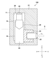
図5は、本実施形態における表示操作部11のチルト機構100を示した模式的断面図である。より詳しくは、表示操作部11をYZ平面で切断した断面図であり、表示操作部11のチルト機構100に対応する部分を示している。また、図5(a)は表示操作部11が開いた状態を示し、図5(b)は表示操作部11が閉じた状態を示している。さらに、図5(c)は、図5(a)の下方の一部を抜き出して示している。
FIG. 5 is a schematic cross-sectional view showing the
表示操作部11には、操作部材12などが配置されているため、ユーザーが操作面16に配置されたボタン類を押した場合に表示操作部11を閉じる方向に力が加わる。その場合、チルト機構100は、表示操作部11の現在のチルト角度が変わらないように、表示操作部11を保持する必要がある。
Since the
そのため、本実施形態においては、筐体5に対して、表示操作部11をその回転中心である第1の軸14だけで支えるのではなく、表示操作部11のほぼ中央(第1の軸14から表示操作部11の先端に向かって所定距離離れた位置)において、ストッパー(スライド部材)18により支えるようにしている。ストッパー18の先端部(一端部)18aは、表示操作部11のほぼ中央に配置された第2の軸17と回転可能に連結されている。ストッパー18の本体部18bの表面にはカム面44が形成されており、この面に向けて(矢印Aで示す方向に)押圧部材19の先端が圧縮コイルバネ20により付勢されている。この付勢力により、押圧部材19の先端がカム面44のスライド方向複数位置に形成された溝部23のそれぞれにはまり込み、それぞれの溝部23の位置(クリック位置)でストッパー18が停止する。これにより、表示操作部11のチルト角度が保持される。ストッパー18と押圧部材19と圧縮コイルバネ20は、筐体5に固定されたカバー部材21(案内部材)により保持されている。ストッパー18は、カバー部材21の案内面27によって案内されることにより、長手方向にスライド可能(摺動可能)に保持される。また、押圧部材19は、カバー部材21の複数の案内面28によって案内されることにより、押圧方向にスライド可能に保持される。
Therefore, in the present embodiment, the display/
なお、表示操作部11のチルト角度を変える場合は、ユーザーは表示操作部11に所定以上の力を加えるだけでよい。ユーザーが圧縮コイルバネ20の付勢力に抗して表示操作部11に力を加えることにより、押圧部材19の先端がカム面44に沿ってストッパー18の溝部23から抜け出し、チルト角度の保持は解除される。
In order to change the tilt angle of the display/
上記のように表示操作部11を保持することにより、第1の軸14と第2の軸17とカム面44上の溝部23により三角形が構成されることになる。これより、表示操作部11が開いた状態において、キー操作などを行った場合においても三角形という外力に対して安定した構成となることで表示操作部11のチルト角度を保持することが可能となる。
By holding the
なお、第2の軸17の位置は、表示操作部11の角度保持を優先的に考えれば、第1の軸14から遠い表示操作部11の先端が望ましい。しかしながら、表示操作部11の先端に配置した場合、ストッパー18の長さが長くなり、スペースをとって装置の大型化を招く。そのため、表示操作部11の角度保持と装置の小型化を考慮すると、第2の軸17は表示操作部11のほぼ中央に配置することが望ましい。
It should be noted that the position of the
図6は、チルト機構100におけるストッパー18を抜き出して示した図である。図6(a)はストッパー18と押圧部材19を示し、図6(b)はストッパー18のみを示している。
FIG. 6 is a diagram showing the
図6において、ストッパー18のカム面44上には、ストッパー18のスライド方向に直交する方向である幅方向(短手方向)に分割されたカム面(分割カム面)44a、カム面44bが形成されている(存在する)。押圧部材19のカム面への接触部は、カム面44a,44bの両方にまたがる幅を有している。
In FIG. 6, on the
表示操作部11の開閉動作をユーザーが繰り返し行った場合、カム面44との間で発生する摩擦により押圧部材19とストッパー18が摩耗し、表示操作部11をチルトさせる操作力が変化してしまう。操作力が変化すると操作感が悪化するため好ましくない。そのため、本実施形態では、押圧部材19と当接するカム面44がカム面44aとカム面44bの二つに分けられており、それぞれ異なる位置に溝部23が配置されている。また、前述したように、押圧部材19は、カム面44a,44bの両方にまたがる幅を有している。
When the user repeatedly opens and closes the
より具体的には、カム面44bには、表示操作部11が最も閉じた位置(図2(b)に示す開口部Qが形成される位置)に対応する溝部23aと、2番目に閉じた位置に対応する溝部23bと、3番目に閉じた位置に対応する溝部23cが形成されている。一方、カム面44aには、表示操作部11が4番目に閉じた位置(最も開いた位置)に対応する溝部23dが形成されている。表示操作部11が最も閉じた位置、2番目に閉じた位置、3番目に閉じた位置においては、押圧部材19の先端はカム面44bには接触するが、カム面44aは押圧部材19の先端から逃げている。
More specifically, the
カム面44がこのように形成されていると、以下のような効果が得られる。まず、表示操作部11が最も閉じた位置、2番目に閉じた位置、3番目に閉じた位置においては、押圧部材19の幅のうち19bで示す幅の部分のみがカム面44bと摺動し、19aで示す幅の部分はカム面44aと摺動しない。また、表示部材11が最も開いた位置では、押圧部材19の幅のうち19aで示す幅の部分のみがカム面44aと摺動し、19bで示す幅の部分はカム面44bと摺動しない。つまり、表示操作部材11のチルト位置(開き位置)によって押圧部材19の先端部の摺動部分が使い分けられるため、押圧部材19の摩耗を分散させることができる。
When the
また、カム面44bは、3か所の停止位置に対応する溝部を有し、カム面44aは1か所のみの停止位置に対応する溝部を有するため、カム面44bと摺動する押圧部材19の19bで示す幅の部分の方が摺動が頻繁に行われる。そのため、本実施形態では、カム面44bと押圧部材19の19bで示す部分の幅を、カム面44a及び押圧部材19の19aで示す部分の幅より広くしている。これにより、押圧部材19の先端の摩耗を均等化することができる。
The
以上のような効果により、本実施形態によれば、製品が長期間にわたって使用される場合に、表示操作部11の開閉操作を繰り返し行ったとしても、操作力が変化することなく、安定した操作力を実現することができる。
Due to the effects described above, according to the present embodiment, when the product is used for a long period of time, even if the opening and closing operations of the
さらに、図5(c)に示すように、ストッパー18が装置の水平方向に移動するのではなく、矢印S1で示す方向へ移動することにより、チルト機構100のサイズを矢印S2で示す方向に関して小型化することが可能である。
Furthermore, as shown in FIG. 5(c), the
なお、上記の実施形態では、カム面44bに3か所の溝部を形成し、カム面44aに1か所の溝部を形成するように説明したが、本発明はこれに限定されるものではなく、カム面44b,44aに配置する溝部の数は任意に設定可能である。また、カム面44bには、3か所の溝部を連続して形成するように説明したが、溝部をカム面44bとカム面44aに交互に配置するようにしてもよい。さらには、カム面44を2つのカム面に分割する場合について説明したが、3つ以上に分割してもよい。
In the above embodiment, three grooves are formed on the
図7は、本実施形態におけるチルト機構100を背面から見た概略図である。本実形態においては、ストッパー18に対して、押圧部材19による付勢力だけでなく、押圧部材19の付勢方向である第1の付勢方向(図5に矢印Aで示す方向)とは異なる方向である第2の付勢方向にも付勢力(押圧力)を与えている。以下、第2の付勢方向について説明する。
FIG. 7 is a schematic view of the
押圧部材24は、ストッパー18の押圧部材19の付勢力が作用する面であるカム面44とは異なる面29に接しており、圧縮コイルバネ25により矢印Fcで示す方向に付勢されている。より具体的には、押圧部材24はストッパー18のカム面44の側面29に接触しており、ストッパー18を側面から押圧する。ストッパー18と押圧部材24と圧縮コイルバネ25は、筐体5に固定されたカバー部材21により保持されている。押圧部材24と圧縮コイルバネ25は、カバー部材21によって案内され、矢印Fcで示す方向に移動可能である。
The pressing
表示操作部11のチルト角度の保持のために、押圧部材19の付勢力に加え、押圧部材24のストッパー18に対する付勢力による摩擦力も用いることにより、その力がストッパー18に対するブレーキの役割を果たす。これにより押圧部材19の付勢力を若干弱めても表示操作部11のチルト角度を保持できるようになり、押圧部材19とストッパー18と押圧部材24の摩耗をさらに減らすことができる。
In order to maintain the tilt angle of the
図8は、チルト機構100における表示操作部11のチルト位置を保持する力関係を示す図である。
FIG. 8 is a diagram showing a force relationship for holding the tilt position of the
本実施形態では、既に説明したように、表示操作部11を第1の軸14だけで支えるのではなく、表示操作部11のほぼ中央(上端部と下端部の距離の約半分の距離の位置)においてストッパー18により支える。さらに、図7に示すように、押圧部材24によりストッパー18に加えられる力Fcにより、ストッパー18とカバー部材21の間にストッパー18の動きにブレーキをかける摩擦力が働く。結果として、ユーザーによるボタン類の操作により表示操作部11に加えられる力Faに対して、押圧部材19と押圧部材24から与えられる力FbとFc(図7参照)の総合力として、表示操作部11を支える力Fzが働く。これにより、表示操作部11のチルト角度を確実に保持することができる。
In the present embodiment, as already described, the display/
図9は、本実施形態における表示操作部11を閉じるときのロック機構の概略構成を示す図である。表示操作部11を閉じる位置に移動させた場合、表示操作部11の下部に設けられたロック部26と押圧部材24に設けられたロック爪24bが係合する。これにより、ユーザーは、表示操作部11を閉じる位置(格納位置)に移動させた際に、閉じ位置に確実にロックされたというクリック感を感じることができる。
FIG. 9 is a diagram showing a schematic configuration of a lock mechanism when closing the
(第2の実施形態)
第1の実施形態では、図7に示すように、ストッパー18に押圧部材24により側面から力を加え、カバー部材21との間にストッパー18にブレーキをかける摩擦力を発生させる構成について説明した。しかし、この押圧部材24による摩擦力は、表示操作部11を閉じた格納位置にロックしようとした場合に、表示操作部11のロック位置への最後の押し込み時に表示操作部材11を開く方向に付勢する反力となり、ロックが不確実になる場合がある。この反力を防ぐためには、表示操作部11のロック位置への最後の押し込み時に、押圧部材24のストッパー部材18への付勢力を一時的に解除することが望ましい。第2の実施形態では、押圧部材24の付勢力を一時的に解除する構成について説明する。
(Second embodiment)
In the first embodiment, as shown in FIG. 7, the pressing
図10は、第2の実施形態における表示操作部11の閉時における摩擦力解除機構を示す概略図である。図10は、図7の点線Dで示す面(XY平面からなる面)で表示操作部11を切断し、-Z方向に見た断面図である。
FIG. 10 is a schematic diagram showing a frictional force releasing mechanism when the
図10において、ロック部26の先端部には斜面26aが形成され、押圧部材24のロック爪24bの先端部には斜面24aが形成されている。図10(a)に示す状態から表示操作部11が閉じる時、図10(b)に示すように、斜面24a,26aの作用によって押圧部材24がストッパー18の側面から退避し、ストッパー18への付勢力が解除される。この結果、表示操作部11が閉じる時における押圧部材24の摩擦力によるスプリングバックを回避することが可能となり、表示操作部11の閉じ位置へのロックを確実にすることができる
なお、ここまで、記録装置としてインクジェット方式を利用した画像形成装置を例に説明したが、電子写真方式を利用した画像形成装置においても同様の課題があり、本発明は、インクジェット方式以外の画像形成装置にも適用可能である。
10, a
(他の実施形態)
また本発明は、上述の実施形態の1以上の機能を実現するプログラムを、ネットワーク又は記憶媒体を介してシステム又は装置に供給し、そのシステム又は装置のコンピュータにおける1つ以上のプロセッサーがプログラムを読み出し実行する処理でも実現できる。また、1以上の機能を実現する回路(例えば、ASIC)によっても実現できる。
(Other embodiments)
Further, the present invention supplies a program that implements one or more functions of the above-described embodiments to a system or device via a network or a storage medium, and one or more processors in the computer of the system or device reads the program. It can also be realized by executing processing. It can also be implemented by a circuit (eg, ASIC) that implements one or more functions.
発明は上記実施形態に制限されるものではなく、発明の精神及び範囲から離脱することなく、様々な変更及び変形が可能である。従って、発明の範囲を公にするために請求項を添付する。 The invention is not limited to the embodiments described above, and various modifications and variations are possible without departing from the spirit and scope of the invention. Accordingly, the claims are appended to make public the scope of the invention.
1:記録装置、11:表示操作部、18:ストッパー、19,24:押圧部材、44:カム面、44a:カム面、44b:カム面 1: recording device, 11: display operation unit, 18: stopper, 19, 24: pressing member, 44: cam surface, 44a: cam surface, 44b: cam surface
Claims (8)
前記本体部に対して、回転軸を中心に回動する操作パネルと、
一端部が前記操作パネルに回転可能に接続され、表面において長手方向に延在するカム面を有するストッパーと、
前記本体部に設けられ、前記ストッパーを前記長手方向に摺動可能に案内する案内面を有する案内部材と、
前記長手方向と交差する短手方向に渡って前記カム面と接触する接触部を有し、前記ストッパーを前記案内面に向けて押し付ける押圧部材と、を備え、
前記カム面は、前記長手方向に複数の傾斜を有する分割カム面が前記短手方向に複数配され、前記押圧部材の前記接触部は、前記短手方向において複数の前記分割カム面と接触することを特徴とする記録装置。 a main body;
an operation panel that rotates around a rotation axis with respect to the main body;
a stopper having one end rotatably connected to the operation panel and having a longitudinally extending cam surface on its surface;
a guide member provided on the main body and having a guide surface for slidably guiding the stopper in the longitudinal direction;
a pressing member that has a contact portion that contacts the cam surface over a lateral direction that intersects the longitudinal direction and presses the stopper toward the guide surface;
In the cam surface, a plurality of divided cam surfaces having a plurality of inclinations in the longitudinal direction are arranged in the lateral direction, and the contact portion of the pressing member contacts the plurality of divided cam surfaces in the lateral direction. A recording device characterized by:
Priority Applications (2)
| Application Number | Priority Date | Filing Date | Title |
|---|---|---|---|
| JP2019072168A JP7222793B2 (en) | 2019-04-04 | 2019-04-04 | recording device |
| US16/826,609 US11124004B2 (en) | 2019-04-04 | 2020-03-23 | Printing apparatus |
Applications Claiming Priority (1)
| Application Number | Priority Date | Filing Date | Title |
|---|---|---|---|
| JP2019072168A JP7222793B2 (en) | 2019-04-04 | 2019-04-04 | recording device |
Publications (3)
| Publication Number | Publication Date |
|---|---|
| JP2020168815A JP2020168815A (en) | 2020-10-15 |
| JP2020168815A5 JP2020168815A5 (en) | 2022-02-07 |
| JP7222793B2 true JP7222793B2 (en) | 2023-02-15 |
Family
ID=72663482
Family Applications (1)
| Application Number | Title | Priority Date | Filing Date |
|---|---|---|---|
| JP2019072168A Active JP7222793B2 (en) | 2019-04-04 | 2019-04-04 | recording device |
Country Status (2)
| Country | Link |
|---|---|
| US (1) | US11124004B2 (en) |
| JP (1) | JP7222793B2 (en) |
Families Citing this family (8)
| Publication number | Priority date | Publication date | Assignee | Title |
|---|---|---|---|---|
| JP1634499S (en) * | 2018-11-08 | 2019-06-17 | printer | |
| JP1633759S (en) * | 2018-11-08 | 2019-06-10 | printer | |
| JP2022064572A (en) | 2020-10-14 | 2022-04-26 | キヤノン株式会社 | Processing device |
| JP2022125716A (en) | 2021-02-17 | 2022-08-29 | キヤノン株式会社 | Drawer device and recording device |
| JP2022125760A (en) | 2021-02-17 | 2022-08-29 | キヤノン株式会社 | recording device |
| JP1711931S (en) * | 2021-10-19 | 2022-04-06 | Printer | |
| USD1013032S1 (en) * | 2022-05-20 | 2024-01-30 | Kyocera Corporation | Inkjet printer |
| USD1013031S1 (en) * | 2022-05-20 | 2024-01-30 | Kyocera Corporation | Inkjet printer |
Citations (7)
| Publication number | Priority date | Publication date | Assignee | Title |
|---|---|---|---|---|
| US20050226647A1 (en) | 2004-04-10 | 2005-10-13 | Lee Ho-Il | Image forming apparatus |
| JP2006026924A (en) | 2004-07-12 | 2006-02-02 | Kyocera Mita Corp | Processing device |
| JP2006168173A (en) | 2004-12-15 | 2006-06-29 | Funai Electric Co Ltd | Electrical equipment and composite printer device |
| JP2011177981A (en) | 2010-02-26 | 2011-09-15 | Brother Industries Ltd | Rubbing sound preventive apparatus of opening/closing body during opening and closing and electric apparatus including the same |
| JP2014072458A (en) | 2012-09-28 | 2014-04-21 | Brother Ind Ltd | Electronic device |
| JP2015198099A (en) | 2014-03-31 | 2015-11-09 | ブラザー工業株式会社 | Tilting mechanism of panel, and image forming apparatus |
| JP2016193533A (en) | 2015-03-31 | 2016-11-17 | ブラザー工業株式会社 | Panel device and image recording device |
Family Cites Families (5)
| Publication number | Priority date | Publication date | Assignee | Title |
|---|---|---|---|---|
| JPH0895669A (en) * | 1994-09-29 | 1996-04-12 | Toshiba Corp | Electronic equipment system |
| DE19832338C2 (en) * | 1998-07-17 | 2002-01-31 | Feierbach Wolfgang | computer equipment |
| GB9825108D0 (en) * | 1998-11-16 | 1999-01-13 | Checkout Computer Systems Limi | Computer displays |
| US7366436B2 (en) * | 2004-07-12 | 2008-04-29 | Kyocera Mita Corporation | Processing unit having a panel supported movably with respect to a unit main body |
| US7542699B2 (en) * | 2005-08-22 | 2009-06-02 | Kyocera Mita Corporation | Image forming apparatus having slidable control portion |
-
2019
- 2019-04-04 JP JP2019072168A patent/JP7222793B2/en active Active
-
2020
- 2020-03-23 US US16/826,609 patent/US11124004B2/en active Active
Patent Citations (7)
| Publication number | Priority date | Publication date | Assignee | Title |
|---|---|---|---|---|
| US20050226647A1 (en) | 2004-04-10 | 2005-10-13 | Lee Ho-Il | Image forming apparatus |
| JP2006026924A (en) | 2004-07-12 | 2006-02-02 | Kyocera Mita Corp | Processing device |
| JP2006168173A (en) | 2004-12-15 | 2006-06-29 | Funai Electric Co Ltd | Electrical equipment and composite printer device |
| JP2011177981A (en) | 2010-02-26 | 2011-09-15 | Brother Industries Ltd | Rubbing sound preventive apparatus of opening/closing body during opening and closing and electric apparatus including the same |
| JP2014072458A (en) | 2012-09-28 | 2014-04-21 | Brother Ind Ltd | Electronic device |
| JP2015198099A (en) | 2014-03-31 | 2015-11-09 | ブラザー工業株式会社 | Tilting mechanism of panel, and image forming apparatus |
| JP2016193533A (en) | 2015-03-31 | 2016-11-17 | ブラザー工業株式会社 | Panel device and image recording device |
Also Published As
| Publication number | Publication date |
|---|---|
| JP2020168815A (en) | 2020-10-15 |
| US20200316972A1 (en) | 2020-10-08 |
| US11124004B2 (en) | 2021-09-21 |
Similar Documents
| Publication | Publication Date | Title |
|---|---|---|
| JP7222793B2 (en) | recording device | |
| JP7256670B2 (en) | recording device | |
| US7600746B2 (en) | Cassette and image forming apparatus | |
| EP1642736B1 (en) | Liquid ejecting apparatus | |
| US7677548B2 (en) | Cassette and image forming apparatus with multiple separation portions | |
| JP4715938B2 (en) | Image recording device | |
| US8092004B2 (en) | Image recording apparatus | |
| JP5099177B2 (en) | Sheet guide | |
| JP3960322B2 (en) | Recording sheet supply apparatus and facsimile apparatus | |
| JP2017030305A (en) | Electronic apparatus | |
| JP2002255358A (en) | Sheet position regulating loading device and image recorder having this device | |
| US7119914B2 (en) | Printer comprising detection device to detect whether a discharged-recording-medium tray or a cover member is at a position to obstruct conveyance of a recording medium | |
| US8047534B2 (en) | Sheet accommodating device and image recording apparatus with a translating pressing member attached to a rotating tray cover | |
| JP2009274249A (en) | Opening and closing mechanism, and information processing apparatus | |
| CN115362067A (en) | Printing apparatus | |
| US20220314668A1 (en) | Recording apparatus | |
| JP7159907B2 (en) | recording device | |
| JP3132531B2 (en) | Paper thickness adjustment device for image forming equipment | |
| JP3397714B2 (en) | Recording device and image processing device | |
| JP2021160878A (en) | Printer | |
| JP2003154730A (en) | Printer | |
| JP2023020117A (en) | Hand-held type recording device | |
| JP2008184323A (en) | Sheet sorting device, and image recording device provided with the same | |
| JP2006086698A (en) | Image processor | |
| JP2008290791A (en) | Image forming device |
Legal Events
| Date | Code | Title | Description |
|---|---|---|---|
| RD01 | Notification of change of attorney |
Free format text: JAPANESE INTERMEDIATE CODE: A7421 Effective date: 20210103 |
|
| A521 | Request for written amendment filed |
Free format text: JAPANESE INTERMEDIATE CODE: A523 Effective date: 20210113 |
|
| A521 | Request for written amendment filed |
Free format text: JAPANESE INTERMEDIATE CODE: A523 Effective date: 20220128 |
|
| A621 | Written request for application examination |
Free format text: JAPANESE INTERMEDIATE CODE: A621 Effective date: 20220128 |
|
| A977 | Report on retrieval |
Free format text: JAPANESE INTERMEDIATE CODE: A971007 Effective date: 20221031 |
|
| A131 | Notification of reasons for refusal |
Free format text: JAPANESE INTERMEDIATE CODE: A131 Effective date: 20221104 |
|
| A521 | Request for written amendment filed |
Free format text: JAPANESE INTERMEDIATE CODE: A523 Effective date: 20221223 |
|
| TRDD | Decision of grant or rejection written | ||
| A01 | Written decision to grant a patent or to grant a registration (utility model) |
Free format text: JAPANESE INTERMEDIATE CODE: A01 Effective date: 20230106 |
|
| A61 | First payment of annual fees (during grant procedure) |
Free format text: JAPANESE INTERMEDIATE CODE: A61 Effective date: 20230203 |
|
| R151 | Written notification of patent or utility model registration |
Ref document number: 7222793 Country of ref document: JP Free format text: JAPANESE INTERMEDIATE CODE: R151 |