JP7221977B2 - Improved carrier phase tracking using multiple carriers - Google Patents
Improved carrier phase tracking using multiple carriers Download PDFInfo
- Publication number
- JP7221977B2 JP7221977B2 JP2020543161A JP2020543161A JP7221977B2 JP 7221977 B2 JP7221977 B2 JP 7221977B2 JP 2020543161 A JP2020543161 A JP 2020543161A JP 2020543161 A JP2020543161 A JP 2020543161A JP 7221977 B2 JP7221977 B2 JP 7221977B2
- Authority
- JP
- Japan
- Prior art keywords
- propagation
- signal
- clock synchronization
- delayed
- wireless
- Prior art date
- Legal status (The legal status is an assumption and is not a legal conclusion. Google has not performed a legal analysis and makes no representation as to the accuracy of the status listed.)
- Active
Links
Images


Classifications
-
- G—PHYSICS
- G01—MEASURING; TESTING
- G01R—MEASURING ELECTRIC VARIABLES; MEASURING MAGNETIC VARIABLES
- G01R33/00—Arrangements or instruments for measuring magnetic variables
- G01R33/20—Arrangements or instruments for measuring magnetic variables involving magnetic resonance
- G01R33/28—Details of apparatus provided for in groups G01R33/44 - G01R33/64
- G01R33/32—Excitation or detection systems, e.g. using radio frequency signals
- G01R33/36—Electrical details, e.g. matching or coupling of the coil to the receiver
- G01R33/3692—Electrical details, e.g. matching or coupling of the coil to the receiver involving signal transmission without using electrically conductive connections, e.g. wireless communication or optical communication of the MR signal or an auxiliary signal other than the MR signal
-
- A—HUMAN NECESSITIES
- A61—MEDICAL OR VETERINARY SCIENCE; HYGIENE
- A61B—DIAGNOSIS; SURGERY; IDENTIFICATION
- A61B5/00—Measuring for diagnostic purposes; Identification of persons
- A61B5/0002—Remote monitoring of patients using telemetry, e.g. transmission of vital signals via a communication network
- A61B5/0004—Remote monitoring of patients using telemetry, e.g. transmission of vital signals via a communication network characterised by the type of physiological signal transmitted
- A61B5/0013—Medical image data
-
- A—HUMAN NECESSITIES
- A61—MEDICAL OR VETERINARY SCIENCE; HYGIENE
- A61B—DIAGNOSIS; SURGERY; IDENTIFICATION
- A61B5/00—Measuring for diagnostic purposes; Identification of persons
- A61B5/05—Detecting, measuring or recording for diagnosis by means of electric currents or magnetic fields; Measuring using microwaves or radio waves
- A61B5/055—Detecting, measuring or recording for diagnosis by means of electric currents or magnetic fields; Measuring using microwaves or radio waves involving electronic [EMR] or nuclear [NMR] magnetic resonance, e.g. magnetic resonance imaging
-
- G—PHYSICS
- G01—MEASURING; TESTING
- G01R—MEASURING ELECTRIC VARIABLES; MEASURING MAGNETIC VARIABLES
- G01R33/00—Arrangements or instruments for measuring magnetic variables
- G01R33/20—Arrangements or instruments for measuring magnetic variables involving magnetic resonance
- G01R33/28—Details of apparatus provided for in groups G01R33/44 - G01R33/64
- G01R33/32—Excitation or detection systems, e.g. using radio frequency signals
- G01R33/34—Constructional details, e.g. resonators, specially adapted to MR
- G01R33/34092—RF coils specially adapted for NMR spectrometers
-
- G—PHYSICS
- G01—MEASURING; TESTING
- G01R—MEASURING ELECTRIC VARIABLES; MEASURING MAGNETIC VARIABLES
- G01R33/00—Arrangements or instruments for measuring magnetic variables
- G01R33/20—Arrangements or instruments for measuring magnetic variables involving magnetic resonance
- G01R33/28—Details of apparatus provided for in groups G01R33/44 - G01R33/64
- G01R33/32—Excitation or detection systems, e.g. using radio frequency signals
- G01R33/36—Electrical details, e.g. matching or coupling of the coil to the receiver
- G01R33/3621—NMR receivers or demodulators, e.g. preamplifiers, means for frequency modulation of the MR signal using a digital down converter, means for analog to digital conversion [ADC] or for filtering or processing of the MR signal such as bandpass filtering, resampling, decimation or interpolation
-
- H—ELECTRICITY
- H04—ELECTRIC COMMUNICATION TECHNIQUE
- H04W—WIRELESS COMMUNICATION NETWORKS
- H04W56/00—Synchronisation arrangements
- H04W56/0035—Synchronisation arrangements detecting errors in frequency or phase
-
- A—HUMAN NECESSITIES
- A61—MEDICAL OR VETERINARY SCIENCE; HYGIENE
- A61B—DIAGNOSIS; SURGERY; IDENTIFICATION
- A61B5/00—Measuring for diagnostic purposes; Identification of persons
- A61B5/0002—Remote monitoring of patients using telemetry, e.g. transmission of vital signals via a communication network
- A61B5/0004—Remote monitoring of patients using telemetry, e.g. transmission of vital signals via a communication network characterised by the type of physiological signal transmitted
- A61B5/0006—ECG or EEG signals
Landscapes
- Physics & Mathematics (AREA)
- Health & Medical Sciences (AREA)
- Engineering & Computer Science (AREA)
- Life Sciences & Earth Sciences (AREA)
- Computer Networks & Wireless Communication (AREA)
- General Physics & Mathematics (AREA)
- Condensed Matter Physics & Semiconductors (AREA)
- Nuclear Medicine, Radiotherapy & Molecular Imaging (AREA)
- Biophysics (AREA)
- Veterinary Medicine (AREA)
- Heart & Thoracic Surgery (AREA)
- Medical Informatics (AREA)
- Molecular Biology (AREA)
- Surgery (AREA)
- Animal Behavior & Ethology (AREA)
- General Health & Medical Sciences (AREA)
- Public Health (AREA)
- Biomedical Technology (AREA)
- Pathology (AREA)
- Radiology & Medical Imaging (AREA)
- Signal Processing (AREA)
- High Energy & Nuclear Physics (AREA)
- Physiology (AREA)
- Magnetic Resonance Imaging Apparatus (AREA)
- Synchronisation In Digital Transmission Systems (AREA)
Description
[0001] 以下は、包括的には、医療用撮像技術、ワイヤレスコンポーネント同期技術、磁気共鳴撮像技術、ポジトロン放出断層撮影(PET)撮像技術、医療用撮像データタイムスタンプ同期技術、及び関連技術に関する。 [0001] The following relates generally to medical imaging technology, wireless component synchronization technology, magnetic resonance imaging technology, positron emission tomography (PET) imaging technology, medical imaging data timestamp synchronization technology, and related technologies.
[0002] 医療用撮像では、取得された撮像データに関して正確かつ厳密にタイムスタンプを割り当てることが極めて重要になる可能性がある。磁気共鳴(MR)撮像では、タイムスタンプは、取得された撮像データを、無線周波数(RF)励起パルス、印加される傾斜磁場などのタイミングのような、MR撮像データ取得シーケンスの事象と時間的に相関させることに頼る。また、正確かつ厳密なタイムスタンプは、いくつかのMR受信コイル、又はコイル素子のアレイを備える受信コイルを用いて取得されたMR信号の位相成分を正確に合成することに頼る。より一般的には、MR撮像システムのMR送信及び受信コイル、傾斜磁場コイルなどのコンポーネントのクロックを用いて、種々のアナログ信号を生成及びサンプリングし、アナログ信号がMR画像を生成するために処理される。これらのクロックは、最適な画像品質を確保するために、互いに非常に高い精度で同期しなければならない。例えば、RFサンプリングクロックの場合、1つのデジタル受信機仕様は、これらのクロックの最大ドリフトが22ps未満であることを要求する。光の速さで換算すると、22psは、光が7mm進行するのに要する時間である。 [0002] In medical imaging, the accurate and precise assignment of time stamps on acquired imaging data can be extremely important. In magnetic resonance (MR) imaging, timestamps associate acquired imaging data temporally with events in the MR imaging data acquisition sequence, such as the timing of radio frequency (RF) excitation pulses, applied gradient magnetic fields, and the like. Rely on correlating. Accurate and precise time stamping also relies on accurately combining the phase components of MR signals acquired using several MR receive coils, or receive coils comprising arrays of coil elements. More generally, MR transmit and receive coils, gradient coils, and other components of an MR imaging system are clocked to generate and sample various analog signals that are processed to generate MR images. be. These clocks must be synchronized with each other to a very high degree of accuracy to ensure optimum image quality. For example, for RF sampling clocks, one digital receiver specification requires the maximum drift of these clocks to be less than 22 ps. When converted to the speed of light, 22 ps is the time required for light to travel 7 mm.
[0003] 同様に、飛行時間ポジトロン放出断層撮影(TOF-PET)では、正確な飛行時間情報は、放射線検出事象のタイムスタンプが同様の精度まで同期することを要求する。TOF-PETの場合、飛行時間空間定位は、数百ピコ秒程度か、それより速いタイムスタンプ精度を要求する。 [0003] Similarly, in time-of-flight positron emission tomography (TOF-PET), accurate time-of-flight information requires that the time stamps of radiation detection events be synchronized to similar accuracy. For TOF-PET, time-of-flight spatial localization requires timestamp accuracy on the order of hundreds of picoseconds or faster.
[0004] 有線のRFケーブル又は光学接続を用いるMR受信コイルの場合、ケーブルに沿ったクロック信号伝搬遅延は一般に、MR受信コイルの位置決めに関して、又はコイルに最も近い外部事象に関してそれぞれ不変である。ワイヤレスMR受信コイルの場合、ワイヤレスクロック同期信号が利用される場合がある。この手法に関するいくつかの例示が、例えば、Reykowskiらの国際公開第2017/103759号A2に記述されている。 [0004] For MR receive coils using wired RF cables or optical connections, the clock signal propagation delay along the cable is generally invariant with respect to the positioning of the MR receive coil or with respect to the external event closest to the coil, respectively. For wireless MR receive coils, a wireless clock synchronization signal may be utilized. Some examples of this approach are described, for example, in WO2017/103759 A2 to Reykowski et al.
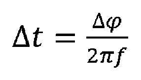
[0005] ワイヤレスMR受信コイルの場合、患者の動き、患者寝台の動き、撮像検査室内の医療従事者の動きなどの種々の要因に起因して、ワイヤレスクロック同期信号の伝搬遅延が時間の関数として変化する可能性がある。先に言及されたように、7mmほどの小さい空間的な動きが、22psの伝搬遅延の変化を導入し、それにより、MR撮像システムが仕様から外れる可能性がある。この問題に対する通常の解決策は、ワイヤレスクロック同期信号の位相を測定すること、及び関係Δφ=2πf・Δtに基づいて、位相を時間遅延に変換することである。ここで、Δtは、推定される伝搬遅延(の変化)であり、Δφは、何らかの基準位相に対して測定された位相シフトであり、fは、ワイヤレスクロック同期信号の搬送波周波数である。位相φ(t)は、指定された基準時刻t0における基準位相φ(t0)=0に対する時間の関数として監視することができ、時刻tにおける伝搬遅延Δtは、

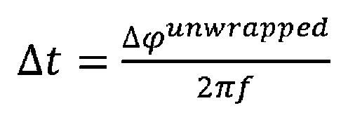
[0006] φwrapped(t)の次の測定との間の位相増分が十分に小さい場合には、真の(すなわち、アンラップされた)搬送波位相φunwrapped(t)は、φwrapped(t)の被測定値間の位相増分を累積することによって取得することができる。しかしながら、この方法は、測定された(ラップされた)搬送波位相φwrapped(t)を絶えず監視することを要求し、それは必ずしも可能であるとは限らない。例えば、短時間の通信損失があると、通信中断中に位相ラップが生じたか否かは確実にはわからない。 [0006] If the phase increment between subsequent measurements of φ wrapped (t) is small enough, then the true (ie, unwrapped) carrier phase φ unwrapped (t) is φ wrapped (t). It can be obtained by accumulating the phase increments between measured values. However, this method requires constant monitoring of the measured (wrapped) carrier phase φ wrapped (t), which is not always possible. For example, with a short communication loss, it is not known with certainty whether a phase wrap occurred during the communication interruption.
[0007] 以下はある改善形態を開示する。 [0007] The following discloses certain improvements.
[0008] 本明細書において開示されるいくつかの実施形態において、クロック式電子デバイスが、伝搬遅延したワイヤレスクロック同期信号を受信するように構成されるワイヤレス受信機又は送受信機を備える。その信号は、ある周波数差だけ離間された第1の搬送波周波数及び第2の搬送波周波数それぞれの第1の伝搬遅延した搬送波信号及び第2の伝搬遅延した搬送波信号を含む。クロック式電子デバイスは、例えば、デジタルカウンタをドライブするローカル発振器(LO)を備えるクロックを更に備え、クロック同期を実行するように構成される電子信号処理コンポーネントを更に備える。クロック同期は、第1の伝搬遅延した搬送波信号の位相と第2の伝搬遅延した搬送波信号の位相との間の位相差(φ1)からラップカウント(k)を求めることと、ラップカウントを用いて、伝搬遅延したワイヤレスクロック同期信号のラップされた位相(φ2,wrapped)をアンラップし、アンラップされた位相(φ2,unwrapped)を生成することと、アンラップされた位相を用いてクロックを同期させることとを含む。伝搬遅延したワイヤレスクロック同期信号のラップされた位相(φ2,wrapped)は、例えば、第1の伝搬遅延した搬送波信号、第2の伝搬遅延した搬送波信号、第1の伝搬遅延した搬送波信号及び第2の伝搬遅延した搬送波信号を合成した合成信号、伝搬遅延したワイヤレスクロック同期信号の第3の伝搬遅延した搬送波信号、のうちの1つのラップされた位相とすることができ、第3の伝搬遅延した搬送波信号は第1の伝搬遅延した搬送波信号とは異なり、第2の伝搬遅延した搬送波信号とは異なる。1つの例示的な手法では、クロック同期は、アンラップされた位相(φ2,unwrapped)から、伝搬遅延したワイヤレスクロック同期信号の伝搬遅延(Δt)を求めることと、求められた伝搬遅延を用いてクロックを同期させることとを更に含む。 [0008] In some embodiments disclosed herein, a clocked electronic device comprises a wireless receiver or transceiver configured to receive a propagation-delayed wireless clock synchronization signal. The signal includes a first propagation delayed carrier signal and a second propagation delayed carrier signal at respective first and second carrier frequencies separated by a frequency difference. The clocked electronic device further comprises, for example, a clock comprising a local oscillator (LO) driving a digital counter, and further comprising electronic signal processing components configured to perform clock synchronization. Clock synchronization is performed by obtaining a wrap count (k) from the phase difference (φ 1 ) between the phase of the first propagation-delayed carrier signal and the phase of the second propagation-delayed carrier signal, and using the wrap count unwrapping the wrapped phase (φ 2,wrapped ) of the propagation-delayed wireless clock synchronization signal to produce an unwrapped phase (φ 2,unwrapped ); and synchronizing the clock using the unwrapped phase. and The wrapped phase (φ 2,wrapped ) of the propagation-delayed wireless clock synchronization signal is, for example, a first propagation-delayed carrier signal, a second propagation-delayed carrier signal, a first propagation-delayed carrier signal, and a second propagation-delayed carrier signal. a third propagation-delayed carrier signal of the propagation-delayed wireless clock synchronization signal; The resulting carrier signal is different from the first propagation delayed carrier signal and is different from the second propagation delayed carrier signal. In one exemplary approach, clock synchronization is performed by determining the propagation delay (Δt) of a propagation-delayed wireless clock synchronization signal from the unwrapped phase (φ 2,unwrapped ) and using the determined propagation delay and synchronizing the clocks.
[0009] いくつかの実施形態において、上記のクロック式電子デバイスは、生理的データ又は医療用撮像データのサンプルを収集するように構成されるワイヤレス医療用撮像デバイスコンポーネントを備え、電子信号処理コンポーネントは、サンプルにタイムスタンプを割り当てるように更に構成される。タイムスタンプは、アンラップされた位相を用いて同期したクロックから取得される。ワイヤレス医療用撮像デバイスコンポーネントは、例えば、MR撮像デバイスとともに使用するように構成されるワイヤレス磁気共鳴(MR)受信コイルを備えることができる。別の実施形態では、ワイヤレス医療用撮像デバイスコンポーネントは、例えば、MR撮像デバイスとともに使用するように構成される心電計(ECG)又は他の生理的検知デバイスを備えることができる。更に別の例示的な非限定的例では、ワイヤレス医療用撮像デバイスコンポーネントは、例えば、ポジトロン放出断層撮影(PET)撮像デバイスの放射線検出器モジュールを備えることができる。 [0009] In some embodiments, the clocked electronic device described above comprises a wireless medical imaging device component configured to collect samples of physiological data or medical imaging data, wherein the electronic signal processing component comprises , is further configured to assign timestamps to the samples. Timestamps are obtained from a synchronized clock using unwrapped phase. A wireless medical imaging device component can comprise, for example, a wireless magnetic resonance (MR) receive coil configured for use with an MR imaging device. In another embodiment, the wireless medical imaging device component can comprise, for example, an electrocardiograph (ECG) or other physiological sensing device configured for use with an MR imaging device. In yet another illustrative, non-limiting example, a wireless medical imaging device component can comprise, for example, a radiation detector module of a positron emission tomography (PET) imaging device.
[0010] 別の開示される態様では、上記のクロック式電子デバイスは、クロック同期信号を生成するように構成される無線周波数(RF)信号発生器を含むワイヤレスクロック同期信号発生器と、クロック同期信号をワイヤレスクロック同期信号として自由空間の中にワイヤレス送信するように接続される送信機又は送受信機とを更に備える(又は、それらとワイヤレスに動作可能に結合される)。伝搬遅延したワイヤレスクロック同期信号は、それゆえ、自由空間を通ってワイヤレス受信機又は送受信機に送信されるワイヤレスクロック同期信号を含む。いくつかの非限定的な例示的実施形態では、RF信号発生器は、マスター搬送波信号を、第1の搬送波周波数と第2の搬送波周波数との間の周波数差の半分に等しいベースバンド周波数のベースバンド信号で変調するように構成される両側波帯(DSB)変調器を備えることができる。 [0010] In another disclosed aspect, the above clocked electronic device includes a wireless clock synchronization signal generator including a radio frequency (RF) signal generator configured to generate a clock synchronization signal; It further comprises (or is wirelessly operably coupled to) a transmitter or transceiver connected to wirelessly transmit the signal as a wireless clock synchronization signal into free space. A propagation-delayed wireless clock synchronization signal therefore comprises a wireless clock synchronization signal transmitted through free space to a wireless receiver or transceiver. In some non-limiting exemplary embodiments, the RF signal generator generates a master carrier signal at the base of the baseband frequency equal to half the frequency difference between the first carrier frequency and the second carrier frequency. A double sideband (DSB) modulator configured to modulate with a band signal may be provided.
[0011] いくつかの実施形態において、ワイヤレス受信機又は送受信機、クロック及び電子信号処理コンポーネントはワイヤレスデバイスを構成し、ワイヤレスクロック同期信号発生器は、そのワイヤレスデバイスの一部ではない。 [0011] In some embodiments, the wireless receiver or transceiver, clock and electronic signal processing components constitute a wireless device, and the wireless clock synchronization signal generator is not part of that wireless device.
[0012] 別の開示される態様では、クロック同期方法が開示される。ワイヤレス受信機又は送受信機を用いて、ある周波数差だけ離間された第1の搬送波周波数及び第2の搬送波周波数それぞれの第1の伝搬遅延した搬送波信号及び第2の伝搬遅延した搬送波信号を含む、伝搬遅延したワイヤレスクロック同期信号の自由空間送信が受信される。電子信号処理コンポーネントを用いて、第1の伝搬遅延した搬送波信号の位相と第2の伝搬遅延した搬送波信号の位相との間の位相差(φ1)からラップカウント(k)を求めることと、ラップカウントを用いて、伝搬遅延したワイヤレスクロック同期信号のラップされた位相(φ2,wrapped)をアンラップし、アンラップされた位相(φ2,unwrapped)を生成することと、アンラップされた位相を用いて電子クロックを同期させることとを含む動作が実行される。クロック同期方法は、無線周波数(RF)信号発生器を動作させて、クロック同期信号を生成することと、クロック同期信号をワイヤレスクロック同期信号として自由空間の中にワイヤレス送信することとを更に含むことができる。伝搬遅延したワイヤレスクロック同期信号は、その際、自由空間を通ってワイヤレス受信機又は送受信機に送信されるワイヤレスクロック同期信号を含む。いくつかのそのような実施形態では、ワイヤレスクロック同期信号発生器は、マスター搬送波信号を、第1の搬送波周波数と第2の搬送波周波数との間の周波数差の半分に等しいベースバンド周波数のベースバンド信号で変調するように構成される両側波帯(DSB)変調器を備える。 [0012] In another disclosed aspect, a clock synchronization method is disclosed. using a wireless receiver or transceiver comprising a first propagation delayed carrier signal and a second propagation delayed carrier signal at respective first carrier frequencies and second carrier frequencies separated by a frequency difference; A free-space transmission of a propagation-delayed wireless clock synchronization signal is received. determining a wrap count (k) from the phase difference (φ 1 ) between the phase of the first propagation-delayed carrier signal and the phase of the second propagation-delayed carrier signal using an electronic signal processing component; unwrapping the wrapped phase (φ 2,wrapped ) of the propagation-delayed wireless clock synchronization signal using the wrap count to produce an unwrapped phase (φ 2,unwrapped ); and synchronizing the electronic clocks. The clock synchronization method further includes operating a radio frequency (RF) signal generator to generate a clock synchronization signal and wirelessly transmitting the clock synchronization signal into free space as a wireless clock synchronization signal. can be done. A propagation-delayed wireless clock synchronization signal then includes a wireless clock synchronization signal that is transmitted through free space to a wireless receiver or transceiver. In some such embodiments, the wireless clock synchronization signal generator transmits the master carrier signal to baseband at a baseband frequency equal to half the frequency difference between the first carrier frequency and the second carrier frequency. A double sideband (DSB) modulator configured to modulate with a signal is provided.
[0013] 1つの利点は、起こり得る位相ラッピングに起因する曖昧さが考慮に入れられたワイヤレスクロック同期信号を用いてクロック同期を提供することにある。 [0013] One advantage resides in providing clock synchronization using a wireless clock synchronization signal in which ambiguities due to possible phase wrapping are taken into account.
[0014] 別の利点は、起こり得る位相ラッピングに起因する曖昧さが考慮に入れられたそのようなクロック同期を提供する、ワイヤレスMRコイル、又は他のワイヤレスMRコンポーネント、又は他のワイヤレス医療用撮像コンポーネントを提供することにある。 [0014] Another advantage is a wireless MR coil, or other wireless MR component, or other wireless medical imaging device that provides such clock synchronization that takes into account ambiguities due to possible phase wrapping. to provide components.
[0015] 別の利点は、ワイヤレスクロック同期信号との同期中に起こり得る位相ラッピングを考慮に入れることによって、タイムスタンプ信頼性が改善されたワイヤレスMRコイル又は他のワイヤレス医療用撮像コンポーネントを提供することにある。 [0015] Another advantage provides a wireless MR coil or other wireless medical imaging component with improved timestamp reliability by accounting for possible phase wrapping during synchronization with a wireless clock synchronization signal. That's what it is.
[0016] 別の利点は、相対的に狭い帯域幅を有するワイヤレスクロック同期信号を用いて、上記の利点のうちの1つ以上を提供することにある。 [0016] Another advantage resides in using a wireless clock synchronization signal having a relatively narrow bandwidth to provide one or more of the above advantages.
[0017] 別の利点は、両側波帯(DSB)変調器回路のような安価な回路を用いて生成されたワイヤレスクロック同期信号を用いて、上記の利点のうちの1つ以上を提供することにある。 [0017] Another advantage is to provide one or more of the above advantages using wireless clock synchronization signals generated using inexpensive circuitry such as double sideband (DSB) modulator circuitry. It is in.
[0018] 別の利点は、クロック同期がワイヤレスクロック同期信号の通信中の短時間の中断に対してロバストである、上記の利点のうちの1つ以上を提供することにある。 [0018] Another advantage resides in providing one or more of the above advantages in which clock synchronization is robust to short interruptions in the communication of wireless clock synchronization signals.
[0019] 所与の実施形態が、上記の利点をいずれも提供しないか、又は上記の利点のうちの1つ、2つ、若しくは3つ以上、又は全てを提供する場合があり、及び/又は本開示を読み、理解すると、当業者には明らかになるような他の利点を提供する場合がある。 [0019] A given embodiment may provide none of the above advantages, or one, two, three or more, or all of the above advantages, and/or Other advantages may be provided that will become apparent to those skilled in the art upon reading and understanding this disclosure.
[0020] 本発明は、種々のコンポーネント及びコンポーネントの配置、並びに種々のステップ及びステップの配置の形をとることができる。図面は、好ましい実施形態を例示することのみを目的とし、本発明を制限するものと解釈されるべきではない。 [0020] The invention may take form in various components and arrangements of components, and in various steps and arrangements of steps. The drawings are for purposes of illustrating preferred embodiments only and are not to be construed as limiting the invention.
[0024] 図1を参照すると、例示的な医療用撮像デバイス10が、磁気共鳴(MR)撮像スキャナを備え、磁気共鳴(MR)撮像スキャナは、非限定的な例示として、静(B0)磁場を生成する超伝導又は常伝導磁石、B0磁場に傾斜磁場を重ね合わせるための傾斜磁場コイル、MRボア14又は他のMR検査領域内に配置される撮像対象者において磁気共鳴を励起し、及び/又は空間的に符号化するためにRFパルスを印加するための全身無線周波数(RF)コイルなどの、図1には示されない種々のコンポーネントを含むハウジング又はガントリ12を備える。ロボット制御患者寝台16又は他の対象者支持体が、診断患者、医療スクリーニングを受ける対象者、又は他の撮像対象者を撮像するためにMRボア14の中に送り込むことを可能にする。
[0024] Referring to FIG. 1, an exemplary
[0025] 医療従事者によって理解されるように、例示的なMR撮像スキャナ10のような医療用撮像デバイスを使用することは、数多くの医療用撮像デバイスコンポーネントの位置決め及び動作を伴う可能性がある。非限定的な例示として、図1は、役に立つ場合がある2つのそのような医療用撮像デバイスコンポーネントとして、MR撮像デバイス10とともに使用するように構成されるワイヤレスMR受信コイル20と、MR撮像デバイス10とともに使用するように構成される心電計(ECG)22とを示す。ワイヤレスMR受信コイル20は、MR撮像デバイス10の動作によって生成されるMR信号を受信するために、少なくとも、MR周波数に同調することによって構成される少なくとも1つのコイル素子24(9個のコイル素子24からなる例示的なアレイ)を含む限りにおいて、MR撮像デバイス10とともに使用するように構成され、他の態様によれば、任意選択で、MR信号を増幅する前置増幅器、撮像を受ける解剖学的領域に隣接して位置決めされる物理的形状などを含む。例示的なECG22は、MRボア14の閉ざされた空間内でECG生理学的データの取得を容易にするために、EASI構成などに配置された少ない数の電極を備えるコンパクトな電極パッド26を利用することによって、MR撮像デバイス10とともに使用するように構成され、更には、電子回路内の強磁性コアインダクタの使用を制限するか、又は使用しないこと、RF干渉を軽減するために広範囲にRFを遮蔽することなどの態様によって、MR撮像デバイス10とともに使用するように構成される。
[0025] As will be appreciated by medical practitioners, using a medical imaging device such as the exemplary
[0026] 例示的な医療用撮像デバイス10及び例示的なクロック式電子デバイス20、22は例示にすぎず、広範な適用例にわたる広範なデバイスに関して、本明細書において開示されるようなクロック同期を含むクロック式電子デバイスを利用することが考えられる。開示されるクロック同期は、クロック式ワイヤレス電子デバイスとの関連で特に有用であるが、他のタイプのクロック式電子デバイスとともに使用することもできる。例えば、飛行時間ポジトロン放出断層撮影(TOF-PET)撮像デバイスは、陽電子-電子対消滅事象から放出される511keVγ線を検出するための放射線検出器モジュールの1つ以上のリングを利用する。各陽電子-電子対消滅事象は2つの511keVγ線を放出し、それらのγ線は、運動量保存を満たすために反対方向に放出される。狭い時間窓内で検出される2つのそのような511keVγ線は、同時に生じた511keVγ線対として識別される。TOF定位が利用されるとき、これら2つの同時検出間の時間差(もしあるなら)は、検出を接続する応答線(LOR)に沿った空間定位に変換される。γ線が光の速さで進行するとき、TOF定位は、数十又は数百ピコ秒より高い精度までの、PETスキャナの全ての放射線検出器モジュールの厳密な同期を要求する。放射線検出器モジュール(それは医療用撮像デバイスコンポーネントである)は、医療用撮像データ(ここでは、タイムスタンプ付きのγ線検出事象を示すデジタル化された信号又はアナログ信号)をポート出力するように配線されるが、それにもかかわらず、放射線検出器モジュールを設置するために必要とされる配線を大幅に削減するために、ワイヤレスクロック同期信号のブロードキャストを利用して、本明細書において開示されるようなクロック同期方法を利用することが考えられる。これ以外に、ある周波数差だけ離間されるそれぞれの第1の搬送波周波数及び第2の搬送波周波数の第1の伝搬遅延した搬送波信号及び第2の伝搬遅延した搬送波信号を含むワイヤレスクロック同期信号を使用する開示されるクロック同期は、ワイヤレスクロック同期信号の位相ラッピングに起因する同期の曖昧さが懸念されるあらゆる状況において有用に利用されるので、医療用撮像以外の適用例において、開示されるクロック同期を利用することも更に考えられる。
[0026] The example
[0027] 以下において、例示的な説明は例示的なワイヤレスMR受信コイル20に注目し、ワイヤレスMR受信コイル20は、概略的に示されるように、ある周波数差だけ離間された第1の搬送波周波数及び第2の搬送波周波数それぞれの第1の伝搬遅延した搬送波信号及び第2の伝搬遅延した搬送波信号を含む伝搬遅延したワイヤレスクロック同期信号を受信するように構成されるワイヤレス受信機又は送受信機30と、少なくとも1つのオンボードクロック、及びオンボードクロックを用いて、少なくとも1つのコイル素子24によって受信されたMR信号のタイムスタンプ付きサンプルを生成するように構成され、本明細書において開示されるようなクロック同期を実行するように更に構成される少なくとも1つの電子信号処理コンポーネントを含む電子回路32とを備える。さらに、ワイヤレスクロック同期信号発生器34が、クロック同期信号を生成するように構成されるRF信号発生器42と、クロック同期信号を、ワイヤレスクロック同期信号として自由空間の中にワイヤレス送信するように接続される送信機又は送受信機44とを備える。上記の伝搬遅延したワイヤレスクロック同期信号は、それゆえ、送信機又は送受信機44から、自由空間を通って、ワイヤレスMR受信コイル20(すなわち、例示的なクロック式電子デバイス)のワイヤレス受信機又は送受信機30に送信されるワイヤレスクロック同期信号を含む。
[0027] In the following, the exemplary description will focus on an exemplary wireless MR receive
[0028] 例示的なワイヤレスMR受信コイル20を参照しながらクロック同期が説明されるが、任意の他のクロック式電子デバイスが、ワイヤレスクロック同期信号発生器34の送信機又は送受信機44によって出力されるワイヤレスクロック同期信号を利用して、開示されるクロック同期を利用するように同様に構成されることは理解されよう。このようにして、全てのそのようなクロック式電子デバイスが同じワイヤレスクロック同期信号に同期し、それゆえ、互いに同期することになる。更なる例示として、ワイヤレスECG22は、オンボードクロックと、オンボードクロックを用いて、電極パッド26を介して受信された(この場合)ECG信号のタイムスタンプ付きサンプルを生成するように構成され、例示としてMRコイル20に関して説明された手法と同様にクロック同期を実行するように更に構成される少なくとも1つの電子信号処理コンポーネントとを備える電子回路(ECG22に関して図示されない)とともに、ワイヤレスMR受信コイル20のワイヤレス受信機又は送受信機30に類似のワイヤレス受信機又は送受信機31を備える。
[0028] Although clock synchronization is described with reference to an exemplary wireless MR receive
[0029] 引き続き図1を参照するとともに、ワイヤレスクロック同期信号発生器34の概略的に図示された実施形態及び概略的な上側差込図Aを特に参照すると、位相アンラッピングを含むクロック同期が示される。例示的なワイヤレスクロック同期信号発生器34において、RF信号発生器は、N2f0で表される周波数のマスター搬送波信号を、第1の搬送波周波数と第2の搬送波周波数との間の周波数差の半分に等しい、N1f0で表されるベースバンド周波数のベースバンド信号で変調するように構成される両側波帯(DSB)変調器42を備える。DSB変調は、2つの信号:周波数(N2+N1)f0の上側波帯信号及び周波数(N2-N1)f0の下側波帯信号を生成する。生成されたクロック同期信号は、上側波帯及び下側波帯の両方の成分を含み、本明細書において簡略表記(N2±N1)f0によって表される。ここで上側差込図Aを参照すると、ワイヤレスクロック同期信号発生器34の送信機又は送受信機44が、この生成されたクロック同期信号をワイヤレスクロック同期信号50として自由空間の中に出力する(差込図Aは、ωによって表される角周波数を利用し、角周波数は、よく知られている関係ω=2πfによってヘルツ単位の対応する周波数fに関連することに留意されたい)。自由空間を通しての送信は、差込図Aに概略的に示されるように送信チャネル52と見なすことができる。ワイヤレスMR受信コイル20のワイヤレス受信機又は送受信機30において受信される伝搬遅延したワイヤレスクロック同期信号54は、それゆえ、自由空間52を通って、ワイヤレス受信機又は送受信機30に送信されたワイヤレスクロック同期信号50である。
[0029] With continued reference to Figure 1, and with particular reference to the schematically illustrated embodiment of the wireless clock
[0030] 引き続き図1、差込図Aを参照すると、自由空間チャネル52は、遅延Δtを導入する。この遅延は、一般に、MR受信コイル20の動き、自由空間チャネル52を通り抜け、歪める移動中の放射線科医又は他の物理的実体の介在などに起因して、時間の関数として変化する可能性がある。さらに、自由空間チャネル遅延Δtは、ワイヤレスクロック同期信号50を用いて互いに同期することになるクロック式電子デバイスごとに異なることは理解されよう。例えば、自由空間チャネル遅延Δtは、MR受信コイル20及びECG22に関して異なる場合があり、いずれも一般に時間の関数として変化する場合がある。通常、同期基準時刻t0において、同期した各クロック式電子デバイスのワイヤレスクロック同期信号の位相は0に設定され(すなわち、基準位相は、デバイスごとに、φ0(t0)=0と設定される)、その後、時刻tにおける可変時間遅延が関係Δφ=(φ(t)-φ(t0))=2πf・(Δt(t)-Δt(t0))から求められる。基準時刻t0に関して、φ0(t0)=0及びΔt(t0)=0が設定されると、これはΔφ(t)=2πf・Δt(t)に置き換えられ、それは、Δφ及びΔtがある了解された時刻t(現在の時刻など)にあるという了解の下で、本明細書において簡略表記Δφ=2πf・Δtを用いて書かれる場合がある。その後、時刻tにおける位相シフトΔφ、すなわち、時間遅延Δtを用いて、クロック式電子デバイスのオンボードクロックを同期させる際の可変時間遅延を調整することができる。しかしながら、本明細書において先に論じられたように、この手法には欠点がある。位相シフトΔφがラップされている場合には、Δφは180度(又は角度単位を使用するとき、+π)より大きくなるか、又は-180度(又は角度単位を使用するとき、-π)より小さくなるので、曖昧さがあり、
[0031] この曖昧さは、本明細書において開示されるように、ある周波数差だけ離間された第1の搬送波周波数及び第2の搬送波周波数それぞれの第1の伝搬遅延した搬送波信号及び第2の伝搬遅延した搬送波信号を含む伝搬遅延したワイヤレスクロック同期信号を使用することによって克服される。例示では、DSB変調例の表記が使用され、それにより、伝搬遅延したワイヤレスクロック同期信号54は、角周波数(N2+N1)ω0の第1の(ここでは、上側波帯の)伝搬遅延した搬送波信号と、角周波数(N2-N1)ω0の第2の(ここでは、下側波帯の)伝搬遅延した搬送波信号とを含む。これら2つの搬送波周波数は、周波数差2N1ω0だけ離間される。ベースバンド周波数N1f0が、相対的に小さい値、例えば、50MHz以下に設定される場合には、上側波帯と下側波帯との間の周波数差2N1f0は、このベースバンド周波数の2倍になり、例えば、この定量的な例では、100MHz以下になる。2つの伝搬遅延した搬送波信号間の位相差は、本明細書においてφ1と表される。この位相差は、以下のように、伝搬遅延したワイヤレスクロック同期信号54の伝搬遅延Δtに関連付けることができる。上側波帯の位相シフトは(N2+N1)ω0・Δtである。下側波帯の位相シフトは(N2-N1)ω0・Δtである。位相差は、その際、
φ1=[(N2+N1)ω0・Δt]-[(N2-N1)ω0・Δt]=2N1ω0・Δt(1)
である。この位相シフトφ1は差分信号の場合であり、「実効」周波数は2つの搬送波周波数を離間する(例えば、DSB変調例の場合、上側波帯及び下側波帯を離間する)周波数差2N1f0に等しい。低い周波数は、位相シフトφ1をラップするために必要とされる長い伝搬遅延Δtに対応する。例えば、N1f0=50MHzである場合には、位相シフトφ1は、

φ 1 = [(N 2 + N 1 ) ω 0 · Δt] - [(N 2 - N 1 ) ω 0 · Δt] = 2N 1 ω 0 · Δt(1)
is. This phase shift φ 1 is for the differential signal, and the "effective" frequency is the frequency difference 2N 1 that separates the two carrier frequencies (e.g., separates the upper and lower sidebands for the DSB modulation example). equal to f0 . A low frequency corresponds to a long propagation delay Δt required to wrap the phase shift φ1 . For example, if N 1 f 0 =50 MHz, then the phase shift φ 1 is
[0032] 2つの伝搬遅延した搬送波信号間の位相差φ1は、周波数差2N1f0に対応する相対的に低い「実効」周波数を有する。これは、位相差φ1の位相ラッピングを回避するのに有利であるが、2つの伝搬遅延した搬送波信号間の位相差φ1が一般に、数十又は数百ピコ秒程度の所望の時間同期精度を与えるのに不十分な時間分解能を有することも意味する。したがって、本明細書において開示される実施形態では、第1の伝搬遅延した搬送波信号の位相と第2の伝搬遅延した搬送波信号の位相との間の位相差φ1から、本明細書においてkと表される、ラップカウントが求められる。このラップカウントは、伝搬遅延したワイヤレスクロック同期信号54のラップされた位相(φ2,wrapped)のラッピングを測定する(それは0になる可能性がある)。したがって、アンラップされた位相(φ2,unwrapped)を生成するために、ラップカウントkを用いて、伝搬遅延したワイヤレスクロック同期信号54のラップされた位相φ2,wrappedをアンラップする。このアンラップされた位相は、クロック式電子デバイス(例えば、MR受信コイル20)のオンボードクロックを所望の高い時間分解能で、例えば、いくつかの実施形態では数ピコ秒から数十ピコ秒程度の時間分解能で同期させるだけの十分な時間精度を有する。
[0032] The phase difference φ 1 between the two propagation-delayed carrier signals has a relatively low “effective” frequency corresponding to the frequency difference 2N 1 f 0 . This is advantageous in avoiding phase wrapping of the phase difference φ 1 , but the phase difference φ 1 between the two propagation-delayed carrier signals is generally less than the desired time synchronization accuracy on the order of tens or hundreds of picoseconds. It also means having insufficient temporal resolution to give Thus, in the embodiments disclosed herein, from the phase difference φ 1 between the phase of the first propagation-delayed carrier signal and the phase of the second propagation-delayed carrier signal, k herein A lap count is determined. This wrap count measures the wrapping of the wrapped phase (φ 2,wrapped ) of the propagation-delayed wireless clock synchronization signal 54 (which can be 0). Thus, the wrap count k is used to unwrap the wrapped
[0033] アンラップされ、その後、クロック同期のために使用される伝搬遅延したワイヤレスクロック同期信号54のラップされた位相φ2,wrappedは、様々に得られる場合がある。ワイヤレスクロック同期信号50がDSB変調によって生成される例示では、伝搬遅延したワイヤレスクロック同期信号54は、2つの成分:周波数(N2+N1)f0の上側波帯及び周波数(N2-N1)f0の下側波帯を含む。したがって、ラップされた位相φ2,wrappedは、アナログ又はデジタル位相検出器を用いて抽出される上側波帯の位相とすることができる。代替的には、ラップされた位相φ2,wrappedは、アナログ又はデジタル位相検出器を用いて抽出される下側波帯の位相とすることができる。別の考えられる手法では、ラップされた位相φ2,wrappedは、第1の伝搬遅延した搬送波信号及び第2の伝搬遅延した搬送波信号を合成した合成信号、例えば、伝搬遅延したワイヤレスクロック同期信号54をローカル発振器信号と混合し、その後、フィルタリングすることによって生成される、マスター搬送波周波数N2f0の合成信号の位相とすることができる。更に別の考えられる手法では、ラップされた位相φ2,wrappedは、伝搬遅延したワイヤレスクロック同期信号の第3の伝搬遅延した搬送波信号(図示せず)の位相とすることができ、第3の伝搬遅延した搬送波信号は第1の伝搬遅延した搬送波信号とは異なり、第2の伝搬遅延した搬送波信号とは異なる。例えば、例示的なワイヤレスクロック同期信号発生器34によって実行されるDSB変調は、混合器42の出力(N2±N1)f0がマスター搬送波周波数N2f0のいかなる成分も含まないので、DSB-SC(すなわち、「抑圧搬送波」)を実行する。代替のDSB-RC(「低減搬送波」)変調方式では、マスター搬送波周波数N2f0の成分が出力に(例えば、図示されない信号加算器を用いて)加算され、基準としての役割を果たす。この場合、ラップされた位相φ2,wrappedは、マスター搬送波周波数N2f0のその基準搬送波の位相とすることができる。
[0033] The wrapped phase φ 2,wrapped of the propagation-delayed wireless
[0034] 数学的に簡略化するために、以下において、位相φ2は、マスター搬送波周波数N2f0の第3の伝搬遅延した搬送波信号の位相であると仮定する。代わりに周波数(N2+N1)f0の上側波帯の位相が使用された場合、又は代替的には、代わりに周波数(N2-N1)f0の下側波帯の位相が使用された場合、N2≫N1、すなわち、マスター搬送波周波数N2f0がベースバンド周波数N1f0よりはるかに大きい場合には、これは事実上、結果には影響しない。これは典型的な事例であると予想され、例えば、いくつかの例示的な実施形態では、(N2+N1)f0≧1GHzであり、一方、周波数差は2N1≦100MHzである。この例示において、位相φ2がマスター搬送波周波数N2f0の第3の伝搬遅延した搬送波信号の位相である場合、アンラップされた位相は、結果として、
φ2,unwrapped=N2ω0・Δt (2)
によって与えられることになる(以下において全ての位相が角度位相である、すなわち、ラジアンにおいて測定される)。この結果は、伝搬遅延したワイヤレスクロック同期信号54の異なる成分又は合成信号が選択された場合には当然違ったものになり、例えば、位相φ2が上側波帯成分の位相として選択された場合には、これは
φ2,unwrapped=(N2+N1)ω0・Δt (2a)
になり、一方、位相φ2が下側波帯成分の位相として選択された場合には、これは
φ2,unwrapped=(N2-N1)ω0・Δt (2b)
になる。N2≫N1の予想される事例の場合、自由空間チャネル52の分散は無視できるはずであり、この場合、ワイヤレスクロック同期信号50がそれを介して送信される自由空間チャネル52の下側波帯周波数(N2-N1)f0、上側波帯周波数(N2+N1)f0及び(任意選択の)マスター搬送波周波数N2f0のそれぞれに関して、伝搬遅延Δtは同じになる(無視できる誤差内にある)はずである。
[0034] For mathematical simplicity, in the following it is assumed that phase φ 2 is the phase of the third propagation delayed carrier signal of master carrier frequency N 2 f 0 . If instead the phase of the upper sideband at frequency (N 2 +N 1 )f 0 is used, or alternatively the phase of the lower sideband at frequency (N 2 −N 1 )f 0 is used instead. If N 2 >>N 1 , ie the master carrier frequency N 2 f 0 is much larger than the baseband frequency N 1 f 0 , this practically does not affect the result. This is expected to be the typical case, eg, (N 2 +N 1 )f 0 ≧1 GHz, while the frequency difference is 2N 1 ≦100 MHz in some exemplary embodiments. In this illustration, if phase φ 2 is the phase of the third propagation-delayed carrier signal of master carrier frequency N 2 f 0 , the unwrapped phase is, as a result,
φ 2,unwrapped =N 2 ω 0 ·Δt (2)
(in the following all phases are angular phases, ie measured in radians). The result will of course be different if a different component of the propagation-delayed wireless
whereas if the phase φ 2 was chosen as the phase of the lower sideband component, this would be φ 2,unwrapped =(N 2 −N 1 )ω 0 ·Δt (2b)
become. For the expected case of N 2 >> N 1 , the dispersion of the free-
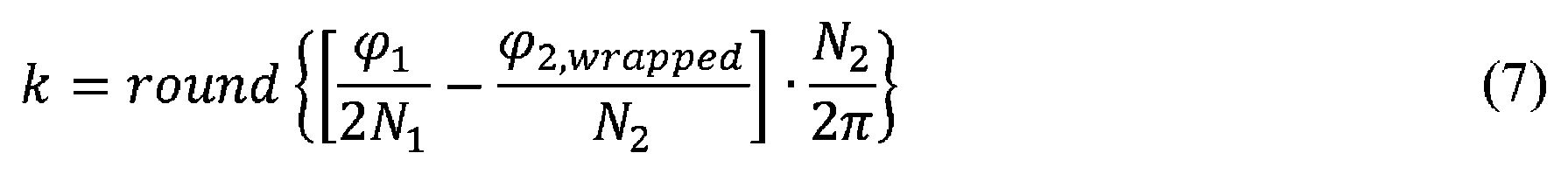
[0035] 所与のΔtに関して、式(1)のφ1と式(2)のアンラップされた位相φ2,unwrappedとの間には、

φ2,unwrapped=φ2,wrapped+2πk (4)
ここで、kはラップカウントであり、ラップされた位相φ2,unwrappedが何回ラップされたかのカウントを示す整数(場合によっては、0)である。伝搬遅延したワイヤレスクロック同期信号のラップされた位相φ2,wrappedが、その後、ラップカウントkを用いてアンラップされ、アンラップされた位相φ2,unwrappedが生成される。このため、式(4)を用いて、式(3)を以下のように書き直すことができる。


φ 2,unwrapped =φ 2,wrapped +2πk (4)
where k is the wrap count, an integer (possibly 0) that indicates the count of how many times the wrapped phase φ 2,unwrapped has been wrapped. The wrapped phase φ 2,wrapped of the propagation delayed wireless clock synchronization signal is then unwrapped using the wrap count k to produce the unwrapped phase φ 2,unwrapped . Therefore, using equation (4), equation (3) can be rewritten as follows.
[0036] 代わりに、測定されたラップされた位相φ2,wrappedが周波数(N2+N1)f0の上側波帯のラップされた位相として選択される場合には、式(8)において、N2の各出現が(N2+N1)に置き換えられ、


[0037] ここで図2を参照すると、図1のMR受信コイル20の電子回路32の例示が示される。電子回路32は、MR信号サンプルにタイムスタンプを割り当てるためのオンボードクロック60を備える。例示的なクロック60は、デジタルカウンタ64をドライブするローカル発振器(LO)62を備える。電子回路32は、クロック同期を実行し、例示的なMR受信コイル例では、受信されたMR信号を処理するように構成される少なくとも1つの電子信号処理コンポーネント66を更に備える。後端に向かって、少なくとも1つの電子信号処理コンポーネント66は、少なくとも1つのコイルループ24によって受信されたMR信号を増幅する前置増幅器67と、受信され、増幅されたMR信号のデジタルサンプルを生成するアナログ/デジタル(A/D)コンバータ68とを備える。図2は、単一の前置増幅器67-A/Dコンバータ68のチェーンを示すが、複数の受信チャネルに対応する並列チェーンが存在する場合もあり、例えば、図1のMR受信コイル20は、9個の別々のチャネルに給電することができるか、又は9個より少ないチャネルに給電するように様々に組み合わせることができる9個のコイルループ24を備える。
[0037] Referring now to FIG. 2, an illustration of the
[0038] 少なくとも1つの電子信号処理コンポーネント66は、オンボードクロック60を用いて、少なくとも1つのコイル素子24によって受信された(そして、信号処理チェーン67、68によって増幅され、デジタル化された)MR信号のタイムスタンプ付きサンプルを生成するように構成されるデジタルプロセッサ70(例えば、デジタルマイクロプロセッサ、デジタルマイクロコントローラ、フィールドプログラマブルゲートアレイ(FPGA)など)を更に備える。1つの手法では、クロック60のデジタルカウンタ64のインクリメントによって(又は何らかの設定されたインクリメント数の発生によって、例えば、16カウントごとに)、MR信号サンプル取得がトリガされる。これは、デジタルカウンタ64のインクリメント時にサンプルにロックするために、A/Dコンバータ68のラッチをトリガする。デジタルMR信号サンプルは、その後、ラッチされたA/Dコンバータ68からデジタルプロセッサ70に読み込まれ、デジタルカウンタ64から、デジタルプロセッサ70に読み込まれたタイムスタンプを割り当てられる。これは、タイムスタンプ付きMR信号サンプルを生成するための1つの例示的な手法にすぎない。取得されたサンプルは、送信機又は送受信機72によってワイヤレスで出力され、送信機又は送受信機は、いくつかの実施形態において、伝搬遅延したワイヤレスクロック同期信号54を受信する送受信機30(図1を参照)と同じである送受信機72であるが、異なる受信機/送信機/送受信機ユニットも考えられる。MR信号サンプルをMR受信コイルからワイヤレスでポート出力する代わりに、光ファイバ接続又は電気ケーブルを使用するなどの他の手法も考えられる。
[0038] The at least one electronic
[0039] 引き続き図2を参照すると、少なくとも1つの電子信号処理コンポーネント66は、ワイヤレスクロック同期信号50(図1を参照)を用いてクロック60を同期させるクロック同期を実行するように更に構成される。例示的なクロック同期コンポーネントは、式(8)を実現するために図2に示されるように相互接続される、利得


[0040] 図3及び図4を参照すると、式(8)のMathcadの実施態様を用いた、シミュレーション結果が提示される。このシミュレーションにおいては、N1=1、N2=128、及びf0=20MHzである。図3は、0psから2000psまでのΔtの線形掃引の場合の入力データを示す。所与の範囲にわたって、kに関する値とともに、φ1及びφ2,wrappedが図示される。図から明らかであるように、φ1が30度だけ変化し、その間、φ2,wrappedが+180度から-180度まで5回ラップされる。図4は、k値及び測定された搬送波位相φ2,wrappedとともに、再生された搬送波位相φ2,unwrappedを示す。 [0040] Referring to Figures 3 and 4, simulation results are presented using a Mathcad implementation of equation (8). In this simulation, N 1 =1, N 2 =128, and f 0 =20 MHz. FIG. 3 shows the input data for a linear sweep of Δt from 0 ps to 2000 ps. φ 1 and φ 2,wrapped are plotted along with the values for k over the given range. As can be seen, φ 1 changes by 30 degrees while φ 2,wrapped from +180 degrees to -180 degrees five times. FIG. 4 shows the recovered carrier phase φ 2,unwrapped along with the k value and the measured carrier phase φ 2, wrapped.
[0041] 本発明が、好ましい実施形態を参照しながら説明されてきた。これまでの詳細な説明を読み、理解すると、第三者にも変更及び改変が思い浮かぶ場合がある。全てのそのような変更及び改変が添付の特許請求の範囲及びその均等物の範囲内に入る限り、例示的な実施形態は、全てのそのような変更及び改変を含むものと解釈されることを意図している。 [0041] The invention has been described with reference to preferred embodiments. Modifications and alterations may occur to third parties upon reading and understanding the preceding detailed description. It is intended that the exemplary embodiments be construed to include all such modifications and modifications insofar as they come within the scope of the appended claims and their equivalents. intended.
Claims (22)
デジタルカウンタをドライブするローカル発振器を備えるクロックと、
クロック同期を実行する少なくとも1つの電子信号処理コンポーネントとを備える、クロック式電子デバイスであって、
前記第1の搬送波周波数及び前記第2の搬送波周波数は、マスター搬送波周波数に対して相対的に小さい、かつ、前記第1の伝搬遅延した搬送波信号の位相と前記第2の伝搬遅延した搬送波信号の位相との間の位相差のラッピングが予想されない周波数差だけ離間されており、
前記クロック同期は、
前記位相差及び前記伝搬遅延したワイヤレスクロック同期信号のラップされた位相からラップカウントを求めることと、
前記ラップカウントを用いて、前記伝搬遅延したワイヤレスクロック同期信号のラップされた位相をアンラップし、アンラップされた位相を生成することと、
前記アンラップされた位相を用いて前記クロックを同期させることとを含む、
クロック式電子デバイス。 a wireless receiver or transceiver for receiving a propagation-delayed wireless clock synchronization signal comprising a first propagation-delayed carrier signal and a second propagation-delayed carrier signal at a first carrier frequency and a second carrier frequency, respectively;
a clock with a local oscillator driving a digital counter;
at least one electronic signal processing component for performing clock synchronization, the clocked electronic device comprising:
The first carrier frequency and the second carrier frequency are relatively small with respect to a master carrier frequency and the phase of the first propagation-delayed carrier signal and the phase of the second propagation-delayed carrier signal the wrapping of the phase difference between the phases is spaced apart by an unexpected frequency difference , and
The clock synchronization is
determining a wrap count from the phase difference and the wrapped phase of the propagation delayed wireless clock synchronization signal ;
unwrapping a wrapped phase of the propagation-delayed wireless clock synchronization signal using the wrap count to produce an unwrapped phase;
synchronizing the clock using the unwrapped phase;
A clocked electronic device.
前記アンラップされた位相から、前記伝搬遅延したワイヤレスクロック同期信号の伝搬遅延を求めることと、
求められた前記伝搬遅延を用いて、前記クロックを同期させることとを含む、請求項1に記載のクロック式電子デバイス。 The clock synchronization is
determining a propagation delay of the propagation-delayed wireless clock synchronization signal from the unwrapped phase;
using the determined propagation delay to synchronize the clock.
前記第1の伝搬遅延した搬送波信号、
前記第2の伝搬遅延した搬送波信号、
前記第1の伝搬遅延した搬送波信号及び前記第2の伝搬遅延した搬送波信号を合成した合成信号、及び
前記伝搬遅延したワイヤレスクロック同期信号の第3の伝搬遅延した搬送波信号、
のうちの1つの前記ラップされた位相であり、前記第3の伝搬遅延した搬送波信号は、前記第1の伝搬遅延した搬送波信号とは異なり、且つ、前記第2の伝搬遅延した搬送波信号とは異なる、請求項1から5のいずれか一項に記載のクロック式電子デバイス。 the wrapped phase of the propagation-delayed wireless clock synchronization signal comprising:
the first propagation-delayed carrier signal;
the second propagation-delayed carrier signal;
a combined signal combining said first propagation delayed carrier signal and said second propagation delayed carrier signal; and a third propagation delayed carrier signal of said propagation delayed wireless clock synchronization signal;
wherein the third propagation delayed carrier signal is different from the first propagation delayed carrier signal and different from the second propagation delayed carrier signal A clocked electronic device according to any one of claims 1 to 5, which is different.
クロック同期信号を生成する無線周波数(RF)信号発生器と、
前記クロック同期信号をワイヤレスクロック同期信号として自由空間の中にワイヤレス送信するように接続される送信機又は送受信機とを備え、前記伝搬遅延したワイヤレスクロック同期信号は、自由空間を通って前記ワイヤレス受信機又は送受信機に送信される前記ワイヤレスクロック同期信号を含む、請求項1から6のいずれか一項に記載のクロック式電子デバイス。 Further comprising a wireless clock synchronization signal generator, the wireless clock synchronization signal generator comprising:
a radio frequency (RF) signal generator for generating a clock synchronization signal;
a transmitter or transceiver connected to wirelessly transmit said clock synchronization signal as a wireless clock synchronization signal into free space, said propagation delayed wireless clock synchronization signal being transmitted through said wireless reception through free space. 7. A clocked electronic device according to any one of the preceding claims, comprising the wireless clock synchronization signal transmitted to a machine or transceiver.
前記ワイヤレスクロック同期信号発生器は前記ワイヤレスデバイスの一部ではない、請求項7又は8に記載のクロック式電子デバイス。 said wireless receiver or transceiver, said clock, and said at least one electronic signal processing component constitute a wireless device;
9. A clocked electronic device according to claim 7 or 8, wherein the wireless clock synchronization signal generator is not part of the wireless device.
第1の搬送波周波数及び第2の搬送波周波数それぞれの第1の伝搬遅延した搬送波信号及び第2の伝搬遅延した搬送波信号を含む伝搬遅延したワイヤレスクロック同期信号を受信するワイヤレス受信機又は送受信機と、
オンボードクロックと、
前記オンボードクロックを用いて、前記少なくとも1つのコイル素子によって受信された前記MR信号のタイムスタンプ付きサンプルを生成し、クロック同期を更に実行する少なくとも1つの電子信号処理コンポーネントとを備える、磁気共鳴受信コイルであって、
前記第1の搬送波周波数及び前記第2の搬送波周波数は、マスター搬送波周波数に対して相対的に小さい、かつ、前記第1の伝搬遅延した搬送波信号の位相と前記第2の伝搬遅延した搬送波信号の位相との間の位相差のラッピングが予想されない周波数差だけ離間されており、
前記クロック同期は、
前記位相差及び前記伝搬遅延したワイヤレスクロック同期信号のラップされた位相からラップカウントを求めることと、
前記ラップカウントを用いて、前記伝搬遅延したワイヤレスクロック同期信号のラップされた位相をアンラップし、アンラップされた位相を生成することと、
前記アンラップされた位相を用いて、前記MR受信コイルの前記オンボードクロックを同期させることとを含む、
磁気共鳴受信コイル。 at least one coil element for receiving magnetic resonance (MR) signals;
a wireless receiver or transceiver for receiving a propagation-delayed wireless clock synchronization signal comprising a first propagation-delayed carrier signal and a second propagation-delayed carrier signal at a first carrier frequency and a second carrier frequency, respectively;
onboard clock and
at least one electronic signal processing component that uses the onboard clock to generate time-stamped samples of the MR signals received by the at least one coil element and further performs clock synchronization. a coil,
The first carrier frequency and the second carrier frequency are relatively small with respect to a master carrier frequency and the phase of the first propagation-delayed carrier signal and the phase of the second propagation-delayed carrier signal the wrapping of the phase difference between the phases is spaced apart by an unexpected frequency difference, and
The clock synchronization is
determining a wrap count from the phase difference and the wrapped phase of the propagation delayed wireless clock synchronization signal ;
unwrapping a wrapped phase of the propagation-delayed wireless clock synchronization signal using the wrap count to produce an unwrapped phase;
using the unwrapped phase to synchronize the on-board clock of the MR receive coil;
magnetic resonance receiving coil.
前記アンラップされた位相から、前記伝搬遅延したワイヤレスクロック同期信号の伝搬遅延を求めることと、
求められた前記伝搬遅延を用いて、前記MR受信コイルの前記オンボードクロックを同期させることとを更に含む、請求項10に記載の磁気共鳴受信コイル。 The clock synchronization is
determining a propagation delay of the propagation-delayed wireless clock synchronization signal from the unwrapped phase;
11. The magnetic resonance receive coil of claim 10, further comprising using the determined propagation delay to synchronize the onboard clock of the MR receive coil.
前記少なくとも1つのコイル素子によって受信された前記MR信号を増幅するように接続される前置増幅器と、
前記少なくとも1つのコイル素子によって受信され、前記前置増幅器によって増幅された前記MR信号のデジタルサンプルを生成するように接続されるアナログ/デジタル(A/D)コンバータと、
前記オンボードクロックを用いて前記デジタルサンプルにタイムスタンプを割り当てる、デジタルマイクロプロセッサ、デジタルマイクロコントローラ、及びフィールドプログラマブルゲートアレイ(FPGA)のうちの1つ以上を含む電子プロセッサとを備える、請求項10又は11に記載の磁気共鳴受信コイル。 The at least one electronic signal processing component comprises:
a preamplifier connected to amplify the MR signal received by the at least one coil element;
an analog-to-digital (A/D) converter connected to produce digital samples of the MR signal received by the at least one coil element and amplified by the preamplifier;
an electronic processor including one or more of a digital microprocessor, a digital microcontroller, and a field programmable gate array (FPGA) that assigns time stamps to the digital samples using the onboard clock. 12. The magnetic resonance receiving coil according to 11.
前記磁気共鳴受信コイルが、伝搬遅延したワイヤレスクロック同期信号を受信する前記ワイヤレス受信機又は送受信機とは別のワイヤレスデータ出力送信機又は送受信機を更に備えるか、の一方であって、前記ワイヤレスデータ出力送信機又は送受信機は、前記少なくとも1つのコイル素子によって受信された前記磁気共鳴信号の前記タイムスタンプ付きサンプルを前記磁気共鳴受信コイルから送信する、請求項10から14のいずれか一項に記載の磁気共鳴受信コイル。 wherein the wireless receiver or transceiver is a wireless transceiver further configured to transmit from the MR receive coil the time-stamped samples of the MR signal received by the at least one coil element; or wherein said magnetic resonance receive coil further comprises a wireless data output transmitter or transceiver separate from said wireless receiver or transceiver for receiving a propagation delayed wireless clock synchronization signal, wherein said wireless data 15. Any one of claims 10 to 14, wherein an output transmitter or transceiver transmits from the magnetic resonance receive coil the time-stamped samples of the magnetic resonance signals received by the at least one coil element. magnetic resonance receiving coil.
請求項10から15のいずれか一項に記載の磁気共鳴受信コイルと、
ワイヤレスクロック同期信号を自由空間の中に送信するワイヤレスクロック同期信号発生器とを備える、磁気共鳴撮像デバイスであって、
前記伝搬遅延したワイヤレスクロック同期信号は、自由空間を通って、前記磁気共鳴受信コイルの前記ワイヤレス受信機又は送受信機に送信される前記ワイヤレスクロック同期信号を含む、磁気共鳴撮像デバイス。 a magnetic resonance imaging scanner;
a magnetic resonance receiving coil according to any one of claims 10 to 15;
a wireless clock synchronization signal generator for transmitting a wireless clock synchronization signal into free space, comprising:
A magnetic resonance imaging device, wherein the propagation-delayed wireless clock synchronization signal comprises the wireless clock synchronization signal transmitted through free space to the wireless receiver or transceiver of the magnetic resonance receive coil.
少なくとも1つの電子信号処理コンポーネントを用いて、動作を実行するステップとを含む、クロック同期方法であって、
前記動作は、
前記位相差及び前記伝搬遅延したワイヤレスクロック同期信号のラップされた位相からラップカウントを求めるステップと、
前記ラップカウントを用いて、前記伝搬遅延したワイヤレスクロック同期信号のラップされた位相をアンラップし、アンラップされた位相を生成するステップと、
前記アンラップされた位相を用いて電子クロックを同期させるステップとを含む、
クロック同期方法。 generating a propagation-delayed wireless clock synchronization signal comprising a first propagation-delayed carrier signal and a second propagation-delayed carrier signal at a first carrier frequency and a second carrier frequency, respectively, using a wireless receiver or transceiver; receiving a free space transmission, wherein said first carrier frequency and said second carrier frequency are relatively small relative to a master carrier frequency and phase of said first propagation delayed carrier signal; and the phase of the second propagation-delayed carrier signal is spaced apart by an unexpected frequency difference;
and performing an operation with at least one electronic signal processing component, comprising:
The operation is
determining a wrap count from the phase difference and the wrapped phase of the propagation delayed wireless clock synchronization signal ;
unwrapping a wrapped phase of the propagation-delayed wireless clock synchronization signal using the wrap count to produce an unwrapped phase;
and synchronizing an electronic clock using the unwrapped phase.
Clock synchronization method.
前記電子クロックは、求められた前記伝搬遅延を用いて同期する、請求項18に記載のクロック同期方法。 the operations performed with the at least one electronic signal processing component further comprising determining a propagation delay of the propagation-delayed wireless clock synchronization signal from the unwrapped phase;
19. The clock synchronization method of claim 18, wherein the electronic clock is synchronized using the determined propagation delay.
前記第1の伝搬遅延した搬送波信号、
前記第2の伝搬遅延した搬送波信号、
前記第1の伝搬遅延した搬送波信号及び前記第2の伝搬遅延した搬送波信号を合成した合成信号、及び
前記伝搬遅延したワイヤレスクロック同期信号の第3の伝搬遅延した搬送波信号、
のうちの1つの前記ラップされた位相であり、前記第3の伝搬遅延した搬送波信号は、前記第1の伝搬遅延した搬送波信号とは異なり、且つ、前記第2の伝搬遅延した搬送波信号とは異なる、請求項18又は19に記載のクロック同期方法。 the wrapped phase of the propagation-delayed wireless clock synchronization signal comprising:
the first propagation-delayed carrier signal;
the second propagation-delayed carrier signal;
a combined signal combining said first propagation delayed carrier signal and said second propagation delayed carrier signal; and a third propagation delayed carrier signal of said propagation delayed wireless clock synchronization signal;
wherein the third propagation delayed carrier signal is different from the first propagation delayed carrier signal and different from the second propagation delayed carrier signal 20. A clock synchronization method according to claim 18 or 19, which is different.
前記クロック同期信号をワイヤレスクロック同期信号として自由空間の中にワイヤレス送信するステップとを更に含み、前記伝搬遅延したワイヤレスクロック同期信号は、自由空間を通って、前記ワイヤレス受信機又は送受信機に送信される前記ワイヤレスクロック同期信号を含む、請求項18から20のいずれか一項に記載のクロック同期方法。 operating a radio frequency (RF) signal generator to generate a clock synchronization signal;
wirelessly transmitting the clock synchronization signal as a wireless clock synchronization signal into free space, wherein the propagation delayed wireless clock synchronization signal is transmitted through free space to the wireless receiver or transceiver. 21. A clock synchronization method as claimed in any one of claims 18 to 20, comprising the wireless clock synchronization signal.
両側波帯(DSB)変調器を備える前記RF信号発生器を動作させて、マスター搬送波信号を、前記第1の搬送波周波数と前記第2の搬送波周波数との前記周波数差の半分に等しいベースバンド周波数のベースバンド信号で変調することによって前記クロック同期信号を生成するステップを含む、請求項21に記載のクロック同期方法。 Operating the RF signal generator comprises:
operating said RF signal generator comprising a double sideband (DSB) modulator to generate a master carrier signal at a baseband frequency equal to half said frequency difference between said first carrier frequency and said second carrier frequency; 22. The clock synchronization method of claim 21, comprising generating the clock synchronization signal by modulating with a baseband signal of .
Applications Claiming Priority (3)
| Application Number | Priority Date | Filing Date | Title |
|---|---|---|---|
| US201862631528P | 2018-02-16 | 2018-02-16 | |
| US62/631,528 | 2018-02-16 | ||
| PCT/EP2019/052160 WO2019158357A1 (en) | 2018-02-16 | 2019-01-30 | Improved carrier phase tracking using multiple carriers |
Publications (2)
| Publication Number | Publication Date |
|---|---|
| JP2021514580A JP2021514580A (en) | 2021-06-10 |
| JP7221977B2 true JP7221977B2 (en) | 2023-02-14 |
Family
ID=65363243
Family Applications (1)
| Application Number | Title | Priority Date | Filing Date |
|---|---|---|---|
| JP2020543161A Active JP7221977B2 (en) | 2018-02-16 | 2019-01-30 | Improved carrier phase tracking using multiple carriers |
Country Status (5)
| Country | Link |
|---|---|
| US (1) | US11320501B2 (en) |
| EP (1) | EP3752846B1 (en) |
| JP (1) | JP7221977B2 (en) |
| CN (1) | CN111727377B (en) |
| WO (1) | WO2019158357A1 (en) |
Families Citing this family (10)
| Publication number | Priority date | Publication date | Assignee | Title |
|---|---|---|---|---|
| US11402451B2 (en) * | 2020-09-24 | 2022-08-02 | Siemens Medical Solutions Usa, Inc. | Timing signal distribution to pet imaging components via optical path |
| CN113054932B (en) * | 2021-03-09 | 2024-08-16 | 中国计量科学研究院 | One-dimensional phase unwrapping method implemented on FPGA |
| WO2023009855A2 (en) * | 2021-07-29 | 2023-02-02 | Spearix Technologies, Inc. | Accurate clock synchronization and location detection in time-sensitive wireless networks |
| USD1057157S1 (en) * | 2021-10-06 | 2025-01-07 | Koninklijke Philips N.V. | Scanner |
| USD1057158S1 (en) * | 2021-10-06 | 2025-01-07 | Koninklijke Philips N.V. | Scanner |
| US12376760B2 (en) * | 2022-04-27 | 2025-08-05 | Canon Medical Systems Corporation | Magnetic resonance imaging apparatus, and control method for magnetic resonance imaging apparatus |
| EP4618467A4 (en) * | 2022-11-16 | 2026-01-21 | Huawei Tech Co Ltd | METHOD AND DEVICE FOR TIME SYNCHRONIZATION |
| JP2025027202A (en) * | 2023-08-14 | 2025-02-27 | キヤノンメディカルシステムズ株式会社 | Magnetic resonance imaging equipment |
| KR102916976B1 (en) * | 2024-11-07 | 2026-01-26 | 엘아이지넥스원 주식회사 | Near-field test system and near-field test method |
| CN119655736A (en) * | 2024-11-27 | 2025-03-21 | 上海联影医疗科技股份有限公司 | Magnetic resonance imaging method and magnetic resonance imaging device |
Citations (5)
| Publication number | Priority date | Publication date | Assignee | Title |
|---|---|---|---|---|
| JP2005509372A (en) | 2001-11-06 | 2005-04-07 | コーニンクレッカ フィリップス エレクトロニクス エヌ ヴィ | DAT-assisted frequency offset detection using phase unwrapping |
| US20150084644A1 (en) | 2013-09-26 | 2015-03-26 | Electronics And Telecommunications Research Institute | Phase measurement device and method in microwave tomography system |
| WO2015197720A1 (en) | 2014-06-25 | 2015-12-30 | Koninklijke Philips N.V. | Mri system with wireless synchronization of a wireless rf coil portion using a double sideband suppressed carrier signal |
| JP2016054931A (en) | 2014-09-09 | 2016-04-21 | 株式会社東芝 | Magnetic resonance imaging apparatus and RF coil |
| JP2017143429A (en) | 2016-02-10 | 2017-08-17 | 国立研究開発法人情報通信研究機構 | Method for detecting synchronization deviation between communication stations |
Family Cites Families (22)
| Publication number | Priority date | Publication date | Assignee | Title |
|---|---|---|---|---|
| US5529068A (en) | 1994-06-16 | 1996-06-25 | The Regents Of The University Of California | Synchronized digital signal processor for MRI reception |
| US6044122A (en) * | 1997-01-23 | 2000-03-28 | Ericsson, Inc. | Digital phase acquisition with delay locked loop |
| US6058151A (en) * | 1997-08-19 | 2000-05-02 | Realtek Semiconductor Corp. | Digital phase shift phase-locked loop for data and clock recovery |
| US6148052A (en) * | 1997-12-10 | 2000-11-14 | Nortel Networks Corporation | Digital phase detector with ring oscillator capture and inverter delay calibration |
| US6356608B1 (en) * | 1998-06-29 | 2002-03-12 | Telefonaktiebolaget Lm Ericsson (Publ) | Method, apparatus, and system for determining a location of a frequency synchronization signal |
| US20070061657A1 (en) * | 2005-08-12 | 2007-03-15 | National Tsing Hua University | Delay fault testing apparatus |
| CN101442369B (en) * | 2007-11-20 | 2012-07-25 | 上海瑞高信息技术有限公司 | Ground forwarding synchronization system and method for mobile multimedia broadcast satellite distribution system |
| RU2559716C2 (en) | 2009-12-17 | 2015-08-10 | Конинклейке Филипс Электроникс Н.В. | Direct digital receiver with local free running clock |
| KR101229499B1 (en) | 2011-11-17 | 2013-02-04 | 삼성전자주식회사 | Apparatus and method for synchronizing clock between devices of mri system |
| EP2820450B1 (en) * | 2012-02-28 | 2019-04-10 | Koninklijke Philips N.V. | Method and system for synchronizing positron emission tomography (pet) detector modules |
| US8837653B2 (en) * | 2012-06-08 | 2014-09-16 | Deere & Company | High frequency signal receiver with self-calibrated group delay compensation |
| US9897677B2 (en) | 2013-09-04 | 2018-02-20 | Samsung Electronics Co., Ltd. | Method for correcting errors associated with asynchronous timing offsets between transmit and receive clocks in MRI wireless radiofrequency coils |
| US10302716B2 (en) * | 2014-09-25 | 2019-05-28 | Koninklijke Philips N.V. | Digital receiver coil with built-in received phase noise indicator |
| EP3391068B1 (en) | 2015-12-16 | 2022-04-20 | Koninklijke Philips N.V. | Systems and methods for synchronising wireless communication for magnetic resonance imaging (mri) systems |
| EP3203635B1 (en) * | 2016-02-05 | 2018-05-09 | Panthronics AG | Clock synchronizer to synchronize a device clock with a clock of a remote device |
| EP3255800B8 (en) * | 2016-06-10 | 2021-01-20 | Apple Inc. | Interference detection device, interference detection apparatus, interference detection method, computer program, receiver, mobile terminal and base station |
| CN106483445B (en) * | 2016-06-30 | 2019-06-14 | 南京国睿安泰信科技股份有限公司 | A kind of built-in measurement method and device of wideband circuit phase nonlinear distortion |
| CN107645770B (en) * | 2016-07-13 | 2020-10-23 | 华为技术有限公司 | A phase calibration method and device |
| CN107595289B (en) * | 2017-09-19 | 2021-04-27 | 佛山市丈量科技有限公司 | Non-contact respiratory ventilation detection method and device, medium and computer equipment |
| IL282493B2 (en) * | 2018-10-29 | 2025-03-01 | Lyseonics BV | A method and system for detection of electromagnetic radiation |
| US11228821B2 (en) * | 2019-01-24 | 2022-01-18 | Baker Hughes Oilfield Operations Llc | Two-way dual-tone methods and systems for synchronizing remote modules |
| JP7664931B2 (en) * | 2020-01-13 | 2025-04-18 | メドルミクス,エセ.エレ. | System for optical analysis and prediction of lesions using an ablation catheter - Patents.com |
-
2019
- 2019-01-30 JP JP2020543161A patent/JP7221977B2/en active Active
- 2019-01-30 EP EP19704231.0A patent/EP3752846B1/en active Active
- 2019-01-30 CN CN201980013463.2A patent/CN111727377B/en active Active
- 2019-01-30 US US16/969,215 patent/US11320501B2/en active Active
- 2019-01-30 WO PCT/EP2019/052160 patent/WO2019158357A1/en not_active Ceased
Patent Citations (5)
| Publication number | Priority date | Publication date | Assignee | Title |
|---|---|---|---|---|
| JP2005509372A (en) | 2001-11-06 | 2005-04-07 | コーニンクレッカ フィリップス エレクトロニクス エヌ ヴィ | DAT-assisted frequency offset detection using phase unwrapping |
| US20150084644A1 (en) | 2013-09-26 | 2015-03-26 | Electronics And Telecommunications Research Institute | Phase measurement device and method in microwave tomography system |
| WO2015197720A1 (en) | 2014-06-25 | 2015-12-30 | Koninklijke Philips N.V. | Mri system with wireless synchronization of a wireless rf coil portion using a double sideband suppressed carrier signal |
| JP2016054931A (en) | 2014-09-09 | 2016-04-21 | 株式会社東芝 | Magnetic resonance imaging apparatus and RF coil |
| JP2017143429A (en) | 2016-02-10 | 2017-08-17 | 国立研究開発法人情報通信研究機構 | Method for detecting synchronization deviation between communication stations |
Also Published As
| Publication number | Publication date |
|---|---|
| US11320501B2 (en) | 2022-05-03 |
| US20200408862A1 (en) | 2020-12-31 |
| EP3752846A1 (en) | 2020-12-23 |
| CN111727377B (en) | 2023-10-31 |
| JP2021514580A (en) | 2021-06-10 |
| EP3752846B1 (en) | 2023-07-12 |
| WO2019158357A1 (en) | 2019-08-22 |
| CN111727377A (en) | 2020-09-29 |
Similar Documents
| Publication | Publication Date | Title |
|---|---|---|
| JP7221977B2 (en) | Improved carrier phase tracking using multiple carriers | |
| RU2605525C2 (en) | Data detection device for use in combination with mri apparatus | |
| CN102193075B (en) | Magnetic resonance imaging apparatus | |
| RU2710012C2 (en) | Magnetic resonance imaging method and device with rf noise | |
| US9012853B2 (en) | Radiation measurement using timing-over-ethernet protocol | |
| CN105517495B (en) | Method and apparatus for correcting errors associated with asynchronous timing offsets between transmit and receive clocks in magnetic resonance imaging wireless radio frequency coils | |
| US10663543B2 (en) | Device and method for recovering a temporal reference in free-running MR receive chains | |
| US10578690B2 (en) | Digital receiver coil with built-in received phase noise indicator | |
| JP2018518322A (en) | Dixon magnetic resonance imaging with phase correction | |
| EP2912484A1 (en) | Reducing interference in a combined system comprising an mri system and a non-mr imaging system | |
| Gebhardt et al. | FPGA-based RF interference reduction techniques for simultaneous PET–MRI | |
| US20100084560A1 (en) | Timing response improvement in light-sharing detectors | |
| US10520568B2 (en) | Hybrid TOF-PET/MRI tomograph | |
| Dong et al. | Design and characterization of the detector readout electronics used in PETcoil: An RF-penetrable TOF-PET insert for PET/MRI | |
| Speier et al. | Skip the electrodes, but not a beat: the engineering behind the beat sensor | |
| Tasdelen et al. | Contactless cardiac gating at 0.55 T using high‐amplitude pilot tone with interference cancellation (HAPTIC) | |
| KR20090068416A (en) | Fusion image acquisition device and driving method thereof | |
| JP6933518B2 (en) | Magnetic resonance imaging system and receiving coil unit | |
| Chang | Radio-Frequency Penetrable Positron Emission Tomography (PET) Insert for Simultaneous PET and Magnetic Resonance Imaging | |
| Schildknecht et al. | Christoph Schildknecht, PhD Research Engineer, Skope | |
| Schildknecht et al. | LEAN RF HEAD FOR LOW-NOISE, LOW-POWER DIGITIZATION AT THE |
Legal Events
| Date | Code | Title | Description |
|---|---|---|---|
| A621 | Written request for application examination |
Free format text: JAPANESE INTERMEDIATE CODE: A621 Effective date: 20220126 |
|
| A871 | Explanation of circumstances concerning accelerated examination |
Free format text: JAPANESE INTERMEDIATE CODE: A871 Effective date: 20220126 |
|
| A131 | Notification of reasons for refusal |
Free format text: JAPANESE INTERMEDIATE CODE: A131 Effective date: 20220427 |
|
| A601 | Written request for extension of time |
Free format text: JAPANESE INTERMEDIATE CODE: A601 Effective date: 20220720 |
|
| A521 | Request for written amendment filed |
Free format text: JAPANESE INTERMEDIATE CODE: A523 Effective date: 20221026 |
|
| TRDD | Decision of grant or rejection written | ||
| A01 | Written decision to grant a patent or to grant a registration (utility model) |
Free format text: JAPANESE INTERMEDIATE CODE: A01 Effective date: 20230106 |
|
| A61 | First payment of annual fees (during grant procedure) |
Free format text: JAPANESE INTERMEDIATE CODE: A61 Effective date: 20230202 |
|
| R150 | Certificate of patent or registration of utility model |
Ref document number: 7221977 Country of ref document: JP Free format text: JAPANESE INTERMEDIATE CODE: R150 |
|
| R250 | Receipt of annual fees |
Free format text: JAPANESE INTERMEDIATE CODE: R250 |