JP7221870B2 - Uplink MIMO reference signal and data transmission scheme - Google Patents
Uplink MIMO reference signal and data transmission scheme Download PDFInfo
- Publication number
- JP7221870B2 JP7221870B2 JP2019540572A JP2019540572A JP7221870B2 JP 7221870 B2 JP7221870 B2 JP 7221870B2 JP 2019540572 A JP2019540572 A JP 2019540572A JP 2019540572 A JP2019540572 A JP 2019540572A JP 7221870 B2 JP7221870 B2 JP 7221870B2
- Authority
- JP
- Japan
- Prior art keywords
- prg
- srs
- transmission
- aspects
- ofdm
- Prior art date
- Legal status (The legal status is an assumption and is not a legal conclusion. Google has not performed a legal analysis and makes no representation as to the accuracy of the status listed.)
- Active
Links
Images


Classifications
-
- H—ELECTRICITY
- H04—ELECTRIC COMMUNICATION TECHNIQUE
- H04L—TRANSMISSION OF DIGITAL INFORMATION, e.g. TELEGRAPHIC COMMUNICATION
- H04L27/00—Modulated-carrier systems
- H04L27/26—Systems using multi-frequency codes
-
- H—ELECTRICITY
- H04—ELECTRIC COMMUNICATION TECHNIQUE
- H04L—TRANSMISSION OF DIGITAL INFORMATION, e.g. TELEGRAPHIC COMMUNICATION
- H04L27/00—Modulated-carrier systems
- H04L27/26—Systems using multi-frequency codes
- H04L27/2601—Multicarrier modulation systems
- H04L27/2602—Signal structure
- H04L27/261—Details of reference signals
- H04L27/2613—Structure of the reference signals
-
- H—ELECTRICITY
- H04—ELECTRIC COMMUNICATION TECHNIQUE
- H04L—TRANSMISSION OF DIGITAL INFORMATION, e.g. TELEGRAPHIC COMMUNICATION
- H04L5/00—Arrangements affording multiple use of the transmission path
- H04L5/0001—Arrangements for dividing the transmission path
- H04L5/0014—Three-dimensional division
- H04L5/0016—Time-frequency-code
-
- H—ELECTRICITY
- H04—ELECTRIC COMMUNICATION TECHNIQUE
- H04L—TRANSMISSION OF DIGITAL INFORMATION, e.g. TELEGRAPHIC COMMUNICATION
- H04L5/00—Arrangements affording multiple use of the transmission path
- H04L5/0001—Arrangements for dividing the transmission path
- H04L5/0014—Three-dimensional division
- H04L5/0023—Time-frequency-space
-
- H—ELECTRICITY
- H04—ELECTRIC COMMUNICATION TECHNIQUE
- H04L—TRANSMISSION OF DIGITAL INFORMATION, e.g. TELEGRAPHIC COMMUNICATION
- H04L5/00—Arrangements affording multiple use of the transmission path
- H04L5/003—Arrangements for allocating sub-channels of the transmission path
- H04L5/0048—Allocation of pilot signals, i.e. of signals known to the receiver
- H04L5/005—Allocation of pilot signals, i.e. of signals known to the receiver of common pilots, i.e. pilots destined for multiple users or terminals
-
- H—ELECTRICITY
- H04—ELECTRIC COMMUNICATION TECHNIQUE
- H04L—TRANSMISSION OF DIGITAL INFORMATION, e.g. TELEGRAPHIC COMMUNICATION
- H04L5/00—Arrangements affording multiple use of the transmission path
- H04L5/003—Arrangements for allocating sub-channels of the transmission path
- H04L5/0048—Allocation of pilot signals, i.e. of signals known to the receiver
- H04L5/0051—Allocation of pilot signals, i.e. of signals known to the receiver of dedicated pilots, i.e. pilots destined for a single user or terminal
-
- H—ELECTRICITY
- H04—ELECTRIC COMMUNICATION TECHNIQUE
- H04L—TRANSMISSION OF DIGITAL INFORMATION, e.g. TELEGRAPHIC COMMUNICATION
- H04L5/00—Arrangements affording multiple use of the transmission path
- H04L5/0091—Signaling for the administration of the divided path
-
- H—ELECTRICITY
- H04—ELECTRIC COMMUNICATION TECHNIQUE
- H04W—WIRELESS COMMUNICATION NETWORKS
- H04W52/00—Power management, e.g. TPC [Transmission Power Control], power saving or power classes
- H04W52/04—TPC
- H04W52/18—TPC being performed according to specific parameters
-
- H—ELECTRICITY
- H04—ELECTRIC COMMUNICATION TECHNIQUE
- H04W—WIRELESS COMMUNICATION NETWORKS
- H04W52/00—Power management, e.g. TPC [Transmission Power Control], power saving or power classes
- H04W52/04—TPC
- H04W52/30—TPC using constraints in the total amount of available transmission power
- H04W52/36—TPC using constraints in the total amount of available transmission power with a discrete range or set of values, e.g. step size, ramping or offsets
- H04W52/365—Power headroom reporting
-
- H—ELECTRICITY
- H04—ELECTRIC COMMUNICATION TECHNIQUE
- H04W—WIRELESS COMMUNICATION NETWORKS
- H04W72/00—Local resource management
- H04W72/20—Control channels or signalling for resource management
- H04W72/21—Control channels or signalling for resource management in the uplink direction of a wireless link, i.e. towards the network
-
- H—ELECTRICITY
- H04—ELECTRIC COMMUNICATION TECHNIQUE
- H04L—TRANSMISSION OF DIGITAL INFORMATION, e.g. TELEGRAPHIC COMMUNICATION
- H04L27/00—Modulated-carrier systems
- H04L27/26—Systems using multi-frequency codes
- H04L27/2601—Multicarrier modulation systems
- H04L27/2602—Signal structure
- H04L27/2605—Symbol extensions, e.g. Zero Tail, Unique Word [UW]
- H04L27/2607—Cyclic extensions
-
- H—ELECTRICITY
- H04—ELECTRIC COMMUNICATION TECHNIQUE
- H04L—TRANSMISSION OF DIGITAL INFORMATION, e.g. TELEGRAPHIC COMMUNICATION
- H04L27/00—Modulated-carrier systems
- H04L27/26—Systems using multi-frequency codes
- H04L27/2601—Multicarrier modulation systems
- H04L27/2626—Arrangements specific to the transmitter only
- H04L27/2627—Modulators
- H04L27/2634—Inverse fast Fourier transform [IFFT] or inverse discrete Fourier transform [IDFT] modulators in combination with other circuits for modulation
- H04L27/2636—Inverse fast Fourier transform [IFFT] or inverse discrete Fourier transform [IDFT] modulators in combination with other circuits for modulation with FFT or DFT modulators, e.g. standard single-carrier frequency-division multiple access [SC-FDMA] transmitter or DFT spread orthogonal frequency division multiplexing [DFT-SOFDM]
Description
関連出願の相互参照
本特許出願は、2017年2月6日に出願された米国仮特許出願第62/455,558号、および2017年9月22日に出願された米国特許出願第15/713,270号の利益を主張するものであり、その両出願は本出願の譲受人に譲渡され、参照により本明細書に明確に組み込まれている。
CROSS-REFERENCE TO RELATED APPLICATIONS This patent application is subject to U.S. Provisional Patent Application No. 62/455,558, filed February 6, 2017, and U.S. Patent Application No. 15/713,270, filed September 22, 2017. Both applications are assigned to the assignee of the present application and are expressly incorporated herein by reference.
本開示は、一般に、通信システムに関し、より詳細には、5G技術に従って動作するアップリンクMIMO基準信号およびデータ送信方式の通信システムのための方法および装置に関する。 TECHNICAL FIELD This disclosure relates generally to communication systems, and more particularly to methods and apparatus for communication systems for uplink MIMO reference signal and data transmission schemes operating in accordance with 5G technologies.
ワイヤレス通信システムは、電話、ビデオ、データ、メッセージング、およびブロードキャストなどの、様々な電気通信サービスを提供するために広く展開されている。一般のワイヤレス通信システムは、利用可能なシステムリソース(たとえば、帯域幅、送信電力)を共有することによって複数のユーザとの通信をサポートすることが可能な多元接続技術を採用し得る。そのような多元接続技術の例は、ロングタームエボリューション(LTE)システム、符号分割多元接続(CDMA)システム、時分割多元接続(TDMA)システム、周波数分割多元接続(FDMA)システム、直交周波数分割多元接続(OFDMA)システム、シングルキャリア周波数分割多元接続(SC-FDMA)システム、および時分割同期符号分割多元接続(TD-SCDMA)システムを含む。 Wireless communication systems are widely deployed to provide various telecommunication services such as telephone, video, data, messaging and broadcast. A typical wireless communication system may employ multiple-access techniques that can support communication with multiple users by sharing available system resources (eg, bandwidth, transmit power). Examples of such multiple-access techniques are Long Term Evolution (LTE) systems, Code Division Multiple Access (CDMA) systems, Time Division Multiple Access (TDMA) systems, Frequency Division Multiple Access (FDMA) systems, Orthogonal Frequency Division Multiple Access. (OFDMA) systems, single carrier frequency division multiple access (SC-FDMA) systems, and time division synchronous code division multiple access (TD-SCDMA) systems.
いくつかの例では、ワイヤレス多元接続通信システムは、ユーザ機器(UE)としても知られている複数の通信デバイスのための通信を各々が同時にサポートする、いくつかの基地局を含み得る。LTEまたはLTE-Aネットワークでは、1つまたは複数の基地局のセットがeノードB(eNB)を定義してよい。他の例では(たとえば、次世代または5Gネットワークでは)、ワイヤレス多元接続通信システムは、いくつかの集約ユニット(CU)(たとえば、中央ノード(CN)、アクセスノードコントローラ(ANC)など)と通信するいくつかの分散ユニット(DU)(たとえば、エッジユニット(EU)、エッジノード(EN)、無線ヘッド(RH)、スマート無線ヘッド(SRH)、送信受信ポイント(TRP)など)を含んでよく、集約ユニットと通信する1つまたは複数の分散ユニットのセットがアクセスノード(たとえば、ニューラジオ基地局(NR BS:new radio base station)、ニューラジオノードB(NR NB:new radio node-B)、ネットワークノード、5G NB、eNBなど)を定義してよい。基地局またはDUは、(たとえば、基地局から、またはUEへの送信のための)ダウンリンクチャネルおよび(たとえば、UEから基地局または分散ユニットへの送信のための)アップリンクチャネル上でUEのセットと通信してよい。 In some examples, a wireless multiple-access communication system may include a number of base stations that each simultaneously support communication for multiple communication devices, also known as user equipments (UEs). In an LTE or LTE-A network, a set of one or more base stations may define an eNodeB (eNB). In other examples (e.g., in next-generation or 5G networks), a wireless multiple-access communication system communicates with several aggregation units (CUs) (e.g., central nodes (CN), access node controllers (ANC), etc.). It may contain several distributed units (DUs) (e.g. Edge Units (EU), Edge Nodes (EN), Radio Heads (RH), Smart Radio Heads (SRH), Transmit and Receive Points (TRP), etc.) and aggregate A set of one or more distributed units communicating with the unit is an access node (e.g., new radio base station (NR BS), new radio node-B (NR NB), network node). , 5G NB, eNB, etc.). A base station or DU monitors a UE on a downlink channel (eg, for transmission from the base station or to the UE) and an uplink channel (eg, for transmission from the UE to the base station or distribution unit). You may communicate with the set.
これらの多元接続技術は、異なるワイヤレスデバイスが都市、国家、地域、さらには地球規模で通信することを可能にする共通プロトコルを提供するために、様々な電気通信規格において採用されている。新生の電気通信規格の一例は、ニューラジオ(NR)、たとえば、5G無線アクセスである。NRは、第3世代パートナーシッププロジェクト(3GPP)によって公表されたLTEモバイル規格に対する拡張のセットである。それは、スペクトル効率を改善し、コストを削減し、サービスを改善し、新しいスペクトルを利用し、またダウンリンク(DL)およびアップリンク(UL)上でOFDMAをサイクリックプレフィックス(CP)とともに使用する他のオープン規格とよりうまく統合することによって、モバイルブロードバンドインターネットアクセスをよりうまくサポートし、ならびにビームフォーミング、多入力多出力(MIMO)アンテナ技術、およびキャリアアグリゲーションをサポートするように設計されている。 These multiple-access techniques have been adopted in various telecommunication standards to provide a common protocol that allows different wireless devices to communicate on a city, national, regional and even global scale. An example of an emerging telecommunications standard is New Radio (NR), eg 5G radio access. NR is a set of extensions to the LTE mobile standard promulgated by the 3rd Generation Partnership Project (3GPP). It improves spectral efficiency, reduces costs, improves services, takes advantage of new spectrum, and uses OFDMA with cyclic prefixes (CP) on the downlink (DL) and uplink (UL). It is designed to better support mobile broadband Internet access by better integrating with the open standards of , as well as support beamforming, multiple-input multiple-output (MIMO) antenna technology, and carrier aggregation.
しかしながら、モバイルブロードバンドアクセスに対する需要が増大し続けるにつれて、5G技術におけるさらなる改善が望まれる。好ましくは、これらの改善は、他の多元接続技術、およびこれらの技術を用いる電気通信規格に適用可能であるべきである。 However, as the demand for mobile broadband access continues to grow, further improvements in 5G technology are desired. Preferably, these improvements should be applicable to other multiple access technologies and telecommunications standards that use these technologies.
本開示のシステム、方法、およびデバイスはそれぞれ、いくつかの態様を有し、それらのうちの単一の態様だけが、その望ましい属性を担うわけではない。以下の特許請求の範囲によって表される本開示の範囲を限定することなく、いくつかの特徴についてここで簡潔に説明する。この説明を考慮した後、また特に「発明を実施するための形態」と題するセクションを読んだ後、本開示の特徴が、ワイヤレスネットワークにおけるアクセスポイントと局との間の改善された通信を含む利点をどのようにもたらすかが理解されよう。 The systems, methods, and devices of the disclosure each have several aspects, no single one of which is solely responsible for its desirable attributes. Without limiting the scope of the disclosure, which is represented by the following claims, some features are briefly described here. After considering this description, and particularly after reading the section entitled "Detailed Description," the features of the present disclosure have the advantage of including improved communication between access points and stations in wireless networks. It will be understood how to bring about
ワイヤレスネットワーク内のデバイスは、SRS送信を使用して通信し得る。場合によっては、SRSは、異なるサブバンドに対して異なってプリコーディングされてもよく、異なるプリコーダは、帯域幅を割り振られたSRSの異なる物理リソースグループ(PRG)選択を使用してもよい。しかしながら、プリコーダ選択は困難である場合がある。同じく、SRS送信に対するPRG選択を決定するための技法を定義することも困難である場合がある。場合によっては、OFDMとDFT-s-OFDMの波形はともに、アップリンクにおいてサポートされ得る。しかしながら、プリコーダ行列、Tx電力スケーリングファクタ、および/または被変調コーディング方式(MCS)は、OFDMに対する場合とDFT-s-OFDMに対する場合とで異なり得る。 Devices within a wireless network may communicate using SRS transmissions. In some cases, SRS may be precoded differently for different subbands, and different precoders may use different physical resource group (PRG) selections of SRS allocated bandwidth. However, precoder selection can be difficult. Similarly, defining techniques for determining PRG selection for SRS transmission can be difficult. In some cases, both OFDM and DFT-s-OFDM waveforms may be supported in the uplink. However, the precoder matrix, Tx power scaling factor, and/or modulated coding scheme (MCS) may be different for OFDM and DFT-s-OFDM.
したがって、本開示の態様は、PRG選択を可能にしてその選択を伝達するための技法を提示する。場合によっては、プリコーダ選択技法が提供され得る。さらに、場合によっては、異なるポートを使用することによってOFDMとDFT-s-OFDMとを区別するための技法が提供され得る。 Accordingly, aspects of this disclosure present techniques for enabling PRG selection and communicating that selection. In some cases, precoder selection techniques may be provided. Additionally, in some cases techniques may be provided to distinguish between OFDM and DFT-s-OFDM by using different ports.
いくつかの態様は、ユーザ機器(UE)によるワイヤレス通信のための方法を提供する。方法は、一般に、UEがサウンディング基準信号(SRS)送信に使用するためのプリコーディングリソースブロックグループ(PRG)サイズを決定するステップであって、SRS送信が、複数のPRGを含む帯域幅にわたって割り振られる、ステップと、その決定に従ってSRS送信を基地局(BS)に送信するステップとを含み、複数のPRGのうちの少なくとも2つは異なるプリコーディングを有する。 Certain aspects provide a method for wireless communication by a user equipment (UE). The method generally comprises determining a precoding resource block group (PRG) size for a UE to use for sounding reference signal (SRS) transmission, wherein the SRS transmission is allocated across a bandwidth containing multiple PRGs. , and transmitting an SRS transmission to a base station (BS) according to the determination, at least two of the plurality of PRGs having different precoding.
いくつかの態様は、基地局によるワイヤレス通信のための方法を提供する。方法は、一般に、ユーザ機器(UE)がサウンディング基準信号(SRS)送信に使用するためのプリコーディングリソースブロックグループ(PRG)サイズを決定するステップと、その決定に従ってUEから送信されたSRSを受信するステップとを含む。 Certain aspects provide a method for wireless communication by a base station. The method generally comprises determining a precoding resource block group (PRG) size for a user equipment (UE) to use for sounding reference signal (SRS) transmission, and receiving the SRS transmitted from the UE according to the determination. step.
いくつかの態様は、装置によるワイヤレス通信のための方法を提供する。方法は、一般に、第1のプリコーダを使用して第1のサブバンドリソース上のサウンディング基準信号(SRS)送信のための第1のシーケンスをプリコーディングするステップと、第2のプリコーダを使用して第2のサブバンドリソース上のサウンディング基準信号(SRS)送信のための第2のシーケンスをプリコーディングするステップと、第1の送信時間間隔内に第1のサブバンドリソース上で基準信号SRS送信の第1のプリコーディングされたシーケンスを送信するステップと、第2の送信時間間隔内に第2のサブバンドリソース上で基準信号SRS送信の第2のプリコーディングされたシーケンスを送信するステップとを含む。 Certain aspects provide a method for wireless communication by an apparatus. The method generally comprises precoding a first sequence for Sounding Reference Signal (SRS) transmission on a first subband resource using a first precoder; precoding a second sequence for sounding reference signal (SRS) transmission on second subband resources; transmitting a first precoded sequence; and transmitting a second precoded sequence of reference signal SRS transmissions on a second subband resource within a second transmission time interval. .
いくつかの態様は、装置によるワイヤレス通信のための方法を提供する。方法は、一般に、第1の送信時間間隔内に第1のサブバンドリソース上でユーザ機器(UE)送信装置から基準信号SRS送信の第1の部分を受信するステップであって、第1の部分は第1のプリコーダを使用してUE送信装置によってプリコーディングされている、ステップと、第2の送信時間間隔内に第2のサブバンドリソース上でUE送信装置から基準信号SRS送信の第2の部分を受信するステップであって、第2の部分は第2のプリコーダを使用してUE送信装置によってプリコーディングされている、ステップと、第1のプリコーダおよび第2のプリコーダに基づいて基準信号SRS送信の第1の部分および第2の部分を処理するステップとを含む。 Certain aspects provide a method for wireless communication by an apparatus. The method generally comprises receiving a first portion of a reference signal SRS transmission from a user equipment (UE) transmitter over a first subband resource within a first transmission time interval, the first portion is precoded by the UE transmitter using the first precoder; and a second reference signal SRS transmission from the UE transmitter on the second subband resource within the second transmission time interval. receiving a portion, the second portion being precoded by the UE transmitter using a second precoder; and a reference signal SRS based on the first precoder and the second precoder. and processing the first and second portions of the transmission.
いくつかの態様は、ユーザ機器によるワイヤレス通信のための方法を提供する。方法は、一般に、アップリンク送信が、DFT拡散直交周波数分割多重(DFT-s-OFDM)信号として送られることになっているかどうかを決定するステップと、その決定に基づいてアップリンク送信を送るための1つまたは複数のポートを選択するステップとを含む。 Certain aspects provide a method for wireless communication by user equipment. The method generally comprises determining whether an uplink transmission is to be sent as a DFT-spread orthogonal frequency division multiplexing (DFT-s-OFDM) signal; and selecting one or more ports of .
いくつかの態様は、基地局によるワイヤレス通信のための方法を提供する。方法は、一般に、アップリンク送信がDFT拡散直交周波数分割多重(DFT-s-OFDM)信号として送られたかどうかを、アップリンク送信を送るためにユーザ機器(UE)によって使用される1つまたは複数のポートに基づいて決定するステップと、その決定に基づいてアップリンク送信を処理するステップとを含む。 Certain aspects provide a method for wireless communication by a base station. The method generally determines whether the uplink transmission was sent as a DFT spread orthogonal frequency division multiplexing (DFT-s-OFDM) signal, one or more and processing the uplink transmission based on the determination.
態様は、一般に、添付の図面を参照しながら本明細書で十分に説明され、添付の図面によって示される、方法、装置、システム、コンピュータ可読媒体、および処理システムを含む。 Aspects generally include methods, apparatus, systems, computer-readable media, and processing systems, which are fully described herein with reference to and illustrated by the accompanying drawings.
上記の目的および関係する目的を達成するために、1つまたは複数の態様は、以下で十分に説明され、特に特許請求の範囲で指摘される特徴を含む。以下の説明および添付の図面は、1つまたは複数の態様のいくつかの例示的な特徴を詳細に記載する。しかしながら、これらの特徴は、様々な態様の原理が利用され得る様々な方法のほんのいくつかを示すものであり、この説明は、すべてのそのような態様およびそれらの均等物を含むものである。 To the accomplishment of the foregoing and related ends, the one or more embodiments comprise the features hereinafter fully described and particularly pointed out in the claims. The following description and the annexed drawings set forth in detail certain illustrative features of the one or more embodiments. These features are indicative, however, of but a few of the various ways in which the principles of various aspects may be employed and this description is intended to include all such aspects and their equivalents.
本開示の上記の特徴が詳細に理解され得るように、上記で簡単に要約したより具体的な説明が、態様を参照することによって行われることがあり、態様のうちのいくつかは添付の図面に示される。しかしながら、本説明は他の等しく効果的な態様に通じ得るので、添付の図面が、本開示のいくつかの典型的な態様のみを示し、したがって、本開示の範囲を限定するものと見なされるべきではないことに留意されたい。 So that the above features of the disclosure may be understood in detail, a more specific description briefly summarized above may be had by reference to the aspects, some of which are illustrated in the accompanying drawings shown in The accompanying drawings, however, should be considered to limit the scope of the disclosure, however, as the description may lead to other equally effective aspects, showing only certain typical aspects of the disclosure. Note that it is not
理解を容易にするために、可能な場合、図に共通する同一の要素を示すために、同一の参照番号が使用されている。特定の具陳なしに、一態様において説明する要素が他の態様において有利に利用され得ることが企図される。 For ease of understanding, identical reference numbers have been used, where possible, to designate identical elements that are common to the figures. It is contemplated that elements described in one aspect may be advantageously utilized in other aspects without specific recitation.
本開示の態様は、ニューラジオ(NR)(ニューラジオアクセス技術または5G技術)のための装置、方法、処理システム、およびコンピュータ可読媒体を提供する。 Aspects of the present disclosure provide apparatus, methods, processing systems, and computer readable media for New Radio (NR) (New Radio Access Technology or 5G Technology).
5Gは、拡張モバイルブロードバンド(eMBB:Enhanced mobile broadband)ターゲットの広い帯域幅(たとえば、80MHzを越える)、ミリ波(mmW:millimeter wave)ターゲットの高いキャリア周波数(たとえば、60GHz)、マッシブMTC(mMTC:massive MTC)ターゲットの後方互換性のないMTC技法、および/またはミッションクリティカルターゲットの超高信頼低レイテンシ通信(URLLC:ultra reliable low latency communication)などの、様々なワイヤレス通信サービスをサポートし得る。これらのサービスは、レイテンシ要件および信頼性要件を含み得る。これらのサービスはまた、それぞれのサービス品質(QoS)要件を満たすための異なる送信時間間隔(TTI)を有し得る。加えて、これらのサービスは、同じサブフレームにおいて共存し得る。 5G will offer enhanced mobile broadband (eMBB) target wide bandwidth (e.g. above 80MHz), millimeter wave (mmW) target high carrier frequency (e.g. 60GHz), massive MTC (mMTC: various wireless communication services, such as non-backwards compatible MTC techniques for massive MTC) targets, and/or ultra reliable low latency communication (URLLC) for mission-critical targets. These services may have latency and reliability requirements. These services may also have different transmission time intervals (TTI) to meet their respective quality of service (QoS) requirements. Additionally, these services can coexist in the same subframe.
以下の説明は例を提供するものであり、特許請求の範囲に記載される範囲、適用可能性、または例を限定するものではない。本開示の範囲から逸脱することなく、説明する要素の機能および構成に変更が加えられてよい。様々な例は、様々な手順または構成要素を適宜に省略してよく、置換してよく、または追加してよい。たとえば、説明する方法は、説明する順序とは異なる順序で実行されてよく、様々なステップが追加されてよく、省略されてよく、または組み合わせられてよい。また、いくつかの例に関して説明する特徴が、いくつかの他の例では組み合わせられてよい。たとえば、本明細書に記載される任意の数の態様を使用して、装置が実装されてよく、または方法が実践されてよい。加えて、本開示の範囲は、本明細書に記載された本開示の様々な態様に加えて、またはそれらの態様以外に、他の構造、機能、または構造および機能を使用して実践されるそのような装置または方法を包含するものとする。本明細書で説明する本開示のいずれの態様も、請求項の1つまたは複数の要素によって具現化され得ることを理解されたい。「例示的」という語は、本明細書では「例、事例、または例示として機能すること」を意味するために使用される。本明細書で「例示的」であるものとして説明されるいずれの態様も、必ずしも他の態様よりも好ましいまたは有利であると解釈されるべきではない。 The following description provides examples and does not limit the scope, applicability, or examples set forth in the claims. Changes may be made in the function and arrangement of elements described without departing from the scope of the disclosure. Various examples may omit, substitute, or add various procedures or components as appropriate. For example, the methods described may be performed in a different order than that described, and various steps may be added, omitted, or combined. Also, features described with respect to some examples may be combined in some other examples. For example, an apparatus may be implemented or a method may be practiced using any number of the aspects set forth herein. Additionally, the scope of the present disclosure may be practiced using other structures, functions, or structures and functions in addition to or outside of the various aspects of the disclosure described herein Any such apparatus or method is intended to be included. It should be understood that any aspect of the disclosure described herein may be embodied by one or more elements of a claim. The word "exemplary" is used herein to mean "serving as an example, instance, or illustration." Any aspect described herein as being "exemplary" is not necessarily to be construed as preferred or advantageous over other aspects.
本明細書で説明する技法は、LTE、CDMA、TDMA、FDMA、OFDMA、SC-FDMA、および他のネットワークなどの、様々なワイヤレス通信ネットワークに使用され得る。「ネットワーク」および「システム」という用語は、しばしば、互換的に使用される。CDMAネットワークは、ユニバーサル地上無線アクセス(UTRA)、cdma2000などの無線技術を実装し得る。UTRAは、広帯域CDMA(WCDMA(登録商標))、およびCDMAの他の変形を含む。cdma2000は、IS-2000規格、IS-95規格、およびIS-856規格を対象とする。TDMAネットワークは、モバイル通信用グローバルシステム(GSM(登録商標))などの無線技術を実装し得る。OFDMAネットワークは、NR(たとえば、5G RA)、発展型UTRA(E-UTRA)、ウルトラモバイルブロードバンド(UMB)、IEEE 802.11(Wi-Fi)、IEEE 802.16(WiMAX)、IEEE 802.20、Flash-OFDMAなどの無線技術を実装し得る。UTRAおよびE-UTRAは、ユニバーサルモバイルテレコミュニケーションシステム(UMTS)の一部である。NRは、5G技術フォーラム(5GTF)とともに開発中の新しく出現したワイヤレス通信技術である。3GPPロングタームエボリューション(LTE)およびLTEアドバンスト(LTE-A)は、E-UTRAを使用するUMTSのリリースである。UTRA、E-UTRA、UMTS、LTE、LTE-AおよびGSM(登録商標)は、「第3世代パートナーシッププロジェクト」(3GPP)と称する団体による文書に記載されている。cdma2000およびUMBは、「第3世代パートナーシッププロジェクト2」(3GPP2)と称する団体の文書に記載されている。本明細書で説明する技法は、上述のワイヤレスネットワークおよび無線技術、ならびに他のワイヤレスネットワークおよび無線技術に使用され得る。明確にするために、本明細書では一般に3Gおよび/または4Gワイヤレス技術に関連する用語を使用して態様が説明されることがあるが、本開示の態様は、NR技術を含めて、5G以降のものなどの他の世代ベースの通信システムにおいて適用され得る。
The techniques described herein may be used for various wireless communication networks such as LTE, CDMA, TDMA, FDMA, OFDMA, SC-FDMA and other networks. The terms "network" and "system" are often used interchangeably. A CDMA network may implement a radio technology such as Universal Terrestrial Radio Access (UTRA), cdma2000, and so on. UTRA includes Wideband CDMA (WCDMA®) and other variants of CDMA. cdma2000 covers IS-2000, IS-95 and IS-856 standards. A TDMA network may implement a radio technology such as Global System for Mobile Communications (GSM). OFDMA networks include NR (e.g. 5G RA), Evolved UTRA (E-UTRA), Ultra Mobile Broadband (UMB), IEEE 802.11 (Wi-Fi), IEEE 802.16 (WiMAX), IEEE 802.20, Flash-OFDMA, etc. Wireless technology may be implemented. UTRA and E-UTRA are part of the Universal Mobile Telecommunications System (UMTS). NR is a newly emerging wireless communication technology under development with the 5G Technology Forum (5GTF). 3GPP Long Term Evolution (LTE) and LTE Advanced (LTE-A) are releases of UMTS that use E-UTRA. UTRA, E-UTRA, UMTS, LTE, LTE-A and GSM are described in documents by an organization named "3rd Generation Partnership Project" (3GPP). cdma2000 and UMB are described in documents from an organization named "3rd
例示的なワイヤレス通信システム
図1は、本開示の態様が実行され得る、5Gネットワークなどの、例示的なワイヤレスネットワーク100を示す。
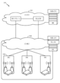
Exemplary Wireless Communication System FIG. 1 shows an
図1に示すように、ワイヤレスネットワーク100は、いくつかのBS110と他のネットワークエンティティとを含み得る。BSは、UEと通信する局であり得る。各BS110は、特定の地理的エリアに通信カバレージを提供し得る。3GPPでは、「セル」という用語は、この用語が使用される状況に応じて、このカバレージエリアにサービスしているノードBおよび/またはノードBサブシステムのカバレージエリアを指すことがある。5Gシステムでは、「セル」およびeNB、ノードB、5G NB、AP、NR BS、またはTRPなどの用語は交換可能であり得る。いくつかの例では、セルは、必ずしも静止しているとは限らないことがあり、セルの地理的エリアは、モバイル基地局のロケーションに従って移動し得る。いくつかの例では、基地局は、任意の適切なトランスポートネットワークを使用して、直接物理接続、仮想ネットワークなど、様々なタイプのバックホールインターフェースを通じて、ワイヤレスネットワーク100内で互いに、および/または1つもしくは複数の他の基地局もしくはネットワークノード(図示せず)に相互接続され得る。
As shown in FIG. 1,
一般に、任意の数のワイヤレスネットワークが、所与の地理的エリアにおいて展開されてよい。各ワイヤレスネットワークは、特定の無線アクセス技術(RAT)をサポートしてよく、1つまたは複数の周波数で動作してよい。RATは、無線技術、エアインターフェースなどと呼ばれることもある。周波数は、キャリア、周波数チャネルなどと呼ばれることもある。各周波数は、異なるRATのワイヤレスネットワーク間の干渉を回避するために、所与の地理的エリアにおいて単一のRATをサポートしてよい。場合によっては、NR RATネットワークまたは5G RATネットワークが展開されてよい。 In general, any number of wireless networks may be deployed in a given geographic area. Each wireless network may support a particular radio access technology (RAT) and may operate on one or more frequencies. RAT is also called radio technology, air interface, etc. A frequency may also be referred to as a carrier, frequency channel, or the like. Each frequency may support a single RAT in a given geographical area to avoid interference between wireless networks of different RATs. In some cases, NR RAT networks or 5G RAT networks may be deployed.
BSは、マクロセル、ピコセル、フェムトセル、および/または他のタイプのセルのための通信カバレージを提供し得る。マクロセルは、比較的大きい地理的エリア(たとえば、半径数キロメートル)をカバーすることができ、サービスに加入しているUEによる無制限アクセスを可能にしてよい。ピコセルは、比較的小さい地理的エリアをカバーすることができ、サービスに加入しているUEによる無制限アクセスを可能にしてよい。フェムトセルは、比較的小さい地理的エリア(たとえば、自宅)をカバーすることができ、フェムトセルとの関連を有するUE(たとえば、限定加入者グループ(CSG)内のUE、自宅内のユーザのためのUEなど)による制限付きアクセスを可能にしてよい。マクロセルのためのBSは、マクロBSと呼ばれることがある。ピコセルのためのBSは、ピコBSと呼ばれることがある。フェムトセルのためのBSは、フェムトBSまたはホームBSと呼ばれることがある。図1に示す例では、BS110a、110bおよび110cは、それぞれ、マクロセル102a、102bおよび102cのためのマクロBSであり得る。BS110xは、ピコセル102xのためのピコBSであり得る。BS110yおよび110zは、それぞれ、フェムトセル102yおよび102zのためのフェムトBSであり得る。BSは1つまたは複数(たとえば、3つ)のセルをサポートしてよい。
A BS may provide communication coverage for macrocells, picocells, femtocells, and/or other types of cells. A macrocell may cover a relatively large geographic area (eg, several kilometers in radius) and may allow unrestricted access by UEs with service subscription. A picocell may cover a relatively small geographic area and may allow unrestricted access by UEs with service subscription. A femtocell can cover a relatively small geographical area (e.g., a home) and UEs that have an association with the femtocell (e.g., UEs in a closed subscriber group (CSG), for users within the home). UEs) may allow restricted access. A BS for a macro cell is sometimes called a macro BS. A BS for pico cells is sometimes called a pico BS. A BS for femtocells is sometimes called a femto BS or a home BS. In the example shown in FIG. 1,
ワイヤレスネットワーク100は、中継局も含んでもよい。中継局は、アップストリーム局(たとえばBSまたはUE)からデータおよび/または他の情報の送信を受信し、ダウンストリーム局(たとえば、UEまたBS)にデータおよび/または他の情報の送信を送る局である。また、中継局は、他のUEのための送信を中継するUEであってもよい。図1に示す例では、中継局110rは、BS110aとUE120rとの間の通信を容易にするために、BS110aおよびUE120rと通信することができる。中継局はまた、リレーBS、リレーなどと呼ばれることもある。
ワイヤレスネットワーク100は、異なるタイプのBS、たとえば、マクロBS、ピコBS、フェムトBS、リレーなどを含む異種ネットワークとすることができる。これらの異なるタイプのBSは、異なる送信電力レベル、異なるカバレージエリア、およびワイヤレスネットワーク100中の干渉に対する異なる影響を有してよい。たとえば、マクロBSは高い送信電力レベル(たとえば、20ワット)を有することがあり、一方で、ピコBS、フェムトBS、およびリレーはより低い送信電力レベル(たとえば、1ワット)を有することがある。
ワイヤレスネットワーク100は、同期動作または非同期動作をサポートしてよい。同期動作の場合、BSは、同様のフレームタイミングを有することができ、異なるBSからの送信は、時間的にほぼ整合し得る。非同期動作の場合、BSは、異なるフレームタイミングを有する場合があり、異なるBSからの送信は、時間的に整合していない場合がある。本明細書で説明する技法は、同期動作と非同期動作の両方に使用されてよい。
ネットワークコントローラ130は、BSのセットに結合され、これらのBSのための調整および制御を行い得る。ネットワークコントローラ130は、バックホールを介してBS110と通信し得る。BS110はまた、たとえば、直接、または間接的にワイヤレスバックホールもしくは有線バックホールを介して、互いに通信し得る。
A
UE120(たとえば、120x、120yなど)は、ワイヤレスネットワーク100の全体にわたって分散されてよく、各UEは静止であってよく、またはモバイルであってよい。UEは、移動局、端末、アクセス端末、加入者ユニット、局、顧客構内設備(CPE:Customer Premises Equipment)、セルラーフォン、スマートフォン、携帯情報端末(PDA)、ワイヤレスモデム、ワイヤレス通信デバイス、ハンドヘルドデバイス、ラップトップコンピュータ、コードレスフォン、ワイヤレスローカルループ(WLL)局、タブレット、カメラ、ゲームデバイス、ネットブック、スマートブック、ウルトラブック、医療デバイスもしくは医療機器、生体センサー/デバイス、スマートウォッチ、スマート衣料、スマートグラス、スマートリストバンド、スマートジュエリー(たとえば、スマートリング、スマートブレスレットなど)などのウェアラブルデバイス、娯楽デバイス(たとえば、音楽デバイス、ビデオデバイス、衛星無線など)、車両コンポーネントもしくは車両センサー、スマートメータ/センサー、工業生産機器、全地球測位システムデバイス、またはワイヤレス媒体もしくはワイヤード媒体を介して通信するように構成された任意の他の適切なデバイスと呼ばれる場合もある。一部のUEは、発展型デバイスもしくはマシンタイプ通信(MTC)デバイスまたは発展型MTC(eMTC)デバイスと見なされる場合がある。MTC UEおよびeMTC UEは、BS、別のデバイス(たとえば、リモートデバイス)、または何らかの他のエンティティと通信することができる、たとえば、ロボット、ドローン、リモートデバイス、センサー、メータ、モニタ、ロケーションタグなどを含む。ワイヤレスノードは、たとえば、ワイヤード通信リンクまたはワイヤレス通信リンクを介して、ネットワーク(たとえば、インターネットもしくはセルラーネットワークなどのワイドエリアネットワーク)のための、またはネットワークへの接続性を提供し得る。一部のUEは、モノのインターネット(IoT)デバイスと見なされ得る。
UEs 120 (eg, 120x, 120y, etc.) may be dispersed throughout
図1において、両矢印を有する実線は、UEとサービングBSとの間の所望の送信を示し、サービングBSは、ダウンリンクおよび/またはアップリンク上でUEにサービスするように指定されたBSである。両矢印を有する破線は、UEとBSとの間の干渉する送信を示す。 In FIG. 1, the solid line with double arrows indicates the desired transmission between the UE and the serving BS, which is the BS designated to serve the UE on the downlink and/or uplink. . A dashed line with double arrows indicates interfering transmissions between a UE and a BS.
特定のワイヤレスネットワーク(たとえば、LTE)は、ダウンリンク上で直交周波数分割多重化(OFDM)を利用し、かつアップリンク上でシングルキャリア周波数分割多重化(SC-FDM)を利用する。OFDMおよびSC-FDMは、システム帯域幅を、一般に、トーン、ビンなどとも呼ばれる、複数の(K個の)直交サブキャリアに区分する。各サブキャリアは、データで変調され得る。一般に、変調シンボルは、OFDMでは周波数領域において送られ、SC-FDMでは時間領域において送られる。隣接するサブキャリア間の間隔は固定される場合があり、サブキャリアの総数(K)は、システム帯域幅に依存する場合がある。たとえば、サブキャリアの間隔は15kHzであってよく、最小のリソース割振り(「リソースブロック」と呼ばれる)は12個のサブキャリア(または180kHz)であってよい。その結果、公称FFTサイズは、1.25、2.5、5、10または20メガヘルツ(MHz)のシステム帯域幅に対して、それぞれ、128、256、512、1024または2048に等しくなり得る。システム帯域幅はまた、サブバンドに区分され得る。たとえば、サブバンドは、1.08MHz(すなわち、6個のリソースブロック)をカバーすることができ、1.25、2.5、5、10または20MHzのシステム帯域幅に対して、それぞれ、1、2、4、8または16個のサブバンドが存在し得る。 Certain wireless networks (eg, LTE) utilize orthogonal frequency division multiplexing (OFDM) on the downlink and single-carrier frequency division multiplexing (SC-FDM) on the uplink. OFDM and SC-FDM partition the system bandwidth into multiple (K) orthogonal subcarriers, also commonly called tones, bins, and so on. Each subcarrier may be modulated with data. In general, modulation symbols are sent in the frequency domain with OFDM and in the time domain with SC-FDM. The spacing between adjacent subcarriers may be fixed, and the total number of subcarriers (K) may depend on the system bandwidth. For example, the subcarrier spacing may be 15kHz, and the minimum resource allocation (called a "resource block") may be 12 subcarriers (or 180kHz). As a result, the nominal FFT size can be equal to 128, 256, 512, 1024 or 2048 for system bandwidths of 1.25, 2.5, 5, 10 or 20 megahertz (MHz) respectively. The system bandwidth may also be partitioned into subbands. For example, a subband can cover 1.08 MHz (i.e., 6 resource blocks), and 1, 2, 4, 8 subbands, respectively, for system bandwidths of 1.25, 2.5, 5, 10 or 20 MHz. Or there can be 16 subbands.
本明細書で説明する例の態様はLTE技術に関連付けられ得るが、本開示の態様は、5Gなど、他のワイヤレス通信システムに適用可能であり得る。5Gは、アップリンクおよびダウンリンク上でCPを用いてOFDMを利用し、時分割複信(TDD)を使用する半二重動作に対するサポートを含み得る。100MHzの単一のコンポーネントキャリア帯域幅がサポートされ得る。5Gリソースブロックは、0.1msの持続時間にわたって、サブキャリア帯域幅が75kHzの12個のサブキャリアにまたがり得る。各無線フレームは、10msの長さを有する50個のサブフレームで構成され得る。結果として、各サブフレームは0.2msの長さを有することができる。各サブフレームは、データ送信用のリンク方向(すなわち、DLまたはUL)を示してよく、サブフレームごとのリンク方向は、動的に切り替えられてよい。各サブフレームは、DL/ULデータならびにDL/UL制御データを含み得る。5Gに関するULサブフレームおよびDLサブフレームは、図6および図7に関して以下でより詳細に説明されるようなものであり得る。ビームフォーミングがサポートされ得、ビーム方向が動的に構成され得る。プリコーディングを用いたMIMO送信もサポートされ得る。DLにおけるMIMO構成は、最大で8個のストリームおよびUEごとに最大で2個のストリームを用いたマルチレイヤDL送信で最大で8個の送信アンテナをサポートし得る。UEごとに最大で2個のストリームを用いたマルチレイヤ送信がサポートされ得る。最大で8個のサービングセルを用いて複数のセルのアグリゲーションがサポートされ得る。代替として、5Gは、OFDMベース以外の異なるエアインターフェースをサポートし得る。5Gネットワークは、CUおよび/またはDUなどのエンティティを含み得る。 Although aspects of the examples described herein may relate to LTE technology, aspects of the disclosure may be applicable to other wireless communication systems, such as 5G. 5G utilizes OFDM with CP on the uplink and downlink and may include support for half-duplex operation using time division duplex (TDD). A single component carrier bandwidth of 100MHz may be supported. A 5G resource block may span 12 subcarriers with a subcarrier bandwidth of 75kHz for a duration of 0.1ms. Each radio frame may consist of 50 subframes with a length of 10ms. As a result, each subframe can have a length of 0.2ms. Each subframe may indicate a link direction (ie, DL or UL) for data transmission, and the link direction for each subframe may be dynamically switched. Each subframe may contain DL/UL data as well as DL/UL control data. UL and DL subframes for 5G may be as described in more detail below with respect to FIGS. Beamforming may be supported and beam directions may be dynamically configured. MIMO transmission with precoding may also be supported. A MIMO configuration in the DL may support up to 8 transmit antennas with multi-layer DL transmissions with up to 8 streams and up to 2 streams per UE. Multi-layer transmission with up to two streams per UE may be supported. Aggregation of multiple cells may be supported with up to 8 serving cells. Alternatively, 5G may support different air interfaces other than OFDM-based. A 5G network may include entities such as CUs and/or DUs.
いくつかの例では、エアインターフェースへのアクセスがスケジュールされてよく、スケジューリングエンティティ(たとえば、基地局)は、スケジューリングエンティティのサービスエリアまたはセル内のいくつかのまたはすべてのデバイスおよび機器の間で通信のためのリソースを割り振る。本開示内では、以下でさらに説明するように、スケジューリングエンティティは、1つまたは複数の従属エンティティ用のリソースをスケジュールすること、割り当てること、再構成すること、および解放することを担当し得る。すなわち、スケジュールされた通信に対して、従属エンティティは、スケジューリングエンティティによって割り振られたリソースを利用する。基地局は、スケジューリングエンティティとして機能し得る唯一のエンティティではない。すなわち、いくつかの例では、UEが、1つまたは複数の従属エンティティ(たとえば、1つまたは複数の他のUE)のためのリソースをスケジュールする、スケジューリングエンティティとして機能し得る。この例では、UEは、スケジューリングエンティティとして機能しており、他のUEは、ワイヤレス通信のためにUEによってスケジュールされたリソースを利用する。UEは、ピアツーピア(P2P)ネットワーク中および/またはメッシュネットワーク中でスケジューリングエンティティとして機能し得る。メッシュネットワーク例では、UEは、スケジューリングエンティティと通信することに加えて、場合によっては互いに直接通信し得る。 In some examples, access to an air interface may be scheduled, and a scheduling entity (e.g., a base station) directs communication between some or all devices and equipment within the scheduling entity's coverage area or cell. Allocate resources for Within this disclosure, a scheduling entity may be responsible for scheduling, allocating, reconfiguring, and releasing resources for one or more dependent entities, as described further below. That is, for scheduled communications, dependent entities utilize resources allocated by the scheduling entity. A base station is not the only entity that can act as a scheduling entity. That is, in some examples, a UE may act as a scheduling entity that schedules resources for one or more dependent entities (eg, one or more other UEs). In this example, the UE is acting as a scheduling entity and other UEs utilize resources scheduled by the UE for wireless communication. A UE may act as a scheduling entity in a peer-to-peer (P2P) network and/or in a mesh network. In a mesh network example, UEs may communicate directly with each other in some cases in addition to communicating with a scheduling entity.
したがって、時間-周波数リソースへのスケジュールされたアクセスを伴い、セルラー構成、P2P構成、およびメッシュ構成を有するワイヤレス通信ネットワークでは、スケジューリングエンティティおよび1つまたは複数の従属エンティティは、スケジュールされたリソースを利用して通信し得る。 Thus, in wireless communication networks with scheduled access to time-frequency resources and having cellular, P2P and mesh configurations, the scheduling entity and one or more subordinate entities utilize the scheduled resources. can communicate.
上述のように、RANは、CUおよびDUを含み得る。5G BS(たとえば、eNB、5GノードB、ノードB、送信受信ポイント(TRP)、アクセスポイント(AP))が、1つまたは複数のBSに対応し得る。5Gセルは、アクセスセル(ACell)またはデータオンリーセル(DCell)として構成され得る。たとえば、RAN(たとえば、集約ユニットまたは分散ユニット)は、セルを構成することができる。DCellは、キャリアアグリゲーションまたは二重接続性に使用されるが、初期アクセス、セル選択/再選択、またはハンドオーバに使用されないセルであり得る。場合によっては、DCellは同期信号を送信しないことがあり、場合によっては、DCellはSSを送信することがある。5G BSは、セルタイプを示すダウンリンク信号をUEに送信し得る。セルタイプ指示に基づいて、UEは5G BSと通信し得る。たとえば、UEは、示されたセルタイプに基づいて、セル選択用、アクセス用、ハンドオーバ用、および/または測定用と見なすべき5G BSを決定し得る。 As noted above, a RAN may include CUs and DUs. A 5G BS (eg, eNB, 5G Node B, Node B, Transmit Receive Point (TRP), Access Point (AP)) may correspond to one or more BSs. A 5G cell can be configured as an access cell (ACell) or a data only cell (DCell). For example, a RAN (eg, aggregation unit or distribution unit) may constitute a cell. A DCell may be a cell used for carrier aggregation or dual connectivity, but not used for initial access, cell selection/reselection, or handover. In some cases, the DCell may not transmit synchronization signals, and in other cases, the DCell may transmit SS. The 5G BS may send downlink signals to the UE indicating the cell type. Based on the cell type indication, the UE may communicate with the 5G BS. For example, the UE may decide which 5G BS to consider for cell selection, access, handover, and/or measurement based on the indicated cell type.
図2は、図1に示したワイヤレス通信システム内で実装され得る分散型無線アクセスネットワーク(RAN)200の例示的な論理アーキテクチャを示す。5Gアクセスノード206は、アクセスノードコントローラ(ANC)202を含み得る。ANCは、分散型RAN200の集約ユニット(CU)であってよい。次世代コアネットワーク(NG-CN:next generation core network)204へのバックホールインターフェースは、ANCにおいて終端し得る。近隣次世代アクセスノード(NG-AN)へのバックホールインターフェースは、ANCにおいて終端し得る。ANCは、1つまたは複数のTRP208(BS、NR BS、ノードB、5G NB、AP、または何らかの他の用語で呼ばれることもある)を含み得る。上記で説明したように、TRPは「セル」と交換可能に使用され得る。
FIG. 2 shows an exemplary logical architecture of a distributed radio access network (RAN) 200 that may be implemented within the wireless communication system shown in FIG. A
TRP208は、DUであってよい。TRPは、1つのANC(ANC202)に接続されてよく、または2つ以上のANC(図示せず)に接続されてよい。たとえば、RAN共有、サービスとしての無線(RaaS:radio as a service)、およびサービス固有ANC配置に対して、TRPは2つ以上のANCに接続され得る。TRPは、1つまたは複数のアンテナポートを含み得る。TRPは、UEへのトラフィックを個別に(たとえば、動的選択)または一緒に(たとえば、共同送信)サービスするように構成され得る。
ローカルアーキテクチャ200は、フロントホール定義を示すために使用され得る。異なる展開タイプにわたるフロントホール(fronthauling)解決策をサポートするアーキテクチャが定義され得る。たとえば、アーキテクチャは、送信ネットワーク能力(たとえば、帯域幅、レイテンシ、および/またはジッタ)に基づき得る。
A
アーキテクチャは、特徴および/または構成要素をLTEと共有し得る。態様によれば、次世代AN(NG-AN)210は、5Gとの二重接続性をサポートし得る。NG-ANは、LTEおよびNRに対して共通フロントホールを共有し得る。 The architecture may share features and/or components with LTE. According to aspects, the next generation AN (NG-AN) 210 may support dual connectivity with 5G. NG-AN may share a common fronthaul for LTE and NR.
アーキテクチャは、TRP208間の協働を可能にし得る。たとえば、協働は、TRP内にプリセットされてよく、かつ/またはANC202を経由してTRPにわたってプリセットされてよい。態様によれば、TRP間インターフェースが必要とされない/存在しない場合がある。
The architecture may allow cooperation between
態様によれば、アーキテクチャ200内に、分割された論理機能の動的構成が存在する場合がある。図5を参照しながらより詳細に説明するように、無線リソース制御(RRC)レイヤ、パケットデータコンバージェンスプロトコル(PDCP)レイヤ、無線リンク制御(RLC)レイヤ、媒体アクセス制御(MAC)レイヤ、および物理(PHY)レイヤは、DUまたはCU(たとえば、それぞれTRPまたはANC)に適応可能に配置され得る。いくつかの態様によれば、BSは、集約ユニット(CU)(たとえば、ANC202)および/または1つもしくは複数の分散ユニット(たとえば、1つもしくは複数のTRP208)を含んでよい。
According to aspects, within
図3は、本開示のいくつかの態様による、分散型RAN300の例示的な物理アーキテクチャを示す。集中型コアネットワークユニット(C-CU)302が、コアネットワーク機能をホストし得る。C-CUは、中央に配置されてよい。C-CU機能は、ピーク容量に対処しようとして、(たとえば、アドバンストワイヤレスサービス(AWS)に)オフロードされ得る。
FIG. 3 illustrates an example physical architecture of distributed
集中型RANユニット(C-RU)304が、1つまたは複数のANC機能をホストし得る。場合によっては、C-RUは、コアネットワーク機能を局所的にホストし得る。C-RUは分散配置を有してよい。C-RUは、ネットワークエッジのより近くにあってよい。 A centralized RAN unit (C-RU) 304 may host one or more ANC functions. In some cases, the C-RU may host core network functions locally. C-RUs may have a distributed arrangement. C-RUs may be closer to the network edge.
DU306が、1つまたは複数のTRP(エッジノード(EN)、エッジユニット(EU)、無線ヘッド(RH)、スマート無線ヘッド(SRH)など)をホストし得る。DUは、無線周波数(RF)機能を備えたネットワークのエッジに位置し得る。
図4は、本開示の態様を実施するために使用され得る、図1に示すBS110およびUE120の例示的な構成要素を示す。上記で説明したように、BSはTRPを含み得る。BS110およびUE120の1つまたは複数の構成要素は、本開示の態様を実践するために使用され得る。たとえば、UE120のアンテナ452、Tx/Rx222、プロセッサ466、458、464、および/もしくはコントローラ/プロセッサ480、ならびに/またはBS110のアンテナ434、プロセッサ430、420、438、および/もしくはコントローラ/プロセッサ440は、本明細書で説明し、図13を参照しながら示す動作を実行するために使用され得る。
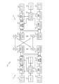
FIG. 4 shows exemplary components of
図4は、図1におけるBSのうちの1つおよびUEのうちの1つであってよい、BS110およびUE120の設計のブロック図を示す。制限された接続シナリオの場合、基地局110は図1のマクロBS110cであってよく、UE120はUE120yであってよい。基地局110はまた、何らかの他のタイプの基地局であり得る。基地局110は、アンテナ434a~434tを備えることができ、UE120は、アンテナ452a~452rを備えることができる。
FIG. 4 shows a block diagram of a design of
基地局110において、送信プロセッサ420は、データソース412からデータを受信し、コントローラ/プロセッサ440から制御情報を受信し得る。制御情報は、物理ブロードキャストチャネル(PBCH)、物理制御フォーマットインジケータチャネル(PCFICH)、物理ハイブリッドARQインジケータチャネル(PHICH)、物理ダウンリンク制御チャネル(PDCCH)などに関するものであってよい。データは、物理ダウンリンク共有チャネル(PDSCH)などに関するものであってよい。プロセッサ420は、データおよび制御情報を処理(たとえば、符号化およびシンボルマッピング)して、それぞれデータシンボルおよび制御シンボルを取得することができる。プロセッサ420はまた、たとえば、PSS、SSS、およびセル固有基準信号に関する基準シンボルを生成することもできる。送信(TX)多入力多出力(MIMO)プロセッサ430は、適用可能な場合には、データシンボル、制御シンボル、および/または基準シンボルに対して空間処理(たとえば、プリコーディング)を実行することができ、出力シンボルストリームを変調器(MOD)432a~432tに提供することができる。たとえば、TX MIMOプロセッサ430は、RS多重化のために本明細書で説明するいくつかの態様を実行し得る。各変調器432は、(たとえば、OFDMなどのための)それぞれの出力シンボルストリームを処理して、出力サンプルストリームを取得することができる。各変調器432は、出力サンプルストリームをさらに処理(たとえば、アナログに変換、増幅、フィルタリング、およびアップコンバート)して、ダウンリンク信号を取得することができる。変調器432a~432tからのダウンリンク信号を、それぞれアンテナ434a~434tを介して送信してよい。
At
UE120において、アンテナ452a~452rは、基地局110からダウンリンク信号を受信することができ、受信信号をそれぞれ復調器(DEMOD)454a~454rに提供することができる。各復調器454は、それぞれの受信信号を調整(たとえば、フィルタリング、増幅、ダウンコンバート、およびデジタル化)して、入力サンプルを取得することができる。各復調器454は、(たとえば、OFDMなどのための)入力サンプルをさらに処理して、受信シンボルを取得することができる。MIMO検出器456は、すべての復調器454a~454rから受信シンボルを取得し、適用可能な場合、受信シンボルに対してMIMO検出を実行し、検出されたシンボルを提供することができる。たとえば、MIMO検出器456は、本明細書で説明する技法を使用して送信された検出済みRSを提供し得る。受信プロセッサ458は、検出されたシンボルを処理(たとえば、復調、デインターリーブ、および復号)し、UE120のための復号されたデータをデータシンク460に提供し、復号された制御情報をコントローラ/プロセッサ480に提供することができる。1つまたは複数の事例によれば、CoMP態様は、アンテナならびにいくつかのTx/Rx機能を、CoMP態様が分散されたユニット内に存在するように提供することを含むことができる。たとえば、いくつかのTx/Rx処理は中央ユニット内で行われ得る一方で、他の処理は分散されたユニットにおいて行われ得る。たとえば、図に示す1つまたは複数の態様によれば、BS変調器/復調器432は、分散されたユニット内にあってもよい。
At
アップリンクでは、UE120において、送信プロセッサ464が、データソース462からの(たとえば、物理アップリンク共有チャネル(PUSCH)についての)データ、およびコントローラ/プロセッサ480からの(たとえば、物理アップリンク制御チャネル(PUCCH)についての)制御情報を受信し、処理してよい。送信プロセッサ464はまた、基準信号のための基準シンボルを生成し得る。送信プロセッサ464からのシンボルは、適用可能な場合には、TX MIMOプロセッサ466によってプリコーディングされ、(たとえばSC-FDMなどのために)復調器454a~454rによってさらに処理され、基地局110に送信されてよい。BS110において、UE120からのアップリンク信号は、アンテナ434によって受信され、変調器432によって処理され、適用可能な場合には、MIMO検出器436によって検出され、受信プロセッサ438によってさらに処理されて、UE120によって送られた復号データおよび制御情報を取得し得る。受信プロセッサ438は、データシンク439に復号されたデータを提供し、コントローラ/プロセッサ440に復号された制御情報を提供してよい。
On the uplink, in
コントローラ/プロセッサ440および480は、それぞれ基地局110およびUE120における動作を指示し得る。基地局110におけるプロセッサ440ならびに/または他のプロセッサおよびモジュールは、たとえば、図12に示す機能的ブロックの実施および/または本明細書で説明する技法に対する他のプロセスを実行または指示し得る。UE120におけるプロセッサ480ならびに/または他のプロセッサおよびモジュールも、本明細書で説明する技法に対するプロセスを実行または指示し得る。メモリ442および482は、それぞれBS110およびUE120のためのデータおよびプログラムコードを記憶し得る。スケジューラ444は、ダウンリンクおよび/またはアップリンク上でのデータ送信のためにUEをスケジューリングし得る。
Controllers/
図5は、本開示の態様による、通信プロトコルスタックを実装するための例を示す図500を示す。示された通信プロトコルスタックは、5Gシステム(たとえば、アップリンクベースのモビリティをサポートするシステム)内で動作するデバイスによって実装され得る。図500は、無線リソース制御(RRC)レイヤ510、パケットデータコンバージェンスプロトコル(PDCP)レイヤ515、無線リンク制御(RLC)レイヤ520、媒体アクセス制御(MAC)レイヤ525、および物理(PHY)レイヤ530を含む通信プロトコルスタックを示す。様々な例では、プロトコルスタックのレイヤは、ソフトウェアの個別のモジュール、プロセッサもしくはASICの部分、通信リンクによって接続された非コロケートデバイスの部分、またはそれらの様々な組合せとして実装され得る。コロケート実装形態および非コロケート実装形態は、たとえば、ネットワークアクセスデバイス(たとえば、AN、CU、および/もしくはDU)またはUEのためのプロトコルスタックの中で使用されてよい。
FIG. 5 shows a diagram 500 illustrating an example for implementing communication protocol stacks, according to aspects of the present disclosure. The illustrated communication protocol stacks may be implemented by devices operating within 5G systems (eg, systems supporting uplink-based mobility). The diagram 500 includes a radio resource control (RRC)
第1のオプション505-aは、プロトコルスタックの実装が集中ネットワークアクセスデバイス(たとえば、図2のANC202)と分散ネットワークアクセスデバイス(たとえば、図2のDU208)との間で分割される、プロトコルスタックの分割実装形態を示す。第1のオプション505-aでは、RRCレイヤ510およびPDCPレイヤ515は、集約ユニットによって実装されてよく、RLCレイヤ520、MACレイヤ525、およびPHYレイヤ530は、DUによって実装されてよい。様々な例では、CUおよびDUは、コロケートされてよく、またはコロケートされなくてもよい。第1のオプション505-aは、マクロセル配置、マイクロセル配置、またはピコセル配置において有用であり得る。
A first option 505-a is protocol stack implementation split between a centralized network access device (eg,
第2のオプション505-bは、プロトコルスタックが単一のネットワークアクセスデバイス(たとえば、アクセスノード(AN)、ニューラジオ基地局(NB BS)、ニューラジオノードB(NR NB)、ネットワークノード(NN)など)の中で実装される、プロトコルスタックの統合実装形態を示す。第2のオプションでは、RRCレイヤ510、PDCPレイヤ515、RLCレイヤ520、MACレイヤ525、およびPHYレイヤ530は各々、ANによって実装され得る。第2のオプション505-bは、フェムトセル配置において有用であり得る。
A second option 505-b is for network access devices with a single protocol stack (e.g., Access Node (AN), New Radio Base Station (NB BS), New Radio Node B (NR NB), Network Node (NN) etc.) shows an integrated implementation of the protocol stack. In a second option,
ネットワークアクセスデバイスがプロトコルスタックの一部を実装するのか全部を実装するのかにかかわらず、UEは、全プロトコルスタック(たとえば、RRCレイヤ510、PDCPレイヤ515、RLCレイヤ520、MACレイヤ525、およびPHYレイヤ530)を実装してよい。
Regardless of whether the network access device implements part or all of the protocol stack, the UE has access to the entire protocol stack (e.g.,
図6は、DL中心のサブフレームの一例を示す図600である。DL中心のサブフレームは、制御部分602を含み得る。制御部分602は、DL中心のサブフレームの最初の部分または開始部分に存在し得る。制御部分602は、DL中心のサブフレームの様々な部分に対応する様々なスケジューリング情報および/または制御情報を含み得る。いくつかの構成では、制御部分602は、図6に示すように、物理DL制御チャネル(PDCCH)であってよい。DL中心のサブフレームは、DLデータ部分604も含み得る。DLデータ部分604は時々、DL中心のサブフレームのペイロードと呼ばれ得る。DLデータ部分604は、スケジューリングエンティティ(たとえば、UEまたはBS)から従属エンティティ(たとえば、UE)にDLデータを通信するために利用される通信リソースを含み得る。いくつかの構成では、DLデータ部分604は、物理DL共有チャネル(PDSCH)であってよい。
FIG. 6 is a diagram 600 showing an example of DL-centered subframes. A DL-centric subframe may include a
DL中心のサブフレームは、共通UL部分606も含み得る。共通UL部分606は時々、ULバースト、共通ULバースト、および/または様々な他の適切な用語で呼ばれ得る。共通UL部分606は、DL中心のサブフレームの様々な他の部分に対応するフィードバック情報を含み得る。たとえば、共通UL部分606は、制御部分602に対応するフィードバック情報を含み得る。フィードバック情報の非限定的な例は、ACK信号、NACK信号、HARQインジケータ、および/または様々な他の適切なタイプの情報を含み得る。共通UL部分606は、ランダムアクセスチャネル(RACH)手順、スケジューリング要求(SR)に関する情報、および様々な他の適切なタイプの情報などの、追加のまたは代替の情報を含み得る。図6に示すように、DLデータ部分604の終わりは、共通UL部分606の始まりから時間的に分離され得る。この時間の分離は時々、ギャップ、ガード期間、ガードインターバル、および/または様々な他の適切な用語で呼ばれ得る。この分離は、DL通信(たとえば、従属エンティティ(たとえば、UE)による受信動作)からUL通信(たとえば、従属エンティティ(たとえば、UE)による送信)への切替えのための時間を与える。上記はDL中心のサブフレームの一例にすぎず、同様の特徴を有する代替構造が、必ずしも本明細書で説明する態様から逸脱することなく存在し得ることを、当業者は理解されよう。
A DL-centric subframe may also include a
図7は、UL中心のサブフレームの一例を示す図700である。UL中心のサブフレームは、制御部分702を含み得る。制御部分702は、UL中心のサブフレームの最初の部分または開始部分に存在し得る。図7における制御部分702は、図6を参照しながら上記で説明した制御部分と同様であってよい。UL中心のサブフレームは、ULデータ部分704も含み得る。ULデータ部分704は時々、UL中心のサブフレームのペイロードと呼ばれ得る。UL部分は、従属エンティティ(たとえば、UE)からスケジューリングエンティティ(たとえば、UEまたはBS)にULデータを通信するために利用される通信リソースを指すことがある。いくつかの構成では、制御部分702は、物理DL制御チャネル(PDCCH)であってよい。
FIG. 7 is a diagram 700 illustrating an example of a UL-centered subframe. A UL-centric subframe may include a
図7に示すように、制御部分702の終わりは、ULデータ部分704の始まりから時間的に分離され得る。この時間の分離は時々、ギャップ、ガード期間、ガードインターバル、および/または様々な他の適切な用語で呼ばれ得る。この分離は、DL通信(たとえば、スケジューリングエンティティによる受信動作)からUL通信(たとえば、スケジューリングエンティティによる送信)への切替えのための時間を与える。UL中心のサブフレームは、共通UL部分706も含み得る。図7における共通UL部分706は、図6を参照しながら上記で説明した共通UL部分606と同様であってよい。共通UL部分706は、追加または代替として、チャネル品質インジケータ(CQI)、サウンディング基準信号(SRS)に関する情報、および様々な他の適切なタイプの情報を含み得る。上記はUL中心のサブフレームの一例にすぎず、同様の特徴を有する代替構造が、必ずしも本明細書で説明する態様から逸脱することなく存在し得ることを、当業者は理解されよう。
As shown in FIG. 7, the end of the
いくつかの状況では、2つ以上の従属エンティティ(たとえば、UE)はサイドリンク信号を使用して互いに通信することができる。そのようなサイドリンク通信の現実世界の適用例は、公共安全、近接サービス、UEからネットワークへの中継、車両間(V2V)通信、インターネットオブエブリシング(IoE:Internet of Everything)通信、IoT通信、ミッションクリティカルメッシュ、および/または様々な他の適切な適用例を含み得る。一般に、サイドリンク信号は、スケジューリングおよび/または制御のためにスケジューリングエンティティが利用され得るにもかかわらず、スケジューリングエンティティ(たとえば、UEまたはBS)を通じてその通信を中継せずに、ある従属エンティティ(たとえば、UE1)から別の従属エンティティ(たとえば、UE2)に通信される信号を指す場合がある。いくつかの例では、サイドリンク信号は、(通常は免許不要スペクトルを使用するワイヤレスローカルエリアネットワークとは異なり)免許必要スペクトルを使用して通信されてよい。 In some situations, two or more dependent entities (eg, UEs) may communicate with each other using sidelink signals. Real-world applications of such sidelink communication are public safety, proximity services, UE-to-network relay, vehicle-to-vehicle (V2V) communication, Internet of Everything (IoE) communication, IoT communication, mission may include critical meshes, and/or various other suitable applications. In general, sidelink signals are used by a dependent entity (e.g., It may refer to a signal communicated from UE1) to another dependent entity (eg, UE2). In some examples, sidelink signals may be communicated using a licensed spectrum (unlike wireless local area networks, which typically use unlicensed spectrum).
UEは、リソースの専用セットを使用してパイロットを送信することに関連する構成(たとえば、無線リソース制御(RRC)専用状態など)、またはリソースの共通セットを使用してパイロットを送信することに関連する構成(たとえば、RRC共通状態など)を含む、様々な無線リソース構成において動作し得る。RRC専用状態において動作するとき、UEは、パイロット信号をネットワークに送信するために、リソースの専用セットを選択し得る。RRC共通状態において動作するとき、UEは、パイロット信号をネットワークに送信するために、リソースの共通セットを選択し得る。いずれの場合も、UEによって送信されるパイロット信号は、ANもしくはDU、またはそれらの部分などの、1つまたは複数のネットワークアクセスデバイスによって受信され得る。各受信ネットワークアクセスデバイスは、リソースの共通セット上で送信されるパイロット信号を受信および測定するとともに、ネットワークアクセスデバイスがUEのためのネットワークアクセスデバイスの監視セットのメンバーであるUEに割り振られたリソースの専用セット上で送信されるパイロット信号も受信および測定するように構成され得る。受信ネットワークアクセスデバイスのうちの1つもしくは複数、または受信ネットワークアクセスデバイスがパイロット信号の測定値を送信する先のCUは、UE用のサービングセルを識別するために、またはUEのうちの1つもしくは複数のためのサービングセルの変更を開始するために、測定値を使用し得る。 The UE may be configured to transmit pilot using a dedicated set of resources (e.g., radio resource control (RRC) dedicated state, etc.) or to transmit pilot using a common set of resources. It may operate in a variety of radio resource configurations, including configurations that do (eg, RRC common state, etc.). When operating in RRC dedicated state, a UE may select a dedicated set of resources to transmit pilot signals to the network. When operating in RRC common state, a UE may select a common set of resources to transmit pilot signals to the network. In any case, pilot signals transmitted by the UE may be received by one or more network access devices, such as the AN or DU, or parts thereof. Each receiving network access device receives and measures a pilot signal transmitted on a common set of resources and a resource allocated to the UE for which the network access device is a member of a monitored set of network access devices for the UE. Pilot signals transmitted on the dedicated set may also be configured to receive and measure. One or more of the receiving network access devices, or the CUs to which the receiving network access devices transmit measurements of the pilot signal, to identify the serving cell for the UE, or one or more of the UEs. The measurements may be used to initiate a serving cell change for .
SRS送信のためのPRG(プリコーディングリソースブロックグループ)サイズ選択の例
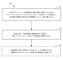
図8は、本開示の態様による、UEによるワイヤレス通信のための例示的な動作を示す。
Example Precoding Resource Block Group (PRG) Size Selection for SRS Transmission FIG. 8 illustrates example operations for wireless communication by a UE, according to aspects of this disclosure.
動作800は、ブロック802において、UEがサウンディング基準信号(SRS)送信に使用するためのプリコーディングリソースブロックグループ(PRG)サイズをUEが決定することで開始し、ここでSRS送信は、複数のPRGを含む帯域幅にわたって割り振られる。1つまたは複数の場合には、決定は、基地局からのシグナリングに基づく場合がある。他の場合には、決定は、SRS送信のために使用されるポートの数に基づく場合がある。PRGサイズは、レイヤの数が所定の数より少ない場合、全動作帯域幅に相当する場合がある。一例では、所定の数は4である。1つまたは複数の場合には、決定は、UEの電力ヘッドルームに基づく場合がある。1つまたは複数の他の態様によれば、UEが全電力で送信しているので利用可能なUE電力ヘッドルームがもはや存在しない場合、PRGサイズは全動作帯域幅に相当する場合がある。SRS送信に対するPRGサイズまたはレイヤの数は、ダウンリンクのために再使用され得る。たとえば、SRS送信に対するPRGサイズまたはレイヤの数は、BSからUEに1つまたは複数のダウンリンク基準信号を送信するために使用され得る。
UEはまた、ブロック804において、決定に従ってSRS送信を基地局(BS)に送信することを含んでもよく、同じプリコーディングがPRG内で使用される。たとえば、UEは、前の動作において決定されたPRGサイズに基づいてSRSを基地局に送信し得る。806において示すように、方法はまた、場合によっては、SRS送信に対するPRGサイズまたはレイヤの数のうちの推奨される少なくとも1つの指示を基地局に送信するステップを含み得る。指示をBSに提供することは、たとえば決定されたPRGサイズに関してUEによってなされた決定をBSに通知するのを助ける。したがって、指示を有することは、決定に基づいてSRS送信の形態でUEからBSに送信されたものをBSが処理するのを助け得る。
The UE may also include transmitting an SRS transmission to a base station (BS) according to the determination at
図8Aは、図8に示す動作を実行するように構成された様々なミーンズプラスファンクション構成要素を含み得る通信デバイス800Aを示す。たとえば、802Aにおいて、通信デバイス800Aは、図8の802において示される動作を実行するための手段を含む。具体的には、1つまたは複数の場合には、手段802Aの目的は、基準信号を送信するときに使用するための1つまたは複数の特性を決定するための、UEに対する処理要素としてサービスすることである。たとえば、手段802Aは、UEがSRS送信に使用するためのPRGサイズを決定するように構成され得る。場合によっては、SRS送信は、複数のPRGを含む帯域幅にわたって割り振られ得る。加えて、804Aにおいて、通信デバイス800Aは、図8の804において示される動作を実行するための手段を含む。具体的には、1つまたは複数の場合には、手段804Aの目的は、1つまたは複数の基準信号を基地局に送信するための、UEに対する送信機としてサービスすることである。たとえば、手段804Aは、手段802Aによって決定されたPRGサイズに基づいてSRS送信を基地局(BS)に送信するように構成され得る。場合によっては、同じプリコーディングが、PRG内で使用される。1つまたは複数の場合には、複数のPRGのうちの少なくとも2つは、異なるプリコーディングを有する場合がある。場合によっては、806Aにおいて、通信デバイス800Aは、図8の806において示される動作を実行するための手段をさらに含み得る。具体的には、通信デバイス800Aは、SRS送信に対するPRGサイズまたはレイヤの数のうちの推奨される少なくとも1つの指示を基地局に送信するための手段を含み得る。
FIG. 8A shows a
図9は、本開示の態様による、基地局によるワイヤレス通信のための例示的な動作を示す。たとえば、基地局は、UEがSRS送信のために使用することになるPRGサイズを決定し、次いで、そのPRGサイズを、BSがUEからSRS送信を受信するときに使用し得るように構成され得る。 FIG. 9 illustrates example operations for wireless communication by a base station, according to aspects of this disclosure. For example, the base station may be configured to determine the PRG size that the UE will use for SRS transmission, and then use that PRG size when the BS receives the SRS transmission from the UE. .
具体的には、動作900は、ブロック902において、ユーザ機器(UE)がサウンディング基準信号(SRS)送信に使用するためのプリコーディングリソースブロックグループ(PRG)サイズを基地局が決定することで開始する。決定は、SRS送信のために使用されるポートの数に基づく場合がある。PRGサイズは、レイヤの数が所定の数より少ない場合、全動作帯域幅に相当する場合がある。決定は、UEの電力ヘッドルームに基づく場合がある。UEが全電力で送信しているために利用可能なUE電力ヘッドルームがない場合、PRGサイズは、全動作帯域幅に相当する場合がある。
Specifically,
ブロック904に示すように、基地局はまた、決定に従ってUEから送信されたSRSを受信することを含む場合がある。たとえば、基地局は、送信を受信する受信機を有する場合がある。送信は、UEから発生する場合があり、決定されたPRGサイズに従って送られるSRS送信を含む場合がある。たとえば、SRS送信は、SRS送信のサブバンドに応じて異なってプリコーディングされる場合がある。さらに、906において示すように、方法は、場合によっては、SRS送信に対するPRGサイズまたはレイヤの数のうちの推奨される少なくとも1つの指示をUEから受信するステップを含み得る。BSは、PRGサイズを決定するときに、この指示を考慮に入れる場合がある。1つまたは複数の場合には、BSは、受信されたときに指示を使用してもよく、さもなければ、そのような指示が受信されない他の場合に、計算された値を使用してもよい。
As indicated at
図9Aは、図9に示す動作を実行するように構成された様々なミーンズプラスファンクション構成要素を含み得る通信デバイス900Aを示す。たとえば、902Aにおいて、通信デバイス900Aは、図9の902において示される動作を実行するための手段を含む。具体的には、1つまたは複数の場合には、手段902Aの目的は、UEから受信された基準信号上で使用するための1つまたは複数の特性を決定するための、BSに対する処理要素としてサービスすることである。たとえば、手段902Aは、UEがSRS送信に使用するためのPRGサイズを決定するように構成され得る。加えて、904Aにおいて、通信デバイス900Aは、図9の904において示される動作を実行するための手段を含む。具体的には、1つまたは複数の場合には、手段904Aの目的は、1つまたは複数のサブバンド内の1つまたは複数の基準信号をUEから受信するための、BSに対する受信機としてサービスすることである。たとえば、手段904Aは、手段902Aによって決定されたPRGサイズに基づいてSRS送信をUEから受信するように構成され得る。場合によっては、906Aにおいて、通信デバイス900Aは、図9の906において示される動作を実行するための手段をさらに含み得る。具体的には、通信デバイス900Aは、SRS送信に対するPRGサイズまたはレイヤの数のうちの推奨される少なくとも1つの指示をUEから受信するための手段を含み得る。
FIG. 9A shows a
場合によっては、方法は、PRGサイズに関する情報をUEにシグナリングするステップを含み得る。場合によっては、SRS送信に対するPRGサイズまたはレイヤの数は、ダウンリンクのために再使用され得る。たとえば、SRS送信に対するPRGサイズまたはレイヤの数は、BSからUEに1つまたは複数のダウンリンク基準信号を送信するために使用され得る。この再使用に寄与し得る少なくとも1つのファクタは、チャネル相反性(channel reciprocity)を含む。具体的には、チャネル相反性のため、DLチャネルは、UL測定値から推定され得る。 In some cases, the method may include signaling information regarding the PRG size to the UE. In some cases, the PRG size or number of layers for SRS transmission may be reused for the downlink. For example, the PRG size or number of layers for SRS transmission may be used to transmit one or more downlink reference signals from the BS to the UE. At least one factor that may contribute to this reuse includes channel reciprocity. Specifically, due to channel reciprocity, the DL channel can be estimated from UL measurements.
SRS送信の場合、SRSは、異なるサブバンドに対して異なってプリコーディングされ得る。たとえば、図10は、本開示の態様による、サブバンドプリコーディングを示す。いくつかの態様によれば、いくつかのサブバンド1002、1003および1004にまたがるSRS帯域幅1001が示される。この例では、3つの図示のプリコーダおよび物理リソースグループ(PRG)に対応する3つのサブバンド1002、1003および1004がある。具体的には、SRS帯域幅は、図に示すPRG1、PRG2およびPRG3に対応する。さらに、PRG1、PRG2およびPRG3は、それぞれ、対応するプリコーダ、すなわちプリコーダ1、プリコーダ2およびプリコーダ3を使用してプリコーディングされる。
For SRS transmission, SRS may be precoded differently for different subbands. For example, FIG. 10 illustrates subband precoding according to aspects of this disclosure. According to some aspects, an
1つまたは複数の場合によれば、PRG(プリコーディングリソースグループ)の異なるサブバンドに対するパラメータおよびサイズを定義するユニットが変化してもよい。たとえば、PRGは、2^n*PRB(プリコーディングリソースブロック)であってもよく、PRBは12トーンであってもよい。1つまたは複数の場合には、PRGは、限定はしないが、2^n*PRBに対応する1、2、4、8など、任意の数のサイズであってもよく、ここでn=0、1、2、3などである。さらに、PRGは、特定の数のトーンに限定されず、したがって、特定の実施形態に応じて任意の数のトーンであってもよい。 According to one or more cases, the units defining parameters and sizes for different subbands of a PRG (precoding resource group) may vary. For example, a PRG may be 2^n*PRBs (precoding resource blocks) and a PRB may be 12 tones. In one or more cases, the PRG may be of any number of sizes, including but not limited to 1, 2, 4, 8, corresponding to 2^n*PRB, where n=0. , 1, 2, 3, etc. Additionally, the PRG is not limited to a specific number of tones, and thus may be any number of tones depending on the particular embodiment.
PRGサイズは、UEおよび/またはgNBによって構成され得る。1つまたは複数の態様によれば、PRGサイズはまた、レイヤ(ポート)の数に基づいて構成され得る。1つまたは複数の場合によれば、レイヤの数が所定の数、たとえば4より小さい場合、PRGは全帯域であってもよく、サブバンドプリコーディングは適用可能ではない。 PRG size may be configured by the UE and/or gNB. According to one or more aspects, the PRG size can also be configured based on the number of layers (ports). According to one or more cases, if the number of layers is less than a predetermined number, eg, 4, the PRG may be full-band and subband precoding is not applicable.
1つまたは複数の態様によれば、PRGサイズがUEおよび/またはgNBによって構成可能であることに加えて、PRGサイズはまた、UE電力ヘッドルームに基づいて構成され得る。たとえば、1つまたは複数の態様に従って、UEが全電力で送信しているために、利用可能なUE電力ヘッドルームがない場合を取り上げる。UE電力ヘッドルームがないこの場合には、全帯域プリコーディングが選択され得る。たとえば、UE電力ヘッドルームがない場合、UEは全電力で送信している場合がある。この場合、PRGは、全SRS帯域に等しい場合がある。 According to one or more aspects, in addition to PRG size being configurable by the UE and/or gNB, PRG size may also be configured based on UE power headroom. For example, in accordance with one or more aspects, take the case where there is no UE power headroom available because the UE is transmitting at full power. Full band precoding may be selected in this case where there is no UE power headroom. For example, if there is no UE power headroom, the UE may be transmitting at full power. In this case, PRG may equal the entire SRS band.
1つまたは複数の態様によれば、UE電力ヘッドルームがある場合には、1つは、サブバンドプリコーディングを自由に使用し得る。この例では、UE電力ヘッドルームがあるとき、PRGサイズは、したがって全SRS帯域より小さくてもよい。 According to one or more aspects, one may be free to use subband precoding if there is UE power headroom. In this example, when there is UE power headroom, the PRG size may therefore be smaller than the entire SRS band.
図11は、本開示の態様に従って送信するワイヤレスシステムの一例を示す。具体的には、図11は、UE1102に送信するgNB1101を示し、次いで、gNB1101に応答するUE1102を示す。
FIG. 11 illustrates an example wireless system that transmits in accordance with aspects of the present disclosure. Specifically, FIG. 11 shows
具体的には、gNB1101は、SRSに対するレイヤの数、および/またはレイヤの数によって決定され得る、SRSに対するPRGサイズを構成してもよい。次いで、gNB1101は、レイヤの数および/またはPRGサイズをUE1102に送信する。次いで、UE1102は、gNB1101から受信された送信に基づいてプリコーディングされたSRSを生成する。次いで、UE1102は、構成されたレイヤおよびPRGサイズを有するプリコーディングされたSRSを送信し得る。1つまたは複数の場合によれば、SRSに対するプリコーディング行列は、プリコーディング行列が各PRGに対して一定のままであるように構成され得る。
Specifically,
図12は、本開示の態様に従って送信するワイヤレスシステムの別の例を示す。具体的には、図12は、レイヤの数および/またはPRGサイズをgNB1201に送信するUE1202を示し、次いで、同じく、プリコーディングされたSRSをgNB1201に送信するUE1202を示す。
FIG. 12 illustrates another example wireless system that transmits in accordance with aspects of the disclosure. Specifically, FIG. 12
具体的には、図12は、SRSに対するレイヤの数、および/または同じくレイヤの数によって決定され得る、SRSに対するPRGサイズの示唆を含み得る1つまたは複数の指示を送信するUE1202を示す。次いで、UE1202は、示唆されたレイヤおよび/またはPRGサイズに基づいて構成されたプリコーディングされたSRSを送信し得る。1つまたは複数の場合によれば、SRSに対するプリコーディング行列は、プリコーディング行列が各PRGに対して一定のままであるように構成され得る。
Specifically, FIG. 12
1つまたは複数の場合には、上記で説明したように、ワイヤレスシステムは、レイヤの数および/またはPRGサイズがダウンリンク送信ならびにアップリンク送信のために再使用され得るように構成され得る。具体的には、SRS(アップリンク)は、チャネル相反性に基づいてダウンリンクチャネル推定のためにも使用され得る。 In one or more cases, as described above, the wireless system may be configured such that the number of layers and/or PRG size may be reused for downlink and uplink transmissions. Specifically, SRS (uplink) can also be used for downlink channel estimation based on channel reciprocity.
時間分割シンボルの例
図13は、本開示の態様による、装置によるワイヤレス通信のための例示的な動作1300を示す。具体的には、図13に示すように、動作1300は、基準信号の複数のシーケンスを異なるプリコーダでプリコーディングすることと、次いで、基準信号のプリコーディングされたシーケンスを送信することとを含み得る。
Examples of Time Division Symbols FIG. 13 illustrates
具体的には、動作1300は、ブロック1302において、装置が、第1のプリコーダを使用して第1のリソース上の基準信号送信に対する第1のシーケンスをプリコーディングすることで開始する。1つまたは複数の場合には、装置は、ユーザ機器(UE)または基地局(BS)のうちの少なくとも1つであってもよい。さらに、基準信号は、装置がUEであるときのサウンディング基準信号(SRS)および装置がBSであるときのダウンリンク(DL)基準信号のうちの少なくとも1つであり得る。加えて、場合によっては、第1のリソースは、第1のサブバンドおよび/または第1のポートのうちの少なくとも1つであり得る。
Specifically,
動作1300は、ブロック1304において、第2のプリコーダを使用して第2のリソース上の基準信号送信に対する第2のシーケンスをプリコーディングすることも含む。1つまたは複数の場合には、第2のリソースは、第2のサブバンドおよび/または第2のポートのうちの少なくとも1つであり得る。1つまたは複数の態様によれば、第1および第2のプリコーダは異なる場合がある。1つまたは複数の場合には、異なるプリコーディングリソースブロックグループ(PRG)サイズは、第1および第2のSRS送信のために使用され得る。
動作1300は、ブロック1306において、第1の送信時間間隔内に第1のリソース上で基準信号送信の第1のプリコーディングされたシーケンスを送信することをさらに含む。1つまたは複数の場合には、第1のシーケンスをプリコーディングして送信する装置は、ユーザ機器(UE)であり得る。これらの場合には、基準信号は、サウンディング基準信号(SRS)であり得る。他の場合によれば、第1のシーケンスをプリコーディングして送信する装置は、基地局(BS)であり得る。これらの場合には、基準信号は、ダウンリンク(DL)基準信号であり得る。1つまたは複数の場合によれば、第1のリソースは、第1のサブバンドまたは第1のポートのうちの少なくとも1つである。
さらに、動作1300は、ブロック1308において、第2の送信時間間隔内に第2のリソース上で基準信号送信の第2のプリコーディングされたシーケンスを送信することを含む。1つまたは複数の場合には、第1の送信時間間隔は、第2の送信時間間隔と異なる。1つまたは複数の場合には、第2のシーケンスをプリコーディングして送信する装置は、ユーザ機器(UE)であり得る。これらの場合には、基準信号は、サウンディング基準信号(SRS)であり得る。他の場合によれば、第2のシーケンスをプリコーディングして送信する装置は、基地局(BS)であり得る。これらの場合には、基準信号は、ダウンリンク(DL)基準信号であり得る。1つまたは複数の場合によれば、第2のリソースは、第2のサブバンドまたは第2のポートのうちの少なくとも1つである。
Additionally,
図13Aは、図13に示す動作を実行するように構成された様々なミーンズプラスファンクション構成要素を含み得る通信デバイス1300Aを示す。たとえば、1302Aにおいて、通信デバイス1300Aは、図13の1302において示される動作を実行するための手段を含む。具体的には、1つまたは複数の場合には、手段1302Aの目的は、後で送信され得る基準信号の第1のシーケンスをプリコーディングするための装置の処理要素としてサービスすることである。たとえば、1つまたは複数の場合によれば、IDFTサイズは、第1のシーケンスのために使用されてもよく、第1のサブバンド内のトーンの数に応じてスケーリングして(scale with)もよい。1つまたは複数の場合には、手段1302Aは、少なくとも1つのサイクリックプレフィックスを第1のプリコーディングされたシーケンスに加えてもよい。さらに、IDFTサイズは、半分に縮小され(scale by half)てもよく、第1のサブバンド内のトーンの数も半分に縮小されてもよい。
FIG. 13A shows a
加えて、1304Aにおいて、通信デバイス1300Aは、図13の1304において示される動作を実行するための手段を含む。具体的には、1つまたは複数の場合には、手段1304Aの目的は、後で送信され得る基準信号の第2のシーケンスをプリコーディングするための装置の処理要素としてサービスすることである。たとえば、1つまたは複数の場合によれば、IDFTサイズが第2のシーケンスのために使用されてもよく、第2のサブバンド内のトーンの数に応じてスケーリングしてもよい。1つまたは複数の場合には、手段1304Aは、少なくとも1つのサイクリックプレフィックスを少なくとも第2のプリコーディングされたシーケンスに加えてもよい。さらに、IDFTサイズは、半分に縮小されてもよく、第2のサブバンド内のトーンの数も半分に縮小されてもよい。
Additionally, at 1304A, the
さらに、1306Aにおいて、通信デバイス1300Aは、図13の1306において示される動作を実行するための手段を含む。具体的には、1つまたは複数の場合には、手段1306Aの目的は、基準信号の1つまたは複数の部分を送信するための装置に対する送信機としてサービスすることである。たとえば、手段1306Aは、手段1302AによってプリコーディングされたSRS送信の第1のプリコーディングされたシーケンスを送信するように構成され得る。加えて、1308Aにおいて、通信デバイス1300Aは、図13の1308において示される動作を実行するための手段を含む。具体的には、1つまたは複数の場合には、手段1308Aの目的は、基準信号の1つまたは複数の部分を送信するための装置に対する送信機としてサービスすることである。たとえば、手段1308Aは、手段1304AによってプリコーディングされたSRS送信の第2のプリコーディングされたシーケンスを送信するように構成され得る。
Additionally, at 1306A, the
図14は、本開示の態様による、装置によるワイヤレス通信のための例示的な動作1400を示す。具体的には、図14に示すように、動作1400は、異なる時間間隔の間に基準信号の第1および第2の部分を受信することと、受信された部分を処理することとを含む。
FIG. 14 illustrates
具体的には、動作1400は、ブロック1402において、装置が、第1の送信時間間隔内に第1のリソース上で送信装置から基準信号送信の第1の部分を受信することで開始し、第1の部分は、第1のプリコーダを使用して送信装置によってプリコーディングされている。1つまたは複数の場合には、第1の部分を受信する装置は基地局(BS)であってもよく、送信装置はユーザ機器(UE)であってもよい。これらの場合には、基準信号送信は、サウンディング基準信号(SRS)送信であってもよい。他の場合には、第1の部分を受信する装置はユーザ機器(UE)であってもよく、送信装置は基地局(BS)であってもよい。これらの場合には、基準信号送信は、ダウンリンク(DL)基準信号送信であってもよい。場合によっては、第1のリソースは、第1のサブバンドまたは第1のポートのうちの少なくとも1つであり得る。
Specifically,
装置はまた、ブロック1404において示すように、第2の送信時間間隔内に第2のリソース上で送信装置から基準信号送信の第2の部分を受信することを含み、第2の部分は、第2のプリコーダを使用して送信装置によってプリコーディングされている。1つまたは複数の場合には、第2の部分を受信する装置は基地局(BS)であってもよく、送信装置はユーザ機器(UE)であってもよい。これらの場合には、基準信号送信は、サウンディング基準信号(SRS)送信であってもよい。他の場合には、第2の部分を受信する装置はユーザ機器(UE)であってもよく、送信装置は基地局(BS)であってもよい。これらの場合には、基準信号送信は、ダウンリンク(DL)基準信号送信であってもよい。場合によっては、第2のリソースは、第2のサブバンドまたは第2のポートのうちの少なくとも1つであり得る。
The apparatus also includes receiving a second portion of the reference signal transmission from the transmitting device over the second resource within the second transmission time interval, as shown at
装置はまた、ブロック1406において、基準信号送信の受信された部分を処理することを含む。具体的には、装置は、第1のプリコーダに基づいて基準信号送信の第1の部分を処理し得る。さらに、装置はまた、第2のプリコーダに基づいて基準信号送信の第2の部分を処理し得る。1つまたは複数の場合には、装置は、第1および第2のプリコーダに基づいてUEからのSRS送信の第1および第2の部分を処理するように構成されたBSであり得る。他の場合には、装置は、第1および第2のプリコーダに基づいてBSからのDL基準信号送信の第1および第2の部分を処理するように構成されたUEであり得る。
The apparatus also includes processing the received portion of the reference signal transmission at
図14Aは、図14に示す動作を実行するように構成された様々なミーンズプラスファンクション構成要素を含み得る通信デバイス1400Aを示す。たとえば、1402Aにおいて、通信デバイス1400Aは、図14の1402において示される動作を実行するための手段を含む。具体的には、1つまたは複数の場合には、手段1402Aの目的は、送信装置からの基準信号の1つまたは複数の部分を受信するための装置の受信機としてサービスすることである。たとえば、手段1402Aは、第1の送信時間間隔内に第1のリソース上で送信装置から基準信号送信の第1の部分を受信するように構成されてもよく、第1の部分は、第1のプリコーダを使用して送信装置によってプリコーディングされている。
FIG. 14A shows a
加えて、1404Aにおいて、通信デバイス1400Aは、図14の1404において示される動作を実行するための手段を含む。具体的には、1つまたは複数の場合には、手段1404Aの目的は、送信装置からの基準信号の1つまたは複数の他の部分を受信するための装置の受信機としてサービスすることである。たとえば、手段1404Aは、第2の送信時間間隔内に第2のリソース上で送信装置から基準信号送信の第2の部分を受信するように構成されてもよく、第2の部分は、第2のプリコーダを使用して送信装置によってプリコーディングされている。
Additionally, at 1404A, the
さらに、1406Aにおいて、通信デバイス1400Aは、図14の1406において示される動作を実行するための手段を含む。具体的には、1つまたは複数の場合には、手段1406Aの目的は、基準信号送信の1つまたは複数の部分を処理するための装置に対する処理要素としてサービスすることである。たとえば、手段1406Aは、第1および第2のプリコーダに基づいて基準信号送信の第1の部分および第2の部分を処理するように構成され得る。
Additionally, at 1406A, the
1つまたは複数の態様によれば、処理することは、SRS送信の第1の部分または第2の部分のうちの少なくとも1つの、少なくとも1つのプリコーディングされたシーケンスから少なくとも1つのサイクリックプレフィックスを除去することを含み得る。場合によっては、第1および第2のプリコーダは異なる場合がある。1つまたは複数の場合によれば、異なるプリコーディングリソースブロックグループ(PRG)サイズは、第1および第2のSRS送信のために使用され得る。場合によっては、IDFTサイズが第1および第2のシーケンスのために使用されてもよく、第1および第2のサブバンド内のトーンの数に応じてスケーリングしてもよい。IDFTサイズは、半分に縮小されてもよく、第1および第2のサブバンド内のトーンの数は、半分に縮小されてもよい。 In accordance with one or more aspects, processing includes extracting at least one cyclic prefix from at least one precoded sequence of at least one of the first portion or the second portion of the SRS transmission. can include removing. In some cases, the first and second precoders may be different. According to one or more cases, different precoding resource block group (PRG) sizes may be used for the first and second SRS transmissions. In some cases, an IDFT size may be used for the first and second sequences and scaled according to the number of tones in the first and second subbands. The IDFT size may be reduced by half and the number of tones in the first and second subbands may be reduced by half.
図15は、本開示の態様による、複数のプリコーダp1およびp2を同時に使用する一例を示す。具体的には、図15は、a1~a16の部分の中で時間「a」において送信するパイロットシーケンス1502を示す。図に示すように、シーケンスa1~a16はDFT1504に入力され、DFTの出力は、IDFT1506に供給される前にp1およびp2を使用してプリコーディングされる。
FIG. 15 shows an example of using multiple precoders p1 and p2 simultaneously, according to aspects of the present disclosure. Specifically, FIG. 15 shows a
具体的には、図15に示すように、異なるプリコーダ(プリコーダp1およびプリコーダp2)は、それぞれ、同時に異なる周波数帯域に対して使用される。特定の周波数帯域に対するこのプリコーダの使用は、サブバンドプリコーディングと呼ばれる場合がある。しかしながら、この例では、異なるサブバンドに対して異なるプリコーダを同時に使用することによって、基準信号は、論理ポートに対してさえ、単一のキャリア内で適合しない場合がある。 Specifically, as shown in FIG. 15, different precoders (precoder p1 and precoder p2) are used simultaneously for different frequency bands. This use of precoders for specific frequency bands is sometimes referred to as subband precoding. However, in this example, by using different precoders for different subbands simultaneously, the reference signal may not fit within a single carrier, even for logical ports.
図16は、本開示の態様による、異なるプリコーダp1およびp2を異なる時間に使用する一例を示す。大きいPAPRを有する波形は、全帯域幅にわたって1つのプリコーダを使用するのと比較して、異なるサブバンドに対して異なるプリコーダを使用することによってもたらされる。1つの解決策は、SRSシンボルを複数の部分に分割することである。この分割は、IDFTを半分に低減し得、対応するトーンの数が、同じく半分に縮小し得る。 FIG. 16 shows an example of using different precoders p1 and p2 at different times according to aspects of the present disclosure. A waveform with large PAPR results from using different precoders for different subbands compared to using one precoder over the entire bandwidth. One solution is to split the SRS symbol into multiple parts. This division may reduce the IDFT by half and the number of corresponding tones may also be reduced by half.
具体的には、全基準信号のサイズを低減するために、1つまたは複数の事例は、図16に示すように、プリコーダを適用するときに、サイズ低減をもたらす時間分割を行うことができる。図に示すように、パイロットシーケンス1601Aおよびパイロットシーケンス1601Bが示され、各々は、それぞれ、異なる時間「a」および「b」におけるものである。具体的には、パイロットシーケンス1601Aは、a1~a4において送信する時間「a」におけるものであり、パイロットシーケンス1601Bは、時間「b」においてb1~b4を送信する。図に示すように、時間分割(TDM)手法を実施することによって、サイズ低減が、他の要素に与えられる。たとえば、図16に示すように、時間分割によって、1つまたは複数の事例が、同じくIDFTサイズを半分に低減し得、対応するトーンの数が、同じく半分に縮小され、たとえば半分にダウンサンプリングされる。これらのサイズ低減によって、1つまたは複数の場合には、基準信号は、今や、単一のキャリア内に適合し得ることが諒解されよう。1つまたは複数の場合によれば、TDM手法を使用することで、ピーク対平均電力比(PAPR)の低減が実現され得る。
Specifically, in order to reduce the size of the overall reference signal, one or more cases can perform time division resulting in size reduction when applying the precoder, as shown in FIG. As shown,
次に図17を参照すると、本開示の態様による、SRS送信の例が示されている。 Referring now to FIG. 17, an example of SRS transmission is shown, in accordance with aspects of the present disclosure.
具体的には、図17は、SRS送信に対するPRGサイズ選択の例を示す。図17の上部に示すように、異なるプリコーダが異なる時間に適用される(図16で行われるように)ときに得られる分割が提供される。具体的には、図に示すように、CP1702は、後続のCP1706から分割されるプリコーダp1でプリコーディングされているシーケンスa1~a4 1704とともに提供され、CP1706は、プリコーダp2でプリコーディングされているシーケンスb1~b4 1708とともに提供される。したがって、両プリコーダにわたってTDMを導入することによって示されるように、得られるSRSは単一のキャリアである。
Specifically, FIG. 17 shows an example of PRG size selection for SRS transmission. As shown at the top of FIG. 17, the splits obtained when different precoders are applied at different times (as done in FIG. 16) are provided. Specifically, as shown, CP1702 is provided with the sequence a1-
対照的に、図に示すように、図17の下部において、プリコーダが同時に適用される(図15で行われるように)とき、単一の得られる送信が提供される。具体的には、単一のより大きいCP1703が、プリコーダp1およびプリコーダp2で同時にプリコーディングされている、a1~a4 1705とb1~b4 1707の両方とともに提供される。2つの部分への単一の分割が図17に示されているが、開示による態様および事例はこの例に限定されないことは諒解され得る。具体的には、半分の分割を行うことに限定されず、たとえば、複数のプリコーダを使用して複数の時間に分割することによって、3つまたは4つまたはそれ以上への分割を提供することができる。概念は、プリコーダが経時的に分割されているということである。
In contrast, as shown at the bottom of FIG. 17, when the precoders are applied simultaneously (as done in FIG. 15), a single resulting transmission is provided. Specifically, a single
図18は、本開示の態様による、単一のプリコーダを単一の時間に使用する一例を示す。図に示すように、同じプリコーダp1が、a1~a16からなるパイロットシーケンス1801をプリコーディングするために使用される。
FIG. 18 illustrates an example of using a single precoder at a single time, according to aspects of this disclosure. As shown, the same precoder p1 is used to precode a
具体的には、プリコーダp1がa1~a8をプリコーディングするために使用され、次いで、同じプリコーダp1が第2のサブバンド内のa9~a16をプリコーディングするために使用される。したがって、示されるものは、単一のポートおよび単一のプリコーダを使用するマルチバンドプリコーディングである。しかしながら、図15で生じたものと同様に、得られる出力は、単一のキャリア内に適合しない。具体的には、単一のプリコーダが使用されるといえども、SRSが複数の周波数帯域にわたって割り振られる場合、最終的なSRSは、もはや単一のキャリアではない。 Specifically, precoder p1 is used to precode a1-a8, and then the same precoder p1 is used to precode a9-a16 in the second subband. So what is shown is multi-band precoding using a single port and a single precoder. However, similar to what occurred in FIG. 15, the resulting output does not fit within a single carrier. Specifically, even though a single precoder is used, the final SRS is no longer a single carrier when the SRS is allocated across multiple frequency bands.
したがって、図19を見ると、同じプリコーダを適用するときに時間分割を行うことができ、それにより、出力が単一のキャリア内に適合することが可能になる。具体的には、図19は、本開示の態様による、単一のプリコーダp1を異なる時間に使用する一例を示す。 Therefore, looking at Figure 19, time division can be done when applying the same precoder, which allows the output to fit within a single carrier. Specifically, FIG. 19 shows an example of using a single precoder p1 at different times according to aspects of the present disclosure.
具体的には、図19は、時間「a」において送信する部分a1,...,a4を有するパイロットシーケンス1901と、後の時間「b」において送信するb1,...,b4を有するパイロットシーケンス1902とを示す。図に示すように、プリコーダp1のこの時間分割および適用は、他の要素に対するサイズ低減をもたらす。具体的には、IDFTサイズを半分に低減することがもたらされ得る。さらに、対応するトーンの数も半分に縮小され、たとえば、半分にダウンサンプリングされる。
Specifically, FIG. 19 shows a pilot sequence 1901 having portions a1,...,a4 transmitted at time "a" and pilots having portions b1,...,b4 transmitted at a later time "b". A
図20は、本開示の態様による、プリコーディングされたSRSのアンテナ送信の一例を示す。 FIG. 20 illustrates an example antenna transmission of precoded SRS, in accordance with aspects of this disclosure.
図に示すように、パイロットシーケンスs1が、ポート1において供給される。同様に、パイロットシーケンスs2が、ポート2において供給される。さらに、図20は、パイロットシーケンスs1およびs2をプリコーディングするために使用されるプリコーダp1、p2、p3およびp4を示す。具体的には、s1がp1でプリコーディングされてアンテナ1(Ant 1)に供給され、ならびにs2がp2でプリコーディングされてアンテナ1に供給される。同じく、s1がp3でプリコーディングされてアンテナ2(Ant 2)に供給される。s2がp4でプリコーディングされてアンテナ2に供給される。次いで、アンテナ1は、それぞれp1およびp2でプリコーディングされたs1とs2の両方を送信する。アンテナ2は、それぞれp3およびp4でプリコーディングされたs1とs2の両方を送信する。
A pilot sequence s1 is provided at
しかしながら、図に示すプリコーディングされたSRSを使用するこの構成には、課題が存在する。具体的には、プリコーディングのため、論理ポートにおけるパイロットシーケンス(s1、s2)が単一のキャリアであるとしても、物理アンテナ(Ant 1およびAnt 2)におけるパイロットシーケンスは、信号が時間領域内で追加されて送信されているため、単一のキャリアではない。
However, there is a problem with this configuration using the precoded SRS shown in the figure. Specifically, because of precoding, even if the pilot sequences (s1, s2) at the logical ports are single-carrier, the pilot sequences at the physical antennas (
この課題は、本開示の態様による、プリコーディングされたSRSの例示的なFDMを示す図21を参照しながらさらに説明される。 This problem is further explained with reference to FIG. 21, which shows an exemplary FDM of precoded SRS, according to aspects of this disclosure.
図に示すように、a1~a8からなるパイロットシーケンス2101はポート1を使用してプリコーディングされ、b1~b8からなる第2のパイロットシーケンス2102はポート2を使用して同時にプリコーディングされる。次いで、これらのポートの出力は、送信のために物理アンテナに供給される。しかしながら、図に示すように、プリコーディングされたシーケンスのアンテナ(Ant 1)送信は、単一のキャリア上に適合しないことになる。したがって、図20と同様に、物理アンテナにおいて送信されるパイロットシーケンスは、単一のキャリアではない。
As shown, a
図22は、本開示の態様による、SRSの時間分割プリコーディングの一例の形態の解決策を示す。 FIG. 22 illustrates an example form solution for time division precoding of SRS, according to aspects of this disclosure.
図に示すように、パイロットシーケンス2201 a1~a4は、ポート1において時間1においてプリコーディングされる。さらに、パイロットシーケンス2202 b1~b4は、ポート2において時間2においてプリコーディングされる。時間領域において、これらのパイロットシーケンスは加算しない。異なる時間においてプリコーディングすることによって、シーケンスはサイズを低減され、結果的に他の要素もサイズを低減される。たとえば、図に示すように、IDFTサイズを半分に低減することが、この例において行われる。さらに、対応するトーンの数も半分に縮小される。このサイズの低減は、1つのキャリア上で適合し得るプリコーディングされたシーケンスをもたらす。場合によっては、周波数領域シーケンス2201および2202は、時間領域内で低いPAPRを有するように(たとえば、Zadoff-Chuシーケンスの拡張または切り詰めとして)選択され得る。
As shown,
DFT-s-OFDMに対する個別のポートの例
図23は、本開示の態様による、UEによるワイヤレス通信のための例示的な動作2300を示す。
Individual Port Example for DFT-s-OFDM FIG. 23 illustrates
動作2300は、ブロック2302において、アップリンク送信が、DFT拡散直交周波数分割多重(DFT-s-OFDM)信号として送られることになっているかどうかをUEが決定することで開始する。一例では、アップリンク送信は、DFT拡散直交周波数分割多重(DFT-s-OFDM)信号として送られてもよく、または直交周波数分割多重(OFDM)信号として送信されてもよい。
UEはまた、ブロック2304において、その決定に基づいてアップリンク送信を送るための1つまたは複数のポートを選択する。他の態様によれば、UL送信をOFDM信号として送ることに対して、アップリンク送信がDFT-s-OFDM信号として構成される場合に、ポートの第1のセットが選択され得る。同じく、アップリンク送信がDFT-s-OFDM信号として構成されない場合に、すなわちOFDM信号である場合に、ポートの第2のセットが選択され得る。一例では、UEがUL送信のためにポート10を選択する場合、DFT-s-OFDMが使用されることになる。BSがUEをポート11~18を使用するように構成する場合、OFDMが使用されることになる。
The UE also selects one or more ports for sending uplink transmissions based on the determination at
図23Aは、図23に示す動作を実行するように構成された様々なミーンズプラスファンクション構成要素を含み得る通信デバイス2300Aを示す。たとえば、2302Aにおいて、通信デバイス2300Aは、図23の2302において示される動作を実行するための手段を含む。加えて、2304Aにおいて、通信デバイス2300Aは、図23の2304において示される動作を実行するための手段を含む。
FIG. 23A shows a
1つまたは複数の場合には、方法は、アップリンク送信がDFT拡散直交周波数分割多重(DFT-s-OFDM)信号として送られることになっているかどうかに基づいて、UEによって構成される送信電力スケーリングファクタを決定するステップをさらに含み得る。別の態様によれば、第1の行列は、アップリンク送信がDFT-s-OFDM信号として送られることになっている場合に選択されてもよく、第2のプリコーディング行列は、アップリンク送信がDFT-s-OFDM信号として送られることになっていない場合に選択される。1つまたは複数の事例によれば、第1の行列および第2のプリコーディング行列の要素は、異なる振幅を有する場合がある。他の場合には、第1の行列および第2のプリコーディング行列の要素は、同じ振幅であるが異なる位相を有する場合がある。DFT-s-OFDMに対して、プリコーディング行列は、CM(キュービックメトリック)保存行列(reserving matrices)に限定される。1つまたは複数の場合には、アップリンク送信が、DFT拡散直交周波数分割多重(DFT-s-OFDM)信号として送られてもよく、または直交周波数分割多重(OFDM)信号として送られてもよい。さらに、DFT-s-OFDM信号が1つのレイヤをサポートし得るが、OFDM信号は複数のレイヤをサポートし得る。1つまたは複数の場合には、異なるポートが、DFT-s-OFDM信号および/またはCP-OFDM信号を使用して送信されたSRSに対して使用され得る。さらに、SRS送信電力、帯域幅、または周波数帯域内のクラスタのうちの少なくとも1つは、SRSが、DFT-s-OFDM信号を使用して送信されるかまたはCP-OFDM信号を使用して送信されるかに応じて異なる場合がある。 In one or more cases, the method comprises transmitting power configured by the UE based on whether the uplink transmission is to be sent as a DFT spread orthogonal frequency division multiplexing (DFT-s-OFDM) signal. It may further include determining a scaling factor. According to another aspect, the first matrix may be selected if the uplink transmission is to be sent as a DFT-s-OFDM signal, and the second precoding matrix is the is not to be sent as a DFT-s-OFDM signal. According to one or more cases, the elements of the first matrix and the second precoding matrix may have different amplitudes. In other cases, the elements of the first matrix and the second precoding matrix may have the same amplitude but different phases. For DFT-s-OFDM, precoding matrices are limited to CM (cubic metric) reserving matrices. In one or more cases, uplink transmissions may be sent as DFT spread orthogonal frequency division multiplexing (DFT-s-OFDM) signals or may be sent as orthogonal frequency division multiplexing (OFDM) signals. . Further, DFT-s-OFDM signals may support one layer, while OFDM signals may support multiple layers. In one or more cases, different ports may be used for SRS transmitted using DFT-s-OFDM and/or CP-OFDM signals. Further, at least one of the SRS transmission power, the bandwidth, or the cluster within the frequency band is the SRS transmitted using DFT-s-OFDM signals or transmitted using CP-OFDM signals. may vary depending on whether
図24は、本開示の態様による、基地局によるワイヤレス通信のための例示的な動作2400を示す。
FIG. 24 illustrates
動作2400は、ブロック2402において、基地局が、アップリンク送信がDFT拡散直交周波数分割多重(DFT-s-OFDM)信号として送られたかどうかを、アップリンク送信を送るためにユーザ機器(UE)によって使用される1つまたは複数のポートに基づいて決定することで開始する。1つまたは複数の態様によれば、ポートの第1のセットは、アップリンク送信がDFT-s-OFDM信号として構成される場合にUEによって選択されてもよく、ポートの第2のセットは、アップリンク送信がDFT-s-OFDM信号として構成されない場合にUEによって選択される。1つまたは複数の場合には、ポートの第1のセットは、ポートの第2のセットとは異なる場合がある。たとえば、ポートの第1のセットがポート10を含んでもよく、一方でポートの第2のセットがポート11~18のうちの1つまたは複数を含んでもよい。
さらに、動作2400はまた、ブロック2404において、決定に基づいてアップリンク送信を処理することを含む。
Additionally,
図24Aは、図24に示す動作を実行するように構成された様々なミーンズプラスファンクション構成要素を含み得る通信デバイス2400Aを示す。たとえば、2402Aにおいて、通信デバイス2400Aは、図24の2402において示される動作を実行するための手段を含む。加えて、2404Aにおいて、通信デバイス2400Aは、図24の2404において示される動作を実行するための手段を含む。
FIG. 24A shows a
方法は、アップリンク送信がDFT拡散直交周波数分割多重(DFT-s-OFDM)信号として送られることになっているかどうかに基づいて、UEによって構成される送信電力スケーリングファクタを決定するステップを含み得る。DFT-s-OFDM信号に対する送信電力スケーリングファクタとOFDM信号に対する送信電力スケーリングファクタとの間の差は、固定量より小さく、その差はUEによって構成可能である。1つまたは複数の場合には、第1の行列は、アップリンク送信がDFT-s-OFDM信号として送られる場合に処理のために選択され、第2の行列は、アップリンク送信がDFT-s-OFDM信号として送られない場合に処理のために選択される。いくつかの例では、第1の行列および第2のプリコーディング行列の要素は、異なる振幅を有する。いくつかの例では、第1の行列および第2のプリコーディング行列の要素は、同じ振幅であるが異なる位相を有する。 The method may include determining a transmit power scaling factor configured by the UE based on whether the uplink transmission is to be sent as a DFT spread orthogonal frequency division multiplexing (DFT-s-OFDM) signal. . The difference between the transmit power scaling factor for DFT-s-OFDM signals and the transmit power scaling factor for OFDM signals is less than a fixed amount and the difference is configurable by the UE. In one or more cases, the first matrix is selected for processing when the uplink transmission is sent as a DFT-s-OFDM signal and the second matrix is selected for processing when the uplink transmission is sent as a DFT-s-OFDM signal. - Selected for processing if not sent as an OFDM signal. In some examples, the elements of the first matrix and the second precoding matrix have different amplitudes. In some examples, the elements of the first matrix and the second precoding matrix have the same amplitude but different phases.
1つまたは複数の例によれば、本開示の態様は、異なるポート(UL Data)によってOFDMとDFT-s-OFDMとを区別するための技法および装置を提供する。OFDMとDFT-s-OFDMの両方の波形がアップリンクデータ送信をサポートし得ることが諒解され得る。しかしながら、プリコーダ行列、送信(Tx)電力スケーリングファクタ、MCSは、OFDMに対する場合とDFT-s-OFDMに対する場合とで異なる場合がある。 According to one or more examples, aspects of this disclosure provide techniques and apparatus for distinguishing between OFDM and DFT-s-OFDM by different ports (UL Data). It can be appreciated that both OFDM and DFT-s-OFDM waveforms can support uplink data transmission. However, the precoder matrix, transmit (Tx) power scaling factor, MCS may be different for OFDM and DFT-s-OFDM.
したがって、本開示の1つまたは複数の態様によれば、OFDM波形とDFT-s-OFDM波形とに対して、異なるポート(レイヤ)が割り当てられる。これらの異なるポート(レイヤ)を設けることによって、OFDM波形とDFT-s-OFDM波形とは、区別され得る。たとえば、ポート10はDFT-s-OFDMのために割り当てられてもよく、ポート11~18のうちの1つまたは複数はOFDMのために割り当てられてもよい。したがって、一例では、UEがUL送信のためにポート10を選択する場合、その選択は、DFT-s-OFDMが使用されることになることを意味する。さらに別の一例では、BSがUEを、UL送信のためにポート10を使用するように構成する場合、それは、DFT-s-OFDMが使用されることになることを意味する。 Therefore, according to one or more aspects of the present disclosure, different ports (layers) are allocated for OFDM waveforms and DFT-s-OFDM waveforms. By providing these different ports (layers), OFDM waveforms and DFT-s-OFDM waveforms can be distinguished. For example, port 10 may be assigned for DFT-s-OFDM and one or more of ports 11-18 may be assigned for OFDM. Thus, in one example, if the UE selects port 10 for UL transmission, the selection implies that DFT-s-OFDM will be used. In yet another example, if the BS configures the UE to use port 10 for UL transmission, it means that DFT-s-OFDM will be used.
1つまたは複数の場合によれば、OFDMに対するTx電力スケーリングファクタとDFT-s-OFDMに対するTx電力スケーリングファクタとは、固定のファクタだけ異なる場合がある。たとえば、OFDM電力スケーリングファクタ=bが与えられてもよく、一方で、OFDM電力スケーリングファクタとは異なる、DFT-s-OFDM電力スケーリングファクタ=b*2が与えられてもよい。1つまたは複数の場合には、OFDMに対するTx電力スケーリングファクタとDFT-s-OFDMに対するTx電力スケーリングファクタとは、UEまたはgNBによって別個に構成されてもよい。 According to one or more cases, the Tx power scaling factor for OFDM and the Tx power scaling factor for DFT-s-OFDM may differ by a fixed factor. For example, an OFDM power scaling factor=b may be given, while a DFT-s-OFDM power scaling factor=b*2, different from the OFDM power scaling factor, may be given. In one or more cases, the Tx power scaling factor for OFDM and the Tx power scaling factor for DFT-s-OFDM may be configured separately by the UE or gNB.
OFDMとDFT-s-OFDMとのポートを構成することはまた、1つまたは複数の事例に従って行われてもよい。たとえば、OFDMに対するプリコーダとDFT-s-OFDMに対するプリコーダとは、異なってもよい。1つまたは複数の場合には、OFDM波形に対して、プリコーディング行列内の要素は、異なる振幅を有してもよい。DFT-s-OFDMに対して、プリコーディング行列内の要素は同じ振幅を有してもよく、異なる位相を有するのみであってもよい。DFT-s-OFDMに対して、プリコーディング行列は、CM(キュービックメトリック)保存行列に限定される場合がある。 Configuring OFDM and DFT-s-OFDM ports may also be done according to one or more cases. For example, the precoder for OFDM and the precoder for DFT-s-OFDM may be different. In one or more cases, for OFDM waveforms, elements in the precoding matrix may have different amplitudes. For DFT-s-OFDM, the elements in the precoding matrix may have the same amplitude, and may only have different phases. For DFT-s-OFDM, precoding matrices may be limited to CM (cubic metric) storage matrices.
OFDMおよびDFT-s-OFDMのポートに対するランク選択もまた、1つまたは複数の事例に従って行われてもよい。たとえば、OFDM波形は、マルチランク/マルチレイヤ送信をサポートし得る。したがって、複数のポートは、複数のOFDMポートの中から選択されてもよい。DFT-s-OFDM波形は、1レイヤ送信だけをサポートし得る。したがって、唯一のDFT-s-OFDMポートが存在し得、OFDMポートと一緒に選択されることはない。 Rank selection for OFDM and DFT-s-OFDM ports may also be performed according to one or more cases. For example, OFDM waveforms may support multi-rank/multi-layer transmission. Accordingly, multiple ports may be selected from among multiple OFDM ports. A DFT-s-OFDM waveform may support only one layer transmission. Therefore, only one DFT-s-OFDM port can exist and not be selected together with an OFDM port.
OFDMおよびDFT-s-OFDMのポートを構成する態様は、1つまたは複数の事例に従って提供され得る。たとえば、OFDMに対するSRSとDFT-s-OFDMに対するSRSとに対して異なるポートを割り当てることが可能である。具体的には、データポート(OFDM/DFT-s-OFDMポート)とSRSポートとの間の1対1対応を構成することが行われてもよい。 Aspects of configuring ports for OFDM and DFT-s-OFDM may be provided according to one or more cases. For example, different ports can be allocated for SRS for OFDM and SRS for DFT-s-OFDM. Specifically, configuring a one-to-one correspondence between data ports (OFDM/DFT-s-OFDM ports) and SRS ports may be performed.
本明細書で説明する方法は、説明した方法を実現するための1つまたは複数のステップまたはアクションを含む。方法ステップおよび/またはアクションは、特許請求の範囲の範囲から逸脱することなく互いに入れ替えられ得る。言い換えれば、ステップまたはアクションの特定の順序が指定されない限り、特定のステップおよび/またはアクションの順序および/または使用は、特許請求の範囲の範囲から逸脱することなく修正され得る。 The methods described herein comprise one or more steps or actions for achieving the described method. The method steps and/or actions may be interchanged with one another without departing from the scope of the claims. In other words, unless a specific order of steps or actions is specified, the order and/or use of specific steps and/or actions may be modified without departing from the scope of the claims.
本明細書で使用する場合、項目の列挙「のうちの少なくとも1つ」を指す句は、単一のメンバーを含むそれらの項目の任意の組合せを指す。一例として、「a、b、またはcのうちの少なくとも1つ」は、a、b、c、a-b、a-c、b-c、およびa-b-c、ならびに複数の同じ要素を有する任意の組合せ(たとえば、a-a、a-a-a、a-a-b、a-a-c、a-b-b、a-c-c、b-b、b-b-b、b-b-c、c-c、およびc-c-c、または任意の他の順序のa、b、およびc)を包含するものとする。 As used herein, a phrase referring to “at least one of” a list of items refers to any combination of those items, including single members. As an example, "at least one of a, b, or c" refers to a, b, c, a-b, a-c, b-c, and a-b-c, and any combination having more than one of the same elements (e.g., a-a, a-a-a , a-a-b, a-a-c, a-b-b, a-c-c, b-b, b-b-b, b-b-c, c-c, and c-c-c, or any other order of a, b, and c).
本明細書で使用する「決定すること」という用語は、幅広い様々なアクションを包含する。たとえば、「決定すること」は、算出すること、計算すること、処理すること、導出すること、調査すること、ルックアップすること(たとえば、テーブル、データベースまたは別のデータ構造においてルックアップすること)、確認することなどを含んでよい。また、「決定すること」は、受信すること(たとえば、情報を受信すること)、アクセスすること(たとえば、メモリ内のデータにアクセスすること)などを含み得る。また、「決定すること」は、解決すること、選択すること、選出すること、確立することなどを含み得る。 As used herein, the term "determining" encompasses a wide variety of actions. For example, "determining" means calculating, calculating, processing, deriving, examining, looking up (e.g., looking up in a table, database, or another data structure) , verifying, etc. Also, "determining" can include receiving (eg, receiving information), accessing (eg, accessing data in memory), and the like. Also, "determining" can include resolving, selecting, electing, establishing and the like.
前述の説明は、いかなる当業者も、本明細書で説明した様々な態様を実践することが可能になるように提供される。これらの態様の様々な変更が、当業者には容易に明らかになり、本明細書において規定される一般原理は、他の態様に適用される場合がある。したがって、特許請求の範囲は、本明細書に示した態様に限定されるものではなく、クレーム文言と一致するすべての範囲を与えられるべきであり、単数形での要素への言及は、そのように明記されていない限り、「唯一無二の」ではなく、「1つまたは複数の」を意味するものとする。別段に明記されていない限り、「いくつかの」という用語は、1つまたは複数を指す。当業者に知られているか、または後で知られることになる、本開示全体にわたって説明した様々な態様の要素に対するすべての構造的および機能的均等物は、参照により本明細書に明確に組み込まれ、特許請求の範囲によって包含されることが意図される。その上、本明細書で説明したものは、そのような開示が特許請求の範囲に明示的に記載されているかどうかにかかわらず、公に供されるものではない。請求項の要素は、要素が「のための手段」という句を使用して明確に列挙されていない限り、または方法クレームの場合、要素が「のためのステップ」という句を使用して列挙されていない限り、米国特許法112条第6段落の規定に基づいて解釈されるべきではない。 The previous description is provided to enable any person skilled in the art to practice the various aspects described herein. Various modifications of these aspects will be readily apparent to those skilled in the art, and the general principles defined herein may apply to other aspects. Accordingly, the claims are not intended to be limited to the embodiments shown herein, but are to be accorded full scope consistent with the claim language, and references to elements in the singular shall not be construed as such. shall mean "one or more" rather than "one and only", unless expressly stated otherwise. Unless otherwise specified, the term "some" refers to one or more. All structural and functional equivalents to the elements of the various aspects described throughout this disclosure that are known or later become known to those skilled in the art are expressly incorporated herein by reference. , is intended to be encompassed by the claims. Moreover, nothing described herein is made available to the public, regardless of whether such disclosure is expressly recited in the claims. An element of a claim is recited using the phrase "means for" unless the element is specifically recited using the phrase "means for" or, in the case of a method claim, the element is recited using the phrase "step for". should not be construed under the provisions of 35 U.S.C. 112, sixth paragraph unless
上記で説明した方法の様々な動作は、対応する機能を実行することが可能な任意の適切な手段によって実行され得る。手段は、限定はしないが、回路、特定用途向け集積回路(ASIC)、またはプロセッサを含む、様々なハードウェアおよび/またはソフトウェア構成要素および/またはモジュールを含み得る。一般に、図に示す動作が存在する場合、たとえば図8A、図9A、図13A、図14A、図23Aおよび図24Aに示すように、それらの動作は、対応する相当物であるミーンズプラスファンクション構成要素を有し得る。 The various acts of methods described above may be performed by any suitable means capable of performing the corresponding functions. The means may comprise various hardware and/or software components and/or modules including, but not limited to, circuits, application specific integrated circuits (ASICs), or processors. In general, where there are operations shown in the figures, for example, as shown in FIGS. 8A, 9A, 13A, 14A, 23A and 24A, they are the corresponding means-plus-function components can have
たとえば、送信するための手段および/または受信するための手段は、基地局110の送信プロセッサ420、TX MIMOプロセッサ430、受信プロセッサ438、もしくはアンテナ434、および/またはユーザ機器120の送信プロセッサ464、TX MIMOプロセッサ466、受信プロセッサ458、もしくはアンテナ452のうちの1つまたは複数を含み得る。加えて、生成するための手段、多重化するための手段、および/または適用するための手段は、基地局110のコントローラ/プロセッサ440および/またはユーザ機器120のコントローラ/プロセッサ480などの1つまたは複数のプロセッサを含み得る。
For example, the means for transmitting and/or the means for receiving may be transmit
本開示に関連して説明する様々な例示的な論理ブロック、モジュール、および回路は、汎用プロセッサ、デジタル信号プロセッサ(DSP)、特定用途向け集積回路(ASIC)、フィールドプログラマブルゲートアレイ(FPGA)もしくは他のプログラマブル論理デバイス(PLD)、ディスクリートゲートもしくはトランジスタ論理、ディスクリートハードウェア構成要素、または本明細書で説明する機能を実行するように設計されたそれらの任意の組合せを用いて実装または実行され得る。汎用プロセッサは、マイクロプロセッサであってよいが、代替として、プロセッサは、任意の市販のプロセッサ、コントローラ、マイクロコントローラ、または状態機械であってよい。プロセッサはまた、コンピューティングデバイスの組合せ、たとえば、DSPとマイクロプロセッサとの組合せ、複数のマイクロプロセッサ、DSPコアと連携した1つもしくは複数のマイクロプロセッサ、または任意の他のそのような構成として実装されてもよい。 Various exemplary logic blocks, modules, and circuits described in connection with this disclosure may be general purpose processors, digital signal processors (DSPs), application specific integrated circuits (ASICs), field programmable gate arrays (FPGAs), or others. can be implemented or performed using programmable logic devices (PLDs), discrete gate or transistor logic, discrete hardware components, or any combination thereof designed to perform the functions described herein. A general purpose processor may be a microprocessor, but in the alternative, the processor may be any commercially available processor, controller, microcontroller, or state machine. A processor may also be implemented as a combination of computing devices, such as a DSP and microprocessor combination, multiple microprocessors, one or more microprocessors in conjunction with a DSP core, or any other such configuration. may
ハードウェアにおいて実装される場合、例示的なハードウェア構成は、ワイヤレスノード内の処理システムを含み得る。処理システムは、バスアーキテクチャを用いて実装され得る。バスは、処理システムの特定の適用例および全体的な設計制約に応じて、任意の数の相互接続バスおよびブリッジを含んでよい。バスは、プロセッサ、機械可読媒体、およびバスインターフェースを含む様々な回路を互いにリンクさせ得る。バスインターフェースは、バスを介して、とりわけ、処理システムにネットワークアダプタを接続するために使用され得る。ネットワークアダプタは、PHYレイヤの信号処理機能を実装するために使用され得る。ユーザ端末120(図1参照)の場合、ユーザインターフェース(たとえば、キーパッド、ディスプレイ、マウス、ジョイスティックなど)がバスに接続されてもよい。バスは、タイミングソース、周辺装置、電圧調整器、電力管理回路などの様々な他の回路をリンクさせる場合があるが、これらの回路は当技術分野でよく知られており、したがって、これ以上は説明しない。プロセッサは、1つまたは複数の汎用プロセッサおよび/または専用プロセッサを用いて実装されてよい。例には、マイクロプロセッサ、マイクロコントローラ、DSPプロセッサ、およびソフトウェアを実行できる他の回路が含まれる。当業者は、特定の適用例とシステム全体に課せられた全体的な設計制約とに応じて処理システムに関する上述の機能を最も適切に実装するにはどうすべきかを認識するであろう。 When implemented in hardware, an exemplary hardware configuration may include the processing system within the wireless node. A processing system may be implemented using a bus architecture. A bus may include any number of interconnecting buses and bridges, depending on the particular application and overall design constraints of the processing system. A bus may link together various circuits including a processor, a machine-readable medium, and a bus interface. A bus interface can be used to connect, among other things, a network adapter to a processing system via a bus. A network adapter may be used to implement the signal processing functions of the PHY layer. For user terminal 120 (see FIG. 1), a user interface (eg, keypad, display, mouse, joystick, etc.) may be connected to the bus. The bus may link various other circuits such as timing sources, peripherals, voltage regulators, power management circuits, etc., but these circuits are well known in the art and therefore no further No explanation. A processor may be implemented with one or more general-purpose and/or special-purpose processors. Examples include microprocessors, microcontrollers, DSP processors, and other circuits capable of executing software. Those skilled in the art will recognize how to best implement the above-described functionality for a processing system depending on the particular application and the overall design constraints imposed on the overall system.
ソフトウェアにおいて実装される場合、機能は、1つまたは複数の命令またはコードとしてコンピュータ可読媒体上に記憶されるか、またはコンピュータ可読媒体を介して送信され得る。ソフトウェアは、ソフトウェア、ファームウェア、ミドルウェア、マイクロコード、ハードウェア記述言語と呼ばれるか、または他の名称で呼ばれるかどうかにかかわらず、命令、データ、またはそれらの任意の組合せを意味するように広く解釈されるべきである。コンピュータ可読媒体は、コンピュータ記憶媒体と、ある場所から別の場所へのコンピュータプログラムの伝達を容易にする任意の媒体を含む通信媒体の両方を含む。プロセッサは、機械可読記憶媒体に記憶されたソフトウェアモジュールの実行を含む、バスおよび一般的な処理を管理することを担い得る。コンピュータ可読記憶媒体は、プロセッサがその記憶媒体から情報を読み取ることができ、かつその記憶媒体に情報を書き込むことができるようにプロセッサに結合されてよい。代替として、記憶媒体は、プロセッサと一体であってよい。例として、機械可読媒体は、送信線路、データによって変調された搬送波、および/またはワイヤレスノードとは別個の命令が記憶されたコンピュータ可読記憶媒体を含んでよく、これらはすべて、バスインターフェースを介してプロセッサによってアクセスされる場合がある。代替としてまたは追加として、機械可読媒体またはその任意の部分は、キャッシュおよび/または汎用レジスタファイルと同様にプロセッサに統合されてよい。機械可読記憶媒体の例は、例として挙げると、RAM(ランダムアクセスメモリ)、フラッシュメモリ、ROM(読取り専用メモリ)、PROM(プログラマブル読取り専用メモリ)、EPROM(消去可能プログラマブル読取り専用メモリ)、EEPROM(電気的消去可能プログラマブル読取り専用メモリ)、レジスタ、磁気ディスク、光ディスク、ハードドライブ、もしくは任意の他の適切な記憶媒体、またはそれらの任意の組合せがあり得る。機械可読媒体はコンピュータプログラム製品内で具現化されてよい。 If implemented in software, the functions may be stored on or transmitted over a computer-readable medium as one or more instructions or code. Software shall be construed broadly to mean instructions, data, or any combination thereof, whether referred to as software, firmware, middleware, microcode, hardware description language, or otherwise. should. Computer-readable media includes both computer storage media and communication media including any medium that facilitates transfer of a computer program from one place to another. A processor may be responsible for managing the bus and general processing, including executing software modules stored on a machine-readable storage medium. A computer-readable storage medium may be coupled to the processor such that the processor can read information from, and write information to, the storage medium. Alternatively, the storage medium may be integral with the processor. By way of example, the machine-readable medium may include a transmission line, a carrier wave modulated with data, and/or a computer-readable storage medium having instructions separate from the wireless node, all via a bus interface. May be accessed by a processor. Alternatively or additionally, the machine-readable medium, or any portion thereof, may be integrated with the processor, as well as caches and/or general register files. Examples of machine-readable storage media include, by way of example, RAM (random access memory), flash memory, ROM (read-only memory), PROM (programmable read-only memory), EPROM (erasable programmable read-only memory), EEPROM ( electrically erasable programmable read-only memory), registers, magnetic disks, optical disks, hard drives, or any other suitable storage medium, or any combination thereof. A machine-readable medium may be embodied in a computer program product.
ソフトウェアモジュールは、単一の命令または多くの命令を含み得、いくつかの異なるコードセグメントにわたって、異なるプログラム間で、また複数の記憶媒体にわたって、分散され得る。コンピュータ可読媒体は、いくつかのソフトウェアモジュールを含んでよい。ソフトウェアモジュールは、プロセッサなどの装置によって実行されると、処理システムに様々な機能を実行させる命令を含む。ソフトウェアモジュールは、送信モジュールと受信モジュールとを含んでよい。各ソフトウェアモジュールは、単一の記憶デバイス内に存在しても、または複数の記憶デバイスにわたって分散されてよい。例として、トリガイベントが発生したときに、ソフトウェアモジュールは、ハードドライブからRAMにロードされてよい。ソフトウェアモジュールの実行中、プロセッサは、アクセス速度を高めるために、命令のうちのいくつかをキャッシュにロードしてよい。1つまたは複数のキャッシュラインが、次いで、プロセッサによって実行されるように汎用レジスタファイルにロードされてよい。以下でソフトウェアモジュールの機能に言及する場合、そのような機能は、そのソフトウェアモジュールからの命令を実行するときにプロセッサによって実装されることが理解されよう。 A software module may contain a single instruction, or many instructions, and may be distributed over several different code segments, among different programs, and across multiple storage media. A computer readable medium may include a number of software modules. The software modules contain instructions that, when executed by a device such as a processor, cause the processing system to perform various functions. Software modules may include a transmit module and a receive module. Each software module may reside in a single storage device or distributed across multiple storage devices. By way of example, a software module may be loaded from the hard drive into RAM when a trigger event occurs. During execution of the software module, the processor may load some of the instructions into cache to increase access speed. One or more cache lines may then be loaded into the general register file for execution by the processor. When referring to functionality of a software module below, it will be understood that such functionality is implemented by the processor when executing instructions from that software module.
また、任意の接続が、適切にコンピュータ可読媒体と呼ばれる。たとえば、ソフトウェアが、同軸ケーブル、光ファイバーケーブル、ツイストペア、デジタル加入者回線(DSL)、または赤外線(IR)、無線、およびマイクロ波などのワイヤレス技術を使用して、ウェブサイト、サーバ、または他のリモートソースから送信される場合、同軸ケーブル、光ファイバーケーブル、ツイストペア、DSL、または赤外線、無線、およびマイクロ波などのワイヤレス技術は、媒体の定義に含まれる。本明細書で使用するディスク(disk)およびディスク(disc)は、コンパクトディスク(disc)(CD)、レーザディスク(disc)、光ディスク(disc)、デジタル多用途ディスク(disc)(DVD)、フロッピー(登録商標)ディスク(disk)、およびBlu-ray(登録商標)ディスク(disc)を含み、ディスク(disk)は、通常、データを磁気的に再生し、ディスク(disc)は、レーザを用いてデータを光学的に再生する。したがって、いくつかの態様では、コンピュータ可読媒体は、非一時的コンピュータ可読媒体(たとえば、有形媒体)を含んでよい。加えて、他の態様の場合、コンピュータ可読媒体は、一時的コンピュータ可読媒体(たとえば、信号)を含んでよい。上記の組合せもコンピュータ可読媒体の範囲に含まれるべきである。 Also, any connection is properly termed a computer-readable medium. For example, the software may link websites, servers, or other remote When transmitted from a source, coaxial cable, fiber optic cable, twisted pair, DSL, or wireless technologies such as infrared, radio, and microwave are included in the definition of medium. As used herein, disk and disc refer to compact disc (CD), laser disc, optical disc, digital versatile disc (DVD), floppy ( (registered trademark) disk, and Blu-ray (registered trademark) disc, where the disk usually reproduces data magnetically and the disc uses a laser to reproduce the data. is optically reproduced. Thus, in some aspects computer readable medium may comprise non-transitory computer readable medium (eg, tangible media). In addition, for other aspects computer readable media may comprise transitory computer readable media (eg, a signal). Combinations of the above should also be included within the scope of computer-readable media.
したがって、いくつかの態様は、本明細書で提示した動作を実行するためのコンピュータプログラム製品を含んでよい。たとえば、そのようなコンピュータプログラム製品は、本明細書で説明した動作を実行するように1つまたは複数のプロセッサによって実行可能である命令が記憶された(および/または符号化された)コンピュータ可読媒体を含んでよい。たとえば、本明細書で説明し、図10および図11に示す動作を実行するための命令。 Accordingly, some aspects may include a computer program product for performing the operations presented herein. For example, such a computer program product may be a computer-readable medium having stored (and/or encoded) instructions executable by one or more processors to perform the operations described herein. may contain For example, instructions for performing the operations described herein and illustrated in FIGS.
さらに、本明細書で説明する方法および技法を実行するためのモジュールおよび/または他の適切な手段は、適用可能な場合、ユーザ端末および/または基地局によってダウンロードおよび/または別の方法で取得されてよいことを理解されたい。たとえば、そのようなデバイスは、本明細書で説明する方法を実行するための手段の転送を容易にするためにサーバに結合されてよい。代替的に、本明細書で説明する様々な方法は、ユーザ端末および/または基地局が記憶手段(たとえば、RAM、ROM、コンパクトディスク(CD)またはフロッピー(登録商標)ディスクなどの物理的記憶媒体など)をデバイスに結合または提供すると様々な方法を取得することができるように、記憶手段を介して提供されてよい。さらに、本明細書で説明する方法および技法をデバイスに提供するための任意の他の適切な技法が利用されてよい。 In addition, modules and/or other suitable means for performing the methods and techniques described herein may be downloaded and/or otherwise obtained by user terminals and/or base stations, where applicable. It should be understood that For example, such devices may be coupled to servers to facilitate transfer of means for performing the methods described herein. Alternatively, the various methods described herein allow the user terminal and/or base station to store storage means (e.g., physical storage media such as RAM, ROM, compact discs (CDs) or floppy disks). etc.) may be provided via storage means such that when coupled or provided to the device, various methods may be retrieved. In addition, any other suitable technique for providing a device with the methods and techniques described herein may be utilized.
特許請求の範囲が上記で示した厳密な構成および構成要素に限定されないことを理解されたい。特許請求の範囲の範囲から逸脱することなく、上記で説明した方法および装置の構成、動作、および詳細において、様々な修正、変更、および変形が加えられてよい。 It should be understood that the claims are not limited to the precise configuration and components shown above. Various modifications, changes and variations may be made in the arrangement, operation and details of the methods and apparatus described above without departing from the scope of the claims.
100 ワイヤレスネットワーク
102a マクロセル
102b マクロセル
102c マクロセル
102x ピコセル
102y フェムトセル
102z フェムトセル
110 基地局(BS)
110a BS
110b BS
110c BS、マクロBS
110r 中継局
110x BS
110y BS
110z BS
120 UE、ユーザ機器、ユーザ端末
120r UE
120x UE
120y UE
130 ネットワークコントローラ
200 分散型無線アクセスネットワーク(RAN)、ローカルアーキテクチャ、アーキテクチャ
202 アクセスノードコントローラ(ANC)
204 次世代コアネットワーク(NG-CN)
206 5Gアクセスノード
208 TRP、DU
210 次世代AN(NG-AN)
222 Tx/Rx
300 分散型RAN
302 集中型コアネットワークユニット(C-CU)
304 集中型RANユニット(C-RU)
306 DU
412 データソース
420 プロセッサ、送信プロセッサ
432 変調器、BS変調器/復調器
432a~432t 変調器(MOD)
434 アンテナ
434a~434t アンテナ
436 MIMO検出器
438 プロセッサ、受信プロセッサ
439 データシンク
440 コントローラ/プロセッサ、プロセッサ
442 メモリ
444 スケジューラ
452 アンテナ
452a~452r アンテナ
454 復調器
454a~454r 復調器(DEMOD)
456 MIMO検出器
458 プロセッサ、受信プロセッサ
462 データソース
464 プロセッサ、送信プロセッサ
466 プロセッサ、TX MIMOプロセッサ
480 コントローラ/プロセッサ、プロセッサ
500 図
505-a 第1のオプション
505-b 第2のオプション
510 無線リソース制御(RRC)レイヤ
515 パケットデータコンバージェンスプロトコル(PDCP)レイヤ
520 無線リンク制御(RLC)レイヤ
525 媒体アクセス制御(MAC)レイヤ
530 物理(PHY)レイヤ
600 図
604 DLデータ部分
606 共通UL部分
700 図
702 制御部分
704 ULデータ部分
706 共通UL部分
800 動作
800A 通信デバイス
802 ブロック
802A 手段
804 ブロック
804A 手段
806A 手段
900 動作
900A 手段
902 ブロック
902A 手段
904 ブロック
904A 手段
1000 動作
1001 SRS帯域幅
1002 サブバンド
1003 サブバンド
1004 サブバンド
1101 gNB
1102 UE
1201 gNB
1202 UE
1300 動作
1300A 通信デバイス
1302 ブロック
1302A 手段
1304 ブロック
1304A 手段
1306 ブロック
1306A 手段
1308 ブロック
1308A 手段
1400 動作
1400A 通信デバイス
1402 ブロック
1402A 手段
1404 ブロック
1404A 手段
1406 ブロック
1406A 手段
1502 パイロットシーケンス
1504 DFT
1506 IDFT
1601A パイロットシーケンス
1601B パイロットシーケンス
1702 CP
1703 CP
1704 シーケンス
1705 シーケンス
1706 シーケンス、CP
1707 シーケンス
1708 シーケンス
1801 パイロットシーケンス
1901 パイロットシーケンス
1902 パイロットシーケンス
2101 パイロットシーケンス
2102 第2のパイロットシーケンス
2201 パイロットシーケンス
2202 パイロットシーケンス
2300 動作
2300A 通信デバイス
2302 ブロック
2304 ブロック
2400 動作
2400A 通信デバイス
2402 ブロック
2404 ブロック
a 時間
a1~a16 シーケンス
b 時間
b1~b16 シーケンス
Ant 1 アンテナ1、アンテナ、物理アンテナ
Ant 2 アンテナ2、アンテナ、物理アンテナ
p1、p2、p3、p4 プリコーダ
s1、s2 パイロットシーケンス
100 wireless networks
102a Macrocell
102b Macrocell
102c Macrocell
102x picocell
102y Femtocell
102z Femtocell
110 base station (BS)
110a BS
110b BS
110c BS, Macro BS
110r relay station
110x BS
110y BS
110z BS
120 UE, user equipment, user terminal
120r UE
120x UEs
120y UE
130 network controller
200 Distributed Radio Access Network (RAN), Local Architecture, Architecture
202 Access Node Controller (ANC)
204 Next Generation Core Network (NG-CN)
206 5G access nodes
208 TRP, DU
210 Next Generation AN (NG-AN)
222 Tx/Rx
300 Distributed RAN
302 Centralized Core Network Unit (C-CU)
304 Centralized RAN Unit (C-RU)
306 DU
412 data sources
420 processor, transmit processor
432 Modulator, BS Modulator/Demodulator
432a-432t Modulator (MOD)
434 Antenna
434a-434t Antennas
436 MIMO detector
438 processor, receive processor
439 Data Sync
440 Controller/Processor, Processor
442 memory
444 Scheduler
452 Antenna
452a-452r Antennas
454 Demodulator
454a-454r Demodulator (DEMOD)
456 MIMO detector
458 processor, receive processor
462 data sources
464 processor, transmit processor
466 processor, TX MIMO processor
480 Controller/Processor, Processor
500 figures
505-a first option
505-b second option
510 Radio Resource Control (RRC) Layer
515 Packet Data Convergence Protocol (PDCP) Layer
520 Radio Link Control (RLC) layer
525 Medium Access Control (MAC) Layer
530 Physical (PHY) Layer
600 figures
604 DL data part
606 Common UL Part
700 figures
702 control part
704 UL data part
706 Common UL Part
800 motion
800A communication device
802 blocks
802A Means
804 blocks
804A Means
806A Means
900 movement
900A means
902 blocks
902A Means
904 blocks
904A Means
1000 movements
1001 SRS bandwidth
1002 Subband
1003 Subband
1004 Subband
1101 gNB
1102 UE
1201 gNB
1202 UE
1300 movement
1300A communication device
1302 blocks
1302A Means
1304 blocks
1304A Means
1306 blocks
1306A Means
1308 blocks
1308A Means
1400 movement
1400A communication device
1402 blocks
1402A Means
1404 blocks
1404A Means
1406 blocks
1406A Means
1502 Pilot Sequence
1504 DFT
1506 IDFT
1601A Pilot Sequence
1601B Pilot Sequence
1702 CP
1703 CP
1704 Sequence
1705 Sequence
1706 Sequence, CP
1707 Sequence
1708 Sequence
1801 pilot sequence
1901 Pilot Sequence
1902 pilot sequence
2101 Pilot Sequence
2102 second pilot sequence
2201 Pilot Sequence
2202 Pilot Sequence
2300 movement
2300A communication device
2302 blocks
2304 blocks
2400 movement
2400A communication device
2402 blocks
2404 blocks
a time
a1 to a16 sequence
b time
b1 to b16 sequence
p1, p2, p3, p4 precoder
s1, s2 pilot sequence
Claims (13)
前記UEがサウンディング基準信号(SRS)送信に使用するためのプリコーディングリソースブロックグループ(PRG)サイズを決定するステップであって、前記SRS送信が、1つまたは複数のPRGを含む帯域幅にわたって割り振られ、前記1つまたは複数のPRGの各々が、1つまたは複数のプリコーディングリソースブロック(PRB)によって構成される、ステップと、
前記決定に従って前記SRS送信を基地局(BS)に送信するステップであって、各PRGが異なるプリコーダと関連し、同じプリコーダがそれぞれのPRG内で前記SRS送信に使用される、
ステップとを含む、方法。 A method for wireless communication by a user equipment (UE), comprising:
determining a precoding resource block group (PRG) size for the UE to use for sounding reference signal (SRS) transmission, wherein the SRS transmission is allocated over a bandwidth containing one or more PRGs; , each of said one or more PRGs is configured by one or more precoding resource blocks (PRBs);
transmitting the SRS transmission to a base station (BS) according to the determination, wherein each PRG is associated with a different precoder and the same precoder is used for the SRS transmission within each PRG;
A method, including steps.
ユーザ機器(UE)がサウンディング基準信号(SRS)送信に使用するためのプリコーディングリソースブロックグループ(PRG)サイズを決定するステップであって、前記SRS送信が1つまたは複数のPRGを含む帯域幅にわたって割り振られ、前記1つまたは複数のPRGの各々が、1つまたは複数のプリコーディングリソースブロック(PRB)によって構成される、ステップと、
前記決定に従って前記UEからのSRS送信を受信するステップであって、各PRGが異なるプリコーダと関連し、同じプリコーダがそれぞれのPRG内で前記SRS送信に使用される、ステップとを含む、方法。 A method for wireless communication by a base station, comprising:
determining a precoding resource block group (PRG) size for a user equipment (UE) to use for sounding reference signal (SRS) transmission, over a bandwidth where said SRS transmission includes one or more PRGs. each of the one or more PRGs allocated and configured by one or more precoding resource blocks (PRBs);
receiving SRS transmissions from the UE according to the determination, wherein each PRG is associated with a different precoder and the same precoder is used for the SRS transmission within each PRG.
少なくとも1つのプロセッサを備え、前記少なくとも1つのプロセッサが、
前記UEがサウンディング基準信号(SRS)送信に使用するためのプリコーディングリソースブロックグループ(PRG)サイズを決定することであって、前記SRS送信が、1つまたは複数のPRGを含む帯域幅にわたって割り振られ、前記1つまたは複数のPRGの各々が、1つまたは複数のプリコーディングリソースブロック(PRB)によって構成される、ことと、
前記決定に従って前記SRS送信を基地局(BS)に送信することであって、各PRGが異なるプリコーダと関連し、同じプリコーダがそれぞれのPRG内で前記SRS送信に使用されることとを行うように構成される、装置。 An apparatus for wireless communication by a user equipment (UE), comprising:
at least one processor, said at least one processor comprising:
Determining a precoding resource block group (PRG) size for the UE to use for sounding reference signal (SRS) transmission, wherein the SRS transmission is allocated across a bandwidth containing one or more PRGs. , each of the one or more PRGs is configured by one or more precoding resource blocks (PRBs);
transmitting the SRS transmission to a base station (BS) according to the determination, wherein each PRG is associated with a different precoder and the same precoder is used for the SRS transmission within each PRG; Constructed, device.
少なくとも1つのプロセッサを備え、前記少なくとも1つのプロセッサが、
ユーザ機器(UE)がサウンディング基準信号(SRS)送信に使用するためのプリコーディングリソースブロックグループ(PRG)サイズを決定することであって、前記SRS送信が1つまたは複数のPRGを含む帯域幅にわたって割り振られ、前記1つまたは複数のPRGの各々が、1つまたは複数のプリコーディングリソースブロック(PRB)によって構成される、ことと、
前記決定に従って前記UEからのSRS送信を受信することであって、各PRGが異なるプリコーダと関連し、同じプリコーダがそれぞれのPRG内で前記SRS送信に使用されることと
を行うように構成される、装置。 An apparatus for wireless communication with a base station (BS), comprising:
at least one processor, said at least one processor comprising:
Determining a precoding resource block group (PRG) size for a user equipment (UE) to use for sounding reference signal (SRS) transmission, over a bandwidth including one or more PRGs, said SRS transmission each of the one or more PRGs allocated and configured by one or more precoding resource blocks (PRBs);
receiving an SRS transmission from the UE according to the determination, wherein each PRG is associated with a different precoder and the same precoder is used for the SRS transmission within each PRG. ,Device.
Applications Claiming Priority (5)
| Application Number | Priority Date | Filing Date | Title |
|---|---|---|---|
| US201762455558P | 2017-02-06 | 2017-02-06 | |
| US62/455,558 | 2017-02-06 | ||
| US15/713,270 US11018828B2 (en) | 2017-02-06 | 2017-09-22 | Uplink MIMO reference signals and data transmission schemes |
| US15/713,270 | 2017-09-22 | ||
| PCT/US2018/015409 WO2018144333A1 (en) | 2017-02-06 | 2018-01-26 | Uplink mimo reference signals and data transmission schemes |
Publications (3)
| Publication Number | Publication Date |
|---|---|
| JP2020507969A JP2020507969A (en) | 2020-03-12 |
| JP2020507969A5 JP2020507969A5 (en) | 2021-02-18 |
| JP7221870B2 true JP7221870B2 (en) | 2023-02-14 |
Family
ID=63037447
Family Applications (1)
| Application Number | Title | Priority Date | Filing Date |
|---|---|---|---|
| JP2019540572A Active JP7221870B2 (en) | 2017-02-06 | 2018-01-26 | Uplink MIMO reference signal and data transmission scheme |
Country Status (9)
| Country | Link |
|---|---|
| US (1) | US11018828B2 (en) |
| EP (1) | EP3577869B1 (en) |
| JP (1) | JP7221870B2 (en) |
| KR (1) | KR102616334B1 (en) |
| CN (1) | CN110249600B (en) |
| BR (1) | BR112019015712A2 (en) |
| CA (1) | CA3048912A1 (en) |
| TW (1) | TWI758403B (en) |
| WO (1) | WO2018144333A1 (en) |
Families Citing this family (10)
| Publication number | Priority date | Publication date | Assignee | Title |
|---|---|---|---|---|
| US11018828B2 (en) | 2017-02-06 | 2021-05-25 | Qualcomm Incorporated | Uplink MIMO reference signals and data transmission schemes |
| US10454644B2 (en) * | 2017-03-24 | 2019-10-22 | Qualcomm Incorporated | Techniques for multi-cluster uplink transmissions |
| ES2936791T3 (en) * | 2017-04-21 | 2023-03-22 | Asustek Comp Inc | Method and apparatus for improving resource block group precoding in a wireless communication system |
| CN108809578B (en) * | 2017-05-05 | 2021-07-16 | 华为技术有限公司 | Data transmission method, terminal equipment and network equipment |
| US10411770B2 (en) * | 2017-05-22 | 2019-09-10 | Wisig Networks | Multiple input multiple output (MIMO) communication system with transmit diversity |
| US11277234B2 (en) * | 2017-06-08 | 2022-03-15 | Guangdong Oppo Mobile Telecommunications Corp., Ltd. | Data transmission method, terminal device and network device |
| US10771131B2 (en) * | 2017-08-10 | 2020-09-08 | Apple Inc. | Split precoding and split prefiltering between a central unit and a distributed unit of a generation node-B (GNB) |
| CN112823484A (en) * | 2018-10-16 | 2021-05-18 | 高通股份有限公司 | Uplink SRS with precoding |
| WO2021040350A1 (en) * | 2019-08-23 | 2021-03-04 | 엘지전자 주식회사 | Method and apparatus for transmitting and receiving wireless signal in wireless communication system |
| CN110830236B (en) * | 2019-11-14 | 2020-08-04 | 湖南盾神科技有限公司 | Identity-based encryption method based on global hash |
Citations (4)
| Publication number | Priority date | Publication date | Assignee | Title |
|---|---|---|---|---|
| WO2018025906A1 (en) | 2016-08-03 | 2018-02-08 | 株式会社Nttドコモ | User terminal and wireless communication method |
| CN109565311A (en) | 2016-09-26 | 2019-04-02 | Lg 电子株式会社 | Uplink transmission/received method and device thereof in a wireless communication system |
| JP2020504468A (en) | 2017-01-06 | 2020-02-06 | パナソニック インテレクチュアル プロパティ コーポレーション オブ アメリカPanasonic Intellectual Property Corporation of America | Base station, communication method and integrated circuit |
| JP2020507969A (en) | 2017-02-06 | 2020-03-12 | クアルコム,インコーポレイテッド | Uplink MIMO reference signal and data transmission scheme |
Family Cites Families (14)
| Publication number | Priority date | Publication date | Assignee | Title |
|---|---|---|---|---|
| CN102084684A (en) | 2008-04-04 | 2011-06-01 | 松下电器产业株式会社 | Wireless communication mobile station device and method for using precoding matrix |
| US9019906B2 (en) * | 2009-04-10 | 2015-04-28 | Panasonic Intellectual Property Corporation Of America | Wireless base station apparatus, wireless terminal apparatus, frequency resource allocation method, and method of forming transmission signal |
| US8797950B2 (en) | 2009-05-27 | 2014-08-05 | Texas Instruments Incorporated | Dual-layer beam forming in cellular networks |
| CN102948186A (en) | 2010-06-21 | 2013-02-27 | 富士通株式会社 | Method for reference signal transmission, method for channel quality estimation, mobile station, base station, and wireless communication system |
| CN102469059B (en) * | 2010-11-15 | 2015-10-28 | 中兴通讯股份有限公司 | Demodulated reference signal bearing method and device |
| EP2674007A1 (en) * | 2011-02-11 | 2013-12-18 | Interdigital Patent Holdings, Inc. | Systems and methods for an enhanced control channel |
| WO2013112972A1 (en) * | 2012-01-27 | 2013-08-01 | Interdigital Patent Holdings, Inc. | Systems and/or methods for providing epdcch in a multiple carrier based and/or quasi-collated network |
| US20150065153A1 (en) | 2012-04-13 | 2015-03-05 | Nokia Corporation | Arrangement for Enhanced Multi-Transmit Antenna Sounding |
| US9300431B2 (en) * | 2012-06-04 | 2016-03-29 | Alcatel Lucent | Apparatus, method and computer readable medium for payload segmentation of wireless packet data transmissions |
| US9154267B2 (en) * | 2012-07-02 | 2015-10-06 | Intel Corporation | Sounding reference signal (SRS) mechanism for intracell device-to-device (D2D) communication |
| CN114944853A (en) * | 2013-01-25 | 2022-08-26 | 交互数字专利控股公司 | Method for determining resources and wireless transmit/receive unit |
| US9655088B2 (en) * | 2013-04-17 | 2017-05-16 | Qualcomm Incorporated | Utilizing unused uplink sequence shifts for signaling |
| CN104283581B (en) * | 2013-07-01 | 2019-01-15 | 中兴通讯股份有限公司 | A kind of method and system of determining detection reference signal frequency hopping pattern |
| WO2015103752A1 (en) * | 2014-01-09 | 2015-07-16 | 华为技术有限公司 | Pre-coding matrix set determination method, parameter indication information sending method and apparatus |
-
2017
- 2017-09-22 US US15/713,270 patent/US11018828B2/en active Active
-
2018
- 2018-01-26 BR BR112019015712-3A patent/BR112019015712A2/en unknown
- 2018-01-26 TW TW107102881A patent/TWI758403B/en active
- 2018-01-26 WO PCT/US2018/015409 patent/WO2018144333A1/en active Application Filing
- 2018-01-26 CA CA3048912A patent/CA3048912A1/en active Pending
- 2018-01-26 EP EP18705752.6A patent/EP3577869B1/en active Active
- 2018-01-26 KR KR1020197022639A patent/KR102616334B1/en active IP Right Grant
- 2018-01-26 JP JP2019540572A patent/JP7221870B2/en active Active
- 2018-01-26 CN CN201880009706.0A patent/CN110249600B/en active Active
Patent Citations (6)
| Publication number | Priority date | Publication date | Assignee | Title |
|---|---|---|---|---|
| WO2018025906A1 (en) | 2016-08-03 | 2018-02-08 | 株式会社Nttドコモ | User terminal and wireless communication method |
| CN109565311A (en) | 2016-09-26 | 2019-04-02 | Lg 电子株式会社 | Uplink transmission/received method and device thereof in a wireless communication system |
| US20190199553A1 (en) | 2016-09-26 | 2019-06-27 | Lg Electronics Inc. | Uplink transmission/reception method in wireless communication system and device therefor |
| JP2019535174A (en) | 2016-09-26 | 2019-12-05 | エルジー エレクトロニクス インコーポレイティド | Method and apparatus for uplink transmission / reception in a wireless communication system |
| JP2020504468A (en) | 2017-01-06 | 2020-02-06 | パナソニック インテレクチュアル プロパティ コーポレーション オブ アメリカPanasonic Intellectual Property Corporation of America | Base station, communication method and integrated circuit |
| JP2020507969A (en) | 2017-02-06 | 2020-03-12 | クアルコム,インコーポレイテッド | Uplink MIMO reference signal and data transmission scheme |
Non-Patent Citations (3)
| Title |
|---|
| HUAWEI, HISILICON,Discussion on UL CSI acquisition[online],3GPP TSG RAN WG1 adhoc_NR_AH_1701 R1-1700061,Internet<URL:http://www.3gpp.org/ftp/tsg_ran/WG1_RL1/TSGR1_AH/NR_AH_1701/Docs/R1-1700061.zip>,2017年01月09日 |
| LG ELECTRONICS,Views on NR UL MIMO[online], 3GPP TSG-RAN WG1#86b R1-1609250,Internet<URL:http://www.3gpp.org/ftp/tsg_ran/WG1_RL1/TSGR1_86b/Docs/R1-1609250.zip>,2016年10月01日 |
| QUALCOMM INCORPORATED,Discussion on SRS Design[online],3GPP TSG RAN WG1 #88 R1-1702618,Internet<URL:http://www.3gpp.org/ftp/tsg_ran/WG1_RL1/TSGR1_88/Docs/R1-1702618.zip>,2017年02月07日 |
Also Published As
| Publication number | Publication date |
|---|---|
| CN110249600A (en) | 2019-09-17 |
| US11018828B2 (en) | 2021-05-25 |
| EP3577869B1 (en) | 2022-04-20 |
| KR20190113795A (en) | 2019-10-08 |
| TW201832509A (en) | 2018-09-01 |
| CN110249600B (en) | 2022-01-25 |
| WO2018144333A1 (en) | 2018-08-09 |
| KR102616334B1 (en) | 2023-12-20 |
| TWI758403B (en) | 2022-03-21 |
| US20180227101A1 (en) | 2018-08-09 |
| CA3048912A1 (en) | 2018-08-09 |
| EP3577869A1 (en) | 2019-12-11 |
| BR112019015712A2 (en) | 2020-03-24 |
| JP2020507969A (en) | 2020-03-12 |
Similar Documents
| Publication | Publication Date | Title |
|---|---|---|
| US11843558B2 (en) | Transmitting multiplexed sounding reference signal ports in new radio | |
| US11943771B2 (en) | Resource allocation patterns for scheduling services in a wireless network | |
| JP7221870B2 (en) | Uplink MIMO reference signal and data transmission scheme | |
| US11172444B2 (en) | Techniques for power control and management | |
| US11917661B2 (en) | Method for indicating PDSCH/PUSCH resource element mapping | |
| US10856288B2 (en) | Multi-level slot bundling design | |
| US20240113830A1 (en) | Beam procedure information for channel state information reference signals (csi-rs) | |
| US10938539B2 (en) | UE-assisted physical resource block group (PRG) configuration and signaling | |
| US11088736B2 (en) | Precoding reference signals for uplink transmission with downlink interference information | |
| US11064396B2 (en) | Channel reservation signal design with different numerology | |
| JP2020528688A (en) | Multiplexing of demodulation reference signal and synchronization signal in new radio | |
| US11589351B2 (en) | Larger bandwidths and higher data rates for eMTC | |
| US10790944B2 (en) | Comb interlacing of DFT-spreaded data and reference signals |
Legal Events
| Date | Code | Title | Description |
|---|---|---|---|
| A521 | Request for written amendment filed |
Free format text: JAPANESE INTERMEDIATE CODE: A523 Effective date: 20210106 |
|
| A621 | Written request for application examination |
Free format text: JAPANESE INTERMEDIATE CODE: A621 Effective date: 20210106 |
|
| A977 | Report on retrieval |
Free format text: JAPANESE INTERMEDIATE CODE: A971007 Effective date: 20211202 |
|
| A131 | Notification of reasons for refusal |
Free format text: JAPANESE INTERMEDIATE CODE: A131 Effective date: 20211213 |
|
| A131 | Notification of reasons for refusal |
Free format text: JAPANESE INTERMEDIATE CODE: A131 Effective date: 20220719 |
|
| A521 | Request for written amendment filed |
Free format text: JAPANESE INTERMEDIATE CODE: A523 Effective date: 20221019 |
|
| TRDD | Decision of grant or rejection written | ||
| A01 | Written decision to grant a patent or to grant a registration (utility model) |
Free format text: JAPANESE INTERMEDIATE CODE: A01 Effective date: 20230104 |
|
| A61 | First payment of annual fees (during grant procedure) |
Free format text: JAPANESE INTERMEDIATE CODE: A61 Effective date: 20230202 |
|
| R150 | Certificate of patent or registration of utility model |
Ref document number: 7221870 Country of ref document: JP Free format text: JAPANESE INTERMEDIATE CODE: R150 |