JP7220616B2 - GAME PROGRAM, GAME SYSTEM, GAME DEVICE AND GAME CONTROL METHOD - Google Patents
GAME PROGRAM, GAME SYSTEM, GAME DEVICE AND GAME CONTROL METHOD Download PDFInfo
- Publication number
- JP7220616B2 JP7220616B2 JP2019079802A JP2019079802A JP7220616B2 JP 7220616 B2 JP7220616 B2 JP 7220616B2 JP 2019079802 A JP2019079802 A JP 2019079802A JP 2019079802 A JP2019079802 A JP 2019079802A JP 7220616 B2 JP7220616 B2 JP 7220616B2
- Authority
- JP
- Japan
- Prior art keywords
- vibration
- target object
- game
- virtual space
- determination area
- Prior art date
- Legal status (The legal status is an assumption and is not a legal conclusion. Google has not performed a legal analysis and makes no representation as to the accuracy of the status listed.)
- Active
Links
Images


Classifications
-
- A—HUMAN NECESSITIES
- A63—SPORTS; GAMES; AMUSEMENTS
- A63F—CARD, BOARD, OR ROULETTE GAMES; INDOOR GAMES USING SMALL MOVING PLAYING BODIES; VIDEO GAMES; GAMES NOT OTHERWISE PROVIDED FOR
- A63F13/00—Video games, i.e. games using an electronically generated display having two or more dimensions
- A63F13/50—Controlling the output signals based on the game progress
- A63F13/52—Controlling the output signals based on the game progress involving aspects of the displayed game scene
- A63F13/525—Changing parameters of virtual cameras
- A63F13/5255—Changing parameters of virtual cameras according to dedicated instructions from a player, e.g. using a secondary joystick to rotate the camera around a player's character
-
- A—HUMAN NECESSITIES
- A63—SPORTS; GAMES; AMUSEMENTS
- A63F—CARD, BOARD, OR ROULETTE GAMES; INDOOR GAMES USING SMALL MOVING PLAYING BODIES; VIDEO GAMES; GAMES NOT OTHERWISE PROVIDED FOR
- A63F13/00—Video games, i.e. games using an electronically generated display having two or more dimensions
- A63F13/25—Output arrangements for video game devices
- A63F13/28—Output arrangements for video game devices responding to control signals received from the game device for affecting ambient conditions, e.g. for vibrating players' seats, activating scent dispensers or affecting temperature or light
- A63F13/285—Generating tactile feedback signals via the game input device, e.g. force feedback
-
- A—HUMAN NECESSITIES
- A63—SPORTS; GAMES; AMUSEMENTS
- A63F—CARD, BOARD, OR ROULETTE GAMES; INDOOR GAMES USING SMALL MOVING PLAYING BODIES; VIDEO GAMES; GAMES NOT OTHERWISE PROVIDED FOR
- A63F13/00—Video games, i.e. games using an electronically generated display having two or more dimensions
- A63F13/20—Input arrangements for video game devices
- A63F13/24—Constructional details thereof, e.g. game controllers with detachable joystick handles
-
- A—HUMAN NECESSITIES
- A63—SPORTS; GAMES; AMUSEMENTS
- A63F—CARD, BOARD, OR ROULETTE GAMES; INDOOR GAMES USING SMALL MOVING PLAYING BODIES; VIDEO GAMES; GAMES NOT OTHERWISE PROVIDED FOR
- A63F13/00—Video games, i.e. games using an electronically generated display having two or more dimensions
- A63F13/40—Processing input control signals of video game devices, e.g. signals generated by the player or derived from the environment
- A63F13/42—Processing input control signals of video game devices, e.g. signals generated by the player or derived from the environment by mapping the input signals into game commands, e.g. mapping the displacement of a stylus on a touch screen to the steering angle of a virtual vehicle
- A63F13/422—Processing input control signals of video game devices, e.g. signals generated by the player or derived from the environment by mapping the input signals into game commands, e.g. mapping the displacement of a stylus on a touch screen to the steering angle of a virtual vehicle automatically for the purpose of assisting the player, e.g. automatic braking in a driving game
-
- A—HUMAN NECESSITIES
- A63—SPORTS; GAMES; AMUSEMENTS
- A63F—CARD, BOARD, OR ROULETTE GAMES; INDOOR GAMES USING SMALL MOVING PLAYING BODIES; VIDEO GAMES; GAMES NOT OTHERWISE PROVIDED FOR
- A63F13/00—Video games, i.e. games using an electronically generated display having two or more dimensions
- A63F13/55—Controlling game characters or game objects based on the game progress
- A63F13/57—Simulating properties, behaviour or motion of objects in the game world, e.g. computing tyre load in a car race game
- A63F13/573—Simulating properties, behaviour or motion of objects in the game world, e.g. computing tyre load in a car race game using trajectories of game objects, e.g. of a golf ball according to the point of impact
-
- A—HUMAN NECESSITIES
- A63—SPORTS; GAMES; AMUSEMENTS
- A63F—CARD, BOARD, OR ROULETTE GAMES; INDOOR GAMES USING SMALL MOVING PLAYING BODIES; VIDEO GAMES; GAMES NOT OTHERWISE PROVIDED FOR
- A63F13/00—Video games, i.e. games using an electronically generated display having two or more dimensions
- A63F13/55—Controlling game characters or game objects based on the game progress
- A63F13/57—Simulating properties, behaviour or motion of objects in the game world, e.g. computing tyre load in a car race game
- A63F13/577—Simulating properties, behaviour or motion of objects in the game world, e.g. computing tyre load in a car race game using determination of contact between game characters or objects, e.g. to avoid collision between virtual racing cars
-
- A—HUMAN NECESSITIES
- A63—SPORTS; GAMES; AMUSEMENTS
- A63F—CARD, BOARD, OR ROULETTE GAMES; INDOOR GAMES USING SMALL MOVING PLAYING BODIES; VIDEO GAMES; GAMES NOT OTHERWISE PROVIDED FOR
- A63F13/00—Video games, i.e. games using an electronically generated display having two or more dimensions
- A63F13/90—Constructional details or arrangements of video game devices not provided for in groups A63F13/20 or A63F13/25, e.g. housing, wiring, connections or cabinets
- A63F13/92—Video game devices specially adapted to be hand-held while playing
-
- A—HUMAN NECESSITIES
- A63—SPORTS; GAMES; AMUSEMENTS
- A63F—CARD, BOARD, OR ROULETTE GAMES; INDOOR GAMES USING SMALL MOVING PLAYING BODIES; VIDEO GAMES; GAMES NOT OTHERWISE PROVIDED FOR
- A63F2300/00—Features of games using an electronically generated display having two or more dimensions, e.g. on a television screen, showing representations related to the game
- A63F2300/10—Features of games using an electronically generated display having two or more dimensions, e.g. on a television screen, showing representations related to the game characterized by input arrangements for converting player-generated signals into game device control signals
- A63F2300/1037—Features of games using an electronically generated display having two or more dimensions, e.g. on a television screen, showing representations related to the game characterized by input arrangements for converting player-generated signals into game device control signals being specially adapted for converting control signals received from the game device into a haptic signal, e.g. using force feedback
-
- A—HUMAN NECESSITIES
- A63—SPORTS; GAMES; AMUSEMENTS
- A63F—CARD, BOARD, OR ROULETTE GAMES; INDOOR GAMES USING SMALL MOVING PLAYING BODIES; VIDEO GAMES; GAMES NOT OTHERWISE PROVIDED FOR
- A63F2300/00—Features of games using an electronically generated display having two or more dimensions, e.g. on a television screen, showing representations related to the game
- A63F2300/60—Methods for processing data by generating or executing the game program
- A63F2300/66—Methods for processing data by generating or executing the game program for rendering three dimensional images
- A63F2300/6661—Methods for processing data by generating or executing the game program for rendering three dimensional images for changing the position of the virtual camera
- A63F2300/6676—Methods for processing data by generating or executing the game program for rendering three dimensional images for changing the position of the virtual camera by dedicated player input
Description
この発明はゲームプログラム、ゲームシステム、ゲーム装置およびゲーム制御方法に関し、特にたとえば、振動で仮想空間内のオブジェクトの位置を示す、ゲームプログラム、ゲームシステム、ゲーム装置およびゲーム制御方法に関する。 The present invention relates to a game program, a game system, a game device and a game control method, and more particularly to a game program, a game system, a game device and a game control method for indicating the position of an object in a virtual space by vibration.
背景技術の一例が特許文献1に開示される。この特許文献1のゲーム装置は、振動制御装置として機能する本体装置並びに着脱可能な第1コントローラおよび第2コントローラを含む。ゲーム装置は、2つのコントローラを本体装置に装着した第1態様、2つのコントローラを本体装置から分離した状態で個別に使用する第2態様、2つのコントローラを本体装置から離脱した状態で一体的に連結して使用する第3態様または2つのコントローラとは異なる第3コントローラを使用する第4態様で使用される。仮想空間において、振動源および振動の受容部が設定され、振動源から発生される振動は仮想空間における状況に応じて減衰されて受容部に伝達される。減衰された振動が第1または第3コントローラの振動部で発生されるとともに、減衰された振動が第2または第3コントローラの振動部で発生される。
An example of the background art is disclosed in
この特許文献1に開示された手法とは異なる新しい手法を提供することにより、振動で仮想空間内のオブジェクトの位置を示す。
By providing a new method different from the method disclosed in this
それゆえに、この発明の主たる目的は、新規な、ゲームプログラム、ゲームシステム、ゲーム装置およびゲーム制御方法を提供することである。 SUMMARY OF THE INVENTION Therefore, a primary object of the present invention is to provide a novel game program, game system, game device, and game control method.
また、この発明の他の目的は、振動で仮想空間内のオブジェクトの位置を示すことができる、ゲームプログラム、ゲームシステム、ゲーム装置およびゲーム制御方法を提供することである。 Another object of the present invention is to provide a game program, a game system, a game device, and a game control method that can indicate the position of an object in a virtual space by vibration.
第1の発明は、情報処理装置のコンピュータに、操作装置に対する操作入力に基づいて、仮想空間内において操作オブジェクトを制御させ、仮想空間内に、探索対象となるターゲットオブジェクトを配置させ、仮想空間内においてターゲットオブジェクトを探索するための判定領域を設定させ、判定領域を、操作オブジェクトの位置を中心に所定速度で自動的に回転させ、判定領域にターゲットオブジェクトが触れているときに、操作装置に備えられた振動デバイスを振動させるための振動信号を生成させる、ゲームプログラムである。 In a first invention, a computer of an information processing device controls an operation object in a virtual space based on an operation input to an operation device, arranges a target object to be searched in the virtual space, to set a determination area for searching for a target object, automatically rotate the determination area around the position of the operation object at a predetermined speed, and when the target object is in contact with the determination area, the operation device is provided with A game program for generating a vibration signal for vibrating a vibrating device attached to the device.
第1の発明によれば、新規なゲームプログラムを提供することができる。また、判定領域を回転させてターゲットオブジェクトを探索するので、操作オブジェクトの位置を中心にして360°の方向におけるターゲットオブジェクトの位置を振動により示すことができる。したがって、プレイヤは、操作オブジェクトの位置を中心にして360°の方向におけるターゲットオブジェクトの位置を振動により特定することができる。 According to the first invention, a novel game program can be provided. In addition, since the determination area is rotated to search for the target object, the position of the target object in 360° directions around the position of the operation object can be indicated by vibration. Therefore, the player can specify the position of the target object in the directions of 360° around the position of the operation object by vibration.
第2の発明は、第1の発明に従属し、判定領域にターゲットオブジェクトが触れているときに、操作オブジェクトとターゲットオブジェクトとの仮想空間内での距離が近い場合により強い振動をするように、振動信号を生成させる。 A second invention is according to the first invention, wherein when the target object is in contact with the determination area and the distance in the virtual space between the operation object and the target object is short, the vibration is stronger. Generate a vibration signal.
第2の発明によれば、振動の強さによって、操作オブジェクトとターゲットオブジェクトの距離が分かるため、操作オブジェクトに対するターゲットオブジェクトの位置をより特定し易くすることができる。 According to the second invention, the distance between the operation object and the target object can be determined from the strength of vibration, so the position of the target object with respect to the operation object can be more easily specified.
第3の発明は、第1または第2の発明に従属し、操作オブジェクトとターゲットオブジェクトとの仮想空間内での距離に応じて判定領域を回転させる所定速度を変化させる。 A third invention is according to the first or second invention, and changes the predetermined speed for rotating the determination region according to the distance between the operation object and the target object in the virtual space.
第3の発明によれば、判定領域を回転させる所定速度を変化させるので、操作オブジェクトがターゲットオブジェクトの近づいているのか遠ざかっているのかを振動の間隔で知ることができる。つまり、操作オブジェクトに対するターゲットオブジェクトの位置をより特定し易くすることができる。 According to the third invention, since the predetermined speed for rotating the determination area is changed, it is possible to know whether the operation object is approaching or moving away from the target object from the interval of vibration. That is, it is possible to make it easier to specify the position of the target object with respect to the operation object.
第4の発明は、第1の発明から第3の発明までのいずれかに従属し、操作装置は複数の振動デバイスを備え、判定領域にターゲットオブジェクトが触れているときに、ターゲットオブジェクトの位置の操作オブジェクトに対する方向に応じて、複数の振動デバイスのいずれかが振動する強さが強くなるよう、振動信号を生成させる。 A fourth invention is according to any one of the first invention to the third invention, and the operation device includes a plurality of vibration devices, and when the target object is touching the determination area, the position of the target object is determined. A vibration signal is generated such that one of the plurality of vibration devices vibrates at a higher strength according to the direction with respect to the operation object.
第4の発明によれば、複数の振動デバイスを備える場合には、操作オブジェクトに対するターゲットオブジェクトの位置に応じて、複数の振動デバイスのうちのいずれかが振動を強くされるので、振動の強さによって、操作オブジェクトに対するターゲットオブジェクトの位置をより容易に特定または把握することができる。 According to the fourth invention, when a plurality of vibration devices are provided, one of the plurality of vibration devices vibrates strongly according to the position of the target object with respect to the operation object. , the position of the target object with respect to the operation object can be more easily specified or grasped.
第5の発明は、第1の発明から第4の発明までのいずれかに従属し、コンピュータに、操作オブジェクトの位置に、探索を行っていることを示す演出オブジェクトをさらに配置させ、判定領域の回転速度と同じ速度で演出オブジェクトを回転させる。 A fifth invention is dependent on any one of the first invention to the fourth invention, and causes the computer to further arrange a rendering object indicating that a search is being performed at the position of the operation object, Rotate the production object at the same speed as the rotation speed.
第5の発明によれば、判定領域の動きを演出オブジェクトの動きで知ることができるので、判定領域の回転がより分かり易くなり、したがって、操作オブジェクトに対するターゲットオブジェクトの位置をより容易に特定または把握することができる。 According to the fifth aspect, since the motion of the determination area can be known from the motion of the effect object, the rotation of the determination area becomes easier to understand, and therefore the position of the target object with respect to the operation object can be more easily specified or grasped. can do.
第6の発明は、第1の発明から第5の発明までのいずれかに従属し、コンピュータにさらに、操作入力に基づいて、操作オブジェクトに、ターゲットオブジェクトに対して所定のアクションを行わせる。 A sixth invention is according to any one of the first invention to the fifth invention, and the computer further causes the operation object to perform a predetermined action on the target object based on the operation input.
第6の発明によれば、操作オブジェクトがターゲットオブジェクトに触れているまたはターゲットオブジェクトを取得することにより、たとえば隠れているものを探すゲームに使うことができる。
第7の発明は、第1の発明から第6の発明までのいずれかに従属し、コンピュータに、判定領域を、操作オブジェクトの向きに関係無く、当該操作オブジェクトの位置を中心に所定速度で回転させる。
According to the sixth invention, the operation object can touch the target object or acquire the target object, so that it can be used for a game of searching for hidden objects, for example.
A seventh invention is according to any one of the first invention to the sixth invention, wherein the computer rotates the determination region around the position of the operable object at a predetermined speed regardless of the orientation of the operable object. Let
第8の発明は、プロセッサと、操作装置を備え、プロセッサは、操作装置に対する操作入力に基づいて、仮想空間内において操作オブジェクトを制御し、仮想空間内に、探索対象となるターゲットオブジェクトを配置し、仮想空間内においてターゲットオブジェクトを探索するための判定領域を設定し、判定領域を、操作オブジェクトの位置を中心に所定速度で自動的に回転し、判定領域にターゲットオブジェクトが触れているときに、操作装置に備えられた振動デバイスを振動させるための振動信号を生成する、ゲームシステムである。 An eighth aspect of the invention comprises a processor and an operation device, the processor controlling an operation object in a virtual space based on an operation input to the operation device, and arranging a target object to be searched in the virtual space. setting a determination area for searching for a target object in a virtual space, automatically rotating the determination area around the position of the operation object at a predetermined speed, and when the target object is in contact with the determination area, A game system that generates a vibration signal for vibrating a vibration device provided in an operating device.
第9の発明は、プロセッサと、操作部を備え、プロセッサは、操作部に対する操作入力に基づいて、仮想空間内において操作オブジェクトを制御し、仮想空間内に、探索対象となるターゲットオブジェクトを配置し、仮想空間内においてターゲットオブジェクトを探索するための判定領域を設定し、判定領域を、操作オブジェクトの位置を中心に所定速度で自動的に回転し、判定領域にターゲットオブジェクトが触れているときに、操作部に備えられた振動デバイスを振動させるための振動信号を生成する、ゲーム装置である。 A ninth aspect of the invention comprises a processor and an operation unit, the processor controls an operation object in a virtual space based on an operation input to the operation unit, and arranges a target object to be searched in the virtual space. setting a determination area for searching for a target object in a virtual space, automatically rotating the determination area around the position of the operation object at a predetermined speed, and when the target object is in contact with the determination area, A game device that generates a vibration signal for vibrating a vibration device provided in an operation unit.
第10の発明は、操作装置に対する操作入力に基づいて、仮想空間内において操作オブジェクトを制御させ、仮想空間内に、探索対象となるターゲットオブジェクトを配置させ、仮想空間内においてターゲットオブジェクトを探索するための判定領域を設定させ、判定領域を、操作オブジェクトの位置を中心に所定速度で自動的に回転させ、判定領域にターゲットオブジェクトが触れているときに、操作装置に備えられた振動デバイスを振動させるための振動信号を生成させる、ゲーム制御方法である。 A tenth invention is for controlling an operation object in a virtual space, arranging a target object to be searched in the virtual space, and searching for the target object in the virtual space, based on an operation input to the operation device. is set, the determination area is automatically rotated around the position of the operation object at a predetermined speed, and when the target object touches the determination area, a vibrating device provided in the operation device is vibrated. A game control method for generating a vibration signal for
この発明によれば、新規なゲームプログラム、ゲームシステム、ゲーム装置およびゲーム制御方法を提供することができる。また、振動で仮想空間内のオブジェクトの位置を示すことができる。 According to the present invention, it is possible to provide a novel game program, game system, game device, and game control method. Also, the vibration can indicate the position of the object in the virtual space.
この発明の上述の目的,その他の目的,特徴および利点は、図面を参照して行う以下の実施例の詳細な説明から一層明らかとなろう。 The above object, other objects, features and advantages of the present invention will become more apparent from the following detailed description of the embodiments with reference to the drawings.
以下、この実施例の限定しない一例に係るゲームシステムについて説明する。この実施例におけるゲームシステム1の一例は、本体装置(情報処理装置;この実施例ではゲーム装置本体として機能する)2と左コントローラ3および右コントローラ4とを含む。本体装置2は、左コントローラ3および右コントローラ4がそれぞれ着脱可能である。つまり、ゲームシステム1は、左コントローラ3および右コントローラ4をそれぞれ本体装置2に装着して一体化された装置として利用できる。また、ゲームシステム1は、本体装置2と左コントローラ3および右コントローラ4とを別体として利用することもできる(図2参照)。以下では、この実施例のゲームシステム1のハードウェア構成について説明し、その後に、この実施例のゲームシステム1の制御について説明する。
A game system according to a non-limiting example of this embodiment will be described below. An example of a
図1は、本体装置2に左コントローラ3および右コントローラ4を装着した状態の一例を示す図である。図1に示すように、左コントローラ3および右コントローラ4は、それぞれ本体装置2に装着されて一体化されている。本体装置2は、ゲームシステム1における各種の処理(例えば、ゲーム処理)を実行する装置である。本体装置2は、ディスプレイ12を備える。左コントローラ3および右コントローラ4は、ユーザが入力を行うための操作部を備える装置である。
FIG. 1 is a diagram showing an example of a state in which a
図2は、本体装置2から左コントローラ3および右コントローラ4をそれぞれ外した状態の一例を示す図である。図1および図2に示すように、左コントローラ3および右コントローラ4は、本体装置2に着脱可能である。なお、以下において、左コントローラ3および右コントローラ4の総称として「コントローラ」と記載することがある。
FIG. 2 is a diagram showing an example of a state in which the
図3は、本体装置2の一例を示す六面図である。図3に示すように、本体装置2は、略板状のハウジング11を備える。この実施例において、ハウジング11の主面(換言すれば、表側の面、すなわち、ディスプレイ12が設けられる面)は、大略的には矩形形状である。
3A and 3B are six views showing an example of the
なお、ハウジング11の形状および大きさは、任意である。一例として、ハウジング11は、携帯可能な大きさであってよい。また、本体装置2単体または本体装置2に左コントローラ3および右コントローラ4が装着された一体型装置は、携帯型装置となってもよい。また、本体装置2または一体型装置が手持ち型の装置となってもよい。また、本体装置2または一体型装置が可搬型装置となってもよい。
The shape and size of the
図3に示すように、本体装置2は、ハウジング11の主面に設けられるディスプレイ12を備える。ディスプレイ12は、本体装置2が生成した画像を表示する。この実施例においては、ディスプレイ12は、液晶表示装置(LCD)とする。ただし、ディスプレイ12は任意の種類の表示装置であってよい。
As shown in FIG. 3 ,
また、本体装置2は、ディスプレイ12の画面上にタッチパネル13を備える。この実施例においては、タッチパネル13は、マルチタッチ入力が可能な方式(例えば、静電容量方式)のものである。ただし、タッチパネル13は、任意の種類のものであってよく、例えば、シングルタッチ入力が可能な方式(例えば、抵抗膜方式)のものであってもよい。
The
本体装置2は、ハウジング11の内部においてスピーカ(すなわち、図6に示すスピーカ88)を備えている。図3に示すように、ハウジング11の主面には、スピーカ孔11aおよび11bが形成される。そして、スピーカ88の出力音は、これらのスピーカ孔11aおよび11bからそれぞれ出力される。
The
また、本体装置2は、本体装置2が左コントローラ3と有線通信を行うための端子である左側端子17と、本体装置2が右コントローラ4と有線通信を行うための右側端子21を備える。
The
図3に示すように、本体装置2は、スロット23を備える。スロット23は、ハウジング11の上側面に設けられる。スロット23は、所定の種類の記憶媒体を装着可能な形状を有する。所定の種類の記憶媒体は、例えば、ゲームシステム1およびそれと同種の情報処理装置に専用の記憶媒体(例えば、専用メモリカード)である。所定の種類の記憶媒体は、例えば、本体装置2で利用されるデータ(例えば、アプリケーションのセーブデータ等)、および/または、本体装置2で実行されるプログラム(例えば、アプリケーションのプログラム等)を記憶するために用いられる。また、本体装置2は、電源ボタン28を備える。
As shown in FIG. 3 , the
本体装置2は、下側端子27を備える。下側端子27は、本体装置2がクレードルと通信を行うための端子である。この実施例において、下側端子27は、USBコネクタ(より具体的には、メス側コネクタ)である。上記一体型装置または本体装置2単体をクレードルに載置した場合、ゲームシステム1は、本体装置2が生成して出力する画像を据置型モニタに表示することができる。また、この実施例においては、クレードルは、載置された上記一体型装置または本体装置2単体を充電する機能を有する。また、クレードルは、ハブ装置(具体的には、USBハブ)の機能を有する。
The
図4は、左コントローラ3の一例を示す六面図である。図4に示すように、左コントローラ3は、ハウジング31を備える。この実施例においては、ハウジング31は、縦長の形状、すなわち、上下方向(すなわち、図1および図4に示すy軸方向)に長い形状である。左コントローラ3は、本体装置2から外された状態において、縦長となる向きで把持されることも可能である。ハウジング31は、縦長となる向きで把持される場合に片手、特に左手で把持可能な形状および大きさをしている。また、左コントローラ3は、横長となる向きで把持されることも可能である。左コントローラ3が横長となる向きで把持される場合には、両手で把持されるようにしてもよい。
4A and 4B are six views showing an example of the
左コントローラ3は、アナログスティック32を備える。図4に示すように、アナログスティック32は、ハウジング31の主面に設けられる。アナログスティック32は、方向を入力することが可能な方向入力部として用いることができる。ユーザは、アナログスティック32を傾倒することによって傾倒方向に応じた方向の入力(および、傾倒した角度に応じた大きさの入力)が可能である。なお、左コントローラ3は、方向入力部として、アナログスティックに代えて、十字キーまたはスライド入力が可能なスライドスティック等を備えるようにしてもよい。また、この実施例においては、アナログスティック32を押下する入力が可能である。
The
左コントローラ3は、各種操作ボタンを備える。左コントローラ3は、ハウジング31の主面上に4つの操作ボタン33~36(具体的には、右方向ボタン33、下方向ボタン34、上方向ボタン35、および左方向ボタン36)を備える。さらに、左コントローラ3は、録画ボタン37および-(マイナス)ボタン47を備える。左コントローラ3は、ハウジング31の側面の左上にLボタン38およびZLボタン39を備える。また、左コントローラ3は、ハウジング31の側面のうち、本体装置2に装着される際に装着される側の面に、SLボタン43およびSRボタン44を備える。これらの操作ボタンは、本体装置2で実行される各種プログラム(例えば、OSプログラムやアプリケーションのプログラム)に応じた指示を行うために用いられる。
The
また、左コントローラ3は、左コントローラ3が本体装置2と有線通信を行うための端子42を備える。
The
図5は、右コントローラ4の一例を示す六面図である。図5に示すように、右コントローラ4は、ハウジング51を備える。この実施例においては、ハウジング51は、縦長の形状、すなわち、上下方向に長い形状である。右コントローラ4は、本体装置2から外された状態において、縦長となる向きで把持されることも可能である。ハウジング51は、縦長となる向きで把持される場合に片手、特に右手で把持可能な形状および大きさをしている。また、右コントローラ4は、横長となる向きで把持されることも可能である。右コントローラ4が横長となる向きで把持される場合には、両手で把持されるようにしてもよい。
5A and 5B are six views showing an example of the
右コントローラ4は、左コントローラ3と同様、方向入力部としてアナログスティック52を備える。この実施例においては、アナログスティック52は、左コントローラ3のアナログスティック32と同じ構成である。また、右コントローラ4は、アナログスティックに代えて、十字キーまたはスライド入力が可能なスライドスティック等を備えるようにしてもよい。また、右コントローラ4は、左コントローラ3と同様、ハウジング51の主面上に4つの操作ボタン53~56(具体的には、Aボタン53、Bボタン54、Xボタン55、およびYボタン56)を備える。さらに、右コントローラ4は、+(プラス)ボタン57およびホームボタン58を備える。また、右コントローラ4は、ハウジング51の側面の右上にRボタン60およびZRボタン61を備える。また、右コントローラ4は、左コントローラ3と同様、SLボタン65およびSRボタン66を備える。
The
また、右コントローラ4は、右コントローラ4が本体装置2と有線通信を行うための端子64を備える。
The
図6は、本体装置2の内部構成の一例を示すブロック図である。本体装置2は、図3に示す構成の他、図6に示す各構成要素81~91、97、および98を備える。これらの構成要素81~91、97、および98のいくつかは、電子部品として電子回路基板上に実装されてハウジング11内に収納されてもよい。
FIG. 6 is a block diagram showing an example of the internal configuration of the
本体装置2は、プロセッサ81を備える。プロセッサ81は、本体装置2において実行される各種の情報処理を実行する情報処理部であって、例えば、CPU(Central Processing Unit)のみから構成されてもよいし、CPU機能、GPU(Graphics Processing Unit)機能等の複数の機能を含むSoC(System-on-a-chip)から構成されてもよい。プロセッサ81は、記憶部(具体的には、フラッシュメモリ84等の内部記憶媒体、あるいは、スロット23に装着される外部記憶媒体等)に記憶される情報処理プログラム(例えば、ゲームプログラム)を実行することによって、各種の情報処理を実行する。
The
本体装置2は、自身に内蔵される内部記憶媒体の一例として、フラッシュメモリ84およびDRAM(Dynamic Random Access Memory)85を備える。フラッシュメモリ84およびDRAM85は、プロセッサ81に接続される。フラッシュメモリ84は、主に、本体装置2に保存される各種のデータ(プログラムであってもよい)を記憶するために用いられるメモリである。DRAM85は、情報処理において用いられる各種のデータを一時的に記憶するために用いられるメモリである。
The
本体装置2は、スロットインターフェース(以下、「I/F」と略記する)91を備える。スロットI/F91は、プロセッサ81に接続される。スロットI/F91は、スロット23に接続され、スロット23に装着された所定の種類の記憶媒体(例えば、専用メモリカード)に対するデータの読み出しおよび書き込みを、プロセッサ81の指示に応じて行う。
The
プロセッサ81は、フラッシュメモリ84およびDRAM85、ならびに上記各記憶媒体との間でデータを適宜読み出したり書き込んだりして、上記の情報処理を実行する。
The
本体装置2は、ネットワーク通信部82を備える。ネットワーク通信部82は、プロセッサ81に接続される。ネットワーク通信部82は、ネットワークを介して外部の装置と通信(具体的には、無線通信)を行う。この実施例においては、ネットワーク通信部82は、第1の通信態様としてWi-Fiの規格に準拠した方式により、無線LANに接続して外部装置と通信を行う。また、ネットワーク通信部82は、第2の通信態様として所定の通信方式(例えば、独自プロトコルによる通信や、赤外線通信)により、同種の他の本体装置2との間で無線通信を行う。なお、上記第2の通信態様による無線通信は、閉ざされたローカルネットワークエリア内に配置された他の本体装置2との間で無線通信可能であり、複数の本体装置2の間で直接通信することによってデータが送受信される、いわゆる「ローカル通信」を可能とする機能を実現する。
The
本体装置2は、コントローラ通信部83を備える。コントローラ通信部83は、プロセッサ81に接続される。コントローラ通信部83は、左コントローラ3および/または右コントローラ4と無線通信を行う。本体装置2と左コントローラ3および右コントローラ4との通信方式は任意であるが、この実施例においては、コントローラ通信部83は、左コントローラ3との間および右コントローラ4との間で、Bluetooth(登録商標)の規格に従った通信を行う。
The
プロセッサ81は、上述の左側端子17、右側端子21、および下側端子27に接続される。プロセッサ81は、左コントローラ3と有線通信を行う場合、左側端子17を介して左コントローラ3へデータを送信するとともに、左側端子17を介して左コントローラ3から操作データを受信(または、取得)する。また、プロセッサ81は、右コントローラ4と有線通信を行う場合、右側端子21を介して右コントローラ4へデータを送信するとともに、右側端子21を介して右コントローラ4から操作データを受信(または、取得)する。また、プロセッサ81は、クレードルと通信を行う場合、下側端子27を介してクレードルへデータを送信する。このように、この実施例においては、本体装置2は、左コントローラ3および右コントローラ4との間で、それぞれ有線通信と無線通信との両方を行うことができる。また、左コントローラ3および右コントローラ4が本体装置2に装着された一体型装置または本体装置2単体がクレードルに装着された場合、本体装置2は、クレードルを介してデータ(例えば、表示画像データや音声データ)を据置型モニタ等に出力することができる。
ここで、本体装置2は、複数の左コントローラ3と同時に(換言すれば、並行して)通信を行うことができる。また、本体装置2は、複数の右コントローラ4と同時に(換言すれば、並行して)通信を行うことができる。したがって、複数のユーザは、左コントローラ3および右コントローラ4のセットをそれぞれ用いて、本体装置2に対する入力を同時に行うことができる。一例として、第1ユーザが左コントローラ3および右コントローラ4の第1セットを用いて本体装置2に対して入力を行うと同時に、第2ユーザが左コントローラ3および右コントローラ4の第2セットを用いて本体装置2に対して入力を行うことが可能となる。
Here, the
本体装置2は、タッチパネル13の制御を行う回路であるタッチパネルコントローラ86を備える。タッチパネルコントローラ86は、タッチパネル13とプロセッサ81との間に接続される。タッチパネルコントローラ86は、タッチパネル13からの信号に基づいて、例えばタッチ入力が行われた位置を示すデータを生成して、プロセッサ81へ出力する。
The
また、ディスプレイ12は、プロセッサ81に接続される。プロセッサ81は、(例えば、上記の情報処理の実行によって)生成した画像および/または外部から取得した画像をディスプレイ12に表示する。
本体装置2は、コーデック回路87およびスピーカ(具体的には、左スピーカおよび右スピーカ)88を備える。コーデック回路87は、スピーカ88および音声入出力端子25に接続されるとともに、プロセッサ81に接続される。コーデック回路87は、スピーカ88および音声入出力端子25に対する音声データの入出力を制御する回路である。
本体装置2は、電力制御部97およびバッテリ98を備える。電力制御部97は、バッテリ98およびプロセッサ81に接続される。また、図示しないが、電力制御部97は、本体装置2の各部(具体的には、バッテリ98の電力の給電を受ける各部、左側端子17、および右側端子21)に接続される。電力制御部97は、プロセッサ81からの指令に基づいて、バッテリ98から上記各部への電力供給を制御する。
また、バッテリ98は、下側端子27に接続される。外部の充電装置(例えば、クレードル)が下側端子27に接続され、下側端子27を介して本体装置2に電力が供給される場合、供給された電力がバッテリ98に充電される。
Also, the
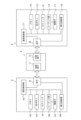
図7は、本体装置2と左コントローラ3および右コントローラ4との内部構成の一例を示すブロック図である。なお、本体装置2に関する内部構成の詳細については、図6で示しているため図7では省略している。
FIG. 7 is a block diagram showing an example of internal configurations of the
左コントローラ3は、本体装置2との間で通信を行う通信制御部101を備える。図7に示すように、通信制御部101は、端子42を含む各構成要素に接続される。この実施例においては、通信制御部101は、端子42を介した有線通信と、端子42を介さない無線通信との両方で本体装置2と通信を行うことが可能である。通信制御部101は、左コントローラ3が本体装置2に対して行う通信方法を制御する。すなわち、左コントローラ3が本体装置2に装着されている場合、通信制御部101は、端子42を介して本体装置2と通信を行う。また、左コントローラ3が本体装置2から外されている場合、通信制御部101は、本体装置2(具体的には、コントローラ通信部83)との間で無線通信を行う。コントローラ通信部83と通信制御部101との間の無線通信は、例えばBluetooth(登録商標)の規格に従って行われる。
The
また、左コントローラ3は、例えばフラッシュメモリ等のメモリ102を備える。通信制御部101は、例えばマイコン(マイクロプロセッサとも言う)で構成され、メモリ102に記憶されるファームウェアを実行することによって各種の処理を実行する。
The
左コントローラ3は、各ボタン103(具体的には、ボタン33~39、43、44、および47)を備える。また、左コントローラ3は、アナログスティック(図7では「スティック」と記載する)32を備える。各ボタン103およびアナログスティック32は、自身に対して行われた操作に関する情報を、適宜のタイミングで繰り返し通信制御部101へ出力する。
The
通信制御部101は、各入力部(具体的には、各ボタン103、アナログスティック32、各センサ104および105)から、入力に関する情報(具体的には、操作に関する情報、またはセンサによる検出結果)を取得する。通信制御部101は、取得した情報(または取得した情報に所定の加工を行った情報)を含む操作データを本体装置2へ送信する。なお、操作データは、所定時間に1回の割合で繰り返し送信される。なお、入力に関する情報が本体装置2へ送信される間隔は、各入力部について同じであってもよいし、同じでなくてもよい。
The communication control unit 101 receives information on input (specifically, information on operation or detection result by sensor) from each input unit (specifically, each
上記操作データが本体装置2へ送信されることによって、本体装置2は、左コントローラ3に対して行われた入力を得ることができる。すなわち、本体装置2は、各ボタン103およびアナログスティック32に対する操作を、操作データに基づいて判断することができる。
By transmitting the operation data to the
左コントローラ3は、振動によってユーザに通知を行うための振動子(または、振動デバイス)107を備える。この実施例においては、振動子107は、本体装置2からの指令によって制御される。すなわち、通信制御部101は、本体装置2からの上記指令を受け取ると、当該指令に従って振動子107を駆動させる。ここで、左コントローラ3は、コーデック部106を備える。通信制御部101は、上記指令を受け取ると、指令に応じた振動信号をコーデック部106へ出力する。コーデック部106は、通信制御部101からの振動信号から振動子107を駆動させるための駆動信号を生成して振動子107へ与える。これによって振動子107が動作する。
The
振動子107は、より具体的にはリニア振動子である。リニア振動子は、回転運動をする通常のモータと異なり、入力される電圧に応じて所定方向に駆動されるため、入力される電圧の波形に応じた振幅および周波数で振動をさせることができる。この実施例において、本体装置2から左コントローラ3に送信される振動信号は、単位時間ごとに周波数と振幅とを表すデジタル信号であってよい。別の実施例においては、本体装置2から波形そのものを示す情報を送信するようにしてもよいが、振幅および周波数だけを送信することで通信データ量を削減することができる。また、さらにデータ量を削減するため、そのときの振幅および周波数の数値に替えて、前回の値からの差分だけを送信するようにしてもよい。この場合、コーデック部106は、通信制御部101から取得される振幅および周波数の値を示すデジタル信号をアナログの電圧の波形に変換し、当該波形に合わせて電圧を入力することで振動子107を駆動させる。したがって、本体装置2は、単位時間ごとに送信する振幅および周波数を変えることによって、そのときに振動子107を振動させる振幅および周波数を制御することができる。なお、本体装置2から左コントローラ3に送信される振幅および周波数は、1つに限らず、2つ以上送信するようにしてもよい。その場合、コーデック部106は、受信された複数の振幅および周波数それぞれが示す波形を合成することで、振動子107を制御する電圧の波形を生成することができる。
左コントローラ3は、電力供給部108を備える。この実施例において、電力供給部108は、バッテリおよび電力制御回路を有する。図示しないが、電力制御回路は、バッテリに接続されるとともに、左コントローラ3の各部(具体的には、バッテリの電力の給電を受ける各部)に接続される。
The
図7に示すように、右コントローラ4は、本体装置2との間で通信を行う通信制御部111を備える。また、右コントローラ4は、通信制御部111に接続されるメモリ112を備える。通信制御部111は、端子64を含む各構成要素に接続される。通信制御部111およびメモリ112は、左コントローラ3の通信制御部101およびメモリ102と同様の機能を有する。したがって、通信制御部111は、端子64を介した有線通信と、端子64を介さない無線通信(具体的には、Bluetooth(登録商標)の規格に従った通信)との両方で本体装置2と通信を行うことが可能であり、右コントローラ4が本体装置2に対して行う通信方法を制御する。
As shown in FIG. 7 , the
右コントローラ4は、左コントローラ3の各入力部と同様の各入力部を備える。具体的には、各ボタン113、アナログスティック52を備える。これらの各入力部については、左コントローラ3の各入力部と同様の機能を有し、同様に動作する。
The
また、右コントローラ4は、振動子117およびコーデック部116を備える。振動子117およびコーデック部116は、左コントローラ3の振動子107およびコーデック部106と同様に動作する。すなわち、通信制御部111は、本体装置2からの指令に従って、コーデック部116を用いて振動子117を動作させる。
右コントローラ4は、電力供給部118を備える。電力供給部118は、左コントローラ3の電力供給部108と同様の機能を有し、同様に動作する。
The
The
次に、図8を参照して、この実施例のゲームシステム1において実行される仮想のゲームのゲーム処理についての概要を説明する。図8は、この実施例の仮想のゲームのアプリケーションを実行した場合に、表示装置(たとえば、ディスプレイ12)に表示されるゲーム画像の限定しない一例を示す図である。
Next, with reference to FIG. 8, an outline of game processing of a virtual game executed in the
図8に示すように、限定しない一例のゲーム画像としてのゲーム画面200は、プレイヤキャラクタ202を含み、プレイヤキャラクタ202には、敵キャラクタ206を探索するためのアイテムとしてレーダーオブジェクト204が装着される。また、ゲーム画面200は、敵キャラクタ206および背景オブジェクト208を含み、敵キャラクタ206は背景オブジェクト208によって隠れるように配置される。
As shown in FIG. 8 , a game screen 200 as a non-limiting example game image includes a
なお、図8に示す例では、敵キャラクタ206が背景オブジェクト208に隠れている様子を示すが、敵キャラクタ206は隠れていなくてもよい。たとえば、プレイヤキャラクタ202、敵キャラクタ206および敵キャラクタ206とは異なる他のノンプレイヤキャラクタが存在するようなシーンにおいて、敵キャラクタ206を探索する場合もある。すなわち、本実施例のゲーム処理は、隠れている探索対象を探す目的に有効であるが、隠れていない対象を探す場面でも使うことができる。
Although the example shown in FIG. 8 shows the
プレイヤキャラクタ202は、プレイヤの操作に従って所定の動作の実行を制御されるキャラクタまたはオブジェクトである。プレイヤキャラクタ202の所定の動作としては、仮想の或る場所すなわち仮想空間内において、移動したり、アイテムを取得したり、敵キャラクタ206を探索したり、敵キャラクタ206を攻撃したり、敵キャラクタ206の攻撃を防御したりすることなどが該当する。この実施例では、レーダーオブジェクト204は、プレイヤキャラクタ202に装着されるため、プレイヤキャラクタ202の移動に従ってレーダーオブジェクト204も移動される。
The
レーダーオブジェクト204は、敵キャラクタ206を探索するレーダーを模したオブジェクトであり、プレイヤキャラクタ202の頭上で軸204a回りに回転される。レーダーオブジェクト204が回転表示されることにより、プレイヤキャラクタ202またはレーダーオブジェクト204によって敵キャラクタ206を探索していることが示される(演出される)。
The
敵キャラクタ206を含む複数のノンプレイヤキャラクタは、それぞれ、プレイヤによる操作ではなくコンピュータ(図6のプロセッサ81)によって所定の動作を制御されるキャラクタまたはオブジェクトである。ノンプレイヤキャラクタの所定の動作としては、移動したり、プレイヤキャラクタ202を攻撃したり、プレイヤキャラクタ202からの攻撃を防御したりすることが該当する。ただし、レーダーオブジェクト204の回転は、コンピュータによって制御される。
A plurality of non-player characters, including the
背景オブジェクト208は、主として、仮想空間に配置される地形のオブジェクトを意味する。また、この実施例においては、地形とは、地面(道路、広場などを含む)、床、木、草、花、建物、階段、洞窟、崖、壁などを意味する。図8に示す例では、背景オブジェクト208として、草木(花を含む)オブジェクトが表示される。
The
本体装置2は、画像処理装置としても機能し、ゲーム画面200を含む各種画面に対応する表示画像データを生成および出力(表示)する。プロセッサ81は、3次元の仮想空間に各種のオブジェクトおよびキャラクタを配置し、或る情景または場面(シーン)が生成される。このシーンを仮想のカメラで撮影した(視点から見た)画像がゲーム画像としてディスプレイ12に表示される。
図8に示すゲーム画面200は、仮想空間に生成した或るシーンを仮想のカメラで撮影した画像である。図9に示すように、仮想空間において、XY平面に相当する平面またはこのXY平面に平行な平面上に、プレイヤキャラクタ202および複数の敵キャラクタ206に配置される。ただし、図9では、背景オブジェクト208を省略してある。
A game screen 200 shown in FIG. 8 is an image of a certain scene generated in a virtual space captured by a virtual camera. As shown in FIG. 9, a
この実施例では、プレイヤは、アナログスティック32を操作することにより、プレイヤキャラクタ202を仮想空間内で移動させ、レーダーオブジェクト204の探索結果に基づいて敵キャラクタ206を探索し、Aボタン53を操作することにより、探索した敵キャラクタ206を攻撃する。
In this embodiment, the player moves the
レーダーオブジェクト204は、Z軸方向と平行な方向に延びる軸204aを中心に回転され、その検出面(この実施例では、円形状の面)が向いている方向に存在する敵キャラクタ206を検出する。レーダーオブジェクト204は回転するため、プレイヤキャラクタ202またはレーダーオブジェクト204は、仮想空間(または、ワールド座標系)のXY平面またはこれに平行な面において、360度の向きについて敵キャラクタ206が存在するかどうかを探索することができる。
The
ただし、後述するように、敵キャラクタ206を探索可能な範囲(探索領域SR)はプレイヤキャラクタ202またはレーダーオブジェクト204の位置を基準に設定されている(図10参照)。
However, as will be described later, the searchable range (search area SR) for the
また、レーダーオブジェクト204が回転する速度(以下、「回転速度」という)vは、プレイヤキャラクタ202と敵キャラクタ206の距離に応じて変化される。ただし、複数の敵キャラクタ206が探索領域SR内に存在する場合には、回転速度vは、プレイヤキャラクタ202の最も近くに存在する敵キャラクタ206との距離に応じて変化される。
Also, the speed v at which the
この実施例では、プレイヤキャラクタ202が敵キャラクタ206に所定距離未満まで近づいたとき(または、接触したとき)の回転速度vが最大値vmに設定され、所定距離以上離れると、距離に応じて回転速度vが遅くされる。たとえば、距離または距離の二乗に反比例して回転速度vが変化される。または、距離に応じて段階的(ステップ状)に回転速度vが変化される。つまり、敵キャラクタ206との距離が近いほど、レーダーオブジェクト204は速く回転される。後述するように、レーダーオブジェクト204によって敵キャラクタ206が検出されると振動を発生するため、敵キャラクタ206がプレイヤキャラクタ202の近くに存在する場合には、振動が発生される時間間隔が短くされる。つまり、振動が発生する時間間隔の長さによって、プレイヤキャラクタ202と敵キャラクタの206の距離の大きさを認識することができる。
In this embodiment, when the
図10は、図9に示す仮想空間を上方から見た場合において、プレイヤキャラクタ202、レーダーオブジェクト204および複数の敵キャラクタ206(または、後述する「簡易形状230」)を模式的に示した図である。以下、図9および図10を参照しながら、プレイヤキャラクタ202またはレーダーオブジェクト204による探索領域SRおよび敵キャラクタ206を検出した場合の振動制御について説明する。
FIG. 10 is a diagram schematically showing a
図9および図10に示すように、仮想空間においてワールド座標系が設定される。この実施例では、仮想空間における水平面はワールド座標系のXY平面に平行に設定され、水平面に垂直な方向すなわち高さ方向がZ軸の方向に設定される。ただし、図9に示す例では、横方向がX軸の方向であり、奥行き方向がY軸の方向である。 As shown in FIGS. 9 and 10, a world coordinate system is set in the virtual space. In this embodiment, the horizontal plane in the virtual space is set parallel to the XY plane of the world coordinate system, and the direction perpendicular to the horizontal plane, that is, the height direction, is set in the Z-axis direction. However, in the example shown in FIG. 9, the horizontal direction is the direction of the X-axis, and the depth direction is the direction of the Y-axis.
また、プレイヤキャラクタ202(「操作オブジェクト」に相当する)には、敵キャラクタ206を探索するための仮想の判定オブジェクト(「判定領域」に相当する)220が設けられる。判定オブジェクト220は、棒状(線状)のオブジェクトであり、一方端がプレイヤキャラクタ202の中心に位置し、XY平面に対して平行に伸びている。また、判定オブジェクト220は、所定の長さhを有し、XY平面に平行な面内において、上記の一方端を中心に一方向(この実施例では、時計回り)に回転される。この判定オブジェクト220の回転に従って、上記のレーダーオブジェクト204は回転される。したがって、判定オブジェクト220も回転速度vで回転される。この実施例では、判定オブジェクト220は、XY平面を上方から見た場合に、時計回りに回転される。ただし、反時計回りに回転されてもよい。また、一回転する毎に、回転する方向が反転されてもよい。ただし、判定オブジェクト220は、仮想の形状であるため、描画されることはない。実際の判定のためには、プレイヤキャラクタ202の中心と所定の長さhが定義されていればよい。
Also, the player character 202 (corresponding to the “operation object”) is provided with a virtual determination object (corresponding to the “determination area”) 220 for searching for the
したがって、判定オブジェクト220は、図10に示すような円内を走査するように回転される。つまり、この円内の範囲または領域が探索領域SRである。この探索領域SR内に存在する敵キャラクタ206が探索または検出される。つまり、プレイヤキャラクタ202またはレーダーオブジェクト204を中心として、360度の向きについて敵キャラクタ206が存在するかどうかが探索される。
Therefore,
なお、判定オブジェクト220をレーダーオブジェクト204の位置に設定しないのは、この実施例では、レーダーオブジェクト204はプレイヤキャラクタ202の頭部に装着されるため、プレイヤキャラクタ202よりも高さが低い敵キャラクタ206についても検出可能にするためである。
The reason why the
ただし、宙に浮いている敵キャラクタ206も検出可能にするためには、図11に示すように、判定オブジェクト220を縦方向(Z軸に平行な方向)にも伸ばした(または、広げた)平面形状にしてもよい。このようにすれば、プレイヤキャラクタ202よりも高さの低い敵キャラクタ206および宙に浮いている敵キャラクタ206を検出することができる。図11に示す例では、判定オブジェクト220は、プレイヤキャラクタ202の足元から頭上の位置まで伸びている。また、判定オブジェクト220の縦方向の長さをプレイヤキャラクタ202の足元よりも下側の位置まで延ばした場合には、地中に埋もれている敵キャラクタ206を検出することもできる。
However, in order to detect the
また、判定オブジェクト220を平面形状にせずに、複数(たとえば、3つ)の判定オブジェクト220をそれぞれ間隔を隔ててZ軸方向に並べて配置するようにしてもよい。
Also, instead of making the
一方、探索される対象のオブジェクトまたはキャラクタ(「ターゲットオブジェクト」に相当する)である敵キャラクタ206には、衝突判定(当り判定)に用いられる簡易の形状(簡易形状)230が設定される。簡易形状230は、所定の形状であり、この実施例では、図9に示すように、球形状である。この簡易形状230は仮想の形状であるため、描画されることは無い。すなわち、仮想ゲーム空間において、敵キャラクタ206の中心から、所定の距離(つまり、半径rで決まる長さ)となる部分が簡易形状230とされる。なお、実際の判定のためには、球形状のモデルを保持する必要があるわけではなく、敵キャラクタ206の中心と所定の距離(半径r)が定義されていればよい。
On the other hand, a simple shape (simple shape) 230 used for collision determination (hit determination) is set for an
また、この実施例では、判定オブジェクト220によって敵キャラクタ206が探知(または検出)されると、そのことが振動でプレイヤに報知される。この実施例では、判定オブジェクト220が敵キャラクタ206に設定された簡易形状230に触れている(または、当たっている)場合に、プレイヤキャラクタ202またはレーダーオブジェクト204によって当該敵キャラクタ206が検出されたことが判断され、振動が発生される。以下、プレイヤキャラクタ202またはレーダーオブジェクト204によって検出された敵キャラクタ206を、単に「検出された敵キャラクタ206」と記載することにする。
Also, in this embodiment, when the
上述したように、判定オブジェクト220は、仮想空間のXY平面に平行な面において回転され、360度の向きについて敵キャラクタ206が存在するかどうかを探索するので、振動により、プレイヤキャラクタ202またはレーダーオブジェクト204から見た、検出された敵キャラクタ206の位置をプレイヤに示すことができ、プレイヤはその位置を特定することができる。
As described above, the
さらに、この実施例では、レーダーオブジェクト204を判定オブジェクト220とともに回転させるので、振動とレーダーオブジェクト204の向きにより、プレイヤキャラクタ202またはレーダーオブジェクト204から見た、検出された敵キャラクタ206の位置を特定し易くすることができる。
Furthermore, in this embodiment, since the
また、この実施例では、振動の大きさ(または、振動の強さ)δは、プレイヤキャラクタ202と、検出された敵キャラクタ206の距離dに応じて算出(または、変化)される。ただし、この実施例では、プレイヤキャラクタ202の頭部にレーダーオブジェクト204が設けられるため、振動の大きさδは、レーダーオブジェクト204と敵キャラクタ206の距離dに応じて変化されるということもできる。以下、振動の大きさδを算出する場合について同様である。また、この実施例では、距離dは、XY平面に平行な面内における直線距離(2次元距離)である。ただし、3次元距離でもよい。
Also, in this embodiment, the magnitude of vibration (or strength of vibration) δ is calculated (or changed) according to the distance d between the
この実施例では、プレイヤキャラクタ202と、検出された敵キャラクタ206の距離dが所定距離未満である(または、接触している)場合の振動の大きさδが最大値δmに設定され、プレイヤキャラクタ202と、検出された敵キャラクタ206の距離dまたは距離dの二乗に反比例して振動の大きさδが変化される、または、距離dに応じて段階的(ステップ状)に振動の大きさδが変化される。
In this embodiment, the magnitude δ of vibration when the distance d between the
さらに、この実施例では、振動の大きさδは、プレイヤキャラクタ202に対する、検出された敵キャラクタ206の位置に応じて、左コントローラ3に設けられる振動子107による振動の大きさδLと、右コントローラ4に設けられる振動子117による振動の大きさδRが調整される。つまり、左右の振動の大きさのバランスが調整される。ただし、この実施例では、プレイヤキャラクタ202の頭部にレーダーオブジェクト204が設けられるため、レーダーオブジェクト204と検出された敵キャラクタ206の位置関係に応じて、振動子107による振動の大きさδLと振動子117による振動の大きさδRが調整されるということもできる。以下、左右の振動の大きさのバランスが調整される場合について同様である。
Furthermore, in this embodiment, the magnitude of vibration δ is the magnitude of vibration δ L caused by the
一例として、ゲーム画面200において、検出された敵キャラクタ206が、プレイヤキャラクタ202の左側に位置している場合には、振動子107による振動の大きさ(または、振動の強さ)δLは、振動子117による振動の大きさδRよりも大きく(または、強く)される。一方、ゲーム画面200において、検出された敵キャラクタ206が、プレイヤキャラクタ202の右側に位置している場合には、振動子117による振動の大きさδRは、振動子107による振動の大きさδLよりも大きくされる。また、ゲーム画面200において、検出された敵キャラクタ206が、プレイヤキャラクタ202の手前または後ろである場合には、つまり、プレイヤキャラクタ202と検出された敵キャラクタ206とが縦の直線上に並んでいる場合には、振動子107による振動の大きさδLと振動子117による振動の大きさδRは同じにされる。
As an example, when the detected
ゲーム画面200において、検出された敵キャラクタ206がプレイヤキャラクタ202の左側に位置するか、右側に位置するか、手前または後ろに位置するかは、仮想のカメラの位置とプレイヤキャラクタ202の位置を通る仮想の直線よりも右側に位置するか、左側に位置するか、当該直線上に位置するかで判断することができる。
On the game screen 200, whether the detected
ただし、仮想の直線が検出された敵キャラクタ206に触れている場合には、この検出された敵キャラクタ206は、プレイヤキャラクタ202の手前または後ろに位置すると判断するようにしてある。つまり、検出された敵キャラクタ206が仮想の直線に触れない(または、当たらない)位置にずれている場合に、プレイヤキャラクタ202の左側または右側に位置することが判断される。
However, when the virtual straight line touches the detected
この実施例では、振動の大きさδは、プレイヤキャラクタ202に対する、検出された敵キャラクタ206の位置に応じて、数1に従って算出される。
In this embodiment, the magnitude δ of vibration is calculated according to
[数1]
δL=α×δ,δR=β×δ
ただし、係数αおよびβは、プレイヤキャラクタ202に対して、検出された敵キャラクタ206が左側に位置するか、右側に位置するか、奥または手前に位置するかで設定される。この実施例では、検出された敵キャラクタ206がプレイヤキャラクタ202の左側に位置する場合には、係数αが1.0に設定され、係数βが0.2に設定される。一方、検出された敵キャラクタ206がプレイヤキャラクタ202の右側に位置する場合には、係数αが0.2に設定され、係数βが1.0に設定される。ただし、検出された敵キャラクタ206がプレイヤキャラクタ202の手前または後ろに位置する場合には、係数αおよび係数βは初期値(α=β=1.0)に設定される。つまり、プレイヤキャラクタ202に対して、検出された敵キャラクタ206が左側に位置する場合には、左右の振動の大きさの比率が5対1に設定され、右側に位置する場合には、左右の振動の大きさの比率が1対5に設定され、奥または手前に位置する場合には、左右の振動の大きさの比率が1対1に設定される。
[Number 1]
δL = α×δ, δR = β×δ
However, the coefficients α and β are set depending on whether the detected
これは一例であり、プレイヤキャラクタ202と、検出された敵キャラクタ206の位置関係を振動の大きさで表現すれば良いため、振動の大きさを小さくする場合には、振動させない(すなわち、振動の大きさを0にする)ために係数αまたはβを0に設定してもよい。たとえば、敵キャラクタ206がプレイヤキャラクタ202に対して真横に位置する場合に、そのことをプレイヤが認識できるように、反対側(つまり、敵キャラクタ206が存在しない側)の振動を0にしてもよい。また、振動の大きさを大きくする場合に、係数αまたはβを1.0よりも大きい値に設定するようにしてもよい。
This is just an example, and the positional relationship between the
上述したように、プレイヤキャラクタ202またはレーダーオブジェクト204は、仮想空間のXY平面またはこれに平行な面において、360度の向きについて敵キャラクタ206が存在するかどうかを探索するため、プレイヤキャラクタ202に対する、検出された敵キャラクタ206の方向に応じて、左右の振動の大きさのバランスが調整される。また、左右の振動の大きさのバランスを調整する場合に、一方の振動の大きさを0にすることもあるため、プレイヤキャラクタ202に対する、検出された敵キャラクタ206の方向に応じて、左右のいずれかの振動の大きさを大きくするということもできる。
As described above, the
また、判定オブジェクト220をXY平面に平行な面内で回転させるとともに、プレイヤキャラクタ202と、検出された敵キャラクタ206の位置関係に応じて、左コントローラ3および右コントローラ4における振動の大きさのバランスを調整するので、敵キャラクタ206が背景オブジェクト208に隠れていても、左右の振動の大きさに基づいて、検出された敵キャラクタ206の位置をより特定し易くすることができる。
In addition, the
なお、この実施例では、判定オブジェクト220が敵キャラクタ206に設定された簡易形状230に触れている場合に、振動が発生されるため、振動が発生している期間を長くする場合には、図12に示すように、判定オブジェクト220のXY平面に平行な方向の幅を大きくすればよい。このようにすれば、プレイヤキャラクタ202またはレーダーオブジェクト204から見た、検出された敵キャラクタ206の位置をより分かり易く示すことができる。ただし、敵キャラクタ206の数が多く、互いに近い位置に存在する場合には、判定オブジェクト220のXY平面に平行な方向の幅を大きくすると、一度に複数の敵キャラクタ206に判定オブジェクト220が触れてしまう可能性がある。このため、敵キャラクタ206の数およびそれらの位置関係に応じて、判定オブジェクト220のXY平面に平行な方向の幅を設定する必要がある。
In this embodiment, when the
また、判定オブジェクト220のXY平面に平行な方向の幅を固定せずに、ゲームの難易度またはレベルに応じて、または、敵キャラクタ206の数に応じて、可変的に設定するようにしてもよい。
Alternatively, instead of fixing the width of the
以上のように、プレイヤキャラクタ202またはレーダーオブジェクト204によって敵キャラクタ206が検出されたことに応じて、プレイヤキャラクタ202と、検出された敵キャラクタ206の距離dが算出され、この距離dによって振動の大きさδが決定される。さらに、プレイヤキャラクタ202と、検出された敵キャラクタ206の位置関係によって、振動子107の振動の大きさδLと振動子117の振動の大きさδRのバランスが調整される。バランスの調整された振動の大きさδLおよびδRで振動させるための左側振動信号854hおよび右側振動信号854i(図13参照)が算出される。この実施例では、振動信号は、単位時間ごとに周波数と振幅とを表すデジタル信号である。したがって、所定の周波数であり、振動の大きさδLおよびδRに応じて決定された振幅の振動信号(すなわち、左側振動信号854hおよび右側振動信号854i)が算出される。
As described above, when the
図13は図6に示したDRAM85のメモリマップ850の限定しない一例を示す図である。図13に示すように、DRAM85は、プログラム記憶領域852およびデータ記憶領域854を含む。プログラム記憶領域852には、ゲームアプリケーションのプログラム(つまり、ゲームプログラム)が記憶される。図13に示すように、ゲームプログラムは、メイン処理プログラム852a、画像生成プログラム852b、操作検出プログラム852c、キャラクタ制御プログラム852d、探索プログラム852eおよび振動信号生成プログラム852fなどを含む。
FIG. 13 is a non-limiting example of memory map 850 of
ただし、生成されたゲーム画像などの画像を表示する機能および生成された振動信号に従って振動を発生する機能は本体装置2が備える機能である。したがって、画像表示プログラム852gおよび振動制御プログラム852hは、ゲームプログラムに含まれない。
However, the function of displaying an image such as a generated game image and the function of generating vibration according to the generated vibration signal are functions provided in
詳細な説明は省略するが、各プログラム852a-852hは、本体装置2に電源が投入された後の適宜のタイミングで、フラッシュメモリ84および/またはスロット23に装着された記憶媒体からその一部または全部が読み込まれてDRAM85に記憶される。ただし、各プログラム852a-852hの一部または全部は、本体装置2と通信可能な他のコンピュータから取得するようにしてもよい。
Although detailed description is omitted, each of the
メイン処理プログラム852aは、この実施例の仮想のゲームの全体的なゲーム処理を実行するためのプログラムである。画像生成プログラム852bは、画像生成データ854bを用いて、ゲーム画像などの各種の画像に対応する表示画像データを生成するためのプログラムである。
The
操作検出プログラム852cは、左コントローラ3または/および右コントローラ4からの操作データ854aを取得するためのプログラムである。キャラクタ制御プログラム852dは、プレイヤの操作に基づいて、プレイヤキャラクタ202の動作を制御したり、プレイヤの操作に関わらず、レーダーオブジェクト204および敵キャラクタ206を含むノンプレイヤオブジェクトまたはノンプレイヤキャラクタの動作を制御したりするためのプログラムである。
The
探索プログラム852eは、レーダーオブジェクト204によってプレイヤキャラクタ202を中心とする探索領域SR内に存在する対象のキャラクタ(この実施例では、敵キャラクタ206)を探索(または、検出)するためのプログラムである。具体的には、探索プログラム852eは、判定オブジェクト220をプレイヤキャラクタ202を中心に回転移動させ、この判定オブジェクト220が敵キャラクタ206に触れているかどうかを判断するためのプログラムである。ただし、探索プログラム852eは、判定オブジェクト220が敵キャラクタ206に触れているとき、当該敵キャラクタ206を検出したと判断する。
The
振動信号生成プログラム852fは、所定のイベントが発生しことに応じて、左コントローラ3に内蔵される振動子107を駆動させるための左側振動信号854hおよび右コントローラ4に内蔵される振動子117を駆動させるための右側振動信号854iを生成するためのプログラムである。この実施例では、上述したように、プレイヤキャラクタ202またはレーダーオブジェクト204によって敵キャラクタ206が検出されたことに応じて、プレイヤキャラクタ202と、検出された敵キャラクタ206の距離dが算出され、この距離dによって振動の大きさδが決定される。さらに、プレイヤキャラクタ202と、検出された敵キャラクタ206の位置関係によって、振動子107の振動の大きさδLと振動子117の振動の大きさδRのバランスが調整される。バランスの調整された振動の大きさδLおよびδRで振動させるための左側振動信号854hおよび右側振動信号854iが算出される。
The vibration
画像表示プログラム852gは、画像生成プログラム852bに従って生成した表示画像データを表示装置に出力するためのプログラムである。したがって、表示画像データに対応する画像(つまり、ゲーム画面200など)がディスプレイ12などの表示装置に表示される。
The
振動制御プログラム852hは、振動信号生成プログラム852fに従って算出された左側振動信号854hを用いて左コントローラ3の振動子107を駆動制御するとともに、探索プログラム852eに従って算出された右側振動信号854iを用いて右コントローラ4の振動子117を駆動制御するためのプログラムである。
The
なお、プログラム記憶領域852には、BGM等の音を出力するための音出力プログラム、他の機器と通信するための通信プログラム、データをフラッシュメモリ84などの不揮発性の記憶媒体に記憶するためのバックアッププログラムなども記憶される。
The
また、データ記憶領域854には、操作データ854a、画像生成データ854b、現在位置データ854c、判定オブジェクトデータ854d、距離データ854e、振動データ854f、係数データ854g、左側振動信号854hおよび右側振動信号854iなどが記憶される。
The
操作データ854aは、左コントローラ3または/および右コントローラ4から受信される操作データである。この実施例においては、本体装置2が左コントローラ3および右コントローラ4の両方から操作データを受信する場合には、本体装置2は、左コントローラ3および右コントローラ4のそれぞれに分類して操作データ854aを記憶する。
The
画像生成データ854bは、ポリゴンデータおよびテクスチャデータなど、表示画像データを生成するために必要なデータである。
The
現在位置データ854cは、プレイヤキャラクタ202、レーダーオブジェクト204および敵キャラクタ206のような仮想空間内において移動可能なキャラクタおよびオブジェクトについての現在フレームの位置に対応する位置座標のデータである。また、現在位置データ854cは、プレイヤキャラクタ202および敵キャラクタ206についての衝突(または、当たり)判定のための判定オブジェクト220および簡易形状230についてのデータも含む。ただし、判定オブジェクト220のデータは、プレイヤキャラクタ202の中心の位置および所定の長さhのデータであり、簡易形状230のデータは、敵キャラクタ206毎の中心の位置および半径rのデータである。
The
判定オブジェクトデータ854dは、判定オブジェクト220の現在フレームにおける位置および向きについてのデータである。距離データ854eは、仮想空間における、プレイヤキャラクタ202と、検出された敵キャラクタ206との距離dについてデータである。
振動データ854fは、距離データ854eが示す、仮想空間における、プレイヤキャラクタ202と、検出された敵キャラクタ206との距離dに応じて算出される振動の大きさδについてのデータである。振動の大きさδの算出方法は上述したとおりである。係数データ854gは、振動の大きさδLと振動の大きさδRのバランスを調整するための係数αおよび係数βについてのデータである。
The
左側振動信号854hは、振動子107を駆動するための振動信号である。右側振動信号854iは、振動子117を駆動するための振動信号である。
The
また、DRAM85のデータ記憶領域854には、振動フラグ854jが設けられる。振動フラグ854jは、振動を発生させるかどうかを判断するためのフラグである。振動フラグ854jは、振動を発生させる場合にオンされ、振動を発生させない場合にオフされる。
A
図示は省略するが、データ記憶領域854には、ゲームプログラムの実行に必要な、他のデータが記憶されたり、他のフラグおよびタイマ(またはカウンタ)が設けられたりする。
Although illustration is omitted, the
図14は、本体装置2のプロセッサ81(またはコンピュータ)のゲームプログラムの処理(ゲーム全体処理)の限定しない一例を示すフロー図である。以下、図14を用いて、ゲーム全体処理について説明するが、同じ処理を実行するステップについては重複する説明は省略することにする。
FIG. 14 is a flowchart showing a non-limiting example of game program processing (game overall processing) of processor 81 (or computer) of
ただし、図14に示すフロー図(図15-図17も同じ)の各ステップの処理は、単なる一例に過ぎず、同様の結果が得られるのであれば、各ステップの処理順序を入れ替えてもよい。また、この実施例では、基本的には、図14-図17に示すフロー図の各ステップの処理をプロセッサ81が実行するものとして説明するが、プロセッサ81以外のプロセッサや専用回路が一部のステップを実行するようにしてもよい。 However, the processing of each step in the flow chart shown in FIG. 14 (the same applies to FIGS. 15 to 17 ) is merely an example, and the processing order of each step may be changed as long as the same result can be obtained. . Further, in this embodiment, basically, the processing of each step in the flow charts shown in FIGS . Steps may be executed.
本体装置2の電源が投入されると、ゲーム全体処理の実行に先だって、プロセッサ81は、図示しないブートROMに記憶されている起動プログラムを実行し、これによってDRAM85等の各ユニットが初期化される。本体装置2は、ユーザによって、この実施例のゲームプログラムの実行が指示されると、ゲーム全体処理を開始する。
When the
図14に示すように、プロセッサ81は、ゲーム全体処理を開始すると、ステップS1で、初期処理を実行する。初期処理では、たとえば、プロセッサ81は、ゲーム画面200を生成および表示するための仮想空間を構築し、この仮想空間に登場するプレイヤキャラクタ202、レーダーオブジェクト204、敵キャラクタ206および背景オブジェクト208等の各キャラクタないし各オブジェクトを初期位置に配置する。また、プロセッサ81は、ゲーム制御処理(S5)で用いる各種パラメータの初期値を設定する。
As shown in FIG. 14, when the
なお、詳細な説明は省略するが、ゲーム全体処理の開始に先立って、左コントローラ3および右コントローラ4が本体装置2に装着されているかどうかが判断され、左コントローラ3および右コントローラ4が本体装置2から分離されている場合には、本体装置2と、左コントローラ3および右コントローラ4との間でペアリング処理が実行される。
Although detailed description is omitted, it is determined whether or not the
続いて、プロセッサ81は、ステップS3で、コントローラ(3,4)から送信されてくる操作データを取得し、ステップS5で、ゲーム制御処理を実行する。たとえば、ゲーム制御処理では、操作データに従ってプレイヤキャラクタ202を移動させるなどの任意のアクションを実行する。また、ゲームプログラムに従ってレーダーオブジェクト204および敵キャラクタ206を移動させるなどの任意のアクションを実行する。さらに、必要に応じて、アイテムを仮想空間に出現させる(配置する)。
Subsequently, the
次のステップS7では、プロセッサ81は、ディスプレイ12に表示するためのゲーム画像を生成および表示する。簡単に説明すると、プロセッサ81は、ステップS5のゲーム制御処理の結果を表すデータおよび画像生成データ854bをDRAM85から読み出し、ゲーム画像データを生成し、ディスプレイ12に出力する。
At the next step S7, the
続いて、ステップS9では、振動を発生させるかどうかを判断する。ここでは、振動フラグ854jがオンであるかどうかを判断する。
Subsequently, in step S9, it is determined whether or not to generate vibration. Here, it is determined whether or not the
ステップS9で“NO”であれば、つまり、振動を発生させない場合には、ステップS13に進む。一方、ステップS9で“YES”であれば、つまり、振動を発生させる場合には、ステップS11で、左側振動信号854hおよび右側振動信号854iを振動制御部に送信する。振動制御部は、本体装置2のオペレーティングシステムであり、このオペレーティングシステムもプロセッサ81によって実行される。つまり、コントローラ(14,16)を振動させることの指令がアプケーションのプログラムからオペレーティングシステム(すなわち、振動制御部)に送信される。そして、ステップS13では、ゲームを終了するかどうかを判断する。ステップS13の判断は、たとえば、ゲームオーバーになったか否か、あるいは、プレイヤがゲームを中止する指示を行ったか否か等によって行われる。ステップS13で“NO”であれば、つまりゲームを終了しない場合には、ステップS3に戻る。一方、ステップS13で“YES”であれば、つまりゲームを終了する場合には、ゲーム全体処理を終了する。
If "NO" in step S9, that is, if vibration is not to be generated, the process proceeds to step S13. On the other hand, if "YES" in step S9, that is, if vibration is to be generated, in step S11, the
図15および図16は、本体装置2のプロセッサ81(またはコンピュータ)の探索および振動信号生成処理の限定しない一例を示すフロー図である。この探索および振動信号生成処理は、プロセッサ81によって、図14に示したゲーム全体処理と並行して実行される。ただし、レーダーオブジェクト204によって敵キャラクタ206を探索しないシーンまたはプレイヤキャラクタ202がレーダーオブジェクト204を装着していない場合には、探索および振動信号生成処理は実行されない。
15 and 16 are flowcharts showing non-limiting examples of search and vibration signal generation processing of processor 81 (or computer) of
図15に示すように、プロセッサ81は、探索および振動信号生成処理を開始すると、ステップS31で、判定オブジェクト220を所定速度で回転開始する。ただし、実際に判定オブジェクト220(または、判定領域)を描画して回転させる必要はなく、判定オブジェクト220に含まれる複数の点のそれぞれのフレーム毎の位置が算出される。この判定オブジェクト220に含まれる複数の点のそれぞれの位置に対応する位置座標データが判定オブジェクトデータ854dとしてデータ記憶領域854に記憶または更新される。
As shown in FIG. 15, after starting the search and vibration signal generation processing, the
続くステップS33では、係数αおよびβを初期値(α=β=1.0)に設定する。次のステップS35では、判定オブジェクト220が敵キャラクタ206に触れているかどうかを判断する。つまり、プロセッサ81は、判定オブジェクト220が敵キャラクタ206に設定された簡易形状230に触れいているかどうかを判断する。
In subsequent step S33, coefficients α and β are set to initial values (α=β=1.0). In the next step S35, it is determined whether the
ステップS35で“NO”であれば、つまり、判定オブジェクト220が敵キャラクタ206に触れていなければ、図16に示すステップS55に進む。一方、ステップS35で“YES”であれば、つまり、判定オブジェクト220が敵キャラクタ206に触れていれば、ステップS37で、振動フラグ854jをオンし、ステップS39で、プレイヤキャラクタ202と、当該敵キャラクタ206すなわち検出された敵キャラクタ206の距離dを算出する。このとき、算出した距離dについての距離データ854eがデータ記憶領域854に記憶または更新される。
If "NO" in step S35, that is, if the
次のステップS41では、ステップS39で算出した距離dに応じて振動の大きさδを算出する。振動の大きさδの算出方法は上述したとおりである。このとき、算出された振動の大きさδについての振動データ854fがデータ記憶領域854に記憶または更新される。続くステップS43では、検出された敵キャラクタ206がプレイヤキャラクタ202に最も近い位置の敵キャラクタ206であるかどうかを判断する。
In the next step S41, the magnitude δ of vibration is calculated according to the distance d calculated in step S39. The method for calculating the magnitude δ of vibration is as described above. At this time, the
ステップS43で“NO”であれば、つまり、検出された敵キャラクタ206がプレイヤキャラクタ202に最も近い位置の敵キャラクタ206でなければ、図16に示すステップS47に進む。一方、ステップS43で“YES”であれば、つまり、検出された敵キャラクタ206がプレイヤキャラクタ202に最も近い位置の敵キャラクタ206であれば、ステップS45で、ステップS39で算出した距離dに応じて所定速度を変化させて、ステップS47に進む。
If "NO" in step S43, that is, if the detected
図16に示すステップS47では、検出された敵キャラクタ206がプレイヤキャラクタ202よりも右側であるかどうかを判断する。ステップS47で“YES”であれば、つまり、検出された敵キャラクタ206がプレイヤキャラクタ202よりも右側であれば、ステップS49で、左よりも右の振動を大きくするように、係数αおよびβを設定して、ステップS55に進む。つまり、ステップS49では、プロセッサ81は、α=0.2、β=1.0に設定する。このとき、係数データ854gが更新される。
In step S47 shown in FIG. 16, it is determined whether the detected
また、ステップS47で“NO”であれば、つまり、検出された敵キャラクタ206がプレイヤキャラクタ202よりも右側でなければ、ステップS51で、検出された敵キャラクタ206がプレイヤキャラクタ202よりも左側であるかどうかを判断する。
If "NO" in step S47, that is, if the detected
ステップS51で“NO”であれば、つまり、検出された敵キャラクタ206がプレイヤキャラクタ202よりも左側でなければ、ステップS55に進む。一方、ステップS51で“YES”であれば、つまり、検出された敵キャラクタ206がプレイヤキャラクタ202よりも左側であれば、ステップS53で、右よりも左の振動を大きくするように、係数αおよびβを設定して、ステップS55に進む。つまり、ステップS53では、プロセッサ81は、α=1.0、β=0.2に設定する。このとき、係数データ854gが更新される。
If "NO" in step S51, that is, if the detected
ステップS55では、数1に従って、左側振動信号854hおよび右側振動信号854iを生成する。このとき、ステップS41で算出された振動の大きさδと、ステップS33、S49またはS53で設定された係数α、βすなわち係数データ854gが用いられる。
In step S55, the left
そして、ステップS57では、終了かどうかを判断する。ここでは、プロセッサ81は、現在のシーンが敵キャラクタ206を探索しないシーンであるかどうか、または、プレイヤキャラクタ202がレーダーオブジェクト204を外したかどうかを判断する。
Then, in step S57, it is determined whether or not the processing is finished. Here,
ステップS57で“NO”であれば、つまり、終了でなければ、図15に示したステップS33に戻る。一方、ステップS57で“YES”であれば、つまり、終了であれば、探索および振動信号生成処理を終了する。 If "NO" in step S57, that is, if the process is not finished, the process returns to step S33 shown in FIG. On the other hand, if "YES" in step S57, that is, if it is finished, the search and vibration signal generation process is finished.
図17は図6に示したプロセッサ81の振動制御処理の限定しない一例を示すフロー図である。たとえば、プロセッサ81は、アプリケーションのプログラムから振動を発生させることを要求(指示)されると、振動制御処理を開始する。ただし、左側振動信号854hおよび右側振動信号854iのそれぞれについて、振動制御処理が並行して実行される。
FIG. 17 is a flowchart showing a non-limiting example of vibration control processing of
図17に示すように、プロセッサ81は、振動制御処理を開始すると、ステップS71で、アプリケーションのプログラムつまりゲームプログラムから振動信号が入力されたかどうかを判断する。ステップS71で“NO”であれば、つまり、アプリケーションのプログラムから振動信号が入力されていなければ、ステップS71に戻る。
As shown in FIG. 17, when starting the vibration control process, the
一方、ステップS71で“YES”であれば、つまり、アプリケーションのプログラムから振動信号が入力されれば、ステップS73で、振動信号(左側振動信号854hまたは右側振動信号854i)を該当するコントローラ(3、4)に送信する。したがって、振動信号を受信したコントローラ(3、4)では、振動信号に従って、振動子(107、117)が駆動される。
On the other hand, if "YES" in step S71, that is, if a vibration signal is input from the application program, in step S73, the vibration signal (left
そして、ステップS75では、終了かどうかを判断する。ここでは、プロセッサ81は、振動を提示する処理を有するアプリケーションが終了されたかどうか、または、当該アプリケーションにおいて振動を提示するシーンが終了されたかどうかを判断する。ステップS75で“NO”であれば、つまり、終了でなければ、ステップS71に戻る。一方、ステップS75で“YES”であれば、つまり、終了であれば、振動制御処理を終了する。
Then, in step S75, it is determined whether or not the processing is finished. Here, the
この実施例によれば、判定オブジェクトをプレイヤキャラクタを中心に回転させ、判定オブジェクトが敵キャラクタに触れると、コントローラに振動を発生させるので、新しいゲームプログラム、ゲームシステム、ゲーム装置およびゲーム制御方法を提供することができる。また、プレイヤキャラクタの位置を中心に360°の方向の敵キャラクタの位置を振動により示し易くすることができる。したがって、プレイヤは、プレイヤキャラクタの位置を中心に360°の方向の敵キャラクタの位置を振動により知ることができる。 According to this embodiment, the judgment object is rotated around the player character, and when the judgment object touches the enemy character, the controller vibrates, thereby providing a new game program, game system, game device, and game control method. can do. In addition, it is possible to easily indicate the position of the enemy character in the direction of 360 degrees around the position of the player character by vibration. Therefore, the player can know the position of the enemy character in 360 degrees around the position of the player character by the vibration.
また、この実施例によれば、判定オブジェクトの回転に合わせてレーダーオブジェクトを回転表示させるので、振動の情報とともに知覚することにより、複数の敵キャラクタが探索領域内に存在する場合には、それぞれの位置を容易に知ることができる。 Further, according to this embodiment, since the radar object is rotated and displayed in accordance with the rotation of the judgment object, by perceiving the radar object together with the vibration information, when a plurality of enemy characters exist in the search area, each of them can be displayed. You can easily know the position.
さらに、この実施例によれば、左右のコントローラの振動のバランスを維持したり調整したりすることにより、検出された敵キャラクタの位置がプレイヤキャラクタに対して、左側または右側を報知し、さらに判定オブジェクトの回転に合わせて振動させることにより左右だけでなく前方であるか後方であるかも識別できるので、プレイヤキャラクタに対する、検出された敵キャラクタの位置または/および方向を容易に知ることができる。 Furthermore, according to this embodiment, by maintaining or adjusting the balance of the vibrations of the left and right controllers, the position of the detected enemy character is notified to the player character to the left or right, and further determined. By vibrating the object in accordance with the rotation of the object, it is possible to identify not only the left and right but also the front or back, so that the position and/or direction of the detected enemy character with respect to the player character can be easily known.
なお、この実施例では、プレイヤキャラクタの頭上にレーダーオブジェクトを装着し、敵キャラクタを探索するようにしたが、操作オブジェクトおよびターゲットオブジェクトはこれらに限定される必要はない。 In this embodiment, a radar object is mounted on the player character's head to search for enemy characters, but the operation object and the target object need not be limited to these.
プレイヤキャラクタが所有するレーダーオブジェクトまたはセンサのような他の操作オブジェクトをプレイヤキャラクタから離れた位置に置いて、敵キャラクタを探索するようにしてもよい。かかる場合には、他の操作オブジェクトは、プレイヤによって直接移動を操作されてもよいし、プレイヤが操作するプレイヤキャラクタの移動に追従して仮想空間内を移動されてもよい。 A radar object owned by the player character or other operation object such as a sensor may be placed at a position away from the player character to search for the enemy character. In such a case, the other operation object may be directly operated by the player, or may be moved in the virtual space following the movement of the player character operated by the player.
また、敵キャラクタに代えて、アイテム、お宝、味方のキャラクタのような他のターゲットオブジェクトを探索するようにしてもい。 Also, instead of enemy characters, other target objects such as items, treasures, and friendly characters may be searched.
さらに、この実施例では、プレイヤキャラクタに対する、検出された敵キャラクタが左側または右側に位置する場合には、左右の振動の大きさの比率が所定の比率となるように、係数αおよびβを所定の値に設定するようにしたが、これに限定される必要はない。係数αおよびβには、プレイヤキャラクタと、検出された敵キャラクタの距離dに応じて変化される値が設定されてもよい。この場合、プレイヤキャラクタに対する、検出された敵キャラクタの位置が左または右に離れるに従って比率が偏るように、係数αおよびβが設定される。 Furthermore, in this embodiment, when the detected enemy character is positioned on the left or right side of the player character, the coefficients α and β are set to a predetermined ratio so that the ratio of the magnitude of the lateral vibration is a predetermined ratio. , but it need not be limited to this. Values that change according to the distance d between the player character and the detected enemy character may be set for the coefficients α and β. In this case, the coefficients α and β are set so that the ratio is biased as the position of the detected enemy character with respect to the player character moves to the left or right.
たとえば、プレイヤキャラクタに対する、検出された敵キャラクタの位置が左である場合には、プレキャラクタと、検出された敵キャラクタの距離dが離れるに従って、係数βの値が0.8,0.6,0.4,0.2に変化される。つまり、係数βが段階的に変化される。この場合、係数αの値を1.0で固定しておけば、係数αとβの比率が5対4、5対3、5対2、5対1と次第に変化する。一方、プレイヤキャラクタに対する、検出された敵キャラクタの位置が右である場合には、プレキャラクタと、検出された敵キャラクタの距離dが離れるに従って、係数αの値が0.8,0.6,0.4,0.2に変化される。つまり、係数αが段階的に変化される。この場合、係数βの値を1.0で固定しておけば、係数αとβの比率が4対5、3対5、2対5、1対5と次第に変化する。ただし、これは一例であり、係数αおよびβの両方の値を変化させてるようにしてもよい。 For example, when the position of the detected enemy character is to the left of the player character, the values of the coefficient β are 0.8, 0.6, 0.8, 0.6, and 0.6 as the distance d between the pre-character and the detected enemy character increases. changed to 0.4, 0.2. That is, the coefficient β is changed stepwise. In this case, if the value of the coefficient α is fixed at 1.0, the ratio between the coefficients α and β gradually changes to 5:4, 5:3, 5:2, and 5:1. On the other hand, when the position of the detected enemy character with respect to the player character is to the right, the values of the coefficient α are 0.8, 0.6, 0.8, 0.6, 0.8, 0.6, 0.8, 0.6, 0.8, 0.6, 0.8, 0.6, 0.8, 0.6, 0.8, 0.6, 0.8, 0.6, changed to 0.4, 0.2. That is, the coefficient α is changed stepwise. In this case, if the value of the coefficient β is fixed at 1.0, the ratio between the coefficients α and β gradually changes to 4:5, 3:5, 2:5, and 1:5. However, this is an example, and the values of both coefficients α and β may be changed.
さらにまた、この実施例では、複数の敵キャラクタが探索領域に存在する場合には、検出された複数の敵キャラクタのうち、プレイヤキャラクタの最も近くに存在する敵キャラクタとの距離に基づいて判定オブジェクトの回転速度を決定するようにしたが、これに限定される必要はない。検出するべき順番または優先度が複数の敵キャラクタのそれぞれに設定されている場合には、探索された複数の敵キャラクタのうち、検出するべき順番が最も早いまたは優先度が最も高い敵キャラクタとプレイヤキャラクタの距離に基づいて判定オブジェクトの回転速度を決定するようにしてもよい。 Furthermore, in this embodiment, when a plurality of enemy characters exist in the search area, the determination object is determined based on the distance to the player character's closest enemy character among the plurality of detected enemy characters. , but it is not necessary to be limited to this. When the order or priority to be detected is set for each of a plurality of enemy characters, the enemy character and the player having the earliest order or highest priority to be detected among the searched plurality of enemy characters. The rotation speed of the judgment object may be determined based on the distance of the character.
また、この実施例では、様々なターゲットオブジェクトを探索するための例として、判定オブジェクトを変化させるようにしたが、判定オブジェクトは変化させずに、または、判定オブジェクトとともに、ターゲットオブジェクトに設定される当たり判定用の所定の形状を変化させるようにしてもよい。たとえば、球形状または楕円球形状を、縦方向に延びるカプセル形状または円筒形状に変化させてもよい。 Also, in this embodiment, as an example for searching for various target objects, the determination object is changed. The predetermined shape for determination may be changed. For example, a spherical or ellipsoidal shape may be changed to a longitudinally extending capsule or cylindrical shape.
さらに、この実施例では、情報処理システムの一例としてゲームシステム1を示したが、その構成は限定される必要は無く、他の構成を採用することが可能である。たとえば、上記「コンピュータ」は、上述の実施例においては、1つのコンピュータ(具体的には、プロセッサ81)であるが、他の実施例においては、複数のコンピュータであってもよい。上記「コンピュータ」は、例えば、複数の装置に設けられる(複数の)コンピュータであってもよく、より具体的には、上記「コンピュータ」は、本体装置2のプロセッサ81と、コントローラが備える通信制御部(マイクロプロセッサ)101、111とによって構成されてもよい。
Furthermore, in this embodiment, the
さらにまた、他の実施例では、インターネットのようなネットワーク上のサーバで、図14に示したゲーム制御処理を実行するようにしてもよい。かかる場合には、本体装置2のプロセッサ81は、左コントローラ3および右コントローラ4から受信した操作データを、ネットワーク通信部82およびネットワークを介して上記のサーバに送信し、サーバでゲーム制御処理を実行された結果(つまり、ゲーム画像のデータおよびゲーム音声のデータ)を受信して、ゲーム画像をディスプレイ12に表示するとともに、ゲーム音声をスピーカ88から出力する。つまり、上記の実施例で示したゲームシステム1とネットワーク上のサーバを含む情報処理システムを構成することもできる。
Furthermore, in another embodiment, a server on a network such as the Internet may execute the game control process shown in FIG. In such a case, the
また、上述の実施例では、ディスプレイ12にゲーム画像を表示する場合について説明したが、これに限定される必要はない。本体装置2を、クレードルを介して据置型モニタ(たとえば、テレビモニタ)に接続することにより、ゲーム画像を据置型モニタに表示することもできる。かかる場合には、ゲームシステム1と据置型モニタを含む情報処理システムを構成することもできる。
Also, in the above-described embodiment, the case where the game image is displayed on the
さらに、上述の実施例では、本体装置2に左コントローラ3および右コントローラ4を着脱可能な構成のゲームシステム1を用いた場合について説明したが、これに限定される必要はない。たとえば、左コントローラ3および右コントローラ4と同様の操作ボタンおよびアナログスティックを有する操作部を本体装置2に一体的に設けたゲーム装置またはゲームプログラムを実行可能な他の電子機器のような情報処理装置を用いることもできる。他の電子機器としては、スマートフォンまたはタブレットPCなどが該当する。かかる場合には、操作部はソフトウェアキーで構成することもできる。
Furthermore, in the above-described embodiment, the
さらにまた、他の実施例では、左コントローラ3および右コントローラ4に代えて、他のコントローラを用いるようにしてもよい。たとえば、左コントローラ3および右コントローラ4と同様の操作ボタン、アナログスティックおよび振動子を左右に有する他のコントローラを本体装置2に通信可能に接続してもよい。
Furthermore, in another embodiment, instead of the
また、その他の実施例では、連結部材を用いて、左コントローラ3および右コントローラ4を一体的に構成して1つのコントローラとして使用するようにしてもよい。
In another embodiment, a connecting member may be used to integrally configure the
さらに、上述の実施例で示した具体的な数値および画像は一例であり、実際の製品に応じて適宜変更可能である。 Furthermore, the specific numerical values and images shown in the above embodiment are examples, and can be changed as appropriate according to the actual product.
1 …ゲームシステム
2 …本体装置
3 …左コントローラ
4 …右コントローラ
32、52 …アナログスティック
39 …ZLボタン
60 …Rボタン
61 …ZRボタン
81 …プロセッサ
REFERENCE SIGNS
Claims (28)
操作装置に対する操作入力に基づいて、仮想空間内において操作オブジェクトを制御させ、
前記仮想空間内に、探索対象となるターゲットオブジェクトを配置させ、
前記仮想空間内において前記ターゲットオブジェクトを探索するための判定領域を設定させ、
前記判定領域を、前記操作オブジェクトの位置を中心に所定速度で自動的に回転させ、
前記判定領域に前記ターゲットオブジェクトが触れているときに、前記操作装置に備えられた振動デバイスを振動させるための振動信号を生成させる、ゲームプログラム。 In the computer of the information processing equipment,
controlling an operation object in a virtual space based on an operation input to the operation device;
arranging a target object to be searched in the virtual space;
setting a determination region for searching for the target object in the virtual space;
automatically rotating the determination area at a predetermined speed around the position of the operation object;
A game program for generating a vibration signal for vibrating a vibration device provided in the operating device when the target object is in contact with the determination area.
前記判定領域に前記ターゲットオブジェクトが触れているときに、前記ターゲットオブジェクトの位置の前記操作オブジェクトに対する方向に応じて、前記複数の振動デバイスのいずれかが振動する強さが強くなるよう、前記振動信号を生成させる、請求項1から3までのいずれかに記載のゲームプログラム。 The operation device includes a plurality of the vibration devices,
When the target object is in contact with the determination area, the vibration signal increases the intensity of vibration of any one of the plurality of vibration devices according to the direction of the position of the target object with respect to the operation object. 4. The game program according to any one of claims 1 to 3, which generates a
前記操作オブジェクトの位置に、探索を行っていることを示す演出オブジェクトをさらに配置させ、
前記判定領域の回転速度と同じ速度で前記演出オブジェクトを回転させる、請求項1から4までのいずれか記載のゲームプログラム。 to the computer;
further disposing a rendering object indicating that a search is being performed at the position of the operation object;
5. The game program according to any one of claims 1 to 4, wherein said effect object is rotated at the same speed as the rotation speed of said determination area.
前記操作入力に基づいて、前記操作オブジェクトに、前記ターゲットオブジェクトに対して所定のアクションを行わせる、請求項1から5までのいずれか記載のゲームプログラム。 The computer further comprises:
6. The game program according to any one of claims 1 to 5, wherein the operation object is caused to perform a predetermined action on the target object based on the operation input.
前記判定領域を、前記操作オブジェクトの向きに関係無く、当該操作オブジェクトの位置を中心に所定速度で回転させる、請求項1から6までのいずれかに記載のゲームプログラム。 to the computer;
7. The game program according to any one of claims 1 to 6, wherein the determination area is rotated around the position of the operable object at a predetermined speed regardless of the orientation of the operable object.
操作装置を備え、
前記プロセッサは、
前記操作装置に対する操作入力に基づいて、仮想空間内において操作オブジェクトを制御し、
前記仮想空間内に、探索対象となるターゲットオブジェクトを配置し、
前記仮想空間内において前記ターゲットオブジェクトを探索するための判定領域を設定し、
前記判定領域を、前記操作オブジェクトの位置を中心に所定速度で自動的に回転し、
前記判定領域に前記ターゲットオブジェクトが触れているときに、前記操作装置に備えられた振動デバイスを振動させるための振動信号を生成する、ゲームシステム。 a processor;
Equipped with an operating device,
The processor
controlling an operation object in a virtual space based on an operation input to the operation device;
arranging a target object to be searched in the virtual space;
setting a determination region for searching for the target object in the virtual space;
automatically rotating the determination area at a predetermined speed around the position of the operation object;
A game system that generates a vibration signal for vibrating a vibration device provided in the operating device when the target object is in contact with the determination area.
前記判定領域の範囲内に前記ターゲットオブジェクトが含まれ触れているときに、前記ターゲットオブジェクトの位置の前記操作オブジェクトに対する方向に応じて、前記複数の振動デバイスのいずれかが振動する強さが強くなるよう、前記振動信号を生成する、請求項8から10までのいずれかに記載のゲームシステム。 The operation device includes a plurality of the vibration devices,
When the target object is contained within the determination area and is in contact with the target object, the intensity of vibration of any one of the plurality of vibration devices increases according to the direction of the position of the target object with respect to the operation object. 11. A gaming system as claimed in any one of claims 8 to 10, wherein the vibration signal is generated as such.
前記判定領域の回転速度と同じ速度で前記演出オブジェクトを回転させる、請求項8から11までのいずれか記載のゲームシステム。 further arranging a rendering object indicating that a search is being performed at the position of the operation object;
12. The game system according to any one of claims 8 to 11, wherein said effect object is rotated at the same speed as the rotation speed of said judgment area.
操作部を備え、
前記プロセッサは、
前記操作部に対する操作入力に基づいて、仮想空間内において操作オブジェクトを制御し、
前記仮想空間内に、探索対象となるターゲットオブジェクトを配置し、
前記仮想空間内において前記ターゲットオブジェクトを探索するための判定領域を設定し、
前記判定領域を、前記操作オブジェクトの位置を中心に所定速度で自動的に回転し、
前記判定領域に前記ターゲットオブジェクトが触れているときに、前記操作部に備えられた振動デバイスを振動させるための振動信号を生成する、ゲーム装置。 a processor;
Equipped with an operation unit,
The processor
controlling an operation object in a virtual space based on an operation input to the operation unit;
arranging a target object to be searched in the virtual space;
setting a determination region for searching for the target object in the virtual space;
automatically rotating the determination area at a predetermined speed around the position of the operation object;
A game device that generates a vibration signal for vibrating a vibration device provided in the operation unit when the target object is in contact with the determination area.
前記判定領域の範囲内に前記ターゲットオブジェクトが触れているときに、前記ターゲットオブジェクトの位置の前記操作オブジェクトに対する方向に応じて、前記複数の振動デバイスのいずれかが振動する強さが強くなるよう、前記振動信号を生成する、請求項15から17までのいずれかに記載のゲーム装置。 The operation unit includes a plurality of vibration devices,
so that when the target object is in contact with the determination area, the vibration strength of any one of the plurality of vibration devices increases according to the direction of the position of the target object with respect to the operation object; 18. A game device according to any one of claims 15 to 17, which generates said vibration signal.
に配置し、
前記判定領域の回転速度と同じ速度で前記演出オブジェクトを回転させる、請求項15から18までのいずれか記載のゲーム装置。 further arranging a rendering object indicating that a search is being performed at the position of the operation object;
19. The game device according to any one of claims 15 to 18, wherein said effect object is rotated at the same speed as the rotation speed of said judgment area.
前記仮想空間内に、探索対象となるターゲットオブジェクトを配置させ、
前記仮想空間内において前記ターゲットオブジェクトを探索するための判定領域を設定させ、
前記判定領域を、前記操作オブジェクトの位置を中心に所定速度で自動的に回転させ、
前記判定領域に前記ターゲットオブジェクトが触れているときに、前記操作装置に備えられた振動デバイスを振動させるための振動信号を生成させる、ゲーム制御方法。 controlling an operation object in a virtual space based on an operation input to the operation device;
arranging a target object to be searched in the virtual space;
setting a determination region for searching for the target object in the virtual space;
automatically rotating the determination area at a predetermined speed around the position of the operation object;
A game control method comprising generating a vibration signal for vibrating a vibration device provided in the operating device when the target object is in contact with the determination area.
前記判定領域に前記ターゲットオブジェクトが触れているときに、前記ターゲットオブジェクトの位置の前記操作オブジェクトに対する方向に応じて、前記複数の振動デバイスのいずれかが振動する強さが強くなるよう、前記振動信号を生成させる、請求項22から24までのいずれかに記載のゲーム制御方法。 The operation device includes a plurality of the vibration devices,
When the target object is in contact with the determination area, the vibration signal increases the intensity of vibration of any one of the plurality of vibration devices according to the direction of the position of the target object with respect to the operation object. 25. The game control method according to any one of claims 22 to 24, wherein
前記判定領域の回転速度と同じ速度で前記演出オブジェクトを回転させる、請求項22から25までのいずれか記載のゲーム制御方法。 further disposing a rendering object indicating that a search is being performed at the position of the operation object;
26. The game control method according to any one of claims 22 to 25, wherein said effect object is rotated at the same speed as the rotation speed of said judgment area.
Priority Applications (2)
| Application Number | Priority Date | Filing Date | Title |
|---|---|---|---|
| JP2019079802A JP7220616B2 (en) | 2019-04-19 | 2019-04-19 | GAME PROGRAM, GAME SYSTEM, GAME DEVICE AND GAME CONTROL METHOD |
| US16/783,439 US10967265B2 (en) | 2019-04-19 | 2020-02-06 | Storage medium, game system, game apparatus and game controlling method |
Applications Claiming Priority (1)
| Application Number | Priority Date | Filing Date | Title |
|---|---|---|---|
| JP2019079802A JP7220616B2 (en) | 2019-04-19 | 2019-04-19 | GAME PROGRAM, GAME SYSTEM, GAME DEVICE AND GAME CONTROL METHOD |
Publications (2)
| Publication Number | Publication Date |
|---|---|
| JP2020174938A JP2020174938A (en) | 2020-10-29 |
| JP7220616B2 true JP7220616B2 (en) | 2023-02-10 |
Family
ID=72833394
Family Applications (1)
| Application Number | Title | Priority Date | Filing Date |
|---|---|---|---|
| JP2019079802A Active JP7220616B2 (en) | 2019-04-19 | 2019-04-19 | GAME PROGRAM, GAME SYSTEM, GAME DEVICE AND GAME CONTROL METHOD |
Country Status (2)
| Country | Link |
|---|---|
| US (1) | US10967265B2 (en) |
| JP (1) | JP7220616B2 (en) |
Families Citing this family (1)
| Publication number | Priority date | Publication date | Assignee | Title |
|---|---|---|---|---|
| CN115591226B (en) * | 2021-07-08 | 2023-09-22 | 腾讯科技(深圳)有限公司 | Service processing method, device, equipment and medium |
Citations (3)
| Publication number | Priority date | Publication date | Assignee | Title |
|---|---|---|---|---|
| JP2000167243A (en) | 1998-12-11 | 2000-06-20 | Sony Computer Entertainment Inc | Entertainment system and recording medium |
| JP2000262749A (en) | 1999-03-18 | 2000-09-26 | Snk Corp | Communication device for game and game device |
| JP2002306849A (en) | 2001-04-13 | 2002-10-22 | Artoon:Kk | Electronic game machine |
Family Cites Families (1)
| Publication number | Priority date | Publication date | Assignee | Title |
|---|---|---|---|---|
| JP6832712B2 (en) | 2017-01-13 | 2021-02-24 | 任天堂株式会社 | Vibration control system, vibration control device, vibration control program and vibration control method |
-
2019
- 2019-04-19 JP JP2019079802A patent/JP7220616B2/en active Active
-
2020
- 2020-02-06 US US16/783,439 patent/US10967265B2/en active Active
Patent Citations (3)
| Publication number | Priority date | Publication date | Assignee | Title |
|---|---|---|---|---|
| JP2000167243A (en) | 1998-12-11 | 2000-06-20 | Sony Computer Entertainment Inc | Entertainment system and recording medium |
| JP2000262749A (en) | 1999-03-18 | 2000-09-26 | Snk Corp | Communication device for game and game device |
| JP2002306849A (en) | 2001-04-13 | 2002-10-22 | Artoon:Kk | Electronic game machine |
Also Published As
| Publication number | Publication date |
|---|---|
| US20200330867A1 (en) | 2020-10-22 |
| JP2020174938A (en) | 2020-10-29 |
| US10967265B2 (en) | 2021-04-06 |
Similar Documents
| Publication | Publication Date | Title |
|---|---|---|
| US8961305B2 (en) | Game system, controller device and game method | |
| US8845426B2 (en) | Input system, information processing device, storage medium storing information processing program, and three-dimensional position calculation method | |
| US10471346B2 (en) | Information processing system, non-transitory storage medium having stored therein information processing program, information processing apparatus, and information processing method | |
| US20160016079A1 (en) | Storage medium, input terminal device, control system, and control method | |
| US10596459B2 (en) | Systems, methods, and/or computer readable storage medium having program, for localized haptic feedback based on position of virtual object | |
| US9044672B2 (en) | Game system, game apparatus, storage medium and game controlling method | |
| US10758819B2 (en) | Game system, non-transitory storage medium having stored therein game program, information processing apparatus, and game control method | |
| US11439907B2 (en) | Audio feedback that varies based on direction of input stroke | |
| JP7232223B2 (en) | Game program, game system, information processing device, and information processing method | |
| JP7220616B2 (en) | GAME PROGRAM, GAME SYSTEM, GAME DEVICE AND GAME CONTROL METHOD | |
| JP2018197911A (en) | Information processing program, information processing unit, information processing system and information processing method | |
| US11045728B2 (en) | Game system, non-transitory storage medium having stored therein game program, information processing apparatus, and game control method | |
| JP7469378B2 (en) | GAME PROGRAM, GAME DEVICE, GAME SYSTEM, AND GAME PROCESSING METHOD | |
| US10661163B2 (en) | Video game with haptic signal that is disabled based on losing contact with a surface | |
| US10653971B2 (en) | Apparatus movement system, apparatus, apparatus movement control method, storage medium having stored therein apparatus movement control program, and cardboard member | |
| JP2023039201A (en) | Game program, information processor, information processing system, and game processing method | |
| US10617944B2 (en) | Game system, storage medium having stored therein game program, information processing device, and information processing method | |
| US20230398446A1 (en) | Computer-readable non-transitory storage medium, information processing apparatus, information processing system, and information processing method | |
| US11117050B2 (en) | Information processing program | |
| JP7045408B2 (en) | Information processing program | |
| JP6937168B2 (en) | Information processing programs, information processing devices, information processing systems, and information processing methods | |
| JP2023027585A (en) | Game program, information processing apparatus, information processing system, and information processing method | |
| JP2023166357A (en) | Game program, game system, and game method | |
| JP2015158706A (en) | Information processing program, information processing apparatus, information processing system, and information processing method | |
| JP2017037404A (en) | Information processing apparatus, information processing system, and information processing program |
Legal Events
| Date | Code | Title | Description |
|---|---|---|---|
| A521 | Request for written amendment filed |
Free format text: JAPANESE INTERMEDIATE CODE: A523 Effective date: 20200130 |
|
| A621 | Written request for application examination |
Free format text: JAPANESE INTERMEDIATE CODE: A621 Effective date: 20210309 |
|
| A977 | Report on retrieval |
Free format text: JAPANESE INTERMEDIATE CODE: A971007 Effective date: 20220323 |
|
| A131 | Notification of reasons for refusal |
Free format text: JAPANESE INTERMEDIATE CODE: A131 Effective date: 20220405 |
|
| A521 | Request for written amendment filed |
Free format text: JAPANESE INTERMEDIATE CODE: A523 Effective date: 20220506 |
|
| A02 | Decision of refusal |
Free format text: JAPANESE INTERMEDIATE CODE: A02 Effective date: 20220913 |
|
| A521 | Request for written amendment filed |
Free format text: JAPANESE INTERMEDIATE CODE: A523 Effective date: 20221101 |
|
| C60 | Trial request (containing other claim documents, opposition documents) |
Free format text: JAPANESE INTERMEDIATE CODE: C60 Effective date: 20221101 |
|
| A911 | Transfer to examiner for re-examination before appeal (zenchi) |
Free format text: JAPANESE INTERMEDIATE CODE: A911 Effective date: 20221115 |
|
| C21 | Notice of transfer of a case for reconsideration by examiners before appeal proceedings |
Free format text: JAPANESE INTERMEDIATE CODE: C21 Effective date: 20221122 |
|
| TRDD | Decision of grant or rejection written | ||
| A01 | Written decision to grant a patent or to grant a registration (utility model) |
Free format text: JAPANESE INTERMEDIATE CODE: A01 Effective date: 20230117 |
|
| A61 | First payment of annual fees (during grant procedure) |
Free format text: JAPANESE INTERMEDIATE CODE: A61 Effective date: 20230131 |
|
| R150 | Certificate of patent or registration of utility model |
Ref document number: 7220616 Country of ref document: JP Free format text: JAPANESE INTERMEDIATE CODE: R150 |