(実施形態1)
(1)概要
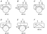
以下、本実施形態に係る毛切断装置1及び毛切断システム10の概要について、図1A~図2Bを参照して説明する。毛切断装置1は、毛91に光を作用させることで毛91を切断する装置である。毛切断装置1での切断対象となる毛91は、一例として人の「ひげ」等であるが、「ひげ」に限らず、人等の皮膚92から突出する様々な毛を含む。図1B、図2A及び図2Bでは、毛91及び皮膚92を想像線(二点鎖線)で示す。
(Embodiment 1)
(1) Overview An overview of the hair-cutting device 1 and the hair-cutting system 10 according to the present embodiment will be described below with reference to FIGS. 1A to 2B. The hair cutting device 1 is a device that cuts the hair 91 by applying light to the hair 91 . The hair 91 to be cut by the hair cutting apparatus 1 is, for example, a human "whiskers" or the like, but is not limited to the "whiskers" and includes various hairs protruding from the skin 92 of a human or the like. In FIGS. 1B, 2A and 2B, hair 91 and skin 92 are indicated by imaginary lines (double-dot chain lines).
要するに、毛切断装置1及び毛切断システム10は、物理的な「刃」にて毛91を切断する一般的な「かみそり」又は「はさみ」等とは異なり、「刃」の代わりに光エネルギを毛91に与えることで、毛91の切断を行う。そのため、毛切断装置1及び毛切断システム10では、一般的な、「かみそり」又は「はさみ」等に比較して、毛91の周囲の皮膚92等にダメージを与えにくく、さらに、刃こぼれ等の物理的な劣化も生じにくい。
In short, the hair-cutting device 1 and hair-cutting system 10 use light energy instead of a "blade", unlike common "razors" or "scissors" that cut hair 91 with a physical "blade". By applying it to the hair 91, the hair 91 is cut. Therefore, the hair-cutting device 1 and the hair-cutting system 10 are less likely to damage the skin 92 around the hair 91 than a general "razor" or "scissors", etc. Physical deterioration is less likely to occur.
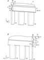
本実施形態に係る毛切断システム10は、図1A及び図1Bに示すように、グリップ2と、ヘッド3と、を備えている。グリップ2は、光を発生する光源21(図1B参照)を有している。ヘッド3は、光導波路4と、保持部材5と、を備えている。光導波路4は、グリップ2内に受光部43(図1B参照)を有しており、光源21で発生した光が光導波路4の受光部43に入力されることにより、光導波路4内を光が伝達する。本実施形態では一例として、光源21はレーザ光源であって、光導波路4内を伝達する光はレーザ光である。
A hair cutting system 10 according to this embodiment includes a grip 2 and a head 3, as shown in FIGS. 1A and 1B. The grip 2 has a light source 21 (see FIG. 1B) for generating light. The head 3 has an optical waveguide 4 and a holding member 5 . The optical waveguide 4 has a light receiving portion 43 (see FIG. 1B) inside the grip 2, and the light generated by the light source 21 is input to the light receiving portion 43 of the optical waveguide 4, thereby causing the light to pass through the optical waveguide 4. conveys. In this embodiment, as an example, the light source 21 is a laser light source, and the light transmitted through the optical waveguide 4 is laser light.
ここで、光導波路4は、光照射部40を有している。光導波路4は、光照射部40から毛91に光を照射することで毛91の切断を行う。保持部材5は、ヘッド3内において光導波路4を保持している。毛切断装置1は、光導波路4の光照射部40からの光を切断対象となる毛91に照射することで、毛91の切断を行う。具体的には、毛切断装置1は、切断対象である毛91の屈折率に近い屈折率を持つ光照射部40を、毛91に接触させることで、光照射部40から毛91に光の漏れを生じさせ、この光のエネルギで毛91を切断する。
Here, the optical waveguide 4 has a light irradiation section 40 . The optical waveguide 4 cuts the hair 91 by irradiating the hair 91 with light from the light irradiation unit 40 . The holding member 5 holds the optical waveguide 4 inside the head 3 . The hair cutting device 1 cuts the hair 91 by irradiating the hair 91 to be cut with light from the light irradiation section 40 of the optical waveguide 4 . Specifically, the hair cutting apparatus 1 brings the light irradiation unit 40 having a refractive index close to the refractive index of the hair 91 to be cut into contact with the hair 91 , so that the light is emitted from the light irradiation unit 40 to the hair 91 . A leak is created and the energy of this light cuts the hair 91 .
本実施形態では、毛切断システム10のうち、ヘッド3に相当する部分が毛切断装置1を構成する。言い換えれば、本実施形態に係る毛切断装置1は、光導波路4と、保持部材5と、を備えている。また、毛切断装置1に相当するヘッド3は、光源21を有するグリップ2と共に、毛切断システム10を構成する。言い換えれば、本実施形態に係る毛切断システム10は、毛切断装置1と、光源21と、を備えている。光源21は、光導波路4に入力される光を発生する。
In the present embodiment, a portion of the hair cutting system 10 that corresponds to the head 3 constitutes the hair cutting device 1 . In other words, the hair cutting device 1 according to this embodiment includes the optical waveguide 4 and the holding member 5 . The head 3 corresponding to the hair-cutting device 1 also constitutes the hair-cutting system 10 together with the grip 2 having the light source 21 . In other words, the hair-cutting system 10 according to this embodiment includes the hair-cutting device 1 and the light source 21 . A light source 21 generates light that is input to the optical waveguide 4 .
ところで、本実施形態では、毛切断装置1は、光導波路4を備え、光導波路4は、光照射部40を有している。光照射部40は、皮膚92から突出する毛91に光を照射することで毛91の切断を行う。ここで、光照射部40の屈折率は、皮膚92の表面921(図2A参照)の屈折率よりも小さい。
By the way, in this embodiment, the hair cutting device 1 is provided with an optical waveguide 4 , and the optical waveguide 4 has a light irradiation section 40 . The light irradiation unit 40 cuts the hair 91 by irradiating the hair 91 protruding from the skin 92 with light. Here, the refractive index of the light irradiation section 40 is smaller than the refractive index of the surface 921 (see FIG. 2A) of the skin 92 .
この構成によれば、光照射部40の屈折率が、皮膚92の表面921の屈折率よりも小さいので、光照射部40を含む光導波路4の材質等の選択肢が広がり、毛切断装置1を実現しやすくなる。さらに、この毛切断装置1によれば、例えば、光照射部40からの光を適切に皮膚92に照射すれば、殺菌又は活性化等の皮膚92への作用も期待できるようになる。結果的に、改善された毛切断装置1を提供できる、という利点がある。
According to this configuration, since the refractive index of the light irradiation section 40 is smaller than the refractive index of the surface 921 of the skin 92, the options for the material of the optical waveguide 4 including the light irradiation section 40 are widened, and the hair cutting device 1 can be used. easier to implement. Furthermore, according to the hair cutting device 1, for example, if the skin 92 is appropriately irradiated with the light from the light irradiation unit 40, an effect on the skin 92 such as sterilization or activation can be expected. Consequently, there is the advantage that an improved hair-cutting device 1 can be provided.
また、本実施形態では、毛切断装置1は、光導波路4を備え、光導波路4は、光照射部40を有している。光照射部40は、皮膚92から突出する毛91に光を照射することで毛91の切断を行う。ここで、少なくとも毛91の切断時において、光導波路4を通る光のパワー密度は50kW/cm2以上である。
Moreover, in this embodiment, the hair cutting device 1 is provided with an optical waveguide 4 , and the optical waveguide 4 has a light irradiation section 40 . The light irradiation unit 40 cuts the hair 91 by irradiating the hair 91 protruding from the skin 92 with light. Here, at least when the hair 91 is cut, the power density of light passing through the optical waveguide 4 is 50 kW/cm 2 or more.
この構成によれば、毛91の切断時における、光導波路4を通る光のパワー密度が50kW/cm2以上であるので、光照射部40から毛91に照射する光で毛91を効率的に切断しやすい。つまり、毛91を切断するのに十分な光エネルギを光導波路4から毛91に与えることができ、比較的に短時間で、毛91の切断を行うことができる。したがって、例えば、切断可能な毛91の太さ又は硬さ等の幅が広がり、結果的に、改善された毛切断装置1を提供できる、という利点がある。
According to this configuration, when the hair 91 is cut, the power density of the light passing through the optical waveguide 4 is 50 kW/cm 2 or more. Easy to cut. That is, the light energy sufficient to cut the hair 91 can be applied from the optical waveguide 4 to the hair 91, and the hair 91 can be cut in a relatively short time. Accordingly, there is the advantage that, for example, the range of thickness or hardness of hairs 91 that can be cut is widened, and as a result, an improved hair cutting device 1 can be provided.
また、本実施形態では、毛切断装置1は、光導波路4と、光導波路4を保持する保持部材5と、を備えている。光導波路4は、光照射部40を有している。光照射部40は、皮膚92から突出する毛91に光を照射することで毛91の切断を行う。保持部材5は、少なくとも一面から光照射部40が露出する態様で、光導波路4を保持する。
Further, in this embodiment, the hair cutting device 1 includes an optical waveguide 4 and a holding member 5 that holds the optical waveguide 4 . The optical waveguide 4 has a light irradiation section 40 . The light irradiation unit 40 cuts the hair 91 by irradiating the hair 91 protruding from the skin 92 with light. The holding member 5 holds the optical waveguide 4 in such a manner that the light irradiation section 40 is exposed from at least one surface.
この構成によれば、保持部材5の少なくとも一面から光照射部40が露出する態様で、保持部材5が光導波路4を保持するので、例えば、光照射部40に毛91又は皮膚92が接触しても、光導波路4の位置ずれ等が生じにくい。つまり、例えば、毛91を切断する際に、毛91又は皮膚92からの外力が光照射部40に作用しても、この外力によって光導波路4が外れたり破損したりすることが生じにくくなる。結果的に、改善された毛切断装置1を提供できる、という利点がある。
According to this configuration, since the holding member 5 holds the optical waveguide 4 in such a manner that the light irradiation section 40 is exposed from at least one surface of the holding member 5, for example, the hair 91 or the skin 92 may come into contact with the light irradiation section 40. However, displacement of the optical waveguide 4 is unlikely to occur. In other words, for example, even if an external force from the hair 91 or the skin 92 acts on the light irradiation section 40 when cutting the hair 91, the optical waveguide 4 is less likely to come off or break due to this external force. Consequently, there is the advantage that an improved hair-cutting device 1 can be provided.
(2)詳細
以下、本実施形態に係る毛切断装置1及び毛切断システム10の詳細について、図1A~図6を参照して説明する。
(2) Details Details of the hair-cutting device 1 and the hair-cutting system 10 according to the present embodiment will be described below with reference to FIGS. 1A to 6. FIG.
以下では一例として、互いに直交するX軸、Y軸及びZ軸の3軸を設定し、特に、光照射部40の長さに沿った軸を「X軸」、光照射部40の進行方向に沿った軸を「Y軸」とする。X軸、Y軸、及びZ軸は、いずれも仮想的な軸であり、図面中の「X」、「Y」、「Z」を示す矢印は、説明のために表記しているに過ぎず、いずれも実体を伴わない。また、これらの方向は毛切断装置1及び毛切断システム10の使用時の方向を限定する趣旨ではない。
In the following, as an example, three axes, the X-axis, the Y-axis, and the Z-axis, which are orthogonal to each other, are set. The axis along which is defined as the "Y-axis". The X-axis, Y-axis, and Z-axis are all virtual axes, and the arrows indicating "X", "Y", and "Z" in the drawings are merely used for explanation. , none of which is material. Also, these directions are not intended to limit the directions in which the hair-cutting device 1 and the hair-cutting system 10 are used.
(2.1)定義
本開示でいう「毛」は、皮膚92から突出する様々な毛91、つまり皮膚92から延びる様々な毛を含み、例えば、人(人間)の髪の毛、ひげ、眉毛、すね毛、鼻毛又は耳毛等の種々の体毛を含む。さらに、例えば、犬又は猫等のほ乳類、その他の動物においても、その皮膚92から突出する様々な毛91が、本開示でいう「毛」に含まれる。すなわち、本実施形態に係る毛切断装置1は、これらの毛91を切断対象とする装置である。また、本開示でいう「皮膚」には、人工皮膚等も含む。本実施形態では一例として、毛切断装置1の切断対象となる毛91が、人の皮膚92から突出する毛、特には成人男性の「ひげ」である場合について説明する。つまり、毛切断装置1の切断対象となる毛91は、人の顔の皮膚92から生えた毛である。顔の皮膚92等を含む人の皮膚92を「肌」ともいう。
(2.1) Definitions "Hair" as used in the present disclosure includes various hairs 91 protruding from the skin 92, i.e., various hairs extending from the skin 92, e.g., human (human) hair, beard, eyebrows, shins Includes various body hairs such as hair, nose hair or ear hair. In addition, various hairs 91 protruding from the skin 92 of mammals such as dogs or cats and other animals are also included in the term "hair" in the present disclosure. That is, the hair cutting device 1 according to this embodiment is a device for cutting these hairs 91 . In addition, "skin" as used in the present disclosure includes artificial skin and the like. In this embodiment, as an example, a case where the hair 91 to be cut by the hair cutting device 1 is hair protruding from human skin 92, particularly the "beard" of an adult male, will be described. In other words, the hair 91 to be cut by the hair cutting device 1 is the hair grown from the skin 92 of the human face. A person's skin 92, including facial skin 92, etc., is also referred to as "skin."
また、本開示でいう毛91の「切断」は、毛91を切断すること全般を含み、例えば、毛91を根元で切る(つまり、毛をそる)こと、適当な長さで毛91を切り揃えること、及び毛先のみを切ること等を含む。そのため、本開示でいう「毛切断装置」には、例えば、毛91をそるための装置である「シェーバ」又は「てい毛装置」、及び適当な長さで毛を切るための装置である「トリマ」、「バリカン」又は「はさみ」等が含まれる。さらには、本開示でいう毛91の「切断」は、毛91を略平面状の切断面にて2つに切断することだけでなく、毛91の切断部に損傷を与えて毛91を切断部にて破断すること等も含む。本実施形態では一例として、毛切断装置1及び毛切断システム10が、切断対象となる毛91(ひげ)を根元で切る(つまり、毛をそる)ことに適した「シェーバ」である場合について説明する。
In addition, "cutting" the hair 91 as used in the present disclosure includes cutting the hair 91 in general, for example, cutting the hair 91 at the root (that is, shaving the hair), cutting the hair 91 at an appropriate length, This includes aligning and cutting only the tips of the hair. Therefore, the "hair cutting device" referred to in the present disclosure includes, for example, a "shaver" or a "hair device" that is a device for shaving the hair 91, and a device that is for cutting the hair to an appropriate length. trimmer," "hair clipper," or "scissors." Furthermore, “cutting” the hair 91 as used in the present disclosure means not only cutting the hair 91 into two along a substantially planar cutting surface, but also cutting the hair 91 by damaging the cut portion of the hair 91 . It also includes breaking at a part. In this embodiment, as an example, the hair cutting device 1 and the hair cutting system 10 are described as a "shaver" suitable for cutting (that is, shaving) the hair 91 (beard) to be cut at the root. do.
また、本開示でいう「レーザ光」は、誘導放出によって発生する光(Light Amplification by Stimulated Emission of Radiation)を意味する。レーザ光を発生する光源21としては、例えば、半導体の再結合発光を利用した半導体レーザ(LD:Laser Diode)等がある。レーザ光は、発光ダイオード(LED:Light Emitting Diode)が発生する光に比較して、干渉性(coherence)が高く、出力(パワー密度)が高く、単色性(単一波長)が高く、かつ指向性が高い、という特性を持つ。
In addition, “laser light” as used in the present disclosure means light generated by stimulated emission (Light Amplification by Stimulated Emission of Radiation). As the light source 21 for generating laser light, for example, there is a semiconductor laser (LD: Laser Diode) utilizing recombination light emission of a semiconductor. Laser light has higher coherence, higher output (power density), higher monochromaticity (single wavelength), and more directivity than light emitted by a light emitting diode (LED). It has the characteristic of being highly resilient.
また、本開示でいう「光導波路」は、光を通すことで光を所望の経路に沿って導く光学部材を意味する。光導波路の具体例としては、互いに屈折率の異なるコア及びクラッドを有し、コアをクラッドで覆った光ファイバ等がある。光ファイバは、コアとクラッドとの界面での光の全反射を利用して、コアの内部に光を通すことで所望の経路に沿って光を導くことが可能である。ここで、光導波路は、特に、通信用の信号(光信号)を通す伝送路に限らず、光を所望の経路に沿って導く光学部材全般を意味する。
In addition, the term “optical waveguide” used in the present disclosure means an optical member that guides light along a desired path by allowing light to pass therethrough. A specific example of the optical waveguide is an optical fiber having a core and a clad having different refractive indices and covering the core with the clad. An optical fiber can guide light along a desired path by passing the light through the interior of the core using total reflection of light at the interface between the core and the clad. Here, the optical waveguide is not limited to a transmission line for passing communication signals (optical signals), but generally refers to optical members that guide light along a desired path.
また、本開示でいう「保持」は、2つの物体同士が互いの位置関係を保ち続けるように、一方の物体が他方の物体を支持することを意味する。ここで、2つの物体同士の相対的な位置関係は、多少、変化してもよく、一方の物体と他方の物体とが堅牢に固定されていなくてもよい。つまり、保持部材5は、光導波路4と保持部材5との位置関係が多少変化する態様で、光導波路4を保持していてもよい。
Also, "holding" as used in the present disclosure means that one object supports the other such that the two objects maintain their positional relationship with each other. Here, the relative positional relationship between the two objects may change somewhat, and one object and the other object may not be rigidly fixed. That is, the holding member 5 may hold the optical waveguide 4 in such a manner that the positional relationship between the optical waveguide 4 and the holding member 5 is slightly changed.
また、本開示でいう「屈折率」は、真空中の光速度を媒質中の光速度(より正確には位相速度)で除した値である。屈折率は、基本的に、物質に依存して決まっており、例えば、空気の屈折率は「1.0003」であって、水の屈折率は「1.3334」である。同じ物質であっても、屈折率は入射する光の波長によって異なることがあるが、本開示では、特に断りがない限り、屈折率は波長404.7nmの光(水銀のh線)について示すこととする。
Also, the “refractive index” referred to in the present disclosure is a value obtained by dividing the speed of light in a vacuum by the speed of light in a medium (more precisely, the phase velocity). The refractive index is basically determined depending on the substance. For example, the refractive index of air is "1.0003" and the refractive index of water is "1.3334". Even for the same material, the refractive index may vary depending on the wavelength of the incident light, but in this disclosure, unless otherwise specified, the refractive index is shown for light with a wavelength of 404.7 nm (h-line of mercury). and
また、本開示でいう「パワー密度」は、単位面積(1cm2)あたりの光強度を意味する。パワー密度の単位は「kW/cm2」又は「J/(s・cm2)」である。光導波路4の断面において光強度の分布にばらつきがある場合でも、光導波路4を通る光強度を光導波路4のコア部41の断面積で除することにより、コア部41の断面全域において平均化された平均的なパワー密度が求まる。本開示では、特に断りがない限り、このように求まる平均的なパワー密度を「パワー密度」とする。
Also, the term “power density” used in the present disclosure means light intensity per unit area (1 cm 2 ). The unit of power density is “kW/cm 2 ” or “J/(s·cm 2 )”. Even if the distribution of the light intensity varies in the cross section of the optical waveguide 4, by dividing the light intensity passing through the optical waveguide 4 by the cross-sectional area of the core part 41 of the optical waveguide 4, the cross-sectional area of the core part 41 is averaged. Then the average power density is obtained. In the present disclosure, unless otherwise specified, the average power density obtained in this manner is referred to as "power density."
(2.2)全体構成
ここではまず、本実施形態に係る毛切断システム10の全体構成について、図1A及び図1Bを参照して説明する。
(2.2) Overall Configuration First, the overall configuration of the hair cutting system 10 according to this embodiment will be described with reference to FIGS. 1A and 1B.
毛切断システム10は、上述したように、毛切断装置1と、光源21と、を備えている。毛切断装置1は、光導波路4と、光導波路4を保持する保持部材5と、を備えている。光導波路4は、光照射部40を有しており、光源21で発生した光が入力されることによって、光照射部40から光を出力する。毛切断システム10は、光源21で発生した光を、毛切断装置1の光導波路4に入力し、光導波路4の光照射部40から毛91に照射することで、毛91の切断を行う。
Hair-cutting system 10 comprises hair-cutting device 1 and light source 21 as described above. The hair cutting device 1 includes an optical waveguide 4 and a holding member 5 that holds the optical waveguide 4 . The optical waveguide 4 has a light irradiation section 40 and outputs light from the light irradiation section 40 by receiving the light generated by the light source 21 . The hair cutting system 10 cuts the hair 91 by inputting the light generated by the light source 21 into the optical waveguide 4 of the hair cutting device 1 and irradiating the hair 91 from the light irradiation section 40 of the optical waveguide 4 .
より詳細には、毛切断システム10は、光照射部40の屈折率として、切断対象である毛91の屈折率に近い値を採用している。これにより、光照射部40に毛91が接触した状態では、光照射部40から毛91に光が漏れ出し、この光のエネルギで毛91が切断される。一方で、光照射部40に毛91が接触しておらず、光照射部40に空気(屈折率:1.0)のみが接するような状態では、光照射部40と空気との屈折率の差によって、光照射部40からの光の漏れ量が小さく抑えられる。
More specifically, the hair cutting system 10 employs a value close to the refractive index of the hair 91 to be cut as the refractive index of the light irradiation unit 40 . As a result, when the hair 91 is in contact with the light irradiation section 40 , light leaks from the light irradiation section 40 to the hair 91 , and the energy of this light cuts the hair 91 . On the other hand, in a state where the hair 91 is not in contact with the light irradiation section 40 and only air (refractive index: 1.0) is in contact with the light irradiation section 40, the refractive index between the light irradiation section 40 and the air is Due to the difference, the amount of light leaked from the light irradiation section 40 can be kept small.
ところで、本実施形態では、毛切断システム10は、上述したように、光源21を有するグリップ2と、毛切断装置1を構成するヘッド3と、を備えている。グリップ2は、図1A及び図1Bに示すように、第1ケース20を有し、第1ケース20内に光源21等を収容している。第1ケース20は、一例として、Y軸に沿って長さを有する角柱状に形成されている。ヘッド3は、図1A及び図1Bに示すように、第2ケース30を有し、第2ケース30内に光導波路4等を収容している。第2ケース30は、一例として、X軸に沿って長さを有する角柱状に形成されている。本実施形態では、第1ケース20の長手方向の一端部と、第2ケース30の長手方向の中央部と、が結合されることにより、第1ケース20及び第2ケース30は、Z軸の一方側から見て、全体として略T字状のケースを構成している。
By the way, in this embodiment, the hair-cutting system 10 includes the grip 2 having the light source 21 and the head 3 constituting the hair-cutting device 1, as described above. As shown in FIGS. 1A and 1B, the grip 2 has a first case 20 in which a light source 21 and the like are housed. As an example, the first case 20 is formed in a prism shape having a length along the Y-axis. As shown in FIGS. 1A and 1B, the head 3 has a second case 30 in which the optical waveguide 4 and the like are accommodated. As an example, the second case 30 is formed in a prism shape having a length along the X-axis. In the present embodiment, the first case 20 and the second case 30 are connected to one end in the longitudinal direction of the first case 20 and the central part in the longitudinal direction of the second case 30, so that the first case 20 and the second case 30 are arranged along the Z axis. When viewed from one side, it forms a substantially T-shaped case as a whole.
このように、全体として略T字状の外観を有する毛切断システム10は、「T字かみそり」と同じように使用される。つまり、ユーザは、切断対象となる毛91(ここでは「ひげ」)を切断する(ここでは「そる」)際に、毛切断システム10のグリップ2、つまり第1ケース20を片手で握ることで、毛切断システム10を把持する。この状態で、ユーザは、毛切断システム10のヘッド3、つまり第2ケース30のZ軸方向の一面をユーザの(顔の)皮膚92に接触させ、ヘッド3を皮膚92に沿わせてY軸方向に移動させることにより、ヘッド3の光照射部40にて毛91を切断する。このとき、ユーザは、図1Bに示すように、第2ケース30のうちのZ軸の負の向きを向いた面を皮膚92に接触させ、かつヘッド3をY軸の負の向きに移動させることによって、ヘッド3の進行方向の前方(つまりY軸の負の向き)に位置する毛91を切断する。
Thus, the hair-cutting system 10, which has an overall generally T-shaped appearance, is used in a manner similar to a "T-razor." In other words, when the user cuts (here, "shaving") the hair 91 to be cut (here, "beard"), the user holds the grip 2 of the hair cutting system 10, that is, the first case 20, with one hand. , grasp the hair-cutting system 10 . In this state, the user brings the head 3 of the hair cutting system 10, that is, one side of the second case 30 in the Z-axis direction, into contact with the user's (face) skin 92, and moves the head 3 along the skin 92 along the Y-axis. The hair 91 is cut by the light irradiation section 40 of the head 3 by moving in the direction. At this time, as shown in FIG. 1B, the user brings the surface of the second case 30 facing in the negative direction of the Z-axis into contact with the skin 92 and moves the head 3 in the negative direction of the Y-axis. By doing so, the hair 91 located forward in the traveling direction of the head 3 (that is, in the negative direction of the Y-axis) is cut.
本実施形態では一例として、第1ケース20及び第2ケース30は、いずれも合成樹脂製である。第1ケース20及び第2ケース30は、接着、溶着、貼り付け又は締結部材(ねじ等)を用いた結合等の適宜の手段にて、結合されている。
As an example in this embodiment, the first case 20 and the second case 30 are both made of synthetic resin. The first case 20 and the second case 30 are connected by appropriate means such as adhesion, welding, pasting, or connection using fastening members (such as screws).
グリップ2は、第1ケース20及び光源21に加えて、制御回路6、光学系22、電池23、ファン24、ヒートシンク25及び操作部26を更に有している。
The grip 2 further has a control circuit 6 , an optical system 22 , a battery 23 , a fan 24 , a heat sink 25 and an operation section 26 in addition to the first case 20 and the light source 21 .
制御回路6、光学系22、電池23、ファン24及びヒートシンク25は、いずれも第1ケース20内に収容されている。操作部26は、第1ケース20の一面(Z軸の負の向きを向いた面)に設けられている。また、ヘッド3に含まれる光導波路4は、その一端部(受光部43)がグリップ2の第1ケース20内に位置するように、第1ケース20と第2ケース30とにまたがって収容されている。
The control circuit 6 , optical system 22 , battery 23 , fan 24 and heat sink 25 are all housed inside the first case 20 . The operation unit 26 is provided on one surface of the first case 20 (the surface facing the negative direction of the Z axis). The optical waveguide 4 included in the head 3 is housed across the first case 20 and the second case 30 so that one end (light receiving portion 43) of the optical waveguide 4 is positioned inside the first case 20 of the grip 2. ing.
光源21は、電気エネルギを光エネルギに変換することで、光導波路4に入力される光を発生する。本実施形態では、光源21は、レーザ光源である。つまり、光源21で発生する光は、誘導放出によって発生するレーザ光である。ここでは、光源21は、半導体の再結合発光を利用した半導体レーザからなる。
The light source 21 generates light input to the optical waveguide 4 by converting electrical energy into optical energy. In this embodiment, the light source 21 is a laser light source. That is, the light generated by the light source 21 is laser light generated by stimulated emission. Here, the light source 21 is composed of a semiconductor laser using recombination light emission of a semiconductor.
また、光源21で発生する光の波長は、400nm以上である。つまり、光源21は、400nmよりも長波長側にピーク波長又はドミナント波長を有するレーザ光を発生する。本実施形態では、光源21で発生する光の波長は、700nm以下である。詳しくは「(3)作用」の欄で説明するが、例えば、波長が400nm以上450nm以下の範囲にある光であれば、皮膚92に存在するアクネ菌等に対する殺菌作用が期待できる。また、波長が450nm以上700nm以下の範囲にある光であれば、皮膚92の活性化作用が期待できる。
Moreover, the wavelength of the light generated by the light source 21 is 400 nm or more. That is, the light source 21 generates laser light having a peak wavelength or dominant wavelength on the longer wavelength side than 400 nm. In this embodiment, the wavelength of the light generated by the light source 21 is 700 nm or less. Details will be described in the section “(3) Action”. For example, if the light has a wavelength in the range of 400 nm or more and 450 nm or less, it can be expected to have a bactericidal action against P. acnes and the like existing on the skin 92 . Also, if the wavelength is in the range of 450 nm or more and 700 nm or less, activation of the skin 92 can be expected.
制御回路6は、少なくとも光源21を制御する回路である。制御回路6は、光源21に電力を供給することで光源21を発光(点灯)させる。さらに、制御回路6は、光源21の点灯/消灯の切り替え、及び光源21の出力(明るさ又は波長等)の調節等を行う。制御回路6は、プリント配線板(基板)と、プリント配線板に実装された複数の電子部品と、を含んでいる。制御回路6は、光源21の他、ファン24及び操作部26等の制御も行う。制御回路6について詳しくは、「(2.6)制御回路」の欄で説明する。
The control circuit 6 is a circuit that controls at least the light source 21 . The control circuit 6 causes the light source 21 to emit light (turn on) by supplying power to the light source 21 . Further, the control circuit 6 switches between lighting and extinguishing of the light source 21, adjusts the output (brightness or wavelength, etc.) of the light source 21, and the like. The control circuit 6 includes a printed wiring board (substrate) and a plurality of electronic components mounted on the printed wiring board. The control circuit 6 controls not only the light source 21 but also the fan 24, the operation unit 26, and the like. The details of the control circuit 6 will be described in the section "(2.6) Control circuit".
光学系22は、光源21と光導波路4との間に配置されており、光源21からの光を光導波路4へと導く。光学系22は、複数のレンズを含んでいる。図1Bの例では、光学系22は、第1レンズ221、第2レンズ222、第3レンズ223及び第4レンズ224を含んでいる。ただし、図1Bは、個々のレンズの形状及び配置を厳密には示しておらず、光学系22を模式的に示しているに過ぎない。
The optical system 22 is arranged between the light source 21 and the optical waveguide 4 and guides the light from the light source 21 to the optical waveguide 4 . Optical system 22 includes a plurality of lenses. In the example of FIG. 1B, optical system 22 includes first lens 221 , second lens 222 , third lens 223 and fourth lens 224 . However, FIG. 1B does not strictly show the shape and arrangement of individual lenses, but merely shows the optical system 22 schematically.
電池23は、制御回路6、光源21及びファン24等の駆動用の電力を供給する電源として機能する。本実施形態では一例として、電池23は、充電及び放電が可能な、リチウムイオン電池(LIB:Lithium Ion Battery)等の二次電池である。
The battery 23 functions as a power source that supplies power for driving the control circuit 6, the light source 21, the fan 24, and the like. In this embodiment, as an example, the battery 23 is a secondary battery such as a lithium ion battery (LIB) that can be charged and discharged.
ファン24は、光源21の冷却用の冷却ファンである。具体的には、ファン24は、第1ケース20内においてヒートシンク25を通る気流を発生することにより、ヒートシンク25の放熱を促進する。
Fan 24 is a cooling fan for cooling light source 21 . Specifically, the fan 24 promotes heat dissipation from the heat sink 25 by generating an airflow passing through the heat sink 25 within the first case 20 .
ヒートシンク25は、熱伝導率が比較的に高い材質、例えば、アルミニウム等で構成されている。ヒートシンク25は、光源21と熱的に結合されており、主として光源21の放熱を行う。
The heat sink 25 is made of a material with relatively high thermal conductivity, such as aluminum. The heat sink 25 is thermally coupled with the light source 21 and mainly dissipates heat from the light source 21 .
操作部26は、ユーザの操作を受け付けて、ユーザの操作に応じた電気信号を制御回路6に出力する。本実施形態では一例として、操作部26は、プッシュスイッチ又はスライドスイッチ等のメカニカルスイッチを少なくとも1つ有している。
The operation unit 26 receives a user's operation and outputs an electrical signal according to the user's operation to the control circuit 6 . In this embodiment, as an example, the operation unit 26 has at least one mechanical switch such as a push switch or slide switch.
ヘッド3は、第2ケース30、光導波路4及び保持部材5に加えて、固定ブロック32を更に有している。
The head 3 further has a fixing block 32 in addition to the second case 30 , the optical waveguide 4 and the holding member 5 .
第2ケース30のうち、ユーザの皮膚92に接触する面(つまりZ軸の負の向きを向いた面)には、少なくとも光照射部40を第2ケース30の外部に露出させるための開口部31が形成されている。開口部31は、X軸に沿って長さを有する長方形状に形成されている。この開口部31を通して、第2ケース30の内側の空間と外側の空間とがつながることになる。
An opening for exposing at least the light irradiation unit 40 to the outside of the second case 30 is provided on the surface of the second case 30 that contacts the user's skin 92 (that is, the surface facing in the negative direction of the Z axis). 31 are formed. The opening 31 is formed in a rectangular shape having a length along the X-axis. Through this opening 31, the inner space and the outer space of the second case 30 are connected.
光導波路4、保持部材5及び固定ブロック32は、いずれも第2ケース30内に収容されている。ただし、上述したように、光導波路4は、その一端部(受光部43)がグリップ2の第1ケース20内に位置する。そのため、第1ケース20の内部空間と第2ケース30の内部空間とは連続しており、光導波路4は、第1ケース20と第2ケース30とにまたがって収容される。本実施形態では一例として、光導波路4の光照射部40に加えて、保持部材5及び固定ブロック32についても、開口部31を通して第2ケース30の外部に露出する。
The optical waveguide 4 , the holding member 5 and the fixing block 32 are all housed inside the second case 30 . However, as described above, the optical waveguide 4 has one end portion (the light receiving portion 43 ) located inside the first case 20 of the grip 2 . Therefore, the internal space of the first case 20 and the internal space of the second case 30 are continuous, and the optical waveguide 4 is housed across the first case 20 and the second case 30 . In this embodiment, as an example, in addition to the light irradiation section 40 of the optical waveguide 4 , the holding member 5 and the fixing block 32 are also exposed to the outside of the second case 30 through the opening 31 .
光導波路4は、光源21で発生した光を通すことで、光源21からの光を所望の経路に沿って導く光学部材である。本実施形態では一例として、光導波路4は光ファイバである。この光導波路4は、コア部41及びクラッド部42を有しており、コア部41がクラッド部42にて覆われている。さらに、本実施形態では、光導波路4は、図1Bに示すように、受光部43及び保護シース44を更に有している。受光部43は、第1ケース20に収容され、光学系22に対向するように配置されることで、光源21からの光を光導波路4内に取り込む。具体的には、光導波路4は、光源21からの光が光導波路4(コア部41)を通って伝播するように、コア部41の端部に設けられた受光部43にて、光学系22を介して光源21と光学的に結合される。保護シース44は、クラッド部42を覆うように構成された樹脂製の被覆部材である。つまり、本実施形態で光導波路4として用いられる光ファイバは、コア部41と、コア部41の外側に位置するクラッド部42と、クラッド部42の外側に位置する保護シース44と、の三重構造を有している。
The optical waveguide 4 is an optical member that guides the light from the light source 21 along a desired path by passing the light generated by the light source 21 . As an example in this embodiment, the optical waveguide 4 is an optical fiber. This optical waveguide 4 has a core portion 41 and a clad portion 42 , and the core portion 41 is covered with the clad portion 42 . Furthermore, in this embodiment, the optical waveguide 4 further has a light receiving portion 43 and a protective sheath 44, as shown in FIG. 1B. The light receiving unit 43 is accommodated in the first case 20 and arranged to face the optical system 22 , thereby taking in the light from the light source 21 into the optical waveguide 4 . Specifically, the optical waveguide 4 has a light receiving portion 43 provided at the end of the core portion 41 so that the light from the light source 21 propagates through the optical waveguide 4 (core portion 41). Optically coupled to light source 21 via 22 . The protective sheath 44 is a resin covering member configured to cover the clad portion 42 . That is, the optical fiber used as the optical waveguide 4 in this embodiment has a triple structure of the core portion 41, the clad portion 42 positioned outside the core portion 41, and the protective sheath 44 positioned outside the clad portion 42. have.
光導波路4は、少なくとも受光部43が第1ケース20内に配置され、受光部43から延びる部位が第2ケース30に引き込まれるように、第1ケース20及び第2ケース30内に引き回されている。光導波路4は、受光部43側の一端部から第1中間部までの部分についてのみ保護シース44を有しており、第1中間部から先の部分については保護シース44が除去されてクラッド部42が露出する。さらに、光導波路4は、第1中間部から第2中間部までの部分についてのみクラッド部42を有しており、第2中間部から先の部分についてはクラッド部42が除去されてコア部41が露出する。このように、光導波路4のうち、クラッド部42が除去されてコア部41がむき出しになった部位が、光照射部40を構成する。
The optical waveguide 4 is routed in the first case 20 and the second case 30 so that at least the light receiving portion 43 is arranged in the first case 20 and the portion extending from the light receiving portion 43 is pulled into the second case 30. ing. The optical waveguide 4 has a protective sheath 44 only for a portion from one end portion on the side of the light receiving portion 43 to the first intermediate portion. 42 are exposed. Furthermore, the optical waveguide 4 has a clad portion 42 only in the portion from the first intermediate portion to the second intermediate portion, and the clad portion 42 is removed in the portion beyond the second intermediate portion to form a core portion 41 . is exposed. Thus, the portion of the optical waveguide 4 where the clad portion 42 is removed and the core portion 41 is exposed constitutes the light irradiation portion 40 .
すなわち、本実施形態では、光導波路4は、コア部41を有し、光照射部40は、コア部41からなる。言い換えれば、本実施形態では光導波路4のうち、毛91に光を照射することで毛91の切断を行う部分(光照射部40)は、コア部41のみで構成される。光導波路4について詳しくは、「(2.3)毛切断装置の構成」の欄で説明する。
That is, in this embodiment, the optical waveguide 4 has a core portion 41 and the light irradiation portion 40 is composed of the core portion 41 . In other words, in the present embodiment, the portion of the optical waveguide 4 that cuts the hair 91 by irradiating the hair 91 with light (the light irradiation portion 40 ) is composed of only the core portion 41 . The details of the optical waveguide 4 will be described in the section "(2.3) Structure of hair cutting device".
保持部材5は、光導波路4を保持する部材である。保持部材5は、光導波路4のうち少なくとも光照射部40を保持する。つまり、保持部材5は、光導波路4のうちクラッド部42が除去されてコア部41がむき出しになった部位(光照射部40)を少なくとも保持する。本実施形態では一例として、光導波路4のうち保持部材5に保持されるのは光照射部40のみであって、光導波路4のうち光照射部40以外の部位については、保持部材5以外の構造で適宜位置固定されている。保持部材5は、固定ブロック32に固定されている。保持部材5は、固定ブロック32に対して、接着、溶着、貼り付け又は締結部材(ねじ等)を用いた結合等の適宜の手段にて、固定されている。これにより、光導波路4(光照射部40)は、保持部材5を介して固定ブロック32に間接的に固定されることになる。保持部材5について詳しくは、「(2.4)光導波路の保持構造」の欄で説明する。
The holding member 5 is a member that holds the optical waveguide 4 . The holding member 5 holds at least the light irradiation section 40 of the optical waveguide 4 . In other words, the holding member 5 holds at least a portion (light irradiation portion 40) of the optical waveguide 4 where the clad portion 42 is removed and the core portion 41 is exposed. In the present embodiment, as an example, only the light irradiation section 40 of the optical waveguide 4 is held by the holding member 5, and the portion of the optical waveguide 4 other than the light irradiation section 40 is held by the holding member 5. The position is appropriately fixed in the structure. The holding member 5 is fixed to the fixed block 32 . The holding member 5 is fixed to the fixed block 32 by an appropriate means such as adhesion, welding, pasting, or coupling using a fastening member (screw or the like). As a result, the optical waveguide 4 (light irradiation section 40 ) is indirectly fixed to the fixing block 32 via the holding member 5 . Details of the holding member 5 will be described in the section "(2.4) Optical waveguide holding structure".
固定ブロック32は、第2ケース30に固定されている。固定ブロック32は、合成樹脂製であって、X軸に沿って長さを有する角柱状に形成されている。固定ブロック32は、第2ケース30に対して、接着、溶着、貼り付け又は締結部材(ねじ等)を用いた結合等の適宜の手段にて、固定されている。固定ブロック32には、上述したように保持部材5が固定されている。そのため、光導波路4(光照射部40)は、保持部材5及び固定ブロック32を介して第2ケース30に間接的に固定されることになる。
The fixed block 32 is fixed to the second case 30 . The fixed block 32 is made of synthetic resin and formed into a prism shape having a length along the X-axis. The fixed block 32 is fixed to the second case 30 by an appropriate means such as adhesion, welding, pasting, or coupling using a fastening member (screw or the like). The holding member 5 is fixed to the fixed block 32 as described above. Therefore, the optical waveguide 4 (light irradiation section 40 ) is indirectly fixed to the second case 30 via the holding member 5 and the fixing block 32 .
ここで、ヘッド3は、光導波路4の光照射部40、保持部材5及び固定ブロック32の全てが、開口部31を通して第2ケース30の外部に露出する。具体的には、図1A及び図1Bに示すように、固定ブロック32は、第2ケース30における開口部31の長さ(X軸)に沿って配置されている。そして、保持部材5は、固定ブロック32における毛切断装置1の進行方向の前方(Y軸の負の向き)を向いた面に固定されている。しかも、固定ブロック32及び保持部材5は、開口部31の短手方向(Y軸方向)において、毛切断装置1(ヘッド3)の進行方向の前方側に隙間を確保するように、毛切断装置1の進行方向の後方側(つまりY軸の正の側)に寄せて配置されている。
Here, in the head 3 , the light irradiation section 40 of the optical waveguide 4 , the holding member 5 and the fixing block 32 are all exposed to the outside of the second case 30 through the opening 31 . Specifically, as shown in FIGS. 1A and 1B, the fixing block 32 is arranged along the length (X axis) of the opening 31 in the second case 30 . The holding member 5 is fixed to a surface of the fixed block 32 facing forward (negative direction of the Y-axis) in the traveling direction of the hair cutting device 1 . Moreover, the fixing block 32 and the holding member 5 are arranged so as to secure a gap on the front side of the movement direction of the hair cutting device 1 (head 3 ) in the lateral direction (Y-axis direction) of the opening 31 . 1 (that is, the positive side of the Y axis).
また、固定ブロック32及び保持部材5は、Z軸の負の向きを向いた面が、第2ケース30におけるZ軸の負の向きを向いた面と面一になるように、配置されている。さらに、詳しくは「(2.4)光導波路の保持構造」の欄で説明するが、光導波路4(光照射部40)は、保持部材5における毛切断装置1の進行方向の前方(Y軸の負の向き)を向いた面に固定されている。
The fixing block 32 and the holding member 5 are arranged so that the surface facing the negative Z-axis is flush with the surface of the second case 30 facing the negative Z-axis. . Further, details will be described in the section "(2.4) Optical waveguide holding structure". (negative direction).
また、図1A及び図1Bでは図示を省略しているが、毛切断システム10は、例えば、電池23用の充電回路、又は、毛切断システム10の動作状態を表示するための表示部等の構成要素を更に備えていてもよい。
Although not shown in FIGS. 1A and 1B, the hair cutting system 10 includes, for example, a charging circuit for the battery 23 or a display unit for displaying the operating state of the hair cutting system 10. It may further comprise elements.
(2.3)毛切断装置の構成
次に、本実施形態に係る毛切断装置1、つまり毛切断システム10のヘッド3のより詳細な構成について、図2A及び図2Bを参照して説明する。図2Aは、毛切断装置1(ヘッド3)における光導波路4及び保持構造5周辺の構成を示す概略断面図である。図2Bは、図2Aの要部の拡大図である。
(2.3) Configuration of hair-cutting device Next, a more detailed configuration of the hair-cutting device 1 according to the present embodiment, that is, the head 3 of the hair-cutting system 10 will be described with reference to FIGS. 2A and 2B. FIG. 2A is a schematic cross-sectional view showing the configuration around the optical waveguide 4 and the holding structure 5 in the hair cutting device 1 (head 3). FIG. 2B is an enlarged view of the main part of FIG. 2A.
本実施形態では、毛切断システム10のうちのヘッド3に相当する部分が毛切断装置1を構成するので、ヘッド3に含まれる第2ケース30、光導波路4、保持部材5及び固定ブロック32は、全て毛切断装置1の構成要素である。つまり、本実施形態に係る毛切断装置1は、光導波路4及び保持部材5に加えて、第2ケース30及び固定ブロック32を更に備えている。ただし、第2ケース30及び固定ブロック32は、毛切断装置1にとって必須の構成要素ではなく、第2ケース30及び固定ブロック32の少なくとも一方は適宜省略可能である。
In this embodiment, the part of the hair cutting system 10 corresponding to the head 3 constitutes the hair cutting device 1, so the second case 30, the optical waveguide 4, the holding member 5 and the fixing block 32 included in the head 3 are , are all components of the hair-cutting device 1 . That is, the hair cutting device 1 according to this embodiment further includes the second case 30 and the fixing block 32 in addition to the optical waveguide 4 and the holding member 5 . However, the second case 30 and the fixed block 32 are not essential components for the hair cutting device 1, and at least one of the second case 30 and the fixed block 32 can be omitted as appropriate.
毛切断装置1における光導波路4は、上述したように、毛91に光を照射することで毛91の切断を行う光照射部40を有している。本実施形態では、光導波路4は、コア部41と、クラッド部42と、を有する光ファイバである。クラッド部42は、コア部41をコア部41の全周にわたって覆っている。ここで、コア部41及びクラッド部42は、いずれも比較的に高い光透過性を有している。ただし、コア部41とクラッド部42とでは屈折率が異なっており、コア部41の屈折率は、クラッド部42の屈折率よりも大きい。この構成により、受光部43からコア部41に入射した光は、コア部41とクラッド部42との界面での全反射又は屈折により、極力、コア部41のみを通るようにして、光導波路4の先端部(受光部43とは反対側の端部)まで到達する。
The optical waveguide 4 in the hair cutting device 1 has the light irradiation section 40 that cuts the hair 91 by irradiating the hair 91 with light, as described above. In this embodiment, the optical waveguide 4 is an optical fiber having a core portion 41 and a clad portion 42 . The cladding portion 42 covers the core portion 41 over the entire circumference of the core portion 41 . Here, both the core portion 41 and the clad portion 42 have relatively high light transmittance. However, the core portion 41 and the clad portion 42 have different refractive indexes, and the core portion 41 has a higher refractive index than the clad portion 42 . With this configuration, the light incident on the core portion 41 from the light receiving portion 43 is totally reflected or refracted at the interface between the core portion 41 and the clad portion 42 so as to pass through only the core portion 41 as much as possible. (the end opposite to the light receiving section 43).
本実施形態では一例として、光導波路4は、コア部41及びクラッド部42のいずれもが合成石英からなる。例えば、コア部41は合成石英製であって、クラッド部42は、コア部41とは屈折率が異なる、不純物を添加した合成石英製である。本実施形態では一例として、ファイバ入射NA(Numerical Aperture)が「0.1」の場合、コア部41の屈折率は「1.4698」であって、クラッド部42の屈折率は「1.4309」である。また、ファイバ入射NAが「0.2」の場合、コア部41の屈折率は「1.4698」であって、クラッド部42の屈折率は「1.309」である。ここで挙げるNA及び屈折率は、あくまで一例に過ぎず、コア部41の屈折率とクラッド部42の屈折率との差等を規定する趣旨ではない。
In this embodiment, as an example, both the core portion 41 and the clad portion 42 of the optical waveguide 4 are made of synthetic quartz. For example, the core portion 41 is made of synthetic quartz, and the clad portion 42 is made of synthetic quartz doped with impurities having a refractive index different from that of the core portion 41 . In this embodiment, as an example, when the fiber incident NA (Numerical Aperture) is "0.1", the refractive index of the core portion 41 is "1.4698" and the refractive index of the clad portion 42 is "1.4309". ”. Further, when the fiber incident NA is "0.2", the refractive index of the core portion 41 is "1.4698" and the refractive index of the clad portion 42 is "1.309". The NA and refractive index mentioned here are merely examples, and are not meant to define the difference between the refractive index of the core portion 41 and the refractive index of the clad portion 42 .
ところで、上述した構成の光導波路4(光ファイバ)のうち、受光部43とは反対側の先端部から第2中間部までの、クラッド部42が除去されてコア部41が露出した部位は、光照射部40を構成する。つまり、光導波路4のうち、クラッド部42が除去されてコア部41がむき出しになった部位のコア部41こそが、毛91に光を照射する光照射部40を構成する。
By the way, in the optical waveguide 4 (optical fiber) configured as described above, the portion where the core portion 41 is exposed by removing the cladding portion 42 from the tip portion on the side opposite to the light receiving portion 43 to the second intermediate portion is A light irradiation unit 40 is configured. That is, the core portion 41 of the optical waveguide 4 where the clad portion 42 is removed and the core portion 41 is exposed constitutes the light irradiation portion 40 that irradiates the hair 91 with light.
ただし、より厳密には、クラッド部42が除去されてむき出しになったコア部41のうち、保持部材5にて覆われる部位は、毛91に光を漏らすことができないため、毛91に光を照射する光照射部40として機能しない。言い換えれば、本実施形態では、光照射部40はコア部41のみからなるのであって、コア部41のうち、特にクラッド部42に覆われずに露出した部位が、光照射部40となる。図2A及び図2B等においては、光導波路4のうちのコア部41が露出した部位での断面を示し、クラッド部42としては端面を図示している。
However, more strictly speaking, of the core portion 41 exposed by removing the cladding portion 42 , the portion covered with the holding member 5 cannot leak light to the hairs 91 . It does not function as the light irradiation unit 40 for irradiation. In other words, in the present embodiment, the light irradiation section 40 is composed only of the core section 41 , and the exposed portion of the core section 41 that is not particularly covered with the clad section 42 serves as the light irradiation section 40 . 2A and 2B and the like show a cross section of the portion of the optical waveguide 4 where the core portion 41 is exposed, and the clad portion 42 is an end face.
そして、本実施形態に係る毛切断装置1では、上述したように、光導波路4における光照射部40の屈折率は、皮膚92の表面921(図2A参照)の屈折率よりも小さい。ここで、人の皮膚92(肌)は、表皮、真皮及び皮下組織等を含んでいる。ここでいう皮膚92の表面921は、これら皮膚92を構成する複数の要素のうち最も外側に位置する表皮、又は表皮の表面を意味する。
In the hair cutting device 1 according to this embodiment, as described above, the refractive index of the light irradiation section 40 in the optical waveguide 4 is smaller than the refractive index of the surface 921 (see FIG. 2A) of the skin 92 . Here, the human skin 92 (skin) includes epidermis, dermis, subcutaneous tissue, and the like. The surface 921 of the skin 92 here means the outermost epidermis or the surface of the epidermis among the plurality of elements forming the skin 92 .
すなわち、本実施形態では、光照射部40は、コア部41及びクラッド部42を有する光導波路4(光ファイバ)のうちのコア部41からなるので、コア部41の屈折率は皮膚92の表面921の屈折率よりも小さくなるように設定される。一例として、人の皮膚92の表面921の屈折率は「1.4770」であると仮定する。そうすると、光照射部40であるコア部41の屈折率が上述したように「1.4698」であれば、光照射部40の屈折率が皮膚92の表面921の屈折率より小さい、という条件は満足する。
That is, in the present embodiment, the light irradiation section 40 is composed of the core section 41 of the optical waveguide 4 (optical fiber) having the core section 41 and the clad section 42, so the refractive index of the core section 41 is the surface of the skin 92. It is set to be smaller than the refractive index of 921. As an example, assume that the refractive index of surface 921 of human skin 92 is "1.4770". Then, if the refractive index of the core portion 41 which is the light irradiation portion 40 is "1.4698" as described above, the condition that the refractive index of the light irradiation portion 40 is smaller than the refractive index of the surface 921 of the skin 92 is Be satisfied.
より詳細には、本実施形態では、光照射部40の屈折率は、1.47以下である。要するに、光照射部40の屈折率が皮膚92の表面921の屈折率よりも小さくなるように、光照射部40の屈折率は「1.4700」以下の範囲に設定されている。これにより、皮膚92の表面921の屈折率に多少のばらつきがあっても、光照射部40の屈折率は、皮膚92の表面921の屈折率よりも小さくなる。つまり、皮膚92の表面921の屈折率が「1.4770」よりもわずかに小さい場合でも、光照射部40の屈折率が皮膚92の表面921の屈折率よりも小さい、という条件は満足できる。
More specifically, in this embodiment, the refractive index of the light irradiation section 40 is 1.47 or less. In short, the refractive index of the light irradiation section 40 is set in the range of “1.4700” or less so that the refractive index of the light irradiation section 40 is smaller than the refractive index of the surface 921 of the skin 92 . Thereby, even if the refractive index of the surface 921 of the skin 92 varies to some extent, the refractive index of the light irradiation section 40 is smaller than the refractive index of the surface 921 of the skin 92 . That is, even when the refractive index of the surface 921 of the skin 92 is slightly smaller than "1.4770", the condition that the refractive index of the light irradiation section 40 is smaller than the refractive index of the surface 921 of the skin 92 can be satisfied.
さらに、ここでいう皮膚92の表面921の屈折率は、毛91の屈折率よりも小さい。つまり、皮膚92の表面921と、皮膚92から突出する切断対象である毛91と、光照射部40(コア部41)と、の三者で屈折率を比較すると、毛91の屈折率が最も大きく、次に皮膚92の表面921の屈折率が大きく、光照射部40の屈折率が最も小さい。一例として、毛切断装置1での切断対象である人の毛91(ここでは「ひげ」)の屈折率は「1.5432」であると仮定する。そうすると、人の皮膚92の表面921の屈折率が「1.4770」であれば、皮膚92の表面921の屈折率が毛91の屈折率よりも小さい、という条件は満足する。
Furthermore, the refractive index of the surface 921 of the skin 92 here is smaller than the refractive index of the hair 91 . That is, when the refractive indices of the surface 921 of the skin 92, the hair 91 protruding from the skin 92 to be cut, and the light irradiation section 40 (core section 41) are compared, the refractive index of the hair 91 is the highest. The refractive index of the surface 921 of the skin 92 is the second largest, and the refractive index of the light irradiation section 40 is the smallest. As an example, it is assumed that the refractive index of human hair 91 (here, “whisker”) to be cut by the hair cutting apparatus 1 is “1.5432”. Then, if the refractive index of the surface 921 of the human skin 92 is "1.4770", the condition that the refractive index of the surface 921 of the skin 92 is smaller than the refractive index of the hair 91 is satisfied.
要するに、本実施形態では、屈折率の関係としては「光照射部<皮膚<毛」のように、光照射部40(コア部41)よりも皮膚92の表面921の方が屈折率は大きく、皮膚92の表面921よりも毛91の方が更に屈折率は大きくなる。つまり、光照射部40の屈折率は、切断対象である毛91の屈折率よりも小さく、かつ皮膚92の表面921の屈折率よりも小さい。
In short, in the present embodiment, the surface 921 of the skin 92 has a larger refractive index than the light-irradiated portion 40 (core portion 41), such as “light-irradiated portion < skin < hair” as a refractive index relationship. The refractive index of the hair 91 is even greater than that of the surface 921 of the skin 92 . That is, the refractive index of the light irradiation unit 40 is smaller than the refractive index of the hair 91 to be cut and smaller than the refractive index of the surface 921 of the skin 92 .
このように、本実施形態に係る毛切断装置1においては、光照射部40の屈折率は、切断対象である毛91の屈折率よりも小さいので、光照射部40に毛91が接触した状態では、光照射部40から毛91に光が漏れ出すことになる。したがって、光照射部40から毛91に漏れ出した光のエネルギで、毛91が切断されることになる。毛91が切断される原理(メカニズム)については「(2.5)使用例」の欄で詳しく説明する。一方で、光照射部40に毛91が接触しておらず、光照射部40に空気(屈折率:1.0)のみが接するような状態では、光照射部40と空気との屈折率の差によって、光照射部40からの光の漏れ量が小さく抑えられる。
As described above, in the hair cutting device 1 according to the present embodiment, the refractive index of the light irradiation section 40 is smaller than the refractive index of the hair 91 to be cut. Then, light leaks from the light irradiation unit 40 to the hair 91 . Therefore, the hair 91 is cut by the light energy leaked from the light irradiation unit 40 to the hair 91 . The principle (mechanism) of cutting the hair 91 will be described in detail in the section "(2.5) Example of use". On the other hand, in a state where the hair 91 is not in contact with the light irradiation section 40 and only air (refractive index: 1.0) is in contact with the light irradiation section 40, the refractive index between the light irradiation section 40 and the air is Due to the difference, the amount of light leaked from the light irradiation section 40 can be kept small.
さらに、屈折率の関係として、より好ましくは、光照射部40の屈折率と、切断対象である毛91の屈折率との差は、極力小さい方がよい。つまり、皮膚92の表面921と、毛91と、光照射部40と、の三者では、屈折率が上述したような大小関係を満たしつつも、その差は極力小さいことが好ましい。これにより、光照射部40の屈折率は、切断対象である毛91の屈折率に近い値となり、光照射部40に毛91が接触した状態では、光照射部40から毛91に光が漏れ出しやすくなる。
Further, regarding the relationship between the refractive indices, it is more preferable that the difference between the refractive index of the light irradiation section 40 and the refractive index of the hair 91 to be cut should be as small as possible. In other words, it is preferable that the surface 921 of the skin 92, the hair 91, and the light irradiation section 40 satisfy the above-described magnitude relationship in terms of refractive index, but that the difference therebetween is as small as possible. As a result, the refractive index of the light irradiation unit 40 becomes a value close to the refractive index of the hair 91 to be cut, and when the hair 91 is in contact with the light irradiation unit 40, light leaks from the light irradiation unit 40 to the hair 91. Easier to put out.
本実施形態では一例として、光照射部40(コア部41)の屈折率は「1.4698」、皮膚92の表面921の屈折率は「1.4770」、毛91の屈折率は「1.5432」であり、光照射部40の屈折率と皮膚92の表面921の屈折率とは同程度であると言える。ここで、「屈折率が同程度」とは、互いに異なる2つの屈折率があった場合において、大きい方の屈折率の±5%の範囲内に、小さい方の屈折率が含まれる程度に、両者が近しい値をとることをいう。この場合、例えば、光の入射角(皮膚92の表面921の法線との間の角度)を80度(入射NAは約0.17)とすると、毛91の屈折率の-5%の屈折率をもつ物体と毛91の屈折率をもつ物体との界面での反射率(s偏光)が13.2%、光照射部40と毛91との界面での反射率(s偏光)が12.5%、皮膚92と毛91との界面での反射率(s偏光)が11.3%となる。このように、屈折率が-5%変化しても、反射率は2%しか変化しない。つまり、本実施形態では、光照射部40の屈折率(1.4698)及び皮膚92の表面921の屈折率は、毛91の屈折率(1.5432)の±5%の範囲にあるため、同程度にあると言える。
In this embodiment, as an example, the refractive index of the light irradiation section 40 (core section 41) is "1.4698", the refractive index of the surface 921 of the skin 92 is "1.4770", and the refractive index of the hair 91 is "1.4770". 5432", and it can be said that the refractive index of the light irradiation section 40 and the refractive index of the surface 921 of the skin 92 are approximately the same. Here, the phrase “having approximately the same refractive index” means that when there are two different refractive indices, the smaller refractive index is included within ±5% of the larger refractive index. It means that both values are close to each other. In this case, for example, if the incident angle of light (the angle between the normal to the surface 921 of the skin 92) is 80 degrees (incident NA is about 0.17), the refractive index of the hair 91 is -5%. The reflectance (s-polarized light) at the interface between the object having the refractive index of the hair 91 and the object having the refractive index of the hair 91 is 13.2%, and the reflectance (s-polarized light) at the interface between the light irradiation unit 40 and the hair 91 is 12%. 5%, and the reflectance (s-polarized light) at the interface between the skin 92 and the hair 91 is 11.3%. Thus, even if the refractive index changes by -5%, the reflectance will change by only 2%. That is, in the present embodiment, since the refractive index (1.4698) of the light irradiation section 40 and the refractive index of the surface 921 of the skin 92 are within ±5% of the refractive index (1.5432) of the hair 91, can be said to be on the same level.
ちなみに、「(2.1)定義」の欄で説明したように、同じ物質であっても屈折率は波長によって異なるが、上述した屈折率の関係は、少なくとも光源21から出力される光の波長の範囲においては不変である。すなわち、少なくとも光源21から出力される光の波長の範囲(例えば、400nm以上700nm以下の範囲)においては、屈折率は「光照射部<皮膚<毛」との関係を満たす。
By the way, as explained in the column of "(2.1) Definition", the refractive index of the same substance varies depending on the wavelength, but the relationship of the refractive indices described above is at least the wavelength of the light output from the light source 21. is invariant in the range of That is, at least within the wavelength range of light output from the light source 21 (for example, the range of 400 nm or more and 700 nm or less), the refractive index satisfies the relationship of "light irradiation area<skin<hair".
さらに、クラッド部42の屈折率は光照射部40であるコア部41の屈折率よりも小さいので、上述した条件を満たす場合には、コア部41、クラッド部42、皮膚92の表面921、及び毛91の四者の中では、クラッド部42の屈折率が最小となる。つまり、四者の屈折率の関係は「クラッド部<コア部<皮膚<毛」となる。
Furthermore, since the refractive index of the clad portion 42 is smaller than the refractive index of the core portion 41 which is the light irradiation portion 40, when the above conditions are satisfied, the core portion 41, the clad portion 42, the surface 921 of the skin 92, and the surface 921 of the skin 92, and Among the four bristles 91, the clad portion 42 has the lowest refractive index. In other words, the relationship between the refractive indices of the four is "cladding <core <skin <hair".
ところで、本実施形態に係る毛切断装置1では、上述したように、少なくとも毛91の切断時において、光導波路4を通る光のパワー密度は50kW/cm2以上である。すなわち、コア部41及びクラッド部42を有する光導波路4においては、コア部41の内部を光が通ることになるため、コア部41の断面における単位面積(1cm2)あたりの光強度が、50kW以上となる。ここで、光導波路4を通る光のパワー密度は、常に、50kW/cm2以上である必要はなく、少なくとも毛91の切断を行う際(毛91の切断時)において、50kW/cm2以上であればよい。
By the way, in the hair cutting device 1 according to the present embodiment, the power density of the light passing through the optical waveguide 4 is 50 kW/cm 2 or more at least when the hair 91 is cut, as described above. That is, in the optical waveguide 4 having the core portion 41 and the clad portion 42, since light passes through the inside of the core portion 41, the light intensity per unit area (1 cm 2 ) in the cross section of the core portion 41 is 50 kW. That's it. Here, the power density of the light passing through the optical waveguide 4 does not always need to be 50 kW/cm 2 or more, and at least when cutting the hair 91 (when cutting the hair 91), it is 50 kW/cm 2 or more. I wish I had.
本実施形態では一例として、毛91の切断時における光導波路4を通る光のパワー密度は、50kW/cm2以上300kW/cm2以下である。また、毛91の切断時における光導波路4を通る光のパワー密度は、毛91を切断可能な70kW/cm2以上であることが好ましく、75kW/cm2以上であることがより好ましい。さらに、毛91を素早く(例えば0.1s程度で)切断可能とするならば、毛91の切断時における光導波路4を通る光のパワー密度は、100kW/cm2以上であることがより好ましい。さらに、毛91の切断時における光導波路4を通る光のパワー密度は、民生品として応用可能なレーザの光出力、及びファイバ径等を考慮すると200kW/cm2以下であることが好ましい。本実施形態では一例として、毛91の切断時における光導波路4を通る光のパワー密度は、初期値が100kW/cm2であると仮定する。
In this embodiment, as an example, the power density of light passing through the optical waveguide 4 when cutting the hair 91 is 50 kW/cm 2 or more and 300 kW/cm 2 or less. Further, the power density of the light passing through the optical waveguide 4 when cutting the hair 91 is preferably 70 kW/cm 2 or more, more preferably 75 kW/cm 2 or more, at which the hair 91 can be cut. Furthermore, if the hair 91 can be cut quickly (for example, in about 0.1 s), the power density of light passing through the optical waveguide 4 when cutting the hair 91 is more preferably 100 kW/cm 2 or more. Furthermore, the power density of the light passing through the optical waveguide 4 when cutting the hair 91 is preferably 200 kW/cm 2 or less, considering the optical output of a laser that can be used as a consumer product, the fiber diameter, and the like. As an example in this embodiment, it is assumed that the initial value of the power density of light passing through the optical waveguide 4 when cutting the hair 91 is 100 kW/cm 2 .
詳しくは「(2.5)使用例」の欄及び「(3)作用」の欄で説明するが、この程度のパワー密度であれば、毛切断装置1は、光照射部40から毛91に照射する光で毛91を効率的に切断しやすい。
Details will be described in the sections "(2.5) Example of use" and "(3) Action". It is easy to efficiently cut the hair 91 with the irradiated light.
また、本実施形態では、光導波路4を通る光のパワー密度は可変である。すなわち、本実施形態に係る毛切断装置1は、光導波路4を通る光のパワー密度が初期値に固定されているわけではなく、光導波路4を通る光のパワー密度が変更可能に構成されている。ここでは特に、毛91の切断時における光導波路4を通る光のパワー密度が、初期値(100kW/cm2)に固定されるのでなく、初期値から変更可能である。毛91の切断時における光導波路4を通る光のパワー密度は、50kW/cm2以上の範囲で可変であることが好ましい。光導波路4を通る光のパワー密度は、連続的に変化してもよいし、つまり段階的(非連続的)に変化してもよい。
Moreover, in this embodiment, the power density of the light passing through the optical waveguide 4 is variable. That is, in the hair cutting device 1 according to the present embodiment, the power density of light passing through the optical waveguide 4 is not fixed to an initial value, but the power density of light passing through the optical waveguide 4 can be changed. there is Here, in particular, the power density of the light passing through the optical waveguide 4 when cutting the hair 91 is not fixed at the initial value (100 kW/cm 2 ), but can be changed from the initial value. The power density of the light passing through the optical waveguide 4 when cutting the hair 91 is preferably variable within a range of 50 kW/cm 2 or more. The power density of the light passing through the optical waveguide 4 may change continuously, that is, change stepwise (discontinuously).
また、本実施形態では、光導波路4を通る光のパワー密度は、光源21からの出力にて調整されている。すなわち、本実施形態に係る毛切断装置1は、光源21と共に毛切断システム10を構成しているのであって、この光源21からの出力を調整することによって、光導波路4を通る光のパワー密度が調整されている。ここでいう「調整」は、所定値にパワー密度を設定する態様と、上述したようにパワー密度を変化させる態様と、の両方の態様を含んでいる。要するに、光導波路4を通る光のパワー密度が初期値に固定される場合には、パワー密度が初期値(100kW/cm2)となるように、光源21からの出力の大きさが決定される。一方、光導波路4を通る光のパワー密度が初期値から所望の値に変化させられる場合には、パワー密度が変化後の所望の値となるように、光源21からの出力の大きさが決定される。光源21からの出力の大きさを決定するための構成について詳しくは、「(2.6)制御回路」の欄で説明する。
Moreover, in this embodiment, the power density of the light passing through the optical waveguide 4 is adjusted by the output from the light source 21 . That is, the hair-cutting device 1 according to the present embodiment constitutes the hair-cutting system 10 together with the light source 21. By adjusting the output from the light source 21, the power density of the light passing through the optical waveguide 4 is adjusted. is adjusted. "Adjustment" as used herein includes both modes of setting the power density to a predetermined value and varying the power density as described above. In short, when the power density of light passing through the optical waveguide 4 is fixed at the initial value, the magnitude of the output from the light source 21 is determined so that the power density becomes the initial value (100 kW/cm 2 ). . On the other hand, when the power density of the light passing through the optical waveguide 4 is changed from the initial value to the desired value, the magnitude of the output from the light source 21 is determined so that the power density becomes the desired value after the change. be done. The details of the configuration for determining the magnitude of the output from the light source 21 will be described in the section "(2.6) Control circuit".
(2.4)光導波路の保持構造
次に、本実施形態に係る毛切断装置1における光導波路4の保持構造の詳細について、図2A及び図2Bを参照して説明する。
(2.4) Optical Waveguide Holding Structure Next, the details of the holding structure of the optical waveguide 4 in the hair cutting device 1 according to the present embodiment will be described with reference to FIGS. 2A and 2B.
毛切断装置1は、上述したように、光導波路4を保持する保持部材5を備えている。ここで、保持部材5は、図2A及び図2Bに示すように、保持部材5は、少なくとも一面から光照射部40が露出する態様で、光導波路4を保持する。すなわち、光導波路4は、保持部材5における毛切断装置1の進行方向の前方(Y軸の負の向き)を向いた面に、少なくとも光照射部40を露出させる態様で、保持部材5に保持されている。より詳細には、光照射部40を構成するコア部41の全体が露出するのではなく、少なくともコア部41のうち毛切断装置1の進行方向の前方(Y軸の負の向き)を向いた面が、保持部材5から露出する。そして、コア部41のうち、このように保持部材5から露出した部位が、毛91に光を照射することで毛91の切断を行う、光照射部40として機能する。
The hair cutting device 1 is provided with the holding member 5 holding the optical waveguide 4 as described above. Here, as shown in FIGS. 2A and 2B, the holding member 5 holds the optical waveguide 4 in such a manner that the light irradiation section 40 is exposed from at least one surface. That is, the optical waveguide 4 is held by the holding member 5 in such a manner that at least the light irradiation section 40 is exposed on the surface of the holding member 5 facing forward (negative direction of the Y-axis) in the traveling direction of the hair cutting device 1 . It is More specifically, instead of exposing the entire core portion 41 constituting the light irradiation portion 40, at least the core portion 41 faces forward in the traveling direction of the hair cutting device 1 (negative direction of the Y-axis). A face is exposed from the holding member 5 . The portion of the core portion 41 exposed from the holding member 5 in this way functions as the light irradiation portion 40 that cuts the hair 91 by irradiating the hair 91 with light.
また、保持部材5は、上述したように、ヘッド3の固定ブロック32に固定されているので、光導波路4(光照射部40)は、保持部材5及び固定ブロック32を介してヘッド3の第2ケース30に間接的に固定されることになる。
In addition, since the holding member 5 is fixed to the fixing block 32 of the head 3 as described above, the optical waveguide 4 (the light irradiation section 40 ) is positioned at the head 3 through the holding member 5 and the fixing block 32 . 2 is indirectly fixed to the case 30 .
ここで、光導波路4の光照射部40、保持部材5及び固定ブロック32の全てが、開口部31(図1B参照)を通してヘッド3の第2ケース30(図1B参照)の外部に露出している。しかも、開口部31内では、固定ブロック32及び保持部材5は、開口部31の短手方向(Y軸方向)において、毛切断装置1(ヘッド3)の進行方向の後方側(つまりY軸の正の側)に偏って配置されている。そのため、保持部材5から見て、毛切断装置1の進行方向の前方側(つまりY軸の負の側)には、開口部31の周縁との間に隙間が確保され、この隙間を通して、開口部31内に切断対象である毛91を取り込むことが可能である。言い換えれば、保持部材5のうちの光照射部40が露出するように光導波路4が保持された面、つまり毛切断装置1の進行方向の前方(Y軸の負の向き)を向いた面と、開口部31の周縁との間には、図2Aに示すように、切断対象の毛91を導入可能である。
Here, the light irradiation portion 40 of the optical waveguide 4, the holding member 5 and the fixing block 32 are all exposed to the outside of the second case 30 (see FIG. 1B) of the head 3 through the opening 31 (see FIG. 1B). there is Moreover, in the opening 31, the fixing block 32 and the holding member 5 are positioned behind the hair cutting device 1 (head 3) in the lateral direction (Y-axis direction) of the opening 31 (that is, in the Y-axis direction). positive side). Therefore, when viewed from the holding member 5, a gap is secured between the front side of the hair cutting device 1 in the traveling direction (that is, the negative side of the Y axis) and the peripheral edge of the opening 31, and the opening is passed through this gap. Hair 91 to be cut can be taken into the portion 31 . In other words, the surface of the holding member 5 on which the optical waveguide 4 is held so that the light irradiation section 40 is exposed, that is, the surface facing forward in the traveling direction of the hair cutting device 1 (in the negative direction of the Y-axis). , and the periphery of the opening 31, hairs 91 to be cut can be introduced, as shown in FIG. 2A.
上述した構成により、切断対象である毛91は、図2Aに示すように、保持部材5で保持された光照射部40と対向する位置に、開口部31から第2ケース30内に導入される。この状態では、保持部材5にて保持されている光導波路4は、光照射部40のうちの少なくとも保持部材5から露出した部位(Y軸の負の向きを向いた面)を、切断対象である毛91に突き合わせる格好になる。これにより、光導波路4は、切断対象である毛91に光照射部40を接触させることが可能である。
With the above-described configuration, the hair 91 to be cut is introduced into the second case 30 through the opening 31 at a position facing the light irradiation unit 40 held by the holding member 5, as shown in FIG. 2A. . In this state, the optical waveguide 4 held by the holding member 5 is cut at least at the portion of the light irradiation section 40 exposed from the holding member 5 (the surface facing the negative direction of the Y axis). A certain hair 91 is brought into a state of being butted against. Thereby, the optical waveguide 4 can bring the light irradiation section 40 into contact with the hair 91 to be cut.
ところで、本実施形態では、保持部材5は、基台51と、接着部材52と、を有している。接着部材52は、基台51に対して光導波路4を接着する。基台51及び接着部材52は、いずれも光透過性を有する合成樹脂製である。特に、基台51は金型を用いて成形される樹脂成形品である。これに対して、接着部材52は、接着剤であるペースト状の樹脂が硬化した硬化物である。つまり、接着部材52は、基台51と光導波路4とを接合するための接着剤の硬化物である。
By the way, in this embodiment, the holding member 5 has a base 51 and an adhesive member 52 . The bonding member 52 bonds the optical waveguide 4 to the base 51 . Both the base 51 and the adhesive member 52 are made of synthetic resin having optical transparency. In particular, the base 51 is a resin molded product that is molded using a mold. On the other hand, the adhesive member 52 is a cured product obtained by curing a pasty resin that is an adhesive. In other words, the adhesive member 52 is a cured adhesive for bonding the base 51 and the optical waveguide 4 together.
そのため、保持部材5にて保持された状態の光導波路4を実現するためには、例えば、基台51にペースト状の接着部材52が塗布された状態で、接着部材52に光導波路4の一部を埋め込んで、接着部材52を硬化させればよい。これにより、保持部材5は、接着部材52にて基台51に光導波路4を接着しつつ、接着部材52から光導波路4の一部を露出させることで、保持部材5の一面から光照射部40が露出する態様で光導波路4を保持することができる。
Therefore, in order to realize the optical waveguide 4 held by the holding member 5 , for example, a paste-like adhesive member 52 is applied to the base 51 , and one part of the optical waveguide 4 is attached to the adhesive member 52 . The adhesive member 52 may be cured after embedding the portion. As a result, the holding member 5 adheres the optical waveguide 4 to the base 51 with the adhesive member 52 , and partially exposes the optical waveguide 4 from the adhesive member 52 . The optical waveguide 4 can be held in such a manner that 40 is exposed.
基台51は、X軸に沿って長さを有する角柱状に形成されている。基台51は、固定ブロック32における毛切断装置1の進行方向の前方(Y軸の負の向き)を向いた面に、接着、溶着、貼り付け又は締結部材(ねじ等)を用いた結合等の適宜の手段にて、固定されている。本実施形態では、基台51の屈折率は、コア部41(光照射部40)の屈折率以上である。
The base 51 is formed in a prism shape having a length along the X-axis. The base 51 is attached to a surface of the fixed block 32 facing forward (negative direction of the Y-axis) in the traveling direction of the hair cutting device 1, and is bonded, welded, pasted, or coupled using a fastening member (screw or the like). is fixed by any suitable means. In this embodiment, the refractive index of the base 51 is equal to or higher than the refractive index of the core portion 41 (light irradiation portion 40).
また、基台51は、図2Bに示すように、対向面511と、側面512と、背面513と、裏面514と、の4面を有している。基台51の長さ(X軸)に直交する断面は、これら4面を四辺とする略矩形状となる。対向面511は、毛91の切断時に皮膚92の表面921に対向する面である。側面512は、毛91の切断時に皮膚92の表面921に対して交差する面であって、対向面511と隣接する面である。背面513は、対向面511とは反対側を向いた面であって、側面512と隣接する面である。裏面514は、側面512とは反対側を向いた面であって、背面513と隣接する面である。すなわち、基台51のうちZ軸の負の向きを向いた面が対向面511であって、Y軸の負の向きを向いた面が側面512である。さらに、基台51のうちZ軸の正の向きを向いた面が背面513であって、Y軸の正の向きを向いた面が裏面514である。
In addition, the base 51 has four surfaces, a facing surface 511, a side surface 512, a rear surface 513, and a rear surface 514, as shown in FIG. 2B. A cross section orthogonal to the length (X-axis) of the base 51 has a substantially rectangular shape with these four faces as four sides. The facing surface 511 is the surface facing the surface 921 of the skin 92 when the hair 91 is cut. The side surface 512 is a surface that intersects the surface 921 of the skin 92 when the hair 91 is cut and is adjacent to the opposing surface 511 . The back surface 513 is a surface facing away from the facing surface 511 and adjacent to the side surface 512 . The back surface 514 is a surface facing away from the side surface 512 and adjacent to the back surface 513 . That is, the surface of the base 51 facing the negative direction of the Z axis is the facing surface 511 , and the surface facing the negative direction of the Y axis is the side surface 512 . Further, the surface of the base 51 facing the positive direction of the Z axis is the rear surface 513 , and the surface facing the positive direction of the Y axis is the rear surface 514 .
そして、本実施形態では、これら対向面511、側面512、背面513及び裏面514のうちの側面512に、光導波路4が保持されている。すなわち、本実施形態では、保持部材5は、毛91の切断時に皮膚92の表面921に対して交差する側面512を有している。光導波路4は、保持部材5における側面512に保持されている。特に、側面512は、基台51において、毛切断装置1(ヘッド3)の進行方向の前方(Y軸の負の向き)を向いた面である。そのため、光導波路4の光照射部40は、保持部材5における毛切断装置1の進行方向の前方(Y軸の負の向き)を向いた面に固定されることになる。
In this embodiment, the optical waveguide 4 is held on the side surface 512 out of the facing surface 511 , the side surface 512 , the back surface 513 and the back surface 514 . That is, in this embodiment, the holding member 5 has a side surface 512 that intersects the surface 921 of the skin 92 when the hair 91 is cut. The optical waveguide 4 is held on the side surface 512 of the holding member 5 . In particular, the side surface 512 is a surface of the base 51 facing forward (negative direction of the Y-axis) in the traveling direction of the hair cutting device 1 (head 3). Therefore, the light irradiation section 40 of the optical waveguide 4 is fixed to the surface of the holding member 5 facing forward (negative direction of the Y-axis) in the traveling direction of the hair cutting device 1 .
接着部材52は、基台51に対して光導波路4を接着する。本実施形態では、基台51の側面512に光導波路4が保持されるように、接着部材52は、基台51の側面512に設けられ、基台51と光導波路4との接合を行う。ここで、接着部材52は、基台51の長手方向(X軸方向)の全長にわたって配置されている。そのため、光導波路4は、基台51の長手方向の全長にわたって、接着部材52にて基台51に接着されることになる。
The bonding member 52 bonds the optical waveguide 4 to the base 51 . In this embodiment, the adhesive member 52 is provided on the side surface 512 of the base 51 so as to hold the optical waveguide 4 on the side surface 512 of the base 51 , and joins the base 51 and the optical waveguide 4 . Here, the adhesive member 52 is arranged over the entire length of the base 51 in the longitudinal direction (X-axis direction). Therefore, the optical waveguide 4 is bonded to the base 51 with the bonding member 52 over the entire length of the base 51 in the longitudinal direction.
接着部材52は、接着剤としてのペースト状の樹脂の硬化物であるので、接着部材52の形状を完全に制御することは困難であるが、例えば、基台51の側面512に設けられる接着部材52の量等によって、接着部材52の形状は、ある程度、制御可能である。本実施形態では、図2Bに示すように、基台51の長手方向(X軸方向)に直交する断面において、光導波路4のコア部41の一部を接着部材52に埋没させつつ、コア部41の一部が接着部材52から露出するように、接着部材52の形状が制御されている。より詳細には、毛切断装置1の進行方向(Y軸方向)におけるコア部41の略半分(つまり半径)の高さまで、接着部材52がコア部41の「ぬれ性」によってコア部41の周面に沿ってはい上がる。これにより、光導波路4のコア部41は、その周面の半周部分が接着部材52にて覆われ、残りの半周部分が保持部材5(接着部材52)から露出して、光照射部40を構成する。
Since the adhesive member 52 is a paste-like cured resin as an adhesive, it is difficult to completely control the shape of the adhesive member 52. The shape of the adhesive member 52 can be controlled to some extent by the amount of the adhesive member 52 or the like. In the present embodiment, as shown in FIG. 2B, in a cross section orthogonal to the longitudinal direction (X-axis direction) of the base 51, a portion of the core portion 41 of the optical waveguide 4 is buried in the adhesive member 52, and the core portion The shape of the adhesive member 52 is controlled so that a part of the 41 is exposed from the adhesive member 52 . More specifically, the adhesive member 52 is attached to the periphery of the core portion 41 due to the “wettability” of the core portion 41 up to approximately half the height (that is, the radius) of the core portion 41 in the traveling direction (Y-axis direction) of the hair cutting device 1 . Crawl along the surface. As a result, the core portion 41 of the optical waveguide 4 is covered with the adhesive member 52 on the half circumference portion of the peripheral surface thereof, and the remaining half circumference portion is exposed from the holding member 5 (adhesive member 52 ), and the light irradiation portion 40 is exposed. Configure.
本実施形態では、接着部材52の屈折率は、光照射部40の屈折率よりも小さい。つまり、光照射部40(コア部41)の屈折率が「1.4698」であるとすれば、接着部材52の屈折率は「1.4698」よりも小さい。これにより、コア部41から接着部材52への光の漏れ量を適度に制限することができ、必要以上にコア部41から光が漏れ出すことによる光のパワー密度の低下を抑制できる。本実施形態では、クラッド部42が除去されてコア部41がむき出しになった部位が光照射部40を構成しているので、接着部材52は、直接的に光照射部40(コア部41)に接触する。そのため、一例として、接着部材52の屈折率は、クラッド部42の屈折率と同等、又はクラッド部42の屈折率以下である。
In this embodiment, the refractive index of the adhesive member 52 is smaller than the refractive index of the light irradiation section 40 . That is, if the refractive index of the light irradiation section 40 (core section 41) is "1.4698", the refractive index of the adhesive member 52 is smaller than "1.4698". As a result, the amount of light leaking from the core portion 41 to the adhesive member 52 can be moderately limited, and a reduction in light power density due to light leaking out of the core portion 41 more than necessary can be suppressed. In the present embodiment, since the portion where the clad portion 42 is removed and the core portion 41 is exposed constitutes the light irradiation portion 40, the adhesive member 52 is directly attached to the light irradiation portion 40 (core portion 41). come into contact with Therefore, as an example, the refractive index of the adhesive member 52 is equal to or less than the refractive index of the clad portion 42 .
また、上述したように、固定ブロック32及び保持部材5のうちのZ軸の負の向きを向いた面は、第2ケース30におけるZ軸の負の向きを向いた面と面一になるように、第2ケース30に対する、固定ブロック32及び保持部材5の配置が決められている。より詳細には、固定ブロック32及び保持部材5の基台51の各々におけるZ軸の負の向きを向いた面は、第2ケース30におけるZ軸の負の向きを向いた面と面一である。基台51のうちのZ軸の負の向きを向いた面は、対向面511である。そのため、毛切断装置1(ヘッド3)において、第2ケース30のうちのZ軸の負の向きを向いた面を皮膚92に接触させた状態では、固定ブロック32及び保持部材5の基台51もまた、皮膚92に接触する。
Further, as described above, the surfaces of the fixed block 32 and the holding member 5 facing the negative Z-axis are flush with the surface of the second case 30 facing the negative Z-axis. 2, the arrangement of the fixed block 32 and the holding member 5 with respect to the second case 30 is determined. More specifically, the surface of each of the fixing block 32 and the base 51 of the holding member 5 facing in the negative direction of the Z axis is flush with the surface of the second case 30 facing in the negative direction of the Z axis. be. The surface of the base 51 facing the negative direction of the Z-axis is the opposing surface 511 . Therefore, in the hair cutting device 1 (head 3), when the surface of the second case 30 facing the negative direction of the Z-axis is in contact with the skin 92, the fixed block 32 and the base 51 of the holding member 5 are in contact with each other. also contacts the skin 92 .
ところで、本実施形態では、基台51のうち、光導波路4が保持される側面512に、光導波路4の位置決めを行う位置決め部53が形成されている。位置決め部53は、少なくとも光導波路4の長さに直交する平面、つまりX軸に直交するY-Z平面内での光導波路4の位置決めを行う。このように、本実施形態では、保持部材5は、光導波路4の長さに直交する平面内での光導波路4の位置決めを行う位置決め部53を有している。
By the way, in this embodiment, the positioning portion 53 for positioning the optical waveguide 4 is formed on the side surface 512 of the base 51 on which the optical waveguide 4 is held. The positioning part 53 positions the optical waveguide 4 at least in a plane perpendicular to the length of the optical waveguide 4, that is, a YZ plane perpendicular to the X axis. Thus, in this embodiment, the holding member 5 has the positioning portion 53 for positioning the optical waveguide 4 within the plane perpendicular to the length of the optical waveguide 4 .
ここでは、図2Bに示すように、位置決め部53は、基台51の側面512に形成された溝からなる。つまり、位置決め部53は、保持部材5の一面(側面512)に形成された溝である。位置決め部53としての溝は、基台51の長手方向(X軸方向)の全長にわたって形成されている。光導波路4は、クラッド部42が除去されてむき出しになったコア部41の少なくとも一部が、位置決め部53としての溝内に収容されるようにして、基台51の側面512に保持される。つまり、光導波路4は、少なくとも一部が溝(位置決め部53)内に収まることになる。
Here, as shown in FIG. 2B, the positioning portion 53 consists of grooves formed in the side surface 512 of the base 51 . That is, the positioning portion 53 is a groove formed on one surface (side surface 512) of the holding member 5. As shown in FIG. The groove as the positioning portion 53 is formed over the entire length of the base 51 in the longitudinal direction (X-axis direction). The optical waveguide 4 is held on the side surface 512 of the base 51 so that at least a portion of the core portion 41 exposed by removing the clad portion 42 is accommodated in the groove as the positioning portion 53. . That is, at least a portion of the optical waveguide 4 is accommodated within the groove (positioning portion 53).
ここで、本実施形態では一例として、位置決め部53としての溝は、短手方向(幅方向)の中心に近づくほどに深くなる、断面V字状の溝である。このように、短手方向(幅方向)の中心に近づくほどに深くなる形状の溝(位置決め部53)内に配置されることで、光導波路4は、セルフアライメント効果により、位置決め部53としての溝の短手方向(幅方向)の略中心に配置されることになる。特に、本実施形態のように、接着部材52にて光導波路4が基台51に接着される構成では、接着部材52が硬化するまでの間に、光導波路4が変位する可能性があるので、セルフアライメント効果を奏することは有用である。
Here, in this embodiment, as an example, the groove as the positioning portion 53 is a groove having a V-shaped cross section that becomes deeper as it approaches the center in the lateral direction (width direction). In this way, the optical waveguide 4 is arranged in the groove (positioning portion 53) having a shape that becomes deeper as it approaches the center in the lateral direction (width direction). It is arranged substantially at the center of the groove in the lateral direction (width direction). In particular, in the configuration in which the optical waveguide 4 is adhered to the base 51 by the adhesive member 52 as in this embodiment, the optical waveguide 4 may be displaced until the adhesive member 52 is cured. , it is useful to have a self-alignment effect.
また、本実施形態では、保持部材5は、少なくとも毛91の切断時以外において、光照射部40と基台51との間に隙間が生じるように、光導波路4を保持している。つまり、少なくとも毛91の切断時以外においては、図2Bに示すように、保持部材5の基台51と光照射部40とは接触しておらず、光照射部40は、基台51との間に、ある程度の間隔を空けた状態で保持されている。ここにおいて、本実施形態では、上述したように、基台51の屈折率はコア部41(光照射部40)の屈折率以上である。そのため、もし仮に光照射部40が基台51に接触すると、光照射部40における基台51との接触部位から基台51に光が漏れ、毛切断装置1としての光の利用効率が低下する可能性がある。そこで、本実施形態に係る毛切断装置1では、基台51から光照射部40を離すことによって、光の利用効率の低下を抑制する。
Further, in this embodiment, the holding member 5 holds the optical waveguide 4 so that a gap is formed between the light irradiation section 40 and the base 51 at least when the hair 91 is not cut. That is, at least except when the hair 91 is cut, the base 51 of the holding member 5 and the light irradiation section 40 are not in contact with each other, as shown in FIG. They are held with a certain amount of space between them. Here, in this embodiment, as described above, the refractive index of the base 51 is equal to or higher than the refractive index of the core portion 41 (light irradiation portion 40). Therefore, if the light irradiation unit 40 were to come into contact with the base 51, light would leak to the base 51 from the contact portion of the light irradiation unit 40 with the base 51, and the light utilization efficiency of the hair cutting device 1 would be reduced. there is a possibility. Therefore, in the hair cutting device 1 according to the present embodiment, by separating the light irradiation section 40 from the base 51, the decrease in light utilization efficiency is suppressed.
特に、本実施形態では、接着部材52のうち基台51と光導波路4との間に介在する部位は、光導波路4を通る光の波長以上の厚みD1を有する。接着部材52のうち基台51と光導波路4との間に介在する部位の厚みD1は、図2Bに示すように、接着部材52を挟んで対向する、基台51と光導波路4との間の最短距離を意味する。つまり、光導波路4の光照射部40(コア部41)と基台51との間には、光導波路4を基台51に接着するための接着部材52が介在するため、この接着部材52によって、光照射部40と基台51との間に隙間が確保されている。ただし、基台51と光導波路4との間に介在する接着部材52の厚みが小さい(薄い)場合、光導波路4(コア部41)と接着部材52との界面からの接着部材52側への光(エバネッセント波)の染み出しにより、光が基台51に漏れ出すことがある。このようなエバネッセント波が生じるのは、界面から光の1波長分程度の範である。そこで、本実施形態では、図2Bに示すように、基台51と光導波路4との間に介在する接着部材52の厚みD1を、光導波路4を通る光の波長以上の大きさとすることで、基台51へのエバネッセント波の影響が及びにくくする。一例として、光導波路4を通る光の波長、つまり光源21で発生する光の波長が700nmであれば、基台51と光導波路4との間に介在する接着部材52の厚みD1は700nm以上である。
In particular, in this embodiment, a portion of the adhesive member 52 interposed between the base 51 and the optical waveguide 4 has a thickness D1 equal to or greater than the wavelength of light passing through the optical waveguide 4 . The thickness D1 of the portion of the adhesive member 52 interposed between the base 51 and the optical waveguide 4 is, as shown in FIG. means the shortest distance between That is, since the adhesive member 52 for bonding the optical waveguide 4 to the base 51 is interposed between the light irradiation portion 40 (core portion 41) of the optical waveguide 4 and the base 51, the adhesive member 52 , a gap is secured between the light irradiation unit 40 and the base 51 . However, when the thickness of the adhesive member 52 interposed between the base 51 and the optical waveguide 4 is small (thin), the distance from the interface between the optical waveguide 4 (core portion 41) and the adhesive member 52 to the adhesive member 52 side is The light (evanescent wave) may leak to the base 51 due to seepage of the light (evanescent wave). Such an evanescent wave is generated within a range of about one wavelength of light from the interface. Therefore, in the present embodiment, as shown in FIG. 2B, the thickness D1 of the adhesive member 52 interposed between the base 51 and the optical waveguide 4 is set to be equal to or greater than the wavelength of the light passing through the optical waveguide 4. , the evanescent wave is less likely to affect the base 51 . As an example, if the wavelength of light passing through the optical waveguide 4, that is, the wavelength of light generated by the light source 21 is 700 nm, the thickness D1 of the adhesive member 52 interposed between the base 51 and the optical waveguide 4 should be 700 nm or more. be.
さらに、本実施形態では、毛切断装置1は、毛91の切断時に皮膚92に接触する接触面を有している。光導波路4は、接触面からの光照射部40の高さL0が100μm以下となるように、保持部材5に保持されている。本開示でいう「接触面」は、毛切断装置1のうち、毛91の切断時に皮膚92に接触する面を意味し、基本的には、毛切断装置1の中で最もZ軸の負の方向に位置する面である。ここで、本実施形態に係る毛切断装置1は、皮膚92に接触する接触面として、少なくとも基台51の対向面511を有している。さらに、固定ブロック32におけるZ軸の負の向きを向いた面、及び第2ケース30におけるZ軸の負の向きを向いた面は、基台51の対向面511であるから、これらも接触面に含まれる。このような接触面からの光照射部40のZ軸方向における高さL0は、毛91の切断時における皮膚92の表面921からの光照射部40の高さに等しい。すなわち、本実施形態では、図2Bに示すように、接触面である対向面511からの光照射部40の高さL0が、100μm以下に設定されることで、毛91の切断時における皮膚92の表面921から光照射部40までの距離(高さ)は100μm以下となる。
Furthermore, in this embodiment, the hair cutting device 1 has a contact surface that contacts the skin 92 when the hair 91 is cut. The optical waveguide 4 is held by the holding member 5 so that the height L0 of the light irradiation section 40 from the contact surface is 100 μm or less. The “contact surface” as used in the present disclosure means the surface of the hair cutting device 1 that comes into contact with the skin 92 when cutting the hair 91 . It is a plane located in the direction. Here, the hair cutting device 1 according to this embodiment has at least the facing surface 511 of the base 51 as a contact surface that contacts the skin 92 . Furthermore, since the surface of the fixing block 32 facing the negative Z-axis and the surface facing the negative Z-axis of the second case 30 are the facing surfaces 511 of the base 51, they are also contact surfaces. include. The height L0 of the light irradiation section 40 in the Z-axis direction from such a contact surface is equal to the height of the light irradiation section 40 from the surface 921 of the skin 92 when the hair 91 is cut. That is, in the present embodiment, as shown in FIG. 2B, the height L0 of the light irradiation unit 40 from the facing surface 511, which is the contact surface, is set to 100 μm or less, so that the skin 92 when the hair 91 is cut. The distance (height) from the surface 921 to the light irradiation section 40 is 100 μm or less.
ただし、本実施形態では、接触面である対向面511からの光照射部40の高さL0は1μm以上であり、ゼロ(0)ではない。言い換えれば、毛切断装置1は、光照射部40は接触面(対向面511)からある程度の高さL0を有するので、毛91の切断時において、皮膚92の表面921から光照射部40を離すことができる。このように、光導波路4の光照射部40が皮膚92の表面921から離れていることで、例えば、皮膚92の表面921にニキビ等の隆起物があっても、隆起物による光照射部40の引っ掛かりが生じにくい。
However, in the present embodiment, the height L0 of the light irradiation section 40 from the facing surface 511, which is the contact surface, is 1 μm or more and is not zero (0). In other words, in the hair cutting device 1, since the light irradiation section 40 has a certain height L0 from the contact surface (the facing surface 511), the light irradiation section 40 is separated from the surface 921 of the skin 92 when cutting the hair 91. be able to. Since the light irradiation section 40 of the optical waveguide 4 is separated from the surface 921 of the skin 92 in this way, even if there is a bump such as a pimple on the surface 921 of the skin 92, the light irradiation section 40 due to the bump can be removed. is less likely to get caught.
また、本実施形態のように、保持部材5が位置決め部53を有する場合には、接触面からの光照射部40の高さL0に代えて、接触面からの位置決め部53の高さが規定されていてもよい。すなわち、Z軸方向における接触面(対向面511等)から位置決め部53としての溝の縁までの距離は、100μm以下であることが好ましい。特に、本実施形態では、接触面からの位置決め部53の高さ、つまりZ軸方向における接触面(対向面511等)から位置決め部53としての溝の縁までの距離は、1μm以上である。
Further, when the holding member 5 has the positioning portion 53 as in the present embodiment, the height of the positioning portion 53 from the contact surface is defined instead of the height L0 of the light irradiation portion 40 from the contact surface. may have been That is, the distance from the contact surface (the facing surface 511 and the like) to the edge of the groove as the positioning portion 53 in the Z-axis direction is preferably 100 μm or less. In particular, in the present embodiment, the height of the positioning portion 53 from the contact surface, that is, the distance from the contact surface (the facing surface 511 and the like) to the edge of the groove as the positioning portion 53 in the Z-axis direction is 1 μm or more.
(2.5)使用例
次に、本実施形態に係る毛切断装置1及び毛切断システム10の使用例について、図3A~図4Bを参照して説明する。
(2.5) Usage Examples Next, usage examples of the hair-cutting device 1 and the hair-cutting system 10 according to the present embodiment will be described with reference to FIGS. 3A to 4B.
すなわち、本実施形態では、上述した構成の毛切断装置1及び毛切断システム10は、毛91(ここでは「ひげ」)の切断(ここでは「そる」)に用いられる。その際、ユーザは、毛切断システム10のグリップ2を片手で握って毛切断システム10を把持した状態で、毛切断システム10のヘッド3、つまり第2ケース30のZ軸の負の向きを向いた面をユーザの(顔の)皮膚92に接触させる。これにより、図3Aに示すように、切断対象である毛91は、保持部材5で保持された光照射部40と対向する位置に、開口部31から第2ケース30内に導入される。
That is, in this embodiment, the hair cutting device 1 and the hair cutting system 10 configured as described above are used for cutting (here, "shaving") the hair 91 (here, "beard"). At that time, the user holds the grip 2 of the hair-cutting system 10 with one hand and faces the head 3 of the hair-cutting system 10, that is, the negative direction of the Z-axis of the second case 30. The curved surface is brought into contact with the user's (face) skin 92 . As a result, as shown in FIG. 3A , the hair 91 to be cut is introduced into the second case 30 through the opening 31 at a position facing the light irradiation section 40 held by the holding member 5 .
図3Aに示すように、光照射部40が毛91に接触していない状態では、光照射部40には空気が接することになるため、光照射部40と空気との屈折率の差によって、光照射部40からの光の漏れはほとんど生じない。この状態で、ユーザは、毛切断装置1としてのヘッド3(第2ケース30)を、皮膚92の表面921に沿って図3Aにおける矢印A1の向きに移動させる。
As shown in FIG. 3A, when the light irradiation section 40 is not in contact with the hair 91, the light irradiation section 40 is in contact with air. Leakage of light from the light irradiation unit 40 hardly occurs. In this state, the user moves the head 3 (second case 30) as the hair cutting device 1 along the surface 921 of the skin 92 in the direction of arrow A1 in FIG. 3A.
ヘッド3(第2ケース30)の移動に伴って、図3Bに示すように、光照射部40は、ヘッド3の進行方向の前方(つまりY軸の負の向き)に位置する毛91に接触する。このとき、光照射部40と毛91との屈折率の差によって、光照射部40からの光が毛91に漏れ出すようにして毛91に照射する。すなわち、光照射部40の屈折率は、切断対象である毛91の屈折率よりも小さいので、光照射部40に毛91が接触した状態では、光照射部40から毛91に光が漏れ出すことになり、光照射部40から毛91に光が照射される。
As the head 3 (second case 30) moves, as shown in FIG. 3B, the light irradiation unit 40 comes into contact with the bristles 91 positioned forward in the traveling direction of the head 3 (that is, in the negative direction of the Y axis). do. At this time, due to the difference in refractive index between the light irradiation section 40 and the hair 91 , the light from the light irradiation section 40 is irradiated to the hair 91 so as to leak to the hair 91 . That is, since the refractive index of the light irradiation section 40 is smaller than the refractive index of the hair 91 to be cut, when the hair 91 is in contact with the light irradiation section 40, light leaks from the light irradiation section 40 to the hair 91. As a result, the hair 91 is irradiated with light from the light irradiation unit 40 .
さらに、図3Bに示す状態において、光照射部40から毛91に照射される光の一部が散乱することで、光照射部40からの光は、毛91の周辺の皮膚92にも照射することになる。具体的には、光照射部40における毛91との接触部位から漏れ出た光の一部は、毛91にて散乱して皮膚92に照射する。ここで、図3Bに示すように、主として毛91に照射する光を第1照射光Op1、主として皮膚92に照射する光を第2照射光Op2とする。すなわち、光照射部40に毛91が接触した状態においては、光照射部40からは、第1照射光Op1が毛91に照射されるとともに、第2照射光Op2が皮膚92に照射する。
Furthermore, in the state shown in FIG. 3B, part of the light irradiated from the light irradiation unit 40 to the hair 91 is scattered, so that the light from the light irradiation unit 40 is also irradiated to the skin 92 around the hair 91. It will be. Specifically, part of the light leaking from the contact portion of the light irradiation unit 40 with the hair 91 is scattered by the hair 91 and irradiated to the skin 92 . Here, as shown in FIG. 3B, the light that is mainly applied to the hair 91 is referred to as first irradiation light Op1, and the light that is mainly applied to the skin 92 is referred to as second irradiation light Op2. That is, when the hair 91 is in contact with the light irradiation unit 40 , the light irradiation unit 40 irradiates the hair 91 with the first irradiation light Op<b>1 and irradiates the skin 92 with the second irradiation light Op<b>2 .
特に、光照射部40から毛91に第1照射光Op1が照射すると、光照射部40から毛91に照射する光(第1照射光Op1)のエネルギにて、毛91が切断される。要するに、本実施形態では、光源21から出力されて光導波路4を通る光の波長(例えば400nm以上700nm以下)は、毛91の中の発色団(分子にその色を提供する分子の一部)によって吸収される光の波長を含む。したがって、第1照射光Op1は、毛91の発色団によって吸収されることで熱に変換され、この熱をもって、毛91の分子の結合を破壊、又は毛91を溶融若しくは燃焼させる。光照射部40から毛91に照射する光(第1照射光Op1)の標的となり得る発色団は、例えば、ケラチン及び水等の発色団を含む。
In particular, when the hair 91 is irradiated with the first irradiation light Op1 from the light irradiation unit 40, the hair 91 is cut by the energy of the light (the first irradiation light Op1) irradiated from the light irradiation unit 40 to the hair 91. FIG. In short, in this embodiment, the wavelength of the light output from the light source 21 and passing through the optical waveguide 4 (for example, 400 nm or more and 700 nm or less) is generated by the chromophores in the hair 91 (the part of the molecule that provides the molecule with its color). contains the wavelengths of light absorbed by Therefore, the first irradiation light Op1 is converted into heat by being absorbed by the chromophores of the hair 91 , and the heat breaks the molecular bonds of the hair 91 or melts or burns the hair 91 . Chromophores that can be the target of the light (first irradiation light Op1) irradiated from the light irradiation unit 40 to the hair 91 include, for example, chromophores such as keratin and water.
上述のように、ユーザが、毛切断装置1としてのヘッド3(第2ケース30)を、皮膚92に沿って矢印A1(図3A参照)の向きに移動させることで、皮膚92から突出した毛91を切断することができる。したがって、光導波路4が通過した後は、図3Cに示すように、皮膚92には、切り残しとなる毛91の根元部分のみが残ることになる。
As described above, the user moves the head 3 (second case 30) as the hair cutting device 1 in the direction of the arrow A1 (see FIG. 3A) along the skin 92, thereby cutting the hair protruding from the skin 92. 91 can be cut. Therefore, after the optical waveguide 4 has passed through, only the root portion of the uncut hair 91 remains on the skin 92 as shown in FIG. 3C.
ただし、毛切断装置1では、図3Bに示すように、光照射部40が毛91に接触しなくても、例えば、光照射部40と空気との界面からの空気側への光(エバネッセント波)の染み出し等により、光が毛91に照射することもある。そのため、光照射部40が毛91に接触した場合のみならず、光照射部40と毛91とが接触寸前まで接近した場合等にも、毛切断装置1において、光照射部40から毛91に第1照射光Op1が照射して毛91を切断できることがある。
However, in the hair cutting device 1, as shown in FIG. 3B, even if the light irradiation unit 40 does not contact the hair 91, for example, light (evanescent wave ) may irradiate the hair 91 with light. Therefore, not only when the light irradiation unit 40 contacts the hair 91, but also when the light irradiation unit 40 and the hair 91 approach to the point of contact, the light irradiation unit 40 does not reach the hair 91 in the hair cutting device 1. The hair 91 may be cut by irradiation with the first irradiation light Op1.
ところで、皮膚92の状態によっては、図4A及び図4Bに示すように、毛切断装置1及び毛切断システム10を使用して毛91(ここでは「ひげ」)の切断(ここでは「そる」)を行う際に、光照射部40が皮膚92の一部に接触する場合もある。図4A及び図4Bは、皮膚92における毛91の周辺(毛根周辺)に、一例としてニキビ等の隆起部922が存在する場合の、毛切断装置1及び毛切断システム10の使用例を示す。隆起部922は、皮膚92のうち、隆起部922の周辺の皮膚92の表面921に比較して盛り上がった(隆起した)部位である。
By the way, depending on the condition of the skin 92, as shown in FIGS. 4A and 4B, the hair 91 (here, "beard") is cut (here, "shaving") using the hair cutting device 1 and the hair cutting system 10. , the light irradiation unit 40 may come into contact with a part of the skin 92 . 4A and 4B show an example of use of the hair-cutting device 1 and the hair-cutting system 10 when there is, for example, a raised portion 922 such as a pimple around the hair 91 (around the hair root) on the skin 92 . The raised portion 922 is a portion of the skin 92 that is raised (raised) compared to the surface 921 of the skin 92 around the raised portion 922 .
すなわち、図4Aに示すように、光照射部40が毛91に接触していない状態では、光照射部40には空気が接することになるため、光照射部40と空気との屈折率の差によって、光照射部40からの光の漏れはほとんど生じない。この状態で、ユーザは、毛切断装置1としてのヘッド3(第2ケース30)を、皮膚92の表面921に沿って図4Aにおける矢印A1の向きに移動させる。
That is, as shown in FIG. 4A , when the light irradiation section 40 is not in contact with the hair 91, the light irradiation section 40 is in contact with the air. Therefore, almost no leakage of light from the light irradiation section 40 occurs. In this state, the user moves the head 3 (second case 30) as the hair cutting device 1 along the surface 921 of the skin 92 in the direction of arrow A1 in FIG. 4A.
ヘッド3(第2ケース30)の移動に伴って、図4Bに示すように、光照射部40は、ヘッド3の進行方向の前方(つまりY軸の負の向き)に位置する毛91に接触する。このとき、光照射部40と毛91との屈折率の差によって、光照射部40からの光(第1照射光Op1)が毛91に漏れ出すようにして毛91に照射する。光照射部40から毛91に第1照射光Op1が照射すると、光照射部40から毛91に照射する光(第1照射光Op1)のエネルギにて、毛91が切断される。
As the head 3 (second case 30) moves, as shown in FIG. 4B, the light irradiation unit 40 comes into contact with the hair 91 positioned forward in the traveling direction of the head 3 (that is, in the negative direction of the Y axis). do. At this time, the light (first irradiation light Op1) from the light irradiation unit 40 leaks to the hair 91 due to the difference in refractive index between the light irradiation unit 40 and the hair 91 . When the hair 91 is irradiated with the first irradiation light Op1 from the light irradiation unit 40, the hair 91 is cut by the energy of the light (the first irradiation light Op1) irradiated from the light irradiation unit 40 to the hair 91. FIG.
さらに、図4Bに示す状態において、光照射部40は、皮膚92における毛91の周辺の隆起部922にも接触する。このとき、光照射部40と皮膚92の表面921(隆起部922)との屈折率の差によって、光照射部40からの光が皮膚92に漏れ出すようにして皮膚92に照射する。すなわち、光照射部40の屈折率は、皮膚92の表面921の屈折率よりも小さいので、光照射部40に皮膚92が接触した状態では、光照射部40から皮膚92に光が漏れ出すことになり、光照射部40から皮膚92に光(第2照射光Op2)が照射される。このとき、光照射部40から皮膚92には第2照射光Op2が直接的に照射され、第2照射光Op2は、主として隆起部922に照射される。
Furthermore, in the state shown in FIG. 4B , the light irradiation section 40 also contacts the protuberances 922 around the hairs 91 on the skin 92 . At this time, due to the difference in refractive index between the light irradiation unit 40 and the surface 921 (protrusion 922 ) of the skin 92 , the light from the light irradiation unit 40 leaks to the skin 92 to irradiate the skin 92 . That is, since the refractive index of the light irradiation section 40 is smaller than the refractive index of the surface 921 of the skin 92, when the skin 92 is in contact with the light irradiation section 40, light leaks from the light irradiation section 40 to the skin 92. , the skin 92 is irradiated with light (second irradiation light Op2) from the light irradiation unit 40 . At this time, the skin 92 is directly irradiated with the second irradiation light Op<b>2 from the light irradiation unit 40 , and the protuberance 922 is mainly irradiated with the second irradiation light Op<b>2 .
(2.6)制御回路
次に、本実施形態に係る毛切断システム10の制御回路6の構成について、図5及び図6を参照して説明する。
(2.6) Control Circuit Next, the configuration of the control circuit 6 of the hair cutting system 10 according to this embodiment will be described with reference to FIGS. 5 and 6. FIG.
制御回路6は、図5に示すように、光源21、電池23、ファン24及び操作部26等に電気的に接続されている。制御回路6は、入力部61と、モード切替部62と、出力調整部63と、駆動部64と、を有している。
The control circuit 6, as shown in FIG. 5, is electrically connected to the light source 21, battery 23, fan 24, operation unit 26, and the like. The control circuit 6 has an input section 61 , a mode switching section 62 , an output adjusting section 63 and a driving section 64 .
制御回路6は、例えば、1以上のプロセッサ及び1以上のメモリを有するマイクロコントローラを含んでいる。マイクロコントローラは、1以上のメモリに記録されているプログラムを1以上のプロセッサで実行することにより、制御回路6としての機能を実現する。プログラムは、予めメモリに記録されていてもよいし、メモリカードのような非一時的記録媒体に記録されて提供されたり、電気通信回線を通して提供されたりしてもよい。言い換えれば、上記プログラムは、1以上のプロセッサを、制御回路6として機能させるためのプログラムである。
Control circuit 6 includes, for example, a microcontroller having one or more processors and one or more memories. The microcontroller functions as the control circuit 6 by executing programs recorded in one or more memories with one or more processors. The program may be recorded in memory in advance, recorded in a non-temporary recording medium such as a memory card and provided, or provided through an electric communication line. In other words, the program is a program for causing one or more processors to function as the control circuit 6 .
入力部61には、ユーザの操作に応じた電気信号が、操作部26から入力される。例えば、操作部26が光源21の点灯/消灯の切り替え等の操作を受け付けた場合に、この操作に応じた電気信号が入力部61に入力される。
An electrical signal corresponding to a user's operation is input from the operation unit 26 to the input unit 61 . For example, when the operation unit 26 receives an operation such as switching on/off of the light source 21 , an electric signal corresponding to this operation is input to the input unit 61 .
モード切替部62は、光源21の動作モードの切り替えを行う。本実施形態では、光源21の動作モードとしては、後述する第1モード及び第2モードの2種類のモードを有している。モード切替部62は、例えば、入力部61からの電気信号に従って、これら第1モードと第2モードとの切り替えを行う。
The mode switching unit 62 switches the operation mode of the light source 21 . In this embodiment, the operation mode of the light source 21 has two types of modes, a first mode and a second mode, which will be described later. The mode switching unit 62 switches between the first mode and the second mode according to the electric signal from the input unit 61, for example.
駆動部64は、光源21に電力を供給することで光源21を駆動する。つまり、駆動部64は、半導体レーザからなる光源21に駆動電流I1を供給することで、光源21を発光(点灯)させる。ここで、駆動部64は、光源21を駆動する際には、図5に示すように、発光期間T1と消灯期間T2とを交互に繰り返す矩形波状の駆動電流I1を光源21に供給することで、光源21を発光させる。つまり、駆動部64は、パルス電流からなる駆動電流I1を光源21に供給し、これを受けて、光源21は間欠的に光を発生(点滅)する。
The drive unit 64 drives the light source 21 by supplying power to the light source 21 . In other words, the drive unit 64 supplies the driving current I1 to the light source 21 made up of a semiconductor laser to cause the light source 21 to emit light (turn on). Here, when driving the light source 21, the drive unit 64 supplies the light source 21 with a rectangular wave-shaped drive current I1 that alternately repeats the light emitting period T1 and the extinguishing period T2, as shown in FIG. , causes the light source 21 to emit light. That is, the drive unit 64 supplies the drive current I1, which is a pulse current, to the light source 21, and the light source 21 intermittently emits (blinks) light.
すなわち、駆動電流I1の発光期間T1に光源21は発光し、駆動電流I1の消灯期間T2に光源21は消灯するので、光源21は駆動電流I1の周波数に合わせて間欠的に光を発生(点滅)する。要するに、光源21は、発光期間T1及び消灯期間T2を繰り返すことにより間欠的に光を発生する。本実施形態では一例として、駆動電流I1のデューティ(1周期に占める発光期間T1の割合)は50%であると仮定する。つまり、発光期間T1の時間長さと消灯期間T2の時間長さとは等しい。
That is, the light source 21 emits light during the light emission period T1 of the drive current I1, and the light source 21 is turned off during the light emission period T2 of the drive current I1. )do. In short, the light source 21 intermittently emits light by repeating the light emitting period T1 and the extinguishing period T2. In this embodiment, as an example, it is assumed that the duty of the drive current I1 (ratio of the light emission period T1 to one cycle) is 50%. That is, the length of time of the light emitting period T1 and the length of time of the extinguishing period T2 are equal.
ところで、本実施形態では、光源21の動作モードとしては、第1モード及び第2モードの2種類のモードを有している。
By the way, in this embodiment, the operation mode of the light source 21 has two kinds of modes, a first mode and a second mode.
第1モードは、皮膚92への作用を優先するモードであって、発光期間T1の時間長さが1万分の1秒以下となるモードである。つまり、光源21の動作モードが第1モードであれば、光源21の発光期間T1の時間長さは、1万分の1秒以下である。言い換えれば、第1モードにおいては、駆動部64は、周波数が5kHz以上の駆動電流I1にて光源21を駆動する。これにより、光源21が連続的に光を発生する最大時間は、10000分の1秒(1/10000s)以下となる。本実施形態では一例として、光源21の動作モードが第1モードである場合における、光源21の発光期間T1の時間長さは15000分の1秒である。
The first mode is a mode that prioritizes action on the skin 92, and is a mode in which the length of the light emission period T1 is 1/10,000 second or less. That is, if the operation mode of the light source 21 is the first mode, the length of time of the light emission period T1 of the light source 21 is 1/10,000 second or less. In other words, in the first mode, the driving section 64 drives the light source 21 with the driving current I1 having a frequency of 5 kHz or higher. As a result, the maximum time during which the light source 21 continuously emits light is 1/10000 seconds or less. In this embodiment, as an example, the time length of the light emission period T1 of the light source 21 is 1/15000 second when the operation mode of the light source 21 is the first mode.
第2モードは、毛91の切断を優先するモードであって、発光期間T1の時間長さが百分の1秒以上となるモードである。つまり、光源21の動作モードが第2モードであれば、光源21の発光期間T1の時間長さは、百分の1秒以上である。言い換えれば、第2モードにおいては、駆動部64は、周波数が50Hz以下の駆動電流I1にて光源21を駆動する。これにより、光源21が連続的に光を発生する最小時間は、100分の1秒(1/100s)以上となる。本実施形態では一例として、光源21の動作モードが第2モードである場合における、光源21の発光期間T1の時間長さは80分の1秒である。
The second mode is a mode in which cutting of the hair 91 is prioritized, and the length of the light emitting period T1 is 1/100 second or longer. That is, if the operation mode of the light source 21 is the second mode, the length of time of the light emission period T1 of the light source 21 is 1/100 second or longer. In other words, in the second mode, the driving section 64 drives the light source 21 with the driving current I1 having a frequency of 50 Hz or less. As a result, the minimum time for the light source 21 to continuously emit light is 1/100 second or more. In this embodiment, as an example, the time length of the light emission period T1 of the light source 21 is 1/80 second when the operation mode of the light source 21 is the second mode.
ここで、制御回路6は、これら第1モードと第2モードとの切り替えを行うモード切替部62を有している。すなわち、本実施形態では、光源21の動作モードは、発光期間T1の時間長さが1万分の1秒以下である第1モードと、発光期間T1の時間長さが百分の1秒以上である第2モードと、の切り替えが可能である。
Here, the control circuit 6 has a mode switching section 62 for switching between the first mode and the second mode. That is, in the present embodiment, the operation modes of the light source 21 are the first mode in which the time length of the light emission period T1 is 1/10,000 second or less, and the first mode in which the time length of the light emission period T1 is 1/100 second or more. It is possible to switch between certain second modes.
出力調整部63は、駆動部64を制御することで光源21の出力を調整する。出力調整部63での調整対象となる光源21の出力は、光源21が発生する光強度(明るさ)及び光の波長等を含む。出力調整部63は、例えば、入力部61からの電気信号に従って、光源21の出力の調整を行う。
The output adjusting section 63 adjusts the output of the light source 21 by controlling the driving section 64 . The output of the light source 21 to be adjusted by the output adjustment unit 63 includes the light intensity (brightness) generated by the light source 21, the wavelength of light, and the like. The output adjustment unit 63 adjusts the output of the light source 21 according to the electrical signal from the input unit 61, for example.
特に、本実施形態では、上述したように、光導波路4を通る光のパワー密度は、光源21からの出力にて調整されている。そのため、出力調整部63は、光源21の出力の大きさ(パワー密度)を調整することによって、光導波路4を通る光のパワー密度を調整する。具体的には、出力調整部63は、駆動部64から光源21に供給される駆動電流I1の大きさを変化させることで、光源21から光導波路4に出力される光のパワー密度を調整する。
In particular, in this embodiment, the power density of the light passing through the optical waveguide 4 is adjusted by the output from the light source 21, as described above. Therefore, the output adjuster 63 adjusts the power density of the light passing through the optical waveguide 4 by adjusting the output magnitude (power density) of the light source 21 . Specifically, the output adjustment unit 63 adjusts the power density of the light output from the light source 21 to the optical waveguide 4 by changing the magnitude of the drive current I1 supplied from the drive unit 64 to the light source 21. .
さらに、上述したように、光導波路4を通る光のパワー密度が可変である場合、パワー密度の変化は、出力調整部63にて実現される。すなわち、出力調整部63は、光源21の出力の大きさ(パワー密度)を変化させることで、光導波路4を通る光のパワー密度を変化させる。出力調整部63は、例えば、入力部61からの電気信号に従って、これら光源21の出力の大きさ(パワー密度)を変化させる。
Furthermore, as described above, when the power density of the light passing through the optical waveguide 4 is variable, the change in power density is realized by the output adjustment section 63 . That is, the output adjustment unit 63 changes the power density of the light passing through the optical waveguide 4 by changing the output magnitude (power density) of the light source 21 . The output adjustment unit 63 changes the output magnitude (power density) of these light sources 21 according to the electrical signal from the input unit 61, for example.
次に、上述した制御回路6を備えた毛切断システム10の動作例について、図6を参照して説明する。図6は、本実施形態に係る毛切断システム10の動作例を示すフローチャートである。
Next, an operation example of the hair cutting system 10 including the control circuit 6 described above will be described with reference to FIG. FIG. 6 is a flowchart showing an operation example of the hair cutting system 10 according to this embodiment.
毛切断システム10は、まず、光源21の動作モードが第1モードであるか否かの判定を行う(S1)。このとき、動作モードが第1モードであれば(S1:Yes)、毛切断システム10は、発光期間T1の時間長さを1万分の1秒以下に設定して、駆動部64にて光源21を駆動する(S2)。一方、動作モードが第1モードでなければ(S1:No)、毛切断システム10は、処理S2をスキップして処理S3に移行する。
The hair cutting system 10 first determines whether or not the operation mode of the light source 21 is the first mode (S1). At this time, if the operation mode is the first mode (S1: Yes), the hair cutting system 10 sets the time length of the light emission period T1 to 1/10,000 second or less, is driven (S2). On the other hand, if the operation mode is not the first mode (S1: No), the hair cutting system 10 skips processing S2 and proceeds to processing S3.
処理S3では、毛切断システム10は、光源21の動作モードが第2モードであるか否かの判定を行う。このとき、動作モードが第2モードであれば(S3:Yes)、毛切断システム10は、発光期間T1の時間長さを100分の1秒以上に設定して、駆動部64にて光源21を駆動する(S4)。一方、動作モードが第2モードでなければ(S3:No)、毛切断システム10は、処理S4をスキップして処理を終了する。
In process S3, the hair cutting system 10 determines whether or not the operation mode of the light source 21 is the second mode. At this time, if the operation mode is the second mode (S3: Yes), the hair cutting system 10 sets the time length of the light emission period T1 to 1/100 second or longer, is driven (S4). On the other hand, if the operation mode is not the second mode (S3: No), the hair cutting system 10 skips the process S4 and ends the process.
毛切断システム10は、上記処理S1~S4を繰り返し実行する。図6に示すフローチャートは、毛切断システム10の動作の一例に過ぎず、例えば、処理の順序が適宜入れ替わってもよいし、適宜、処理が追加又は省略されてもよい。
The hair cutting system 10 repeatedly executes the processes S1 to S4. The flowchart shown in FIG. 6 is merely an example of the operation of the hair cutting system 10, and for example, the order of processing may be changed as appropriate, and processing may be added or omitted as appropriate.
(3)作用
次に、本実施形態に係る毛切断装置1及び毛切断システム10にて期待し得る作用について説明する。
(3) Action Next, the expected action of the hair-cutting device 1 and the hair-cutting system 10 according to the present embodiment will be described.
まず、毛切断装置1及び毛切断システム10の基本的な機能である毛91の切断については、「(2.5)使用例」の欄で説明したようなメカニズムにより実現される。
First, the cutting of the hair 91, which is the basic function of the hair cutting device 1 and the hair cutting system 10, is realized by the mechanism described in the section "(2.5) Example of use".
ここで、本実施形態では、光照射部40から毛91に照射する第1照射光Op1は、400nm以上700nm以下の波長を持つので、例えば、ケラチン及び水等の毛91に含まれる発色団に吸収されやすい。また、本実施形態では、少なくとも毛91の切断時において、光導波路4を通る光のパワー密度は50kW/cm2以上である。そのため、光照射部40から毛91に照射する第1照射光Op1においても、毛91を切断するのに十分なパワー密度(50kW/cm2以上)を持ち得る。
Here, in the present embodiment, the first irradiation light Op1 irradiated from the light irradiation unit 40 to the hair 91 has a wavelength of 400 nm or more and 700 nm or less. Easily absorbed. Further, in this embodiment, the power density of the light passing through the optical waveguide 4 is 50 kW/cm 2 or more at least when the hair 91 is cut. Therefore, even the first irradiation light Op1 irradiated from the light irradiation unit 40 to the hair 91 can have a sufficient power density (50 kW/cm 2 or more) to cut the hair 91 .
加えて、本実施形態では、上述したように、光源21の動作モードが、毛91の切断を優先する第2モードであれば、光源21の発光期間T1の時間長さが百分の1秒以上となる。そのため、毛切断装置1は、例えば、1回の発光期間T1において、毛91を切断するのに十分なエネルギの第1照射光Op1を毛91に照射することができる。したがって、本実施形態に係る毛切断装置1及び毛切断システム10によれば、比較的に短時間で毛91を切断することができる。そのため、本実施形態に係る毛切断装置1及び毛切断システム10によれば、毛91の引っ掛かり又は噛み込み等も生じにくく、スムーズな毛91の切断を実現しやすい。
In addition, in the present embodiment, as described above, if the operation mode of the light source 21 is the second mode that prioritizes cutting the hair 91, the time length of the light emission period T1 of the light source 21 is 1/100 second. That's it. Therefore, the hair cutting device 1 can irradiate the hair 91 with the first irradiation light Op1 having sufficient energy to cut the hair 91, for example, in one light emission period T1. Therefore, according to the hair cutting device 1 and the hair cutting system 10 according to this embodiment, the hair 91 can be cut in a relatively short time. Therefore, according to the hair cutting device 1 and the hair cutting system 10 according to the present embodiment, the hair 91 is less likely to be caught or caught, and the hair 91 can be smoothly cut.
さらに、毛切断装置1及び毛切断システム10では、比較的に短時間で毛91を切断できるので、毛切断装置1が1箇所にとどまりにくく、皮膚92の同一箇所に長時間にわたって光が照射するような事態も起こりにくいため、皮膚92へのダメージも与えにくい。結果的に、改善された毛切断装置1及び毛切断システム10を提供できる、という利点がある。
Furthermore, since the hair cutting device 1 and the hair cutting system 10 can cut the hair 91 in a relatively short time, it is difficult for the hair cutting device 1 to stay in one place, and the same spot on the skin 92 is irradiated with light for a long time. Since such a situation is less likely to occur, the skin 92 is less likely to be damaged. Consequently, there is the advantage that an improved hair-cutting device 1 and hair-cutting system 10 can be provided.
次に、本実施形態に係る毛切断装置1の副次的な機能である皮膚92への作用について説明する。
Next, the effect on the skin 92, which is a secondary function of the hair cutting device 1 according to this embodiment, will be described.
すなわち、光照射部40から皮膚92に照射する第2照射光Op2は、400nm以上700nm以下の波長を持つので、殺菌又は活性化等の皮膚92への作用も期待できるようになる。つまり、皮膚92に照射する第2照射光Op2が、例えば、400nm以上450nm以下の波長を持つ場合、皮膚92に存在するアクネ菌等に対する殺菌作用が期待できる。特に、図4A及び図4Bに例示したように、皮膚92における毛91の周辺に、ニキビ等の隆起部922が存在する場合には、光照射部40から隆起部922に第2照射光Op2が直接的に照射し、より効果的な殺菌作用等を期待できる。
That is, the second irradiation light Op2 irradiated from the light irradiation unit 40 to the skin 92 has a wavelength of 400 nm or more and 700 nm or less. That is, when the second irradiation light Op2 applied to the skin 92 has a wavelength of, for example, 400 nm or more and 450 nm or less, it can be expected to have a bactericidal effect on P. acnes and the like existing on the skin 92 . In particular, as illustrated in FIGS. 4A and 4B , when there is a bump 922 such as a pimple around the hair 91 on the skin 92, the second irradiation light Op2 is emitted from the light irradiation unit 40 to the bump 922. A more effective bactericidal action can be expected by direct irradiation.
さらに、皮膚92に照射する第2照射光Op2が、例えば、450nm以上700nm以下の波長を持つ場合、皮膚92の活性化作用が期待できる。つまり、第2照射光Op2が皮膚92に照射されることによって、皮膚92が活性化され、肌質の改善等のいわゆる「美肌効果」といった作用が期待できる。
Furthermore, when the second irradiation light Op2 that irradiates the skin 92 has a wavelength of, for example, 450 nm or more and 700 nm or less, activation of the skin 92 can be expected. That is, by irradiating the skin 92 with the second irradiation light Op2, the skin 92 is activated, and a so-called "skin-beautifying effect" such as improvement of skin quality can be expected.
また、本実施形態では、少なくとも毛91の切断時において、光導波路4を通る光のパワー密度は50kW/cm2以上である。そのため、光照射部40から皮膚92に照射する第2照射光Op2においても、光導波路4を通る光と同程度のパワー密度(50kW/cm2以上)を持ち得る。ここで、本実施形態では、接触面である対向面511からの光照射部40の高さL0は1μm以上であって、毛91の切断時において、皮膚92の表面921から光照射部40を離すことができる。そのため、皮膚92に対しては、基本的には、毛91で散乱した第2照射光Op2が照射されるのであって、皮膚92に照射される第2照射光Op2のパワー密度を、適度に小さく抑えることができる。一方で、接触面である対向面511からの光照射部40の高さL0は、100μm以下に設定されるので、ニキビ等の隆起部922にも効果的に第2照射光Op2を作用させることができる。
Further, in this embodiment, the power density of the light passing through the optical waveguide 4 is 50 kW/cm 2 or more at least when the hair 91 is cut. Therefore, the second irradiation light Op2 irradiated from the light irradiation unit 40 to the skin 92 can also have a power density (50 kW/cm 2 or more) similar to that of the light passing through the optical waveguide 4 . Here, in the present embodiment, the height L0 of the light irradiator 40 from the facing surface 511, which is the contact surface, is 1 μm or more, and when the hair 91 is cut, the light irradiator 40 is lifted from the surface 921 of the skin 92. can be released. Therefore, the skin 92 is basically irradiated with the second irradiation light Op2 scattered by the hair 91, and the power density of the second irradiation light Op2 irradiated on the skin 92 is appropriately can be kept small. On the other hand, since the height L0 of the light irradiation part 40 from the facing surface 511, which is the contact surface, is set to 100 μm or less, the second irradiation light Op2 can be effectively applied to the raised part 922 such as a pimple. can be done.
加えて、本実施形態では、上述したように、光源21の動作モードが皮膚92への作用を優先する第1モードであれば、光源21の発光期間T1の時間長さが1万分の1秒以下となる。そのため、毛切断装置1は、例えば、1回の発光期間T1において、皮膚92に照射される第2照射光Op2のエネルギを、適度に小さく抑えることができる。具体的には、光導波路4を通る光のパワー密度が50kW/cm2であって、1回の発光期間T1の時間長さが10000分の1秒(1/10000s)であるとすれば、単位面積当たりの第2照射光Op2のエネルギは、最大でも5J/cm2に抑えられる。
In addition, in the present embodiment, as described above, if the operation mode of the light source 21 is the first mode that prioritizes the action on the skin 92, the time length of the light emission period T1 of the light source 21 is 1/10,000 second. It is as follows. Therefore, the hair cutting device 1 can moderately reduce the energy of the second irradiation light Op2 irradiated to the skin 92 in one light emission period T1, for example. Specifically, if the power density of light passing through the optical waveguide 4 is 50 kW/cm 2 and the time length of one light emission period T1 is 1/10000 second (1/10000 s), The energy of the second irradiation light Op2 per unit area is suppressed to 5 J/cm 2 at the maximum.
したがって、本実施形態に係る毛切断装置1及び毛切断システム10によれば、毛91の切断のみならず、皮膚92への作用といった副次的な機能も期待できる。しかも、毛切断装置1及び毛切断システム10では、皮膚92に照射する第2照射光Op2のエネルギを適度に調整することで、皮膚92へのダメージを与えにくくしながらも、皮膚92の殺菌又は活性化等の作用が期待できる。結果的に、改善された毛切断装置1及び毛切断システム10を提供できる、という利点がある。
Therefore, according to the hair-cutting device 1 and the hair-cutting system 10 according to the present embodiment, not only can the hair 91 be cut, but also a secondary function such as action on the skin 92 can be expected. Moreover, in the hair cutting device 1 and the hair cutting system 10, by appropriately adjusting the energy of the second irradiation light Op2 that irradiates the skin 92, the skin 92 is not easily damaged, and the skin 92 is sterilized or disinfected. Effects such as activation can be expected. Consequently, there is the advantage that an improved hair-cutting device 1 and hair-cutting system 10 can be provided.
(4)変形例
実施形態1は、本開示の様々な実施形態の一つに過ぎない。実施形態1は、本開示の目的を達成できれば、設計等に応じて種々の変更が可能である。また、本開示で参照する図面は、いずれも模式的な図であり、図中の各構成要素の大きさ及び厚さそれぞれの比が、必ずしも実際の寸法比を反映しているとは限らない。以下、実施形態1の変形例を列挙する。以下に説明する変形例は、適宜組み合わせて適用可能である。
(4) Modifications Embodiment 1 is merely one of various embodiments of the present disclosure. Embodiment 1 can be modified in various ways according to design and the like, as long as the object of the present disclosure can be achieved. In addition, the drawings referred to in this disclosure are all schematic diagrams, and the ratio of the size and thickness of each component in the drawings does not necessarily reflect the actual dimensional ratio. . Modifications of the first embodiment are listed below. Modifications described below can be applied in combination as appropriate.
(4.1)第1変形例
実施形態1の第1変形例に係る毛切断装置1について、図7A~図8Dを参照して説明する。
(4.1) First Modification A hair cutting device 1 according to a first modification of Embodiment 1 will be described with reference to FIGS. 7A to 8D.
本変形例では、光導波路4の構成が実施形態1に係る毛切断装置1と相違する。すなわち、実施形態1では、図7Aに示すように、コア部41及びクラッド部42を備える光導波路4のうち、先端側から所定長さ分についてクラッド部42を除去し、コア部41をむき出しにすることで、むき出しにされたコア部41が光照射部40を構成する。これに対して、図7Bに示す変形例では、光導波路4Aは、先端側から所定長さ分について、コア部41の周方向の一部のみ、クラッド部42が除去されることでコア部41が露出している。図7Cに示す変形例では、光導波路4Bは、クラッド部42に対して偏心したコア部41を有しており、コア部41の周方向の一部のみ、クラッド部42から露出している。
In this modified example, the configuration of the optical waveguide 4 is different from that of the hair cutting device 1 according to the first embodiment. That is, in Embodiment 1, as shown in FIG. 7A , the clad portion 42 is removed from the tip end of the optical waveguide 4 including the core portion 41 and the clad portion 42 to expose the core portion 41 . By doing so, the exposed core portion 41 constitutes the light irradiation portion 40 . On the other hand, in the modification shown in FIG. 7B, the optical waveguide 4A is configured such that the clad portion 42 is removed from only a portion of the core portion 41 in the circumferential direction for a predetermined length from the distal end side. is exposed. In the modification shown in FIG. 7C, the optical waveguide 4B has a core portion 41 that is eccentric with respect to the clad portion 42, and only a portion of the core portion 41 in the circumferential direction is exposed from the clad portion .
すなわち、図7B及び図7Cに示す変形例では、光導波路4A,4Bは、コア部41の少なくとも一部を覆うクラッド部42を有している。光照射部40は、コア部41の周方向の一部であってクラッド部42から露出する部位からなる。このように、本変形例においては、コア部41の周方向の全周にわたってクラッド部42が存在しない実施形態1とは異なり、コア部41の周方向の一部についてのみクラッド部42が存在しない。そのため、本変形例における光導波路4A,4Bにおいては、コア部41の周方向における光照射部40以外の部位については、クラッド部42で覆われることになるため、コア部41からの必要以上の光の漏れが生じにくい。
That is, in the modification shown in FIGS. 7B and 7C, the optical waveguides 4A and 4B have a clad portion 42 covering at least a portion of the core portion 41. As shown in FIG. The light irradiation portion 40 is a portion of the core portion 41 in the circumferential direction and is exposed from the clad portion 42 . Thus, in this modification, unlike the first embodiment in which the clad portion 42 does not exist over the entire circumference of the core portion 41 in the circumferential direction, the clad portion 42 does not exist only in a part of the core portion 41 in the circumferential direction. . Therefore, in the optical waveguides 4A and 4B according to the present modification, the portions other than the light irradiation portion 40 in the circumferential direction of the core portion 41 are covered with the clad portion 42. Light leakage is less likely to occur.
図8Aは、実施形態1に係る毛切断装置1の構成をベースに、光導波路4に代えて、図7Bに示す光導波路4Aを採用した場合の毛切断装置1を示す概略断面図である。図8Aに示す変形例においても、実施形態1に係る毛切断装置1と同様に、保持部材5は、少なくとも一面から光照射部40が露出する態様で、光導波路4Aを保持する。このような構成であっても、光導波路4Aの光照射部40から、毛91に対しては第1照射光Op1が照射され、皮膚92に対しては第2照射光Op2が照射される。
8A is a schematic cross-sectional view showing the hair-cutting device 1 based on the configuration of the hair-cutting device 1 according to Embodiment 1, in which the optical waveguide 4A shown in FIG. 7B is employed in place of the optical waveguide 4. FIG. Also in the modification shown in FIG. 8A, similarly to the hair cutting device 1 according to Embodiment 1, the holding member 5 holds the optical waveguide 4A in such a manner that the light irradiation section 40 is exposed from at least one surface. Even with such a configuration, the hair 91 is irradiated with the first irradiation light Op1 and the skin 92 is irradiated with the second irradiation light Op2 from the light irradiation section 40 of the optical waveguide 4A.
図8Bは、実施形態1に係る毛切断装置1の構成をベースに、光導波路4に代えて、図7Cに示す光導波路4Bを採用した場合の毛切断装置1を示す概略断面図である。図8Bに示す変形例においても、実施形態1に係る毛切断装置1と同様に、保持部材5は、少なくとも一面から光照射部40が露出する態様で、光導波路4Bを保持する。このような構成であっても、光導波路4Bの光照射部40から、毛91に対しては第1照射光Op1が照射され、皮膚92に対しては第2照射光Op2が照射される。
8B is a schematic cross-sectional view showing the hair-cutting device 1 based on the configuration of the hair-cutting device 1 according to Embodiment 1, in which the optical waveguide 4B shown in FIG. 7C is employed in place of the optical waveguide 4. FIG. In the modification shown in FIG. 8B, similarly to the hair cutting device 1 according to Embodiment 1, the holding member 5 holds the optical waveguide 4B in such a manner that the light irradiation section 40 is exposed from at least one surface. Even with such a configuration, the hair 91 is irradiated with the first irradiation light Op1 and the skin 92 is irradiated with the second irradiation light Op2 from the light irradiation section 40 of the optical waveguide 4B.
ところで、図8C及び図8Dに示すように、基台51と光導波路4A,4Bとの少なくとも一方において接着部材52に接触する部位は、複数の凹部と複数の凸部との少なくとも一方を含む起伏面R1,R2を有することが好ましい。図8Cは、図8Aにおける光導波路4Aの保持部材5による保持構造を示す概略図、図8Dは、図8Bにおける光導波路4Bの保持部材5による保持構造を示す概略図である。図8C及び図8Dにおいては、起伏面R1,R2が形成されている範囲(領域)に、網掛(ドットハッチング)を付している。つまり、起伏面R1,R2を表す網掛は、あくまで起伏面R1,R2の範囲を表すために便宜的に付しているに過ぎず、実際の毛切断装置1に網掛が付されている訳ではない。
By the way, as shown in FIGS. 8C and 8D, the portion of at least one of the base 51 and the optical waveguides 4A and 4B that contacts the adhesive member 52 has undulations including at least one of a plurality of concave portions and a plurality of convex portions. It preferably has surfaces R1 and R2. FIG. 8C is a schematic diagram showing a structure for holding the optical waveguide 4A by the holding member 5 in FIG. 8A, and FIG. 8D is a schematic diagram showing a structure for holding the optical waveguide 4B by the holding member 5 in FIG. 8B. In FIGS. 8C and 8D, the ranges (regions) where the undulating surfaces R1 and R2 are formed are indicated by hatching (dot hatching). In other words, the hatching representing the undulating surfaces R1 and R2 is added only for convenience to represent the range of the undulating surfaces R1 and R2, and the actual hair cutting device 1 is not shaded. do not have.
図8Cの例では、基台51において接着部材52に接触する部位は起伏面R2を有し、光導波路4Aにおいて接着部材52に接触する部位は起伏面R1を有する。図8Cの例では、起伏面R2は、位置決め部53として基台51の側面512に形成された溝の内周面に形成され、起伏面R1は、光導波路4Aのクラッド部42の外周面に形成されている。より詳細には、光導波路4Aのうちのクラッド部42の外周面であって、光照射部40とは反対側(Y軸の正の向き)を向いた面に、起伏面R1が形成されている。
In the example of FIG. 8C, the portion of the base 51 that contacts the adhesive member 52 has an undulating surface R2, and the portion of the optical waveguide 4A that contacts the adhesive member 52 has an undulating surface R1. In the example of FIG. 8C, the undulating surface R2 is formed on the inner peripheral surface of the groove formed in the side surface 512 of the base 51 as the positioning portion 53, and the undulating surface R1 is formed on the outer peripheral surface of the clad portion 42 of the optical waveguide 4A. formed. More specifically, an undulating surface R1 is formed on the outer peripheral surface of the cladding portion 42 of the optical waveguide 4A, which faces the opposite side of the light irradiation portion 40 (positive direction of the Y-axis). there is
同様に、図8Dの例では、基台51において接着部材52に接触する部位は起伏面R2を有し、光導波路4Bにおいて接着部材52に接触する部位は起伏面R1を有する。図8Dの例では、起伏面R2は、位置決め部53として基台51の側面512に形成された溝の内周面に形成され、起伏面R1は、光導波路4Bのクラッド部42の外周面に形成されている。より詳細には、光導波路4Aのうちのクラッド部42の外周面であって、光照射部40とは反対側(Y軸の正の向き)を向いた面に、起伏面R1が形成されている。
Similarly, in the example of FIG. 8D, the portion of the base 51 that contacts the adhesive member 52 has an undulating surface R2, and the portion of the optical waveguide 4B that contacts the adhesive member 52 has an undulating surface R1. In the example of FIG. 8D, the undulating surface R2 is formed on the inner peripheral surface of the groove formed in the side surface 512 of the base 51 as the positioning portion 53, and the undulating surface R1 is formed on the outer peripheral surface of the clad portion 42 of the optical waveguide 4B. formed. More specifically, an undulating surface R1 is formed on the outer peripheral surface of the cladding portion 42 of the optical waveguide 4A, which faces the opposite side of the light irradiation portion 40 (positive direction of the Y-axis). there is
本開示でいう「起伏面」は、複数の凹部と複数の凸部との少なくとも一方を含む面を意味する。つまり、起伏面R1,R2は、複数の凹部のみで構成されていてもよいし、複数の凸部のみで構成されていてもよい。さらに、起伏面R1,R2は、複数の凹部と1つの凸部とで構成されていてもよい。この場合、一例として、起伏面R1,R2は、網状の1つの凸部と、この凸部で囲まれた網目の部位からなる複数の凹部とで構成される。同様に、一例として、起伏面R1,R2は、網状の1つの凹部と、この凹部で囲まれた網目の部位からなる複数の凸部とで構成されていてもよい。
As used in this disclosure, the term "undulating surface" means a surface that includes at least one of a plurality of recesses and a plurality of protrusions. That is, the undulating surfaces R1 and R2 may be composed only of a plurality of concave portions, or may be composed only of a plurality of convex portions. Further, the undulating surfaces R1 and R2 may be composed of a plurality of concave portions and one convex portion. In this case, as an example, each of the undulating surfaces R1 and R2 is composed of one mesh-like projection and a plurality of recesses made up of mesh portions surrounded by the projection. Similarly, as an example, the undulating surfaces R1 and R2 may be composed of one mesh-like concave portion and a plurality of convex portions formed by mesh portions surrounded by the concave portion.
ここでは一例として、起伏面R1,R2は、複数の凹部と複数の凸部とを含んでいる。そして、起伏面R1,R2における複数の凹部及び複数の凸部は、肉眼では個々の識別ができない程度の極めて小さなサイズを持ち、1つの起伏面R1,R2には、多数の凹部及び多数の凸部が含まれることになる。つまり、凹部及び凸部は起伏面R1,R2全体に比べて微細である。これにより、人が起伏面R1,R2を見たときに、凹部及び凸部があることで起伏面R1,R2がざらざらした「梨地」のように見えることになる。このような微細な凹部及び凸部を多数含んだ起伏面R1,R2は、例えば、シボ加工により形成される。
Here, as an example, the undulating surfaces R1 and R2 include a plurality of concave portions and a plurality of convex portions. The plurality of concave portions and the plurality of convex portions on the undulating surfaces R1 and R2 have extremely small sizes that cannot be individually identified with the naked eye. part will be included. That is, the recesses and protrusions are finer than the entire undulating surfaces R1 and R2. As a result, when a person looks at the undulating surfaces R1 and R2, the undulating surfaces R1 and R2 look like a rough "satin finish" due to the presence of the concave portions and the convex portions. The undulating surfaces R1 and R2 including a large number of such fine concave portions and convex portions are formed by texturing, for example.
このような起伏面R1,R2は、多数の凹部及び凸部により、全体として、梨地、しわ模様(シボ)、木目、岩目、砂目、又は幾何学模様等の模様(凹凸形状)を有することになる。
Such undulating surfaces R1 and R2 have, as a whole, a pattern (concavo-convex shape) such as a satin finish, wrinkle pattern (emboss), wood grain, rock grain, sand grain, or geometric pattern due to a large number of concave portions and convex portions. It will be.
また、このような微細な凹部及び凸部のサイズは、起伏面R1,R2の表面粗さで表すことができる、つまり、凹部及び凸部の形状は、起伏面R1,R2の輪郭曲線のうちの粗さ曲線に反映される。よって、起伏面R1,R2における凹部及び凸部のサイズは、起伏面R1,R2の算術平均粗さ(Ra)に相当する。そのため、溝(位置決め部53)の内周面(起伏面R2)の算術平均粗さ(Ra)は、基台51の側面512のうちの溝(位置決め部53)以外の部位の算術平均粗さ(Ra)よりも大きい。言い換えれば、基台51において接着部材52に接触する部位は、基台51において接着部材52に接触しない部位よりも粗い面である。同様に、クラッド部42の外周面(起伏面R1)の算術平均粗さ(Ra)は、コア部41の外周面の算術平均粗さ(Ra)よりも大きい。言い換えれば、光導波路4A,4Bにおいて接着部材52に接触する部位は、光導波路4A,4Bにおいて接着部材52に接触しない部位よりも粗い面である。
In addition, the size of such minute recesses and protrusions can be represented by the surface roughness of the undulating surfaces R1 and R2. is reflected in the roughness curve of Therefore, the size of the recesses and protrusions on the undulating surfaces R1 and R2 corresponds to the arithmetic mean roughness (Ra) of the undulating surfaces R1 and R2. Therefore, the arithmetic average roughness (Ra) of the inner peripheral surface (undulating surface R2) of the groove (positioning portion 53) is the arithmetic average roughness of the portion other than the groove (positioning portion 53) of the side surface 512 of the base 51. (Ra). In other words, the portion of the base 51 that contacts the adhesive member 52 has a rougher surface than the portion of the base 51 that does not contact the adhesive member 52 . Similarly, the arithmetic average roughness (Ra) of the outer peripheral surface (undulating surface R1) of the clad portion 42 is greater than the arithmetic average roughness (Ra) of the outer peripheral surface of the core portion 41 . In other words, the portions of the optical waveguides 4A and 4B that contact the adhesive member 52 are rougher than the portions of the optical waveguides 4A and 4B that do not contact the adhesive member 52 .
光導波路4A,4Bの起伏面R1は、クラッド部42の外周面上に形成された、複数の凹部と複数の凸部との少なくとも一方を含む無機部材又は有機部材の層にて実現されてもよい。または、光導波路4A,4Bの起伏面R1は、コア部41の外周面上に形成された、複数の凹部と複数の凸部との少なくとも一方を含む無機部材又は有機部材の層にて実現されてもよい。
The undulating surfaces R1 of the optical waveguides 4A and 4B may be realized by a layer of an inorganic member or an organic member that includes at least one of a plurality of concave portions and a plurality of convex portions formed on the outer peripheral surface of the clad portion 42. good. Alternatively, the undulating surfaces R1 of the optical waveguides 4A and 4B are formed on the outer peripheral surface of the core portion 41 and are realized by a layer of an inorganic member or an organic member that includes at least one of a plurality of concave portions and a plurality of convex portions. may
このように、基台51と光導波路4A,4Bとの少なくとも一方において接着部材52に接触する部位が起伏面R1,R2を有することで、アンカー効果により、接着部材52による基台51と光導波路4A,4Bとの接着力(密着性)が向上する。結果的に、保持部材5による光導波路4A,4Bの保持構造について、耐久性の向上を図りやすい。また、ここでは、基台51と光導波路4A,4Bとの両方における接着部材52に接触する部位が起伏面R1,R2を有する例を示したが、基台51と光導波路4A,4Bとの一方のみにおける接着部材52に接触する部位が起伏面を有していてもよい。さらに、第1変形例以外の態様(例えば、実施形態1又は実施形態1の第1変形例以外の変形例)であっても、基台51と光導波路4との少なくとも一方において接着部材52に接触する部位が起伏面を有する構成は、採用可能である。
In this way, since the portions of at least one of the base 51 and the optical waveguides 4A and 4B that come into contact with the adhesive member 52 have the undulating surfaces R1 and R2, the base 51 and the optical waveguides are separated from each other by the adhesive member 52 due to the anchor effect. Adhesive strength (adhesion) with 4A and 4B is improved. As a result, the durability of the structure for holding the optical waveguides 4A and 4B by the holding member 5 can be easily improved. Further, here, an example is shown in which the portions of both the base 51 and the optical waveguides 4A and 4B that come into contact with the adhesive member 52 have the undulating surfaces R1 and R2. A portion of only one side that contacts the adhesive member 52 may have an undulating surface. Furthermore, even in aspects other than the first modification (e.g., Embodiment 1 or modifications other than the first modification of Embodiment 1), the adhesive member 52 may be attached to at least one of the base 51 and the optical waveguide 4 . A configuration in which the contact portion has an undulating surface can be adopted.
また、第1変形例に係る毛切断装置1のように、光照射部40(コア部41)の一部がクラッド部42から露出している場合には、接着部材52は、クラッド部42と基台51とを接着すればよく、直接的に光照射部40(コア部41)に接触しない。そのため、接着部材52の屈折率は、クラッド部42の屈折率と同等、又はクラッド部42の屈折率以下でなくてもよく、クラッド42の屈折率に関わらず適宜設定可能である。
Further, when a part of the light irradiation section 40 (core section 41) is exposed from the clad section 42 as in the hair cutting device 1 according to the first modified example, the adhesive member 52 and the clad section 42 The base 51 may be adhered, and the light irradiation section 40 (core section 41) is not directly contacted. Therefore, the refractive index of the adhesive member 52 does not have to be equal to or lower than the refractive index of the clad portion 42 , and can be appropriately set regardless of the refractive index of the clad portion 42 .
(4.2)第2変形例
実施形態1の第2変形例に係る毛切断装置1について、図9A~図9Fを参照して説明する。本変形例では、図9A~図9Fに示すように、保持部材5による光導波路4のコア部41(光照射部40)の保持の態様が実施形態1とは相違する。
(4.2) Second Modification A hair cutting device 1 according to a second modification of Embodiment 1 will be described with reference to FIGS. 9A to 9F. In this modification, as shown in FIGS. 9A to 9F, the mode of holding the core portion 41 (light irradiation portion 40) of the optical waveguide 4 by the holding member 5 is different from that in the first embodiment.
図9A~図9Cに示す例では、保持部材5の基台51に形成されている位置決め部53としての溝の形状が、実施形態1(断面V字状)とは相違する。すなわち、図9Aの例では、位置決め部53としての溝は、短手方向(幅方向)の中心に近づくほどに深くなる、断面半円弧状(U字状)の溝である。図9Bの例では、位置決め部53としての溝は、短手方向(幅方向)において深さが均一となる断面矩形状(長方形状)の溝である。図9Cの例では、位置決め部53としての溝は、短手方向(幅方向)の中心側ほどに深くなる、断面台形状の溝である。
In the example shown in FIGS. 9A to 9C, the shape of the groove as the positioning portion 53 formed in the base 51 of the holding member 5 is different from that of the first embodiment (V-shaped cross section). That is, in the example of FIG. 9A, the groove as the positioning portion 53 is a groove with a semicircular (U-shaped) cross section that becomes deeper as it approaches the center in the lateral direction (width direction). In the example of FIG. 9B, the groove as the positioning portion 53 is a groove with a rectangular cross section (rectangular shape) whose depth is uniform in the lateral direction (width direction). In the example of FIG. 9C, the groove as the positioning portion 53 is a trapezoidal cross-sectional groove that becomes deeper toward the center in the lateral direction (width direction).
また、図9D~図9Fに示す例では、保持部材5は、光照射部40(コア部41)を基台51に接触させた状態で、光導波路4を保持している。すなわち、図9Dの例では、コア部41が位置決め部53(溝)の底面に接触した状態で、位置決め部53としての断面V字状の溝内にコア部41が配置されている。図9Eの例では、位置決め部54は、基台51の側面512(図2B参照)における短手方向の両端部から突出するリブであって、位置決め部54である一対のリブの間にコア部41が配置されている。図9Fの例では、コア部41が位置決め部53(溝)を埋め尽くすように、位置決め部53としての断面V字状の溝内にコア部41が配置されている。
9D to 9F, the holding member 5 holds the optical waveguide 4 with the light irradiation section 40 (core section 41) in contact with the base 51. In the example shown in FIGS. That is, in the example of FIG. 9D , the core portion 41 is arranged in the V-shaped cross-sectional groove serving as the positioning portion 53 while the core portion 41 is in contact with the bottom surface of the positioning portion 53 (groove). In the example of FIG. 9E, the positioning portion 54 is a rib protruding from both ends in the short direction of the side surface 512 (see FIG. 2B) of the base 51. 41 are arranged. In the example of FIG. 9F, the core portion 41 is arranged in a V-shaped cross-sectional groove as the positioning portion 53 so that the core portion 41 fills the positioning portion 53 (groove).
また、図9Fの例からも明らかなように、保持部材5が接着部材52(図2A等参照)を有することは、毛切断装置1に必須の構成ではない。すなわち、保持部材5が接着部材52を有していなくても、保持部材5は、光導波路4、特に光照射部40としてのコア部41を保持することが可能である。つまり、保持部材5が基台51のみを有する構成であっても、光導波路4の光照射部40は保持部材5(基台51)にて保持可能である。この場合、光照射部40(コア部41)は保持部材5(基台51)に対して直接的に固定されていればよい。コア部41を基台51に直接的に固定する手段としては、例えば、コア部41と基台51とを二色成形等により一体成形する手段、コア部41を基台51に溶着する手段、又は、コア部41を基台51に圧着する手段等がある。
Moreover, as is clear from the example of FIG. 9F, it is not essential for the hair cutting device 1 that the holding member 5 has the adhesive member 52 (see FIG. 2A, etc.). That is, even if the holding member 5 does not have the adhesive member 52 , the holding member 5 can hold the optical waveguide 4 , particularly the core portion 41 as the light irradiation portion 40 . That is, even if the holding member 5 has only the base 51, the light irradiation section 40 of the optical waveguide 4 can be held by the holding member 5 (the base 51). In this case, the light irradiation section 40 (core section 41) may be fixed directly to the holding member 5 (base 51). Means for directly fixing the core portion 41 to the base 51 include, for example, means for integrally molding the core portion 41 and the base 51 by two-color molding or the like, means for welding the core portion 41 to the base 51, Alternatively, there is a means for crimping the core portion 41 to the base 51, or the like.
(4.3)その他の変形例
以下、実施形態1の第1変形例及び第2変形例以外の変形例について説明する。
(4.3) Other Modifications Hereinafter, modifications other than the first and second modifications of the first embodiment will be described.
また、実施形態1に係る毛切断システム10の制御回路6と同様の機能は、制御方法、コンピュータプログラム、又はコンピュータプログラムを記録した記録媒体等で具現化されてもよい。すなわち、制御回路6に対応する機能を、制御方法、コンピュータプログラム、又はコンピュータプログラムを記録した記録媒体等で具現化してもよい。
Also, functions similar to those of the control circuit 6 of the hair cutting system 10 according to the first embodiment may be embodied by a control method, a computer program, or a recording medium recording the computer program. That is, the function corresponding to the control circuit 6 may be embodied by a control method, a computer program, or a recording medium recording the computer program.
本開示における毛切断システム10は、制御回路6等にコンピュータシステムを含んでいる。コンピュータシステムは、ハードウェアとしてのプロセッサ及びメモリを主構成とする。コンピュータシステムのメモリに記録されたプログラムをプロセッサが実行することによって、本開示における制御回路6としての機能が実現される。プログラムは、コンピュータシステムのメモリに予め記録されてもよく、電気通信回線を通じて提供されてもよく、コンピュータシステムで読み取り可能なメモリカード、光学ディスク、ハードディスクドライブ等の非一時的記録媒体に記録されて提供されてもよい。コンピュータシステムのプロセッサは、半導体集積回路(IC)又は大規模集積回路(LSI)を含む1ないし複数の電子回路で構成される。ここでいうIC又はLSI等の集積回路は、集積の度合いによって呼び方が異なっており、システムLSI、VLSI(Very LargeScale Integration)、又はULSI(UltraLarge Scale Integration)と呼ばれる集積回路を含む。さらに、LSIの製造後にプログラムされる、FPGA(Field-Programmable GateArray)、又はLSI内部の接合関係の再構成若しくはLSI内部の回路区画の再構成が可能な論理デバイスについても、プロセッサとして採用することができる。複数の電子回路は、1つのチップに集約されていてもよいし、複数のチップに分散して設けられていてもよい。複数のチップは、1つの装置に集約されていてもよいし、複数の装置に分散して設けられていてもよい。ここでいうコンピュータシステムは、1以上のプロセッサ及び1以上のメモリを有するマイクロコントローラを含む。したがって、マイクロコントローラについても、半導体集積回路又は大規模集積回路を含む1ないし複数の電子回路で構成される。
The hair cutting system 10 in the present disclosure includes a computer system such as the control circuit 6 . A computer system is mainly composed of a processor and a memory as hardware. The function of the control circuit 6 in the present disclosure is realized by the processor executing a program recorded in the memory of the computer system. The program may be recorded in advance in the memory of the computer system, may be provided through an electric communication line, or may be recorded in a non-temporary recording medium such as a computer system-readable memory card, optical disk, or hard disk drive. may be provided. A processor in a computer system consists of one or more electronic circuits, including semiconductor integrated circuits (ICs) or large scale integrated circuits (LSIs). The integrated circuit such as IC or LSI referred to here is called differently depending on the degree of integration, and includes integrated circuits called system LSI, VLSI (Very Large Scale Integration), or ULSI (Ultra Large Scale Integration). Furthermore, an FPGA (Field-Programmable Gate Array), which is programmed after the LSI is manufactured, or a logic device capable of reconfiguring the bonding relationship inside the LSI or reconfiguring the circuit partitions inside the LSI, can also be adopted as the processor. can. A plurality of electronic circuits may be integrated into one chip, or may be distributed over a plurality of chips. A plurality of chips may be integrated in one device, or may be distributed in a plurality of devices. A computer system, as used herein, includes a microcontroller having one or more processors and one or more memories. Accordingly, the microcontroller also consists of one or more electronic circuits including semiconductor integrated circuits or large scale integrated circuits.
また、毛切断システム10の少なくとも一部の機能が、1つの筐体内に集約されていることは毛切断システム10に必須の構成ではなく、毛切断システム10の構成要素は、複数の筐体に分散して設けられていてもよい。また、毛切断システム10における制御回路6等の少なくとも一部の機能は、例えば、サーバ又はクラウド(クラウドコンピューティング)等によって実現されてもよい。
In addition, it is not an essential configuration of the hair-cutting system 10 that at least part of the functions of the hair-cutting system 10 are integrated in one housing, and the components of the hair-cutting system 10 are arranged in a plurality of housings. It may be distributed and provided. Also, at least part of the functions of the control circuit 6 and the like in the hair cutting system 10 may be implemented by, for example, a server or cloud (cloud computing).
反対に、実施形態1において、複数の筐体(ケース)に分散されている毛切断システム10の少なくとも一部の機能が、1つの筐体(ケース)内に集約されていてもよい。例えば、毛切断システム10は、第1ケース20及び第2ケース30に代えて、分離できない一体のケースを有していてもよい。この場合、毛切断システム10の構成要素は、1つのケースに収容又は付設されることになる。
Conversely, in Embodiment 1, at least some of the functions of the hair cutting system 10 distributed over multiple housings (cases) may be integrated into one housing (case). For example, instead of the first case 20 and the second case 30, the hair-cutting system 10 may have a unitary case that cannot be separated. In this case, the components of hair-cutting system 10 would be housed or attached to a single case.
また、操作部26は、メカニカルスイッチに限らず、タッチスイッチ、光学式若しくは静電容量式の非接触スイッチ、又はジェスチャセンサ等であってもよい。さらに、操作部26は、例えば、スマートフォン等の外部端末からの操作信号を受け付ける通信部、又はユーザの音声操作を受け付ける音声入力部等であってもよい。
Further, the operation unit 26 is not limited to a mechanical switch, and may be a touch switch, an optical or capacitive non-contact switch, a gesture sensor, or the like. Furthermore, the operation unit 26 may be, for example, a communication unit that receives an operation signal from an external terminal such as a smartphone, or a voice input unit that receives a user's voice operation.
また、毛切断装置1は、物理的な「刃」にて毛91を切断するシェーバ(刃が駆動される電気シェーバを含む)等と組み合わされてもよい。この場合、毛切断装置1は、光照射部40に加えて、物理的な「刃」を有することで、光照射部40から照射される光と物理的な「刃」との両方で、毛91を切断できる。
The hair cutting device 1 may also be combined with a shaver (including an electric shaver in which the blade is driven) that cuts the hair 91 with a physical "blade". In this case, the hair cutting device 1 has a physical “blade” in addition to the light irradiation unit 40, so that both the light emitted from the light irradiation unit 40 and the physical “blade” cut the hair. 91 can be cut.
また、光導波路4は、コア部41及びクラッド部42が合成石英製である光ファイバに限らず、例えば、石英(SiO2)製又はプラスチック製の光ファイバであってもよい。プラスチック製の光ファイバの例としては、クラッド部42がフッ素系ポリマ等からなり、コア部41が完全フッ素化ポリマ、ポリメタクリル酸メチル系又はポリカーボネート等からなる光ファイバがある。さらに、光導波路4は、スラブ導波路、矩形光導波路又はフォトニック結晶ファイバ等であってもよい。
Further, the optical waveguide 4 is not limited to an optical fiber in which the core portion 41 and the clad portion 42 are made of synthetic quartz, but may be an optical fiber made of quartz (SiO 2 ) or plastic, for example. An example of a plastic optical fiber is an optical fiber in which the clad portion 42 is made of fluorine-based polymer or the like, and the core portion 41 is made of fully fluorinated polymer, polymethyl methacrylate, polycarbonate, or the like. Furthermore, the optical waveguide 4 may be a slab waveguide, a rectangular optical waveguide, a photonic crystal fiber, or the like.
また、光導波路4は、最小限の構成としてコア部41を有していればよく、クラッド部42は適宜省略されていてもよい。
Moreover, the optical waveguide 4 only needs to have the core portion 41 as a minimum configuration, and the clad portion 42 may be omitted as appropriate.
また、保持部材5における接着部材52の屈折率が光照射部40の屈折率よりも小さいことは、毛切断装置1に必須の構成ではない。つまり、接着部材52の屈折率は、光照射部40の屈折率以上であってもよい。
Further, it is not essential for the hair cutting device 1 that the adhesive member 52 in the holding member 5 has a smaller refractive index than the light irradiation section 40 . That is, the refractive index of the adhesive member 52 may be equal to or higher than the refractive index of the light irradiation section 40 .
また、保持部材5において、基台51の長手方向(X軸方向)の全長にわたって、接着部材52にて光導波路4を基台51に接着することは、毛切断装置1に必須の構成ではない。すなわち、保持部材5は、基台51の長手方向の一部でのみ、接着部材52にて光導波路4を局所的に基台51に接着することで、光導波路4を保持する構成であってもよい。この場合、光導波路4には、基台51に対して接着されている部位と、接着されていない部位と、が生じる。この場合、光導波路4のずれ等が極力抑えられるように、接着部材52は、複数個所で光導波路4を基台51に接着することが好ましい。
Further, in the holding member 5, it is not essential for the hair cutting device 1 to adhere the optical waveguide 4 to the base 51 with the adhesive member 52 over the entire length in the longitudinal direction (X-axis direction) of the base 51. . That is, the holding member 5 is configured to hold the optical waveguide 4 by locally bonding the optical waveguide 4 to the base 51 with the adhesive member 52 only in a part of the base 51 in the longitudinal direction. good too. In this case, the optical waveguide 4 has a portion bonded to the base 51 and a portion not bonded. In this case, it is preferable that the adhesive member 52 adheres the optical waveguide 4 to the base 51 at a plurality of locations so that the displacement of the optical waveguide 4 can be suppressed as much as possible.
また、光照射部40と基台51との間の隙間は、少なくとも、毛切断装置1における毛91の切断時以外において確保されていればよく、毛91の切断時には、光照射部40が基台51に接触してもよい。例えば、光導波路4が、基台51の長手方向の両端部でのみ接着部材52にて基台51に接着された構成では、基台51の長手方向の中央部では、光導波路4は基台51に対して接着されていない。このような構成において、基台51の長手方向の中央部では、毛切断装置1による毛91の切断時以外において、光導波路4は基台51から浮いた状態で保持されていればよい。つまり、基台51の長手方向の中央部においては、光導波路4は、例えば、毛切断装置1による毛91の切断時に、毛91からの反力を受けて基台51に押し付けられてもよい。
Moreover, the gap between the light irradiation unit 40 and the base 51 should be secured at least when the hair 91 is not cut by the hair cutting device 1, and the light irradiation unit 40 is used as the base when the hair 91 is cut. It may touch the platform 51 . For example, in a configuration in which the optical waveguide 4 is adhered to the base 51 by the adhesive member 52 only at both ends in the longitudinal direction of the base 51, the optical waveguide 4 is attached to the base 51 at the central portion in the longitudinal direction of the base 51. 51 is not glued. In such a configuration, it is sufficient that the optical waveguide 4 is held in a floating state from the base 51 at the central portion in the longitudinal direction of the base 51 except when the hair 91 is cut by the hair cutting device 1 . That is, at the central portion in the longitudinal direction of the base 51, the optical waveguide 4 may be pressed against the base 51 by receiving a reaction force from the hair 91 when the hair 91 is cut by the hair cutting device 1, for example. .
また、光源21は、単一波長の光に限らず、例えば、複数の波長の光を発生してもよい。この場合、光源21は、複数の波長の光を、同時に発生してもよいし、順次切り替えながら発生してもよい。この構成では、光照射部40から毛91に照射する光(第1照射光Op1)は、複数の波長に対応する複数の発色団を標的とし得るので、複数種類の分子の結合を破壊することができ、毛91の切断効率の向上を図ることができる。
Moreover, the light source 21 is not limited to light of a single wavelength, and may generate light of a plurality of wavelengths, for example. In this case, the light source 21 may generate light of a plurality of wavelengths at the same time, or may generate light while sequentially switching. In this configuration, the light (first irradiation light Op1) irradiated from the light irradiation unit 40 to the hair 91 can target a plurality of chromophores corresponding to a plurality of wavelengths. , and the efficiency of cutting the hair 91 can be improved.
また、毛切断装置1は、光導波路4を複数備えていてもよい。この場合、毛切断装置1は、複数の光導波路4の各々の光照射部40にて毛91に光を照射して毛91を切断することが可能になる。ここで、複数の光導波路4は、同一の波長の光を通してもよいし、互いに異なる複数の波長の光を通してもよい。
Moreover, the hair cutting device 1 may include a plurality of optical waveguides 4 . In this case, the hair cutting device 1 can cut the hair 91 by irradiating the hair 91 with light from the light irradiation section 40 of each of the plurality of optical waveguides 4 . Here, the plurality of optical waveguides 4 may pass light of the same wavelength, or may pass light of a plurality of different wavelengths.
また、実施形態1では、光源21の動作モードについて、第1モードと第2モードとの切替えが手動で行われているが、この例に限らず、第1モードと第2モードとの切替えが自動的に行われてもよい。一例として、光源21の動作モードが、第1モード及び第2モードに加えて、第3モードとしての混合モードを含む場合に、モード切替部62は、混合モード(第3モード)を選択できてもよい。混合モード(第3モード)においては、第1モードと第2モードとが、例えば、周期的に交互に切り替わる。そのため、光源21の動作モードが混合モード(第3モード)であれば、光源21は、発光期間T1の時間長さが1万分の1秒以下である第1モードと、発光期間T1の時間長さが百分の1秒以上である第2モードと、を交互に繰り返すことになる。
Further, in Embodiment 1, the operation mode of the light source 21 is manually switched between the first mode and the second mode. It may be done automatically. As an example, when the operation mode of the light source 21 includes the mixed mode as the third mode in addition to the first mode and the second mode, the mode switching unit 62 can select the mixed mode (third mode). good too. In the mixed mode (third mode), for example, the first mode and the second mode are alternately switched periodically. Therefore, if the operation mode of the light source 21 is the mixed mode (third mode), the light source 21 operates in the first mode in which the time length of the light emission period T1 is 1/10,000 second or less and and a second mode in which the time is greater than 1/100th of a second.
また、電池23は、二次電池に限らず、一次電池であってもよい。さらに、毛切断システム10は、電池駆動式に限らず、例えば、系統電源(商用電源)等の外部電源からの電力供給を受けて動作してもよい。この場合、毛切断システム10としての電池23は省略可能である。
Moreover, the battery 23 is not limited to a secondary battery, and may be a primary battery. Furthermore, the hair cutting system 10 is not limited to a battery-driven system, and may operate by receiving power supply from an external power supply such as a system power supply (commercial power supply). In this case, the battery 23 as the hair cutting system 10 can be omitted.
また、光導波路4を通る光のパワー密度は、光源21からの出力以外で調整されていてもよい。例えば、光学系22又は光導波路4に含まれる光学フィルタにて、光導波路4を通る光のパワー密度が調整されてもよい。あるいは、光導波路4の曲率半径を変えることによって、光導波路4を通る光のパワー密度が調整されてもよい。光導波路4の一部からコア部41を露出させ、コア部41から光の一部を漏洩させることで、光導波路4を通る光のパワー密度が調整されてもよい。
Also, the power density of light passing through the optical waveguide 4 may be adjusted by means other than the output from the light source 21 . For example, an optical filter included in the optical system 22 or the optical waveguide 4 may adjust the power density of light passing through the optical waveguide 4 . Alternatively, the power density of light passing through the optical waveguide 4 may be adjusted by changing the radius of curvature of the optical waveguide 4 . The power density of the light passing through the optical waveguide 4 may be adjusted by exposing the core portion 41 from a portion of the optical waveguide 4 and allowing a portion of the light to leak from the core portion 41 .
また、光導波路4における受光部43と反対側の端部(先端部)にミラーが配置され、光導波路4の先端部まで到達する光がミラーにて光導波路4内に反射されるように構成されていてもよい。
In addition, a mirror is arranged at the end (tip) of the optical waveguide 4 opposite to the light receiving part 43 , and the light reaching the tip of the optical waveguide 4 is reflected into the optical waveguide 4 by the mirror. may have been
また、皮膚92への作用という機能は、あくまで毛切断装置1の副次的な機能であって、適宜省略可能である。つまり、毛切断装置1は、基本的な機能である毛91の切断の機能を有していればよい。
Also, the function of acting on the skin 92 is a secondary function of the hair cutting device 1 and can be omitted as appropriate. In other words, the hair cutting device 1 only needs to have the basic function of cutting the hair 91 .
また、固定ブロック32は、合成樹脂製に限らず、例えば、金属製であってもよい。
Further, the fixed block 32 is not limited to be made of synthetic resin, and may be made of metal, for example.
また、二値間の比較において、「以上」としているところは、二値が等しい場合、及び二値の一方が他方を超えている場合との両方を含む。ただし、これに限らず、ここでいう「以上」は、二値の一方が他方を超えている場合のみを含む「より大きい」と同義であってもよい。つまり、二値が等しい場合を含むか否かは、閾値等の設定次第で任意に変更できるので、「以上」か「より大きい」かに技術上の差異はない。同様に、「未満」においても「以下」と同義であってもよい。
In addition, in the comparison between two values, "greater than or equal to" includes both the case where the two values are equal and the case where one of the two values exceeds the other. However, it is not limited to this, and "greater than or equal to" as used herein may be synonymous with "greater than" which includes only the case where one of the two values exceeds the other. That is, whether the two values are equal can be arbitrarily changed depending on the setting of the threshold value, etc., so there is no technical difference between "greater than or equal to" and "greater than". Similarly, "less than" may be synonymous with "less than".
(実施形態2)
本実施形態に係る毛切断装置1Aは、図10A及び図10Bに示すように、保持部材5による光導波路4の保持構造が、実施形態1に係る毛切断装置1とは相違する。以下、実施形態1と同様の構成については共通の符号を付して適宜説明を省略する。また、図10A以降の図面に関しては、光導波路4のうちのコア部41が露出した部位での断面図において、その断面(紙面)よりも奥に存在するクラッド部42の図示を省略する。
(Embodiment 2)
As shown in FIGS. 10A and 10B, the hair cutting device 1A according to this embodiment differs from the hair cutting device 1 according to the first embodiment in the holding structure of the optical waveguide 4 by the holding member 5. FIG. In the following, configurations similar to those of the first embodiment are denoted by common reference numerals, and descriptions thereof are omitted as appropriate. 10A and subsequent drawings, in the cross-sectional view of the portion of the optical waveguide 4 where the core portion 41 is exposed, the illustration of the cladding portion 42 existing behind the cross-section (paper surface) is omitted.
本実施形態に係る毛切断装置1Aでは、図10Aに示すように、光導波路4(コア部41)は、Z軸方向における基台51の一端側(Z軸の負の側)に偏って配置されている。すなわち、本実施形態では、基台51の側面512のうち、短手方向(Z軸方向)における中心から見て対向面511(接触面)側の端縁寄りの位置に、コア部41の光軸(中心軸)が配置されている。これにより、実施形態1のように基台51の側面512の中心にコア部41の光軸が位置する場合に比較して、毛91の切断時において、光導波路4(コア部41)を皮膚92の表面921により近づけることが可能である。したがって、本実施形態に係る毛切断装置1Aによれば、より根元に近い位置で毛91を切断することが可能である。
In the hair cutting device 1A according to the present embodiment, as shown in FIG. 10A, the optical waveguide 4 (core portion 41) is biased toward one end side of the base 51 in the Z-axis direction (negative side of the Z-axis). It is That is, in the present embodiment, the light beam of the core portion 41 is positioned near the edge of the side surface 512 of the base 51 on the opposite surface 511 (contact surface) side when viewed from the center in the lateral direction (Z-axis direction). An axis (central axis) is arranged. As a result, compared to the case where the optical axis of the core portion 41 is positioned at the center of the side surface 512 of the base 51 as in the first embodiment, when the hair 91 is cut, the optical waveguide 4 (core portion 41) is placed on the skin. It is possible to get closer to the surface 921 of 92 . Therefore, according to the hair cutting device 1A according to this embodiment, it is possible to cut the hair 91 at a position closer to the root.
ここにおいて、図10Bに示すように、基台51の長手方向(X軸方向)に直交する断面において、光導波路4のコア部41の一部を接着部材52に埋没させつつ、コア部41の一部が接着部材52から露出するように、接着部材52の形状が制御されている。より詳細には、毛切断装置1Aの進行方向(Y軸方向)におけるコア部41の略4分の3程度(つまり半径の3倍)の高さまで、接着部材52がコア部41の「ぬれ性」によってコア部41の周面に沿ってはい上がる。これにより、光導波路4のコア部41は、その周面の大半が接着部材52にて覆われ、残りの部分が保持部材5(接着部材52)から露出して、光照射部40を構成する。すなわち、接着部材52は、光導波路4における光照射部40以外の部位を覆っている。
Here, as shown in FIG. 10B , in a cross section perpendicular to the longitudinal direction (X-axis direction) of the base 51 , while part of the core portion 41 of the optical waveguide 4 is embedded in the adhesive member 52 , the core portion 41 is The shape of the adhesive member 52 is controlled so that a portion of the adhesive member 52 is exposed. More specifically, the adhesive member 52 extends the "wettability" of the core portion 41 to a height of approximately three-fourths (three times the radius) of the core portion 41 in the traveling direction (Y-axis direction) of the hair cutting device 1A. ” along the peripheral surface of the core portion 41 . As a result, most of the peripheral surface of the core portion 41 of the optical waveguide 4 is covered with the adhesive member 52, and the remaining portion is exposed from the holding member 5 (adhesive member 52) to form the light irradiation portion 40. . That is, the adhesive member 52 covers the portion of the optical waveguide 4 other than the light irradiation portion 40 .
また、本実施形態では、図10Bに示すように、接着部材52のうちのZ軸の負の向きを向いた面は、基台51の対向面511と面一である。つまり、コア部41の周面に沿ってはい上がることで光導波路4(コア部41)を覆うように形成された接着部材52は、対向面511と面一となる面を有し、この面が、毛91の切断時に皮膚92に接触する接触面として機能する。対向面511は、固定ブロック32及び第2ケース30のうちのZ軸の負の向きを向いた面とも面一であるので、接着部材52の接触面は、固定ブロック32及び第2ケース30のうちのZ軸の負の向きを向いた面とも面一となる。
Further, in the present embodiment, as shown in FIG. 10B , the surface of the bonding member 52 facing the negative direction of the Z axis is flush with the opposing surface 511 of the base 51 . That is, the adhesive member 52 formed so as to cover the optical waveguide 4 (core portion 41) by climbing along the peripheral surface of the core portion 41 has a surface flush with the opposing surface 511, and this surface functions as a contact surface that contacts the skin 92 when the hair 91 is cut. Since the facing surface 511 is also flush with the surfaces of the fixed block 32 and the second case 30 facing the negative direction of the Z axis, the contact surface of the adhesive member 52 is the same as that of the fixed block 32 and the second case 30 . The surface facing the negative direction of the Z axis is also flush.
そして、実施形態1と同様に、光導波路4は、接触面(対向面511等)からの光照射部40の高さL1が100μm以下となるように、保持部材5に保持されている。さらに、本実施形態では、接触面である対向面511からの光照射部40の高さL1は1μm以上であり、ゼロ(0)ではない。ここで、本実施形態においても、接触面からの光照射部40の高さL1に代えて、接触面からの位置決め部53の高さが規定されてもよい。この場合、Z軸方向における接触面(対向面511等)から位置決め部53としての溝の縁までの距離は、100μm以下であることが好ましい。特に、本実施形態では、接触面からの位置決め部53の高さ、つまりZ軸方向における接触面(対向面511等)から位置決め部53としての溝の縁までの距離は、ゼロ(0)である。
As in the first embodiment, the optical waveguide 4 is held by the holding member 5 so that the height L1 of the light irradiation section 40 from the contact surface (the facing surface 511, etc.) is 100 μm or less. Furthermore, in the present embodiment, the height L1 of the light irradiation section 40 from the facing surface 511, which is the contact surface, is 1 μm or more and is not zero (0). Here, also in the present embodiment, the height of the positioning portion 53 from the contact surface may be defined instead of the height L1 of the light irradiation portion 40 from the contact surface. In this case, the distance from the contact surface (facing surface 511, etc.) to the edge of the groove as the positioning portion 53 in the Z-axis direction is preferably 100 μm or less. In particular, in the present embodiment, the height of the positioning portion 53 from the contact surface, that is, the distance from the contact surface (such as the facing surface 511) in the Z-axis direction to the edge of the groove as the positioning portion 53 is zero (0). be.
以上説明した本実施形態に係る毛切断装置1Aにおいても、実施形態1に係る毛切断装置1と同様に、保持部材5は、少なくとも一面から光照射部40が露出する態様で、光導波路4を保持する。このような構成であっても、光導波路4の光照射部40から、毛91に対しては第1照射光Op1(図3B参照)が照射され、皮膚92に対しては第2照射光Op2(図3B参照)が照射される。
In the hair-cutting device 1A according to the present embodiment described above, similarly to the hair-cutting device 1 according to the first embodiment, the holding member 5 extends the optical waveguide 4 in such a manner that the light irradiation section 40 is exposed from at least one surface. Hold. Even with such a configuration, the hair 91 is irradiated with the first irradiation light Op1 (see FIG. 3B) from the light irradiation section 40 of the optical waveguide 4, and the skin 92 is irradiated with the second irradiation light Op2. (see FIG. 3B) is irradiated.
しかも、本実施形態では、実施形態1に比較して、毛91の切断時において、光導波路4(コア部41)を皮膚92の表面921により近づけることが可能であるため、コア部41からの光を皮膚92に対してより効果的に作用させることができる。すなわち、本実施形態に係る毛切断装置1Aによれば、光照射部40から毛91に照射される光の一部が散乱した場合に、散乱光は第2照射光Op2として毛91の周辺の皮膚92に照射しやすくなる。
Moreover, in this embodiment, as compared with the first embodiment, the optical waveguide 4 (core portion 41) can be brought closer to the surface 921 of the skin 92 when cutting the hair 91. Light can be made to act more effectively on the skin 92 . That is, according to the hair cutting device 1A according to the present embodiment, when part of the light irradiated onto the hair 91 from the light irradiation unit 40 is scattered, the scattered light is the second irradiation light Op2 and It becomes easier to irradiate the skin 92 .
さらに、本実施形態では、接着部材52のうちのZ軸の負の向きを向いた面は、基台51の対向面511等と面一であって、毛91の切断時に皮膚92に接触する接触面として機能する。そのため、毛91の切断時においては、図10Aに示すように、接着部材52が皮膚92の表面921に接触することになり、光導波路4のコア部41と皮膚92の表面921との間に、接着部材52が挟まれる格好となる。言い換えれば、光導波路4のコア部41と皮膚92との間には、接着部材52が介在することになる。
Furthermore, in this embodiment, the surface of the adhesive member 52 facing in the negative direction of the Z axis is flush with the facing surface 511 of the base 51 and the like, and contacts the skin 92 when the hair 91 is cut. Acts as a contact surface. Therefore, when the hair 91 is cut, the adhesive member 52 comes into contact with the surface 921 of the skin 92 as shown in FIG. , the adhesive member 52 is sandwiched. In other words, the adhesive member 52 is interposed between the core portion 41 of the optical waveguide 4 and the skin 92 .
したがって、毛切断装置1Aでは、コア部41が直接的に皮膚92に接触する場合に比べて、接着部材52にて光が減衰することになり、コア部41から皮膚92へ照射する光を適当なパワー密度に調整しやすくなる。具体的には、コア部41と接着部材52との屈折率の差、及び接着部材52と皮膚92の表面921との屈折率の差によって、コア部41から皮膚92に照射する光のパワー密度が調整されることになる。本実施形態では、接着部材52の屈折率は、コア部41(光照射部40)の屈折率よりも小さいので、コア部41から接着部材52への光の漏れ量を比較的小さく抑えることができる。その結果、毛切断装置1Aを用いた毛切断システム10においては、例えば、光源21の動作モードが毛91の切断を優先する第2モードであっても、皮膚92へのダメージを十分に抑えることができる。
Therefore, in the hair cutting device 1A, the light is attenuated by the adhesive member 52 as compared with the case where the core portion 41 is in direct contact with the skin 92, and the light emitted from the core portion 41 to the skin 92 is appropriately radiated. It becomes easier to adjust to a suitable power density. Specifically, the power density of the light irradiated from the core portion 41 to the skin 92 is determined by the difference in refractive index between the core portion 41 and the adhesive member 52 and the difference in refractive index between the adhesive member 52 and the surface 921 of the skin 92. will be adjusted. In this embodiment, since the refractive index of the adhesive member 52 is smaller than the refractive index of the core portion 41 (light irradiation portion 40), the amount of light leaked from the core portion 41 to the adhesive member 52 can be kept relatively small. can. As a result, in the hair cutting system 10 using the hair cutting device 1A, for example, even if the operation mode of the light source 21 is the second mode in which cutting of the hair 91 is prioritized, damage to the skin 92 can be sufficiently suppressed. can be done.
図11A及び図11Bは、実施形態2の変形例に係る毛切断装置1Aを示している。変形例に係る毛切断装置1Aは、皮膚92の表面921からの光照射部40の高さが可変である点で、実施形態2に係る毛切断装置1Aと相違する。これにより、毛切断装置1Aでは、トリマのように、毛91を切断する際の毛91の切断面の位置、つまり切り残しとなる毛91の長さを、調整することが可能となる。
11A and 11B show a hair cutting device 1A according to a modification of the second embodiment. The hair cutting device 1A according to the modification differs from the hair cutting device 1A according to the second embodiment in that the height of the light irradiation section 40 from the surface 921 of the skin 92 is variable. As a result, the hair cutting apparatus 1A can adjust the position of the cut surface of the hair 91 when cutting the hair 91, that is, the length of the uncut hair 91, like a trimmer.
すなわち、図11Aに示す例では、毛切断装置1Aは、ヘッド3の第2ケース30に取外し可能に取り付けられたアタッチメント33Aを備えることで、皮膚92の表面921からの光照射部40の高さを増加させている。つまり、アタッチメント33Aが、固定ブロック32及び第2ケース30のうちのZ軸の負の向きを向いた面に取り付けられることで、アタッチメント33Aの厚み分だけ、皮膚92の表面921からの光照射部40の高さが大きくなる。アタッチメント33Aは、毛切断装置1Aの進行方向の前方(Y軸の負の向き)に突出する複数のくし歯331(図11A及び図11Bでは1本のみ図示)を有している。複数のくし歯331は、光照射部40の長手方向(X軸方向)に並んで配置されている。この毛切断装置1Aでは、複数のくし歯331のうち、隣接する一対のくし歯331間に、毛91が案内されることにより、毛91の切断が可能となる。
That is, in the example shown in FIG. 11A , the hair cutting device 1A includes the attachment 33A detachably attached to the second case 30 of the head 3, so that the height of the light irradiation section 40 from the surface 921 of the skin 92 is adjusted. is increasing. In other words, by attaching the attachment 33A to the surface of the fixing block 32 and the second case 30 facing the negative direction of the Z axis, the light irradiation portion from the surface 921 of the skin 92 is equal to the thickness of the attachment 33A. The height of 40 increases. The attachment 33A has a plurality of comb teeth 331 (only one is shown in FIGS. 11A and 11B) that protrude forward (in the negative direction of the Y axis) in the traveling direction of the hair cutting device 1A. The plurality of comb teeth 331 are arranged side by side in the longitudinal direction (X-axis direction) of the light irradiation section 40 . In this hair cutting device 1A, the hair 91 is guided between a pair of adjacent comb teeth 331 among the plurality of comb teeth 331, so that the hair 91 can be cut.
図11Aに示す毛切断装置1Aでは、毛91の切断時に皮膚92に接触する接触面は、基台51の対向面511等ではなく、アタッチメント33AにおけるZ軸の負の向きを向いた面となる。この例において、接触面(アタッチメント33AにおけるZ軸の負の向きを向いた面)からの光照射部40の高さL2は、実施形態2における高さL1(図10B参照)よりも大きくなる。
In the hair cutting device 1A shown in FIG. 11A, the contact surface that contacts the skin 92 when cutting the hair 91 is not the facing surface 511 of the base 51, but the surface of the attachment 33A facing in the negative direction of the Z axis. . In this example, the height L2 of the light irradiation section 40 from the contact surface (the surface of the attachment 33A facing the negative direction of the Z axis) is greater than the height L1 (see FIG. 10B) in the second embodiment.
また、図11Bに示す例では、毛切断装置1Aは、ヘッド3の第2ケース30に取外し可能に取り付けられたアタッチメント33Bを備えることで、皮膚92の表面921からの光照射部40の高さを増加させている。アタッチメント33Bは、その厚みがアタッチメント33Aよりも大きい点を除き、アタッチメント33Aと共通の構成を有する。したがって、図11Bの例では、接触面(アタッチメント33BにおけるZ軸の負の向きを向いた面)からの光照射部40の高さL3は、高さL2(図11A参照)よりも大きくなる。
Moreover, in the example shown in FIG. 11B, the hair cutting device 1A includes an attachment 33B detachably attached to the second case 30 of the head 3, so that the height of the light irradiation section 40 from the surface 921 of the skin 92 can be adjusted. is increasing. The attachment 33B has the same configuration as the attachment 33A except that its thickness is greater than that of the attachment 33A. Therefore, in the example of FIG. 11B, the height L3 of the light irradiation section 40 from the contact surface (the surface of the attachment 33B facing the negative direction of the Z axis) is greater than the height L2 (see FIG. 11A).
図11A及び図11Bに示す例においては、アタッチメント33A,33Bは、第2ケース30に対して取外し可能に取り付けられているが、この構成に限らない。例えば、アタッチメント33A,33Bは、第2ケース30に対してスライド動作することで、皮膚92の表面921からの光照射部40の高さを変化させてもよい。
In the example shown in FIGS. 11A and 11B, the attachments 33A and 33B are detachably attached to the second case 30, but the configuration is not limited to this. For example, the attachments 33A and 33B may slide with respect to the second case 30 to change the height of the light irradiation section 40 from the surface 921 of the skin 92 .
実施形態2で説明した種々の構成(変形例を含む)は、実施形態1で説明した種々の構成(変形例を含む)と適宜組み合わせて採用可能である。
Various configurations (including modifications) described in the second embodiment can be employed in appropriate combination with various configurations (including modifications) described in the first embodiment.
(実施形態3)
本実施形態に係る毛切断装置1Bは、図12A及び図12Bに示すように、保持部材5による光導波路4の保持構造が、実施形態1に係る毛切断装置1とは相違する。以下、実施形態1と同様の構成については共通の符号を付して適宜説明を省略する。
(Embodiment 3)
As shown in FIGS. 12A and 12B, the hair cutting device 1B according to this embodiment differs from the hair cutting device 1 according to the first embodiment in the structure for holding the optical waveguide 4 by the holding member 5. FIG. In the following, configurations similar to those of the first embodiment are denoted by common reference numerals, and descriptions thereof are omitted as appropriate.
本実施形態に係る毛切断装置1Bでは、図12A及び図12Bに示すように、基台51における対向面511、側面512、背面513及び裏面514のうちの背面513に、光導波路4が保持されている。つまり、光導波路4は、実施形態1のような基台51の側面512ではなく、基台51の背面513に保持されている。すなわち、本実施形態では、保持部材5は、毛91の切断時に皮膚92の表面921に対向する対向面511とは反対側を向いた背面513を有している。光導波路4は、保持部材5における背面513に保持されている。特に、背面513は、基台51において、毛切断装置1Bの進行方向(Y軸方向)に沿った面であって、Z軸の正の向きを向いた面である。そのため、光導波路4の光照射部40は、保持部材5における毛切断装置1Bの進行方向に沿った面(Z軸の正の向きを向いた面)に固定されることになる。
In the hair cutting device 1B according to this embodiment, as shown in FIGS. 12A and 12B, the optical waveguide 4 is held on the rear surface 513 of the facing surface 511, the side surface 512, the rear surface 513, and the rear surface 514 of the base 51. ing. That is, the optical waveguide 4 is held on the rear surface 513 of the base 51 instead of the side surface 512 of the base 51 as in the first embodiment. That is, in this embodiment, the holding member 5 has a rear surface 513 facing away from the facing surface 511 that faces the surface 921 of the skin 92 when the hair 91 is cut. The optical waveguide 4 is held on the back surface 513 of the holding member 5 . In particular, the rear surface 513 is a surface of the base 51 along the traveling direction (Y-axis direction) of the hair cutting device 1B and facing the positive direction of the Z-axis. Therefore, the light irradiation section 40 of the optical waveguide 4 is fixed to the surface of the holding member 5 along the traveling direction of the hair cutting device 1B (the surface facing the positive direction of the Z-axis).
本実施形態では、基台51のうち、光導波路4が保持される背面513に、光導波路4の位置決めを行う位置決め部53が形成されている。位置決め部53は、基台51の背面513に形成された溝からなる。光導波路4は、クラッド部42が除去されてむき出しになったコア部41の少なくとも一部が、位置決め部53としての溝内に収容されるようにして、基台51の背面513に、接着部材52にて保持される。
In this embodiment, a positioning portion 53 for positioning the optical waveguide 4 is formed on the rear surface 513 of the base 51 on which the optical waveguide 4 is held. The positioning portion 53 consists of a groove formed in the rear surface 513 of the base 51 . The optical waveguide 4 is arranged such that at least a portion of the core portion 41 exposed by removing the clad portion 42 is accommodated in the groove as the positioning portion 53, and is attached to the back surface 513 of the base 51 with an adhesive member. 52 is retained.
さらに、本実施形態に係る毛切断装置1Bでは、光導波路4(コア部41)は、Y軸方向における基台51の一端側(Y軸の負の側)に偏って配置されている。すなわち、本実施形態では、基台51の背面513のうち、短手方向(Y軸方向)における中心から見て、毛切断装置1Bの進行方向の前方(Y軸の負の向き)側の端縁寄りの位置に、コア部41の光軸(中心軸)が配置されている。これにより、保持部材5は、基台51の背面513にて光導波路4を保持しながらも、毛91の切断時においては、毛91に光照射部40が接触しやすい。
Furthermore, in the hair cutting device 1B according to the present embodiment, the optical waveguide 4 (core portion 41) is arranged biased toward one end side (negative side of the Y axis) of the base 51 in the Y axis direction. That is, in the present embodiment, in the back surface 513 of the base 51, the end on the front side (negative direction of the Y axis) in the traveling direction of the hair cutting device 1B when viewed from the center in the short direction (Y axis direction). The optical axis (central axis) of the core portion 41 is arranged at a position near the edge. Accordingly, while the holding member 5 holds the optical waveguide 4 on the back surface 513 of the base 51 , the light irradiation section 40 is likely to come into contact with the hair 91 when cutting the hair 91 .
また、本実施形態においても、毛91の切断時に皮膚92に接触する接触面(対向面511)からの光照射部40の高さL4が100μm以下となるように、光導波路4が保持部材5に保持されることが好ましい。ただし、コア部41と接触面(対向面511)との間には基台51が介在するので、接触面である対向面511からの光照射部40の高さL4は1μm以上であり、ゼロ(0)ではない。
Also in the present embodiment, the optical waveguide 4 and the holding member 5 are arranged such that the height L4 of the light irradiation section 40 from the contact surface (facing surface 511) that contacts the skin 92 when the hair 91 is cut is 100 μm or less. is preferably held at . However, since the base 51 is interposed between the core portion 41 and the contact surface (facing surface 511), the height L4 of the light irradiation portion 40 from the opposing surface 511, which is the contact surface, is 1 μm or more and is zero. not (0).
以上説明した本実施形態に係る毛切断装置1Bにおいても、実施形態1に係る毛切断装置1と同様に、保持部材5は、少なくとも一面から光照射部40が露出する態様で、光導波路4を保持する。このような構成であっても、光導波路4の光照射部40から、毛91に対しては第1照射光Op1(図3B参照)が照射され、皮膚92に対しては第2照射光Op2(図3B参照)が照射される。
In the hair-cutting device 1B according to the present embodiment described above, similarly to the hair-cutting device 1 according to the first embodiment, the holding member 5 extends the optical waveguide 4 in such a manner that the light irradiation section 40 is exposed from at least one surface. Hold. Even with such a configuration, the hair 91 is irradiated with the first irradiation light Op1 (see FIG. 3B) from the light irradiation section 40 of the optical waveguide 4, and the skin 92 is irradiated with the second irradiation light Op2. (see FIG. 3B) is irradiated.
しかも、本実施形態では、光導波路4(コア部41)と皮膚92の表面921との間に、基台51が介在する。したがって、コア部41から接着部材52に漏れ出た光は、基台51を通して皮膚92に照射することが可能である。ここで、接着部材52及び基台51にて光が減衰することになり、コア部41から皮膚92へ照射する光を適当なパワー密度に調整しやすくなる。具体的には、コア部41と接着部材52との屈折率の差、接着部材52と基台51との屈折率の差、及び基台51と皮膚92の表面921との屈折率の差によって、コア部41から皮膚92に照射する光のパワー密度が調整される。
Moreover, in this embodiment, the base 51 is interposed between the optical waveguide 4 (core portion 41 ) and the surface 921 of the skin 92 . Therefore, the light leaking from the core portion 41 to the adhesive member 52 can be irradiated to the skin 92 through the base 51 . Here, the light is attenuated by the adhesive member 52 and the base 51, making it easier to adjust the light radiating from the core portion 41 to the skin 92 to an appropriate power density. Specifically, due to the difference in refractive index between the core portion 41 and the adhesive member 52, the difference in refractive index between the adhesive member 52 and the base 51, and the difference in refractive index between the base 51 and the surface 921 of the skin 92, , the power density of the light irradiated from the core portion 41 to the skin 92 is adjusted.
図13は、実施形態3の変形例に係る毛切断装置1Bを示している。変形例に係る毛切断装置1Bは、基台51がシート材である点で、実施形態3に係る毛切断装置1Bと相違する。ここでは一例として、基台51としてのシート材は柔軟性を有する合成樹脂製のシートであると仮定する。
FIG. 13 shows a hair cutting device 1B according to a modification of the third embodiment. The hair cutting device 1B according to the modification differs from the hair cutting device 1B according to the third embodiment in that the base 51 is made of sheet material. Here, as an example, it is assumed that the sheet material as the base 51 is a flexible synthetic resin sheet.
また、本変形例では、基台51であるシート材の屈折率は、光照射部40の屈折率よりも小さい。つまり、光照射部40(コア部41)の屈折率が「1.4698」であるとすれば、基台51であるシート材の屈折率は「1.4698」よりも小さい。ここでは一例として、基台51(シート材)の屈折率は、クラッド部42の屈折率と略同一である。
Further, in this modified example, the refractive index of the sheet material that is the base 51 is smaller than the refractive index of the light irradiation section 40 . That is, if the refractive index of the light irradiation section 40 (core section 41) is "1.4698", the refractive index of the sheet material that is the base 51 is smaller than "1.4698". Here, as an example, the refractive index of the base 51 (sheet material) is substantially the same as the refractive index of the clad portion 42 .
さらに、図13に示す毛切断装置1Bでは、基台51がシート材であるため、位置決め部53(図12B参照)としての溝が省略され、平坦な基台51の一表面(厚み方向の一方の面)に光導波路4が接着部材52にて接着さされている。すなわち、本変形例に係る毛切断装置1Bでは、基台51は、シート材であって、光導波路4は、シート材の厚み方向の一方の面に接着部材52にて保持されている。
Furthermore, in the hair cutting device 1B shown in FIG. 13, since the base 51 is a sheet material, the groove as the positioning portion 53 (see FIG. 12B) is omitted, and one surface of the flat base 51 (one side in the thickness direction) is omitted. ), the optical waveguide 4 is adhered with an adhesive member 52 . That is, in the hair cutting device 1B according to this modified example, the base 51 is a sheet material, and the optical waveguide 4 is held by the adhesive member 52 on one surface of the sheet material in the thickness direction.
本変形例によれば、実施形態3の毛切断装置1Bに比較して、毛91の切断時において、光導波路4(コア部41)を皮膚92の表面921により近づけることが可能である。したがって、本変形例に係る毛切断装置1Bによれば、より根元に近い位置で毛91を切断することが可能である。また、コア部41と接着部材52との屈折率の差、接着部材52と基台51(シート材)との屈折率の差、及び基台51(シート材)と皮膚92の表面921との屈折率の差によって、コア部41から皮膚92に照射する光のパワー密度の調整が可能である。
According to this modification, it is possible to bring the optical waveguide 4 (core portion 41) closer to the surface 921 of the skin 92 when cutting the hair 91, compared to the hair cutting device 1B of the third embodiment. Therefore, according to the hair cutting device 1B according to this modified example, it is possible to cut the hair 91 at a position closer to the root. In addition, the difference in refractive index between the core portion 41 and the adhesive member 52, the difference in refractive index between the adhesive member 52 and the base 51 (sheet material), and the difference between the base 51 (sheet material) and the surface 921 of the skin 92 It is possible to adjust the power density of the light irradiated from the core portion 41 to the skin 92 by the difference in refractive index.
実施形態3で説明した種々の構成(変形例を含む)は、実施形態1又は実施形態2で説明した種々の構成(変形例を含む)と適宜組み合わせて採用可能である。
Various configurations (including modifications) described in the third embodiment can be employed in appropriate combination with various configurations (including modifications) described in the first or second embodiment.
(実施形態4)
本実施形態に係る毛切断装置1Cは、図14A及び図14Bに示すように、保持部材5の形状が、実施形態3に係る毛切断装置1とは相違する。以下、実施形態3と同様の構成については共通の符号を付して適宜説明を省略する。
(Embodiment 4)
A hair cutting device 1C according to this embodiment differs from the hair cutting device 1 according to the third embodiment in the shape of a holding member 5, as shown in FIGS. 14A and 14B. In the following, configurations similar to those of the third embodiment are denoted by common reference numerals, and descriptions thereof are omitted as appropriate.
本実施形態では、基台51は、毛切断装置1Cの進行方向の前方(Y軸の負の向き)に突出する複数の突起部55を有している。複数の突起部55は、光照射部40の長手方向(X軸方向)に並んで配置されている。本実施形態では一例として、基台51と複数の突起部55とは、分離できない態様で一体に形成された樹脂成形品である。ここで、複数の突起部55においてZ軸の負の向きを向いた面は、基台51におけるZ軸の負の向きを向いた面である対向面511(図12B参照)と面一である。したがって、毛切断装置1Cでは、毛91の切断時に皮膚92に接触する接触面は、基台51の対向面511、及び複数の突起部55におけるZ軸の負の向きを向いた面となる。
In this embodiment, the base 51 has a plurality of protrusions 55 that protrude forward (in the negative direction of the Y axis) in the traveling direction of the hair cutting device 1C. The plurality of projecting portions 55 are arranged side by side in the longitudinal direction (X-axis direction) of the light irradiation portion 40 . In this embodiment, as an example, the base 51 and the plurality of protrusions 55 are resin molded products integrally formed in an inseparable manner. Here, the surfaces of the plurality of projections 55 facing in the negative direction of the Z axis are flush with the opposing surface 511 (see FIG. 12B), which is the surface of the base 51 facing in the negative direction of the Z axis. . Therefore, in the hair cutting device 1C, the contact surfaces that come into contact with the skin 92 when cutting the hair 91 are the opposing surface 511 of the base 51 and the surfaces of the plurality of protrusions 55 facing the negative direction of the Z axis.
本実施形態に係る毛切断装置1Cにおいても、実施形態3と同様に、光導波路4は、基台51のうち、毛切断装置1Cの進行方向(Y軸方向)に沿った面であって、Z軸の正の向きを向いた背面513(図12B参照)に保持される。そのため、光導波路4は、基台51の背面513における複数の突起部55の付け根付近に、光照射部40を露出させるように接着部材52にて保持されることになる。言い換えれば、複数の突起部55は、基台51のうち、毛91の切断時に皮膚92の表面921に対して交差する側面512(図12B参照)から突出している。そして、基台51における側面512であって、隣接する一対の突起部55の間からは、基台51に保持されている光照射部40が露出する。
Also in the hair cutting device 1C according to this embodiment, as in the third embodiment, the optical waveguide 4 is a surface of the base 51 along the traveling direction (Y-axis direction) of the hair cutting device 1C, It is held on the back surface 513 (see FIG. 12B) facing the positive Z axis. Therefore, the optical waveguide 4 is held by the adhesive member 52 near the roots of the plurality of protrusions 55 on the rear surface 513 of the base 51 so as to expose the light irradiation section 40 . In other words, the plurality of protrusions 55 protrude from the side surface 512 (see FIG. 12B) of the base 51 that intersects the surface 921 of the skin 92 when the hair 91 is cut. The light irradiation section 40 held by the base 51 is exposed from between the pair of adjacent protrusions 55 on the side surface 512 of the base 51 .
以上説明した本実施形態に係る毛切断装置1Cでは、毛91の切断時においては、図15に示すように、複数の突起部55のうち、隣接する一対の突起部55間に、毛91が案内されることにより、毛91の切断が可能となる。つまり、一対の突起部55の間においては、基台51に保持された光導波路4の光照射部40が露出するので、一対の突起部55間に案内された毛91に光照射部40が接触し、光照射部40から毛91に対して第1照射光Op1が照射され、毛91が切断される。
In the hair cutting apparatus 1C according to the present embodiment described above, when cutting the hair 91, the hair 91 is cut between a pair of adjacent projections 55 among the plurality of projections 55, as shown in FIG. Cutting of the hair 91 becomes possible by being guided. That is, the light irradiation portion 40 of the optical waveguide 4 held by the base 51 is exposed between the pair of protrusions 55 , so that the light irradiation portion 40 is exposed to the hair 91 guided between the pair of protrusions 55 . The first irradiation light Op1 is emitted from the light irradiation unit 40 to the hair 91, and the hair 91 is cut.
すなわち、本実施形態では、保持部材5は、複数の突起部55を有している。複数の突起部55は、毛91の切断時に皮膚92の表面921に対して交差する面(側面512)であって、光照射部40が露出する一面(側面512)から突出する。光照射部40は、複数の突起部55における隣接する一対の突起部55の間に導入された毛91に光を照射する。したがって、光照射部40は、その長手方向の全長にわたって毛91が接触するのではなく、隣接する一対の突起部55の間から露出する部分にのみ毛91が接触し得ることになる。これにより、毛切断装置1Cでは、光照射部40が毛91に接触することで光照射部40から毛91に漏れ出す光の量を抑えることができ、光導波路4を通る光の損失を小さく抑えることが可能である。
That is, in this embodiment, the holding member 5 has a plurality of protrusions 55 . The plurality of protrusions 55 protrude from one surface (side surface 512) that intersects the surface 921 of the skin 92 when the hair 91 is cut and where the light irradiation unit 40 is exposed. The light irradiator 40 irradiates the hair 91 introduced between a pair of adjacent protrusions 55 in the plurality of protrusions 55 with light. Therefore, the hairs 91 do not contact the entire length of the light irradiation section 40 in the longitudinal direction, but the hairs 91 can contact only the portion exposed between the pair of adjacent protrusions 55 . As a result, in the hair cutting device 1C, the amount of light leaking from the light irradiation unit 40 to the hair 91 can be suppressed by the light irradiation unit 40 coming into contact with the hair 91, and the loss of light passing through the optical waveguide 4 can be reduced. can be suppressed.
また、本実施形態に係る毛切断装置1Cにおいても、光照射部40から皮膚92に対しては第2照射光Op2(図3B参照)が照射される。ただし、第2照射光Op2の一部は、複数の突起部55の各々で遮られることになり、皮膚92には到達しない。つまり、皮膚92のうち、光照射部40から見て複数の突起部55の影になる部分には、光照射部40からの第2照射光Op2は直接的には届かないため、皮膚92に照射する光のエネルギを適当な大きさに調整しやすくなる。言い換えれば、第2照射光Op2は、隣接する一対の突起部55の隙間から局所的に皮膚92に照射するので、皮膚92の広範囲にわたって光が照射する場合に比べて、皮膚92に照射する光のエネルギを小さく抑えることができる。
Also in the hair cutting device 1C according to the present embodiment, the light irradiation section 40 irradiates the skin 92 with the second irradiation light Op2 (see FIG. 3B). However, part of the second irradiation light Op2 is blocked by each of the multiple protrusions 55 and does not reach the skin 92 . That is, since the second irradiation light Op2 from the light irradiation unit 40 does not directly reach the portion of the skin 92 that is in the shadow of the plurality of protrusions 55 when viewed from the light irradiation unit 40, the skin 92 It becomes easy to adjust the energy of the light to be irradiated to an appropriate level. In other words, the second irradiation light Op2 irradiates the skin 92 locally through the gap between the pair of adjacent protrusions 55, so the light irradiates the skin 92 more than when the light irradiates the skin 92 over a wide area. energy can be kept small.
さらに、本実施形態に係る毛切断装置1Cは、図16A及び図16Bに示すように、毛91の切断時において、複数の突起部55にて皮膚92を部分的に押さえつけることが可能である。図16A及び図16Bは、いずれも毛91の切断時において、毛切断装置1Cの進行方向の前方(Y軸の負の向き)から見た光導波路4及び保持構造5周辺の構成を示す概略図である。
Furthermore, as shown in FIGS. 16A and 16B, the hair cutting device 1C according to this embodiment can partially press the skin 92 with the plurality of protrusions 55 when cutting the hair 91 . 16A and 16B are both schematic diagrams showing the configuration around the optical waveguide 4 and the holding structure 5 when the hair 91 is cut, viewed from the front (negative direction of the Y-axis) in the traveling direction of the hair cutting device 1C. is.
すなわち、図16Aに示すように、切断対象である毛91の両側の皮膚92が一対の突起部55で押さえつけられることにより、一対の突起部55の間から露出する、毛91の周辺の皮膚92は、盛り上がることになる。そのため、毛切断装置1Cによれば、より根元に近い位置で毛91を切断することが可能である。しかも、皮膚92への作用に関しても、図16Bに示すように、一対の突起部55の間で盛り上がった皮膚92は、光照射部40に近づいて光照射部40に接触しやすくなるので、光照射部40から皮膚92に対しても光が効率的に照射される。
That is, as shown in FIG. 16A , the skin 92 on both sides of the hair 91 to be cut is pressed by the pair of protrusions 55 , thereby exposing the skin 92 around the hair 91 between the pair of protrusions 55 . will get excited. Therefore, according to the hair cutting device 1C, it is possible to cut the hair 91 at a position closer to the root. Moreover, as for the action on the skin 92, as shown in FIG. The skin 92 is also efficiently irradiated with light from the irradiation unit 40 .
実施形態4の変形例として、複数の突起部55の形状は、適宜変更可能である。例えば、複数の突起部55の各々は、平面視において(Z軸の一方から見て)、直線状に限らず、矩形状、台形状、三角形状、半円状又は曲線状等の任意の形状を採用し得る。
As a modification of Embodiment 4, the shape of the plurality of projections 55 can be changed as appropriate. For example, each of the plurality of protrusions 55 may have an arbitrary shape, such as a rectangular shape, a trapezoidal shape, a triangular shape, a semicircular shape, or a curved shape, in plan view (as seen from one side of the Z axis), not limited to a linear shape. can be adopted.
実施形態4で説明した種々の構成(変形例を含む)は、実施形態1、実施形態2又は実施形態3で説明した種々の構成(変形例を含む)と適宜組み合わせて採用可能である。
Various configurations (including modifications) described in the fourth embodiment can be employed in appropriate combination with various configurations (including modifications) described in the first, second, or third embodiment.
(まとめ)
以上説明したように、第1の態様に係る毛切断装置(1,1A~1C)は、光導波路(4,4A,4B)を備える。光導波路(4,4A,4B)は、光照射部(40)を有する。光照射部(40)は、皮膚(92)から突出する毛(91)に光を照射することで毛(91)の切断を行う。光照射部(40)の屈折率は、皮膚(92)の表面(921)の屈折率よりも小さい。
(summary)
As explained above, the hair cutting device (1, 1A to 1C) according to the first aspect comprises the optical waveguides (4, 4A, 4B). The optical waveguides (4, 4A, 4B) have a light irradiation section (40). The light irradiation unit (40) cuts the hair (91) by irradiating the hair (91) protruding from the skin (92) with light. The refractive index of the light irradiation part (40) is smaller than the refractive index of the surface (921) of the skin (92).
この態様によれば、光照射部(40)の屈折率が、皮膚(92)の表面(921)の屈折率よりも小さいので、光照射部(40)を含む光導波路(4,4A,4B)の材質等の選択肢が広がり、毛切断装置(1,1A~1C)を実現しやすくなる。さらに、この毛切断装置(1,1A~1C)によれば、例えば、光照射部(40)からの光を適切に皮膚(92)に照射すれば、殺菌又は活性化等の皮膚(92)への作用も期待できるようになる。結果的に、改善された毛切断装置(1,1A~1C)を提供できる、という利点がある。
According to this aspect, since the refractive index of the light irradiation part (40) is smaller than the refractive index of the surface (921) of the skin (92), the optical waveguides (4, 4A, 4B) including the light irradiation part (40) ) and the like, and the hair cutting device (1, 1A to 1C) can be easily realized. Furthermore, according to this hair cutting device (1, 1A to 1C), for example, if the skin (92) is appropriately irradiated with light from the light irradiation unit (40), the skin (92) can be sterilized or activated. can also be expected to have an effect on Consequently, there is the advantage that an improved hair-cutting device (1, 1A-1C) can be provided.
第2の態様に係る毛切断装置(1,1A~1C)では、第1の態様において、皮膚(92)の表面(921)の屈折率は、毛(91)の屈折率よりも小さい。
In the hair cutting device (1, 1A-1C) according to the second aspect, in the first aspect, the refractive index of the surface (921) of the skin (92) is smaller than the refractive index of the hair (91).
この態様によれば、皮膚(92)の表面(921)よりも屈折率の大きな毛(91)に対して、光照射部(40)からの光を効率的に照射することができる。
According to this aspect, the hair (91) having a higher refractive index than the surface (921) of the skin (92) can be efficiently irradiated with the light from the light irradiation section (40).
第3の態様に係る毛切断装置(1,1A~1C)では、第1又は2の態様において、光導波路(4,4A,4B)は、コア部(41)を有する。光照射部(40)は、コア部(41)からなる。
In the hair cutting device (1, 1A-1C) according to the third aspect, in the first or second aspect, the optical waveguide (4, 4A, 4B) has a core portion (41). The light irradiation part (40) consists of a core part (41).
この態様によれば、コア部(41)を有する一般的な光ファイバ等を光導波路(4,4A,4B)として用いることができる。
According to this aspect, a general optical fiber or the like having a core portion (41) can be used as the optical waveguides (4, 4A, 4B).
第4の態様に係る毛切断装置(1,1A~1C)では、第3の態様において、光導波路(4,4A,4B)は、クラッド部(42)を更に有する。クラッド部(42)は、コア部(41)の少なくとも一部を覆う。光照射部(40)は、コア部(41)の周方向の一部であってクラッド部(42)から露出する部位からなる。
In the hair cutting device (1, 1A-1C) according to the fourth aspect, in the third aspect, the optical waveguide (4, 4A, 4B) further has a clad portion (42). The cladding (42) covers at least part of the core (41). The light irradiation part (40) is a portion of the core part (41) in the circumferential direction and is exposed from the clad part (42).
この態様によれば、コア部(41)及びクラッド部(42)の界面での全反射を利用して、光導波路(4,4A,4B)内において効率的に光を伝播することができる。
According to this aspect, light can be efficiently propagated in the optical waveguides (4, 4A, 4B) by utilizing total reflection at the interface between the core portion (41) and the clad portion (42).
第5の態様に係る毛切断装置(1,1A~1C)では、第1~4のいずれかの態様において、光照射部(40)の屈折率は、1.47以下である。
In the hair cutting device (1, 1A to 1C) according to the fifth aspect, in any one of the first to fourth aspects, the light irradiation section (40) has a refractive index of 1.47 or less.
この態様によれば、光照射部(40)の屈折率を、一般的な人の皮膚(92)の表面(921)の屈折率よりも小さく設定できる。
According to this aspect, the refractive index of the light irradiation section (40) can be set smaller than the refractive index of the surface (921) of the general human skin (92).
第6の態様に係る毛切断システム(10)は、第1~5のいずれかの態様に係る毛切断装置(1,1A~1C)と、光導波路(4,4A,4B)に入力される光を発生する光源(21)と、を備える。
A hair-cutting system (10) according to a sixth aspect comprises a hair-cutting device (1, 1A-1C) according to any one of the first to fifth aspects, and an optical waveguide (4, 4A, 4B). a light source (21) for generating light.
この態様によれば、改善された毛切断システム(10)を提供できる、という利点がある。
This aspect has the advantage of providing an improved hair-cutting system (10).
第7の態様に係る毛切断システム(10)では、第6の態様において、光源(21)は、発光期間(T1)及び消灯期間(T2)を繰り返すことにより間欠的に光を発生する。
In the hair cutting system (10) according to the seventh aspect, in the sixth aspect, the light source (21) intermittently emits light by repeating the light emitting period (T1) and the extinguishing period (T2).
この態様によれば、光源(21)での電気エネルギの消費を抑えることができる。
According to this aspect, consumption of electrical energy in the light source (21) can be suppressed.
第8の態様に係る毛切断システム(10)では、第7の態様において、発光期間(T1)の時間長さは、1万分の1秒以下である。
In the hair cutting system (10) according to the eighth aspect, in the seventh aspect, the length of time of the light emitting period (T1) is 1/10,000 second or less.
この態様によれば、皮膚(92)への作用に適したエネルギの光を照射することができる。
According to this aspect, it is possible to irradiate light with energy suitable for acting on the skin (92).
第9の態様に係る毛切断システム(10)では、第7の態様において、発光期間(T1)の時間長さは、百分の1秒以上である。
In the hair cutting system (10) according to the ninth aspect, in the seventh aspect, the length of time of the light emitting period (T1) is 1/100 second or more.
この態様によれば、毛(91)の切断に適したエネルギの光を照射することができる。
According to this aspect, it is possible to irradiate light with energy suitable for cutting the hair (91).
第10の態様に係る毛切断システム(10)では、第7の態様において、光源(21)の動作モードは、第1モードと、第2モードと、の切り替えが可能である。第1モードでは、発光期間(T1)の時間長さが1万分の1秒以下である。第2モードでは、発光期間(T1)の時間長さが百分の1秒以上である。
In the hair cutting system (10) according to the tenth aspect, in the seventh aspect, the operation mode of the light source (21) can be switched between the first mode and the second mode. In the first mode, the length of time of the light emission period (T1) is 1/10,000 second or less. In the second mode, the length of time of the light emission period (T1) is 1/100 second or longer.
この態様によれば、皮膚(92)への作用に適したエネルギの光と、毛(91)の切断に適したエネルギの光と、を切り替えて照射することができる。
According to this aspect, it is possible to switch between light with energy suitable for acting on the skin (92) and light with energy suitable for cutting the hair (91).
第11の態様に係る毛切断システム(10)では、第7~10のいずれかの態様において、光源(21)で発生する光の波長は、400nm以上である。
In the hair cutting system (10) according to the eleventh aspect, in any one of the seventh to tenth aspects, the wavelength of the light generated by the light source (21) is 400 nm or more.
この態様によれば、皮膚(92)への作用に適した波長の光を照射することができる。
According to this aspect, it is possible to irradiate light of a wavelength suitable for acting on the skin (92).
第12の態様に係る毛切断システム(10)では、第7~11のいずれかの態様において、光源(21)は、レーザ光源である。
In the hair cutting system (10) according to the twelfth aspect, in any one of the seventh to eleventh aspects, the light source (21) is a laser light source.
この態様によれば、毛(91)の切断に適したエネルギの光を照射することができる。
According to this aspect, it is possible to irradiate light with energy suitable for cutting the hair (91).
第2~5の態様に係る構成については、毛切断装置(1,1A~1C)に必須の構成ではなく、適宜省略可能である。
The configurations according to the second to fifth aspects are not essential configurations for the hair cutting device (1, 1A to 1C), and can be omitted as appropriate.
第7~12の態様に係る構成については、毛切断システム(10)に必須の構成ではなく、適宜省略可能である。
The configurations according to the seventh to twelfth aspects are not essential configurations for the hair cutting system (10) and can be omitted as appropriate.