JP7219829B2 - Turbine airfoil with modal frequency response tuning - Google Patents
Turbine airfoil with modal frequency response tuning Download PDFInfo
- Publication number
- JP7219829B2 JP7219829B2 JP2021577651A JP2021577651A JP7219829B2 JP 7219829 B2 JP7219829 B2 JP 7219829B2 JP 2021577651 A JP2021577651 A JP 2021577651A JP 2021577651 A JP2021577651 A JP 2021577651A JP 7219829 B2 JP7219829 B2 JP 7219829B2
- Authority
- JP
- Japan
- Prior art keywords
- displacement portion
- turbine airfoil
- flow displacement
- airfoil
- turbine
- Prior art date
- Legal status (The legal status is an assumption and is not a legal conclusion. Google has not performed a legal analysis and makes no representation as to the accuracy of the status listed.)
- Active
Links
Images


Classifications
-
- F—MECHANICAL ENGINEERING; LIGHTING; HEATING; WEAPONS; BLASTING
- F01—MACHINES OR ENGINES IN GENERAL; ENGINE PLANTS IN GENERAL; STEAM ENGINES
- F01D—NON-POSITIVE DISPLACEMENT MACHINES OR ENGINES, e.g. STEAM TURBINES
- F01D5/00—Blades; Blade-carrying members; Heating, heat-insulating, cooling or antivibration means on the blades or the members
- F01D5/12—Blades
- F01D5/14—Form or construction
- F01D5/18—Hollow blades, i.e. blades with cooling or heating channels or cavities; Heating, heat-insulating or cooling means on blades
- F01D5/187—Convection cooling
- F01D5/188—Convection cooling with an insert in the blade cavity to guide the cooling fluid, e.g. forming a separation wall
- F01D5/189—Convection cooling with an insert in the blade cavity to guide the cooling fluid, e.g. forming a separation wall the insert having a tubular cross-section, e.g. airfoil shape
-
- F—MECHANICAL ENGINEERING; LIGHTING; HEATING; WEAPONS; BLASTING
- F01—MACHINES OR ENGINES IN GENERAL; ENGINE PLANTS IN GENERAL; STEAM ENGINES
- F01D—NON-POSITIVE DISPLACEMENT MACHINES OR ENGINES, e.g. STEAM TURBINES
- F01D25/00—Component parts, details, or accessories, not provided for in, or of interest apart from, other groups
- F01D25/08—Cooling; Heating; Heat-insulation
- F01D25/12—Cooling
-
- F—MECHANICAL ENGINEERING; LIGHTING; HEATING; WEAPONS; BLASTING
- F01—MACHINES OR ENGINES IN GENERAL; ENGINE PLANTS IN GENERAL; STEAM ENGINES
- F01D—NON-POSITIVE DISPLACEMENT MACHINES OR ENGINES, e.g. STEAM TURBINES
- F01D5/00—Blades; Blade-carrying members; Heating, heat-insulating, cooling or antivibration means on the blades or the members
- F01D5/12—Blades
- F01D5/14—Form or construction
- F01D5/147—Construction, i.e. structural features, e.g. of weight-saving hollow blades
-
- F—MECHANICAL ENGINEERING; LIGHTING; HEATING; WEAPONS; BLASTING
- F01—MACHINES OR ENGINES IN GENERAL; ENGINE PLANTS IN GENERAL; STEAM ENGINES
- F01D—NON-POSITIVE DISPLACEMENT MACHINES OR ENGINES, e.g. STEAM TURBINES
- F01D5/00—Blades; Blade-carrying members; Heating, heat-insulating, cooling or antivibration means on the blades or the members
- F01D5/12—Blades
- F01D5/14—Form or construction
- F01D5/16—Form or construction for counteracting blade vibration
-
- F—MECHANICAL ENGINEERING; LIGHTING; HEATING; WEAPONS; BLASTING
- F01—MACHINES OR ENGINES IN GENERAL; ENGINE PLANTS IN GENERAL; STEAM ENGINES
- F01D—NON-POSITIVE DISPLACEMENT MACHINES OR ENGINES, e.g. STEAM TURBINES
- F01D5/00—Blades; Blade-carrying members; Heating, heat-insulating, cooling or antivibration means on the blades or the members
- F01D5/12—Blades
- F01D5/14—Form or construction
- F01D5/20—Specially-shaped blade tips to seal space between tips and stator
-
- F—MECHANICAL ENGINEERING; LIGHTING; HEATING; WEAPONS; BLASTING
- F01—MACHINES OR ENGINES IN GENERAL; ENGINE PLANTS IN GENERAL; STEAM ENGINES
- F01D—NON-POSITIVE DISPLACEMENT MACHINES OR ENGINES, e.g. STEAM TURBINES
- F01D25/00—Component parts, details, or accessories, not provided for in, or of interest apart from, other groups
- F01D25/04—Antivibration arrangements
- F01D25/06—Antivibration arrangements for preventing blade vibration
-
- F—MECHANICAL ENGINEERING; LIGHTING; HEATING; WEAPONS; BLASTING
- F05—INDEXING SCHEMES RELATING TO ENGINES OR PUMPS IN VARIOUS SUBCLASSES OF CLASSES F01-F04
- F05D—INDEXING SCHEME FOR ASPECTS RELATING TO NON-POSITIVE-DISPLACEMENT MACHINES OR ENGINES, GAS-TURBINES OR JET-PROPULSION PLANTS
- F05D2260/00—Function
- F05D2260/20—Heat transfer, e.g. cooling
- F05D2260/201—Heat transfer, e.g. cooling by impingement of a fluid
-
- F—MECHANICAL ENGINEERING; LIGHTING; HEATING; WEAPONS; BLASTING
- F05—INDEXING SCHEMES RELATING TO ENGINES OR PUMPS IN VARIOUS SUBCLASSES OF CLASSES F01-F04
- F05D—INDEXING SCHEME FOR ASPECTS RELATING TO NON-POSITIVE-DISPLACEMENT MACHINES OR ENGINES, GAS-TURBINES OR JET-PROPULSION PLANTS
- F05D2260/00—Function
- F05D2260/96—Preventing, counteracting or reducing vibration or noise
-
- Y—GENERAL TAGGING OF NEW TECHNOLOGICAL DEVELOPMENTS; GENERAL TAGGING OF CROSS-SECTIONAL TECHNOLOGIES SPANNING OVER SEVERAL SECTIONS OF THE IPC; TECHNICAL SUBJECTS COVERED BY FORMER USPC CROSS-REFERENCE ART COLLECTIONS [XRACs] AND DIGESTS
- Y02—TECHNOLOGIES OR APPLICATIONS FOR MITIGATION OR ADAPTATION AGAINST CLIMATE CHANGE
- Y02T—CLIMATE CHANGE MITIGATION TECHNOLOGIES RELATED TO TRANSPORTATION
- Y02T50/00—Aeronautics or air transport
- Y02T50/60—Efficient propulsion technologies, e.g. for aircraft
Landscapes
- Engineering & Computer Science (AREA)
- Mechanical Engineering (AREA)
- General Engineering & Computer Science (AREA)
- Architecture (AREA)
- Turbine Rotor Nozzle Sealing (AREA)
Description
本開示内容は、ガスタービン・エンジンに用いられる翼形部(エアフォイル)に関し、特に、モーダル周波数応答の調整(チューニング)を行うタービン翼形部と、係るタービン翼形部を形成する方法とに関する。 TECHNICAL FIELD The present disclosure relates to airfoils (airfoils) used in gas turbine engines and, more particularly, to turbine airfoils with modal frequency response tuning and methods of forming such turbine airfoils. .
ガスタービン・エンジン等のターボ機械では、空気がコンプレッサ部内で圧縮された後、燃焼部(コンバスタ部)内で燃料と混合されて、燃焼されて、高温の燃焼ガスを生成している。この高温の燃焼ガスは、エンジンのタービン部内で膨張されて、そこからエネルギが取り出されることで、コンプレッサ部の動力が供給されて、有用な仕事を行えるようにしており、例えば、電気を生じさせるように発電機の回転等を行っている。この高温の燃焼ガスは、タービン部内で一連のタービンの段を通って移動する。このタービンの段には、静止型の翼形部、即ちベーンの列と、続いて、回転型の翼形部、即ちタービン・ブレードの列とが含まれる得るが、この際、タービン・ブレードは、高温の燃焼ガスからエネルギを取り出して、出力電力を供給している。 In turbomachines such as gas turbine engines, air is compressed in a compressor section, then mixed with fuel in a combustor section and combusted to produce hot combustion gases. The hot gases of combustion are expanded in the turbine section of the engine, extracting energy therefrom to power the compressor section so that it can do useful work, e.g., produce electricity. It rotates the generator, etc. The hot gases of combustion move through a series of turbine stages within the turbine section. The turbine stage may include a row of stationary airfoils, or vanes, followed by a row of rotating airfoils, or turbine blades, where the turbine blades are , extracts energy from the hot combustion gases to provide output power.
タービン翼形部のモーダル周波数応答の調整では、共振(レゾナンス)を回避するため、翼形部の固有振動周波数を、ガスタービン・エンジンの作動速度の範囲外へと移すように、翼形部を修正することが含まれる。タービン翼形部のモーダル周波数応答の調整は困難な場合があるが、それは、共振から離れるように設計する上で利用可能な設計パラメータの数が限られているためである。さらに、現在、利用可能な設計パラメータは、幾つかのモーダル周波数と不随して関連しているため、設計時にトレードオフがもたらされる虞がある。 Tuning the modal frequency response of a turbine airfoil involves adjusting the airfoil so as to move the natural vibration frequency of the airfoil out of the operating speed range of the gas turbine engine to avoid resonance. Includes fixing. Tuning the modal frequency response of a turbine airfoil can be difficult because of the limited number of design parameters available for designing away from resonance. Moreover, currently available design parameters are concomitantly related to some modal frequencies, which can lead to trade-offs in design.
要約すると、本開示内容の各態様は、内部の流動変位部(フロー変化部)の形状を修正することによって、タービン翼形部のモーダル周波数応答を調整することに関する。 In summary, aspects of the present disclosure relate to tuning the modal frequency response of a turbine airfoil by modifying the geometry of internal flow displacements.
第1の態様では、タービン翼形部が提供される。このタービン翼形部は、外壁によって形成される翼形部本体を備えるが、この外壁は、前縁及び後縁で接続される圧力側壁及び吸入側壁を備える。さらに、タービン翼形部は、略中空の流動変位部を備えるが、これは、翼形部本体の内側部分に位置決められて、翼長方向に沿って延在する。流動変位部は、その内部に不活性内部空間を画定する。流動変位部は、圧力側壁及び吸入側壁から離間されて、第1の壁近傍冷却路及び第2の壁近傍冷却路をそれぞれ画定する。流動変位部は、壁近傍冷却路と対向する外面と、不活性内部空間と対向する内面とを備える。不活性内部空間と対向する内面には、タービン翼形部の質量及び/又は剛性に対して影響を及ぼすように構成された特徴部が備えられ、それによってタービン翼形部の所定のモーダル周波数応答を生じさせるようにする。 In a first aspect, a turbine airfoil is provided. The turbine airfoil comprises an airfoil body formed by an outer wall comprising a pressure sidewall and a suction sidewall connected at leading and trailing edges. Additionally, the turbine airfoil includes a generally hollow flow displacement section that is positioned in the inner portion of the airfoil body and extends along the spanwise direction. The flow displacement portion defines an inert interior space therein. A flow displacement is spaced from the pressure sidewall and the suction sidewall to define a first near-wall cooling channel and a second near-wall cooling channel, respectively. The flow displacement portion has an outer surface facing the near-wall cooling passage and an inner surface facing the inert interior space. The inner surface facing the inert interior space is provided with features configured to affect the mass and/or stiffness of the turbine airfoil, thereby providing a predetermined modal frequency response of the turbine airfoil. to give rise to
第2の態様では、タービン・エンジンで用いられるために、調整されたモーダル周波数応答を有するタービン翼形部を形成するための方法が提供される。この方法は、タービン翼形部の第1の形状(幾何学的形状)を得ることを含む。第1の形状は、タービン翼形部の公称の形状であって、それは、前縁及び後縁で接続された圧力側壁及び吸入側壁を含む外壁によって形成された翼形部本体と、翼形部本体の内側部分に位置決められて、その翼長方向に沿って延在する略中空の流動変位部とによって定められる。流動変位部は、その内部に不活性内部空間を画定する。流動変位部は、圧力側壁及び吸入側壁から離間されて、第1の壁近傍冷却路及び第2の壁近傍冷却路をそれぞれ画定する。流動変位部は、壁近傍冷却路と対向する外面と、不活性内部空間と対向する内面とを備える。この方法は、タービン翼形部の第1の形状に関する第1の固有周波数(固有振動数)を決定することと、この第1の固有周波数がタービン・エンジンの規定された作動速度の範囲内で生じているか否かを決定することとを含む。さらに、本方法では、タービン翼形部の第2の形状を決定することを含み、この第2の形状は、第1の形状とは異なる点として、不活性内部空間と対向する流動変位部の内面上に質量及び/又は剛性に影響を及ぼす特徴部が設けられる。第2の形状は、タービン・エンジンの規定された作動速度の範囲外で生じる第2の固有周波数と関連付けられる。この方法は、さらに、決定された第2の形状に基づいてタービン翼形部を製造することを含む。 In a second aspect, a method is provided for forming a turbine airfoil having a tailored modal frequency response for use in a turbine engine. The method includes obtaining a first shape (geometry) of a turbine airfoil. The first shape is the nominal shape of a turbine airfoil, which is an airfoil body formed by an outer wall including a pressure sidewall and a suction sidewall connected at leading and trailing edges; and a substantially hollow flow displacement portion positioned in the inner portion of the body and extending along the spanwise direction thereof. The flow displacement portion defines an inert interior space therein. A flow displacement is spaced from the pressure sidewall and the suction sidewall to define a first near-wall cooling channel and a second near-wall cooling channel, respectively. The flow displacement portion has an outer surface facing the near-wall cooling passage and an inner surface facing the inert interior space. The method includes determining a first natural frequency (natural frequency) for a first shape of a turbine airfoil; and determining whether it has occurred. The method further includes determining a second shape of the turbine airfoil, the second shape differing from the first shape in that the flow displacement portion opposite the inert interior space is Features are provided on the inner surface that affect mass and/or stiffness. A second shape is associated with a second natural frequency that occurs outside of the specified operating speed range of the turbine engine. The method further includes manufacturing a turbine airfoil based on the determined second shape.
以下、本発明について、図面を参照して、より詳細に説明する。これら図には好適な構成が例示されている。これら図は、本発明の範囲を限定するものではない。 The present invention will now be described in more detail with reference to the drawings. These figures illustrate preferred configurations. These figures are not intended to limit the scope of the invention.
以下、添付の図面を参照して、様々な実施形態について詳細な説明を行う。図面は様々な実施形態の一部を構成し、それらを例示するものであって、限定するものではなく、本発明を実施することができる特定の実施形態を示している。なお、他の実施形態を用いることは可能であって、本発明の技術思想及び範囲から逸脱することなく、そのような変更を行うことができることを理解されたい。 Detailed descriptions of various embodiments are provided below with reference to the accompanying drawings. The drawings constitute a part of various embodiments and are intended to be illustrative, not limiting, and show specific embodiments in which the invention may be practiced. It is to be understood that other embodiments may be used and such changes may be made without departing from the spirit and scope of the invention.
モーダル周波数応答の調整(チューニング)は、翼形部の設計の修正によって行うことができるが、例えば、翼形部のコード(翼弦)、キャンバ、ねじれ等を修正したり、ブレードの柄(シャンク)の再設計、内部リブの配置等を行うことができる。これらの設計態様は、全て、エンジンの熱効率及び/又は空気力学の効率と直接的に関係する。本発明者は、これら設計態様のうちの1つ又は複数の修正によって、しばしば、エンジンの性能及び/又は機械的整合性の折衷が導かれることを認識した。 Adjustment (tuning) of the modal frequency response can be done by modifying the airfoil design, for example by modifying the chord (chord), camber, twist, etc. of the airfoil, or modifying the shank (shank) of the blade. ) can be redesigned, internal ribs can be arranged, etc. All of these design aspects are directly related to the thermal and/or aerodynamic efficiency of the engine. The inventors have recognized that modifications to one or more of these design aspects often lead to compromises in engine performance and/or mechanical integrity.
以下で説明される実施形態は、当該技術分野で問題となっている空気力学の効率、クーラント(冷却剤)、及びモーダル周波数応答の調整の間でのトレードオフのうち、少なくとも幾つかを削減して、上記カテゴリの各々で、独立した効率の最適化を可能にする設計方法を提供する。このことは、タービン翼形部の外部形状及び内部冷却路の形状を変えることなく、モーダル周波数応答を調整するために、タービン翼形部の内部の流動変位部に質量及び/又は剛性に影響を及ぼす特徴部を設けることで行うことができる。本明細書に記載される技術思想は、ブレードとベーンとから成る複数段に拡張することができ、それによって相当なエアロゲインを提供して、タービン全体の効率を向上することを可能にする。 The embodiments described below reduce at least some of the tradeoffs between aerodynamic efficiency, coolant, and modal frequency response tuning that are problematic in the art. provides a design methodology that allows independent efficiency optimization in each of the above categories. This influences the mass and/or stiffness of the flow displacements inside the turbine airfoil to adjust the modal frequency response without changing the external geometry of the turbine airfoil and the geometry of the internal cooling passages. This can be done by providing an influencing feature. The concepts described herein can be extended to multiple stages of blades and vanes, thereby providing significant aero gains and enabling improved overall turbine efficiency.
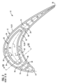
ここで、図1を参照すると、例示的なタービン翼形部10が示されている。この例では、翼形部10は、ガスタービン・エンジンのタービン・ブレードである。ただし、本発明の態様は、ガスタービン・エンジンの静止ベーンに適用可能なことに留意されたい。図示された翼形部10は、翼形部本体12を含むが、これは、例えば、軸流ガスタービン・エンジンのタービン部内での使用に適した外壁18から形成される。この外壁18は、タービン・エンジンの半径方向に沿って翼長方向に延在し、略凹状形状の圧力側壁20と略凸状形状の吸入側壁(吸引側壁)22とを含む。これら圧力側壁20と吸入側壁22は、前縁24と後縁26とで接続されている。図示のように、翼形部本体12は、基台部(プラットフォーム)14からタービン翼形部10の先端部15に向かって半径方向外側に延在している。タービン翼形部10をロータディスク(図示略)に対して連結させるために、基台部14から半径方向内側に根元部(ルート)16が延在している。本明細書では、半径方向又は翼長方向は、根元部16からタービン翼形部の先端部15に向かって延出する方向として理解されるものとする。
Referring now to FIG. 1, an
図2及び図3は、タービン翼形部10の公称の形状又は第1の形状を示す断面図である。図2を参照すると、タービン翼形部10は、圧力側壁20と吸入側壁22との間で、前縁24から後縁26まで、中央で延びる翼弦軸17を有する。翼弦方向は、翼弦軸17と平行な方向として定義することができる。図示のように、翼形部本体12は、冷却流体を受け入れることができる内側部分を有するが、それは、例えば、根元部16を通って形成される1つ又は複数の冷却流体の供給通路を介してコンプレッサ部(図示略)から送られる空気等を受け入れる。本実施形態では、タービン翼形部10は、翼形部本体12の内側部分に配置された複数の翼長方向に延在する隔壁28を備える。隔壁28は、圧力側壁20と吸入側壁22とを連結し、翼弦方向に沿って離間されて配置され、それらの間に半径方向の冷却路19を画定する。タービン翼形部10は、少なくとも1つの流動変位部30を備えるが、それは、翼形部本体12の内側部分に配置されていて、その翼長方向に沿って延在する。図示の例では、流動変位部30は、一対の隣接する隔壁28の間に配置されている。流動変位部30は、概して中空状であり、その内側に内部空間40を画定する。流動変位部30は、圧力側壁20と吸入側壁22とから離間して、第1の壁近傍冷却路92及び第2の壁近傍冷却路94をそれぞれ画定する。図示した実施形態では、流動変位部30と隣接する隔壁28との間には、壁近傍冷却路92及び94を連結する接続路96が形成されていて、略C字形状の断面を有する半径方向の流路を形成している。
2 and 3 are cross-sectional views illustrating the nominal or first shape of
流動変位部30は、翼形部本体と一体的に製造することができる。図示した実施形態では、タービン翼形部10には、一対の接続用リブ32、34が設けられていて、それぞれ、翼長方向に沿って、圧力側壁20と吸入側壁22とに対して流動変位部30を接続している。その結果、接続用リブ32、34の両側では、断面で、対称的に相対するように、一対の略C字形状の半径方向の流路が形成される。他の実施形態では、流動変位部30と、1つ又は複数の隔壁28とに関して、追加的又は代替的に、接続用リブを設けることも可能である。
The
流動変位部30内に画定された内部空間40は、不活性内部空間である。即ち、内部空間40は、流体の活動的な流れが行われない、デッドスペースである。従って、流動変位部30は、冷却流体の半径方向の流れの断面積を削減するとともに、冷却流体を圧力側20と吸入側22とに向かわせるように作用し、即ち、冷却流体の大部分を壁近傍冷却路92及び94内に移動させように作用する。図3に示すように、不活性内部空間40は、第1の端部42から第2の端部44まで、翼長方向に延在している。図示した実施形態では、第1の端部42は、先端部15に近接して位置し、第2の端部44は、根元部16の側に位置している。不活性内部空間40は、第1の端部42で開口し、第2の端部44で閉鎖されている。壁近傍冷却路92及び94は、根元部16に位置する冷却流体入口21で接続されている。流動変位部30は、壁近傍冷却路92、94と対向する外面36と、不活性内部空間40と対向する内面38とを備える。図2及び図3に示す公称の形状では、流動変位部30の外面36及び内面38は互いに略平行であって、外面36と内面38との間に画定される流動変位部30の壁厚tは、翼長方向及び翼弦方向に沿って実質的に一定である。
The
本開示内容では、タービン翼形部のモーダル周波数応答を調整可能にしているが、そのためにタービン翼形部の第1の(公称)形状を修正して、所定のモーダル周波数応答を有する第2の(修正又は適合された)形状を形成する。特に、タービン翼形部が、タービン・エンジンの規定の通常の作動速度の範囲外で生じる固有(モーダル)周波数を有するように、第2の形状を決定することができる。第2の形状が、第1の形状とは本質的に異なる点として、不活性内部空間40と対向する流動変位部30の内面38上に、質量及び/又は剛性に影響を及ぼす特徴部50が設けられている。図4乃至図7を参照して、この質量及び/又は剛性に影響を及ぼす特徴部50について例示する。
The present disclosure allows the modal frequency response of a turbine airfoil to be adjusted by modifying a first (nominal) shape of the turbine airfoil to create a second shape having a predetermined modal frequency response. Form a (modified or adapted) shape. In particular, the second shape may be determined such that the turbine airfoil has a natural (modal) frequency that occurs outside of the specified normal operating speed range of the turbine engine. The second shape differs substantially from the first shape in that there is a mass and/or
図4に例示する、第1の修正された形状の実施形態では、質量及び/又は剛性に影響を及ぼす特徴部50は、流動変位部30の内面38に輪郭(外形)を形付けることで実装されており、その結果、流動変位部30は、タービン翼形部10の第1の形状(図3参照)と対比して、1つ又は複数の位置で、変更された壁厚tを有している。図4に示す図では、表面38について二次元の輪郭(形状)が示されているが、この際、流動変位部30の壁厚tは、翼長方向で変化している。代替の実施形態では、表面38に二次元の輪郭を形付ける際、流動変位部30の壁厚tは、翼弦方向に変化してもよい。さらに代替の実施形態では、表面38に三次元の輪郭を形付けることもでき、その際、流動変位部30の壁厚tは、翼長方向と翼弦方向との双方で変化する。タービン翼形部10の剛性と質量の双方を所望なように設計(カスタマイズ)して、モーダル周波数を上方又は下方にして、タービン・エンジンの規定の正常な作動速度の範囲内での共振を回避させるように、流動変位部30の肉厚分布を構成することができる。一実施形態では、流動変位部の内面38は、規定のモーダル周波数応答を得るために、様々な翼長方向(及び/又は翼弦方向)の断面で、厚さt1、t2、t3を定めるとともに、滑らかな関数曲線で断面を接続することで、輪郭を形成してもよい。他の実施態様において、流動変位部30の内面38は、3次元的に輪郭を形成してもよく、その際、1つ以上の山(隆起部)、1つ以上の谷(陥没部)、又は山と谷の組合せを定める。
In a first modified shape embodiment, illustrated in FIG. 4, the mass and/or
次に、図5及び図6を参照すると、タービン翼形部の第2の修正された形状の実施形態が例示されているが、この際、複数の異なる種類の質量及び/又は剛性に影響を及ぼす特徴部50が用いられている。ここで例示されている質量及び/又は剛性に影響を及ぼす特徴部50の第1の種類は、流動変位部30の内面38上の1つ又は複数の翼弦方向に延在する突出部60を含む。この翼弦方向に延在する突出部60は、タービン翼形部10の質量よりも剛性に対して相当に高い影響を及ぼすため、補剛域として参照することができる。別の変形例(図示略)では、質量及び/又は剛性に影響を及ぼす特徴部は、タービン翼形部の全体的な剛性を低下させる役割を果たす、1つ又は複数の翼弦方向に延在する窪み又は溝を含んでいてもよい。ここで例示されている質量及び/又は剛性に影響を及ぼす特徴部50の第2の種類は、流動変位部30の内部に位置する1つ又は複数のロッド(棒状部)70を含む。各ロッド70は、第1の端部72と第2の端部74との間で延出している。各ロッド70の第1の端部72と第2の端部74は、それぞれ第1の位置と第2の位置とで、流動変位部30の内面38に対して接続されている。その結果、この場合も、ロッド70は、タービン翼形部10の質量よりも剛性に対して相当に高い影響を及ぼすため、補剛ロッドとして参照することができる。図5に例示するように、補剛ロッド70は、流動変位部30の内部で翼弦方向に延びるアレイ(整列)状に配置することができる。代替的又は追加的に、補剛ロッド70は、流動変位部30の内部に翼長方向に延びるアレイ状に配置されてもよい。図示した実施形態では、補剛ロッド70の第1の端部72と第2の端部74とは、補剛域60上に配置されている。
5 and 6, a second modified geometry embodiment of a turbine airfoil is illustrated, in which several different types of mass and/or stiffness are affected. An influencing
図7を参照すると、タービン翼形部の第3の修正された形状の実施形態が例示されている。ここでは、質量及び/又は剛性に影響を及ぼす特徴部50は、流動変位部30の内部に位置している、1つ又は複数の片持梁ロッド80を含んでいる。各片持梁ロッド80は、流動変位部30の内面38に対して接続された第1の端部82から、自由端である第2の端部84まで延出している。この場合、片持梁ロッド80は、タービン翼形部10の剛性よりも質量に対して相当に高い影響を及ぼしている。
Referring to FIG. 7, a third modified shape embodiment of a turbine airfoil is illustrated. Here, the mass and/or stiffness affecting features 50 include one or more cantilever rods 80 located within the
以上、様々な実施形態では、異なる種類の質量及び/又は剛性に影響を及ぼす特徴部50が用いられており、例えば、輪郭形成された内面38、1つ又は複数の補剛域60、1つ又は複数の補剛ロッド70、及び1つ又は複数の片持梁ロッド80等が用いられているが、これらは独立して用いられてもよく、又は、これら特徴部の2つ又は複数が組み合わされて用いられてもよく、それによって、所定のモーダル周波数応答を有するタービン翼形部の設計時に高い柔軟性が得られることを可能にする。
Thus, various embodiments employ different types of mass and/or stiffness affecting features 50, such as a contoured
図8では、タービン翼形部を製造する方法100の一実施形態を、フローチャートで例示している。この方法100のブロック(ステップ)102では、タービン翼形部の第1の形状を求めるが、この際、第1の形状は、タービン翼形部の公称の形状である。このタービン翼形部の公称の形状は、例えば、他の要因のうち、空気力学と熱伝達の考察に基づいて得ることができる。このため、公称の形状は、とりわけ、翼形部本体の外部形状と、タービン翼形部の冷却路の内部形状とを特徴付けることができる。このタービン翼形部の公称の形状は、図2乃至図3を参照して例示されている。この方法100のブロック104では、タービン翼形部の第1の形状に関して、1つ又は複数の振動モードに対応して、少なくとも1つの第1の固有周波数(固有振動数)を決定する。この方法100のブロック106では、振動モードのいずれかで、上で決定された固有周波数が、タービン・エンジンの規定の作動速度の範囲内で生じているか否かについて判定し、即ち、共振の条件が満たされているか否かを判定する。一般に、タービン・エンジンの全ての規定の速度範囲内では、例えば、燃焼器(コンバスタ)をカウント可能にしたり、上流ベーンをカウントさせる等、1つ又は複数の強制された応答の動力伝導部(ドライバ)を避けることが望ましい。共振の条件が決定されると、方法100のブロック108では、タービン翼形部10の第2の(修正された)形状を決定する。第2の形状が、第1の形状とは相違する点として、不活性内部空間40と対向する流動変位部30の内面38上に質量及び/又は剛性に影響を及ぼす特徴部50が設けられることがある。修正された形状は、図4乃至図7を参照して例示されている。第2の(修正された)形状は、振動モードのいずれかで、関連する第2の固有周波数が、タービン・エンジンの規定の作動速度の範囲外で生じるように決定される。さらに、この方法100のブロック110では、決定された第2の形状に基づいて、タービン翼形部10を製造することが含まれる。
FIG. 8 illustrates in a flow chart one embodiment of a
上記方法によって、従来、調整(チューニング)の変更が受け入れられる前に、空気力学及び冷却特性の再評価が必要とされていたような、タービン翼形部の周波数応答の調整の方法に関して、複雑さを相当に減少することを可能にする。不活性内部空間40と対向する表面38上に質量及び/又は剛性に影響を及ぼす特徴部50を設けることによって、タービン翼形部10の第1の形状と対比して、基本的にタービン翼形部10の第2の形状内の壁近傍冷却路92、94が変更されないことを確保可能にする。上記実施形態は、コード(翼弦)、キャンバ、ねじれ、根本部(ルート)再設計等の翼形部形状の更なる修正に基づかない。そのため、タービン翼形部10の第1の形状と対比して、タービン翼形部10の第2の形状においても、翼形部本体12の外部形状の変更がされないことを可能にする。従って、上記実施形態では、当技術分野で問題となっているような、空気力学の効率、クーラント(冷却剤)の削減、及びモーダル周波数応答の調整の間でのトレードオフについて、少なくとも幾つかをなくすことを可能にする。
The above methods add complexity to the method of tuning the frequency response of turbine airfoils, such that, in the past, aerodynamic and cooling characteristics had to be re-evaluated before tuning changes were accepted. can be considerably reduced. By providing a mass and/or
例示した実施形態では、流動変位部30は、翼形部本体12と一体に形成することができる。この場合、製造プロセスは、インサートを行う等のような、製造後の組立を必要とせずに、任意の技術を用いることができる。一例では、流動変位部30は、翼形部本体12と一体に鋳造されてもよく、例えばセラミック鋳造コアを用いることができる。他の製造技術として、例えば、3D印刷のような付加製造プロセスを用いることができる。この場合、本発明の設計は、高度に輪郭を形付けた翼形を用いることができ、例えば、3D状に輪郭を形付けたブレード及びベーンを含み得る。
In the illustrated embodiment, the
以上、特定の実施形態について詳述したが、当業者であれば、本開示内容から、様々な変更や代替を導くことができるであろう。従って、ここで開示される特定の構成は、単なる例示に過ぎず、本発明の範囲を限定するものではなく、そして、本発明の範囲は、添付された特許請求範囲によって定められ、さらに、その中には任意の均等物が含まれるものとする。 Although specific embodiments have been described in detail above, those skilled in the art will be able to derive various modifications and alternatives from this disclosure. Accordingly, the specific configurations disclosed herein are exemplary only and do not limit the scope of the invention, which is defined by the appended claims, which in turn It is intended to include any equivalents.
Claims (10)
前記翼形部本体(12)の内側部分に位置決められて、翼長方向に沿って延在し、かつ不活性内部空間(40)を画定する略中空の流動変位部(30)と、
を備えるタービン翼形部(10)であって、
前記流動変位部(30)は、前記圧力側壁(20)及び前記吸入側壁(22)から離間された第1の壁近傍冷却路(92)及び第2の壁近傍冷却路(94)をそれぞれ画定し、
前記流動変位部(30)は、前記壁近傍冷却路(92、94)と対向する外面(36)と、前記不活性内部空間(40)と対向する内面(38)とを備え、かつ、
前記不活性内部空間(40)と対向する内面(38)は、前記タービン翼形部(10)の所定のモーダル周波数応答を生じさせるように、前記タービン翼形部(10)の質量及び/又は剛性に対して影響を及ぼすように構成された特徴部(50)を含み、
前記流動変位部(30)が可変的な壁厚(t)を有するように、前記流動変位部(30)の前記内面(38)に輪郭を形付けることで、前記特徴部(50)が構成され、
前記流動変位部(30)の前記壁厚(t)は、翼長方向と翼弦方向とのうち少なくとも一方に沿って変化する、
タービン翼形部(10)。 an airfoil body (12) formed by an outer wall (18) including a pressure sidewall (20) and a suction sidewall (22) connected at leading and trailing edges (24) and (26);
a substantially hollow flow displacement portion (30) positioned in the inner portion of said airfoil body (12) and extending along the spanwise direction and defining an inert interior space (40);
A turbine airfoil (10) comprising:
The flow displacement portion (30) defines a first near-wall cooling passage (92) and a second near-wall cooling passage (94) spaced apart from the pressure sidewall (20) and the suction sidewall (22), respectively. death,
the flow displacement portion (30) comprises an outer surface (36) facing the near-wall cooling passages (92, 94) and an inner surface (38) facing the inert interior space (40);
The inner surface (38) facing the inert interior space (40) has a mass and/or a mass of the turbine airfoil (10) to produce a predetermined modal frequency response of the turbine airfoil (10) including a feature (50) configured to affect stiffness;
The feature (50) is configured by contouring the inner surface (38) of the flow displacement portion (30) such that the flow displacement portion (30) has a variable wall thickness (t). is,
the wall thickness (t) of the flow displacement portion (30) varies along at least one of the span direction and the chord direction;
A turbine airfoil (10).
前記タービン翼形部(10)の公称の形状である前記タービン翼形部の第1の形状を求めることを含み、この際、前記タービン翼形部は、
前縁(24)及び後縁(26)で接続された圧力側壁(20)及び吸入側壁(22)を含む外壁(18)によって形成された翼形部本体(12)と、
前記翼形部本体(12)の内側部分に位置決められて、その翼長方向に沿って延在して、不活性内部空間(40)を画定する、略中空の流動変位部(30)と、
によって定められ、
前記流動変位部(30)は、第1の壁近傍冷却路(92)及び第2の壁近傍冷却路(94)をそれぞれ画定するように、前記圧力側壁(20)及び前記吸入側壁(22)から離間されて、
前記流動変位部(30)は、前記壁近傍冷却路(92、94)と対向する外面(36)と、前記不活性内部空間(40)と対向する内面(38)とを備え、
前記タービン翼形部の第1の形状に関する第1の固有周波数を決定して(104)、前記第1の固有周波数が前記タービン・エンジンの定められた作動速度の範囲内で生じているか否かを決定すること(106)と、
前記タービン翼形部(10)の第2の形状を決定し(108)、この際、前記第2の形状が、前記第1の形状とは異なる点として、前記不活性内部空間(40)と対向する流動変位部(30)の内面(38)上に質量及び/又は剛性に影響を及ぼす特徴部(50)が設けられることであって、
この際、前記第2の形状は、前記タービン・エンジンの定められた作動速度の範囲外で生じる第2の固有周波数と関連付けられることと、
決定された前記第2の形状に基づいて前記タービン翼形部(10)を製造することと、
を含む方法(100)。 A method (100) for forming a turbine airfoil (10) according to any preceding claim having a tailored modal frequency response for use in a turbine engine, comprising:
determining a first shape of said turbine airfoil which is a nominal shape of said turbine airfoil (10) , wherein said turbine airfoil comprises:
an airfoil body (12) formed by an outer wall (18) including a pressure sidewall (20) and a suction sidewall (22) connected at leading and trailing edges (24) and (26);
a generally hollow flow displacement section (30) positioned in an inner portion of said airfoil body (12) and extending along its spanwise direction to define an inert interior space (40) ;
determined by
The flow displacement portion (30) defines a first near-wall cooling passage (92) and a second near-wall cooling passage (94), respectively, the pressure sidewall (20) and the suction sidewall (22). separated from
the flow displacement portion (30) comprises an outer surface (36) facing the near-wall cooling passages (92, 94) and an inner surface (38) facing the inert interior space (40);
determining 104 a first natural frequency for a first shape of the turbine airfoil and whether the first natural frequency occurs within a defined operating speed range of the turbine engine; determining (106) whether
determining (108) a second shape of the turbine airfoil (10) , wherein the second shape differs from the first shape in that the inert interior space (40) and A mass and/or stiffness influencing feature (50) is provided on the inner surface (38) of the opposing flow displacement portion (30),
wherein the second shape is associated with a second natural frequency that occurs outside of a defined operating speed range of the turbine engine;
manufacturing the turbine airfoil (10) based on the determined second shape;
A method (100) comprising:
Applications Claiming Priority (3)
| Application Number | Priority Date | Filing Date | Title |
|---|---|---|---|
| US201962868318P | 2019-06-28 | 2019-06-28 | |
| US62/868,318 | 2019-06-28 | ||
| PCT/US2020/029674 WO2020263396A1 (en) | 2019-06-28 | 2020-04-24 | Turbine airfoil incorporating modal frequency response tuning |
Publications (2)
| Publication Number | Publication Date |
|---|---|
| JP2022540798A JP2022540798A (en) | 2022-09-20 |
| JP7219829B2 true JP7219829B2 (en) | 2023-02-08 |
Family
ID=70614691
Family Applications (1)
| Application Number | Title | Priority Date | Filing Date |
|---|---|---|---|
| JP2021577651A Active JP7219829B2 (en) | 2019-06-28 | 2020-04-24 | Turbine airfoil with modal frequency response tuning |
Country Status (6)
| Country | Link |
|---|---|
| US (1) | US11988110B2 (en) |
| EP (1) | EP3969727B1 (en) |
| JP (1) | JP7219829B2 (en) |
| KR (1) | KR102738347B1 (en) |
| CN (1) | CN114096737B (en) |
| WO (1) | WO2020263396A1 (en) |
Families Citing this family (1)
| Publication number | Priority date | Publication date | Assignee | Title |
|---|---|---|---|---|
| US12043368B2 (en) * | 2022-03-23 | 2024-07-23 | General Electric Company | Rotating airfoil assembly |
Citations (1)
| Publication number | Priority date | Publication date | Assignee | Title |
|---|---|---|---|---|
| JP2010525229A (en) | 2007-04-23 | 2010-07-22 | シーメンス アクチエンゲゼルシヤフト | Method for manufacturing a coated turbine blade |
Family Cites Families (21)
| Publication number | Priority date | Publication date | Assignee | Title |
|---|---|---|---|---|
| GB2121483B (en) * | 1982-06-08 | 1985-02-13 | Rolls Royce | Cooled turbine blade for a gas turbine engine |
| US6481972B2 (en) | 2000-12-22 | 2002-11-19 | General Electric Company | Turbine bucket natural frequency tuning rib |
| US7008179B2 (en) * | 2003-12-16 | 2006-03-07 | General Electric Co. | Turbine blade frequency tuned pin bank |
| US7147437B2 (en) * | 2004-08-09 | 2006-12-12 | General Electric Company | Mixed tuned hybrid blade related method |
| US7303376B2 (en) * | 2005-12-02 | 2007-12-04 | Siemens Power Generation, Inc. | Turbine airfoil with outer wall cooling system and inner mid-chord hot gas receiving cavity |
| US7556476B1 (en) | 2006-11-16 | 2009-07-07 | Florida Turbine Technologies, Inc. | Turbine airfoil with multiple near wall compartment cooling |
| EP1975373A1 (en) * | 2007-03-06 | 2008-10-01 | Siemens Aktiengesellschaft | Guide vane duct element for a guide vane assembly of a gas turbine engine |
| US7828526B2 (en) * | 2007-04-11 | 2010-11-09 | General Electric Company | Metallic blade having a composite inlay |
| GB2450937B (en) * | 2007-07-13 | 2009-06-03 | Rolls Royce Plc | Component with tuned frequency response |
| FR2939832B1 (en) * | 2008-12-11 | 2011-01-07 | Turbomeca | TURBINE WHEEL EQUIPPED WITH AXIAL HOLDING DEVICE LOCKING BLADES WITH RESPECT TO A DISK. |
| US9394793B1 (en) * | 2012-09-14 | 2016-07-19 | United Technologies Corporation | Turbomachine blade |
| US9695696B2 (en) * | 2013-07-31 | 2017-07-04 | General Electric Company | Turbine blade with sectioned pins |
| US20150198050A1 (en) * | 2014-01-15 | 2015-07-16 | Siemens Energy, Inc. | Internal cooling system with corrugated insert forming nearwall cooling channels for airfoil usable in a gas turbine engine |
| EP3140515B1 (en) * | 2014-05-08 | 2019-04-03 | Siemens Energy, Inc. | Airfoil cooling with internal cavity displacement features |
| US10392942B2 (en) * | 2014-11-26 | 2019-08-27 | Ansaldo Energia Ip Uk Limited | Tapered cooling channel for airfoil |
| EP3292277A1 (en) * | 2015-05-07 | 2018-03-14 | Siemens Aktiengesellschaft | Turbine airfoil with internal cooling channels |
| US10494931B2 (en) * | 2015-08-28 | 2019-12-03 | Siemens Aktiengesellschaft | Internally cooled turbine airfoil with flow displacement feature |
| US11230935B2 (en) | 2015-09-18 | 2022-01-25 | General Electric Company | Stator component cooling |
| US9759073B1 (en) * | 2016-02-26 | 2017-09-12 | Siemens Energy, Inc. | Turbine airfoil having near-wall cooling insert |
| WO2017171763A1 (en) | 2016-03-31 | 2017-10-05 | Siemens Aktiengesellschaft | Turbine airfoil with turbulating feature on a cold wall |
| EP3511522A1 (en) * | 2018-01-11 | 2019-07-17 | Siemens Aktiengesellschaft | Gas turbine blade and method for producing such blade |
-
2020
- 2020-04-24 JP JP2021577651A patent/JP7219829B2/en active Active
- 2020-04-24 EP EP20724721.4A patent/EP3969727B1/en active Active
- 2020-04-24 KR KR1020227002974A patent/KR102738347B1/en active Active
- 2020-04-24 CN CN202080047425.1A patent/CN114096737B/en active Active
- 2020-04-24 US US17/597,115 patent/US11988110B2/en active Active
- 2020-04-24 WO PCT/US2020/029674 patent/WO2020263396A1/en not_active Ceased
Patent Citations (1)
| Publication number | Priority date | Publication date | Assignee | Title |
|---|---|---|---|---|
| JP2010525229A (en) | 2007-04-23 | 2010-07-22 | シーメンス アクチエンゲゼルシヤフト | Method for manufacturing a coated turbine blade |
Also Published As
| Publication number | Publication date |
|---|---|
| CN114096737B (en) | 2024-06-14 |
| WO2020263396A1 (en) | 2020-12-30 |
| EP3969727A1 (en) | 2022-03-23 |
| CN114096737A (en) | 2022-02-25 |
| KR20220025033A (en) | 2022-03-03 |
| JP2022540798A (en) | 2022-09-20 |
| US20220235664A1 (en) | 2022-07-28 |
| KR102738347B1 (en) | 2024-12-03 |
| EP3969727B1 (en) | 2024-05-29 |
| US11988110B2 (en) | 2024-05-21 |
Similar Documents
| Publication | Publication Date | Title |
|---|---|---|
| US11732593B2 (en) | Flared central cavity aft of airfoil leading edge | |
| JP7638676B2 (en) | Damper stack for turbomachinery rotor blades - Patents.com | |
| CN107435562B (en) | Vanes with stress-reducing bulbs at turn openings of coolant passages | |
| US10605090B2 (en) | Intermediate central passage spanning outer walls aft of airfoil leading edge passage | |
| JP7012452B2 (en) | Aerofoil with variable slot separation | |
| US9879547B2 (en) | Interior cooling circuits in turbine blades | |
| JP3213107U (en) | Collision system for airfoils | |
| CN106050321A (en) | Cooled airfoil, guide vane, and method for manufacturing the airfoil and guide vane | |
| JP7219829B2 (en) | Turbine airfoil with modal frequency response tuning | |
| JP7118597B2 (en) | Method for manufacturing internal ribs | |
| EP3894663A2 (en) | Modal response tuned turbine blade | |
| CN113464209B (en) | Turbine rotor blade with cooling circuit having offset ribs | |
| CN110678627A (en) | Turbine blade with improved structure | |
| CN110546348B (en) | Turbine blade with improved structure | |
| JP2025026364A (en) | Trailing edge cooling circuit for turbomachine airfoils | |
| JPS59196904A (en) | Stator blade of gas turbine |
Legal Events
| Date | Code | Title | Description |
|---|---|---|---|
| A521 | Request for written amendment filed |
Free format text: JAPANESE INTERMEDIATE CODE: A523 Effective date: 20220331 |
|
| A621 | Written request for application examination |
Free format text: JAPANESE INTERMEDIATE CODE: A621 Effective date: 20220331 |
|
| A521 | Request for written amendment filed |
Free format text: JAPANESE INTERMEDIATE CODE: A523 Effective date: 20220906 |
|
| TRDD | Decision of grant or rejection written | ||
| A01 | Written decision to grant a patent or to grant a registration (utility model) |
Free format text: JAPANESE INTERMEDIATE CODE: A01 Effective date: 20230124 |
|
| A977 | Report on retrieval |
Free format text: JAPANESE INTERMEDIATE CODE: A971007 Effective date: 20230126 |
|
| A61 | First payment of annual fees (during grant procedure) |
Free format text: JAPANESE INTERMEDIATE CODE: A61 Effective date: 20230127 |
|
| R150 | Certificate of patent or registration of utility model |
Ref document number: 7219829 Country of ref document: JP Free format text: JAPANESE INTERMEDIATE CODE: R150 |
|
| R250 | Receipt of annual fees |
Free format text: JAPANESE INTERMEDIATE CODE: R250 |