JP7217281B2 - Method using static multi-view display and collimated guided light - Google Patents
Method using static multi-view display and collimated guided light Download PDFInfo
- Publication number
- JP7217281B2 JP7217281B2 JP2020545339A JP2020545339A JP7217281B2 JP 7217281 B2 JP7217281 B2 JP 7217281B2 JP 2020545339 A JP2020545339 A JP 2020545339A JP 2020545339 A JP2020545339 A JP 2020545339A JP 7217281 B2 JP7217281 B2 JP 7217281B2
- Authority
- JP
- Japan
- Prior art keywords
- light
- view
- grating
- static
- light beam
- Prior art date
- Legal status (The legal status is an assumption and is not a legal conclusion. Google has not performed a legal analysis and makes no representation as to the accuracy of the status listed.)
- Active
Links
Images


Classifications
-
- G—PHYSICS
- G02—OPTICS
- G02B—OPTICAL ELEMENTS, SYSTEMS OR APPARATUS
- G02B6/00—Light guides; Structural details of arrangements comprising light guides and other optical elements, e.g. couplings
- G02B6/0001—Light guides; Structural details of arrangements comprising light guides and other optical elements, e.g. couplings specially adapted for lighting devices or systems
- G02B6/0011—Light guides; Structural details of arrangements comprising light guides and other optical elements, e.g. couplings specially adapted for lighting devices or systems the light guides being planar or of plate-like form
- G02B6/0066—Light guides; Structural details of arrangements comprising light guides and other optical elements, e.g. couplings specially adapted for lighting devices or systems the light guides being planar or of plate-like form characterised by the light source being coupled to the light guide
- G02B6/0068—Arrangements of plural sources, e.g. multi-colour light sources
-
- G—PHYSICS
- G02—OPTICS
- G02B—OPTICAL ELEMENTS, SYSTEMS OR APPARATUS
- G02B6/00—Light guides; Structural details of arrangements comprising light guides and other optical elements, e.g. couplings
- G02B6/0001—Light guides; Structural details of arrangements comprising light guides and other optical elements, e.g. couplings specially adapted for lighting devices or systems
- G02B6/0011—Light guides; Structural details of arrangements comprising light guides and other optical elements, e.g. couplings specially adapted for lighting devices or systems the light guides being planar or of plate-like form
- G02B6/0013—Means for improving the coupling-in of light from the light source into the light guide
- G02B6/0015—Means for improving the coupling-in of light from the light source into the light guide provided on the surface of the light guide or in the bulk of it
- G02B6/0018—Redirecting means on the surface of the light guide
-
- G—PHYSICS
- G02—OPTICS
- G02B—OPTICAL ELEMENTS, SYSTEMS OR APPARATUS
- G02B6/00—Light guides; Structural details of arrangements comprising light guides and other optical elements, e.g. couplings
- G02B6/0001—Light guides; Structural details of arrangements comprising light guides and other optical elements, e.g. couplings specially adapted for lighting devices or systems
- G02B6/0011—Light guides; Structural details of arrangements comprising light guides and other optical elements, e.g. couplings specially adapted for lighting devices or systems the light guides being planar or of plate-like form
- G02B6/0033—Means for improving the coupling-out of light from the light guide
- G02B6/0035—Means for improving the coupling-out of light from the light guide provided on the surface of the light guide or in the bulk of it
- G02B6/0036—2-D arrangement of prisms, protrusions, indentations or roughened surfaces
-
- G—PHYSICS
- G02—OPTICS
- G02B—OPTICAL ELEMENTS, SYSTEMS OR APPARATUS
- G02B27/00—Optical systems or apparatus not provided for by any of the groups G02B1/00 - G02B26/00, G02B30/00
- G02B27/09—Beam shaping, e.g. changing the cross-sectional area, not otherwise provided for
- G02B27/0938—Using specific optical elements
- G02B27/0944—Diffractive optical elements, e.g. gratings, holograms
-
- G—PHYSICS
- G02—OPTICS
- G02B—OPTICAL ELEMENTS, SYSTEMS OR APPARATUS
- G02B27/00—Optical systems or apparatus not provided for by any of the groups G02B1/00 - G02B26/00, G02B30/00
- G02B27/30—Collimators
-
- G—PHYSICS
- G02—OPTICS
- G02B—OPTICAL ELEMENTS, SYSTEMS OR APPARATUS
- G02B27/00—Optical systems or apparatus not provided for by any of the groups G02B1/00 - G02B26/00, G02B30/00
- G02B27/42—Diffraction optics, i.e. systems including a diffractive element being designed for providing a diffractive effect
- G02B27/4205—Diffraction optics, i.e. systems including a diffractive element being designed for providing a diffractive effect having a diffractive optical element [DOE] contributing to image formation, e.g. whereby modulation transfer function MTF or optical aberrations are relevant
-
- G—PHYSICS
- G02—OPTICS
- G02B—OPTICAL ELEMENTS, SYSTEMS OR APPARATUS
- G02B6/00—Light guides; Structural details of arrangements comprising light guides and other optical elements, e.g. couplings
- G02B6/0001—Light guides; Structural details of arrangements comprising light guides and other optical elements, e.g. couplings specially adapted for lighting devices or systems
- G02B6/0011—Light guides; Structural details of arrangements comprising light guides and other optical elements, e.g. couplings specially adapted for lighting devices or systems the light guides being planar or of plate-like form
- G02B6/0013—Means for improving the coupling-in of light from the light source into the light guide
- G02B6/0015—Means for improving the coupling-in of light from the light source into the light guide provided on the surface of the light guide or in the bulk of it
- G02B6/0016—Grooves, prisms, gratings, scattering particles or rough surfaces
-
- G—PHYSICS
- G02—OPTICS
- G02B—OPTICAL ELEMENTS, SYSTEMS OR APPARATUS
- G02B6/00—Light guides; Structural details of arrangements comprising light guides and other optical elements, e.g. couplings
- G02B6/0001—Light guides; Structural details of arrangements comprising light guides and other optical elements, e.g. couplings specially adapted for lighting devices or systems
- G02B6/0011—Light guides; Structural details of arrangements comprising light guides and other optical elements, e.g. couplings specially adapted for lighting devices or systems the light guides being planar or of plate-like form
- G02B6/0013—Means for improving the coupling-in of light from the light source into the light guide
- G02B6/0023—Means for improving the coupling-in of light from the light source into the light guide provided by one optical element, or plurality thereof, placed between the light guide and the light source, or around the light source
- G02B6/0028—Light guide, e.g. taper
-
- G—PHYSICS
- G02—OPTICS
- G02B—OPTICAL ELEMENTS, SYSTEMS OR APPARATUS
- G02B6/00—Light guides; Structural details of arrangements comprising light guides and other optical elements, e.g. couplings
- G02B6/0001—Light guides; Structural details of arrangements comprising light guides and other optical elements, e.g. couplings specially adapted for lighting devices or systems
- G02B6/0011—Light guides; Structural details of arrangements comprising light guides and other optical elements, e.g. couplings specially adapted for lighting devices or systems the light guides being planar or of plate-like form
- G02B6/0013—Means for improving the coupling-in of light from the light source into the light guide
- G02B6/0023—Means for improving the coupling-in of light from the light source into the light guide provided by one optical element, or plurality thereof, placed between the light guide and the light source, or around the light source
- G02B6/0031—Reflecting element, sheet or layer
Description
関連出願の相互参照
適用なし
Cross-reference to related applications Not applicable
連邦政府による資金提供を受けた研究開発の記載
適用なし
STATEMENT OF FEDERALLY SPONSORED RESEARCH AND DEVELOPMENT Not applicable
電子ディスプレイは、多種多様なデバイス及び製品の情報をユーザに伝達するための、ほぼ至る所にある媒体である。一般に、電子ディスプレイは、アクティブディスプレイ(すなわち、光を出射するディスプレイ)又はパッシブディスプレイ(すなわち、別の光源によって供給される光を変調するディスプレイ)のいずれかに分類され得る。パッシブディスプレイは多くの場合、魅力的な性能特性、例えば本質的に低消費電力であることを含むが、それに限定されない性能特性を呈するが、光を出射する能力が欠如していることを考えると、多くの実用的用途において幾分使用が制限され得る。出射光に関連するパッシブディスプレイの制限を克服するために、多くのパッシブディスプレイは、バックライトなどの外部光源に結合されて(coupled to)いる。 Electronic displays are a nearly ubiquitous medium for communicating information to users for a wide variety of devices and products. In general, electronic displays can be classified as either active displays (ie, displays that emit light) or passive displays (ie, displays that modulate light supplied by another light source). Passive displays often exhibit attractive performance characteristics, including, but not limited to, inherently low power consumption, given their lack of ability to emit light. , can be of somewhat limited use in many practical applications. To overcome the limitations of passive displays related to emitted light, many passive displays are coupled to an external light source such as a backlight.
本明細書に記載の原理による例及び実施形態の様々な特徴は、添付の図面と併せて以下の詳細な説明を参照することにより、より容易に理解することができ、図面において同一の参照番号が同一の構造要素を示している。 Various features of examples and embodiments according to the principles described herein can be more readily understood by referring to the following detailed description in conjunction with the accompanying drawings, wherein like reference numerals are used in the drawings. indicate identical structural elements.
特定の例及び実施形態は、上記の図に示した特徴に加えて、またその代わりとなる1つである他の特徴を有する。これら及び他の特徴については、上記の図を参照して以下で詳述する。
本開示は、以下の[1]から[21]を含む。
[1]長手方向に光を導波するように構成されたライトガイドと、
上記長手方向に互いにずらして配置され、かつ上記ライトガイドに光学的に結合されている複数の発光体を含む光源であって、上記光源のうちの1つの上記発光体は、上記ライトガイド内に、上記発光体の長手方向のずれによって決まる伝播角度を有する、コリメートされた導波光ビームを供給するように構成されている、光源と、
上記コリメートされた導波光ビームの一部を、マルチビュー画像を表示する複数の指向性光ビームとして外部に散乱させるように構成された回折格子のアレイであって、上記マルチビュー画像の方向が、上記コリメートされた導波光ビームの色及び上記伝播角度の両方の関数である、回折格子のアレイと
を備える、静的マルチビューディスプレイ。
[2]上記回折格子アレイの回折格子が、上記マルチビュー画像のビューピクセルの強度及びビュー方向に対応している強度と主角度方向とを有する、上記複数の指向性光ビームのうちの1つの指向性光ビームを供給するように構成されている、上記[1]に記載の静的マルチビューディスプレイ。
[3]上記回折格子の格子特性が、上記強度及び上記主角度方向を決定するように構成されており、上記主角度方向を決定するように構成された上記格子特性が、上記回折格子の格子ピッチ、及び上記回折格子の格子方向の一方若しくは両方を含む、上記[2]に記載の静的マルチビューディスプレイ。
[4]上記強度を決定するように構成された上記格子特性が、上記回折格子の格子深さを含む、上記[3]に記載の静的マルチビューディスプレイ。
[5]上記回折格子のアレイが、上記コリメートされた導波光ビームの一部が上記複数の指向性光ビームとして外部に散乱される、上記ライトガイドの出射面の反対側にある上記ライトガイドの表面に配置されている、上記[1]に記載の静的マルチビューディスプレイ。
[6]上記ライトガイドの入力端にコリメート光カプラをさらに備え、上記コリメート光カプラが、上記光源からの光を、上記コリメートされた導波光ビームとして上記ライトガイド内へと光学的に結合するように構成されており、上記発光体の上記長手方向のずれが、上記コリメート光カプラに対する上記発光体の上記長手方向の位置となる、上記[1]に記載の静的マルチビューディスプレイ。
[7]上記コリメート光カプラが円筒状格子カプラを含み、上記光源が、上記ライトガイドのガイド面に隣接して配置され、また上記光源の発光体が、上記ガイド面を通して光を出射するように構成されている、上記[6]に記載の静的マルチビューディスプレイ。
[8]上記光源の上記複数の発光体が、上記ライトガイド内に、第1の伝播角度で第1のコリメートされた導波光ビームを供給するように構成された、第1の長手方向のずれを有する第1の発光体と、第2の伝播角度で第2のコリメートされた導波光ビームを供給するように構成された、第2の長手方向のずれを有する第2の発光体とを含む、上記[1]に記載の静的マルチビューディスプレイ。
[9]上記第1の伝播角度が、第1の方向を有する第1のマルチビュー画像を供給するように構成され、上記第2の伝播角度が、第2の方向を有する第2のマルチビュー画像を供給するように構成されており、上記第1及び第2の発光体を選択的に駆動することによって、上記第1の方向における上記第1のマルチビュー画像と上記第2の方向における上記第2のマルチビュー画像との間で切替えを行い、上記マルチビュー画像を動画化し、上記静的マルチビューディスプレイが準静的マルチビューディスプレイである、上記[8]に記載の静的マルチビューディスプレイ。
[10]上記第1の発光体が、第1の色を有する上記第1のコリメートされた導波光ビームを供給するように構成され、上記第2の発光体が、第2の色を有する上記第2のコリメートされた導波光ビームを供給するように構成されており、上記第1及び第2の長手方向のずれが、上記第1のコリメートされた導波光ビームによって供給される第1のマルチビュー画像と上記第2のコリメートされた導波光ビームによって供給される第2のマルチビュー画像との結合を含む合成マルチビュー画像を供給するように選択されており、上記合成マルチビュー画像が、上記第1及び第2の色の結合と上記第1及び第2の発光体の相対照度とを表す色を有する、上記[8]に記載の静的マルチビューディスプレイ。
[11]上記ライトガイド及び上記回折格子のアレイが、上記長手方向と直交している垂直方向に伝播する光に対して透過的である、上記[1]に記載の静的マルチビューディスプレイ。
[12]透過性の静的マルチビューディスプレイであって、
ライトガイド内のコリメートされた導波光ビームからの光を回折的に外部に散乱させて、マルチビュー画像を表示する複数の指向性光ビームを供給するように構成された回折格子のアレイと、
長手方向に互いにずらして配置された複数の発光体を含む光源であって、上記光源のうちの1つの上記発光体は、上記長手方向における上記発光体のずれによって決まる伝播角度を有する、上記コリメートされた導波光ビームを供給するように構成されている、光源とを備え、
上記マルチビュー画像の方向が、上記コリメートされた導波光ビームの色及び上記伝播角度の両方の関数であり、上記透過性の静的マルチビューディスプレイが、上記長手方向と直交している垂直方向に対して透過的である、
透過性の静的マルチビューディスプレイ。
[13]上記回折格子アレイの回折格子が、上記マルチビュー画像のビューピクセルの強度及びビュー方向に対応している強度と主角度方向とを有する、上記複数の指向性光ビームのうちの1つの指向性光ビームを供給するように構成され、上記回折格子の格子ピッチ及び格子方向が、上記指向性光ビームの上記主角度方向を決定するように構成され、上記回折格子の格子深さが、上記指向性光ビームの上記強度を決定するように構成されている、上記[12]に記載の透過性の静的マルチビューディスプレイ。
[14]上記ライトガイドの入力端にコリメート光カプラをさらに備え、上記コリメート光カプラが、上記光源の上記発光体からの光を、上記コリメートされた導波光ビームとして上記ライトガイド入力内へと光学的に結合するように構成されており、上記発光体の上記ずれが、上記コリメート光カプラに対する上記発光体の上記長手方向の位置となる、上記[12]に記載の透過性の静的マルチビューディスプレイ。
[15]光源の第1の発光体が、第1の伝播角度で第1のコリメートされた導波光ビームを供給するように構成された第1のずれを、長手方向において有し、上記光源の第2の発光体が、上記ライトガイド内で第2の伝播角度で、第2のコリメートされた導波光ビームを供給するように構成された第2のずれを、長手方向において有し、上記第1の伝播角度が、上記マルチビュー画像を第1の方向に供給するように構成され、また上記第2の伝播角度が、上記マルチビュー画像を第2の方向に供給するように構成されている、上記[12]に記載の透過性の静的マルチビューディスプレイ。
[16]光源の第1の発光体が、第1の色の光を供給するように構成され、上記光源の第2の発光体が、第2の色の光を供給するように構成されており、上記第1及び第2の発光体が、上記第1及び第2の色の結合を含む合成マルチビュー画像を供給するように構成されたずれを有する、上記[12]に記載の透過性の静的マルチビューディスプレイ。
[17]複数の発光体のうちの1つの発光体を使用して、ある色を有する光を供給するステップであって、上記複数の発光体のうちの発光体は、長手方向に互いにずらして配置されている、供給するステップと、
コリメート光カプラを使用して、上記光をコリメートされた導波光ビームとしてライトガイド内へと結合するステップであって、上記コリメートされた導波光ビームは、上記発光体の長手方向のずれによって決まる伝播角度を有する、結合するステップと、
回折格子のアレイを使用して、上記コリメートされた導波光ビームの一部を外部に散乱させることにより、マルチビュー画像を表示する複数の指向性光ビームを供給するステップであって、上記マルチビュー画像の方向は、上記コリメートされた導波光ビームの上記色及び上記伝播角度の両方の関数である、供給するステップと
を含む、静的マルチビューディスプレイの動作方法。
[18]上記回折格子アレイの回折格子が、上記コリメートされた導波光ビームの一部を、上記マルチビュー画像のビューピクセルの強度及びビュー方向に対応している強度と主角度方向とを有する、上記複数の指向性光ビームのうちの1つの指向性光ビームとして、外部に散乱させており、上記回折格子の格子ピッチ及び格子方向が、上記指向性光ビームの上記主角度方向を決定するように構成され、上記回折格子の格子深さが、上記指向性光ビームの上記強度を決定するように構成されている、上記[17]に記載の静的マルチビューディスプレイの動作方法。
[19]上記ライトガイドと、上記コリメート光カプラと、上記回折格子のアレイとを備える上記静的マルチビューディスプレイが、上記長手方向と直交している垂直方向に伝播する光に対して透過的である、上記[17]に記載の静的マルチビューディスプレイの動作方法。
[20]上記複数の発光体のうちの第1の発光体を使用して光を供給することにより、第1のマルチビュー画像を生成するステップであって、上記第1の発光体が第1の長手方向のずれを有する、生成するステップと、
上記複数の発光体のうちの第2の発光体を使用して光を供給することにより、第2のマルチビュー画像を生成するステップであって、上記第2の発光体が第2の長手方向のずれを有する、生成するステップと
をさらに含む、上記[17]に記載の静的マルチビューディスプレイの動作方法。
[21]上記複数の発光体のうちの第1の発光体を使用して、第1の色を有する光を供給することにより、第1のマルチビュー画像を生成するステップであって、上記第1の発光体が第1の長手方向のずれを有する、生成するステップと、
上記複数の発光体のうちの第2の発光体を使用して、第2の色を有する光を供給することにより、第2のマルチビュー画像を生成するステップであって、上記第2の発光体が第2の長手方向のずれを有する、生成するステップと
をさらに含み、
上記第1及び第2の長手方向のずれが、上記第1及び第2のマルチビュー画像の結合を含む、合成マルチビュー画像を供給するように選択されており、上記合成画像の色が、上記第1の色と第2の色とを結合したものである、
上記[17]に記載の静的マルチビューディスプレイの動作方法。
Certain examples and embodiments have other features that are in addition to and in place of those shown in the figures above. These and other features are described in detail below with reference to the above figures.
The present disclosure includes the following [1] to [21].
[1] a light guide configured to guide light in a longitudinal direction;
a light source including a plurality of longitudinally staggered light emitters optically coupled to the light guide, wherein one of the light emitters is positioned within the light guide; a light source configured to provide a collimated guided light beam having a propagation angle determined by the longitudinal displacement of the light emitter;
an array of diffraction gratings configured to outwardly scatter a portion of the collimated guided light beam as a plurality of directional light beams displaying a multi-view image, the direction of the multi-view image being: an array of diffraction gratings that are a function of both the color of the collimated guided light beam and the angle of propagation;
A static multi-view display with
[2] one of the plurality of directional light beams, wherein the gratings of the grating array have intensities and principal angular directions corresponding to the intensities and view directions of the view pixels of the multi-view image; A static multi-view display according to [1] above, configured to provide a directional light beam.
[3] a grating characteristic of the diffraction grating configured to determine the intensity and the principal angular direction; and a grating characteristic of the diffraction grating configured to determine the principal angular direction; The static multi-view display according to [2] above, including one or both of a pitch and a grating direction of the diffraction grating.
[4] The static multi-view display of [3] above, wherein the grating property configured to determine the intensity comprises a grating depth of the diffraction grating.
[5] the array of diffraction gratings in the light guide opposite the exit face of the light guide, wherein a portion of the collimated guided light beam is scattered out as the plurality of directional light beams; The static multi-view display according to [1] above, arranged on a surface.
[6] further comprising a collimating optical coupler at the input end of the light guide, such that the collimating optical coupler optically couples light from the light source into the light guide as the collimated guided light beam; , wherein the longitudinal offset of the light emitter results in the longitudinal position of the light emitter relative to the collimating optical coupler.
[7] such that the collimating light coupler comprises a cylindrical grating coupler, the light source is positioned adjacent to the guide surface of the light guide, and the illuminator of the light source emits light through the guide surface; The static multi-view display of [6] above, configured.
[8] A first longitudinal offset, wherein the plurality of light emitters of the light source are configured to provide a first collimated guided light beam at a first propagation angle within the light guide. and a second light emitter having a second longitudinal offset configured to provide a second collimated guided light beam at a second propagation angle. , the static multi-view display according to [1] above.
[9] the first propagation angle is configured to provide a first multi-view image having a first direction, and the second propagation angle is a second multi-view image having a second direction; configured to provide an image, by selectively activating the first and second light emitters, the first multi-view image in the first direction and the multi-view image in the second direction; The static multi-view display of [8] above, wherein switching between a second multi-view image and animating the multi-view image, wherein the static multi-view display is a quasi-static multi-view display. .
[10] wherein the first light emitter is configured to provide the first collimated guided light beam having a first color and the second light emitter has a second color; A first multiplexer configured to provide a second collimated guided light beam, wherein said first and second longitudinal offsets are provided by said first collimated guided light beam. selected to provide a composite multi-view image comprising a combination of a view image and a second multi-view image provided by said second collimated guided light beam, said composite multi-view image being said A static multi-view display according to [8] above, having a color representing the combination of the first and second colors and the relative illumination of the first and second light emitters.
[11] The static multi-view display of [1] above, wherein the light guide and the diffraction grating array are transparent to light propagating in a direction perpendicular to the longitudinal direction.
[12] A transparent static multi-view display comprising:
an array of diffraction gratings configured to diffractively scatter light from collimated guided light beams within the light guide to provide a plurality of directional light beams for displaying a multi-view image;
A light source comprising a plurality of longitudinally staggered emitters, the emitters of one of the light sources having a propagation angle determined by the displacement of the emitters in the longitudinal direction. a light source configured to provide a guided guided light beam;
wherein the direction of the multi-view image is a function of both the color of the collimated guided light beam and the angle of propagation, and the transmissive static multi-view display is oriented in a vertical direction orthogonal to the longitudinal direction; transparent to
Transparent static multiview display.
[13] one of the plurality of directional light beams, wherein the gratings of the grating array have intensities and principal angular directions corresponding to the intensities and view directions of the view pixels of the multi-view image; configured to provide a directional light beam, the grating pitch and grating direction of the diffraction grating being configured to determine the principal angular direction of the directional light beam, the grating depth of the diffraction grating being: Transmissive static multi-view display according to [12] above, configured to determine the intensity of the directional light beam.
[14] further comprising a collimating optical coupler at the input end of the light guide, the collimating optical coupler optically coupling light from the emitter of the light source into the light guide input as the collimated guided light beam; The transmissive static multiview of
[15] a first light emitter of a light source having a first offset in a longitudinal direction configured to provide a first collimated guided light beam at a first propagation angle; a second light emitter having a second offset in the longitudinal direction configured to provide a second collimated guided light beam at a second propagation angle within the light guide; One propagation angle is configured to deliver the multi-view images in a first direction and the second propagation angle is configured to deliver the multi-view images in a second direction. , a transmissive static multi-view display according to [12] above.
[16] a first light emitter of a light source configured to provide light of a first color and a second light emitter of said light source configured to provide light of a second color; and wherein said first and second light emitters have offsets configured to provide a composite multi-view image comprising a combination of said first and second colors. static multiview display.
[17] using an emitter of a plurality of emitters to provide light having a color, wherein the emitters of said plurality of emitters are longitudinally offset from each other; a providing step disposed;
coupling the light into a light guide as a collimated guided light beam using a collimating optical coupler, the collimated guided light beam having a propagation determined by a longitudinal displacement of the light emitters; joining at an angle;
providing a plurality of directional light beams for displaying a multi-view image by scattering out portions of the collimated guided light beams using an array of diffraction gratings; image orientation is a function of both the color and the propagation angle of the collimated guided light beam;
How static multiview displays work, including.
[18] gratings of the grating array direct portions of the collimated guided light beams with intensities and principal angular directions corresponding to the intensities and view directions of view pixels of the multi-view image; One of the plurality of directional light beams is scattered to the outside, and the grating pitch and grating direction of the diffraction grating determine the principal angular direction of the directional light beam. and wherein the grating depth of the diffraction grating is configured to determine the intensity of the directional light beam.
[19] wherein the static multi-view display comprising the light guide, the collimating optical coupler and the array of diffraction gratings is transparent to light propagating in a direction orthogonal to the longitudinal direction; A method of operating a static multi-view display according to [17] above.
[20] generating a first multi-view image by providing light using a first light emitter of the plurality of light emitters, wherein the first light emitter is a first a generating step having a longitudinal offset of
generating a second multi-view image by providing light using a second one of said plurality of light emitters, said second light emitter being aligned in a second longitudinal direction; a step of generating, with a deviation of
The method of operating a static multi-view display according to [17] above, further comprising:
[21] generating a first multi-view image by providing light having a first color using a first light emitter of said plurality of light emitters; generating one light emitter having a first longitudinal offset;
generating a second multi-view image by providing light having a second color using a second one of said plurality of light emitters, said second light emission generating, wherein the body has a second longitudinal offset;
further comprising
wherein the first and second longitudinal offsets are selected to provide a composite multi-view image comprising a combination of the first and second multi-view images, the colors of the composite image being the is a combination of a first color and a second color,
A method of operating a static multi-view display according to [17] above.
本明細書に記載の原理による例及び実施形態は、マルチビュー画像又は三次元(3D)画像を表示する指向性光ビームを出射するように構成された、静的マルチビューディスプレイを提供する。具体的には、本明細書に記載の原理と一致する実施形態は、光源から長手方向に光を導波するライトガイドを有する、マルチビューディスプレイを提供する。この光源は、長手方向に互いにずらして配置された(offset from one another in the longitudinal direction)複数の発光体(a plurality of optical emitters)を含む。光源の発光体は、ライトガイド内に、この発光体(optical emitter)の長手方向のずれ(a longitudinal offset)によって決まる伝播角度を有する、コリメートされた導波光ビーム(collimated guided light beam)を供給する。さらに、回折格子のアレイは、このコリメートされた導波光ビームの一部を、マルチビュー画像を表示する複数の指向性光ビームとして外部に散乱又は回折させ(scatters or diffracts out)、ここで、このマルチビュー画像の方向は、コリメートされた導波光ビームの色及び伝播角度の両方の関数である。様々な実施形態によれば、回折格子アレイの回折格子は、マルチビュー画像のビューピクセルの強度及びビュー方向に対応している強度と主角度方向とを有する、複数の指向性光ビームのうちの1つの指向性光ビームを供給する。 Examples and embodiments according to the principles described herein provide static multi-view displays configured to emit directional light beams that display multi-view or three-dimensional (3D) images. Specifically, embodiments consistent with principles described herein provide a multi-view display having a light guide that guides light longitudinally from a light source. The light source includes a plurality of optical emitters offset from one another in the longitudinal direction. The light source emitter provides a collimated guided light beam within the light guide with a propagation angle determined by a longitudinal offset of the optical emitter. . Further, an array of diffraction gratings scatters or diffracts out a portion of this collimated guided light beam as a plurality of directional light beams displaying a multi-view image, where this The orientation of the multi-view image is a function of both the color and propagation angle of the collimated guided light beams. According to various embodiments, the gratings of the grating array of the plurality of directional light beams have intensities and principal angular directions corresponding to the intensities and view directions of the view pixels of the multi-view image. Provides one directional light beam.
様々な実施形態によれば、回折格子アレイのうちの回折格子それぞれの格子特性は、回折格子によって供給される指向性光ビームの強度及び主角度方向を決定するように構成されていてもよい。具体的には、供給される指向性光ビームの主角度方向を決定するように構成された格子特性は、回折格子の格子ピッチ又は特徴部間隔、及び回折格子の格子方向の一方若しくは両方を含んでいてもよい。同様に、指向性光ビームの強度を決定するように構成された格子特性は、格子深さ又は格子サイズ(長さ又は幅など)の一方若しくは両方を含んでいてもよい。 According to various embodiments, the grating characteristics of each grating in the grating array may be configured to determine the intensity and principal angular direction of the directional light beam provided by the grating. Specifically, the grating properties configured to determine the principal angular direction of the provided directional light beam include one or both of the grating pitch or feature spacing of the diffraction grating and the grating direction of the diffraction grating. You can stay. Similarly, grating properties configured to determine the intensity of a directional light beam may include one or both of grating depth or grating size (such as length or width).
いくつかの実施形態では、これらの回折格子は、コリメートされた導波光ビームの一部が複数の指向性光ビームとして外部に散乱される(scattered out)ライトガイドの出射面と同一の面上に配置されていてもよい。あるいは、他の実施形態では、これらの回折格子は、ライトガイドの出射面の反対側にあるライトガイドの表面上に配置されていてもよい。いくつかの実施形態では、ライトガイド及び回折格子のアレイは、長手方向と直交している垂直方向に伝播する光に対して透過的である。 In some embodiments, these gratings are coplanar with the exit face of the light guide from which a portion of the collimated guided light beam is scattered out as multiple directional light beams. may be placed. Alternatively, in other embodiments, these diffraction gratings may be located on the surface of the light guide opposite the exit face of the light guide. In some embodiments, the light guide and grating array are transparent to light propagating in a perpendicular direction perpendicular to the longitudinal direction.
さらに、いくつかの実施形態では、本静的マルチビューディスプレイは、ライトガイドの入力端にコリメート光カプラ又はコリメート光カプラを備えていてもよい。このコリメート光カプラは、光源の発光体からの光を、コリメートされた導波光ビームとしてライトガイドの入力端内へと光学的に結合しており、ここで、発光体の長手方向のずれは、コリメート光カプラに対する発光体の長手方向の位置となる。例えば、このコリメート光カプラは円筒状格子カプラを含んでいてもよい。この円筒状格子カプラは、例えば反射モード回折格子又は透過モード回折格子の一方若しくは両方を含んでいてもよい。他の例では、コリメート光カプラは別のコリメートカプラ、例えばコリメート反射器(例えば、傾斜放物線状反射カプラ)などであるが、これに限定されない別のカプラを含んでいてもよい。 Additionally, in some embodiments, the static multi-view display may comprise a collimating optical coupler or collimating optical couplers at the input end of the light guide. The collimating optical coupler optically couples light from the emitter of the light source as a collimated guided light beam into the input end of the light guide, where the longitudinal displacement of the emitter is: This is the longitudinal position of the emitter with respect to the collimating optical coupler. For example, the collimating optical coupler may include a cylindrical grating coupler. The cylindrical grating coupler may include, for example, one or both of a reflection mode grating or a transmission mode grating. In other examples, the collimating optical coupler may include another collimating coupler, such as, but not limited to, a collimating reflector (eg, a tilted parabolic reflective coupler).
様々な実施形態によれば、本静的マルチビューディスプレイによって出射される、強度及び主角度方向を有する複数の指向性光ビームは、1つ又はそれ以上のマルチビュー画像を供給又は表示するように構成されていてもよい。いくつかの実施形態では、この静的マルチビュー画像は、準静的マルチビュー画像として供給されてもよい。例えば、光源の発光体は、異なる伝播角度でコリメートされた導波光ビームを供給するような、互いから異なる長手方向のずれを有していてもよい。伝播角度が異なると、マルチビュー画像の方向が互いに異なっている可能性がある。異なる長手方向のずれを有する発光体を選択的に駆動することにより、本静的マルチビューディスプレイは、異なる方向を有するマルチビュー画像間で切替えを行い、これによってマルチビュー画像の動画を供給するように構成されていてもよい。その結果、これらの実施形態では、本静的マルチビューディスプレイは、準静的又は動画化されたマルチビュー画像が供給されるということから、準静的である可能性がある。他の実施形態では、光源の発光体は、供給され、様々な色に対応しているマルチビュー画像が合成マルチビュー画像として結合されるように選択された長手方向のずれを備える、様々な色を有する発光体を含んでいてもよい。この合成マルチビュー画像は、様々な色の結合と個々の発光体の相対照度とを表す色を有する。 According to various embodiments, multiple directional light beams having intensities and principal angular directions emitted by the present static multi-view display are arranged to provide or display one or more multi-view images. may be configured. In some embodiments, this static multiview image may be provided as a quasi-static multiview image. For example, the light emitters of the light source may have different longitudinal offsets from each other to provide collimated guided light beams at different propagation angles. Different propagation angles may result in different orientations of the multi-view images. By selectively driving the light emitters with different longitudinal offsets, the static multi-view display switches between multi-view images with different orientations, thereby providing a moving image of the multi-view images. may be configured to As a result, in these embodiments, the static multi-view display may be semi-static in that semi-static or animated multi-view images are provided. In another embodiment, the light source illuminants are of different colors with longitudinal offsets selected such that the multi-view images provided and corresponding to the different colors are combined as a composite multi-view image. may include a light emitter having a This composite multi-view image has colors that represent the combination of the various colors and the relative illumination of the individual light emitters.
本明細書では、「マルチビューディスプレイ(multiview display)」を、異なるビュー方向(different view directions)でマルチビュー画像の様々なビュー(different views)を供給するように構成された、電子ディスプレイ又は電子ディスプレイシステムと定義している。「静的マルチビューディスプレイ(static multiview display)」を、複数の異なるビューであっても、所定の又は固定の(すなわち、静的)マルチビュー画像を表示するように構成されたマルチビューディスプレイと定義している。本明細書では、「準静的マルチビューディスプレイ(quasi-static multiview display)」を、典型的には時間の関数として、異なる固定のマルチビュー画像間又は複数のマルチビュー画像の状態間で切り替えることができる、静的マルチビューディスプレイと定義している。異なる固定のマルチビュー画像又はマルチビュー画像の状態間で切り替えると、例えば初歩的な動画形式がもたらされ得る。また、本明細書で定義しているように、準静的マルチビューディスプレイは、静的マルチビューディスプレイの一種である。したがって、正しく理解するためにそのような区別をする必要がない限り、純粋な静的マルチビューディスプレイ又は画像と準静的マルチビューディスプレイ又は画像とを全く区別していない。 As used herein, a "multiview display" is an electronic display or electronic display configured to provide different views of a multiview image in different view directions. defined as a system. Define “static multiview display” as a multiview display configured to display a predetermined or fixed (i.e., static) multiview image, even in multiple different views. are doing. As used herein, a "quasi-static multiview display" typically switches between different fixed multiview images or between multiple multiview image states as a function of time. It is defined as a static multi-view display that can Switching between different fixed multi-view images or multi-view image states may result in eg rudimentary animation formats. Also, as defined herein, a quasi-static multi-view display is a type of static multi-view display. Therefore, unless such a distinction is necessary for proper understanding, no distinction is made between a purely static multi-view display or image and a quasi-static multi-view display or image.
また、本明細書では「カラー(color)」マルチビュー画像を、特定の又は所定の色を有するマルチビュー画像と定義している。いくつかの実施形態では、この所定の色を選択可能とすることができる。すなわち、この所定の色を動作中に選択してもよく、さらにこれを、時間の関数として変更可能とすることができる。例えば、第1の時間間隔中に、カラー・マルチビュー画像の色を第1の色として、又はこれが含まれるように選択してもよく、その一方で第2の時間間隔中に、カラー・マルチビュー画像の色を第2の色として、又はこれが含まれるように選択してもよい。この色選択を、例えば色選択可能な又は色制御可能なマルチカラー光源(すなわち、供給光の色が制御可能なカラー光源である)によって実現してもよい。 A "color" multi-view image is also defined herein as a multi-view image having a particular or predetermined color. In some embodiments, this predetermined color may be selectable. That is, this predetermined color may be selected during operation, and it may be changeable as a function of time. For example, during the first time interval the color of the color multi-view image may be selected as or included as the first color, while during the second time interval the color multi-view image The color of the view image may be selected as or included as the second color. This color selection may be realized, for example, by means of a color-selectable or color-controllable multi-color light source (ie the color of the supplied light is a color-controllable color light source).
図1Aは、本明細書に記載の原理と一致する一実施形態による、一例におけるマルチビューディスプレイ10の斜視図を示す。図1Aに示すように、マルチビューディスプレイ10は、マルチビュー画像のビュー14にビューピクセルを表示するために、画面12上に回折格子を含む。マルチビュー画像は選択可能な色を有していてもよく、したがってこれを、例えばカラー・マルチビュー画像とすることができる。画面12を、例えば電話(例えば、携帯電話、スマートフォンなど)、タブレットコンピュータ、ラップトップコンピュータのディスプレイ画面、デスクトップコンピュータのコンピュータモニタ、カメラ用ディスプレイ、又は実質的に他のあらゆる装置の電子ディスプレイとすることができる。マルチビューディスプレイ10は、画面12上の回折格子に対して、様々なビュー又は主角度方向16で、マルチビュー画像の異なるビュー14を供給する。ビュー方向16を、画面12から様々な異なる主角度方向に延在する矢印として示し、異なるビュー14を、矢印の終端にある多角形のボックスとして示し(すなわち、ビュー方向16を示している)、また4つのビュー14及び4つのビュー方向16のみを示しているが、これらを全て一例として示すのであって、限定するものではない。なお、図1Aでは異なるビュー14が画面12の上方にあるように示しているが、マルチビュー画像がマルチビューディスプレイ10上に表示されるとき、これらのビュー14は、実際は画面12上又はその付近に出現する。画面12の上方にビュー14を図示しているのは、図示を簡単にするためのみであり、また、特定のビュー14に対応しているビュー方向16のそれぞれの方向から、マルチビューディスプレイ10を視認していることを表す意図がある。同様に、ビュー14を、y軸周りの弧に沿った状態で(すなわち、x-z平面で)図示しているが、これもまた図示を簡単にするためであり、限定することを意図するものではない。
FIG. 1A shows a perspective view of an
ビュー方向、又は等価的にはマルチビューディスプレイのビュー方向に対応している方向を有する光ビームは通常、本明細書の定義により、角度成分{θ、φ}が示す主角度方向を有する。本明細書では角度成分θを、光ビームの「仰角成分(elevation component)」又は「仰角(elevation angle)」と呼んでいる。角度成分φを、光ビームの「方位角成分(azimuth component)」又は「方位角(azimuth angle)」と呼んでいる。定義により、仰角θを垂直面内の角度(例えば、マルチビューディスプレイ画面の平面に垂直)とする一方、方位角φを水平面内の角度(例えば、マルチビューディスプレイ画面の平面に平行)としている。図1Bは、本明細書に記載の原理と一致する一実施形態による、一例におけるマルチビューディスプレイのビュー方向(例えば、図1Aのビュー方向16)に対応している特定の主角度方向を有する、光ビーム20の角度成分{θ、φ}を表すグラフ表示を示す。加えて、光ビーム20を、本明細書の定義により、特定の地点から出射させるか、又は放射させている。すなわち、定義により、光ビーム20は、マルチビューディスプレイ内の特定の原点と関連付けられた中心光線を有する。図1Bはまた、光ビーム(又はビュー方向)の原点Oを示す。
A light beam having a view direction, or equivalently a direction corresponding to the view direction of a multi-view display, typically has a principal angular direction indicated by the angular components {θ, φ} by definition herein. The angular component θ is referred to herein as the "elevation component" or "elevation angle" of the light beam. The angular component φ is called the "azimuth component" or "azimuth angle" of the light beam. By definition, the elevation angle θ is the angle in the vertical plane (eg, perpendicular to the plane of the multi-view display screen), while the azimuth angle φ is the angle in the horizontal plane (eg, parallel to the plane of the multi-view display screen). FIG. 1B has particular principal angular directions corresponding to the view directions of a multi-view display in one example (e.g.,
また、本明細書では、「マルチビュー画像(multivew image)」や「マルチビューディスプレイ(multiview display)」という用語で使用している「マルチビュー(multiview)」という用語を、様々な視野を表示するか、又は複数のビューのビュー間における角度視差を含む複数のビューと定義している。さらに、本明細書では、「マルチビュー」という用語は、本明細書の定義により、3つ以上の異なるビュー(すなわち、最低3つのビュー、ひいては概ね4つ以上のビュー)を明示的に含む。したがって、本明細書で使用している「マルチビューディスプレイ」を、シーン又は画像を表示するために異なるビューを2つのみ含む立体ディスプレイと明確に区別している。ただし、マルチビュー画像及びマルチビューディスプレイは3つ以上のビューを含んでいる場合があるが、本明細書の定義により、一度に表示するマルチビュー表示を2つのみ選択して(例えば、片眼ごとに1つのビュー)、立体画像のペアとしてマルチビュー画像を表示してもよい(例えば、マルチビューディスプレイ上で)。 Also, the term "multiview", as used herein in the terms "multiview image" and "multiview display", is used to refer to different fields of view. or a plurality of views including angular parallax between the views of the plurality of views. Further, as used herein, the term "multi-view" expressly includes three or more different views (i.e., at least three views, and thus generally four or more views), as defined herein. Thus, a "multi-view display" as used herein is clearly distinguished from a stereoscopic display that contains only two different views for displaying a scene or image. However, although multi-view images and multi-view displays may include more than two views, by definition herein only two multi-view displays are selected for display at a time (e.g., monocular one view per view), the multi-view images may be displayed as pairs of stereoscopic images (eg, on a multi-view display).
マルチビューディスプレイでは、複数の回折格子内の回折格子はそれぞれ、マルチビュー画像内のビューピクセルを構成していてもよい。具体的には、回折格子はそれぞれ、マルチビューディスプレイによって供給されるマルチビュー画像の特定のビューにおけるビューピクセルを表示する(強度及び主角度方向を有する)、光ビームをもたらしてもよい。したがって、いくつかの実施形態では、回折格子はそれぞれ、マルチビュー画像のビューに寄与する光ビームをもたらしてもよい。いくつかの実施形態では、本マルチビューディスプレイは、640×480、すなわち307,200個の回折格子を備える。他の実施形態では、本マルチビューディスプレイは、100×100、すなわち10,000個の回折格子を備える。 In a multi-view display, each diffraction grating in the multiple diffraction gratings may constitute a view pixel in the multi-view image. Specifically, each diffraction grating may provide a light beam (having an intensity and a principal angular direction) that displays a view pixel in a particular view of the multi-view image provided by the multi-view display. Thus, in some embodiments, each diffraction grating may provide a light beam that contributes to a view of the multi-view image. In some embodiments, the multi-view display comprises 640×480, or 307,200 diffraction gratings. In another embodiment, the multiview display comprises 100×100 or 10,000 diffraction gratings.
本明細書では、「ライトガイド(light guide)」を、内部全反射を使用して構造体内に光を導波している、1つの構造体と定義している。具体的には、このライトガイドは、ライトガイドの動作波長において実質的に透過性であるコアを含んでいてもよい。様々な例では、「ライトガイド」という用語は通常、内部全反射を使用して、ライトガイドの誘電体材料とそのライトガイドを包囲している材料又は媒体との間の境界面において光を導波する、誘電体光導波路を指す。定義により、内部全反射の条件を、ライトガイドの屈折率が、ライトガイド材料の表面に隣接する周囲の媒体の屈折率よりも大きいこととしている。いくつかの実施形態では、このライトガイドは上記の屈折率差に加えて、又はその代わりにコーティングを含み、これにより内部全反射をさらに促進していてもよい。このコーティングを、例えば反射コーティングとすることができる。このライトガイドを、いくつかのライトガイド、例えば平板ガイド若しくはスラブガイド又はストリップガイドのうちの一方若しくは両方を含むが、これらに限定されないいくつかのガイドの任意のものとすることができる。 A "light guide" is defined herein as a structure that uses total internal reflection to guide light within the structure. Specifically, the light guide may include a core that is substantially transparent at the operating wavelength of the light guide. In various instances, the term "light guide" typically uses total internal reflection to direct light at the interface between the light guide's dielectric material and the material or medium surrounding the light guide. It refers to a dielectric optical waveguide that waves. By definition, the condition for total internal reflection is that the refractive index of the light guide is greater than the refractive index of the surrounding medium adjacent to the surface of the light guide material. In some embodiments, the light guide may include coatings in addition to or in place of the refractive index contrast described above to further enhance total internal reflection. This coating can be, for example, a reflective coating. This light guide can be any of a number of light guides including, but not limited to, one or both of a plate guide or a slab guide or a strip guide.
また、本明細書では、「平板ライトガイド(plate light guide)」のようにライトガイドに適用する場合の「平板(plate)」という用語を、区分的又は個別的に平面状の層又はシートと定義しており、これを「スラブ(slab)」ガイドと呼ぶ場合もある。具体的には、この平板ライトガイドを、ライトガイドの上面及び底面(すなわち、対向面)により境界を画された、実質的に直交している2つの方向に光を導波するように構成されたライトガイドと定義している。さらに、本明細書の定義により、これらの上面及び底面は両方とも互いから離隔されており、少なくとも個別的な意味で、これらを実質的に互いに対して平行とすることができる。すなわち、平板ライトガイドの個別的に小さないかなる領域でも、これらの上面と底面とは実質的に平行であるか、又は同一平面上にある。 Also, in this specification, the term "plate" when applied to a light guide as in "plate light guide" is used piecewise or individually as a planar layer or sheet. defines and is sometimes called a "slab" guide. Specifically, the planar light guide is configured to guide light in two substantially orthogonal directions bounded by the top and bottom surfaces (i.e., opposing surfaces) of the light guide. defined as a light guide. Further, by definition herein, both of these top and bottom surfaces are spaced apart from each other and may, at least in an individual sense, be substantially parallel to each other. That is, in any discretely small area of a planar light guide, their top and bottom surfaces are substantially parallel or coplanar.
いくつかの実施形態では、この平板ライトガイドは実質的に平坦(すなわち、平面の範囲内にある)であってもよく、したがって、この平板ライトガイドは平面ライトガイドとなる。他の実施形態では、この平板ライトガイドは、1つ又はそれ以上の直交する次元において湾曲していてもよい。例えば、この平板ライトガイドを一次元で湾曲させて、円筒形状の平板ライトガイドを形成してもよい。ただし、光を導波する平板ライトガイド内で確実に内部全反射が維持されるのに十分な大きさとなるように、あらゆる湾曲の曲率半径を設定している。 In some embodiments, the planar light guide may be substantially flat (ie, within a plane), thus making the planar light guide a planar light guide. In other embodiments, the planar light guide may be curved in one or more orthogonal dimensions. For example, the flat plate light guide may be curved in one dimension to form a cylindrical flat plate light guide. However, the radius of curvature of any curvature is set to be large enough to ensure that total internal reflection is maintained within the planar light guide that guides the light.
本明細書では、通常「回折格子(diffraction grating)」を、自身に入射する光の回折をもたらすように配置された、複数の特徴部(features)(すなわち、回折特徴部(diffractive features))と定義している。いくつかの例では、これら複数の特徴部は、特徴部のペア間に1つ又はそれ以上の格子間隔を有するような、周期的若しくは準周期的な形式で配置されていてもよい。例えば、この回折格子は、一次元(1D)アレイに配置された複数の特徴部(例えば、材料表面上にある複数の溝又は隆起)を含んでいてもよい。他の例では、この回折格子を特徴部の二次元(2D)アレイとすることができる。この回折格子を、例えば材料表面内の突起又は穴の2Dアレイとすることもできる。様々な実施形態及び例によれば、この回折格子を、隣り合う回折特徴部間にあり、回折格子によって回折される光の約一波長分よりも短くなる格子間隔又は格子距離を有する、サブ波長格子とすることもできる。 As used herein, a "diffraction grating" is generally defined as a plurality of features (i.e., diffractive features) arranged to effect diffraction of light incident on them. Define. In some examples, these multiple features may be arranged in a periodic or quasi-periodic fashion, with one or more grid spacings between pairs of features. For example, the diffraction grating may include multiple features (eg, multiple grooves or ridges on the material surface) arranged in a one-dimensional (1D) array. In other examples, the grating can be a two-dimensional (2D) array of features. This diffraction grating can also be a 2D array of protrusions or holes in the material surface, for example. According to various embodiments and examples, the grating is sub-wavelength between adjacent diffractive features and has a grating spacing or grating distance that is less than about one wavelength of light diffracted by the grating. It can also be a grid.
したがって、本明細書の定義により、「回折格子」を、自身に入射する光の回折をもたらす構造体としている。光がライトガイドから回折格子へと入射する場合、そこでもたらされる回折又は回折散乱は、回折により、回折格子がライトガイドからの光を外部結合(couple light out of the light guide)できるということから、その結果これを「回折結合(diffractive coupling)」と呼ぶことがある。この回折格子はまた、回折によって光の角度を方向変更又は変化させている(すなわち、回折角度で)。具体的には、回折の結果として、回折格子から出射される光の伝播方向は、通常、回折格子に入射する光(すなわち、入射光)の伝播方向とは異なるものとなる。回折によって光の伝播方向が変化することを、本明細書では「回折的方向変更(diffractive redirection)」と呼んでいる。したがって、この回折格子を、自身に入射する光を回折的に方向変更する回折特徴部を含む構造体であると理解することができ、光がライトガイドから入射する場合、この回折格子は、ライトガイドからの光を回折的に外部結合することもできる。 Thus, the definition herein is a "diffraction grating" as a structure that causes diffraction of light incident on it. When light enters a diffraction grating from a light guide, the resulting diffraction or diffraction scattering is derived from the fact that the diffraction allows the grating to couple light out of the light guide. As a result, this is sometimes called "diffractive coupling". The diffraction grating also redirects or changes the angle of the light by diffraction (ie, at the diffraction angle). Specifically, as a result of diffraction, the direction of propagation of light exiting the diffraction grating is typically different from the direction of propagation of light incident on the diffraction grating (ie, incident light). A change in the direction of light propagation due to diffraction is referred to herein as "diffractive redirection." Thus, the grating can be understood to be a structure containing diffractive features that diffractively redirect light incident on it, such that when light is incident from a light guide, the grating transforms the light Light from the guide can also be diffractively outcoupled.
また、本明細書の定義により、これら回折格子の特徴部を「回折特徴部(diffractive features)」と呼んでおり、これらを材料表面にあり、その内部にあり、かつその上にある(すなわち、2つの材料間の境界)特徴部のうちの1つ又はそれ以上とすることができる。この表面を、例えばライトガイドの表面とすることができる。これらの回折特徴部は、光を回折する様々な構造体、例えば当該表面にあるか、その内部にあるか、又はその上にある溝、隆起、穴若しくは突起のうちの1つ又はそれ以上を含むが、これらに限定されない構造体のいずれかを含んでいてもよい。例えば、回折格子は、材料表面における複数の実質的に平行な溝を含んでいてもよい。別の例では、回折格子は、材料表面から隆起している複数の平行な隆起を含んでいてもよい。回折特徴部(例えば、溝、隆起、穴、突起など)は、回折をもたらす様々な断面形状又はプロファイル、例えば正弦波プロファイル、長方形プロファイル(例えば、バイナリ回折格子など)、三角形プロファイル又は鋸歯状プロファイル(ブレーズド格子など)のうちの1つ又はそれ以上を含むが、これらに限定されない断面形状又はプロファイルのいずれかを有していてもよい。 Also, by definition herein, these diffraction grating features are referred to as "diffractive features" and are at, within, and above the material surface (i.e., boundary between two materials) features. This surface can be, for example, the surface of a light guide. These diffractive features may comprise various structures that diffract light, such as one or more of grooves, ridges, holes or protrusions in, within or on the surface. It may include any of the structures including, but not limited to. For example, a diffraction grating may include a plurality of substantially parallel grooves in a material surface. In another example, the diffraction grating may include multiple parallel ridges raised from the surface of the material. Diffractive features (e.g., grooves, ridges, holes, protrusions, etc.) can be of various cross-sectional shapes or profiles that provide diffraction, such as sinusoidal profiles, rectangular profiles (e.g., binary gratings), triangular profiles, or sawtooth profiles (e.g., binary gratings, etc.). blazed gratings, etc.).
図6A及び図6Bを参照して以下でさらに説明しているように、本明細書の回折格子は、格子特性、例えば特徴部間隔又はピッチ、方向又はサイズ(回折格子の幅又は長さなど)のうちの1つ又はそれ以上を含む格子特性を有していてもよい。図3A~図5を参照して以下でさらに説明しているように、格子特性の選択は、少なくとも部分的に、コリメートされた導波光ビームの伝播角度、コリメートされた導波光ビームの色、又はその両方の関数によるものであってもよい。例えば、回折格子の格子特性は、光源内の発光体の長手方向のずれ及び回折格子の位置によって異なっていてもよい。回折格子の格子特性を適切に変化させることにより、回折格子によって回折される光ビーム(「指向性光ビーム」と呼ぶ場合もある)の強度及び主角度方向の両方が、マルチビュー画像のビューピクセルの強度及びビュー方向に対応するようにしている。 As further described below with reference to FIGS. 6A and 6B, the gratings herein have grating properties such as feature spacing or pitch, orientation or size (such as grating width or length). may have grating properties that include one or more of As further described below with reference to FIGS. 3A-5, the selection of grating properties may, at least in part, affect the angle of propagation of the collimated guided light beam, the color of the collimated guided light beam, or the It may be based on both functions. For example, the grating properties of the grating may vary depending on the longitudinal displacement of the emitter and the position of the grating within the light source. By appropriately changing the grating properties of the diffraction grating, both the intensity and the principal angular direction of the light beam diffracted by the diffraction grating (sometimes referred to as a "directional light beam") can be adjusted to the view pixels of the multi-view image. intensity and view direction.
本明細書に記載の様々な例によれば、回折格子(例えば、以下に記載しているような、マルチビューディスプレイの回折格子)を使用して、ライトガイド(例えば、平板ライトガイド)からの光を、光ビームとして回折的に外部に散乱させるか、又は結合してもよい。具体的には、局所的に周期的な回折格子の回折角度θm、又はこれによってもたらされる回折角度θmを、式(1)で次のように得ることができる。
![]()
![]()
図2は、本明細書に記載の原理と一致する一実施形態による、一例における回折格子30の断面図を示す。例えば、回折格子30は、ライトガイド40の表面に配置されていてもよい。また図2は、入射角度θiで回折格子30に入射する光ビーム(又は光ビームの集合)50を示している。光ビーム50は、ライトガイド40内にあるコリメートされた導波光ビームである。また、図2では、入射光ビーム50を回折させた結果として、回折格子30によって回折的に生成されて外部結合される、外部結合光ビーム(又は光ビームの集合)60を示している。この外部結合光ビーム60は、式(1)によって得られる回折角度θm(又は本明細書では「主角度方向」)を有する。この外部結合光ビーム60は、例えば回折格子30の回折次数「m」に対応していてもよい。
FIG. 2 shows a cross-sectional view of an
様々な実施形態によれば、様々な光ビームの主角度方向は、格子特性、例えば回折格子のサイズ(例えば、長さ、幅、面積など)、方向、特徴部間隔、及び格子深さのうちの1つ又はそれ以上を含むが、これらに限定されない格子特性によって決まる。また、回折格子によって生成される光ビームは、本明細書の定義により、また図1Bに関連して上記で説明したように、角度成分{θ、φ}によって得られる主角度方向を有する。 According to various embodiments, the principal angular directions of various light beams are selected from among grating properties, such as grating size (e.g., length, width, area, etc.), orientation, feature spacing, and grating depth. determined by lattice properties including, but not limited to, one or more of Also, the light beam produced by the diffraction grating has a principal angular direction given by the angular components {θ, φ}, as defined herein and as explained above in connection with FIG. 1B.
図3A~図5を参照して以下でさらに説明しているように、本マルチビューディスプレイは、ライトガイドからの光を外部結合する能力、具体的には、回折格子を使用して、ライトガイドの特定の位置で主角度方向に指向性光ビームを操舵する能力に基づいていてもよい。回折格子からの単一の指向性光ビーム(強度及び主角度方向を有する)は、マルチビューディスプレイの特定のビューにおけるビューピクセルを表示する。ライトガイド上の回折格子は、結合構造を維持する効果的な角度を有し、ここで、入射角度に対する出射角度は、格子方程式、すなわち式(1)によって決まる。したがって、回折格子に入射する単一の単色光ビームは、回折格子の特定の回折次数に対して単一の指向性光ビームを生成又は出力することができる。 As further described below with reference to FIGS. 3A-5, the present multi-view display uses the ability to out-couple light from the light guides, specifically diffraction gratings, to the light guides. may be based on the ability to steer a directional light beam in a principal angular direction at a particular location of the . A single directional light beam (with intensity and principal angular direction) from the diffraction grating displays the view pixels in a particular view of the multi-view display. The grating on the light guide has an effective angle that maintains the coupling structure, where the exit angle with respect to the incident angle is determined by the grating equation, equation (1). Thus, a single monochromatic light beam incident on the grating can produce or output a single directional light beam for a particular diffraction order of the grating.
いくつかの実施形態では、ライトガイド内の導波光(guided light)は、長手方向、垂直方向、又はその両方に沿って少なくとも部分的にコリメートされる。例えば、光源は、少なくとも部分的にコリメートされた光を供給してもよく、ライトガイドは、少なくとも部分的に導波光をコリメートしてもよく、かつ/又は本マルチビューディスプレイはコリメータを備えていてもよい。したがって、いくつかの実施形態では、本マルチビューディスプレイ内の1つ又はそれ以上のコンポーネントがコリメータの機能を実行する。 In some embodiments, guided light within the light guide is at least partially collimated along the longitudinal direction, the vertical direction, or both. For example, the light source may provide at least partially collimated light, the light guide may at least partially collimate the guided light, and/or the multi-view display may include a collimator. good too. Accordingly, in some embodiments one or more components within the present multi-view display perform the function of a collimator.
本明細書では、通常、「コリメートされた光(collimated light)」又は「コリメートされた光ビーム(collimated light beam)」を、光ビームの光線が光ビーム内で実質的に互いに対して平行である光ビーム(例えば、ライトガイド内のコリメートされた導波光ビーム)と定義している。また、このコリメートされた光ビームから発散するか、又は散乱される光線を、本明細書の定義により、コリメートされた光ビームの一部と見なしてはいない。さらに、本明細書では、「コリメータ(collimator)」又は「コリメート光カプラ(collimating light coupler)」を、光をコリメートし、かつこのコリメートされた光をライトガイドへと結合するように構成された、実質的に任意の光デバイス又は装置と定義している。例えば、コリメータ(例えば、コリメート光カプラ)は、コリメートミラー又は反射器、コリメートレンズ、コリメート回折格子、又はそれらの様々な組み合わせを含んでいてもよいが、これらに限定されない。いくつかの実施形態では、コリメート反射器を含むコリメータは、放物曲線又は放物形状を特徴とする反射面を有していてもよい。図8A及び図8Bを参照して以下でさらに説明しているように、別の例では、このコリメート反射器は、成形放物線状反射器を含んでいてもよい。「成形放物線状」とは、その成形放物線状反射器の湾曲した反射面が、所定の反射特性(例えば、コリメーション度)を実現するように決定される仕方で、「真の」放物曲線から逸脱していることを意味する。同様に、コリメートレンズは、球形表面(例えば、両凸球面レンズ)を含むことがある。 As used herein, we generally refer to "collimated light" or "collimated light beam" in which the rays of the light beam are substantially parallel to each other within the light beam. It is defined as a light beam (eg, a collimated guided light beam within a light guide). Also, light rays that diverge or scatter from this collimated light beam are not considered part of the collimated light beam by definition herein. Further herein, a "collimator" or "collimating light coupler" configured to collimate light and couple this collimated light into a light guide It is defined as substantially any optical device or apparatus. For example, collimators (eg, collimating optical couplers) may include, but are not limited to, collimating mirrors or reflectors, collimating lenses, collimating gratings, or various combinations thereof. In some embodiments, collimators, including collimating reflectors, may have reflective surfaces characterized by parabolic curves or shapes. In another example, the collimating reflector may comprise a shaped parabolic reflector, as further described below with reference to FIGS. 8A and 8B. "Shaped parabolic" means that the curved reflective surface of the shaped parabolic reflector is determined to achieve a predetermined reflective property (e.g., degree of collimation) from a "true" parabolic curve. It means deviating. Similarly, collimating lenses may include spherical surfaces (eg, biconvex spherical lenses).
本明細書では「コリメーション係数」を、光がコリメートされる度合いと定義している。具体的には、コリメーション係数は、本明細書の定義により、コリメートされた光ビーム内の光線の角度広がりを規定している。例えば、コリメーション係数σは、コリメートされた光のビームにおける光線の大多数が、特定の角度広がり範囲(例えば、コリメートされた光ビームの中心又は主角度方向のまわりに+/-σ度)内にあることを指定してもよい。コリメートされた光ビームの光線は、角度に関してガウス分布を有していてもよく、また角度広がりは、いくつかの例によれば、コリメートされた光ビームのピーク強度の2分の1によって求められる角度であってもよい。 "Collimation factor" is defined herein as the degree to which light is collimated. Specifically, the collimation factor, as defined herein, defines the angular spread of rays within a collimated light beam. For example, the collimation factor σ indicates that the majority of rays in a beam of collimated light fall within a particular range of angular spread (eg, +/- σ degrees around the center or principal angular direction of the collimated light beam). You can specify that there is The rays of the collimated light beam may have a Gaussian distribution with respect to angle, and the angular spread is according to some examples given by one-half of the peak intensity of the collimated light beam. It may be an angle.
本明細書では、「光源」を、光供給源(例えば、光を発生させて出射するように構成された1つ又はそれ以上の発光体)と定義している。例えば、この光源は、駆動するか又はオンにすると光を出射する、発光ダイオード(LED)などの発光体を含んでいてもよい。具体的には本明細書では、この光源は、実質的に任意の光供給源であるか、又は実質的に任意の発光体、例えば発光ダイオード(LED)、レーザ、有機発光ダイオード(OLED)、ポリマー発光ダイオード、プラズマ式発光体、蛍光灯、白熱灯、又は実質的に任意の他の光供給源のうちの1つ又はそれ以上を含むが、これらに限定されない実質的に任意の発光体を含んでいてもよい。光源によって生成された光は、ある色を有してもよく(すなわち、特定の波長の光を含んでいてもよい)、又はある範囲の波長(例えば、白色光)であってもよい。いくつかの実施形態では、この光源は複数の発光体を含んでいてもよい。例えば、この光源は、ある色又は同等の波長を有する光を発光体の少なくとも1つが発生させる形態の、発光体のセット又はグループを含んでいてもよく、その色又は波長は、このセット又はグループにおける少なくとも1つの他の発光体が発生させる光の色若しくは波長とは異なっている。これらの異なる色は、例えば原色(例えば、赤色、緑色、青色)を含んでいてもよい。 A "light source" is defined herein as a light source (eg, one or more light emitters configured to generate and emit light). For example, the light source may include a light emitter, such as a light emitting diode (LED), that emits light when activated or turned on. Specifically, as used herein, the light source is substantially any light source or substantially any light emitter, such as light emitting diodes (LEDs), lasers, organic light emitting diodes (OLEDs), Virtually any light emitter including, but not limited to, one or more of polymer light emitting diodes, plasma light emitters, fluorescent lamps, incandescent lamps, or virtually any other light source. may contain. The light produced by the light source may have a color (ie, include light of a particular wavelength) or may be a range of wavelengths (eg, white light). In some embodiments, the light source may include multiple light emitters. For example, the light source may include a set or group of light emitters, in which at least one of the light emitters emits light having a color or similar wavelength, the color or wavelength of the set or group is different from the color or wavelength of light emitted by at least one other light emitter in the . These different colors may include, for example, primary colors (eg, red, green, blue).
また、本明細書で使用する場合、冠詞「a(1つの)」は、特許技術分野においてその通常の意味、すなわち「1つ又はそれ以上」という意味を有することを意図するものである。例えば「1つの回折格子」とは1つ又はそれ以上の回折格子を意味し、したがって、「その回折格子」は、本明細書では「その1つ又はそれ以上の回折格子」を意味する。また、本明細書における「上部(top)」、「底部(bottom)」、「上側(upper)」、「下側(lower)」、「上向き(up)」、「下向き(down)」、「正面(front)」、「背面(back)」、「第1の(first)」、「第2の(second)」、「左(left)」、又は「右(right)」に対するいずれの言及も、本明細書では限定を意図するものではない。本明細書では、通常「約(about)」という用語は、ある値に適用されたときは、その値を生成するために使用される機器の許容誤差範囲内を意味するか、あるいは別段の明示的な指定がない限り、プラスマイナス10%、又はプラスマイナス5%、又はプラスマイナス1%を意味してもよい。また、本明細書で使用する「実質的に(substantially)」という用語は、大部分、又はほとんど全て、若しくは全て、又は約51%~約100%の範囲内の量を意味する。さらに、本明細書における例は例示を意図するものに過ぎず、説明の目的で示すもので、限定することを意図するものではない。 Also, as used herein, the article "a" is intended to have its ordinary meaning in the patent arts, i.e., "one or more." For example, "a diffraction grating" means one or more diffraction gratings, and thus "the diffraction grating" means "the one or more diffraction gratings" herein. In addition, "top", "bottom", "upper", "lower", "up", "down", " Any reference to "front", "back", "first", "second", "left" or "right" , is not intended to be limiting herein. As used herein, the term "about," when applied to a value, generally means within the tolerances of the equipment used to generate that value, or otherwise explicitly stated. It may mean plus or minus 10%, or plus or minus 5%, or plus or minus 1%, unless specifically specified. Also, as used herein, the term "substantially" means mostly, or almost all, or all, or an amount within the range of about 51% to about 100%. Furthermore, the examples herein are intended to be illustrative only and are set forth for purposes of illustration and are not intended to be limiting.
本明細書に記載の原理によるいくつかの実施形態によれば、静的マルチビューディスプレイを提供する。様々な実施形態によれば、本静的マルチビューディスプレイは、マルチビュー画像を供給するように構成されている。図3Aは、本明細書に記載の原理と一致する一実施形態による、一例における静的マルチビューディスプレイ100の断面図を示す。図3Bは、本明細書に記載の原理と一致する一実施形態による、一例における静的マルチビューディスプレイ100の平面図を示す。図3Cは、本明細書に記載の原理と一致する一実施形態による、一例における静的マルチビューディスプレイ100の斜視図を示す。
According to some embodiments according to principles described herein, a static multi-view display is provided. According to various embodiments, the static multi-view display is configured to provide multi-view images. FIG. 3A shows a cross-sectional view of an example static
図示のように、本静的マルチビューディスプレイ100は、平板ライトガイドなどのライトガイド110を備える。ライトガイド110は、ライトガイド110内で長手方向108に沿って光を導波するように構成されている。さらに、この光は、ライトガイド110によって長手方向108に、コリメートされた導波光ビーム112(、コリメートされた導波光ビーム112a、112b、及び112cなど)として導波される。例えば、ライトガイド110は、光導波路として構成された誘電体材料を含んでいてもよい。この誘電体材料は、誘電体光導波路を包囲している媒体の第2の屈折率よりも高い、第1の屈折率を有していてもよい。例えば、ライトガイド110の1つ又はそれ以上の導波モードに従って、コリメートされた導波光ビーム112の内部全反射を促進するように、屈折率差が構成されている。なお、長手方向108は、コリメートされた導波光ビーム112の全体的な、又は正味の伝播方向を規定してもよい。図示しているように、長手方向108は「x方向」であるか、又はx軸に沿っている。さらに、コリメートされた導波光ビーム112は、図示しているように、垂直方向、すなわちx-z平面におけるコリメーション係数に従ってコリメートされる。
As shown, the present static
いくつかの実施形態では、このライトガイド110を、光学的に透過性の誘電体材料で構成された、延展された実質的に平面状のシートを含む、スラブ光導波路又は平板光導波路とすることができる。内部全反射を使用してコリメートされた導波光ビーム112を導波するように、この誘電体材料で構成された実質的に平面状のシートが構成されている。様々な例によれば、このライトガイド110の光学的に透過性の材料は、様々な誘電体材料、例えば様々なタイプのガラス(例えば、石英ガラス、アルミノケイ酸アルカリガラス、ホウケイ酸ガラスなど)又は実質的にかつ光学的に透過性のプラスチック若しくはポリマー(例えば、ポリ(メチルメタクリレート)又は「アクリルガラス」、ポリカーボネートなど)のうちの1つ又はそれ以上を含むが、これらに限定されない様々な誘電体材料のいずれかを含むか、又はそのいずれかで構成されていてもよい。いくつかの例では、ライトガイド110は、ライトガイド110の表面の少なくとも一部(例えば、上面又は底面の一方若しくは両方)に、クラッド層(図示せず)をさらに含んでいてもよい。いくつかの例によれば、このクラッド層を使用して、内部全反射をさらに促進することができる。
In some embodiments, this
図3A~図3Cに示すマルチビューディスプレイ100は、光122を供給するように構成された光源114をさらに備える。光源114は、長手方向108に長手方向のずれ118によって互いにずらして配置された複数の発光体116(発光体116a、116b、及び116cなど)を含む。さらに、様々な実施形態によれば、光源114の発光体116は、ライトガイド110に光学的に結合されている(例えば、以下に記載しているコリメート光カプラ124によって)。
The
様々な実施形態では、光源114における複数の発光体のうちの1つの発光体116は、ライトガイド110内に、発光体116の長手方向のずれ118によって決まる伝播角度120を有する、コリメートされた導波光ビーム112を供給するように構成されている。例えば、第1の発光体116aは第1の長手方向のずれ118aを有していてもよく、第2の発光体116bは第2の長手方向のずれ118bを有していてもよく、また第3の発光体116cは第3の長手方向のずれ118cを有していてもよい。第1の長手方向のずれ118aは、ライトガイド110内に第1の発光体116aによって供給される、第1のコリメートされた導波光ビーム112aの第1の伝播角度120aを決定するように構成されている。同様に、第2及び第3の長手方向のずれ118b、118cは、ライトガイド110内に第2及び第3の発光体116b、116cによってそれぞれ供給される、コリメートされた導波光ビーム112b、112cの第2の伝播角度120b及び第3の伝播角度120cをそれぞれ決定するように構成されている。様々な実施形態によれば、光源114は、ライトガイド110の入射表面又は入力端126に隣接して配置されていてもよい。発光体116は、ライトガイド110内へと結合される光122を供給し(コリメート光カプラ124によって)、その結果、コリメートされた導波光ビーム112が伝播角度120を有し、さらに、コリメートされた導波光ビーム112が通常、長手方向108に沿って(すなわち、図3Aのx軸に沿って)、入力端126から離隔されて伝播するようにしてもよい。
In various embodiments, one
様々な実施形態では、光源114、より具体的には複数の発光体116は、実質的に任意の光供給源、例えば1つ若しくはそれ以上の発光ダイオード(LED)又はレーザ(例えば、レーザダイオード)を含むがこれらに限定されない、実質的に任意の光供給源を含んでいてもよい。いくつかの実施形態では、光源114の発光体116はそれぞれ、特定の色によって示される狭帯域スペクトルを有する、実質的に単色光122を発生させるように構成されている。具体的には、発光体116によって供給される単色光122の色を、特定の色空間又はカラーモデル(例えば、RGBカラーモデル)の原色とすることができる。いくつかの実施形態では、複数の発光体116は1つの色を有する光122を供給してもよく、すなわち、複数の発光体のうちの発光体116それぞれ(例えば、発光体116a、116b、116c)からの光122の色は同一であってもよい。あるいは、図5を参照して以下でさらに説明しているように、異なる長手方向のずれ118にある発光体116は、様々な色の光122を発生させてもよく、すなわち、異なる長手方向のずれ118にある発光体116からの光122の色は異なっていてもよい。したがって、光源114は、様々な色の光を供給するように構成された、複数の異なる発光体116を含んでいてもよい。さらに、これらの異なる発光体116は、様々な色の光それぞれに対応している、コリメートされた導波光ビーム112の様々な色固有の伝播角度120を有する、光122を供給するように構成されていてもよい。
In various embodiments, the
前述したように、ライトガイド110は、ライトガイド110の第1の表面136’(例えば、「正」面又は側面)と第2の表面136’’(例えば、「背」面又は側面)との間の伝播角度120での内部全反射に従って、コリメートされた導波光ビーム112を導波するように構成されている。具体的には、このコリメートされた導波光ビーム112は、伝播角度120で、ライトガイド110の第1の表面136’と第2の表面136’’との間で0回又はそれ以上反射するか、若しくは「バウンス」することによって伝播する。
As previously mentioned, the
本明細書で定義しているように、「伝播角度」(伝播角度120などの)とは、ライトガイド110の表面(例えば、第1の表面136’又は第2の表面136’’)に対する角度のことである。また本明細書の定義により、この伝播角度は、ゼロよりも大きく、かつライトガイド110内の内部全反射の臨界角度よりも小さい「非ゼロの角度」である。例えば、コリメートされた導波光ビーム112の伝播角度120を、約10度~約50度、又はいくつかの例では約20度~約40度、若しくは約25度~約35度とすることができる。例えば、伝播角度を約30度とすることができる。他の例では、伝播角度を約20度、又は約25度、又は約35度とすることができる。さらに、特定の伝播角度をライトガイド110内の内部全反射の臨界角度よりも小さくなるように選択する限り、特定の実装に対して特定の伝播角度を(例えば、任意に)選択してもよい。
As defined herein, a “propagation angle” (such as propagation angle 120) is an angle relative to a surface of light guide 110 (eg,
図3A~図3Cに示すように、マルチビューディスプレイ100は、回折格子128のアレイをさらに備える。回折格子128のアレイは、コリメートされた導波光ビーム112の一部を、マルチビュー画像132を表示する複数の指向性光ビーム130として外部に散乱させるように構成されている。様々な実施形態によれば、マルチビュー画像132の方向は、コリメートされた導波光ビーム112の色及び伝播角度の両方の関数である。図示を簡単にするために、図3A及び図3Cでは、特定のマルチビュー画像132と関連付けられた複数の指向性光ビーム130のうちの指向性光ビーム130のセットを、方向134を有するブロック矢印として示している。例えば、図3Aは、それぞれが方向134a、134b、134cを有する図示した3つのマルチビュー画像132a、132b、132cのそれぞれ1つに対応している、3セットの指向性光ビーム130a、130b、130cを示している。したがって、指向性光ビーム130のセットの方向134は、定義により、また図示のように、対応しているマルチビュー画像132の方向でもある。
The
いくつかの実施形態では、回折格子128のアレイは、例えば図3A~図3Cに示すように、ライトガイド110の第1の表面136’上に配置されていてもよい。他の実施形態(図示せず)では、回折格子128のアレイは、第2の表面136’’上に配置されていてもよい。さらに別の実施形態(図示せず)では、回折格子アレイの回折格子128は、第1及び第2の表面136’、136’’間に、又は第1及び第2の表面136’、136’’両方の上に配置されていてもよく、あるいは第1の表面136’、第2の表面136’’、及び第1の表面136’と第2の表面136’’との間による様々な組み合わせにおいてさらに分散配置されていてもよい。例えば、回折格子128のアレイは、コリメートされた導波光ビーム112の一部が複数の指向性光ビーム130として外部に散乱される、ライトガイド110の出射面の反対側にあるライトガイドの表面に配置されていてもよい。いくつかの実施形態では、回折格子アレイの回折格子128は通常、いくつかの実施形態によれば、互いに交差せず、重なり合わず、又はその他の方法で接触し合うこともない。すなわち、回折格子128はそれぞれ、通常は別個であり、回折格子アレイ内の他の回折格子128から離隔されている。
In some embodiments, an array of
様々な実施形態によれば、具体的には回折格子アレイは、個別の回折格子128、例えば回折格子128a及び128bを含む。個別の回折格子128は、図3Aに示すように、光を外部に散乱させて、様々なマルチビュー画像132(マルチビュー画像132a、132b及び132cなど)を表示する、様々なセットにおける(数セットの指向性光ビーム130a、130b及び130cなど)指向性光ビーム130の個々の光ビームを供給又は出射するように構成されている。なお、マルチビュー画像132はそれぞれ、方向134において関連付けられた1つの方向(方向134a、134b、及び134cなど)を有する。方向134は、マルチビュー画像132におけるビューの特定のビュー方向(例えば、中心ビュー方向)に対応していてもよい。マルチビュー画像132内の他のビューは、中心ビュー方向(例えば、方向134)に対して相対的となるビュー方向を有していてもよい。
Specifically, the grating array includes
例えば、回折格子128のアレイにおける回折格子128の特定のセットによって出射される指向性光ビーム130aは、図3Aに示すマルチビュー画像132aを形成又は表示すことができる。このマルチビュー画像132aは、方向134aを有していてもよく、また複数のビューV1、V2...Vnを含んでいてもよい。さらに、マルチビュー画像132aは、方向134aに対応しているビュー方向(例えば、中心ビュー方向)を有する中心ビューを有していてもよい。他のビュー(例えば、中心ビューを除くビューV1、V2...Vn)はそれぞれ、中心ビューのビュー方向及び方向134aに対しても相対的となる、他のビュー方向を有する。同様に、指向性光ビーム130b、130cの他のセットは、中心ビュー及び他のビューV1、V2...Vnを有する他のマルチビュー画像132b、132cを表示しており、図示しているように、中心ビュー方向が方向134b、134cに対応している。
For example, a
様々な実施形態によれば、回折格子アレイの回折格子128は、マルチビュー画像132のビューピクセルの強度及びビュー方向に対応している強度と主角度方向とを有する、複数の指向性光ビーム130のうちの1つの指向性光ビーム130を供給するように構成されている。具体的には、回折格子128はそれぞれ、マルチビュー画像132のビューにおける単一のビューピクセルを表示する、単一の指向性光ビーム130を供給するように構成されていてもよい。また、回折格子128の格子特性は、強度及び主角度方向(例えば、方向134)を決定するように構成されている。様々な実施形態では、主角度方向を決定するように構成された格子特性は、回折格子128の格子ピッチ、及び回折格子128の格子方向の一方若しくは両方を含んでいてもよい。さらに、いくつかの実施形態では、強度を決定するように構成された格子特性は、回折格子の格子深さを含んでいてもよい。また、いくつかの実施形態では、回折格子の結合効率(回折格子面積、溝の深さ、又は隆起の高さなど)は、入力端126からの距離の関数として上昇するように構成されている。こうした上昇は、コリメートされた導波光ビーム112の強度が距離の関数として低下した場合に、これを補正するように構成されていてもよい。したがって、回折格子128によって供給され、かつ該当するビューピクセルの強度に対応している指向性光ビーム130の強度は、回折格子128の回折結合効率によって部分的に決まってもよい。
According to various embodiments, the
いくつかの実施形態では(図3A~図3Cに示すように)、静的マルチビューディスプレイ100はコリメート光カプラ124をさらに備える。具体的には、コリメート光カプラは、図示しているように、光源114とライトガイド110との間にあるライトガイド110の入力端126に配置されている。コリメート光カプラ124は、光源114からの光122を、コリメートされた導波光ビーム112としてライトガイド110内へと光学的に結合するように構成されている。さらに、発光体116の長手方向のずれ118は、コリメート光カプラ124に対する発光体116の長手方向の位置となる。いくつかの実施形態では、コリメート光カプラ124は円筒状格子カプラを含み、光源は、ライトガイドのガイド面に隣接して配置され、また光源の発光体は、ガイド面を通して光を出射するように構成されている。他の実施形態では、コリメート光カプラ124は、別のタイプのコリメータ、例えば放物線状反射器又は成形放物線状反射器を備える光カプラを含むが、これに限定されない別のタイプのコリメータを備える。コリメート光カプラ124のいくつかの実施形態を、図7A~図7C(円筒状格子カプラ)及び図8A~図8B(反射型光カプラ)を参照して以下に説明する。
In some embodiments (as shown in FIGS. 3A-3C), static
いくつかの実施形態では、静的マルチビューディスプレイ100は、マルチビュー画像を動画化するように構成されていてもよい。具体的には、静的マルチビューディスプレイ100は、類似の様々な複数の方向に複数の異なるマルチビュー画像を供給するように構成された、準静的マルチビューディスプレイであってもよい。複数の異なるマルチビュー画像において様々な方向を有する個々のマルチビュー画像は、マルチビュー画像の動画を供給するために、時系列に従って表示されてもよい。例えば、図3Aに関して上記で説明したように、光源114の複数の発光体116は、第1の伝播角度120aで第1のコリメートされた導波光ビーム112aを供給するように構成された、第1の長手方向のずれ118aを有する第1の発光体116aと、ライトガイド110内に第2の伝播角度120bで第2のコリメートされた導波光ビーム112bを供給するように構成された、第2の長手方向のずれ118bを有する第2の発光体116bとを含んでいてもよい。第1の伝播角度120aは、第1の方向134aを有する第1のマルチビュー画像132aを供給するように構成されていてもよく、また第2の伝播角度120bは、第2の方向134bを有する第2のマルチビュー画像132bを供給するように構成されていてもよい。第1及び第2の発光体116a、116bの選択的駆動を使用して、第1の方向134aにおける第1のマルチビュー画像132aと、第2の方向134bにおける第2のマルチビュー画像132bとの間で切替えを行い、これによってマルチビュー画像を動画化してもよい。
In some embodiments, static
図4Aは、本明細書に記載の原理と一致する一実施形態による、一例における静的マルチビューディスプレイ100の断面図を示す。図4Bは、本明細書に記載の原理と一致する一実施形態による、一例における静的マルチビューディスプレイ100の断面図を示す。図4Cは、本明細書に記載の原理と一致する一実施形態による、一例における静的マルチビューディスプレイ100の断面図を示す。図4A~図4Cに示す静的マルチビューディスプレイ100は、図3A~図3Cに示すものと実質的に同様であってもよい。具体的には、静的マルチビューディスプレイ100は、ライトガイド110と、発光体116を含む光源114と、コリメート光カプラ124と、回折格子128のアレイとを備える。
FIG. 4A shows a cross-sectional view of an example static
図4A~図4Cに示すように、光源114内の発光体116(発光体116a、116b、及び116cなど)は、異なる長手方向のずれ118(長手方向のずれ118a、118b、118cなど)を有する。これらの発光体116によって光122が出射されることにより、異なる方向134(方向134a、134b、134cなど)を有する指向性光ビーム130(指向性光ビーム130a、130b、130cなど)がもたらされ、ひいては異なる中心ビュー方向を有する様々なマルチビュー画像132(マルチビュー画像132a、132b、132cなど)がもたらされてもよい。例えば、発光体116a、116b及び116cは同一の色を有していてもよいが、異なる長手方向のずれ118a、118b、118cのために、これらに対応しているコリメートされた導波光ビーム112a、112b、112cは、異なる伝播角度120a、120b、120cをそれぞれ有していてもよい。したがって、その結果として、図4A~図4Cに示すように、異なる方向134a、134b、134cを有する様々なマルチビュー画像132a、132b、132cが形成される。具体的には、図4A~図4Cに示すように、発光体116a、116b及び116cは、時間の関数として、又は時系列に従って選択的に照明され、その結果、静的マルチビューディスプレイ100が、対応している様々な方向134を有する様々なマルチビュー画像132a、132b、132c間で切り替わると、動画(時系列3D動画など)が供給されることになる。さらに、異なる連続時間間隔又は期間中に発光体116を順次照明していくことにより、静的マルチビューディスプレイ100は異なる期間中に、様々なマルチビュー画像132の見かけ上の位置をシフトすることができる。したがって、いくつかの実施形態では、静的マルチビューディスプレイ100は、準静的マルチビューディスプレイとして動作している。
As shown in FIGS. 4A-4C, light emitters 116 (such as
別の例では、第1の発光体116aは、第1の色を有する第1のコリメートされた導波光ビーム112aを供給するように構成されていてもよく、第2の発光体116bは、第2の色を有する第2のコリメートされた導波光ビーム112bを供給するように構成されていてもよい。第1及び第2の長手方向のずれ118a、118bは、第1のコリメートされた導波光ビーム112aによって供給される第1のマルチビュー画像132aと、第2のコリメートされた導波光ビーム112bによって供給される第2のマルチビュー画像132bとの結合を含む合成マルチビュー画像を供給するように選択されてもよい。この合成マルチビュー画像は、例えば第1及び第2の色の結合と、第1及び第2の発光体116a、116bの相対照度とを表す色を有していてもよい。
In another example,
図5は、本明細書に記載の原理と一致する一実施形態による、一例におけるマルチビューディスプレイ100の断面図を示す。図5に示す静的マルチビューディスプレイ100は、図3A~図3Cに示すものと実質的に同様であってもよい。具体的には、静的マルチビューディスプレイ100は、ライトガイド110と、発光体116を含む光源114と、コリメート光カプラ124と、回折格子128のアレイとを備える。
FIG. 5 shows a cross-sectional view of an example
さらに、図5に示すように、光源114内の個々の発光体116(発光体116a、116b及び116cなど)は、互いと異なる長手方向のずれ118a、118b、118c及び互いと異なる色を有する。例えば、第1の発光体116aは赤色光122を供給してもよく、第2の発光体116bは緑色光122を供給してもよく、また第3の発光体116cは青色光122を供給してもよい。異なる長手方向のずれ118a、118b、118cは、コリメートされた導波光ビーム112の伝播角度120が、同一の主角度方向を有する、コリメートされた導波光ビーム112に対応している指向性光ビーム130をもたらすように選択されてもよい。すなわち、発光体116は、様々な色の光それぞれに対応している、コリメートされた導波光ビーム112の様々な色固有の伝播角度120を有する光122を供給するように構成されていてもよい。このように、マルチビュー画像132は、コリメートされた導波光ビーム112aによって供給される第1のマルチビュー画像と、コリメートされた導波光ビーム112bによって供給される第2のマルチビュー画像と、コリメートされた導波光ビーム112cによって供給される第3のマルチビュー画像との結合を表示する、合成マルチビュー画像132dとなる。第1、第2及び第3のマルチビュー画像はそれぞれ同一の方向134を有するが、異なる色を有する。一方合成マルチビュー画像132dは、様々な色の結合と、発光体116a、116b、及び116cの相対照度とを表す色を有していてもよい。図5では、赤色、緑色及び青色の指向性光ビーム130(破線、実線及び点線で示す)を、明確にするために互いにわずかにずらして配置されたブロック矢印として示している。いくつかの実施形態では、合成画像の色は白色である。より一般的には、発光体116の異なる強度により、合成マルチビュー画像の色が決まってもよい。また、前述の例では、3つの色(例えば、赤色、緑色、及び青色)をもたらす発光体116を示しているが、他の実施形態では、異なる長手方向のずれ118で設ける発光体の数を増減させてもよく、その際、もたらす色の数も増減される。
Further, as shown in FIG. 5, individual light emitters 116 (such as
図6Aは、本明細書に記載の原理と一致する一実施形態による、一例における回折格子128の平面図を示す。図6Bは、本明細書に記載の原理と一致する別の実施形態による、一例における複数の回折格子128の平面図を示す。具体的には、図6A及び図6Bは、静的マルチビューディスプレイ100に関して上記で説明した回折格子128のアレイ内にあってもよい、回折格子128を示す。したがって、様々な実施形態によれば、図6A~図6Bに示す回折格子128は、コリメートされた導波光ビーム112の一部を、複数の指向性光ビーム130のうちの1つの指向性光ビームとして回折的に外部に散乱させるように構成されている。
FIG. 6A shows a plan view of an
図示しているように、回折格子128は、回折特徴部間隔(「格子間隔」と呼ばれることもある)によって互いから離隔されている複数の回折特徴部、又は導波光部分を回折的に外部に散乱させるように構成された1つの回折特徴部若しくは格子ピッチを含む。様々な実施形態によれば、回折格子128内の回折特徴部の間隔又は格子ピッチを、サブ波長(すなわち、コリメートされた導波光ビーム112の波長未満)とすることができる。なお、図6A及び図6Bでは、図示を簡単にするために、単一の格子間隔(すなわち、一定の格子ピッチ)を有する回折格子128を示している。ただし、以下に記載しているように、回折格子128は、複数の異なる格子間隔(例えば、2つ以上の格子間隔)又は可変格子間隔若しくは可変格子ピッチを含むことにより、指向性光ビーム130を供給してもよい。したがって、図6A及び図6Bにおいて、単一の格子ピッチが回折格子128の実施形態であることを示唆していない。
As shown, the
いくつかの実施形態によれば、回折格子128の回折特徴部は、互いから離隔された溝又は隆起の一方若しくは両方を含んでいてもよい。これらの溝又は隆起は、ライトガイド110の材料、例えばライトガイド110の表面上に形成され得る材料を含んでいてもよい。別の例では、これらの溝又は隆起が、ライトガイド材料以外の材料、例えば、ライトガイド110の表面上にある別の材料のフィルム又は層から形成されていてもよい。
According to some embodiments, the diffractive features of
上述したように、また図6Aに示すように、回折特徴部の構成は回折格子128の格子特性を含む。例えば、回折格子の格子深さは、回折格子128によって供給される指向性光ビームの強度を決定するように構成されていてもよい。加えて、また図6A~図6Bにさらに示すように、格子特性は、回折格子128の格子ピッチ、及び回折格子128の格子方向γの一方若しくは両方を含んでいてもよい。具体的には図6Aは、伝播方向に対する角度とすることができる、格子方向γを示す。さらに、図6Bは、いくつかの異なる格子方向を有する複数の回折格子128を示す。コリメートされた導波光ビーム112の入射角度(すなわち、伝播角度120)と併せて、これらの格子特性により、回折格子128によって供給される指向性光ビーム130の主角度方向が決まる。
As described above and as shown in FIG. 6A, the configuration of the diffractive features includes the grating properties of
いくつかの実施形態(図示せず)では、指向性光ビーム130を供給するように構成された回折格子128は、可変回折格子若しくはチャープ回折格子であるか、又はこれを含む。定義により、この「チャープ」回折格子は、自身の範囲又は長さにわたって変化する、回折特徴部の回折間隔(すなわち、格子ピッチ)を呈するか、又は有する回折格子である。いくつかの実施形態では、このチャープ回折格子は、距離とともに線形に変化する回折特徴部間隔のチャープを有するか、又は呈する場合がある。したがって、このチャープ回折格子は、定義により「線形チャープ」回折格子となる。他の実施形態では、マルチビューディスプレイ100におけるこのチャープ回折格子は、回折特徴部間隔の非線形チャープを呈する場合がある。様々な非線形チャープ、例えば指数チャープ、対数チャープ、又は別の、実質的に不均一若しくはランダムであるにもかかわらず、依然として単調に変化するチャープを含むが、これらに限定されない、様々な非線形チャープを使用してもよい。非単調チャープ、例えば正弦波チャープ又は三角チャープ若しくは鋸歯状チャープなどの非単調チャープも使用することができるが、これらに限定されない。このようなタイプのチャープのいずれかを組み合わせたものを、同様に使用してもよい。いくつかの実施形態(図示せず)では、回折格子128は、複数のサブ格子を含んでいてもよい。いくつかの実施形態では、複数のサブ格子のうちの個々のサブ格子を、互いに重ね合わせてもよい。他の実施形態では、これらのサブ格子を、例えば1つのアレイとして互いに隣接配置させて、回折格子128を形成している、別個の回折格子とすることができる。
In some embodiments (not shown), grating 128 configured to provide directional
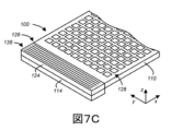
前述したように、いくつかの実施形態では、静的マルチビューディスプレイ100のコリメート光カプラ124は、円筒状格子カプラを含んでいてもよい。図7Aは、本明細書に記載の原理と一致する一実施形態による、一例における円筒状格子カプラを138含むコリメート光カプラ124の断面図を示す。図7Bは、本明細書に記載の原理と一致する別の実施形態による、一例における円筒状格子カプラ138を含むコリメート光カプラ124の断面図を示す。図7Cは、本明細書に記載の原理と一致する一実施形態による、一例における図7Bのコリメート光カプラ124の斜視図を示す。具体的には、図7A~図7Cは、ライトガイド110の入力端126付近における、静的マルチビューディスプレイ100の切欠き部分を示す。図7A~図7Bでは、光源114によって供給されるコリメートされた導波光ビーム112及び光122を描写するために、様々な破線を使用している。図7Cはさらに、回折格子128のアレイを示す(図示を簡単にするために、図7A~図7Bから省略してある)。
As previously mentioned, in some embodiments the collimating
図7A~図7Cでは、コリメート光カプラ124の円筒状格子カプラ138は、光122を、コリメートされた導波光ビーム112として静的マルチビューディスプレイ100のライトガイド110内へと結合するように構成されている。光122は、例えば光源114(例えば、実質的にコリメートされていない光源)によって供給されてもよい。様々な実施形態によれば、コリメート光カプラ124の円筒状格子カプラ138は、比較的高い結合効率をもたらすことができる。さらに、様々な実施形態によれば、円筒状格子カプラ138は、光122を、ライトガイド110内で所定のコリメーション係数を有するコリメートされた導波光ビーム112(例えば、導波光のビーム)へと変換することができる。
7A-7C, cylindrical
様々な例によれば、ライトガイド110内に、コリメート光カプラ124の円筒状格子カプラ138によって所定のコリメーション係数がもたらされることにより、制御された、又は所定の伝播特性を有するコリメートされた導波光ビーム112が発生することになり得る。具体的には、コリメート光カプラ124の円筒状格子カプラ138は、「垂直」方向、すなわち、ライトガイド110の表面の平面に垂直となる平面において、制御された、又は所定のコリメーション係数をもたらすことができる。さらに、光122は、ライトガイド平面に実質的に垂直となる角度で光源114から受光され、次いで、ライトガイド110内で伝播角度120、例えば、ライトガイド110内で内部全反射の臨界角度と一致しているか、又はそれ未満である伝播角度を有する、コリメートされた導波光ビーム112へと変換されてもよい。
According to various examples, within the
いくつかの実施形態によれば、円筒状格子カプラ138は透過モード回折格子であるか、又はこれを含んでいてもよく、その一方で他の実施形態では、円筒状格子カプラ138は反射モード回折格子であるか、又はこれを含んでいてもよい。具体的には、図7Aに示すように、円筒状格子カプラ138は、光源114に隣接するライトガイド110の表面に透過モード回折格子を含む。例えば、円筒状格子カプラ138の透過モード回折格子は、ライトガイド110の底部(又は第2の)表面136’’上にあってもよく、また光源114は、底部から円筒状格子カプラ138を照明してもよい。図7Aに示すように、円筒状格子カプラ138の透過モード回折格子は、透過モード回折格子を透過するか、又は通過する光122を回折的に方向変更させるように構成されている。光源114の発光体116の相対的位置を長手方向108に沿ってシフトすることにより、発光体の長手方向のずれがもたらされ、これにより、回折角度、すなわちライトガイド110内におけるコリメートされた導波光ビーム112の伝播角度120が変化する。
According to some embodiments, the cylindrical
図7Bに示すように、円筒状格子カプラ138は、光源114に隣接する表面の反対側にあるライトガイド110の表面に、反射モード回折格子を含む。例えば、円筒状格子カプラ138の反射モード回折格子は、ライトガイド110の上(又は第1の)面136’上にあってもよく、光源114は、ライトガイド110の底(又は第2の)面136’’の一部を介して、円筒状格子カプラ138を照明してもよい。反射モード回折格子は、図7Bに示すように、反射回折(すなわち、反射及び回折)を使用して、光122をライトガイド110内へと回折的に方向変更するように構成されている。
As shown in FIG. 7B, cylindrical
様々な例によれば、円筒状格子カプラ138の透過モード回折格子及び反射モード回折格子の両方は、ライトガイド110の表面136’又は136”の上若しくは中に形成されるか、あるいは設けられる溝、隆起、又は同様の回折特徴部を含んでいてもよい。例えば、溝又は隆起は、透過モード回折格子として機能するように、ライトガイド110の光源に隣接する表面136’’(例えば、底面又は第2の表面)の中又は上に形成されてもよい。同様に、例えば反射モード回折格子として機能するように、光源に隣接する表面136’’の反対側にあるライトガイド110の表面136’内若しくはその上に、溝又は隆起が形成されるか、あるいは設けられていてもよい。
According to various examples, both the transmission mode grating and the reflection mode grating of cylindrical
いくつかの実施形態によれば、円筒状格子カプラ138は、ライトガイド表面の上又は中に格子材料(例えば、格子材料の層)を含んでいてもよい。いくつかの実施形態では、この格子材料は、ライトガイド110の材料と実質的に同様であってもよく、その一方で他の実施形態では、この格子材料はライトガイド材料とは異なっていてもよい(例えば、屈折率が異なっている)。いくつかの実施形態では、ライトガイド表面の溝は、格子材料で充填されていてもよい。例えば、透過モード回折格子又は反射モード回折格子のいずれかにおける回折格子の溝は、ライトガイド110の材料とは異なる誘電体材料(すなわち、格子材料)で充填されていてもよい。いくつかの例によれば、円筒状格子カプラ138の格子材料は、例えば窒化ケイ素を含んでいてもよいが、ライトガイド110はガラスであってもよい。他の格子材料、例えば酸化インジウムスズ(ITO)を含むが、これに限定されない他の格子材料を同様に使用してもよい。
According to some embodiments, cylindrical
いくつかの例では、反射モード回折格子を含む円筒状格子カプラ138の格子材料は、反射金属又は同様の反射材料をさらに含んでいてもよい。例えば、反射モード回折格子は、自身による反射を促進するために、反射金属、例えば金、銀、アルミニウム、銅、及びスズなどであるが、これらに限定されない反射金属の層であるか、又はこれを含んでいてもよい。なお、いくつかの実施形態によれば、円筒状格子カプラ138の透過モード回折格子及び反射モード回折格子は、y方向に沿って均一又は少なくとも実質的に均一である。このことを図7Cに図示しており、図7Cは、円筒状格子カプラ138の反射モード回折格子の斜視図を示している。
In some examples, the grating material of cylindrical
いくつかの実施形態では、円筒状格子カプラ138は、ライトガイド110の一部をさらに含んでいてもよい。具体的には、上記の考察においてこれらの実施形態を説明している。他の実施形態では、円筒状格子カプラ138は、ライトガイド110の入力端126から離隔されているが、これに光学的に結合されている別のライトガイドを含む。しかしながら、上記の考察は、ライトガイド110の部分の代わりに、別のライトガイドを使用する際にも十分等しく当てはまるものである。
In some embodiments, cylindrical
図7A~図7Cでは、回折格子ベースの円筒状格子カプラ138の使用について図示しているが、他の実施形態では、他のタイプの光カプラをコリメート光カプラ124として使用してもよい。例えば、図8Aは、本明細書に記載の原理と一致する一実施形態による、一例における放物線状反射カプラ140を含むコリメート光カプラ124の断面図を示す。図8Bは、本明細書に記載の原理と一致する一実施形態による、一例における放物線状反射カプラ140を含むコリメート光カプラ124の斜視図を示す。図8Bに示すように、放物線状反射カプラ140は、y方向に沿って均一であってもよい。円筒状格子カプラ138と同様に、光源114内における発光体116の長手方向のずれは、コリメートされた導波光ビーム112の異なる伝播角度を、静的マルチビューディスプレイ100のライトガイド110内において供給するように構成されている。
7A-7C illustrate the use of a grating-based cylindrical
いくつかの実施形態では、静的マルチビューディスプレイ100は透過性であるか、又は実質的に透過性であってもよい。具体的には、いくつかの実施形態では、ライトガイド110及び回折格子128のアレイは、ライトガイド110の第1の表面136’及び第2の表面136’’の両方と直交している方向に、光が静的マルチビューディスプレイ100を通過できるようにしてもよい。すなわち、ライトガイド110及び回折格子128のアレイは、長手方向と直交している垂直方向に伝播する光に対して透過的であってもよい。したがって、ライトガイド110及び回折格子128のアレイ、又はより一般的には静的マルチビューディスプレイ100は、長手方向108と直交している垂直方向、すなわち、コリメートされた導波光ビーム112の全体的伝播方向に伝播する光に対して透過的であってもよい。さらに、回折格子128が実質的に透過性であることにより、また回折格子128間に間隔があることにより、少なくとも部分的にこうした透過性が促進され得る。
In some embodiments, static
本明細書に記載の原理によるいくつかの実施形態によれば、透過性の静的マルチビューディスプレイを提供する。本透過性の静的マルチビューディスプレイは、マルチビュー画像又は複数のマルチビュー画像を表示する、複数の指向性光ビームを出射するように構成されている。具体的には、出射されるこれらの指向性光ビームは、本透過性の静的マルチビューディスプレイにおける回折格子のアレイ内の回折格子の格子特性に基づいて、1つ又はそれ以上のマルチビュー画像の複数のビューへと選択的に向けられる。様々な例によれば、指向性光ビームの個々のビームは、マルチビュー画像と関連付けられた様々な「ビュー」の個々のビューピクセルに対応していてもよい。これらの様々なビューは、例えば本マルチビューディスプレイによって表示される1つ又はそれ以上のマルチビュー画像において、情報の「メガネなし」(例えば、自動立体)表示を実現することができる。 According to some embodiments according to the principles described herein, a transmissive static multi-view display is provided. The transmissive static multi-view display is configured to emit multiple directional light beams for displaying a multi-view image or multiple multi-view images. Specifically, these emitted directional light beams are directed to one or more multi-view images based on the grating properties of the gratings in the array of gratings in the present transmissive static multi-view display. selectively directed to multiple views of the According to various examples, individual beams of directional light beams may correspond to individual view pixels of various "views" associated with the multi-view image. These various views can provide a "glasses-free" (eg, autostereoscopic) display of information, eg, in one or more multi-view images displayed by the present multi-view display.
図9は、本明細書に記載の原理と一致する一実施形態による、一例における透過性の静的マルチビューディスプレイ200のブロック図を示す。様々な実施形態によれば、透過性の静的マルチビューディスプレイ200は、様々なビュー方向の個々のビューに従って、マルチビュー画像232を表示するように構成されている。また、マルチビュー画像232はある方向を有する。具体的には、透過性の静的マルチビューディスプレイ200によって出射される複数の指向性光ビーム202を使用して、マルチビュー画像232を表示しており、またこれらの指向性光ビーム202は、マルチビュー画像232の個々のビュー(例えば、Vi、V2…Vn)のピクセル(すなわち、ビューピクセル)に対応していてもよい。いくつかの実施形態によれば、複数のマルチビュー画像232を供給してもよく、これら複数のマルチビュー画像のうちのマルチビュー画像232はそれぞれ、関連付けられた方向を有する。指向性光ビーム202を、複数のマルチビュー画像において対応しているマルチビュー画像232(例えば、232a、232b、232c)の方向を指すブロック矢印として、図9では集合的に図示している。様々な実施形態によれば、透過性の静的マルチビューディスプレイ200は、その長さに沿って長手方向と直交している垂直方向に対して透過的である。
FIG. 9 shows a block diagram of an example transmissive static
図9に示す透過性の静的マルチビューディスプレイ200は、回折格子204のアレイを備える。回折格子アレイの回折格子204は、ライトガイド206内のコリメートされた導波光ビームからの光を回折的に外部に散乱させて、マルチビュー画像232を表示する複数の指向性光ビーム202を供給するように構成されている。いくつかの実施形態では、回折格子204のアレイは、静的マルチビューディスプレイ100に関して上記で説明した回折格子128のアレイと実質的に同様である。具体的には、回折格子アレイの回折格子204は、マルチビュー画像232のビューピクセルの強度及びビュー方向に対応している強度と主角度方向とを有する、複数の指向性光ビームのうちの1つの指向性光ビーム202を供給するように構成されていてもよい。いくつかの実施形態によれば、回折格子204の格子ピッチ及び格子方向は、指向性光ビーム202の主角度方向を決定するように構成されていてもよい。さらに、いくつかの実施形態によれば、回折格子204の格子深さは、指向性光ビーム202の強度を決定するように構成されていてもよい。
The transmissive static
図9に示すように、透過性の静的マルチビューディスプレイ200は、光源214をさらに備える。光源214は、長手方向に互いにずらして配置された複数の発光体を含む。様々な実施形態によれば、光源214の発光体は、長手方向における発光体のずれによって決まる伝播角度を有する、コリメートされた導波光ビームを供給するように構成されている。いくつかの実施形態によれば、光源214は、上記で説明した静的マルチビューディスプレイ100の光源114と実質的に同様であってもよい。具体的には、様々な実施形態によれば、マルチビュー画像232の方向は、コリメートされた導波光ビームの色及び伝播角度の両方の関数である。
As shown in FIG. 9, transmissive static
図9に示す透過性の静的マルチビューディスプレイ200は、ライトガイド206とコリメート光カプラ210とをさらに備える。具体的には、コリメート光カプラ210は、ライトガイド206の入力端に配置されていてもよい。コリメート光カプラ210は、光源214の発光体からの光212を、コリメートされた導波光ビームとしてライトガイドの入力端内へと結合するように構成されている。発光体のずれは、コリメート光カプラ210に対する発光体の長手方向の位置となる。図9の矢印208は、コリメート光カプラ210によって、コリメートされた導波光ビームがライトガイド206内へと結合される様子を表す。さらに、様々な実施形態によれば、ひとたびその中に結合されると、ライトガイド206内におけるコリメートされた導波光ビームの伝播方向が長手方向を規定する。
The transmissive static
いくつかの実施形態によれば、光源214の第1の発光体は、第1の伝播角度で第1のコリメートされた導波光ビームを供給するように構成された第1のずれを、長手方向において有していてもよい。さらに、光源214の第2の発光体は、ライトガイド206内で第2の伝播角度で、第2のコリメートされた導波光ビームを供給するように構成された第2のずれを、長手方向において有していてもよい。様々な実施形態によれば、第1の伝播角度は、マルチビュー画像232を第1の方向に供給するように構成され、また第2の伝播角度は、マルチビュー画像232を第2の方向に供給するように構成されている。
According to some embodiments, the first light emitter of
図9を参照すると、第1の方向に供給されるマルチビュー画像232を、マルチビュー画像232aによって表してもよいが、一方、マルチビュー画像232bは、例えば第2の方向にあるマルチビュー画像232を表してもよい。マルチビュー画像232cは、例えば第3の方向にあるマルチビュー画像232cを表してもよい。いくつかの実施形態によれば、マルチビュー画像232a、232b、232cは集合的に、図3A~図4Cを参照して上記で説明したマルチビュー画像132a、132b、132cと実質的に同様であってもよい。例えば、異なるずれで個々の発光体を順次かつ選択的に照明することにより、マルチビュー画像132a、132b、132cの動画又は見かけ上の運動が時間の関数としてもたらされ、その結果、透過性の静的マルチビューディスプレイ200が準静的マルチビューディスプレイとして機能するようにしてもよい。
Referring to FIG. 9,
いくつかの実施形態によれば、光源214の第1の発光体は、第1の色の光を供給するように構成されていてもよく、また光源214の第2の発光体は、第2の色の光を供給するように構成されていてもよい。さらに、第1及び第2の発光体は、第1及び第2の色の結合を含む合成マルチビュー画像(図示せず)を供給するように構成されたずれを有していてもよい。例えば、透過性の静的マルチビューディスプレイ200によって供給される色の結合を含む合成マルチビュー画像は、図5に関して上記で説明したように、静的マルチビューディスプレイ100によって供給される合成マルチビュー画像132dと実質的に同様であってもよい。
According to some embodiments, a first light emitter of
本明細書に記載の原理による他の実施形態によれば、静的マルチビューディスプレイの動作方法を提供している。図10は、本明細書に記載の原理と一致する一実施形態による、一例における静的マルチビューディスプレイの動作方法300を表すフローチャートを示す。図10に示すように、静的マルチビューディスプレイの動作方法300は、複数の発光体のうちの1つの発光体を使用して、ある色を有する光を供給すること310を含み、これら複数の発光体のうちの発光体は、長手方向に互いにずらして配置されている。いくつかの実施形態によれば、これら複数の発光体は、静的マルチビューディスプレイ100に関して上記で説明した光源114の複数の発光体116と、実質的に同様であってもよい。さらに、310で供給される光は、これも上記で説明した光122と実質的に同様であってもよい。
According to another embodiment of the principles described herein, a method of operating a static multi-view display is provided. FIG. 10 shows a flowchart representing a
図10に示す静的マルチビューディスプレイの動作方法300は、コリメート光カプラを使用して、光をコリメートされた導波光ビームとしてライトガイド内へと結合すること320をさらに含む。様々な実施形態によれば、これらのコリメートされた導波光ビームは、発光体の長手方向のずれによって決まる伝播角度を有する。いくつかの実施形態によれば、コリメート光カプラは、上記で説明した静的マルチビューディスプレイ100のコリメート光カプラ124と実質的に同様であってもよい。例えば、このコリメート光カプラは、様々なコリメート光カプラ、例えば円筒状格子カプラを含むがこれに限定されない様々なコリメート光カプラのいずれかを含んでいてもよい。
The
さらに、図示しているように、静的マルチビューディスプレイの動作方法300は、回折格子のアレイを使用して、コリメートされた導波光ビームの一部を外部に散乱させることにより、マルチビュー画像を表示する複数の指向性光ビームを供給すること330を含む。様々な実施形態によれば、マルチビュー画像の方向は、コリメートされた導波光ビームの色及び伝播角度の両方の関数である。いくつかの実施形態では、回折格子のアレイは、上記で説明した静的マルチビューディスプレイ100の回折格子128のアレイと実質的に同様であってもよい。
Further, as shown, the
いくつかの実施形態によれば、具体的には回折格子アレイの回折格子は、コリメートされた導波光ビームの一部を、マルチビュー画像のビューピクセルの強度及びビュー方向に対応している強度と主角度方向とを有する、複数の指向性光ビームのうちの1つの指向性光ビームとして、外部に散乱させている330。さらに、回折格子の格子ピッチ及び格子方向は、指向性光ビームの主角度方向を決定するように構成されていてもよい。同様に、いくつかの実施形態によれば、回折格子の格子深さは、指向性光ビームの強度を決定するように構成されていてもよい。 According to some embodiments, the gratings, in particular of the grating array, divide the portion of the collimated guided light beams with intensities corresponding to the intensities of the view pixels and the view direction of the multi-view image. outwardly scattering 330 as a directional light beam of a plurality of directional light beams having a principal angular direction. Additionally, the grating pitch and grating direction of the diffraction grating may be configured to determine the principal angular direction of the directional light beam. Similarly, according to some embodiments, the grating depth of the diffraction grating may be configured to determine the intensity of the directional light beam.
いくつかの実施形態では、ライトガイドと、コリメート光カプラと、回折格子のアレイとを備える本静的マルチビューディスプレイは、長手方向と直交している垂直方向に伝播する光に対して透過的である。例えば、本静的マルチビューディスプレイは、上記で説明した透過性の静的マルチビューディスプレイ200と実質的に同様であってもよい。したがって、静的マルチビューディスプレイの動作方法300は、透過性の静的マルチビューディスプレイを動作させる方法であってもよい。
In some embodiments, the present static multi-view display comprising a light guide, a collimating optical coupler, and an array of diffraction gratings is transparent to light propagating in a direction perpendicular to the longitudinal direction. be. For example, the static multi-view display may be substantially similar to transmissive static
いくつかの実施形態(図示せず)では、静的マルチビューディスプレイの動作方法300は、複数の発光体のうちの第1の発光体を使用して光を供給することにより、第1の方向に第1のマルチビュー画像を生成することをさらに含んでいてもよく、この第1の発光体は第1の長手方向のずれを有する。さらに、静的マルチビューディスプレイの動作方法300は、複数の発光体のうちの第2の発光体を使用して光を供給することにより、第2の方向に第2のマルチビュー画像を生成することを含んでいてもよく、この第2の発光体は第2の長手方向のずれを有する。例えば時系列的に第1及び第2のマルチビュー画像を生成することにより、本静的マルチビューディスプレイが、例えばマルチビュー画像の動画をもたらすことができ得る。したがって、静的マルチビューディスプレイの動作方法300は、準静的マルチビューディスプレイの動作をもたらすことができる。
In some embodiments (not shown), the
いくつかの実施形態(図示せず)では、静的マルチビューディスプレイの動作方法300は、複数の発光体のうちの第1の発光体を使用して、第1の色を有する光を供給することにより、第1のマルチビュー画像を生成することをさらに含んでいてもよく、この第1の発光体は第1の長手方向のずれを有する。また、静的マルチビューディスプレイの動作方法300は、複数の発光体のうちの第2の発光体を使用して、第2の色を有する光を供給することにより、第2のマルチビュー画像を生成することをさらに含んでいてもよく、この第2の発光体は第2の長手方向のずれを有する。様々な実施形態によれば、これら第1及び第2の長手方向のずれは、第1及び第2のマルチビュー画像の結合を含む、合成マルチビュー画像を供給するように選択されてもよい。この合成画像の色は、例えば第1の色と第2の色とを結合したものであってもよい。いくつかの実施形態では、この合成マルチビュー画像は、図5に関して上記で説明した静的マルチビューディスプレイ100によって供給される合成マルチビュー画像134dと、実質的に同様であってもよい。
In some embodiments (not shown), the static multi-view
このように、回折格子を使用してマルチビュー画像を表示する指向性光ビームを供給する、静的マルチビューディスプレイ及び静的マルチビューディスプレイの動作方法の例と実施形態とについて説明してきた。また、光源における発光体の相対的なずれは、マルチビュー画像の方向をもたらす。上記で説明した例は、本明細書に記載の原理を表す多くの特定の例のうちのいくつかを単に例示するものに過ぎないことを理解すべきである。当業者であれば、以下の特許請求の範囲によって定義されている範囲から逸脱することなく、他の数多くの構成を容易に考案できることは明らかである。
Thus, examples and embodiments of static multi-view displays and methods of operating static multi-view displays have been described that use diffraction gratings to provide directional light beams for displaying multi-view images. Also, the relative displacement of the emitters in the light source provides the orientation of the multi-view image. It should be understood that the examples described above are merely illustrative of a few of the many specific examples that illustrate the principles described herein. Clearly, those skilled in the art can readily devise numerous other arrangements without departing from the scope defined by the following claims.
Claims (21)
前記長手方向に互いにずらして配置され、かつ前記ライトガイドに光学的に結合されている複数の発光体(a plurality of optical emitters)を含む光源であって、前記光源の発光体(an optical emitter)は、前記ライトガイド内に、前記発光体の長手方向のずれによって決まる伝播角度を有する、コリメートされた導波光ビーム(a collimated guided light beam)を供給するように構成されている、光源と、
前記コリメートされた導波光ビーム(the collimated guided light beam)の一部を、マルチビュー画像を表示する複数の指向性光ビームとして外部に散乱させるように構成された回折格子のアレイであって、前記マルチビュー画像の方向が、前記コリメートされた導波光ビームの色及び前記伝播角度の両方の関数である、回折格子のアレイと、を備える、静的マルチビューディスプレイであって、
複数の異なるビューとしてであっても、所定のまたは固定のマルチビュー画像を表示するように構成されており、
さらに、時間の関数として、異なる所定のまたは固定のマルチビュー画像間で切り替えられるように構成されている、静的マルチビューディスプレイ。 a light guide configured to guide light longitudinally;
a light source comprising a plurality of optical emitters staggered in the longitudinal direction and optically coupled to the light guide, wherein an optical emitter is a light source configured to provide within the light guide a collimated guided light beam having a propagation angle determined by the longitudinal displacement of the light emitter;
an array of diffraction gratings configured to scatter a portion of the collimated guided light beam outwardly as a plurality of directional light beams displaying a multi-view image; an array of diffraction gratings, wherein the direction of the multi-view image is a function of both the color of the collimated guided light beams and the angle of propagation;
configured to display a predetermined or fixed multi-view image, even as multiple different views;
Furthermore, a static multi-view display configured to switch between different predetermined or fixed multi-view images as a function of time.
長手方向に互いにずらして配置された複数の発光体(a plurality of optical emitters)を含む光源であって、前記光源の発光体(an optical emitter)は、前記長手方向における前記発光体のずれによって決まる伝播角度を有する、前記コリメートされた導波光ビーム(the collimated guided light beam)を供給するように構成されている、光源と、を備える、透過性の静的マルチビューディスプレイであって、
前記マルチビュー画像の方向が、前記コリメートされた導波光ビームの色及び前記伝播角度の両方の関数であり、前記透過性の静的マルチビューディスプレイが、前記長手方向と直交している垂直方向に対して透過的であり、
前記透過性の静的マルチビューディスプレイが、複数の異なるビューとしてであっても、所定のまたは固定のマルチビュー画像を表示するように構成されており、さらに、時間の関数として、異なる所定のまたは固定のマルチビュー画像間で切り替えられるように構成されている、透過性の静的マルチビューディスプレイ。 configured to diffractively scatter light from a collimated guided light beam within a light guide to provide multiple directional light beams for displaying a multi-view image; an array of diffraction gratings;
A light source comprising a plurality of optical emitters staggered in the longitudinal direction, wherein an optical emitter of the light source is determined by the displacement of the light emitters in the longitudinal direction. a light source configured to provide the collimated guided light beam having a propagation angle, the static transmissive multi-view display comprising:
wherein the direction of the multi-view image is a function of both the color of the collimated guided light beam and the angle of propagation, and the transmissive static multi-view display is oriented in a vertical direction orthogonal to the longitudinal direction; transparent to
The transmissive static multi-view display is configured to display a predetermined or fixed multi-view image, even as a plurality of different views, and a different predetermined or fixed view image as a function of time. is a translucent static multiview display configured to be switched between fixed multiview images.
コリメート光カプラ(a collimating light coupler)を使用して、前記光をコリメートされた導波光ビーム(collimated guided light beams)としてライトガイド内へと結合するステップであって、前記コリメートされた導波光ビームは、前記発光体の長手方向のずれによって決まる伝播角度を有する、結合するステップと、
回折格子のアレイを使用して、前記コリメートされた導波光ビーム(the collimated guided light beam)の一部を外部に散乱させることにより、マルチビュー画像を表示する複数の指向性光ビームを供給するステップであって、前記マルチビュー画像の方向は、前記コリメートされた導波光ビームの前記色及び前記伝播角度の両方の関数である、供給するステップと、を含む、静的マルチビューディスプレイの動作方法であって、
前記静的マルチビューディスプレイが、複数の異なるビューとしてであっても、所定のまたは固定のマルチビュー画像を表示するように構成されており、さらに、時間の関数として、異なる所定のまたは固定のマルチビュー画像間で切り替えられるように構成されている、静的マルチビューディスプレイの動作方法。 providing light having a color using an optical emitter of a plurality of optical emitters, the optical emitters being longitudinally offset from each other; a providing step disposed;
coupling said light as collimated guided light beams into a light guide using a collimating light coupler, said collimated guided light beams comprising: , with a propagation angle determined by the longitudinal displacement of the light emitters;
Outwardly scattering a portion of the collimated guided light beam using an array of diffraction gratings to provide a plurality of directional light beams for displaying a multi-view image. wherein the direction of the multi-view image is a function of both the color and the propagation angle of the collimated guided light beams. There is
The static multi-view display is configured to display a predetermined or fixed multi-view image, even as a plurality of different views; A method of operating a static multi-view display configured to switch between multi-view images.
前記複数の発光体の第2の発光体を使用して光を供給することにより、第2のマルチビュー画像を生成するステップであって、前記第2の発光体が第2の長手方向のずれを有する、生成するステップと
をさらに含む、請求項17から19のいずれか一項に記載の静的マルチビューディスプレイの動作方法。 generating a first multi-view image by providing light using a first light emitter of said plurality of light emitters, said first light emitter having a first longitudinal displacement and a step of generating
generating a second multi-view image by providing light using a second light emitter of said plurality of light emitters, said second light emitter having a second longitudinal offset; 20. A method of operating a static multi-view display according to any one of claims 17 to 19, further comprising the step of generating a .
前記複数の発光体の第2の発光体を使用して、第2の色を有する光を供給することにより、第2のマルチビュー画像を生成するステップであって、前記第2の発光体が第2の長手方向のずれを有する、生成するステップと
をさらに含み、
前記第1及び第2の長手方向のずれが、前記第1及び第2のマルチビュー画像の結合を含む、合成マルチビュー画像を供給するように選択されており、前記合成画像の色が、前記第1の色と第2の色とを結合したものである、
請求項17から20のいずれか一項に記載の静的マルチビューディスプレイの動作方法。 generating a first multi-view image by providing light having a first color using a first light emitter of said plurality of light emitters, said first light emitter generating with a first longitudinal offset;
generating a second multi-view image by providing light having a second color using a second light emitter of said plurality of light emitters, said second light emitter comprising having a second longitudinal offset, and
wherein the first and second longitudinal offsets are selected to provide a composite multi-view image comprising a combination of the first and second multi-view images, the colors of the composite image being the is a combination of a first color and a second color,
Method of operating a static multi-view display according to any one of claims 17-20.
Applications Claiming Priority (1)
| Application Number | Priority Date | Filing Date | Title |
|---|---|---|---|
| PCT/US2018/020541 WO2019168538A1 (en) | 2018-03-01 | 2018-03-01 | Static multiview display and method employing collimated guided light |
Publications (2)
| Publication Number | Publication Date |
|---|---|
| JP2021516362A JP2021516362A (en) | 2021-07-01 |
| JP7217281B2 true JP7217281B2 (en) | 2023-02-02 |
Family
ID=67806265
Family Applications (1)
| Application Number | Title | Priority Date | Filing Date |
|---|---|---|---|
| JP2020545339A Active JP7217281B2 (en) | 2018-03-01 | 2018-03-01 | Method using static multi-view display and collimated guided light |
Country Status (8)
| Country | Link |
|---|---|
| US (1) | US11360259B2 (en) |
| EP (1) | EP3735557A4 (en) |
| JP (1) | JP7217281B2 (en) |
| KR (1) | KR102479674B1 (en) |
| CN (1) | CN111801526B (en) |
| CA (1) | CA3089955C (en) |
| TW (1) | TWI699563B (en) |
| WO (1) | WO2019168538A1 (en) |
Families Citing this family (6)
| Publication number | Priority date | Publication date | Assignee | Title |
|---|---|---|---|---|
| EP3688370A4 (en) | 2017-09-27 | 2021-04-28 | LEIA Inc. | Multicolor static multiview display and method |
| KR20200040928A (en) | 2017-09-28 | 2020-04-20 | 레이아 인코포레이티드 | Grid-coupled light guides using condensing, display systems, and methods |
| JP7128354B2 (en) | 2018-10-15 | 2022-08-30 | レイア、インコーポレイテッド | Backlight with grid spreader, multi-view display, and method |
| CN109343243B (en) * | 2018-11-16 | 2020-11-24 | 京东方科技集团股份有限公司 | Light modulation device and single-channel spectrum detection system |
| CN115210634A (en) * | 2020-03-02 | 2022-10-18 | 镭亚股份有限公司 | Static image enhanced privacy display, privacy display system with switchable modes and method |
| WO2023048768A1 (en) * | 2021-09-25 | 2023-03-30 | Leia Inc. | Static color multiview display and method |
Citations (4)
| Publication number | Priority date | Publication date | Assignee | Title |
|---|---|---|---|---|
| JP2015531075A (en) | 2012-05-31 | 2015-10-29 | レイア インコーポレイテッド | Directional backlight |
| JP2016130833A (en) | 2015-01-13 | 2016-07-21 | オムロン株式会社 | Optical device, optical system, and ticket examination machine |
| WO2017039725A1 (en) | 2015-09-05 | 2017-03-09 | Leia Inc. | Dual-direction collimator |
| JP2017525115A (en) | 2014-07-30 | 2017-08-31 | レイア、インコーポレイテッドLeia Inc. | Multi-beam diffraction grating based color backlighting |
Family Cites Families (39)
| Publication number | Priority date | Publication date | Assignee | Title |
|---|---|---|---|---|
| BR9106868A (en) * | 1990-09-20 | 1993-07-06 | Ilumination Research Group Pro | A DISPLAY SYSTEM |
| US5561558A (en) | 1993-10-18 | 1996-10-01 | Matsushita Electric Industrial Co., Ltd. | Diffractive optical device |
| FI106323B (en) | 1998-12-30 | 2001-01-15 | Nokia Mobile Phones Ltd | Backlight light guide for flat screen |
| DE60030541T2 (en) * | 2000-01-06 | 2007-08-30 | Koninklijke Philips Electronics N.V. | LIGHT AND LIGHT PANELS |
| TWI282446B (en) | 2003-12-05 | 2007-06-11 | Hon Hai Prec Ind Co Ltd | Light guide plate and backlight device using the same |
| JP4990275B2 (en) | 2006-05-18 | 2012-08-01 | パナソニック株式会社 | Planar light source device and liquid crystal display device |
| US20110002143A1 (en) | 2006-12-28 | 2011-01-06 | Nokia Corporation | Light guide plate and a method of manufacturing thereof |
| TWI363900B (en) | 2007-10-04 | 2012-05-11 | Ind Tech Res Inst | Light guiding film |
| WO2010010749A1 (en) | 2008-07-22 | 2010-01-28 | シャープ株式会社 | Backlight unit and liquid crystal display device |
| US20100141868A1 (en) | 2008-10-21 | 2010-06-10 | Holox Technologies, Inc. | Replicated bragg selective diffractive element for display illumination |
| EP2419772A2 (en) | 2009-04-16 | 2012-02-22 | Koninklijke Philips Electronics N.V. | A light guide apparatus |
| KR101680770B1 (en) | 2010-07-09 | 2016-11-29 | 삼성전자주식회사 | Back light unit and display apparatus employing the same |
| WO2012038856A1 (en) | 2010-09-21 | 2012-03-29 | Koninklijke Philips Electronics N.V. | Multi-view display device |
| US8585268B2 (en) | 2011-10-21 | 2013-11-19 | Ergophos, Llc | Light-guide panel for display with laser backlight |
| US9389415B2 (en) | 2012-04-27 | 2016-07-12 | Leia Inc. | Directional pixel for use in a display screen |
| US9459461B2 (en) * | 2012-05-31 | 2016-10-04 | Leia Inc. | Directional backlight |
| US9201270B2 (en) | 2012-06-01 | 2015-12-01 | Leia Inc. | Directional backlight with a modulation layer |
| US8944662B2 (en) * | 2012-08-13 | 2015-02-03 | 3M Innovative Properties Company | Diffractive luminaires |
| US8834004B2 (en) | 2012-08-13 | 2014-09-16 | 3M Innovative Properties Company | Lighting devices with patterned printing of diffractive extraction features |
| US8807817B2 (en) | 2012-08-13 | 2014-08-19 | 3M Innovative Properties Company | Colorful diffractive luminaires providing white light illumination |
| US9298168B2 (en) | 2013-01-31 | 2016-03-29 | Leia Inc. | Multiview 3D wrist watch |
| US20160018582A1 (en) * | 2013-03-13 | 2016-01-21 | Hewlett-Packard Development Company, L.P. | Backlight having collimating reflector |
| WO2015016844A1 (en) * | 2013-07-30 | 2015-02-05 | Leia Inc. | Multibeam diffraction grating-based backlighting |
| US20160033784A1 (en) * | 2014-07-30 | 2016-02-04 | Tapani Levola | Optical Components |
| US9557466B2 (en) | 2014-07-30 | 2017-01-31 | Leia, Inc | Multibeam diffraction grating-based color backlighting |
| JP6331020B2 (en) * | 2014-09-03 | 2018-05-30 | パナソニックIpマネジメント株式会社 | Light guide plate display device |
| CN104460115B (en) * | 2014-12-31 | 2017-09-01 | 苏州大学 | A kind of various visual angles pixel directing backlight module and bore hole 3D display device |
| JP6507250B2 (en) | 2015-01-10 | 2019-04-24 | レイア、インコーポレイテッドLeia Inc. | Lattice coupling type light guide |
| WO2016111709A1 (en) * | 2015-01-10 | 2016-07-14 | Leia Inc. | Diffraction grating-based backlighting having controlled diffractive coupling efficiency |
| PT3295242T (en) * | 2015-05-09 | 2020-07-31 | Leia Inc | Color-scanning grating-based backlight and electronic display using same |
| KR102335719B1 (en) * | 2015-09-05 | 2021-12-06 | 레이아 인코포레이티드 | Time-multiplexed backlight and multi-view display using same |
| WO2017039750A1 (en) * | 2015-09-05 | 2017-03-09 | Leia Inc. | Polychromatic grating-coupled backlighting |
| JP6987044B2 (en) | 2015-09-05 | 2021-12-22 | レイア、インコーポレイテッドLeia Inc. | Two-sided collimator and 3D electronic display with grid-based rear lighting using the collimator |
| CN105487239B (en) | 2015-11-13 | 2018-03-02 | 苏州苏大维格光电科技股份有限公司 | Directive property colored filter and bore hole 3D display device |
| CA3027156C (en) | 2016-07-26 | 2021-05-25 | Leia Inc. | Bar collimator, backlight system and method |
| JP6798372B2 (en) * | 2017-03-14 | 2020-12-09 | オムロン株式会社 | Light guide, display device and game machine |
| KR20200040928A (en) | 2017-09-28 | 2020-04-20 | 레이아 인코포레이티드 | Grid-coupled light guides using condensing, display systems, and methods |
| EP3514784A4 (en) * | 2017-11-22 | 2020-07-29 | Liang, Yuexing | Layered dynamic image display device |
| CN111239878A (en) * | 2018-11-09 | 2020-06-05 | 英属开曼群岛商音飞光电科技股份有限公司 | Grating plate device |
-
2018
- 2018-03-01 KR KR1020207023909A patent/KR102479674B1/en active IP Right Grant
- 2018-03-01 CA CA3089955A patent/CA3089955C/en active Active
- 2018-03-01 CN CN201880090612.0A patent/CN111801526B/en active Active
- 2018-03-01 EP EP18908238.1A patent/EP3735557A4/en active Pending
- 2018-03-01 JP JP2020545339A patent/JP7217281B2/en active Active
- 2018-03-01 WO PCT/US2018/020541 patent/WO2019168538A1/en unknown
-
2019
- 2019-02-26 TW TW108106506A patent/TWI699563B/en active
-
2020
- 2020-08-21 US US17/000,107 patent/US11360259B2/en active Active
Patent Citations (4)
| Publication number | Priority date | Publication date | Assignee | Title |
|---|---|---|---|---|
| JP2015531075A (en) | 2012-05-31 | 2015-10-29 | レイア インコーポレイテッド | Directional backlight |
| JP2017525115A (en) | 2014-07-30 | 2017-08-31 | レイア、インコーポレイテッドLeia Inc. | Multi-beam diffraction grating based color backlighting |
| JP2016130833A (en) | 2015-01-13 | 2016-07-21 | オムロン株式会社 | Optical device, optical system, and ticket examination machine |
| WO2017039725A1 (en) | 2015-09-05 | 2017-03-09 | Leia Inc. | Dual-direction collimator |
Also Published As
| Publication number | Publication date |
|---|---|
| EP3735557A4 (en) | 2021-08-25 |
| KR20200101995A (en) | 2020-08-28 |
| TWI699563B (en) | 2020-07-21 |
| US20200386937A1 (en) | 2020-12-10 |
| EP3735557A1 (en) | 2020-11-11 |
| JP2021516362A (en) | 2021-07-01 |
| US11360259B2 (en) | 2022-06-14 |
| KR102479674B1 (en) | 2022-12-21 |
| CN111801526B (en) | 2023-06-02 |
| WO2019168538A1 (en) | 2019-09-06 |
| CA3089955C (en) | 2022-10-18 |
| TW201942601A (en) | 2019-11-01 |
| CA3089955A1 (en) | 2019-09-06 |
| CN111801526A (en) | 2020-10-20 |
Similar Documents
| Publication | Publication Date | Title |
|---|---|---|
| JP7217281B2 (en) | Method using static multi-view display and collimated guided light | |
| EP3566003B1 (en) | Static multiview display and method | |
| JP2019511079A (en) | Multi-beam element type backlight and display using the same | |
| KR102322331B1 (en) | Backlit, multi-view display and method employing tapered collimator | |
| JP2020506507A (en) | Multi-view backlight with color-adjusted emission pattern | |
| US11256022B2 (en) | Polarization recycling backlight, method and multiview display employing subwavelength gratings | |
| US11906761B2 (en) | Multicolor static multiview display and method | |
| JP7308267B2 (en) | Static multi-view display and method using directional light source and planar diffuser | |
| US20210302630A1 (en) | Static multiview display and method having multiview zones | |
| JP7128354B2 (en) | Backlight with grid spreader, multi-view display, and method | |
| JP7317140B2 (en) | Static multi-view display and method with diagonal parallax | |
| JP7256830B2 (en) | Multi-view display and method using dynamically reconfigurable multi-view pixels |
Legal Events
| Date | Code | Title | Description |
|---|---|---|---|
| A521 | Request for written amendment filed |
Free format text: JAPANESE INTERMEDIATE CODE: A523 Effective date: 20201001 |
|
| A621 | Written request for application examination |
Free format text: JAPANESE INTERMEDIATE CODE: A621 Effective date: 20201001 |
|
| A977 | Report on retrieval |
Free format text: JAPANESE INTERMEDIATE CODE: A971007 Effective date: 20211027 |
|
| A131 | Notification of reasons for refusal |
Free format text: JAPANESE INTERMEDIATE CODE: A131 Effective date: 20211102 |
|
| A521 | Request for written amendment filed |
Free format text: JAPANESE INTERMEDIATE CODE: A523 Effective date: 20220202 |
|
| A131 | Notification of reasons for refusal |
Free format text: JAPANESE INTERMEDIATE CODE: A131 Effective date: 20220614 |
|
| A521 | Request for written amendment filed |
Free format text: JAPANESE INTERMEDIATE CODE: A523 Effective date: 20220909 |
|
| A131 | Notification of reasons for refusal |
Free format text: JAPANESE INTERMEDIATE CODE: A131 Effective date: 20221004 |
|
| A521 | Request for written amendment filed |
Free format text: JAPANESE INTERMEDIATE CODE: A523 Effective date: 20221226 |
|
| TRDD | Decision of grant or rejection written | ||
| A01 | Written decision to grant a patent or to grant a registration (utility model) |
Free format text: JAPANESE INTERMEDIATE CODE: A01 Effective date: 20230117 |
|
| A61 | First payment of annual fees (during grant procedure) |
Free format text: JAPANESE INTERMEDIATE CODE: A61 Effective date: 20230123 |
|
| R150 | Certificate of patent or registration of utility model |
Ref document number: 7217281 Country of ref document: JP Free format text: JAPANESE INTERMEDIATE CODE: R150 |