JP7215440B2 - gas sensor element - Google Patents

gas sensor element Download PDF

Info

Publication number
JP7215440B2
JP7215440B2 JP2020018041A JP2020018041A JP7215440B2 JP 7215440 B2 JP7215440 B2 JP 7215440B2 JP 2020018041 A JP2020018041 A JP 2020018041A JP 2020018041 A JP2020018041 A JP 2020018041A JP 7215440 B2 JP7215440 B2 JP 7215440B2
Authority
JP
Japan
Prior art keywords
chamber
sensor element
gas sensor
heater
duct
Prior art date
Legal status (The legal status is an assumption and is not a legal conclusion. Google has not performed a legal analysis and makes no representation as to the accuracy of the status listed.)
Active
Application number
JP2020018041A
Other languages
Japanese (ja)
Other versions
JP2021124389A5 (en
JP2021124389A (en
Inventor
啓 杉浦
真 野口
Current Assignee (The listed assignees may be inaccurate. Google has not performed a legal analysis and makes no representation or warranty as to the accuracy of the list.)
Denso Corp
Original Assignee
Denso Corp
Priority date (The priority date is an assumption and is not a legal conclusion. Google has not performed a legal analysis and makes no representation as to the accuracy of the date listed.)
Filing date
Publication date
Application filed by Denso Corp filed Critical Denso Corp
Priority to JP2020018041A priority Critical patent/JP7215440B2/en
Priority to PCT/JP2021/002165 priority patent/WO2021157378A1/en
Priority to DE112021000870.6T priority patent/DE112021000870T5/en
Priority to CN202180012975.4A priority patent/CN115053127A/en
Publication of JP2021124389A publication Critical patent/JP2021124389A/en
Publication of JP2021124389A5 publication Critical patent/JP2021124389A5/ja
Priority to US17/880,995 priority patent/US20220373504A1/en
Application granted granted Critical
Publication of JP7215440B2 publication Critical patent/JP7215440B2/en
Active legal-status Critical Current
Anticipated expiration legal-status Critical

Links

Images

Classifications

    • GPHYSICS
    • G01MEASURING; TESTING
    • G01NINVESTIGATING OR ANALYSING MATERIALS BY DETERMINING THEIR CHEMICAL OR PHYSICAL PROPERTIES
    • G01N27/00Investigating or analysing materials by the use of electric, electrochemical, or magnetic means
    • G01N27/26Investigating or analysing materials by the use of electric, electrochemical, or magnetic means by investigating electrochemical variables; by using electrolysis or electrophoresis
    • G01N27/403Cells and electrode assemblies
    • G01N27/406Cells and probes with solid electrolytes
    • G01N27/407Cells and probes with solid electrolytes for investigating or analysing gases
    • G01N27/4071Cells and probes with solid electrolytes for investigating or analysing gases using sensor elements of laminated structure
    • GPHYSICS
    • G01MEASURING; TESTING
    • G01NINVESTIGATING OR ANALYSING MATERIALS BY DETERMINING THEIR CHEMICAL OR PHYSICAL PROPERTIES
    • G01N27/00Investigating or analysing materials by the use of electric, electrochemical, or magnetic means
    • G01N27/26Investigating or analysing materials by the use of electric, electrochemical, or magnetic means by investigating electrochemical variables; by using electrolysis or electrophoresis
    • G01N27/403Cells and electrode assemblies
    • G01N27/406Cells and probes with solid electrolytes
    • G01N27/4067Means for heating or controlling the temperature of the solid electrolyte
    • GPHYSICS
    • G01MEASURING; TESTING
    • G01NINVESTIGATING OR ANALYSING MATERIALS BY DETERMINING THEIR CHEMICAL OR PHYSICAL PROPERTIES
    • G01N27/00Investigating or analysing materials by the use of electric, electrochemical, or magnetic means
    • G01N27/26Investigating or analysing materials by the use of electric, electrochemical, or magnetic means by investigating electrochemical variables; by using electrolysis or electrophoresis
    • G01N27/403Cells and electrode assemblies
    • G01N27/406Cells and probes with solid electrolytes
    • G01N27/407Cells and probes with solid electrolytes for investigating or analysing gases
    • G01N27/4077Means for protecting the electrolyte or the electrodes

Description

本発明は、積層型のガスセンサ素子に関する。 The present invention relates to a laminated gas sensor element.

複数のセラミック層を積層してなる積層型のガスセンサ素子として、被測定ガスを導入するチャンバを備えたものが、例えば特許文献1に開示されている。 Japanese Laid-Open Patent Application Publication No. 2002-300003 discloses, for example, a laminated gas sensor element having a chamber for introducing a gas to be measured as a laminated gas sensor element formed by laminating a plurality of ceramic layers.

特開2010-261727号公報JP 2010-261727 A

しかしながら、特許文献1に記載のガスセンサ素子においては、チャンバの幅方向の両端に突出した角部が形成されている。ガスセンサ素子の構造によっては、ヒータによる昇温時等において、積層方向における温度差が生じる。この温度差が顕著に発生すると、温度差に起因する引張応力がチャンバの角部に隣接するセラミック層に作用して、素子割れの要因となることが懸念される。 However, in the gas sensor element described in Patent Document 1, protruding corners are formed at both ends in the width direction of the chamber. Depending on the structure of the gas sensor element, a temperature difference occurs in the stacking direction when the temperature is raised by a heater. If this temperature difference occurs significantly, there is concern that the tensile stress caused by the temperature difference will act on the ceramic layers adjacent to the corners of the chamber, causing element cracking.

本発明は、かかる課題に鑑みてなされたものであり、素子割れを効果的に防ぐことができるガスセンサ素子を提供しようとするものである。 SUMMARY OF THE INVENTION The present invention has been made in view of such problems, and an object of the present invention is to provide a gas sensor element that can effectively prevent element cracking.

本発明の一態様は、複数のセラミック層を積層してなる積層型のガスセンサ素子(1)であって、
酸素イオン伝導性を有する固体電解質体(2)と、
該固体電解質体の両主面に設けられた測定電極(31)及び基準電極(32)と、
上記測定電極に面し被測定ガスを導入するチャンバ(4)と、
上記固体電解質体を加熱するヒータ(5)と、を有し、
上記チャンバは、上記ガスセンサ素子の長手方向(Y)に直交する断面において、長手方向及び積層方向(Z)の双方に直交する幅方向(W)に突出した突出角部(43)を有し、
該突出角部の頂点(433)は、積層方向における上記チャンバの中心(4C)よりも上記ヒータに近い側に配置されており、
上記基準電極に面し基準ガスが導入されるダクト(6)を有し、積層方向において上記ダクトを挟んで上記固体電解質体と反対側に上記ヒータが配されており、
上記チャンバは上記ダクトよりも幅方向の寸法が大きく、
上記チャンバの幅Wcと、上記ダクトの幅Wdとは、1<Wc/Wd≦1.73を満たす、ガスセンサ素子にある。
One aspect of the present invention is a laminated gas sensor element (1) formed by laminating a plurality of ceramic layers,
a solid electrolyte body (2) having oxygen ion conductivity;
a measurement electrode (31) and a reference electrode (32) provided on both main surfaces of the solid electrolyte body;
a chamber (4) facing the measuring electrode and introducing a gas to be measured;
a heater (5) for heating the solid electrolyte body,
The chamber has a projecting corner (43) projecting in a width direction (W) orthogonal to both the longitudinal direction and the stacking direction (Z) in a cross section orthogonal to the longitudinal direction (Y) of the gas sensor element,
The vertex (433) of the protruding corner is arranged closer to the heater than the center (4C) of the chamber in the stacking direction ,
having a duct (6) facing the reference electrode and into which a reference gas is introduced, the heater being arranged on the side opposite to the solid electrolyte body with the duct interposed in the stacking direction,
The chamber has a widthwise dimension larger than that of the duct, and
The width Wc of the chamber and the width Wd of the duct are in the gas sensor element satisfying 1<Wc/Wd≦1.73 .

上記ガスセンサ素子においては、突出角部の頂点が、積層方向におけるチャンバの中心よりもヒータに近い側に配置されている。それゆえ、ヒータによる加熱時に発生する温度差によって、突出角部の頂点に隣接するセラミック層に作用する引張応力を、抑制することができる。その結果、素子割れを効果的に防ぐことができる。 In the gas sensor element described above, the apex of the protruding corner is arranged closer to the heater than the center of the chamber in the stacking direction. Therefore, it is possible to suppress the tensile stress acting on the ceramic layer adjacent to the apex of the protruding corner due to the temperature difference generated during heating by the heater. As a result, element cracking can be effectively prevented.

以上のごとく、上記態様によれば、素子割れを効果的に防ぐことができるガスセンサ素子を提供することができる。
なお、特許請求の範囲及び課題を解決する手段に記載した括弧内の符号は、後述する実施形態に記載の具体的手段との対応関係を示すものであり、本発明の技術的範囲を限定するものではない。
As described above, according to the above aspect, it is possible to provide a gas sensor element that can effectively prevent element cracking.
It should be noted that the symbols in parentheses described in the claims and the means for solving the problems indicate the corresponding relationship with the specific means described in the embodiments described later, and limit the technical scope of the present invention. not a thing

実施形態1における、ガスセンサ素子の長手方向に直交する断面の断面説明図。FIG. 2 is a cross-sectional explanatory view of a cross section perpendicular to the longitudinal direction of the gas sensor element in Embodiment 1; 図1のII-II線矢視断面図。FIG. 2 is a cross-sectional view taken along the line II-II in FIG. 1; 実施形態1における、ガスセンサ素子の展開説明図。FIG. 2 is an explanatory view showing the development of the gas sensor element according to the first embodiment; 実施形態1における、突出角部の断面説明図。FIG. 4 is a cross-sectional explanatory diagram of a protruded corner portion in the first embodiment; 実施形態1における、突出角部の角度αの説明図。FIG. 4 is an explanatory diagram of the angle α of the protruding corner in the first embodiment; 実施形態1における、ガスセンサ素子の製造方法の説明図であって、固体電解質体にセラミックペーストを塗布した状態を示す説明図。FIG. 4 is an explanatory diagram of the method for manufacturing the gas sensor element in the first embodiment, and is an explanatory diagram showing a state in which a ceramic paste is applied to the solid electrolyte body; 実施形態1における、第1の未焼成体の説明図。FIG. 2 is an explanatory diagram of a first unfired body in Embodiment 1; 実施形態1における、遮蔽層にセラミックペーストを塗布した状態を示す説明図。FIG. 4 is an explanatory diagram showing a state in which a ceramic paste is applied to a shielding layer in Embodiment 1; 実施形態1における、第2の未焼成体の説明図。FIG. 4 is an explanatory diagram of a second unfired body in Embodiment 1; 実施形態1における、第1の未焼成体と第2の未焼成体とを対向配置した状態を示す説明図。FIG. 4 is an explanatory diagram showing a state in which a first unfired body and a second unfired body are arranged to face each other in Embodiment 1; 実施形態1における、第3の未焼成体の説明図。FIG. 4 is an explanatory diagram of a third unfired body in Embodiment 1; 実施形態1における、第3の未焼成体を焼成した後の状態を示す説明図。FIG. 4 is an explanatory view showing a state after firing a third unfired body in Embodiment 1; 実施形態1における、突出角部付近の断面拡大写真。2 is an enlarged cross-sectional photograph of the vicinity of a protruding corner in Embodiment 1. FIG. 比較形態における、ガスセンサ素子の断面説明図。Cross-sectional explanatory drawing of the gas sensor element in a comparative form. ガスセンサ素子の昇温時における熱膨張を説明する模式図。FIG. 4 is a schematic diagram for explaining thermal expansion of the gas sensor element when the temperature rises. ガスセンサ素子の反りを説明する模式図。FIG. 4 is a schematic diagram for explaining warping of a gas sensor element; 比較形態のガスセンサ素子における、突出角部付近に作用する引張応力の説明図。FIG. 5 is an explanatory diagram of tensile stress acting near the protruded corner portion in the gas sensor element of the comparative embodiment; 実施形態1のガスセンサ素子における、突出角部付近に作用する引張応力の説明図。FIG. 4 is an explanatory diagram of tensile stress acting near the protruding corner in the gas sensor element of Embodiment 1; 角度αと応力拡大係数との関係を示す線図。FIG. 4 is a diagram showing the relationship between the angle α and the stress intensity factor; 実施形態2における、ガスセンサ素子の断面説明図であって、図21のXX-XX線矢視断面図。FIG. 22 is a cross-sectional explanatory view of the gas sensor element in Embodiment 2, and is a cross-sectional view taken along the line XX-XX of FIG. 21; 図20のXXI-XXI線矢視断面図。A cross-sectional view taken along line XXI-XXI of FIG. 実施形態2における、ガスセンサ素子の展開説明図。FIG. 10 is an explanatory view showing the development of the gas sensor element according to the second embodiment; 実施形態3における、ダクトを設けていないガスセンサ素子の断面説明図。FIG. 11 is a cross-sectional explanatory view of a gas sensor element without a duct according to Embodiment 3; 実施形態3における、ダクトに多孔質体を充填したガスセンサ素子の断面説明図。FIG. 11 is a cross-sectional explanatory view of a gas sensor element in which a duct is filled with a porous material according to Embodiment 3; 実施形態3における、ヒータを面状に設けたガスセンサ素子の断面説明図。FIG. 11 is a cross-sectional explanatory view of a gas sensor element having a planar heater according to Embodiment 3; 実施形態3における、ヒータの配置を変更したガスセンサ素子の断面説明図。FIG. 11 is a cross-sectional explanatory view of a gas sensor element in which the arrangement of heaters is changed according to the third embodiment; 実施形態3における、チャンバの位置を変更したガスセンサ素子の断面説明図。FIG. 11 is a cross-sectional explanatory view of a gas sensor element in which the position of the chamber is changed according to Embodiment 3; 実施形態4における、チャンバ形成層の内側面を略平坦面としたチャンバの断面説明図。FIG. 11 is a cross-sectional explanatory view of a chamber in which the inner surface of the chamber forming layer is a substantially flat surface according to Embodiment 4; 実施形態4における、チャンバ形成層の内側面を凹曲面としたチャンバの断面説明図。FIG. 11 is a cross-sectional explanatory view of a chamber in which the inner surface of the chamber forming layer is a concave surface according to Embodiment 4; 実施形態4における、チャンバ形成層が頂点以外に角部を有するチャンバの断面説明図。FIG. 12 is a cross-sectional explanatory view of a chamber in which the chamber-forming layer has corners other than the vertex in Embodiment 4; 実施形態4における、チャンバ形成層が頂点以外に角部を有する、他のチャンバの断面説明図。FIG. 12 is a cross-sectional explanatory view of another chamber in which the chamber-forming layer has corners other than the vertex in Embodiment 4; 実施形態5における、ガスセンサ素子の断面説明図。FIG. 11 is a cross-sectional explanatory view of a gas sensor element in Embodiment 5; 実施形態6における、ガスセンサ素子の一部の断面説明図。FIG. 11 is a cross-sectional explanatory view of part of a gas sensor element in Embodiment 6; 実施形態6における、他のガスセンサ素子の一部の断面説明図。FIG. 11 is a cross-sectional explanatory view of part of another gas sensor element in Embodiment 6; 実施形態6における、さらに他のガスセンサ素子の一部の断面説明図。FIG. 11 is a cross-sectional explanatory view of a part of still another gas sensor element in Embodiment 6; 実施形態7における、ガスセンサ素子の一部の断面説明図。FIG. 11 is a cross-sectional explanatory view of part of a gas sensor element in Embodiment 7;

(実施形態1)
ガスセンサ素子に係る実施形態について、図1~図13を参照して説明する。
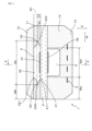
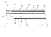
本形態のガスセンサ素子1は、図1、図2に示すごとく、複数のセラミック層を積層してなる積層型のガスセンサ素子である。ガスセンサ素子1は、固体電解質体2と、測定電極31及び基準電極32と、チャンバ4と、ヒータ5と、を有する。
(Embodiment 1)
An embodiment of a gas sensor element will be described with reference to FIGS. 1 to 13. FIG.
As shown in FIGS. 1 and 2, the gas sensor element 1 of this embodiment is a laminated gas sensor element formed by laminating a plurality of ceramic layers. The gas sensor element 1 has a solid electrolyte body 2 , a measurement electrode 31 and a reference electrode 32 , a chamber 4 and a heater 5 .

固体電解質体2は、酸素イオン伝導性を有する。測定電極31及び基準電極32は、固体電解質体2の両主面に設けられている。チャンバ4は、測定電極31に面し被測定ガスを導入する空間である。ヒータ5は、固体電解質体2を加熱する。 The solid electrolyte body 2 has oxygen ion conductivity. The measurement electrode 31 and the reference electrode 32 are provided on both main surfaces of the solid electrolyte body 2 . The chamber 4 is a space facing the measuring electrode 31 and into which the gas to be measured is introduced. The heater 5 heats the solid electrolyte body 2 .

チャンバ4は、突出角部43を有する。突出角部43は、ガスセンサ素子1の長手方向Yに直交する断面において、幅方向Wに突出した部位である。ここで、幅方向Wは、長手方向Y及び積層方向Zの双方に直交する方向である。突出角部43の頂点433は、積層方向Zにおけるチャンバ4の中心4Cよりもヒータ5に近い側に配置されている。 The chamber 4 has protruding corners 43 . The protruding corner portion 43 is a portion that protrudes in the width direction W in a cross section orthogonal to the longitudinal direction Y of the gas sensor element 1 . Here, the width direction W is a direction perpendicular to both the longitudinal direction Y and the stacking direction Z. As shown in FIG. A vertex 433 of the protruding corner portion 43 is arranged closer to the heater 5 than the center 4C of the chamber 4 in the stacking direction Z. As shown in FIG.

ガスセンサ素子1は長尺形状を有し、その長手方向Yの一端に近い位置に、測定電極31及び基準電極32が形成されている。長手方向Yにおける、測定電極31及び基準電極32が設けられた側を、先端側、その反対側を基端側という。
長手方向Yのいずれの位置においても、突出角部43の頂点433は、積層方向Zにおけるチャンバ4の中心4Cよりもヒータ5に近い側に配置されている。
The gas sensor element 1 has an elongated shape, and a measurement electrode 31 and a reference electrode 32 are formed near one end in the longitudinal direction Y thereof. The side on which the measurement electrode 31 and the reference electrode 32 are provided in the longitudinal direction Y is called the distal side, and the opposite side is called the proximal side.
At any position in the longitudinal direction Y, the apex 433 of the protruding corner 43 is arranged closer to the heater 5 than the center 4C of the chamber 4 in the stacking direction Z. As shown in FIG.

本形態のガスセンサ素子1は、ダクト6を有する。ダクト6は、基準電極32に面し基準ガスが導入される空間である。積層方向Zにおいてダクト6を挟んで固体電解質体2と反対側にヒータ5が配されている。チャンバ4はダクト6よりも幅方向Wの寸法が大きい。また、チャンバ4の幅Wcと、ダクト6の幅Wdとは、1<Wc/Wd≦1.73を満たす。 The gas sensor element 1 of this embodiment has a duct 6 . The duct 6 is a space facing the reference electrode 32 and into which the reference gas is introduced. A heater 5 is arranged on the side opposite to the solid electrolyte body 2 with the duct 6 interposed therebetween in the stacking direction Z. As shown in FIG. The chamber 4 has a dimension in the width direction W larger than that of the duct 6 . Also, the width Wc of the chamber 4 and the width Wd of the duct 6 satisfy 1<Wc/Wd≦1.73.

なお、チャンバ4の幅Wcは、幅方向Wの寸法が最大となる部分における幅寸法にて定義できる。すなわち、幅方向Wにおける、両側の突出角部43の頂点433の間の距離が、幅Wcとなる。ダクト6の幅Wdも、幅方向Wの寸法が最大となる部分における幅寸法にて定義できる。図1に示すガスセンサ素子1において、ダクト6は、固体電解質体2に面する部分にて最大幅となる。かかる場合は、ダクト6の幅Wdは、固体電解質体2に面する部分における幅寸法にて定義される。 Note that the width Wc of the chamber 4 can be defined by the width dimension of the portion where the dimension in the width direction W is the maximum. That is, the distance between the vertexes 433 of the protruding corners 43 on both sides in the width direction W is the width Wc. The width Wd of the duct 6 can also be defined by the width dimension at the portion where the dimension in the width direction W is maximum. In the gas sensor element 1 shown in FIG. 1 , the duct 6 has the maximum width at the portion facing the solid electrolyte body 2 . In such a case, the width Wd of the duct 6 is defined by the width dimension of the portion facing the solid electrolyte body 2 .

本形態のガスセンサ素子1においては、固体電解質体2における測定電極31を設けた側の面に、チャンバ形成層11と遮蔽層12とを順次積層してある。また、固体電解質体2における基準電極32を設けた側の面に、ダクト形成層13とヒータ層14とが順次積層してある。 In the gas sensor element 1 of this embodiment, the chamber-forming layer 11 and the shielding layer 12 are sequentially laminated on the surface of the solid electrolyte body 2 on which the measuring electrode 31 is provided. A duct-forming layer 13 and a heater layer 14 are sequentially laminated on the surface of the solid electrolyte body 2 on which the reference electrode 32 is provided.

チャンバ形成層11は、図1~図3に示すごとく、積層方向Zに直交する方向からチャンバ4を囲むように形成されたセラミック層である。チャンバ形成層11と、固体電解質体2と遮蔽層12との間に、チャンバ4が形成される。なお、図2、図3に示すごとく、チャンバ形成層11の一部には、拡散抵抗部15が設けられている。拡散抵抗部15は、被測定ガスを拡散させながらチャンバ4に導入する部位である。また、図3には、チャンバ形成層11が2つに分かれて描かれているが、これらは後述する個別のセラミックペーストに対応して示したものである。また、同図における符号4を示した2つの箇所は、複数のセラミック層が積層された状態において、一つのチャンバ4を形成する箇所を示している。 The chamber-forming layer 11 is a ceramic layer formed so as to surround the chamber 4 in a direction perpendicular to the stacking direction Z, as shown in FIGS. A chamber 4 is formed between the chamber-forming layer 11 and between the solid electrolyte body 2 and the shielding layer 12 . Incidentally, as shown in FIGS. 2 and 3, a diffusion resistance portion 15 is provided in a part of the chamber forming layer 11. As shown in FIG. The diffusion resistance portion 15 is a portion that introduces the gas to be measured into the chamber 4 while diffusing it. Also, in FIG. 3, the chamber forming layer 11 is divided into two parts, which correspond to individual ceramic pastes to be described later. In addition, two locations indicated by reference numeral 4 in the figure indicate locations where one chamber 4 is formed in a state in which a plurality of ceramic layers are laminated.

本形態において、拡散抵抗部15は、ガスセンサ素子1の先端部に形成されている。すなわち、チャンバ4の先端側に拡散抵抗部15が配置されている。拡散抵抗部15は、多孔質のセラミックからなる。これにより、本形態のガスセンサ素子1は、素子の先端側から被測定ガスをチャンバ4に導入するよう構成されている。 In this embodiment, the diffusion resistance portion 15 is formed at the tip portion of the gas sensor element 1 . That is, the diffusion resistor 15 is arranged on the tip side of the chamber 4 . The diffused resistor portion 15 is made of porous ceramic. Thus, the gas sensor element 1 of this embodiment is configured to introduce the gas to be measured into the chamber 4 from the tip side of the element.

ダクト形成層13は、図1~図3に示すごとく、ダクト6を固体電解質体2と反対側から覆うと共に、積層方向Zに直交する方向からダクト6を囲むように形成されたセラミック層である。ただし、ダクト形成層13は、ダクト6の基端側を塞いでいない。すなわち、ダクト6は、ガスセンサ素子1の基端部に開口している。これにより、基準ガスは、ガスセンサ素子1の基端側からダクト6に導入される。本形態において、基準ガスは大気である。 As shown in FIGS. 1 to 3, the duct-forming layer 13 is a ceramic layer formed so as to cover the duct 6 from the side opposite to the solid electrolyte body 2 and surround the duct 6 from the direction perpendicular to the stacking direction Z. . However, the duct-forming layer 13 does not block the base end side of the duct 6 . That is, the duct 6 opens at the base end of the gas sensor element 1 . Thereby, the reference gas is introduced into the duct 6 from the base end side of the gas sensor element 1 . In this embodiment, the reference gas is air.

固体電解質体2は、ジルコニアを主成分とするセラミック層である。チャンバ形成層11、遮蔽層12、ダクト形成層13、ヒータ層14は、いずれもアルミナを主成分とするセラミック層である。拡散抵抗部15も、アルミナを主成分とする。ただし、被測定ガスを透過させることができるよう、多孔質のセラミック体からなる。 The solid electrolyte body 2 is a ceramic layer containing zirconia as a main component. The chamber forming layer 11, the shielding layer 12, the duct forming layer 13, and the heater layer 14 are all ceramic layers containing alumina as a main component. The diffused resistor portion 15 is also mainly composed of alumina. However, it consists of a porous ceramic body so that the gas to be measured can permeate.

ガスセンサ素子1は、複数のセラミック層を積層してなるが、完成品の状態において、各セラミック層の間の境界が存在しない場合もある。例えば、チャンバ形成層11と遮蔽層12との間の境界、ダクト形成層13とヒータ層14との境界は、存在しない場合がある。 The gas sensor element 1 is formed by laminating a plurality of ceramic layers, and there may be no boundaries between the ceramic layers in the state of a finished product. For example, the boundary between the chamber forming layer 11 and the shield layer 12, the boundary between the duct forming layer 13 and the heater layer 14 may not exist.

図1に示すごとく、長手方向Yに直交する断面において、チャンバ4の外側におけるチャンバ形成層11の幅Wbは、チャンバ4の幅Wcよりも小さい。また、チャンバ形成層11の幅Wbは、ダクト6の外側におけるダクト形成層13の幅Weよりも小さい。 As shown in FIG. 1 , the width Wb of the chamber forming layer 11 outside the chamber 4 is smaller than the width Wc of the chamber 4 in a cross section perpendicular to the longitudinal direction Y. As shown in FIG. Also, the width Wb of the chamber forming layer 11 is smaller than the width We of the duct forming layer 13 outside the duct 6 .

チャンバ4の突出角部43は、積層方向Zにおける両側において、同一材料に面して形成されている。すなわち、本形態においては、突出角部43は、積層方向Zの両側において、アルミナを主成分とする同一組成の材料に面している。突出角部の頂点433は、異なる材料の界面に存在するわけではなく、同一材料からなるチャンバ形成層11の中に存在する。また、チャンバ形成層11における、突出角部43に隣接する部位は、略均質となっている。 The protruding corners 43 of the chamber 4 are formed so as to face the same material on both sides in the stacking direction Z. As shown in FIG. That is, in the present embodiment, the protruding corner portion 43 faces, on both sides in the stacking direction Z, materials of the same composition containing alumina as the main component. The apex 433 of the protruding corner does not exist at the interface of different materials, but exists in the chamber forming layer 11 made of the same material. In addition, the portion of the chamber forming layer 11 adjacent to the protruding corner portion 43 is substantially uniform.

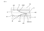
チャンバ4は、積層方向Zを向いた第1面41と第2面42とを有する。第1面41は、積層方向Zにおいて、ヒータ5に近い側の面である。第2面42は、積層方向Zにおいて、ヒータ5から遠い側の面である。本形態において、第1面41は、固体電解質体2に面する。第2面42は、遮蔽層12に面する。なお、便宜的に、第1面41と突出角部43の頂点433との間の積層方向Zの寸法を「角部高さt1」という。また、便宜的に、第1面41とチャンバ4の中心4Cとの間の積層方向Zの寸法を「中心高さt2」という。ここで、t1<t2である。
第1面41と第2面42とは、略同一の幅とすることができる。ただし、第1面41の幅を第2面42の幅よりも大きくすることもできる。或いは、第1面41の幅を第2面42の幅よりも小さくすることもできる。
The chamber 4 has a first surface 41 and a second surface 42 facing the stacking direction Z. As shown in FIG. The first surface 41 is the surface closer to the heater 5 in the stacking direction Z. As shown in FIG. The second surface 42 is a surface farther from the heater 5 in the stacking direction Z. As shown in FIG. In this embodiment, the first surface 41 faces the solid electrolyte body 2 . A second surface 42 faces the shielding layer 12 . For convenience, the dimension in the stacking direction Z between the first surface 41 and the vertex 433 of the protruding corner 43 is referred to as "corner height t1". For convenience, the dimension in the stacking direction Z between the first surface 41 and the center 4C of the chamber 4 is called "center height t2". Here, t1<t2.
The first surface 41 and the second surface 42 can have substantially the same width. However, the width of the first surface 41 can be made larger than the width of the second surface 42 . Alternatively, the width of the first surface 41 can be made smaller than the width of the second surface 42 .

チャンバ4においては、第1面41及び第2面42の幅方向Wの両端からそれぞれ外側に突出するように、突出角部43が形成されている。各突出角部43は、図4に示すごとく、チャンバ4側に凸となる曲面である2つの凸曲面431、432によって、形成されている。凸曲面431は、長手方向Yに直交する断面において、突出角部43の頂点433から第1面41までの曲面である。凸曲面432は、長手方向Yに直交する断面において、突出角部43の頂点433から第2面42までの曲面である。 In the chamber 4 , protruding corners 43 are formed to protrude outward from both ends in the width direction W of the first surface 41 and the second surface 42 . Each protruding corner 43 is formed by two convex curved surfaces 431 and 432 which are curved surfaces convex toward the chamber 4 side, as shown in FIG. The convex curved surface 431 is a curved surface extending from the vertex 433 of the protruding corner portion 43 to the first surface 41 in a cross section perpendicular to the longitudinal direction Y. As shown in FIG. The convex curved surface 432 is a curved surface extending from the vertex 433 of the protruding corner portion 43 to the second surface 42 in a cross section perpendicular to the longitudinal direction Y. As shown in FIG.

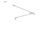
長手方向Yに直交する断面において、少なくとも一部の突出角部43の角度αは鋭角、すなわち90°未満である。また、少なくとも一部の突出角部43の角度αは30°以下である。本形態においては、幅方向Wの両端における突出角部43のいずれにおいても、角度αが30°以下となっている。突出角部43の角度αは、以下のように定義される。すなわち、長手方向Yに直交する断面において、突出角部43の頂点433をA点とし、当該突出角部43側における第1面41の一端をB点とし、当該突出角部43側における第2面42の一端をC点としたとき、図5に示すごとく、角CABを、角度αとする。 In a cross section perpendicular to the longitudinal direction Y, the angle α of at least some protruding corners 43 is an acute angle, ie less than 90°. Moreover, the angle α of at least a part of the projecting corners 43 is 30° or less. In this embodiment, the angle α is 30° or less at any of the protruding corner portions 43 at both ends in the width direction W. As shown in FIG. The angle α of the protruding corner 43 is defined as follows. That is, in a cross section perpendicular to the longitudinal direction Y, the vertex 433 of the protruding corner 43 is point A, one end of the first surface 41 on the protruding corner 43 side is point B, and the second surface on the protruding corner 43 side is point B. Assuming that one end of the surface 42 is point C, angle CAB is angle α as shown in FIG.

また、チャンバ4の幅方向の両側に形成される突出角部43の形状は、互いに略線対称となっている。ただし、チャンバ4の幅方向の両側に形成される突出角部43の形状は、互いに非対称の形状とすることもできる。或いは、チャンバ4の幅方向Wの一方側のみに、突出角部43が形成される構成とすることもできる。 Further, the shapes of the protruding corner portions 43 formed on both sides in the width direction of the chamber 4 are substantially line-symmetrical to each other. However, the shapes of the protruding corner portions 43 formed on both sides in the width direction of the chamber 4 may be mutually asymmetrical. Alternatively, a configuration in which the protruding corner portion 43 is formed only on one side in the width direction W of the chamber 4 may be adopted.

次に、ガスセンサ素子1の製造方法の一例を、主として図6~図12を参照して説明する。
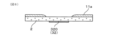
まず、図6に示すごとく、未焼性の状態の固体電解質体2の一方の面に、チャンバ形成層11の一部となるセラミックペースト11aを塗布する。ここで、セラミックペースト11aは、固体電解質体2の表面のうち、チャンバ4の第1面41となる部分を除く領域に、塗布する。なお、図6においては、この段階において、固体電解質体2における他方の面に基準電極32となる導電ペースト320を印刷した状態を示している。
Next, an example of a method for manufacturing the gas sensor element 1 will be described mainly with reference to FIGS. 6 to 12. FIG.
First, as shown in FIG. 6, a ceramic paste 11a that will form a part of the chamber forming layer 11 is applied to one surface of the solid electrolyte body 2 in an unfired state. Here, the ceramic paste 11 a is applied to a region of the surface of the solid electrolyte body 2 excluding the portion that will become the first surface 41 of the chamber 4 . FIG. 6 shows a state in which the conductive paste 320 to be the reference electrode 32 is printed on the other surface of the solid electrolyte body 2 at this stage.

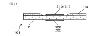
次いで、図7に示すごとく、固体電解質体2における、セラミックペースト11aが塗布された側の表面に、測定電極31となる導電ペースト310を印刷する。また、この導電ペースト310は、固体電解質体2に塗布されたセラミックペースト11aの表面の一部にも連続して形成する(図示略)。この部分の導電ペースト310は、図2に示すごとく、リード311となる。以上により、第1の未焼成体101を得る。 Next, as shown in FIG. 7, a conductive paste 310 to be a measuring electrode 31 is printed on the surface of the solid electrolyte body 2 on which the ceramic paste 11a is applied. The conductive paste 310 is also continuously formed on part of the surface of the ceramic paste 11a applied to the solid electrolyte body 2 (not shown). The conductive paste 310 in this portion becomes leads 311 as shown in FIG. As described above, the first green body 101 is obtained.

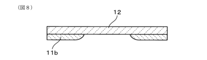
一方、図8に示すごとく、未焼性の状態の遮蔽層12の一方の面に、チャンバ形成層11の他の一部となるセラミックペースト11bを塗布する。ここで、セラミックペースト11bは、固体電解質体2の表面のうち、チャンバ4の第2面42となる部分を除く領域に、塗布する。 On the other hand, as shown in FIG. 8, a ceramic paste 11b that will form another part of the chamber-forming layer 11 is applied to one surface of the shielding layer 12 in an unfired state. Here, the ceramic paste 11 b is applied to a region of the surface of the solid electrolyte body 2 excluding the portion that will become the second surface 42 of the chamber 4 .

次いで、図9に示すごとく、固体電解質体2の表面のうち、チャンバ4の第2面42となる部分を含むように、焼失材40を塗布する。焼失材40は、セラミックペースト11bの一部に重なるように、塗布する。以上により、第2の未焼成体102を得る。焼失材40は、例えば、カーボンパウダ―を含むペーストとすることができる。焼失材40は、後の焼成工程にて、焼失するものを用いることができる。 Next, as shown in FIG. 9 , a burnout material 40 is applied so as to include a portion of the surface of the solid electrolyte body 2 that will become the second surface 42 of the chamber 4 . The burnout material 40 is applied so as to partially overlap the ceramic paste 11b. As described above, the second green body 102 is obtained. The burnout material 40 can be, for example, a paste containing carbon powder. As the burnt-off material 40, one that is burnt off in the subsequent firing process can be used.

次いで、図10に示すごとく、セラミックペースト11aと、セラミックペースト11bとが対向するように、第1の未焼成体101と第2の未焼成体102とを対向配置する。そして、この姿勢にて、第1の未焼成体101と、第2の未焼成体102とを、互いに積層し、圧着して、図11に示すような第3の未焼成体103を得る。この第3の未焼成体103においては、チャンバ4となる空間に、焼失材40が充填された状態となっている。 Next, as shown in FIG. 10, the first green body 101 and the second green body 102 are placed facing each other so that the ceramic paste 11a and the ceramic paste 11b face each other. Then, in this posture, the first green body 101 and the second green body 102 are stacked and pressed against each other to obtain the third green body 103 as shown in FIG. In this third green body 103 , the space to be the chamber 4 is filled with the burnt-off material 40 .

また、図示は省略するが、この第3の未焼成体103に対して、未焼成のダクト形成層13及び未焼成のヒータ層14を積層、圧着したものを、接合する。なお、ヒータ層14は、アルミナを主成分とするセラミックシートの一方の面に、ヒータ5及びこれに接続されるリード51となる導電ペーストが印刷してある(図3参照)。 Also, although illustration is omitted, the unfired duct forming layer 13 and the unfired heater layer 14 are stacked and pressure-bonded to the third unfired body 103, and then joined. The heater layer 14 is formed by printing a conductive paste for forming the heater 5 and leads 51 connected thereto on one surface of a ceramic sheet containing alumina as a main component (see FIG. 3).

次いで、第3の未焼成体103を焼成して、ガスセンサ素子1を得る。このとき、図12に示すごとく、焼失材40が焼失し、チャンバ4が形成される。
以上により、図1、図2に示すような、ガスセンサ素子1が得られる。
Next, the third unfired body 103 is fired to obtain the gas sensor element 1 . At this time, as shown in FIG. 12, the burnt-out material 40 is burnt out to form the chamber 4 .
As described above, the gas sensor element 1 as shown in FIGS. 1 and 2 is obtained.

なお、図13は、実際に作製したガスセンサ素子1の一部の断面写真である。この断面写真は、概ね、図4に示した部位の断面に相当する部位の写真である。図13には、角部高さt1及び中心高さt2を記入した。 In addition, FIG. 13 is a cross-sectional photograph of a part of the actually manufactured gas sensor element 1 . This cross-sectional photograph is generally a photograph of a portion corresponding to the cross section of the portion shown in FIG. Corner height t1 and center height t2 are shown in FIG.

本形態のガスセンサ素子1は、例えば、自動車エンジンの排気系に取り付けられる、いわゆるA/Fセンサ素子(すなわち空燃比センサ素子)とすることができる。そして、被測定ガスとしての排ガス中における、特定ガスとしての酸素の濃度を測定することで、空燃比を検出することができる。 The gas sensor element 1 of this embodiment can be, for example, a so-called A/F sensor element (that is, an air-fuel ratio sensor element) attached to an exhaust system of an automobile engine. By measuring the concentration of oxygen as the specific gas in the exhaust gas as the gas to be measured, the air-fuel ratio can be detected.

次に、本形態の作用効果につき説明する。
上記ガスセンサ素子1においては、突出角部43の頂点433が、積層方向Zにおけるチャンバ4の中心4Cよりもヒータ5に近い側に配置されている。それゆえ、ヒータ5による加熱時に発生する温度差によって、突出角部43の頂点433に隣接するセラミック層に作用する引張応力を、抑制することができる。その結果、素子割れを効果的に防ぐことができる。
Next, the effects of this embodiment will be described.
In the gas sensor element 1 described above, the apex 433 of the projecting corner portion 43 is arranged closer to the heater 5 than the center 4C of the chamber 4 in the stacking direction Z. As shown in FIG. Therefore, the tensile stress acting on the ceramic layer adjacent to the apex 433 of the protruding corner 43 due to the temperature difference generated during heating by the heater 5 can be suppressed. As a result, element cracking can be effectively prevented.

この点につき、図14に示す比較形態のガスセンサ素子9と比較しつつ、説明する。図14に示す比較形態のガスセンサ素子9は、チャンバ4の突出角部43の頂点433が、チャンバ4の中心4Cよりも、ヒータ5から遠い側に位置する点で、実施形態1のガスセンサ素子1と異なる。その他は、実施形態1のガスセンサ素子1と同様である。 This point will be described in comparison with the comparative gas sensor element 9 shown in FIG. The gas sensor element 9 of the comparative form shown in FIG. different from Others are the same as those of the gas sensor element 1 of the first embodiment.

ヒータ5による加熱時には、ガスセンサ素子1において、ヒータ5に近い部位がヒータ5から遠い部位よりも高温となりやすい。それゆえ、ヒータ層14及びダクト形成層13が、遮蔽層12よりも高温となりやすい。これに伴い、図15に示すごとく、ガスセンサ素子1は、ヒータ層14及びダクト形成層13の幅方向Wへの膨張T1が、遮蔽層12の幅方向Wへの膨張T2よりも、大きく生じることとなる。 During heating by the heater 5 , in the gas sensor element 1 , a portion closer to the heater 5 tends to be hotter than a portion farther from the heater 5 . Therefore, the heater layer 14 and the duct-forming layer 13 tend to have a higher temperature than the shielding layer 12 . Accordingly, as shown in FIG. 15, in the gas sensor element 1, the expansion T1 of the heater layer 14 and the duct forming layer 13 in the width direction W is greater than the expansion T2 of the shielding layer 12 in the width direction W. becomes.

そうすると、チャンバ4の突出角部43の頂点433付近においても、ヒータ5に近い側の部位が、ヒータ5から遠い側の部位よりも幅方向Wの外側へ向う熱応力が生じる。そして、ガスセンサ素子1は、図16に示すごとく、ヒータ層14側が凸となるような反りを生じる。なお、図15、図16は模式図であって、ダクト等も省略してある。
一方、突出角部43を起点とするセラミック層の亀裂は、突出角部43の突出方向に直交する方向に作用する引張応力が大きいほど生じやすくなる。
Then, in the vicinity of the apex 433 of the protruding corner 43 of the chamber 4 as well, thermal stress directed outward in the width direction W is generated in the portion closer to the heater 5 than in the portion farther from the heater 5 . Then, as shown in FIG. 16, the gas sensor element 1 is warped such that the heater layer 14 side is convex. 15 and 16 are schematic diagrams, and ducts and the like are omitted.
On the other hand, the larger the tensile stress acting in the direction orthogonal to the direction in which the protruding corner 43 protrudes, the more likely the ceramic layer to crack starting from the protruding corner 43 .

ここで、熱応力が作用したときの状態において、図17に示す比較形態のガスセンサ素子9と、図18に示す本形態のガスセンサ素子1とを、比較する。そうすると、本形態のガスセンサ素子1は、比較形態のガスセンサ素子9に比べて、突出角部43付近において、突出角部43の突出方向に直交する方向の熱応力のベクトル成分fが小さくなりやすい。すなわち、比較形態に比べて、本形態の方が、突出角部43付近におけるセラミック層に作用する引張応力fを小さくすることができる。それゆえ、本形態においては、突出角部43を起点とする素子割れを抑制することができる。 Here, a comparison will be made between the gas sensor element 9 of the comparative embodiment shown in FIG. 17 and the gas sensor element 1 of the present embodiment shown in FIG. 18 in the state when thermal stress acts. Then, in the gas sensor element 1 of the present embodiment, the vector component f of the thermal stress in the direction orthogonal to the projection direction of the projection corner 43 tends to be smaller in the vicinity of the projection corner 43 than in the gas sensor element 9 of the comparative embodiment. That is, in this embodiment, the tensile stress f acting on the ceramic layer near the protruding corner 43 can be made smaller than in the comparative embodiment. Therefore, in the present embodiment, it is possible to suppress element cracking originating from the protruding corner portion 43 .

長手方向Yに直交する断面において、少なくとも一部の突出角部43の角度αは30°以下である。角度αが30°以下の場合には、突出角部43の頂点433の形成位置を適切に設定しないと、突出角部43を起点とする亀裂が比較的生じやすくなる。すなわち、下記の応力拡大係数Kが大きくなり、亀裂の伸展が生じやすくなる。そこで、上述のように、突出角部43の頂点433の位置をチャンバ4の中心4Cよりもヒータ5側に配置することで、より効果的に素子割れを防ぐことができる。 In a cross section orthogonal to the longitudinal direction Y, the angle α of at least some protruding corners 43 is 30° or less. When the angle α is 30° or less, a crack originating from the protruding corner 43 is relatively likely to occur unless the formation position of the vertex 433 of the protruding corner 43 is appropriately set. That is, the stress intensity factor K described below becomes large, and crack extension is likely to occur. Therefore, by arranging the apex 433 of the protruding corner 43 closer to the heater 5 than the center 4C of the chamber 4 as described above, element cracking can be prevented more effectively.

応力拡大係数Kは、一般に、K=σ×(πa)1/2 にて表される。ここで、aは、突出角部43の突出長さである。σは、仮に突出角部43が存在しないとした場合にチャンバ形成層11における、突出角部43の位置に相当する位置に生じる応力である。この式に基づいて、突出角部43の角度αと、応力拡大係数Kとの関係を、図19のグラフに示す。同図において、縦軸は、α=90°のときの応力拡大係数K0の値に対する、当該角度αのときの応力拡大係数Kの相対比(K/K0)として表している。同図から分かるように、α≦30°の場合には、特に応力拡大係数Kが大きくなっている。すなわち、α≦30°の場合には、特に亀裂の伸展が起きやすい状態、つまり素子割れが生じやすい状態となることが分かる。 The stress intensity factor K is generally expressed as K=σ×(πa) 1/2 . Here, a is the protruding length of the protruding corner portion 43 . σ is the stress generated at a position corresponding to the position of the protruding corner 43 in the chamber forming layer 11 if the protruding corner 43 were not present. Based on this formula, the relationship between the angle α of the protruding corner 43 and the stress intensity factor K is shown in the graph of FIG. In the figure, the vertical axis represents the relative ratio (K/K0) of the stress intensity factor K at the angle α to the value of the stress intensity factor K0 at α=90°. As can be seen from the figure, the stress intensity factor K is particularly large when α≦30°. That is, when α≦30°, crack extension is particularly likely to occur, that is, element cracking is likely to occur.

また、チャンバ4はダクト6よりも幅方向Wの寸法が大きい。これにより、測定電極31の電極反応面積を確保しつつ、ガスセンサ素子1の小型化を図りやすくなる。その一方で、チャンバ4の幅Wcが大きくなることに伴い、チャンバ4の外側部分におけるチャンバ形成層11の幅Wbが小さくなりやすい。これにより、遮蔽層12の温度が上がり難くなり、積層方向Zにおける温度差がガスセンサ素子1において生じやすくなる。そうすると、突出角部43付近の熱応力が大きくなりやすい。 Also, the chamber 4 has a dimension in the width direction W larger than that of the duct 6 . This makes it easier to downsize the gas sensor element 1 while securing the electrode reaction area of the measurement electrode 31 . On the other hand, as the width Wc of the chamber 4 increases, the width Wb of the chamber forming layer 11 in the outer portion of the chamber 4 tends to decrease. As a result, the temperature of the shielding layer 12 is less likely to rise, and a temperature difference in the stacking direction Z is more likely to occur in the gas sensor element 1 . As a result, the thermal stress in the vicinity of the protruding corner portion 43 tends to increase.

また、チャンバ4の幅Wcがダクト6の幅Wdよりも大きいと、ヒータ5の熱がチャンバ4の突出角部43よりも幅方向Wの内側において、固体電解質体2に伝わりやすくなる。そうすると、突出角部43よりも内側において、固体電解質体2が膨張しやすくなり、突出角部43近傍における熱応力が大きくなりやすくなる。 Further, when the width Wc of the chamber 4 is larger than the width Wd of the duct 6 , the heat of the heater 5 is more likely to be transferred to the solid electrolyte body 2 inside the protruding corner portion 43 of the chamber 4 in the width direction W. Then, the solid electrolyte body 2 tends to expand inside the protruding corner portion 43 , and the thermal stress in the vicinity of the protruding corner portion 43 tends to increase.

上述のように熱応力が大きくなりやすい構造において、突出角部43の頂点433の位置をヒータ5に近い位置に設けることで、上述の素子割れの防止を、効果的に実現することができる。 In the structure where the thermal stress tends to increase as described above, by providing the position of the vertex 433 of the projecting corner portion 43 at a position close to the heater 5, it is possible to effectively prevent the above-described element cracking.

また、突出角部43は、積層方向Zにおける両側において、同一材料に面して形成されている。それゆえ、突出角部43の頂点433を起点とするガスセンサ素子1の素子割れを抑制することができる。 In addition, the protruding corner portions 43 are formed so as to face the same material on both sides in the stacking direction Z. As shown in FIG. Therefore, element cracking of the gas sensor element 1 originating from the vertex 433 of the projecting corner portion 43 can be suppressed.

以上のごとく、本形態によれば、素子割れを効果的に防ぐことができるガスセンサ素子を提供することができる。 As described above, according to this embodiment, it is possible to provide a gas sensor element that can effectively prevent element cracking.

(実験例1)
本例においては、表1に示すように、種々の形状のガスセンサ素子について、素子割れ防止効果及び測定精度を調べた。
すなわち、チャンバ4の幅Wc、ダクト6の幅Wd、角部高さt1、中心高さt2等の各部の寸法を種々変更した複数のガスセンサ素子を試料1~10として用意した。
(Experimental example 1)
In this example, as shown in Table 1, gas sensor elements of various shapes were examined for their element crack prevention effect and measurement accuracy.
That is, a plurality of gas sensor elements were prepared as samples 1 to 10 in which the width Wc of the chamber 4, the width Wd of the duct 6, the height t1 of the corners, the height t2 of the center, etc. were variously changed.

Figure 0007215440000001

そして、素子割れ防止効果の評価として、各試料においてヒータ5に通電して昇温させる際に、どの程度の昇温速度までであれば素子割れを防ぐことができるかを調べた。つまり、各試料を大気中に配置した状態で、ヒータ5に一定の印加電圧にて通電し、昇温させた。このとき、ヒータ5の中心温度を、室温から950℃まで昇温した。ヒータ5の中心温度が950℃に達した時点にて、ヒータ通電を停止して、自然冷却した。この操作を5回繰り返した。ヒータ5の中心温度は、ヒータ5における最高温度部分を意味する。この耐久試験を行った後、各試料につき、染色外観検査を行い、素子割れの有無を判定した。この試験においては、昇温速度を50℃/secずつ変化させて、どの程度の昇温速度まで素子割れがない状態とできるかにて、評価した。昇温速度は、室温から100℃に達するまでの平均昇温速度とした。その結果を、表1に示す。表1における「許容昇温速度」が、本試験にて素子割れが生じなかった最高の昇温速度を示す。許容昇温速度が300℃/sec以上であれば、耐久性としては問題ない。 Then, as an evaluation of the effect of preventing element cracking, it was investigated to what extent the heating rate can prevent element cracking when the heater 5 is energized and the temperature is raised in each sample. That is, each sample was placed in the atmosphere, and the heater 5 was energized with a constant applied voltage to raise the temperature. At this time, the central temperature of the heater 5 was raised from room temperature to 950°C. When the temperature at the center of the heater 5 reached 950° C., power supply to the heater was stopped and natural cooling was allowed. This operation was repeated 5 times. The center temperature of the heater 5 means the highest temperature portion of the heater 5 . After the endurance test, each sample was subjected to a dyeing appearance inspection to determine the presence or absence of element cracks. In this test, the heating rate was changed by 50° C./sec, and evaluation was made based on the temperature up to which the crack-free state can be maintained. The temperature increase rate was the average temperature increase rate from room temperature to 100°C. The results are shown in Table 1. "Allowable heating rate" in Table 1 indicates the highest heating rate at which element cracking did not occur in this test. If the allowable heating rate is 300° C./sec or more, there is no problem in terms of durability.

表1から分かるように、試料4については、許容昇温速度が250℃/secであった。これに対し、Wb、Wc、Wdが試料4と同じである試料1~3については、許容昇温速度が400℃/sec以上であった。つまり、t>t2となる試料4に素子割れが生じる条件において、t1<t2を満たす試料1~3については、いずれも素子割れが生じないという結果が得られた。なお、表1における「許容昇温速度」の項目において、「≧400」との記載は、昇温速度400℃/secにて、耐久試験を行ったとき、少なくとも突出角部43を起点とする割れは生じていなかったということを表し、他の部位における割れが生じた場合を含む。なお、本例にて「素子割れ」というときは、特に断らない限り、突出角部43を起点とする素子割れを表す。 As can be seen from Table 1, Sample 4 had an allowable heating rate of 250°C/sec. On the other hand, samples 1 to 3, in which Wb, Wc, and Wd are the same as sample 4, had an allowable temperature increase rate of 400° C./sec or higher. In other words, under the condition that sample 4 satisfies t>t2 and element cracking occurred, it was found that none of samples 1 to 3, satisfying t1<t2, caused element cracking. In addition, in the item of "allowable heating rate" in Table 1, the description "≧400" means that at least the protruding corner portion 43 is the starting point when the endurance test is performed at the heating rate of 400° C./sec. This indicates that no cracks occurred, including cases where cracks occurred at other sites. In this example, "element cracking" means element cracking originating from the protruding corner portion 43 unless otherwise specified.

また、試料9の許容昇温速度が200℃/secであったのに対して、Wb、Wc、Wdが試料9と同じである試料10については、許容昇温速度が400℃/sec以上であった。つまり、t>t2となる試料9に素子割れが生じる条件において、t1<t2を満たす試料10については素子割れが生じないという結果が得られた。 In addition, while the allowable temperature rise rate of sample 9 was 200° C./sec, the allowable temperature increase rate of sample 10, which has the same Wb, Wc, and Wd as those of sample 9, was 400° C./sec or more. there were. In other words, under the condition that the sample 9 satisfies t>t2 and the element cracked, the result was obtained that the element crack did not occur in the sample 10 satisfying t1<t2.

これらの結果からも、突出角部43の頂点433の位置を、チャンバ4の中心4Cよりヒータ5に近い位置に設けることで、素子割れを抑制することができることが裏付けられる。 These results also support that element cracking can be suppressed by providing the position of the apex 433 of the protruding corner 43 at a position closer to the heater 5 than the center 4C of the chamber 4 .

また、試料4、試料10以外にも、t1<t2を満たす試料5、試料7、試料8についても、許容昇温速度が350℃/sec以上と高かった。このことからも、突出角部43の頂点433の位置を、チャンバ4の中心4Cよりヒータ5に近い位置に設けることで、素子割れを抑制する効果が裏付けられる。 In addition to sample 4 and sample 10, sample 5, sample 7, and sample 8, which satisfy t1<t2, also had a high allowable temperature increase rate of 350° C./sec or more. This also confirms the effect of suppressing element cracking by providing the position of the apex 433 of the protruding corner 43 at a position closer to the heater 5 than the center 4C of the chamber 4 .

なお、試料6については、t1>t2であるにもかかわらず、許容昇温速度は300℃/secと、比較的高かった。これは、Wc<Wdとなっており、比較的素子割れが生じにくいチャンバ4の幅とダクト6の幅との関係であるためと考えられる。 In addition, regarding sample 6, although t1>t2, the allowable temperature increase rate was 300° C./sec, which is relatively high. It is considered that this is because Wc<Wd, which is a relationship between the width of the chamber 4 and the width of the duct 6 in which element cracking is relatively unlikely to occur.

また、上述のように、Wc/Wdが小さくなりすぎると、測定精度が低下することが懸念される。この点についても確認すべく、上記の試料に関し、ガスセンサ素子の測定精度についても評価した。測定精度は、ストイキの混合気を燃焼させたガソリンエンジンの排ガスを測定したときに検出される限界電流の値の精度(以下、IL精度という。)によって評価した。試料1~4、試料8~10のIL精度は、いずれも±0.5%以内の精度であり、良好であった。 Moreover, as described above, if Wc/Wd becomes too small, there is a concern that the measurement accuracy will deteriorate. In order to confirm this point, the measurement accuracy of the gas sensor element was also evaluated for the above samples. The measurement accuracy was evaluated by the accuracy of the value of the limit current detected when measuring the exhaust gas of a gasoline engine burning a stoichiometric air-fuel mixture (hereinafter referred to as IL accuracy). The IL accuracies of Samples 1 to 4 and Samples 8 to 10 were all within ±0.5% and were good.

これに対して、試料5~7については、IL精度が±0.5%を超えていた。これら試料5~7は、いずれもWc/Wdが1未満であり、Wc<Wdの関係を有するものである。これら試料5~7は、素子割れは比較的生じにくいものの、測定精度の観点においては、不利になりやすいといえる。 In contrast, for samples 5-7, the IL accuracy exceeded ±0.5%. All of these samples 5 to 7 have Wc/Wd of less than 1 and have a relationship of Wc<Wd. Although these samples 5 to 7 are relatively resistant to element cracking, they are likely to be disadvantageous from the viewpoint of measurement accuracy.

また、表1から、1<Wc/Wd≦1.73を満たしつつ、t1<t2を満たす試料1~3、10は、特に、良好なIL精度を確保しつつ許容昇温速度が高いといえる。つまり、測定精度を確保しつつ素子割れ防止効果が特に得られるといえる。 Further, from Table 1, it can be said that Samples 1 to 3 and 10, which satisfy t1<t2 while satisfying 1<Wc/Wd≦1.73, have a particularly high allowable heating rate while ensuring good IL accuracy. . In other words, it can be said that the effect of preventing element cracking can be particularly obtained while ensuring measurement accuracy.

(実施形態2)
本形態は、図20~図22に示すごとく、チャンバ4への被測定ガスの導入箇所を、チャンバ4の幅方向Wの両側に設けた形態である。
本形態においては、図21、図22に示すごとく、拡散抵抗部15を、長手方向Yにおける、チャンバ4中央部付近に設けている。そして、チャンバ4の先端側はチャンバ形成層11の一部によって閉塞されている。つまり、チャンバ4は、先端側においてはガスが透過しないように閉塞されている。
(Embodiment 2)
20 to 22, the present embodiment is one in which points for introducing the gas to be measured into the chamber 4 are provided on both sides in the width direction W of the chamber 4. FIG.
In this embodiment, as shown in FIGS. 21 and 22, the diffusion resistance section 15 is provided near the center of the chamber 4 in the longitudinal direction Y. As shown in FIGS. The tip side of the chamber 4 is closed by a part of the chamber forming layer 11 . That is, the chamber 4 is closed on the tip end side so as to prevent gas from permeating therethrough.

拡散抵抗部15は、チャンバ4の長手方向Yの一部において、図20、図21に示すごとく、チャンバ4の第2面42に沿って形成されている。そして、図20、図22に示すごとく、拡散抵抗部15は、ガスセンサ素子1の幅方向Wの全域にわたって形成されている。なお、拡散抵抗部15が存在する位置におけるガスセンサ素子1の断面は、図20に示されるような形状に表れる。このとき、
一方、拡散抵抗部15が存在しない位置におけるガスセンサ素子1の断面は、図1に示す実施形態1のガスセンサ素子1の断面と同様である。
The diffusion resistance portion 15 is formed along the second surface 42 of the chamber 4 in a part of the chamber 4 in the longitudinal direction Y, as shown in FIGS. 20 and 21 . As shown in FIGS. 20 and 22, the diffused resistor portion 15 is formed over the entire width direction W of the gas sensor element 1 . Note that the cross section of the gas sensor element 1 at the position where the diffusion resistance portion 15 exists appears in a shape as shown in FIG. At this time,
On the other hand, the cross section of the gas sensor element 1 at the position where the diffusion resistance portion 15 does not exist is the same as the cross section of the gas sensor element 1 of Embodiment 1 shown in FIG.

その他は、実施形態1と同様である。なお、実施形態2以降において用いた符号のうち、既出の実施形態において用いた符号と同一のものは、特に示さない限り、既出の実施形態におけるものと同様の構成要素等を表す。
本形態においても、実施形態1と同様の作用効果を有する。
Others are the same as those of the first embodiment. Note that, of the reference numerals used in the second and subsequent embodiments, the same reference numerals as those used in the previous embodiments represent the same components as those in the previous embodiments, unless otherwise specified.
This embodiment also has the same effect as the first embodiment.

(実施形態3)
本形態は、図23~図27に示すごとく、固体電解質体2におけるヒータ5に近い側のセラミック層の構造のバリエーションの形態である。なお、図23~図27においては、測定電極及び基準電極を省略してある。図28~図35においても同様である。
(Embodiment 3)
As shown in FIGS. 23 to 27, this embodiment is a variation of the structure of the ceramic layer of the solid electrolyte body 2 on the side closer to the heater 5 . 23 to 27, measurement electrodes and reference electrodes are omitted. The same applies to FIGS. 28 to 35 as well.

図23に示すガスセンサ素子1は、ダクトを設けていない。
図24に示すガスセンサ素子1は、ダクト6に多孔質体60を充填してある。この多孔質体60は、大気側からダクト6に侵入する被毒物質を吸着除去する機能を有する。
The gas sensor element 1 shown in FIG. 23 does not have a duct.
A gas sensor element 1 shown in FIG. 24 has a duct 6 filled with a porous body 60 . This porous body 60 has a function of adsorbing and removing poisonous substances entering the duct 6 from the atmosphere side.

図25に示すガスセンサ素子1は、ヒータ5を面状に配置したものである。
図26に示すガスセンサ素子1は、ヒータ5をダクト6よりも幅方向の外側に配置したものである。すなわち、ヒータ5が、ダクト6と積層方向Zに重ならない位置に形成されている。
図27に示すガスセンサ素子1は、チャンバ4をヒータ5とダクト6との間の位置に形成したものである。
A gas sensor element 1 shown in FIG. 25 has heaters 5 arranged in a plane.
The gas sensor element 1 shown in FIG. 26 has the heater 5 arranged outside the duct 6 in the width direction. That is, the heater 5 is formed at a position not overlapping the duct 6 in the stacking direction Z. As shown in FIG.
A gas sensor element 1 shown in FIG. 27 has a chamber 4 formed between a heater 5 and a duct 6 .

これら図23~図27に示すようなガスセンサ素子においても、実施形態1と同様に、チャンバ4の突出角部43の頂点433を、ヒータ5に近い積層方向Zの位置に設けることで、素子割れを抑制することができる。
その他は、実施形態1と同様の構成及び作用効果を得ることができる。
23 to 27, the apex 433 of the protruding corner 43 of the chamber 4 is provided at a position in the stacking direction Z near the heater 5 in the same manner as in the first embodiment, thereby preventing element cracking. can be suppressed.
In other respects, the same configuration and effects as those of the first embodiment can be obtained.

(実施形態4)
また、チャンバ4の形状や構造も、例えば、図28~図31に示すごとく、種々変更することができる。なお、図28~図31においては、ガスセンサ素子1の一部の構成(例えばダクト形成層13、ヒータ層14)を省略してある。後述する図33~図35も同様である。
(Embodiment 4)
Also, the shape and structure of the chamber 4 can be variously changed as shown in FIGS. 28 to 31, for example. 28 to 31, a part of the structure of the gas sensor element 1 (for example, the duct forming layer 13 and the heater layer 14) is omitted. The same applies to FIGS. 33 to 35, which will be described later.

図28に示すように、突出角部43を形成するチャンバ形成層11の内側面を、略平面とすることもできる。
図29に示すように、突出角部43を形成するチャンバ形成層11の内側面を、凹曲面とすることもできる。
As shown in FIG. 28, the inner surface of the chamber forming layer 11 forming the protruding corner portion 43 may be substantially flat.
As shown in FIG. 29, the inner surface of the chamber forming layer 11 that forms the protruding corner 43 may be a concave curved surface.

図30、図31に示すように、チャンバ形成層11の内側面が、突出角部43の頂点433以外においても角部を有する形態とすることもできる。かかる場合においては、突出角部43の角度αは、突出角部43の頂点433をA点とし、積層方向Zの両側に隣接する角部の頂点をそれぞれB点及びC点として、角BACにて定義することができる。すなわち、頂点433に対して積層方向Zの両側に隣接する角部の頂点が、上述の図5に示したB点及びC点に相当するものとして、角度αを定義することができる。 As shown in FIGS. 30 and 31 , the inner surface of the chamber forming layer 11 may have corners other than the vertex 433 of the protruding corner 43 . In this case, the angle α of the protruding corner 43 is set to the angle BAC, with the vertex 433 of the protruding corner 43 as point A, and the vertexes of the corners adjacent to both sides in the stacking direction Z as points B and C, respectively. can be defined as That is, the angle α can be defined such that the corner vertices adjacent to the vertex 433 on both sides in the stacking direction Z correspond to points B and C shown in FIG.

(実施形態5)
本形態は、図32に示すごとく、複数のチャンバ4を積層方向Zに配置したガスセンサ素子1の形態である。
また、本形態においては、固体電解質体2が2層設けられている。そして、各固体電解質体2a、2bにおける、ヒータ5と反対側の面に、それぞれチャンバ形成層11が積層されている。これらのチャンバ形成層11によって、チャンバ4(4a、4b)がそれぞれ形成されている。
(Embodiment 5)
This embodiment is a form of the gas sensor element 1 in which a plurality of chambers 4 are arranged in the stacking direction Z, as shown in FIG.
Moreover, in this embodiment, two layers of the solid electrolyte body 2 are provided. A chamber forming layer 11 is laminated on the surface of each of the solid electrolyte bodies 2a and 2b opposite to the heater 5. As shown in FIG. These chamber-forming layers 11 form chambers 4 (4a, 4b), respectively.

かかる構成の場合、複数のチャンバ4のうちの少なくとも一方において、突出角部43の頂点433が、チャンバ4の中心4Cよりもヒータ5に近い位置に配されている。好ましくは、ヒータ5により近い側のチャンバ4aにおいて、突出角部43の頂点433が、チャンバ4の中心4Cよりもヒータ5に近い位置に配されている。さらに好ましくは、複数のチャンバ4のいずれにおいても、突出角部43の頂点433が、チャンバ4の中心4Cよりもヒータ5に近い位置に配されている。 With such a configuration, in at least one of the plurality of chambers 4 , the apex 433 of the protruding corner 43 is arranged at a position closer to the heater 5 than the center 4C of the chamber 4 . Preferably, in the chamber 4a closer to the heater 5, the apex 433 of the protruding corner 43 is located closer to the heater 5 than the center 4C of the chamber 4 is. More preferably, in any one of the plurality of chambers 4 , the apex 433 of the protruding corner 43 is arranged at a position closer to the heater 5 than the center 4C of the chamber 4 .

本形態のガスセンサ素子1は、例えば、窒素酸化物濃度を検出するNOxセンサ素子として、好適に用いることができる。この場合、ヒータ5に近い側の固体電解質体2aに、ポンプセルを設け、ヒータ5から遠い側の固体電解質体2bにセンサセルを設ける。チャンバ4aに被測定ガス(例えば排ガス)を導入し、チャンバ4bに基準ガス(例えば大気)を導入する。ポンプセルにてチャンバ4a内の酸素をダクト6へポンピングしつつ、センサセルにて被測定ガス中のNOx(窒素酸化物)の濃度を測定する。 The gas sensor element 1 of this embodiment can be suitably used, for example, as a NOx sensor element for detecting nitrogen oxide concentration. In this case, the solid electrolyte body 2a closer to the heater 5 is provided with a pump cell, and the solid electrolyte body 2b farther from the heater 5 is provided with a sensor cell. A gas to be measured (eg, exhaust gas) is introduced into the chamber 4a, and a reference gas (eg, air) is introduced into the chamber 4b. While the pump cell pumps oxygen in the chamber 4a to the duct 6, the sensor cell measures the concentration of NOx (nitrogen oxide) in the gas to be measured.

その他は、実施形態1と同様である。本形態においても、実施形態1と同様の作用効果を得ることができる。 Others are the same as those of the first embodiment. Also in this embodiment, the same effects as in the first embodiment can be obtained.

(実施形態6)
本形態は、図33~図35に示すごとく、上述の実施形態2の変形形態として、拡散抵抗部15の形成位置を種々変更したガスセンサ素子の形態である。
図33に示すように、拡散抵抗部15が、チャンバ形成層11と遮蔽層12との間に介在した構成とすることができる。この場合において、拡散抵抗部15は、チャンバ4の第2面42を形成するものとすることができる。また、拡散抵抗部15は、チャンバ4の長手方向Yの全体にわたり形成されているものとすることもできる。或いは、実施形態2(図21、図22参照)のように、チャンバ4の長手方向Yの一部のみに、拡散抵抗部15を設けることもできる。
(Embodiment 6)
As shown in FIGS. 33 to 35, this embodiment is a modification of the above-described second embodiment, which is a gas sensor element in which the formation position of the diffusion resistor portion 15 is variously changed.
As shown in FIG. 33, the diffused resistor section 15 can be configured to be interposed between the chamber forming layer 11 and the shielding layer 12 . In this case, the diffused resistor portion 15 may form the second surface 42 of the chamber 4 . Further, the diffusion resistance section 15 may be formed over the entire longitudinal direction Y of the chamber 4 . Alternatively, as in Embodiment 2 (see FIGS. 21 and 22), the diffusion resistance section 15 can be provided only in a part of the chamber 4 in the longitudinal direction Y. FIG.

また、図34に示すごとく、遮蔽層12を設けずに、チャンバ4を固体電解質体2と反対側から覆うように、拡散抵抗部15を設けることもできる。 Alternatively, as shown in FIG. 34, the diffused resistor 15 may be provided so as to cover the chamber 4 from the side opposite to the solid electrolyte body 2 without providing the shielding layer 12 .

また、図35に示すごとく、拡散抵抗部15は、チャンバ4の幅方向Wの外側に隣接するように設けることもできる。また、かかる場合において、拡散抵抗部15とチャンバ形成層11との界面に、突出角部43の頂点433が配置されるような構成とすることもできる。
その他は、実施形態1と同様である。本形態においても、実施形態1と同様の作用効果を得ることができる。
Further, as shown in FIG. 35, the diffused resistor portion 15 can be provided adjacent to the outside of the chamber 4 in the width direction W. As shown in FIG. In such a case, it is also possible to adopt a configuration in which the apex 433 of the protruding corner portion 43 is arranged at the interface between the diffusion resistor portion 15 and the chamber forming layer 11 .
Others are the same as those of the first embodiment. Also in this embodiment, the same effects as in the first embodiment can be obtained.

(実施形態7)
本形態は、図35に示すごとく、2つの固体電解質体2の間にチャンバ4を設けた2セル構造のガスセンサ素子1の形態である。
ヒータ5に近い側の固体電解質体2aに、参照セルを設け、ヒータ5から遠い側の固体電解質体2bにポンプセルを設ける。ポンプセルにおけるチャンバ4と反対側は、多孔質層17を介して素子表面に露出している。チャンバ形成層11の一部には、拡散抵抗部15が設けられている。また、参照セルにおけるチャンバ4と反対側には、特に空間は設けられていない。すなわち、本形態においては、ダクトが形成されていない。
(Embodiment 7)
As shown in FIG. 35, this embodiment is a two-cell structure gas sensor element 1 in which a chamber 4 is provided between two solid electrolyte bodies 2 .
A reference cell is provided in the solid electrolyte body 2a closer to the heater 5, and a pump cell is provided in the solid electrolyte body 2b farther from the heater 5. FIG. The side of the pump cell opposite to the chamber 4 is exposed to the element surface through the porous layer 17 . A diffusion resistance section 15 is provided in a portion of the chamber forming layer 11 . Further, no space is provided on the opposite side of the chamber 4 in the reference cell. That is, no duct is formed in this embodiment.

かかる構成のガスセンサ素子1は、ポンプセルによってチャンバ4内の酸素濃度を所定の値に保つように、ポンプセルの電極間に電圧を印加する。参照セルにおいては、チャンバ4内の酸素濃度に応じた起電力が生じる。本形態のガスセンサ素子1においては、参照セルに生じる起電力が一定となるように、ポンプセルを作動させる。このときにポンプセルに流れる電流値を基に、被測定ガス中の酸素濃度を測定する。 The gas sensor element 1 having such a configuration applies a voltage between electrodes of the pump cell so that the oxygen concentration in the chamber 4 is kept at a predetermined value by the pump cell. An electromotive force corresponding to the oxygen concentration in the chamber 4 is generated in the reference cell. In the gas sensor element 1 of this embodiment, the pump cell is operated so that the electromotive force generated in the reference cell is constant. Based on the value of the current flowing through the pump cell at this time, the oxygen concentration in the gas to be measured is measured.

上述のようなガスセンサ素子1においても、チャンバ4における突出角部43の頂点433が、積層方向Zにおけるチャンバ4の中心4Cよりもヒータ5に近い側に配置されている。
その他は、実施形態1と同様である。本形態においても、実施形態1と同様の作用効果を得ることができる。
Also in the gas sensor element 1 as described above, the apex 433 of the protruding corner portion 43 in the chamber 4 is arranged closer to the heater 5 than the center 4C of the chamber 4 in the stacking direction Z. As shown in FIG.
Others are the same as those of the first embodiment. Also in this embodiment, the same effects as in the first embodiment can be obtained.

本発明は上記各実施形態に限定されるものではなく、その要旨を逸脱しない範囲において種々の実施形態に適用することが可能である。 The present invention is not limited to the above embodiments, and can be applied to various embodiments without departing from the scope of the invention.

1 ガスセンサ素子
2 固体電解質体
31 測定電極
32 基準電極
4 チャンバ
43 突出角部
433 頂点
5 ヒータ
REFERENCE SIGNS LIST 1 gas sensor element 2 solid electrolyte body 31 measurement electrode 32 reference electrode 4 chamber 43 protruding corner 433 vertex 5 heater

Claims (3)

複数のセラミック層を積層してなる積層型のガスセンサ素子(1)であって、
酸素イオン伝導性を有する固体電解質体(2)と、
該固体電解質体の両主面に設けられた測定電極(31)及び基準電極(32)と、
上記測定電極に面し被測定ガスを導入するチャンバ(4)と、
上記固体電解質体を加熱するヒータ(5)と、を有し、
上記チャンバは、上記ガスセンサ素子の長手方向(Y)に直交する断面において、長手方向及び積層方向(Z)の双方に直交する幅方向(W)に突出した突出角部(43)を有し、
該突出角部の頂点(433)は、積層方向における上記チャンバの中心(4C)よりも上記ヒータに近い側に配置されており、
上記基準電極に面し基準ガスが導入されるダクト(6)を有し、積層方向において上記ダクトを挟んで上記固体電解質体と反対側に上記ヒータが配されており、
上記チャンバは上記ダクトよりも幅方向の寸法が大きく、
上記チャンバの幅Wcと、上記ダクトの幅Wdとは、1<Wc/Wd≦1.73を満たす、ガスセンサ素子。
A laminated gas sensor element (1) formed by laminating a plurality of ceramic layers,
a solid electrolyte body (2) having oxygen ion conductivity;
a measurement electrode (31) and a reference electrode (32) provided on both main surfaces of the solid electrolyte body;
a chamber (4) facing the measuring electrode and introducing a gas to be measured;
a heater (5) for heating the solid electrolyte body,
The chamber has a projecting corner (43) projecting in a width direction (W) orthogonal to both the longitudinal direction and the stacking direction (Z) in a cross section orthogonal to the longitudinal direction (Y) of the gas sensor element,
The vertex (433) of the protruding corner is arranged closer to the heater than the center (4C) of the chamber in the stacking direction ,
having a duct (6) facing the reference electrode and into which a reference gas is introduced, the heater being arranged on the side opposite to the solid electrolyte body with the duct interposed in the stacking direction,
The chamber has a widthwise dimension larger than that of the duct, and
The width Wc of the chamber and the width Wd of the duct satisfy 1<Wc/Wd≦1.73 .
長手方向に直交する断面において、少なくとも一部の上記突出角部の角度(α)は30°以下である、請求項1に記載のガスセンサ素子。 2. The gas sensor element according to claim 1, wherein the angle ([alpha]) of at least a portion of said projecting corners is 30[deg.] or less in a cross section perpendicular to the longitudinal direction. 上記突出角部は、積層方向における両側において、同一材料に面して形成されている、請求項1又は2に記載のガスセンサ素子。 3. The gas sensor element according to claim 1, wherein the protruding corners are formed so as to face the same material on both sides in the stacking direction.
JP2020018041A 2020-02-05 2020-02-05 gas sensor element Active JP7215440B2 (en)

Priority Applications (5)

Application Number Priority Date Filing Date Title
JP2020018041A JP7215440B2 (en) 2020-02-05 2020-02-05 gas sensor element
PCT/JP2021/002165 WO2021157378A1 (en) 2020-02-05 2021-01-22 Gas sensor element
DE112021000870.6T DE112021000870T5 (en) 2020-02-05 2021-01-22 gas sensing element
CN202180012975.4A CN115053127A (en) 2020-02-05 2021-01-22 Gas sensor element
US17/880,995 US20220373504A1 (en) 2020-02-05 2022-08-04 Gas sensor element

Applications Claiming Priority (1)

Application Number Priority Date Filing Date Title
JP2020018041A JP7215440B2 (en) 2020-02-05 2020-02-05 gas sensor element

Publications (3)

Publication Number Publication Date
JP2021124389A JP2021124389A (en) 2021-08-30
JP2021124389A5 JP2021124389A5 (en) 2022-02-22
JP7215440B2 true JP7215440B2 (en) 2023-01-31

Family

ID=77199324

Family Applications (1)

Application Number Title Priority Date Filing Date
JP2020018041A Active JP7215440B2 (en) 2020-02-05 2020-02-05 gas sensor element

Country Status (5)

Country Link
US (1) US20220373504A1 (en)
JP (1) JP7215440B2 (en)
CN (1) CN115053127A (en)
DE (1) DE112021000870T5 (en)
WO (1) WO2021157378A1 (en)

Citations (7)

* Cited by examiner, † Cited by third party
Publication number Priority date Publication date Assignee Title
US20040140213A1 (en) 2002-11-13 2004-07-22 Johannes Kanters Gas sensor
US20060151466A1 (en) 2004-12-15 2006-07-13 Lothar Diehl Sensor element for determining gas components in gas mixtures, and method for manufacturing it
JP2007248219A (en) 2006-03-15 2007-09-27 Denso Corp Ceramic laminate and its manufacturing method
JP2009250655A (en) 2008-04-02 2009-10-29 Denso Corp Gas sensor element
JP2010261727A (en) 2009-04-30 2010-11-18 Denso Corp Gas sensor element and method of manufacturing the same, as well as gas sensor
JP2012247390A (en) 2011-05-31 2012-12-13 Denso Corp Gas sensor element, manufacturing method thereof, and gas sensor
JP2018185234A (en) 2017-04-26 2018-11-22 株式会社デンソー Gas sensor

Family Cites Families (7)

* Cited by examiner, † Cited by third party
Publication number Priority date Publication date Assignee Title
JP3855483B2 (en) * 1998-08-25 2006-12-13 株式会社デンソー Stacked air-fuel ratio sensor element
JP4653546B2 (en) * 2004-06-14 2011-03-16 株式会社デンソー Gas sensor element
JP5287795B2 (en) * 2010-05-28 2013-09-11 株式会社デンソー Gas sensor
JP6105507B2 (en) * 2013-05-28 2017-03-29 日本特殊陶業株式会社 Gas sensor element and gas sensor
JP6367709B2 (en) * 2014-12-26 2018-08-01 日本特殊陶業株式会社 Gas sensor element and gas sensor
JP6804367B2 (en) * 2017-03-30 2020-12-23 日本碍子株式会社 Sensor element and gas sensor
JP2020018041A (en) 2018-07-23 2020-01-30 株式会社Soken Air conditioner

Patent Citations (7)

* Cited by examiner, † Cited by third party
Publication number Priority date Publication date Assignee Title
US20040140213A1 (en) 2002-11-13 2004-07-22 Johannes Kanters Gas sensor
US20060151466A1 (en) 2004-12-15 2006-07-13 Lothar Diehl Sensor element for determining gas components in gas mixtures, and method for manufacturing it
JP2007248219A (en) 2006-03-15 2007-09-27 Denso Corp Ceramic laminate and its manufacturing method
JP2009250655A (en) 2008-04-02 2009-10-29 Denso Corp Gas sensor element
JP2010261727A (en) 2009-04-30 2010-11-18 Denso Corp Gas sensor element and method of manufacturing the same, as well as gas sensor
JP2012247390A (en) 2011-05-31 2012-12-13 Denso Corp Gas sensor element, manufacturing method thereof, and gas sensor
JP2018185234A (en) 2017-04-26 2018-11-22 株式会社デンソー Gas sensor

Also Published As

Publication number Publication date
US20220373504A1 (en) 2022-11-24
CN115053127A (en) 2022-09-13
DE112021000870T5 (en) 2022-11-17
JP2021124389A (en) 2021-08-30
WO2021157378A1 (en) 2021-08-12

Similar Documents

Publication Publication Date Title
US4798693A (en) Method of manufacturing an electrochemical device
JP5104744B2 (en) Gas sensor element and manufacturing method thereof
US20220013260A1 (en) Electric resistor, honeycomb structure, and electrically heated catalyst device
JP5158009B2 (en) GAS SENSOR ELEMENT, MANUFACTURING METHOD THEREOF, AND GAS SENSOR
JP7227824B2 (en) Sensor element of gas sensor
JP7215440B2 (en) gas sensor element
US8480870B2 (en) Sensor element and gas sensor
JP2013238408A (en) Gas sensor element
JP4228975B2 (en) Multilayer gas sensor element
JP2003294697A (en) Stacked gas sensor element, its manufacturing method, and gas sensor
US20230071139A1 (en) Sensor element and gas sensor
US20090000352A1 (en) Gas sensing element with increased mechanical strength
JP4061125B2 (en) Method for manufacturing oxygen sensor element
JP7261640B2 (en) Sensor element of gas sensor
JP2851632B2 (en) Electrochemical element
JP3931783B2 (en) Gas sensor element
JP6540640B2 (en) Gas sensor
JP3679609B2 (en) Gas sensor and manufacturing method thereof
JP6796359B2 (en) Ceramic heater, sensor element and gas sensor
JP7360311B2 (en) Gas sensor sensor element
JP6873298B2 (en) Ceramic heater, sensor element and gas sensor
WO2023162385A1 (en) Gas sensor
JP2023033155A (en) Sensor element and gas sensor
JP5035078B2 (en) Gas sensor element
JP2017041423A (en) Ceramic heater, sensor element, and gas sensor

Legal Events

Date Code Title Description
A521 Request for written amendment filed

Free format text: JAPANESE INTERMEDIATE CODE: A523

Effective date: 20220214

A621 Written request for application examination

Free format text: JAPANESE INTERMEDIATE CODE: A621

Effective date: 20220404

TRDD Decision of grant or rejection written
A01 Written decision to grant a patent or to grant a registration (utility model)

Free format text: JAPANESE INTERMEDIATE CODE: A01

Effective date: 20221220

A61 First payment of annual fees (during grant procedure)

Free format text: JAPANESE INTERMEDIATE CODE: A61

Effective date: 20230102

R151 Written notification of patent or utility model registration

Ref document number: 7215440

Country of ref document: JP

Free format text: JAPANESE INTERMEDIATE CODE: R151