JP7213873B2 - Tissue grasping device and related method - Google Patents
Tissue grasping device and related method Download PDFInfo
- Publication number
- JP7213873B2 JP7213873B2 JP2020520225A JP2020520225A JP7213873B2 JP 7213873 B2 JP7213873 B2 JP 7213873B2 JP 2020520225 A JP2020520225 A JP 2020520225A JP 2020520225 A JP2020520225 A JP 2020520225A JP 7213873 B2 JP7213873 B2 JP 7213873B2
- Authority
- JP
- Japan
- Prior art keywords
- catheter
- clamp structure
- feature
- gripping feature
- engagement element
- Prior art date
- Legal status (The legal status is an assumption and is not a legal conclusion. Google has not performed a legal analysis and makes no representation as to the accuracy of the status listed.)
- Active
Links
Images


Classifications
-
- A—HUMAN NECESSITIES
- A61—MEDICAL OR VETERINARY SCIENCE; HYGIENE
- A61M—DEVICES FOR INTRODUCING MEDIA INTO, OR ONTO, THE BODY; DEVICES FOR TRANSDUCING BODY MEDIA OR FOR TAKING MEDIA FROM THE BODY; DEVICES FOR PRODUCING OR ENDING SLEEP OR STUPOR
- A61M25/00—Catheters; Hollow probes
- A61M25/01—Introducing, guiding, advancing, emplacing or holding catheters
- A61M25/02—Holding devices, e.g. on the body
-
- A—HUMAN NECESSITIES
- A61—MEDICAL OR VETERINARY SCIENCE; HYGIENE
- A61B—DIAGNOSIS; SURGERY; IDENTIFICATION
- A61B90/00—Instruments, implements or accessories specially adapted for surgery or diagnosis and not covered by any of the groups A61B1/00 - A61B50/00, e.g. for luxation treatment or for protecting wound edges
- A61B90/50—Supports for surgical instruments, e.g. articulated arms
-
- A—HUMAN NECESSITIES
- A61—MEDICAL OR VETERINARY SCIENCE; HYGIENE
- A61F—FILTERS IMPLANTABLE INTO BLOOD VESSELS; PROSTHESES; DEVICES PROVIDING PATENCY TO, OR PREVENTING COLLAPSING OF, TUBULAR STRUCTURES OF THE BODY, e.g. STENTS; ORTHOPAEDIC, NURSING OR CONTRACEPTIVE DEVICES; FOMENTATION; TREATMENT OR PROTECTION OF EYES OR EARS; BANDAGES, DRESSINGS OR ABSORBENT PADS; FIRST-AID KITS
- A61F2/00—Filters implantable into blood vessels; Prostheses, i.e. artificial substitutes or replacements for parts of the body; Appliances for connecting them with the body; Devices providing patency to, or preventing collapsing of, tubular structures of the body, e.g. stents
- A61F2/02—Prostheses implantable into the body
- A61F2/24—Heart valves ; Vascular valves, e.g. venous valves; Heart implants, e.g. passive devices for improving the function of the native valve or the heart muscle; Transmyocardial revascularisation [TMR] devices; Valves implantable in the body
- A61F2/2427—Devices for manipulating or deploying heart valves during implantation
-
- A—HUMAN NECESSITIES
- A61—MEDICAL OR VETERINARY SCIENCE; HYGIENE
- A61B—DIAGNOSIS; SURGERY; IDENTIFICATION
- A61B17/00—Surgical instruments, devices or methods, e.g. tourniquets
- A61B17/00234—Surgical instruments, devices or methods, e.g. tourniquets for minimally invasive surgery
- A61B2017/00292—Surgical instruments, devices or methods, e.g. tourniquets for minimally invasive surgery mounted on or guided by flexible, e.g. catheter-like, means
-
- A—HUMAN NECESSITIES
- A61—MEDICAL OR VETERINARY SCIENCE; HYGIENE
- A61B—DIAGNOSIS; SURGERY; IDENTIFICATION
- A61B17/00—Surgical instruments, devices or methods, e.g. tourniquets
- A61B2017/00743—Type of operation; Specification of treatment sites
- A61B2017/00778—Operations on blood vessels
- A61B2017/00783—Valvuloplasty
-
- A—HUMAN NECESSITIES
- A61—MEDICAL OR VETERINARY SCIENCE; HYGIENE
- A61M—DEVICES FOR INTRODUCING MEDIA INTO, OR ONTO, THE BODY; DEVICES FOR TRANSDUCING BODY MEDIA OR FOR TAKING MEDIA FROM THE BODY; DEVICES FOR PRODUCING OR ENDING SLEEP OR STUPOR
- A61M25/00—Catheters; Hollow probes
- A61M25/01—Introducing, guiding, advancing, emplacing or holding catheters
- A61M25/02—Holding devices, e.g. on the body
- A61M2025/024—Holding devices, e.g. on the body having a clip or clamp system
-
- A—HUMAN NECESSITIES
- A61—MEDICAL OR VETERINARY SCIENCE; HYGIENE
- A61M—DEVICES FOR INTRODUCING MEDIA INTO, OR ONTO, THE BODY; DEVICES FOR TRANSDUCING BODY MEDIA OR FOR TAKING MEDIA FROM THE BODY; DEVICES FOR PRODUCING OR ENDING SLEEP OR STUPOR
- A61M25/00—Catheters; Hollow probes
- A61M25/01—Introducing, guiding, advancing, emplacing or holding catheters
- A61M25/02—Holding devices, e.g. on the body
- A61M2025/028—Holding devices, e.g. on the body having a mainly rigid support structure
-
- A—HUMAN NECESSITIES
- A61—MEDICAL OR VETERINARY SCIENCE; HYGIENE
- A61M—DEVICES FOR INTRODUCING MEDIA INTO, OR ONTO, THE BODY; DEVICES FOR TRANSDUCING BODY MEDIA OR FOR TAKING MEDIA FROM THE BODY; DEVICES FOR PRODUCING OR ENDING SLEEP OR STUPOR
- A61M25/00—Catheters; Hollow probes
- A61M25/01—Introducing, guiding, advancing, emplacing or holding catheters
- A61M25/06—Body-piercing guide needles or the like
- A61M25/0662—Guide tubes
- A61M2025/0681—Systems with catheter and outer tubing, e.g. sheath, sleeve or guide tube
-
- A—HUMAN NECESSITIES
- A61—MEDICAL OR VETERINARY SCIENCE; HYGIENE
- A61M—DEVICES FOR INTRODUCING MEDIA INTO, OR ONTO, THE BODY; DEVICES FOR TRANSDUCING BODY MEDIA OR FOR TAKING MEDIA FROM THE BODY; DEVICES FOR PRODUCING OR ENDING SLEEP OR STUPOR
- A61M25/00—Catheters; Hollow probes
- A61M25/01—Introducing, guiding, advancing, emplacing or holding catheters
- A61M25/0105—Steering means as part of the catheter or advancing means; Markers for positioning
- A61M25/0113—Mechanical advancing means, e.g. catheter dispensers
-
- A—HUMAN NECESSITIES
- A61—MEDICAL OR VETERINARY SCIENCE; HYGIENE
- A61M—DEVICES FOR INTRODUCING MEDIA INTO, OR ONTO, THE BODY; DEVICES FOR TRANSDUCING BODY MEDIA OR FOR TAKING MEDIA FROM THE BODY; DEVICES FOR PRODUCING OR ENDING SLEEP OR STUPOR
- A61M25/00—Catheters; Hollow probes
- A61M25/01—Introducing, guiding, advancing, emplacing or holding catheters
- A61M25/0105—Steering means as part of the catheter or advancing means; Markers for positioning
- A61M25/0116—Steering means as part of the catheter or advancing means; Markers for positioning self-propelled, e.g. autonomous robots
Description
(関連出願の相互参照)
本願は、その全内容が、その全体として本明細書に組み込まれる、2017年10月10日に出願された、仮出願第62/570,270号(弁理士整理番号第50389-704.101号)の利益を主張する。
(Cross reference to related applications)
This application is based on Provisional Application Serial No. 62/570,270 (Attorney Docket No. 50389-704.101), filed October 10, 2017, the entire contents of which are incorporated herein in their entirety. ).
(1.発明の分野)
本開示は、概して、経カテーテル医療デバイス等の医療デバイスを支持する、安定させる、および/または位置付けるためのシステム、デバイス、および方法に関する。特に、本発明は、組織接近または弁修復等、身体組織の血管内、経皮的、または低侵襲性外科手術治療のための方法、デバイス、およびシステムに関する。より具体的には、本発明は、低侵襲性および他の手技を通した僧帽弁および三尖弁、静脈弁、および他の組織構造の修復のための方法およびデバイスに関する。
(1. Field of Invention)
The present disclosure relates generally to systems, devices, and methods for supporting, stabilizing, and/or positioning medical devices, such as transcatheter medical devices. In particular, the present invention relates to methods, devices, and systems for endovascular, percutaneous, or minimally invasive surgical treatment of body tissue, such as tissue approximation or valve repair. More specifically, the present invention relates to methods and devices for the repair of mitral and tricuspid valves, venous valves, and other tissue structures through minimally invasive and other procedures.
種々の医療手技が、医療デバイスの制御された使用を要求する。典型的には、そのような医療手技の間、医療デバイスの一部は、医療手技の間に患者の身体の近傍または外科手術部位の近傍に位置付けられなければならない。多くの場合、そのような手技の間、医療デバイスは、操作され、再位置付けされなければならず、多くの事例では、医療デバイスの一部は、医療デバイスの別の部分に対して移動されなければならない。一方、繊細な医療手技の間の医療デバイスの不注意な移動または意図せぬ位置付けは、望ましくなく、特に、身体内に位置付けられたカテーテルまたはインプラント等の医療デバイスの部分が存在するとき、患者に危険であり得る。 Various medical procedures require controlled use of medical devices. Typically, during such medical procedures, a portion of the medical device must be positioned near the patient's body or near the surgical site during the medical procedure. Often during such procedures the medical device must be manipulated and repositioned, and in many cases one portion of the medical device must be moved relative to another portion of the medical device. must. On the other hand, inadvertent movement or unintentional positioning of medical devices during delicate medical procedures is undesirable, especially when there are portions of the medical device, such as catheters or implants, positioned within the body, which may cause injury to the patient. can be dangerous.
医療デバイスは、医療デバイスの不注意な移動のリスクを低減させるために、安定器上に位置付けられ、患者および/または外科手術台に対して定位置に固定されることができる。しかしながら、安定器はまた、手技の間に要求されるような医療デバイスの制御された再位置付けを可能にしなければならない(例えば、いくつかの操作は、安定器が、デバイスの平行移動変位を制限しながら、デバイスが回転されることを可能にすることを要求し得る)。現在の安定器(例えば、本実施例に限定されないが、Abbott Vascular(Santa Clara, California, USA)によって販売される、第US8740920号によるMitraClip固定デバイスの安定器)は、デバイスが回転および平行移動の両方において制約されないため、本重要なタスクを確実に遂行しない。それによって、安定器が限定することを意図したリスクそのものを再導入する。新しい特許出願(米国特許公開第2017/0100201号、第PCT/US2016/055777号、第WO 2017/062637 A1号)は、現在の安定器の限界のうちのいくつかに対処するように試みるが、しかしながら、はるかに複雑であり、あまり直感的ではなく、触覚フィードバックが低減される、またはそれを全く伴わない。例えば、これは、平行移動運動を固定しながら、ガイドの制御された回転を可能にする。平行移動運動が要求される場合、安定器プラットフォーム全体が、ねじレバーを使用して移動される必要があり、これは、複雑かつ煩雑であることに加えて、所望の触覚フィードバックを喪失する。 A medical device can be positioned on a stabilizer and secured in place relative to the patient and/or surgical table to reduce the risk of inadvertent movement of the medical device. However, the stabilizer must also allow controlled repositioning of the medical device as required during the procedure (e.g., some maneuvers require that the stabilizer limit translational displacement of the device). may require that the device be allowed to be rotated while rotating). Current stabilizers (e.g., but not limited to, the MitraClip fixation device stabilizer according to US Pat. It does not perform this important task reliably because it is not constrained in both. It thereby reintroduces the very risks that the ballast is intended to limit. New patent applications (U.S. Patent Publication No. 2017/0100201, PCT/US2016/055777, WO 2017/062637 A1) attempt to address some of the limitations of current ballasts, However, it is much more complex, less intuitive, and involves reduced or no haptic feedback. For example, this allows controlled rotation of the guide while fixing the translational motion. If translational motion is required, the entire stabilizer platform must be moved using screw levers, which is complex and cumbersome and loses the desired tactile feedback.
同様に、競合他社の安定器の殆どは、複雑であり、取扱が不便であり、保管することが困難である(病院は、典型的には、限定された保管空間を有する)。少なくともこれらの前述の理由から、改良された安定器の必要性が依然として存在する。具体的には、安定器は、以下の特性、すなわち、a)容易、単純、かつ直感的な使用、b)容易な洗浄、滅菌、および保管、c)要求される生体適合性要件を満たす、d)耐久性があり、安全な動作、e)安定器からのカテーテルの迅速な係合および係脱、f)カテーテルの制御された平行移動および回転運動が可能、g)平行移動を制限しながら制御された回転が可能、h)所望の位置におけるカテーテルの迅速な固定が可能、およびi)使用の間のカテーテルおよび/または送達カテーテルシステムの固着または支持を保有しなければならない。 Similarly, most competitor ballasts are complex, inconvenient to handle, and difficult to store (hospitals typically have limited storage space). For at least these aforementioned reasons, there remains a need for improved ballasts. Specifically, the ballast has the following properties: a) easy, simple, and intuitive use; b) easy cleaning, sterilization, and storage; c) meeting required biocompatibility requirements; d) durable and safe operation; e) rapid engagement and disengagement of the catheter from the stabilizer; f) allowing controlled translational and rotational movement of the catheter; g) while limiting translational movement. It must possess controlled rotation, h) rapid fixation of the catheter in the desired position, and i) anchoring or support of the catheter and/or delivery catheter system during use.
(2.背景技術の説明)
カテーテル保持デバイスおよび類似する装置が、第US8,740,920号、第US8,057,493号、第US7,226,467号、米国特許公開第2017/0100201号、PCT公開第WO2017/062637号、およびPCT公開第WO2017/062640号に説明されている。
(2. Description of background technology)
Catheter retention devices and similar devices have been disclosed in US Pat. and PCT Publication No. WO2017/062640.
第1の側面では、本発明は、遠位端および近位ハブを伴う本体を有する、第1のカテーテルを含む、カテーテル展開システムを提供する。把持特徴が、近位ハブの遠位のカテーテル本体上に形成され、典型的には、ハブの遠位側のすぐ近位にある。自立支持構造が、少なくとも1つの支持支柱を有し、クランプ構造が、支持構造上に、典型的には、その垂直に上側の端部に配置される。クランプ構造は、開放位置と、閉鎖位置と、開放位置と閉鎖位置との間の複数の中間位置とを有する。把持特徴は、クランプ構造と相互作用し、ユーザが、支持構造に対して第1のカテーテルを選択的に係止し、部分的に係止し、係止解除することを可能にするように構成される。特に、把持特徴は、クランプ構造がその開放構成にあるとき、カテーテル本体がクランプ構造の中に自由に挿入され、それから除去され得るように構成されてもよい。クランプ構造が第1の中間位置にあるとき、把持特徴およびクランプ構造は、係合または別様に相互係止し、第1のカテーテルが別様にクランプ構造によって支持構造に固着されたままである間、カテーテル本体がクランプ構造に対して回転されることと、軸方向に平行移動されることとの両方を行うことを可能にするであろう。第2の中間位置にあるとき、クランプ構造は、カテーテル本体における軸方向平行移動が阻止される間、カテーテル本体の回転が可能にされるように、把持特徴と界面接触するであろう。完全に閉鎖されるとき、クランプ構造は、カテーテル本体が回転されない、または軸方向に前進され得ない、すなわち、これが自立支持構造に対して固定化されるであろうように、把持特徴に完全に係合する。 In a first aspect, the invention provides a catheter deployment system including a first catheter having a body with a distal end and a proximal hub. A gripping feature is formed on the catheter body distal to the proximal hub, typically just proximal to the distal side of the hub. A free-standing support structure has at least one support strut and a clamp structure is positioned on the support structure, typically at its vertically upper end. The clamp structure has an open position, a closed position, and a plurality of intermediate positions between the open and closed positions. A grasping feature is configured to interact with the clamp structure to allow a user to selectively lock, partially lock, and unlock the first catheter relative to the support structure. be done. In particular, the gripping feature may be configured such that the catheter body can be freely inserted into and removed from the clamp structure when the clamp structure is in its open configuration. When the clamp structure is in the first intermediate position, the grasping feature and the clamp structure engage or otherwise interlock while the first catheter otherwise remains secured to the support structure by the clamp structure. , would allow the catheter body to be both rotated and axially translated with respect to the clamp structure. When in the second intermediate position, the clamp structure will interface with the gripping feature such that rotation of the catheter body is allowed while axial translation in the catheter body is prevented. When fully closed, the clamping structure is fully engaged with the gripping features such that the catheter body cannot be rotated or advanced axially, i.e., it will be immobilized relative to the free-standing support structure. engage.
これらの選択肢の可用性は、ユーザが、所望の自由度で第1のカテーテルを都合よく操作することを可能にすることを理解されたい。すなわち、第1の中間位置では、カテーテル本体は、支持体に固着されるが、自由に回転し、軸方向に平行移動し続け、ユーザが、患者内にカテーテル本体の遠位端を位置付けることを可能にする。いったん最初に所望される位置付けが達成されると、クランプ構造は、カテーテル本体の回転を可能にするが、軸方向平行移動を阻止し、カテーテルの微細な位置付けを可能にするために、その第2の中間位置に調節されてもよい。いったん最終所望場所に来ると、クランプ構造は、カテーテル本体の回転および軸方向平行移動の両方を阻止するために、完全に閉鎖されてもよい。第1のカテーテルは、当然ながら、クランプ構造をその第1または第2の中間位置まで弛め、上記に記述される位置付けステップを繰り返すことによって、任意の時点で再位置付けされてもよい。 It should be appreciated that the availability of these options allows the user to conveniently manipulate the first catheter in any desired degree of freedom. That is, in the first intermediate position, the catheter body is anchored to the support, but is free to rotate and continue to translate axially, allowing the user to position the distal end of the catheter body within the patient. to enable. Once the initial desired positioning is achieved, the clamping structure permits rotation of the catheter body, but prevents axial translation, allowing fine positioning of the catheter. may be adjusted to an intermediate position of Once at the final desired location, the clamp structure may be completely closed to prevent both rotation and axial translation of the catheter body. The first catheter may, of course, be repositioned at any time by loosening the clamp structure to its first or second intermediate position and repeating the positioning steps described above.
例示的把持特徴は、その間に谷部を有する円周肋材を備える。好ましくは、隆起は、隣接する隆起が接続されないように完全に円周である。しかしながら、他の実施形態では、隆起は、螺旋またはねじ様であり得るが、そのような螺旋構造は、下記に説明されるようなカテーテルが位置付けられる方法に影響を及ぼすであろう。 An exemplary gripping feature comprises circumferential ribs with valleys therebetween. Preferably, the ridges are completely circumferential so that adjacent ridges are not connected. However, in other embodiments the ridges may be helical or screw-like, but such helical structure will affect how the catheter is positioned as described below.
そのような「肋材-谷部」把持特徴を用いて、クランプ構造は、典型的には、第1のカテーテルがクランプ構造内にあるとき、把持特徴に隣接して位置付けられる係合要素を含むであろう。第1のカテーテルは、クランプ構造が第1の中間位置まで閉鎖され、第1のカテーテルを自立支持構造に固着させる間、クランプのスロット、チャネル、または他の受容部分内に可撤式に設置される。クランプ構造がその第1の中間位置に留まっている間、係合要素は、第1のカテーテルが支持構造に対して回転されることと、軸方向に平行移動されることとの両方を行われ得るように、把持特徴から十分に係脱されたままである。第1のカテーテルの所望の軸方向位置付けが達成されると、クランプ構造は、第2の中間位置までさらに閉鎖されることができ、係合要素は、係合要素が軸方向平行移動を阻止するが、カテーテル軸を中心とする回転を可能にし、典型的には、隣接する肋材の間の谷部の中に前進され、カテーテルが係合要素とともに自由に回転し、谷部内でカテーテルの周囲で円周方向に進行するように、把持特徴と相互作用する。谷部を画定する肋材は、カテーテルの軸方向移動を阻止するであろう。 With such "rib-valley" gripping features, the clamp structure typically includes an engagement element positioned adjacent to the gripping feature when the first catheter is within the clamp structure. Will. The first catheter is removably installed within a slot, channel or other receiving portion of the clamp while the clamp structure is closed to a first intermediate position to secure the first catheter to the freestanding support structure. be. While the clamp structure remains in its first intermediate position, the engagement element is both rotated and axially translated relative to the support structure. It remains sufficiently disengaged from the gripping feature so as to obtain. Once the desired axial positioning of the first catheter has been achieved, the clamping structure can be further closed to a second intermediate position and the engaging element prevents axial translation. allows rotation about the catheter axis and is typically advanced into a valley between adjacent ribs, where the catheter is free to rotate with the engaging elements and around the catheter within the valley. interacts with the grasping feature to progress circumferentially at . The ribs defining the valley will prevent axial movement of the catheter.
図示される実施形態では、肋材および谷部は、第1のカテーテルが回転される際、係合要素が単一の円周谷部内に拘束され、いかなる軸方向平行移動も阻止するであろうように、一連の円形円周構造である。代替実施形態では、肋材および谷部は、第1のカテーテルの回転が、回転の方向および螺旋パターンのピッチによって決定されるカテーテルの制御された前進または後退を提供するであろうように、螺旋状に配列され得る。 In the illustrated embodiment, the ribs and valleys will constrain the engagement element within a single circumferential valley to prevent any axial translation as the first catheter is rotated. As such, it is a series of circular perimeter structures. In an alternative embodiment, the ribs and valleys are helical so that rotation of the first catheter will provide controlled advancement or retraction of the catheter determined by the direction of rotation and the pitch of the helical pattern. can be arranged in the form of
具体的実施形態では、第1のカテーテルは、誘導カテーテルであってもよく、本システムはさらに、誘導カテーテルを通して導入されるインプラント送達カテーテル等の第2のカテーテルを備えてもよい。典型的には、第2のカテーテルは、第1の(誘導)カテーテルがクランプ構造によって支持構造上に保持されている間、第1のカテーテルの管腔を通して導入されるように構成される。第2のカテーテルのハンドルまたはハブを支持するために、第2のカテーテルは、第2のカテーテルのハンドルまたはハブを自己支持する剛性近位シャフト領域を有してもよい。そのような剛性近位シャフト領域は、第2のカテーテルのハブまたはハンドルから遠位に延在する、金属または他の剛性応力緩和構成要素であってもよい。代替として、第2の支持支柱が、第2のカテーテルが第1のカテーテルの近位端から近位に延在しているとき、第2のカテーテルのハブまたはハンドルを支持するために、支持構造上に提供されてもよい。 In a specific embodiment, the first catheter may be a guiding catheter and the system may further comprise a second catheter, such as an implant delivery catheter, introduced through the guiding catheter. Typically, the second catheter is configured to be introduced through the lumen of the first catheter while the first (guide) catheter is held on the support structure by the clamp structure. To support the handle or hub of the second catheter, the second catheter may have a rigid proximal shaft region that self-supports the handle or hub of the second catheter. Such rigid proximal shaft region may be a metal or other rigid stress relief component extending distally from the hub or handle of the second catheter. Alternatively, a second support strut is a support structure for supporting a hub or handle of the second catheter when the second catheter extends proximally from the proximal end of the first catheter. may be provided above.
クランプ構造は、種々の構成を有してもよい。一具体的構成では、付勢部材が、第1のカテーテルのための受容スロットまたはチャネル内にある係合要素に向かって把持特徴を前進させるように構成される。付勢部材は、例えば、クランプ構造内に存在するとき、把持特徴に対して引締るために、クランプ構造の内外に螺合され得るねじ山付きシャフトを備えてもよい。具体的事例では、クランプ構造の係合要素は、カテーテル本体上の把持特徴の肋材と噛合する表面を有する肋材構造を備えてもよい。したがって、ねじ山付きシャフトまたは他の付勢部材が係合要素に対して肋材を押勢すると、係合要素の肋材は、カテーテル本体が(係合肋材が把持特徴の谷部内で進行する際に)回転され得るが、把持特徴の肋材および係合要素の肋材が締まり嵌めにある際に軸方向に平行移動されないように、把持特徴の肋材と噛み合うであろう。 The clamp structure may have various configurations. In one specific configuration, the biasing member is configured to advance the grasping feature toward the engagement element within the receiving slot or channel for the first catheter. The biasing member may, for example, comprise a threaded shaft that may be threaded into or out of the clamp structure to tighten against the gripping feature when present within the clamp structure. In a specific instance, the engagement element of the clamp structure may comprise a rib structure having a surface that mates with the rib of the gripping feature on the catheter body. Thus, when the threaded shaft or other biasing member urges the ribs against the engagement element, the ribs of the engagement element cause the catheter body (the engagement ribs to advance within the valleys of the grasping feature). ), but will mate with the ribs of the gripping feature such that the ribs of the gripping feature and the ribs of the engaging element are not axially translated when in the interference fit.
第2の側面では、本発明は、手技、典型的には、第1のカテーテルが大腿動脈または他の血管の中に導入される血管内手技の間に第1のカテーテルを支持するための方法を提供する。本方法は、遠位端、近位ハブ、および近位ハブの遠位のカテーテル本体上に形成される把持特徴を伴う本体を有する、第1のカテーテルを提供するステップを含む。少なくとも1つの支持支柱を含む支持構造もまた、提供される。支持構造は、開放位置と、閉鎖位置と、開放位置および閉鎖位置の間の複数の中間位置とを有するクランプ構造を含む。第1のカテーテルは、クランプ構造が開放位置にある間、把持特徴がクランプ構造内に位置するように、支持構造上に設置される。典型的には、第1のカテーテルは、クランプ構造の受容スロットまたは他の容器内に設置されるであろう。クランプ構造は、次いで、把持特徴にわたる第1の中間位置まで閉鎖され、カテーテル本体は、本クランプ構造が第1の中間位置に留まる限り、その中心軸を中心として自由に回転する、および/または軸方向に平行移動する。軸方向位置付けが達成された後、クランプ構造は、把持特徴にわたる第2の中間位置までさらに閉鎖されるであろう。クランプ構造が第2の中間位置にある間、第1のカテーテルは、その軸を中心として回転され得るが、前述で説明されるような把持特徴およびクランプ構造の機械的相互作用によって軸方向平行移動を阻止されるであろう。本発明の方法はさらに、第1のカテーテルの回転または軸方向平行移動のいずれも可能にしないために、クランプ構造を完全に閉鎖するステップを含んでもよい。 In a second aspect, the invention provides a method for supporting a first catheter during a procedure, typically an intravascular procedure in which the first catheter is introduced into the femoral artery or other vessel. I will provide a. The method includes providing a first catheter having a body with a distal end, a proximal hub, and grasping features formed on the catheter body distal to the proximal hub. A support structure including at least one support strut is also provided. The support structure includes a clamp structure having an open position, a closed position, and a plurality of intermediate positions between the open and closed positions. The first catheter is placed over the support structure such that the grasping feature is located within the clamp structure while the clamp structure is in the open position. Typically, the first catheter will be placed within a receiving slot or other container of the clamp structure. The clamping structure is then closed to a first intermediate position across the gripping feature, and the catheter body is free to rotate about its central axis and/or pivot as long as the clamping structure remains in the first intermediate position. direction. After axial positioning is achieved, the clamp structure will be further closed to a second intermediate position across the gripping feature. While the clamp structure is in the second intermediate position, the first catheter can be rotated about its axis, but axially translated due to the mechanical interaction of the gripping features and clamp structure as previously described. would be prevented. The method of the invention may further comprise the step of completely closing the clamping structure so as not to allow either rotation or axial translation of the first catheter.
前述で説明される本発明のシステムにおけるように、好ましい把持特徴は、円周肋材および谷部を備え、その第2の中間位置までクランプ構造を閉鎖するステップは、係合要素が谷部内で円周方向に進行する際にカテーテルが自由に回転するが、肋材によって軸方向移動が制約されるように、隣接する肋材の間の谷部の中に係合要素を前進させるであろう。 As in the system of the invention described above, the preferred gripping feature comprises a circumferential rib and a valley, and closing the clamping structure to its second intermediate position is such that the engagement element is within the valley. It will advance the engagement element into the valley between adjacent ribs such that the catheter is free to rotate as it is advanced circumferentially, but axial movement is constrained by the ribs. .
本明細書における方法はさらに、第1のカテーテルがクランプ構造によって支持構造上に保持される間、第1のカテーテルの管腔を通して第2のカテーテルを導入するステップを含んでもよい。本方法はさらに、典型的には、第1のカテーテル上のハブまたはハンドルと連携して第2のカテーテル上のハブまたはハンドルを支持するステップを含み、第2のカテーテル上のハブは、典型的には、第2のカテーテル上の剛性近位シャフト領域を通して自己支持してもよい、または支持構造上の第2の支持支柱によって別個に支持されてもよい、および/または第2の独立または相互接続支持構造上に支持されてもよい。 Methods herein may further include introducing a second catheter through the lumen of the first catheter while the first catheter is held on the support structure by the clamp structure. The method typically further includes supporting a hub or handle on the second catheter in conjunction with the hub or handle on the first catheter, the hub on the second catheter typically may be self-supporting through a rigid proximal shaft region on a second catheter, or may be separately supported by a second support strut on a support structure, and/or a second independent or mutual It may be supported on a connecting support structure.
第3の側面では、本発明は、前述で説明される支持構造および方法と併用するために好適なカテーテルを提供する。特に、本発明によるカテーテルは、遠位端および近位ハブを伴うカテーテル本体を備える。把持特徴が、近位ハブの遠位のカテーテル本体上に形成される、または別様に提供される。例えば、把持特徴は、カテーテル本体の近位端にあり、近位ハブのすぐ遠位にある応力解放構造の一部であってもよい。把持特徴は、クランプ構造が開放構成にあるとき、クランプ構造の中に挿入され、それから除去されるように構成されるであろう。把持特徴はさらに、クランプ構造が第1の中間位置まで部分的に閉鎖された後、カテーテル本体がクランプ構造内で回転され、軸方向に平行移動され得るように構成される。クランプ構造が第2の中間位置までさらに閉鎖された後、把持特徴は、カテーテルが自由に回転されるが、軸方向に平行移動され得ないように構成される。加えて、完全に閉鎖されると、クランプ構造は、把持特徴およびカテーテル全体の回転および軸方向平行移動の両方を阻止するであろう。本発明のカテーテルの具体的構造詳細が、本発明のシステムおよび方法と関連して前述で説明された。 In a third aspect, the invention provides catheters suitable for use with the support structures and methods described above. In particular, a catheter according to the invention comprises a catheter body with a distal end and a proximal hub. Grasping features are formed or otherwise provided on the catheter body distal to the proximal hub. For example, the gripping feature may be part of a stress relief structure at the proximal end of the catheter body and just distal to the proximal hub. The gripping feature will be configured to be inserted into and removed from the clamp structure when the clamp structure is in the open configuration. The gripping feature is further configured such that the catheter body can be rotated and axially translated within the clamp structure after the clamp structure is partially closed to the first intermediate position. After the clamping structure is further closed to the second intermediate position, the gripping features are configured such that the catheter is freely rotated but cannot be axially translated. Additionally, when fully closed, the clamping structure will prevent both rotation and axial translation of the grasping feature and the entire catheter. Specific structural details of the catheters of the present invention have been described above in connection with the systems and methods of the present invention.
第4の側面では、本発明は、手技の間に第1および第2のカテーテルを支持するための方法を提供し、第1および第2のカテーテルは、典型的には、第1のカテーテルが大腿動脈または他の血管の中に導入される血管内手技において、相互に対する運動を制御するための特徴を有する。本方法は、遠位端、近位ハブ、および近位ハブの遠位のカテーテル本体上に形成される把持特徴を伴う本体を有する、第1のカテーテルを提供するステップを含む。少なくとも1つの支持支柱を含む支持構造もまた、提供される。支持構造は、クランプ構造を含む。典型的には、第2のカテーテルは、第1の(誘導)カテーテルがクランプ構造によって支持構造上に保持されている間、第1のカテーテルの管腔を通して導入されるように構成される。第1のカテーテルに対して第2のカテーテルのハンドルまたはハブを支持するために、第2のカテーテルは、第2のカテーテルのハンドルまたはハブを自己支持する剛性近位シャフト領域を有してもよい。そのような剛性近位シャフト領域は、第2のカテーテルのハブまたはハンドルから遠位に延在する、金属または他の剛性応力緩和構成要素であってもよい。加えて、第1のカテーテルの近位端は、支持構造と類似する受容クランプ構造を有してもよく、第2のカテーテルのハブまたはハンドルから遠位に延在する、金属または他の剛性応力緩和構成要素は、肋材またはねじ山等の把持特徴を有してもよい。支持構造クランプと同様に、第1のカテーテルの受容構造は、開放位置と、閉鎖位置と、開放位置および閉鎖位置の間の複数の中間位置とを有するように構成されることができる。第2のカテーテルは、クランプ構造が開放位置にある間、把持特徴が第1のカテーテルのクランプ構造内に位置するように、第1のカテーテル内に挿入される。クランプ構造は、次いで、把持特徴にわたる第1の中間位置まで閉鎖され、第2のカテーテル本体は、本クランプ構造が第1の中間位置に留まる限り、その中心軸を中心として自由に回転する、および/または軸方向に平行移動する。軸方向位置付けが達成された後、クランプ構造は、把持特徴にわたる第2の中間位置までさらに閉鎖されるであろう。クランプ構造が第2の中間位置にある間、第2のカテーテルは、その軸を中心として回転され得るが、前述で説明されるような把持特徴およびクランプ構造の機械的相互作用によって軸方向平行移動を阻止されるであろう。本発明の方法はさらに、第1のカテーテルに対する第2のカテーテルの回転または軸方向平行移動のいずれも可能にしないために、クランプ構造を完全に閉鎖するステップを含んでもよい。 In a fourth aspect, the invention provides a method for supporting first and second catheters during a procedure, the first and second catheters typically being In endovascular procedures introduced into the femoral artery or other vessels, it has features for controlling motion relative to each other. The method includes providing a first catheter having a body with a distal end, a proximal hub, and grasping features formed on the catheter body distal to the proximal hub. A support structure including at least one support strut is also provided. The support structure includes a clamp structure. Typically, the second catheter is configured to be introduced through the lumen of the first catheter while the first (guide) catheter is held on the support structure by the clamp structure. To support the handle or hub of the second catheter relative to the first catheter, the second catheter may have a rigid proximal shaft region that self-supports the handle or hub of the second catheter. . Such rigid proximal shaft region may be a metal or other rigid stress relief component extending distally from the hub or handle of the second catheter. Additionally, the proximal end of the first catheter may have a receiving clamp structure similar to the support structure, extending distally from the hub or handle of the second catheter, a metal or other rigid stress clamp. The mitigation component may have gripping features such as ribs or threads. Similar to the support structure clamp, the receiving structure of the first catheter can be configured to have an open position, a closed position, and a plurality of intermediate positions between the open and closed positions. A second catheter is inserted into the first catheter such that the grasping feature is located within the clamp structure of the first catheter while the clamp structure is in the open position. The clamping structure is then closed to a first intermediate position across the gripping feature, the second catheter body is free to rotate about its central axis as long as the clamping structure remains in the first intermediate position, and / Or translate axially. After axial positioning is achieved, the clamp structure will be further closed to a second intermediate position across the gripping feature. While the clamping structure is in the second intermediate position, the second catheter can be rotated about its axis, but axially translated due to the mechanical interaction of the gripping features and the clamping structure as previously described. would be prevented. The method of the invention may further comprise completely closing the clamping structure so as not to allow either rotation or axial translation of the second catheter relative to the first catheter.
本明細書に開示される本発明の他の特徴は、調節可能および/または関節式の高さまたは傾斜であり得る安定した滑り止め表面を含む。安定した滑り止め表面は、手術室台上に設置される、または手術室(OR)台のサイドレールまたは手術室床スタンド/ポール上に取り付けられる、または搭載されてもよい。 Other features of the inventions disclosed herein include stable non-slip surfaces that may be adjustable and/or articulated in height or tilt. The stable non-slip surface may be placed on an operating room table, or mounted or mounted on a side rail of an operating room (OR) table or an operating room floor stand/pole.
本発明は、再使用可能かつ使い捨ての構成要素を備える、安定器を提供してもよい。随意に、安定器は、単回使用の滅菌かつ使い捨ての構成要素から完全に作製されてもよい。例えば、デバイス界面接触安定器は、順に、OR台の標準サイドレール上に搭載されるトレイまたは特徴上に確実に搭載される、単回使用の滅菌使い捨て構成要素から完全に作製され得ることが、医療デバイス分野における当業者に明白となるであろう。 The present invention may provide a ballast comprising reusable and disposable components. Optionally, the stabilizer may be made entirely from single-use sterile and disposable components. For example, that the device interface contact stabilizer can be made entirely from single-use, sterile, disposable components that, in turn, mount securely on trays or features that mount on standard side rails of an OR platform. will be apparent to those skilled in the medical device arts.
安定器は、アナログまたはデジタルディスプレイおよび/またはカテーテル/ハンドルシステムの位置、回転、平行移動、除去、または取付の遠隔制御/フィードバック/評価のためのセンサおよびアクチュエータを備えてもよい。 The stabilizer may include an analog or digital display and/or sensors and actuators for remote control/feedback/evaluation of catheter/handle system position, rotation, translation, removal or attachment.
安定器および/またはその構成要素は、金属、合金、セラミック、ポリマー、ガラス、または有機物および/または無機物由来の任意の好適な原料、および/またはそれらの組み合わせから作製されることができる。例えば、ニチノール等の形状記憶または超弾性ポリマーまたは合金である。 The ballast and/or components thereof can be made from metals, alloys, ceramics, polymers, glasses, or any suitable raw materials of organic and/or inorganic origin, and/or combinations thereof. For example, shape memory or superelastic polymers or alloys such as Nitinol.
デバイスまたはユーザと界面接触する安定器および他の構成要素は、無菌または防腐または他の現在または将来のOR要件を改良するために、コーティングまたは被覆されてもよい。 Stabilizers and other components that interface with the device or user may be coated or coated to improve sterility or preservation or other current or future OR requirements.
本発明の他の目的および利点が、付随の図面および付記とともに、続く詳細な説明から明白となるであろう。 Other objects and advantages of the present invention will become apparent from the detailed description that follows, taken in conjunction with the accompanying drawings and accompanying drawings.
当業者に明白であるように、実施形態の変形例が、上記に説明される種々の例示的実施形態の種々の側面または特徴または副次構成要素および/または部分を組み合わせる、または代用することによって形成されてもよい。例えば、2つ以上の安定器が、1つ以上のカテーテルを制御し、限定ではないが、圧力感知、造影剤注入、iceカテーテル操作等の手技(および/または外科手術、カテーテルベースの介入、低侵襲性外科手術、内視鏡および/またはロボット手技の間に日常的に実施される支援活動)を実施するために、独立して、またはユニットとして使用されてもよい。 As will be apparent to those skilled in the art, variations of the embodiments may be made by combining or substituting various aspects or features or subcomponents and/or portions of the various exemplary embodiments described above. may be formed. For example, two or more stabilizers control one or more catheters for procedures such as, but not limited to, pressure sensing, contrast injection, ice catheter manipulation (and/or surgery, catheter-based interventions, low It may be used independently or as a unit to perform assistive activities routinely performed during invasive surgical procedures, endoscopic and/or robotic procedures.
当業者は、本明細書に説明および請求される種々の実施例および実施形態および側面が、本願全体を通して部分的または全体的に組み合わせられ得ることを理解するであろう。 Those skilled in the art will appreciate that the various examples and embodiments and aspects described and claimed herein can be combined in part or in whole throughout the application.
以下の付番された付記は、本明細書に説明される本発明の実施例、側面、実施形態、および潜在的請求項を説明する。 The following numbered appendixes describe examples, aspects, embodiments, and potential claims of the inventions described herein.
1.プラットフォームと、プラットフォームに結合される平行移動アクチュエータと、プラットフォームに結合される回転アクチュエータと、プラットフォームに結合される角度アクチュエータとを備える、安定器。 1. A ballast comprising a platform, a translational actuator coupled to the platform, a rotational actuator coupled to the platform, and an angular actuator coupled to the platform.
2.アクチュエータシステムは全て、独立した機能を別個に実施する、付記1に記載の安定器システム。 2. Clause 1. The ballast system of Clause 1, wherein all actuator systems separately perform independent functions.
3.アクチュエータシステムの全てまたはいくつかは、2つ以上の作動機能を実施する、付記1に記載の安定器システム。 3. Clause 1. The ballast system of Clause 1, wherein all or some of the actuator systems perform more than one actuation function.
4.作動される運動は、平滑な増分、または中断および設定される増分、またはそれらの組み合わせにおいてであり得る、付記1に記載の安定器システム。 4. Clause 1. The ballast system of Clause 1, wherein the actuated motion can be in smooth increments, or paused and set increments, or a combination thereof.
5.平行移動アクチュエータは、送りねじを含み、受容部材は、送りねじと選択的に係合または係脱するように構成される、ナットを含む、付記1に記載の安定器システム。 5. Clause 1. The stabilizer system of Clause 1, wherein the translation actuator includes a lead screw, and the receiving member includes a nut configured to selectively engage or disengage with the lead screw.
6.回転アクチュエータは、送りねじを含み、受容部材は、送りねじと選択的に係合または係脱するように構成される、ナットを含む、付記1に記載の安定器システム。 6. Clause 1. The stabilizer system of Clause 1, wherein the rotary actuator includes a lead screw, and the receiving member includes a nut configured to selectively engage or disengage with the lead screw.
7.回転または平行移動および/または傾斜角は、設定/限定された範囲内のみで選択的に作動されることができる、付記1に記載の安定器システム。 7. Clause 1. The ballast system of Clause 1, wherein rotation or translation and/or tilt angles can be selectively actuated only within a set/limited range.
8.回転および/または平行移動は、設定/限定された範囲内で選択的に作動され、傾斜角は、事前設定された構成において固定される、付記1に記載の安定器システム。 8. Clause 1. The ballast system of Clause 1, wherein rotation and/or translation is selectively actuated within a set/limited range and tilt angle is fixed in a preset configuration.
9.医療デバイスは、使用の間に安定器に選択的かつ繰り返し係合される、またはそれから完全に係脱/除去されることができる、付記1に記載の安定器システム。 9. Clause 1. The stabilizer system of Clause 1, wherein the medical device can be selectively and repeatedly engaged to or fully disengaged/removed from the stabilizer during use.
10.医療デバイスは、医療デバイスのいかなる分解も要求することなく、使用の間に安定器に選択的かつ繰り返し係合される、またはそれから完全に係脱/除去されることができる、付記1に記載の安定器システム。 10. 2. The medical device of clause 1, wherein the medical device can be selectively and repeatedly engaged to or fully disengaged/removed from the stabilizer during use without requiring any disassembly of the medical device. stabilizer system.
11.医療デバイスは、使用の間に安定器に選択的かつ繰り返し係合される、またはそれから完全に係脱/除去されることができ、医療デバイスの限定された、または部分的分解を要求する、付記1に記載の安定器システム。 11. The medical device can be selectively and repeatedly engaged or fully disengaged/removed from the stabilizer during use, requiring limited or partial disassembly of the medical device. 2. The ballast system of claim 1.
12.基部と、基部に結合される平行移動アクチュエータと、基部に結合される回転アクチュエータと、基部に結合される角度アクチュエータと、基部と確実かつ可撤式に結合するプラットフォームとを備える、医療デバイスを支持および作動させるための安定器システム。 12. Supporting a medical device comprising a base, a translational actuator coupled to the base, a rotational actuator coupled to the base, an angular actuator coupled to the base, and a platform securely and removably coupled to the base. and ballast system for operating.
13.プラットフォームは、OR台の標準サイドレールと確実かつ可撤式に結合されることができる、付記12に記載の安定器システム。 13. 13. The ballast system of Clause 12, wherein the platform can be securely and removably coupled with standard side rails of an OR platform.
14.プラットフォームは、関節接合または屈曲可能および/または係止可能および再位置付け可能結合具を介してOR台に結合される、付記13に記載の安定器システム。
14. 14. The stabilizer system of
15.基部と、基部に結合される平行移動アクチュエータと、基部に結合される回転アクチュエータと、基部に結合される角度アクチュエータとを備え、アクチュエータの位置は、ローカルディスプレイ上で感知されることができる、医療デバイスを支持および作動させるための受動的安定器システム。 15. 1. A medical device comprising a base, a translational actuator coupled to the base, a rotary actuator coupled to the base, and an angular actuator coupled to the base, wherein the position of the actuator can be sensed on a local display. Passive stabilizer system for supporting and actuating the device.
16.基部と、基部に結合される平行移動アクチュエータと、基部に結合される回転アクチュエータと、基部に結合される角度アクチュエータとを備え、アクチュエータの位置は、遠隔ディスプレイ上で感知されることができる、医療デバイスを支持および作動させるための受動的安定器システム。 16. 1. A medical device comprising a base, a translational actuator coupled to the base, a rotary actuator coupled to the base, and an angular actuator coupled to the base, wherein the position of the actuator can be sensed on a remote display. Passive stabilizer system for supporting and actuating the device.
17.基部と、基部に結合される平行移動アクチュエータと、基部に結合される回転アクチュエータと、基部に結合される角度アクチュエータとを備え、アクチュエータの位置は、作動、制御、および感知されることができる、医療デバイスを支持および作動させるための能動的およびスマート安定器システム。 17. a base, a translational actuator coupled to the base, a rotary actuator coupled to the base, and an angular actuator coupled to the base, the position of the actuator being capable of being actuated, controlled, and sensed; Active and smart ballast systems for supporting and actuating medical devices.
18.基部と、基部に結合される平行移動アクチュエータと、基部に結合される回転アクチュエータと、基部に結合される角度アクチュエータとを備え、アクチュエータの位置は、作動、制御、および感知されることができ、安定器は、結合された医療デバイスに給電する、またはそれを感知および/または制御することができる、医療デバイスを支持および作動させるための能動的およびスマート安定器システム。 18. comprising a base, a translational actuator coupled to the base, a rotary actuator coupled to the base, and an angular actuator coupled to the base, the position of the actuator being capable of being actuated, controlled and sensed; Active and smart ballast systems for supporting and actuating medical devices, where the ballast can power, sense and/or control the associated medical device.
19.基部と、基部に結合される電動平行移動アクチュエータと、基部に結合される電動回転アクチュエータと、基部に結合される電動角度アクチュエータとを備え、アクチュエータの位置は、制御モジュール上で無線で作動、制御、および感知されることができ、安定器は、結合された医療デバイスに給電する、またはそれを感知および/または制御することができる、医療デバイスを支持および作動させるための能動的およびスマート安定器システム。 19. a base, a motorized translational actuator coupled to the base, a motorized rotary actuator coupled to the base, and a motorized angular actuator coupled to the base, the position of the actuator being actuated and controlled wirelessly on the control module. , and active and smart ballasts for supporting and actuating medical devices, which can be sensed and the ballasts can power or sense and/or control the associated medical devices system.
20.基部と、基部に結合される電動平行移動アクチュエータと、基部に結合される電動回転アクチュエータと、基部に結合される電動角度アクチュエータとを備え、アクチュエータの位置は、制御モジュール上で作動、制御、および感知、および表示されることができる、医療デバイスを支持および作動させるための能動的およびスマート安定器システム。 20. a base, a motorized translational actuator coupled to the base, a motorized rotary actuator coupled to the base, and a motorized angular actuator coupled to the base, the position of the actuator being actuated, controlled, and controlled on a control module. Active and smart ballast systems for supporting and actuating medical devices that can be sensed and displayed.
21.基部と、基部に結合される電動平行移動アクチュエータと、基部に結合される電動回転アクチュエータと、基部に結合される電動角度アクチュエータであって、アクチュエータの位置は、制御モジュール上で作動、制御、および感知、および表示されることができる、電動角度アクチュエータと、安定器および医療デバイス使用/機能の間のフィードバックによる相乗制御のための安定器と医療デバイスとの間のスマートインターフェースとを備える、医療デバイスを支持および作動させるための能動的およびスマート安定器システム。 21. A base, a motorized translational actuator coupled to the base, a motorized rotary actuator coupled to the base, and a motorized angular actuator coupled to the base, the position of the actuators being actuated, controlled, and controlled on a control module. A medical device comprising a motorized angular actuator that can be sensed and displayed and a smart interface between the ballast and the medical device for synergistic control with feedback between the ballast and medical device use/function. active and smart ballast system for supporting and actuating the
22.基部と、基部に結合される電動ロボットアームと、基部に結合される電動平行移動アクチュエータと、基部に結合される電動回転アクチュエータと、基部に結合される電動角度アクチュエータであって、アクチュエータの位置は、制御モジュール上で作動、制御、および感知、および表示されることができる、電動角度アクチュエータと、デバイス、カテーテル、および安定器の間のロボット制御およびインターフェースと、安定器および医療デバイス使用/機能の間のユーザフィードバックによる相乗制御のための安定器と医療デバイスとの間のスマートインターフェースとを備える、ロボット医療デバイスを支持および作動させるための能動的およびスマートロボット安定器システム。 22. A base, a motorized robotic arm coupled to the base, a motorized translational actuator coupled to the base, a motorized rotary actuator coupled to the base, and a motorized angular actuator coupled to the base, the positions of the actuators being , a motorized angular actuator that can be actuated, controlled, sensed and displayed on the control module; robotic control and interface between devices, catheters, and stabilizers; and stabilizer and medical device usage/functions. An active and smart robotic ballast system for supporting and actuating a robotic medical device, comprising a smart interface between the ballast and the medical device for synergistic control with user feedback between.
23.医療デバイスハンドルは、a)水平から+180度~-180度、b)水平から+90度~-90度、c)水平から+45度~-45度、d)水平から+20度~-20度、e)水平から+10度~-10度、e)水平から+5度~-5度の角度を付けられることができる、これらの付記に記載のいずれかの安定器。 23. The medical device handle is a) +180 degrees to -180 degrees from horizontal, b) +90 degrees to -90 degrees from horizontal, c) +45 degrees to -45 degrees from horizontal, d) +20 degrees to -20 degrees from horizontal, e ) +10 degrees to -10 degrees from horizontal, e) +5 degrees to -5 degrees from horizontal.
24.医療デバイスは、任意または全ての自由度に沿って選択的に操作または固定され、例えば、実施例に限定されないが、a)x軸、y軸、およびz軸に沿って平行移動および/または固定される、b)x軸、y軸、およびz軸に沿って回転および/または固定され、その間で角度を付けられる、c)時間等の他の自由度に沿った操作を含むことができる、これらの付記に記載のいずれかの安定器。 24. The medical device is selectively manipulated or fixed along any or all degrees of freedom, such as, but not limited to: a) translation and/or fixation along the x-, y-, and z-axes; b) rotated and/or fixed along and angled between the x-, y-, and z-axes; c) can include manipulation along other degrees of freedom, such as time; Any ballast described in these appendices.
25.医療デバイスは、任意または全ての自由度に沿って選択的に操作または固定され、例えば、実施例に限定されないが、a)x軸、y軸、およびz軸に沿って平行移動および/または固定される、b)x軸、y軸、およびz軸に沿って回転および/または固定され、その間で角度を付けられる、c)時間等の他の自由度に沿った操作を含むことができ、平行移動は、0mm~無限(絶対)、0mm~10m(絶対)、0mm~1m(絶対)、0mm~0.5m(絶対)、0mm~0.25m(絶対)、0mm~100mm(絶対)、0mm~10mm(絶対)、0mm~5mm(絶対)であり得、回転は、0~180度(絶対)、0~90度(絶対)、0~45度(絶対)、0~30度(絶対)、0~20度(絶対)、0~10度(絶対)、0~5度(絶対)、0~3度(絶対)であり得、時間は、0時間~無限、0時間~>30日、0時間~>1日、0時間~<1日、0時間~12時間、0時間~6時間、0時間~3時間、0時間~2時間、0時間~2時間、0時間~1時間、0分~30分、0分~15分、0分~5分、0分~<1分であり得、および/またはこれらの操作の任意の組み合わせおよび/または変形例であり得る、これらの付記に記載のいずれかの安定器。 25. The medical device is selectively manipulated or fixed along any or all degrees of freedom, such as, but not limited to: a) translation and/or fixation along the x-, y-, and z-axes; b) rotated and/or fixed along and angled between the x-, y-, and z-axes; c) manipulation along other degrees of freedom such as time; Parallel movement is 0 mm to infinity (absolute), 0 mm to 10 m (absolute), 0 mm to 1 m (absolute), 0 mm to 0.5 m (absolute), 0 mm to 0.25 m (absolute), 0 mm to 100 mm (absolute), can be 0 mm-10 mm (absolute), 0 mm-5 mm (absolute), rotation can be 0-180 degrees (absolute), 0-90 degrees (absolute), 0-45 degrees (absolute), 0-30 ), 0-20 degrees (absolute), 0-10 degrees (absolute), 0-5 degrees (absolute), 0-3 degrees (absolute), time is 0 hours to infinity, 0 hours to >30 Days, 0 hours to >1 day, 0 hours to <1 day, 0 hours to 12 hours, 0 hours to 6 hours, 0 hours to 3 hours, 0 hours to 2 hours, 0 hours to 2 hours, 0 hours to 1 hour time, 0 minutes to 30 minutes, 0 minutes to 15 minutes, 0 minutes to 5 minutes, 0 minutes to <1 minute, and/or any combination and/or variation of these operations. any of the ballasts described in the Appendix.
26.医療手技を支援または補助するために、これは、送達システムまたはインプラントおよび/または医療デバイスと能動的または受動的に相互作用する、これらの付記に記載のいずれかの安定器。 26. A stabilizer according to any of these appendices which actively or passively interacts with a delivery system or implant and/or medical device to assist or assist a medical procedure.
27.安定器と医療デバイスとの間の双方向通信または相互作用を含み、システム(安定器および医療デバイス)は、手技を自律的に実施することができる、本願に記載のいずれかのスマート、能動的、および/または受動的安定器。 27. Any smart, active device described herein that includes two-way communication or interaction between the ballast and the medical device such that the system (ballast and medical device) can autonomously perform a procedure. , and/or passive ballasts.
28.安定器と医療デバイスとの間の多方向および/または双方向通信または相互作用を含み、システム(安定器および医療デバイス)は、人間オペレータからの手掛かりを用いて手技を自律的に実施することができる、本願に記載のいずれかのスマート、能動的、および/または受動的安定器。 28. Including multi-way and/or two-way communication or interaction between the ballast and the medical device, the system (ballast and medical device) can autonomously perform procedures with cues from a human operator. Any smart, active and/or passive ballast described herein.
29.安定器と医療デバイスとの間の通信、相互作用、人工知能、深層学習認識を含み、システム(安定器および医療デバイス)は、遠隔の人間および/またはロボットオペレータからの手掛かりを用いて部分的または全体的手技を自律的に実施することができる、本願に記載のいずれかのスマート、能動的、および/または受動的安定器。 29. Including communication, interaction, artificial intelligence, deep learning recognition between ballasts and medical devices, systems (ballasts and medical devices) can be partially or Any smart, active, and/or passive ballast described herein capable of performing the entire procedure autonomously.
30.当業者に明白であるように、実施形態(および付記)の変形例が、上記に説明される種々の例示的実施形態の種々の側面または特徴または副次構成要素および/または部分を組み合わせる、または代用することによって形成されてもよい。例えば、2つ以上の安定器が、1つ以上のカテーテルを制御し、限定ではないが、圧力感知、造影剤注入、3D位置感知、3D場所撮像、医療(例えば、光学)撮像、iceカテーテル操作/統合等の手技(および/または外科手術、カテーテルベースの介入、低侵襲性外科手術、内視鏡および/またはロボット手技の間に日常的に実施される支援活動)を実施するために、独立して、またはユニットとして使用されてもよい。 30. Variations of the embodiments (and appendices) combine various aspects or features or sub-components and/or portions of the various exemplary embodiments described above, or It may be formed by substituting For example, two or more stabilizers control one or more catheters, including but not limited to pressure sensing, contrast injection, 3D position sensing, 3D location imaging, medical (e.g., optical) imaging, ice catheter manipulation. / to perform procedures such as integration (and/or support activities routinely performed during surgical procedures, catheter-based interventions, minimally invasive surgical procedures, endoscopic and/or robotic procedures). may be used together or as a unit.
31.当業者は、殆どのカテーテルおよびデバイスハンドルが、デバイス送達システムを動作させるために、引動するステップ、押動するステップ、回転するステップ、および/または平行移動するステップを含むことを理解するであろう。従来のカテーテル、カニューレ、内視鏡等では、これらの操作は、手動で達成されるが、これらの運動は、モータ、アクチュエータ、トランスデューサ、センサ、ギヤ、レバー、および/または他の一般的なプログラム可能な遠隔制御および/またはロボット方法を使用して容易に再現されることができる。本発明における安定器は、医療デバイスハンドルおよび/またはハンドルインターフェースの内部機構と界面接触し、デバイスまたは療法を動作、制御、および送達するように構成されることができる。 31. Those skilled in the art will appreciate that most catheter and device handles include steps of pulling, pushing, rotating and/or translating to operate the device delivery system. . In conventional catheters, cannulae, endoscopes, etc., these manipulations are accomplished manually, but these movements are controlled by motors, actuators, transducers, sensors, gears, levers, and/or other commonly programmed devices. It can be easily reproduced using possible remote control and/or robotic methods. A stabilizer in the present invention can be configured to interface with internal mechanisms of a medical device handle and/or handle interface to operate, control, and deliver a device or therapy.
32.当業者は、本明細書における付記に説明および請求される種々の実施例および実施形態および側面が、構造心臓手技(例えば、僧帽弁修復/置換、三尖弁修復/置換、大動脈弁修復/置換)、ステント、電極、インプラント、アブレーション、縫合、化学および放射線療法の設置等の介入手技、および他の低侵襲性および内視鏡手技を実施するために、本願全体を通して部分的または全体的に組み合わせられ得ることを理解するであろう。 32. Those skilled in the art will appreciate that the various examples and embodiments and aspects described and claimed in the appendix herein are useful for structural cardiac procedures (e.g., mitral valve repair/replacement, tricuspid valve repair/replacement, aortic valve repair/replacement, etc.). replacement), interventional procedures such as placement of stents, electrodes, implants, ablation, suturing, chemotherapy and radiotherapy, and other minimally invasive and endoscopic procedures throughout this application. You will understand that they can be combined.
33.当業者は、本明細書における付記に説明および請求される種々の実施例および実施形態および側面が、本願全体を通して部分的または全体的に組み合わせられ得ることを理解するであろう。例えば、上記の付記に説明される相対的または絶対的平行移動、回転、係合、および係脱作動は、a)支持構造(安定器)とガイドカテーテルとの間、b)ガイドカテーテルと送達カテーテルとの間、および/またはc)安定器、ガイドカテーテル、および/または送達カテーテルの間で実施されることができる。 33. Those skilled in the art will appreciate that the various examples and embodiments and aspects described and claimed in the appendices herein can be combined in part or in whole throughout the application. For example, the relative or absolute translation, rotation, engagement, and disengagement actuation described in the appendices above can be applied to a) between the support structure (stabilizer) and the guide catheter, b) the guide catheter and the delivery catheter. and/or c) between stabilizers, guide catheters, and/or delivery catheters.
34.止血弁が、ガイドハンドル34の中に組み込まれる、請求項1-22および上記の付記に記載のカテーテルシステム。
34. The catheter system of claims 1-22 and the appendices above, wherein the hemostasis valve is incorporated into the
35.止血弁が、ガイドカテーテルハンドル34および送達カテーテルハンドル44の中に組み込まれる、請求項1-22および上記の付記に記載のカテーテルシステム。
35. The catheter system of claims 1-22 and the appendices above, wherein the hemostasis valve is incorporated into the guide catheter handle 34 and the
36.止血弁が、ガイドハンドル34の中に組み込まれ、拡張器、送達カテーテル、および/または他の介入デバイス/付属品の挿入および除去を可能にしながら止血を提供するように構成される、請求項1-22および上記の付記に記載のカテーテルシステム。 36. 2. A hemostasis valve is incorporated into guide handle 34 and configured to provide hemostasis while permitting insertion and removal of dilators, delivery catheters, and/or other interventional devices/accessories. -22 and the catheter system described in the Appendix above.
37.遠位端および近位ハブを伴う本体を有する、送達カテーテルと、近位ハブの遠位の送達カテーテル本体上の把持特徴と、管腔を伴う本体を有する、ガイドカテーテルと、ガイドカテーテル本体管腔内のクランプ特徴とを備え、(a)送達カテーテル本体の把持特徴は、クランプ構造がその開放構成にあるとき、クランプ構造の中に挿入され、それから除去されるように構成され、(b)送達カテーテル本体の把持特徴は、クランプ構造が第1の中間位置にあるとき、クランプ構造内で回転され、軸方向に平行移動され得、(c)送達カテーテル本体の把持特徴は、クランプ構造が第2の中間位置にあるとき、クランプ構造内で回転されるが、軸方向に平行移動され得ない、請求項1-22および上記の付記に記載のカテーテルシステム。 37. A delivery catheter having a body with a distal end and a proximal hub, a gripping feature on the delivery catheter body distal to the proximal hub, a guide catheter having a body with a lumen, and a guide catheter body lumen. (a) the gripping feature of the delivery catheter body is configured to be inserted into and removed from the clamp structure when the clamp structure is in its open configuration; (b) the delivery The gripping features of the catheter body may be rotated and axially translated within the clamp structure when the clamp structure is in the first intermediate position; 23. The catheter system of claims 1-22 and above appendices, wherein when in the intermediate position of the clamping structure, it is rotated within the clamping structure, but cannot be axially translated.
38.把持特徴は、当業者に一般的に公知である、肋材、スロット、指向性および/または非指向性摩擦特徴、能動的および/または受動的アクチュエータを備える、付記37に記載のカテーテルシステム。
本願明細書は、例えば、以下の項目も提供する。
(項目1)
カテーテル展開システムであって、
遠位端および近位ハブを伴う本体を有する第1のカテーテルと、
前記近位ハブの遠位の前記カテーテル本体上の把持特徴と、
少なくとも1つの支持支柱を有する自立支持構造と、
前記支持構造上のクランプ構造であって、前記クランプ構造は、開放位置と、閉鎖位置と、前記開放位置と前記閉鎖位置との間の複数の中間位置とを有する、クランプ構造と
を備え、
(a)前記カテーテル本体の把持特徴は、前記クランプ構造がその開放構成にあるとき、前記クランプ構造の中に挿入され、前記クランプ構造から除去され得、(b)前記カテーテル本体の把持特徴は、前記クランプ構造が第1の中間位置にあるとき、前記クランプ構造内で回転され、軸方向に平行移動され得、(c)前記カテーテル本体の把持特徴は、前記クランプ構造が第2の中間位置にあるとき、前記クランプ構造内で回転されるが、軸方向に平行移動され得ない、カテーテル展開システム。
(項目2)
(d)前記カテーテル本体の把持特徴は、前記クランプ構造がその閉鎖位置にあるとき、前記クランプ構造内での回転および軸方向平行移動の両方を阻止される、項目1に記載のカテーテル展開システム。
(項目3)
前記把持特徴は、円周肋材および谷部を備え、前記クランプ構造は、前記第1のカテーテルが前記クランプ構造内にあるとき、前記把持特徴に隣接して位置する係合要素を有する、項目1に記載のカテーテル展開システム。
(項目4)
前記係合要素は、前記第1のカテーテルが前記支持構造に対して自由に回転することと、軸方向に平行移動することとの両方を行うように、前記クランプ構造が前記第1の中間位置にあるとき、前記把持特徴に係合しない、項目3に記載のカテーテル展開システム。
(項目5)
前記係合要素は、前記係合要素が前記谷部内で進行する際に前記カテーテルが自由に回転するが、前記肋材によって軸方向移動が制約されるように、前記クランプ構造が前記第2の中間位置にあるとき、隣接する肋材の間の谷部の中に前進される、項目3に記載のカテーテル展開システム。
(項目6)
前記第1のカテーテルが前記クランプ構造によって保持される間、前記第1のカテーテルの管腔を通して導入されるように構成される第2のカテーテルをさらに備える、項目1に記載のカテーテル展開システム。
(項目7)
前記第2のカテーテルは、前記第1のカテーテルの近位端から近位に延在するとき、前記第2のカテーテルのハンドルを自己支持する剛性近位シャフト領域を有する、項目6に記載のカテーテル展開システム。
(項目8)
前記支持構造上に第2の支持支柱をさらに備え、前記第2の支持支柱は、前記第1のカテーテルの近位端から近位に延在するとき、前記第2のカテーテルのハンドルを支持する、項目6に記載のカテーテル展開システム。
(項目9)
前記クランプ構造は、前記把持特徴を前記係合要素に向かって前進させるように構成される付勢部材を備える、項目2に記載のカテーテル展開システム。
(項目10)
前記付勢部材は、ねじ山付きシャフトを備える、項目9に記載のカテーテル展開システム。
(項目11)
前記係合要素は、前記把持特徴の肋材と噛合する肋材構造を備える、項目10に記載のカテーテル展開システム。
(項目12)
手技の間に第1のカテーテルを支持するための方法であって、前記方法は、
遠位端、近位ハブ、および前記近位ハブの遠位のカテーテル本体上の把持特徴を伴う前記本体を有する第1のカテーテルを提供することと、
開放位置と、閉鎖位置と、前記開放位置と前記閉鎖位置との間の複数の中間位置とを有するクランプ構造とともに少なくとも1つの支持支柱を含む支持構造を提供することと、
前記クランプ構造が前記開放位置にある間、前記把持特徴が前記クランプ構造内に位置するように、前記支持構造上に前記第1のカテーテルを設置することと、
前記把持特徴にわたる第1の中間位置まで前記クランプ構造を閉鎖することと、
前記クランプ構造が前記第1の中間位置に留まっている間、その軸を中心として前記カテーテルを回転させる、および/または軸方向に平行移動させることと、
前記把持特徴にわたる第2の中間位置まで前記クランプ構造を閉鎖することと、
前記クランプ構造が前記第2の中間位置に留まっている間、その軸を中心として前記第1のカテーテルを回転させることであって、前記クランプ構造は、前記第1のカテーテルの回転を可能にするが、前記第1のカテーテルの軸方向平行移動を阻止する、ことと
を含む、方法。
(項目13)
前記把持特徴にわたるその閉鎖位置まで前記クランプ構造を閉鎖することをさらに含み、前記クランプ構造は、前記第1のカテーテルの回転または軸方向平行移動のいずれも可能にしない、項目12に記載の方法。
(項目14)
前記把持特徴は、円周肋材および谷部を備え、前記第1の中間位置まで前記クランプ構造を閉鎖することは、前記把持特徴に係合することなく、前記把持特徴に隣接して前記クランプ構造上に係合要素を設置する、項目12に記載の方法。
(項目15)
前記第2の中間位置まで前記クランプ構造を閉鎖することは、前記係合要素が前記谷部内で進行する際に前記カテーテルが自由に回転するが、前記肋材によって軸方向移動が制約されるように、隣接する肋材の間の前記谷部の中に前記係合要素を前進させる、項目12に記載の方法。
(項目16)
前記第1のカテーテルが前記クランプ構造によって前記支持構造上に保持される間、前記第1のカテーテルの管腔を通して第2のカテーテルを導入することをさらに含む、項目12に記載の方法。
(項目17)
前記第1のカテーテル上の前記ハブと連携して前記第2のカテーテル上のハブを支持することをさらに含む、項目12に記載の方法。
(項目18)
前記第1のカテーテル上の前記ハブと連携して前記第2のカテーテル上の前記ハブを支持することは、前記第2のカテーテルの剛性近位シャフト領域上の前記ハブを自己支持することを含む、項目12に記載の方法。
(項目19)
前記第1のカテーテル上の前記ハブと連携して前記第2のカテーテル上の前記ハブを支持することは、前記支持構造上の第2の支持支柱上に前記ハブを設置することを含む、項目12に記載の方法。
(項目20)
カテーテルであって、
遠位端および近位ハブを伴う本体を有するカテーテルと、
前記近位ハブの遠位の前記カテーテル本体上の把持特徴と
を備え、
(a)前記カテーテル本体の把持特徴は、クランプ構造がその開放構成にあるとき、前記クランプ構造の中に挿入され、前記クランプ構造から除去されるように構成され、(b)前記カテーテル本体の把持特徴は、前記クランプ構造が第1の中間位置にあるとき、前記クランプ構造内で回転され、軸方向に平行移動され得、(c)前記カテーテル本体の把持特徴は、前記クランプ構造が第2の中間位置にあるとき、前記クランプ構造内で回転されるが、軸方向に平行移動され得ない、カテーテル。
(項目21)
前記カテーテル本体の把持特徴はさらに、前記クランプ構造が閉鎖位置にあるとき、前記クランプ構造内での回転および軸方向平行移動の両方を阻止されるように構成される、項目20に記載のカテーテル。
(項目22)
前記把持特徴は、前記把持特徴が前記クランプ構造内にあるとき、前記把持特徴に隣接して位置する要素に係合するように構成される円周肋材および谷部を備える、項目20に記載のカテーテル。
(項目23)
前記把持特徴は、前記第1のカテーテルが前記支持構造に対して自由に回転することと、軸方向に平行移動することとの両方を行うように、前記クランプ構造が前記第1の中間位置にあるとき、前記係合要素に係合しないように構成される、項目22に記載のカテーテル。
(項目24)
前記把持特徴は、前記係合要素が前記谷部内で進行する際に前記カテーテルが自由に回転するが、前記肋材によって軸方向移動が制約されるように、前記クランプ構造が前記第2の中間位置にあるとき、隣接する肋材の間の前記谷部内に前記係合要素を受容するように構成される、項目22に記載のカテーテル。
38. 38. The catheter system of paragraph 37, wherein the gripping features comprise ribs, slots, directional and/or non-directional friction features, active and/or passive actuators, commonly known to those skilled in the art.
This specification also provides the following items, for example.
(Item 1)
A catheter deployment system comprising:
a first catheter having a body with a distal end and a proximal hub;
a gripping feature on the catheter body distal to the proximal hub;
a freestanding support structure having at least one support strut;
a clamp structure on the support structure, the clamp structure having an open position, a closed position, and a plurality of intermediate positions between the open position and the closed position;
with
(a) a grasping feature of the catheter body may be inserted into and removed from the clamp structure when the clamp structure is in its open configuration; and (b) a grasping feature of the catheter body comprising: When the clamp structure is in a first intermediate position, it may be rotated and axially translated within the clamp structure; A catheter deployment system that, at one time, is rotated within the clamp structure, but cannot be axially translated.
(Item 2)
(d) The catheter deployment system of item 1, wherein the gripping feature of the catheter body is prevented from both rotation and axial translation within the clamp structure when the clamp structure is in its closed position.
(Item 3)
wherein said gripping feature comprises a circumferential rib and valley, and said clamp structure has an engagement element positioned adjacent said gripping feature when said first catheter is within said clamp structure. 2. The catheter deployment system of 1.
(Item 4)
The engagement element is configured such that the clamping structure is in the first intermediate position such that the first catheter is both freely rotatable and axially translatable relative to the support structure. 4. The catheter deployment system of claim 3, wherein the gripping feature is disengaged when in position.
(Item 5)
The engagement element is configured such that the clamping structure is positioned in the second region such that the catheter is free to rotate as the engagement element is advanced within the valley, but is constrained from axial movement by the ribs. 4. The catheter deployment system of item 3, advanced into the valley between adjacent ribs when in the intermediate position.
(Item 6)
The catheter deployment system of Claim 1, further comprising a second catheter configured to be introduced through a lumen of the first catheter while the first catheter is held by the clamp structure.
(Item 7)
The catheter of item 6, wherein the second catheter has a rigid proximal shaft region that self-supports a handle of the second catheter as it extends proximally from the proximal end of the first catheter. deployment system.
(Item 8)
Further comprising a second support strut on the support structure, the second support strut supporting a handle of the second catheter as it extends proximally from the proximal end of the first catheter. 7. The catheter deployment system of claim 6, item 6.
(Item 9)
3. The catheter deployment system of clause 2, wherein the clamping structure comprises a biasing member configured to advance the grasping feature toward the engagement element.
(Item 10)
10. The catheter deployment system of item 9, wherein the biasing member comprises a threaded shaft.
(Item 11)
11. The catheter deployment system of
(Item 12)
A method for supporting a first catheter during a procedure, the method comprising:
providing a first catheter having a distal end, a proximal hub, and a gripping feature on the catheter body distal to the proximal hub;
providing a support structure including at least one support strut with a clamp structure having an open position, a closed position, and a plurality of intermediate positions between the open position and the closed position;
placing the first catheter on the support structure such that the grasping feature is located within the clamp structure while the clamp structure is in the open position;
closing the clamp structure to a first intermediate position across the gripping feature;
rotating and/or axially translating the catheter about its axis while the clamping structure remains in the first intermediate position;
closing the clamp structure to a second intermediate position across the gripping feature;
Rotating the first catheter about its axis while the clamping structure remains in the second intermediate position, the clamping structure permitting rotation of the first catheter. prevents axial translation of said first catheter; and
A method, including
(Item 13)
13. The method of item 12, further comprising closing the clamping structure to its closed position over the gripping feature, wherein the clamping structure does not allow either rotation or axial translation of the first catheter.
(Item 14)
The gripping feature comprises a circumferential rib and a valley, and closing the clamp structure to the first intermediate position causes the clamp adjacent the gripping feature without engaging the gripping feature. 13. A method according to item 12, wherein the engaging element is installed on the structure.
(Item 15)
Closing the clamping structure to the second intermediate position is such that the catheter is free to rotate as the engagement element is advanced within the valley, but is constrained from axial movement by the ribs. 13. The method of item 12, further comprising advancing the engagement element into the valley between adjacent ribs.
(Item 16)
13. The method of item 12, further comprising introducing a second catheter through the lumen of the first catheter while the first catheter is held on the support structure by the clamp structure.
(Item 17)
13. The method of item 12, further comprising supporting a hub on the second catheter in conjunction with the hub on the first catheter.
(Item 18)
Supporting the hub on the second catheter in conjunction with the hub on the first catheter includes self-supporting the hub on a rigid proximal shaft region of the second catheter. , item 12.
(Item 19)
wherein supporting the hub on the second catheter in conjunction with the hub on the first catheter includes mounting the hub on a second support strut on the support structure. 12. The method according to 12.
(Item 20)
a catheter,
a catheter having a body with a distal end and a proximal hub;
a gripping feature on the catheter body distal to the proximal hub;
with
(a) a grasping feature of the catheter body configured to be inserted into and removed from the clamp structure when the clamp structure is in its open configuration; and (b) a grasp of the catheter body. a feature capable of being rotated and axially translated within the clamp structure when the clamp structure is in a first intermediate position; A catheter that, when in the intermediate position, is rotated within the clamping structure but cannot be axially translated.
(Item 21)
21. The catheter of paragraph 20, wherein the gripping features of the catheter body are further configured to prevent both rotation and axial translation within the clamp structure when the clamp structure is in the closed position.
(Item 22)
21. The method of clause 20, wherein the gripping feature comprises circumferential ribs and valleys configured to engage elements located adjacent to the gripping feature when the gripping feature is in the clamp structure. catheter.
(Item 23)
The gripping feature is such that the clamping structure is in the first intermediate position such that the first catheter is both freely rotatable and axially translatable relative to the support structure. 23. The catheter of item 22, configured not to engage the engagement element at one time.
(Item 24)
The gripping feature is such that the clamping structure is positioned between the second intermediate portion such that the catheter is free to rotate as the engagement element is advanced within the valley, but is constrained from axial movement by the ribs. 23. The catheter of item 22, configured to receive the engagement element within the valley between adjacent ribs when in position.
僧帽弁修復または置換等の重要な介入手技は、カテーテルがある配向において位置付けられることを要求する。さらに、手技は、他の方向における移動を制限しながら、ある方向における迅速かつ制御された操作を要求する。例えば、僧帽弁の修復の間、大きい、または突然の平行移動を制限しながら操向可能ガイドを回転させることが、必要であり得る。意図せぬ運動を阻止することの失敗は、患者および/または手技の成功への有意なリスクにつながり得る。したがって、安定器が、そのような重要な介入または低侵襲性手技において使用される。 Critical interventional procedures such as mitral valve repair or replacement require the catheter to be positioned in a certain orientation. Furthermore, the procedure requires rapid and controlled manipulation in one direction while restricting movement in other directions. For example, during mitral valve repair, it may be necessary to rotate the steerable guide while limiting large or sudden translations. Failure to prevent unintended motion can lead to significant risk to the patient and/or the success of the procedure. Stabilizers are therefore used in such critical interventions or minimally invasive procedures.
本開示は、医療デバイスを支持し、安定させ、位置付けるためのデバイス、システム、および方法に関する。典型的には、そのような医療デバイスは、カテーテルベースである。ある実施形態は、有利なこととして、安定器上での医療デバイスの安定した支持を維持しながら、医療デバイスの調節および/または位置付けを可能にすることができる。少なくとも1つの実施形態は、安定器システム全体の移動を要求することなく、医療デバイスの調節および/または位置付けを可能にしてもよい。加えて、ある実施形態は、有利なこととして、医療デバイスの一部が、医療デバイスの別の部分に対して操作および/または再位置付けされることを可能にすることができ、少なくとも1つの実施形態は、安定器からの医療デバイスの結合解除を要求しない。さらに、ある実施形態は、有利なこととして、医療デバイスの意図せぬ、および望ましくない移動を阻止しながら、所望の位置において医療デバイスまたはその一部を保持および/または係止することができる。 The present disclosure relates to devices, systems, and methods for supporting, stabilizing, and positioning medical devices. Typically such medical devices are catheter-based. Certain embodiments can advantageously allow adjustment and/or positioning of the medical device while maintaining stable support of the medical device on the stabilizer. At least one embodiment may allow adjustment and/or positioning of the medical device without requiring movement of the entire ballast system. Additionally, certain embodiments can advantageously allow one portion of the medical device to be manipulated and/or repositioned relative to another portion of the medical device, and at least one implementation The configuration does not require uncoupling of the medical device from the ballast. Moreover, certain embodiments can advantageously hold and/or lock a medical device or portion thereof in a desired position while preventing unintended and undesired movement of the medical device.
図1は、安定器実施形態10の側面図を図示する。概略的長方形が、ガイドカテーテル34を表すために使用される。僧帽弁手技に関して、操向可能ガイドカテーテルが、典型的には、使用される。本例示的実施形態10では、ねじ山付き歪み緩和部19が、使用される。本歪み緩和部は、ガイドカテーテルの一体部品であり、カテーテルハンドルを支持するために要求される構造強度を有するように構成される。安定器10の基部構成要素は、基板15と、角度付き安定化支柱17とから成る。これらの構成要素のうちのいずれかは、ポリマー、金属、合金、強化複合材、セラミック、および/または有機物または無機物由来のそれらの組み合わせから作製されることができる。例えば、本実施例に限定されないが、これは、PEEK、UHMWPE、ナイロン、および/またはステンレス鋼から作製されることができる。
FIG. 1 illustrates a side view of
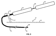
図2は、図1に先に説明されるような安定器10およびガイドカテーテルとともに使用される、送達カテーテルを示す。本特定の実施形態は、支持のためにガイドハンドルの内側に挿入され得る構造近位区画49を有する、送達カテーテル44、45と併用される。そのような例示的実施形態では、構造近位シャフト49は、弾性および/または剛性金属、ポリマー複合材、および/またはセラミック材料を用いて強化される。典型的には、強化構造シャフト49は、ガイドカテーテルハンドルの内側に部分的に、またはガイドカテーテル構造歪み緩和部19まで、および/またはそれを越えて挿入される。
FIG. 2 shows a delivery catheter used with the
図3は、送達カテーテル44のための付加的および/または独立した支持支柱71を備える、安定器10の代替実施形態を示す。さらに、ねじ山付き歪み緩和部19を介するガイドカテーテル34のための支柱17における機能的特徴(本発明において後で詳細に説明される)の全てまたは大部分は、類似する構造歪み緩和部49を介して送達カテーテル44のための支柱71において利用可能である、および/または再現され得る。本第2の支柱71は、基板10に一体的である、または、随意に、基板10に取り付けられるように構成され得る独立した二次特徴であってもよい。例えば、図1に示されるような2つ以上の独立した安定器が、連携して使用されてもよい。
FIG. 3 shows an alternative embodiment of
図4は、送達カテーテルが湾曲支柱81によって支持および制御される、実施形態10の例示的変形例を示す。本構成では、近位シャフト49の構造強化は、随意である。さらに、送達カテーテル44の回転および平行移動運動は、ノブ83または工学設計において一般的に使用される任意の設計を使用して制御されることができる。
FIG. 4 shows an exemplary variation of
図5は、図1に示されるような安定器実施形態10の3D図を示す。ガイドカテーテル本体は、簡易化のために示されず、代わりに、これは、ねじ山付き歪み緩和部19を介して表される。
FIG. 5 shows a 3D view of
図6は、図5に先に示される例示的安定器実施形態10の上面図を示す。
FIG. 6 shows a top view of the
図7は、図5に先に示された安定器実施形態10の例示的構成を示す。本構成において留意され得るように、ノブ13は、完全に後退され、ねじ山付き歪み緩和部19とノブねじ21との間に大きい間隙93が存在する。加えて、ねじ山付き歪み緩和部19と支柱17のねじ切り/ねじ山付き領域18との間にもまた大きい間隙95が存在する。したがって、本構成では、ねじ山付き歪み緩和部19は、平行移動および回転されることができる。これらの運動は、ユーザによって、ガイドハンドル34を直接把持し、これを移動させることによって実施され、したがって、所望の触覚フィードバックを保全することができる。加えて、本構成では、カテーテル19を安定器10から除去/係脱する(またはそれに挿入/係合させる)こともまた、可能である。
FIG. 7 shows an exemplary configuration of
図8は、図5に先に示された安定器実施形態10の例示的構成を示す。本構成において留意され得るように、ノブ13は、部分的に閉鎖され、ねじ山付き歪み緩和部19とノブねじ21との間に小さい間隙93が存在する。加えて、ねじ山付き歪み緩和部19と支柱17のねじ切り/ねじ山付き領域18との間にいかなる間隙95も存在しない。したがって、本構成において明白であるように、ねじ山付き歪み緩和部19は、回転されることができるが、しかしながら、これは、(任意の臨床的有意性を伴って)軸方向に平行移動されることができない。本回転運動は、ユーザによって、ガイドハンドル34を直接把持し、これを回転させることによって実施され、したがって、所望の触覚フィードバックを保全することができる。
FIG. 8 shows an exemplary configuration of
図9は、図5に先に示された安定器実施形態10の例示的構成を示す。本構成において留意され得るように、ねじ山付き歪み緩和部19とノブねじ21との間にいかなる間隙93も存在しない。すなわち、ノブ13は、完全に閉鎖され、ねじ山付き歪み緩和部19に対して引締され、これは、順に、ねじ切り領域18の中に完全に噛み合わされる。したがって、明白であるように、ねじ山付き歪み緩和部19の回転および平行移動の両方の完全な制限が存在する。すなわち、本構成では、ガイドカテーテルは、安定器10に対して設定位置において固定される。
FIG. 9 shows an exemplary configuration of
図10は、代替例示的安定器実施形態110の3D図を示す。これは、加えて、ねじ山付き歪み緩和部19を備える、代表的かつ例示的ガイドカテーテル界面接触構成要素を示す。安定器実施形態10との主要な差異は、図11においてより良好に明白である、支柱117の設計にある。
FIG. 10 shows a 3D view of an alternative
図12は、図10に示されるような例示的安定器実施形態110のクロッピング背面図を示す。本構成では、ねじ山付き歪み緩和部は、安定器110から除去される、またはそれと係合されることができる。
FIG. 12 shows a cropped rear view of
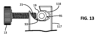
図13は、図10に示されるような例示的安定器実施形態110のクロッピング背面図を示す。本構成において留意され得るように、ノブ13は、完全に後退され、ねじ山付き歪み緩和部19とノブねじ21との間に大きい間隙93が存在する。加えて、ねじ山付き歪み緩和部19と支柱117のねじ切り/ねじ山付き領域118との間にもまた大きい間隙95が存在する。したがって、本構成では、ねじ山付き歪み緩和部19は、平行移動および回転されることができる。これらの運動は、ユーザによって、ガイドハンドル34を直接把持し、これを移動させることによって実施され、したがって、所望の触覚フィードバックを保全することができる。加えて、本構成では、カテーテル19を安定器110から除去/係脱する(またはそれに挿入/係合させる)こともまた、可能である。
FIG. 13 shows a cropped rear view of
図14は、図10に先に示された安定器実施形態110の例示的構成を示す。本構成において留意され得るように、ノブ13は、部分的に閉鎖され、ねじ山付き歪み緩和部19とノブねじ21との間に小さい間隙93が存在する。加えて、ねじ山付き歪み緩和部19と支柱117のねじ切り/ねじ山付き領域118との間にいかなる間隙95も存在しない。したがって、本構成において明白であるように、ねじ山付き歪み緩和部19は、回転されることができるが、しかしながら、これは、(本質的に)平行移動されることができない。本回転運動は、ユーザによって、ガイドハンドル34を直接把持し、これを回転させることによって実施され、したがって、所望の触覚フィードバックを保全することができる。
FIG. 14 shows an exemplary configuration of
図15は、図10に先に示された安定器実施形態110の例示的構成を示す。本構成において留意され得るように、ねじ山付き歪み緩和部19とノブねじ21との間にいかなる間隙93も存在しない。すなわち、ノブ13は、完全に閉鎖され、ねじ山付き歪み緩和部19に対して引締され、これは、順に、ねじ切り/ねじ山付き領域118の中に完全に噛み合わされる。したがって、明白であるように、ねじ山付き歪み緩和部19の回転および平行移動の両方の完全な制限が存在する。すなわち、本構成では、ガイドカテーテルは、安定器110に対して設定位置において固定される。
FIG. 15 shows an exemplary configuration of
図16は、例示的安定器実施形態210の3D背面図を示し、ノブ13は、平行移動を制限しながらカテーテル19の制御された回転運動を可能にする例示的構成にある。
FIG. 16 shows a 3D rear view of
図17は、図16に示されるような例示的安定器実施形態210のクロッピング背面図を示す。本構成では、ねじ山付き歪み緩和部は、安定器110から除去される、またはそれと係合されることができる。さらに、本構成において留意され得るように、ノブ13は、完全に後退され、ねじ山付き歪み緩和部19とノブねじ21との間に大きい間隙93が存在する。加えて、ねじ山付き歪み緩和部19と支柱217のねじ切り/ねじ山付き領域218との間にもまた大きい間隙95が存在する。したがって、本構成では、ねじ山付き歪み緩和部19は、平行移動および回転されることができる。これらの運動は、ユーザによって、ガイドハンドル34を直接把持し、これを移動させることによって実施され、したがって、所望の触覚フィードバックを保全することができる。加えて、本構成では、カテーテル19を安定器10から除去/係脱する(またはそれに挿入/係合させる)こともまた、可能である。
FIG. 17 shows a cropped rear view of
図18は、図16に先に示された安定器実施形態210の例示的構成を示す。本構成において留意され得るように、ノブ13は、部分的に閉鎖され、ねじ山付き歪み緩和部19とノブねじ21との間に小さい間隙93が存在する。加えて、ねじ山付き歪み緩和部19と支柱217のねじ切り/ねじ山付き領域218との間にいかなる間隙95も存在しない。したがって、本構成において明白であるように、ねじ山付き歪み緩和部19は、回転されることができるが、しかしながら、これは、平行移動されることができない。本回転運動は、ユーザによって、ガイドハンドル34を直接把持し、これを回転させることによって実施され、したがって、所望の触覚フィードバックを保全することができる。
FIG. 18 shows an exemplary configuration of
図19は、図16に先に示された安定器実施形態210の例示的構成を示す。本構成において留意され得るように、ねじ山付き歪み緩和部19とノブねじ21との間にいかなる間隙93も存在しない。すなわち、ノブ13は、完全に閉鎖され、ねじ山付き歪み緩和部19に対して引締され、これは、順に、ねじ切り/ねじ山付き領域218の中に完全に噛み合わされる。したがって、明白であるように、ねじ山付き歪み緩和部19の回転および平行移動の両方の完全な制限が存在する。すなわち、本構成では、ガイドカテーテルは、安定器210に対して設定位置において固定される。
FIG. 19 shows an exemplary configuration of
図20は、平行移動を制限しながらカテーテル19の制御された回転運動を可能にするように構成される、代替例示的安定器実施形態310の3D正面図を示す。これは、迅速な作動のための後退可能ばねプランジャ113を使用する。さらに、これは、(簡易化のために示されず、ねじ山付き歪み緩和部19によって表される)ガイドカテーテルの種々の角度を可能にするために、旋回支柱317を使用する。
FIG. 20 shows a 3D front view of an alternative
図21-22は、安定器310の3D側面図を示す。図20-23に見られ得るように、2つの板315が存在する。これらの板315はそれぞれ、それを中心として旋回安定器支柱317が回転するヒンジとして使用される、底部孔328を有する。これは、迅速接続ピン327を使用して底部孔328を通して旋回支柱317を組み立てることによって達成される。次に、旋回支柱317は、第2の迅速接続ピン327を挿入することによって、3つの利用可能な上部孔325のうちの1つを使用して所望の角度に設定される。図23-25は、3つの上部孔325のそれぞれを使用する3つのそのような例示的構成を示す。
21-22 show 3D side views of
図26-27は、ねじ山付き歪み緩和部19によって表されるように、カテーテルの角度におけるある範囲の平滑な変動を可能にする、スロット付き板415を伴う例示的実施形態410のクロッピング3D図を示す。図20-25に前述で示される上部孔325を通して迅速接続ピンを使用する代わりに、ねじ435および蝶ナット445が、スロット425内の所望の場所において旋回支柱317を係止するために使用される。
26-27 are cropping 3D views of
図28は、矢印を伴う標識M、L、A、Pを伴う例示的実施形態410を示す。図28に示される標識は、デボス加工されるが、医療デバイス産業または製造産業における当業者に明らかな任意の他の手段が、使用されてもよい。いくつかの実施例は、これらの実施例に限定されないが、レーザエッチング、成形、スタンピング、彫刻、および/または粉末コーティングである。
FIG. 28 shows an
図29-30は、ねじ山付き歪み緩和部19を安定器と迅速に係合/係止および/または係脱/係止解除する代替手段を示す。例えば、スリップオン捩れ閉鎖ナット560または六角プッシュボタンスライド調節ナット570は、ねじ山付き歪み緩和部19の操作を制御するために、ノブ13(ねじ21を含有する)と併せてねじ切り/ねじ山付き区画218を使用する代わりに、例示的安定器支柱217に取り付けられてもよい。
Figures 29-30 show an alternative means of quickly engaging/locking and/or disengaging/unlocking the threaded
代替例示的実施形態では、六角プッシュボタンスライド調節ナット570等の機構が、近位ガイドハンドル34の内側に組み込まれてもよい。送達ハンドル44の歪み緩和部49は、肋材またはねじ山(ガイドカテーテルねじ山付き歪み緩和部19と類似する)等の把持特徴を備えるように構成されることができる。ナット570のプッシュボタンまたは作動機構は、開放位置/閉鎖位置および種々の他の中間位置において構成されることができる。開放位置では、ねじ山付き歪み緩和部49は、ガイドカテーテルに対して挿入、除去、回転、および/または平行移動されることができる。中間位置では、ねじ山付き歪み緩和部49は、回転されるが、平行移動されることができない。閉鎖位置では、ねじ山付き歪み緩和部49(したがって、送達カテーテルハンドル44)は、ガイドカテーテルハンドル34に対して位置および回転において固定されることができる。代替として、および加えて、止血弁が、送達カテーテルハンドル44の前述で説明された運動制約を遂行し、図2に示されるような例示的構成における止血を提供するために、ガイドハンドル34に組み込まれてもよい。ねじ山付き歪み緩和部(または送りねじ)が実施例として説明されたが、前述で説明される把持および運動作動は、当業者に一般的に公知である、肋材、スロット、指向性および/または非指向性摩擦特徴を使用して達成されてもよい。
In alternate exemplary embodiments, a mechanism such as a hex push button
図31は、関節接合トレイ512および/または容器522に噛合され、その上に確実に搭載されるように構成される、例示的安定器実施形態10を示す。関節接合システムは、安定器を搭載するための安定した確実なプラットフォームを提供するために、係止可能および/または再位置付け可能であってもよい。さらに、関節接合(または代替として、屈曲可能/順応性)システムは、手術台の標準サイドレール上に可撤式に搭載される、または床または台スタンド上に設置されてもよい。代替として、安定器は、床スツールまたはOR台スツール上に設置されてもよい。さらに、スツールは、調節可能な高さおよび傾斜を有してもよい。
FIG. 31 illustrates an
ここで説明される実施形態は、例示にすぎず、当業者に非常に明白な他の変形例も、したがって、本明細書に含まれる。例えば、歪み緩和部19におけるようなねじ山の代わりに、実質的に同一の結果が、いくつかの妥当な変形例を挙げると、摩擦、円形スロット/リング/ボス/デボス、ローレット、磁石、ボール/ピン窪みを使用して得られることができる。
The embodiments described herein are exemplary only, and other variations that will be readily apparent to those skilled in the art are therefore also included herein. For example, instead of threads as in the
本開示の実施形態は、種々の産業用途において使用されることができる。例えば、いくつかの実施形態は、本開示による安定化システムを使用して医療デバイスを位置付ける方法を含み、そのようなシステム、デバイス、および方法は、医療デバイスの操作および位置付けが要求および/または所望される医療手技において使用されることができる。 Embodiments of the present disclosure can be used in various industrial applications. For example, some embodiments include methods of positioning a medical device using a stabilization system according to the present disclosure, such systems, devices, and methods being suitable for situations where manipulation and positioning of the medical device is required and/or desired. can be used in any medical procedure performed.
加えて、そのようなシステム、デバイス、および方法は、医療製品試験産業または医療製品分析産業において適用されることができる。例えば、支持、位置付け、再配向、および/または操作されるべき医療デバイスの能力が、本開示のデバイス、システム、および方法を使用して試験および分析されることができる。さらに、そのような使用下での医療デバイスの動作および耐久性限界が、試験および/または分析されることができる。 Additionally, such systems, devices and methods can be applied in the medical product testing industry or the medical product analysis industry. For example, the ability of a medical device to be supported, positioned, reoriented, and/or manipulated can be tested and analyzed using the devices, systems, and methods of the present disclosure. Additionally, the operational and durability limits of the medical device under such use can be tested and/or analyzed.
加えて、本開示の実施形態は、医療オペレータ訓練産業において使用されることができる。例えば、本開示の1つ以上のデバイス、システム、または方法が、内科医、外科医、医師、または医療エンジニアが、医療デバイスを位置付ける、操作する、再配向する、および/または再位置付けすることによって訓練を受けることを可能にする訓練用途において使用されることができる。 Additionally, embodiments of the present disclosure can be used in the medical operator training industry. For example, one or more of the devices, systems, or methods of the present disclosure may be used to train a physician, surgeon, physician, or medical engineer by positioning, manipulating, reorienting, and/or repositioning a medical device. It can be used in training applications that allow it to receive
本明細書で使用されるような用語「およそ」、「約」、および「実質的に」は、依然として所望の機能を実施する、または所望の結果を達成する記載される量または条件に近接する量または条件を表す。例えば、用語「およそ」、「約」、および「実質的に」は、記載される量または条件から10%未満、または5%未満、または1%未満、または0.1%未満、または0.01%未満逸脱する量を指し得る。 As used herein, the terms "approximately," "about," and "substantially" approximate the stated amount or condition that still performs the desired function or achieves the desired result. Denotes quantity or condition. For example, the terms “approximately,” “about,” and “substantially” refer to less than 10%, or less than 5%, or less than 1%, or less than 0.1%, or less than 0.1% from a stated amount or condition. It can refer to an amount that deviates from less than 0.1%.
加えて、別様に明確に説明されない限り、全ての記載される量(例えば、角度測定値、寸法測定値等)は、用語「およそ」、「約」、および/または「実質的に」が記載される量に関連して明確に記載されるかどうかにかかわらず、「およそ」、「約」、および「実質的に」記載される量であるものとして解釈されるものである。 Additionally, unless explicitly stated otherwise, all stated quantities (e.g., angular measurements, dimensional measurements, etc.) are It is to be understood that "approximately," "about," and "substantially" the stated amounts, whether or not explicitly stated in relation to the stated amounts.
さらに、本明細書に描写および/または説明される任意の実施形態に関連して説明される要素は、本明細書に描写および/または説明される任意の他の実施形態に関連して説明される要素と組み合わせ可能であってもよい。 Moreover, elements described in connection with any embodiment depicted and/or described herein may be described in connection with any other embodiment depicted and/or described herein. may be combinable with other elements.
本開示は、その精神または不可欠な特性から逸脱することなく、他の具体的形態において具現化されてもよい。説明される実施形態は、あらゆる点で、制限的ではなく、例証的にすぎないとして見なされるものである。本開示の範囲は、したがって、前述の説明によってではなく、添付される請求項および/または付記によって示される。請求項および/または付記の均等性の意味および範囲内に該当する全ての変更は、その範囲内に包含されるものである。 This disclosure may be embodied in other specific forms without departing from its spirit or essential characteristics. The described embodiments are to be considered in all respects only as illustrative and not restrictive. The scope of the disclosure is, therefore, indicated by the appended claims and/or appendices rather than by the foregoing description. All changes that come within the meaning and range of equivalency of the claims and/or claims are to be embraced within their scope.
ここで提示される例示的実施形態は、手動かつ機械的であるが、当業者に明らかおよび/または明白である他の電動および/または自動化変形例が、使用されてもよい。例えば、コンピュータ、人工知能、モータ、磁石、センサ、アクチュエータ、および/またはトランスデューサによる直接または間接または手動または自動化または遠隔制御が、カテーテルの制御された操作を可能にし、例示的な純粋な機械的かつ手動安定器を「スマート」安定器に変換するために使用されてもよい。例えば、安定器は、ワイヤの有無を問わず、ディスプレイ上に伝送される場合とそうではない場合がある3D、2D、および/または線形位置感知および作動を可能にするためのセンサを有してもよい。ディスプレイは、ローカルまたは遠隔、ハンドヘルド、または大型かつ非ハンドヘルド式であっておよい。 Although the exemplary embodiments presented here are manual and mechanical, other motorized and/or automated variations may be used that are obvious and/or obvious to those skilled in the art. For example, direct or indirect or manual or automated or remote control by computers, artificial intelligence, motors, magnets, sensors, actuators, and/or transducers enable controlled manipulation of the catheter, exemplary purely mechanical and It may be used to convert a manual ballast into a "smart" ballast. For example, ballasts have sensors with or without wires to enable 3D, 2D, and/or linear position sensing and actuation that may or may not be transmitted onto the display. good too. The display may be local or remote, handheld, or large and non-handheld.
本発明に説明される全ての実施形態は、ポリマー、金属合金、セラミック、強化複合材、および/または有機物または無機物由来のそれらの組み合わせを使用して製造されてもよい。さらに、これらの構成要素は、随意に、ユーザ体験または手技転帰を改良するために、被覆、被着、コーティング、または同等物を行われてもよい。好適なカバーは、ファブリック、ウェブ、繊維質、編組、織成、または非織成であり得る。コーティングは、金属、セラミック、ポリマー、またはそれらの組み合わせであり得る。好適な金属コーティングは、チタン、TiN、タンタル、金、白金、およびそれらの合金を含む。好適なセラミックおよび無機コーティングは、二酸化チタン、ヒドロキシアパタイト、CaP、および同等物を含む。好適なポリマーコーティングは、フルオロポリマー、例えば、PTFE、PFA、FEP、ECTFE、ETFE、パリレン、ポリエステル、PET、ポリプロピレン、PEEK、PVDF、HDPE、LDPE、UHMWPE、ホスホリルコリン、THV、および同等物を含む。好適な生分解性物質は、ポリ(乳酸)、ポリ(グリコール酸)、ポリジオキサノン、ポリ(ε-カプロラクトン)、ポリ酸無水物、ポリ(オルトエステル)、コポリ(エーテル-エステル)、ポリアミド、ポリラクトン、ポリ(プロピレンフマレート)、およびそれらの組み合わせを含む。そのような金属、セラミック、および/またはポリマーコーティングは、実施例としてのみ列挙される。任意の好適な金属、セラミック、ポリマー、およびそれらの組み合わせが、望ましいコーティングを生産するために使用されてもよい。 All embodiments described in this invention may be manufactured using polymers, metal alloys, ceramics, reinforced composites, and/or combinations thereof of organic or inorganic origin. Additionally, these components may optionally be coated, adhered, coated, or the like to improve user experience or procedure outcome. Suitable covers can be fabrics, webs, fibrous, braided, woven, or non-woven. Coatings can be metallic, ceramic, polymeric, or combinations thereof. Suitable metallic coatings include titanium, TiN, tantalum, gold, platinum, and alloys thereof. Suitable ceramic and inorganic coatings include titanium dioxide, hydroxyapatite, CaP, and the like. Suitable polymeric coatings include fluoropolymers such as PTFE, PFA, FEP, ECTFE, ETFE, parylene, polyester, PET, polypropylene, PEEK, PVDF, HDPE, LDPE, UHMWPE, phosphorylcholine, THV, and the like. Suitable biodegradable materials include poly(lactic acid), poly(glycolic acid), polydioxanone, poly(ε-caprolactone), polyanhydrides, poly(orthoesters), copoly(ether-esters), polyamides, polylactones, Including poly(propylene fumarate), and combinations thereof. Such metal, ceramic and/or polymer coatings are listed as examples only. Any suitable metals, ceramics, polymers, and combinations thereof may be used to produce the desired coatings.
以下は、本願において使用される参照番号の一覧である。
10 安定器-ガイドおよび送達カテーテル等のカテーテルを安定させる、および/または搭載するために使用される。
13 ノブ-カテーテルハンドル34を制御する、または安定させる、および/または締結するために使用される。これは、例示的ねじ山付き歪み緩和部19と相互作用する。
15 安定器基板
17 安定化支柱-ノブ13とともに、カテーテルハンドル19を制御する、または安定させる、および/または締結するために使用される
18 ねじ山付き歪み緩和部19のねじ山と噛み合う支柱17のねじ切り/ねじ山付き領域
19 安定器10、110、210、310、410と相互作用するガイドカテーテルハンドル34およびシャフト35のねじ山付き歪み緩和部
21 ノブ13のねじ山付きねじ
34 ハンドル-ガイドカテーテルハンドル
35 ガイドカテーテルシャフト
44 ハンドル-送達カテーテルハンドル
45 送達カテーテルシャフト
49 送達カテーテルハンドル44および送達カテーテルシャフト45の構造歪み緩和部
60 例示的インプラント
71 安定化支柱-ノブ73とともに、送達カテーテルハンドル44を制御する、または安定させる、および/または締結するために使用される
73 ノブ-カテーテルハンドル44を制御する、または安定させる、および/または締結するために使用される。これは、例示的歪み緩和部49と相互作用する。
81 安定化支柱-ノブ83とともに、送達カテーテルハンドル44を制御する、または安定させる、および/または締結するために使用される
83 ノブ-カテーテルハンドル44を制御する、または安定させる、および/または締結するために使用される
93 ノブねじとねじ山付き歪み緩和部19との間の間隙
95 安定化支柱17とねじ山付き歪み緩和部19との間の間隙
110 安定化支柱117を伴う安定器の代替実施形態
113 後退可能ばねプランジャ-カテーテルハンドル34を制御する、または安定させる、および/または締結するために使用される。これは、例示的ねじ山付き歪み緩和部19と相互作用する。
117 安定化支柱の代替実施形態-ノブ13とともに、カテーテルハンドル19を制御する、または安定させる、および/または締結するために使用される
118 ねじ山付き歪み緩和部19のねじ山と噛み合う支柱117のねじ切り/ねじ山付き領域
120 安定化支柱217を伴う安定器の代替実施形態
121 後退可能ばねプランジャ113のねじ山付きねじ
124 後退可能ばねプランジャ113の後退可能プランジャ区画
210 安定化支柱217を伴う安定器の代替実施形態
217 安定化支柱の代替実施形態-ノブ13とともに、カテーテルハンドル19を制御する、または安定させる、および/または締結するために使用される
218 ねじ山付き歪み緩和部19のねじ山と噛み合う支柱217のねじ切り/ねじ山付き領域
310 旋回安定化支柱317を伴う安定器の代替実施形態
315 旋回安定化支柱317を搭載するための上部孔325および底部孔328を伴う板
317 旋回安定器支柱
325 板315の上部孔
327 迅速解放ピン
328 板315の底部孔
410 旋回安定化支柱317を伴う安定器の代替実施形態
415 旋回安定化支柱317を搭載するための上部スロット425および底部孔328を伴う板
425 板415上の上部スロット
435 旋回安定化支柱317を固定するねじ
445 旋回安定化支柱317を固定する蝶ナット
512 OR台標準サイドレール上に搭載されるトレイ
515 例示的安定器10をORトレイ512に固着させるための迅速接続クランプ
522 ORトレイ512と関節接合アーム526との間のインターフェース構成要素
526 係止可能関節接合アーム
531 関節接合アーム526および/または台標準サイドレール537の間のインターフェース構成要素
537 OR台の標準サイドレール
560 スリップオン捩れ閉鎖ナット(例えば、本実施例に限定されないが、https://www.mcmaster.com/90125a086と類似する)
570 六角プッシュボタンスライド調節ナット(例えば、本実施例に限定されないが、https://www.mcmaster.com/98150a150と類似する)
Below is a list of reference numbers used in this application.
10 Stabilizer—Used to stabilize and/or mount catheters such as guides and delivery catheters.
13 Knob—used to control or stabilize and/or tighten the
15
81 Stabilizing strut - Used with
117 Stabilizing Strut Alternate Embodiment—A
570 Hex Push Button Slide Adjustment Nut (e.g., similar to, but not limited to, https://www.mcmaster.com/98150a150)
(一般的考慮事項)
本開示の多くの実施形態が詳細に説明されたが、本明細書に説明される全ての特徴および利益を提供するわけではない実施形態を含む、ある変形例および修正が、当業者に明白となるであろう。本開示は、具体的に開示される実施形態以外にも、他の代替または付加的実施形態および/または使用およびそれらの明らかな修正および均等物に及ぶことが、当業者によって理解されるであろう。加えて、いくつかの変形例が、様々な詳細において示され、説明されたが、本開示の範囲内である他の修正も、本開示に基づいて当業者に容易に明白となるであろう。また、実施形態の具体的特徴および側面の種々の組み合わせまたは副次的組み合わせが、行われ得、依然として、本開示の範囲内に該当することが考慮される。故に、開示される実施形態の種々の特徴および側面は、本開示の様々なモードを形成するために、相互に組み合わせられる、または相互に代用され得ることを理解されたい。したがって、本明細書に開示される本開示の範囲は、上記に説明される特定の開示される実施形態によって限定されるべきではないことを意図している。上記に説明される実施形態の全てに関して、任意の方法のステップは、連続的に実施される必要はない。
(general considerations)
Although many embodiments of the present disclosure have been described in detail, certain variations and modifications, including embodiments that do not provide all the features and benefits described herein, will become apparent to those skilled in the art. will be. It will be appreciated by those skilled in the art that the present disclosure extends to other alternative or additional embodiments and/or uses and obvious modifications and equivalents thereof beyond the specifically disclosed embodiments. deaf. Additionally, while several variations have been shown and described in various details, other modifications within the scope of the present disclosure will be readily apparent to those skilled in the art based on the present disclosure. . It is also contemplated that various combinations or subcombinations of the specific features and aspects of the embodiments can be made and still fall within the scope of the disclosure. Thus, it should be understood that various features and aspects of the disclosed embodiments can be combined or substituted for one another to form various modes of the disclosure. Accordingly, it is intended that the scope of the disclosure disclosed herein should not be limited by the specific disclosed embodiments set forth above. For all of the embodiments described above, any method steps need not be performed sequentially.
本説明の目的のために、本開示の実施形態のある側面、利点、および新規の特徴が、本明細書に説明される。開示される方法、装置、およびシステムは、いかようにも限定として解釈されるべきではない。代わりに、本開示は、単独で、そして相互との種々の組み合わせおよび副次的組み合わせで、種々の開示される実施形態の全ての新規かつ非自明な特徴および側面を対象とする。本方法、装置、およびシステムは、任意の具体的側面または特徴またはそれらの組み合わせに限定されず、開示される実施形態は、いずれか1つ以上の具体的利点が存在する、または問題が解決されることを要求しない。 For purposes of explanation, certain aspects, advantages and novel features of embodiments of the disclosure are described herein. The disclosed methods, devices, and systems should not be construed as limiting in any way. Instead, the present disclosure is directed to all novel and non-obvious features and aspects of the various disclosed embodiments alone and in various combinations and subcombinations with each other. The methods, apparatus, and systems are not limited to any specific aspect or feature or combination thereof, and the disclosed embodiments may exhibit any one or more specific advantages or solve problems. does not require
開示される方法のうちのいくつかの動作は、都合の良い提示のために特定の順序で説明されるが、説明の本様式は、特定の順序付けが具体的言語によって要求されない限り、再配列を包含することを理解されたい。例えば、連続的に説明される動作は、ある場合には、再配列される、または並行して実施されてもよい。さらに、簡略化のために、添付される図は、開示される方法が他の方法と併せて使用され得る種々の方法を示さない場合がある。本明細書で使用されるように、用語「a(ある)」、「an(ある)」、および「at least one(少なくとも1つ)」は、規定される要素のうちの1つ以上のものを包含する。すなわち、特定の要素のうちの2つが存在する場合、これらの要素のうちの1つもまた、存在し、したがって、「ある(an)」要素が、存在する。用語「a plurality of(複数の)」および「plural(複数)」は、規定される要素のうちの2つ以上のものを意味する。 Although the acts of some of the disclosed methods are described in a particular order for convenient presentation, the present mode of description precludes rearrangement unless a particular ordering is required by the specific language. be understood to include. For example, operations described sequentially may in some cases be rearranged or performed in parallel. Further, for the sake of simplicity, the attached figures may not show the various ways in which the disclosed methods can be used in conjunction with other methods. As used herein, the terms "a," "an," and "at least one" refer to one or more of the specified elements. encompasses That is, if two of a particular element are present, then one of those elements is also present, thus an "an" element is present. The terms "a plurality of" and "plural" mean two or more of the specified elements.
本明細書で使用されるように、要素の一覧の間に使用される用語「および/または」は、列挙される要素のうちのいずれか1つ以上のものを意味する。例えば、語句「A、B、および/またはC」は、「A」、「B」、「C」、「AおよびB」、「AおよびC」、「BおよびC」、または「A、B、およびC」を意味する。 As used herein, the term “and/or” used between listings of elements means any one or more of the listed elements. For example, the phrases "A, B, and/or C" can be replaced with "A," "B," "C," "A and B," "A and C," "B and C," or "A, B , and C”.
Claims (14)
遠位端および近位ハブを伴う本体を有する第1のカテーテルと、
前記近位ハブの遠位の前記カテーテル本体上の把持特徴と、
少なくとも1つの支持支柱を有する自立支持構造と、
前記支持構造上のクランプ構造であって、前記クランプ構造は、開放位置と、閉鎖位置と、前記開放位置と前記閉鎖位置との間の複数の中間位置とを有する、クランプ構造と
を備え、
(a)前記カテーテル本体の把持特徴は、前記クランプ構造がその開放構成にあるとき、前記クランプ構造の中に挿入され、前記クランプ構造から除去され得、(b)前記カテーテル本体の把持特徴は、前記クランプ構造が第1の中間位置にあるとき、前記クランプ構造内で回転され、軸方向に平行移動され得、(c)前記カテーテル本体の把持特徴は、前記クランプ構造が第2の中間位置にあるとき、前記クランプ構造内で回転されるが、軸方向に平行移動され得ない、カテーテル展開システム。 A catheter deployment system comprising:
a first catheter having a body with a distal end and a proximal hub;
a gripping feature on the catheter body distal to the proximal hub;
a freestanding support structure having at least one support strut;
a clamp structure on the support structure, the clamp structure having an open position, a closed position, and a plurality of intermediate positions between the open position and the closed position;
(a) a grasping feature of the catheter body may be inserted into and removed from the clamp structure when the clamp structure is in its open configuration; and (b) a grasping feature of the catheter body comprising: When the clamp structure is in a first intermediate position, it may be rotated and axially translated within the clamp structure; A catheter deployment system that, at one time, is rotated within the clamp structure, but cannot be axially translated.
遠位端および近位ハブを伴う本体を有するカテーテルと、
前記近位ハブの遠位の前記カテーテル本体上の把持特徴と
を備え、
(a)前記カテーテル本体の把持特徴は、クランプ構造がその開放構成にあるとき、前記クランプ構造の中に挿入され、前記クランプ構造から除去されるように構成され、(b)前記カテーテル本体の把持特徴は、前記クランプ構造が第1の中間位置にあるとき、前記クランプ構造内で回転され、軸方向に平行移動され得、(c)前記カテーテル本体の把持特徴は、前記クランプ構造が第2の中間位置にあるとき、前記クランプ構造内で回転されるが、軸方向に平行移動され得ない、カテーテル。 a catheter,
a catheter having a body with a distal end and a proximal hub;
a gripping feature on the catheter body distal to the proximal hub;
(a) a grasping feature of the catheter body configured to be inserted into and removed from the clamp structure when the clamp structure is in its open configuration; and (b) a grasp of the catheter body. a feature capable of being rotated and axially translated within the clamp structure when the clamp structure is in a first intermediate position; A catheter that, when in the intermediate position, is rotated within the clamping structure but cannot be axially translated.
前記把持特徴は、前記係合要素が前記谷部内で進行する際に前記カテーテルが自由に回転するが、前記肋材によって軸方向移動が制約されるように、前記クランプ構造が前記第2の中間位置にあるとき、隣接する肋材の間の前記谷部内に前記係合要素を受容するように構成される、請求項13に記載のカテーテル。 The clamp structure has an engagement element positioned adjacent to the gripping feature when the first catheter is within the clamp structure, the gripping feature allowing the first catheter to engage against the support structure. configured not to engage the engagement element when the clamping structure is in the first intermediate position so as to both rotate freely with respect to and translate axially; the clamping structure is on the support structure; or
The gripping feature is such that the clamping structure is positioned between the second intermediate portion such that the catheter is free to rotate as the engagement element is advanced within the valley, but is constrained from axial movement by the ribs. 14. The catheter of claim 13 , configured to receive the engagement element within the valley between adjacent ribs when in position.
Applications Claiming Priority (3)
| Application Number | Priority Date | Filing Date | Title |
|---|---|---|---|
| US201762570270P | 2017-10-10 | 2017-10-10 | |
| US62/570,270 | 2017-10-10 | ||
| PCT/US2018/055259 WO2019075095A1 (en) | 2017-10-10 | 2018-10-10 | Tissue grasping devices and related methods |
Publications (3)
| Publication Number | Publication Date |
|---|---|
| JP2020536645A JP2020536645A (en) | 2020-12-17 |
| JP2020536645A5 JP2020536645A5 (en) | 2021-10-28 |
| JP7213873B2 true JP7213873B2 (en) | 2023-01-27 |
Family
ID=66101677
Family Applications (1)
| Application Number | Title | Priority Date | Filing Date |
|---|---|---|---|
| JP2020520225A Active JP7213873B2 (en) | 2017-10-10 | 2018-10-10 | Tissue grasping device and related method |
Country Status (5)
| Country | Link |
|---|---|
| US (1) | US11701493B2 (en) |
| EP (1) | EP3694421A4 (en) |
| JP (1) | JP7213873B2 (en) |
| CN (2) | CN117838381A (en) |
| WO (1) | WO2019075095A1 (en) |
Families Citing this family (5)
| Publication number | Priority date | Publication date | Assignee | Title |
|---|---|---|---|---|
| US10799312B2 (en) | 2017-04-28 | 2020-10-13 | Edwards Lifesciences Corporation | Medical device stabilizing apparatus and method of use |
| EP3694421A4 (en) | 2017-10-10 | 2021-06-16 | Raghuveer Basude | Tissue grasping devices and related methods |
| US20200345483A1 (en) * | 2019-05-01 | 2020-11-05 | Twelve, Inc. | Support devices for transcatheter delivery system handles |
| EP4312866A1 (en) * | 2021-03-30 | 2024-02-07 | Edwards Lifesciences Corporation | Medical device support and method of use |
| WO2023172435A1 (en) * | 2022-03-08 | 2023-09-14 | Edwards Lifesciences Corporation | Stabilizer systems for medical procedures that maintain sterility of an articulating arm above a sterile barrier |
Citations (2)
| Publication number | Priority date | Publication date | Assignee | Title |
|---|---|---|---|---|
| US20120118088A1 (en) | 2010-11-17 | 2012-05-17 | Boston Scientific Scimed, Inc. | Bearing assembly for instrument |
| WO2017062637A1 (en) | 2015-10-09 | 2017-04-13 | Evalve, Inc. | Devices, systems, and methods to support, stabilize, and position a medical device |
Family Cites Families (17)
| Publication number | Priority date | Publication date | Assignee | Title |
|---|---|---|---|---|
| BE887056Q (en) * | 1979-01-19 | 1981-05-04 | Whitman Med Corp | STABILIZATION MOUNT FOR AN INTRAVENOUS CATHETER |
| US6752813B2 (en) | 1999-04-09 | 2004-06-22 | Evalve, Inc. | Methods and devices for capturing and fixing leaflets in valve repair |
| US7563267B2 (en) | 1999-04-09 | 2009-07-21 | Evalve, Inc. | Fixation device and methods for engaging tissue |
| US6530880B2 (en) * | 2001-03-29 | 2003-03-11 | Endius Incorporated | Apparatus for supporting an endoscope |
| US6834837B2 (en) * | 2002-11-07 | 2004-12-28 | Rultract, Inc. | Surgical instrument support device and method |
| US7569014B2 (en) * | 2005-09-07 | 2009-08-04 | West Coast Surgical, Llc | Connector for a surgical retractor |
| US20160030036A1 (en) * | 2005-09-14 | 2016-02-04 | Boss Instruments, Ltd., Inc. | Endoscopic Suturing Needle Loader Device, System And Method |
| US20070158513A1 (en) * | 2006-01-12 | 2007-07-12 | Levahn Intellectual Property Holding Company, Llc | Surgical clamp and tool support system |
| US9289266B2 (en) * | 2006-12-01 | 2016-03-22 | Boston Scientific Scimed, Inc. | On-axis drive systems and methods |
| US9398922B2 (en) * | 2008-12-18 | 2016-07-26 | Devicor Medical Products, Inc. | Targeting set for MRI biopsy device with probe holster support |
| WO2010081067A1 (en) | 2009-01-12 | 2010-07-15 | Becton, Dickinson And Company | Systems and methods for providing a convection-enhanced delivery device |
| US8979826B2 (en) | 2010-12-29 | 2015-03-17 | Boston Scientific Scimed, Inc. | Instrument holder |
| US9302075B2 (en) * | 2013-04-26 | 2016-04-05 | Furqan Tejani | Catheter retention device |
| ES2865049T3 (en) * | 2013-09-06 | 2021-10-14 | Covidien Lp | Catheter, Handle, and Microwave Ablation System |
| US10238495B2 (en) | 2015-10-09 | 2019-03-26 | Evalve, Inc. | Delivery catheter handle and methods of use |
| US20190030285A1 (en) | 2017-07-27 | 2019-01-31 | Evalve, Inc. | Intravascular delivery system with centralized steering |
| EP3694421A4 (en) | 2017-10-10 | 2021-06-16 | Raghuveer Basude | Tissue grasping devices and related methods |
-
2018
- 2018-10-10 EP EP18866289.4A patent/EP3694421A4/en active Pending
- 2018-10-10 CN CN202410018498.8A patent/CN117838381A/en active Pending
- 2018-10-10 WO PCT/US2018/055259 patent/WO2019075095A1/en unknown
- 2018-10-10 CN CN201880078527.2A patent/CN111465356B/en active Active
- 2018-10-10 JP JP2020520225A patent/JP7213873B2/en active Active
-
2020
- 2020-04-09 US US16/844,338 patent/US11701493B2/en active Active
Patent Citations (2)
| Publication number | Priority date | Publication date | Assignee | Title |
|---|---|---|---|---|
| US20120118088A1 (en) | 2010-11-17 | 2012-05-17 | Boston Scientific Scimed, Inc. | Bearing assembly for instrument |
| WO2017062637A1 (en) | 2015-10-09 | 2017-04-13 | Evalve, Inc. | Devices, systems, and methods to support, stabilize, and position a medical device |
Also Published As
| Publication number | Publication date |
|---|---|
| CN111465356A (en) | 2020-07-28 |
| EP3694421A1 (en) | 2020-08-19 |
| CN111465356B (en) | 2024-01-23 |
| US20200230362A1 (en) | 2020-07-23 |
| EP3694421A4 (en) | 2021-06-16 |
| WO2019075095A1 (en) | 2019-04-18 |
| US11701493B2 (en) | 2023-07-18 |
| CN117838381A (en) | 2024-04-09 |
| JP2020536645A (en) | 2020-12-17 |
Similar Documents
| Publication | Publication Date | Title |
|---|---|---|
| JP7213873B2 (en) | Tissue grasping device and related method | |
| US10470831B2 (en) | Actuation of a device comprising mechanical arms | |
| US10660625B2 (en) | One-way actuator knob | |
| JP6139630B2 (en) | Direct drive endoscopy system | |
| AU2014313763B2 (en) | Control unit for a medical device | |
| US10624671B2 (en) | Trocar attachment devices and methods | |
| EP2609872B2 (en) | Medical device for a delivery of a medical implant | |
| EP3272295B1 (en) | Implant and medical implant | |
| CN111447886B (en) | Patient-mounted surgical support | |
| EP2640302B1 (en) | Bearing assembly for instrument | |
| CN108135634A (en) | With the positioning device that surgical instruments is used together | |
| US20190282317A1 (en) | Surgical draping system and method | |
| US20190282316A1 (en) | Surgical draping system and method | |
| KR20200038887A (en) | Systems, devices and methods for positioning a patient before, during and / or after medical treatment | |
| US11278371B1 (en) | Surgical table apparatus | |
| RU2789707C1 (en) | Robotic surgical system for transcatheter aortic valve replacement | |
| US20240138984A1 (en) | Device, system, and method for intravascularly delivering an intravascular device to a targeted cardiac valve |
Legal Events
| Date | Code | Title | Description |
|---|---|---|---|
| A521 | Request for written amendment filed |
Free format text: JAPANESE INTERMEDIATE CODE: A523 Effective date: 20210916 |
|
| A621 | Written request for application examination |
Free format text: JAPANESE INTERMEDIATE CODE: A621 Effective date: 20210916 |
|
| A131 | Notification of reasons for refusal |
Free format text: JAPANESE INTERMEDIATE CODE: A131 Effective date: 20220720 |
|
| A977 | Report on retrieval |
Free format text: JAPANESE INTERMEDIATE CODE: A971007 Effective date: 20220722 |
|
| A521 | Request for written amendment filed |
Free format text: JAPANESE INTERMEDIATE CODE: A523 Effective date: 20221014 |
|
| TRDD | Decision of grant or rejection written | ||
| A01 | Written decision to grant a patent or to grant a registration (utility model) |
Free format text: JAPANESE INTERMEDIATE CODE: A01 Effective date: 20221227 |
|
| A61 | First payment of annual fees (during grant procedure) |
Free format text: JAPANESE INTERMEDIATE CODE: A61 Effective date: 20230117 |
|
| R150 | Certificate of patent or registration of utility model |
Ref document number: 7213873 Country of ref document: JP Free format text: JAPANESE INTERMEDIATE CODE: R150 |