JP7210532B2 - Heating blanket of metal-coated fabric and method of making same - Google Patents
Heating blanket of metal-coated fabric and method of making same Download PDFInfo
- Publication number
- JP7210532B2 JP7210532B2 JP2020500005A JP2020500005A JP7210532B2 JP 7210532 B2 JP7210532 B2 JP 7210532B2 JP 2020500005 A JP2020500005 A JP 2020500005A JP 2020500005 A JP2020500005 A JP 2020500005A JP 7210532 B2 JP7210532 B2 JP 7210532B2
- Authority
- JP
- Japan
- Prior art keywords
- fabric
- electrically insulating
- heating element
- electrical resistance
- layer
- Prior art date
- Legal status (The legal status is an assumption and is not a legal conclusion. Google has not performed a legal analysis and makes no representation as to the accuracy of the status listed.)
- Active
Links
Images


Classifications
-
- H—ELECTRICITY
- H05—ELECTRIC TECHNIQUES NOT OTHERWISE PROVIDED FOR
- H05B—ELECTRIC HEATING; ELECTRIC LIGHT SOURCES NOT OTHERWISE PROVIDED FOR; CIRCUIT ARRANGEMENTS FOR ELECTRIC LIGHT SOURCES, IN GENERAL
- H05B3/00—Ohmic-resistance heating
- H05B3/20—Heating elements having extended surface area substantially in a two-dimensional plane, e.g. plate-heater
- H05B3/34—Heating elements having extended surface area substantially in a two-dimensional plane, e.g. plate-heater flexible, e.g. heating nets or webs
- H05B3/342—Heating elements having extended surface area substantially in a two-dimensional plane, e.g. plate-heater flexible, e.g. heating nets or webs heaters used in textiles
-
- A—HUMAN NECESSITIES
- A61—MEDICAL OR VETERINARY SCIENCE; HYGIENE
- A61F—FILTERS IMPLANTABLE INTO BLOOD VESSELS; PROSTHESES; DEVICES PROVIDING PATENCY TO, OR PREVENTING COLLAPSING OF, TUBULAR STRUCTURES OF THE BODY, e.g. STENTS; ORTHOPAEDIC, NURSING OR CONTRACEPTIVE DEVICES; FOMENTATION; TREATMENT OR PROTECTION OF EYES OR EARS; BANDAGES, DRESSINGS OR ABSORBENT PADS; FIRST-AID KITS
- A61F7/00—Heating or cooling appliances for medical or therapeutic treatment of the human body
- A61F7/0097—Blankets with active heating or cooling sources
-
- H—ELECTRICITY
- H05—ELECTRIC TECHNIQUES NOT OTHERWISE PROVIDED FOR
- H05B—ELECTRIC HEATING; ELECTRIC LIGHT SOURCES NOT OTHERWISE PROVIDED FOR; CIRCUIT ARRANGEMENTS FOR ELECTRIC LIGHT SOURCES, IN GENERAL
- H05B3/00—Ohmic-resistance heating
- H05B3/10—Heater elements characterised by the composition or nature of the materials or by the arrangement of the conductor
- H05B3/12—Heater elements characterised by the composition or nature of the materials or by the arrangement of the conductor characterised by the composition or nature of the conductive material
- H05B3/14—Heater elements characterised by the composition or nature of the materials or by the arrangement of the conductor characterised by the composition or nature of the conductive material the material being non-metallic
- H05B3/145—Carbon only, e.g. carbon black, graphite
-
- H—ELECTRICITY
- H05—ELECTRIC TECHNIQUES NOT OTHERWISE PROVIDED FOR
- H05B—ELECTRIC HEATING; ELECTRIC LIGHT SOURCES NOT OTHERWISE PROVIDED FOR; CIRCUIT ARRANGEMENTS FOR ELECTRIC LIGHT SOURCES, IN GENERAL
- H05B2203/00—Aspects relating to Ohmic resistive heating covered by group H05B3/00
- H05B2203/002—Heaters using a particular layout for the resistive material or resistive elements
-
- H—ELECTRICITY
- H05—ELECTRIC TECHNIQUES NOT OTHERWISE PROVIDED FOR
- H05B—ELECTRIC HEATING; ELECTRIC LIGHT SOURCES NOT OTHERWISE PROVIDED FOR; CIRCUIT ARRANGEMENTS FOR ELECTRIC LIGHT SOURCES, IN GENERAL
- H05B2203/00—Aspects relating to Ohmic resistive heating covered by group H05B3/00
- H05B2203/011—Heaters using laterally extending conductive material as connecting means
-
- H—ELECTRICITY
- H05—ELECTRIC TECHNIQUES NOT OTHERWISE PROVIDED FOR
- H05B—ELECTRIC HEATING; ELECTRIC LIGHT SOURCES NOT OTHERWISE PROVIDED FOR; CIRCUIT ARRANGEMENTS FOR ELECTRIC LIGHT SOURCES, IN GENERAL
- H05B2203/00—Aspects relating to Ohmic resistive heating covered by group H05B3/00
- H05B2203/016—Heaters using particular connecting means
-
- H—ELECTRICITY
- H05—ELECTRIC TECHNIQUES NOT OTHERWISE PROVIDED FOR
- H05B—ELECTRIC HEATING; ELECTRIC LIGHT SOURCES NOT OTHERWISE PROVIDED FOR; CIRCUIT ARRANGEMENTS FOR ELECTRIC LIGHT SOURCES, IN GENERAL
- H05B2203/00—Aspects relating to Ohmic resistive heating covered by group H05B3/00
- H05B2203/017—Manufacturing methods or apparatus for heaters
-
- H—ELECTRICITY
- H05—ELECTRIC TECHNIQUES NOT OTHERWISE PROVIDED FOR
- H05B—ELECTRIC HEATING; ELECTRIC LIGHT SOURCES NOT OTHERWISE PROVIDED FOR; CIRCUIT ARRANGEMENTS FOR ELECTRIC LIGHT SOURCES, IN GENERAL
- H05B2203/00—Aspects relating to Ohmic resistive heating covered by group H05B3/00
- H05B2203/034—Heater using resistive elements made of short fibbers of conductive material
-
- H—ELECTRICITY
- H05—ELECTRIC TECHNIQUES NOT OTHERWISE PROVIDED FOR
- H05B—ELECTRIC HEATING; ELECTRIC LIGHT SOURCES NOT OTHERWISE PROVIDED FOR; CIRCUIT ARRANGEMENTS FOR ELECTRIC LIGHT SOURCES, IN GENERAL
- H05B2203/00—Aspects relating to Ohmic resistive heating covered by group H05B3/00
- H05B2203/036—Heaters specially adapted for garment heating
Description
関連出願の相互参照
出願人は、2017年3月14日に出願された、「Metalized Fabric Heating Blanket」と題する米国仮特許出願第62/471,103号、および2017年12月13日に出願された、「Metalized Fabric Heating Blanket」と題する米国特許出願第15/841,044号の優先権を主張する。
CROSS REFERENCES TO RELATED APPLICATIONS Applicants have U.S. Provisional Patent Application Serial Nos. 62/471,103 entitled "Metalized Fabric Heating Blanket," filed March 14, 2017 and It also claims priority from US patent application Ser. No. 15/841,044, entitled "Metalized Fabric Heating Blanket."
本発明は、一般に、加熱毛布、より詳細には、金属被覆された布帛を用いた加熱毛布、およびその製造方法に関する。 FIELD OF THE INVENTION The present invention relates generally to heating blankets, and more particularly to heating blankets using metal coated fabrics, and methods of making same.
何世紀にもわたり、断熱性の毛布などが作られてきた。そのような毛布は、伝統的に羊毛か綿布製であった。これらの材料は、ある程度の保温特性を提供してきたが、これらはそのような課題に最適ではない。 For centuries, insulating blankets and the like have been made. Such blankets have traditionally been made of wool or cotton fabric. While these materials have provided some degree of heat retention properties, they are not optimal for such tasks.
毛布および衣類を金属被覆された材料で作製して、赤外線熱反射機能という追加の利点を提供し、それによって、人からの熱損失をよりよく防止できることが、最近発見された。これらの製品は、屋外用毛布、医療患者の覆い、または体温の維持が所望される他の衣類として使用することができる。しかしながら、これらの金属被覆された布帛は、通常堅く、肌触りが柔軟ではない。 It has recently been discovered that blankets and clothing can be made of metallized materials to provide the added benefit of infrared heat reflective functionality, thereby better preventing heat loss from a person. These products can be used as outdoor blankets, medical patient coverings, or other garments where it is desired to maintain body temperature. However, these metallized fabrics are usually stiff and not soft to the touch.
Encompass Group,LLCは、長年Thermoflectという商品名で金属被覆された布帛材料を提供してきた。この金属被覆された布帛には、ともに接合されて布帛を形成する4つの個別の層がある。これらの4つの層には、透明なポリエチレン層、蒸着させたアルミニウム層、第2のポリエチレン層および滑らかな表面のスパンボンドポリプロピレン層が含まれ、これらの層は、外面から布帛を組み込んだ物品を着用する人に面している内面に向かって順に記載されている。肌触りが柔軟で、剛性が低く良好なドレープ特性および嵩高特性をもたらす金属被覆された布帛材料があることが望ましいと考えられる。より迅速かつ効率的な方法で人を暖めるための補助加熱を提供することも望ましいと考えられる。 The Encompass Group, LLC has offered metallized textile materials under the trade name Thermoflect for many years. This metallized fabric has four separate layers that are joined together to form the fabric. These four layers include a clear polyethylene layer, a vapor-deposited aluminum layer, a second polyethylene layer and a smooth-faced spunbond polypropylene layer, which layers form the article incorporating the fabric from the outside. They are written in order towards the inner side facing the wearer. It would be desirable to have a metallized fabric material that is soft to the touch, has low stiffness, and provides good drape and loft properties. It would also be desirable to provide supplemental heating to warm a person in a more rapid and efficient manner.
補助加熱を提供する1つの方法は、電気抵抗加熱素子を毛布に連結することである。加熱素子に電流を通じると、人を暖めるために利用される熱が生成される。これらの電気加温毛布に関する問題は、それらが効率的ではないということである。別の問題は、熱が加熱素子の領域に集中するので、不均一な加温領域が生じることである。 One method of providing supplemental heating is to couple an electrical resistance heating element to the blanket. Passing an electric current through the heating element produces heat that is used to warm a person. A problem with these electric heating blankets is that they are not efficient. Another problem is that heat is concentrated in the area of the heating element, resulting in non-uniform heating areas.
人に使用するのに従来技術の加温毛布に比べてより適するように、より効率的に、時間をかけずに、均一な熱を人に提供する加温毛布を提供することは、有益なはずである。したがって、本発明は主としてその提供を目的とするものである。 It would be beneficial to provide a warming blanket that provides uniform heat to a person more efficiently, in less time, and more suitable for use on a person than prior art warming blankets. should be. Accordingly, the present invention is primarily directed to that provision.
本発明の好ましい形態では、加熱毛布は、金属層を有する第1の布帛と、第1の布帛に連結された電気抵抗加熱素子と、電気抵抗加熱素子を被覆し、第1の布帛の反対側に位置する電気絶縁性の第2の布帛とを含む。 In a preferred form of the invention, the heating blanket comprises a first fabric having a metal layer, an electrical resistance heating element connected to the first fabric, covering the electrical resistance heating element and covering the opposite side of the first fabric. and a second electrically insulating fabric located at the .
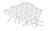
次に図面を参照すると、本発明の原理を好ましい形態で具体化する金属被覆された布帛10で部分的に作製された加温毛布8が示されている。加温毛布8は、材料で覆われているかまたは、材料を着用している人(患者)から離れる方に面するよう意図された下面11と、人(患者)に面するように意図された上面12とを有する。金属被覆された布帛は、透明な熱可塑性(例えばポリエチレン)材料の第1の層15と、蒸着させたアルミニウム材料(固体の金属被覆された層)の第2の層16と、熱可塑性(例えばポリエチレン)材料の第3の層17と、嵩高くふわふわしたスパンボンド熱可塑性(例えばポリプロピレン)不織布材料の第4の層18とを含んでいる。第1の層15の外面は布帛の下面11を構成し、第4の層18の外面は上面12を構成している。
Referring now to the drawings, there is shown a warming blanket 8 partially made of
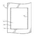
加温毛布8はまた、第3の層17と第4の層18の間に位置する抵抗加熱部30を含む。抵抗加熱部30は、加温毛布31および金属被覆された布帛10の周辺部または外縁から遠位に位置し、その結果、周辺マージン32がその間に形成される。
The warming blanket 8 also includes a
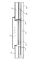
抵抗加熱部30は、図4に最もよく示されるように、各加熱素子34が横方向に延在する長手方向アレイに配置されたヒータートレース抵抗器または加熱素子34を有する。加熱素子34は、所望のパターンで第3の層17上に従来の導電性インクを堆積させることにより形成される。加熱素子34は、加熱素子の端部に連結された一対の導電性テープ35を介して電気的にともに接合されている。導電性テープ35は、銅などの金属で作製することができ、または、導電性テープ35は、追加の導電性インクストリップもしくは導電性素子の任意の他の構成で置き換えることができる。抵抗加熱部30はまた、サーミスタ37または熱電対を含むコントローラへの迅速な接続を可能にする従来のフラットフレックスクリンプピンタイプの接続性、またはカプラ36を含み、加温毛布8の電流および温度を調整することができる。
The
加温毛布8の入力電圧は、100~250VACであってもよく、最大の毛布電力は7W@12VDC~109W@48VDCである。 The input voltage of the warming blanket 8 may be 100-250VAC, with a maximum blanket power of 7W@12VDC to 109W@48VDC.
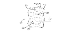
金属被覆された布帛は、抵抗加熱部30を有する熱可塑性材料の第3の層17を、スパンボンド熱可塑性不織布材料の第4の層18に接合することにより製造される。次いで、蒸着させたアルミニウム材料の第2の層16は真空堆積チャンバを介して第3の層17上に堆積または接合される。次いで、第1の層15は、第2の層16の上に押し出されるか接合される。次いで、この層の組合せは、大きな枕状領域のシリーズ、マトリックスもしくはフィールドまたは小さな枕状領域21によって四方を囲まれた領域20を形成するパターンで層をともに封止するコールドカレンダーローラーを通過する。大きな枕状領域20は、長さが約3/16インチの長手方向長さLAおよび約2/16インチの横幅LWを有するほぼ楕円形である。封止23自体は、いくつかの非接合セグメント24によって形成されているため非連続的または断片的であり、封止されていない布帛の領域よりも硬い傾向がある封止を破壊することによって、金属被覆された布帛に、硬さのより少ない風合いをもたらすのに役立つ。すなわち、封止での材料の接合は、封止された領域を硬くする傾向があり、それにより、全体の材料を硬くする傾向があるので、そのドレープ性および嵩高性を低下させる。本発明の金属被覆された布帛は、最小で18%の融着、接合または封止を含む従来技術の材料とは対照的に、材料の約14%で融着、接合または封止されている。
The metallized fabric is manufactured by bonding a
人と金属被覆された第2の層16の間の加熱素子の位置は、熱のより均一な分布を提供すると考えられている。加熱素子から発生した熱は、金属被覆された第2の層16によって反射されて人に戻る。したがって、最初に人から引き出された熱は、周囲環境へ失われず、その代り、人を暖めるために使用されるので、これは従来技術に対する歴然とした利点である。
It is believed that the location of the heating element between the person and the metallized
金属被覆された布帛の枕は、より高い絶縁品質、より柔らかい風合い、よりよく低減されたギラツキ感、改善されたドレープ性、および改善された嵩高性をもたらすと考えられている。 Metallized fabric pillows are believed to provide higher insulation qualities, softer hand, better reduced glare, improved drape, and improved loft.
別の発見された利点は、材料の交差方向の引裂き抵抗が改善されたことであった。先に述べた金属被覆された従来のThermoflect材料を本発明の金属被覆された布帛と比較して、試験を行った。本発明の金属被覆された布帛は、435.7の横方向引裂き係数を有することが見出された一方、金属被覆された従来のThermoflect材料は試験された393の横方向引裂き係数を有した。この試験では、耐引裂性の約11パーセント(11%)の改善が示されている。 Another discovered advantage was the improved cross-direction tear resistance of the material. A test was conducted comparing the metallized conventional Thermoflect materials described above to the metallized fabrics of the present invention. The metal-coated fabric of the present invention was found to have a transverse tear factor of 435.7, while the metal-coated conventional Thermoflect material had a transverse tear factor of 393 tested. This test shows about an eleven percent (11%) improvement in tear resistance.
第1の実施形態の代替として、好ましい形態の本発明の第2の実施形態を、図5および図6に示す。ここに、加温毛布40には一体構造として形成されている前述の第1の層15、第2の層16、第3の層17および第4の層18がある。第5の層41は、第4の層18に連結されている。第5の層41は、スパンボンド熱可塑性(例えばポリプロピレン)不織布材料であってもよい。第5の層41は、抵抗加熱部30と、特に導電性インクの形態で第4の層18に面する第5の層41の内面42に接合されるか連結することができる加熱素子34を含む前述のすべての構成要素とを含んでいる。
As an alternative to the first embodiment, a second embodiment of the invention in preferred form is shown in FIGS. Here, the
一対の両面テープストリップ44を、第5の層41に貼り付けて、既存の加温毛布に取付けまたは連結することができる。また、必要であれば、電子部品を備えた第5の層41は加温毛布から容易に取り外しまたは剥離することができる。そのため、既存の加温毛布を、静的なまたは厳密に言えば体熱を捕捉する加温毛布から、積極的なまたは能動的な電気抵抗性熱付加加温毛布に変換することができる。その後、加温毛布を、第5の層42および電子部品を取り外すことにより、静的な、体熱を捕捉する加温毛布に再構成することができる。このように、電子部品を取り付けることができ、次いで、電子部品が汚れた場合や使用できなくなった場合に、複数の加温毛布から取り外すことができ、廃棄することができる。この分別廃棄性は、抵抗加熱機能を有する加温毛布の提供に関わる費用を減少させる。
A pair of double-sided tape strips 44 can be applied to fifth layer 41 to attach or connect to an existing warming blanket. Also, if desired, the fifth layer 41 with electronic components can be easily removed or peeled from the warming blanket. As such, existing warming blankets can be converted from static or strictly body heat trapping warming blankets to positive or active electrically resistive heat added warming blankets. The warming blanket can then be reconfigured into a static, body heat trapping warming blanket by removing the
患者から離れる方向に最初に放射される加熱素子34からの熱の一部が、第4の層18を通過するときに分散され、第2の層16によって反射され、次いで人に到達する前に第4の層18を再び通過するときにさらに分散するので、この実施形態は、さらに高い量の熱分散または分布を提供すると考えられる。すなわち、熱は人に到達する前に第4の層18を2回通過する。これにより、追加の反射熱が人に戻されるので、導電性加熱素子34の温度を、より低い温度に設定することが可能になる。
A portion of the heat from the
本明細書で使用される「嵩高い(lofted)」という用語は、毛羽立って膨らんだ(fluffed)、ふわふわした(fluffy)、膨張した(expanded)、膨張した層(expanded layers)などを意味することが意図されていることを理解されたい。また、用語「ふわふわした(billow)」または、「ふわふわした(billowed)」は、隆起した(raised)、浮き彫りにした(embossed)、うねるような起伏のある表面(undulating surface)、嵩高い領域のある(having lofted areas)などを意味することが意図されている。薄い層を利用する場合に熱が集中するのとは対照的に、嵩高い内部材を使用することにより、加熱素子34からの熱と、金属被覆された第2の層16から反射して戻ってくる熱とを、より均一な加熱を提供するように、拡張または拡散できるようになると考えられる。
As used herein, the term "lofted" means fluffed, fluffy, expanded, expanded layers, etc. is intended. Also, the term "billow" or "billowed" refers to a raised, embossed, undulating surface, bulky area of It is intended to mean having lofted areas and the like. By using a bulky inner member, heat from the
次に図7~図13の実施形態を参照すると、本発明の別の好ましい形態の加熱毛布40が示されている。
7-13, there is shown another preferred
ここで、加熱素子34は、電気絶縁性スパンボンド材料の小さなパッチ53を炭素ベール材料52の外側に面する表面に接着することにより形成され、炭素ベール材料52は、ランダムに配向した炭素繊維のシートまたはマットであってもよい。次いで、炭素ベール材料52は、縫製、接着剤、音波溶接などにより電気絶縁性スパンボンド材料63の第2の層に接着され、これは、後で前述の金属被覆された布帛54に接合される。金属被覆された布帛54は、前述のものとほぼ同じであり、透明な熱可塑性(例えばポリエチレン)材料の第1の層15と、蒸着させたアルミニウム材料(金属被覆された層)の第2の層16と、熱可塑性(例えばポリエチレン)材料の第3の層17と、嵩高くふわふわしたスパンボンド熱可塑性(例えばポリプロピレン)不織布材料の第4の層18とを含んでいる。第3の層17および第4の層18は、電気的に絶縁性であってもよい。
Here, the
次に、ニッケルまたは銀インクで作製することができる導電性インク層56の形態の導電性ストリップが、図7にも示されている薄いストリップまたはサイドレール56として炭素ベール材料52の両側縁に堆積、噴霧、または印刷される。導電性インクサイドレール56は、炭素ベール材料52の異なる深さでランダム導電性繊維を局所的に接続するように作用する。
Conductive strips in the form of conductive ink layers 56, which may be made of nickel or silver ink, are then deposited on both side edges of the
次に図8を参照すると、次いで、下部導電性ストリップ58が、炭素ベール材料52の底縁部に縫い付けられるか、または導電性接着剤もしくは他の接合方法によって取り付けられる。下部導電性ストリップ58は、それぞれ、サイドレール56に電気的に接続される。下部導電性ストリップ58は、アルミニウム箔または他の導電性材料から作製することができる。下部導電性ストリップ58は、炭素ベール材料52から電気的に絶縁されている。下部導電性ストリップ58には、以下により詳細に説明される接続回路基板を受け入れるように、互いに間隔を空けた接続端部60がある。
Referring now to FIG. 8, a lower
次に図9を参照すると、次いで、側部導電性ストリップ62は、導電性インクサイドレール56と電気的に接触して、導電性インクサイドレール56に縫いつけられる。導電性インクサイドレール56のニッケル境界は、抵抗ドリフトの発生を防ぐ。側部導電性ストリップ62も下部導電性ストリップ58と電気的に接触するように縫い付けられている。
Referring now to FIG. 9, the side
次いで、スパンボンド材料63の第2の層は、第4の層(スパンボンド材料)18および/または炭素ベール材料52の周縁部に積層されるか、またはそうでなければ接合され(接着剤、音波溶接など)、それによって、スパンボンド材料の2つの層の間に炭素ベール材料52が挟まれる。スパンボンド材料63の第2の層は、患者の快適さと安全性のために柔軟な外部層を提供しながら、炭素ベール材料52を保護する。スパンボンド材料63の第2の層とスパンボンド材料(金属被覆された布帛)の第1の層の組合せは、本質的に炭素ベールを包囲するかまたは包む包被を作製する。
A second layer of spunbond material 63 is then laminated or otherwise bonded (adhesive, sonic welding), thereby sandwiching the
次に図10を参照すると、下部導電性ストリップ58の接続端部60を露出するように、穴または開口部66が金属被覆された布帛54に切り込まれる。次いで、図11に示すように、バッキングプレート68を、開口部66の位置でスパンボンド材料63の第2の層の裏側に、またはその後に毛布の患者側に接着されるスパンボンド材料のパッチに、取り付ける。図13に示すように、バッキングプレート68は、パッチ53に対して面一であるようにスパンボンド材料63の第2の層において、スロットまたはカット67を通過することができる。バッキングプレート68の使用は、サーミスタボードの接触面と下部導電性ストリップ58(クロスレール)との間に圧力を提供するだけでなく、加温毛布の接続点の局所的な支持を提供する。バッキングプレート68は、サーミスタ(サーミスタプレート71)を含んでいるスナップオン回路基板70、または熱電対と係合、嵌合できるように、パッチ53および炭素ベール材料52を貫通して延びるかまたは貫通してパンチ形成される1セットの装着爪69を含んでいる。次いで、回路基板70は、図12および図13に示すように、金属被覆された布帛54の外面に装着され、下部導電性ストリップ58の接続端部60に接続される。回路基板70は、サーミスタが配置されている場所への熱伝達を支援するためにビアホールの大きな配列を含む。接続目的で大きな回路基板を使用すると、加熱布帛(炭素ベール材料)の平均温度がより正確になる。つまり、エラーの可能性を最小限に抑えるために、平均化のために広い範囲にわたって温度が検出される。コネクタハウジング内にサーミスタを収めることができるように、ビアホールは回路基板の上面に熱を伝達する。これにより、操作者の安全のためにサーミスタも保護される。
Referring now to FIG. 10, holes or openings 66 are cut into the metallized
使用に際して、回路基板70を介して電流を制御し、下部導電性ストリップ58の接続端部60に流す。次いで、電流を側部導電性ストリップ62および導電性インクサイドレール56に移動し、そこで、抵抗熱が生成される炭素ベール材料52に流す。金属被覆された布帛は、熱を反射して、熱の均一な分布と、より効率的な使用を生み出す。嵩高い材料層は、熱を拡散して、熱の集中またはホットスポットを防止する。
In use, current is controlled through the
回路基板70は、ばらつきを最小限にするために複数のサーミスタを使用する。サーミスタを回路基板70上に配置することにより、サーミスタを使い捨ての「毛布」または材料被覆部分ではなく、加温毛布50の再使用可能な部分に配置することが可能になる。この配置により、加温毛布の交換コストが削減される。
下部導電性ストリップ58および側部導電性ストリップ62の導電性箔を、スパンボンド材料63の第2の層および炭素ベール材料52に縫い付けると、より良好な電気接続が得られると考えられる。また、縫製により、加温毛布のよりよいドレープ性が維持されると考えられる。改善されたドレープ性は、患者の快適さ、効果的な加温、および製造コストの削減にとって重要である。
It is believed that stitching the conductive foils of the bottom
下部導電性ストリップ58、および側部導電性ストリップ62の縫製工程は、非導電性の綿-ポリ混紡糸を使用して達成されることが好ましい。
The sewing process for the lower
説明は、加温毛布を構築する1つの方法に関するものであることを理解されたい。構築に関与するステップの正確な順序は、本発明を実施している間に異なってもよい。 It should be understood that the description is for one method of constructing the warming blanket. The exact order of steps involved in construction may vary while practicing the invention.
本明細書で使用される縫製、接着剤接合、音波溶接、熱溶接、または任意の他の従来の接合もしくは連結方法は、同等であることを理解されたい。 It should be understood that sewing, adhesive bonding, sonic welding, heat welding, or any other conventional joining or connecting method used herein are equivalent.
したがって、金属被覆された布帛を使用する加熱毛布およびその製造方法がここで提供され、これは従来技術の加熱毛布に関連した問題を克服することが分かる。当然のことながら、以下の特許請求の範囲に記載の本発明の精神および範囲から逸脱することなく、本明細書に具体的に列挙したものに加えて、本明細書に記載の特定の好ましい実施形態に多くの変更を加えることができることを理解されたい。 Thus, it can be seen that a heating blanket using metallized fabric and methods of making same are provided herein, which overcome the problems associated with prior art heating blankets. It should be understood that certain preferred implementations described herein, in addition to those specifically recited herein, may be used without departing from the spirit and scope of the invention as set forth in the following claims. It should be understood that many variations in form can be made.
Claims (18)
前記第1の布帛に連結された電気抵抗加熱素子と;
前記電気抵抗加熱素子を被覆し、前記第1の布帛の反対側に位置する電気絶縁性の第2の布帛と;
前記電気抵抗加熱素子に電気的に連結された電気制御回路と
を含み、
前記第1の布帛は、前記蒸着金属層の第1の表面を覆う第1の熱可塑性層と、前記蒸着金属層の前記第1の表面から反対に配置された前記蒸着金属層の第2の表面を覆う電気絶縁性の第2の熱可塑性層と、電気絶縁性のスパンボンド熱可塑性不織布材料層とを、この順に含み、
前記電気抵抗加熱素子は、導電性インク加熱素子であり、炭素ベール材料と、導電性インクサイドレールと、電気絶縁性スパンボンド材料層と、下部導電性ストリップと、側部導電性ストリップとを含み、
前記炭素ベール材料は、ランダムに配向した炭素繊維のシートまたはマットからなり、前記第1の布帛に接合されており、前記電気絶縁性スパンボンド材料層に接着されており、抵抗熱を生成し、
前記導電性インクサイドレールは、ニッケルまたは銀インクからなり、前記炭素ベール材料の両側縁に配置されており、
前記下部導電性ストリップは、前記炭素ベール材料の底縁部に取り付けられており、前記導電性インクサイドレールに電気的に接続されており、
前記側部導電性ストリップは、前記導電性インクサイドレールに縫いつけられ、前記導電性インクサイドレール及び前記下部導電性ストリップと電気的に接触している、
前記加熱毛布。 a first fabric having a vapor deposited metal layer;
an electrical resistance heating element coupled to said first fabric;
a second electrically insulating fabric covering said electrical resistance heating element and positioned opposite said first fabric ;
an electrical control circuit electrically coupled to the electrical resistance heating element;
including
The first fabric comprises a first thermoplastic layer covering a first surface of the vapor-deposited metal layer and a second layer of the vapor-deposited metal layer opposite from the first surface of the vapor-deposited metal layer. an electrically insulating second thermoplastic layer overlying a surface and an electrically insulating spunbond thermoplastic nonwoven material layer, in that order;
The electrical resistance heating element is a conductive ink heating element and includes a carbon veil material, a conductive ink side rail, an electrically insulating spunbond material layer, a bottom conductive strip, and a side conductive strip. ,
said carbon veil material comprising a sheet or mat of randomly oriented carbon fibers bonded to said first fabric and bonded to said electrically insulating spunbond material layer to generate resistive heat;
the conductive ink side rails are made of nickel or silver ink and are located on both side edges of the carbon veil material;
said lower conductive strip is attached to the bottom edge of said carbon veil material and is electrically connected to said conductive ink side rail;
the side conductive strips are sewn to the conductive ink side rails and are in electrical contact with the conductive ink side rails and the bottom conductive strip;
the heating blanket;
蒸着金属層を被覆する外向き熱可塑性層を有する金属被覆された布帛と;
前記金属被覆された布帛に連結された導電性インク電気抵抗加熱素子と;
前記導電性インク電気抵抗加熱素子を被覆し、前記金属被覆された布帛から反対側に配置された第1の電気絶縁性布帛と;
前記導電性インク電気抵抗加熱素子に電気的に連結された電気制御回路と
を含み、
前記金属被覆された布帛は、前記蒸着金属層の第1の表面を覆う電気絶縁性の第1の熱可塑性層と、前記蒸着金属層の前記第1の表面から反対に配置された前記蒸着金属層の第2の表面を覆う電気絶縁性の第2の熱可塑性層と、電気絶縁性のスパンボンド熱可塑性不織布材料層とを、この順に含み、
前記電気抵抗加熱素子は、導電性インク加熱素子であり、炭素ベール材料と、導電性インクサイドレールと、電気絶縁性スパンボンド材料層と、下部導電性ストリップと、側部導電性ストリップとを含み、
前記炭素ベール材料は、ランダムに配向した炭素繊維のシートまたはマットからなり、前記金属被覆された布帛に接合されており、前記電気絶縁性スパンボンド材料層に接着されており、抵抗熱を生成し、
前記導電性インクサイドレールは、ニッケルまたは銀インクからなり、前記炭素ベール材料の両側縁に配置されており、
前記下部導電性ストリップは、前記炭素ベール材料の底縁部に取り付けられており、前記導電性インクサイドレールに電気的に接続されており、
前記側部導電性ストリップは、前記導電性インクサイドレールに縫いつけられ、前記導電性インクサイドレール及び前記下部導電性ストリップと電気的に接触している、
前記加熱毛布。 A heating blanket,
a metallized fabric having an outwardly facing thermoplastic layer covering the vapor deposited metal layer;
a conductive ink electrical resistance heating element coupled to said metallized fabric;
a first electrically insulating fabric covering said conductive ink electrical resistance heating element and positioned opposite from said metallized fabric ;
an electrical control circuit electrically coupled to the conductive ink electrical resistance heating element;
including
The metallized fabric comprises an electrically insulating first thermoplastic layer overlying a first surface of the vapor-deposited metal layer and the vapor-deposited metal disposed opposite from the first surface of the vapor-deposited metal layer. comprising, in order, an electrically insulating second thermoplastic layer overlying a second surface of the layer and an electrically insulating spunbond thermoplastic nonwoven material layer;
The electrical resistance heating element is a conductive ink heating element and includes a carbon veil material, a conductive ink side rail, an electrically insulating spunbond material layer, a bottom conductive strip, and a side conductive strip. ,
The carbon veil material consists of a sheet or mat of randomly oriented carbon fibers, bonded to the metallized fabric, bonded to the electrically insulating spunbond material layer, and generates resistive heat. ,
the conductive ink side rails are made of nickel or silver ink and are located on both side edges of the carbon veil material;
said lower conductive strip is attached to the bottom edge of said carbon veil material and is electrically connected to said conductive ink side rail;
the side conductive strips are sewn to the conductive ink side rails and are in electrical contact with the conductive ink side rails and the bottom conductive strip;
the heating blanket;
(A)蒸着金属被覆された布帛を用意する工程と;
(B)電気抵抗加熱素子を作製する工程と;
(C)電気抵抗加熱素子を該蒸着金属被覆された布帛に連結する工程と;
(D)該電気抵抗加熱素子上に第1の電気絶縁性布帛を連結する工程と;
(E)電気制御回路を該電気抵抗加熱素子に連結する工程と
を含む、前記加熱毛布の製造方法。 A method for manufacturing a heating blanket according to claim 1 or 8, comprising:
(A) providing a vapor-deposited metal coated fabric;
(B) fabricating an electrical resistance heating element;
( C ) connecting an electrical resistance heating element to the vapor- deposited metal coated fabric;
( D ) connecting a first electrically insulating fabric over the electrical resistance heating element;
( E ) coupling an electrical control circuit to said electrical resistance heating element.
請求項15に記載の方法。 a second electrically insulating fabric is provided between the vapor- deposited metal coated fabric and the electrical resistance heating element;
16. The method of claim 15 .
Applications Claiming Priority (5)
| Application Number | Priority Date | Filing Date | Title |
|---|---|---|---|
| US201762471103P | 2017-03-14 | 2017-03-14 | |
| US62/471,103 | 2017-03-14 | ||
| US15/841,044 | 2017-12-13 | ||
| US15/841,044 US10805988B2 (en) | 2017-03-14 | 2017-12-13 | Metalized fabric heating blanket and method of manufacturing such |
| PCT/US2018/022264 WO2018170020A1 (en) | 2017-03-14 | 2018-03-13 | Metalized fabric heating blanket and method of manufacturing such |
Publications (2)
| Publication Number | Publication Date |
|---|---|
| JP2020510304A JP2020510304A (en) | 2020-04-02 |
| JP7210532B2 true JP7210532B2 (en) | 2023-01-23 |
Family
ID=63520494
Family Applications (1)
| Application Number | Title | Priority Date | Filing Date |
|---|---|---|---|
| JP2020500005A Active JP7210532B2 (en) | 2017-03-14 | 2018-03-13 | Heating blanket of metal-coated fabric and method of making same |
Country Status (9)
| Country | Link |
|---|---|
| US (1) | US10805988B2 (en) |
| EP (1) | EP3597003A4 (en) |
| JP (1) | JP7210532B2 (en) |
| KR (1) | KR20200007772A (en) |
| AU (1) | AU2018236223A1 (en) |
| BR (1) | BR112019019179A2 (en) |
| CA (1) | CA3056605A1 (en) |
| MX (1) | MX2019010938A (en) |
| WO (1) | WO2018170020A1 (en) |
Families Citing this family (5)
| Publication number | Priority date | Publication date | Assignee | Title |
|---|---|---|---|---|
| IT201800009440A1 (en) | 2018-10-15 | 2020-04-15 | Health For Life Srl | CUSTOMIZABLE SPACE-SAVING HEATED THERMAL COVER AND ASSOCIATED KIT |
| EP3660642B1 (en) * | 2018-11-28 | 2023-11-08 | Sanko Tekstil Isletmeleri San. Ve Tic. A.S. | Large area touch fabric |
| CN109618433B (en) * | 2018-12-20 | 2022-04-08 | 四川省中科烯捷石墨烯科技有限公司 | Graphene safe voltage heating film |
| KR20210094253A (en) | 2020-01-21 | 2021-07-29 | 삼성전자주식회사 | Calibration modules of image sensors, image sensros and methdods of calibrating crosstalk |
| US11696861B1 (en) * | 2020-06-15 | 2023-07-11 | Kendrick L. Riley | Crib bedding with temperature gauge |
Citations (9)
| Publication number | Priority date | Publication date | Assignee | Title |
|---|---|---|---|---|
| JP2003163070A (en) | 2001-11-27 | 2003-06-06 | Misawa Shokai:Kk | Heating apparatus |
| US6770854B1 (en) | 2001-08-29 | 2004-08-03 | Inotec Incorporated | Electric blanket and system and method for making an electric blanket |
| JP2007183036A (en) | 2006-01-06 | 2007-07-19 | Fujitsu General Ltd | Planar electric heater |
| US20090299442A1 (en) | 2008-06-03 | 2009-12-03 | Joseph Blase Vergona | Warming Blankets, Covers, and Apparatus, and Methods of Fabricating and Using the Same |
| JP2011097976A (en) | 2009-11-04 | 2011-05-19 | Sanyo Electric Co Ltd | Electric blanket |
| US20120191164A1 (en) | 2011-01-26 | 2012-07-26 | Gander Nicholas M | Radiant heating apparatus and method for therapeutic heating |
| JP2013223624A (en) | 2012-04-23 | 2013-10-31 | Panasonic Corp | Flat warmer |
| US20150072113A1 (en) | 2013-09-12 | 2015-03-12 | Encompass Group, Llc | Metalized fabric |
| CN105640178A (en) | 2016-03-07 | 2016-06-08 | 徐勇 | Reflective constant-temperature C-shaped dual-purpose electric blanket |
Family Cites Families (31)
| Publication number | Priority date | Publication date | Assignee | Title |
|---|---|---|---|---|
| US4912306A (en) * | 1987-07-14 | 1990-03-27 | Grise Frederick Gerard J | Electric resistance heater |
| US4950868A (en) * | 1989-03-03 | 1990-08-21 | Marmon Holdings, Inc. | Heated gloves |
| US6229123B1 (en) * | 1998-09-25 | 2001-05-08 | Thermosoft International Corporation | Soft electrical textile heater and method of assembly |
| US6713733B2 (en) * | 1999-05-11 | 2004-03-30 | Thermosoft International Corporation | Textile heater with continuous temperature sensing and hot spot detection |
| AU2071701A (en) * | 1999-12-10 | 2001-06-18 | Thermion Systems International | A thermoplastic laminate fabric heater and methods for making same |
| AU6687401A (en) | 2000-06-14 | 2001-12-24 | Inc American Healthcare Produc | Heating pad systems, such as for patient warming applications |
| US6967309B2 (en) | 2000-06-14 | 2005-11-22 | American Healthcare Products, Inc. | Personal warming systems and apparatuses for use in hospitals and other settings, and associated methods of manufacture and use |
| US6933469B2 (en) | 2000-06-14 | 2005-08-23 | American Healthcare Products, Inc. | Personal warming systems and apparatuses for use in hospitals and other settings, and associated methods of manufacture and use |
| US6946628B2 (en) * | 2003-09-09 | 2005-09-20 | Klai Enterprises, Inc. | Heating elements deposited on a substrate and related method |
| AU2006299636A1 (en) | 2005-09-29 | 2007-04-12 | Augustine Biomedical And Design Llc | Heating blanket and pads |
| US7851729B2 (en) | 2005-09-29 | 2010-12-14 | Augustine Temperature Management LLC | Electric warming blanket having optimized temperature zones |
| US8062343B2 (en) | 2006-10-13 | 2011-11-22 | Augustine Temperature Management LLC | Heating blanket |
| ITVA20060042U1 (en) * | 2006-10-18 | 2008-04-19 | Gvp Elettronica Srl | TRANSPORTABLE MEDICAL HEATING DEVICE DM-EMG CODE IN CARBON YARN AND BIOCOMPATIBLE PVC FOR HEATING THE PATIENT AND PREVENTING HYPOTHERMIA (WITH CHEST DIRECT CONTACT POSITIONING) DURING EMERG'S INTERVENTIONS |
| US8624164B2 (en) | 2007-01-18 | 2014-01-07 | Augustine Temperature Management LLC | Shut-off timer for a heating blanket |
| US8283602B2 (en) | 2007-03-19 | 2012-10-09 | Augustine Temperature Management LLC | Heating blanket |
| WO2009049271A1 (en) | 2007-10-12 | 2009-04-16 | Augustine Biomedical And Design Llc | Multi-zone electric warming blanket |
| WO2010049927A1 (en) * | 2008-10-28 | 2010-05-06 | Yael Bonneh | A breathable insulation material, device and methods |
| US20100161016A1 (en) * | 2008-12-19 | 2010-06-24 | Augustine Biomedical And Design, Llc | Apparatus and method for effectively warming a patient |
| US20100200558A1 (en) * | 2009-02-12 | 2010-08-12 | Liu Ying-Hsiung | Electrical heating blanket |
| US8876812B2 (en) * | 2009-02-26 | 2014-11-04 | Megadyne Medical Products, Inc. | Self-limiting electrosurgical return electrode with pressure sore reduction and heating capabilities |
| US20100255277A1 (en) | 2009-04-02 | 2010-10-07 | Xerox Corporation | Thermal insulating multiple layer blanket |
| TWM387445U (en) * | 2010-03-29 | 2010-08-21 | Xin Zhuan Technology Co Ltd | Flexible flat strip heater applied in a carbon fiber as a heat source |
| US9687093B2 (en) | 2011-05-26 | 2017-06-27 | Medline Industries, Inc | Patient warming blanket, drape, and corresponding patient warming system |
| KR101428035B1 (en) * | 2012-09-25 | 2014-08-06 | (주)그린산업 | Planar Heat Generator |
| US9668303B2 (en) | 2013-04-17 | 2017-05-30 | Augustine Biomedical And Design, Llc | Flexible electric heaters |
| EP3217906B1 (en) * | 2014-11-13 | 2022-03-02 | Augustine Temperature Management, LLC | Heated underbody warming systems with electrosurgical grounding |
| EP3245844B1 (en) * | 2015-01-12 | 2020-05-27 | Laminaheat Holding Ltd. | Fabric heating element |
| EP3297588A4 (en) * | 2015-05-21 | 2019-02-13 | Vitaheat Medical, LLC | Patient warming system |
| US20180124871A1 (en) * | 2016-10-31 | 2018-05-03 | Gentherm Gmbh | Carbon veil heater and method of making |
| US20190351153A1 (en) * | 2017-03-14 | 2019-11-21 | Encompass Group, Llc | Metalized fabric heating device for medical soulutions |
| US11583437B2 (en) * | 2018-02-06 | 2023-02-21 | Aspen Surgical Products, Inc. | Reusable warming blanket with phase change material |
-
2017
- 2017-12-13 US US15/841,044 patent/US10805988B2/en active Active
-
2018
- 2018-03-13 CA CA3056605A patent/CA3056605A1/en active Pending
- 2018-03-13 EP EP18767009.6A patent/EP3597003A4/en not_active Withdrawn
- 2018-03-13 WO PCT/US2018/022264 patent/WO2018170020A1/en unknown
- 2018-03-13 JP JP2020500005A patent/JP7210532B2/en active Active
- 2018-03-13 BR BR112019019179A patent/BR112019019179A2/en not_active Application Discontinuation
- 2018-03-13 MX MX2019010938A patent/MX2019010938A/en unknown
- 2018-03-13 KR KR1020197029473A patent/KR20200007772A/en not_active Application Discontinuation
- 2018-03-13 AU AU2018236223A patent/AU2018236223A1/en not_active Abandoned
Patent Citations (9)
| Publication number | Priority date | Publication date | Assignee | Title |
|---|---|---|---|---|
| US6770854B1 (en) | 2001-08-29 | 2004-08-03 | Inotec Incorporated | Electric blanket and system and method for making an electric blanket |
| JP2003163070A (en) | 2001-11-27 | 2003-06-06 | Misawa Shokai:Kk | Heating apparatus |
| JP2007183036A (en) | 2006-01-06 | 2007-07-19 | Fujitsu General Ltd | Planar electric heater |
| US20090299442A1 (en) | 2008-06-03 | 2009-12-03 | Joseph Blase Vergona | Warming Blankets, Covers, and Apparatus, and Methods of Fabricating and Using the Same |
| JP2011097976A (en) | 2009-11-04 | 2011-05-19 | Sanyo Electric Co Ltd | Electric blanket |
| US20120191164A1 (en) | 2011-01-26 | 2012-07-26 | Gander Nicholas M | Radiant heating apparatus and method for therapeutic heating |
| JP2013223624A (en) | 2012-04-23 | 2013-10-31 | Panasonic Corp | Flat warmer |
| US20150072113A1 (en) | 2013-09-12 | 2015-03-12 | Encompass Group, Llc | Metalized fabric |
| CN105640178A (en) | 2016-03-07 | 2016-06-08 | 徐勇 | Reflective constant-temperature C-shaped dual-purpose electric blanket |
Also Published As
| Publication number | Publication date |
|---|---|
| MX2019010938A (en) | 2020-01-21 |
| US20180270907A1 (en) | 2018-09-20 |
| AU2018236223A1 (en) | 2019-10-10 |
| WO2018170020A1 (en) | 2018-09-20 |
| EP3597003A4 (en) | 2021-03-03 |
| US10805988B2 (en) | 2020-10-13 |
| CA3056605A1 (en) | 2018-09-20 |
| JP2020510304A (en) | 2020-04-02 |
| KR20200007772A (en) | 2020-01-22 |
| EP3597003A1 (en) | 2020-01-22 |
| BR112019019179A2 (en) | 2020-04-14 |
Similar Documents
| Publication | Publication Date | Title |
|---|---|---|
| JP7210532B2 (en) | Heating blanket of metal-coated fabric and method of making same | |
| US11388782B2 (en) | Heating blanket | |
| CA2416038C (en) | Electric heating/warming fabric articles | |
| US7714255B2 (en) | Bus bar attachments for flexible heating elements | |
| US8062343B2 (en) | Heating blanket | |
| US20060278631A1 (en) | Laminate fabric heater and method of making | |
| TW201019916A (en) | Absorbent article | |
| JP2000311770A (en) | Electric heating/warming cloth product | |
| JP2012164547A (en) | Method of manufacturing planar electrothermal heating instrument | |
| US20180263385A1 (en) | Metalized fabric heating blanket and method of manufacturing such | |
| US20200113357A1 (en) | Metalized fabric heating blanket | |
| US20190351153A1 (en) | Metalized fabric heating device for medical soulutions | |
| CA3166473A1 (en) | Ptc heating element and warming device including same for use in a patient warming system | |
| US20220047102A1 (en) | Metalized fabric heating blanket electrical connector | |
| WO2021119374A1 (en) | Metalized fabric heating device for medical solutions | |
| WO2020163452A1 (en) | Metalized fabric heating device for medical soulutions | |
| WO2022115500A2 (en) | Medical heating blanket with temperature sensor | |
| US20220095422A1 (en) | Metalized fabric heating blanket | |
| JPH074680A (en) | Heating tatami mat | |
| US20220218917A1 (en) | Metalized fabric heating device for medical soulutions | |
| US20230284801A1 (en) | Medical Heater Blanket with Temperature Sensor | |
| TW202306554A (en) | Heater | |
| CN113194892A (en) | Warming appliance |
Legal Events
| Date | Code | Title | Description |
|---|---|---|---|
| A621 | Written request for application examination |
Free format text: JAPANESE INTERMEDIATE CODE: A621 Effective date: 20210311 |
|
| A977 | Report on retrieval |
Free format text: JAPANESE INTERMEDIATE CODE: A971007 Effective date: 20220124 |
|
| A131 | Notification of reasons for refusal |
Free format text: JAPANESE INTERMEDIATE CODE: A131 Effective date: 20220208 |
|
| A521 | Request for written amendment filed |
Free format text: JAPANESE INTERMEDIATE CODE: A523 Effective date: 20220502 |
|
| A02 | Decision of refusal |
Free format text: JAPANESE INTERMEDIATE CODE: A02 Effective date: 20220809 |
|
| A521 | Request for written amendment filed |
Free format text: JAPANESE INTERMEDIATE CODE: A523 Effective date: 20221028 |
|
| C60 | Trial request (containing other claim documents, opposition documents) |
Free format text: JAPANESE INTERMEDIATE CODE: C60 Effective date: 20221028 |
|
| A521 | Request for written amendment filed |
Free format text: JAPANESE INTERMEDIATE CODE: A821 Effective date: 20221028 |
|
| A911 | Transfer to examiner for re-examination before appeal (zenchi) |
Free format text: JAPANESE INTERMEDIATE CODE: A911 Effective date: 20221121 |
|
| C21 | Notice of transfer of a case for reconsideration by examiners before appeal proceedings |
Free format text: JAPANESE INTERMEDIATE CODE: C21 Effective date: 20221122 |
|
| TRDD | Decision of grant or rejection written | ||
| A01 | Written decision to grant a patent or to grant a registration (utility model) |
Free format text: JAPANESE INTERMEDIATE CODE: A01 Effective date: 20221213 |
|
| A61 | First payment of annual fees (during grant procedure) |
Free format text: JAPANESE INTERMEDIATE CODE: A61 Effective date: 20230111 |
|
| R150 | Certificate of patent or registration of utility model |
Ref document number: 7210532 Country of ref document: JP Free format text: JAPANESE INTERMEDIATE CODE: R150 |