JP7210180B2 - Image processing device, image display device, image processing method, and program - Google Patents
Image processing device, image display device, image processing method, and program Download PDFInfo
- Publication number
- JP7210180B2 JP7210180B2 JP2018139350A JP2018139350A JP7210180B2 JP 7210180 B2 JP7210180 B2 JP 7210180B2 JP 2018139350 A JP2018139350 A JP 2018139350A JP 2018139350 A JP2018139350 A JP 2018139350A JP 7210180 B2 JP7210180 B2 JP 7210180B2
- Authority
- JP
- Japan
- Prior art keywords
- image
- virtual viewpoint
- objects
- image processing
- virtual
- Prior art date
- Legal status (The legal status is an assumption and is not a legal conclusion. Google has not performed a legal analysis and makes no representation as to the accuracy of the status listed.)
- Active
Links
- 238000012545 processing Methods 0.000 title claims description 119
- 238000003672 processing method Methods 0.000 title claims description 6
- 230000008859 change Effects 0.000 claims description 27
- 238000000034 method Methods 0.000 claims description 22
- 230000008569 process Effects 0.000 claims description 15
- 230000005484 gravity Effects 0.000 claims description 8
- 238000011946 reduction process Methods 0.000 claims description 4
- 238000012935 Averaging Methods 0.000 claims description 2
- 238000003384 imaging method Methods 0.000 claims description 2
- 230000003287 optical effect Effects 0.000 description 21
- 238000010586 diagram Methods 0.000 description 14
- 230000009467 reduction Effects 0.000 description 14
- 201000003152 motion sickness Diseases 0.000 description 10
- 239000013598 vector Substances 0.000 description 7
- 239000011159 matrix material Substances 0.000 description 6
- 238000004891 communication Methods 0.000 description 3
- 238000009795 derivation Methods 0.000 description 2
- 239000000463 material Substances 0.000 description 2
- 230000009466 transformation Effects 0.000 description 2
- 230000008901 benefit Effects 0.000 description 1
- 230000006866 deterioration Effects 0.000 description 1
- 239000004973 liquid crystal related substance Substances 0.000 description 1
- 206010025482 malaise Diseases 0.000 description 1
- 230000002093 peripheral effect Effects 0.000 description 1
- 238000009877 rendering Methods 0.000 description 1
- 238000013519 translation Methods 0.000 description 1
- 230000000007 visual effect Effects 0.000 description 1
Images


Classifications
-
- G—PHYSICS
- G06—COMPUTING; CALCULATING OR COUNTING
- G06T—IMAGE DATA PROCESSING OR GENERATION, IN GENERAL
- G06T19/00—Manipulating 3D models or images for computer graphics
- G06T19/20—Editing of 3D images, e.g. changing shapes or colours, aligning objects or positioning parts
-
- G—PHYSICS
- G06—COMPUTING; CALCULATING OR COUNTING
- G06T—IMAGE DATA PROCESSING OR GENERATION, IN GENERAL
- G06T15/00—3D [Three Dimensional] image rendering
- G06T15/10—Geometric effects
- G06T15/20—Perspective computation
-
- G06T5/73—
-
- G—PHYSICS
- G06—COMPUTING; CALCULATING OR COUNTING
- G06T—IMAGE DATA PROCESSING OR GENERATION, IN GENERAL
- G06T7/00—Image analysis
- G06T7/70—Determining position or orientation of objects or cameras
-
- G—PHYSICS
- G06—COMPUTING; CALCULATING OR COUNTING
- G06T—IMAGE DATA PROCESSING OR GENERATION, IN GENERAL
- G06T19/00—Manipulating 3D models or images for computer graphics
- G06T19/006—Mixed reality
-
- G—PHYSICS
- G06—COMPUTING; CALCULATING OR COUNTING
- G06T—IMAGE DATA PROCESSING OR GENERATION, IN GENERAL
- G06T2219/00—Indexing scheme for manipulating 3D models or images for computer graphics
- G06T2219/20—Indexing scheme for editing of 3D models
- G06T2219/2024—Style variation
Description
本発明は、画像処理装置、画像表示装置、画像処理方法、及びプログラムに関する。 The present invention relates to an image processing device, an image display device, an image processing method, and a program.
コンピュータグラフィックスの分野では、三次元の仮想空間内に配置された人や建物のオブジェクトを、当該仮想空間内を移動可能な仮想カメラに投影することによって、当該仮想カメラから見た画像を仮想画像として生成し、表示することが行われている。 In the field of computer graphics, by projecting objects such as people and buildings placed in a three-dimensional virtual space onto a virtual camera that can move in the virtual space, the image seen from the virtual camera is transformed into a virtual image. It is generated and displayed as
この仮想画像を映像としてディスプレイに表示して視聴する場合に、仮想カメラの動きが速いと、視聴者に映像酔いが生じやすくなる。これに対し、特許文献1は、仮想カメラの動きに応じて、画像全体または画像の周辺部の解像度やコントラストを低下させた過渡期画像を生成し、表示することによって、映像酔いを軽減する方法を開示している。 When viewing this virtual image as a video on a display, if the virtual camera moves quickly, the viewer is likely to experience motion sickness. On the other hand, Patent Document 1 discloses a method for reducing motion sickness by generating and displaying a transitional image in which the resolution or contrast of the entire image or the peripheral portion of the image is reduced according to the movement of a virtual camera. is disclosed.
しかしながら、特許文献1に開示された方法では、表示画像内の注目すべきオブジェクトの解像度やコントラストが低下し、そのオブジェクトの視認性が低下してしまう虞があった。 However, with the method disclosed in Patent Document 1, the resolution and contrast of an object of interest in the display image may be lowered, and the visibility of the object may be lowered.
本発明はこのような問題に鑑みてなされたものであり、画像内の所定のオブジェクトの視認性が低下することを抑制しつつ、ユーザの映像酔いを軽減することを目的とする。 SUMMARY OF THE INVENTION The present invention has been made in view of such problems, and an object of the present invention is to reduce visual sickness of a user while suppressing deterioration in visibility of a predetermined object in an image.
本開示の一実施形態における画像処理装置は、仮想視点に対応する複数フレームから成る仮想視点画像を生成する画像処理装置であって、前記複数フレームのうち第1のフレームに対応する第1の仮想視点の位置と当該第1のフレームよりも時間的に進んだ第2のフレームに対応する第2の仮想視点の位置との差、又は前記第1の仮想視点からの視線方向と前記第2の仮想視点からの視線方向との差の少なくとも一方を特定する第1の特定手段と、特定された差に基づき、複数のオブジェクトそれぞれに対して、前記第1の仮想視点に対応する第1の仮想視点画像における位置と、前記第2の仮想視点に対応する第2の仮想視点画像における位置との差の度合いを決定する第1の決定手段と、前記第1の決定手段により決定された度合いに基づき、前記複数のオブジェクトそれぞれの先鋭度が異なる前記第2の仮想視点画像を生成する生成手段と、を有し、前記複数のオブジェクトに含まれる第1のオブジェクトに対して前記第1の決定手段により決定された第1の度合いが前記複数のオブジェクトに含まれる第2のオブジェクトに対して前記第1の決定手段により決定された第2の度合いよりも大きい場合、前記第2の仮想視点画像においては、前記第1のオブジェクトの鮮鋭度が前記第2のオブジェクトの鮮鋭度よりも低い、ことを特徴とする。 An image processing device according to an embodiment of the present disclosure is an image processing device that generates a virtual viewpoint image composed of a plurality of frames corresponding to a virtual viewpoint, wherein a first virtual The difference between the position of the viewpoint and the position of the second virtual viewpoint corresponding to the second frame temporally earlier than the first frame , or the line-of-sight direction from the first virtual viewpoint and the second virtual viewpoint. a first specifying means for specifying at least one difference between a line-of-sight direction from a virtual viewpoint and a first virtual viewpoint corresponding to the first virtual viewpoint for each of a plurality of objects based on the specified difference; a first determining means for determining a degree of difference between a position in a viewpoint image and a position in a second virtual viewpoint image corresponding to the second virtual viewpoint; and the first determining means. generating means for generating the second virtual viewpoint images in which the sharpness of each of the plurality of objects differs based on the degree determined by the first object included in the plurality of objects ; if the first degree determined by the first determining means is greater than the second degree determined by the first determining means for a second object included in the plurality of objects, the 2, the sharpness of the first object is lower than the sharpness of the second object.
本発明によれば、画像内の所定のオブジェクトの視認性が低下することを抑制しつつ、ユーザの映像酔いを軽減することができる。 ADVANTAGE OF THE INVENTION According to this invention, a user's motion sickness can be alleviated, suppressing that the visibility of the predetermined object in an image falls.
以下、図面を参照して、本発明の実施形態について詳細に説明する。 BEST MODE FOR CARRYING OUT THE INVENTION Hereinafter, embodiments of the present invention will be described in detail with reference to the drawings.
(第1の実施形態)
本実施形態では、三次元の仮想空間内に存在する人や建物などのオブジェクトが仮想空間内に設定された仮想カメラに投影された仮想画像(仮想カメラの視点に応じた仮想画像)において、動きの大きなオブジェクトにぼかし処理(画質変更処理)を行う。本実施形態では、そうすることで、映像酔いを軽減する方法について説明する。なお、以下の実施形態における仮想画像は、全体としてコンピュータグラフィックスで生成された画像であってもよいし、撮影装置による撮影画像に基づいて生成される画像であってもよい。例えば仮想画像は、それぞれ異なる位置に設置された複数の撮影装置により複数の方向から撮影対象領域を撮影することで得られる画像と、仮想視点を示す視点情報とに基づいて生成される、仮想視点画像(自由視点映像)であってもよい。
(First embodiment)
In this embodiment, objects such as people and buildings existing in a three-dimensional virtual space are projected onto a virtual camera set in the virtual space (a virtual image according to the viewpoint of the virtual camera). Blur processing (image quality change processing) is performed on large objects. In this embodiment, a method for reducing motion sickness by doing so will be described. Note that the virtual image in the following embodiments may be an image generated by computer graphics as a whole, or may be an image generated based on an image captured by an imaging device. For example, a virtual image is a virtual viewpoint that is generated based on an image obtained by photographing a photographing target area from a plurality of directions by a plurality of photographing devices installed at different positions, and viewpoint information indicating a virtual viewpoint. It may be an image (free viewpoint video).
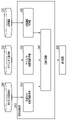
図1は、本実施形態における画像処理システムの構成を示す。画像処理装置200は、仮想カメラ移動情報取得部210、オブジェクト位置情報取得部220、仮想画像取得部230、及び画像処理部240を有する。また、画像処理装置200は、仮想カメラ移動情報140、オブジェクト位置情報110、及び仮想画像130の各データを記憶した不図示の記憶装置、並びに表示装置300(液晶ディスプレイなど)と、ネットワークを介して接続される。仮想カメラ移動情報取得部210、オブジェクト位置情報取得部220、及び仮想画像取得部230は、それぞれ仮想カメラ移動情報140、オブジェクト位置情報110、及び仮想画像130のデータを、ネットワークを介して取得する。なお、画像処理装置200により処理される仮想画像が撮影画像に基づく仮想視点画像である場合、オブジェクト位置情報110は、撮影画像に基づいて撮影対象領域内のオブジェクトの位置を特定することで取得されたデータであってもよい。取得したデータは、画像処理装置200内の不図示の記録部に記録される。画像処理部240は、仮想カメラ移動情報140及びオブジェクト位置情報110を用いて、仮想画像130に対して後述する画像処理を行う。画像処理が行われた仮想画像130は、表示装置300にネットワークを介して送信される。表示装置300は、受信した仮想画像130を表示する。すなわち、表示装置300は、画像表示装置である。なお、画像処理部240により仮想画像130が出力される出力先は表示装置300に限らず、仮想画像130を記憶する記憶装置などであってもよい。
FIG. 1 shows the configuration of an image processing system according to this embodiment. The
図2は、本実施形態における画像処理装置のハードウェア構成図である。画像処理装置200は、CPU201、ROM202、RAM203、記憶装置204、及び通信部205を有する。
FIG. 2 is a hardware configuration diagram of the image processing apparatus according to this embodiment. The
CPU201は、画像処理装置200の全体を制御する中央演算ユニットであり、画像処理装置200の処理シーケンスを統括的に制御する。ROM202及び記憶装置204は、後述するフローチャートに示す処理を実現するためのプログラムやデータを格納する。RAM203は、データの一時保存やプログラムのロードに使用される。通信部205は、ネットワーク206を介した外部装置とのデータ送受信を行う。通信部205は、例えば、画像処理装置200によって画像処理を行った仮想画像130を、ネットワーク206を介して表示装置300に送信する。画像処理装置200の各構成要素は、バス207を介して相互に接続される。
The
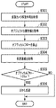
図3は、画像処理装置200による画像処理のフローチャートを示す。フローチャートに示される一連の処理は、画像処理装置200のCPU201がROM202または記憶装置204に記憶された制御プログラムをRAM203に展開し、実行することにより実施される。あるいはまた、フローチャートにおけるステップの一部または全部の機能をASICや電子回路等のハードウェアで実現してもよい。各処理の説明における記号「S」は、当該フローチャートにおけるステップを意味する。その他のフローチャートについても同様である。
FIG. 3 shows a flow chart of image processing by the
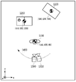
S301において、仮想カメラ移動情報取得部210は、仮想カメラ移動情報140を取得する。仮想カメラ移動情報140は、仮想カメラの時刻tにおける位置T(t)=(tx,ty,tz)、及び向きr(t)=(rx,ry,rz)を含む。また、仮想カメラ移動情報140は、仮想カメラの時刻tにおける速度V(t)=(vtx,vty,vtz,vrx,vry,vrz)を含んでもよい。速度V(t)は、単位時刻を映像のフレーム間隔とした、仮想カメラの位置と向きの微分値である。また、仮想カメラ移動情報140は、時刻tの1フレーム前の時刻t-1における仮想カメラの位置T(t-1)及び向きr(t-1)を含んでもよい。図4は、仮想空間内のオブジェクトおよび仮想カメラの位置を示す。オブジェクト及び仮想カメラの各位置は、XYZ座標で表される。また、図4では、Z軸方向から見たオブジェクト及び仮想カメラの位置が示されている。時刻tにおける仮想カメラ1300、及びその1フレーム前の時刻t-1における仮想カメラ1310が、軌跡1400上に示されている。図示した例では、仮想カメラ1300は、オブジェクト1100を中心として、オブジェクト1100の方向を向いて移動する。そのため、仮想カメラの映像は終始、仮想画像の中央にオブジェクト1100が写るものとなる。なお、仮想カメラは、不図示の入力装置を介して受信するユーザの指示に応じて動いてもよいし、予め定められたように動いてもよい。オブジェクト1100は、人のオブジェクトであって、前景オブジェクトの一例である。また、オブジェクト1210、1220は、建物のオブジェクトであって、背景の一例である。また、仮想空間内のオブジェクトの数は限定されるものではなく、1または複数のオブジェクトを配置することができる。
In S<b>301 , the virtual camera movement
次いで、S302において、オブジェクト位置情報取得部220は、オブジェクト位置情報110を取得する。オブジェクト位置情報110は、仮想空間内に存在するオブジェクト1100、1210、1220のそれぞれの重心の三次元座標(以下、重心座標とも呼ぶ)を含む。図4において、オブジェクト1100の重心座標は(1840,4525,950)、オブジェクト1210の重心座標は(1810,5082,2850)、オブジェクト1220の重心座標は(1900,5200,3300)である。なお、オブジェクト位置情報110は、オブジェクトの重心に限定されるものではなく、オブジェクトの代表点や、オブジェクトを構成する複数の要素の三次元座標の集合(メッシュポリゴンの頂点群など)でもよい。
Next, in S<b>302 , the object position
次いで、S303において、画像処理部240は、オブジェクト位置情報110を仮想カメラに投影した画像座標のオプティカルフローの大きさを算出する。具体的には、画像処理部240は、オブジェクト位置情報110(ここでは、オブジェクトの重心の三次元座標)が投影された画素が、1フレームで何画素(px)移動するかを算出する。三次元座標(X,Y,Z)から画像座標u(t)=(u,v)への座標系変換は、以下の式(1)による一般的な透視投影の射影変換を用いて行われる。
Next, in S303, the

ここで、記号「~」は、その両辺が定数倍の違いを許して等しいことを示す。また、A(3×3行列)は、仮想カメラの焦点距離と解像度によって決まる内部パラメータ行列であり、R(3×3行列)は、仮想カメラの向きr(t)からロドリゲスの回転公式によって得られる回転行列である。T(3×1行列)は、仮想カメラの位置T(t)から得られる並進ベクトルを表す行列である。 Here, the symbol "~" indicates that both sides are equal with a constant multiple difference allowed. Also, A (3×3 matrix) is an internal parameter matrix determined by the focal length and resolution of the virtual camera, and R (3×3 matrix) is obtained from the orientation r(t) of the virtual camera by Rodriguez's rotation formula. is the rotation matrix T (3×1 matrix) is a matrix representing a translation vector obtained from the position T(t) of the virtual camera.
このように、画像処理部240は、時刻tにおける画像座標u(t)を算出する。同様に、画像処理部240は、時刻t-1における画像座標u(t-1)を算出する。画像座標u(t-1)は、時刻t-1における仮想カメラ移動情報140を使用して算出することができる。なお、時刻t-1における仮想カメラ移動情報140は、時刻tにおける仮想カメラの速度V(t)を使用して、時刻tにおける仮想カメラ移動情報140から算出するようにしてもよい。図5は、時刻tにおける仮想カメラ1300に、オブジェクト1100、1210、1220を投影した仮想画像を示す。仮想画像501は、オブジェクト1100、1210、1220のそれぞれが投影された像2100、2210、2220を含む。また、オブジェクト1100の重心を、時刻tにおける仮想カメラ1300およびその1フレーム前の時刻t-1における仮想カメラ1310にそれぞれ投影した点をu1(t)、u1(t-1)として示す。同様に、オブジェクト1210の重心を投影した点をu2(t)、u2(t-1)として示し、オブジェクト1220の重心を投影した点をu3(t)、u3(t-1)として示す。この場合、オブジェクト1100の重心の時刻t-1からtまでのオプティカルフローは、ベクトル3110で表される。また、ベクトル3110の大きさは、式(1)により算出された画像座標u1(t)=(1032,980)、u1(t-1)=(1038,978)より、6.3pxとなる。すなわち、ベクトル3110の大きさは、画像座標u1(t)とu1(t-1)との間の距離である。同様に、オブジェクト1210の重心のオプティカルフロー(すなわち、ベクトル3210)の大きさは、式(1)により算出された画像座標u2(t)=(400,430)、u2(t-1)=(440,434)より、40.2pxとなる。また、オブジェクト1220の重心のオプティカルフロー(すなわち、ベクトル3220)の大きさは、式(1)により算出された画像座標u3(t)=(1680,355)、u3(t-1)=(1780,365)より、100.5pxとなる。このように、画像処理部240は、仮想カメラの動きに応じたオブジェクトの像の動きの大きさを導出する動き導出手段として機能する。
Thus, the
S304において、仮想画像取得部230は、仮想画像130を取得する。仮想画像130は、画像処理装置200の外部でレンダリング処理された図5に示す仮想画像501とすることができる。
In S<b>304 , the virtual
S305において、画像処理部240は、S303で算出された各オブジェクトのオプティカルフローの大きさ(すなわち、導出結果)が、所定の値、例えば、20pxより大きいかどうかを判定する。各オブジェクトのオプティカルフローの大きさが20px以下の場合は処理を終了する。一方、オプティカルフローの大きさが20pxより大きいオブジェクトが存在する場合は、S306に進む。図5の仮想画像501では、オブジェクト1210、1220のオプティカルフロー(すなわち、ベクトル3210、3220)の大きさがともに、20pxより大きいため、S306に進む。
In S305, the
S306において、画像処理部240は、オプティカルフローが所定の値よりも大きいと判定されたオブジェクト1210、1220の像2210、2220に対してぼかし処理を行う。ぼかし処理に用いる画像フィルタには、ガウシアンフィルタを用いることができる。ガウシアンフィルタのフィルタサイズは、オプティカルフローの大きさに係数a(=0.1)を乗算して決定する。図6は、本実施形態におけるぼかし処理前後の仮想画像を示す。図6(a)は、ぼかし処理前の仮想画像601を示し、図6(b)は、ぼかし処理後の仮想画像602を示す。図6(b)では、像2210及び2220が、ぼかし処理によって不鮮明になっている。すなわち、本実施形態では、背景をぼかして、視聴者の視線を前景のオブジェクトに向かせることになる。また、オプティカルフローが大きいほどフィルタサイズが大きなガウシアンフィルタが適用されるため、像2210より像2220の方が、ぼかし量(すなわち、画質の変更の程度)が大きくなる。このように、画像処理部240は、オブジェクトの像の画質を変更する画質変更手段として機能する。
In S306, the
以上のステップを終了すると、画像処理部240は、仮想画像を表示装置300に送信する。表示装置300は、受信した仮想画像を映像として表示する。
After completing the above steps, the
このように、本実施形態では、仮想空間に存在するオブジェクトが投影された仮想画像において、動きの大きなオブジェクト(上述した例では、建物のオブジェクト)にぼかし処理をする。すなわち、動きの大きなオブジェクトの画質を変更することで、視聴者の視線が動きの小さなオブジェクト(上述した例では、人のオブジェクト)の像に向きやすくなる。したがって、動きの小さなオブジェクトの画質を維持したまま、映像酔いを軽減することができる。 As described above, in the present embodiment, in a virtual image in which an object existing in the virtual space is projected, blurring processing is performed on an object with a large movement (a building object in the above example). That is, by changing the image quality of an object with large motion, it becomes easier for the viewer's line of sight to turn to the image of the object with small motion (the human object in the above example). Therefore, motion sickness can be reduced while maintaining the image quality of an object with small motion.
なお、上記S306のぼかし処理では、オプティカルフローの大きさに応じてフィルタサイズを決定したが、オプティカルフローの大きさによらず、所定のフィルタサイズ(例えば、フィルタサイズ10)で一括処理してもよい。また、ガウシアンフィルタではなく、オプティカルフローの方向に応じてモーションぼかしフィルタを用いてもよい。また、代替として、平均化フィルタを用いてもよい。 In the blurring process of S306, the filter size is determined according to the size of the optical flow. good. Also, instead of the Gaussian filter, a motion blur filter may be used according to the direction of the optical flow. Alternatively, an averaging filter may also be used.
また、上記の実施形態では、画像処理装置200がすでに生成された仮想画像を取得し、仮想画像内の各オブジェクトの動きに関する判定を行った結果に基づいて、仮想画像内の特定のオブジェクトに対応する部分に画像処理を行うものとした。ただしこれに限らず、画像処理装置200が仮想カメラ情報や撮像画像などの素材データに基づいて仮想画像を生成してもよい。この場合に画像処理装置200は、上述のように一旦仮想画像を生成してから特定の部分に画像処理を行ってもよいし、もしくは素材データに基づいて仮想画像のレンダリングを行う際に特定のオブジェクトに対応する部分の画質を制御してもよい。
Further, in the above embodiment, the
(第2の実施形態)
第1の実施形態では、画質の変更処理としてぼかし処理を行ったが、本実施形態では解像度低減処理を行って、映像酔いを軽減する方法について説明する。
(Second embodiment)
In the first embodiment, blurring processing is performed as image quality change processing, but in this embodiment, resolution reduction processing is performed to reduce motion sickness.
以下、第1の実施形態と同様の構成、処理フローについては説明を省略する。 Descriptions of the same configuration and processing flow as in the first embodiment will be omitted below.
図7は、本実施形態における画像処理の処理フローを示す。S301からS305の処理は、第1の実施形態における図3のフローチャートと同様である。 FIG. 7 shows a processing flow of image processing in this embodiment. The processing from S301 to S305 is the same as in the flowchart of FIG. 3 in the first embodiment.
S701において、画像処理装置200は、オプティカルフローが所定の値よりも大きいと判断された像2210および2220に対して、解像度低減処理を行う。
In S701, the
図8は、本実施形態における解像度低減処理を説明する図である。図8(a)は、解像度低減処理前の、像2210中の領域の画素および画素値を表す。本実施形態では、1画素に1つの画素値をもつ1チャンネルのグレースケール画像を前提として説明するが、これに限定されず、多チャンネルRGB画像などでもよい。本実施形態における解像度低減処理では、所定の解像度低減率(例えば、縦、横それぞれ50%)になるように画素をサブサンプリングし、単純拡大することで解像度を低減する。つまり、サブサンプリングされた画素値を右、下、右下の計3pxの領域にコピーする。こうしてコピーされた結果を、図8(b)に示す。すなわち、図8(b)は、解像度低減処理後の、像2210中の領域の画素および画素値を表す。
FIG. 8 is a diagram for explaining resolution reduction processing in this embodiment. FIG. 8(a) represents pixels and pixel values of regions in
図9は、本実施形態における解像度低減処理前後の仮想画像を示す。図9(a)は、解像度低減処理前の仮想画像901を示し、図9(b)は、解像度低減処理後の仮想画像902を示す。図9(b)では、解像度低減処理により、対象像(すなわち、像2210、2220)の解像度が低くなっている。
FIG. 9 shows virtual images before and after resolution reduction processing in this embodiment. 9A shows a
以上説明したように、本実施形態では、画質の変更処理として、動きの大きなオブジェクト(上述した例では、建物のオブジェクト)の像に解像度低減処理をする。そうすることで、動きの小さなオブジェクト(上述した例では、人のオブジェクト)の像は比較的高い解像度のまま維持されるので、仮想画像内で際立つ。これにより、視聴者の視線が動きの小さなオブジェクトの像に向きやすくなるとともに、動きの小さなオブジェクトの画質を維持したまま、映像酔いを軽減することができる。 As described above, in this embodiment, as image quality change processing, resolution reduction processing is performed on an image of an object that moves a lot (a building object in the above example). By doing so, the images of objects with small movements (human objects in the example above) remain at relatively high resolution and thus stand out in the virtual image. This makes it easier for the viewer's line of sight to turn to the image of the object with small movement, and reduces motion sickness while maintaining the image quality of the object with small movement.
なお、解像度低減率は、所定の値(50%)に限らず、オプティカルフローの大きさに応じて決定してもよい。 Note that the resolution reduction rate is not limited to a predetermined value (50%), and may be determined according to the magnitude of the optical flow.
(第3の実施形態)
本実施形態では、画質の変更処理として明度変更処理を行って、映像酔いを軽減する方法について説明する。
(Third embodiment)
In the present embodiment, a method of reducing motion sickness by performing brightness change processing as image quality change processing will be described.
以下、第1の実施形態と同様の構成、処理フローについては説明を省略する。 Descriptions of the same configuration and processing flow as in the first embodiment will be omitted below.
図10は、本実施形態における画像処理の処理フローを示す。S301からS305の処理は、第1の実施形態における図3のフローチャートと同様である。 FIG. 10 shows the processing flow of image processing in this embodiment. The processing from S301 to S305 is the same as in the flowchart of FIG. 3 in the first embodiment.
S1001において、画像処理装置200は、オプティカルフローが所定の値よりも大きいと判断された像2210および2220に対して、明度変更処理を行う。明度変更処理では、対象像の各画素の輝度値に、予め定められた所定の明度変更係数を乗算することで、対象像を明るくまたは暗くする。
In S1001, the
図11は、本実施形態における明度変更処理前後の仮想画像を示す。図11(a)は、明度変更処理前の仮想画像1101を示す。図11(b)は、明度変更係数を1.5として、対象像が明るくなるように処理を行った仮想画像1102を示す。図11(c)は、明度変更係数を0.5として、対象像が暗くなるように処理を行った仮想画像1103を示す。図11(b)では、明度変更処理により、像2210、及び2220の明度が高くなり、明るくなっている。また、図11(c)では、像2210、及び2220の明度が低くなり、暗くなっている。
FIG. 11 shows a virtual image before and after brightness change processing in this embodiment. FIG. 11A shows a
以上説明したように、本実施形態では、画質の変更処理として、動きの大きなオブジェクト(上述した例では、建物のオブジェクト)の像に明度変更処理をする。そうすることで、動きの小さなオブジェクト(上述した例では、人のオブジェクト)の像は、明度が適切な状態で維持されるので、仮想画像内で際立つ。これにより、視聴者の視線が動きの小さなオブジェクトに向きやすくなるとともに、動きの小さなオブジェクトの画質を維持したまま、映像酔いを軽減することができる。 As described above, in the present embodiment, as image quality change processing, brightness change processing is performed on an image of an object that moves a lot (a building object in the above example). By doing so, the images of objects with small movements (human objects in the example above) stand out in the virtual image because the brightness is maintained at an appropriate level. This makes it easier for the viewer's line of sight to turn to objects with small movements, and also reduces motion sickness while maintaining the image quality of objects with small movements.
なお、上記処理では明度を変更したが、彩度やコントラストを変更してもよい。すなわち、本実施形態では、明度や彩度、またはコントラストを含む、対象像の色調を変更してもよい。また、明度変更係数には所定の値を用いたが、オプティカルフローの大きさに応じて決定してもよい。 Although the lightness is changed in the above processing, the saturation and contrast may be changed. That is, in this embodiment, the color tone of the target image, including brightness, saturation, or contrast, may be changed. Also, although a predetermined value is used for the lightness change coefficient, it may be determined according to the magnitude of the optical flow.
(第4の実施形態)
第1の実施形態では、仮想カメラが、人のオブジェクト1100を中心として移動する例について説明したが、本実施形態では、仮想カメラが第1の実施形態とは異なる動きをする例について説明する。
(Fourth embodiment)
In the first embodiment, an example in which the virtual camera moves around the
以下、第1の実施形態と同様の構成、処理フローについては説明を省略する。 Descriptions of the same configuration and processing flow as in the first embodiment will be omitted below.
図12は、本実施形態における仮想空間内のオブジェクトおよび仮想カメラの位置を示す。時刻tにおける仮想カメラ1350、及びその1フレーム前の時刻t-1における仮想カメラ1360が、軌跡1410上に示されている。図示した例では、仮想カメラは、オブジェクト1210、1220の近傍にある回転中心1201を中心として回転し、往復するように、回転中心1201を向いて移動する。そのため、映像は、仮想画像上をオブジェクト1100が左右に往復するものとなる。
FIG. 12 shows the positions of the object and the virtual camera in the virtual space in this embodiment. A
この場合、図3のS303において算出されるオプティカルフローの大きさは、オブジェクト1100のオプティカルフローの大きさが50.3pxとなる。また、オブジェクト1210、1220のオプティカルフローの大きさがそれぞれ19.5px、15.7pxとなる。したがって、オプティカルフローの大きさが20pxより大きいオブジェクト1100の像に対してS306のぼかし処理が行われる。
In this case, the size of the optical flow calculated in S303 of FIG. 3 is 50.3 px for the
S306において、画像処理部240は、オブジェクト1100のオプティカルフローの大きさに所定の係数a(=0.1)を乗算して決定したフィルタサイズ5でぼかし処理を行う。
In S306, the
図13は、本実施形態におけるぼかし処理前後の仮想画像を示す。図13(a)は、ぼかし処理前の仮想画像1301を示し、図13(b)は、ぼかし処理後の仮想画像1302を示す。図13(b)では、像2100が、ぼかし処理によって不鮮明になっている。すなわち、本実施形態では、前景のオブジェクトをぼかして、視聴者の視線を背景に向かせることになる。
FIG. 13 shows a virtual image before and after blurring processing in this embodiment. FIG. 13(a) shows a
以上説明したように、本実施形態では、仮想カメラの動きによって異なるオブジェクトの像にぼかし処理をする。そうすることで、視聴者の視線が動きの小さなオブジェクトの像に向きやすくなるとともに、動きの小さなオブジェクトの画質を維持したまま、映像酔いを軽減することができる。なお、上述した実施形態ではそれぞれ、ぼかし処理、解像度低減処理、及び明度変更処理(すなわち、色調変更処理)について説明したが、それらを組み合わせて実施してもよい。 As described above, in the present embodiment, blurring processing is performed on images of different objects depending on the movement of the virtual camera. By doing so, it becomes easier for the viewer's line of sight to turn to the image of the object with small movement, and motion sickness can be reduced while maintaining the image quality of the object with small movement. In the above-described embodiments, the blurring process, the resolution reduction process, and the brightness change process (that is, color tone change process) have been described, but they may be combined.
また、上述の実施形態では、仮想画像における各オブジェクトの動きの大きさに基づいて特定されたオブジェクトの画質を制御するものとした。ただし、画質の変更の対象の決定方法はこれに限定されない。例えば画像処理装置200は、移動する仮想カメラに応じた仮想画像を生成する場合に、ユーザ操作などに応じて予め指定されたオブジェクト以外の領域のボケ量が大きくなるように画像処理を行ってもよい。また例えば、画像処理装置200は、所定の種別のオブジェクト(例えば人物など)以外の領域のボケ量が大きくなるように画像処理を行ってもよい。また例えば、画像処理装置200は、仮想カメラからの距離が所定値未満であるオブジェクト以外の領域のボケ量が大きくなるように画像処理を行ってもよい。
Further, in the above-described embodiment, the image quality of the specified object is controlled based on the magnitude of motion of each object in the virtual image. However, the method of determining the image quality change target is not limited to this. For example, when generating a virtual image according to a moving virtual camera, the
また、画像処理装置200が撮像画像に基づく仮想画像を生成する場合に、撮像画像に基づいて撮影対象領域内の所定のオブジェクトが特定され、仮想画像におけるその所定のオブジェクト以外の領域のボケ量が大きくなるように画像処理が行われてもよい。撮像画像に基づいて特定されるオブジェクトは、例えば移動するオブジェクトや、特定の期間にのみ撮影対象領域に存在するオブジェクトであってもよい。
Further, when the
なお、仮想画像内においてボケ量などの画質の変更対象となる領域は、上記のような方法で特定されたオブジェクト以外の領域全体であってもよいし、特定されたオブジェクトの周囲の所定範囲の領域については画質変更が行われなくてもよい。また、仮想画像に含まれるオブジェクトのうち、上記のような方法で特定されたオブジェクト以外のオブジェクトの領域が画質の変更対象となってもよい。すなわち、オブジェクトが存在しない領域については画質変更が行われなくてもよい。また、画像処理装置200は、上述したぼかし処理や解像度低下処理、及び明度変更処理などの程度を、仮想カメラの移動速度や仮想カメラの画角などに基づいて決定してもよい。
Note that the area in the virtual image whose image quality such as the amount of blurring is to be changed may be the entire area other than the object identified by the above method, or a predetermined range around the identified object. Image quality change may not be performed for the area. Further, among the objects included in the virtual image, an area of the object other than the object specified by the method described above may be subject to image quality change. That is, the image quality need not be changed for areas where no object exists. Further, the
(その他の実施形態)
本発明は、上述の実施形態の1以上の機能を実現するプログラムを、ネットワーク又は記憶媒体を介してシステム又は装置に供給し、そのシステム又は装置のコンピュータにおける1つ以上のプロセッサーがプログラムを読出し実行する処理でも実現可能である。また、1以上の機能を実現する回路(例えば、ASIC)によっても実現可能である。
(Other embodiments)
The present invention supplies a program that implements one or more functions of the above-described embodiments to a system or device via a network or a storage medium, and one or more processors in the computer of the system or device reads and executes the program. It can also be realized by processing to It can also be implemented by a circuit (for example, ASIC) that implements one or more functions.
110 オブジェクト位置情報
130 仮想画像
140 仮想カメラ移動情報
200 画像処理装置
210 仮想カメラ移動情報取得部
220 オブジェクト位置情報取得部
230 仮想画像取得部
240 画像処理部
300 表示装置
110
Claims (14)
前記複数フレームのうち第1のフレームに対応する第1の仮想視点の位置と当該第1のフレームよりも時間的に進んだ第2のフレームに対応する第2の仮想視点の位置との差、又は前記第1の仮想視点からの視線方向と前記第2の仮想視点からの視線方向との差の少なくとも一方を特定する第1の特定手段と、
特定された差に基づき、複数のオブジェクトそれぞれに対して、前記第1の仮想視点に対応する第1の仮想視点画像における位置と、前記第2の仮想視点に対応する第2の仮想視点画像における位置との差の度合いを決定する第1の決定手段と、
前記第1の決定手段により決定された度合いに基づき、前記複数のオブジェクトそれぞれの先鋭度が異なる前記第2の仮想視点画像を生成する生成手段と、
を有し、
前記複数のオブジェクトに含まれる第1のオブジェクトに対して前記第1の決定手段により決定された第1の度合いが前記複数のオブジェクトに含まれる第2のオブジェクトに対して前記第1の決定手段により決定された第2の度合いよりも大きい場合、前記第2の仮想視点画像においては、前記第1のオブジェクトの鮮鋭度が前記第2のオブジェクトの鮮鋭度よりも低い、
ことを特徴とする画像処理装置。 An image processing device that generates a virtual viewpoint image consisting of a plurality of frames corresponding to a virtual viewpoint,
a difference between a position of a first virtual viewpoint corresponding to a first frame among the plurality of frames and a position of a second virtual viewpoint corresponding to a second frame temporally preceding the first frame ; or a first specifying means for specifying at least one of the difference between the line-of-sight direction from the first virtual viewpoint and the line-of-sight direction from the second virtual viewpoint;
Based on the identified difference, for each of a plurality of objects, a position in a first virtual viewpoint image corresponding to the first virtual viewpoint and a second virtual viewpoint image corresponding to the second virtual viewpoint. a first determining means for determining the degree of difference from the position in the viewpoint image;
generation means for generating the second virtual viewpoint image in which the sharpness of each of the plurality of objects differs based on the degree determined by the first determination means;
has
The first degree determined by the first determination means for a first object included in the plurality of objects is determined by the first determination means for a second object included in the plurality of objects if greater than the determined second degree, the sharpness of the first object is lower than the sharpness of the second object in the second virtual viewpoint image;
An image processing apparatus characterized by:
前記生成手段は、前記第2の決定手段により決定された鮮鋭度に基づいて前記第2の仮想視点画像を生成する、
ことを特徴とする請求項1に記載の画像処理装置。 further comprising second determining means for determining the sharpness of each of the plurality of objects in the second virtual viewpoint image so as to have an inverse correlation with the degree determined by the first determining means;
The generation means generates the second virtual viewpoint image based on the sharpness determined by the second determination means.
2. The image processing apparatus according to claim 1, wherein:
前記第1の決定手段は、前記第2の特定手段にて特定された前記複数のオブジェクトそれぞれの三次元位置にさらに基づいて、前記複数のオブジェクトそれぞれについての前記度合いを決定する、
ことを特徴とする請求項2又は3に記載の画像処理装置。 further comprising second identifying means for identifying the three-dimensional position of each of the plurality of objects in the virtual space;
The first determination means determines the degree for each of the plurality of objects further based on the three-dimensional position of each of the plurality of objects identified by the second identification means.
4. The image processing apparatus according to claim 2, wherein:
前記複数フレームのうち第1のフレームに対応する第1の仮想視点の位置と当該第1のフレームよりも時間的に進んだ第2のフレームに対応する第2の仮想視点の位置との差、又は前記第1の仮想視点からの視線方向と前記第2の仮想視点からの視線方向との差の少なくとも一方を特定する第1の特定ステップと、
特定された差に基づき、複数のオブジェクトそれぞれに対して、前記第1の仮想視点に対応する第1の仮想視点画像における位置と、前記第2の仮想視点に対応する第2の仮想視点画像における位置との差の度合いを決定する第1の決定ステップと、
前記第1の決定ステップにて決定された度合いに基づき、前記複数のオブジェクトそれぞれの先鋭度が異なる前記第2の仮想視点画像を生成する生成ステップと、
を含み、
前記複数のオブジェクトに含まれる第1のオブジェクトに対して前記第1の決定ステップにて決定された第1の度合いが前記複数のオブジェクトに含まれる第2のオブジェクトに対して前記第1の決定ステップにて決定された第2の度合いよりも大きい場合、前記第2の仮想視点画像においては、前記第1のオブジェクトの鮮鋭度が前記第2のオブジェクトの鮮鋭度よりも低い、
ことを特徴とする画像処理方法。 An image processing method for generating a virtual viewpoint image composed of a plurality of frames corresponding to a virtual viewpoint,
a difference between a position of a first virtual viewpoint corresponding to a first frame among the plurality of frames and a position of a second virtual viewpoint corresponding to a second frame temporally preceding the first frame ; or a first specifying step of specifying at least one of a difference between a line-of-sight direction from the first virtual viewpoint and a line-of-sight direction from the second virtual viewpoint;
Based on the identified difference, for each of a plurality of objects, a position in a first virtual viewpoint image corresponding to the first virtual viewpoint and a second virtual viewpoint image corresponding to the second virtual viewpoint. a first determining step of determining the degree of difference from the position in the viewpoint image;
a generation step of generating the second virtual viewpoint image in which the sharpness of each of the plurality of objects differs based on the degree determined in the first determination step;
including
The first degree determined in the first determining step for a first object included in the plurality of objects is the first determining step for a second object included in the plurality of objects. the sharpness of the first object is lower than the sharpness of the second object in the second virtual viewpoint image, if greater than the second degree determined in
An image processing method characterized by:
前記生成ステップでは、前記第2の決定ステップにて決定された鮮鋭度に基づいて前記第2の仮想視点画像を生成する、
ことを特徴とする請求項11に記載の画像処理方法。 further comprising a second determining step of determining the sharpness of each of the plurality of objects in the second virtual viewpoint image so as to have an inverse correlation with the degree determined in the first determining step;
In the generating step, the second virtual viewpoint image is generated based on the sharpness determined in the second determining step.
12. The image processing method according to claim 11, wherein:
前記第1の決定ステップでは、前記第2の特定ステップにて特定された前記複数のオブジェクトそれぞれの三次元位置にさらに基づいて、前記複数のオブジェクトそれぞれについての前記度合いが決定される、
ことを特徴とする請求項11又は12に記載の画像処理方法。 further comprising a second identifying step of identifying a three-dimensional position of each of the plurality of objects in virtual space;
In the first determining step, the degree for each of the plurality of objects is determined further based on the three-dimensional position of each of the plurality of objects identified in the second identifying step,
13. The image processing method according to claim 11 or 12 , characterized by:
Priority Applications (3)
| Application Number | Priority Date | Filing Date | Title |
|---|---|---|---|
| JP2018139350A JP7210180B2 (en) | 2018-07-25 | 2018-07-25 | Image processing device, image display device, image processing method, and program |
| EP19185279.7A EP3599589A1 (en) | 2018-07-25 | 2019-07-09 | Image processing apparatus, image processing method, and program |
| US16/509,922 US11328494B2 (en) | 2018-07-25 | 2019-07-12 | Image processing apparatus, image processing method, and storage medium |
Applications Claiming Priority (1)
| Application Number | Priority Date | Filing Date | Title |
|---|---|---|---|
| JP2018139350A JP7210180B2 (en) | 2018-07-25 | 2018-07-25 | Image processing device, image display device, image processing method, and program |
Publications (3)
| Publication Number | Publication Date |
|---|---|
| JP2020017061A JP2020017061A (en) | 2020-01-30 |
| JP2020017061A5 JP2020017061A5 (en) | 2021-09-02 |
| JP7210180B2 true JP7210180B2 (en) | 2023-01-23 |
Family
ID=67253678
Family Applications (1)
| Application Number | Title | Priority Date | Filing Date |
|---|---|---|---|
| JP2018139350A Active JP7210180B2 (en) | 2018-07-25 | 2018-07-25 | Image processing device, image display device, image processing method, and program |
Country Status (3)
| Country | Link |
|---|---|
| US (1) | US11328494B2 (en) |
| EP (1) | EP3599589A1 (en) |
| JP (1) | JP7210180B2 (en) |
Families Citing this family (1)
| Publication number | Priority date | Publication date | Assignee | Title |
|---|---|---|---|---|
| US11721063B1 (en) * | 2023-01-26 | 2023-08-08 | Illuscio, Inc. | Systems and methods for dynamic image rendering using a depth map |
Citations (5)
| Publication number | Priority date | Publication date | Assignee | Title |
|---|---|---|---|---|
| JP2006155063A (en) | 2004-11-26 | 2006-06-15 | Seiko Epson Corp | Image correction device, image correction method, and computer program |
| JP2014153893A (en) | 2013-02-07 | 2014-08-25 | Sony Computer Entertainment Inc | Drawing processing device and drawing processing method |
| JP2015521322A (en) | 2012-05-18 | 2015-07-27 | トムソン ライセンシングThomson Licensing | Panorama picture processing |
| JP2018049614A (en) | 2016-09-15 | 2018-03-29 | トムソン ライセンシングThomson Licensing | Method and device for blurring virtual object in video |
| WO2018062538A1 (en) | 2016-09-30 | 2018-04-05 | 株式会社ニコン | Display device and program |
Family Cites Families (10)
| Publication number | Priority date | Publication date | Assignee | Title |
|---|---|---|---|---|
| JP2007116309A (en) * | 2005-10-19 | 2007-05-10 | Seiko Epson Corp | Image information reproduction apparatus |
| JP5968107B2 (en) * | 2011-09-01 | 2016-08-10 | キヤノン株式会社 | Image processing method, image processing apparatus, and program |
| KR101917630B1 (en) * | 2011-10-28 | 2018-11-13 | 매직 립, 인코포레이티드 | System and method for augmented and virtual reality |
| US10139902B2 (en) * | 2015-09-16 | 2018-11-27 | Colopl, Inc. | Method and apparatus for changing a field of view without synchronization with movement of a head-mounted display |
| JP5869177B1 (en) | 2015-09-16 | 2016-02-24 | 株式会社コロプラ | Virtual reality space video display method and program |
| US10026212B2 (en) * | 2015-11-20 | 2018-07-17 | Google Llc | Electronic display stabilization using pixel velocities |
| JP6714791B2 (en) * | 2016-07-13 | 2020-07-01 | 株式会社バンダイナムコエンターテインメント | Simulation system and program |
| KR20180028796A (en) * | 2016-09-09 | 2018-03-19 | 삼성전자주식회사 | Method, storage medium and electronic device for displaying images |
| US10565777B2 (en) * | 2016-09-30 | 2020-02-18 | Sony Interactive Entertainment Inc. | Field of view (FOV) throttling of virtual reality (VR) content in a head mounted display |
| US10754529B2 (en) * | 2016-10-28 | 2020-08-25 | Adobe Inc. | Facilitating editing of virtual-reality content using a virtual-reality headset |
-
2018
- 2018-07-25 JP JP2018139350A patent/JP7210180B2/en active Active
-
2019
- 2019-07-09 EP EP19185279.7A patent/EP3599589A1/en active Pending
- 2019-07-12 US US16/509,922 patent/US11328494B2/en active Active
Patent Citations (5)
| Publication number | Priority date | Publication date | Assignee | Title |
|---|---|---|---|---|
| JP2006155063A (en) | 2004-11-26 | 2006-06-15 | Seiko Epson Corp | Image correction device, image correction method, and computer program |
| JP2015521322A (en) | 2012-05-18 | 2015-07-27 | トムソン ライセンシングThomson Licensing | Panorama picture processing |
| JP2014153893A (en) | 2013-02-07 | 2014-08-25 | Sony Computer Entertainment Inc | Drawing processing device and drawing processing method |
| JP2018049614A (en) | 2016-09-15 | 2018-03-29 | トムソン ライセンシングThomson Licensing | Method and device for blurring virtual object in video |
| WO2018062538A1 (en) | 2016-09-30 | 2018-04-05 | 株式会社ニコン | Display device and program |
Also Published As
| Publication number | Publication date |
|---|---|
| EP3599589A1 (en) | 2020-01-29 |
| JP2020017061A (en) | 2020-01-30 |
| US20200035039A1 (en) | 2020-01-30 |
| US11328494B2 (en) | 2022-05-10 |
Similar Documents
| Publication | Publication Date | Title |
|---|---|---|
| JP6514826B2 (en) | Electronic Display Stabilization Using Pixel Speed | |
| CN109672886B (en) | Image frame prediction method and device and head display equipment | |
| CN110944119B (en) | Image processing system, image processing method, and storage medium | |
| KR102316061B1 (en) | Image processing apparatus, method, and computer program | |
| US20160301868A1 (en) | Automated generation of panning shots | |
| JP5645450B2 (en) | Image processing apparatus and method | |
| US20110141224A1 (en) | Panorama Imaging Using Lo-Res Images | |
| US20110141229A1 (en) | Panorama imaging using super-resolution | |
| US20110141225A1 (en) | Panorama Imaging Based on Low-Res Images | |
| CN110460835B (en) | Image processing apparatus, control method thereof, and computer-readable storage medium | |
| JP2006350334A (en) | Method and system for compensating perceptible blurring due to movement between current frames and former frame of digital video sequence | |
| EP3296952B1 (en) | Method and device for blurring a virtual object in a video | |
| EP2545411A1 (en) | Panorama imaging | |
| KR20150145725A (en) | Method and apparatus for dynamic range expansion of ldr video sequence | |
| WO2019198570A1 (en) | Video generation device, video generation method, program, and data structure | |
| JP2006319578A (en) | Depth direction movement determining device, blurring correction system having the same, and blurring correction method, program, computer readable record medium recording the program, and electronic apparatus equipped with the blurring correction system | |
| JP7210180B2 (en) | Image processing device, image display device, image processing method, and program | |
| WO2021261248A1 (en) | Image processing device, image display system, method, and program | |
| KR101437898B1 (en) | Apparatus and method for generating a High Dynamic Range image using single image | |
| CN111263951A (en) | Method and system for fast image fusion of overlapping regions in panoramic views | |
| US11748938B2 (en) | Virtual reality simulator and virtual reality simulation program | |
| KR102517104B1 (en) | Method and apparatus for processing image in virtual reality system | |
| CN115623184A (en) | Virtual reality simulator and computer-readable recording medium | |
| JP7161865B2 (en) | Video analysis device and its program | |
| Sakakibara et al. | Seeing temporal modulation of lights from standard cameras |
Legal Events
| Date | Code | Title | Description |
|---|---|---|---|
| A521 | Request for written amendment filed |
Free format text: JAPANESE INTERMEDIATE CODE: A523 Effective date: 20210721 |
|
| A621 | Written request for application examination |
Free format text: JAPANESE INTERMEDIATE CODE: A621 Effective date: 20210721 |
|
| A977 | Report on retrieval |
Free format text: JAPANESE INTERMEDIATE CODE: A971007 Effective date: 20220510 |
|
| A131 | Notification of reasons for refusal |
Free format text: JAPANESE INTERMEDIATE CODE: A131 Effective date: 20220614 |
|
| A521 | Request for written amendment filed |
Free format text: JAPANESE INTERMEDIATE CODE: A523 Effective date: 20220803 |
|
| TRDD | Decision of grant or rejection written | ||
| A01 | Written decision to grant a patent or to grant a registration (utility model) |
Free format text: JAPANESE INTERMEDIATE CODE: A01 Effective date: 20221213 |
|
| A61 | First payment of annual fees (during grant procedure) |
Free format text: JAPANESE INTERMEDIATE CODE: A61 Effective date: 20230111 |
|
| R151 | Written notification of patent or utility model registration |
Ref document number: 7210180 Country of ref document: JP Free format text: JAPANESE INTERMEDIATE CODE: R151 |