JP7209099B2 - hair styling equipment - Google Patents
hair styling equipment Download PDFInfo
- Publication number
- JP7209099B2 JP7209099B2 JP2021538809A JP2021538809A JP7209099B2 JP 7209099 B2 JP7209099 B2 JP 7209099B2 JP 2021538809 A JP2021538809 A JP 2021538809A JP 2021538809 A JP2021538809 A JP 2021538809A JP 7209099 B2 JP7209099 B2 JP 7209099B2
- Authority
- JP
- Japan
- Prior art keywords
- arm
- hair styling
- spring
- styling device
- pack
- Prior art date
- Legal status (The legal status is an assumption and is not a legal conclusion. Google has not performed a legal analysis and makes no representation as to the accuracy of the status listed.)
- Active
Links
Images


Classifications
-
- A—HUMAN NECESSITIES
- A45—HAND OR TRAVELLING ARTICLES
- A45D—HAIRDRESSING OR SHAVING EQUIPMENT; EQUIPMENT FOR COSMETICS OR COSMETIC TREATMENTS, e.g. FOR MANICURING OR PEDICURING
- A45D1/00—Curling-tongs, i.e. tongs for use when hot; Curling-irons, i.e. irons for use when hot; Accessories therefor
- A45D1/06—Curling-tongs, i.e. tongs for use when hot; Curling-irons, i.e. irons for use when hot; Accessories therefor with two or more jaws
-
- A—HUMAN NECESSITIES
- A45—HAND OR TRAVELLING ARTICLES
- A45D—HAIRDRESSING OR SHAVING EQUIPMENT; EQUIPMENT FOR COSMETICS OR COSMETIC TREATMENTS, e.g. FOR MANICURING OR PEDICURING
- A45D2/00—Hair-curling or hair-waving appliances ; Appliances for hair dressing treatment not otherwise provided for
- A45D2/001—Hair straightening appliances
-
- A—HUMAN NECESSITIES
- A45—HAND OR TRAVELLING ARTICLES
- A45D—HAIRDRESSING OR SHAVING EQUIPMENT; EQUIPMENT FOR COSMETICS OR COSMETIC TREATMENTS, e.g. FOR MANICURING OR PEDICURING
- A45D1/00—Curling-tongs, i.e. tongs for use when hot; Curling-irons, i.e. irons for use when hot; Accessories therefor
- A45D1/02—Curling-tongs, i.e. tongs for use when hot; Curling-irons, i.e. irons for use when hot; Accessories therefor with means for internal heating, e.g. by liquid fuel
- A45D1/04—Curling-tongs, i.e. tongs for use when hot; Curling-irons, i.e. irons for use when hot; Accessories therefor with means for internal heating, e.g. by liquid fuel by electricity
-
- A—HUMAN NECESSITIES
- A45—HAND OR TRAVELLING ARTICLES
- A45D—HAIRDRESSING OR SHAVING EQUIPMENT; EQUIPMENT FOR COSMETICS OR COSMETIC TREATMENTS, e.g. FOR MANICURING OR PEDICURING
- A45D1/00—Curling-tongs, i.e. tongs for use when hot; Curling-irons, i.e. irons for use when hot; Accessories therefor
- A45D1/06—Curling-tongs, i.e. tongs for use when hot; Curling-irons, i.e. irons for use when hot; Accessories therefor with two or more jaws
- A45D1/14—Curling-tongs, i.e. tongs for use when hot; Curling-irons, i.e. irons for use when hot; Accessories therefor with two or more jaws the jaws being separable from each other
-
- A—HUMAN NECESSITIES
- A45—HAND OR TRAVELLING ARTICLES
- A45D—HAIRDRESSING OR SHAVING EQUIPMENT; EQUIPMENT FOR COSMETICS OR COSMETIC TREATMENTS, e.g. FOR MANICURING OR PEDICURING
- A45D2/00—Hair-curling or hair-waving appliances ; Appliances for hair dressing treatment not otherwise provided for
-
- A—HUMAN NECESSITIES
- A45—HAND OR TRAVELLING ARTICLES
- A45D—HAIRDRESSING OR SHAVING EQUIPMENT; EQUIPMENT FOR COSMETICS OR COSMETIC TREATMENTS, e.g. FOR MANICURING OR PEDICURING
- A45D2/00—Hair-curling or hair-waving appliances ; Appliances for hair dressing treatment not otherwise provided for
- A45D2/36—Hair curlers or hair winders with incorporated heating or drying means, e.g. electric, using chemical reaction
- A45D2/367—Hair curlers or hair winders with incorporated heating or drying means, e.g. electric, using chemical reaction with electrical heating means
-
- A—HUMAN NECESSITIES
- A45—HAND OR TRAVELLING ARTICLES
- A45D—HAIRDRESSING OR SHAVING EQUIPMENT; EQUIPMENT FOR COSMETICS OR COSMETIC TREATMENTS, e.g. FOR MANICURING OR PEDICURING
- A45D1/00—Curling-tongs, i.e. tongs for use when hot; Curling-irons, i.e. irons for use when hot; Accessories therefor
- A45D1/02—Curling-tongs, i.e. tongs for use when hot; Curling-irons, i.e. irons for use when hot; Accessories therefor with means for internal heating, e.g. by liquid fuel
- A45D1/04—Curling-tongs, i.e. tongs for use when hot; Curling-irons, i.e. irons for use when hot; Accessories therefor with means for internal heating, e.g. by liquid fuel by electricity
- A45D2001/045—Curling-tongs, i.e. tongs for use when hot; Curling-irons, i.e. irons for use when hot; Accessories therefor with means for internal heating, e.g. by liquid fuel by electricity the power being supplied by batteries
Description
本発明は、ヘアスタイリング機器に関する。加熱されるヘアスタイリング機器は、ヘアを所望の形状またはスタイルに形成するために熱および機械的な手段の動作を使用するように設計されている。 The present invention relates to hair styling equipment. Heated hair styling equipment is designed to use the action of heat and mechanical means to shape hair into a desired shape or style.
ヘアストレートナは、加熱されるプレートの間にヘアのトレスがクランプされて、ユーザによって閉鎖位置に保持されることができる回動連結アームに取り付けられた加熱されるプレートを利用する。ヘアのトレスは、一旦空気が転移温度以上に加熱されると、変化された形状にスタイリングされることができる。 Hair straighteners utilize heated plates mounted on a pivoting linkage arm that can be held in a closed position by the user with the tresses of the hair clamped between the heated plates. The tresses of hair can be styled into altered shapes once the air is heated above the transition temperature.
ユーザによって再充電されることができるバッテリーパックを有するコードレスヘアストレートナを含めて、コードを有するおよびコードを有しないヘアスタイリング機器の両方が、知られている。典型的なコードレスヘアストレートナは、1つのアームに配置されたバッテリーパックを有することができ、それによって、ヘアストレートナの重量分布に不均衡を生じさせる。ヘアストレートナによりヘアをスタイリングすることは、繰り返しのユーザの動作を必要とし、機器の重量の不均衡は、ユーザの手に不快感を生じさせることがある。したがって、改良されたヘアスタイリング装置を提供することが望ましい。 Both corded and cordless hair styling appliances are known, including cordless hair straighteners that have battery packs that can be recharged by the user. A typical cordless hair straightener may have a battery pack located on one arm, thereby creating an imbalance in the weight distribution of the hair straightener. Styling hair with a hair straightener requires repetitive user actions, and the weight imbalance of the equipment can cause discomfort in the user's hands. Accordingly, it would be desirable to provide an improved hair styling device.
本発明の第1の観点は、ヘアスタイリング装置であって、該ヘアスタイリング装置は、第1のアームおよび第2のアームであって、該第1のアームおよび該第2のアームが、該第1のアームの対面する側および該第2の対面する側が隣接している閉鎖位置と、該第1のアームの前記対面する側および第該2の対面する側が間隔を隔てて配置される開放位置と、の間で移動可能であることを可能にするようにヒンジ端で互いに結合されている第1のアームおよび第2のアームと、前記第1のアームと前記第2のアームの間に配置され、前記ヒンジ端で前記ヘアスタイリング装置に結合されている中央パックと、前記第1のアームと前記第2のアームの間で対称に前記中央パックを支持するようになっている付勢手段と、を含む、ヘアスタイリング装置を提供する。 A first aspect of the present invention is a hair styling device comprising a first arm and a second arm, wherein the first arm and the second arm are connected to the first arm. a closed position in which the facing side of one arm and the second facing side are adjacent; and an open position in which the facing side of the first arm and the second facing side are spaced apart. and a first arm and a second arm joined together at a hinge end so as to be movable between and; a central pack connected at said hinged end to said hair styling device; and biasing means adapted to support said central pack symmetrically between said first arm and said second arm. to provide a hair styling device comprising:
かかる対称的な均衡のとれた構成は、ヘアスタイリング装置の人間工学を改善する、 Such a symmetrically balanced configuration improves the ergonomics of the hair styling device,
使用に際して、空気間隙が、第1のアームと中央パックの間、および、また、第2のアームと中央バッグの間に形成される。有利には、各空気間隙は、アームと中央パックの間に熱障壁を形成し、それによって、ユーザの手、中央パック、および、アーム中の加熱手段の間の熱伝達を最小にする。 In use, air gaps are formed between the first arm and the central pack and also between the second arm and the central bag. Advantageously, each air gap forms a thermal barrier between the arm and the central puck, thereby minimizing heat transfer between the user's hand, the central puck and the heating means in the arm.
好ましくは、中央パックは、パワーパックであり、パワーパックは、少なくとも1つのセルを含む。 Preferably, the central pack is a power pack and the power pack contains at least one cell.
好ましい実施形態では、中央パックは、モータおよびファンを含む。 In a preferred embodiment, the central pack contains a motor and a fan.
ヘアスタイリング装置は、第1のアームと第2のアームの間に連結されたカバーをさらに含むことができ、前記カバーは、前記中央パックを保護するようになっている。 The hair styling device may further include a cover coupled between the first arm and the second arm, said cover adapted to protect said central pack.
好ましくは、前記付勢手段は、少なくとも1つのばねを含む。前記少なくとも1つのばねは、前記第1のアームと前記中央パックの間に結合された第1のばね、および、前記第2のアームと前記中央パックの間に結合された第2のばねを含み、前記第1のばねおよび前記第2のばねは、前記ヘアスタイリング装置の長手方向軸線に関して対称的に配置されている。前記第1のばねおよび前記第2のばねは、コイルばねまたは板ばねであるのがよい。前記第1のばねおよび前記第2のばねは、金属アーム鋳造構造から一体的に形成されることができる。 Preferably, said biasing means comprises at least one spring. The at least one spring includes a first spring coupled between the first arm and the central pack and a second spring coupled between the second arm and the central pack. , said first spring and said second spring are arranged symmetrically with respect to the longitudinal axis of said hair styling device. The first spring and the second spring may be coil springs or leaf springs. The first spring and the second spring can be integrally formed from a metal arm casting structure.
好ましい実施形態では、前記少なくとも1つのばねは、コイルばねに結合されたねじりばねを含む。前記ねじりばねは、ピボットと、それぞれ、前記第1のアームおよび前記第2のアームに取り付けられた第1の脚部および前記第2の脚部と、を含む。前記コイルばねは、ラグを介して前記ピボットに取り付けられた第1の端、および、前記中央パックに取り付けられた第2の端を含む。 In preferred embodiments, said at least one spring comprises a torsion spring coupled to a coil spring. The torsion spring includes a pivot and first and second legs attached to the first and second arms, respectively. The coil spring includes a first end attached to the pivot via a lug and a second end attached to the central pack.
単一のコイルばねは、ばねが漸進的に圧縮されるときに増大するばね力を有する。有利には、ねじりばねおよびコイルばねのこの構成は、スタイリング装置のアームが閉鎖位置に移動されるときにばね力を漸進的に低下させる、これに対して、スタイリング装置が開放するときに、より大きなばね力を提供する。 A single coil spring has a spring force that increases as the spring is progressively compressed. Advantageously, this configuration of the torsion and coil springs provides a progressively lower spring force when the arms of the styling device are moved to the closed position, whereas a higher spring force when the styling device opens. Provides large spring force.
好ましくは、ヘアスタイリング装置は、前記第1のアームと前記第2のアームに取り付けられたカバーを含み、前記カバーは、前記中央パックを保護するようになっている。さらに好ましくは、前記カバーは、前記ねじりばねに取り付けられており、それによって、前記第1のばねおよび前記第2のばねが閉鎖位置にあるときに、前記カバーが引っ込むことを可能にする。 Preferably, the hair styling device includes a cover attached to said first arm and said second arm, said cover adapted to protect said central pack. More preferably, said cover is attached to said torsion spring, thereby allowing said cover to retract when said first and said second springs are in a closed position.
好ましい実施形態では、前記第1のアームおよび前記第2のアームは、構造が対称的であり、重量が実質的に同一であり、さらに、前記中央パックは、前記ヘアスタイリング装置の長手方向中心軸線のまわりで構造が実質的に対称的である。 In a preferred embodiment, said first arm and said second arm are symmetrical in construction and substantially identical in weight, and further said central pack is aligned with the central longitudinal axis of said hair styling device. The structure is substantially symmetrical about .
本発明の第2の観点は、ヘアスタイリング装置であって、該ヘアスタイリング装置は、第1のアームおよび第2のアームであって、該第1のアームおよび該第2のアームが、該第1のアームの対面する側および該第2の対面する側が隣接している閉鎖位置と、該第1のアームの前記対面する側および第該2の対面する側が間隔を隔てて配置される開放位置との間で移動可能であることを可能にするようにヒンジ端で互いに結合されている第1のアームおよび第2のアームと、前記第1のアームと前記第2のアームの間に配置され、前記ヒンジ端で前記ヘアスタイリング装置に結合されているパワーパックと、を含む、ヘアスタイリング装置において、前記パワーパックは、複数のセルを含む、ヘアスタイリング装置を提供する。 A second aspect of the present invention is a hair styling device comprising a first arm and a second arm, wherein the first arm and the second arm are connected to the first arm. a closed position in which the facing side of one arm and the second facing side are adjacent; and an open position in which the facing side of the first arm and the second facing side are spaced apart. a first arm and a second arm joined together at a hinge end so as to be movable between and; and a power pack coupled to the hair styling device at the hinged end, wherein the power pack includes a plurality of cells.
好ましくは、バッテリーハックは、4つのセルを含み、前記4つのセルは、相互接続され、直列に接続された4つのセル、または、並列に接続された2つのセル、および、直列に接続された2つセルを含む。 Preferably, the battery hack includes 4 cells, said 4 cells being interconnected, 4 cells connected in series, or 2 cells connected in parallel and 4 cells connected in series Contains two cells.
好ましい実施形態では、各セルは、二次的セルである。各セルは、細長いリチウムイオンセルであるがよく、各端に電気接触部を有する。好ましくは、各電気接触部は、バッテリータブに接続されている。好ましくは、バッテリータブは、降伏線を含む。 In preferred embodiments, each cell is a secondary cell. Each cell may be an elongated lithium ion cell with electrical contacts at each end. Preferably each electrical contact is connected to a battery tab. Preferably, the battery tab includes a yield line.
好ましい実施形態では、バッテリータブは、2つの隣接した電気接触部を接続し、バッテリータブが180度に亘って折り畳まれるような折り畳み構造を有する。さらに、バッテリータブは、降伏線、および、バッテリータブの縁から延びるスロットを有し、スロットは、降伏線を横断し、その交差部で2つの部分に分割し、それによって、Y形スロットを形成する。 In a preferred embodiment, the battery tab connects two adjacent electrical contacts and has a folding configuration such that the battery tab is folded through 180 degrees. Further, the battery tab has a yield line and a slot extending from an edge of the battery tab, the slot traversing the yield line and dividing into two parts at the intersection, thereby forming a Y-shaped slot. do.
各電気接続部は抵抗溶接によってバッテリータブに接続される。好ましくは、パワーパックは、フレームを受け入れるようになったスリーブを含み、フレームは、4つのセルを支持するようになる。有利には、スリーブは、セルおよび関連した相互接続部の近くで破砕物の侵入を最小にする。また、スリーブは、ヘアスタイリング装置が衝撃を受けた場合に、セル、相互接続部、および、PCBを保護するように機能することができる。さらに、スリーブは、ヘアスタイリング装置に構造的剛性を提供する。 Each electrical connection is connected to the battery tab by resistance welding. Preferably, the power pack includes a sleeve adapted to receive the frame, the frame supporting the four cells. Advantageously, the sleeve minimizes debris ingress near the cells and associated interconnects. The sleeve can also serve to protect the cells, interconnects and PCB when the hair styling device is impacted. Additionally, the sleeve provides structural rigidity to the hair styling device.
本発明の第3の観点は、セル接触部への接続のためのバッテリータブを提供し、バッテリータブは、スロットを含み、スロットの第1の部分は、バッテリータブの縁から真っ直ぐに延び、次いで、2つの部分に分割し、それによって、Y形スロットを形成する。有利には、かかるY形スロットは、バッテリータブ降伏線と隣接するスロットの大部分を回避する。 A third aspect of the invention provides a battery tab for connection to a cell contact, the battery tab including a slot, a first portion of the slot extending straight from an edge of the battery tab and then a , into two parts, thereby forming a Y-shaped slot. Advantageously, such a Y-shaped slot avoids most of the slot adjacent to the battery tab yield line.
好ましくは、第1の部分は、第1の対の突出部と第2の対の突出部の間の中央を延びている。突出部は、抵抗溶接によってセル端子に溶接されているのがよい。 Preferably, the first portion extends centrally between the first pair of protrusions and the second pair of protrusions. The protrusions may be welded to the cell terminals by resistance welding.
本発明の第4の観点は、ヘアスタイリング装置であって、該ヘアスタイリング装置は、第1のアームおよび第2のアームであって、該第1のアームおよび該第2のアームが、該第1のアームの対面する側および該第2のアームの対面する側が隣接している閉鎖位置と、該第1のアームの前記対面する側および第該2の対面する側が間隔を隔てて配置される開放位置との間で移動可能であることを可能にするようにヒンジ端で互いに結合されている第1のアームおよび第2のアームと、前記第1のアームと前記第2のアームの間に配置され、前記ヒンジ端で前記ヘアスタイリング装置に結合されているパワーパックと、前記パワーパックをヒータ構造に結合するためのワイヤハーネスと、を含む、ヘアスタイリング装置において、前記ワイヤハーネスは、前記パワーパック内で延びる第1の部分、および、前記第1のアームまたは前記第2のアーム内で延びる第2の部分を有する、ヘアスタイリング装置を提供する。 A fourth aspect of the present invention is a hair styling device, the hair styling device having a first arm and a second arm, wherein the first arm and the second arm are connected to the first arm. A closed position in which facing sides of one arm and facing sides of said second arm are adjacent and said facing sides of said first arm and said facing sides of said second arm are spaced apart. between a first arm and a second arm joined together at a hinge end to allow movement between an open position and said first arm and said second arm; a power pack positioned and coupled to the hair styling device at the hinged end; and a wire harness for coupling the power pack to a heater structure, the wire harness connecting the power pack to the heater structure. A hair styling device is provided having a first portion extending within the puck and a second portion extending within said first arm or said second arm.
用語「ハーネス」は、ワイヤが製品内に一旦組み立てられた後のワイヤの構造体をいう。 The term "harness" refers to the structure of wires once they have been assembled into a product.
好ましくは、ワイヤハーネスは、第1の部分と第2の部分の間に変曲点を有し、この変曲点は、ヒンジの近くにある。ワイヤハーネスの第1の部分は、パワーパックに結合されているのが好ましい。好ましくは、ワイヤハーネスの第2の部分は、ヒータ構造に結合されている。 Preferably, the wire harness has an inflection point between the first portion and the second portion, the inflection point being near the hinge. A first portion of the wire harness is preferably coupled to the power pack. Preferably, the second portion of the wire harness is coupled to the heater structure.
好ましい実施形態では、ワイヤハーネスの第1の部分および第2の部分は、第1のアームおよび第2のアームが、閉鎖位置にあるときに、互いに平行に配置される。さらに、ワイヤハーネスの第1の部分および第2の部分は、第1のアームおよび第2のアームが開放位置にあるときに、互いに角度をなして配置されることができる。好ましくは、パワーパックは、ワイヤハーネスの第1の部分を受け入れるようになっている。第1のアームおよび第2のアームの少なくとも1つの内側面は、ワイヤハーネスの第2の部分を受け入れるようになっている。 In a preferred embodiment, the first and second portions of the wire harness are arranged parallel to each other when the first and second arms are in the closed position. Additionally, the first portion and the second portion of the wire harness can be arranged at an angle to each other when the first arm and the second arm are in the open position. Preferably, the power pack is adapted to receive the first portion of the wire harness. At least one inner surface of the first arm and the second arm is adapted to receive a second portion of the wire harness.
好ましい実施形態では、ヒータ構造は、第1のアームおよび第2のアームの少なくとも1つ内に配置されている。第1のアームおよび第2のアームの各々は、1つのワイヤハーネスを含むことができ、或いは、第1のアームおよび第2のアームの各々は、2つのワイヤハーネスを含むことができる。好ましくは、第1のアームおよび第2のアームの各々は、正の電荷をもつハーネスの第2の部分を支持し、ワイヤハーネスの第2の部分は、負の電荷をもつ。 In preferred embodiments, the heater structure is positioned within at least one of the first arm and the second arm. Each of the first and second arms can include one wire harness, or each of the first and second arms can include two wire harnesses. Preferably, the first arm and the second arm each support a positively charged second portion of the harness and the wire harness second portion is negatively charged.
4つのパワーハーネスは、電源とヒータ構造の間で間接的に経路付けされている。この間接的な径路付けは、ヘアスタイリング装置のヒンジ端で各ハーネスを関節連結することを介して達成される。有利には、ハーネスのこの関節連結は、ワイヤの疲労を最小化し、電源とヒータの間で電力経路中の接続外れを回避する。 Four power harnesses are indirectly routed between the power supply and the heater structure. This indirect routing is accomplished via articulating each harness at the hinged end of the hair styling device. Advantageously, this articulation of the harness minimizes wire fatigue and avoids disconnection in the power path between the power supply and the heater.
本発明の第5の観点は、ヘアスタイリング装置であって、該ヘアスタイリング装置は、第1のアームおよび第2のアームであって、該第1のアームおよび該第2のアームが、該第1のアームの対面する側および該第2のアームの対面する側が隣接している閉鎖位置と、該第1のアームの前記対面する側および第該2の対面する側が間隔を隔てて配置される開放位置との間で移動可能であることを可能にするようにヒンジ端で互いに結合されている第1のアームおよび第2のアームと、前記第1のアームと前記第2のアームの間に配置され、前記ヒンジ端で前記ヘアスタイリング装置に結合されている中央パックと、前記中央パック内に配置されたロック手段と、を含む、ヘアスタイリング装置において、前記ロック手段は、前記中央パック内に長さ方向に配置された細長いロックアームを含む、ヘアスタイリング装置を提供する。 A fifth aspect of the present invention is a hair styling device comprising a first arm and a second arm, wherein the first arm and the second arm are connected to the first arm. A closed position in which facing sides of one arm and facing sides of said second arm are adjacent and said facing sides of said first arm and said facing sides of said second arm are spaced apart. between a first arm and a second arm joined together at a hinge end to allow movement between an open position and said first arm and said second arm; a central pack disposed and coupled to the hair styling device at the hinged end; and locking means disposed within the central pack, wherein the locking means is positioned within the central pack. To provide a hair styling device including elongated lock arms arranged in the longitudinal direction.
好ましくは、ロック手段は、前記ロックアームの第1の端に対称的に配置されたロックバーをさらに含む。ロックアームは、ロックバーと共に、T形形態を有する。ロック手段は、中央パックに対して、第1の位置と第2の位置の間で移動するようになっており、中央バックの外側面上のユーザインターフェースロックボタンが、ロック手段に接続されており、前記第1の位置と前記第2の位置の間で前記ロック手段を移動させるようになっている。 Preferably, the locking means further includes a locking bar symmetrically arranged at the first end of said locking arm. The locking arm, together with the locking bar, has a T-shaped configuration. A locking means is adapted to move between a first position and a second position relative to the central pack, and a user interface locking button on the outer surface of the central bag is connected to the locking means. , to move the locking means between the first position and the second position.
好ましくは、ロック手段は、中央パックに移動可能に取り付けられたアクチュエータをさらに含み、前記アクチュエータは、付勢手段に接続されており、前記アクチュエータは、延長位置に付勢されている。 Preferably, the locking means further comprises an actuator movably mounted on the central pack, said actuator being connected to biasing means, said actuator being biased to the extended position.
前記アクチュエータは、第1のアームおよび第2のアームの少なくとも1つが閉鎖位置にあるときに、収縮位置に移動されるようになっている。好ましくは、前記アクチュエータは、第1のアームおよび第2のアームの少なくとも1つから突出部によって収縮位置に押し入れられる。ロック手段は、前記アクチュエータが収縮位置にあるときに、前記第1の位置と前記第2の位置の間で移動可能であり、ロック手段は、前記アクチュエータが延長位置にあるときに、移動不能であることが好ましい。 The actuator is adapted to be moved to the retracted position when at least one of the first arm and the second arm is in the closed position. Preferably, said actuator is pushed into the retracted position by a protrusion from at least one of the first and second arms. The locking means is movable between the first position and the second position when the actuator is in the retracted position, and the locking means is immovable when the actuator is in the extended position. Preferably.
好ましくは、前記付勢手段は、ばねであり、より好ましくは、コイルばねである。 Preferably, said biasing means is a spring, more preferably a coil spring.
捕獲特徴が、第1のアームおよび第2のアームの各々の内側面に一体的である。前記捕獲特徴は、前記ロックバーと係合するように形成されている。したがって、前記ロックバーがロック位置に移動されることができるときに、第1のアームおよび第2のアームは、前記中央パックに同時にかつ対称的にロックされる。 A capture feature is integral to the inner surface of each of the first arm and the second arm. The capture feature is configured to engage the locking bar. Thus, the first arm and the second arm are simultaneously and symmetrically locked to the central pack when the locking bar can be moved to the locking position.
好ましい実施形態では、中央パックは、パワーパックである。前記中央パックは、少なくとも1つのフレームを含むことができ、前記フレームは、前記ロック手段、少なくとも1つのセル、および、ユーザインターフェースPCBを支持するようになっている。前記ロック手段は、ねじりばねによって前記フレームに連結されている。 In preferred embodiments, the central pack is a power pack. Said central pack may comprise at least one frame, said frame adapted to support said locking means, at least one cell and a user interface PCB. The locking means are connected to the frame by torsion springs.
本発明がより容易に理解されることができるために、本発明の一実施形態が、例として、添付図面を参照して、以下で説明される。 In order that the invention can be understood more easily, one embodiment of the invention is described below, by way of example, with reference to the accompanying drawings.
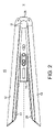
ヘアスタイリング装置10は、図1および図2に示されているように、第1のアーム12、第2のアーム14、および、中央パック16を含み、これらは、ヒンジ18によって1つの端で互いに回動可能に接合されている。ヘアスタイリング装置10は、アームのヒンジ端付近にハンドル部分20を含み、アームの遠位端付近にヘア接触部分22を含む。ヘア接触部分22は、アームの対面表面の少なくとも1つ上に配置されたプレート24、26を含む。プレート24、26は、可撓性または非可撓性ヘア接触プレートを有することができ、これらのプレート24、26は、ヘアストレートナ装置10が使用中にあるときに、増大された温度を有することができる。ヘアストレートナ装置10が使用中にないときに、プレートは、一般的に周囲温度にあるようになる。
The
長手方向軸線xが、図1および図2に示されており、長手方向軸線xは、ヘアスタイリング装置10の中心を通って長さ方向延びている。
A longitudinal axis x is shown in FIGS. 1 and 2 and extends longitudinally through the center of the
好ましい実施形態では、ヘアスタイリング装置10は、バッテリー作動ヘアストレートナであり、ヘア接触部分22は、加熱される金属プレートを含む。かかる実施形態では、電気導体28が、ヘアスタイリング装置10のヒンジ端に位置しており、中央パック16は、バッテリーパック組立体である。
In a preferred embodiment,
図3を参照すると、バッテリーパックスリーブ30は、略管状であり、バッテリーパックのための保護ケーシングを提供する、バッテリーパックスリーブ30は、実質的に閉鎖されており、ヒンジに近接して位置している第1の端32、および、開放しており、加熱されるプレートに近接して位置する第2の端34を有する。バッテリーパックスリーブ30は、バッテリーパックスリーブ30に形成されており、第1の端32と第2の端34の間で延びている第1のハーネスガイド36を有する。第2のハーネスガイド38がまた、第1のハーネスガイド36と平行に、バッテリーパックスリーブ30に沿って延びている。バッテリーパックスリーブ30は、第3のハーネスガイド40 および 第3のハーネスガイドと平行に、第1の端32と第2の端34の間でバッテリースリーブ30の内側面に沿って延びている第4のハーネスガイド42を有する。
Referring to FIG. 3,
孔44が、バッテリーパックスリーブ30の第1の端32近くで第2のハーネスガイド38上に位置している。同様な孔が、バッテリーパックの第1の端近くに各ハーネスガイド上に位置決めされているが、図3では見えない。ヒンジねじ穴46が、バッテリーパックスリーブ30の第1の端の両側の各々に形成されている。いくつかの丸いカットアウト48が、第2のハーネスガイドと第3のハーネスガイドの間でバッテリーパックスリーブ30の1つの面に位置している。
A
4つの再充電可能な円筒形バッテリーセルの構造体が、図4に示されている。第1のセル50の端面は、第2のセル52の端面と整合しており、電気的に直列に接合されている。第3のセル54の端面は、第4のセル56の端面と整合しており、電気的に直列に接合されている。第1および第2のセル50、52は、第3および第4のセル54、56に並列に接合されている。各セルと同様な外径を有する各セル50、52、54、56のフォームリング58、60、62、64が、各セル50、52、54、56の外側端面に位置決めされている。かかるフォームリング58、60、62、64は、ヘアスタイリング装置10が使用されているときに、バッテリーパック16への衝撃を吸収するよう機能する。各セルと同様な外径を有するフィッシュペーパーリング68が、第1のセル50の端面と第2のセル52の端面の間に位置決めされており、別のフィッシュペーパーリング70が、第3のセル54と第4のセル56の間に位置決めされている。
A structure of four rechargeable cylindrical battery cells is shown in FIG. The end face of the
各セルは、約3.8Vのハイパワーリチウムイオンセルであり、約1400mAhの比較的高い容量を有する。各セルは、約6.5Aの最大充電を有し、約20Aの最大放電を有する。 Each cell is a high power lithium ion cell of about 3.8V and has a relatively high capacity of about 1400mAh. Each cell has a maximum charge of approximately 6.5A and a maximum discharge of approximately 20A.
第1のセルタブ72が、第1のセル50のプラス端子に接続されている。第2のセルのプラス端子が、第2の相互接続タブ74を介して第1のセルのマイナス端子に接続されている。第2のセルのマイナス端子が、第3の相互接続タブ76を介して第3のセル54のプラス端子に接続されている。第4のセル56のプラス端子が、第4の相互接続タブ78を介して第4のセル56のマイナス端子に接続されている。第5の相互接続タブ80が、第4のセル56のマイナス端子に接続されている。
A
図示されている実施形態における各接続は、抵抗溶接によって実現される溶接接続である。代替的には、バッテリーパックタブとバッテリー端子の間の接続は、溶接または接合またははんだ付けの任意の適当な形態によって実現されることができる。 Each connection in the illustrated embodiment is a welded connection realized by resistance welding. Alternatively, the connection between the battery pack tabs and the battery terminals can be accomplished by any suitable form of welding or bonding or soldering.
図5aは、第1のセル50と第2のセル52の間、および、また、第3のセル54と第4のセル56の間の接続を示している。相互接続タブ74、78は、接続されたセルの間のU形ベンドを形成している。有利には、この形状は、セルの間でいくらかの弾性運動を提供し、また、4つの接続されたセルのためのスペースの必要を最小にする。相互接続タブ74は、突出部82をさらに含み、突出部82は、組み立てられた装置において、第2のフレーム部品(図6に図示されている)を通して配置され、バッテリー管理システムPCBにはんだ付けされている。
FIG. 5a shows the connections between the
図5bには、真っ直ぐなスロット84であって、真っ直ぐなスロット84の両側に2つの溶接ディンプル86を備えた真っ直ぐなスロット84を有する第1のタブレイアウトが示されている。第1の降伏線88が、タブの第1の縁から、タブの第2の反対側の縁まで延びており、真っ直ぐなスロット84を横断している。第2の降伏線90が、タブ84の端に隣接して、タブの第1の縁から、タブの第2の反対側の縁まで延びている(図4に示されているように、降伏線は、いずれの折り畳み方向においてもタブの屈曲を許容することができる。)。
FIG. 5b shows a first tab layout having a
溶接電流を最良化するために、より長いスロット長さが必要とされる。しかしながら、図5cに示されている第2のタブレイアウトは、スロットの両側に2つの溶接ディンプル93を備えたT形スロット92を有することによって、スロットの長さを増大させる。かかるT形は、スロットが、降伏線と一致する場所に潜在的な脆弱部を導入する。したがって、図5dには、スロットの両側に2つの溶接ディンプル96を備えたY形スロットを有する第3のタブレイアウトが、示されている。第3の降伏線98が、タブの第1の縁から、タブの第2の反対側の縁まで延びており、Y形スロット94の中間点を横断している。第2の降伏線100が、Y形スロット94の端に隣接4して、タブの第1の縁から、タブの第2の反対側の縁まで延びている。
A longer slot length is required to optimize the welding current. However, the second tab layout shown in Figure 5c increases the length of the slot by having a T-shaped
図5bの真っ直ぐなスロットと比較して、より大きな全体スロット長さの結果として、Y形スロットから、利点が得られる。特に、より大きな全体スロット長さは、抵抗溶接工程中に溶接電流を最良化し、それによって、各ディンプルの基部で溶接温度を増大させる。 Advantages are obtained from the Y-shaped slot as a result of the larger overall slot length compared to the straight slot of Figure 5b. Specifically, a larger overall slot length optimizes the welding current during the resistance welding process, thereby increasing the weld temperature at the base of each dimple.
バッテリーパックタブは、好ましくは、約0.2mmの厚さを有する銅合金で構成されている。バッテリーパックタブは、約3ミクロンの厚さの錫メッキを有するのがよい。 The battery pack tabs are preferably constructed of a copper alloy having a thickness of approximately 0.2 mm. Battery pack tabs may have a tin plating thickness of about 3 microns.
4つのセルの構造体は、図6に示されているように、第1のフレーム部品102および第2のフレーム部品104を含むフレーム内に取り付けられている。第1のフレーム部品102および第2のフレーム部品104の各々の内側面は、4つのセル52、54、56、58の構造体に嵌合し、係合する。第1のフレーム部品102の外側面は、ユーザインターフェースPCBを支持するように配置されており、第2のフレーム部品104の外側面は、バッテリー管理システムPCBを支持するように配置されている。第1の部品および第2の部品はまた、セルおよびPCBの組み合わされた構造のために安定性を提供する。また、第1の部品および第2の部品は、近接してセルおよびPCBを収容し、それによって、これらの組み合わされた体積、および、その結果、ヘアスタイリング装置の全体周囲を最小にする。さらに、OLED(有機発光デバイス)およびスピーカー(図示せず)が、ユーザインターフェースPCB上に搭載され、組み合わされたヘアスタイリング装置は、サウンドチャンバがスピーカーに隣接して形成されるように配置される。第1のフレーム部品102および第2のフレーム部品104は、第1のフレーム部品102および第2のフレーム部品104を互いに固定するための係合機構としてスナップ嵌め構造を含む。
The four-cell structure is mounted in a frame that includes a
かかるヘアスタイリング装置10では、中央バッテリーパック16から各アーム内のヒータ組立体まで電力を経路付けする必要がある。しかしながら、アームが開放位置にあるときに、バッテリーパックの遠位端においてバッテリーパックとアームの間には間隙がある。この間隙に亘る電気接合は、熱を発生させることがある高い電気抵抗接続部と潜在的になるであろう。したがって、電力をバッテリーパックから少なくとも1つのヒータ組立体に伝達するための代替的なスキームが、望ましい。
Such a
図7には、2つのパワーハーネスの経路が、ヘアスタイリング装置のアームと関連して概略的に示されている。各パワーハーネスの経路は、ヒンジに向かう経路の両側で長手方向軸線xと略平行に延びており、また、関節連結部の後は、遠位端に向かう戻り経路上に延びる。ヒンジに向かう経路は、バッテリーパックスリーブ30の内側面に沿って経路付けされており、装置の遠位端に向かう戻り経路は、それぞれ、第1のアーム12または第2のアーム14のアームを通して経路付けされている。
In Figure 7, the paths of the two power harnesses are shown schematically in relation to the arms of the hair styling device. Each power harness path extends generally parallel to the longitudinal axis x on both sides of the path towards the hinge and, after the articulation, on a return path towards the distal end. A path toward the hinge is routed along the inner surface of the
各パワーハーネスの第1の端は、バッテリー管理システムPCBに接続されている。この接続は、はんだ付け接合によって実現される。各パワーハーネスの第2の端は、ヘアスタイリング装置の各アーム内に位置するヒータ組立体に接続されている。この接続は、かしめ端子によって実現される、相互接続を結ぶワイヤであるのがよい。 A first end of each power harness is connected to the battery management system PCB. This connection is realized by a soldered joint. A second end of each power harness is connected to a heater assembly located within each arm of the hair styling device. This connection may be a wire to interconnect realized by a crimp terminal.
各パワーハーネスは、好ましくは、PTFE絶縁体を有する20AWGワイヤである。PTFE絶縁体は、高度に効果的であり、その結果、中心ワイヤストランドのまわりのPTFEの比較的薄い層が必要とされる。これは、各パワーハーネスが、最小化径を有することを可能にし、したがって、ヘアスタイリング装置で4つのパワーハーネスによって占められる体積を最小化するのに有利である。 Each power harness is preferably 20 AWG wire with PTFE insulation. PTFE insulation is highly effective and as a result a relatively thin layer of PTFE around the central wire strand is required. This allows each power harness to have a minimized diameter, thus advantageously minimizing the volume occupied by the four power harnesses in the hair styling device.
図8に示されている、ハンドル部分を通る横断面は、各々がヒンジ端に向かって延び(aによって示されている)、および、遠位端に向かって戻る(bによって示されている)、4つのパワーハーネスを示している。使用に際して、第1のハーネス106は、負電流を運び、第2のハーネス108は、正電流を運び、第3のハーネス110は、負電流を運び、第4のハーネス112は、正電流を運ぶ。第2のハーネスおよび第3のハーネスの両方の第1の端は、バッテリーパックを横切って、バッテリーバック16に一体であるオーバーハーネスシャーシ(図示せず)を介してバッテリー管理システムPCBまで経路付けされていることに留意すべきである。
Cross-sections through the handle portion, shown in FIG. 8, each extend toward the hinge end (indicated by a) and return toward the distal end (indicated by b). , showing four power harnesses. In use, the first harness 106 carries a negative current, the second harness 108 carries a positive current, the third harness 110 carries a negative current, and the fourth harness 112 carries a positive current. . First ends of both the second and third harnesses are routed across the battery pack through an overharness chassis (not shown) integral to the
第1のセル50は、第4のセル56に隣接して位置し、第3のセルおよび第4のセルは、装置のy軸線に沿って中央に位置決めされている。バッテリーパックスリーブ30は、構成要素の製造誤差、および、ありうる熱膨張を考慮するためのスリーブとセルの間の小さい許容間隙をもって両方のセル50、56を取り囲んでいる。干渉リブ114、116、118、120が、各パワーハーネスに隣接して、バッテリーパックスリーブ30の外側面とアームシェル13、15の1つの内側面の間に位置している。干渉リブ114、116、118、120は、バッテリースリーブ内でバッテリーパックを不動化する。
The
図8は、y軸線およびz軸線に関してヘアスタイリング装置のハンドル部分の対称を示している。第1のヒンジねじ122および第2のヒンジねじ124が、ヘアスタイリング装置のヒンジ端の各側で対称的に位置決めされている。第1のフレーム部品102および第2のフレーム部品104もまた、y軸線およびz軸線に関して対称的に配置されている。
Figure 8 shows the symmetry of the handle portion of the hair styling device with respect to the y-axis and the z-axis. A
図9-図11は、スタイリング装置のアームがユーザ作動摺動ボタンによって閉鎖位置に固定されることを可能にするロック機構の形態および機能を示している。図示されている実施形態は、バッテリーパックである中央パックを示しているけれども、中央パックは、代替的には、スタイリング装置アームに空気流若しくは振動運動を提供するモータパック、或いは、スタイリング装置アームに任意の電磁輻射線を提供するパワーパックであってもよい。 Figures 9-11 illustrate the form and function of the locking mechanism that allows the arm of the styling device to be locked in the closed position by a user-actuated slide button. Although the illustrated embodiment shows the center pack being a battery pack, the center pack could alternatively be a motor pack that provides airflow or vibratory motion to the styling device arm, or a styling device arm. It may be a power pack that provides any electromagnetic radiation.
ロックアーム106が、ヘアスタイリング装置10のハンドル部分20内で長手方向に延びており、アームシェル13、15と第1のフレーム部分102の間に位置している。ロックアーム126は、T形形態を有し、第1の端131にスライダキャップレシーバ130を備えたシャフト128を含み、第2の端133に垂直ロックバー132を含む。ロックバー132は、各端にロックバーブロック134、136を有し、ロックバーブロック134、136は、図示されている実施形態では、三角形プリズムである。ロックアーム126は、第1の端131がスタイリング装置のヒンジ端18に近接して位置決めされている。
A locking arm 106 extends longitudinally within the
ロックアーム126は、第1および第2のアームシェル13、15に隣接した側でロックアーム126から突出するロックアームボス138をさらに含む。ロックアームボス138は、ねじりばね142の第1の脚部140を通して延びており、第1のフレームボス144は、よじりばね142の第2の脚部146を通して延びている(図11aに示されている)。よじりばね142は、ロックアームをスタイリング装置10のヒンジ端18に向けて移動させる付勢機構として機能する。
The locking
バッテリーパックスリーブ30のスリーブキャップ148、ばねハウジング150、ロックアウトアクチュエータ152、および、ロックアウトばね154が、図9で個別でわかり、図10aおよび図10bにおいて、スリーブキャップ148の透明図で組み立てられた位置にある。ばね154の第1の端は、ロックアウトアクチュエータの足部156に取り付けられており、ばね154の第2の端は、ばねハウジング150内の真ん中箇所で安定化ベース158に取り付けられている。ばね154の延長状態および収縮状態の両方で、アクチュエータ足部156は、ばねハウジング150内に位置決めされている。ばねハウジングは、スリーブキャップ148に固定されており、スリーブキャップは、バッテリーパックスリーブ30内で摩擦嵌めを有する長手方向係合突出部160を含み、それによって、第1のフレーム部分102および第2のフレーム部分104に対してばねハウジング150の位置を固定する。
The
使用に際して、スタイリング装置アーム12、14が開放位置に配置されると、そのときには、ロックアウトばね154は、ばねハウジング150内で延長状態にある。その結果、ロックアウトアクチュエータ152は、図10aでわかるように、延長位置にある。この位置において、ロックアウトアクチュエータ152は、図11aに示されているようにロックバーブロック134に当接し、それによって、ロックアーム126を所定位置に固定し、ロックボタン162を不動にする。
In use, when the
スタイリング装置アーム12、14が、開放位置から閉鎖位置に向かって移動されるときに、第1のアームの内側面上の突出部(図示せず)は、ロックアウトアクチュエータと接触するようになり、次いで、第2のアームに向けて距離pロックアウトアクチュエータ152を徐々に押す。スタイリング装置アーム12、14が完全閉鎖位置にあるときに、そのときには、ロックアウトばね154は、ばねハウジング150内で圧縮状態にあり、ロックアウトアクチュエータは、図10bでわかるように、引っ込め状態にある。このロック位置で、ロックアウトアクチュエータ152は、もはやロックバーブロックに当接せず、それによって、ユーザが、図11bでわかるように、ロックボタン162を作動するときに、ロックアーム126が、スタイリング装置10のヒンジ端に向かって距離m移動することを可能にする。
When the
捕獲特徴(図示せず)が、第1のアームシェル13および第2のアームシェル15の各々の内側面に一体的である。捕獲特徴は、ロックバー132と係合するように形成されている。したがって、ロックアーム126がロック位置に移動されるときに、そのときには、第1の端12および第2の端14は、中央パック16に同時にかつ対称的にロックされる。
A capture feature (not shown) is integral to the inner surface of each of the
ヘアスタイリング装置の全体的な構造は、図12に示されているように、第1のアーム12、第2のアーム14、および、中央パック16を含む。第1のアームおよび第2のアームが、形態および重量において同一であり、中央パック16が、その長さに沿って略一定の重量分布を有する場合には、質量中心は、ハンドル部分に位置するようになる。これは、ユーザにとって人間工学的心地よさを増大させる。なぜならば、バランスの取れた装置は、ユーザの手および腕の疲労を最小にすることができ、バランスの取れていない装置と比較して重量がより軽く感じられるからである。重要なことに、本ヘアスタイリング装置は、アームを弾性的に開放し、閉鎖するためのばね機構を有し、このばね機構は、開放動作中、および、また、アームが完全に開放しているときに、x軸線を中心としたスタイリング装置の対称性を維持する。これは、スタイリング装置が使用中にバランスが取れていると感じられるので、ユーザに対して著しい人間工学的利益を提供する。
The overall structure of the hair styling device includes a
図12、図13、および、図14は、アームおよび中央パックを互いに弾性的に取り付け、アームが、開放位置に付勢され、また、ユーザによってスムーズに閉鎖されることを可能にするためのオプションを概略的に示している。 Figures 12, 13 and 14 show options for resiliently attaching the arms and central pack to each other, allowing the arms to be biased to an open position and smoothly closed by the user. is schematically shown.
図12は、第1のアーム12内側面と中央パック16の隣接した面の間に取り付けられた第1のコイルばね162、および、第2のアーム14の内側面と中央パック16の隣接した面の間に取り付けられた第2のコイルばね164を示している。この対称的な構成は、スタイリング装置内でバランスの取れた重量分布を維持しながら、機械的に簡単で、信頼性がある。代替的または追加的には、第3および第4のコイルばね166、168が、スタイリング装置10のヒンジ端18により近接して位置決めされていてもよい。コイルばねのかかる代替的な構成もまた、図12に示されている。
FIG. 12 shows a
図13は、第1のアーム12の内側面と中央パック16の隣接した面の間に位置決めされた第1の板ばね170、および、第2のアーム14の内側面と中央パック16の隣接した面の間に位置決めされた第2の板ばね172を概略的に示している。第1および第2の板ばね170、172は、金属から形成されており、横断面が平らか、或いは円筒形であるのがよく、第1および第2の板ばねの各々は、1つまたはそれ以上の板ばねから構成されているのがよい。再び、この対称的な構成は、スタイリング装置内でバランスの取れた重量分布を維持しながら、機械的に簡単で、信頼性がある。好ましい実施形態では、第1および第2のアームは、金属アーム構造174、176を含み、板ばね170、172は、金属アーム構造と一体的に形成されている。かかる金属アーム構造は、装置の剛性に関して有益であり、金属アームの外側面は、プラスチック層によって覆われている。
13 shows a
別のばね構造が、図14a~図14eに概略的に示されており、単独で、或いは、図12-図13に関して記載されたばね構造と組み合わされて利用されることができる。図14bに示されているように、ねじりばね構造は、ねじりばねの中心回動点でねじりばね180に取り付けられたラグ178を含む。ラグ178は、ラグ178の主円筒型本体よりも大きい径を有するショルダ184を含む。折り畳みカバー186が、図14eに示されており、折り畳みカバー186は、ねじりばね構造177と共に、第1のボード部分188および第2のボード部分190を含む。第1および第2のボード部分188、190は、中心ピン190によって互いに保持され、回動される共通のヒンジ連結縁を共有する。第1のピン194が、第1のボード部分188の外側縁で管状通路196を通して延び、第2のピン196が、第2のボード部分190の外側縁で管状通路200を通して延びる。ねじりばね構造177は、ねじりばね構造177の回動点192を中心ピン192上に固定し、ねじりばね構造177の第1の脚部および第2の脚部を、ぞれぞれ、第1のピン194および第2のピン198上に固定することによって、折り畳みカバー186に取り付けられている。
Another spring structure is shown schematically in Figures 14a-14e and can be utilized alone or in combination with the spring structure described with respect to Figures 12-13. As shown in Figure 14b, the torsion spring structure includes a
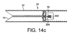
図14aを参照すると、折り畳みカバー186は、ヘアスタイリング装置10の第1および第2のアーム12、14の間、および、ヘア接触部分22およびハンドル部分20の移行部に位置している。第1のピン194の両端は、第1のアーム12上の受け入れ孔内に受け入れられ、第2のピン198の両端は、第2のアーム14上の受け入れ孔内に受け入れられている。中央パック16は、図14cに示されているように、スタイリング装置の第1および第2のアーム12、14が閉鎖されるときに、ねじりばね構造177のラグ178を受け入れるように位置決めされたリセプタクル202を含む。スタイリング装置の第1および第2のアームが開放位置に移動されるときに、ねじりばね構造177のラグ178は、折り畳みカバー186および連結されたねじりばね180の運動によってリセプタクル202から持ち上げられる。
Referring to FIG. 14a, fold-
コイルばね204が、リセプタクル202に対するラグ178の相対運動を緩和するために、リセプタクル202とラグの間に位置している。コイルばね204は、ラグ178に、或いは、リセプタクル202内に、或いは、両方に、連結されている。コイルばねの第1の端206は、リセプタクルの基部に当接し、コイルばね204の第2の端208は、ラグ178のショルダ184に当接する。有利には、ねじりばね177およびコイルばね204の構成は、図14fでデータ線Bによって概略的に示されているように、スタイリング装置アームが、開放位置(最大角度変位)に移動されるときに漸進的に大きくなるばね力を提供しながら、スタイリング装置のアームが閉鎖位置(最小角度変位)に移動されるときに漸進的に小さくなるばね力を提供する。かくして、スタイリング装置アームは開放位置に付勢されているけれども、ユーザは、ヘアのトレスを把持するために、アームを閉鎖位置に容易に絞ることができる。
A
比較のために、図14f中のデータ線Aは、ばね力が、アームが開放位置から閉鎖位置に移動されるときに増大する、典型的なばね機構のばね特徴を概略的に示している。したがって、アームの間にヘアを把持するために、ユーザは、スタイリング装置アームを絞るために最大の努力が必要とされる。この動作を繰り返すことは、ユーザにとって、不快感を生じさせ得る。 For comparison, data line A in FIG. 14f schematically shows the spring feature of a typical spring mechanism in which the spring force increases as the arm is moved from the open position to the closed position. Therefore, maximum effort is required of the user to squeeze the styling device arms in order to grip the hair between the arms. Repetition of this action may cause discomfort to the user.
有利には、折り畳みカバー186は、単一毛髪または毛髪化学生成物のような破片の侵入から中央パック16を保護する。折り畳みカバーはさらに、スターリング装置アームの間の偶発的なねじり運動を妨げることによって、スタイリング装置アームの平行構造および滑らかな機能を維持するように機能する。別の実施形態では、ヘアスタイリング装置の対称性およびバランスを増大させるために、しかし、主に、スタイリング装置のアームの間の偶発的なねじり運動の可能性をさらに回避するために、第2のねじりばね構造を、折り畳みカバーの他方の縁に含めることもできよう。代替的な実施形態では、折り畳みカバーは、中央ヒンジ連結部分なしに可撓性材料を含むことができる。
Advantageously, the folded
図12、図13、および、図14に関連して記載されているばね構造の各々は、単独で、或いは、スタイリング装置のヒンジ端に設けられたばねと組み合わされて使用されることができる。ヒンジ端に設けられたばねは、ねじりばね、或いは、C-カップばねであることができ、ヒンジ構造は、スタイリング装置の外側面上に露出されることができ、或いは、アーム構造の下に隠されることができる。 Each of the spring structures described in connection with Figures 12, 13 and 14 can be used alone or in combination with springs provided at the hinge ends of the styling device. The spring provided at the hinge end can be a torsion spring or a C-cup spring, and the hinge structure can be exposed on the outer surface of the styling device or hidden under the arm structure. be able to.
種々の代替例が、本発明の範囲内で可能であることが、当業者には明らかであろう。例えば、単一のセル構造を含めて、任意の数の対称的に配置された再充電可能なセルを利用することができる。セルは、直列、或いは、並列、或いは、両方の組み合わせで、種々の電気的配列で接続されることができる。バッテリーパックスリーブは、ヒンジ端または遠位端に開口部を含むことができ、この開口部を通して、セルの構造体を挿入することができ、次いで、この開口部上にバッテリースリーブキャップを取り付けることができる。 It will be apparent to those skilled in the art that various alternatives are possible within the scope of the invention. For example, any number of symmetrically arranged rechargeable cells can be utilized, including a single cell structure. Cells can be connected in various electrical arrangements, either in series, or in parallel, or a combination of both. The battery pack sleeve can include an opening at the hinged or distal end through which the structure of the cell can be inserted, over which the battery sleeve cap can then be attached. can.
ヘア接触部分は、アームの対面表面の少なくとも1つ上に配置された加熱されるプレートを含むことができる。加熱されるプレートは、標準的な、撓まない加熱されるプレートであることができ、或いは、代替的には、加熱されるプレートは、可撓性であることができる。使用に際して、加熱されるプレート24のヘア接触面32は、50℃~250℃の温度、さらに好ましくは、150℃~210℃の温度を有することができる。ヘア接触面は、正方形、楕円形、或いは、不規則な形態のような、形状が非矩形である形態を有することができる。
The hair contacting portion can include a heated plate positioned on at least one of the facing surfaces of the arms. The heated plate can be a standard, non-flexing heated plate, or alternatively, the heated plate can be flexible. In use, the hair-contacting
図6に示されているバッテリーパック構造を参照すると、第1のフレーム部分および第2のフレーム部分は、第1のフレーム部分および第2のフレーム部分を互いに固定するために、相互係止部品のような代替的な係合機構を含むことができる。組み立て中、バッテリーパックは、バッテリーパックのヒンジ端または遠位端に設けられた開口部を経てバッテリーパックスリーブ内に挿入される。 Referring to the battery pack structure shown in FIG. 6, the first frame portion and the second frame portion are interlocking pieces to secure the first frame portion and the second frame portion to each other. It can include alternative engagement mechanisms such as: During assembly, the battery pack is inserted into the battery pack sleeve through an opening provided at the hinged or distal end of the battery pack.
図8を参照すると、干渉リブは、バッテリースリーブ内にバッテリーパックを取り付け、代替的には、バッテリーパックスリーブの一部として、或いは、代替的には、第1および第2のアームシェルの一部として一体的に成型されることができる。 Referring to FIG. 8, the interference ribs mount the battery pack within the battery sleeve, alternatively as part of the battery pack sleeve, or alternatively as part of the first and second arm shells. can be integrally molded as
図9を参照すると、ロックバーの端に設けられたロックバーブロックは、任意の適当な形態を有することができる。さらに、ロックバーは、ロック機構の正しい機能性を可能にするために、一方の端だけにロックバーブロックを有することができる。しかしながら、対称的なロックバーブロックが、ユーザ相互作用スライダキャップ動作のスムーズな機能を確保するための対称的な重量分布を提供するために好ましい。ロックアームは、プラスチック、または、ステンレス鋼のような金属で構成されることができる。 Referring to FIG. 9, the locking bar blocks provided at the ends of the locking bars can have any suitable configuration. Additionally, the locking bar can have a locking bar block at only one end to allow correct functionality of the locking mechanism. However, a symmetrical locking bar block is preferred to provide a symmetrical weight distribution to ensure smooth functioning of user-interacting slider cap motion. The locking arm can be constructed of plastic or metal such as stainless steel.
2つのロックバーブロックの1つに当接する単一のロックアウトアクチュエータが、本願で記載されてきた。しかしながら、第2のロックバーブロックが、ロックアウトアクチュエータからz軸線のまわりに対称的に使用されることができる。第2のロックアウトアクチュエータは、非対称的なまたはねじり力がロックアームに加えられることを回避するであろう。 A single lockout actuator that abuts one of the two lock bar blocks has been described herein. However, a second lock bar block can be used symmetrically about the z-axis from the lockout actuator. A second lockout actuator will avoid asymmetric or torsional forces being applied to the lock arm.
本願に記載されているヘアケア装置は、一般的に、ヘアスタイリング装置、特に、ヘアストレートナとして言及されているけれども、装置は、トレスがアームの間に把持されるときに種々の仕方でヘアを乾燥させ、或いは、スタイリングするように機能することができる。例えば、本願に記載されているヘアケア装置のいくつかの特徴は、熱だけを提供するプレート、または、熱および空気流を提供するプレートを含むヘアスタイリング装置と共に使用されることができる。 Although the hair care devices described herein are generally referred to as hair styling devices, and more particularly as hair straighteners, the devices can be used to straighten the hair in various ways when the tress is gripped between the arms. It can function to dry or to style. For example, some features of the hair care devices described herein can be used with hair styling devices that include plates that provide heat only or plates that provide heat and airflow.
本発明は、上記の詳細な説明に制限されない。当業者には、種々の変形が明らかであろう。 The invention is not limited to the detailed description provided above. Various modifications will be apparent to those skilled in the art.
Claims (12)
前記第1のアームと前記第2のアームとの間に配置され、前記ヒンジに結合されている中央パックと、
前記第1のアームと前記中央パックとの間に取り付けられた第1のばね、および前記第2のアームと前記中央パックとの間に取り付けられた第2のばねを含み、前記第1のばねおよび前記第2のばねが、前記ヒンジを通って前記第1のアームと前記第2のアームとの間を延びる軸線に関して対称に前記中央パックを支持するようになっている付勢手段と、を含む、ヘアスタイリング装置。 are connected to each other at one end by a hinge so as to move between a closed position and an open position, the sides facing each other are adjacent to each other in the closed position, and the positions facing each other are farther from the one end in the open position a first arm and a second arm spaced apart from each other ;
a central pack positioned between the first arm and the second arm and coupled to the hinge ;
said first spring comprising a first spring mounted between said first arm and said central pack and a second spring mounted between said second arm and said central pack; and biasing means adapted for said second spring to support said central pack symmetrically about an axis extending through said hinge between said first arm and said second arm. hair styling equipment.
前記板ばねは、前記金属アーム構造と一体的に形成されている、請求項8に記載のヘアスタイリング装置。 said first arm and said second arm comprise a metal arm structure;
9. The hair styling device of Claim 8 , wherein the leaf spring is integrally formed with the metal arm structure.
Applications Claiming Priority (7)
| Application Number | Priority Date | Filing Date | Title |
|---|---|---|---|
| GB1900013.2 | 2019-01-02 | ||
| GB1900014.0A GB2580340B (en) | 2019-01-02 | 2019-01-02 | A hair styling appliance |
| GB1900014.0 | 2019-01-02 | ||
| GB1900012.4A GB2580338B (en) | 2019-01-02 | 2019-01-02 | A hair styling appliance |
| GB1900013.2A GB2580339B (en) | 2019-01-02 | 2019-01-02 | A hair styling appliance |
| GB1900012.4 | 2019-01-02 | ||
| PCT/GB2019/053283 WO2020141295A1 (en) | 2019-01-02 | 2019-11-20 | A hair styling appliance |
Publications (2)
| Publication Number | Publication Date |
|---|---|
| JP2022516177A JP2022516177A (en) | 2022-02-24 |
| JP7209099B2 true JP7209099B2 (en) | 2023-01-19 |
Family
ID=68696462
Family Applications (1)
| Application Number | Title | Priority Date | Filing Date |
|---|---|---|---|
| JP2021538809A Active JP7209099B2 (en) | 2019-01-02 | 2019-11-20 | hair styling equipment |
Country Status (7)
| Country | Link |
|---|---|
| US (1) | US20220087391A1 (en) |
| EP (1) | EP3905919A1 (en) |
| JP (1) | JP7209099B2 (en) |
| KR (1) | KR102572218B1 (en) |
| CN (2) | CN212185556U (en) |
| SG (1) | SG11202104651TA (en) |
| WO (1) | WO2020141295A1 (en) |
Families Citing this family (4)
| Publication number | Priority date | Publication date | Assignee | Title |
|---|---|---|---|---|
| US20220087391A1 (en) * | 2019-01-02 | 2022-03-24 | Dyson Technology Limited | Hair styling appliance |
| WO2022220343A1 (en) * | 2021-04-15 | 2022-10-20 | 망고슬래브 주식회사 | Cordless hair straightener having dual hidden hinge structure |
| US11653737B1 (en) | 2021-11-12 | 2023-05-23 | Sharkninja Operating Llc | Hair care appliance |
| USD1021238S1 (en) | 2022-06-02 | 2024-04-02 | Sharkninja Operating Llc | Hair care appliance |
Citations (3)
| Publication number | Priority date | Publication date | Assignee | Title |
|---|---|---|---|---|
| KR100539710B1 (en) | 2004-08-24 | 2005-12-28 | 카오스 주식회사 | Portable hair iron |
| KR100539586B1 (en) | 2005-05-16 | 2006-01-11 | 김유목 | Electric curling iron |
| JP2013121497A (en) | 2011-11-07 | 2013-06-20 | Sharp Corp | Hair iron |
Family Cites Families (13)
| Publication number | Priority date | Publication date | Assignee | Title |
|---|---|---|---|---|
| JPS62137005A (en) * | 1985-11-19 | 1987-06-19 | 橋田 直樹 | Electric eyelashes curler |
| JP2889305B2 (en) * | 1990-03-15 | 1999-05-10 | 松下電工株式会社 | Hair set |
| BE1010931A7 (en) * | 1997-02-17 | 1999-03-02 | Faco Sa | Clip styling. |
| JP3522666B2 (en) * | 2000-08-09 | 2004-04-26 | 秀利 澤田 | hair iron |
| GB2456233B (en) * | 2004-11-19 | 2009-09-23 | Jemella Ltd | Improvements in and relating to hair irons |
| CN201108132Y (en) * | 2007-11-27 | 2008-09-03 | 孙国春 | Rechargeable hair straightening device |
| KR100910102B1 (en) * | 2007-12-17 | 2009-07-30 | 이승국 | Hair iron |
| KR100978039B1 (en) * | 2009-08-17 | 2010-08-25 | 이성준 | A electric curling iron |
| FR2997271B1 (en) * | 2012-10-26 | 2016-01-01 | Oreal | DEVICE FOR TREATING THE HAIR |
| CN106714613B (en) * | 2014-06-13 | 2021-04-06 | 罗霍尔姆有限公司 | Hair conditioning and nursing device and method |
| JP6902239B2 (en) * | 2017-03-30 | 2021-07-14 | テスコム電機株式会社 | Hair iron |
| CN207927981U (en) * | 2017-11-14 | 2018-10-02 | 东莞市瑞迪三维电子科技有限公司 | A kind of hair iron of replaceable battery |
| US20220087391A1 (en) * | 2019-01-02 | 2022-03-24 | Dyson Technology Limited | Hair styling appliance |
-
2019
- 2019-11-20 US US17/420,311 patent/US20220087391A1/en active Pending
- 2019-11-20 EP EP19809597.8A patent/EP3905919A1/en active Pending
- 2019-11-20 WO PCT/GB2019/053283 patent/WO2020141295A1/en unknown
- 2019-11-20 JP JP2021538809A patent/JP7209099B2/en active Active
- 2019-11-20 SG SG11202104651TA patent/SG11202104651TA/en unknown
- 2019-11-20 KR KR1020217023677A patent/KR102572218B1/en active IP Right Grant
- 2019-12-25 CN CN201922374682.3U patent/CN212185556U/en active Active
- 2019-12-25 CN CN201911356305.5A patent/CN111387669A/en active Pending
Patent Citations (3)
| Publication number | Priority date | Publication date | Assignee | Title |
|---|---|---|---|---|
| KR100539710B1 (en) | 2004-08-24 | 2005-12-28 | 카오스 주식회사 | Portable hair iron |
| KR100539586B1 (en) | 2005-05-16 | 2006-01-11 | 김유목 | Electric curling iron |
| JP2013121497A (en) | 2011-11-07 | 2013-06-20 | Sharp Corp | Hair iron |
Also Published As
| Publication number | Publication date |
|---|---|
| JP2022516177A (en) | 2022-02-24 |
| CN111387669A (en) | 2020-07-10 |
| WO2020141295A1 (en) | 2020-07-09 |
| CN212185556U (en) | 2020-12-22 |
| KR102572218B1 (en) | 2023-08-29 |
| SG11202104651TA (en) | 2021-07-29 |
| EP3905919A1 (en) | 2021-11-10 |
| KR20210106560A (en) | 2021-08-30 |
| US20220087391A1 (en) | 2022-03-24 |
Similar Documents
| Publication | Publication Date | Title |
|---|---|---|
| JP7209099B2 (en) | hair styling equipment | |
| US11005281B2 (en) | Charging device | |
| US7540289B2 (en) | Hair styling device and method of operation | |
| US7938653B2 (en) | Electrical plug device with folding blades | |
| TWI628676B (en) | Cable | |
| JP7053097B2 (en) | Battery pack | |
| CN109478617A (en) | Battery module | |
| WO2003096367A1 (en) | Thermal protector | |
| TW200400670A (en) | Latching system for electrical connectors | |
| GB2580340A (en) | A hair styling appliance | |
| CN113226107B (en) | Hair styling appliance | |
| WO2021000396A1 (en) | Heat-not-burn smoking set | |
| CN113226107A (en) | Hair styling appliance | |
| GB2580338A (en) | A hair styling appliance | |
| JP2010045882A (en) | Charging cradle | |
| GB2580339A (en) | A hair styling appliance | |
| JPS633807A (en) | Electric heating type curl iron | |
| JP2003134680A (en) | Charging adaptor | |
| US7018737B2 (en) | Battery pack including rechargeable batteries | |
| US20200323324A1 (en) | Electrical hair iron | |
| CN109804483A (en) | Band component | |
| CN111129383B (en) | Flexible battery pack | |
| KR20220099244A (en) | Hair Iron | |
| US20240122327A1 (en) | Device for the electrical connection of hair-care household appliances or electrical apparatuses | |
| JP2017514283A (en) | Movable contact device without conductor braiding |
Legal Events
| Date | Code | Title | Description |
|---|---|---|---|
| A621 | Written request for application examination |
Free format text: JAPANESE INTERMEDIATE CODE: A621 Effective date: 20210701 |
|
| RD03 | Notification of appointment of power of attorney |
Free format text: JAPANESE INTERMEDIATE CODE: A7423 Effective date: 20210902 |
|
| RD04 | Notification of resignation of power of attorney |
Free format text: JAPANESE INTERMEDIATE CODE: A7424 Effective date: 20210913 |
|
| A977 | Report on retrieval |
Free format text: JAPANESE INTERMEDIATE CODE: A971007 Effective date: 20220727 |
|
| A131 | Notification of reasons for refusal |
Free format text: JAPANESE INTERMEDIATE CODE: A131 Effective date: 20220802 |
|
| A521 | Request for written amendment filed |
Free format text: JAPANESE INTERMEDIATE CODE: A523 Effective date: 20221014 |
|
| TRDD | Decision of grant or rejection written | ||
| A01 | Written decision to grant a patent or to grant a registration (utility model) |
Free format text: JAPANESE INTERMEDIATE CODE: A01 Effective date: 20221213 |
|
| A61 | First payment of annual fees (during grant procedure) |
Free format text: JAPANESE INTERMEDIATE CODE: A61 Effective date: 20230106 |
|
| R150 | Certificate of patent or registration of utility model |
Ref document number: 7209099 Country of ref document: JP Free format text: JAPANESE INTERMEDIATE CODE: R150 |