JP7207987B2 - Imaging device - Google Patents

Imaging device Download PDF

Info

Publication number
JP7207987B2
JP7207987B2 JP2018235037A JP2018235037A JP7207987B2 JP 7207987 B2 JP7207987 B2 JP 7207987B2 JP 2018235037 A JP2018235037 A JP 2018235037A JP 2018235037 A JP2018235037 A JP 2018235037A JP 7207987 B2 JP7207987 B2 JP 7207987B2
Authority
JP
Japan
Prior art keywords
connector
state
main body
imaging
optical system
Prior art date
Legal status (The legal status is an assumption and is not a legal conclusion. Google has not performed a legal analysis and makes no representation as to the accuracy of the status listed.)
Active
Application number
JP2018235037A
Other languages
Japanese (ja)
Other versions
JP2019120938A (en
Inventor
博之 長谷
陽介 深井
大士 鳥海
Current Assignee (The listed assignees may be inaccurate. Google has not performed a legal analysis and makes no representation or warranty as to the accuracy of the list.)
Canon Inc
Original Assignee
Canon Inc
Priority date (The priority date is an assumption and is not a legal conclusion. Google has not performed a legal analysis and makes no representation as to the accuracy of the date listed.)
Filing date
Publication date
Application filed by Canon Inc filed Critical Canon Inc
Publication of JP2019120938A publication Critical patent/JP2019120938A/en
Application granted granted Critical
Publication of JP7207987B2 publication Critical patent/JP7207987B2/en
Active legal-status Critical Current
Anticipated expiration legal-status Critical

Links

Images

Description

本発明は、望遠の光学系を有する撮像装置に関する。 The present invention relates to an imaging apparatus having a telephoto optical system.

デジタルスチルカメラ、ビデオカメラおよびTVカメラ等の光学機器(撮像装置またはカメラ)を用いて撮影を行う場合、カメラ本体にレイアウトされる液晶モニターや、電子ビューファインダー(以降、EVF)を用いて被写体確認が行われる。近年、Wi-Fiなどの無線接続や、USBなどの外部接続コネクタによる有線接続によってカメラ本体をパソコンやスマートフォンに電気的に接続することで、スマートフォンなどのカメラ本体とは異なる電子機器の表示画面を用いて被写体確認が行われている。パソコンやスマートフォンに接続することで、ユーザがカメラ本体を保持することなく、カメラ本体とは異なる電子機器の表示画面を確認しながら遠隔操作によって撮影が可能となる。遠隔操作する場合、カメラ本体を上下左右方向へ振り、光軸を所定の方向になるように移動させることが望まれている。特許文献1には、カメラ本体が装着されたクレードルの脚部を移動させることで、カメラ本体の光軸を所定の位置に移動させる技術が開示されている。また、特許文献2には、カメラ付き携帯電話機が取り付けられた載置台の回動部によってカメラ付携帯電話機を自由な角度で保持可能な技術が開示されている。 When shooting with an optical device (imaging device or camera) such as a digital still camera, video camera, or TV camera, confirm the subject using the LCD monitor or electronic viewfinder (EVF) laid out on the camera body. is done. In recent years, by electrically connecting the camera body to a personal computer or smartphone via a wireless connection such as Wi-Fi or a wired connection using an external connector such as USB, the display screen of an electronic device that is different from the camera body such as a smartphone can be displayed. Subject confirmation is performed using By connecting to a personal computer or smartphone, the user can take pictures by remote control while checking the display screen of the electronic device, which is different from the camera body, without holding the camera body. For remote control, it is desirable to swing the camera body vertically and horizontally to move the optical axis in a predetermined direction. Japanese Patent Application Laid-Open No. 2002-200000 discloses a technique for moving the optical axis of a camera body to a predetermined position by moving the legs of a cradle on which the camera body is mounted. Further, Patent Literature 2 discloses a technique in which a camera-equipped mobile phone can be held at any angle by a pivoting part of a mounting table to which the camera-equipped mobile phone is attached.

特開2003-131312号公報Japanese Patent Application Laid-Open No. 2003-131312 特開2006-074585号公報JP 2006-074585 A

しかしながら、特許文献1および特許文献2に開示された技術は、カメラ本体とは別のクレードルや載置台に関し、カメラ本体とは別の付属品として撮影を補助するものである。 However, the techniques disclosed in Patent Documents 1 and 2 relate to cradles and mounting tables that are separate from the camera body, and that assist photography as accessories separate from the camera body.

本発明は、大型化を抑制しつつ、光軸を自在に調整可能な撮像装置を提供することを目的とする。 SUMMARY OF THE INVENTION An object of the present invention is to provide an imaging apparatus capable of freely adjusting an optical axis while suppressing an increase in size.

本発明の一側面としての撮像装置は、撮影光学系および前記撮影光学系を通過した光束を撮像する撮像素子を備える本体部と、前記本体部から回動自在に突出するコネクタと、前記コネクタを収納する収納部と、を有し、前記コネクタは、前記本体部から突出している場合、前記撮影光学系の撮影範囲を調整するために前記本体部の姿勢を調整可能な第1の状態、および外部機器と電気的に接続可能な第2の状態を取ることが可能であり、前記コネクタが前記第1の状態である場合に前記本体部と成す角度は、前記コネクタが前記第2の状態である場合に前記本体部と成す角度と異なり、前記コネクタは、前記第1の状態である場合、前記外部機器と電気的に接続不可能であることを特徴とする。

An imaging apparatus as one aspect of the present invention includes a main body section including a photographing optical system and an image pickup device for picking up a light flux that has passed through the photographing optical system, a connector projecting from the main body section so as to rotate freely, and the connector. a housing for housing, wherein when the connector protrudes from the main body, a first state in which the attitude of the main body can be adjusted to adjust the photographing range of the photographing optical system; and A second state in which the connector can be electrically connected to an external device can be assumed, and the angle formed between the connector and the main body when the connector is in the first state is such that the connector is in the second state. Unlike the angle formed with the main body when , the connector is electrically unconnectable to the external device when in the first state .

本発明によれば、大型化を抑制しつつ、光軸を自在に調整可能な撮像装置を提供することができる。 ADVANTAGE OF THE INVENTION According to this invention, the imaging device which can adjust an optical axis freely can be provided, suppressing enlargement.

第1の実施形態の撮像装置の上面側斜視図である。1 is a top perspective view of an imaging device according to a first embodiment; FIG. 第1の実施形態の撮像装置の底面側斜視図である。1 is a bottom side perspective view of an imaging device according to a first embodiment; FIG. USB TYPE-Cコネクタの説明図である。FIG. 2 is an explanatory diagram of a USB TYPE-C connector; 撮像装置とEVFとの接続を示す図である。It is a figure which shows the connection of an imaging device and EVF. 撮像装置と外部機器との接続を示す図である。It is a figure which shows the connection of an imaging device and an external device. カメラシステムの概略構成を示す電気ブロック図である。1 is an electrical block diagram showing a schematic configuration of a camera system; FIG. 撮像装置の光軸位置調整の説明図である。FIG. 5 is an explanatory diagram of optical axis position adjustment of the imaging device; 第1の実施形態のコネクタの説明図である。It is an explanatory view of the connector of the first embodiment. 撮像装置と外部機器との接続フローチャートである。4 is a connection flowchart between the imaging device and an external device; 第2の実施形態のコネクタの説明図である。FIG. 10 is an explanatory diagram of a connector according to a second embodiment; 第3の実施形態のコネクタの説明図である。It is explanatory drawing of the connector of 3rd Embodiment. 第4の実施形態の撮像装置の外観斜視図である。FIG. 11 is an external perspective view of an imaging device according to a fourth embodiment; 第5の実施形態の撮像装置の外観斜視図である。FIG. 11 is an external perspective view of an imaging device according to a fifth embodiment; 第6の実施形態のコネクタの構成を示す分解斜視図である。FIG. 11 is an exploded perspective view showing the configuration of a connector according to a sixth embodiment; 第6の実施形態のコネクタの支持構成を示す分解斜視図である。FIG. 11 is an exploded perspective view showing a support structure of a connector according to a sixth embodiment; 第6の実施形態のコネクタの支持構造を示す断面図である。FIG. 11 is a cross-sectional view showing a support structure for a connector according to a sixth embodiment; 第6の実施形態のコネクタの突出状態を示す断面図である。FIG. 11 is a cross-sectional view showing a protruded state of a connector according to a sixth embodiment; 第7の実施形態のコネクタの構成を示す分解斜視図である。FIG. 21 is an exploded perspective view showing the configuration of a connector according to a seventh embodiment; 第7の実施形態のコネクタと姿勢調整部の支持構成を示す分解斜視図である。FIG. 21 is an exploded perspective view showing a support structure of a connector and a posture adjusting section according to a seventh embodiment; 第7の実施形態のコネクタと姿勢調整部の支持構造を示す断面図である。FIG. 21 is a cross-sectional view showing a support structure for a connector and a posture adjusting section according to a seventh embodiment; 第7の実施形態のコネクタ蓋の移動状態を示す下面図である。FIG. 20 is a bottom view showing a moving state of the connector lid of the seventh embodiment; 第7の実施形態のコネクタと姿勢調整部の突出状態を示す断面図である。FIG. 14 is a cross-sectional view showing a protruding state of the connector and the posture adjusting portion of the seventh embodiment; 第8の実施形態のコネクタの構成を示す分解斜視図である。FIG. 21 is an exploded perspective view showing the configuration of a connector according to an eighth embodiment; 第8の実施形態のコネクタと姿勢調整部の突出状態を示す断面図である。FIG. 20 is a cross-sectional view showing a protruding state of the connector and the posture adjusting portion of the eighth embodiment;

以下、本発明の実施例について、図面を参照しながら詳細に説明する。各図において、同一の部材については同一の参照番号を付し、重複する説明は省略する。
[第1の実施形態]
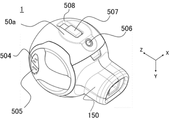
図1および図2はそれぞれ、本実施形態の撮像装置1の上面側斜視図および底面側斜視図である。撮像装置1は、結像光学系(撮影光学系)501およびCCDセンサやCMOSセンサ等の撮像素子(不図示)が内蔵されているカメラ本体(本体部)50を有する。結像光学系501は、カメラ本体50の正面側に設けられ、被写体光を撮像素子上に結像させる。結像光学系501は、焦点距離を100mmと400mmとに切り替え可能な2焦点切り替えタイプの光学系である。なお、焦点距離の切り替え数は2つに限るものではなく、焦点距離も100mmと400mmに限るものではない。また、図1では、結像光学系501は、便宜的に1枚のレンズで表現されているが、複数のレンズから構成されていてもよい。
BEST MODE FOR CARRYING OUT THE INVENTION Hereinafter, embodiments of the present invention will be described in detail with reference to the drawings. In each figure, the same reference numerals are given to the same members, and overlapping descriptions are omitted.
[First Embodiment]
1 and 2 are top and bottom perspective views, respectively, of an imaging device 1 of this embodiment. The imaging apparatus 1 has a camera body (body section) 50 in which an imaging optical system (photographing optical system) 501 and an imaging device (not shown) such as a CCD sensor or a CMOS sensor are built. The imaging optical system 501 is provided on the front side of the camera body 50 and forms an image of subject light on the imaging device. The imaging optical system 501 is a bifocal switching type optical system that can switch the focal length between 100 mm and 400 mm. The number of focal lengths to be switched is not limited to two, and the focal lengths are not limited to 100 mm and 400 mm. Further, in FIG. 1, the imaging optical system 501 is represented by one lens for the sake of convenience, but may be composed of a plurality of lenses.

カメラ本体50の上面には、撮影動作(被写体像の撮像)の開始を指示するためのレリーズスイッチ502が設けられている。レリーズスイッチ502は、レリーズボタンの押下圧によって2段階のスイッチポジションを有する。1段目のポジション(SW1 ON)の検出で、ホワイトバランスや測光等のカメラ設定のロック動作が行われる。2段目のポジション(SW2 ON)の検出で、被写体画像信号の取り込み動作が行われる。 A release switch 502 is provided on the upper surface of the camera body 50 for instructing the start of a photographing operation (imaging of a subject image). The release switch 502 has two switch positions depending on the pressing pressure of the release button. When the first stage position (SW1 ON) is detected, camera settings such as white balance and photometry are locked. Upon detection of the second stage position (SW2 ON), an operation of capturing the subject image signal is performed.

カメラ本体50の正面から見て右側面には、ズームスイッチ503が設けられている。ズームスイッチ503は、ズームスイッチ503aおよびズームスイッチ503bから構成されている。ズームスイッチ503aを押すことで、焦点距離が100mmになるように結像光学系501が駆動する。ズームスイッチ503bを押すことで、焦点距離が400mmになるように結像光学系501が駆動する。本実施形態では、結像光学系501の焦点距離に合わせて2つのズームスイッチが設けられているが、ズームスイッチの数は焦点距離の切り替え数に応じて変更可能である。 A zoom switch 503 is provided on the right side of the camera body 50 when viewed from the front. The zoom switch 503 is composed of a zoom switch 503a and a zoom switch 503b. By pressing the zoom switch 503a, the imaging optical system 501 is driven so that the focal length becomes 100 mm. By pressing the zoom switch 503b, the imaging optical system 501 is driven so that the focal length becomes 400 mm. In this embodiment, two zoom switches are provided according to the focal length of the imaging optical system 501, but the number of zoom switches can be changed according to the number of focal length switches.

カメラ本体50の正面から見て左側面には、パワースイッチ504およびモードスイッチ505が設けられている。パワースイッチ504を押すことで、カメラ本体50の電源のONとOFFを切り替えることができる。モードスイッチ505を押すことで、カメラ本体50に設定されているモードを切り替えることができる。例えば、モードスイッチ505を押すことで、静止画撮影モードと動画撮影モードを切り替えることができるように設定されていてもよい。 A power switch 504 and a mode switch 505 are provided on the left side of the camera body 50 when viewed from the front. By pressing the power switch 504, the power of the camera body 50 can be switched between ON and OFF. By pressing the mode switch 505, the mode set in the camera body 50 can be switched. For example, the still image shooting mode and the moving image shooting mode may be switched by pressing the mode switch 505 .

カメラ本体50の底面側には、三脚取付け用の三脚穴506およびスマートフォンなどの外部機器接続用のコネクタ507が設けられている。三脚穴506は、一般的なデジタルスチルカメラやビデオカメラ等の光学機器に設けられたものと同じ構成である。本実施形態では、コネクタ507は、USB TYPE―Cのコネクタであるが、外部機器と接続可能であればこれに限定されない。 A tripod hole 506 for attaching a tripod and a connector 507 for connecting an external device such as a smartphone are provided on the bottom side of the camera body 50 . The tripod hole 506 has the same configuration as that provided in optical equipment such as general digital still cameras and video cameras. In this embodiment, the connector 507 is a USB TYPE-C connector, but is not limited to this as long as it can be connected to an external device.

図3を参照して、USB TYPE-Cのコネクタについて説明する。図3は、USBTYPE-Cコネクタの説明図である。 A USB TYPE-C connector will be described with reference to FIG. FIG. 3 is an explanatory diagram of a USB TYPE-C connector.

Type-C Plugは、USB Type-CのPlugコネクタのピン配置を持つ。VBUS端子により、Type-C Plugに接続された機器に電力を供給する。CC端子により、ACジャックにACアダプタが接続されているかをType-C Plugに接続された機器に示す。VCONN端子により、Type-B ReceptacleにUSBホストなどのUSB機器が接続されているかをType-C Plugに接続された機器に示す。D+端子およびD-端子により、Type-C Plugに接続された機器とのデータの送受信に用いられる。 The Type-C Plug has the pinout of the USB Type-C Plug connector. The VBUS terminal supplies power to devices connected to the Type-C Plug. The CC terminal indicates to the equipment connected to the Type-C Plug whether an AC adapter is connected to the AC jack. The VCONN terminal indicates to the device connected to the Type-C Plug whether a USB device such as a USB host is connected to the Type-B Receptacle. The D+ and D- terminals are used to send and receive data to and from devices connected to the Type-C Plug.

Type-C Receptacleは、USB Type-CのReceptacleコネクタのピン配置を持つ。VBUS端子により、Type-C Receptacleに接続された機器から電力を受電する。CC1端子およびCC2端子により、USB Type-C規格で規定されるCC端子のプルダウン抵抗を介してGNDに接続される。 The Type-C Receptacle has the pinout of the USB Type-C Receptacle connector. Power is received from a device connected to the Type-C Receptacle through the VBUS terminal. The CC1 terminal and the CC2 terminal are connected to GND through a pull-down resistor of the CC terminal specified by the USB Type-C standard.

カメラ本体50の底面には平面部50aが設けられており、カメラ本体50を安定的に設置することができる。コネクタ507は、不使用時には、平面部50aから突出しないように、収納部508内に配置されている。コネクタ507は、後述するように、使用時にはカメラ本体50から回動自在に突出する。 A flat portion 50a is provided on the bottom surface of the camera body 50, so that the camera body 50 can be stably installed. The connector 507 is arranged in the housing portion 508 so as not to protrude from the flat portion 50a when not in use. The connector 507 rotatably protrudes from the camera body 50 during use, as will be described later.

図4は、撮像装置1とEVF150との接続を示す図である。EVF150は、カメラ本体50の背面部に着脱可能に取り付けられる。カメラ本体50とEVF150は、カメラ本体50の背面側に設けられたEVFコネクタ509とEVF150に設けられたコネクタ151によって、互いに電気的に接続される。結像光学系501を通過した光束は撮像素子上に結像され、取得された映像はEVF150に内蔵された不図示の内蔵ディスプレイに表示される。ユーザは、接眼レンズ153を通じて内蔵ディスプレイに表示される映像を見ることができる。そのため、ユーザは、内蔵ディスプレイに表示される映像を見ながら撮影することが可能となる。接眼検出部152は、ユーザがEVF150を覗いたときに接眼を検出するためのアイセンサーなどの検出手段である。内蔵ディスプレイは、例えば、TFT方式のディスプレイや有機ELディスプレイなどである。 FIG. 4 is a diagram showing the connection between the imaging device 1 and the EVF 150. As shown in FIG. The EVF 150 is detachably attached to the rear portion of the camera body 50 . The camera body 50 and the EVF 150 are electrically connected to each other by an EVF connector 509 provided on the rear side of the camera body 50 and a connector 151 provided on the EVF 150 . The light flux passing through the imaging optical system 501 forms an image on the imaging device, and the captured image is displayed on a built-in display (not shown) built in the EVF 150 . The user can see the image displayed on the built-in display through the eyepiece lens 153 . Therefore, the user can shoot while watching the video displayed on the built-in display. The eye contact detection unit 152 is detection means such as an eye sensor for detecting eye contact when the user looks into the EVF 150 . The built-in display is, for example, a TFT display or an organic EL display.

図5は、撮像装置1と携帯機器などの外部機器との接続を示す図である。本実施形態では、外部機器の一例としてスマートフォン80に撮像装置1を取り付ける場合について説明する。撮像装置1を外部機器に接続して使用する場合、EVF150は通常カメラ本体50から取り外されている。コネクタ507とスマートフォン80のコネクタ部801とが連結することで、撮像装置1とスマートフォン80を連動させた撮影動作を行うことが可能となる。スマートフォン80に撮像装置1に対応するアプリケーションプログラムがインストールされている場合、スマートフォン80を使って撮像装置1を動作させることが可能となり、各種の撮影機能を利用することができる。また、アプリケーションプログラムによってスマートフォン80の表示制御部を制御することで、表示ディスプレイ802に画像を表示させることが可能となる。また、撮像装置1は、撮影可能範囲よりも小さな任意の撮影範囲を切り出すトリミング手段を備えていてもよい。この場合、アプリケーションプログラムの指示に応じて、トリミング手段が撮像素子によって取り込まれた画像データの一部を切り出し、見かけの焦点距離を電子的に変更することが可能となる。また、撮像装置1とスマートフォン80を接続することで、スマートフォン80から撮像装置1への給電も可能となる。なお、本実施形態では、撮像装置1と外部機器を有線接続する場合について説明したが、無線接続によって撮像装置1を遠隔操作して撮影することや、撮影画像を転送することも可能である。 FIG. 5 is a diagram showing connections between the imaging apparatus 1 and external devices such as mobile devices. In this embodiment, a case where the imaging device 1 is attached to a smart phone 80 as an example of an external device will be described. The EVF 150 is usually removed from the camera body 50 when the imaging apparatus 1 is used by connecting it to an external device. By connecting the connector 507 and the connector unit 801 of the smartphone 80 , it is possible to perform a photographing operation in which the imaging device 1 and the smartphone 80 are linked. When an application program corresponding to the imaging device 1 is installed in the smartphone 80, the imaging device 1 can be operated using the smartphone 80, and various imaging functions can be used. Also, by controlling the display control unit of the smartphone 80 with an application program, it is possible to display an image on the display 802 . Further, the imaging device 1 may include trimming means for cutting out an arbitrary shooting range that is smaller than the shootable range. In this case, it is possible for the trimming means to cut out a part of the image data captured by the image pickup device and electronically change the apparent focal length in accordance with an instruction from the application program. Further, by connecting the imaging device 1 and the smartphone 80 , power can be supplied from the smartphone 80 to the imaging device 1 . In the present embodiment, a wired connection between the imaging device 1 and an external device has been described.

図6を参照して、本実施形態のカメラシステムについて説明する。図6は、カメラシステムの概略構成を示す電気ブロック図である。 The camera system of this embodiment will be described with reference to FIG. FIG. 6 is an electrical block diagram showing a schematic configuration of the camera system.

本実施形態では、結像光学系501、撮像素子106、撮像素子制御部107、レンズ駆動部131、焦点制御部119、レリーズスイッチ502、測光制御部132およびシャッター133から撮像部が構成されている。 In this embodiment, an image pickup unit is composed of an imaging optical system 501, an image pickup device 106, an image pickup device control unit 107, a lens drive unit 131, a focus control unit 119, a release switch 502, a photometry control unit 132, and a shutter 133. .

通常の静止画撮影では、ユーザがレリーズスイッチ502を押すと、結像光学系501によって集光された被写体光は、シャッター133によってその光量制御がなされ、撮像素子106により被写体像として光電変換処理表示される。取得された映像は、EVF150の表示部154に表示される。シャッター133は、フォーカルプレーンシャッターやレンズシャッターでもよいし、電子的に撮像素子106に取り込む光量を制御する電子シャッターでもよい。結像光学系501は、図6では便宜的に1枚のレンズで表現されているが、複数のレンズから構成されていてもよい。表示部154は、例えば、TFT方式のディスプレイや有機ELディスプレイなどであり、ユーザに撮像装置1の状態を表示してもよい。 In normal still image shooting, when the user presses the release switch 502, the subject light collected by the imaging optical system 501 is subjected to light amount control by the shutter 133, and the image pickup device 106 displays a subject image by photoelectric conversion processing. be done. The acquired image is displayed on the display unit 154 of the EVF 150 . The shutter 133 may be a focal plane shutter, a lens shutter, or an electronic shutter that electronically controls the amount of light taken into the image sensor 106 . The imaging optical system 501 is represented by one lens in FIG. 6 for the sake of convenience, but may be composed of a plurality of lenses. The display unit 154 is, for example, a TFT display or an organic EL display, and may display the state of the imaging device 1 to the user.

撮像素子制御部107は、撮像素子106に転送クロック信号やシャッター信号を供給するためのタイミングジェネレータや、撮像素子106の出力信号に対するノイズ除去やゲイン処理を行うための回路を有する。また、撮像素子制御部107は、アナログ信号を例えば10ビットデジタル信号に変換するためのA/D変換回路を有する。10ビットデジタル信号は、映像情報取得量子化ビット数に対応する。ビット数は、撮像素子106の仕様などで種々変更可能である。さらに、撮像素子制御部107は、表示部154への表示および動画撮影を行うために、コントローラ101からの解像度変換指示に従って、撮像素子106に水平方向および垂直方向の間引き画素データを出力させる画素間引き処理を行うための回路等を有する。 The image pickup device control unit 107 has a timing generator for supplying a transfer clock signal and a shutter signal to the image pickup device 106 and a circuit for performing noise removal and gain processing on the output signal of the image pickup device 106 . The imaging device control unit 107 also has an A/D conversion circuit for converting an analog signal into, for example, a 10-bit digital signal. A 10-bit digital signal corresponds to the number of quantization bits for video information acquisition. The number of bits can be changed variously depending on the specifications of the image sensor 106 or the like. Furthermore, in order to perform display on the display unit 154 and video shooting, the image sensor control unit 107 causes the image sensor 106 to output thinned pixel data in the horizontal direction and the vertical direction according to the resolution conversion instruction from the controller 101. It has circuits and the like for processing.

測光制御部132は、撮像素子106の受光面の画素において発生した輝度信号を取り込み、コントローラ101にその情報を送る。コントローラ101は、取得した情報に基づいて撮像装置1の最適露出演算を行い、シャッタスピードや結像光学系501の絞りを制御することで最適な露光を達成する。また、コントローラ101は、撮像素子106が出力する輝度信号や色信号に基づいて、被写体の検出、ひいては撮影シーンの判別を行うことが可能である。 The photometry control unit 132 takes in luminance signals generated in the pixels of the light receiving surface of the image sensor 106 and sends the information to the controller 101 . The controller 101 performs optimum exposure calculation for the imaging apparatus 1 based on the acquired information, and achieves optimum exposure by controlling the shutter speed and the aperture of the imaging optical system 501 . Further, the controller 101 can detect a subject and, in turn, determine a shooting scene based on luminance signals and color signals output by the image sensor 106 .

焦点制御部119は、コントラストAF(山登りAF)や位相差AFなどの従来の焦点位置検出方法によって撮像画面の複数の領域について焦点位置を検出する。焦点制御部119は、例えば、コントローラ101を通じて現在位置からどの程度レンズを駆動させれば焦点が合うか(または現状のレンズ位置で焦点が合ったか)を計算し、レンズ駆動部131に駆動量を指示する。レンズ駆動部131は、焦点制御部119により算出された駆動量に応じて、結像光学系501内の特定のレンズの位置を変えることによって焦点を合わせる動作を行う。焦点を合わせる方法については、レンズ駆動に限定せず、撮像素子106と結像光学系501全体との相対位置を変化させても同様の効果が得られる。この場合、例えば、撮像素子106を結像光学系501の光軸に沿って前後させればよい。 The focus control unit 119 detects focus positions for a plurality of areas of the imaging screen by conventional focus position detection methods such as contrast AF (hill-climbing AF) and phase-difference AF. The focus control unit 119 calculates, for example, how much the lens should be driven from the current position through the controller 101 to achieve focus (or whether the focus is achieved at the current lens position), and instructs the lens driving unit 131 to drive the amount. instruct. The lens drive unit 131 performs a focusing operation by changing the position of a specific lens in the imaging optical system 501 according to the drive amount calculated by the focus control unit 119 . The focusing method is not limited to driving the lens, and similar effects can be obtained by changing the relative position between the imaging device 106 and the entire imaging optical system 501 . In this case, for example, the imaging device 106 may be moved back and forth along the optical axis of the imaging optical system 501 .

コントローラ(中央演算処理装置)101は、カメラシステム全体の動作を制御する。コントローラ101は、ROM102内の制御プログラムに基づいて各種制御を行う。制御の中には、レリーズスイッチ502の操作に伴う撮影動作を指示する処理や、画像処理部108から出力された撮影画像(映像)信号を読み込み、RAM103に転送を行う処理がある。同様に、RAM103より表示制御部111に画像データを転送する処理や、画像データをJPEG圧縮し、ファイル形式でデータ格納手段104に格納する処理がある。動画データの場合も同様の処理を経て、MOV形式などのファイルに圧縮され、データ格納手段104に格納される。また、コントローラ101は、撮像素子106、撮像素子制御部107、画像処理部108および表示制御部111に対してデータ取り込み範囲やデジタル画像処理の変更指示を行う。 A controller (central processing unit) 101 controls the operation of the entire camera system. The controller 101 performs various controls based on control programs in the ROM 102 . The control includes processing for instructing a shooting operation associated with the operation of the release switch 502 and processing for reading a captured image (video) signal output from the image processing unit 108 and transferring it to the RAM 103 . Similarly, there is a process of transferring image data from the RAM 103 to the display control unit 111 and a process of compressing the image data by JPEG and storing it in the data storage unit 104 in a file format. In the case of moving image data, the same processing is performed, and the data is compressed into a file of MOV format or the like and stored in the data storage means 104 . The controller 101 also instructs the image sensor 106, image sensor control unit 107, image processing unit 108, and display control unit 111 to change the data capture range and digital image processing.

また、コントローラ101は、各素子への電源の供給をコントロールするための制御信号をDC/DCコンバータ117に対して出力する。DC/DCコンバータ117は、電池116から電源供給を受け、昇圧やレギュレーションを行う。これにより、複数の電源を作り出し、コントローラ101をはじめとする各素子に必要な電圧の電源を供給する。また、DC/DCコンバータ117は、コントローラ101からの制御信号により、各素子への電圧供給の開始や停止を制御する。電池116は、リチャージャブルの2次電池または乾電池である。本実施形態では、DC/DCコンバータ117に電源を供給するために、電池116が用いられているが、本発明はこれに限定されない。電源が供給可能な他の電源装置を用いてもよい。 The controller 101 also outputs a control signal to the DC/DC converter 117 for controlling power supply to each element. The DC/DC converter 117 receives power supply from the battery 116 and performs boosting and regulation. As a result, a plurality of power supplies are created, and power supplies of necessary voltages are supplied to each element including the controller 101 . Also, the DC/DC converter 117 controls start and stop of voltage supply to each element according to a control signal from the controller 101 . The battery 116 is a rechargeable secondary battery or dry battery. In this embodiment, the battery 116 is used to supply power to the DC/DC converter 117, but the invention is not limited to this. Other power supply devices that can supply power may be used.

RAM103は、画像展開エリア、ワークエリア、VRAMおよび一時退避エリアなどを備えている。画像展開エリアは、画像処理部108より送られてきた撮影画像(YUVデジタル信号)やデータ格納手段104から読み出されたJPEG圧縮画像データを一時的に格納するためのテンポラリバッファとして使用される。画像展開エリアは、画像圧縮処理や解凍処理のための画像専用ワークエリアとしても使用される。ワークエリアは、各種プログラムのためのワークエリアである。VRAMは、各表示部に表示する表示データを格納する。一時退避エリアは、各種データを一時退避させるためのエリアである。 The RAM 103 has an image development area, a work area, a VRAM, a temporary save area, and the like. The image expansion area is used as a temporary buffer for temporarily storing the photographed image (YUV digital signal) sent from the image processing unit 108 and the JPEG compressed image data read from the data storage means 104 . The image expansion area is also used as an image dedicated work area for image compression processing and decompression processing. A work area is a work area for various programs. The VRAM stores display data to be displayed on each display unit. The temporary save area is an area for temporarily saving various data.

データ格納手段104は、コントローラ101によりJPEG圧縮された撮影画像データや、MOV形式などの動画像データをファイル形式で格納しておくためのフラッシュメモリである。 The data storage unit 104 is a flash memory for storing JPEG-compressed captured image data by the controller 101 and moving image data such as MOV format in a file format.

画像処理部108は、撮像素子制御部107から出力された10ビットデジタル信号に対してガンマ変換、色空間変換、ホワイトバランス、AE、およびフラッシュ補正等の画像処理を行い、YUV(4:2:2)フォーマットの8ビットデジタル信号を出力する。 The image processing unit 108 performs image processing such as gamma conversion, color space conversion, white balance, AE, and flash correction on the 10-bit digital signal output from the image sensor control unit 107, and converts it into YUV (4:2: 2) output a formatted 8-bit digital signal;

表示制御部111は、画像処理部108から転送されたYUVデジタル画像データ、またはデータ格納手段104の画像ファイルに対してJPEGの解凍を行ったYUVデジタル画像データを受け取る。表示制御部111は、受け取った画像データをRGBデジタル信号に変換した後、表示部154に出力する。また、表示制御部111は、EVF150のカメラ本体50への接続を検出するファインダ接続検出部115を有する。 The display control unit 111 receives the YUV digital image data transferred from the image processing unit 108 or the YUV digital image data obtained by performing JPEG decompression on the image file in the data storage unit 104 . The display control unit 111 converts the received image data into RGB digital signals, and then outputs the RGB digital signals to the display unit 154 . The display control unit 111 also has a viewfinder connection detection unit 115 that detects connection of the EVF 150 to the camera body 50 .

データ通信手段109は、例えば、スマートフォン等の表示部161を有する外部機器160と無線通信を行う。これにより、撮像装置1の遠隔制御が可能となる。例えば、撮像装置1を所定の位置に設置した状態で表示部161に撮像装置1で取得された映像を確認しながら、撮影を行うことが可能である。 The data communication unit 109 wirelessly communicates with an external device 160 having a display unit 161 such as a smartphone. This enables remote control of the imaging device 1 . For example, it is possible to shoot while confirming the image acquired by the imaging device 1 on the display unit 161 with the imaging device 1 installed at a predetermined position.

ズームスイッチ503は、結像光学系105の光学ズーム倍率をユーザが操作するための操作部材である。コントローラ101に入力されたズームスイッチ503からの信号により、レンズ駆動部131が結像光学系105を制御し、光学ズーム倍率が可変可能となる。本実施例では、ズームスイッチ503は、前述したように、光学ズーム倍率アップおよび光学ズーム倍率ダウンの2つのスイッチを有する。 A zoom switch 503 is an operation member for the user to operate the optical zoom magnification of the imaging optical system 105 . A signal from the zoom switch 503 that is input to the controller 101 causes the lens drive unit 131 to control the imaging optical system 105 so that the optical zoom magnification can be varied. In this embodiment, the zoom switch 503 has two switches for increasing the optical zoom magnification and decreasing the optical zoom magnification, as described above.

パワースイッチ504は、撮像装置1の電源投入および電源停止をユーザが操作するための操作部材である。 A power switch 504 is an operation member for a user to operate power-on and power-off of the imaging apparatus 1 .

モードスイッチ505は、撮像装置1が具える各種撮影のためのモード切替をユーザが操作するための操作部材である。コントローラ101に入力されたモードスイッチ505からの信号により、モード切替が行われる。 A mode switch 505 is an operation member for a user to operate mode switching for various types of shooting provided in the imaging apparatus 1 . Mode switching is performed by a signal from the mode switch 505 that is input to the controller 101 .

EVF150に設けられたコントローラ155は、コネクタ151、接眼検出部152および表示部154に接続され、EVF150全体の制御を司る。 A controller 155 provided in the EVF 150 is connected to a connector 151 , an eye proximity detection section 152 and a display section 154 and controls the entire EVF 150 .

以下、図7を参照して、コネクタ507を撮像装置1の光軸位置調整用の脚部として機能させる撮影方法について説明する。図7は、撮像装置1を側面から見た図であり、コネクタ507の突出量により撮像装置1の光軸位置が変化する様子を示している。 A photographing method in which the connector 507 functions as a leg for adjusting the optical axis position of the imaging apparatus 1 will be described below with reference to FIG. FIG. 7 is a side view of the imaging device 1 and shows how the optical axis position of the imaging device 1 changes depending on the amount of protrusion of the connector 507 .

図7(a)は、コネクタ507がカメラ本体50に対して突出しておらず、平面部50aが設置面に当接している状態を示している。図7(b)は、図7(a)の状態からコネクタ507を回動させた状態であり、コネクタ507がカメラ本体50から突出し、カメラ本体50が設置面に対して傾いている状態を示している。このとき、平面部50aおよびコネクタ507が設置面に当接し、カメラ本体50の光軸は設置面に対して角度θ1の傾きを有する。図7(c)は、図7(b)の状態からコネクタ507を回動させた状態であり、カメラ本体50が設置面に対して図7(b)の状態よりも大きく傾いている状態である。このとき、カメラ本体50の光軸は、設置面に対して角度θ2(>θ1)の傾きを有する。このように、コネクタ507をカメラ本体50に対して突出させた状態で回動させることで、カメラ本体50の姿勢を調整可能である。すなわち、撮像装置1の光軸を自在に調整可能である。 FIG. 7A shows a state in which the connector 507 does not protrude from the camera body 50 and the flat portion 50a is in contact with the installation surface. 7B shows a state in which the connector 507 is rotated from the state in FIG. 7A, the connector 507 protrudes from the camera body 50, and the camera body 50 is tilted with respect to the installation surface. ing. At this time, the flat portion 50a and the connector 507 are in contact with the installation surface, and the optical axis of the camera body 50 is inclined at an angle θ1 with respect to the installation surface. FIG. 7C shows a state in which the connector 507 has been rotated from the state in FIG. be. At this time, the optical axis of the camera body 50 is inclined at an angle θ2 (>θ1) with respect to the installation surface. In this way, by rotating the connector 507 in a state of protruding from the camera body 50, the posture of the camera body 50 can be adjusted. That is, the optical axis of the imaging device 1 can be freely adjusted.

以下、図8を参照して、コネクタ507について説明する。図8は、コネクタ507の説明図である。コネクタ507は、前述したように、外部機器との接続コネクタとして使用されるとともに、撮像装置1の光軸調整用の脚部としても使用される。 The connector 507 will be described below with reference to FIG. FIG. 8 is an explanatory diagram of the connector 507. As shown in FIG. As described above, the connector 507 is used as a connector for connecting to an external device, and is also used as a leg for adjusting the optical axis of the imaging device 1 .

図8(a)は、コネクタ507がカメラ本体50から突出している状態を示している。図8(b)は、収納部508に収納されている状態(収納状態)のコネクタ507の断面図である。図8(c)は、カメラ本体50から突出し、撮像装置1の光軸調整用の脚部として使用可能な状態(第1の状態)のコネクタ507の断面図である。図8(d)は、カメラ本体50から突出し、外部機器に有線接続可能な状態(第2の状態)のコネクタ507の断面図である。 8A shows a state in which the connector 507 protrudes from the camera body 50. FIG. FIG. 8(b) is a cross-sectional view of the connector 507 in a state of being housed in the housing portion 508 (stored state). FIG. 8C is a cross-sectional view of the connector 507 in a state (first state) that protrudes from the camera body 50 and can be used as a leg for adjusting the optical axis of the imaging device 1 . FIG. 8D is a cross-sectional view of the connector 507 protruding from the camera body 50 and in a state (second state) capable of being wiredly connected to an external device.

コネクタ507は、外部機器に接続するためのプラグ部(接続部)507a、プラグ部507aを保持するコネクタ本体部507b、およびプラグ部507aを保護する保護部材507dを有する。コネクタ507は、軸部507cによってカメラ本体50に軸部507cを中心として回動可能に取り付けられている。 The connector 507 has a plug portion (connecting portion) 507a for connecting to an external device, a connector body portion 507b that holds the plug portion 507a, and a protective member 507d that protects the plug portion 507a. The connector 507 is attached to the camera body 50 by a shaft portion 507c so as to be rotatable about the shaft portion 507c.

図8(b)の状態では、保護部材507dはプラグ部507aを覆っていないが、プラグ部507aは収納部508に収納されているので外力により破損することはない。このとき、保護部材507dは、不図示のカメラ本体50に設けられた付勢部材によりコネクタ本体部507b側に付勢されている。 In the state shown in FIG. 8(b), the protective member 507d does not cover the plug portion 507a, but the plug portion 507a is housed in the housing portion 508 so that it will not be damaged by an external force. At this time, the protective member 507d is biased toward the connector main body 507b by a biasing member provided on the camera body 50 (not shown).

図8(b)の状態からコネクタ507を回動させると、コネクタ507はカメラ本体50に対して突出し、図8(c)の状態になる。コネクタ507が図8(b)の状態から図8(c)の状態に移行する際、保護部材507dに対する付勢が解除され、保護部材507は図8(c)の矢印方向(プラグ部507aに向かう方向)へ移動する。図8(c)の状態では、プラグ部507aは保護部材507dによって常に保護されているため、コネクタ507を撮像装置1の光軸調整用の脚部として使用することが可能となる。また、本実施形態では、カメラ本体50は、コネクタ507が図8(b)の状態からカメラ本体50に対して突出することで、データ通信手段109を介して無線通信可能な状態になる。 When the connector 507 is rotated from the state shown in FIG. 8(b), the connector 507 protrudes from the camera body 50 and enters the state shown in FIG. 8(c). When the connector 507 shifts from the state shown in FIG. 8B to the state shown in FIG. direction). In the state of FIG. 8C, the plug portion 507a is always protected by the protective member 507d, so the connector 507 can be used as a leg portion for adjusting the optical axis of the imaging device 1. FIG. Further, in this embodiment, the camera body 50 becomes ready for wireless communication via the data communication means 109 by protruding the connector 507 from the state shown in FIG. 8B.


図8(c)の状態からコネクタ507を回動させると、コネクタ507は図8(b)の状態に対して略直角となる状態で不図示の係止部により係止される図8(d)の状態になる。保護部材507dは、図8(c)の状態から図8(d)の状態に移行する際、前述の付勢部材により図8(d)の矢印方向(プラグ部507aに向かう方向とは反対方向)へ付勢され、図8(d)の状態ではプラグ部507aを覆わない状態になる。そのため、図8(d)の状態では、プラグ部507aを外部機器に接続可能であり、コネクタ507を外部機器との接続コネクタとして使用することが可能となる。

When the connector 507 is rotated from the state shown in FIG. 8(c), the connector 507 is locked by a locking portion (not shown) in a state substantially perpendicular to the state shown in FIG. 8(b). ). When the protective member 507d shifts from the state shown in FIG. 8C to the state shown in FIG. ), and the plug portion 507a is not covered in the state of FIG. 8(d). Therefore, in the state of FIG. 8D, the plug portion 507a can be connected to an external device, and the connector 507 can be used as a connector for connecting to the external device.

なお、本実施形態では、保護部材507dは不図示の付勢部材によるメカ的な付勢によってプラグ部507aを覆う状態と覆わない状態との間を移動したが、本発明はこれに限定されない。磁石やモータを用いて保護部材507aを移動させてもよい。また、本実施形態では、図8(b)の状態において、保護部材507dはプラグ部507aを覆っていないが、プラグ部507aをより強く保護するために、プラグ部507aを覆うようにしてもよい。また、図8(c)の状態は、プラグ部507aは保護部材507aにより保護されており、コネクタ507は外部機器と接続不可能な状態である。しかしながら、保護部材507dをプラグ部507aに向かう方向とは反対方向へ押し込むことで、コネクタ507は外部機器に接続可能になる。 In this embodiment, the protective member 507d moves between the state of covering the plug portion 507a and the state of not covering it by mechanical biasing by a biasing member (not shown), but the present invention is not limited to this. A magnet or a motor may be used to move the protective member 507a. In this embodiment, the protective member 507d does not cover the plug portion 507a in the state of FIG. 8(b), but the plug portion 507a may be covered in order to protect the plug portion 507a more strongly. . In the state of FIG. 8C, the plug portion 507a is protected by the protective member 507a, and the connector 507 cannot be connected to an external device. However, by pushing the protective member 507d in the direction opposite to the direction toward the plug portion 507a, the connector 507 can be connected to an external device.

以下、図9を参照して、撮像装置1と外部機器との代表的な接続フローについて説明する。図9は、本実施形態の撮像装置1と外部機器との接続フローチャートの一例である。 A typical connection flow between the imaging device 1 and an external device will be described below with reference to FIG. FIG. 9 is an example of a connection flowchart between the imaging apparatus 1 of this embodiment and an external device.

ステップS200では、コントローラ101は、ユーザによりパワースイッチ504が押されたことを検出し、DC/DCコンバータ117に撮像装置1内の各構成要素に電源を供給させる。 In step S<b>200 , the controller 101 detects that the power switch 504 has been pressed by the user, and causes the DC/DC converter 117 to supply power to each component within the imaging apparatus 1 .

ステップS201では、コントローラ101は、ファインダ接続検出部115によりEVF150のカメラ本体50への接続が検出されたかどうかを判定する。EVF150の接続が検出された場合、ステップS202に進み、EVF150の接続が検出されていない場合、ステップS203に進む。 In step S<b>201 , controller 101 determines whether connection of EVF 150 to camera body 50 has been detected by viewfinder connection detection unit 115 . If the connection of the EVF 150 is detected, the process proceeds to step S202, and if the connection of the EVF 150 is not detected, the process proceeds to step S203.

ステップS202では、コントローラ101は、図7(b)、図7(c)および図8(c)のように、コネクタ507がカメラ本体50に対して突出しているかどうかを判定する。コネクタ507が突出している場合、ステップS203に進み、コネクタ507が突出していない場合、ユーザはEVF150を覗いていると判定し、撮影状態に移行する。ステップS202において、撮像装置1は図1や図2のようにカメラ本体50にEVF150が接続されている状態であるため、ユーザはEVF150を覗いて撮影するケースが多いと考えられる。 In step S202, the controller 101 determines whether the connector 507 protrudes from the camera body 50 as shown in FIGS. 7(b), 7(c) and 8(c). If the connector 507 protrudes, the process proceeds to step S203, and if the connector 507 does not protrude, it is determined that the user is looking into the EVF 150, and the shooting state is entered. In step S202, the imaging apparatus 1 is in a state in which the EVF 150 is connected to the camera body 50 as shown in FIGS.

ステップS203では、コントローラ101は、コネクタ507がカメラ本体50に対して有線接続されているかどうかを判定する。コネクタ507が有線接続されている場合、カメラ本体50が外部機器に接続されていると判定し、撮影状態に移行し、コネクタ507が有線接続されていない場合、カメラ本体50が遠隔操作されていると判定し、ステップS204に進む。 In step S203, the controller 101 determines whether the connector 507 is connected to the camera body 50 by wire. When the connector 507 is connected by wire, it is determined that the camera body 50 is connected to an external device, and the image capturing state is entered. When the connector 507 is not connected by wire, the camera body 50 is being remotely controlled. , and the process proceeds to step S204.

ステップS204では、コントローラ101は、外部機器と無線接続を行い、撮影状態に移行する。 In step S204, the controller 101 establishes a wireless connection with an external device, and shifts to a photographing state.

以上説明したように、撮像装置1に内蔵されているコネクタ507は、カメラ本体50に対して回動自在に突出し、脚部として撮像装置1の光軸の角度を自在に調整することが可能である。 As described above, the connector 507 built in the imaging device 1 projects rotatably with respect to the camera main body 50, and can freely adjust the angle of the optical axis of the imaging device 1 as a leg. be.

なお、本実施形態では、外部機器との接続コネクタおよび光軸調整用の脚部の数がそれぞれ1つである場合について説明したが、本発明はこれに限定されない。また、コネクタ507の回動は、手動で操作可能に構成されていてもよいし、カメラ本体50にモータなどの電気駆動部材を設け、外部からリモコン操作可能に構成されていてもよい。
[第2の実施形態]
本実施形態では、コネクタの構成が第1の実施形態と異なる。他の構成については、第1の実施形態と同様であるため、説明は省略する。
In this embodiment, the number of the connector for connecting to the external device and the number of legs for adjusting the optical axis are respectively one, but the present invention is not limited to this. Further, the rotation of the connector 507 may be configured to be manually operable, or may be configured such that an electric driving member such as a motor is provided in the camera body 50 so as to be remotely operable from the outside.
[Second embodiment]
This embodiment differs from the first embodiment in the configuration of the connector. Since other configurations are the same as those of the first embodiment, description thereof will be omitted.

図10は、本実施形態のコネクタ507の説明図である。コネクタ507は、第1の実施形態で説明したように、外部機器との接続コネクタとして使用されるとともに、撮像装置1の光軸調整用の脚部としても使用される。 FIG. 10 is an explanatory diagram of the connector 507 of this embodiment. As described in the first embodiment, the connector 507 is used as a connector for connecting to an external device, and is also used as a leg for adjusting the optical axis of the imaging device 1 .

コネクタ507は、プラグ部(接続部)507eおよび本体部(脚部)507fを有する。コネクタ507は、軸部507gによってカメラ本体50に軸部507gを中心として回動可能に取り付けられている。本実施形態では、コネクタ507には、プラグ部507eを保護する保護部材は設けられていない。 The connector 507 has a plug portion (connection portion) 507e and a body portion (leg portion) 507f. The connector 507 is attached to the camera body 50 by a shaft portion 507g so as to be rotatable about the shaft portion 507g. In this embodiment, the connector 507 is not provided with a protective member for protecting the plug portion 507e.

図10(a)は、カメラ本体50に収納されている状態(収納状態)のコネクタ507の断面図である。図10(a)の状態からコネクタ507を図中の時計回りの方向(図10(b)の矢印方向)へ回動させると、コネクタ507は図10(a)の状態に対して略直角となる状態で不図示の係止部により係止される図10(b)の状態になる。図10(b)の状態では、プラグ部507eを外部機器に接続可能であり、コネクタ507を外部機器との接続コネクタとして使用することが可能になる。 FIG. 10A is a cross-sectional view of the connector 507 in a state (stored state) housed in the camera body 50. FIG. When the connector 507 is rotated clockwise (in the direction of the arrow in FIG. 10B) from the state shown in FIG. 10(b) in which it is locked by a locking portion (not shown). In the state shown in FIG. 10B, the plug portion 507e can be connected to an external device, and the connector 507 can be used as a connector for connecting to the external device.

図10(a)の状態からコネクタ507を図中の反時計回りの方向(図10(c)-図10(e)の矢印方向)へ回動させると、プラグ部507eは収納部508側に回動し、本体部507fはカメラ本体50に対して突出する方向へ回動する。コネクタ507は、図10(a)の位置から図10(c)の位置、図10(d)の位置、図10(e)の位置の順に移動する。このとき、各位置において、ユーザにクリック感を与えて、コネクタ507を係止させてもよい。このようにコネクタ507がカメラ本体50に対して自在に回動することで、本体部507fは撮像装置1の光軸調整用の脚部として使用され、撮像装置1の光軸を段階的に調整することができる。本体部507fが撮像装置1の光軸調整用の脚部として使用される間、当接部507hは設置面に当接する。当接部507hの表面粗さは、プラグ部507eや本体部507fよりも粗くなっている。これにより、撮像装置1を安定して設置することが可能になる。当接部507hの表面粗さは、例えば、マット処理などによって大きくすることができる。 When the connector 507 is rotated counterclockwise in FIG. 10(c)-FIG. 10(e) from the state shown in FIG. As a result, the body portion 507f rotates in a direction in which it protrudes from the camera body 50. As shown in FIG. The connector 507 moves from the position shown in FIG. 10(a) to the position shown in FIG. 10(c), the position shown in FIG. 10(d), and the position shown in FIG. 10(e) in this order. At this time, the connector 507 may be locked by giving a click feeling to the user at each position. As the connector 507 freely rotates with respect to the camera body 50 in this manner, the body portion 507f is used as a leg portion for adjusting the optical axis of the imaging device 1, and the optical axis of the imaging device 1 is adjusted step by step. can do. While the body portion 507f is used as a leg portion for adjusting the optical axis of the imaging device 1, the contact portion 507h contacts the installation surface. The surface roughness of the contact portion 507h is rougher than that of the plug portion 507e and the body portion 507f. This makes it possible to stably install the imaging device 1 . The surface roughness of the contact portion 507h can be increased by, for example, matting.

本実施形態では、コネクタ507が図10(a)の位置から反時計回りに回動する場合、本体部507fは段階的に位置(本実施形態では図10(c)-図10(e)の3つの位置)をとるが、本発明はこれに限定されない。コネクタ507が図10(a)の位置から反時計回りに回動する間、本体部507fはどの位置であっても脚部として使用可能となるように構成されていてもよい。また、図10(a)の位置からコネクタ507を時計回りに回動させる場合、コネクタ507をシームレスに回動させてもよい。
[第3の実施形態]
本実施形態では、コネクタのとりうる状態が第1の実施形態と異なる。他の構成については、第1の実施形態と同様であるため、説明は省略する。
In this embodiment, when the connector 507 rotates counterclockwise from the position shown in FIG. three positions), but the invention is not so limited. The body portion 507f may be configured to be usable as a leg portion at any position while the connector 507 rotates counterclockwise from the position shown in FIG. 10(a). Further, when the connector 507 is rotated clockwise from the position shown in FIG. 10A, the connector 507 may be rotated seamlessly.
[Third embodiment]
In this embodiment, the possible states of the connector are different from those in the first embodiment. Since other configurations are the same as those of the first embodiment, description thereof will be omitted.

図11(a)は、カメラ本体50から突出し、外部機器に有線接続可能な状態のコネクタ507の状態を示している。第1および第2の実施形態で説明したように、コネクタ507は、収納状態と図11(a)の状態との間を回動可能に構成されている。本実施形態では、コネクタ507は、さらに、図11(a)の状態と図11(b)との間を回動可能に構成されている。具体的には、コネクタ507は、図11(a)の状態において、図11(a)の矢印で示される、収納状態から図11(a)の状態に至るまでの回動方向(第1の回動方向)に直交する方向(第2の回動方向)へ回動可能である。コネクタ507が図11(a)に至るまでの回動方向に直交する方向へ略90度回動すると、図11(b)の状態(第3の状態)になる。 FIG. 11A shows the state of the connector 507 protruding from the camera body 50 and capable of being wiredly connected to an external device. As described in the first and second embodiments, the connector 507 is rotatable between the housed state and the state shown in FIG. 11(a). In this embodiment, the connector 507 is further configured to be rotatable between the state shown in FIG. 11(a) and the state shown in FIG. 11(b). Specifically, in the state shown in FIG. 11(a), the connector 507 is rotated in the direction indicated by the arrow in FIG. 11(a) from the retracted state to the state shown in FIG. (rotating direction) in a direction (second rotating direction) perpendicular to the rotating direction). When the connector 507 rotates approximately 90 degrees in a direction perpendicular to the direction of rotation up to FIG. 11(a), the state (third state) of FIG. 11(b) is reached.

図11(a)の状態では、コネクタ507は、撮像素子106の長さXの短辺側に配置されている。図11(b)の状態では、コネクタ507は、撮像素子106の長さY(>X)の長辺側に配置されている。このように撮像素子106に対してコネクタ507の位置を90度回転可能な構成にすることで、例えば、スマートフォンなどの外部機器に接続する際に、撮像素子106と外部機器の表示ディスプレイのアスペクト比を合わせることが可能となる。そのため、ユーザが撮影後に表示ディスプレイを確認する際に、画像表示上、違和感のない撮影画像が出力される。 In the state of FIG. 11A, the connector 507 is arranged on the short side of the image sensor 106 with the length X. In the state shown in FIG. In the state of FIG. 11B, the connector 507 is arranged on the long side of the imaging device 106 with a length Y (>X). By configuring the connector 507 so that the position of the connector 507 can be rotated 90 degrees with respect to the image sensor 106, for example, when connecting to an external device such as a smartphone, the aspect ratio of the image sensor 106 and the display of the external device can be combined. Therefore, when the user confirms the display after photographing, a photographed image that does not cause a sense of incongruity in terms of image display is output.

なお、撮像素子106のレイアウトは本実施形態のレイアウトに限るものではなく、図11(a)の状態で撮像素子106の長辺側にコネクタ507が配置されていてもよい。
[第4の実施形態]
図12は、本実施形態の撮像装置2の外観斜視図である。図12(a)に示されるように、カメラ本体60の正面から見て右側面にはレリーズスイッチとパワースイッチを兼用したパワー/レリーズスイッチ602が配置され、右側稜線にはズームスイッチ603が配置されている。また、図12(b)に示されるように、カメラ本体60の背面から見て右側稜線にはモードスイッチ605が配置され、右側面にはコネクタ607が配置されている。パワー/レリーズスイッチ602は、例えば、長い時間押すことで電源ONと電源OFFを切り替えることが可能あり、短い時間押すことで撮像動作を開始させることが可能である。EVF150は、カメラ本体60に対して取り外し可能に構成されている。コネクタ607は、カメラ本体60の側面に配置されているが、第1および第2の実施形態に記載の内容と同じ用途で使用可能である。他の構成部品については、第1の実施形態と同様であるため、説明は省略する。
[第5の実施形態]
図13は、本実施形態の撮像装置3の外観斜視図である。図13(a)に示されるように、カメラ本体70の上面部にはレリーズスイッチ702が配置され、前面部には結像光学系501の周囲を囲むようにズームレバー703が配置されている。ズームレバー703は、焦点距離を100mmと400mmに切り替えることが可能である。ズームレバー703の先端を、図の100の位置に合わせることで結像光学系501の焦点距離が100mmに設定され、400の位置に合わせることで結像光学系501の焦点距離が400mmに設定される。また、図13(b)に示されるように、カメラ本体70の側面部にはパワースイッチ704が配置され、底面部には三脚穴706およびコネクタ707が配置されている。EVF150は、カメラ本体70に対して取り外し可能に構成されている。コネクタ707は、カメラ本体70の底面に配置されているが、第1および第2の実施形態に記載の内容と同じ用途で使用可能である。他の構成部品については、第1の実施形態と同様であるため、説明は省略する。
[第6の実施形態]
本実施形態では、コネクタの構成が第1の実施形態と異なる。他の構成については、第1の実施形態と同様であるため、説明は省略する。
Note that the layout of the imaging element 106 is not limited to the layout of this embodiment, and the connector 507 may be arranged on the long side of the imaging element 106 in the state of FIG. 11(a).
[Fourth embodiment]
FIG. 12 is an external perspective view of the imaging device 2 of this embodiment. As shown in FIG. 12(a), a power/release switch 602 serving as both a release switch and a power switch is arranged on the right side of the camera body 60 when viewed from the front, and a zoom switch 603 is arranged on the right edge. ing. Also, as shown in FIG. 12(b), a mode switch 605 is arranged on the right edge of the camera body 60 as viewed from the back, and a connector 607 is arranged on the right side. The power/release switch 602 can, for example, switch between power ON and power OFF by pressing it for a long time, and can start an imaging operation by pressing it for a short time. The EVF 150 is configured to be removable from the camera body 60 . The connector 607 is located on the side of the camera body 60 and can be used for the same purposes as described in the first and second embodiments. Other components are the same as those in the first embodiment, so descriptions thereof are omitted.
[Fifth embodiment]
FIG. 13 is an external perspective view of the imaging device 3 of this embodiment. As shown in FIG. 13A, a release switch 702 is arranged on the top surface of the camera body 70, and a zoom lever 703 is arranged on the front surface so as to surround the imaging optical system 501. As shown in FIG. A zoom lever 703 can switch the focal length between 100 mm and 400 mm. The focal length of the imaging optical system 501 is set to 100 mm by adjusting the tip of the zoom lever 703 to the position 100 in the figure, and the focal length of the imaging optical system 501 is set to 400 mm by adjusting the tip to the position 400. be. As shown in FIG. 13B, a power switch 704 is arranged on the side of the camera body 70, and a tripod hole 706 and a connector 707 are arranged on the bottom. The EVF 150 is configured to be removable from the camera body 70 . The connector 707 is arranged on the bottom surface of the camera body 70 and can be used for the same purposes as described in the first and second embodiments. Other components are the same as those in the first embodiment, so descriptions thereof are omitted.
[Sixth embodiment]
This embodiment differs from the first embodiment in the configuration of the connector. Since other configurations are the same as those of the first embodiment, description thereof will be omitted.

まず、図14を参照して、本実施形態のコネクタ507の構成について説明する。図14は、コネクタ507の構成を示す分解斜視図である。コネクタ507は、プラグ部507a、コネクタ本体部507b、保護部材507d、スプリング507m、プラグカバー507n、およびフレキシブル基板507pを有する。 First, referring to FIG. 14, the configuration of the connector 507 of this embodiment will be described. FIG. 14 is an exploded perspective view showing the configuration of the connector 507. As shown in FIG. The connector 507 has a plug portion 507a, a connector body portion 507b, a protective member 507d, a spring 507m, a plug cover 507n, and a flexible substrate 507p.

プラグ部507aは、外部機器との接続コネクタでコネクタ本体部507bに保持されている。 The plug portion 507a is held by the connector body portion 507b as a connector for connecting to an external device.

保護部材507dは、コネクタ本体部507bと摺動可能に嵌合し、収納状態でプラグ部507aを保護している。また、保護部材507dには、コネクタ507を撮像装置1の光軸調整用の脚部として使用する場合に設置面に当接する当接部507hがプラグ部507aと対向するように形成されている。 The protection member 507d is slidably fitted to the connector body 507b and protects the plug 507a in the housed state. The protection member 507d is formed with a contact portion 507h that contacts the installation surface when the connector 507 is used as a leg portion for adjusting the optical axis of the imaging device 1 so as to face the plug portion 507a.

スプリング507mは、コネクタ本体部507bと保護部材507dとの間に配置され、プラグ部507aを保護部材507dから突出するように付勢している。 The spring 507m is arranged between the connector body 507b and the protective member 507d, and biases the plug portion 507a to protrude from the protective member 507d.

プラグカバー507nは、プラグ部507a、コネクタ本体部507b、およびスプリング507mを保護部材507d内に支持している。 The plug cover 507n supports the plug portion 507a, the connector body portion 507b, and the spring 507m within the protective member 507d.

フレキシブル基板507pは、プラグ部507aとカメラ本体50の基板(不図示)とを接続している。 The flexible substrate 507p connects the plug portion 507a and the substrate (not shown) of the camera body 50 .

次に、図15および図16を参照して、本実施形態のコネクタ507の支持構成について説明する。図15は、コネクタ507の支持構成を示す分解斜視図である。図16は、コネクタ507の支持構造を示す断面図である。 Next, referring to FIGS. 15 and 16, a support structure for the connector 507 of this embodiment will be described. FIG. 15 is an exploded perspective view showing the support structure of the connector 507. FIG. FIG. 16 is a cross-sectional view showing a support structure for the connector 507. As shown in FIG.

コネクタ507の支持構成は、収納部508、弾性部材510、および回転軸(軸部)511で構成されている。 A supporting structure of the connector 507 is composed of a storage portion 508 , an elastic member 510 and a rotating shaft (shaft portion) 511 .

収納部508は、コネクタ507を収納し、不図示の固定ビスによってカメラ本体50に固定されている。収納部508には、回転軸511が回動可能に嵌合する孔508aと、コネクタ507が収納部508内に収納されている場合にコネクタ507を係止する係止爪508bとが形成されている。 The housing portion 508 houses the connector 507 and is fixed to the camera body 50 with fixing screws (not shown). The housing portion 508 is formed with a hole 508a into which the rotating shaft 511 is rotatably fitted, and a locking claw 508b for locking the connector 507 when the connector 507 is housed in the housing portion 508. there is

弾性部材510は、収納部508と回転軸511との間に配置されており、コネクタ507が収納部508に対して回転する場合に一定のフリクション力を付加する。 The elastic member 510 is arranged between the housing portion 508 and the rotating shaft 511 and applies a constant frictional force when the connector 507 rotates with respect to the housing portion 508 .

回転軸511は、孔508aと保護部材507dに設けられた長孔507rとに回動可能に嵌合し、コネクタ本体部507bに固定される。これにより、コネクタ507は、収納部508に回動可能に支持される。 The rotating shaft 511 is rotatably fitted in the hole 508a and the elongated hole 507r provided in the protective member 507d, and fixed to the connector body 507b. Thereby, the connector 507 is rotatably supported by the housing portion 508 .

次に、図17を参照して、本実施形態のコネクタ507の突出方法について説明する。図17は、コネクタ507の突出状態を示す断面図である。図17(a)は、コネクタ507が収納部508内に収納された状態を示す断面図である。図17(b)は、保護部材507dが収納部508内から突出し、撮像装置1の光軸調整用の脚部として使用可能な状態(第1の状態)のコネクタ507の断面図である。図17(c)は、プラグ部507aが収納部508内から突出し、外部機器に有線接続可能な状態(第2の状態)のコネクタ507の断面図である。 Next, referring to FIG. 17, a method for projecting the connector 507 of this embodiment will be described. FIG. 17 is a cross-sectional view showing a projecting state of the connector 507. As shown in FIG. FIG. 17(a) is a cross-sectional view showing a state in which the connector 507 is housed in the housing portion 508. FIG. FIG. 17B is a cross-sectional view of the connector 507 in a state (first state) in which the protective member 507d protrudes from the storage portion 508 and can be used as a leg portion for adjusting the optical axis of the imaging device 1. FIG. FIG. 17C is a cross-sectional view of the connector 507 in a state (second state) in which the plug portion 507a protrudes from the storage portion 508 and can be wiredly connected to an external device.

まず、保護部材507dの突出動作について説明する。コネクタ507は、図17(a)の状態でプラグ部507a側を反時計方向(矢印A方向)へ押圧操作されると、回転軸511を中心に反時計方向へ回動する。この回動により、当接部507hが係止爪508bの斜面に沿ってスプリング507mをチャージしながら図面の右方向へ移動し、当接部507hが係止爪508bを通過する。係止爪508bを通過した保護部材507dは、スプリング507mのチャージ力により図面の左方向へ移動する。プラグ部507aがプラグカバー507nに当接することで、保護部材507dの移動が止まる。図17(b)に示されるように、当接部507hが収納部508内から突出することで、コネクタ507は撮像装置1の光軸調整用の脚部として使用可能な状態になる。このとき、プラグ部507aは保護部材507dに覆われていないが、収納部508内に収納されているため、コネクタ507は外部機器と接続不可能な状態になる。 First, the projecting operation of the protective member 507d will be described. When the plug portion 507a side is pushed counterclockwise (in the direction of arrow A) in the state shown in FIG. By this rotation, the contact portion 507h moves rightward in the drawing along the slope of the locking claw 508b while charging the spring 507m, and the contact portion 507h passes the locking claw 508b. The protective member 507d that has passed through the locking claw 508b moves leftward in the drawing due to the charging force of the spring 507m. The movement of the protection member 507d stops when the plug portion 507a comes into contact with the plug cover 507n. As shown in FIG. 17B, the contact portion 507h protrudes from the storage portion 508 so that the connector 507 can be used as a leg portion for adjusting the optical axis of the imaging device 1. As shown in FIG. At this time, the plug portion 507a is not covered with the protective member 507d, but is housed in the housing portion 508, so that the connector 507 cannot be connected to an external device.

次に、プラグ部507aの突出動作について説明する。コネクタ507は、図17(a)の状態で当接部507h側を時計方向(矢印B方向)へ押圧操作されると、回転軸511を中心に時計方向へ回動する。この回動により、保護部材507dはスプリング507mのスプリング力によって収納部508の内壁508cに向かって移動する。プラグ部507aがプラグカバー507nに当接することで、保護部材507dの移動が止まる。図17(c)に示されるように、保護部材507dで覆われない状態となったプラグ部507aが突出することで、コネクタ507は外部機器と接続可能な状態になる。このとき、当接部507hは収納部508内に収納されているため、コネクタ507は撮像装置1の光軸調整用の脚部として使用不可能な状態になる。
[第7の実施形態]
本実施形態では、コネクタの構成が第1から第3および第6の実施形態と異なる。他の構成については、第1から第3および第6の実施形態と同様であるため、説明は省略する。
Next, the projecting operation of the plug portion 507a will be described. When the contact portion 507h side is pressed clockwise (in the direction of arrow B) in the state shown in FIG. Due to this rotation, the protective member 507d moves toward the inner wall 508c of the housing portion 508 by the spring force of the spring 507m. The movement of the protection member 507d stops when the plug portion 507a comes into contact with the plug cover 507n. As shown in FIG. 17(c), the connector 507 becomes connectable to an external device by protruding the plug portion 507a that is not covered with the protective member 507d. At this time, since the contact portion 507h is housed in the housing portion 508, the connector 507 cannot be used as a leg portion for adjusting the optical axis of the imaging device 1. FIG.
[Seventh Embodiment]
This embodiment differs from the first to third and sixth embodiments in the configuration of the connector. Other configurations are the same as those of the first to third and sixth embodiments, so descriptions thereof are omitted.

本実施形態では、コネクタ507は、外部機器との接続コネクタとして使用される。また、姿勢調整部915は、撮像装置1の光軸調整用の脚部として使用される。 In this embodiment, the connector 507 is used as a connector for connecting to an external device. In addition, the posture adjusting section 915 is used as a leg section for adjusting the optical axis of the imaging device 1 .

まず、図18を参照して、本実施形態のコネクタ507の構成について説明する。図18は、コネクタ507の構成を示す分解斜視図である。 First, referring to FIG. 18, the configuration of the connector 507 of this embodiment will be described. FIG. 18 is an exploded perspective view showing the configuration of the connector 507. As shown in FIG.

コネクタ507は、プラグ部507a、コネクタ本体部507b、プラグカバー507n、およびフレキシブル基板507pを有する。 The connector 507 has a plug portion 507a, a connector body portion 507b, a plug cover 507n, and a flexible substrate 507p.

プラグ部507aは、外部機器との接続コネクタでコネクタ本体部507bに保持されている。 The plug portion 507a is held by the connector body portion 507b as a connector for connecting to an external device.

プラグカバー507nは、外装部品でコネクタ本体部507bに支持されている。 The plug cover 507n is supported by the connector body 507b as an exterior component.

フレキシブル基板507pは、プラグ部507aとカメラ本体50の基板(不図示)とを接続している。 The flexible substrate 507p connects the plug portion 507a and the substrate (not shown) of the camera body 50 .

次に、図19および図20を参照して、本実施形態のコネクタ507と姿勢調整部915の支持構成について説明する。図19は、コネクタ507と姿勢調整部915の支持構成を示す分解斜視図である。図20は、コネクタ507と姿勢調整部915の支持構造を示す断面図である。 Next, referring to FIGS. 19 and 20, the support structure of the connector 507 and the posture adjusting section 915 of this embodiment will be described. FIG. 19 is an exploded perspective view showing the supporting structure of the connector 507 and the posture adjusting section 915. As shown in FIG. FIG. 20 is a cross-sectional view showing a support structure for the connector 507 and the posture adjusting portion 915. As shown in FIG.

コネクタ507と姿勢調整部915の支持構成は、収納部508、回転軸(軸部)511、スプリング916、姿勢調整部係止ツマミ917、ツマミスプリング918、ツマミカバー919、およびコネクタ蓋920で構成されている。 The support structure of the connector 507 and the attitude adjustment part 915 is composed of the storage part 508, the rotation shaft (shaft part) 511, the spring 916, the attitude adjustment part locking knob 917, the knob spring 918, the knob cover 919, and the connector lid 920. ing.

収納部508は、コネクタ507と姿勢調整部915を収納し、不図示の固定ビスによってカメラ本体50に固定されている。収納部508には、回転軸511が回動可能に嵌合する孔508aと、フレキシブル基板507pを収納する空間508dと、姿勢調整部915の突出位置を規制する突部508eとが形成されている。
コネクタ507は、軸部507cによってカメラ本体50に軸部507cを中心として回動可能に取り付けられている。
The housing portion 508 houses the connector 507 and the posture adjusting portion 915, and is fixed to the camera body 50 with fixing screws (not shown). The housing portion 508 is formed with a hole 508a into which the rotating shaft 511 is rotatably fitted, a space 508d for housing the flexible substrate 507p, and a protrusion 508e for regulating the projecting position of the posture adjusting portion 915. .
The connector 507 is attached to the camera body 50 by a shaft portion 507c so as to be rotatable about the shaft portion 507c.

コネクタ507は、回転軸511によって収納部508に回転軸511を中心として回動可能に取り付けられている。 The connector 507 is attached to the housing portion 508 by a rotating shaft 511 so as to be rotatable around the rotating shaft 511 .

姿勢調整部915は、コネクタ507と同様に回転軸511によって収納部508に回転軸511を中心として回動可能に取り付けられている。姿勢調整部915には、撮像装置1の光軸調整用の脚部として使用される際、設置面に当接する当接部915aと、収納部508内に収納された場合に係止される係止穴915bと、突出位置を規制する規制突部915cとが形成されている。 The posture adjusting section 915 is attached to the storage section 508 by a rotating shaft 511 so as to be rotatable about the rotating shaft 511 , similarly to the connector 507 . The posture adjustment portion 915 includes a contact portion 915 a that contacts the installation surface when used as a leg portion for adjusting the optical axis of the imaging device 1 and a latch that is locked when stored in the storage portion 508 . A stop hole 915b and a restricting protrusion 915c that restricts the projecting position are formed.

コネクタ507と姿勢調整部915が収納部508内に収納された状態では、回転軸511を中心としてプラグ部507aは右側に収納され、当接部915aは左側に収納される。 When the connector 507 and the posture adjusting portion 915 are stored in the storage portion 508, the plug portion 507a is stored on the right side of the rotation shaft 511, and the contact portion 915a is stored on the left side.

スプリング916は、コネクタ507と姿勢調整部915との間に配置され、一方がコネクタ本体部507b、他方が姿勢調整部915に掛けられており、コネクタ507と姿勢調整部915を収納部508内(カメラ本体50)から突出する方向へ付勢している。 The spring 916 is arranged between the connector 507 and the posture adjusting portion 915, one of which is hung on the connector main body portion 507b and the other on the posture adjusting portion 915, and the connector 507 and the posture adjusting portion 915 are held in the storage portion 508 ( It is biased in the direction of protruding from the camera body 50).

姿勢調整部係止ツマミ917には、係止穴915bに挿入される係止部917aが形成されている。係止部917aは、姿勢調整部915が収納部508内に収納された場合に姿勢調整部915を係止する。 A locking portion 917a that is inserted into the locking hole 915b is formed in the posture adjusting portion locking knob 917. As shown in FIG. The locking portion 917 a locks the posture adjusting portion 915 when the posture adjusting portion 915 is stored in the storage portion 508 .

ツマミスプリング918は、収納部508と姿勢調整部係止ツマミ917との間に配置され、姿勢調整部係止ツマミ917と姿勢調整部915を係止する方向へ付勢している。 The knob spring 918 is arranged between the storage portion 508 and the attitude adjustment portion locking knob 917 and biases the attitude adjustment portion locking knob 917 and the attitude adjustment portion 915 in a locking direction.

ツマミカバー919は、4本の固定爪919aによって収納部508に固定され、姿勢調整部係止ツマミ917を覆っている。 The knob cover 919 is fixed to the housing portion 508 by four fixing claws 919 a and covers the attitude adjustment portion locking knob 917 .

コネクタ蓋920は、ツマミカバー919に形成された溝919bにスライド可能に取り付けられており、コネクタ507が収納部508内に収納された場合にコネクタ507を係止するとともにプラグ部507aを覆っている。 The connector lid 920 is slidably attached to a groove 919b formed in the knob cover 919, and when the connector 507 is stored in the storage portion 508, it locks the connector 507 and covers the plug portion 507a. .

次に、図21および図22を参照して、本実施形態のコネクタ507と姿勢調整部915の突出方法について説明する。図21は、コネクタ蓋920の移動状態を示す下面図である。図21(a)は、コネクタ蓋920がプラグ部507aを覆っている状態を示す下面図である。図21(b)は、コネクタ蓋920が姿勢調整部915に移動している状態を示す下面図である。図22は、コネクタ507と姿勢調整部915の突出状態を示す断面図である。図22(a)は、コネクタ507と姿勢調整部915が収納部508内に収納された状態を示す断面図である。図22(b)は、コネクタ507が収納部508内から突出した状態を示す断面図である。図22(c)は、姿勢調整部915が収納部508内から突出した状態を示す断面図である。 Next, referring to FIGS. 21 and 22, a method of protruding the connector 507 and the posture adjusting portion 915 of this embodiment will be described. FIG. 21 is a bottom view showing how the connector cover 920 is moved. FIG. 21(a) is a bottom view showing a state where the connector lid 920 covers the plug portion 507a. FIG. 21(b) is a bottom view showing a state in which the connector lid 920 is moved to the posture adjusting portion 915. FIG. FIG. 22 is a cross-sectional view showing a protruding state of the connector 507 and the posture adjusting portion 915. As shown in FIG. FIG. 22A is a cross-sectional view showing a state in which the connector 507 and the attitude adjustment section 915 are stored in the storage section 508. FIG. FIG. 22(b) is a cross-sectional view showing a state in which the connector 507 protrudes from the housing portion 508. As shown in FIG. FIG. 22C is a cross-sectional view showing a state in which the posture adjusting portion 915 protrudes from inside the storage portion 508. As shown in FIG.

まず、コネクタ507の突出方法について説明する。図21(a)および図22(a)の状態から、コネクタ蓋920を図21(b)および図22(b)に示されるように姿勢調整部915を覆う方向(左方向)へスライドさせる。このスライドにより、コネクタ蓋920で係止されていたプラグ部507aの係止が解除され、コネクタ507がスプリング916のチャージ力により回転軸511を中心に時計方向へ回動し、プラグ部507aが収納部508内から突出する。このとき、コネクタ本体部507bが姿勢調整部915に当接することで、図22(b)に示されるように、プラグ部507aの突出位置が決まる。また、空間508dに収納されていたフレキシブル基板507pは、収納部508のフレキ固定軸508fを中心に反時計方向へ回動する。プラグ部507aが突出することで、コネクタ507は外部機器と接続可能な状態になる。このとき、姿勢調整部915はコネクタ蓋920によって覆われているため、姿勢調整部915は撮像装置1の光軸調整用の脚部として使用不可能な状態になる。 First, a method for projecting the connector 507 will be described. From the state shown in FIGS. 21(a) and 22(a), the connector cover 920 is slid in the direction (to the left) to cover the posture adjusting portion 915 as shown in FIGS. 21(b) and 22(b). This slide releases the locking of the plug portion 507a locked by the connector cover 920, and the connector 507 rotates clockwise about the rotating shaft 511 by the charging force of the spring 916, and the plug portion 507a is retracted. It protrudes from within the portion 508 . At this time, when the connector main body 507b abuts on the posture adjusting portion 915, the protruding position of the plug portion 507a is determined as shown in FIG. 22(b). Also, the flexible substrate 507p stored in the space 508d rotates counterclockwise about the flexible substrate fixing shaft 508f of the storage portion 508. As shown in FIG. Projecting the plug portion 507a allows the connector 507 to be connected to an external device. At this time, since the posture adjusting section 915 is covered with the connector cover 920 , the posture adjusting section 915 cannot be used as a leg for adjusting the optical axis of the imaging device 1 .

次に、コネクタ507の収納方法について説明する。図21(b)および図22(b)の状態から、コネクタ蓋920を右方向へスライドさせる。このスライドにより、コネクタ蓋920がプラグ部507aを押圧する。この押圧により、プラグ部507aはスプリング916をチャージしながら反時計方向へ回動し、図22(a)に示されるように、プラグ部507aが収納部508内に収納される。このとき、フレキシブル基板507pは、収納部508のフレキ固定軸508fを中心に時計方向へ回動し、空間508dに収納される。 Next, a method for housing the connector 507 will be described. From the state shown in FIGS. 21(b) and 22(b), the connector cover 920 is slid to the right. This sliding causes the connector lid 920 to press the plug portion 507a. By this pressing, the plug portion 507a rotates counterclockwise while charging the spring 916, and the plug portion 507a is housed in the housing portion 508 as shown in FIG. 22(a). At this time, the flexible board 507p rotates clockwise around the flexible board fixing shaft 508f of the storage portion 508 and is stored in the space 508d.

次に、姿勢調整部915の突出方法について説明する。図21(a)および図22(a)の状態から、姿勢調整部係止ツマミ917を左方向へツマミスプリング918をチャージしながらスライドさせる。このスライドにより、係止部917aと係止穴915bとの係止が解除され、姿勢調整部915がスプリング916のチャージ力により回転軸511を中心に反時計方向へ回動し、姿勢調整部915が収納部508内から突出する。規制突部915cが突部508eに当接することで、図22(c)に示されるように、姿勢調整部915の突出位置が決まる。図22(c)に示されるように、姿勢調整部915が突出することで、姿勢調整部915は撮像装置1の光軸調整用の脚部として使用可能な状態になる。このとき、プラグ部507aはコネクタ蓋920により覆われているため、コネクタ507は外部機器と接続不可能な状態になる。 Next, a method for protruding the posture adjusting portion 915 will be described. From the state shown in FIGS. 21A and 22A, the posture adjustment unit locking knob 917 is slid leftward while charging the knob spring 918 . This slide releases the engagement between the engagement portion 917a and the engagement hole 915b, and the attitude adjustment portion 915 rotates counterclockwise about the rotating shaft 511 due to the charging force of the spring 916. protrudes from the housing portion 508 . The projection position of the posture adjusting portion 915 is determined by the contact of the restricting protrusion 915c with the protrusion 508e, as shown in FIG. 22(c). As shown in FIG. 22( c ), the posture adjusting section 915 protrudes so that the posture adjusting section 915 can be used as a leg section for adjusting the optical axis of the imaging device 1 . At this time, since the plug portion 507a is covered with the connector cover 920, the connector 507 cannot be connected to an external device.

次に、姿勢調整部915の収納方法について説明する。図22(c)の状態から、姿勢調整部915を時計方向へ押圧する。この押圧により、姿勢調整部915は、スプリング916をチャージしながら図22(a)に示されるように、収納部508内に収納される。姿勢調整部915が収納部508内に収納されると、係止部917aは係止穴915bに挿入される。
[第8の実施形態]
本実施形態では、コネクタの構成が第1から第3、第6および第7の実施形態と異なる。他の構成については、第1から第3、第6および第7の実施形態と同様であるため、説明は省略する。
Next, a method for storing the posture adjusting section 915 will be described. From the state shown in FIG. 22(c), the posture adjusting portion 915 is pressed clockwise. By this pressing, the posture adjusting portion 915 is stored in the storage portion 508 while charging the spring 916 as shown in FIG. 22(a). When the posture adjusting portion 915 is stored in the storage portion 508, the locking portion 917a is inserted into the locking hole 915b.
[Eighth embodiment]
This embodiment differs from the first to third, sixth and seventh embodiments in the configuration of the connector. Other configurations are the same as those of the first to third, sixth and seventh embodiments, so description thereof will be omitted.

図23は、本実施形態のコネクタ507の構成を示す分解斜視図である。上記実施形態と異なる構成は、コネクタ507の収納方向が姿勢調整部915の収納方向と同じであることと、スプリング921、コネクタ係止ツマミ922、およびツマミスプリング923が追加されていることのみである。 FIG. 23 is an exploded perspective view showing the configuration of the connector 507 of this embodiment. The only differences from the above-described embodiment are that the direction in which the connector 507 is retracted is the same as the direction in which the posture adjusting portion 915 is retracted, and that a spring 921, a connector locking knob 922, and a knob spring 923 are added. .

スプリング921は、姿勢調整部915と収納部508との間に配置され、一方が姿勢調整部915、他方が収納部508に掛けられており、姿勢調整部915を収納部508内(カメラ本体50)から突出する方向へ付勢している。スプリング921が新たに追加されたことで、スプリング916はコネクタ507のみを収納部508内(カメラ本体50)から突出する方向へ付勢している。 The spring 921 is arranged between the posture adjusting portion 915 and the storage portion 508 , one of which is hung on the posture adjusting portion 915 and the other on the storage portion 508 , and the posture adjusting portion 915 is placed in the storage portion 508 (camera body 50 ). ) is biased in the direction of protruding from the With the addition of the spring 921, the spring 916 biases only the connector 507 in the direction of protruding from the housing portion 508 (camera body 50).

コネクタ係止ツマミ922には、コネクタ507のプラグ部507aの係止穴に挿入される係止部922aが形成されている。係止部922aは、コネクタ507が収納部508内に収納された場合にコネクタ507を係止する。 The connector locking knob 922 is formed with a locking portion 922 a that is inserted into the locking hole of the plug portion 507 a of the connector 507 . Locking portion 922 a locks connector 507 when connector 507 is housed in housing portion 508 .

ツマミスプリング923は、収納部508とコネクタ係止ツマミ922との間に配置され、コネクタ係止ツマミ922とコネクタ507を係止する方向へ付勢している。 The knob spring 923 is arranged between the housing portion 508 and the connector locking knob 922 and biases the connector locking knob 922 and the connector 507 in a locking direction.

以下、図24を参照して、コネクタ507と姿勢調整部915の突出方法について説明する。図24は、コネクタ507と姿勢調整部915の突出状態を示す断面図である。図24(a)は、コネクタ507と姿勢調整部915が収納部508内に収納された状態を示す断面図である。図24(b)は、コネクタ507が収納部508内から突出した状態を示す断面図である。図24(c)は、姿勢調整部915が収納部508内から突出した状態を示す断面図である。 A method for projecting the connector 507 and the posture adjustment portion 915 will be described below with reference to FIG. 24 . FIG. 24 is a cross-sectional view showing a protruding state of the connector 507 and the posture adjusting portion 915. As shown in FIG. FIG. 24A is a cross-sectional view showing a state in which the connector 507 and the posture adjusting section 915 are housed in the housing section 508. FIG. FIG. 24(b) is a cross-sectional view showing a state in which the connector 507 protrudes from the housing portion 508. As shown in FIG. FIG. 24C is a cross-sectional view showing a state in which the posture adjusting portion 915 protrudes from inside the storage portion 508. As shown in FIG.

まず、コネクタ507の突出方法について説明する。図24(a)の状態から、コネクタ係止ツマミ922を右方向へツマミスプリング923をチャージしながらスライドさせる。このスライドにより、係止部922aとプラグ部507aの係止穴との係止が解除され、コネクタ507がスプリング916のチャージ力により回転軸511を中心に反時計方向へ回動し、収納部508内から突出する。コネクタ507のコネクタ本体部507bが姿勢調整部915に当接することで、図24(b)に示されるようにコネクタ507の突出位置が決まる。また、収納部508の空間508dに収納されていたフレキシブル基板507pは、収納部508のフレキ固定軸508fを中心に時計方向へ回動する。図24(b)に示されるように、コネクタ507のプラグ部507aが突出することで、コネクタ507は外部機器と接続可能な状態になる。 First, a method for projecting the connector 507 will be described. From the state shown in FIG. 24( a ), the connector locking knob 922 is slid rightward while charging the knob spring 923 . Due to this sliding, the engagement between the engagement portion 922a and the engagement hole of the plug portion 507a is released, and the connector 507 rotates counterclockwise about the rotating shaft 511 by the charging force of the spring 916, and the storage portion 508 protrude from within. When the connector main body 507b of the connector 507 abuts against the posture adjusting portion 915, the projecting position of the connector 507 is determined as shown in FIG. 24(b). Also, the flexible substrate 507p stored in the space 508d of the storage portion 508 rotates clockwise around the flexible board fixing shaft 508f of the storage portion 508. As shown in FIG. As shown in FIG. 24(b), the connector 507 can be connected to an external device by projecting the plug portion 507a of the connector 507. As shown in FIG.

次に、姿勢調整部915の突出方法について説明する。図24(a)の状態から、姿勢調整部係止ツマミ917を左方向へツマミスプリング918をチャージしながらスライドさせる。このスライドにより姿勢調整部係止ツマミ917の係止部917aと姿勢調整部915の係止穴915aとの係止が解除され、姿勢調整部915がスプリング921のチャージ力により回転軸511を中心に反時計方向へ回動し、収納部508内から突出する。姿勢調整部915の規制突部915cが収納部508の突部908eに当接することで、図24(c)に示されるように、姿勢調整部915の突出位置が決まる。図24(c)に示されるように、姿勢調整部915が突出することで、姿勢調整部915は撮像装置1の光軸調整用の脚部として使用可能な状態になる。 Next, a method for protruding the posture adjusting portion 915 will be described. From the state shown in FIG. 24( a ), slide the posture adjustment unit locking knob 917 leftward while charging the knob spring 918 . This slide releases the engagement between the locking portion 917 a of the posture adjusting portion locking knob 917 and the locking hole 915 a of the posture adjusting portion 915 , and the posture adjusting portion 915 rotates around the rotating shaft 511 by the charging force of the spring 921 . It rotates counterclockwise and protrudes from inside the housing portion 508 . The projection position of the posture adjusting portion 915 is determined by the contact of the restricting protrusion 915c of the posture adjusting portion 915 with the protrusion 908e of the storage portion 508, as shown in FIG. 24(c). As shown in FIG. 24( c ), the posture adjusting section 915 protrudes so that the posture adjusting section 915 can be used as a leg section for adjusting the optical axis of the imaging device 1 .

以上、本発明の好ましい実施形態について説明したが、本発明はこれらの実施形態に限定されず、その要旨の範囲内で種々の変形及び変更が可能である。 Although preferred embodiments of the present invention have been described above, the present invention is not limited to these embodiments, and various modifications and changes are possible within the scope of the gist.

1 撮像装置
106 撮像素子
50 カメラ本体(本体部)
501 結像光学系(撮影光学系)
507 外部機器接続用コネクタ(コネクタ)
508 収納部
1 imaging device 106 imaging element 50 camera main body (main body)
501 imaging optical system (imaging optical system)
507 External device connection connector (connector)
508 storage unit

Claims (13)

撮影光学系および前記撮影光学系を通過した光束を撮像する撮像素子を備える本体部と、
前記本体部から回動自在に突出するコネクタと、
前記コネクタを収納する収納部と、を有し、
前記コネクタは、前記本体部から突出している場合、前記撮影光学系の撮影範囲を調整するために前記本体部の姿勢を調整可能な第1の状態、および外部機器と電気的に接続可能な第2の状態を取ることが可能であり、
前記コネクタが前記第1の状態である場合に前記本体部と成す角度は、前記コネクタが前記第2の状態である場合に前記本体部と成す角度と異なり、
前記コネクタは、前記第1の状態である場合、前記外部機器と電気的に接続不可能であることを特徴とする撮像装置。
a main body including an imaging optical system and an imaging device that captures an image of a light flux that has passed through the imaging optical system;
a connector rotatably protruding from the main body;
a storage unit that stores the connector,
When the connector protrudes from the main body, the connector is in a first state in which the attitude of the main body can be adjusted in order to adjust the photographing range of the photographing optical system, and in a second state in which it can be electrically connected to an external device. It is possible to take two states,
The angle formed with the main body portion when the connector is in the first state is different from the angle formed with the main body portion when the connector is in the second state,
The imaging device , wherein the connector is electrically unconnectable to the external device when in the first state .
前記コネクタは、前記コネクタの先端に設けられた前記外部機器に接続するための接続部と、前記第1の状態である場合に前記接続部を覆い、前記第2の状態である場合に前記接続部を覆わない保護部材と、を有することを特徴とする請求項1に記載の撮像装置。 The connector includes a connecting portion for connecting to the external device provided at the tip of the connector, and a cover for covering the connecting portion when in the first state and connecting the connecting portion when in the second state. 2. The imaging apparatus according to claim 1, further comprising a protective member that does not cover the part. 前記保護部材は、前記コネクタが前記収納部に収納されている場合に前記接続部を覆わないことを特徴とする請求項に記載の撮像装置。 3. The imaging apparatus according to claim 2 , wherein the protective member does not cover the connection portion when the connector is stored in the storage portion. 撮影光学系および前記撮影光学系を通過した光束を撮像する撮像素子を備える本体部と、
前記本体部から回動自在に突出するコネクタと、
前記コネクタを収納する収納部と、を有し、
前記コネクタは、前記本体部から突出している場合、前記撮影光学系の撮影範囲を調整するために前記本体部の姿勢を調整可能な第1の状態、および外部機器と電気的に接続可能な第2の状態を取ることが可能であり、
前記コネクタは、前記コネクタの先端に設けられた前記外部機器に接続するための接続部と、前記接続部を保護する保護部材と、を有し、
前記保護部材は、前記コネクタが前記収納部に収納されている状態から前記本体部から突出する状態に移行する場合、前記接続部を覆うように前記接続部に向かう方向へ移動し、前記コネクタが前記本体部から突出している状態から前記収納部に収納される状態に移行する場合、前記接続部を覆わないように前記接続部に向かう方向と反対方向へ移動することを特徴とする撮像装置。
a main body including an imaging optical system and an imaging device that captures an image of a light flux that has passed through the imaging optical system;
a connector rotatably protruding from the main body;
a storage unit that stores the connector,
When the connector protrudes from the main body, the connector is in a first state in which the attitude of the main body can be adjusted in order to adjust the photographing range of the photographing optical system, and in a second state in which it can be electrically connected to an external device. It is possible to take two states,
The connector has a connecting portion provided at the tip of the connector for connecting to the external device, and a protective member for protecting the connecting portion,
The protective member moves in a direction toward the connecting portion so as to cover the connecting portion when the connector moves from a state in which the connector is housed in the housing portion to a state in which the connector protrudes from the main body portion. When moving from a state of protruding from the main body to a state of being housed in the housing, the imaging device moves in a direction opposite to a direction toward the connection so as not to cover the connection. Device.
前記保護部材は、前記コネクタが前記第1の状態から前記第2の状態に移行する場合に、前記反対方向へ移動することを特徴とする請求項に記載の撮像装置。 5. The imaging apparatus according to claim 4 , wherein the protective member moves in the opposite direction when the connector shifts from the first state to the second state. 前記本体部は、前記コネクタが前記本体部から突出することで、前記外部機器との無線通信が可能になることを特徴とする請求項1からのいずれか1項に記載の撮像装置。 6. The image pickup apparatus according to claim 1 , wherein the connector protrudes from the main body, thereby enabling wireless communication with the external device. 撮影光学系および前記撮影光学系を通過した光束を撮像する撮像素子を備える本体部と、
前記本体部から回動自在に突出するコネクタと、
前記コネクタを収納する収納部と、を有し、
前記コネクタは、前記本体部から突出している場合、前記撮影光学系の撮影範囲を調整するために前記本体部の姿勢を調整可能な第1の状態、および外部機器と電気的に接続可能な第2の状態を取ることが可能であり、
前記コネクタの第1端は、前記外部機器に接続するための接続部であり、
前記コネクタの第2端は、前記本体部の姿勢を調整可能な脚部であり、
前記本体部に設けられた軸部を中心として前記コネクタを回転させることで、前記接続部が前記本体部から突出し、前記脚部が前記収納部に収納される状態と、前記脚部が前記本体部から突出し、前記本体部が前記収納部に収納される状態とが切り替わることを特徴とする撮像装置。
a main body including an imaging optical system and an imaging device that captures an image of a light flux that has passed through the imaging optical system;
a connector rotatably protruding from the main body;
a storage unit that stores the connector,
When the connector protrudes from the main body, the connector is in a first state in which the attitude of the main body can be adjusted in order to adjust the photographing range of the photographing optical system, and in a second state in which it can be electrically connected to an external device. It is possible to take two states,
the first end of the connector is a connection portion for connecting to the external device;
the second end of the connector is a leg capable of adjusting the posture of the main body;
By rotating the connector around a shaft provided in the main body, the connection part protrudes from the main body, and the leg is stored in the storage. and a state in which the body portion is stored in the storage portion.
前記コネクタが第1の方向へ回転して前記本体部から前記接続部が突出する場合、前記接続部が回動方向において係止される位置は1つであり、
コネクタが前記第1の方向と反対方向である第2の方向へ回転して前記本体部から前記脚部が突出する場合、前記脚部が回動方向において係止される位置は複数であることを特徴とする請求項に記載の撮像装置。
when the connector rotates in the first direction and the connecting portion protrudes from the main body, the connecting portion is locked at one position in the rotation direction;
When the connector rotates in a second direction opposite to the first direction and the legs protrude from the main body, the legs are locked at a plurality of positions in the rotation direction. 8. The imaging device according to claim 7 , characterized by:
前記脚部の表面粗さは、前記接続部の表面粗さに比べて大きいことを特徴とする請求項またはに記載の撮像装置。 9. The image pickup apparatus according to claim 7 , wherein the surface roughness of the leg portion is larger than that of the connection portion. 撮影光学系および前記撮影光学系を通過した光束を撮像する撮像素子を備える本体部と、
前記本体部から回動自在に突出するコネクタと、
前記コネクタを収納する収納部と、を有し、
前記コネクタは、前記本体部から突出している場合、前記撮影光学系の撮影範囲を調整するために前記本体部の姿勢を調整可能な第1の状態、および外部機器と電気的に接続可能な第2の状態を取ることが可能であり、
前記第1の状態と前記第2の状態との切り替えは、リモコン操作可能であることを特徴とする撮像装置。
a main body including an imaging optical system and an imaging device that captures an image of a light flux that has passed through the imaging optical system;
a connector rotatably protruding from the main body;
a storage unit that stores the connector,
When the connector protrudes from the main body, the connector is in a first state in which the attitude of the main body can be adjusted in order to adjust the photographing range of the photographing optical system, and in a second state in which it can be electrically connected to an external device. It is possible to take two states,
An imaging apparatus, wherein switching between the first state and the second state can be performed by a remote controller.
前記コネクタは、第1の回動方向に回動することで、前記第1の状態と前記第2の状態との間を回動可能であり、前記第1の回動方向に直交する第2の回動方向に回動することで、前記第2の状態と前記外部機器と電気的に接続可能な第3の状態との間を回動可能であることを特徴とする請求項1から10のいずれか1項に記載の撮像装置。 The connector can rotate between the first state and the second state by rotating in a first rotating direction, and can rotate in a second state orthogonal to the first rotating direction. 10 , characterized by being able to rotate between said second state and a third state in which said external device can be electrically connected by rotating in a rotating direction of . The imaging device according to any one of . 前記コネクタは、前記第2の状態において前記第2の回動方向へ90度回転することで前記第3の状態になることを特徴とする請求項11に記載の撮像装置。 12. The imaging apparatus according to claim 11 , wherein the connector enters the third state by rotating in the second state by 90 degrees in the second rotation direction. 前記コネクタは、前記撮像素子の短辺側に配置されていることを特徴とする請求項11または12に記載の撮像装置。 13. The image pickup apparatus according to claim 11 , wherein the connector is arranged on the short side of the image pickup device.
JP2018235037A 2017-12-28 2018-12-17 Imaging device Active JP7207987B2 (en)

Applications Claiming Priority (2)

Application Number Priority Date Filing Date Title
JP2017252882 2017-12-28

Publications (2)

Publication Number Publication Date
JP2019120938A JP2019120938A (en) 2019-07-22
JP7207987B2 true JP7207987B2 (en) 2023-01-18

Family

ID=67307217

Family Applications (1)

Application Number Title Priority Date Filing Date
JP2018235037A Active JP7207987B2 (en) 2017-12-28 2018-12-17 Imaging device

Country Status (1)

Country Link
JP (1) JP7207987B2 (en)

Families Citing this family (1)

* Cited by examiner, † Cited by third party
Publication number Priority date Publication date Assignee Title
CN115598439B (en) * 2022-09-28 2023-06-23 广州电力工程监理有限公司 Portable power detection equipment and detection method

Citations (5)

* Cited by examiner, † Cited by third party
Publication number Priority date Publication date Assignee Title
JP2004078048A (en) 2002-08-22 2004-03-11 Fuji Photo Film Co Ltd Camera
JP2006058663A (en) 2004-08-20 2006-03-02 Casio Comput Co Ltd Camera stand
US20090079835A1 (en) 2006-07-31 2009-03-26 Pure Digital Technologies, Inc. Digital video camera with retractable data connector and resident software application
JP2009278246A (en) 2008-05-13 2009-11-26 Canon Inc Imaging apparatus
JP2011138978A (en) 2009-12-29 2011-07-14 Sanyo Electric Co Ltd Recorder set and holder

Patent Citations (5)

* Cited by examiner, † Cited by third party
Publication number Priority date Publication date Assignee Title
JP2004078048A (en) 2002-08-22 2004-03-11 Fuji Photo Film Co Ltd Camera
JP2006058663A (en) 2004-08-20 2006-03-02 Casio Comput Co Ltd Camera stand
US20090079835A1 (en) 2006-07-31 2009-03-26 Pure Digital Technologies, Inc. Digital video camera with retractable data connector and resident software application
JP2009278246A (en) 2008-05-13 2009-11-26 Canon Inc Imaging apparatus
JP2011138978A (en) 2009-12-29 2011-07-14 Sanyo Electric Co Ltd Recorder set and holder

Also Published As

Publication number Publication date
JP2019120938A (en) 2019-07-22

Similar Documents

Publication Publication Date Title
US8654236B2 (en) Imaging apparatus including a control unit configured to change a correction value for correcting an output of an orientation detection unit
US7538792B2 (en) Digital camera and cradle on which the digital camera is mounted
JP5276308B2 (en) Imaging apparatus and control method thereof
US8482648B2 (en) Image pickup apparatus that facilitates checking of tilt thereof, method of controlling the same, and storage medium
US8207489B2 (en) Imaging apparatus having heat dissipation structure for image sensor
JP2013207325A (en) Image pickup device equipped with accessory shoe
US10075638B2 (en) Apparatus that performs zooming operation, control method therefor, and storage medium
JP7207987B2 (en) Imaging device
JP2011049685A (en) Imaging apparatus, and method for controlling the same
JP4367061B2 (en) Imaging system and portable electronic device
US8345142B2 (en) Imaging apparatus
US20130002896A1 (en) Image capturing apparatus and control method thereof
US9635281B2 (en) Imaging apparatus method for controlling imaging apparatus and storage medium
JP4027340B2 (en) Imaging apparatus and imaging method
JP2002051239A (en) Electronic camera
JP2014143457A (en) HDR switching control method
JP2021103261A (en) Image pick-up device
US10848679B2 (en) Optical apparatus
JP2019186872A (en) Control device, imaging device, control method, and program
JP7362394B2 (en) Imaging device and method of controlling the imaging device
JP2012156886A (en) Imaging apparatus
JP2005229538A (en) Digital camera system
JP4065740B2 (en) Cradle device
JP4873050B2 (en) Imaging system and portable electronic device
JP2007150596A (en) Imaging apparatus, control method for the imaging apparatus, control program, and storage medium

Legal Events

Date Code Title Description
A621 Written request for application examination

Free format text: JAPANESE INTERMEDIATE CODE: A621

Effective date: 20211203

A977 Report on retrieval

Free format text: JAPANESE INTERMEDIATE CODE: A971007

Effective date: 20220913

A131 Notification of reasons for refusal

Free format text: JAPANESE INTERMEDIATE CODE: A131

Effective date: 20220920

A521 Request for written amendment filed

Free format text: JAPANESE INTERMEDIATE CODE: A523

Effective date: 20221102

TRDD Decision of grant or rejection written
A01 Written decision to grant a patent or to grant a registration (utility model)

Free format text: JAPANESE INTERMEDIATE CODE: A01

Effective date: 20221206

A61 First payment of annual fees (during grant procedure)

Free format text: JAPANESE INTERMEDIATE CODE: A61

Effective date: 20230105

R151 Written notification of patent or utility model registration

Ref document number: 7207987

Country of ref document: JP

Free format text: JAPANESE INTERMEDIATE CODE: R151