JP7207548B2 - Control method and control device for internal combustion engine - Google Patents
Control method and control device for internal combustion engine Download PDFInfo
- Publication number
- JP7207548B2 JP7207548B2 JP2021536470A JP2021536470A JP7207548B2 JP 7207548 B2 JP7207548 B2 JP 7207548B2 JP 2021536470 A JP2021536470 A JP 2021536470A JP 2021536470 A JP2021536470 A JP 2021536470A JP 7207548 B2 JP7207548 B2 JP 7207548B2
- Authority
- JP
- Japan
- Prior art keywords
- intake
- valve timing
- intake valve
- internal combustion
- combustion engine
- Prior art date
- Legal status (The legal status is an assumption and is not a legal conclusion. Google has not performed a legal analysis and makes no representation as to the accuracy of the status listed.)
- Active
Links
Images


Classifications
-
- F—MECHANICAL ENGINEERING; LIGHTING; HEATING; WEAPONS; BLASTING
- F02—COMBUSTION ENGINES; HOT-GAS OR COMBUSTION-PRODUCT ENGINE PLANTS
- F02D—CONTROLLING COMBUSTION ENGINES
- F02D41/00—Electrical control of supply of combustible mixture or its constituents
- F02D41/0025—Controlling engines characterised by use of non-liquid fuels, pluralities of fuels, or non-fuel substances added to the combustible mixtures
- F02D41/0047—Controlling exhaust gas recirculation [EGR]
- F02D41/006—Controlling exhaust gas recirculation [EGR] using internal EGR
- F02D41/0062—Estimating, calculating or determining the internal EGR rate, amount or flow
-
- F—MECHANICAL ENGINEERING; LIGHTING; HEATING; WEAPONS; BLASTING
- F02—COMBUSTION ENGINES; HOT-GAS OR COMBUSTION-PRODUCT ENGINE PLANTS
- F02D—CONTROLLING COMBUSTION ENGINES
- F02D13/00—Controlling the engine output power by varying inlet or exhaust valve operating characteristics, e.g. timing
- F02D13/02—Controlling the engine output power by varying inlet or exhaust valve operating characteristics, e.g. timing during engine operation
- F02D13/0203—Variable control of intake and exhaust valves
- F02D13/0215—Variable control of intake and exhaust valves changing the valve timing only
-
- F—MECHANICAL ENGINEERING; LIGHTING; HEATING; WEAPONS; BLASTING
- F02—COMBUSTION ENGINES; HOT-GAS OR COMBUSTION-PRODUCT ENGINE PLANTS
- F02D—CONTROLLING COMBUSTION ENGINES
- F02D13/00—Controlling the engine output power by varying inlet or exhaust valve operating characteristics, e.g. timing
- F02D13/02—Controlling the engine output power by varying inlet or exhaust valve operating characteristics, e.g. timing during engine operation
- F02D13/0261—Controlling the valve overlap
-
- F—MECHANICAL ENGINEERING; LIGHTING; HEATING; WEAPONS; BLASTING
- F02—COMBUSTION ENGINES; HOT-GAS OR COMBUSTION-PRODUCT ENGINE PLANTS
- F02D—CONTROLLING COMBUSTION ENGINES
- F02D23/00—Controlling engines characterised by their being supercharged
-
- F—MECHANICAL ENGINEERING; LIGHTING; HEATING; WEAPONS; BLASTING
- F02—COMBUSTION ENGINES; HOT-GAS OR COMBUSTION-PRODUCT ENGINE PLANTS
- F02D—CONTROLLING COMBUSTION ENGINES
- F02D41/00—Electrical control of supply of combustible mixture or its constituents
- F02D41/0002—Controlling intake air
-
- F—MECHANICAL ENGINEERING; LIGHTING; HEATING; WEAPONS; BLASTING
- F02—COMBUSTION ENGINES; HOT-GAS OR COMBUSTION-PRODUCT ENGINE PLANTS
- F02D—CONTROLLING COMBUSTION ENGINES
- F02D41/00—Electrical control of supply of combustible mixture or its constituents
- F02D41/0002—Controlling intake air
- F02D2041/001—Controlling intake air for engines with variable valve actuation
-
- F—MECHANICAL ENGINEERING; LIGHTING; HEATING; WEAPONS; BLASTING
- F02—COMBUSTION ENGINES; HOT-GAS OR COMBUSTION-PRODUCT ENGINE PLANTS
- F02D—CONTROLLING COMBUSTION ENGINES
- F02D2200/00—Input parameters for engine control
- F02D2200/02—Input parameters for engine control the parameters being related to the engine
- F02D2200/04—Engine intake system parameters
- F02D2200/0402—Engine intake system parameters the parameter being determined by using a model of the engine intake or its components
-
- F—MECHANICAL ENGINEERING; LIGHTING; HEATING; WEAPONS; BLASTING
- F02—COMBUSTION ENGINES; HOT-GAS OR COMBUSTION-PRODUCT ENGINE PLANTS
- F02D—CONTROLLING COMBUSTION ENGINES
- F02D2200/00—Input parameters for engine control
- F02D2200/02—Input parameters for engine control the parameters being related to the engine
- F02D2200/04—Engine intake system parameters
- F02D2200/0406—Intake manifold pressure
-
- F—MECHANICAL ENGINEERING; LIGHTING; HEATING; WEAPONS; BLASTING
- F02—COMBUSTION ENGINES; HOT-GAS OR COMBUSTION-PRODUCT ENGINE PLANTS
- F02D—CONTROLLING COMBUSTION ENGINES
- F02D2200/00—Input parameters for engine control
- F02D2200/02—Input parameters for engine control the parameters being related to the engine
- F02D2200/04—Engine intake system parameters
- F02D2200/0414—Air temperature
-
- F—MECHANICAL ENGINEERING; LIGHTING; HEATING; WEAPONS; BLASTING
- F02—COMBUSTION ENGINES; HOT-GAS OR COMBUSTION-PRODUCT ENGINE PLANTS
- F02D—CONTROLLING COMBUSTION ENGINES
- F02D41/00—Electrical control of supply of combustible mixture or its constituents
- F02D41/0002—Controlling intake air
- F02D41/0007—Controlling intake air for control of turbo-charged or super-charged engines
-
- F—MECHANICAL ENGINEERING; LIGHTING; HEATING; WEAPONS; BLASTING
- F02—COMBUSTION ENGINES; HOT-GAS OR COMBUSTION-PRODUCT ENGINE PLANTS
- F02D—CONTROLLING COMBUSTION ENGINES
- F02D41/00—Electrical control of supply of combustible mixture or its constituents
- F02D41/02—Circuit arrangements for generating control signals
- F02D41/04—Introducing corrections for particular operating conditions
- F02D41/10—Introducing corrections for particular operating conditions for acceleration
-
- Y—GENERAL TAGGING OF NEW TECHNOLOGICAL DEVELOPMENTS; GENERAL TAGGING OF CROSS-SECTIONAL TECHNOLOGIES SPANNING OVER SEVERAL SECTIONS OF THE IPC; TECHNICAL SUBJECTS COVERED BY FORMER USPC CROSS-REFERENCE ART COLLECTIONS [XRACs] AND DIGESTS
- Y02—TECHNOLOGIES OR APPLICATIONS FOR MITIGATION OR ADAPTATION AGAINST CLIMATE CHANGE
- Y02T—CLIMATE CHANGE MITIGATION TECHNOLOGIES RELATED TO TRANSPORTATION
- Y02T10/00—Road transport of goods or passengers
- Y02T10/10—Internal combustion engine [ICE] based vehicles
- Y02T10/12—Improving ICE efficiencies
Description
本発明は、少なくとも吸気側に可変動弁機構を備え、筒内に充填される空気の量であるシリンダ充填空気量を、吸気弁のバルブタイミングの変更により制御する内燃エンジンの制御方法および制御装置に関する。 The present invention provides a control method and apparatus for an internal combustion engine that includes a variable valve mechanism on at least the intake side and controls the amount of air charged in a cylinder, which is the amount of air charged in a cylinder, by changing the valve timing of an intake valve. Regarding.
JP2011-106339Aには、吸気側に可変動弁機構を備えた内燃エンジンにおいて、吸気弁のバルブタイミングを進角させた場合と、遅角させた場合と、の双方について、過給圧および筒内ガス量から過給効率を予測する。そして、予測された過給効率がより高くなる方向に、例えば、進角させた場合の過給効率が遅角させた場合よりも高くなる場合は、進角方向に、吸気弁のバルブタイミングを変更することが開示されている(段落0007~0008)。 In JP2011-106339A, in an internal combustion engine having a variable valve mechanism on the intake side, the boost pressure and the cylinder pressure are measured both when the valve timing of the intake valve is advanced and when it is retarded. Predict the supercharging efficiency from the amount of gas. Then, in the direction in which the predicted supercharging efficiency becomes higher, for example, when the supercharging efficiency when advanced is higher than when retarded, the valve timing of the intake valve is adjusted in the advance direction. It is disclosed to change (paragraphs 0007-0008).
加速時におけるシリンダ充填空気量の、目標トルクに対する制御応答性のより一層の向上を念頭に置いた場合に、目標値として設定されるべき吸気バルブタイミングは、加速中を通じて一定ではなく、過渡的な変化を伴う。JP2011-106339Aに開示されている技術は、ディーゼルエンジンへの適用を前提に、過給圧および筒内ガス量に対する過給効率の適正化を図ることを目的としたものであり、過渡的な変化を伴う目標吸気バルブタイミングの実現に対応したものではない。 Considering the further improvement of the control responsiveness to the target torque for the amount of air charged in the cylinder during acceleration, the intake valve timing that should be set as the target value is not constant during acceleration, but is transient. with change. The technology disclosed in JP2011-106339A is intended to optimize the supercharging efficiency with respect to the supercharging pressure and the amount of gas in the cylinder on the premise of application to a diesel engine. It does not correspond to the realization of the target intake valve timing with
本発明は、以上の問題を考慮した内燃エンジンの制御方法および制御装置を提供することを目的とする。 SUMMARY OF THE INVENTION It is an object of the present invention to provide a control method and control apparatus for an internal combustion engine in which the above problems are taken into account.
一態様では、少なくとも吸気側に可変動弁機構を備える内燃エンジンにおいて、加速時にこの吸気側の可変動弁機構の動作を制御する内燃エンジンの制御方法が提供される。本態様では、吸気弁の作動時期である吸気バルブタイミングを現在値から所定の演算周期内で進角させまたは遅角させることのできる範囲において、吸気バルブタイミングとシリンダ充填空気量との間の関係式を算出する。そして、内燃エンジンの運転状態に基づき、加速時におけるシリンダ充填空気量の目標値である目標充填空気量を算出するとともに、吸気バルブタイミングとシリンダ充填空気量との間の関係式から、目標充填空気量に対する吸気バルブタイミングの目標値を演算周期毎に算出し、算出された吸気バルブタイミングの目標値をもとに、吸気側の可変動弁機構に対する指令信号を設定する。 In one aspect, there is provided a control method for an internal combustion engine having at least an intake-side variable valve mechanism for controlling the operation of the intake-side variable valve mechanism during acceleration. In this aspect, the relationship between the intake valve timing and the cylinder charged air amount is within a range in which the intake valve timing, which is the actuation timing of the intake valve, can be advanced or retarded from the current value within a predetermined calculation period. Calculate the formula. Then, based on the operating state of the internal combustion engine, a target air charge amount, which is a target value of the cylinder air charge amount during acceleration, is calculated. A target value of intake valve timing is calculated for each calculation cycle, and a command signal for the variable valve mechanism on the intake side is set based on the calculated target value of intake valve timing.
他の態様では、内燃エンジンの制御装置が提供される。 In another aspect, a control system for an internal combustion engine is provided.
以下、図面を参照して、本発明の実施形態について説明する。 Hereinafter, embodiments of the present invention will be described with reference to the drawings.
(内燃エンジンの全体構成)
図1は、本発明の一実施形態に係る内燃エンジン1の全体的な構成を示している。(Overall Configuration of Internal Combustion Engine)
FIG. 1 shows the overall configuration of an
本実施形態に係る内燃エンジン(以下「内燃エンジン」といい、単に「エンジン」という場合がある)1は、車両に搭載され、車両の駆動源を構成する。 An internal combustion engine (hereinafter referred to as "internal combustion engine", sometimes simply referred to as "engine") 1 according to the present embodiment is mounted on a vehicle and constitutes a driving source of the vehicle.
内燃エンジン1は、ターボ式の過給器2を備える。過給機2は、吸気コンプレッサ21および排気タービン22を備え、吸気コンプレッサ21は、内燃エンジン1の吸気通路11に、排気タービン22は、排気通路15に、夫々介装されている。吸気コンプレッサ21と排気タービン22とは、軸23により互いに結合されており、排気タービン22が排気の流れを受け、その回転が軸23を介して吸気コンプレッサ21に伝達されることで、吸気コンプレッサ21が回転する。
The
吸気通路11には、導入部に図示しないエアクリーナが設置されるとともに、吸入された空気の流れに関して吸気コンプレッサ21よりも下流側にスロットル弁12が設置され、そのさらに下流側にインタークーラ13が設置されている。エアクリーナは、大気から吸気通路11に吸入される空気に含まれる異物を除去し、スロットル弁12は、吸気通路11の実質的な開口面積を拡大または縮小可能である。本実施形態では、スロットル弁12は、吸入空気量の制御よりも、むしろ、吸気マニホールド内の圧力(以下「吸気マニホールド圧」という)の調整を、その設置の主な目的とする。インタークーラ13は、吸気コンプレッサ21により圧縮された空気を冷却する。インタークーラ13のさらに下流側には、燃料噴射弁14が、筒内に燃料を供給可能に設置されている。本実施形態では、燃料噴射弁14は、シリンダヘッド1Bに埋設され、吸気ポートに向けて燃料を噴射する。
In the
内燃エンジン1の本体は、シリンダブロック1Aとシリンダヘッド1Bとに分割形成され、シリンダブロック1Aとシリンダヘッド1Bとは、互いに結合されている。シリンダブロック1Aのシリンダボアに挿入されたピストン31の上面と、シリンダヘッド1Bの下面と、の間に形成される空間が、燃焼室Cとなる。燃焼室Cに対し、一側では吸気通路11がシリンダヘッド1Bの吸気ポートを介して連通し、他側では排気通路15がシリンダヘッド1Bの排気ポートを介して連通し、吸気ポートには、吸気弁32が、排気ポートには、排気弁34が、夫々各ポートを開閉可能に設置されている。
A main body of the
吸気弁32および排気弁34の動作は、可変動弁機構33、35により、夫々作動時期、つまり、バルブタイミングを可変に制御される。本実施形態において、吸気側に設けられる可変動弁機構(以下「吸気VTC」という場合がある)33と、排気側に設けられる可変動弁機構(以下「排気VTC」という場合がある)35とは、開時期から閉時期までのクランク角である作動角を一定として、開時期と閉時期との間の作動中心角を変更可能に構成されている。
The operation of the
ここで、本実施形成では、吸気弁32の作動中心角を「吸気バルブタイミング」とし、排気弁34の作動中心角を「排気バルブタイミング」とする。しかし、「バルブタイミング」とは、これに限定されるものではなく、可変動弁機構33、35の構成によっては吸気弁32または排気弁34の開時期としたり、閉時期としたりすることが可能である。つまり、「バルブタイミング」とは、吸気弁32または排気弁34の開期間の、特定クランク角(例えば、排気上死点)に対する相対的な位置を示すものとする。
Here, in the present embodiment, the operating central angle of the
以上に加え、シリンダヘッド1Bには、気筒中心軸Ax上に点火プラグ36が設置されている。点火プラグ36は、プラグギャップを燃焼室Cに臨ませて設置され、燃焼室Cに形成された燃料と空気との混合気に点火し、着火させる。
In addition to the above, a
排気通路15には、燃焼室Cから出た排気の流れに関して排気タービン22よりも下流側に排気浄化装置41が設置されるとともに、そのさらに下流側に図示しないマフラが設置されている。排気浄化装置41は、排気浄化用の触媒を内蔵する。
In the
内燃エンジン1は、さらに、燃焼後の排気をEGRガスとして筒内に還流させるEGRシステム(図示せず)を備える。本実施形態では、排気タービン22よりも下流側の排気通路15と、吸気コンプレッサ21よりも上流側の吸気通路11と、を連通させるEGR通路を備え、このEGR通路を介して排気を還流させる低圧型のEGRシステムを採用する。
The
(制御システムの基本構成)
内燃エンジン1の動作は、エンジンコントローラ101により制御される。(Basic configuration of control system)
Operation of the
エンジンコントローラ101は、電子制御ユニットとして構成され、中央演算装置(CPU)、RAMおよびROM等の各種記憶装置、入出力インターフェース等を備えたマイクロコンピュータからなる。
The
エンジンコントローラ101は、内燃エンジン1の運転状態を検出する各種運転状態センサの検出信号を入力し、検出された運転状態をもとに所定の演算を周期的に実行して、内燃エンジン1の燃料噴射量、燃料噴射時期、吸気バルブタイミング、排気バルブタイミングおよび点火時期等を設定する。
The
本実施形態では、運転状態センサとして、運転者によるアクセルペダルの操作量(以下「アクセル開度」という)APOを検出するアクセルセンサ111、内燃エンジン1の回転速度NEを検出する回転速度センサ112、エンジン冷却水の温度TWを検出する冷却水温度センサ113等が設けられるほか、吸気マニホールド圧センサ114、吸気マニホールド温度センサ115、排気マニホールド圧センサ116、排気マニホールド温度センサ117、さらに、図示しないエアフローメータ、スロットルセンサおよび空燃比センサ等が設けられる。
In the present embodiment, as driving state sensors, an
吸気マニホールド圧センサ114は、吸気通路11のマニホールド部における空気の圧力を、吸気マニホールド圧Pmani_iとして検出し、吸気マニホールド温度センサ115は、吸気通路11のマニホールド部における空気の温度を、吸気マニホールド温度Tmani_iとして検出する。排気マニホールド圧センサ116は、排気通路15のマニホールド部における排気の圧力を、排気マニホールド圧Pmani_eとして検出し、排気マニホールド温度センサ117は、排気通路15のマニホールド部における排気の温度を、排気マニホールド温度Tmani_eとして検出する。
An intake manifold pressure sensor 114 detects the pressure of air in the manifold portion of the
(吸気バルブタイミング制御の概要)
本実施形態では、アクセル開度APOに応じたエンジントルクの目標値ないし要求値のため、筒内に燃焼サイクル毎に充填される空気の量であるシリンダ充填空気量Qintを制御する。そして、シリンダ充填空気量Qintの制御に際し、吸気バルブタイミングVTCintを変更し、併せて、吸気マニホールド圧Pmani_iを調整する。吸気バルブタイミングVTCintの変更は、吸気VTC33を作動させることにより、吸気マニホールド圧Pmani_iの調整は、スロットル弁12を作動させることによる。(Overview of intake valve timing control)
In this embodiment, the cylinder charge air amount Qint, which is the amount of air charged into the cylinder in each combustion cycle, is controlled for the target value or required value of the engine torque according to the accelerator opening APO. Then, when controlling the cylinder charged air amount Qint, the intake valve timing VTCint is changed, and the intake manifold pressure Pmani_i is also adjusted. The intake valve timing VTCint is changed by operating the
本実施形態に係る吸気バルブタイミング制御は、概して、次のようである。 The intake valve timing control according to this embodiment is generally as follows.
図6は、本実施形態に係る内燃エンジン1の加速時における動作を、アクセル開度APOの単調的な増大に対するシリンダ充填空気量Qint、吸気バルブタイミングVTCintおよび吸気マニホールド圧Pmani_iの変化により示している。当然ながら、時間tに対するアクセル開度APO等、各パラメータの傾きは、分かり易さを優先したものであり、実際の縮尺によるものではない。
FIG. 6 shows the acceleration operation of the
時刻t1において、運転者によりアクセルペダルが踏み増された場合を想定する。 Assume that the driver further depresses the accelerator pedal at time t1.
アクセル開度APOおよびエンジン回転速度NEをもとに、内燃エンジン1の要求トルクを実現するためのシリンダ充填空気量の目標値(以下「目標充填空気量」という)Qint_trgを算出する。
Based on the accelerator opening APO and the engine rotation speed NE, a target value (hereinafter referred to as "target air charge amount") Qint_trg for the cylinder charge air amount for realizing the required torque of the
そして、運転状態に応じて予め設定され、エンジンコントローラ101に記憶された演算マップを参照し、目標充填空気量Qint_trgを定常時に実現可能な吸気バルブタイミングの基本値(以下「基本吸気バルブタイミング」という)VTCint_0および吸気マニホールド圧の基本値(以下「基本吸気マニホールド圧」という)Pmani_0を算出する。本実施形態では、ピストン31の位置と、吸気弁32の開期間と、の相対的な関係から、アクセル開度APOおよび要求エンジントルクの単調的な増大に対し、基本吸気バルブタイミングVTCint_0を一旦遅角させた後、進角させる。他方で、基本吸気マニホールド圧Pmani_0は、基本吸気バルブタイミングVTCint_0の変化に合わせて増大させる。
A calculation map stored in the
ここで、基本吸気バルブタイミングVTCint_0に対し、吸気バルブタイミングVTCintの実際値(以下「実吸気バルブタイミング」という)VTCint_actの変化に、基本吸気バルブタイミングVTCint_0を進角前に一旦遅角させることに起因する遅れに加え、吸気VTC33の油圧系における応答遅れ等に起因する遅れが生じる。この実吸気バルブタイミングVTCint_actの遅れを補償するため、基本吸気マニホールド圧Pmani_0を補正する。この補正は、概して、実吸気バルブタイミングVTCint_actの基本値VTCint_0に対する不足に対し、基本吸気マニホールド圧Pmani_0よりも大きな吸気マニホールド圧Pmani_iの目標値(以下「目標吸気マニホールド圧」という)Pmani_trgを設定することによる。
Here, with respect to the basic intake valve timing VTCint_0, the actual value of the intake valve timing VTCint (hereinafter referred to as "actual intake valve timing") VTCint_act changes, the basic intake valve timing VTCint_0 is once retarded before being advanced. In addition to the delay that occurs, there is a delay due to a response delay in the hydraulic system of the
吸気バルブタイミングVTCintと同様に、吸気マニホールド圧Pmani_iの実際値(以下「実吸気マニホールド圧」という)Pmani_actに、スロットル弁12よりも下流側の空気系における応答遅れ等に起因する遅れが生じる。アクセルペダルの踏み増しが速いかまたは大きく、この実吸気マニホールド圧Pmani_actの遅れが顕著である場合に(時刻t2)、吸気バルブタイミングVTCintの、演算マップによる設定を離れた調整により、目標吸気バルブタイミングVTCint_trgを設定し、シリンダ充填空気量Qintを、強制的にその目標値Qint_trgに近付ける。
Similar to the intake valve timing VTCint, the actual value of the intake manifold pressure Pmani_i (hereinafter referred to as "actual intake manifold pressure") Pmani_act is delayed due to delay in response in the air system downstream of the
(フローチャートによる説明)
図2は、エンジンコントローラ101が実行する制御として、吸気バルブタイミング制御の基本的な流れを示し、図3は、吸気バルブタイミング制御における目標吸気バルブタイミング設定処理(S106)の具体的な内容を示している。エンジンコントローラ101は、運転者のキー操作による電源投入後、所定の演算周期(例えば、10ms)毎にこの制御を実行するようにプログラムされている。(Explanation by flow chart)
FIG. 2 shows the basic flow of intake valve timing control as control executed by the
図2に示すフローチャートにおいて、S101では、内燃エンジン1の運転状態を読み込む。読み込まれる運転状態には、アクセル開度APO、エンジン回転速度NEおよび冷却水温度TW等、エンジン制御に関わる基本的な情報のほか、吸気マニホールド圧Pmani_i、吸気マニホールド温度Tmani_i、排気マニホールド圧Pmani_e、排気マニホールド温度Tmani_e、圧縮比RcmpおよびEGR率Regrが含まれる。
In the flowchart shown in FIG. 2, the operating state of the
S102では、目標充填空気量Qint_trgを算出する。 In S102, a target air charge amount Qint_trg is calculated.
S103では、基本吸気バルブタイミングVTCint_0を算出する。 At S103, a basic intake valve timing VTCint_0 is calculated.
S104では、基本排気バルブタイミングVTCexh_0を算出する。基本排気バルブタイミングVTCexh_0は、運転状態に応じた排気バルブタイミングVTCexhの基本値であり、演算マップの参照により求められる。 At S104, a basic exhaust valve timing VTCexh_0 is calculated. The basic exhaust valve timing VTCexh_0 is a basic value of the exhaust valve timing VTCexh according to the operating state, and is obtained by referring to a calculation map.
S105では、基本吸気マニホールド圧Pmani_0を算出する。 At S105, a basic intake manifold pressure Pmani_0 is calculated.
S106では、目標吸気バルブタイミングVTCint_trgを設定する。目標吸気バルブタイミングVTCint_trgの設定は、次の図3に示すフローチャートの手順による。 At S106, a target intake valve timing VTCint_trg is set. The target intake valve timing VTCint_trg is set according to the procedure of the flowchart shown in FIG.
図3に示すフローチャートに移り、S201では、実吸気マニホールド圧Pmani_actを推定する。この推定は、吸気マニホールド圧センサ114の検出値に対し、一次遅れの適合要素を考慮することによる。 Moving on to the flowchart shown in FIG. 3, in S201, the actual intake manifold pressure Pmani_act is estimated. This estimation is made by considering the first-order lag matching factor for the detected value of the intake manifold pressure sensor 114 .
S202~204および後に述べるS207~209では、吸気弁32と排気弁34とがともに開弁する期間の長さであるバルブオーバーラップ量を制限する。具体的には、筒内残ガス率εrgの適正な管理の観点から、S202~204では、排気バルブタイミングVTCexhを制限することにより、S207~209では、吸気バルブタイミングVTCintを制限することにより、バルブオーバーラップ量を制限する。「筒内残ガス率」εrgとは、筒内に占めるガスのうち、前回のサイクルから持ち越された排ガスの比率をいう。
In S202-204 and S207-209 which will be described later, the valve overlap amount, which is the length of the period during which both the
S202~204では、筒内残ガス率εrg1を、残ガスの量を許容可能とする範囲の上限値εth以下に収めるように、排気バルブタイミングVTCexhの目標値(以下「目標排気バルブタイミング」という)VTCexh_trgを制限する。 In S202 to S204, the target value of the exhaust valve timing VTCexh (hereinafter referred to as "target exhaust valve timing") is set so that the in-cylinder residual gas ratio εrg1 is kept below the upper limit value εth of the range in which the amount of residual gas is allowable. Limit VTCexh_trg.
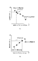
図4は、吸気弁32および排気弁34のバルブタイミングVTCint、VTCexhと筒内残ガス率εrgとの関係を示している。本実施形態において、筒内残ガス率εrgは、全般的な傾向として、バルブオーバーラップ量が増大するほど増加する傾向を有する。具体的には、筒内残ガス率εrgは、吸気バルブタイミングVTCintに対し、図4(A)に示すように、その進角側への変更により増加し、排気バルブタイミングVTCexhに対し、同図(B)に示すように、その遅角側への変更により増加する。
FIG. 4 shows the relationship between the valve timings VTCint and VTCexh of the
基本吸気バルブタイミング、吸気マニホールド圧および排気マニホールド圧等をもとに、排気弁34のバルブタイミングVTCexhと筒内残ガス率εrgとの関係を予め求めておき(図4(B))、筒内残ガス率の上限値εthに対応する排気バルブタイミングVTCexhを算出し、これを、排気バルブタイミングの制限値VTCexh_limとする。演算マップからの参照により得られた基本排気バルブタイミングVTCexh_0がこの制限値TCexh_limを超えて遅角側にある場合は(S203)、最終的な目標排気バルブタイミングVTCexh_trgを、制限値VTCexh_limに設定する(S204)。対して、基本排気バルブタイミングVTCexh_0が制限値TCexh_limよりも進角側にある場合は、目標排気バルブタイミングVTCexh_trgを、基本排気バルブタイミングVTCexh_0に設定する。
Based on the basic intake valve timing, intake manifold pressure, exhaust manifold pressure, etc., the relationship between the valve timing VTCexh of the
S205~206では、実際の吸気マニホールド圧Pmani_actに生じた遅れを、目標吸気バルブタイミングVTCint_trgの調整ないし補正により補償する。 In S205-206, the delay in the actual intake manifold pressure Pmani_act is compensated for by adjusting or correcting the target intake valve timing VTCint_trg.
S205では、実吸気マニホールド圧Pmani_actの、目標吸気マニホールド圧Pmani_trgに対する乖離量(以下「吸気マニホールド乖離圧」という)ΔPmani_iを算出し、これが、実吸気マニホールド圧Pmani_actの遅れが顕著であることを示す所定値ΔPthよりも大きいか否かを判定する。本実施形態では、吸気マニホールド乖離圧ΔPmani_iの算出は、目標吸気マニホールド圧Pmani_trgから実吸気マニホールド圧Pmani_actを減ずることによる。吸気マニホールド乖離圧ΔPmani_iが所定値ΔPthよりも大きい場合は、S206へ進み、所定値ΔPth以下である場合は、S207へ進む。ここで、吸気マニホールド乖離圧ΔPmani_iが所定値ΔPth以下である場合は、目標吸気バルブタイミングVTCint_trgの暫定値を、基本吸気バルブタイミングVTCint_0に設定する。 In S205, the amount of difference between the actual intake manifold pressure Pmani_act and the target intake manifold pressure Pmani_trg (hereinafter referred to as "intake manifold pressure difference") ΔPmani_i is calculated, and this is a predetermined value indicating that the actual intake manifold pressure Pmani_act lags significantly. It is determined whether or not it is greater than the value ΔPth. In this embodiment, the intake manifold differential pressure ΔPmani_i is calculated by subtracting the actual intake manifold pressure Pmani_act from the target intake manifold pressure Pmani_trg. When the intake manifold differential pressure ΔPmani_i is greater than the predetermined value ΔPth, the process proceeds to S206, and when it is equal to or less than the predetermined value ΔPth, the process proceeds to S207. Here, if the intake manifold differential pressure ΔPmani_i is equal to or less than the predetermined value ΔPth, the provisional value of the target intake valve timing VTCint_trg is set to the basic intake valve timing VTCint_0.
S206では、目標吸気バルブタイミングVTCint_trgを算出する。具体的には、次の方法による。 At S206, a target intake valve timing VTCint_trg is calculated. Specifically, the method is as follows.
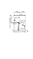
図5は、吸気バルブタイミングVTCintとシリンダ充填空気量Qintとの関係を示している。 FIG. 5 shows the relationship between the intake valve timing VTCint and the cylinder charge air amount Qint.
吸気バルブタイミングVTCintを現在値(前回の制御実行時における吸気バルブタイミング)VTCint_preから演算周期ΔFRQ内で進角させまたは遅角させることのできる範囲(VTCint_adv~VTCint_rtd)で変更した場合に得られるシリンダ充填空気量Qintを車上での計算により求め、得られた複数の点の間の関係式を算出する。本実施形態では、関係式を算出する基礎として、吸気バルブタイミングVTCintの現在値VTCint_preに対応する点、進角側の値VTCint_advに対応する点および遅角側の値VTCint_rtdに対応する点を採用し、これらの点に基づく関係式の算出は、例えば、隣り合う点同士をつなぐことによってもよいし、確からしい直線を近似することによってもよい。本実施形態では、X-Y座標上の2点(X1,Y1)および(X2,Y2)間における補完を、次に示す計算式により行う。X座標が、目標充填空気量Qint_trgに、Y座標が、吸気バルブタイミングVTCintに、夫々対応する。
y={(Y2-Y1)/(X2-X1)}×(X-X1)+Y1 …(1)Cylinder filling obtained when the intake valve timing VTCint is changed from the current value (intake valve timing at the time of the previous control execution) VTCint_pre within the range (VTCint_adv to VTCint_rtd) that can be advanced or retarded within the calculation period ΔFRQ The air quantity Qint is obtained by calculation on the vehicle, and a relational expression between the obtained points is calculated. In this embodiment, as the basis for calculating the relational expression, a point corresponding to the current value VTCint_pre of the intake valve timing VTCint, a point corresponding to the advance value VTCint_adv, and a point corresponding to the retard value VTCint_rtd are used. , the calculation of the relational expression based on these points may be performed, for example, by connecting adjacent points or by approximating a probable straight line. In this embodiment, interpolation between two points (X 1 , Y 1 ) and (X 2 , Y 2 ) on the XY coordinates is performed by the following formulas. The X coordinate corresponds to the target air charge amount Qint_trg, and the Y coordinate corresponds to the intake valve timing VTCint.
y={(Y 2 −Y 1 )/(X 2 −X 1 )}×(X−X 1 )+Y 1 (1)
そして、目標充填空気量Qint_trgに対応する吸気バルブタイミングVTCintを算出し、これを、目標吸気バルブタイミングVTCint_trgの暫定値とする。 Then, the intake valve timing VTCint corresponding to the target air charge amount Qint_trg is calculated and used as the provisional value of the target intake valve timing VTCint_trg.
吸気バルブタイミングVTCintに対するシリンダ充填空気量Qintの算出は、吸気バルブタイミングVTCintおよび排気バルブタイミングVTCexhにより各ポートに定められる実質的な開口面積のもと、吸気通路11および排気通路15内の状態、さらに、筒内の状態に基づく流体力学的な計算によることが可能である。本実施形態では、エンジン回転速度NE、吸気バルブタイミングVTCint、排気バルブタイミングVTCexh、吸気マニホールド圧Pmani_i、吸気マニホールド温度Tmani_i、排気マニホールド圧Pmani_e、排気マニホールド温度Tmani_e、圧縮比Rcmp、EGR率Regrおよび冷却水温度TWに基づき、シリンダ充填空気量Qintを算出する。本実施形態に係るシリンダ充填空気量Qintの算出に適用可能な計算方法の例として、次のものが掲げられる。
John B.Heywood(1989)、“Internal Combustion Engine Fundamentals”、McGraw-Hill Education、P.205~234Calculation of the cylinder charge air amount Qint with respect to the intake valve timing VTCint is based on the actual opening area determined for each port by the intake valve timing VTCint and the exhaust valve timing VTCexh, the conditions inside the
John B. Heywood (1989), "Internal Combustion Engine Fundamentals", McGraw-Hill Education, P.S. 205-234
S207~209では、筒内残ガス率εrg2を、先の述べた上限値εth以下に収めるように、目標吸気バルブタイミングVTCint_trgを制限する。 In S207 to S209, the target intake valve timing VTCint_trg is limited so that the cylinder residual gas ratio εrg2 is kept within the above-described upper limit value εth.
目標排気バルブタイミング、吸気マニホールド圧および排気マニホールド圧等をもとに、吸気弁32のバルブタイミングVTCintと筒内残ガス率εrgとの関係を予め求めておき(図4(A))、筒内残ガス率の上限値εthに対応する吸気バルブタイミングVTCintを算出し、これを、吸気バルブタイミングの制限値VTCint_limとする。S206で算出された目標吸気バルブタイミングVTCint_trg(暫定値)がこの制限値VTCint_limを超えて進角側にある場合は(S208)、最終的な目標吸気バルブタイミングVTCexh_trgを、制限値VTCint_limに設定する(S209)。
Based on the target exhaust valve timing, the intake manifold pressure, the exhaust manifold pressure, etc., the relationship between the valve timing VTCint of the
本実施形態では、目標吸気バルブタイミングVTCexh_trgの制限は、暫定値の書き換え(S209)による。 In this embodiment, the target intake valve timing VTCexh_trg is limited by rewriting the provisional value (S209).
そして、吸気VTC33および排気VTC35(具体的には、作動油圧を調整するアクチュエータ)に対し、目標吸気バルブタイミングVTCexh_trg、目標排気バルブタイミングVTCexh_trgに応じた指令信号を出力する。
Then, command signals corresponding to the target intake valve timing VTCexh_trg and the target exhaust valve timing VTCexh_trg are output to the
本実施形態では、吸気弁32、吸気VTC33およびエンジンコントローラ101が「内燃エンジンの制御装置」を構成する。そして、エンジンコントローラ101が、本実施形態に係る「バルブタイミングコントローラ」の機能を具現する。
In this embodiment, the
(作用効果の説明)
本実施形態に係る内燃エンジン1およびその制御装置は、以上の構成を有し、本実施形態により得られる効果について、以下に説明する。(Description of Action and Effect)
The
第1に、吸気バルブタイミングVTCintを現在値VTCint_preから所定の演算周期ΔFRQ内で進角または遅角可能な範囲VTCint_adv~VTCint_rtdにおいて、吸気バルブタイミングVTCintとシリンダ充填空気量Qintとの間の関係式を算出し、この関係式から、目標充填空気量Qint_trgに対する吸気バルブタイミングの目標値VTCint_trgを、演算周期毎に算出し、この目標値VTCint_trgをもとに、吸気側の可変動弁機構33の動作を制御することとした。これにより、目標吸気バルブタイミングVTCint_trgを、演算周期毎の瞬時値として算出することが可能となり、加速中の過渡的な変化を伴う目標充填空気量Qint_trgを、高い精度で実現することが可能となる。よって、シリンダ充填空気量Qintの制御応答性を向上させ、内燃エンジン1の動力制御の更なる改善を図ることができる。
First, in a range VTCint_adv to VTCint_rtd in which the intake valve timing VTCint can be advanced or retarded from the current value VTCint_pre within a predetermined calculation period ΔFRQ, the relational expression between the intake valve timing VTCint and the cylinder charge air amount Qint is: Based on this relational expression, a target value VTCint_trg of the intake valve timing with respect to the target charged air amount Qint_trg is calculated for each calculation cycle. I decided to control. As a result, the target intake valve timing VTCint_trg can be calculated as an instantaneous value for each calculation cycle, and the target air charge amount Qint_trg, which undergoes transient changes during acceleration, can be achieved with high accuracy. . Therefore, the control responsiveness of the cylinder charged air amount Qint can be improved, and the power control of the
第2に、関係式の算出に、吸気マニホールド温度Tmani_i、吸気マニホールド圧Pmani_iおよび排気バルブタイミングVTCexhのうち少なくとも1つを反映させることで、関係式を適切に算出可能とし、目標エンジントルクに対するシリンダ充填空気量Qintの制御応答性をさらに向上させることができる。 Second, by reflecting at least one of the intake manifold temperature Tmani_i, the intake manifold pressure Pmani_i, and the exhaust valve timing VTCexh in the calculation of the relational expression, the relational expression can be appropriately calculated, and the cylinder filling with respect to the target engine torque. It is possible to further improve the control responsiveness of the air amount Qint.
第3に、関係式の算出に際し、複数の吸気バルブタイミングVTCintおよびシリンダ充填空気量Qintに基づくことで、関係式をより適切に算出することが可能となる。 Third, when calculating the relational expression, it is possible to more appropriately calculate the relational expression based on a plurality of intake valve timings VTCint and cylinder charged air amounts Qint.
第4に、吸気バルブタイミングに関する制限値VTCint_limを採用し、筒内残ガス率εrgが上限値εthを超える目標吸気バルブタイミングVTCint_trgの設定を回避可能としたことで、筒内残ガス率εrgの過度な上昇を抑え、燃焼が不安定となるのを回避することができる。 Fourthly, by adopting the limit value VTCint_lim related to the intake valve timing, it is possible to avoid setting the target intake valve timing VTCint_trg in which the cylinder residual gas ratio εrg exceeds the upper limit value εth. It is possible to suppress an excessive rise and avoid unstable combustion.
さらに、目標吸気バルブタイミングVTCint_trgに加え、目標排気バルブタイミングVTCexh_trgについても筒内残ガス率εrgの観点から制限し、筒内残ガス率εrgが上限値εthを超える目標排気バルブタイミングVTCexh_trgの設定を回避可能としたことで、燃焼が不安定となるのをより確実に回避することが可能となる。 Furthermore, in addition to the target intake valve timing VTCint_trg, the target exhaust valve timing VTCexh_trg is also restricted from the viewpoint of the in-cylinder residual gas ratio εrg to avoid setting the target exhaust valve timing VTCexh_trg in which the in-cylinder residual gas ratio εrg exceeds the upper limit value εth. By making it possible, it is possible to more reliably avoid unstable combustion.
第5に、過給機2を備える内燃エンジン1に適用することで、加速時におけるシリンダ充填空気量Qintの変化が特に急速となる内燃エンジン1において、シリンダ充填空気量Qintの制御応答性を向上させ、内燃エンジン1の動力性能の更なる改善を図ることが可能となる。
Fifth, by applying it to the
以上の説明では、吸気バルブタイミングVTCintとシリンダ充填空気量Qintとの間の関係式を算出する基礎として、図5に示すように、吸気バルブタイミングの現在値VTCint_preに対応する点、進角側の限界値よりも現在値に近い値VTCint_advに対応する点および遅角側の限界値よりも現在値に近い値VTCint_rtdに対応する点を採用したが、基礎とする点は、これに限定されるものではなく、これに代えるかまたはこれに加え、進角側の限界値(-ΔFRQ)および遅角側の限界値(+ΔFRQ)を採用することができ、さらに、該当する運転状態のもとで定常時に設定される吸気バルブタイミングVTCint_stdが変更可能な範囲RNGにある場合は、この定常点を含めることが可能である。 In the above description, as a basis for calculating the relational expression between the intake valve timing VTCint and the cylinder charged air amount Qint, as shown in FIG. A point corresponding to the value VTCint_adv closer to the current value than the limit value and a point corresponding to the value VTCint_rtd closer to the current value than the limit value on the retard side were adopted, but the base points are limited to these. instead, or in addition, an advance limit (-ΔFRQ) and a retard limit (+ΔFRQ) can be employed and, under the relevant operating conditions, steady-state This steady point can be included if the intake valve timing VTCint_std, which is set at the time, is within the variable range RNG.
図7は、吸気バルブタイミングVTCintとシリンダ充填空気量Qintとの関係を示しており、定常時に設定される吸気バルブタイミングVTCint_stdに対応する点を含める場合の例を示す。このように、定常点を含めることで、より多くの点をもとに関係式を算出することが可能となり、関係式の信頼性を高めることができる。 FIG. 7 shows the relationship between the intake valve timing VTCint and the cylinder charged air amount Qint, and shows an example of including a point corresponding to the intake valve timing VTCint_std that is set in steady state. By including stationary points in this way, it becomes possible to calculate the relational expression based on more points, and the reliability of the relational expression can be improved.
さらに、以上の説明では、吸気側および排気側に設けられる可変動弁機構33、35として、作動角を一定としながら、作動中心角を可変に構成されたものを採用したが、可変動弁装置33、35として採用可能なのは、これに限定されるものではない。可変動弁機構33、35は、作動中心角に代えるかまたはこれに加え、作動角または弁リフト量を可変に構成されたものであってもよい。
Furthermore, in the above description, as the
以上、本発明の実施形態について説明したが、上記実施形態は、本発明の適用例の一部を示したに過ぎず、本発明の技術的範囲を、上記実施形態の具体的構成に限定する趣旨ではない。上記実施形態に対し、請求の範囲に記載した事項の範囲内で様々な変更および修正が可能である。 Although the embodiments of the present invention have been described above, the above embodiments merely show a part of the application examples of the present invention, and the technical scope of the present invention is limited to the specific configurations of the above embodiments. not on purpose. Various changes and modifications can be made to the above-described embodiment within the scope of matters described in the claims.
Claims (8)
吸気弁の作動時期である吸気バルブタイミングを現在値から所定の演算周期内で進角させまたは遅角させることのできる範囲において、前記吸気バルブタイミングとシリンダ充填空気量との間の関係式を算出し、
前記内燃エンジンの運転状態に基づき、前記加速時における前記シリンダ充填空気量の目標値である目標充填空気量を算出し、
前記関係式から、前記目標充填空気量に対する前記吸気バルブタイミングの目標値を、前記演算周期毎に算出し、
算出された前記吸気バルブタイミングの目標値をもとに、前記吸気側の可変動弁機構に対する指令信号を設定する、
内燃エンジンの制御方法。A control method for an internal combustion engine comprising at least an intake-side variable valve mechanism for controlling the operation of the intake-side variable valve mechanism during acceleration, comprising:
A relational expression between the intake valve timing and the cylinder filling air amount is calculated within a range in which the intake valve timing, which is the actuation timing of the intake valve, can be advanced or retarded from the current value within a predetermined calculation cycle. death,
calculating a target charged air amount, which is a target value of the cylinder charged air amount during acceleration, based on the operating state of the internal combustion engine;
calculating a target value of the intake valve timing with respect to the target air charge amount from the relational expression for each calculation cycle;
setting a command signal for the variable valve mechanism on the intake side based on the calculated target value of the intake valve timing;
A control method for an internal combustion engine.
請求項1に記載の内燃エンジンの制御方法。calculating the relational expression based on at least one of intake air temperature, intake pressure and exhaust valve timing;
2. A method of controlling an internal combustion engine according to claim 1.
請求項1または2に記載の内燃エンジンの制御方法。calculating the relational expression based on the plurality of intake valve timings in the range and the cylinder charge air amount corresponding to each intake valve timing;
3. A control method for an internal combustion engine according to claim 1 or 2.
請求項3に記載の内燃エンジンの制御方法。The plurality of intake valve timings include an intake valve timing that is set at a steady state under the operating conditions;
4. A method of controlling an internal combustion engine according to claim 3.
請求項1~4のいずれか一項に記載の内燃エンジンの制御方法。The target intake valve timing with respect to the limit value of the intake valve timing to keep the residual gas ratio in the cylinder, which is the ratio of the exhaust gas carried over from the previous cycle to the gas occupying the cylinder, to be below a predetermined upper limit value. limiting the value to the lag side of the limit value;
A control method for an internal combustion engine according to any one of claims 1 to 4.
筒内に占めるガスのうち、前回のサイクルから持ち越された排ガスの比率である筒内残ガス率を所定の上限値以下に収めるように、前記吸気バルブタイミングおよび排気バルブタイミングの目標値を設定する、
内燃エンジンの制御方法。In the internal combustion engine having a variable valve mechanism on the exhaust side in addition to the variable valve mechanism on the intake side, operations of the variable valve mechanisms on the intake side and the exhaust side are controlled during acceleration. A control method for an internal combustion engine according to any one of
The target values of the intake valve timing and the exhaust valve timing are set so that the residual gas ratio in the cylinder, which is the ratio of the exhaust gas carried over from the previous cycle, to the gas occupying the cylinder is kept below a predetermined upper limit value. ,
A control method for an internal combustion engine.
請求項1~6のいずれか一項に記載の内燃エンジンの制御方法。wherein the internal combustion engine comprises a supercharger operably arranged during the acceleration;
A control method for an internal combustion engine according to any one of claims 1 to 6.
前記吸気弁を、異なる吸気バルブタイミングにより駆動可能に構成された可変動弁機構と、
加速時に前記可変動弁機構の動作を制御するバルブタイミングコントローラと、
を備える内燃エンジンの制御装置であって、
前記バルブタイミングコントローラは、
前記吸気バルブタイミングを現在値から所定の演算周期内で進角させまたは遅角させることのできる範囲において、前記吸気バルブタイミングとシリンダ充填空気量との間の関係式を算出し、
前記内燃エンジンの運転状態を検出し、
検出された前記運転状態に基づき、前記加速時における前記シリンダ充填空気量の目標値である目標充填空気量を算出し、
前記関係式から、前記目標充填空気量に対する前記吸気バルブタイミングの目標値を、前記演算周期毎に算出し、
算出された前記吸気バルブタイミングの目標値をもとに、前記吸気側の可変動弁機構に対する指令信号を設定するように構成された、
内燃エンジンの制御装置。an intake valve;
a variable valve mechanism configured to be able to drive the intake valves with different intake valve timings;
a valve timing controller that controls the operation of the variable valve mechanism during acceleration;
A control device for an internal combustion engine comprising
The valve timing controller is
calculating a relational expression between the intake valve timing and the cylinder filling air amount within a range in which the intake valve timing can be advanced or retarded from the current value within a predetermined calculation cycle;
detecting the operating state of the internal combustion engine;
calculating a target charged air amount, which is a target value of the cylinder charged air amount during the acceleration, based on the detected operating state;
calculating a target value of the intake valve timing with respect to the target air charge amount from the relational expression for each calculation cycle;
configured to set a command signal for the variable valve mechanism on the intake side based on the calculated target value of the intake valve timing;
A control device for an internal combustion engine.
Applications Claiming Priority (1)
| Application Number | Priority Date | Filing Date | Title |
|---|---|---|---|
| PCT/JP2019/029525 WO2021019626A1 (en) | 2019-07-26 | 2019-07-26 | Control method and control device for internal combustion engine |
Publications (3)
| Publication Number | Publication Date |
|---|---|
| JPWO2021019626A1 JPWO2021019626A1 (en) | 2021-02-04 |
| JPWO2021019626A5 JPWO2021019626A5 (en) | 2022-03-17 |
| JP7207548B2 true JP7207548B2 (en) | 2023-01-18 |
Family
ID=74229408
Family Applications (1)
| Application Number | Title | Priority Date | Filing Date |
|---|---|---|---|
| JP2021536470A Active JP7207548B2 (en) | 2019-07-26 | 2019-07-26 | Control method and control device for internal combustion engine |
Country Status (5)
| Country | Link |
|---|---|
| US (1) | US11754004B2 (en) |
| EP (1) | EP4006326A4 (en) |
| JP (1) | JP7207548B2 (en) |
| CN (1) | CN114026316A (en) |
| WO (1) | WO2021019626A1 (en) |
Families Citing this family (1)
| Publication number | Priority date | Publication date | Assignee | Title |
|---|---|---|---|---|
| FR3132933A1 (en) * | 2022-02-23 | 2023-08-25 | Renault S.A.S | Method for controlling the richness of the fuel mixture of a motor vehicle internal combustion engine |
Citations (4)
| Publication number | Priority date | Publication date | Assignee | Title |
|---|---|---|---|---|
| JP2002180877A (en) | 2000-10-05 | 2002-06-26 | Toyota Motor Corp | Controller of internal combustion engine |
| JP2005337186A (en) | 2004-05-31 | 2005-12-08 | Denso Corp | Controller for internal combustion engine |
| JP2010116798A (en) | 2008-11-11 | 2010-05-27 | Toyota Motor Corp | Intake-air control device for internal combustion engine |
| WO2014014018A1 (en) | 2012-07-18 | 2014-01-23 | 日産自動車株式会社 | Control device for internal combustion engine |
Family Cites Families (9)
| Publication number | Priority date | Publication date | Assignee | Title |
|---|---|---|---|---|
| JP3985375B2 (en) * | 1999-01-14 | 2007-10-03 | 日産自動車株式会社 | Engine intake control device |
| EP1790845A1 (en) | 2000-08-11 | 2007-05-30 | Hitachi, Ltd. | Apparatus and method for controlling internal combustion engine |
| JP4089408B2 (en) * | 2002-11-29 | 2008-05-28 | 三菱自動車工業株式会社 | High compression ratio cycle engine |
| JP4029739B2 (en) * | 2003-02-05 | 2008-01-09 | トヨタ自動車株式会社 | Calculation of charge air quantity in internal combustion engine |
| JP2011106339A (en) | 2009-11-17 | 2011-06-02 | Toyota Motor Corp | Control system of internal combustion engine |
| US9964055B2 (en) | 2012-07-25 | 2018-05-08 | Nissan Motor Co., Ltd. | Control device and control method of internal combustion engine |
| US9404407B2 (en) * | 2014-01-23 | 2016-08-02 | Ford Global Technologies, Llc | Method and system for pre-ignition control |
| US9599036B2 (en) * | 2014-07-31 | 2017-03-21 | Ford Global Technologies, Llc | Method and system for diagonal blow-through exhaust gas scavenging |
| US10920689B2 (en) * | 2017-04-10 | 2021-02-16 | Ford Global Technologies, Llc | Methods and system for improving transient torque response |
-
2019
- 2019-07-26 EP EP19939580.7A patent/EP4006326A4/en active Pending
- 2019-07-26 CN CN201980098000.0A patent/CN114026316A/en active Pending
- 2019-07-26 US US17/625,141 patent/US11754004B2/en active Active
- 2019-07-26 WO PCT/JP2019/029525 patent/WO2021019626A1/en unknown
- 2019-07-26 JP JP2021536470A patent/JP7207548B2/en active Active
Patent Citations (4)
| Publication number | Priority date | Publication date | Assignee | Title |
|---|---|---|---|---|
| JP2002180877A (en) | 2000-10-05 | 2002-06-26 | Toyota Motor Corp | Controller of internal combustion engine |
| JP2005337186A (en) | 2004-05-31 | 2005-12-08 | Denso Corp | Controller for internal combustion engine |
| JP2010116798A (en) | 2008-11-11 | 2010-05-27 | Toyota Motor Corp | Intake-air control device for internal combustion engine |
| WO2014014018A1 (en) | 2012-07-18 | 2014-01-23 | 日産自動車株式会社 | Control device for internal combustion engine |
Also Published As
| Publication number | Publication date |
|---|---|
| CN114026316A (en) | 2022-02-08 |
| WO2021019626A1 (en) | 2021-02-04 |
| US11754004B2 (en) | 2023-09-12 |
| JPWO2021019626A1 (en) | 2021-02-04 |
| US20220268220A1 (en) | 2022-08-25 |
| EP4006326A1 (en) | 2022-06-01 |
| EP4006326A4 (en) | 2022-07-27 |
Similar Documents
| Publication | Publication Date | Title |
|---|---|---|
| JP5360121B2 (en) | Control method of spark ignition engine and spark ignition engine | |
| JP3817991B2 (en) | Control device for internal combustion engine | |
| US6817349B2 (en) | Control system and method and engine control unit for compression ignition internal combustion engine | |
| JP5270008B2 (en) | Control device for internal combustion engine | |
| JP2006046084A (en) | Ignition timing controller for internal combustion engine | |
| JP2005307847A (en) | Air amount calculation device for internal combustion engine | |
| JP2006283754A (en) | Engine | |
| KR20070118685A (en) | Controller of internal combustion engine | |
| JP4969546B2 (en) | Control device and method for internal combustion engine | |
| JP7121332B2 (en) | Control device for internal combustion engine | |
| US10480434B2 (en) | Control device for internal combustion engine | |
| CN113015848B (en) | Control device | |
| US6848435B2 (en) | Control system for compression ignition internal combustion engine | |
| JP5146619B2 (en) | Control device for internal combustion engine | |
| JP7207548B2 (en) | Control method and control device for internal combustion engine | |
| US10294875B2 (en) | Control device for adjusting first and second fuel ratios | |
| JP6536613B2 (en) | Control device for internal combustion engine | |
| CN110462204B (en) | Control device for internal combustion engine | |
| JP4761072B2 (en) | Ignition timing control device for internal combustion engine | |
| JP5594236B2 (en) | Control device for internal combustion engine | |
| JP5490646B2 (en) | Variable valve timing control device for internal combustion engine | |
| US10598106B2 (en) | Control device for internal combustion engine and control method for internal combustion engine | |
| JP2022094005A (en) | Control device for internal combustion engine | |
| JP5042255B2 (en) | Control device for multi-cylinder spark ignition internal combustion engine | |
| JP2011085063A (en) | Controller for internal combustion engine |
Legal Events
| Date | Code | Title | Description |
|---|---|---|---|
| A521 | Request for written amendment filed |
Free format text: JAPANESE INTERMEDIATE CODE: A523 Effective date: 20211224 |
|
| A621 | Written request for application examination |
Free format text: JAPANESE INTERMEDIATE CODE: A621 Effective date: 20211224 |
|
| TRDD | Decision of grant or rejection written | ||
| A01 | Written decision to grant a patent or to grant a registration (utility model) |
Free format text: JAPANESE INTERMEDIATE CODE: A01 Effective date: 20221206 |
|
| A61 | First payment of annual fees (during grant procedure) |
Free format text: JAPANESE INTERMEDIATE CODE: A61 Effective date: 20221219 |
|
| R151 | Written notification of patent or utility model registration |
Ref document number: 7207548 Country of ref document: JP Free format text: JAPANESE INTERMEDIATE CODE: R151 |