JP7207162B2 - head-up display device - Google Patents
head-up display device Download PDFInfo
- Publication number
- JP7207162B2 JP7207162B2 JP2019096807A JP2019096807A JP7207162B2 JP 7207162 B2 JP7207162 B2 JP 7207162B2 JP 2019096807 A JP2019096807 A JP 2019096807A JP 2019096807 A JP2019096807 A JP 2019096807A JP 7207162 B2 JP7207162 B2 JP 7207162B2
- Authority
- JP
- Japan
- Prior art keywords
- bezel
- polarizing plate
- light
- head
- display image
- Prior art date
- Legal status (The legal status is an assumption and is not a legal conclusion. Google has not performed a legal analysis and makes no representation as to the accuracy of the status listed.)
- Active
Links
- 230000005540 biological transmission Effects 0.000 claims description 36
- 210000000078 claw Anatomy 0.000 claims description 15
- 230000003287 optical effect Effects 0.000 claims description 10
- 239000000428 dust Substances 0.000 claims description 4
- 238000001615 p wave Methods 0.000 claims description 3
- 238000005286 illumination Methods 0.000 claims 2
- 239000004973 liquid crystal related substance Substances 0.000 description 20
- 230000010287 polarization Effects 0.000 description 19
- 239000010408 film Substances 0.000 description 11
- 238000010586 diagram Methods 0.000 description 9
- 238000010521 absorption reaction Methods 0.000 description 8
- 230000006870 function Effects 0.000 description 8
- 238000000034 method Methods 0.000 description 6
- 230000002093 peripheral effect Effects 0.000 description 6
- 238000002834 transmittance Methods 0.000 description 6
- 230000004308 accommodation Effects 0.000 description 5
- 239000013598 vector Substances 0.000 description 5
- 230000005684 electric field Effects 0.000 description 4
- 238000001514 detection method Methods 0.000 description 3
- 238000009792 diffusion process Methods 0.000 description 3
- 230000000694 effects Effects 0.000 description 3
- 239000011521 glass Substances 0.000 description 3
- ZCYVEMRRCGMTRW-UHFFFAOYSA-N 7553-56-2 Chemical compound [I] ZCYVEMRRCGMTRW-UHFFFAOYSA-N 0.000 description 2
- 230000000052 comparative effect Effects 0.000 description 2
- 238000004590 computer program Methods 0.000 description 2
- 210000003128 head Anatomy 0.000 description 2
- 229910052740 iodine Inorganic materials 0.000 description 2
- 239000011630 iodine Substances 0.000 description 2
- 238000012986 modification Methods 0.000 description 2
- 230000004048 modification Effects 0.000 description 2
- 238000003466 welding Methods 0.000 description 2
- 239000004372 Polyvinyl alcohol Substances 0.000 description 1
- 230000000903 blocking effect Effects 0.000 description 1
- 230000037237 body shape Effects 0.000 description 1
- 238000003780 insertion Methods 0.000 description 1
- 230000037431 insertion Effects 0.000 description 1
- 239000000463 material Substances 0.000 description 1
- 239000000203 mixture Substances 0.000 description 1
- 229920002451 polyvinyl alcohol Polymers 0.000 description 1
- 229920003002 synthetic resin Polymers 0.000 description 1
- 239000000057 synthetic resin Substances 0.000 description 1
- 239000010409 thin film Substances 0.000 description 1
- 238000011144 upstream manufacturing Methods 0.000 description 1
Images


Classifications
-
- B—PERFORMING OPERATIONS; TRANSPORTING
- B60—VEHICLES IN GENERAL
- B60K—ARRANGEMENT OR MOUNTING OF PROPULSION UNITS OR OF TRANSMISSIONS IN VEHICLES; ARRANGEMENT OR MOUNTING OF PLURAL DIVERSE PRIME-MOVERS IN VEHICLES; AUXILIARY DRIVES FOR VEHICLES; INSTRUMENTATION OR DASHBOARDS FOR VEHICLES; ARRANGEMENTS IN CONNECTION WITH COOLING, AIR INTAKE, GAS EXHAUST OR FUEL SUPPLY OF PROPULSION UNITS IN VEHICLES
- B60K35/00—Arrangement of adaptations of instruments
-
- G—PHYSICS
- G02—OPTICS
- G02B—OPTICAL ELEMENTS, SYSTEMS OR APPARATUS
- G02B27/00—Optical systems or apparatus not provided for by any of the groups G02B1/00 - G02B26/00, G02B30/00
- G02B27/01—Head-up displays
-
- H—ELECTRICITY
- H04—ELECTRIC COMMUNICATION TECHNIQUE
- H04N—PICTORIAL COMMUNICATION, e.g. TELEVISION
- H04N5/00—Details of television systems
- H04N5/64—Constructional details of receivers, e.g. cabinets or dust covers
Description
本発明は、表示画像をウインドシールドなどに備えられた投影面に投影することで、ユーザに表示画像を視認可能とするヘッドアップディスプレイ装置に関するものである。 The present invention relates to a head-up display device that allows a user to visually recognize a display image by projecting the display image onto a projection surface provided on a windshield or the like.
従来より、ディスプレイや凹面鏡等の導光部をウインドシールドの下に配置し、ディスプレイの表示画像を導光部で反射させてウインドシールドの投影面に映し出すことでユーザに視認させるヘッドアップディスプレイ装置がある。このヘッドアップディスプレイ装置において、特許文献1に、裸眼状態での視認性と偏光サングラスを着用した状態での視認性の両立を図る技術が提案されている。
Conventionally, there has been a head-up display device that allows a user to visually recognize a display image by arranging a light guide part such as a display or a concave mirror under the windshield, reflecting the displayed image of the display on the light guide part, and projecting it onto the projection surface of the windshield. be. In this head-up display device,
具体的には、特許文献1のヘッドアップディスプレイ装置では、導光部とウインドシールドとの間に、対応する偏光の透過率が最大となる透過軸を有する偏光板を備え、偏光板により、投射偏光方位角と透過軸方位角とを異ならせている。このような偏光板を備えると、ウインドシールドに反射された画像の光の偏光方向が画像縦方向および画像横方向の両方に対して傾く。したがって、画像縦方向に対応する車両の上下方向の偏光成分と画像横方向に対応する車両の上下方向に対して垂直な方向の偏光成分が共に得られる。これにより、ドライバが裸眼で虚像を視認する場合の輝度(以下、裸眼輝度という)と、偏光サングラスを着用した状態で虚像を視認する場合の輝度(以下、サングラス輝度という)とで輝度のバランスを取ることが可能となる。
Specifically, in the head-up display device of
しかしながら、特許文献1の構成では、裸眼輝度とサングラス輝度のバランスを取ることができるものの、サングラス輝度を上げるために裸眼輝度を低下させることになる反面、サングラス輝度も十分には得られない。ヘッドアップディスプレイ装置では、一般的に裸眼輝度を優先し、サングラス輝度が低くなってしまうが、ユーザの嗜好に合わせて、サングラス輝度を向上させたいという要望もある。
However, in the configuration of
本発明は上記点に鑑みて、サングラス輝度を高くすることが可能なヘッドアップディスプレイ装置を提供することを目的とする。 SUMMARY OF THE INVENTION An object of the present invention is to provide a head-up display device capable of increasing the brightness of sunglasses.
上記目的を達成するため、請求項1に記載の発明は、車両(V)に搭載され、投影部材(2)における投影面(3)に表示画像を投影し、表示画像の光が投影面に投影されることで表示画像の虚像を表示するヘッドアップディスプレイ装置であって、表示画像の光を投射する投射器(20)と、投射器からの表示画像の光を投影部材へ向けて導光する導光部(40)と、開口部(11)が形成されており、投射器および導光部を収容すると共に開口部を通じて導光部にて導光された表示画像の光を投影部材に導くハウジング(10)と、導光部と投影部材との間の光路上に配置された偏光機能を有するベゼル偏光板(62)を含み、開口部からハウジング内への塵の侵入を抑制するベゼル部材(60)と、を備え、導光部とベゼル部材との間には、車体側偏光板(50)が備えられ、車体側偏光板は、偏光により、該車体側偏光板を透過する前よりも透過した後の方がs波の輝度を高くするように透過軸方位角が設定され、ベゼル偏光板は、偏光により、該ベゼル偏光板を透過する前よりも透過した後の方が、表示画像の光のうちのp波の輝度を高くするように透過軸方位角が設定されている。
In order to achieve the above object, the invention described in
このように、ベゼル偏光板に偏光機能を備えることにより、ベゼル部材を装着していないときに裸眼輝度を高めた虚像を表示するヘッドアップディスプレイ装置において、ベゼル部材を装着することでサングラス輝度を高めた虚像を表示できる。したがって、ヘッドアップディスプレイ装置として、適用対象が多いと想定される虚像を裸眼で視認する場合に合わせた設計としつつ、ユーザのニーズがあればベゼル部材を装着することで、サングラス輝度を高められる。よって、サングラス輝度を高くすることが可能なヘッドアップディスプレイ装置にできる。 In this way, in a head-up display device that displays a virtual image with enhanced naked-eye brightness when the bezel member is not attached by providing a polarization function to the bezel polarizing plate, attaching the bezel member increases the brightness of sunglasses. A virtual image can be displayed. Therefore, the brightness of sunglasses can be increased by attaching a bezel member if there is a user's need, while designing the head-up display device to match the case of visually recognizing a virtual image with the naked eye, which is assumed to be applied to many devices. Therefore, a head-up display device capable of increasing the luminance of sunglasses can be obtained.
なお、各構成要素等に付された括弧付きの参照符号は、その構成要素等と後述する実施形態に記載の具体的な構成要素等との対応関係の一例を示すものである。 It should be noted that the reference numerals in parentheses attached to each component etc. indicate an example of the correspondence relationship between the component etc. and specific components etc. described in the embodiments described later.
以下、本発明の実施形態について図に基づいて説明する。なお、以下の各実施形態相互において、互いに同一もしくは均等である部分には、同一符号を付して説明を行う。 An embodiment of the present invention will be described below with reference to the drawings. In addition, in each of the following embodiments, portions that are the same or equivalent to each other will be described with the same reference numerals.
(第1実施形態)
第1実施形態にかかるヘッドアップディスプレイ装置について説明する。ヘッドアップディスプレイ装置は、車両に適用されるものであり、ドライバに対して表示画像の虚像を視認させることで、車速やナビゲーションシステムによる進行方向の表示などの情報を提供するものとして用いられる。
(First embodiment)
A head-up display device according to the first embodiment will be described. A head-up display device is applied to a vehicle, and is used to provide information such as display of vehicle speed and direction of travel by a navigation system by allowing a driver to visually recognize a virtual image of a display image.
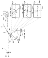
図1に示すヘッドアップディスプレイ装置100は、例えば車両Vのインストルメントパネル1内に収容されており、ウインドシールド2の投影面3に表示画像を投影することで、ドライバに表示画像の虚像4を視認可能とする。表示画像については、ドライバが運転席5に着座したときの眼6の位置として想定される長方形の領域をアイボックスとして、アイボックスから投影面3に投影された表示画像の虚像4が視認可能となるように表示される。
A head-up
なお、以下の説明において、車両上下方向、左右方向などの方向を記載する場合、車両Vが水平面上にあるときにおける天地方向、車両前方に向かって左右方向のことを示していることとする。また、虚像4のうちの車両上下方向に沿う方向を画像縦方向Dilといい、虚像4のうちの画像縦方向Dilと垂直な方向を画像横方向Disという。すなわち、運転席5に着座した状態のドライバが、虚像4のうちの縦の方向と認識する方向を画像縦方向Dil、横の方向と認識する方向を画像横方向Disとしている。
In the following description, when directions such as the vehicle vertical direction and the horizontal direction are described, it means the vertical direction when the vehicle V is on a horizontal plane, and the horizontal direction toward the front of the vehicle. A direction along the vertical direction of the vehicle in the
ヘッドアップディスプレイ装置100は、ハウジング10、投射器20、導光部40、偏光板50およびベゼル部材60を備えた構成とされている。
A head-up
ハウジング10は、内部に収容スペースを構成する収容部材であり、インストルメントパネル1内に配置されており、上部に収容スペースに繋がる開口部11が形成された構造とされている。ハウジング10の収容スペース内には、投射器20および導光部40が収容され、開口部11には、偏光板50およびベゼル部材60が配置されている。そして、投射器20から投影された表示画像が導光部40を介して開口部11側に導かれ、偏光板50およびベゼル部材60を通じて投影面3に投影されるようになっている。
The
投射器20は、図4に詳細を示すように、光源22、集光レンズ24、拡散板26、投射レンズ28および液晶パネル30を有し、これらが図示しない中空状のケースに収容された構成とされている。
As shown in detail in FIG. 4, the
光源22は、例えば複数のLED(発光ダイオード素子)を光源用回路基板に実装したものとされる。光源22は、LEDへの通電により電流量に応じた発光量にて光を集光レンズ24へ向けて照射する。
The
集光レンズ24は、ガラス等で構成された透光性の凸レンズであり、光源22から照射された光を集光し、拡散板26に出射する。
The
拡散板26は、ガラス等で構成された光拡散を行う板であり、集光レンズ24から出射された光を拡散することで表示画像の面内での輝度の均一性を調整する。
The
投射レンズ28は、合成樹脂ないしはガラス等からなる透光性の凸レンズであり、拡散板26と液晶パネル30との間に配置されている。投射レンズ28は、拡散板26からの光を集光して液晶パネル30へ向けて投射する。
The
液晶パネル30は、例えばTFT(薄膜トランジスタ)を用いたパネルとされ、図3に示すように画像縦方向Dilおよび画像横方向Disの2次元方向に配列された複数の液晶画素から形成されるアクティブマトリクス型のもので構成されている。液晶パネル30は、一対の液晶用偏光板と、この一対の液晶用偏光板に挟まれた液晶層等が積層された構成とされている。各液晶用偏光板は、電場ベクトルが所定方向の偏光を透過させ、電場ベクトルが所定方向と実質垂直な方向の偏光を遮光する性質を有している。そして、一対の液晶用偏光板は、それぞれの透過させる磁場ベクトルの方向が直行するように配置されている。また、一対の液晶偏光板に挟まれて配置された液晶層は、液晶画素毎の電圧印加に基づいて、印加電圧に応じて、液晶層に入射する光の偏光方向を回転させられるようになっている。なお、図3中などにおいは、光路に沿う方向をDcとして示してある。
The
このような構成とされているため、投射器20は、液晶パネル30にて液晶画素毎の透過率を制御することで、所望の画像の光を投射することが可能となる。そして、投射器20から投射される画像の光は、射出側の液晶用偏光板の配置に応じて偏光したものとなっており、本実施形態では、投射器20から投射される画像の光の偏光方向Dppが画像横方向Disに沿う方向とされている。
With such a configuration, the
導光部40は、投射器20からの画像の光を、ウインドシールド2へ向けて導光する光学系であり、本実施形態の場合は、平面鏡42および凹面鏡44を有した構成とされている。
The
平面鏡42は、液晶パネル30から出射された表示画像の光を凹面鏡44に向けて反射する。 凹面鏡44は、平面鏡42から伝えられた表示画像の光をウインドシールド2に向けて反射するものであり、凹面鏡44の中心が凹む曲面状の反射鏡とされている。
The
このような構成とされているため、投射器20から出射された表示画像の光が図1、図3中に示した光路のように、導光部40で反射されてウインドシールド2の投影面3に導かれるようになっている。
With such a configuration, the light of the display image emitted from the
偏光板50は、車体側偏光板に相当するもので、導光部40とウインドシールド2との間の光路上に配置されており、ハウジング10の開口部11を塞ぐように配置されることでハウジング10内への塵の侵入を抑制する。偏光板50は、偏光素子層52を有している。
The
偏光素子層52は、例えばポリビニルアルコールにヨウ素を添加して形成され、ヨウ素分子の配向方向によって透過軸52aと遮光軸52bとが互いに直交した状態となっている。透過軸52aは、対応する偏光の透過率が最大となる軸である。
The
なお、透過軸52aに対応する偏光とは、電場ベクトルが透過軸52aに沿った偏光のことである。遮光軸52bは、対応する偏光の透過率が最小となる軸である。なお、遮光軸52bに対応する偏光とは、電場ベクトルが当該遮光軸52bに沿った偏光のことである。このような構成の偏光素子層52の遮光軸52bは、光を吸収する吸収軸となっている。すなわち、吸収軸としての遮光軸52bに対応する偏光が偏光素子層52に入射した場合、吸収率が最大となる。
The polarized light corresponding to the
ベゼル部材60は、太陽光の反射光を遮断し、眼6に不要な光を入射させないようにするためのものであるが、本実施形態では、偏光板50を透過してきた表示画像の光の偏光方向を変えて、ウインドシールド2側に導く偏光機能も有している。具体的には、ベゼル部材60は、図1、図6Aおよび図6Bに示すように、偏光板62とベゼル64とを有した構成とされ、図1に示すように、ハウジング10の開口部11の入口の位置においてインストルメントパネル1に着脱可能とされている。
The
偏光板62は、ベゼル偏光板に相当するもので、図1に示すように、偏光板50に沿って、所定距離離れた位置もしくは偏光板50に接して配置されている。本実施形態では、偏光板50を曲面とし、かつ、偏光板50のうちの車両Vの前端側の方が後端側よりも下方に位置するように傾けて配置してあるが、偏光板62も同様の配置とされている。
The
偏光板62は、上記した偏光素子層52と同様のもので構成されることで2つ目の偏光板を構成しており、図3に示すように、透過軸62aと遮光軸62bとが互いに直交した状態となっている。ただし、偏光板62の透過軸62aと遮光軸62bは、それぞれ、偏光素子層52の透過軸52aと遮光軸52bに対して方位角がずらしてある。
The
ベゼル64は、図6Aおよび図6Bに示すように、ハウジング10の開口部11の入口の位置においてインストルメントパネル1の開口部に嵌め込まれる枠体形状で構成されており、本実施形態では四角形枠体形状とされている。このベゼル64の底部、つまり開口部11への挿入方向先端に偏光板62が固定されており、ベゼル64を開口部11に嵌め込むことにより、偏光板62が開口部11を塞ぐように設置されるようになっている。本実施形態では、ベゼル64の底部、つまりベゼル64のうち表示画像の光の光路の上流側となる導光部40側の端部に対して、偏光板62が溶着などによって接合されている。そして、偏光板62により、ベゼル64の開口部が全域覆われている。このように構成された偏光板50および偏光板62を通じて表示画像の光がウインドシールド2の投影面3に導かれ、投影面3にて表示画像が投影されることにより、ドライバに表示画像の虚像4が視認可能となる。
As shown in FIGS. 6A and 6B, the
続いて、このように構成されたヘッドアップディスプレイ装置100において、偏光板50や偏光板62での偏光による輝度調整について説明する。
Next, in the head-up
本実施形態では、偏光板50における偏光素子層52の透過軸52aと遮光軸52bを調整することで、ドライバが裸眼である場合に虚像4を視認し易くする裸眼輝度を高めるようにしている。逆に、偏光板62の透過軸62aと遮光軸62bを調整することで、ドライバが偏光サングラス7を着用している場合に虚像4を視認し易くするサングラス輝度を高めるようにしている。
In this embodiment, by adjusting the
ドライバが偏光サングラス7を着用した状態で虚像4を視認する場合、ウインドシールド2に反射された後の表示画像の光の偏光方向の影響を受けて、虚像4の輝度が変化する。具体的に、一般的な偏光サングラス7は、透過軸Dst(以下、サングラス透過軸)が鉛直方向に設定され、吸収軸Dsa(以下、サングラス吸収軸)が水平方向に設定されている。このため、ドライバが偏光サングラス7を着用した状態で車両Vの運転席5に着座すると、当該偏光サングラス7は、車両Vの上下方向に偏光する光に対して最大透過率となり、車両Vの偏光方向とは垂直な方向に偏光する光に対して最小透過率となる。このような偏光サングラス7の透過特性に起因して、偏光サングラス7の着用時に視認される虚像4の輝度であるサングラス輝度Ipは、透過軸52aおよび遮光軸52bの方向の設定に応じて変化する。なお、サングラス輝度Ipは、表示画像の光のうちのp(Parallel)波の輝度を意味している。
When the driver wears the
他方、ドライバが裸眼の状態で虚像4を視認する場合、ウインドシールド2に反射された後の表示画像の光は偏光方向の影響を受けないが、ウインドシールド2での表示画像の光の反射率は、ウインドシールド2に入射する表示画像の光の偏光方向に依存する。これは、フレネルの式にて示されている。このため、裸眼で視認される虚像4の輝度である裸眼輝度Iは、透過軸52aおよび遮光軸52bの方向の設定に応じて変化する。なお、裸眼輝度Iは、表示画像の光のうちのs(senkrecht)波の輝度を意味している。
On the other hand, when the driver visually recognizes the
ここでまず、比較例として、偏光板50を設けなかった場合を考える。この場合に、裸眼輝度Iは数1で表され、サングラス輝度Ipは数2で表される。
First, as a comparative example, consider a case where the
![]()
![]()
![]()
![]()
このような比較例において、裸眼輝度Iやサングラス輝度Ipは、αおよびθによって変化する。しかしながら、αおよびθを変更するには、ハウジング10の収容スペース、ウインドシールド2、および運転席5の位置関係を変更しなければならず、車両Vの機能性やデザイン、車両Vにおける他の機器の配置を考慮すると、当該位置関係の変更は極めて困難である。
In such a comparative example, the naked-eye luminance I and the sunglasses luminance Ip change depending on α and θ. However, in order to change α and θ, it is necessary to change the positional relationship between the accommodation space of the
一方、上述の数1、2を、偏光板50が設けられた本実施形態に応用すると、裸眼輝度Iは数3で表され、サングラス輝度Ipは数4で表される。
On the other hand, if the above-described

![]()
![]()
数3、4によれば、βが変われば、裸眼輝度Iやサングラス輝度Ipが変化することが判る。なお、数1~4において、サングラス透過軸Dstは画像縦方向Dilと一致し、サングラス吸収軸Dsaは画像横方向Disと一致することとなるので、これらの読替が可能である。また本実施形態においてs偏光反射率Rsは、p偏光反射率Rpよりも大きくなっている。
According to
このように、角度βを適宜設定することにより、裸眼輝度Iやサングラス輝度Ipを調整できる。そして、特許文献1では、裸眼輝度Iとサングラス輝度Ipとをバランスさせることで、ドライバが裸眼の状態で虚像4を視認する場合と偏光サングラス7を着用して虚像4を視認した場合とで、輝度をバランスさせるようにしている。
Thus, by appropriately setting the angle β, the naked eye luminance I and the sunglasses luminance Ip can be adjusted. Further, in
しかしながら、裸眼輝度Iとサングラス輝度Ipを共に高い値に設定することは困難であり、サングラス輝度Ipを高い値にしようとすると、裸眼輝度Iを低くせざるを得ないという関係がある。具体的には、透過軸方位角に対する裸眼輝度Iとサングラス輝度Ipとの関係は、図7で示され、裸眼輝度Iとサングラス輝度Ipが高くなる透過軸方位角は一致しない。 However, it is difficult to set both the naked-eye brightness I and the sunglasses brightness Ip to high values, and there is a relationship that if the sunglasses brightness Ip is to be set to a high value, the naked-eye brightness I must be lowered. Specifically, the relationship between the naked-eye luminance I and the sunglasses luminance Ip with respect to the transmission axis azimuth angle is shown in FIG.
このため、本実施形態では、偏光板50の透過軸52aについては、偏光サングラス7を着用して虚像4を視認する場合よりも裸眼で虚像4を視認する場合の方が多いと想定し、裸眼輝度Iを優先した設定としてある。これにより、サングラス輝度Ipについては高い値が得られないものの、裸眼輝度Iについては高い値が得られるようにしている。
For this reason, in the present embodiment, the
ただし、裸眼輝度Iよりもサングラス輝度Ipを優先したいというニーズもあり、その場合には、上記のような設定行うと、サングラス輝度Ipが低くなってしまい、そのようなニーズに応えることができなくなる。 However, there is also a need to give priority to the brightness Ip of sunglasses over the brightness I of the naked eye. .
このため、本実施形態では、ベゼル部材60に備えた偏光板62で2つ目の偏光板を構成し、表示画像の光が偏光板62を透過することで、サングラス輝度Ipが高くなるようにしている。図7の例で言えば、表示画像の光の偏光方向は、偏光板62を透過する前の状態では透過軸方位角が60°となるように偏光板50の透過軸52aおよび遮光軸52bが設定される。そして、表示画像の光の偏光方向は、偏光板62を透過した後の状態では透過軸方位角が90°となるように偏光板62の透過軸62aおよび遮光軸62bが設定される。
Therefore, in the present embodiment, the
このように、偏光板62に偏光機能を備えることにより、ベゼル部材60を装着していない状態であれば裸眼輝度Iを高めた虚像4を表示でき、ベゼル部材60を装着した状態であればサングラス輝度Ipを高めた虚像4を表示できる。したがって、ヘッドアップディスプレイ装置100として、適用対象が多いと想定される虚像4を裸眼で視認する場合に合わせた設計としつつ、ユーザのニーズがあればベゼル部材60を装着することで、サングラス輝度Ipを高められる。よって、サングラス輝度Ipを高くすることが可能なヘッドアップディスプレイ装置100にできる。
In this way, by providing the
また、本実施形態においては、ベゼル部材60を着脱可能な構成としている。このため、ドライバの嗜好に合わせて、必要時にのみベゼル部材60を取り付けることでサングラス輝度Ipを高められ、不要なときにはベゼル部材60を取り外して裸眼輝度Iが高められるようにすることもできる。
Further, in this embodiment, the
(第2実施形態)
第2実施形態について説明する。本実施形態は、第1実施形態に対してベゼル部材60の構成を変更したものであり、その他については第1実施形態と同様であるため、第1実施形態と異なる部分についてのみ説明する。
(Second embodiment)
A second embodiment will be described. This embodiment differs from the first embodiment in the configuration of the
図8に示すように、本実施形態では、四角形枠体形状のベゼル64の四つの壁それぞれの壁面に穴部64aを設けると共に、四角形状の偏光板62にも四辺それぞれから張り出したタブ62cを設けている。タブ62cには、ベゼル64の穴部64aと対応する位置に穴部62dが形成してある。そして、4つの固定ピン66が用いられ、偏光板62の各穴部62dとベゼル64の各穴部62dおよび各穴部64a内に固定ピン66が嵌め込まれるようにしている。このように、固定ピン66を用いて偏光板62がベゼル64に固定されることでこれらが図9Aおよび図9Bに示すように一体となっている。
As shown in FIG. 8, in this embodiment, holes 64a are provided in the four walls of a rectangular frame-shaped
このように、偏光板62とベゼル64とを固定ピン66を用いて固定する構造としても良い。このような構造のベゼル部材60を用いても、第1実施形態と同様の効果が得られる。
As described above, a structure in which the
(第3実施形態)
第3実施形態について説明する。本実施形態も、第1実施形態に対してベゼル部材60の構成を変更したものであり、その他については第1実施形態と同様であるため、第1実施形態と異なる部分についてのみ説明する。
(Third embodiment)
A third embodiment will be described. This embodiment also differs from the first embodiment in the configuration of the
図10に示すように、本実施形態では、四角形枠体形状のベゼル64の四つの壁のうち対向する2つの壁の内壁面に爪部64bを設けている。また、四角形状の偏光板62を四角形枠体形状のアタッチメントで構成された枠体部62eに溶着などによって接合して一体化している。枠体部62eの外壁とベゼル64の内壁とが対応する形状となっており、枠体部62eの四つの壁のうち対向する2つの壁の内壁面には爪部64bと対応する形状の爪受け部62fが設けられている。
As shown in FIG. 10, in this embodiment, claw
そして、枠体部62eをベゼル64内に嵌め込むと共に、爪部64bと爪受け部62fとが係合されることで、図11に示すように、偏光板62がベゼル64に密着させられて一体となっている。
By fitting the
このように、枠体部62eを用いて偏光板62とベゼル64とを爪部64bと爪受け部62fで固定する構造としても良い。このような構造のベゼル部材60を用いても、第1実施形態と同様の効果が得られる。
In this way, the
なお、ここでは、爪部64bを円柱形状の凸部とし、爪受け部62fを円形穴としているが、形状は問わない。また、ここではベゼル64に爪部64bを設け、枠体部62eに爪受け部62fを備えるようにしたが、ベゼル64に爪受け部を備え、枠体部62eに爪部を備えても良い。
Here, the
また、ここでは、枠体部62eを偏光板62と別部材のアタッチメントで構成したが、枠体部62eと偏光板62とが一体で成形されている一体成形品であっても良い。
Also, here, the
(第4実施形態)
第4実施形態について説明する。本実施形態は、第1~第3実施形態に対して偏光板62と偏光板50との間の多重反射を抑制するようにしたものであり、その他については第1~第3実施形態と同様であるため、第1~第3実施形態と異なる部分についてのみ説明する。
(Fourth embodiment)
A fourth embodiment will be described. This embodiment suppresses multiple reflection between the
図12に示すように、本実施形態では、偏光板62のうちの偏光板50側の一面に反射防止膜68を備えると共に、偏光板50のうちの偏光板62側の一面に反射防止膜56を備えてある。反射防止膜56としては、表示画像の光を透過しつつ、反射することを抑制できるものであれば良く、例えば、AR(Anti Reflection)コーティングと呼ばれる屈折率が小さい誘電体をコーティングしたり、モスアイシートを貼り付けたりすることで反射防止膜68や反射防止膜56を構成できる。
As shown in FIG. 12, in this embodiment, an
偏光板62を偏光板50に沿うように配置した場合、図12中に破線で示したように、これらの間において多重反射が発生し、虚像4が2重3重になってドライバに視認されることがある。これに対して、本実施形態のように、偏光板62に反射防止膜68を備えたり、偏光板50に反射防止膜56を備えることで、これらの間における多重反射を抑制できる。これにより、虚像4が2重3重になってドライバに視認されることを抑制できる。
When the
なお、ここでは、偏光板62に反射防止膜68を備えると共に偏光板50に反射防止膜56を備えるようにしたが、少なくとも一方に備えられていれば良い。
Here, the
(第5実施形態)
第5実施形態について説明する。本実施形態は、第1~第4実施形態に対して投射器20での輝度調整を行うようにしたものである。なお、ヘッドアップディスプレイ装置100の構成については第1~第4実施形態とほぼ同様であるため、第1~第4実施形態と異なる部分についてのみ説明する。
(Fifth embodiment)
A fifth embodiment will be described. In this embodiment, brightness adjustment is performed in the
投射器20における光源22の発光量は、光源22への通電の電流量に応じた大きさになる。この光源22での発光量の制御は、図13に示すブロック構成により行われる。
The amount of light emitted by the
図13に示すように、輝度制御用の電子制御装置(以下、輝度制御ECUという)70と、照度センサ72および切替スイッチ74が備えられている。そして、輝度制御ECU70が照度センサ72の検出信号および切替スイッチ74の操作状態に基づいて光源22での発光量の制御を行うことで虚像4の輝度が制御されるようになっている。
As shown in FIG. 13, an electronic control unit for brightness control (hereinafter referred to as a brightness control ECU) 70, an
照度センサ72は、例えば車両Vにおけるインストルメントパネル1の上面に設置されており、車両Vの周辺照度に応じた検出信号を出力する。切替スイッチ74は、サングラス輝度Ipの調整用のスイッチであり、例えばインストルメントパネル1内に配置されたプッシュスイッチで構成され、切替スイッチ74が押下されたか否かという操作状態に応じた切替信号を出力する。換言すれば、切替スイッチ74は、ベゼル部材60が取り付けられていることを示す信号を出力する。
The
輝度制御ECU70は、制御部に相当するものであり、照度センサ72の検出信号に基づいて、光源22を周辺照度に応じた発光量で発光させることで虚像4の輝度を制御する。また、輝度制御ECU70は、切替スイッチ74の操作状態に応じた切替信号に基づいて、光源22での発光量の制御形態の切替えを行う。
The
具体的には、切替スイッチ74が操作されていない場合には、輝度制御ECU70は、ベゼル部材60が装着されていない場合に想定される制御を行う。すなわち、ドライバが裸眼で虚像4を視認する場合を想定し、周辺照度が低くて暗いような状況下では照度の高さに応じて徐々に光源22の発光量を大きくし、虚像4の輝度も徐々に大きくなるようにする。そして、周辺照度が所定照度以上になって明るいような状況下では光源22の発光量を一定値に設定する。
Specifically, when the
このような制御を行う場合において、ベゼル部材60を装着した場合と装着していない場合のサングラス輝度Ipの変化を示すと、図14Aのように表される。この図に示されるように、ベゼル部材60を装着した場合、偏光板62によってサングラス輝度Ipを優先する偏光が行われる。このため、ベゼル部材60を装着していない場合と比較して、周辺照度が所定照度より低い場合も高くなった場合も、共に、サングラス輝度Ipが高くなる。
FIG. 14A shows a change in the luminance Ip of sunglasses when the
ここで、周辺照度が所定照度より高い場合には、周りが明るい状況であることから、虚像4についても高い輝度でないとドライバが視認しにくい。したがって、サングラス輝度Ipが高くなっていたとしても、ドライバに明る過ぎると感じさせることはない。しかしながら、周りが暗い状況では、虚像4の輝度が高くなるとドライバに明る過ぎると感じさせ得る。このため、ベゼル部材60を装着した場合には、虚像4の輝度がベゼル部材60を装着していない場合に想定される狙いの値から乖離して明るくなり過ぎる可能性がある。
Here, when the ambient illuminance is higher than the predetermined illuminance, it is difficult for the driver to visually recognize the
したがって、ベゼル部材60を装着した場合には切替スイッチ74を操作して、その切替信号が輝度制御ECU70に入力されるようにし、輝度制御ECU70にてベゼル部材60を装着したとき用の制御が行われるようにしている。
Therefore, when the
具体的には、図14Bに示すように、周辺照度が所定照度よりも低い場合には、サングラス輝度Ipがベゼル部材60を装着していない場合と同様に狙いの値となるようにする。すなわち、周辺照度が所定照度よりも低い場合には、ベゼル部材60が装着されていない場合と比較して、周辺照度に対応した光源22の発光量が小さくなるようにする。そして、周辺照度が所定照度より高い場合には、サングラス輝度Ipがベゼル部材60を装着していない場合と比較して高くなるようにする。
Specifically, as shown in FIG. 14B, when the peripheral illuminance is lower than the predetermined illuminance, the sunglasses brightness Ip is set to the target value as in the case where the
このようにすることで、ベゼル部材60を装着した場合に、虚像4の輝度が狙いの値から乖離して明るくなり過ぎることを抑制できる。
By doing so, when the
(他の実施形態)
本開示は、上記した実施形態に準拠して記述されたが、当該実施形態に限定されるものではなく、様々な変形例や均等範囲内の変形をも包含する。加えて、様々な組み合わせや形態、さらには、それらに一要素のみ、それ以上、あるいはそれ以下、を含む他の組み合わせや形態をも、本開示の範疇や思想範囲に入るものである。
(Other embodiments)
Although the present disclosure has been described based on the above embodiment, it is not limited to the embodiment, and includes various modifications and modifications within the equivalent range. In addition, various combinations and configurations, as well as other combinations and configurations, including single elements, more, or less, are within the scope and spirit of this disclosure.
例えば、ベゼル部材60における偏光板62は、全域において偏光機能を有している必要はなく、少なくとも表示画像の光が透過する光路において偏光機能を有していれば良い。また、偏光板62を四角形、ベゼル64を四角形枠体形状としたがこれらの形状については任意であり、偏光板62を円形や楕円形等の他の形状、ベゼル64を円形枠体形状や楕円形枠体形状などの他の枠体形状としても良い。
For example, the
また、ベゼル部材60を着脱可能としているが、ユーザの要望に応じて取り付けが可能となっていれば良く、取り外しについては可能でなくても良い。
Also, although the
また、上記実施形態では、ベゼル部材60の装着していない状態では、偏光板50を用いて裸眼輝度Iが高くなるようにしたが、偏光板50を備えていなくても、ベゼル部材60を備えることで、上記実施形態と同様の効果が得られる。さらに、偏光板50を備える場合についても、偏光板50によって裸眼輝度Iが最も高くなるようにする必要はなく、偏光板50を透過する前よりも透過した後の方が裸眼輝度Iが高くなるような偏光が行われていれば良い。
In the above-described embodiment, the
また、偏光板62にて、サングラス輝度が最も高くなるように偏光する例を説明したが、少なくとも偏光板62を通過する前に比べて通過した後の方がサングラス輝度Ipが高くなるように偏光が行われれば良い。より好ましくは、裸眼輝度Iよりもサングラス輝度Ipが高くなるような偏光が行われると良い。
Further, although an example in which the
また、投射器20として、液晶パネル30を用いて表示画像の光を出射するものを例に挙げて説明したが、偏光した表示画像の光を投射するものであれば、液晶パネル30を用いた方式以外でも良い。例えば、直線偏光のレーザーにより画像の光を投射する方式が採用されてもよい。
Further, the
また、導光部40を平面鏡42と凹面鏡44によって構成したが、いずれか一方でも良く、また、他の光学素子が追加された構成としてもよい。
Further, although the
また、表示画像が投射される投影面3を構成する投影部材としてウインドシールド2を例に挙げたが、他のもの、例えば車室内の壁面などであっても良い。
Further, although the
また、上記第5実施形態では、輝度制御ECU70により、周辺照度が所定照度よりも低い場合には周辺照度が高くなるほど光源22の発光量を高くし、周辺照度が所定照度よりも高い場合には光源22の発光量を一定値にした。しかしながら、これは一例を示したに過ぎず、少なくとも周辺照度が所定照度よりも低い場合には周辺照度が高くなるほど光源22の発光量を高くするという制御が行われれば良い。
In the fifth embodiment, the
本開示に記載の制御部およびその手法は、コンピュータプログラムにより具体化された一つ乃至は複数の機能を実行するようにプログラムされたプロセッサおよびメモリーを構成することによって提供された専用コンピュータにより、実現されてもよい。あるいは、本開示に記載の制御部およびその手法は、一つ以上の専用ハードウエア論理回路によってプロセッサを構成することによって提供された専用コンピュータにより、実現されてもよい。もしくは、本開示に記載の制御部およびその手法は、一つ乃至は複数の機能を実行するようにプログラムされたプロセッサおよびメモリーと一つ以上のハードウエア論理回路によって構成されたプロセッサとの組み合わせにより構成された一つ以上の専用コンピュータにより、実現されてもよい。また、コンピュータプログラムは、コンピュータにより実行されるインストラクションとして、コンピュータ読み取り可能な非遷移有形記録媒体に記憶されていてもよい。 The controls and techniques described in this disclosure may be implemented by a dedicated computer provided by configuring a processor and memory programmed to perform one or more functions embodied by the computer program. may be Alternatively, the controls and techniques described in this disclosure may be implemented by a dedicated computer provided by configuring the processor with one or more dedicated hardware logic circuits. Alternatively, the control units and techniques described in this disclosure can be implemented by a combination of a processor and memory programmed to perform one or more functions and a processor configured by one or more hardware logic circuits. It may also be implemented by one or more dedicated computers configured. The computer program may also be stored as computer-executable instructions on a computer-readable non-transitional tangible recording medium.
3 :投影面
4 :虚像
10 :ハウジング
11 :開口部
20 :投射器
40 :導光部
50 :偏光板
60 :ベゼル部材
62 :偏光板
64 :ベゼル
3: Projection surface 4: Virtual image 10: Housing 11: Opening 20: Projector 40: Light guide 50: Polarizing plate 60: Bezel member 62: Polarizing plate 64: Bezel
Claims (8)
前記表示画像の光を投射する投射器(20)と、
前記投射器からの前記表示画像の光を前記投影部材に導く導光部(40)と、
開口部(11)が形成されており、前記投射器および前記導光部を収容すると共に前記開口部を通じて前記導光部にて導光された前記表示画像の光を前記投影部材に導くハウジング(10)と、
前記導光部と前記投影部材との間の光路上に配置された偏光機能を有するベゼル偏光板(62)を含み、前記開口部から前記ハウジング内への塵の侵入を抑制するベゼル部材(60)と、を備え、
前記導光部と前記ベゼル部材との間には、車体側偏光板(50)が備えられ、
前記車体側偏光板は、偏光により、該車体側偏光板を透過する前よりも透過した後の方がs波の輝度を高くするように透過軸方位角が設定され、
前記ベゼル偏光板は、偏光により、該ベゼル偏光板を透過する前よりも透過した後の方が、表示画像の光のうちのp波の輝度を高くするように透過軸方位角が設定されている、ヘッドアップディスプレイ装置。 A head that is mounted on a vehicle (V), projects a display image onto a projection plane (3) of a projection member (2), and displays a virtual image of the display image by projecting the light of the display image onto the projection plane. An up display device,
a projector (20) for projecting light of the display image;
a light guide section (40) for guiding the light of the display image from the projector to the projection member;
An opening (11) is formed, and a housing ( 10) and
A bezel member (60) including a bezel polarizing plate (62) having a polarizing function arranged on an optical path between the light guide section and the projection member, and suppressing dust from entering the housing through the opening. ) and
A vehicle body side polarizing plate (50) is provided between the light guide portion and the bezel member,
The azimuth angle of the transmission axis of the vehicle-body-side polarizing plate is set so that the luminance of the s-wave is higher after passing through the vehicle-body-side polarizing plate than before passing through the vehicle-body-side polarizing plate, and
The azimuth of the transmission axis of the bezel polarizing plate is set so that the brightness of the p-wave in the light of the display image is higher after passing through the bezel polarizing plate than before passing through the bezel polarizing plate. A head-up display device.
前記車体側偏光板のうちの前記ベゼル偏光板側の面と前記ベゼル偏光板ののうちの前記車体側偏光板側の面との少なくとも一方には、反射防止膜(56、68)が備えられている、請求項1に記載のヘッドアップディスプレイ装置。 The bezel polarizing plate is arranged along the vehicle body side polarizing plate,
An antireflection film (56, 68) is provided on at least one of the surface of the vehicle body side polarizing plate facing the bezel polarizing plate and the surface of the bezel polarizing plate facing the vehicle body side polarizing plate. The head-up display device according to claim 1 , wherein the head-up display device is
前記ベゼル部材が装着されていることを示す信号を出力する切替スイッチ(74)と、を有し、
前記制御部は、前記車両の周辺照度に基づいて、前記周辺照度が所定照度より低い場合には前記周辺照度が高くなるほど前記発光量も高くする制御を行いつつ、前記切替スイッチより前記ベゼル偏光板が装着されていることを示す信号が入力されると、前記ベゼル部材が取り付けられていない場合と比較して、前記周辺照度に対応する前記発光量を小さくする、請求項1または2に記載のヘッドアップディスプレイ装置。 a control unit (70) for controlling the light emission amount of the light source (22) of the projector;
a changeover switch (74) that outputs a signal indicating that the bezel member is mounted;
Based on the ambient illuminance of the vehicle, the control unit controls the amount of light emission to increase as the ambient illuminance increases when the ambient illuminance is lower than a predetermined illuminance, and controls the bezel polarizer by the changeover switch. 3. The light emitting device according to claim 1 or 2 , wherein when a signal indicating that the bezel member is attached is input, the amount of light emitted corresponding to the ambient illumination is reduced compared to when the bezel member is not attached. Head-up display device.
前記表示画像の光を投射する投射器(20)と、
前記投射器からの前記表示画像の光を前記投影部材に導く導光部(40)と、
開口部(11)が形成されており、前記投射器および前記導光部を収容すると共に前記開口部を通じて前記導光部にて導光された前記表示画像の光を前記投影部材に導くハウジング(10)と、
前記導光部と前記投影部材との間の光路上に配置された偏光機能を有するベゼル偏光板(62)を含み、前記開口部から前記ハウジング内への塵の侵入を抑制するベゼル部材(60)と、
前記投射器の光源(22)の発光量を制御する制御部(70)と、
前記ベゼル部材が装着されていることを示す信号を出力する切替スイッチ(74)と、を備え、
前記ベゼル偏光板は、偏光により、該ベゼル偏光板を透過する前よりも透過した後の方が、表示画像の光のうちのp波の輝度を高くするように透過軸方位角が設定されており、
前記制御部は、前記車両の周辺照度に基づいて、前記周辺照度が所定照度より低い場合には前記周辺照度が高くなるほど前記発光量も高くする制御を行いつつ、前記切替スイッチより前記ベゼル偏光板が装着されていることを示す信号が入力されると、前記ベゼル部材が取り付けられていない場合と比較して、前記周辺照度に対応する前記発光量を小さくする、ヘッドアップディスプレイ装置。 A head that is mounted on a vehicle (V), projects a display image onto a projection plane (3) of a projection member (2), and displays a virtual image of the display image by projecting the light of the display image onto the projection plane. An up display device,
a projector (20) for projecting light of the display image;
a light guide section (40) for guiding the light of the display image from the projector to the projection member;
An opening (11) is formed, and a housing ( 10) and
A bezel member (60) including a bezel polarizing plate (62) having a polarizing function arranged on an optical path between the light guide section and the projection member, and suppressing dust from entering the housing through the opening. )When,
a control unit (70) for controlling the light emission amount of the light source (22) of the projector;
a changeover switch (74) that outputs a signal indicating that the bezel member is attached,
The azimuth angle of the transmission axis of the bezel polarizing plate is set so that the brightness of the p-wave in the light of the display image is higher after passing through the bezel polarizing plate than before passing through the bezel polarizing plate. cage ,
Based on the ambient illuminance of the vehicle, the control unit controls the amount of light emission to increase as the ambient illuminance increases when the ambient illuminance is lower than a predetermined illuminance, and controls the bezel polarizing plate from the changeover switch. is attached, the head-up display device reduces the amount of light emitted corresponding to the ambient illumination in comparison with the case where the bezel member is not attached.
前記爪部と前記爪受け部のいずれか一方が前記枠体部に備えられており、該枠体部が前記ベゼル内に嵌め込まれることで、前記爪部と前記爪受け部とが係合されている、請求項7に記載のヘッドアップディスプレイ装置。 The bezel polarizing plate is integrated with a frame body (62e) fitted in the bezel,
Either one of the pawl portion and the pawl receiving portion is provided on the frame portion, and the pawl portion and the pawl receiving portion are engaged by fitting the frame portion into the bezel. 8. The head-up display device according to claim 7 .
Priority Applications (2)
| Application Number | Priority Date | Filing Date | Title |
|---|---|---|---|
| JP2019096807A JP7207162B2 (en) | 2019-05-23 | 2019-05-23 | head-up display device |
| PCT/JP2020/020299 WO2020235675A1 (en) | 2019-05-23 | 2020-05-22 | Head-up display device |
Applications Claiming Priority (1)
| Application Number | Priority Date | Filing Date | Title |
|---|---|---|---|
| JP2019096807A JP7207162B2 (en) | 2019-05-23 | 2019-05-23 | head-up display device |
Publications (3)
| Publication Number | Publication Date |
|---|---|
| JP2020190677A JP2020190677A (en) | 2020-11-26 |
| JP2020190677A5 JP2020190677A5 (en) | 2021-11-18 |
| JP7207162B2 true JP7207162B2 (en) | 2023-01-18 |
Family
ID=73453758
Family Applications (1)
| Application Number | Title | Priority Date | Filing Date |
|---|---|---|---|
| JP2019096807A Active JP7207162B2 (en) | 2019-05-23 | 2019-05-23 | head-up display device |
Country Status (2)
| Country | Link |
|---|---|
| JP (1) | JP7207162B2 (en) |
| WO (1) | WO2020235675A1 (en) |
Families Citing this family (4)
| Publication number | Priority date | Publication date | Assignee | Title |
|---|---|---|---|---|
| JP2024015460A (en) | 2020-12-16 | 2024-02-02 | ソニーグループ株式会社 | Display device and display system |
| WO2022130865A1 (en) | 2020-12-16 | 2022-06-23 | ソニーグループ株式会社 | Display dimming control apparatus, display dimming control method, recording medium, and display dimming system |
| US20240020803A1 (en) | 2020-12-16 | 2024-01-18 | Sony Group Corporation | Display control apparatus, display control method, recording medium, and display system |
| US20230400687A1 (en) * | 2022-06-08 | 2023-12-14 | Ferrari S.P.A. | Motor vehicle |
Citations (6)
| Publication number | Priority date | Publication date | Assignee | Title |
|---|---|---|---|---|
| JP2015031924A (en) | 2013-08-06 | 2015-02-16 | 株式会社デンソー | Vehicle-mounted head-up display device |
| JP2015169661A (en) | 2014-03-04 | 2015-09-28 | 株式会社デンソー | Head-up display device |
| JP2015225118A (en) | 2014-05-26 | 2015-12-14 | 株式会社デンソー | Head-up display device |
| JP2017026978A (en) | 2015-07-28 | 2017-02-02 | 日本精機株式会社 | Head-up display device |
| JP2017102347A (en) | 2015-12-03 | 2017-06-08 | 株式会社デンソー | Head-up display device |
| CN107015369A (en) | 2017-06-06 | 2017-08-04 | 孝感市青谷信息科技有限公司 | A kind of anti-ghost head-up display device |
-
2019
- 2019-05-23 JP JP2019096807A patent/JP7207162B2/en active Active
-
2020
- 2020-05-22 WO PCT/JP2020/020299 patent/WO2020235675A1/en active Application Filing
Patent Citations (6)
| Publication number | Priority date | Publication date | Assignee | Title |
|---|---|---|---|---|
| JP2015031924A (en) | 2013-08-06 | 2015-02-16 | 株式会社デンソー | Vehicle-mounted head-up display device |
| JP2015169661A (en) | 2014-03-04 | 2015-09-28 | 株式会社デンソー | Head-up display device |
| JP2015225118A (en) | 2014-05-26 | 2015-12-14 | 株式会社デンソー | Head-up display device |
| JP2017026978A (en) | 2015-07-28 | 2017-02-02 | 日本精機株式会社 | Head-up display device |
| JP2017102347A (en) | 2015-12-03 | 2017-06-08 | 株式会社デンソー | Head-up display device |
| CN107015369A (en) | 2017-06-06 | 2017-08-04 | 孝感市青谷信息科技有限公司 | A kind of anti-ghost head-up display device |
Also Published As
| Publication number | Publication date |
|---|---|
| JP2020190677A (en) | 2020-11-26 |
| WO2020235675A1 (en) | 2020-11-26 |
Similar Documents
| Publication | Publication Date | Title |
|---|---|---|
| JP7207162B2 (en) | head-up display device | |
| US10234683B2 (en) | Head-up display, and vehicle equipped with head-up display | |
| JP6369451B2 (en) | Head-up display device | |
| WO2014013702A1 (en) | Image display apparatus | |
| US20160195727A1 (en) | Head-up display, and vehicle equipped with head-up display | |
| WO2016203732A1 (en) | Head-up display device | |
| US9580015B2 (en) | Image display device | |
| JP6432540B2 (en) | Head-up display device | |
| WO2015182027A1 (en) | Head-up display device | |
| JP2020190677A5 (en) | ||
| CN110770635A (en) | Head-up display device | |
| JP6363828B2 (en) | Optical system | |
| TW201725420A (en) | Head-up display system | |
| JP7304573B2 (en) | head-up display device | |
| JP6287017B2 (en) | Head-up display device | |
| US11204496B2 (en) | Image generating device and head-up display | |
| WO2022045064A1 (en) | Head-up display device | |
| JP2020134588A (en) | Virtual image display device | |
| JP5910394B2 (en) | Image display device | |
| JP6600742B2 (en) | Display device and vehicle head-up display device | |
| US20230128022A1 (en) | Floating-information display | |
| EP4163713A1 (en) | Display device, head-up display, and mobile object | |
| US20230113611A1 (en) | Image generation unit and head-up display | |
| US20230236456A1 (en) | Display device and in-vehicle display device | |
| WO2020241218A1 (en) | Projection device and head-up display |
Legal Events
| Date | Code | Title | Description |
|---|---|---|---|
| A521 | Request for written amendment filed |
Free format text: JAPANESE INTERMEDIATE CODE: A523 Effective date: 20211005 |
|
| A621 | Written request for application examination |
Free format text: JAPANESE INTERMEDIATE CODE: A621 Effective date: 20211005 |
|
| A131 | Notification of reasons for refusal |
Free format text: JAPANESE INTERMEDIATE CODE: A131 Effective date: 20220809 |
|
| A521 | Request for written amendment filed |
Free format text: JAPANESE INTERMEDIATE CODE: A523 Effective date: 20220914 |
|
| A131 | Notification of reasons for refusal |
Free format text: JAPANESE INTERMEDIATE CODE: A131 Effective date: 20221018 |
|
| A521 | Request for written amendment filed |
Free format text: JAPANESE INTERMEDIATE CODE: A523 Effective date: 20221114 |
|
| TRDD | Decision of grant or rejection written | ||
| A01 | Written decision to grant a patent or to grant a registration (utility model) |
Free format text: JAPANESE INTERMEDIATE CODE: A01 Effective date: 20221206 |
|
| A61 | First payment of annual fees (during grant procedure) |
Free format text: JAPANESE INTERMEDIATE CODE: A61 Effective date: 20221219 |
|
| R151 | Written notification of patent or utility model registration |
Ref document number: 7207162 Country of ref document: JP Free format text: JAPANESE INTERMEDIATE CODE: R151 |