JP7206552B2 - Emergency activation device for moving parts of vehicles - Google Patents
Emergency activation device for moving parts of vehicles Download PDFInfo
- Publication number
- JP7206552B2 JP7206552B2 JP2020524326A JP2020524326A JP7206552B2 JP 7206552 B2 JP7206552 B2 JP 7206552B2 JP 2020524326 A JP2020524326 A JP 2020524326A JP 2020524326 A JP2020524326 A JP 2020524326A JP 7206552 B2 JP7206552 B2 JP 7206552B2
- Authority
- JP
- Japan
- Prior art keywords
- emergency
- vehicle
- lock
- transponder
- storage device
- Prior art date
- Legal status (The legal status is an assumption and is not a legal conclusion. Google has not performed a legal analysis and makes no representation as to the accuracy of the status listed.)
- Active
Links
Images


Classifications
-
- E—FIXED CONSTRUCTIONS
- E05—LOCKS; KEYS; WINDOW OR DOOR FITTINGS; SAFES
- E05B—LOCKS; ACCESSORIES THEREFOR; HANDCUFFS
- E05B81/00—Power-actuated vehicle locks
- E05B81/12—Power-actuated vehicle locks characterised by the function or purpose of the powered actuators
- E05B81/16—Power-actuated vehicle locks characterised by the function or purpose of the powered actuators operating on locking elements for locking or unlocking action
-
- G—PHYSICS
- G07—CHECKING-DEVICES
- G07C—TIME OR ATTENDANCE REGISTERS; REGISTERING OR INDICATING THE WORKING OF MACHINES; GENERATING RANDOM NUMBERS; VOTING OR LOTTERY APPARATUS; ARRANGEMENTS, SYSTEMS OR APPARATUS FOR CHECKING NOT PROVIDED FOR ELSEWHERE
- G07C9/00—Individual registration on entry or exit
- G07C9/00174—Electronically operated locks; Circuits therefor; Nonmechanical keys therefor, e.g. passive or active electrical keys or other data carriers without mechanical keys
- G07C9/00309—Electronically operated locks; Circuits therefor; Nonmechanical keys therefor, e.g. passive or active electrical keys or other data carriers without mechanical keys operated with bidirectional data transmission between data carrier and locks
-
- B—PERFORMING OPERATIONS; TRANSPORTING
- B60—VEHICLES IN GENERAL
- B60R—VEHICLES, VEHICLE FITTINGS, OR VEHICLE PARTS, NOT OTHERWISE PROVIDED FOR
- B60R25/00—Fittings or systems for preventing or indicating unauthorised use or theft of vehicles
- B60R25/20—Means to switch the anti-theft system on or off
- B60R25/24—Means to switch the anti-theft system on or off using electronic identifiers containing a code not memorised by the user
-
- B—PERFORMING OPERATIONS; TRANSPORTING
- B60—VEHICLES IN GENERAL
- B60R—VEHICLES, VEHICLE FITTINGS, OR VEHICLE PARTS, NOT OTHERWISE PROVIDED FOR
- B60R25/00—Fittings or systems for preventing or indicating unauthorised use or theft of vehicles
- B60R25/30—Detection related to theft or to other events relevant to anti-theft systems
- B60R25/34—Detection related to theft or to other events relevant to anti-theft systems of conditions of vehicle components, e.g. of windows, door locks or gear selectors
-
- B—PERFORMING OPERATIONS; TRANSPORTING
- B60—VEHICLES IN GENERAL
- B60R—VEHICLES, VEHICLE FITTINGS, OR VEHICLE PARTS, NOT OTHERWISE PROVIDED FOR
- B60R25/00—Fittings or systems for preventing or indicating unauthorised use or theft of vehicles
- B60R25/40—Features of the power supply for the anti-theft system, e.g. anti-theft batteries, back-up power supply or means to save battery power
- B60R25/403—Power supply in the vehicle
-
- E—FIXED CONSTRUCTIONS
- E05—LOCKS; KEYS; WINDOW OR DOOR FITTINGS; SAFES
- E05B—LOCKS; ACCESSORIES THEREFOR; HANDCUFFS
- E05B81/00—Power-actuated vehicle locks
- E05B81/54—Electrical circuits
- E05B81/80—Electrical circuits characterised by the power supply; Emergency power operation
- E05B81/82—Electrical circuits characterised by the power supply; Emergency power operation using batteries other than the vehicle main battery
-
- E—FIXED CONSTRUCTIONS
- E05—LOCKS; KEYS; WINDOW OR DOOR FITTINGS; SAFES
- E05B—LOCKS; ACCESSORIES THEREFOR; HANDCUFFS
- E05B81/00—Power-actuated vehicle locks
- E05B81/54—Electrical circuits
- E05B81/80—Electrical circuits characterised by the power supply; Emergency power operation
- E05B81/86—Electrical circuits characterised by the power supply; Emergency power operation using capacitors
-
- E—FIXED CONSTRUCTIONS
- E05—LOCKS; KEYS; WINDOW OR DOOR FITTINGS; SAFES
- E05B—LOCKS; ACCESSORIES THEREFOR; HANDCUFFS
- E05B81/00—Power-actuated vehicle locks
- E05B81/54—Electrical circuits
- E05B81/80—Electrical circuits characterised by the power supply; Emergency power operation
- E05B81/88—Electrical circuits characterised by the power supply; Emergency power operation using inductive energy transmission
-
- E—FIXED CONSTRUCTIONS
- E05—LOCKS; KEYS; WINDOW OR DOOR FITTINGS; SAFES
- E05B—LOCKS; ACCESSORIES THEREFOR; HANDCUFFS
- E05B81/00—Power-actuated vehicle locks
- E05B81/54—Electrical circuits
- E05B81/90—Manual override in case of power failure
-
- E—FIXED CONSTRUCTIONS
- E05—LOCKS; KEYS; WINDOW OR DOOR FITTINGS; SAFES
- E05B—LOCKS; ACCESSORIES THEREFOR; HANDCUFFS
- E05B83/00—Vehicle locks specially adapted for particular types of wing or vehicle
- E05B83/36—Locks for passenger or like doors
- E05B83/40—Locks for passenger or like doors for sliding doors
-
- E—FIXED CONSTRUCTIONS
- E05—LOCKS; KEYS; WINDOW OR DOOR FITTINGS; SAFES
- E05B—LOCKS; ACCESSORIES THEREFOR; HANDCUFFS
- E05B85/00—Details of vehicle locks not provided for in groups E05B77/00 - E05B83/00
- E05B85/10—Handles
-
- B—PERFORMING OPERATIONS; TRANSPORTING
- B60—VEHICLES IN GENERAL
- B60R—VEHICLES, VEHICLE FITTINGS, OR VEHICLE PARTS, NOT OTHERWISE PROVIDED FOR
- B60R25/00—Fittings or systems for preventing or indicating unauthorised use or theft of vehicles
- B60R25/40—Features of the power supply for the anti-theft system, e.g. anti-theft batteries, back-up power supply or means to save battery power
- B60R25/406—Power supply in the remote key
-
- E—FIXED CONSTRUCTIONS
- E05—LOCKS; KEYS; WINDOW OR DOOR FITTINGS; SAFES
- E05Y—INDEXING SCHEME ASSOCIATED WITH SUBCLASSES E05D AND E05F, RELATING TO CONSTRUCTION ELEMENTS, ELECTRIC CONTROL, POWER SUPPLY, POWER SIGNAL OR TRANSMISSION, USER INTERFACES, MOUNTING OR COUPLING, DETAILS, ACCESSORIES, AUXILIARY OPERATIONS NOT OTHERWISE PROVIDED FOR, APPLICATION THEREOF
- E05Y2201/00—Constructional elements; Accessories therefor
- E05Y2201/20—Brakes; Disengaging means; Holders; Stops; Valves; Accessories therefor
- E05Y2201/23—Actuation thereof
- E05Y2201/244—Actuation thereof by manual operation
-
- E—FIXED CONSTRUCTIONS
- E05—LOCKS; KEYS; WINDOW OR DOOR FITTINGS; SAFES
- E05Y—INDEXING SCHEME ASSOCIATED WITH SUBCLASSES E05D AND E05F, RELATING TO CONSTRUCTION ELEMENTS, ELECTRIC CONTROL, POWER SUPPLY, POWER SIGNAL OR TRANSMISSION, USER INTERFACES, MOUNTING OR COUPLING, DETAILS, ACCESSORIES, AUXILIARY OPERATIONS NOT OTHERWISE PROVIDED FOR, APPLICATION THEREOF
- E05Y2201/00—Constructional elements; Accessories therefor
- E05Y2201/20—Brakes; Disengaging means; Holders; Stops; Valves; Accessories therefor
- E05Y2201/23—Actuation thereof
- E05Y2201/248—Transmissions
-
- E—FIXED CONSTRUCTIONS
- E05—LOCKS; KEYS; WINDOW OR DOOR FITTINGS; SAFES
- E05Y—INDEXING SCHEME ASSOCIATED WITH SUBCLASSES E05D AND E05F, RELATING TO CONSTRUCTION ELEMENTS, ELECTRIC CONTROL, POWER SUPPLY, POWER SIGNAL OR TRANSMISSION, USER INTERFACES, MOUNTING OR COUPLING, DETAILS, ACCESSORIES, AUXILIARY OPERATIONS NOT OTHERWISE PROVIDED FOR, APPLICATION THEREOF
- E05Y2201/00—Constructional elements; Accessories therefor
- E05Y2201/40—Motors; Magnets; Springs; Weights; Accessories therefor
- E05Y2201/404—Function thereof
- E05Y2201/42—Function thereof for locking
-
- E—FIXED CONSTRUCTIONS
- E05—LOCKS; KEYS; WINDOW OR DOOR FITTINGS; SAFES
- E05Y—INDEXING SCHEME ASSOCIATED WITH SUBCLASSES E05D AND E05F, RELATING TO CONSTRUCTION ELEMENTS, ELECTRIC CONTROL, POWER SUPPLY, POWER SIGNAL OR TRANSMISSION, USER INTERFACES, MOUNTING OR COUPLING, DETAILS, ACCESSORIES, AUXILIARY OPERATIONS NOT OTHERWISE PROVIDED FOR, APPLICATION THEREOF
- E05Y2400/00—Electronic control; Electrical power; Power supply; Power or signal transmission; User interfaces
- E05Y2400/10—Electronic control
- E05Y2400/30—Electronic control of motors
- E05Y2400/3013—Electronic control of motors during manual wing operation
-
- E—FIXED CONSTRUCTIONS
- E05—LOCKS; KEYS; WINDOW OR DOOR FITTINGS; SAFES
- E05Y—INDEXING SCHEME ASSOCIATED WITH SUBCLASSES E05D AND E05F, RELATING TO CONSTRUCTION ELEMENTS, ELECTRIC CONTROL, POWER SUPPLY, POWER SIGNAL OR TRANSMISSION, USER INTERFACES, MOUNTING OR COUPLING, DETAILS, ACCESSORIES, AUXILIARY OPERATIONS NOT OTHERWISE PROVIDED FOR, APPLICATION THEREOF
- E05Y2400/00—Electronic control; Electrical power; Power supply; Power or signal transmission; User interfaces
- E05Y2400/65—Power or signal transmission
- E05Y2400/66—Wireless transmission
-
- E—FIXED CONSTRUCTIONS
- E05—LOCKS; KEYS; WINDOW OR DOOR FITTINGS; SAFES
- E05Y—INDEXING SCHEME ASSOCIATED WITH SUBCLASSES E05D AND E05F, RELATING TO CONSTRUCTION ELEMENTS, ELECTRIC CONTROL, POWER SUPPLY, POWER SIGNAL OR TRANSMISSION, USER INTERFACES, MOUNTING OR COUPLING, DETAILS, ACCESSORIES, AUXILIARY OPERATIONS NOT OTHERWISE PROVIDED FOR, APPLICATION THEREOF
- E05Y2900/00—Application of doors, windows, wings or fittings thereof
- E05Y2900/50—Application of doors, windows, wings or fittings thereof for vehicles
- E05Y2900/53—Type of wing
- E05Y2900/531—Doors
-
- E—FIXED CONSTRUCTIONS
- E05—LOCKS; KEYS; WINDOW OR DOOR FITTINGS; SAFES
- E05Y—INDEXING SCHEME ASSOCIATED WITH SUBCLASSES E05D AND E05F, RELATING TO CONSTRUCTION ELEMENTS, ELECTRIC CONTROL, POWER SUPPLY, POWER SIGNAL OR TRANSMISSION, USER INTERFACES, MOUNTING OR COUPLING, DETAILS, ACCESSORIES, AUXILIARY OPERATIONS NOT OTHERWISE PROVIDED FOR, APPLICATION THEREOF
- E05Y2900/00—Application of doors, windows, wings or fittings thereof
- E05Y2900/50—Application of doors, windows, wings or fittings thereof for vehicles
- E05Y2900/53—Type of wing
- E05Y2900/546—Tailboards, tailgates or sideboards opening upwards
-
- G—PHYSICS
- G07—CHECKING-DEVICES
- G07C—TIME OR ATTENDANCE REGISTERS; REGISTERING OR INDICATING THE WORKING OF MACHINES; GENERATING RANDOM NUMBERS; VOTING OR LOTTERY APPARATUS; ARRANGEMENTS, SYSTEMS OR APPARATUS FOR CHECKING NOT PROVIDED FOR ELSEWHERE
- G07C9/00—Individual registration on entry or exit
- G07C9/00174—Electronically operated locks; Circuits therefor; Nonmechanical keys therefor, e.g. passive or active electrical keys or other data carriers without mechanical keys
- G07C2009/00634—Power supply for the lock
- G07C2009/00642—Power supply for the lock by battery
Landscapes
- Engineering & Computer Science (AREA)
- Mechanical Engineering (AREA)
- Computer Networks & Wireless Communication (AREA)
- Physics & Mathematics (AREA)
- General Physics & Mathematics (AREA)
- Power Engineering (AREA)
- Lock And Its Accessories (AREA)
Description
本発明は、請求項1の前文に係る車両の可動部分の閉鎖システムのための緊急時作動装置、システムに関する独立請求項に係る緊急時作動のための閉鎖システム、及び方法に関する独立請求項に係る緊急時作動のための方法に関する。 The invention relates to an emergency actuation device for a closing system of a moving part of a vehicle according to the preamble of claim 1, a closing system for emergency actuation according to the independent system claim and an independent claim to a method. It relates to a method for emergency operation.
現在の車両用閉鎖システムの場合、ロックシリンダを省略し、ロック(施錠装置)を単に電子的に起動する電気機械式閉鎖システムを使用することへの要求が高まっている。この場合、車両へのアクセス、又は車両の各部分へのアクセスは、通常、従来の無線キーを用いて行うことができる。これにより、認証信号が送受信されるため、認証が正の場合はロックが解錠される。 With current vehicle closure systems, there is an increasing desire to omit the lock cylinder and use an electromechanical closure system that simply activates the lock electronically. In this case, access to the vehicle, or to parts of the vehicle, can usually be achieved using a conventional radio key. As a result, the authentication signal is transmitted and received, so that the lock is unlocked when the authentication is positive.
前述した閉鎖システムによる問題は、緊急時に無線キーが紛失又は損傷したときに発生する。さらに、車両全体が無電流であるとき、ユーザは自分の車両にアクセスすることができない。その結果、認証リクエストも解錠もできず、ユーザは外部の救助に誘導されることになる。 A problem with the closed system described above arises when the radio key is lost or damaged in an emergency. Furthermore, the user cannot access his vehicle when the entire vehicle is without current. As a result, neither the authentication request nor the unlocking can be performed, and the user is directed to external rescue.
独国特許第102016005342号明細書は、ユーザが携帯することのできるIDトランスポンダが閉鎖システムの非常用電池に電気エネルギーを無線で伝送できる電子閉鎖システムを開示する。伝送された電気エネルギーは、閉鎖システムの非常用電池を充電するため、充分なエネルギーを利用できる場合は、車両の制御装置で認証を実行することができる。 DE 102016005342 discloses an electronic closure system in which a user-portable ID transponder can wirelessly transmit electrical energy to the emergency battery of the closure system. The transmitted electrical energy charges the emergency battery of the closed system so that, if sufficient energy is available, verification can be performed in the vehicle's controller.
従来技術から知られている閉鎖システムの欠点は、解錠の際に車両の制御装置及びアクチュエータの両方にエネルギーが供給され得るように、充分なエネルギーがキーと車両とに存在しなければならないことである。 A drawback of the closure systems known from the prior art is that sufficient energy must be present in the key and in the vehicle so that both the vehicle controls and the actuators can be energized during unlocking. is.
本発明の目的は、従来技術から知られている欠点を少なくとも部分的に克服することである。特に、本発明の目的は、車両又は車両電子機器が実質的に無電流であるときに、車両の可動部分の施錠及び/又は解錠を可能にする緊急時作動装置を提供することである。 SUMMARY OF THE INVENTION It is an object of the present invention to at least partially overcome the drawbacks known from the prior art. In particular, it is an object of the present invention to provide an emergency activation device that allows locking and/or unlocking of moving parts of a vehicle when the vehicle or vehicle electronics are substantially currentless.
本目的は、装置に関する独立請求項に係る緊急時作動装置、システムに関する独立請求項に係る閉鎖システム、及び方法に関する独立請求項に係る方法により達成される。 This object is achieved by an emergency activation device according to the independent device claim, a closing system according to the independent system claim and a method according to the independent method claim.
本発明の更なる特徴及び詳細は、従属請求項、明細書、及び図面から明らかである。この場合、本発明に係る装置に関連して上述した特徴及び詳細はまた、もちろん、本発明に係る自動車及び/又は本発明に係る方法に関連して適用され、その逆も同様であるため、常に本開示に関して、本発明の個々の態様を参照するか、又は代替的に参照することができる。 Further features and details of the invention are evident from the dependent claims, the description and the drawings. In this case, the features and details described above in relation to the device according to the invention of course also apply in relation to the motor vehicle according to the invention and/or the method according to the invention and vice versa, As always with the present disclosure, reference may be made, or alternatively, to individual aspects of the invention.
本発明によれば、車両の可動部分、特にドア、スライドドア、フラップ、又はテールゲートの閉鎖システムのための緊急時作動装置が提案される。緊急時作動装置はエネルギー貯蔵装置、特に電気エネルギー貯蔵装置と、IDトランスポンダと無線通信するための通信ユニットと、可動部分のロックを作動させることにより、ロックを施錠位置から解錠位置に、又はその逆に移すことができる電子ユニットとを有する。さらに、車両の外部から到達可能な作動要素が設けられているため、ユーザは閉鎖システムを緊急時作動モードに切り替えることができ、緊急時作動モードでは、通信ユニットはIDトランスポンダと通信可能であるため、認証信号を伝送でき、認証が正の場合は、電子ユニットがロックを施錠位置から解錠位置に、又はその逆に移す。 According to the invention, an emergency actuation device for closing systems of moving parts of a vehicle, in particular doors, sliding doors, flaps or tailgates, is proposed. The emergency actuating device comprises an energy storage device, in particular an electrical energy storage device, a communication unit for wireless communication with the ID transponder, and a lock of the movable part by activating the lock to move the lock from the locked position to the unlocked position or to its unlocked position. and an electronic unit that can be transferred in reverse. Furthermore, an actuating element is provided that is reachable from outside the vehicle so that the user can switch the closure system into an emergency operating mode, in which the communication unit can communicate with the ID transponder. , an authentication signal can be transmitted and, if the authentication is positive, the electronic unit moves the lock from the locked position to the unlocked position and vice versa.
本発明に係る構成により、ユーザは、車両が無電流であるときでも可動部分にアクセスすることができる。 The arrangement according to the invention allows the user to access the moving parts even when the vehicle is without current.
本発明の内容において、可動部分は、ドア、スライドドア、フラップ、又はテールゲートであると理解され得る。これにはまた、車両の中又は上のフラップ又はドア、及びフード、例えばボンネットも含まれる。この場合、フラップはまた、例えばグローブボックス、車両内部の荷積み区画、又は外部から到達可能な荷積み区画であると理解されるべきである。 In the context of the invention, movable parts may be understood to be doors, sliding doors, flaps or tailgates. This also includes flaps or doors in or on the vehicle and hoods, eg bonnets. In this case, a flap should also be understood to be, for example, a glove box, a loading compartment inside the vehicle or a loading compartment accessible from the outside.
本発明の内容において自動車用のロックを参照する場合、これは、自動車に対して或る位置に可動部分を固定するすべての閉鎖システムを包含する。ロックは、例えばサイドドア、スライドドア、フラップ、又はカバーに配置してもよいし、また例えば、後部座席に配置してもよい。特に、ロックは、ロック機構及び留金から構成された閉鎖システムを用いて可動部分が使用されるあらゆる場所に配置してもよい。 If we refer to a lock for a motor vehicle in the context of the invention, this includes all closure systems that fix a movable part in a position relative to the motor vehicle. Locks may be arranged, for example, on side doors, sliding doors, flaps or covers, or, for example, on rear seats. In particular, locks may be placed wherever moving parts are used with a closure system consisting of a locking mechanism and a clasp.
本発明に係るエネルギー貯蔵装置は、特に、緊急時作動装置に電気的及び/又は機械的エネルギーを供給するよう働く。特に電気エネルギー貯蔵装置の場合、エネルギー管理システムを設けることができ、これを用いて、例えば充電状態を判定することができる。 The energy storage device according to the invention serves in particular to supply electrical and/or mechanical energy to an emergency actuation device. Particularly in the case of electrical energy storage devices, an energy management system can be provided, with which the state of charge can be determined, for example.
本発明に係る通信ユニットは、IDトランスポンダと無線通信するための伝送及び/又は受信ユニットとして機能する。このように、通信ユニットは、特に認証のためにデータを受信及び/又は伝送することができる。 A communication unit according to the invention serves as a transmitting and/or receiving unit for wireless communication with an ID transponder. Thus, the communication unit can receive and/or transmit data, especially for authentication purposes.
本発明の意味の範囲内で、IDトランスポンダは、例えば携帯用無線キー、キーフォブ、スマートフォン、スマートウォッチ、又はユーザが携帯できる同様のスマートデバイスとして設計されてもよい。この場合、IDトランスポンダは少なくとも1つの伝送及び/又は受信ユニットを有するため、通信ユニットとの無線通信が可能である。 Within the meaning of the invention, the ID transponder may be designed, for example, as a portable radio key, key fob, smartphone, smartwatch or similar smart device that the user can carry with him. In this case, the ID transponder has at least one transmitting and/or receiving unit so that wireless communication with the communication unit is possible.
本発明に係る電子ユニットは、可動部分のロックを作動させるのに役立つ。したがって、電子ユニットは、通信ユニットと通信状態にあるか、又は通信ユニットを含む。さらに、電子ユニットは、ロック、又はロックに割り当てられたロック駆動装置と通信可能である。電子ユニットは、可動部分へのアクセスを管理するためのロジックを有する。閉鎖システムが緊急時作動モードに設定されている場合、電子ユニットによるアクセスを制御することができる。 The electronic unit according to the invention serves to activate the locking of the moving parts. Accordingly, the electronic unit is in communication with or includes the communication unit. Furthermore, the electronic unit can communicate with a lock or a lock drive assigned to the lock. The electronic unit has logic for managing access to the moving parts. Access by the electronic unit can be controlled when the closure system is set to an emergency operating mode.
とりわけ、本発明の本質的な特徴は、作動要素が設けられているため、ユーザが閉鎖システムを緊急時作動モードに切り替えることができることである。これは、車両の外部からのユーザによる作動要素の作動により、車両が無電流であるときでも、通信ユニットのIDトランスポンダとの信号接続が可能になることを意味する。緊急時作動装置はアイドルモードを有しており、このモードでは、閉鎖システムの制御が行われないため、エネルギー貯蔵装置からのエネルギーは実質的に消費されない。車両が無電流であるときでも、緊急時作動装置は、ユーザが起動させるだけで、作動要素を作動させ、ロックの施錠及び/又は解錠を可能にする。作動は、本発明の内容において機械的及び/又は電気的に行うことができる。このように、ユーザが外部から到達可能なスイッチ、例えばマイクロスイッチを作動させるか、又は外部電流源を作動に使用するようにすることができる。このように、緊急時作動装置のエネルギー貯蔵装置は、ユーザが作動要素を作動させ、閉鎖システムが緊急時作動モードに移行したときにのみ要求される/起動する。そのため、外部電流源は必ずしも必要ではない。 Among other things, an essential feature of the invention is that an actuating element is provided so that the user can switch the closure system into an emergency operative mode. This means that actuation of the actuating element by the user from outside the vehicle enables a signal connection with the ID transponder of the communication unit even when the vehicle is currentless. The emergency activation device has an idle mode in which substantially no energy is consumed from the energy storage device as there is no control of the closing system. Even when the vehicle is current-free, the emergency actuating device enables the actuating element to be activated and the lock to be locked and/or unlocked upon simple user activation. Actuation can be mechanical and/or electrical in the context of the invention. In this way, the user can actuate an externally reachable switch, eg a microswitch, or use an external current source for actuation. In this way, the energy storage device of the emergency activation device is requested/activated only when the user activates the activation element and the closure system transitions to the emergency activation mode. Therefore, an external current source is not necessarily required.
緊急時作動モードでは、少なくとも電子ユニット、通信ユニット、ロック、及び/又はロック駆動装置に電気エネルギーを供給することができるように、エネルギー貯蔵装置を使用することができる。緊急時作動モードが起動されない限り、エネルギー、又はエネルギー貯蔵装置からのエネルギーは実質的に消費されない。実際、車両の通常動作において、すなわち車両内に電気エネルギーが存在している状態においては、エネルギー貯蔵装置を充電できるが、エネルギーは消費/要求されないことが考えられる。 In an emergency operating mode, an energy storage device can be used so that at least the electronic unit, the communication unit, the lock and/or the lock drive can be supplied with electrical energy. Substantially no energy or energy from the energy storage device is consumed unless the emergency mode of operation is activated. Indeed, in normal operation of the vehicle, i.e. with electrical energy present in the vehicle, it is conceivable that the energy storage device can be charged, but no energy is consumed/required.
さらに、緊急時作動装置が少なくとも部分的にロックに組み込まれることが考えられる。同様に、緊急時作動装置がハウジングを有し、可動部分の中若しくは上、又は車両上に配置されることが考えられる。緊急時作動装置は、好ましくはロック上又はロックの領域の中に配置される。 Furthermore, it is conceivable that the emergency actuation device is at least partially integrated into the lock. Similarly, it is conceivable that the emergency activation device has a housing and is arranged in or on the moving part or on the vehicle. The emergency actuator is preferably arranged on or in the area of the lock.
エネルギー接続部が設けられ、このエネルギー接続部が、外部からユーザが到達可能な車両上の位置に配置されるため、外部エネルギー源を備えた緊急時作動装置への緊急時電流供給が可能である。エネルギー接続部は、好ましくは、ロックシリンダ用のキャップの後方に配置することができる。キャップはまた、ロックシリンダが設けられない場合にも存在することができる。このように、これはドア把手の領域のカバーである。エネルギー接続部が作動要素に組み込まれることが考えられる。したがって、エネルギー接続部を使用して、閉鎖システムを起動し、さらに緊急時作動に切り替えることができる。エネルギー接続部は、例えば電池用の電気接点として設計することができる。さらに、電気エネルギーを無線で伝送し得ることが考えられる。 An energy connection is provided, which is arranged at a position on the vehicle that is reachable by the user from the outside, so that an emergency current supply to an emergency activation device with an external energy source is possible. . The energy connection can preferably be arranged behind the cap for the locking cylinder. A cap can also be present if no locking cylinder is provided. Thus, it is a cover in the area of the door handle. It is conceivable that the energy connection is integrated into the actuating element. Thus, the energy connection can be used to activate the closure system and even switch to emergency operation. The energy connections can be designed as electrical contacts for batteries, for example. Furthermore, it is conceivable that electrical energy may be transmitted wirelessly.
本発明の内容において、通信ユニットは、エネルギー及び/又はデータを、電磁的及び/又は誘導的及び/又は容量的及び/又は光学的に伝送、すなわち送信及び/又は受信することができる。これに関連して、ケーブル不要の伝送の原理は、特定の伝送路又は媒体を用いずにガス/真空セクション又はそれぞれ使用される絶縁材料を通過できるすべての電磁伝送方法及び伝送周波数に関係し得る。例えば、赤外線ダイオード、NFC、及び赤外線LEDなどの近距離無線通信技術の使用。このような構成要素はまた、常に一体型構成要素の一部とすることもできる。LED(又はレーザ源若しくは広帯域光源)及びフォトダイオードの両方として機能し得る、例えば双方向チップ又は特殊LEDなどの構成要素もある。紫外線までの光学範囲もまた、ダイオードのような機能原理を有する構成要素に用いることが可能な周波数範囲である。紫外線/IS/赤外線用の他の光検出器及びエミッタもまた、本発明の内容において考えられる。本発明に係るエネルギー接続部が、電気エネルギーの伝送及びデータ伝送の両方に使用される場合、これは、例えば、接続された装置への、又は接続された装置からのデータ信号を高周波数領域に変調し、第2のトランスポンダからの、又は第2のトランスポンダへのデータ信号を復調する搬送周波数システムを含んでもよい。この場合、エネルギー及び/又はデータの一側性/一方向性及び双方向性伝送の両方が考えられる。 In the context of the present invention, the communication unit can transmit, ie transmit and/or receive energy and/or data electromagnetically and/or inductively and/or capacitively and/or optically. In this context, the principle of cable-free transmission can relate to all electromagnetic transmission methods and transmission frequencies that can pass through the gas/vacuum section or the insulating material used respectively without using a specific transmission line or medium. . For example, using near-field communication technologies such as infrared diodes, NFC, and infrared LEDs. Such components may also always be part of an integral component. There are also components such as bi-directional chips or specialty LEDs that can function as both LEDs (or laser or broadband sources) and photodiodes. The optical range down to the ultraviolet is also a frequency range that can be used for components with functional principles such as diodes. Other photodetectors and emitters for UV/IS/IR are also contemplated within the context of the present invention. If the energy connection according to the invention is used both for the transmission of electrical energy and for the transmission of data, this can e.g. A carrier frequency system may be included for modulating and demodulating the data signal from or to the second transponder. In this case, both unilateral/unidirectional and bidirectional transmission of energy and/or data are conceivable.
本発明の内容において、第1のトランスポンダ及び第2のトランスポンダがデータ用のデータインターフェースを有し、Bluetooth及び/又はNFC及び/又は無線LAN及び/又はGSMがデータの伝送に使用されることが考えられる。Bluetoothを使用すると、電池と外部装置との間の高速かつ柔軟な接続が可能になり、この外部装置はまた、ユーザの携帯電話とすることもできる。頻繁な周波数シフト及び小さなデータパケットにより、Bluetooth接続の安定性は非常に高いことが証明されている。さらに、Bluetoothは、低消費電力、低伝送電力、及び干渉の影響を受けにくいことを特徴とする。NFC(近距離無線通信)を用いた伝送は、電池から外部装置への信頼性が高く便利なデータ伝送を可能にする。信頼性は、伝送が短い距離でのみ可能であることにより、第三者による操作を防止できることにより高められる。 In the context of the invention it is envisaged that the first transponder and the second transponder have a data interface for data and that Bluetooth and/or NFC and/or WLAN and/or GSM are used for the transmission of data. be done. Using Bluetooth allows a fast and flexible connection between the battery and an external device, which can also be the user's mobile phone. Frequent frequency shifts and small data packets prove that Bluetooth connections are very stable. Furthermore, Bluetooth is characterized by low power consumption, low transmission power, and immunity to interference. Transmission using NFC (Near Field Communication) enables reliable and convenient data transmission from a battery to an external device. Reliability is enhanced by the fact that transmission is only possible over short distances, thus preventing manipulation by third parties.
エネルギー貯蔵装置は、電気エネルギー貯蔵装置として、電気化学エネルギー貯蔵装置として、及び/又は静電エネルギー貯蔵装置、例えば電池として設計することが好適な場合がある。同様に、機械式エネルギー貯蔵装置を設けることが考えられる。この場合、電池はIDトランスポンダ及び/又は車両に配置することができる。特に、例えばダイナモ又は制御ワイヤの形態である電気機械式発電機を設けることが考えられる。この場合、ダイナモは機械式ドア把手に連動させることができるため、ドア把手の引く及び/又は押す動き(把手の動き)によってダイナモが動作するため、電気エネルギーを生成することができる。同様に、解錠位置から施錠位置に、又はその逆へのロックの作動を実行することができる、ばね機構又は加圧容器を設けることが考えられる。 The energy store may preferably be designed as an electrical energy store, as an electrochemical energy store and/or as an electrostatic energy store, eg a battery. It is likewise conceivable to provide a mechanical energy storage device. In this case the battery can be located in the ID transponder and/or the vehicle. In particular, it is conceivable to provide an electromechanical generator, for example in the form of a dynamo or control wires. In this case, the dynamo can be coupled to a mechanical door handle so that the pulling and/or pushing motion of the door handle (handle movement) will operate the dynamo and thus generate electrical energy. Likewise, it is conceivable to provide a spring mechanism or a pressurized container capable of effecting actuation of the lock from the unlocked position to the locked position or vice versa.
さらに、本目的は、システムに関する独立請求項に係る閉鎖システムを用いて達成される。車両の可動部分、特にドア、スライドドア、フラップ、又はテールゲートのための閉鎖システムは、本発明に係る緊急時作動装置を有する。したがって、本発明に係る閉鎖システムに対して、本発明に係る緊急時作動装置に関連して上述したものと同じ利点及び特性が生じ、その逆も同様である。さらに、本発明に係る閉鎖システムは、緊急時作動装置及び/又はロックの作動のために、可動部分用の少なくとも1つのロックと、車両の外部からアクセス可能であり車両に配置することができる把手とを有する。 Furthermore, the object is achieved with a closure system according to the independent system claim. Closure systems for movable parts of vehicles, in particular doors, sliding doors, flaps or tailgates, have an emergency actuation device according to the invention. Therefore, the same advantages and characteristics arise for the closure system according to the invention as those described above in relation to the emergency actuator according to the invention, and vice versa. Furthermore, the closure system according to the invention comprises at least one lock for the moving part and a handle accessible from outside the vehicle and positionable on the vehicle for emergency actuation and/or actuation of the lock. and
可動部分のためのロックは、可動部分の上若しくは中、又は車両上に配置される。本発明の内容において、把手は、外側ドア把手、電気機械式押しボタン、又はレバーであってもよい。 A lock for the moving part is located on or in the moving part or on the vehicle. In the context of the invention, the handle may be an outer door handle, an electromechanical push button or a lever.
把手は、ユーザがドア、特にロックを作動させ、車両が無電流である場合に緊急時作動装置を作動させるのに役立つ。したがって、ユーザが車両の外部から把手を操作することができることにより、緊急時作動装置の作動要素が作動する。したがって、作動要素は好適には、把手に連動させてもよい。 The handle helps the user to activate the doors, especially the locks, and to activate the emergency activation device when the vehicle is without current. Thus, the ability of the user to operate the handle from outside the vehicle actuates the actuating elements of the emergency actuator. Accordingly, the actuating element may preferably be associated with the handle.
特定の利点は、閉鎖システムを緊急時作動モードに切り替えるには、ユーザが把手、さらに作動要素を所定の時間枠で作動させなければならないという事実に起因する。このように、緊急時作動モードは、例えば作動が3秒を超えた場合にのみ起動することができる。これにより、把手を通常使用しているときの緊急時作動モードの起動及びエネルギー貯蔵装置の放電が防止される。 A particular advantage results from the fact that the user must actuate the handle and also the actuating element within a predetermined time frame in order to switch the closure system to the emergency operating mode. Thus, the emergency mode of operation can only be activated if, for example, the operation exceeds 3 seconds. This prevents activation of the emergency mode of operation and discharge of the energy storage device during normal use of the handle.
作動要素が把手に組み込まれるか、又は把手上に配置されることが好適であり得る。特に好ましくは、作動要素はマイクロスイッチとして設計され、したがって、把手の作動により作動させる/引き起こすことができる。作動要素が、把手の上又は中にエネルギー接続部として設計されることが考えられる。エネルギー接続部は、好ましくは、ロックシリンダが通常配置される把手の領域に配置される。この場合、エネルギー接続部は、ロックシリンダの収容ハウジング、又はロックシリンダのカバーキャップに配置できる。 It may be preferred that the actuating element is integrated into the handle or arranged on the handle. Particularly preferably, the actuating element is designed as a microswitch and can therefore be activated/triggered by actuation of the handle. It is conceivable that the actuating element is designed as an energy connection on or in the handle. The energy connection is preferably arranged in the region of the handle where the locking cylinder is usually arranged. In this case, the energy connection can be arranged on the receiving housing of the lock cylinder or on the cover cap of the lock cylinder.
さらに、把手が、IDトランスポンダを少なくとも部分的に配置させることができるIDトランスポンダ用の収容ハウジングを有すると、好適であり得る。この場合、作動要素が収容ハウジングの領域に配置されることが特に好適な場合がある。したがって、作動要素は、IDトランスポンダを収容ハウジングに挿入することによって作動させることができる。このように、例えばマイクロスイッチをIDトランスポンダによって作動させることができ、このように、閉鎖システムを緊急時作動モードに切り替えることができる。そして、データ及び/又は電流をIDトランスポンダから緊急時作動装置に伝送することができる。このように、特に近距離無線通信を用いて、IDトランスポンダと通信ユニットとの間の認証を生成することができる。 Furthermore, it may be advantageous if the handle has a receiving housing for the ID transponder in which the ID transponder can be at least partially arranged. In this case, it may be particularly favorable for the actuating element to be arranged in the region of the receiving housing. The actuating element can thus be activated by inserting the ID transponder into the receiving housing. Thus, for example, a microswitch can be activated by an ID transponder and thus switch the closure system to an emergency operating mode. Data and/or current can then be transmitted from the ID transponder to the emergency activation device. In this way an authentication between the ID transponder and the communication unit can be generated, especially using near field communication.
本発明によれば、本発明の目的はまた、方法に関する独立請求項に係る方法によっても達成される。本方法は、車両の可動部分のための本発明に係る閉鎖システムの緊急時作動に役立つ。したがって、本発明に係る閉鎖システムに関連して既に上述したすべての利点及び特性は、本発明に係る方法のために生成される。 According to the invention, the object of the invention is also achieved by the method according to the independent method claim. The method serves for emergency actuation of a closure system according to the invention for moving parts of a vehicle. Therefore, all the advantages and properties already mentioned above in connection with the closure system according to the invention are produced for the method according to the invention.
本方法は少なくとも、
a)車両の作動要素を作動させて、閉鎖システムを緊急時作動モードに切り替えるステップと、
b)エネルギー貯蔵装置を作動させて、少なくとも1つの通信ユニットに電気エネルギーを供給するステップと、
c)ユーザが携帯するIDトランスポンダに対する無線信号接続を確立するステップと、
d)IDトランスポンダから通信ユニットに、及び/又はその逆に、少なくとも1つの認証信号を伝送するステップと、
e)認証が正であった場合は、可動部分のロックを解錠又は施錠するステップと
を含む。
The method is at least
a) activating an operating element of the vehicle to switch the closure system to an emergency operating mode;
b) activating the energy storage device to supply electrical energy to the at least one communication unit;
c) establishing a radio signal connection to an ID transponder carried by the user;
d) transmitting at least one authentication signal from the ID transponder to the communication unit and/or vice versa;
e) if the authentication is positive, unlocking or locking the lock of the moving part.
この場合、方法の複数のステップは少なくとも部分的に同時又は連続的に進むことができ、方法のステップの順序は番号付けにより定義された順序に限定されないため、個々のステップは異なる順序で実行することができる。 In this case, the steps of the method may proceed at least partially concurrently or sequentially, and the order of the steps of the method is not limited to the order defined by the numbering, so that the individual steps are performed in a different order. be able to.
本発明によれば、作動要素の作動は、特にT>2.5秒、好ましくは3秒~10秒、特に好ましくは5秒~7秒の持続時間に亘って機械的に行われることが考えられる。 According to the invention it is envisaged that the actuation of the actuating element takes place mechanically, in particular over a duration of T>2.5 seconds, preferably between 3 seconds and 10 seconds, particularly preferably between 5 seconds and 7 seconds. be done.
作動が、外部エネルギー源を用いて、又は電気的短絡を用いて電気的に行われることが好適な場合がある。外部エネルギー源により、緊急時作動装置のエネルギー貯蔵装置が空の場合でも、閉鎖システムを緊急時作動モードに切り替えることが可能になる。すると、例えば外部電池を用いて電気エネルギーを供給することができ、作動、さらに緊急時作動モードへの設定を行うことができる。さらに、電気接点を短絡させることにより作動させることができる。この場合、エネルギー接続部の短絡をドアロックシリンダのカバーキャップ上で実行することができる装置が考えられる。 It may be preferred that actuation is done electrically using an external energy source or using an electrical short circuit. The external energy source allows the closure system to switch to the emergency operating mode even if the energy storage device of the emergency operating device is empty. It can then be supplied with electrical energy, for example by means of an external battery, and can be activated and even set into an emergency mode of operation. Furthermore, it can be actuated by shorting the electrical contacts. In this case, devices are conceivable with which the short-circuiting of the energy connection can be carried out on the cover cap of the door lock cylinder.
本発明の内容において、認証がスマートデバイス、例えばスマートフォン又はスマートウォッチを用いて行われることにより、装置上のソフトウェアを用いて、オペレータに、閉鎖システムの緊急時作動方法がどのように行われるかに関する指示を与えることが考えられる。したがって、スマートフォン又はスマートウォッチを用いて、操作手順に関する情報をユーザに対して表示又は出力することが考えられる。このように、操作はかなり簡単になる。特に、緊急時に車両が閉まっている場合、オペレータはアクセスを回復できる方法を知ることができる。 In the context of the present invention, how the authentication is done with a smart device, e.g. a smart phone or a smart watch, so that the operator, using the software on the device, is instructed how to activate the closed system in an emergency. It is conceivable to give instructions. Therefore, it is conceivable to use a smart phone or a smart watch to display or output information regarding operation procedures to the user. This way, the operation becomes considerably simpler. Especially if the vehicle is closed in an emergency, the operator will know how access can be restored.
以下、本発明は、いくつかの好ましい例示的な実施形態に基づいて、添付の図面を参照してより詳細に説明される。しかしながら、本発明の実施形態は、例示される例示的な実施形態に限定されず、これらは、単に好適な実施形態を構成するものであることを再度指摘する。例示される特徴は、個別に、又は明細書の更なる特徴と組み合わせて好適に実施することができ、また請求項も個別に、又は組み合わせて好適に実施することができる。尚、この場合、図面は単に説明的なものであり、決して本発明を限定することを意図するものではない。 In the following, the invention will be explained in more detail on the basis of some preferred exemplary embodiments and with reference to the accompanying drawings. It is reiterated, however, that the embodiments of the present invention are not limited to the illustrated exemplary embodiments, which merely constitute preferred embodiments. The illustrated features may suitably be implemented individually or in combination with further features of the specification, and the claims may also be conveniently implemented individually or in combination. In this case, the drawings are merely illustrative and are not intended to limit the invention in any way.
以下の実施形態において、同一又は同等の要素は同一の参照番号で示され、重複した説明を少なくとも部分的に避ける。 In the following embodiments, identical or equivalent elements are designated with identical reference numerals to at least partially avoid redundant description.
図1は、本発明に係る緊急時作動装置120の可能な実施形態を有する、本発明に係る閉鎖システム130の可能な実施形態を備える車両100を示す。この場合、車両100は、例として、サイドドア110、ボンネット110、及びテールゲート110の形態である可動部分を備えるものとして示されている。本発明の内容において、本発明に係る緊急時作動装置120を有する、本発明に係る閉鎖システム130は、車両100の各可動部分110に割り当てることができる。さらに、中央閉鎖システム130のみが設けられ、解錠及び/又は施錠は、閉鎖システム130と組み合わせた車両100の中央施錠システムを用いて実行することが考えられる。
FIG. 1 shows a
閉鎖システム130は、緊急時作動装置120、把手150、及びロック140を有する。本発明の内容において、把手150は、例えばドア把手、押しボタン、テールゲート把手、又はボンネットオープナとして設計することができる。
車両が無電流であって従来の方法では電気機械式ロック140を施錠及び/又は解錠できないときに、車両、特にその可動部分110を施錠及び/又は解錠するために、本発明によれば、方法は、
a)車両100の作動要素50を作動させて、閉鎖システム130を緊急時作動モードに切り替えるステップと、
b)エネルギー貯蔵装置10を起動して、少なくとも1つの通信ユニット20に電気エネルギーを供給するステップと、
c)ユーザが携帯するIDトランスポンダ30に対する無線信号接続を確立するステップと、
d)IDトランスポンダ30から通信ユニット20に、及び/又はその逆に、少なくとも1つの認証信号を伝送するステップと、
e)認証が正であった場合は、可動部分110のロック140を解錠又は施錠するステップと
によりこれを可能にすることができる。
In order to lock and/or unlock a vehicle, in particular its
a) activating the
b) activating the
c) establishing a radio signal connection to an
d) transmitting at least one authentication signal from the
e) unlocking or locking the
図2は、車両のサイドドアの形態である可動部分110を示す。サイドドアは、本発明に係る緊急時作動装置120の可能な実施形態を有する、本発明に係る閉鎖システム130の可能な実施形態を有する。
FIG. 2 shows a
緊急時作動装置120は、エネルギー貯蔵装置10、特に電気エネルギー貯蔵装置と、IDトランスポンダと無線通信するための通信ユニット20と、可動部分110のロック140を作動させることにより、ロック140を施錠位置から解錠位置に、又はその逆に移すことができる電子ユニット40とを有する。さらに、車両の外部から到達可能な作動要素50が設けられているため、ユーザは閉鎖システム130を緊急時作動モードに切り替えることができ、緊急時作動モードにおいて、通信ユニット20はIDトランスポンダと通信可能であるため、認証信号を伝送することができ、認証が正の場合、電子ユニット40はロック140を施錠位置から解錠位置に、又はその逆に移す。
The
本発明に係る構成により、ユーザは、車両が完全に無電流であるときでも、可動部分110、さらに車両にアクセスすることができる。エネルギー貯蔵装置10は、作動要素50の作動によって起動又はウェイクアップされるため、電気エネルギーは、少なくとも通信ユニット20に、好ましくはロック140又はロック駆動装置にも伝送され得る。
The arrangement according to the invention allows the user to access the moving
作動は、本発明の内容において機械的及び/又は電気的に行うことができる。このように、ユーザが外部から到達可能なスイッチを、作動要素50として、例えばマイクロスイッチとして作動させるか、又は外部電流源を作動に使用するようにすることができる。このように、緊急時作動装置120のエネルギー貯蔵装置10は、ユーザが作動要素50を作動させ、閉鎖システム130が緊急時作動モードに移行したときにのみ必要とされる。そのため、外部電流源は必ずしも必要ではない。
Actuation can be mechanical and/or electrical in the context of the invention. Thus, a user-reachable switch can be operated as actuating
緊急時作動モードにおいて、エネルギー貯蔵装置10を使用して、少なくとも電子ユニット40、通信ユニット20、ロック140、及び/又はロック駆動装置に電気エネルギーを供給することができる。緊急時作動モードが起動されない限り、エネルギー貯蔵装置10からのエネルギーは実質的に消費されない。実際、車両の通常動作において、すなわち電気エネルギーが存在している状態においては、エネルギー貯蔵装置10を充電できることが考えられる。
In an emergency operating mode, the
図2に示されるように、緊急時作動装置120は、少なくとも部分的にロック140に組み込まれるか、又はロック140上に直に配置され得る。緊急時作動装置120は、少なくとも部分的にロックハウジングに組み込まれることが考えられる。同様に、緊急時作動装置120がハウジングを有し、可動部分110の中若しくは上、又は車両上に配置されることが考えられる。緊急時作動装置120は、好ましくは、ロック140の領域の上又は中に配置される。電気エネルギー貯蔵装置10は、例えばエネルギー貯蔵装置10の充電状態を判定することができるエネルギー管理システム80を有する。
As shown in FIG. 2 , the
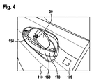
図3は、ドア把手の形態である把手150を有する可動部分110の詳細を示す。この場合、把手150は、可動部分110上に移動可能に配置される。また、把手150はカバー170を有する。ロックシリンダは通常、カバーの下に配置される。本発明によれば、エネルギー接続部60は、カバー170の後方及び/又は中又は上に配置することができる。図3において、エネルギー接続部60は、外部からのアクセスが容易に可能であるようにカバー170に組み込まれている。外部エネルギー貯蔵装置70は、エネルギー接続部60に接続することができ、閉鎖システム又は少なくとも緊急時作動装置120に電気エネルギーを供給することができる。
FIG. 3 shows details of the
図4は、把手150の更なる可能な実施形態を示す。把手150は、同様に把手として設計され、カバー170を有する。収容ハウジング160はカバー170内に配置され、IDトランスポンダ30は、収容ハウジング160に少なくとも部分的に挿入することができる。このように、収容ハウジング160内の作動要素を作動させることができ、緊急時作動モードを起動することができる。さらに、IDトランスポンダ30の挿入位置において、緊急時作動装置120の通信ユニットとの通信を確実に行うことができる。さらに、データ及び/又は電気エネルギーをIDトランスポンダ30から緊急時作動装置120に伝送することが考えられる。
FIG. 4 shows a further possible embodiment of
実施形態の上記の説明は、複数の例の状況において、排他的に本発明を説明している。もちろん、実施形態の個々の特徴は、技術的に実用的であれば、本発明の範囲から逸脱することなく互いに自由に組み合わせることができる。 The above description of the embodiments exclusively describes the invention in the context of several examples. Of course, the individual features of the embodiments can be freely combined with each other, where technically practical, without departing from the scope of the invention.
10 エネルギー貯蔵装置
20 通信ユニット
30 IDトランスポンダ
40 電子ユニット
50 作動要素
60 エネルギー接続部
70 外部エネルギー貯蔵装置
80 エネルギー管理システム
100 車両
110 可動部分
120 緊急時作動装置
130 閉鎖システム
140 ロック
150 把手
160 収容ハウジング
170 カバー
10
Claims (8)
少なくとも1つのエネルギー貯蔵装置(10)と、IDトランスポンダ(30)と無線通信するための通信ユニット(20)と、前記可動部分(110)のロック(140)を作動させることにより、前記可動部分(110)の前記ロック(140)を施錠位置から解錠位置に、又はその逆に移すことができる電子ユニット(40)とを有する緊急時作動装置(120)であって、車両(100)の外部から到達可能な作動要素(50)が設けられており、それによって、ユーザが前記閉鎖システム(130)を緊急時作動モードに切り替えることができ、緊急時作動モードにおいて、前記通信ユニット(20)が前記IDトランスポンダ(30)と通信可能であるため、認証信号を伝送することができ、認証が正の場合は、前記電子ユニット(40)が前記ロック(140)を施錠位置から解錠位置に、又はその逆に移すことを特徴とする、緊急時作動装置(120)と、
前記可動部分(110)用の少なくとも1つのロック(140)と、
前記車両(100)の外部から到達可能であり、前記緊急時作動装置(120)及び/又は前記ロック(140)を作動させるために前記車両(100)に配置され得る把手(150)と、
を有し、
前記把手(150)が、IDトランスポンダ(30)を少なくとも部分的に配置することができる前記IDトランスポンダ(30)用の収容ハウジング(160)を有し、前記作動要素(50)が前記収容ハウジング(160)上に配置されていることを特徴とする、
閉鎖システム(130)。 In a closing system (130) for a moving part (110), door, sliding door, flap or tailgate of a vehicle (100),
at least one energy storage device (10), a communication unit (20) for wireless communication with an ID transponder (30) and said movable part (110) by activating a lock (140) of said movable part (110). an electronic unit (40) capable of moving said lock (140) of 110) from a locked position to an unlocked position and vice versa, said emergency activation device (120) external to the vehicle (100). is provided an actuating element (50) reachable from, by means of which a user can switch said closure system (130) to an emergency operating mode, in which said communication unit (20) is being able to communicate with said ID transponder (30) so that it can transmit an authentication signal, and if the authentication is positive, said electronic unit (40) moves said lock (140) from a locked position to an unlocked position; or vice versa, an emergency actuator (120);
at least one lock (140) for said movable part (110);
a handle (150) that is accessible from outside the vehicle (100) and that can be placed on the vehicle (100) to activate the emergency actuator (120) and/or the lock (140);
has
Said handle (150) has a receiving housing (160) for said ID transponder (30) in which said ID transponder (30) can be at least partially arranged, said actuating element (50) said receiving housing ( 160), characterized in that it is located on
Closure system (130) .
前記エネルギー接続部(60)は、ユーザが外部から到達可能な前記車両(100)上の位置に配置されており、それによって、外部エネルギー貯蔵装置(70)による当該緊急時作動装置(120)への緊急時電流供給を実行することができることを特徴とする、請求項1に記載の閉鎖システム(130)。 an energy connection (60) is provided,
Said energy connection (60) is located at a location on said vehicle (100) that is externally reachable by a user, thereby allowing an external energy storage device (70) to power said emergency activation device (120). 2. Closure system (130) according to claim 1, characterized in that it is capable of performing an emergency current supply of .
f)車両(100)の作動要素(50)を作動させて、前記閉鎖システム(130)を緊急時作動モードに切り替えるステップと、
g)エネルギー貯蔵装置(10)を作動させて、少なくとも1つの通信ユニット(20)に電気エネルギーを供給するステップと、
h)ユーザが携帯するIDトランスポンダ(30)に対する無線信号接続を確立するステップと、
i)前記IDトランスポンダ(30)から前記通信ユニット(20)に、及び/又はその逆に、少なくとも1つの認証信号を伝送するステップと、
j)認証が正であった場合は、前記可動部分(110)のロック(140)を解錠又は施錠するステップと
を含む方法。 A method for emergency actuation of a closing system (130) for a moving part (110) of a vehicle (100), comprising the features of any one of claims 3 to 5 , comprising:
f) activating an actuating element (50) of the vehicle (100) to switch said closure system (130) to an emergency operating mode;
g) activating the energy storage device (10) to supply electrical energy to the at least one communication unit (20);
h) establishing a radio signal connection to an ID transponder (30) carried by the user;
i) transmitting at least one authentication signal from said ID transponder (30) to said communication unit (20) and/or vice versa;
j) if the authentication is positive, unlocking or locking the lock (140) of said movable part (110).
Applications Claiming Priority (3)
| Application Number | Priority Date | Filing Date | Title |
|---|---|---|---|
| DE102017125719.5 | 2017-11-03 | ||
| DE102017125719.5A DE102017125719A1 (en) | 2017-11-03 | 2017-11-03 | Emergency operating device for a moving part of a vehicle |
| PCT/DE2018/100876 WO2019086072A1 (en) | 2017-11-03 | 2018-10-26 | Emergency actuating device for a movable part of a vehicle |
Publications (2)
| Publication Number | Publication Date |
|---|---|
| JP2021501842A JP2021501842A (en) | 2021-01-21 |
| JP7206552B2 true JP7206552B2 (en) | 2023-01-18 |
Family
ID=64316239
Family Applications (1)
| Application Number | Title | Priority Date | Filing Date |
|---|---|---|---|
| JP2020524326A Active JP7206552B2 (en) | 2017-11-03 | 2018-10-26 | Emergency activation device for moving parts of vehicles |
Country Status (7)
| Country | Link |
|---|---|
| US (1) | US11781350B2 (en) |
| EP (1) | EP3704675A1 (en) |
| JP (1) | JP7206552B2 (en) |
| KR (1) | KR102717628B1 (en) |
| CN (1) | CN111344751A (en) |
| DE (1) | DE102017125719A1 (en) |
| WO (1) | WO2019086072A1 (en) |
Families Citing this family (13)
| Publication number | Priority date | Publication date | Assignee | Title |
|---|---|---|---|---|
| DE102017125719A1 (en) * | 2017-11-03 | 2019-05-09 | Kiekert Ag | Emergency operating device for a moving part of a vehicle |
| WO2020223794A1 (en) * | 2019-05-09 | 2020-11-12 | Magna Closures Inc. | Backup energy supply and authentication for electronic latch |
| DE102019121300A1 (en) | 2019-08-07 | 2021-02-11 | Daimler Ag | Motor vehicle lock, in particular motor vehicle door lock |
| DE102019126570A1 (en) | 2019-10-02 | 2021-04-08 | Kiekert Aktiengesellschaft | Drive arrangement for a motor vehicle lock |
| DE102020104846A1 (en) | 2020-02-25 | 2021-08-26 | Brose Fahrzeugteile Se & Co. Kommanditgesellschaft, Bamberg | Method for operating a motor vehicle locking system |
| DE102020123596A1 (en) | 2020-09-10 | 2022-03-10 | Kiekert Aktiengesellschaft | Installation device for a motor vehicle door element |
| DE102021108334A1 (en) | 2021-04-01 | 2022-10-06 | Kiekert Aktiengesellschaft | Road user communication device |
| DE102021123330A1 (en) * | 2021-09-09 | 2023-03-09 | Kiekert Aktiengesellschaft | Motor vehicle lock, in particular motor vehicle door lock |
| DE102021128395A1 (en) | 2021-10-27 | 2023-04-27 | Elmos Semiconductor Se | Emergency unlocking system for electrically locked vehicle doors |
| KR102737353B1 (en) * | 2021-11-01 | 2024-12-03 | 콘티넨탈 오토모티브 테크놀로지스 게엠베하 | Door unlock apparatus for vehicle |
| DE102022103754A1 (en) | 2022-02-17 | 2023-08-17 | Lufthansa Technik Aktiengesellschaft | Access control device, access control system, door section with access control device and method for opening a door |
| DE102022115827A1 (en) * | 2022-06-24 | 2024-01-04 | Kiekert Aktiengesellschaft | Electric locking system for motor vehicles with emergency power supply |
| CN119037139A (en) * | 2024-07-16 | 2024-11-29 | 比亚迪股份有限公司 | Emergency power supply system, method, vehicle and storage medium |
Citations (4)
| Publication number | Priority date | Publication date | Assignee | Title |
|---|---|---|---|---|
| JP2006152676A (en) | 2004-11-29 | 2006-06-15 | Tokai Rika Co Ltd | Electronic key system |
| DE102005054111A1 (en) | 2005-11-12 | 2007-05-16 | Marquardt Gmbh | Locking system e.g. door locking system, for e.g. car, has electrical system energy determining unit whose power supply is switched over to emergency battery in case of system`s energy loss, where battery has activatable battery |
| JP2009513844A (en) | 2003-07-10 | 2009-04-02 | ヴァレオ セキュリテ アビタクル エス・ア・エス | Electronically actuable locking device for automobile |
| US20140316612A1 (en) | 2012-01-05 | 2014-10-23 | Rob Bingle | Vehicle access system |
Family Cites Families (22)
| Publication number | Priority date | Publication date | Assignee | Title |
|---|---|---|---|---|
| JP3456779B2 (en) * | 1995-01-10 | 2003-10-14 | 本田技研工業株式会社 | Vehicle unlocking system |
| JP4055243B2 (en) * | 1998-05-12 | 2008-03-05 | 株式会社デンソー | Keyless entry device for vehicle |
| EP1083285A1 (en) * | 1999-09-07 | 2001-03-14 | Robert Bosch Gmbh | Vehicle door locking system |
| WO2001023695A1 (en) * | 1999-09-30 | 2001-04-05 | Siemens Automotive Corporation | An electronic transmitter key to supply backup power for an electronic locking system |
| EP1564689A3 (en) * | 2004-02-17 | 2006-04-26 | Huf Hülsbeck & Fürst GmbH & Co. KG | Method for operating a lock with back-up device for locking and/or unlocking the lock |
| DE102006002119A1 (en) * | 2005-01-19 | 2006-07-20 | Marquardt Gmbh | Door locking system for motor vehicle, has electrical lock with rechargeable battery, and electrical and/or electronic key that allows energy transfer from battery for lock to activate lock in case of failure of electrical system in vehicle |
| DE102005031186C5 (en) * | 2005-07-01 | 2021-02-18 | Huf Hülsbeck & Fürst Gmbh & Co. Kg | Intelligent actuator |
| DE102006048369A1 (en) * | 2006-10-09 | 2008-04-10 | Huf Hülsbeck & Fürst Gmbh & Co. Kg | Electronic key |
| KR100959012B1 (en) * | 2008-12-03 | 2010-05-25 | 한국오므론전장주식회사 | Door open and close device |
| DE102012014471A1 (en) * | 2011-07-27 | 2013-01-31 | Marquardt Gmbh | Power supply circuit for electrical components |
| US9416565B2 (en) * | 2013-11-21 | 2016-08-16 | Ford Global Technologies, Llc | Piezo based energy harvesting for e-latch systems |
| US9909344B2 (en) * | 2014-08-26 | 2018-03-06 | Ford Global Technologies, Llc | Keyless vehicle door latch system with powered backup unlock feature |
| EP3020895B1 (en) * | 2014-11-13 | 2017-11-15 | Huf Hülsbeck & Fürst GmbH & Co. KG | Handle for a vehicle with a pulling device |
| DE102015121740A1 (en) * | 2014-12-24 | 2016-07-14 | Magna Closures S.P.A. | Electronic lock unlocking reserve system for a motor vehicle door |
| DE102016005342A1 (en) * | 2015-05-04 | 2016-11-10 | Marquardt Gmbh | Locking system and device with a locking system |
| US9518408B1 (en) * | 2015-05-21 | 2016-12-13 | Ford Global Technologies, Llc | Alternate backup entry for vehicles |
| US9725069B2 (en) * | 2015-10-12 | 2017-08-08 | Ford Global Technologies, Llc | Keyless vehicle systems |
| EP3217365B1 (en) * | 2016-03-10 | 2018-10-10 | iLOQ Oy | Near field communication tag |
| US9845071B1 (en) * | 2016-06-06 | 2017-12-19 | Ford Global Technologies, Llc | Keyless car sharing mechanism using smartphones and inbuilt WiFi systems for authentication |
| US10329823B2 (en) * | 2016-08-24 | 2019-06-25 | Ford Global Technologies, Llc | Anti-pinch control system for powered vehicle doors |
| US10137857B1 (en) * | 2017-08-22 | 2018-11-27 | Ford Global Technologies, Llc | Vehicle unlocking systems, devices, and methods |
| DE102017125719A1 (en) * | 2017-11-03 | 2019-05-09 | Kiekert Ag | Emergency operating device for a moving part of a vehicle |
-
2017
- 2017-11-03 DE DE102017125719.5A patent/DE102017125719A1/en not_active Ceased
-
2018
- 2018-10-26 WO PCT/DE2018/100876 patent/WO2019086072A1/en not_active Ceased
- 2018-10-26 JP JP2020524326A patent/JP7206552B2/en active Active
- 2018-10-26 EP EP18803532.3A patent/EP3704675A1/en not_active Withdrawn
- 2018-10-26 US US16/760,958 patent/US11781350B2/en active Active
- 2018-10-26 KR KR1020207015846A patent/KR102717628B1/en active Active
- 2018-10-26 CN CN201880072218.4A patent/CN111344751A/en active Pending
Patent Citations (4)
| Publication number | Priority date | Publication date | Assignee | Title |
|---|---|---|---|---|
| JP2009513844A (en) | 2003-07-10 | 2009-04-02 | ヴァレオ セキュリテ アビタクル エス・ア・エス | Electronically actuable locking device for automobile |
| JP2006152676A (en) | 2004-11-29 | 2006-06-15 | Tokai Rika Co Ltd | Electronic key system |
| DE102005054111A1 (en) | 2005-11-12 | 2007-05-16 | Marquardt Gmbh | Locking system e.g. door locking system, for e.g. car, has electrical system energy determining unit whose power supply is switched over to emergency battery in case of system`s energy loss, where battery has activatable battery |
| US20140316612A1 (en) | 2012-01-05 | 2014-10-23 | Rob Bingle | Vehicle access system |
Also Published As
| Publication number | Publication date |
|---|---|
| KR20200083566A (en) | 2020-07-08 |
| JP2021501842A (en) | 2021-01-21 |
| US11781350B2 (en) | 2023-10-10 |
| CN111344751A (en) | 2020-06-26 |
| DE102017125719A1 (en) | 2019-05-09 |
| US20200300006A1 (en) | 2020-09-24 |
| EP3704675A1 (en) | 2020-09-09 |
| WO2019086072A1 (en) | 2019-05-09 |
| KR102717628B1 (en) | 2024-10-16 |
Similar Documents
| Publication | Publication Date | Title |
|---|---|---|
| JP7206552B2 (en) | Emergency activation device for moving parts of vehicles | |
| US10377343B2 (en) | Keyless vehicle systems | |
| CN106168087B (en) | Alternative Alternative Access Devices for Vehicles | |
| US6657537B1 (en) | Device for initiating an authorization request for a vehicle | |
| CN105083041B (en) | The control of the locking system of electrical charging interface | |
| JP6726460B2 (en) | Electronic latch release backup system for car doors | |
| JP4045275B2 (en) | Driver approval system | |
| ES2734367T3 (en) | Closing unit, closing device and procedure for unlocking and / or locking a lock | |
| KR20140144174A (en) | Vehicle access system | |
| JP2014193062A (en) | Cable lock device | |
| CN105389867A (en) | Keyless vehicle door latch system with powered backup unlock feature | |
| JP2009513844A (en) | Electronically actuable locking device for automobile | |
| CN109306823B (en) | Electronic lock for two-wheel cycle | |
| US11192525B2 (en) | Access arrangement for a vehicle | |
| US20150243116A1 (en) | Electronic vehicle key | |
| US11741767B1 (en) | NFC-based enclosure access using passive energy harvesting | |
| CN101506008B (en) | Electric steering lock, in particular for a motor vehicle | |
| US20220194320A1 (en) | Backup energy supply and authentication for electronic latch | |
| KR20240005882A (en) | Motor vehicle locks, especially electric locks | |
| US20220316239A1 (en) | Arrangement for electronic locking system, and electronic locking system | |
| KR102070357B1 (en) | Motor vehicle | |
| US11713022B1 (en) | NFC-based enclosure access using passive energy harvesting | |
| JP6471034B2 (en) | Door operation control system | |
| KR20140096404A (en) | Smart Key For Vehicles | |
| JP2018123554A (en) | Lock device |
Legal Events
| Date | Code | Title | Description |
|---|---|---|---|
| A621 | Written request for application examination |
Free format text: JAPANESE INTERMEDIATE CODE: A621 Effective date: 20210825 |
|
| A977 | Report on retrieval |
Free format text: JAPANESE INTERMEDIATE CODE: A971007 Effective date: 20220623 |
|
| A131 | Notification of reasons for refusal |
Free format text: JAPANESE INTERMEDIATE CODE: A131 Effective date: 20220705 |
|
| A521 | Request for written amendment filed |
Free format text: JAPANESE INTERMEDIATE CODE: A523 Effective date: 20221004 |
|
| TRDD | Decision of grant or rejection written | ||
| A01 | Written decision to grant a patent or to grant a registration (utility model) |
Free format text: JAPANESE INTERMEDIATE CODE: A01 Effective date: 20221206 |
|
| A61 | First payment of annual fees (during grant procedure) |
Free format text: JAPANESE INTERMEDIATE CODE: A61 Effective date: 20221214 |
|
| R150 | Certificate of patent or registration of utility model |
Ref document number: 7206552 Country of ref document: JP Free format text: JAPANESE INTERMEDIATE CODE: R150 |
|
| R250 | Receipt of annual fees |
Free format text: JAPANESE INTERMEDIATE CODE: R250 |