JP7205608B2 - Synchronous 4-mass gyroscope - Google Patents
Synchronous 4-mass gyroscope Download PDFInfo
- Publication number
- JP7205608B2 JP7205608B2 JP2021191776A JP2021191776A JP7205608B2 JP 7205608 B2 JP7205608 B2 JP 7205608B2 JP 2021191776 A JP2021191776 A JP 2021191776A JP 2021191776 A JP2021191776 A JP 2021191776A JP 7205608 B2 JP7205608 B2 JP 7205608B2
- Authority
- JP
- Japan
- Prior art keywords
- proof mass
- axis
- mass
- anchor points
- proof
- Prior art date
- Legal status (The legal status is an assumption and is not a legal conclusion. Google has not performed a legal analysis and makes no representation as to the accuracy of the status listed.)
- Active
Links
Images


Classifications
-
- G—PHYSICS
- G01—MEASURING; TESTING
- G01C—MEASURING DISTANCES, LEVELS OR BEARINGS; SURVEYING; NAVIGATION; GYROSCOPIC INSTRUMENTS; PHOTOGRAMMETRY OR VIDEOGRAMMETRY
- G01C19/00—Gyroscopes; Turn-sensitive devices using vibrating masses; Turn-sensitive devices without moving masses; Measuring angular rate using gyroscopic effects
- G01C19/56—Turn-sensitive devices using vibrating masses, e.g. vibratory angular rate sensors based on Coriolis forces
- G01C19/5719—Turn-sensitive devices using vibrating masses, e.g. vibratory angular rate sensors based on Coriolis forces using planar vibrating masses driven in a translation vibration along an axis
- G01C19/5733—Structural details or topology
- G01C19/574—Structural details or topology the devices having two sensing masses in anti-phase motion
Description
本開示は、微小電気機械ジャイロスコープに関し、より詳細には、4つの試験質量がデバイス平面(xy平面)内で振動し、回転速度が、当該デバイス平面に垂直な入力軸(z軸)を中心として測定されるz軸ジャイロスコープに関する。 The present disclosure relates to micro-electromechanical gyroscopes, and more particularly, four proof masses oscillate in the device plane (xy-plane) and rotational velocity about an input axis (z-axis) perpendicular to the device plane. for a z-axis gyroscope measured as
微小電気機械(MEMS)ジャイロスコープでは、試験質量は、好ましくは、一次振動モード(駆動振動モードとも呼ばれる場合がある)で振動するように容易に設定されるべきである。試験質量はまた、コリオリの力によって誘発される二次振動モード(センス振動モードとも呼ばれる場合がある)の振動を容易に受けるはずである。ジャイロスコープ設計における一般的な問題は、一次振動モードおよび二次振動モードにおける試験質量の振動が、好ましくは、外乱によって乱されるべきではないことである。ジャイロスコープは、好ましくは、その出力信号が、ジャイロスコープが意図された周波数範囲において受ける角回転速度によってのみ決定されるように、線形振動および回転振動の両方によって乱されるべきではない。例えば、自動車用途では、通常、可能性のある擾乱は0~50kHzの周波数範囲にあり、一方、入力周波数範囲は通常1kHz未満である。 In a micro-electro-mechanical (MEMS) gyroscope, the proof mass should preferably be easily set to vibrate in the primary vibration mode (sometimes called the drive vibration mode). The proof mass should also readily undergo vibrations in the Coriolis force induced secondary vibration mode (sometimes referred to as the sense vibration mode). A general problem in gyroscope design is that the vibration of the proof mass in the primary and secondary vibration modes should preferably not be perturbed by disturbances. The gyroscope should preferably be unperturbed by both linear and rotational vibrations so that its output signal is determined solely by the angular rate of rotation that the gyroscope undergoes in the intended frequency range. For example, in automotive applications, the possible disturbances are typically in the frequency range 0-50 kHz, while the input frequency range is typically less than 1 kHz.
1つの振動試験質量のみを利用して単純なMEMSジャイロスコープを構築することができるが、動作周波数に近い周波数の外部振動が存在する場合、そのようなジャイロスコープの出力信号は通常ノイズが多くなる。単質量ジャイロスコープは、50kHzを超える動作周波数でのみ実用的であるが、そのような周波数では、製造の不完全性から生じる直交信号などの他の妨害効果が非常に顕著になることが多い。 Simple MEMS gyroscopes can be constructed using only one vibrating proof mass, but the output signal of such gyroscopes is typically noisy in the presence of external vibrations with frequencies close to the operating frequency. . Single-mass gyroscopes are only practical at operating frequencies above 50 kHz, where other disturbing effects, such as quadrature signals resulting from manufacturing imperfections, often become very pronounced.
4つの試験質量が逆相で振動する系は、単質量ジャイロスコープよりも振動に対してはるかにロバストにすることができることが知られている。試験質量の任意の対の同相運動を誘発する振動から生じる信号成分は、当該系において、差分測定によって少なくともある程度自動的に相殺することができる。さらに、4つの試験質量の逆相振動が効果的に同期される場合、すべての同相共振周波数は、逆相共振周波数に影響を及ぼすことなく50kHzを超えることができる。次いで、妨害振動は、典型的には共振増幅を生じず、以て、デバイスへの妨害振動の影響が大幅に低減される。 It is known that a system with four proof masses vibrating in antiphase can be made much more robust to vibrations than a single-mass gyroscope. Signal components resulting from vibrations that induce in-phase motion of any pair of proof masses can be automatically canceled in the system, at least to some extent, by differential measurements. Furthermore, if the out-of-phase vibrations of the four proof masses are effectively synchronized, all common-mode resonant frequencies can exceed 50 kHz without affecting the out-of-phase resonant frequencies. Disturbing vibrations then typically do not produce resonant amplification, thus greatly reducing the impact of disturbing vibrations on the device.
デバイス基板に垂直な1つの軸を中心とした角回転速度を測定するように設計されているMEMSジャイロスコープは、z軸ジャイロスコープと呼ばれ得る。当該事例におけるコリオリの力はデバイス平面の方向に作用するため、試験質量の一次振動および二次振動の両方がデバイス平面内で発生するように、z軸ジャイロスコープを設計することができる。 A MEMS gyroscope designed to measure the angular rate of rotation about one axis perpendicular to the device substrate can be referred to as a z-axis gyroscope. Since the Coriolis force in this case acts in the direction of the device plane, the z-axis gyroscope can be designed such that both the primary and secondary vibrations of the proof mass occur in the device plane.
米国特許第10415968号明細書および論文Zotov他「High-Range Angular Rate Sensor Based on Mechanical Frequency Modulation」(Journal of Microelectromechanical Systems,Vol.21,No.2,p.398-405,April 2012)は、4つの試験質量が逆相運動を促進し、同相運動に抵抗する配置において互いに結合されているz軸ジャイロスコープを開示している。しかしながら、当該ジャイロスコープにおいて使用される同期および懸架構成のいくつかは、非線形であることが知られている両持ち梁ばね構造に基づいている。非線形ばねは、ジャイロスコープの質量振動振幅を低いレベルに制限し、以て、ジャイロスコープの正確度およびノイズ性能を制限する。 U.S. Pat. No. 10415968 and the article Zotov et al. "High-Range Angular Rate Sensor Based on Mechanical Frequency Modulation" (Journal of Microelectromechanical Systems, Vol. 21, No. 2, p. discloses a z-axis gyroscope in which two proof masses are coupled together in an arrangement that promotes out-of-phase motion and resists in-phase motion. However, some of the synchronization and suspension arrangements used in such gyroscopes are based on double-ended beam spring structures, which are known to be non-linear. Nonlinear springs limit the gyroscope's mass vibration amplitude to a low level, thereby limiting the accuracy and noise performance of the gyroscope.
本開示の目的は、上記の問題が軽減された逆相同期を有する4質量ジャイロスコープを提供することである。 It is an object of the present disclosure to provide a four-mass gyroscope with anti-phase synchronization in which the above problems are mitigated.
本開示の目的は、独立請求項に述べられている事項を特徴とする構成によって達成される。本開示の好ましい実施形態が、従属請求項に開示されている。 The objects of the disclosure are achieved by arrangements characterized by what is stated in the independent claims. Preferred embodiments of the disclosure are disclosed in the dependent claims.
本開示は、x方向の力を対応する試験質量に伝達するすべての同期構造を、x方向に剛性であるがy方向に可撓性である結合要素を用いて結合し、y方向の力を対応する試験質量に伝達するすべての同期構造を、y方向に剛性であるがx方向に可撓性である結合要素を用いて結合するという着想に基づく。本開示は、中央同期のために面内シーソー同期構造を利用するという考えにさらに基づいている。 The present disclosure couples all synchronous structures that transmit x-directed forces to corresponding proof masses with coupling elements that are rigid in the x-direction but flexible in the y-direction so that the y-directed forces are The idea is to connect all synchronous structures that transmit to the corresponding proof masses with a connecting element that is rigid in the y-direction but flexible in the x-direction. The present disclosure is further based on the idea of utilizing an in-plane seesaw synchronization structure for central synchronization.
本開示の構成の利点は、各試験質量が大きな振幅で振動することができ、x方向の各試験質量の振動が、y方向のその振動から独立するようになる一方で、両方向の他の試験質量の振動と依然として同期していることである。 An advantage of the configuration of the present disclosure is that each proof mass can vibrate with a large amplitude, making the vibration of each proof mass in the x-direction independent of its vibration in the y-direction, while the other test masses in both directions. It is still in synchronism with the vibration of the mass.
以下において、添付の図面を参照しながら、好ましい実施形態によって、本開示をより詳細に説明する。
本開示は、第1の横軸および第2の横軸が第1の交差軸および第2の交差軸と直交して交差するデバイス平面を備えるジャイロスコープを説明する。ジャイロスコープはまた、第1の試験質量、第2の試験質量、第3の試験質量、および第4の試験質量を備える。第1の試験質量および第2の試験質量は第1の横軸上に位置合わせされ、第3の試験質量および第4の試験質量は第2の横軸上に位置合わせされ、第1の試験質量および第3の試験質量は第1の交差軸上に位置合わせされ、第2の試験質量および第4の試験質量は第2の交差軸上に位置合わせされる。 This disclosure describes a gyroscope with a device plane in which first and second horizontal axes orthogonally intersect first and second cross-axes. The gyroscope also includes a first proof mass, a second proof mass, a third proof mass, and a fourth proof mass. The first and second proof masses are aligned on the first horizontal axis, the third and fourth proof masses are aligned on the second horizontal axis, and the first test mass is aligned on the second horizontal axis. The mass and the third proof mass are aligned on the first cross axis and the second proof mass and the fourth proof mass are aligned on the second cross axis.
第1の試験質量および第2の試験質量は、第1の中央x軸逆相結合構造を用いて互いに結合され、第1の中央x軸逆相結合構造は、第1の試験質量および第2の試験質量の反対の横方向における同時運動を柔軟に可能にするが、第1の試験質量および第2の試験質量の同じ横方向における同時運動には剛性に抵抗する。 The first proof mass and the second proof mass are coupled together using a first central x-axis reversed-phase coupling structure, the first central x-axis reversed-phase coupling structure connecting the first proof mass and the second proof mass. of the first and second proof masses in opposite lateral directions, but rigidly resists simultaneous motion of the first and second proof masses in the same lateral direction.
第3の試験質量および第4の試験質量は、第2の中央x軸逆相結合構造を用いて互いに結合され、第2の中央x軸逆相結合構造は、第3の試験質量および第4の試験質量の反対の横方向における同時運動を柔軟に可能にするが、第3の試験質量および第4の試験質量の同じ横方向における同時運動には剛性に抵抗する。 The third proof mass and the fourth proof mass are coupled together using a second central x-axis reversed-phase coupling structure, the second central x-axis reversed-phase coupling structure connecting the third proof mass and the fourth proof mass. , yet rigidly resists simultaneous movement of the third and fourth proof masses in the same lateral direction.
第1の試験質量および第3の試験質量は、第1の中央y軸逆相結合構造を用いて互いに結合され、第1の中央y軸逆相結合構造は、第1の試験質量および第3の試験質量の反対の交差方向における同時運動を柔軟に可能にするが、第1の試験質量および第3の試験質量の同じ交差方向における同時運動には剛性に抵抗する。 The first proof mass and the third proof mass are coupled together using a first central y-axis reversed-phase coupling structure, the first central y-axis reversed-phase coupling structure connecting the first proof mass and the third proof mass. , but rigidly resists simultaneous movement in the same cross direction of the first and third proof masses.
第2の試験質量および第4の試験質量は、第2の中央y軸逆相結合構造を用いて互いに結合され、第2の中央y軸逆相結合構造は、第2の試験質量および第4の試験質量の反対の交差方向における同時運動を柔軟に可能にするが、第2の試験質量および第4の試験質量の同じ交差方向における同時運動には剛性に抵抗する。 The second proof mass and the fourth proof mass are coupled together using a second central y-axis reversed-phase coupling structure, the second central y-axis reversed-phase coupling structure connecting the second proof mass and the fourth proof mass. , but rigidly resists simultaneous movement in the same cross direction of the second and fourth proof masses.
第1の試験質量および第2の試験質量は、第1の周縁y軸逆相結合構造を用いて互いに結合され、第1の周縁y軸逆相結合構造は、第1の試験質量および第2の試験質量の反対の交差方向における同時運動を柔軟に可能にするが、第1の試験質量および第2の試験質量の同じ交差方向における同時運動には剛性に抵抗する。 The first proof mass and the second proof mass are coupled together using a first peripheral y-axis negative phase coupling structure, the first peripheral y-axis negative phase coupling structure connecting the first proof mass and the second proof mass. of the first and second proof masses in opposite cross-directions, but rigidly resists simultaneous motion in the same cross-direction of the first and second proof masses.
第3の試験質量および第4の試験質量は、第2の周縁y軸逆相結合構造を用いて互いに結合され、第2の周縁y軸逆相結合構造は、第3の試験質量および第4の試験質量の反対の交差方向における同時運動を柔軟に可能にするが、第3の試験質量および第4の試験質量の同じ交差方向における同時運動には剛性に抵抗する。 The third proof mass and the fourth proof mass are coupled together using a second peripheral y-axis negative phase coupling structure, the second peripheral y-axis negative phase coupling structure connecting the third proof mass and the fourth proof mass. , but rigidly resists simultaneous movement in the same cross direction of the third and fourth proof masses.
第1の試験質量および第3の試験質量は、第1の周縁x軸逆相結合構造を用いて互いに結合され、第1の周縁x軸逆相結合構造は、第1の試験質量および第3の試験質量の反対の横方向における同時運動を柔軟に可能にするが、第1の試験質量および第3の試験質量の同じ横方向における同時運動には剛性に抵抗する。 The first proof mass and the third proof mass are coupled together using a first peripheral x-axis negative phase coupling structure, the first peripheral x-axis negative phase coupling structure connecting the first proof mass and the third proof mass. of the first and third proof masses in opposite lateral directions, but rigidly resists simultaneous motion of the first and third proof masses in the same lateral direction.
第2の試験質量および第4の試験質量は、第2の周縁x軸逆相結合構造を用いて互いに結合され、第2の周縁x軸逆相結合構造は、第2の試験質量および第4の試験質量の反対の横方向における同時運動を柔軟に可能にするが、第2の試験質量および第4の試験質量の同じ横方向における同時運動には剛性に抵抗する。 The second proof mass and the fourth proof mass are coupled together using a second peripheral x-axis negative phase coupling structure, the second peripheral x-axis negative phase coupling structure connecting the second proof mass and the fourth proof mass. , yet rigidly resists simultaneous movement of the second and fourth proof masses in the same lateral direction.
ジャイロスコープは、第1の試験質量に隣接する第1のアンカー点のセットと、第2の試験質量に隣接する第2のアンカー点のセットと、第3の試験質量に隣接する第3のアンカー点のセットと、第4の試験質量に隣接する第4のアンカー点のセットとをさらに備え、第1の試験質量、第2の試験質量、第3の試験質量および第4の試験質量の各々は、1つまたは複数の懸架構造によって第1のアンカー点、第2のアンカー点、第3のアンカー点および第4のアンカー点の対応するセットから懸架されている。 The gyroscope has a first set of anchor points adjacent to the first proof mass, a second set of anchor points adjacent to the second proof mass, and a third anchor point adjacent to the third proof mass. further comprising a set of points and a fourth set of anchor points adjacent to the fourth proof mass, each of the first proof mass, the second proof mass, the third proof mass and the fourth proof mass; are suspended from corresponding sets of first, second, third and fourth anchor points by one or more suspension structures.
各中央および周縁x軸逆相結合構造は、交差方向に可撓性であり、横方向に剛性であるx軸結合要素を用いて、対応する試験質量に結合されている。各中央および周縁y軸逆相結合構造は、横方向に可撓性であり、交差方向に剛性であるy軸結合要素を用いて、対応する試験質量に結合されている。 Each central and peripheral x-axis reversed-phase coupling structure is coupled to a corresponding proof mass using a transversely flexible, laterally rigid x-axis coupling element. Each central and peripheral y-axis reversed-phase coupling structure is coupled to a corresponding proof mass using a laterally flexible, transversely rigid y-axis coupling element.
各中央x軸逆相構造および各中央y軸逆相構造は、中央長尺バーを有する面内シーソーを備え、中央長尺バーは、中央長尺バーがデバイス平面に垂直な軸を中心にデバイス平面内で回転することを可能にする少なくとも1つの中央シーソー懸架装置を用いて少なくとも1つの中央アンカー点から懸架されている。 Each central x-axis reversed-phase structure and each central y-axis reversed-phase structure comprises an in-plane seesaw having a central elongated bar that steers the device about an axis perpendicular to the plane of the device. It is suspended from at least one central anchor point with at least one central seesaw suspension that allows it to rotate in a plane.
本開示では、デバイス平面が例示され、xy平面と称される。x方向を横方向と称し、y方向を交差方向と称する。デバイス平面は、水平面と呼ばれる場合もある。z軸はxy平面に垂直である。z軸はまた、垂直軸と呼ばれる場合もある。試験質量が静止位置から外方に離れると、デバイス平面内で水平のままである線形運動および/または回転運動は、「面内」運動または「デバイス平面内の運動」として参照される。 In this disclosure the device plane is exemplified and referred to as the xy plane. The x direction is referred to as the transverse direction and the y direction as the cross direction. The device plane is sometimes called the horizontal plane. The z-axis is perpendicular to the xy-plane. The z-axis is also sometimes referred to as the vertical axis. Linear and/or rotational motion that remains horizontal in the device plane as the proof mass moves outward from its rest position is referred to as "in-plane" motion or "in-device-plane motion."
本開示において、「水平」および「垂直」という用語は、それぞれデバイス平面およびデバイス平面に垂直な方向を指す。デバイス平面は、典型的には、微小機械構造が作成される基板によって規定される。「水平」および「垂直」という言葉は、製造中または使用中にデバイスをどのように方向付けるべきかについて何も暗示しない。 In this disclosure, the terms "horizontal" and "vertical" refer to the device plane and directions perpendicular to the device plane, respectively. A device plane is typically defined by the substrate on which the micromechanical structures are fabricated. The words "horizontal" and "vertical" imply nothing about how the device should be oriented during manufacture or use.
「第1の横軸上に位置合わせされた」などの表現は、デバイス要素を、上記軸が上記デバイス要素の中点に実質的に交差するように配置することを指す。試験質量は、例えば、上記軸に関して対称であり得、および/または軸は、上記試験質量の重心と交差し得る。しかしながら、完璧な位置合わせは必ずしも常に必要ではない。 Phrases such as "aligned on a first lateral axis" refer to arranging a device element such that said axis substantially intersects the midpoint of said device element. The proof mass may, for example, be symmetrical about the axis and/or the axis may intersect the center of gravity of the proof mass. However, perfect alignment is not always necessary.
本開示において、「ばね」という用語は、少なくとも1つの方向に可撓性であるデバイス部分を指す。「懸架装置」または「懸架要素」という用語は、固定部分(アンカー点など)と、デバイスが動作するときに動くデバイス部分との間に(場合によっては他のデバイス部分と共に)配置される要素を指す。「懸架構造」という用語は、共に可動質量に構造的支持を提供する懸架装置のより多くの組み合わせを指す。懸架構造は、連結方式で互いに接続された懸架装置を含むことができる。懸架装置のいくつかは剛性であってもよく、他のものは可撓性であってもよい。懸架構造は、所望の振動に適応するために必要な可撓性を提供する少なくとも1つの可撓性懸架装置を含む。 In this disclosure, the term "spring" refers to a device portion that is flexible in at least one direction. The term "suspension" or "suspension element" refers to an element that is placed between a fixed part (such as an anchor point) and a device part that moves (possibly with other device parts) when the device is in operation. Point. The term "suspension structure" refers to more combinations of suspension systems that together provide structural support to a moving mass. The suspension structure may include suspension devices connected together in an articulated manner. Some of the suspensions may be rigid and others flexible. The suspension structure includes at least one flexible suspension that provides the necessary flexibility to accommodate the desired vibrations.
懸架構造は、試験質量のための構造的支持を提供する。下記により詳細に説明するように、第1の試験質量、第2の試験質量、第3の試験質量、および第4の試験質量は、当該懸架構造を介して互いに結合されてもよい(ただし、必ずしもそうである必要はない)。言い換えれば、中央結合構造および周縁結合構造は、同じ軸上に位置合わせされた2つの試験質量の懸架構造の間に延在することができる。あるいは、中央結合構造および周縁結合構造は、同じ軸上に位置合わせされた2つの試験質量の間に延在してもよく、懸架構造は、結合構造と試験質量との間に存在しない別個の構造であってもよい。 The suspension structure provides structural support for the proof mass. As described in more detail below, the first proof mass, the second proof mass, the third proof mass, and the fourth proof mass may be coupled together via the suspension structure (provided that not necessarily so). In other words, the central bonding structure and the peripheral bonding structure may extend between two proof mass suspension structures that are aligned on the same axis. Alternatively, the central and peripheral bond structures may extend between two proof masses aligned on the same axis, and the suspension structure is a separate, non-existent interface between the bond structure and the proof masses. It may be a structure.
中央および周縁逆相結合構造は、上述した方法で試験質量の横方向および交差方向の振動運動の両方を同期させる。本開示全体を通して、「同期させる(synchronize)」という用語、および「構造Aが振動モードXを同期させる」などの語句は、以下の意味を有する。構造Aは、好ましくは所望のモードXにおいて振動すべきであるが、好ましくは望ましくないモードYにおいては振動すべきでない、相互接続された質量要素のシステムにおいて機械的接続を構成する。構造Aは、剛性と柔軟性との有益な組み合わせを呈し、結果、構造Aの存在はシステムにおけるモードXの共振周波数FXとモードYの共振周波数FYとの間の関係を改善する。 The central and peripheral antiphase coupling structures synchronize both the lateral and cross-directional oscillatory motions of the proof mass in the manner described above. Throughout this disclosure, the term "synchronize" and phrases such as "structure A synchronizes vibration mode X" have the following meanings. Structure A constitutes a mechanical connection in a system of interconnected mass elements that should preferably vibrate in the desired mode X, but preferably not in the undesired mode Y. Structure A exhibits a beneficial combination of stiffness and flexibility, such that the presence of structure A improves the relationship between the resonant frequencies F X of mode X and F Y of mode Y in the system.
構造Aの存在は、例えば、比FY/FXおよび/または差FY-FXを増加させることができる。この改善が測定される基準状態は、場合によっては、構造Aのない質量要素の同じシステムである場合がある。当該事例において、構造Aは同期にのみ必要である。他の場合、構造Aが質量要素の重量を支えるためにも必要であるとき、同期改善が測定される基準状態は、Aが、構造的な支持のみを提供する代替の構造Bに置き換えられた質量要素から成る同じシステムであってもよい。 The presence of structure A can, for example, increase the ratio F Y /F X and/or the difference F Y -F X. The reference condition under which this improvement is measured may possibly be the same system of mass elements without structure A. In the present case structure A is only needed for synchronization. In other cases, when structure A is also required to support the weight of the mass elements, the reference condition under which the improvement in synchronization is measured is that A has been replaced by an alternative structure B that provides only structural support. It may be the same system of mass elements.
一般に、すべての懸架、同期および結合構成は、支持、ならびに、特定の方向の柔軟性および他の方向の剛性のために最適化されている。当該3つの変数は互いに競合する可能性があるため、当該変数の最適化は、適切な妥協案を見つけるべきであることを意味することが多い。ジャイロスコープのすべての要素が当該妥協に影響を与える可能性がある。 In general, all suspension, synchronization and coupling configurations are optimized for support and flexibility in certain directions and stiffness in others. Since the three variables can compete with each other, optimization of the variables often means that a good compromise should be found. All gyroscope factors can affect the compromise.
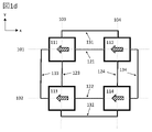
図1aは、本開示に記載のジャイロスコープにおける所望の振動モードである第1の振動モードを黒色実線矢印で概略的に示す。図1aは、第1の横軸(101)および第2の横軸(102)、第1の交差軸(103)および第2の交差軸(104)、ならびに第1の試験質量(111)、第2の試験質量(112)、第3の試験質量(113)および第4の試験質量(114)を示している。図1aはまた、第1の中央x軸逆相結合構造121、第2の中央x軸逆相結合構造122、第1の中央y軸逆相結合構造123、第2の中央y軸逆相結合構造124、第1の周縁y軸逆相結合構造131、第2の周縁y軸逆相結合構造132、第1の周縁x軸逆相結合構造133、および第2の周縁x軸逆相結合構造134を概略的に示す。
FIG. 1a schematically illustrates, with solid black arrows, a first vibration mode, which is the desired vibration mode in the gyroscope described in this disclosure. FIG. 1a shows a first transverse axis (101) and a second transverse axis (102), a first cross axis (103) and a second cross axis (104), and a first proof mass (111), A second proof mass (112), a third proof mass (113) and a fourth proof mass (114) are shown. FIG. 1a also shows a first central x-axis
中央および周縁x軸逆相結合構造121~122および133~134は、質量113および114が第2の横軸102上で互いから離れるように同時に動くときに、質量111および112が第1の横軸101上で互いに向かって動く第1の振動モードを促進する。振動周期の反対の半部では、質量111および112は互いから離れるように動き、一方で、質量113および114は互いに向かって動く。
The central and peripheral x-axis reversed-phase coupling structures 121-122 and 133-134 are configured such that
図1b、図1cおよび図1dは、同相振動が発生する3つの望ましくない振動モードを模様付き矢印で示している。周縁x軸逆相結合構造133~134は、試験質量対111+112および113+114の両方が同時に互いに向かって振動する、図1bに示されている同相振動に抵抗する。中央x軸逆相結合構造121~122は、角加速度によって誘発され得る、図1cに示される同相振動に抵抗する。試験質量111および112は、一方の横方向に同時に動き、一方で113および114は、他方の横方向に同時に動く。そして最後に、中央結合構造121~122および周縁結合構造133~134の両方が、4つの試験質量111~114のすべてが同じ方向に動く図1dの線形加速によって誘発される同相振動に抵抗する。
Figures 1b, 1c and 1d show with slashed arrows three undesired vibration modes in which in-phase vibration occurs. The peripheral x-axis out-of-phase coupling structures 133-134 resist in-phase vibration, shown in FIG. 1b, in which both proof mass pairs 111+112 and 113+114 simultaneously vibrate toward each other. The central x-axis antiphase coupling structures 121-122 resist in-phase vibrations shown in FIG. 1c that can be induced by angular acceleration.
図2aは、所望の振動モードである第2の振動モードを実線矢印で概略的に示す。参照符号201~204、211~214、221~224および231~234は、それぞれ図1a~図1cの参照符号101~104、111~114、121~124および131~134に対応する。 FIG. 2a schematically shows the second vibration mode, which is the desired vibration mode, with solid arrows. Reference numerals 201-204, 211-214, 221-224 and 231-234 correspond respectively to reference numerals 101-104, 111-114, 121-124 and 131-134 of FIGS. 1a-1c.
中央および周縁y軸逆相結合構造223~224および231~232は、質量212および214が第2の交差軸204上で互いに向かって同時に動くときに、質量211および213が第1の交差軸203上で互いから離れるように動く第2の振動モードを促進する。振動周期の反対の半部では、質量211および213は互いに向かって動き、一方で、質量212および214は互いから離れるように動く。
The central and peripheral y-axis reversed-phase coupling structures 223-224 and 231-232 are arranged such that
図2b、図2cおよび図2dは、同相振動を伴う3つの望ましくない振動モードを示す。周縁y軸逆相結合構造231~232は、試験質量対211+213および212+214の両方が同時に互いに向かって振動する、図2bに示されている同相振動に抵抗する。中央y軸逆相結合構造223~224は、角加速度によって誘発され得る、図2cに示される同相振動に抵抗する。試験質量211および213は、一方の交差方向に同時に動き、一方で212および214は、他方の交差方向に同時に動く。そして最後に、中央結合構造223~224および周縁結合構造231~232の両方が、4つの試験質量211~214のすべてが同じ方向に動く図2dの線形加速によって誘発される同相振動に抵抗する。
Figures 2b, 2c and 2d show three undesirable modes of vibration with in-phase vibration. The peripheral y-axis anti-phase coupling structures 231-232 resist in-phase vibration shown in FIG. 2b, where both proof mass pairs 211+213 and 212+214 vibrate toward each other simultaneously. The central y-axis antiphase coupling structures 223-224 resist in-phase vibrations shown in FIG. 2c that can be induced by angular acceleration.
中央x軸逆相結合構造(121、122、221、222)および周縁x軸逆相結合構造(133、134、233、234)が、交差方向に可撓性であり、横方向に剛性であるx軸結合要素を用いて対応する試験質量(111~114、211~214)に結合されると、各x軸結合要素は横方向にのみ力を伝達し、方向に作用する力を散逸させる。対応して、中央y軸逆相結合構造(123、124、223、224)および周縁y軸逆相結合構造(131、132、231、232)が、横方向に可撓性であり、交差方向に剛性であるy軸結合要素を用いて対応する試験質量(111~114、211~214)に結合されると、各y軸結合要素は交差方向にのみ力を伝達し、横方向に作用する力を散逸させる。 The central x-axis reversed-phase bonding structures (121, 122, 221, 222) and the peripheral x-axis reversed-phase bonding structures (133, 134, 233, 234) are cross-flexible and laterally rigid When coupled to corresponding proof masses (111-114, 211-214) using x-axis coupling elements, each x-axis coupling element transmits forces only in the lateral direction and dissipates forces acting in the direction. Correspondingly, the central y-axis reversed-phase bonding structures (123, 124, 223, 224) and the peripheral y-axis reversed-phase bonding structures (131, 132, 231, 232) are laterally flexible and cross-directionally flexible. When coupled to corresponding proof masses (111-114, 211-214) with y-coupling elements that are rigid to , each y-coupling element transmits forces only in the transverse direction and acts laterally. dissipate power.
本開示に記載されているすべての中央および周縁x軸逆相結合構造の技術的目的は、図1b~図1cに示されているような望ましくない振動モードの共振周波数を増加させることである。同様に、本開示に記載されているすべての中央および周縁y軸逆相結合構造は、図2b~図2cに示されているような望ましくない振動モードの共振周波数を増加させる。 The technical purpose of all central and peripheral x-axis anti-phase coupling structures described in this disclosure is to increase the resonance frequency of unwanted vibration modes such as those shown in FIGS. 1b-1c. Similarly, all of the central and peripheral y-axis anti-phase coupling structures described in this disclosure increase the resonance frequencies of unwanted vibration modes such as those shown in FIGS. 2b-2c.
本開示に記載されている結合構成の利点は、依然として各試験質量において互いに独立したままでありながら、第1の振動モードおよび第2の振動モードを効果的に同期させることができることである。試験質量(111~114、211~214)間の中心および周縁x軸結合は、図1aに示される第1の振動モードを促進し、図1b~図1cに示される望ましくない振動モードに抵抗する。試験質量(111~114、211~214)間のy軸結合は、図2aに示される第2の振動モードを促進し、図2bおよび図2cに示される望ましくない振動モードに抵抗する。したがって、試験質量システムは、外部振動によって容易に妨害されないロバストな第1の振動モードおよび第2の振動モードを取得し、第1の振動モードにおける各試験質量の振動は、第2の振動モードにおける各試験質量の振動とは無関係に発生する。 An advantage of the coupling arrangement described in this disclosure is that the first and second modes of vibration can be effectively synchronized while still remaining independent of each other at each proof mass. Central and peripheral x-axis coupling between proof masses (111-114, 211-214) promotes the first vibrational mode shown in FIG. 1a and resists the undesired vibrational modes shown in FIGS. 1b-1c . The y-axis coupling between the proof masses (111-114, 211-214) promotes the second mode of vibration shown in Figure 2a and resists the undesirable mode of vibration shown in Figures 2b and 2c. Thus, the proof mass system acquires robust first and second vibration modes that are not easily disturbed by external vibrations, and the vibration of each proof mass in the first vibration mode is equal to Occurs independently of the vibration of each proof mass.
第1の振動モードおよび第2の振動モードは、中央長尺バーを有する面内シーソーを備える中央x軸逆相構造および中央y軸逆相構造を用いて特に効果的に互いから独立して行うことができ、中央長尺バーは、中央長尺バーがデバイス平面に垂直な軸を中心にデバイス平面内で回転することを可能にする少なくとも1つの中央シーソー懸架装置を用いて少なくとも1つの中央アンカー点から懸架されている。これは、横/交差方向の試験質量の動きを同期させる各中央長尺バーを、同じ(横/交差)方向に剛性であるが、直交する(交差/横)方向に可撓性である結合要素に容易に接合することができるためである。シーソー構造は、主に所望の逆相運動に対する質量負荷効果を有し、逆相運動共振周波数を低下させる。同相運動はシーソーの変形を必要とし、以て同相共振周波数を上昇させる。当該複合効果は、逆相共振周波数と同相共振周波数とを分離し、所望の逆相運動は最も低い共振周波数を有する。 The first vibration mode and the second vibration mode run independently of each other particularly effectively using a central x-axis out-of-phase structure and a central y-axis out-of-phase structure with an in-plane seesaw with a central elongated bar. and the central elongate bar has at least one central anchor with at least one central seesaw suspension that allows the central elongate bar to rotate in the device plane about an axis normal to the device plane. Suspended from a point. This couples each central elongated bar, which synchronizes the lateral/cross direction proof mass motion, to a joint that is rigid in the same (lateral/cross) direction but flexible in the orthogonal (cross/lateral) direction. This is because it can be easily joined to the element. The seesaw structure primarily has a mass loading effect on the desired anti-phase motion, lowering the anti-phase motion resonance frequency. Common-mode motion requires deformation of the seesaw, thus raising the common-mode resonant frequency. The combined effect separates the out-of-phase and in-phase resonant frequencies, with the desired out-of-phase motion having the lowest resonant frequency.
ジャイロスコープは、駆動トランスデューサが、試験質量111~114/211~214を作動させて図1aに示す第1の振動モードに対応する一次振動モードにする振幅変調ジャイロスコープとして動作することができる。一次振動は、可能な限り一定に保たれる所定の振幅を有する。ジャイロスコープが角回転を受けると、コリオリの力が試験質量を、図2aに示す第2の振動モードに対応する二次振動モードにおいても振動するように設定する。二次振動の振幅は、一次振動の角回転速度および振幅に比例する。当該振幅は、試験質量の交差方向変位に比例するセンス信号を生成するように構成されたセンストランスデューサを用いて測定することができる。外部振動によって生成される外乱は、反対方向に動く試験質量から測定されるセンス信号が互いに減算される差分読み出しによって効果的に相殺することができる。 The gyroscope can operate as an amplitude modulated gyroscope in which the drive transducers actuate the proof masses 111-114/211-214 into a primary vibration mode corresponding to the first vibration mode shown in FIG. 1a. The primary vibration has a given amplitude which is kept as constant as possible. When the gyroscope undergoes an angular rotation, the Coriolis force sets the proof mass to vibrate also in a secondary vibration mode corresponding to the second vibration mode shown in Figure 2a. The amplitude of the secondary vibration is proportional to the angular rotational speed and amplitude of the primary vibration. The amplitude can be measured using a sense transducer configured to produce a sense signal proportional to the transverse displacement of the proof mass. Disturbances generated by external vibrations can be effectively canceled by differential readouts in which sense signals measured from proof masses moving in opposite directions are subtracted from each other.
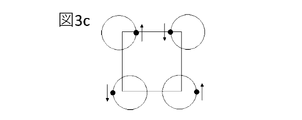
あるいは、ジャイロスコープは、駆動トランスデューサが試験質量111~114/211~214を同時に作動させて第1の振動モードおよび第2の振動モードの両方にする周波数変調ジャイロスコープとして動作してもよい。振動振幅は、第1の振動モードおよび第2の振動モードにおいて実質的に同じであってもよく、結果、駆動トランスデューサは、各試験質量を実質的に円形の運動に作動させる。当該運動は、各々が振動周期における位相を示している図3a~図3dに示されている。各試験質量の質量中心は点で示されており、当該点の配置は、各試験質量の円運動を他の試験質量の円運動とどのように同期させることができるかを示している。 Alternatively, the gyroscope may operate as a frequency modulated gyroscope in which the drive transducer simultaneously actuates the proof masses 111-114/211-214 into both the first and second modes of vibration. The vibration amplitude may be substantially the same in the first vibration mode and the second vibration mode, such that the drive transducers actuate each proof mass into substantially circular motion. The motion is illustrated in Figures 3a-3d, each showing the phase in the oscillation period. The center of mass of each proof mass is indicated by a dot, and the placement of the dots indicates how the circular motion of each proof mass can be synchronized with the circular motion of the other proof masses.
円運動の方向および振動および振動周波数は、各試験質量について同じである。ジャイロスコープが角回転を受けると、コリオリの力は円運動の振動周波数を減少または増加させる。 The direction of circular motion and vibration and vibration frequency are the same for each proof mass. As the gyroscope undergoes angular rotation, the Coriolis force decreases or increases the vibration frequency of the circular motion.
第1の振動モードおよび第2の振動モードがわずかに異なる共振周波数を有する場合、ジャイロスコープをリサジューモードパターンで動作させることも可能である。 It is also possible to operate the gyroscope in a Lissajous mode pattern if the first and second vibration modes have slightly different resonant frequencies.
同期4質量設計の主な利点は、加速効果に対する非感受性である。当該ロバスト性は、2つの手段によって達成される。すなわち、第1に、加速が、結合構造によって機械的に抑制される同相質量運動をもたらす。第2に、質量変位が、4つの質量から差動的に測定される。センストランスデューサは、差動検知において同相運動が相殺される間に逆相運動を合成するように構成される。 A major advantage of the synchronous four-mass design is its insensitivity to acceleration effects. Such robustness is achieved by two means. First, acceleration results in in-phase mass motion that is mechanically constrained by the coupling structure. Second, mass displacement is measured differentially from the four masses. The sense transducers are configured to synthesize anti-phase motion while in-phase motion cancels in differential sensing.
ジャイロスコープが振幅変調ジャイロスコープとして動作する場合、第1の振動モードと第2の振動モードとが独立しているということは、高振幅駆動振動が低振幅センス振動モードにおいて誤った測定信号を引き起こさないことを意味する。ジャイロスコープが周波数変調ジャイロスコープとして動作する場合、第1の振動モードと第2の振動モードとが独立しているということは、試験質量が、信頼できる周波数測定に特に適した円形またはリサジューパターンで確実に駆動され得ることを意味する。 When the gyroscope operates as an amplitude modulated gyroscope, the independence of the first and second vibration modes means that high amplitude drive vibrations can cause erroneous measurement signals in low amplitude sense vibration modes. means no. When the gyroscope operates as a frequency-modulated gyroscope, the independence of the first and second modes of vibration means that the proof mass can be arranged in a circular or Lissajous pattern that is particularly suitable for reliable frequency measurements. It means that it can be reliably driven.
図4aは、ジャイロスコープを示し、参照符号401~404、411~414、421~424および431~434がそれぞれ図1a~図1cの参照符号101~104、111~114、121~124および131~134に対応する。図4aはまた、第1の試験質量411に隣接する第1のアンカー点のセット491~494、および他の3つの試験質量の各々に隣接する対応するアンカー点のセットを示す。図4aはまた、x軸結合要素441~448およびy軸結合要素451~458を示す。
FIG. 4a shows a gyroscope, reference numerals 401-404, 411-414, 421-424 and 431-434 respectively referring to FIGS. 134. FIG. 4a also shows a first set of anchor points 491-494 adjacent the
図示されているジャイロスコープにおいて、第1のアンカー点のセットは、第1の試験質量の周りに対称に配置された4つの第1のアンカー点からなり、第2のアンカー点のセットは、第2の試験質量の周りに対称に配置された4つの第2のアンカー点からなり、第3のアンカー点のセットは、第3の試験質量の周りに対称に配置された4つの第3のアンカー点からなり、第4のアンカー点のセットは、第4の試験質量の周りに対称に配置された4つの第4のアンカー点からなる。 In the illustrated gyroscope, the first set of anchor points consists of four first anchor points arranged symmetrically around the first proof mass, and the second set of anchor points consists of the first The set of 3rd anchor points consists of 4 2nd anchor points symmetrically arranged about 2 proof masses, and the 3rd set of anchor points consists of 4 3rd anchor points symmetrically arranged about 3rd proof mass. points, and the set of fourth anchor points consists of four fourth anchor points symmetrically arranged around the fourth proof mass.
対応する第1のアンカー点のセット、第2のアンカー点のセット、第3のアンカー点のセット、および第4のアンカー点のセットから第1の試験質量、第2の試験質量、第3の試験質量、および第4の試験質量を懸架する1つまたは複数の懸架構造の各々は、対応する試験質量の横方向に対向する両側に2つのx軸懸架構造を含む。各x軸懸架構造は、上記x軸結合要素のうちの1つと、横方向に可撓性であるx軸懸架ばねとを備える。対応する第1のアンカー点のセット、第2のアンカー点のセット、第3のアンカー点のセット、および第4のアンカー点のセットから第1の試験質量、第2の試験質量、第3の試験質量、および第4の試験質量を懸架する1つまたは複数の懸架構造の各々はまた、試験質量の交差方向に対向する両側に2つのy軸懸架構造も含む。各y軸懸架構造は、上記y軸結合要素のうちの1つと、交差方向に可撓性であるy軸懸架ばねとを備える。 The first proof mass, the second proof mass, the third Each of the proof mass and the one or more suspension structures suspending the fourth proof mass includes two x-axis suspension structures on laterally opposite sides of the corresponding proof mass. Each x-axis suspension structure comprises one of the x-axis coupling elements and an x-axis suspension spring that is laterally flexible. The first proof mass, the second proof mass, the third The proof mass and the one or more suspension structures that suspend the fourth proof mass each also include two y-axis suspension structures on opposite transversely opposite sides of the proof mass. Each y-suspension structure comprises one of the y-axis coupling elements and a y-suspension spring that is transversely flexible.
言い換えれば、図4では、x軸およびy軸結合要素は、対応するアンカー点のセットから試験質量を懸架し、試験質量の重量を支持する懸架構造の一部を形成する。中央および周縁逆相結合構造は、当該例では、懸架構造の一部を形成する横方向および交差方向延長要素(481~484)に接続されている。 In other words, in FIG. 4, the x-axis and y-axis coupling elements suspend the proof mass from corresponding sets of anchor points and form part of the suspension structure that supports the weight of the proof mass. The central and peripheral reversed-phase coupling structures are connected in this example to laterally and transversely extending elements (481-484) forming part of the suspension structure.
図4aの対応するアンカー点のセット(491~494)から第1の試験質量411を懸架する1つまたは複数の懸架構造は、2つのx軸懸架構造および2つのy軸懸架構造を含む。x軸懸架構造は、横方向に可撓性であるが交差方向に剛性であるx軸懸架ばね(461、462)を備える。図4aでは、当該x軸懸架ばね(461、462)は、対応する試験質量(411)の横方向に対向する両側に位置するが、これはすべての実施形態において必要な特徴ではない。各x軸懸架ばねは、対応するアンカー点(491、492)から対応する横方向延長要素(481、482)まで延在する。x軸主ばね(461、462)が接続される2つのアンカー点(491、492)は、必ずしもそうである必要はないが、対応する試験質量(411)の横方向に対向する両側に位置することができる。同様に、x軸主ばねが接続される横方向延長要素(481、482)は、必ずしもそうである必要はないが、対応する試験質量の横方向に対向する両側に位置することができる。横方向延長要素は、横方向および交差方向の両方において剛性であることができる。
The suspension structure or structures that suspend the
試験質量411を懸架するy軸懸架構造は、交差方向には可撓性であるが、横方向には剛性であるy軸懸架ばね(471、472)を備える。当該y軸懸架ばね(471、472)は、対応する試験質量(411)の交差方向に対向する両側に位置するが、これはすべての実施形態において必要な特徴ではない。各y軸懸架ばねは、対応するアンカー点(493、494)から対応する交差方向延長要素(483、484)まで延在する。y軸主ばね(471、472)が接続される2つのアンカー点(493、494)は、必ずしもそうである必要はないが、対応する試験質量(411)の交差方向に対向する両側に位置することができる。同様に、y軸主ばねが接続される交差方向延長要素(483、484)は、必ずしもそうである必要はないが、対応する試験質量(411)の交差方向に対向する両側に位置することができる。交差方向延長要素は、横方向および交差方向の両方において剛性であることができる。x軸およびy軸懸架構造に関する上記の考慮事項は、図4aに示すすべての試験質量411~414に適用される。
The y-suspension structure that suspends the
各x軸懸架構造が横方向に可撓性であるが交差方向に剛性であり、各y軸懸架構造が交差方向に可撓性であるが横方向に剛性である、図4aに示す懸架構造の技術的利点は、図1aに示す第1の振動モードが、懸架構造を介して図2aに示す第2の振動モードにも結合されないことである。したがって、試験質量は、第1の振動モードが第2の振動モードから独立したままであることを可能にするようにアンカー点から懸架される。前述のように、これは、振幅変調ジャイロスコープにおけるセンス振動モードおよび周波数変調ジャイロスコープにおける円形またはリサジュー駆動振動の正確な測定を容易にする。 The suspension structure shown in FIG. 4a, wherein each x-axis suspension structure is transversely flexible but transversely rigid and each y-axis suspension structure is transversely flexible but transversely rigid. A technical advantage of is that the first vibration mode shown in FIG. 1a is also not coupled to the second vibration mode shown in FIG. 2a through the suspension structure. The proof mass is thus suspended from the anchor point to allow the first vibration mode to remain independent from the second vibration mode. As previously mentioned, this facilitates accurate measurement of sense vibration modes in amplitude modulated gyroscopes and circular or Lissajous driven vibrations in frequency modulated gyroscopes.
図4aにおいて、各中央x軸逆相構造(421、422)および各中央y軸逆相構造(423、424)は、中央長尺バーを有する面内シーソーを備え、中央長尺バーは、中央長尺バーがデバイス平面に垂直な軸を中心にデバイス平面内で回転することを可能にする少なくとも1つの中央シーソー懸架装置を用いて少なくとも1つの中央アンカー点から懸架されている。各周縁x軸逆相構造(433、434)および各周縁y軸逆相構造(431、432)もまた、周縁長尺バーを有する面内シーソーを備え、周縁長尺バーは、周縁長尺バーがデバイス平面に垂直な軸を中心にデバイス平面内で回転することを可能にする少なくとも1つの周縁シーソー懸架装置を用いて少なくとも1つの周縁アンカー点から懸架されている。しかしながら、面内シーソーではない代替的な周縁逆相構造も使用することができる。 In FIG. 4a, each central x-axis reversed-phase structure (421, 422) and each central y-axis reversed-phase structure (423, 424) comprises an in-plane seesaw with a central elongated bar, the central elongated bar An elongated bar is suspended from at least one central anchor point using at least one central seesaw suspension that allows rotation in the device plane about an axis normal to the device plane. Each peripheral x-axis reversed-phase structure (433, 434) and each peripheral y-axis reversed-phase structure (431, 432) also comprises an in-plane seesaw with a perimeter elongated bar, the perimeter elongated bar is suspended from at least one peripheral anchor point using at least one peripheral seesaw suspension that allows it to rotate in the device plane about an axis normal to the device plane. However, alternative peripheral reversed-phase structures that are not in-plane seesaws can also be used.
図4aは、各周縁シーソー懸架装置-周縁アンカー点対を参照符号499によって示す。周縁アンカー点から懸架されている周縁長尺バーは、符号4311、4321、4331、および4341によって示されている。図4aはまた、各中央シーソー懸架装置-中央アンカー点対を参照符号498によって示す。中央アンカー点から懸架されている中央長尺バーは、符号4211、4221、4231、および4241によって示されている。各周縁および中央シーソー懸架装置は、懸架されたバーが下記の図4bおよび図4cに示すようにデバイス平面内で回転することを可能にする任意の種類のばねシステムであってもよい。
FIG. 4 a indicates each peripheral seesaw suspension-peripheral anchor point pair by
すべての部品が図4aで符号を付された部品に対応する図4bは、第1の振動モードにおける中央および周縁x軸逆相構造の同期作用を示す。また、図4bは、うちいくつかが図4aにおいて参照符号451~458を用いてマークされているy軸結合要素が、第1の振動モードにおいて試験質量の運動を柔軟に吸収し、結果、第1の振動モードでは運動エネルギーがほとんど交差方向延長要素(483、484など)に伝達されず、y軸懸架構造およびy軸逆相構造に向かって伝達される様子も示されている。y軸結合要素は、当該事例において、交差方向延長要素(483、484)から対応する試験質量(411)内の突出部の両側へと延伸するばねである。交差方向延長要素(483、484)は、この両側取り付けを容易にするように寸法決めされている。しかしながら、y軸結合要素は、逆相結合構造と試験質量との間に可撓性および剛性の前述の組み合わせを生成する任意の種類のばね構成であってもよい。上記の考慮事項は、441~448などのx軸結合要素および横方向延長要素(481、482)にも適用される。
FIG. 4b, in which all parts correspond to those labeled in FIG. 4a, shows the synchronous behavior of the central and peripheral x-axis out-of-phase structures in the first vibration mode. Figure 4b also shows that the y-axis coupling elements, some of which are marked with reference numerals 451-458 in Figure 4a, flexibly absorb the motion of the proof mass in the first vibration mode, resulting in It is also shown how little kinetic energy is transferred to the cross-direction extension elements (483, 484, etc.) in
ここでも、すべての図示されている部品が図4aで符号を付された部品に対応する図4cは、第2の振動モードにおける中央および周縁y軸逆相構造の同期作用を示す。また、図4cは、うちいくつかが図4bにおいて参照符号441~448を用いてマークされているx軸結合要素が、第2の振動モードにおいて試験質量の運動を柔軟に吸収し、結果、第2の振動モードでは運動エネルギーがほとんど横方向延長要素(481、482など)に伝達されず、x軸懸架構造およびx軸逆相構造に向かって伝達される様子も示されている。 Again, Figure 4c, in which all illustrated parts correspond to those labeled in Figure 4a, shows the synchronous behavior of the central and peripheral y-axis antiphase structures in the second vibration mode. FIG. 4c also shows that the x-axis coupling elements, some of which are marked with reference numerals 441-448 in FIG. It is also shown how little kinetic energy is transferred to the laterally extending elements (481, 482, etc.) in vibration mode 2, but is transferred towards the x-axis suspension structure and the x-axis anti-phase structure.
図5は、圧電トランスデューサを用いて駆動することができるジャイロスコープを示す。参照符号501~504、511、5211~5241、5311~5341、541~542、551~552、561~562、571~572、581~584、591~594および598~599は、参照符号401~404、411、4211~4241、4311~4341、441~442、451~452、461~462、471~472、481~484、491~494および498~499に対応する。 FIG. 5 shows a gyroscope that can be driven with piezoelectric transducers. Reference numerals 501-504, 511, 5211-5241, 5311-5341, 541-542, 551-552, 561-562, 571-572, 581-584, 591-594 and 598-599 refer to reference numerals 401-404 , 411, 4211-4241, 4311-4341, 441-442, 451-452, 461-462, 471-472, 481-484, 491-494 and 498-499.
x軸懸架ばね561~562は、試験質量の横方向に対向する両側に沿って対応する第1のアンカー点591~592から交差方向に延在する。他方、y軸懸架ばね571~572は、試験質量の交差方向に対向する両側に沿って対応する第1のアンカー点593~594から横方向に延在する。図5では、第1のアンカー点591~592は、当該事例において、第1の横軸501上に位置合わせされていなくてもよく、第1のアンカー点593~594は、第1の交差軸503上に位置合わせされていなくてもよいことが分かる。試験質量の各側に1つまたは複数の平行なx軸/y軸懸架ばねがあってもよい。図5は、各側に2つのx軸/y軸懸架ばねを有するデバイスを示す。
The x-axis suspension springs 561-562 extend transversely from corresponding first anchor points 591-592 along laterally opposite sides of the proof mass. On the other hand, the y-axis suspension springs 571-572 extend laterally from corresponding first anchor points 593-594 along opposite sides of the proof mass in the transverse direction. In FIG. 5, the first anchor points 591-592 may not be aligned on the first
圧電トランスデューサは、x軸懸架ばね561~562およびy軸懸架ばね571~572上に構築することができる。当該トランスデューサは、上記懸架ばねをデバイス平面内で曲げて横方向および交差方向の駆動力を発生させるために使用することができ、または、試験質量511の横方向および交差方向の動きを測定するために使用することができる。
The piezoelectric transducers can be built on the x-axis suspension springs 561-562 and the y-axis suspension springs 571-572. The transducers can be used to bend the suspension springs in the device plane to generate lateral and transverse driving forces, or to measure the lateral and transverse movements of the
1つまたは複数の懸架構造の各々は、x軸懸架ばね上の少なくとも1つの圧電トランスデューサと、y軸懸架ばね上の少なくとも1つの圧電トランスデューサとを備えることができる。 Each of the one or more suspension structures may comprise at least one piezoelectric transducer on the x-axis suspension spring and at least one piezoelectric transducer on the y-axis suspension spring.
横方向延長要素581~582は、当該事例において、試験質量の交差方向に対向する両側に沿って横方向に延在する剛性バーである。横方向延長要素は、x軸懸架ばね561~562と試験質量511との間で横方向の力を伝達する。同様に、交差方向延長要素583~584は、試験質量の横方向に対向する両側に沿って交差方向に延在する剛性バーである。交差方向延長要素は、y軸懸架ばね571~572と試験質量511との間で交差方向の力を伝達する。
The laterally extending elements 581-582 are in the present case rigid bars extending laterally along the transversely opposite sides of the proof mass. Lateral extension elements transmit lateral forces between x-axis suspension springs 561 - 562 and
x軸懸架ばね(561~562)およびy軸懸架ばね(571~572)は、図5に短く細いバーとして示されている屈曲部を有する対応する横方向/交差方向懸架ばね(581~584)に取り付けることができる。当該屈曲部が取り付け点において提供する可撓性は、x軸およびy軸懸架ばねが、ばねの実質的に全長に沿って均一な湾曲を有する片持ち梁ばねとして曲がることを可能にする。x軸懸架ばねおよびy軸懸架ばねは、両端において固定アタッチメントを用いてクランプされる場合、S字形状に曲がる。 The x-axis suspension springs (561-562) and y-axis suspension springs (571-572) have corresponding lateral/cross suspension springs (581-584) with bends shown as short thin bars in FIG. can be attached to The flexibility that the flexures provide at the attachment point allows the x-axis and y-axis suspension springs to flex as cantilever springs with uniform curvature along substantially the entire length of the spring. The x-axis and y-axis suspension springs bend in an S shape when clamped with fixed attachments at both ends.
各横方向延長要素(581~582)は、1つまたは複数のx軸結合要素(541~542)によって試験質量に取り付けることができる。各交差方向延長要素(583~584)は、1つまたは複数のy軸結合要素(551~552)によって試験質量に取り付けることができる。x軸結合要素は、例えば、交差方向に可撓性であるように構成されたボックスばねであってもよく、y軸結合要素は、横方向に可撓性であるように構成されたボックスばねであってもよい。 Each lateral extension element (581-582) may be attached to a proof mass by one or more x-axis coupling elements (541-542). Each transverse extension element (583-584) may be attached to a proof mass by one or more y-axis coupling elements (551-552). The x-axis coupling element may, for example, be a box spring configured to be flexible in the cross direction, and the y-axis coupling element may be a box spring configured to be flexible in the lateral direction. may be
各周縁長尺バー(5311、321、5331、5341)は、試験質量を囲む横方向/交差方向延長要素(581~584)を介して対応する試験質量に結合することができる。同様に、各中央長尺バー(5211、221、5231、5241)は、横方向/交差方向延長要素(581~584)を介して対応する試験質量に結合することができる。 Each peripheral elongate bar (5311, 321, 5331, 5341) can be coupled to a corresponding proof mass via lateral/cross extension elements (581-584) surrounding the proof mass. Similarly, each central elongated bar (5211, 221, 5231, 5241) can be coupled to a corresponding proof mass via lateral/cross extension elements (581-584).
図6は、容量性力トランスデューサを用いてジャイロスコープをどのように駆動することができるかを示す。図示されたデバイス部品は、図4aに示されたデバイス部品に対応する。図6に示す追加のデバイス部品は、ステータフィンガ電極(612など)のセットと互いに噛み合うロータフィンガ電極(611など)のセットを備える力トランスデューサを含む。ロータフィンガ電極611の各セットは、交差方向延長要素683などの可動デバイス部品に取り付けられる。ステータフィンガ電極612の各セットは、隣接する固定構造に取り付けられている。力トランスデューサ611+612、および交差方向延長要素に取り付けられた他の力トランスデューサは、交差方向の試験質量運動を作動させることができ、および/または交差方向の隣接する試験質量の運動を測定することができる。横方向延長要素に取り付けられた力トランスデューサは、横方向の試験質量運動を作動させることができ、および/または横方向の隣接する試験質量の運動を測定することができる。
FIG. 6 shows how a gyroscope can be driven using a capacitive force transducer. The device parts shown correspond to the device parts shown in FIG. 4a. Additional device components shown in FIG. 6 include a force transducer comprising a set of rotor finger electrodes (such as 611) that intermesh with a set of stator finger electrodes (such as 612). Each set of
図4aおよび図5のように、図6の第1のアンカー点のセットは、第1の試験質量の周りに対称に配置された4つの第1のアンカー点からなり、第2のアンカー点のセットは、第2の試験質量の周りに対称に配置された4つの第2のアンカー点からなり、第3のアンカー点のセットは、第3の試験質量の周りに対称に配置された4つの第3のアンカー点からなり、第4のアンカー点のセットは、第4の試験質量の周りに対称に配置された4つの第4のアンカー点からなる。 As in FIGS. 4a and 5, the set of first anchor points in FIG. The set consists of four second anchor points symmetrically arranged around the second proof mass and the third anchor point set consists of four anchor points symmetrically arranged around the third proof mass. A third anchor point and a fourth set of anchor points consist of four fourth anchor points symmetrically arranged around the fourth proof mass.
対応する第1のアンカー点のセット、第2のアンカー点のセット、第3のアンカー点のセット、および第4のアンカー点のセットから第1の試験質量、第2の試験質量、第3の試験質量、および第4の試験質量を懸架する、図6の1つまたは複数の懸架構造の各々は、対応する試験質量の横方向に対向する両側に2つのx軸懸架構造を含む。各x軸懸架構造は、上記x軸結合要素(441、442)のうちの1つと、横方向に可撓性であるx軸懸架ばね(461、462)とを備える。対応する第1のアンカー点のセット、第2のアンカー点のセット、第3のアンカー点のセット、および第4のアンカー点のセットから第1の試験質量、第2の試験質量、第3の試験質量、および第4の試験質量を懸架する1つまたは複数の懸架構造の各々はまた、対応する試験質量の交差方向に対向する両側に2つのy軸懸架構造も含む。各y軸懸架構造は、上記y軸結合要素(451、452)のうちの1つと、交差方向に可撓性であるy軸懸架ばね(471、472)とを備える。 The first proof mass, the second proof mass, the third Each of the one or more suspension structures of FIG. 6 suspending the proof mass and the fourth proof mass includes two x-axis suspension structures on laterally opposite sides of the corresponding proof mass. Each x-axis suspension structure comprises one of said x-axis coupling elements (441, 442) and a laterally flexible x-axis suspension spring (461, 462). The first proof mass, the second proof mass, the third Each of the proof mass and the one or more suspension structures suspending the fourth proof mass also includes two y-axis suspension structures on opposite transversely opposite sides of the corresponding proof mass. Each y-suspension structure comprises one of said y-axis coupling elements (451, 452) and a y-axis suspension spring (471, 472) flexible in the transverse direction.
容量性力トランスデューサは、上述したように、横方向および交差方向延長要素に結合することができる。 Capacitive force transducers can be coupled to the lateral and transverse extension elements as described above.
図7は、ジャイロスコープを示し、参照符号711、721、723、731および733がそれぞれ図4aの参照符号411、4211、4231、4311および4331に対応する。
FIG. 7 shows a gyroscope, with
図7に示されているジャイロスコープでは、第1のアンカー点のセットは第1の試験質量の中央開口部内にあり、第2のアンカー点のセットは第2の試験質量の中央開口部内にあり、第3のアンカー点のセットは第3の試験質量の中央開口部内にあり、第4のアンカー点のセットは第4の試験質量の中央開口部内にある。 In the gyroscope shown in FIG. 7, the first set of anchor points are within the central opening of the first proof mass and the second set of anchor points are within the central opening of the second proof mass. , the third set of anchor points is in the central opening of the third proof mass and the fourth set of anchor points is in the central opening of the fourth proof mass.
対応する第1のアンカー点のセット、第2のアンカー点のセット、第3のアンカー点のセット、および第4のアンカー点のセットから第1の試験質量、第2の試験質量、第3の試験質量、および第4の試験質量を懸架する1つまたは複数の懸架構造の各々は、対応するアンカー点のセットの横方向に対向する両側に2つのx軸懸架構造を含む。各x軸懸架構造は、横方向に可撓性であるx軸懸架ばねを備える。対応する第1のアンカー点のセット、第2のアンカー点のセット、第3のアンカー点のセット、および第4のアンカー点のセットから第1の試験質量、第2の試験質量、第3の試験質量、および第4の試験質量を懸架する1つまたは複数の懸架構造の各々はまた、対応するアンカー点のセットの交差方向に対向する両側に2つのy軸懸架構造も含む。各y軸懸架構造は、交差方向に可撓性であるy軸懸架ばねを備える。 The first proof mass, the second proof mass, the third Each of the proof mass and the one or more suspension structures suspending the fourth proof mass includes two x-axis suspension structures on laterally opposite sides of the corresponding set of anchor points. Each x-axis suspension structure comprises an x-axis suspension spring that is laterally flexible. The first proof mass, the second proof mass, the third Each of the proof mass and the one or more suspension structures suspending the fourth proof mass also includes two y-axis suspension structures on transversely opposite sides of the corresponding set of anchor points. Each y-suspension structure comprises a y-suspension spring that is flexible in the transverse direction.
各x軸懸架構造は、対応するアンカー点から対応するx軸懸架ばねまで延在する1つまたは複数の横方向バーをさらに備える。各y軸懸架構造は、対応するアンカー点から対応するy軸懸架ばねまで延在する1つまたは複数の交差方向バーをさらに備える。1つまたは複数の懸架構造の各々は、横方向バー上の少なくとも1つの圧電トランスデューサと、交差方向バー上の少なくとも1つの圧電トランスデューサとを備える。 Each x-axis suspension structure further comprises one or more transverse bars extending from corresponding anchor points to corresponding x-axis suspension springs. Each y-axis suspension structure further comprises one or more cross direction bars extending from corresponding anchor points to corresponding y-axis suspension springs. Each of the one or more suspension structures comprises at least one piezoelectric transducer on the transverse bars and at least one piezoelectric transducer on the transverse bars.
図7では、第1のアンカー点のセットは、第1の試験質量711の開口部の中心に位置する1つの第1のアンカー点799を含む。第1の試験質量711が懸架される懸架構造は、横方向バーの第1のセット781と、第1の横方向に可撓性のx軸懸架ばね761とを含む第1のx軸懸架構造を含む。横方向バーの第1のセット781は、第1のアンカー点799から第1のx軸懸架ばね761まで第1の横方向に延在する。第1のx軸懸架ばね761は、横方向バーの第1のセット781から試験質量711まで延在する。横方向バーの第1のセット781は、交差方向に可撓性の屈曲部785を用いて第1のx軸懸架ばね761に取り付けることができる。当該屈曲部が取り付け点において提供する可撓性は、横方向バー781が、ばねの実質的に全長に沿って均一な湾曲を有する片持ち梁ばねとして曲がることを可能にする。横方向バーは、両端において固定アタッチメントを用いてクランプされる場合、S字形状に曲がる。
In FIG. 7 , the set of first anchor points includes one
第1の試験質量711が懸架される懸架構造はまた、横方向バーの第2のセット782と、第2の横方向に可撓性のx軸懸架ばね762とを含む第2のx軸懸架構造をも含む。横方向バーの第2のセット782は、第1のアンカー点799から第2のx軸懸架ばね762まで第1の横方向と反対の第2の横方向に延在する。第2のx軸懸架ばね762は、横方向バーの第2のセット782から試験質量711まで延在する。横方向バーの第2のセット782はまた、上述の機能を果たす交差方向に可撓性の屈曲部785を用いて第2のx軸懸架ばね762に取り付けられてもよい。
The suspension structure on which the
第1の試験質量711が懸架される懸架構造はまた、交差方向バーの第1のセット791および第1の交差方向に可撓性のy軸懸架ばね771を含む第1のy軸懸架構造と、交差方向バーの第2のセット792および第2の交差方向に可撓性のy軸懸架ばね772を含む第2のy軸懸架構造とを含む。交差方向バーの第1のセット791は、第1のアンカー点799から第1のy軸懸架ばね771まで第1の交差方向に延在し、交差方向バーの第2のセット792は、第1のアンカー点799から第2のy軸懸架ばね772まで第1の交差方向とは反対の第2の交差方向に延在する。
The suspension structure from which the
第1のy軸懸架ばね771は、交差方向バーの第1のセット791から試験質量711まで延在し、第2のy軸懸架ばね772は、交差方向バーの第2のセット792から試験質量711まで延在する。交差方向バーの当該セット791~792の各々は、横方向に可撓性の屈曲部786を用いて、対応するy軸懸架ばね771~772に取り付けることができる。前述のように、当該屈曲部が取り付け点においてもたらす可撓性は、交差方向バー791~792が片持ち梁ばねとして曲がることを可能にする。
A first y-
あるいは、第1のアンカー点のセットは、複数の第1のアンカー点を含んでもよい。各横方向バー781~782および交差方向バー791~792は、それ自体の第1のアンカー点を有することができる。第1の横方向バー781の数は、例えば、1つであってもよく、2つであってもよく、または2つより多くてもよい。第2の横方向バー782の数は、同様に、1つであってもよく、2つであってもよく、または2つより多くてもよい。第1の交差方向バー791の数は、例えば、1つであってもよく、2つであってもよく、または2つより多くてもよく、第2の横方向バー792の数は、同様に、1つ、2つ、または2つより多くてもよい。
Alternatively, the set of first anchor points may include multiple first anchor points. Each lateral bar 781-782 and cross bar 791-792 can have its own first anchor point. The number of first
圧電トランスデューサは、横方向バー781~782および交差方向バー791~792上に構築することができる。横方向バー781~782は、交差方向の可撓性を有するように寸法決めされており、横方向バー上のトランスデューサによって生成される力は、横方向バーを曲げることができ、試験質量の動きによって生成される曲げを、バー上のトランスデューサによって測定することができる。対応して、交差方向バー791~792は、横方向の可撓性を有するように寸法決めされる。言い換えれば、トランスデューサは、上記懸架ばねをデバイス平面内で曲げて横方向および交差方向の駆動力を発生させるために使用することができ、または、試験質量711の横方向および交差方向の動きを測定するために使用することができる。
Piezoelectric transducers can be built on the lateral bars 781-782 and cross bars 791-792. The transverse bars 781-782 are dimensioned to be flexible in the transverse direction so that forces generated by transducers on the transverse bars can bend the transverse bars, resulting in motion of the proof mass. can be measured by a transducer on the bar. Correspondingly, the transverse bars 791-792 are dimensioned for lateral flexibility. In other words, transducers can be used to bend the suspension springs in the device plane to generate lateral and transverse driving forces, or to measure lateral and transverse motion of
周縁x軸逆相構造733および中央x軸逆相構造721は、それぞれx軸結合要素741および742を介して試験質量711に直接結合される。当該x軸結合要素は、それぞれの逆相構造から試験質量711まで延在する。x軸結合要素741および742は、当該事例において、横方向に配向された長尺バーであってもよい。x軸結合要素の(横方向の)長さ/(交差方向の)幅のアスペクト比は、長尺バーに交差方向の可撓性を与えるのに十分な大きさである。他方、x軸結合要素741および742は、中央x軸逆相構造721および周縁x軸逆相構造733の横方向のプッシュ/プル運動を試験質量711に堅固に伝達する。
Peripheral x-axis reversed-
対応して、周縁y軸逆相構造731および中央y軸逆相構造731は、それぞれy軸結合要素751および752を介して試験質量711に直接結合される。当該y軸結合要素は、それぞれの逆相構造から試験質量711まで延在する。y軸結合要素751および752は、交差方向に配向された長尺バーであってもよい。y軸結合要素の(交差方向の)長さ/(横方向の)幅のアスペクト比は、長尺バーに横方向の可撓性を与えるのに十分な大きさである。他方、y軸結合要素751および752は、中央y軸逆相構造723および周縁y軸逆相構造731の交差方向のプッシュ/プル運動を試験質量711に堅固に伝達する。
Correspondingly, peripheral y-axis reversed-
各中央x軸逆相構造(721)および各中央y軸逆相構造(723)は、中央長尺バーを有する面内シーソーを備え、中央長尺バーは、中央長尺バーがデバイス平面に垂直な軸を中心にデバイス平面内で回転することを可能にする少なくとも1つの中央シーソー懸架装置を用いて少なくとも1つの中央アンカー点から懸架されている。各周縁x軸逆相構造(733)および各周縁y軸逆相構造(731)もまた、周縁長尺バーを有する面内シーソーを備え、周縁長尺バーは、周縁長尺バーがデバイス平面に垂直な軸を中心にデバイス平面内で回転することを可能にする少なくとも1つの周縁シーソー懸架装置を用いて少なくとも1つの周縁アンカー点から懸架されている。しかしながら、面内シーソーではない代替的な周縁逆相構造も使用することができる。 Each central x-axis reversed-phase structure (721) and each central y-axis reversed-phase structure (723) comprises an in-plane seesaw with a central elongated bar such that the central elongated bar is perpendicular to the plane of the device. suspended from at least one central anchor point using at least one central seesaw suspension that allows rotation in the plane of the device about an axis. Each peripheral x-axis out-of-phase structure (733) and each peripheral y-axis out-of-phase structure (731) also comprises an in-plane seesaw with a perimeter elongated bar, the perimeter elongated bar being in the plane of the device. Suspended from at least one peripheral anchor point using at least one peripheral seesaw suspension that allows rotation in the plane of the device about a vertical axis. However, alternative peripheral reversed-phase structures that are not in-plane seesaws can also be used.
第1の試験質量711の懸架、ならびに中央および周縁逆相構造と試験質量711との間の結合に関する上記考慮事項はすべて、図7に見られるように、他の試験質量712~714の懸架/結合にも当てはまる。各x軸およびy軸懸架構造における交差方向および横方向の可撓性の組み合わせは、各試験質量が第2の振動モードにおける試験質量の振動とは無関係に第1の振動モードで振動することを可能にし、逆もまた同様である。x軸結合要素741および742の交差方向の可撓性ならびにy軸結合要素751および752の横方向の可撓性は、両方のモードが振動する4質量システムにわたって同期している場合でも、各試験質量の第1の振動モードが当該試験質量の第2の振動モードから独立したままであることを保証する。
All of the above considerations regarding the suspension of the
Claims (5)
前記第1の試験質量および前記第2の試験質量は、第1の中央x軸逆相結合構造を用いて互いに結合され、前記第1の中央x軸逆相結合構造は、前記第1の試験質量および前記第2の試験質量の反対の横方向における同時運動を柔軟に可能にするが、前記第1の試験質量および前記第2の試験質量の同じ交差方向における同時運動には剛性に抵抗し、
前記第3の試験質量および前記第4の試験質量は、第2の中央x軸逆相結合構造を用いて互いに結合され、前記第2の中央x軸逆相結合構造は、前記第3の試験質量および前記第4の試験質量の反対の横方向における同時運動を柔軟に可能にするが、前記第3の試験質量および前記第4の試験質量の同じ横方向における同時運動には剛性に抵抗し、
前記第1の試験質量および前記第3の試験質量は、第1の中央y軸逆相結合構造を用いて互いに結合され、前記第1の中央y軸逆相結合構造は、前記第1の試験質量および前記第3の試験質量の反対の交差方向における同時運動を柔軟に可能にするが、前記第1の試験質量および前記第3の試験質量の同じ交差方向における同時運動には剛性に抵抗し、
前記第2の試験質量および前記第4の試験質量は、第2の中央y軸逆相結合構造を用いて互いに結合され、前記第2の中央y軸逆相結合構造は、前記第2の試験質量および前記第4の試験質量の反対の交差方向における同時運動を柔軟に可能にするが、前記第2の試験質量および前記第4の試験質量の同じ交差方向における同時運動には剛性に抵抗し、
前記第1の試験質量および前記第2の試験質量は、第1の周縁y軸逆相結合構造を用いて互いに結合され、前記第1の周縁y軸逆相結合構造は、前記第1の試験質量および前記第2の試験質量の反対の交差方向における同時運動を柔軟に可能にするが、前記第1の試験質量および前記第2の試験質量の同じ交差方向における同時運動には堅固に抵抗し、
第3の試験質量および第4の試験質量は、第2の周縁y軸逆相結合構造を用いて互いに結合され、第2の周縁y軸逆相結合構造は、第3の試験質量および第4の試験質量の反対の交差方向における同時運動を柔軟に可能にするが、第3の試験質量および第4の試験質量の同じ交差方向における同時運動には堅固に抵抗し、
第1の試験質量および第3の試験質量は、第1の周縁x軸逆相結合構造を用いて互いに結合され、第1の周縁x軸逆相結合構造は、第1の試験質量および第3の試験質量の反対の横方向における同時運動を柔軟に可能にするが、第1の試験質量および第3の試験質量の同じ横方向における同時運動には堅固に抵抗し、
前記第2の試験質量および前記第4の試験質量は、第2の周縁x軸逆相結合構造を用いて互いに結合され、前記第2の周縁x軸逆相結合構造は、前記第2の試験質量および前記第4の試験質量の反対の横方向における同時運動を柔軟に可能にするが、前記第2の試験質量および前記第4の試験質量の同じ横方向における同時運動には剛性に抵抗し、
前記ジャイロスコープは、前記第1の試験質量に隣接する第1のアンカー点のセットと、前記第2の試験質量に隣接する第2のアンカー点のセットと、前記第3の試験質量に隣接する第3のアンカー点のセットと、前記第4の試験質量に隣接する第4のアンカー点のセットとをさらに備え、前記第1の試験質量、前記第2の試験質量、前記第3の試験質量および前記第4の試験質量の各々は、1つまたは複数の懸架構造によって前記第1のアンカー点、前記第2のアンカー点、前記第3のアンカー点および前記第4のアンカー点の対応するセットから懸架されており、
各中央x軸逆相結合構造および周縁x軸逆相結合構造は、交差方向に可撓性であり、横方向に剛性であるx軸結合要素を用いて対応する前記試験質量に結合され、各中央y軸逆相結合構造および周縁y軸逆相結合構造は、横方向に可撓性であり、交差方向に剛性であるy軸結合要素を用いて対応する前記試験質量に結合されること、および
各中央x軸逆相構造および各中央y軸逆相構造は、中央長尺バーを有する面内シーソーを備え、前記中央長尺バーは、前記中央長尺バーが前記デバイス平面に垂直な軸を中心に前記デバイス平面内で回転することを可能にする少なくとも1つの中央シーソー懸架装置を用いて少なくとも1つの中央アンカー点から懸架されていることを特徴とする、ジャイロスコープ。 A gyroscope comprising a device plane in which a first horizontal axis and a second horizontal axis orthogonally intersect a first cross axis and a second cross axis, the gyroscope comprising a first proof mass, a second Also comprising two proof masses, a third proof mass and a fourth proof mass, wherein the first proof mass and the second proof mass are aligned on the first horizontal axis and the third test mass The mass and the fourth proof mass are aligned on the second horizontal axis, the first proof mass and the third proof mass are aligned on the first cross axis, and the second and the fourth proof mass are aligned on the second cross axis;
The first proof mass and the second proof mass are coupled together using a first central x-axis reversed-phase coupling structure, the first central x-axis reversed-phase coupling structure being coupled to the first test mass. flexibly permitting simultaneous movement of the mass and said second proof mass in opposite lateral directions, but rigidly resisting simultaneous movement of said first proof mass and said second proof mass in the same cross direction; ,
The third proof mass and the fourth proof mass are coupled together using a second central x-axis reversed-phase coupling structure, the second central x-axis reversed-phase coupling structure being coupled to the third test mass. flexibly permitting simultaneous movement of the mass and said fourth proof mass in opposite lateral directions, but rigidly resisting simultaneous movement of said third proof mass and said fourth proof mass in the same lateral direction; ,
The first proof mass and the third proof mass are coupled together using a first central y-axis reversed-phase coupling structure, the first central y-axis reversed-phase coupling structure being coupled to the first test mass. flexibly permitting simultaneous movement of the mass and said third proof mass in opposite cross directions, but rigidly resisting simultaneous movement of said first proof mass and said third proof mass in the same cross direction; ,
The second proof mass and the fourth proof mass are coupled together using a second central y-axis reversed-phase coupling structure, the second central y-axis reversed-phase coupling structure being coupled to the second test mass. flexibly permitting simultaneous movement of the mass and said fourth proof mass in opposite cross directions, but rigidly resisting simultaneous movement of said second proof mass and said fourth proof mass in the same cross direction; ,
The first proof mass and the second proof mass are coupled together using a first peripheral y-axis reversed-phase coupling structure, the first peripheral y-axis reversed-phase coupling structure being coupled to the first test flexibly permitting simultaneous movement of the mass and said second proof mass in opposite cross directions, but rigidly resisting simultaneous movement of said first proof mass and said second proof mass in the same cross direction; ,
The third proof mass and the fourth proof mass are coupled together using a second peripheral y-axis negative phase coupling structure, the second peripheral y-axis negative phase coupling structure connecting the third proof mass and the fourth proof mass. flexibly permits simultaneous movement in opposite cross directions of the proof masses of , but rigidly resists simultaneous movement in the same cross directions of the third and fourth proof masses;
The first proof mass and the third proof mass are coupled together using a first peripheral x-axis negative phase coupling structure, the first peripheral x-axis negative phase coupling structure connecting the first proof mass and the third proof mass. flexibly permit simultaneous movement in opposite lateral directions of the proof masses of, but rigidly resist simultaneous movement in the same lateral direction of the first and third proof masses,
The second proof mass and the fourth proof mass are coupled together using a second peripheral x-axis negative phase coupling structure, the second peripheral x-axis negative phase coupling structure being coupled to the second test mass. flexibly permitting simultaneous movement of the mass and said fourth proof mass in opposite lateral directions, but rigidly resisting simultaneous movement of said second proof mass and said fourth proof mass in the same lateral direction; ,
The gyroscope has a first set of anchor points adjacent to the first proof mass, a second set of anchor points adjacent to the second proof mass, and adjacent to the third proof mass. further comprising a third set of anchor points and a fourth set of anchor points adjacent to the fourth proof mass, wherein the first proof mass, the second proof mass, the third proof mass; and each of said fourth proof masses is anchored by one or more suspension structures to a corresponding set of said first anchor point, said second anchor point, said third anchor point and said fourth anchor point is suspended from
Each central x-axis negative-phase bonding structure and peripheral x-axis negative-phase bonding structure is coupled to the corresponding proof mass with a transversely flexible, laterally rigid x-axis bonding element, each a central y-axis reversed-phase bonding structure and a peripheral y-axis reversed-phase bonding structure coupled to corresponding said proof masses using laterally flexible, transversely rigid y-axis bonding elements; and each central x-axis reversed-phase structure and each central y-axis reversed-phase structure comprises an in-plane seesaw having a central elongated bar, said central elongated bar along an axis perpendicular to said device plane A gyroscope suspended from at least one central anchor point using at least one central seesaw suspension that allows it to rotate in the device plane about .
対応する前記第1のアンカー点のセット、前記第2のアンカー点のセット、前記第3のアンカー点のセット、および前記第4のアンカー点のセットから前記第1の試験質量、前記第2の試験質量、前記第3の試験質量、および前記第4の試験質量を懸架する前記1つまたは複数の懸架構造の各々は、対応する前記試験質量の横方向に対向する両側に2つのx軸懸架構造を含み、各x軸懸架構造は、前記x軸結合要素のうちの1つと、横方向に可撓性であるx軸懸架ばねとを備え、対応する前記第1のアンカー点のセット、前記第2のアンカー点のセット、前記第3のアンカー点のセット、および前記第4のアンカー点のセットから前記第1の試験質量、前記第2の試験質量、前記第3の試験質量、および前記第4の試験質量を懸架する前記1つまたは複数の懸架構造の各々は、前記試験質量の交差方向に対向する両側に2つのy軸懸架構造も含み、各y軸懸架構造は、前記y軸結合要素のうちの1つと、交差方向に可撓性であるy軸懸架ばねとを備えることを特徴とする、請求項1または2に記載のジャイロスコープ。 The first set of anchor points consists of four first anchor points symmetrically arranged about the first proof mass, and the second set of anchor points comprises the second proof mass. and said third set of anchor points consists of four third anchor points symmetrically arranged around said third proof mass. and said set of fourth anchor points consists of four fourth anchor points symmetrically arranged around said fourth proof mass;
from the corresponding first set of anchor points, the second set of anchor points, the third set of anchor points, and the fourth set of anchor points to the first proof mass, the second set of Each of the one or more suspension structures suspending the proof mass, the third proof mass, and the fourth proof mass has two x-axis suspensions on laterally opposite sides of the corresponding proof mass. structure, each x-axis suspension structure comprising one of said x-axis coupling elements and a laterally flexible x-axis suspension spring, and corresponding said first set of anchor points, said from the second set of anchor points, the third set of anchor points, and the fourth set of anchor points to the first proof mass, the second proof mass, the third proof mass, and the Each of the one or more suspension structures suspending a fourth proof mass also includes two y-axis suspension structures on opposite sides of the proof mass in the cross direction, each y-axis suspension structure 3. A gyroscope according to claim 1 or 2, characterized in that it comprises one of the coupling elements and a y-axis suspension spring which is transversely flexible.
対応する前記第1のアンカー点のセット、前記第2のアンカー点のセット、前記第3のアンカー点のセット、および前記第4のアンカー点のセットから前記第1の試験質量、前記第2の試験質量、前記第3の試験質量、および前記第4の試験質量を懸架する前記1つまたは複数の懸架構造の各々は、対応する前記アンカー点のセットの横方向に対向する両側に2つのx軸懸架構造を含み、各x軸懸架構造は、横方向に可撓性であるx軸懸架ばねを備え、対応する前記第1のアンカー点のセット、前記第2のアンカー点のセット、前記第3のアンカー点のセット、および前記第4のアンカー点のセットから前記第1の試験質量、前記第2の試験質量、前記第3の試験質量、および前記第4の試験質量を懸架する前記1つまたは複数の懸架構造の各々は、対応する前記アンカー点のセットの交差方向に対向する両側に2つのy軸懸架構造も含み、各y軸懸架構造は、交差方向に可撓性であるy軸懸架ばねを備え、
各x軸懸架構造は、対応する前記アンカー点から対応する前記x軸懸架ばねまで延在する1つまたは複数の横方向バーをさらに備え、各y軸懸架構造は、対応する前記アンカー点から対応する前記y軸懸架ばねまで延在する1つまたは複数の交差方向バーをさらに備え、前記1つまたは複数の懸架構造の各々は、横方向バー上の少なくとも1つの圧電トランスデューサと、交差方向バー上の少なくとも1つの圧電トランスデューサとを備えることを特徴とする、請求項1または2に記載のジャイロスコープ。 The first set of anchor points are within the central opening of the first proof mass, the second set of anchor points are within the central opening of the second proof mass, and the third anchor point is are within the central opening of the third proof mass, and the fourth set of anchor points are within the central opening of the fourth proof mass;
from the corresponding first set of anchor points, the second set of anchor points, the third set of anchor points, and the fourth set of anchor points to the first proof mass, the second set of Each of the one or more suspension structures suspending the proof mass, the third proof mass, and the fourth proof mass has two x's on laterally opposite sides of the corresponding set of anchor points. an axial suspension structure, each x-axis suspension structure comprising a laterally flexible x-axis suspension spring and corresponding said first set of anchor points, said second set of anchor points, said second set of a set of three anchor points, and suspending the first proof mass, the second proof mass, the third proof mass, and the fourth proof mass from the fourth set of anchor points; Each of the one or more suspension structures also includes two y-axis suspension structures on transversely opposite sides of the corresponding set of anchor points, each y-axis suspension structure being flexible in the transverse direction. Equipped with axial suspension springs,
Each x-axis suspension structure further comprises one or more transverse bars extending from the corresponding anchor point to the corresponding x-axis suspension spring, and each y-axis suspension structure extends from the corresponding anchor point to the corresponding x-axis suspension spring. one or more transverse bars extending to said y-axis suspension springs, each of said one or more suspension structures comprising: at least one piezoelectric transducer on transverse bars; 3. A gyroscope according to claim 1 or 2, characterized in that it comprises at least one piezoelectric transducer of .
Applications Claiming Priority (2)
| Application Number | Priority Date | Filing Date | Title |
|---|---|---|---|
| FI20206246 | 2020-12-03 | ||
| FI20206246 | 2020-12-03 |
Publications (2)
| Publication Number | Publication Date |
|---|---|
| JP2022089171A JP2022089171A (en) | 2022-06-15 |
| JP7205608B2 true JP7205608B2 (en) | 2023-01-17 |
Family
ID=78770394
Family Applications (1)
| Application Number | Title | Priority Date | Filing Date |
|---|---|---|---|
| JP2021191776A Active JP7205608B2 (en) | 2020-12-03 | 2021-11-26 | Synchronous 4-mass gyroscope |
Country Status (3)
| Country | Link |
|---|---|
| US (1) | US11624613B2 (en) |
| EP (1) | EP4008999B1 (en) |
| JP (1) | JP7205608B2 (en) |
Families Citing this family (1)
| Publication number | Priority date | Publication date | Assignee | Title |
|---|---|---|---|---|
| US11525680B2 (en) * | 2021-02-17 | 2022-12-13 | Nxp Usa, Inc. | Angular rate sensor with centrally positioned coupling structures |
Citations (4)
| Publication number | Priority date | Publication date | Assignee | Title |
|---|---|---|---|---|
| JP2008537114A (en) | 2005-04-14 | 2008-09-11 | アナログ デバイシス, インコーポレイテッド | 4 crossed longitudinally connected inertial sensors |
| JP2009529666A (en) | 2006-03-10 | 2009-08-20 | コンティネンタル・テーベス・アクチエンゲゼルシヤフト・ウント・コンパニー・オッフェネ・ハンデルスゲゼルシヤフト | Rotational speed sensor with connecting rod |
| JP2018100966A (en) | 2016-12-19 | 2018-06-28 | アナログ ディヴァイスィズ インク | Synchronization mass gyroscope |
| JP2020165977A (en) | 2017-12-01 | 2020-10-08 | ノースロップ グラマン システムズ コーポレイションNorthrop Grumman Systems Corporation | Vibrating-mass gyroscope system |
Family Cites Families (9)
| Publication number | Priority date | Publication date | Assignee | Title |
|---|---|---|---|---|
| FR2941525B1 (en) | 2009-01-23 | 2011-03-25 | Commissariat Energie Atomique | GYROMETER IN SURFACE TECHNOLOGY, DETECTION OFFLINE BY MEASURING GAUGE. |
| FI20095201A0 (en) | 2009-03-02 | 2009-03-02 | Vti Technologies Oy | Oscillating micromechanical angular velocity sensor |
| US8322213B2 (en) * | 2009-06-12 | 2012-12-04 | The Regents Of The University Of California | Micromachined tuning fork gyroscopes with ultra-high sensitivity and shock rejection |
| US9995583B2 (en) * | 2014-05-15 | 2018-06-12 | Hanking Electronics, Ltd. | Systems and methods for MEMS gyroscope shock robustness |
| US9810535B2 (en) | 2015-02-10 | 2017-11-07 | Northrop Grumman Systems Corporation | Vibrating-mass gyroscope systems and method |
| US10415968B2 (en) * | 2016-12-19 | 2019-09-17 | Analog Devices, Inc. | Synchronized mass gyroscope |
| US10697774B2 (en) * | 2016-12-19 | 2020-06-30 | Analog Devices, Inc. | Balanced runners synchronizing motion of masses in micromachined devices |
| US10627235B2 (en) | 2016-12-19 | 2020-04-21 | Analog Devices, Inc. | Flexural couplers for microelectromechanical systems (MEMS) devices |
| US10330476B2 (en) * | 2017-07-12 | 2019-06-25 | Nxp Usa, Inc. | Angular rate sensor with in-phase motion suppression structure |
-
2021
- 2021-11-18 US US17/529,667 patent/US11624613B2/en active Active
- 2021-11-23 EP EP21209754.7A patent/EP4008999B1/en active Active
- 2021-11-26 JP JP2021191776A patent/JP7205608B2/en active Active
Patent Citations (4)
| Publication number | Priority date | Publication date | Assignee | Title |
|---|---|---|---|---|
| JP2008537114A (en) | 2005-04-14 | 2008-09-11 | アナログ デバイシス, インコーポレイテッド | 4 crossed longitudinally connected inertial sensors |
| JP2009529666A (en) | 2006-03-10 | 2009-08-20 | コンティネンタル・テーベス・アクチエンゲゼルシヤフト・ウント・コンパニー・オッフェネ・ハンデルスゲゼルシヤフト | Rotational speed sensor with connecting rod |
| JP2018100966A (en) | 2016-12-19 | 2018-06-28 | アナログ ディヴァイスィズ インク | Synchronization mass gyroscope |
| JP2020165977A (en) | 2017-12-01 | 2020-10-08 | ノースロップ グラマン システムズ コーポレイションNorthrop Grumman Systems Corporation | Vibrating-mass gyroscope system |
Also Published As
| Publication number | Publication date |
|---|---|
| US11624613B2 (en) | 2023-04-11 |
| EP4008999A1 (en) | 2022-06-08 |
| JP2022089171A (en) | 2022-06-15 |
| US20220178693A1 (en) | 2022-06-09 |
| EP4008999B1 (en) | 2023-10-11 |
Similar Documents
| Publication | Publication Date | Title |
|---|---|---|
| KR100988440B1 (en) | Cross-quad and vertically coupled inertial sensors | |
| KR101823325B1 (en) | Improved gyroscope structure and gyroscope | |
| US9683844B2 (en) | Extension-mode angular velocity sensor | |
| US6860151B2 (en) | Methods and systems for controlling movement within MEMS structures | |
| JP6897806B2 (en) | Balanced multi-axis gyroscope | |
| JP5583767B2 (en) | Inertial sensor with reduced sensitivity to orthogonal error and micromachining inaccuracies | |
| EP2527789B1 (en) | Oscillating micro-mechanical sensor of angular velocity | |
| EP3588002B1 (en) | Mems angular rate sensor with in-phase drive and sense motion suppression | |
| US8544594B2 (en) | Coupling structure for resonant gyroscope | |
| KR101178692B1 (en) | Coriolis gyro | |
| JP6973522B2 (en) | Multi-axis gyroscope resistant to vibration | |
| JP2020134515A (en) | Multiaxial gyroscope having synchronization frame | |
| JP2016507731A (en) | Micromechanical z-axis gyroscope | |
| JP6973521B2 (en) | Gyroscope with double input | |
| JP2020112545A (en) | Synchronous multi-axis gyroscope | |
| JP7180712B2 (en) | Gyroscope with mass pair | |
| JP7205608B2 (en) | Synchronous 4-mass gyroscope | |
| JP7151819B2 (en) | Gyroscope with ambient detection | |
| JP7276377B2 (en) | Multi-axis gyroscope with auxiliary mass |
Legal Events
| Date | Code | Title | Description |
|---|---|---|---|
| A621 | Written request for application examination |
Free format text: JAPANESE INTERMEDIATE CODE: A621 Effective date: 20220221 |
|
| TRDD | Decision of grant or rejection written | ||
| A01 | Written decision to grant a patent or to grant a registration (utility model) |
Free format text: JAPANESE INTERMEDIATE CODE: A01 Effective date: 20221129 |
|
| A977 | Report on retrieval |
Free format text: JAPANESE INTERMEDIATE CODE: A971007 Effective date: 20221130 |
|
| A61 | First payment of annual fees (during grant procedure) |
Free format text: JAPANESE INTERMEDIATE CODE: A61 Effective date: 20221212 |
|
| R150 | Certificate of patent or registration of utility model |
Ref document number: 7205608 Country of ref document: JP Free format text: JAPANESE INTERMEDIATE CODE: R150 |