JP7204688B2 - Electronics for dose sensing - Google Patents
Electronics for dose sensing Download PDFInfo
- Publication number
- JP7204688B2 JP7204688B2 JP2019567740A JP2019567740A JP7204688B2 JP 7204688 B2 JP7204688 B2 JP 7204688B2 JP 2019567740 A JP2019567740 A JP 2019567740A JP 2019567740 A JP2019567740 A JP 2019567740A JP 7204688 B2 JP7204688 B2 JP 7204688B2
- Authority
- JP
- Japan
- Prior art keywords
- cartridge
- injection device
- stopper
- emitter
- signal
- Prior art date
- Legal status (The legal status is an assumption and is not a legal conclusion. Google has not performed a legal analysis and makes no representation as to the accuracy of the status listed.)
- Active
Links
Images


Classifications
-
- G—PHYSICS
- G01—MEASURING; TESTING
- G01F—MEASURING VOLUME, VOLUME FLOW, MASS FLOW OR LIQUID LEVEL; METERING BY VOLUME
- G01F22/00—Methods or apparatus for measuring volume of fluids or fluent solid material, not otherwise provided for
-
- A—HUMAN NECESSITIES
- A61—MEDICAL OR VETERINARY SCIENCE; HYGIENE
- A61M—DEVICES FOR INTRODUCING MEDIA INTO, OR ONTO, THE BODY; DEVICES FOR TRANSDUCING BODY MEDIA OR FOR TAKING MEDIA FROM THE BODY; DEVICES FOR PRODUCING OR ENDING SLEEP OR STUPOR
- A61M5/00—Devices for bringing media into the body in a subcutaneous, intra-vascular or intramuscular way; Accessories therefor, e.g. filling or cleaning devices, arm-rests
- A61M5/178—Syringes
- A61M5/31—Details
- A61M5/3129—Syringe barrels
-
- A—HUMAN NECESSITIES
- A61—MEDICAL OR VETERINARY SCIENCE; HYGIENE
- A61M—DEVICES FOR INTRODUCING MEDIA INTO, OR ONTO, THE BODY; DEVICES FOR TRANSDUCING BODY MEDIA OR FOR TAKING MEDIA FROM THE BODY; DEVICES FOR PRODUCING OR ENDING SLEEP OR STUPOR
- A61M5/00—Devices for bringing media into the body in a subcutaneous, intra-vascular or intramuscular way; Accessories therefor, e.g. filling or cleaning devices, arm-rests
- A61M5/178—Syringes
- A61M5/31—Details
- A61M5/315—Pistons; Piston-rods; Guiding, blocking or restricting the movement of the rod or piston; Appliances on the rod for facilitating dosing ; Dosing mechanisms
- A61M5/31565—Administration mechanisms, i.e. constructional features, modes of administering a dose
- A61M5/31566—Means improving security or handling thereof
- A61M5/31568—Means keeping track of the total dose administered, e.g. since the cartridge was inserted
-
- A—HUMAN NECESSITIES
- A61—MEDICAL OR VETERINARY SCIENCE; HYGIENE
- A61M—DEVICES FOR INTRODUCING MEDIA INTO, OR ONTO, THE BODY; DEVICES FOR TRANSDUCING BODY MEDIA OR FOR TAKING MEDIA FROM THE BODY; DEVICES FOR PRODUCING OR ENDING SLEEP OR STUPOR
- A61M5/00—Devices for bringing media into the body in a subcutaneous, intra-vascular or intramuscular way; Accessories therefor, e.g. filling or cleaning devices, arm-rests
- A61M5/178—Syringes
- A61M5/31—Details
- A61M5/32—Needles; Details of needles pertaining to their connection with syringe or hub; Accessories for bringing the needle into, or holding the needle on, the body; Devices for protection of needles
- A61M5/3293—Needles; Details of needles pertaining to their connection with syringe or hub; Accessories for bringing the needle into, or holding the needle on, the body; Devices for protection of needles characterised by features of the needle hub
-
- G—PHYSICS
- G01—MEASURING; TESTING
- G01F—MEASURING VOLUME, VOLUME FLOW, MASS FLOW OR LIQUID LEVEL; METERING BY VOLUME
- G01F11/00—Apparatus requiring external operation adapted at each repeated and identical operation to measure and separate a predetermined volume of fluid or fluent solid material from a supply or container, without regard to weight, and to deliver it
- G01F11/02—Apparatus requiring external operation adapted at each repeated and identical operation to measure and separate a predetermined volume of fluid or fluent solid material from a supply or container, without regard to weight, and to deliver it with measuring chambers which expand or contract during measurement
- G01F11/021—Apparatus requiring external operation adapted at each repeated and identical operation to measure and separate a predetermined volume of fluid or fluent solid material from a supply or container, without regard to weight, and to deliver it with measuring chambers which expand or contract during measurement of the piston type
-
- A—HUMAN NECESSITIES
- A61—MEDICAL OR VETERINARY SCIENCE; HYGIENE
- A61M—DEVICES FOR INTRODUCING MEDIA INTO, OR ONTO, THE BODY; DEVICES FOR TRANSDUCING BODY MEDIA OR FOR TAKING MEDIA FROM THE BODY; DEVICES FOR PRODUCING OR ENDING SLEEP OR STUPOR
- A61M5/00—Devices for bringing media into the body in a subcutaneous, intra-vascular or intramuscular way; Accessories therefor, e.g. filling or cleaning devices, arm-rests
- A61M5/178—Syringes
- A61M5/24—Ampoule syringes, i.e. syringes with needle for use in combination with replaceable ampoules or carpules, e.g. automatic
- A61M2005/2485—Ampoule holder connected to rest of syringe
-
- A—HUMAN NECESSITIES
- A61—MEDICAL OR VETERINARY SCIENCE; HYGIENE
- A61M—DEVICES FOR INTRODUCING MEDIA INTO, OR ONTO, THE BODY; DEVICES FOR TRANSDUCING BODY MEDIA OR FOR TAKING MEDIA FROM THE BODY; DEVICES FOR PRODUCING OR ENDING SLEEP OR STUPOR
- A61M2205/00—General characteristics of the apparatus
- A61M2205/33—Controlling, regulating or measuring
- A61M2205/3306—Optical measuring means
-
- A—HUMAN NECESSITIES
- A61—MEDICAL OR VETERINARY SCIENCE; HYGIENE
- A61M—DEVICES FOR INTRODUCING MEDIA INTO, OR ONTO, THE BODY; DEVICES FOR TRANSDUCING BODY MEDIA OR FOR TAKING MEDIA FROM THE BODY; DEVICES FOR PRODUCING OR ENDING SLEEP OR STUPOR
- A61M2205/00—General characteristics of the apparatus
- A61M2205/33—Controlling, regulating or measuring
- A61M2205/3375—Acoustical, e.g. ultrasonic, measuring means
-
- A—HUMAN NECESSITIES
- A61—MEDICAL OR VETERINARY SCIENCE; HYGIENE
- A61M—DEVICES FOR INTRODUCING MEDIA INTO, OR ONTO, THE BODY; DEVICES FOR TRANSDUCING BODY MEDIA OR FOR TAKING MEDIA FROM THE BODY; DEVICES FOR PRODUCING OR ENDING SLEEP OR STUPOR
- A61M2205/00—General characteristics of the apparatus
- A61M2205/33—Controlling, regulating or measuring
- A61M2205/3379—Masses, volumes, levels of fluids in reservoirs, flow rates
- A61M2205/3389—Continuous level detection
-
- A—HUMAN NECESSITIES
- A61—MEDICAL OR VETERINARY SCIENCE; HYGIENE
- A61M—DEVICES FOR INTRODUCING MEDIA INTO, OR ONTO, THE BODY; DEVICES FOR TRANSDUCING BODY MEDIA OR FOR TAKING MEDIA FROM THE BODY; DEVICES FOR PRODUCING OR ENDING SLEEP OR STUPOR
- A61M2205/00—General characteristics of the apparatus
- A61M2205/35—Communication
- A61M2205/3546—Range
- A61M2205/3553—Range remote, e.g. between patient's home and doctor's office
-
- A—HUMAN NECESSITIES
- A61—MEDICAL OR VETERINARY SCIENCE; HYGIENE
- A61M—DEVICES FOR INTRODUCING MEDIA INTO, OR ONTO, THE BODY; DEVICES FOR TRANSDUCING BODY MEDIA OR FOR TAKING MEDIA FROM THE BODY; DEVICES FOR PRODUCING OR ENDING SLEEP OR STUPOR
- A61M2205/00—General characteristics of the apparatus
- A61M2205/50—General characteristics of the apparatus with microprocessors or computers
- A61M2205/52—General characteristics of the apparatus with microprocessors or computers with memories providing a history of measured variating parameters of apparatus or patient
-
- A—HUMAN NECESSITIES
- A61—MEDICAL OR VETERINARY SCIENCE; HYGIENE
- A61M—DEVICES FOR INTRODUCING MEDIA INTO, OR ONTO, THE BODY; DEVICES FOR TRANSDUCING BODY MEDIA OR FOR TAKING MEDIA FROM THE BODY; DEVICES FOR PRODUCING OR ENDING SLEEP OR STUPOR
- A61M2205/00—General characteristics of the apparatus
- A61M2205/82—Internal energy supply devices
- A61M2205/8206—Internal energy supply devices battery-operated
-
- A—HUMAN NECESSITIES
- A61—MEDICAL OR VETERINARY SCIENCE; HYGIENE
- A61M—DEVICES FOR INTRODUCING MEDIA INTO, OR ONTO, THE BODY; DEVICES FOR TRANSDUCING BODY MEDIA OR FOR TAKING MEDIA FROM THE BODY; DEVICES FOR PRODUCING OR ENDING SLEEP OR STUPOR
- A61M5/00—Devices for bringing media into the body in a subcutaneous, intra-vascular or intramuscular way; Accessories therefor, e.g. filling or cleaning devices, arm-rests
- A61M5/14—Infusion devices, e.g. infusing by gravity; Blood infusion; Accessories therefor
- A61M5/168—Means for controlling media flow to the body or for metering media to the body, e.g. drip meters, counters ; Monitoring media flow to the body
- A61M5/16886—Means for controlling media flow to the body or for metering media to the body, e.g. drip meters, counters ; Monitoring media flow to the body for measuring fluid flow rate, i.e. flowmeters
-
- A—HUMAN NECESSITIES
- A61—MEDICAL OR VETERINARY SCIENCE; HYGIENE
- A61M—DEVICES FOR INTRODUCING MEDIA INTO, OR ONTO, THE BODY; DEVICES FOR TRANSDUCING BODY MEDIA OR FOR TAKING MEDIA FROM THE BODY; DEVICES FOR PRODUCING OR ENDING SLEEP OR STUPOR
- A61M5/00—Devices for bringing media into the body in a subcutaneous, intra-vascular or intramuscular way; Accessories therefor, e.g. filling or cleaning devices, arm-rests
- A61M5/178—Syringes
- A61M5/20—Automatic syringes, e.g. with automatically actuated piston rod, with automatic needle injection, filling automatically
-
- A—HUMAN NECESSITIES
- A61—MEDICAL OR VETERINARY SCIENCE; HYGIENE
- A61M—DEVICES FOR INTRODUCING MEDIA INTO, OR ONTO, THE BODY; DEVICES FOR TRANSDUCING BODY MEDIA OR FOR TAKING MEDIA FROM THE BODY; DEVICES FOR PRODUCING OR ENDING SLEEP OR STUPOR
- A61M5/00—Devices for bringing media into the body in a subcutaneous, intra-vascular or intramuscular way; Accessories therefor, e.g. filling or cleaning devices, arm-rests
- A61M5/178—Syringes
- A61M5/24—Ampoule syringes, i.e. syringes with needle for use in combination with replaceable ampoules or carpules, e.g. automatic
Description
本開示は、注射デバイスに関し、より詳細には、投与予定の薬剤の投与量を検知するための注射デバイスの電子部材に関する。 FIELD OF THE DISCLOSURE The present disclosure relates to injection devices and, more particularly, to electronic components of injection devices for sensing doses of drugs to be administered.
薬剤の注射による治療を必要とする、様々な疾病が存在する。そうした注射は、医療従事者または患者自身によって適用される注射デバイスを用いて行うことができる。一例として、1型および2型の糖尿病は、たとえば、1日に1回または数回のインスリン用量の注射により、患者自身で治療することができる。たとえば、注射デバイスとして、充填済みの使い捨てのインスリンペンまたは自動注射器を使用することができる。あるいは、再利用可能なペンまたは自動注射器を使用することもできる。再利用可能なペンまたは自動注射器により、空の薬剤カートリッジを新しい薬剤カートリッジで交換することが可能になる。ペンまたは自動注射器のいずれのタイプも、毎使用前に交換される1組の1回使い切りの針を備えることができる。
There are various diseases that require treatment by injection of drugs. Such injections can be performed with injection devices applied by medical personnel or by the patient himself. As an example,
特に、送達デバイスのカートリッジ内の薬剤の投与量を決定するための検知システムを含む薬物注射器について説明する。 In particular, a drug injector is described that includes a sensing system for determining the dose of drug within the cartridge of the delivery device.
一態様において、注射デバイスは、ある体積の流体を保持するように構成されたカートリッジを含む。カートリッジは、近位端、および流体がそこを通って投薬される遠位端を有する。注射デバイスは、カートリッジ内に配置され、近位端から遠位端へ動き、流体がカートリッジの遠位端を通して投薬されるように構成されたストッパも含む。注射デバイスは、カートリッジ、あるいはカートリッジハウジングの遠位端に配置された電子デバイスも含む。電子デバイスは、信号をストッパに向けて伝送するように構成されたエミッタ、およびストッパからの信号の反射を受けるように構成された受信機を含む。電子デバイスは、カートリッジ内のストッパの位置に関連するデータを無線伝送するように構成されたコントローラも含む。 In one aspect, an injection device includes a cartridge configured to hold a volume of fluid. The cartridge has a proximal end and a distal end through which fluid is dispensed. The injection device also includes a stopper disposed within the cartridge and configured to move from the proximal end to the distal end such that fluid is dispensed through the distal end of the cartridge. The injection device also includes an electronic device located at the distal end of the cartridge or cartridge housing. The electronic device includes an emitter configured to transmit a signal towards the stopper and a receiver configured to receive the signal reflected from the stopper. The electronic device also includes a controller configured to wirelessly transmit data related to the position of the stopper within the cartridge.
添付図面および以下の説明において、1つまたはそれ以上の実施形態を詳しく説明する。他の機能、対象、および利点は、説明および図面、ならびに特許請求の範囲から明らかになるであろう。 The details of one or more embodiments are set forth in the accompanying drawings and the description below. Other features, objects, and advantages will become apparent from the description and drawings, and from the claims.
様々な図において、同様の参照記号は同様の要素を指す。 Like reference symbols in the various figures refer to like elements.
薬物送達デバイスは、送達デバイスのカートリッジ内の薬剤の投与量を決定するための検知システムを含むことが可能な電子デバイスを含むことができる。検知システムは、エミッタおよび受信機を含むことができ、エミッタは、信号をカートリッジ内のストッパではね返すように構成され、受信機は、信号の反射を受けるように構成される。反射された信号のパラメータに基づき、プロセッサが、カートリッジ内のストッパの位置を決定することができる。カートリッジの幾何形状に基づき、プロセッサは、ストッパの位置に応じて投薬された薬剤の投与量を計算することができる。 A drug delivery device may include an electronic device that may include a sensing system for determining the dose of drug within a cartridge of the delivery device. The sensing system can include an emitter and a receiver, the emitter configured to bounce a signal off a stopper in the cartridge and the receiver configured to receive reflections of the signal. Based on the parameters of the reflected signal, a processor can determine the position of the stopper within the cartridge. Based on the geometry of the cartridge, the processor can calculate the dose of drug dispensed depending on the position of the stopper.
本明細書において説明される主題は、主に注射デバイス(たとえば、インスリン注射デバイス)などの薬物送達デバイスを参照して記載される。しかしながら、本明細書において説明されるシステムおよび技術は、そうした用途に限定されず、他の薬剤を放出する注射デバイス、または他のタイプの医療デバイス(たとえば、ポンプ)でも同様に適切に導入することができる。 The subject matter described herein will be described primarily with reference to drug delivery devices such as injection devices (eg, insulin injection devices). However, the systems and techniques described herein are not limited to such applications and may be equally well incorporated in other drug-releasing injection devices or other types of medical devices (e.g., pumps). can be done.
「薬物送達デバイス」という用語は、ある体積の薬物をヒトまたは動物の体内に投薬するように構成された任意のタイプのデバイスまたはシステムを包含するものとする。体積は、典型的には約0.5mlから約10mlの範囲とすることができる。限定されないが、薬物送達デバイスは、シリンジ、針安全システム、ペン型注射器、自動注射器、大容量デバイス(LVD:large-volume device)、ポンプ、かん流システム、または薬物の皮下、筋肉内、もしくは血管内の送達のために構成された他のデバイスを含むことができる。そうしたデバイスは、針を含むことがしばしばであり、針は、小さいゲージの針(たとえば、約24ゲージより大きく、27、29、または31ゲージを含む)を含むことができる。 The term "drug delivery device" shall encompass any type of device or system configured to dispense a volume of drug into the human or animal body. Volumes can typically range from about 0.5 ml to about 10 ml. Drug delivery devices include, but are not limited to, syringes, needle safety systems, pen injectors, autoinjectors, large-volume devices (LVDs), pumps, perfusion systems, or subcutaneous, intramuscular, or vascular delivery of drugs. Other devices configured for delivery within the body can be included. Such devices often include needles, which can include small gauge needles (eg, greater than about 24 gauge, including 27, 29, or 31 gauge).
特定の薬物との組み合わせにおいて、本明細書において説明されるデバイスは、必要なパラメータの範囲内、たとえば、ある特定の時間内(たとえば、注射器の場合は約3から約20秒、LVDの場合は約5分から約60分)で、低いもしくは最低限の不快感のレベルで、または人的要因、有効期間、使用期限、生体適合性、環境的考慮などに関連する特定の条件の範囲内で動作させるためにカスタマイズすることもできる。そうした違いは、たとえば、薬物の粘度が約3cPから約50cPの範囲であるなど、様々な要因によって生じる可能性がある。 In combination with certain drugs, the devices described herein will operate within the required parameters, e.g. 5 minutes to about 60 minutes) with low or minimal discomfort levels or within specified conditions related to human factors, shelf life, expiration date, biocompatibility, environmental considerations, etc. It can also be customized to make Such differences can be caused by a variety of factors, such as, for example, drug viscosities ranging from about 3 cP to about 50 cP.
薬物または薬剤は、薬物送達デバイスで使用するように適用された主要パッケージまたは「薬物容器」内に含むことができる。薬物容器は、たとえば、カートリッジ、シリンジ、リザーバ、または1つまたはそれ以上の薬学的に活性な化合物の保存(たとえば短期または長期保存)に適したチャンバを提供するように構成された他の容器とすることができる。たとえば、一部の場合、チャンバは、少なくとも1日(たとえば1日から少なくとも30日まで)の間薬物を保存するように設計することができる。一部の場合、チャンバは、約1カ月から約2年の間薬物を保存するように設計することができる。保存は、室温(たとえば約18~20℃)または冷蔵温度(たとえば約4~8℃まで)で行うことができる。一部の場合、薬物容器は、薬物製剤の2つまたはそれ以上の成分(たとえば薬物および希釈剤、または2つの異なるタイプの薬物)を別々に、各チャンバに1つずつ保存するように構成された二重チャンバカートリッジとすることができ、またはこれを含むことができる。そのような場合、二重チャンバカートリッジの2つのチャンバは、ヒトまたは動物の体内に投薬する前、および/または投薬中に薬物または薬剤の2つまたはそれ以上の成分間で混合することを可能にするように構成することができる。たとえば、2つのチャンバは、これらが(たとえば2つのチャンバ間の導管によって)互いに流体連通し、所望の場合、投薬の前にユーザによって2つの成分を混合することを可能にするように構成することができる。代替的に、またはこれに加えて、2つのチャンバは、成分がヒトまたは動物の体内に投薬されているときに混合することを可能にするように構成することができる。 A drug or agent may be contained within a primary package or "drug container" adapted for use in a drug delivery device. Drug containers include, for example, cartridges, syringes, reservoirs, or other containers configured to provide a chamber suitable for storage (e.g., short-term or long-term storage) of one or more pharmaceutically active compounds. can do. For example, in some cases, the chamber can be designed to preserve drug for at least 1 day (eg, 1 day to at least 30 days). In some cases, the chamber can be designed to store the drug for about 1 month to about 2 years. Storage can be at room temperature (eg, about 18-20° C.) or refrigerated temperature (eg, up to about 4-8° C.). In some cases, the drug container is configured to store two or more components of the drug formulation (e.g., drug and diluent, or two different types of drug) separately, one in each chamber. can be or include a dual-chamber cartridge. In such cases, the two chambers of the dual-chamber cartridge allow mixing between two or more components of the drug or agent prior to and/or during administration into the human or animal body. can be configured to For example, two chambers can be configured such that they are in fluid communication with each other (e.g., by a conduit between the two chambers) to allow mixing of the two components by the user prior to administration, if desired. can be done. Alternatively, or in addition, the two chambers can be configured to allow the components to mix as they are administered into the human or animal body.
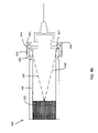
図1は、注射デバイス100の一例の分解図である。注射デバイス100は、充填済み、使い捨て、または再利用可能な注射ペンとすることができる。注射デバイス100は、カートリッジ102を収容するハウジング110を含む。カートリッジ102は、ある体積の流体を保持するように構成される。いくつかの実施形態において、カートリッジ102は、インスリン容器などの薬剤容器である。カートリッジ102は、遠位端105および近位端106を含む。いくつかの実施形態において、カートリッジ102の近位端106は、注射デバイス100のハウジング110の内部にあってもよく、したがって、容易に見ることができない場合がある。
FIG. 1 is an exploded view of an
注射デバイス100は、カートリッジ102内に配置されたストッパ108を含む。ストッパ108は、カートリッジ102の近位端106からカートリッジ102の遠位端105に向けて動かし、流体がカートリッジ102の遠位端105を通して投薬されるように構成される。注射デバイス100は、カートリッジ102の遠位端105に配置されたニードルハブ115も含む。アパーチャ119に近接するようにニードルハブ115に針114を取り付け、流体が投薬されるときにアパーチャ119および針114を通って移動するようにすることができる。いくつかの実施形態では、ニードルハブ115および針114にねじ山を付け、針114をニードルハブ115に螺着させる、またはニードルハブ115を針114に螺着させることができる。針114は、内側の針キャップ116および外側の針キャップ117によって保護され、その結果としてそれらをキャップ118によって覆うことができる。
注射デバイス100から放出予定の薬物の用量(たとえば、インスリンの用量など)は、投与量ノブ112を回すことによって選択することができ、次いで、選択された用量を投与量窓113によって表示することができる。いくつかの例において、投与量窓113は、電子ディスプレイなどのディスプレイである。いくつかの例において、選択された用量は、国際単位(IU)の倍数として表示することができ、1IUは、約45.5マイクログラムの純結晶インスリンなどの薬剤(たとえば、1/22mg)と生物学的に等価である。投与量窓113に表示される選択された用量の一例は、たとえば、図1Aに示すように30IUとすることができる。いくつかの例において、選択された用量は、たとえば、電子ディスプレイによってなど異なる形で表示することできる。いくつかの例において、投与量窓113とは、選択された投与量を、それを通してまたはその上に見ることができる注射デバイスのセクションを指す。
A dose of drug to be released from injection device 100 (eg, a dose of insulin, etc.) can be selected by turning
投与量ノブ112を回すことによって、機械的なクリック音を生じさせ、使用者に聴覚的なフィードバックを与えることができる。投与量窓113に表示される数字は、ハウジング110の中に含まれ、カートリッジ102内のピストンと機械的に相互作用するスリーブに印字されている。針114が患者の皮膚部分に刺し込まれ、次いで注射ボタン111が押されると、注射デバイス100から薬剤が放出される。用量の放出によって、機械的なクリック音を生じさせることもできる。そうした機械的なクリック音は、投与量ノブ112を回すときに発せられる音と異なるようにすることができる。
Turning the
注射デバイス100は、カートリッジ102が空になるまで、または注射デバイス100の使用期限に至るまで、複数の注射処置に使用することができる。いくつかの例では、注射デバイス100を初めて使用する前に、たとえば、2単位の薬剤を選択し、注射デバイス100を針114を上向きにした状態で保持しながら注射ボタン111を押下することによって、「プライムショット」を実行し、カートリッジ102および針114から空気を除くことが必要になる場合がある。
The
注射デバイス100は、カートリッジ102内の薬剤流体(たとえば、インスリン)の体積を決定するように構成され、この体積は、患者に投与予定の薬剤の投与量を表すことができる。たとえば、注射デバイスは、ストッパ108の位置を測定するように構成された電子デバイス120を含む。電子デバイス120は、(図2に示される)エミッタ202および受信機204を含む。いくつかの実施形態では、エミッタ202と受信機204の一方または両方を、カートリッジハウジング104に配置することができる。カートリッジ102および/またはカートリッジハウジング104は、エミッタが放射する1つまたはそれ以上の波、および1つまたはそれ以上の波の反射を通過させる(または、たとえば実質的に通過させる)材料から作る、かつ/またはそうした材料を含むことができる。
図2を参照すると、エミッタ202は、1つまたはそれ以上の信号206をカートリッジ102の近位端106に向けて伝送するように構成され、1つまたはそれ以上の波は、(以下に詳しく説明するように、たとえば、ストッパ108の表面に当たってはね返ることによって)カートリッジ102の近位端106から反射され、遠位端に配置された受信機204に戻る。受信機204は、信号の反射208を受けるように構成される。伝送された信号206、および1つまたはそれ以上の伝送された信号の反射208に関連する情報を用いて、カートリッジ102内の流体の体積を決定することができる。たとえば、1つまたはそれ以上の伝送された信号206、および1つまたはそれ以上の波の反射208に関連する情報を用いて、伝送された信号206が移動した距離を決定することができる。伝送された信号206が移動した距離を用いて、カートリッジ102内の流体の体積を決定することができ、カートリッジ102内の流体の体積を用いて、患者に投与された薬剤の用量を決定することができる。いくつかの実施形態では、単一のトランシーバパッケージの構成要素として、エミッタ202と受信機204の両方が含まれる。1つまたはそれ以上の信号は、音響波、超音波、光波、またはそれらの任意の組み合わせを含むことができる。
Referring to FIG. 2,
いくつかの実施形態において、1つまたはそれ以上の伝送された信号206に関連する情報(たとえば、伝送の時間、伝送時の強度)、および1つまたはそれ以上の伝送された信号の反射208に関連する情報(たとえば、受信の時間、受信時の強度)は、計算デバイス(たとえば、図6のコンピュータシステム600)に提供され、かつ/または計算デバイスが受け、計算デバイスは、そうした情報を用いてカートリッジ102内の流体の体積を決定する。いくつかの例において、エミッタ202は、1つまたはそれ以上の音響波(たとえば、超音波)をカートリッジ102の近位端106に向けて伝送するように構成された音響(たとえば、超音波)送信機であり、受信機204は、1つまたはそれ以上の音響波の反射を受けるように構成された音響受信機である。計算デバイスは、音響波のそれぞれが伝送された時間、および伝送された音響波それぞれについて受信機204が対応する反射を受けた時間を特定することができる。音響波の速度(たとえば、この場合は音の速度)が既知であれば、飛行時間(TOF:time of flight)と呼ばれることもある波の伝送と受信の間の経過時間を用いて、波が移動した距離を決定することができる。
In some embodiments, information associated with one or more transmitted signals 206 (eg, time of transmission, strength at time of transmission) and
波が移動した距離は、エミッタ202から、反射面(たとえば、ストッパ108の表面)に向かい、受信機204に至るまでの距離を表す。この距離を2で割り、ストッパ108と受信機204の間の距離を決定することができる。ストッパ108は、カートリッジ102の近位端106の近くで流体の境界を画成するため、決定された距離は、流体がその内部に存在するカートリッジ102の長さを表す。決定された距離をカートリッジ102の既知の寸法と共に用いて、カートリッジ102内の流体の体積を決定することができる。たとえば、円筒形のカートリッジの場合、カートリッジ102内の流体の体積(V)は、以下の式:
V=π*r^2*D_1
によって決まり、ここで、rはカートリッジの内半径であり、D1はストッパ108の表面からカートリッジ102の遠位端105までの距離である。
The distance traveled by the wave represents the distance from the
V=π*r^2*D_1
where r is the inner radius of the cartridge and D1 is the distance from the surface of the
一例において、エミッタ202は、第1の時間t1に音響波を伝送する。第1の時間t1(たとえば、音響波の伝送時間)は、計算デバイスに提供される。音響波は、エミッタ202からカートリッジ102の近位端106に向かって伝わり、ストッパ108に当たって反射される(たとえば、はね返される)。音響波の反射208(たとえば、反射された波)は、ストッパ108から受信機204に向かって伝わる。反射された波は、第2の時間t2に受けられる。音響波の速度は、液体中での音の速度である。音響波の伝送と受信の間の経過時間は、t2-t1である。経過時間に音の速度を掛けると、波がエミッタ202からカートリッジ102の遠位端105に至り、受信機204に戻るまでに移動した距離が決まる。移動距離を2で割ると、エミッタ202/受信機204とストッパ108との間の距離が決まる。決定された距離にカートリッジ102の断面積を掛けることによって、カートリッジ102内の流体の体積(たとえば、カートリッジ102内のストッパ108と遠位端105の間に入っている流体の体積)が決定される。決定されたカートリッジ102内の流体の体積が、患者に投与予定の用量である。
In one example,
いくつかの実施形態において、ストッパ108は、エミッタ202に対向するストッパ108の端部に配置された反射材料109を含む。反射材料109は、(たとえば、反射したときの信号の損失を最小限に抑える、信号中の雑音を減らす、信号対雑音比を改善するなどによって)反射された信号の信号品質を改善するように構成され、それによって、TOFの計算値が改善される。
In some embodiments,
図1~2および4A~4Bを全体的に参照すると、いくつかの実施形態において、エミッタ202は、ストッパ108に向けて光を伝送するように構成された光源であり、受信機204は、光波の反射または再放出を受けるように構成された光受信機である。いくつかの例において、カートリッジハウジング104は、光波および光波の反射を通過させる(または、たとえば実質的に通過させる)材料から作る、かつ/またはそうした材料を含むことができる。いくつかの実施形態において、カートリッジ102は、ガラスとプラスチックの一方または両方など透明な材料を含む。
Referring generally to FIGS. 1-2 and 4A-4B, in some embodiments emitter 202 is a light source configured to transmit light towards
注射デバイス100を、主に、1つまたはそれ以上の伝送された信号、および1つまたはそれ以上の信号の反射に関連する情報を用いてカートリッジ102内の流体の体積を決定するように構成されたものとして説明してきたが、いくつかの実施形態において、注射デバイス100は、流体の体積を決定するために、エミッタ202および受信機204以外に、またはそれらに加えて、1つまたはそれ以上の構成要素を含むことができる。
いくつかの実施形態において、カートリッジ102内の流体の体積は、流体を注射デバイス100から投薬しながら連続的に決定することができる。たとえば、注射ボタン111が押され、薬剤がカートリッジ102から放出される間、注射デバイス100は、カートリッジ102内の流体の体積を連続的に決定し、使用者がカートリッジ102内の流体の現時の体積に関する連続的なフィードバックを受けられるようにすることが可能である。
In some embodiments, the volume of fluid within
特に、図2に関して上述したものと実質的に同様の方法で、1つまたはそれ以上の伝送された信号に関連する情報(たとえば、伝送の時間)、および1つまたはそれ以上の伝送された信号の反射に関連する情報(たとえば、受信の時間)は、計算デバイスに提供される、かつ/または計算デバイスが受けることが可能である。信号の伝送と受信の間の経過時間(たとえば、TOF)に信号の速度(たとえば、音の速度)を掛け、波が移動した距離を決定することができる。波が移動した距離は、エミッタ202からストッパ108に至り、受信機204に戻るまでの距離を表す。移動距離を2で割ると、エミッタ202/受信機204とストッパ108との間の距離が決まる。決定された距離にカートリッジ102の断面積を掛けることによって、カートリッジ102内の流体の体積(たとえば、カートリッジ102内のストッパ108と遠位端105の間に入っている残りの流体の体積)が決定される。決定されたカートリッジ内の流体の体積は、患者にこれから投与予定のカートリッジ102内に残存する用量である。カートリッジ102内の流体の体積は、投与の間中、残りの投与量が分かるように連続的に決定することができる。投与量の計算は、注射デバイス100に搭載されたマイクロコントローラ210によって行うこと、または外部のコンピュータシステム600によって行うことができる。いくつかの実装形態では、注射デバイス100に搭載されたマイクロコントローラ210の代わりに、別の種類のプロセッサを用いることが可能である。
In particular, information relating to one or more transmitted signals (e.g., time of transmission) and one or more transmitted signals in a manner substantially similar to that described above with respect to FIG. Information related to the reflection of (eg, time of reception) can be provided to and/or received by the computing device. The elapsed time between transmission and reception of the signal (eg, TOF) can be multiplied by the speed of the signal (eg, the speed of sound) to determine the distance traveled by the wave. The distance traveled by the wave represents the distance from
図3は、カートリッジ350内に配置されたストッパ300の断面図である。ストッパは、埋め込まれた電子部材306a、306b、および306cを含む。ストッパ300は、シェル302およびコア304を有し、コア304には、電子デバイス306a、306b、および306cが埋め込まれている。場合により、一体化された封止要素308を、ストッパがカートリッジ350の中に導入されたとき、カートリッジと共に封止インターフェースを提供するように構成することができる。いくつかの例において、シェル302は、プランジャの頭部と連係するための堅い面を提供する。こうして、シェル302は、ストッパ300がカートリッジ350の長さに沿って動かされるとき、プランジャがストッパ300を押すことによって電子デバイス306a、306b、306cが変形を受けるのを防ぐ。いくつかの例において、シェル302は耐熱性を有し、これにより、ストッパ300およびカートリッジ350を滅菌する加熱滅菌プロセスの間に生成される熱から電子部材306a、306b、および306cを保護することができる。シェルおよびコアは、滅菌プロセスの間に用いられる高温に耐えるように、堅いまたは柔らかい材料を様々に組み合わせて作られると同時に、電子機器およびプランジャのための構造および支持を提供することも企図される。あるいは、シェル/コアを、電子機器が内部に成形された一体部材で作ることもできる。
FIG. 3 is a cross-sectional view of
エミッタが発射する波は、本質的に、光波、音響波、または超音波とすることが可能であることが企図される。一例において、送信機306cは、第1の時間t1に音響波を伝送する。第1の時間t1(たとえば、音響波の伝送時間)は、無線トランシーバ306bによる無線伝送を介して外部デバイス(たとえば、コントローラ)に提供することができる。送信機306cおよび無線トランシーバ306bは、電源306aによってエネルギーの供給を受けることができる。音響波は、ストッパ300内の送信機からカートリッジ350の遠位端(キャップ354に最も近い端部)に向かって伝わり、カートリッジ350の表面またはリフレクタ(図示せず)に当たって反射される(たとえば、はね返される)。音響波の反射(たとえば、反射された波)は、カートリッジ350の遠位端からストッパ300内のセンサに向かって伝わる。反射された波は、第2の時間t2に受けられる。音響波の速度は、カートリッジ内の薬剤中での音の速度である(たとえば、水中では1484メートル/秒)。音響波の伝送と受信の間の経過時間は、t2-t1である。経過時間に音の速度を掛けると、波が送信機からカートリッジ350の遠位端に至り、センサに戻るまでに移動した距離が決まる。移動距離を2で割ると、ストッパ300とカートリッジ350の遠位端との間の距離が決まる。決定された距離にカートリッジ350の断面積を掛けることによって、カートリッジ350内の薬剤の体積(たとえば、カートリッジ350内のストッパ300と遠位端の間に入っている薬剤の体積)が決定される。決定されたカートリッジ350内の薬剤の体積が、患者に投与予定の用量である。
It is contemplated that the waves emitted by the emitter can be optical, acoustic, or ultrasonic in nature. In one example,
図1~2、および4A~4Bを全体的に参照すると、信号がエミッタ202によって発射され、信号の反射が受信機204によって受けられるとき、信号の伝送は反対の方向(たとえば、遠位端105から近位端106に向かい、はね返る)に行われる。これは、信号がそれに当たり反射して(たとえば、はね返って)受信機に向かうことができる、カートリッジの断面に実質的に等しい平坦面をストッパ108が提供するため有利である。エミッタおよび受信機が近位端に置かれ、波が遠位端に当たってはね返る別の構成では、カートリッジの形状および構成が、波が当たってはね返る実質的に平坦な面を提供できないことが分かっている。したがって、エミッタおよび受信機をカートリッジの首部に近い遠位端に配置し、波がストッパの実質的に平坦な面に当たってはね返ることができるようにすると、測定の精度が高まる。電子部材をストッパの外部に含むことも、ストッパに埋め込まれた電子部材が高熱によって損傷を受けることを考慮せずにカートリッジを加熱滅菌することができるため有利である。電子部材がストッパの外部に配置されると、ストッパの設計および製造が簡単になる。
1-2 and 4A-4B, when a signal is emitted by
図4Aは、エミッタ202、受信機204、およびエネルギー源412を含む電子デバイス120の一実施形態である。この実施形態では、エネルギー源412は、注射デバイスのハウジング110内に配置される。エネルギー源412は、電子リード線414aおよび414bによってエミッタ202および受信機204に電気接続される。エネルギー源は、バッテリを含むことができる。電子リード線414aおよび414bは、カートリッジハウジング104を通って延びる。電子リード線414aおよび414bによって、エネルギー源412がエミッタ202、受信機204、およびマイクロコントローラ210にエネルギーを供給することが可能になる。
FIG. 4A is one embodiment of
マイクロコントローラ210は、たとえば、ブルートゥース、NFC、または無線周波数を含む、知られている任意の無線通信技術を用いて通信可能な無線トランシーバを含む。マイクロコントローラ210は、カートリッジの状態に関連するデータ、または受信機204で受けられた信号を、外部のデータベースへ伝達することができる。カートリッジの状態は、たとえば、カートリッジ内の薬剤の充填レベル、またはストッパの位置に対応することができる。カートリッジの状態により、注射された薬剤の用量の測定が可能になることがある。
マイクロコントローラ210との通信は、一方向または二方向とすることができる。いくつかの例において、センサデバイスから外部のデータベースへ伝えられるデータは、たとえば、固有番号などのデバイスの識別に関連する情報、較正データ、生産ロット情報、デバイスの材料情報、保管時間および生産時間に関連するデータ、ならびにセンサの測定に関連する情報(たとえば、測定の時間、温度のようなセンサの測定結果、距離、光信号、音響信号)を含む。いくつかの例において、外部のデータベースデバイスからマイクロコントローラ210へ届くデータは、「起動」信号、測定のトリガ、時間情報、または較正データに関連する情報を含む。
Communication with
図5は、長手方向軸500に対するストッパ108、エミッタ202、および受信機204の相対位置を示す概略図である。エミッタ202は、0°からαの間の角度で信号を発射することができるように構成される。それに応じて、受信機204は、0°からαの間の角度でストッパ108に当たってはね返った後の信号の反射を受けることができるように構成される。ストッパ108が、近位端106から遠位端105に向かって距離D1だけ動くとき、エミッタ202および受信機204はそれぞれ、信号の放射および反射の捕捉が可能な範囲を有する。いくつかの実施形態において、αは0°から90°の間である。他の実施形態において、それは20°から70°の間である。さらに他の実施形態において、それは55°から65°の間である。
FIG. 5 is a schematic diagram showing the relative positions of
図4Bは、カートリッジ400またはカートリッジハウジング440から取り外し可能な電子デバイス420の一実施形態である。エミッタ402および受信機404は、取り外し可能な電子デバイス420の中に位置し、それぞれ、カートリッジハウジング440の一部を通して信号の放射および信号の反射の受信が可能になっている。カートリッジハウジング440は、通常、エミッタ402から放射される信号206、および受信機404が受ける信号の反射208を透過する。いくつかの実施形態において、カートリッジハウジング440は、光信号、超音波信号、および/または音響信号を透過する。
FIG. 4B is one embodiment of an
カートリッジハウジング440は隆起部442を含み、電子デバイス420の留め具またはスナップ部分が隆起部442と連係し、電子デバイス420をカートリッジハウジング440に固定できるようになっている。電子デバイス420は、カートリッジハウジング440に対して取り付けおよび取り外しが可能であるため、カートリッジハウジング440に取り付けたときに較正することができる。較正プロセスによって、通常はエミッタおよび受信機がカートリッジ400内のストッパ108の位置を正確に決定することが可能になる。マイクロコントローラ450は、較正に有用な薬剤に関連する情報および投薬情報を記憶するメモリを含むことができる。
エミッタ402および受信機404は、取り外し可能な電子デバイス420内に位置し、取り外し可能な電子デバイス420がカートリッジハウジング440に取り付けられると、エミッタ402および受信機404は、エミッタがカートリッジの長手方向軸に対して0°からαの間の角度で信号を放射できるように位置するようになる。それに応じて、受信機404は、0°からαの間の角度でストッパ108に当たってはね返った後の信号の反射を受けることができるようになる。いくつかの実施形態において、αは0°から90°の間である。他の実施形態において、それは20°から70°の間である。さらに他の実施形態において、それは55°から65°の間である。取り外し可能な電子デバイス420をカートリッジハウジング440に取り付けたとき、エミッタ402および受信機404の適切な位置決めを保証するために、較正が必要になる場合がある。
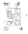
図6は、例示的なコンピュータシステム600のブロック図である。たとえば、コンピュータシステム600を図1~4の注射デバイス100に組み込むこと、および/または注射デバイス100を(たとえば、図2に示すマイクロコントローラ210を介して)独立のコンピュータシステム600と相互作用するように構成することが可能である。システム600は、プロセッサ610、メモリ620、記憶デバイス630、および入力/出力デバイス640を含む。構成要素610、620、630、および640のそれぞれを、たとえば、システムバス650を用いて相互接続することができる。プロセッサ610は、システム600内における実行のための命令を処理することができる。プロセッサ610は、シングルスレッドプロセッサ、マルチスレッドプロセッサ、または量子コンピュータとすることができる。プロセッサ610は、メモリ620または記憶デバイス630に記憶された命令を処理することができる。プロセッサ610は、注射デバイス100にカートリッジ102内の流体の体積を決定する上述の動作の1つまたはそれ以上を行わせるなどの動作を実行することができる。
FIG. 6 is a block diagram of an exemplary computer system 600. As shown in FIG. For example, incorporating computer system 600 into
スマートフォンやタブレットコンピュータなどの携帯型計算デバイスは、コンピュータシステム600の一例とすることができる。いくつかの実装形態において、携帯型計算デバイスは、注射デバイス100の電子デバイス120と連係するためのアプリケーションを動かす。たとえば、携帯型計算デバイスは、1つまたはそれ以上のコンピュータネットワーク(たとえば、無線もしくは有線の通信ネットワーク、またはその2つの組み合わせ)を用いて電子デバイス120と通信することができ、携帯型計算デバイスで動くそうしたアプリケーションは、電子デバイス120から受けたデータに基づいて情報を表示することができる。いくつかの実装形態では、他のタイプのコンピュータシステムが、電子デバイス120から受けたデータに基づいて情報を表示することができる。いくつかの実装形態では、携帯型計算デバイスと電子デバイス120の間で情報を伝達するために、「クラウド」コンピューティング技術が用いられる。たとえば、携帯型計算デバイスと電子デバイス120の両方が、中間データ処理および記憶用の設備として働く1つまたはそれ以上のクラウドサーバ(コンピュータシステム600の他の例とすることができる)と通信することができる。クラウドコンピューティングシステムは、携帯型計算デバイスを介して、外部に記憶された患者、投与量、または他のデータへのアクセスを提供することも可能である。
A portable computing device such as a smart phone or tablet computer may be an example of computer system 600 . In some implementations, the portable computing device runs an application to interface with the
メモリ620は、システム600内で情報を記憶する。いくつかの実施形態において、メモリ620はコンピュータ可読媒体である。メモリ620は、たとえば、揮発性メモリユニットまたは不揮発性メモリユニットとすることができる。いくつかの実施形態において、メモリ620は、エミッタ202によって伝送された1つまたはそれ以上の波の速度、カートリッジ102の寸法、および電極202、204の間の印加電圧を電極202、204の間の距離に関連付けるために使用可能なデータのうちの1つまたはそれ以上に関連する情報を記憶する。
記憶デバイス630は、システム600に大容量記憶を提供することができる。いくつかの実施形態において、記憶デバイス630は非一時的なコンピュータ可読媒体である。記憶デバイス630は、たとえば、ハードディスクデバイス、光ディスクデバイス、ソリッドステートドライブ、フラッシュドライブ、磁気テープ、またはいくつかの他の大容量記憶デバイスを含むことができる。あるいは、記憶デバイス630は、たとえば、ネットワーク上に分散され、ネットワークを用いてアクセスされる複数の物理記憶デバイスを含む論理記憶デバイスなどのクラウド記憶デバイスとすることができる。いくつかの実施形態では、メモリ620に記憶される情報を、さらにまたはその代わりに、記憶デバイス630に記憶させることができる。
入力/出力デバイス640は、システム600に入力/出力動作を提供する。いくつかの実施形態において、入力/出力デバイス640は、ネットワークインターフェースデバイス(たとえば、イーサネットカード)、シリアル通信デバイス(たとえば、RS-232ポート)、および/または無線インターフェースデバイス(たとえば、近距離無線通信デバイス、802.11カード、3G無線モデム、もしくは4G無線モデム)の1つまたはそれ以上を含む。いくつかの実施形態において、入力/出力デバイス640は、入力データを受け、出力データを他の入力/出力デバイス、たとえば、キーボード、プリンタ、および表示デバイス(たとえば、投与量窓113など)へ送るように構成されたドライバデバイスを含む。いくつかの実施形態では、モバイル計算デバイス、モバイル通信デバイス、および他のデバイスが使用される。
Input/
いくつかの実施形態において、システム600はマイクロコントローラである。マイクロコントローラは、単一の電子装置パッケージ内にコンピュータシステムの複数の要素を含むデバイスである。たとえば、単一の電子装置パッケージは、プロセッサ610、メモリ620、記憶デバイス630、および入力/出力デバイス640を含むことが可能である。
In some embodiments, system 600 is a microcontroller. A microcontroller is a device that contains multiple elements of a computer system within a single electronics package. For example, a single electronics package may include
図6で例示的な処理システムについて説明してきたが、上述の主題および機能動作の実施形態は、他のタイプのデジタル電子回路の形、または本明細書において開示される構造およびそれらの構造的等価物を含むコンピュータソフトウェア、ファームウェア、もしくはハードウェアの形、またはそれらの1つまたはそれ以上の組み合わせの形の実施形態とすることができる。本明細書において説明される主題の実施形態は、1つまたはそれ以上のコンピュータプログラム製品、たとえば、処理システムによる実行のための、またはその動作を制御する有形のプログラム担体、たとえばコンピュータ可読媒体にコード化されたコンピュータプログラム命令からなる1つまたはそれ以上のモジュールとして実装することができる。コンピュータ可読媒体は、機械可読記憶デバイス、機械可読記憶基板、メモリデバイス、機械可読伝搬信号をもたらす組成物、またはそれらの1つまたはそれ以上の組み合わせとすることができる。 Although an exemplary processing system has been described in FIG. 6, embodiments of the subject matter and functional operations described above are applicable to other types of digital electronic circuit forms or structures disclosed herein and their structural equivalents. Embodiments can be in the form of computer software, firmware, or hardware including objects, or in the form of combinations of one or more thereof. Embodiments of the subject matter described herein may be encoded in one or more computer program products, e.g., tangible program carriers, e.g., computer readable media, for execution by, or for controlling operation of, a processing system. can be implemented as one or more modules of coded computer program instructions. A computer-readable medium can be a machine-readable storage device, a machine-readable storage substrate, a memory device, a composition that provides a machine-readable propagated signal, or a combination of one or more thereof.
「コンピュータシステム」という用語は、データを処理するためのすべての装置、デバイス、および機械を包含することができ、例として、プログラマブルプロセッサ、コンピュータ、または複数のプロセッサもしくはコンピュータを含む。処理システムは、ハードウェアに加えて、当該のコンピュータプログラムのための実行環境を作成するコード、たとえば、プロセッサファームウェア、プロトコルスタック、データベース管理システム、オペレーティングシステム、またはそれらの1つまたはそれ以上の組み合わせを構成するコードを含むことができる。 The term "computer system" can encompass all apparatus, devices, and machines for processing data and includes, by way of example, a programmable processor, computer, or multiple processors or computers. A processing system includes, in addition to hardware, code that creates an execution environment for such computer programs, such as processor firmware, protocol stacks, database management systems, operating systems, or combinations of one or more thereof. It can contain configuration code.
コンピュータプログラム(プログラム、ソフトウェア、ソフトウェアアプリケーション、スクリプト、実行可能なロジック、またはコードとしても知られる)は、コンパイル型もしくはインタープリタ型の言語、または宣言型もしくは手続き型の言語を含む任意の形式のプログラミング言語で記述することができ、スタンドアローンプログラムとして、またはモジュール、コンポーネント、サブルーチン、もしくはコンピューティング環境での使用に適した他の構成単位としてなどを含む任意の形で導入することができる。コンピュータプログラムは、ファイルシステム内のファイルに必ずしも対応しない。プログラムは、他のプログラムまたはデータ(たとえば、マークアップ言語文書に記憶された1つまたはそれ以上のスクリプト)を保持するファイルの一部、当該プログラム専用の単一のファイル、または複数の連携させたファイル(たとえば、1つまたはそれ以上のモジュール、サブプログラム、もしくはコードの各部分を記憶するファイル)に記憶することができる。コンピュータプログラムは、1つのコンピュータ上で、または1つのサイトにあるか、もしくは複数のサイトにわたって分散され、通信ネットワークによって相互接続された複数のコンピュータ上で実行されるように導入することができる。 A computer program (also known as a program, software, software application, script, executable logic, or code) may be written in any form of programming language, including compiled or interpreted languages, or declarative or procedural languages and can be implemented in any form, including as a stand-alone program or as a module, component, subroutine, or other unit suitable for use in a computing environment. Computer programs do not necessarily correspond to files in a file system. A program may be part of a file holding other programs or data (e.g., one or more scripts stored in a markup language document), a single file dedicated to that program, or multiple linked It can be stored in a file (eg, a file that stores one or more modules, subprograms, or portions of code). A computer program can be deployed to be executed on one computer or on multiple computers at one site or distributed across multiple sites and interconnected by a communication network.
コンピュータプログラム命令およびデータを記憶するのに適したコンピュータ可読媒体は、すべての形の不揮発性または揮発性メモリ、媒体、およびメモリデバイスを含み、例として、たとえばEPROM、EEPROM、およびフラッシュメモリデバイスなどの半導体メモリデバイス;たとえば内蔵ハードディスクもしくはリムーバブルディスク、または磁気テープなどの磁気ディスク;光磁気ディスク;ならびにCD―ROMおよびDVD―ROMディスクを含む。プロセッサおよびメモリは、特定目的の論理回路によって補完すること、またはそれに組み込むことが可能である。システムの構成要素は、デジタルデータ通信、たとえば、通信ネットワークの任意の形または媒体によって相互接続することができる。通信ネットワークの例には、ローカルエリアネットワーク(「LAN」)、およびインターネットなどの広域ネットワーク(「WAN」)が含まれる。 Computer-readable media suitable for storing computer program instructions and data include all forms of non-volatile or volatile memories, media, and memory devices, such as EPROM, EEPROM, and flash memory devices. Includes semiconductor memory devices; magnetic disks, such as internal or removable disks, or magnetic tape; magneto-optical disks; and CD-ROM and DVD-ROM disks. The processor and memory may be supplemented by or incorporated in special purpose logic circuitry. The components of the system can be interconnected by any form or medium of digital data communication, eg, a communication network. Examples of communication networks include local area networks (“LAN”) and wide area networks (“WAN”) such as the Internet.
本明細書で使用する用語「薬物」または「薬剤」は、1つまたはそれ以上の薬学的に活性な化合物を説明するために本明細書において使用される。以下に説明されるように、薬物または薬剤は、1つまたはそれ以上の疾患を処置するための、様々なタイプの製剤の少なくとも1つの低分子もしくは高分子、またはその組み合わせを含むことができる。例示的な薬学的に活性な化合物は、低分子;ポリペプチド、ペプチド、およびタンパク質(たとえばホルモン、成長因子、抗体、抗体フラグメント、および酵素);炭水化物および多糖類;ならびに核酸、二本鎖または一本鎖DNA(裸およびcDNAを含む)、RNA、アンチセンスDNAおよびRNAなどのアンチセンス核酸、低分子干渉RNA(siRNA)、リボザイム、遺伝子、およびオリゴヌクレオチドを含むことができる。核酸は、ベクター、プラスミド、またはリポソームなどの分子送達システムに組み込むことができる。これらの薬物の1つまたはそれ以上の混合物もまた、企図される。 As used herein, the terms "drug" or "agent" are used herein to describe one or more pharmaceutically active compounds. As described below, drugs or agents can include at least one small molecule or macromolecule, or a combination thereof, of various types of formulations for treating one or more diseases. Exemplary pharmaceutically active compounds are small molecules; polypeptides, peptides, and proteins (such as hormones, growth factors, antibodies, antibody fragments, and enzymes); carbohydrates and polysaccharides; It can include single-stranded DNA (including naked and cDNA), RNA, antisense nucleic acids such as antisense DNA and RNA, small interfering RNA (siRNA), ribozymes, genes, and oligonucleotides. Nucleic acids can be incorporated into vectors, plasmids, or molecular delivery systems such as liposomes. Mixtures of one or more of these drugs are also contemplated.
本明細書において説明される薬物送達デバイスおよび薬物は、数多くの異なるタイプの障害の処置および/または予防に使用することができる。例示的な障害は、たとえば、糖尿病、または糖尿病性網膜症などの糖尿病に伴う合併症、深部静脈血栓塞栓症または肺血栓塞栓症などの血栓塞栓症を含む。さらなる例示的な障害は、急性冠症候群(ACS)、狭心症、心筋梗塞、がん、黄斑変性症、炎症、枯草熱、アテローム性動脈硬化症および/または関節リウマチである。 The drug delivery devices and drugs described herein can be used to treat and/or prevent many different types of disorders. Exemplary disorders include, for example, diabetes or complications associated with diabetes such as diabetic retinopathy, thromboembolism such as deep vein thromboembolism or pulmonary thromboembolism. Further exemplary disorders are acute coronary syndrome (ACS), angina pectoris, myocardial infarction, cancer, macular degeneration, inflammation, hay fever, atherosclerosis and/or rheumatoid arthritis.
糖尿病または糖尿病に伴う合併症の処置および/または予防のための例示的な薬物は、インスリン、たとえばヒトインスリン、またはヒトインスリン類似体もしくは誘導体、グルカゴン様ペプチド(GLP-1)、GLP-1類似体もしくはGLP-1受容体アゴニスト、またはその類似体もしくは誘導体、ジペプチジルペプチダーゼ-4(DPP4)阻害剤、または薬学的に許容される塩もしくはその溶媒和物、またはそれらの任意の混合物を含む。本明細書において使用される用語「誘導体」は、元の物質と構造的に十分同様のものであり、それによって同様の機能または活性(たとえば治療効果性)を有することができる任意の物質を指す。 Exemplary drugs for the treatment and/or prevention of diabetes or complications associated with diabetes are insulin, such as human insulin, or human insulin analogs or derivatives, glucagon-like peptide (GLP-1), GLP-1 analogs or GLP-1 receptor agonists, or analogs or derivatives thereof, dipeptidyl peptidase-4 (DPP4) inhibitors, or pharmaceutically acceptable salts or solvates thereof, or any mixture thereof. As used herein, the term "derivative" refers to any substance that is sufficiently structurally similar to the original substance so that it can have a similar function or activity (e.g., therapeutic efficacy). .
例示的なインスリン類似体は、Gly(A21),Arg(B31),Arg(B32)ヒトインスリン(インスリングラルギン);Lys(B3),Glu(B29)ヒトインスリン;Lys(B28),Pro(B29)ヒトインスリン;Asp(B28)ヒトインスリン;B28位におけるプロリンがAsp、Lys、Leu、Val、またはAlaで置き換えられており、B29位において、LysがProで置き換えられていてもよいヒトインスリン;Ala(B26)ヒトインスリン;Des(B28-B30)ヒトインスリン;Des(B27)ヒトインスリンおよびDes(B30)ヒトインスリンである。 Exemplary insulin analogues are Gly (A21), Arg (B31), Arg (B32) human insulin (insulin glargine); Lys (B3), Glu (B29) human insulin; Lys (B28), Pro (B29) human insulin; Asp (B28) human insulin; human insulin in which proline at position B28 is replaced with Asp, Lys, Leu, Val, or Ala, and at position B29, Lys optionally replaced with Pro; B26) Human Insulin; Des(B28-B30) Human Insulin; Des(B27) Human Insulin and Des(B30) Human Insulin.
例示的なインスリン誘導体は、たとえば、B29-N-ミリストイル-des(B30)ヒトインスリン;B29-N-パルミトイル-des(B30)ヒトインスリン;B29-N-ミリストイルヒトインスリン;B29-N-パルミトイルヒトインスリン;B28-N-ミリストイルLysB28ProB29ヒトインスリン;B28-N-パルミトイル-LysB28ProB29ヒトインスリン;B30-N-ミリストイル-ThrB29LysB30ヒトインスリン;B30-N-パルミトイル-ThrB29LysB30ヒトインスリン;B29-N-(N-パルミトイル-γ-グルタミル)-des(B30)ヒトインスリン;B29-N-(N-リトコリル-γ-グルタミル)-des(B30)ヒトインスリン;B29-N-(ω-カルボキシヘプタデカノイル)-des(B30)ヒトインスリン、およびB29-N-(ω-カルボキシヘプタデカノイル)ヒトインスリンである。例示的なGLP-1、GLP-1類似体およびGLP-1受容体アゴニストは、たとえば:リキシセナチド/AVE0010/ZP10/リキスミア、エキセナチド/エクセンディン-4/バイエッタ/ビデュリオン/ITCA650/AC-2993(アメリカドクトカゲの唾液腺によって産生される39アミノ酸ペプチド)、リラグルチド/ビクトザ、セマグルチド、タスポグルチド、シンクリア/アルビグルチド、デュラグルチド、rエクセンディン-4、CJC-1134-PC、PB-1023、TTP-054、ラングレナチド/HM-11260C、CM-3、GLP-1エリゲン、ORMD-0901、NN-9924、NN-9926、NN-9927、ノデキセン、ビアドール-GLP-1、CVX-096、ZYOG-1、ZYD-1、GSK-2374697、DA-3091、MAR-701、MAR709、ZP-2929、ZP-3022、TT-401、BHM-034、MOD-6030、CAM-2036、DA-15864、ARI-2651、ARI-2255、エキセナチド-XTENおよびグルカゴン-Xtenである。 Exemplary insulin derivatives are, for example, B29-N-myristoyl-des(B30) human insulin; B29-N-palmitoyl-des(B30) human insulin; B29-N-myristoyl human insulin; B29-N-palmitoyl human insulin B28-N-myristoyl-LysB28ProB29 human insulin; B28-N-palmitoyl-LysB28ProB29 human insulin; B30-N-myristoyl-ThrB29LysB30 human insulin; B30-N-palmitoyl-ThrB29LysB30 human insulin; -glutamyl)-des(B30) human insulin; B29-N-(N-Litocholyl-γ-glutamyl)-des(B30) human insulin; B29-N-(ω-carboxyheptadecanoyl)-des(B30) human insulin, and B29-N-(ω-carboxyheptadecanoyl) human insulin. Exemplary GLP-1, GLP-1 analogs and GLP-1 receptor agonists include, for example: Lixisenatide/AVE0010/ZP10/Lyxmia, Exenatide/Exendin-4/Byetta/Bidureon/ITCA650/AC-2993 (Monthly Gila 39-amino acid peptide produced by the salivary glands of the body), liraglutide/victoza, semaglutide, taspoglutide, syncria/arbiglutide, dulaglutide, rexendin-4, CJC-1134-PC, PB-1023, TTP-054, langrenatide/HM-11260C , CM-3, GLP-1 Erigen, ORMD-0901, NN-9924, NN-9926, NN-9927, Nodexene, Viador-GLP-1, CVX-096, ZYOG-1, ZYD-1, GSK-2374697, DA-3091, MAR-701, MAR709, ZP-2929, ZP-3022, TT-401, BHM-034, MOD-6030, CAM-2036, DA-15864, ARI-2651, ARI-2255, exenatide-XTEN and Glucagon-Xten.
例示的なオリゴヌクレオチドは、たとえば:家族性高コレステロール血症の処置のためのコレステロール低下アンチセンス治療薬である、ミポメルセン/キナムロである。 Exemplary oligonucleotides are, for example: mipomersen/kinamuro, a cholesterol-lowering antisense therapeutic for the treatment of familial hypercholesterolemia.
例示的なDPP4阻害剤は、ビルダグリプチン、シタグリプチン、デナグリプチン、サキサグリプチン、ベルベリンである。 Exemplary DPP4 inhibitors are vildagliptin, sitagliptin, denagliptin, saxagliptin, berberine.
例示的なホルモンは、ゴナドトロピン(フォリトロピン、ルトロピン、コリオンゴナドトロピン、メノトロピン)、ソマトロピン(ソマトロピン)、デスモプレシン、テルリプレシン、ゴナドレリン、トリプトレリン、ロイプロレリン、ブセレリン、ナファレリン、およびゴセレリンなどの、脳下垂体ホルモンまたは視床下部ホルモンまたは調節性活性ペプチドおよびそれらのアンタゴニストを含む。 Exemplary hormones are pituitary or thalamic hormones such as gonadotropins (follitropin, lutropin, corion gonadotropin, menotropin), somatropins (somatropin), desmopressin, terlipressin, gonadorelin, triptorelin, leuprorelin, buserelin, nafarelin, and goserelin Including hypohormones or regulatory active peptides and their antagonists.
例示的な多糖類は、グルコサミノグリカン、ヒアルロン酸、ヘパリン、低分子量ヘパリン、もしくは超低分子量ヘパリン、またはそれらの誘導体、または上述の多糖類の硫酸化形態、たとえば、ポリ硫酸化形態、および/または、薬学的に許容されるそれらの塩を含む。ポリ硫酸化低分子量ヘパリンの薬学的に許容される塩の例としては、エノキサパリンナトリウムがある。ヒアルロン酸誘導体の例としては、HylanG-F20/Synvisc、ヒアルロン酸ナトリウムがある。 Exemplary polysaccharides are glucosaminoglycans, hyaluronic acid, heparin, low molecular weight heparin, or very low molecular weight heparin, or derivatives thereof, or sulfated forms of the above polysaccharides, such as polysulfated forms, and / Or, including pharmaceutically acceptable salts thereof. An example of a pharmaceutically acceptable salt of polysulfated low molecular weight heparin is enoxaparin sodium. Examples of hyaluronic acid derivatives are Hylan G-F20/Synvisc, sodium hyaluronate.
本明細書において使用する用語「抗体」は、免疫グロブリン分子またはその抗原結合部分を指す。免疫グロブリン分子の抗原結合部分の例は、抗原を結合する能力を保持するF(ab)およびF(ab’)2フラグメントを含む。抗体は、ポリクローナル、モノクローナル、組換え型、キメラ型、非免疫型またはヒト化、完全ヒト型、非ヒト型(たとえばマウス)、または一本鎖抗体とすることができる。いくつかの実施形態では、抗体はエフェクター機能を有し、補体を固定することができる。いくつかの実施形態では、抗体は、Fc受容体と結合する能力が低く、または結合することはできない。たとえば、抗体は、アイソタイプもしくはサブタイプ、抗体フラグメントまたは変異体とすることができ、Fc受容体との結合を支持せず、たとえば、これは、突然変異したまたは欠失したFc受容体結合領域を有する。 As used herein, the term "antibody" refers to an immunoglobulin molecule or antigen-binding portion thereof. Examples of antigen-binding portions of immunoglobulin molecules include F(ab) and F(ab')2 fragments that retain the ability to bind antigen. Antibodies can be polyclonal, monoclonal, recombinant, chimeric, non-immune or humanized, fully human, non-human (eg, murine), or single chain antibodies. In some embodiments, the antibody has effector function and is capable of fixing complement. In some embodiments, the antibody has a reduced ability to bind, or is unable to bind, an Fc receptor. For example, an antibody can be of isotype or subtype, antibody fragment or variant, and does not support binding to an Fc receptor, e.g., it has a mutated or deleted Fc receptor binding region. have.
用語「フラグメント」または「抗体フラグメント」は、全長抗体ポリペプチドを含まないが、抗原と結合することができる全長抗体ポリペプチドの少なくとも一部分を依然として含む、抗体ポリペプチド分子(たとえば、抗体重鎖および/または軽鎖ポリペプチド)由来のポリペプチドを指す。抗体フラグメントは、全長抗体ポリペププチドの切断された部分を含むことができるが、この用語はそのような切断されたフラグメントに限定されない。本発明に有用である抗体フラグメントは、たとえば、Fabフラグメント、F(ab’)2フラグメント、scFv(一本鎖Fv)フラグメント、直鎖抗体、二重特異性、三重特異性、および多重特異性抗体(たとえば、ダイアボディ、トリアボディ、テトラボディ)などの単一特異性または多重特異性抗体フラグメント、ミニボディ、キレート組換え抗体、トリボディまたはバイボディ、イントラボディ、ナノボディ、小モジュラー免疫薬(SMIP)、結合ドメイン免疫グロブリン融合タンパク質、ラクダ化抗体、およびVHH含有抗体を含む。抗原結合抗体フラグメントのさらなる例は、当技術分野で知られている。 The terms "fragment" or "antibody fragment" refer to antibody polypeptide molecules that do not contain a full-length antibody polypeptide, but still contain at least a portion of a full-length antibody polypeptide capable of binding antigen (e.g., antibody heavy chains and/or or light chain polypeptides). Antibody fragments can include truncated portions of full-length antibody polypeptides, although the term is not limited to such truncated fragments. Antibody fragments that are useful in the present invention include, for example, Fab fragments, F(ab')2 fragments, scFv (single chain Fv) fragments, linear antibodies, bispecific, trispecific and multispecific antibodies monospecific or multispecific antibody fragments such as (e.g. diabodies, triabodies, tetrabodies), minibodies, chelating recombinant antibodies, tribodies or bibodies, intrabodies, nanobodies, small modular immunopharmaceuticals (SMIPs), Includes binding domain immunoglobulin fusion proteins, camelized antibodies, and VHH-containing antibodies. Further examples of antigen-binding antibody fragments are known in the art.
用語「相補性決定領域」または「CDR」は、特異的抗原認識を仲介する役割を主に担う重鎖および軽鎖両方のポリペプチドの可変領域内の短いポリペプチド配列を指す。用語「フレームワーク領域」は、CDR配列ではなく、CDR配列の正しい位置決めを維持して抗原結合を可能にする役割を主に担う重鎖および軽鎖両方のポリペプチドの可変領域内のアミノ酸配列を指す。フレームワーク領域自体は、通常、当技術分野で知られているように、抗原結合に直接的に関与しないが、特定の抗体のフレームワーク領域内の特定の残基が、抗原結合に直接的に関与することができ、またはCDR内の1つまたはそれ以上のアミノ酸が抗原と相互作用する能力に影響を与えることができる。 The term "complementarity determining region" or "CDR" refers to the short polypeptide sequences within the variable regions of both heavy and light chain polypeptides that are primarily responsible for mediating specific antigen recognition. The term "framework region" refers not to the CDR sequences, but to those amino acid sequences within the variable regions of both heavy and light chain polypeptides that are primarily responsible for maintaining the correct positioning of the CDR sequences to enable antigen binding. Point. Although the framework regions themselves are usually not directly involved in antigen binding, as is known in the art, certain residues within the framework regions of a particular antibody are directly involved in antigen binding. can participate or affect the ability of one or more amino acids within a CDR to interact with an antigen.
例示的な抗体は、アンチPCSK-9mAb(たとえばアリロクマブ)、アンチIL-6mAb(たとえばサリルマブ)、およびアンチIL-4mAb(たとえばデュピルマブ)である。 Exemplary antibodies are anti-PCSK-9 mAb (eg alirocumab), anti-IL-6 mAb (eg sarilumab), and anti-IL-4 mAb (eg dupilumab).
本明細書において説明される化合物は、(a)化合物または薬学的に許容されるその塩、および(b)薬学的に許容される担体を含む医薬製剤において使用することができる。化合物はまた、1つまたはそれ以上の他の医薬品有効成分を含む医薬製剤、または存在する化合物またはその薬学的に許容される塩が唯一の有効成分である医薬製剤において使用することもできる。したがって、本開示の医薬製剤は、本明細書において説明される化合物および薬学的に許容される担体を混合することによって作られる任意の製剤を包含する。 A compound described herein can be used in a pharmaceutical formulation comprising (a) the compound or a pharmaceutically acceptable salt thereof, and (b) a pharmaceutically acceptable carrier. The compounds may also be used in pharmaceutical formulations that contain one or more other active pharmaceutical ingredients or in which the compound present or a pharmaceutically acceptable salt thereof is the sole active ingredient. Accordingly, the pharmaceutical formulations of the present disclosure encompass any formulation made by admixing a compound described herein and a pharmaceutically acceptable carrier.
本明細書において説明される任意の薬物の薬学的に許容される塩もまた、薬物送達デバイスにおける使用に企図される。薬学的に許容される塩は、たとえば酸付加塩および塩基性塩である。酸付加塩は、たとえば、HClまたはHBr塩である。塩基性塩は、たとえば、アルカリもしくはアルカリ土類金属、たとえばNa+、もしくはK+、もしくはCa2+、またはアンモニウムイオンN+(R1)(R2)(R3)(R4)(式中、R1からR4は互いに独立して:水素、場合により置換されたC1~C6-アルキル基、場合により置換されたC2~C6-アルケニル基、場合により置換されたC6~C10-アリル基、または場合により置換されたC6~C10-ヘテロアリール基を意味する)から選択されるカチオンを有する塩である。薬学的に許容される塩のさらなる例は、当業者に知られている。 Pharmaceutically acceptable salts of any of the drugs described herein are also contemplated for use in drug delivery devices. Pharmaceutically acceptable salts are, for example, acid addition salts and basic salts. Acid addition salts are, for example, HCl or HBr salts. Basic salts are, for example, alkali or alkaline earth metals such as Na+, or K+, or Ca2+, or ammonium ions N+ (R1) (R2) (R3) (R4), where R1 to R4 are is: hydrogen, optionally substituted C1-C6-alkyl group, optionally substituted C2-C6-alkenyl group, optionally substituted C6-C10-allyl group, or optionally substituted C6-C10- heteroaryl groups). Further examples of pharmaceutically acceptable salts are known to those skilled in the art.
薬学的に許容される溶媒和物は、たとえば、水和物またはメタノラートまたはエタノラートなどのアルカノラートである。 Pharmaceutically acceptable solvates are, for example, hydrates or alkanolates such as methanolates or ethanolates.
本明細書において記載される物質、製剤、装置、方法、システム、デバイス、および実施形態の様々な構成要素の変更(たとえば、調整、追加、または削除など)は、そうした変更およびその任意の等価物を包含する本発明の概念の完全な範囲および趣旨から逸脱することなく行うことが可能であることが当業者には理解されるであろう。 Modifications (eg, adjustments, additions, or deletions, etc.) of various components of the materials, formulations, apparatus, methods, systems, devices, and embodiments described herein are not subject to such modifications and any equivalents thereof. It will be understood by those skilled in the art that things can be done without departing from the full scope and spirit of the inventive concept encompassing the .
本明細書において記載されるシステムおよび技術の実施形態のいくつかを示してきた。しかしながら、そうしたシステムおよび技術の趣旨ならびに範囲から逸脱することなく、様々な変更を行うことが可能であることが理解されるであろう。したがって、他の実施形態も以下の特許請求の範囲の範囲内である。 Some of the embodiments of the systems and techniques described herein have been presented. However, it will be understood that various changes may be made without departing from the spirit and scope of such systems and techniques. Accordingly, other embodiments are within the scope of the following claims.
100 注射デバイス
102 カートリッジ
104 カートリッジハウジング
105 カートリッジの遠位端
106 カートリッジの近位端
108 ストッパ
109 反射材料
110 ハウジング
111 注射ボタン
112 投与量ノブ
113 投与量窓
114 針
115 ニードルハブ
116 内側の針キャップ
117 外側の針キャップ
118 キャップ
119 アパーチャ
120 電子デバイス
202 エミッタ
204 受信機
206 信号
208 反射
210 マイクロコントローラ
300 ストッパ
302 シェル
304 コア
306a 電源
306b 無線トランシーバ
306c 送信機
308 一体化された封止要素
350 カートリッジ
400 カートリッジ
402 エミッタ
404 受信機
412 エネルギー源
414a 電子リード線
414b 電子リード線
420 電子デバイス
440 カートリッジハウジング
442 隆起部
450 マイクロコントローラ
500 長手方向軸
600 コンピュータシステム
610 プロセッサ
620 メモリ
630 記憶デバイス
640 入力/出力デバイス
650 システムバス
100
Claims (14)
ある体積の流体を保持するように構成され、近位端(106)、および流体がそこを通って投薬される遠位端(105)を有するカートリッジ(400)と;
該カートリッジ(400)内に配置され、近位端(106)から遠位端(105)へ動き、流体がカートリッジ(400)の遠位端(105)を通して投薬されるように構成されたストッパ(108)と;
カートリッジ(400)の遠位端(105)に配置された電子デバイス(420)と
を含み、該電子デバイス(420)は、
信号(206)をストッパ(108)に向けて伝送するように構成されたエミッタ(402)、
ストッパ(108)からの信号(206)の反射(208)を受けるように構成された受信機(404)、
カートリッジ(400)内のストッパ(108)の位置に関連するデータを無線伝送するように構成されたコントローラ(450)、および
注射デバイス(100)のカートリッジハウジング(440)に電子デバイス(420)を取り外し可能に取り付けるように構成された留め具またはスナップ部分、
を含む、前記注射デバイス。 An injection device (100) comprising:
a cartridge (400) configured to hold a volume of fluid and having a proximal end (106) and a distal end (105) through which the fluid is dispensed;
A stopper disposed within said cartridge (400) and configured to move from a proximal end (106) to a distal end (105) such that fluid is dispensed through the distal end (105) of the cartridge (400). 108) and;
an electronic device (420) disposed at the distal end (105) of the cartridge (400), the electronic device (420) comprising:
an emitter (402) configured to transmit a signal (206) towards the stopper (108);
a receiver (404) configured to receive a reflection (208) of the signal (206) from the stopper (108);
a controller (450) configured to wirelessly transmit data relating to the position of the stopper (108) within the cartridge (400); and removing the electronic device (420) to the cartridge housing (440) of the injection device (100). a clasp or snap portion configured to allow attachment;
The injection device, comprising:
Priority Applications (2)
| Application Number | Priority Date | Filing Date | Title |
|---|---|---|---|
| JP2022209189A JP7304669B2 (en) | 2017-06-09 | 2022-12-27 | Electronics for dose sensing |
| JP2023101312A JP2023116765A (en) | 2017-06-09 | 2023-06-21 | Electronic device for dosage sensing |
Applications Claiming Priority (3)
| Application Number | Priority Date | Filing Date | Title |
|---|---|---|---|
| EP17305693.8 | 2017-06-09 | ||
| EP17305693 | 2017-06-09 | ||
| PCT/EP2018/064686 WO2018224460A1 (en) | 2017-06-09 | 2018-06-05 | Electronics for dosage sensing |
Related Child Applications (1)
| Application Number | Title | Priority Date | Filing Date |
|---|---|---|---|
| JP2022209189A Division JP7304669B2 (en) | 2017-06-09 | 2022-12-27 | Electronics for dose sensing |
Publications (2)
| Publication Number | Publication Date |
|---|---|
| JP2020522359A JP2020522359A (en) | 2020-07-30 |
| JP7204688B2 true JP7204688B2 (en) | 2023-01-16 |
Family
ID=59077986
Family Applications (3)
| Application Number | Title | Priority Date | Filing Date |
|---|---|---|---|
| JP2019567740A Active JP7204688B2 (en) | 2017-06-09 | 2018-06-05 | Electronics for dose sensing |
| JP2022209189A Active JP7304669B2 (en) | 2017-06-09 | 2022-12-27 | Electronics for dose sensing |
| JP2023101312A Pending JP2023116765A (en) | 2017-06-09 | 2023-06-21 | Electronic device for dosage sensing |
Family Applications After (2)
| Application Number | Title | Priority Date | Filing Date |
|---|---|---|---|
| JP2022209189A Active JP7304669B2 (en) | 2017-06-09 | 2022-12-27 | Electronics for dose sensing |
| JP2023101312A Pending JP2023116765A (en) | 2017-06-09 | 2023-06-21 | Electronic device for dosage sensing |
Country Status (5)
| Country | Link |
|---|---|
| US (2) | US11376370B2 (en) |
| EP (1) | EP3634545A1 (en) |
| JP (3) | JP7204688B2 (en) |
| CN (1) | CN110997040A (en) |
| WO (1) | WO2018224460A1 (en) |
Families Citing this family (5)
| Publication number | Priority date | Publication date | Assignee | Title |
|---|---|---|---|---|
| US11331429B2 (en) * | 2017-05-05 | 2022-05-17 | Sanofi | Cartridge for dosage sensing |
| JP2022514091A (en) * | 2018-12-19 | 2022-02-09 | サノフイ | Optical configuration of the drug reservoir of the drug delivery device |
| EP3897783A1 (en) * | 2018-12-19 | 2021-10-27 | Sanofi | Plastic primary pack for injection devices |
| EP3938012A1 (en) * | 2019-03-12 | 2022-01-19 | Sanofi | Apparatus for measuring medicament level |
| US20210154103A1 (en) * | 2019-11-21 | 2021-05-27 | Bjn Technologies Llc | Electronic pill bottle tag |
Citations (4)
| Publication number | Priority date | Publication date | Assignee | Title |
|---|---|---|---|---|
| JP2013505433A (en) | 2009-09-18 | 2013-02-14 | サノフィ−アベンティス・ドイチュラント・ゲゼルシャフト・ミット・ベシュレンクテル・ハフツング | Arrangement for determining the longitudinal position of the stopper |
| US20150174342A1 (en) | 2013-12-20 | 2015-06-25 | Maxim Integrated Products, Inc. | Precise accurate measurement of the administration of drugs using the injection method by means of ultrasonic pulse-echo principles |
| JP2015518747A (en) | 2012-05-21 | 2015-07-06 | コモン センシング インコーポレイテッド | Dose measurement system and method |
| JP2015529481A (en) | 2012-07-11 | 2015-10-08 | サノフィ−アベンティス・ドイチュラント・ゲゼルシャフト・ミット・ベシュレンクテル・ハフツング | Arrangement and method for determining stopper position |
Family Cites Families (13)
| Publication number | Priority date | Publication date | Assignee | Title |
|---|---|---|---|---|
| KR20100067099A (en) * | 2007-09-07 | 2010-06-18 | 큐엘티 플러그 딜리버리, 인코포레이티드 | Lacrimal implant detection |
| US8945066B2 (en) * | 2009-11-06 | 2015-02-03 | Crisi Medical Systems, Inc. | Medication injection site and data collection system |
| WO2013054165A1 (en) | 2011-10-11 | 2013-04-18 | Hospitech Respiration Ltd. | Pressure regulating syringe and method therefor |
| EP2682141A1 (en) * | 2012-07-06 | 2014-01-08 | Sanofi-Aventis Deutschland GmbH | Injection system |
| CN104968380B (en) * | 2013-01-29 | 2018-08-21 | 赛诺菲-安万特德国有限公司 | Assembly for detecting plunger position |
| WO2014145906A2 (en) | 2013-03-15 | 2014-09-18 | Phd Preventative Health Care And Diagnostics, Inc. | A prefilled medication device, method of making and using the same |
| JP5729430B2 (en) * | 2013-08-07 | 2015-06-03 | ソニー株式会社 | Connector device and signal transmission system |
| JP2015199310A (en) | 2014-04-10 | 2015-11-12 | セイコーエプソン株式会社 | Fluid injection device |
| BR112017002825A2 (en) * | 2014-09-02 | 2017-12-19 | Lilly Co Eli | detection system for detecting a container plunger |
| KR20160053322A (en) * | 2014-11-03 | 2016-05-13 | 대화기기주식회사 | Syringe pump capable of auto infusion based on flow rate of inputted drug and control method thereof |
| US10518039B2 (en) | 2016-04-29 | 2019-12-31 | Verily Life Sciences Llc | Apparatus and methods for tracking administering of medication by medication injection devices |
| US10688255B2 (en) | 2016-04-29 | 2020-06-23 | Verily Life Sciences Llc | Air shot detection |
| US10953155B2 (en) | 2016-04-29 | 2021-03-23 | Verily Life Sciences Llc | Pressure sensor in plunger head to wake up electronics |
-
2018
- 2018-06-05 CN CN201880051564.4A patent/CN110997040A/en active Pending
- 2018-06-05 EP EP18727830.4A patent/EP3634545A1/en active Pending
- 2018-06-05 US US16/619,668 patent/US11376370B2/en active Active
- 2018-06-05 JP JP2019567740A patent/JP7204688B2/en active Active
- 2018-06-05 WO PCT/EP2018/064686 patent/WO2018224460A1/en active Application Filing
-
2022
- 2022-06-03 US US17/831,974 patent/US20220339366A1/en active Pending
- 2022-12-27 JP JP2022209189A patent/JP7304669B2/en active Active
-
2023
- 2023-06-21 JP JP2023101312A patent/JP2023116765A/en active Pending
Patent Citations (4)
| Publication number | Priority date | Publication date | Assignee | Title |
|---|---|---|---|---|
| JP2013505433A (en) | 2009-09-18 | 2013-02-14 | サノフィ−アベンティス・ドイチュラント・ゲゼルシャフト・ミット・ベシュレンクテル・ハフツング | Arrangement for determining the longitudinal position of the stopper |
| JP2015518747A (en) | 2012-05-21 | 2015-07-06 | コモン センシング インコーポレイテッド | Dose measurement system and method |
| JP2015529481A (en) | 2012-07-11 | 2015-10-08 | サノフィ−アベンティス・ドイチュラント・ゲゼルシャフト・ミット・ベシュレンクテル・ハフツング | Arrangement and method for determining stopper position |
| US20150174342A1 (en) | 2013-12-20 | 2015-06-25 | Maxim Integrated Products, Inc. | Precise accurate measurement of the administration of drugs using the injection method by means of ultrasonic pulse-echo principles |
Also Published As
| Publication number | Publication date |
|---|---|
| WO2018224460A1 (en) | 2018-12-13 |
| JP2023116765A (en) | 2023-08-22 |
| EP3634545A1 (en) | 2020-04-15 |
| US20220339366A1 (en) | 2022-10-27 |
| US11376370B2 (en) | 2022-07-05 |
| JP7304669B2 (en) | 2023-07-07 |
| US20200164154A1 (en) | 2020-05-28 |
| JP2020522359A (en) | 2020-07-30 |
| JP2023030152A (en) | 2023-03-07 |
| CN110997040A (en) | 2020-04-10 |
Similar Documents
| Publication | Publication Date | Title |
|---|---|---|
| JP7304669B2 (en) | Electronics for dose sensing | |
| US11878152B2 (en) | Determining a status of an injection | |
| US20200016333A1 (en) | A medicament delivery device | |
| JP7220157B2 (en) | Cartridge with distributed electronic components | |
| US20200114088A1 (en) | Integrating Electronics into the Stopper of a Cartridge | |
| US20220031956A1 (en) | Optical configuration of a medicament reservoir of a drug delivery device | |
| JP2023103388A (en) | Wireless electronics assembly for injection devices | |
| JP7144444B2 (en) | Cartridge for dose detection | |
| EP3618894B1 (en) | Cartridge for dosage sensing | |
| US20240100259A1 (en) | A Dose Counting System |
Legal Events
| Date | Code | Title | Description |
|---|---|---|---|
| A621 | Written request for application examination |
Free format text: JAPANESE INTERMEDIATE CODE: A621 Effective date: 20210525 |
|
| A977 | Report on retrieval |
Free format text: JAPANESE INTERMEDIATE CODE: A971007 Effective date: 20220216 |
|
| A131 | Notification of reasons for refusal |
Free format text: JAPANESE INTERMEDIATE CODE: A131 Effective date: 20220222 |
|
| A521 | Request for written amendment filed |
Free format text: JAPANESE INTERMEDIATE CODE: A523 Effective date: 20220523 |
|
| A131 | Notification of reasons for refusal |
Free format text: JAPANESE INTERMEDIATE CODE: A131 Effective date: 20221011 |
|
| A521 | Request for written amendment filed |
Free format text: JAPANESE INTERMEDIATE CODE: A523 Effective date: 20221019 |
|
| TRDD | Decision of grant or rejection written | ||
| A01 | Written decision to grant a patent or to grant a registration (utility model) |
Free format text: JAPANESE INTERMEDIATE CODE: A01 Effective date: 20221206 |
|
| A61 | First payment of annual fees (during grant procedure) |
Free format text: JAPANESE INTERMEDIATE CODE: A61 Effective date: 20221228 |
|
| R150 | Certificate of patent or registration of utility model |
Ref document number: 7204688 Country of ref document: JP Free format text: JAPANESE INTERMEDIATE CODE: R150 |