JP7204336B2 - mobile terminal - Google Patents
mobile terminal Download PDFInfo
- Publication number
- JP7204336B2 JP7204336B2 JP2018086408A JP2018086408A JP7204336B2 JP 7204336 B2 JP7204336 B2 JP 7204336B2 JP 2018086408 A JP2018086408 A JP 2018086408A JP 2018086408 A JP2018086408 A JP 2018086408A JP 7204336 B2 JP7204336 B2 JP 7204336B2
- Authority
- JP
- Japan
- Prior art keywords
- holder
- housing
- mobile terminal
- antenna
- wireless communication
- Prior art date
- Legal status (The legal status is an assumption and is not a legal conclusion. Google has not performed a legal analysis and makes no representation as to the accuracy of the status listed.)
- Active
Links
Images


Landscapes
- Casings For Electric Apparatus (AREA)
- Support Of Aerials (AREA)
Description
本発明は、情報コードを光学的に読み取る携帯端末に関する。 The present invention relates to a mobile terminal that optically reads information codes.
従来、情報コードを光学的に読み取る情報コードリーダとしての機能に加えて無線通信機能を有する携帯端末に関する技術として、例えば、下記特許文献1に開示される情報読取装置が知られている。この情報読取装置は、バーコードを光学的に読み取るコードリード部とデータキャリアに記録される情報を電磁波によって読み取るデータキャリアリード部とを一体に備え、バーコードとデータキャリアを同時に及び/又は別々に読み取るように構成されている。 2. Description of the Related Art Conventionally, an information reading device disclosed in Japanese Unexamined Patent Application Publication No. 2002-200010, for example, is known as a technology related to a mobile terminal having a wireless communication function in addition to the function as an information code reader for optically reading an information code. This information reading device is integrally provided with a code reading section for optically reading a bar code and a data carrier reading section for reading information recorded on the data carrier by electromagnetic waves, and reads the bar code and the data carrier simultaneously and/or separately. configured to read.
ところで、無線通信機能を有する携帯端末では、筐体内に補強用の金属ホルダなどの金属体が収容される場合が多く、このような金属体からアンテナをできるだけ離すように配置する必要がある。しかしながら、アンテナを筐体内の金属体から単に離すような配置構成では、筐体の厚みが増してしまい、筐体の小型化や薄型化が困難になるという問題がある。 By the way, in a mobile terminal having a wireless communication function, a metal body such as a reinforcing metal holder is often housed in the housing, and it is necessary to place the antenna as far away from such a metal body as possible. However, an arrangement in which the antenna is simply separated from the metal body in the housing increases the thickness of the housing, making it difficult to reduce the size and thickness of the housing.
本発明は、上述した課題を解決するためになされたものであり、その目的とするところは、小型化や薄型化を阻害することなく無線通信性能を向上させ得る構成を提供することにある。 The present invention has been made to solve the above-described problems, and its object is to provide a configuration capable of improving wireless communication performance without impeding miniaturization and thickness reduction.
上記目的を達成するため、特許請求の範囲の請求項1に記載の発明は、
情報コード(C)を光学的に読み取る読取部(40)と、
アンテナ(28a)を介して無線通信を行う無線通信部(28)と、
長手方向一側が薄板状の把持部(12)として構成され表面に表示画面が配置される筐体(11)と、
前記筐体の長手方向他側に組み付けられて、前記読取部を保持するホルダ(50)と、
を備える携帯端末(10)であって、
前記ホルダは、前記把持部の一部を構成する裏面(11b)に対して突出するように前記筐体に組み付けられ、
前記筐体内の前記表示画面側には、平板状の金属ホルダが前記筐体の長手方向に沿って配置され、
前記アンテナは、前記ホルダの前記把持部側と前記裏面の前記ホルダ側との間であって前記ホルダの突出端部と前記裏面との間に設けられる支持面(13c)を利用して前記金属ホルダに対して前記ホルダ側ほど離れるようにして配置されることを特徴とする。
なお、上記各括弧内の符号は、後述する実施形態に記載の具体的手段との対応関係を示すものである。
In order to achieve the above object, the invention described in claim 1 of the scope of claims includes:
a reading unit (40) for optically reading the information code (C);
a wireless communication unit (28) that performs wireless communication via an antenna (28a);
A housing (11) having a grip portion (12) having a thin plate shape on one side in the longitudinal direction and having a display screen arranged on the surface thereof ;
a holder (50) assembled on the other longitudinal side of the housing and holding the reading unit;
A mobile terminal (10) comprising
The holder is assembled to the housing so as to protrude from a rear surface (11b) forming part of the grip,
A flat plate-shaped metal holder is arranged along the longitudinal direction of the housing on the display screen side in the housing,
The antenna uses a support surface (13c) provided between the holding portion side of the holder and the holder side of the back surface and between the protruding end portion of the holder and the back surface . It is characterized in that it is arranged so as to separate from the holder toward the holder side.
It should be noted that the symbols in parentheses above indicate the corresponding relationship with specific means described in the embodiments to be described later.
請求項1の発明では、長手方向一側が薄板状の把持部として構成され表面に表示画面が配置される筐体の長手方向他側に、読取部を保持するホルダが組み付けられる。ホルダは、把持部の一部を構成する裏面に対して突出するように筐体に組み付けられ、筐体内の表示画面側には、平板状の金属ホルダが筐体の長手方向に沿って配置され、アンテナは、ホルダの把持部側と上記裏面のホルダ側との間であってホルダの突出端部と上記裏面との間に設けられる支持面を利用して配置される。 In the first aspect of the present invention, the holder for holding the reading section is assembled to the other longitudinal side of the casing having one longitudinal side configured as a thin plate-like grip and having a display screen arranged on the surface thereof. The holder is attached to the housing so as to protrude from the rear surface forming part of the grip , and a flat metal holder is arranged along the longitudinal direction of the housing on the side of the display screen in the housing. The antenna is arranged using a supporting surface provided between the grip portion side of the holder and the holder side of the back surface and between the projecting end portion of the holder and the back surface.
これにより、アンテナが配置される支持面は、ホルダの突出端部と上記裏面との間に配置されるため、アンテナが上記裏面よりも内側となるように筐体内に収容される場合と比較して、アンテナを筐体内の金属体から離すように配置することができる。特に、支持面は、ホルダの把持部側と上記裏面のホルダ側との間となるように配置されるため、ホルダが把持部の裏面から飛び出すことでデッドスペースとなりやすいホルダの把持部側近傍のスペースを有効に活用することができる。したがって、小型化や薄型化を阻害することなく無線通信性能を向上させることができる。 As a result, the support surface on which the antenna is arranged is arranged between the protruding end of the holder and the back surface . Therefore, the antenna can be placed away from the metal body in the housing. In particular, since the support surface is arranged between the gripping portion side of the holder and the holder side of the back surface , the holder tends to protrude from the back surface of the gripping portion, resulting in a dead space near the gripping portion side of the holder. Space can be used effectively. Therefore, it is possible to improve wireless communication performance without hindering miniaturization and thickness reduction.
請求項2の発明では、アンテナが配置される支持面は、筐体に対して着脱可能に組み付けられる蓋部の内面側に設けられる。これにより、アンテナの交換が必要になるような場合でも、蓋部の交換に応じてアンテナを容易に交換することができる。 In the second aspect of the present invention, the support surface on which the antenna is arranged is provided on the inner surface side of the lid that is detachably attached to the housing. Accordingly, even when the antenna needs to be replaced, the antenna can be easily replaced according to the replacement of the cover.
[第1実施形態]
以下、本発明の第1実施形態に係る携帯端末について、図面を参照して説明する。
本実施形態に係る携帯端末10は、ユーザによって携帯されて様々な場所で用いられる携帯型の情報読取端末として構成されており、バーコードや二次元コードなどの情報コードを光学的に読み取る情報コードリーダとしての機能に加えて、アンテナを介して送受信される電波を媒介としてRFIDタグなどの無線タグに記憶されている情報を読み書きする機能を兼ね備え、読み取りを二方式で行いうる構成となっている。
[First Embodiment]
A mobile terminal according to a first embodiment of the present invention will be described below with reference to the drawings.
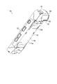
The
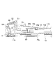
図1~図7に示すように、携帯端末10は、長手方向一側(図4及び図5の下側)が略薄板状の把持部12として構成される筐体11とこの筐体11の長手方向他側(図4及び図5の上側)に組み付けられるホルダ50とによって外郭が形成されている。
As shown in FIGS. 1 to 7, the
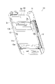
図4等に示すように、筐体11の表面11aには、狭額縁化(狭ベゼル化)されるように大型化された表示画面24aが配置されている。また、把持部12の一部を構成する筐体11の裏面11b側には、電池29aを交換等する際に着脱される蓋部13が組み付けられている。この蓋部13は、裏面11bを構成する外面のうち、把持部12側となる第1外面13aが平面状となり、この第1外面13aのホルダ50側に連なる第2外面13bがホルダ50側ほど筐体11の厚みを増すように傾斜して形成される。なお、筐体11の裏面11bは、把持部12の一部を構成する「一面」の一例に相当し得る。
As shown in FIG. 4 and the like, on the
特に、図5等に示すように、蓋部13は、第2外面13bがホルダ50の把持部側に対して滑らかに連なるように形成されている。このため、第2外面13bがホルダ50側ほど筐体11の厚みを増すように傾斜して形成されても、この厚みを増した部分が裏面11bから飛び出すホルダ50により形成されるデッドスペースに位置するため、携帯端末10の小型化や薄型化を阻害することもない。
In particular, as shown in FIG. 5 and the like, the
ホルダ50は、後述する情報コード読取ユニット40を保持する保持部として機能するもので、裏面11bに対して外方に突出するように筐体11に組み付けられている。このホルダ50の突出端部51には、情報コードCからの反射光を取り込むための読取口52が設けられている。
The
次に、携帯端末10の電気的構成について説明する。
図8(A)に示すように、携帯端末10の筐体11内には、携帯端末10全体を制御する制御部21が設けられている。この制御部21は、マイコンを主体として構成されるものであり、CPU、システムバス、入出力インタフェース等を有し、記憶部22とともに情報処理装置を構成している。記憶部22には、情報コードを光学的に読み取る読取処理を実行するための所定のプログラム等が制御部21により実行可能に予め格納されている。
Next, an electrical configuration of the
As shown in FIG. 8A, a
また、制御部21には、LED23、タッチパネル24、操作部25、バイブレータ26、ブザー27、通信部28などが接続されている。タッチパネル24は、公知のタッチパネル型の表示装置として構成されており、液晶表示器等の公知の表示デバイスとして構成される表示部と、この表示部の表示画面24aに重ねられて当該表示画面24aに対して押圧操作(接触)している範囲を検出可能な検出部として機能する透明性の操作パネルとを備えている。このタッチパネル24は、制御部21によって表示部の表示内容が制御される。操作部25は、上記操作パネルと筐体11の側面等に設けられる複数のキーとを備えるように構成されることで、タッチパネル24の表示画面24aに対する押圧操作(タッチ範囲等)やキー操作に応じた信号を制御部21に出力するように構成される。また、LED23、バイブレータ26及びブザー27は、制御部21によって制御される構成をなしており、それぞれ、制御部21からの指令を受けて動作する。
Further, an
通信部28は、電話回線網やインターネット等の所定のネットワークを介してデータ通信を行うためのインタフェースとして構成されており、無線通信用のアンテナ(以下、無線通信用アンテナ28aともいう)及び制御部21と協働して無線通信処理を行う構成をなしている。なお、通信部28は、「無線通信部」の一例に相当し、無線通信用アンテナ28aの配置構成については後述する。また、筐体11内には、電源部29が設けられており、この電源部29や電池29aによって制御部21や各種電気部品に電力が供給されるようになっている。
The
また、携帯端末10は、制御部21により制御されて外部の情報を読み取り可能な情報読取部として機能する無線タグ処理ユニット30及び情報コード読取ユニット40を備えている。
The
まず、無線タグ処理ユニット30について、図8(B)を用いて説明する。
無線タグ処理ユニット30は、無線タグT用のアンテナ(以下、タグ用アンテナ34ともいう)及び制御部21と協働して無線タグTとの間で電磁波による通信を行ない、無線タグTに記憶されるデータの読取り、或いは無線タグTに対するデータの書込みを行なうように機能するものである。この無線タグ処理ユニット30は、公知の電波方式で伝送を行う回路として構成されており、図8(B)にて概略的に示すように、送信回路31、受信回路32、整合回路33などを有している。
First, the wireless
The wireless
送信回路31は、キャリア発振器、符号化部、増幅器、送信部フィルタ、変調部などによって構成されており、キャリア発振器から所定の周波数のキャリア(搬送波)が出力される構成をなしている。また、符号化部は、制御部21に接続されており、当該制御部21より出力される送信データを符号化して変調部に出力している。変調部は、キャリア発振器からのキャリア(搬送波)、及び符号化部からの送信データが入力される部分であり、キャリア発振器より出力されるキャリア(搬送波)に対し、通信対象へのコマンド送信時に符号化部より出力される符号化された送信符号(変調信号)によってASK(Amplitude Shift Keying)変調された被変調信号を生成し、増幅器に出力している。増幅器は、入力信号(変調部によって変調された被変調信号)を所定のゲインで増幅し、その増幅信号を送信部フィルタに出力しており、送信部フィルタは、増幅器からの増幅信号をフィルタリングした送信信号を、整合回路33を介してタグ用アンテナ34に出力している。このようにしてタグ用アンテナ34に送信信号が出力されると、その送信信号が送信電波として当該タグ用アンテナ34より外部に放射される。
The
一方、タグ用アンテナ34によって受信された応答信号は、整合回路33を介して受信回路32に入力される。この受信回路32は、受信部フィルタ、増幅器、復調部、二値化処理部、複号化部などによって構成されており、タグ用アンテナ34を介して受信された応答信号を受信部フィルタによってフィルタリングした後、増幅器によって増幅し、その増幅信号を復調部によって復調する。そして、その復調された信号波形を二値化処理部によって二値化し、復号化部にて復号化した後、その復号化された信号を受信データとして制御部21に出力している。
On the other hand, the response signal received by the
次に、情報コード読取ユニット40について、図8(C)及び図9を用いて説明する。
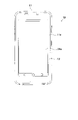
情報コード読取ユニット40は、情報コードCを光学的に読み取るように機能するもので、図9に示すように、ホルダ50により支持されて、筐体11の長手方向他側にて裏面11bから飛び出るようにして配置されている。
Next, the information
The information
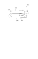
情報コード読取ユニット40は、図8(C)に示すように、CCDエリアセンサからなる受光センサ43、結像レンズ42、複数個のLEDやレンズ等から構成される照明部41などを備えた構成をなしており、制御部21と協働して読取対象Rに付された情報コードC(バーコードや二次元コード)を読み取るように機能する。
As shown in FIG. 8C, the information
この情報コード読取ユニット40によって読み取りを行う場合、まず、制御部21によって指令を受けた照明部41から照明光Lfが出射され、この照明光Lfが読取口52を通って読取対象Rに照射される。そして、照明光Lfが情報コードCにて反射した反射光Lrは読取口52を通って装置内に取り込まれ、結像レンズ42を通って受光センサ43に受光される。読取口52と受光センサ43との間に配される結像レンズ42は、情報コードCの像を受光センサ43上に結像させる構成をなしており、受光センサ43はこの情報コードCの像に応じた受光信号を出力する。受光センサ43から出力された受光信号は、画像データとして記憶部22(図8(A))に記憶され、情報コードCに含まれる情報を取得するためのデコード処理に用いられるようになっている。なお、情報コード読取ユニット40には、受光センサ43からの信号を増幅する増幅回路や、その増幅された信号をデジタル信号に変換するAD変換回路等が設けられているがこれらの回路については図示を省略している。
When reading is performed by the information
このように構成される携帯端末10では、把持部12が薄板状に形成されているため、剛性を高める目的で、図9に示すように、略平板状の金属ホルダ60が筐体11内にて当該筐体11の長手方向に沿って配置されている。このため、この金属ホルダ60から無線通信用アンテナ28aを離して配置することで、無線通信用アンテナ28aを利用した無線通信に関して金属ホルダ60の影響を低減する必要がある。
In the
そこで、本実施形態では、無線通信用アンテナ28aは、蓋部13の内面のうち、ホルダ50側となる支持面13cを利用して配置される。この支持面13cは、蓋部13における第2外面13bの内面側となる面であり、第2外面13bと同様に把持部12側の裏面11bに対して傾斜するように形成されており、ホルダ50側ほど金属ホルダ60から離れるようになっている。この無線通信用アンテナ28aは、蓋部13の内面に設けられるコネクタ28bを介して制御部21に接続される。このため、無線通信用アンテナ28aは、支持面13cを利用することで、筐体11内の金属ホルダ60から離されるように配置される。
Therefore, in this embodiment, the
このように、無線通信用アンテナ28aは、ホルダ50の把持部12側と裏面11bのホルダ50側との間であってホルダ50の突出端部51と裏面11bとの間に設けられる蓋部13の支持面13cを利用して配置される。
In this way, the
これにより、無線通信用アンテナ28aが配置される支持面13cは、ホルダ50の突出端部51と裏面11bとの間に配置されるため、無線通信用アンテナ28aが裏面11bよりも内側となるように筐体11内に収容される場合と比較して、無線通信用アンテナ28aを筐体11内の金属ホルダ60から離すように配置することができる。特に、支持面13cは、ホルダ50の把持部12側と裏面11bのホルダ50側との間となるように配置されるため、ホルダ50が裏面11bから飛び出すことでデッドスペースとなりやすいホルダ50の把持部12側近傍のスペースを有効に活用することができる。したがって、小型化や薄型化を阻害することなく無線通信性能を向上させることができる。
As a result, the
特に、無線通信用アンテナ28aが配置される支持面13cは、筐体11に対して着脱可能に組み付けられる蓋部13の内面側に設けられる。これにより、無線通信用アンテナ28aの交換が必要になるような場合でも、蓋部13の交換に応じて無線通信用アンテナ28aを容易に交換することができる。
In particular, the
なお、本発明は上記実施形態等に限定されるものではなく、例えば、以下のように具体化してもよい。
(1)蓋部13の支持面13cを利用して無線通信用アンテナ28aが配置されることに限らず、他のアンテナ、例えば、蓋部13の支持面13cを利用してタグ用アンテナ34が配置されてもよい。このように蓋部13の支持面13cを利用してタグ用アンテナ34が配置される場合には、このタグ用アンテナ34を金属ホルダ60から離すことができるので、無線タグTの読み書きに関して無線通信性能を向上させることができる。
It should be noted that the present invention is not limited to the above embodiments and the like, and may be embodied as follows, for example.
(1) The
(2)支持面13cは、上述のように筐体11に対して着脱可能な蓋部13に設けられることに限らず、筐体11から取り外し不能な部位のうち、ホルダ50の把持部12側と裏面11bのホルダ50側との間であってホルダ50の突出端部51と裏面11bとの間に設けられる部位の内面等に設けられてもよい。
(2) The
10…携帯端末
11…筐体
11b…裏面(一面)
12…把持部
13…蓋部
13c…支持面
28…通信部(無線通信部)
28a…無線通信用アンテナ(アンテナ)
40…情報コード読取ユニット(読取部)
50…ホルダ
51…突出端部
52…読取口
60…金属ホルダ
DESCRIPTION OF
DESCRIPTION OF
28a ... Antenna for wireless communication (antenna)
40... Information code reading unit (reading section)
50...
Claims (2)
アンテナを介して無線通信を行う無線通信部と、
長手方向一側が薄板状の把持部として構成され表面に表示画面が配置される筐体と、
前記筐体の長手方向他側に組み付けられて、前記読取部を保持するホルダと、
を備える携帯端末であって、
前記ホルダは、前記把持部の一部を構成する裏面に対して突出するように前記筐体に組み付けられ、
前記筐体内の前記表示画面側には、平板状の金属ホルダが前記筐体の長手方向に沿って配置され、
前記アンテナは、前記ホルダの前記把持部側と前記裏面の前記ホルダ側との間であって前記ホルダの突出端部と前記裏面との間に設けられる支持面を利用して前記金属ホルダに対して前記ホルダ側ほど離れるようにして配置されることを特徴とする携帯端末。 a reading unit that optically reads an information code;
a wireless communication unit that performs wireless communication via an antenna;
a casing having one longitudinal side configured as a thin plate-like grip portion and having a display screen arranged on the surface thereof ;
a holder assembled on the other longitudinal side of the housing and holding the reading unit;
A mobile terminal comprising
The holder is assembled to the housing so as to protrude from a back surface forming part of the grip,
A flat plate-shaped metal holder is arranged along the longitudinal direction of the housing on the display screen side in the housing,
The antenna is mounted on the metal holder by using a support surface provided between the holding portion side of the holder and the holder side of the back surface and between the projecting end portion of the holder and the back surface. A mobile terminal, characterized in that the mobile terminal is arranged so as to separate from the holder side.
Priority Applications (1)
| Application Number | Priority Date | Filing Date | Title |
|---|---|---|---|
| JP2018086408A JP7204336B2 (en) | 2018-04-27 | 2018-04-27 | mobile terminal |
Applications Claiming Priority (1)
| Application Number | Priority Date | Filing Date | Title |
|---|---|---|---|
| JP2018086408A JP7204336B2 (en) | 2018-04-27 | 2018-04-27 | mobile terminal |
Publications (2)
| Publication Number | Publication Date |
|---|---|
| JP2019192079A JP2019192079A (en) | 2019-10-31 |
| JP7204336B2 true JP7204336B2 (en) | 2023-01-16 |
Family
ID=68390250
Family Applications (1)
| Application Number | Title | Priority Date | Filing Date |
|---|---|---|---|
| JP2018086408A Active JP7204336B2 (en) | 2018-04-27 | 2018-04-27 | mobile terminal |
Country Status (1)
| Country | Link |
|---|---|
| JP (1) | JP7204336B2 (en) |
Families Citing this family (1)
| Publication number | Priority date | Publication date | Assignee | Title |
|---|---|---|---|---|
| JP7441064B2 (en) * | 2020-02-07 | 2024-02-29 | カシオ計算機株式会社 | mobile information terminal |
Citations (5)
| Publication number | Priority date | Publication date | Assignee | Title |
|---|---|---|---|---|
| JP2000163529A (en) | 1998-11-27 | 2000-06-16 | Toshiba Tec Corp | Handy terminal |
| JP2001057481A (en) | 1999-08-17 | 2001-02-27 | Matsushita Electric Ind Co Ltd | Barcode reader fixture |
| WO2005017821A1 (en) | 2003-08-13 | 2005-02-24 | Murata Manufacturing Co., Ltd. | Reader/writer and mobile communication device |
| JP2009290300A (en) | 2008-05-27 | 2009-12-10 | Denso Wave Inc | Mobile information terminal |
| JP2011034465A (en) | 2009-08-05 | 2011-02-17 | Casio Computer Co Ltd | Reader/writer device |
Family Cites Families (3)
| Publication number | Priority date | Publication date | Assignee | Title |
|---|---|---|---|---|
| JP3880783B2 (en) * | 2000-07-21 | 2007-02-14 | 高嗣 北川 | Portable information equipment |
| JP5263110B2 (en) * | 2009-09-30 | 2013-08-14 | 株式会社デンソーウェーブ | Portable communication terminal |
| US20130248601A1 (en) * | 2012-03-26 | 2013-09-26 | Symbol Technologies, Inc. | Mobile computer with integrated near field communication antenna |
-
2018
- 2018-04-27 JP JP2018086408A patent/JP7204336B2/en active Active
Patent Citations (5)
| Publication number | Priority date | Publication date | Assignee | Title |
|---|---|---|---|---|
| JP2000163529A (en) | 1998-11-27 | 2000-06-16 | Toshiba Tec Corp | Handy terminal |
| JP2001057481A (en) | 1999-08-17 | 2001-02-27 | Matsushita Electric Ind Co Ltd | Barcode reader fixture |
| WO2005017821A1 (en) | 2003-08-13 | 2005-02-24 | Murata Manufacturing Co., Ltd. | Reader/writer and mobile communication device |
| JP2009290300A (en) | 2008-05-27 | 2009-12-10 | Denso Wave Inc | Mobile information terminal |
| JP2011034465A (en) | 2009-08-05 | 2011-02-17 | Casio Computer Co Ltd | Reader/writer device |
Also Published As
| Publication number | Publication date |
|---|---|
| JP2019192079A (en) | 2019-10-31 |
Similar Documents
| Publication | Publication Date | Title |
|---|---|---|
| JP7010579B2 (en) | Connection unit, information processing device | |
| JP7204336B2 (en) | mobile terminal | |
| JP7293774B2 (en) | Optical information reader | |
| KR101955661B1 (en) | Electronic tag reader | |
| JP6680122B2 (en) | Mobile device | |
| JP6458690B2 (en) | RFID reader | |
| JP7163702B2 (en) | Electronics | |
| JP2019193127A (en) | Mobile terminal | |
| JP2020010239A (en) | Portable terminal | |
| US11216032B2 (en) | Information reading apparatus | |
| JP2017004333A (en) | Information reading apparatus and information reading system | |
| JP5136525B2 (en) | Mobile device | |
| JP7196672B2 (en) | Information reader | |
| JP5109860B2 (en) | Payment device | |
| JP2020057496A (en) | battery | |
| JP7205281B2 (en) | Attachment and information reader | |
| JP2019191976A (en) | Optical information reading device | |
| JP2004157744A (en) | Optical and electromagnetic type mobile multi-reader | |
| JP2021087228A (en) | Portable terminal | |
| JP2020140434A (en) | Information processing terminal | |
| JP4968270B2 (en) | Mobile communication terminal | |
| TWI581191B (en) | RFID read / write device | |
| JP2019179779A (en) | Portable terminal | |
| JP5218023B2 (en) | Communications system | |
| JP3857826B2 (en) | Portable device with scanner |
Legal Events
| Date | Code | Title | Description |
|---|---|---|---|
| A621 | Written request for application examination |
Free format text: JAPANESE INTERMEDIATE CODE: A621 Effective date: 20210205 |
|
| A977 | Report on retrieval |
Free format text: JAPANESE INTERMEDIATE CODE: A971007 Effective date: 20211203 |
|
| A131 | Notification of reasons for refusal |
Free format text: JAPANESE INTERMEDIATE CODE: A131 Effective date: 20211221 |
|
| A521 | Request for written amendment filed |
Free format text: JAPANESE INTERMEDIATE CODE: A523 Effective date: 20220217 |
|
| A02 | Decision of refusal |
Free format text: JAPANESE INTERMEDIATE CODE: A02 Effective date: 20220405 |
|
| A521 | Request for written amendment filed |
Free format text: JAPANESE INTERMEDIATE CODE: A523 Effective date: 20220701 |
|
| C60 | Trial request (containing other claim documents, opposition documents) |
Free format text: JAPANESE INTERMEDIATE CODE: C60 Effective date: 20220701 |
|
| A911 | Transfer to examiner for re-examination before appeal (zenchi) |
Free format text: JAPANESE INTERMEDIATE CODE: A911 Effective date: 20220713 |
|
| C21 | Notice of transfer of a case for reconsideration by examiners before appeal proceedings |
Free format text: JAPANESE INTERMEDIATE CODE: C21 Effective date: 20220719 |
|
| A912 | Re-examination (zenchi) completed and case transferred to appeal board |
Free format text: JAPANESE INTERMEDIATE CODE: A912 Effective date: 20220812 |
|
| C211 | Notice of termination of reconsideration by examiners before appeal proceedings |
Free format text: JAPANESE INTERMEDIATE CODE: C211 Effective date: 20220823 |
|
| C22 | Notice of designation (change) of administrative judge |
Free format text: JAPANESE INTERMEDIATE CODE: C22 Effective date: 20221011 |
|
| C22 | Notice of designation (change) of administrative judge |
Free format text: JAPANESE INTERMEDIATE CODE: C22 Effective date: 20221018 |
|
| C23 | Notice of termination of proceedings |
Free format text: JAPANESE INTERMEDIATE CODE: C23 Effective date: 20221129 |
|
| C03 | Trial/appeal decision taken |
Free format text: JAPANESE INTERMEDIATE CODE: C03 Effective date: 20221227 |
|
| C30A | Notification sent |
Free format text: JAPANESE INTERMEDIATE CODE: C3012 Effective date: 20221227 |
|
| A61 | First payment of annual fees (during grant procedure) |
Free format text: JAPANESE INTERMEDIATE CODE: A61 Effective date: 20221228 |
|
| R150 | Certificate of patent or registration of utility model |
Ref document number: 7204336 Country of ref document: JP Free format text: JAPANESE INTERMEDIATE CODE: R150 |