JP7204275B2 - Channel access method for transmitting in unlicensed band and apparatus using the same - Google Patents
Channel access method for transmitting in unlicensed band and apparatus using the same Download PDFInfo
- Publication number
- JP7204275B2 JP7204275B2 JP2022507670A JP2022507670A JP7204275B2 JP 7204275 B2 JP7204275 B2 JP 7204275B2 JP 2022507670 A JP2022507670 A JP 2022507670A JP 2022507670 A JP2022507670 A JP 2022507670A JP 7204275 B2 JP7204275 B2 JP 7204275B2
- Authority
- JP
- Japan
- Prior art keywords
- channel access
- terminal
- channel
- transmission
- transmissions
- Prior art date
- Legal status (The legal status is an assumption and is not a legal conclusion. Google has not performed a legal analysis and makes no representation as to the accuracy of the status listed.)
- Active
Links
Images


Classifications
-
- H—ELECTRICITY
- H04—ELECTRIC COMMUNICATION TECHNIQUE
- H04W—WIRELESS COMMUNICATION NETWORKS
- H04W74/00—Wireless channel access
- H04W74/08—Non-scheduled access, e.g. ALOHA
- H04W74/0833—Random access procedures, e.g. with 4-step access
- H04W74/0841—Random access procedures, e.g. with 4-step access with collision treatment
- H04W74/085—Random access procedures, e.g. with 4-step access with collision treatment collision avoidance
-
- H—ELECTRICITY
- H04—ELECTRIC COMMUNICATION TECHNIQUE
- H04L—TRANSMISSION OF DIGITAL INFORMATION, e.g. TELEGRAPHIC COMMUNICATION
- H04L5/00—Arrangements affording multiple use of the transmission path
- H04L5/0001—Arrangements for dividing the transmission path
- H04L5/0003—Two-dimensional division
- H04L5/0005—Time-frequency
- H04L5/0007—Time-frequency the frequencies being orthogonal, e.g. OFDM(A) or DMT
- H04L5/001—Time-frequency the frequencies being orthogonal, e.g. OFDM(A) or DMT the frequencies being arranged in component carriers
-
- H—ELECTRICITY
- H04—ELECTRIC COMMUNICATION TECHNIQUE
- H04W—WIRELESS COMMUNICATION NETWORKS
- H04W74/00—Wireless channel access
- H04W74/08—Non-scheduled access, e.g. ALOHA
- H04W74/0808—Non-scheduled access, e.g. ALOHA using carrier sensing, e.g. carrier sense multiple access [CSMA]
-
- H—ELECTRICITY
- H04—ELECTRIC COMMUNICATION TECHNIQUE
- H04W—WIRELESS COMMUNICATION NETWORKS
- H04W16/00—Network planning, e.g. coverage or traffic planning tools; Network deployment, e.g. resource partitioning or cells structures
- H04W16/14—Spectrum sharing arrangements between different networks
-
- H—ELECTRICITY
- H04—ELECTRIC COMMUNICATION TECHNIQUE
- H04W—WIRELESS COMMUNICATION NETWORKS
- H04W72/00—Local resource management
- H04W72/04—Wireless resource allocation
-
- H—ELECTRICITY
- H04—ELECTRIC COMMUNICATION TECHNIQUE
- H04W—WIRELESS COMMUNICATION NETWORKS
- H04W72/00—Local resource management
- H04W72/04—Wireless resource allocation
- H04W72/044—Wireless resource allocation based on the type of the allocated resource
- H04W72/0446—Resources in time domain, e.g. slots or frames
-
- H—ELECTRICITY
- H04—ELECTRIC COMMUNICATION TECHNIQUE
- H04W—WIRELESS COMMUNICATION NETWORKS
- H04W72/00—Local resource management
- H04W72/12—Wireless traffic scheduling
- H04W72/1263—Mapping of traffic onto schedule, e.g. scheduled allocation or multiplexing of flows
-
- H—ELECTRICITY
- H04—ELECTRIC COMMUNICATION TECHNIQUE
- H04W—WIRELESS COMMUNICATION NETWORKS
- H04W72/00—Local resource management
- H04W72/12—Wireless traffic scheduling
- H04W72/1263—Mapping of traffic onto schedule, e.g. scheduled allocation or multiplexing of flows
- H04W72/1268—Mapping of traffic onto schedule, e.g. scheduled allocation or multiplexing of flows of uplink data flows
-
- H—ELECTRICITY
- H04—ELECTRIC COMMUNICATION TECHNIQUE
- H04W—WIRELESS COMMUNICATION NETWORKS
- H04W72/00—Local resource management
- H04W72/20—Control channels or signalling for resource management
- H04W72/23—Control channels or signalling for resource management in the downlink direction of a wireless link, i.e. towards a terminal
-
- H—ELECTRICITY
- H04—ELECTRIC COMMUNICATION TECHNIQUE
- H04W—WIRELESS COMMUNICATION NETWORKS
- H04W74/00—Wireless channel access
-
- H—ELECTRICITY
- H04—ELECTRIC COMMUNICATION TECHNIQUE
- H04W—WIRELESS COMMUNICATION NETWORKS
- H04W74/00—Wireless channel access
- H04W74/002—Transmission of channel access control information
-
- H—ELECTRICITY
- H04—ELECTRIC COMMUNICATION TECHNIQUE
- H04W—WIRELESS COMMUNICATION NETWORKS
- H04W74/00—Wireless channel access
- H04W74/08—Non-scheduled access, e.g. ALOHA
-
- H—ELECTRICITY
- H04—ELECTRIC COMMUNICATION TECHNIQUE
- H04W—WIRELESS COMMUNICATION NETWORKS
- H04W74/00—Wireless channel access
- H04W74/08—Non-scheduled access, e.g. ALOHA
- H04W74/0808—Non-scheduled access, e.g. ALOHA using carrier sensing, e.g. carrier sense multiple access [CSMA]
- H04W74/0816—Non-scheduled access, e.g. ALOHA using carrier sensing, e.g. carrier sense multiple access [CSMA] with collision avoidance
-
- H—ELECTRICITY
- H04—ELECTRIC COMMUNICATION TECHNIQUE
- H04W—WIRELESS COMMUNICATION NETWORKS
- H04W74/00—Wireless channel access
- H04W74/08—Non-scheduled access, e.g. ALOHA
- H04W74/0833—Random access procedures, e.g. with 4-step access
-
- H—ELECTRICITY
- H04—ELECTRIC COMMUNICATION TECHNIQUE
- H04W—WIRELESS COMMUNICATION NETWORKS
- H04W74/00—Wireless channel access
- H04W74/08—Non-scheduled access, e.g. ALOHA
- H04W74/0866—Non-scheduled access, e.g. ALOHA using a dedicated channel for access
-
- H—ELECTRICITY
- H04—ELECTRIC COMMUNICATION TECHNIQUE
- H04W—WIRELESS COMMUNICATION NETWORKS
- H04W74/00—Wireless channel access
- H04W74/08—Non-scheduled access, e.g. ALOHA
- H04W74/0866—Non-scheduled access, e.g. ALOHA using a dedicated channel for access
- H04W74/0875—Non-scheduled access, e.g. ALOHA using a dedicated channel for access with assigned priorities based access
-
- H—ELECTRICITY
- H04—ELECTRIC COMMUNICATION TECHNIQUE
- H04L—TRANSMISSION OF DIGITAL INFORMATION, e.g. TELEGRAPHIC COMMUNICATION
- H04L5/00—Arrangements affording multiple use of the transmission path
- H04L5/0091—Signalling for the administration of the divided path, e.g. signalling of configuration information
- H04L5/0096—Indication of changes in allocation
- H04L5/0098—Signalling of the activation or deactivation of component carriers, subcarriers or frequency bands
Landscapes
- Engineering & Computer Science (AREA)
- Signal Processing (AREA)
- Computer Networks & Wireless Communication (AREA)
- Mobile Radio Communication Systems (AREA)
Description
本発明は、無線通信新ステムに関する。具体的に、本発明は、非免許帯域で動作する無線通信システムにおいてチャネルアクセス方法及びこれを用いる装置に関する。 The present invention relates to a new wireless communication system. Specifically, the present invention relates to a channel access method and apparatus using the same in a wireless communication system operating in an unlicensed band.
4G(4th generation)通信システムの商用化以来、増加する無線データトラフィックの需要を充足させるために、新しい5G(5th generation)通信システムを開発するための努力がなされてきている。5G通信システムは、4Gネットワーク以降(beyond 4G network)の通信システム、LTEシステム以降(post LTE)のシステム、又はNR(new radio)システムと呼ばれている。高いデータ伝送率を達成するために、5G通信システムは、6GHz以上の超高周波(mmWave)帯域を用いて運用されるシステムを含み、また、カバレッジが確保できる側面から、6GHz以下の周波数帯域を用いて運用される通信システムを含んで基地局と端末での具現が考慮されている。 Since the commercialization of 4G (4th generation) communication systems, efforts have been made to develop new 5G (5th generation) communication systems to meet the increasing demand for wireless data traffic. The 5G communication system is called a communication system after the 4G network (beyond 4G network), a system after the LTE system (post LTE), or a NR (new radio) system. In order to achieve a high data transmission rate, 5G communication systems include systems that operate using ultra-high frequency (mmWave) bands of 6 GHz or higher, and from the aspect of ensuring coverage, use frequency bands of 6 GHz or lower. Implementation in base stations and terminals, including communication systems operated by both, is considered.
3GPP(3rd generation partnership project)NRシステムはネットワークのスペクトル効率を向上させ、通信事業者が与えられた帯域幅でより多いデータ及び音声サービスを提供できるようにする。したがって、3GPP NRシステムは、大容量音声支援の他にも高速データ及びメディア伝送に対する要求を充足するように設計される。NRシステムの利点は、同一プラットホームで高い処理量、低い待機時間、FDD(frequency division duplex)及びTDD(time division duplex)支援、向上した最終ユーザ環境、及び簡単なアーキテクチャーによる低運営コスト、を有し得るということである。 The 3rd generation partnership project (3GPP) NR system improves the spectral efficiency of networks, enabling carriers to offer more data and voice services with a given bandwidth. Therefore, the 3GPP NR system is designed to meet the demand for high-speed data and media transmission as well as high-capacity voice support. The advantages of the NR system include high throughput, low latency, FDD (frequency division duplex) and TDD (time division duplex) support on the same platform, improved end-user environment, and low operating costs due to simple architecture. It is possible.
より効率的なデータ処理のために、NRシステムのダイナミックTDDは、セルのユーザのデータトラフィック方向にしたがって、上りリンク及び下りリンクに使用できるOFDM(orthogonal frequency division multiplexing)シンボルの数を可変する方式を用いることができる。例えば、セルの下りリンクトラフィックが上りリンクトラフィックよりも多い場合に、基地局は、スロット(又は、サブフレーム)に相対的に多数の下りリンクOFDMシンボルを割り当てることができる。スロット構成に関する情報が端末に送信される必要がある。 For more efficient data processing, the dynamic TDD of the NR system adopts a method of varying the number of orthogonal frequency division multiplexing (OFDM) symbols available for uplink and downlink according to the data traffic direction of the users in the cell. can be used. For example, a base station can allocate a relatively large number of downlink OFDM symbols to a slot (or subframe) when the downlink traffic of a cell is greater than the uplink traffic. Information about the slot configuration needs to be sent to the terminal.
超高周波帯域における電波の経路損失の緩和及び電波の伝達距離の増加のために、5G通信システムでは、ビームフォーミング(beamforming)、巨大配列多重入出力(massive MIMO)、全次元多重入出力(full dimensional MIMO,FD-MIMO)、アレイアンテナ(array antenna)、アナログビームフォーミング(analog beam-forming)、アナログビームフォーミングとデジタルビームフォーミングとを組み合わせるハイブリッドビームフォーミング、及び大規模アンテナ(large scale antenna)技術、が論議されている。また、システムのネットワークの改善のために、5G通信システムでは、進化した小型セル、改善された小型セル(advanced small cell)、クラウド無線アクセスネットワーク(cloud radio access network:cloud RAN)、超高密度ネットワーク(ultra-dense network)、機器間通信(device to device communication:D2D)、車両を用いる通信(vehicle to everything communication:V2X)、無線バックホール(wireless backhaul)、非地上波ネットワーク通信(non-terrestrial network communication,NTN)、移動ネットワーク(moving network)、協力通信(cooperative communication)、CoMP(coordinated multi-points)、及び受信干渉除去(interference cancellation)などに関する技術開発がなされている。その他にも、5Gシステムでは、進歩したコーディング変調(advanced coding modulation:ACM)方式であるFQAM(hybrid FSK and QAM modulation)及びSWSC(sliding window superposition coding)と、進歩した接続技術であるFBMC(filter bank multi-carrier)、NOMA(non-orthogonal multiple access)、及びSCMA(sparse code multiple access)などが開発されている。 In order to alleviate the path loss of radio waves and increase the transmission distance of radio waves in the ultra-high frequency band, beamforming, massive MIMO, and full dimensional multiplexing are used in 5G communication systems. MIMO, FD-MIMO), array antennas, analog beam-forming, hybrid beam-forming that combines analog and digital beam-forming, and large scale antenna technologies, is being discussed. In addition, in order to improve the network of the system, the 5G communication system includes advanced small cells, advanced small cells, cloud radio access networks (cloud RAN), ultra-high density networks. (ultra-dense network), device to device communication (D2D), vehicle to everything communication (V2X), wireless backhaul, non-terrestrial network communication Technologies related to communication (NTN), moving network, cooperative communication, CoMP (coordinated multi-points), reception interference cancellation, etc. are being developed. In addition, in the 5G system, the advanced coding modulation (ACM) scheme FQAM (hybrid FSK and QAM modulation) and SWSC (sliding window superposition coding), and the advanced connection technology FBMC (filter bank multi-carrier), NOMA (non-orthogonal multiple access), SCMA (sparse code multiple access), etc. have been developed.
一方、インターネットは人間が情報を生成し消費する人間中心の連結網において、物など分散された構成要素間に情報を交換し処理するIoT(Internet of Things、モノのインターネット)網に進化している。クラウドサーバなどとの連結を介したビックデータ(big data)処理技術などがIoT技術に結合されたIoE(Internet of Everything)技術も台頭している。IoTを具現するために、センシング技術、有無線通信及びネットワークインフラ、サービスインタフェース技術、及び保安技術などのような技術要素が要求されており、最近は物間の連結のためのセンサネットワーク、マシンツーマシン(machine to machine、M2M)、MTC(machine type communication)などの技術が研究されている。IoT環境では、連結された物から生成されたデータを収集、分析して、人間の生活に新たな価値を生み出す知能型IT(internet technology)サービスが提供される。IoTは、従来のIT技術と多様な産業間の融合及び複合を介し、スマートホーム、スマートビル、スマートシティ、スマートカーまたはコネクテッドカー、スマートグリッド、ヘルスケア、スマート家電、先端医療サービスなどの分野に応用される。 On the other hand, the Internet is a human-centered connection network in which humans generate and consume information, and is evolving into an IoT (Internet of Things) network in which information is exchanged and processed between distributed components such as objects. . Internet of Everything (IoE) technology, which combines IoT technology with big data processing technology through connection with a cloud server, is also emerging. In order to implement IoT, technological elements such as sensing technology, wired/wireless communication and network infrastructure, service interface technology, and security technology are required. Technologies such as machine to machine (M2M) and MTC (machine type communication) are being researched. In the IoT environment, intelligent IT (internet technology) services that create new value in human life by collecting and analyzing data generated from connected objects are provided. Through the fusion and combination of conventional IT technology and various industries, IoT is expanding into fields such as smart homes, smart buildings, smart cities, smart cars or connected cars, smart grids, healthcare, smart home appliances, and advanced medical services. Applied.
そこで、5G通信システムをIoT網に適用するための様々な試みが行われている。例えば、センサネットワーク、マシンツーマシン、MTCなどの技術が、5G通信技術であるビームフォーミング、MIMO、及びアレイアンテナなどの技法によって具現されている。上述したビックデータ処理技術として、クラウド無線アクセスネットワーク(cloud RAN)の適用も5G技術とIoT技術の融合の一例といえる。一般に、移動通信システムは、ユーザの活動性を保障しながら音声サービスを提供するために開発された。 Therefore, various attempts have been made to apply 5G communication systems to IoT networks. For example, technologies such as sensor networks, machine-to-machine, and MTC are embodied by techniques such as beamforming, MIMO, and array antennas, which are 5G communication technologies. Application of a cloud radio access network (cloud RAN) as the above-mentioned big data processing technology can be said to be an example of the fusion of 5G technology and IoT technology. Generally, mobile communication systems have been developed to provide voice services while ensuring user activity.
しかしながら、移動通信システムは次第に音声だけでなくデータサービスにまでサービス領域を拡張しており、現在は高速のデータサービスを提供する程度にまで発展している。しかし、現在サービス提供中の移動通信システムでは、資源不足現象及びユーザの更なる高速サービスの要求のため、より発展した移動通信システムが要求されている。 However, mobile communication systems have gradually expanded their service areas to include not only voice services but also data services, and have now developed to the extent of providing high-speed data services. However, mobile communication systems currently providing services are in need of more developed mobile communication systems due to resource shortages and users' demands for higher speed services.
近年、スマート機器の拡散につれてモバイルトラフィックが急増することにより、既存の免許(licensed)周波数スペクトル又は免許周波数帯域だけでは、セルラー通信サービス提供のために増えるデータ使用量に耐え難くなっている。 In recent years, due to the rapid growth of mobile traffic with the proliferation of smart devices, existing licensed frequency spectrums or bands alone cannot sustain the increased data usage for the provision of cellular communication services.
このような状況で、セルラー通信サービス提供のために非免許(unlicensed)周波数スペクトル又は非免許周波数帯域(例えば、2.4GHz帯域、5GHz帯域、6GHz帯域、52.6GHz以上の帯域など)を用いる方案が、スペクトル不足の問題に対する解決策として論議されている。 Under such circumstances, a plan to use an unlicensed frequency spectrum or unlicensed frequency band (e.g., 2.4 GHz band, 5 GHz band, 6 GHz band, 52.6 GHz or higher band, etc.) to provide cellular communication services. has been discussed as a solution to the spectrum scarcity problem.
通信事業者が競売などの手続きを踏まえて独占的な周波数使用権を確保する免許帯域と違い、非免許帯域では、一定レベルの隣接帯域保護規定する遵守するだけの条件で、多数の通信装置が無制限に同時使用されてよい。これにより、セルラー通信サービスに非免許帯域が用いられる場合、免許帯域で提供されているレベルの通信品質が保障し難く、既存に非免許帯域を用いていた無線通信装置(例えば、無線LAN装置)との干渉問題が発生し得る。 Unlike licensed bands, where telecommunications carriers secure exclusive rights to use frequencies based on procedures such as auctions, unlicensed bands require a certain level of adjacent band protection, and a large number of communication devices can operate on the condition that they comply. Unlimited concurrent use. As a result, when an unlicensed band is used for cellular communication services, it is difficult to guarantee the level of communication quality provided by the licensed band. can cause interference problems with
非免許帯域でもLTE及びNR技術を用いるためには、既存の非免許帯域装置との共存方案、及び効率的に無線チャネルを他の無線通信装置と共有する方案、に関する研究が先行されるべきである。すなわち、非免許帯域でLTE及びNR技術を用いる装置が既存の非免許帯域装置に影響を与えないように強力な共存メカニズム(Robust Coexistence Mechanism,RCM)が開発される必要がある。 In order to use LTE and NR technologies even in unlicensed bands, research on coexistence methods with existing unlicensed band devices and methods for efficiently sharing radio channels with other wireless communication devices should be conducted first. be. That is, a robust coexistence mechanism (RCM) needs to be developed so that devices using LTE and NR technologies in unlicensed bands do not affect existing unlicensed band devices.
本発明の一実施例の目的は、非免許帯域で動作する無線通信システムにおいて送信を行うためのチャネルアクセス方法及びこれを用いる装置を提供することである。 It is an object of one embodiment of the present invention to provide a channel access method and apparatus using the same for transmitting in a wireless communication system operating in unlicensed bands.
本発明の実施例によって非免許帯域で基地局と無線で通信する端末は、通信モジュール;及び、前記通信モジュールを制御するプロセッサを含む。前記プロセッサは、前記基地局から、複数の上りリンク送信をスケジュールするグラントを受信し、前記端末が、前記複数の上りリンク送信の一つである第1送信のために第1固定デューレーションベースチャネルアクセスを試み、前記第1固定デューレーションベースチャネルアクセスに失敗した場合に、前記第1送信の次の送信である第2送信のために第2固定デューレーションベースチャネルアクセスを試みることができる。前記第1固定デューレーションベースチャネルアクセスは、第1固定デューレーション内にチャネルが遊休であるとセンシングされる場合に、前記第1固定デューレーションベースチャネルアクセスを行う端末が、前記第1固定デューレーション以降に直ちに送信を行うことが許容されるチャネルアクセスである。前記第2固定デューレーションベースチャネルアクセスは、第2固定デューレーションの間にチャネルが遊休であるとセンシングされる場合に、前記第2固定デューレーションベースチャネルアクセスを行う端末が、前記第2固定デューレーション以降に直ちに送信を行うことが許容されるチャネルアクセスである。 A terminal wirelessly communicating with a base station in an unlicensed band according to an embodiment of the present invention includes a communication module; and a processor controlling the communication module. The processor receives from the base station a grant to schedule a plurality of uplink transmissions, and the terminal configures a first fixed duration base channel for a first transmission, one of the plurality of uplink transmissions. If access is attempted and the first fixed duration-based channel access fails, a second fixed duration-based channel access may be attempted for a second transmission that is subsequent to the first transmission. When the first fixed duration-based channel access is sensed that the channel is idle within the first fixed duration, the terminal performing the first fixed duration-based channel access is set to the first fixed duration. It is a channel access that permits immediate transmission thereafter. The second fixed duration-based channel access allows the terminal performing the second fixed duration-based channel access to perform the second fixed duration if the channel is sensed to be idle during the second fixed duration. It is a channel access that permits transmission immediately after transmission.
前記第1固定デューレーションは、前記第2固定デューレーションよりも短くてよい。 The first fixed duration may be shorter than the second fixed duration.
前記第1固定デューレーションは、16usであり、前記第2固定デューレーションは、25usであってよい。 The first fixed duration may be 16us and the second fixed duration may be 25us.
前記グラントは、チャネルアクセスタイプとして、固定されたデューレーションベースチャネルアクセスを指示し、前記複数の上りリンク送信が行われるチャネルにアクセスするために用いられるチャネルアクセス優先順位を指示することができる。 The grant may indicate fixed duration-based channel access as a channel access type, and may indicate a channel access priority used to access channels on which the plurality of uplink transmissions are performed.
前記グラントは、チャネルアクセスタイプとして前記第1固定デューレーションベースチャネルアクセスを指示することができる。 The grant may indicate the first fixed duration-based channel access as a channel access type.
前記グラントは、前記複数の上りリンク送信をスケジュールする1つ以上のグラントを含み、前記複数の上りリンク送信は、時間的にギャップ無しで連続してよい。 The grants may include one or more grants scheduling the plurality of uplink transmissions, and the plurality of uplink transmissions may be consecutive without gaps in time.
本発明の実施例に係る非免許帯域で端末と無線で通信する基地局は、通信モジュール;及び、前記通信モジュールを制御するプロセッサを含む。前記端末の送信のデューレーションが最大チャネル占有時間よりも小さく、前記端末の前記送信と前記端末に対する送信との間のギャップが、第1固定デューレーションよりも大きくない場合に、前記プロセッサは、前記端末の前記送信が行われたチャネルで前記ギャップ以降に直ちにセンシング無しで前記最大チャネル占有時間内で前記端末に対する送信を行う。このとき、前記第1固定デューレーションは、16usである。 A base station wirelessly communicating with a terminal in an unlicensed band according to an embodiment of the present invention includes a communication module; and a processor controlling the communication module. If the duration of the transmission of the terminal is less than a maximum channel occupancy time and the gap between the transmission of the terminal and the transmission to the terminal is not greater than a first fixed duration, the processor The terminal transmits to the terminal within the maximum channel occupancy time without sensing immediately after the gap on the channel in which the transmission was performed. At this time, the first fixed duration is 16us.
前記端末の前記送信と前記端末に対する送信との間のギャップが、第1固定デューレーションよりも大きくない場合に、前記プロセッサは、前記ギャップ以降に直ちにセンシング無しで前記端末に対する送信をあらかじめ指定されたデューレーション内で行い、前記あらかじめ指定されたデューレーションは、前記最大チャネル占有時間とは別に前記基地局の前記送信に適用される制約条件であってよい。 If the gap between the transmission of the terminal and the transmission to the terminal is not greater than a first fixed duration, the processor prespecifies transmission to the terminal without sensing immediately after the gap. duration, wherein said pre-specified duration may be a constraint applied to said transmission of said base station apart from said maximum channel occupancy time.
前記プロセッサは、前記端末の前記送信と前記端末に対する送信との間のギャップが、第1固定デューレーションと同一である場合に、前記端末の前記送信が行われたチャネルで第1固定デューレーションベースチャネルアクセスを試みることができる。前記第1固定デューレーションベースチャネルアクセスは、第1固定デューレーション内にチャネルが遊休であるとセンシングされる場合に、前記第1固定デューレーションベースチャネルアクセスを行う基地局が、前記第1固定デューレーション以降に直ちに送信を行うことが許容されるチャネルアクセスであってよい。 The processor performs a first fixed duration base on a channel on which the transmission of the terminal was made when the gap between the transmission of the terminal and the transmission to the terminal is the same as the first fixed duration. Channel access can be attempted. When the first fixed duration based channel access is sensed that the channel is idle within the first fixed duration, the base station performing the first fixed duration based channel access is configured to perform the first fixed duration based channel access. It may be a channel access that permits transmission immediately after the transmission.
前記端末の前記送信と前記端末に対する送信との間のギャップが、第2固定デューレーションよりも大きくない場合に、前記プロセッサは、前記端末の前記送信が行われたチャネルで第2固定デューレーションベースチャネルアクセスを試みる。前記第2固定デューレーションベースチャネルアクセスは、第2固定デューレーションの間にチャネルが遊休であるとセンシングされる場合に、前記第2固定デューレーションベースチャネルアクセスを行う基地局が、前記第2固定デューレーション以降に直ちに送信を行うことが許容されるチャネルアクセスであってよい。このとき、前記第2固定デューレーションは、25usであってよい。 If the gap between the transmission of the terminal and the transmission to the terminal is not greater than a second fixed duration, the processor performs a second fixed duration base Attempt channel access. When the second fixed duration-based channel access is sensed that the channel is idle during the second fixed duration, the base station performing the second fixed duration-based channel access performs the second fixed duration-based channel access. It may be a channel access that allows transmission immediately after the duration. At this time, the second fixed duration may be 25us.
前記端末の前記送信と前記基地局の前記端末に対する送信が含まれたチャネル占有は、前記基地局によって開始されたものでよい。 The channel occupancy involving the terminal's transmission and the base station's transmission to the terminal may be initiated by the base station.
前記端末の前記送信と前記基地局の前記端末に対する送信が含まれたチャネル占有は、前記端末によって開始されたものでよい。 The channel occupancy involving the terminal's transmission and the base station's transmission to the terminal may be initiated by the terminal.
本発明の実施例によって非免許帯域で基地局と無線で通信する端末の動作方法は、前記基地局から、複数の上りリンク送信をスケジュールするグラントを受信する段階;前記端末が、前記複数の上りリンク送信の一つである第1送信のために第1固定デューレーションベースチャネルアクセスを試みる段階;及び、前記第1固定デューレーションベースチャネルアクセスに失敗した場合に、前記第1送信の次の送信である第2送信のために第2固定デューレーションベースチャネルアクセスを試みる段階を含むことができる。このとき、前記第1固定デューレーションベースチャネルアクセスは、第1固定デューレーション内にチャネルが遊休であるとセンシングされる場合に、前記第1固定デューレーションベースチャネルアクセスを行う端末が、前記第1固定デューレーション以降に直ちに送信を行うことが許容されるチャネルアクセスであり、前記第2固定デューレーションベースチャネルアクセスは、第2固定デューレーションの間にチャネルが遊休であるとセンシングされる場合に、前記第2固定デューレーションベースチャネルアクセスを行う端末が、前記第2固定デューレーション以降に直ちに送信を行うことが許容されるチャネルアクセスであってよい。 A method of operating a terminal wirelessly communicating with a base station in an unlicensed band according to an embodiment of the present invention comprises receiving from the base station a grant to schedule a plurality of uplink transmissions; attempting a first fixed duration-based channel access for a first transmission that is one of the link transmissions; and, if said first fixed duration-based channel access fails, the next transmission after said first transmission. attempting a second fixed duration-based channel access for a second transmission where . At this time, when the first fixed duration-based channel access is sensed that the channel is idle within the first fixed duration, the terminal performing the first fixed duration-based channel access performs the first a channel access that is allowed to transmit immediately after a fixed duration, said second fixed duration based channel access if the channel is sensed to be idle during the second fixed duration; A terminal that performs the second fixed duration-based channel access may be a channel access that is allowed to transmit immediately after the second fixed duration.
前記第1固定デューレーションは、前記第2固定デューレーションよりも短くてよい。 The first fixed duration may be shorter than the second fixed duration.
前記第1固定デューレーションは、16usであり、前記第2固定デューレーションは、25usであってよい。 The first fixed duration may be 16us and the second fixed duration may be 25us.
前記グラントは、チャネルアクセスタイプとして、固定されたデューレーションベースチャネルアクセスを指示し、前記複数の上りリンク送信が行われるチャネルにアクセスするために用いられるチャネルアクセス優先順位を指示することができる。 The grant may indicate fixed duration-based channel access as a channel access type, and may indicate a channel access priority used to access channels on which the plurality of uplink transmissions are performed.
前記グラントは、チャネルアクセスタイプとして前記第1固定デューレーションベースチャネルアクセスを指示することができる。 The grant may indicate the first fixed duration-based channel access as a channel access type.
前記グラントは、前記複数の上りリンク送信をスケジュールする1つ以上のグラントを含み、前記複数の上りリンク送信は、時間的にギャップ無しで連続してよい。 The grants may include one or more grants scheduling the plurality of uplink transmissions, and the plurality of uplink transmissions may be consecutive without gaps in time.
本発明の実施例によって非免許帯域で端末と無線で通信する基地局の動作方法は、前記端末の送信のデューレーションが最大チャネル占有時間よりも小さく、前記端末の前記送信と前記端末に対する送信との間のギャップが、第1固定デューレーションよりも大きくない場合に、前記端末の前記送信が行われたチャネルで前記ギャップ以降に直ちにセンシング無しで前記最大チャネル占有時間内で前記端末に対する送信を行う段階を含む。このとき、前記第1固定デューレーションは、16usである。 A method of operating a base station wirelessly communicating with a terminal in an unlicensed band according to an embodiment of the present invention, wherein the duration of transmission of the terminal is less than a maximum channel occupancy time, and the transmission of the terminal and the transmission to the terminal is not greater than a first fixed duration, the terminal transmits to the terminal within the maximum channel occupancy time without sensing immediately after the gap on the channel on which the terminal transmitted. Including stages. At this time, the first fixed duration is 16us.
前記方法は、前記端末の前記送信と前記端末に対する送信との間のギャップが、第1固定デューレーションよりも大きくない場合に、前記ギャップ以降に直ちにセンシング無しで前記端末に対する送信をあらかじめ指定されたデューレーション内で行う段階をさらに含むことができる。このとき、前記あらかじめ指定されたデューレーションは、前記最大チャネル占有時間とは別に前記基地局の前記送信に適用される制約条件であってよい。 In the method, if a gap between the transmission of the terminal and the transmission to the terminal is not greater than a first fixed duration, the transmission to the terminal is specified in advance without sensing immediately after the gap. It can further include performing within a duration. At this time, the pre-specified duration may be a constraint applied to the transmission of the base station separately from the maximum channel occupancy time.
前記方法は、前記端末の前記送信と前記端末に対する送信との間のギャップが、第1固定デューレーションと同一である場合に、前記端末の前記送信が行われたチャネルで第1固定デューレーションベースチャネルアクセスを試みる段階をさらに含むことができる。このとき、前記第1固定デューレーションベースチャネルアクセスは、第1固定デューレーション内にチャネルが遊休であるとセンシングされる場合に、前記第1固定デューレーションベースチャネルアクセスを行う基地局が、前記第1固定デューレーション以降に直ちに送信を行うことが許容されるチャネルアクセスであってよい。 The method is based on a first fixed duration on a channel on which the transmission of the terminal was made when the gap between the transmission of the terminal and the transmission to the terminal is the same as the first fixed duration. It can further include attempting channel access. At this time, when the first fixed duration-based channel access is sensed that the channel is idle within the first fixed duration, the base station performing the first fixed duration-based channel access performs the first It may be a channel access that allows immediate transmission after one fixed duration.
前記方法は、前記端末の前記送信と前記端末に対する送信との間のギャップが、第2固定デューレーションよりも大きくない場合に、前記端末の前記送信が行われたチャネルで第2固定デューレーションベースチャネルアクセスを試みる段階をさらに含むことができる。このとき、前記第2固定デューレーションベースチャネルアクセスは、第2固定デューレーションの間にチャネルが遊休であるとセンシングされる場合に、前記第2固定デューレーションベースチャネルアクセスを行う基地局が、前記第2固定デューレーション以降に直ちに送信を行うことが許容されるチャネルアクセスであってよい。また、前記第2固定デューレーションは、25usであってよい。 The method performs a second fixed duration based on the channel on which the transmission of the terminal was made if the gap between the transmission of the terminal and the transmission to the terminal is not greater than a second fixed duration. It can further include attempting channel access. At this time, when the second fixed duration-based channel access is sensed that the channel is idle during the second fixed duration, the base station performing the second fixed duration-based channel access performs the It may be a channel access that allows immediate transmission after a second fixed duration. Also, the second fixed duration may be 25us.
前記端末の前記送信と前記基地局の前記端末に対する送信が含まれたチャネル占有は、前記基地局によって開始されたものでよい。 The channel occupancy involving the terminal's transmission and the base station's transmission to the terminal may be initiated by the base station.
前記端末の前記送信と前記基地局の前記端末に対する送信が含まれたチャネル占有は、前記端末によって開始されたものでよい。 The channel occupancy involving the terminal's transmission and the base station's transmission to the terminal may be initiated by the terminal.
本発明の一実施例は、非免許帯域で動作する無線通信システムで送信を行うためのチャネルアクセス方法及びこれを用いる装置を提供する。 One embodiment of the present invention provides a channel access method and apparatus using the same for transmitting in a wireless communication system operating in unlicensed bands.
本発明から得られる効果は、以上で言及した効果に制限されず、言及していない他の効果は、以下の記載から、本発明の属する技術の分野における通常の知識を有する者に明確に理解されるであろう。 The effects obtained from the present invention are not limited to the effects mentioned above, and other effects not mentioned will be clearly understood by those having ordinary skill in the technical field to which the present invention belongs from the following description. will be done.
本明細書で使用される用語は本発明における機能を考慮してできるだけ現在広く使用されている一般的な用語を選択しているが、これは当分野に携わる技術者の意図、慣例、または新たな技術の出現などによって異なり得る。また、特定の場合は出願人が任意に選択したものもあるが、この場合、該当する発明の説明部分でその意味を記載する。よって、本明細書で使用される用語は、単なる用語の名称ではなく、その用語の有する実質的意味と本明細書全般にわたる内容に基づいて解析すべきであることを明らかにする。 The terms used in this specification have been selected as general terms that are currently widely used as much as possible in consideration of the functions in the present invention, but this may not be the intention, customary practice, or new may differ depending on the emergence of new technologies. Also, in certain cases, applicants have chosen arbitrarily, in which case the meaning will be stated in the relevant description of the invention. Therefore, it is clarified that the terms used in this specification should be analyzed based on the substantial meanings of the terms and the contents of the specification as a whole, not just the names of the terms.
明細書全体において、ある構成が他の構成を「連結」されているという際、これは「直接連結」されている場合だけでなく、その中間の他の構成要素を介在して「電気的に連結」されていることも含む。また、ある構成が特定構成要素を「含む」という際、これは特に反対する記載がない限り、他の構成要素を除くのではなく、他の構成要素を更に含むことを意味する。加えて、特定臨海を基準にする「以上」または「以下」という限定事項は、実施例によってそれぞれ「超過」または「未満」に適切に代替されてもよい。 Throughout the specification, when one configuration is "coupled" to another configuration, this means not only "direct coupling" but also "electrical coupling" through other intermediate components. It also includes being "connected". In addition, when a configuration "includes" a particular component, this does not exclude other components, but means further including other components, unless specifically stated to the contrary. Additionally, limitations of "greater than" or "less than" relative to a particular criticality may be appropriately replaced by "greater than" or "less than", respectively, depending on the embodiment.
以下の技術はCDMA(code division multiple access)、FDMA(frequency division multiple access)、TDMA(time division multiple access)、OFDMA(orthogonal frequency division multiple access)、SC-FDMA(single carrier frequency division multiple access)などのような多様な無線接続システムに使用される。CDMAは、UTRA(Universal Terrestrial Radio Access)やCDMA2000のような無線技術(radio technology)で具現される。TDMAは、GSM(Global System for Mobile communications)/GPRS(General Packet Radio Service)/EDGE(Enhanced Data Rates for GSM Evolution)のような無線技術で具現される。OFDMAは、IEEE802.11(Wi-Fi)、IEEE802.16(WiMAX)、IEEE802-20、E-UTRA(Evolved UTRA)などのような無線技術で具現される。UTRAは、UMTS(Universal Mobile Telecommunication System)の一部である。3GPP LTE(Long term evolution)はE-UTRAを使用するE-UMTS(Evolved UMTS)の一部であり、LTE-A(Advanced)は3GPP LTEの進化したバージョンである。3GPP NRはLTE/LTE-Aとは別に設計されたシステムであって、IMT-2020の要求条件であるeMBB(enhanced Mobile BroadBand)、URLLC(Ultra-Reliable and Low Latency Communication)、及びmMTC(massive Machine Type Communication)サービスを支援するためのシステムである。説明を明確にするために3GPP NRを中心に説明するが、本発明の技術的思想はこれに限らない。 以下の技術はCDMA(code division multiple access)、FDMA(frequency division multiple access)、TDMA(time division multiple access)、OFDMA(orthogonal frequency division multiple access)、SC-FDMA(single carrier frequency division multiple access)などのIt is used for various wireless access systems such as CDMA is implemented by radio technology such as UTRA (Universal Terrestrial Radio Access) and CDMA2000. TDMA is implemented in radio technologies such as Global System for Mobile Communications (GSM)/General Packet Radio Service (GPRS)/Enhanced Data Rates for GSM Evolution (EDGE). OFDMA is implemented in wireless technologies such as IEEE802.11 (Wi-Fi), IEEE802.16 (WiMAX), IEEE802-20, E-UTRA (Evolved UTRA), and the like. UTRA is part of UMTS (Universal Mobile Telecommunication System). 3GPP LTE (Long term evolution) is part of E-UMTS (Evolved UMTS) that uses E-UTRA, and LTE-A (Advanced) is an evolved version of 3GPP LTE. 3GPP NR is a system designed separately from LTE/LTE-A and meets the requirements of IMT-2020: eMBB (enhanced Mobile Broadband), URLLC (Ultra-Reliable and Low Latency Communication), and mMTC (massive Machine). This is a system for supporting Type Communication) services. Although 3GPP NR is mainly described for clarity of explanation, the technical idea of the present invention is not limited to this.
本明細書で特別な説明がない限り、基地局は、3GPP NRで定義するgNB(next generation node B)を含むことができる。また、特別な説明がない限り、端末は、UE(user equipment)を含むことができる。以下、説明の理解を助けるために、それぞれの内容を個別の実施例にして説明するが、それぞれの実施例は互いに組み合わせて用いられてもよい。本開示において、端末の設定(configure)は、基地局による設定を意味してよい。具体的に、基地局は端末にチャネル又は信号を送信して、端末の動作又は無線通信システムで用いられるパラメータの値を設定することができる。 Unless otherwise specified in this specification, the base station may include a gNB (next generation node B) defined in 3GPP NR. In addition, unless otherwise specified, the terminal may include user equipment (UE). Hereinafter, in order to facilitate understanding of the explanation, each content will be described as an individual example, but each example may be used in combination with each other. In the present disclosure, configuration of a terminal may refer to configuration by a base station. Specifically, the base station can transmit channels or signals to the terminal to set the values of parameters used in the operation of the terminal or the wireless communication system.
図1は、無線通信システムで使用される無線フレーム構造の一例を示す図である。 FIG. 1 is a diagram showing an example of a radio frame structure used in a radio communication system.
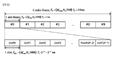
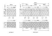
図1を参照すると、3GPP NRシステムで使用される無線フレーム(またはラジオフレーム)は、10ms(ΔfmaxNf/100)*Tc)の長さを有する。また、無線フレームは10個の均等なサイズのサブフレーム(subfame、SF)からなる。ここで、Δfmax=480*103Hz、Nf=4096、Tc=1/(Δfref*Nf,ref)、Δfref=15*103Hz、Nf,ref=2048である。一つのフレーム内の10個のサブフレームにそれぞれ0から9までの番号が与えられる。それぞれのサブフレームは1msの長さを有し、サブキャリア間隔(subcarrier spacing)によって一つまたは複数のスロットからなる。より詳しくは、3GPP NRシステムで使用し得るサブキャリア間隔は15*2μkHzである。μはサブキャリア間隔構成因子(subcarrier spacing configuration)であって、μ=0~4の値を有する。つまり、15kHz、30kHz、60kHz、120kHz、または240kHzがサブキャリア間隔として使用される。1ms長さのサブフレームは2μ個のスロットからなる。この際、各スロットの長さは2-μmsである。一つのサブフレーム内の2μ個のスロットは、それぞれ0から2μ-1までの番号が与えられる。また、一つの無線フレーム内のスロットは、それぞれ0から10*2μ-1までの番号が与えられる。時間資源は、無線フレーム番号(または無線フレームインデックスともいう)、サブフレーム番号(またはサブフレームインデックスともいう)、スロット番号(またはスロットインデックス)のうち少なくともいずれか一つによって区分される。 Referring to FIG. 1, the radio frame (or radio frame) used in the 3GPP NR system has a length of 10 ms (ΔfmaxNf/100)*Tc). Also, a radio frame consists of 10 equally sized subframes (subframes, SF). Here, Δfmax=480*103 Hz, Nf=4096, Tc=1/(Δfref*Nf,ref), Δfref=15*103Hz, Nf,ref=2048. Ten subframes in one frame are numbered from 0 to 9, respectively. Each subframe has a length of 1 ms and consists of one or more slots according to subcarrier spacing. More specifically, the subcarrier spacing that can be used in 3GPP NR systems is 15*2 μkHz. μ is a subcarrier spacing configuration and has a value of μ=0˜4. That is, 15 kHz, 30 kHz, 60 kHz, 120 kHz or 240 kHz are used as subcarrier spacings. A 1 ms long subframe consists of 2 μ slots. At this time, the length of each slot is 2-μms. The 2μ slots in one subframe are numbered from 0 to 2μ−1, respectively. Also, slots in one radio frame are given numbers from 0 to 10*2μ-1. Time resources are identified by at least one of a radio frame number (or radio frame index), a subframe number (or subframe index), and a slot number (or slot index).
図2は、無線通信システムにおける下りリンク(DL)/上りリンク(UL)スロット構造の一例を示す図である。特に、図2は3GPP NRシステムの資源格子(resource grid)構造を示す。 FIG. 2 is a diagram illustrating an example of a downlink (DL)/uplink (UL) slot structure in a wireless communication system. In particular, FIG. 2 shows the resource grid structure of the 3GPP NR system.
アンテナポート当たり一つの資源格子がある。図2を参照すると、スロットは時間ドメインで複数のOFDMシンボルを含み、周波数ドメインで複数の資源ブロック(resource block、RB)を含む。OFDMシンボルは、一つのシンボル区間も意味する。特別な説明がない限り、OFDMシンボルは簡単にシンボルと称される。以下、本明細書において、シンボルはOFDMシンボル、SC-FDMAシンボル、DFTs-OFDMシンボルなどを含む。図2を参照すると、各スロットから送信される信号はNsize、μgrid、x*NRBSC個のサブキャリア(subcarrier)とNslotsymb個のOFDMシンボルからなる資源格子で表現される。ここで、下りリンク資源格子であればx=DLであり、上りリンク資源格子であればx=ULである。Nsize、μgrid、xはサブキャリア間隔構成因子μによる資源ブロック(RB)の個数を示し(xはDLまたはUL)、Nslotsymbはスロット内のOFDMシンボルの個数を示す。NRBSCは一つのRBを構成するサブキャリアの個数であって、NRBSC=12である。OFDMシンボルは、多重アクセス方式によってCP-OFDM(cyclic prefix OFDM)シンボル、またはDFT-S-OFDM(discrete Fourier transform spread OFDM)シンボルと称される。 There is one resource grid per antenna port. Referring to FIG. 2, a slot includes multiple OFDM symbols in the time domain and multiple resource blocks (RBs) in the frequency domain. An OFDM symbol also means one symbol interval. Unless otherwise specified, OFDM symbols are simply referred to as symbols. Hereinafter, symbols include OFDM symbols, SC-FDMA symbols, DFTs-OFDM symbols, and so on. Referring to FIG. 2, a signal transmitted from each slot is represented by a resource grid consisting of Nsize, μgrid, x*NRBSC subcarriers and Nslotsymb OFDM symbols. Here, x=DL for downlink resource grids and x=UL for uplink resource grids. Nsize, μgrid, x indicates the number of resource blocks (RB) by subcarrier spacing component μ (x is DL or UL), and Nslotsymb indicates the number of OFDM symbols in a slot. NRBSC is the number of subcarriers forming one RB, and NRBSC=12. An OFDM symbol is called a CP-OFDM (cyclic prefix OFDM) symbol or a DFT-S-OFDM (discrete Fourier transform spread OFDM) symbol according to a multiple access scheme.
一つのスロットに含まれるOFDMシンボルの数は、CP(cyclic prefix)の長さに応じて異なり得る。例えば、正規(normal)CPであれば一つのスロットが14個のOFDMシンボルを含むが、拡張(extended)CPであれば一つのスロットが12個のOFDMシンボルを含む。具体的な実施例において、拡張CPは60kHzのサブキャリア間隔でのみ使用される。図2では説明の便宜上、一つのスロットが14OFDMシンボルからなる場合を例示したが、本発明の実施例は他の個数のOFDMシンボルを有するスロットでも同じ方式で適用される。図2を参照すると、各OFDMシンボルは、周波数ドメインで、Nsize、μgrid、x*NRBSC個のサブキャリアを含む。サブキャリアの類型は、データを送信するためのデータサブキャリア、参照信号(reference signal)を送信するための参照信号サブキャリア、ガードバンド(guard band)に分けられる。キャリア周波数は中心周波数(center frequency,fc)ともいう。 The number of OFDM symbols included in one slot may vary according to the length of CP (cyclic prefix). For example, one slot includes 14 OFDM symbols in a normal CP, while one slot includes 12 OFDM symbols in an extended CP. In a specific embodiment, the extended CP is used only at subcarrier spacings of 60 kHz. For convenience of explanation, FIG. 2 illustrates the case where one slot consists of 14 OFDM symbols, but the embodiment of the present invention can be applied in the same manner to slots having other numbers of OFDM symbols. Referring to FIG. 2, each OFDM symbol includes Nsize, μgrid, x*NRBSC subcarriers in the frequency domain. The types of subcarriers are divided into data subcarriers for transmitting data, reference signal subcarriers for transmitting reference signals, and guard bands. The carrier frequency is also called a center frequency (fc).
一つのRBは、周波数ドメインでNRBSC個(例えば、12個)の連続するサブキャリアによって定義される。ちなみに、一つのOFDMシンボルと一つのサブキャリアからなる資源を資源要素(resource element、RE)またはトーン(tone)と称する。よって、一つのRBはNslotsymb*NRBSC個の資源要素からなる。資源格子内の各資源要素は、一つのスロット内のインデックス対(k、l)によって固有に定義される。kは周波数ドメインで0からNsize、μgrid、x*NRBSC-1まで与えられるインデックスであり、lは時間ドメインで0からNslotsymb-1まで与えられるインデックスである。 One RB is defined by NRBSC (eg, 12) consecutive subcarriers in the frequency domain. Incidentally, a resource consisting of one OFDM symbol and one subcarrier is called a resource element (RE) or tone. Therefore, one RB consists of Nslotsymb*NRBSC resource elements. Each resource element in the resource lattice is uniquely defined by an index pair (k, l) within one slot. k is an index given from 0 to Nsize, μgrid, x*NRBSC-1 in the frequency domain, and l is an index given from 0 to Nslotsymb-1 in the time domain.
端末が基地局から信号を受信するか基地局信号を送信するためには、端末の時間/周波数同期を基地局の時間/周波数同期と合わせるべきである。基地局と端末が同期化しなければ、端末がDL信号の復調及びUL信号の伝送を正確な時点に行うのに必要な時間及び周波数パラメータを決定できないためである。 In order for a terminal to receive a signal from a base station or transmit a base station signal, the time/frequency synchronization of the terminal should be aligned with the time/frequency synchronization of the base station. This is because if the base station and the terminal are not synchronized, the terminal cannot determine the time and frequency parameters necessary for demodulating the DL signal and transmitting the UL signal at the correct time.
TDD(time division duplex)またはアンペアドスペクトル(unpaired spectrum)で動作する無線フレームの各シンボルは、下りリンクシンボル(DL symbol)、上りリンクシンボル(UL symbol)、またはフレキシブルシンボル(flexible symbol)のうち少なくともいずれか一つからなる。FDD(frequency division duplex)またはペアドスペクトル(paired spectrum)で下りリンクキャリアで動作する無線フレームは、下りリンクシンボルまたはフレキシブルシンボルからなり、上りリンクキャリアで動作する無線フレームは、上りリンクシンボルまたはフレキシブルシンボルからなる。下りリンクシンボルでは下りリンク伝送はできるが上りリンク伝送はできず、上りリンクシンボルでは上りリンク伝送はできるが下りリンク伝送はできない。フレキシブルシンボルは、信号に応じて下りリンクで使用されるか上りリンクで使用されるかが決定される。 Each symbol of a radio frame operating in time division duplex (TDD) or unpaired spectrum is at least one of a downlink symbol (DL symbol), an uplink symbol (UL symbol), or a flexible symbol. Consists of either one. A radio frame operating on a downlink carrier in FDD (frequency division duplex) or a paired spectrum consists of downlink symbols or flexible symbols, and a radio frame operating on an uplink carrier consists of uplink symbols or flexible symbols. consists of A downlink symbol allows downlink transmission but not uplink transmission, and an uplink symbol allows uplink transmission but not downlink transmission. Whether the flexible symbol is used in the downlink or the uplink is determined according to the signal.
各シンボルのタイプ(type)に関する情報、つまり、下りリンクシンボル、上りリンクシンボル、及びフレキシブルシンボルのうちいずれか一つを示す情報は、セル特定(cell-specificまたはcommon)RRC信号からなる。また、各シンボルのタイプに関する情報は、追加に特定端末(UE-specificまたはdedicated)RRC信号からなる。基地局は、セル特定RRC信号を使用し、i)セル特定スロット構成の周期、ii)セル特定スロット構成の周期の最初から下りリンクシンボルのみを有するスロットの数、iii)下りリンクシンボルのみを有するスロットの直後のスロットにおける最初のシンボルから下りリンクシンボルの数、iv)セル特定スロット構成の周期の最後から上りリンクシンボルのみを有するスロットの数、v)上りリンクシンボルのみを有するスロットの直前のスロットにおける最後のシンボルから上りリンクシンボルの数を知らせる。ここで、上りリンクシンボルと下りリンクシンボルのいずれにも構成されていないシンボルはフレキシブルシンボルである。 Information about the type of each symbol, that is, information indicating any one of downlink symbols, uplink symbols, and flexible symbols, consists of cell-specific (or common) RRC signals. In addition, the information on each symbol type additionally consists of a UE-specific (UE-specific or dedicated) RRC signal. The base station uses the cell-specific RRC signal and i) the period of the cell-specific slot structure, ii) the number of slots with only downlink symbols from the beginning of the period of the cell-specific slot structure, iii) with only downlink symbols. iv) the number of slots with only uplink symbols from the end of the period of the cell-specific slot structure; v) the slot immediately preceding the slot with only uplink symbols. signals the number of uplink symbols from the last symbol in . Here, a symbol that is neither an uplink symbol nor a downlink symbol is a flexible symbol.
シンボルタイプに関する情報が端末特定RRC信号からなれば、基地局はフレキシブルシンボルが下りリンクシンボルなのかまたは上りリンクシンボルなのかを、セル特定RRC信号でシグナリングする。この際、端末特定RRC信号は、セル特定RRC信号からなる下りリンクシンボルまたは上りリンクシンボルを他のシンボルタイプに変更することができない。特定端末RRC信号は、各スロットごとに当該スロットのNslotsymbシンボルのうち下りリンクシンボルの数、当該スロットのNslotsymbシンボルのうち上りリンクシンボルの数をシグナリングする。この際、スロットの下りリンクシンボルはスロットの最初のシンボルからi番目のシンボルまで連続的に構成される。また、スロットの上りリンクシンボルはスロットのj番目のシンボルから最後のシンボルまで連続的に構成される(ここで、i<j)。スロットにおいて、上りリンクシンボルと下りリンクシンボルのいずれにも構成されていないシンボルはフレキシブルシンボルである。 If the information about the symbol type consists of a terminal-specific RRC signal, the base station signals whether the flexible symbol is a downlink symbol or an uplink symbol with a cell-specific RRC signal. At this time, the terminal-specific RRC signal cannot change the downlink symbol or uplink symbol made up of the cell-specific RRC signal to another symbol type. The specific terminal RRC signal signals the number of downlink symbols out of Nslotsymb symbols of the slot and the number of uplink symbols out of Nslotsymb symbols of the slot for each slot. At this time, the downlink symbols of the slot are configured consecutively from the first symbol of the slot to the i-th symbol. Also, the uplink symbols of a slot are configured continuously from the j-th symbol of the slot to the last symbol (where i<j). In a slot, a symbol that is configured neither as an uplink symbol nor as a downlink symbol is a flexible symbol.
上のようなRRC信号で構成されたシンボルのタイプを、半静的(semi-static)DL/UL構成と呼ぶことができる。先にRRC信号で構成された半静的DL/UL構成において、フレキシブルシンボルは、物理下りリンク制御チャネル(physical downlink control channel,PDCCH)で送信されるダイナミックSFI(slot format information)により、下りリンクシンボル、上りリンクシンボル、又はフレキシブルシンボルと指示されてよい。このとき、RRC信号で構成された下りリンクシンボル又は上りリンクシンボルは、他のシンボルタイプに変更されない。表1は、基地局が端末に指示できるダイナミックSFIを例示する。 The type of symbols configured with RRC signals as above can be referred to as semi-static DL/UL configuration. In the semi-static DL/UL configuration previously configured with the RRC signal, the flexible symbol is a downlink symbol by dynamic SFI (slot format information) transmitted on the physical downlink control channel (PDCCH). , uplink symbols, or flexible symbols. At this time, the downlink symbols or uplink symbols configured in the RRC signal are not changed to other symbol types. Table 1 illustrates dynamic SFIs that the base station can indicate to the terminal.

表1で、Dは下りリンクシンボルを、Uは上りリンクシンボルを、Xはフレキシブルシンボルを表す。表1に示すように、1スロット内で最大で2回のDL/ULスイッチング(switching)が許容されてよい。 In Table 1, D represents a downlink symbol, U an uplink symbol, and X a flexible symbol. As shown in Table 1, a maximum of two DL/UL switching may be allowed within one slot.
図3は、3GPPシステム(例えば、NR)に利用される物理チャネルと、当該物理チャンネルを利用した一般的な信号伝送方法を説明する図である。 FIG. 3 is a diagram illustrating physical channels used in the 3GPP system (eg, NR) and general signal transmission methods using the physical channels.
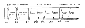
端末の電源がつくか端末が新しくセルに進入すれば、端末は初期セル探索作業を行うS101。詳しくは、端末は初期セル探索で基地局と同期を合わせる。このために、端末は基地局から主同期信号(primary synchronization signal、PSS)及び副同期信号(secondary synchronization signal、SSS)を受信して基地局と同期を合わせ、セルインデックスなどの情報を取得する。次に、端末は基地局から物理放送チャネルを受信し、セル内の放送情報を取得する。 When the terminal is powered on or enters a new cell, the terminal performs an initial cell search operation S101. Specifically, the terminal synchronizes with the base station in the initial cell search. To this end, the terminal receives a primary synchronization signal (PSS) and a secondary synchronization signal (SSS) from the base station, synchronizes with the base station, and acquires information such as a cell index. Then the terminal receives the physical broadcast channel from the base station and obtains the broadcast information in the cell.
初期セル探索を終えた端末は、物理下りリンク制御チャネル(PDCCH)及び前記PDCCHに乗せられている情報によって物理下りリンク共有チャネル(physical downlink shared channel、PDSCH)を受信することで、初期セル探索を介して取得したシステム情報より詳しいシステム情報を取得するS102。ここで、端末に伝達されたシステム情報は、RRC(Radio Resource Control,RRC)における物理層(physical layer)で端末が正確に動作するためのセル共通システム情報であって、リメイニングシステム情報(Remaining system information)又はシステム情報ブロック(System information blcok,SIB)1と呼ばれる。 After completing the initial cell search, the terminal performs the initial cell search by receiving a physical downlink shared channel (PDSCH) according to information carried on the physical downlink control channel (PDCCH) and the PDCCH. S102 to acquire more detailed system information than the system information acquired via the Internet. Here, the system information transmitted to the terminal is cell-common system information for the terminal to operate correctly in a physical layer of RRC (Radio Resource Control, RRC), and is Remaining System Information. system information) or system information block (SIB) 1.
端末が基地局に最初に接続したり、或いは信号送信のための無線リソースがない場合(端末がRRC_IDLEモードである場合)、端末は基地局に対してランダムアクセス過程を行うことができる(段階S103~段階S106)。まず、端末は、物理ランダムアクセスチャネル(physical random access channel,PRACH)でプリアンブルを送信し(S103)、基地局からPDCCH及び対応のPDSCHでプリアンブルに対する応答メッセージを受信することができる(S104)。端末に有効なランダムアクセス応答メッセージが受信された場合、端末は、基地局からPDCCHで伝達された上りリンクグラントが示す物理上りリンク共有チャネル(physical uplink shared channel,PUSCH)で、自身の識別子などを含むデータを基地局に送信する(S105)。次に、端末は、衝突解決のために、基地局の指示としてPDCCHの受信を待つ。端末が自身の識別子でPDCCHの受信に成功すると(S106)、ランダムアクセス過程は終了する。端末は、ランダムアクセス過程中にRRC層の物理層において端末が正しく動作するために必要な端末特定システム情報を取得することができる。端末がRRC層で端末特定システム情報を取得すれば、端末はRRC連結モード(RRC_CONNECTED mode)に進入する。 When the terminal connects to the base station for the first time or there are no radio resources for signal transmission (when the terminal is in RRC_IDLE mode), the terminal can perform a random access procedure to the base station (step S103). to step S106). First, the terminal transmits a preamble through a physical random access channel (PRACH) (S103), and receives a response message to the preamble through the PDCCH and the corresponding PDSCH from the base station (S104). When a valid random access response message is received by the terminal, the terminal transmits its own identifier in a physical uplink shared channel (PUSCH) indicated by the uplink grant transmitted by the PDCCH from the base station. The included data is transmitted to the base station (S105). The terminal then waits to receive the PDCCH as instructed by the base station for conflict resolution. When the terminal successfully receives the PDCCH with its own identifier (S106), the random access process ends. A terminal can acquire terminal-specific system information necessary for the terminal to operate correctly in the physical layer of the RRC layer during the random access process. If the terminal acquires terminal-specific system information in the RRC layer, the terminal enters RRC_CONNECTED mode.
RRC層は、端末と無線接続網(Radio Access Network,RAN)間の制御のためのメッセージ生成及び管理に用いられる。さらにいうと、基地局と端末は、RRC層において、セル内全ての端末に必要なセルシステム情報の放送(broadcasting)、ページング(paging)メッセージの伝達管理、移動性管理及びハンドオーバー、端末の測定報告とそれに関する制御、端末能力管理及び保管管理を行うことができる。一般に、RRC層で伝達する信号(以下、RRC信号)の更新(update)は、物理層での送受信周期(すなわち、transmission time interval,TTI)よりも長いので、RRC設定は、長い周期において変化せずに維持され得る。 The RRC layer is used for message generation and management for control between a terminal and a radio access network (RAN). In addition, the base station and the terminal perform broadcasting of cell system information necessary for all terminals in the cell, paging message delivery management, mobility management and handover, and terminal measurement in the RRC layer. Reports and related controls, terminal capacity management and storage management can be performed. In general, an update of a signal transmitted in the RRC layer (hereinafter referred to as an RRC signal) is longer than a transmission/reception cycle (that is, a transmission time interval (TTI)) in the physical layer, so the RRC setting does not change in a long cycle. can be maintained without
上述した手順後、端末は一般的な上り/下りリンク信号伝送手順としてPDCCH/PDSCH受信S107、及び物理上りリンク共有チャネル(PUSCH)/物理上りリンク制御チャネル(physical uplink control channel、PUCCH)を伝送S108する。特に、端末は、PDCCHを介して下りリンク制御情報(downlink control information、DCI)を受信する。DCIは、端末に対する資源割当情報のような制御情報を含む。また、DCIは使用目的に応じてフォーマットが異なり得る。端末が上りリンクを介して基地局に送信する上りリンク制御情報(uplink control information、UCI)は、下りリンク/上りリンクACK/NACK信号、CQI(channel quality indicator)、PMI(precoding matrix index)、RI(rank indicator)などを含む。ここで、CQI、PMI、及びRIは、CSI(channel state information)に含まれる。3GPP NRシステムの場合、端末はPUSCH及び/またはPUCCHを介して上述したHARQ-ACKとCSIなどの制御情報を送信する。 After the above procedure, the terminal receives PDCCH/PDSCH as a general uplink/downlink signal transmission procedure S107, and transmits a physical uplink shared channel (PUSCH)/physical uplink control channel (PUCCH) S108. do. In particular, the terminal receives downlink control information (DCI) through PDCCH. The DCI includes control information such as resource allocation information for terminals. Also, the DCI may have different formats depending on the purpose of use. Uplink control information (UCI) transmitted from the terminal to the base station via the uplink includes downlink/uplink ACK/NACK signals, CQI (channel quality indicator), PMI (precoding matrix index), RI. (rank indicator) and the like. Here, CQI, PMI, and RI are included in CSI (channel state information). In the 3GPP NR system, the terminal transmits control information such as HARQ-ACK and CSI as described above via PUSCH and/or PUCCH.
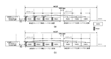
図4は、3GPP NRシステムにおける初期セルアクセスのためのSS/PBCHブロックを示す図である。 FIG. 4 shows an SS/PBCH block for initial cell access in a 3GPP NR system.
端末は、電源が入るか新しくセルにアクセスしようとする際、セルとの時間及び周波数同期を獲得し、初期セル探索過程を行う。端末は、セル探索過程でセルの物理セル識別子(physical cell identity)NcellIDを検出する。このために、端末は基地局から同期信号、例えば、主同期信号(PSS)及び副同期信号(SSS)を受信して基地局と同期を合わせる。この際、端末はセル識別子(identity、ID)などの情報を取得する。 When a terminal is powered on or tries to access a new cell, it acquires time and frequency synchronization with the cell and performs an initial cell search process. A terminal detects a physical cell identity (NcellID) of a cell in a cell search process. For this purpose, the terminal receives a synchronization signal, eg, a primary synchronization signal (PSS) and a secondary synchronization signal (SSS) from the base station, and synchronizes with the base station. At this time, the terminal acquires information such as a cell identifier (identity, ID).
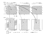
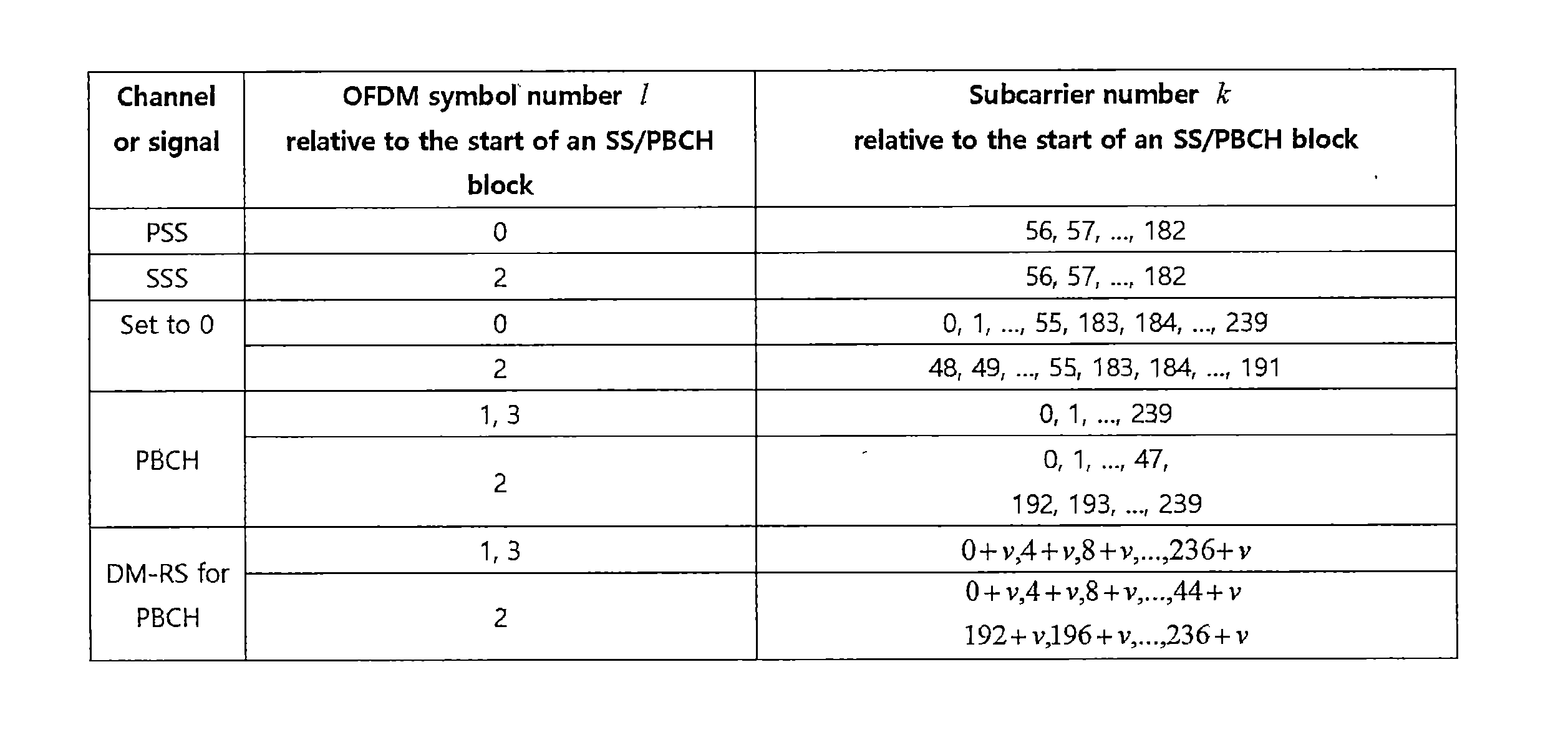
図4(a)を参照して、同期信号(synchronization signal、SS)をより詳しく説明する。同期信号はPSSとSSSに分けられる。PSSは、OFDMシンボル同期、スロット同期のような時間ドメイン同期及び/または周波数ドメイン同期を得るために使用される。SSSは、フレーム同期、セルグループIDを得るために使用される。図4(a)と表1を参照すると、SS/PBCHブロックは周波数軸に連続した20RBs(=240サブキャリア)からなり、時間軸に連続した4OFDMシンボルからなる。この際、SS/PBCHブロックにおいて、PSSは最初のOFDMシンボル、SSSは三番目のOFDMシンボルで56~18二番目のサブキャリアを介して送信される。ここで、SS/PBCHブロックの最も低いサブキャリアインデックスを0から付ける。PSSが送信される最初のOFDMシンボルにおいて、残りのサブキャリア、つまり、0~55、183~239番目のサブキャリアを介しては基地局が信号を送信しない。また、SSSが送信される三番目のOFDMシンボルにおいて、48~55、183~19一番目のサブキャリアを介しては基地局が信号を送信しない。基地局は、SS/PBCHブロックにおいて、前記信号を除いた残りのREを介してPBCH(physical broadcast channel)を送信する。 The synchronization signal (SS) will be described in more detail with reference to FIG. 4(a). The synchronization signal is divided into PSS and SSS. PSS is used to obtain OFDM symbol synchronization, time domain synchronization such as slot synchronization and/or frequency domain synchronization. SSS is used to obtain frame synchronization, cell group ID. Referring to FIG. 4(a) and Table 1, the SS/PBCH block consists of 20 RBs (=240 subcarriers) contiguous on the frequency axis and 4 OFDM symbols contiguous on the time axis. At this time, in the SS/PBCH block, the PSS is transmitted in the first OFDM symbol and the SSS is transmitted in the third OFDM symbol through the 56th to 18th subcarriers. Here, 0 is assigned to the lowest subcarrier index of the SS/PBCH block. In the first OFDM symbol in which the PSS is transmitted, the base station does not transmit signals over the remaining subcarriers, ie, 0-55, 183-239th subcarriers. Also, in the third OFDM symbol in which the SSS is transmitted, the base station does not transmit signals over the 48th to 55th and 183rd to 19th subcarriers. A base station transmits a PBCH (physical broadcast channel) through REs other than the signal in the SS/PBCH block.
SSは3つのPSSとSSSの組み合わせを介して計1008個の固有の物理階層セル識別子(physical layer cell ID)を、詳しくは、それぞれの物理階層セルIDはたった一つの物理-階層セル-識別子グループの部分になるように、各グループが3つの固有の識別子を含む336個の物理-階層セル-識別子グループにグルーピングされる。よって、物理階層セルID NcellID=3N(1)ID+N(2)IDは、物理-階層セル-識別子グループを示す0から335までの範囲内のインデックスN(1)IDと、前記物理-階層セル-識別子グループ内の物理-階層識別子を示す0から2までのインデックスN(2)IDによって固有に定義される。端末はPSSを検出し、3つの固有の物理-階層識別子のうち一つを識別する。また、端末はSSSを検出し、前記物理-階層識別子に連関する336個の物理階層セルIDのうち一つを識別する。この際、PSSのシーケンスdPSS(n)は、次の通りである。 SS has a total of 1008 unique physical layer cell IDs through the combination of three PSS and SSS, in detail, each physical layer cell ID has only one physical-layer cell-identifier group. , into 336 physical-hierarchical cell-identifier groups, each group containing three unique identifiers. Thus, the physical-layer cell ID NcellID=3N(1)ID+N(2)ID is an index N(1)ID in the range from 0 to 335 indicating a physical-layer cell-identifier group and said physical-layer cell- It is uniquely defined by an index N(2)ID from 0 to 2 that indicates the physical-hierarchical identifier within the identifier group. The terminal detects the PSS and identifies one of three unique physical-layer identifiers. Also, the terminal detects the SSS and identifies one of 336 physical layer cell IDs associated with the physical-layer identifier. At this time, the PSS sequence dPSS(n) is as follows.
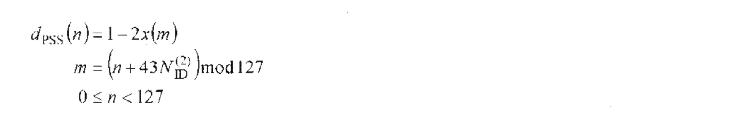
ここで、x(i+7)=(x(i+4)+x(i)) mod 2であり、
where x(i+7)=(x(i+4)+x(i))
[x(6)x(5)x(4)x(3)x(2)x(1)x(0)]=[1110110]と与えられる。 [x(6)x(5)x(4)x(3)x(2)x(1)x(0)]=[1110110].
また、SSSのシーケンスdSSS(n)は、次の通りである。 The SSS sequence dSSS(n) is as follows.

ここで、x0(i+7)=(x0(i+4)+x0(i))mod 2
x1(i+7)=(x1(i+1)+x1(i))mod 2であり、
where x 0 (i+7)=(x 0 (i+4)+x 0 (i))
x 1 (i+7)=(x 1 (i+1)+x 1 (i))
[x0(6)x0(5)x0(4)x0(3)x0(2)x0(1) 0(0)]=[0000001], [x1(6)x1(5)x1(4)x1(3)x1(2)x1(1)x1(0)]=[0000001]と与えられる。 [x 0 (6)x 0 (5)x 0 (4)x 0 (3)x 0 (2)x 0 (1) 0(0)]=[0000001], [x 1 (6)x 1 ( 5) x 1 (4) x 1 (3) x 1 (2) x 1 (1) x 1 (0)]=[0000001].
10ms長さの無線フレームは、5ms長さの2つの半フレームに分けられる。図4(b)を参照して、各半フレーム内でSS/PBCHブロックが送信されるスロットについて説明する。SS/PBCHブロックが送信されるスロットは、ケースA、B、C、D、Eのうちいずれか一つである。ケースAにおいて、サブキャリア間隔は15kHzであり、SS/PBCHブロックの開始時点は{2、8}+14*n番目のシンボルである。この際、3GHz以下のキャリア周波数において、n=0、1である。また、3GHz超過6GHz以下のキャリア周波数において、n=0、1、2、3である。ケースBにおいて、サブキャリア間隔は30kHzであり、SS/PBCHブロックの開始時点は{4、8、16、20}+28*n番目のシンボルである。この際、3GHz以下のキャリア周波数において、n=0である。また、3GHz超過6GHz以下のキャリア周波数において、n=0、1である。ケースCにおいて、サブキャリア間隔は30kHzであり、SS/PBCHブロックの開始時点は{2、8}+14*n番目のシンボルである。この際、3GHz以下のキャリア周波数において、n=0、1である。また、3GHz超過6GHz以下のキャリア周波数において、n=0、1、2、3である。ケースDにおいて、サブキャリア間隔は120kHzであり、SS/PBCHブロックの開始時点は{4、8、16、20}+28*n番目のシンボルである。この際、6GHz以上のキャリア周波数において、n=0、1、2、3、5、6、7、8、10、11、12、13、15、16、17、18である。ケースEにおいて、サブキャリア間隔は240kHzであり、SS/PBCHブロックの開始時点は{8、12、16、20、32、36、40、44}+56*n番目のシンボルである。この際、6GHz以上のキャリア周波数において、n=0、1、2、3、5、6、7、8である。 A radio frame of 10 ms length is divided into two half-frames of 5 ms length. The slots in which the SS/PBCH blocks are transmitted within each half-frame will be described with reference to FIG. 4(b). A slot in which the SS/PBCH block is transmitted is one of cases A, B, C, D, and E. In case A, the subcarrier spacing is 15 kHz and the starting time of the SS/PBCH block is {2, 8}+14*nth symbol. At this time, n=0, 1 at carrier frequencies of 3 GHz or less. Also, n=0, 1, 2, 3 at carrier frequencies greater than 3 GHz and less than or equal to 6 GHz. In case B, the subcarrier spacing is 30 kHz and the starting time of the SS/PBCH block is {4, 8, 16, 20}+28*nth symbol. At this time, n=0 at carrier frequencies of 3 GHz or less. In addition, n=0, 1 at carrier frequencies greater than 3 GHz and less than or equal to 6 GHz. In case C, the subcarrier spacing is 30 kHz and the starting time of the SS/PBCH block is {2, 8}+14*nth symbol. At this time, n=0, 1 at carrier frequencies of 3 GHz or less. Also, n=0, 1, 2, 3 at carrier frequencies greater than 3 GHz and less than or equal to 6 GHz. In case D, the subcarrier spacing is 120 kHz and the starting time of the SS/PBCH block is {4, 8, 16, 20}+28*nth symbol. At this time, n=0, 1, 2, 3, 5, 6, 7, 8, 10, 11, 12, 13, 15, 16, 17, 18 at carrier frequencies above 6 GHz. In case E, the subcarrier spacing is 240 kHz and the starting time of the SS/PBCH block is {8, 12, 16, 20, 32, 36, 40, 44}+56*nth symbol. At this time, n=0, 1, 2, 3, 5, 6, 7, 8 at carrier frequencies above 6 GHz.
図5は、3GPP NRシステムにおける制御情報及び制御チャネル伝送のための手順を示す図である。図5(a)を参照すると、基地局は制御情報(例えば、DCI)にRNTI(radio network temporary identifier)でマスク(例えば、XOR演算)されたCRC(cyclic redundancy check)を付加するS202。基地局は、各制御情報の目的/対象に応じて決定されるRNTI値でCRCをスクランブルする。一つ以上の端末が使用する共通RNTIは、SI-RNTI(system information RNTI)、P-RNTI(paging RNTI)、RA-RNTI(random access RNTI)、及びTPC-RNTI(transmit power control RNTI)のうち少なくともいずれか一つを含む。また、端末-特定RNTIはC-RNTI(cell temporary RNTI)、CS-RNTI、またはMCS-C-RNTIのうち少なくともいずれか一つを含む 次に、基地局はチャネルエンコーディング(例えば、polar coding)を行ったS204後、PDCCH伝送のために使用された資源(ら)の量に合わせてレート-マッチング(rate-matching)をするS206。次に、基地局はCCE(control channel element)基盤のPDCCH構造に基づいて、DCI(ら)を多重化するS208。また、基地局は、多重化したDCI(ら)に対してスクランブリング、モジュレーション(例えば、QPSK)、インターリービングなどの追加過程S210を適用した後、送信しようとする資源にマッピングする。CCEはPDCCHのための基本資源単位であり、一つのCCEは複数(例えば、6つ)のREG(resource element group)からなる。一つのREGは複数(例えば、12個)のREからなる。一つのPDCCHのために使用されたCCEの個数を集成レベル(aggregation level)と定義する。3GPP NRシステムでは、1、2、4、8、または16の集成レベルを使用する。図5(b)はCCE集成レベルとPDCCHの多重化に関する図であり、一つのPDCCHのために使用されたCCE集成レベルの種類とそれによる制御領域で送信されるCCE(ら)を示す。 FIG. 5 shows a procedure for control information and control channel transmission in a 3GPP NR system. Referring to FIG. 5(a), the base station adds a cyclic redundancy check (CRC) masked (eg, XORed) with a radio network temporary identifier (RNTI) to control information (eg, DCI) S202. The base station scrambles the CRC with an RNTI value determined according to the purpose/subject of each control information. The common RNTI used by one or more terminals is SI-RNTI (system information RNTI), P-RNTI (paging RNTI), RA-RNTI (random access RNTI), and TPC-RNTI (transmit power control RNTI). Contains at least one. In addition, the UE-specific RNTI includes at least one of C-RNTI (cell temporary RNTI), CS-RNTI, or MCS-C-RNTI Next, the base station performs channel encoding (eg, polar coding). After performing S204, rate-matching is performed according to the amount of resource(s) used for PDCCH transmission S206. Next, the base station multiplexes DCI(s) based on a CCE (control channel element) based PDCCH structure S208. In addition, the base station applies additional processes S210 such as scrambling, modulation (eg, QPSK), and interleaving to the multiplexed DCI(s), and then maps the DCIs to resources to be transmitted. A CCE is a basic resource unit for PDCCH, and one CCE consists of a plurality of (eg, 6) REGs (resource element groups). One REG consists of a plurality of (eg, 12) REs. The number of CCEs used for one PDCCH is defined as an aggregation level. 3GPP NR systems use 1, 2, 4, 8, or 16 aggregation levels. FIG. 5(b) is a diagram related to CCE aggregation levels and PDCCH multiplexing, and shows types of CCE aggregation levels used for one PDCCH and CCE(s) transmitted in the control region according to them.
図6は、3GPP NRシステムにおけるPDCCHが送信されるCORESETを示す図である。 FIG. 6 is a diagram showing a CORESET through which PDCCH is transmitted in the 3GPP NR system.
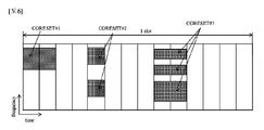
CORESETは、端末のための制御信号であるPDCCHが送信される時間-周波数資源である。また、後述する探索空間(search space)は一つのCORESETにマッピングされる。よって、端末はPDCCHを受信するために全ての周波数帯域をモニタリングするのではなく、CORESETと指定された時間-周波数領域をモニタリングして、CORESETにマッピングされたPDCCHをデコーディングする。基地局は、端末にセル別に一つまたは複数のCORESETを構成する。CORESETは、時間軸に最大3つまでの連続したシンボルからなる。また、CORESETは周波数軸に連続した6つのPRBの単位からなる。図5の実施例において、CORESET#1は連続的なPRBからなり、CORESET#2とCORESET#3は不連続的なPRBからなる。CORESETは、スロット内のいかなるシンボルにも位置し得る。例えば、図5の実施例において、CORESET#1はスロットの最初のシンボルから始まり、CORESET#2はスロットの5番目のシンボルから始まり、CORESET#9はスロットの9番目のシンボルから始まる。
CORESET is a time-frequency resource on which PDCCH, which is a control signal for a terminal, is transmitted. Also, a search space, which will be described later, is mapped to one CORESET. Therefore, the terminal monitors a time-frequency region designated as CORESET and decodes PDCCH mapped to CORESET, instead of monitoring all frequency bands to receive PDCCH. The base station configures one or more CORESETs for each cell in the UE. A CORESET consists of up to three consecutive symbols on the time axis. Also, the CORESET consists of 6 PRB units that are continuous on the frequency axis. In the example of FIG. 5,
図7は、3GPP NRシステムにおけるPDCCH探索空間を設定する方法を示す図である。 FIG. 7 illustrates a method for setting up a PDCCH search space in a 3GPP NR system.
端末にPDCCHを送信するために、各CORESETには少なくとも1つ以上の探索空間が存在する。本発明の実施例において、探索空間は端末のPDCCHが送信される全ての時間-周波数資源(以下、PDCCH候補)の集合である。探索空間は、3GPP NRの端末が共通に探索すべき共通探索空間(common search space)と、特定端末が探索すべき端末-特定探索空間(terminal-specific or UE-specific search space)を含む。共通探索空間では、同一基地局に属するセルにおける全ての端末が共通に探すように設定されているPDCCHをモニタリングする。また、端末-特定探索空間は、端末に応じて互いに異なる探索空間の位置で、各端末に割り当てられたPDCCHをモニタリングするように端末別に設定される。端末-特定探索空間の場合、PDCCHが割り当てられる制限された制御領域のため、端末間の探索空間が部分的に重なって割り当てられている可能性がある。PDCCHをモニタリングすることは、探索空間内のPDCCH候補をブラインドデコーディングすることを含む。ブラインドデコーディングに成功した場合をPDCCHが(成功的に)検出/受信されたと表現し、ブラインドデコーディングに失敗した場合をPDCCHが未検出/未受信されたと表現か、成功的に検出/受信されていないと表現する。 There is at least one or more search spaces in each CORESET for transmitting PDCCH to terminals. In an embodiment of the present invention, the search space is the set of all time-frequency resources (hereinafter PDCCH candidates) on which the terminal's PDCCH is transmitted. The search space includes a common search space that 3GPP NR terminals should search in common and a terminal-specific or UE-specific search space that a specific terminal should search. In the common search space, the PDCCH, which is set to be commonly searched by all terminals in cells belonging to the same base station, is monitored. In addition, the UE-specific search space is set for each UE so that the PDCCH assigned to each UE is monitored at different search space positions according to the UE. In the case of terminal-specific search space, it is possible that the search spaces between terminals are allocated to overlap due to the limited control region to which the PDCCH is allocated. Monitoring the PDCCH includes blind decoding PDCCH candidates within the search space. When blind decoding is successful, PDCCH is (successfully) detected/received, and when blind decoding is unsuccessful, PDCCH is not detected/not received, or successfully detected/received. express as not
説明の便宜上、一つ以上の端末に下りリンク制御情報を送信するために、一つ以上の端末が既に知っているグループ共通(group common、GC)RNTIでスクランブルされたPDCCHをグループ共通(GC)PDCCH、または共通PDCCHと称する。また、一つの特定端末に上りリンクスケジューリング情報または下りリンクスケジューリング情報を送信するために、特定端末が既に知っている端末-特定RNTIでスクランブルされたPDCCHを端末-特定PDCCHと称する。前記共通PDCCHは共通探索空間に含まれ、端末-特定PDCCHは共通探索空間または端末-特定PDCCHに含まれる。 For convenience of explanation, in order to transmit downlink control information to one or more terminals, PDCCH scrambled with a group common (GC) RNTI already known to one or more terminals is group common (GC). It is called PDCCH or common PDCCH. Also, a PDCCH scrambled with a UE-specific RNTI already known to a specific UE in order to transmit uplink scheduling information or downlink scheduling information to one specific UE is referred to as a UE-specific PDCCH. The common PDCCH is included in a common search space, and the terminal-specific PDCCH is included in a common search space or a terminal-specific PDCCH.
基地局は、PDCCHを介して伝送チャネルであるPCH(paging channel)及びDL-SCH(downlink-shared channel)の資源割当に関する情報(つまり、DL Grant)、またはUL-SCH の資源割当とHARQ(hybrid automatic repeat request)に関する情報(つまり、UL Grant)を各端末または端末グループに知らせる。基地局は、PCH伝送ブロック、及びDL-SCH伝送ブロックをPDSCHを介して送信する。基地局は、特定制御情報または特定サービスデータを除いたデータをPDSCHを介して送信する。また、端末は、特定制御情報または特定サービスデータを除いたデータをPDSCHを介して受信する。 The base station transmits information (that is, DL grant) on resource allocation of paging channel (PCH) and downlink-shared channel (DL-SCH), or resource allocation of UL-SCH and HARQ (hybrid (i.e., UL Grant) is notified to each terminal or terminal group. The base station transmits PCH transport blocks and DL-SCH transport blocks over PDSCH. A base station transmits data other than specific control information or specific service data through the PDSCH. In addition, the terminal receives data other than specific control information or specific service data through the PDSCH.
基地局は、PDSCHのデータがいかなる端末(一つまたは複数の端末)に送信されるのか、当該端末がいかにPDSCHデータを受信しデコーディングすべきなのかに関する情報をPDCCHに含ませて送信する。例えば、特定PDCCHを介して送信されるDCIが「A」というRNTIでCRCマスキングされており、そのDCIが「B」という無線資源(例えば、周波数位置)にPDSCHが割り当てられていることを指示し、「C」という伝送形式情報(例えば、伝送ブロックのサイズ、変調方式、コーディング情報など)を指示すると仮定する。端末は、自らが有するRNTI情報を利用してPDCCHをモニタリングする。この場合、「A」RNTIを使用してPDCCHをブラインドデコーディングする端末があれば、当該端末はPDCCHを受信し、受信したPDCCHの情報を介して「B」と「C」によって指示されるPDSCHを受信する。 The base station transmits PDCCH including information about to which terminal (one or more terminals) the PDSCH data is transmitted and how the terminal should receive and decode the PDSCH data. For example, a DCI transmitted via a specific PDCCH is CRC-masked with an RNTI of 'A', and the DCI indicates that a radio resource (eg, frequency location) of 'B' is assigned to the PDSCH. , 'C' indicating transmission format information (eg, transmission block size, modulation scheme, coding information, etc.). A terminal monitors the PDCCH using its own RNTI information. In this case, if there is a terminal that blind-decodes PDCCH using 'A' RNTI, the terminal receives PDCCH and PDSCH indicated by 'B' and 'C' through the received PDCCH information. receive.
表3は、無線通信システムで使用されるPUCCHの一実施例を示す。 Table 3 shows an example of PUCCH used in a wireless communication system.

PUCCHは、以下の上りリンク制御情報(UCI)を送信するのに使用される。 PUCCH is used to transmit the following uplink control information (UCI).
-SR(Scheduling Request):上りリンクUL-SCH資源を要請するのに使用される情報である。 - SR (Scheduling Request): information used to request uplink UL-SCH resources.
-HARQ-ACK:(DL SPS releaseを指示する)PDCCHに対する応答及び/またはPDSCH上の上りリンク伝送ブロック(transport block、TB)に対する応答である。HARQ-ACKは、PDCCHまたはPDSCHを介して送信された情報の受信可否を示す。HARQ-ACK応答は、ポジティブACK(簡単に、ACK)、ネガティブACK(以下、NACK)、DTX(Discontinuous Transmission)、またはNACK/DTXを含む。ここで、HARQ-ACKという用語は、HARQ-ACK/NACK、ACK/NACKと混用される。一般に、ACKはビット値1で表され、NACKはビット値0で表される。 - HARQ-ACK: response to PDCCH (indicating DL SPS release) and/or response to uplink transport block (TB) on PDSCH. HARQ-ACK indicates whether or not information transmitted via PDCCH or PDSCH has been received. HARQ-ACK responses include positive ACK (simply ACK), negative ACK (hereinafter NACK), discontinuous transmission (DTX), or NACK/DTX. Here, the term HARQ-ACK is mixed with HARQ-ACK/NACK and ACK/NACK. In general, an ACK is represented by a bit value of 1 and a NACK is represented by a bit value of 0.
-CSI:下りリンクチャネルに対するフィードバック情報である。基地局が送信するCSI-RS(Reference Signal)に基づいて端末が生成する。MIMO(multiple input multiple output)-関連フィードバック情報は、RI及びPMIを含む。CSIは、CSIが示す情報に応じてCSIパート1とCSIパート2に分けられる。
- CSI: Feedback information for the downlink channel. It is generated by the terminal based on the CSI-RS (Reference Signal) transmitted by the base station. MIMO (multiple input multiple output) - relevant feedback information includes RI and PMI. CSI is divided into
3GPP NRシステムでは、多様なサービスシナリオと多様なチャネル環境、及びフレーム構造を支援するために、5つのPUCCHフォーマットが使用される。 In the 3GPP NR system, five PUCCH formats are used to support various service scenarios and various channel environments and frame structures.
PUCCHフォーマット0は、1ビットまたは2ビットHARQ-ACK情報またはSRを伝達するフォーマットである。PUCCHフォーマット0は、時間軸に1つまたは2つのOFDMシンボルと、周波数軸に1つのRBを介して送信される。PUCCHフォーマット0が2つのOFDMシンボルで送信されれば、2つのシンボルに同じシーケンスが互いに異なるRBで送信される。これを介し、端末は周波数ダイバーシティゲイン(diversity gain)を得る。より詳しくは、端末はMbitビットUCI(Mbit=1or2)に応じてサイクリックシフト(cyclic shift)の値mcsを決定し、長さ12のベースシーケンス(base sequence)を決められた値mcsでサイクリックシフトしたシーケンスを、1つのOFDMシンボル及び1つのPRBの12個のREsにマッピングして送信する。端末が使用可能なサイクリックシフトの個数が12個で、Mbit=1であれば、1bit UCI0と1は、サイクリックシフト値の差が6である2つのサイクリックシフトに当たるシーケンスで示される。また、Mbit=2であれば、2bit UCI00、01、11、10は、サイクリックシフト値の差が3である4つのサイクリックシフトに当たるシーケンスで示される。
PUCCHフォーマット1は、1ビットまたは2ビットHARQ-ACK情報またはSRを伝達する。PUCCHフォーマット1は、時間軸に連続的なOFDMシンボルと、周波数軸に1つのPRBを介して送信される。ここで、PUCCHフォーマット1が占めるOFDMシンボルの数は4~14のうち一つである。より詳しくは、Mbit=1であるUCIはBPSKでモジュレーションされる。端末は、Mbit=2であるUCIをQPSK(quadrature phase shift keying)でモジュレーションされる。モジュレーションされた複素数シンボル(complex valued symbol)d(0)に長さ12のシーケンスをかけて信号を得る。端末は、得られた信号をPUCCHフォーマット1が割り当てられた偶数番目のOFDMシンボルに、時間軸OCC(orthogonal cover code)でスプレッディング(spreading)して送信する。PUCCHフォーマット1は、使用するOCCの長さに応じて同じRBで多重化する互いに異なる端末の最大個数が決めあれる。PUCCHフォーマット1の奇数番目OFDMシンボルには、DMRS(demodulation reference signal)がOCCでスプレッディングされてマッピングされる。
PUCCHフォーマット2は、2ビットを超過するUCIを伝達する。PUCCHフォーマット2は、時間軸に1つまたは2つのOFDMシンボルと、周波数軸に1つまたは複数個のRBを介して送信される。PUCCHフォーマット2が2つのOFDMシンボルで送信されれば、2つのOFDMシンボルを介して同じシーケンスが互いに異なるRBで送信される。これを介し、端末は周波数ダイバーシティゲインを得る。より詳しくは、MbitビットUCI(Mbit>2)はビット-レベルスクランブリングされ、QPSKモジュレーションされて1つまたは2つのOFDMシンボル(ら)のRB(ら)にマッピングされる。ここで、RBの数は1~16のうち一つである。
PUCCHフォーマット3またはPUCCHフォーマット4は、2ビットを超過するUCIを伝達する。PUCCHフォーマット3またはPUCCHフォーマット4は、時間軸に連続的なOFDMシンボルと、周波数軸に1つのPRBを介して送信される。PUCCHフォーマット3またはPUCCHフォーマット4が占めるOFDMシンボルの数は4~14のうち一つである。詳しくは、端末は、MbitビットUCI(Mbit>2)をπ/2-BPSK(Binary Phase Shift Keying)またはQPSKでモジュレーションし、複素数シンボルd(0)~d(Msymb-1)を生成する。ここで、π/2-BPSKを使用するとMsymb=Mbitであり、QPSKを使用するとMsymb=Mbit/2である。端末は、PUCCHフォーマット3にブロック-単位スプレディングを適用しない。但し、端末は、PUCCHフォーマット4が2つまたは4つの多重化容量(multiplexing capacity)を有するように、長さ-12のPreDFT-OCCを使用して1つのRB(つまり、12subcarriers)にブロック-単位スプレディングを適用してもよい。端末は、スプレディングされた信号を伝送プリコーディング(transmit precoding)(またはDFT-precoding)し、各REにマッピングして、スプレディングされた信号を送信する。
この際、PUCCHフォーマット2、PUCCHフォーマット3、またはPUCCHフォーマット4が占めるRBの数は、端末が送信するUCIの長さと最大コードレート(code rate)に応じて決定される。端末がPUCCHフォーマット2を使用すれば、端末はPUCCHを介してHARQ-ACK情報及びCSI情報を共に送信する。もし、端末が送信し得るRBの数がPUCCHフォーマット2、PUCCHフォーマット3、またはPUCCHフォーマット4が使用し得る最大RBの数より大きければ、端末はUCI情報の優先順位に応じて一部のUCI情報は伝送せず、残りのUCI情報のみ送信する。
At this time, the number of RBs occupied by
PUCCHフォーマット1、PUCCHフォーマット3、またはPUCCHフォーマット4がスロット内で周波数ホッピング(frequency hopping)を指示するように、RRC信号を介して構成される。周波数ホッピングが構成される際、周波数ホッピングするRBのインデックスはRRC信号からなる。PUCCHフォーマット1、PUCCHフォーマット3、またはPUCCHフォーマット4が時間軸でN個のOFDMシンボルにわたって送信されれば、最初のホップ(hop)はfloor(N/2)個のOFDMシンボルを有し、二番目のホップはceil(N/2)個のOFDMシンボルを有する。
PUCCHフォーマット1、PUCCHフォーマット3、またはPUCCHフォーマット4は、複数のスロットに繰り返し伝送さ得るように構成される。この際、PUCCHが繰り返し送信されるスロットの個数KはRRC信号によって構成される。繰り返し送信されるPUCCHは、各スロット内で同じ位置のOFDMシンボルから始まり、同じ長さを有するべきである。端末がPUCCHを伝送すべきスロットのOFDMシンボルのうちいずれか一つのOFDMシンボルでもRRC信号によってDLシンボルと指示されれば、端末はPUCCHを当該スロットから伝送せず、次のスロットに延期して送信する。
一方、3GPP NRシステムにおいて、端末はキャリア(またはセル)の帯域幅より小さいか同じ帯域幅を利用して送受信を行う。そのために、端末はキャリア帯域幅のうち一部の連続的な帯域幅からなるBWP(bandwidth part)を構成される。TDDに応じて動作するかまたはアンペアドスペクトルで動作する端末は、一つのキャリア(またはセル)に最大4つのDL/UL BWPペア(pairs)を構成される。また、端末は一つのDL/UL BWPペアを活性化する。FDDに応じて動作するかまたはペアドスペクトルで動作する端末は、下りリンクキャリア(またはセル)に最大4つのDL BWPを構成され、上りリンクキャリア(またはセル)に最大4つのUL BWPを構成される。端末は、各キャリア(またはセル)ごとに一つのDL BWPとUL BWPを活性化する。端末は、活性化されたBWP以外の時間-周波数資源から受信するか送信しなくてもよい。活性化されたBWPをアクティブBWPと称する。 On the other hand, in the 3GPP NR system, a terminal performs transmission and reception using a bandwidth that is smaller than or equal to the bandwidth of a carrier (or cell). For this purpose, the terminal is configured with a BWP (bandwidth part) consisting of a continuous bandwidth part of the carrier bandwidth. A terminal operating according to TDD or operating in the unpaired spectrum is configured with up to four DL/UL BWP pairs in one carrier (or cell). Also, the terminal activates one DL/UL BWP pair. A terminal operating according to FDD or operating in a paired spectrum is configured with up to 4 DL BWPs on a downlink carrier (or cell) and up to 4 UL BWPs on an uplink carrier (or cell). be. A terminal activates one DL BWP and one UL BWP for each carrier (or cell). A terminal may not receive or transmit from time-frequency resources other than the activated BWP. An activated BWP is called an active BWP.
基地局は、端末が構成されたBWPのうち活性化されたBWPをDCIと称する。DCIで指示したBWPは活性化され、他の構成されたBWP(ら)は非活性化される。TDDで動作するキャリア(またはセル)において、基地局は端末のDL/UL BWPペアを変えるために、PDSCHまたはPUSCHをスケジュールするDCIに活性化されるBWPを指示するBPI(bandwidth part indicator)を含ませる。 端末は、PDSCHまたはPUSCHをスケジュールするDCIを受信し、BPIに基づいて活性化されるDL/UL BWPペアを識別する。FDDで動作する下りリンクキャリア(またはセル)の場合、基地局は端末のDL BWPを変えるために、PDSCHをスケジュールするDCIに活性化されるBWPを知らせるBPIを含ませる。FDDで動作する上りリンクキャリア(またはセル)の場合、基地局は端末のUL BWPを変えるために、PUSCHをスケジュールするDCIに活性化されるBWPを指示するBPIを含ませる。 A base station refers to an activated BWP among BWPs in which a terminal is configured as a DCI. DCI-directed BWPs are activated and other composed BWP(s) are deactivated. In a carrier (or cell) operating in TDD, the base station includes a BPI (bandwidth part indicator) that indicates which BWP is activated in DCI that schedules PDSCH or PUSCH in order to change the DL/UL BWP pair of the terminal. Let The terminal receives the DCI scheduling PDSCH or PUSCH and identifies the DL/UL BWP pairs to be activated based on the BPI. In the case of a downlink carrier (or cell) operating in FDD, the base station includes a BPI that indicates the activated BWP in the DCI that schedules the PDSCH in order to change the DL BWP of the terminal. In the case of an uplink carrier (or cell) operating in FDD, the base station includes a BPI indicating the activated BWP in the DCI that schedules PUSCH in order to change the UL BWP of the terminal.
図8は、キャリア集成を説明する概念図である。 FIG. 8 is a conceptual diagram illustrating carrier assembly.
キャリア集成とは、無線通信システムがより広い周波数帯域を使用するために、端末が上りリンク資源(またはコンポーネントキャリア)及び/または下りリンク資源(またはコンポーネントキャリア)からなる周波数ブロック、または(論理的意味の)セルを複数個使用して一つの大きい論理周波数帯域で使用する方法を意味する。以下では説明の便宜上、コンポーネントキャリアという用語に統一する。 Carrier aggregation refers to a frequency block or (in the logical sense of ) means a method of using a plurality of cells in one large logical frequency band. For convenience of explanation, the term "component carrier" is used hereinafter.
図8を参照すると、3GPP NRシステムの一例示として、全体システム帯域は最大16個のコンポーネントキャリアを含み、それぞれのコンポーネントキャリアは最大400MHzの帯域幅を有する。コンポーネントキャリアは、一つ以上の物理的に連続するサブキャリアを含む。図8ではそれぞれのコンポーネントキャリアがいずれも同じ帯域幅を有するように示したが、これは例示に過ぎず、それぞれのコンポーネントキャリアは互いに異なる帯域幅を有してもよい。また、それぞれのコンポーネントキャリアは周波数軸で互いに隣接しているように示したが、前記図面は論理的な概念で示したものであって、それぞれのコンポーネントキャリアは物理的に互いに隣接してもよく、離れていてもよい。 Referring to FIG. 8, as an example of a 3GPP NR system, the total system band includes up to 16 component carriers, and each component carrier has a maximum bandwidth of 400MHz. A component carrier includes one or more physically contiguous subcarriers. Although FIG. 8 shows that each component carrier has the same bandwidth, this is only an example, and each component carrier may have different bandwidths. In addition, although each component carrier is shown to be adjacent to each other on the frequency axis, the above drawing is a logical concept, and each component carrier may be physically adjacent to each other. , may be apart.
それぞれのコンポーネントキャリアにおいて、互いに異なる中心周波数が使用される。また、物理的に隣接したコンポーネントキャリアにおいて、共通した一つの中心周波数が使用される。図8の実施例において、全てのコンポーネントキャリアが物理的に隣接していると仮定すれば、全てのコンポーネントキャリアで中心周波数Aが使用される。また、それぞれのコンポーネントキャリアが物理的に隣接していないと仮定すれば、コンポーネントキャリアそれぞれにおいて中心周波数A、中心周波数Bが使用される。 Different center frequencies are used in the respective component carriers. Also, one common center frequency is used in physically adjacent component carriers. In the example of FIG. 8, center frequency A is used on all component carriers, assuming that all component carriers are physically adjacent. Also, assuming that each component carrier is not physically adjacent, center frequency A and center frequency B are used in each component carrier.
キャリア集成で全体のシステム帯域が拡張されれば、各端末との通信に使用される周波数帯域はコンポーネントキャリア単位に定義される。端末Aは全体のシステム帯域である100MHzを使用し、5つのコンポーネントキャリアをいずれも使用して通信を行う。端末B1~B5は20MHzの帯域幅のみを使用し、一つのコンポーネントキャリアを使用して通信を行う。端末C1及びC2は40MHzの帯域幅のみを使用し、それぞれ2つのコンポーネントキャリアを利用して通信を行う。2つのコンポーネントキャリアは、論理/物理的に隣接するか隣接しない。図8の実施例では、端末C1が隣接していない2つのコンポーネントキャリアを使用し、端末C2が隣接した2つのコンポーネントキャリアを使用する場合を示す。 If the entire system band is expanded by carrier aggregation, the frequency band used for communication with each terminal is defined per component carrier. Terminal A uses the entire system band of 100 MHz and uses all five component carriers for communication. Terminals B1 to B5 use only a bandwidth of 20 MHz and perform communication using one component carrier. Terminals C1 and C2 use only a bandwidth of 40 MHz and communicate using two component carriers each. Two component carriers are either logically/physically adjacent or non-adjacent. The embodiment of FIG. 8 shows a case where terminal C1 uses two non-adjacent component carriers and terminal C2 uses two adjacent component carriers.
図9は、端末キャリア通信と多重キャリア通信を説明するための図である。特に、図9(a)は単一キャリアのサブフレーム構造を示し、図9(b)は多重キャリアのサブフレーム構造を示す。 FIG. 9 is a diagram for explaining terminal carrier communication and multi-carrier communication. In particular, FIG. 9(a) shows a single-carrier subframe structure, and FIG. 9(b) shows a multi-carrier subframe structure.
図9(a)を参照すると、一般的な無線通信システムはFDDモードの場合一つのDL帯域とそれに対応する一つのUL帯域を介してデータ伝送または受信を行う。他の具体的な実施例において、無線通信システムはTDDモードの場合、無線フレームを時間ドメインで上りリンク時間ユニットと下りリンク時間ユニットに区分し、上り/下りリンク時間ユニットを介してデータ伝送または受信を行う。図9(b)を参照すると、UL及びDLにそれぞれ3つの20MHzコンポーネントキャリア(component carrier、CC)が集まって、60MHzの帯域幅が支援される。それぞれのCCは、周波数ドメインで互いに隣接するか非-隣接する。図9(b)は、便宜上UL CCの帯域幅とDL CCの帯域幅がいずれも同じで対称な場合を示したが、各CCの帯域幅は独立的に決められてもよい。また、UL CCの個数とDL CCの個数が異なる非対称のキャリア集成も可能である。RRCを介して特定端末に割当/構成されたDL/UL CCを特定端末のサービング(serving)DL/UL CCと称する。 Referring to FIG. 9(a), a typical wireless communication system performs data transmission or reception through one DL band and one corresponding UL band in the FDD mode. In another specific embodiment, in the TDD mode, the wireless communication system divides a wireless frame into uplink time units and downlink time units in the time domain, and transmits or receives data through the uplink/downlink time units. I do. Referring to FIG. 9(b), three 20 MHz component carriers (CCs) are aggregated in UL and DL respectively to support 60 MHz bandwidth. Each CC may be adjacent or non-adjacent to each other in the frequency domain. For the sake of convenience, FIG. 9(b) shows a case where both the UL CC bandwidth and the DL CC bandwidth are the same and symmetrical, but the bandwidth of each CC may be determined independently. Also, asymmetric carrier aggregation with different numbers of UL CCs and DL CCs is possible. A DL/UL CC allocated/configured for a specific terminal through RRC is called a serving DL/UL CC of the specific terminal.
基地局は、端末のサービングCCのうち一部または全部と活性化(activate)するか一部のCCを非活性化(deactivate)して、端末と通信を行う。基地局は、活性化/非活性化されるCCを変更してもよく、活性化/非活性化されるCCの個数を変更してもよい。基地局が端末に利用可能なCCをセル特定または端末-特定に割り当てると、端末に対するCC割当が全面的に再構成されるか端末がハンドオーバー(handover)しない限り、一旦割り当てられたCCのうち少なくとも1つは非活性化されなくてもよい。端末に非活性化されない一つのCを主CC(primary CC、PCC)またはPCell(primary cell)と称し、基地局が自由に活性化/非活性化されるCCを副CC(secondary CC、SCC)またはSCell(secondary cell)と称する。 The base station activates some or all of the serving CCs of the terminal or deactivates some CCs to communicate with the terminal. The base station may change CCs to be activated/deactivated and may change the number of CCs to be activated/deactivated. When the base station allocates CCs available to the UE in a cell-specific or UE-specific manner, one of the once-allocated CCs is allocated unless the CC allocation for the UE is completely reconfigured or the UE is handed over. At least one may not be deactivated. A CC that is not deactivated by the UE is called a primary CC (PCC) or a PCell (primary cell), and a CC that is freely activated/deactivated by the base station is called a secondary CC (SCC). Or it is called SCell (secondary cell).
一方、3GPP NRは無線資源を管理するためにセル(cell)の概念を使用する。セルは、下りリンク資源と上りリンク資源の組み合わせ、つまり、DL CCとUL CCの組み合わせと定義される。セルは、DL資源単独、またはDL資源とUL資源の組み合わせからなる。キャリア集成が支援されれば、DL資源(または、DL CC)のキャリア周波数とUL資源(または、UL CC)のキャリア周波数との間のリンケージ(linkage)はシステム情報によって指示される。キャリア周波数とは、各セルまたはCCの中心周波数を意味する。PCCに対応するセルをPCellと称し、SCCに対応するセルをSCellと称する。下りリンクにおいてPCellに対応するキャリアはDL PCCであり、上りリンクにおいてPCellに対応するキャリアはUL PCCである。類似して、下りリンクにおいてSCellに対応するキャリアはDL SCCであり、上りリンクにおいてSCellに対応するキャリアはUL SCCである。端末性能(capacity)に応じて、サービングセル(ら)は一つのPCellと0以上のSCellからなる。RRC_CONNECTED状態にあるがキャリア集成が設定されていないか、キャリア集成を支援しないUEの場合、PCellのみからなるサービングセルがたった一つ存在する。 On the other hand, 3GPP NR uses the concept of cells to manage radio resources. A cell is defined as a combination of downlink and uplink resources, that is, a combination of DL CCs and UL CCs. A cell consists of DL resources alone or a combination of DL and UL resources. If carrier aggregation is supported, the linkage between the carrier frequencies of DL resources (or DL CCs) and UL resources (or UL CCs) is indicated by system information. Carrier frequency means the center frequency of each cell or CC. A cell corresponding to PCC is called PCell, and a cell corresponding to SCC is called SCell. A carrier corresponding to the PCell in the downlink is the DL PCC, and a carrier corresponding to the PCell in the uplink is the UL PCC. Similarly, the carrier corresponding to the SCell on the downlink is the DL SCC, and the carrier corresponding to the SCell on the uplink is the UL SCC. Depending on the terminal capacity, the serving cell(s) consists of one PCell and zero or more SCells. For a UE that is in RRC_CONNECTED state but carrier aggregation is not configured or does not support carrier aggregation, there is only one serving cell consisting of PCell only.
上述したように、キャリア集成で使用されるセルという用語は、一つの基地局または一つのアンテナグループによって通信サービスが提供される一定の地理的領域を称するセルという用語とは区分される。但し、一定の地理的領域を称するセルとキャリア集成のセルを区分するために、本発明ではキャリア集成のセルをCCと称し、地理的領域のセルをセルと称する。 As described above, the term cell used in carrier aggregation is distinguished from the term cell, which refers to a certain geographical area served by one base station or one antenna group. However, in order to distinguish between cells that refer to a certain geographical area and cells of carrier aggregation, in the present invention, cells of carrier aggregation are referred to as CCs, and cells of the geographical area are referred to as cells.
図10は、クロスキャリアスケジューリング技法が適用される例を示す図である。クロスキャリアスケジューリングが設定されれば、第1CCを介して送信される制御チャネルはキャリア指示子フィールド(carrier indicator field、CIF)を利用して、第1CCまたは第2CCを介して送信されるデータチャネルをスケジュールする。CIFはDCI内に含まれる。言い換えると、スケジューリングセル(scheduling cell)が設定され、スケジューリングセルのPDCCH領域から送信されるDLグラント/ULグラントは、被スケジューリングセル(scheduled cell)のPDSCH/PUSCHをスケジュールする。つまり、複数のコンポーネントキャリアに対する検索領域がスケジューリングセルのPDCCH領域が存在する。PCellは基本的にスケジューリングセルであり、特定SCellが上位階層によってスケジューリングセルと指定される。 FIG. 10 is a diagram illustrating an example in which the cross-carrier scheduling technique is applied. If cross-carrier scheduling is set, a control channel transmitted through the first CC uses a carrier indicator field (CIF) to select a data channel transmitted through the first CC or the second CC. schedule. The CIF is contained within the DCI. In other words, a scheduling cell is configured and a DL grant/UL grant transmitted from the PDCCH region of the scheduling cell schedules the PDSCH/PUSCH of the scheduled cell. That is, the PDCCH region of the scheduling cell exists as a search region for a plurality of component carriers. A PCell is basically a scheduling cell, and a specific SCell is designated as a scheduling cell by a higher layer.
図10の実施例では、3つのDL CCが併合されていると仮定する。ここで、DLコンポーネントキャリア#0はDL PCC(または、PCell)と仮定し、DLコンポーネントキャリア#1及びDLコンポーネントキャリア#2はDL SCC(または、SCell)と仮定する。また、DL PCCがPDCCHモニタリングCCと設定されていると仮定する。端末-特定(または端末-グループ-特定、またはセル特定)上位階層シグナリングによってクロスキャリアスケジューリングを構成しなければCIFがディスエーブル(disable)となり、それぞれのDL CCはNR PDCCH規則に従ってCIFなしに自らのPDSCHをスケジュールするPDCCHのみを送信する(ノン-クロス-キャリアスケジューリング、セルフ-キャリアスケジューリング)。それに対し、端末-特定(または端末-グループ-特定、またはセル特定)上位階層シグナリングによってクロスキャリアスケジューリングを構成すればCIFがイネーブル(ensable)となり、特定のCC(例えば、DL PCC)はCIFを利用してDL CC AのPDSCHをスケジュールするPDCCHのみならず、他のCCのPDSCHをスケジュールするPDCCHも送信する(クロス-キャリアスケジューリング)。それに対し、他のDL CCではPDCCHが送信されない。よって、端末は端末にクロスキャリアスケジューリングが構成されているのか否かに応じて、CIFを含まないPDCCHをモニタリングしてセルフキャリアスケジュールされたPDSCHを受信するか、CIFを含むPDCCHをモニタリングしてクロスキャリアスケジュールされたPDSCHを受信する。
The example of FIG. 10 assumes that three DL CCs are merged. Here, DL
一方、図9及び図10は、3GPP LTE-Aシステムのサブフレーム構造を例示しているが、これと同一または類似の構成が3GPP NRシステムにも適用可能である。但し、3GPP NRシステムにおいて、図9及び図10のサブフレームはスロットに代替されてもよい。 Meanwhile, FIGS. 9 and 10 illustrate the subframe structure of the 3GPP LTE-A system, but the same or similar configurations are also applicable to the 3GPP NR system. However, in the 3GPP NR system, the subframes in FIGS. 9 and 10 may be replaced with slots.
図11には、本発明の実施例に係るコードブロックグループ(code block group,CBG)構成及びその時間周波数リソースマッピングを示す。より具体的に、図11(a)には、一つの伝送ブロック(transport block,TB)に含まれたCBG構成の一実施例を示し、図11(b)には、当該CBG構成の時間周波数リソースマッピングを示す。 FIG. 11 shows a code block group (CBG) structure and its time-frequency resource mapping according to an embodiment of the present invention. More specifically, FIG. 11(a) shows an example of a CBG configuration included in one transport block (TB), and FIG. 11(b) shows the time-frequency Indicates resource mapping.
チャネル符号は、最大支援可能な長さが定義されている。例えば、3GPP LTE(-A)で用いるターボコードの最大支援長は、6144ビットである。ただし、PDSCHで送信される伝送ブロック(transport block,TB)の長さは、6144ビットよりも長くてよい。仮にTBの長さが最大支援長よりも長いと、TBは、最大6144ビット長のコードブロック(code block,CB)に分けられてよい。各CBは、チャネル符号化が行われる単位である。さらに、効率的な再送信のために、いくつかのCBをまとめて一つのCBGを構成してもよい。端末と基地局には、CBGがどのように構成されていているかに関する情報が必要である。 The channel code has a defined maximum supportable length. For example, the maximum support length for turbo codes used in 3GPP LTE(-A) is 6144 bits. However, the length of a transport block (TB) transmitted on the PDSCH may be longer than 6144 bits. If the length of the TB is longer than the maximum support length, the TB may be divided into code blocks (CB) of maximum length 6144 bits. Each CB is a unit in which channel coding is performed. Furthermore, several CBs may be grouped together to form one CBG for efficient retransmission. Terminals and base stations need information about how the CBG is configured.
TB内でCBG及びCBは、様々な実施例によって構成されてよい。一実施例によれば、使用可能なCBGの個数は、固定の値に定められてもよく、基地局と端末間にRRC構成情報によって構成されてもよい。このとき、TBの長さによってCBの個数が決定され、CBGは、前記定められた個数情報によって設定されてよい。他の実施例によれば、一つのCBGに含まれてよいCBの個数が、固定の値に定められるか、或いは基地局と端末間にRRC構成情報によって構成されてよい。このとき、TBの長さによってCBの個数が決定されると、CBGの個数は、1CBG当たりにCBの個数情報によって設定されてよい。 The CBG and CB within the TB may be configured according to various embodiments. According to one embodiment, the number of usable CBGs may be fixed, or configured by RRC configuration information between the base station and the terminal. At this time, the number of CBs may be determined according to the length of the TB, and the CBG may be set according to the determined number information. According to another embodiment, the number of CBs that may be included in one CBG may be fixed or configured according to RRC configuration information between the base station and the terminal. At this time, if the number of CBs is determined according to the length of the TB, the number of CBGs may be set according to information on the number of CBs per 1 CBG.
図11(a)の実施例を参照すると、1個のTBは8個のCBに分けられてよい。8個のCBはさらに4個のCBGにまとめられてよい。このようなCBとCBGのマッピング関係(又は、CBG構成)は、基地局と端末間に静的(static)に設定されるか、或いはRRC構成情報によって半静的(semi-static)に設定されてよい。他の実施例によれば、前記マッピング関係は、ダイナミックシグナリングによって設定されてよい。基地局の送信したPDCCHを端末が受信すると、端末は、CBとCBGマッピング関係(又は、CBG構成)を明示的情報及び/又は暗黙的情報を用いて直・間接に識別することができる。1個のCBGは1個のCBのみを含んでもよく、1個のTBを構成する全てのCBを含んでもよい。参考として、本発明の実施例で提案する手法は、CBとCBG構成に関係なく適用可能である。 Referring to the example of FIG. 11(a), one TB may be divided into eight CBs. The 8 CBs may be further grouped into 4 CBGs. Such a CB and CBG mapping relationship (or CBG configuration) is statically set between the base station and the terminal, or semi-statically set by the RRC configuration information. you can According to another embodiment, the mapping relationship may be set by dynamic signaling. When the terminal receives the PDCCH transmitted by the base station, the terminal can directly or indirectly identify the CB and CBG mapping relationship (or CBG configuration) using explicit information and/or implicit information. One CBG may include only one CB, or may include all CBs constituting one TB. For reference, the techniques proposed in the embodiments of the present invention are applicable regardless of CB and CBG configurations.
図11(b)を参照すると、1個のTBを構成するCBGは、PDSCHのスケジュールされた時間-周波数リソースにマップされる。一実施例によれば、各CBGは、周波数軸にまず割り当てられた後、時間軸に拡張されてよい。4個のCBGを含む1個のTBで構成されたPDSCHが7個のOFDMシンボルに割り当てられる際に、CBG0は、一番目及び二番目のOFDMシンボルにわたって送信され、CBG1は、二番目、三番目及び四番目のOFDMシンボルにわたって送信され、CBG2は、四番目、五番目及び六番目のOFDMシンボルにわたって送信され、CBG3は、六番目及び七番目のOFDMシンボルにわたって送信されてよい。このようなCBGとPDSCHに割り当てられた時間-周波数マッピング関係は、基地局と端末間に定められていてよい。ただし、図11(b)に示すマッピング関係は、本発明を説明するための一実施例であり、本発明の実施例で提案する手法は、CBGの時間-周波数マッピング関係に関係なく適用可能である。 Referring to FIG. 11(b), CBGs constituting one TB are mapped to scheduled time-frequency resources of PDSCH. According to one embodiment, each CBG may be first assigned to the frequency axis and then extended to the time axis. When a PDSCH consisting of one TB including four CBGs is allocated to seven OFDM symbols, CBG0 is transmitted over the first and second OFDM symbols, and CBG1 is transmitted over the second and third OFDM symbols. and fourth OFDM symbols, CBG2 may be sent over the fourth, fifth and sixth OFDM symbols, and CBG3 may be transmitted over the sixth and seventh OFDM symbols. The time-frequency mapping relationship assigned to such CBG and PDSCH may be defined between the base station and the terminal. However, the mapping relationship shown in FIG. 11(b) is an example for explaining the present invention, and the method proposed in the example of the present invention is applicable regardless of the CBG time-frequency mapping relationship. be.
図12には、基地局がTBベース送信或いはCBGベース送信を行い、端末がそれに対する応答としてHARQ-ACKの送信を行う過程を示す。図12を参照すると、基地局は、TBベース送信とCBGベース送信のうち、端末に適する送信方式を構成できる。端末は、基地局が構成した送信方式によるHARQ-ACK情報ビットを、PUCCH又はPUSCHで送信できる。基地局は、端末に送信されるPDSCHをスケジュールするためにPDCCHを構成することができる。PDCCHは、TBベース送信及び/又はCBGベース送信をスケジュールすることができる。例えば、PDCCHでは、1個のTB又は2個のTBがスケジュールされてよい。1個のTBがスケジュールされると、端末は1ビットHARQ-ACKをフィードバックしなければならない。仮に2個のTBがスケジュールされると、2個のTBのそれぞれのための2ビットHARQ-ACKをフィードバックしなければならない。基地局と端末間の曖昧さ(ambiguity)をなくすために、2ビットHARQ-ACKの各情報ビットと2個のTBとの間には、定められた順序が存在してよい。参考として、MIMO送信ランク又はレイヤが低いときは、1個のPDSCHで1個のTBが送信され、MIMO送信ランク又はレイヤが高いときは、1個のPDSCHで2個のTBが送信されてよい。 FIG. 12 shows a process in which the base station performs TB-based transmission or CBG-based transmission, and the terminal transmits HARQ-ACK in response thereto. Referring to FIG. 12, a base station can configure a transmission scheme suitable for a terminal, out of TB-based transmission and CBG-based transmission. A terminal can transmit HARQ-ACK information bits according to a transmission scheme configured by a base station through PUCCH or PUSCH. A base station can configure a PDCCH to schedule the PDSCH to be transmitted to a terminal. PDCCH can schedule TB-based and/or CBG-based transmissions. For example, 1 TB or 2 TBs may be scheduled on the PDCCH. If 1 TB is scheduled, the terminal should feed back 1-bit HARQ-ACK. If 2 TBs are scheduled, a 2-bit HARQ-ACK for each of the 2 TBs should be fed back. To eliminate ambiguity between the base station and the terminal, there may be a defined order between each information bit of the 2-bit HARQ-ACK and the two TBs. For reference, when the MIMO transmission rank or layer is low, 1 TB may be transmitted on 1 PDSCH, and when the MIMO transmission rank or layer is high, 2 TB may be transmitted on 1 PDSCH. .
端末は、1個のTB当たりに1ビットTBベースHARQ-ACKを送信し、各TBの受信に成功したか否かを基地局に知らせることができる。1個のTBに対するHARQ-ACKを生成するために、端末は、TB-CRCを用いて当該TBの受信誤りの有無を確認することができる。TBに対するTB-CRCが成功的にチェックされると、端末は、当該TBのHARQ-ACKのためにACKを生成する。しかし、TBに対するTB-CRC誤りが発生すると、端末は、当該TBのHARQ-ACKのためにNACKを生成する。端末は、このように生成されたTBベースHARQ-ACKを基地局に送信する。基地局は、端末から受信したTBベースHARQ-ACKのうち、NACKが応答されたTBを再送信する。 The terminal may send a 1-bit TB-based HARQ-ACK per TB to inform the base station whether each TB was successfully received. In order to generate HARQ-ACK for one TB, the terminal can use the TB-CRC to check whether the TB is received in error. If the TB-CRC for a TB is successfully checked, the terminal generates an ACK for HARQ-ACK for that TB. However, when a TB-CRC error occurs for a TB, the terminal will generate a NACK for the HARQ-ACK for that TB. The terminal sends the TB-based HARQ-ACK thus generated to the base station. The base station retransmits the TB for which NACK is responded among the TB-based HARQ-ACKs received from the terminal.
また、端末は、1個のCBG当たりに1ビットCBGベースHARQ-ACKを送信し、各CBGの受信に成功したか否かを基地局に知らせることができる。1個のCBGに対するHARQ-ACKを生成するために、端末は、CBGに含まれた全てのCBをデコードし、CB-CRCを用いて各CBの受信誤りの有無を確認することができる。端末が、1個のCBGを構成する全てのCBを成功的に受信した場合(すなわち、全てのCB-CRCが成功的にチェックされた場合)に、端末は、当該CBGのHARQ-ACKのためにACKを生成する。しかし、端末が1個のCBGを構成するCBのうち少なくとも1つを成功的に受信していない場合(すなわち、少なくとも1つのCB-CRC誤りが発生した場合)に、端末は、当該CBGのHARQ-ACKのためにNACKを生成する。端末は、このように生成されたCBGベースHARQ-ACKを基地局に送信する。基地局は、端末から受信したCBGベースHARQ-ACKのうち、NACKが応答されたCBGを再送信する。一実施例によれば、再送信されるCBGのCB構成は、既存に送信されたCBGのCB構成と同一であってよい。端末が基地局に送信するCBGベースHARQ-ACK情報ビットの長さは、PDSCHで送信されるCBGの個数又はRRC信号で構成されたCBGの最大個数に基づいて決定されてよい。 Also, the terminal may transmit a 1-bit CBG-based HARQ-ACK per CBG to inform the base station whether or not each CBG is successfully received. In order to generate HARQ-ACK for one CBG, the terminal can decode all CBs included in the CBG and check whether each CB has received errors using the CB-CRC. If the terminal successfully receives all CBs that make up one CBG (that is, if all CB-CRCs are successfully checked), the terminal receives HARQ-ACK for the CBG. generate an ACK to However, if the terminal has not successfully received at least one of the CBs constituting one CBG (that is, if at least one CB-CRC error occurs), the terminal performs HARQ of the CBG. - Generate a NACK for the ACK. The terminal transmits the CBG-based HARQ-ACK thus generated to the base station. The base station retransmits the CBG for which NACK is responded among the CBG-based HARQ-ACKs received from the terminal. According to one embodiment, the CB structure of the retransmitted CBG may be the same as the CB structure of the previously transmitted CBG. The length of CBG-based HARQ-ACK information bits transmitted from the terminal to the base station may be determined based on the number of CBGs transmitted on the PDSCH or the maximum number of CBGs configured in the RRC signal.
一方、端末がTBに含まれた全てのCBGを成功的に受信した場合にも、当該TBに対するTB-CRC誤りが発生することがある。このとき、端末は当該TBに対する再送信を要請するために、CBGベースHARQ-ACKのフリッピング(flipping)を行うことができる。すなわち、TBに含まれた全てのCBGが成功的に受信されたにもかかわらず、端末はCBGベースHARQ-ACK情報ビットをいずれもNACKと生成できる。HARQ-ACK情報ビットがいずれもNACKであるCBGベースHARQ-ACKフィードバックを受信した基地局は、当該TBの全てのCBGを再送信する。 On the other hand, even if the terminal successfully receives all the CBGs contained in the TB, a TB-CRC error for that TB may occur. At this time, the terminal can perform CBG-based HARQ-ACK flipping to request retransmission for the corresponding TB. That is, the terminal can generate both CBG-based HARQ-ACK information bits as NACK even though all CBGs included in the TB are successfully received. A base station that receives CBG-based HARQ-ACK feedback with all HARQ-ACK information bits as NACK retransmits all CBGs for that TB.
本発明の実施例によれば、TBの成功的な送信のためにCBGベースHARQ-ACKフィードバックが用いられてよい。基地局は端末にCBGベースHARQ-ACKの送信を指示することができる。この時、CBGベースHARQ-ACKによる再送信手法が用いられてよい。CBGベースHARQ-ACKはPUCCHで送信されてよい。また、PUSCHでUCIが送信されるように設定される場合に、CBGベースHARQ-ACKは当該PUSCHで送信されてよい。PUCCHにおいてHARQ-ACKリソースの設定はRRC信号で構成されてよい。また、CBGベースに送信されるPDSCHをスケジュールするPDCCHを介して、実際に送信されるHARQ-ACKリソースが指示されてもよい。端末は、RRC信号で構成されたPUCCHリソースのうち、PDCCHで指示された1つのPUCCHリソースを介して、送信されたCBGを成功的に受信したか否かに対するHARQ-ACKを送信することができる。 According to embodiments of the present invention, CBG-based HARQ-ACK feedback may be used for successful transmission of TBs. The base station can instruct the terminal to send CBG-based HARQ-ACK. At this time, a retransmission technique with CBG-based HARQ-ACK may be used. CBG-based HARQ-ACK may be sent on PUCCH. Also, if UCI is configured to be sent on PUSCH, CBG-based HARQ-ACK may be sent on that PUSCH. The configuration of HARQ-ACK resources on PUCCH may be configured with RRC signaling. Also, HARQ-ACK resources that are actually transmitted may be indicated via PDCCH that schedules PDSCH that is transmitted on a CBG basis. The terminal can transmit HARQ-ACK regarding whether or not the transmitted CBG is successfully received through one PUCCH resource indicated by the PDCCH among the PUCCH resources configured by the RRC signal. .
基地局は、端末に送信されたCBGを端末が成功的に受信したか否かを、当該端末のCBGベースHARQ-ACKフィードバックを用いて識別することができる。すなわち、端末から受信した各CBGに対するHARQ-ACKを用いて、基地局は、端末が受信に成功したCBGと端末が受信に失敗したCBGを認知することができる。基地局は、受信したCBGベースHARQ-ACKに基づいてCBG再送信を行うことができる。より具体的に、基地局は、1個のTBにおいて受信失敗のHARQ-ACKが応答されたCBGのみをまとめて再送信することができる。この時、受信成功のHARQ-ACKが応答されたCBGは、再送信から除外される。基地局は、再送信されるCBGを1つのPDSCHでスケジュールして端末に送信することができる。 The base station can identify whether the terminal successfully received the CBG sent to the terminal using the terminal's CBG-based HARQ-ACK feedback. That is, using the HARQ-ACK for each CBG received from the terminal, the base station can recognize the CBGs that the terminal successfully received and the CBGs that the terminal failed to receive. The base station may perform CBG retransmissions based on the received CBG-based HARQ-ACK. More specifically, the base station can collectively retransmit only the CBGs for which HARQ-ACKs of reception failure have been responded in one TB. At this time, the CBG for which HARQ-ACK of successful reception is responded is excluded from retransmission. The base station can schedule the retransmitted CBG on one PDSCH and transmit it to the terminal.
<非免許帯域における通信方法> <Communication method in unlicensed band>
図13には、NR-U(NR-Unlicensed)サービス環境を例示する。 FIG. 13 illustrates an NR-U (NR-Unlicensed) service environment.
図13を参照すると、免許帯域におけるNR技術11及び非免許帯域におけるNR技術12であるNR-Uが融合しているサービス環境が、ユーザに提供されてよい。例えば、NR-U環境において免許帯域におけるNR技術11と非免許帯域におけるNR技術12は、キャリア集成などの技術を用いて統合されてよく、これは、ネットワーク容量拡張に寄与することができる。また、上りリンクデータよりも下りリンクデータが相対的に多い非対称トラフィック構造において、NR-Uは様々な要求又は環境に応じて最適化されたNRサービスを提供することができる。便宜上、免許帯域におけるNR技術をNR-L(NR-Licensed)と呼び、非免許帯域におけるNR技術をNR-U(NR-Unlicensed)と呼ぶ。
Referring to FIG. 13, a user may be provided with a service environment in which
図14には、NR-Uサービス環境において端末と基地局の配置シナリオの一実施例を示す。NR-Uサービス環境がターゲットとする周波数帯域は、高周波特性のため、無線通信到達距離が長くない。これを考慮すれば、既存NR-LサービスとNR-Uサービスが共存する環境において、端末と基地局の配置シナリオは、オーバーレイモデル(overlay model)又はコロケーテッドモデル(co-located model)であってよい。 FIG. 14 shows an example of a deployment scenario of terminals and base stations in an NR-U service environment. The frequency band targeted by the NR-U service environment does not have a long wireless communication range due to its high frequency characteristics. Considering this, in an environment where the existing NR-L service and the NR-U service coexist, the deployment scenario of the terminal and the base station is an overlay model or a co-located model. you can
オーバーレイモデルにおいて、マクロ基地局は、免許帯域キャリアを用いてマクロ領域32内のX端末及びX’端末と無線通信を行い、複数のRRH(Radio Remote Head)とX2インターフェースを介して連結されてよい。各RRHは、非免許帯域キャリアを用いて一定領域31内のX端末又はX’端末と無線通信を行うことができる。マクロ基地局とRRHの周波数帯域は互いに異なるため、相互干渉がないが、キャリア集成を用いてNR-UサービスをNR-Lサービスの補助的な下りリンクチャネルとして使用するためには、マクロ基地局とRRHとの間にはX2インターフェースを介して速いデータ交換がなされる必要がある。
In the overlay model, the macro base station performs wireless communication with X terminals and X′ terminals in the
コロケーテッドモデルにおいて、ピコ/フェムト基地局は、免許帯域キャリアと非免許帯域キャリアを同時に用いてY端末と無線通信を行うことができる。ただし、ピコ/フェムト基地局がNR-LサービスとNR-Uサービスを共に使用することは、下りリンク送信時に限られてよい。NR-Lサービスのカバレッジ33とNR-Uサービスのカバレッジ34は周波数帯域、送信電力などによって互いに異なってよい。
In the collocated model, pico/femto base stations can wirelessly communicate with Y terminals using licensed and unlicensed band carriers simultaneously. However, the combined use of NR-L and NR-U services by a pico/femto base station may be limited to downlink transmission. The
非免許帯域でNR通信をする場合に、当該非免許帯域で通信する既存の装備(例えば、無線LAN(Wi-Fi)装備)は、NR-Uメッセージ又はデータを復調することができない。このため、既存の装備は、NR-Uメッセージ又はデータを一種のエネルギーと判断し、エネルギーディテクション(或いは、検出)手法によって干渉回避動作を行うことができる。すなわち、NR-Uメッセージ又はデータに対応するエネルギーが-62dBm或いは特定ED(Energy Detection)臨界値よりも小さい場合に、無線LAN装備は、当該メッセージ又はデータを無視して通信することができる。このため、非免許帯域でNR通信をする端末にとっては、無線LAN装備によって頻繁に干渉を受けることがある。 In the case of NR communication on an unlicensed band, existing equipment (eg, wireless LAN (Wi-Fi) equipment) that communicates on the unlicensed band cannot demodulate the NR-U message or data. Therefore, the existing equipment can consider the NR-U message or data as a kind of energy, and perform interference avoidance operation by means of energy detection. That is, when the energy corresponding to the NR-U message or data is less than -62 dBm or a specific ED (Energy Detection) threshold value, the wireless LAN equipment can ignore the message or data and communicate. For this reason, a terminal performing NR communication in an unlicensed band may be frequently interfered by the wireless LAN equipment.
したがって、NR-U技術/サービスを効果的に具現するために、特定の時間に特定の周波数帯域を割り当て又は予約しておく必要がある。しかし、非免許帯域で通信する周辺装備がエネルギーディテクション手法に基づいて接続を試みるので、効率的なNR-Uサービスが難しいという問題点がある。したがって、NR-U技術が落ち着くためには、既存の非免許帯域装置との共存方案及び効率的に無線チャネルを共有する方案に関する研究が先行される必要がある。すなわち、NR-U装置が既存の非免許帯域装置に影響を与えない強力な共存メカニズムが開発される必要がある。 Therefore, in order to effectively implement NR-U technologies/services, it is necessary to allocate or reserve specific frequency bands at specific times. However, there is a problem that efficient NR-U service is difficult because the peripheral devices communicating in the unlicensed band attempt connection based on the energy detection technique. Therefore, in order for the NR-U technology to settle down, research on coexistence schemes with existing unlicensed band devices and efficient wireless channel sharing schemes should be conducted first. That is, a strong coexistence mechanism needs to be developed in which NR-U devices do not affect existing unlicensed band devices.
図15には、既存に非免許帯域で動作する通信方式(例えば、無線LAN)を示す。非免許帯域で動作する装置はたいていLBT(Listen-Before-Talk)ベースで動作するので、データ送信前にチャネルをセンシングするクリアチャネル評価(Clear Channel Assessment,CCA)を行う。 FIG. 15 shows an existing communication scheme (for example, wireless LAN) that operates in an unlicensed band. Devices operating in unlicensed bands mostly operate on an LBT (Listen-Before-Talk) basis, so they perform Clear Channel Assessment (CCA), which senses the channel before data transmission.
図15を参照すると、無線LAN装置(例えば、AP、STA)は、データを送信する前にキャリアセンシングを行い、チャネルが使用中(busy)か否かチェックする。データを送信しようとするチャネルから一定強度以上の無線信号が感知されると、当該チャネルは使用中であると判別され、無線LAN装置は当該チャネルに対するアクセスを遅延する。このような過程をクリアチャネル評価といい、信号感知の有無を決定する信号レベルをCCA臨界値(CCA threshold)という。一方、当該チャネルから無線信号が感知されないか、CCA臨界値よりも小さい強度の無線信号が感知されると、前記チャネルは遊休(idle)状態であると判別される。 Referring to FIG. 15, a wireless LAN device (eg, AP, STA) performs carrier sensing before transmitting data to check whether the channel is busy. When a radio signal over a certain strength is sensed from a channel on which data is to be transmitted, the channel is determined to be busy and the wireless LAN device delays access to the channel. Such a process is called clear channel evaluation, and a signal level that determines whether or not a signal is detected is called a CCA threshold. On the other hand, if no radio signal is detected from the corresponding channel or if a radio signal having an intensity lower than the CCA threshold is detected, the channel is determined to be idle.
チャネルが遊休状態(idle)と判別されると、送信するデータがある端末は、デファー期間(defer duration)(例えば、AIFS(Arbitration InterFrame Space)、PIFS(PCF IFS)など)後にバックオフ手順を行う。デファー期間は、チャネルが遊休状態になった後、端末が待つべき最小時間を意味する。バックオフ手順は、端末がデファー期限以降に任意の時間だけさらに待つようにする。例えば、端末は、競合ウィンドウ(Contention Window,CW)内で当該端末に割り当てられた乱数(random number)だけのスロットタイムを、前記チャネルが遊休状態である間に減少させていきながら待機し、スロットタイムを全て消尽した端末は、当該チャネルに対するアクセスを試みることができる。 When a channel is determined to be idle, a terminal that has data to transmit performs a backoff procedure after a defer duration (eg, AIFS (Arbitration InterFrame Space), PIFS (PCF IFS), etc.). . The defer period refers to the minimum amount of time a terminal should wait after a channel becomes idle. The backoff procedure causes the terminal to wait any further time after the defer deadline. For example, the terminal waits while decreasing the slot time by a random number assigned to the terminal within a contention window (CW) while the channel is idle. Terminals that run out of time can attempt to access the channel.
チャネルに成功的にアクセスすると、端末は、前記チャネルを介してデータを送信することができる。データ送信に成功すると、競合ウィンドウサイズ(CWS)は初期値(CWmin)にリセットされる。一方、データ送信に失敗すると、CWSは2倍に増加する。これにより、端末は、以前の乱数範囲の2倍の範囲内で新しい乱数が割り当てられ、次のCWでバックオフ手順を行う。無線LANではデータ送信に対する受信応答情報としてACKのみが定義されている。したがって、データ送信に対してACKが受信された場合にCWSは初期値にリセットされ、データ送信に対してフィードバック情報が受信されなかった場合には、CWSは2倍となる。 Upon successfully accessing a channel, the terminal can transmit data over said channel. After successful data transmission, the contention window size (CWS) is reset to the initial value (CWmin). On the other hand, a failed data transmission doubles the CWS. This causes the terminal to be assigned a new random number within twice the range of the previous random number and perform a backoff procedure on the next CW. In wireless LAN, only ACK is defined as reception response information for data transmission. Thus, CWS is reset to an initial value if an ACK is received for a data transmission, and doubles if no feedback information is received for a data transmission.
上述したように、既存に非免許帯域における通信はたいていLBTベースで動作するので、NR-Uシステムにおけるチャネルアクセスも、既存装置との共存のためにLBTを行う。具体的に、NRにおいて非免許帯域上のチャネルアクセス方法は、LBTの有無/適用方式によって、次の4ケカテゴリーに区別されてよい。 As described above, most existing communications in unlicensed bands operate on an LBT basis, so channel access in the NR-U system also performs LBT for coexistence with existing equipment. Specifically, the channel access method on the unlicensed band in NR may be classified into the following four categories according to the presence/absence/applicability of LBT.
●カテゴリー1:LBT無し ●Category 1: No LBT
- Txエンティティ(entity)は送信のためのLBT手順を行わない。 – The Tx entity does not perform the LBT procedure for transmission.
●カテゴリー2:ランダムバックオフのないLBT ●Category 2: LBT without random backoff
- Txエンティティは送信を行うために、ランダムバックオフ無しで第1インターバルにおいてチャネルが遊休状態か否かセンシングする。すなわち、Txエンティティは、第1インターバルの間にチャネルが遊休状態としてセンシングされた直後に、当該チャネルで送信を行うことができる。前記第1インターバルは、Txエンティティが送信を行う直前の既に設定された長さのインターバルである。一実施例によれば、第1インターバルは、25us長のインターバルでよいが、本発明はこれに限定されない。 - The Tx entity senses whether the channel is idle in the first interval without random backoff to transmit. That is, a Tx entity can transmit on a channel immediately after the channel is sensed as idle during the first interval. The first interval is the interval of preconfigured length immediately before the Tx entity transmits. According to one embodiment, the first interval may be a 25us long interval, although the invention is not so limited.
●カテゴリー3:固定サイズのCWを用いてランダムバックオフを行うLBT ●Category 3: LBT with random backoff using fixed-size CW
- Txエンティティは、固定サイズのCW内で乱数を取得してバックオフカウンター(又は、バックオフタイマー)Nの初期値に設定し、設定されたバックオフカウンターNを用いてバックオフを行う。すなわち、バックオフ手順において、Txエンティティは、チャネルが既に設定されたスロット期間において遊休状態としてセンシングされる度にバックオフカウンターを1ずつ減少させる。ここで、既に設定されたスロット期間は9usでよいが、本発明はこれに限定されない。バックオフカウンターNは、初期値から1ずつ減少し、バックオフカウンターNの値が0に到達する際に、Txエンティティは送信を行うことができる。一方、バックオフを行うために、Txエンティティは第2インターバル(すなわち、デファー期間Td)の間にチャネルが遊休状態か否かまずセンシングする。本発明の実施例によれば、Txエンティティは、第2インターバル内の少なくとも一部期間(例えば、1個のスロット期間)の間にチャネルが遊休状態か否かによって、前記第2インターバルの間にチャネルが遊休状態か否かをセンシング(又は、決定)することができる。第2インターバルは、Txエンティティのチャネルアクセス優先順位クラスに基づいて設定されてよく、16usの期間と連続したm個のスロット期間で構成される。ここで、mは、チャネルアクセス優先順位クラスによって設定された値である。Txエンティティは、第2インターバルの間にチャネルが遊休状態としてセンシングされる場合に、バックオフカウンター減少のためのチャネルセンシングを行う。一方、バックオフ手順の途中にチャネルが占有状態としてセンシングされる場合には、バックオフ手順は中断される。バックオフ手順の中断後に、Txエンティティは、追加の第2インターバルの間にチャネルが遊休状態としてセンシングされる場合に、バックオフを再開することができる。このように、Txエンティティは、第2インターバルに加えて、バックオフカウンターNのスロット期間の間にチャネルが遊休である場合に、送信を行うことができる。このとき、バックオフカウンターNの初期値は、固定サイズのCW内で取得される。 - The Tx entity obtains a random number within a fixed-size CW to set the initial value of the backoff counter (or backoff timer) N, and uses the set backoff counter N to perform backoff. That is, in the backoff procedure, the Tx entity decrements the backoff counter by 1 each time the channel is sensed as idle in the already established slot period. Here, the already set slot period may be 9 us, but the present invention is not limited to this. The backoff counter N is decremented by 1 from the initial value, and when the value of the backoff counter N reaches 0, the Tx entity can transmit. On the other hand, to perform backoff, the Tx entity first senses whether the channel is idle during the second interval (ie, the defer period T d ). According to an embodiment of the present invention, the Tx entity may, during said second interval, depend on whether or not the channel is idle during at least a portion of said second interval (e.g., one slot period). It can sense (or determine) whether a channel is idle or not. The second interval may be configured based on the channel access priority class of the Tx entity and consists of a duration of 16us and m consecutive slot durations. where m is the value set by the channel access priority class. The Tx entity performs channel sensing for backoff counter decrement if the channel is sensed as idle during the second interval. On the other hand, if the channel is sensed as occupied during the backoff procedure, the backoff procedure is aborted. After suspending the backoff procedure, the Tx entity may resume backoff if the channel is sensed as idle for an additional second interval. Thus, the Tx entity can transmit when the channel is idle for the backoff counter N slot periods in addition to the second interval. At this time, the initial value of the backoff counter N is obtained within a fixed size CW.
●カテゴリー4:可変サイズのCWを用いてランダムバックオフを行うLBT ● Category 4: LBT with random backoff using variable-size CW
- Txエンティティは、可変サイズのCW内で乱数を取得してバックオフカウンター(又は、バックオフタイマー)Nの初期値に設定し、設定されたバックオフカウンターNを用いてバックオフを行う。より具体的に、Txエンティティは、以前の送信に対するHARQ-ACK情報に基づいてCWのサイズを調整することができ、バックオフカウンターNの初期値は、調整されたサイズのCW内で取得される。Txエンティティがバックオフを行う具体的な過程は、カテゴリー3で説明された通りである。Txエンティティは、第2インターバルに加えてバックオフカウンターNのスロット期間の間にチャネルが遊休である場合に、送信を行うことができる。このとき、バックオフカウンターNの初期値は、可変サイズのCW内で取得される。
- The Tx entity obtains a random number within a variable-sized CW to set the initial value of the backoff counter (or backoff timer) N, and uses the set backoff counter N to perform backoff. More specifically, the Tx entity can adjust the size of the CW based on the HARQ-ACK information for previous transmissions, and the initial value of the backoff counter N is obtained within the adjusted size CW . A specific process for the Tx entity to perform backoff is as described in
前記カテゴリー1~4において、Txエンティティは、基地局或いは端末であってよい。本発明の実施例によって、第1タイプチャネルアクセスはカテゴリー4のチャネルアクセス、第2タイプチャネルアクセスはカテゴリー2のチャネルアクセスのことをそれぞれ指すことができる。
In said categories 1-4, the Tx entity may be a base station or a terminal. According to embodiments of the present invention, the first type channel access may refer to
図16には、本発明の実施例に係るカテゴリー4 LBTに基づくチャネルアクセス過程を示す。
FIG. 16 illustrates a channel access process based on
チャネルアクセスを行うために、まず、Txエンティティは、デファー期間Tdに対するチャネルセンシングを行う(S302)。本発明の実施例によれば、段階S302でのデファー期間Tdに対するチャネルセンシングは、前記デファー期間Td内の少なくとも一部の期間におけるチャネルセンシングによって行われてよい。例えば、デファー期間Tdに対するチャネルセンシングは、前記デファー期間Td内の1個のスロット期間におけるチャネルセンシングによって行われてよい。Txエンティティは、デファー期間Tdに対するチャネルセンシングによってチャネルが遊休状態か否かを確認する(S304)。チャネルがデファー期間Tdに対して遊休状態としてセンシングされると、Txエンティティは、段階S306に移行する。チャネルがデファー期間Tdに対して遊休状態としてセンシングされないと(すなわち、占有状態としてセンシングされると)、Txエンティティは、段階S302に戻る。Txエンティティは、チャネルがデファー期間Tdに対して遊休状態としてセンシングされるまで、前記段階S302~S304の過程を反復する。デファー期間Tdは、Txエンティティのチャネルアクセス優先順位クラスに基づいて設定されてよく、16usの期間と連続したm個のスロット期間とで構成される。ここで、mは、チャネルアクセス優先順位クラスによって設定された値である。 To perform channel access, the Tx entity first performs channel sensing for the defer period Td (S302). According to an embodiment of the present invention, channel sensing for the deferred period Td in step S302 may be performed by channel sensing during at least a portion of the deferred period Td . For example, channel sensing for the deferred period Td may be performed by channel sensing in one slot period within the deferred period Td . The Tx entity checks whether the channel is idle by channel sensing for the defer period Td (S304). If the channel is sensed as idle for the defer period Td , the Tx entity transitions to step S306. If the channel is not sensed as idle for the defer period Td (ie, it is sensed as occupied), the Tx entity returns to step S302. The Tx entity repeats the steps S302-S304 until the channel is sensed as idle for the defer period Td . The defer period Td may be set based on the channel access priority class of the Tx entity and consists of a period of 16us and m consecutive slot periods. where m is the value set by the channel access priority class.
次に、Txエンティティは、あらかじめ定められたCW内で乱数を取得してバックオフカウンター(又は、バックオフタイマー)Nの初期値に設定し(S306)、段階S308に移行する。バックオフカウンターNの初期値は、0~CWの範囲の値からランダムに選択される。Txエンティティは、設定されたバックオフカウンターNを用いてバックオフ手順を行う。すなわち、Txエンティティは、バックオフカウンターNの値が0に到達するまでS308~S316の過程を反復してバックオフ手順を行う。一方、図16では、チャネルがデファー期間Tdに対して遊休状態としてセンシングされた後に段階S306が行われるとしているが、本発明はこれに限定されない。すなわち、段階S306は、段階S302~S304と独立して行われてもよく、段階S302~S304よりも先に行われてもよい。段階S306が段階S302~S304よりも先に行われる場合に、段階S302~S304によってチャネルがデファー期間Tdに対して遊休状態としてセンシングされると、Txエンティティは段階S308に移行する。 Next, the Tx entity obtains a random number within a predetermined CW and sets it as the initial value of the backoff counter (or backoff timer) N (S306), and proceeds to step S308. The initial value of the backoff counter N is randomly selected from values ranging from 0 to CW. The Tx entity performs a backoff procedure with a configured backoff counter N. That is, the Tx entity performs the backoff procedure by repeating steps S308 to S316 until the value of the backoff counter N reaches zero. Meanwhile, in FIG. 16, step S306 is performed after the channel is sensed as idle for the defer period Td , but the present invention is not limited thereto. That is, step S306 may be performed independently of steps S302-S304, or may be performed prior to steps S302-S304. If step S306 precedes steps S302-S304, the Tx entity transitions to step S308 if the channel is sensed as idle for the defer period Td by steps S302-S304.
段階S308で、TxエンティティはバックオフカウンターNの値が0か否か確認する。バックオフカウンターNの値が0であれば、Txエンティティは段階S320に進んで送信を行う。バックオフカウンターNの値が0でなければ、Txエンティティは、段階S310に移行する。段階S310で、Txエンティティは、バックオフカウンターNの値を1だけ減少させる。一実施例によれば、Txエンティティは、各スロットに対するチャネルセンシング過程において選択的にバックオフカウンターの値を1だけ減らすことができる。この時、Txエンティティの選択によって段階S310は少なくとも1回スキップされてよい。次に、Txエンティティは、追加スロット期間に対するチャネルセンシングを行う(S312)。Txエンティティは、追加スロット期間に対するチャネルセンシングによってチャネルが遊休状態か否かを確認する(S314)。チャネルが追加スロット期間に対して遊休状態としてセンシングされると、Txエンティティは段階S308に戻る。このように、Txエンティティは、チャネルが既に設定されたスロット期間で遊休状態としてセンシングされる度にバックオフカウンターを1ずつ減少させることができる。ここで、既に設定されたスロット期間は9usでよいが、本発明はこれに限定されない。 At step S308, the Tx entity checks whether the value of the backoff counter N is zero. If the value of the backoff counter N is 0, the Tx entity proceeds to step S320 to transmit. If the value of the backoff counter N is not 0, the Tx entity moves to step S310. At step S310, the Tx entity decrements the value of the backoff counter N by one. According to one embodiment, the Tx entity can selectively decrement the value of the backoff counter by 1 in the channel sensing process for each slot. At this time, step S310 may be skipped at least once depending on the selection of the Tx entity. Next, the Tx entity performs channel sensing for additional slot periods (S312). The Tx entity checks whether the channel is idle by channel sensing for the additional slot period (S314). If the channel is sensed as idle for the additional slot period, the Tx entity returns to step S308. In this way, the Tx entity can decrement the backoff counter by 1 each time the channel is sensed as idle in an already established slot period. Here, the already set slot period may be 9 us, but the present invention is not limited to this.
前記段階S314で、チャネルが追加スロット期間に対して遊休状態としてセンシングされないと(すなわち、占有状態としてセンシングされると)、Txエンティティは段階S316に移行する。段階S316で、Txエンティティは、チャネルが追加のデファー期間Tdにおいて遊休状態か否か確認する。本発明の実施例によれば、段階S316のチャネルセンシングは、スロット単位で行われてよい。すなわち、Txエンティティは、追加のデファー期間Tdの全スロット期間においてチャネルが遊休状態としてセンシングされるか否か確認する。追加のデファー期間Td内で占有状態のスロットが検出されると、Txエンティティは直ちに段階S316を再開する。追加のデファー期間Tdの全スロット期間においてチャネルが遊休状態としてセンシングされると、Txエンティティは段階S308に戻る。 In step S314, if the channel is not sensed as idle for the additional slot period (ie, if it is sensed as occupied), the Tx entity proceeds to step S316. At step S316, the Tx entity checks whether the channel is idle for the additional defer period Td . According to an embodiment of the present invention, channel sensing in step S316 may be performed on a slot-by-slot basis. That is, the Tx entity checks whether the channel is sensed as idle during all slot periods of the additional defer period Td . As soon as an occupied slot is detected within the additional defer period Td , the Tx entity resumes step S316. If the channel is sensed as idle for all slot periods of the additional defer period Td , the Tx entity returns to step S308.
一方、段階S308でバックオフカウンターNの値が0として確認されると、Txエンティティは送信を行う(S320)。Txエンティティは、前記送信に対応するHARQ-ACKフィードバックを受信する(S322)。Txエンティティは、受信したHARQ-ACKフィードバックによって、以前送信に成功されたか否かを確認することができる。次に、Txエンティティは、受信したHARQ-ACKフィードバックに基づいて次の送信のためのCWサイズを調整する(S324)。 On the other hand, if the value of the backoff counter N is confirmed as 0 in step S308, the Tx entity performs transmission (S320). The Tx entity receives HARQ-ACK feedback corresponding to said transmission (S322). The Tx entity can confirm whether the previous transmission was successful by the received HARQ-ACK feedback. The Tx entity then adjusts the CW size for the next transmission based on the received HARQ-ACK feedback (S324).
このように、Txエンティティは、デファー期間Tdに対してチャネルを遊休状態としてセンシングした後、N個の追加のスロット期間においてチャネルが遊休である場合に送信を行うことができる。前述したように、Txエンティティは、基地局或いは端末であってよく、図16のチャネルアクセス過程は、基地局の下りリンク送信及び/又は端末の上りリンク送信に用いられてよい。 Thus, after sensing the channel as idle for the defer period Td , the Tx entity can transmit when the channel is idle for N additional slot periods. As described above, the Tx entity may be a base station or a terminal, and the channel access process of FIG. 16 may be used for downlink transmission of the base station and/or uplink transmission of the terminal.
以下、非免許帯域でチャネルアクセス時にCWSを適応的に調整する方法について提案する。CWSは、UE(User Equipment)フィードバックに基づいて調整されてよく、CWS調整に用いられるUEフィードバックは、HARQ-ACKフィードバック、CQI/PMI/RIを含むことができる。本発明では、HARQ-ACKフィードバックに基づいてCWSを適応的に調節する方法について提案する。HARQ-ACKフィードバックは、ACK、NACK、DTX及びNACK/DTXのうち少なくとも一つを含む。 In the following, a method for adaptively adjusting the CWS during channel access in unlicensed bands is proposed. CWS may be adjusted based on UE (User Equipment) feedback, and the UE feedback used for CWS adjustment may include HARQ-ACK feedback, CQI/PMI/RI. The present invention proposes a method to adaptively adjust CWS based on HARQ-ACK feedback. HARQ-ACK feedback includes at least one of ACK, NACK, DTX and NACK/DTX.
前述したように、無線LANシステムにおいてもCWSはACKに基づいて調整される。ACKフィードバックが受信されると、CWSは最小値(CWmin)にリセットされ、ACKフィードバックが受信されないと、CWSは増加する。ただし、セルラーシステムでは多重接続を考慮したCWS調整方法が必要である。 As mentioned above, CWS is also adjusted based on ACK in wireless LAN systems. When ACK feedback is received, CWS is reset to a minimum value (CWmin), and when ACK feedback is not received, CWS is incremented. However, cellular systems require a CWS coordination method that takes multiple connections into account.
まず、本発明の説明のために、次のように用語を定義する。 First, terms are defined as follows for explaining the present invention.
- HARQ-ACKフィードバック値のセット(すなわち、HARQ-ACKフィードバックセット):CWSアップデート/調整に用いられるHARQ-ACKフィードバック値を意味する。HARQ-ACKフィードバックセットは、CWSが決定される時間にデコードされており、利用可能なHARQ-ACKフィードバック値に対応する。HARQ-ACKフィードバックセットは、非免許帯域キャリア(例えば、Scell、NR-Uセル)上の1つ以上のDL(チャネル)送信(例えば、PDSCH)に対するHARQ-ACKフィードバック値を含む。HARQ-ACKフィードバックセットは、DL(チャネル)送信(例えば、PDSCH)に対するHARQ-ACKフィードバック値、例えば、複数の端末からフィードバックされる複数のHARQ-ACKフィードバック値を含むことができる。HARQ-ACKフィードバック値は、コードブロックグループ(CBG)又は伝送ブロック(TB)に対する受信応答情報を示し、ACK、NACK、DTX又はNACK/DTXのいずれか一つを示すことができる。文脈上、HARQ-ACKフィードバック値は、HARQ-ACK値、HARQ-ACK情報ビット及びHARQ-ACK応答などの用語と同じ意味で使われてもよい。 - Set of HARQ-ACK feedback values (ie, HARQ-ACK feedback set): Refers to HARQ-ACK feedback values used for CWS update/adjustment. The HARQ-ACK feedback set has been decoded at the time the CWS is determined and corresponds to the available HARQ-ACK feedback values. The HARQ-ACK feedback set contains HARQ-ACK feedback values for one or more DL (channel) transmissions (eg, PDSCH) on unlicensed band carriers (eg, Scell, NR-U cell). A HARQ-ACK feedback set may include HARQ-ACK feedback values for a DL (channel) transmission (eg, PDSCH), eg, multiple HARQ-ACK feedback values fed back from multiple terminals. The HARQ-ACK feedback value indicates acknowledgment information for a code block group (CBG) or transport block (TB) and can indicate any one of ACK, NACK, DTX or NACK/DTX. For context, HARQ-ACK feedback value may be used interchangeably with terms such as HARQ-ACK value, HARQ-ACK information bits, and HARQ-ACK response.
- 基準ウィンドウ:非免許帯域キャリア(例えば、Scell、NR-Uセル)においてHARQ-ACKフィードバックセットに対応するDL送信(例えば、PDSCH)が行われる時間区間を意味する。基準ウィンドウは、実施例によってスロット又はサブフレーム単位と定義されてよい。基準ウィンドウは、1つ以上の特定スロット(又は、サブフレーム)のことを指すことができる。本発明の実施例によれば、特定スロット(又は、基準スロット)は、少なくとも一部のHARQ-ACKフィードバックが利用可能であると期待される最後のDL送信バーストの開始スロットを含むことができる。 - Reference window: refers to the time interval during which DL transmissions (eg PDSCH) corresponding to HARQ-ACK feedback sets occur in unlicensed band carriers (eg Scell, NR-U cell). The reference window may be defined in units of slots or subframes depending on the embodiment. A reference window can refer to one or more specific slots (or subframes). According to embodiments of the present invention, the specific slot (or reference slot) may include the starting slot of the last DL transmission burst for which at least some HARQ-ACK feedback is expected to be available.
図17には、HARQ-ACKフィードバックに基づいて競合ウィンドウサイズ(CWS)を調整する方法の一実施例を示す。図17の実施例において、Txエンティティは基地局でよく、Rxエンティティは端末でよいが、本発明はこれに限定されない。また、図17の実施例は、基地局のDL送信のためのチャネルアクセス過程を仮定しているが、少なくとも一部の構成は、端末のUL送信のためのチャネルアクセス過程に適用されてもよい。 FIG. 17 shows an embodiment of a method for adjusting contention window size (CWS) based on HARQ-ACK feedback. In the embodiment of FIG. 17, the Tx entity can be the base station and the Rx entity can be the terminal, but the invention is not so limited. Also, although the embodiment of FIG. 17 assumes a channel access process for DL transmission of the base station, at least part of the configuration may be applied to a channel access process for UL transmission of the terminal. .
図17を参照すると、Txエンティティがn番目のDL送信バーストを非免許帯域キャリア(例えば、Scell、NR-Uセル)で送信した後(S402)、追加DL送信が必要な場合、LBTチャネルアクセスに基づいて(n+1)番目のDL送信バーストを送信することができる(S412)。ここで、送信バーストは、1つ以上の隣接スロット(又は、サブフレーム)を用いた送信を表す。図17では、前述した第1タイプチャネルアクセス(すなわち、カテゴリー4のチャネルアクセス)に基づくチャネルアクセス手順及びCWS調整方法を例示している。
Referring to FIG. 17, after the Tx entity transmits the nth DL transmission burst on an unlicensed band carrier (eg, Scell, NR-U cell) (S402), if additional DL transmission is required, LBT channel access Based on this, the (n+1)th DL transmission burst can be transmitted (S412). Here, a transmission burst represents transmission using one or more contiguous slots (or subframes). FIG. 17 illustrates the channel access procedure and CWS coordination method based on the first type channel access (ie,
まず、Txエンティティは、非免許帯域キャリア(例えば、Scell、NR-Uセル)上のPDSCH送信に対応するHARQ-ACKフィードバックを受信する(S404)。CWS調整に用いられるHARQ-ACKフィードバックは、非免許帯域キャリア上の最後のDL送信バースト(すなわち、n番目のDL送信バースト)に対応するHARQ-ACKフィードバックを含む。より具体的に、CWS調整に用いられるHARQ-ACKフィードバックは、最後のDL送信バースト内で基準ウィンドウ上のPDSCH送信に対応するHARQ-ACKフィードバックを含む。基準ウィンドウは、1つ以上の特定スロット(又は、サブフレーム)を表すことができる。本発明の実施例によれば、特定スロット(又は、基準スロット)は、少なくとも一部のHARQ-ACKフィードバックが利用可能であると期待される最後のDL送信バーストの開始スロットを含む。 First, the Tx entity receives HARQ-ACK feedback corresponding to PDSCH transmissions on unlicensed band carriers (eg, Scell, NR-U cell) (S404). HARQ-ACK feedback used for CWS coordination includes HARQ-ACK feedback corresponding to the last DL transmission burst (ie, nth DL transmission burst) on the unlicensed carrier. More specifically, the HARQ-ACK feedback used for CWS coordination includes HARQ-ACK feedback corresponding to PDSCH transmissions on the reference window within the last DL transmission burst. A reference window can represent one or more specific slots (or subframes). According to an embodiment of the invention, the specific slot (or reference slot) includes the starting slot of the last DL transmission burst for which at least some HARQ-ACK feedback is expected to be available.
HARQ-ACKフィードバックが受信されると、伝送ブロック(TB)別にHARQ-ACK値が取得される。HARQ-ACKフィードバックは、TBベースHARQ-ACKビットシーケンスとCBGベースHARQ-ACKのうち少なくとも一つを含む。HARQ-ACKフィードバックがTBベースHARQ-ACKビットシーケンスである場合に、1個のTB当たりに1個のHARQ-ACK情報ビットが取得される。一方、HARQ-ACKフィードバックがCBGベースHARQ-ACKビットシーケンスである場合には、1個のTB当たりにN個のHARQ-ACK情報ビットが取得される。ここで、Nは、PDSCH送信のRxエンティティに構成された1個のTB当たりのCBGの最大個数である。本発明の実施例によれば、CWS決定のために、HARQ-ACKフィードバックの各TB別のHARQ-ACK情報ビットによって各TB別のHARQ-ACK値が決定されてよい。より具体的に、HARQ-ACKフィードバックがTBベースHARQ-ACKビットシーケンスである場合に、当該TBの1つのHARQ-ACK情報ビットがHARQ-ACK値と決定される。しかし、HARQ-ACKフィードバックがCBGベースHARQ-ACKビットシーケンスである場合に、当該TBに含まれたCBGに対応するN個のHARQ-ACK情報ビットに基づいて1個のHARQ-ACK値が決定されてよい。 When HARQ-ACK feedback is received, a HARQ-ACK value is obtained for each transport block (TB). The HARQ-ACK feedback includes at least one of TB-based HARQ-ACK bit sequences and CBG-based HARQ-ACK. If the HARQ-ACK feedback is a TB-based HARQ-ACK bit sequence, one HARQ-ACK information bit is obtained per TB. On the other hand, if the HARQ-ACK feedback is a CBG-based HARQ-ACK bit sequence, N HARQ-ACK information bits are obtained per TB. Here, N is the maximum number of CBGs per TB configured in the Rx entity for PDSCH transmission. According to an embodiment of the present invention, the HARQ-ACK value for each TB may be determined by the HARQ-ACK information bits for each TB of the HARQ-ACK feedback for CWS determination. More specifically, if the HARQ-ACK feedback is a TB-based HARQ-ACK bit sequence, one HARQ-ACK information bit of that TB is determined as the HARQ-ACK value. However, if the HARQ-ACK feedback is a CBG-based HARQ-ACK bit sequence, one HARQ-ACK value is determined based on the N HARQ-ACK information bits corresponding to the CBGs included in the TB. you can
次に、Txエンティティは、段階S404で決定されたHARQ-ACK値に基づいてCWSを調整する(S406)。すなわち、Txエンティティは、HARQ-ACKフィードバックの各TB別のHARQ-ACK情報ビットによって決定されたHARQ-ACK値に基づいてCWSを決定する。より具体的に、HARQ-ACK値におけるNACKの比率に基づいてCWSが調整されてよい。まず、次のように変数が定義されてよい。 The Tx entity then adjusts the CWS based on the HARQ-ACK value determined in step S404 (S406). That is, the Tx entity determines the CWS based on the HARQ-ACK value determined by the HARQ-ACK information bits for each TB of HARQ-ACK feedback. More specifically, the CWS may be adjusted based on the ratio of NACKs to HARQ-ACK values. First, variables may be defined as follows:
- p:優先順位クラス値 - p: Priority class value
- CW_min_p:優先順位クラスpの既に設定されたCWS最小値 - CW_min_p: already configured CWS minimum value for priority class p.
- CW_max_p:優先順位クラスpの既に設定されたCWS最大値 – CW_max_p: already configured CWS maximum value for priority class p;
- CW_p:優先順位クラスpの送信のためのCWS。CW_pは、優先順位クラスpの許容されたCWSセットに含まれたCW_min_pとCW_max_pとの間の複数のCWS値のいずれか1つの値に設定される。 - CW_p: CWS for transmissions of priority class p. CW_p is set to any one of multiple CWS values between CW_min_p and CW_max_p contained in the allowed CWS set for priority class p.
本発明の実施例によれば、CWSは、下の段階によって決定されてよい。 According to embodiments of the present invention, CWS may be determined by the steps below.
段階A-1)全ての優先順位クラスpに対してCW_pはCW_min_pに設定される。このとき、優先順位クラスpは{1,2,3,4}を含む。 Step A-1) CW_p is set to CW_min_p for all priority classes p. Then the priority class p contains {1,2,3,4}.
段階A-2)基準ウィンドウkのPDSCH送信に対するHARQ-ACK値においてNACKの比率がZ%以上である場合に、全ての優先順位クラスpに対してCW_pは、次に高い許容された値に増加する(また、段階A-2に残留する。)。そうでない場合は、段階A-1に移行する。ここで、Zは、0<=Z<=100の範囲の既に設定された整数であり、一実施例によれば、{30,50,70,80,100}のいずれか1つの値に設定されてよい。
Step A-2) If the proportion of NACKs in HARQ-ACK values for PDSCH transmissions in reference window k is greater than or equal to Z%, CW_p is increased to the next highest allowed value for all priority classes p (and remain at step A-2). Otherwise, go to step A-1. where Z is a predefined integer in the
ここで、基準ウィンドウkは、Txエンティティによる最後の送信の開始スロット(又は、サブフレーム)を含む。また、基準ウィンドウkは、少なくとも一部のHARQ-ACKフィードバックが可能であると予想されるスロット(又は、サブフレーム)である。仮にCW_p=CW_max_pの場合に、CW_p調整のための次に高い許容された値は、CW_max_pである。 Here the reference window k contains the starting slot (or subframe) of the last transmission by the Tx entity. Also, the reference window k is the slot (or subframe) in which at least some HARQ-ACK feedback is expected to be possible. If CW_p=CW_max_p, then the next highest allowed value for CW_p adjustment is CW_max_p.
次に、Txエンティティは、段階S406で決定されたCWS内で乱数を選択してバックオフカウンターNの初期値に設定する(S408)。Txエンティティは、設定されたバックオフカウンターNを用いてバックオフを行う(S410)。すなわち、Txエンティティは、チャネルが遊休状態としてセンシングされるスロット期間ごとに、バックオフカウンターを1ずつ減少させることができる。バックオフカウンターの値が0に到達する場合に、Txエンティティは当該チャネルで(n+1)番目のDL送信バーストを送信することができる(S412)。 Next, the Tx entity selects a random number within the CWS determined in step S406 and sets it as the initial value of the backoff counter N (S408). The Tx entity performs backoff using the set backoff counter N (S410). That is, the Tx entity can decrement the backoff counter by one every slot period in which the channel is sensed as idle. When the value of the backoff counter reaches 0, the Tx entity can transmit the (n+1)th DL transmission burst on the channel (S412).
一方、前述したCWS調整過程において、HARQ-ACKフィードバックのうち、ACK及びNACKの他に、DTX又はNACK/DTXも共に考慮されるか否かを決定しなければならない。本発明の実施例によれば、非免許帯域における送信がセルフ-キャリアスケジューリングに基づくものか或いはクロス-キャリアスケジューリングに基づくものかによって、CWS調整過程でDTX又はNACK/DTXも共に考慮されるか否かが決定されてよい。 Meanwhile, in the above-described CWS adjustment process, it should be determined whether DTX or NACK/DTX is also considered in addition to ACK and NACK among HARQ-ACK feedback. According to an embodiment of the present invention, whether DTX or NACK/DTX are also considered together in the CWS adjustment process, depending on whether the transmission in the unlicensed band is based on self-carrier scheduling or cross-carrier scheduling. may be determined.
セルフ-キャリアスケジューリング時に、非免許帯域キャリア上でのDL送信(例えば、PDSCH)は、同一の非免許帯域キャリア上で送信される制御チャネル(例えば、(E)PDCCH)でスケジュールされる。ここで、DTXは、非免許帯域キャリアにおいて隠れノードなどによってDL送信が失敗した場合であるので、NACKと共にCWS調整に用いられてよい。また、DTXは、基地局が端末にスケジューリング情報を含む制御チャネル(例えば、(E)PDCCH)を送信したにもかかわらず、端末が当該制御チャネルをデコードできなかった場合を、端末が基地局に知らせる方法の一つである。DTXは、HARQ-ACKフィードバック値によってのみ判別されるか、或いはHARQ-ACKフィードバック値と実際スケジューリング状況を考慮して判別されてよい。本発明の実施例によれば、セルフ-キャリアスケジューリング状況においてCWS調整のために、DTX及びNACK/DTXはNACKとしてカウントされてよい。すなわち、基準ウィンドウkのPDSCH送信に対するHARQ-ACK値においてNACK、DTX及びNACK/DTXを合算した比率がZ%以上である場合に、CWSは、次に高い許容された値に増加する。そうでない場合は、CWSは最小値にリセットされる。 During self-carrier scheduling, DL transmissions on unlicensed band carriers (eg, PDSCH) are scheduled on control channels (eg, (E)PDCCH) transmitted on the same unlicensed band carrier. Here, DTX may be used for CWS adjustment together with NACK because it is a case where DL transmission fails due to a hidden node or the like in an unlicensed band carrier. In addition, DTX allows the terminal to transmit a control channel (for example, (E)PDCCH) containing scheduling information to the terminal when the terminal fails to decode the control channel. That's one way to let us know. DTX may be determined only by the HARQ-ACK feedback value, or may be determined by considering the HARQ-ACK feedback value and the actual scheduling situation. According to embodiments of the present invention, DTX and NACK/DTX may be counted as NACK for CWS coordination in self-carrier scheduling situations. That is, if the combined ratio of NACK, DTX and NACK/DTX in the HARQ-ACK value for the PDSCH transmission in reference window k is greater than or equal to Z%, CWS increases to the next higher allowed value. Otherwise, CWS is reset to the minimum value.
クロス-キャリアスケジューリング時に、非免許帯域キャリア上でのDL送信(例えば、PDSCH)は、免許帯域キャリア上で送信される制御チャネル(例えば、(E)PDCCH)でスケジュールされてよい。この場合、DTXフィードバックは、免許帯域キャリア上で送信された制御チャネルに対する端末のデコーディング状況を判断するために用いられるので、非免許帯域でチャネルアクセスのためにCWSを適応的に調節することには役立たない。したがって、本発明の実施例によれば、免許帯域からのクロス-キャリアスケジューリング状況においてCWS決定のためにDTXは無視されてよい。すなわち、CWS調整のために、HARQ-ACK値のうちACK及びNACKのみを考慮してNACKの比率を算定するか、或いはACK、NACK及びNACK/DTXのみを考慮してNACKの比率を算定することができる。したがって、前記NACKの比率を算定する際にDTXは除外されてよい。 During cross-carrier scheduling, DL transmissions on unlicensed band carriers (eg, PDSCH) may be scheduled on control channels (eg, (E)PDCCH) transmitted on licensed band carriers. In this case, the DTX feedback is used to determine the terminal's decoding status for the control channel transmitted on the licensed band carrier, thus adaptively adjusting the CWS for channel access in the unlicensed band. is useless. Therefore, according to embodiments of the present invention, DTX may be ignored for CWS decisions in cross-carrier scheduling situations from licensed bands. That is, for CWS adjustment, only ACK and NACK among HARQ-ACK values are considered to calculate the NACK ratio, or only ACK, NACK and NACK/DTX are considered to calculate the NACK ratio. can be done. Therefore, DTX may be excluded when calculating the NACK ratio.
図18は、本発明の一実施例による端末と基地局の構成をそれぞれ示すブロック図である。本発明の一実施例において、端末は携帯性と移動性が保障される多様な種類の無線通信装置、またはコンピューティング装置で具現される。端末はUE、STA(Station)、MS(Mobile Subscriber)などと称される。また、本発明の実施例において、基地局はサービス地域に当たるセル(例えば、マクロセル、フェムトセル、ピコセルなど)を制御及び管掌し、信号の送り出し、チャネルの指定、チャネルの監視、自己診断、中継などの機能を行う。基地局は、gNB(next Generation NodeB)またはAP(Access Point)などと称される。 FIG. 18 is a block diagram showing configurations of a terminal and a base station, respectively, according to an embodiment of the present invention. In one embodiment of the present invention, the terminal is implemented as various types of wireless communication devices or computing devices that ensure portability and mobility. Terminals are called UE, STA (Station), MS (Mobile Subscriber), and the like. In addition, in the embodiment of the present invention, the base station controls and manages cells (eg, macrocells, femtocells, picocells, etc.) corresponding to the service area, sends out signals, assigns channels, monitors channels, self-diagnoses, relays, etc. perform the functions of A base station is called gNB (next Generation NodeB) or AP (Access Point).
図示したように、本発明の一実施例による端末100は、プロセッサ110、通信モジュール120、メモリ130、ユーザインタフェース部140、及びディスプレイユニット150を含む。
As shown, the terminal 100 according to one embodiment of the present invention includes a
まず、プロセッサ110は多様な命令またはプログラムを実行し、端末100内部のデータをプロセッシングする。また、プロセッサ110は端末100の各ユニットを含む全体動作を制御し、ユニット間のデータの送受信を制御する。ここで、プロセッサ110は、本発明で説明した実施例による動作を行うように構成される。例えば、プロセッサ110はスロット構成情報を受信し、それに基づいてスロットの構成を判断して、判断したスロット構成に応じて通信を行ってもよい。
First, the
次に、通信モジュール120は、無線通信網を利用した無線通信、及び無線LANを利用した無線LANアクセスを行う統合モジュールである。そのために、通信モジュール120は、セルラー通信インターフェースカード121、122、及び非免許帯域通信インターフェースカード123のような複数のネットワークインターフェースカード(network interface card、NIC)を内蔵または外装の形に備える。図面において、通信モジュール120は一体型統合モジュールと示されているが、それぞれのネットワークインターフェースカードは図面とは異なって、回路構成または用途に応じて独立して配置されてもよい。
Next, the
セルラー通信インターフェースカード121は、移動通信網を介して基地局200、外部ディバイス、サーバのうち少なくとも1つと無線信号を送受信し、プロセッサ110の命令に基づいて第1周波数帯域によるセルラー通信サービスを提供する。一実施例によると、セルラー通信インターフェースカード121は、6GHz未満の周波数帯域を利用する少なくとも1つのNICモジュールを含む。セルラー通信インターフェースカード121の少なくとも1つのNICモジュールは、当該NICモジュールが支援する6GHz未満の周波数帯域のセルラー通信規格またはプロトコールに応じて、独立して基地局200、外部ディバイス、サーバのうち少なくとも1つとセルラー通信を行う。
The cellular
セルラー通信インターフェースカード122は、移動通信網を利用して基地局200、外部ディバイス、サーバのうち少なくとも1つと無線信号を送受信し、プロセッサ110の命令に基づいて第2周波数帯域によるセルラー通信サービスを提供する。一実施例によると、セルラー通信インターフェースカード122は、6GHz以上の周波数帯域を利用する少なくとも1つのNICモジュールを含む。セルラー通信インターフェースカード122の少なくとも1つのNICモジュールは、当該NICモジュールが支援する6GHz以上の周波数帯域のセルラー通信規格またはプロトコールに応じて、独立して基地局200、外部ディバイス、サーバのうち少なくとも1つとセルラー通信を行う。
The cellular
非免許帯域通信インターフェースカード123は、非免許帯域である第3周波数帯域を介して基地局200、外部ディバイス、サーバのうち少なくとも1つと無線信号を送受信し、プロセッサ110の命令に基づいて非免許帯域の通信サービスを提供する。非免許帯域通信インターフェースカード123は、非免許帯域を利用する少なくとも1つのNICモジュールを含む。例えば、非免許帯域は2.4GHz,5GHz,6GHz,7GHzまたは52.6GHz以上の帯域であってもよい。非免許帯域通信インターフェースカード123の少なくとも1つのNICモジュールは、当該NICモジュールが支援する周波数帯域の非免許帯域通信規格またはプロトコールに応じて、独立してまたは従属して基地局200、外部ディバイス、サーバのうち少なくとも1つとセルラー通信を行う。
The unlicensed band
次に、メモリ130は、端末100で使用される制御プログラム及びそれによる各種データを貯蔵する。このような制御プログラムには、端末100が基地局200、外部ディバイス、サーバのうち少なくとも1つと無線通信を行うのに必要な所定のプログラムが含まれる。
Next, the
次に、ユーザインタフェース140は、端末100に備えられた多様な形態の入/出力手段を含む。つまり、ユーザインタフェース部140は多様な入力手段を利用してユーザの入力を受信し、プロセッサ110は受信されたユーザ入力に基づいて端末100を制御する。また、ユーザインタフェース140は、多様な出力手段を利用してプロセッサ110の命令に基づく出力を行う。
Next, the
次に、ディスプレイユニット150は、ディスプレイ画面に多様なイメージを出力する。前記ディスプレイユニット150は、プロセッサ110によって行われるコンテンツ、またはプロセッサ110の制御命令に基づいたユーザインタフェースなどの多様なディスプレイオブジェクトを出力する。
The
また、本発明の実施例による基地局200は、プロセッサ210、通信モジュール220、及びメモリ230を含む。
まず、プロセッサ210は多様な命令またはプログラムを実行し、基地局200内部のデータをプロセッシングする。また、プロセッサ210は基地局200の各ユニットを含む全体動作を制御し、ユニット間のデータの送受信を制御する。ここで、プロセッサ210は、本発明で説明した実施例による動作を行うように構成される。例えば、プロセッサ210はスロット構成情報をシグナリングし、シグナリングしたスロット構成に応じて通信を行ってもよい。
First,
次に、通信モジュール220は、無線通信網を利用した無線通信、及び無線LANを利用した無線LANアクセスを行う統合モジュールである。そのために、通信モジュール220は、セルラー通信インターフェースカード221、222、及び非免許帯域通信インターフェースカード223のような複数のネットワークインターフェースカードを内蔵または外装の形に備える。図面において、通信モジュール220は一体型統合モジュールと示されているが、それぞれのネットワークインターフェースカードは図面とはことなって、回路構成または用途に応じて独立して配置されてもよい。
Next, the
セルラー通信インターフェースカード221は、移動通信網を利用して上述した端末100、外部ディバイス、サーバのうち少なくとも1つと無線信号を送受信し、プロセッサ210の命令に基づいて第1周波数帯域によるセルラー通信サービスを提供する。一実施例によると、セルラー通信インターフェースカード221は、6GHz未満の周波数帯域を利用する少なくとも1つのNICモジュールを含む。セルラー通信インターフェースカード221の少なくとも1つのNICモジュールは、当該NICモジュールが支援する6GHz未満の周波数帯域のセルラー通信規格またはプロトコールに応じて、独立して端末100、外部ディバイス、サーバのうち少なくとも1つとセルラー通信を行う。
The cellular
セルラー通信インターフェースカード222は、移動通信網を利用して端末100、外部ディバイス、サーバのうち少なくとも1つと無線信号を送受信し、プロセッサ210の命令に基づいて第2周波数帯域によるセルラー通信サービスを提供する。一実施例によると、セルラー通信インターフェースカード222は、6GHz以上の周波数帯域を利用する少なくとも1つのNICモジュールを含む。セルラー通信インターフェースカード222の少なくとも1つのNICモジュールは、当該NICモジュールが支援する6GHz以上の周波数帯域のセルラー通信規格またはプロトコールに応じて、独立して端末100、外部ディバイス、サーバのうち少なくとも1つとセルラー通信を行う。
The cellular
非免許帯域通信インターフェースカード223は、非免許帯域である第3周波数帯域を利用して端末100、外部ディバイス、サーバのうち少なくとも1つと無線信号を送受信し、プロセッサ210の命令に基づいて非免許帯域の通信サービスを提供する。非免許帯域通信インターフェースカード223は、非免許帯域を利用する少なくとも1つのNICモジュールを含む。例えば、非免許帯域は2.4GHz,5GHz,6GHz,7GHzまたは52.6GHz以上の帯域であってもよい。非免許帯域通信インターフェースカード223の少なくとも1つのNICモジュールは、当該NICモジュールが支援する周波数帯域の非免許帯域通信規格またはプロトコールに応じて、独立してまたは従属して端末100、外部ディバイス、サーバのうち少なくとも1つとセルラー通信を行う。
The unlicensed band
図18に示した端末100及び基地局200は本発明の一実施例によるブロック図であって、分離して示したブロックはディバイスのエレメントを論理的に区別して示したものである。よって、上述したディバイスのエレメントは、ディバイスの設計に応じて一つのチップまたは複数のチップに取り付けられる。また、端末100の一部の構成、例えば、ユーザインタフェース部150及びディスプレイユニット150などは端末100に選択的に備えられてもよい。また、ユーザインタフェース140及びディスプレイユニット150などは、必要によって基地局200に追加に備えられてもよい。
The terminal 100 and the
図19を用いて、本発明の実施例に係る無線通信装置が非免許帯域で行うチャネルアクセス手順について説明する。具体的に、本発明の実施例に係る無線通信装置が非免許帯域でチャネルアクセスを行う際に用いるLBT手順について説明する。特に、無線通信装置があらかじめ指定されたデューレーションの時間区間(interval)内のチャネルセンシングの結果によって送信を行うチャネルアクセスが、無線通信装置に設定されてよい。このとき、無線通信装置がチャネルアクセスに失敗した場合、無線通信装置の動作方法について説明する。上に言及したあらかじめ指定されたデューレーションは、16usであってよい。 A channel access procedure performed in the unlicensed band by the wireless communication apparatus according to the embodiment of the present invention will be described with reference to FIG. Specifically, the LBT procedure used when the wireless communication device according to the embodiment of the present invention performs channel access in the unlicensed band will be described. In particular, channel access may be set in the wireless communication device, in which the wireless communication device performs transmission according to the result of channel sensing within a predetermined duration interval. At this time, when the wireless communication device fails to access the channel, the operation method of the wireless communication device will be described. The pre-specified duration referred to above may be 16 us.
説明の便宜のために、チャネル占有を開始(initiate)する無線終端(endpoint)である無線通信装置を、開始(initiating)ノード(node)と呼ぶ。また、開始ノードと通信する無線終端である無線通信装置を、応答(responding)ノードと呼ぶ。開始ノードが基地局で、応答ノードが端末であってよい。また、開始ノードが端末で、応答ノードが基地局であってよい。開始ノードがデータを送信しようとする場合に、開始ノードは、データの種類によって決定されるチャネルアクセス優先順位クラスに基づいてチャネルアクセスを行うことができる。この時、チャネルアクセスに用いられるパラメータが、データの種類によって決定されてよい。チャネルアクセスに用いられるパラメータは、CWの最小値、CWの最大値、一回のチャネル占有でチャネルを占有できる最大デューレーションである最大チャネル占有時間(maximum occupancy time,MCOT)、及びセンシングスロットの個数(m p)のうち、少なくともいずれか一つを含むことができる。具体的に、開始ノードは、データの種類によって決定されるチャネルアクセス優先順位クラスに基づいて前述のカテゴリー4 LBTを行うことができる。
For convenience of explanation, a wireless communication device that is a wireless endpoint that initiates channel occupation is referred to as an initiating node. Also, a wireless communication device that is a wireless terminal that communicates with the initiating node is called a responding node. The initiating node may be a base station and the responding node may be a terminal. Also, the initiating node may be a terminal and the responding node may be a base station. When the initiating node wants to send data, the initiating node can make channel access based on the channel access priority class determined by the type of data. At this time, parameters used for channel access may be determined according to data types. The parameters used for channel access are the minimum CW value, the maximum CW value, the maximum channel occupancy time (MCOT), which is the maximum duration in which the channel can be occupied once, and the number of sensing slots. At least one of (mp) can be included. Specifically, the initiating node can perform the
下表4には、チャネルアクセス優先順位クラスに基づいてチャネルアクセスに用いられるパラメータの値の一例を示す。具体的に、表4は、LTE LAAシステムにおいて下りリンク送信のためのチャネルアクセス優先順位クラス別のチャネルアクセスに用いられるパラメータの値を示す。 Table 4 below shows an example of parameter values used for channel access based on the channel access priority class. Specifically, Table 4 shows values of parameters used for channel access for each channel access priority class for downlink transmission in the LTE LAA system.
無線通信装置が送信する下りリンクチャネルがデータトラフィックを含む場合に、デファー期間(defer duration)は、下りリンクチャネルが含むトラフィックのチャネルアクセス優先順位クラスに基づいて設定されてよい。また、デファー期間は、初期区間(Tf)の1つ以上(mp)のスロット区間(Tsl)を含むことができる。このとき、スロット区間(Tsl)のデューレーションは、9usであってよい。初期区間は、1つの遊休のスロット区間(Tsl)を含む。また、デファー期間に含まれるスロット区間の個数(mp)は、前述した通り、チャネルアクセス優先順位クラスに基づいて設定されてよい。具体的に、デファー期間に含まれるスロット区間の個数(mp)は、表4のように設定されてよい。 When a downlink channel transmitted by a wireless communication device contains data traffic, the defer duration may be set based on the channel access priority class of the traffic contained in the downlink channel. Also, the defer period can include one or more (m p ) slot intervals (T sl ) of the initial interval (T f ). At this time, the duration of the slot period (T sl ) may be 9us. The initial interval contains one idle slot interval (T sl ). Also, the number of slot periods (m p ) included in the defer period may be set based on the channel access priority class as described above. Specifically, the number of slot periods (m p ) included in the defer period may be set as shown in Table 4.

また、無線通信装置は、チャネルアクセス優先順位クラスによってCW値の範囲を設定することができる。具体的に、無線通信装置は、CWmin,p<=CW<=CWmax,pを満たすようにCWの値を設定することができる。このとき、CWの最小値(CWmin,p)と最大値(CWmax,p)は、チャネルアクセス優先順位クラスによって決定されてよい。具体的に、CWの最小値(CWmin,p)と最大値(CWmax,p)は、表4のように決定されてよい。無線通信装置は、カウンター値設定手順においてCWの最小値(CWmin,p)と最大値(CWmax,p)を設定できる。無線通信装置がチャネルにアクセスする場合に、無線通信装置は、先に図15~図17で説明した通りにCWの値を調整することができる。また、非免許帯域でMCOT(Tmcot,p)は、前述したように、送信に含まれたデータのチャネルアクセス優先順位によって決定されてよい。具体的に、MCOTは、表4のように決定されてよい。これにより、無線通信装置は、非免許帯域でMCOTを超過する時間の間に連続して送信することが許容されなくてもよい。非免許帯域は、様々な無線通信装置が一定の規則に従って使用する周波数帯域であるためである。表4で、チャネルアクセス優先順位クラスの値がp=3又はp=4であり、規定に基づいて長期間(long term)非免許帯域を使用し、他の技術(other technology)を使用する無線通信装置がない場合に、無線通信装置は、Tmcot,p=10msに設定できる。そうでない場合、無線通信装置は、Tmcot,p=8msに設定できる。 Also, the wireless communication device can set the range of CW values according to the channel access priority class. Specifically, the wireless communication device can set the value of CW to satisfy CW min,p <=CW<=CW max,p . At this time, the minimum value (CW min,p ) and the maximum value (CW max,p ) of the CW may be determined according to the channel access priority class. Specifically, the minimum value (CW min,p ) and the maximum value (CW max,p ) of the CW may be determined as shown in Table 4. The wireless communication device can set the minimum value (CW min,p ) and the maximum value (CW max,p ) of CW in the counter value setting procedure. When the wireless communication device accesses the channel, the wireless communication device may adjust the value of CW as described above in FIGS. 15-17. Also, in the unlicensed band, MCOT(T mcot,p ) may be determined according to the channel access priority of data included in the transmission, as described above. Specifically, MCOT may be determined as shown in Table 4. Thereby, the wireless communication device may not be allowed to transmit continuously during the time exceeding the MCOT in the unlicensed band. This is because the unlicensed band is a frequency band used by various wireless communication devices according to certain rules. In Table 4, radios with a channel access priority class value of p=3 or p=4, using long term unlicensed spectrum based on regulations, and using other technology In the absence of a communication device, the wireless communication device can set T mcot,p =10 ms. Otherwise, the wireless communication device can set T mcot,p =8 ms.
表5は、LTE LAAシステムで用いられる上りリンク送信のためのチャネルアクセス優先順位クラス別チャネルアクセスに用いられるパラメータの値を示す。 Table 5 shows values of parameters used for channel access by channel access priority class for uplink transmission used in the LTE LAA system.

表5に記載されているように、MCOTの値6msは、送信に1つ以上のギャップ(gap)が含まれる場合に8msと増加してもよい。ギャップは、あるキャリアで送信が中断された後、当該キャリアで送信が再開するまでの時間を意味する。このとき、ギャップのデューレーションの最小値は、100usである。また、ギャップが含まれる前に行われた送信のデューレーションの最大値は、6msである。また、ギャップのデューレーションは、チャネル占有時間に含まれない。チャネルアクセス優先順位クラスの値が3又は4であり、チャネルアクセスが行われるキャリアにおいて他のいかなる無線接続技術も使用されないことが保障される場合に、MCOTの値は10msであってよい。このとき、他の無線接続技術は、Wi-Fiを含むことができる。その他の場合では、表5のノート1に記載の通り、MCOTの値が決定されてよい。
As listed in Table 5, the MCOT value of 6ms may be increased to 8ms if the transmission includes one or more gaps. A gap refers to the time from when transmission is interrupted on a carrier to when transmission is resumed on that carrier. At this time, the minimum gap duration is 100 us. Also, the maximum duration of transmissions made before a gap is included is 6 ms. Also, the gap duration is not included in the channel occupancy time. If the channel access priority class value is 3 or 4 and it is guaranteed that no other radio access technology is used on the carrier over which the channel access is made, the value of MCOT may be 10ms. At this time, other wireless connectivity technologies may include Wi-Fi. In other cases, the value of MCOT may be determined as described in
COTは、無線通信装置がチャネルを占有した時間を表す。MCOTは、前述したように、開始ノードが非免許帯域のいずれか1つのキャリアにおけるチャネルを連続して最大で占有できる時間を表す。ただし、前述したように、複数の送信の間に、送信が行われない区間であるギャップが含まれることがあり、ギャップが含まれる場合、MCOTの値は、異なって適用されてよい。 COT represents the time the wireless communication device occupied the channel. MCOT, as described above, represents the maximum amount of time an initiating node can continuously occupy a channel on any one carrier in the unlicensed band. However, as described above, gaps may be included between multiple transmissions, which are periods in which no transmissions are performed, and if gaps are included, the value of MCOT may be applied differently.
図19は、本発明の実施例において、開始ノードが開始したチャネル占有内で開始ノードの送信のデューレーションが当該チャネル占有のMCOTを超えない場合に、応答ノードが、開始ノードの開始したチャネル占有内で送信を行うことを示している。すなわち、開始ノードがいずれか1つのチャネルで送信を完了した後、応答ノードが当該チャネルで送信を行うことを示す。このように開始ノードと応答ノードが1つのチャネルで送信を行うことを、チャネル占有を共有(share)すると表現できる。 FIG. 19 shows that, in an embodiment of the present invention, if the duration of the transmission of the initiating node does not exceed the MCOT of the channel occupancy within the channel occupancy initiated by the initiating node, the responding node It indicates that transmission is performed within That is, after the initiating node has completed transmission on any one channel, the responding node will transmit on that channel. Such transmission by the initiating node and the responding node on one channel can be expressed as sharing channel occupation.
開始ノードの送信のデューレーションがMCOTのデューレーションよりも小さい場合に、応答ノードは、開始ノードの開始したチャネル占有内で送信を行うことができる。このような場合が図19に示されており、開始ノードの送信と応答ノードの送信との間のギャップが16usであるとしている。このとき、応答ノードがチャネルアクセスを行う方法が問題になり得る。 If the duration of the initiating node's transmission is less than the duration of the MCOT, the responding node can transmit within the initiating node's initiated channel occupancy. Such a case is illustrated in FIG. 19, where the gap between the initiating node's transmission and the responding node's transmission is assumed to be 16us. At this point, the manner in which the responding node performs channel access can be an issue.
本発明の実施例において、ギャップのデューレーションが第1デューレーションよりも大きくない場合に、応答ノードはセンシング無しでギャップ以降に直ちに送信を行うことができる。具体的に、応答ノードは、前述したカテゴリー1チャネルアクセスを行うことができる。第1デューレーションは16usでよく、これは、後述する実施例にも適用可能である。このような実施例において、応答ノードの送信のデューレーションに、MCOTの他に更なる制約が適用されてもよい。具体的な実施例において、応答ノードは、あらかじめ指定されたデューレーション内で送信を行うことができる。この時、あらかじめ指定されたデューレーションは、MCOTとは別に応答ノードの送信に適用される制約条件であってよい。具体的に、あらかじめ指定されたデューレーションは、584usであってよい。
In an embodiment of the present invention, if the duration of the gap is not greater than the first duration, the responding node can transmit immediately after the gap without sensing. Specifically, the responding node is capable of
本発明の実施例において、ギャップのデューレーションが第1デューレーションと同一である場合に、応答ノードは、ギャップに続く送信のために、第1固定デューレーションベースのチャネルアクセスを行うことができる。第1固定デューレーションベースチャネルアクセスは、第1固定デューレーション内でチャネルが遊休であるとセンシングされる場合に、第1固定デューレーションベースチャネルアクセスを行う無線通信装置が、第1固定デューレーション以降に直ちに送信を行うことが許容されるチャネルアクセスである。具体的に、第1固定デューレーションベースチャネルアクセスにおいて、無線通信装置は、第1固定デューレーション内にチャネルセンシングを行い、固定デューレーション内でチャネルが遊休であるとセンシングされる場合に、当該チャネルで送信を行う。第1固定デューレーションベースチャネルアクセスは、前述したカテゴリー2 LBTであってよい。このような実施例において、開始ノードは、応答ノードに暗黙的に又は明示的に第1固定デューレーションベースチャネルアクセスを指示することができる。例えば、開始ノードである基地局が、グラントを用いて応答ノードに第1固定デューレーションベースチャネルアクセスを指示することができる。 In an embodiment of the invention, if the duration of the gap is the same as the first duration, the responding node may make a first fixed duration-based channel access for transmissions following the gap. The first fixed duration-based channel access is such that if the channel is sensed to be idle within the first fixed duration, the wireless communication device performing the first fixed duration-based channel access will perform the channel access after the first fixed duration. is a channel access that allows immediate transmission to Specifically, in the first fixed duration-based channel access, the wireless communication device performs channel sensing within the first fixed duration, and if the channel is sensed to be idle within the fixed duration, the channel is to send. The first fixed duration based channel access may be Category 2 LBT as described above. In such an embodiment, the initiating node may implicitly or explicitly instruct the responding node to access the first fixed duration-based channel. For example, the initiating node, the base station, can use the grant to indicate the first fixed duration-based channel access to the responding node.
本発明の実施例において、開始ノードが開始したチャネル占有内で連続してスケジュールされるか、或いはグラントされた(granted)送信間のギャップが第2固定デューレーションよりも大きくない場合、二番目の送信を行うノードは、第2固定デューレーションベースチャネルアクセスを行うことができる。第2固定デューレーションベースチャネルアクセスは、第2固定デューレーションを有する間にチャネルが遊休である場合に、第2固定デューレーションベースチャネルアクセスを行う無線通信装置が、第2固定デューレーション以降に直ちに送信を行うことが許容されるチャネルアクセスである。具体的に、第2固定デューレーションベースチャネルアクセスにおいて、無線通信装置は、第2固定デューレーションの間にチャネルセンシングを行い、固定デューレーションの間にチャネルが遊休であるとセンシングされる場合に、当該チャネルで送信を行う。第2固定デューレーションは、前述した第1固定デューレーションよりも大きくてよい。具体的に、第2固定デューレーションは25usでよく、これは、後述する実施例にも適用可能である。また、同一のチャネル占有内で上りリンク送信の次に下りリンク送信が後続しない場合にも、端末は、上りリンク送信の次に、当該上りリンク送信のために第2固定デューレーションベースチャネルアクセスを行うことができる。また、同一チャネル占有内で下りリンク送信の次に上りリンク送信が後続しない場合にも、端末は、当該上りリンク送信のために第2固定デューレーションベースチャネルアクセスを行うことができる。また、同一チャネル占有内で上りリンク送信の次に後続する下りリンク送信との間のギャップが16usよりは大きく、25usよりは大きくない場合に、基地局は、当該下りリンク送信のために第2固定デューレーションベースチャネルアクセスを行うことができる。 In an embodiment of the present invention, if the gap between consecutively scheduled or granted transmissions within the channel occupancy initiated by the initiating node is not greater than a second fixed duration, the second A transmitting node may have a second fixed duration-based channel access. The second fixed duration-based channel access is such that if the channel is idle while having the second fixed duration, the wireless communication device performing the second fixed duration-based channel access immediately after the second fixed duration. Channel access allowed to transmit. Specifically, in the second fixed duration-based channel access, the wireless communication device performs channel sensing during the second fixed duration, and if the channel is sensed to be idle during the fixed duration, Transmit on that channel. The second fixed duration may be greater than the first fixed duration described above. Specifically, the second fixed duration may be 25us, which is also applicable to embodiments described later. Also, even if an uplink transmission is not followed by a downlink transmission within the same channel occupancy, the terminal may still access the uplink transmission followed by a second fixed duration-based channel access for that uplink transmission. It can be carried out. Also, if a downlink transmission is not followed by an uplink transmission within the same channel occupancy, the terminal may also make a second fixed duration-based channel access for that uplink transmission. Also, if the gap between an uplink transmission and a subsequent downlink transmission within the same channel occupancy is greater than 16us and not greater than 25us, the base station may select a second Fixed duration based channel access can be done.
ギャップが第1固定デューレーションよりも大きくない場合に適用される実施例について説明する。このとき、第1固定デューレーションは、前述のように16usでよい。 An embodiment is described that applies when the gap is not greater than the first fixed duration. At this time, the first fixed duration may be 16us as described above.
ギャップが第1固定デューレーションよりも大きくない場合に、ギャップに続く送信を行う応答ノードは、センシング無しで直ちに送信を行うか、或いは第1固定デューレーションベースチャネルアクセスを行って送信を行うことができる。この時、応答ノードは、ギャップに続く送信が、トラフィックとして分類可能なデータトラフィック又はチャネルアクセス優先順位クラスを決定するデータトラフィックを含むかどうかによって、センシング無しで直ちに送信を行うか、或いは第1固定デューレーションベースチャネルアクセスを行って送信を行うことができる。具体的に、応答ノードが、開始ノードから送信されたデータトラフィックに対するHARQ-ACKフィードバックを送信する場合に、応答ノードは、センシング無しで直ちに送信を行うことができる。 If the gap is not greater than the first fixed duration, a responding node transmitting following the gap may either transmit immediately without sensing or may transmit with a first fixed duration-based channel access. can. At this time, the responding node either transmits immediately without sensing or first fixed depending on whether the transmission following the gap contains data traffic that can be classified as traffic or data traffic that determines the channel access priority class. Duration-based channel access can be performed for transmission. Specifically, when the responding node sends HARQ-ACK feedback for the data traffic sent from the initiating node, the responding node can immediately transmit without sensing.
さらに他の具体的な実施例において、応答ノードが、開始ノードから送信されたデータトラフィックに対するUCI(uplink control information)を送信する場合に、応答ノードはセンシング無しで直ちに送信を行うことができる。 In yet another specific embodiment, when the responding node transmits UCI (uplink control information) for the data traffic sent from the initiating node, the responding node can immediately transmit without sensing.
さらに他の具体的な実施例において、応答ノードがSRSを送信する場合に、応答ノードはセンシング無しで直ちに送信を行うことができる。 In yet another specific embodiment, when the responding node transmits SRS, the responding node can transmit immediately without sensing.
さらに他の具体的な実施例において、応答ノードがPRACH(physical random access channel)を送信する場合に、応答ノードはセンシング無しで直ちに送信を行うことができる。 In yet another specific embodiment, when the responding node transmits PRACH (physical random access channel), the responding node can transmit immediately without sensing.
前述した実施例において、応答ノードが、ギャップ直後に、データトラフィックを含む送信を行う場合に、応答ノードは、第1固定デューレーションベースチャネルアクセスを行うことができる。具体的に、データトラフィックが開始ノードによってスケジュール又は設定されたものである場合に、応答ノードは、第1固定デューレーションベースチャネルアクセスを行うことができる。データトラフィックが、トラフィックとして分類可能であるか、或いはデータトラフィックのチャネルアクセス優先順位クラスが決定され得る場合に、応答ノードは、第1固定デューレーションベースチャネルアクセスを行うことができる。 In the above example, the responding node may make a first fixed duration-based channel access if the responding node makes a transmission containing data traffic immediately after the gap. Specifically, if the data traffic is scheduled or set up by the initiating node, the responding node can make a first fixed duration-based channel access. If the data traffic can be classified as traffic or the channel access priority class of the data traffic can be determined, the responding node can make a first fixed duration-based channel access.
前述した実施例において、応答ノードがセンシング無しで直ちに送信を行うことは、開始ノードが前述のカテゴリー4チャネルアクセスを行うことを意味できる。前述したように、第1固定デューレーションベースチャネルアクセスは、カテゴリー2 LBTであってよい。
In the above example, the responding node transmitting immediately without sensing can mean that the initiating node performs the
開始ノードが開始したCOT内で、応答ノードの送信後に、開始ノードが送信を行うことができる。このとき、開始ノードが開始したCOT内で、応答ノードの送信に続く開始ノードの送信間のギャップが、第1固定デューレーションより大きくなくてもよい。開始ノードは、ギャップ以降の送信が、トラフィックに分類可能なデータトラフィック又はチャネルアクセス優先順位クラスを決定するデータトラフィックを含むか否かによって、センシング無しで直ちに送信を行うか、或いは第1固定デューレーションベースチャネルアクセスを行って送信を行うことができる。 Within the COT initiated by the initiating node, the initiating node may transmit after the responding node has transmitted. Then, within the COT initiated by the initiating node, the gap between the initiating node's transmission following the responding node's transmission may not be greater than the first fixed duration. The initiating node may either transmit immediately without sensing or a first fixed duration, depending on whether the transmission after the gap contains data traffic that can be classified into traffic or data traffic that determines the channel access priority class. A base channel access can be made for transmission.
具体的に、開始ノードが、応答ノードが送信するデータをスケジュールする制御情報のみを送信する場合に、開始ノードは、センシング無しで直ちに送信を行うことができる。この時、制御情報は、PDCCHのみ(only)、グループ共通シグナリング(group common signaling)、ページング(paging)、レファレンス信号のみ、TRS(tracking reference signal)、RACHメッセージ4又はハンドオーバー命令(handover command)のうち少なくとも一つであってよい。
Specifically, if the initiating node only sends control information that schedules data to be sent by the responding node, the initiating node can immediately transmit without sensing. At this time, the control information includes PDCCH only, group common signaling, paging, reference signal only, tracking reference signal (TRS),
さらに他の具体的な実施例において、開始ノードがブロードキャスティング情報のみを送信する場合に、開始ノードはセンシング無しで直ちに送信を行うことができる。このとき、ブロードキャスティング情報は、DRS(discovery reference signal)、SS/PBCHブロック(block)、Type0-PDCCH、又はRMSI(remaining system information)のうち少なくとも一つでよい。 In yet another specific embodiment, if the initiating node only transmits broadcasting information, the initiating node can immediately transmit without sensing. At this time, the broadcasting information may be at least one of DRS (discovery reference signal), SS/PBCH block, Type 0-PDCCH, or RMSI (remaining system information).
前述した実施例において、開始ノードがギャップ直後に、データトラフィックを含む送信を行う場合に、開始ノードは、第1固定デューレーションベースチャネルアクセスを行うことができる。具体的に、データトラフィックが、応答ノードをスケジュールするか或いは応答ノードのために設定されたものである場合に、開始ノードは、第1固定デューレーションベースチャネルアクセスを行うことができる。データトラフィックがトラフィックに分類され得るか、或いはデータトラフィックのチャネルアクセス優先順位クラスが決定され得る場合に、開始ノードは、第1固定デューレーションベースチャネルアクセスを行うことができる。 In the above example, the initiating node may make a first fixed duration-based channel access when the initiating node makes a transmission containing data traffic immediately after the gap. Specifically, the initiating node may make a first fixed duration-based channel access when the data traffic schedules or is set up for the responding node. The initiating node may perform a first fixed duration-based channel access if the data traffic can be classified into traffic or the channel access priority class of the data traffic can be determined.
前述した実施例において、開始ノードがセンシング無しで直ちに送信を行うことは、開始ノードが前述のカテゴリー4チャネルアクセスを行うことを意味できる。前述したように、第1固定デューレーションベースチャネルアクセスはカテゴリー2 LBTであってよい。
In the above example, the initiating node immediately transmitting without sensing can mean that the initiating node performs the
前述した実施例において、開始ノードが基地局で、応答ノードが端末であってよい。すなわち、前述した実施例において、チャネル占有は、基地局によって開始されたものであってよい。開始ノードが端末で、応答ノードが基地局であってよい。すなわち、前述した実施例において、チャネル占有は、端末によって開始されたものであってよい。 In the above embodiments, the initiating node may be the base station and the responding node may be the terminal. That is, in the embodiments described above, channel occupancy may have been initiated by the base station. The initiating node may be a terminal and the responding node may be a base station. That is, in the above embodiments, channel occupancy may be terminal initiated.
前述した実施例において、ギャップ以降に送信を行うノードは、MCOT内で送信を行うことができる。 In the above example, nodes transmitting after the gap can transmit within the MCOT.
図20には、本発明の実施例において、下りリンク送信が、基地局が開始したCOTにおいてMCOT分だけ占有できず、基地局によって端末の送信がスケジュール或いは設定された場合に、端末の動作を示す。 FIG. 20 shows the operation of the terminal when the downlink transmission cannot occupy the MCOT in the COT initiated by the base station in an embodiment of the present invention, and the transmission of the terminal is scheduled or set by the base station. show.
図20で、基地局の下りリンク送信と端末の上りリンク送信との間のギャップは、16usである。図20(a)では、下りリンク送信が、スロット単位でPUSCH送信をスケジュールする複数のULグラントを含む。端末は、複数のULグラントに基づいて複数のスロットでPUSCHを送信する。図20(b)では、下りリンク送信が、複数のスロットでPUSCH送信をスケジュールする1つのULグラントを含む。端末は、ULグラントに基づいて複数のスロットでPUSCHを送信する。図20で、上りリンク送信に対するスケジューリングが、開始ノードである基地局が取得したチャネル占有内で行われるか、或いは上りリンク送信の設定又はスケジューリングがチャネル占有以前に行われてよい。このような場合にも、後述する実施例が適用されてよい。 In FIG. 20, the gap between the downlink transmission of the base station and the uplink transmission of the terminal is 16us. In FIG. 20(a), the downlink transmission includes multiple UL grants that schedule PUSCH transmissions on a slot-by-slot basis. A terminal transmits PUSCH in multiple slots based on multiple UL grants. In FIG. 20(b), the downlink transmission includes one UL grant that schedules PUSCH transmissions in multiple slots. A terminal transmits PUSCH in multiple slots based on the UL grant. In FIG. 20, scheduling for uplink transmissions may be done within the channel occupancy obtained by the base station, the initiating node, or configuration or scheduling of uplink transmissions may be done prior to channel occupancy. Even in such a case, the embodiments described later may be applied.
開始ノードは基地局で、応答ノードが端末であってよい。開始ノードの送信と応答ノードの送信との間のギャップが、第1固定デューレーションである場合に、基地局は、暗黙的に又は明示的に第1固定デューレーションベースチャネルアクセスを指示することができる。例えば、開始ノードである基地局が、ULグラントを用いて応答ノードに第1固定デューレーションベースチャネルアクセスを指示することができる。この時、端末は、第1固定デューレーション内でチャネルをセンシングする。チャネルが第1デューレーション内で遊休であるとセンシングされた場合に、端末は、第1固定デューレーション以降に直ちに送信を行う。チャネルが第1デューレーション内で使用中(busy)であるとセンシングされた場合には、端末の動作方法が問題になる。具体的に、前述したように、端末の複数のスロット上での上りリンク送信がスケジュール或いは設定されてよい。このような場合、当該複数のスロットのうち一番目のスロットで端末がチャネルアクセスに失敗しても、複数のスロットのうち、一番目のスロット以外のスロットで上りリンク送信のためのチャネルアクセスが必要とされ得る。この場合における端末の動作方法について説明する。説明の便宜のために、端末の上りリンク送信がスケジュール或いは設定された複数のスロットを{slot(n),slot(n+1),slot(n+2),…,slot(n+k-1)}と表示し、複数のスロットの個数をkと表示する The initiating node may be a base station and the responding node may be a terminal. If the gap between the initiating node's transmission and the responding node's transmission is a first fixed duration, the base station may implicitly or explicitly indicate the first fixed duration-based channel access. can. For example, the initiating node, the base station, may use a UL grant to indicate the first fixed duration-based channel access to the responding node. At this time, the terminal senses the channel within the first fixed duration. If the channel is sensed to be idle within the first duration, the terminal will immediately transmit after the first fixed duration. If the channel is sensed to be busy within the first duration, then how the terminal operates becomes an issue. Specifically, as described above, uplink transmissions on multiple slots of a terminal may be scheduled or configured. In such a case, even if the terminal fails to access the channel in the first slot among the plurality of slots, channel access for uplink transmission is required in slots other than the first slot among the plurality of slots. can be A method of operating the terminal in this case will be described. For convenience of explanation, a plurality of slots in which uplink transmission of the terminal is scheduled or configured is denoted as {slot (n), slot (n+1), slot (n+2), . . . , slot (n+k−1)}. , denoting the number of slots as k
端末に複数の上りリンク送信がスケジュール或いは設定されてよい。複数の上りリンク送信はギャップ無しで連続してよい。具体的に、端末は基地局から、複数の上りリンク送信をスケジュールするグラントを受信することができる。グラントは、下りリンク制御情報(Downlink control information,DCI)を意味し、上りリンク送信をスケジュールするDLグラント或いはULグラントを含むことができる。具体的な実施例において、DLグラント或いはULグラントは、チャネルアクセスタイプとして、固定されたデューレーションベースチャネルアクセスを指示し、複数の上りリンク送信が行われるチャネルにアクセスするために用いられるチャネルアクセス優先順位を指示することができる。このとき、DLグラント或いはULグラントは、チャネルアクセスタイプとして前記第1固定デューレーションベースチャネルアクセスを指示することができる。 A terminal may be scheduled or configured with multiple uplink transmissions. Multiple uplink transmissions may be consecutive without gaps. Specifically, a terminal can receive a grant from a base station to schedule multiple uplink transmissions. A grant means downlink control information (DCI) and can include a DL grant or a UL grant for scheduling uplink transmission. In a specific embodiment, the DL grant or UL grant indicates fixed duration-based channel access as the channel access type, and the channel access priority used to access the channel on which multiple uplink transmissions occur. You can indicate your order. At this time, the DL grant or UL grant may indicate the first fixed duration-based channel access as a channel access type.
端末が複数の上りリンク送信の一つである第1送信のために、第1固定デューレーションベースチャネルアクセスを試み、第1固定デューレーションベースチャネルアクセスに失敗した場合に、端末は、第1送信の次の送信である第2送信のために、第1固定デューレーションベースチャネルアクセスを試みることができる。端末が第1固定デューレーションベースチャネルアクセスに成功した場合に、端末は、第2送信を行うことができる。具体的な実施例において、端末は、複数のスロットのうち一番目のスロット(slot(n))以降の残りスロット(slot(n+1),slot(n+2),…,slot(n+k-1))の毎スロットごとに、上りリンク送信のための第1固定デューレーションベースチャネルアクセスを行うことができる。 If the terminal attempts a first fixed duration-based channel access for a first transmission that is one of a plurality of uplink transmissions and the first fixed duration-based channel access fails, the terminal performs the first transmission A first fixed duration-based channel access may be attempted for a second transmission, which is the next transmission in . The terminal may make a second transmission if the terminal successfully accesses the first fixed duration-based channel. In a specific embodiment, the terminal uses the remaining slots (slot(n+1), slot(n+2), ..., slot(n+k-1)) after the first slot (slot(n)) among the plurality of slots. A first fixed duration-based channel access for uplink transmission can be made every slot.
さらに他の具体的な実施例において、端末は、複数のスロットのうち一番目のスロット(slot(n))以降の残りスロット(slot(n+1),slot(n+2),…,slot(n+k-1))で、あらかじめ指定された回数だけ上りリンク送信のための第1固定デューレーションベースチャネルアクセスを行うことができる。このとき、あらかじめ指定された回数は、k-1に限定されてよい。 In yet another specific embodiment, the terminal uses the remaining slots (slot(n+1), slot(n+2), . )), a first fixed duration-based channel access for uplink transmission may be performed for a pre-specified number of times. At this time, the number of times specified in advance may be limited to k-1.
さらに他の具体的な実施例において、端末が複数の上りリンク送信の一つである第1送信のために第1固定デューレーションベースチャネルアクセスを試み、前記第1固定デューレーションベースチャネルアクセスに失敗した場合に、端末は、第1送信の次の送信である第2送信のために、連続してチャネルが遊休であるとセンシングされるか否かによって、第1固定デューレーションベースチャネルアクセスを試みるか、或いはランダムバックオフベースチャネルアクセスを試みることができる。端末が一番目のスロット(slot(n))で第1固定デューレーションベースチャネルアクセスに失敗し、端末がチャネルアクセスに失敗した後、連続してチャネルが遊休であるとセンシングされた場合に、端末は、第2送信のために第1固定デューレーションベースチャネルアクセスを試みることができる。この時、端末が第1固定デューレーションベースチャネルアクセスに成功した場合に、端末は第2送信を行うことができる。また、端末が一番目のスロット(slot(n))で第1固定デューレーションベースチャネルアクセスに失敗し、端末がチャネルアクセスに失敗した以降に連続してチャネルが遊休であるとセンシングされない場合に、端末は、複数のスロットのうち一番目のスロット(slot(n))以降の残りスロット(slot(n+1),slot(n+2),…,slot(n+k-1))で、上りリンク送信のためにランダムバックオフベースチャネルアクセスを行うことができる。端末がランダムバックオフベースチャネルアクセスに成功した場合に、端末は第2送信を行うことができる。この時、複数のスロットのうち一番目のスロット(slot(n))で又は一番目のスロット以降の残りスロット(slot(n+1),slot(n+2),…,slot(n+k-1))で、チャネルアクセス方法としてランダムバックオフベースチャネルアクセスが、DCIで端末に指示された場合に、端末は、DCIが指示するチャネルアクセス優先順位クラスを用いてランダムバックオフベースチャネルアクセスを行うことができる。全ての複数のスロット(slot(n)、slot(n+1),slot(n+2),…,slot(n+k-1))で、チャネルアクセス方法としてランダムバックオフベースチャネルアクセス以外の他のチャネルアクセス方法が、DCIで端末に指示された場合に、端末は、スケジューリングDCIで指示されたチャネルアクセス優先順位クラスを用いて、上りリンク送信のためにランダムバックオフベースチャネルアクセスを行うことができる。そのために、基地局がDCIで固定デューレーションベースチャネルアクセスを指示する場合に、基地局は、当該DCIにおいてチャネルに対するアクセスを取得するために用いられるチャネルアクセス優先順位クラスを指示することができる。具体的に、基地局がDCIで第1固定デューレーションベースチャネルアクセスを指示する場合に、基地局は、当該DCIでチャネルに対するアクセスを取得するために用いられるチャネルアクセス優先順位クラスを指示することができる。 In yet another specific embodiment, the terminal attempts a first fixed duration-based channel access for a first transmission that is one of a plurality of uplink transmissions, and fails to access the first fixed duration-based channel. If so, the terminal attempts a first fixed duration-based channel access depending on whether the channel is continuously sensed to be idle for a second transmission, which is the next transmission after the first transmission. Alternatively, random backoff based channel access can be attempted. If the terminal fails to access the first fixed duration-based channel in the first slot (slot(n)) and the channel is continuously idle after the terminal fails to access the channel, the terminal may attempt the first fixed duration-based channel access for the second transmission. At this time, if the terminal successfully accesses the first fixed duration-based channel, the terminal may perform the second transmission. Also, if the terminal fails to access the first fixed duration-based channel in the first slot (slot(n)) and the channel is not continuously sensed to be idle after the terminal fails to access the channel, The terminal uses the remaining slots (slot (n+1), slot (n+2), . Random backoff based channel access can be performed. The terminal may make a second transmission if the terminal has a successful random backoff-based channel access. At this time, in the first slot (slot (n)) of the plurality of slots or in the remaining slots after the first slot (slot (n + 1), slot (n + 2), ..., slot (n + k - 1)), When random backoff-based channel access is indicated as a channel access method to a terminal in DCI, the terminal can perform random backoff-based channel access using a channel access priority class indicated by DCI. In all slots (slot(n), slot(n+1), slot(n+2), . , the terminal can perform random backoff-based channel access for uplink transmission using the channel access priority class indicated in the scheduling DCI, if indicated to the terminal in the DCI. Therefore, when a base station indicates fixed duration based channel access in DCI, the base station can indicate the channel access priority class used to obtain access to the channel in that DCI. Specifically, when the base station indicates the first fixed duration-based channel access with DCI, the base station can indicate the channel access priority class used to obtain access to the channel with the DCI. can.
さらに他の具体的な実施例において、端末が複数の上りリンク送信の一つである第1送信のために第1固定デューレーションベースチャネルアクセスを試み、前記第1固定デューレーションベースチャネルアクセスに失敗した場合に、端末は、第1送信の次の送信である第2送信のために第2固定デューレーションベースチャネルアクセスを試みることができる。端末が第2固定デューレーションベースチャネルアクセスに成功した場合に、端末は第2送信を行うことができる。具体的に、端末が一番目のスロット(slot(n))で第1固定デューレーションベースチャネルアクセスに失敗した後、端末は毎センシングスロット(Tsl)ごとに遊休であるか否かセンシングすることができる。端末が一番目のスロット(slot(n))で第1固定デューレーションベースチャネルアクセスに失敗し、端末がチャネルアクセスに失敗した以降に連続してチャネルが遊休であるとセンシングされた場合に、端末は、複数のスロットのうち一番目のスロット(slot(n))以降の残りスロット(slot(n+1),slot(n+2),…,slot(n+k-1))で上りリンク送信のために第2固定デューレーションベースチャネルアクセスを行うことができる。これは、ギャップが第1固定デューレーション期間である場合に第1固定デューレーションベースチャネルアクセスが行われてよく、一番目のスロット(slot(n))でチャネルアクセスに失敗して送信間のギャップが大きくなったということが考慮されたものである。端末が一番目のスロット(slot(n))で第1固定デューレーションベースチャネルアクセスに失敗し、端末がチャネルアクセスに失敗した以降に連続してチャネルが遊休であるとセンシングされない場合に、端末は、複数のスロットのうち一番目のスロット(slot(n))以降の残りスロット(slot(n+1),slot(n+2),…,slot(n+k-1))で上りリンク送信のためにランダムバックオフベースチャネルアクセスを行うことができる。端末がランダムバックオフベースチャネルアクセスに成功した場合に、端末は第2送信を行うことができる。この時、複数のスロットのうち一番目のスロット(slot(n))で又は一番目のスロット以降の残りスロットslot((n+1),slot(n+2),…,slot(n+k-1))で、チャネルアクセス方法としてランダムバックオフベースチャネルアクセスが、DCIで端末に指示された場合に、端末は、DCIが指示するチャネルアクセス優先順位クラスを用いてランダムバックオフベースチャネルアクセスを行うことができる。全ての複数のスロット(slot(n)、slot(n+1),slot(n+2),…,slot(n+k-1))で、チャネルアクセス方法としてランダムバックオフベースチャネルアクセス以外のチャネルアクセス方法が、DCIで端末に指示された場合に、端末は、スケジューリングDCIで指示されたチャネルアクセス優先順位クラスを用いて、上りリンク送信のためにランダムバックオフベースチャネルアクセスを行うことができる。そのために、基地局がDCIで固定デューレーションベースチャネルアクセスを指示する場合に、基地局は、当該DCIでチャネルに対するアクセスを取得するために用いられるチャネルアクセス優先順位クラスを指示することができる。具体的に、基地局がDCIで第1固定デューレーションベースチャネルアクセスを指示する場合に、基地局は、当該DCIでチャネルに対するアクセスを取得するために用いられるチャネルアクセス優先順位クラスを指示することができる。 In yet another specific embodiment, the terminal attempts a first fixed duration-based channel access for a first transmission that is one of a plurality of uplink transmissions, and fails to access the first fixed duration-based channel. If so, the terminal may attempt a second fixed duration-based channel access for a second transmission, which is the next transmission after the first transmission. The terminal may make a second transmission if the terminal successfully accesses the second fixed duration-based channel. Specifically, after the terminal fails to access the first fixed duration-based channel in the first slot (slot(n)), the terminal senses whether it is idle in every sensing slot (T sl ). can be done. If the terminal fails to access the first fixed duration-based channel in the first slot (slot(n)) and the channel is continuously idle after the terminal fails to access the channel, the terminal is the first slot (slot (n)) of the plurality of slots and the remaining slots (slot (n + 1), slot (n + 2), ..., slot (n + k-1)) for uplink transmission. Fixed duration based channel access can be done. This means that the first fixed duration-based channel access may be performed if the gap is the first fixed duration period, and the channel access fails in the first slot (slot(n)), resulting in a gap between transmissions. It was taken into account that the If the terminal fails to access the first fixed duration-based channel in the first slot (slot(n)) and the channel is not continuously sensed to be idle after the terminal fails to access the channel, the terminal , random backoff for uplink transmission in the remaining slots (slot(n+1), slot(n+2), . Base channel access can be made. The terminal may make a second transmission if the terminal has a successful random backoff-based channel access. At this time, in the first slot (slot(n)) of the plurality of slots or in the remaining slots after the first slot ((n+1), slot(n+2), . . . , slot(n+k−1)), When random backoff-based channel access is indicated as a channel access method to a terminal in DCI, the terminal can perform random backoff-based channel access using a channel access priority class indicated by DCI. In all multiple slots (slot(n), slot(n+1), slot(n+2), ..., slot(n+k-1)), the channel access method other than random backoff-based channel access is DCI , the terminal may perform random backoff-based channel access for uplink transmission using the channel access priority class indicated in the scheduling DCI. Therefore, when a base station indicates fixed duration based channel access with DCI, the base station can indicate the channel access priority class used to obtain access to the channel with that DCI. Specifically, when the base station indicates the first fixed duration-based channel access with the DCI, the base station can indicate the channel access priority class used to obtain access to the channel with the DCI. can.
さらに他の具体的な実施例において、基地局からの送信と端末が送信しようとする上りリンク送信との間に第1固定デューレーションのギャップが設定され、端末が、複数の上りリンク送信の一つである第1送信のために、第1固定デューレーションベースチャネルアクセスへとチャネルアクセスタイプを切り替えることができる。この時、前記第1固定デューレーションベースチャネルアクセスに失敗した場合に、端末は、第1送信の次の送信である第2送信のために、DCIで指示されたチャネルアクセスタイプによってチャネルアクセスを試みることができる。端末が当該チャネルアクセスに成功した場合に、端末は第2送信を行うことができる。具体的に、端末が一番目のスロット(slot(n))で第1固定デューレーションベースチャネルアクセスに失敗した場合に、端末は、複数のスロットのうち一番目のスロット(slot(n))以降の残りスロット(slot(n+1),slot(n+2),…,slot(n+k-1))でDCIで指示されたチャネルアクセスタイプによって上りリンク送信のためのチャネルアクセスを行うことができる。また、複数のグラントが複数のスロット上の上りリンク送信をスケジュールする場合に、スロット別に上りリンク送信のためのチャネルアクセスタイプが指示されてよい。端末は、複数のスロットのうち一番目のスロット(slot(n))以降の残りスロット(slot(n+1),slot(n+2),…,slot(n+k-1))で各スロットに対して指示されたチャネルアクセスタイプによって上りリンク送信のためのチャネルアクセスを行うことができる。このような実施例において、DCIで指示されたチャネルアクセスタイプが第1固定デューレーションベースチャネルアクセスである場合に、端末の動作は、一番目及び二番目に説明した実施例と同一であってよい。ただし、DCIで指示されたチャネルアクセスタイプが第1固定デューレーションベースチャネルアクセスでない場合に、端末の動作は、一番目及び二番目に説明した実施例と相違点を有する。 In yet another specific embodiment, a gap of a first fixed duration is configured between the transmission from the base station and the uplink transmission that the terminal intends to transmit, and the terminal selects one of the multiple uplink transmissions. , the channel access type can be switched to a first fixed duration-based channel access. At this time, if the first fixed duration-based channel access fails, the terminal attempts channel access according to the channel access type indicated by the DCI for the second transmission, which is the next transmission after the first transmission. be able to. If the terminal successfully accesses the channel, the terminal can make a second transmission. Specifically, when the terminal fails to access the first fixed duration-based channel in the first slot (slot(n)), the terminal accesses the first slot (slot(n)) of the plurality of slots. Channel access for uplink transmission can be performed according to the channel access type indicated by DCI in the remaining slots (slot(n+1), slot(n+2), ..., slot(n+k-1)). Also, when multiple grants schedule uplink transmission on multiple slots, a channel access type for uplink transmission may be indicated for each slot. The terminal is instructed for each slot in the remaining slots (slot(n+1), slot(n+2), . Channel access for uplink transmission can be performed according to the channel access type. In such an embodiment, if the channel access type indicated in the DCI is the first fixed duration-based channel access, the operation of the terminal may be the same as the first and second described embodiments. . However, if the channel access type indicated by the DCI is not the first fixed duration-based channel access, the operation of the terminal is different from the first and second embodiments.
さらに他の具体的な実施例において、端末が一番目のスロット(slot(n))で第1固定デューレーションベースチャネルアクセスに失敗した場合に、端末は、複数のスロットのうち一番目のスロット(slot(n))以降の残りスロット(slot(n+1),slot(n+2),…,slot(n+k-1))で上りリンク送信のためにランダムバックオフベースチャネルアクセスを行うことができる。これは、チャネルが遊休でなく、他の非免許帯域を使用するノードによってチャネルが使用中である可能性が大きいことを考慮したものである。具体的に、このような実施例は、第1固定デューレーションベースのチャネルアクセスによってチャネルが遊休でなく、使用中(busy)としてセンシングされた場合に、続けて第1固定デューレーションベースのチャネルアクセス或いは第2固定デューレーションベースのチャネルアクセスを行うとしても、他のノードによってチャネルが使用中であるため、チャネルが遊休でなく、使用中である可能性が高い。したがって、端末がslot(n+1)及び以降のスロット送信のためにランダムバックオフベースチャネルアクセスを行った後に上りリンク送信を行うようにする方式である。 In yet another specific embodiment, if the terminal fails to access the first fixed-duration-based channel in the first slot (slot(n)), the terminal performs the first slot ( slot(n)) and the remaining slots (slot(n+1), slot(n+2), . This takes into account that the channel is not idle and is likely in use by other nodes using unlicensed bands. Specifically, such an embodiment continues to perform a first fixed duration-based channel access if the first fixed duration-based channel access senses the channel as busy rather than idle. Alternatively, even with a second fixed duration based channel access, it is likely that the channel is not idle but in use because the channel is in use by other nodes. Therefore, it is a scheme in which the terminal performs uplink transmission after performing random backoff based channel access for slot (n+1) and subsequent slot transmissions.
前述した実施例において、ランダムバックオフベースチャネルアクセスは、カテゴリー4 LBTであってよい。 In the above example, the random backoff based channel access may be Category 4 LBT.
先に上りリンク送信がスケジュールされる場合は、スケジューリンググラントによって上りリンク送信がスケジュールされる場合を中心に本発明の実施例を説明した。前述した実施例は、RRC設定(configuration)によって時間及び周波数単位のリソースが設定され、設定されたリソースで端末が上りリンク送信を行う場合にも適用可能である。 In the case where uplink transmission is scheduled first, the embodiments of the present invention have been described focusing on the case where uplink transmission is scheduled by a scheduling grant. The above-described embodiments can also be applied when resources in time and frequency units are set by RRC configuration, and the terminal performs uplink transmission using the set resources.
本発明の方法及びシステムは、特定の実施例と関連して説明してきたが、それらの構成要素又は動作の一部又は全部は、汎用ハードウェアアーキテクチャを有するコンピューティングシステムを用いて具現されてよい。 Although the methods and systems of the present invention have been described in connection with specific embodiments, some or all of their components or operations may be implemented using a computing system having a general-purpose hardware architecture. .
前述した本発明の説明は、例示のためのものであり、本発明の属する技術の分野における通常の知識を有する者は、本発明の技術的思想又は必須の特徴を変更することなく他の具体的な形態に容易に変形可能であるということが理解できよう。したがって、以上で記述した実施例は、あらゆる面において例示的なものであり、限定的でないものと理解すべきである。例えば、単一型として説明されている各構成要素は、分散して実施されてもよく、同様に、分散しているものと説明されている構成要素も、結合した形態で実施されてもよい。 The foregoing description of the present invention is for illustrative purposes only, and those skilled in the art to which the present invention pertains may make other specific examples without changing the technical spirit or essential features of the present invention. It will be appreciated that the shape can be easily transformed into Accordingly, the embodiments set forth above are to be considered in all respects as illustrative and not restrictive. For example, each component described as being unitary may be implemented in a distributed manner, and similarly, components described as being distributed may also be implemented in a combined form. .
本発明の範囲は、上記の詳細な説明よりは後述の特許請求の範囲によって示され、特許請求の範囲の意味及び範囲並びにその均等概念から導出される変更又は変形されたいかなる形態も本発明の範囲に含まれるものとして解釈されるべきである。 The scope of the present invention is indicated by the appended claims rather than by the foregoing detailed description, and any changes or modifications derived from the meaning and scope of the claims and their equivalents shall be deemed to be within the scope of the present invention. should be construed as included in the scope.
110 プロセッサ
121 セルラー通信インターフェースカード(第1周波数バンド)
122 セルラー通信インターフェースカード(第2周波数バンド)
123 非免許帯域通信インターフェースカード(第3周波数バンド)
130 メモリ
140 ユーザインタフェース
150 ディスプレイユニット
210 プロセッサ
221 セルラー通信インターフェースカード(第1周波数バンド)
222 セルラー通信インターフェースカード(第2周波数バンド)
223 非免許帯域通信インターフェースカード(第3周波数バンド)
230 メモリ
110 processors
121 Cellular communication interface card (1st frequency band)
122 Cellular communication interface card (second frequency band)
123 Unlicensed band communication interface card (3rd frequency band)
130 memory
140 User Interface
150 display units
210 processor
221 Cellular communication interface card (1st frequency band)
222 Cellular communication interface card (second frequency band)
223 Unlicensed band communication interface card (3rd frequency band)
230 memory
Claims (12)
通信モジュール;及び
前記通信モジュールを制御するプロセッサを含み、
前記プロセッサは、
前記非免許帯域上で複数の連続した上りリンク(UL)送信をスケジュールする少なくとも1つのULグラントを受信し、前記少なくとも1つのULグラントはチャネルアクセスタイプを少なくとも、
-バックオフベースの第1チャネルアクセスタイプ;及び
-固定センシングデューレーションのみのベースの第2チャネルアクセスタイプであって、前記固定センシングデューレーションは16μs及び25μsを含む複数の時間長さのうちの1つを有する、第2チャネルアクセスタイプ
のうちの1つとして指示し、
前記指示されたチャネルアクセスタイプに基づいて、前記非免許帯域上で前記複数の連続したUL送信のうち、最後のUL送信ではないUL送信を行うための第1チャネルアクセスを試み、
(1)16μsの固定センシングデューレーションを有する前記第2チャネルアクセスタイプに対応する前記第1チャネルアクセス、及び(2)前記第1チャネルアクセスに失敗したことに基づいて、25μsの固定センシングデューレーションを有する前記第2チャネルアクセスタイプに従って、前記複数の連続したUL送信のうち次のUL送信を行うために第2チャネルアクセスを試みる
ように構成される、UE。 1. A user equipment (UE) for use in a 3rd Generation Partnership Project New Radio (3GPP NR) based wireless communication system supporting operation in an unlicensed band, comprising:
a communication module; and a processor that controls the communication module;
The processor
receiving at least one UL grant scheduling multiple consecutive uplink (UL) transmissions on the unlicensed band, the at least one UL grant specifying a channel access type of at least:
- a back-off based first channel access type; and - a fixed sensing duration only based second channel access type, wherein said fixed sensing duration is one of a plurality of time lengths including 16 μs and 25 μs. as one of the second channel access types
Based on the indicated channel access type, attempt a first channel access for performing a UL transmission that is not the last UL transmission among the plurality of consecutive UL transmissions on the unlicensed band;
(1) the first channel access corresponding to the second channel access type with a fixed sensing duration of 16 μs; and (2) a fixed sensing duration of 25 μs based on failure of the first channel access. UE configured to attempt a second channel access for performing a next UL transmission of said plurality of consecutive UL transmissions according to said second channel access type having.
前記非免許帯域上で複数の連続した上りリンク(UL)送信をスケジュールする少なくとも1つのULグラントを受信する段階であって、前記少なくとも1つのULグラントはチャネルアクセスタイプを少なくとも、
-バックオフベースの第1チャネルアクセスタイプ;及び
-固定センシングデューレーションのみのベースの第2チャネルアクセスタイプであって、前記固定センシングデューレーションは16μs及び25μsを含む複数の時間長さのうちの1つを有する、第2チャネルアクセスタイプ
のうちの1つとして指示する、段階;
前記指示されたチャネルアクセスタイプに基づいて、前記非免許帯域上で前記複数の連続したUL送信のうち、最後のUL送信ではないUL送信を行うための第1チャネルアクセスを試みる段階;及び
(1)16μsの固定センシングデューレーションを有する前記第2チャネルアクセスタイプに対応する前記第1チャネルアクセス、及び(2)前記第1チャネルアクセスに失敗したことに基づいて、25μsの固定センシングデューレーションを有する前記第2チャネルアクセスタイプに従って、前記複数の連続したUL送信のうち次のUL送信を行うために第2チャネルアクセスを試みる段階
を含む、方法。 1. A method for a user equipment (UE) for use in a 3rd Generation Partnership Project New Radio (3GPP NR) based wireless communication system supporting operation in unlicensed bands, comprising:
receiving at least one UL grant scheduling multiple consecutive uplink (UL) transmissions on the unlicensed band, wherein the at least one UL grant specifies a channel access type of at least:
- a back-off based first channel access type; and - a fixed sensing duration only based second channel access type, wherein said fixed sensing duration is one of a plurality of time lengths including 16 μs and 25 μs. indicating as one of the second channel access types:
Attempting a first channel access for a UL transmission that is not the last UL transmission among the plurality of consecutive UL transmissions on the unlicensed band based on the indicated channel access type; and (1 ) the first channel access corresponding to the second channel access type having a fixed sensing duration of 16 μs; and (2) based on the failure of the first channel access, the having a fixed sensing duration of 25 μs. attempting a second channel access for a next UL transmission of said plurality of consecutive UL transmissions according to a second channel access type.
Priority Applications (4)
| Application Number | Priority Date | Filing Date | Title |
|---|---|---|---|
| JP2022204681A JP7388774B2 (en) | 2019-08-06 | 2022-12-21 | Channel access method for transmitting in unlicensed band and device using same |
| JP2022204680A JP7388773B2 (en) | 2019-08-06 | 2022-12-21 | Channel access method for transmitting in unlicensed band and device using same |
| JP2023191860A JP7578320B2 (en) | 2019-08-06 | 2023-11-09 | Channel access method for transmitting in unlicensed band and device using same |
| JP2024181950A JP7823929B2 (en) | 2019-08-06 | 2024-10-17 | Channel access method for transmitting in unlicensed bands and device using the same |
Applications Claiming Priority (3)
| Application Number | Priority Date | Filing Date | Title |
|---|---|---|---|
| KR10-2019-0095457 | 2019-08-06 | ||
| KR20190095457 | 2019-08-06 | ||
| PCT/KR2020/010409 WO2021025488A1 (en) | 2019-08-06 | 2020-08-06 | Channel access method for performing transmission in unlicensed band, and device using same |
Related Child Applications (2)
| Application Number | Title | Priority Date | Filing Date |
|---|---|---|---|
| JP2022204680A Division JP7388773B2 (en) | 2019-08-06 | 2022-12-21 | Channel access method for transmitting in unlicensed band and device using same |
| JP2022204681A Division JP7388774B2 (en) | 2019-08-06 | 2022-12-21 | Channel access method for transmitting in unlicensed band and device using same |
Publications (2)
| Publication Number | Publication Date |
|---|---|
| JP2022539268A JP2022539268A (en) | 2022-09-07 |
| JP7204275B2 true JP7204275B2 (en) | 2023-01-16 |
Family
ID=74504141
Family Applications (5)
| Application Number | Title | Priority Date | Filing Date |
|---|---|---|---|
| JP2022507670A Active JP7204275B2 (en) | 2019-08-06 | 2020-08-06 | Channel access method for transmitting in unlicensed band and apparatus using the same |
| JP2022204680A Active JP7388773B2 (en) | 2019-08-06 | 2022-12-21 | Channel access method for transmitting in unlicensed band and device using same |
| JP2022204681A Active JP7388774B2 (en) | 2019-08-06 | 2022-12-21 | Channel access method for transmitting in unlicensed band and device using same |
| JP2023191860A Active JP7578320B2 (en) | 2019-08-06 | 2023-11-09 | Channel access method for transmitting in unlicensed band and device using same |
| JP2024181950A Active JP7823929B2 (en) | 2019-08-06 | 2024-10-17 | Channel access method for transmitting in unlicensed bands and device using the same |
Family Applications After (4)
| Application Number | Title | Priority Date | Filing Date |
|---|---|---|---|
| JP2022204680A Active JP7388773B2 (en) | 2019-08-06 | 2022-12-21 | Channel access method for transmitting in unlicensed band and device using same |
| JP2022204681A Active JP7388774B2 (en) | 2019-08-06 | 2022-12-21 | Channel access method for transmitting in unlicensed band and device using same |
| JP2023191860A Active JP7578320B2 (en) | 2019-08-06 | 2023-11-09 | Channel access method for transmitting in unlicensed band and device using same |
| JP2024181950A Active JP7823929B2 (en) | 2019-08-06 | 2024-10-17 | Channel access method for transmitting in unlicensed bands and device using the same |
Country Status (10)
| Country | Link |
|---|---|
| US (5) | US11503653B2 (en) |
| EP (4) | EP3996459B1 (en) |
| JP (5) | JP7204275B2 (en) |
| KR (5) | KR102476055B1 (en) |
| CN (4) | CN120281450A (en) |
| ES (3) | ES3034810T3 (en) |
| FI (3) | FI3996459T3 (en) |
| PL (3) | PL4329353T3 (en) |
| TW (3) | TW202541541A (en) |
| WO (1) | WO2021025488A1 (en) |
Families Citing this family (6)
| Publication number | Priority date | Publication date | Assignee | Title |
|---|---|---|---|---|
| WO2019066482A1 (en) * | 2017-09-27 | 2019-04-04 | 엘지전자 주식회사 | Method for terminal for transmitting uplink signal in wireless communication system supporting unlicensed band, and apparatus supporting method |
| KR102476055B1 (en) | 2019-08-06 | 2022-12-09 | 주식회사 윌러스표준기술연구소 | Channel access method for performing transmission in an unlicensed band and apparatus using the same |
| WO2023167546A1 (en) * | 2022-03-03 | 2023-09-07 | 엘지전자 주식회사 | Method and apparatus for performing sensing procedure in wireless lan system |
| KR20230141463A (en) * | 2022-03-30 | 2023-10-10 | 엘지전자 주식회사 | a terminal to perform sidelink communication in an unlicensed band in a wireless communication system and an apparatus therefor |
| KR20240065669A (en) | 2022-11-07 | 2024-05-14 | 주식회사 엘지에너지솔루션 | Anode for all-solid-state battery and all-solid-state battery comprising the same |
| WO2025034077A1 (en) * | 2023-08-10 | 2025-02-13 | 주식회사 윌러스표준기술연구소 | Method and device for transmitting signals in wireless communication system |
Family Cites Families (21)
| Publication number | Priority date | Publication date | Assignee | Title |
|---|---|---|---|---|
| CN115426657A (en) | 2015-09-25 | 2022-12-02 | 中兴通讯股份有限公司 | Method and device for determining LBT (local binary Transmission) mode and method for realizing LBT mode switching |
| WO2017126935A1 (en) * | 2016-01-20 | 2017-07-27 | 엘지전자 주식회사 | Method for transmitting uplink signal and apparatus supporting method in wireless communication system supporting non-licensed band |
| EP3413494B1 (en) * | 2016-02-04 | 2022-09-28 | Electronics and Telecommunications Research Institute | Method for communicating in network supporting licensed and unlicensed bands |
| KR102479663B1 (en) * | 2016-03-25 | 2022-12-22 | 주식회사 윌러스표준기술연구소 | Method for uplink channel access to unlicensed band in wireless communication system and apparatus for same |
| US11304226B2 (en) * | 2016-05-09 | 2022-04-12 | Sharp Kabushiki Kaisha | User equipments, base stations and methods |
| WO2017196416A1 (en) * | 2016-05-13 | 2017-11-16 | Intel IP Corporation | Defer duration for uplink listen before talk |
| US10383165B2 (en) * | 2016-06-03 | 2019-08-13 | Ofinno, Llc | Uplink resource allocation in a wireless device and wireless network |
| ES2902018T3 (en) * | 2016-06-11 | 2022-03-24 | Beijing Xiaomi Mobile Software Co Ltd | Listen-Before-Speak Procedure on a Wireless Device and Wireless Device |
| KR102278751B1 (en) * | 2016-07-23 | 2021-07-19 | 주식회사 윌러스표준기술연구소 | Channel access method, apparatus and system in unlicensed band |
| KR102520327B1 (en) * | 2017-08-12 | 2023-04-12 | 주식회사 윌러스표준기술연구소 | Method, device, and system for channel access in unlicensed band |
| US10779289B2 (en) * | 2018-02-28 | 2020-09-15 | Lg Electronics Inc. | Method for adjusting contention window size in wireless communication system and apparatus using same |
| WO2019216705A1 (en) * | 2018-05-10 | 2019-11-14 | 엘지전자 주식회사 | Method by which terminal transmits data in unlicensed band, and apparatus for using method |
| US20200053798A1 (en) * | 2018-08-10 | 2020-02-13 | Mediatek Inc. | Methods for mitigating impact of listen-before-talk in unlicensed spectrum |
| CN110958085B (en) * | 2018-09-27 | 2023-06-13 | 北京三星通信技术研究有限公司 | Uplink signal sending method and device |
| US12250722B2 (en) * | 2018-11-02 | 2025-03-11 | Lg Electronics Inc. | Method by which terminal transmits uplink signal in unlicensed band, and apparatus using method |
| EP3900432A4 (en) * | 2018-12-20 | 2022-08-03 | Telefonaktiebolaget LM Ericsson (publ) | Method and apparatus for sharing communication channel |
| US11330443B2 (en) * | 2019-01-08 | 2022-05-10 | Ofinno, Llc | HARQ feedback for configured grant |
| EP3925357A1 (en) * | 2019-02-12 | 2021-12-22 | Telefonaktiebolaget LM Ericsson (publ) | Control signalling for transmission in unlicensed frequency spectrum |
| CN112335326A (en) * | 2019-04-02 | 2021-02-05 | 联发科技(新加坡)私人有限公司 | Switching between load-based mode and frame-based mode when operating in unlicensed band in mobile communication |
| KR102476055B1 (en) | 2019-08-06 | 2022-12-09 | 주식회사 윌러스표준기술연구소 | Channel access method for performing transmission in an unlicensed band and apparatus using the same |
| US11751251B2 (en) | 2019-09-19 | 2023-09-05 | Intel Corporation | Grant based PUSCH transmission and configured grant based PUSCH transmission in NR systems operating on unlicensed spectrum |
-
2020
- 2020-08-06 KR KR1020227003827A patent/KR102476055B1/en active Active
- 2020-08-06 CN CN202510530146.5A patent/CN120281450A/en active Pending
- 2020-08-06 FI FIEP20850465.4T patent/FI3996459T3/en active
- 2020-08-06 TW TW114125165A patent/TW202541541A/en unknown
- 2020-08-06 CN CN202080055952.7A patent/CN114208369B/en active Active
- 2020-08-06 EP EP20850465.4A patent/EP3996459B1/en active Active
- 2020-08-06 WO PCT/KR2020/010409 patent/WO2021025488A1/en not_active Ceased
- 2020-08-06 KR KR1020227036009A patent/KR102577889B1/en active Active
- 2020-08-06 EP EP24151448.8A patent/EP4329353B1/en active Active
- 2020-08-06 FI FIEP24151448.8T patent/FI4329353T3/en active
- 2020-08-06 EP EP25204717.0A patent/EP4648537A1/en active Pending
- 2020-08-06 CN CN202510532444.8A patent/CN120281451A/en active Pending
- 2020-08-06 EP EP24151464.5A patent/EP4329354B9/en active Active
- 2020-08-06 CN CN202510532499.9A patent/CN120281452A/en active Pending
- 2020-08-06 PL PL24151448.8T patent/PL4329353T3/en unknown
- 2020-08-06 PL PL20850465.4T patent/PL3996459T3/en unknown
- 2020-08-06 ES ES24151448T patent/ES3034810T3/en active Active
- 2020-08-06 TW TW109126735A patent/TWI799729B/en active
- 2020-08-06 KR KR1020227036011A patent/KR102647709B1/en active Active
- 2020-08-06 ES ES20850465T patent/ES2984883T3/en active Active
- 2020-08-06 KR KR1020257016832A patent/KR20250078616A/en active Pending
- 2020-08-06 FI FIEP24151464.5T patent/FI4329354T3/en active
- 2020-08-06 JP JP2022507670A patent/JP7204275B2/en active Active
- 2020-08-06 TW TW112110579A patent/TWI895707B/en active
- 2020-08-06 KR KR1020247008123A patent/KR102903207B1/en active Active
- 2020-08-06 PL PL24151464.5T patent/PL4329354T3/en unknown
- 2020-08-06 ES ES24151464T patent/ES3058774T3/en active Active
-
2022
- 2022-02-02 US US17/590,824 patent/US11503653B2/en active Active
- 2022-05-09 US US17/740,194 patent/US11838955B2/en active Active
- 2022-05-09 US US17/740,149 patent/US11792863B2/en active Active
- 2022-12-21 JP JP2022204680A patent/JP7388773B2/en active Active
- 2022-12-21 JP JP2022204681A patent/JP7388774B2/en active Active
-
2023
- 2023-10-19 US US18/381,966 patent/US12225595B2/en active Active
- 2023-11-09 JP JP2023191860A patent/JP7578320B2/en active Active
-
2024
- 2024-10-17 JP JP2024181950A patent/JP7823929B2/en active Active
-
2025
- 2025-01-18 US US19/031,721 patent/US20250168901A1/en active Pending
Non-Patent Citations (4)
| Title |
|---|
| Nokia, Nokia Shanghai Bell,Feature Lead's Summary on Channel Access Procedures,3GPP TSG RAN WG1 #97 R1-1906647,2019年05月16日 |
| Qualcomm Incorporated,Channel access procedures for NR unlicensed,3GPP TSG RAN WG1 #97 R1-1907261,2019年05月04日 |
| WILUS Inc.,Channel access procedure for NR-unlicensed,3GPP TSG RAN WG1 #98 R1-1909363,2019年08月17日 |
| ZTE, Sanechips,Discussion on channel access procedure for NR-U,3GPP TSG RAN WG1 #97 R1-1905951,2019年05月04日 |
Also Published As
Similar Documents
| Publication | Publication Date | Title |
|---|---|---|
| JP7821508B2 (en) | Physical channel and signal transmission/reception method for wireless communication system and device using same | |
| KR102642717B1 (en) | Method, device and system for channel access in unlicensed band | |
| JP7820844B2 (en) | Resource allocation method for transmission in unlicensed bands and device using the same | |
| JP7686301B2 (en) | Channel transmission/reception method using guard band within one carrier in a wireless communication system and device therefor | |
| JP7204275B2 (en) | Channel access method for transmitting in unlicensed band and apparatus using the same | |
| KR102744575B1 (en) | Channel access method for carrying out transmission in unlicensed band, and device using same | |
| KR102780453B1 (en) | Method for transmitting and receiving physical channel and signals on basis of bandwidth part (bwp) in unlicensed band, and device using same | |
| JP2025505268A (en) | Method and apparatus for transmitting a signal in a wireless communication system - Patents.com | |
| JP2025514407A (en) | Method and apparatus for transmitting a signal in a wireless communication system - Patents.com |
Legal Events
| Date | Code | Title | Description |
|---|---|---|---|
| A521 | Request for written amendment filed |
Free format text: JAPANESE INTERMEDIATE CODE: A523 Effective date: 20220301 Free format text: JAPANESE INTERMEDIATE CODE: A523 Effective date: 20220207 |
|
| A621 | Written request for application examination |
Free format text: JAPANESE INTERMEDIATE CODE: A621 Effective date: 20220207 |
|
| A521 | Request for written amendment filed |
Free format text: JAPANESE INTERMEDIATE CODE: A523 Effective date: 20220812 |
|
| A871 | Explanation of circumstances concerning accelerated examination |
Free format text: JAPANESE INTERMEDIATE CODE: A871 Effective date: 20220812 |
|
| TRDD | Decision of grant or rejection written | ||
| A01 | Written decision to grant a patent or to grant a registration (utility model) |
Free format text: JAPANESE INTERMEDIATE CODE: A01 Effective date: 20221121 |
|
| A61 | First payment of annual fees (during grant procedure) |
Free format text: JAPANESE INTERMEDIATE CODE: A61 Effective date: 20221221 |
|
| R150 | Certificate of patent or registration of utility model |
Ref document number: 7204275 Country of ref document: JP Free format text: JAPANESE INTERMEDIATE CODE: R150 |
|
| R250 | Receipt of annual fees |
Free format text: JAPANESE INTERMEDIATE CODE: R250 |