JP7202196B2 - sliding door device - Google Patents
sliding door device Download PDFInfo
- Publication number
- JP7202196B2 JP7202196B2 JP2019010866A JP2019010866A JP7202196B2 JP 7202196 B2 JP7202196 B2 JP 7202196B2 JP 2019010866 A JP2019010866 A JP 2019010866A JP 2019010866 A JP2019010866 A JP 2019010866A JP 7202196 B2 JP7202196 B2 JP 7202196B2
- Authority
- JP
- Japan
- Prior art keywords
- door
- sliding door
- door body
- door device
- central shaft
- Prior art date
- Legal status (The legal status is an assumption and is not a legal conclusion. Google has not performed a legal analysis and makes no representation as to the accuracy of the status listed.)
- Active
Links
Images


Landscapes
- Hinge Accessories (AREA)
- Wing Frames And Configurations (AREA)
Description
本発明は、扉体が、無目部材の内部に配置されているガイドレール等のガイド手段に案内されて開閉移動する引戸装置に係り、特に、扉体の内部に駆動装置が配置されている引戸装置に関する。 TECHNICAL FIELD The present invention relates to a sliding door device in which a door body is guided by guide means such as a guide rail disposed inside a blind member to open and close, and in particular, a driving device is disposed inside the door body. It relates to a sliding door device.
下記の特許文献1には、扉体が、無目部材の内部に配置されたガイド手段となっているガイドレールから吊り下げられ、このガイドレールに案内されて扉体が開閉移動する引戸装置が示されており、特に、この引戸装置では、扉体の内部に駆動装置が配置されている。これを具体的に説明すると、特許文献1に示されている引戸装置は、無目部材の内部に配置されたガイド手段となっているガイドレールと、ローラがこのガイドレールに転動自在に載置されることにより、ガイドレールに案内されて開閉移動自在となっている扉体と、この扉体の内部に配置され、扉体を移動させるための駆動装置とを含んで構成されており、この駆動装置は、端部が不動部材に連結された紐状部材と、この紐状部材を繰り出し自在に巻き取るために駆動装置のケースの内部に回転自在に収納された巻取りリールと、このケースの内部に収納され、巻取りリールから紐状部材が繰り出されたときにこの巻取りリールが紐状部材を巻き取るための戻しばね力が蓄圧される渦巻きばねとを備えたものとなっている。
以上の引戸装置において、渦巻きばねのばね力は、扉体の開閉移動距離や移動速度等に応じた適切値に調整することが求められる。このような渦巻きばねのばね力調整作業は、駆動装置が扉体の内部に配置されているため、駆動装置を扉体の内部から取り出して行わなければならない。 In the sliding door device described above, the spring force of the spiral spring is required to be adjusted to an appropriate value according to the opening/closing movement distance, movement speed, and the like of the door body. Since the driving device is arranged inside the door body, the spring force adjustment work of such a spiral spring must be performed by removing the driving device from the inside of the door body.
本発明の目的は、扉体の内部に駆動装置が配置されていても、この駆動装置の渦巻きばねのばね力についての調整作業を、扉体の内部に駆動装置を配置したまま行えるようになる引戸装置を提供するところにある。 SUMMARY OF THE INVENTION An object of the present invention is to make it possible to adjust the spring force of a spiral spring of a drive device, even if the drive device is arranged inside the door body, while the drive device is arranged inside the door body. There is a place to provide a sliding door device.
本発明に係る引戸装置は、無目部材の内部に配置されたガイド手段と、このガイド手段から吊り下げられているとともに、前記ガイド手段に案内されて開閉移動自在となっている扉体と、この扉体の内部に配置され、前記扉体を移動させるための駆動装置とを含んで構成され、この駆動装置が、端部が不動部材に連結された紐状部材と、この紐状部材を繰り出し自在に巻き取るために前記駆動装置のケースの内部に回転自在に収納された巻取りリールと、前記ケースの内部に収納され、前記巻取りリールから前記紐状部材が繰り出されたときにこの巻取りリールが前記紐状部材を巻き取るための戻しばね力が蓄圧される渦巻きばねとを備えている引戸装置において、この渦巻きばねの内端部は、前記巻取りリールの回転の中心となっている中心軸に連結されているとともに、外端部は前記巻取りリールに連結され、前記中心軸の端部は前記ケースの外側に延出した延出端部となっていて、この延出端部に前記中心軸を回転させるための回転操作部材が取り付けられ、前記扉体の厚さ内に配置されているこの回転操作部材は、前記扉体の外部から前記回転操作部材を回転操作可能とする操作部を有していることを特徴とするものである。 A sliding door device according to the present invention includes a guide means disposed inside a blind member, a door suspended from the guide means and movable to open and close by being guided by the guide means, and a driving device disposed inside the door for moving the door, the driving device comprising a string-like member whose end is connected to a stationary member, and the string-like member. a take-up reel which is rotatably housed inside the case of the driving device for winding the string-like member so as to be unwound; In a sliding door device comprising a spiral spring in which a return spring force for winding the string-like member is accumulated on the take-up reel, the inner end of the spiral spring serves as the center of rotation of the take-up reel. The outer end of the central shaft is connected to the take-up reel, and the end of the central shaft is an extended end extending to the outside of the case. A rotary operation member for rotating the central shaft is attached to the end portion, and the rotary operation member arranged within the thickness of the door body can rotate the rotary operation member from the outside of the door body. It is characterized by having an operation part that
このように本発明に係る引戸装置では、渦巻きばねの内端部は、巻取りリールの回転の中心となっている中心軸に連結されているとともに、外端部は巻取りリールに連結され、そして、中心軸の端部は駆動装置のケースの外側に延出した延出端部となっていて、この延出端部に中心軸を回転させるための回転操作部材が取り付けられ、扉体の厚さ内に配置されているこの回転操作部材は、扉体の外部から回転操作部材を回転操作可能とする操作部を有しているため、扉体の内部に駆動装置が配置されていても、この駆動装置の渦巻きばねのばね力についての調整作業を、扉体の内部に駆動装置を配置したまま、言い換えると、駆動装置を扉体の内部から取り出すことなく、操作部によって回転操作部材を回転操作することにより容易に行えるようになる。 Thus, in the sliding door device according to the present invention, the inner end of the spiral spring is connected to the central shaft that is the center of rotation of the take-up reel, and the outer end is connected to the take-up reel, An end portion of the central shaft is an extended end portion extending outside the case of the driving device, and a rotating operation member for rotating the central shaft is attached to the extended end portion. Since the rotary operation member arranged within the thickness has an operation portion that allows the rotary operation member to be rotated from the outside of the door body, even if the driving device is arranged inside the door body, The operation of adjusting the spring force of the spiral spring of the drive device can be performed by rotating the rotary operation member by the operation part while the drive device is arranged inside the door body, in other words, without removing the drive device from the inside of the door body. Rotating makes it easier.
なお、以上の本発明において、無目部材の内部に扉体を開閉移動自在に案内するために配置するガイド手段は、扉体の上部に設けられたローラが転動自在に載置されるガイドレールでもよく、あるいは、無目部材に取り付けられるアウター部材と、このアウター部材よりも扉体の開閉移動方向の長さが短くて、扉体に取り付けられるインナー部材と、これらのアウター部材とインナー部材との間に転動自在に配置され、インナー部材をアウターに対して扉体の開閉移動方向に移動自在とするボールとを含んで構成されるスライドレール等でもよい。 In the above-described present invention, the guide means arranged to guide the door body inside the blind member so that the door body can be opened and closed is a guide on which a roller provided on the upper part of the door body is rotatably mounted. A rail may be used, or an outer member attached to a blind member, an inner member having a shorter length in the opening/closing movement direction of the door than the outer member and attached to the door, and these outer and inner members A slide rail or the like including a ball that is rotatably disposed between and allows the inner member to move relative to the outer member in the opening/closing movement direction of the door body may be used.
また、以上の本発明において、扉体の外部から回転操作部材を回転操作可能とするためにこの回転操作部材に設けられる操作部は、扉体の上外縁部や戸尻外縁部等の外縁部から突出した状態で回転操作部材に設けられてもよいが、扉体の上外縁部や戸尻外縁部等の外縁部に、この扉体の内側に窪んで形成された凹部を設け、操作部をこの凹部の底部から突出させるとともに、この操作部についての凹部の底部からの突出寸法を、凹部の深さ寸法よりも小さくすることが好ましい。 Further, in the above-described present invention, the operation portion provided on the rotary operation member to enable the rotary operation member to be rotated from the outside of the door is an outer edge such as the upper outer edge of the door or the outer edge of the door tail. Although it may be provided in the rotary operation member in a state of protruding from the outer edge of the door body, a recess formed recessed inside the door body is provided in the outer edge part such as the upper outer edge part of the door body or the outer edge part of the door bottom, and the operation part is projected from the bottom of the recess, and the projection dimension of the operation part from the bottom of the recess is preferably smaller than the depth of the recess.
これによると、操作部は、扉体の外縁部にこの扉体の内側に窪んで形成された凹部の底部から突出しているため、扉体の外部から回転操作部材を回転操作可能となるとともに、操作部についての凹部の底部からの突出寸法は、この凹部の深さ寸法よりも小さいため、操作部に予期しない外力等が作用することを防止できる。 According to this, since the operation part protrudes from the bottom part of the recess formed on the outer edge of the door body by being recessed inside the door body, the rotation operation member can be rotated from the outside of the door body. Since the projection dimension of the operation part from the bottom of the recess is smaller than the depth dimension of the recess, it is possible to prevent an unexpected external force or the like from acting on the operation part.
また、本発明に係る引戸装置は、扉体が無目部材の内部に配置されたガイド手段の長さ範囲内で開閉移動するものでもよく、あるいは、扉体が、無目部材の内部に配置されたガイド手段と、このガイド手段よりも下側に配置された下レール部材とに案内されて開閉移動自在になっていて、扉体がガイド手段と下レール部材とに案内されて開き側へ移動したときに、扉体の上外縁部における戸尻側の端部が、無目部材から外れた位置まで後退可能となっているものでもよい。 Further, in the sliding door device according to the present invention, the door body may open and close within the length of the guide means arranged inside the blind member, or the door body may be arranged inside the blind member. The door body is guided by a guide means and a lower rail member arranged below the guide means to be freely opened and closed, and the door body is guided by the guide means and the lower rail member to the opening side. When moved, the end portion of the upper outer edge portion of the door body on the side of the door trailing edge may be retracted to a position separated from the blind member.
本発明に係る引戸装置を後者とする場合には、扉体の上外縁部における戸尻側の端部又はこの端部の近傍に回転操作部材を配置することが好ましい。 When the sliding door device according to the present invention is the latter, it is preferable to dispose the rotary operation member at the end of the upper outer edge of the door body on the side of the door trailing edge or in the vicinity of this end.
これによると、扉体を、無目部材の内部に配置されたガイド手段と、このガイド手段よりも下側に配置された下レール部材とに案内させて開き側に移動させ、扉体の上外縁部における戸尻側の端部を無目部材から外れた位置まで後退させたときには、回転操作部材を回転操作するための操作部は無目部材から外れた位置に達することになるため、この操作部の操作により回転操作部材を回転させて行う渦巻きばねのばね力についての調整作業を、無目部材の影響を受けることなく容易に行えるようになる。 According to this, the door body is guided by the guide means arranged inside the blind member and the lower rail member arranged below the guide means, and is moved to the opening side. When the door trailing end of the outer edge is retracted to a position separated from the blind member, the operating portion for rotating the rotary operation member reaches a position separated from the blind member. The adjustment work for the spring force of the spiral spring, which is performed by rotating the rotary operation member by operating the operation portion, can be easily performed without being affected by the non-mesh member.
また、回転操作部材の操作部は、種々の形態により回転操作部材に設けることができる。その一例の形態は、回転操作部材の外周部に、中心軸を中心とする円周方向に複数個の突部を設け、これらの突部を操作部とすることである。また、他の例の形態は、回転操作部材を、中心軸を中心とする円形の部材とし、この円形の円周方向の各部分を操作部とすることである。 Further, the operation portion of the rotary operation member can be provided on the rotary operation member in various forms. One example is to provide a plurality of protrusions in the circumferential direction around the central axis on the outer peripheral portion of the rotary operation member, and to use these protrusions as the operation portion. In another embodiment, the rotary operation member is a circular member centered on the central axis, and each portion of the circular shape in the circumferential direction is the operation portion.
また、前者のように回転操作部材の外周部に、中心軸を中心とする円周方向に複数個の突部を設け、これらの突部を操作部とする場合には、複数個の操作部についての前記円周方向の間隔を、回転操作部材の回転角度の如何にかかわらず、少なくとも1個の操作部が前記凹部の底面から突出する間隔とすることが好ましい。 In addition, as in the former case, when a plurality of protrusions are provided on the outer peripheral portion of the rotary operation member in the circumferential direction about the central axis and these protrusions are used as the operation portions, a plurality of operation portions may be provided. is preferably the interval at which at least one operation portion protrudes from the bottom surface of the recess regardless of the rotation angle of the rotary operation member.
これによると、回転操作部材の回転角度の如何にかかわらず、少なくとも1個の操作部が凹部の底面から突出しているため、常に操作部によって回転操作部材を回転操作することができるようになる。 According to this, regardless of the rotation angle of the rotary operation member, since at least one operation portion protrudes from the bottom surface of the concave portion, the rotary operation member can always be rotated by the operation portion.
また、複数個の操作部は、中心軸を中心に等角度で設けてもよく、不等角度で設けてもよい。 Also, the plurality of operation parts may be provided at equal angles around the central axis, or may be provided at unequal angles.
さらに、複数個の操作部を、中心軸を中心に等角度で設ける場合には、前記駆動装置に、回転操作部材の回転により前記中心軸を節度的に一定角度ずつ回転可能とするための節度的回転手段を設け、この節度的回転手段により中心軸が節度的に回転する角度を、複数個の操作部についての前記等角度と同じ角度にすることが好ましい。 Further, when a plurality of operation units are provided at equal angles around the central axis, the driving device is provided with a moderation mechanism for allowing the central axis to be rotated by a constant angle in a moderation manner by rotating the rotary operation member. It is preferable that a target rotation means is provided, and the angle by which the central shaft is moderately rotated by the moderate rotation means is set to the same angle as the equal angle for the plurality of operating portions.
これによると、それぞれの操作部により回転操作部材を回転操作することを、節度的回転手段により中心軸を節度的に一定角度ずつ回転させながら行うことができるため、回転操作部材の回転操作作業を行う者が、回転操作部材の回転角度や回転数を明確に感じてこの回転操作作業を行えるようになる。 According to this, the rotation operation of the rotation operation member can be performed while the central shaft is rotated by the constant angle at a constant angle by the moderate rotation means. The operator can clearly feel the rotation angle and number of rotations of the rotation operation member and perform the rotation operation.
なお、節度的回転手段は、中心軸を節度的に一定角度ずつ回転させることができるものであれば、任意の機構によるものでよい。その一例の節度的回転手段は、中心軸に設けられた四角や六角、八角等の多角形部と、この多角形部に弾性接触するばね部材とを含んで構成されたものであり、他の例の節度的回転手段は、中心軸の円周方向に等角度間隔で設けられた複数個の被係止部と、中心軸に対して揺動し、この揺動によりそれぞれの被係止部材に係止する係止部を有するラチェット部材とを含んで構成されたものである。 It should be noted that any mechanism may be used as the moderately rotating means as long as it can moderately rotate the central shaft by a constant angle. An example of the moderate rotation means includes a polygonal portion such as a square, hexagon, or octagon provided on the central shaft, and a spring member that makes elastic contact with the polygonal portion. An example of the moderate rotation means includes a plurality of locked portions provided at equal angular intervals in the circumferential direction of the central shaft, and a plurality of locked portions that swing with respect to the central shaft. and a ratchet member having an engaging portion that engages with.
また、前述した無目部材に、扉体にこの扉体の厚さ方向に離れて一対に設けられている立上り部の間に振れ止め部材が上から挿入されることにより、扉体がこの扉体の厚さ方向に振れることを阻止するための振れ止め手段を取り付ける場合には、回転操作部材の外周部に、それぞれの操作部の間において、中心軸側へ窪んで形成された複数個の窪み部を設け、これらの窪み部のうち、1個の窪み部が、回転操作部材の回転が節度的回転手段により停止しているときに振れ止め手段の真下又は略真下の位置に達しているようにすることが好ましい。 In addition, the anti-vibration member is inserted from above between the pair of rising portions provided on the door body apart from each other in the thickness direction of the door body in the above-mentioned blind member, so that the door body is In the case of attaching anti-vibration means for preventing vibration in the thickness direction of the body, a plurality of recesses formed on the outer peripheral portion of the rotary operation member, between the respective operation portions, toward the central axis side. Dimples are provided, and one of these dimples reaches a position directly below or substantially below the anti-vibration means when the rotation of the rotary operation member is stopped by the moderate rotation means. It is preferable to
これによると、無目部材に、扉体にこの扉体の厚さ方向に離れて一対に設けられている立上り部の間に振れ止め部材が上から挿入されることにより、扉体がこの扉体の厚さ方向に振れることを阻止するための振れ止め手段を取り付けても、渦巻きばねのばね力についての調整作業を終了して回転操作部材の回転が節度的回転手段により停止しているときには、回転操作部材の外周部に、中心軸側へ窪んで形成された複数個の窪み部のうち、1個の窪み部が、振れ止め手段の真下又は略真下の位置に達しているため、扉体を移動させても、回転操作部材と振れ止め手段とが干渉することをなくすことができるようになる。 According to this, the anti-vibration member is inserted from above into the blind member between a pair of rising portions provided on the door body so as to be spaced apart in the thickness direction of the door body. Even if anti-vibration means for preventing vibration in the direction of the thickness of the body is installed, when the adjustment work for the spring force of the spiral spring is completed and the rotation of the rotary operation member is stopped by the moderate rotation means. , one of a plurality of recessed portions formed on the outer peripheral portion of the rotary operation member so as to be recessed toward the central axis side reaches a position directly below or substantially directly below the anti-vibration means. Interference between the rotating operation member and the anti-vibration means can be eliminated even when the body is moved.
また、本発明に係る引戸装置において、前述した中心軸の軸方向の一方の端部だけを駆動装置のケースの外側に延出した延出端部とすることにより、駆動装置に設ける回転操作部材の個数を1個として駆動装置の片面にこの回転操作部材を設けてもよく、あるいは、中心軸の軸方向を扉体の厚さ方向とし、中心軸の軸方向の両方の端部を駆動装置のケースの外側に延出した延出端部とすることにより、駆動装置に設ける回転操作部材の個数を2個としてこれらの回転操作部材を駆動装置を挟んでこの駆動装置の両側の面に設けてもよい。 Further, in the sliding door device according to the present invention, only one end portion of the central shaft in the axial direction is formed as an extended end portion extending outside the case of the drive device. may be provided on one side of the driving device, or the axial direction of the central shaft may be the thickness direction of the door body, and both ends of the central shaft in the axial direction may be the driving device. By making the extension ends extending to the outside of the case, the number of rotating operation members provided in the driving device is set to two, and these rotating operating members are provided on both sides of the driving device with the driving device sandwiched therebetween. may
後者によると、駆動装置が内部に配置される扉体の形状や構造等に応じて、形状が同じで同期して回転する2個の回転操作部材のうち、操作を行いやすいどちらか一方を選択することができるため、回転操作部材を容易に回転操作できるようになるとともに、扉体の開き移動方向と閉じ移動方向が互いに逆方向となっている左右勝手違いの引戸装置については、回転操作する回転操作部材を使い分けすることができ、回転操作部材を含めた駆動装置を、左右勝手違いの引戸装置について共通化できるようになる。 According to the latter, according to the shape and structure of the door in which the driving device is arranged, one of the two rotary operation members having the same shape and rotating in synchronism is selected which is easier to operate. As a result, the rotation operation member can be easily rotated, and the left and right sliding door devices in which the opening movement direction and the closing movement direction of the door body are opposite to each other can be rotated. The rotary operation member can be used properly, and the driving device including the rotary operation member can be shared for the left and right sliding door devices.
また、以上説明した本発明は、扉体の個数が1個となっている片引き式引戸装置に適用できるとともに、扉体の個数が2個となっている引き分け式引戸装置にも適用できる。また、本発明は、前述した下レール部材が設けられない引戸装置にも適用でき、また、扉体に、この扉体の厚さ方向に折れ曲がる折曲部が設けられている引戸装置にも適用できる。 Further, the present invention described above can be applied to a single-sliding sliding door device having one door member, and can also be applied to a sliding sliding door device having two door members. The present invention can also be applied to a sliding door device that is not provided with the lower rail member described above, and is also applicable to a sliding door device in which the door body is provided with a bent portion that is bent in the thickness direction of the door body. can.
本発明によると、扉体の内部に駆動装置が配置されていても、この駆動装置の渦巻きばねのばね力についての調整作業を、扉体の内部に駆動装置を配置したまま行えるようになるという効果を得られる。 According to the present invention, even if the driving device is arranged inside the door body, the spring force of the spiral spring of the driving device can be adjusted while the driving device is arranged inside the door body. You get the effect.
以下に本発明を実施するための形態を図面に基づいて説明する。図1には、本発明の一実施形態に係る引戸装置の全体の正面図が示されており、この引戸装置は、例えば、集合住宅の玄関等の出入口を開閉するためのものである。このため、本実施形態の引戸装置の扉体1により開閉される開口部は、例えば、玄関等の出入口である。
A mode for carrying out the present invention will be described below with reference to the drawings. FIG. 1 shows a front view of the entire sliding door device according to one embodiment of the present invention, and this sliding door device is for opening and closing a doorway such as the entrance of an apartment house, for example. Therefore, the opening that is opened and closed by the
図1では、扉体1が、建物躯体である壁2に結合された戸先側竪枠部材3に当接することにより全閉位置に達している状態が示されている。扉体1の上方には、無目部材4が、壁2のうち、垂れ壁部2Aに結合されて配設され、この無目部材4には、点検カバー5が取り外し可能に取り付けられている。図2には、扉体1が全閉位置に達し、かつ点検カバー5が無目部材4から取り外された状態が示され、図3には、扉体1が全開位置まで開き移動し、かつ点検カバー5が無目部材4から取り外された状態が示されている。なお、無目部材4から点検カバー5を取り外すことは、無目部材4の内部に収納されている扉体移動機構等についての保守、点検作業等を行うために行われる。
FIG. 1 shows a state in which the
図3から分かるように、扉体1で開閉される開口部となっている玄関等の出入口6は、戸先側竪枠部材3と、無目部材4と、戸先側竪枠部材3に対し扉体1の開閉移動方向に対向して壁2に結合された竪額縁部材7と、床8に敷設された沓摺部材9とにより四方が囲まれた空間であり、沓摺部材9は、出入口6の下辺部を形成する下枠部材となっている。竪額縁部材7は、図1のS4-S4線断面図である図4や、図1のS6-S6線断面図である図6にも示されている。
As can be seen from FIG. 3, a
なお、以下の説明において、戸先側とは、扉体1の閉じ移動側のことであり、また、戸尻側とは、扉体1の開き移動側のことである。
In the following description, the front end side means the closing movement side of the
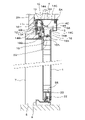
図4及び図6に示されているように、板金の折り曲げ品である無目部材4には、この無目部材4の上面部4Aにおける扉体1の厚さ方向の両端部のうち、垂れ壁部2Aと同じ側の一方の端部から垂下した垂下部4Bが設けられ、この垂下部4Bは、上額縁部材10を介して垂れ壁部2Aにビス等の結合具11,12で結合されている。また、無目部材4には、扉体1の厚さ方向のうち、垂下部4Bとは反対側の箇所において、点検カバー5により覆われる開口部が設けられている。この点検カバー5は、上端に形成された係止部5Aを、無目部材4に取り付けた被係止部材4Cに係止することにより、無目部材4の開口部を塞ぐものであり、また、点検カバー5は、戸先側竪枠部材3等に設けられたブラケットに止めねじで取り付けられ、この止めねじを取り外して係止部5Aを被係止部材4Cから離脱させることにより、点検カバー5を無目部材4から取り外すことができる。
As shown in FIGS. 4 and 6, the
無目部材4の内部には、この無目部材4の強度を補強するための補強部材にもなっている取付部材13が配設されており、扉体1の開閉移動方向へ延びる長さを有する板金の折り曲げ品であって、扉体1の厚さ方向への凹凸の形状を有しているこの取付部材13は、結合具や溶接により無目部材4の垂下部4Bに結合されている。また、取付部材13には、垂れ壁部2A側へ窪んだ凹部13Aが形成されている。
Inside the
この凹部13Aよりも上部において、取付部材13には、図4に示されているように、アルミ又はアルミ合金の押し出し成形で形成された上レール部材14の上部14Aが、ビス等の結合具15により結合されている。この上レール部材14は、扉体1を開閉移動自在に案内するために無目部材4の内部に配置されたガイドレールであって、本実施形態に係るガイド手段となっており、この上レール部材14の上部14Aの下側には、取付部材13の凹部13Aの内部に嵌合された嵌合部14Bが形成されている。また、上レール部材14には、上部14Aと嵌合部14Bとの間において、ガイド部14Cが、扉体1の厚さ方向のうち、垂れ壁部2A側とは反対側へ水平に延出形成されている。このような上部14Aと嵌合部14Bとガイド部14Cとを有する上レール部材14は、扉体1が全閉位置に達しているときにおける無目部材4の内部構造と扉体1の上部の内部構造とを示している図5から分かるように、扉体1の開閉移動方向への長さを有し、無目部材4の全長と略同じ長さ寸法となっている。
Above the
図4に示されているように、扉体1の上端には、扉体1の上力骨である上枠部材16が配設され、この上枠部材16は、水平部16Aと、鉛直上向きに立ち上がった立上り部16Bとからなるアングル材により形成され、立上り部16Bは、扉体1の厚さ方向である水平部16Aの幅方向の両端部のうち、垂れ壁部2Aとは反対側の端部から立ち上がっている。図5に示されているように、水平部16Aには、扉体1の戸先側の端部において、1個の上吊り手段17が取り付けられており、扉体1の上部に配置されているこの上吊り手段17には、上吊りローラ18が回転自在に設けられ、上吊り手段17の本体17Aに回転自在に取り付けられていて、上レール部材14のガイド部14Cに上から転動自在に載置、係合しているこの上吊りローラ18は、扉体1の開閉移動方向に小さな間隔をあけて2個配設されている。そして、上吊りローラ18を備えた上吊り手段17は、上レール部材14が配置されている無目部材4の内部に収納され、この無目部材4の内部は、このような上吊りローラ18を備えた上吊り手段17が収納される空間部ともなっている。
As shown in FIG. 4, the upper end of the
以上の説明から分かるように、扉体1の上側には、扉体1の開閉移動を案内するためのガイド手段として無目部材4の内部に配置された上レール部材14が配設されており、扉体1は、この扉体1の上部に設けられた1個の上吊り手段17の上吊りローラ18が上レール部材14に転動自在に載置、係合することにより、上レール部材14から吊り下げられた上吊り式の扉体となっているとともに、上レール部材14に案内されて開閉移動自在となっている。そして、無目部材4や上レール部材14は、扉体1と異なり、開閉移動しない不動部材となっている。
As can be seen from the above description, the
図5に示されているように、扉体1の上部には、より具体的には、上枠部材16の水平部16Aの上面には、上吊り手段17の配置箇所よりも戸尻側の箇所において、上ガイド部材19が固定されており、上枠部材16の水平部16Aの上面にビス等で結合されているこの上ガイド部材19は、扉体1の開閉移動方向への長さを有している。また、上ガイド部材19は、図4及び図6に示されているように、上枠部材16の水平部16Aの上面にビス等で結合された水平のベース部19Aと、扉体1の厚さ方向であるベース部19Aの幅方向の両端部から鉛直に立ち上がった一対の立上り部19B,19Cとからなる上向きに開口したチャンネル状の部材により形成されている。このため、上枠部材16によって形成されている扉体1の上外縁部には、上ガイド部材19のベース部19Aと立上り部19B,19Cとによって形成された凹部39が設けられ、図5でも示されているこの凹部39は、扉体1の内側に向かって窪んだものとなっている。
As shown in FIG. 5, on the upper part of the
図4及び図6で示されている前述の取付部材13は、図5に示されているように、上レール部材14の戸尻側の端部を越えてさらに戸尻側へ延出した延出部13Bを有しており、この延出部13Bに振れ止め手段20が取り付けられている。この振れ止め手段20は、図6に示されているように、上ガイド部材19の一対の立上り部19B,19Cの間に上から挿入された振れ止め部材21を備えており、この振れ止め部材21により、扉体1が、扉体1の厚さ方向に振れることが防止されるようになっている。そして、前述した上吊り手段17が、扉体1の上部における戸先側の端部の箇所又はこの箇所の近傍に配置されているのに対して、振れ止め手段20は、扉体1が前述の全閉位置に達しているときに、扉体1の上部における戸尻側の端部の箇所又はこの箇所の近傍と対応する位置に配置されている。
4 and 6, as shown in FIG. 5, the mounting
図3から分かるように、前述した沓摺部材9は、扉体1で開閉される出入口6を越えて扉体1の開き移動方向へ延びる延長部9Aを有しており、この延長部9Aの上面には、扉体1の開閉移動方向へ延びる長さを有している下レール部材25が固定設置され、この下レール部材25は、無目部材4の内部にガイド手段として収納されて配置されている上レール部材14の下側において、この上レール部材14から戸尻側へずれて配置されたレール部材となっている。
As can be seen from FIG. 3, the above-described
図6に示されているように、扉体1の下部には、下側に開口したチャンネル材による下ガイド部材23が設けられ、この下ガイド部材23の内部に、図1~図3に示されているように、沓摺部材9に鉛直方向が回転中心の軸方向となって配置されているガイドローラ22が、図4に示されているように、挿入されている。また、図6に示されているように、この下ガイド部材23の内部には、1個の下ローラ26を回転自在に支持したブラケット27がビス等の結合具28で取り付けられ、下ローラ26は、下レール部材25に上から転動自在に載置、係合している。そして、下ローラ26は、図1に示されているように、扉体1の下部における戸尻側の端部の箇所又はこの箇所の近傍に配置されている。
As shown in FIG. 6, the lower portion of the
前述したように、扉体1を上レール部材14から吊り下げるための上吊り手段17が、扉体1の上部における戸先側の端部の箇所又はこの箇所の近傍に配置され、また、下レール部材25に載せられている下ローラ26が、扉体1の下部における戸尻側の端部の箇所又はこの箇所の近傍に配置されていることにより、扉体1の重量は、扉体1が鉛直面内で回転することを阻止されながら、上レール部材14と下レール部材25とで支持されることになる。
As described above, the suspending
また、扉体1は、上部が無目部材4の内部に配置されたガイド手段となっている上レール部材14で案内され、下部は沓摺部材9に配置されたガイドローラ22と下レール部材25で案内されることにより、開閉移動自在となっている。
The upper part of the
さらに、扉体1が上レール部材14とガイドローラ22と下レール部材25に案内されて開き移動したときには、図3に示されているように、扉体1の戸尻側の端部は、無目部材4から外れた位置まで後退する。
Further, when the
図5に示されているように、無目部材4の内部に配置されている上レール部材14には、扉体1が全閉位置に近づいたときに、扉体1の閉じ移動速度を低下させるためのドアクローズ装置55が取り付けられており、この取り付けが行われている箇所は、図4に示されているように、上レール部材14に設けられている前述の嵌合部14Bである。図4及び図5に示されているように、扉体1の上部に配置されている上ガイド部材19の一対の立上り部19B,19Cのうち、垂れ壁部2A側の立上り部19Bには、ドアクローズ装置55を作動させるための作動部材56が取り付けられている。図5に示されているように、ドアクローズ装置55は、装置本体55Aと、この装置本体55Aに対して扉体1の開閉移動方向に往復動自在となっている係止部材55Bとを有し、扉体1が全開位置に達しているときには、係止部材55Bは、装置本体55Aから扉体1の開き移動方向に離れた開き側の移動限界位置に達している。
As shown in FIG. 5, the
装置本体55Aには、係止部材55Bが装置本体55Aからこの開き側の移動限界位置に達する際に、引っ張り力が蓄圧される長寸法のコイルばねと、係止部材55Bが装置本体55Aに対し扉体1の閉じ移動方向に移動して、この移動が閉じ側の移動限界位置に近づくことにより、装置本体55Aの内部に充填されているオイル等の流体の抵抗作用で係止部材55Bの移動速度を低下させるためのダンパーと、係止部材55Bの移動を案内するための案内部材とが設けられている。そして、係止部材55Bは揺動中心軸を中心に揺動自在となっており、この揺動により、作動部材56は係止部材55Bに対して係脱できるようになっている。
The device
また、図5に示されているように、扉体1の上部における内部には、扉体1の戸尻側の端部の近傍において、扉体1を自動的に閉じ移動させるための駆動装置30が配置されている。この駆動部材30からは、後述するように、この駆動装置30の内部に回転自在に収納されている巻取りリールに一端が連結されたワイヤー等の紐状部材31が導出され、この紐状部材31の他端は、無目部材4に取り付けられている前述の振れ止め手段20の本体20Aに連結されている。扉体1の戸先側の先端が戸先側の竪枠部材3に当接することで扉体1が出入口6を全閉としているときに、図1で示す把持部1Aを握った手によって扉体1を開き移動させると、駆動装置30から紐状部材31が巻取りリールを回転させながら繰り出されるとともに、この巻取りリールの回転により、駆動装置30の内部に収納されている渦巻きばねに戻しばね力が蓄圧され、把持部1Aから手を離すと、この蓄圧された戻しばね力によって巻取りリールが紐状部材31を巻き取ることにより、紐状部材31に作用する引っ張り力で扉体1が自動的に全閉位置まで閉じ移動する。このため、本実施形態に係る引戸装置は、自動閉鎖式の引戸装置である。
Further, as shown in FIG. 5, a driving device for automatically closing and moving the
以上の本実施形態に係る引戸装置では、全開位置に達していた扉体1の把持部1Aから手を離し、駆動装置30により自動的に扉体1を閉じ移動させると、その途中において、作動部材56は、この作動部材56が当接することにより揺動するドアクローズ装置55の係止部材55Bに係止され、これにより、扉体1とドアクローズ装置55とが連結され、これにより、これ以後の扉体1は、ドアクローズ装置55の長寸法のコイルばねの引っ張り力と、駆動装置30の紐状部材31が巻取りリールによって巻き取られることによる紐状部材31の引っ張り力とにより閉じ移動する。係止部材55Bが上述の閉じ側の移動限界位置の近くに達すると、言い換えると、扉体1が全閉位置に近づくと、上述のダンパーの作用により係止部材55Bの移動速度が低下するため、扉体1は閉じ移動速度を低下させながら全閉位置に達することになる。
In the sliding door device according to the present embodiment described above, when the hand is released from the
また、全閉位置に達していた扉体1を、把持部1Aを把持した手により開き移動させたときには、扉体1と係止部材55Bは、ダンパーに設けられている逆止弁の作用により移動速度が低下せずに開き移動し、係止部材55Bが、長寸のコイルばねに引っ張り力を蓄圧しながら上述の開き側の移動限界位置に達すると、この係止部材55Bの移動を案内する前述の案内部材に形成されている案内溝の作用により、係止部材55Bは、前述とは逆方向に揺動し、このため、係止部材55Bに係止されていた作動部材56は、この係止部材55Bから離脱し、これにより、扉体1は、ドアクローズ装置55から離れて全開位置等の開き位置まで達する。
Further, when the
図7は、図5の一部拡大図であり、この図7には、駆動装置30が拡大されて示されている。図8には、駆動装置30だけの正面図が示され、図9には、駆動装置30の平面図が示されている。上述した巻取りリール38及び渦巻きばね40は、図8に示されているように、駆動装置30のケース37の内部に収納されており、このケース37の上端には、ケース37の外側に向かって突出した2個の突片部37A,37Bが設けられている。図7に示されているように、扉体1の上端に配置されている前述の上ガイド部材19のベース部19Aと、上枠部材16の水平部16Aには、駆動装置30のケース37を扉体1の内部に挿入、配置するための開口部42が形成され、ケース37を扉体1の内部に挿入した後に、突片部37A,37Bが、上ガイド部材19のベース部19Aと上枠部材16の水平部16Aとにビス等の結合具32,33で結合されることにより、駆動装置30は、扉体1の内部に収納されて扉体1の上部に取り付けられる。
FIG. 7 is a partially enlarged view of FIG. 5, in which the
図10は、一部を破断して示した駆動装置30の平面図である。この図10に示されているように、駆動装置30には、扉体1の厚さ方向が軸方向となっている中心軸35と、この中心軸35を回転させるために作業者の手で回転操作される回転操作部材36とが設けられている。中心軸35は、軸方向に離れた二箇所で駆動装置30のケース37により回転自在に支持されているとともに、中心軸35の軸方向の両方の端部は、ケース37の外側へ延出した延出端部35Aとなっており、これらの延出端部35Aに、形状が同じとなっていて同期して回転する2個の回転操作部材36が取り付けられている。これにより、それぞれの回転操作部材36の回転操作によって中心軸35を回転させることができる。
FIG. 10 is a plan view of the driving
駆動装置30のケース37の内部に収納配置されている巻取りリール38は、中心軸35を中心に回転自在となっており、この巻取りリール38には、図5、図7及び図8でも示されている紐状部材31が巻回されている。一方の端部が巻取りリール38に連結されているこの紐状部材31は、図7に示されているように、ケース37に回転自在に取り付けられている案内ローラ34に掛け回されてからケース37の外部に導出され、紐状部材31の他方の端部は、前述したように、無目部材4に結合されている取付部材13の延出部13Bに取り付けられた前述の振れ止め手段20の本体20Aに連結されている。
A take-
本実施形態では、振れ止め手段20の本体20Aは、図6で示した振れ止め部材21を保持しており、この本体20Aに戸尻側へ延出した延出部20Bが設けられ、この延出部20Bに立設されているピン部材20Cに、紐状部材31の上述した他方の端部に形成したループ部を嵌合することにより、この端部が振れ止め手段20の本体20Aに連結されている。そして、この振れ止め手段20の本体20Aは、扉体1と異なり、開閉移動しないで不動となっているため、前述した無目部材4と同じく、不動部材となっている。
In this embodiment, the
なお、図7に示されているように、振れ止め手段20の本体20Aには、扉体1が閉じ移動したときに、この扉体1に設けられている上吊り手段17の本体17Aが当たる戸当り部材20Dが取り付けられ、本体17Aがこの戸当り部材20Dに当たることにより、扉体1は全開位置に達する。
As shown in FIG. 7, the
図10に示されているように、巻取りリール38の内部には、ぜんまいばねによる前述した渦巻きばね40を収納した空間が設けられ、中心軸35の外周に巻回状態で配置されているこの渦巻きばね40の外端部40Aは、連結具41により巻取りリール38に連結されているとともに、内端部40Bは、中心軸35に形成された長孔35Bに挿入されることにより、この中心軸35に連結されている。このため、前述したように、扉体1を全閉位置から開き移動させると、駆動装置30から紐状部材31が巻取りリール38を回転させながら繰り出され、紐状部材31を繰り出すためのこの巻取りリール38の回転により、渦巻きばね40に戻しばね力が蓄圧されることになり、この蓄圧された戻しばね力によって巻取りリール38が紐状部材31を巻き取ることにより、扉体1は自動的に閉じ移動する。
As shown in FIG. 10, inside the take-
そして、扉体1を全開位置等で停止させているときに、作業者が手で回転操作部材36を回転操作し、この回転操作により中心軸35を回転させると、この回転方向に応じて渦巻きばね40は巻き締められたり、巻き緩められたりするため、渦巻きばね40の初期値のばね力を調整することができ、これにより、渦巻きばね40のばね力を、扉体1の開閉移動距離や移動速度等に応じて適切値に調整することができる。
When the operator rotates the
また、図8及び図10に示されているように、本実施形態の駆動装置30には、この駆動装置30に2個設けられている回転操作部材36を回転操作したときに、中心軸35を節度的に一定角度ずつ回転可能とするための節度的回転手段43が設けられている。この節度的回転手段43は、ケース37の内部において、中心軸35に設けられた多角形部44と、この多角形部44の外面に弾性接触しているばね部材45とを含んで構成されているものであり、本実施形態の多角形部44は、中心軸35の外周に螺合等で固定された六角ナットによるものとなっているため、この多角形部44は、回転操作部材36と節度的回転手段43との関係を概略正面図として示している図11及び図12のように、中心軸35の円周方向に6個の突起44Aが60度の等間隔で設けられた六角形部となっている。また、ばね部材45は、図8、図11及び図12に示されているように、多角形部44における互いに平行となっている2つの外面に弾性的に接触していて、これらの外面を弾性的に挟圧するU字状又は略U字状の板ばねによるものであり、このばね部材45は、ケース37の内面に止着具46で止着された止め部材47により連結部材48を介してケース37に止められている。
Further, as shown in FIGS. 8 and 10, in the
このため、回転操作部材36により中心軸35を回転させたときには、図11及び図12に示されているように、多角形部44における互いに平行となっている2つの外面に弾性接触していたばね部材45は、多角形部44に中心軸35を中心として60度の等角度で設けられている突起44Aを、ばね部材45が弾性的に開くことにより、乗り越え、そして、多角形部44における互いに平行となっている次の2つの外面に弾性接触するため、回転操作部材36による中心軸35の回転は、60度の一定角度ずつの節度的な回転として行われることになる。そして、ばね部材45が多角形部44における互いに平行となっている2つの外面に弾性接触しているときは、回転操作部材36及び中心軸35の回転がばね部材45の弾性的な挟着力により停止することになる。
Therefore, when the
また、中心軸35を回転させるために回転操作される2個の回転操作部材36のそれぞれは、図6に示されているように、扉体1の厚さ方向が厚さ寸法の方向となっている鉛直姿勢の板状のものであり、これらの回転操作部材36の外周部には、図8に示されているように、外径方向に突出した突部36Aと内径方向に窪んだ窪み部36Bとが、中心軸35を中心とする円周方向に交互に6個ずつ設けられ、このため、回転操作部材36の正面形状は、星形状又は略星形状となっている。そして、6個の突部36Aは、中心軸35を中心とする回転操作部材36の円周方向に等間隔で設けられているため、これらの突部36Aは、中心軸35を中心に60度の等角度で設けられ、この60度の角度は、多角形部44の上述した6個の突起44Aについての中心軸35を中心とする60度の等角度の角度と同じである。
As shown in FIG. 6, each of the two
なお、それぞれの回転操作部材36の外周部に中心軸35側へ窪んで形成されているそれぞれの窪み部36Bは、図8に示されているように、中心軸35を中心とする回転操作部材36の円周方向に互いに隣接している2個の突部36Aの間の中央位置に設けられているため、これらの窪み部36Bも、突部36Aと同様に、中心軸35を中心に60度の等角度で設けられている。
It should be noted that, as shown in FIG. 8, each recessed
そして、多角形部44の突起44Aの位置と、それぞれの回転操作部材36の突部36Aの位置とが、中心軸35を中心とする円周方向における同じ角度位置となって、これらの回転操作部材36は、中心軸35の前述した延出端部35Aに取り付けられている。
The positions of the
また、図8及び図11に示されているように、中心軸35の回転が節度的回転手段43により停止しているときに、それぞれの回転操作部材36の外周部に6個設けられている窪み部36Bのうち、1個の窪み部36Bの位置が中心軸35の真上又は略真上の位置となるように、中心軸35に対する多角形部44及び回転操作部材36の回転方向の位置が設定されている。
Also, as shown in FIGS. 8 and 11, when the rotation of the
また、図6に示されているように、駆動装置30が扉体1の内部に収納配置されるときには、この駆動装置30における扉体1の厚さ方向の両側に2個設けられている回転操作部材36は、上部を除く大部分が扉体1の内部に収納され、これらの回転操作部材36は扉体1の厚さ内に配置される。そして、このように駆動装置30と回転操作部材36を扉体1の内部に収納配置するための作業は、図11で示されているように、中心軸35と2個の回転操作部材36の回転が節度的回転手段43により停止しているときに行われ、図7及び図8は、このときの駆動装置30の状態を示しており、このときには、それぞれの回転操作部材36の外周部に6個設けられている窪み部36Bのうち、1個の窪み部36Bが中心軸35の真上又は略真上に達しているため、この1個の窪み部36Bの両隣りの2個の突部36Aが、図7に示されているように、扉体1の上部に配置されている前述の上ガイド部材19のベース部19Aから上方へ突出している。
Further, as shown in FIG. 6, when the driving
このベース部19Aは、図6で示されているように、上ガイド部材19に扉体1の厚さ方向に離れて一対設けられている立上り部19B,19Cと共に、扉体1の上外縁部に形成されている前述の凹部39を形成するものとなっているため、それぞれの回転操作部材36の上記2個の突部36Aは、凹部39のうち、ベース部19Aによって形成される底部から上方へ突出していることになる。そして、これらの突部36Aについての凹部39の底部からの突出寸法は、凹部39の深さ寸法よりも小さくなっている。
As shown in FIG. 6, the
回転操作部材36により中心軸35を図8及び図11で示されている状態から回転させて、中心軸35の回転角度が、図12に示されているように、ばね部材45が多角形部44の突起44Aに弾性接触する角度となったときには、6個の突部36Aのうち、1個の突部36Aが、中心軸35の真上又は略真上の位置に達する。このときは、この1個の突部36Aが凹部39の底部から上方に突出することになり、この突部36Aについての凹部39の底部からの突出寸法も、凹部39の深さ寸法よりも小さい。
By rotating the
このため、本実施形態では、それぞれの回転操作部材36に6個設けられている突部36Aについての中心軸35を中心とする円周方向の間隔は、中心軸35の回転角度の如何にかかわらず、すなわち、回転操作部材36の回転角度の如何にかかわらず、少なくとも1個の突部36Aが凹部39の底部から上方へ突出する間隔となっている。
For this reason, in the present embodiment, the intervals in the circumferential direction about the
そして、それぞれの回転操作部材36に6個設けられている突部36Aは、扉体1の外部から作業者の手によって回転操作部材36を回転させるために操作することができる操作部となっており、これらの操作部により回転操作部材36を回転させて中心軸35を回転させることにより、駆動装置30の渦巻きばね40についての初期値のばね力を調整するための作業を実施することができる。
The six
この作業は、図3に示されているように、開き移動させて扉体1を全開位置に停止させて行う。これにより、扉体1の上部の大部分は前述した無目部材4から外れた位置に達し、この扉体1の内部に配置された駆動装置30と、この駆動装置30の中心軸35の前述した延出端部35Aに取り付けられた回転操作部材36は、扉体1の上外縁部における戸尻側の端部の近傍に配置されていて、これらの駆動装置30と回転操作部材36は、無目部材4により覆われない位置に達しているため、上述の操作部となっている突部36Aにより、回転操作部材36を回転操作して中心軸35を回転させることによって行う渦巻きばね40についての初期値のばね力調整作業を、無目部材4の影響を受けることなく容易に実施できる。
As shown in FIG. 3, this work is performed by moving the
なお、本実施形態の扉体1の上外縁部には、図6に示されているように、作業者が作業する側において、上枠部材16の立上り部16Bが設けられているため、作業者は、駆動装置30における扉体1の厚さ方向の両側に2個設けられている回転操作部材36のうち、立上り部16Bとは反対側に配置されている回転操作部材36を回転操作することにより、渦巻きばね40についての初期値のばね力調整作業を行うことができる。
As shown in FIG. 6, the upper outer edge of the
また、本実施形態では、回転操作部材36を回転させるために操作される操作部は、前述したように、扉体1の上外縁部に設けられた凹部39の底部から上方に突出した突部36Aであり、この突部36Aについての凹部39の底部からの突出寸法は、凹部39の深さ寸法よりも小さいため、扉体1が開閉移動方向のどの位置に達していても、突部36Aに予期しない外力等が作用することを防止できる。
Further, in the present embodiment, the operation portion operated to rotate the
また、回転操作部材36の外周部に6個設けられている突部36Aについての中心軸35を中心とする円周方向の間隔は、前述したように、回転操作部材36の回転角度の如何にかかわらず、少なくとも1個の突部36Aが凹部39の底部から上方へ突出する間隔となっているため、突部36Aによる回転操作部材36の回転作業を,回転操作部材36がどのような回転角度になっていても実施することができる。
Also, the intervals in the circumferential direction around the
さらに、本実施形態に係る駆動装置30には、回転操作部材36の回転により中心軸35を節度的に60度の一定角度ずつ回転可能とするための節度的回転手段43が設けられ、この一定角度となっている60度は、回転操作部材36に60度の等角度で6個設けられている突部36Aについてのこの等角度と同じ角度であるため、回転操作部材36の回転操作作業を行う作業者が、回転操作部材36と中心軸35の回転角度や回転数を明確に感じてこの回転操作作業を行えるようになる。
Furthermore, the driving
また、前述したように、中心軸35に設けられている多角形部44の突起44Aの位置と、回転操作部材36の突部36Aの位置とが、中心軸35を中心とする円周方向における同じ角度位置となっているため、回転操作部材36の回転操作作業を行う作業者は、節度的回転手段43により、回転操作部材36を介した中心軸35の回転を、一層実感のある節度的回転として感じながらこの回転操作作業を行える。
Further, as described above, the position of the
さらに、回転操作部材36の外周部には、それぞれの突部36Aの間において、内径側に、すなわち、中心軸35側に窪んで形成されている窪み部36Bが設けられており、これらの窪み部36Bのうち、1個の窪み部36Bは、前述したように、節度的回転手段43により中心軸35と回転操作部材36の回転が停止しているときには、中心軸35の真上又は略真上の位置に達している。このように節度的回転手段43により中心軸35と回転操作部材36の回転が停止しているときは、渦巻きばね40についての初期値のばね力を調整するための作業が終了したときである。この作業の終了により、扉体1の開閉移動が行われることになり、扉体1が全閉となったときにおいては、図13に示されているように、扉体1がこの扉体1の厚さ方向に振れることを防止するための振れ止め部材21を備えている振れ止め手段20と、中心軸35の真上又は略真上の位置に達している上述の1個の窪み部36Bとの位置関係は、振れ止め手段20の真下又は略真下の位置にこの1個の窪み部36Bが達している関係となっているため、扉体1を開閉移動させても、振れ止め手段20に回転操作部材36が干渉することをなくすことができる。
Further, on the outer peripheral portion of the
これを言い換えると、回転操作部材36を、図13の二点鎖線で示されているように、中心軸35を中心とする円形の回転操作部材36’とした場合には、扉体1が全閉となったときに、振れ止め手段20に円形の回転操作部材36’が干渉してしまう又は干渉するおそれがあるが、節度的回転手段43により中心軸35と回転操作部材36の回転が停止しているときに、中心軸35の真上又は略真上の位置に達している1個の窪み部36Bの位置が、振れ止め手段20の真下又は略真下の位置となっていることにより、このような干渉が生ずることをなくすことができる。
In other words, when the
また、本実施形態の駆動装置30では、前述したように中心軸35の軸方向は扉体1の厚さ方向となっていて、この中心軸35の軸方向の両端部は、図9及び図10に示されているように、駆動装置30のケース37の外側に延出した延出端部35Aとなっており、これらの延出端部35Aのそれぞれに、形状が同じになっていて同期して回転する回転操作部材36が取り付けているため、駆動装置30には、扉体1の厚さ方向の両側に2個の回転操作部材36が設けられている。これによると、前述したように、扉体1の上外縁部に、扉体1の厚さ方向のうち、作業者が作業する側において、上枠部材16の立上り部16Bが設けられていても、2個の回転操作部材36のうち、立上り部16Bとは反対側の回転操作部材36を操作することによって渦巻きばねについての初期値のばね力調整作業を容易に行え、また、図1等で示されている本実施形態の引戸装置とは、扉体の開き移動方向と閉じ移動方向が逆方向となっている左右勝手違いの引戸装置については、回転操作する回転操作部材を使い分けすることができるようになって、回転操作部材36を含めた駆動装置30を、左右勝手違いの引戸装置について共通化できるようになる。
In the driving
本発明は、扉体が無目部材の内部に配置されているガイドレール等のガイド手段に案内され、かつ扉体の内部に駆動装置が配置されている引戸装置に利用することができる。 INDUSTRIAL APPLICABILITY The present invention can be used in a sliding door device in which a door is guided by guide means such as a guide rail arranged inside a blind member, and a driving device is arranged inside the door.
1 扉体
4 無目部材
14 ガイド手段である上レール部材
19 上ガイド部材
19A 凹部の底部となっているベース部
19B,19C 立上り部
20 振れ止め手段
20A 不動部材となっている本体
21 振れ止め部材
25 下レール部材
30 駆動装置
31 紐状部材
35 中心軸
35A 延出端部
36 回転操作部材
36A 操作部となっている突部
36B 窪み部
37 ケース
38 巻取りリール
39 凹部
40 渦巻きばね
40A 外端部
40B 内端部
43 節度的回転手段
44 多角形部
45 ばね部材
Claims (13)
前記駆動装置が、端部が不動部材に連結された紐状部材と、この紐状部材を繰り出し自在に巻き取るために前記駆動装置のケースの内部に回転自在に収納された巻取りリールと、前記ケースの内部に収納され、前記巻取りリールから前記紐状部材が繰り出されたときにこの巻取りリールが前記紐状部材を巻き取るための戻しばね力が蓄圧される渦巻きばねとを備えている引戸装置において、
前記渦巻きばねの内端部は、前記巻取りリールの回転の中心となっている中心軸に連結されているとともに、外端部は前記巻取りリールに連結され、前記中心軸の端部は前記ケースの外側に延出した延出端部となっていて、この延出端部に前記中心軸を回転させるための回転操作部材が取り付けられ、前記扉体の厚さ内に配置されているこの回転操作部材は、前記扉体の外部から前記回転操作部材を回転操作可能とする操作部を有しており、
前記扉体の外縁部には、この扉体の内側に窪んで形成された凹部が設けられ、前記操作部はこの凹部の底部から突出しているとともに、この操作部についての前記凹部の前記底部からの突出寸法は、前記凹部の深さ寸法よりも小さくなっていることを特徴とする引戸装置。 a guide means arranged inside the blind member; a door suspended from the guide means and movable to open and close by being guided by the guide means; and a door arranged inside the door. , and a driving device for moving the door,
The drive device includes a string-like member whose end is connected to a stationary member, and a take-up reel rotatably housed inside a case of the drive device for winding the string-like member so as to be unreeled; a spiral spring that is housed inside the case and accumulates a return spring force for winding the string-like member on the take-up reel when the string-like member is unwound from the take-up reel. In a sliding door device with
The inner end of the spiral spring is connected to the central shaft that is the center of rotation of the take-up reel, the outer end of the spiral spring is connected to the take-up reel, and the end of the central shaft is connected to the It has an extension end portion extending outside the case, and a rotating operation member for rotating the central shaft is attached to the extension end portion, and is arranged within the thickness of the door body. The rotary operation member has an operation portion that allows the rotary operation member to be rotated from the outside of the door body ,
The outer edge portion of the door body is provided with a recess formed by being recessed inside the door body. is smaller than the depth of the recess .
Priority Applications (2)
| Application Number | Priority Date | Filing Date | Title |
|---|---|---|---|
| JP2019010866A JP7202196B2 (en) | 2019-01-25 | 2019-01-25 | sliding door device |
| JP2022163052A JP7346691B2 (en) | 2019-01-25 | 2022-10-11 | sliding door device |
Applications Claiming Priority (1)
| Application Number | Priority Date | Filing Date | Title |
|---|---|---|---|
| JP2019010866A JP7202196B2 (en) | 2019-01-25 | 2019-01-25 | sliding door device |
Related Child Applications (1)
| Application Number | Title | Priority Date | Filing Date |
|---|---|---|---|
| JP2022163052A Division JP7346691B2 (en) | 2019-01-25 | 2022-10-11 | sliding door device |
Publications (2)
| Publication Number | Publication Date |
|---|---|
| JP2020117957A JP2020117957A (en) | 2020-08-06 |
| JP7202196B2 true JP7202196B2 (en) | 2023-01-11 |
Family
ID=71890207
Family Applications (2)
| Application Number | Title | Priority Date | Filing Date |
|---|---|---|---|
| JP2019010866A Active JP7202196B2 (en) | 2019-01-25 | 2019-01-25 | sliding door device |
| JP2022163052A Active JP7346691B2 (en) | 2019-01-25 | 2022-10-11 | sliding door device |
Family Applications After (1)
| Application Number | Title | Priority Date | Filing Date |
|---|---|---|---|
| JP2022163052A Active JP7346691B2 (en) | 2019-01-25 | 2022-10-11 | sliding door device |
Country Status (1)
| Country | Link |
|---|---|
| JP (2) | JP7202196B2 (en) |
Citations (6)
| Publication number | Priority date | Publication date | Assignee | Title |
|---|---|---|---|---|
| JP2006226095A (en) | 2005-01-21 | 2006-08-31 | Asahi Sangyo Kk | Automatic sliding-door closing system |
| JP2008144421A (en) | 2006-12-07 | 2008-06-26 | Asahi Sangyo Kk | Sliding door closer |
| JP2009228405A (en) | 2008-02-29 | 2009-10-08 | Nitto Kohki Co Ltd | Automatic door closing device of horizontal sliding door, horizontal sliding door fitted with automatic door closing device, automatic door closing device kit and its setup method |
| JP2009275497A (en) | 2008-05-16 | 2009-11-26 | Kiyohara:Kk | Shutoff device for sliding door |
| US20100031469A1 (en) | 2008-08-07 | 2010-02-11 | Chou-Chih Chiang | Damped Closing Mechanism for automatic Shutting Pull Door |
| JP2017206946A (en) | 2016-05-17 | 2017-11-24 | 文化シヤッター株式会社 | Sliding door device |
Family Cites Families (1)
| Publication number | Priority date | Publication date | Assignee | Title |
|---|---|---|---|---|
| JPS6480685A (en) * | 1987-09-24 | 1989-03-27 | Comany Kk | Self-closing device for sliding door |
-
2019
- 2019-01-25 JP JP2019010866A patent/JP7202196B2/en active Active
-
2022
- 2022-10-11 JP JP2022163052A patent/JP7346691B2/en active Active
Patent Citations (6)
| Publication number | Priority date | Publication date | Assignee | Title |
|---|---|---|---|---|
| JP2006226095A (en) | 2005-01-21 | 2006-08-31 | Asahi Sangyo Kk | Automatic sliding-door closing system |
| JP2008144421A (en) | 2006-12-07 | 2008-06-26 | Asahi Sangyo Kk | Sliding door closer |
| JP2009228405A (en) | 2008-02-29 | 2009-10-08 | Nitto Kohki Co Ltd | Automatic door closing device of horizontal sliding door, horizontal sliding door fitted with automatic door closing device, automatic door closing device kit and its setup method |
| JP2009275497A (en) | 2008-05-16 | 2009-11-26 | Kiyohara:Kk | Shutoff device for sliding door |
| US20100031469A1 (en) | 2008-08-07 | 2010-02-11 | Chou-Chih Chiang | Damped Closing Mechanism for automatic Shutting Pull Door |
| JP2017206946A (en) | 2016-05-17 | 2017-11-24 | 文化シヤッター株式会社 | Sliding door device |
Also Published As
| Publication number | Publication date |
|---|---|
| JP2020117957A (en) | 2020-08-06 |
| JP2022179639A (en) | 2022-12-02 |
| JP7346691B2 (en) | 2023-09-19 |
Similar Documents
| Publication | Publication Date | Title |
|---|---|---|
| US9212518B2 (en) | Control device for shades | |
| JP5422093B2 (en) | Roll blind | |
| KR102015421B1 (en) | Folding swing door unit with narrow radius of rotation | |
| US20070199662A1 (en) | Bracket assembly for rolling shutter system | |
| AU2016222264B2 (en) | Spool assembly for a blind system | |
| JP6837306B2 (en) | Sliding door device | |
| US9140060B2 (en) | Window covering having at least one deformable connector | |
| JP5238392B2 (en) | Roller blind screen lifting device | |
| JP5108374B2 (en) | Vertical louver device | |
| JP7202196B2 (en) | sliding door device | |
| KR102031526B1 (en) | Smart Privacy Button Blind | |
| US20230349232A1 (en) | Releasable locking mechanism | |
| JP6473313B2 (en) | Shielding device | |
| JP2010007408A (en) | Door having tension spring counter weight, and its actuator | |
| JP6485864B2 (en) | Tension applying device | |
| JP4696401B2 (en) | Blind device | |
| JPS6244068Y2 (en) | ||
| KR101153545B1 (en) | Apparatus prevention from dropping of heavy weight | |
| KR20090033540A (en) | Winding apparatus of wire for blind up-down | |
| TW201606178A (en) | Lifting device of blind window | |
| EP1908912A1 (en) | Sectional overhead door arrangement | |
| US6695033B1 (en) | Guide device for winding shaft of a material handling door comprising a flexible curtain | |
| JP5628077B2 (en) | Elevator hall entrance / exit safety device | |
| JPH0616125Y2 (en) | Roll blind elevating device | |
| JPH0311342Y2 (en) |
Legal Events
| Date | Code | Title | Description |
|---|---|---|---|
| RD03 | Notification of appointment of power of attorney |
Free format text: JAPANESE INTERMEDIATE CODE: A7423 Effective date: 20190206 |
|
| A621 | Written request for application examination |
Free format text: JAPANESE INTERMEDIATE CODE: A621 Effective date: 20211115 |
|
| A977 | Report on retrieval |
Free format text: JAPANESE INTERMEDIATE CODE: A971007 Effective date: 20220810 |
|
| A131 | Notification of reasons for refusal |
Free format text: JAPANESE INTERMEDIATE CODE: A131 Effective date: 20220830 |
|
| A521 | Request for written amendment filed |
Free format text: JAPANESE INTERMEDIATE CODE: A523 Effective date: 20221004 |
|
| TRDD | Decision of grant or rejection written | ||
| A01 | Written decision to grant a patent or to grant a registration (utility model) |
Free format text: JAPANESE INTERMEDIATE CODE: A01 Effective date: 20221213 |
|
| A61 | First payment of annual fees (during grant procedure) |
Free format text: JAPANESE INTERMEDIATE CODE: A61 Effective date: 20221223 |
|
| R150 | Certificate of patent or registration of utility model |
Ref document number: 7202196 Country of ref document: JP Free format text: JAPANESE INTERMEDIATE CODE: R150 |