JP7202170B2 - hydraulic shock absorber - Google Patents
hydraulic shock absorber Download PDFInfo
- Publication number
- JP7202170B2 JP7202170B2 JP2018236564A JP2018236564A JP7202170B2 JP 7202170 B2 JP7202170 B2 JP 7202170B2 JP 2018236564 A JP2018236564 A JP 2018236564A JP 2018236564 A JP2018236564 A JP 2018236564A JP 7202170 B2 JP7202170 B2 JP 7202170B2
- Authority
- JP
- Japan
- Prior art keywords
- piston
- rod
- communication passage
- side chamber
- piston rod
- Prior art date
- Legal status (The legal status is an assumption and is not a legal conclusion. Google has not performed a legal analysis and makes no representation as to the accuracy of the status listed.)
- Active
Links
Images


Classifications
-
- F—MECHANICAL ENGINEERING; LIGHTING; HEATING; WEAPONS; BLASTING
- F16—ENGINEERING ELEMENTS AND UNITS; GENERAL MEASURES FOR PRODUCING AND MAINTAINING EFFECTIVE FUNCTIONING OF MACHINES OR INSTALLATIONS; THERMAL INSULATION IN GENERAL
- F16F—SPRINGS; SHOCK-ABSORBERS; MEANS FOR DAMPING VIBRATION
- F16F9/00—Springs, vibration-dampers, shock-absorbers, or similarly-constructed movement-dampers using a fluid or the equivalent as damping medium
- F16F9/32—Details
- F16F9/34—Special valve constructions; Shape or construction of throttling passages
- F16F9/3405—Throttling passages in or on piston body, e.g. slots
-
- F—MECHANICAL ENGINEERING; LIGHTING; HEATING; WEAPONS; BLASTING
- F16—ENGINEERING ELEMENTS AND UNITS; GENERAL MEASURES FOR PRODUCING AND MAINTAINING EFFECTIVE FUNCTIONING OF MACHINES OR INSTALLATIONS; THERMAL INSULATION IN GENERAL
- F16F—SPRINGS; SHOCK-ABSORBERS; MEANS FOR DAMPING VIBRATION
- F16F9/00—Springs, vibration-dampers, shock-absorbers, or similarly-constructed movement-dampers using a fluid or the equivalent as damping medium
- F16F9/06—Springs, vibration-dampers, shock-absorbers, or similarly-constructed movement-dampers using a fluid or the equivalent as damping medium using both gas and liquid
- F16F9/062—Bi-tubular units
-
- F—MECHANICAL ENGINEERING; LIGHTING; HEATING; WEAPONS; BLASTING
- F16—ENGINEERING ELEMENTS AND UNITS; GENERAL MEASURES FOR PRODUCING AND MAINTAINING EFFECTIVE FUNCTIONING OF MACHINES OR INSTALLATIONS; THERMAL INSULATION IN GENERAL
- F16F—SPRINGS; SHOCK-ABSORBERS; MEANS FOR DAMPING VIBRATION
- F16F9/00—Springs, vibration-dampers, shock-absorbers, or similarly-constructed movement-dampers using a fluid or the equivalent as damping medium
- F16F9/06—Springs, vibration-dampers, shock-absorbers, or similarly-constructed movement-dampers using a fluid or the equivalent as damping medium using both gas and liquid
- F16F9/063—Springs, vibration-dampers, shock-absorbers, or similarly-constructed movement-dampers using a fluid or the equivalent as damping medium using both gas and liquid comprising a hollow piston rod
-
- F—MECHANICAL ENGINEERING; LIGHTING; HEATING; WEAPONS; BLASTING
- F16—ENGINEERING ELEMENTS AND UNITS; GENERAL MEASURES FOR PRODUCING AND MAINTAINING EFFECTIVE FUNCTIONING OF MACHINES OR INSTALLATIONS; THERMAL INSULATION IN GENERAL
- F16F—SPRINGS; SHOCK-ABSORBERS; MEANS FOR DAMPING VIBRATION
- F16F9/00—Springs, vibration-dampers, shock-absorbers, or similarly-constructed movement-dampers using a fluid or the equivalent as damping medium
- F16F9/32—Details
- F16F9/3207—Constructional features
- F16F9/3228—Constructional features of connections between pistons and piston rods
-
- F—MECHANICAL ENGINEERING; LIGHTING; HEATING; WEAPONS; BLASTING
- F16—ENGINEERING ELEMENTS AND UNITS; GENERAL MEASURES FOR PRODUCING AND MAINTAINING EFFECTIVE FUNCTIONING OF MACHINES OR INSTALLATIONS; THERMAL INSULATION IN GENERAL
- F16F—SPRINGS; SHOCK-ABSORBERS; MEANS FOR DAMPING VIBRATION
- F16F9/00—Springs, vibration-dampers, shock-absorbers, or similarly-constructed movement-dampers using a fluid or the equivalent as damping medium
- F16F9/32—Details
- F16F9/50—Special means providing automatic damping adjustment, i.e. self-adjustment of damping by particular sliding movements of a valve element, other than flexions or displacement of valve discs; Special means providing self-adjustment of spring characteristics
- F16F9/516—Special means providing automatic damping adjustment, i.e. self-adjustment of damping by particular sliding movements of a valve element, other than flexions or displacement of valve discs; Special means providing self-adjustment of spring characteristics resulting in the damping effects during contraction being different from the damping effects during extension, i.e. responsive to the direction of movement
Landscapes
- Engineering & Computer Science (AREA)
- General Engineering & Computer Science (AREA)
- Mechanical Engineering (AREA)
- Fluid-Damping Devices (AREA)
Description
本発明は、流体圧緩衝器に関するものである。 The present invention relates to hydraulic shock absorbers.
特許文献1に記載の流体圧緩衝器では、ピストンロッドは、シリンダの外部へと延出するロッド部と、ロッド部の端部に連結されてシリンダ内を摺動自在に移動し、シリンダ内をピストン側室とロッド側室に区画するピストンと、を有し、ロッド部は、ロッド部の内部に形成されてシリンダのピストン側室と連通するロッド内空間と、ロッド内空間とシリンダのロッド側室とを接続する第1連通路と、第1連通路に交換可能に設けられるオリフィスプラグと、を有する。 In the fluid pressure damper described in Patent Document 1, the piston rod is connected to a rod portion extending to the outside of the cylinder and to an end portion of the rod portion to slidably move within the cylinder. The piston has a piston partitioned into a piston side chamber and a rod side chamber, and the rod portion connects the rod inner space formed inside the rod portion and communicating with the piston side chamber of the cylinder, and the rod inner space and the rod side chamber of the cylinder. and an orifice plug exchangeably provided in the first communication passage.
特許文献1に記載の流体圧緩衝器では、オリフィスプラグが設けられる第1連通路が、ロッド部に設けられる。ロッド部が大型の部品である場合、第1連通路をロッド部に加工する際には手間がかかり、流体圧緩衝器を容易に製造できないという問題がある。 In the fluid pressure damper disclosed in Patent Literature 1, a rod portion is provided with a first communication passage in which an orifice plug is provided. If the rod portion is a large-sized component, it takes time and effort to process the first communication passage into the rod portion, which poses a problem that the fluid pressure damper cannot be easily manufactured.
本発明は上記の問題点に鑑みてなされたものであり、流体圧緩衝器を容易に製造することを目的とする。 SUMMARY OF THE INVENTION An object of the present invention is to easily manufacture a fluid pressure damper.
本発明は、流体圧緩衝器であって、シリンダチューブと、シリンダチューブの外部へと延出するピストンロッドと、ピストンロッドの端部に連結されてシリンダチューブ内を摺動自在に移動し、シリンダチューブ内をピストン側室とロッド側室に区画するピストンと、ピストンロッドの内部に形成されるロッド内空間と、ロッド側室とロッド内空間とを連通する第1連通路と、ピストンに設けられ、ピストン側室とロッド内空間とを連通する第2連通路と、第2連通路に設けられ、通過する作動流体の流れに抵抗を付与する絞り部と、ピストンに形成され、ピストン側室とロッド内空間とを連通する第3連通路と、第3連通路に設けられ、ピストン側室からロッド内空間への作動流体の流れのみを許容する逆止弁と、を備えることを特徴とする。 The present invention is a fluid pressure shock absorber comprising a cylinder tube, a piston rod extending to the outside of the cylinder tube, and an end of the piston rod connected to the end of the piston rod to slidably move within the cylinder tube. a piston that partitions the inside of the tube into a piston-side chamber and a rod-side chamber; a rod-side space formed inside the piston rod; a first communication passage that communicates the rod-side chamber and the rod-side space; a second communication passage that communicates with the rod interior space; a throttle portion that is provided in the second communication passage and provides resistance to the flow of the working fluid that passes through ; It is characterized by comprising: a communicating third communication passage; and a check valve provided in the third communication passage and allowing only the flow of the working fluid from the piston-side chamber to the rod internal space .
この発明では、絞り部が設けられる第2連通路が、ピストンロッドよりも小型の部品であるピストンに形成される。これにより、第2連通路を容易に加工することができる。また、この発明では、逆止弁が設けられる第3連通路が、ピストンロッドよりも小型の部品であるピストンに形成される。これにより、第3連通路を容易に加工することができる。 In this aspect of the invention, the second communication passage provided with the throttle portion is formed in the piston, which is a component smaller than the piston rod. Thereby, the second communication path can be easily processed. Also, in the present invention, the third communication passage provided with the check valve is formed in the piston, which is a component smaller than the piston rod. Thereby, the third communication path can be easily processed.
また、本発明は、ピストンとピストンロッドの間に設けられるプレートをさらに備え、第1連通路は、プレートに形成されることを特徴とする。 Also, the present invention is characterized by further comprising a plate provided between the piston and the piston rod, wherein the first communication path is formed in the plate.
この発明では、第1連通路が、ピストンロッドやピストンよりも小型の部品であるプレートに形成される。これにより、第1連通路を容易に加工することができる。 In this invention, the first communication path is formed in the plate, which is a component smaller than the piston rod and the piston. Thereby, the first communication path can be easily processed.
また、本発明は、絞り部が、第2連通路に交換可能に設けられるオリフィスプラグであり、プレートによってロッド内空間へのオリフィスプラグの脱落が防止されることを特徴とする。 Further, the present invention is characterized in that the throttle portion is an orifice plug replaceably provided in the second communication passage, and the plate prevents the orifice plug from dropping into the rod internal space.
この発明では、第2連通路にオリフィスプラグが交換可能に設けられる。これにより、減衰力の調整を、オリフィスプラグの交換によって容易に行うことができる。さらに、プレートによってオリフィスプラグの脱落が防止される。 In this invention, the orifice plug is replaceably provided in the second communication passage. This makes it possible to easily adjust the damping force by replacing the orifice plug. Additionally, the plate prevents the orifice plug from falling off.
また、本発明は、逆止弁が、プレートによって、ロッド内空間への脱落が防止されることを特徴とする。 Further, the present invention is characterized in that the check valve is prevented from dropping into the rod internal space by a plate.
この発明では、プレートによって逆止弁の脱落が防止される。 In this invention, the plate prevents the check valve from coming off.
また、本発明は、第1連通路は、ピストンロッドに形成されることを特徴とする。 Moreover, the present invention is characterized in that the first communication passage is formed in the piston rod.
また、本発明は、第1連通路を通過する作動流体の流れに付与される抵抗は、絞り部を通過する作動流体の流れに付与される抵抗よりも小さいことを特徴とする。 Further, the present invention is characterized in that the resistance applied to the flow of working fluid passing through the first communication passage is smaller than the resistance applied to the flow of working fluid passing through the constricted portion.
この発明では、減衰力に対する第1連通路の抵抗の影響が抑制されるため、絞り部によって所望の減衰力を発生させることができる。 In this aspect of the invention, since the influence of the resistance of the first communication passage on the damping force is suppressed, a desired damping force can be generated by the constricted portion.
本発明によれば、流体圧緩衝器の製造を容易に行うことができる。 According to the present invention, it is possible to easily manufacture a fluid pressure damper.
以下、図面を参照して、本発明の実施形態について説明する。 Hereinafter, embodiments of the present invention will be described with reference to the drawings.
<第1実施形態>
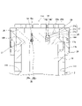
まず、図1~3を参照して、本発明の第1実施形態に係る流体圧緩衝器について説明する。第1実施形態では、流体圧緩衝器が車両に搭載されるショックアブソーバ100である場合について説明する。
<First Embodiment>
First, a fluid pressure damper according to a first embodiment of the present invention will be described with reference to FIGS. 1 to 3. FIG. In the first embodiment, a case where the fluid pressure damper is a shock absorber 100 mounted on a vehicle will be described.
ショックアブソーバ100は、例えば、車両の車体と車軸との間に介装され、減衰力を発生させて車体の振動を抑制する装置である。
The
ショックアブソーバ100は、筒状のシリンダチューブ1と、シリンダチューブ1に進退自在に挿入されシリンダチューブ1の外部へと延出するピストンロッド2と、ピストンロッド2の先端に連結されシリンダチューブ1の内周面に沿って摺動自在に移動するピストン12と、を備える。本実施形態では、ショックアブソーバ100は、シリンダチューブ1が上側、ピストンロッド2が下側となる向きに車両に搭載される。
The
シリンダチューブ1内はピストン12によってピストン側室13とロッド側室14とに区画され、ピストン側室13とロッド側室14には作動流体としての作動油が封入される。また、シリンダチューブ1内には、シリンダチューブ1に対するピストンロッド2の進入、退出に伴うシリンダチューブ1内の容積変化を利用してばね作用を得るためのガスが封入される。このように、ショックアブソーバ100は、ガスによるばね作用によって車体の支持が可能なエアサスペンションの機能を備える流体圧緩衝器であってもよい。この場合、車体を支持するばねを別途設けなくても、ショックアブソーバ100によって減衰力の発生及び車体の支持が可能となる。なお、これに限らず、シリンダチューブ1内にガスが封入されなくてもよい。
The inside of the cylinder tube 1 is partitioned into a piston-
シリンダチューブ1の端部には、ピストンロッド2が摺動自在に挿通するシリンダヘッド3が設けられる。シリンダヘッド3は、円筒状の本体部3aと、本体部3aと比較して大径のフランジ部3bと、を有する。シリンダヘッド3は、フランジ部3bがボルト4にてシリンダチューブ1の端部に締結されることによって、シリンダチューブ1に固定される。シリンダヘッド3の本体部3aの内周面には、ピストンロッド2の外周面に摺接するシール部材7やダストシール8が設けられる。
A
シリンダチューブ1におけるシリンダヘッド3の逆側の端部には、ボトム部材5が接合される。ボトム部材5は、ショックアブソーバ100を車両に取り付けるための取付部5aを有する。
A
ピストンロッド2は、円筒状部材であって、内部にロッド内空間としてのロッド内室16を有する。ピストンロッド2は両端が開口しており、シリンダチューブ1から延出する側の開口端にはロッドヘッド6が設けられ、他方の開口端にはピストン12が設けられる。このように、ロッド内室16は、ロッドヘッド6とピストン12によって区画される。
The
ロッドヘッド6は、ピストンロッド2よりも大径に形成されショックアブソーバ100の収縮作動時のストロークエンドを規定するストッパ部6aと、ショックアブソーバ100を車両に取り付けるための取付部6bと、を有する。ストッパ部6aには、ショックアブソーバ100の収縮作動時にストロークエンドでのシリンダヘッド3とロッドヘッド6との衝突を防止する環状のクッションリング10が設けられる。
The
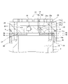
図2及び3に示すように、ピストン12は、プレート9を介してピストンロッド2に連結される。プレート9は、ピストンロッド2とピストン12の間に設けられる。プレート9には、ロッド内室16とロッド側室14とを常時連通する第1連通路としての連通溝9bが形成される。
As shown in FIGS. 2 and 3,
ショックアブソーバ100は、ピストン12に形成されロッド内室16とピストン側室13とを連通する第2連通路18及び第3連通路19を備える。第2連通路18には、交換可能に設けられ通過する作動油に対して抵抗を付与して減衰力を発生する絞り部としてのオリフィスプラグ20が設けられる。第3連通路19には、ピストン側室13からロッド内室16への作動油の流れのみを許容する逆止弁21が設けられる。
The shock absorber 100 includes a
ショックアブソーバ100が収縮作動した際には、ピストン側室13の圧力が上昇して逆止弁21が開弁するため、ピストン側室13の作動油は逆止弁21及びオリフィスプラグ20を通じて、ロッド内室16及びロッド側室14に流入する。一方、ショックアブソーバ100が伸長作動した際には、ロッド側室14及びロッド内室16の圧力が上昇して逆止弁21が閉弁するため、ロッド側室14及びロッド内室16の作動油はオリフィスプラグ20のみを通じてピストン側室13に流入する。このように、ショックアブソーバ100が発生する減衰力は、伸長作動時の方が収縮作動時よりも大きくなる。これにより、車両が路面上の突起部に乗り上げたような場合には、ショックアブソーバ100は比較的スムーズに収縮作動し、その後、伸長作動する際に大きな減衰力を発生して、路面から車体に入力される振動を効果的に減衰させる。
When the shock absorber 100 contracts, the pressure in the
以下では、ピストンロッド2とピストン12の連結構造について詳しく説明する。
Below, the connecting structure of the
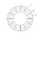
図2に示すように、ピストン12は、ピストンロッド2に締結され凹部25aを有する円柱状の本体部25と、本体部25の外周面に連続して形成され、本体部25の端面から軸方向に突出する円筒状のリング部26と、を備える。このように、ピストン12は、一端面には凹部25aが形成され、他端面からリング部26が突出する。ピストン12には、本体部25とリング部26により凹状の収容部27が形成される。この収容部27にピストンロッド2の先端側が挿入され、ピストンロッド2とピストン12が連結される。リング部26は、収容部27に挿入されたピストンロッド2とピストン12との径方向の位置決めをする(同軸を確保する)位置決め部として機能すると共に、ピストンロッド2に作用する径方向の荷重を受圧する受圧部として機能する。
As shown in FIG. 2, the
リング部26の内周面には、軸方向に沿った複数の溝28が周方向に並んで形成される。溝28は、リング部26の端部から本体部25に達するように、軸方向に沿って形成される。ピストンロッド2とピストン12が連結された状態では、ピストンロッド2の外周面とリング部26の内周面との間には、溝28によって空間が形成される。なお、溝28は、少なくとも1つが形成されていればよい。
A plurality of
本体部25には、軸方向に貫通して形成され収容部27に開口する締結孔25bが形成される。締結孔25bは、周方向に所定間隔を空けて複数形成される。ピストンロッド2にも、軸方向に沿って形成され端面11aに開口する締結穴11bが形成される。締結穴11bは、締結用のボルト29がねじ込まれるねじ穴であり、周方向に締結孔25bと同一の間隔を空けて複数形成される。締結孔25bは、収容部27にピストンロッド2の先端側を挿入した際にピストンロッド2の端面11aに面する位置に形成される。ピストンロッド2とピストン12は、ピストンロッド2の先端側を収容部27に挿入した状態で、締結孔25bと締結穴11bにわたってボルト29を締結することで連結される。
The
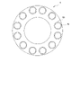
図3に示すように、プレート9は、平板状の円環部材であって、軸方向に貫通して形成される複数の締結孔9aと、両端面に複数形成される連通溝9bと、を有する。連通溝9bは、プレート9の一端面のみに形成されてもよい。プレート9の外径は、ピストンロッド2の外径と略同一である。プレート9の内径は、ピストンロッド2とピストン12が連結された状態で、ピストン12の第2連通路18及び第3連通路19の開口部の一部を覆うように設定される。
As shown in FIG. 3, the
締結孔9aは、周方向に締結孔25b及び締結穴11bと同一の間隔を空けて複数形成される。締結孔9aには、ピストン12とピストンロッド2を連結するボルト29が挿通する。
A plurality of
連通溝9bは、プレート9の外周面と内周面を連通するように、径方向に延びて形成される。連通溝9bは、隣り合う締結孔9aの間にそれぞれ形成される。
The
ピストン12をピストンロッド2に連結する際には、まず、プレート9をピストン12の収容部27に収容する。次に、収容部27にピストンロッド2の先端側を挿入し、ピストンロッド2の端面11aとプレート9を当接させる。そして、締結孔25bと締結孔9aと締結穴11bとを一致させた状態で、ボルト29を締結孔25bから締結孔9aにわたって挿通し、締結穴11bに締結する。このようにして、ピストン12はピストンロッド2に固定される。
When connecting the
ピストン12とピストンロッド2が連結された状態では、溝28及びプレート9に形成された連通溝9bを通じて、ロッド内室16とロッド側室14とが常時連通し、作動油の移動が可能となる。このように、連通溝9bが、ロッド内室16とロッド側室14とを常時連通する第1連通路となる。
When the
このように、本実施形態では、連通溝9bを通じてロッド側室14とロッド内室16が常時連通している。よって、ショックアブソーバ100が高速で収縮作動する際や、最伸長状態から収縮作動する際には、ロッド内室16の作動油が速やかにロッド側室14へ導かれるため、ロッド側室14の急激な圧力低下が抑制される。
Thus, in this embodiment, the
以下では、第2連通路18及び第3連通路19について詳しく説明する。
Below, the
第2連通路18及び第3連通路19は、ピストン12の凹部25aに開口し、軸方向に貫通して形成される。第2連通路18の内周面には、プレート9側にのみ、めねじ18aが形成される。オリフィスプラグ20は、外周面に形成され第2連通路18のめねじ18aと螺合するおねじ20aと、作動油の流れを絞るオリフィス部20bと、を有する。オリフィスプラグ20は第2連通路18内に螺合して締結される。また、プレート9の連通溝9bは、ピストン12とピストンロッド2が連結された状態での連通溝9bの合計流路断面積が、オリフィスプラグ20のオリフィス部20bの流路断面積よりも十分に大きく形成される。さらに、ピストン12の溝28は、ピストン12とピストンロッド2が連結された状態での溝28の合計流路断面積が、オリフィスプラグ20のオリフィス部20bの流路断面積よりも十分に大きく形成される。このように、連通溝9b及び溝28を通過する作動油の流れに付与される抵抗は、オリフィスプラグ20を通過する作動油の流れに付与される抵抗よりも小さい。よって、ショックアブソーバ100が発生する伸長作動時の減衰力の大部分は、オリフィス部20bによって決定される。
The
第3連通路19は、ロッド内室16に開口する大径部19aと、ピストン側室13に開口し大径部19aと比較して小径な小径部19bと、を有する。逆止弁21は、大径部19aと小径部19bの間に形成された環状のシート面21aと、大径部19a内に収容され小径部19bの内径よりも大きな直径を有する弁体としてのボール21bと、ボール21bをシート面21aへ付勢する付勢部材としてのスプリング21cと、を有する。大径部19a側の圧力が小径部19b側の圧力よりも大きい場合には、ボール21bはスプリング21cに付勢されてシート面21aに着座し、ロッド内室16からピストン側室13への作動油の流れが遮断される。一方、小径部19b側の圧力が大径部19a側の圧力よりも大きい場合には、ボール21bはスプリング21cの付勢力に抗してシート面21aから離間し、ピストン側室13からロッド内室16への作動油の流れが許容される。
The
このように、第2連通路18が、ピストンロッド2よりも小型の部品であるピストン12に設けられるため、第2連通路18の加工が容易となり、ショックアブソーバ100の製造を容易に行うことができる。さらに、ピストン12はピストンロッド2よりも肉厚であるため、第2連通路18の配置自由度が高くなり、オリフィスプラグ20だけではなく他の部材を第2連通路18に設けることができる。
Since the
また、第3連通路19が、ピストンロッド2よりも小型の部品であるピストン12に設けられるため、第3連通路19の加工が容易となり、ショックアブソーバ100の製造を容易に行うことができる。さらに、ピストン12はピストンロッド2よりも肉厚であるため、第3連通路19の配置自由度が高くなり、スプリング21c等の部材を第3連通路19に設けることができる。つまり、逆止弁21を、スプリング21cを有するスプリングチェック弁とすることができ、逆止弁21をより安定して動作させることがきる。
Further, since the
また、一般に、通路を流れる作動油は、その通路の流路長が長いほどいわゆるチョーク流れとなり、通過する流量は作動油の粘度の影響を受けやすくなる。作動油の粘度は、温度変化によって変化するため、チョーク流れでは、温度変化によって流量が変化しやすい。これに対し、本実施形態では、第2連通路18及び第3連通路19は、ピストン12の凹部25aに開口するように形成されるため、流路長が比較的短くなる。よって、第3連通路19を通過する作動油の流れをいわゆるオリフィス流れとしやすい。このため、逆止弁21を通じて第3連通路19を流れる作動油の流量は、温度変化による影響を受けにくい。このように、第3連通路19を通過する作動油の流れの温度依存性が低いため、ショックアブソーバ100を安定して作動させることができる。
Further, in general, hydraulic oil flowing through a passage becomes a so-called choke flow as the length of the passage becomes longer, and the flow rate of the hydraulic oil passing through is more susceptible to the viscosity of the hydraulic oil. Since the viscosity of hydraulic oil changes with temperature changes, in choked flow, the flow rate is likely to change with temperature changes. On the other hand, in the present embodiment, the
プレート9は、第2連通路18への作動油の通過は許容しつつ、第2連通路18におけるロッド内室16への開口部の一部を閉じるように、つまり、オリフィスプラグ20の一部を覆うように、ピストン12とピストンロッド2の間に設けられる。具体的には、プレート9の内縁により、オリフィスプラグ20が第2連通路18からロッド内室16へ脱落することが防止される。第2連通路18の内周面におけるピストン側室13側にはめねじが形成されていないため、オリフィスプラグ20がピストン側室13へ脱落することもない。このように、プレート9によって、オリフィスプラグ20の脱落を防止することができる。
The
また、プレート9は、第3連通路19への作動油の通過は許容しつつ、第3連通路19におけるロッド内室16への開口部の一部を閉じるように、つまり、逆止弁21の一部を覆うように、ピストン12とピストンロッド2の間に設けられる。具体的には、プレート9の内縁により、逆止弁21のボール21b及びスプリング21cが第3連通路19からロッド内室16へ脱落することが防止される。このように、プレート9によって、逆止弁21の脱落も防止することができる。
In addition, the
このように、連通溝9bを有するプレート9を設けることによって、連通溝9bを通じてロッド内室16とロッド側室14とを連通するとともに、オリフィスプラグ20及び逆止弁21のロッド内室16への脱落を防止することができる。言い換えれば、プレート9は、ロッド内室16とロッド側室14とを連通するとともに、ロッド内室16へのオリフィスプラグ20及び逆止弁21の脱落を防止しつつオリフィス部20b、第3連通路19、及び逆止弁21の流路を減じない形状に形成される。
By providing the
以上の第1実施形態によれば、以下に示す効果を奏する。 According to the first embodiment described above, the following effects are obtained.
ショックアブソーバ100は、ピストン12に形成されオリフィスプラグ20が設けられる第2連通路18を備える。第2連通路18は、ピストンロッド2よりも小型の部品であるピストン12に形成されるため、第2連通路18の加工が容易となり、ショックアブソーバ100の製造を容易に行うことができる。
The
また、ショックアブソーバ100は、ピストン12に形成され逆止弁21が設けられる第3連通路19を備える。第3連通路19は、ピストンロッド2よりも小型の部品であるピストン12に形成されるため、第3連通路19の加工が容易となり、ショックアブソーバ100の製造を容易に行うことができる。
The
さらに、ピストン12はピストンロッド2よりも肉厚であるため、第2連通路18の配置自由度が高くなり、オリフィスプラグ20だけではなく他の部材を第2連通路18に設けることができる。また、ピストン12はピストンロッド2よりも肉厚であるため、第3連通路19の配置自由度が高くなり、逆止弁21を構成するボール21bやスプリング21c等の部品を第3連通路19に設けることができる。
Furthermore, since the
また、ショックアブソーバ100は、ピストンロッド2とピストン12の間に設けられるプレート9を備える。プレート9に形成された連通溝9bを通じて、ロッド側室14とロッド内室16とが常時連通するため、ショックアブソーバ100が高速で収縮作動する際や、最伸長状態から収縮作動する際には、ロッド内室16の作動油が速やかにロッド側室14へ導かれ、ロッド側室14の急激な圧力低下が抑制される。
The
次に、本実施形態の変形例について、説明する。以下のような変形例も本発明の範囲内であり、以下の変形例と上記実施形態の各構成とを組み合わせたり、以下の変形例と後述の第2実施形態の各構成とを組み合わせたり、以下の変形例同士を組み合わせたりすることも可能である。 Next, a modified example of this embodiment will be described. The following modifications are also within the scope of the present invention, combining the following modifications with each configuration of the above embodiment, or combining the following modifications with each configuration of the second embodiment described later, It is also possible to combine the following modified examples.
(1)上記実施形態では、ピストン12とピストンロッド2の間に、連通溝9bが形成されたプレート9が設けられる。プレート9に連通溝9bを形成する代わりに、図4に示すように、プレート9にワッシャ50を設けてもよい。ワッシャ50は環状部材であり、締結孔9aに沿って配置される。ワッシャ50及び締結孔9aには、ボルト29が挿通する。ピストン12とピストンロッド2が連結された状態では、各ワッシャ50間に隙間が形成される。この隙間を通じて、ロッド内室16とロッド側室14とが連通し、作動油の移動が可能となる。つまり、この変形例では、ワッシャ50間の隙間が第1連通路に相当する。なお、プレート9を設けず、ピストン12とピストンロッド2の間に、ワッシャ50のみを設けてもよい。この場合には、ロッド内室16へのオリフィスプラグ20及びスプリング21cの脱落を防止する、他の構成を設けることが望ましい。
(1) In the above embodiment, the
(2)上記実施形態では、第2連通路18を通過する作動油に対して抵抗を付与して減衰力を発生する絞り部として、オリフィスプラグ20が設けられる。オリフィスプラグ20に代えて、図5に示すように、ロッド内室16の圧力が所定圧力に達した場合に開弁するリリーフ弁60を絞り部として設けてもよい。この場合、ロッド内室16の圧力が上昇し所定圧力に達すると、リリーフ弁60が開弁し、作動油がピストン側室13へ導かれ、リリーフ弁60の抵抗により減衰力が発生する。また、オリフィスプラグ20とリリーフ弁60の両方をピストン12に設けてもよい。
(2) In the above-described embodiment, the
(3)上記実施形態では、逆止弁21は、第3連通路19を開閉可能な弁体としてのボール21bと、付勢部材としてのスプリング21cと、を有する構成である。これに代えて、逆止弁21は、スプリング21cを持たない構成としてもよい。この場合でも、逆止弁21は、ロッド内室16からピストン側室13への作動油の流れを遮断し、ピストン側室13からロッド内室16への作動油の流れを許容する。
(3) In the above embodiment, the
(4)上記実施形態では、シリンダチューブ1が上側、ピストンロッド2が下側となる構成である。これに対して、ピストンロッド2を上側、シリンダチューブ1を下側とし、ショックアブソーバ100を上下反転させた構造としてもよい。
(4) In the above embodiment, the cylinder tube 1 is on the upper side and the
また、上記実施形態では、ピストン12は、収容部27を形成するリング部26を備える。また、プレート9の連通溝9bは、リング部26に形成される溝28を通じてロッド側室14と連通する。これに対し、リング部26は必須の構成ではなく、ピストン12は、リング部26を備えていなくてもよい。この場合、連通溝9bは、ロッド側室14と直接連通するように構成される。
Also, in the above embodiment, the
<第2実施形態>
次に、図6,7を参照して本発明の第2実施形態に係るショックアブソーバ200について説明する。以下では、上記第1実施形態と異なる点を中心に説明し、上記第1実施形態に係るショックアブソーバ100と同一の機能を有する構成には同一の符号を付して説明を省略する。
<Second embodiment>
Next, a
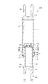
第1実施形態におけるショックアブソーバ100は、ロッド内室16とロッド側室14とを連通する第1連通路が、プレート9に形成される連通溝9bである。これに対し、第2実施形態におけるショックアブソーバ200は、第1連通路が、ピストンロッド2に形成される通路110である点で第1実施形態と相違する。
In the
ショックアブソーバ200は、図6,7に示すように、ピストンロッド2の内外周面に開口部を有し、径方向に貫通して形成される通路110を備える。ピストンロッド2は、通路110が形成される点でのみピストンロッド2と異なる。本実施形態では、180°離間して2つの通路110が設けられる。なお、通路110の数は、2つに限らず、少なくとも1つが形成されていればよい。通路110は、その内径が一様であり、通路110の全体としての流路断面積は、第2連通路18のオリフィス部20bよりも十分に大きく形成される。このように、通路110を通過する作動油の流れに付与される抵抗は、オリフィスプラグ20を通過する作動油の流れに付与される抵抗よりも小さい。よって、ショックアブソーバ200が発生する伸長作動時の減衰力の大部分は、オリフィス部20bによって決定される。
As shown in FIGS. 6 and 7, the
また、ショックアブソーバ200は、ピストンロッド2とピストン112との間に、プレート109が設けられる。プレート109は、連通溝9bが形成されない点でのみ第1実施形態におけるプレート9と異なる。また、ピストン112は、リング部26の内周面に溝28が形成されない点でのみ第1実施形態におけるピストン12と異なる。よって、ピストン112は、リング部26の内径がピストンロッド2の外径と略同一である。
Moreover, the
プレート109の外径はピストンロッド2の外径と略同一であり、ピストンロッド2とピストン112の連結方法は、第1実施形態と同様である。プレート109は、ロッド内室16へのオリフィスプラグ20及び逆止弁21の脱落を防止する。
The outer diameter of the
なお、通路110は、ピストンロッド2の端面11aに形成されるスリットでもよい。
The
以上の第2実施形態によれば、以下に示す効果を奏する。 According to the second embodiment described above, the following effects are obtained.
ショックアブソーバ200においても、通路110を通じて、ロッド側室14とロッド内室16とが常時連通する。そのため、ショックアブソーバ200が高速で収縮作動する際や、最伸長状態から収縮作動する際には、ロッド内室16の作動油が速やかにロッド側室14へ導かれ、ロッド側室14の急激な圧力低下が抑制される。
In
また、ショックアブソーバ200は、第1連通路である通路110が、ピストンロッド2に形成される。ピストンロッド2にオリフィス部20bの流路断面積よりも大きい断面積を有する通路110を形成すればよく、プレート109に複数の溝を形成する必要がないため、ショックアブソーバ200の製造が容易となる。
Further, the
以下、本発明の各実施形態の構成、作用、及び効果をまとめて説明する。 Hereinafter, the configuration, action, and effect of each embodiment of the present invention will be collectively described.
ショックアブソーバ100,200は、シリンダチューブ1の外部へと延出するピストンロッド2と、ピストンロッド2の端部に連結されてシリンダチューブ1内を摺動自在に移動し、シリンダチューブ1内をピストン側室13とロッド側室14に区画するピストン12,112と、ピストンロッド2の内部に形成されるロッド内室16(ロッド内空間)と、ロッド側室14とロッド内室16とを連通する連通溝9b、通路110(第1連通路)と、ピストン12,112に形成され、ピストン側室13とロッド内室16とを連通する第2連通路18と、第2連通路18に設けられ、通過する作動油の流れに抵抗を付与するオリフィスプラグ20(絞り部)と、を備える。
The
この構成では、絞り部が設けられる第2連通路18が、ピストンロッド2よりも小型な部品であるピストン12に形成される。これにより、第2連通路18の加工が容易となり、ショックアブソーバ100,200の製造が容易となる。さらに、ピストン12,112はピストンロッド2よりも肉厚であるため、第2連通路18の配置自由度が高くなり、オリフィスプラグ20だけではなく他の部材を第2連通路18に設けることができる。
In this configuration, the
また、ショックアブソーバ100,200は、ピストン12,112に形成され、ピストン側室13とロッド内室16とを連通する第3連通路19と、第3連通路19に設けられ、ピストン側室13からロッド内室16への作動油の流れのみを許容する逆止弁21と、をさらに備える。
Further, the
この構成では、逆止弁21を有する第3連通路19が、ピストンロッド2よりも小型の部品であるピストン12,112に形成される。これにより、第3連通路19の加工が容易となり、流体圧緩衝器の製造が容易となる。さらに、ピストン12,112はピストンロッド2よりも肉厚であるため、第3連通路19の配置自由度が高くなり、スプリング21c等の部材を第3連通路19に設けることができる。
In this configuration, the
また、ショックアブソーバ100は、ピストン12とピストンロッド2の間に設けられるプレート9を備え、連通溝9bは、プレート9に形成される。
The
この構成では、連通溝9bが、ピストンロッド2やピストン12よりも小型の部品であるプレート9に形成される。これにより、連通溝9bを容易に加工することができる。さらに、プレート9に形成された連通溝9bを通じて、ロッド側室14とロッド内室16とが常時連通するため、ショックアブソーバ100が高速で収縮作動する際や、最伸長状態から収縮作動する際には、ロッド内室16の作動油が速やかにロッド側室14へ導かれ、ロッド側室14の急激な圧力低下が抑制される。
In this configuration, the
また、絞り部は、第2連通路18に交換可能に設けられるオリフィスプラグ20であり、プレート9,109によってロッド内室16へのオリフィスプラグ20の脱落が防止される。
The restrictor is an
この構成では、第2連通路18にオリフィスプラグ20が交換可能に設けられる。これにより、減衰力の調整を、オリフィスプラグ20の交換によって容易に行うことができる。さらに、プレート9,109によってオリフィスプラグ20の脱落が防止される。
In this configuration, an
また、逆止弁21は、プレート9,109によって、ロッド内室16への脱落が防止される。
Also, the
この構成では、プレート9,109によって逆止弁21の脱落が防止される。
In this configuration, the
また、通路110は、ピストンロッド2に形成される。
A
この構成では、ピストンロッド2に大面積の通路110を形成すればよく、プレート109に複数の溝を形成する必要がないため、ショックアブソーバ200の製造を容易に行うことができる。
In this configuration, it is sufficient to form the large-
また、連通溝9b、通路110を通過する作動油の流れに付与する抵抗は、第2連通路18を通過する作動油の流れに付与する抵抗よりも小さい。
Further, the resistance applied to the flow of hydraulic fluid passing through the
この構成では、第2連通路18の絞り部によって伸長作動時の減衰力が発生する。これにより、減衰力の調整が容易となる。
In this configuration, the throttle portion of the
以上、本発明の実施形態について説明したが、上記実施形態は本発明の適用例の一部を示したに過ぎず、本発明の技術的範囲を上記実施形態の具体的構成に限定する趣旨ではない。 Although the embodiments of the present invention have been described above, the above embodiments merely show a part of application examples of the present invention, and the technical scope of the present invention is not limited to the specific configurations of the above embodiments. Absent.
1…シリンダチューブ、2…ピストンロッド、9,109…プレート、9b…連通溝(第1連通路)、12,112…ピストン、13…ピストン側室、14…ロッド側室、16…ロッド内室(ロッド内空間)、18…第2連通路、19…第3連通路、20…オリフィスプラグ(絞り部)、21…逆止弁、60…リリーフ弁、100,200…ショックアブソーバ(流体圧緩衝器)、110…通路(第1連通路)
1...
Claims (6)
前記シリンダチューブの外部へと延出するピストンロッドと、
前記ピストンロッドの端部に連結されて前記シリンダチューブ内を摺動自在に移動し、前記シリンダチューブ内をピストン側室とロッド側室に区画するピストンと、
前記ピストンロッドの内部に形成されるロッド内空間と、
前記ロッド側室と前記ロッド内空間とを連通する第1連通路と、
前記ピストンに形成され、前記ピストン側室と前記ロッド内空間とを連通する第2連通路と、
前記第2連通路に設けられ、通過する作動流体の流れに抵抗を付与する絞り部と、
前記ピストンに形成され、前記ピストン側室と前記ロッド内空間とを連通する第3連通路と、
前記第3連通路に設けられ、前記ピストン側室から前記ロッド内空間への作動流体の流れのみを許容する逆止弁と、を備えることを特徴とする流体圧緩衝器。 a cylinder tube;
a piston rod extending to the outside of the cylinder tube;
a piston that is connected to the end of the piston rod and slidably moves in the cylinder tube and partitions the inside of the cylinder tube into a piston-side chamber and a rod-side chamber;
a rod internal space formed inside the piston rod;
a first communication passage communicating between the rod-side chamber and the rod internal space;
a second communication passage formed in the piston and communicating between the piston-side chamber and the rod internal space;
a constricted portion provided in the second communication passage and applying resistance to the flow of the working fluid passing therethrough;
a third communication passage formed in the piston and communicating between the piston-side chamber and the rod internal space;
a check valve that is provided in the third communication passage and that allows the working fluid to flow only from the piston-side chamber to the rod internal space .
前記第1連通路は、前記プレートに形成されることを特徴とする請求項1に記載の流体圧緩衝器。 further comprising a plate provided between the piston and the piston rod;
2. A fluid pressure damper according to claim 1 , wherein said first communication path is formed in said plate.
前記プレートによって前記ロッド内空間への前記オリフィスプラグの脱落が防止されることを特徴とする請求項2に記載の流体圧緩衝器。 the throttle portion is an orifice plug replaceably provided in the second communication passage;
3. A fluid pressure damper according to claim 2 , wherein said plate prevents said orifice plug from dropping into said rod internal space.
Priority Applications (5)
| Application Number | Priority Date | Filing Date | Title |
|---|---|---|---|
| JP2018236564A JP7202170B2 (en) | 2018-12-18 | 2018-12-18 | hydraulic shock absorber |
| PCT/JP2019/047709 WO2020129682A1 (en) | 2018-12-18 | 2019-12-05 | Fluid pressure shock absorber |
| CN201980083016.4A CN113242943B (en) | 2018-12-18 | 2019-12-05 | fluid pressure buffer |
| US17/414,630 US12247638B2 (en) | 2018-12-18 | 2019-12-05 | Fluid pressure shock absorber |
| GB2108715.0A GB2595075B (en) | 2018-12-18 | 2019-12-05 | Fluid pressure shock absorber |
Applications Claiming Priority (1)
| Application Number | Priority Date | Filing Date | Title |
|---|---|---|---|
| JP2018236564A JP7202170B2 (en) | 2018-12-18 | 2018-12-18 | hydraulic shock absorber |
Publications (2)
| Publication Number | Publication Date |
|---|---|
| JP2020097997A JP2020097997A (en) | 2020-06-25 |
| JP7202170B2 true JP7202170B2 (en) | 2023-01-11 |
Family
ID=71101410
Family Applications (1)
| Application Number | Title | Priority Date | Filing Date |
|---|---|---|---|
| JP2018236564A Active JP7202170B2 (en) | 2018-12-18 | 2018-12-18 | hydraulic shock absorber |
Country Status (5)
| Country | Link |
|---|---|
| US (1) | US12247638B2 (en) |
| JP (1) | JP7202170B2 (en) |
| CN (1) | CN113242943B (en) |
| GB (1) | GB2595075B (en) |
| WO (1) | WO2020129682A1 (en) |
Families Citing this family (1)
| Publication number | Priority date | Publication date | Assignee | Title |
|---|---|---|---|---|
| JP7627158B2 (en) * | 2021-03-23 | 2025-02-05 | カヤバ株式会社 | Fluid pressure shock absorber |
Citations (1)
| Publication number | Priority date | Publication date | Assignee | Title |
|---|---|---|---|---|
| JP2015206374A (en) | 2014-04-17 | 2015-11-19 | カヤバ工業株式会社 | cylinder device |
Family Cites Families (22)
| Publication number | Priority date | Publication date | Assignee | Title |
|---|---|---|---|---|
| US3647239A (en) * | 1969-07-17 | 1972-03-07 | Tokico Ltd | Vehicle suspension mechanism |
| DE2165812A1 (en) * | 1970-12-29 | 1972-07-20 | Tokico Ltd., Kawasaki, Kanagawa (Japan) | Shock absorber assembly |
| JPS55135835U (en) * | 1979-03-20 | 1980-09-27 | ||
| DD142764A1 (en) * | 1979-04-04 | 1980-07-09 | Horst Engelmann | LIGHT-SENSITIVE, COLOR PHOTOGRAPHIC SILVER HALOGENIDE MATERIAL WITH DIR COUPLER |
| JPH063238B2 (en) * | 1986-11-12 | 1994-01-12 | いすゞ自動車株式会社 | Hydromatic Suspension Device |
| US4971344A (en) * | 1989-01-04 | 1990-11-20 | Rockshox, Inc. | Bicycle with a front fork wheel suspension |
| DE4017924A1 (en) * | 1990-06-05 | 1991-12-12 | Boge Ag | FRONT WHEEL FORK FOR BICYCLES |
| EP0508134B1 (en) * | 1991-03-20 | 1995-08-23 | Showa Corporation | Wheel suspension system for bicycle |
| US5094324A (en) * | 1991-04-05 | 1992-03-10 | Dah Ken Industrial Co., Ltd. | Bicycle shock-absorbing apparatus |
| DE4226754A1 (en) * | 1991-09-21 | 1993-03-25 | Bosch Gmbh Robert | SUSPENSION SYSTEM FOR VEHICLES |
| US5775677A (en) * | 1995-02-07 | 1998-07-07 | Englund; Arlo C. | Air or gas sprung and dampened shock absorber |
| JP2004076785A (en) * | 2002-08-12 | 2004-03-11 | Kayaba Ind Co Ltd | Lock cylinder |
| WO2005015384A1 (en) * | 2003-08-12 | 2005-02-17 | Robertson Graeme K | Shock absorber assembly |
| CN2811665Y (en) | 2005-05-26 | 2006-08-30 | 江苏大学 | Single-chamber oil-gas separation type oil-gas spring with nonlinear characteristics |
| US9322449B2 (en) * | 2005-08-11 | 2016-04-26 | Eko Sport, Inc. | Valve for shock absorbers |
| FR2917371B1 (en) | 2007-06-15 | 2009-11-20 | Messier Dowty Sa | AIRCRAFT DRIVER SHOCK ABSORBER |
| CN201198853Y (en) * | 2008-05-15 | 2009-02-25 | 内蒙古北方重型汽车股份有限公司 | Buffering device of automobile hanging cylinder |
| JP5961124B2 (en) * | 2012-04-27 | 2016-08-02 | Kyb株式会社 | Suspension device |
| JP5876855B2 (en) * | 2013-07-05 | 2016-03-02 | Kyb株式会社 | Fluid pressure cylinder |
| JP6134238B2 (en) * | 2013-09-11 | 2017-05-24 | Kyb株式会社 | Shock absorber |
| JP6212340B2 (en) * | 2013-09-24 | 2017-10-11 | Kyb株式会社 | Shock absorber and suspension system |
| CN104179872A (en) * | 2014-07-24 | 2014-12-03 | 三一矿机有限公司 | Variable damping oil-gas suspension cylinder and mining dump truck thereof |
-
2018
- 2018-12-18 JP JP2018236564A patent/JP7202170B2/en active Active
-
2019
- 2019-12-05 CN CN201980083016.4A patent/CN113242943B/en active Active
- 2019-12-05 WO PCT/JP2019/047709 patent/WO2020129682A1/en not_active Ceased
- 2019-12-05 GB GB2108715.0A patent/GB2595075B/en active Active
- 2019-12-05 US US17/414,630 patent/US12247638B2/en active Active
Patent Citations (1)
| Publication number | Priority date | Publication date | Assignee | Title |
|---|---|---|---|---|
| JP2015206374A (en) | 2014-04-17 | 2015-11-19 | カヤバ工業株式会社 | cylinder device |
Also Published As
| Publication number | Publication date |
|---|---|
| WO2020129682A1 (en) | 2020-06-25 |
| CN113242943A (en) | 2021-08-10 |
| US20220065324A1 (en) | 2022-03-03 |
| CN113242943B (en) | 2023-09-26 |
| US12247638B2 (en) | 2025-03-11 |
| JP2020097997A (en) | 2020-06-25 |
| GB2595075A (en) | 2021-11-17 |
| GB202108715D0 (en) | 2021-08-04 |
| GB2595075B (en) | 2023-03-15 |
Similar Documents
| Publication | Publication Date | Title |
|---|---|---|
| CN105452708B (en) | The damper of passive valve with dependent Frequency | |
| CN105556161B (en) | Buffer | |
| US10060497B2 (en) | Shock absorber | |
| CN110873144B (en) | Shock absorber | |
| EP3236105B1 (en) | Shock absorber | |
| CN106795934B (en) | Shock absorber with frequency-dependent passive valve | |
| US11655875B2 (en) | Damping valve and shock absorber | |
| US9995362B2 (en) | Cylinder device | |
| CN102057180A (en) | Nested one-way high-speed valve | |
| CN106030149A (en) | Shock Absorber with Frequency-Dependent Passive Valve | |
| US20180135718A1 (en) | Shock absorber | |
| CN102859228A (en) | Two stage valve and hydraulic damped valve | |
| JP2011257002A (en) | Shock absorber | |
| JP7202170B2 (en) | hydraulic shock absorber | |
| CN109983249A (en) | Frequency dependence damper | |
| WO2022202472A1 (en) | Fluid pressure shock absorber | |
| US9022186B2 (en) | Damping force generator for hydraulic shock absorber | |
| JP4965490B2 (en) | Hydraulic shock absorber | |
| JP5212812B2 (en) | Hydraulic buffer | |
| JP7422941B2 (en) | buffer | |
| WO2020241422A1 (en) | Shock absorber | |
| JP6377931B2 (en) | Front fork | |
| JP2017096311A (en) | Front fork |
Legal Events
| Date | Code | Title | Description |
|---|---|---|---|
| A621 | Written request for application examination |
Free format text: JAPANESE INTERMEDIATE CODE: A621 Effective date: 20211119 |
|
| A131 | Notification of reasons for refusal |
Free format text: JAPANESE INTERMEDIATE CODE: A131 Effective date: 20220816 |
|
| A521 | Request for written amendment filed |
Free format text: JAPANESE INTERMEDIATE CODE: A523 Effective date: 20221004 |
|
| TRDD | Decision of grant or rejection written | ||
| A01 | Written decision to grant a patent or to grant a registration (utility model) |
Free format text: JAPANESE INTERMEDIATE CODE: A01 Effective date: 20221206 |
|
| A61 | First payment of annual fees (during grant procedure) |
Free format text: JAPANESE INTERMEDIATE CODE: A61 Effective date: 20221223 |
|
| R151 | Written notification of patent or utility model registration |
Ref document number: 7202170 Country of ref document: JP Free format text: JAPANESE INTERMEDIATE CODE: R151 |
|
| S533 | Written request for registration of change of name |
Free format text: JAPANESE INTERMEDIATE CODE: R313533 |
|
| R350 | Written notification of registration of transfer |
Free format text: JAPANESE INTERMEDIATE CODE: R350 |